EP3434615B1 - System for manufacturing pairs of containers and pair of containers - Google Patents
System for manufacturing pairs of containers and pair of containersDownload PDFInfo
- Publication number
- EP3434615B1 EP3434615B1EP17001293.4AEP17001293AEP3434615B1EP 3434615 B1EP3434615 B1EP 3434615B1EP 17001293 AEP17001293 AEP 17001293AEP 3434615 B1EP3434615 B1EP 3434615B1
- Authority
- EP
- European Patent Office
- Prior art keywords
- mold
- containers
- diameter
- vessel
- pair
- Prior art date
- Legal status (The legal status is an assumption and is not a legal conclusion. Google has not performed a legal analysis and makes no representation as to the accuracy of the status listed.)
- Active
Links
Images


Classifications
- B—PERFORMING OPERATIONS; TRANSPORTING
- B29—WORKING OF PLASTICS; WORKING OF SUBSTANCES IN A PLASTIC STATE IN GENERAL
- B29C—SHAPING OR JOINING OF PLASTICS; SHAPING OF MATERIAL IN A PLASTIC STATE, NOT OTHERWISE PROVIDED FOR; AFTER-TREATMENT OF THE SHAPED PRODUCTS, e.g. REPAIRING
- B29C51/00—Shaping by thermoforming, i.e. shaping sheets or sheet like preforms after heating, e.g. shaping sheets in matched moulds or by deep-drawing; Apparatus therefor
- B29C51/10—Forming by pressure difference, e.g. vacuum
- B—PERFORMING OPERATIONS; TRANSPORTING
- B29—WORKING OF PLASTICS; WORKING OF SUBSTANCES IN A PLASTIC STATE IN GENERAL
- B29C—SHAPING OR JOINING OF PLASTICS; SHAPING OF MATERIAL IN A PLASTIC STATE, NOT OTHERWISE PROVIDED FOR; AFTER-TREATMENT OF THE SHAPED PRODUCTS, e.g. REPAIRING
- B29C33/00—Moulds or cores; Details thereof or accessories therefor
- B29C33/0022—Multi-cavity moulds
- B—PERFORMING OPERATIONS; TRANSPORTING
- B29—WORKING OF PLASTICS; WORKING OF SUBSTANCES IN A PLASTIC STATE IN GENERAL
- B29C—SHAPING OR JOINING OF PLASTICS; SHAPING OF MATERIAL IN A PLASTIC STATE, NOT OTHERWISE PROVIDED FOR; AFTER-TREATMENT OF THE SHAPED PRODUCTS, e.g. REPAIRING
- B29C33/00—Moulds or cores; Details thereof or accessories therefor
- B29C33/44—Moulds or cores; Details thereof or accessories therefor with means for, or specially constructed to facilitate, the removal of articles, e.g. of undercut articles
- B29C33/48—Moulds or cores; Details thereof or accessories therefor with means for, or specially constructed to facilitate, the removal of articles, e.g. of undercut articles with means for collapsing or disassembling
- B—PERFORMING OPERATIONS; TRANSPORTING
- B29—WORKING OF PLASTICS; WORKING OF SUBSTANCES IN A PLASTIC STATE IN GENERAL
- B29C—SHAPING OR JOINING OF PLASTICS; SHAPING OF MATERIAL IN A PLASTIC STATE, NOT OTHERWISE PROVIDED FOR; AFTER-TREATMENT OF THE SHAPED PRODUCTS, e.g. REPAIRING
- B29C51/00—Shaping by thermoforming, i.e. shaping sheets or sheet like preforms after heating, e.g. shaping sheets in matched moulds or by deep-drawing; Apparatus therefor
- B29C51/16—Lining or labelling
- B29C51/165—Lining or labelling combined with the feeding or the shaping of the lining or the labels
- B—PERFORMING OPERATIONS; TRANSPORTING
- B29—WORKING OF PLASTICS; WORKING OF SUBSTANCES IN A PLASTIC STATE IN GENERAL
- B29C—SHAPING OR JOINING OF PLASTICS; SHAPING OF MATERIAL IN A PLASTIC STATE, NOT OTHERWISE PROVIDED FOR; AFTER-TREATMENT OF THE SHAPED PRODUCTS, e.g. REPAIRING
- B29C51/00—Shaping by thermoforming, i.e. shaping sheets or sheet like preforms after heating, e.g. shaping sheets in matched moulds or by deep-drawing; Apparatus therefor
- B29C51/26—Component parts, details or accessories; Auxiliary operations
- B29C51/264—Auxiliary operations prior to the thermoforming operation, e.g. cutting
- B—PERFORMING OPERATIONS; TRANSPORTING
- B29—WORKING OF PLASTICS; WORKING OF SUBSTANCES IN A PLASTIC STATE IN GENERAL
- B29C—SHAPING OR JOINING OF PLASTICS; SHAPING OF MATERIAL IN A PLASTIC STATE, NOT OTHERWISE PROVIDED FOR; AFTER-TREATMENT OF THE SHAPED PRODUCTS, e.g. REPAIRING
- B29C51/00—Shaping by thermoforming, i.e. shaping sheets or sheet like preforms after heating, e.g. shaping sheets in matched moulds or by deep-drawing; Apparatus therefor
- B29C51/26—Component parts, details or accessories; Auxiliary operations
- B29C51/30—Moulds
- B29C51/34—Moulds for undercut articles
- B29C51/343—Moulds for undercut articles having recessed undersurfaces
- B—PERFORMING OPERATIONS; TRANSPORTING
- B65—CONVEYING; PACKING; STORING; HANDLING THIN OR FILAMENTARY MATERIAL
- B65D—CONTAINERS FOR STORAGE OR TRANSPORT OF ARTICLES OR MATERIALS, e.g. BAGS, BARRELS, BOTTLES, BOXES, CANS, CARTONS, CRATES, DRUMS, JARS, TANKS, HOPPERS, FORWARDING CONTAINERS; ACCESSORIES, CLOSURES, OR FITTINGS THEREFOR; PACKAGING ELEMENTS; PACKAGES
- B65D1/00—Rigid or semi-rigid containers having bodies formed in one piece, e.g. by casting metallic material, by moulding plastics, by blowing vitreous material, by throwing ceramic material, by moulding pulped fibrous material or by deep-drawing operations performed on sheet material
- B65D1/22—Boxes or like containers with side walls of substantial depth for enclosing contents
- B65D1/26—Thin-walled containers, e.g. formed by deep-drawing operations
- B65D1/30—Groups of containers joined together end-to-end or side-by-side
- B—PERFORMING OPERATIONS; TRANSPORTING
- B65—CONVEYING; PACKING; STORING; HANDLING THIN OR FILAMENTARY MATERIAL
- B65D—CONTAINERS FOR STORAGE OR TRANSPORT OF ARTICLES OR MATERIALS, e.g. BAGS, BARRELS, BOTTLES, BOXES, CANS, CARTONS, CRATES, DRUMS, JARS, TANKS, HOPPERS, FORWARDING CONTAINERS; ACCESSORIES, CLOSURES, OR FITTINGS THEREFOR; PACKAGING ELEMENTS; PACKAGES
- B65D21/00—Nestable, stackable or joinable containers; Containers of variable capacity
- B65D21/02—Containers specially shaped, or provided with fittings or attachments, to facilitate nesting, stacking, or joining together
- B65D21/0201—Containers specially shaped, or provided with fittings or attachments, to facilitate nesting, stacking, or joining together stackable or joined together side-by-side
- B65D21/0206—Separate rigid or semi-rigid trays or cups joined together, e.g. separate trays connected by single foil closure or crimped together
- B—PERFORMING OPERATIONS; TRANSPORTING
- B65—CONVEYING; PACKING; STORING; HANDLING THIN OR FILAMENTARY MATERIAL
- B65D—CONTAINERS FOR STORAGE OR TRANSPORT OF ARTICLES OR MATERIALS, e.g. BAGS, BARRELS, BOTTLES, BOXES, CANS, CARTONS, CRATES, DRUMS, JARS, TANKS, HOPPERS, FORWARDING CONTAINERS; ACCESSORIES, CLOSURES, OR FITTINGS THEREFOR; PACKAGING ELEMENTS; PACKAGES
- B65D77/00—Packages formed by enclosing articles or materials in preformed containers, e.g. boxes, cartons, sacks or bags
- B65D77/10—Container closures formed after filling
- B65D77/20—Container closures formed after filling by applying separate lids or covers, i.e. flexible membrane or foil-like covers
- B65D77/2024—Container closures formed after filling by applying separate lids or covers, i.e. flexible membrane or foil-like covers the cover being welded or adhered to the container
- B—PERFORMING OPERATIONS; TRANSPORTING
- B29—WORKING OF PLASTICS; WORKING OF SUBSTANCES IN A PLASTIC STATE IN GENERAL
- B29L—INDEXING SCHEME ASSOCIATED WITH SUBCLASS B29C, RELATING TO PARTICULAR ARTICLES
- B29L2031/00—Other particular articles
- B29L2031/712—Containers; Packaging elements or accessories, Packages
- B29L2031/7158—Bottles
- B29L2031/716—Bottles of the wide mouth type, i.e. the diameters of the bottle opening and its body are substantially identical
Definitions
- the object of the inventionis a system for manufacturing pairs of containers and a pair of containers.
- the vesselhas characteristics that allow, on the one hand, preventing wastage of the plastic paper and the film of the lid, consequently reducing manufacturing costs and, on the other hand, using a rectangular banner, cut with circular blades, like any standard banner insertion device.
- This inventioncan be applied in the sector for packaging food products more specifically dairy products, such as yogurt or the like.
- the plastic containers for food productsthat are currently known comprise a vessel intended to contain the product to be packaged, a closing lid made of plastic material with a film and a decorative perimeter banner.
- Containers with this type of vesselshave a number of manufacturing drawbacks among which it is worth mentioning that they require the use of a die or tool for cutting the banner with a banana-shaped or circular ring sector to that it can adapt to the frustoconical configuration of the upper portion, and an additional difficulty consists in transferring said banner to an insertion device for placing it in the shaping mold of the container.
- the technical problem that arisesconsists in the development of a plastic container that allows solving the exposed problem in a satisfactory way and a system for the manufacture thereof that enables significantly reducing the material used, working with standard placement devices for placing the standard banner, and with standard non-working molds, with different sizes and without wasting the material that makes up the lids
- Document US 2962758 Adiscloses a system for manufacturing pairs of containers, each pair of containers comprising a pair of adjacent vessels made of plastic material, each vessel comprising a cylindrical portion with a conical cross section having a maximum first diameter, a cylindrical lower portion having a maximum second diameter equal to the first diameter, and an annular surface defined around a mouth at the top of the cylindrical upper portion, the system comprising a mold for shaping pairs of adjacent vessels in an area for forming vessels inside the mold.
- each vesselbeing made of plastic material intended to contain a product to be packaged, the laminar lid being fastened to an annular surface defined around a mouth of each vessel, wherein the vessel comprises a cylindrical lower portion with a constant cross section having a first diameter, and a conical upper portion having a maximum second diameter equal to the first diameter of the cylindrical upper portion.
- Document WO 2004/106162discloses a container or vessel being made of plastic material intended to contain a product to be packaged, the laminar lid being fastened to an annular surface defined around a mouth of each vessel, wherein the vessel comprises a cylindrical upper portion with a non-constant cross section having a first diameter, and a spherical lower portion having a maximum second diameter greater than the first diameter of the cylindrical upper portion.
- a pair of containers of this inventionis manufactured by the system of claim 1 and comprises a pair of adjacent vessels joined together by a common laminar lid and a decorative perimeter banner on each vessel, each vessel being made of plastic material intended to contain a product to be packaged, the laminar lid being fastened to an annular surface defined around a mouth of each vessel, wherein the vessel comprises a cylindrical upper portion with a constant cross section having a first diameter shaping a fastening surface for the perimeter banner, and a spherical lower portion having a maximum second diameter greater than the first diameter of the cylindrical upper portion.
- the vesselcomprises a cylindrical upper portion with a constant cross section, shaping a fastening surface of the perimeter banner; and a spherical lower portion, with a maximum diameter greater than that of the cylindrical upper portion.
- This systemhas suitable characteristics for working with a working mold made up of various rows of containers, equal to a standard 63x63 format mold, or any other FFS (Form, Fill, Seal) machine step; and working with standard non-working molds of different sizes and with standard devices for placing banners on the container, without wasting material be it plastic, paper or lid, making it possible to exchange one mold for another.
- FFSForm, Fill, Seal
- this systemhas a mold capable of rotating between a first inlet position of the banner or decorative paper and a second position for forming the vessels of the containers therein.
- said positionsare 180° out of phase.
- An essential characteristic of the inventionis that the opening of the mold during the demolding of the containers is of a lesser range than the space that remains between two adjacent containers shaped therein; said opening range being less than the distance between adjacent vessels.
- one of the containerscomprises a vessel (1) made of plastic material, a laminar closing lid (2) made up of a plastic paper with a film and a perimeter banner (3).
- the vessel (1)comprises: a cylindrical upper portion (11) with a constant cross section, shaping a fastening surface of a perimeter banner (3) having a rectangular shape; and a spherical lower portion (12), with a maximum diameter (D) greater than the diameter (d) of the cylindrical upper portion (11).
- the cylindrical upper portion (11)tops out in a mouth that extends towards the outside of the vessel on a coplanar annular surface (13), on which a sheet forming the lid (2) is fastened.
- the system for manufacturing the containercomprises a mold (4) capable of rotating between a decorating area (5a) in which banners (3) are inserted into the mold (4); and an area for creating (5b) the vessels (1) in this case 180° out of phase with respect to the decorating area (5a).
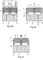
- Figures 5a - 5cshow schematically the simultaneous insertion of two banners (3) in two adjacent cavities of the mold (4) by a conventional-type banner insertion device (6).
- a mold openingis carried out, of a range (A) lesser than the distance (B) between the two adjacent vessels (1), and substantially equal to the difference between the maximum diameter (D) of the spherical lower portion (12) and the diameter (d) of the cylindrical upper portion (11), this opening being sufficient to produce the demolding of the vessels (1) as shown in Figure 6c .
- Figure 6dschematically shows the open mold (4) and the advancing of the sheet shaping the lid (2) once it is fastened to the vessels (1).
Landscapes
- Engineering & Computer Science (AREA)
- Mechanical Engineering (AREA)
- Ceramic Engineering (AREA)
- Moulds For Moulding Plastics Or The Like (AREA)
- Containers Having Bodies Formed In One Piece (AREA)
- Closures For Containers (AREA)
Description
- The object of the invention is a system for manufacturing pairs of containers and a pair of containers.
- The vessel has characteristics that allow, on the one hand, preventing wastage of the plastic paper and the film of the lid, consequently reducing manufacturing costs and, on the other hand, using a rectangular banner, cut with circular blades, like any standard banner insertion device.
- This invention can be applied in the sector for packaging food products more specifically dairy products, such as yogurt or the like.
- The plastic containers for food products that are currently known comprise a vessel intended to contain the product to be packaged, a closing lid made of plastic material with a film and a decorative perimeter banner.
- Among this type of containers those that are known have a vessel with a frustoconical upper portion of increasing cross section in downward direction that extends in a rounded lower portion defining the cross section or maximum diameter of the container.
- Containers with this type of vessels have a number of manufacturing drawbacks among which it is worth mentioning that they require the use of a die or tool for cutting the banner with a banana-shaped or circular ring sector to that it can adapt to the frustoconical configuration of the upper portion, and an additional difficulty consists in transferring said banner to an insertion device for placing it in the shaping mold of the container.
- This therefore requires the use of specific packaging systems for this type of vessels.
- An additional problem is that the systems used for the manufacture of this type of containers require, for the demolding of the vessels, a mold opening greater than the distance between two formed vessels, whereby said vessels can only be manufactured in rows of a single vessel, generating a large amount of waste in plastic and the material being used for the lid between two parallel rows.
- Systems currently used for the manufacture of these containers operate with very complicated and rigid mechanisms that can only work a single packaging model and that generate a waste of 25% to 30% of material, namely plastic, banner paper and the sheet of the lid.
- Current systems either place a banana-type banner, the process of which is expensive and complicated, or decorate the vessel by means of a "sleever" (a system that places a plastic sheath at the station subsequent to forming the container).
- Current systems, provided with a working mold can only work with their own mold, since when a remnant of 30% occurs (festoon) in the trimming of the material that remains between the rows of containers, it conditions the rest of the FFS machine to work at a different to standard pace. It therefore forces the machine to work exclusively with that product.
- Therefore the technical problem that arises consists in the development of a plastic container that allows solving the exposed problem in a satisfactory way and a system for the manufacture thereof that enables significantly reducing the material used, working with standard placement devices for placing the standard banner, and with standard non-working molds, with different sizes and without wasting the material that makes up the lids
- Document
US 2962758 A discloses a system for manufacturing pairs of containers, each pair of containers comprising a pair of adjacent vessels made of plastic material, each vessel comprising a cylindrical portion with a conical cross section having a maximum first diameter, a cylindrical lower portion having a maximum second diameter equal to the first diameter, and an annular surface defined around a mouth at the top of the cylindrical upper portion, the system comprising a mold for shaping pairs of adjacent vessels in an area for forming vessels inside the mold. Furthermore, it also discloses a pair of containers or vessels with a laminar lid, each vessel being made of plastic material intended to contain a product to be packaged, the laminar lid being fastened to an annular surface defined around a mouth of each vessel, wherein the vessel comprises a cylindrical lower portion with a constant cross section having a first diameter, and a conical upper portion having a maximum second diameter equal to the first diameter of the cylindrical upper portion. DocumentWO 2004/106162 discloses a container or vessel being made of plastic material intended to contain a product to be packaged, the laminar lid being fastened to an annular surface defined around a mouth of each vessel, wherein the vessel comprises a cylindrical upper portion with a non-constant cross section having a first diameter, and a spherical lower portion having a maximum second diameter greater than the first diameter of the cylindrical upper portion. - A pair of containers of this invention is manufactured by the system of
claim 1 and comprises a pair of adjacent vessels joined together by a common laminar lid and a decorative perimeter banner on each vessel, each vessel being made of plastic material intended to contain a product to be packaged, the laminar lid being fastened to an annular surface defined around a mouth of each vessel, wherein the vessel comprises a cylindrical upper portion with a constant cross section having a first diameter shaping a fastening surface for the perimeter banner, and a spherical lower portion having a maximum second diameter greater than the first diameter of the cylindrical upper portion. - The vessel comprises a cylindrical upper portion with a constant cross section, shaping a fastening surface of the perimeter banner; and a spherical lower portion, with a maximum diameter greater than that of the cylindrical upper portion.
- This container provides a number of advantages including:
- it allows demolding with a mold opening lesser than the gap between the containers formed during the process and proportional to the difference between the maximum diameter of the spherical lower portion and the diameter of the cylindrical upper portion.
- it allows working with a cut without wasting the sheet that forms the lid, which is equivalent to manufacturing the container with 30% less material than the current festoon systems and;
- it also allows working with standard systems of cutting and placing banners, and it does not require a banana-shaped banner cut with wastage;
- it allows manufacturing the containers in standard FFS (Form - Fill- Seal) machines and facilitates changing the size or the shape of the model while current manufacturing systems work exclusively with a single model and;
- the manufacture thereof is between 30% and 50% cheaper than containers manufactured with current systems.
- The system for manufacturing the aforementioned pair of containers is defined in
claim 1. - This system has suitable characteristics for working with a working mold made up of various rows of containers, equal to a standard 63x63 format mold, or any other FFS (Form, Fill, Seal) machine step; and working with standard non-working molds of different sizes and with standard devices for placing banners on the container, without wasting material be it plastic, paper or lid, making it possible to exchange one mold for another.
- According to the invention, this system has a mold capable of rotating between a first inlet position of the banner or decorative paper and a second position for forming the vessels of the containers therein.
- In a preferred embodiment said positions are 180° out of phase.
- An essential characteristic of the invention is that the opening of the mold during the demolding of the containers is of a lesser range than the space that remains between two adjacent containers shaped therein; said opening range being less than the distance between adjacent vessels.
- This system provides a number of advantages:
- There is no material wastage.
- It is installed on a standard FFS machine.
- It is automatically fully compatible and exchangeable with standard FFS machine molds.
- It enables manufacturing containers with different volumes and different banner lengths and widths.
- As a complement to the description provided herein, and for the purpose of helping to make the characteristics of the invention more readily understandable, the present specification is accompanied by a set of figures which, by way of illustration and not limitation, represent the following:
Figures1, 2 and 3 show perspective, elevation and plan views of an exemplary embodiment of one of the container of the invention.Figure 4 shows a schematic plan view of an exemplary embodiment of the system for manufacturing the container of the previous figures, in which the 180° rotation of the mold is schematically shown in order to change from the position for decorating to the position for forming the vessels of the containers.Figures 5a - 5c schematically show the decorating area of the system for forming the vessel during the insertion of the banner, during loading of the banner and with the banner positioned within the mold, respectively.Figures 6a- 6d schematically show the area for forming the vessels during the process of: forming the vessels, opening the mold, demolding the vessels and advancing the closing sheet thereof.- As can be seen in
Figures 1 to 3 , one of the containers comprises a vessel (1) made of plastic material, a laminar closing lid (2) made up of a plastic paper with a film and a perimeter banner (3). - The vessel (1) comprises: a cylindrical upper portion (11) with a constant cross section, shaping a fastening surface of a perimeter banner (3) having a rectangular shape; and a spherical lower portion (12), with a maximum diameter (D) greater than the diameter (d) of the cylindrical upper portion (11).
- The cylindrical upper portion (11) tops out in a mouth that extends towards the outside of the vessel on a coplanar annular surface (13), on which a sheet forming the lid (2) is fastened.
- The system for manufacturing the container, schematically shown in
Figure 4 , comprises a mold (4) capable of rotating between a decorating area (5a) in which banners (3) are inserted into the mold (4); and an area for creating (5b) the vessels (1) in this case 180° out of phase with respect to the decorating area (5a). Figures 5a - 5c show schematically the simultaneous insertion of two banners (3) in two adjacent cavities of the mold (4) by a conventional-type banner insertion device (6).- Once the banners (3) have been inserted into the mold (4), said mold (4) rotates to the forming area (5b) where the shaping of the vessels (1) is carried out in pairs therein, as shown in
Figure 6a . - Thereafter, as shown in
Figure 6b , a mold opening is carried out, of a range (A) lesser than the distance (B) between the two adjacent vessels (1), and substantially equal to the difference between the maximum diameter (D) of the spherical lower portion (12) and the diameter (d) of the cylindrical upper portion (11), this opening being sufficient to produce the demolding of the vessels (1) as shown inFigure 6c . Figure 6d schematically shows the open mold (4) and the advancing of the sheet shaping the lid (2) once it is fastened to the vessels (1).- Having sufficiently described the nature of the invention, as well as an example of a preferred embodiment, it is hereby stated for the relevant purposes that the materials, shape, size and arrangement of the described elements may be modified, provided that it does not imply altering the essential characteristics of the invention claimed below.
Claims (2)
- A system for manufacturing pairs of containers, each pair of containers comprising a pair of adjacent vessels (1) made of plastic material joined together by a common laminar lid (2) and with a decorative perimeter banner (3) on each vessel (1), each vessel (1) comprising a cylindrical upper portion (11) with a constant cross section having a first diameter (d) shaping a fastening surface for the perimeter banner (3), a spherical lower portion (12) having a maximum second diameter (D) greater than the first diameter (d), and an annular surface (13) defined around a mouth at the top of the cylindrical upper portion (11), the common laminar lid (2) being fastened to the annular surfaces (13) of the adjacent vessels (1), the system comprising a mold (4) for shaping pairs of adjacent vessels (1), a device (6) for inserting the banners (3) into the mold (4), and an area for forming (5b) vessels (1) inside the mold (4); the mold (4) comprising a mold central body defining two first half-molds for molding two contiguous halves of the adjacent vessels (1) and two mold side bodies defining two second half-molds for molding the other two opposed halves of the adjacent vessels (1), and an open position of the mold (4) for demolding the pair of containers the mold side bodies being separated from the mold central body at an opening range (A) lesser than a distance (8) between two adjacent vessels (1) and equal to the difference between the maximum second diameter (D) of the spherical lower portion (12) and the first diameter (d) of the cylindrical portion (11) of the vessel.
- A pair of containers manufactured by the system of claim 1, the pair of containers comprising a pair of adjacent vessels (1) joined together by a common laminar lid (2) and a decorative perimeter banner (3) on each vessel (1), each vessel (1) being made of plastic material intended to contain a product to be packaged, the laminar lid (2) being fastened to an annular surface (13) defined around a mouth of each vessel (1), wherein the vessel (1) comprises a cylindrical upper portion (11) with a constant cross section having a first diameter (d) shaping a fastening surface for the perimeter banner (3), and a spherical lower portion (12) having a maximum second diameter (D) greater than the first diameter (d) of the cylindrical upper portion (11).
Priority Applications (4)
| Application Number | Priority Date | Filing Date | Title |
|---|---|---|---|
| EP17001293.4AEP3434615B1 (en) | 2017-07-26 | 2017-07-26 | System for manufacturing pairs of containers and pair of containers |
| ES17001293TES2842294T3 (en) | 2017-07-26 | 2017-07-26 | System for manufacturing pairs of containers and pair of containers |
| PL17001293TPL3434615T3 (en) | 2017-07-26 | 2017-07-26 | System for manufacturing pairs of containers and pair of containers |
| DK17001293.4TDK3434615T3 (en) | 2017-07-26 | 2017-07-26 | SYSTEM FOR MANUFACTURE OF CONTAINERS AND CONTAINERS |
Applications Claiming Priority (1)
| Application Number | Priority Date | Filing Date | Title |
|---|---|---|---|
| EP17001293.4AEP3434615B1 (en) | 2017-07-26 | 2017-07-26 | System for manufacturing pairs of containers and pair of containers |
Publications (2)
| Publication Number | Publication Date |
|---|---|
| EP3434615A1 EP3434615A1 (en) | 2019-01-30 |
| EP3434615B1true EP3434615B1 (en) | 2020-11-25 |
Family
ID=59655813
Family Applications (1)
| Application Number | Title | Priority Date | Filing Date |
|---|---|---|---|
| EP17001293.4AActiveEP3434615B1 (en) | 2017-07-26 | 2017-07-26 | System for manufacturing pairs of containers and pair of containers |
Country Status (4)
| Country | Link |
|---|---|
| EP (1) | EP3434615B1 (en) |
| DK (1) | DK3434615T3 (en) |
| ES (1) | ES2842294T3 (en) |
| PL (1) | PL3434615T3 (en) |
Cited By (1)
| Publication number | Priority date | Publication date | Assignee | Title |
|---|---|---|---|---|
| EP4112270A1 (en)* | 2021-07-02 | 2023-01-04 | Decam Technology Solutions 2000, S.L. | Thermoforming machine for containers |
Family Cites Families (6)
| Publication number | Priority date | Publication date | Assignee | Title |
|---|---|---|---|---|
| US2962758A (en)* | 1957-02-08 | 1960-12-06 | Illinois Tool Works | Method and apparatus for forming hollow plastic articles |
| US3504403A (en)* | 1967-03-20 | 1970-04-07 | Brown Machine Co Of Michigan | Differential pressure plastic forming machine partible mold mechanism for forming articles in a plastic sheet |
| CN1022748C (en)* | 1987-12-07 | 1993-11-17 | 索诺科产品有限公司 | Intermediate article of wide mouth container |
| KR200176899Y1 (en)* | 1999-10-28 | 2000-04-15 | 배성우 | Case for a golf ball |
| AT500064B8 (en)* | 2003-05-16 | 2007-02-15 | Rundpack Ag | PACKAGING BOX IN PLASTIC |
| DE10324749A1 (en)* | 2003-05-30 | 2004-12-16 | Kourtoglou S.A., Nea Kios | Method and device for producing packaging containers |
- 2017
- 2017-07-26ESES17001293Tpatent/ES2842294T3/enactiveActive
- 2017-07-26DKDK17001293.4Tpatent/DK3434615T3/enactive
- 2017-07-26EPEP17001293.4Apatent/EP3434615B1/enactiveActive
- 2017-07-26PLPL17001293Tpatent/PL3434615T3/enunknown
Non-Patent Citations (1)
| Title |
|---|
| None* |
Cited By (1)
| Publication number | Priority date | Publication date | Assignee | Title |
|---|---|---|---|---|
| EP4112270A1 (en)* | 2021-07-02 | 2023-01-04 | Decam Technology Solutions 2000, S.L. | Thermoforming machine for containers |
Also Published As
| Publication number | Publication date |
|---|---|
| PL3434615T3 (en) | 2021-03-08 |
| DK3434615T3 (en) | 2021-01-04 |
| ES2842294T3 (en) | 2021-07-13 |
| EP3434615A1 (en) | 2019-01-30 |
Similar Documents
| Publication | Publication Date | Title |
|---|---|---|
| US6094890A (en) | Thermoforming, filling, and capping receptacles | |
| EP4219126B1 (en) | Pouch forming mold configuration, method and pouch | |
| US20070138192A1 (en) | Packaging with subsequently molded form-fit connection | |
| US20150336691A1 (en) | Apparatus and method for continuous motion rotatable forming of soluble pouches | |
| EP3253668B1 (en) | Plastic cup with a thin outer sleeve and food product pack comprising such cups | |
| RU2559009C2 (en) | Fabrication of vessels and vessel thus made | |
| US3251319A (en) | Process and apparatus for the continuous and successive manufacturing of figurine molds | |
| US7665281B2 (en) | Machine for making packaging with form-fit connection | |
| EA029729B1 (en) | Apparatus and method for producing packaging | |
| EP2576184B1 (en) | Plate and apparatus for forming a plastic material flanged hollow article | |
| AU2002249196B2 (en) | Methods and apparatus for manufacturing a diffusion-tight plastic container | |
| JP6719459B2 (en) | Reverse molding simultaneous filling packaging | |
| EP1631495B1 (en) | Method of producing packaging containers from plastics and a packaging machine | |
| US3321562A (en) | Method and apparatus for forming enlarged container rim | |
| EP2925622B1 (en) | Packaging machine with increased functionality, particularly for small preformed bags | |
| EP3434615B1 (en) | System for manufacturing pairs of containers and pair of containers | |
| US3323274A (en) | Vacuum plastic bottle forming machine and method | |
| US6929141B1 (en) | System for thermoforming sheet material to obtain containers therefrom | |
| EP3087008B1 (en) | Packaging, a device and method for producing same | |
| ES2420525T3 (en) | Method for producing a lid that includes a plastic label using the integrated molding technique and lid thus obtained | |
| EP2927133A1 (en) | Method for manufacturing flexible packages having a dispensing valve | |
| NZ221782A (en) | Containers formed from opposed thermoplastics series connected blanks | |
| CA2945844C (en) | Method for transferring bottom labels and wraparound labels into an injection mould and device, suitable for this purpose, for producing injection-moulded parts provided with bottom labels and wraparound labels | |
| EP1884474B1 (en) | Molded container of plastic material, manufacturing process and mold therefor | |
| US20170282234A1 (en) | Device for partial embossing of seal blanks and method for partial embossing of seal blanks |
Legal Events
| Date | Code | Title | Description |
|---|---|---|---|
| PUAI | Public reference made under article 153(3) epc to a published international application that has entered the european phase | Free format text:ORIGINAL CODE: 0009012 | |
| STAA | Information on the status of an ep patent application or granted ep patent | Free format text:STATUS: THE APPLICATION HAS BEEN PUBLISHED | |
| AK | Designated contracting states | Kind code of ref document:A1 Designated state(s):AL AT BE BG CH CY CZ DE DK EE ES FI FR GB GR HR HU IE IS IT LI LT LU LV MC MK MT NL NO PL PT RO RS SE SI SK SM TR | |
| AX | Request for extension of the european patent | Extension state:BA ME | |
| STAA | Information on the status of an ep patent application or granted ep patent | Free format text:STATUS: REQUEST FOR EXAMINATION WAS MADE | |
| 17P | Request for examination filed | Effective date:20190617 | |
| RAP1 | Party data changed (applicant data changed or rights of an application transferred) | Owner name:INDUSTRIAS TECNOLOGICAS DE MECANIZACION Y AUTOMATIZACION, S.A. | |
| GRAP | Despatch of communication of intention to grant a patent | Free format text:ORIGINAL CODE: EPIDOSNIGR1 | |
| STAA | Information on the status of an ep patent application or granted ep patent | Free format text:STATUS: GRANT OF PATENT IS INTENDED | |
| RIC1 | Information provided on ipc code assigned before grant | Ipc:B65D 85/72 20060101ALI20200828BHEP Ipc:B29C 51/16 20060101ALI20200828BHEP Ipc:B29C 33/48 20060101ALI20200828BHEP Ipc:B29C 51/26 20060101ALI20200828BHEP Ipc:B29C 33/44 20060101ALI20200828BHEP Ipc:B65D 1/26 20060101ALI20200828BHEP Ipc:B29C 51/10 20060101ALI20200828BHEP Ipc:B29C 33/00 20060101ALI20200828BHEP Ipc:B29C 51/34 20060101ALI20200828BHEP Ipc:B65D 51/18 20060101AFI20200828BHEP Ipc:B65D 1/46 20060101ALI20200828BHEP Ipc:B29L 31/00 20060101ALN20200828BHEP Ipc:B65D 1/30 20060101ALI20200828BHEP Ipc:B65D 21/02 20060101ALI20200828BHEP Ipc:B65D 77/20 20060101ALI20200828BHEP Ipc:B65D 23/08 20060101ALI20200828BHEP | |
| INTG | Intention to grant announced | Effective date:20200914 | |
| GRAS | Grant fee paid | Free format text:ORIGINAL CODE: EPIDOSNIGR3 | |
| GRAA | (expected) grant | Free format text:ORIGINAL CODE: 0009210 | |
| STAA | Information on the status of an ep patent application or granted ep patent | Free format text:STATUS: THE PATENT HAS BEEN GRANTED | |
| AK | Designated contracting states | Kind code of ref document:B1 Designated state(s):AL AT BE BG CH CY CZ DE DK EE ES FI FR GB GR HR HU IE IS IT LI LT LU LV MC MK MT NL NO PL PT RO RS SE SI SK SM TR | |
| REG | Reference to a national code | Ref country code:GB Ref legal event code:FG4D | |
| REG | Reference to a national code | Ref country code:CH Ref legal event code:EP | |
| REG | Reference to a national code | Ref country code:AT Ref legal event code:REF Ref document number:1338039 Country of ref document:AT Kind code of ref document:T Effective date:20201215 | |
| REG | Reference to a national code | Ref country code:DE Ref legal event code:R096 Ref document number:602017028049 Country of ref document:DE | |
| REG | Reference to a national code | Ref country code:DE Ref legal event code:R081 Ref document number:602017028049 Country of ref document:DE Owner name:INDUSTRIAS TECNOLOGICAS DE MECANIZACION Y AUTO, ES Free format text:FORMER OWNER: INDUSTRIAS TECNOLOGICAS DE MECANIZACION Y AUTOMATIZACION, S.A., SANT JUST DESVERN, ES | |
| REG | Reference to a national code | Ref country code:IE Ref legal event code:FG4D | |
| REG | Reference to a national code | Ref country code:DK Ref legal event code:T3 Effective date:20201223 | |
| REG | Reference to a national code | Ref country code:GR Ref legal event code:EP Ref document number:20200403538 Country of ref document:GR Effective date:20210215 | |
| REG | Reference to a national code | Ref country code:AT Ref legal event code:MK05 Ref document number:1338039 Country of ref document:AT Kind code of ref document:T Effective date:20201125 | |
| REG | Reference to a national code | Ref country code:NL Ref legal event code:MP Effective date:20201125 | |
| PG25 | Lapsed in a contracting state [announced via postgrant information from national office to epo] | Ref country code:NO Free format text:LAPSE BECAUSE OF FAILURE TO SUBMIT A TRANSLATION OF THE DESCRIPTION OR TO PAY THE FEE WITHIN THE PRESCRIBED TIME-LIMIT Effective date:20210225 Ref country code:PT Free format text:LAPSE BECAUSE OF FAILURE TO SUBMIT A TRANSLATION OF THE DESCRIPTION OR TO PAY THE FEE WITHIN THE PRESCRIBED TIME-LIMIT Effective date:20210325 Ref country code:RS Free format text:LAPSE BECAUSE OF FAILURE TO SUBMIT A TRANSLATION OF THE DESCRIPTION OR TO PAY THE FEE WITHIN THE PRESCRIBED TIME-LIMIT Effective date:20201125 Ref country code:FI Free format text:LAPSE BECAUSE OF FAILURE TO SUBMIT A TRANSLATION OF THE DESCRIPTION OR TO PAY THE FEE WITHIN THE PRESCRIBED TIME-LIMIT Effective date:20201125 | |
| PG25 | Lapsed in a contracting state [announced via postgrant information from national office to epo] | Ref country code:AT Free format text:LAPSE BECAUSE OF FAILURE TO SUBMIT A TRANSLATION OF THE DESCRIPTION OR TO PAY THE FEE WITHIN THE PRESCRIBED TIME-LIMIT Effective date:20201125 Ref country code:LV Free format text:LAPSE BECAUSE OF FAILURE TO SUBMIT A TRANSLATION OF THE DESCRIPTION OR TO PAY THE FEE WITHIN THE PRESCRIBED TIME-LIMIT Effective date:20201125 Ref country code:IS Free format text:LAPSE BECAUSE OF FAILURE TO SUBMIT A TRANSLATION OF THE DESCRIPTION OR TO PAY THE FEE WITHIN THE PRESCRIBED TIME-LIMIT Effective date:20210325 Ref country code:BG Free format text:LAPSE BECAUSE OF FAILURE TO SUBMIT A TRANSLATION OF THE DESCRIPTION OR TO PAY THE FEE WITHIN THE PRESCRIBED TIME-LIMIT Effective date:20210225 Ref country code:SE Free format text:LAPSE BECAUSE OF FAILURE TO SUBMIT A TRANSLATION OF THE DESCRIPTION OR TO PAY THE FEE WITHIN THE PRESCRIBED TIME-LIMIT Effective date:20201125 | |
| REG | Reference to a national code | Ref country code:LT Ref legal event code:MG9D | |
| PG25 | Lapsed in a contracting state [announced via postgrant information from national office to epo] | Ref country code:HR Free format text:LAPSE BECAUSE OF FAILURE TO SUBMIT A TRANSLATION OF THE DESCRIPTION OR TO PAY THE FEE WITHIN THE PRESCRIBED TIME-LIMIT Effective date:20201125 | |
| REG | Reference to a national code | Ref country code:ES Ref legal event code:FG2A Ref document number:2842294 Country of ref document:ES Kind code of ref document:T3 Effective date:20210713 | |
| PG25 | Lapsed in a contracting state [announced via postgrant information from national office to epo] | Ref country code:LT Free format text:LAPSE BECAUSE OF FAILURE TO SUBMIT A TRANSLATION OF THE DESCRIPTION OR TO PAY THE FEE WITHIN THE PRESCRIBED TIME-LIMIT Effective date:20201125 Ref country code:SM Free format text:LAPSE BECAUSE OF FAILURE TO SUBMIT A TRANSLATION OF THE DESCRIPTION OR TO PAY THE FEE WITHIN THE PRESCRIBED TIME-LIMIT Effective date:20201125 Ref country code:EE Free format text:LAPSE BECAUSE OF FAILURE TO SUBMIT A TRANSLATION OF THE DESCRIPTION OR TO PAY THE FEE WITHIN THE PRESCRIBED TIME-LIMIT Effective date:20201125 Ref country code:CZ Free format text:LAPSE BECAUSE OF FAILURE TO SUBMIT A TRANSLATION OF THE DESCRIPTION OR TO PAY THE FEE WITHIN THE PRESCRIBED TIME-LIMIT Effective date:20201125 Ref country code:SK Free format text:LAPSE BECAUSE OF FAILURE TO SUBMIT A TRANSLATION OF THE DESCRIPTION OR TO PAY THE FEE WITHIN THE PRESCRIBED TIME-LIMIT Effective date:20201125 Ref country code:RO Free format text:LAPSE BECAUSE OF FAILURE TO SUBMIT A TRANSLATION OF THE DESCRIPTION OR TO PAY THE FEE WITHIN THE PRESCRIBED TIME-LIMIT Effective date:20201125 | |
| REG | Reference to a national code | Ref country code:DE Ref legal event code:R097 Ref document number:602017028049 Country of ref document:DE | |
| PLBE | No opposition filed within time limit | Free format text:ORIGINAL CODE: 0009261 | |
| STAA | Information on the status of an ep patent application or granted ep patent | Free format text:STATUS: NO OPPOSITION FILED WITHIN TIME LIMIT | |
| PG25 | Lapsed in a contracting state [announced via postgrant information from national office to epo] | Ref country code:AL Free format text:LAPSE BECAUSE OF FAILURE TO SUBMIT A TRANSLATION OF THE DESCRIPTION OR TO PAY THE FEE WITHIN THE PRESCRIBED TIME-LIMIT Effective date:20201125 Ref country code:NL Free format text:LAPSE BECAUSE OF FAILURE TO SUBMIT A TRANSLATION OF THE DESCRIPTION OR TO PAY THE FEE WITHIN THE PRESCRIBED TIME-LIMIT Effective date:20201125 | |
| 26N | No opposition filed | Effective date:20210826 | |
| PG25 | Lapsed in a contracting state [announced via postgrant information from national office to epo] | Ref country code:SI Free format text:LAPSE BECAUSE OF FAILURE TO SUBMIT A TRANSLATION OF THE DESCRIPTION OR TO PAY THE FEE WITHIN THE PRESCRIBED TIME-LIMIT Effective date:20201125 | |
| PG25 | Lapsed in a contracting state [announced via postgrant information from national office to epo] | Ref country code:MC Free format text:LAPSE BECAUSE OF FAILURE TO SUBMIT A TRANSLATION OF THE DESCRIPTION OR TO PAY THE FEE WITHIN THE PRESCRIBED TIME-LIMIT Effective date:20201125 | |
| REG | Reference to a national code | Ref country code:BE Ref legal event code:MM Effective date:20210731 | |
| PG25 | Lapsed in a contracting state [announced via postgrant information from national office to epo] | Ref country code:IS Free format text:LAPSE BECAUSE OF FAILURE TO SUBMIT A TRANSLATION OF THE DESCRIPTION OR TO PAY THE FEE WITHIN THE PRESCRIBED TIME-LIMIT Effective date:20210325 Ref country code:LU Free format text:LAPSE BECAUSE OF NON-PAYMENT OF DUE FEES Effective date:20210726 | |
| PG25 | Lapsed in a contracting state [announced via postgrant information from national office to epo] | Ref country code:IE Free format text:LAPSE BECAUSE OF NON-PAYMENT OF DUE FEES Effective date:20210726 Ref country code:BE Free format text:LAPSE BECAUSE OF NON-PAYMENT OF DUE FEES Effective date:20210731 | |
| PG25 | Lapsed in a contracting state [announced via postgrant information from national office to epo] | Ref country code:CY Free format text:LAPSE BECAUSE OF FAILURE TO SUBMIT A TRANSLATION OF THE DESCRIPTION OR TO PAY THE FEE WITHIN THE PRESCRIBED TIME-LIMIT Effective date:20201125 | |
| PG25 | Lapsed in a contracting state [announced via postgrant information from national office to epo] | Ref country code:HU Free format text:LAPSE BECAUSE OF FAILURE TO SUBMIT A TRANSLATION OF THE DESCRIPTION OR TO PAY THE FEE WITHIN THE PRESCRIBED TIME-LIMIT; INVALID AB INITIO Effective date:20170726 | |
| PG25 | Lapsed in a contracting state [announced via postgrant information from national office to epo] | Ref country code:MK Free format text:LAPSE BECAUSE OF FAILURE TO SUBMIT A TRANSLATION OF THE DESCRIPTION OR TO PAY THE FEE WITHIN THE PRESCRIBED TIME-LIMIT Effective date:20201125 | |
| PG25 | Lapsed in a contracting state [announced via postgrant information from national office to epo] | Ref country code:MT Free format text:LAPSE BECAUSE OF FAILURE TO SUBMIT A TRANSLATION OF THE DESCRIPTION OR TO PAY THE FEE WITHIN THE PRESCRIBED TIME-LIMIT Effective date:20201125 | |
| PGFP | Annual fee paid to national office [announced via postgrant information from national office to epo] | Ref country code:DE Payment date:20240729 Year of fee payment:8 | |
| PGFP | Annual fee paid to national office [announced via postgrant information from national office to epo] | Ref country code:DK Payment date:20240725 Year of fee payment:8 Ref country code:GR Payment date:20240726 Year of fee payment:8 | |
| PGFP | Annual fee paid to national office [announced via postgrant information from national office to epo] | Ref country code:GB Payment date:20240729 Year of fee payment:8 | |
| PGFP | Annual fee paid to national office [announced via postgrant information from national office to epo] | Ref country code:FR Payment date:20240725 Year of fee payment:8 | |
| PGFP | Annual fee paid to national office [announced via postgrant information from national office to epo] | Ref country code:CH Payment date:20240801 Year of fee payment:8 | |
| PGFP | Annual fee paid to national office [announced via postgrant information from national office to epo] | Ref country code:PL Payment date:20240701 Year of fee payment:8 | |
| PGFP | Annual fee paid to national office [announced via postgrant information from national office to epo] | Ref country code:IT Payment date:20240719 Year of fee payment:8 | |
| PGFP | Annual fee paid to national office [announced via postgrant information from national office to epo] | Ref country code:TR Payment date:20240705 Year of fee payment:8 | |
| PGFP | Annual fee paid to national office [announced via postgrant information from national office to epo] | Ref country code:ES Payment date:20250801 Year of fee payment:9 |