EP3429738B1 - Chemical looping syngas production from carbonaceous fuels - Google Patents
Chemical looping syngas production from carbonaceous fuelsDownload PDFInfo
- Publication number
- EP3429738B1 EP3429738B1EP17783069.2AEP17783069AEP3429738B1EP 3429738 B1EP3429738 B1EP 3429738B1EP 17783069 AEP17783069 AEP 17783069AEP 3429738 B1EP3429738 B1EP 3429738B1
- Authority
- EP
- European Patent Office
- Prior art keywords
- moving bed
- metal oxide
- bed reactor
- reactor
- syngas
- Prior art date
- Legal status (The legal status is an assumption and is not a legal conclusion. Google has not performed a legal analysis and makes no representation as to the accuracy of the status listed.)
- Active
Links
Images


Classifications
- C—CHEMISTRY; METALLURGY
- C01—INORGANIC CHEMISTRY
- C01B—NON-METALLIC ELEMENTS; COMPOUNDS THEREOF; METALLOIDS OR COMPOUNDS THEREOF NOT COVERED BY SUBCLASS C01C
- C01B3/00—Hydrogen; Gaseous mixtures containing hydrogen; Separation of hydrogen from mixtures containing it; Purification of hydrogen
- C01B3/02—Production of hydrogen or of gaseous mixtures containing a substantial proportion of hydrogen
- C01B3/32—Production of hydrogen or of gaseous mixtures containing a substantial proportion of hydrogen by reaction of gaseous or liquid organic compounds with gasifying agents, e.g. water, carbon dioxide, air
- C01B3/34—Production of hydrogen or of gaseous mixtures containing a substantial proportion of hydrogen by reaction of gaseous or liquid organic compounds with gasifying agents, e.g. water, carbon dioxide, air by reaction of hydrocarbons with gasifying agents
- C01B3/38—Production of hydrogen or of gaseous mixtures containing a substantial proportion of hydrogen by reaction of gaseous or liquid organic compounds with gasifying agents, e.g. water, carbon dioxide, air by reaction of hydrocarbons with gasifying agents using catalysts
- C01B3/42—Production of hydrogen or of gaseous mixtures containing a substantial proportion of hydrogen by reaction of gaseous or liquid organic compounds with gasifying agents, e.g. water, carbon dioxide, air by reaction of hydrocarbons with gasifying agents using catalysts using moving solid particles
- B—PERFORMING OPERATIONS; TRANSPORTING
- B01—PHYSICAL OR CHEMICAL PROCESSES OR APPARATUS IN GENERAL
- B01J—CHEMICAL OR PHYSICAL PROCESSES, e.g. CATALYSIS OR COLLOID CHEMISTRY; THEIR RELEVANT APPARATUS
- B01J19/00—Chemical, physical or physico-chemical processes in general; Their relevant apparatus
- B01J19/18—Stationary reactors having moving elements inside
- B01J19/1812—Tubular reactors
- B01J19/1837—Loop-type reactors
- B—PERFORMING OPERATIONS; TRANSPORTING
- B01—PHYSICAL OR CHEMICAL PROCESSES OR APPARATUS IN GENERAL
- B01J—CHEMICAL OR PHYSICAL PROCESSES, e.g. CATALYSIS OR COLLOID CHEMISTRY; THEIR RELEVANT APPARATUS
- B01J8/00—Chemical or physical processes in general, conducted in the presence of fluids and solid particles; Apparatus for such processes
- B01J8/08—Chemical or physical processes in general, conducted in the presence of fluids and solid particles; Apparatus for such processes with moving particles
- B01J8/12—Chemical or physical processes in general, conducted in the presence of fluids and solid particles; Apparatus for such processes with moving particles moved by gravity in a downward flow
- B—PERFORMING OPERATIONS; TRANSPORTING
- B01—PHYSICAL OR CHEMICAL PROCESSES OR APPARATUS IN GENERAL
- B01J—CHEMICAL OR PHYSICAL PROCESSES, e.g. CATALYSIS OR COLLOID CHEMISTRY; THEIR RELEVANT APPARATUS
- B01J8/00—Chemical or physical processes in general, conducted in the presence of fluids and solid particles; Apparatus for such processes
- B01J8/18—Chemical or physical processes in general, conducted in the presence of fluids and solid particles; Apparatus for such processes with fluidised particles
- B01J8/24—Chemical or physical processes in general, conducted in the presence of fluids and solid particles; Apparatus for such processes with fluidised particles according to "fluidised-bed" technique
- B01J8/32—Chemical or physical processes in general, conducted in the presence of fluids and solid particles; Apparatus for such processes with fluidised particles according to "fluidised-bed" technique with introduction into the fluidised bed of more than one kind of moving particles
- B—PERFORMING OPERATIONS; TRANSPORTING
- B01—PHYSICAL OR CHEMICAL PROCESSES OR APPARATUS IN GENERAL
- B01J—CHEMICAL OR PHYSICAL PROCESSES, e.g. CATALYSIS OR COLLOID CHEMISTRY; THEIR RELEVANT APPARATUS
- B01J8/00—Chemical or physical processes in general, conducted in the presence of fluids and solid particles; Apparatus for such processes
- B01J8/18—Chemical or physical processes in general, conducted in the presence of fluids and solid particles; Apparatus for such processes with fluidised particles
- B01J8/24—Chemical or physical processes in general, conducted in the presence of fluids and solid particles; Apparatus for such processes with fluidised particles according to "fluidised-bed" technique
- B01J8/38—Chemical or physical processes in general, conducted in the presence of fluids and solid particles; Apparatus for such processes with fluidised particles according to "fluidised-bed" technique with fluidised bed containing a rotatable device or being subject to rotation or to a circulatory movement, i.e. leaving a vessel and subsequently re-entering it
- B01J8/384—Chemical or physical processes in general, conducted in the presence of fluids and solid particles; Apparatus for such processes with fluidised particles according to "fluidised-bed" technique with fluidised bed containing a rotatable device or being subject to rotation or to a circulatory movement, i.e. leaving a vessel and subsequently re-entering it being subject to a circulatory movement only
- B01J8/388—Chemical or physical processes in general, conducted in the presence of fluids and solid particles; Apparatus for such processes with fluidised particles according to "fluidised-bed" technique with fluidised bed containing a rotatable device or being subject to rotation or to a circulatory movement, i.e. leaving a vessel and subsequently re-entering it being subject to a circulatory movement only externally, i.e. the particles leaving the vessel and subsequently re-entering it
- C—CHEMISTRY; METALLURGY
- C01—INORGANIC CHEMISTRY
- C01B—NON-METALLIC ELEMENTS; COMPOUNDS THEREOF; METALLOIDS OR COMPOUNDS THEREOF NOT COVERED BY SUBCLASS C01C
- C01B3/00—Hydrogen; Gaseous mixtures containing hydrogen; Separation of hydrogen from mixtures containing it; Purification of hydrogen
- C01B3/02—Production of hydrogen or of gaseous mixtures containing a substantial proportion of hydrogen
- C01B3/32—Production of hydrogen or of gaseous mixtures containing a substantial proportion of hydrogen by reaction of gaseous or liquid organic compounds with gasifying agents, e.g. water, carbon dioxide, air
- C01B3/34—Production of hydrogen or of gaseous mixtures containing a substantial proportion of hydrogen by reaction of gaseous or liquid organic compounds with gasifying agents, e.g. water, carbon dioxide, air by reaction of hydrocarbons with gasifying agents
- C01B3/344—Production of hydrogen or of gaseous mixtures containing a substantial proportion of hydrogen by reaction of gaseous or liquid organic compounds with gasifying agents, e.g. water, carbon dioxide, air by reaction of hydrocarbons with gasifying agents using non-catalytic solid particles
- C—CHEMISTRY; METALLURGY
- C01—INORGANIC CHEMISTRY
- C01B—NON-METALLIC ELEMENTS; COMPOUNDS THEREOF; METALLOIDS OR COMPOUNDS THEREOF NOT COVERED BY SUBCLASS C01C
- C01B3/00—Hydrogen; Gaseous mixtures containing hydrogen; Separation of hydrogen from mixtures containing it; Purification of hydrogen
- C01B3/50—Separation of hydrogen or hydrogen containing gases from gaseous mixtures, e.g. purification
- C01B3/56—Separation of hydrogen or hydrogen containing gases from gaseous mixtures, e.g. purification by contacting with solids; Regeneration of used solids
- C—CHEMISTRY; METALLURGY
- C10—PETROLEUM, GAS OR COKE INDUSTRIES; TECHNICAL GASES CONTAINING CARBON MONOXIDE; FUELS; LUBRICANTS; PEAT
- C10J—PRODUCTION OF PRODUCER GAS, WATER-GAS, SYNTHESIS GAS FROM SOLID CARBONACEOUS MATERIAL, OR MIXTURES CONTAINING THESE GASES; CARBURETTING AIR OR OTHER GASES
- C10J3/00—Production of combustible gases containing carbon monoxide from solid carbonaceous fuels
- C10J3/02—Fixed-bed gasification of lump fuel
- C10J3/20—Apparatus; Plants
- C10J3/22—Arrangements or dispositions of valves or flues
- C10J3/24—Arrangements or dispositions of valves or flues to permit flow of gases or vapours other than upwardly through the fuel bed
- C10J3/26—Arrangements or dispositions of valves or flues to permit flow of gases or vapours other than upwardly through the fuel bed downwardly
- C—CHEMISTRY; METALLURGY
- C10—PETROLEUM, GAS OR COKE INDUSTRIES; TECHNICAL GASES CONTAINING CARBON MONOXIDE; FUELS; LUBRICANTS; PEAT
- C10J—PRODUCTION OF PRODUCER GAS, WATER-GAS, SYNTHESIS GAS FROM SOLID CARBONACEOUS MATERIAL, OR MIXTURES CONTAINING THESE GASES; CARBURETTING AIR OR OTHER GASES
- C10J3/00—Production of combustible gases containing carbon monoxide from solid carbonaceous fuels
- C10J3/57—Gasification using molten salts or metals
- C—CHEMISTRY; METALLURGY
- C10—PETROLEUM, GAS OR COKE INDUSTRIES; TECHNICAL GASES CONTAINING CARBON MONOXIDE; FUELS; LUBRICANTS; PEAT
- C10J—PRODUCTION OF PRODUCER GAS, WATER-GAS, SYNTHESIS GAS FROM SOLID CARBONACEOUS MATERIAL, OR MIXTURES CONTAINING THESE GASES; CARBURETTING AIR OR OTHER GASES
- C10J3/00—Production of combustible gases containing carbon monoxide from solid carbonaceous fuels
- C10J3/72—Other features
- C10J3/721—Multistage gasification, e.g. plural parallel or serial gasification stages
- C—CHEMISTRY; METALLURGY
- C10—PETROLEUM, GAS OR COKE INDUSTRIES; TECHNICAL GASES CONTAINING CARBON MONOXIDE; FUELS; LUBRICANTS; PEAT
- C10J—PRODUCTION OF PRODUCER GAS, WATER-GAS, SYNTHESIS GAS FROM SOLID CARBONACEOUS MATERIAL, OR MIXTURES CONTAINING THESE GASES; CARBURETTING AIR OR OTHER GASES
- C10J3/00—Production of combustible gases containing carbon monoxide from solid carbonaceous fuels
- C10J3/72—Other features
- C10J3/725—Redox processes
- B—PERFORMING OPERATIONS; TRANSPORTING
- B01—PHYSICAL OR CHEMICAL PROCESSES OR APPARATUS IN GENERAL
- B01J—CHEMICAL OR PHYSICAL PROCESSES, e.g. CATALYSIS OR COLLOID CHEMISTRY; THEIR RELEVANT APPARATUS
- B01J2208/00—Processes carried out in the presence of solid particles; Reactors therefor
- B01J2208/00008—Controlling the process
- B01J2208/00017—Controlling the temperature
- B01J2208/00327—Controlling the temperature by direct heat exchange
- B01J2208/00336—Controlling the temperature by direct heat exchange adding a temperature modifying medium to the reactants
- B01J2208/0038—Solids
- C—CHEMISTRY; METALLURGY
- C01—INORGANIC CHEMISTRY
- C01B—NON-METALLIC ELEMENTS; COMPOUNDS THEREOF; METALLOIDS OR COMPOUNDS THEREOF NOT COVERED BY SUBCLASS C01C
- C01B2203/00—Integrated processes for the production of hydrogen or synthesis gas
- C01B2203/02—Processes for making hydrogen or synthesis gas
- C01B2203/0205—Processes for making hydrogen or synthesis gas containing a reforming step
- C01B2203/0211—Processes for making hydrogen or synthesis gas containing a reforming step containing a non-catalytic reforming step
- C01B2203/0216—Processes for making hydrogen or synthesis gas containing a reforming step containing a non-catalytic reforming step containing a non-catalytic steam reforming step
- C—CHEMISTRY; METALLURGY
- C01—INORGANIC CHEMISTRY
- C01B—NON-METALLIC ELEMENTS; COMPOUNDS THEREOF; METALLOIDS OR COMPOUNDS THEREOF NOT COVERED BY SUBCLASS C01C
- C01B2203/00—Integrated processes for the production of hydrogen or synthesis gas
- C01B2203/02—Processes for making hydrogen or synthesis gas
- C01B2203/0205—Processes for making hydrogen or synthesis gas containing a reforming step
- C01B2203/0211—Processes for making hydrogen or synthesis gas containing a reforming step containing a non-catalytic reforming step
- C01B2203/0222—Processes for making hydrogen or synthesis gas containing a reforming step containing a non-catalytic reforming step containing a non-catalytic carbon dioxide reforming step
- C—CHEMISTRY; METALLURGY
- C01—INORGANIC CHEMISTRY
- C01B—NON-METALLIC ELEMENTS; COMPOUNDS THEREOF; METALLOIDS OR COMPOUNDS THEREOF NOT COVERED BY SUBCLASS C01C
- C01B2203/00—Integrated processes for the production of hydrogen or synthesis gas
- C01B2203/02—Processes for making hydrogen or synthesis gas
- C01B2203/025—Processes for making hydrogen or synthesis gas containing a partial oxidation step
- C01B2203/0255—Processes for making hydrogen or synthesis gas containing a partial oxidation step containing a non-catalytic partial oxidation step
- C—CHEMISTRY; METALLURGY
- C01—INORGANIC CHEMISTRY
- C01B—NON-METALLIC ELEMENTS; COMPOUNDS THEREOF; METALLOIDS OR COMPOUNDS THEREOF NOT COVERED BY SUBCLASS C01C
- C01B2203/00—Integrated processes for the production of hydrogen or synthesis gas
- C01B2203/04—Integrated processes for the production of hydrogen or synthesis gas containing a purification step for the hydrogen or the synthesis gas
- C01B2203/0465—Composition of the impurity
- C01B2203/0475—Composition of the impurity the impurity being carbon dioxide
- C—CHEMISTRY; METALLURGY
- C01—INORGANIC CHEMISTRY
- C01B—NON-METALLIC ELEMENTS; COMPOUNDS THEREOF; METALLOIDS OR COMPOUNDS THEREOF NOT COVERED BY SUBCLASS C01C
- C01B2203/00—Integrated processes for the production of hydrogen or synthesis gas
- C01B2203/12—Feeding the process for making hydrogen or synthesis gas
- C01B2203/1205—Composition of the feed
- C01B2203/1211—Organic compounds or organic mixtures used in the process for making hydrogen or synthesis gas
- C01B2203/1235—Hydrocarbons
- C01B2203/1241—Natural gas or methane
- C—CHEMISTRY; METALLURGY
- C01—INORGANIC CHEMISTRY
- C01B—NON-METALLIC ELEMENTS; COMPOUNDS THEREOF; METALLOIDS OR COMPOUNDS THEREOF NOT COVERED BY SUBCLASS C01C
- C01B2203/00—Integrated processes for the production of hydrogen or synthesis gas
- C01B2203/14—Details of the flowsheet
- C01B2203/141—At least two reforming, decomposition or partial oxidation steps in parallel
- C—CHEMISTRY; METALLURGY
- C01—INORGANIC CHEMISTRY
- C01B—NON-METALLIC ELEMENTS; COMPOUNDS THEREOF; METALLOIDS OR COMPOUNDS THEREOF NOT COVERED BY SUBCLASS C01C
- C01B2203/00—Integrated processes for the production of hydrogen or synthesis gas
- C01B2203/14—Details of the flowsheet
- C01B2203/148—Details of the flowsheet involving a recycle stream to the feed of the process for making hydrogen or synthesis gas
- C—CHEMISTRY; METALLURGY
- C01—INORGANIC CHEMISTRY
- C01B—NON-METALLIC ELEMENTS; COMPOUNDS THEREOF; METALLOIDS OR COMPOUNDS THEREOF NOT COVERED BY SUBCLASS C01C
- C01B2203/00—Integrated processes for the production of hydrogen or synthesis gas
- C01B2203/16—Controlling the process
- C01B2203/1614—Controlling the temperature
- C—CHEMISTRY; METALLURGY
- C01—INORGANIC CHEMISTRY
- C01B—NON-METALLIC ELEMENTS; COMPOUNDS THEREOF; METALLOIDS OR COMPOUNDS THEREOF NOT COVERED BY SUBCLASS C01C
- C01B2203/00—Integrated processes for the production of hydrogen or synthesis gas
- C01B2203/16—Controlling the process
- C01B2203/1628—Controlling the pressure
- C—CHEMISTRY; METALLURGY
- C10—PETROLEUM, GAS OR COKE INDUSTRIES; TECHNICAL GASES CONTAINING CARBON MONOXIDE; FUELS; LUBRICANTS; PEAT
- C10J—PRODUCTION OF PRODUCER GAS, WATER-GAS, SYNTHESIS GAS FROM SOLID CARBONACEOUS MATERIAL, OR MIXTURES CONTAINING THESE GASES; CARBURETTING AIR OR OTHER GASES
- C10J2300/00—Details of gasification processes
- C10J2300/16—Integration of gasification processes with another plant or parts within the plant
- C10J2300/1603—Integration of gasification processes with another plant or parts within the plant with gas treatment
- C10J2300/1612—CO2-separation and sequestration, i.e. long time storage
- C—CHEMISTRY; METALLURGY
- C10—PETROLEUM, GAS OR COKE INDUSTRIES; TECHNICAL GASES CONTAINING CARBON MONOXIDE; FUELS; LUBRICANTS; PEAT
- C10J—PRODUCTION OF PRODUCER GAS, WATER-GAS, SYNTHESIS GAS FROM SOLID CARBONACEOUS MATERIAL, OR MIXTURES CONTAINING THESE GASES; CARBURETTING AIR OR OTHER GASES
- C10J2300/00—Details of gasification processes
- C10J2300/18—Details of the gasification process, e.g. loops, autothermal operation
- C10J2300/1807—Recycle loops, e.g. gas, solids, heating medium, water
- C10J2300/1815—Recycle loops, e.g. gas, solids, heating medium, water for carbon dioxide
- C—CHEMISTRY; METALLURGY
- C10—PETROLEUM, GAS OR COKE INDUSTRIES; TECHNICAL GASES CONTAINING CARBON MONOXIDE; FUELS; LUBRICANTS; PEAT
- C10J—PRODUCTION OF PRODUCER GAS, WATER-GAS, SYNTHESIS GAS FROM SOLID CARBONACEOUS MATERIAL, OR MIXTURES CONTAINING THESE GASES; CARBURETTING AIR OR OTHER GASES
- C10J2300/00—Details of gasification processes
- C10J2300/18—Details of the gasification process, e.g. loops, autothermal operation
- C10J2300/1807—Recycle loops, e.g. gas, solids, heating medium, water
- C10J2300/1823—Recycle loops, e.g. gas, solids, heating medium, water for synthesis gas
- Y—GENERAL TAGGING OF NEW TECHNOLOGICAL DEVELOPMENTS; GENERAL TAGGING OF CROSS-SECTIONAL TECHNOLOGIES SPANNING OVER SEVERAL SECTIONS OF THE IPC; TECHNICAL SUBJECTS COVERED BY FORMER USPC CROSS-REFERENCE ART COLLECTIONS [XRACs] AND DIGESTS
- Y02—TECHNOLOGIES OR APPLICATIONS FOR MITIGATION OR ADAPTATION AGAINST CLIMATE CHANGE
- Y02P—CLIMATE CHANGE MITIGATION TECHNOLOGIES IN THE PRODUCTION OR PROCESSING OF GOODS
- Y02P30/00—Technologies relating to oil refining and petrochemical industry
Definitions
- the carbon efficiencyis defined here as the percentage of carbon in the natural gas feed that is converted to CO and in-turn to liquid fuels. This number increases as the net conversion to CO 2 decreases.
- the carbon efficiencyis qualitatively measured by a reduction in the total natural gas consumption over that used in the conventional method of syngas production, which uses an auto-thermal reforming based system.
- the benefits of this disclosureare demonstrated by considering a case study for a 50,000 bpd GTL plant.
- the design H 2 /CO ratio for this GTL plantis 2.19, and it is achieved using a (H 2 -CO 2 )/ (CO + CO 2 ) ratio of 1.58.
- Carbon Capture Utilization and Sequestrationis also a grand challenge for modern chemical engineers. Many new technologies strive to implement either CO 2 capture or CO 2 utilization, but the two processes are rarely thought of as mutually inclusive. In order to have a meaningful impact on the mitigation of CO 2 emissions it is paramount that CO 2 capture and utilization or sequestration technologies are developed in conjunction with each other.
- US 2015/238915 A1describes a system used for converting multiple fuel feedstocks that may include three reactors.
- the reactor system combinationcan be so chosen that one of the reactors completely or partially converts the fuel while the other generates the gaseous product required by utilizing the gaseous product from the second reactor.
- the metal-oxide composition and the reactor flow-patternscan be manipulated to provide the desired product.
- This disclosurerelates to reactors and methods that may significantly reduce the costs associated with syngas production from natural gas using chemical looping technology and applying a novel concept of reacting the CO 2 to near extinction, or consuming more CO 2 than is produced.
- the disclosureincludes a reactors and processes that allow for both the capture and the utilization of CO 2 in a single process while utilizing fossil fuels. On a commercial scale, a fossil fuel process involving unprecedented simultaneous capture and utilization of CO 2 can be transformational and disruptive in conventional CO 2 utilization and carbon capture markets.
- the methods and system configurations disclosed hereinuse a chemical looping system characterized by a co-current downward contacting reactive flow of oxygen carriers and carbonaceous flow which are accompanied by CO 2 recycle and steam which may be introduced at variable flow rates and positions along the reducer in order to generate the desired quantity and quality of syngas for liquid fuel production.
- This disclosuredescribes specific reactors and conditions that enable the disclosed novel chemical looping process to function as a carbon negative or a carbon neutral fossil fuel process.
- the disclosed chemical looping systemcan function as an effective CO 2 utilization system.
- a system for converting a fuelcomprising: a first moving bed reactor comprising a metal oxide particles having a primary component and a secondary component, wherein fuel, CO 2 and steam are added to the first moving bed reactor in a co-current flow pattern relative to the metal oxide particles, wherein the first moving bed reactor is configured to reduce at least a portion of the metal oxide particles with the fuel to produce a first reduced metal oxide, and is further configured to produce a first syngas stream comprising H 2 , CO, CO 2 and steam; a second moving bed reactor, configured to operate in parallel with the first moving bed reactor and comprising metal oxide particles having a primary component and a secondary component, wherein fuel, CO 2 and steam are added to the second moving bed reactor in a co-current flow pattern relative to the metal oxide particles, wherein the second moving bed reactor is configured to reduce at least a portion of the metal oxide particles with the fuel to produce a second reduced metal oxide, and is further configured to produce a second syngas stream comprising H 2 , CO,
- the primary componentis Fe 2 O 3 .
- the secondary componentcomprises a metal-oxide selected from the group consisting of oxides of Ti, Al, Co, Cu, Mg, Mn, Zn, and combinations thereof.
- the secondary componentis titanium oxide.
- the fuelis methane.
- the H 2 /CO ratio of the first syngas streamis about 2.9 to about 3.1.
- the H 2 /CO ratio of the second syngas streamis about 1.0 to about 1.5.
- the combination of the syngas from each reducerresults in a total syngas H 2 /CO ratio of about 1 to about 3.
- the first reduced metal oxides and the second reduced metal oxidesare oxidized by introducing steam into the third reactor. In some embodiments, the system consumes more CO 2 than it produces.
- a method for converting fuelcomprising: feeding the fuel and metal oxide particles into a first moving bed reactor, operating in parallel with a second moving bed reactor, in a co-current flow pattern relative to one another, wherein the metal oxide particles comprise a primary component and a secondary component and reducing at least a portion of the metal oxide particles in the first moving bed reactor to produce a first reduced metal oxide and a first syngas stream comprising H 2 , CO, CO 2 steam or combinations thereof; feeding the fuel and metal oxide particles into a second moving bed reactor in a co-current flow pattern relative to one another, and reducing at least a portion of the metal oxide particles in the second moving bed reactor to produce a second reduced metal oxide and a first syngas stream comprising H 2 , CO, CO 2 steam or combinations thereof; transporting the first reduced metal oxide particles and the second reduced metal oxide particles to a third reactor to oxidize the first reduced metal oxide particles and the second reduced metal oxide particles to produce oxidized metal oxide particles and recycling the oxidized metal oxide particles
- CO 2 and steamare fed into the first moving bed reactor and the second moving bed reactor.
- the first and second moving bed reactorsoperate at a temperature of about 800 °C to about 1190 °C.
- the first and second moving bed reactorsoperate at a pressure of about 1 atm to about 10 atm.
- the fuelis methane.
- the primary componentis Fe 2 O 3 .
- the first reduced metal oxides and the second reduced metal oxidesare oxidized by introducing steam into the third reactor.
- This disclosuredescribes specific reactors and conditions that allow the disclosed novel chemical looping process to function as a carbon negative or a carbon neutral fossil fuel process.
- the disclosed chemical looping systemcan function as an effective CO 2 utilization system.
- the conjunctive term "or"includes any and all combinations of one or more listed elements associated by the conjunctive term.
- the phrase "an apparatus comprising A or B”may refer to an apparatus including A where B is not present, an apparatus including B where A is not present, or an apparatus where both A and B are present.
- the phrases "at least one of A, B, ... and N" or "at least one of A, B, ... N, or combinations thereof'are defined in the broadest sense to mean one or more elements selected from the group comprising A, B, ... and N, that is to say, any combination of one or more of the elements A, B, ... or N including any one element alone or in combination with one or more of the other elements which may also include, in combination, additional elements not listed.
- each intervening number there between with the same degree of precisionis explicitly contemplated.
- the numbers 7 and 8are contemplated in addition to 6 and 9, and for the range 6.0-7.0, the number 6.0, 6.1, 6.2, 6.3, 6.4, 6.5, 6.6, 6.7, 6.8, 6.9, and 7.0 are explicitly contemplated.
- Carbon neutralrefers to a system or process in which about 100% of the CO 2 produced by a system is recycled.
- Carbon negativerefers to a system or process in which more CO 2 is consumed than the system or process produces.
- a novel modularization strategycan be employed in which multiple reducer reactors operate in parallel. This concept allows for each reducer reactor to operate under different operating conditions and produce different qualities of syngas. The operating conditions yield the desired overall syngas purity and H 2 : CO requirements when linearly combined while using less fossil fuel feedstock when compared to a single reducer reactor.
- Figure 1shows a scheme for a carbon negative chemical looping process that converts fossil fuels to value added products.
- the processcomprises co-feeding fossil fuels, CO 2 and steam into multiple moving bed reducer reactors to produce syngas.
- the fossil fuelsmay include but are not limited to gaseous fossil fuels (natural gas, shale gas, coal bed methane, etc.), solid fossil fuels (coal, biomass, petcoke, etc.), or liquid fossil fuels (kerosene, petroleum, etc.).
- Operating conditions for a syngas producing reducer reactorare chosen to maximize the moles of syngas produced per mole fossil fuel feedstock, to maximize syngas purity, and to meet the H 2 :CO ratio requirements for downstream processes.
- a novel combination of these conditionscan yield a CO 2 negative scheme, in which the molar amount of CO 2 entering the reactor divided by the molar amount of CO 2 exiting the reactor (CRP or CO 2 reaction parameter) is greater than 1.
- Group (1)refers to the reaction of CH 4 with the metal oxide
- Group (2)refers to the reactions of CH 4 with CO 2 and the metal oxide
- Group (3)refers to the reactions of CH 4 with H 2 O and the metal oxide
- Group (4)refers to the reactions of CH 4 with CO 2 , H 2 O and the metal oxide.
- Table 1Experimental data for various reaction conditions involving CH 4 , Fe 2 O 3 and/or CO 2 and/or H 2 O in a single co-current moving bed reactor Group (1) Group (2) Group (3) Group (4) Input Conditions CH 4 flow rate (SLPM) 1.0 1.3 1.1 1.1 0.9 0.9 0.9 0.7 H 2 O flow rate (mL/min) 0 0 0 0 0.15 0.2 0.2 0.15 H 2 O/CH 4 molar ratio 0 0 0 0.61 0.79 0.79 0.78 CO 2 flow rate (SLPM) 0 0 0.22 0.33 0 0 0.14 0.11 CO 2 /CH 4 molar ratio 0 0 0.2 0.3 0 0 0.15 0.15 Fe 2 O 3 :CH 4 molar ratio 1.03 0.75 0.83 0.77 0.68 0.68 0.65 0.81 Reactor temperature (°C) 1037 1039 1039 1038 1032 1031 1037 1034 Experimental results % CH 4 conversion 95.7 93.3 94.5 94.1 93.3 96.5 94.3 93.2 H
- the conditions necessary for a CRP greater than 1are fixed using thermodynamic Gibbs free energy minimization simulations.
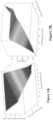
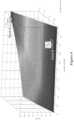
- Figure 2adepicts syngas production per mole CH 4 feedstock as a function of CO 2 and H 2 O input to the reactor. It is noted that the largest amount of syngas is produced per mole CH 4 at high H 2 O and CO 2 inputs.
- Figure 2bshows that the syngas purity (moles (H 2 +CO)/(total moles syngas)) is relatively low (75%) under these operating conditions due to a fraction of the H 2 O and CO 2 feedstocks flowing through the reactor unreacted. Typically, a high syngas purity (greater than 95%) is desirable for efficient downstream processing.
- Figure 3shows one embodiment of the design of the carbon negative chemical looping system.
- natural gasis converted to syngas which is suitable for Fischer-Tropsch synthesis and the production of liquid fuels.
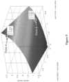
- Figure 4shows an analysis of the viable operating points for the carbon negative system shown in Figure 3 .
- the graphincludes H 2 /CO ratios and corresponding ratios for the amount of CO 2 in syngas to the amount of CO 2 being recycled at various steam to natural gas ratios. From this graph it is possible to determine if a set of conditions yield a syngas stream at the correct H 2 /CO ratio and what CO 2 recycle percentage this point corresponds to.
- One exampleis shown by the connection of points A and B. This example corresponds to a H 2 O/CH 4 ratio of 0.5, a H 2 /CO ratio of 2.0, and a CO 2 recycle rate of nearly 140%.
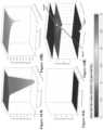
- Figure 5shows H 2 /CO ratio as a function of steam input and CO 2 per mol of CH 4 for a co-current moving bed reactor, operating at 900°C, 1 atm and effective Fe 2 O 3 /CH 4 ratio of 0.8.
- Figure 6shows the variation of H 2 flowrate, in syngas, for the H 2 /CO ratio shown in Figure 4 .
- the nonlinearity between the H 2 /CO ratio when steam and CO 2 is variably inputis an unique characteristic of CO 2 recycle in chemical looping systems.
- This nonlinearitymay be leveraged to develop a multiple reducer system.
- Each of these reducer reactorsmay be exclusively optimized to maximize the overall benefits in terms of carbon efficiency and cost, obtained from minimizing the overall natural gas consumption.
- a multiple reducer systemcan be feasibly concieved on a commercial scale as a single circulating solids loop with multiple reducers and a single combustor, as shown in Figure 7 .
- Another commercial scale operation of the multiple reducer systemcan be designed with multiple modules, each containing multiple reducers and combustors, as shown in Figure 8 .
- the chemical looping recycle systemcomprises a multiple reducer design having a two reducer and a three reducer system, which may generate a syngas composition (H 2 /CO ratio of 2) needed for Fischer-Tropsch synthesis.
- Figure 9 and Figure 10show a two reducer CO 2 recycle chemical looping system, where operating conditions for each reducer are represented by Point A and Point B in Figure 5 and Figure 6 .
- Each reducer operationis optimized such that the net syngas has an effective H 2 /CO ratio of about 1 to about 3.
- the net syngashas an effective H 2 /CO ratio of about 2.
- the reducer operation corresponding to Point Amaximizes the H 2 production, operating at a H 2 O/CH 4 ratio of 2, CO 2 /CH 4 ratio of 0.20, yielding a syngas H 2 /CO ratio of about 2.9 to about 3.1, preferably 3.02.
- the reducer corresponding to Point Boptimized for CO production, operates at a H 2 O/CH 4 ratio of 0.20, CO 2 /CH 4 ratio of 0.57, yielding a syngas ratio of about 1.0 to about 1.5, preferably 1.27.
- the first reducercould operate at Point A (H 2 O/CH 4 ratio of 2, CO 2 /CH 4 ratio of 0.20, outputting a H 2 /CO ratio of 3.0)
- the second reducercould operate at Point B (H 2 O/CH 4 ratio of 1.8, CO 2 /CH 4 ratio of 0.20, outputting a H 2 /CO ratio of 2.90)
- the third reducercould operate at Point C (H 2 O/CH 4 ratio of 0.4, CO 2 /CH 4 ratio of 1.12, outputting a H 2 /CO ratio of 1.03).
- the net H 2 /CO ratio of these three reducersis '2.' It should be noted that like the two and three reducer cases, the concept can be expanded to 'n' reducers or modules.
- Each of these 'n' reducer reactorsmay be selectively optimized for specific functions, which may include, but are not limited to, operating temperatures, operating pressures, syngas H 2 /CO ratios, effective Fe 2 O 3 /CH 4 ratios, support weight percentages, etc. Such specialized operation may be used to reduce overall cost and maximize the efficiency, based on a given set of operating conditions.
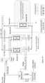
- Figure 15schematically illustrates a chemical looping modular process for producing syngas from fossil fuel.
- the systemscomprises three main reactor sections inclduing the reducer reactor section, a combustor reactor and a sepration unit.
- the reducer reactor sectionis a modular system in which two or more co-current moving bed reactors covnert fossil fuel to a syngas stream comprising H 2 , CO, CO 2 and steam.
- the modular configuration of the reducer reactorsallows for maximizing the H 2 + CO production, beyond the configuation of a single reducer reactor.
- Each reactor in the modular systemcan be optimized based on the oxygen carrier to fuel ratio, temperature, and pressure of the reactor.
- One advantage of the co-current moving bed reactorsis that it ensures that thermodynamic design conditions for a high syngas conversion can be obtained by controlling the reaction stoichiometric and that sufficient residence times are available for complete reactant conversion.
- the reducer reactor sectioncomprises two co-current moving bed reactors, operating in parallel.
- the reducer reactor systemcomprises two or more co-current moving bed reactors, operarting in parallel with respect to one another.
- the reducer reactorscomprise metal oxide particles.
- the metal-oxide compositionconsists of two components, namely primary and secondary.
- the primary metal-oxideis being chosen to be Fe 2 O 3 .
- the primary metal-oxideshould be able to donate oxygen to the fuel mixture.
- the secondary metal-oxidecan be an oxide of any combination of Ti, Al, Co, Cu, Mg, Mn, Zn, etc.
- the secondary metal-oxideserves to strengthen the primary metal-oxide and can enhance reactivity by forming complexes which have a better thermodynamic selectivity than iron-oxide alone.
- the oxygen-carrier metal-oxidemay contain a combination of primary and secondary metal-oxides in varying weight percentages.
- the metal-oxidecan be prepared by methods including but not limited to extrusion, pelletizing, co-precipitation, wet-impregnation, and mechanical compression. Techniques like sintering the synthesized metal-oxide or adding a binder with sol-gel combustion can be used to increase the strength of the metal-oxide.
- the specific metal-oxide compositionconsists of an iron-titanium composite metal oxide (ITCMO) or an iron-aluminum complex.
- This complexcan be titanium-rich, or iron-rich depending on the relative molar ratios.
- the overall reduced form for the specific chemistry simulatedis dependent on the relative molar ratio composition of the metal-oxide.
- a titanium-rich iron based composite metal-oxide particlecontains a TiO 2 : Fe 2 O 3 molar ratio of greater than 2 will yield a reduced form, FeTiO3.
- a TiO 2 : Fe 2 O 3 molar ratio of less than 2will favor formation of FeO-Fe 2 TiO 4 in addition to FeTiOs in the composite's reduced form, and the chemistry must be adjusted accordingly.
- ITCMOinterlecular O 2
- CO 2 usageand the H 2 :CO molar ratio in syngas production.
- ITCMO particlesare designed around lattice oxygen based on higher syngas selectivity and theoretically achieve much greater syngas yield over a wider operational range than molecular O 2 or Fe 2 O 3 alone due to interactions between iron and titanium oxides.
- the oxygen necessary to convert CH 4 to H 2 and COcomes from a combination of H 2 O, CO 2 and ITCMO.
- a combination of fuel, CO 2 and steamare added to a first moving bed reactor in a co-current flow pattern relative to the metal oxide particles.
- the first reactorreduces at least a portion of its the metal oxide particles and oxidizes the fuel to produce a first syngas stream comprising H 2 , CO, CO 2 and steam.
- a combination of fuel, CO 2 and steamare added to a second moving bed reactor, operating in parallel with the first moving bed reactor, in a co-current flow pattern.
- the second reactorreduces at least a portion of its metal oxide particles and oxidizes the fuell to produce a second syngas stream comprising H 2 , CO, CO 2 and steam.
- multiple moving bed reactorsreceive the fuel, CO 2 and steam in a co-current flow pattern relative to the metal oxide particles.
- Each reactorreduces at least a portion of its metal oxide particles to produce reduced metal or reduced metal oxide particles and syngas streams comprising H 2 , CO, CO 2 and steam.
- the typical operating temperature range of the reducer reactorsis between 800°C and 1190°C with the pressure range of 1atm to 10 atm.
- the first syngas stream from the first reducer rectionhas a H 2 /CO ratio of about 2.9 to about 3.1 and the second syngas stream from the second reducer reactor has a H 2 /CO ratio of about 1.0 to about 1.5.
- the combination of the syngas streams from each reducerresults in a total syngas H 2 /CO of about 1 to about 3, preferably 2.
- the fuel for this systemcan be any gaseous hydrocarbon based fuel including but not limited to natural gas, shale gas, and coal-bed methane.
- the fuelis methane.
- a steam to hydrocarbon carbon molar ratio between 0.01 and 0.90is implemented for adjusting the H 2 /CO ratio.
- the first and second moving bed reducer reactorshave an effective Fe 2 O 3 /CH 4 ratio of about 0.5 to about 1. It should be noted that operating under the specified conditions leads to a unique combination which will maximize the steam conversion to H 2 , by donating its oxygen to the metal-oxide lattice. In conjunction with the above stated variables, a CO 2 to hydrocarbon carbon molar ratio is applied.
- a separation unitis connected to each of the multiple reducer reactors and configured to receive the syngas stream from each of the reducer reactors.
- the separation unitremoves the CO 2 from each of the syngas streams and controls the H 2 /CO ratio by recycling the CO 2 from the separation unit to the multiple reducer reactors. Substantially all of the CO 2 extracted from the syngas streams is recycled back into the reducer reactors.
- the separation unitreceives a first syngas stream and a second syngas stream from the first and second reducer reactors.
- the separation unitextracts CO 2 from the first and second syngas streams and sends the CO 2 -depleted syngas streams downstream for further processing.
- a combustor reactorin communication with the multiple reducer reactors, receives the reduced metal oxide particles from the reducer reactors.
- the combustor reactorregenerates the metal oxide particles by oxidizing the reduced metal oxide particles from the reducer reactors, in the presence of a reducing agent. This reaction is exothermic and is capable of offsetting the endothermic heat requirements in the reducer reactors.
- the product of the oxidation reactionis oxidized composite metal oxide particles that comprise oxidized metal oxide particles from each of the multiple reducer reactors.
- the oxidized composite metal oxide particlesare recycled back to the multiple reducer reactors to produce additional syngas.
- the combustor reactormay be a bubbling fluidized reactor.
- the reducing agentis air.
- the reducer reactoris a moving bed reactor that takes in natural gas and partially oxidizes it to a mixture of CO and H 2 using a co-current solids stream of ITCMO.
- the ITCMOin the form of Fe 2 TiO 5 , provides oxygen necessary to partially oxidize CH 4 to a mixture of CO and H 2 .
- the ITCMOis reduced to a mixture of Fe, FeTiOs, and Fe 3 O 4 depending on the reactor design and contact mode.
- a co-current moving bed systemensures that, thermodynamic design conditions for a high syngas conversion can be obtained by controlling the reaction stoichiometric and ensuring that sufficient residence time are available for complete reactant conversion.
- the target reactions in the reducer reactorcan be represented by Equation (1): FeTiyOx + CH 4 ⁇ FeTi y O x-1 + CO + 2 H 2 Where ⁇ H reducer ⁇ 0 (1)
- the design of the reducer reactoris based on an optimal oxygen carrier to fuel ratio, temperature and pressure of the reactor, and the weight ratio of active oxygen carrier to support material.
- the combustor reactoris a bubbling fluidized bed reactor which reoxidizes the reduced ITCMO particles from the reducer with air.
- the target reactions in the combustor reactorcan be represented by Equation (2): FeTiyO 1- x + 0.5 O 2 ⁇ FeTi y O x Where ⁇ H reducer ⁇ 0 (2)
- the combustor reactionis exothermic and the heat can be transferred to the reducer reactor using the oxygen carrier to offset the energy requirements for the endothermic heat requirements of the reducer reactor.
- Example 1Modularization Design for Syngas Production from 1 kmol/hr CH 4 using Fe 2 O 3 , CO 2 and H 2 O for a Constant Fe 2 O 3 :CH 4 Ratio
- FIG 16bis a co-planar view of Figure 16a .
- a ⁇ Point A'is chosen such that it serves as the optimal design conditions for a single reducer syngas-production unit. This point is decomposed into two reducer operating conditions represented by Point B and Point C.
- the composite syngas generation performance for the points B and Clies along a straight line connecting the two points.
- Point Drepresents a composite syngas generation performance for the modular system utilizing the same H 2 O, CO 2 and methane flow rates as that for Point A, but an improvement in syngas yield by ' ⁇ '.
- the relative splits of natural gas and steamare determined by the ratio of differences in coordinates between Point B and Point C.
- the line connecting Point B and Point Cmay have components in all the three dimensions it is plotted on.
- a specific example for the modular syngas production systemis shown in Table 2 (below).
- the composite Point D for the two reducer modular systemshows an 11.8% increase (% ⁇ ) in syngas yield for the same input flows as that for the one reducer system.
- Table 2Specific example for the modularization strategy in syngas generation for a constant Fe 2 O 3 :CH 4 ratio of 0.333 using Fe 2 O 3 CH 4 CO 2 H 2 O Fe 2 O 3 CO H 2 CO+H 2 H 2 :CO
- One Reducer System(Point A) 1.000 0.418 1.100 0.333 1.000 1.999 2.999 2.00
- Reactor 1(Point B) 0.525 0.343 1.086 0.175 0.597 1.338 1.935 2.24 Reactor 2 (Point C) 0.475 0.075 0.014 0.158 0.521 0.897 1.418 1.72 Total of Reactor 1 & Reactor 2 (Point D) 1.000 0.418 1.100 0.333 1.118 2.235 3.353 2.00 % increase in syngas production 11.8%
- Example 2Modularization Design for Syngas Production from 1 kmol/hr CH 4 using ITCMO, CO 2 and H 2 O for a Constant Fe 2 O 3 :CH 4 Ratio
- a modularization strategy similar to Fe 2 O 3can be applied to ITCMO particles.
- the motivation for ITCMO modularitycan be explained using Figure 17 .
- a specific example for the modular syngas production system using ITCMO particlesis given in Table 3 (below).
- the single reducer reactor performance (Point A*)is specified by a CH 4 input of 1 kmol/hr.
- Point B* and Point C*represent the operating conditions for the modular reactors with ITCMO.
- Point D*the composite of the modular Point B* and Point C*, shows a 2.2% increase (% ⁇ *) in syngas production with matching inputs as the one reducer system shown in Point A*.
- Table 3Specific example for the modularization strategy in syngas generation for a constant Fe 2 O 3 :CH 4 ratio of 0.333 using ITCMO CH 4 CO 2 H 2 O Fe 2 O 3 CO H 2 CO+H 2 H 2 :CO
- One Reducer System(Point A*) 1.00 0.080 0.410 0.333 1.01 2.20 3.210 2.19 Reactor 1 (Point B*) 0.47 0.064 0.400 0.158 0.50 1.23 1.732 2.45 Reactor 2 (Point C*) 0.52 0.016 0.010 0.175 0.52 1.03 1.548 1.95 Total of Reactor 1& Reactor 2 (Point D*) 1.00 0.080 0.410 0.333 1.02 2.25 3.280 2.19 % increase in syngas production 2.2%
- Example 3Modularization Design for Syngas Production from 1 kmol/hr CH 4 using ITCMO, H 2 O and CO 2 for Various Fe 2 O 3 :CH 4 Ratios
- the two reducersare chosen such that one reducer operates at a lower Fe 2 O 3 :CH 4 and produces a high syngas yield per mole of methane, Point B**, while the second reducer operates at a higher Fe 2 O 3 :CH 4 and produces little syngas, Point C**.
- Syngas generation performanceis higher at lower Fe 2 O 3 :CH 4 molar ratios but comes at a cost of a higher net endothermic reaction as the lattice oxygen content in the system is lower.
- Point C**maintains the overall heat balance consideration similar to the single reducer case, while Point B** produces the majority of the syngas.
- Table 4The comparison between the single reducer and the two reducer modular system are shown in Table 4 (below).
Landscapes
- Chemical & Material Sciences (AREA)
- Organic Chemistry (AREA)
- Engineering & Computer Science (AREA)
- Combustion & Propulsion (AREA)
- Chemical Kinetics & Catalysis (AREA)
- Oil, Petroleum & Natural Gas (AREA)
- Inorganic Chemistry (AREA)
- Health & Medical Sciences (AREA)
- General Health & Medical Sciences (AREA)
- Hydrogen, Water And Hydrids (AREA)
- Organic Low-Molecular-Weight Compounds And Preparation Thereof (AREA)
Description
- Increased natural gas availability in the United States has presented an opportunity to decrease dependence on foreign oil (which constitutes 27% of the total consumption1), and diversify the supply for energy consumption needs. Turbulence in the oil market is seen as a driving force for the advancement of Gas to Liquids (GTL) technology. Liquid fuels are projected to continue to be a necessary component in supplying human energy needs.2 Technological advances in drilling have driven the shale-gas production boom, leading to an increase in natural gas contribution to the energy demand. Another driving force for the development of highly efficient GTL facilities is the percentage of stranded natural gas that is flared because transportation costs of gaseous fuels are too high to make transporting them economical. In 2011, 5.3×10¹² cubic feet of associated petroleum gas was flared; the equivalent of about 25% of annual gas consumption in the United States.3 At current market price ($2/MMBtu)4 for natural gas, the nominal market value of the flared gas was $13.8 billion. GTL is an effective way to monetize the stranded natural gas. However, widespread applications of GTL processes have been hindered due to high risk of cost escalation associated with GTL based projects. The syngas production unit accounts for 30-50 % of the total capital cost investment.5
- The carbon efficiency is defined here as the percentage of carbon in the natural gas feed that is converted to CO and in-turn to liquid fuels. This number increases as the net conversion to CO2 decreases. The carbon efficiency is qualitatively measured by a reduction in the total natural gas consumption over that used in the conventional method of syngas production, which uses an auto-thermal reforming based system. The benefits of this disclosure are demonstrated by considering a case study for a 50,000 bpd GTL plant. The design H2/CO ratio for this GTL plant is 2.19, and it is achieved using a (H2-CO2)/ (CO + CO2) ratio of 1.58.
- Carbon Capture Utilization and Sequestration (CCUS) is also a grand challenge for modern chemical engineers. Many new technologies strive to implement either CO2 capture or CO2 utilization, but the two processes are rarely thought of as mutually inclusive. In order to have a meaningful impact on the mitigation of CO2 emissions it is paramount that CO2 capture and utilization or sequestration technologies are developed in conjunction with each other.
US 2015/238915 A1 describes a system used for converting multiple fuel feedstocks that may include three reactors. The reactor system combination can be so chosen that one of the reactors completely or partially converts the fuel while the other generates the gaseous product required by utilizing the gaseous product from the second reactor. The metal-oxide composition and the reactor flow-patterns can be manipulated to provide the desired product.- This disclosure relates to reactors and methods that may significantly reduce the costs associated with syngas production from natural gas using chemical looping technology and applying a novel concept of reacting the CO2 to near extinction, or consuming more CO2 than is produced. The disclosure includes a reactors and processes that allow for both the capture and the utilization of CO2 in a single process while utilizing fossil fuels. On a commercial scale, a fossil fuel process involving unprecedented simultaneous capture and utilization of CO2 can be transformational and disruptive in conventional CO2 utilization and carbon capture markets.
- The methods and system configurations disclosed herein use a chemical looping system characterized by a co-current downward contacting reactive flow of oxygen carriers and carbonaceous flow which are accompanied by CO2 recycle and steam which may be introduced at variable flow rates and positions along the reducer in order to generate the desired quantity and quality of syngas for liquid fuel production. These specific operating conditions, along with a unique oxygen carrier and support composition and heat transfer management, yield a system with highly controlled oxygen transfer that ensures the highly efficient generation of the desired syngas quality.
- This disclosure describes specific reactors and conditions that enable the disclosed novel chemical looping process to function as a carbon negative or a carbon neutral fossil fuel process. In cases where the CO2 consumed is more than CO2 produced (CO2 negative system), the disclosed chemical looping system can function as an effective CO2 utilization system.
- In one aspect, disclosed herein is a system for converting a fuel, the system comprising: a first moving bed reactor comprising a metal oxide particles having a primary component and a secondary component, wherein fuel, CO2 and steam are added to the first moving bed reactor in a co-current flow pattern relative to the metal oxide particles, wherein the first moving bed reactor is configured to reduce at least a portion of the metal oxide particles with the fuel to produce a first reduced metal oxide, and is further configured to produce a first syngas stream comprising H2, CO, CO2 and steam; a second moving bed reactor, configured to operate in parallel with the first moving bed reactor and comprising metal oxide particles having a primary component and a secondary component, wherein fuel, CO2 and steam are added to the second moving bed reactor in a co-current flow pattern relative to the metal oxide particles, wherein the second moving bed reactor is configured to reduce at least a portion of the metal oxide particles with the fuel to produce a second reduced metal oxide, and is further configured to produce a second syngas stream comprising H2, CO, CO2 and steam; a separation unit, in communication with the first moving bed reactor and the second moving bed reactor, and configured to remove the CO2 from the first syngas stream and the second syngas stream, wherein the H2/CO ratios of the first and second syngas streams are controlled by recycling substantially all of the CO2 from the separation unit to the first moving bed reactor and the second moving bed reactor; and a third co-current fluidized bed reactor in communication with the first moving bed reactor and the second moving bed reactor and configured to oxidize the first reduced metal oxide and the second reduced metal oxide with an oxidizing agent to produce oxidized metal oxide particles and recycle the oxidized composite metal oxide to the first moving bed reactor and the second moving bed reactor for subsequent reduction reactions, wherein the first and second moving bed reactors have an effective Fe2O3/CH4 ratio of 0.5 to 1.
- In some embodiments, the primary component is Fe2O3. In some embodiments, the secondary component comprises a metal-oxide selected from the group consisting of oxides of Ti, Al, Co, Cu, Mg, Mn, Zn, and combinations thereof. In some embodiments, the secondary component is titanium oxide. In some embodiments, the fuel is methane. In some embodiments, the H2/CO ratio of the first syngas stream is about 2.9 to about 3.1. In some embodiments, the H2/CO ratio of the second syngas stream is about 1.0 to about 1.5. In some embodiments, the combination of the syngas from each reducer results in a total syngas H2/CO ratio of about 1 to about 3. In some embodiments, the first reduced metal oxides and the second reduced metal oxides are oxidized by introducing steam into the third reactor. In some embodiments, the system consumes more CO2 than it produces.
- In another aspect, disclosed herein is a method for converting fuel, the method comprising: feeding the fuel and metal oxide particles into a first moving bed reactor, operating in parallel with a second moving bed reactor, in a co-current flow pattern relative to one another, wherein the metal oxide particles comprise a primary component and a secondary component and reducing at least a portion of the metal oxide particles in the first moving bed reactor to produce a first reduced metal oxide and a first syngas stream comprising H2, CO, CO2 steam or combinations thereof; feeding the fuel and metal oxide particles into a second moving bed reactor in a co-current flow pattern relative to one another, and reducing at least a portion of the metal oxide particles in the second moving bed reactor to produce a second reduced metal oxide and a first syngas stream comprising H2, CO, CO2 steam or combinations thereof; transporting the first reduced metal oxide particles and the second reduced metal oxide particles to a third reactor to oxidize the first reduced metal oxide particles and the second reduced metal oxide particles to produce oxidized metal oxide particles and recycling the oxidized metal oxide particles to the first and second reactors for subsequent reduction reactions; and removing the CO2 from the first and second syngas streams in a separation unit and controlling the H2/CO ratio by recycling substantially all of the CO2 from separation unit to the first moving bed reactor and second moving bed reactor, wherein the combination of the first and second syngas streams result in a total syngas H2/CO of between 1 and 3, wherein the first and second moving bed reactors have an effective Fe2O3/CH4 ratio of 0.5 to 1.
- In some embodiments, CO2 and steam are fed into the first moving bed reactor and the second moving bed reactor. In some embodiments, the first and second moving bed reactors operate at a temperature of about 800 °C to about 1190 °C. In some embodiments, the first and second moving bed reactors operate at a pressure of about 1 atm to about 10 atm. In some embodiments, the fuel is methane. In some embodiments, the primary component is Fe2O3. In some embodiments, the first reduced metal oxides and the second reduced metal oxides are oxidized by introducing steam into the third reactor.
- Other aspects of the invention will become apparent by consideration of the detailed description and accompanying drawings.
FIG. 1 : Conceptual schematic for a carbon negative or carbon neutral iron based chemical looping system that uses CO2 recycle and an external CO2 source in the high efficiency conversion of fossil fuels.FIG. 2a : Syngas generation surface for iron-titanium composite metal oxide (ITCMO) at an Fe2O3:CH4 ratio of 0.33.FIG. 2b : Syngas purity surface for ITCMO at an Fe2O3:CH4 ratio of 0.333.FIG. 3 : Conceptual schematic for a carbon negative or carbon neutral iron based chemical looping system that uses CO2 recycle and an external CO2 source in the high efficiency conversion of natural gas to syngas suitable for Fischer-Tropsch synthesis and the production of liquid fuels.FIG. 4 : Comparison of obtainable H2/CO ratios with corresponding percentages of CO2 recycle at various H2O/CH4 ratios.FIG. 5 : H2/CO ratio as a function of H2O/CH4 and CO2/CH4 ratios, at 900°C, 1 atm, for a co-current moving bed reactor and at an effective Fe2O3/CH4 ratio of 0.8.FIG. 6 : H2 flowrate as a function of H2O/CH4 and CO2/CH4 ratios, at 900°C, 1 atm, for a co-current moving bed reactor and at an effective Fe2O3/CH4 ratio of 0.8.FIG. 7 : Conceptual schematic of multiple reducers operating in parallel with a single combustor reactor.FIG. 8 : Conceptual schematic of multiple reactor modules, containing multiple reducers and combustors.FIG. 9 : Conceptual schematic of chemical looping CO2 recycle concept with two reducers operating in parallel with a single combustor reactor.FIG. 10 : Conceptual schematic of chemical looping CO2 recycle concept with two modules, containing both a reducer and combustor, operating in parallel.FIG. 11 : Conceptual schematic of chemical looping CO2 recycle concept with three reducers operating in parallel with a single combustor reactor.FIG. 12 : Conceptual schematic of chemical looping CO2 recycle concept with three modules, containing both a reducer and combustor, operating in parallel.FIG. 13 : H2/CO ratio as a function of H2O/CH4 and CO2/CH4 ratios, at 900°C, 1 atm, for a co-current moving bed reactor and at an effective Fe2O3/CH4 ratio of 0.8.FIG. 14 : H2 flowrate as a function of H2O/CH4 and CO2/CH4 ratios, at 900°C, 1 atm, for a co-current moving bed reactor and at an effective Fe2O3/CH4 ratio of 0.8.FIG. 15 : Schematic representation of an embodiment of the chemical looping CO2 recycle system with two reducers operating in parallel with a single combustor reactor and a CO2 separation unit.FIG. 16a : Syngas generation surface for pure Fe2O3 at an Fe2O3:CH4 ratio of 0.33.FIG. 16b : Geometric representation of the modularization strategy for the syngas generation performance.FIG. 17 : Syngas generation surface for ITCMO at an Fe2O3:CH4 ratio of 0.333.FIG. 18a : Syngas yield at an Fe2O3:CH4 ratio of 0.34, 900°C, 1 atm.FIG. 18b : Syngas yield at an Fe2O3:CH4 ratio of 1.2, 900°C, 1 atm.FIG. 18c : Syngas yield at an Fe2O3:CH4 ratio of 9.8, 900°C, 1 atm.FIG. 18d : Operating points of the ITCMO-based modular system at 900°C, 1 atm for varying H2O and CO2 injection.FIG. 19 : Co-planar view ofFigure 18d showing the operating points of the ITCMO-based modular system at 900°C, 1 atm for varying [O]/CH4.- Before any embodiments of the invention are explained in detail, it is to be understood that the invention is not limited in its application to the details of construction and the arrangement of components set forth in the following description or illustrated in the following drawings. The invention is capable of other embodiments and of being practiced or of being carried out in various ways.
- This disclosure describes specific reactors and conditions that allow the disclosed novel chemical looping process to function as a carbon negative or a carbon neutral fossil fuel process. In cases where the CO2 consumed is more than CO2 produced (CO2 negative system), the disclosed chemical looping system can function as an effective CO2 utilization system.
- Unless otherwise defined, all technical and scientific terms used herein have the same meaning as commonly understood by one of ordinary skill in the art. In case of conflict, the present document, including definitions, will control. Preferred methods and materials are described below, although methods and materials similar or equivalent to those described herein can be used in practice or testing of the present invention. The materials, methods, and examples disclosed herein are illustrative only and not intended to be limiting.
- The terms "comprise(s)," "include(s)," "having," "has," "can," "contain(s)," and variants thereof, as used herein, are intended to be open-ended transitional phrases, terms, or words that do not preclude the possibility of additional acts or structures. The singular forms "a," "an" and "the" include plural references unless the context clearly dictates otherwise. The present disclosure also contemplates other embodiments "comprising," "consisting of' and "consisting essentially of," the embodiments or elements presented herein, whether explicitly set forth or not.
- The conjunctive term "or" includes any and all combinations of one or more listed elements associated by the conjunctive term. For example, the phrase "an apparatus comprising A or B" may refer to an apparatus including A where B is not present, an apparatus including B where A is not present, or an apparatus where both A and B are present. The phrases "at least one of A, B, ... and N" or "at least one of A, B, ... N, or combinations thereof' are defined in the broadest sense to mean one or more elements selected from the group comprising A, B, ... and N, that is to say, any combination of one or more of the elements A, B, ... or N including any one element alone or in combination with one or more of the other elements which may also include, in combination, additional elements not listed.
- For the recitation of numeric ranges herein, each intervening number there between with the same degree of precision is explicitly contemplated. For example, for the range of 6-9, the
numbers - "Carbon neutral," as used herein, refers to a system or process in which about 100% of the CO2 produced by a system is recycled.
- "Carbon negative," as used herein, refers to a system or process in which more CO2 is consumed than the system or process produces.
- To maximize the amount of syngas produced per mole of a fossil fuel feedstock, a novel modularization strategy can be employed in which multiple reducer reactors operate in parallel. This concept allows for each reducer reactor to operate under different operating conditions and produce different qualities of syngas. The operating conditions yield the desired overall syngas purity and H2: CO requirements when linearly combined while using less fossil fuel feedstock when compared to a single reducer reactor.
Figure 1 shows a scheme for a carbon negative chemical looping process that converts fossil fuels to value added products. The process comprises co-feeding fossil fuels, CO2 and steam into multiple moving bed reducer reactors to produce syngas. The fossil fuels may include but are not limited to gaseous fossil fuels (natural gas, shale gas, coal bed methane, etc.), solid fossil fuels (coal, biomass, petcoke, etc.), or liquid fossil fuels (kerosene, petroleum, etc.).- Operating conditions for a syngas producing reducer reactor are chosen to maximize the moles of syngas produced per mole fossil fuel feedstock, to maximize syngas purity, and to meet the H2:CO ratio requirements for downstream processes. A novel combination of these conditions can yield a CO2 negative scheme, in which the molar amount of CO2 entering the reactor divided by the molar amount of CO2 exiting the reactor (CRP or CO2 reaction parameter) is greater than 1.
- A specific set of operating conditions is given in Table 1 (below). Group (1) refers to the reaction of CH4 with the metal oxide; Group (2) refers to the reactions of CH4 with CO2 and the metal oxide; Group (3) refers to the reactions of CH4 with H2O and the metal oxide; Group (4) refers to the reactions of CH4 with CO2, H2O and the metal oxide. For a Group (4) operation, it can be seen that a CRP > 1 operating condition that reasonably satisfies the previously given criteria has been determined thermodynamically and verified with experiments.
Table 1: Experimental data for various reaction conditions involving CH4, Fe2O3 and/or CO2 and/or H2O in a single co-current moving bed reactor Group (1) Group (2) Group (3) Group (4) Input Conditions CH4 flow rate (SLPM) 1.0 1.3 1.1 1.1 0.9 0.9 0.9 0.7 H2O flow rate (mL/min) 0 0 0 0 0.15 0.2 0.2 0.15 H2O/CH4 molar ratio 0 0 0 0 0.61 0.79 0.79 0.78 CO2 flow rate (SLPM) 0 0 0.22 0.33 0 0 0.14 0.11 CO2/CH4 molar ratio 0 0 0.2 0.3 0 0 0.15 0.15 Fe2O3:CH4 molar ratio 1.03 0.75 0.83 0.77 0.68 0.68 0.65 0.81 Reactor temperature (°C) 1037 1039 1039 1038 1032 1031 1037 1034 Experimental results % CH4 conversion 95.7 93.3 94.5 94.1 93.3 96.5 94.3 93.2 H2:CO molar ratio 1.83 1.84 1.53 1.41 2.14 2.15 1.95 1.90 CO/CO2 molar ratio 8.11 9.52 13.5 13.7 13.1 12.9 13.6 13.7 CRP 0 0 1.93 2.50 0 0 1.51 1.66 % Syngas Purity on dry basis 94.2 93.9 95.2 95.1 95.3 96.4 95.8 95.4 Thermodynamic results % CH4 conversion 100 100 100 100 100 100 100 100 H2:CO molar ratio 1.88 1.88 1.57 1.45 2.46 2.61 2.23 2.18 CO/CO2 molar ratio 12.8 12.8 12.8 12.9 12.9 11.3 9.09 6.89 CRP 0 0 2.31 3.20 0 0 1.32 1.03 % Syngas Purity on dry basis 97.4 97.4 97.1 96.9 97.8 97.6 96.7 95.6 - In certain embodiments of the carbon negative chemical looping system, the conditions necessary for a CRP greater than 1 are fixed using thermodynamic Gibbs free energy minimization simulations.
Figure 2a depicts syngas production per mole CH4 feedstock as a function of CO2 and H2O input to the reactor. It is noted that the largest amount of syngas is produced per mole CH4 at high H2O and CO2 inputs.Figure 2b , however, shows that the syngas purity (moles (H2+CO)/(total moles syngas)) is relatively low (75%) under these operating conditions due to a fraction of the H2O and CO2 feedstocks flowing through the reactor unreacted. Typically, a high syngas purity (greater than 95%) is desirable for efficient downstream processing. Figure 3 shows one embodiment of the design of the carbon negative chemical looping system. In this embodiment, natural gas is converted to syngas which is suitable for Fischer-Tropsch synthesis and the production of liquid fuels.Figure 4 shows an analysis of the viable operating points for the carbon negative system shown inFigure 3 . The graph includes H2/CO ratios and corresponding ratios for the amount of CO2 in syngas to the amount of CO2 being recycled at various steam to natural gas ratios. From this graph it is possible to determine if a set of conditions yield a syngas stream at the correct H2/CO ratio and what CO2 recycle percentage this point corresponds to. One example is shown by the connection of points A and B. This example corresponds to a H2O/CH4 ratio of 0.5, a H2/CO ratio of 2.0, and a CO2 recycle rate of nearly 140%.Figure 5 shows H2/CO ratio as a function of steam input and CO2 per mol of CH4 for a co-current moving bed reactor, operating at 900°C, 1 atm and effective Fe2O3/CH4 ratio of 0.8.Figure 6 shows the variation of H2 flowrate, in syngas, for the H2/CO ratio shown inFigure 4 . It should be noticed that the nonlinearity between the H2/CO ratio when steam and CO2 is variably input is an unique characteristic of CO2 recycle in chemical looping systems. This nonlinearity may be leveraged to develop a multiple reducer system. Each of these reducer reactors may be exclusively optimized to maximize the overall benefits in terms of carbon efficiency and cost, obtained from minimizing the overall natural gas consumption. A multiple reducer system can be feasibly concieved on a commercial scale as a single circulating solids loop with multiple reducers and a single combustor, as shown inFigure 7 . Another commercial scale operation of the multiple reducer system can be designed with multiple modules, each containing multiple reducers and combustors, as shown inFigure 8 .- In certain embodiments, the chemical looping recycle system comprises a multiple reducer design having a two reducer and a three reducer system, which may generate a syngas composition (H2/CO ratio of 2) needed for Fischer-Tropsch synthesis.
Figure 9 andFigure 10 show a two reducer CO2 recycle chemical looping system, where operating conditions for each reducer are represented by Point A and Point B inFigure 5 andFigure 6 . Each reducer operation, is optimized such that the net syngas has an effective H2/CO ratio of about 1 to about 3. In certain embodiments, the net syngas has an effective H2/CO ratio of about 2. In certain embodiments, the reducer operation corresponding to Point A, maximizes the H2 production, operating at a H2O/CH4 ratio of 2, CO2/CH4 ratio of 0.20, yielding a syngas H2/CO ratio of about 2.9 to about 3.1, preferably 3.02. The reducer corresponding to Point B, optimized for CO production, operates at a H2O/CH4 ratio of 0.20, CO2/CH4 ratio of 0.57, yielding a syngas ratio of about 1.0 to about 1.5, preferably 1.27. The combination of the syngas from each reducer results in a total syngas H2/CO ratio of '2.' Another application of multiple reducer concepts is demonstrated using three reducer modules, as shown inFigure 11 andFigure 12 with the specific operating conditions represented by Points A, B, and C inFigures 13 and14 .Figures 13 and14 show the H2/CO ratios and H2 flowrates similar to those shown inFigures 5 and6 . A three reducer combination could be useful for operating one reducer optimized at an extreme to produce H2 (Point A inFigure 13 ), a second reducer optimized at an extreme to produce CO (Point C inFigure 13 ), and a third reducer to mitigate the H2/CO ratio (Point B inFigure 13 ). The first reducer could operate at Point A (H2O/CH4 ratio of 2, CO2/CH4 ratio of 0.20, outputting a H2/CO ratio of 3.0), the second reducer could operate at Point B (H2O/CH4 ratio of 1.8, CO2/CH4 ratio of 0.20, outputting a H2/CO ratio of 2.90), and the third reducer could operate at Point C (H2O/CH4 ratio of 0.4, CO2/CH4 ratio of 1.12, outputting a H2/CO ratio of 1.03). The net H2/CO ratio of these three reducers is '2.' It should be noted that like the two and three reducer cases, the concept can be expanded to 'n' reducers or modules. Each of these 'n' reducer reactors may be selectively optimized for specific functions, which may include, but are not limited to, operating temperatures, operating pressures, syngas H2/CO ratios, effective Fe2O3/CH4 ratios, support weight percentages, etc. Such specialized operation may be used to reduce overall cost and maximize the efficiency, based on a given set of operating conditions. Figure 15 schematically illustrates a chemical looping modular process for producing syngas from fossil fuel. The systems comprises three main reactor sections inclduing the reducer reactor section, a combustor reactor and a sepration unit. The reducer reactor section is a modular system in which two or more co-current moving bed reactors covnert fossil fuel to a syngas stream comprising H2, CO, CO2 and steam. The modular configuration of the reducer reactors allows for maximizing the H2 + CO production, beyond the configuation of a single reducer reactor. Each reactor in the modular system can be optimized based on the oxygen carrier to fuel ratio, temperature, and pressure of the reactor. One advantage of the co-current moving bed reactors is that it ensures that thermodynamic design conditions for a high syngas conversion can be obtained by controlling the reaction stoichiometric and that sufficient residence times are available for complete reactant conversion.- In certain embodiments of the system, the reducer reactor section comprises two co-current moving bed reactors, operating in parallel. In another embodiment, the reducer reactor system comprises two or more co-current moving bed reactors, operarting in parallel with respect to one another. The reducer reactors comprise metal oxide particles. The metal-oxide composition consists of two components, namely primary and secondary. In certain embodiments, the primary metal-oxide is being chosen to be Fe2O3. The primary metal-oxide should be able to donate oxygen to the fuel mixture. The secondary metal-oxide can be an oxide of any combination of Ti, Al, Co, Cu, Mg, Mn, Zn, etc. The secondary metal-oxide serves to strengthen the primary metal-oxide and can enhance reactivity by forming complexes which have a better thermodynamic selectivity than iron-oxide alone. The oxygen-carrier metal-oxide may contain a combination of primary and secondary metal-oxides in varying weight percentages. The metal-oxide can be prepared by methods including but not limited to extrusion, pelletizing, co-precipitation, wet-impregnation, and mechanical compression. Techniques like sintering the synthesized metal-oxide or adding a binder with sol-gel combustion can be used to increase the strength of the metal-oxide.
- In certain embodiments, the specific metal-oxide composition consists of an iron-titanium composite metal oxide (ITCMO) or an iron-aluminum complex. This complex can be titanium-rich, or iron-rich depending on the relative molar ratios. The overall reduced form for the specific chemistry simulated is dependent on the relative molar ratio composition of the metal-oxide. For example, a titanium-rich iron based composite metal-oxide particle contains a TiO2: Fe2O3 molar ratio of greater than 2 will yield a reduced form, FeTiO3. On the other hand, a TiO2: Fe2O3 molar ratio of less than 2 will favor formation of FeO-Fe2TiO4 in addition to FeTiOs in the composite's reduced form, and the chemistry must be adjusted accordingly.
- The usage of ITCMO eliminates the need for molecular O2, lowers operating temperatures, and allows greater flexibility in steam usage, CO2 usage and the H2:CO molar ratio in syngas production. ITCMO particles are designed around lattice oxygen based on higher syngas selectivity and theoretically achieve much greater syngas yield over a wider operational range than molecular O2 or Fe2O3 alone due to interactions between iron and titanium oxides. The oxygen necessary to convert CH4 to H2 and CO comes from a combination of H2O, CO2 and ITCMO.
- In certain embodiments, a combination of fuel, CO2 and steam are added to a first moving bed reactor in a co-current flow pattern relative to the metal oxide particles. The first reactor reduces at least a portion of its the metal oxide particles and oxidizes the fuel to produce a first syngas stream comprising H2, CO, CO2 and steam. Similarly, a combination of fuel, CO2 and steam are added to a second moving bed reactor, operating in parallel with the first moving bed reactor, in a co-current flow pattern. The second reactor reduces at least a portion of its metal oxide particles and oxidizes the fuell to produce a second syngas stream comprising H2, CO, CO2 and steam. In another embodiment, multiple moving bed reactors, operating in parallel, receive the fuel, CO2 and steam in a co-current flow pattern relative to the metal oxide particles. Each reactor reduces at least a portion of its metal oxide particles to produce reduced metal or reduced metal oxide particles and syngas streams comprising H2, CO, CO2 and steam. The typical operating temperature range of the reducer reactors is between 800°C and 1190°C with the pressure range of 1atm to 10 atm. In certain embodiments, the first syngas stream from the first reducer rection has a H2/CO ratio of about 2.9 to about 3.1 and the second syngas stream from the second reducer reactor has a H2/CO ratio of about 1.0 to about 1.5. In other embodiments, the combination of the syngas streams from each reducer results in a total syngas H2/CO of about 1 to about 3, preferably 2.
- The fuel for this system can be any gaseous hydrocarbon based fuel including but not limited to natural gas, shale gas, and coal-bed methane. In certain embodiments, the fuel is methane. In addition to the specified molar ratio, a steam to hydrocarbon carbon molar ratio between 0.01 and 0.90 is implemented for adjusting the H2/CO ratio. In certain embodiments, the first and second moving bed reducer reactors have an effective Fe2O3/CH4 ratio of about 0.5 to about 1. It should be noted that operating under the specified conditions leads to a unique combination which will maximize the steam conversion to H2, by donating its oxygen to the metal-oxide lattice. In conjunction with the above stated variables, a CO2 to hydrocarbon carbon molar ratio is applied. This uniquely helps the overall syngas quality in terms of limiting the water-gas shift type effects and helps the carbon efficiency improvement significantly. It should also be noted that the above stated conditions create a unique combination and are necessary for the desired hydrocarbon to syngas conversion efficiency. These specific operating conditions along with a unique oxygen carrier and support composition, and heat transfer management yield a system with highly controlled oxygen transfer that ensures the highly efficient generation of the desired syngas quality. All of the gaseous reactants are injected into the top of the co-current moving bed reducer reactor and flow downward along with the metal oxide partcles. The design condition for the injection port of these gases is based on giving them enough residence time to obtain a steady state conversion.
- A separation unit is connected to each of the multiple reducer reactors and configured to receive the syngas stream from each of the reducer reactors. The separation unit removes the CO2 from each of the syngas streams and controls the H2/CO ratio by recycling the CO2 from the separation unit to the multiple reducer reactors. Substantially all of the CO2 extracted from the syngas streams is recycled back into the reducer reactors. In certain embodiments having two reducer rectors, the separation unit receives a first syngas stream and a second syngas stream from the first and second reducer reactors. The separation unit extracts CO2 from the first and second syngas streams and sends the CO2-depleted syngas streams downstream for further processing. Substantially all of the separated CO2 is recycled back into the first and second reactors. In certain embodiments, the system is carbon neutral which means that the CO2 input to the reducer reactors equals the CO2 output in syngas from the reducer reactors (CRP=1). In other embodiments, the system is carbon negative which means that the CO2 input to the reducer reactors is greater than the CO2 output in syngas from the reducer reactors (CRP > 1).
- A combustor reactor, in communication with the multiple reducer reactors, receives the reduced metal oxide particles from the reducer reactors. The combustor reactor regenerates the metal oxide particles by oxidizing the reduced metal oxide particles from the reducer reactors, in the presence of a reducing agent. This reaction is exothermic and is capable of offsetting the endothermic heat requirements in the reducer reactors. The product of the oxidation reaction is oxidized composite metal oxide particles that comprise oxidized metal oxide particles from each of the multiple reducer reactors. The oxidized composite metal oxide particles are recycled back to the multiple reducer reactors to produce additional syngas. The combustor reactor may be a bubbling fluidized reactor. In certain embodiments, the reducing agent is air.
- In certain embodiments, the reducer reactor is a moving bed reactor that takes in natural gas and partially oxidizes it to a mixture of CO and H2 using a co-current solids stream of ITCMO. The ITCMO, in the form of Fe2TiO5, provides oxygen necessary to partially oxidize CH4 to a mixture of CO and H2. In the reducer, the ITCMO is reduced to a mixture of Fe, FeTiOs, and Fe3O4 depending on the reactor design and contact mode. A co-current moving bed system ensures that, thermodynamic design conditions for a high syngas conversion can be obtained by controlling the reaction stoichiometric and ensuring that sufficient residence time are available for complete reactant conversion. If natural gas is represented by CH4 and the oxidized and reduced ITCMO solids are represented by FeTiyOx and FeTiyOx-1 respectively, the target reactions in the reducer reactor can be represented by Equation (1):
FeTiyOx + CH4 → FeTiyOx-1 + CO + 2 H2 Where ΔHreducer ≥ 0 (1)
The design of the reducer reactor is based on an optimal oxygen carrier to fuel ratio, temperature and pressure of the reactor, and the weight ratio of active oxygen carrier to support material. The combustor reactor is a bubbling fluidized bed reactor which reoxidizes the reduced ITCMO particles from the reducer with air. The target reactions in the combustor reactor can be represented by Equation (2):
FeTiyO1-x + 0.5 O2 → FeTiyOx Where ΔHreducer ≤ 0 (2)
The combustor reaction is exothermic and the heat can be transferred to the reducer reactor using the oxygen carrier to offset the energy requirements for the endothermic heat requirements of the reducer reactor. - The proposed modifications eliminate direct sources of CO2 emissions in the syngas production process. The carbon emission reduction enabled by this process results in a lower environmental impact compared to conventional fossil fuel conversion processes. Carbon efficiency is drastically increased, and what was once a waste stream of the process is now recycled to extinction and also acts as a supplemental feedstock.
- The foregoing may be better understood by reference to the following examples, which are presented for purposes of illustration and are not intended to limit the scope of the invention.
- The modularization strategy used in this example is explained using
Figure 16b , which is a co-planar view ofFigure 16a . A `Point A' is chosen such that it serves as the optimal design conditions for a single reducer syngas-production unit. This point is decomposed into two reducer operating conditions represented by Point B and Point C. The composite syngas generation performance for the points B and C lies along a straight line connecting the two points. Point D represents a composite syngas generation performance for the modular system utilizing the same H2O, CO2 and methane flow rates as that for Point A, but an improvement in syngas yield by 'Δ'. The relative splits of natural gas and steam are determined by the ratio of differences in coordinates between Point B and Point C. It should be noted that the line connecting Point B and Point C may have components in all the three dimensions it is plotted on. A specific example for the modular syngas production system is shown in Table 2 (below). The composite Point D for the two reducer modular system shows an 11.8% increase (%Δ) in syngas yield for the same input flows as that for the one reducer system.Table 2: Specific example for the modularization strategy in syngas generation for a constant Fe2O3:CH4 ratio of 0.333 using Fe2O3 CH4 CO2 H2O Fe2O3 CO H2 CO+H2 H2:CO One Reducer System (Point A) 1.000 0.418 1.100 0.333 1.000 1.999 2.999 2.00 Reactor 1 (Point B) 0.525 0.343 1.086 0.175 0.597 1.338 1.935 2.24 Reactor 2 (Point C) 0.475 0.075 0.014 0.158 0.521 0.897 1.418 1.72 Total of Reactor 1 & Reactor 2 (Point D)1.000 0.418 1.100 0.333 1.118 2.235 3.353 2.00 % increase in syngas production 11.8% - A modularization strategy similar to Fe2O3 can be applied to ITCMO particles. The motivation for ITCMO modularity can be explained using
Figure 17 . A specific example for the modular syngas production system using ITCMO particles is given in Table 3 (below). The single reducer reactor performance (Point A*) is specified by a CH4 input of 1 kmol/hr. Point B* and Point C* represent the operating conditions for the modular reactors with ITCMO. Point D*, the composite of the modular Point B* and Point C*, shows a 2.2% increase (%Δ*) in syngas production with matching inputs as the one reducer system shown in Point A*.Table 3: Specific example for the modularization strategy in syngas generation for a constant Fe2O3:CH4 ratio of 0.333 using ITCMO CH4 CO2 H2O Fe2O3 CO H2 CO+H2 H2:CO One Reducer System (Point A*) 1.00 0.080 0.410 0.333 1.01 2.20 3.210 2.19 Reactor 1 (Point B*) 0.47 0.064 0.400 0.158 0.50 1.23 1.732 2.45 Reactor 2 (Point C*) 0.52 0.016 0.010 0.175 0.52 1.03 1.548 1.95 Total of Reactor 1& Reactor 2 (Point D*) 1.00 0.080 0.410 0.333 1.02 2.25 3.280 2.19 % increase in syngas production 2.2% - The design approach for the pure Fe2O3 and the ITCMO cases discussed in example 1 and example 2 show a modularization strategy which operates the two reducer modules at the same Fe2O3:CH4 molar ratios. This section investigates an example in which a single reducer performance is compared to a modular two-reducer performance, wherein the two reducers operate at different Fe2O3:CH4 ratios.
Figures 18a-d show the syngas production performance when the Fe2O3:CH4 ratio in each reducer reactor is '0.34', '1.2' and '9.8', respectively. The modularization strategy may be applied to this system and is demonstrated by maintaining the same overall inputs as a single reducer system at the operating condition shown inFigure 18d , Point A**. The two reducers are chosen such that one reducer operates at a lower Fe2O3:CH4 and produces a high syngas yield per mole of methane, Point B**, while the second reducer operates at a higher Fe2O3:CH4 and produces little syngas, Point C**. Syngas generation performance is higher at lower Fe2O3:CH4 molar ratios but comes at a cost of a higher net endothermic reaction as the lattice oxygen content in the system is lower. Thus, Point C** maintains the overall heat balance consideration similar to the single reducer case, while Point B** produces the majority of the syngas. The comparison between the single reducer and the two reducer modular system are shown in Table 4 (below). The benefits of a modular system are illustrated by the comparison between examples provided in Point A** and the modular sum, Point D**. The two reducer modular system produces a 19% increase (%Δ**) in total syngas yield over the single reducer system for comparable CH4 input, geometrically shown inFigure 19 .Table 4: Specific example for the modularization strategy in syngas generation for a constant Fe2O3:CH4 ratio of 0.333 using ITCMO Single Reactor (Point A**) Reactor 1 (Point B**) Reactor 2 (Point C**) Modular Sum (Point D**) Input Conditions: Fe2O3 1.2 0.32 0.88 1.20 TiO2 3.6 0.95 2.65 3.60 CH 41 0.91 0.09 1.00 H2O 1.05 0.82 0.23 1.05 CO2 0.265 0.25 0.01 0.27 Output Conditions: CH4 2.1*10-4 0.00 0.00 0.00 H2O 1.12 0.36 0.41 0.77 CO 0.87 1.04 0.00 1.04 CO2 0.39 0.12 0.10 0.23 H2 1.92 2.28 0.00 2.28 H2+CO 2.79 3.32 0.0 3.32 H2:CO 2.19 2.20 0.0 2.20 % increase in syngas production = 19 % (%Δ**) - 1. "How Much Petroleum Does the United States Import and from Where?" U.S. Energy Information Administration - EIA - Independent Statistics and Analysis. U.S. Department of Energy. Web.
- 2. "Annual Energy Outlook 2015 with Projections to 2040." U.S. Energy Information Administration - EIA - Independent Statistics and Analysis. U.S. Department of Energy, April 2015.
- 3. "Natural Gas Vented and Flared." U.S. Energy Information Administration - EIA - Independent Statistics and Analysis. U.S. Department of Energy, 29 Feb. 2016. Web.
- 4. "Natural Gas Weekly Update." U.S. Energy Information Administration - EIA - Independent Statistics and Analysis. U.S. Department of Energy. Web.
- 5. Arno, De Klerk. "Gas-to-Liquid Conversion." Natural Gas Conversion Technologies Workshop of ARPA-E. U.S. Department of Energy, Houston, TX. Vol 13 (2012).
- 6. "Quality Guidelines for Energy System Studies - Specification for Selected Feedstocks." National Energy Technology Laboratory. U.S. Department of Energy, Jan. 2012.
Claims (17)
- A system for converting a fuel, the system comprising:a first moving bed reactor comprising metal oxide particles having a primary component and a secondary component, wherein the first moving bed reactor is configured to provide fuel, CO2 and steam in a co-current flow pattern relative to the metal oxide particles, wherein the first moving bed reactor is configured to reduce at least a portion of the metal oxide particles with the fuel to produce a first reduced metal oxide, and is further configured to produce a first syngas stream comprising H2, CO, CO2 and steam;a second moving bed reactor, configured to operate in parallel with the first moving bed reactor and comprising metal oxide particles having a primary component and a secondary component, wherein the second moving bed reactor is configured to provide fuel, CO2 and steam in a co-current flow pattern relative to the metal oxide particles, wherein the second moving bed reactor is configured to reduce at least a portion of the metal oxide particles with the fuel to produce a second reduced metal oxide, and is further configured to produce a second syngas stream comprising H2, CO, CO2 and steam;a separation unit, in communication with the first moving bed reactor and the second moving bed reactor, and configured to remove the CO2 from the first syngas stream and the second syngas stream and recycle substantially all of the CO2 to the first moving bed reactor and the second moving bed reactor; anda third reactor, the third reactor being a co-current fluidized bed reactor in communication with the first moving bed reactor and the second moving bed reactor and configured to oxidize the first reduced metal oxide and the second reduced metal oxide with an oxidizing agent to produce oxidized metal oxide particles and recycle the oxidized composite metal oxide to the first reactor and the second reactor for subsequent reduction reactions,wherein the first and second moving bed reactors have an effective Fe2O3/CH4 ratio of 0.5 to 1.
- The system of claim 1, wherein the primary component is Fe2O3.
- The system of any of claims 1-2, wherein the secondary component comprises a metal-oxide selected from the group consisting of oxides of Ti, Al, Co, Cu, Mg, Mn, Zn, and combinations thereof.
- The system of any of claims 1-3, wherein the secondary component is titanium oxide.
- The system of any of claims 1-4, wherein the fuel is methane.
- The system of any of claims 1-5, wherein the third reactor is configured to receive steam to oxidize the first reduced metal oxides and the second reduced metal oxides.
- The system of any of claims 1-6, wherein the system is configured to consume more CO2 than it produces.
- A method for converting fuel, the method comprising:feeding the fuel and metal oxide particles into a first moving bed reactor, operating in parallel with a second moving bed reactor, in a co-current flow pattern relative to one another, wherein the metal oxide particles comprise a primary component and a secondary component and reducing at least a portion of the metal oxide particles in the first moving bed reactor to produce a first reduced metal oxide and a first syngas stream comprising H2, CO, CO2 steam or combinations thereof;feeding the fuel and metal oxide particles into a second moving bed reactor in a co-current flow pattern relative to one another, and reducing at least a portion of the metal oxide particles in the second moving bed reactor to produce a second reduced metal oxide and a first syngas stream comprising H2, CO, CO2 steam or combinations thereof;transporting the first reduced metal oxide particles and the second reduced metal oxide particles to a third reactor to oxidize the first reduced metal oxide particles and the second reduced metal oxide particles to produce oxidized metal oxide particles and recycling the oxidized metal oxide particles to the first and second moving bed reactors for subsequent reduction reactions; andremoving the CO2 from the first and second syngas streams in a separation unit and controlling the H2/CO ratio by recycling substantially all of the CO2 from separation unit to the first moving bed reactor and second moving bed reactor, wherein the combination of the first and second syngas streams result in a total syngas H2/CO of between 1 and 3,wherein the first and second moving bed reactors have an effective Fe2O3/CH4 ratio of 0.5 to 1.
- The method of claim 8, wherein CO2 and steam are fed into the first moving bed reactor and the second moving bed reactor.
- The method of any of claims 8-9, wherein the first and second moving bed reactors operate at a temperature of about 800 °C to about 1190 °C.
- The method of any of claims 8-10, wherein the first and second moving bed reactors operate at a pressure of about 1 atm to about 10 atm.
- The method of any of claims 8-11, wherein the fuel is methane.
- The method of any of claims 8-12, wherein the primary component is Fe2O3.
- The method of any of claims 8-13, wherein the first reduced metal oxides and the second reduced metal oxides are oxidized by introducing steam into the third reactor.
- The method of any of claims 8-14, wherein an H2/CO ratio of the first syngas stream is 2.9 to 3.1.
- The method of any of claims 8-15, wherein an H2/CO ratio of the second syngas stream is 1.0 to 1.5.
- The method of any of claims 8-16, wherein the combination of the first and second syngas streams result in a total syngas H2/CO of about 2.
Applications Claiming Priority (2)
| Application Number | Priority Date | Filing Date | Title |
|---|---|---|---|
| US201662321607P | 2016-04-12 | 2016-04-12 | |
| PCT/US2017/027241WO2017180763A1 (en) | 2016-04-12 | 2017-04-12 | Chemical looping syngas production from carbonaceous fuels |
Publications (3)
| Publication Number | Publication Date |
|---|---|
| EP3429738A1 EP3429738A1 (en) | 2019-01-23 |
| EP3429738A4 EP3429738A4 (en) | 2019-09-18 |
| EP3429738B1true EP3429738B1 (en) | 2024-07-17 |
Family
ID=60042237
Family Applications (1)
| Application Number | Title | Priority Date | Filing Date |
|---|---|---|---|
| EP17783069.2AActiveEP3429738B1 (en) | 2016-04-12 | 2017-04-12 | Chemical looping syngas production from carbonaceous fuels |
Country Status (6)
| Country | Link |
|---|---|
| US (1) | US11111143B2 (en) |
| EP (1) | EP3429738B1 (en) |
| CN (1) | CN109195696B (en) |
| AU (1) | AU2017250214B2 (en) |
| CA (1) | CA3020406A1 (en) |
| WO (1) | WO2017180763A1 (en) |
Families Citing this family (12)
| Publication number | Priority date | Publication date | Assignee | Title |
|---|---|---|---|---|
| AU2010292310B2 (en) | 2009-09-08 | 2017-01-12 | The Ohio State University Research Foundation | Synthetic fuels and chemicals production with in-situ CO2 capture |
| US10549236B2 (en) | 2018-01-29 | 2020-02-04 | Ohio State Innovation Foundation | Systems, methods and materials for NOx decomposition with metal oxide materials |
| US11413574B2 (en) | 2018-08-09 | 2022-08-16 | Ohio State Innovation Foundation | Systems, methods and materials for hydrogen sulfide conversion |
| CA3125491A1 (en) | 2019-01-17 | 2020-07-23 | Ohio State Innovation Foundation | Systems, methods and materials for stable phase syngas generation |
| CA3129146A1 (en) | 2019-04-09 | 2020-10-15 | Liang-Shih Fan | Alkene generation using metal sulfide particles |
| US12350651B2 (en) | 2019-08-19 | 2025-07-08 | Ohio State Innovation Foundation | Mesoporous support-immobilized metal oxide-based nanoparticles |
| EP4010107A4 (en) | 2019-09-03 | 2023-09-06 | Ohio State Innovation Foundation | Redox reaction facilitated carbon dioxide capture from flue gas and conversion to carbon monoxide |
| WO2021162751A1 (en)* | 2020-02-14 | 2021-08-19 | Ohio State Innovation Foundation | Chemical looping systems with at least two particle types |
| KR20230143173A (en)* | 2021-02-08 | 2023-10-11 | 오하이오 스테이트 이노베이션 파운데이션 | Chemical Process Heating Method Using Oxygen Capture |
| CN113620240B (en)* | 2021-06-29 | 2022-08-19 | 东北大学 | Method for determining technological parameters for preparing hydrogen-based reducing gas |
| US20250290627A1 (en)* | 2021-10-19 | 2025-09-18 | Her Majesty The Queen In Right Of Canada As Represented By The Minister Of Natural Resources | Arrangements for chemical looping combustion systems |
| US20250002336A1 (en)* | 2021-11-24 | 2025-01-02 | Ohio State Innovation Foundation | Systems and methods for redox energy recovery |
Family Cites Families (259)
| Publication number | Priority date | Publication date | Assignee | Title |
|---|---|---|---|---|
| US2899374A (en) | 1959-08-11 | Methods and apparatus for handling particulate solids | ||
| US1658939A (en) | 1928-02-14 | Chaeles e | ||
| US971206A (en) | 1908-12-02 | 1910-09-27 | Corp Internationale Wasserstoff Ag | Process of producing hydrogen. |
| US1078686A (en) | 1910-07-16 | 1913-11-18 | Int Wasserstoff Ag | Process for the production of hydrogen. |
| US2198560A (en) | 1938-04-18 | 1940-04-23 | Kellogg M W Co | Method for the production of hydrogen |
| US2182747A (en) | 1938-04-18 | 1939-12-05 | Kellogg M W Co | Production of hydrogen by the high pressure iron process |
| US2449635A (en) | 1943-03-19 | 1948-09-21 | Standard Catalytic Co | Production of hydrogen |
| US2694622A (en) | 1948-07-02 | 1954-11-16 | Union Oil Co | Hydrocarbon refining apparatus |
| US2614067A (en) | 1948-07-02 | 1952-10-14 | Union Oil Co | Refining process and apparatus |
| US2635947A (en) | 1948-07-02 | 1953-04-21 | Union Oil Co | Hydrogen process |
| US2686819A (en) | 1949-09-01 | 1954-08-17 | Kellogg M W Co | Synthesis of methane |
| US2697686A (en) | 1951-04-26 | 1954-12-21 | Universal Oil Prod Co | Method for effecting the conversion of fluid reactant streams by contact with a moving bed of solid particles |
| US3031287A (en) | 1958-06-23 | 1962-04-24 | Homer E Benson | Process for manufacturing mixtures of hydrogen, carbon monoxide, and methane |
| US2979384A (en) | 1958-12-22 | 1961-04-11 | Parsons Co Ralph M | Process for production of hydrogen and sulfur |
| US3027238A (en) | 1959-12-07 | 1962-03-27 | Universal Oil Prod Co | Hydrogen manufacture |
| DE1248843B (en) | 1962-05-23 | |||
| FR1043603A (en) | 1963-02-20 | 1953-11-10 | Jumper in elastic material usable in files | |
| US3338667A (en) | 1963-12-02 | 1967-08-29 | Johns Manville | Recovery of silica, iron oxide and magnesium carbonate from the treatment of serpentine with ammonium bisulfate |
| US3421869A (en) | 1964-06-01 | 1969-01-14 | Con Gas Service Corp | Method for the production of a mixture of hydrogen and steam |
| US3442613A (en) | 1965-10-22 | 1969-05-06 | Braun & Co C F | Hydrocarbon reforming for production of a synthesis gas from which ammonia can be prepared |
| GB1150906A (en) | 1966-07-27 | 1969-05-07 | Mullard Ltd | Improvement relating to Screened Ferrite Elements |
| US3573224A (en) | 1967-11-14 | 1971-03-30 | Chemical Construction Corp | Production of hydrogen-rich synthesis gas |
| US3494858A (en) | 1967-11-17 | 1970-02-10 | Exxon Research Engineering Co | Two-stage countercurrent catalyst regenerator |
| US3442619A (en) | 1968-03-27 | 1969-05-06 | Consolidation Coal Co | Production of hydrogen via the steam-iron process utilizing dual solids recycle |
| US3442620A (en) | 1968-04-18 | 1969-05-06 | Consolidation Coal Co | Production of hydrogen via the steam-iron process |
| US3619142A (en) | 1969-02-11 | 1971-11-09 | Consolidation Coal Co | Continuous steam-iron process |
| US3726966A (en) | 1970-10-06 | 1973-04-10 | Phillips Petroleum Co | Barium promoted iron oxide for use as a catalyst in steam-iron process for producing hydrogen |
| NO127185B (en) | 1971-10-08 | 1973-05-21 | Elkem Spigerverket As | |
| US3801661A (en) | 1972-07-11 | 1974-04-02 | Dow Chemical Co | Selective process for the continuous dyhydrogenation of nonaromatic hydrocarbons |
| JPS5111032B2 (en) | 1973-10-29 | 1976-04-08 | ||
| US4017270A (en) | 1974-01-31 | 1977-04-12 | Kamyr, Inc. | Coal gasification process with improved procedures for continuously feeding lump coal under pressure |
| US4334959A (en) | 1974-03-07 | 1982-06-15 | Occidental Petroleum Corporation | Mixing method and apparatus |
| CA1050736A (en) | 1974-05-24 | 1979-03-20 | Occidental Petroleum Corporation | Mixing of particulate materials |
| US4075079A (en) | 1976-06-09 | 1978-02-21 | Exxon Research & Engineering Co. | Process for the production of hydrocarbons from coal |
| US4057402A (en) | 1976-06-28 | 1977-11-08 | Institute Of Gas Technology | Coal pretreatment and gasification process |
| US4151124A (en) | 1977-12-16 | 1979-04-24 | Institute Of Gas Technology | Sorbent composition and process for preparing it |
| US4155832A (en) | 1977-12-23 | 1979-05-22 | The United States Of America As Represented By The United States Department Of Energy | Hydrogenation process for solid carbonaceous materials |
| US4272399A (en) | 1979-09-21 | 1981-06-09 | Monsanto Company | Conversion of carbon-containing materials to synthesis gas |
| US4343624A (en) | 1979-12-10 | 1982-08-10 | Caterpillar Tractor Co. | Rotating fluidized bed hydrogen production system |
| US4318711A (en) | 1979-12-28 | 1982-03-09 | Atlantic Richfield Company | Converting low BTU gas to high BTU gas |
| US4325833A (en) | 1980-06-27 | 1982-04-20 | Chevron Research Company | Three-stage catalyst regeneration |
| JPS5836034B2 (en) | 1980-12-22 | 1983-08-06 | 重質油対策技術研究組合 | Method for producing reduced iron through pyrolysis of heavy oil |
| CA1134596A (en) | 1981-07-06 | 1982-11-02 | Leo A. Behie | Process for producing hydrogen from hydrogen sulphide in a gas fluidized bed reactor |
| US4348487A (en) | 1981-11-02 | 1982-09-07 | Exxon Research And Engineering Co. | Production of methanol via catalytic coal gasification |
| US4404086A (en) | 1981-12-21 | 1983-09-13 | Standard Oil Company (Indiana) | Radial flow retorting process with trays and downcomers |
| NL190510C (en) | 1983-02-17 | 1994-04-05 | Hoogovens Groep Bv | Gas mixer. |
| US4778585A (en) | 1983-07-14 | 1988-10-18 | Research Foundation Of The City Univ. Of Ny | Two-stage pyrolysis of coal for producing liquid hydrocarbon fuels |
| US4594140A (en) | 1984-04-04 | 1986-06-10 | Cheng Shang I | Integrated coal liquefaction, gasification and electricity production process |
| FR2563118B1 (en) | 1984-04-20 | 1987-04-30 | Creusot Loire | PROCESS AND PLANT FOR TREATING FLUIDIZED BED MATERIAL |
| US4861165A (en) | 1986-08-20 | 1989-08-29 | Beloit Corporation | Method of and means for hydrodynamic mixing |
| US4869207A (en) | 1987-07-13 | 1989-09-26 | A. Ahlstrom Corporation | Circulating fluidized bed reactor |
| FR2619023B1 (en) | 1987-08-07 | 1991-04-12 | Lamort E & M | PRESSURE MIXER INJECTOR |
| DE3727119A1 (en) | 1987-08-14 | 1989-02-23 | Didier Werke Ag | METHOD FOR PRODUCING CATALYSTS FOR REDUCING NITROGEN OXIDES FROM EXHAUST GASES OR FOR CHEMICAL AIR PURIFYING METHODS AND CATALYSTS MANUFACTURED BY THE METHOD |
| US5130106A (en) | 1988-12-28 | 1992-07-14 | Uop | Moving bed radial flow reactor for high gas flow |
| AU5635290A (en) | 1989-05-01 | 1990-11-29 | Ky Dangtran | Fluidized bed device for combustion of low-melting fuels |
| US5916529A (en) | 1989-07-19 | 1999-06-29 | Chevron U.S.A. Inc | Multistage moving-bed hydroprocessing reactor with separate catalyst addition and withdrawal systems for each stage, and method for hydroprocessing a hydrocarbon feed stream |
| JPH0368898A (en) | 1989-08-08 | 1991-03-25 | Nippon Nuclear Fuel Dev Co Ltd | Method of manufacturing nuclear fuel pellet |
| US4902586A (en) | 1989-08-28 | 1990-02-20 | International Fuel Cells Corporation | Once through molten carbonate fuel cell system |
| HU9201539D0 (en) | 1990-09-11 | 1992-08-28 | Kortec Ag | Method and device for gasifying gasifiable materials and/or transforming gas as well as heat exchanger of high temperature for executing said method |
| US5578498A (en) | 1991-05-22 | 1996-11-26 | Behringwerke Ag | Metal chelate containing compositions for use in chemiluminescent assays |
| US5365560A (en) | 1991-07-29 | 1994-11-15 | General Electric Company | Method and apparatus for acquiring a uniform distribution of radon data sufficiently dense to constitute a complete set for exact image reconstruction of an object irradiated by a cone beam source |
| JP3315719B2 (en) | 1992-06-03 | 2002-08-19 | 東京電力株式会社 | Chemical loop combustion power plant system |
| NZ248813A (en) | 1992-11-25 | 1995-06-27 | Eastman Kodak Co | Polymeric grinding media used in grinding pharmaceutical substances |
| US5827496A (en) | 1992-12-11 | 1998-10-27 | Energy And Environmental Research Corp. | Methods and systems for heat transfer by unmixed combustion |
| US5509362A (en) | 1992-12-11 | 1996-04-23 | Energy And Environmental Research Corporation | Method and apparatus for unmixed combustion as an alternative to fire |
| US5630368A (en) | 1993-05-24 | 1997-05-20 | The University Of Tennessee Research Corporation | Coal feed and injection system for a coal-fired firetube boiler |
| US5584615A (en) | 1993-12-27 | 1996-12-17 | Uop | Pneumatic particulate transport with gravity assisted flow |
| US5456807A (en) | 1994-03-09 | 1995-10-10 | Gas Research Institute | Method and apparatus for treating nitrogen oxide-containing gas streams using a combined electrochemical-sorbent approach |
| KR100249936B1 (en) | 1995-01-20 | 2000-03-15 | 제이. 에이치. 블롬 | Method for desulfurising gas stream and absorber suitable for this method |
| US5529599A (en) | 1995-01-20 | 1996-06-25 | Calderon; Albert | Method for co-producing fuel and iron |
| DE19546476A1 (en) | 1995-12-13 | 1997-06-19 | Daimler Benz Ag | Catalyst, process for its manufacture and use thereof |
| DE19606657C1 (en) | 1996-02-23 | 1997-07-10 | Basf Ag | Process and device for cleaning gases |
| JPH09272815A (en) | 1996-04-02 | 1997-10-21 | Merck Japan Kk | Metal oxide composite fine particles and method for producing the same |
| TW406055B (en) | 1996-04-08 | 2000-09-21 | Air Prod & Chem | Integrated steam methane reforming process for producing carbon monoxide and hydrogen |
| US5858210A (en) | 1996-05-20 | 1999-01-12 | Uop Llc | Method for regulating particle transfer rates |
| US6007699A (en) | 1996-08-21 | 1999-12-28 | Energy And Environmental Research Corporation | Autothermal methods and systems for fuels conversion |
| JP3094093B2 (en) | 1997-03-11 | 2000-10-03 | 科学技術庁無機材質研究所長 | Method for immobilizing CO2 with alkaline earth silicate |
| DE19724286A1 (en) | 1997-06-09 | 1998-12-10 | Linde Ag | Process for removing nitrogen oxides from gases |
| US6025403A (en) | 1997-07-07 | 2000-02-15 | Mobil Oil Corporation | Process for heat integration of an autothermal reformer and cogeneration power plant |
| CN1242717A (en) | 1997-10-07 | 2000-01-26 | 日本钢管株式会社 | Catalyst for producing hydrogen or synthesis gas and method for producing hydrogen or synthesis gas |
| WO2000022690A1 (en) | 1998-10-14 | 2000-04-20 | Northwest Power Systems, Llc | Fuel processing system |
| US6187465B1 (en) | 1997-11-07 | 2001-02-13 | Terry R. Galloway | Process and system for converting carbonaceous feedstocks into energy without greenhouse gas emissions |
| US5958222A (en) | 1997-11-17 | 1999-09-28 | Uop Llc | Standpipe distributor for short time contact of hydrocarbon compounds with particles |
| US6348278B1 (en) | 1998-06-09 | 2002-02-19 | Mobil Oil Corporation | Method and system for supplying hydrogen for use in fuel cells |
| US6334895B1 (en) | 1998-07-20 | 2002-01-01 | The University Of Wyoming Research Corporation | System for producing manufactured materials from coal combustion ash |
| GB9819645D0 (en) | 1998-09-10 | 1998-11-04 | Bp Chem Int Ltd | Process |
| US6258330B1 (en)* | 1998-11-10 | 2001-07-10 | International Fuel Cells, Llc | Inhibition of carbon deposition on fuel gas steam reformer walls |
| US6143203A (en) | 1999-04-13 | 2000-11-07 | The Boc Group, Inc. | Hydrocarbon partial oxidation process |
| AU4835800A (en) | 1999-05-07 | 2000-11-21 | Rentech, Inc. | Convertible methanol/fischer-tropsch plant and method |
| FI107758B (en) | 1999-11-10 | 2001-09-28 | Foster Wheeler Energia Oy | Reactor with circulating fluidized bed |
| US6790430B1 (en) | 1999-12-09 | 2004-09-14 | The Regents Of The University Of California | Hydrogen production from carbonaceous material |
| CA2340822C (en) | 2000-03-17 | 2010-08-03 | Snamprogetti S.P.A. | Process for the production of hydrogen |
| EP1136467A1 (en) | 2000-03-24 | 2001-09-26 | Aventis Animal Nutrition S.A. | Catalytic conversion of alkanes to alkenes |
| JP2001299744A (en) | 2000-04-18 | 2001-10-30 | Hitachi Medical Corp | Medical radiotomographic instrument |
| AU5836701A (en) | 2000-04-24 | 2001-11-07 | Shell Int Research | In situ recovery of hydrocarbons from a kerogen-containing formation |
| AU2001281329A1 (en) | 2000-07-25 | 2002-02-05 | Apollo Energy Systems, Incorporated | Ammonia cracker for production of hydrogen |
| US7247279B2 (en) | 2000-08-01 | 2007-07-24 | Enviroscrub Technologies Corporation | System for removal of pollutants from a gas stream |
| US6506351B1 (en) | 2000-08-11 | 2003-01-14 | The Boc Group, Inc. | Removal of nitrogen oxides from gas streams |
| US6509000B1 (en) | 2000-08-31 | 2003-01-21 | Council Of Scientific And Industrial Research | Low temperature process for the production of hydrogen |
| DE10047642A1 (en) | 2000-09-26 | 2002-04-11 | Basf Ag | Process for the dehydrogenation of hydrocarbons |
| US6444712B1 (en) | 2000-09-28 | 2002-09-03 | Exxonmobil Chemical Patents, Inc. | Methanol, olefin, and hydrocarbon synthesis process |
| WO2002058557A2 (en) | 2000-10-24 | 2002-08-01 | The Johns Hopkins University | Method and apparatus for multiple-projection, dual-energy x-ray absorptiometry scanning |
| US6412559B1 (en) | 2000-11-24 | 2002-07-02 | Alberta Research Council Inc. | Process for recovering methane and/or sequestering fluids |
| DE10063862A1 (en) | 2000-12-21 | 2002-07-11 | Solarworld Ag | Process for the production of high-purity, granular silicon |
| MXPA03007886A (en) | 2001-03-02 | 2004-10-15 | Mesofuel Inc | Ammonia-based hydrogen generation apparatus and method for using same. |
| US6663681B2 (en) | 2001-03-06 | 2003-12-16 | Alchemix Corporation | Method for the production of hydrogen and applications thereof |
| US6682714B2 (en) | 2001-03-06 | 2004-01-27 | Alchemix Corporation | Method for the production of hydrogen gas |
| US6685754B2 (en) | 2001-03-06 | 2004-02-03 | Alchemix Corporation | Method for the production of hydrogen-containing gaseous mixtures |
| WO2002085788A1 (en) | 2001-04-20 | 2002-10-31 | Shell Internationale Research Maatschappij B.V. | Process for mineral carbonation with carbon dioxide |
| US20020179887A1 (en) | 2001-05-01 | 2002-12-05 | Yongxian Zeng | Supported perovskite-type oxides and methods for preparation thereof |
| US6448441B1 (en)* | 2001-05-07 | 2002-09-10 | Texaco, Inc. | Gasification process for ammonia/urea production |
| EP1262235A3 (en) | 2001-05-23 | 2003-04-16 | Rohm And Haas Company | Mixed-metal oxide catalysts containing molybdenum and vanadium and processes for preparing the same |
| JP4092090B2 (en) | 2001-06-26 | 2008-05-28 | 株式会社日本触媒 | Solid particle packed reactor and catalytic gas phase oxidation method using the reactor |
| US6568206B2 (en) | 2001-07-18 | 2003-05-27 | Air Products And Chemicals, Inc. | Cryogenic hydrogen and carbon monoxide production with membrane permeate expander |
| US6669917B2 (en) | 2001-07-31 | 2003-12-30 | General Electric Co. | Process for converting coal into fuel cell quality hydrogen and sequestration-ready carbon dioxide |
| US6494153B1 (en) | 2001-07-31 | 2002-12-17 | General Electric Co. | Unmixed combustion of coal with sulfur recycle |
| US6834623B2 (en) | 2001-08-07 | 2004-12-28 | Christopher T. Cheng | Portable hydrogen generation using metal emulsions |
| US6667022B2 (en) | 2001-08-14 | 2003-12-23 | General Electric Co. | Process for separating synthesis gas into fuel cell quality hydrogen and sequestration ready carbon dioxide |
| WO2003029390A1 (en) | 2001-09-28 | 2003-04-10 | Ebara Corporation | Process for reforming inflammable gas, apparatus for reforming inflammable gas and gasification apparatus |
| US6607704B2 (en) | 2001-10-18 | 2003-08-19 | Ford Global Technologies, Llc | Sulfur tolerant lean NOx trap |
| US6797253B2 (en) | 2001-11-26 | 2004-09-28 | General Electric Co. | Conversion of static sour natural gas to fuels and chemicals |
| FR2833005B1 (en) | 2001-11-30 | 2004-01-23 | Atofina | PROCESS FOR MANUFACTURING ACRYLIC ACID FROM PROPANE AND IN THE ABSENCE OF MOLECULAR OXYGEN |
| US6703343B2 (en) | 2001-12-18 | 2004-03-09 | Caterpillar Inc | Method of preparing doped oxide catalysts for lean NOx exhaust |
| US20030119658A1 (en) | 2001-12-21 | 2003-06-26 | Conocophillips Company | Recovery of rhenium from a spent catalyst via sublimation |
| DE10202127A1 (en) | 2002-01-22 | 2003-07-31 | Kataleuna Gmbh Catalysts | Spherical, highly active metal supported catalysts |
| US6747066B2 (en) | 2002-01-31 | 2004-06-08 | Conocophillips Company | Selective removal of oxygen from syngas |
| US20080031809A1 (en) | 2006-07-18 | 2008-02-07 | Norbeck Joseph M | Controlling the synthesis gas composition of a steam methane reformer |
| US20030162846A1 (en) | 2002-02-25 | 2003-08-28 | Wang Shoou-L | Process and apparatus for the production of synthesis gas |
| WO2003078309A1 (en) | 2002-03-13 | 2003-09-25 | Conocophillips Company | Controlled-pore catalyst structures and process for producing synthesis gas |
| US7244399B2 (en) | 2002-04-26 | 2007-07-17 | Foster Wheeler Energia Oy | Grid construction for a fluidized bed reactor |
| TWI225426B (en) | 2002-05-01 | 2004-12-21 | Rohm & Haas | Supported mixed metal oxide catalyst |
| EP1516853A1 (en) | 2002-06-26 | 2005-03-23 | Uchiya Thermostat Co., Ltd. | Method for producing hydrogen and apparatus for supplying hydrogen |
| US7012104B2 (en) | 2002-10-16 | 2006-03-14 | Conocophillips Company | Fischer-Tropsch processes and catalysts made from a material comprising boehmite |
| EP1551531A1 (en) | 2002-10-17 | 2005-07-13 | Mykrolis Corporation | Method for purifying carbon dioxide |
| US20040126293A1 (en) | 2002-10-23 | 2004-07-01 | Geerlings Jacobus Johannes Cornelis | Process for removal of carbon dioxide from flue gases |
| AU2003295465A1 (en) | 2002-11-11 | 2004-06-03 | Conocophillips Company | Stabilized alumina supports, catalysts made therefrom, and their use in partial oxidation |
| CA2448715C (en) | 2002-11-11 | 2011-07-05 | Nippon Telegraph And Telephone Corporation | Fuel cell power generating system with two fuel cells of different types and method of controlling the same |
| US7945021B2 (en) | 2002-12-18 | 2011-05-17 | Varian Medical Systems, Inc. | Multi-mode cone beam CT radiotherapy simulator and treatment machine with a flat panel imager |
| ITMI20030192A1 (en) | 2003-02-05 | 2004-08-06 | Eni Spa | CATALYTIC SYSTEM AND PRODUCTION PROCESS |
| US7067456B2 (en) | 2003-02-06 | 2006-06-27 | The Ohio State University | Sorbent for separation of carbon dioxide (CO2) from gas mixtures |
| WO2004076017A2 (en) | 2003-02-26 | 2004-09-10 | Questair Technologies Inc. | Hydrogen recycle for high temperature fuel cells |
| US20040213705A1 (en) | 2003-04-23 | 2004-10-28 | Blencoe James G. | Carbonation of metal silicates for long-term CO2 sequestration |
| US7604787B2 (en) | 2003-05-02 | 2009-10-20 | The Penn State Research Foundation | Process for sequestering carbon dioxide and sulfur dioxide |
| US7075532B2 (en) | 2003-05-23 | 2006-07-11 | International Business Machines Corporation | Robust tetrahedralization and triangulation method with applications in VLSI layout design and manufacturability |
| US7255840B2 (en) | 2003-06-26 | 2007-08-14 | Praxair Technology, Inc. | Autothermal reactor and method for production of synthesis gas |
| TW200519073A (en) | 2003-08-21 | 2005-06-16 | Pearson Technologies Inc | Process and apparatus for the production of useful products from carbonaceous feedstock |
| AU2003256141A1 (en) | 2003-08-22 | 2005-03-10 | Instituto Mexicano Del Petroleo | Method of viewing multiphase flows using electrical capacitance tomography |
| US7767191B2 (en)* | 2003-12-11 | 2010-08-03 | The Ohio State University | Combustion looping using composite oxygen carriers |
| WO2005077818A1 (en) | 2004-02-06 | 2005-08-25 | David Tsay | Single stage membrane reactor for high purity hydrogen production |
| ITMI20040555A1 (en) | 2004-03-23 | 2004-06-23 | Eni Spa | PROCEDURE FOR THE PRODUCTION OF HYDROGEN AND THE CO-PRODUCTION OF CARBON DIOXIDE |
| US20050274648A1 (en) | 2004-04-21 | 2005-12-15 | Goldstein Stuart S | Method for revamping fixed-bed catalytic reformers |
| US7547419B2 (en) | 2004-06-16 | 2009-06-16 | United Technologies Corporation | Two phase injector for fluidized bed reactor |
| US20060021308A1 (en) | 2004-07-29 | 2006-02-02 | Merkel Gregory A | Mullite-aluminum titanate body and method for making same |
| US20060042565A1 (en) | 2004-08-26 | 2006-03-02 | Eaton Corporation | Integrated fuel injection system for on-board fuel reformer |
| US7223714B2 (en) | 2004-11-04 | 2007-05-29 | Exxonmobil Chemical Patents Inc. | Method of transferring catalyst in a reaction system |
| KR100655133B1 (en) | 2005-03-02 | 2006-12-08 | 아주대학교산학협력단 | Metal Oxide Catalyst for Nitric Oxide Removal |
| KR20070108269A (en) | 2005-03-29 | 2007-11-08 | 얀마 가부시키가이샤 | Exhaust gas purification device |
| US20110289845A1 (en) | 2005-04-12 | 2011-12-01 | Ze-Gen, Inc. | Method for controlling syngas production in a system with multiple feed materials using a molten metal bath |
| FR2889248B1 (en) | 2005-07-29 | 2007-09-07 | Inst Francais Du Petrole | NOVEL OXYDO-REDUCTIVE ACTIVE MASS FOR A LOOP OXYDO-REDUCTION PROCESS |
| US7842635B2 (en) | 2006-01-06 | 2010-11-30 | Headwaters Technology Innovation, Llc | Hydrocarbon-soluble, bimetallic catalyst precursors and methods for making same |
| CN101389734A (en) | 2006-01-12 | 2009-03-18 | 俄亥俄州立大学 | System and method for converting fuel |
| CN102390979A (en) | 2006-01-12 | 2012-03-28 | 俄亥俄州立大学 | Systems and methods of converting fuel |
| DE102006017614A1 (en) | 2006-04-12 | 2007-10-18 | J. Eberspächer GmbH & Co. KG | Fuel cell system and associated operating method |
| AU2007242514B2 (en) | 2006-04-24 | 2011-09-22 | University Of The Witwatersrand, Johannesburg | Improvement of carbon efficiencies in hydrocarbon production |
| NZ573217A (en) | 2006-05-05 | 2011-11-25 | Plascoenergy Ip Holdings S L Bilbao Schaffhausen Branch | A facility for conversion of carbonaceous feedstock into a reformulated syngas containing CO and H2 |
| WO2007134075A2 (en) | 2006-05-08 | 2007-11-22 | Alchemix Corporation | Method for the gasification of hydrocarbon feedstocks |
| WO2008019079A2 (en) | 2006-08-04 | 2008-02-14 | Zabolotny Ernest R | Gasification process |
| US7824574B2 (en) | 2006-09-21 | 2010-11-02 | Eltron Research & Development | Cyclic catalytic upgrading of chemical species using metal oxide materials |
| WO2008039783A2 (en) | 2006-09-25 | 2008-04-03 | The Ohio State University | Calcium looping process for high purity hydrogen production |
| US20080134666A1 (en) | 2006-12-11 | 2008-06-12 | Parag Prakash Kulkarni | Systems and Methods Using an Unmixed Fuel Processor |
| WO2008071215A1 (en) | 2006-12-14 | 2008-06-19 | Horst Grochowski | Method and device for scrubbing effluent gases from a sintering process for ores or other metal-containing materials in metal production |
| US7902416B2 (en) | 2006-12-28 | 2011-03-08 | Uop Llc | Fluidized bed reactor with back-mixing for dehydrogenation of light paraffins |
| WO2008082312A1 (en) | 2007-01-05 | 2008-07-10 | Sinvent As | Hydrogen production |
| NO328522B1 (en) | 2007-03-19 | 2010-03-08 | Statoil Asa | Hydrogen production process, hydrogen production plant, a water gas exchange reactor and a process for producing hydrogen from syngas. |
| US7840053B2 (en) | 2007-04-05 | 2010-11-23 | Liao Hstau Y | System and methods for tomography image reconstruction |
| CA2693117A1 (en) | 2007-06-14 | 2008-12-24 | Kansas State University Research Foundation | Fluidized bed precipitator |
| DE102007031635A1 (en) | 2007-07-06 | 2009-01-15 | Evonik Degussa Gmbh | Process for the preparation of metal oxide granules |
| AU2008275348A1 (en) | 2007-07-09 | 2009-01-15 | Range Fuels, Inc. | Methods and apparatus for producing syngas |
| KR100896455B1 (en) | 2007-07-09 | 2009-05-14 | 한국에너지기술연구원 | Pressure swing adsorption apparatus and method for hydrogen purification using the same |
| US8926717B2 (en) | 2007-07-27 | 2015-01-06 | The Trustees Of Columbia University In The City Of New York | Methods and systems for producing synthetic fuel |
| US20090042070A1 (en) | 2007-08-08 | 2009-02-12 | The University Corporation, Inc. At California State University, Northridge | Barometric thermal trap and collection apparatus and method thereof for combining multiple exhaust streams into one |
| WO2009023515A2 (en) | 2007-08-09 | 2009-02-19 | Eli Lilly And Company | Reactors and methods for processing reactants therein |
| AT505526B1 (en) | 2007-08-14 | 2010-09-15 | Univ Wien Tech | FLUID BED REACTOR SYSTEM |
| FR2923732B1 (en) | 2007-11-16 | 2011-03-04 | Nicolas Ugolin | METHOD USING PLASMA-COUPLED SOLAR THERMAL ENERGY TO PRODUCE LIQUID FUEL AND DIHYDROGEN FROM BIOMASS OR FOSSIL CHARCOAL (P-SL AND P-SH PROCESS) |
| FR2924035B1 (en) | 2007-11-23 | 2010-09-03 | Sebatien Roux | FORMULATION OF OXIDES, ITS OBTAINING AND ITS USE AS OXYGEN CARRIER IN A PROCESS FOR OXIDATION AND / OR DEOXIDATION OF A GASEOUS FLOW |
| US7880481B2 (en) | 2007-12-19 | 2011-02-01 | Infineon Technologies Ag | Capacitive sensor and measurement system |
| US8160730B2 (en) | 2008-03-03 | 2012-04-17 | Xinsheng Lou | Fuzzy logic control and optimization system |
| TWI461522B (en) | 2008-03-05 | 2014-11-21 | Thyssenkrupp Uhde Gmbh | Continuous fuel supply system for a coal gasification reactor |
| RU2568976C2 (en) | 2008-04-21 | 2015-11-20 | Свапсол Корп. | Conversion of hydrogen sulphide into hydrogen |
| FR2930733B1 (en) | 2008-04-30 | 2014-04-11 | Inst Francais Du Petrole | ACTIVE OXYDO-REDUCTION MASS AND CHEMICAL LOOP COMBUSTION METHOD |
| AU2009262073B2 (en) | 2008-06-27 | 2012-09-06 | Greatpoint Energy, Inc. | Four-train catalytic gasification systems for SNG production |
| US20110176988A1 (en) | 2008-09-17 | 2011-07-21 | Junji Okamura | Ammonia decomposition catalysts and their production processes, as well as ammonia treatment method |
| CN102159683B (en) | 2008-09-19 | 2014-10-01 | 格雷特波因特能源公司 | Processes for gasification of carbonaceous feedstock |
| US8877147B2 (en) | 2008-09-26 | 2014-11-04 | The Ohio State University | Conversion of carbonaceous fuels into carbon free energy carriers |
| FR2937119B1 (en) | 2008-10-15 | 2010-12-17 | Air Liquide | METHOD FOR GENERATING ENERGY AND CAPTURING CO 2 |
| US8790048B2 (en) | 2008-11-14 | 2014-07-29 | J-Power Entech, Inc. | Lock hopper |
| WO2010063923A2 (en) | 2008-12-02 | 2010-06-10 | Jean-Xavier Morin | Facility having thermochemical cycle for reactive fuel |
| US20100187159A1 (en) | 2009-01-28 | 2010-07-29 | Christopher Naunheimer | Moving Bed Hydrocarbon Conversion Process |
| EP3078632A1 (en) | 2009-01-21 | 2016-10-12 | Res Usa, Llc | Method for continuous dry reforming |
| JP2010167366A (en) | 2009-01-22 | 2010-08-05 | Ngk Insulators Ltd | Honeycomb catalytic article |
| FR2941689B1 (en) | 2009-01-30 | 2011-02-18 | Inst Francais Du Petrole | INTEGRATED OXIDATION, REDUCTION AND GASIFICATION PROCESS FOR THE PRODUCTION OF CHEMICAL LOOP SYNTHESIS GAS |
| KR20120010232A (en) | 2009-04-10 | 2012-02-02 | 유니버시티 오브 써던 캘리포니아 | How to make coal an environmentally friendly carbon dioxide neutral fuel and renewable carbon source |
| US20100275514A1 (en)* | 2009-04-14 | 2010-11-04 | Packer Engineering, Inc. | Biomass gasification/pyrolysis system and process |
| FR2945034B1 (en) | 2009-04-29 | 2012-06-08 | Inst Francais Du Petrole | INTEGRATED METHOD OF GENERATING ENERGY AND / OR SYNTHESIS GAS BY IN SITU OXYGEN PRODUCTION, CHEMICAL LOOP COMBUSTION AND GASIFICATION |
| US8500868B2 (en) | 2009-05-01 | 2013-08-06 | Massachusetts Institute Of Technology | Systems and methods for the separation of carbon dioxide and water |
| US8202349B2 (en) | 2009-06-30 | 2012-06-19 | General Electric Company | Method and apparatus for removal of carbon dioxide from pre-combustion syngas |
| WO2011002793A1 (en) | 2009-06-30 | 2011-01-06 | The University Of Connecticut | Multiple excitation capacitance polling for enhanced electronic capacitance tomography |
| US8303696B2 (en) | 2009-07-10 | 2012-11-06 | Southern Company | Carbon dioxide absorber and regeneration assemblies useful for power plant flue gas |
| US8394240B2 (en) | 2009-07-14 | 2013-03-12 | C2O Technologies, Llc | Process for treating bituminous coal by removing volatile components |
| FR2948177B1 (en) | 2009-07-16 | 2011-08-05 | Inst Francais Du Petrole | CHEMICAL LOOP COMBUSTION PROCESS WITH INDEPENDENT CONTROL OF SOLIDS CIRCULATION |
| WO2011021161A2 (en) | 2009-08-18 | 2011-02-24 | Oron Zachar | Method and system for producing syngas |
| AU2010292310B2 (en) | 2009-09-08 | 2017-01-12 | The Ohio State University Research Foundation | Synthetic fuels and chemicals production with in-situ CO2 capture |
| CA2773458C (en) | 2009-09-08 | 2018-05-08 | The Ohio State University Research Foundation | Integration of reforming/water splitting and electrochemical systems for power generation with integrated carbon capture |
| US9873840B2 (en) | 2009-09-18 | 2018-01-23 | Wormser Energy Solutions, Inc. | Integrated gasification combined cycle plant with char preparation system |
| KR101029680B1 (en) | 2009-10-26 | 2011-04-15 | 상명대학교 산학협력단 | Storage and Decomposition of Dilute Nitrogen Oxides Using Mixed Metal Oxide Catalysts |
| US20110094226A1 (en) | 2009-10-28 | 2011-04-28 | Mchugh Lawrence F | Process and apparatus for high energy efficiency chemical looping combustion |
| US8356992B2 (en) | 2009-11-30 | 2013-01-22 | Chevron U.S.A. Inc. | Method and system for capturing carbon dioxide in an oxyfiring process where oxygen is supplied by regenerable metal oxide sorbents |
| US8961629B2 (en) | 2009-12-21 | 2015-02-24 | Southern Company Services, Inc. | Apparatus, components and operating methods for circulating fluidized bed transport gasifiers and reactors |
| US8761943B2 (en) | 2010-01-29 | 2014-06-24 | Alstom Technology Ltd | Control and optimization system and method for chemical looping processes |
| DE102010028816A1 (en) | 2010-05-10 | 2011-11-10 | Highterm Research Gmbh | Fluidized bed reactor useful for producing product gas from carbon-containing input materials via allothermal gasification comprises combustion chamber with first fluidized bed, reformer reactor with second fluidized bed and feeding device |
| CN102917784B (en) | 2010-05-28 | 2015-12-02 | 埃克森美孚化学专利公司 | Reactor with reactor header and integrated valve |
| FR2960869B1 (en) | 2010-06-02 | 2014-08-08 | Inst Francais Du Petrole | PROCESS AND PLANT FOR PRODUCING OXYGEN BY FLUIDIZED BED CHEMICAL LOOP |
| FR2960940B1 (en) | 2010-06-02 | 2015-08-07 | Inst Francais Du Petrole | CHEMICAL LOOP COMBUSTION PROCESS WITH A REACTION ZONE INTEGRATING A GAS-SOLID SEPARATION AREA AND INSTALLATION USING SUCH A METHOD |
| AT509586B8 (en) | 2010-06-11 | 2011-12-15 | Univ Wien Tech | IMPROVED SWITCH LAYER REACTOR SYSTEM |
| WO2012016582A1 (en) | 2010-08-02 | 2012-02-09 | Siemens Aktiengesellschaft | Chemical looping system |
| US8508238B2 (en) | 2010-08-12 | 2013-08-13 | General Electric Company | System and method for performing electrical impedance tomography |
| CA2754948A1 (en)* | 2010-10-13 | 2012-04-13 | Song Sit | Chemical looping combustion |
| FR2966160B1 (en) | 2010-10-14 | 2013-11-15 | IFP Energies Nouvelles | CATALYTIC CRACKING METHOD FOR PROCESSING LOW CARBON CONRADSON LOADS COMPRISING THE RECYCLING OF A CUTTING CUTTING ACCORDING TO A NEW TECHNOLOGY |
| CA2816800C (en) | 2010-11-08 | 2019-01-08 | The Ohio State University | Circulating fluidized bed with moving bed downcomers and gas sealing between reactors |
| EP2450420A1 (en) | 2010-11-08 | 2012-05-09 | Shell Internationale Research Maatschappij B.V. | Multi stage process for producing hydrocarbons from syngas |
| KR20120064030A (en) | 2010-12-08 | 2012-06-18 | 에스케이이노베이션 주식회사 | Carbon dioxide free gasification |
| EP2515038A1 (en) | 2011-04-21 | 2012-10-24 | Nederlandse Organisatie voor toegepast -natuurwetenschappelijk onderzoek TNO | Fixed bed chemical looping combustion |
| US9777920B2 (en)* | 2011-05-11 | 2017-10-03 | Ohio State Innovation Foundation | Oxygen carrying materials |
| AU2012253328B2 (en) | 2011-05-11 | 2017-05-25 | Ohio State Innovation Foundation | Systems for converting fuel |
| US9017627B2 (en) | 2011-09-21 | 2015-04-28 | Shell Oil Company | Process for removing hydrogen sulfide from very sour hydrocarbon gas streams using metal sulfide |
| US8562928B2 (en) | 2011-09-21 | 2013-10-22 | Shell Oil Company | Process for producing hydrogen, sulfur and sulfur dioxide from hydrogen sulfide-containing gas streams |
| WO2013040645A1 (en) | 2011-09-23 | 2013-03-28 | Newcastle Innovation Limited | Integrated chemical looping air separation in large-scale oxy-fuel plants |
| US9259168B2 (en) | 2011-10-04 | 2016-02-16 | The Ohio State University | Adaptive electrical capacitance volume tomography |
| US20130261355A1 (en) | 2012-03-28 | 2013-10-03 | Kior, Inc. | Catalyst Compositions for Use in a Two-Stage Reactor Assembly Unit for the Thermolysis and Catalytic Conversion of Biomass |
| US20130255272A1 (en) | 2012-03-30 | 2013-10-03 | Alstom Technology Ltd. | Method for carbon capture in a gas turbine based power plant using chemical looping reactor system |
| WO2014032794A1 (en) | 2012-08-29 | 2014-03-06 | Borealis Ag | Reactor assembly and method for polymerization of olefins |
| US9573118B2 (en) | 2012-11-08 | 2017-02-21 | Stamicarbon B.V. Acting Under The Name Of Mt Innovation Center | Catalyst for a sulphur recovery process with concurrent hydrogen production, method of making thereof and the sulphur recovery process with concurrent hydrogen production using the catalyst |
| KR101785816B1 (en) | 2012-11-30 | 2017-10-16 | 사우디 아라비안 오일 컴퍼니 | Staged Chemical Looping Process with Integrated Oxygen Generation |
| WO2014124011A1 (en)* | 2013-02-05 | 2014-08-14 | Ohio State Innovation Foundation | Methods for fuel conversion |
| EP2969129A4 (en) | 2013-03-13 | 2016-11-02 | Ohio State Innovation Foundation | OXYGEN SUPPORT MATERIALS AND METHODS OF MAKING THE SAME |
| US20160030904A1 (en) | 2013-03-13 | 2016-02-04 | Ohio State Innovation Foundation | Distributing secondary solids in packed moving bed reactors |
| WO2014152914A1 (en) | 2013-03-14 | 2014-09-25 | Ohio State Innovation Foundation | Systems and methods for converting carbonaceous fuels |
| US10086349B2 (en) | 2013-03-15 | 2018-10-02 | Seerstone Llc | Reactors, systems, and methods for forming solid products |
| US9481837B2 (en) | 2013-03-15 | 2016-11-01 | The Babcock & Wilcox Company | Chemical looping processes for partial oxidation of carbonaceous fuels |
| EP2810709A1 (en) | 2013-06-06 | 2014-12-10 | Saudi Basic Industries Corporation | Catalyst composition for the production of syngas |
| CN103468322B (en) | 2013-07-25 | 2015-08-12 | 易高环保能源研究院有限公司 | A method for producing hydrogen-rich gas by steam gasification of solid organic matter |
| US8877150B1 (en) | 2013-07-26 | 2014-11-04 | The Ohio State University | Single-step process for the simultaneous removal of CO2, SOx and NOx from a gas mixture |
| WO2015131117A1 (en) | 2014-02-27 | 2015-09-03 | Ohio State Innovation Foundation | Systems and methods for partial or complete oxidation of fuels |
| US20150343416A1 (en) | 2014-06-03 | 2015-12-03 | Saudi Arabian Oil Company | Activation of Waste Metal Oxide as an Oxygen Carrier for Chemical Looping Combustion Applications |
| CN106714956B (en) | 2014-10-01 | 2020-03-06 | 国际壳牌研究有限公司 | System and method for providing feed material to a pressurization system |
| CN108472624B (en) | 2015-12-18 | 2022-03-18 | 3M创新有限公司 | Metal-containing adsorbents for nitrogen-containing compounds |
| NO20151775A1 (en) | 2015-12-22 | 2017-06-23 | Inst Energiteknik | Sustainable oxygen carriers for chemical looping combustion with oxygen uncoupling and methods for their manufacture |
| WO2017162427A1 (en) | 2016-03-22 | 2017-09-28 | Haldor Topsøe A/S | Sulfide-based alkane dehydrogenation catalysts |
| US10434471B2 (en) | 2017-04-17 | 2019-10-08 | Toyota Motor Engineering & Manufacturing North America, Inc. | Copper oxides supported on spinel oxides as catalysts for low temperature direct NOx decomposition |
- 2017
- 2017-04-12EPEP17783069.2Apatent/EP3429738B1/enactiveActive
- 2017-04-12WOPCT/US2017/027241patent/WO2017180763A1/ennot_activeCeased
- 2017-04-12USUS16/091,253patent/US11111143B2/enactiveActive
- 2017-04-12CACA3020406Apatent/CA3020406A1/enactivePending
- 2017-04-12AUAU2017250214Apatent/AU2017250214B2/enactiveActive
- 2017-04-12CNCN201780023280.XApatent/CN109195696B/enactiveActive
Also Published As
| Publication number | Publication date |
|---|---|
| AU2017250214B2 (en) | 2021-08-12 |
| CN109195696A (en) | 2019-01-11 |
| EP3429738A1 (en) | 2019-01-23 |
| CA3020406A1 (en) | 2017-10-19 |
| EP3429738A4 (en) | 2019-09-18 |
| AU2017250214A1 (en) | 2018-11-15 |
| WO2017180763A1 (en) | 2017-10-19 |
| US20190152778A1 (en) | 2019-05-23 |
| CN109195696B (en) | 2022-04-26 |
| US11111143B2 (en) | 2021-09-07 |
Similar Documents
| Publication | Publication Date | Title |
|---|---|---|
| EP3429738B1 (en) | Chemical looping syngas production from carbonaceous fuels | |
| US10022693B2 (en) | Systems and methods for partial or complete oxidation of fuels | |
| Kathe et al. | Utilization of CO 2 as a partial substitute for methane feedstock in chemical looping methane–steam redox processes for syngas production | |
| CN104046393B (en) | Chemical looping process for partial oxidation of carbonaceous fuels | |
| EP2953892B1 (en) | Methods for fuel conversion | |
| US9115045B2 (en) | Method and system for producing methanol using an oxygen transport membrane based reforming system | |
| US6025403A (en) | Process for heat integration of an autothermal reformer and cogeneration power plant | |
| CN107849462B (en) | Syngas production via cyclic reduction and oxidation of metal oxides | |
| CA2930471C (en) | Plant complex for steel production and method for operating the plant complex | |
| AU2019203801B2 (en) | Combined system for producing steel and method for operating the combined system | |
| US5799482A (en) | Process for improved heat integration of an oxidant-supplemented autothermal reformer and cogeneration power plant | |
| CN105836707A (en) | Non-catalytic partial oxidation-reforming furnace and method for preparing synthesis gas by using same | |
| WO2020159657A1 (en) | Methanol production process with increased energy efficiency | |
| US9212059B2 (en) | Method and apparatus for improving the efficiency of an SMR process for producing syngas while reducing the CO2 in a gaseous stream | |
| CN108373138B (en) | Synthetic gas preparation system and preparation process | |
| EP4371933A1 (en) | System and process for producing synthesis gas | |
| WO2024059619A2 (en) | Redox looping systems, methods and techniques for the production of hydrogen and carbon dioxide products | |
| WO2023215493A1 (en) | Redox looping systems and methods for production of oxidized products | |
| GB2626862A (en) | Process | |
| WO2024100267A2 (en) | Process to control the outlet temperature of a heat exchange reformer in syngas production for chemical and fuel industries | |
| EP1746143A1 (en) | Fischer-Tropsch process | |
| MXPA00000086A (en) | Process for heat integration of an autothermal reformer and cogeneration power plant |
Legal Events
| Date | Code | Title | Description |
|---|---|---|---|
| STAA | Information on the status of an ep patent application or granted ep patent | Free format text:STATUS: THE INTERNATIONAL PUBLICATION HAS BEEN MADE | |
| PUAI | Public reference made under article 153(3) epc to a published international application that has entered the european phase | Free format text:ORIGINAL CODE: 0009012 | |
| STAA | Information on the status of an ep patent application or granted ep patent | Free format text:STATUS: REQUEST FOR EXAMINATION WAS MADE | |
| 17P | Request for examination filed | Effective date:20181015 | |
| AK | Designated contracting states | Kind code of ref document:A1 Designated state(s):AL AT BE BG CH CY CZ DE DK EE ES FI FR GB GR HR HU IE IS IT LI LT LU LV MC MK MT NL NO PL PT RO RS SE SI SK SM TR | |
| AX | Request for extension of the european patent | Extension state:BA ME | |
| DAV | Request for validation of the european patent (deleted) | ||
| DAX | Request for extension of the european patent (deleted) | ||
| A4 | Supplementary search report drawn up and despatched | Effective date:20190816 | |
| RIC1 | Information provided on ipc code assigned before grant | Ipc:B01J 8/18 20060101AFI20190809BHEP Ipc:C01B 3/34 20060101ALI20190809BHEP Ipc:C10J 3/57 20060101ALI20190809BHEP Ipc:C01B 3/56 20060101ALI20190809BHEP Ipc:C01B 3/42 20060101ALI20190809BHEP Ipc:B01J 8/26 20060101ALI20190809BHEP Ipc:B01J 8/32 20060101ALI20190809BHEP | |
| STAA | Information on the status of an ep patent application or granted ep patent | Free format text:STATUS: EXAMINATION IS IN PROGRESS | |
| 17Q | First examination report despatched | Effective date:20211117 | |
| P01 | Opt-out of the competence of the unified patent court (upc) registered | Effective date:20230512 | |
| GRAP | Despatch of communication of intention to grant a patent | Free format text:ORIGINAL CODE: EPIDOSNIGR1 | |
| STAA | Information on the status of an ep patent application or granted ep patent | Free format text:STATUS: GRANT OF PATENT IS INTENDED | |
| INTG | Intention to grant announced | Effective date:20240212 | |
| GRAS | Grant fee paid | Free format text:ORIGINAL CODE: EPIDOSNIGR3 | |
| GRAA | (expected) grant | Free format text:ORIGINAL CODE: 0009210 | |
| STAA | Information on the status of an ep patent application or granted ep patent | Free format text:STATUS: THE PATENT HAS BEEN GRANTED | |
| AK | Designated contracting states | Kind code of ref document:B1 Designated state(s):AL AT BE BG CH CY CZ DE DK EE ES FI FR GB GR HR HU IE IS IT LI LT LU LV MC MK MT NL NO PL PT RO RS SE SI SK SM TR | |
| REG | Reference to a national code | Ref country code:CH Ref legal event code:EP | |
| REG | Reference to a national code | Ref country code:DE Ref legal event code:R096 Ref document number:602017083371 Country of ref document:DE | |
| REG | Reference to a national code | Ref country code:IE Ref legal event code:FG4D | |
| REG | Reference to a national code | Ref country code:LT Ref legal event code:MG9D | |
| REG | Reference to a national code | Ref country code:NL Ref legal event code:MP Effective date:20240717 | |
| PG25 | Lapsed in a contracting state [announced via postgrant information from national office to epo] | Ref country code:PT Free format text:LAPSE BECAUSE OF FAILURE TO SUBMIT A TRANSLATION OF THE DESCRIPTION OR TO PAY THE FEE WITHIN THE PRESCRIBED TIME-LIMIT Effective date:20241118 | |
| REG | Reference to a national code | Ref country code:AT Ref legal event code:MK05 Ref document number:1703630 Country of ref document:AT Kind code of ref document:T Effective date:20240717 | |
| PG25 | Lapsed in a contracting state [announced via postgrant information from national office to epo] | Ref country code:NL Free format text:LAPSE BECAUSE OF FAILURE TO SUBMIT A TRANSLATION OF THE DESCRIPTION OR TO PAY THE FEE WITHIN THE PRESCRIBED TIME-LIMIT Effective date:20240717 | |
| PG25 | Lapsed in a contracting state [announced via postgrant information from national office to epo] | Ref country code:PT Free format text:LAPSE BECAUSE OF FAILURE TO SUBMIT A TRANSLATION OF THE DESCRIPTION OR TO PAY THE FEE WITHIN THE PRESCRIBED TIME-LIMIT Effective date:20241118 Ref country code:NL Free format text:LAPSE BECAUSE OF FAILURE TO SUBMIT A TRANSLATION OF THE DESCRIPTION OR TO PAY THE FEE WITHIN THE PRESCRIBED TIME-LIMIT Effective date:20240717 | |
| PG25 | Lapsed in a contracting state [announced via postgrant information from national office to epo] | Ref country code:NO Free format text:LAPSE BECAUSE OF FAILURE TO SUBMIT A TRANSLATION OF THE DESCRIPTION OR TO PAY THE FEE WITHIN THE PRESCRIBED TIME-LIMIT Effective date:20241017 | |
| PG25 | Lapsed in a contracting state [announced via postgrant information from national office to epo] | Ref country code:FI Free format text:LAPSE BECAUSE OF FAILURE TO SUBMIT A TRANSLATION OF THE DESCRIPTION OR TO PAY THE FEE WITHIN THE PRESCRIBED TIME-LIMIT Effective date:20240717 Ref country code:PL Free format text:LAPSE BECAUSE OF FAILURE TO SUBMIT A TRANSLATION OF THE DESCRIPTION OR TO PAY THE FEE WITHIN THE PRESCRIBED TIME-LIMIT Effective date:20240717 Ref country code:GR Free format text:LAPSE BECAUSE OF FAILURE TO SUBMIT A TRANSLATION OF THE DESCRIPTION OR TO PAY THE FEE WITHIN THE PRESCRIBED TIME-LIMIT Effective date:20241018 | |
| PG25 | Lapsed in a contracting state [announced via postgrant information from national office to epo] | Ref country code:BG Free format text:LAPSE BECAUSE OF FAILURE TO SUBMIT A TRANSLATION OF THE DESCRIPTION OR TO PAY THE FEE WITHIN THE PRESCRIBED TIME-LIMIT Effective date:20240717 | |
| PG25 | Lapsed in a contracting state [announced via postgrant information from national office to epo] | Ref country code:LV Free format text:LAPSE BECAUSE OF FAILURE TO SUBMIT A TRANSLATION OF THE DESCRIPTION OR TO PAY THE FEE WITHIN THE PRESCRIBED TIME-LIMIT Effective date:20240717 | |
| PG25 | Lapsed in a contracting state [announced via postgrant information from national office to epo] | Ref country code:IS Free format text:LAPSE BECAUSE OF FAILURE TO SUBMIT A TRANSLATION OF THE DESCRIPTION OR TO PAY THE FEE WITHIN THE PRESCRIBED TIME-LIMIT Effective date:20241117 Ref country code:AT Free format text:LAPSE BECAUSE OF FAILURE TO SUBMIT A TRANSLATION OF THE DESCRIPTION OR TO PAY THE FEE WITHIN THE PRESCRIBED TIME-LIMIT Effective date:20240717 | |
| PG25 | Lapsed in a contracting state [announced via postgrant information from national office to epo] | Ref country code:HR Free format text:LAPSE BECAUSE OF FAILURE TO SUBMIT A TRANSLATION OF THE DESCRIPTION OR TO PAY THE FEE WITHIN THE PRESCRIBED TIME-LIMIT Effective date:20240717 | |
| PG25 | Lapsed in a contracting state [announced via postgrant information from national office to epo] | Ref country code:ES Free format text:LAPSE BECAUSE OF FAILURE TO SUBMIT A TRANSLATION OF THE DESCRIPTION OR TO PAY THE FEE WITHIN THE PRESCRIBED TIME-LIMIT Effective date:20240717 Ref country code:RS Free format text:LAPSE BECAUSE OF FAILURE TO SUBMIT A TRANSLATION OF THE DESCRIPTION OR TO PAY THE FEE WITHIN THE PRESCRIBED TIME-LIMIT Effective date:20241017 | |
| PG25 | Lapsed in a contracting state [announced via postgrant information from national office to epo] | Ref country code:RS Free format text:LAPSE BECAUSE OF FAILURE TO SUBMIT A TRANSLATION OF THE DESCRIPTION OR TO PAY THE FEE WITHIN THE PRESCRIBED TIME-LIMIT Effective date:20241017 Ref country code:PL Free format text:LAPSE BECAUSE OF FAILURE TO SUBMIT A TRANSLATION OF THE DESCRIPTION OR TO PAY THE FEE WITHIN THE PRESCRIBED TIME-LIMIT Effective date:20240717 Ref country code:NO Free format text:LAPSE BECAUSE OF FAILURE TO SUBMIT A TRANSLATION OF THE DESCRIPTION OR TO PAY THE FEE WITHIN THE PRESCRIBED TIME-LIMIT Effective date:20241017 Ref country code:LV Free format text:LAPSE BECAUSE OF FAILURE TO SUBMIT A TRANSLATION OF THE DESCRIPTION OR TO PAY THE FEE WITHIN THE PRESCRIBED TIME-LIMIT Effective date:20240717 Ref country code:IS Free format text:LAPSE BECAUSE OF FAILURE TO SUBMIT A TRANSLATION OF THE DESCRIPTION OR TO PAY THE FEE WITHIN THE PRESCRIBED TIME-LIMIT Effective date:20241117 Ref country code:HR Free format text:LAPSE BECAUSE OF FAILURE TO SUBMIT A TRANSLATION OF THE DESCRIPTION OR TO PAY THE FEE WITHIN THE PRESCRIBED TIME-LIMIT Effective date:20240717 Ref country code:GR Free format text:LAPSE BECAUSE OF FAILURE TO SUBMIT A TRANSLATION OF THE DESCRIPTION OR TO PAY THE FEE WITHIN THE PRESCRIBED TIME-LIMIT Effective date:20241018 Ref country code:FI Free format text:LAPSE BECAUSE OF FAILURE TO SUBMIT A TRANSLATION OF THE DESCRIPTION OR TO PAY THE FEE WITHIN THE PRESCRIBED TIME-LIMIT Effective date:20240717 Ref country code:ES Free format text:LAPSE BECAUSE OF FAILURE TO SUBMIT A TRANSLATION OF THE DESCRIPTION OR TO PAY THE FEE WITHIN THE PRESCRIBED TIME-LIMIT Effective date:20240717 Ref country code:BG Free format text:LAPSE BECAUSE OF FAILURE TO SUBMIT A TRANSLATION OF THE DESCRIPTION OR TO PAY THE FEE WITHIN THE PRESCRIBED TIME-LIMIT Effective date:20240717 Ref country code:AT Free format text:LAPSE BECAUSE OF FAILURE TO SUBMIT A TRANSLATION OF THE DESCRIPTION OR TO PAY THE FEE WITHIN THE PRESCRIBED TIME-LIMIT Effective date:20240717 | |
| PG25 | Lapsed in a contracting state [announced via postgrant information from national office to epo] | Ref country code:DK Free format text:LAPSE BECAUSE OF FAILURE TO SUBMIT A TRANSLATION OF THE DESCRIPTION OR TO PAY THE FEE WITHIN THE PRESCRIBED TIME-LIMIT Effective date:20240717 Ref country code:RO Free format text:LAPSE BECAUSE OF FAILURE TO SUBMIT A TRANSLATION OF THE DESCRIPTION OR TO PAY THE FEE WITHIN THE PRESCRIBED TIME-LIMIT Effective date:20240717 Ref country code:SM Free format text:LAPSE BECAUSE OF FAILURE TO SUBMIT A TRANSLATION OF THE DESCRIPTION OR TO PAY THE FEE WITHIN THE PRESCRIBED TIME-LIMIT Effective date:20240717 | |
| REG | Reference to a national code | Ref country code:DE Ref legal event code:R097 Ref document number:602017083371 Country of ref document:DE | |
| PG25 | Lapsed in a contracting state [announced via postgrant information from national office to epo] | Ref country code:EE Free format text:LAPSE BECAUSE OF FAILURE TO SUBMIT A TRANSLATION OF THE DESCRIPTION OR TO PAY THE FEE WITHIN THE PRESCRIBED TIME-LIMIT Effective date:20240717 | |
| PG25 | Lapsed in a contracting state [announced via postgrant information from national office to epo] | Ref country code:CZ Free format text:LAPSE BECAUSE OF FAILURE TO SUBMIT A TRANSLATION OF THE DESCRIPTION OR TO PAY THE FEE WITHIN THE PRESCRIBED TIME-LIMIT Effective date:20240717 | |
| PG25 | Lapsed in a contracting state [announced via postgrant information from national office to epo] | Ref country code:SK Free format text:LAPSE BECAUSE OF FAILURE TO SUBMIT A TRANSLATION OF THE DESCRIPTION OR TO PAY THE FEE WITHIN THE PRESCRIBED TIME-LIMIT Effective date:20240717 | |
| PLBE | No opposition filed within time limit | Free format text:ORIGINAL CODE: 0009261 | |
| STAA | Information on the status of an ep patent application or granted ep patent | Free format text:STATUS: NO OPPOSITION FILED WITHIN TIME LIMIT | |
| 26N | No opposition filed | Effective date:20250422 | |
| PGFP | Annual fee paid to national office [announced via postgrant information from national office to epo] | Ref country code:DE Payment date:20250429 Year of fee payment:9 | |
| PGFP | Annual fee paid to national office [announced via postgrant information from national office to epo] | Ref country code:FR Payment date:20250425 Year of fee payment:9 | |
| PG25 | Lapsed in a contracting state [announced via postgrant information from national office to epo] | Ref country code:SE Free format text:LAPSE BECAUSE OF FAILURE TO SUBMIT A TRANSLATION OF THE DESCRIPTION OR TO PAY THE FEE WITHIN THE PRESCRIBED TIME-LIMIT Effective date:20240717 |