EP3427067B1 - Device and method for accurate wind measurement - Google Patents
Device and method for accurate wind measurementDownload PDFInfo
- Publication number
- EP3427067B1 EP3427067B1EP17762638.9AEP17762638AEP3427067B1EP 3427067 B1EP3427067 B1EP 3427067B1EP 17762638 AEP17762638 AEP 17762638AEP 3427067 B1EP3427067 B1EP 3427067B1
- Authority
- EP
- European Patent Office
- Prior art keywords
- wind
- camera
- computer
- string
- dsp
- Prior art date
- Legal status (The legal status is an assumption and is not a legal conclusion. Google has not performed a legal analysis and makes no representation as to the accuracy of the status listed.)
- Active
Links
Images


Classifications
- G—PHYSICS
- G01—MEASURING; TESTING
- G01P—MEASURING LINEAR OR ANGULAR SPEED, ACCELERATION, DECELERATION, OR SHOCK; INDICATING PRESENCE, ABSENCE, OR DIRECTION, OF MOVEMENT
- G01P5/00—Measuring speed of fluids, e.g. of air stream; Measuring speed of bodies relative to fluids, e.g. of ship, of aircraft
- G01P5/02—Measuring speed of fluids, e.g. of air stream; Measuring speed of bodies relative to fluids, e.g. of ship, of aircraft by measuring forces exerted by the fluid on solid bodies, e.g. anemometer
- F—MECHANICAL ENGINEERING; LIGHTING; HEATING; WEAPONS; BLASTING
- F03—MACHINES OR ENGINES FOR LIQUIDS; WIND, SPRING, OR WEIGHT MOTORS; PRODUCING MECHANICAL POWER OR A REACTIVE PROPULSIVE THRUST, NOT OTHERWISE PROVIDED FOR
- F03D—WIND MOTORS
- F03D17/00—Monitoring or testing of wind motors, e.g. diagnostics
- G—PHYSICS
- G06—COMPUTING OR CALCULATING; COUNTING
- G06T—IMAGE DATA PROCESSING OR GENERATION, IN GENERAL
- G06T7/00—Image analysis
- G06T7/20—Analysis of motion
- G—PHYSICS
- G06—COMPUTING OR CALCULATING; COUNTING
- G06T—IMAGE DATA PROCESSING OR GENERATION, IN GENERAL
- G06T7/00—Image analysis
- G06T7/70—Determining position or orientation of objects or cameras
- G—PHYSICS
- G06—COMPUTING OR CALCULATING; COUNTING
- G06T—IMAGE DATA PROCESSING OR GENERATION, IN GENERAL
- G06T2207/00—Indexing scheme for image analysis or image enhancement
- G06T2207/30—Subject of image; Context of image processing
- G06T2207/30248—Vehicle exterior or interior
- G06T2207/30252—Vehicle exterior; Vicinity of vehicle
Definitions
- the present inventionrelates to an accurate wind measurement device and method, and more particularly, to a device and method for accurate wind measurement onboard an aerial vehicle.
- the ability to position the accurate wind measurement device according to the invention directly in front of wind turbine rotorsenables wind resource characteristics (predominantly direction and speed) detected by the measurement instrumentation mounted on the wind turbines (the logged data of which are often biased due to the positioning of the instruments behind the rotor-blades) to be compared with the data taken by an external, unbiased device, mounted on an unmanned aerial vehicle.
- the device'sbetter accuracy enables corrections to the alignment of the wind turbine nacelle towards the prevailing wind direction among other corrections, thereby optimizing power production.
- the scale, mobility and autonomous capabilities of unmanned aerial vehicles carrying the deviceenable scheduled, sporadic, unmanned and on-demand, external and unbiased power production performance monitoring of wind turbines. This enables constant monitoring and immediate or post flight corrections to the wind turbine alignment, all of which capabilities are currently non-existent and very much required.
- WO 2013/111429discloses a system wherein the apex of a wind receiving body consistently face windward.
- a threadis attached to a first attachment point of a conical wind receiving body having an apex, with the wind receiving body hanging by the thread, and a thread which supports a weight is attached to a second attachment point which is opposite the first attachment point in the vertical direction with respect to the center axis of the cone and nearer to the apex of the wind receiving body than the first attachment point.
- the weightis image captured from below with a camera, and wind speed and wind direction are derived from the distance and direction which the weight has moved from a reference location due to the wind.
- Telltale wind indicatorfor the Mars Phoenix lander
- H. P. Gunnlaugsson et al.appearing in the Journal of Geophysical Research vol. 113 Issue E3, January 1, 2008 .
- This paperdiscloses a telltale wind indicator in the form of a mechanical anemometer consisting of a lightweight cylinder suspended by Kevlar fibers and deflected under the action of wind.
- the present inventiondescribes an accurate wind measurement device carried by an aerial vehicle.
- the wind measurementis based on the photographing of an object's behavior under the force of gravity and the aerodynamic force generated by the wind.
- the behavior of some predefined shapese.g. sphere
- Such behavioronce calibrated against other high accuracy measurement technologies, can provide a valid and accurate measurement.
- the devicedeploys an object that is carried by a low cross-section string.
- the deployment space of the objectis continuously monitored by a camera, thus enabling measurement of the string's spatial angles relative to the axis of the camera's optics.
- the string lengthdefined as a distance between the object and the camera's sensor, allows calculating the accurate location of the object relative to the camera sensor.
- the object location measured by the camera based on the string lengthis then converted into the aerodynamic forces (e.g. drag) vector generated by the wind.
- the string tensionis continiousely measured in order to deduce the aerodynamic forces in the vertical and horizontal planes.
- the weighted result of the horizontal and vertical aerodynamic forcesprovides a well-defined wind speed spatial vector.
- the objectcan be of different aerodynamic shapes (e.g. sphere), or can be an anemometer of any known technology, to provide dual technology measurement.
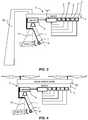
- Figs. 1 and 2are schematic diagrams of a basic wind measurement device shown generally as 2 having a bench 4 carrying a camera 6 which is generally directed downward and monitoring the position of a remote object 8 impacted by gravity and aerodynamic forces, generated by the wind and/or airflow ( Fig. 2 ).
- Object 8has a predefined aerodynamic shape, preferably a sphere, at least indirectly connected to the bench 4 by a low cross-section string 10 of predefined length.
- string 10is crossing the centerline 12 of the camera optics.
- the string 10 tensionis measured by the tension sensor 14, which may be located directly along the string 10, at the upper side or close to the object 6 (as shown in Fig. 1 ), or indirectly, elsewhere (not shown).
- the video signal of camera 6streams to a digital signal processor (hereinafter: "DSP") 16 or to a computer 18.
- DSP 16 or computer 18is connected to a temperature sensor 20 and a pressure sensor 22, both measuring the ambient air conditions.
- DSP 16 or computer 18is connected to a compass 24 and to GPS 26, in order to define the bench location and azimuth.
- the algorithm (not shown) running onboard the DSP 16 or computer 18has inputs of location from GPS 26, azimuth from compass 24, altitude and air pressure from pressure sensor 22, ambient temperature from temperature senor 20 and string 10 length.
- the algorithm 28decodes the images taken by the camera 6 and based on the string 10 length finds the location of the object 8, relative to the camera 6, and calculates the string 10 spatial angles.
- Tension sensor 14measures the tension of string 10, which is needed in order to balance the object 8 against the gravity and aerodynamic forces.
- the tension force vectorcan be represented by horizontal and vertical forces. These forces are calculated by the algorithm 28 based on length of the string 10 and the spatial angle, which are generated by the algorithm's 28 decoding of the camera 6 images. Now, knowing the weight of the object 8 and the length of the string 10, and spatial angles, the aerodynamic forces in the vertical and horizontal planes can be calculated. The vertical and horizontal aerodynamic forces are calculated based on the following inputs: (a) spatial angle of the string 10; (b) length of the string 10; (c) tension force in the string 10 measured by sensor 14; (d) weight of the object 8.
- the aerodynamic force vectoris the weighted result of both the horizontal and vertical forces.
- the aerodynamic force vectorcan be converted to a wind vector (airflow vector) based on look-up tables generated via the calibration of the device 2 measurements against the measurements of other high accuracy measurement technology or based on a mathematical model, or based on the merging of both.
- the centerline 12 of the camera opticsshould be perpendicular to the ground collinear with the gravity force vector (hereinafter: "first condition”).
- the spatial angle of the centerline 12 of the camera optics relative to the gravity force vectorshould be measured and the spatial angle of the string 10 should be corrected based on this measurement (hereinafter: "second condition").
- the first conditionmay be simply achieved by calibrating the centerline 12 of the camera optics to fit the gravity force vector.
- the second conditionmay be simply achieved by measuring the centerline of the camera optics relative to the gravity force vector by the sensor 34 (e.g. three axis gyro or any other suitable sensor based on any appropriate technology).
- Another option to allow operation of the device 2 while coupled to the aerial vehicle body 32is by stabilizing the centerline of the camera optics in order to meet the first condition. This can be done either by the existing stabilization capability of the aerial vehicle, as is shown in Fig. 4 , or by a stabilization system 36, as is shown in Fig. 5 . In this case, one side of the stabilization system 36 is coupled to the vehicle body 32, and the other side is coupled to the bench 4 of the device 2.
- the length of string 10 and the parameters of the object 8should be optimized. For example, large and powerful aerial vehicles will require a longer string 10 to minimize the aerial vehicle impact (e.g. propellers airflow, which can reduce the measurement accuracy) on the object 8 of device 2.
- aerial vehicle impacte.g. propellers airflow, which can reduce the measurement accuracy
- the device 2can be positioned directly in front of a wind turbine rotor 38, to enable comparison of the wind resource characteristics (predominantly, direction and speed) detected by the commonplace measurement instruments 40 mounted behind the wind turbine rotor 38 ( Fig. 6 ).
- the data received from the instruments 40are often biased due to their positioning behind the rotor 38 and the resulting influence of the rotor on the wind flow.
- the scale and mobile potential of the device 2 in the case at handwill enable periodic, sporadic, unmanned, on demand, external non-biased performance monitoring of wind turbines-capability, currently non-existent and very much required.
- the object 8is an anemometer of any known technology (e.g. cup anemometer 8a with wind vane 8b).
- object 8provides two types of measurements: first, based on the above-mentioned description; second, direct readings from anemometer 8a.
- the merge of two types of measurementsallows achieving higher level of accuracy and confidence.
- the direction of anemometer 8ais controlled by the wind vane 8b, and therefore can be monitored by the camera 6. This direction can be measured by the algorithm 28 and can be used as an additional, independent measurement.
Landscapes
- Engineering & Computer Science (AREA)
- Physics & Mathematics (AREA)
- General Physics & Mathematics (AREA)
- Computer Vision & Pattern Recognition (AREA)
- Theoretical Computer Science (AREA)
- Aviation & Aerospace Engineering (AREA)
- Life Sciences & Earth Sciences (AREA)
- Chemical & Material Sciences (AREA)
- Combustion & Propulsion (AREA)
- Mechanical Engineering (AREA)
- General Engineering & Computer Science (AREA)
- Sustainable Energy (AREA)
- Sustainable Development (AREA)
- Multimedia (AREA)
- Aerodynamic Tests, Hydrodynamic Tests, Wind Tunnels, And Water Tanks (AREA)
- Indicating Or Recording The Presence, Absence, Or Direction Of Movement (AREA)
Description
- The present invention relates to an accurate wind measurement device and method, and more particularly, to a device and method for accurate wind measurement onboard an aerial vehicle.
- It is a common practice to utilize aerial vehicles for measurement of various environmental parameters. Typical wind measurement devices onboard aerial vehicles, particularly helicopter or multi-rotors, are affected by the vehicle's body or propulsion systems, and therefore have a limited level of accuracy. Due to the high distribution and increasing utility of low-cost small and medium size aerial vehicles (UAVs), there are evident benefits to a compact, low-weight and accurate wind measurement device, capable of being carried by these type of vehicles. One of several possible applications is the external performance monitoring of wind-turbine power production. The ability to position the accurate wind measurement device according to the invention directly in front of wind turbine rotors enables wind resource characteristics (predominantly direction and speed) detected by the measurement instrumentation mounted on the wind turbines (the logged data of which are often biased due to the positioning of the instruments behind the rotor-blades) to be compared with the data taken by an external, unbiased device, mounted on an unmanned aerial vehicle. The device's better accuracy enables corrections to the alignment of the wind turbine nacelle towards the prevailing wind direction among other corrections, thereby optimizing power production. The scale, mobility and autonomous capabilities of unmanned aerial vehicles carrying the device enable scheduled, sporadic, unmanned and on-demand, external and unbiased power production performance monitoring of wind turbines. This enables constant monitoring and immediate or post flight corrections to the wind turbine alignment, all of which capabilities are currently non-existent and very much required.
WO 2013/111429 discloses a system wherein the apex of a wind receiving body consistently face windward. A thread is attached to a first attachment point of a conical wind receiving body having an apex, with the wind receiving body hanging by the thread, and a thread which supports a weight is attached to a second attachment point which is opposite the first attachment point in the vertical direction with respect to the center axis of the cone and nearer to the apex of the wind receiving body than the first attachment point. The weight is image captured from below with a camera, and wind speed and wind direction are derived from the distance and direction which the weight has moved from a reference location due to the wind.- Reference is also made to"Telltale wind indicator for the Mars Phoenix lander" by H. P. Gunnlaugsson et al. appearing in the Journal of Geophysical Research vol. 113 Issue E3, January 1, 2008. This paper discloses a telltale wind indicator in the form of a mechanical anemometer consisting of a lightweight cylinder suspended by Kevlar fibers and deflected under the action of wind.
- The present invention describes an accurate wind measurement device carried by an aerial vehicle.
- The wind measurement is based on the photographing of an object's behavior under the force of gravity and the aerodynamic force generated by the wind. The behavior of some predefined shapes (e.g. sphere) has been widely explored, and has a broad theoretical basis. Such behavior, once calibrated against other high accuracy measurement technologies, can provide a valid and accurate measurement.
- In accordance with the present invention provided herein are a device and method for accurate wind measurement, which are the subject matter of independent claims presented below.
- The device deploys an object that is carried by a low cross-section string. The deployment space of the object is continuously monitored by a camera, thus enabling measurement of the string's spatial angles relative to the axis of the camera's optics. The string length, defined as a distance between the object and the camera's sensor, allows calculating the accurate location of the object relative to the camera sensor. The object location measured by the camera based on the string length, is then converted into the aerodynamic forces (e.g. drag) vector generated by the wind. The string tension is continiousely measured in order to deduce the aerodynamic forces in the vertical and horizontal planes. The weighted result of the horizontal and vertical aerodynamic forces provides a well-defined wind speed spatial vector. The object can be of different aerodynamic shapes (e.g. sphere), or can be an anemometer of any known technology, to provide dual technology measurement.
- In order to understand the invention and to see how it may be carried out in practice, embodiments will now be described, by way of non-limiting example only, with reference to the accompanying drawings, in which:
Fig. 1 is a schematic diagram of a basic device according to an embodiment of the invention;Fig. 2 is a schematic diagram of a basic device according to an embodiment of the invention under the influence of gravity and aerodynamic forces;Fig. 3 is a schematic diagram of a basic device according to an embodiment of the invention, carried by a mast;Fig. 4 is a schematic diagram of a basic device according to an embodiment of the invention, carried by an aerial vehicle;Fig. 5 is a schematic diagram of a stabilized device according to an embodiment of the invention;Fig. 6 is a schematic diagram of a device carried by an aerial vehicle monitoring the wind resources in front of the rotor of a wind turbine, andFig. 7 is a schematic diagram of dual technology measurement device according to an embodiment of the invention, carried by an aerial vehicle.Figs. 1 and 2 are schematic diagrams of a basic wind measurement device shown generally as 2 having abench 4 carrying acamera 6 which is generally directed downward and monitoring the position of aremote object 8 impacted by gravity and aerodynamic forces, generated by the wind and/or airflow (Fig. 2 ).Object 8 has a predefined aerodynamic shape, preferably a sphere, at least indirectly connected to thebench 4 by alow cross-section string 10 of predefined length. At the upper side,string 10 is crossing thecenterline 12 of the camera optics. Thestring 10 tension is measured by thetension sensor 14, which may be located directly along thestring 10, at the upper side or close to the object 6 (as shown inFig. 1 ), or indirectly, elsewhere (not shown). The video signal ofcamera 6 streams to a digital signal processor (hereinafter: "DSP") 16 or to a computer 18. DSP 16 or computer 18 is connected to atemperature sensor 20 and apressure sensor 22, both measuring the ambient air conditions. In addition, DSP 16 or computer 18 is connected to acompass 24 and toGPS 26, in order to define the bench location and azimuth. The algorithm (not shown) running onboard the DSP 16 or computer 18 has inputs of location fromGPS 26, azimuth fromcompass 24, altitude and air pressure frompressure sensor 22, ambient temperature fromtemperature senor 20 andstring 10 length. The algorithm 28 decodes the images taken by thecamera 6 and based on thestring 10 length finds the location of theobject 8, relative to thecamera 6, and calculates thestring 10 spatial angles.Tension sensor 14 measures the tension ofstring 10, which is needed in order to balance theobject 8 against the gravity and aerodynamic forces. The tension force vector can be represented by horizontal and vertical forces. These forces are calculated by the algorithm 28 based on length of thestring 10 and the spatial angle, which are generated by the algorithm's 28 decoding of thecamera 6 images. Now, knowing the weight of theobject 8 and the length of thestring 10, and spatial angles, the aerodynamic forces in the vertical and horizontal planes can be calculated. The vertical and horizontal aerodynamic forces are calculated based on the following inputs: (a) spatial angle of thestring 10; (b) length of thestring 10; (c) tension force in thestring 10 measured bysensor 14; (d) weight of theobject 8. The aerodynamic force vector is the weighted result of both the horizontal and vertical forces. The aerodynamic force vector can be converted to a wind vector (airflow vector) based on look-up tables generated via the calibration of thedevice 2 measurements against the measurements of other high accuracy measurement technology or based on a mathematical model, or based on the merging of both. To achieve accurate measurements based on the abovementioned description, thecenterline 12 of the camera optics should be perpendicular to the ground collinear with the gravity force vector (hereinafter: "first condition"). Alternatively, the spatial angle of thecenterline 12 of the camera optics relative to the gravity force vector should be measured and the spatial angle of thestring 10 should be corrected based on this measurement (hereinafter: "second condition"). Wheneverdevice 2 is static and coupled for example, to the top of mast 30 (Fig. 3 ), the first condition may be simply achieved by calibrating thecenterline 12 of the camera optics to fit the gravity force vector. Wheneverdevice 2 is mobile and coupled for example, to an aerial vehicle body 32 (Fig. 4 ), the second condition may be simply achieved by measuring the centerline of the camera optics relative to the gravity force vector by the sensor 34 (e.g. three axis gyro or any other suitable sensor based on any appropriate technology). Another option to allow operation of thedevice 2 while coupled to theaerial vehicle body 32 is by stabilizing the centerline of the camera optics in order to meet the first condition. This can be done either by the existing stabilization capability of the aerial vehicle, as is shown inFig. 4 , or by astabilization system 36, as is shown inFig. 5 . In this case, one side of thestabilization system 36 is coupled to thevehicle body 32, and the other side is coupled to thebench 4 of thedevice 2.- To fit the aerial vehicle characteristics, the length of
string 10 and the parameters of theobject 8 should be optimized. For example, large and powerful aerial vehicles will require alonger string 10 to minimize the aerial vehicle impact (e.g. propellers airflow, which can reduce the measurement accuracy) on theobject 8 ofdevice 2. - To monitor the power production performance of a wind turbine generator, the
device 2 can be positioned directly in front of a wind turbine rotor 38, to enable comparison of the wind resource characteristics (predominantly, direction and speed) detected by the commonplace measurement instruments 40 mounted behind the wind turbine rotor 38 (Fig. 6 ). The data received from the instruments 40 are often biased due to their positioning behind the rotor 38 and the resulting influence of the rotor on the wind flow. By comparing the instruments 40 detected data against the data accumulated by thedevice 2 coupled to thevehicle body 32, the alignment of the rotor 38 towards the prevailing wind direction can be corrected, thus enabling optimal power production. - The scale and mobile potential of the
device 2 in the case at hand, will enable periodic, sporadic, unmanned, on demand, external non-biased performance monitoring of wind turbines-capability, currently non-existent and very much required. - Whenever higher level of accuracy and confidence is required, dual technology measurement can be implemented based on the above-mentioned device and method. In
device 2, shown inFig. 7 , theobject 8 is an anemometer of any known technology (e.g. cup anemometer 8a with wind vane 8b). In this case,object 8 provides two types of measurements: first, based on the above-mentioned description; second, direct readings from anemometer 8a. The merge of two types of measurements allows achieving higher level of accuracy and confidence. The direction of anemometer 8a is controlled by the wind vane 8b, and therefore can be monitored by thecamera 6. This direction can be measured by the algorithm 28 and can be used as an additional, independent measurement. - It should be noted that features that are described with reference to one or more embodiments are described by way of example rather than by way of limitation to those embodiments.
Claims (9)
- A device (2) for accurate wind measurement, the device comprising:a bench (4) carrying a camera having camera optics;a moving object (8a,8b) connected to said camera by a string (10); anda digital signal processor (DSP) (16) or a computer (18);characterized by:said camera being generally directed downward and taking images of said object's movement while influenced by gravity and aerodynamic forces;said camera being configured to stream the images to a digital signal processor or computer, andsaid digital signal processor or computer being adapted to decode the images and compute the object location and spatial angles.
- The device as claimed in claim 1, wherein an upper side of said string crosses the centerline of the camera optics.
- The device as claimed in claim 1 or 2, wherein: a predetermined length of the string provides a first input to the DSP or computer; a predetermined weight of the object provides a second input to the DSP or computer; the string is at least indirectly connected to a tension sensor (14) and the tension sensor provides to the DSP or computer a third input of tension force along said string needed to balance the object against the gravity and aerodynamic forces; at least one sensor (20, 22, 24, 26) is coupled to the DSP or computer for providing a fourth input indicative of at least one physical condition, and the DSP or computer is responsive to camera images depicting movement of the moving object for decoding said images based on said first input so as calculate the spatial location of the object relative to the bench, and the DSP or computer is configured to calculate aerodynamic force based on said location in conjunction with the second, third and fourth inputs..
- The device as claimed in claim 3, wherein the at least one sensor is any one or more in a group consisting of a temperature sensor (20), a pressure sensor (22), a compass (24) and a GPS (26).
- The device as claimed in any one of the preceding claims, wherein said DSP or computer is configured to calculate from the camera images the spatial angle between a centerline of the camera optics and the string vector.
- The device as claimed in any one of the preceding claims, wherein the moving object is an anemometer (8a) whose direction is controlled by a wind vane (8b) and which is monitored by the camera, and wherein the DSP or computer is configured to receive additional wind speed and direction measurements from the anemometer (8a) used by the DSP or computer to improve accuracy..
- A method for accurate wind measurement, the method comprising:coupling the device of claim 1 to an aerial vehicle;obtaining a first input of string length;obtaining a second input of object weight;obtaining a third input of tension force along said string needed to balance the object against the gravity and aerodynamic forces;obtaining a fourth input from a sensor measuring at least one physical condition;obtaining camera images depciting movement of the aerial vehicle and decoding said images based on said first input so as calculate the location of the object relative to spatial angles of the string that connects the object to the camera, andcalculating aerodynamic force based on said location in conjunction with the second, third and fourth inputs.
- The method as claimed in claim 7, wherein said fourth input is any one of: (i) a location from a GPS sensor (26), (ii) an azimuth from a compass, (24) (iii) an altitude and air pressure from a pressure sensor (22), (iv) an ambient temperature from a temperature senor (20), (v) a spatial angle between the camera optics centerline and the gravity force vector.
- A method of monitoring power production performance of a wind turbine, the method comprising;positioning the device according to claim 1 in front of a rotor of said wind turbine;measuring wind properties using the device in order to obtain first wind measurements;comparing said first wind measurements with second wind measurements detected by conventional wind turbine wind measurement instruments;determining wind turbine wind measurement bias based on differences between the first wind measurements and the second wind measurements; andapplying the wind properties measured by the device to a respective wind turbine power curve for said turbine in order to calculate power production loss due to wind turbine wind measurement bias.
Applications Claiming Priority (2)
| Application Number | Priority Date | Filing Date | Title |
|---|---|---|---|
| IL244503AIL244503B (en) | 2016-03-09 | 2016-03-09 | Device and method for accurate wind measurement |
| PCT/IL2017/050282WO2017153987A1 (en) | 2016-03-09 | 2017-03-08 | Device and method for accurate wind measurement |
Publications (3)
| Publication Number | Publication Date |
|---|---|
| EP3427067A1 EP3427067A1 (en) | 2019-01-16 |
| EP3427067A4 EP3427067A4 (en) | 2019-04-24 |
| EP3427067B1true EP3427067B1 (en) | 2020-05-13 |
Family
ID=57300932
Family Applications (1)
| Application Number | Title | Priority Date | Filing Date |
|---|---|---|---|
| EP17762638.9AActiveEP3427067B1 (en) | 2016-03-09 | 2017-03-08 | Device and method for accurate wind measurement |
Country Status (4)
| Country | Link |
|---|---|
| US (1) | US10739369B2 (en) |
| EP (1) | EP3427067B1 (en) |
| IL (1) | IL244503B (en) |
| WO (1) | WO2017153987A1 (en) |
Families Citing this family (3)
| Publication number | Priority date | Publication date | Assignee | Title |
|---|---|---|---|---|
| IL260035B (en)* | 2018-06-14 | 2019-07-31 | Ventus Product Dev & Consulting Ltd | Anemometer |
| JP6803036B1 (en)* | 2020-08-26 | 2020-12-23 | 株式会社エクサウィザーズ | Information processing methods, information processing devices, information processing systems, and programs |
| US12164308B2 (en)* | 2022-07-15 | 2024-12-10 | Wing Aviation Llc | Tether-based wind estimation |
Family Cites Families (9)
| Publication number | Priority date | Publication date | Assignee | Title |
|---|---|---|---|---|
| US4058010A (en) | 1976-04-06 | 1977-11-15 | Approach Fish | Airport wind shear monitoring method and apparatus |
| US4449400A (en)* | 1982-11-24 | 1984-05-22 | The United States Of America As Represented By The Administrator Of The National Aeronautics And Space Administration | Radionuculide counting technique for measuring wind velocity and direction |
| JPS59136658A (en) | 1983-01-25 | 1984-08-06 | Matsushita Electric Ind Co Ltd | Wind vane and anemometer |
| DE8814788U1 (en) | 1988-11-28 | 1989-01-12 | Wachtendorf, Matthias, 7500 Karlsruhe | Wind speed meter |
| JP4005056B2 (en)* | 2004-06-01 | 2007-11-07 | 飛島建設株式会社 | Groundwater flow measurement device |
| US10354407B2 (en)* | 2013-03-15 | 2019-07-16 | Spatial Cam Llc | Camera for locating hidden objects |
| WO2013111429A1 (en) | 2012-01-24 | 2013-08-01 | 村田機械株式会社 | Wind direction and wind speed measurement device |
| US20140163884A1 (en)* | 2012-12-10 | 2014-06-12 | Universite De Liege | Method and system for the determination of wind speeds and incident radiation parameters of overhead power lines |
| US10475239B1 (en)* | 2015-04-14 | 2019-11-12 | ETAK Systems, LLC | Systems and methods for obtaining accurate 3D modeling data with a multiple camera apparatus |
- 2016
- 2016-03-09ILIL244503Apatent/IL244503B/enactiveIP Right Grant
- 2017
- 2017-03-08EPEP17762638.9Apatent/EP3427067B1/enactiveActive
- 2017-03-08WOPCT/IL2017/050282patent/WO2017153987A1/ennot_activeCeased
- 2017-03-08USUS16/083,257patent/US10739369B2/enactiveActive
Non-Patent Citations (1)
| Title |
|---|
| None* |
Also Published As
| Publication number | Publication date |
|---|---|
| EP3427067A1 (en) | 2019-01-16 |
| IL244503A0 (en) | 2016-07-31 |
| US10739369B2 (en) | 2020-08-11 |
| WO2017153987A1 (en) | 2017-09-14 |
| US20190094255A1 (en) | 2019-03-28 |
| EP3427067A4 (en) | 2019-04-24 |
| IL244503B (en) | 2019-12-31 |
Similar Documents
| Publication | Publication Date | Title |
|---|---|---|
| US11506175B2 (en) | Wind-turbine tower to blade-tip measuring system | |
| US7841563B2 (en) | Ducted fan air data system | |
| US8235662B2 (en) | Wind turbine metrology system | |
| US8718971B2 (en) | System for determining the airspeed of an aircraft | |
| EP3427067B1 (en) | Device and method for accurate wind measurement | |
| Donnell et al. | Wind characterization using onboard IMU of sUAS | |
| US20120298801A1 (en) | Aircraft wing and sensor | |
| KR101844727B1 (en) | System for estimating wind information using rotor type unmanned areial vehicle | |
| US9815565B1 (en) | Tracker and vibration analysis system | |
| CN106772694A (en) | A kind of turbulence intensity vertical distribution measurement and turbulent flow profile Radar Calibration method | |
| US20200264209A1 (en) | System and method for determining wind direction and velocity measurement from altitude for an unmanned aerial vehicle | |
| Thorpe et al. | Measurement of unsteady gusts in an urban wind field using a uav-based anemometer | |
| US20180072405A1 (en) | Tracker and vibration analysis system having uv sensitivity | |
| RU2426995C1 (en) | System to measure helicopter flight low speeds | |
| KR20180049478A (en) | System and method for measuring vertical distribution of wind direction and speed using unmanned plane | |
| Doddi | Insitu Sensing and Analysis of Turbulence-Investigation to Enhance Fine-Structure Turbulence Observation Capabilities of Autonomous Aircraft Systems | |
| CN113092813A (en) | System and method for detecting self-adaptive wind speed and wind direction under parachute landing situation | |
| KR101746437B1 (en) | Two-dimensional vane using bimorphs | |
| Bordogna et al. | MUSCAT experiment: Active free falling units for in situ measurements of temperature and density in the middle atmosphere | |
| US10884015B2 (en) | Multidirectional airspeed detection system | |
| KR20210058065A (en) | Environmental observation device using drone | |
| Saputra et al. | Analysis of Wind Direction using Speed on Three Vertical Propellers | |
| JPS601419Y2 (en) | Shape of true airspeed sensor | |
| Sickenberger et al. | An optics-based tip-path plane tracking system for rotorcraft applications | |
| Mangold | XIII. Instrumentation for High-Altitude Tethered Ballooning |
Legal Events
| Date | Code | Title | Description |
|---|---|---|---|
| STAA | Information on the status of an ep patent application or granted ep patent | Free format text:STATUS: THE INTERNATIONAL PUBLICATION HAS BEEN MADE | |
| PUAI | Public reference made under article 153(3) epc to a published international application that has entered the european phase | Free format text:ORIGINAL CODE: 0009012 | |
| STAA | Information on the status of an ep patent application or granted ep patent | Free format text:STATUS: REQUEST FOR EXAMINATION WAS MADE | |
| 17P | Request for examination filed | Effective date:20180919 | |
| AK | Designated contracting states | Kind code of ref document:A1 Designated state(s):AL AT BE BG CH CY CZ DE DK EE ES FI FR GB GR HR HU IE IS IT LI LT LU LV MC MK MT NL NO PL PT RO RS SE SI SK SM TR | |
| AX | Request for extension of the european patent | Extension state:BA ME | |
| A4 | Supplementary search report drawn up and despatched | Effective date:20190321 | |
| RIC1 | Information provided on ipc code assigned before grant | Ipc:G01P 5/02 20060101ALI20190315BHEP Ipc:G01P 5/00 20060101AFI20190315BHEP | |
| DAV | Request for validation of the european patent (deleted) | ||
| DAX | Request for extension of the european patent (deleted) | ||
| GRAP | Despatch of communication of intention to grant a patent | Free format text:ORIGINAL CODE: EPIDOSNIGR1 | |
| STAA | Information on the status of an ep patent application or granted ep patent | Free format text:STATUS: GRANT OF PATENT IS INTENDED | |
| INTG | Intention to grant announced | Effective date:20200103 | |
| GRAS | Grant fee paid | Free format text:ORIGINAL CODE: EPIDOSNIGR3 | |
| GRAA | (expected) grant | Free format text:ORIGINAL CODE: 0009210 | |
| STAA | Information on the status of an ep patent application or granted ep patent | Free format text:STATUS: THE PATENT HAS BEEN GRANTED | |
| AK | Designated contracting states | Kind code of ref document:B1 Designated state(s):AL AT BE BG CH CY CZ DE DK EE ES FI FR GB GR HR HU IE IS IT LI LT LU LV MC MK MT NL NO PL PT RO RS SE SI SK SM TR | |
| REG | Reference to a national code | Ref country code:GB Ref legal event code:FG4D | |
| REG | Reference to a national code | Ref country code:CH Ref legal event code:EP | |
| REG | Reference to a national code | Ref country code:DE Ref legal event code:R096 Ref document number:602017016736 Country of ref document:DE | |
| REG | Reference to a national code | Ref country code:AT Ref legal event code:REF Ref document number:1270969 Country of ref document:AT Kind code of ref document:T Effective date:20200615 | |
| REG | Reference to a national code | Ref country code:LT Ref legal event code:MG4D | |
| REG | Reference to a national code | Ref country code:NL Ref legal event code:MP Effective date:20200513 | |
| PG25 | Lapsed in a contracting state [announced via postgrant information from national office to epo] | Ref country code:PT Free format text:LAPSE BECAUSE OF FAILURE TO SUBMIT A TRANSLATION OF THE DESCRIPTION OR TO PAY THE FEE WITHIN THE PRESCRIBED TIME-LIMIT Effective date:20200914 Ref country code:IS Free format text:LAPSE BECAUSE OF FAILURE TO SUBMIT A TRANSLATION OF THE DESCRIPTION OR TO PAY THE FEE WITHIN THE PRESCRIBED TIME-LIMIT Effective date:20200913 Ref country code:FI Free format text:LAPSE BECAUSE OF FAILURE TO SUBMIT A TRANSLATION OF THE DESCRIPTION OR TO PAY THE FEE WITHIN THE PRESCRIBED TIME-LIMIT Effective date:20200513 Ref country code:GR Free format text:LAPSE BECAUSE OF FAILURE TO SUBMIT A TRANSLATION OF THE DESCRIPTION OR TO PAY THE FEE WITHIN THE PRESCRIBED TIME-LIMIT Effective date:20200814 Ref country code:NO Free format text:LAPSE BECAUSE OF FAILURE TO SUBMIT A TRANSLATION OF THE DESCRIPTION OR TO PAY THE FEE WITHIN THE PRESCRIBED TIME-LIMIT Effective date:20200813 Ref country code:SE Free format text:LAPSE BECAUSE OF FAILURE TO SUBMIT A TRANSLATION OF THE DESCRIPTION OR TO PAY THE FEE WITHIN THE PRESCRIBED TIME-LIMIT Effective date:20200513 Ref country code:LT Free format text:LAPSE BECAUSE OF FAILURE TO SUBMIT A TRANSLATION OF THE DESCRIPTION OR TO PAY THE FEE WITHIN THE PRESCRIBED TIME-LIMIT Effective date:20200513 | |
| PG25 | Lapsed in a contracting state [announced via postgrant information from national office to epo] | Ref country code:BG Free format text:LAPSE BECAUSE OF FAILURE TO SUBMIT A TRANSLATION OF THE DESCRIPTION OR TO PAY THE FEE WITHIN THE PRESCRIBED TIME-LIMIT Effective date:20200813 Ref country code:HR Free format text:LAPSE BECAUSE OF FAILURE TO SUBMIT A TRANSLATION OF THE DESCRIPTION OR TO PAY THE FEE WITHIN THE PRESCRIBED TIME-LIMIT Effective date:20200513 Ref country code:LV Free format text:LAPSE BECAUSE OF FAILURE TO SUBMIT A TRANSLATION OF THE DESCRIPTION OR TO PAY THE FEE WITHIN THE PRESCRIBED TIME-LIMIT Effective date:20200513 Ref country code:RS Free format text:LAPSE BECAUSE OF FAILURE TO SUBMIT A TRANSLATION OF THE DESCRIPTION OR TO PAY THE FEE WITHIN THE PRESCRIBED TIME-LIMIT Effective date:20200513 | |
| REG | Reference to a national code | Ref country code:AT Ref legal event code:MK05 Ref document number:1270969 Country of ref document:AT Kind code of ref document:T Effective date:20200513 | |
| PG25 | Lapsed in a contracting state [announced via postgrant information from national office to epo] | Ref country code:NL Free format text:LAPSE BECAUSE OF FAILURE TO SUBMIT A TRANSLATION OF THE DESCRIPTION OR TO PAY THE FEE WITHIN THE PRESCRIBED TIME-LIMIT Effective date:20200513 Ref country code:AL Free format text:LAPSE BECAUSE OF FAILURE TO SUBMIT A TRANSLATION OF THE DESCRIPTION OR TO PAY THE FEE WITHIN THE PRESCRIBED TIME-LIMIT Effective date:20200513 | |
| PG25 | Lapsed in a contracting state [announced via postgrant information from national office to epo] | Ref country code:AT Free format text:LAPSE BECAUSE OF FAILURE TO SUBMIT A TRANSLATION OF THE DESCRIPTION OR TO PAY THE FEE WITHIN THE PRESCRIBED TIME-LIMIT Effective date:20200513 Ref country code:ES Free format text:LAPSE BECAUSE OF FAILURE TO SUBMIT A TRANSLATION OF THE DESCRIPTION OR TO PAY THE FEE WITHIN THE PRESCRIBED TIME-LIMIT Effective date:20200513 Ref country code:DK Free format text:LAPSE BECAUSE OF FAILURE TO SUBMIT A TRANSLATION OF THE DESCRIPTION OR TO PAY THE FEE WITHIN THE PRESCRIBED TIME-LIMIT Effective date:20200513 Ref country code:RO Free format text:LAPSE BECAUSE OF FAILURE TO SUBMIT A TRANSLATION OF THE DESCRIPTION OR TO PAY THE FEE WITHIN THE PRESCRIBED TIME-LIMIT Effective date:20200513 Ref country code:IT Free format text:LAPSE BECAUSE OF FAILURE TO SUBMIT A TRANSLATION OF THE DESCRIPTION OR TO PAY THE FEE WITHIN THE PRESCRIBED TIME-LIMIT Effective date:20200513 Ref country code:SM Free format text:LAPSE BECAUSE OF FAILURE TO SUBMIT A TRANSLATION OF THE DESCRIPTION OR TO PAY THE FEE WITHIN THE PRESCRIBED TIME-LIMIT Effective date:20200513 Ref country code:EE Free format text:LAPSE BECAUSE OF FAILURE TO SUBMIT A TRANSLATION OF THE DESCRIPTION OR TO PAY THE FEE WITHIN THE PRESCRIBED TIME-LIMIT Effective date:20200513 Ref country code:CZ Free format text:LAPSE BECAUSE OF FAILURE TO SUBMIT A TRANSLATION OF THE DESCRIPTION OR TO PAY THE FEE WITHIN THE PRESCRIBED TIME-LIMIT Effective date:20200513 | |
| REG | Reference to a national code | Ref country code:DE Ref legal event code:R097 Ref document number:602017016736 Country of ref document:DE | |
| PG25 | Lapsed in a contracting state [announced via postgrant information from national office to epo] | Ref country code:PL Free format text:LAPSE BECAUSE OF FAILURE TO SUBMIT A TRANSLATION OF THE DESCRIPTION OR TO PAY THE FEE WITHIN THE PRESCRIBED TIME-LIMIT Effective date:20200513 Ref country code:SK Free format text:LAPSE BECAUSE OF FAILURE TO SUBMIT A TRANSLATION OF THE DESCRIPTION OR TO PAY THE FEE WITHIN THE PRESCRIBED TIME-LIMIT Effective date:20200513 | |
| PLBE | No opposition filed within time limit | Free format text:ORIGINAL CODE: 0009261 | |
| STAA | Information on the status of an ep patent application or granted ep patent | Free format text:STATUS: NO OPPOSITION FILED WITHIN TIME LIMIT | |
| 26N | No opposition filed | Effective date:20210216 | |
| PG25 | Lapsed in a contracting state [announced via postgrant information from national office to epo] | Ref country code:SI Free format text:LAPSE BECAUSE OF FAILURE TO SUBMIT A TRANSLATION OF THE DESCRIPTION OR TO PAY THE FEE WITHIN THE PRESCRIBED TIME-LIMIT Effective date:20200513 | |
| PG25 | Lapsed in a contracting state [announced via postgrant information from national office to epo] | Ref country code:MC Free format text:LAPSE BECAUSE OF FAILURE TO SUBMIT A TRANSLATION OF THE DESCRIPTION OR TO PAY THE FEE WITHIN THE PRESCRIBED TIME-LIMIT Effective date:20200513 | |
| REG | Reference to a national code | Ref country code:CH Ref legal event code:PL | |
| REG | Reference to a national code | Ref country code:BE Ref legal event code:MM Effective date:20210331 | |
| PG25 | Lapsed in a contracting state [announced via postgrant information from national office to epo] | Ref country code:LU Free format text:LAPSE BECAUSE OF NON-PAYMENT OF DUE FEES Effective date:20210308 Ref country code:LI Free format text:LAPSE BECAUSE OF NON-PAYMENT OF DUE FEES Effective date:20210331 Ref country code:CH Free format text:LAPSE BECAUSE OF NON-PAYMENT OF DUE FEES Effective date:20210331 Ref country code:IE Free format text:LAPSE BECAUSE OF NON-PAYMENT OF DUE FEES Effective date:20210308 | |
| PG25 | Lapsed in a contracting state [announced via postgrant information from national office to epo] | Ref country code:BE Free format text:LAPSE BECAUSE OF NON-PAYMENT OF DUE FEES Effective date:20210331 | |
| PG25 | Lapsed in a contracting state [announced via postgrant information from national office to epo] | Ref country code:CY Free format text:LAPSE BECAUSE OF FAILURE TO SUBMIT A TRANSLATION OF THE DESCRIPTION OR TO PAY THE FEE WITHIN THE PRESCRIBED TIME-LIMIT Effective date:20200513 | |
| PG25 | Lapsed in a contracting state [announced via postgrant information from national office to epo] | Ref country code:HU Free format text:LAPSE BECAUSE OF FAILURE TO SUBMIT A TRANSLATION OF THE DESCRIPTION OR TO PAY THE FEE WITHIN THE PRESCRIBED TIME-LIMIT; INVALID AB INITIO Effective date:20170308 | |
| PG25 | Lapsed in a contracting state [announced via postgrant information from national office to epo] | Ref country code:MK Free format text:LAPSE BECAUSE OF FAILURE TO SUBMIT A TRANSLATION OF THE DESCRIPTION OR TO PAY THE FEE WITHIN THE PRESCRIBED TIME-LIMIT Effective date:20200513 | |
| PG25 | Lapsed in a contracting state [announced via postgrant information from national office to epo] | Ref country code:MT Free format text:LAPSE BECAUSE OF FAILURE TO SUBMIT A TRANSLATION OF THE DESCRIPTION OR TO PAY THE FEE WITHIN THE PRESCRIBED TIME-LIMIT Effective date:20200513 | |
| PGFP | Annual fee paid to national office [announced via postgrant information from national office to epo] | Ref country code:FR Payment date:20241230 Year of fee payment:9 | |
| PGFP | Annual fee paid to national office [announced via postgrant information from national office to epo] | Ref country code:DE Payment date:20241219 Year of fee payment:9 | |
| PGFP | Annual fee paid to national office [announced via postgrant information from national office to epo] | Ref country code:GB Payment date:20250123 Year of fee payment:9 |