EP3426086B1 - Footwear arch support - Google Patents
Footwear arch supportDownload PDFInfo
- Publication number
- EP3426086B1 EP3426086B1EP17711531.8AEP17711531AEP3426086B1EP 3426086 B1EP3426086 B1EP 3426086B1EP 17711531 AEP17711531 AEP 17711531AEP 3426086 B1EP3426086 B1EP 3426086B1
- Authority
- EP
- European Patent Office
- Prior art keywords
- arch
- plate
- base plate
- arch support
- sock liner
- Prior art date
- Legal status (The legal status is an assumption and is not a legal conclusion. Google has not performed a legal analysis and makes no representation as to the accuracy of the status listed.)
- Active
Links
- 238000000926separation methodMethods0.000claimsdescription13
- 238000000034methodMethods0.000claimsdescription11
- 239000011800void materialSubstances0.000claimsdescription6
- 2380000101463D printingMethods0.000claimsdescription5
- 238000000149argon plasma sinteringMethods0.000claimsdescription5
- 239000012530fluidSubstances0.000claimsdescription3
- 230000002093peripheral effectEffects0.000claimsdescription3
- 239000006260foamSubstances0.000claimsdescription2
- 229920000642polymerPolymers0.000claims1
- 210000002683footAnatomy0.000description43
- 239000000463materialSubstances0.000description12
- 210000000474heelAnatomy0.000description7
- 230000002045lasting effectEffects0.000description5
- 210000000452mid-footAnatomy0.000description5
- 238000010276constructionMethods0.000description4
- 210000004744fore-footAnatomy0.000description4
- 238000004519manufacturing processMethods0.000description4
- 230000000694effectsEffects0.000description3
- 210000003127kneeAnatomy0.000description3
- 210000001872metatarsal boneAnatomy0.000description3
- 210000003371toeAnatomy0.000description3
- 208000007353Hip OsteoarthritisDiseases0.000description2
- 208000003947Knee OsteoarthritisDiseases0.000description2
- 239000004952PolyamideSubstances0.000description2
- 239000004433Thermoplastic polyurethaneSubstances0.000description2
- 230000006978adaptationEffects0.000description2
- 239000000654additiveSubstances0.000description2
- 230000000996additive effectEffects0.000description2
- 239000000853adhesiveSubstances0.000description2
- 230000001070adhesive effectEffects0.000description2
- 210000003484anatomyAnatomy0.000description2
- 210000003423ankleAnatomy0.000description2
- 230000005021gaitEffects0.000description2
- 210000003205muscleAnatomy0.000description2
- 201000008482osteoarthritisDiseases0.000description2
- 229920002803thermoplastic polyurethanePolymers0.000description2
- 230000007704transitionEffects0.000description2
- 238000003466weldingMethods0.000description2
- 206010024453Ligament sprainDiseases0.000description1
- 206010073713Musculoskeletal injuryDiseases0.000description1
- 239000004677NylonSubstances0.000description1
- 241000469816VarusSpecies0.000description1
- 208000027418Wounds and injuryDiseases0.000description1
- 239000004676acrylonitrile butadiene styreneSubstances0.000description1
- 210000000544articulatio talocruralisAnatomy0.000description1
- 210000000459calcaneusAnatomy0.000description1
- 230000006835compressionEffects0.000description1
- 238000007906compressionMethods0.000description1
- 230000006378damageEffects0.000description1
- 230000001419dependent effectEffects0.000description1
- 239000003822epoxy resinSubstances0.000description1
- 239000006261foam materialSubstances0.000description1
- 239000011521glassSubstances0.000description1
- LNEPOXFFQSENCJ-UHFFFAOYSA-NhaloperidolChemical compoundC1CC(O)(C=2C=CC(Cl)=CC=2)CCN1CCCC(=O)C1=CC=C(F)C=C1LNEPOXFFQSENCJ-UHFFFAOYSA-N0.000description1
- 238000001746injection mouldingMethods0.000description1
- 208000014674injuryDiseases0.000description1
- 210000000859intermediate cuneiformAnatomy0.000description1
- 210000000113medial cuneiformAnatomy0.000description1
- 238000000465mouldingMethods0.000description1
- 229920001778nylonPolymers0.000description1
- 229920002647polyamidePolymers0.000description1
- 229920006122polyamide resinPolymers0.000description1
- 229920000647polyepoxidePolymers0.000description1
- 239000004626polylactic acidSubstances0.000description1
- 239000004814polyurethaneSubstances0.000description1
- 230000000284resting effectEffects0.000description1
- 238000004904shorteningMethods0.000description1
- 210000004233talusAnatomy0.000description1
Images


Classifications
- A—HUMAN NECESSITIES
- A43—FOOTWEAR
- A43B—CHARACTERISTIC FEATURES OF FOOTWEAR; PARTS OF FOOTWEAR
- A43B7/00—Footwear with health or hygienic arrangements
- A43B7/14—Footwear with health or hygienic arrangements with foot-supporting parts
- A43B7/1405—Footwear with health or hygienic arrangements with foot-supporting parts with pads or holes on one or more locations, or having an anatomical or curved form
- A43B7/1415—Footwear with health or hygienic arrangements with foot-supporting parts with pads or holes on one or more locations, or having an anatomical or curved form characterised by the location under the foot
- A43B7/142—Footwear with health or hygienic arrangements with foot-supporting parts with pads or holes on one or more locations, or having an anatomical or curved form characterised by the location under the foot situated under the medial arch, i.e. under the navicular or cuneiform bones
- A—HUMAN NECESSITIES
- A43—FOOTWEAR
- A43B—CHARACTERISTIC FEATURES OF FOOTWEAR; PARTS OF FOOTWEAR
- A43B17/00—Insoles for insertion, e.g. footbeds or inlays, for attachment to the shoe after the upper has been joined
- A43B17/003—Insoles for insertion, e.g. footbeds or inlays, for attachment to the shoe after the upper has been joined characterised by the material
- A43B17/006—Insoles for insertion, e.g. footbeds or inlays, for attachment to the shoe after the upper has been joined characterised by the material multilayered
- A—HUMAN NECESSITIES
- A43—FOOTWEAR
- A43B—CHARACTERISTIC FEATURES OF FOOTWEAR; PARTS OF FOOTWEAR
- A43B7/00—Footwear with health or hygienic arrangements
- A43B7/14—Footwear with health or hygienic arrangements with foot-supporting parts
- A43B7/1405—Footwear with health or hygienic arrangements with foot-supporting parts with pads or holes on one or more locations, or having an anatomical or curved form
- A43B7/141—Footwear with health or hygienic arrangements with foot-supporting parts with pads or holes on one or more locations, or having an anatomical or curved form having an anatomical or curved form
- A—HUMAN NECESSITIES
- A43—FOOTWEAR
- A43B—CHARACTERISTIC FEATURES OF FOOTWEAR; PARTS OF FOOTWEAR
- A43B7/00—Footwear with health or hygienic arrangements
- A43B7/14—Footwear with health or hygienic arrangements with foot-supporting parts
- A43B7/1405—Footwear with health or hygienic arrangements with foot-supporting parts with pads or holes on one or more locations, or having an anatomical or curved form
- A43B7/1475—Footwear with health or hygienic arrangements with foot-supporting parts with pads or holes on one or more locations, or having an anatomical or curved form characterised by the type of support
- A43B7/149—Pads, e.g. protruding on the foot-facing surface
- B—PERFORMING OPERATIONS; TRANSPORTING
- B33—ADDITIVE MANUFACTURING TECHNOLOGY
- B33Y—ADDITIVE MANUFACTURING, i.e. MANUFACTURING OF THREE-DIMENSIONAL [3-D] OBJECTS BY ADDITIVE DEPOSITION, ADDITIVE AGGLOMERATION OR ADDITIVE LAYERING, e.g. BY 3-D PRINTING, STEREOLITHOGRAPHY OR SELECTIVE LASER SINTERING
- B33Y80/00—Products made by additive manufacturing
Definitions
- Conventional articles of footweargenerally include an upper and a sole structure.
- the upperprovides a covering for the foot and securely positions the foot relative to the sole structure.
- the sole structureis secured to the upper and is configured so as to be positioned between the foot and the ground when a wearer is standing, walking or running.
- individual shoes conforming to that designmay be available in a wide range of sizes to accommodate different sizes of intended wearers' feet.
- many footwear designsinclude laces, straps, or other elements that allow some degree of adjustment for an individual wearer.
- Orthotics and other insertsare sometimes used to further customize the fit of a shoe for a particular wearer's foot and/or to provide additional support.
- One foot region that frequently requires additional supportis the arch, and various types of arch supports have been developed.
- economically creating durable arch supports and incorporating such supports into shoesremains a challenge.
- the shoe constructionincludes a cantilevered foot support with an anchored lateral side and a fully or partially cantilevered medial side.
- the cantilevered foot supporttransfers forces, otherwise transmitted through the medial aspect of the shoe and foot, to the lateral side of the shoe and foot, thereby reducing the knee varus and hip adductor torques to prevent or delay onset of knee and hip osteoarthritis and reducing the ankle joint adductor torque to reduce the risk for ankle sprain injury.
- the reduction of these joint torquesalso maintains posture without counterbalancing muscle activity, thereby improving muscle efficiency and performance during weight bearing activities and reducing the tendency for musculoskeletal injury.
- a spring loading effect of other embodimentsenhances the natural coronal foot progression during gait so as to enhance the push off phase of gait.
- the inventionrelates to an arch support as specified in appended independent claim 1 and to a method for manufacturing an arch support as specified in appended independent claim 14. Preferred embodiments of the invention are disclosed in the dependent claims.
- Embodimentsfurther include a sock liner incorporating an arch support, a shoe incorporating an arch support, and a method of fabricating an arch support. Additional embodiments are described herein.
- Shoe elementscan be described based on regions and/or anatomical structures of a human foot wearing that shoe, and by assuming that the interior of the shoe generally conforms to and is otherwise properly sized for the wearing foot.
- a forefoot region of a footincludes the phalanges, as well as the heads and bodies of the metatarsals.
- a forefoot element of a shoeis an element having one or more portions located under, over, to the lateral and/or medial side of, and/or in front of a wearer's forefoot (or portion thereof) when the shoe is worn.
- a midfoot region of a footincludes the cuboid, navicular, and cuneiforms, as well as the bases of the metatarsals.
- a midfoot element of a shoeis an element having one or more portions located under, over, and/or to the lateral and/or medial side of a wearer's midfoot (or portion thereof) when the shoe is worn.
- a heel region of a footincludes the talus and the calcaneus.
- a heel element of a shoeis an element having one or more portions located under, to the lateral and/or medial side of, and/or behind a wearer's heel (or portion thereof) when the shoe is worn.
- the forefoot regionmay overlap with the midfoot region, as may the midfoot and heel regions.
- sagittal planesdivide medial and lateral portions of a foot.
- a central sagittal planepasses vertically through a foot centerline that runs from the heel and between the second and third toes. Other sagittal planes are parallel to the central sagittal plane.
- a transverse planeis orthogonal to sagittal planes and divides top and bottom portions of a foot.
- a frontal planedivides front and rear portions of a foot and is orthogonal to sagittal planes and to transverse planes.
- archrefers to the medial side plantar region of a foot located under at least the proximal portions of the first and second metatarsals, the medial and intermediate cuneiforms, and an anterior portion of the navicular. An arch may extend further forward, further toward the lateral side, and/or further rearward.
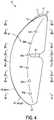
- FIG. 1is lateral side, top rear perspective view of an arch support 10 according to some embodiments.
- FIG. 2is a lateral side, top front perspective view of arch support 10.
- Arch support 10is configured for use in a right foot shoe.
- An arch support configured for wear in a left foot shoemay, but need not necessarily, be a mirror image of arch support 10.
- arch supports according to some embodimentsmay be specially created for a particular individual.
- a right arch supportmay differ from a left arch support based on differences between an individual's right and left feet.
- Arch support 10includes an arch plate 11 and a base plate 12.
- Arch plate 11has a top surface 15, a rear end 16, and a front end 17.
- the lateral side of arch plate 11terminates in a curved lateral edge 19 that extends from front end 17 to rear end 16.
- the medial side of arch plate 11terminates in an upwardly-turned medial edge 20 that extends between front end 17 and rear end 16.
- Arch plate 11 and bottom plate 12are attached at a joint 30 located in a middle portion of lateral edge 19 and of a lateral edge 47 of base plate 12.
- joint 30does not extend along the entirety of lateral edge 19 or of lateral edge 47. Portions of lateral edge 19 and of lateral edge 47 forward of joint 30 are not attached. Similarly, portions of lateral edge 19 and of lateral edge 47 rearward of joint 30 are not attached.
- An edge of arch plate 11 or of base plate 12refers to a physical boundary defined by the end of material forming that plate.
- medial edge 20includes features such as the sides of slots 24a, 24b, and 24c, which slots are further discussed below.
- An envelope of an edgeis a continuous path that follows at least some of that edge, but that bridges slots or other openings that project inward into the body of a plate (e.g., slots 24a, 25b, 24c). Because lateral edge 19 does not include such openings, the envelope 21 of edge 19 is coincident with edge 19. However, medial edge 20 has an envelope 22 that spans openings of slots 24a, 24b, and 24c.
- FIG. 3is a top view of arch support 10. Envelope 21 of lateral edge 19 is bowed and convex on the lateral side.
- arch support 10is oriented as it would be when installed in a sock liner, and with that sock liner oriented with its front and rear ends respectively corresponding to the top and bottom of the page.
- FIG. 3is also a view of arch support 10 in a transverse plane. Contours of top surface 15 in various transverse planes passing through arch support 10 are similarly bowed and convex toward the lateral side.
- FIG. 3is a top view of arch support 10. Envelope 21 of lateral edge 19 is bowed and convex on the lateral side.
- FIG. 4is a bottom view of arch support 10 and shows additional details of base plate 12.
- Base plate 12has a bottom surface 42, a rear end 43, and a front end 44.
- the lateral side of base plate 12terminates in a curved lateral edge 47 that extends from front end 44 to rear end 43.
- Edge 47has a coinciding boundary 49, with edge 47 and boundary 49 being bowed and convex.
- the medial side of base plate 12terminates in an upwardly-turned medial edge 48 (see FIG. 3 ) that extends between front end 44 and rear end 43.
- Medial edge 48includes a single slot 52.
- Bottom surface 42further includes downward projections 56a through 56f.
- a lateral side view of arch support 10some or all of projections 56a through 56f may terminate in pointed ends. Projections 56a through 56 help to stabilize arch support 10 within a shoe by digging into a lasting element (e.g., a Strobel) or other component in the bottom of a shoe interior.
- a lasting elemente.g., a Strobel
- envelope 22 of arch plate 11medial edge 20 is bowed and convex.
- FIG. 6is a medial side view of arch support 10.
- Medial edge 48 of base plate 12has an envelope 50 that is also bowed and convex.
- slots 24a through 24cprovide flexibility in upwardly extending regions of arch plate 11.
- each of slots 24a through 24callows portions of arch plate 11 rearward of the slot to flatten or otherwise deform relative portions of arch plate 11 forward of the slot. This facilitates adaptation to a shape of a wearer's foot.
- the number, depth, and width of slotsmay be varied.
- Slot 52similarly provides flexibility in upward extending portions of base plate 12 and facilitates adaptation to a shape of a wearer's foot.
- base platemay also or alternatively be thicker than an arch plate.
- an arch platemay have stiffening ribs 63.
- Each of ribs 63is a medial-to-lateral extending region of increased thickness that helps to resist flattening of arch plate.
- a top surface of an arch platemay also or alternatively include ribs similar to ribs 63.
- an arch platemay include areas of reduced thickness in addition to or in conjunction with ribs and/or slots.
- top surface 15 of arch plate 11includes grooves at the lateral/bottom ends of slots 24a through 24c. Similar grooves could be included in other regions of top surface 15 and/or of bottom surface 61.
- ribs and/or groovescould be included on top and/or bottom surfaces of an arch support base plate.
- FIGS. 7 and 8are respective rear end and front end views of arch support 10.
- bottom surface 61 of arch plate 11faces and is separated from top surface 62 of base plate 12.
- an extent of that separation(shown as a height h) increases toward the medial side of arch support 10.
- arch plate 11is cantilevered relative to base plate 12.
- arch plate 11is biased against flexion at joint 30 and along a width of arch plate 11 extending from joint 30 toward the medial side.
- Arch plate 11 and base plate 12are biased against reduction of the separation distance h over that width.
- the amount of this separation biasvaries based on, e.g., the elastic modulus of the material(s) used for arch plate 11, the thickness of arch plate 11, the presence of ribs, grooves, and slots, and width of arch plate 11 in the medial-lateral direction.
- the extent of joint 30also affects the amount of separation bias. Lengthening joint 30 to extend along a longer portion of lateral edges 19 and 47 will increase the amount of separation bias, while shortening joint 30 to extend along a shorter portion of lateral edges 19 and 47 will decrease the amount of separation bias.
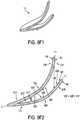
- FIGS. 9A1 through 9I2are partially schematic cross-sectional views across medial-lateral sectioning planes having the locations indicated in FIG. 4 .
- FIG. 9A1is a partially schematic cross-sectional view from sectioning plane 9A-9A
- FIG. 9B1is a partially schematic cross-sectional view from sectioning plane 9B-9B, etc.
- the sectioning planes indicatedare also frontal planes.
- FIGS. 9A2 through 9I2are partially schematic enlarged area cross-sectional views taken across the same sectioning planes used to create 9A1 through 911 (e.g., FIG. 9A2 is a partially schematic enlarged area cross-sectional view from sectioning plane 9A-9A, etc.).
- top surface 15 of arch plate 11has medial-lateral contours that includes a lateral section 71_, a transitional section 72_, and a medial section 73_, with "-" being an appended lower case letter matching the upper case letter in the corresponding drawing figure (e.g., sections 71a, 72a, and 73a in FIG. 9A2 ).
- Medial-lateral contours of arch plate 11 bottom surface 61include a lateral section 75_, a transitional section 76_, and a medial section 77_.
- Medial-lateral contours of top surface 62 of base plate 12similarly include a lateral section 81 _, a transitional section 82_, and a medial section 83_, with medial-lateral contours of base plate 12 bottom surface 42 including a lateral section 85_, a transitional section 86_, and a medial section 87_. Because of the locations of the sectioning planes corresponding to FIGS. 9A2 , 9E2 , and 9I2 , transitional sections and/or medial sections may be absent for base plate 12.
- lateral section 71_has a relatively shallow inclination and medial section 73_ has a more steep inclination, with transitional section 72_ providing a rounded transition between the shallow and steep inclinations.
- lateral section 71ahas an overall average inclination (relative to the horizontal) of approximately 25 degrees and medial section 73a has an overall average inclination of approximately 57 degrees.
- FIGS. 9B2 through 9I2A similar pattern can be seen in FIGS. 9B2 through 9I2 , although the average inclinations of the lateral sections 71 and medial sections 73 in the sectioning planes of those figures may vary.
- the medial-lateral contours of arch plate 11 bottom surface 61, base plate 12 top surface 62, and base plate 12 bottom surface 42also show similar patterns.
- those patternsinclude a relatively shallow inclination in the lateral section, a steeper inclination in the medial section, and a transitional section.
- lateral section 71a and medial section 73aare merely examples according to one embodiment.
- a cross-section taken at a similar location of an arch support according to a different embodimentmay have different lateral section and medial section inclinations.
- medial-lateral cross sections of arch plate 11are concave in the upward and lateral directions on the side of top surface 15.
- medial-lateral cross sections of arch plate 11are convex in the downward and medial directions.
- Medial-lateral cross sections of base plate 12are concave in the upward and lateral directions on the side of top surface 62.
- medial-lateral cross sections of base plate 12are convex in the downward and medial directions.
- arch plate 11 and base plate 12may be integrally formed as a monolithic unit.
- arch plate 11 and base plate 12may be formed of the same material.
- different materialsmay be used for one or more portions of a monolithic arch support.
- an arch supportcould be fabricated using a multi-shot molding process in which different material as sequentially injected into a mold, but which yields an arch support in which there is a continuous transition between materials.
- an arch supportcould be fabricated using 3D printing, laser sintering, or other rapid prototyping techniques and in which different materials are used for different portions of the arch support being fabricated
- FIGS. 9A2 through 9I2are also labeled to show how, at each of the corresponding cross sections, an extent of separation (shown as a height h) between arch plate 11 bottom surface 61 and base plate 12 top surface 62 increases when going from the medial side to the lateral side.
- height h3ais greater than height h2a, with height h2a being greater than height h1a.
- FIG. 9Jis a partially schematic cross-sectional view across a vertical front-rear sectioning plane having the location indicated in FIG. 3 .
- the sectioning plane indicatedis also a sagittal plane.
- at least some contours of top surface 15 along front-to-rear cross sectionsinclude at least a portion that is convex in the upward direction.
- At least some contours of bottom surface 61 along front-to-rear cross sectionsinclude at least a portion that is concave in the downward direction.
- top surface 62 along front-to-rear cross sectionsinclude at least a portion that is convex in the upward direction and at least some contours of bottom surface 42 along front-to-rear cross sections include at least a portion that is concave in the downward direction.
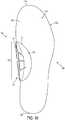
- FIG. 10is a top view of a sock liner 100 incorporating arch support 10.
- sock linerrefers to an element that can be inserted into a shoe and that rests in the bottom of a void formed by the upper.
- a sock linerwhich may also be known as an insole, may in some embodiments be non-destructively removable from and replaceable into a shoe.
- sock liner 10may be of conventional construction.
- sock linermay have a top surface 101 that is generally contoured to conform to the plantar surface of a wearer foot and may include material configured to absorb moisture and/or to provide slip resistance to a socked wearer foot.
- Sock liner 100may further comprise one or more layers of foam or other compressible material beneath top surface 101.
- a sock linermay be relatively thin and of generally constant thickness.
- a sock linermay have increased thickness in one or more regions and/or include orthotic components in addition to an arch support according to various embodiments.
- Sock liner 100is shaped to fit within the lower portion of a void formed by a shoe upper, as further described below, and has a peripheral boundary 102 having the approximate shape of a footbed of a shoe into which sock liner 100 is to be inserted.
- Sock liner 100includes a heel end 103, a lateral side 104, a toe end 105, and a medial side 106.
- Arch support 10is installed in an arch region 107.
- sock liner 100includes an aperture 110 through which arch support 10 passes.
- a portion of base plate 12 upper surface 62faces the underside of a bridging section of sock liner 100 on the medial side of aperture 110.
- a portion of arch plate 11 bottom surface 61faces the top side of that bridging section of sock liner 100.
- FIG. 11is a medial side, top front perspective view of sock liner 100 incorporating arch support 10. A portion of bridging section 111 of sock liner 100 between base plate 12 and arch plate 11 is visible.
- FIG. 12is a top view of sock liner 100 with arch support 10 removed.
- aperture 110is roughly crescent shaped.
- Bridging section 111forms the medial side of aperture 110.
- Arch support 10can be installed into sock liner 100 by inserting rear end 43 of base plate 12 into aperture 110 from the top of sock liner 100 and so that a portion of bridging section 111 is between base plate 12 and arch plate 11. The rear end of arch support 10 can then be moved toward the rear of aperture 110 until front end 44 of base plate 12 can be pushed through the front end of aperture 110. The position of arch support 10 can then be adjusted by moving forwardly, medially and/or laterally.
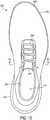
- FIG. 13is a top view of a shoe 200 incorporating sock liner 100 and arch support 10.
- Shoe 200includes an upper 201 and a sole structure 202.
- Upper 201 and sole structure 202may have any of various conventional constructions.
- Upper 200includes a tongue 204 and an ankle opening 205. Lace 209 may extend across an instep region. A portion of sock liner 100 top surface 101 is visible through ankle opening 205, but arch support 10 is obscured by upper 201 in FIG. 13 .
- FIG. 14is a partially schematic area cross-sectional view of shoe 200 across a medial-lateral sectioning plane having the location indicated as 14-14 in FIG. 13 . Visible in FIG. 14 are upper 201, tongue 204, and sole structure 202. As further shown in FIG. 14 , a lasting element 207 is attached to bottom edges of upper 201 to enclose a void 208 within upper 201. Void 208 is sized and shaped to receive sock liner 100 and arch support 10 in the lower portion and to conform to a socked wearer foot in the remaining portion. Sole structure 202 may be attached to the underside of lasting element 207 and/or to upper 201 in a conventional manner.
- sock liner 100fits within void 208 in a conventional manner.
- the underside 112 of sock liner 100may rest directly against lasting element 207 and lower portions of the upper 201 interior surface.
- underside 112may be treated to create a tacky surface that adheres sock liner 100 to lasting element 207, but that allows nondestructive removal of sock liner 100.
- Peripheral boundary 102 of sock liner 100generally follows the boundary of the shoe 200 footbed.
- the wearer's footWhen shoe 200 is donned by a wearer, the wearer's foot pushes against top surface 15 of arch plate 11 and partially compresses arch support 10 by pushing arch plate 11 toward base plate 12.
- the resulting reactive force of arch plate 11 against the wearer footprovides support to the arch region of the wearer foot.
- the amount of reactive forcecan be tuned when fabricating arch support 10. In particular, the reactive force can be controlled by adjusting one or more of the features discussed above in connection with varying the amount of separation bias between arch plate 11 and base plate 12.
- Bridging section 111may also contribute to the separation bias between arch plate 11 and base plate 12.
- sock liner 100may comprise a compressible foam material.
- pushing arch plate 11 toward base plate 12requires force to compress bridging section 111.
- a sock linermay be fabricated so that a bridging section has extra thickness so as to further increase a contribution to separation bias. This is shown in FIG. 15 , a partially schematic area cross-sectional view of shoe 200 from the same sectioning plane used for FIG. 14 , but with sock liner 100 replaced with sock liner 120. Sock liner 120 includes a thicker bridging section 131, but is otherwise the same as sock liner 100.
- FIG. 16a partially schematic area cross-sectional view of shoe 200 from the same sectioning plane used for FIG. 14 , but with sock liner 100 replaced with sock liner 140, and with a compression spring 401 located between base plate 12 and arch plate 11. Sock liner 140 lacks a bridging section, but is otherwise the same as sock liner 100.
- FIG. 17is a partially schematic area cross-sectional view of shoe 200 from the same sectioning plane used for FIG. 14 , but with sock liner 100 replaced with sock liner 140, and with a fluid-filled bladder 402 located between base plate 12 and arch plate 11.
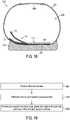
- FIG. 18is a partially schematic area cross-sectional view of shoe 200 from the same sectioning plane used for FIG. 14 , but with sock liner 100 replaced with sock liner 140.
- Arch supports such as arch support 100 and arch supports according to other embodimentscan be customized to fit an individual wearer. Using dimensional data for that individual's foot, an arch support can be created using 3D printing, laser sintering, and/or another additive manufacturing process. Once fabricated, the arch support can be installed into a sock liner and the sock liner and arch support then placed into a shoe.
- the sock linermay be a non-customized standard sock liner, or may be one of a limited number of available sock liner configurations.
- the customized arch supportmay be used with a sock liner that is also customized to the same wearer.
- FIG. 19is a flow chart showing steps in a method according to some embodiments.
- step 501dimensional data regarding a shape of an individual's foot is received.
- step 501may include gathering foot shape data.
- step 501may include retrieving previously stored data.
- an arch supportis fabricated based on the received foot shape data.
- an arch supportmay be fabricated using 3D printing, laser sintering, and/or another additive manufacturing process.
- the arch support and an article of footwear sized for the individual's footare provided.
- the providingmay only consist of furnishing the arch support and the article of footwear to the individual or to another person, with the placement of the arch support into the article of footwear to be performed at a future time.
- the providingmay include placing the fabricated arch support in a sock liner and placing the sock liner with the arch support into the article of footwear.
- the arch support and the sock linermay be separately installed in the shoe.
- the shoemay lack a sock liner.
- Arch supports such as arch support 10 and arch supports according to other embodimentscan be fabricated from any of a variety of materials.
- materials from which sock liners may be formedinclude thermoplastic polyurethane (TPU), polyurethane (PU), acrylonitrile butadiene styrene (ABS), polylactic acid (PLA), polyamide (Nylon), glass filled polyamide, and epoxy resins.
- Arch supports according to at least some embodimentscan be fabricated for any of a wide variety of shoe sizes.
- the overall length of an arch support according to various embodimentsmay vary based on, e.g., the size shoe for which the arch support is intended.
- an arch supportmay have an overall length from forward-most point to rear-most point of between 5.1 and 15.2 cm (2 and 6 inches).
- an arch supportmay include an arch plate and a base plate that were fabricated as individual elements and subsequent attached at a joint using adhesives, mechanical fasteners, radio frequency (RF) welding, and/or other techniques.
- RFradio frequency
- the joint between those platesmay be pivoted.
- such a jointmay allow the joined arch plate and base plate to move relative to one another similar to sides of a hinge. Separation bias between that arch plate and base plate can then be created using a bridging portion of a sock liner or other component(s) (e.g., a spring or a fluid filled bladder).
- Arch supports according to some embodimentscould be formed using multiple different methods.
- base platesmay be fabricated using injection molding so as to create a limited number of standard base plates (e.g., a different base plate for each shoe size).
- An arch platemay then be fabricated, using 3D printing, laser sintering, or other rapid prototyping method, so as to be customized for a specific wearer.
- the custom arch platemay then be attached to the standard base at a joint using adhesives, mechanical fasteners, radio frequency (RF) welding, and/or other techniques.
- RFradio frequency
Landscapes
- Health & Medical Sciences (AREA)
- Epidemiology (AREA)
- General Health & Medical Sciences (AREA)
- Public Health (AREA)
- Chemical & Material Sciences (AREA)
- Engineering & Computer Science (AREA)
- Materials Engineering (AREA)
- Life Sciences & Earth Sciences (AREA)
- Wood Science & Technology (AREA)
- Manufacturing & Machinery (AREA)
- Footwear And Its Accessory, Manufacturing Method And Apparatuses (AREA)
- Orthopedics, Nursing, And Contraception (AREA)
Description
- Conventional articles of footwear generally include an upper and a sole structure. The upper provides a covering for the foot and securely positions the foot relative to the sole structure. The sole structure is secured to the upper and is configured so as to be positioned between the foot and the ground when a wearer is standing, walking or running. For a given footwear design, individual shoes conforming to that design may be available in a wide range of sizes to accommodate different sizes of intended wearers' feet. Moreover, many footwear designs include laces, straps, or other elements that allow some degree of adjustment for an individual wearer.
- Orthotics and other inserts are sometimes used to further customize the fit of a shoe for a particular wearer's foot and/or to provide additional support. One foot region that frequently requires additional support is the arch, and various types of arch supports have been developed. However, economically creating durable arch supports and incorporating such supports into shoes remains a challenge.
- Document
US 2004/0401183 describes a cantilevered shoe construction for preventing knee and hip osteoarthritis. The shoe construction includes a cantilevered foot support with an anchored lateral side and a fully or partially cantilevered medial side. The cantilevered foot support transfers forces, otherwise transmitted through the medial aspect of the shoe and foot, to the lateral side of the shoe and foot, thereby reducing the knee varus and hip adductor torques to prevent or delay onset of knee and hip osteoarthritis and reducing the ankle joint adductor torque to reduce the risk for ankle sprain injury. The reduction of these joint torques also maintains posture without counterbalancing muscle activity, thereby improving muscle efficiency and performance during weight bearing activities and reducing the tendency for musculoskeletal injury. A spring loading effect of other embodiments enhances the natural coronal foot progression during gait so as to enhance the push off phase of gait. - Some embodiments are illustrated by way of example, and not by way of limitation, in the figures of the accompanying drawings and in which like reference numerals refer to similar elements.
FIG. 1 is a lateral side, top rear perspective view of a right foot arch support according to some embodiments.FIG. 2 is a lateral side, top front perspective view of the arch support fromFIG. 1 .FIG. 3 is a top view of the arch support fromFIG. 1 .FIG. 4 is a bottom view of the arch support fromFIG. 1 .FIG. 5 is a lateral side view of the arch support fromFIG. 1 .FIG. 6 is a medial side view of the arch support fromFIG. 1 .FIG. 7 is a rear end view of the arch support fromFIG. 1 .FIG. 8 is a front end view of the arch support fromFIG. 1 .FIGS. 9A1 and 9A2 are a cross-sectional view and an enlarged area cross-sectional view, respectively, taken from the location indicated as 9A-9A inFIG. 4 .FIGS. 9B1 and 9B2 are a cross-sectional view and an enlarged area cross-sectional view, respectively, taken from the location indicated as 9B-9B inFIG. 4 .FIGS. 9C1 and 9C2 are a cross-sectional view and an enlarged area cross-sectional view, respectively, taken from the location indicated as 9C-9C inFIG. 4 .FIGS. 9D1 and 9D2 are a cross-sectional view and an enlarged area cross-sectional view, respectively, taken from the location indicated as 9D-9D inFIG. 4 .FIGS. 9E1 and 9E2 are a cross-sectional view and an enlarged area cross-sectional view, respectively, taken from the location indicated as 9E-9E inFIG. 4 .FIGS. 9F1 and 9F2 are a cross-sectional view and an enlarged area cross-sectional view, respectively, taken from the location indicated as 9F-9F inFIG. 4 .FIGS. 9G1 and 9G2 are a cross-sectional view and an enlarged area cross-sectional view, respectively, taken from the location indicated as 9G-9G inFIG. 4 .FIGS. 9H1 and 9H2 are a cross-sectional view and an enlarged area cross-sectional view, respectively, taken from the location indicated as 9H-9H inFIG. 4 .FIGS. 9I1 and 9I2 are a cross-sectional view and an enlarged area cross-sectional view, respectively, taken from the location indicated as 9I-9I inFIG. 4 .FIG. 9J is a cross-sectional view taken from the location indicated as 9J-9J inFIG. 3 .FIG. 10 is a top view of the arch support fromFIG. 1 , incorporated in a sock liner, according to some embodiments.FIG. 11 is a medial side, top front perspective view of the arch support and sock liner fromFIG. 10 .FIG. 12 is a top view of the sock liner fromFIGS. 10 and11 .FIG. 13 is a top view of a shoe incorporating the sock liner and arch support ofFIGS. 10 through 12 .FIG. 14 is a partially schematic area cross-sectional view taken from the location indicated as 14-14 inFIG. 13 .FIGS. 15 through 18 are partially schematic area cross-sectional views of shoes incorporating configurations according to additional embodiments.FIG. 19 is a flow chart showing steps in a method according to some embodiments.- The invention relates to an arch support as specified in appended independent claim 1 and to a method for manufacturing an arch support as specified in appended
independent claim 14. Preferred embodiments of the invention are disclosed in the dependent claims. - Embodiments further include a sock liner incorporating an arch support, a shoe incorporating an arch support, and a method of fabricating an arch support. Additional embodiments are described herein.
- To assist and clarify subsequent description of various embodiments, various terms are defined herein. Unless context indicates otherwise, the following definitions apply throughout this specification (including the claims). "Shoe" and "article of footwear" are used interchangeably to refer to an article intended for wear on a human foot. A shoe may or may not enclose the entire foot of a wearer. For example, a shoe could be a sandal or other article that exposes large portions of a wearing foot.
- Shoe elements can be described based on regions and/or anatomical structures of a human foot wearing that shoe, and by assuming that the interior of the shoe generally conforms to and is otherwise properly sized for the wearing foot. A forefoot region of a foot includes the phalanges, as well as the heads and bodies of the metatarsals. A forefoot element of a shoe is an element having one or more portions located under, over, to the lateral and/or medial side of, and/or in front of a wearer's forefoot (or portion thereof) when the shoe is worn. A midfoot region of a foot includes the cuboid, navicular, and cuneiforms, as well as the bases of the metatarsals. A midfoot element of a shoe is an element having one or more portions located under, over, and/or to the lateral and/or medial side of a wearer's midfoot (or portion thereof) when the shoe is worn. A heel region of a foot includes the talus and the calcaneus. A heel element of a shoe is an element having one or more portions located under, to the lateral and/or medial side of, and/or behind a wearer's heel (or portion thereof) when the shoe is worn. The forefoot region may overlap with the midfoot region, as may the midfoot and heel regions.
- For purposes of directions used to describe a shoe, it is assumed that surfaces of that shoe's sole structure that are intended for ground contact are resting on a horizontal reference plane. It is further assumed that studs or other projections from a bottom side of a sole structure do not penetrate that reference plane, and that the shoe is not deformed. A forward direction is toward the toe. A rearward direction is toward the heel. An upward direction is away from the reference plane. A downward direction is toward the reference plane. With regard to an arch support or other shoe component, directions assume that the component has the orientation it would have when incorporated into the shoe.
- With regard to anatomy of a foot, sagittal planes divide medial and lateral portions of a foot. A central sagittal plane passes vertically through a foot centerline that runs from the heel and between the second and third toes. Other sagittal planes are parallel to the central sagittal plane. A transverse plane is orthogonal to sagittal planes and divides top and bottom portions of a foot. A frontal plane divides front and rear portions of a foot and is orthogonal to sagittal planes and to transverse planes. When sagittal, transverse, and frontal planes are referenced herein when describing an arch support or other shoe component, it is assumed that the arch support or other component is oriented as it would be oriented when installed in a shoe, and that the sagittal, transverse, and frontal planes are relative to where a central sagittal plane would be positioned if the shoe was worn by a foot for which the shoe is sized.
- As used herein, "arch" refers to the medial side plantar region of a foot located under at least the proximal portions of the first and second metatarsals, the medial and intermediate cuneiforms, and an anterior portion of the navicular. An arch may extend further forward, further toward the lateral side, and/or further rearward.
FIG. 1 is lateral side, top rear perspective view of anarch support 10 according to some embodiments.FIG. 2 is a lateral side, top front perspective view ofarch support 10.Arch support 10 is configured for use in a right foot shoe. An arch support configured for wear in a left foot shoe may, but need not necessarily, be a mirror image ofarch support 10. For example, arch supports according to some embodiments may be specially created for a particular individual. In some cases, a right arch support may differ from a left arch support based on differences between an individual's right and left feet.Arch support 10 includes anarch plate 11 and abase plate 12.Arch plate 11 has atop surface 15, arear end 16, and afront end 17. The lateral side ofarch plate 11 terminates in a curvedlateral edge 19 that extends fromfront end 17 torear end 16. The medial side ofarch plate 11 terminates in an upwardly-turnedmedial edge 20 that extends betweenfront end 17 andrear end 16.Arch plate 11 andbottom plate 12 are attached at a joint 30 located in a middle portion oflateral edge 19 and of alateral edge 47 ofbase plate 12. In the embodiment ofarch support 10, joint 30 does not extend along the entirety oflateral edge 19 or oflateral edge 47. Portions oflateral edge 19 and oflateral edge 47 forward of joint 30 are not attached. Similarly, portions oflateral edge 19 and oflateral edge 47 rearward of joint 30 are not attached.- For convenience, a distinction is made herein between an edge and an envelope of that edge. An edge of
arch plate 11 or ofbase plate 12 refers to a physical boundary defined by the end of material forming that plate. In the case ofarch plate 11,medial edge 20 includes features such as the sides ofslots slots lateral edge 19 does not include such openings, theenvelope 21 ofedge 19 is coincident withedge 19. However,medial edge 20 has anenvelope 22 that spans openings ofslots FIG. 3 is a top view ofarch support 10.Envelope 21 oflateral edge 19 is bowed and convex on the lateral side. InFIG. 3 , and as can be further appreciated below in connection with discussion ofFIG. 10 ,arch support 10 is oriented as it would be when installed in a sock liner, and with that sock liner oriented with its front and rear ends respectively corresponding to the top and bottom of the page.FIG. 3 is also a view ofarch support 10 in a transverse plane. Contours oftop surface 15 in various transverse planes passing througharch support 10 are similarly bowed and convex toward the lateral side. Several representative contours are indicated inFIG. 3 as broken lines C1-C3.FIG. 4 is a bottom view ofarch support 10 and shows additional details ofbase plate 12.Base plate 12 has abottom surface 42, arear end 43, and afront end 44. The lateral side ofbase plate 12 terminates in a curvedlateral edge 47 that extends fromfront end 44 torear end 43.Edge 47 has a coincidingboundary 49, withedge 47 andboundary 49 being bowed and convex. The medial side ofbase plate 12 terminates in an upwardly-turned medial edge 48 (seeFIG. 3 ) that extends betweenfront end 44 andrear end 43.Medial edge 48 includes asingle slot 52.Bottom surface 42 further includesdownward projections 56a through 56f. As seen inFIG. 5 , a lateral side view ofarch support 10, some or all ofprojections 56a through 56f may terminate in pointed ends.Projections 56a through 56 help to stabilizearch support 10 within a shoe by digging into a lasting element (e.g., a Strobel) or other component in the bottom of a shoe interior. As also seen inFIG. 5 ,envelope 22 ofarch plate 11medial edge 20 is bowed and convex.FIG. 6 is a medial side view ofarch support 10.Medial edge 48 ofbase plate 12 has anenvelope 50 that is also bowed and convex. Also visible inFIG. 6 are abottom surface 61 ofarch plate 11 and atop surface 62 ofbase plate 12. As can be appreciated fromFIGS. 5 and 6 ,slots 24a through 24c provide flexibility in upwardly extending regions ofarch plate 11. In particular, each ofslots 24a through 24c allows portions ofarch plate 11 rearward of the slot to flatten or otherwise deform relative portions ofarch plate 11 forward of the slot. This facilitates adaptation to a shape of a wearer's foot. The number, depth, and width of slots may be varied.Slot 52 similarly provides flexibility in upward extending portions ofbase plate 12 and facilitates adaptation to a shape of a wearer's foot. In some embodiments, including the embodiment ofarch support 10, there are more slots in an arch plate than in a base plate. In some embodiments, base plate may also or alternatively be thicker than an arch plate.- In some embodiments, and as also shown in
FIG. 6 , an arch plate may have stiffeningribs 63. Each ofribs 63 is a medial-to-lateral extending region of increased thickness that helps to resist flattening of arch plate. In some embodiments, a top surface of an arch plate may also or alternatively include ribs similar toribs 63. In some embodiments, an arch plate may include areas of reduced thickness in addition to or in conjunction with ribs and/or slots. For example, and as seen inFIGS. 3 and5 ,top surface 15 ofarch plate 11 includes grooves at the lateral/bottom ends ofslots 24a through 24c. Similar grooves could be included in other regions oftop surface 15 and/or ofbottom surface 61. In some embodiments, ribs and/or grooves could be included on top and/or bottom surfaces of an arch support base plate. FIGS. 7 and 8 are respective rear end and front end views ofarch support 10. As can be appreciated fromFIGS. 7 and 8 ,bottom surface 61 ofarch plate 11 faces and is separated fromtop surface 62 ofbase plate 12. Moreover, an extent of that separation (shown as a height h) increases toward the medial side ofarch support 10. Through the connection betweenarch plate 11 andbase plate 12 at joint 30,arch plate 11 is cantilevered relative tobase plate 12. As a result of this structure and the material from whicharch plate 11 is formed (described below),arch plate 11 is biased against flexion at joint 30 and along a width ofarch plate 11 extending from joint 30 toward the medial side.Arch plate 11 andbase plate 12 are biased against reduction of the separation distance h over that width. The amount of this separation bias varies based on, e.g., the elastic modulus of the material(s) used forarch plate 11, the thickness ofarch plate 11, the presence of ribs, grooves, and slots, and width ofarch plate 11 in the medial-lateral direction. The extent of joint 30 also affects the amount of separation bias. Lengthening joint 30 to extend along a longer portion oflateral edges lateral edges FIGS. 9A1 through 9I2 are partially schematic cross-sectional views across medial-lateral sectioning planes having the locations indicated inFIG. 4 . For example,FIG. 9A1 is a partially schematic cross-sectional view from sectioningplane 9A-9A,FIG. 9B1 is a partially schematic cross-sectional view from sectioningplane 9B-9B, etc. The sectioning planes indicated are also frontal planes.FIGS. 9A2 through 9I2 are partially schematic enlarged area cross-sectional views taken across the same sectioning planes used to create 9A1 through 911 (e.g.,FIG. 9A2 is a partially schematic enlarged area cross-sectional view from sectioningplane 9A-9A, etc.).- As seen in
FIGS. 9A2 through 9I2 ,top surface 15 ofarch plate 11 has medial-lateral contours that includes a lateral section 71_, a transitional section 72_, and a medial section 73_, with "-" being an appended lower case letter matching the upper case letter in the corresponding drawing figure (e.g.,sections FIG. 9A2 ). Medial-lateral contours ofarch plate 11bottom surface 61 include a lateral section 75_, a transitional section 76_, and a medial section 77_. Medial-lateral contours oftop surface 62 ofbase plate 12 similarly include a lateral section 81 _, a transitional section 82_, and a medial section 83_, with medial-lateral contours ofbase plate 12bottom surface 42 including a lateral section 85_, a transitional section 86_, and a medial section 87_. Because of the locations of the sectioning planes corresponding toFIGS. 9A2 ,9E2 , and9I2 , transitional sections and/or medial sections may be absent forbase plate 12. - For a given
top surface 15 contour, lateral section 71_ has a relatively shallow inclination and medial section 73_ has a more steep inclination, with transitional section 72_ providing a rounded transition between the shallow and steep inclinations. InFIG. 9A2 , for example,lateral section 71a has an overall average inclination (relative to the horizontal) of approximately 25 degrees andmedial section 73a has an overall average inclination of approximately 57 degrees. A similar pattern can be seen inFIGS. 9B2 through 9I2 , although the average inclinations of thelateral sections 71 and medial sections 73 in the sectioning planes of those figures may vary. The medial-lateral contours ofarch plate 11bottom surface 61,base plate 12top surface 62, andbase plate 12bottom surface 42 also show similar patterns. In particular, those patterns include a relatively shallow inclination in the lateral section, a steeper inclination in the medial section, and a transitional section. - It is noted that the numerical values given above for the inclinations of
lateral section 71a andmedial section 73a are merely examples according to one embodiment. A cross-section taken at a similar location of an arch support according to a different embodiment may have different lateral section and medial section inclinations. - As can be further appreciated from
FIGS. 9A2 through 9I2 , medial-lateral cross sections ofarch plate 11 are concave in the upward and lateral directions on the side oftop surface 15. On the side ofbottom surface 61, medial-lateral cross sections ofarch plate 11 are convex in the downward and medial directions. Medial-lateral cross sections ofbase plate 12 are concave in the upward and lateral directions on the side oftop surface 62. On the side ofbottom surface 42, medial-lateral cross sections ofbase plate 12 are convex in the downward and medial directions. - Additional details of joint 30 can be seen in
FIGS. 9C2 through 9H2 . In particular, and as shown in those figures,arch plate 11 andbase plate 12 may be integrally formed as a monolithic unit. In some such embodiments,arch plate 11 andbase plate 12 may be formed of the same material. In other embodiments, different materials may be used for one or more portions of a monolithic arch support. For example, an arch support could be fabricated using a multi-shot molding process in which different material as sequentially injected into a mold, but which yields an arch support in which there is a continuous transition between materials. As another example, an arch support could be fabricated using 3D printing, laser sintering, or other rapid prototyping techniques and in which different materials are used for different portions of the arch support being fabricated FIGS. 9A2 through 9I2 are also labeled to show how, at each of the corresponding cross sections, an extent of separation (shown as a height h) betweenarch plate 11bottom surface 61 andbase plate 12top surface 62 increases when going from the medial side to the lateral side. InFIG. 9A2 , for example, height h3a is greater than height h2a, with height h2a being greater than height h1a.FIG. 9J is a partially schematic cross-sectional view across a vertical front-rear sectioning plane having the location indicated inFIG. 3 . The sectioning plane indicated is also a sagittal plane. As seen inFIG. 9J , at least some contours oftop surface 15 along front-to-rear cross sections include at least a portion that is convex in the upward direction. At least some contours ofbottom surface 61 along front-to-rear cross sections include at least a portion that is concave in the downward direction. Similarly, at least some contours oftop surface 62 along front-to-rear cross sections include at least a portion that is convex in the upward direction and at least some contours ofbottom surface 42 along front-to-rear cross sections include at least a portion that is concave in the downward direction.FIG. 10 is a top view of asock liner 100 incorporatingarch support 10. As used herein, "sock liner" refers to an element that can be inserted into a shoe and that rests in the bottom of a void formed by the upper. A sock liner, which may also be known as an insole, may in some embodiments be non-destructively removable from and replaceable into a shoe.- In some embodiments, and except as described herein,
sock liner 10 may be of conventional construction. For example, sock liner may have atop surface 101 that is generally contoured to conform to the plantar surface of a wearer foot and may include material configured to absorb moisture and/or to provide slip resistance to a socked wearer foot.Sock liner 100 may further comprise one or more layers of foam or other compressible material beneathtop surface 101. In some embodiments, a sock liner may be relatively thin and of generally constant thickness. In other embodiments, a sock liner may have increased thickness in one or more regions and/or include orthotic components in addition to an arch support according to various embodiments. Sock liner 100 is shaped to fit within the lower portion of a void formed by a shoe upper, as further described below, and has aperipheral boundary 102 having the approximate shape of a footbed of a shoe into whichsock liner 100 is to be inserted.Sock liner 100 includes aheel end 103, alateral side 104, atoe end 105, and a medial side 106.Arch support 10 is installed in anarch region 107. In particular, and as is partially visible inFIG. 10 ,sock liner 100 includes anaperture 110 through whicharch support 10 passes. A portion ofbase plate 12upper surface 62 faces the underside of a bridging section ofsock liner 100 on the medial side ofaperture 110. A portion ofarch plate 11bottom surface 61 faces the top side of that bridging section ofsock liner 100.FIG. 11 is a medial side, top front perspective view ofsock liner 100 incorporatingarch support 10. A portion ofbridging section 111 ofsock liner 100 betweenbase plate 12 andarch plate 11 is visible.FIG. 12 is a top view ofsock liner 100 witharch support 10 removed. As seen inFIG. 12 ,aperture 110 is roughly crescent shaped.Bridging section 111 forms the medial side ofaperture 110.Arch support 10 can be installed intosock liner 100 by insertingrear end 43 ofbase plate 12 intoaperture 110 from the top ofsock liner 100 and so that a portion ofbridging section 111 is betweenbase plate 12 andarch plate 11. The rear end ofarch support 10 can then be moved toward the rear ofaperture 110 untilfront end 44 ofbase plate 12 can be pushed through the front end ofaperture 110. The position ofarch support 10 can then be adjusted by moving forwardly, medially and/or laterally.FIG. 13 is a top view of ashoe 200 incorporatingsock liner 100 andarch support 10.Shoe 200 includes an upper 201 and asole structure 202.Upper 201 andsole structure 202 may have any of various conventional constructions.Upper 200 includes atongue 204 and anankle opening 205.Lace 209 may extend across an instep region. A portion ofsock liner 100top surface 101 is visible throughankle opening 205, butarch support 10 is obscured by upper 201 inFIG. 13 .FIG. 14 is a partially schematic area cross-sectional view ofshoe 200 across a medial-lateral sectioning plane having the location indicated as 14-14 inFIG. 13 . Visible inFIG. 14 are upper 201,tongue 204, andsole structure 202. As further shown inFIG. 14 , alasting element 207 is attached to bottom edges of upper 201 to enclose avoid 208 within upper 201.Void 208 is sized and shaped to receivesock liner 100 andarch support 10 in the lower portion and to conform to a socked wearer foot in the remaining portion.Sole structure 202 may be attached to the underside oflasting element 207 and/or to upper 201 in a conventional manner.- With the exception of the regions where
arch support 10 is installed,sock liner 100 fits withinvoid 208 in a conventional manner. With the exception of bridgingelement 111, theunderside 112 ofsock liner 100 may rest directly againstlasting element 207 and lower portions of the upper 201 interior surface. In some embodiments,underside 112 may be treated to create a tacky surface that adheressock liner 100 tolasting element 207, but that allows nondestructive removal ofsock liner 100.Peripheral boundary 102 ofsock liner 100 generally follows the boundary of theshoe 200 footbed. - When
shoe 200 is donned by a wearer, the wearer's foot pushes againsttop surface 15 ofarch plate 11 and partially compressesarch support 10 by pushingarch plate 11 towardbase plate 12. The resulting reactive force ofarch plate 11 against the wearer foot provides support to the arch region of the wearer foot. The amount of reactive force can be tuned when fabricatingarch support 10. In particular, the reactive force can be controlled by adjusting one or more of the features discussed above in connection with varying the amount of separation bias betweenarch plate 11 andbase plate 12. Bridging section 111 may also contribute to the separation bias betweenarch plate 11 andbase plate 12. In some embodiments, and as indicated above,sock liner 100 may comprise a compressible foam material. Thus, and in addition to force necessary to deformarch plate 11, pushingarch plate 11 towardbase plate 12 requires force to compress bridgingsection 111.- In some embodiments, a sock liner may be fabricated so that a bridging section has extra thickness so as to further increase a contribution to separation bias. This is shown in
FIG. 15 , a partially schematic area cross-sectional view ofshoe 200 from the same sectioning plane used forFIG. 14 , but withsock liner 100 replaced withsock liner 120.Sock liner 120 includes athicker bridging section 131, but is otherwise the same assock liner 100. - In some embodiments, other types of components may be used to increase separation bias between
base plate 12 andarch plate 11. This is shown inFIG. 16 , a partially schematic area cross-sectional view ofshoe 200 from the same sectioning plane used forFIG. 14 , but withsock liner 100 replaced withsock liner 140, and with acompression spring 401 located betweenbase plate 12 andarch plate 11.Sock liner 140 lacks a bridging section, but is otherwise the same assock liner 100.FIG. 17 is a partially schematic area cross-sectional view ofshoe 200 from the same sectioning plane used forFIG. 14 , but withsock liner 100 replaced withsock liner 140, and with a fluid-filledbladder 402 located betweenbase plate 12 andarch plate 11. In some embodiments, and as shown inFIG. 18 , there may be nothing betweenarch plate 11 andbase plate 12.FIG. 18 is a partially schematic area cross-sectional view ofshoe 200 from the same sectioning plane used forFIG. 14 , but withsock liner 100 replaced withsock liner 140. - Arch supports such as
arch support 100 and arch supports according to other embodiments can be customized to fit an individual wearer. Using dimensional data for that individual's foot, an arch support can be created using 3D printing, laser sintering, and/or another additive manufacturing process. Once fabricated, the arch support can be installed into a sock liner and the sock liner and arch support then placed into a shoe. In some embodiments, the sock liner may be a non-customized standard sock liner, or may be one of a limited number of available sock liner configurations. In still other embodiments, the customized arch support may be used with a sock liner that is also customized to the same wearer. FIG. 19 is a flow chart showing steps in a method according to some embodiments. Instep 501, dimensional data regarding a shape of an individual's foot is received. In some embodiments,step 501 may include gathering foot shape data. In some embodiments,step 501 may include retrieving previously stored data. Instep 503, an arch support is fabricated based on the received foot shape data. In some embodiments, and as described above, an arch support may be fabricated using 3D printing, laser sintering, and/or another additive manufacturing process. Instep 505, the arch support and an article of footwear sized for the individual's foot are provided. In some embodiments, the providing may only consist of furnishing the arch support and the article of footwear to the individual or to another person, with the placement of the arch support into the article of footwear to be performed at a future time. In some embodiments, the providing may include placing the fabricated arch support in a sock liner and placing the sock liner with the arch support into the article of footwear. In some embodiments, the arch support and the sock liner may be separately installed in the shoe. In other embodiments, the shoe may lack a sock liner.- Arch supports such as
arch support 10 and arch supports according to other embodiments can be fabricated from any of a variety of materials. Without limitation, examples of materials from which sock liners may be formed include thermoplastic polyurethane (TPU), polyurethane (PU), acrylonitrile butadiene styrene (ABS), polylactic acid (PLA), polyamide (Nylon), glass filled polyamide, and epoxy resins. - Arch supports according to at least some embodiments can be fabricated for any of a wide variety of shoe sizes. The overall length of an arch support according to various embodiments may vary based on, e.g., the size shoe for which the arch support is intended. In some embodiments, an arch support may have an overall length from forward-most point to rear-most point of between 5.1 and 15.2 cm (2 and 6 inches).
- Other embodiments include numerous additional variations on the components and combinations described above. Without limitation, such variations may include one or more of the following.
- In some embodiments, an arch support may include an arch plate and a base plate that were fabricated as individual elements and subsequent attached at a joint using adhesives, mechanical fasteners, radio frequency (RF) welding, and/or other techniques.
- In some embodiments, and instead of a joint used to make an arch plate cantilevered relative to a base plate, the joint between those plates may be pivoted. In particular, such a joint may allow the joined arch plate and base plate to move relative to one another similar to sides of a hinge. Separation bias between that arch plate and base plate can then be created using a bridging portion of a sock liner or other component(s) (e.g., a spring or a fluid filled bladder).
- Arch supports according to some embodiments could be formed using multiple different methods. In some embodiments, for example, base plates may be fabricated using injection molding so as to create a limited number of standard base plates (e.g., a different base plate for each shoe size). An arch plate may then be fabricated, using 3D printing, laser sintering, or other rapid prototyping method, so as to be customized for a specific wearer. The custom arch plate may then be attached to the standard base at a joint using adhesives, mechanical fasteners, radio frequency (RF) welding, and/or other techniques.
Claims (15)
- An arch support (10), comprising:a base plate (12) having a base plate top surface (62) and a base plate lateral edge (47); anda contoured arch plate (11) having an arch plate bottom surface (61), a rear end (16) and a front end (17);the lateral side of arch plate (11) terminating in an arch plate curved lateral edge (19) extending from the front end (17) to the rear end (16) of the arch plate (11),the medial side of arch plate (11) terminating in an upwardly-turned medial edge (20) that extends between the front end (17) and the rear end (16) of the arch plate (11); wherein:the base plate (12) and the arch plate (11) are attached at a joint (30) located in a middle portion of the arch plate lateral edge (19) and the base plate lateral edge (47),the arch plate bottom surface (61) faces and is separated from the base plate top surface (62), an extent (h) of the separation increasing toward a medial side of the arch support opposite the joint (30), andthe arch plate lateral edge (47) includes a front portion located forward of the joint (30) and a rear portion located rearward of the joint (30).
- The arch support (10) of claim 1, wherein the arch plate (11) is cantilevered relative to the base plate (12) at the joint (30).
- The arch support (10) of claim 1 or claim 2, wherein:an envelope (21) of the arch plate lateral edge (19) is convex, andan envelope (22) of the arch plate medial edge is convex.
- The arch support (10) of any of claims 1 through 3, wherein:the base plate (12) includes a base plate medial edge (48),an envelope of the base plate lateral edge is convex, andan envelope (50) of the base plate medial edge is convex.
- The arch support (10) of any one of claim 1 through claim 4, wherein:a bottom surface (42) of the base plate includes one or more downwardly-extending projections (56a-56f), andeach of the one or more downwardly-extending projections terminates in a pointed end.
- The arch support (10) of any one of claims 1 through claim 5, wherein the arch plate (11) includes at least one arch plate slot (24a-24c) extending into the arch plate from the envelope (22) of the arch plate medial edge (20).
- The arch support (10) of claim 6, wherein:the base plate (12) includes at least one base plate slot (52) extending into the base plate from the envelope (50) of the base plate medial edge (48), andthere are more arch plate slots (24a-24c) than base plate slots.
- The arch support (10) of any one of claim 1 through claim 7, wherein the arch plate (11) and the base plate (12) are integrally formed as a monolithic unit.
- The arch support (10) of any one of claim 1 through claim 8, wherein an overall front to rear length of the arch support is between 5.1 and 15.2 cm (2 and 6 inches).
- The arch support (10) of any one of claim 1 through claim 9, wherein the arch support further comprises a polymer foam or a fluid filled chamber (402) positioned between the base plate top surface (62) and the arch plate bottom surface (61).
- An article of footwear (200) comprising an arch support (10) according to any one of claim 1 through claim 9, further comprising a sock liner (100), wherein:the sock liner is shaped to fit within a lower portion of a void (208) formed by an upper (201) of the article of footwear,the sock liner has a peripheral boundary (102) having an approximate shape of a footbed of article of footwear, anda portion of the sock liner positioned between the base plate and the arch plate.
- A sock liner (100) incorporating an arch support (10) according to any one of claim 1 through claim 9, wherein:at least a portion of the sock liner is between the base plate and the arch plate,the sock liner comprises an aperture (110), andthe arch support is engaged with the sock liner through the aperture.
- The sock liner (100) of claim 12, wherein the aperture (110) is crescent-shaped and the joint (30) is positioned in the aperture.
- A method comprising fabricating an arch support (10) according to any one of claim 1 through claim 10, wherein the fabricating comprises:3D printing at least one of the base plate and the arch plate, orlaser sintering at least one of the base plate and the arch plate.
- The method of claim 14, wherein the fabricating comprises fabricating (503) the arch support based on dimensional data specific to a foot of an individual; and
providing (505) the arch support with an article of footwear sized for the foot of the individual.
Applications Claiming Priority (3)
| Application Number | Priority Date | Filing Date | Title |
|---|---|---|---|
| US201662305326P | 2016-03-08 | 2016-03-08 | |
| US15/448,973US10631590B2 (en) | 2016-03-08 | 2017-03-03 | Footwear arch support |
| PCT/US2017/020945WO2017155881A1 (en) | 2016-03-08 | 2017-03-06 | Footwear arch support |
Publications (2)
| Publication Number | Publication Date |
|---|---|
| EP3426086A1 EP3426086A1 (en) | 2019-01-16 |
| EP3426086B1true EP3426086B1 (en) | 2020-09-23 |
Family
ID=59788578
Family Applications (1)
| Application Number | Title | Priority Date | Filing Date |
|---|---|---|---|
| EP17711531.8AActiveEP3426086B1 (en) | 2016-03-08 | 2017-03-06 | Footwear arch support |
Country Status (4)
| Country | Link |
|---|---|
| US (2) | US10631590B2 (en) |
| EP (1) | EP3426086B1 (en) |
| CN (1) | CN108697195B (en) |
| WO (1) | WO2017155881A1 (en) |
Families Citing this family (9)
| Publication number | Priority date | Publication date | Assignee | Title |
|---|---|---|---|---|
| USD827998S1 (en)* | 2016-08-09 | 2018-09-11 | Protalus, Llc | Insole |
| US12376983B2 (en) | 2018-07-06 | 2025-08-05 | Richard Kim | Orthotic arch support devices and methods of use |
| US11350699B2 (en) | 2018-07-06 | 2022-06-07 | Richard Kim | Orthotic arch support device and method of use |
| BR112021022301A2 (en)* | 2019-05-08 | 2021-12-28 | Scholls Wellness Company Llc | Flexible plantar arch support for shoes |
| IT201900014082A1 (en)* | 2019-08-05 | 2021-02-05 | Selle Royal Spa | SPORTS FOOTWEAR, IN PARTICULAR CYCLING FOOTWEAR |
| US12082651B2 (en)* | 2019-09-20 | 2024-09-10 | R. G. Barry Corporation | Footwear article including cushion management system |
| US11758975B2 (en) | 2020-03-26 | 2023-09-19 | Nike, Inc. | Encased strobel with cushioning member and method of manufacturing an article of footwear |
| US11457690B2 (en) | 2020-08-12 | 2022-10-04 | Christopher Wayne Edge | Adjustable arch support system |
| JP7225296B2 (en)* | 2021-03-31 | 2023-02-20 | 美津濃株式会社 | Sole structure and shoes using the same |
Family Cites Families (45)
| Publication number | Priority date | Publication date | Assignee | Title |
|---|---|---|---|---|
| DE233603C (en)* | ||||
| US717523A (en) | 1901-05-27 | 1903-01-06 | James W Arrowsmith | Instep-support or arch-prop. |
| US741826A (en)* | 1902-10-01 | 1903-10-20 | George N Phelps | Instep-supporter for boots or shoes. |
| US748553A (en) | 1903-08-15 | 1903-12-29 | James W Arrowsmith | Instep-support or arch-prop. |
| US881974A (en) | 1906-09-29 | 1908-03-17 | Egidius Van Der Heyden | Instep-supporter. |
| US957718A (en)* | 1908-12-28 | 1910-05-10 | Perfect Foot Arch Supporter Co | Device for the correction of flat foot, weak foot, or fallen arch of the foot. |
| US1103463A (en)* | 1910-03-29 | 1914-07-14 | James W Arrowsmith | Instep-support. |
| GB191124914A (en)* | 1911-11-08 | 1912-03-14 | Frank John Scholl | Improved Foot Arch Support. |
| US1346444A (en) | 1919-07-15 | 1920-07-13 | Darling Samuel | Arch-support |
| US1418048A (en)* | 1921-01-31 | 1922-05-30 | Abramowitz Joseph | Arch support |
| US1490991A (en) | 1922-05-01 | 1924-04-22 | Tilson William George | Longitudinal arch support |
| US1741340A (en) | 1925-11-07 | 1929-12-31 | William M Scholl | Orthopedic sock |
| US1690837A (en)* | 1926-02-23 | 1928-11-06 | Rehle Ignaz | Insertable arch support |
| US1696786A (en)* | 1926-04-29 | 1928-12-25 | Jonathan T Wood | Instep-arch support |
| US1824176A (en) | 1929-08-12 | 1931-09-22 | Clarence H Stemmons | Sock liner |
| US2043396A (en) | 1934-12-20 | 1936-06-09 | Jacob P Schnellbacher | Arch support |
| US2022247A (en)* | 1935-02-01 | 1935-11-26 | Lobel Melville | Arch support |
| US2070814A (en) | 1935-07-22 | 1937-02-16 | Clarence H Stemmons | Sock liner arch support |
| US2063625A (en)* | 1935-12-11 | 1936-12-08 | Rigandi Joseph Ruig | Arch supporter |
| US2178910A (en)* | 1938-02-12 | 1939-11-07 | Robert L Latham | Arch support |
| US2188182A (en)* | 1938-11-18 | 1940-01-23 | Gould Horace Parker | Arch supporting shoe |
| US2193174A (en)* | 1938-11-21 | 1940-03-12 | Leo P Knupp | Arch support |
| US2698490A (en)* | 1951-11-09 | 1955-01-04 | Goldman Markus | Sandal with arch support |
| US2672698A (en) | 1952-11-29 | 1954-03-23 | Carlisle V Watson | Form-fitting sock lining |
| US2716295A (en) | 1953-11-04 | 1955-08-30 | Leonard J Stein | Self-adjusting arch support |
| US2769251A (en)* | 1955-10-21 | 1956-11-06 | Philip W Smith | Orthopedic shoe |
| CA1039499A (en) | 1975-06-30 | 1978-10-03 | Katsuhisa Terasaki | Means for reducing fatigue from wearing footgear |
| DE8131084U1 (en) | 1981-10-24 | 1982-03-04 | Heinrichs, Karl-Heinz, 5143 Wassenberg | Shoe insole with joint support |
| US5138774A (en)* | 1990-06-04 | 1992-08-18 | Jeff Sarkozi | Insole with removable, height-adjustable stackable support pads |
| US6948262B2 (en)* | 2001-04-03 | 2005-09-27 | Kerrigan D Casey | Cantilevered shoe construction |
| AU2003901576A0 (en) | 2003-04-01 | 2003-05-01 | Ssl International Plc | Arch support insoles |
| WO2007037581A1 (en) | 2005-09-27 | 2007-04-05 | Segun Co., Ltd. | Arch support for shoes and insole employing the same |
| US7707751B2 (en) | 2006-06-16 | 2010-05-04 | Schering-Plough Healthcare Products, Inc. | Adjustable orthotic |
| US8667716B2 (en) | 2007-01-31 | 2014-03-11 | Tony L Torrance | Adjustable sole support system |
| US20090025254A1 (en) | 2007-07-25 | 2009-01-29 | Smith Charles A | Orthotic insole assembly |
| US8250783B2 (en) | 2007-09-18 | 2012-08-28 | Esoles Llc | Multi-component footbeds |
| KR101096561B1 (en) | 2009-08-14 | 2011-12-20 | 윤성찬 | Insole with self-positioning system of arch support |
| US20110302805A1 (en) | 2010-06-11 | 2011-12-15 | Vito Robert A | Adjustable and interchangebale insole and arch support system |
| CA2829125A1 (en) | 2011-03-18 | 2012-09-27 | Columbia Sportswear North America, Inc. | High-stability multi-density midsole |
| US20130160331A1 (en) | 2011-12-23 | 2013-06-27 | Park Global Footwear Inc. | Shoe Insole or Midsole with a Tri-Dome Configuration for Foot Rehabilitation |
| US20130219744A1 (en) | 2012-02-27 | 2013-08-29 | Pedifix, Inc. | Footwear insole with adjustable arch support |
| GB2508204B (en) | 2012-11-23 | 2015-03-04 | Kent Community Health Trust | Orthosis |
| US20140259751A1 (en)* | 2013-03-12 | 2014-09-18 | Glen Stevick | Device and method for varying insole camber |
| US20170027277A1 (en) | 2014-01-21 | 2017-02-02 | Implus Footcare, Llc | Customizable Component Insole System |
| DE102014216859B4 (en) | 2014-08-25 | 2022-06-02 | Adidas Ag | Metallic, additively manufactured footwear components for athletic performance |
- 2017
- 2017-03-03USUS15/448,973patent/US10631590B2/enactiveActive
- 2017-03-06EPEP17711531.8Apatent/EP3426086B1/enactiveActive
- 2017-03-06CNCN201780011711.0Apatent/CN108697195B/enactiveActive
- 2017-03-06WOPCT/US2017/020945patent/WO2017155881A1/ennot_activeCeased
- 2020
- 2020-03-23USUS16/826,875patent/US11382385B2/enactiveActive
Non-Patent Citations (1)
| Title |
|---|
| None* |
Also Published As
| Publication number | Publication date |
|---|---|
| EP3426086A1 (en) | 2019-01-16 |
| WO2017155881A1 (en) | 2017-09-14 |
| CN108697195A (en) | 2018-10-23 |
| US11382385B2 (en) | 2022-07-12 |
| US10631590B2 (en) | 2020-04-28 |
| CN108697195B (en) | 2021-06-15 |
| US20200214388A1 (en) | 2020-07-09 |
| US20170258176A1 (en) | 2017-09-14 |
Similar Documents
| Publication | Publication Date | Title |
|---|---|---|
| EP3426086B1 (en) | Footwear arch support | |
| AU2003203502B2 (en) | Footwear Sole | |
| CN105768359B (en) | Insole for footwear | |
| CN108135325B (en) | Apparatus for high heels and method of constructing high heels | |
| CA2713114C (en) | Cushioned shoe construction | |
| US20180116335A1 (en) | Footwear Sole Structure Including a Spring Plate | |
| US8984775B2 (en) | Energy return member for footwear | |
| CN113423298A (en) | Footwear and sole structure assembly with adhesive-free mechanical attachment between insole and midsole | |
| JP7383733B2 (en) | Articles of footwear with plates and methods for customizing such articles of footwear | |
| EP0164424A1 (en) | Sandal having side wall for preventing pronation | |
| US7120958B2 (en) | Mass producible custom-made shoe inserts | |
| US20150027002A1 (en) | Platform shoe, last and insole therefor and manufacture thereof | |
| WO2016014922A1 (en) | High heeled shoe with internal comfort and pronation control system | |
| US11910878B2 (en) | Medially-located lateral footwear stabilizer | |
| WO2012079646A1 (en) | Multi-layered sole for heeled footwear | |
| CN100502714C (en) | Apparatus for high-heeled shoes and method of constructing high-heeled shoes | |
| US20130061496A1 (en) | Footwear support structures | |
| US20200170825A1 (en) | Footwear to correct pronation issues | |
| JP6997543B2 (en) | Shoe correction parts and shoes | |
| HK1254997A1 (en) | Device for high-heeled shoes and method of constructing a high-heeled shoe | |
| GB2497103A (en) | Shoe with insole of varying hardness | |
| KR20110022161A (en) | Shoe insole | |
| HK1226263A1 (en) | Insoles for footwear | |
| WO2014190232A1 (en) | Shoe sole |
Legal Events
| Date | Code | Title | Description |
|---|---|---|---|
| STAA | Information on the status of an ep patent application or granted ep patent | Free format text:STATUS: UNKNOWN | |
| STAA | Information on the status of an ep patent application or granted ep patent | Free format text:STATUS: THE INTERNATIONAL PUBLICATION HAS BEEN MADE | |
| PUAI | Public reference made under article 153(3) epc to a published international application that has entered the european phase | Free format text:ORIGINAL CODE: 0009012 | |
| STAA | Information on the status of an ep patent application or granted ep patent | Free format text:STATUS: REQUEST FOR EXAMINATION WAS MADE | |
| 17P | Request for examination filed | Effective date:20180913 | |
| AK | Designated contracting states | Kind code of ref document:A1 Designated state(s):AL AT BE BG CH CY CZ DE DK EE ES FI FR GB GR HR HU IE IS IT LI LT LU LV MC MK MT NL NO PL PT RO RS SE SI SK SM TR | |
| AX | Request for extension of the european patent | Extension state:BA ME | |
| DAV | Request for validation of the european patent (deleted) | ||
| DAX | Request for extension of the european patent (deleted) | ||
| STAA | Information on the status of an ep patent application or granted ep patent | Free format text:STATUS: EXAMINATION IS IN PROGRESS | |
| 17Q | First examination report despatched | Effective date:20190927 | |
| GRAP | Despatch of communication of intention to grant a patent | Free format text:ORIGINAL CODE: EPIDOSNIGR1 | |
| STAA | Information on the status of an ep patent application or granted ep patent | Free format text:STATUS: GRANT OF PATENT IS INTENDED | |
| INTG | Intention to grant announced | Effective date:20200424 | |
| GRAS | Grant fee paid | Free format text:ORIGINAL CODE: EPIDOSNIGR3 | |
| GRAA | (expected) grant | Free format text:ORIGINAL CODE: 0009210 | |
| STAA | Information on the status of an ep patent application or granted ep patent | Free format text:STATUS: THE PATENT HAS BEEN GRANTED | |
| AK | Designated contracting states | Kind code of ref document:B1 Designated state(s):AL AT BE BG CH CY CZ DE DK EE ES FI FR GB GR HR HU IE IS IT LI LT LU LV MC MK MT NL NO PL PT RO RS SE SI SK SM TR | |
| REG | Reference to a national code | Ref country code:GB Ref legal event code:FG4D | |
| REG | Reference to a national code | Ref country code:CH Ref legal event code:EP | |
| REG | Reference to a national code | Ref country code:IE Ref legal event code:FG4D | |
| REG | Reference to a national code | Ref country code:DE Ref legal event code:R096 Ref document number:602017024116 Country of ref document:DE Ref country code:AT Ref legal event code:REF Ref document number:1315479 Country of ref document:AT Kind code of ref document:T Effective date:20201015 | |
| PG25 | Lapsed in a contracting state [announced via postgrant information from national office to epo] | Ref country code:HR Free format text:LAPSE BECAUSE OF FAILURE TO SUBMIT A TRANSLATION OF THE DESCRIPTION OR TO PAY THE FEE WITHIN THE PRESCRIBED TIME-LIMIT Effective date:20200923 Ref country code:SE Free format text:LAPSE BECAUSE OF FAILURE TO SUBMIT A TRANSLATION OF THE DESCRIPTION OR TO PAY THE FEE WITHIN THE PRESCRIBED TIME-LIMIT Effective date:20200923 Ref country code:GR Free format text:LAPSE BECAUSE OF FAILURE TO SUBMIT A TRANSLATION OF THE DESCRIPTION OR TO PAY THE FEE WITHIN THE PRESCRIBED TIME-LIMIT Effective date:20201224 Ref country code:FI Free format text:LAPSE BECAUSE OF FAILURE TO SUBMIT A TRANSLATION OF THE DESCRIPTION OR TO PAY THE FEE WITHIN THE PRESCRIBED TIME-LIMIT Effective date:20200923 Ref country code:NO Free format text:LAPSE BECAUSE OF FAILURE TO SUBMIT A TRANSLATION OF THE DESCRIPTION OR TO PAY THE FEE WITHIN THE PRESCRIBED TIME-LIMIT Effective date:20201223 Ref country code:BG Free format text:LAPSE BECAUSE OF FAILURE TO SUBMIT A TRANSLATION OF THE DESCRIPTION OR TO PAY THE FEE WITHIN THE PRESCRIBED TIME-LIMIT Effective date:20201223 | |
| REG | Reference to a national code | Ref country code:AT Ref legal event code:MK05 Ref document number:1315479 Country of ref document:AT Kind code of ref document:T Effective date:20200923 | |
| PG25 | Lapsed in a contracting state [announced via postgrant information from national office to epo] | Ref country code:LV Free format text:LAPSE BECAUSE OF FAILURE TO SUBMIT A TRANSLATION OF THE DESCRIPTION OR TO PAY THE FEE WITHIN THE PRESCRIBED TIME-LIMIT Effective date:20200923 Ref country code:RS Free format text:LAPSE BECAUSE OF FAILURE TO SUBMIT A TRANSLATION OF THE DESCRIPTION OR TO PAY THE FEE WITHIN THE PRESCRIBED TIME-LIMIT Effective date:20200923 | |
| REG | Reference to a national code | Ref country code:NL Ref legal event code:MP Effective date:20200923 | |
| REG | Reference to a national code | Ref country code:LT Ref legal event code:MG4D | |
| PG25 | Lapsed in a contracting state [announced via postgrant information from national office to epo] | Ref country code:EE Free format text:LAPSE BECAUSE OF FAILURE TO SUBMIT A TRANSLATION OF THE DESCRIPTION OR TO PAY THE FEE WITHIN THE PRESCRIBED TIME-LIMIT Effective date:20200923 Ref country code:SM Free format text:LAPSE BECAUSE OF FAILURE TO SUBMIT A TRANSLATION OF THE DESCRIPTION OR TO PAY THE FEE WITHIN THE PRESCRIBED TIME-LIMIT Effective date:20200923 Ref country code:LT Free format text:LAPSE BECAUSE OF FAILURE TO SUBMIT A TRANSLATION OF THE DESCRIPTION OR TO PAY THE FEE WITHIN THE PRESCRIBED TIME-LIMIT Effective date:20200923 Ref country code:RO Free format text:LAPSE BECAUSE OF FAILURE TO SUBMIT A TRANSLATION OF THE DESCRIPTION OR TO PAY THE FEE WITHIN THE PRESCRIBED TIME-LIMIT Effective date:20200923 Ref country code:PT Free format text:LAPSE BECAUSE OF FAILURE TO SUBMIT A TRANSLATION OF THE DESCRIPTION OR TO PAY THE FEE WITHIN THE PRESCRIBED TIME-LIMIT Effective date:20210125 Ref country code:CZ Free format text:LAPSE BECAUSE OF FAILURE TO SUBMIT A TRANSLATION OF THE DESCRIPTION OR TO PAY THE FEE WITHIN THE PRESCRIBED TIME-LIMIT Effective date:20200923 | |
| PG25 | Lapsed in a contracting state [announced via postgrant information from national office to epo] | Ref country code:IS Free format text:LAPSE BECAUSE OF FAILURE TO SUBMIT A TRANSLATION OF THE DESCRIPTION OR TO PAY THE FEE WITHIN THE PRESCRIBED TIME-LIMIT Effective date:20210123 Ref country code:PL Free format text:LAPSE BECAUSE OF FAILURE TO SUBMIT A TRANSLATION OF THE DESCRIPTION OR TO PAY THE FEE WITHIN THE PRESCRIBED TIME-LIMIT Effective date:20200923 Ref country code:AL Free format text:LAPSE BECAUSE OF FAILURE TO SUBMIT A TRANSLATION OF THE DESCRIPTION OR TO PAY THE FEE WITHIN THE PRESCRIBED TIME-LIMIT Effective date:20200923 Ref country code:AT Free format text:LAPSE BECAUSE OF FAILURE TO SUBMIT A TRANSLATION OF THE DESCRIPTION OR TO PAY THE FEE WITHIN THE PRESCRIBED TIME-LIMIT Effective date:20200923 Ref country code:ES Free format text:LAPSE BECAUSE OF FAILURE TO SUBMIT A TRANSLATION OF THE DESCRIPTION OR TO PAY THE FEE WITHIN THE PRESCRIBED TIME-LIMIT Effective date:20200923 | |
| REG | Reference to a national code | Ref country code:DE Ref legal event code:R097 Ref document number:602017024116 Country of ref document:DE | |
| PG25 | Lapsed in a contracting state [announced via postgrant information from national office to epo] | Ref country code:SK Free format text:LAPSE BECAUSE OF FAILURE TO SUBMIT A TRANSLATION OF THE DESCRIPTION OR TO PAY THE FEE WITHIN THE PRESCRIBED TIME-LIMIT Effective date:20200923 | |
| PLBE | No opposition filed within time limit | Free format text:ORIGINAL CODE: 0009261 | |
| STAA | Information on the status of an ep patent application or granted ep patent | Free format text:STATUS: NO OPPOSITION FILED WITHIN TIME LIMIT | |
| PG25 | Lapsed in a contracting state [announced via postgrant information from national office to epo] | Ref country code:DK Free format text:LAPSE BECAUSE OF FAILURE TO SUBMIT A TRANSLATION OF THE DESCRIPTION OR TO PAY THE FEE WITHIN THE PRESCRIBED TIME-LIMIT Effective date:20200923 Ref country code:SI Free format text:LAPSE BECAUSE OF FAILURE TO SUBMIT A TRANSLATION OF THE DESCRIPTION OR TO PAY THE FEE WITHIN THE PRESCRIBED TIME-LIMIT Effective date:20200923 | |
| 26N | No opposition filed | Effective date:20210624 | |
| PG25 | Lapsed in a contracting state [announced via postgrant information from national office to epo] | Ref country code:IT Free format text:LAPSE BECAUSE OF FAILURE TO SUBMIT A TRANSLATION OF THE DESCRIPTION OR TO PAY THE FEE WITHIN THE PRESCRIBED TIME-LIMIT Effective date:20200923 Ref country code:MC Free format text:LAPSE BECAUSE OF FAILURE TO SUBMIT A TRANSLATION OF THE DESCRIPTION OR TO PAY THE FEE WITHIN THE PRESCRIBED TIME-LIMIT Effective date:20200923 | |
| REG | Reference to a national code | Ref country code:CH Ref legal event code:PL | |
| REG | Reference to a national code | Ref country code:BE Ref legal event code:MM Effective date:20210331 | |
| PG25 | Lapsed in a contracting state [announced via postgrant information from national office to epo] | Ref country code:IE Free format text:LAPSE BECAUSE OF NON-PAYMENT OF DUE FEES Effective date:20210306 Ref country code:CH Free format text:LAPSE BECAUSE OF NON-PAYMENT OF DUE FEES Effective date:20210331 Ref country code:LU Free format text:LAPSE BECAUSE OF NON-PAYMENT OF DUE FEES Effective date:20210306 Ref country code:LI Free format text:LAPSE BECAUSE OF NON-PAYMENT OF DUE FEES Effective date:20210331 | |
| PG25 | Lapsed in a contracting state [announced via postgrant information from national office to epo] | Ref country code:BE Free format text:LAPSE BECAUSE OF NON-PAYMENT OF DUE FEES Effective date:20210331 | |
| P01 | Opt-out of the competence of the unified patent court (upc) registered | Effective date:20230515 | |
| PG25 | Lapsed in a contracting state [announced via postgrant information from national office to epo] | Ref country code:NL Free format text:LAPSE BECAUSE OF NON-PAYMENT OF DUE FEES Effective date:20200923 Ref country code:CY Free format text:LAPSE BECAUSE OF FAILURE TO SUBMIT A TRANSLATION OF THE DESCRIPTION OR TO PAY THE FEE WITHIN THE PRESCRIBED TIME-LIMIT Effective date:20200923 | |
| PG25 | Lapsed in a contracting state [announced via postgrant information from national office to epo] | Ref country code:HU Free format text:LAPSE BECAUSE OF FAILURE TO SUBMIT A TRANSLATION OF THE DESCRIPTION OR TO PAY THE FEE WITHIN THE PRESCRIBED TIME-LIMIT; INVALID AB INITIO Effective date:20170306 | |
| PG25 | Lapsed in a contracting state [announced via postgrant information from national office to epo] | Ref country code:MK Free format text:LAPSE BECAUSE OF FAILURE TO SUBMIT A TRANSLATION OF THE DESCRIPTION OR TO PAY THE FEE WITHIN THE PRESCRIBED TIME-LIMIT Effective date:20200923 | |
| PG25 | Lapsed in a contracting state [announced via postgrant information from national office to epo] | Ref country code:MT Free format text:LAPSE BECAUSE OF FAILURE TO SUBMIT A TRANSLATION OF THE DESCRIPTION OR TO PAY THE FEE WITHIN THE PRESCRIBED TIME-LIMIT Effective date:20200923 | |
| PGFP | Annual fee paid to national office [announced via postgrant information from national office to epo] | Ref country code:FR Payment date:20241231 Year of fee payment:9 | |
| PGFP | Annual fee paid to national office [announced via postgrant information from national office to epo] | Ref country code:DE Payment date:20241231 Year of fee payment:9 | |
| PGFP | Annual fee paid to national office [announced via postgrant information from national office to epo] | Ref country code:GB Payment date:20250102 Year of fee payment:9 |