EP3426046B1 - Conveyor-type oven - Google Patents
Conveyor-type ovenDownload PDFInfo
- Publication number
- EP3426046B1 EP3426046B1EP17762329.5AEP17762329AEP3426046B1EP 3426046 B1EP3426046 B1EP 3426046B1EP 17762329 AEP17762329 AEP 17762329AEP 3426046 B1EP3426046 B1EP 3426046B1
- Authority
- EP
- European Patent Office
- Prior art keywords
- conveyor
- oven
- baking chamber
- chamber
- hot air
- Prior art date
- Legal status (The legal status is an assumption and is not a legal conclusion. Google has not performed a legal analysis and makes no representation as to the accuracy of the status listed.)
- Active
Links
Images


Classifications
- A—HUMAN NECESSITIES
- A21—BAKING; EDIBLE DOUGHS
- A21B—BAKERS' OVENS; MACHINES OR EQUIPMENT FOR BAKING
- A21B1/00—Bakers' ovens
- A21B1/02—Bakers' ovens characterised by the heating arrangements
- A21B1/24—Ovens heated by media flowing therethrough
- A21B1/245—Ovens heated by media flowing therethrough with a plurality of air nozzles to obtain an impingement effect on the food
- A—HUMAN NECESSITIES
- A21—BAKING; EDIBLE DOUGHS
- A21B—BAKERS' OVENS; MACHINES OR EQUIPMENT FOR BAKING
- A21B1/00—Bakers' ovens
- A21B1/02—Bakers' ovens characterised by the heating arrangements
- A21B1/24—Ovens heated by media flowing therethrough
- A21B1/26—Ovens heated by media flowing therethrough by hot air
- A—HUMAN NECESSITIES
- A21—BAKING; EDIBLE DOUGHS
- A21B—BAKERS' OVENS; MACHINES OR EQUIPMENT FOR BAKING
- A21B1/00—Bakers' ovens
- A21B1/42—Bakers' ovens characterised by the baking surfaces moving during the baking
- A21B1/48—Bakers' ovens characterised by the baking surfaces moving during the baking with surfaces in the form of an endless band
- A—HUMAN NECESSITIES
- A21—BAKING; EDIBLE DOUGHS
- A21B—BAKERS' OVENS; MACHINES OR EQUIPMENT FOR BAKING
- A21B3/00—Parts or accessories of ovens
- A21B3/04—Air-treatment devices for ovens, e.g. regulating humidity
Definitions
- the present inventionrelates to a conveyor-type oven for cooking food.
- Conveyor-type ovensare often used in the commercial food and hospitality industries for baking food products in a fast, reliable and consistent manner.
- the prepared, uncooked foodis loaded on a conveyor belt on one side of the oven, and the conveyor belt transports the food through the baking chamber at a selected speed.
- the cooked foodarrives at the opposing side.
- These types of ovenare often used for baking pizzas in commercial quantities because there is minimal user intervention required during the cooking process, once the baking chamber conditions and conveyor belt speeds have been set.
- Conveyor-type ovenscook food using either by radiant heat transfer that is generated by resistive heating elements in the baking chamber, or by convective heat transfer via hot air that is generated by a source and supplied to the baking chamber.
- convective heat transfer conveyor-type ovenshave a gas burner, and fans and ducting that transports the exhausted hot gases to the baking chamber.
- the evenness of temperature in the length and width directions of the baking chamberhas a significant impact on the cooking performance of a conveyor-type oven.
- variations in temperaturecan affect the colour and/or "doneness" of the pizza exiting the baking chamber.
- Considerable effortis made by manufacturers and users of conveyor-type ovens to provide even temperatures.
- manufacturershave provided conveyor-type ovens with a high degree of customization so that, in turn, users can "tweak” the oven, with the aim to provide a suitably cooked product, in the shortest time possible.
- conveyor-type ovenstend to have a large footprint.
- the allocation of floor space in their shopis a significant consideration, as this affects the business overheads.
- the oven installationmay represent a substantial portion of that floor space, and also places constraints on the movement of staff within the store. Thus, for many shop owners, it is desirable that the footprint of the oven is minimized.
- EP1530006does not disclose the positioning of the heating chamber relative to the cooking chamber, such as claimed in the invention.
- US 4960100discloses a conveyor-type oven which does not disclose the positioning of the fan and of the ducts according to the invention.
- US4252055 and CA 892920disclose conveyor-type ovens with upper ducts extending upwardly on opposing sides of the baking chamber but which do not describe the remaining features of the invention.
- the present inventionprovides a conveyor-type oven comprising the features of claim 1.
- said ductingincludes a manifold portion that receives hot air from the fans in use of the oven, and first and second lower ducts that each interconnect the manifold portion with the respective first and second boxes of the lower plenum assembly, the lower duct(s) and manifold portion being located underneath the baking chamber, such that, in use of the oven, hot air from the fans moves linearly upwards in the direction of its natural buoyancy into the baking chamber.
- the housingincludes a divider between the primary chamber and the baking chamber, the divider having a divider opening, and wherein the first and second boxes are spaced apart, such that, in use of the oven, air within the baking chamber is able to propagate through the space between the first and second boxes, through the divider opening, and into the primary chamber.
- the lower plenum chambersare spaced apart in the longitudinal direction.
- the divider openingis vertically aligned with the separation of the first and second boxes.
- the lower plenum assemblycan have a floor that is spaced from the divider, such that, in use of the oven, air within the baking chamber is able to propagate beneath the lower plenum assembly, through the divider opening, and into the primary chamber.
- the first and second boxesare spaced apart in the longitudinal direction of the oven, and wherein each upper duct opens into the long sides of the box of the upper plenum assembly, such that, in use of the oven, the movement of hot air through the upper ducts is spaced from the return of cooler air through the divider opening.
- the upper plenum assemblyis arranged to provide an air curtain effect across each of the openings.
- the opposing ends of the upper plenum assemblyare closer to the openings than the opposing ends of the lower plenum assembly.
- the density of orifices in the upper plenum assemblyis higher in regions adjacent the openings, compared with a central region of the upper plenum assembly.
- the ductingincludes one or more upper ducts that each extends upwardly beside the baking chamber and opens into the upper manifold assembly.
- the ovenhas two upper ducts.
- the manifold portionopens into the upper ducts.
- the ductingis configured such that at least some hot air discharged from the fans can follow a generally linear path through the manifold portion and into the lower ducts.
- the conveyor beltcan be part of a conveyor assembly that comprises:
- the conveyor assemblycan further comprise a support frame that extends through the baking chamber, and provides vertical support to the belt.
- the support frameextends outwardly of the baking chamber.
- the support framecan include an upper frame that is to support the belt whilst transporting food to be cooked through the baking chamber.
- the support framecan also include a lower frame that is to support the belt in a return traversal of the baking chamber.
- the upper and/or lower framescan each include two or more frame sections.
- each frame sectionis curved in a vertical plane.
- the support framecan include first support members, and second support members, the first support members being non-parallel with the second support members.
- the first support membersextend generally transversely to the direction of movement of the conveyor belt.
- the second support membersextend obliquely to the direction of movement of the conveyor belt.
- the ovenhas a bank of one or more of said fans at each longitudinal end of the primary chamber.
- the source of hot airis a gas burner or resistive-type heating element that is arranged to introduce hot air into the primary chamber.
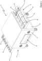
- FIGS 1 to 12show a conveyor-type oven 10 according to a first embodiment of the present invention.
- the oven 10has a housing 12 that has a front wall 14, a rear wall 16, and two opposing longitudinal end walls 18, 20.
- the housing 12has an opening 22, 24 at each of the two longitudinal end walls 18, 20.
- the housing 12defines a baking chamber 26 within which food product - such as pizza - is to be cooked, and a primary chamber 28 that is positioned beneath the baking chamber 26.
- a source of hot airis arranged to introduce hot air into the primary chamber 28.
- the source of hot airis a blower gas burner 30 that receives combustible gas from a supply, burns that gas with air to discharge hot combustion products from a nozzle.
- the nozzledischarges the hot combustion products through a flame tube 31, which surrounds the nozzle of the burner 30, and into the primary chamber 28. Accordingly, in this embodiment, the hot air is introduced by the discharge of hot combustion products into the primary chamber 28.
- hot airis to be understood to include hot combustion products (for example, produced by combusting a mix of air and combustible gases), hot exhaust gases, and heated atmospheric air.
- Combustible gasesinclude propane, natural gas, among others.
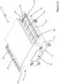
- the oven 12has a conveyor assembly 32 that includes a continuous conveyor belt 34 (which is shown only in Figure 12 , and is omitted from Figures 1 to 11 for clarity).
- the belt 34extends through the baking chamber 26, and the conveyor assembly 32 is driven so as to transport food to be cooked and that is placed on the belt 34 through the baking chamber 26.
- the direction of travel of the belt 34defines a longitudinal direction of the oven 12 (although the assembly 32 may be operated to rotate the belt 34 in either direction without materially affecting the longitudinal direction).
- the oven 10has an upper plenum assembly, and a lower plenum assembly. Ducting interconnects the primary chamber with the upper and lower plenum assemblies.
- the oven 10further has fans 36 that are operable to transport hot air from the primary chamber 28 through the ducting to the upper and lower plenum assemblies from which it is discharged into the baking chamber 26.
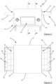
- the oven 12has the benefit of the hot air being generated and distributed in the primary chamber 28, which is beneath the baking chamber 26. This is most evident from Figures 10 to 12 that show, schematically, the portions of the oven 12 that contain the hot air in use; these portions being the primary chamber 28, the fans 36, the ducting and the upper and lower plenum assemblies. This enables heated air to move in the direction of its natural buoyancy, and to enable a construction of oven that has a high degree of symmetry in the components that supply hot air to the baking chamber (the symmetry being considered in vertical planes extending through the centre of the baking chamber). In addition, the oven 12 has the benefit of the burner 30, fans 36, and parts of the ducting being underneath the baking chamber 26, which minimizes the footprint of the oven 12.
- the lower plenum assemblyhas two boxes 38 that each define one the lower plenum chambers.
- the ductingincludes a manifold portion 40 that is to receive hot air from the fans 36, and two lower ducts 42 that each interconnect the manifold portion 40 with one of the boxes 38.
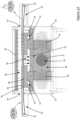
- the upper side of each box 38has orifices from which to discharge hot air upwardly towards the belt 34. The orifices are evident in Figures 5 and 8 , in which the upper side of each box 38 is visible.
- the upper plenum assemblyhas a box 44 that is supported by the housing 12 across the top of the baking chamber 26.
- the ductingfurther includes two upper ducts 46 that interconnect the manifold portion 40 with the box 44.
- Each upper duct 46extends upwardly beside the baking chamber 26 and opens into the long sides of the box 44.
- the upper ducts 46are on opposing sides of the baking chamber 26 so that the hot air enters the box 44 on opposing sides. This symmetrical arrangement facilitates a high degree of symmetry in the gas flows into the box 44.
- the lower side of the box 44has orifices from which to discharge hot air downwardly towards the belt 34. The orifices are evident in Figures 5 to 7 , in which the lower side of the box 44 is visible.
- the orifices in the boxes 38, 44operate to release hot air towards the conveyor belt.
- the boxesmay each have an orifice at the end of a short tube, which is known in this field as a "finger".
- the housing 12includes an internal divider 48 that is positioned between the primary chamber 28 and the baking chamber 26.
- the divider 48has a divider opening 50, which is shown in Figures 5 , 8 , 9 and 12 .
- air within the baking chamber 26is able to propagate through the divider opening 50 and into the primary chamber 28.
- the cooler air within the baking chamber 26that moves to the bottom of the baking chamber 26, and is able to return to the primary chamber 28 via the divider opening 50.
- the baking chamber 26may have an operating temperature in the order of approximately 220 °C to 320 °C.
- the gas returning to the primary chamber 28is cooler than the operating temperature, it will be appreciated that the return of the air enables the more efficient operation of the burner 30. This has the benefit of enabling a reduction in the operating costs of the oven 12.
- the boxes 38 of the lower plenum assemblyare spaced apart in the longitudinal direction.
- the divider opening 50is vertically aligned with the separation of the boxes 38 (as shown in Figure 8 ).
- the floor of each of the boxes 38is vertically spaced above the divider 48. In this way, cooler gas within the baking chamber 26 can propagate beneath the boxes 38, through the divider opening 50, and into the primary chamber 28 in use of the oven 12.
- the boxes 38, 44 of both the lower and upper plenum assembliesextend transversely the full width of the baking chamber 26, such that hot air is supplied evenly across the width of the baking chamber 26.
- the upper plenum assemblyis arranged to provide an air curtain effect across each of the openings 22, 24 to the baking chamber 26.
- the opposing longitudinal ends of the box 44are closer to the openings 22, 24 than the longitudinally outer ends of the two boxes 38.
- the density of orifices in the lower side of the box 44is higher in regions adjacent the openings 22, 24, than in the central region of the box 44.
- the lower side of the box 44has fourteen rows of orifices; each row extending linearly in a transverse direction across the baking chamber 26.
- the separation of the two groups of five rows of orifices adjacent each longitudinal end wall 18, 20 of the housing 12is half the separation of the four rows of orifices that are between these two groups.
- the air curtain effectoperates to minimize heat loss through the openings 22, 24.
- Figures 7 to 9are horizontal cross section views of the oven 12, in which the conveyor assembly has been removed for clarity.
- Figure 7is a section view through the centre of the box 44, such that the lower side of the box 44 is visible; and in particular, the orifices of the upper plenum assembly are visible.
- Figure 8is a section view through the centre of the baking chamber 26, such that the upper sides of the boxes 38 of the lower plenum assembly are visible.
- Figure 9is a section view taken between the lower side of the boxes 38 and the divider 48. In Figure 9 , the gas outlets of the four fans 36, and the flame tube around the nozzle of the burner 30 are visible. The lower ducts 42 are evident in Figure 12 .
- the conveyor assembly 32also has a first outer portion 52 and a second outer portion 54.
- Each of the first and second outer portions 52, 54supports the belt 34 outwardly of the respective first and second openings 22, 24.
- Each of the first and second outer portions 52, 54has a drum roller 56, 58 about which the belt 34 is to rotate.
- the conveyor assembly 32also has a drive for causing the conveyor belt 32 to rotate.
- the driveis contained within a drive box 60.
- the oven 12has an operating panel 62 on the front wall 14, from which a user can adjust the operating parameters of the oven 12, such as the baking chamber temperature, and the belt speed and direction.
- the first and second outer portion 52, 54each include a crumb tray, and the second outer portion 54 includes a tray stop to prevent unattended trays with cooked food from falling from the oven 10.
- a tray stopmay also be provided on the first outer portion.
- the tray stopcan be interchanged between the first and second outer portions so as to be mounted at the appropriate end having regard to the direction of the conveyor belt rotation.
- the belt 34is preferably made of a stainless steel wire mesh through which gas is readily able to pass so that hot gases may reach the underside of a food product resting on the belt.
- an uncooked food productsuch as pizza
- the belt 34is preferably made of a stainless steel wire mesh through which gas is readily able to pass so that hot gases may reach the underside of a food product resting on the belt.
- an uncooked food productsuch as pizza
- the conveyor assembly 32After travelling on the belt 34 through the baking chamber 26, the cooked food product is available to be unloaded on the other of the outer portions.
- the conveyor assembly 32also has a support frame that extends through the baking chamber 26 to provide vertical support to the belt 34.
- the support frameincludes an upper frame 64 that is to support the belt 34 whilst transporting food to be cooked through the baking chamber 26, and a lower frame 66 that is to support the belt 34 in a return traversal (in other words, when the belt is travelling in the opposite direction) of the baking chamber 26.
- the upper and lower frames 64, 66can each include two frame sections, and these frame sections are arranged beside each other in the longitudinal direction of the oven 12. In the illustrated embodiment, each frame section is curved in a vertical plane.
- Each of the upper and lower frames 64, 66has first support members that extend generally transversely to the longitudinal direction, and second support members that extend obliquely to the longitudinal direction. Thus, the first and second support members are neither parallel nor perpendicular with the second support members.
- the oblique arrangement of the second support membershas the benefit of spreading wear across the width of the belt 34. In addition, the heat variation caused by the second support members is spread across the length of the baking chamber 26.
- the variation in cooking of the under side of the food productis spread across the food product.
- the base of a cooked pizzais less likely to have stripes of uncooked, or partially cooked, pizza dough.
- the oven 12has a bank of two fans 36 at each longitudinal end of primary chamber 28.
- the burner 30is arranged with its nozzle and flame tube positioned to discharge hot air into the primary chamber 28 centrally between the two banks of fans 36.
- the oven 12has a conveyor belt width so as to be capable of being loaded with three "lanes" of 30 cm diameter pizza trays.
- the location of the openings 22, 24is indicated to facilitate identification of the orientation of the view, although it will be understood that the openings are not visible in these views.
- FIGs 13 to 18show a conveyor-type oven 110 according to a second embodiment of the present invention.
- the oven 110is substantially similar to the oven 10 of Figures 1 to 12 .
- the features of the oven 110 that are substantially similar to those of the oven 10have the same reference numeral with the prefix "1".
- FIGs 13 to 15 , and 18show the conveyor assembly 132, although the continuous conveyor belt is omitted from these figures for clarity.
- the entire conveyor assembly 132is omitted in its entirety.
- Figure 18the movement of hot air that is moved by the fans 136 from the primary chamber 128, into the ducting, the lower and upper plenum assemblies, and discharged from the orifices (into the baking chamber 126) is shown in the shaded portions, and also by means of solid line arrows.
- the oven 10is to have a conveyor belt width that is capable of being loaded with three "lanes" of 30 cm diameter pizza trays.
- the oven 110is to have a conveyor belt width that is capable of being loaded with four "lanes" of 30 cm diameter pizza trays.
- the baking chamber 126 of the oven 110is wider to accommodate the greater width of the belt.
- the oven 110has two banks of three fans 136; one bank at each longitudinal end of the primary chamber 128.
- the oven 110has six fans 136.
- Figure 16shows the two banks of fans 136 with the nozzle of the burner 130 and the flame tube 131 positioned to discharge hot air centrally into the primary chamber 128, and between the two banks of fans 136.
- FIGs 19 to 24show a conveyor-type oven 210 according to a third embodiment of the present invention.
- the oven 210is substantially similar to the oven 10 of Figures 1 to 12 .
- the features of the oven 210 that are substantially similar to those of the oven 10have the same reference numeral with the prefix "2".
- FIGs 19 to 21 , and 24show the conveyor assembly 232, although the continuous conveyor belt is omitted from these figures for clarity.
- the entire conveyor assembly 232is omitted in its entirety.
- the movement of hot air that is moved by the fans 236 from the primary chamber 228, into the ducting, the lower and upper plenum assemblies, and discharged from the orifices (into the baking chamber 226)is shown in the shaded portions, and also by means of solid line arrows.
- the oven 210is to have a conveyor belt width that is capable of being loaded with 30 cm diameter pizza trays in two "lanes".
- the baking chamber 226 of the oven 210is narrower as it only needs to accommodate a relatively narrow width of the belt.
- the oven 210has two fans 236; one at either longitudinal end of the primary chamber 228.
- the burner 230 and flame tube 231are positioned to discharge hot air centrally into the primary chamber 228, and between the two fans 236.
- hot airmay be introduced into the primary chamber by a gas burner.
- hot airmay be introduced into the primary chamber by a resistive-type heating element (or elements). The heat exchange between the heating elements and the air may occur within the primary chamber, or in a separate space and then introduced into the primary chamber.
Landscapes
- Life Sciences & Earth Sciences (AREA)
- Engineering & Computer Science (AREA)
- Food Science & Technology (AREA)
- Baking, Grill, Roasting (AREA)
Description
- The present invention relates to a conveyor-type oven for cooking food.
- Conveyor-type ovens are often used in the commercial food and hospitality industries for baking food products in a fast, reliable and consistent manner. The prepared, uncooked food is loaded on a conveyor belt on one side of the oven, and the conveyor belt transports the food through the baking chamber at a selected speed. The cooked food arrives at the opposing side. These types of oven are often used for baking pizzas in commercial quantities because there is minimal user intervention required during the cooking process, once the baking chamber conditions and conveyor belt speeds have been set.
- Conveyor-type ovens cook food using either by radiant heat transfer that is generated by resistive heating elements in the baking chamber, or by convective heat transfer via hot air that is generated by a source and supplied to the baking chamber. Typically, convective heat transfer conveyor-type ovens have a gas burner, and fans and ducting that transports the exhausted hot gases to the baking chamber.
- The evenness of temperature in the length and width directions of the baking chamber has a significant impact on the cooking performance of a conveyor-type oven. When used in cooking pizza, variations in temperature can affect the colour and/or "doneness" of the pizza exiting the baking chamber. Considerable effort is made by manufacturers and users of conveyor-type ovens to provide even temperatures. To this end, manufacturers have provided conveyor-type ovens with a high degree of customization so that, in turn, users can "tweak" the oven, with the aim to provide a suitably cooked product, in the shortest time possible.
- In addition, conveyor-type ovens tend to have a large footprint. For many shop owners, the allocation of floor space in their shop is a significant consideration, as this affects the business overheads. The oven installation may represent a substantial portion of that floor space, and also places constraints on the movement of staff within the store. Thus, for many shop owners, it is desirable that the footprint of the oven is minimized.
- The specification of
US4368664 discloses an oven according to the preamble of claim 1. - The specifications of
EP1530006 ,US5179265 ,US 2004/177769 ,WO91/11660 US5231920 andUS4873107 all disclose conveyor-type ovens according to the prior art.EP 1530006 does not disclose the positioning of the heating chamber relative to the cooking chamber, such as claimed in the invention. US 4960100 discloses a conveyor-type oven which does not disclose the positioning of the fan and of the ducts according to the invention.- Accordingly, it is desired to address one or more of the above issues, and/or at least provide a useful alternative.
- The present invention provides a conveyor-type oven comprising the features of claim 1.
- According to the invention, said ducting includes a manifold portion that receives hot air from the fans in use of the oven, and first and second lower ducts that each interconnect the manifold portion with the respective first and second boxes of the lower plenum assembly, the lower duct(s) and manifold portion being located underneath the baking chamber, such that, in use of the oven, hot air from the fans moves linearly upwards in the direction of its natural buoyancy into the baking chamber..
- Preferably, the housing includes a divider between the primary chamber and the baking chamber, the divider having a divider opening, and wherein the first and second boxes are spaced apart, such that, in use of the oven, air within the baking chamber is able to propagate through the space between the first and second boxes, through the divider opening, and into the primary chamber.
- Preferably, the lower plenum chambers are spaced apart in the longitudinal direction.
- Preferably, the divider opening is vertically aligned with the separation of the first and second boxes.
- Alternatively or additionally, the lower plenum assembly can have a floor that is spaced from the divider, such that, in use of the oven, air within the baking chamber is able to propagate beneath the lower plenum assembly, through the divider opening, and into the primary chamber.
- Preferably, the first and second boxes are spaced apart in the longitudinal direction of the oven, and wherein each upper duct opens into the long sides of the box of the upper plenum assembly, such that, in use of the oven, the movement of hot air through the upper ducts is spaced from the return of cooler air through the divider opening.
- In at least some embodiments, the upper plenum assembly is arranged to provide an air curtain effect across each of the openings. Preferably, the opposing ends of the upper plenum assembly are closer to the openings than the opposing ends of the lower plenum assembly. In at least some preferred embodiment, the density of orifices in the upper plenum assembly is higher in regions adjacent the openings, compared with a central region of the upper plenum assembly.
- The ducting includes one or more upper ducts that each extends upwardly beside the baking chamber and opens into the upper manifold assembly. In preferred embodiments, the oven has two upper ducts.
- In certain embodiments, the manifold portion opens into the upper ducts. In some embodiments, the ducting is configured such that at least some hot air discharged from the fans can follow a generally linear path through the manifold portion and into the lower ducts.
- The conveyor belt can be part of a conveyor assembly that comprises:
- a first outer portion that supports the conveyor belt outwardly of a first of the openings;
- a second outer portion that supports the conveyor belt outwardly of a second of the openings;
- a first drum mounted on the first outer portion about which the conveyor belt is to rotate;
- a second drum mounted on the second outer portion about which the conveyor belt is to rotate; and
- a drive for causing the conveyor belt to rotate.
- The conveyor assembly can further comprise a support frame that extends through the baking chamber, and provides vertical support to the belt. In certain embodiments, the support frame extends outwardly of the baking chamber. The support frame can include an upper frame that is to support the belt whilst transporting food to be cooked through the baking chamber. The support frame can also include a lower frame that is to support the belt in a return traversal of the baking chamber.
- At least some sections of the support frame are curved in a vertical plane. The upper and/or lower frames can each include two or more frame sections. Preferably, each frame section is curved in a vertical plane.
- The support frame can include first support members, and second support members, the first support members being non-parallel with the second support members. Preferably, the first support members extend generally transversely to the direction of movement of the conveyor belt. Preferably, the second support members extend obliquely to the direction of movement of the conveyor belt.
- In some embodiments, the oven has a bank of one or more of said fans at each longitudinal end of the primary chamber.
- The source of hot air is a gas burner or resistive-type heating element that is arranged to introduce hot air into the primary chamber.
- In order that the invention may be more easily understood, embodiments will now be described, by way of example only, with reference to the accompanying drawings, in which:
- Figure 1:
- is a perspective view of a conveyor-type oven in accordance with a first embodiment of the present invention;
- Figure 2:
- is a front view of the oven of
Figure 1 ; - Figure 3:
- is a top view of the oven of
Figure 1 ; - Figure 4:
- is a right side view of the oven of
Figure 1 ; - Figure 5:
- is a front, right perspective view of the oven of
Figure 1 , with the conveyor assembly, and side and end panels omitted; - Figure 6:
- is a left side view of the oven as shown in
Figure 5 ; - Figure 7:
- is a cross section view of the oven, as viewed along the line VII-VII in
Figure 4 , with the conveyor assembly omitted; - Figure 8:
- is a cross section view of the oven, as viewed along the line VIII-VIII in
Figure 4 , with the conveyor assembly omitted; - Figure 9:
- is a cross section view of the oven, as viewed along the line IX-IX in
Figure 4 , with the conveyor assembly omitted; - Figure 10:
- is a cross section view of the oven, as viewed along the line X-X in
Figure 2 ; - Figure 11:
- is a cross section view of the oven, as viewed along the line XI-XI in
Figure 2 ; and - Figure 12:
- is a cross section view of the oven, as viewed along the line XII-XII in
Figure 4 ; - Figure 13:
- is a perspective view of a conveyor-type oven in accordance with a second embodiment of the present invention;
- Figure 14:
- is a front view of the oven of
Figure 13 ; - Figure 15:
- is a right side view of the oven of
Figure 13 ; - Figure 16:
- is a front, right perspective view of the oven of
Figure 13 , with the conveyor assembly, and side and end panels omitted; - Figure 17:
- is a cross section view of the oven, as viewed along the line XVII-XVII in
Figure 15 ; - Figure 18:
- is a cross section view of the oven, as viewed along the line XVIII-XVIII in
Figure 14 ; - Figure 19:
- is a perspective view of a conveyor-type oven in accordance with a third embodiment of the present invention;
- Figure 20:
- is a front view of the oven of
Figure 19 ; - Figure 21:
- is a right side view of the oven of
Figure 19 ; - Figure 22:
- is a front, right perspective view of the oven of
Figure 19 , with the conveyor assembly, and side and end panels omitted; - Figure 23:
- is a cross section view of the oven, as viewed along the line XXIII-XXIII in
Figure 21 ; and - Figure 24:
- is a cross section view of the oven, as viewed along the line XXIV-XXIV in
Figure 20 . Figures 1 to 12 show a conveyor-type oven 10 according to a first embodiment of the present invention. Theoven 10 has ahousing 12 that has afront wall 14, arear wall 16, and two opposinglongitudinal end walls housing 12 has anopening longitudinal end walls housing 12 defines abaking chamber 26 within which food product - such as pizza - is to be cooked, and aprimary chamber 28 that is positioned beneath thebaking chamber 26.- A source of hot air is arranged to introduce hot air into the
primary chamber 28. In this particular embodiment, the source of hot air is ablower gas burner 30 that receives combustible gas from a supply, burns that gas with air to discharge hot combustion products from a nozzle. The nozzle discharges the hot combustion products through aflame tube 31, which surrounds the nozzle of theburner 30, and into theprimary chamber 28. Accordingly, in this embodiment, the hot air is introduced by the discharge of hot combustion products into theprimary chamber 28. - For the purposes of this specification and claims, the term "hot air" is to be understood to include hot combustion products (for example, produced by combusting a mix of air and combustible gases), hot exhaust gases, and heated atmospheric air. Combustible gases include propane, natural gas, among others.
- The
oven 12 has aconveyor assembly 32 that includes a continuous conveyor belt 34 (which is shown only inFigure 12 , and is omitted fromFigures 1 to 11 for clarity). Thebelt 34 extends through thebaking chamber 26, and theconveyor assembly 32 is driven so as to transport food to be cooked and that is placed on thebelt 34 through thebaking chamber 26. For the purposes of this specification, it will be understood that the direction of travel of thebelt 34 defines a longitudinal direction of the oven 12 (although theassembly 32 may be operated to rotate thebelt 34 in either direction without materially affecting the longitudinal direction). - Within the
baking chamber 26, theoven 10 has an upper plenum assembly, and a lower plenum assembly. Ducting interconnects the primary chamber with the upper and lower plenum assemblies. Theoven 10 further hasfans 36 that are operable to transport hot air from theprimary chamber 28 through the ducting to the upper and lower plenum assemblies from which it is discharged into thebaking chamber 26. In the embodiment illustrated inFigures 1 to 12 , there are fourfans 36, and these are of the centrifugal type that are each driven by dedicated electrical motor. - The
oven 12 has the benefit of the hot air being generated and distributed in theprimary chamber 28, which is beneath thebaking chamber 26. This is most evident fromFigures 10 to 12 that show, schematically, the portions of theoven 12 that contain the hot air in use; these portions being theprimary chamber 28, thefans 36, the ducting and the upper and lower plenum assemblies. This enables heated air to move in the direction of its natural buoyancy, and to enable a construction of oven that has a high degree of symmetry in the components that supply hot air to the baking chamber (the symmetry being considered in vertical planes extending through the centre of the baking chamber). In addition, theoven 12 has the benefit of theburner 30,fans 36, and parts of the ducting being underneath the bakingchamber 26, which minimizes the footprint of theoven 12. - In this particular embodiment, the lower plenum assembly has two
boxes 38 that each define one the lower plenum chambers. The ducting includes amanifold portion 40 that is to receive hot air from thefans 36, and twolower ducts 42 that each interconnect themanifold portion 40 with one of theboxes 38. The upper side of eachbox 38 has orifices from which to discharge hot air upwardly towards thebelt 34. The orifices are evident inFigures 5 and8 , in which the upper side of eachbox 38 is visible. - In this embodiment, the upper plenum assembly has a
box 44 that is supported by thehousing 12 across the top of thebaking chamber 26. The ducting further includes twoupper ducts 46 that interconnect themanifold portion 40 with thebox 44. Eachupper duct 46 extends upwardly beside the bakingchamber 26 and opens into the long sides of thebox 44. As is particularly evident fromFigures 10 and 11 , theupper ducts 46 are on opposing sides of thebaking chamber 26 so that the hot air enters thebox 44 on opposing sides. This symmetrical arrangement facilitates a high degree of symmetry in the gas flows into thebox 44. The lower side of thebox 44 has orifices from which to discharge hot air downwardly towards thebelt 34. The orifices are evident inFigures 5 to 7 , in which the lower side of thebox 44 is visible. - The orifices in the
boxes - The
housing 12 includes aninternal divider 48 that is positioned between theprimary chamber 28 and thebaking chamber 26. Thedivider 48 has adivider opening 50, which is shown inFigures 5 ,8 ,9 and12 . In use of theoven 12, air within thebaking chamber 26 is able to propagate through thedivider opening 50 and into theprimary chamber 28. As will be appreciated, it is the cooler air within thebaking chamber 26 that moves to the bottom of thebaking chamber 26, and is able to return to theprimary chamber 28 via thedivider opening 50. In operation of theoven 12, the bakingchamber 26 may have an operating temperature in the order of approximately 220 °C to 320 °C. Although the gas returning to theprimary chamber 28 is cooler than the operating temperature, it will be appreciated that the return of the air enables the more efficient operation of theburner 30. This has the benefit of enabling a reduction in the operating costs of theoven 12. - To facilitate the movement of cooler gas towards the
divider opening 50, theboxes 38 of the lower plenum assembly are spaced apart in the longitudinal direction. Conveniently, in this embodiment thedivider opening 50 is vertically aligned with the separation of the boxes 38 (as shown inFigure 8 ). In addition, in this embodiment the floor of each of theboxes 38 is vertically spaced above thedivider 48. In this way, cooler gas within thebaking chamber 26 can propagate beneath theboxes 38, through thedivider opening 50, and into theprimary chamber 28 in use of theoven 12. - The
boxes baking chamber 26, such that hot air is supplied evenly across the width of thebaking chamber 26. However, as will be evident fromFigure 12 , the upper plenum assembly is arranged to provide an air curtain effect across each of theopenings baking chamber 26. To this end, the opposing longitudinal ends of thebox 44 are closer to theopenings boxes 38. Further, the density of orifices in the lower side of thebox 44 is higher in regions adjacent theopenings box 44. The lower side of thebox 44 has fourteen rows of orifices; each row extending linearly in a transverse direction across the bakingchamber 26. As is shown inFigure 7 , the separation of the two groups of five rows of orifices adjacent eachlongitudinal end wall housing 12 is half the separation of the four rows of orifices that are between these two groups. The air curtain effect operates to minimize heat loss through theopenings Figures 7 to 9 are horizontal cross section views of theoven 12, in which the conveyor assembly has been removed for clarity.Figure 7 is a section view through the centre of thebox 44, such that the lower side of thebox 44 is visible; and in particular, the orifices of the upper plenum assembly are visible.Figure 8 is a section view through the centre of thebaking chamber 26, such that the upper sides of theboxes 38 of the lower plenum assembly are visible.Figure 9 is a section view taken between the lower side of theboxes 38 and thedivider 48. InFigure 9 , the gas outlets of the fourfans 36, and the flame tube around the nozzle of theburner 30 are visible. Thelower ducts 42 are evident inFigure 12 .- In addition to the
conveyor belt 34, theconveyor assembly 32 also has a firstouter portion 52 and a secondouter portion 54. Each of the first and secondouter portions belt 34 outwardly of the respective first andsecond openings outer portions drum roller belt 34 is to rotate. Theconveyor assembly 32 also has a drive for causing theconveyor belt 32 to rotate. In this embodiment, the drive is contained within adrive box 60. Theoven 12 has anoperating panel 62 on thefront wall 14, from which a user can adjust the operating parameters of theoven 12, such as the baking chamber temperature, and the belt speed and direction. The first and secondouter portion outer portion 54 includes a tray stop to prevent unattended trays with cooked food from falling from theoven 10. In some alternative embodiments in which the conveyor belt is to be operable in either direction, a tray stop may also be provided on the first outer portion. In some embodiments, the tray stop can be interchanged between the first and second outer portions so as to be mounted at the appropriate end having regard to the direction of the conveyor belt rotation. - The
belt 34 is preferably made of a stainless steel wire mesh through which gas is readily able to pass so that hot gases may reach the underside of a food product resting on the belt. As is indicated inFigure 12 , an uncooked food product, such as pizza, is loaded onto the belt on one of the outer portions of theconveyor assembly 32. After travelling on thebelt 34 through thebaking chamber 26, the cooked food product is available to be unloaded on the other of the outer portions. - The
conveyor assembly 32 also has a support frame that extends through thebaking chamber 26 to provide vertical support to thebelt 34. In this embodiment, the support frame includes anupper frame 64 that is to support thebelt 34 whilst transporting food to be cooked through thebaking chamber 26, and alower frame 66 that is to support thebelt 34 in a return traversal (in other words, when the belt is travelling in the opposite direction) of thebaking chamber 26. - The upper and
lower frames oven 12. In the illustrated embodiment, each frame section is curved in a vertical plane. Each of the upper andlower frames belt 34. In addition, the heat variation caused by the second support members is spread across the length of thebaking chamber 26. In uses of theoven 12 in which the food product is placed directly onto the belt 34 (that is, in which a cooking tray is not used) the variation in cooking of the under side of the food product is spread across the food product. For example, the base of a cooked pizza is less likely to have stripes of uncooked, or partially cooked, pizza dough. - As is shown most clearly in
Figures 5 and6 , in this embodiment theoven 12 has a bank of twofans 36 at each longitudinal end ofprimary chamber 28. Theburner 30 is arranged with its nozzle and flame tube positioned to discharge hot air into theprimary chamber 28 centrally between the two banks offans 36. - In
Figures 10 to 12 , the movement of hot air that is discharged from theburner 30 into theprimary chamber 28, and then into the ducting, the lower and upper plenum assemblies, and discharged from the orifices (into the baking chamber 26) is shown in the shaded portions, and also by means of solid line arrows. The movement of cooler gas towards and/or through thedivider opening 50 is shown by means of dashed line arrows. - The
oven 12 has a conveyor belt width so as to be capable of being loaded with three "lanes" of 30 cm diameter pizza trays. InFigures 5 and6 , the location of theopenings Figures 13 to 18 show a conveyor-type oven 110 according to a second embodiment of the present invention. Theoven 110 is substantially similar to theoven 10 ofFigures 1 to 12 . InFigures 13 to 18 , the features of theoven 110 that are substantially similar to those of theoven 10 have the same reference numeral with the prefix "1".Figures 13 to 15 , and18 show theconveyor assembly 132, although the continuous conveyor belt is omitted from these figures for clarity. InFigures 16 and17 , theentire conveyor assembly 132 is omitted in its entirety. InFigure 18 , the movement of hot air that is moved by thefans 136 from theprimary chamber 128, into the ducting, the lower and upper plenum assemblies, and discharged from the orifices (into the baking chamber 126) is shown in the shaded portions, and also by means of solid line arrows.- The
oven 10 is to have a conveyor belt width that is capable of being loaded with three "lanes" of 30 cm diameter pizza trays. In contrast, theoven 110 is to have a conveyor belt width that is capable of being loaded with four "lanes" of 30 cm diameter pizza trays. Thebaking chamber 126 of theoven 110 is wider to accommodate the greater width of the belt. As a consequence of this greater width, theoven 110 has two banks of threefans 136; one bank at each longitudinal end of theprimary chamber 128. In other words, theoven 110 has sixfans 136.Figure 16 shows the two banks offans 136 with the nozzle of theburner 130 and theflame tube 131 positioned to discharge hot air centrally into theprimary chamber 128, and between the two banks offans 136. Figures 19 to 24 show a conveyor-type oven 210 according to a third embodiment of the present invention. Theoven 210 is substantially similar to theoven 10 ofFigures 1 to 12 . InFigures 19 to 24 , the features of theoven 210 that are substantially similar to those of theoven 10 have the same reference numeral with the prefix "2".Figures 19 to 21 , and24 show theconveyor assembly 232, although the continuous conveyor belt is omitted from these figures for clarity. InFigure 22 , theentire conveyor assembly 232 is omitted in its entirety. InFigure 24 , the movement of hot air that is moved by thefans 236 from theprimary chamber 228, into the ducting, the lower and upper plenum assemblies, and discharged from the orifices (into the baking chamber 226) is shown in the shaded portions, and also by means of solid line arrows.- The
oven 210 is to have a conveyor belt width that is capable of being loaded with 30 cm diameter pizza trays in two "lanes". Thebaking chamber 226 of theoven 210 is narrower as it only needs to accommodate a relatively narrow width of the belt. As a consequence of this narrower width, theoven 210 has twofans 236; one at either longitudinal end of theprimary chamber 228. As shown inFigure 22 , theburner 230 andflame tube 231 are positioned to discharge hot air centrally into theprimary chamber 228, and between the twofans 236. - It will be appreciated that the present invention is not limited to embodiments in which hot air is introduced into the primary chamber by a gas burner. In some alternative embodiments, hot air may be introduced into the primary chamber by a resistive-type heating element (or elements). The heat exchange between the heating elements and the air may occur within the primary chamber, or in a separate space and then introduced into the primary chamber.
- Throughout this specification and the claims which follow, unless the context requires otherwise, the word "comprise", and variations such as "comprises" and "comprising", will be understood to imply the inclusion of a stated integer or step or group of integers or steps but not the exclusion of any other integer or step or group of integers or steps.
Claims (12)
- A conveyor-type oven comprising:a housing (12, 112, 212) defining a baking chamber (26, 126, 226), and a primary chamber (28, 128, 228) that is positioned beneath the baking chamber, the housing having an opening (22, 122, 222, 24, 124, 224) at each of the two longitudinal ends of the baking chamber;a gas burner (30, 130, 230) or a resistive-type heating element underneath the baking chamber that is arranged to introduce hot air into the primary chamber;a continuous conveyor belt (32, 132, 232) for transporting food to be cooked through the baking chamber;an upper plenum assembly comprising a box (44, 144, 244) that is supported by the housing (12, 112, 212) across the top of the baking chamber (26, 126, 226) and includes a plurality of orifices from which to discharge hot air downwardly towards the conveyor belt;a lower plenum assembly comprising first and second boxes (38, 138, 238), each box being disposed in the baking chamber (26, 126, 226) and the upper side of each box (38, 138, 238) having a plurality of orifices from which to discharge hot air upwardly towards the conveyor belt;ducting (40, 140, 240, 42, 142, 242, 46, 146, 246) that interconnects the primary chamber (28, 128, 228) with the upper and lower plenum assemblies; andfans (36, 136, 236) that are operable to transport hot air from the primary chamber (28, 128, 228) through the ducting to the upper and lower plenum assemblies; each of said fans (36, 136, 236) being underneath the baking chamber (26, 126, 226);the ducting including two upper ducts (46, 146, 246) that each extends upwardly on opposing sides of the baking chamber (26, 126, 226) and opens into the box (44, 144, 244) of the upper plenum assembly for movement of hot air to the box (44, 144, 244) in use of the oven;characterised in that said ducting includes a manifold portion (40, 140, 240) that receives hot air from the fans (36, 136, 236) in use of the oven, and first and second lower ducts (42, 142, 242) that each interconnect the manifold portion (40, 140, 240) with the respective first and second boxes (38, 138, 238) of the lower plenum assembly, the lower ducts (42, 142, 242) and manifold portion 40 being located underneath the baking chamber, such that, in use of the oven, hot air from the fans (36, 136, 236) moves linearly upwards in the direction of its natural buoyancy into the baking chamber.
- A conveyor-type oven according to claim 1, wherein the housing (12, 112, 212) includes a divider (48, 148, 248) between the primary chamber (28, 128, 228) and the baking chamber (26, 126, 226), the divider having a divider opening (50, 150, 250), and wherein the first and second boxes (38, 138, 238) are spaced apart, such that, in use of the oven, air within the baking chamber is able to propagate through the space between the first and second boxes (38, 138, 238), through the divider opening, and into the primary chamber.
- A conveyor-type oven according to claim 2, wherein the divider opening (50, 150, 250) is vertically aligned with the separation of the first and second boxes (38, 138, 238).
- A conveyor-type oven according to claim 2 or 3, wherein the lower plenum assembly (38, 138, 238) has a floor that is spaced from the divider (48, 148, 248), such that, in use of the oven, air within the baking chamber (26, 126, 226) is able to propagate beneath the lower plenum assembly, through the divider opening (50, 150, 250), and into the primary chamber (28, 128, 228).
- A conveyor-type oven according to claim 3, wherein the first and second boxes (38, 138, 238) are spaced apart in the longitudinal direction of the oven, and wherein each upper duct (46, 146, 246) opens into the long sides of the box (44, 144, 244) of the upper plenum assembly, such that, in use of the oven, the movement of hot air through the upper ducts (46, 146, 246) is spaced from the return of cooler air through the divider opening (50, 150, 250).
- A conveyor-type oven according to any one of the preceding claims, wherein opposing ends of the upper plenum assembly (44, 144, 244) are closer to the openings (22, 122, 222, 24, 124, 224) than opposing ends of the lower plenum assembly (38, 138, 238), so as to provide an air curtain effect across each of the openings.
- A conveyor-type oven according to any one of the preceding claims, wherein the density of orifices in the upper plenum assembly (44, 144, 244) is higher in regions adjacent the openings (22, 122, 222, 24, 124, 224), compared with a central region of the upper plenum assembly.
- A conveyor-type oven according to any one of the preceding claims, wherein the manifold portion (40, 140, 240) opens into the upper ducts (46, 146, 246).
- A conveyor-type oven according to any one of the preceding claims, wherein the conveyor belt (32, 132, 232) is part of a conveyor assembly that comprises:a first outer portion (52, 152, 252) that supports the conveyor belt outwardly of a first of the openings;a second outer portion (54, 154, 254) that supports the conveyor belt outwardly of a second of the openings;a first drum (56, 156, 256) mounted on the first outer portion about which the conveyor belt is to rotate;a second drum (58, 158, 258) mounted on the second outer portion about which the conveyor belt is to rotate; anda drive (60, 160, 260) for causing the conveyor belt to rotate.
- A conveyor-type oven according to claim 9, wherein the conveyor assembly further comprises a support frame (64, 164, 264, 66, 166, 266) that extends through the baking chamber (26, 126, 226), and provides vertical support to the belt (32, 132, 232).
- A conveyor-type oven according to any one of the preceding claims, wherein the oven has a bank of one or more of said fans (36, 136, 236) at each longitudinal end of the primary chamber (28, 128, 228).
- A conveyor-type oven according to any one of the preceding claims, wherein the gas burner is arranged to introduce hot air into the primary chamber (28, 128, 228).
Applications Claiming Priority (2)
| Application Number | Priority Date | Filing Date | Title |
|---|---|---|---|
| AU2016900882AAU2016900882A0 (en) | 2016-03-09 | Conveyer-type Oven | |
| PCT/AU2017/050200WO2017152225A1 (en) | 2016-03-09 | 2017-03-08 | Conveyor-type oven |
Publications (3)
| Publication Number | Publication Date |
|---|---|
| EP3426046A1 EP3426046A1 (en) | 2019-01-16 |
| EP3426046A4 EP3426046A4 (en) | 2019-10-30 |
| EP3426046B1true EP3426046B1 (en) | 2023-06-07 |
Family
ID=59788925
Family Applications (1)
| Application Number | Title | Priority Date | Filing Date |
|---|---|---|---|
| EP17762329.5AActiveEP3426046B1 (en) | 2016-03-09 | 2017-03-08 | Conveyor-type oven |
Country Status (5)
| Country | Link |
|---|---|
| US (1) | US11266152B2 (en) |
| EP (1) | EP3426046B1 (en) |
| AU (1) | AU2017231095B2 (en) |
| NZ (1) | NZ746496A (en) |
| WO (1) | WO2017152225A1 (en) |
Families Citing this family (3)
| Publication number | Priority date | Publication date | Assignee | Title |
|---|---|---|---|---|
| US10948193B2 (en)* | 2018-08-06 | 2021-03-16 | Haier Us Appliance Solutions, Inc. | Fan assembly for an induction cooking appliance |
| US11485581B2 (en)* | 2019-10-29 | 2022-11-01 | John Bean Technologies Ab | Air balance tunnel for spiral conveyor |
| WO2021101363A2 (en)* | 2019-11-21 | 2021-05-27 | Baptista Barocio Rodrigo | Hot food vending machine |
Citations (3)
| Publication number | Priority date | Publication date | Assignee | Title |
|---|---|---|---|---|
| CA892920A (en)* | 1972-02-15 | Jansen Peter | Oven apparatus | |
| US4252055A (en)* | 1978-06-19 | 1981-02-24 | Tipe Reven Ab | Tunnel-chamber baking oven |
| EP1530006A2 (en)* | 2003-11-04 | 2005-05-11 | OEM - Ali S.p.A | Convection oven with exchangeable energy supply |
Family Cites Families (175)
| Publication number | Priority date | Publication date | Assignee | Title |
|---|---|---|---|---|
| US2778914A (en)* | 1954-10-22 | 1957-01-22 | Gen Electric | Control circuits for electric ovens |
| US3154004A (en)* | 1961-06-19 | 1964-10-27 | Knapp Monarch Co | Oven toaster |
| US3257544A (en)* | 1963-05-09 | 1966-06-21 | Warren Electric Corp | Heating circuits |
| US3736860A (en)* | 1971-04-06 | 1973-06-05 | Vischer Products Co | Infrared cooking apparatus |
| US4065659A (en)* | 1976-01-09 | 1977-12-27 | Mcgraw-Edison Company | Food processing oven |
| US4479776A (en)* | 1981-07-22 | 1984-10-30 | Smith Donald P | Thermal treatment of food products |
| US4492839A (en)* | 1976-05-19 | 1985-01-08 | Smith Donald P | Thermal treatment apparatus |
| FR2365927A1 (en)* | 1976-09-28 | 1978-04-21 | Cepem | METHOD AND DEVICE FOR REGULATING THE TEMPERATURE FOR CLEANING AN OVEN |
| US4176589A (en)* | 1978-02-27 | 1979-12-04 | Marshall Air Systems, Inc. | Cooking apparatus |
| US4368664A (en) | 1978-05-01 | 1983-01-18 | Donald P. Smith | Apparatus to transfer heat to a product and side loading door therefor |
| US4281594A (en)* | 1979-07-26 | 1981-08-04 | Npi Corporation | Bun section toaster |
| US4302661A (en)* | 1980-03-31 | 1981-11-24 | Perry Jr Edward H | Self-cleaning oven control system |
| US4337893A (en)* | 1980-04-07 | 1982-07-06 | Energy Savings Parhelion | Multi-phase modular comfort controlled heating system |
| US4377109B1 (en)* | 1981-05-22 | 1996-08-06 | Wolverine Corp | Apparatus for baking food products such as pizzas and the like |
| US4389562A (en)* | 1981-08-05 | 1983-06-21 | Hatco Corporation | Conveyor oven |
| US4474498A (en)* | 1982-01-22 | 1984-10-02 | Smith Donald P | Multiple-pass impingement heating and cooling device |
| US5361749A (en)* | 1982-02-10 | 1994-11-08 | Southbend | Gas fired convection oven |
| US4679542A (en)* | 1982-03-19 | 1987-07-14 | Donald P. Smith | Fan-plenum configuration |
| US4576090A (en)* | 1982-05-19 | 1986-03-18 | Mastermatic, Inc. | Tunnel heater |
| US4471750A (en)* | 1982-05-19 | 1984-09-18 | Mastermatic, Inc. | Tunnel heater |
| US4462383A (en)* | 1982-06-09 | 1984-07-31 | Lincoln Manufacturing Company, Inc. | Impingement food preparation apparatus |
| US4438572A (en)* | 1982-06-09 | 1984-03-27 | Lincoln Manufacturing Co., Inc. | Heat duct support assembly for a food preparation oven and method |
| US4538049A (en)* | 1984-04-03 | 1985-08-27 | Black & Decker, Inc. | Toaster oven |
| US4626661A (en)* | 1984-04-16 | 1986-12-02 | Lincoln Manufacturing Company, Inc. | Air delivery system for an impingement food preparation oven |
| US4554437A (en)* | 1984-05-17 | 1985-11-19 | Pet Incorporated | Tunnel oven |
| US4556043A (en)* | 1984-09-17 | 1985-12-03 | Lincoln Manufacturing Company, Inc. | Air delivery system for an impingement food preparation oven including a conical air deflector |
| US4591333A (en)* | 1985-03-26 | 1986-05-27 | Lincoln Manufacturing Company, Inc. | Impingement oven with radiant panel |
| US4749581A (en)* | 1985-09-03 | 1988-06-07 | Lincoln Foodservice Products, Inc. | Method for baking a food product |
| US4965435A (en)* | 1985-10-15 | 1990-10-23 | Donald P. Smith | Forced convection tunnel oven |
| FR2588641B1 (en)* | 1985-10-16 | 1987-11-20 | Europ Equip Menager | PYROLYSIS CLEANING COOKING OVEN |
| US4701340A (en)* | 1985-12-09 | 1987-10-20 | Lincoln Foodservice Products, Inc. | Impingement and steam oven apparatus for preparing food products |
| JPS62271386A (en)* | 1986-01-04 | 1987-11-25 | カ−ル・ツワイス・ステイフツング | Glass-ceramic system cooking oven |
| US5013563A (en)* | 1986-05-23 | 1991-05-07 | Marshall Air Systems, Inc. | Conveyorized cooking method |
| US4873107A (en)* | 1986-12-24 | 1989-10-10 | Archer Air Industries, Inc. | Air impingement tunnel oven apparatus |
| US4757800A (en)* | 1987-01-14 | 1988-07-19 | Lincoln Foodservice Products, Inc. | Air flow system for a low profile impingement oven |
| US4753215A (en)* | 1987-01-14 | 1988-06-28 | Lincoln Foodservice Products, Inc. | Burner for low profile inpingement oven |
| US4781169A (en)* | 1987-04-14 | 1988-11-01 | Lincoln Foodservice Products, Inc. | Oven with radiant panel |
| US4834063A (en)* | 1987-05-28 | 1989-05-30 | Stein Associates, Inc. | Food cooking oven with duct fingers and method |
| AU3436289A (en)* | 1988-03-10 | 1989-10-05 | Pizza Hut Inc. | Method and oven for baking pizza |
| US4964392A (en)* | 1988-07-05 | 1990-10-23 | Middleby Marshall Inc. | Baking oven |
| US4881519A (en)* | 1988-07-18 | 1989-11-21 | Lincoln Foodservice Products, Inc. | Hot air oven having infra-red radiant surfaces |
| US4924763A (en)* | 1988-10-17 | 1990-05-15 | Pizza Hut | Compact pizza oven |
| US4940040A (en)* | 1989-01-31 | 1990-07-10 | Stein, Inc. | Adjustable cooking oven |
| US4960100A (en)* | 1989-03-13 | 1990-10-02 | Mastermatic, Inc. | Conveyor oven |
| US4951648A (en)* | 1989-03-23 | 1990-08-28 | Tecogen, Inc. | Conveyor oven |
| FR2648034B1 (en)* | 1989-06-09 | 1994-07-08 | Seb Sa | MULTIPURPOSE TOASTER |
| US5185172A (en)* | 1989-07-10 | 1993-02-09 | Kfc Corporation | Method for simulating open flame broiled meat products |
| CA2024203C (en)* | 1989-09-22 | 2002-07-30 | Donald P. Smith | Balanced air return convection oven |
| US5398666A (en)* | 1989-09-22 | 1995-03-21 | Patentsmith Ii, Inc. | Turntable convection heater |
| US5205274A (en)* | 1989-09-22 | 1993-04-27 | Patentsmith Ii, Inc. | Turntable convection oven |
| US6041398A (en)* | 1992-06-26 | 2000-03-21 | International Business Machines Corporation | Massively parallel multiple-folded clustered processor mesh array |
| US4936286A (en)* | 1989-11-08 | 1990-06-26 | Nieco Corporation, A Division Of Alco Standard Corporation | Gas broiler |
| US5401940A (en)* | 1990-01-10 | 1995-03-28 | Patentsmith Ii, Inc. | Oscillating air dispensers for microwave oven |
| US5717192A (en)* | 1990-01-10 | 1998-02-10 | Patentsmith Technology, Ltd. | Jet impingement batch oven |
| US5818014A (en)* | 1990-01-10 | 1998-10-06 | Patentsmith Technology, Ltd. | Air dispensers for microwave oven |
| US5078120A (en) | 1990-01-26 | 1992-01-07 | Stein, Inc. | Cooking oven for slow cooking of food products |
| US5321920A (en) | 1990-05-23 | 1994-06-21 | Sichel Gerald M S | Roof gutter screen |
| US5025775A (en)* | 1990-06-04 | 1991-06-25 | Lincoln Foodservice Products, Inc. | Air delivery system and oven control circuitry cooling system for a low profile impingement oven |
| US5179265A (en) | 1990-08-21 | 1993-01-12 | United Electric Controls Company | Cooking time control system for conveyor ovens |
| US5239917A (en)* | 1991-06-06 | 1993-08-31 | Genie Tech, Inc. | Oven |
| US5180898A (en)* | 1991-07-25 | 1993-01-19 | G. S. Blodgett Corporation | High velocity conveyor oven |
| US5253564A (en)* | 1991-08-30 | 1993-10-19 | The Middleby Corporation | Conveyor oven control |
| US5197375A (en)* | 1991-08-30 | 1993-03-30 | The Middleby Corporation | Conveyor oven control |
| US5231920A (en)* | 1991-09-19 | 1993-08-03 | G. S. Blodgett Corporation | Conveyor oven with uniform air flow |
| US5276978A (en)* | 1991-10-03 | 1994-01-11 | Hopkins International, Inc. | Temperature controlled conveyor dryer |
| US5351416A (en)* | 1991-10-31 | 1994-10-04 | Marshall And Williams Company | Clean air oven with heat recovery and method |
| US5655511A (en)* | 1992-02-10 | 1997-08-12 | Southbend-A. Middleby Company | Gas fired convection oven |
| US5584237A (en)* | 1994-12-12 | 1996-12-17 | Zesto Inc. | Heated air-circulating oven |
| US5671660A (en)* | 1994-12-12 | 1997-09-30 | Moshonas; Georges | Heated air-circulating oven |
| US6080972A (en)* | 1995-02-16 | 2000-06-27 | May; Leonhard | Remotely operated universal programmable oven controller |
| AU7362696A (en)* | 1995-09-19 | 1997-04-28 | Pillsbury Company, The | Broiler apparatus |
| US5588354A (en)* | 1995-09-21 | 1996-12-31 | Marshall Air Systems, Inc. | Apparatus for conveyorized griddle-like cooking of food products |
| US5640896A (en)* | 1995-11-20 | 1997-06-24 | Stuck; Robert M. | Conveyorized cooking apparatus for imparting charcoal flavoring to foods and gas-fired burner assembly for use in such apparatus |
| US5676044A (en)* | 1996-01-03 | 1997-10-14 | Lara, Jr.; George A. | Rotary air impingement oven |
| US5673610A (en)* | 1996-08-23 | 1997-10-07 | Stuck; Robert M. | Apparatus for conveyorized toasting of breads and like food items |
| US5964044A (en)* | 1997-01-14 | 1999-10-12 | Wisconsin Oven Corporation | Conveyor oven usable as pre-bake oven in a print plate imaging and processing system and method of using same |
| EP0920274B1 (en)* | 1997-01-29 | 2002-01-23 | Koninklijke Philips Electronics N.V. | Electric toaster with asymmetric heating effect |
| US5832812A (en)* | 1997-02-25 | 1998-11-10 | Wolfe; Ronald Dale | Dual conveyer oven |
| US5821503A (en)* | 1997-07-23 | 1998-10-13 | Hatco Corporation | Conveyor speed control ciruit for a conveyor oven |
| US6157002A (en)* | 1998-02-06 | 2000-12-05 | Middleby Cooking Systems Group | Small conveyor toaster/oven |
| US6146677A (en)* | 1998-05-01 | 2000-11-14 | Remco Techologies, Inc. | High efficiency infrared oven |
| DE69937309T2 (en)* | 1998-05-23 | 2008-01-31 | Enersyst Development Center, L.L.C., Dallas | CONVECTION OVEN WITH HIGH HEAT TRANSFER SPEED, GREASE MANAGEMENT AND SMOKE REDUCTION ABILITY |
| US6016935A (en)* | 1998-08-01 | 2000-01-25 | Star Manufacturing International, Inc. | Viscous food dispensing and heating/cooling assembly and method |
| US6201218B1 (en)* | 1998-10-08 | 2001-03-13 | The Frymaster Corporation | Food cooking apparatus with removable conveyor assembly and serpentine heater providing non-uniform heating |
| US6684657B1 (en)* | 1999-03-18 | 2004-02-03 | Enersyst Development Center, L.L.C. | Rethermalization / refrigeration food delivery system |
| AU4021200A (en)* | 1999-03-23 | 2000-10-09 | Pizza Hut Inc. | Impingement oven airflow devices and methods |
| US6205910B1 (en)* | 1999-04-16 | 2001-03-27 | Star Manufacturing International Inc. | Toaster assembly and method for toasting bread products |
| WO2001005235A2 (en)* | 1999-07-16 | 2001-01-25 | Stuck Robert M | Loader for conveyorized cooking apparatus |
| US6595117B1 (en)* | 1999-08-04 | 2003-07-22 | The Frymaster Corporation | High speed variable size toaster |
| US6817283B2 (en)* | 1999-08-04 | 2004-11-16 | Lincoln Foodservice Products, Inc. | High speed cooking device and method |
| US6223650B1 (en)* | 1999-09-30 | 2001-05-01 | Robert M. Stuck | Apparatus for conveyorized toasting of breads and like food items |
| US6252201B1 (en)* | 2000-01-06 | 2001-06-26 | Middleby Marshall Incorporated | Small fast acting conveyor toaster oven |
| DE10107289A1 (en)* | 2000-03-14 | 2001-09-27 | Werner & Pfleiderer Lebensmitt | Tunnel baking oven has continuous baking conveyor belts driven at same direction and drivable at same or different rates, which run from inlet station to outlet station of each baking chamber |
| US6572911B1 (en)* | 2000-04-21 | 2003-06-03 | The Pillsbury Company | Impingement oven with steam injection and method of baking dough products |
| US6526961B1 (en)* | 2000-07-10 | 2003-03-04 | Lincoln Foodservice Products, Inc | Conveyor oven |
| US6723961B2 (en)* | 2000-08-29 | 2004-04-20 | Maytag Corporation | Self-cleaning system for convection cooking appliance |
| US6684875B1 (en)* | 2000-11-17 | 2004-02-03 | Middleby Corporation | Conveyor oven with modulated gas flow |
| EP1408763A1 (en)* | 2001-03-22 | 2004-04-21 | Zesto Food Equipment Manufacturing Inc. | Multiconveyor convection oven |
| US6462319B1 (en)* | 2001-05-29 | 2002-10-08 | Bsh Home Appliances Corporation | Multi-stage self-cleaning control for oven |
| US6389960B1 (en)* | 2001-07-12 | 2002-05-21 | Middleby-Marshall, Inc. | Gas-fired cooking device with griddle surface heated by heat bank |
| US6624396B2 (en)* | 2001-08-28 | 2003-09-23 | Hatco Corporation | Conveyor speed control system for a conveyor oven |
| US6386095B1 (en)* | 2001-08-31 | 2002-05-14 | Nick Ausaf | Skewers mounted on an oven conveyor belt |
| US6576874B2 (en)* | 2001-09-06 | 2003-06-10 | Bakers Pride | Modular heating element for a conveyor oven |
| US20030041851A1 (en)* | 2001-09-06 | 2003-03-06 | Charles Kingdon | Conveyor oven having a removable front cover |
| US6638553B2 (en)* | 2001-10-09 | 2003-10-28 | Recot, Inc. | System and method for monolayer alignment snack chip transfer |
| US6655373B1 (en)* | 2001-11-14 | 2003-12-02 | Middleby Marshall, Incorporated | High efficiency conveyor oven |
| US6592364B2 (en)* | 2001-11-30 | 2003-07-15 | David Zapata | Apparatus, method and system for independently controlling airflow in a conveyor oven |
| US6718965B2 (en)* | 2002-01-29 | 2004-04-13 | Dynamic Cooking Systems, Inc. | Gas “true” convection bake oven |
| WO2003082024A1 (en)* | 2002-03-27 | 2003-10-09 | Endodis Corporation | Conveyorized oven with moisture laden air impingement and method |
| US6936793B1 (en)* | 2002-04-17 | 2005-08-30 | Novastar Technologiesm Inc. | Oven apparatus and method of use thereof |
| US20030213371A1 (en)* | 2002-05-14 | 2003-11-20 | Saunders David N. | Conveyor-toaster control system |
| US7007807B1 (en)* | 2003-01-29 | 2006-03-07 | Fmc Technologies, Inc. | Sorting system for multiple conveyor belts |
| WO2005112650A1 (en)* | 2003-02-21 | 2005-12-01 | Middleby Corporation | Charbroiler |
| US20070006865A1 (en)* | 2003-02-21 | 2007-01-11 | Wiker John H | Self-cleaning oven |
| JP2004269242A (en) | 2003-03-12 | 2004-09-30 | Paloma Ind Ltd | Conveyor oven |
| US7297903B1 (en)* | 2003-04-11 | 2007-11-20 | A.J. Antunes & Company | Faster universal contact toaster |
| US7307243B2 (en)* | 2003-05-09 | 2007-12-11 | North Carolina State University | Dynamic radiant food preparation methods and systems |
| US7038172B1 (en)* | 2003-05-16 | 2006-05-02 | Marshall Air Systems, Inc. | Conveyorized food broiling apparatus |
| MXPA05013045A (en)* | 2003-06-10 | 2006-08-23 | Lincoln Foodservice | A high speed cooking oven having an air impingement heater with an improved orifice configuration. |
| US6880545B2 (en)* | 2003-08-28 | 2005-04-19 | Gas Research Institute | Dual conveyor jet impingement oven |
| ES2537300T3 (en)* | 2003-09-16 | 2015-06-05 | Lincoln Foodservice Products, Inc. | Conveyor belt oven with improved air return and method |
| ITMI20032120A1 (en)* | 2003-11-04 | 2005-05-05 | Oem Ali S P A | VENTILATED GAS OVEN FOR FOOD PRODUCTS AND HEAT EXCHANGER FOR SUCH OVEN |
| US7850448B2 (en)* | 2004-03-03 | 2010-12-14 | Beckett Gas, Inc. | Furnace |
| MXPA06010098A (en)* | 2004-03-05 | 2007-04-25 | Turbochef Tech Inc | Conveyor oven. |
| US8087407B2 (en)* | 2004-03-23 | 2012-01-03 | Middleby Corporation | Conveyor oven apparatus and method |
| US9585400B2 (en)* | 2004-03-23 | 2017-03-07 | The Middleby Corporation | Conveyor oven apparatus and method |
| US7202447B2 (en)* | 2004-04-02 | 2007-04-10 | Kingdon Charles J | Conveyor type oven |
| US7026579B2 (en)* | 2004-04-28 | 2006-04-11 | Q-Matic Technologies, Inc. | Food preparation oven having quartz heaters |
| FI115834B (en)* | 2004-06-09 | 2005-07-29 | Tamglass Ltd Oy | Heating glass panels in heating oven involves heating the glass panel from above and below with convection air or with a combination of convection air and radiation heat, where convection air is heated using heat accumulator |
| US20060087136A1 (en)* | 2004-10-12 | 2006-04-27 | Jayson Pearl | French fry scoop |
| US7624728B1 (en)* | 2004-12-22 | 2009-12-01 | David C Forbes | Impingement tunnel oven with reduced energy consumption and reduced maintenance |
| US7340992B1 (en)* | 2005-01-27 | 2008-03-11 | Wolfe Electric, Inc. | Dual belt conveyor oven |
| NL1028252C2 (en)* | 2005-02-11 | 2006-08-14 | Cfs Bakel Bv | Method for treating food products, as well as line oven therefor. |
| US20060243721A1 (en)* | 2005-04-14 | 2006-11-02 | Chris Sorensen | Conveyor steam cabinet and preparation method for consumable-at-sale food products |
| US7921767B2 (en)* | 2005-05-13 | 2011-04-12 | Burger King Corporation | Automatic broiler for variable batch cooking |
| ITPS20060024A1 (en)* | 2006-07-27 | 2008-01-28 | Moretti Forni S P A | SYSTEM FOR OPTIMIZATION OF THE FUNCTIONALITY OF GAS TAPES FOR FOOD |
| WO2008030573A2 (en)* | 2006-09-08 | 2008-03-13 | Lincoln Foodservice Products, L.L.C. | Conveyor oven and method with smart control |
| CN101528044B (en)* | 2006-09-14 | 2012-11-14 | 林科尔恩食品服务产品有限公司 | Ovens with flowing airflow and energy saving features |
| GB2455397B (en)* | 2006-09-29 | 2012-02-01 | Fgf Brands Inc | System and method for preparing naan bread |
| AU2007313345B2 (en)* | 2006-10-13 | 2011-12-08 | Lincoln Foodservices Products, Llc | Impinging air ovens having high mass flow orifices |
| US8075304B2 (en)* | 2006-10-19 | 2011-12-13 | Wayne/Scott Fetzer Company | Modulated power burner system and method |
| US20080092754A1 (en)* | 2006-10-19 | 2008-04-24 | Wayne/Scott Fetzer Company | Conveyor oven |
| US7604000B2 (en)* | 2006-12-21 | 2009-10-20 | Wolfe Electric, Inc. | Tunnel oven |
| EP2139341B1 (en)* | 2007-03-10 | 2016-11-16 | TurboChef Technologies, Inc. | Compact conveyor oven |
| US7800023B2 (en)* | 2007-04-24 | 2010-09-21 | Prince Castle LLC | Conveyor oven with hybrid heating sources |
| US7851727B2 (en)* | 2007-05-16 | 2010-12-14 | Prince Castle LLC | Method of controlling an oven with hybrid heating sources |
| US8642928B2 (en)* | 2007-10-09 | 2014-02-04 | Acp, Inc. | Temperature control for cooking appliance including combination heating system |
| WO2009049081A1 (en)* | 2007-10-09 | 2009-04-16 | Acp, Inc. | Air circuit for cooking appliance including combination heating system |
| US8093533B2 (en)* | 2007-12-17 | 2012-01-10 | Michael French | Modular pizza oven kit, pizza oven finger assembly support, and a method of operating a pizza oven at different speeds and a control arrangement for performing the method |
| AU2009202799A1 (en)* | 2008-07-11 | 2010-01-28 | Breville Pty Limited | Toaster Oven |
| AU2008359322B2 (en)* | 2008-07-16 | 2013-05-23 | Fgf Brands Inc. | Bottom access dollies for conveyor oven |
| WO2010027922A1 (en)* | 2008-09-05 | 2010-03-11 | The Middleby Corporation | Recirculating end cover plates for a conveyor oven |
| US8210844B2 (en)* | 2008-10-27 | 2012-07-03 | Wolfe Electric, Inc. | Air impingement conveyor oven |
| US8839714B2 (en)* | 2009-08-28 | 2014-09-23 | The Middleby Corporation | Apparatus and method for controlling a conveyor oven |
| US20110048244A1 (en)* | 2009-08-28 | 2011-03-03 | Wiker John H | Apparatus and method for controlling a combustion blower in a gas-fueled conveyor oven |
| WO2011106608A1 (en)* | 2010-02-26 | 2011-09-01 | Merco/Savory Llc | Conveyor oven and method for handling heated air |
| WO2011106628A1 (en)* | 2010-02-26 | 2011-09-01 | Merco/Savory Llc | A conveyor oven and method for easy access for maintenance |
| US20110277643A1 (en)* | 2010-05-11 | 2011-11-17 | Roger Schwierking | Quick heating quartz toaster |
| WO2011146867A1 (en)* | 2010-05-21 | 2011-11-24 | The Middleby Corporation | Conveyor oven and conveyor belt for conveyor oven |
| US8536493B1 (en)* | 2010-11-30 | 2013-09-17 | Wolfe Electric, Inc. | Vertically stacked air impingement tunnel oven |
| WO2012099893A2 (en)* | 2011-01-17 | 2012-07-26 | Lincoln Foodservice Products Llc | Impingement oven with a plurality of variable airflow cooking zones |
| US8733236B2 (en)* | 2011-09-20 | 2014-05-27 | Ovention, Inc. | Matchbox oven |
| US8637792B2 (en)* | 2011-05-18 | 2014-01-28 | Prince Castle, LLC | Conveyor oven with adjustable air vents |
| US20130192583A1 (en)* | 2012-02-01 | 2013-08-01 | Darwin Chang | Oven convection fan |
| US10004358B2 (en)* | 2012-05-16 | 2018-06-26 | Hatco Corporation | Toaster with controlled conveyor speed |
| US8776773B1 (en)* | 2012-08-27 | 2014-07-15 | Wolfe Electric, Inc. | Air impingement tunnel oven |
| EP2935056B2 (en)* | 2012-12-21 | 2023-07-26 | John Bean Technologies Corporation | Thermal measurement and process control |
| US20140199446A1 (en)* | 2013-01-11 | 2014-07-17 | Star Manufacturing International, Inc. | Split-Belt Conveyor Toaster |
| US9149154B1 (en)* | 2013-03-04 | 2015-10-06 | Marshall Air Systems, Inc. | Apparatus for transiently holding cooked food in a warm condition pending service of the food for consumption |
| US9320284B2 (en)* | 2013-03-12 | 2016-04-26 | The Middleby Corporation | Conveyor oven with split flow scroll |
| US20140331870A1 (en)* | 2013-05-13 | 2014-11-13 | Marel Meat Processing Inc. | Peeling System And Peeling Machine For Peeling A Strand Of Food Product |
| US9723952B2 (en)* | 2013-12-06 | 2017-08-08 | J & B Sausage Company, Inc. | Roller conveyor oven for heating while rotating and conveying a multiplicity of cylindrical food items thereon |
| CN106687749A (en)* | 2014-08-19 | 2017-05-17 | 克利夫兰炉灶有限责任公司 | A system to prevent incorrect finger placement in conveyor ovens |
| US9560853B2 (en)* | 2014-12-23 | 2017-02-07 | Aleksandr Taslagyan | Return flow conveyor device for heating food items |
| US9924832B2 (en)* | 2015-06-19 | 2018-03-27 | Prince Castle LLC | Heating system for heating a food product |
- 2017
- 2017-03-08NZNZ746496Apatent/NZ746496A/enunknown
- 2017-03-08WOPCT/AU2017/050200patent/WO2017152225A1/ennot_activeCeased
- 2017-03-08USUS16/083,402patent/US11266152B2/enactiveActive
- 2017-03-08AUAU2017231095Apatent/AU2017231095B2/enactiveActive
- 2017-03-08EPEP17762329.5Apatent/EP3426046B1/enactiveActive
Patent Citations (3)
| Publication number | Priority date | Publication date | Assignee | Title |
|---|---|---|---|---|
| CA892920A (en)* | 1972-02-15 | Jansen Peter | Oven apparatus | |
| US4252055A (en)* | 1978-06-19 | 1981-02-24 | Tipe Reven Ab | Tunnel-chamber baking oven |
| EP1530006A2 (en)* | 2003-11-04 | 2005-05-11 | OEM - Ali S.p.A | Convection oven with exchangeable energy supply |
Also Published As
| Publication number | Publication date |
|---|---|
| US11266152B2 (en) | 2022-03-08 |
| AU2017231095A1 (en) | 2018-10-11 |
| NZ746496A (en) | 2021-12-24 |
| EP3426046A1 (en) | 2019-01-16 |
| AU2017231095B2 (en) | 2022-12-08 |
| WO2017152225A1 (en) | 2017-09-14 |
| EP3426046A4 (en) | 2019-10-30 |
| US20190090494A1 (en) | 2019-03-28 |
Similar Documents
| Publication | Publication Date | Title |
|---|---|---|
| EP1797758B1 (en) | Continuous cooking oven system | |
| US5228385A (en) | Convection oven for bakery goods | |
| EP1199963B1 (en) | High speed variable size toaster | |
| US8646383B1 (en) | Spiral oven apparatus and method of cooking | |
| US6817283B2 (en) | High speed cooking device and method | |
| CN101589283B (en) | Impingement Air Ovens with High Quality Flow Orifices | |
| CN106455584A (en) | Baking oven | |
| US9375016B2 (en) | Convection heating in track ovens | |
| EP3426046B1 (en) | Conveyor-type oven | |
| JPH04228019A (en) | Air supply system for low impingement oven, and cooling system for oven control circuit | |
| JPH0439330B2 (en) | ||
| US20060249138A1 (en) | Convection oven for bakery goods | |
| JP2005521395A (en) | Conveyor oven and method for impinging moisture-containing air | |
| US6065463A (en) | Forced convective track oven | |
| US6138660A (en) | Forced convective track oven having oval spirals | |
| US5544570A (en) | Continuous oven for making baked ware | |
| US1971766A (en) | Baking oven | |
| US20190373899A1 (en) | Conveyor baking oven for continuous baking operation | |
| AU2011227241B2 (en) | An oven for heating food | |
| US4355972A (en) | Travelling baking oven | |
| AU2014284710B2 (en) | A steam generating system | |
| US3543697A (en) | Double lap oven heating system | |
| US6425260B1 (en) | Tortilla cooling conveyor with distributed air diffusion | |
| JP2007068789A (en) | Food heating equipment | |
| BR112019015518A2 (en) | SPIRAL CARRIER THERMAL PROCESSING SYSTEM |
Legal Events
| Date | Code | Title | Description |
|---|---|---|---|
| STAA | Information on the status of an ep patent application or granted ep patent | Free format text:STATUS: THE INTERNATIONAL PUBLICATION HAS BEEN MADE | |
| PUAI | Public reference made under article 153(3) epc to a published international application that has entered the european phase | Free format text:ORIGINAL CODE: 0009012 | |
| STAA | Information on the status of an ep patent application or granted ep patent | Free format text:STATUS: REQUEST FOR EXAMINATION WAS MADE | |
| 17P | Request for examination filed | Effective date:20181004 | |
| AK | Designated contracting states | Kind code of ref document:A1 Designated state(s):AL AT BE BG CH CY CZ DE DK EE ES FI FR GB GR HR HU IE IS IT LI LT LU LV MC MK MT NL NO PL PT RO RS SE SI SK SM TR | |
| AX | Request for extension of the european patent | Extension state:BA ME | |
| DAV | Request for validation of the european patent (deleted) | ||
| DAX | Request for extension of the european patent (deleted) | ||
| A4 | Supplementary search report drawn up and despatched | Effective date:20191001 | |
| RIC1 | Information provided on ipc code assigned before grant | Ipc:A21B 1/24 20060101ALI20190925BHEP Ipc:A21B 1/48 20060101ALI20190925BHEP Ipc:A21B 1/26 20060101AFI20190925BHEP | |
| STAA | Information on the status of an ep patent application or granted ep patent | Free format text:STATUS: EXAMINATION IS IN PROGRESS | |
| 17Q | First examination report despatched | Effective date:20200722 | |
| GRAP | Despatch of communication of intention to grant a patent | Free format text:ORIGINAL CODE: EPIDOSNIGR1 | |
| STAA | Information on the status of an ep patent application or granted ep patent | Free format text:STATUS: GRANT OF PATENT IS INTENDED | |
| INTG | Intention to grant announced | Effective date:20221111 | |
| GRAS | Grant fee paid | Free format text:ORIGINAL CODE: EPIDOSNIGR3 | |
| GRAA | (expected) grant | Free format text:ORIGINAL CODE: 0009210 | |
| STAA | Information on the status of an ep patent application or granted ep patent | Free format text:STATUS: THE PATENT HAS BEEN GRANTED | |
| AK | Designated contracting states | Kind code of ref document:B1 Designated state(s):AL AT BE BG CH CY CZ DE DK EE ES FI FR GB GR HR HU IE IS IT LI LT LU LV MC MK MT NL NO PL PT RO RS SE SI SK SM TR | |
| REG | Reference to a national code | Ref country code:GB Ref legal event code:FG4D | |
| REG | Reference to a national code | Ref country code:CH Ref legal event code:EP Ref country code:AT Ref legal event code:REF Ref document number:1571941 Country of ref document:AT Kind code of ref document:T Effective date:20230615 | |
| REG | Reference to a national code | Ref country code:DE Ref legal event code:R096 Ref document number:602017069629 Country of ref document:DE | |
| REG | Reference to a national code | Ref country code:NL Ref legal event code:FP | |
| REG | Reference to a national code | Ref country code:LT Ref legal event code:MG9D | |
| PG25 | Lapsed in a contracting state [announced via postgrant information from national office to epo] | Ref country code:SE Free format text:LAPSE BECAUSE OF FAILURE TO SUBMIT A TRANSLATION OF THE DESCRIPTION OR TO PAY THE FEE WITHIN THE PRESCRIBED TIME-LIMIT Effective date:20230607 Ref country code:NO Free format text:LAPSE BECAUSE OF FAILURE TO SUBMIT A TRANSLATION OF THE DESCRIPTION OR TO PAY THE FEE WITHIN THE PRESCRIBED TIME-LIMIT Effective date:20230907 Ref country code:ES Free format text:LAPSE BECAUSE OF FAILURE TO SUBMIT A TRANSLATION OF THE DESCRIPTION OR TO PAY THE FEE WITHIN THE PRESCRIBED TIME-LIMIT Effective date:20230607 | |
| REG | Reference to a national code | Ref country code:AT Ref legal event code:MK05 Ref document number:1571941 Country of ref document:AT Kind code of ref document:T Effective date:20230607 | |
| PG25 | Lapsed in a contracting state [announced via postgrant information from national office to epo] | Ref country code:RS Free format text:LAPSE BECAUSE OF FAILURE TO SUBMIT A TRANSLATION OF THE DESCRIPTION OR TO PAY THE FEE WITHIN THE PRESCRIBED TIME-LIMIT Effective date:20230607 Ref country code:LV Free format text:LAPSE BECAUSE OF FAILURE TO SUBMIT A TRANSLATION OF THE DESCRIPTION OR TO PAY THE FEE WITHIN THE PRESCRIBED TIME-LIMIT Effective date:20230607 Ref country code:LT Free format text:LAPSE BECAUSE OF FAILURE TO SUBMIT A TRANSLATION OF THE DESCRIPTION OR TO PAY THE FEE WITHIN THE PRESCRIBED TIME-LIMIT Effective date:20230607 Ref country code:HR Free format text:LAPSE BECAUSE OF FAILURE TO SUBMIT A TRANSLATION OF THE DESCRIPTION OR TO PAY THE FEE WITHIN THE PRESCRIBED TIME-LIMIT Effective date:20230607 Ref country code:GR Free format text:LAPSE BECAUSE OF FAILURE TO SUBMIT A TRANSLATION OF THE DESCRIPTION OR TO PAY THE FEE WITHIN THE PRESCRIBED TIME-LIMIT Effective date:20230908 | |
| PG25 | Lapsed in a contracting state [announced via postgrant information from national office to epo] | Ref country code:FI Free format text:LAPSE BECAUSE OF FAILURE TO SUBMIT A TRANSLATION OF THE DESCRIPTION OR TO PAY THE FEE WITHIN THE PRESCRIBED TIME-LIMIT Effective date:20230607 | |
| PG25 | Lapsed in a contracting state [announced via postgrant information from national office to epo] | Ref country code:SK Free format text:LAPSE BECAUSE OF FAILURE TO SUBMIT A TRANSLATION OF THE DESCRIPTION OR TO PAY THE FEE WITHIN THE PRESCRIBED TIME-LIMIT Effective date:20230607 | |
| PG25 | Lapsed in a contracting state [announced via postgrant information from national office to epo] | Ref country code:IS Free format text:LAPSE BECAUSE OF FAILURE TO SUBMIT A TRANSLATION OF THE DESCRIPTION OR TO PAY THE FEE WITHIN THE PRESCRIBED TIME-LIMIT Effective date:20231007 | |
| PG25 | Lapsed in a contracting state [announced via postgrant information from national office to epo] | Ref country code:SM Free format text:LAPSE BECAUSE OF FAILURE TO SUBMIT A TRANSLATION OF THE DESCRIPTION OR TO PAY THE FEE WITHIN THE PRESCRIBED TIME-LIMIT Effective date:20230607 Ref country code:SK Free format text:LAPSE BECAUSE OF FAILURE TO SUBMIT A TRANSLATION OF THE DESCRIPTION OR TO PAY THE FEE WITHIN THE PRESCRIBED TIME-LIMIT Effective date:20230607 Ref country code:RO Free format text:LAPSE BECAUSE OF FAILURE TO SUBMIT A TRANSLATION OF THE DESCRIPTION OR TO PAY THE FEE WITHIN THE PRESCRIBED TIME-LIMIT Effective date:20230607 Ref country code:PT Free format text:LAPSE BECAUSE OF FAILURE TO SUBMIT A TRANSLATION OF THE DESCRIPTION OR TO PAY THE FEE WITHIN THE PRESCRIBED TIME-LIMIT Effective date:20231009 Ref country code:IS Free format text:LAPSE BECAUSE OF FAILURE TO SUBMIT A TRANSLATION OF THE DESCRIPTION OR TO PAY THE FEE WITHIN THE PRESCRIBED TIME-LIMIT Effective date:20231007 Ref country code:EE Free format text:LAPSE BECAUSE OF FAILURE TO SUBMIT A TRANSLATION OF THE DESCRIPTION OR TO PAY THE FEE WITHIN THE PRESCRIBED TIME-LIMIT Effective date:20230607 Ref country code:CZ Free format text:LAPSE BECAUSE OF FAILURE TO SUBMIT A TRANSLATION OF THE DESCRIPTION OR TO PAY THE FEE WITHIN THE PRESCRIBED TIME-LIMIT Effective date:20230607 Ref country code:AT Free format text:LAPSE BECAUSE OF FAILURE TO SUBMIT A TRANSLATION OF THE DESCRIPTION OR TO PAY THE FEE WITHIN THE PRESCRIBED TIME-LIMIT Effective date:20230607 | |
| PG25 | Lapsed in a contracting state [announced via postgrant information from national office to epo] | Ref country code:PL Free format text:LAPSE BECAUSE OF FAILURE TO SUBMIT A TRANSLATION OF THE DESCRIPTION OR TO PAY THE FEE WITHIN THE PRESCRIBED TIME-LIMIT Effective date:20230607 | |
| REG | Reference to a national code | Ref country code:DE Ref legal event code:R097 Ref document number:602017069629 Country of ref document:DE | |
| PLBE | No opposition filed within time limit | Free format text:ORIGINAL CODE: 0009261 | |
| STAA | Information on the status of an ep patent application or granted ep patent | Free format text:STATUS: NO OPPOSITION FILED WITHIN TIME LIMIT | |
| PG25 | Lapsed in a contracting state [announced via postgrant information from national office to epo] | Ref country code:DK Free format text:LAPSE BECAUSE OF FAILURE TO SUBMIT A TRANSLATION OF THE DESCRIPTION OR TO PAY THE FEE WITHIN THE PRESCRIBED TIME-LIMIT Effective date:20230607 | |
| PG25 | Lapsed in a contracting state [announced via postgrant information from national office to epo] | Ref country code:SI Free format text:LAPSE BECAUSE OF FAILURE TO SUBMIT A TRANSLATION OF THE DESCRIPTION OR TO PAY THE FEE WITHIN THE PRESCRIBED TIME-LIMIT Effective date:20230607 | |
| 26N | No opposition filed | Effective date:20240308 | |
| PG25 | Lapsed in a contracting state [announced via postgrant information from national office to epo] | Ref country code:SI Free format text:LAPSE BECAUSE OF FAILURE TO SUBMIT A TRANSLATION OF THE DESCRIPTION OR TO PAY THE FEE WITHIN THE PRESCRIBED TIME-LIMIT Effective date:20230607 Ref country code:IT Free format text:LAPSE BECAUSE OF FAILURE TO SUBMIT A TRANSLATION OF THE DESCRIPTION OR TO PAY THE FEE WITHIN THE PRESCRIBED TIME-LIMIT Effective date:20230607 | |
| REG | Reference to a national code | Ref country code:CH Ref legal event code:PL | |
| PG25 | Lapsed in a contracting state [announced via postgrant information from national office to epo] | Ref country code:BG Free format text:LAPSE BECAUSE OF FAILURE TO SUBMIT A TRANSLATION OF THE DESCRIPTION OR TO PAY THE FEE WITHIN THE PRESCRIBED TIME-LIMIT Effective date:20230607 | |
| PG25 | Lapsed in a contracting state [announced via postgrant information from national office to epo] | Ref country code:LU Free format text:LAPSE BECAUSE OF NON-PAYMENT OF DUE FEES Effective date:20240308 | |
| PG25 | Lapsed in a contracting state [announced via postgrant information from national office to epo] | Ref country code:MC Free format text:LAPSE BECAUSE OF FAILURE TO SUBMIT A TRANSLATION OF THE DESCRIPTION OR TO PAY THE FEE WITHIN THE PRESCRIBED TIME-LIMIT Effective date:20230607 | |
| PG25 | Lapsed in a contracting state [announced via postgrant information from national office to epo] | Ref country code:MC Free format text:LAPSE BECAUSE OF FAILURE TO SUBMIT A TRANSLATION OF THE DESCRIPTION OR TO PAY THE FEE WITHIN THE PRESCRIBED TIME-LIMIT Effective date:20230607 Ref country code:LU Free format text:LAPSE BECAUSE OF NON-PAYMENT OF DUE FEES Effective date:20240308 Ref country code:BG Free format text:LAPSE BECAUSE OF FAILURE TO SUBMIT A TRANSLATION OF THE DESCRIPTION OR TO PAY THE FEE WITHIN THE PRESCRIBED TIME-LIMIT Effective date:20230607 | |
| PG25 | Lapsed in a contracting state [announced via postgrant information from national office to epo] | Ref country code:IE Free format text:LAPSE BECAUSE OF NON-PAYMENT OF DUE FEES Effective date:20240308 | |
| PG25 | Lapsed in a contracting state [announced via postgrant information from national office to epo] | Ref country code:IE Free format text:LAPSE BECAUSE OF NON-PAYMENT OF DUE FEES Effective date:20240308 Ref country code:CH Free format text:LAPSE BECAUSE OF NON-PAYMENT OF DUE FEES Effective date:20240331 | |
| PGFP | Annual fee paid to national office [announced via postgrant information from national office to epo] | Ref country code:DE Payment date:20250319 Year of fee payment:9 | |
| PGFP | Annual fee paid to national office [announced via postgrant information from national office to epo] | Ref country code:NL Payment date:20250319 Year of fee payment:9 | |
| PGFP | Annual fee paid to national office [announced via postgrant information from national office to epo] | Ref country code:BE Payment date:20250319 Year of fee payment:9 | |
| PGFP | Annual fee paid to national office [announced via postgrant information from national office to epo] | Ref country code:FR Payment date:20250326 Year of fee payment:9 | |
| PGFP | Annual fee paid to national office [announced via postgrant information from national office to epo] | Ref country code:GB Payment date:20250324 Year of fee payment:9 | |
| PG25 | Lapsed in a contracting state [announced via postgrant information from national office to epo] | Ref country code:CY Free format text:LAPSE BECAUSE OF FAILURE TO SUBMIT A TRANSLATION OF THE DESCRIPTION OR TO PAY THE FEE WITHIN THE PRESCRIBED TIME-LIMIT; INVALID AB INITIO Effective date:20170308 | |
| PG25 | Lapsed in a contracting state [announced via postgrant information from national office to epo] | Ref country code:HU Free format text:LAPSE BECAUSE OF FAILURE TO SUBMIT A TRANSLATION OF THE DESCRIPTION OR TO PAY THE FEE WITHIN THE PRESCRIBED TIME-LIMIT; INVALID AB INITIO Effective date:20170308 |