EP3423156B1 - Sonotrode - Google Patents
SonotrodeDownload PDFInfo
- Publication number
- EP3423156B1 EP3423156B1EP17716628.7AEP17716628AEP3423156B1EP 3423156 B1EP3423156 B1EP 3423156B1EP 17716628 AEP17716628 AEP 17716628AEP 3423156 B1EP3423156 B1EP 3423156B1
- Authority
- EP
- European Patent Office
- Prior art keywords
- sonotrode
- cap portion
- ultrasonic
- working face
- axis
- Prior art date
- Legal status (The legal status is an assumption and is not a legal conclusion. Google has not performed a legal analysis and makes no representation as to the accuracy of the status listed.)
- Active
Links
Images


Classifications
- A—HUMAN NECESSITIES
- A61—MEDICAL OR VETERINARY SCIENCE; HYGIENE
- A61N—ELECTROTHERAPY; MAGNETOTHERAPY; RADIATION THERAPY; ULTRASOUND THERAPY
- A61N7/00—Ultrasound therapy
- A—HUMAN NECESSITIES
- A61—MEDICAL OR VETERINARY SCIENCE; HYGIENE
- A61B—DIAGNOSIS; SURGERY; IDENTIFICATION
- A61B18/00—Surgical instruments, devices or methods for transferring non-mechanical forms of energy to or from the body
- A61B18/04—Surgical instruments, devices or methods for transferring non-mechanical forms of energy to or from the body by heating
- A—HUMAN NECESSITIES
- A61—MEDICAL OR VETERINARY SCIENCE; HYGIENE
- A61B—DIAGNOSIS; SURGERY; IDENTIFICATION
- A61B17/00—Surgical instruments, devices or methods
- A61B17/32—Surgical cutting instruments
- A61B17/320068—Surgical cutting instruments using mechanical vibrations, e.g. ultrasonic
- A—HUMAN NECESSITIES
- A61—MEDICAL OR VETERINARY SCIENCE; HYGIENE
- A61B—DIAGNOSIS; SURGERY; IDENTIFICATION
- A61B17/00—Surgical instruments, devices or methods
- A61B17/32—Surgical cutting instruments
- A61B17/320068—Surgical cutting instruments using mechanical vibrations, e.g. ultrasonic
- A61B2017/320098—Surgical cutting instruments using mechanical vibrations, e.g. ultrasonic with transverse or torsional motion
- A—HUMAN NECESSITIES
- A61—MEDICAL OR VETERINARY SCIENCE; HYGIENE
- A61B—DIAGNOSIS; SURGERY; IDENTIFICATION
- A61B18/00—Surgical instruments, devices or methods for transferring non-mechanical forms of energy to or from the body
- A61B2018/00315—Surgical instruments, devices or methods for transferring non-mechanical forms of energy to or from the body for treatment of particular body parts
- A61B2018/00452—Skin
- A61B2018/00458—Deeper parts of the skin, e.g. treatment of vascular disorders or port wine stains
- A61B2018/00464—Subcutaneous fat, e.g. liposuction, lipolysis
- A—HUMAN NECESSITIES
- A61—MEDICAL OR VETERINARY SCIENCE; HYGIENE
- A61N—ELECTROTHERAPY; MAGNETOTHERAPY; RADIATION THERAPY; ULTRASOUND THERAPY
- A61N7/00—Ultrasound therapy
- A61N2007/0004—Applications of ultrasound therapy
- A61N2007/0008—Destruction of fat cells
- A—HUMAN NECESSITIES
- A61—MEDICAL OR VETERINARY SCIENCE; HYGIENE
- A61N—ELECTROTHERAPY; MAGNETOTHERAPY; RADIATION THERAPY; ULTRASOUND THERAPY
- A61N7/00—Ultrasound therapy
- A61N2007/0004—Applications of ultrasound therapy
- A61N2007/0034—Skin treatment
Definitions
- the inventionin some embodiments, relates to the field of treatment of body tissue with acoustically-delivered energy and more particularly, to devices for treatment of subcutaneous fat suitable for simultaneously transdermally inducing both ultrasonic transverse vibrations and ultrasonic longitudinal vibrations in subcutaneous tissue thereby acoustically delivering energy through the skin, for example for reduction of subcutaneous fat by applying ultrasonic vibrations to a skin surface.
- a device 10that includes a proximal ultrasonic transducer 12 for generation of ultrasonic longitudinal vibrations (e.g., a Langevin-type transducer comprising a stack of piezoelectric elements) having a proximal face 14 functionally associated with an acoustic reflector 16 and a distal face 18 and a distal sonotrode 20 having a proximal face 22, a distal end 24 defining a working face 26 that constitutes an acoustic radiative surface and a sonotrode axis 28, where the proximal face 22 of the sonotrode 20 is acoustically coupled to the distal face 18 of the ultrasonic transducer 12.
- a proximal ultrasonic transducer 12for generation of ultrasonic longitudinal vibrations (e.g., a Langevin-type transducer comprising a stack of piezoelectric elements) having a proximal face 14 functionally associated with an acoustic reflector 16 and a distal
- an alternating current (AC) oscillating at an ultrasonic driving frequencyis supplied from an ultrasound power supply 34 to drive the ultrasonic transducer 12.
- the piezoelectric elements of the ultrasonic transducer 12expand and relax at the driving frequency in response to the oscillations of the AC potential, thereby generating ultrasonic longitudinal vibrations with the frequency of the driving frequency.
- the generated ultrasonic longitudinal vibrationspropagate in parallel with the axis 28 through the sonotrode 20 from the proximal face 22 to the working face 26.
- the working face 26applies the ultrasonic longitudinal vibrations to the surface 30, inducing ultrasonic longitudinal vibrations in the medium 32.
- a sonotrodeFor practical use it is advantageous to configure a sonotrode to function as an acoustic amplitude transformer (also called a horn) that increases the amplitude of the ultrasonic longitudinal vibrations (i.e., the maximal displacement of distal working face 26) from being relatively small at the proximal face 22 of the sonotrode 20 to substantially larger at working face 26, typically to between 10 and 150 micrometers.
- acoustic amplitude transformeralso called a horn
- Such configurationincludes that the sonotrode tapers from a large cross section proximal end 22 to a small cross section working face 26 and that the total length 36 of the sonotrode (from proximal face 22 to working face 26) is an integral multiple of ⁇ L/2, ⁇ L being the wavelength of the ultrasonic longitudinal vibrations in the sonotrode which is dependent on the driving frequency and on the longitudinal speed of sound along the axis 28 so that the sonotrode functions as a halfwavelength resonator.
- Figure 2Aa linear taper sonotrode 38a
- Figure 2Ban exponential taper sonotrode 38b
- Figure 2Ca stepped taper sonotrode 38c.
- the ultrasonic vibrations in the sonotrode and that are induced in a mediumare predominantly, if not entirely, longitudinal vibrations that propagate collinearly with the axis 28 of the sonotrode.
- the biological effects of energy transdermally delivered by ultrasonic longitudinal vibrationsprimarily arise from heating of tissue, especially heating of the dermis.
- FIG. 2dsuch a mushroom-shaped sonotrode 38d is schematically depicted in side cross section having a tapering stem 40 that functions as an acoustic amplitude transformer as described above (particularly sonotrode 38c depicted in Figure 2C ) and a broader cap 42.
- Cap 42is lenticular, in side cross section resembling a lens having a curved back side 44 and a convex working face 26.
- Working face 26 of sonotrode 38dalso includes concentric circular transverse-wave transferring ridges 46.
- a sonotrodesuch as 38d is operative to transdermally induce, depending on the value of the driving frequency, either ultrasonic longitudinal vibrations or ultrasonic transverse vibrations in subcutaneous tissue when the working face 26 is acoustically coupled with skin.
- the ultrasonic longitudinal vibrations generated by an ultrasonic transducer 12preferentially propagate in parallel with the axis 28 of mushroom-shaped sonotrode such as 38d from the proximal face 22 to the working face 26.
- These ultrasonic longitudinal vibrationsprimarily lead to ultrasonic longitudinal vibrations of the sonotrode 38d, which are applied by working face 26 to a skin surface acoustically coupled with working face 26, transdermally inducing ultrasonic longitudinal vibrations in the subcutaneous tissue.
- the ultrasonic longitudinal vibrations generated by an ultrasonic transducer 12preferentially produce ultrasonic shear wave vibrations in the cap 42 of sonotrode 38d, the ultrasonic shear wave vibrations being perpendicular to the longitudinal vibrations in the stem 40, that is to say, a greater proportion of the energy transferred by the transducer 12 into the sonotrode 38d is in ultrasonic shear wave vibrations in the cap 42 perpendicular to axis 28 rather than ultrasonic longitudinal vibrations parallel or collinear with axis 28.
- working face 26substantially vibrates transversely, presumably alternately increasing and decreasing in diameter.
- the ultrasonic shear wave vibrationsinduce ultrasonic transverse vibrations in the subcutaneous tissue by virtue of the convex shape of working face 26 and by virtue of the concentric circular transverse-wave transferring ridges 46 that can be considered as physically moving the skin and tissue transversely.
- a device including a sonotrode such as 38dprovides two modes of operation that are advantageously serially activated:
- ultrasonic longitudinal vibrations of the first mode and ultrasonic shear wave vibrations of the second modeare alternately applied through a mushroom-shaped sonotrode such as 38d described above.
- the ultrasonic longitudinal vibrationsare applied by the working face to the skin surface (typically for a duration of about 5 seconds) to transdermally induce ultrasonic longitudinal waves that heat subcutaneous tissue such as the dermis.
- ultrasonic shear wave vibrationsare applied by the working face to the skin surface (typically for a duration of about 15 seconds) to induce ultrasonic transverse vibrations to disrupt the adipocytes.
- the ultrasonic transverse vibrationspenetrate more deeply and/or more effectively and/or a greater fraction of the energy penetrates to a given depth of the adipose tissue and/or the heated tissue has improved energy-absorbing properties.
- a sonotrodesuch as described in US 2011/0213279 is sometimes considered less than ideal for some uses because the shear wave vibrations are not applied continuously, because of the added complexity required for generating and switching between two different driving frequencies and because if a user moves the working face over different portions of a treated subjects too quickly, the results of a treatment might be considered less than ideal.
- an ultrasonic treatment apparatusincludes an ultrasonic transducer to generate ultrasonic vibration, a probe (sonotrode) a proximal end of which is connected to the ultrasonic transducer and which extends from a proximal end side to a distal end side, and a treatment portion which includes at least one recess formed on the side of the probe and treats a living tissue by ultrasonic vibration generated by the ultrasonic transducer.
- an ultrasonic lipectomy probe devicewith a sonotrode having a shank with a proximal end and a distal end, a connector at the proximal end of the shank for connecting the shank to a source of ultrasonic vibrational energy, and an enlarged head at the distal end of the shank.
- the probe headhas a width, in a first direction, substantially larger than an outer diameter of the shank at the distal end thereof.
- the headhas a thickness, in a second direction essentially orthogonal with respect to the first direction, substantially equal to the outer diameter of the shank.
- a sonotrodeand its use for transdermal delivery of therapeutic or cosmetic compounds.
- the sonotrodecomprises a tubular neck attached at a proximal end to a solid head and ending at a distal end in a flared foot.
- the sonotrodeenhances the delivery of compounds into the skin.
- the inventionas defined in claim 1, relates to devices for treatment of body tissue with energy and more particularly, to devices for treatment of subcutaneous fat suitable for simultaneously transdermally inducing both ultrasonic transverse vibrations and ultrasonic longitudinal vibrations in subcutaneous tissue, for example for reduction of subcutaneous fat.
- devices for treatment of subcutaneous fatsuitable for simultaneously transdermally inducing both ultrasonic transverse vibrations and ultrasonic longitudinal vibrations in subcutaneous tissue, for example for reduction of subcutaneous fat.
- a device suitable for treating subcutaneous adipose tissuecomprising:
- the inventionin some embodiments, relates to devices for treatment of body tissue with energy and more particularly, but not exclusively, to devices for treatment of subcutaneous fat suitable for simultaneously transdermally inducing both ultrasonic transverse vibrations and ultrasonic longitudinal vibrations in subcutaneous tissue, thereby acoustically delivering energy through the skin to treat subcutaneous fat, by applying ultrasonic vibrations to a skin surface
- US 2011/0213279are disclosed methods and devices for serially transdermally inducing ultrasonic transverse vibrations and ultrasonic longitudinal vibrations in a volume of subcutaneous tissue thereby acoustically conveying energy through the skin to treat subcutaneous fat.
- Energy conveyed by the ultrasonic transverse vibrationsselectively and effectively disrupts adipocytes in the volume of tissue, while the energy conveyed by the ultrasonic longitudinal vibrations heats subcutaneous tissue, amplifying the efficacy of the ultrasonic transverse vibrations.
- a sonotrodesuch as described in US 2011/0213279 is sometimes considered less than ideal for some uses because the ultrasonic shear wave vibrations that induce transverse vibrations in the tissue are not applied continuously, because of the added complexity required for generating and switching between two different driving frequencies and because if a user moves the working face over different portions of a treated subjects too quickly, the results of a treatment might be considered less than ideal.
- devices for treatment of subcutaneous fatsuitable for simultaneously transdermally inducing both ultrasonic transverse vibrations and ultrasonic longitudinal vibrations in subcutaneous tissue, thereby acoustically delivering energy through the skin to treat subcutaneous fat, by applying ultrasonic vibrations to a skin surface, for example for reduction of subcutaneous fat.
- a device suitable for treating subcutaneous adipose tissuecomprising:
- device 48is schematically depicted.
- a device 48 according to the teachings hereinwas actually constructed, tested and proved to successfully treat subcutaneous fat, see the reproductions of the photomicrographs on the last page of the Appendix.
- Device 48includes an ultrasonic transducer 12 and a sonotrode 50.
- Ultrasonic transducer 12has a proximal face 14 and a distal face 18.
- Ultrasonic transducer 12is a Langevin-type prestressed (at between 45N/m to 100 N/m) transducer that includes a stack of four 6mm diameter disks, configured to produce ultrasonic longitudinal frequencies of between 58 kHz to 60 kHz.
- Sonotrode 50includes a proximal stem portion 52 defining a sonotrode axis 28 and a distal cap portion 54. Sonotrode 50 is a monolithic block of aluminum 6061 (an alloy of aluminum that includes magnesium and silicon as alloying elements) so that stem portion 52 and cap portion 54 are integrally formed.
- Stem portion 52bears a proximal face 56 (also called “input surface") of sonotrode 50 and has a distal end 58.
- Sonotrode 50is acoustically coupled to distal face 18 of transducer 12 through proximal face 56 of sonotrode 50.
- stem portion 52is configured substantially as a stepped taper sonotrode, having a circular cross section perpendicular to sonotrode axis 28, where the proximal part is 2.75 cm long and has a 40 mm diameter while the distal part is 2.15 cm long and has a 20 mm diameter.
- Cap portion 54has a proximally-facing back side 60, a distal working face 62 (also called “contact area” or “ output surface ”) of sonotrode 50 and a periphery 64.
- Cap portion 54is substantially a disk have a circular cross section with a 88 mm diameter perpendicular to sonotrode axis 28 and is uniformly 6 mm thick.
- Distal end 58 of stem portion 52meets back side 60 of cap portion 54.
- the axial length of sonotrode 50 from proximal face 56 to working face 62is 55 mm, which is ⁇ L/2, ⁇ L being the wavelength of ultrasonic longitudinal vibrations of the selected ultrasonic frequency of 57.5 kHz for sonotrode 50.
- An ultrasound power supply 34is functionally associated with transducer 12.
- working face 62 of sonotrode 50 of device 48is acoustically coupled with a skin surface (e.g., by direct contact or by indirect contact through a coupling substance, e.g., a liquid or gel), and an AC oscillating at the selected ultrasonic frequency of sonotrode 50 is supplied from ultrasound power supply 34 to drive ultrasonic transducer 12 to generate ultrasonic longitudinal vibrations.
- the generated ultrasonic longitudinal vibrationspropagate in parallel with axis 28 through sonotrode 50 from proximal face 56 to the working face 62.
- sonotrode 50to function as an acoustic amplitude transformer for the selected ultrasonic frequency is that the relatively small-amplitude of the longitudinal vibrations at distal face 18 of transducer 12 are transformed to relatively large-amplitude longitudinal vibrations at working face 62 of sonotrode 50.
- both ultrasonic longitudinal vibrations and ultrasonic transverse vibrationsare simultaneously transdermally induced in subcutaneous tissue, both modes of vibrations having sufficient intensity to deliver substantial energy to achieve a desired biological effect, e.g., substantial heating of tissue and substantial disrupting of adipocytes.
- a non-trivial goal for simultaneous induction of transverse and longitudinal ultrasonic vibrations in subcutaneous tissueis that the energy delivered by the two modes of vibration be "balanced". It has been surprisingly found that this goal is achieved by a device according to the teachings herein, specifically, that the energy delivered by the two modes of vibration is "balanced", that is to say, during normal use by a body sculpting technician having ordinary skill in the art, the induced ultrasonic transverse vibrations are sufficiently intense to effectively disrupt adipocytes as described in US 2011/0213279 and the simultaneouslyinduced ultrasonic longitudinal vibrations are sufficiently intense to heat subcutaneous tissue sufficiently to increase the efficacy of the induced ultrasonic transverse vibrations without being so intense as to easily cause potentially catastrophic overheating of bodily tissue (e.g., burns, scarring).
- bodily tissuee.g., burns, scarring
- the ultrasonic longitudinal vibrations generated by the ultrasonic transduceract as a line source perpendicular to the cap portion of the sonotrode that is configured as a plate.
- Lamb wavesform in and propagate through the cap portion.
- the waves formedare cylindrical plate waves, but as the same characteristic equations apply to both Lamb waves and cylindrical plate waves, for convenience the term Lamb waves and cylindrical plate waves will be used here as synonyms.
- the Lamb waveslead to ultrasonic flexural vibrations of the cap portion.
- the ultrasonic flexural vibrations in the cap portiontransdermally induce substantial ultrasonic transverse vibrations in subcutaneous tissue.
- Some embodiments of the teachings hereinhave one or more advantages compared to the teachings of US 2011/0213279 that, depending on the embodiment, include:
- a deviceconfigured to simultaneously transdermally induce substantial ultrasonic transverse vibrations and substantial ultrasonic longitudinal vibrations in a volume of subcutaneous tissue through skin with which the working face is acoustically coupled.
- the ultrasonic transducer and the sonotrodeare configured so that the volume of material is between 7 cm 3 and 56 cm 3 .
- the substantial transdermally-induced ultrasonic longitudinal vibrationsare sufficient to substantially raise the temperature of the volume of hypodermis, in some embodiments raising the temperature of the volume of tissue by not less than 2°C, in some embodiments by not less than 4°C, and in some embodiments by not less than 6°C.
- raising the temperature in the volume of tissueit is typically desirable to raise the temperature in the volume of tissue to between 42°C and 48°C, in some embodiments to between 42°C and 46°C and in some embodiments between 42°C and 45°C.
- the substantial transdermally-induced ultrasonic transverse vibrationsare sufficient to initiate a process that leads to irreversible disruption of subcutaneous adipocytes
- a devicecomprises an ultrasonic transducer for the generation of ultrasonic longitudinal vibrations, in Figure 3 ultrasonic transducer 12 where distal face 18 is the radiating surface of ultrasonic transducer 12.
- the ultrasonic transducer of a deviceneeds to be able to generate sufficiently powerful ultrasonic longitudinal vibrations to allow practice of the teachings herein. If the transducer is not powerful enough, the device will be ineffective while if the transducer is too powerful, a treated subject may be injured.
- an ultrasonic transducer of a deviceis an ultrasonic transducer that, during use, is able to have an ultrasonic power output of the selected frequency of a suitable power, in some embodiments an ultrasonic power output of between 40 Watts and 120 Watts and in some embodiments between 45 Watts and 100 Watts. That said, it has been found that it is preferable that the ultrasonic transducer have an ultrasonic power output of the selected frequency of between 50 Watts and 80 Watts, and even of between 60 Watts and 70 Watts.
- ultrasonic transducerAny suitable type of ultrasonic transducer may be used in implementing the teachings herein, for example a prestressed Langevin-type ultrasonic transducer. Suitable such transducers are available from a variety of commercial sources.
- a devicefurther comprises an acoustic reflector functionally associated with the ultrasonic transducer through the proximal face of the ultrasonic transducer.
- device 48comprises an acoustic reflector 16 functionally associated with ultrasonic transducer 12 through proximal face 14.
- Acoustic reflectorsare well-known components in the art commercially available from a variety of sources. Some acoustic reflectors are fluid-filled stainless steel enclosures.
- an acoustic reflectoris configured as a portion of a cooling assembly, e.g., includes a cooling fluid inlet 66 and a cooling fluid outlet 68.
- a devicecomprises an ultrasound power supply functionally associated with the ultrasonic transducer, configured to provide to the ultrasonic transducer, when activated, an alternating current oscillating at the selected ultrasonic frequency.
- device 48comprises an ultrasound power supply 34 functionally associated with ultrasonic transducer 12
- An ultrasound power supply suitable for implementing the teachings hereinis configured to provide an alternating current oscillating at the selected ultrasonic frequency having sufficient power so that the ultrasonic transducer has a desired power output as discussed above. Accordingly, in some embodiments, the ultrasound power supply is configured to provide an alternating current oscillating at the selected ultrasonic frequency with a power so that the ultrasonic transducer has a power output of between 40 Watts and 120 Watts, in some embodiments between 45 Watts and 100 Watts, in some embodiments between 50 Watts and 80 Watts, and in some embodiments even between 60 Watts and 70 Watts.
- sonotrode 50includes a proximal stem portion 52 defining an axis 28 and a distal cap portion 54.
- a sonotrode of a deviceis configured to function as an acoustic amplitude transformer for a selected ultrasonic frequency.
- the selected ultrasonic frequencyis the driving frequency of the ultrasonic transducer, the frequency of the ultrasonic longitudinal vibrations generated by the ultrasonic transducer and the frequency of the ultrasonic longitudinal vibrations transdermally induced in subcutaneous tissue.
- the selected ultrasonic frequencyis any suitable ultrasonic frequency, in some embodiments between 20 kHz and 150 kHz, and even between 20 kHz and 80 kHz. That said, due to limitations in size of the sub-assembly of the device that includes the transducer and the sonotrode (in some embodiments, a hand-piece that is preferably handheld during use in treating a subject), the requirement that the sonotrode be configured as an acoustic amplitude transformer for the selected ultrasonic frequency and the limited number of materials from which the sonotrode can be made (which limits the speed of sound through the sonotrode to certain values), in some preferred embodiments the selected ultrasonic frequency is between 55 kHz and 70 kHz
- configuration of a sonotrode to function as an acoustic amplitude transformer for a selected ultrasonic frequencyincludes that the length of the sonotrode from the proximal face of the sonotrode (in Figure 3 , 56) to the distal working face (62) along the sonotrode axis (28) is an integral multiple of ⁇ L/2, ⁇ L being the wavelength of ultrasonic longitudinal vibrations of the selected ultrasonic frequency, which is dependent on the longitudinal speed of sound along the sonotrode axis from the proximal face of the sonotrode to the working face.
- the axial length of sonotrode 50 from proximal face 56 to working face 62is 55 mm, which is ⁇ L/2, ⁇ L being the wavelength of ultrasonic longitudinal vibrations of the selected ultrasonic frequency of 57.5 kHz for sonotrode 50.
- the length of the sonotrodeis set based on the longitudinal speed of sound through the sonotrode at room temperature (25°C).
- the length of the sonotrodeis set based on the longitudinal speed of sound through the sonotrode to an expected operating temperature (e.g., 36° - 40°C).
- the length of a sonotrode from the proximal face of the sonotrode to the distal working faceis not less than 50mm and not more than 300mm.
- a sonotrode of a device according to the teachings hereinis made using any suitable method. That said, to avoid imperfections, seams and interfaces that could potentially compromise the vibration-transmission properties of the sonotrode, in some embodiments, the cap portion of the sonotrode is integrally formed with the rod portion of the sonotrode.
- a sonotrode of a deviceis made of any suitable material. Due to need for low acoustic loss, high dynamic fatigue strength, resistance to cavitation erosion and chemical inertness suitable materials include titanium, titanium alloys, aluminum, aluminum alloys, aluminum bronze or stainless steel. Accordingly, in some embodiments the sonotrode is made of a material selected from the group consisting of titanium, titanium alloys, aluminum, aluminum alloys, aluminum bronze and stainless steel.
- the sonotrodeis made of a material selected from the group consisting of aluminum and aluminum alloys.
- the working faceis coated with aluminum oxide, but such embodiments may leave an aluminum oxide residue on treated skin surfaces so are less preferred.
- the working faceis coated with an acoustic matching layer (e.g., PVDF or PTFE) on an aluminum oxide layer.
- acoustic matching layere.g., PVDF or PTFE
- Such double layer coatingimproves the acoustic coupling of the working face with tissue.
- the aluminum oxide layeris not more than 75 micrometers thick, not more than 50 micrometers thick, not more than 40 micrometers thick, and even between 5 micrometers and 15 micrometers (e.g., 10 micrometers) while the acoustic matching layer applied to the surface of the aluminum oxide layer (e.g., of PVDF or PTFE) is typically 1 to 50 micrometers thick, preferably 5 to 20 micrometers thick.
- a hard anodization layer on the working facemay give poor results, apparently the hard anodization layer having an acoustic impedance substantially different from that of skin.
- a soft anodization layer on the working facegives acceptable results.
- the working face of the sonotrodecomprises a soft anodization layer, in some embodiments between 5 and 20 micrometers thick, and in some embodiments, between 8 and 12 micrometers thick, e.g., 10 micrometers thick.
- a sonotrode 50includes a narrower proximal stem portion 52 that defines the sonotrode axis 28 and a broader distal cap portion 54.
- the stem portion 52bears the proximal face 56 of the sonotrode 50 through which the sonotrode 50 is acoustically coupled to the distal face 18 of the ultrasonic transducer 12.
- the distal end 58 of the stem portion 52meets the back side 60 of the cap portion 54.
- the stem portionis coaxial with the sonotrode axis.
- stem portion 52is coaxial with sonotrode axis 28.
- the stem portionhas any suitable cross section perpendicular to the sonotrode axis. In preferred embodiments, the stem portion has a circular cross section perpendicular to the sonotrode axis. In device 48 depicted in Figure 3 , stem portion 52 has a circular cross section perpendicular to sonotrode axis 28.
- configuration of a sonotrode to function as an acoustic amplitude transformer for a selected ultrasonic frequencyincludes that the stem portion is tapered.
- taperand variants thereof are used herein as understood by a person in the art of ultrasonic vibrations, that is to say that the cross sectional area of the proximal face is greater than the cross sectional area of the distal portion, and that the cross sectional area of the stem portion does not increase when moving from the proximal face towards the distal portion.
- the ratio of the cross sectional area of the proximal face (A) to the cross sectional area of the distal end of the stem portion (a)determines the magnitude of amplitude amplification of an acoustic amplitude transformer.
- the most common taper configurationsare as depicted in Figure 2A (linear taper, amplitude amplification is the square root of A/a), Figure 2B (exponential taper, amplitude amplification is square root of A/a), and Figures 2C (stepped taper, amplification is A/a).
- stem portion 52has a stepped taper configuration.
- the ratio of the cross sectional area of the proximal face (A) to the cross sectional area of the distal end of the stem portion (a)is any suitable ratio. That said, in some preferred embodiments the ratio is such that the magnitude of amplitude amplification of ultrasonic longitudinal vibrations having the selected ultrasonic frequency is not less than 2.5 X, not less than 3.0 X, not less than 3.5 X and even not less than 4.0 X.
- the diameter of proximal portion 56is 40mm twice the diameter of the distal end 58 which is 20mm, so that the magnitude of the amplitude amplification is .0 X.
- the main determinant of the cross sectional area of the stem portionis the configuration of the sonotrode as an acoustic amplitude transformer for the selected ultrasonic frequency.
- the cross sectional area of the distal end of the stem portion where the stem portion meets the back side of the cap portionis not less than that of a 5mm diameter circle (20mm 2 ), not less than that of a 7mm diameter circle (38mm 2 ) and even not less than that of a 9mm diameter circle (64mm 2 ).
- the diameter of distal end 58 of stem portion 52 where stem portion 52 meets back side 60 of cap portion 64is 20 mm, accordingly having a cross sectional area of 314 mm 2 .
- the stem portionbe as thin as possible, not only for increased amplitude amplification but also because it is believed that smaller dimensions lead to a more balanced energy distribution between the ultrasonic transverse and longitudinal waves transdermally induced in tissue.
- a smaller stem portionallows the cap portion to be "floppier" and therefore more easily subject to flexural vibrations.
- the cross sectional area of the distal end of the stem portion where the stem portion meets the back side of the cap portionis not more than that of a 25 mm diameter circle (491 mm 2 ), not more than that of a 23 mm diameter circle (415 mm 2 ) and even not more than that of a 21 mm diameter circle (346 mm 2 ).
- the stem portionmeets the back side of the cap portion.
- the distal end of the stem portionmeets the back side of the cap portion at a right angle, for example, in device 48 depicted in Figure 3 .
- the devicefurther comprises a fillet (an inwardly curved meeting) where the distal end of the stem portion meets the back side of the cap portion, mechanically strengthening the meeting.
- the devicefurther comprises a chamfer (in a cross section that includes the sonotrode axis, a straight line segment that connects the shaft of the stem portion with the back side of the cap portion,) where the distal end of the stem portion meets the back side of the cap portion, mechanically strengthening the meeting.
- a chamferin a cross section that includes the sonotrode axis, a straight line segment that connects the shaft of the stem portion with the back side of the cap portion, where the distal end of the stem portion meets the back side of the cap portion, mechanically strengthening the meeting.
- cap portion 54has a proximally-facing back side 60, a distal working face 62 of sonotrode 50 and a periphery 64, wherein distal end 58 of stem portion 52 meets back side 60 of cap portion 54, and wherein where distal end 28 of stem portion 52 meets back side 60 of cap portion 54, the cross sectional area of cap portion 54 perpendicular to sonotrode axis 28 is not less than 4 times greater than the cross sectional area of distal end 28 of stem portion 52 perpendicular to the sonotrode axis 28.
- the cross sectional area of the cap portionis not less than 8 times greater than the cross sectional area of the distal end of the stem portion.
- the cap portionis coaxial with the sonotrode axis.
- cap portion 54is coaxial with sonotrode axis 28.
- the cap portionhas any suitable cross section perpendicular to the sonotrode axis. In preferred embodiments, the cap portion has a circular cross section perpendicular to the sonotrode axis. In device 48 depicted in Figure 3 , cap portion 54 has a circular cross section perpendicular to sonotrode axis 28.
- the working facehas any suitable shape perpendicular to the sonotrode axis. In preferred embodiments, the working face is circular. In device 48 depicted in Figure 3 , working face 62 has a circular shape perpendicular to sonotrode axis 28.
- not less than 70% of the surface area of the working faceis planar and perpendicular to the sonotrode axis. In some such embodiments, not less than 80%, not less than 90% and even not less than 95% of the surface area of the working face is planar and perpendicular to the sonotrode axis. In device 48 depicted in Figure 3 , more than 95% of the surface area of working area 62 is planar and perpendicular to sonotrode axis 28.
- not less than 70% of the surface area of the back sideis planar and perpendicular to the sonotrode axis. In some such embodiments, not less than 80%, not less than 90% and even not less than 95% of the surface area of the back side is planar and perpendicular to the sonotrode axis. In device 48 depicted in Figure 3 , more than 95% of the surface area of back side 60 is planar and perpendicular to sonotrode axis 28.
- not less than 70% of the surface area of both the working face and of the back sideare planar and mutually parallel. In some such embodiments, not less than 80%, not less than 90% and even not less than 95% of the surface area of both the working face and of the back side are planar mutually parallel. In some preferred embodiments, the planar and mutually parallel portions of the working face and of the back side are also perpendicular to the sonotrode axis. Without wishing to be held to any one theory, it is currently believed that when a substantial portion of both the working face and the back side are planar and mutually parallel, the cap portion more easily allows propagation of Lamb Waves, and the cap portion is "floppier" and therefore more easily subject to flexural vibrations. In device 48 depicted in Figure 3 , more than 95% of the surface area of both working face 62 and back side 60 are planar, mutually parallel and perpendicular to sonotrode axis 28.
- US 2011/0213279are preferably implemented when the working face of a sonotrode includes transverse-wave transferring ridges.
- both the working face and the back sidebe smooth and featureless. It was found that 200 micrometer high concentric rings on an otherwise smooth working face were relatively ineffective in inducing Without wishing to be held to any one theory, it is currently believed that surface variations disrupt the formation and/or propagation of Lamb Waves and/or flexural vibrations.
- the planar part of the working face of the sonotrodeis smooth.
- the planar part of the working face of the sonotrodeis devoid of surface variations greater than 200 micrometers, 100 micrometers, 50 micrometers and even 20 micrometers.
- the planar part of the back side of the cap portionis smooth.
- the planar part of the back side of the capis devoid of surface variations greater than 200 micrometers, 100 micrometers, 50 micrometers and even 20 micrometers.
- planar parts of both working face 62 and back side 60are smooth and have no surface variations greater than 20 micrometers.
- the thickness of the cap portionis defined as the longitudinal dimension along the sonotrode axis. In general, it is desirable that the cap portion be as thin as possible, allowing the cap portion to be "floppier”. At the same time, it is necessary that the cap portion be thick enough to be sufficiently robust.
- the thickness of the cap portionis less than or equal to ⁇ L/10, ⁇ L being the wavelength of ultrasonic longitudinal vibrations of the selected ultrasonic frequency.
- the cap portionis not less than 2 mm, not less than 3 mm, not less than 4 mm and even not less than 5 mm thick.
- the cap portionis not more than 10 mm, not more than 9 mm, not more than 8mm and even not more than 7 mm thick.
- cap portion 54is 6 mm thick.
- the periphery of the cap portion of a sonotrode of a deviceis any suitable periphery. That said, in some embodiments the periphery, when viewed from the side is a straight line. That said, in some embodiments the periphery, when viewed from the side is a straight line parallel to the sonotrode axis. In device 48 depicted in Figure 3 , when viewed from the side, periphery 64 of ring portion is a straight line parallel to sonotrode axis 28. Without wishing to be held to any one theory, it is currently believed that when the periphery is a straight line, especially a straight line parallel to the sonotrode axis, Lamb Waves more easily propagate in the cap portion.
- edges of the periphery where the periphery meets either the back side or the working faceare of any suitable configuration.
- an edge of where the periphery of the cap portion meets the back side, the working face or both the back side and the working faceis a right angle, that is to say the back side / working face intersect the periphery at a right angle.
- the edges where periphery 64 meets back side 60are right angles.
- an edge of where the periphery of the cap portion meets the back side, the working face or both the back side and the working faceis not a right angle (e.g., is beveled or rounded).
- the edges where periphery 64 meets working face 62are rounded.
- a side cross section of the cap portionis a rectangle and the cap portion is substantially a right cylinder (excluding the edges, that may be rounded or beveled). It is currently believed that such embodiments are preferred for providing the most balanced transdermal induction of ultrasonic transverse and longitudinal waves in subcutaneous tissue.
- the size of the cap portion(in terms of cross sectional area perpendicular to the sonotrode axis, or equivalently, the diameter of a circular cap portion) is any suitable size.
- cap portion and working facebe as large as possible as this allows the amplitude of flexural vibrations to be as large as possible and, all other things being equal, a larger cap portion is "floppier".
- a large cap portion with a working face that is too large to make adequate contact with a skin surface to be treatedis presumably unsuitable for efficiently inducing transverse ultrasonic vibrations in subcutaneous tissue.
- the area of a cross section perpendicular to the sonotrode axis of the cap portion through the longitudinal center of the cap portionis not more than that of a 150 mm diameter circle (17700 mm 2 ), not more than that of a 130 mm diameter circle (13300 mm 2 ) and even not more than that of a 100 mm diameter circle (7850 mm 2 ).
- the diameter of cap portion 54is 88 mm, so that the area of a cross section perpendicular to sonotrode axis 28 of cap portion 54 through the longitudinal center 70 of cap portion 54 is 6080 mm 2 .
- the cross sectional area of the cap portion (54) perpendicular to the axisis not less than 4 times greater than the cross sectional area of the distal end (58) of the stem portion (52) perpendicular to the sonotrode axis (28).
- the cross sectional area of the cap portionis even larger, being not less than 6 times (not in accordance with the present claimed invention), not less than 8 times, not less than 10 times, not less than 12 times, not less than 14 times and even not less than 16 times greater than the cross sectional area of the distal end of the stem portion.
- the diameter of cap portion 54is 88 mm and the diameter of distal end 58 of stem portion 52 is 20 mm, so that where distal end 58 of stem portion 52 meets back side 60 of cap portion 54 the cross sectional area of cap portion 54 perpendicular to the sonotrode axis 28 is 19.4 times the cross sectional area of distal end 58.
- an associated sonotrodemay be heated to a temperature that makes skin contact with the working face of the sonotrode uncomfortable or even harmful. Additionally, heating of subcutaneous tissue may lead to excessive heating of the skin.
- a devicefurther comprises a cooling assembly configured, when activated, to cool at least a portion of the working face, directly or indirectly (e.g., by cooling a distal part of the transducer or the sonotrode which is in thermal communication with the working face.
- a devicefurther comprises cooling-fluid channels in thermal communication with the working face, e.g., the cooling-fluid channels are in thermal communication with the sonotrode.
- cooling-fluid channelscan be functionally associated with an appropriately configured cooling device or cooling assembly that drives a cooling fluid through the cooling-fluid channels, thereby cooling the working face.
- the devicefurther comprises a cooling assembly functionally associated with the cooling-fluid channels configured, when activated, to drive a cooling fluid through the cooling-fluid channels, thereby cooling the working face.
- a devicemay be used in implementing a method of transdermally treating subcutaneous fat according to the teachings herein.
- a method of transdermally treating subcutaneous fatcomprising:
- the methodis non-invasive, that is to say the skin surface remains intact, and is not punctured or otherwise penetrated.
- the methodis a nonsurgical method, performed without breaking the skin.
- Embodiments of the methodare performed by any suitable person, including medical personnel but typically aesthetic technicians such as beauticians.
- the simultaneous inducing of ultrasonic longitudinal vibrations and ultrasonic transverse vibrationsinitiates a process leading to a reduction of the amount of subcutaneous fat in proximity to the skin surface.
- the ultrasonic longitudinal vibrationsconvey sufficient energy to raise the temperature of the subcutaneous tissue, as discussed above with reference to the device of the teachings herein.
- a treatment sessioncomprises one or more treatment events.
- a treatment sessiontypically between 15 minutes and 60 minutes
- an operatoruses the device to transdermally treating subcutaneous fat of a subject.
- the operatortypically slides the working face over an area of the skin of the subject, ensuring homogeneous heating of the subcutaneous tissue in proximity of the area of the skin by the action of the induced longitudinal vibrations.
- a single treatment eventis of any suitable duration. In some embodiments, a single treatment event has a duration of not less than 30 seconds.
- the ultrasound power supplyis continuously activated to supply the driving current throughout the treatment event.
- the ultrasound power supplyis intermittently activated during the treatment event.
- the driving current having the selected frequencyis the only driving current supplied to the ultrasonic transducer.
- the working faceis directly acoustically coupled with a skin surface.
- the working faceis indirectly acoustically coupled with a skin surface through a fluid (e.g., petroleum jelly, or an impedance-matching material such as an ultrasound gel (e.g., Graham-Field Ultrasound Gel, GF Health Products Inc., Atlanta, Georgia, USA).
- a fluide.g., petroleum jelly, or an impedance-matching material such as an ultrasound gel (e.g., Graham-Field Ultrasound Gel, GF Health Products Inc., Atlanta, Georgia, USA).
- a portion of the skin surface of the subjectis actively cooled.
- the methodfurther comprises, during a treatment event, cooling a portion of a skin surface proximal to the working face, in some embodiments, thereby effecting cooling of a portion of a skin surface proximal to the working face.
- the working faceis cooled, for example by the passage of a cooling fluid in proximity thereto (for example near or through the sonotrode), to effect cooling of the portion of the skin surface.
- amplitude in the surface S1is equal to A1
- amplitude A2reaches 0 ⁇ maximal stress
- the centrtal area of applied surface S3gets the strong vibration with high amplitude.
- the disc part of sonotrodeis thin and flexible. It starts the vibration from the central area, generating plate (guided or Lamb) waves, which propagate form the central part to the edge of the plate, therefore in the direction orthogonal to initial wave propagation.
- This waveis symmetric plate wave.
- Lamb wavesare similar to surface waves except they can only be generated in materials a few wavelengths thick. Lamb waves are complex vibrational waves that propagate parallel to the test surface throughout the thickness of the material. Propagation of Lamb waves depends on the density and the elastic material properties of a component. They are also influenced a great deal by the test frequency and material thickness. Lamb waves are generated at an incident angle in which the parallel component of the velocity of the wave in the source is equal to the velocity of the wave in the test material.
- Lamb wavesWith Lamb waves, a number of modes of particle vibration are possible, but the two most common are symmetrical and asymmetrical.
- the complex motion of the particlesis similar to the elliptical orbits for surface waves.
- Symmetrical Lamb wavesmove in a symmetrical fashion about the median plane of the plate. This is sometimes called the extensional mode because the wave is "stretching and compressing" the plate in the wave motion direction.
- Wave motion in the symmetrical modeis most efficiently produced when the exciting force is parallel to the plate.
- the asymmetrical Lamb wave modeis often called the "flexural mode" because a large portion of the motion moves in a normal direction to the plate, and a little motion occurs in the direction parallel to the plate.
- planar standing waveforms the distribution of the ultrasound energy through the dimeter D showed by Fig. 5:
- the central area generating longitudinal portion of ultrasound waveis most energetic.
- the edge areaproduces pure planar wave.
- the approximate path of the front of ultrasound waveis also shoved by Fig.5 above and Fig.6 below
- the thickness of the plateshould be less than wavelength in the plate material (Fig below)
- the plate waveis complex of flexural and compressional flexural and compressional motion of the particles of the plate material, therefore there are two components of the wave: Compressional that coincides with the wave propagation direction and Flexural that is orthogonal to the wave propagation and to the plate surface.
- the flexural component of the waveis intensively absorbed by biological tissue.
- the compressionalcan propagate deep.
- the angle of wave emission into biological tissueis different (see Fig. 9 below).
- the compressional componentis emitted particularly is emitted practically in parallel with applied surface of sonotrode but flexural component is normal to this surface.
- the penetration depth of this ultrasoundis 15-25 mm.
- the compressional componentis also reflected from borders between different layers (dermis/hypodermis and hypodermis/ muscles.
Landscapes
- Health & Medical Sciences (AREA)
- Engineering & Computer Science (AREA)
- Life Sciences & Earth Sciences (AREA)
- Biomedical Technology (AREA)
- Nuclear Medicine, Radiotherapy & Molecular Imaging (AREA)
- Animal Behavior & Ethology (AREA)
- General Health & Medical Sciences (AREA)
- Public Health (AREA)
- Veterinary Medicine (AREA)
- Radiology & Medical Imaging (AREA)
- Surgery (AREA)
- Medical Informatics (AREA)
- Heart & Thoracic Surgery (AREA)
- Molecular Biology (AREA)
- Otolaryngology (AREA)
- Plasma & Fusion (AREA)
- Physics & Mathematics (AREA)
- Surgical Instruments (AREA)
- Dentistry (AREA)
- Mechanical Engineering (AREA)
Description
- The invention, in some embodiments, relates to the field of treatment of body tissue with acoustically-delivered energy and more particularly, to devices for treatment of subcutaneous fat suitable for simultaneously transdermally inducing both ultrasonic transverse vibrations and ultrasonic longitudinal vibrations in subcutaneous tissue thereby acoustically delivering energy through the skin, for example for reduction of subcutaneous fat by applying ultrasonic vibrations to a skin surface.
- In the art it is known to apply ultrasonic vibrations to a skin surface to transdermally induce ultrasonic vibrations to acoustically deliver energy to subcutaneous tissue such as a subcutaneous fat layer to damage adipocytes, for example in the field of body sculpting.
- Application of ultrasonic vibrations to a surface is typically performed by a device10 (see
Figure 1 ) that includes a proximalultrasonic transducer 12 for generation of ultrasonic longitudinal vibrations (e.g., a Langevin-type transducer comprising a stack of piezoelectric elements) having aproximal face 14 functionally associated with anacoustic reflector 16 and adistal face 18 and adistal sonotrode 20 having aproximal face 22, adistal end 24 defining a workingface 26 that constitutes an acoustic radiative surface and asonotrode axis 28, where theproximal face 22 of thesonotrode 20 is acoustically coupled to thedistal face 18 of theultrasonic transducer 12. - For use, while the working
face 26 of thesonotrode 20 is acoustically coupled to asurface 30 of a medium32 (e.g., by direct contact or by indirect contact through a coupling substance, e.g., a liquid or gel), an alternating current (AC) oscillating at an ultrasonic driving frequency is supplied from anultrasound power supply 34 to drive theultrasonic transducer 12. The piezoelectric elements of theultrasonic transducer 12 expand and relax at the driving frequency in response to the oscillations of the AC potential, thereby generating ultrasonic longitudinal vibrations with the frequency of the driving frequency. The generated ultrasonic longitudinal vibrations propagate in parallel with theaxis 28 through thesonotrode 20 from theproximal face 22 to the workingface 26. The workingface 26 applies the ultrasonic longitudinal vibrations to thesurface 30, inducing ultrasonic longitudinal vibrations in themedium 32. - For practical use it is advantageous to configure a sonotrode to function as an acoustic amplitude transformer (also called a horn) that increases the amplitude of the ultrasonic longitudinal vibrations (i.e., the maximal displacement of distal working face26) from being relatively small at the
proximal face 22 of thesonotrode 20 to substantially larger at workingface 26, typically to between 10 and 150 micrometers. Such configuration includes that the sonotrode tapers from a large cross sectionproximal end 22 to a small crosssection working face 26 and that thetotal length 36 of the sonotrode (fromproximal face 22 to working face26) is an integral multiple of λL/2, λL being the wavelength of the ultrasonic longitudinal vibrations in the sonotrode which is dependent on the driving frequency and on the longitudinal speed of sound along theaxis 28 so that the sonotrode functions as a halfwavelength resonator. The most popular such acoustic amplitude transformer configurations are schematically depicted in side cross section inFigures 2: Figure 2A alinear taper sonotrode 38a,Figure 2B anexponential taper sonotrode 38b, andFigure 2C astepped taper sonotrode 38c. - When a
sonotrode Figures 1 ,2A, 2B or 2C respectively is used, the ultrasonic vibrations in the sonotrode and that are induced in a medium are predominantly, if not entirely, longitudinal vibrations that propagate collinearly with theaxis 28 of the sonotrode. The biological effects of energy transdermally delivered by ultrasonic longitudinal vibrations primarily arise from heating of tissue, especially heating of the dermis. - In patent publication
US 2011/0213279 , some of the Inventors disclosed a "mushroom-shaped" sonotrode. InFigure 2d , such a mushroom-shaped sonotrode 38d is schematically depicted in side cross section having atapering stem 40 that functions as an acoustic amplitude transformer as described above (particularlysonotrode 38c depicted inFigure 2C ) and abroader cap 42.Cap 42 is lenticular, in side cross section resembling a lens having acurved back side 44 and a convex workingface 26. Workingface 26 ofsonotrode 38d also includes concentric circular transverse-wave transferring ridges 46. - As detailed in
US 2011/0213279 , a sonotrode such as38d is operative to transdermally induce, depending on the value of the driving frequency, either ultrasonic longitudinal vibrations or ultrasonic transverse vibrations in subcutaneous tissue when the workingface 26 is acoustically coupled with skin. - Without wishing to be held to any one theory, it is currently believed that with some driving frequencies the ultrasonic longitudinal vibrations generated by an
ultrasonic transducer 12 preferentially propagate in parallel with theaxis 28 of mushroom-shaped sonotrode such as38d from theproximal face 22 to the workingface 26. These ultrasonic longitudinal vibrations primarily lead to ultrasonic longitudinal vibrations of thesonotrode 38d, which are applied by workingface 26 to a skin surface acoustically coupled with workingface 26, transdermally inducing ultrasonic longitudinal vibrations in the subcutaneous tissue. - However, with some other different driving frequencies the ultrasonic longitudinal vibrations generated by an
ultrasonic transducer 12 preferentially produce ultrasonic shear wave vibrations in thecap 42 ofsonotrode 38d, the ultrasonic shear wave vibrations being perpendicular to the longitudinal vibrations in thestem 40, that is to say, a greater proportion of the energy transferred by thetransducer 12 into thesonotrode 38d is in ultrasonic shear wave vibrations in thecap 42 perpendicular toaxis 28 rather than ultrasonic longitudinal vibrations parallel or collinear withaxis 28. As a result, workingface 26 substantially vibrates transversely, presumably alternately increasing and decreasing in diameter. When the vibrating workingface 26 is applied to a skin surface, the ultrasonic shear wave vibrations induce ultrasonic transverse vibrations in the subcutaneous tissue by virtue of the convex shape of workingface 26 and by virtue of the concentric circular transverse-wave transferring ridges 46 that can be considered as physically moving the skin and tissue transversely. - A device including a sonotrode such as38d provides two modes of operation that are advantageously serially activated:
- at a first driving frequency that is related to the wavelength λL for which the
sonotrode 38d is configured to act as an acoustic amplitude transformer, a first "hot" or "longitudinal" mode where the energy transdermally delivered to subcutaneous tissue through the workingface 26 is primarily by ultrasonic longitudinal vibrations that are perpendicular to the skin surface; and - at a second driving frequency different from the first driving frequency, a second "cold" or "transverse" mode where the energy transdermally delivered to subcutaneous tissue through the working
face 26 is primarily by ultrasonic transverse vibrations that are parallel to the skin surface. As described inUS 2011/0213279 , relatively low-energy "cold" ultrasonic transverse waves disrupt adipocytes, apparently by repeatedly stretching the cell membranes and then allowing these to relax, yet cause substantially no collateral damage to surrounding non-adipose tissue. - In some preferred embodiments described in
US 2011/0213279 , ultrasonic longitudinal vibrations of the first mode and ultrasonic shear wave vibrations of the second mode are alternately applied through a mushroom-shaped sonotrode such as38d described above. The ultrasonic longitudinal vibrations are applied by the working face to the skin surface (typically for a duration of about 5 seconds) to transdermally induce ultrasonic longitudinal waves that heat subcutaneous tissue such as the dermis. Subsequently ultrasonic shear wave vibrations are applied by the working face to the skin surface (typically for a duration of about 15 seconds) to induce ultrasonic transverse vibrations to disrupt the adipocytes. Because of the preceding heating by the ultrasonic longitudinal vibrations, the ultrasonic transverse vibrations penetrate more deeply and/or more effectively and/or a greater fraction of the energy penetrates to a given depth of the adipose tissue and/or the heated tissue has improved energy-absorbing properties. - Although highly effective in the field of body sculpting, a sonotrode such as described in
US 2011/0213279 is sometimes considered less than ideal for some uses because the shear wave vibrations are not applied continuously, because of the added complexity required for generating and switching between two different driving frequencies and because if a user moves the working face over different portions of a treated subjects too quickly, the results of a treatment might be considered less than ideal. - In US Patent Publication
US 2008/0194999 is disclosed an ultrasonic treatment apparatus includes an ultrasonic transducer to generate ultrasonic vibration, a probe (sonotrode) a proximal end of which is connected to the ultrasonic transducer and which extends from a proximal end side to a distal end side, and a treatment portion which includes at least one recess formed on the side of the probe and treats a living tissue by ultrasonic vibration generated by the ultrasonic transducer. - In
US patent 5,527,273 is disclosed an ultrasonic lipectomy probe device with a sonotrode having a shank with a proximal end and a distal end, a connector at the proximal end of the shank for connecting the shank to a source of ultrasonic vibrational energy, and an enlarged head at the distal end of the shank. The probe head has a width, in a first direction, substantially larger than an outer diameter of the shank at the distal end thereof. In addition, the head has a thickness, in a second direction essentially orthogonal with respect to the first direction, substantially equal to the outer diameter of the shank. - In
PCT publication WO 92/09238 WO9209238 - In
PCT publication WO 2011/013101 is disclosed a sonotrode and its use for transdermal delivery of therapeutic or cosmetic compounds. The sonotrode comprises a tubular neck attached at a proximal end to a solid head and ending at a distal end in a flared foot. When coupled to an ultrasonic transducer and applied to skin of a human or animal, the sonotrode enhances the delivery of compounds into the skin. - The invention, as defined in claim 1, relates to devices for treatment of body tissue with energy and more particularly, to devices for treatment of subcutaneous fat suitable for simultaneously transdermally inducing both ultrasonic transverse vibrations and ultrasonic longitudinal vibrations in subcutaneous tissue, for example for reduction of subcutaneous fat. Further embodiments of the invention are defined by the dependent claims. Methods do not form part of the invention.
- According to an aspect of some embodiments there is provided a device suitable for treating subcutaneous adipose tissue, comprising:
- a. an ultrasonic transducer for generation of ultrasonic vibrations having a proximal face and a distal face; and
- b. a sonotrode including a narrower proximal stem portion defining a sonotrode axis and a broader distal cap portion
- wherein the cap portion has a proximally-facing back side, a distal working face of the sonotrode and a periphery,
- wherein the distal end of the stem portion meets the back side of the cap portion,
- wherein where the distal end of the stem portion meets the back side of the cap portion a cross sectional area of the cap portion perpendicular to the sonotrode axis is not less than 4 times greater than a cross sectional area of the distal end of the stem portion perpendicular to the sonotrode axis; and
- wherein said sonotrode is configured as an acoustic amplitude transformer for a selected ultrasonic frequency.
US Provisional Patent Application 62/302,875 filed 3 March 2016- Unless otherwise defined, all technical and scientific terms used herein have the same meaning as commonly understood by one of ordinary skill in the art to which the invention pertains. In case of conflict, the specification, including definitions, will control.
- As used herein, the terms "comprising", "including", "having" and grammatical variants thereof are to be taken as specifying the stated features, integers, steps or components but do not preclude the addition of one or more additional features, integers, steps, components or groups thereof. These terms encompass the terms "consisting of" and "consisting essentially of".
- As used herein, the indefinite articles "a" and "an" mean "at least one" or "one or more" unless the context clearly dictates otherwise. "
- Some embodiments of the invention are described herein with reference to the accompanying figures. The description, together with the figures, makes apparent to a person having ordinary skill in the art how some embodiments of the invention may be practiced. The figures are for the purpose of illustrative discussion and no attempt is made to show structural details of an embodiment in more detail than is necessary for a fundamental understanding of the invention. For the sake of clarity, some objects depicted in the figures are not to scale.
- In the Figures:
FIG. 1 (prior art) schematically depicts a device for application of ultrasonic vibrations into a medium through a surface of the medium;FIGS. 2A, 2B, 2C and 2D (prior art) schematically depict different sonotrodes configured to function as acoustic amplitude transformers:Figure 2A linear taper sonotrode;Figure 2B exponential taper sonotrode;Figure 2C stepped taper sonotrode; andFigure 2D mushroom sonotrode according toUS 2011/0213279 ; andFIG. 3 schematically depicts an embodiment of a device according to the teachings herein.- The invention, in some embodiments, relates to devices for treatment of body tissue with energy and more particularly, but not exclusively, to devices for treatment of subcutaneous fat suitable for simultaneously transdermally inducing both ultrasonic transverse vibrations and ultrasonic longitudinal vibrations in subcutaneous tissue, thereby acoustically delivering energy through the skin to treat subcutaneous fat, by applying ultrasonic vibrations to a skin surface
- The principles, uses and implementations of the teachings herein may be better understood with reference to the accompanying description and figures. Upon perusal of the description and figures present herein, one skilled in the art is able to implement the invention without undue effort or experimentation. In the figures, like reference numerals refer to like parts throughout.
- Before explaining at least one embodiment in detail, it is to be understood that the invention is not necessarily limited in its application to the details of construction and the arrangement of the components and/or methods set forth herein. The invention is capable of other embodiments or of being practiced or carried out in various ways. The phraseology and terminology employed herein are for descriptive purpose and should not be regarded as limiting.
- As discussed above, in
US 2011/0213279 are disclosed methods and devices for serially transdermally inducing ultrasonic transverse vibrations and ultrasonic longitudinal vibrations in a volume of subcutaneous tissue thereby acoustically conveying energy through the skin to treat subcutaneous fat. Energy conveyed by the ultrasonic transverse vibrations selectively and effectively disrupts adipocytes in the volume of tissue, while the energy conveyed by the ultrasonic longitudinal vibrations heats subcutaneous tissue, amplifying the efficacy of the ultrasonic transverse vibrations. Although highly effective in the field of body sculpting, a sonotrode such as described inUS 2011/0213279 is sometimes considered less than ideal for some uses because the ultrasonic shear wave vibrations that induce transverse vibrations in the tissue are not applied continuously, because of the added complexity required for generating and switching between two different driving frequencies and because if a user moves the working face over different portions of a treated subjects too quickly, the results of a treatment might be considered less than ideal. - Herein are disclosed devices for treatment of subcutaneous fat suitable for simultaneously transdermally inducing both ultrasonic transverse vibrations and ultrasonic longitudinal vibrations in subcutaneous tissue, thereby acoustically delivering energy through the skin to treat subcutaneous fat, by applying ultrasonic vibrations to a skin surface, for example for reduction of subcutaneous fat.
- According to an aspect of some embodiments of the teachings herein, there is provided a device suitable for treating subcutaneous adipose tissue, comprising:
- a. an ultrasonic transducer for generation of ultrasonic vibrations having a proximal face and a distal face; and
- b. a sonotrode including a narrower proximal stem portion defining a sonotrode axis and a broader distal cap portion
- wherein the cap portion has a proximally-facing back side, a distal working face of the sonotrode and a periphery,
- wherein the distal end of the stem portion meets the back side of the cap portion,
- wherein where the distal end of the stem portion meets the back side of the cap portion the cross sectional area of the cap portion perpendicular to the sonotrode axis is not less than 4 times greater than the cross sectional area of the distal end of the stem portion perpendicular to the sonotrode axis; and
- wherein the sonotrode is configured to function as an acoustic amplitude transformer for a selected ultrasonic frequency.
- In
Figure 3 , an embodiment of a device according to the teachings herein,device 48 is schematically depicted. Adevice 48 according to the teachings herein was actually constructed, tested and proved to successfully treat subcutaneous fat, see the reproductions of the photomicrographs on the last page of the Appendix.Device 48 includes anultrasonic transducer 12 and asonotrode 50. Ultrasonic transducer 12 has aproximal face 14 and adistal face 18.Ultrasonic transducer 12 is a Langevin-type prestressed (at between 45N/m to 100 N/m) transducer that includes a stack of four 6mm diameter disks, configured to produce ultrasonic longitudinal frequencies of between 58 kHz to 60 kHz.Sonotrode 50 includes aproximal stem portion 52 defining asonotrode axis 28 and adistal cap portion 54.Sonotrode 50 is a monolithic block of aluminum 6061 (an alloy of aluminum that includes magnesium and silicon as alloying elements) so thatstem portion 52 andcap portion 54 are integrally formed.Stem portion 52 bears a proximal face56 (also called "input surface") ofsonotrode 50 and has adistal end 58.Sonotrode 50 is acoustically coupled todistal face 18 oftransducer 12 throughproximal face 56 ofsonotrode 50. As will be discussed in greater detail below,stem portion 52 is configured substantially as a stepped taper sonotrode, having a circular cross section perpendicular tosonotrode axis 28, where the proximal part is 2.75 cm long and has a 40 mm diameter while the distal part is 2.15 cm long and has a 20 mm diameter.Cap portion 54 has a proximally-facing backside 60, a distal working face62 (also called"contact area" or "output surface") ofsonotrode 50 and aperiphery 64.Cap portion 54 is substantially a disk have a circular cross section with a 88 mm diameter perpendicular tosonotrode axis 28 and is uniformly 6 mm thick.Distal end 58 ofstem portion 52 meets backside 60 ofcap portion 54.- The axial length of
sonotrode 50 fromproximal face 56 to workingface 62 is 55 mm, which is λL/2, λL being the wavelength of ultrasonic longitudinal vibrations of the selected ultrasonic frequency of 57.5 kHz forsonotrode 50. - An
ultrasound power supply 34 is functionally associated withtransducer 12. - For use, working
face 62 ofsonotrode 50 ofdevice 48 is acoustically coupled with a skin surface (e.g., by direct contact or by indirect contact through a coupling substance, e.g., a liquid or gel), and an AC oscillating at the selected ultrasonic frequency ofsonotrode 50 is supplied fromultrasound power supply 34 to driveultrasonic transducer 12 to generate ultrasonic longitudinal vibrations. The generated ultrasonic longitudinal vibrations propagate in parallel withaxis 28 throughsonotrode 50 fromproximal face 56 to the workingface 62. As briefly discussed and as known in the art, a consequence the configuration ofsonotrode 50 to function as an acoustic amplitude transformer for the selected ultrasonic frequency is that the relatively small-amplitude of the longitudinal vibrations atdistal face 18 oftransducer 12 are transformed to relatively large-amplitude longitudinal vibrations at workingface 62 ofsonotrode 50. - It has been surprisingly found that when using a device according to the teachings herein, both ultrasonic longitudinal vibrations and ultrasonic transverse vibrations are simultaneously transdermally induced in subcutaneous tissue, both modes of vibrations having sufficient intensity to deliver substantial energy to achieve a desired biological effect, e.g., substantial heating of tissue and substantial disrupting of adipocytes.
- A non-trivial goal for simultaneous induction of transverse and longitudinal ultrasonic vibrations in subcutaneous tissue is that the energy delivered by the two modes of vibration be "balanced". It has been surprisingly found that this goal is achieved by a device according to the teachings herein, specifically, that the energy delivered by the two modes of vibration is "balanced", that is to say, during normal use by a body sculpting technician having ordinary skill in the art, the induced ultrasonic transverse vibrations are sufficiently intense to effectively disrupt adipocytes as described in
US 2011/0213279 and the simultaneouslyinduced ultrasonic longitudinal vibrations are sufficiently intense to heat subcutaneous tissue sufficiently to increase the efficacy of the induced ultrasonic transverse vibrations without being so intense as to easily cause potentially catastrophic overheating of bodily tissue (e.g., burns, scarring). - The Inventors' current understanding is that simultaneous transdermal induction of both longitudinal and transverse vibrations in subcutaneous tissue cannot occur through the mechanism described in
US 2011/0213279 (generation of ultrasonic shear wave vibrations in a sonotrode cap to induce ultrasonic transverse vibrations in tissue), but apparently through an entirely different and unexpected mechanism. Without wishing to be held to any one theory, it is currently believed that in a device according to the teachings herein, ultrasonic longitudinal vibrations propagate through the sonotrode to the working face, and when applied to a skin surface acoustically coupled with the working face to induce ultrasonic longitudinal vibrations in the subcutaneous tissue in the same or similar fashion as described in the introduction for known sonotrodes. However, due to the particular characteristics of the cap portion of a sonotrode of a device according to the teachings herein, the ultrasonic longitudinal vibrations generated by the ultrasonic transducer act as a line source perpendicular to the cap portion of the sonotrode that is configured as a plate. As a result Lamb waves form in and propagate through the cap portion. (Strictly speaking, the waves formed are cylindrical plate waves, but as the same characteristic equations apply to both Lamb waves and cylindrical plate waves, for convenience the term Lamb waves and cylindrical plate waves will be used here as synonyms.). The Lamb waves lead to ultrasonic flexural vibrations of the cap portion. By some, not yet completely understood mechanism, when the working face is acoustically coupled with skin, the ultrasonic flexural vibrations in the cap portion transdermally induce substantial ultrasonic transverse vibrations in subcutaneous tissue. - Some embodiments of the teachings herein have one or more advantages compared to the teachings of
US 2011/0213279 that, depending on the embodiment, include: - a simpler device that requires provision of only a single driving frequency rather than two driving frequencies that are alternately applied through some switching mechanism;
- potentially shorter or more effective treatment sessions as a greater proportion of the treatment time is dedicated to inducing adipocyte-disrupting ultrasonic transverse vibrations simultaneously with inducing tissue-heating ultrasonic longitudinal vibrations as opposed to inducing the ultrasonic transverse vibrations only part of the time, alternating with inducing ultrasonic longitudinal vibrations;
- potentially shorter or more effective treatment sessions as the ultrasonic transverse vibrations are substantially always induced in or near tissue heated by ultrasonic longitudinal vibrations;
- potentially shorter or more effective treatment sessions as some embodiments allow a larger working face that can treat a larger skin surface at any one time compared to the teachings of
US 2011/0213279 ; and - potentially shorter or more effective treatment sessions as the use of a device having simultaneous induction of ultrasonic transverse and longitudinal vibrations has been demonstrated to be less sensitive to the skill of the user.
- Accordingly, in some embodiments, a device according to the teachings herein is configured to simultaneously transdermally induce substantial ultrasonic transverse vibrations and substantial ultrasonic longitudinal vibrations in a volume of subcutaneous tissue through skin with which the working face is acoustically coupled. In some embodiments, the ultrasonic transducer and the sonotrode are configured so that the volume of material is between 7 cm3 and 56 cm3.
- In some embodiments, the substantial transdermally-induced ultrasonic longitudinal vibrations are sufficient to substantially raise the temperature of the volume of hypodermis, in some embodiments raising the temperature of the volume of tissue by not less than 2°C, in some embodiments by not less than 4°C, and in some embodiments by not less than 6°C. For typical treatments it is typically desirable to raise the temperature in the volume of tissue to between 42°C and 48°C, in some embodiments to between 42°C and 46°C and in some embodiments between 42°C and 45°C.
- In some embodiments, the substantial transdermally-induced ultrasonic transverse vibrations are sufficient to initiate a process that leads to irreversible disruption of subcutaneous adipocytes
- As noted above, in some embodiments, a device according to the teachings herein comprises an ultrasonic transducer for the generation of ultrasonic longitudinal vibrations, in
Figure 3 ultrasonic transducer 12 wheredistal face 18 is the radiating surface ofultrasonic transducer 12. - The ultrasonic transducer of a device according to the teachings herein needs to be able to generate sufficiently powerful ultrasonic longitudinal vibrations to allow practice of the teachings herein. If the transducer is not powerful enough, the device will be ineffective while if the transducer is too powerful, a treated subject may be injured.
- Accordingly, an ultrasonic transducer of a device according to the teachings herein is an ultrasonic transducer that, during use, is able to have an ultrasonic power output of the selected frequency of a suitable power, in some embodiments an ultrasonic power output of between 40 Watts and 120 Watts and in some embodiments between 45 Watts and 100 Watts. That said, it has been found that it is preferable that the ultrasonic transducer have an ultrasonic power output of the selected frequency of between 50 Watts and 80 Watts, and even of between 60 Watts and 70 Watts.
- Any suitable type of ultrasonic transducer may be used in implementing the teachings herein, for example a prestressed Langevin-type ultrasonic transducer. Suitable such transducers are available from a variety of commercial sources.
- In some embodiments, a device according to the teachings herein further comprises an acoustic reflector functionally associated with the ultrasonic transducer through the proximal face of the ultrasonic transducer. In
Figure 3 ,device 48 comprises anacoustic reflector 16 functionally associated withultrasonic transducer 12 throughproximal face 14. Acoustic reflectors are well-known components in the art commercially available from a variety of sources. Some acoustic reflectors are fluid-filled stainless steel enclosures. In some embodiments such asdevice 48 depicted inFigure 3 , an acoustic reflector is configured as a portion of a cooling assembly, e.g., includes a cooling fluid inlet66 and a cooling fluid outlet68. - As known in the art, an alternating current oscillating at an ultrasonic driving frequency is required to drive an ultrasonic transducer to generate ultrasonic vibrations. Such an alternating current is typically provided by an ultrasound power supply functionally associated with the ultrasonic transducer. Accordingly, in some embodiments a device according to the teachings herein comprises an ultrasound power supply functionally associated with the ultrasonic transducer, configured to provide to the ultrasonic transducer, when activated, an alternating current oscillating at the selected ultrasonic frequency. In
Figure 3 ,device 48 comprises anultrasound power supply 34 functionally associated withultrasonic transducer 12 - An ultrasound power supply suitable for implementing the teachings herein is configured to provide an alternating current oscillating at the selected ultrasonic frequency having sufficient power so that the ultrasonic transducer has a desired power output as discussed above. Accordingly, in some embodiments, the ultrasound power supply is configured to provide an alternating current oscillating at the selected ultrasonic frequency with a power so that the ultrasonic transducer has a power output of between 40 Watts and 120 Watts, in some embodiments between 45 Watts and 100 Watts, in some embodiments between 50 Watts and 80 Watts, and in some embodiments even between 60 Watts and 70 Watts.
- As depicted in
Figure 3 ,sonotrode 50 includes aproximal stem portion 52 defining anaxis 28 and adistal cap portion 54. - As noted above, a sonotrode of a device according to the teachings herein is configured to function as an acoustic amplitude transformer for a selected ultrasonic frequency.
- The selected ultrasonic frequency is the driving frequency of the ultrasonic transducer, the frequency of the ultrasonic longitudinal vibrations generated by the ultrasonic transducer and the frequency of the ultrasonic longitudinal vibrations transdermally induced in subcutaneous tissue.
- The selected ultrasonic frequency is any suitable ultrasonic frequency, in some embodiments between 20 kHz and 150 kHz, and even between 20 kHz and 80 kHz. That said, due to limitations in size of the sub-assembly of the device that includes the transducer and the sonotrode (in some embodiments, a hand-piece that is preferably handheld during use in treating a subject), the requirement that the sonotrode be configured as an acoustic amplitude transformer for the selected ultrasonic frequency and the limited number of materials from which the sonotrode can be made (which limits the speed of sound through the sonotrode to certain values), in some preferred embodiments the selected ultrasonic frequency is between 55 kHz and 70 kHz
- A person having ordinary skill in the art knows that, in some embodiments, configuration of a sonotrode to function as an acoustic amplitude transformer for a selected ultrasonic frequency includes that the length of the sonotrode from the proximal face of the sonotrode (in
Figure 3 ,56) to the distal working face(62) along the sonotrode axis(28) is an integral multiple of λL/2, λL being the wavelength of ultrasonic longitudinal vibrations of the selected ultrasonic frequency, which is dependent on the longitudinal speed of sound along the sonotrode axis from the proximal face of the sonotrode to the working face. InFigure 3 , the axial length ofsonotrode 50 fromproximal face 56 to workingface 62 is 55 mm, which is λL/2, λL being the wavelength of ultrasonic longitudinal vibrations of the selected ultrasonic frequency of 57.5 kHz forsonotrode 50. - In some embodiments, the length of the sonotrode is set based on the longitudinal speed of sound through the sonotrode at room temperature (25°C).
- In some embodiments, the length of the sonotrode is set based on the longitudinal speed of sound through the sonotrode to an expected operating temperature (e.g., 36° - 40°C).
- That said, in some embodiments the length of a sonotrode from the proximal face of the sonotrode to the distal working face is not less than 50mm and not more than 300mm.
- A sonotrode of a device according to the teachings herein is made using any suitable method. That said, to avoid imperfections, seams and interfaces that could potentially compromise the vibration-transmission properties of the sonotrode, in some embodiments, the cap portion of the sonotrode is integrally formed with the rod portion of the sonotrode.
- A sonotrode of a device according to the teachings herein is made of any suitable material. Due to need for low acoustic loss, high dynamic fatigue strength, resistance to cavitation erosion and chemical inertness suitable materials include titanium, titanium alloys, aluminum, aluminum alloys, aluminum bronze or stainless steel. Accordingly, in some embodiments the sonotrode is made of a material selected from the group consisting of titanium, titanium alloys, aluminum, aluminum alloys, aluminum bronze and stainless steel.
- Of the listed materials, aluminum and aluminum alloys have an acoustic impedance closest to that of skin, so a sonotrode made of aluminum or aluminum alloys has superior acoustic transmission properties to skin. Accordingly, in some preferred embodiments the sonotrode is made of a material selected from the group consisting of aluminum and aluminum alloys.
- In some such embodiments, the working face is coated with aluminum oxide, but such embodiments may leave an aluminum oxide residue on treated skin surfaces so are less preferred. In some embodiments, the working face is coated with an acoustic matching layer (e.g., PVDF or PTFE) on an aluminum oxide layer. Such double layer coating improves the acoustic coupling of the working face with tissue. In such embodiments, the aluminum oxide layer is not more than 75 micrometers thick, not more than 50 micrometers thick, not more than 40 micrometers thick, and even between 5 micrometers and 15 micrometers (e.g., 10 micrometers) while the acoustic matching layer applied to the surface of the aluminum oxide layer (e.g., of PVDF or PTFE) is typically 1 to 50 micrometers thick, preferably 5 to 20 micrometers thick.
- In some embodiments where a sonotrode is made of aluminum, a hard anodization layer on the working face may give poor results, apparently the hard anodization layer having an acoustic impedance substantially different from that of skin. In contrast, a soft anodization layer on the working face gives acceptable results. Accordingly, in some embodiments the working face of the sonotrode comprises a soft anodization layer, in some embodiments between 5 and 20 micrometers thick, and in some embodiments, between 8 and 12 micrometers thick, e.g., 10 micrometers thick.
- As noted above and seen in
Figure 3 , asonotrode 50 according to the teachings herein includes a narrowerproximal stem portion 52 that defines thesonotrode axis 28 and a broaderdistal cap portion 54. Thestem portion 52 bears theproximal face 56 of thesonotrode 50 through which thesonotrode 50 is acoustically coupled to thedistal face 18 of theultrasonic transducer 12. Thedistal end 58 of thestem portion 52 meets theback side 60 of thecap portion 54. - In preferred embodiments, the stem portion is coaxial with the sonotrode axis. In
device 48 depicted inFigure 3 , stemportion 52 is coaxial withsonotrode axis 28. - The stem portion has any suitable cross section perpendicular to the sonotrode axis. In preferred embodiments, the stem portion has a circular cross section perpendicular to the sonotrode axis. In
device 48 depicted inFigure 3 , stemportion 52 has a circular cross section perpendicular tosonotrode axis 28. - In some embodiments, configuration of a sonotrode to function as an acoustic amplitude transformer for a selected ultrasonic frequency includes that the stem portion is tapered. The term "taper" and variants thereof are used herein as understood by a person in the art of ultrasonic vibrations, that is to say that the cross sectional area of the proximal face is greater than the cross sectional area of the distal portion, and that the cross sectional area of the stem portion does not increase when moving from the proximal face towards the distal portion. As is known to a person having ordinary skill in the art, the ratio of the cross sectional area of the proximal face (A) to the cross sectional area of the distal end of the stem portion (a) determines the magnitude of amplitude amplification of an acoustic amplitude transformer. The most common taper configurations are as depicted in
Figure 2A (linear taper, amplitude amplification is the square root of A/a),Figure 2B (exponential taper, amplitude amplification is square root of A/a), andFigures 2C (stepped taper, amplification is A/a). Indevice 48 depicted inFigure 3 , stemportion 52 has a stepped taper configuration. - The ratio of the cross sectional area of the proximal face (A) to the cross sectional area of the distal end of the stem portion (a) is any suitable ratio. That said, in some preferred embodiments the ratio is such that the magnitude of amplitude amplification of ultrasonic longitudinal vibrations having the selected ultrasonic frequency is not less than 2.5 X, not less than 3.0 X, not less than 3.5 X and even not less than 4.0 X. In
device 48 depicted inFigure 3 , the diameter ofproximal portion 56 is 40mm twice the diameter of thedistal end 58 which is 20mm, so that the magnitude of the amplitude amplification is .0 X. - As discussed immediately above, the main determinant of the cross sectional area of the stem portion (when having a circular cross section as depicted in
Figure 3 , the diameter) is the configuration of the sonotrode as an acoustic amplitude transformer for the selected ultrasonic frequency. - That said, it is important that the stem portion be sufficiently thick to be robust for use. Accordingly, in some typical embodiments, the cross sectional area of the distal end of the stem portion where the stem portion meets the back side of the cap portion is not less than that of a 5mm diameter circle (20mm2), not less than that of a 7mm diameter circle (38mm2) and even not less than that of a 9mm diameter circle (64mm2). In
device 48 depicted inFigure 3 , the diameter ofdistal end 58 ofstem portion 52 wherestem portion 52 meets backside 60 ofcap portion 64 is 20 mm, accordingly having a cross sectional area of 314 mm2. - It is currently believed that it is preferable that near the cap portion the stem portion be as thin as possible, not only for increased amplitude amplification but also because it is believed that smaller dimensions lead to a more balanced energy distribution between the ultrasonic transverse and longitudinal waves transdermally induced in tissue. Although not wishing to be held to any one theory, it is currently believed that a smaller stem portion allows the cap portion to be "floppier" and therefore more easily subject to flexural vibrations.
- Accordingly, in some typical embodiments, the cross sectional area of the distal end of the stem portion where the stem portion meets the back side of the cap portion is not more than that of a 25 mm diameter circle (491 mm2), not more than that of a 23 mm diameter circle (415 mm2) and even not more than that of a 21 mm diameter circle (346 mm2).
- As noted above, the stem portion meets the back side of the cap portion.
- In some embodiments, the distal end of the stem portion meets the back side of the cap portion at a right angle, for example, in
device 48 depicted inFigure 3 . - In some embodiments, the device further comprises a fillet (an inwardly curved meeting) where the distal end of the stem portion meets the back side of the cap portion, mechanically strengthening the meeting.
- In some embodiments, the device further comprises a chamfer (in a cross section that includes the sonotrode axis, a straight line segment that connects the shaft of the stem portion with the back side of the cap portion,) where the distal end of the stem portion meets the back side of the cap portion, mechanically strengthening the meeting.
- As noted above and seen in
Figure 3 , in some embodiments capportion 54 has a proximally-facing backside 60, a distal workingface 62 ofsonotrode 50 and aperiphery 64, whereindistal end 58 ofstem portion 52 meets backside 60 ofcap portion 54, and wherein wheredistal end 28 ofstem portion 52 meets backside 60 ofcap portion 54, the cross sectional area ofcap portion 54 perpendicular tosonotrode axis 28 is not less than 4 times greater than the cross sectional area ofdistal end 28 ofstem portion 52 perpendicular to thesonotrode axis 28. According to the present claimed invention, the cross sectional area of the cap portion is not less than 8 times greater than the cross sectional area of the distal end of the stem portion. - In preferred embodiments, the cap portion is coaxial with the sonotrode axis. In
device 48 depicted inFigure 3 ,cap portion 54 is coaxial withsonotrode axis 28. - The cap portion has any suitable cross section perpendicular to the sonotrode axis. In preferred embodiments, the cap portion has a circular cross section perpendicular to the sonotrode axis. In
device 48 depicted inFigure 3 ,cap portion 54 has a circular cross section perpendicular tosonotrode axis 28. - The working face has any suitable shape perpendicular to the sonotrode axis. In preferred embodiments, the working face is circular. In
device 48 depicted inFigure 3 , workingface 62 has a circular shape perpendicular tosonotrode axis 28. - In some embodiments, not less than 70% of the surface area of the working face is planar and perpendicular to the sonotrode axis. In some such embodiments, not less than 80%, not less than 90% and even not less than 95% of the surface area of the working face is planar and perpendicular to the sonotrode axis. In
device 48 depicted inFigure 3 , more than 95% of the surface area of workingarea 62 is planar and perpendicular tosonotrode axis 28. - In some embodiments, not less than 70% of the surface area of the back side is planar and perpendicular to the sonotrode axis. In some such embodiments, not less than 80%, not less than 90% and even not less than 95% of the surface area of the back side is planar and perpendicular to the sonotrode axis. In
device 48 depicted inFigure 3 , more than 95% of the surface area ofback side 60 is planar and perpendicular tosonotrode axis 28. - In some preferred embodiments, not less than 70% of the surface area of both the working face and of the back side are planar and mutually parallel. In some such embodiments, not less than 80%, not less than 90% and even not less than 95% of the surface area of both the working face and of the back side are planar mutually parallel. In some preferred embodiments, the planar and mutually parallel portions of the working face and of the back side are also perpendicular to the sonotrode axis. Without wishing to be held to any one theory, it is currently believed that when a substantial portion of both the working face and the back side are planar and mutually parallel, the cap portion more easily allows propagation of Lamb Waves, and the cap portion is "floppier" and therefore more easily subject to flexural vibrations. In
device 48 depicted inFigure 3 , more than 95% of the surface area of both workingface 62 and backside 60 are planar, mutually parallel and perpendicular tosonotrode axis 28. - As discussed hereinabove in the introduction, the teachings of
US 2011/0213279 are preferably implemented when the working face of a sonotrode includes transverse-wave transferring ridges. - In contrast, it has been found that when implementing the teachings herein, it is preferable, and in some embodiments critical, that both the working face and the back side be smooth and featureless. It was found that 200 micrometer high concentric rings on an otherwise smooth working face were relatively ineffective in inducing Without wishing to be held to any one theory, it is currently believed that surface variations disrupt the formation and/or propagation of Lamb Waves and/or flexural vibrations.
- Accordingly, in some embodiments, the planar part of the working face of the sonotrode is smooth.
- In some embodiments, the planar part of the working face of the sonotrode is devoid of surface variations greater than 200 micrometers, 100 micrometers, 50 micrometers and even 20 micrometers.
- In some embodiments, the planar part of the back side of the cap portion is smooth.
- In some embodiments, the planar part of the back side of the cap is devoid of surface variations greater than 200 micrometers, 100 micrometers, 50 micrometers and even 20 micrometers.
- In
device 48 depicted inFigure 3 , the planar parts of both workingface 62 and backside 60 are smooth and have no surface variations greater than 20 micrometers. - As used herein, the thickness of the cap portion is defined as the longitudinal dimension along the sonotrode axis. In general, it is desirable that the cap portion be as thin as possible, allowing the cap portion to be "floppier". At the same time, it is necessary that the cap portion be thick enough to be sufficiently robust.
- In some embodiments, the thickness of the cap portion is less than or equal to λL/10, λL being the wavelength of ultrasonic longitudinal vibrations of the selected ultrasonic frequency.
- In some embodiments, the cap portion is not less than 2 mm, not less than 3 mm, not less than 4 mm and even not less than 5 mm thick.
- In some embodiments, the cap portion is not more than 10 mm, not more than 9 mm, not more than 8mm and even not more than 7 mm thick.
- In
device 48 depicted inFigure 3 ,cap portion 54 is 6 mm thick. - The periphery of the cap portion of a sonotrode of a device according to the teachings herein is any suitable periphery. That said, in some embodiments the periphery, when viewed from the side is a straight line. That said, in some embodiments the periphery, when viewed from the side is a straight line parallel to the sonotrode axis. In
device 48 depicted inFigure 3 , when viewed from the side,periphery 64 of ring portion is a straight line parallel tosonotrode axis 28. Without wishing to be held to any one theory, it is currently believed that when the periphery is a straight line, especially a straight line parallel to the sonotrode axis, Lamb Waves more easily propagate in the cap portion. - The edges of the periphery where the periphery meets either the back side or the working face are of any suitable configuration.
- In some embodiments, an edge of where the periphery of the cap portion meets the back side, the working face or both the back side and the working face is a right angle, that is to say the back side / working face intersect the periphery at a right angle. For example, in
device 48 depicted inFigure 3 , the edges whereperiphery 64 meets backside 60 are right angles. - A disadvantage of right angle edges, especially of the working face, is that these may scrape or be otherwise uncomfortable to a person. Accordingly, in some embodiments, an edge of where the periphery of the cap portion meets the back side, the working face or both the back side and the working face is not a right angle (e.g., is beveled or rounded). For example, in
device 48 depicted inFigure 3 , the edges whereperiphery 64 meets workingface 62 are rounded. - As is clear to a person having ordinary skill in the art, in some preferred embodiments such as depicted in
Figure 3 , where not less than 90% of both the working face and the back side of the cap portion are planar and perpendicular to the sonotrode axis, and where the periphery of the cap portion, when viewed from the side is a straight line parallel to the sonotrode axis, a side cross section of the cap portion is a rectangle and the cap portion is substantially a right cylinder (excluding the edges, that may be rounded or beveled). It is currently believed that such embodiments are preferred for providing the most balanced transdermal induction of ultrasonic transverse and longitudinal waves in subcutaneous tissue. - The size of the cap portion (in terms of cross sectional area perpendicular to the sonotrode axis, or equivalently, the diameter of a circular cap portion) is any suitable size.
- It is currently believed that it advantageous that the cap portion and working face be as large as possible as this allows the amplitude of flexural vibrations to be as large as possible and, all other things being equal, a larger cap portion is "floppier". On the other hand, a large cap portion with a working face that is too large to make adequate contact with a skin surface to be treated is presumably unsuitable for efficiently inducing transverse ultrasonic vibrations in subcutaneous tissue.
- Accordingly, in some embodiments the area of a cross section perpendicular to the sonotrode axis of the cap portion through the longitudinal center of the cap portion (indicated by
line 70 inFigure 3 ) is not more than that of a 150 mm diameter circle (17700 mm2), not more than that of a 130 mm diameter circle (13300 mm2) and even not more than that of a 100 mm diameter circle (7850 mm2). Indevice 48 depicted inFigure 3 , the diameter ofcap portion 54 is 88 mm, so that the area of a cross section perpendicular tosonotrode axis 28 ofcap portion 54 through thelongitudinal center 70 ofcap portion 54 is 6080 mm2. - As noted above, in some preferred embodiments, where the distal end(58 in
Figure 3 ) of the stem portion(52) meets the back side(60) of the cap portion(54) the cross sectional area of the cap portion(54) perpendicular to the axis is not less than 4 times greater than the cross sectional area of the distal end(58) of the stem portion(52) perpendicular to the sonotrode axis(28). Without wishing to be held to any one theory, it is currently believed that a smaller cap portion will be insufficiently "floppy" for efficient flexural vibration. In some embodiments, the cross sectional area of the cap portion is even larger, being not less than 6 times (not in accordance with the present claimed invention), not less than 8 times, not less than 10 times, not less than 12 times, not less than 14 times and even not less than 16 times greater than the cross sectional area of the distal end of the stem portion. Indevice 48 depicted inFigure 3 , the diameter ofcap portion 54 is 88 mm and the diameter ofdistal end 58 ofstem portion 52 is 20 mm, so that wheredistal end 58 ofstem portion 52 meets backside 60 ofcap portion 54 the cross sectional area ofcap portion 54 perpendicular to thesonotrode axis 28 is 19.4 times the cross sectional area ofdistal end 58. - As is known to a person having ordinary skill in the art, during operation of an ultrasonic transducer an associated sonotrode may be heated to a temperature that makes skin contact with the working face of the sonotrode uncomfortable or even harmful. Additionally, heating of subcutaneous tissue may lead to excessive heating of the skin.
- To reduce the incidence of such undesirable effects when the device is used, in some embodiments the device is configured to actively cool at least a portion of the working face. To this end, in some embodiments, a device further comprises a cooling assembly configured, when activated, to cool at least a portion of the working face, directly or indirectly (e.g., by cooling a distal part of the transducer or the sonotrode which is in thermal communication with the working face. In some embodiments, a device further comprises cooling-fluid channels in thermal communication with the working face, e.g., the cooling-fluid channels are in thermal communication with the sonotrode.
- During use of the device, such cooling-fluid channels can be functionally associated with an appropriately configured cooling device or cooling assembly that drives a cooling fluid through the cooling-fluid channels, thereby cooling the working face. In some embodiments, the device further comprises a cooling assembly functionally associated with the cooling-fluid channels configured, when activated, to drive a cooling fluid through the cooling-fluid channels, thereby cooling the working face.
- Construction and use of such a cooling assembly is described in
US 9,545,529 - Only devices are claimed in the present set of claims. Methods are not claimed.
- A device according to the teachings herein may be used in implementing a method of transdermally treating subcutaneous fat according to the teachings herein. According to an aspect of some embodiments of the teachings herein, there is provided a method of transdermally treating subcutaneous fat comprising:
- i. providing a device according to the teachings herein, wherein the ultrasonic transducer is functionally associated with an ultrasound power supply;
- ii. for a treatment event having a duration, maintaining the working face acoustically coupled with a skin surface while the ultrasound power supply is activated to supply a driving current having the selected ultrasonic frequency to the ultrasonic transducer,
- ultrasonic longitudinal vibrations (perpendicular to the skin surface) sufficient to convey sufficient energy to substantially heat subcutaneous tissue; and
- ultrasonic transverse vibrations (parallel to the skin surface) in subcutaneous tissue to convey sufficient energy to disrupt adipocytes in the subcutaneous tissue.
- Typically, the method is non-invasive, that is to say the skin surface remains intact, and is not punctured or otherwise penetrated. In some embodiments, the method is a nonsurgical method, performed without breaking the skin. Embodiments of the method are performed by any suitable person, including medical personnel but typically aesthetic technicians such as beauticians.
- In some embodiments, the simultaneous inducing of ultrasonic longitudinal vibrations and ultrasonic transverse vibrations initiates a process leading to a reduction of the amount of subcutaneous fat in proximity to the skin surface.
- In some embodiments, the ultrasonic longitudinal vibrations convey sufficient energy to raise the temperature of the subcutaneous tissue, as discussed above with reference to the device of the teachings herein.
- In some embodiments, a treatment session comprises one or more treatment events. During a treatment session (typically between 15 minutes and 60 minutes), an operator uses the device to transdermally treating subcutaneous fat of a subject. During each treatment event, the operator typically slides the working face over an area of the skin of the subject, ensuring homogeneous heating of the subcutaneous tissue in proximity of the area of the skin by the action of the induced longitudinal vibrations.
- A single treatment event is of any suitable duration. In some embodiments, a single treatment event has a duration of not less than 30 seconds.
- In some embodiments, the ultrasound power supply is continuously activated to supply the driving current throughout the treatment event.
- In some embodiments, the ultrasound power supply is intermittently activated during the treatment event.
- In some embodiments, during the treatment event, the driving current having the selected frequency is the only driving current supplied to the ultrasonic transducer.
- In some embodiments, the working face is directly acoustically coupled with a skin surface.
- In some embodiments, the working face is indirectly acoustically coupled with a skin surface through a fluid (e.g., petroleum jelly, or an impedance-matching material such as an ultrasound gel (e.g., Graham-Field Ultrasound Gel, GF Health Products Inc., Atlanta, Georgia, USA).
- In some embodiments, during the treatment event, maintaining a temperature of the working face at not more than 42°C. In some such embodiments, maintaining the temperature is performed by operating a cooling assembly that is part of the device.
- In some embodiments a portion of the skin surface of the subject is actively cooled.
- In some embodiments, the method further comprises, during a treatment event, cooling a portion of a skin surface proximal to the working face, in some embodiments, thereby effecting cooling of a portion of a skin surface proximal to the working face. In some such embodiments, the working face is cooled, for example by the passage of a cooling fluid in proximity thereto (for example near or through the sonotrode), to effect cooling of the portion of the skin surface.
- It is appreciated that certain features of the invention, which are, for clarity, described in the context of separate embodiments, may also be provided in combination in a single embodiment. Conversely, various features of the invention, which are, for brevity, described in the context of a single embodiment, may also be provided separately or in any suitable subcombination or as suitable in any other described embodiment of the invention. Certain features described in the context of various embodiments are not to be considered essential features of those embodiments, unless the embodiment is inoperative without those elements.
- Although the invention has been described in conjunction with specific embodiments thereof, it is evident that many alternatives, modifications and variations will be apparent to those skilled in the art. Accordingly, the invention is defined by the appended claims.
- Citation or identification of any reference in this application shall not be construed as an admission that such reference is available as prior art to the invention.
- Section headings are used herein to ease understanding of the specification and should not be construed as necessarily limiting.
- 1. Sandwich type Langevin transducer (pre-stressed) consists of four 6 mm piezoceramic rings. The frequency of operation in between 58-60 kHz
Fig. 1 The Rings are pre-stressed with a torque 45 N/m to 100 N/m.
- 2. The piezoceramic ring can be simulated by polarized capacitor (such as electrolytic capacitors). The transducer is four capacitors connected in parallel (
Fig.2 )
- 3. The DC-current consumed by the transducer is up to 1500 mA maximum. The DC supplying voltage 85 VDC; therefore the input power of the resonant system is 130 W. Efficiency of conversion of HF power to acoustic power is approximately 40-50% therefore the ultrasound power is 60-70 W, the contact area of the sonotrode is 61 cm2 and the acoustic power flux (intensity) is 1.1 - 1.2 W/ cm2.
- 4. Usually we use a resonant principle for excitation of theultrasound transducer, which means at the chosen frequency the resonant inductor (L) is connected in series with capacitance (C) of the transducer. The capacitance of the transducer is equal to 5.68 nF (measurements at 100 kHz). Therefore, the resonant inductor at optimal frequency (f) 59.2 kHz is derived from resonant condition: XL = Xc 2nfL=1/2nfC where: XL - inductive reactance (Ohms) and Xc - capacitance reactance (Ohms) The resonant inductor is equal to L= 1.3 mH approximately
- 5. We physically divide the inductor into two parts : 11- Non-tunable Inductor located in the high frequency (HF) generator and 12- Tunable inductor, located in the connector block of the handpiece. This inductor L2 should be tuned for the individual ultrasound transducer. individual ultrasound transducer.
- 6. The <HF>-generator operates as a class E amplifier "The idea behind class E is to reduce or eliminate the effects the various capacitances within the MOSFET have on efficiency and operation at high frequencies. The major operational condition is that the MOSFET is only switched (turned on) when there is no voltage across the device. This eliminates switching losses, a major loss component of most <HF> amplifiers" -- source:http://www.classeradio.com/theory.html
- 7. The resonant circuitry described above is a low-ohmic load for the class E amplifier.
- 8. The main task of the circuitry tuning is an achievement of a coincidence of electrical and acoustic resonance. The tuning of this circuit includes a preliminary searching of the operative electrical frequency that produces a resonant acoustic wave. The specific geometry of the sonotrode and tuning provides this coincidence.
- 9. The geometry of the sonotrode is showed by
Figure 3 .The most important dimensions are the following: L3- thickness of the applicator L3 should be much less than λ/2 (half-wavelength) of the sound in sonotrode material (aluminum 6061 96-99% Al, 1% Mg). L3 should be thin enough to produce efficient flexure. In one embodiment of the invention, L3<= λ/10. L3 can be thicker at higher power. The sound velocity is c=6300 m/sec (approx.) Therefore the half-wavelength at resonant frequency will be

- In our case we choose L3= 0.6 cm the is 0.1 of λ/2 approximately Sonotrode length L2 is equal to λ/2 (namely 5.5 cm). Hence, the maximum of amplitude of ultrasonic oscillations is at input surface S21 of the sonotrode, and, consequently, a maximum of the amplitude locates at the output surface S3 of the sonotrode is as well.
- Let us analyse the amplitude (stress) transformation through the length the sonotrode, Figure 4 below.

- If amplitude in the surface S1 is equal to A1, on the surface S2 amplitude A2 reaches 0 {maximal stress). From the surface S2 along the the amplitude started to increase up to along the axis x the amplitude started to increase up to value A3 defined by formula magnification factor (a) a = D1/D2 (
Fig. 3 ), In out case a = 8.8 cm/2 cm = 4.4 - Therefore, if the amplitude at the surface S1 is 5 µm at the central area of surface S3 it achieves 22 µm.
- The centrtal area of applied surface S3 gets the strong vibration with high amplitude. The disc part of sonotrode is thin and flexible. It starts the vibration from the central area, generating plate (guided or Lamb) waves, which propagate form the central part to the edge of the plate, therefore in the direction orthogonal to initial wave propagation.
- The type of this wave is symmetric plate wave.
- "Plate waves are similar to surface waves except they can only be generated in materials a few wavelengths thick. Lamb waves are complex vibrational waves that propagate parallel to the test surface throughout the thickness of the material. Propagation of Lamb waves depends on the density and the elastic material properties of a component. They are also influenced a great deal by the test frequency and material thickness. Lamb waves are generated at an incident angle in which the parallel component of the velocity of the wave in the source is equal to the velocity of the wave in the test material.
- With Lamb waves, a number of modes of particle vibration are possible, but the two most common are symmetrical and asymmetrical. The complex motion of the particles is similar to the elliptical orbits for surface waves. Symmetrical Lamb waves move in a symmetrical fashion about the median plane of the plate. This is sometimes called the extensional mode because the wave is "stretching and compressing" the plate in the wave motion direction. Wave motion in the symmetrical mode is most efficiently produced when the exciting force is parallel to the plate. The asymmetrical Lamb wave mode is often called the "flexural mode" because a large portion of the motion moves in a normal direction to the plate, and a little motion occurs in the direction parallel to the plate. In this mode, the body of the plate bends as the two surfaces move in the same direction".source: https://www.nde-ed. org/EducationResources/CommunityCollege/Ultrasonics/Phys ed.org/EducationResources/CommunityCollege/Ultrasonics/Phys ics/modepropagation.htm
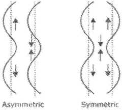
- The planar standing wave forms the distribution of the ultrasound energy through the dimeter D showed by Fig. 5:

- The central area generating longitudinal portion of ultrasound wave is most energetic. The edge area produces pure planar wave. The approximate path of the front of ultrasound wave is also shoved by Fig.5 above and Fig.6 below

- I would like to remind a main condition of planar (guided wave generation, the thickness of the plate should be less than wavelength in the plate material (Fig below)


- The picture above (Wavesounds LLC) discusses a difference between shear (SH) and Plate (Lamb) waves.
- The plate wave is complex of flexural and compressional flexural and compressional motion of the particles of the plate material, therefore there are two components of the wave: Compressional that coincides with the wave propagation direction and Flexural that is orthogonal to the wave propagation and to the plate surface. The flexural component of the wave is intensively absorbed by biological tissue. The compressional can propagate deep. The angle of wave emission into biological tissue is different (see Fig. 9 below).
- The compressional component is emitted particularly is emitted practically in parallel with applied surface of sonotrode but flexural component is normal to this surface.
- The penetration depth of this ultrasound is 15-25 mm. the compressional component is also reflected from borders between different layers (dermis/hypodermis and hypodermis/ muscles.


- Results of treatment with invention.


Claims (19)
- A device (48) suitable for treating subcutaneous adipose tissue, comprising:a. an ultrasonic transducer (12) for generation of ultrasonic vibrations having a proximal face (14) and a distal face (18); andb. a sonotrode (50) including a narrower proximal stem portion (52) defining a sonotrode axis (28) and a broader distal cap portion (54)wherein said stem portion (52) has a distal end (58) and bears a proximal face (56) of said sonotrode (50), said sonotrode (50) acoustically coupled to said distal face (18) of said ultrasonic transducer (12) through said proximal face (56) of said sonotrode (50),wherein said cap portion (54) has a proximally-facing back side (60), a distal working face (62) of said sonotrode (50) and a periphery (64),wherein said distal end (58) of said stem portion (52) meets said back side (60) of said cap portion (54),wherein where said distal end (58) of said stem portion (52) meets said back side (60) of said cap portion (54) a cross sectional area of said cap portion (54) perpendicular to said sonotrode axis (28) is not less than 8 times greater than a cross sectional area of said distal end (58) of said stem portion (52) perpendicular to said sonotrode axis (28); andwherein said cap portion (54) is thin, being not less than than 2 mm and not more than 10 mm thick,wherein not less than 70% of both said working face (62) and said back side (60) of said cap portion (54) are planar and perpendicular to said sonotrode axis (28), andwherein a periphery of said cap portion (54) when viewed from the side is a straight line parallel to said sonotrode axis (28), optionally where an edge of said periphery is not a right angle,wherein said sonotrode (20) is configured, for a selected ultrasonic frequency, to act as an acoustic amplitude transformer for both longitudinal and transverse vibration, so as simultaneously transdermally induce substantial ultrasonic transverse vibrations and substantial ultrasonic longitudinal vibrations in a volume of subcutaneous tissue through skin with which said working face (62) is acoustically coupled.
- The device of any one of claim 1, further comprising an ultrasound power supply (34) functionally associated with said ultrasonic transducer (12), configured to provide to said ultrasonic transducer, when activated, an alternating current oscillating at said selected ultrasonic frequency.
- The device of claim 1 or 2, wherein a length of said sonotrode (50) from said proximal face (56) of said sonotrode to said distal working face (62) is not less than 50mm and not more than 3 00mm.
- The device of any one of claims 1 to 3, wherein said sonotrode (50) is made of a material selected from the group consisting of aluminum and aluminum alloy, said working face (62) including a soft anodization layer, optionally said soft anodization layer being between 5 and 20 micrometers thick..
- The device of any one of claims 1 to 4, wherein said stem portion (52) of said sonotrode (50) is tapered, optionally tapered such that a ratio of a cross sectional area of said proximal face (56) of said sonotrode (50) to a cross sectional area of said distal end (58) of said stem portion (52) is such that a magnitude of amplitude amplification of ultrasonic longitudinal vibrations having said selected ultrasonic frequency is not less than 2.5 X.
- The device of any one of claims 1 to 5, wherein a cross sectional area of said distal end (58) of said stem portion (52) where said stem portion meets said back side (60) of said cap portion (54) is not less than that of a 5mm diameter circle (20mm2) and not more than that of a 25 mm diameter circle (491 mm2).
- The device of any one of claims 1 to 6, wherein not less than 80% of a surface area of said working face (62) is planar and perpendicular to said sonotrode axis (28).
- The device of any one of claims 1 to 7, wherein not less than 80% of a surface area of said back side (60) is planar and perpendicular to said sonotrode axis (28).
- The device of any one of claims 1 to 8, wherein both a planar part of said working face (62) of said sonotrode (50) and a planar part of said back side of said cap portion of said sonotrode are devoid of surface variations greater than 200 micrometers.
- The device of any one of claims 1 to 9, wherein an area of a cross section perpendicular to said sonotrode axis of said cap portion is not more than that of a 150 mm diameter circle (17700 mm2).
- The device of any one of claims 1 to 10, wherein where said distal end of said stem portion meets said back side of said cap portion, a cross sectional area of said cap portion perpendicular to said axis is not less than 12 times greater than a cross sectional area of said distal end of said stem portion perpendicular to said sonotrode axis.
- The device of any one of claims 1 to 10, wherein where said distal end of said stem portion meets said back side of said cap portion, a cross sectional area of said cap portion perpendicular to said axis is not less than 14 times greater than a cross sectional area of said distal end of said stem portion perpendicular to said sonotrode axis.
- The device of any one of claims 1 to 10, wherein where said distal end of said stem portion meets said back side of said cap portion, a cross sectional area of said cap portion perpendicular to said axis is not less than 16 times greater than a cross sectional area of said distal end of said stem portion perpendicular to said sonotrode axis.
- The device of any one of claims 1 to 13, wherein said selected ultrasonic frequency is between 20kHz and 150 kHz.
- The device of any one of claims 1 to 14, wherein the axial length of said sonotrode (50) from said proximal face (56) to said working face (62) is an integral multiple of XL / 2, XL being the wavelength of ultrasonic longitudinal vibrations of said selected ultrasonic frequency.
- The device of any one of claims 1 to 15, wherein not less than 90% of both said working face (62) and said back side (60) of said cap portion (54) are planar and perpendicular to said sonotrode axis (28).
- The device of any one of claims 1 to 16, wherein not less than 95% of both said working face (62) and said back side (60) of said cap portion (54) are planar and perpendicular to said sonotrode axis.
- The device of any one of claims 1 to 17, wherein said thickness of said cap portion is less than or equal to XL/10, XL being the wavelength of ultrasonic longitudinal vibrations of said selected ultrasonic frequency.
- The device of any one of claims 1 to 18, said side cross section of said cap portion (54) is a rectangle and said cap portion (54) is substantially a right cylinder, optionally having rounded or beveled edges.
Applications Claiming Priority (2)
| Application Number | Priority Date | Filing Date | Title |
|---|---|---|---|
| US201662302875P | 2016-03-03 | 2016-03-03 | |
| PCT/IB2017/051253WO2017149506A1 (en) | 2016-03-03 | 2017-03-03 | Sonotrode |
Publications (2)
| Publication Number | Publication Date |
|---|---|
| EP3423156A1 EP3423156A1 (en) | 2019-01-09 |
| EP3423156B1true EP3423156B1 (en) | 2022-10-19 |
Family
ID=58530593
Family Applications (1)
| Application Number | Title | Priority Date | Filing Date |
|---|---|---|---|
| EP17716628.7AActiveEP3423156B1 (en) | 2016-03-03 | 2017-03-03 | Sonotrode |
Country Status (8)
| Country | Link |
|---|---|
| US (2) | US11278745B2 (en) |
| EP (1) | EP3423156B1 (en) |
| JP (1) | JP6937769B2 (en) |
| KR (1) | KR102346814B1 (en) |
| CA (1) | CA3016756C (en) |
| ES (1) | ES2933557T3 (en) |
| IL (1) | IL261564A (en) |
| WO (1) | WO2017149506A1 (en) |
Families Citing this family (28)
| Publication number | Priority date | Publication date | Assignee | Title |
|---|---|---|---|---|
| US8444562B2 (en) | 2004-10-06 | 2013-05-21 | Guided Therapy Systems, Llc | System and method for treating muscle, tendon, ligament and cartilage tissue |
| US8535228B2 (en) | 2004-10-06 | 2013-09-17 | Guided Therapy Systems, Llc | Method and system for noninvasive face lifts and deep tissue tightening |
| US10864385B2 (en) | 2004-09-24 | 2020-12-15 | Guided Therapy Systems, Llc | Rejuvenating skin by heating tissue for cosmetic treatment of the face and body |
| US9694212B2 (en) | 2004-10-06 | 2017-07-04 | Guided Therapy Systems, Llc | Method and system for ultrasound treatment of skin |
| US20060111744A1 (en) | 2004-10-13 | 2006-05-25 | Guided Therapy Systems, L.L.C. | Method and system for treatment of sweat glands |
| US9827449B2 (en) | 2004-10-06 | 2017-11-28 | Guided Therapy Systems, L.L.C. | Systems for treating skin laxity |
| US11883688B2 (en) | 2004-10-06 | 2024-01-30 | Guided Therapy Systems, Llc | Energy based fat reduction |
| US8690779B2 (en) | 2004-10-06 | 2014-04-08 | Guided Therapy Systems, Llc | Noninvasive aesthetic treatment for tightening tissue |
| US11235179B2 (en) | 2004-10-06 | 2022-02-01 | Guided Therapy Systems, Llc | Energy based skin gland treatment |
| US8133180B2 (en) | 2004-10-06 | 2012-03-13 | Guided Therapy Systems, L.L.C. | Method and system for treating cellulite |
| US11724133B2 (en) | 2004-10-07 | 2023-08-15 | Guided Therapy Systems, Llc | Ultrasound probe for treatment of skin |
| US11207548B2 (en) | 2004-10-07 | 2021-12-28 | Guided Therapy Systems, L.L.C. | Ultrasound probe for treating skin laxity |
| US12102473B2 (en) | 2008-06-06 | 2024-10-01 | Ulthera, Inc. | Systems for ultrasound treatment |
| KR20110091832A (en) | 2008-06-06 | 2011-08-12 | 얼테라, 인크 | Tissue Imaging and Treatment Systems |
| CA2748362A1 (en) | 2008-12-24 | 2010-07-01 | Michael H. Slayton | Methods and systems for fat reduction and/or cellulite treatment |
| CN104027893B (en) | 2013-03-08 | 2021-08-31 | 奥赛拉公司 | Apparatus and method for multifocal ultrasound therapy |
| WO2015160708A1 (en) | 2014-04-18 | 2015-10-22 | Ulthera, Inc. | Band transducer ultrasound therapy |
| ES2939604T3 (en) | 2016-01-18 | 2023-04-25 | Ulthera Inc | Compact ultrasonic device having an annular ultrasonic array peripherally electrically connected to a flexible printed circuit board |
| PL3981466T3 (en) | 2016-08-16 | 2023-11-20 | Ulthera, Inc. | Systems and methods for cosmetic ultrasound treatment of skin |
| TWI797235B (en) | 2018-01-26 | 2023-04-01 | 美商奧賽拉公司 | Systems and methods for simultaneous multi-focus ultrasound therapy in multiple dimensions |
| US11944849B2 (en) | 2018-02-20 | 2024-04-02 | Ulthera, Inc. | Systems and methods for combined cosmetic treatment of cellulite with ultrasound |
| US20220031160A1 (en)* | 2018-09-28 | 2022-02-03 | Nidekco., Ltd. | Ultrasonic tonometer and ultrasonic actuator |
| JP2022543732A (en)* | 2019-06-18 | 2022-10-14 | シー・アール・バード・インコーポレーテッド | Ultrasound system and method with improved occlusion engagement during crossing and atherectomy procedures |
| US12377293B2 (en) | 2019-07-15 | 2025-08-05 | Ulthera, Inc. | Systems and methods for measuring elasticity with imaging of ultrasound multi-focus shearwaves in multiple dimensions |
| CN110598366B (en)* | 2019-09-30 | 2021-07-09 | 清华大学 | Frequency coupling design method of longitudinal-torsional composite vibration ultrasonic horn |
| WO2021222084A1 (en) | 2020-04-28 | 2021-11-04 | Siemens Healthcare Diagnostics Inc. | Acoustophoretic lysis devices and methods |
| GB2598179A (en)* | 2020-07-16 | 2022-02-23 | Alma Lasers Ltd | Sonotrode |
| WO2025018326A1 (en)* | 2023-07-19 | 2025-01-23 | 株式会社ニデック | Ultrasonic tonometer and ophthalmic ultrasonic actuator |
Family Cites Families (10)
| Publication number | Priority date | Publication date | Assignee | Title |
|---|---|---|---|---|
| JPS4913332Y1 (en)* | 1968-05-02 | 1974-04-02 | ||
| JPS5123340B2 (en)* | 1972-07-17 | 1976-07-16 | ||
| JPS62292153A (en)* | 1986-06-13 | 1987-12-18 | オリンパス光学工業株式会社 | Ultrasonic living body tissue cutting probe |
| EP0513244A1 (en)* | 1990-11-30 | 1992-11-19 | Michele Dr. Zocchi | Method and apparatus for treating human fat tissue |
| US5527273A (en)* | 1994-10-06 | 1996-06-18 | Misonix, Inc. | Ultrasonic lipectomy probe and method for manufacture |
| US20080194999A1 (en)* | 2007-02-09 | 2008-08-14 | Norihiro Yamaha | Ultrasonic treatment apparatus and treatment method |
| US8579835B2 (en)* | 2008-02-01 | 2013-11-12 | Alma Lasers Ltd. | Apparatus and method for selective ultrasonic damage of adipocytes |
| FR2927238B1 (en)* | 2008-02-13 | 2012-08-31 | Oreal | SPRAY DEVICE COMPRISING A SOUNDRODE |
| WO2011013101A1 (en)* | 2009-07-30 | 2011-02-03 | Alma Lasers Ltd. | A sonotrode |
| JP5749472B2 (en)* | 2010-11-09 | 2015-07-15 | オリンパス株式会社 | Ultrasonic transducer and medical ultrasonic equipment |
- 2017
- 2017-03-03EPEP17716628.7Apatent/EP3423156B1/enactiveActive
- 2017-03-03ESES17716628Tpatent/ES2933557T3/enactiveActive
- 2017-03-03USUS16/081,966patent/US11278745B2/enactiveActive
- 2017-03-03JPJP2018545849Apatent/JP6937769B2/enactiveActive
- 2017-03-03WOPCT/IB2017/051253patent/WO2017149506A1/ennot_activeCeased
- 2017-03-03CACA3016756Apatent/CA3016756C/enactiveActive
- 2017-03-03KRKR1020187026238Apatent/KR102346814B1/enactiveActive
- 2018
- 2018-09-03ILIL261564Apatent/IL261564A/enunknown
- 2022
- 2022-02-10USUS17/669,179patent/US11642551B2/enactiveActive
Also Published As
| Publication number | Publication date |
|---|---|
| KR20180123035A (en) | 2018-11-14 |
| CA3016756A1 (en) | 2017-09-08 |
| WO2017149506A1 (en) | 2017-09-08 |
| IL261564A (en) | 2018-10-31 |
| CA3016756C (en) | 2023-03-21 |
| JP2019509111A (en) | 2019-04-04 |
| US11642551B2 (en) | 2023-05-09 |
| US20190091490A1 (en) | 2019-03-28 |
| EP3423156A1 (en) | 2019-01-09 |
| JP6937769B2 (en) | 2021-09-22 |
| ES2933557T3 (en) | 2023-02-10 |
| US20220176166A1 (en) | 2022-06-09 |
| US11278745B2 (en) | 2022-03-22 |
| KR102346814B1 (en) | 2022-01-03 |
Similar Documents
| Publication | Publication Date | Title |
|---|---|---|
| EP3423156B1 (en) | Sonotrode | |
| US8298163B1 (en) | Non-invasive ultrasonic soft-tissue treatment apparatus | |
| US20180099162A1 (en) | Apparatus and method for treating electile disfunction applying transversal ultrasound waves | |
| US9737735B2 (en) | Ultrasonic surgical apparatus with silicon waveguide | |
| EP2796170B1 (en) | Ultrasonic surgical apparatus and silicon waveguide | |
| US20180099163A1 (en) | Apparatus and method for damaging or destroying adipocytes | |
| CA2661917C (en) | Ultrasonic wound treatment method and apparatus | |
| KR20170118746A (en) | Methods and systems for removing target tissue from the body | |
| KR20170118745A (en) | Method and system for removing foreign matter from tissue | |
| CN107735035A (en) | Devices and methods for injuring or destroying fat cells | |
| TW200800323A (en) | Method and apparatus for treatment of adipose tissue | |
| CN107708473A (en) | For strengthening the hair care device and method of the absorption of external application thing in hair | |
| Rybyanets et al. | New combinational method for noninvasive treatments of superficial tissues for body aesthetics applications | |
| KR101721441B1 (en) | Appratus for generating ultrasound | |
| GB2598179A (en) | Sonotrode | |
| RU2683153C1 (en) | Method of acoustic shock-wave action on human biotissues | |
| Shvetsova et al. | Combinational Radiofrequency Electromagnetic and Ultrasonic Methods for Medical Applications |
Legal Events
| Date | Code | Title | Description |
|---|---|---|---|
| STAA | Information on the status of an ep patent application or granted ep patent | Free format text:STATUS: UNKNOWN | |
| STAA | Information on the status of an ep patent application or granted ep patent | Free format text:STATUS: THE INTERNATIONAL PUBLICATION HAS BEEN MADE | |
| PUAI | Public reference made under article 153(3) epc to a published international application that has entered the european phase | Free format text:ORIGINAL CODE: 0009012 | |
| STAA | Information on the status of an ep patent application or granted ep patent | Free format text:STATUS: REQUEST FOR EXAMINATION WAS MADE | |
| 17P | Request for examination filed | Effective date:20180924 | |
| AK | Designated contracting states | Kind code of ref document:A1 Designated state(s):AL AT BE BG CH CY CZ DE DK EE ES FI FR GB GR HR HU IE IS IT LI LT LU LV MC MK MT NL NO PL PT RO RS SE SI SK SM TR | |
| AX | Request for extension of the european patent | Extension state:BA ME | |
| RIN1 | Information on inventor provided before grant (corrected) | Inventor name:LEPSELTER, JOSEPH Inventor name:DVERIN, ALEXANDER Inventor name:KARNI, ZIV Inventor name:TSURGIL, SHAHAR Inventor name:TOLEDANO, OHAD Inventor name:PENS, YEVGENY Inventor name:BRITVA, ALEXANDER | |
| DAV | Request for validation of the european patent (deleted) | ||
| DAX | Request for extension of the european patent (deleted) | ||
| STAA | Information on the status of an ep patent application or granted ep patent | Free format text:STATUS: EXAMINATION IS IN PROGRESS | |
| 17Q | First examination report despatched | Effective date:20220419 | |
| RAP3 | Party data changed (applicant data changed or rights of an application transferred) | Owner name:ALMA LASERS LTD. | |
| GRAP | Despatch of communication of intention to grant a patent | Free format text:ORIGINAL CODE: EPIDOSNIGR1 | |
| STAA | Information on the status of an ep patent application or granted ep patent | Free format text:STATUS: GRANT OF PATENT IS INTENDED | |
| GRAS | Grant fee paid | Free format text:ORIGINAL CODE: EPIDOSNIGR3 | |
| GRAA | (expected) grant | Free format text:ORIGINAL CODE: 0009210 | |
| STAA | Information on the status of an ep patent application or granted ep patent | Free format text:STATUS: THE PATENT HAS BEEN GRANTED | |
| INTG | Intention to grant announced | Effective date:20220825 | |
| AK | Designated contracting states | Kind code of ref document:B1 Designated state(s):AL AT BE BG CH CY CZ DE DK EE ES FI FR GB GR HR HU IE IS IT LI LT LU LV MC MK MT NL NO PL PT RO RS SE SI SK SM TR | |
| REG | Reference to a national code | Ref country code:GB Ref legal event code:FG4D | |
| REG | Reference to a national code | Ref country code:CH Ref legal event code:EP | |
| REG | Reference to a national code | Ref country code:DE Ref legal event code:R096 Ref document number:602017062754 Country of ref document:DE | |
| REG | Reference to a national code | Ref country code:IE Ref legal event code:FG4D | |
| REG | Reference to a national code | Ref country code:AT Ref legal event code:REF Ref document number:1525202 Country of ref document:AT Kind code of ref document:T Effective date:20221115 | |
| REG | Reference to a national code | Ref country code:LT Ref legal event code:MG9D Ref country code:ES Ref legal event code:FG2A Ref document number:2933557 Country of ref document:ES Kind code of ref document:T3 Effective date:20230210 | |
| REG | Reference to a national code | Ref country code:NL Ref legal event code:MP Effective date:20221019 | |
| REG | Reference to a national code | Ref country code:AT Ref legal event code:MK05 Ref document number:1525202 Country of ref document:AT Kind code of ref document:T Effective date:20221019 | |
| PG25 | Lapsed in a contracting state [announced via postgrant information from national office to epo] | Ref country code:NL Free format text:LAPSE BECAUSE OF FAILURE TO SUBMIT A TRANSLATION OF THE DESCRIPTION OR TO PAY THE FEE WITHIN THE PRESCRIBED TIME-LIMIT Effective date:20221019 | |
| PG25 | Lapsed in a contracting state [announced via postgrant information from national office to epo] | Ref country code:SE Free format text:LAPSE BECAUSE OF FAILURE TO SUBMIT A TRANSLATION OF THE DESCRIPTION OR TO PAY THE FEE WITHIN THE PRESCRIBED TIME-LIMIT Effective date:20221019 Ref country code:PT Free format text:LAPSE BECAUSE OF FAILURE TO SUBMIT A TRANSLATION OF THE DESCRIPTION OR TO PAY THE FEE WITHIN THE PRESCRIBED TIME-LIMIT Effective date:20230220 Ref country code:NO Free format text:LAPSE BECAUSE OF FAILURE TO SUBMIT A TRANSLATION OF THE DESCRIPTION OR TO PAY THE FEE WITHIN THE PRESCRIBED TIME-LIMIT Effective date:20230119 Ref country code:LT Free format text:LAPSE BECAUSE OF FAILURE TO SUBMIT A TRANSLATION OF THE DESCRIPTION OR TO PAY THE FEE WITHIN THE PRESCRIBED TIME-LIMIT Effective date:20221019 Ref country code:FI Free format text:LAPSE BECAUSE OF FAILURE TO SUBMIT A TRANSLATION OF THE DESCRIPTION OR TO PAY THE FEE WITHIN THE PRESCRIBED TIME-LIMIT Effective date:20221019 Ref country code:AT Free format text:LAPSE BECAUSE OF FAILURE TO SUBMIT A TRANSLATION OF THE DESCRIPTION OR TO PAY THE FEE WITHIN THE PRESCRIBED TIME-LIMIT Effective date:20221019 | |
| PG25 | Lapsed in a contracting state [announced via postgrant information from national office to epo] | Ref country code:RS Free format text:LAPSE BECAUSE OF FAILURE TO SUBMIT A TRANSLATION OF THE DESCRIPTION OR TO PAY THE FEE WITHIN THE PRESCRIBED TIME-LIMIT Effective date:20221019 Ref country code:PL Free format text:LAPSE BECAUSE OF FAILURE TO SUBMIT A TRANSLATION OF THE DESCRIPTION OR TO PAY THE FEE WITHIN THE PRESCRIBED TIME-LIMIT Effective date:20221019 Ref country code:LV Free format text:LAPSE BECAUSE OF FAILURE TO SUBMIT A TRANSLATION OF THE DESCRIPTION OR TO PAY THE FEE WITHIN THE PRESCRIBED TIME-LIMIT Effective date:20221019 Ref country code:IS Free format text:LAPSE BECAUSE OF FAILURE TO SUBMIT A TRANSLATION OF THE DESCRIPTION OR TO PAY THE FEE WITHIN THE PRESCRIBED TIME-LIMIT Effective date:20230219 Ref country code:HR Free format text:LAPSE BECAUSE OF FAILURE TO SUBMIT A TRANSLATION OF THE DESCRIPTION OR TO PAY THE FEE WITHIN THE PRESCRIBED TIME-LIMIT Effective date:20221019 Ref country code:GR Free format text:LAPSE BECAUSE OF FAILURE TO SUBMIT A TRANSLATION OF THE DESCRIPTION OR TO PAY THE FEE WITHIN THE PRESCRIBED TIME-LIMIT Effective date:20230120 | |
| REG | Reference to a national code | Ref country code:DE Ref legal event code:R097 Ref document number:602017062754 Country of ref document:DE | |
| PG25 | Lapsed in a contracting state [announced via postgrant information from national office to epo] | Ref country code:SM Free format text:LAPSE BECAUSE OF FAILURE TO SUBMIT A TRANSLATION OF THE DESCRIPTION OR TO PAY THE FEE WITHIN THE PRESCRIBED TIME-LIMIT Effective date:20221019 Ref country code:RO Free format text:LAPSE BECAUSE OF FAILURE TO SUBMIT A TRANSLATION OF THE DESCRIPTION OR TO PAY THE FEE WITHIN THE PRESCRIBED TIME-LIMIT Effective date:20221019 Ref country code:EE Free format text:LAPSE BECAUSE OF FAILURE TO SUBMIT A TRANSLATION OF THE DESCRIPTION OR TO PAY THE FEE WITHIN THE PRESCRIBED TIME-LIMIT Effective date:20221019 Ref country code:DK Free format text:LAPSE BECAUSE OF FAILURE TO SUBMIT A TRANSLATION OF THE DESCRIPTION OR TO PAY THE FEE WITHIN THE PRESCRIBED TIME-LIMIT Effective date:20221019 Ref country code:CZ Free format text:LAPSE BECAUSE OF FAILURE TO SUBMIT A TRANSLATION OF THE DESCRIPTION OR TO PAY THE FEE WITHIN THE PRESCRIBED TIME-LIMIT Effective date:20221019 | |
| PLBE | No opposition filed within time limit | Free format text:ORIGINAL CODE: 0009261 | |
| STAA | Information on the status of an ep patent application or granted ep patent | Free format text:STATUS: NO OPPOSITION FILED WITHIN TIME LIMIT | |
| PG25 | Lapsed in a contracting state [announced via postgrant information from national office to epo] | Ref country code:SK Free format text:LAPSE BECAUSE OF FAILURE TO SUBMIT A TRANSLATION OF THE DESCRIPTION OR TO PAY THE FEE WITHIN THE PRESCRIBED TIME-LIMIT Effective date:20221019 Ref country code:AL Free format text:LAPSE BECAUSE OF FAILURE TO SUBMIT A TRANSLATION OF THE DESCRIPTION OR TO PAY THE FEE WITHIN THE PRESCRIBED TIME-LIMIT Effective date:20221019 | |
| 26N | No opposition filed | Effective date:20230720 | |
| PG25 | Lapsed in a contracting state [announced via postgrant information from national office to epo] | Ref country code:MC Free format text:LAPSE BECAUSE OF FAILURE TO SUBMIT A TRANSLATION OF THE DESCRIPTION OR TO PAY THE FEE WITHIN THE PRESCRIBED TIME-LIMIT Effective date:20221019 | |
| REG | Reference to a national code | Ref country code:CH Ref legal event code:PL | |
| PG25 | Lapsed in a contracting state [announced via postgrant information from national office to epo] | Ref country code:SI Free format text:LAPSE BECAUSE OF FAILURE TO SUBMIT A TRANSLATION OF THE DESCRIPTION OR TO PAY THE FEE WITHIN THE PRESCRIBED TIME-LIMIT Effective date:20221019 | |
| REG | Reference to a national code | Ref country code:BE Ref legal event code:MM Effective date:20230331 | |
| PG25 | Lapsed in a contracting state [announced via postgrant information from national office to epo] | Ref country code:LU Free format text:LAPSE BECAUSE OF NON-PAYMENT OF DUE FEES Effective date:20230303 | |
| REG | Reference to a national code | Ref country code:IE Ref legal event code:MM4A | |
| PG25 | Lapsed in a contracting state [announced via postgrant information from national office to epo] | Ref country code:LI Free format text:LAPSE BECAUSE OF NON-PAYMENT OF DUE FEES Effective date:20230331 Ref country code:IE Free format text:LAPSE BECAUSE OF NON-PAYMENT OF DUE FEES Effective date:20230303 Ref country code:CH Free format text:LAPSE BECAUSE OF NON-PAYMENT OF DUE FEES Effective date:20230331 | |
| PG25 | Lapsed in a contracting state [announced via postgrant information from national office to epo] | Ref country code:BE Free format text:LAPSE BECAUSE OF NON-PAYMENT OF DUE FEES Effective date:20230331 | |
| PG25 | Lapsed in a contracting state [announced via postgrant information from national office to epo] | Ref country code:BG Free format text:LAPSE BECAUSE OF FAILURE TO SUBMIT A TRANSLATION OF THE DESCRIPTION OR TO PAY THE FEE WITHIN THE PRESCRIBED TIME-LIMIT Effective date:20221019 | |
| PG25 | Lapsed in a contracting state [announced via postgrant information from national office to epo] | Ref country code:BG Free format text:LAPSE BECAUSE OF FAILURE TO SUBMIT A TRANSLATION OF THE DESCRIPTION OR TO PAY THE FEE WITHIN THE PRESCRIBED TIME-LIMIT Effective date:20221019 | |
| PGFP | Annual fee paid to national office [announced via postgrant information from national office to epo] | Ref country code:DE Payment date:20250226 Year of fee payment:9 | |
| PGFP | Annual fee paid to national office [announced via postgrant information from national office to epo] | Ref country code:FR Payment date:20250312 Year of fee payment:9 | |
| PGFP | Annual fee paid to national office [announced via postgrant information from national office to epo] | Ref country code:GB Payment date:20250321 Year of fee payment:9 Ref country code:IT Payment date:20250225 Year of fee payment:9 | |
| PGFP | Annual fee paid to national office [announced via postgrant information from national office to epo] | Ref country code:ES Payment date:20250409 Year of fee payment:9 | |
| PG25 | Lapsed in a contracting state [announced via postgrant information from national office to epo] | Ref country code:CY Free format text:LAPSE BECAUSE OF FAILURE TO SUBMIT A TRANSLATION OF THE DESCRIPTION OR TO PAY THE FEE WITHIN THE PRESCRIBED TIME-LIMIT; INVALID AB INITIO Effective date:20170303 | |
| PG25 | Lapsed in a contracting state [announced via postgrant information from national office to epo] | Ref country code:HU Free format text:LAPSE BECAUSE OF FAILURE TO SUBMIT A TRANSLATION OF THE DESCRIPTION OR TO PAY THE FEE WITHIN THE PRESCRIBED TIME-LIMIT; INVALID AB INITIO Effective date:20170303 |