EP3420998A1 - Shaft module circuitry arrangements - Google Patents
Shaft module circuitry arrangementsDownload PDFInfo
- Publication number
- EP3420998A1 EP3420998A1EP17209630.7AEP17209630AEP3420998A1EP 3420998 A1EP3420998 A1EP 3420998A1EP 17209630 AEP17209630 AEP 17209630AEP 3420998 A1EP3420998 A1EP 3420998A1
- Authority
- EP
- European Patent Office
- Prior art keywords
- assembly
- control segment
- shaft
- end effector
- electrosurgical
- Prior art date
- Legal status (The legal status is an assumption and is not a legal conclusion. Google has not performed a legal analysis and makes no representation as to the accuracy of the status listed.)
- Withdrawn
Links
- 239000012636effectorSubstances0.000claimsabstractdescription116
- 239000004020conductorSubstances0.000claimsdescription87
- 230000005540biological transmissionEffects0.000claimsdescription7
- 238000010304firingMethods0.000description72
- 210000001519tissueAnatomy0.000description54
- 230000033001locomotionEffects0.000description28
- 238000007726management methodMethods0.000description25
- 230000006870functionEffects0.000description22
- 238000004891communicationMethods0.000description19
- 238000000034methodMethods0.000description15
- 238000010586diagramMethods0.000description11
- 239000007787solidSubstances0.000description7
- 238000006073displacement reactionMethods0.000description6
- 230000008569processEffects0.000description6
- 230000005355Hall effectEffects0.000description5
- 230000000712assemblyEffects0.000description5
- 238000000429assemblyMethods0.000description5
- 230000002441reversible effectEffects0.000description5
- 230000001133accelerationEffects0.000description4
- 230000006835compressionEffects0.000description4
- 238000007906compressionMethods0.000description4
- 238000010168coupling processMethods0.000description4
- 230000000694effectsEffects0.000description4
- 238000007789sealingMethods0.000description4
- 238000001356surgical procedureMethods0.000description4
- 238000013519translationMethods0.000description4
- 238000004590computer programMethods0.000description3
- 230000008878couplingEffects0.000description3
- 238000005859coupling reactionMethods0.000description3
- 238000009434installationMethods0.000description3
- 230000007246mechanismEffects0.000description3
- 230000003287optical effectEffects0.000description3
- 230000000717retained effectEffects0.000description3
- 229920000106Liquid crystal polymerPolymers0.000description2
- 239000004977Liquid-crystal polymers (LCPs)Substances0.000description2
- HBBGRARXTFLTSG-UHFFFAOYSA-NLithium ionChemical compound[Li+]HBBGRARXTFLTSG-UHFFFAOYSA-N0.000description2
- 238000005452bendingMethods0.000description2
- 210000004204blood vesselAnatomy0.000description2
- 230000001112coagulating effectEffects0.000description2
- 238000013461designMethods0.000description2
- 230000005669field effectEffects0.000description2
- 239000012212insulatorSubstances0.000description2
- 230000003993interactionEffects0.000description2
- 229910001416lithium ionInorganic materials0.000description2
- 229910044991metal oxideInorganic materials0.000description2
- 150000004706metal oxidesChemical class0.000description2
- 238000012986modificationMethods0.000description2
- 230000004048modificationEffects0.000description2
- 230000004044responseEffects0.000description2
- 230000001953sensory effectEffects0.000description2
- 230000000638stimulationEffects0.000description2
- 230000001360synchronised effectEffects0.000description2
- 230000000007visual effectEffects0.000description2
- 238000004804windingMethods0.000description2
- 102000008186CollagenHuman genes0.000description1
- 108010035532CollagenProteins0.000description1
- 230000009471actionEffects0.000description1
- 230000003044adaptive effectEffects0.000description1
- 239000000853adhesiveSubstances0.000description1
- 230000001070adhesive effectEffects0.000description1
- 230000004931aggregating effectEffects0.000description1
- 238000013019agitationMethods0.000description1
- 238000003491arrayMethods0.000description1
- 239000003990capacitorSubstances0.000description1
- 239000003795chemical substances by applicationSubstances0.000description1
- 230000015271coagulationEffects0.000description1
- 238000005345coagulationMethods0.000description1
- 229920001436collagenPolymers0.000description1
- 210000002808connective tissueAnatomy0.000description1
- 230000000994depressogenic effectEffects0.000description1
- 230000009977dual effectEffects0.000description1
- 230000002828effect on organs or tissueEffects0.000description1
- 229920003247engineering thermoplasticPolymers0.000description1
- 239000000835fiberSubstances0.000description1
- 238000010438heat treatmentMethods0.000description1
- 230000023597hemostasisEffects0.000description1
- 230000002439hemostatic effectEffects0.000description1
- 230000001939inductive effectEffects0.000description1
- 238000002955isolationMethods0.000description1
- 239000004973liquid crystal related substanceSubstances0.000description1
- 239000000463materialSubstances0.000description1
- 238000005259measurementMethods0.000description1
- 239000002184metalSubstances0.000description1
- 229910052751metalInorganic materials0.000description1
- 239000007769metal materialSubstances0.000description1
- 210000003205muscleAnatomy0.000description1
- 210000005036nerveAnatomy0.000description1
- 230000002232neuromuscularEffects0.000description1
- 230000008520organizationEffects0.000description1
- 239000002861polymer materialSubstances0.000description1
- 238000012545processingMethods0.000description1
- 238000012502risk assessmentMethods0.000description1
- 210000004872soft tissueAnatomy0.000description1
- 238000012546transferMethods0.000description1
- 230000007704transitionEffects0.000description1
- 238000003466weldingMethods0.000description1
Images


Classifications
- A—HUMAN NECESSITIES
- A61—MEDICAL OR VETERINARY SCIENCE; HYGIENE
- A61B—DIAGNOSIS; SURGERY; IDENTIFICATION
- A61B18/00—Surgical instruments, devices or methods for transferring non-mechanical forms of energy to or from the body
- A61B18/04—Surgical instruments, devices or methods for transferring non-mechanical forms of energy to or from the body by heating
- A61B18/12—Surgical instruments, devices or methods for transferring non-mechanical forms of energy to or from the body by heating by passing a current through the tissue to be heated, e.g. high-frequency current
- A61B18/1206—Generators therefor
- A—HUMAN NECESSITIES
- A61—MEDICAL OR VETERINARY SCIENCE; HYGIENE
- A61B—DIAGNOSIS; SURGERY; IDENTIFICATION
- A61B17/00—Surgical instruments, devices or methods
- A61B17/068—Surgical staplers, e.g. containing multiple staples or clamps
- A61B17/072—Surgical staplers, e.g. containing multiple staples or clamps for applying a row of staples in a single action, e.g. the staples being applied simultaneously
- A61B17/07207—Surgical staplers, e.g. containing multiple staples or clamps for applying a row of staples in a single action, e.g. the staples being applied simultaneously the staples being applied sequentially
- A—HUMAN NECESSITIES
- A61—MEDICAL OR VETERINARY SCIENCE; HYGIENE
- A61B—DIAGNOSIS; SURGERY; IDENTIFICATION
- A61B18/00—Surgical instruments, devices or methods for transferring non-mechanical forms of energy to or from the body
- A61B18/04—Surgical instruments, devices or methods for transferring non-mechanical forms of energy to or from the body by heating
- A61B18/12—Surgical instruments, devices or methods for transferring non-mechanical forms of energy to or from the body by heating by passing a current through the tissue to be heated, e.g. high-frequency current
- A61B18/14—Probes or electrodes therefor
- A61B18/1442—Probes having pivoting end effectors, e.g. forceps
- A61B18/1445—Probes having pivoting end effectors, e.g. forceps at the distal end of a shaft, e.g. forceps or scissors at the end of a rigid rod
- A—HUMAN NECESSITIES
- A61—MEDICAL OR VETERINARY SCIENCE; HYGIENE
- A61B—DIAGNOSIS; SURGERY; IDENTIFICATION
- A61B17/00—Surgical instruments, devices or methods
- A61B17/28—Surgical forceps
- A61B17/29—Forceps for use in minimally invasive surgery
- A61B17/295—Forceps for use in minimally invasive surgery combined with cutting implements
- A—HUMAN NECESSITIES
- A61—MEDICAL OR VETERINARY SCIENCE; HYGIENE
- A61B—DIAGNOSIS; SURGERY; IDENTIFICATION
- A61B17/00—Surgical instruments, devices or methods
- A61B2017/00017—Electrical control of surgical instruments
- A—HUMAN NECESSITIES
- A61—MEDICAL OR VETERINARY SCIENCE; HYGIENE
- A61B—DIAGNOSIS; SURGERY; IDENTIFICATION
- A61B17/00—Surgical instruments, devices or methods
- A61B2017/00017—Electrical control of surgical instruments
- A61B2017/00022—Sensing or detecting at the treatment site
- A61B2017/00026—Conductivity or impedance, e.g. of tissue
- A—HUMAN NECESSITIES
- A61—MEDICAL OR VETERINARY SCIENCE; HYGIENE
- A61B—DIAGNOSIS; SURGERY; IDENTIFICATION
- A61B17/00—Surgical instruments, devices or methods
- A61B2017/00017—Electrical control of surgical instruments
- A61B2017/00022—Sensing or detecting at the treatment site
- A61B2017/00075—Motion
- A—HUMAN NECESSITIES
- A61—MEDICAL OR VETERINARY SCIENCE; HYGIENE
- A61B—DIAGNOSIS; SURGERY; IDENTIFICATION
- A61B17/00—Surgical instruments, devices or methods
- A61B2017/00017—Electrical control of surgical instruments
- A61B2017/00115—Electrical control of surgical instruments with audible or visual output
- A61B2017/00119—Electrical control of surgical instruments with audible or visual output alarm; indicating an abnormal situation
- A—HUMAN NECESSITIES
- A61—MEDICAL OR VETERINARY SCIENCE; HYGIENE
- A61B—DIAGNOSIS; SURGERY; IDENTIFICATION
- A61B17/00—Surgical instruments, devices or methods
- A61B2017/00017—Electrical control of surgical instruments
- A61B2017/00115—Electrical control of surgical instruments with audible or visual output
- A61B2017/00128—Electrical control of surgical instruments with audible or visual output related to intensity or progress of surgical action
- A—HUMAN NECESSITIES
- A61—MEDICAL OR VETERINARY SCIENCE; HYGIENE
- A61B—DIAGNOSIS; SURGERY; IDENTIFICATION
- A61B17/00—Surgical instruments, devices or methods
- A61B2017/00017—Electrical control of surgical instruments
- A61B2017/00199—Electrical control of surgical instruments with a console, e.g. a control panel with a display
- A—HUMAN NECESSITIES
- A61—MEDICAL OR VETERINARY SCIENCE; HYGIENE
- A61B—DIAGNOSIS; SURGERY; IDENTIFICATION
- A61B17/00—Surgical instruments, devices or methods
- A61B17/00234—Surgical instruments, devices or methods for minimally invasive surgery
- A61B2017/00353—Surgical instruments, devices or methods for minimally invasive surgery one mechanical instrument performing multiple functions, e.g. cutting and grasping
- A—HUMAN NECESSITIES
- A61—MEDICAL OR VETERINARY SCIENCE; HYGIENE
- A61B—DIAGNOSIS; SURGERY; IDENTIFICATION
- A61B17/00—Surgical instruments, devices or methods
- A61B2017/00367—Details of actuation of instruments, e.g. relations between pushing buttons, or the like, and activation of the tool, working tip, or the like
- A61B2017/00398—Details of actuation of instruments, e.g. relations between pushing buttons, or the like, and activation of the tool, working tip, or the like using powered actuators, e.g. stepper motors, solenoids
- A—HUMAN NECESSITIES
- A61—MEDICAL OR VETERINARY SCIENCE; HYGIENE
- A61B—DIAGNOSIS; SURGERY; IDENTIFICATION
- A61B17/00—Surgical instruments, devices or methods
- A61B2017/0046—Surgical instruments, devices or methods with a releasable handle; with handle and operating part separable
- A—HUMAN NECESSITIES
- A61—MEDICAL OR VETERINARY SCIENCE; HYGIENE
- A61B—DIAGNOSIS; SURGERY; IDENTIFICATION
- A61B17/00—Surgical instruments, devices or methods
- A61B2017/0046—Surgical instruments, devices or methods with a releasable handle; with handle and operating part separable
- A61B2017/00464—Surgical instruments, devices or methods with a releasable handle; with handle and operating part separable for use with different instruments
- A—HUMAN NECESSITIES
- A61—MEDICAL OR VETERINARY SCIENCE; HYGIENE
- A61B—DIAGNOSIS; SURGERY; IDENTIFICATION
- A61B17/00—Surgical instruments, devices or methods
- A61B2017/00477—Coupling
- A—HUMAN NECESSITIES
- A61—MEDICAL OR VETERINARY SCIENCE; HYGIENE
- A61B—DIAGNOSIS; SURGERY; IDENTIFICATION
- A61B17/00—Surgical instruments, devices or methods
- A61B2017/00681—Aspects not otherwise provided for
- A61B2017/00734—Aspects not otherwise provided for battery operated
- A—HUMAN NECESSITIES
- A61—MEDICAL OR VETERINARY SCIENCE; HYGIENE
- A61B—DIAGNOSIS; SURGERY; IDENTIFICATION
- A61B17/00—Surgical instruments, devices or methods
- A61B17/068—Surgical staplers, e.g. containing multiple staples or clamps
- A61B17/072—Surgical staplers, e.g. containing multiple staples or clamps for applying a row of staples in a single action, e.g. the staples being applied simultaneously
- A61B2017/07214—Stapler heads
- A61B2017/07257—Stapler heads characterised by its anvil
- A—HUMAN NECESSITIES
- A61—MEDICAL OR VETERINARY SCIENCE; HYGIENE
- A61B—DIAGNOSIS; SURGERY; IDENTIFICATION
- A61B17/00—Surgical instruments, devices or methods
- A61B17/068—Surgical staplers, e.g. containing multiple staples or clamps
- A61B17/072—Surgical staplers, e.g. containing multiple staples or clamps for applying a row of staples in a single action, e.g. the staples being applied simultaneously
- A61B2017/07214—Stapler heads
- A61B2017/07271—Stapler heads characterised by its cartridge
- A—HUMAN NECESSITIES
- A61—MEDICAL OR VETERINARY SCIENCE; HYGIENE
- A61B—DIAGNOSIS; SURGERY; IDENTIFICATION
- A61B17/00—Surgical instruments, devices or methods
- A61B17/068—Surgical staplers, e.g. containing multiple staples or clamps
- A61B17/072—Surgical staplers, e.g. containing multiple staples or clamps for applying a row of staples in a single action, e.g. the staples being applied simultaneously
- A61B2017/07214—Stapler heads
- A61B2017/07285—Stapler heads characterised by its cutter
- A—HUMAN NECESSITIES
- A61—MEDICAL OR VETERINARY SCIENCE; HYGIENE
- A61B—DIAGNOSIS; SURGERY; IDENTIFICATION
- A61B18/00—Surgical instruments, devices or methods for transferring non-mechanical forms of energy to or from the body
- A61B2018/00053—Mechanical features of the instrument of device
- A61B2018/00172—Connectors and adapters therefor
- A61B2018/00178—Electrical connectors
- A—HUMAN NECESSITIES
- A61—MEDICAL OR VETERINARY SCIENCE; HYGIENE
- A61B—DIAGNOSIS; SURGERY; IDENTIFICATION
- A61B18/00—Surgical instruments, devices or methods for transferring non-mechanical forms of energy to or from the body
- A61B2018/00571—Surgical instruments, devices or methods for transferring non-mechanical forms of energy to or from the body for achieving a particular surgical effect
- A61B2018/00619—Welding
- A—HUMAN NECESSITIES
- A61—MEDICAL OR VETERINARY SCIENCE; HYGIENE
- A61B—DIAGNOSIS; SURGERY; IDENTIFICATION
- A61B18/00—Surgical instruments, devices or methods for transferring non-mechanical forms of energy to or from the body
- A61B2018/00571—Surgical instruments, devices or methods for transferring non-mechanical forms of energy to or from the body for achieving a particular surgical effect
- A61B2018/0063—Sealing
- A—HUMAN NECESSITIES
- A61—MEDICAL OR VETERINARY SCIENCE; HYGIENE
- A61B—DIAGNOSIS; SURGERY; IDENTIFICATION
- A61B18/00—Surgical instruments, devices or methods for transferring non-mechanical forms of energy to or from the body
- A61B2018/00636—Sensing and controlling the application of energy
- A61B2018/00898—Alarms or notifications created in response to an abnormal condition
- A—HUMAN NECESSITIES
- A61—MEDICAL OR VETERINARY SCIENCE; HYGIENE
- A61B—DIAGNOSIS; SURGERY; IDENTIFICATION
- A61B18/00—Surgical instruments, devices or methods for transferring non-mechanical forms of energy to or from the body
- A61B2018/0091—Handpieces of the surgical instrument or device
- A61B2018/00916—Handpieces of the surgical instrument or device with means for switching or controlling the main function of the instrument or device
- A61B2018/00922—Handpieces of the surgical instrument or device with means for switching or controlling the main function of the instrument or device by switching or controlling the treatment energy directly within the hand-piece
- A—HUMAN NECESSITIES
- A61—MEDICAL OR VETERINARY SCIENCE; HYGIENE
- A61B—DIAGNOSIS; SURGERY; IDENTIFICATION
- A61B18/00—Surgical instruments, devices or methods for transferring non-mechanical forms of energy to or from the body
- A61B18/04—Surgical instruments, devices or methods for transferring non-mechanical forms of energy to or from the body by heating
- A61B18/12—Surgical instruments, devices or methods for transferring non-mechanical forms of energy to or from the body by heating by passing a current through the tissue to be heated, e.g. high-frequency current
- A61B18/1206—Generators therefor
- A61B2018/124—Generators therefor switching the output to different electrodes, e.g. sequentially
- A—HUMAN NECESSITIES
- A61—MEDICAL OR VETERINARY SCIENCE; HYGIENE
- A61B—DIAGNOSIS; SURGERY; IDENTIFICATION
- A61B18/00—Surgical instruments, devices or methods for transferring non-mechanical forms of energy to or from the body
- A61B18/04—Surgical instruments, devices or methods for transferring non-mechanical forms of energy to or from the body by heating
- A61B18/12—Surgical instruments, devices or methods for transferring non-mechanical forms of energy to or from the body by heating by passing a current through the tissue to be heated, e.g. high-frequency current
- A61B18/1206—Generators therefor
- A61B2018/1246—Generators therefor characterised by the output polarity
- A61B2018/126—Generators therefor characterised by the output polarity bipolar
- A—HUMAN NECESSITIES
- A61—MEDICAL OR VETERINARY SCIENCE; HYGIENE
- A61B—DIAGNOSIS; SURGERY; IDENTIFICATION
- A61B18/00—Surgical instruments, devices or methods for transferring non-mechanical forms of energy to or from the body
- A61B18/04—Surgical instruments, devices or methods for transferring non-mechanical forms of energy to or from the body by heating
- A61B18/12—Surgical instruments, devices or methods for transferring non-mechanical forms of energy to or from the body by heating by passing a current through the tissue to be heated, e.g. high-frequency current
- A61B18/14—Probes or electrodes therefor
- A61B18/1442—Probes having pivoting end effectors, e.g. forceps
- A61B2018/1452—Probes having pivoting end effectors, e.g. forceps including means for cutting
- A61B2018/1455—Probes having pivoting end effectors, e.g. forceps including means for cutting having a moving blade for cutting tissue grasped by the jaws
- A—HUMAN NECESSITIES
- A61—MEDICAL OR VETERINARY SCIENCE; HYGIENE
- A61B—DIAGNOSIS; SURGERY; IDENTIFICATION
- A61B18/00—Surgical instruments, devices or methods for transferring non-mechanical forms of energy to or from the body
- A61B18/04—Surgical instruments, devices or methods for transferring non-mechanical forms of energy to or from the body by heating
- A61B18/12—Surgical instruments, devices or methods for transferring non-mechanical forms of energy to or from the body by heating by passing a current through the tissue to be heated, e.g. high-frequency current
- A61B18/14—Probes or electrodes therefor
- A61B2018/1467—Probes or electrodes therefor using more than two electrodes on a single probe
Definitions
- the present disclosuregenerally relates to an electrosurgical systems with modular components for performing surgical procedures.
- the present disclosurerelates to shaft module circuitry arrangements.
- a modular designthat allows a single handle assembly to attach to multiple nozzle assemblies, and for a nozzle assembly to attach to multiple handle assemblies. Since the nozzle assembly would include the various surgical instruments in the end effector, special circuity in the nozzle may be required to allow for instrumentation in a handle assembly to control the various functions in the end effector of the modular nozzle assembly. In addition, energy may need to be applied to the end effector that may or may not originate from the handle assembly. For example, the handle assembly may be battery powered to control the functions of the handle assembly, but may not possess power sufficient to control the end effector.
- a control circuit for a surgical instrumentmay include: a shaft control segment; an electrosurgical energy control segment; and a connector coupled to the electrosurgical energy control segment configured to couple to an electrosurgical generator.
- the shaft control segmentmay be configured to: communicate with a handle portion of the surgical instrument; and receive user input controls.
- the electrosurgical energy control segmentmay be configured to: detect connection of the electrosurgical generator to the connector; communicate with the electrosurgical generator; electrically isolate the handle control segment from the electrosurgical energy control segment when the connection of the electrosurgical generator to the connector is detected; and provide electrosurgical energy from the electrosurgical generator to an end effector portion of the surgical instrument through a first set of electrical conductors.
- a nozzle assembly of a surgical systemmay include: an onboard circuit board; an onboard connector coupled to the onboard circuit board and proximally located on the nozzle assembly, the onboard connector configured to interface with a housing connector of a handle assembly when the nozzle assembly is attached to the handle assembly; a shaft attachment lug proximally located on the nozzle assembly and configured to be coupled to an attachment cradle of the handle assembly to attach the nozzle assembly to the handle assembly; and a control circuit comprising: a shaft control segment; an electrosurgical energy control segment; and a connector coupled to the electrosurgical energy control segment configured to couple to an electrosurgical generator.
- the shaft control segmentmay be configured to: communicate with a handle portion of the surgical instrument; and receive user input controls.
- the electrosurgical energy control segmentmay be configured to: detect connection of the electrosurgical generator to the connector; communicate with the electrosurgical generator; electrically isolate the handle control segment from the electrosurgical energy control segment when the connection of the electrosurgical generator to the connector is detected; and provide electrosurgical energy from the electrosurgical generator to an end effector portion of the surgical instrument through a first set of electrical conductors.
- the nozzle assemblymay be detachable from and attachable to the handle assembly.
- Electrosurgical devicesmay be used in many surgical operations. Electrosurgical devices may apply electrical energy to tissue in order to treat tissue.
- An electrosurgical devicemay comprise an instrument having a distally mounted end effector comprising one or more electrodes. The end effector can be positioned against tissue such that electrical current may be introduced into the tissue.
- Electrosurgical devicescan be configured for monopolar or bipolar operation. During monopolar operation, current may be introduced into the tissue by an active (or source) electrode on the end effector and returned through a return electrode. The return electrode may be a grounding pad and separately located on a patient's body. During bipolar operation, current may be introduced into and returned from the tissue by the active and return electrodes, respectively, of the end effector.
- the end effectormay include two or more jaw members. At least one of the jaw members may have at least one electrode. At least one jaw may be moveable from a position spaced apart from the opposing jaw for receiving tissues to a position in which the space between the jaw members is less than that of the first position. This movement of the moveable jaw may compress the tissue held between. Heat generated by the current flow through the tissue in combination with the compression achieved by the jaw's movement may form hemostatic seals within the tissue and/or between tissues and, thus, may be particularly useful for sealing blood vessels, for example.
- the end effectormay comprise a cutting member. The cutting member may be movable relative to the tissue and the electrodes to transect the tissue.
- Electrosurgical devicesalso may include mechanisms to clamp tissue together, such as a stapling device, and/or mechanisms to sever tissue, such as a tissue knife.
- An electrosurgical devicemay include a shaft for placing the end effector proximate to tissue undergoing treatment.
- the shaftmay be straight or curved, bendable or non-bendable.
- the shaftmay have one or more articulation joints to permit controlled bending of the shaft. Such joints may permit a user of the electrosurgical device to place the end effector in contact with tissue at an angle to the shaft when the tissue being treated is not readily accessible using an electrosurgical device having a straight, non-bending shaft.
- RF energyis a form of electrical energy that may be in the frequency range of 200 kilohertz (kHz) to 1 megahertz (MHz).
- kHzkilohertz
- MHzmegahertz
- an electrosurgical instrumentcan transmit low frequency RF energy through tissue, which causes ionic agitation, or friction, in effect resistive heating, thereby increasing the temperature of the tissue. Because a sharp boundary is created between the affected tissue and the surrounding tissue, surgeons can operate with a high level of precision and control, without sacrificing untargeted adjacent tissue. The low operating temperatures of RF energy is useful for removing, shrinking, or sculpting soft tissue while simultaneously sealing blood vessels. RF energy works particularly well on connective tissue, which is primarily comprised of collagen and shrinks when contacted by heat.
- the RF energymay be in a frequency range described in EN 60601-2-2:2009+A11:2011, Definition 201.3.218- HIGH FREQUENCY.
- the frequency in monopolar RF applicationsmay be typically restricted to less than 5MHz.
- the frequency in bipolar RF applicationscan be almost anything. Frequencies above 200 kHz can be typically used for monopolar applications in order to avoid the unwanted stimulation of nerves and muscles that would result from the use of low frequency current. Lower frequencies may be used for bipolar applications if the risk analysis shows the possibility of neuromuscular stimulation has been mitigated to an acceptable level. Normally, frequencies above 5 MHz are not used in order to minimize the problems associated with high frequency leakage currents. Higher frequencies may, however, be used in the case of bipolar applications. It is generally recognized that 10 mA is the lower threshold of thermal effects on tissue.
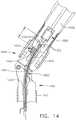
- FIGS. 1 and 2depict a motor-driven surgical system 10 that may be used to perform a variety of different surgical procedures.
- the surgical system 10comprises an interchangeable surgical tool assembly 1000 that is operably coupled to a handle assembly 500.
- the interchangeable surgical tool assembly 1000may also be effectively employed with a tool drive assembly of a robotically controlled or automated surgical system.
- the surgical tool assembly 1000 disclosed hereinmay be employed with various robotic systems, instruments, components and methods such as, but not limited to, those disclosed in U.S. Patent No. 9,072,535 , entitled SURGICAL STAPLING INSTRUMENTS WITH ROTATABLE STAPLE DEPLOYMENT ARRANGEMENTS, which is hereby incorporated by reference herein in its entirety.
- the handle assembly 500may comprise a handle housing 502 that includes a pistol grip portion 504 that can be gripped and manipulated by the clinician.
- the handle assembly 500operably supports a plurality of drive systems that are configured to generate and apply various control motions to corresponding portions of the interchangeable surgical tool assembly 1000.
- the handle assembly 500may further include a handle frame 506 that operably supports the plurality of drive systems.
- the handle frame 506can operably support a "first" or closure drive system, generally designated as 510, which may be employed to apply closing and opening motions to the interchangeable surgical tool assembly 1000.
- the closure drive system 510may include an actuator in the form of a closure trigger 512 that is pivotally supported by the handle frame 506.
- an actuatorin the form of a closure trigger 512 that is pivotally supported by the handle frame 506.
- the closure trigger 512may be easily pivoted from a starting or "unactuated” position to an "actuated” position and more particularly to a fully compressed or fully actuated position.
- the cliniciandepresses the closure trigger 512 towards the pistol grip portion 504.
- closure drive system 510when the clinician fully depresses the closure trigger 512 to attain the full closure stroke, the closure drive system 510 is configured to lock the closure trigger 512 into the fully depressed or fully actuated position.
- the clinicianWhen the clinician desires to unlock the closure trigger 512 to permit it to be biased to the unactuated position, the clinician simply activates a closure release button assembly 518 which enables the closure trigger to return to unactuated position.
- the closure release button assembly 518may also be configured to interact with various sensors that communicate with a microcontroller in the handle assembly 500 for tracking the position of the closure trigger 512. Further details concerning the configuration and operation of the closure release button assembly 518 may be found in U.S. Patent Application Publication No. 2015/0272575 .
- the handle assembly 500 and the handle frame 506may operably support another drive system referred to herein as a firing drive system 530 that is configured to apply firing motions to corresponding portions of the interchangeable surgical tool assembly that is attached thereto.
- the firing drive system 530may employ an electric motor 505 that is located in the pistol grip portion 504 of the handle assembly 500.
- the motor 505may be a DC brushed driving motor having a maximum rotation of, approximately, 25,000 RPM, for example.
- the motor 505may include a brushless motor, a cordless motor, a synchronous motor, a stepper motor, or any other suitable electric motor.
- the motor 505may be powered by a power source 522 that in one form may comprise a removable power pack.
- the power packmay support a plurality of Lithium Ion ("LI") or other suitable batteries therein.
- a number of batteries connected in series or parallelmay be used as the power source 522 for the surgical system 10.
- the power source 522may be replaceable and/or rechargeable.
- the electric motor 505is configured to axially drive a longitudinally movable drive member 540 ( FIG. 3 ) in distal and proximal directions depending upon the polarity of the motor. For example, when the motor 505 is driven in one rotary direction, the longitudinally movable drive member will be axially driven in a distal direction "DD". When the motor 505 is driven in the opposite rotary direction, the longitudinally movable drive member 540 will be axially driven in a proximal direction "PD”.
- the handle assembly 500can include a switch 513 which can be configured to reverse the polarity applied to the electric motor 505 by the power source 522 or otherwise control the motor 505.
- the handle assembly 500can also include a sensor or sensors (not shown) that is configured to detect the position of the drive member and/or the direction in which the drive member is being moved. Actuation of the motor 505 can be controlled by a firing trigger (not shown) that is adjacent to the closure trigger 512 and pivotally supported on the handle assembly 500.
- the firing triggermay be pivoted between an unactuated position and an actuated position.
- the firing triggermay be biased into the unactuated position by a spring or other biasing arrangement such that when the clinician releases the firing trigger, it may be pivoted or otherwise returned to the unactuated position by the spring or biasing arrangement.
- the firing triggercan be positioned "outboard" of the closure trigger 512. As discussed in U.S. Patent Application Publication No.
- the handle assembly 500may be equipped with a firing trigger safety button (not shown) to prevent inadvertent actuation of the firing trigger.
- a firing trigger safety button(not shown) to prevent inadvertent actuation of the firing trigger.
- the safety buttonis contained in the handle assembly 500 where the clinician cannot readily access it and move it between a safety position preventing actuation of the firing trigger and a firing position wherein the firing trigger may be fired.
- the safety button and the firing triggerpivot down wherein they can then be manipulated by the clinician.
- the longitudinally movable drive member 540may have a rack of teeth 542 formed thereon for meshing engagement with a corresponding drive gear arrangement (not shown) that interfaces with the motor. See FIG. 3 . Further details regarding those features may be found in U.S. Patent Application Publication No. 2015/0272575 .
- the longitudinally movable drive memberis insulated to protect it from inadvertent RF energy.
- At least one formalso includes a manually-actuatable "bailout" assembly that is configured to enable the clinician to manually retract the longitudinally movable drive member should the motor 505 become disabled.
- the bailout assemblymay include a lever or bailout handle assembly that is stored within the handle assembly 500 under a releasable door 550. See FIG. 2 .
- the levermay be configured to be manually pivoted into ratcheting engagement with the teeth in the drive member.
- the cliniciancan manually retract the drive member 540 by using the bailout handle assembly to ratchet the drive member in the proximal direction "PD".
- the interchangeable surgical tool assembly 1000includes a surgical end effector 1500 that comprises a first jaw 1600 and a second jaw 1800.
- the first jawcomprises an elongate channel 1602 that is configured to operably support a conventional (mechanical) surgical staple/fastener cartridge 1400 ( FIG. 4 ) or a radio frequency (RF) cartridge 1700 ( FIGS. 1 and 2 ) therein.
- the second jaw 1800comprises an anvil 1810 that is pivotally supported relative to the elongate channel 1602. The anvil 1810 may be selectively moved toward and away from a surgical cartridge supported in the elongate channel 1602 between open and closed positions by actuating the closure drive system 510.
- the anvil 1810is pivotally supported on a proximal end portion of the elongate channel 1602 for selective pivotal travel about a pivot axis that is transverse to the shaft axis SA.
- Actuation of the closure drive system 510may result in the distal axial movement of a proximal closure member or proximal closure tube 1910 that is attached to an articulation connector 1920.
- the articulation connector 1920includes upper and lower tangs 1922, 1924 protrude distally from a distal end of the articulation connector 1920 to be movably coupled to an end effector closure sleeve or distal closure tube segment 1930. See FIG. 3 .
- the distal closure tube segment 1930includes an upper tang 1932 and a lower tang (not shown) that protrude proximally from a proximal end thereof.
- An upper double pivot link 1940includes proximal and distal pins 1941, 1942 that engage corresponding holes in the upper tangs 1922, 1932 of the articulation connector 1920 and distal closure tube segment 1930, respectively.
- a lower double pivot link 1944includes proximal and distal pins 1945, 1946 that engage corresponding holes in the lower tangs 1924 of the articulation connector 1920 and distal closure tube segment 1930, respectively.
- the distal closure tube segment 1930includes positive jaw opening features or tabs 1936, 1938 that correspond with corresponding portions of the anvil 1810 to apply opening motions to the anvil 1810 as the distal closure tube segment 1930 is retracted in the proximal direction PD to a starting position.
- positive jaw opening features or tabs 1936, 1938that correspond with corresponding portions of the anvil 1810 to apply opening motions to the anvil 1810 as the distal closure tube segment 1930 is retracted in the proximal direction PD to a starting position.
- Further details regarding the opening and closing of the anvil 1810may be found in U.S. Patent Application entitled SURGICAL INSTRUMENT WITH POSITIVE JAW OPENING FEATURES, Attorney Docket No. END8208USNP/170096, filed on even date herewith, the entire disclosure of which is hereby incorporated by reference herein.
- the interchangeable surgical tool assembly 1000includes a tool frame assembly 1200 that comprises a tool chassis 1210 that operably supports a nozzle assembly 1240 thereon.
- a tool frame assembly 1200that comprises a tool chassis 1210 that operably supports a nozzle assembly 1240 thereon.
- the tool chassis 1210 and nozzle arrangement 1240facilitate rotation of the surgical end effector 1500 about a shaft axis SA relative to the tool chassis 1210. Such rotational travel is represented by arrow R in FIG. 1 .
- the interchangeable surgical tool assembly 1000includes a spine assembly 1250 that operably supports the proximal closure tube 1910 and is coupled to the surgical end effector 1500.
- the spine assembly 1250may be fabricated from an upper spine segment 1251 and a lower spine segment 1252 that are interconnected together by snap features, adhesive, welding, etc.
- the spine assembly 1250includes a proximal end 1253 that is rotatably supported in the tool chassis 1210.
- the proximal end 1253 of the spine assembly 1250is attached to a spine bearing (not shown) that is configured to be supported within the tool chassis 1210.
- Such arrangementfacilitates rotatable attachment of the spine assembly 1250 to the tool chassis such that the spine assembly 1250 may be selectively rotated about a shaft axis SA relative to the tool chassis 1210.
- the upper spine segment 1251terminates in an upper lug mount feature 1260 and the lower spine segment 1252 terminates in a lower lug mount feature 1270.
- the upper lug mount feature 1260is formed with a lug slot 1262 therein that is adapted to mountingly support an upper mounting link 1264 therein.
- the lower lug mount feature 1270is formed with a lug slot 1272 therein that is adapted to mountingly support a lower mounting link 1274 therein.
- the upper mounting link 1264includes a pivot socket 1266 therein that is offset from the shaft axis SA.
- the pivot socket 1266is adapted to rotatably receive therein a pivot pin 1634 that is formed on a channel cap or anvil retainer 1630 that is attached to a proximal end portion 1610 of the elongate channel 1602.
- the lower mounting link 1274includes lower pivot pin 1276 that adapted to be received within a pivot hole 1611 formed in the proximal end portion 1610 of the elongate channel 1602.
- the lower pivot pin 1276 as well as the pivot hole 1611is offset from the shaft axis SA.
- the lower pivot pin 1276is vertically aligned with the pivot socket 1266 to define the articulation axis AA about which the surgical end effector 1500 may articulate relative to the shaft axis SA. See FIG. 1 .
- the articulation axis AAis transverse to the shaft axis SA, in at least one arrangement, the articulation axis AA is laterally offset therefrom and does not intersect the shaft axis SA.
- a proximal end 1912 of the proximal closure tube 1910is rotatably coupled to a closure shuttle 1914 by a connector 1916 that is seated in an annular groove 1915 in the proximal closure tube segment 1910.
- the closure shuttle 1914is supported for axial travel within the tool chassis 1210 and has a pair of hooks 1917 thereon configured to engage the closure drive system 510 when the tool chassis 1210 is coupled to the handle frame 506.
- the tool chassis 1210further supports a latch assembly 1280 for releasably latching the tool chassis 1210 to the handle frame 506. Further details regarding the tool chassis 1210 and latch assembly 1280 may be found in U.S.
- the firing drive system 530 in the handle assembly 500is configured to be operably coupled to a firing system 1300 that is operably supported in the interchangeable surgical tool assembly 1000.
- the firing system 1300may include an intermediate firing shaft portion 1310 that is configured to be axially moved in the distal and proximal directions in response to corresponding firing motions applied thereto by the firing drive system 530. See FIG. 4 .
- a proximal end 1312 of the intermediate firing shaft portion 1310has a firing shaft attachment lug 1314 formed thereon that is configured to be seated into an attachment cradle 544 ( FIG. 3 ) that is on the distal end of the longitudinally movable drive member 540 of the firing drive system 530 within the handle assembly 500.
- the intermediate firing shaft portion 1310is configured for attachment to a distal cutting portion or knife bar 1320.
- the knife bar 1320is connected to a firing member or knife member 1330.
- the knife member 1330comprises a knife body 1332 that operably supports a tissue cutting blade 1334 thereon.
- the knife body 1332may further include anvil engagement tabs or features 1336 and channel engagement features or a foot 1338.
- the anvil engagement features 1336may serve to apply additional closure motions to the anvil 1810 as the knife member 1330 is advanced distally through the end effector 1500.
- the surgical end effector 1500is selectively articulatable about the articulation axis AA by an articulation system 1360.
- the articulation system 1360includes proximal articulation driver 1370 that is pivotally coupled to an articulation link 1380.
- an offset attachment lug 1373is formed on a distal end 1372 of the proximal articulation driver 1370.
- a pivot hole 1374is formed in the offset attachment lug 1373 and is configured to pivotally receive therein a proximal link pin 1382 formed on the proximal end 1381 of the articulation link 1380.
- a distal end 1383 of the articulation link 1380includes a pivot hole 1384 that is configured to pivotally receive therein a channel pin 1618 formed on the proximal end portion 1610 of the elongate channel 1602.
- proximal articulation driver 1370will thereby apply articulation motions to the elongate channel 1602 to thereby cause the surgical end effector 1500 to articulate about the articulation axis AA relative to the spine assembly 1250.
- the proximal articulation driver 1370can be held in position by an articulation lock 1390 when the proximal articulation driver 1370 is not being moved in the proximal or distal directions.
- the interchangeable surgical tool assembly 1000can include a shifter assembly 1100 which can be configured to selectively and releasably couple the proximal articulation driver 1310 to the firing system 1300.
- the shifter assembly 1100includes a lock collar, or lock sleeve 1110, positioned around the intermediate firing shaft portion 1310 of the firing system 1300 wherein the lock sleeve 1110 can be rotated between an engaged position in which the lock sleeve 1110 operably couples the proximal articulation driver 1370 to the firing member assembly 1300 and a disengaged position in which the proximal articulation driver 1370 is not operably coupled to the firing member assembly 1300.
- proximal articulation driver 1370When lock sleeve 1110 is in its engaged position, distal movement of the firing member assembly 1300 can move the proximal articulation driver 1370 distally and, correspondingly, proximal movement of the firing member assembly 1300 can move the proximal articulation driver 1370 proximally.
- lock sleeve 1110When lock sleeve 1110 is in its disengaged position, movement of the firing member assembly 1300 is not transmitted to the proximal articulation driver 1370 and, as a result, the firing member assembly 1300 can move independently of the proximal articulation driver 1370.
- the proximal articulation driver 1370can be held in position by the articulation lock 1390 when the proximal articulation driver 1370 is not being moved in the proximal or distal directions by the firing member assembly 1300.
- the intermediate firing shaft portion 1310 of the firing member assembly 1300is formed with two opposed flat sides with a drive notch 1316 formed therein. See Fig. 5 .
- the lock sleeve 1110comprises a cylindrical, or an at least substantially cylindrical, body that includes a longitudinal aperture that is configured to receive the intermediate firing shaft portion 1310 therethrough.
- the lock sleeve 1110can comprise diametrically-opposed, inwardly-facing lock protrusions that, when the lock sleeve 1110 is in one position, are engagingly received within corresponding portions of the drive notch 1316 in the intermediate firing shaft portion 1310 and, when in another position, are not received within the drive notch 1316 to thereby permit relative axial motion between the lock sleeve 1110 and the intermediate firing shaft 1310.
- the lock sleeve 1110further includes a lock member 1112 that is sized to be movably received within a notch 1375 in a proximal end of the proximal articulation driver 1370.
- Such arrangementpermits the lock sleeve 1110 to slightly rotate into and out of engagement with the intermediate firing shaft portion 1310 while remaining in position for engagement or in engagement with the notch 1375 in the proximal articulation driver 1370.
- the lock protrusionsare positioned within the drive notch 1316 in the intermediate firing shaft portion 1310 such that a distal pushing force and/or a proximal pulling force can be transmitted from the firing member assembly 1300 to the lock sleeve 1110.
- Such axial pushing or pulling motionis then transmitted from the lock sleeve 1110 to the proximal articulation driver 1370 to thereby articulate the surgical end effector 1500.
- the firing member assembly 1300, the lock sleeve 1110, and the proximal articulation driver 1370will move together when the lock sleeve 1110 is in its engaged (articulation) position.
- the lock sleeve 1110is in its disengaged position, the lock protrusions are not received within the drive notch 1316 in the intermediate firing shaft portion 1310 and, as a result, a distal pushing force and/or a proximal pulling force may not be transmitted from the firing member assembly 1300 to the lock sleeve 1110 (and the proximal articulation driver 1370).
- the shifter assembly 1100further includes a shifter key 1120 that is configured to be slidably received within a key groove formed in the outer perimeter of the lock sleeve 1110. Such arrangement enables the shifter key 1120 to move axially with respect to the lock sleeve 1110.
- a portion of the shifter key 1120is configured to cammingly interact with a cam opening (not shown) in the proximal closure tube portion 1910.
- the shifter assembly 1100further includes a switch drum 1130 that is rotatably received on a proximal end portion of the proximal closure tube portion 1910.
- a portion of the shifter key 1120extends through an axial slot segment in the switch drum 1130 and is movably received within an arcuate slot segment in the switch drum 1130.
- a switch drum torsion spring 1132is mounted on the switch drum 1130 and engages a portion of the nozzle assembly 1240 to apply a torsional bias or rotation which serves to rotate the switch drum 1130 until the portion of the shifter key 1120 reaches an end portion of the cam opening in the proximal closure tube portion 1910.
- the switch drum 1130may provide a torsional bias to the shifter key 1120 which thereby causes the lock sleeve 1110 to rotate into its engaged position with the intermediate firing shaft portion 1310. This position also corresponds to the unactuated configuration of the proximal closure tube 1910 (and distal closure tube segment 1930).
- actuation of the intermediate firing shaft portion 1310will result in the axial movement of the proximal articulation driver 1370 to facilitate articulation of the end effector 1500.
- the usermay then actuate the proximal closure tube portion 1910. Actuation of the proximal closure tube portion 1910 will result in the distal travel of the distal closure tube segment 1930 to ultimately apply a closing motion to the anvil 1810.
- This distal travel of the proximal closure tube portion 1910will result in the cam opening therein cammingly interacting with a cam portion of the shifter key 1120 to thereby cause the shifter key 1120 to rotate the lock sleeve 1110 in an actuation direction.
- Such rotation of the lock sleeve 1110will result in the disengagement of the lock protrusions from the drive notch 1316 in the intermediate firing shaft portion 1310.
- the firing drive system 530may be actuated to actuate the intermediate firing shaft portion 1310 without actuating the proximal articulation driver 1370.
- the interchangeable surgical tool assembly 1000can comprise a slip ring assembly 1150 which can be configured to conduct electrical power to and/or from the surgical end effector 1500 and/or communicate signals to and/or from the surgical end effector 1500, back to an onboard circuit board 1152, while facilitating rotational travel of the shaft and end effector 1500 about the shaft axis SA relative to the tool chassis 1210 by rotating the nozzle assembly 1240.
- the onboard circuit board 1152includes an onboard connector 1154 that is configured to interface with a housing connector 562 ( FIG. 9 ) communicating with a microprocessor 560 that is supported in the handle assembly 500 or robotic system controller, for example.
- the slip ring assembly 1150is configured to interface with a proximal connector 1153 that interfaces with the onboard circuit board 1152. Further details concerning the slip ring assembly 1150 and associated connectors may be found in U.S. Patent Application Serial No. 13/803,086 , now U.S. Patent Application Publication No. 2014/0263541 , and U.S. Patent Application Serial No. 15/019,196 which have each been herein incorporated by reference in their respective entirety as well as in U.S. Patent Application Serial No. 13/800,067 , entitled STAPLE CARTRIDGE TISSUE THICKNESS SENSOR SYSTEM, now U.S. Patent Application Publication No. 2014/0263552 , which is hereby incorporated by reference herein in its entirety.
- FIG. 4An example version of the interchangeable surgical tool assembly 1000 disclosed herein may be employed in connection with a standard (mechanical) surgical fastener cartridge 1400 or a cartridge 1700 that is configured to facilitate cutting of tissue with the knife member and seal the cut tissue using radio frequency (RF) energy.
- RFradio frequency
- FIG. 4a conventional or standard mechanical-type cartridge 1400 is depicted.
- Such cartridge arrangementsare known and may comprise a cartridge body 1402 that is sized and shaped to be removably received and supported in the elongate channel 1602.
- the cartridge body 1402may be configured to be removably retained in snap engagement with the elongate channel 1602.
- the cartridge body 1402includes an elongate slot 1404 to accommodate axial travel of the knife member 1330 therethrough.
- the cartridge body 1402operably supports therein a plurality of staple drivers (not shown) that are aligned in rows on each side of the centrally disposed elongate slot 1404.
- the driversare associated with corresponding staple/fastener pockets 1412 that open through the upper deck surface 1410 of the cartridge body 1402.
- Each of the staple driverssupports one or more surgical staple or fastener (not shown) thereon.
- a sled assembly 1420is supported within a proximal end of the cartridge body 1402 and is located proximal to the drivers and fasteners in a starting position when the cartridge 1400 is new and unfired.
- the sled assembly 1420includes a plurality of sloped or wedge-shaped cams 1422 wherein each cam 1422 corresponds to a particular line of fasteners or drivers located on a side of the slot 1404.
- the sled assembly 1420is configured to be contacted and driven by the knife member 1330 as the knife member is driven distally through the tissue that is clamped between the anvil and the cartridge deck surface 1410. As the drivers are driven upward toward the cartridge deck surface 1410, the fastener(s) supported thereon are driven out of their staple pockets 1412 and through the tissue that is clamped between anvil and the cartridge.
- the anvil 1810 in at least one formincludes an anvil mounting portion 1820 that has a pair of anvil trunnions 1822 protruding laterally therefrom to be pivotally received in corresponding trunnion cradles 1614 formed in the upstanding walls 1622 of the proximal end portion 1610 of the elongate channel 1602.
- the anvil trunnions 1822are pivotally retained in their corresponding trunnion cradle 1614 by the channel cap or anvil retainer 1630.
- the anvil mounting portion 1820is movably or pivotably supported on the elongate channel 1602 for selective pivotal travel relative thereto about a fixed anvil pivot axis that is transverse to the shaft axis SA.
- the anvil 1810includes an anvil body portion 1812 that is fabricated from an electrically conductive metal material for example and has a staple forming undersurface 1813 that has a series of fastener forming pockets 1814 formed therein on each side of a centrally disposed anvil slot 1815 that is configured to slidably accommodate the knife member 1330 therein.
- the anvil slot 1815opens into an upper opening 1816 that extends longitudinally through the anvil body 1812 to accommodate the anvil engagement features 1336 on the knife member 1330 during firing.
- a conventional mechanical surgical staple/fastener cartridge 1400is installed in the elongate channel 1602
- the staples/fastenersare driven through the tissue T and into forming contact with the corresponding fastener forming pockets 1814.
- the anvil body 1812may have an opening in the upper portion thereof to facilitate ease of installation for example.
- An anvil cap 1818may be inserted therein and welded to the anvil body 1812 to enclose the opening and improve the overall stiffness of the anvil body 1812.
- the tissue facing segments 1817 of the fastener forming undersurface 1813may have electrically insulative material 1819 thereon.
- the interchangeable surgical tool assembly 1000is configured with a firing member lockout system, generally designated as 1640. See FIG. 8 .
- the elongate channel 1602includes a bottom surface or bottom portion 1620 that has two upstanding side walls 1622 protruding therefrom.
- a centrally disposed longitudinal channel slot 1624is formed through the bottom portion 1620 to facilitate the axial travel of the knife member 1330 therethrough.
- the channel slot 1624opens into a longitudinal passage 1626 that accommodates the channel engagement feature or foot 1338 on the knife member 1330.
- the passage 1626serves to define two inwardly extending ledge portions 1628 that serve to engage corresponding portions of the channel engagement feature or foot 1338.
- the firing member lockout system 1640includes proximal openings 1642 located on each side of the channel slot 1624 that are each configured to receive corresponding portions of the channel engagement feature or foot 1338 when the knife member 1330 is in a starting position.
- a knife lockout spring 1650is supported in the proximal end 1610 of the elongate channel 1602 and serves to bias the knife member 1330 downward.
- the knife lockout spring 1650includes two distally ending spring arms 1652 that are configured to engage corresponding central channel engagement features 1337 on the knife body 1332. The spring arms 1652 are configured to bias the central channel engagement features 1337 downward.
- the knife member 1330when in the starting (unfired position), the knife member 1330 is biased downward such that the channel engagement features or foot 1338 is received within the corresponding proximal openings 1642 in the elongate 1602 channel.
- the central channel engagement features 1137 and/or foot 1338When in that locked position, if one were to attempt to distally advance the knife 1330, the central channel engagement features 1137 and/or foot 1338 would engage upstanding ledges 1654 on the elongate channel 1602 ( FIGS. 8 and 11 ) and the knife 1330 could not be fired.
- the firing member lockout system 1640also includes an unlocking assembly 1660 formed or supported on a distal end of the firing member body 1332.
- the unlocking assembly 1660includes a distally extending ledge 1662 that is configured to engage an unlocking feature 1426 formed on the sled assembly 1420 when the sled assembly 1420 is in its starting position in an unfired surgical staple cartridge 1400.
- the ledge 1662 on the unlocking assembly 1660contacts the unlocking feature 1426 on the sled assembly 1420 which serves to bias the knife member 1330 upward such that the central channel engagement features 1137 and/or foot 1338 clear the upstanding ledges 1654 in the channel bottom 1620 to facilitate axial passage of the knife member 1330 through the elongate channel 1602. If a partially fired cartridge 1400 is unwittingly installed in the elongate channel, the sled assembly 1420 will not be in the starting position and the knife member 1330 will remain in the locked position.
- the clinicianmay position the tool chassis 1210 of the interchangeable surgical tool assembly 1000 above or adjacent to the distal end of the handle frame 506 such that tapered attachment portions 1212 formed on the tool chassis 1210 are aligned with dovetail slots 507 in the handle frame 506.
- the clinicianmay then move the surgical tool assembly 1000 along an installation axis IA that is perpendicular to the shaft axis SA to seat the tapered attachment portions 1212 in "operable engagement" with the corresponding dovetail receiving slots 507 in the distal end of the handle frame 506.
- the firing shaft attachment lug 1314 on the intermediate firing shaft portion 1310will also be seated in the cradle 544 in the longitudinally movable drive member 540 within the handle assembly 500 and the portions of a pin 516 on a closure link 514 will be seated in the corresponding hooks 1917 in the closure shuttle 1914.
- operble engagementin the context of two components means that the two components are sufficiently engaged with each other so that upon application of an actuation motion thereto, the components may carry out their intended action, function and/or procedure.
- the onboard connector 1154 on the surgical tool assembly 1000is coupled to the housing connector 562 that communicates with the microprocessor 560 that is supported in the handle assembly 500 or robotic system controller, for example.
- the clinicianmay introduce the surgical end effector 1500 into the surgical site through a trocar or other opening in the patient to access the target tissue.
- the cliniciantypically axially aligns the surgical end effector 1500 along the shaft axis SA (unarticulated state).
- SAshaft axis
- the clinicianmay need to articulate the end effector 1500 to advantageously position it adjacent the target tissue. This is prior to closing the anvil 1810 onto the target tissue, so the closure drive system 510 would remain unactuated.
- actuation of the firing drive system 530will result in the application of articulation motions to the proximal articulation driver 1370.
- the firing drive system 530is deactivated and the articulation lock 1390 may retain the surgical end effector 1500 in the articulated position.
- the clinicianmay then actuate the closure drive system 510 to close the anvil 1810 onto the target tissue.
- Such actuation of the closure drive system 510may also result in the shifter assembly 1100 delinking the proximal articulation driver 1370 from the intermediate firing shaft portion 1310.
- the clinicianmay once again actuate the firing drive system 530 to axially advance the firing member 1330 through the surgical staple/fastener cartridge 1400 or RF cartridge 1700 to cut the clamped tissue and fire the staples/fasteners into the cut tissue T.
- Other closure and firing drive arrangements, actuator arrangementsmay also be employed to control the axial movement of the closure system components, the articulation system components and/or the firing system components of the surgical tool assembly 1000 without departing from the scope of the present disclosure.
- the surgical tool assembly 1000is configured to be used in connection with conventional mechanical surgical staple/fastener cartridges 1400 as well as with RF cartridges 1700.
- the RF cartridge 1700may facilitate mechanical cutting of tissue that is clamped between the anvil 1810 and the RF cartridge 1700 with the knife member 1330 while coagulating electrical current is delivered to the tissue in the current path.
- Alternative arrangements for mechanically cutting and coagulating tissue using electrical currentare disclosed in, for example, U.S. Patent No. 5,403,312 ; 7,780,663 and U.S. Patent Application Serial No.
- the RF surgical cartridge 1700includes a cartridge body 1710 that is sized and shaped to be removably received and supported in the elongate channel 1602.
- the cartridge body 1710may be configured to be removably retained in snap engagement with the elongate channel 1602.
- the cartridge body 1710may be fabricated from a polymer material, such as, for example, an engineering thermoplastic such as the liquid crystal polymer (LCP) VECTRATM and the elongate channel 1602 may be fabricated from metal.
- the cartridge body 1710includes a centrally disposed elongate slot 1712 that extends longitudinally through the cartridge body to accommodate longitudinal travel of the knife 1330 therethrough.
- a pair of lockout engagement tails 1714extend proximally from the cartridge body 1710.
- Each lockout engagement tail 1714has a lockout pad 1716 formed on the underside thereof that are sized to be received within a corresponding proximal opening portion 1642 in the channel bottom 1620.
- the lockout engagement tails 1714cover the openings 1642 and ledges 1654 to retain the knife 1330 in an unlocked position ready for firing.
- the cartridge body 1710is formed with a centrally disposed raised electrode pad 1720.
- the elongate slot 1712extends through the center of the electrode pad 1720 and serves to divide the pad 1720 into a left pad segment 1720L and a right pad segment 1720R.
- a right flexible circuit assembly 1730Ris attached to the right pad segment 1720R and a left flexible circuit assembly 1730L is attached to the left pad segment 1720L.
- the right flexible circuit 1730Rcomprises a plurality of electrical conductors 1732R that may include, for example, wider electrical conductors/conductors for RF purposes and thinner electrical conductors for conventional stapling purposes that are supported or attached or embedded into a right insulator sheath/member 1734R that is attached to the right pad 1720R.
- the right flexible circuit assembly 1730Rincludes a "phase one", proximal right electrode 1736R and a "phase two" distal right electrode 1738R.
- the left flexible circuit assembly 1730Lcomprises a plurality of electrical conductors 1732L that may include, for example, wider electrical conductors/conductors for RF purposes and thinner electrical conductors for conventional stapling purposes that are supported or attached or embedded into a left insulator sheath/member 1734L that is attached to the left pad 1720L.
- the left flexible circuit assembly 1730Lincludes a "phase one", proximal left electrode 1736L and a "phase two" distal left electrode 1738L.
- the left and right electrical conductors 1732L, 1732Rare attached to a distal micro-chip 1740 mounted to the distal end portion of the cartridge body 1710.
- each of the right and left flexible circuits 1730R, 1730Lmay have an overall width "CW” of approximately 0.025 inches and each of the electrodes 1736R, 1736L, 1738R, 1738R has a width "EW" of approximately 0.010 inches for example. See FIG. 13 .
- CWoverall width
- EWwidth
- other widths/sizesare contemplated and may be employed in alternative aspects.
- RF energyis supplied to the surgical tool assembly 1000 by a conventional RF generator 400 through a supply lead 402.
- the supply lead 402includes a male plug assembly 406 that is configured to be plugged into corresponding female connectors 410 that are attached to a segmented RF circuit 1160 on the an onboard circuit board 1152. See FIG. 15 .
- Such arrangementfacilitates rotational travel of the shaft and end effector 1500 about the shaft axis SA relative to the tool chassis 1210 by rotating the nozzle assembly 1240 without winding up the supply lead 402 from the generator 400.
- An onboard on/off power switch 420is supported on the latch assembly 1280 and tool chassis 1210 for turning the RF generator on and off.
- the onboard segmented RF circuit 1160communicates with the microprocessor 560 through the connectors 1154 and 562.
- the handle assembly 500may also include a display screen 430 for viewing information about the progress of sealing, stapling, knife location, status of the cartridge, tissue, temperature, etc.
- the slip ring assembly 1150interfaces with a distal connector 1162 that includes a flexible shaft circuit strip or assembly 1164 that may include a plurality of narrow electrical conductors 1166 for stapling related activities and wider electrical conductors 1168 used for RF purposes. As shown in FIGS.
- the flexible shaft circuit strip 1164is centrally supported between the laminated plates or bars 1322 that form the knife bar 1320. Such arrangement facilitates sufficient flexing of the knife bar 1320 and flexible shaft circuit strip 1164 during articulation of the end effector 1500 while remaining sufficiently stiff so as to enable the knife member 1330 to be distally advanced through the clamped tissue.
- the elongate channel 1602includes a channel circuit 1670 supported in a recess 1621 that extends from the proximal end 1610 of the elongate channel 1602 to a distal location 1623 in the elongate channel bottom portion 1620.
- the channel circuit 1670includes a proximal contact portion 1672 that contacts a distal contact portion 1169 of the flexible shaft circuit strip 1164 for electrical contact therewith.
- a distal end 1674 of the channel circuit 1670is received within a corresponding wall recess 1625 formed in one of the channel walls 1622 and is folded over and attached to an upper edge 1627 of the channel wall 1622.
- a series of corresponding exposed contacts 1676are provided in the distal end 1674 of the channel circuit 1670 As shown in FIG. 10 .
- an end 1752 of a flexible cartridge circuit 1750is attached to the distal micro-chip 1740 and is affixed to the distal end portion of the cartridge body 1710.
- Another end 1754is folded over the edge of the cartridge deck surface 1711 and includes exposed contacts 1756 configured to make electrical contact with the exposed contacts 1676 of the channel circuit 1670.
- the electrodes as well as the distal micro-chip 1740are powered and communicate with the onboard circuit board 1152 through contact between the flexible cartridge circuit 1750, the flexible channel circuit 1670, the flexible shaft circuit 1164 and the slip ring assembly 1150.
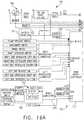
- FIGS. 16A-16Bis a block diagram of a control circuit 700 of the surgical instrument 10 of FIG. 1 spanning two drawing sheets according to one aspect of this disclosure.
- a handle assembly 702may include a motor 714 which can be controlled by a motor driver 715 and can be employed by the firing system of the surgical instrument 10.
- the motor 714may be a DC brushed driving motor having a maximum rotational speed of approximately 25,000 RPM.
- the motor 714may include a brushless motor, a cordless motor, a synchronous motor, a stepper motor, or any other suitable electric motor.
- the motor driver 715may comprise an H-Bridge driver comprising field-effect transistors (FETs) 719, for example.
- the motor 714can be powered by the power assembly 706 releasably mounted to the handle assembly 500 for supplying control power to the surgical instrument 10.
- the power assembly 706may comprise a battery which may include a number of battery cells connected in series that can be used as the power source to power the surgical instrument 10. In certain circumstances, the battery cells of the power assembly 706 may be replaceable and/or rechargeable. In at least one example, the battery cells can be Lithium-Ion batteries which can be separably couplable to the power assembly 706.
- the shaft assembly 704may include a shaft assembly controller 722 which can communicate with a safety controller and power management controller 716 through an interface while the shaft assembly 704 and the power assembly 706 are coupled to the handle assembly 702.
- the interfacemay comprise a first interface portion 725 which may include one or more electric connectors for coupling engagement with corresponding shaft assembly electric connectors and a second interface portion 727 which may include one or more electric connectors for coupling engagement with corresponding power assembly electric connectors to permit electrical communication between the shaft assembly controller 722 and the power management controller 716 while the shaft assembly 704 and the power assembly 706 are coupled to the handle assembly 702.
- One or more communication signalscan be transmitted through the interface to communicate one or more of the power requirements of the attached interchangeable shaft assembly 704 to the power management controller 716.
- the power management controllermay modulate the power output of the battery of the power assembly 706, as described below in greater detail, in accordance with the power requirements of the attached shaft assembly 704.
- the connectorsmay comprise switches which can be activated after mechanical coupling engagement of the handle assembly 702 to the shaft assembly 704 and/or to the power assembly 706 to allow electrical communication between the shaft assembly controller 722 and the power management controller 716.
- the interfacecan facilitate transmission of the one or more communication signals between the power management controller 716 and the shaft assembly controller 722 by routing such communication signals through a main controller 717 residing in the handle assembly 702, for example.
- the interfacecan facilitate a direct line of communication between the power management controller 716 and the shaft assembly controller 722 through the handle assembly 702 while the shaft assembly 704 and the power assembly 706 are coupled to the handle assembly 702.
- the main controller 717may be any single core or multicore processor such as those known under the trade name ARM Cortex by Texas Instruments.
- the main controller 717may be an LM4F230H5QR ARM Cortex-M4F Processor Core, available from Texas Instruments, for example, comprising on-chip memory of 256 KB single-cycle flash memory, or other non-volatile memory, up to 40 MHz, a prefetch buffer to improve performance above 40 MHz, a 32 KB single-cycle serial random access memory (SRAM), internal read-only memory (ROM) loaded with StellarisWare® software, 2 KB electrically erasable programmable read-only memory (EEPROM), one or more pulse width modulation (PWM) modules, one or more quadrature encoder inputs (QEI) analog, one or more 12-bit Analog-to-Digital Converters (ADC) with 12 analog input channels, details of which are available for the product datasheet.
- the safety controllermay be a safety controller platform comprising two controller-based families such as TMS570 and RM4x known under the trade name Hercules ARM Cortex R4, also by Texas Instruments.
- the safety controllermay be configured specifically for IEC 61508 and ISO 26262 safety critical applications, among others, to provide advanced integrated safety features while delivering scalable performance, connectivity, and memory options.
- the power assembly 706may include a power management circuit which may comprise the power management controller 716, a power modulator 738, and a current sense circuit 736.
- the power management circuitcan be configured to modulate power output of the battery based on the power requirements of the shaft assembly 704 while the shaft assembly 704 and the power assembly 706 are coupled to the handle assembly 702.
- the power management controller 716can be programmed to control the power modulator 738 of the power output of the power assembly 706 and the current sense circuit 736 can be employed to monitor power output of the power assembly 706 to provide feedback to the power management controller 716 about the power output of the battery so that the power management controller 716 may adjust the power output of the power assembly 706 to maintain a desired output.
- the power management controller 716 and/or the shaft assembly controller 722each may comprise one or more processors and/or memory units which may store a number of software modules.
- the surgical instrument 10may comprise an output device 742 which may include devices for providing a sensory feedback to a user. Such devices may comprise, for example, visual feedback devices (e.g., an LCD display screen, LED indicators), audio feedback devices (e.g., a speaker, a buzzer) or tactile feedback devices (e.g., haptic actuators).
- the output device 742may comprise a display 743 which may be included in the handle assembly 702.
- the shaft assembly controller 722 and/or the power management controller 716can provide feedback to a user of the surgical instrument 10 through the output device 742.
- the interfacecan be configured to connect the shaft assembly controller 722 and/or the power management controller 716 to the output device 742.
- the output device 742can instead be integrated with the power assembly 706. In such circumstances, communication between the output device 742 and the shaft assembly controller 722 may be accomplished through the interface while the shaft assembly 704 is coupled to the handle assembly 702.
- the control circuit 700comprises circuit segments configured to control operations of the powered surgical instrument 10.
- a safety controller segment(Segment 1) comprises a safety controller and the main controller 717 segment (Segment 2).
- the safety controller and/or the main controller 717are configured to interact with one or more additional circuit segments such as an acceleration segment, a display segment, a shaft segment, an encoder segment, a motor segment, and a power segment.
- Each of the circuit segmentsmay be coupled to the safety controller and/or the main controller 717.
- the main controller 717is also coupled to a flash memory.
- the main controller 717also comprises a serial communication interface.
- the main controller 717comprises a plurality of inputs coupled to, for example, one or more circuit segments, a battery, and/or a plurality of switches.
- the segmented circuitmay be implemented by any suitable circuit, such as, for example, a printed circuit board assembly (PCBA) within the powered surgical instrument 10.
- PCBAprinted circuit board assembly
- processorincludes any microprocessor, processors, controller, controllers, or other basic computing device that incorporates the functions of a computer's central processing unit (CPU) on an integrated circuit or at most a few integrated circuits.
- the main controller 717is a multipurpose, programmable device that accepts digital data as input, processes it according to instructions stored in its memory, and provides results as output. It is an example of sequential digital logic, as it has internal memory.
- the control circuit 700can be configured to implement one or more of the processes described herein.
- the acceleration segment(Segment 3) comprises an accelerometer.
- the accelerometeris configured to detect movement or acceleration of the powered surgical instrument 10. Input from the accelerometer may be used to transition to and from a sleep mode, identify an orientation of the powered surgical instrument, and/or identify when the surgical instrument has been dropped.
- the acceleration segmentis coupled to the safety controller and/or the main controller 717.
- the display segment(Segment 4) comprises a display connector coupled to the main controller 717.
- the display connectorcouples the main controller 717 to a display through one or more integrated circuit drivers of the display.
- the integrated circuit drivers of the displaymay be integrated with the display and/or may be located separately from the display.
- the displaymay comprise any suitable display, such as, for example, an organic light-emitting diode (OLED) display, a liquid-crystal display (LCD), and/or any other suitable display.
- the display segmentis coupled to the safety controller.
- the shaft segment(Segment 5) comprises controls for an interchangeable shaft assembly 500 coupled to the surgical instrument 10 ( FIGS. 1-5 ) and/or one or more controls for an end effector 1500 coupled to the interchangeable shaft assembly 500.
- the shaft segmentcomprises a shaft connector configured to couple the main controller 717 to a shaft PCBA.
- the shaft PCBAcomprises a low-power microcontroller with a ferroelectric random access memory (FRAM), an articulation switch, a shaft release Hall effect switch, and a shaft PCBA EEPROM.
- the shaft PCBA EEPROMcomprises one or more parameters, routines, and/or programs specific to the interchangeable shaft assembly 500 and/or the shaft PCBA.
- the shaft PCBAmay be coupled to the interchangeable shaft assembly 500 and/or integral with the surgical instrument 10.
- the shaft segmentcomprises a second shaft EEPROM.
- the second shaft EEPROMcomprises a plurality of algorithms, routines, parameters, and/or other data corresponding to one or more shaft assemblies 500 and/or end effectors 1500 that may be interfaced with the powered surgical instrument 10.
- the position encoder segment(Segment 6) comprises one or more magnetic angle rotary position encoders.
- the one or more magnetic angle rotary position encodersare configured to identify the rotational position of the motor 714, an interchangeable shaft assembly 500, and/or an end effector 1500 of the surgical instrument 10 ( FIGS. 1-5 ).
- the magnetic angle rotary position encodersmay be coupled to the safety controller and/or the main controller 717.
- the motor circuit segment(Segment 7) comprises a motor 714 configured to control movements of the powered surgical instrument 10 ( FIGS. 1-5 ).
- the motor 714is coupled to the main microcontroller processor 717 by an H-bridge driver comprising one or more H-bridge field-effect transistors (FETs) and a motor controller.
- the H-bridge driveris also coupled to the safety controller.
- a motor current sensoris coupled in series with the motor to measure the current draw of the motor.
- the motor current sensoris in signal communication with the main controller 717 and/or the safety controller.
- the motor 714is coupled to a motor electromagnetic interference (EMI) filter.
- EMImotor electromagnetic interference
- the motor controllercontrols a first motor flag and a second motor flag to indicate the status and position of the motor 714 to the main controller 717.
- the main controller 717provides a pulse-width modulation (PWM) high signal, a PWM low signal, a direction signal, a synchronize signal, and a motor reset signal to the motor controller through a buffer.
- PWMpulse-width modulation
- the power segmentis configured to provide a segment voltage to each of the circuit segments.
- the power segment(Segment 8) comprises a battery coupled to the safety controller, the main controller 717, and additional circuit segments.
- the batteryis coupled to the segmented circuit by a battery connector and a current sensor.
- the current sensoris configured to measure the total current draw of the segmented circuit.
- one or more voltage convertersare configured to provide predetermined voltage values to one or more circuit segments.
- the segmented circuitmay comprise 3.3V voltage converters and/or 5V voltage converters.
- a boost converteris configured to provide a boost voltage up to a predetermined amount, such as, for example, up to 13V.
- the boost converteris configured to provide additional voltage and/or current during power intensive operations and prevent brownout or low-power conditions.
- a plurality of switchesare coupled to the safety controller and/or the main controller 717.
- the switchesmay be configured to control operations of the surgical instrument 10 ( FIGS. 1-5 ), of the segmented circuit, and/or indicate a status of the surgical instrument 10.
- a bail-out door switch and Hall effect switch for bailoutare configured to indicate the status of a bail-out door.
- a plurality of articulation switchessuch as, for example, a left side articulation left switch, a left side articulation right switch, a left side articulation center switch, a right side articulation left switch, a right side articulation right switch, and a right side articulation center switch are configured to control articulation of an interchangeable shaft assembly 500 ( FIGS.
- a left side reverse switch and a right side reverse switchare coupled to the main controller 717.
- the left side switchescomprising the left side articulation left switch, the left side articulation right switch, the left side articulation center switch, and the left side reverse switch are coupled to the main controller 717 by a left flex connector.
- the right side switchescomprising the right side articulation left switch, the right side articulation right switch, the right side articulation center switch, and the right side reverse switch are coupled to the main controller 717 by a right flex connector.
- a firing switch, a clamp release switch, and a shaft engaged switchare coupled to the main controller 717.
- any suitable mechanical, electromechanical, or solid state switchesmay be employed to implement the plurality of switches, in any combination.
- the switchesmay be limit switches operated by the motion of components associated with the surgical instrument 10 ( FIGS. 1-5 ) or the presence of an object.
- Such switchesmay be employed to control various functions associated with the surgical instrument 10.
- a limit switchis an electromechanical device that consists of an actuator mechanically linked to a set of contacts. When an object comes into contact with the actuator, the device operates the contacts to make or break an electrical connection.
- Limit switchesare used in a variety of applications and environments because of their ruggedness, ease of installation, and reliability of operation. They can determine the presence or absence, passing, positioning, and end of travel of an object.
- the switchesmay be solid state switches that operate under the influence of a magnetic field such as Hall-effect devices, magneto-resistive (MR) devices, giant magneto-resistive (GMR) devices, magnetometers, among others.
- the switchesmay be solid state switches that operate under the influence of light, such as optical sensors, infrared sensors, ultraviolet sensors, among others.
- the switchesmay be solid state devices such as transistors (e.g., FET, Junction-FET, metal-oxide semiconductor-FET (MOSFET), bipolar, and the like).
- Other switchesmay include electrical conductorless switches, ultrasonic switches, accelerometers, inertial sensors, among others.
- FIG. 17is another block diagram of the control circuit 700 of the surgical instrument of FIG. 1 illustrating interfaces between the handle assembly 702 and the power assembly 706 and between the handle assembly 702 and the interchangeable shaft assembly 704 according to one aspect of this disclosure.
- the handle assembly 702may comprise a main controller 717, a shaft assembly connector 726 and a power assembly connector 730.
- the power assembly 706may include a power assembly connector 732, a power management circuit 734 that may comprise the power management controller 716, a power modulator 738, and a current sense circuit 736.
- the shaft assembly connectors 730, 732form an interface 727.
- the power management circuit 734can be configured to modulate power output of the battery 707 based on the power requirements of the interchangeable shaft assembly 704 while the interchangeable shaft assembly 704 and the power assembly 706 are coupled to the handle assembly 702.
- the power management controller 716can be programmed to control the power modulator 738 of the power output of the power assembly 706 and the current sense circuit 736 can be employed to monitor power output of the power assembly 706 to provide feedback to the power management controller 716 about the power output of the battery 707 so that the power management controller 716 may adjust the power output of the power assembly 706 to maintain a desired output.
- the shaft assembly 704comprises a shaft processor 719 coupled to a non-volatile memory 721 and shaft assembly connector 728 to electrically couple the shaft assembly 704 to the handle assembly 702.
- the shaft assembly connectors 726, 728form interface 725.
- the main controller 717, the shaft processor 719, and/or the power management controller 716can be configured to implement one or more of the processes described herein.
- the surgical instrument 10may comprise an output device 742 to a sensory feedback to a user.
- Such devicesmay comprise visual feedback devices (e.g., an LCD display screen, LED indicators), audio feedback devices (e.g., a speaker, a buzzer), or tactile feedback devices (e.g., haptic actuators).
- the output device 742may comprise a display 743 that may be included in the handle assembly 702.
- the shaft assembly controller 722 and/or the power management controller 716can provide feedback to a user of the surgical instrument 10 through the output device 742.
- the interface 727can be configured to connect the shaft assembly controller 722 and/or the power management controller 716 to the output device 742.
- the output device 742can be integrated with the power assembly 706.
- Communication between the output device 742 and the shaft assembly controller 722may be accomplished through the interface 725 while the interchangeable shaft assembly 704 is coupled to the handle assembly 702.
- a control circuit 700FIGS. 16A-16B and 6 for controlling the operation of the surgical instrument 10 ( FIGS. 1-5 )
- the disclosurenow turns to various configurations of the surgical instrument 10 ( FIGS. 1-5 ) and control circuit 700.
- FIG. 18is a schematic diagram of a surgical instrument 600 configured to control various functions according to one aspect of this disclosure.
- the surgical instrument 600is programmed to control distal translation of a displacement member such as the I-beam 614.
- the surgical instrument 600comprises an end effector 602 that may comprise an anvil 616, an I-beam 614, and a removable staple cartridge 618 which may be interchanged with an RF cartridge 609 (shown in dashed line).
- the end effector 602, anvil 616, I-beam 614, staple cartridge 618, and RF cartridge 609may be configured as described herein, for example, with respect to FIGS. 1-15 .
- FIG. 18For conciseness and clarity of disclosure, several aspects of the present disclosure may be described with reference to FIG. 18 .
- FIG. 18the components shown schematically in FIG. 18 such as the control circuit 610, sensors 638, position sensor 634, end effector 602, I-beam 614, staple cartridge 618, RF cartridge 609, anvil 616, are described in connection with FIGS. 1-17 of this disclosure.
- the components represented schematically in FIG. 18may be readily substituted with the physical and functional equivalent components described in connection with FIGS. 1-17 .
- the control circuit 610may be implemented as the control circuit 700 shown and described in connection with FIGS. 16-17 .
- the sensors 638may be implemented as a limit switch, electromechanical device, solid state switches, Hall-effect devices, magneto-resistive (MR) devices, giant magneto-resistive (GMR) devices, magnetometers, among others.
- the sensors 638may be solid state switches that operate under the influence of light, such as optical sensors, infrared sensors, ultraviolet sensors, among others.
- the switchesmay be solid state devices such as transistors (e.g., FET, Junction-FET, metal-oxide semiconductor-FET (MOSFET), bipolar, and the like).
- the sensors 638may include electrical conductorless switches, ultrasonic switches, accelerometers, inertial sensors, among others.
- the position sensor 634may be implemented as an absolute positioning system comprising a magnetic rotary absolute positioning system implemented as an AS5055EQFT single-chip magnetic rotary position sensor available from Austria Microsystems, AG. The position sensor 634 may interface with the control circuit 700 to provide an absolute positioning system.
- the positionmay include multiple Hall-effect elements located above a magnet and coupled to a CORDIC processor (for Coordinate Rotation Digital Computer), also known as the digit-by-digit method and Volder's algorithm, is provided to implement a simple and efficient algorithm to calculate hyperbolic and trigonometric functions that require only addition, subtraction, bitshift, and table lookup operations.
- a CORDIC processorfor Coordinate Rotation Digital Computer
- the end effector 602may be implemented as surgical end effector 1500 shown and described in connection with FIGS. 1 , 2 , and 4 .
- the I-beam 614may be implemented as the knife member 1330 comprising a knife body 1332 that operably supports a tissue cutting blade 1334 thereon and may further include anvil engagement tabs or features 1336 and channel engagement features or a foot 1338 as shown and described in connection with FIGS. 2-4 , 8 , 11 and 14 .
- the staple cartridge 618may be implemented as the standard (mechanical) surgical fastener cartridge 1400 shown and described in connection with FIG. 4 .
- the RF cartridge 609may be implemented as the radio frequency (RF) cartridge 1700 shown and described in connection with FIGS. 1 , 2 , 6 , and 10-13 .
- the anvil 616may be implemented the anvil 1810 shown and described in connection with FIGS. 1 , 2 , 4 , and 6 .
- sensors arrangementsare described in commonly owned US Patent Application No. 15/628,175 , entitled TECHNIQUES FOR ADAPTIVE CONTROL OF MOTOR VELOCITY OF A SURGICAL STAPLING AND CUTTING INSTRUMENT, which is incorporated herein by reference in its entirety.
- the position, movement, displacement, and/or translation of a linear displacement membercan be measured by an absolute positioning system, sensor arrangement, and position sensor represented as position sensor 634. Because the I-beam 614 is coupled to the longitudinally movable drive member 540, the position of the I-beam 614 can be determined by measuring the position of the longitudinally movable drive member 540 employing the position sensor 634. Accordingly, in the following description, the position, displacement, and/or translation of the I-beam 614 can be achieved by the position sensor 634 as described herein.
- a control circuit 610such as the control circuit 700 described in FIGS.
- the control circuit 610may comprise one or more microcontrollers, microprocessors, or other suitable processors for executing instructions that cause the processor or processors to control the displacement member, e.g., the I-beam 614, in the manner described.
- a timer/counter circuit 631provides an output signal, such as elapsed time or a digital count, to the control circuit 610 to correlate the position of the I-beam 614 as determined by the position sensor 634 with the output of the timer/counter circuit 631 such that the control circuit 610 can determine the position of the I-beam 614 at a specific time (t) relative to a starting position.
- the timer/counter circuit 631may be configured to measure elapsed time, count external evens, or time external events.
- the control circuit 610may generate a motor set point signal 622.
- the motor set point signal 622may be provided to a motor controller 608.
- the motor controller 608may comprise one or more circuits configured to provide a motor drive signal 624 to the motor 604 to drive the motor 604 as described herein.
- the motor 604may be a brushed DC electric motor, such as the motor 505 shown in FIG. 1 .
- the velocity of the motor 604may be proportional to the motor drive signal 624.
- the motor 604may be a brushless direct current (DC) electric motor and the motor drive signal 624 may comprise a pulse-width-modulated (PWM) signal provided to one or more stator windings of the motor 604.
- PWMpulse-width-modulated
- the motor controller 608may be omitted and the control circuit 610 may generate the motor drive signal 624 directly.
- the motor 604may receive power from an energy source 612.
- the energy source 612may be or include a battery, a super capacitor, or any other suitable energy source 612.
- the motor 604may be mechanically coupled to the I-beam 614 via a transmission 606.
- the transmission 606may include one or more gears or other linkage components to couple the motor 604 to the I-beam 614.
- a position sensor 634may sense a position of the I-beam 614.
- the position sensor 634may be or include any type of sensor that is capable of generating position data that indicates a position of the I-beam 614.
- the position sensor 634may include an encoder configured to provide a series of pulses to the control circuit 610 as the I-beam 614 translates distally and proximally.
- the control circuit 610may track the pulses to determine the position of the I-beam 614.
- Other suitable position sensormay be used, including, for example, a proximity sensor.
- Other types of position sensorsmay provide other signals indicating motion of the I-beam 614.
- the position sensor 634may be omitted. Where the motor 604 is a stepper motor, the control circuit 610 may track the position of the I-beam 614 by aggregating the number and direction of steps that the motor 604 has been instructed to execute.
- the position sensor 634may be located in the end effector 602 or at any other portion of the instrument.
- the control circuit 610may be in communication with one or more sensors 638.
- the sensors 638may be positioned on the end effector 602 and adapted to operate with the surgical instrument 600 to measure the various derived parameters such as gap distance versus time, tissue compression versus time, and anvil strain versus time.
- the sensors 638may comprise a magnetic sensor, a magnetic field sensor, a strain gauge, a pressure sensor, a force sensor, an inductive sensor such as an eddy current sensor, a resistive sensor, a capacitive sensor, an optical sensor, and/or any other suitable sensor for measuring one or more parameters of the end effector 602.
- the sensors 638may include one or more sensors.
- the one or more sensors 638may comprise a strain gauge, such as a micro-strain gauge, configured to measure the magnitude of the strain in the anvil 616 during a clamped condition.
- the strain gaugeprovides an electrical signal whose amplitude varies with the magnitude of the strain.
- the sensors 638may comprise a pressure sensor configured to detect a pressure generated by the presence of compressed tissue between the anvil 616 and the staple cartridge 618.
- the sensors 638may be configured to detect impedance of a tissue section located between the anvil 616 and the staple cartridge 618 that is indicative of the thickness and/or fullness of tissue located therebetween.
- the sensors 638may be configured to measure forces exerted on the anvil 616 by the closure drive system.
- one or more sensors 638can be at an interaction point between the closure tube 1910 ( FIGS. 1-4 ) and the anvil 616 to detect the closure forces applied by the closure tube 1910 to the anvil 616.
- the forces exerted on the anvil 616can be representative of the tissue compression experienced by the tissue section captured between the anvil 616 and the staple cartridge 618.
- the one or more sensors 638can be positioned at various interaction points along the closure drive system to detect the closure forces applied to the anvil 616 by the closure drive system.
- the one or more sensors 638may be sampled in real time during a clamping operation by a processor as described in FIGS. 16A-16B .
- the control circuit 610receives real-time sample measurements to analyze time based information and assess, in real time, closure forces applied to the anvil 616.
- a current sensor 636can be employed to measure the current drawn by the motor 604.
- the force required to advance the I-beam 614corresponds to the current drawn by the motor 604.
- the forceis converted to a digital signal and provided to the control circuit 610.
- the RF energy source 400is coupled to the end effector 602 and is applied to the RF cartridge 609 when the RF cartridge 609 is loaded in the end effector 602 in place of the staple cartridge 618.
- the control circuit 610controls the delivery of the RF energy to the RF cartridge 609.
- a unique circuitry systemis included in the nozzle assembly that allows for a user of the modular surgical instruments described herein to manipulate the end effector directly from the instrumentation contained in the handle assembly.
- the nozzle assemblymay include an onboard circuit board that allows for an electrosurgical generator to attach directly to the nozzle assembly and supply radio frequency (RF) energy to the end effector, while also interfacing with the processor or control circuit of the handle assembly.
- RFradio frequency
- the unique circuitry of the nozzle assemblyalso allows for shaft rotation while still supplying proper energy and functionality to the end effector.
- connecting the surgical instrument to a generatorenables certain shaft functions.
- attachment of RF leads to the generatorallow the surgical instrument onboard circuit board to isolate some of the elongated shaft integral circuit wiring for RF application to an RF cartridge interchangeably usable with stapling cartridges.
- the onboard circuit boardis a segmented circuit configured to isolate the generator inputs (e.g., RF energy, etc.) from the handle electronics where appropriate.
- a flex circuitcontains electrical conductors with different geometries to accommodate RF energy transfer.
- the nozzle assembly 1240 that constitutes a modular portion of the surgical tool assembly 1000may include shaft module circuitry uniquely configured to control various functions in the shaft assembly while also communicating with the handle assembly 500 and allowing for the RF generator 400 to be controlled from the powered stapling handle.
- the circuitry of FIG. 15is shown in the context of an example nozzle assembly 1240.
- the circuitry according to some aspects of the present disclosuresincludes the onboard circuit board 1152 with various connectors. Female connectors 410 are electrically coupled to the circuit board 1152, which allows for connection with the male plug assembly 406 to the generator 400, not shown.
- the onboard on/off power switch 420is electrically coupled to the circuit board 1152 and positioned in such a way so as to be pressed when the nozzle assembly 1240 is attached to the handle assembly 500, according to some aspects.
- the on/off power switch 420may be positioned to face proximally to the handle assembly and may be pressed as the nozzle assembly slides into the slot of the handle assembly via the closure link 514 (see FIG. 9 ).
- the on/off power switch 420is exposed so that it may be manually pressed by an operator of the surgical tool assembly 1000.
- the circuit board 1152includes the onboard connector 1154 configured to interface with the housing connector 562 (see FIG. 9 ) communicating with the microprocessor 560 contained in the handle assembly 500.
- the handle assembly 500is capable of commanding the circuit board 1152 that controls several functions in the nozzle assembly 1240.
- the design of the circuitry in the nozzle assembly 1240allows for an operator to perform a number of functions from the various controls of the handle assembly 500, such as through the various controls and display consoles available in the handle assembly 500.
- the circuit board 1152also includes the proximal connector 1153 that is configured to interface with the slip ring assembly 1150. Power may be supplied to the end effector even while the shaft rotates due to power being supplied throughout the slip ring assembly 1150 and the distal connector 1162 being in constant contact with the slip ring assembly as the flexible shaft circuit strip 1164 rotates within the proximal closure tube 1910.
- the shaft circuit strip 1164may include a number of electrical conductors, such as the narrow electrical conductors 1166 for stapling related activities and the wider electrical conductors 1168 for RF purposes (see FIG. 15 ).
- the circuitry 1152may be configured to control the RF generator 400 from the powered handle assembly 500, allowing for communication with the various functions and interfaces of the handle assembly 500, and allowing for operation of the RF and stapling functions of the end effector from the handle assembly 500.
- Other functionsmay include controlling a type of algorithm for performing various surgical procedures and energy applications at the end effector, enabling warning functionality viewable at the handle assembly 500 of any part of the nozzle assembly 1240, and varying energy modulation from the RF generator 400.
- the circuit board 1152may be programmed to facilitate these functions, while in other cases the onboard connecter 1154 may allow for the handle assembly circuitry to be programmed to facilitate these functions and the circuit board 1152 is configured to command the end effector accordingly.
- the onboard circuitincludes the segmented RF circuit 1160, which may allow for the RF energy of the generator 400 to be supplied to the flexible shaft circuit strip via the slip ring assembly (see, e.g., FIG. 15 ).
- the RF generatormay be coupled to the onboard circuit board 1152 via the RF segmented circuit 1160.
- the on/off power switch 420may be similarly connected to the segmented RF circuit 1160.
- FIG. 20illustrates a block diagram of a surgical system 3200 programmed to communicate power and control signals with an end effector 3250 according to one aspect of this disclosure.
- the surgical system 3200may include a control circuit 3210 (e.g., microprocessor 560, segmented RF circuit 1160, or distal micro-chip 1740) having an electrosurgical energy control segment (or an RF energy control segment) 3220 and a shaft control segment 3230 (e.g., shaft segment (Segment 5), motor circuit segment (Segment 7), or power segment (Segment 8)).
- a control circuit 3210e.g., microprocessor 560, segmented RF circuit 1160, or distal micro-chip 1740
- an electrosurgical energy control segmentor an RF energy control segment
- shaft control segment 3230e.g., shaft segment (Segment 5), motor circuit segment (Segment 7), or power segment (Segment 8).
- the control circuit 3210may be programed to provide electrosurgical energy (e.g., RF energy) to electrodes in the end effector 3250 (e.g., end effector 1500).
- the surgical system 3200may include one or more electrical conductors 3260 (e.g., electrical conductors 1168) used for providing the electrosurgical energy, from an electrosurgical energy generator 3240 (e.g., RF generator 400), to the end effector 3250.
- the one or more electrical conductors 3260may be electrically connected between the end effector 3250 and the control circuit 3210 (e.g., the electrosurgical energy control segment 3220 and the shaft control segment 3230).
- the electrosurgical energy control segment 3220may be programed to provide the electrosurgical energy to the electrodes through the one or more electrical conductors 3260.
- the shaft control segment 3230may be programed to provide and/or receive a control signal to/from the end effector 3250 (and/or the surgical tool assembly 1000, the shaft assembly 704) through the one or more electrical conductors 3260. That is, the one or more electrical conductors 3260 may be used not only for providing the electrosurgical energy to the end effector 3250, but also for communicating control signals with the end effector 3250.
- at least some portions of the electrosurgical energy control segment 3220 and the shaft control segment 3230may be electrically isolated from each other.
- the electrosurgical energy control segment 3220may electrically isolate the one or more electrical conductors 3260 from the shaft control segment 3230, for example, when providing the electrosurgical energy to the electrodes in the end effector 3250 through the one or more electrical conductors 3260.
- the electrosurgical energy control segment 3220may control a switch 3270 located between the one or more electrical conductors 3260 and the shaft control segment 3230 by providing a signal through a control line 3280 to electrically isolate the one or more electrical conductors 3260 from the shaft control segment 3230.
- the switch 3270may be configured to switch between an open state and a closed state.
- the shaft control segment 3230 and the one or more electrical conductors 3260may be electrically isolated when the switch 3270 is in the open state, and may be in electrical communication when the switch 3270 is in the closed state.
- the electrosurgical energy control segment 3220may electrically isolate the one or more electrical conductors 3260 from the shaft control segment 3230 in any other suitable manner.
- Other configurations of the switch 3270may enable electrical isolation of the one or more electrical conductors 3260 from the shaft control segment 3230 by closing the switch 3270.
- the electrosurgical energy control segment 3220may electrically isolate the one or more electrical conductors 3260 from the shaft control segment 3230 when the control circuit 3210 detects that the electrosurgical energy generator 3240 is connected to the connector 3265 (e.g., female connectors 410), for example, by continuously checking the connector 3265 or sensing the application of the electrosurgical energy.
- the electrosurgical energy control segment 3220may isolate the electrical conductors 3260 from the shaft control segment 3230.
- the electrosurgical energy control segment 3220may electrically isolate the one or more electrical conductors 3260 from the shaft control segment 3230 when the electrosurgical energy is provided to the end effector 3250 or at any other suitable moment.
- the surgical systemmay include one or more electrical conductors 3290 (e.g., electrical conductors 1166) used for operating the end effector 3250 (and/or the surgical tool assembly 1000, the shaft assembly 704).
- the one or more electrical conductors 3290may not be used to deliver the electrosurgical energy to the end effector 3250.
- the shaft control segment 3230may be programed to provide and/or receive a control signal to/from the end effector 3250 through the one or more electrical conductors 3290.
- the shaft control segment 3230may use the one or more electrical conductors 3290 to provide and/or receive the control signal to/from the end effector 3250 while the switch 3270 is in an open state (e.g., while the electrosurgical energy control segment 3220 is providing the electrosurgical energy to the end effector 3250 through the one or more electrical conductors 3260).
- the shaft control segment 3230also may use the one or more electrical conductors 3290 to provide and/or receive the control signal to/from the end effector 3250 while the switch 3270 is in a closed state.
- the switch 3270may be a transistor switch, a mechanical switch, or any other suitable switch.
- the control signals communicated between the control circuit 3210 and the end effector 3250 (and/or the surgical tool assembly 1000, the shaft assembly 704) through the electrical conductors 3260, 3290include, but are not limited to, signals for driving the end effector 3250 (and/or the surgical tool assembly 1000, the shaft assembly 704) in cutting and/or coagulation operating modes, measuring electrical characteristics of the surgical system 3200 and/or the tissue clamped in the end effector 3250, providing feedback to use, communicating sensor signals, and identifying certain characteristics of the end effector 3250 (e.g., used/unused status).
- aspects of the present disclosuremay advantageously reduce the number of electrical conductors necessary for communicating control signals between the control circuit 3210 and the end effector 3250 (and/or the surgical tool assembly 1000, the shaft assembly 704) by using some of the electrical conductors (e.g., electrical conductors 3260) used for the delivery of the electrosurgical energy to communicate the control signals when those electrical conductors are not used for the electrosurgical energy.
- some of the electrical conductorse.g., electrical conductors 3260
- aspects of the present disclosuremay prevent the electrosurgical energy from flowing into the other circuit segments and/or electrical conductors (e.g., electrical conductors 3290) connected to those circuit segments, preventing damages to those circuit segments and/or electrical conductors.
- electrical circuitryincludes electrical circuitry having at least one discrete electrical circuit, electrical circuitry having at least one integrated circuit, electrical circuitry having at least one application specific integrated circuit, electrical circuitry forming a general purpose computing device configured by a computer program (e.g., a general purpose computer or processor configured by a computer program, which at least partially carries out processes and/or devices described herein), electrical circuitry forming a memory device (e.g., forms of random access memory), and/or electrical circuitry forming a communications device (e.g., a modem, communications switch, or optical-electric
- ASICsApplication Specific Integrated Circuits
- FPGAsField Programmable Gate Arrays
- DSPsdigital signal processors
- PLDsProgrammable Logic Devices
- circuitsregisters and/or software components, e.g., programs, subroutines, logic and/or combinations of hardware and software components, logic gates, or other integrated formats.
- Some aspects disclosed herein, in whole or in part,can be equivalently implemented in integrated circuits, as one or more computer programs running on one or more computers (e.g., as one or more programs running on one or more computer systems), as one or more programs running on one or more processors (e.g., as one or more programs running on one or more microprocessors), as firmware, or as virtually any combination thereof, and that designing the circuitry and/or writing the code for the software and or firmware would be well within the skill of one of skill in the art in light of this disclosure.
- a signal bearing mediumexamples include the following: a recordable type medium such as a floppy disk, a hard disk drive, a Compact Disc (CD), a Digital Video Disk (DVD), a digital tape, a computer memory, etc.; and a transmission type medium such as a digital and/or an analog communication medium (e.g., a fiber optic cable, a waveguide, an electrical conductor communications link, an electrical conductorless communication link (e.g., transmitter, receiver, transmission logic, reception logic, etc.).
- a recordable type mediumsuch as a floppy disk, a hard disk drive, a Compact Disc (CD), a Digital Video Disk (DVD), a digital tape, a computer memory, etc.
- a transmission type mediumsuch as a digital and/or an analog communication medium (e.g., a fiber optic cable, a waveguide, an electrical conductor communications link, an electrical conductorless communication link (e.g., transmitter, receiver, transmission logic, reception logic, etc.).
Landscapes
- Health & Medical Sciences (AREA)
- Surgery (AREA)
- Life Sciences & Earth Sciences (AREA)
- Engineering & Computer Science (AREA)
- Biomedical Technology (AREA)
- Nuclear Medicine, Radiotherapy & Molecular Imaging (AREA)
- Heart & Thoracic Surgery (AREA)
- Medical Informatics (AREA)
- Molecular Biology (AREA)
- Animal Behavior & Ethology (AREA)
- General Health & Medical Sciences (AREA)
- Public Health (AREA)
- Veterinary Medicine (AREA)
- Otolaryngology (AREA)
- Plasma & Fusion (AREA)
- Physics & Mathematics (AREA)
- Surgical Instruments (AREA)
Abstract
Description
- The present disclosure generally relates to an electrosurgical systems with modular components for performing surgical procedures. In particular, the present disclosure relates to shaft module circuitry arrangements.
- In a surgical sealing and stapling system, it may be useful to employ a modular design that allows a single handle assembly to attach to multiple nozzle assemblies, and for a nozzle assembly to attach to multiple handle assemblies. Since the nozzle assembly would include the various surgical instruments in the end effector, special circuity in the nozzle may be required to allow for instrumentation in a handle assembly to control the various functions in the end effector of the modular nozzle assembly. In addition, energy may need to be applied to the end effector that may or may not originate from the handle assembly. For example, the handle assembly may be battery powered to control the functions of the handle assembly, but may not possess power sufficient to control the end effector.
- In one aspect, a control circuit for a surgical instrument is presented. The control circuit may include: a shaft control segment; an electrosurgical energy control segment; and a connector coupled to the electrosurgical energy control segment configured to couple to an electrosurgical generator. The shaft control segment may be configured to: communicate with a handle portion of the surgical instrument; and receive user input controls. The electrosurgical energy control segment may be configured to: detect connection of the electrosurgical generator to the connector; communicate with the electrosurgical generator; electrically isolate the handle control segment from the electrosurgical energy control segment when the connection of the electrosurgical generator to the connector is detected; and provide electrosurgical energy from the electrosurgical generator to an end effector portion of the surgical instrument through a first set of electrical conductors.
- In another aspect, a nozzle assembly of a surgical system is presented. The nozzle assembly may include: an onboard circuit board; an onboard connector coupled to the onboard circuit board and proximally located on the nozzle assembly, the onboard connector configured to interface with a housing connector of a handle assembly when the nozzle assembly is attached to the handle assembly; a shaft attachment lug proximally located on the nozzle assembly and configured to be coupled to an attachment cradle of the handle assembly to attach the nozzle assembly to the handle assembly; and a control circuit comprising: a shaft control segment; an electrosurgical energy control segment; and a connector coupled to the electrosurgical energy control segment configured to couple to an electrosurgical generator. The shaft control segment may be configured to: communicate with a handle portion of the surgical instrument; and receive user input controls. The electrosurgical energy control segment may be configured to: detect connection of the electrosurgical generator to the connector; communicate with the electrosurgical generator; electrically isolate the handle control segment from the electrosurgical energy control segment when the connection of the electrosurgical generator to the connector is detected; and provide electrosurgical energy from the electrosurgical generator to an end effector portion of the surgical instrument through a first set of electrical conductors. The nozzle assembly may be detachable from and attachable to the handle assembly.
- The novel features of the aspects described herein are set forth with particularity in the appended claims. These aspects, however, both as to organization and methods of operation may be better understood by reference to the following description, taken in conjunction with the accompanying drawings.
FIG. 1 is a perspective view of a surgical system including a handle assembly coupled to an interchangeable surgical tool assembly that is configured to be used in connection with conventional surgical staple/fastener cartridges and radio frequency (RF) cartridges according to one aspect of this disclosure.FIG. 2 is an exploded perspective assembly view of the surgical system ofFIG. 1 according to one aspect of this disclosure.FIG. 3 is another exploded perspective assembly view of portions of the handle assembly and interchangeable surgical tool assembly ofFIGS. 1 and2 according to one aspect of this disclosure.FIG. 4 is an exploded assembly view of a proximal portion of the interchangeable surgical tool assembly ofFIGS. 1-3 according to one aspect of this disclosure.FIG. 5 is another exploded assembly view of a distal portion of the interchangeable surgical tool assembly ofFIGS. 1-5 according to one aspect of this disclosure.FIG. 6 is a partial cross-sectional view of the end effector depicted inFIGS. 1-5 supporting an RF cartridge therein and with tissue clamped between the cartridge and the anvil according to one aspect of this disclosure.FIG. 7 is a partial cross-sectional view of the anvil ofFIG. 6 according to one aspect of this disclosure.FIG. 8 is another exploded assembly view of a portion of the interchangeable surgical tool assembly ofFIGS. 1-5 according to one aspect of this disclosure.FIG. 9 is another exploded assembly view of the interchangeable surgical tool assembly and handle assembly ofFIGS. 1 and2 according to one aspect of this disclosure.FIG. 10 is a perspective view of an RF cartridge and an elongate channel of the interchangeable surgical tool assembly ofFIGS. 1-5 according to one aspect of this disclosure.FIG. 11 is a partial perspective view of portions of the RF cartridge and elongate channel ofFIG. 10 with a knife member according to one aspect of this disclosure.FIG. 12 is another perspective view of the RF cartridge installed in the elongate channel ofFIG. 10 and illustrating a portion of a flexible shaft circuit arrangement according to one aspect of this disclosure.FIG. 13 is a cross-sectional end view of the RF cartridge and elongate channel ofFIG. 12 taken along lines 13-13 inFIG. 12 according to one aspect of this disclosure.FIG. 14 is a top cross-sectional view of a portion of the interchangeable surgical tool assembly ofFIGS. 1 and5 with the end effector thereof in an articulated position according to one aspect of this disclosure.FIG. 15 is a perspective view of an onboard circuit board arrangement and RF generator plus configuration according to one aspect of this disclosure.FIGS. 16A-16B is a block diagram of a control circuit of the surgical instrument ofFIG. 1 spanning two drawing sheets according to one aspect of this disclosure.FIG. 17 is a block diagram of the control circuit of the surgical instrument ofFIG. 1 illustrating interfaces between the handle assembly, the power assembly, and the handle assembly and the interchangeable shaft assembly according to one aspect of this disclosure.FIG. 18 is a schematic diagram of a surgical instrument configured to control various functions according to one aspect of this disclosure.FIG. 19 shows a nozzle assembly that constitutes a modular portion of the surgical tool assembly may include shaft module circuitry uniquely configured to control various functions in the shaft assembly while also communicating with the handle assembly and allowing for an electrosurgical generator to be controlled from the powered stapling handle, according to some aspects.FIG. 20 illustrates a block diagram of a surgical system programmed to communicate power and control signals with an end effector, according to one aspect of this disclosure.- Applicant of the present application owns the following patent applications filed concurrently herewith and which are each herein incorporated by reference in their respective entireties:
- Attorney Docket No. END8184USNP/170063, titled SURGICAL SYSTEM COUPLABLE WITH STAPLE CARTRIDGE AND RADIO FREQUENCY CARTRIDGE, AND METHOD OF USING SAME, by inventors Jeffrey D. Messerly et al., filed June 28, 2017.
- Attorney Docket No. END8183USNP/170064, titled SYSTEMS AND METHODS OF DISPLAYING SURGICAL INSTRUMENT STATUS, by inventors Jeffrey D. Messerly et al., filed June 28, 2017.
- Attorney Docket No. END8189USNP/170066, titled SYSTEMS AND METHODS FOR CONTROLLING CONTROL CIRCUITS FOR INDEPENDENT ENERGY DELIVERY OVER SEGMENTED SECTIONS, by inventors Jeffrey D. Messerly et al., filed June 28, 2017.
- Attorney Docket No. END8185USNP/170067, titled FLEXIBLE CIRCUIT ARRANGEMENT FOR SURGICAL FASTENING INSTRUMENTS, by inventors Jeffrey D. Messerly et al., filed June 28, 2017.
- Attorney Docket No. END8188USNP/170068, titled SURGICAL SYSTEM COUPLEABLE WITH STAPLE CARTRIDGE AND RADIO FREQUENCY CARTRIDGE, AND HAVING A PLURALITY OF RADIO-FREQUENCY ENERGY RETURN PATHS, by inventors Jeffrey D. Messerly et al., filed June 28, 2017.
- Attorney Docket No. END8181USNP/170069, titled SYSTEMS AND METHODS FOR CONTROLLING CONTROL CIRCUITS FOR AN INDEPENDENT ENERGY DELIVERY OVER SEGMENTED SECTIONS, by inventors David C. Yates et al., filed June 28, 2017.
- Attorney Docket No. END8187USNP/170070, titled SURGICAL END EFFECTOR FOR APPLYING ELECTROSURGICAL ENERGY TO DIFFERENT ELECTRODES ON DIFFERENT TIME PERIODS, by inventors Tamara Widenhouse et al., filed June 28, 2017.
- Attorney Docket No. END8182USNP/170071, titled ELECTROSURGICAL CARTRIDGE FOR USE IN THIN PROFILE SURGICAL CUTTING AND STAPLING INSTRUMENT, by inventors Tamara Widenhouse et al., filed June 28, 2017.
- Attorney Docket No. END8186USNP/170072, titled SURGICAL END EFFECTOR TO ADJUST JAW COMPRESSION, by inventors Frederick E. Shelton, IV et al., filed June 28, 2017.
- Attorney Docket No. END8224USNP/170073, titled CARTRIDGE ARRANGEMENTS FOR SURGICAL CUTTING AND FASTENING INSTRUMENTS WITH LOCKOUT DISABLEMENT FEATURES, by inventors Jason L. Harris et al., filed June 28, 2017.
- Attorney Docket No. END8229USNP/170074, titled SURGICAL CUTTING AND FASTENING INSTRUMENTS WITH DUAL POWER SOURCES, by inventors Jeffrey D. Messerly et al., filed June 28, 2017.
- Electrosurgical devices may be used in many surgical operations. Electrosurgical devices may apply electrical energy to tissue in order to treat tissue. An electrosurgical device may comprise an instrument having a distally mounted end effector comprising one or more electrodes. The end effector can be positioned against tissue such that electrical current may be introduced into the tissue. Electrosurgical devices can be configured for monopolar or bipolar operation. During monopolar operation, current may be introduced into the tissue by an active (or source) electrode on the end effector and returned through a return electrode. The return electrode may be a grounding pad and separately located on a patient's body. During bipolar operation, current may be introduced into and returned from the tissue by the active and return electrodes, respectively, of the end effector.
- The end effector may include two or more jaw members. At least one of the jaw members may have at least one electrode. At least one jaw may be moveable from a position spaced apart from the opposing jaw for receiving tissues to a position in which the space between the jaw members is less than that of the first position. This movement of the moveable jaw may compress the tissue held between. Heat generated by the current flow through the tissue in combination with the compression achieved by the jaw's movement may form hemostatic seals within the tissue and/or between tissues and, thus, may be particularly useful for sealing blood vessels, for example. The end effector may comprise a cutting member. The cutting member may be movable relative to the tissue and the electrodes to transect the tissue.
- Electrosurgical devices also may include mechanisms to clamp tissue together, such as a stapling device, and/or mechanisms to sever tissue, such as a tissue knife. An electrosurgical device may include a shaft for placing the end effector proximate to tissue undergoing treatment. The shaft may be straight or curved, bendable or non-bendable. In an electrosurgical device including a straight and bendable shaft, the shaft may have one or more articulation joints to permit controlled bending of the shaft. Such joints may permit a user of the electrosurgical device to place the end effector in contact with tissue at an angle to the shaft when the tissue being treated is not readily accessible using an electrosurgical device having a straight, non-bending shaft.
- Electrical energy applied by electrosurgical devices can be transmitted to the instrument by a generator in communication with the hand piece. The electrical energy may be in the form of radio frequency ("RF") energy. RF energy is a form of electrical energy that may be in the frequency range of 200 kilohertz (kHz) to 1 megahertz (MHz). In application, an electrosurgical instrument can transmit low frequency RF energy through tissue, which causes ionic agitation, or friction, in effect resistive heating, thereby increasing the temperature of the tissue. Because a sharp boundary is created between the affected tissue and the surrounding tissue, surgeons can operate with a high level of precision and control, without sacrificing untargeted adjacent tissue. The low operating temperatures of RF energy is useful for removing, shrinking, or sculpting soft tissue while simultaneously sealing blood vessels. RF energy works particularly well on connective tissue, which is primarily comprised of collagen and shrinks when contacted by heat.
- The RF energy may be in a frequency range described in EN 60601-2-2:2009+A11:2011, Definition 201.3.218- HIGH FREQUENCY. For example, the frequency in monopolar RF applications may be typically restricted to less than 5MHz. However, in bipolar RF applications, the frequency can be almost anything. Frequencies above 200 kHz can be typically used for monopolar applications in order to avoid the unwanted stimulation of nerves and muscles that would result from the use of low frequency current. Lower frequencies may be used for bipolar applications if the risk analysis shows the possibility of neuromuscular stimulation has been mitigated to an acceptable level. Normally, frequencies above 5 MHz are not used in order to minimize the problems associated with high frequency leakage currents. Higher frequencies may, however, be used in the case of bipolar applications. It is generally recognized that 10 mA is the lower threshold of thermal effects on tissue.
FIGS. 1 and2 depict a motor-drivensurgical system 10 that may be used to perform a variety of different surgical procedures. In the illustrated arrangement, thesurgical system 10 comprises an interchangeablesurgical tool assembly 1000 that is operably coupled to ahandle assembly 500. In another surgical system aspect, the interchangeablesurgical tool assembly 1000 may also be effectively employed with a tool drive assembly of a robotically controlled or automated surgical system. For example, thesurgical tool assembly 1000 disclosed herein may be employed with various robotic systems, instruments, components and methods such as, but not limited to, those disclosed inU.S. Patent No. 9,072,535 - In the illustrated aspect, the
handle assembly 500 may comprise ahandle housing 502 that includes a pistol grip portion 504 that can be gripped and manipulated by the clinician. As will be briefly discussed below, thehandle assembly 500 operably supports a plurality of drive systems that are configured to generate and apply various control motions to corresponding portions of the interchangeablesurgical tool assembly 1000. As shown inFIG. 2 , thehandle assembly 500 may further include ahandle frame 506 that operably supports the plurality of drive systems. For example, thehandle frame 506 can operably support a "first" or closure drive system, generally designated as 510, which may be employed to apply closing and opening motions to the interchangeablesurgical tool assembly 1000. In at least one form, theclosure drive system 510 may include an actuator in the form of aclosure trigger 512 that is pivotally supported by thehandle frame 506. Such arrangement enables theclosure trigger 512 to be manipulated by a clinician such that when the clinician grips the pistol grip portion 504 of thehandle assembly 500, theclosure trigger 512 may be easily pivoted from a starting or "unactuated" position to an "actuated" position and more particularly to a fully compressed or fully actuated position. In use, to actuate theclosure drive system 510, the clinician depresses theclosure trigger 512 towards the pistol grip portion 504. As described in further detail inU.S. Patent Application Serial No. 14/226,142 , entitled SURGICAL INSTRUMENT COMPRISING A SENSOR SYSTEM, nowU.S. Patent Application Publication No. 2015/0272575 , which is hereby incorporated by reference in its entirety herein, when the clinician fully depresses theclosure trigger 512 to attain the full closure stroke, theclosure drive system 510 is configured to lock theclosure trigger 512 into the fully depressed or fully actuated position. When the clinician desires to unlock theclosure trigger 512 to permit it to be biased to the unactuated position, the clinician simply activates a closurerelease button assembly 518 which enables the closure trigger to return to unactuated position. The closurerelease button assembly 518 may also be configured to interact with various sensors that communicate with a microcontroller in thehandle assembly 500 for tracking the position of theclosure trigger 512. Further details concerning the configuration and operation of the closurerelease button assembly 518 may be found inU.S. Patent Application Publication No. 2015/0272575 . - In at least one form, the
handle assembly 500 and thehandle frame 506 may operably support another drive system referred to herein as afiring drive system 530 that is configured to apply firing motions to corresponding portions of the interchangeable surgical tool assembly that is attached thereto. As was described in detail inU.S. Patent Application Publication No. 2015/0272575 , the firingdrive system 530 may employ anelectric motor 505 that is located in the pistol grip portion 504 of thehandle assembly 500. In various forms, themotor 505 may be a DC brushed driving motor having a maximum rotation of, approximately, 25,000 RPM, for example. In other arrangements, themotor 505 may include a brushless motor, a cordless motor, a synchronous motor, a stepper motor, or any other suitable electric motor. Themotor 505 may be powered by apower source 522 that in one form may comprise a removable power pack. The power pack may support a plurality of Lithium Ion ("LI") or other suitable batteries therein. A number of batteries connected in series or parallel may be used as thepower source 522 for thesurgical system 10. In addition, thepower source 522 may be replaceable and/or rechargeable. - The
electric motor 505 is configured to axially drive a longitudinally movable drive member 540 (FIG. 3 ) in distal and proximal directions depending upon the polarity of the motor. For example, when themotor 505 is driven in one rotary direction, the longitudinally movable drive member will be axially driven in a distal direction "DD". When themotor 505 is driven in the opposite rotary direction, the longitudinallymovable drive member 540 will be axially driven in a proximal direction "PD". Thehandle assembly 500 can include aswitch 513 which can be configured to reverse the polarity applied to theelectric motor 505 by thepower source 522 or otherwise control themotor 505. Thehandle assembly 500 can also include a sensor or sensors (not shown) that is configured to detect the position of the drive member and/or the direction in which the drive member is being moved. Actuation of themotor 505 can be controlled by a firing trigger (not shown) that is adjacent to theclosure trigger 512 and pivotally supported on thehandle assembly 500. The firing trigger may be pivoted between an unactuated position and an actuated position. The firing trigger may be biased into the unactuated position by a spring or other biasing arrangement such that when the clinician releases the firing trigger, it may be pivoted or otherwise returned to the unactuated position by the spring or biasing arrangement. In at least one form, the firing trigger can be positioned "outboard" of theclosure trigger 512. As discussed inU.S. Patent Application Publication No. 2015/0272575 , thehandle assembly 500 may be equipped with a firing trigger safety button (not shown) to prevent inadvertent actuation of the firing trigger. When theclosure trigger 512 is in the unactuated position, the safety button is contained in thehandle assembly 500 where the clinician cannot readily access it and move it between a safety position preventing actuation of the firing trigger and a firing position wherein the firing trigger may be fired. As the clinician depresses the closure trigger, the safety button and the firing trigger pivot down wherein they can then be manipulated by the clinician. - In at least one form, the longitudinally
movable drive member 540 may have a rack ofteeth 542 formed thereon for meshing engagement with a corresponding drive gear arrangement (not shown) that interfaces with the motor. SeeFIG. 3 . Further details regarding those features may be found inU.S. Patent Application Publication No. 2015/0272575 . In at least one arrangement, however, the longitudinally movable drive member is insulated to protect it from inadvertent RF energy. At least one form also includes a manually-actuatable "bailout" assembly that is configured to enable the clinician to manually retract the longitudinally movable drive member should themotor 505 become disabled. The bailout assembly may include a lever or bailout handle assembly that is stored within thehandle assembly 500 under areleasable door 550. SeeFIG. 2 . The lever may be configured to be manually pivoted into ratcheting engagement with the teeth in the drive member. Thus, the clinician can manually retract thedrive member 540 by using the bailout handle assembly to ratchet the drive member in the proximal direction "PD".U.S. Patent No. 8,608,045 , entitled POWERED SURGICAL CUTTING AND STAPLING APPARATUS WITH MANUALLY RETRACTABLE FIRING SYSTEM, the entire disclosure of which is hereby incorporated by reference herein, discloses bailout arrangements and other components, arrangements and systems that may also be employed with any one of the various interchangeable surgical tool assemblies disclosed herein. - In the illustrated aspect, the interchangeable
surgical tool assembly 1000 includes asurgical end effector 1500 that comprises afirst jaw 1600 and asecond jaw 1800. In one arrangement, the first jaw comprises anelongate channel 1602 that is configured to operably support a conventional (mechanical) surgical staple/fastener cartridge 1400 (FIG. 4 ) or a radio frequency (RF) cartridge 1700 (FIGS. 1 and2 ) therein. Thesecond jaw 1800 comprises ananvil 1810 that is pivotally supported relative to theelongate channel 1602. Theanvil 1810 may be selectively moved toward and away from a surgical cartridge supported in theelongate channel 1602 between open and closed positions by actuating theclosure drive system 510. In the illustrated arrangement, theanvil 1810 is pivotally supported on a proximal end portion of theelongate channel 1602 for selective pivotal travel about a pivot axis that is transverse to the shaft axis SA. Actuation of theclosure drive system 510 may result in the distal axial movement of a proximal closure member orproximal closure tube 1910 that is attached to anarticulation connector 1920. - Turning to
FIG. 4 , thearticulation connector 1920 includes upper andlower tangs articulation connector 1920 to be movably coupled to an end effector closure sleeve or distalclosure tube segment 1930. SeeFIG. 3 . The distalclosure tube segment 1930 includes anupper tang 1932 and a lower tang (not shown) that protrude proximally from a proximal end thereof. An upperdouble pivot link 1940 includes proximal anddistal pins upper tangs articulation connector 1920 and distalclosure tube segment 1930, respectively. Similarly, a lowerdouble pivot link 1944 includes proximal anddistal pins lower tangs 1924 of thearticulation connector 1920 and distalclosure tube segment 1930, respectively. - Still referring to
FIG. 4 , in the illustrated example, the distalclosure tube segment 1930 includes positive jaw opening features ortabs anvil 1810 to apply opening motions to theanvil 1810 as the distalclosure tube segment 1930 is retracted in the proximal direction PD to a starting position. Further details regarding the opening and closing of theanvil 1810 may be found in U.S. Patent Application entitled SURGICAL INSTRUMENT WITH POSITIVE JAW OPENING FEATURES, Attorney Docket No. END8208USNP/170096, filed on even date herewith, the entire disclosure of which is hereby incorporated by reference herein. - As shown in
FIG. 5 , in at least one arrangement, the interchangeablesurgical tool assembly 1000 includes atool frame assembly 1200 that comprises atool chassis 1210 that operably supports anozzle assembly 1240 thereon. As further discussed in detail in U.S. Patent Application entitled SURGICAL INSTRUMENT WITH AXIALLY MOVABLE CLOSURE MEMBER, Attorney Docket No. END8209USNP/170097, filed on even date herewith, and which is hereby incorporated by reference in its entirety herein, thetool chassis 1210 andnozzle arrangement 1240 facilitate rotation of thesurgical end effector 1500 about a shaft axis SA relative to thetool chassis 1210. Such rotational travel is represented by arrow R inFIG. 1 . As also shown inFIGS. 4 and5 , the interchangeablesurgical tool assembly 1000 includes aspine assembly 1250 that operably supports theproximal closure tube 1910 and is coupled to thesurgical end effector 1500. In various circumstances, for ease of assembly, thespine assembly 1250 may be fabricated from anupper spine segment 1251 and alower spine segment 1252 that are interconnected together by snap features, adhesive, welding, etc. In assembled form, thespine assembly 1250 includes aproximal end 1253 that is rotatably supported in thetool chassis 1210. In one arrangement, for example, theproximal end 1253 of thespine assembly 1250 is attached to a spine bearing (not shown) that is configured to be supported within thetool chassis 1210. Such arrangement facilitates rotatable attachment of thespine assembly 1250 to the tool chassis such that thespine assembly 1250 may be selectively rotated about a shaft axis SA relative to thetool chassis 1210. - As shown in
FIG. 4 , theupper spine segment 1251 terminates in an upperlug mount feature 1260 and thelower spine segment 1252 terminates in a lowerlug mount feature 1270. The upperlug mount feature 1260 is formed with alug slot 1262 therein that is adapted to mountingly support anupper mounting link 1264 therein. Similarly, the lowerlug mount feature 1270 is formed with alug slot 1272 therein that is adapted to mountingly support alower mounting link 1274 therein. Theupper mounting link 1264 includes apivot socket 1266 therein that is offset from the shaft axis SA. Thepivot socket 1266 is adapted to rotatably receive therein apivot pin 1634 that is formed on a channel cap oranvil retainer 1630 that is attached to aproximal end portion 1610 of theelongate channel 1602. Thelower mounting link 1274 includeslower pivot pin 1276 that adapted to be received within apivot hole 1611 formed in theproximal end portion 1610 of theelongate channel 1602. Thelower pivot pin 1276 as well as thepivot hole 1611 is offset from the shaft axis SA. Thelower pivot pin 1276 is vertically aligned with thepivot socket 1266 to define the articulation axis AA about which thesurgical end effector 1500 may articulate relative to the shaft axis SA. SeeFIG. 1 . Although the articulation axis AA is transverse to the shaft axis SA, in at least one arrangement, the articulation axis AA is laterally offset therefrom and does not intersect the shaft axis SA. - Turning to
FIG. 5 , aproximal end 1912 of theproximal closure tube 1910 is rotatably coupled to aclosure shuttle 1914 by aconnector 1916 that is seated in anannular groove 1915 in the proximalclosure tube segment 1910. Theclosure shuttle 1914 is supported for axial travel within thetool chassis 1210 and has a pair ofhooks 1917 thereon configured to engage theclosure drive system 510 when thetool chassis 1210 is coupled to thehandle frame 506. Thetool chassis 1210 further supports alatch assembly 1280 for releasably latching thetool chassis 1210 to thehandle frame 506. Further details regarding thetool chassis 1210 andlatch assembly 1280 may be found in U.S. Patent Application entitled SURGICAL INSTRUMENT WITH AXIALLY MOVABLE CLOSURE MEMBER, Attorney Docket No. END8209USNP/170097, filed on even date herewith and the entire disclosure of which is hereby incorporated by reference herein. - The firing
drive system 530 in thehandle assembly 500 is configured to be operably coupled to afiring system 1300 that is operably supported in the interchangeablesurgical tool assembly 1000. Thefiring system 1300 may include an intermediatefiring shaft portion 1310 that is configured to be axially moved in the distal and proximal directions in response to corresponding firing motions applied thereto by the firingdrive system 530. SeeFIG. 4 . As shown inFIG. 5 , aproximal end 1312 of the intermediatefiring shaft portion 1310 has a firingshaft attachment lug 1314 formed thereon that is configured to be seated into an attachment cradle 544 (FIG. 3 ) that is on the distal end of the longitudinallymovable drive member 540 of thefiring drive system 530 within thehandle assembly 500. Such arrangement facilitates the axial movement of the intermediatefiring shaft portion 1310 upon actuation of thefiring drive system 530. In the illustrated example, the intermediatefiring shaft portion 1310 is configured for attachment to a distal cutting portion orknife bar 1320. As shown inFIG. 4 , theknife bar 1320 is connected to a firing member orknife member 1330. Theknife member 1330 comprises aknife body 1332 that operably supports atissue cutting blade 1334 thereon. Theknife body 1332 may further include anvil engagement tabs or features 1336 and channel engagement features or afoot 1338. The anvil engagement features 1336 may serve to apply additional closure motions to theanvil 1810 as theknife member 1330 is advanced distally through theend effector 1500. - In the illustrated example, the
surgical end effector 1500 is selectively articulatable about the articulation axis AA by anarticulation system 1360. In one form, thearticulation system 1360 includesproximal articulation driver 1370 that is pivotally coupled to anarticulation link 1380. As can be most particularly seen inFIG. 4 , an offsetattachment lug 1373 is formed on adistal end 1372 of theproximal articulation driver 1370. Apivot hole 1374 is formed in the offsetattachment lug 1373 and is configured to pivotally receive therein aproximal link pin 1382 formed on theproximal end 1381 of thearticulation link 1380. Adistal end 1383 of thearticulation link 1380 includes apivot hole 1384 that is configured to pivotally receive therein achannel pin 1618 formed on theproximal end portion 1610 of theelongate channel 1602. Thus, axial movement ofproximal articulation driver 1370 will thereby apply articulation motions to theelongate channel 1602 to thereby cause thesurgical end effector 1500 to articulate about the articulation axis AA relative to thespine assembly 1250. In various circumstances, theproximal articulation driver 1370 can be held in position by anarticulation lock 1390 when theproximal articulation driver 1370 is not being moved in the proximal or distal directions. Further details regarding an example form ofarticulation lock 1390 may be found in U.S. Patent Application entitled SURGICAL INSTRUMENT COMPRISING AN ARTICULATION SYSTEM LOCKABLE TO A FRAME, Attorney Docket No. END8217USNP/170102, filed on even date herewith, the entire disclosure of which is hereby incorporated by reference herein. - Further to the above, the interchangeable
surgical tool assembly 1000 can include ashifter assembly 1100 which can be configured to selectively and releasably couple theproximal articulation driver 1310 to thefiring system 1300. As illustrated inFIG. 5 , for example, in one form, theshifter assembly 1100 includes a lock collar, or locksleeve 1110, positioned around the intermediatefiring shaft portion 1310 of thefiring system 1300 wherein thelock sleeve 1110 can be rotated between an engaged position in which thelock sleeve 1110 operably couples theproximal articulation driver 1370 to the firingmember assembly 1300 and a disengaged position in which theproximal articulation driver 1370 is not operably coupled to the firingmember assembly 1300. Whenlock sleeve 1110 is in its engaged position, distal movement of the firingmember assembly 1300 can move theproximal articulation driver 1370 distally and, correspondingly, proximal movement of the firingmember assembly 1300 can move theproximal articulation driver 1370 proximally. Whenlock sleeve 1110 is in its disengaged position, movement of the firingmember assembly 1300 is not transmitted to theproximal articulation driver 1370 and, as a result, the firingmember assembly 1300 can move independently of theproximal articulation driver 1370. In various circumstances, theproximal articulation driver 1370 can be held in position by thearticulation lock 1390 when theproximal articulation driver 1370 is not being moved in the proximal or distal directions by the firingmember assembly 1300. - In the illustrated arrangement, the intermediate
firing shaft portion 1310 of the firingmember assembly 1300 is formed with two opposed flat sides with adrive notch 1316 formed therein. SeeFig. 5 . As can also be seen inFIG. 5 , thelock sleeve 1110 comprises a cylindrical, or an at least substantially cylindrical, body that includes a longitudinal aperture that is configured to receive the intermediatefiring shaft portion 1310 therethrough. Thelock sleeve 1110 can comprise diametrically-opposed, inwardly-facing lock protrusions that, when thelock sleeve 1110 is in one position, are engagingly received within corresponding portions of thedrive notch 1316 in the intermediatefiring shaft portion 1310 and, when in another position, are not received within thedrive notch 1316 to thereby permit relative axial motion between thelock sleeve 1110 and theintermediate firing shaft 1310. As can be further seen inFIG. 5 , thelock sleeve 1110 further includes a lock member 1112 that is sized to be movably received within anotch 1375 in a proximal end of theproximal articulation driver 1370. Such arrangement permits thelock sleeve 1110 to slightly rotate into and out of engagement with the intermediatefiring shaft portion 1310 while remaining in position for engagement or in engagement with thenotch 1375 in theproximal articulation driver 1370. For example, when thelock sleeve 1110 is in its engaged position, the lock protrusions are positioned within thedrive notch 1316 in the intermediatefiring shaft portion 1310 such that a distal pushing force and/or a proximal pulling force can be transmitted from the firingmember assembly 1300 to thelock sleeve 1110. Such axial pushing or pulling motion is then transmitted from thelock sleeve 1110 to theproximal articulation driver 1370 to thereby articulate thesurgical end effector 1500. In effect, the firingmember assembly 1300, thelock sleeve 1110, and theproximal articulation driver 1370 will move together when thelock sleeve 1110 is in its engaged (articulation) position. On the other hand, when thelock sleeve 1110 is in its disengaged position, the lock protrusions are not received within thedrive notch 1316 in the intermediatefiring shaft portion 1310 and, as a result, a distal pushing force and/or a proximal pulling force may not be transmitted from the firingmember assembly 1300 to the lock sleeve 1110 (and the proximal articulation driver 1370). - In the illustrated example, relative movement of the
lock sleeve 1110 between its engaged and disengaged positions may be controlled by theshifter assembly 1100 that interfaces with theproximal closure tube 1910. Still referring toFIG. 5 , theshifter assembly 1100 further includes a shifter key 1120 that is configured to be slidably received within a key groove formed in the outer perimeter of thelock sleeve 1110. Such arrangement enables the shifter key 1120 to move axially with respect to thelock sleeve 1110. As discussed in further detail in U.S. Patent Application entitled SURGICAL INSTRUMENT WITH AXIALLY MOVABLE CLOSURE MEMBER, Attorney Docket No. END8209USNP/170097, filed on even date herewith, the entire disclosure of which is hereby incorporated by reference herein, a portion of theshifter key 1120 is configured to cammingly interact with a cam opening (not shown) in the proximalclosure tube portion 1910. Also in the illustrated example, theshifter assembly 1100 further includes aswitch drum 1130 that is rotatably received on a proximal end portion of the proximalclosure tube portion 1910. A portion of theshifter key 1120 extends through an axial slot segment in theswitch drum 1130 and is movably received within an arcuate slot segment in theswitch drum 1130. A switchdrum torsion spring 1132 is mounted on theswitch drum 1130 and engages a portion of thenozzle assembly 1240 to apply a torsional bias or rotation which serves to rotate theswitch drum 1130 until the portion of theshifter key 1120 reaches an end portion of the cam opening in the proximalclosure tube portion 1910. When in this position, theswitch drum 1130 may provide a torsional bias to the shifter key 1120 which thereby causes thelock sleeve 1110 to rotate into its engaged position with the intermediatefiring shaft portion 1310. This position also corresponds to the unactuated configuration of the proximal closure tube 1910 (and distal closure tube segment 1930). - In one arrangement, for example, when the
proximal closure tube 1910 is in an unactuated configuration (anvil 1810 is in an open position spaced away from the cartridge mounted in the elongate channel 1602) actuation of the intermediatefiring shaft portion 1310 will result in the axial movement of theproximal articulation driver 1370 to facilitate articulation of theend effector 1500. Once the user has articulated thesurgical end effector 1500 to a desired orientation, the user may then actuate the proximalclosure tube portion 1910. Actuation of the proximalclosure tube portion 1910 will result in the distal travel of the distalclosure tube segment 1930 to ultimately apply a closing motion to theanvil 1810. This distal travel of the proximalclosure tube portion 1910 will result in the cam opening therein cammingly interacting with a cam portion of the shifter key 1120 to thereby cause the shifter key 1120 to rotate thelock sleeve 1110 in an actuation direction. Such rotation of thelock sleeve 1110 will result in the disengagement of the lock protrusions from thedrive notch 1316 in the intermediatefiring shaft portion 1310. When in such configuration, the firingdrive system 530 may be actuated to actuate the intermediatefiring shaft portion 1310 without actuating theproximal articulation driver 1370. Further details concerning the operation of theswitch drum 1130 and locksleeve 1110, as well as alternative articulation and firing drive arrangements that may be employed with the various interchangeable surgical tool assemblies described herein, may be found inU.S. Patent Application Serial No. 13/803,086 , nowU.S. Patent Application Publication No. 2014/0263541 , andU.S. Patent Application Serial No. 15/019,196 , the entire disclosures of which are hereby incorporated by reference herein.. - As also illustrated in
FIGS. 5 and15 , the interchangeablesurgical tool assembly 1000 can comprise aslip ring assembly 1150 which can be configured to conduct electrical power to and/or from thesurgical end effector 1500 and/or communicate signals to and/or from thesurgical end effector 1500, back to anonboard circuit board 1152, while facilitating rotational travel of the shaft andend effector 1500 about the shaft axis SA relative to thetool chassis 1210 by rotating thenozzle assembly 1240. As shown inFIG. 15 , in at least one arrangement, theonboard circuit board 1152 includes anonboard connector 1154 that is configured to interface with a housing connector 562 (FIG. 9 ) communicating with amicroprocessor 560 that is supported in thehandle assembly 500 or robotic system controller, for example. Theslip ring assembly 1150 is configured to interface with aproximal connector 1153 that interfaces with theonboard circuit board 1152. Further details concerning theslip ring assembly 1150 and associated connectors may be found inU.S. Patent Application Serial No. 13/803,086 , nowU.S. Patent Application Publication No. 2014/0263541 , andU.S. Patent Application Serial No. 15/019,196 which have each been herein incorporated by reference in their respective entirety as well as inU.S. Patent Application Serial No. 13/800,067 , entitled STAPLE CARTRIDGE TISSUE THICKNESS SENSOR SYSTEM, nowU.S. Patent Application Publication No. 2014/0263552 , which is hereby incorporated by reference herein in its entirety. - An example version of the interchangeable
surgical tool assembly 1000 disclosed herein may be employed in connection with a standard (mechanical)surgical fastener cartridge 1400 or acartridge 1700 that is configured to facilitate cutting of tissue with the knife member and seal the cut tissue using radio frequency (RF) energy. Turning again toFIG. 4 , a conventional or standard mechanical-type cartridge 1400 is depicted. Such cartridge arrangements are known and may comprise acartridge body 1402 that is sized and shaped to be removably received and supported in theelongate channel 1602. For example, thecartridge body 1402 may be configured to be removably retained in snap engagement with theelongate channel 1602. Thecartridge body 1402 includes anelongate slot 1404 to accommodate axial travel of theknife member 1330 therethrough. Thecartridge body 1402 operably supports therein a plurality of staple drivers (not shown) that are aligned in rows on each side of the centrally disposedelongate slot 1404. The drivers are associated with corresponding staple/fastener pockets 1412 that open through theupper deck surface 1410 of thecartridge body 1402. Each of the staple drivers supports one or more surgical staple or fastener (not shown) thereon. Asled assembly 1420 is supported within a proximal end of thecartridge body 1402 and is located proximal to the drivers and fasteners in a starting position when thecartridge 1400 is new and unfired. Thesled assembly 1420 includes a plurality of sloped or wedge-shapedcams 1422 wherein eachcam 1422 corresponds to a particular line of fasteners or drivers located on a side of theslot 1404. Thesled assembly 1420 is configured to be contacted and driven by theknife member 1330 as the knife member is driven distally through the tissue that is clamped between the anvil and thecartridge deck surface 1410. As the drivers are driven upward toward thecartridge deck surface 1410, the fastener(s) supported thereon are driven out of theirstaple pockets 1412 and through the tissue that is clamped between anvil and the cartridge. - Still referring to
FIG. 4 , theanvil 1810 in at least one form includes ananvil mounting portion 1820 that has a pair ofanvil trunnions 1822 protruding laterally therefrom to be pivotally received in corresponding trunnion cradles 1614 formed in theupstanding walls 1622 of theproximal end portion 1610 of theelongate channel 1602. Theanvil trunnions 1822 are pivotally retained in theircorresponding trunnion cradle 1614 by the channel cap oranvil retainer 1630. Theanvil mounting portion 1820 is movably or pivotably supported on theelongate channel 1602 for selective pivotal travel relative thereto about a fixed anvil pivot axis that is transverse to the shaft axis SA. As shown inFIGS. 6 and 7 , in at least one form, theanvil 1810 includes ananvil body portion 1812 that is fabricated from an electrically conductive metal material for example and has astaple forming undersurface 1813 that has a series offastener forming pockets 1814 formed therein on each side of a centrallydisposed anvil slot 1815 that is configured to slidably accommodate theknife member 1330 therein. Theanvil slot 1815 opens into anupper opening 1816 that extends longitudinally through theanvil body 1812 to accommodate the anvil engagement features 1336 on theknife member 1330 during firing. When a conventional mechanical surgical staple/fastener cartridge 1400 is installed in theelongate channel 1602, the staples/fasteners are driven through the tissue T and into forming contact with the correspondingfastener forming pockets 1814. Theanvil body 1812 may have an opening in the upper portion thereof to facilitate ease of installation for example. Ananvil cap 1818 may be inserted therein and welded to theanvil body 1812 to enclose the opening and improve the overall stiffness of theanvil body 1812. As shown inFIG. 7 , to facilitate use of theend effector 1500 in connection withRF cartridges 1700, thetissue facing segments 1817 of thefastener forming undersurface 1813 may have electricallyinsulative material 1819 thereon. - In the illustrated arrangement, the interchangeable
surgical tool assembly 1000 is configured with a firing member lockout system, generally designated as 1640. SeeFIG. 8 . As shown inFIG. 8 , theelongate channel 1602 includes a bottom surface orbottom portion 1620 that has twoupstanding side walls 1622 protruding therefrom. A centrally disposedlongitudinal channel slot 1624 is formed through thebottom portion 1620 to facilitate the axial travel of theknife member 1330 therethrough. Thechannel slot 1624 opens into alongitudinal passage 1626 that accommodates the channel engagement feature orfoot 1338 on theknife member 1330. Thepassage 1626 serves to define two inwardly extendingledge portions 1628 that serve to engage corresponding portions of the channel engagement feature orfoot 1338. The firingmember lockout system 1640 includesproximal openings 1642 located on each side of thechannel slot 1624 that are each configured to receive corresponding portions of the channel engagement feature orfoot 1338 when theknife member 1330 is in a starting position. Aknife lockout spring 1650 is supported in theproximal end 1610 of theelongate channel 1602 and serves to bias theknife member 1330 downward. As shown inFIG. 8 , theknife lockout spring 1650 includes two distally endingspring arms 1652 that are configured to engage corresponding central channel engagement features 1337 on theknife body 1332. Thespring arms 1652 are configured to bias the central channel engagement features 1337 downward. Thus, when in the starting (unfired position), theknife member 1330 is biased downward such that the channel engagement features orfoot 1338 is received within the correspondingproximal openings 1642 in the elongate 1602 channel. When in that locked position, if one were to attempt to distally advance theknife 1330, the central channel engagement features 1137 and/orfoot 1338 would engageupstanding ledges 1654 on the elongate channel 1602 (FIGS. 8 and11 ) and theknife 1330 could not be fired. - Still referring to
FIG. 8 , the firingmember lockout system 1640 also includes an unlockingassembly 1660 formed or supported on a distal end of the firingmember body 1332. The unlockingassembly 1660 includes adistally extending ledge 1662 that is configured to engage an unlockingfeature 1426 formed on thesled assembly 1420 when thesled assembly 1420 is in its starting position in an unfiredsurgical staple cartridge 1400. Thus, when an unfiredsurgical staple cartridge 1400 is properly installed in theelongate channel 1602, theledge 1662 on the unlockingassembly 1660 contacts the unlockingfeature 1426 on thesled assembly 1420 which serves to bias theknife member 1330 upward such that the central channel engagement features 1137 and/orfoot 1338 clear theupstanding ledges 1654 in thechannel bottom 1620 to facilitate axial passage of theknife member 1330 through theelongate channel 1602. If a partially firedcartridge 1400 is unwittingly installed in the elongate channel, thesled assembly 1420 will not be in the starting position and theknife member 1330 will remain in the locked position. - Attachment of the interchangeable
surgical tool assembly 1000 to thehandle assembly 500 will now be described with reference toFIGS. 3 and9 . To commence the coupling process, the clinician may position thetool chassis 1210 of the interchangeablesurgical tool assembly 1000 above or adjacent to the distal end of thehandle frame 506 such that taperedattachment portions 1212 formed on thetool chassis 1210 are aligned withdovetail slots 507 in thehandle frame 506. The clinician may then move thesurgical tool assembly 1000 along an installation axis IA that is perpendicular to the shaft axis SA to seat the taperedattachment portions 1212 in "operable engagement" with the correspondingdovetail receiving slots 507 in the distal end of thehandle frame 506. In doing so, the firingshaft attachment lug 1314 on the intermediatefiring shaft portion 1310 will also be seated in thecradle 544 in the longitudinallymovable drive member 540 within thehandle assembly 500 and the portions of apin 516 on aclosure link 514 will be seated in the correspondinghooks 1917 in theclosure shuttle 1914. As used herein, the term "operable engagement" in the context of two components means that the two components are sufficiently engaged with each other so that upon application of an actuation motion thereto, the components may carry out their intended action, function and/or procedure. Also during this process, theonboard connector 1154 on thesurgical tool assembly 1000 is coupled to thehousing connector 562 that communicates with themicroprocessor 560 that is supported in thehandle assembly 500 or robotic system controller, for example. - During a typical surgical procedure, the clinician may introduce the
surgical end effector 1500 into the surgical site through a trocar or other opening in the patient to access the target tissue. When doing so, the clinician typically axially aligns thesurgical end effector 1500 along the shaft axis SA (unarticulated state). Once thesurgical end effector 1500 has passed through the trocar port, for example, the clinician may need to articulate theend effector 1500 to advantageously position it adjacent the target tissue. This is prior to closing theanvil 1810 onto the target tissue, so theclosure drive system 510 would remain unactuated. When in this position, actuation of thefiring drive system 530 will result in the application of articulation motions to theproximal articulation driver 1370. Once theend effector 1500 has attained the desired articulated position, the firingdrive system 530 is deactivated and thearticulation lock 1390 may retain thesurgical end effector 1500 in the articulated position. The clinician may then actuate theclosure drive system 510 to close theanvil 1810 onto the target tissue. Such actuation of theclosure drive system 510 may also result in theshifter assembly 1100 delinking theproximal articulation driver 1370 from the intermediatefiring shaft portion 1310. Thus, once the target tissue has been captured in thesurgical end effector 1500, the clinician may once again actuate thefiring drive system 530 to axially advance the firingmember 1330 through the surgical staple/fastener cartridge 1400 orRF cartridge 1700 to cut the clamped tissue and fire the staples/fasteners into the cut tissue T. Other closure and firing drive arrangements, actuator arrangements (both handheld, manual and automated or robotic) may also be employed to control the axial movement of the closure system components, the articulation system components and/or the firing system components of thesurgical tool assembly 1000 without departing from the scope of the present disclosure. - As indicated above, the
surgical tool assembly 1000 is configured to be used in connection with conventional mechanical surgical staple/fastener cartridges 1400 as well as withRF cartridges 1700. In at least one form, theRF cartridge 1700 may facilitate mechanical cutting of tissue that is clamped between theanvil 1810 and theRF cartridge 1700 with theknife member 1330 while coagulating electrical current is delivered to the tissue in the current path. Alternative arrangements for mechanically cutting and coagulating tissue using electrical current are disclosed in, for example,U.S. Patent No. 5,403,312 ;7,780,663 andU.S. Patent Application Serial No. 15/142,609 , entitled ELECTROSURGICAL INSTRUMENT WITH ELECTRICALLY CONDUCTIVE GAP SETTING AND TISSUE ENGAGING MEMBERS, the entire disclosures of each said references being incorporated by reference herein. Such instruments, may, for example, improve hemostasis, reduce surgical complexity as well as operating room time. - As shown in
FIGS. 10-12 , in at least one arrangement, the RFsurgical cartridge 1700 includes acartridge body 1710 that is sized and shaped to be removably received and supported in theelongate channel 1602. For example, thecartridge body 1710 may be configured to be removably retained in snap engagement with theelongate channel 1602. In various arrangements, thecartridge body 1710 may be fabricated from a polymer material, such as, for example, an engineering thermoplastic such as the liquid crystal polymer (LCP) VECTRA™ and theelongate channel 1602 may be fabricated from metal. In at least one aspect, thecartridge body 1710 includes a centrally disposedelongate slot 1712 that extends longitudinally through the cartridge body to accommodate longitudinal travel of theknife 1330 therethrough. As shown inFIGS. 10 and11 , a pair oflockout engagement tails 1714 extend proximally from thecartridge body 1710. Eachlockout engagement tail 1714 has alockout pad 1716 formed on the underside thereof that are sized to be received within a correspondingproximal opening portion 1642 in thechannel bottom 1620. Thus, when thecartridge 1700 is properly installed in theelongate channel 1602, thelockout engagement tails 1714 cover theopenings 1642 andledges 1654 to retain theknife 1330 in an unlocked position ready for firing. - Turning now to
FIGS. 10-13 , in the illustrated example, thecartridge body 1710 is formed with a centrally disposed raisedelectrode pad 1720. As can be most particularly seen inFIG. 6 , theelongate slot 1712 extends through the center of theelectrode pad 1720 and serves to divide thepad 1720 into aleft pad segment 1720L and aright pad segment 1720R. A rightflexible circuit assembly 1730R is attached to theright pad segment 1720R and a leftflexible circuit assembly 1730L is attached to theleft pad segment 1720L. In at least one arrangement for example, the rightflexible circuit 1730R comprises a plurality ofelectrical conductors 1732R that may include, for example, wider electrical conductors/conductors for RF purposes and thinner electrical conductors for conventional stapling purposes that are supported or attached or embedded into a right insulator sheath/member 1734R that is attached to theright pad 1720R. In addition, the rightflexible circuit assembly 1730R includes a "phase one", proximalright electrode 1736R and a "phase two" distalright electrode 1738R. Likewise, the leftflexible circuit assembly 1730L comprises a plurality ofelectrical conductors 1732L that may include, for example, wider electrical conductors/conductors for RF purposes and thinner electrical conductors for conventional stapling purposes that are supported or attached or embedded into a left insulator sheath/member 1734L that is attached to theleft pad 1720L. In addition, the leftflexible circuit assembly 1730L includes a "phase one", proximalleft electrode 1736L and a "phase two" distalleft electrode 1738L. The left and rightelectrical conductors cartridge body 1710. In one arrangement, for example, each of the right and leftflexible circuits electrodes FIG. 13 . However, other widths/sizes are contemplated and may be employed in alternative aspects. - In at least one arrangement, RF energy is supplied to the
surgical tool assembly 1000 by aconventional RF generator 400 through asupply lead 402. In at least one arrangement, thesupply lead 402 includes amale plug assembly 406 that is configured to be plugged into correspondingfemale connectors 410 that are attached to asegmented RF circuit 1160 on the anonboard circuit board 1152. SeeFIG. 15 . Such arrangement facilitates rotational travel of the shaft andend effector 1500 about the shaft axis SA relative to thetool chassis 1210 by rotating thenozzle assembly 1240 without winding up thesupply lead 402 from thegenerator 400. An onboard on/offpower switch 420 is supported on thelatch assembly 1280 andtool chassis 1210 for turning the RF generator on and off. When thetool assembly 1000 is operably coupled to thehandle assembly 500 or robotic system, the onboardsegmented RF circuit 1160 communicates with themicroprocessor 560 through theconnectors FIG. 1 , thehandle assembly 500 may also include adisplay screen 430 for viewing information about the progress of sealing, stapling, knife location, status of the cartridge, tissue, temperature, etc. As can also be seenFIG. 15 , theslip ring assembly 1150 interfaces with adistal connector 1162 that includes a flexible shaft circuit strip orassembly 1164 that may include a plurality of narrowelectrical conductors 1166 for stapling related activities and widerelectrical conductors 1168 used for RF purposes. As shown inFIGS. 14 and15 , the flexibleshaft circuit strip 1164 is centrally supported between the laminated plates orbars 1322 that form theknife bar 1320. Such arrangement facilitates sufficient flexing of theknife bar 1320 and flexibleshaft circuit strip 1164 during articulation of theend effector 1500 while remaining sufficiently stiff so as to enable theknife member 1330 to be distally advanced through the clamped tissue. - Turning again to
FIG. 10 , in at least one illustrated arrangement, theelongate channel 1602 includes achannel circuit 1670 supported in arecess 1621 that extends from theproximal end 1610 of theelongate channel 1602 to adistal location 1623 in the elongatechannel bottom portion 1620. Thechannel circuit 1670 includes aproximal contact portion 1672 that contacts adistal contact portion 1169 of the flexibleshaft circuit strip 1164 for electrical contact therewith. Adistal end 1674 of thechannel circuit 1670 is received within acorresponding wall recess 1625 formed in one of thechannel walls 1622 and is folded over and attached to anupper edge 1627 of thechannel wall 1622. A series of corresponding exposedcontacts 1676 are provided in thedistal end 1674 of thechannel circuit 1670 As shown inFIG. 10 . As can also be seen inFIG. 10 , an end 1752 of aflexible cartridge circuit 1750 is attached to thedistal micro-chip 1740 and is affixed to the distal end portion of thecartridge body 1710. Anotherend 1754 is folded over the edge of thecartridge deck surface 1711 and includes exposedcontacts 1756 configured to make electrical contact with the exposedcontacts 1676 of thechannel circuit 1670. Thus, when theRF cartridge 1700 is installed in theelongate channel 1602, the electrodes as well as thedistal micro-chip 1740 are powered and communicate with theonboard circuit board 1152 through contact between theflexible cartridge circuit 1750, theflexible channel circuit 1670, theflexible shaft circuit 1164 and theslip ring assembly 1150. FIGS. 16A-16B is a block diagram of acontrol circuit 700 of thesurgical instrument 10 ofFIG. 1 spanning two drawing sheets according to one aspect of this disclosure. Referring primarily toFIGS. 16A-16B , ahandle assembly 702 may include amotor 714 which can be controlled by amotor driver 715 and can be employed by the firing system of thesurgical instrument 10. In various forms, themotor 714 may be a DC brushed driving motor having a maximum rotational speed of approximately 25,000 RPM. In other arrangements, themotor 714 may include a brushless motor, a cordless motor, a synchronous motor, a stepper motor, or any other suitable electric motor. Themotor driver 715 may comprise an H-Bridge driver comprising field-effect transistors (FETs) 719, for example. Themotor 714 can be powered by thepower assembly 706 releasably mounted to thehandle assembly 500 for supplying control power to thesurgical instrument 10. Thepower assembly 706 may comprise a battery which may include a number of battery cells connected in series that can be used as the power source to power thesurgical instrument 10. In certain circumstances, the battery cells of thepower assembly 706 may be replaceable and/or rechargeable. In at least one example, the battery cells can be Lithium-Ion batteries which can be separably couplable to thepower assembly 706.- The
shaft assembly 704 may include ashaft assembly controller 722 which can communicate with a safety controller andpower management controller 716 through an interface while theshaft assembly 704 and thepower assembly 706 are coupled to thehandle assembly 702. For example, the interface may comprise afirst interface portion 725 which may include one or more electric connectors for coupling engagement with corresponding shaft assembly electric connectors and asecond interface portion 727 which may include one or more electric connectors for coupling engagement with corresponding power assembly electric connectors to permit electrical communication between theshaft assembly controller 722 and thepower management controller 716 while theshaft assembly 704 and thepower assembly 706 are coupled to thehandle assembly 702. One or more communication signals can be transmitted through the interface to communicate one or more of the power requirements of the attachedinterchangeable shaft assembly 704 to thepower management controller 716. In response, the power management controller may modulate the power output of the battery of thepower assembly 706, as described below in greater detail, in accordance with the power requirements of the attachedshaft assembly 704. The connectors may comprise switches which can be activated after mechanical coupling engagement of thehandle assembly 702 to theshaft assembly 704 and/or to thepower assembly 706 to allow electrical communication between theshaft assembly controller 722 and thepower management controller 716. - The interface can facilitate transmission of the one or more communication signals between the
power management controller 716 and theshaft assembly controller 722 by routing such communication signals through amain controller 717 residing in thehandle assembly 702, for example. In other circumstances, the interface can facilitate a direct line of communication between thepower management controller 716 and theshaft assembly controller 722 through thehandle assembly 702 while theshaft assembly 704 and thepower assembly 706 are coupled to thehandle assembly 702. - The
main controller 717 may be any single core or multicore processor such as those known under the trade name ARM Cortex by Texas Instruments. In one aspect, themain controller 717 may be an LM4F230H5QR ARM Cortex-M4F Processor Core, available from Texas Instruments, for example, comprising on-chip memory of 256 KB single-cycle flash memory, or other non-volatile memory, up to 40 MHz, a prefetch buffer to improve performance above 40 MHz, a 32 KB single-cycle serial random access memory (SRAM), internal read-only memory (ROM) loaded with StellarisWare® software, 2 KB electrically erasable programmable read-only memory (EEPROM), one or more pulse width modulation (PWM) modules, one or more quadrature encoder inputs (QEI) analog, one or more 12-bit Analog-to-Digital Converters (ADC) with 12 analog input channels, details of which are available for the product datasheet. - The safety controller may be a safety controller platform comprising two controller-based families such as TMS570 and RM4x known under the trade name Hercules ARM Cortex R4, also by Texas Instruments. The safety controller may be configured specifically for IEC 61508 and ISO 26262 safety critical applications, among others, to provide advanced integrated safety features while delivering scalable performance, connectivity, and memory options.
- The
power assembly 706 may include a power management circuit which may comprise thepower management controller 716, apower modulator 738, and acurrent sense circuit 736. The power management circuit can be configured to modulate power output of the battery based on the power requirements of theshaft assembly 704 while theshaft assembly 704 and thepower assembly 706 are coupled to thehandle assembly 702. Thepower management controller 716 can be programmed to control thepower modulator 738 of the power output of thepower assembly 706 and thecurrent sense circuit 736 can be employed to monitor power output of thepower assembly 706 to provide feedback to thepower management controller 716 about the power output of the battery so that thepower management controller 716 may adjust the power output of thepower assembly 706 to maintain a desired output. Thepower management controller 716 and/or theshaft assembly controller 722 each may comprise one or more processors and/or memory units which may store a number of software modules. - The surgical instrument 10 (
FIGS. 1-5 ) may comprise anoutput device 742 which may include devices for providing a sensory feedback to a user. Such devices may comprise, for example, visual feedback devices (e.g., an LCD display screen, LED indicators), audio feedback devices (e.g., a speaker, a buzzer) or tactile feedback devices (e.g., haptic actuators). In certain circumstances, theoutput device 742 may comprise adisplay 743 which may be included in thehandle assembly 702. Theshaft assembly controller 722 and/or thepower management controller 716 can provide feedback to a user of thesurgical instrument 10 through theoutput device 742. The interface can be configured to connect theshaft assembly controller 722 and/or thepower management controller 716 to theoutput device 742. Theoutput device 742 can instead be integrated with thepower assembly 706. In such circumstances, communication between theoutput device 742 and theshaft assembly controller 722 may be accomplished through the interface while theshaft assembly 704 is coupled to thehandle assembly 702. - The
control circuit 700 comprises circuit segments configured to control operations of the poweredsurgical instrument 10. A safety controller segment (Segment 1) comprises a safety controller and themain controller 717 segment (Segment 2). The safety controller and/or themain controller 717 are configured to interact with one or more additional circuit segments such as an acceleration segment, a display segment, a shaft segment, an encoder segment, a motor segment, and a power segment. Each of the circuit segments may be coupled to the safety controller and/or themain controller 717. Themain controller 717 is also coupled to a flash memory. Themain controller 717 also comprises a serial communication interface. Themain controller 717 comprises a plurality of inputs coupled to, for example, one or more circuit segments, a battery, and/or a plurality of switches. The segmented circuit may be implemented by any suitable circuit, such as, for example, a printed circuit board assembly (PCBA) within the poweredsurgical instrument 10. It should be understood that the term processor as used herein includes any microprocessor, processors, controller, controllers, or other basic computing device that incorporates the functions of a computer's central processing unit (CPU) on an integrated circuit or at most a few integrated circuits. Themain controller 717 is a multipurpose, programmable device that accepts digital data as input, processes it according to instructions stored in its memory, and provides results as output. It is an example of sequential digital logic, as it has internal memory. Thecontrol circuit 700 can be configured to implement one or more of the processes described herein. - The acceleration segment (Segment 3) comprises an accelerometer. The accelerometer is configured to detect movement or acceleration of the powered
surgical instrument 10. Input from the accelerometer may be used to transition to and from a sleep mode, identify an orientation of the powered surgical instrument, and/or identify when the surgical instrument has been dropped. In some examples, the acceleration segment is coupled to the safety controller and/or themain controller 717. - The display segment (Segment 4) comprises a display connector coupled to the
main controller 717. The display connector couples themain controller 717 to a display through one or more integrated circuit drivers of the display. The integrated circuit drivers of the display may be integrated with the display and/or may be located separately from the display. The display may comprise any suitable display, such as, for example, an organic light-emitting diode (OLED) display, a liquid-crystal display (LCD), and/or any other suitable display. In some examples, the display segment is coupled to the safety controller. - The shaft segment (Segment 5) comprises controls for an
interchangeable shaft assembly 500 coupled to the surgical instrument 10 (FIGS. 1-5 ) and/or one or more controls for anend effector 1500 coupled to theinterchangeable shaft assembly 500. The shaft segment comprises a shaft connector configured to couple themain controller 717 to a shaft PCBA. The shaft PCBA comprises a low-power microcontroller with a ferroelectric random access memory (FRAM), an articulation switch, a shaft release Hall effect switch, and a shaft PCBA EEPROM. The shaft PCBA EEPROM comprises one or more parameters, routines, and/or programs specific to theinterchangeable shaft assembly 500 and/or the shaft PCBA. The shaft PCBA may be coupled to theinterchangeable shaft assembly 500 and/or integral with thesurgical instrument 10. In some examples, the shaft segment comprises a second shaft EEPROM. The second shaft EEPROM comprises a plurality of algorithms, routines, parameters, and/or other data corresponding to one ormore shaft assemblies 500 and/orend effectors 1500 that may be interfaced with the poweredsurgical instrument 10. - The position encoder segment (Segment 6) comprises one or more magnetic angle rotary position encoders. The one or more magnetic angle rotary position encoders are configured to identify the rotational position of the
motor 714, aninterchangeable shaft assembly 500, and/or anend effector 1500 of the surgical instrument 10 (FIGS. 1-5 ). In some examples, the magnetic angle rotary position encoders may be coupled to the safety controller and/or themain controller 717. - The motor circuit segment (Segment 7) comprises a
motor 714 configured to control movements of the powered surgical instrument 10 (FIGS. 1-5 ). Themotor 714 is coupled to themain microcontroller processor 717 by an H-bridge driver comprising one or more H-bridge field-effect transistors (FETs) and a motor controller. The H-bridge driver is also coupled to the safety controller. A motor current sensor is coupled in series with the motor to measure the current draw of the motor. The motor current sensor is in signal communication with themain controller 717 and/or the safety controller. In some examples, themotor 714 is coupled to a motor electromagnetic interference (EMI) filter. - The motor controller controls a first motor flag and a second motor flag to indicate the status and position of the
motor 714 to themain controller 717. Themain controller 717 provides a pulse-width modulation (PWM) high signal, a PWM low signal, a direction signal, a synchronize signal, and a motor reset signal to the motor controller through a buffer. The power segment is configured to provide a segment voltage to each of the circuit segments. - The power segment (Segment 8) comprises a battery coupled to the safety controller, the
main controller 717, and additional circuit segments. The battery is coupled to the segmented circuit by a battery connector and a current sensor. The current sensor is configured to measure the total current draw of the segmented circuit. In some examples, one or more voltage converters are configured to provide predetermined voltage values to one or more circuit segments. For example, in some examples, the segmented circuit may comprise 3.3V voltage converters and/or 5V voltage converters. A boost converter is configured to provide a boost voltage up to a predetermined amount, such as, for example, up to 13V. The boost converter is configured to provide additional voltage and/or current during power intensive operations and prevent brownout or low-power conditions. - A plurality of switches are coupled to the safety controller and/or the
main controller 717. The switches may be configured to control operations of the surgical instrument 10 (FIGS. 1-5 ), of the segmented circuit, and/or indicate a status of thesurgical instrument 10. A bail-out door switch and Hall effect switch for bailout are configured to indicate the status of a bail-out door. A plurality of articulation switches, such as, for example, a left side articulation left switch, a left side articulation right switch, a left side articulation center switch, a right side articulation left switch, a right side articulation right switch, and a right side articulation center switch are configured to control articulation of an interchangeable shaft assembly 500 (FIGS. 1 and3 ) and/or the end effector 300 (FIGS. 1 and4 ). A left side reverse switch and a right side reverse switch are coupled to themain controller 717. The left side switches comprising the left side articulation left switch, the left side articulation right switch, the left side articulation center switch, and the left side reverse switch are coupled to themain controller 717 by a left flex connector. The right side switches comprising the right side articulation left switch, the right side articulation right switch, the right side articulation center switch, and the right side reverse switch are coupled to themain controller 717 by a right flex connector. A firing switch, a clamp release switch, and a shaft engaged switch are coupled to themain controller 717. - Any suitable mechanical, electromechanical, or solid state switches may be employed to implement the plurality of switches, in any combination. For example, the switches may be limit switches operated by the motion of components associated with the surgical instrument 10 (
FIGS. 1-5 ) or the presence of an object. Such switches may be employed to control various functions associated with thesurgical instrument 10. A limit switch is an electromechanical device that consists of an actuator mechanically linked to a set of contacts. When an object comes into contact with the actuator, the device operates the contacts to make or break an electrical connection. Limit switches are used in a variety of applications and environments because of their ruggedness, ease of installation, and reliability of operation. They can determine the presence or absence, passing, positioning, and end of travel of an object. In other implementations, the switches may be solid state switches that operate under the influence of a magnetic field such as Hall-effect devices, magneto-resistive (MR) devices, giant magneto-resistive (GMR) devices, magnetometers, among others. In other implementations, the switches may be solid state switches that operate under the influence of light, such as optical sensors, infrared sensors, ultraviolet sensors, among others. Still, the switches may be solid state devices such as transistors (e.g., FET, Junction-FET, metal-oxide semiconductor-FET (MOSFET), bipolar, and the like). Other switches may include electrical conductorless switches, ultrasonic switches, accelerometers, inertial sensors, among others. FIG. 17 is another block diagram of thecontrol circuit 700 of the surgical instrument ofFIG. 1 illustrating interfaces between thehandle assembly 702 and thepower assembly 706 and between thehandle assembly 702 and theinterchangeable shaft assembly 704 according to one aspect of this disclosure. Thehandle assembly 702 may comprise amain controller 717, ashaft assembly connector 726 and apower assembly connector 730. Thepower assembly 706 may include apower assembly connector 732, apower management circuit 734 that may comprise thepower management controller 716, apower modulator 738, and acurrent sense circuit 736. Theshaft assembly connectors interface 727. Thepower management circuit 734 can be configured to modulate power output of thebattery 707 based on the power requirements of theinterchangeable shaft assembly 704 while theinterchangeable shaft assembly 704 and thepower assembly 706 are coupled to thehandle assembly 702. Thepower management controller 716 can be programmed to control thepower modulator 738 of the power output of thepower assembly 706 and thecurrent sense circuit 736 can be employed to monitor power output of thepower assembly 706 to provide feedback to thepower management controller 716 about the power output of thebattery 707 so that thepower management controller 716 may adjust the power output of thepower assembly 706 to maintain a desired output. Theshaft assembly 704 comprises ashaft processor 719 coupled to anon-volatile memory 721 andshaft assembly connector 728 to electrically couple theshaft assembly 704 to thehandle assembly 702. Theshaft assembly connectors form interface 725. Themain controller 717, theshaft processor 719, and/or thepower management controller 716 can be configured to implement one or more of the processes described herein.- The surgical instrument 10 (
FIGS. 1-5 ) may comprise anoutput device 742 to a sensory feedback to a user. Such devices may comprise visual feedback devices (e.g., an LCD display screen, LED indicators), audio feedback devices (e.g., a speaker, a buzzer), or tactile feedback devices (e.g., haptic actuators). In certain circumstances, theoutput device 742 may comprise adisplay 743 that may be included in thehandle assembly 702. Theshaft assembly controller 722 and/or thepower management controller 716 can provide feedback to a user of thesurgical instrument 10 through theoutput device 742. Theinterface 727 can be configured to connect theshaft assembly controller 722 and/or thepower management controller 716 to theoutput device 742. Theoutput device 742 can be integrated with thepower assembly 706. Communication between theoutput device 742 and theshaft assembly controller 722 may be accomplished through theinterface 725 while theinterchangeable shaft assembly 704 is coupled to thehandle assembly 702. Having described a control circuit 700 (FIGS. 16A-16B and6 ) for controlling the operation of the surgical instrument 10 (FIGS. 1-5 ), the disclosure now turns to various configurations of the surgical instrument 10 (FIGS. 1-5 ) andcontrol circuit 700. FIG. 18 is a schematic diagram of asurgical instrument 600 configured to control various functions according to one aspect of this disclosure. In one aspect, thesurgical instrument 600 is programmed to control distal translation of a displacement member such as the I-beam 614. Thesurgical instrument 600 comprises anend effector 602 that may comprise ananvil 616, an I-beam 614, and a removablestaple cartridge 618 which may be interchanged with an RF cartridge 609 (shown in dashed line). Theend effector 602,anvil 616, I-beam 614,staple cartridge 618, andRF cartridge 609 may be configured as described herein, for example, with respect toFIGS. 1-15 . For conciseness and clarity of disclosure, several aspects of the present disclosure may be described with reference toFIG. 18 . It will be appreciated that the components shown schematically inFIG. 18 such as thecontrol circuit 610,sensors 638,position sensor 634,end effector 602, I-beam 614,staple cartridge 618,RF cartridge 609,anvil 616, are described in connection withFIGS. 1-17 of this disclosure.- Accordingly, the components represented schematically in
FIG. 18 may be readily substituted with the physical and functional equivalent components described in connection withFIGS. 1-17 . For example, in one aspect, thecontrol circuit 610 may be implemented as thecontrol circuit 700 shown and described in connection withFIGS. 16-17 . In one aspect, thesensors 638 may be implemented as a limit switch, electromechanical device, solid state switches, Hall-effect devices, magneto-resistive (MR) devices, giant magneto-resistive (GMR) devices, magnetometers, among others. In other implementations, thesensors 638 may be solid state switches that operate under the influence of light, such as optical sensors, infrared sensors, ultraviolet sensors, among others. Still, the switches may be solid state devices such as transistors (e.g., FET, Junction-FET, metal-oxide semiconductor-FET (MOSFET), bipolar, and the like). In other implementations, thesensors 638 may include electrical conductorless switches, ultrasonic switches, accelerometers, inertial sensors, among others. In one aspect, theposition sensor 634 may be implemented as an absolute positioning system comprising a magnetic rotary absolute positioning system implemented as an AS5055EQFT single-chip magnetic rotary position sensor available from Austria Microsystems, AG. Theposition sensor 634 may interface with thecontrol circuit 700 to provide an absolute positioning system. The position may include multiple Hall-effect elements located above a magnet and coupled to a CORDIC processor (for Coordinate Rotation Digital Computer), also known as the digit-by-digit method and Volder's algorithm, is provided to implement a simple and efficient algorithm to calculate hyperbolic and trigonometric functions that require only addition, subtraction, bitshift, and table lookup operations. In one aspect, theend effector 602 may be implemented assurgical end effector 1500 shown and described in connection withFIGS. 1 ,2 , and4 . In one aspect, the I-beam 614 may be implemented as theknife member 1330 comprising aknife body 1332 that operably supports atissue cutting blade 1334 thereon and may further include anvil engagement tabs or features 1336 and channel engagement features or afoot 1338 as shown and described in connection withFIGS. 2-4 ,8 ,11 and14 . In one aspect, thestaple cartridge 618 may be implemented as the standard (mechanical)surgical fastener cartridge 1400 shown and described in connection withFIG. 4 . In one aspect, theRF cartridge 609 may be implemented as the radio frequency (RF)cartridge 1700 shown and described in connection withFIGS. 1 ,2 ,6 , and10-13 . In one aspect, theanvil 616 may be implemented theanvil 1810 shown and described in connection withFIGS. 1 ,2 ,4 , and6 . These and other sensors arrangements are described in commonly ownedUS Patent Application No. 15/628,175 - The position, movement, displacement, and/or translation of a linear displacement member, such as the I-
beam 614, can be measured by an absolute positioning system, sensor arrangement, and position sensor represented asposition sensor 634. Because the I-beam 614 is coupled to the longitudinallymovable drive member 540, the position of the I-beam 614 can be determined by measuring the position of the longitudinallymovable drive member 540 employing theposition sensor 634. Accordingly, in the following description, the position, displacement, and/or translation of the I-beam 614 can be achieved by theposition sensor 634 as described herein. Acontrol circuit 610, such as thecontrol circuit 700 described inFIGS. 16A and16B , may be programmed to control the translation of the displacement member, such as the I-beam 614, as described herein. Thecontrol circuit 610, in some examples, may comprise one or more microcontrollers, microprocessors, or other suitable processors for executing instructions that cause the processor or processors to control the displacement member, e.g., the I-beam 614, in the manner described. In one aspect, a timer/counter circuit 631 provides an output signal, such as elapsed time or a digital count, to thecontrol circuit 610 to correlate the position of the I-beam 614 as determined by theposition sensor 634 with the output of the timer/counter circuit 631 such that thecontrol circuit 610 can determine the position of the I-beam 614 at a specific time (t) relative to a starting position. The timer/counter circuit 631 may be configured to measure elapsed time, count external evens, or time external events. - The
control circuit 610 may generate a motor setpoint signal 622. The motor setpoint signal 622 may be provided to amotor controller 608. Themotor controller 608 may comprise one or more circuits configured to provide amotor drive signal 624 to themotor 604 to drive themotor 604 as described herein. In some examples, themotor 604 may be a brushed DC electric motor, such as themotor 505 shown inFIG. 1 . For example, the velocity of themotor 604 may be proportional to themotor drive signal 624. In some examples, themotor 604 may be a brushless direct current (DC) electric motor and themotor drive signal 624 may comprise a pulse-width-modulated (PWM) signal provided to one or more stator windings of themotor 604. Also, in some examples, themotor controller 608 may be omitted and thecontrol circuit 610 may generate themotor drive signal 624 directly. - The
motor 604 may receive power from anenergy source 612. Theenergy source 612 may be or include a battery, a super capacitor, or any othersuitable energy source 612. Themotor 604 may be mechanically coupled to the I-beam 614 via atransmission 606. Thetransmission 606 may include one or more gears or other linkage components to couple themotor 604 to the I-beam 614. Aposition sensor 634 may sense a position of the I-beam 614. Theposition sensor 634 may be or include any type of sensor that is capable of generating position data that indicates a position of the I-beam 614. In some examples, theposition sensor 634 may include an encoder configured to provide a series of pulses to thecontrol circuit 610 as the I-beam 614 translates distally and proximally. Thecontrol circuit 610 may track the pulses to determine the position of the I-beam 614. Other suitable position sensor may be used, including, for example, a proximity sensor. Other types of position sensors may provide other signals indicating motion of the I-beam 614. Also, in some examples, theposition sensor 634 may be omitted. Where themotor 604 is a stepper motor, thecontrol circuit 610 may track the position of the I-beam 614 by aggregating the number and direction of steps that themotor 604 has been instructed to execute. Theposition sensor 634 may be located in theend effector 602 or at any other portion of the instrument. - The
control circuit 610 may be in communication with one ormore sensors 638. Thesensors 638 may be positioned on theend effector 602 and adapted to operate with thesurgical instrument 600 to measure the various derived parameters such as gap distance versus time, tissue compression versus time, and anvil strain versus time. Thesensors 638 may comprise a magnetic sensor, a magnetic field sensor, a strain gauge, a pressure sensor, a force sensor, an inductive sensor such as an eddy current sensor, a resistive sensor, a capacitive sensor, an optical sensor, and/or any other suitable sensor for measuring one or more parameters of theend effector 602. Thesensors 638 may include one or more sensors. - The one or
more sensors 638 may comprise a strain gauge, such as a micro-strain gauge, configured to measure the magnitude of the strain in theanvil 616 during a clamped condition. The strain gauge provides an electrical signal whose amplitude varies with the magnitude of the strain. Thesensors 638 may comprise a pressure sensor configured to detect a pressure generated by the presence of compressed tissue between theanvil 616 and thestaple cartridge 618. Thesensors 638 may be configured to detect impedance of a tissue section located between theanvil 616 and thestaple cartridge 618 that is indicative of the thickness and/or fullness of tissue located therebetween. - The
sensors 638 may be configured to measure forces exerted on theanvil 616 by the closure drive system. For example, one ormore sensors 638 can be at an interaction point between the closure tube 1910 (FIGS. 1-4 ) and theanvil 616 to detect the closure forces applied by theclosure tube 1910 to theanvil 616. The forces exerted on theanvil 616 can be representative of the tissue compression experienced by the tissue section captured between theanvil 616 and thestaple cartridge 618. The one ormore sensors 638 can be positioned at various interaction points along the closure drive system to detect the closure forces applied to theanvil 616 by the closure drive system. The one ormore sensors 638 may be sampled in real time during a clamping operation by a processor as described inFIGS. 16A-16B . Thecontrol circuit 610 receives real-time sample measurements to analyze time based information and assess, in real time, closure forces applied to theanvil 616. - A
current sensor 636 can be employed to measure the current drawn by themotor 604. The force required to advance the I-beam 614 corresponds to the current drawn by themotor 604. The force is converted to a digital signal and provided to thecontrol circuit 610. - The
RF energy source 400 is coupled to theend effector 602 and is applied to theRF cartridge 609 when theRF cartridge 609 is loaded in theend effector 602 in place of thestaple cartridge 618. Thecontrol circuit 610 controls the delivery of the RF energy to theRF cartridge 609. - In some aspects, a unique circuitry system is included in the nozzle assembly that allows for a user of the modular surgical instruments described herein to manipulate the end effector directly from the instrumentation contained in the handle assembly. The nozzle assembly may include an onboard circuit board that allows for an electrosurgical generator to attach directly to the nozzle assembly and supply radio frequency (RF) energy to the end effector, while also interfacing with the processor or control circuit of the handle assembly. In some aspects, the unique circuitry of the nozzle assembly also allows for shaft rotation while still supplying proper energy and functionality to the end effector.
- In one aspect, connecting the surgical instrument to a generator enables certain shaft functions. For example, attachment of RF leads to the generator allow the surgical instrument onboard circuit board to isolate some of the elongated shaft integral circuit wiring for RF application to an RF cartridge interchangeably usable with stapling cartridges. The onboard circuit board is a segmented circuit configured to isolate the generator inputs (e.g., RF energy, etc.) from the handle electronics where appropriate. A flex circuit contains electrical conductors with different geometries to accommodate RF energy transfer.
- Referring to
FIG. 19 , in some aspects, thenozzle assembly 1240 that constitutes a modular portion of thesurgical tool assembly 1000 may include shaft module circuitry uniquely configured to control various functions in the shaft assembly while also communicating with thehandle assembly 500 and allowing for theRF generator 400 to be controlled from the powered stapling handle. InFIG. 19 , the circuitry ofFIG. 15 is shown in the context of anexample nozzle assembly 1240. The circuitry according to some aspects of the present disclosures includes theonboard circuit board 1152 with various connectors.Female connectors 410 are electrically coupled to thecircuit board 1152, which allows for connection with themale plug assembly 406 to thegenerator 400, not shown. - In addition, the onboard on/off
power switch 420 is electrically coupled to thecircuit board 1152 and positioned in such a way so as to be pressed when thenozzle assembly 1240 is attached to thehandle assembly 500, according to some aspects. For example, when the nozzle assembly locks into place (see e.g.,FIG. 9 ), the on/offpower switch 420 may be positioned to face proximally to the handle assembly and may be pressed as the nozzle assembly slides into the slot of the handle assembly via the closure link 514 (seeFIG. 9 ). In other cases, the on/offpower switch 420 is exposed so that it may be manually pressed by an operator of thesurgical tool assembly 1000. - The
circuit board 1152 includes theonboard connector 1154 configured to interface with the housing connector 562 (seeFIG. 9 ) communicating with themicroprocessor 560 contained in thehandle assembly 500. In this way, thehandle assembly 500 is capable of commanding thecircuit board 1152 that controls several functions in thenozzle assembly 1240. The design of the circuitry in thenozzle assembly 1240 allows for an operator to perform a number of functions from the various controls of thehandle assembly 500, such as through the various controls and display consoles available in thehandle assembly 500. - The
circuit board 1152 also includes theproximal connector 1153 that is configured to interface with theslip ring assembly 1150. Power may be supplied to the end effector even while the shaft rotates due to power being supplied throughout theslip ring assembly 1150 and thedistal connector 1162 being in constant contact with the slip ring assembly as the flexibleshaft circuit strip 1164 rotates within theproximal closure tube 1910. Theshaft circuit strip 1164 may include a number of electrical conductors, such as the narrowelectrical conductors 1166 for stapling related activities and the widerelectrical conductors 1168 for RF purposes (seeFIG. 15 ). - Based on the various components described in the
nozzle assembly 1240, thecircuitry 1152 may be configured to control theRF generator 400 from thepowered handle assembly 500, allowing for communication with the various functions and interfaces of thehandle assembly 500, and allowing for operation of the RF and stapling functions of the end effector from thehandle assembly 500. Other functions may include controlling a type of algorithm for performing various surgical procedures and energy applications at the end effector, enabling warning functionality viewable at thehandle assembly 500 of any part of thenozzle assembly 1240, and varying energy modulation from theRF generator 400. In some aspects, thecircuit board 1152 may be programmed to facilitate these functions, while in other cases theonboard connecter 1154 may allow for the handle assembly circuitry to be programmed to facilitate these functions and thecircuit board 1152 is configured to command the end effector accordingly. - In some aspects, the onboard circuit includes the
segmented RF circuit 1160, which may allow for the RF energy of thegenerator 400 to be supplied to the flexible shaft circuit strip via the slip ring assembly (see, e.g.,FIG. 15 ). The RF generator may be coupled to theonboard circuit board 1152 via the RF segmentedcircuit 1160. The on/offpower switch 420 may be similarly connected to thesegmented RF circuit 1160. FIG. 20 illustrates a block diagram of asurgical system 3200 programmed to communicate power and control signals with anend effector 3250 according to one aspect of this disclosure. In an example aspect, thesurgical system 3200 may include a control circuit 3210 (e.g.,microprocessor 560,segmented RF circuit 1160, or distal micro-chip 1740) having an electrosurgical energy control segment (or an RF energy control segment) 3220 and a shaft control segment 3230 (e.g., shaft segment (Segment 5), motor circuit segment (Segment 7), or power segment (Segment 8)). Thecontrol circuit 3210 may be programed to provide electrosurgical energy (e.g., RF energy) to electrodes in the end effector 3250 (e.g., end effector 1500). Thesurgical system 3200 may include one or more electrical conductors 3260 (e.g., electrical conductors 1168) used for providing the electrosurgical energy, from an electrosurgical energy generator 3240 (e.g., RF generator 400), to theend effector 3250. The one or moreelectrical conductors 3260 may be electrically connected between theend effector 3250 and the control circuit 3210 (e.g., the electrosurgicalenergy control segment 3220 and the shaft control segment 3230).- The electrosurgical
energy control segment 3220 may be programed to provide the electrosurgical energy to the electrodes through the one or moreelectrical conductors 3260. In an example aspect, theshaft control segment 3230 may be programed to provide and/or receive a control signal to/from the end effector 3250 (and/or thesurgical tool assembly 1000, the shaft assembly 704) through the one or moreelectrical conductors 3260. That is, the one or moreelectrical conductors 3260 may be used not only for providing the electrosurgical energy to theend effector 3250, but also for communicating control signals with theend effector 3250. In an example aspect, at least some portions of the electrosurgicalenergy control segment 3220 and theshaft control segment 3230 may be electrically isolated from each other. - In an example aspect, the electrosurgical
energy control segment 3220 may electrically isolate the one or moreelectrical conductors 3260 from theshaft control segment 3230, for example, when providing the electrosurgical energy to the electrodes in theend effector 3250 through the one or moreelectrical conductors 3260. In an example aspect, the electrosurgicalenergy control segment 3220 may control aswitch 3270 located between the one or moreelectrical conductors 3260 and theshaft control segment 3230 by providing a signal through acontrol line 3280 to electrically isolate the one or moreelectrical conductors 3260 from theshaft control segment 3230. Theswitch 3270 may be configured to switch between an open state and a closed state. Theshaft control segment 3230 and the one or moreelectrical conductors 3260 may be electrically isolated when theswitch 3270 is in the open state, and may be in electrical communication when theswitch 3270 is in the closed state. In another example aspect, the electrosurgicalenergy control segment 3220 may electrically isolate the one or moreelectrical conductors 3260 from theshaft control segment 3230 in any other suitable manner. Other configurations of theswitch 3270 may enable electrical isolation of the one or moreelectrical conductors 3260 from theshaft control segment 3230 by closing theswitch 3270. - In an example aspect, the electrosurgical
energy control segment 3220 may electrically isolate the one or moreelectrical conductors 3260 from theshaft control segment 3230 when thecontrol circuit 3210 detects that theelectrosurgical energy generator 3240 is connected to the connector 3265 (e.g., female connectors 410), for example, by continuously checking theconnector 3265 or sensing the application of the electrosurgical energy. For example, when themale plug assembly 406 is plugged into thefemale connectors 410, the electrosurgicalenergy control segment 3220 may isolate theelectrical conductors 3260 from theshaft control segment 3230. In another example aspect, the electrosurgicalenergy control segment 3220 may electrically isolate the one or moreelectrical conductors 3260 from theshaft control segment 3230 when the electrosurgical energy is provided to theend effector 3250 or at any other suitable moment. - In an example aspect, the surgical system may include one or more electrical conductors 3290 (e.g., electrical conductors 1166) used for operating the end effector 3250 (and/or the
surgical tool assembly 1000, the shaft assembly 704). In an example aspect, the one or moreelectrical conductors 3290 may not be used to deliver the electrosurgical energy to theend effector 3250. Theshaft control segment 3230 may be programed to provide and/or receive a control signal to/from theend effector 3250 through the one or moreelectrical conductors 3290. In an example aspect, theshaft control segment 3230 may use the one or moreelectrical conductors 3290 to provide and/or receive the control signal to/from theend effector 3250 while theswitch 3270 is in an open state (e.g., while the electrosurgicalenergy control segment 3220 is providing the electrosurgical energy to theend effector 3250 through the one or more electrical conductors 3260). In an example aspect, theshaft control segment 3230 also may use the one or moreelectrical conductors 3290 to provide and/or receive the control signal to/from theend effector 3250 while theswitch 3270 is in a closed state. - The
switch 3270 may be a transistor switch, a mechanical switch, or any other suitable switch. In an example aspect, the control signals communicated between thecontrol circuit 3210 and the end effector 3250 (and/or thesurgical tool assembly 1000, the shaft assembly 704) through theelectrical conductors surgical tool assembly 1000, the shaft assembly 704) in cutting and/or coagulation operating modes, measuring electrical characteristics of thesurgical system 3200 and/or the tissue clamped in theend effector 3250, providing feedback to use, communicating sensor signals, and identifying certain characteristics of the end effector 3250 (e.g., used/unused status). - Accordingly, aspects of the present disclosure may advantageously reduce the number of electrical conductors necessary for communicating control signals between the
control circuit 3210 and the end effector 3250 (and/or thesurgical tool assembly 1000, the shaft assembly 704) by using some of the electrical conductors (e.g., electrical conductors 3260) used for the delivery of the electrosurgical energy to communicate the control signals when those electrical conductors are not used for the electrosurgical energy. Moreover, by isolating those electrical conductors from other circuit segments (e.g., shaft control segment 3230) when providing the electrosurgical energy through those electrical conductors, aspects of the present disclosure may prevent the electrosurgical energy from flowing into the other circuit segments and/or electrical conductors (e.g., electrical conductors 3290) connected to those circuit segments, preventing damages to those circuit segments and/or electrical conductors. - Aspects of the surgical instrument may be practiced without the specific details disclosed herein. Some aspects have been shown as block diagrams rather than detail. Parts of this disclosure may be presented in terms of instructions that operate on data stored in a computer memory. Generally, aspects described herein which can be implemented, individually and/or collectively, by a wide range of hardware, software, firmware, or any combination thereof can be viewed as being composed of various types of "electrical circuitry." Consequently, "electrical circuitry" includes electrical circuitry having at least one discrete electrical circuit, electrical circuitry having at least one integrated circuit, electrical circuitry having at least one application specific integrated circuit, electrical circuitry forming a general purpose computing device configured by a computer program (e.g., a general purpose computer or processor configured by a computer program, which at least partially carries out processes and/or devices described herein), electrical circuitry forming a memory device (e.g., forms of random access memory), and/or electrical circuitry forming a communications device (e.g., a modem, communications switch, or optical-electrical equipment). These aspects may be implemented in analog or digital form, or combinations thereof.
- The foregoing description has set forth aspects of devices and/or processes via the use of block diagrams, flowcharts, and/or examples, which may contain one or more functions and/or operation. Each function and/or operation within such block diagrams, flowcharts, or examples can be implemented, individually and/or collectively, by a wide range of hardware, software, firmware, or virtually any combination thereof. In one aspect, several portions of the subject matter described herein may be implemented via Application Specific Integrated Circuits (ASICs), Field Programmable Gate Arrays (FPGAs), digital signal processors (DSPs), Programmable Logic Devices (PLDs), circuits, registers and/or software components, e.g., programs, subroutines, logic and/or combinations of hardware and software components, logic gates, or other integrated formats. Some aspects disclosed herein, in whole or in part, can be equivalently implemented in integrated circuits, as one or more computer programs running on one or more computers (e.g., as one or more programs running on one or more computer systems), as one or more programs running on one or more processors (e.g., as one or more programs running on one or more microprocessors), as firmware, or as virtually any combination thereof, and that designing the circuitry and/or writing the code for the software and or firmware would be well within the skill of one of skill in the art in light of this disclosure.
- The mechanisms of the disclosed subject matter are capable of being distributed as a program product in a variety of forms, and that an illustrative aspect of the subject matter described herein applies regardless of the particular type of signal bearing medium used to actually carry out the distribution. Examples of a signal bearing medium include the following: a recordable type medium such as a floppy disk, a hard disk drive, a Compact Disc (CD), a Digital Video Disk (DVD), a digital tape, a computer memory, etc.; and a transmission type medium such as a digital and/or an analog communication medium (e.g., a fiber optic cable, a waveguide, an electrical conductor communications link, an electrical conductorless communication link (e.g., transmitter, receiver, transmission logic, reception logic, etc.).
- The foregoing description of these aspects has been presented for purposes of illustration and description. It is not intended to be exhaustive or limiting to the precise form disclosed. Modifications or variations are possible in light of the above teachings. These aspects were chosen and described in order to illustrate principles and practical application to thereby enable one of ordinary skill in the art to utilize the aspects and with modifications as are suited to the particular use contemplated. It is intended that the claims submitted herewith define the overall scope.
- Various aspects of the subject matter described herein are set out in the following examples:
- Example 1. A control circuit for a surgical instrument, the control circuit comprising: a shaft control segment; an electrosurgical energy control segment; and a connector coupled to the electrosurgical energy control segment configured to couple to an electrosurgical generator; wherein the shaft control segment is configured to: communicate with a handle portion of the surgical instrument; and receive user input controls; wherein the electrosurgical energy control segment is configured to: detect connection of the electrosurgical generator to the connector; communicate with the electrosurgical generator; electrically isolate the handle control segment from the electrosurgical energy control segment when the connection of the electrosurgical generator to the connector is detected; and provide electrosurgical energy from the electrosurgical generator to an end effector portion of the surgical instrument through a first set of electrical conductors.
- Example 2. The control circuit of Example 1, further comprising a first electrical conductor to electrically connect the control circuit to an end effector; wherein the shaft control segment is configured to provide a control signal for operating the end effector to the end effector through the first electrical conductor; and wherein the electrosurgical energy control segment is configured to provide the electrosurgical energy to the at least one electrode through the first electrical conductor.
- Example 3. The control circuit of Example 2, wherein the electrosurgical energy control segment is configured to electrically isolate the first electrical conductor from the shaft control segment when providing the electrosurgical energy to at least one electrode located in the end effector.
- Example 4. The control circuit of Example 3, further comprising a switch electrically coupled between the electrosurgical energy control segment and the shaft control segment, wherein the electrosurgical energy control segment is configured to electrically isolate the first electrical conductor from the shaft control segment by controlling the switch.
- Example 5. The control circuit of Example 4, wherein the electrosurgical energy control segment is configured to electrically isolate the first electrical conductor from the shaft control segment by opening the switch.
- Example 6. The control circuit of one or more of Example 2 through Example 5, further comprising a second electrical conductor, wherein the shaft control segment is configured to provide the control signal to the end effector through the second electrical conductor and wherein the shaft control segment is configured to provide the control signal to the end effector through the second electrical conductor when the electrosurgical energy control segment is providing the electrosurgical energy to the electrode through the first electrical conductor.
- Example 7. The control circuit of one or more of Example 2 through Example 6, wherein the shaft control segment is configured to receive executable instructions to operate the end effector.
- Example 8. The control circuit of one or more of Example 2 through Example 7, wherein the shaft control segment is configured to coordinate a stapling function and an energy delivery function.
- Example 9. The control circuit of one or more of Example 1 through Example 8, wherein the shaft control segment is configured to provide a warning signal.
- Example 10. The control circuit of one or more of Example 1 through Example 9, wherein the shaft control segment is configured to transmit instructions to an end effector.
- Example 11. The control circuit of one or more of Example 1 through Example 10, further comprising a slip ring assembly coupled to the shaft control segment and the electrosurgical energy control segment.
- Example 12. A nozzle assembly of a surgical system, the nozzle assembly comprising: an onboard circuit board; an onboard connector coupled to the onboard circuit board and proximally located on the nozzle assembly, the onboard connector configured to interface with a housing connector of a handle assembly when the nozzle assembly is attached to the handle assembly; a shaft attachment lug proximally located on the nozzle assembly and configured to be coupled to an attachment cradle of the handle assembly to attach the nozzle assembly to the handle assembly; and a control circuit comprising: a shaft control segment; an electrosurgical energy control segment; and a connector coupled to the electrosurgical energy control segment configured to couple to an electrosurgical generator; wherein the shaft control segment is configured to: communicate with a handle portion of the surgical instrument; and receive user input controls; wherein the electrosurgical energy control segment is configured to: detect connection of the electrosurgical generator to the connector; communicate with the electrosurgical generator; electrically isolate the handle control segment from the electrosurgical energy control segment when the connection of the electrosurgical generator to the connector is detected; and provide electrosurgical energy from the electrosurgical generator to an end effector portion of the surgical instrument through a first set of electrical conductors; wherein the nozzle assembly is detachable from and attachable to the handle assembly.
- Example 13. The nozzle assembly of Example 12, further comprising: an electrosurgical generator connector electrically coupled to the onboard circuit board and configured to be coupled to a plug assembly of an electrosurgical generator such that the onboard circuit board receives electrosurgical energy from the electrosurgical generator.
- Example 14. The nozzle assembly of one or more of Example 12 through Example 13, wherein the onboard circuit board is configured to transmit the electrosurgical energy to the end effector via the one or more electrical conductors.
- Example 15. The nozzle assembly of one or more Example 12 through Example 14, further configured to receive instructions from a handle assembly to an end effector through an interface between a housing connector of the handle assembly and the onboard connector of the nozzle assembly.
- Example 16. The nozzle assembly of Example 15, further configured to receive the instructions from a microprocessor of the handle assembly through the interface between the housing connector and the onboard connector.
- Example 17. The nozzle assembly of one or more of Example 12 through Example 16, wherein the nozzle assembly further comprises a power switch electrically coupled to the onboard circuit board and is configured to activate and deactivate transmission of electrosurgical energy.
- Example 18. The nozzle assembly of one or more of Example 12 through Example 17, further comprising a slip ring assembly distally located to the onboard circuit board and configured to interface with the onboard circuit board.
- Example 19. The nozzle assembly of Example 18, further comprising: a proximal connector coupled to a distal end of the onboard circuit board and a proximal end of the slip ring assembly; and a distal connector configured to interface with a distal end of the slip ring assembly and coupled to the one or more electrical conductors.
- Example 20. The nozzle assembly of one or more of Example 12 through Example 19, further comprising a flexible shaft circuit strip configured to house the one or more electrical conductors.
- Example 21. The nozzle assembly of one or more of Example 12 through Example 20, wherein the one or more electrical conductors comprises: a first electrical conductor configured to deliver energy to the end effector for stapler functionality; and a second electrical conductor configured to deliver electrosurgical energy to the end effector for electrosurgical functionality.
Claims (15)
- A control circuit for a surgical instrument, the control circuit comprising:a shaft control segment;an electrosurgical energy control segment; anda connector coupled to the electrosurgical energy control segment configured to couple to an electrosurgical generator;wherein the shaft control segment is configured to:communicate with a handle portion of the surgical instrument; andreceive user input controls;wherein the electrosurgical energy control segment is configured to:detect connection of the electrosurgical generator to the connector;communicate with the electrosurgical generator;electrically isolate the handle control segment from the electrosurgical energy control segment when the connection of the electrosurgical generator to the connector is detected; andprovide electrosurgical energy from the electrosurgical generator to an end effector portion of the surgical instrument through a first set of electrical conductors.
- The control circuit of claim 1, further comprising a first electrical conductor to electrically connect the control circuit to an end effector;wherein the shaft control segment is configured to provide a control signal for operating the end effector to the end effector through the first electrical conductor; andwherein the electrosurgical energy control segment is configured to provide the electrosurgical energy to the at least one electrode through the first electrical conductor.
- The control circuit of claim 2, wherein the electrosurgical energy control segment is configured to electrically isolate the first electrical conductor from the shaft control segment when providing the electrosurgical energy to at least one electrode located in the end effector.
- The control circuit of claim 3, further comprising a switch electrically coupled between the electrosurgical energy control segment and the shaft control segment, wherein the electrosurgical energy control segment is configured to electrically isolate the first electrical conductor from the shaft control segment by controlling the switch.
- The control circuit of claim 4, wherein the electrosurgical energy control segment is configured to electrically isolate the first electrical conductor from the shaft control segment by opening the switch.
- The control circuit of any one of claims 2 to 5, further comprising a second electrical conductor, wherein the shaft control segment is configured to provide the control signal to the end effector through the second electrical conductor and wherein the shaft control segment is configured to provide the control signal to the end effector through the second electrical conductor when the electrosurgical energy control segment is providing the electrosurgical energy to the electrode through the first electrical conductor.
- The control circuit of any one of claims 2 to 6, wherein the shaft control segment is configured to receive executable instructions to operate the end effector, and/orwherein the shaft control segment is configured to coordinate a stapling function and an energy delivery function.
- The control circuit of any one of the preceding claims, wherein the shaft control segment is configured to provide a warning signal, and/orwherein the shaft control segment is configured to transmit instructions to an end effector, and/orfurther comprising a slip ring assembly coupled to the shaft control segment and the electrosurgical energy control segment.
- A nozzle assembly of a surgical system, the nozzle assembly comprising:an onboard circuit board;an onboard connector coupled to the onboard circuit board and proximally located on the nozzle assembly, the onboard connector configured to interface with a housing connector of a handle assembly when the nozzle assembly is attached to the handle assembly;a shaft attachment lug proximally located on the nozzle assembly and configured to be coupled to an attachment cradle of the handle assembly to attach the nozzle assembly to the handle assembly; anda control circuit comprising:a shaft control segment;an electrosurgical energy control segment; anda connector coupled to the electrosurgical energy control segment configured to couple to an electrosurgical generator;wherein the shaft control segment is configured to:communicate with a handle portion of the surgical instrument; andreceive user input controls;wherein the electrosurgical energy control segment is configured to:detect connection of the electrosurgical generator to the connector;communicate with the electrosurgical generator;electrically isolate the handle control segment from the electrosurgical energy control segment when the connection of the electrosurgical generator to the connector is detected; andprovide electrosurgical energy from the electrosurgical generator to an end effector portion of the surgical instrument through a first set of electrical conductors;wherein the nozzle assembly is detachable from and attachable to the handle assembly.
- The nozzle assembly of claim 9, further comprising:an electrosurgical generator connector electrically coupled to the onboard circuit board and configured to be coupled to a plug assembly of an electrosurgical generator such that the onboard circuit board receives electrosurgical energy from the electrosurgical generator.
- The nozzle assembly of claim 9 or claim 10, wherein the onboard circuit board is configured to transmit the electrosurgical energy to the end effector via the one or more electrical conductors.
- The nozzle assembly of any one of claims 9 to 11, further configured to receive instructions from a handle assembly to an end effector through an interface between a housing connector of the handle assembly and the onboard connector of the nozzle assembly, and optionallyfurther configured to receive the instructions from a microprocessor of the handle assembly through the interface between the housing connector and the onboard connector.
- The nozzle assembly of any one of claims 9 to 12, wherein the nozzle assembly further comprises a power switch electrically coupled to the onboard circuit board and is configured to activate and deactivate transmission of electrosurgical energy, and/orfurther comprising a slip ring assembly distally located to the onboard circuit board and configured to interface with the onboard circuit board.
- The nozzle assembly of claim 13, further comprising:a proximal connector coupled to a distal end of the onboard circuit board and a proximal end of the slip ring assembly; anda distal connector configured to interface with a distal end of the slip ring assembly and coupled to the one or more electrical conductors.
- The nozzle assembly of any one of claims 9 to 14, further comprising a flexible shaft circuit strip configured to house the one or more electrical conductors, and/orwherein the one or more electrical conductors comprises:a first electrical conductor configured to deliver energy to the end effector for stapler functionality; anda second electrical conductor configured to deliver electrosurgical energy to the end effector for electrosurgical functionality.
Applications Claiming Priority (1)
| Application Number | Priority Date | Filing Date | Title |
|---|---|---|---|
| US15/636,110US11129666B2 (en) | 2017-06-28 | 2017-06-28 | Shaft module circuitry arrangements |
Publications (1)
| Publication Number | Publication Date |
|---|---|
| EP3420998A1true EP3420998A1 (en) | 2019-01-02 |
Family
ID=60781907
Family Applications (1)
| Application Number | Title | Priority Date | Filing Date |
|---|---|---|---|
| EP17209630.7AWithdrawnEP3420998A1 (en) | 2017-06-28 | 2017-12-21 | Shaft module circuitry arrangements |
Country Status (6)
| Country | Link |
|---|---|
| US (1) | US11129666B2 (en) |
| EP (1) | EP3420998A1 (en) |
| JP (1) | JP7286557B2 (en) |
| CN (1) | CN110831533B (en) |
| BR (1) | BR112019026766A2 (en) |
| WO (1) | WO2019002999A1 (en) |
Cited By (2)
| Publication number | Priority date | Publication date | Assignee | Title |
|---|---|---|---|---|
| GB2598336A (en)* | 2020-08-26 | 2022-03-02 | Gyrus Medical Ltd | Surgical device connection hub |
| WO2022204359A1 (en)* | 2021-03-25 | 2022-09-29 | Intuitive Surgical Operations, Inc. | Controlling conductive paths between electrodes in electrosurgical instruments and related systems and methods |
Families Citing this family (475)
| Publication number | Priority date | Publication date | Assignee | Title |
|---|---|---|---|---|
| US20070084897A1 (en) | 2003-05-20 | 2007-04-19 | Shelton Frederick E Iv | Articulating surgical stapling instrument incorporating a two-piece e-beam firing mechanism |
| US9060770B2 (en) | 2003-05-20 | 2015-06-23 | Ethicon Endo-Surgery, Inc. | Robotically-driven surgical instrument with E-beam driver |
| US9072535B2 (en) | 2011-05-27 | 2015-07-07 | Ethicon Endo-Surgery, Inc. | Surgical stapling instruments with rotatable staple deployment arrangements |
| US11998198B2 (en) | 2004-07-28 | 2024-06-04 | Cilag Gmbh International | Surgical stapling instrument incorporating a two-piece E-beam firing mechanism |
| US11890012B2 (en) | 2004-07-28 | 2024-02-06 | Cilag Gmbh International | Staple cartridge comprising cartridge body and attached support |
| US8215531B2 (en) | 2004-07-28 | 2012-07-10 | Ethicon Endo-Surgery, Inc. | Surgical stapling instrument having a medical substance dispenser |
| US7669746B2 (en) | 2005-08-31 | 2010-03-02 | Ethicon Endo-Surgery, Inc. | Staple cartridges for forming staples having differing formed staple heights |
| US11246590B2 (en) | 2005-08-31 | 2022-02-15 | Cilag Gmbh International | Staple cartridge including staple drivers having different unfired heights |
| US9237891B2 (en) | 2005-08-31 | 2016-01-19 | Ethicon Endo-Surgery, Inc. | Robotically-controlled surgical stapling devices that produce formed staples having different lengths |
| US10159482B2 (en) | 2005-08-31 | 2018-12-25 | Ethicon Llc | Fastener cartridge assembly comprising a fixed anvil and different staple heights |
| US11484312B2 (en) | 2005-08-31 | 2022-11-01 | Cilag Gmbh International | Staple cartridge comprising a staple driver arrangement |
| US7934630B2 (en) | 2005-08-31 | 2011-05-03 | Ethicon Endo-Surgery, Inc. | Staple cartridges for forming staples having differing formed staple heights |
| US20070106317A1 (en) | 2005-11-09 | 2007-05-10 | Shelton Frederick E Iv | Hydraulically and electrically actuated articulation joints for surgical instruments |
| US20120292367A1 (en) | 2006-01-31 | 2012-11-22 | Ethicon Endo-Surgery, Inc. | Robotically-controlled end effector |
| US7845537B2 (en) | 2006-01-31 | 2010-12-07 | Ethicon Endo-Surgery, Inc. | Surgical instrument having recording capabilities |
| US11793518B2 (en) | 2006-01-31 | 2023-10-24 | Cilag Gmbh International | Powered surgical instruments with firing system lockout arrangements |
| US11278279B2 (en) | 2006-01-31 | 2022-03-22 | Cilag Gmbh International | Surgical instrument assembly |
| US8186555B2 (en) | 2006-01-31 | 2012-05-29 | Ethicon Endo-Surgery, Inc. | Motor-driven surgical cutting and fastening instrument with mechanical closure system |
| US11224427B2 (en) | 2006-01-31 | 2022-01-18 | Cilag Gmbh International | Surgical stapling system including a console and retraction assembly |
| US20110295295A1 (en) | 2006-01-31 | 2011-12-01 | Ethicon Endo-Surgery, Inc. | Robotically-controlled surgical instrument having recording capabilities |
| US8708213B2 (en) | 2006-01-31 | 2014-04-29 | Ethicon Endo-Surgery, Inc. | Surgical instrument having a feedback system |
| US8820603B2 (en) | 2006-01-31 | 2014-09-02 | Ethicon Endo-Surgery, Inc. | Accessing data stored in a memory of a surgical instrument |
| US7753904B2 (en) | 2006-01-31 | 2010-07-13 | Ethicon Endo-Surgery, Inc. | Endoscopic surgical instrument with a handle that can articulate with respect to the shaft |
| US20110024477A1 (en) | 2009-02-06 | 2011-02-03 | Hall Steven G | Driven Surgical Stapler Improvements |
| US8992422B2 (en) | 2006-03-23 | 2015-03-31 | Ethicon Endo-Surgery, Inc. | Robotically-controlled endoscopic accessory channel |
| US8322455B2 (en) | 2006-06-27 | 2012-12-04 | Ethicon Endo-Surgery, Inc. | Manually driven surgical cutting and fastening instrument |
| US7506791B2 (en) | 2006-09-29 | 2009-03-24 | Ethicon Endo-Surgery, Inc. | Surgical stapling instrument with mechanical mechanism for limiting maximum tissue compression |
| US10568652B2 (en) | 2006-09-29 | 2020-02-25 | Ethicon Llc | Surgical staples having attached drivers of different heights and stapling instruments for deploying the same |
| US11980366B2 (en) | 2006-10-03 | 2024-05-14 | Cilag Gmbh International | Surgical instrument |
| US8684253B2 (en) | 2007-01-10 | 2014-04-01 | Ethicon Endo-Surgery, Inc. | Surgical instrument with wireless communication between a control unit of a robotic system and remote sensor |
| US8652120B2 (en) | 2007-01-10 | 2014-02-18 | Ethicon Endo-Surgery, Inc. | Surgical instrument with wireless communication between control unit and sensor transponders |
| US11291441B2 (en) | 2007-01-10 | 2022-04-05 | Cilag Gmbh International | Surgical instrument with wireless communication between control unit and remote sensor |
| US8632535B2 (en) | 2007-01-10 | 2014-01-21 | Ethicon Endo-Surgery, Inc. | Interlock and surgical instrument including same |
| US20080169333A1 (en) | 2007-01-11 | 2008-07-17 | Shelton Frederick E | Surgical stapler end effector with tapered distal end |
| US11039836B2 (en) | 2007-01-11 | 2021-06-22 | Cilag Gmbh International | Staple cartridge for use with a surgical stapling instrument |
| US7673782B2 (en) | 2007-03-15 | 2010-03-09 | Ethicon Endo-Surgery, Inc. | Surgical stapling instrument having a releasable buttress material |
| US8893946B2 (en) | 2007-03-28 | 2014-11-25 | Ethicon Endo-Surgery, Inc. | Laparoscopic tissue thickness and clamp load measuring devices |
| US11564682B2 (en) | 2007-06-04 | 2023-01-31 | Cilag Gmbh International | Surgical stapler device |
| US8931682B2 (en) | 2007-06-04 | 2015-01-13 | Ethicon Endo-Surgery, Inc. | Robotically-controlled shaft based rotary drive systems for surgical instruments |
| US7753245B2 (en) | 2007-06-22 | 2010-07-13 | Ethicon Endo-Surgery, Inc. | Surgical stapling instruments |
| US11849941B2 (en) | 2007-06-29 | 2023-12-26 | Cilag Gmbh International | Staple cartridge having staple cavities extending at a transverse angle relative to a longitudinal cartridge axis |
| JP5410110B2 (en) | 2008-02-14 | 2014-02-05 | エシコン・エンド−サージェリィ・インコーポレイテッド | Surgical cutting / fixing instrument with RF electrode |
| US11986183B2 (en) | 2008-02-14 | 2024-05-21 | Cilag Gmbh International | Surgical cutting and fastening instrument comprising a plurality of sensors to measure an electrical parameter |
| US7866527B2 (en) | 2008-02-14 | 2011-01-11 | Ethicon Endo-Surgery, Inc. | Surgical stapling apparatus with interlockable firing system |
| US8636736B2 (en) | 2008-02-14 | 2014-01-28 | Ethicon Endo-Surgery, Inc. | Motorized surgical cutting and fastening instrument |
| US8758391B2 (en) | 2008-02-14 | 2014-06-24 | Ethicon Endo-Surgery, Inc. | Interchangeable tools for surgical instruments |
| US8573465B2 (en) | 2008-02-14 | 2013-11-05 | Ethicon Endo-Surgery, Inc. | Robotically-controlled surgical end effector system with rotary actuated closure systems |
| US7819298B2 (en) | 2008-02-14 | 2010-10-26 | Ethicon Endo-Surgery, Inc. | Surgical stapling apparatus with control features operable with one hand |
| US9179912B2 (en) | 2008-02-14 | 2015-11-10 | Ethicon Endo-Surgery, Inc. | Robotically-controlled motorized surgical cutting and fastening instrument |
| US9585657B2 (en) | 2008-02-15 | 2017-03-07 | Ethicon Endo-Surgery, Llc | Actuator for releasing a layer of material from a surgical end effector |
| US11648005B2 (en) | 2008-09-23 | 2023-05-16 | Cilag Gmbh International | Robotically-controlled motorized surgical instrument with an end effector |
| US9005230B2 (en) | 2008-09-23 | 2015-04-14 | Ethicon Endo-Surgery, Inc. | Motorized surgical instrument |
| US9386983B2 (en) | 2008-09-23 | 2016-07-12 | Ethicon Endo-Surgery, Llc | Robotically-controlled motorized surgical instrument |
| US8210411B2 (en) | 2008-09-23 | 2012-07-03 | Ethicon Endo-Surgery, Inc. | Motor-driven surgical cutting instrument |
| US8608045B2 (en) | 2008-10-10 | 2013-12-17 | Ethicon Endo-Sugery, Inc. | Powered surgical cutting and stapling apparatus with manually retractable firing system |
| US8517239B2 (en) | 2009-02-05 | 2013-08-27 | Ethicon Endo-Surgery, Inc. | Surgical stapling instrument comprising a magnetic element driver |
| US8444036B2 (en) | 2009-02-06 | 2013-05-21 | Ethicon Endo-Surgery, Inc. | Motor driven surgical fastener device with mechanisms for adjusting a tissue gap within the end effector |
| RU2525225C2 (en) | 2009-02-06 | 2014-08-10 | Этикон Эндо-Серджери, Инк. | Improvement of drive surgical suturing instrument |
| US8663220B2 (en) | 2009-07-15 | 2014-03-04 | Ethicon Endo-Surgery, Inc. | Ultrasonic surgical instruments |
| US11090104B2 (en) | 2009-10-09 | 2021-08-17 | Cilag Gmbh International | Surgical generator for ultrasonic and electrosurgical devices |
| US8220688B2 (en) | 2009-12-24 | 2012-07-17 | Ethicon Endo-Surgery, Inc. | Motor-driven surgical cutting instrument with electric actuator directional control assembly |
| US8851354B2 (en) | 2009-12-24 | 2014-10-07 | Ethicon Endo-Surgery, Inc. | Surgical cutting instrument that analyzes tissue thickness |
| US8783543B2 (en) | 2010-07-30 | 2014-07-22 | Ethicon Endo-Surgery, Inc. | Tissue acquisition arrangements and methods for surgical stapling devices |
| US10945731B2 (en) | 2010-09-30 | 2021-03-16 | Ethicon Llc | Tissue thickness compensator comprising controlled release and expansion |
| US11298125B2 (en) | 2010-09-30 | 2022-04-12 | Cilag Gmbh International | Tissue stapler having a thickness compensator |
| US12213666B2 (en) | 2010-09-30 | 2025-02-04 | Cilag Gmbh International | Tissue thickness compensator comprising layers |
| US9386988B2 (en) | 2010-09-30 | 2016-07-12 | Ethicon End-Surgery, LLC | Retainer assembly including a tissue thickness compensator |
| US9351730B2 (en) | 2011-04-29 | 2016-05-31 | Ethicon Endo-Surgery, Llc | Tissue thickness compensator comprising channels |
| US9629814B2 (en) | 2010-09-30 | 2017-04-25 | Ethicon Endo-Surgery, Llc | Tissue thickness compensator configured to redistribute compressive forces |
| US11925354B2 (en) | 2010-09-30 | 2024-03-12 | Cilag Gmbh International | Staple cartridge comprising staples positioned within a compressible portion thereof |
| US11812965B2 (en) | 2010-09-30 | 2023-11-14 | Cilag Gmbh International | Layer of material for a surgical end effector |
| US9016542B2 (en) | 2010-09-30 | 2015-04-28 | Ethicon Endo-Surgery, Inc. | Staple cartridge comprising compressible distortion resistant components |
| US9788834B2 (en) | 2010-09-30 | 2017-10-17 | Ethicon Llc | Layer comprising deployable attachment members |
| US8695866B2 (en) | 2010-10-01 | 2014-04-15 | Ethicon Endo-Surgery, Inc. | Surgical instrument having a power control circuit |
| AU2012250197B2 (en) | 2011-04-29 | 2017-08-10 | Ethicon Endo-Surgery, Inc. | Staple cartridge comprising staples positioned within a compressible portion thereof |
| US11207064B2 (en) | 2011-05-27 | 2021-12-28 | Cilag Gmbh International | Automated end effector component reloading system for use with a robotic system |
| US9044230B2 (en) | 2012-02-13 | 2015-06-02 | Ethicon Endo-Surgery, Inc. | Surgical cutting and fastening instrument with apparatus for determining cartridge and firing motion status |
| JP6224070B2 (en) | 2012-03-28 | 2017-11-01 | エシコン・エンド−サージェリィ・インコーポレイテッドEthicon Endo−Surgery,Inc. | Retainer assembly including tissue thickness compensator |
| BR112014024098B1 (en) | 2012-03-28 | 2021-05-25 | Ethicon Endo-Surgery, Inc. | staple cartridge |
| MX358135B (en) | 2012-03-28 | 2018-08-06 | Ethicon Endo Surgery Inc | Tissue thickness compensator comprising a plurality of layers. |
| US9439668B2 (en) | 2012-04-09 | 2016-09-13 | Ethicon Endo-Surgery, Llc | Switch arrangements for ultrasonic surgical instruments |
| US9101358B2 (en) | 2012-06-15 | 2015-08-11 | Ethicon Endo-Surgery, Inc. | Articulatable surgical instrument comprising a firing drive |
| BR112014032776B1 (en) | 2012-06-28 | 2021-09-08 | Ethicon Endo-Surgery, Inc | SURGICAL INSTRUMENT SYSTEM AND SURGICAL KIT FOR USE WITH A SURGICAL INSTRUMENT SYSTEM |
| US20140005705A1 (en) | 2012-06-29 | 2014-01-02 | Ethicon Endo-Surgery, Inc. | Surgical instruments with articulating shafts |
| US20140001231A1 (en) | 2012-06-28 | 2014-01-02 | Ethicon Endo-Surgery, Inc. | Firing system lockout arrangements for surgical instruments |
| US11278284B2 (en) | 2012-06-28 | 2022-03-22 | Cilag Gmbh International | Rotary drive arrangements for surgical instruments |
| US9289256B2 (en) | 2012-06-28 | 2016-03-22 | Ethicon Endo-Surgery, Llc | Surgical end effectors having angled tissue-contacting surfaces |
| US9282974B2 (en) | 2012-06-28 | 2016-03-15 | Ethicon Endo-Surgery, Llc | Empty clip cartridge lockout |
| US12383267B2 (en) | 2012-06-28 | 2025-08-12 | Cilag Gmbh International | Robotically powered surgical device with manually-actuatable reversing system |
| US20140005718A1 (en) | 2012-06-28 | 2014-01-02 | Ethicon Endo-Surgery, Inc. | Multi-functional powered surgical device with external dissection features |
| US9408606B2 (en) | 2012-06-28 | 2016-08-09 | Ethicon Endo-Surgery, Llc | Robotically powered surgical device with manually-actuatable reversing system |
| JP6290201B2 (en) | 2012-06-28 | 2018-03-07 | エシコン・エンド−サージェリィ・インコーポレイテッドEthicon Endo−Surgery,Inc. | Lockout for empty clip cartridge |
| US9408622B2 (en) | 2012-06-29 | 2016-08-09 | Ethicon Endo-Surgery, Llc | Surgical instruments with articulating shafts |
| US9393037B2 (en) | 2012-06-29 | 2016-07-19 | Ethicon Endo-Surgery, Llc | Surgical instruments with articulating shafts |
| BR112015021082B1 (en) | 2013-03-01 | 2022-05-10 | Ethicon Endo-Surgery, Inc | surgical instrument |
| RU2672520C2 (en) | 2013-03-01 | 2018-11-15 | Этикон Эндо-Серджери, Инк. | Hingedly turnable surgical instruments with conducting ways for signal transfer |
| US9629629B2 (en) | 2013-03-14 | 2017-04-25 | Ethicon Endo-Surgey, LLC | Control systems for surgical instruments |
| US9808244B2 (en) | 2013-03-14 | 2017-11-07 | Ethicon Llc | Sensor arrangements for absolute positioning system for surgical instruments |
| US9826976B2 (en) | 2013-04-16 | 2017-11-28 | Ethicon Llc | Motor driven surgical instruments with lockable dual drive shafts |
| BR112015026109B1 (en) | 2013-04-16 | 2022-02-22 | Ethicon Endo-Surgery, Inc | surgical instrument |
| US9775609B2 (en) | 2013-08-23 | 2017-10-03 | Ethicon Llc | Tamper proof circuit for surgical instrument battery pack |
| MX369362B (en) | 2013-08-23 | 2019-11-06 | Ethicon Endo Surgery Llc | Firing member retraction devices for powered surgical instruments. |
| US9962161B2 (en) | 2014-02-12 | 2018-05-08 | Ethicon Llc | Deliverable surgical instrument |
| US20150272580A1 (en) | 2014-03-26 | 2015-10-01 | Ethicon Endo-Surgery, Inc. | Verification of number of battery exchanges/procedure count |
| US10004497B2 (en) | 2014-03-26 | 2018-06-26 | Ethicon Llc | Interface systems for use with surgical instruments |
| US10013049B2 (en) | 2014-03-26 | 2018-07-03 | Ethicon Llc | Power management through sleep options of segmented circuit and wake up control |
| BR112016021943B1 (en) | 2014-03-26 | 2022-06-14 | Ethicon Endo-Surgery, Llc | SURGICAL INSTRUMENT FOR USE BY AN OPERATOR IN A SURGICAL PROCEDURE |
| US12232723B2 (en) | 2014-03-26 | 2025-02-25 | Cilag Gmbh International | Systems and methods for controlling a segmented circuit |
| US9737355B2 (en) | 2014-03-31 | 2017-08-22 | Ethicon Llc | Controlling impedance rise in electrosurgical medical devices |
| CN106456176B (en) | 2014-04-16 | 2019-06-28 | 伊西康内外科有限责任公司 | Fastener Cartridge Including Extensions With Different Configurations |
| US10470768B2 (en) | 2014-04-16 | 2019-11-12 | Ethicon Llc | Fastener cartridge including a layer attached thereto |
| US10327764B2 (en) | 2014-09-26 | 2019-06-25 | Ethicon Llc | Method for creating a flexible staple line |
| BR112016023825B1 (en) | 2014-04-16 | 2022-08-02 | Ethicon Endo-Surgery, Llc | STAPLE CARTRIDGE FOR USE WITH A SURGICAL STAPLER AND STAPLE CARTRIDGE FOR USE WITH A SURGICAL INSTRUMENT |
| US20150297225A1 (en) | 2014-04-16 | 2015-10-22 | Ethicon Endo-Surgery, Inc. | Fastener cartridges including extensions having different configurations |
| CN106456159B (en) | 2014-04-16 | 2019-03-08 | 伊西康内外科有限责任公司 | Fastener Cartridge Assembly and Nail Retainer Cover Arrangement |
| US9839425B2 (en) | 2014-06-26 | 2017-12-12 | Covidien Lp | Adapter assembly for interconnecting electromechanical surgical devices and surgical loading units, and surgical systems thereof |
| BR112017004361B1 (en) | 2014-09-05 | 2023-04-11 | Ethicon Llc | ELECTRONIC SYSTEM FOR A SURGICAL INSTRUMENT |
| US10135242B2 (en) | 2014-09-05 | 2018-11-20 | Ethicon Llc | Smart cartridge wake up operation and data retention |
| US11311294B2 (en) | 2014-09-05 | 2022-04-26 | Cilag Gmbh International | Powered medical device including measurement of closure state of jaws |
| US10105142B2 (en) | 2014-09-18 | 2018-10-23 | Ethicon Llc | Surgical stapler with plurality of cutting elements |
| US11523821B2 (en) | 2014-09-26 | 2022-12-13 | Cilag Gmbh International | Method for creating a flexible staple line |
| CN107427300B (en) | 2014-09-26 | 2020-12-04 | 伊西康有限责任公司 | Surgical suture buttresses and auxiliary materials |
| US10076325B2 (en) | 2014-10-13 | 2018-09-18 | Ethicon Llc | Surgical stapling apparatus comprising a tissue stop |
| US9924944B2 (en) | 2014-10-16 | 2018-03-27 | Ethicon Llc | Staple cartridge comprising an adjunct material |
| US10517594B2 (en) | 2014-10-29 | 2019-12-31 | Ethicon Llc | Cartridge assemblies for surgical staplers |
| US11141153B2 (en) | 2014-10-29 | 2021-10-12 | Cilag Gmbh International | Staple cartridges comprising driver arrangements |
| US9844376B2 (en) | 2014-11-06 | 2017-12-19 | Ethicon Llc | Staple cartridge comprising a releasable adjunct material |
| US10736636B2 (en) | 2014-12-10 | 2020-08-11 | Ethicon Llc | Articulatable surgical instrument system |
| US9987000B2 (en) | 2014-12-18 | 2018-06-05 | Ethicon Llc | Surgical instrument assembly comprising a flexible articulation system |
| US10085748B2 (en) | 2014-12-18 | 2018-10-02 | Ethicon Llc | Locking arrangements for detachable shaft assemblies with articulatable surgical end effectors |
| MX389118B (en) | 2014-12-18 | 2025-03-20 | Ethicon Llc | SURGICAL INSTRUMENT WITH AN ANVIL THAT CAN BE SELECTIVELY MOVED ON A DISCRETE, NON-MOBILE AXIS RELATIVE TO A STAPLE CARTRIDGE. |
| US9844375B2 (en) | 2014-12-18 | 2017-12-19 | Ethicon Llc | Drive arrangements for articulatable surgical instruments |
| US9943309B2 (en) | 2014-12-18 | 2018-04-17 | Ethicon Llc | Surgical instruments with articulatable end effectors and movable firing beam support arrangements |
| US9844374B2 (en) | 2014-12-18 | 2017-12-19 | Ethicon Llc | Surgical instrument systems comprising an articulatable end effector and means for adjusting the firing stroke of a firing member |
| US11154301B2 (en) | 2015-02-27 | 2021-10-26 | Cilag Gmbh International | Modular stapling assembly |
| US9901342B2 (en) | 2015-03-06 | 2018-02-27 | Ethicon Endo-Surgery, Llc | Signal and power communication system positioned on a rotatable shaft |
| US9924961B2 (en) | 2015-03-06 | 2018-03-27 | Ethicon Endo-Surgery, Llc | Interactive feedback system for powered surgical instruments |
| US10687806B2 (en) | 2015-03-06 | 2020-06-23 | Ethicon Llc | Adaptive tissue compression techniques to adjust closure rates for multiple tissue types |
| US10441279B2 (en) | 2015-03-06 | 2019-10-15 | Ethicon Llc | Multiple level thresholds to modify operation of powered surgical instruments |
| US10617412B2 (en) | 2015-03-06 | 2020-04-14 | Ethicon Llc | System for detecting the mis-insertion of a staple cartridge into a surgical stapler |
| JP2020121162A (en) | 2015-03-06 | 2020-08-13 | エシコン エルエルシーEthicon LLC | Time dependent evaluation of sensor data to determine stability element, creep element and viscoelastic element of measurement |
| US9808246B2 (en) | 2015-03-06 | 2017-11-07 | Ethicon Endo-Surgery, Llc | Method of operating a powered surgical instrument |
| US10548504B2 (en) | 2015-03-06 | 2020-02-04 | Ethicon Llc | Overlaid multi sensor radio frequency (RF) electrode system to measure tissue compression |
| US9993248B2 (en) | 2015-03-06 | 2018-06-12 | Ethicon Endo-Surgery, Llc | Smart sensors with local signal processing |
| US10245033B2 (en) | 2015-03-06 | 2019-04-02 | Ethicon Llc | Surgical instrument comprising a lockable battery housing |
| US10433844B2 (en) | 2015-03-31 | 2019-10-08 | Ethicon Llc | Surgical instrument with selectively disengageable threaded drive systems |
| US10835249B2 (en) | 2015-08-17 | 2020-11-17 | Ethicon Llc | Implantable layers for a surgical instrument |
| US10238386B2 (en) | 2015-09-23 | 2019-03-26 | Ethicon Llc | Surgical stapler having motor control based on an electrical parameter related to a motor current |
| US10105139B2 (en) | 2015-09-23 | 2018-10-23 | Ethicon Llc | Surgical stapler having downstream current-based motor control |
| US10299878B2 (en) | 2015-09-25 | 2019-05-28 | Ethicon Llc | Implantable adjunct systems for determining adjunct skew |
| US10478188B2 (en) | 2015-09-30 | 2019-11-19 | Ethicon Llc | Implantable layer comprising a constricted configuration |
| US10980539B2 (en) | 2015-09-30 | 2021-04-20 | Ethicon Llc | Implantable adjunct comprising bonded layers |
| US10433846B2 (en) | 2015-09-30 | 2019-10-08 | Ethicon Llc | Compressible adjunct with crossing spacer fibers |
| US11890015B2 (en) | 2015-09-30 | 2024-02-06 | Cilag Gmbh International | Compressible adjunct with crossing spacer fibers |
| US10194973B2 (en) | 2015-09-30 | 2019-02-05 | Ethicon Llc | Generator for digitally generating electrical signal waveforms for electrosurgical and ultrasonic surgical instruments |
| US10548655B2 (en) | 2015-10-16 | 2020-02-04 | Ethicon Llc | Control and electrical connections for electrode endocutter device |
| US10595930B2 (en) | 2015-10-16 | 2020-03-24 | Ethicon Llc | Electrode wiping surgical device |
| US10973517B2 (en) | 2015-11-13 | 2021-04-13 | Intuitive Surgical Operations, Inc. | Stapler with composite cardan and screw drive |
| US10265068B2 (en) | 2015-12-30 | 2019-04-23 | Ethicon Llc | Surgical instruments with separable motors and motor control circuits |
| US10368865B2 (en) | 2015-12-30 | 2019-08-06 | Ethicon Llc | Mechanisms for compensating for drivetrain failure in powered surgical instruments |
| US10292704B2 (en) | 2015-12-30 | 2019-05-21 | Ethicon Llc | Mechanisms for compensating for battery pack failure in powered surgical instruments |
| US11051840B2 (en) | 2016-01-15 | 2021-07-06 | Ethicon Llc | Modular battery powered handheld surgical instrument with reusable asymmetric handle housing |
| US12193698B2 (en) | 2016-01-15 | 2025-01-14 | Cilag Gmbh International | Method for self-diagnosing operation of a control switch in a surgical instrument system |
| US11129670B2 (en) | 2016-01-15 | 2021-09-28 | Cilag Gmbh International | Modular battery powered handheld surgical instrument with selective application of energy based on button displacement, intensity, or local tissue characterization |
| US11229471B2 (en) | 2016-01-15 | 2022-01-25 | Cilag Gmbh International | Modular battery powered handheld surgical instrument with selective application of energy based on tissue characterization |
| US10413291B2 (en) | 2016-02-09 | 2019-09-17 | Ethicon Llc | Surgical instrument articulation mechanism with slotted secondary constraint |
| BR112018016098B1 (en) | 2016-02-09 | 2023-02-23 | Ethicon Llc | SURGICAL INSTRUMENT |
| US11213293B2 (en) | 2016-02-09 | 2022-01-04 | Cilag Gmbh International | Articulatable surgical instruments with single articulation link arrangements |
| US10448948B2 (en) | 2016-02-12 | 2019-10-22 | Ethicon Llc | Mechanisms for compensating for drivetrain failure in powered surgical instruments |
| US11224426B2 (en) | 2016-02-12 | 2022-01-18 | Cilag Gmbh International | Mechanisms for compensating for drivetrain failure in powered surgical instruments |
| US10617413B2 (en) | 2016-04-01 | 2020-04-14 | Ethicon Llc | Closure system arrangements for surgical cutting and stapling devices with separate and distinct firing shafts |
| US10492783B2 (en) | 2016-04-15 | 2019-12-03 | Ethicon, Llc | Surgical instrument with improved stop/start control during a firing motion |
| US10456137B2 (en) | 2016-04-15 | 2019-10-29 | Ethicon Llc | Staple formation detection mechanisms |
| US10357247B2 (en) | 2016-04-15 | 2019-07-23 | Ethicon Llc | Surgical instrument with multiple program responses during a firing motion |
| US11607239B2 (en) | 2016-04-15 | 2023-03-21 | Cilag Gmbh International | Systems and methods for controlling a surgical stapling and cutting instrument |
| US10335145B2 (en) | 2016-04-15 | 2019-07-02 | Ethicon Llc | Modular surgical instrument with configurable operating mode |
| US10426467B2 (en) | 2016-04-15 | 2019-10-01 | Ethicon Llc | Surgical instrument with detection sensors |
| US11179150B2 (en) | 2016-04-15 | 2021-11-23 | Cilag Gmbh International | Systems and methods for controlling a surgical stapling and cutting instrument |
| US10828028B2 (en) | 2016-04-15 | 2020-11-10 | Ethicon Llc | Surgical instrument with multiple program responses during a firing motion |
| US20170296173A1 (en) | 2016-04-18 | 2017-10-19 | Ethicon Endo-Surgery, Llc | Method for operating a surgical instrument |
| US10363037B2 (en) | 2016-04-18 | 2019-07-30 | Ethicon Llc | Surgical instrument system comprising a magnetic lockout |
| US11317917B2 (en) | 2016-04-18 | 2022-05-03 | Cilag Gmbh International | Surgical stapling system comprising a lockable firing assembly |
| US10456193B2 (en) | 2016-05-03 | 2019-10-29 | Ethicon Llc | Medical device with a bilateral jaw configuration for nerve stimulation |
| US10376305B2 (en) | 2016-08-05 | 2019-08-13 | Ethicon Llc | Methods and systems for advanced harmonic energy |
| US10500000B2 (en) | 2016-08-16 | 2019-12-10 | Ethicon Llc | Surgical tool with manual control of end effector jaws |
| US11266430B2 (en) | 2016-11-29 | 2022-03-08 | Cilag Gmbh International | End effector control and calibration |
| US11134942B2 (en) | 2016-12-21 | 2021-10-05 | Cilag Gmbh International | Surgical stapling instruments and staple-forming anvils |
| JP2020501815A (en) | 2016-12-21 | 2020-01-23 | エシコン エルエルシーEthicon LLC | Surgical stapling system |
| US10568625B2 (en) | 2016-12-21 | 2020-02-25 | Ethicon Llc | Staple cartridges and arrangements of staples and staple cavities therein |
| US20180168615A1 (en) | 2016-12-21 | 2018-06-21 | Ethicon Endo-Surgery, Llc | Method of deforming staples from two different types of staple cartridges with the same surgical stapling instrument |
| US10973516B2 (en) | 2016-12-21 | 2021-04-13 | Ethicon Llc | Surgical end effectors and adaptable firing members therefor |
| US10582928B2 (en) | 2016-12-21 | 2020-03-10 | Ethicon Llc | Articulation lock arrangements for locking an end effector in an articulated position in response to actuation of a jaw closure system |
| US10898186B2 (en) | 2016-12-21 | 2021-01-26 | Ethicon Llc | Staple forming pocket arrangements comprising primary sidewalls and pocket sidewalls |
| US10426471B2 (en) | 2016-12-21 | 2019-10-01 | Ethicon Llc | Surgical instrument with multiple failure response modes |
| JP7010956B2 (en) | 2016-12-21 | 2022-01-26 | エシコン エルエルシー | How to staple tissue |
| US10485543B2 (en) | 2016-12-21 | 2019-11-26 | Ethicon Llc | Anvil having a knife slot width |
| US10542982B2 (en) | 2016-12-21 | 2020-01-28 | Ethicon Llc | Shaft assembly comprising first and second articulation lockouts |
| US10758229B2 (en) | 2016-12-21 | 2020-09-01 | Ethicon Llc | Surgical instrument comprising improved jaw control |
| MX2019007295A (en) | 2016-12-21 | 2019-10-15 | Ethicon Llc | Surgical instrument system comprising an end effector lockout and a firing assembly lockout. |
| JP6983893B2 (en) | 2016-12-21 | 2021-12-17 | エシコン エルエルシーEthicon LLC | Lockout configuration for surgical end effectors and replaceable tool assemblies |
| US10695055B2 (en) | 2016-12-21 | 2020-06-30 | Ethicon Llc | Firing assembly comprising a lockout |
| US10980536B2 (en) | 2016-12-21 | 2021-04-20 | Ethicon Llc | No-cartridge and spent cartridge lockout arrangements for surgical staplers |
| JP7010957B2 (en) | 2016-12-21 | 2022-01-26 | エシコン エルエルシー | Shaft assembly with lockout |
| US11419606B2 (en) | 2016-12-21 | 2022-08-23 | Cilag Gmbh International | Shaft assembly comprising a clutch configured to adapt the output of a rotary firing member to two different systems |
| US10813638B2 (en) | 2016-12-21 | 2020-10-27 | Ethicon Llc | Surgical end effectors with expandable tissue stop arrangements |
| CN110087565A (en) | 2016-12-21 | 2019-08-02 | 爱惜康有限责任公司 | Surgical stapling system |
| US11090048B2 (en) | 2016-12-21 | 2021-08-17 | Cilag Gmbh International | Method for resetting a fuse of a surgical instrument shaft |
| US20180168625A1 (en) | 2016-12-21 | 2018-06-21 | Ethicon Endo-Surgery, Llc | Surgical stapling instruments with smart staple cartridges |
| US10813639B2 (en) | 2017-06-20 | 2020-10-27 | Ethicon Llc | Closed loop feedback control of motor velocity of a surgical stapling and cutting instrument based on system conditions |
| US11090046B2 (en) | 2017-06-20 | 2021-08-17 | Cilag Gmbh International | Systems and methods for controlling displacement member motion of a surgical stapling and cutting instrument |
| US10624633B2 (en) | 2017-06-20 | 2020-04-21 | Ethicon Llc | Systems and methods for controlling motor velocity of a surgical stapling and cutting instrument |
| US10307170B2 (en) | 2017-06-20 | 2019-06-04 | Ethicon Llc | Method for closed loop control of motor velocity of a surgical stapling and cutting instrument |
| US10881396B2 (en) | 2017-06-20 | 2021-01-05 | Ethicon Llc | Surgical instrument with variable duration trigger arrangement |
| US11382638B2 (en) | 2017-06-20 | 2022-07-12 | Cilag Gmbh International | Closed loop feedback control of motor velocity of a surgical stapling and cutting instrument based on measured time over a specified displacement distance |
| US10888321B2 (en) | 2017-06-20 | 2021-01-12 | Ethicon Llc | Systems and methods for controlling velocity of a displacement member of a surgical stapling and cutting instrument |
| USD879809S1 (en) | 2017-06-20 | 2020-03-31 | Ethicon Llc | Display panel with changeable graphical user interface |
| US11517325B2 (en) | 2017-06-20 | 2022-12-06 | Cilag Gmbh International | Closed loop feedback control of motor velocity of a surgical stapling and cutting instrument based on measured displacement distance traveled over a specified time interval |
| US10646220B2 (en) | 2017-06-20 | 2020-05-12 | Ethicon Llc | Systems and methods for controlling displacement member velocity for a surgical instrument |
| US11071554B2 (en) | 2017-06-20 | 2021-07-27 | Cilag Gmbh International | Closed loop feedback control of motor velocity of a surgical stapling and cutting instrument based on magnitude of velocity error measurements |
| US10779820B2 (en) | 2017-06-20 | 2020-09-22 | Ethicon Llc | Systems and methods for controlling motor speed according to user input for a surgical instrument |
| US10881399B2 (en) | 2017-06-20 | 2021-01-05 | Ethicon Llc | Techniques for adaptive control of motor velocity of a surgical stapling and cutting instrument |
| US10980537B2 (en) | 2017-06-20 | 2021-04-20 | Ethicon Llc | Closed loop feedback control of motor velocity of a surgical stapling and cutting instrument based on measured time over a specified number of shaft rotations |
| US11653914B2 (en) | 2017-06-20 | 2023-05-23 | Cilag Gmbh International | Systems and methods for controlling motor velocity of a surgical stapling and cutting instrument according to articulation angle of end effector |
| USD890784S1 (en) | 2017-06-20 | 2020-07-21 | Ethicon Llc | Display panel with changeable graphical user interface |
| USD879808S1 (en) | 2017-06-20 | 2020-03-31 | Ethicon Llc | Display panel with graphical user interface |
| US10856869B2 (en) | 2017-06-27 | 2020-12-08 | Ethicon Llc | Surgical anvil arrangements |
| US10772629B2 (en) | 2017-06-27 | 2020-09-15 | Ethicon Llc | Surgical anvil arrangements |
| US11324503B2 (en) | 2017-06-27 | 2022-05-10 | Cilag Gmbh International | Surgical firing member arrangements |
| US11266405B2 (en) | 2017-06-27 | 2022-03-08 | Cilag Gmbh International | Surgical anvil manufacturing methods |
| US11090049B2 (en) | 2017-06-27 | 2021-08-17 | Cilag Gmbh International | Staple forming pocket arrangements |
| US10993716B2 (en) | 2017-06-27 | 2021-05-04 | Ethicon Llc | Surgical anvil arrangements |
| US11103301B2 (en) | 2017-06-28 | 2021-08-31 | Cilag Gmbh International | Surgical system coupleable with staple cartridge and radio frequency cartridge, and having a plurality of radio-frequency energy return paths |
| USD865175S1 (en) | 2017-06-28 | 2019-10-29 | Ethicon Llc | Staple cartridge for surgical instrument |
| USD854151S1 (en)* | 2017-06-28 | 2019-07-16 | Ethicon Llc | Surgical instrument shaft |
| USD908216S1 (en) | 2017-06-28 | 2021-01-19 | Ethicon Llc | Surgical instrument |
| US11013552B2 (en) | 2017-06-28 | 2021-05-25 | Cilag Gmbh International | Electrosurgical cartridge for use in thin profile surgical cutting and stapling instrument |
| US11484310B2 (en) | 2017-06-28 | 2022-11-01 | Cilag Gmbh International | Surgical instrument comprising a shaft including a closure tube profile |
| US11259805B2 (en) | 2017-06-28 | 2022-03-01 | Cilag Gmbh International | Surgical instrument comprising firing member supports |
| US11298128B2 (en) | 2017-06-28 | 2022-04-12 | Cilag Gmbh International | Surgical system couplable with staple cartridge and radio frequency cartridge, and method of using same |
| US10716614B2 (en) | 2017-06-28 | 2020-07-21 | Ethicon Llc | Surgical shaft assemblies with slip ring assemblies with increased contact pressure |
| US11058477B2 (en)* | 2017-06-28 | 2021-07-13 | Cilag Gmbh International | Surgical cutting and fastening instruments with dual power sources |
| US11278346B2 (en) | 2017-06-28 | 2022-03-22 | Cilag Gmbh International | Systems and methods of displaying surgical instrument status |
| US10888325B2 (en) | 2017-06-28 | 2021-01-12 | Ethicon Llc | Cartridge arrangements for surgical cutting and fastening instruments with lockout disablement features |
| US11246592B2 (en) | 2017-06-28 | 2022-02-15 | Cilag Gmbh International | Surgical instrument comprising an articulation system lockable to a frame |
| US11065048B2 (en) | 2017-06-28 | 2021-07-20 | Cilag Gmbh International | Flexible circuit arrangement for surgical fastening instruments |
| US10903685B2 (en) | 2017-06-28 | 2021-01-26 | Ethicon Llc | Surgical shaft assemblies with slip ring assemblies forming capacitive channels |
| EP3420947B1 (en) | 2017-06-28 | 2022-05-25 | Cilag GmbH International | Surgical instrument comprising selectively actuatable rotatable couplers |
| US11272976B2 (en) | 2017-06-28 | 2022-03-15 | Cilag Gmbh International | Surgical end effector for applying electrosurgical energy to different electrodes on different time periods |
| US10765427B2 (en) | 2017-06-28 | 2020-09-08 | Ethicon Llc | Method for articulating a surgical instrument |
| USD869655S1 (en) | 2017-06-28 | 2019-12-10 | Ethicon Llc | Surgical fastener cartridge |
| US10813640B2 (en) | 2017-06-28 | 2020-10-27 | Ethicon Llc | Method of coating slip rings |
| USD906355S1 (en) | 2017-06-28 | 2020-12-29 | Ethicon Llc | Display screen or portion thereof with a graphical user interface for a surgical instrument |
| US10888369B2 (en) | 2017-06-28 | 2021-01-12 | Ethicon Llc | Systems and methods for controlling control circuits for independent energy delivery over segmented sections |
| US11564686B2 (en) | 2017-06-28 | 2023-01-31 | Cilag Gmbh International | Surgical shaft assemblies with flexible interfaces |
| US10758232B2 (en) | 2017-06-28 | 2020-09-01 | Ethicon Llc | Surgical instrument with positive jaw opening features |
| US11160604B2 (en) | 2017-06-28 | 2021-11-02 | Cilag Gmbh International | Surgical end effector to adjust jaw compression |
| USD893717S1 (en) | 2017-06-28 | 2020-08-18 | Ethicon Llc | Staple cartridge for surgical instrument |
| US10898183B2 (en) | 2017-06-29 | 2021-01-26 | Ethicon Llc | Robotic surgical instrument with closed loop feedback techniques for advancement of closure member during firing |
| US10932772B2 (en) | 2017-06-29 | 2021-03-02 | Ethicon Llc | Methods for closed loop velocity control for robotic surgical instrument |
| US11007022B2 (en) | 2017-06-29 | 2021-05-18 | Ethicon Llc | Closed loop velocity control techniques based on sensed tissue parameters for robotic surgical instrument |
| US11471155B2 (en) | 2017-08-03 | 2022-10-18 | Cilag Gmbh International | Surgical system bailout |
| US11944300B2 (en) | 2017-08-03 | 2024-04-02 | Cilag Gmbh International | Method for operating a surgical system bailout |
| US11304695B2 (en) | 2017-08-03 | 2022-04-19 | Cilag Gmbh International | Surgical system shaft interconnection |
| US11974742B2 (en) | 2017-08-03 | 2024-05-07 | Cilag Gmbh International | Surgical system comprising an articulation bailout |
| USD917500S1 (en) | 2017-09-29 | 2021-04-27 | Ethicon Llc | Display screen or portion thereof with graphical user interface |
| US10729501B2 (en) | 2017-09-29 | 2020-08-04 | Ethicon Llc | Systems and methods for language selection of a surgical instrument |
| US10743872B2 (en) | 2017-09-29 | 2020-08-18 | Ethicon Llc | System and methods for controlling a display of a surgical instrument |
| US10765429B2 (en) | 2017-09-29 | 2020-09-08 | Ethicon Llc | Systems and methods for providing alerts according to the operational state of a surgical instrument |
| US11399829B2 (en) | 2017-09-29 | 2022-08-02 | Cilag Gmbh International | Systems and methods of initiating a power shutdown mode for a surgical instrument |
| USD907647S1 (en) | 2017-09-29 | 2021-01-12 | Ethicon Llc | Display screen or portion thereof with animated graphical user interface |
| USD907648S1 (en) | 2017-09-29 | 2021-01-12 | Ethicon Llc | Display screen or portion thereof with animated graphical user interface |
| US10796471B2 (en) | 2017-09-29 | 2020-10-06 | Ethicon Llc | Systems and methods of displaying a knife position for a surgical instrument |
| US11134944B2 (en) | 2017-10-30 | 2021-10-05 | Cilag Gmbh International | Surgical stapler knife motion controls |
| US11090075B2 (en) | 2017-10-30 | 2021-08-17 | Cilag Gmbh International | Articulation features for surgical end effector |
| US10842490B2 (en) | 2017-10-31 | 2020-11-24 | Ethicon Llc | Cartridge body design with force reduction based on firing completion |
| US10779903B2 (en) | 2017-10-31 | 2020-09-22 | Ethicon Llc | Positive shaft rotation lock activated by jaw closure |
| US10743875B2 (en) | 2017-12-15 | 2020-08-18 | Ethicon Llc | Surgical end effectors with jaw stiffener arrangements configured to permit monitoring of firing member |
| US10828033B2 (en) | 2017-12-15 | 2020-11-10 | Ethicon Llc | Handheld electromechanical surgical instruments with improved motor control arrangements for positioning components of an adapter coupled thereto |
| US10779825B2 (en) | 2017-12-15 | 2020-09-22 | Ethicon Llc | Adapters with end effector position sensing and control arrangements for use in connection with electromechanical surgical instruments |
| US10779826B2 (en) | 2017-12-15 | 2020-09-22 | Ethicon Llc | Methods of operating surgical end effectors |
| US10869666B2 (en) | 2017-12-15 | 2020-12-22 | Ethicon Llc | Adapters with control systems for controlling multiple motors of an electromechanical surgical instrument |
| US11033267B2 (en) | 2017-12-15 | 2021-06-15 | Ethicon Llc | Systems and methods of controlling a clamping member firing rate of a surgical instrument |
| US10687813B2 (en) | 2017-12-15 | 2020-06-23 | Ethicon Llc | Adapters with firing stroke sensing arrangements for use in connection with electromechanical surgical instruments |
| US10966718B2 (en) | 2017-12-15 | 2021-04-06 | Ethicon Llc | Dynamic clamping assemblies with improved wear characteristics for use in connection with electromechanical surgical instruments |
| US11197670B2 (en) | 2017-12-15 | 2021-12-14 | Cilag Gmbh International | Surgical end effectors with pivotal jaws configured to touch at their respective distal ends when fully closed |
| US10743874B2 (en) | 2017-12-15 | 2020-08-18 | Ethicon Llc | Sealed adapters for use with electromechanical surgical instruments |
| US11006955B2 (en) | 2017-12-15 | 2021-05-18 | Ethicon Llc | End effectors with positive jaw opening features for use with adapters for electromechanical surgical instruments |
| US11071543B2 (en) | 2017-12-15 | 2021-07-27 | Cilag Gmbh International | Surgical end effectors with clamping assemblies configured to increase jaw aperture ranges |
| US11020112B2 (en) | 2017-12-19 | 2021-06-01 | Ethicon Llc | Surgical tools configured for interchangeable use with different controller interfaces |
| US11045270B2 (en) | 2017-12-19 | 2021-06-29 | Cilag Gmbh International | Robotic attachment comprising exterior drive actuator |
| US10729509B2 (en) | 2017-12-19 | 2020-08-04 | Ethicon Llc | Surgical instrument comprising closure and firing locking mechanism |
| USD910847S1 (en) | 2017-12-19 | 2021-02-16 | Ethicon Llc | Surgical instrument assembly |
| US10835330B2 (en) | 2017-12-19 | 2020-11-17 | Ethicon Llc | Method for determining the position of a rotatable jaw of a surgical instrument attachment assembly |
| US10716565B2 (en) | 2017-12-19 | 2020-07-21 | Ethicon Llc | Surgical instruments with dual articulation drivers |
| US11129680B2 (en) | 2017-12-21 | 2021-09-28 | Cilag Gmbh International | Surgical instrument comprising a projector |
| US12336705B2 (en) | 2017-12-21 | 2025-06-24 | Cilag Gmbh International | Continuous use self-propelled stapling instrument |
| US11311290B2 (en) | 2017-12-21 | 2022-04-26 | Cilag Gmbh International | Surgical instrument comprising an end effector dampener |
| US11179151B2 (en) | 2017-12-21 | 2021-11-23 | Cilag Gmbh International | Surgical instrument comprising a display |
| US11076853B2 (en) | 2017-12-21 | 2021-08-03 | Cilag Gmbh International | Systems and methods of displaying a knife position during transection for a surgical instrument |
| US10856870B2 (en) | 2018-08-20 | 2020-12-08 | Ethicon Llc | Switching arrangements for motor powered articulatable surgical instruments |
| US11253256B2 (en) | 2018-08-20 | 2022-02-22 | Cilag Gmbh International | Articulatable motor powered surgical instruments with dedicated articulation motor arrangements |
| USD914878S1 (en) | 2018-08-20 | 2021-03-30 | Ethicon Llc | Surgical instrument anvil |
| US11207065B2 (en) | 2018-08-20 | 2021-12-28 | Cilag Gmbh International | Method for fabricating surgical stapler anvils |
| US11039834B2 (en) | 2018-08-20 | 2021-06-22 | Cilag Gmbh International | Surgical stapler anvils with staple directing protrusions and tissue stability features |
| US11045192B2 (en) | 2018-08-20 | 2021-06-29 | Cilag Gmbh International | Fabricating techniques for surgical stapler anvils |
| US10912559B2 (en) | 2018-08-20 | 2021-02-09 | Ethicon Llc | Reinforced deformable anvil tip for surgical stapler anvil |
| US11083458B2 (en) | 2018-08-20 | 2021-08-10 | Cilag Gmbh International | Powered surgical instruments with clutching arrangements to convert linear drive motions to rotary drive motions |
| US10779821B2 (en) | 2018-08-20 | 2020-09-22 | Ethicon Llc | Surgical stapler anvils with tissue stop features configured to avoid tissue pinch |
| US11291440B2 (en) | 2018-08-20 | 2022-04-05 | Cilag Gmbh International | Method for operating a powered articulatable surgical instrument |
| US10842492B2 (en) | 2018-08-20 | 2020-11-24 | Ethicon Llc | Powered articulatable surgical instruments with clutching and locking arrangements for linking an articulation drive system to a firing drive system |
| US11324501B2 (en) | 2018-08-20 | 2022-05-10 | Cilag Gmbh International | Surgical stapling devices with improved closure members |
| US20200054321A1 (en) | 2018-08-20 | 2020-02-20 | Ethicon Llc | Surgical instruments with progressive jaw closure arrangements |
| WO2020131692A1 (en) | 2018-12-21 | 2020-06-25 | Intuitive Surgical Operations, Inc. | Surgical instruments having mechanisms for identifying and/or deactivating stapler cartridges |
| JP7241178B2 (en)* | 2018-12-21 | 2023-03-16 | インテュイティブ サージカル オペレーションズ, インコーポレイテッド | Surgical instrument with reinforced staple cartridge |
| US11147551B2 (en) | 2019-03-25 | 2021-10-19 | Cilag Gmbh International | Firing drive arrangements for surgical systems |
| US11147553B2 (en) | 2019-03-25 | 2021-10-19 | Cilag Gmbh International | Firing drive arrangements for surgical systems |
| US11172929B2 (en) | 2019-03-25 | 2021-11-16 | Cilag Gmbh International | Articulation drive arrangements for surgical systems |
| US11696761B2 (en) | 2019-03-25 | 2023-07-11 | Cilag Gmbh International | Firing drive arrangements for surgical systems |
| US11426251B2 (en) | 2019-04-30 | 2022-08-30 | Cilag Gmbh International | Articulation directional lights on a surgical instrument |
| US11903581B2 (en) | 2019-04-30 | 2024-02-20 | Cilag Gmbh International | Methods for stapling tissue using a surgical instrument |
| US11253254B2 (en) | 2019-04-30 | 2022-02-22 | Cilag Gmbh International | Shaft rotation actuator on a surgical instrument |
| US11471157B2 (en) | 2019-04-30 | 2022-10-18 | Cilag Gmbh International | Articulation control mapping for a surgical instrument |
| US11452528B2 (en) | 2019-04-30 | 2022-09-27 | Cilag Gmbh International | Articulation actuators for a surgical instrument |
| US11432816B2 (en) | 2019-04-30 | 2022-09-06 | Cilag Gmbh International | Articulation pin for a surgical instrument |
| US11648009B2 (en) | 2019-04-30 | 2023-05-16 | Cilag Gmbh International | Rotatable jaw tip for a surgical instrument |
| CN113905675B (en) | 2019-05-31 | 2025-01-14 | 直观外科手术操作公司 | Staple cartridge for surgical instruments |
| US11219455B2 (en) | 2019-06-28 | 2022-01-11 | Cilag Gmbh International | Surgical instrument including a lockout key |
| US11246678B2 (en) | 2019-06-28 | 2022-02-15 | Cilag Gmbh International | Surgical stapling system having a frangible RFID tag |
| US11051807B2 (en) | 2019-06-28 | 2021-07-06 | Cilag Gmbh International | Packaging assembly including a particulate trap |
| US11241235B2 (en) | 2019-06-28 | 2022-02-08 | Cilag Gmbh International | Method of using multiple RFID chips with a surgical assembly |
| US11478241B2 (en) | 2019-06-28 | 2022-10-25 | Cilag Gmbh International | Staple cartridge including projections |
| US11259803B2 (en) | 2019-06-28 | 2022-03-01 | Cilag Gmbh International | Surgical stapling system having an information encryption protocol |
| US11553971B2 (en) | 2019-06-28 | 2023-01-17 | Cilag Gmbh International | Surgical RFID assemblies for display and communication |
| US11684434B2 (en) | 2019-06-28 | 2023-06-27 | Cilag Gmbh International | Surgical RFID assemblies for instrument operational setting control |
| US11660163B2 (en) | 2019-06-28 | 2023-05-30 | Cilag Gmbh International | Surgical system with RFID tags for updating motor assembly parameters |
| US11224497B2 (en) | 2019-06-28 | 2022-01-18 | Cilag Gmbh International | Surgical systems with multiple RFID tags |
| US11464601B2 (en) | 2019-06-28 | 2022-10-11 | Cilag Gmbh International | Surgical instrument comprising an RFID system for tracking a movable component |
| US11376098B2 (en) | 2019-06-28 | 2022-07-05 | Cilag Gmbh International | Surgical instrument system comprising an RFID system |
| US11771419B2 (en) | 2019-06-28 | 2023-10-03 | Cilag Gmbh International | Packaging for a replaceable component of a surgical stapling system |
| US11298127B2 (en) | 2019-06-28 | 2022-04-12 | Cilag GmbH Interational | Surgical stapling system having a lockout mechanism for an incompatible cartridge |
| US11627959B2 (en) | 2019-06-28 | 2023-04-18 | Cilag Gmbh International | Surgical instruments including manual and powered system lockouts |
| US11638587B2 (en) | 2019-06-28 | 2023-05-02 | Cilag Gmbh International | RFID identification systems for surgical instruments |
| US11298132B2 (en) | 2019-06-28 | 2022-04-12 | Cilag GmbH Inlernational | Staple cartridge including a honeycomb extension |
| US11399837B2 (en) | 2019-06-28 | 2022-08-02 | Cilag Gmbh International | Mechanisms for motor control adjustments of a motorized surgical instrument |
| US11426167B2 (en) | 2019-06-28 | 2022-08-30 | Cilag Gmbh International | Mechanisms for proper anvil attachment surgical stapling head assembly |
| US11497492B2 (en) | 2019-06-28 | 2022-11-15 | Cilag Gmbh International | Surgical instrument including an articulation lock |
| US12004740B2 (en) | 2019-06-28 | 2024-06-11 | Cilag Gmbh International | Surgical stapling system having an information decryption protocol |
| US11523822B2 (en) | 2019-06-28 | 2022-12-13 | Cilag Gmbh International | Battery pack including a circuit interrupter |
| US11291451B2 (en) | 2019-06-28 | 2022-04-05 | Cilag Gmbh International | Surgical instrument with battery compatibility verification functionality |
| US11701111B2 (en) | 2019-12-19 | 2023-07-18 | Cilag Gmbh International | Method for operating a surgical stapling instrument |
| US11529137B2 (en) | 2019-12-19 | 2022-12-20 | Cilag Gmbh International | Staple cartridge comprising driver retention members |
| US11607219B2 (en) | 2019-12-19 | 2023-03-21 | Cilag Gmbh International | Staple cartridge comprising a detachable tissue cutting knife |
| US12035913B2 (en) | 2019-12-19 | 2024-07-16 | Cilag Gmbh International | Staple cartridge comprising a deployable knife |
| US11931033B2 (en) | 2019-12-19 | 2024-03-19 | Cilag Gmbh International | Staple cartridge comprising a latch lockout |
| US11304696B2 (en) | 2019-12-19 | 2022-04-19 | Cilag Gmbh International | Surgical instrument comprising a powered articulation system |
| US11234698B2 (en) | 2019-12-19 | 2022-02-01 | Cilag Gmbh International | Stapling system comprising a clamp lockout and a firing lockout |
| US11446029B2 (en) | 2019-12-19 | 2022-09-20 | Cilag Gmbh International | Staple cartridge comprising projections extending from a curved deck surface |
| US11464512B2 (en) | 2019-12-19 | 2022-10-11 | Cilag Gmbh International | Staple cartridge comprising a curved deck surface |
| US11576672B2 (en) | 2019-12-19 | 2023-02-14 | Cilag Gmbh International | Surgical instrument comprising a closure system including a closure member and an opening member driven by a drive screw |
| US11504122B2 (en) | 2019-12-19 | 2022-11-22 | Cilag Gmbh International | Surgical instrument comprising a nested firing member |
| US11844520B2 (en) | 2019-12-19 | 2023-12-19 | Cilag Gmbh International | Staple cartridge comprising driver retention members |
| US11529139B2 (en) | 2019-12-19 | 2022-12-20 | Cilag Gmbh International | Motor driven surgical instrument |
| US11911032B2 (en) | 2019-12-19 | 2024-02-27 | Cilag Gmbh International | Staple cartridge comprising a seating cam |
| US11559304B2 (en) | 2019-12-19 | 2023-01-24 | Cilag Gmbh International | Surgical instrument comprising a rapid closure mechanism |
| US11291447B2 (en) | 2019-12-19 | 2022-04-05 | Cilag Gmbh International | Stapling instrument comprising independent jaw closing and staple firing systems |
| US12076006B2 (en) | 2019-12-30 | 2024-09-03 | Cilag Gmbh International | Surgical instrument comprising an orientation detection system |
| US12053224B2 (en) | 2019-12-30 | 2024-08-06 | Cilag Gmbh International | Variation in electrode parameters and deflectable electrode to modify energy density and tissue interaction |
| US12023086B2 (en) | 2019-12-30 | 2024-07-02 | Cilag Gmbh International | Electrosurgical instrument for delivering blended energy modalities to tissue |
| US11812957B2 (en) | 2019-12-30 | 2023-11-14 | Cilag Gmbh International | Surgical instrument comprising a signal interference resolution system |
| US11950797B2 (en) | 2019-12-30 | 2024-04-09 | Cilag Gmbh International | Deflectable electrode with higher distal bias relative to proximal bias |
| US12082808B2 (en) | 2019-12-30 | 2024-09-10 | Cilag Gmbh International | Surgical instrument comprising a control system responsive to software configurations |
| US11786294B2 (en) | 2019-12-30 | 2023-10-17 | Cilag Gmbh International | Control program for modular combination energy device |
| US11779329B2 (en)* | 2019-12-30 | 2023-10-10 | Cilag Gmbh International | Surgical instrument comprising a flex circuit including a sensor system |
| US11684412B2 (en) | 2019-12-30 | 2023-06-27 | Cilag Gmbh International | Surgical instrument with rotatable and articulatable surgical end effector |
| US11779387B2 (en) | 2019-12-30 | 2023-10-10 | Cilag Gmbh International | Clamp arm jaw to minimize tissue sticking and improve tissue control |
| US20210196362A1 (en) | 2019-12-30 | 2021-07-01 | Ethicon Llc | Electrosurgical end effectors with thermally insulative and thermally conductive portions |
| US12262937B2 (en) | 2019-12-30 | 2025-04-01 | Cilag Gmbh International | User interface for surgical instrument with combination energy modality end-effector |
| US20210196357A1 (en) | 2019-12-30 | 2021-07-01 | Ethicon Llc | Electrosurgical instrument with asynchronous energizing electrodes |
| US11696776B2 (en) | 2019-12-30 | 2023-07-11 | Cilag Gmbh International | Articulatable surgical instrument |
| US12343063B2 (en) | 2019-12-30 | 2025-07-01 | Cilag Gmbh International | Multi-layer clamp arm pad for enhanced versatility and performance of a surgical device |
| US12336747B2 (en) | 2019-12-30 | 2025-06-24 | Cilag Gmbh International | Method of operating a combination ultrasonic / bipolar RF surgical device with a combination energy modality end-effector |
| US11452525B2 (en) | 2019-12-30 | 2022-09-27 | Cilag Gmbh International | Surgical instrument comprising an adjustment system |
| US11937866B2 (en) | 2019-12-30 | 2024-03-26 | Cilag Gmbh International | Method for an electrosurgical procedure |
| US11944366B2 (en) | 2019-12-30 | 2024-04-02 | Cilag Gmbh International | Asymmetric segmented ultrasonic support pad for cooperative engagement with a movable RF electrode |
| US11986201B2 (en) | 2019-12-30 | 2024-05-21 | Cilag Gmbh International | Method for operating a surgical instrument |
| US11786291B2 (en) | 2019-12-30 | 2023-10-17 | Cilag Gmbh International | Deflectable support of RF energy electrode with respect to opposing ultrasonic blade |
| US11660089B2 (en) | 2019-12-30 | 2023-05-30 | Cilag Gmbh International | Surgical instrument comprising a sensing system |
| US12064109B2 (en) | 2019-12-30 | 2024-08-20 | Cilag Gmbh International | Surgical instrument comprising a feedback control circuit |
| US11937863B2 (en) | 2019-12-30 | 2024-03-26 | Cilag Gmbh International | Deflectable electrode with variable compression bias along the length of the deflectable electrode |
| US12114912B2 (en) | 2019-12-30 | 2024-10-15 | Cilag Gmbh International | Non-biased deflectable electrode to minimize contact between ultrasonic blade and electrode |
| USD966512S1 (en) | 2020-06-02 | 2022-10-11 | Cilag Gmbh International | Staple cartridge |
| USD967421S1 (en) | 2020-06-02 | 2022-10-18 | Cilag Gmbh International | Staple cartridge |
| USD974560S1 (en) | 2020-06-02 | 2023-01-03 | Cilag Gmbh International | Staple cartridge |
| USD975278S1 (en) | 2020-06-02 | 2023-01-10 | Cilag Gmbh International | Staple cartridge |
| USD976401S1 (en) | 2020-06-02 | 2023-01-24 | Cilag Gmbh International | Staple cartridge |
| USD975851S1 (en) | 2020-06-02 | 2023-01-17 | Cilag Gmbh International | Staple cartridge |
| USD975850S1 (en) | 2020-06-02 | 2023-01-17 | Cilag Gmbh International | Staple cartridge |
| US12016557B2 (en)* | 2020-06-10 | 2024-06-25 | Covidien Lp | Sealed electrical connection between surgical loading unit and adapter |
| CN111820970B (en)* | 2020-07-27 | 2021-02-09 | 苏州贝诺医疗器械有限公司 | Driving switching mechanism for anastomat and anastomat |
| US11871925B2 (en) | 2020-07-28 | 2024-01-16 | Cilag Gmbh International | Surgical instruments with dual spherical articulation joint arrangements |
| US11534259B2 (en) | 2020-10-29 | 2022-12-27 | Cilag Gmbh International | Surgical instrument comprising an articulation indicator |
| US12053175B2 (en) | 2020-10-29 | 2024-08-06 | Cilag Gmbh International | Surgical instrument comprising a stowed closure actuator stop |
| USD1013170S1 (en) | 2020-10-29 | 2024-01-30 | Cilag Gmbh International | Surgical instrument assembly |
| US11779330B2 (en) | 2020-10-29 | 2023-10-10 | Cilag Gmbh International | Surgical instrument comprising a jaw alignment system |
| USD980425S1 (en) | 2020-10-29 | 2023-03-07 | Cilag Gmbh International | Surgical instrument assembly |
| US11452526B2 (en) | 2020-10-29 | 2022-09-27 | Cilag Gmbh International | Surgical instrument comprising a staged voltage regulation start-up system |
| US11617577B2 (en) | 2020-10-29 | 2023-04-04 | Cilag Gmbh International | Surgical instrument comprising a sensor configured to sense whether an articulation drive of the surgical instrument is actuatable |
| US11517390B2 (en) | 2020-10-29 | 2022-12-06 | Cilag Gmbh International | Surgical instrument comprising a limited travel switch |
| US11844518B2 (en) | 2020-10-29 | 2023-12-19 | Cilag Gmbh International | Method for operating a surgical instrument |
| US11896217B2 (en) | 2020-10-29 | 2024-02-13 | Cilag Gmbh International | Surgical instrument comprising an articulation lock |
| US11931025B2 (en) | 2020-10-29 | 2024-03-19 | Cilag Gmbh International | Surgical instrument comprising a releasable closure drive lock |
| US11717289B2 (en) | 2020-10-29 | 2023-08-08 | Cilag Gmbh International | Surgical instrument comprising an indicator which indicates that an articulation drive is actuatable |
| US12107710B2 (en)* | 2020-11-19 | 2024-10-01 | Allegro Microsystems, Llc | Sensor signaling of absolute and incremental data |
| US11653915B2 (en) | 2020-12-02 | 2023-05-23 | Cilag Gmbh International | Surgical instruments with sled location detection and adjustment features |
| US11744581B2 (en) | 2020-12-02 | 2023-09-05 | Cilag Gmbh International | Powered surgical instruments with multi-phase tissue treatment |
| US11627960B2 (en) | 2020-12-02 | 2023-04-18 | Cilag Gmbh International | Powered surgical instruments with smart reload with separately attachable exteriorly mounted wiring connections |
| US11849943B2 (en) | 2020-12-02 | 2023-12-26 | Cilag Gmbh International | Surgical instrument with cartridge release mechanisms |
| US11890010B2 (en) | 2020-12-02 | 2024-02-06 | Cllag GmbH International | Dual-sided reinforced reload for surgical instruments |
| US11653920B2 (en) | 2020-12-02 | 2023-05-23 | Cilag Gmbh International | Powered surgical instruments with communication interfaces through sterile barrier |
| US11944296B2 (en) | 2020-12-02 | 2024-04-02 | Cilag Gmbh International | Powered surgical instruments with external connectors |
| US11678882B2 (en) | 2020-12-02 | 2023-06-20 | Cilag Gmbh International | Surgical instruments with interactive features to remedy incidental sled movements |
| US11737751B2 (en) | 2020-12-02 | 2023-08-29 | Cilag Gmbh International | Devices and methods of managing energy dissipated within sterile barriers of surgical instrument housings |
| US12402883B2 (en) | 2021-01-08 | 2025-09-02 | Intuitive Surgical Operations, Inc. | Surgical instrument with linear and purse string suture staples |
| US12108951B2 (en) | 2021-02-26 | 2024-10-08 | Cilag Gmbh International | Staple cartridge comprising a sensing array and a temperature control system |
| US12324580B2 (en) | 2021-02-26 | 2025-06-10 | Cilag Gmbh International | Method of powering and communicating with a staple cartridge |
| US11701113B2 (en) | 2021-02-26 | 2023-07-18 | Cilag Gmbh International | Stapling instrument comprising a separate power antenna and a data transfer antenna |
| US11812964B2 (en) | 2021-02-26 | 2023-11-14 | Cilag Gmbh International | Staple cartridge comprising a power management circuit |
| US11730473B2 (en) | 2021-02-26 | 2023-08-22 | Cilag Gmbh International | Monitoring of manufacturing life-cycle |
| US11696757B2 (en) | 2021-02-26 | 2023-07-11 | Cilag Gmbh International | Monitoring of internal systems to detect and track cartridge motion status |
| US11751869B2 (en) | 2021-02-26 | 2023-09-12 | Cilag Gmbh International | Monitoring of multiple sensors over time to detect moving characteristics of tissue |
| US11980362B2 (en) | 2021-02-26 | 2024-05-14 | Cilag Gmbh International | Surgical instrument system comprising a power transfer coil |
| US11723657B2 (en) | 2021-02-26 | 2023-08-15 | Cilag Gmbh International | Adjustable communication based on available bandwidth and power capacity |
| US11950777B2 (en) | 2021-02-26 | 2024-04-09 | Cilag Gmbh International | Staple cartridge comprising an information access control system |
| US11749877B2 (en) | 2021-02-26 | 2023-09-05 | Cilag Gmbh International | Stapling instrument comprising a signal antenna |
| US11925349B2 (en) | 2021-02-26 | 2024-03-12 | Cilag Gmbh International | Adjustment to transfer parameters to improve available power |
| US11744583B2 (en) | 2021-02-26 | 2023-09-05 | Cilag Gmbh International | Distal communication array to tune frequency of RF systems |
| US11793514B2 (en) | 2021-02-26 | 2023-10-24 | Cilag Gmbh International | Staple cartridge comprising sensor array which may be embedded in cartridge body |
| US11950779B2 (en) | 2021-02-26 | 2024-04-09 | Cilag Gmbh International | Method of powering and communicating with a staple cartridge |
| US11717291B2 (en) | 2021-03-22 | 2023-08-08 | Cilag Gmbh International | Staple cartridge comprising staples configured to apply different tissue compression |
| US11806011B2 (en) | 2021-03-22 | 2023-11-07 | Cilag Gmbh International | Stapling instrument comprising tissue compression systems |
| US11826042B2 (en) | 2021-03-22 | 2023-11-28 | Cilag Gmbh International | Surgical instrument comprising a firing drive including a selectable leverage mechanism |
| US11826012B2 (en) | 2021-03-22 | 2023-11-28 | Cilag Gmbh International | Stapling instrument comprising a pulsed motor-driven firing rack |
| US11737749B2 (en) | 2021-03-22 | 2023-08-29 | Cilag Gmbh International | Surgical stapling instrument comprising a retraction system |
| US11723658B2 (en) | 2021-03-22 | 2023-08-15 | Cilag Gmbh International | Staple cartridge comprising a firing lockout |
| US11759202B2 (en) | 2021-03-22 | 2023-09-19 | Cilag Gmbh International | Staple cartridge comprising an implantable layer |
| US11849945B2 (en) | 2021-03-24 | 2023-12-26 | Cilag Gmbh International | Rotary-driven surgical stapling assembly comprising eccentrically driven firing member |
| US11793516B2 (en) | 2021-03-24 | 2023-10-24 | Cilag Gmbh International | Surgical staple cartridge comprising longitudinal support beam |
| US11744603B2 (en) | 2021-03-24 | 2023-09-05 | Cilag Gmbh International | Multi-axis pivot joints for surgical instruments and methods for manufacturing same |
| US11896218B2 (en) | 2021-03-24 | 2024-02-13 | Cilag Gmbh International | Method of using a powered stapling device |
| US11857183B2 (en) | 2021-03-24 | 2024-01-02 | Cilag Gmbh International | Stapling assembly components having metal substrates and plastic bodies |
| US11903582B2 (en) | 2021-03-24 | 2024-02-20 | Cilag Gmbh International | Leveraging surfaces for cartridge installation |
| US11849944B2 (en) | 2021-03-24 | 2023-12-26 | Cilag Gmbh International | Drivers for fastener cartridge assemblies having rotary drive screws |
| US12102323B2 (en) | 2021-03-24 | 2024-10-01 | Cilag Gmbh International | Rotary-driven surgical stapling assembly comprising a floatable component |
| US11832816B2 (en) | 2021-03-24 | 2023-12-05 | Cilag Gmbh International | Surgical stapling assembly comprising nonplanar staples and planar staples |
| US11786243B2 (en) | 2021-03-24 | 2023-10-17 | Cilag Gmbh International | Firing members having flexible portions for adapting to a load during a surgical firing stroke |
| US11896219B2 (en) | 2021-03-24 | 2024-02-13 | Cilag Gmbh International | Mating features between drivers and underside of a cartridge deck |
| US11786239B2 (en) | 2021-03-24 | 2023-10-17 | Cilag Gmbh International | Surgical instrument articulation joint arrangements comprising multiple moving linkage features |
| US11944336B2 (en) | 2021-03-24 | 2024-04-02 | Cilag Gmbh International | Joint arrangements for multi-planar alignment and support of operational drive shafts in articulatable surgical instruments |
| US11944295B2 (en) | 2021-04-30 | 2024-04-02 | Cilag Gmbh International | Surgical instrument comprising end effector with longitudinal sealing step |
| US11918275B2 (en) | 2021-04-30 | 2024-03-05 | Cilag Gmbh International | Electrosurgical adaptation techniques of energy modality for combination electrosurgical instruments based on shorting or tissue impedance irregularity |
| US12232796B2 (en) | 2021-04-30 | 2025-02-25 | Cilag Gmbh International | Electrosurgical techniques for sealing, short circuit detection, and system determination of power level |
| US11826043B2 (en) | 2021-04-30 | 2023-11-28 | Cilag Gmbh International | Staple cartridge comprising formation support features |
| US11857184B2 (en) | 2021-04-30 | 2024-01-02 | Cilag Gmbh International | Surgical instrument comprising a rotation-driven and translation-driven tissue cutting knife |
| US11931035B2 (en) | 2021-04-30 | 2024-03-19 | Cilag Gmbh International | Articulation system for surgical instrument |
| US11826047B2 (en) | 2021-05-28 | 2023-11-28 | Cilag Gmbh International | Stapling instrument comprising jaw mounts |
| US11862884B2 (en) | 2021-08-16 | 2024-01-02 | Covidien Lp | Surgical instrument with electrical connection |
| US12239317B2 (en) | 2021-10-18 | 2025-03-04 | Cilag Gmbh International | Anvil comprising an arrangement of forming pockets proximal to tissue stop |
| US11957337B2 (en) | 2021-10-18 | 2024-04-16 | Cilag Gmbh International | Surgical stapling assembly with offset ramped drive surfaces |
| US11877745B2 (en) | 2021-10-18 | 2024-01-23 | Cilag Gmbh International | Surgical stapling assembly having longitudinally-repeating staple leg clusters |
| US11980363B2 (en) | 2021-10-18 | 2024-05-14 | Cilag Gmbh International | Row-to-row staple array variations |
| US12432790B2 (en) | 2021-10-28 | 2025-09-30 | Cilag Gmbh International | Method and device for transmitting UART communications over a security short range wireless communication |
| US12089841B2 (en) | 2021-10-28 | 2024-09-17 | Cilag CmbH International | Staple cartridge identification systems |
| US11937816B2 (en) | 2021-10-28 | 2024-03-26 | Cilag Gmbh International | Electrical lead arrangements for surgical instruments |
| US20230181275A1 (en)* | 2021-12-15 | 2023-06-15 | Cilag Gmbh International | Robotic surgical instruments having onboard generators |
| US12104900B2 (en) | 2022-09-29 | 2024-10-01 | Allegro Microsystems, Llc | Sensor with estimated real-time parameter data |
Citations (12)
| Publication number | Priority date | Publication date | Assignee | Title |
|---|---|---|---|---|
| US5403312A (en) | 1993-07-22 | 1995-04-04 | Ethicon, Inc. | Electrosurgical hemostatic device |
| US20090275940A1 (en)* | 2008-05-05 | 2009-11-05 | Malackowski Donald W | Surgical tool system including a tool and a control console, the console capable of reading data from a memory internal to the tool over the conductors over which power is sourced to the tool |
| US7780663B2 (en) | 2006-09-22 | 2010-08-24 | Ethicon Endo-Surgery, Inc. | End effector coatings for electrosurgical instruments |
| US8608045B2 (en) | 2008-10-10 | 2013-12-17 | Ethicon Endo-Sugery, Inc. | Powered surgical cutting and stapling apparatus with manually retractable firing system |
| EP2772214A2 (en)* | 2013-03-01 | 2014-09-03 | Ethicon Endo-Surgery, Inc. | Rotary powered articulation joints for surgical instruments |
| US20140263552A1 (en) | 2013-03-13 | 2014-09-18 | Ethicon Endo-Surgery, Inc. | Staple cartridge tissue thickness sensor system |
| US20140263541A1 (en) | 2013-03-14 | 2014-09-18 | Ethicon Endo-Surgery, Inc. | Articulatable surgical instrument comprising an articulation lock |
| US20150088122A1 (en)* | 2013-09-25 | 2015-03-26 | Covidien Lp | Devices, systems, and methods for grasping, treating, and dividing tissue |
| US9072535B2 (en) | 2011-05-27 | 2015-07-07 | Ethicon Endo-Surgery, Inc. | Surgical stapling instruments with rotatable staple deployment arrangements |
| US20150272575A1 (en) | 2014-03-26 | 2015-10-01 | Ethicon Endo-Surgery, Inc. | Surgical instrument comprising a sensor system |
| US20150272654A1 (en)* | 2014-03-26 | 2015-10-01 | Venclose Inc. | Venous Disease Treatment |
| US20170105786A1 (en)* | 2015-10-16 | 2017-04-20 | Ethicon Endo-Surgery, Llc | Electrode wiping surgical device |
Family Cites Families (178)
| Publication number | Priority date | Publication date | Assignee | Title |
|---|---|---|---|---|
| US2961385A (en) | 1958-06-30 | 1960-11-22 | Breeze Corp | Method of forming slip-rings in annular grooves |
| DE1239392B (en) | 1965-02-11 | 1967-04-27 | Teldix Luftfahrt Ausruestung | Slip ring body, consisting of an insulating body, power supply lines and galvanically generated slip rings as well as a process for its production |
| GB1526401A (en) | 1975-10-28 | 1978-09-27 | Mcgeoch & Co Ltd W | Slip-ring assembly |
| USD278081S (en) | 1982-04-02 | 1985-03-19 | United States Surgical Corporation | Linear anastomosis surgical staple cartridge |
| USD297764S (en) | 1985-12-18 | 1988-09-20 | Ethicon, Inc. | Surgical staple cartridge |
| JPS62266051A (en)* | 1986-05-14 | 1987-11-18 | オリンパス光学工業株式会社 | High frequency electric knife apparatus |
| DE3834230A1 (en) | 1987-10-07 | 1989-04-27 | Olympus Optical Co | Resectoscope |
| US6730081B1 (en) | 1991-10-18 | 2004-05-04 | Ashvin H. Desai | Endoscopic surgical instrument |
| US5307976A (en) | 1991-10-18 | 1994-05-03 | Ethicon, Inc. | Linear stapling mechanism with cutting means |
| USD360688S (en) | 1993-02-16 | 1995-07-25 | American Cyanamid Company | Combined proximal end and shaft of a low profile surgical suture knot pusher |
| US5364395A (en) | 1993-05-14 | 1994-11-15 | West Jr Hugh S | Arthroscopic surgical instrument with cauterizing capability |
| GR940100335A (en) | 1993-07-22 | 1996-05-22 | Ethicon Inc. | Electrosurgical device for placing staples. |
| US5817093A (en) | 1993-07-22 | 1998-10-06 | Ethicon Endo-Surgery, Inc. | Impedance feedback monitor with query electrode for electrosurgical instrument |
| US5658281A (en) | 1995-12-04 | 1997-08-19 | Valleylab Inc | Bipolar electrosurgical scissors and method of manufacture |
| US5673842A (en) | 1996-03-05 | 1997-10-07 | Ethicon Endo-Surgery | Surgical stapler with locking mechanism |
| US5827279A (en) | 1996-12-06 | 1998-10-27 | Ethicon Endo-Surgery, Inc. | Knife coupler mechanism for an endoscopic instrument |
| US5835829A (en) | 1997-05-12 | 1998-11-10 | Xerox Corporation | Single-ended symmetric resistive ring design for sed rolls |
| US6004320A (en) | 1997-09-19 | 1999-12-21 | Oratec Interventions, Inc. | Clip on electrocauterizing sheath for orthopedic shave devices |
| AU2459099A (en) | 1998-01-26 | 1999-08-09 | Surgical Laser Technologies, Inc. | Attachable electrosurgical device |
| US7901400B2 (en) | 1998-10-23 | 2011-03-08 | Covidien Ag | Method and system for controlling output of RF medical generator |
| US6918906B2 (en) | 2001-03-30 | 2005-07-19 | Gary L. Long | Endoscopic ablation system with improved electrode geometry |
| ES2262639T3 (en) | 2001-04-06 | 2006-12-01 | Sherwood Services Ag | SHUTTER AND DIVIDER OF GLASSES WITH BUMPER MEMBERS N OCONDUCTIVES. |
| USD480808S1 (en) | 2001-10-12 | 2003-10-14 | Tyco Healthcare Group Lp | Surgical fastener applying apparatus |
| US6905497B2 (en) | 2001-10-22 | 2005-06-14 | Surgrx, Inc. | Jaw structure for electrosurgical instrument |
| US7354440B2 (en) | 2001-10-22 | 2008-04-08 | Surgrx, Inc. | Electrosurgical instrument and method of use |
| EP2298187B1 (en) | 2002-04-16 | 2017-06-07 | Covidien LP | Surgical stapler and method |
| WO2003090630A2 (en)* | 2002-04-25 | 2003-11-06 | Tyco Healthcare Group, Lp | Surgical instruments including micro-electromechanical systems (mems) |
| US7461158B2 (en) | 2002-08-07 | 2008-12-02 | Intelliden, Inc. | System and method for controlling access rights to network resources |
| AU2003259355A1 (en) | 2002-08-28 | 2004-03-19 | Castor Technology Ltd | Improvements in or relating to castors |
| JP4390511B2 (en) | 2002-09-20 | 2009-12-24 | Hoya株式会社 | Electronic endoscope device |
| ES2289334T3 (en) | 2002-10-04 | 2008-02-01 | Tyco Healthcare Group Lp | TOOL ASSEMBLY FOR SURGICAL STAPLING DEVICE. |
| US20060064086A1 (en) | 2003-03-13 | 2006-03-23 | Darren Odom | Bipolar forceps with multiple electrode array end effector assembly |
| US7044352B2 (en) | 2003-05-20 | 2006-05-16 | Ethicon Endo-Surgery, Inc. | Surgical stapling instrument having a single lockout mechanism for prevention of firing |
| US6988649B2 (en) | 2003-05-20 | 2006-01-24 | Ethicon Endo-Surgery, Inc. | Surgical stapling instrument having a spent cartridge lockout |
| US7476222B2 (en) | 2003-06-30 | 2009-01-13 | Johnson & Johnson Consumer Companies, Inc. | Methods of reducing the appearance of pigmentation with galvanic generated electricity |
| USD509297S1 (en) | 2003-10-17 | 2005-09-06 | Tyco Healthcare Group, Lp | Surgical instrument |
| US7431720B2 (en) | 2003-11-25 | 2008-10-07 | Ethicon, Inc. | Multi-function clamping device with stapler and ablation heads |
| US7223267B2 (en) | 2004-02-06 | 2007-05-29 | Misonix, Incorporated | Ultrasonic probe with detachable slidable cauterization forceps |
| US7766905B2 (en) | 2004-02-12 | 2010-08-03 | Covidien Ag | Method and system for continuity testing of medical electrodes |
| US8100822B2 (en) | 2004-03-16 | 2012-01-24 | Macroplata Systems, Llc | Anoscope for treating hemorrhoids without the trauma of cutting or the use of an endoscope |
| JP4499466B2 (en) | 2004-04-14 | 2010-07-07 | アロカ株式会社 | Ultrasound surgical device |
| GB2414185A (en) | 2004-05-20 | 2005-11-23 | Gyrus Medical Ltd | Morcellating device using cutting electrodes on end-face of tube |
| US7559452B2 (en) | 2005-02-18 | 2009-07-14 | Ethicon Endo-Surgery, Inc. | Surgical instrument having fluid actuated opposing jaws |
| US8579176B2 (en) | 2005-07-26 | 2013-11-12 | Ethicon Endo-Surgery, Inc. | Surgical stapling and cutting device and method for using the device |
| US7673781B2 (en) | 2005-08-31 | 2010-03-09 | Ethicon Endo-Surgery, Inc. | Surgical stapling device with staple driver that supports multiple wire diameter staples |
| US7722607B2 (en) | 2005-09-30 | 2010-05-25 | Covidien Ag | In-line vessel sealer and divider |
| US20070102472A1 (en) | 2005-11-04 | 2007-05-10 | Ethicon Endo-Surgery, Inc. | Electrosurgical stapling instrument with disposable severing / stapling unit |
| US8708213B2 (en) | 2006-01-31 | 2014-04-29 | Ethicon Endo-Surgery, Inc. | Surgical instrument having a feedback system |
| US7845537B2 (en) | 2006-01-31 | 2010-12-07 | Ethicon Endo-Surgery, Inc. | Surgical instrument having recording capabilities |
| US7575144B2 (en) | 2006-01-31 | 2009-08-18 | Ethicon Endo-Surgery, Inc. | Surgical fastener and cutter with single cable actuator |
| US20120292367A1 (en) | 2006-01-31 | 2012-11-22 | Ethicon Endo-Surgery, Inc. | Robotically-controlled end effector |
| US8820603B2 (en) | 2006-01-31 | 2014-09-02 | Ethicon Endo-Surgery, Inc. | Accessing data stored in a memory of a surgical instrument |
| US9757142B2 (en) | 2006-08-09 | 2017-09-12 | Olympus Corporation | Relay device and ultrasonic-surgical and electrosurgical system |
| US8632535B2 (en) | 2007-01-10 | 2014-01-21 | Ethicon Endo-Surgery, Inc. | Interlock and surgical instrument including same |
| US9924998B2 (en) | 2007-01-12 | 2018-03-27 | Atricure, Inc. | Ablation system, clamp and method of use |
| US8931682B2 (en) | 2007-06-04 | 2015-01-13 | Ethicon Endo-Surgery, Inc. | Robotically-controlled shaft based rotary drive systems for surgical instruments |
| USD605762S1 (en) | 2007-07-16 | 2009-12-08 | Ethicon Endo-Surgery, Inc. | Surgical stapler cartridge |
| USD576278S1 (en) | 2007-07-16 | 2008-09-02 | Ethicon Endo-Surgery, Inc. | Surgical stapler |
| US8657174B2 (en) | 2008-02-14 | 2014-02-25 | Ethicon Endo-Surgery, Inc. | Motorized surgical cutting and fastening instrument having handle based power source |
| US7861906B2 (en) | 2008-02-14 | 2011-01-04 | Ethicon Endo-Surgery, Inc. | Surgical stapling apparatus with articulatable components |
| US9179912B2 (en) | 2008-02-14 | 2015-11-10 | Ethicon Endo-Surgery, Inc. | Robotically-controlled motorized surgical cutting and fastening instrument |
| US8622274B2 (en) | 2008-02-14 | 2014-01-07 | Ethicon Endo-Surgery, Inc. | Motorized cutting and fastening instrument having control circuit for optimizing battery usage |
| JP5410110B2 (en) | 2008-02-14 | 2014-02-05 | エシコン・エンド−サージェリィ・インコーポレイテッド | Surgical cutting / fixing instrument with RF electrode |
| US20090206133A1 (en) | 2008-02-14 | 2009-08-20 | Ethicon Endo-Surgery, Inc. | Articulatable loading units for surgical stapling and cutting instruments |
| US7819296B2 (en) | 2008-02-14 | 2010-10-26 | Ethicon Endo-Surgery, Inc. | Surgical stapling apparatus with retractable firing systems |
| US8636736B2 (en) | 2008-02-14 | 2014-01-28 | Ethicon Endo-Surgery, Inc. | Motorized surgical cutting and fastening instrument |
| US9585657B2 (en) | 2008-02-15 | 2017-03-07 | Ethicon Endo-Surgery, Llc | Actuator for releasing a layer of material from a surgical end effector |
| US8465534B2 (en) | 2008-05-20 | 2013-06-18 | David A. Schechter | Radio-frequency tissue welder with polymer reinforcement |
| US8517239B2 (en) | 2009-02-05 | 2013-08-27 | Ethicon Endo-Surgery, Inc. | Surgical stapling instrument comprising a magnetic element driver |
| US20100193566A1 (en) | 2009-02-05 | 2010-08-05 | Ethicon Endo-Surgery, Inc. | Surgical stapling instrument |
| US8485413B2 (en) | 2009-02-05 | 2013-07-16 | Ethicon Endo-Surgery, Inc. | Surgical stapling instrument comprising an articulation joint |
| US8858547B2 (en) | 2009-03-05 | 2014-10-14 | Intuitive Surgical Operations, Inc. | Cut and seal instrument |
| US20100228250A1 (en) | 2009-03-05 | 2010-09-09 | Intuitive Surgical Operations, Inc. | Cut and seal instrument |
| US8277446B2 (en) | 2009-04-24 | 2012-10-02 | Tyco Healthcare Group Lp | Electrosurgical tissue sealer and cutter |
| GB2472216A (en) | 2009-07-28 | 2011-02-02 | Gyrus Medical Ltd | Bipolar electrosurgical instrument with four electrodes |
| US9050093B2 (en) | 2009-10-09 | 2015-06-09 | Ethicon Endo-Surgery, Inc. | Surgical generator for ultrasonic and electrosurgical devices |
| US20110106076A1 (en)* | 2009-11-04 | 2011-05-05 | Gregorio Hernandez Zendejas | Myoablation system |
| EP2377477B1 (en) | 2010-04-14 | 2012-05-30 | Tuebingen Scientific Medical GmbH | Surgical instrument with elastically moveable instrument head |
| US8926607B2 (en) | 2010-06-09 | 2015-01-06 | Ethicon Endo-Surgery, Inc. | Electrosurgical instrument employing multiple positive temperature coefficient electrodes |
| US8888776B2 (en) | 2010-06-09 | 2014-11-18 | Ethicon Endo-Surgery, Inc. | Electrosurgical instrument employing an electrode |
| US9005199B2 (en) | 2010-06-10 | 2015-04-14 | Ethicon Endo-Surgery, Inc. | Heat management configurations for controlling heat dissipation from electrosurgical instruments |
| US8764747B2 (en) | 2010-06-10 | 2014-07-01 | Ethicon Endo-Surgery, Inc. | Electrosurgical instrument comprising sequentially activated electrodes |
| US8453906B2 (en) | 2010-07-14 | 2013-06-04 | Ethicon Endo-Surgery, Inc. | Surgical instruments with electrodes |
| US20120016413A1 (en) | 2010-07-14 | 2012-01-19 | Ethicon Endo-Surgery, Inc. | Surgical fastening devices comprising rivets |
| US8439246B1 (en) | 2010-07-20 | 2013-05-14 | Cardica, Inc. | Surgical stapler with cartridge-adjustable clamp gap |
| EP2417925B1 (en) | 2010-08-12 | 2016-12-07 | Immersion Corporation | Electrosurgical tool having tactile feedback |
| US8663222B2 (en) | 2010-09-07 | 2014-03-04 | Covidien Lp | Dynamic and static bipolar electrical sealing and cutting device |
| US9788834B2 (en) | 2010-09-30 | 2017-10-17 | Ethicon Llc | Layer comprising deployable attachment members |
| US8979890B2 (en) | 2010-10-01 | 2015-03-17 | Ethicon Endo-Surgery, Inc. | Surgical instrument with jaw member |
| USD650074S1 (en) | 2010-10-01 | 2011-12-06 | Ethicon Endo-Surgery, Inc. | Surgical instrument |
| US9161803B2 (en) | 2010-11-05 | 2015-10-20 | Ethicon Endo-Surgery, Inc. | Motor driven electrosurgical device with mechanical and electrical feedback |
| US8523043B2 (en) | 2010-12-07 | 2013-09-03 | Immersion Corporation | Surgical stapler having haptic feedback |
| WO2012097342A1 (en) | 2011-01-14 | 2012-07-19 | Transenterix, Inc. | Surgical stapling device and method |
| USD769445S1 (en) | 2011-03-10 | 2016-10-18 | Conmed Corporation | Surgical clip |
| US10874453B2 (en) | 2011-03-23 | 2020-12-29 | Acessa Health Inc. | Merged image user interface and navigational tool for remote control of surgical devices |
| US8888771B2 (en) | 2011-07-15 | 2014-11-18 | Covidien Lp | Clip-over disposable assembly for use with hemostat-style surgical instrument and methods of manufacturing same |
| US9724095B2 (en) | 2011-08-08 | 2017-08-08 | Covidien Lp | Surgical fastener applying apparatus |
| US8968317B2 (en) | 2011-08-18 | 2015-03-03 | Covidien Lp | Surgical forceps |
| US8998060B2 (en) | 2011-09-13 | 2015-04-07 | Ethicon Endo-Surgery, Inc. | Resistive heated surgical staple cartridge with phase change sealant |
| GB2496624A (en) | 2011-11-16 | 2013-05-22 | Gyrus Medical Ltd | Surgical instrument with a plurality of handswitches |
| EP2856962A4 (en) | 2012-06-01 | 2016-01-20 | Olympus Corp | Energy-using treatment tool |
| US9326788B2 (en) | 2012-06-29 | 2016-05-03 | Ethicon Endo-Surgery, Llc | Lockout mechanism for use with robotic electrosurgical device |
| US9526564B2 (en) | 2012-10-08 | 2016-12-27 | Covidien Lp | Electric stapler device |
| US9566062B2 (en) | 2012-12-03 | 2017-02-14 | Ethicon Endo-Surgery, Llc | Surgical instrument with secondary jaw closure feature |
| US9572622B2 (en) | 2012-12-10 | 2017-02-21 | Ethicon Endo-Surgery, Llc | Bipolar electrosurgical features for targeted hemostasis |
| US9402627B2 (en) | 2012-12-13 | 2016-08-02 | Covidien Lp | Folded buttress for use with a surgical apparatus |
| US9161802B2 (en) | 2013-01-03 | 2015-10-20 | Solta Medical, Inc. | Patterned electrodes for tissue treatment systems |
| US9149325B2 (en) | 2013-01-25 | 2015-10-06 | Ethicon Endo-Surgery, Inc. | End effector with compliant clamping jaw |
| US9839421B2 (en) | 2013-02-28 | 2017-12-12 | Ethicon Llc | Jaw closure feature for end effector of surgical instrument |
| US9795379B2 (en) | 2013-02-28 | 2017-10-24 | Ethicon Llc | Surgical instrument with multi-diameter shaft |
| JP6333864B2 (en) | 2013-03-01 | 2018-05-30 | エシコン・エンド−サージェリィ・インコーポレイテッドEthicon Endo−Surgery,Inc. | Electromechanical surgical device with signal relay configuration |
| US9706993B2 (en) | 2013-03-08 | 2017-07-18 | Covidien Lp | Staple cartridge with shipping wedge |
| US9629628B2 (en) | 2013-03-13 | 2017-04-25 | Covidien Lp | Surgical stapling apparatus |
| US9510906B2 (en) | 2013-03-15 | 2016-12-06 | Ethicon Endo-Surgery, Llc | Tissue clamping features of surgical instrument end effector |
| US9775609B2 (en) | 2013-08-23 | 2017-10-03 | Ethicon Llc | Tamper proof circuit for surgical instrument battery pack |
| US9814514B2 (en) | 2013-09-13 | 2017-11-14 | Ethicon Llc | Electrosurgical (RF) medical instruments for cutting and coagulating tissue |
| US20150080876A1 (en) | 2013-09-16 | 2015-03-19 | Ethoicon Endo-Surgery, Inc | Integrated systems for electrosurgical steam or smoke control |
| US9629627B2 (en) | 2014-01-28 | 2017-04-25 | Coviden Lp | Surgical apparatus |
| US10231776B2 (en) | 2014-01-29 | 2019-03-19 | Covidien Lp | Tissue sealing instrument with tissue-dissecting electrode |
| BR112016021974B1 (en) | 2014-03-26 | 2022-07-12 | Ethicon Endo-Surgery, Llc | SURGICAL INSTRUMENT |
| US20150272580A1 (en) | 2014-03-26 | 2015-10-01 | Ethicon Endo-Surgery, Inc. | Verification of number of battery exchanges/procedure count |
| US9980769B2 (en) | 2014-04-08 | 2018-05-29 | Ethicon Llc | Methods and devices for controlling motorized surgical devices |
| US10470768B2 (en) | 2014-04-16 | 2019-11-12 | Ethicon Llc | Fastener cartridge including a layer attached thereto |
| US10327764B2 (en) | 2014-09-26 | 2019-06-25 | Ethicon Llc | Method for creating a flexible staple line |
| JP2017518800A (en) | 2014-05-15 | 2017-07-13 | コヴィディエン リミテッド パートナーシップ | Surgical fastener application device |
| US10335147B2 (en) | 2014-06-25 | 2019-07-02 | Ethicon Llc | Method of using lockout features for surgical stapler cartridge |
| WO2016028835A1 (en)* | 2014-08-20 | 2016-02-25 | GYRUS ACMI, INC. (d/b/a OLYMPUS SURGICAL TECHNOLOGIES AMERICA) | Surgical forceps and latching system |
| US9877722B2 (en) | 2014-09-02 | 2018-01-30 | Ethicon Llc | Devices and methods for guiding surgical fasteners |
| US9788835B2 (en) | 2014-09-02 | 2017-10-17 | Ethicon Llc | Devices and methods for facilitating ejection of surgical fasteners from cartridges |
| US10135242B2 (en) | 2014-09-05 | 2018-11-20 | Ethicon Llc | Smart cartridge wake up operation and data retention |
| US9924944B2 (en) | 2014-10-16 | 2018-03-27 | Ethicon Llc | Staple cartridge comprising an adjunct material |
| US11141153B2 (en) | 2014-10-29 | 2021-10-12 | Cilag Gmbh International | Staple cartridges comprising driver arrangements |
| US10010366B2 (en) | 2014-12-17 | 2018-07-03 | Ethicon Llc | Surgical devices and methods for tissue cutting and sealing |
| US9943309B2 (en) | 2014-12-18 | 2018-04-17 | Ethicon Llc | Surgical instruments with articulatable end effectors and movable firing beam support arrangements |
| US9844375B2 (en) | 2014-12-18 | 2017-12-19 | Ethicon Llc | Drive arrangements for articulatable surgical instruments |
| US9808246B2 (en) | 2015-03-06 | 2017-11-07 | Ethicon Endo-Surgery, Llc | Method of operating a powered surgical instrument |
| US10617412B2 (en) | 2015-03-06 | 2020-04-14 | Ethicon Llc | System for detecting the mis-insertion of a staple cartridge into a surgical stapler |
| US10548504B2 (en) | 2015-03-06 | 2020-02-04 | Ethicon Llc | Overlaid multi sensor radio frequency (RF) electrode system to measure tissue compression |
| US20160270842A1 (en) | 2015-03-20 | 2016-09-22 | Ethicon Endo-Surgery, Llc | Electrosurgical device having controllable current paths |
| US10154841B2 (en) | 2015-06-18 | 2018-12-18 | Ethicon Llc | Surgical stapling instruments with lockout arrangements for preventing firing system actuation when a cartridge is spent or missing |
| US10201348B2 (en) | 2015-07-28 | 2019-02-12 | Ethicon Llc | Surgical stapler cartridge with compression features at staple driver edges |
| US10194912B2 (en) | 2015-07-28 | 2019-02-05 | Ethicon Llc | Surgical staple cartridge with outer edge compression features |
| US10548655B2 (en) | 2015-10-16 | 2020-02-04 | Ethicon Llc | Control and electrical connections for electrode endocutter device |
| US10772632B2 (en) | 2015-10-28 | 2020-09-15 | Covidien Lp | Surgical stapling device with triple leg staples |
| US10413291B2 (en) | 2016-02-09 | 2019-09-17 | Ethicon Llc | Surgical instrument articulation mechanism with slotted secondary constraint |
| USD800904S1 (en) | 2016-03-09 | 2017-10-24 | Ethicon Endo-Surgery, Llc | Surgical stapling instrument |
| US11607239B2 (en) | 2016-04-15 | 2023-03-21 | Cilag Gmbh International | Systems and methods for controlling a surgical stapling and cutting instrument |
| US10456137B2 (en) | 2016-04-15 | 2019-10-29 | Ethicon Llc | Staple formation detection mechanisms |
| US10856934B2 (en) | 2016-04-29 | 2020-12-08 | Ethicon Llc | Electrosurgical instrument with electrically conductive gap setting and tissue engaging members |
| USD850617S1 (en) | 2016-06-24 | 2019-06-04 | Ethicon Llc | Surgical fastener cartridge |
| USD847989S1 (en) | 2016-06-24 | 2019-05-07 | Ethicon Llc | Surgical fastener cartridge |
| US20180168648A1 (en) | 2016-12-21 | 2018-06-21 | Ethicon Endo-Surgery, Llc | Durability features for end effectors and firing assemblies of surgical stapling instruments |
| US10582928B2 (en) | 2016-12-21 | 2020-03-10 | Ethicon Llc | Articulation lock arrangements for locking an end effector in an articulated position in response to actuation of a jaw closure system |
| USD836198S1 (en) | 2017-02-17 | 2018-12-18 | Ethicon Llc | Staple cartridge for a surgical stapler |
| US10881399B2 (en) | 2017-06-20 | 2021-01-05 | Ethicon Llc | Techniques for adaptive control of motor velocity of a surgical stapling and cutting instrument |
| US11013552B2 (en) | 2017-06-28 | 2021-05-25 | Cilag Gmbh International | Electrosurgical cartridge for use in thin profile surgical cutting and stapling instrument |
| USD865175S1 (en) | 2017-06-28 | 2019-10-29 | Ethicon Llc | Staple cartridge for surgical instrument |
| US11564686B2 (en) | 2017-06-28 | 2023-01-31 | Cilag Gmbh International | Surgical shaft assemblies with flexible interfaces |
| US10813640B2 (en) | 2017-06-28 | 2020-10-27 | Ethicon Llc | Method of coating slip rings |
| US10716614B2 (en) | 2017-06-28 | 2020-07-21 | Ethicon Llc | Surgical shaft assemblies with slip ring assemblies with increased contact pressure |
| US10903685B2 (en) | 2017-06-28 | 2021-01-26 | Ethicon Llc | Surgical shaft assemblies with slip ring assemblies forming capacitive channels |
| US11272976B2 (en) | 2017-06-28 | 2022-03-15 | Cilag Gmbh International | Surgical end effector for applying electrosurgical energy to different electrodes on different time periods |
| US11160604B2 (en) | 2017-06-28 | 2021-11-02 | Cilag Gmbh International | Surgical end effector to adjust jaw compression |
| US10758232B2 (en) | 2017-06-28 | 2020-09-01 | Ethicon Llc | Surgical instrument with positive jaw opening features |
| US11065048B2 (en) | 2017-06-28 | 2021-07-20 | Cilag Gmbh International | Flexible circuit arrangement for surgical fastening instruments |
| USD908216S1 (en) | 2017-06-28 | 2021-01-19 | Ethicon Llc | Surgical instrument |
| US11103301B2 (en) | 2017-06-28 | 2021-08-31 | Cilag Gmbh International | Surgical system coupleable with staple cartridge and radio frequency cartridge, and having a plurality of radio-frequency energy return paths |
| US11246592B2 (en) | 2017-06-28 | 2022-02-15 | Cilag Gmbh International | Surgical instrument comprising an articulation system lockable to a frame |
| US10888325B2 (en) | 2017-06-28 | 2021-01-12 | Ethicon Llc | Cartridge arrangements for surgical cutting and fastening instruments with lockout disablement features |
| US11278346B2 (en) | 2017-06-28 | 2022-03-22 | Cilag Gmbh International | Systems and methods of displaying surgical instrument status |
| US10888369B2 (en) | 2017-06-28 | 2021-01-12 | Ethicon Llc | Systems and methods for controlling control circuits for independent energy delivery over segmented sections |
| US10603117B2 (en) | 2017-06-28 | 2020-03-31 | Ethicon Llc | Articulation state detection mechanisms |
| US11298128B2 (en) | 2017-06-28 | 2022-04-12 | Cilag Gmbh International | Surgical system couplable with staple cartridge and radio frequency cartridge, and method of using same |
| US10265120B2 (en) | 2017-06-28 | 2019-04-23 | Ethicon Llc | Systems and methods for controlling control circuits for an independent energy delivery over segmented sections |
| US11058477B2 (en)* | 2017-06-28 | 2021-07-13 | Cilag Gmbh International | Surgical cutting and fastening instruments with dual power sources |
| US10211586B2 (en) | 2017-06-28 | 2019-02-19 | Ethicon Llc | Surgical shaft assemblies with watertight housings |
| USD893717S1 (en) | 2017-06-28 | 2020-08-18 | Ethicon Llc | Staple cartridge for surgical instrument |
| USD831209S1 (en) | 2017-09-14 | 2018-10-16 | Ethicon Llc | Surgical stapler cartridge |
- 2017
- 2017-06-28USUS15/636,110patent/US11129666B2/enactiveActive
- 2017-12-21EPEP17209630.7Apatent/EP3420998A1/ennot_activeWithdrawn
- 2018
- 2018-06-07BRBR112019026766-2Apatent/BR112019026766A2/ennot_activeApplication Discontinuation
- 2018-06-07WOPCT/IB2018/054113patent/WO2019002999A1/ennot_activeCeased
- 2018-06-07CNCN201880044296.3Apatent/CN110831533B/enactiveActive
- 2018-06-07JPJP2019572090Apatent/JP7286557B2/enactiveActive
Patent Citations (12)
| Publication number | Priority date | Publication date | Assignee | Title |
|---|---|---|---|---|
| US5403312A (en) | 1993-07-22 | 1995-04-04 | Ethicon, Inc. | Electrosurgical hemostatic device |
| US7780663B2 (en) | 2006-09-22 | 2010-08-24 | Ethicon Endo-Surgery, Inc. | End effector coatings for electrosurgical instruments |
| US20090275940A1 (en)* | 2008-05-05 | 2009-11-05 | Malackowski Donald W | Surgical tool system including a tool and a control console, the console capable of reading data from a memory internal to the tool over the conductors over which power is sourced to the tool |
| US8608045B2 (en) | 2008-10-10 | 2013-12-17 | Ethicon Endo-Sugery, Inc. | Powered surgical cutting and stapling apparatus with manually retractable firing system |
| US9072535B2 (en) | 2011-05-27 | 2015-07-07 | Ethicon Endo-Surgery, Inc. | Surgical stapling instruments with rotatable staple deployment arrangements |
| EP2772214A2 (en)* | 2013-03-01 | 2014-09-03 | Ethicon Endo-Surgery, Inc. | Rotary powered articulation joints for surgical instruments |
| US20140263552A1 (en) | 2013-03-13 | 2014-09-18 | Ethicon Endo-Surgery, Inc. | Staple cartridge tissue thickness sensor system |
| US20140263541A1 (en) | 2013-03-14 | 2014-09-18 | Ethicon Endo-Surgery, Inc. | Articulatable surgical instrument comprising an articulation lock |
| US20150088122A1 (en)* | 2013-09-25 | 2015-03-26 | Covidien Lp | Devices, systems, and methods for grasping, treating, and dividing tissue |
| US20150272575A1 (en) | 2014-03-26 | 2015-10-01 | Ethicon Endo-Surgery, Inc. | Surgical instrument comprising a sensor system |
| US20150272654A1 (en)* | 2014-03-26 | 2015-10-01 | Venclose Inc. | Venous Disease Treatment |
| US20170105786A1 (en)* | 2015-10-16 | 2017-04-20 | Ethicon Endo-Surgery, Llc | Electrode wiping surgical device |
Cited By (3)
| Publication number | Priority date | Publication date | Assignee | Title |
|---|---|---|---|---|
| GB2598336A (en)* | 2020-08-26 | 2022-03-02 | Gyrus Medical Ltd | Surgical device connection hub |
| GB2598336B (en)* | 2020-08-26 | 2024-10-09 | Gyrus Medical Ltd | Surgical device connection hub |
| WO2022204359A1 (en)* | 2021-03-25 | 2022-09-29 | Intuitive Surgical Operations, Inc. | Controlling conductive paths between electrodes in electrosurgical instruments and related systems and methods |
Also Published As
| Publication number | Publication date |
|---|---|
| JP2020525183A (en) | 2020-08-27 |
| BR112019026766A2 (en) | 2020-06-30 |
| US11129666B2 (en) | 2021-09-28 |
| US20190000525A1 (en) | 2019-01-03 |
| WO2019002999A1 (en) | 2019-01-03 |
| CN110831533A (en) | 2020-02-21 |
| JP7286557B2 (en) | 2023-06-05 |
| CN110831533B (en) | 2023-06-06 |
Similar Documents
| Publication | Publication Date | Title |
|---|---|---|
| US11129666B2 (en) | Shaft module circuitry arrangements | |
| US10888325B2 (en) | Cartridge arrangements for surgical cutting and fastening instruments with lockout disablement features | |
| US11058477B2 (en) | Surgical cutting and fastening instruments with dual power sources | |
| US11103301B2 (en) | Surgical system coupleable with staple cartridge and radio frequency cartridge, and having a plurality of radio-frequency energy return paths | |
| US11065048B2 (en) | Flexible circuit arrangement for surgical fastening instruments | |
| US11272976B2 (en) | Surgical end effector for applying electrosurgical energy to different electrodes on different time periods | |
| US11013552B2 (en) | Electrosurgical cartridge for use in thin profile surgical cutting and stapling instrument | |
| US11160604B2 (en) | Surgical end effector to adjust jaw compression | |
| US10265120B2 (en) | Systems and methods for controlling control circuits for an independent energy delivery over segmented sections | |
| US20210068891A1 (en) | Systems and methods for controlling control circuits for independent energy delivery over segmented sections |
Legal Events
| Date | Code | Title | Description |
|---|---|---|---|
| PUAI | Public reference made under article 153(3) epc to a published international application that has entered the european phase | Free format text:ORIGINAL CODE: 0009012 | |
| STAA | Information on the status of an ep patent application or granted ep patent | Free format text:STATUS: THE APPLICATION HAS BEEN PUBLISHED | |
| AK | Designated contracting states | Kind code of ref document:A1 Designated state(s):AL AT BE BG CH CY CZ DE DK EE ES FI FR GB GR HR HU IE IS IT LI LT LU LV MC MK MT NL NO PL PT RO RS SE SI SK SM TR | |
| AX | Request for extension of the european patent | Extension state:BA ME | |
| STAA | Information on the status of an ep patent application or granted ep patent | Free format text:STATUS: REQUEST FOR EXAMINATION WAS MADE | |
| 17P | Request for examination filed | Effective date:20190702 | |
| RBV | Designated contracting states (corrected) | Designated state(s):AL AT BE BG CH CY CZ DE DK EE ES FI FR GB GR HR HU IE IS IT LI LT LU LV MC MK MT NL NO PL PT RO RS SE SI SK SM TR | |
| STAA | Information on the status of an ep patent application or granted ep patent | Free format text:STATUS: EXAMINATION IS IN PROGRESS | |
| 17Q | First examination report despatched | Effective date:20220601 | |
| GRAP | Despatch of communication of intention to grant a patent | Free format text:ORIGINAL CODE: EPIDOSNIGR1 | |
| STAA | Information on the status of an ep patent application or granted ep patent | Free format text:STATUS: GRANT OF PATENT IS INTENDED | |
| INTG | Intention to grant announced | Effective date:20230523 | |
| STAA | Information on the status of an ep patent application or granted ep patent | Free format text:STATUS: THE APPLICATION IS DEEMED TO BE WITHDRAWN | |
| 18D | Application deemed to be withdrawn | Effective date:20231003 |