EP3420966B1 - Battery pack with integrated circuit providing sleep mode to battery pack and associated surgical instrument - Google Patents
Battery pack with integrated circuit providing sleep mode to battery pack and associated surgical instrumentDownload PDFInfo
- Publication number
- EP3420966B1 EP3420966B1EP18180162.2AEP18180162AEP3420966B1EP 3420966 B1EP3420966 B1EP 3420966B1EP 18180162 AEP18180162 AEP 18180162AEP 3420966 B1EP3420966 B1EP 3420966B1
- Authority
- EP
- European Patent Office
- Prior art keywords
- control circuit
- assembly
- battery pack
- handle assembly
- handle
- Prior art date
- Legal status (The legal status is an assumption and is not a legal conclusion. Google has not performed a legal analysis and makes no representation as to the accuracy of the status listed.)
- Active
Links
Images


Classifications
- A—HUMAN NECESSITIES
- A61—MEDICAL OR VETERINARY SCIENCE; HYGIENE
- A61B—DIAGNOSIS; SURGERY; IDENTIFICATION
- A61B17/00—Surgical instruments, devices or methods
- A61B17/068—Surgical staplers, e.g. containing multiple staples or clamps
- A61B17/072—Surgical staplers, e.g. containing multiple staples or clamps for applying a row of staples in a single action, e.g. the staples being applied simultaneously
- A61B17/07207—Surgical staplers, e.g. containing multiple staples or clamps for applying a row of staples in a single action, e.g. the staples being applied simultaneously the staples being applied sequentially
- A—HUMAN NECESSITIES
- A61—MEDICAL OR VETERINARY SCIENCE; HYGIENE
- A61B—DIAGNOSIS; SURGERY; IDENTIFICATION
- A61B17/00—Surgical instruments, devices or methods
- A61B17/00234—Surgical instruments, devices or methods for minimally invasive surgery
- A—HUMAN NECESSITIES
- A61—MEDICAL OR VETERINARY SCIENCE; HYGIENE
- A61B—DIAGNOSIS; SURGERY; IDENTIFICATION
- A61B17/00—Surgical instruments, devices or methods
- A61B17/068—Surgical staplers, e.g. containing multiple staples or clamps
- A61B17/072—Surgical staplers, e.g. containing multiple staples or clamps for applying a row of staples in a single action, e.g. the staples being applied simultaneously
- A—HUMAN NECESSITIES
- A61—MEDICAL OR VETERINARY SCIENCE; HYGIENE
- A61B—DIAGNOSIS; SURGERY; IDENTIFICATION
- A61B17/00—Surgical instruments, devices or methods
- A61B17/11—Surgical instruments, devices or methods for performing anastomosis; Buttons for anastomosis
- A61B17/115—Staplers for performing anastomosis, e.g. in a single operation
- A61B17/1155—Circular staplers comprising a plurality of staples
- A—HUMAN NECESSITIES
- A61—MEDICAL OR VETERINARY SCIENCE; HYGIENE
- A61B—DIAGNOSIS; SURGERY; IDENTIFICATION
- A61B90/00—Instruments, implements or accessories specially adapted for surgery or diagnosis and not covered by any of the groups A61B1/00 - A61B50/00, e.g. for luxation treatment or for protecting wound edges
- A61B90/70—Cleaning devices specially adapted for surgical instruments
- A—HUMAN NECESSITIES
- A61—MEDICAL OR VETERINARY SCIENCE; HYGIENE
- A61B—DIAGNOSIS; SURGERY; IDENTIFICATION
- A61B90/00—Instruments, implements or accessories specially adapted for surgery or diagnosis and not covered by any of the groups A61B1/00 - A61B50/00, e.g. for luxation treatment or for protecting wound edges
- A61B90/90—Identification means for patients or instruments, e.g. tags
- A61B90/98—Identification means for patients or instruments, e.g. tags using electromagnetic means, e.g. transponders
- H—ELECTRICITY
- H01—ELECTRIC ELEMENTS
- H01M—PROCESSES OR MEANS, e.g. BATTERIES, FOR THE DIRECT CONVERSION OF CHEMICAL ENERGY INTO ELECTRICAL ENERGY
- H01M10/00—Secondary cells; Manufacture thereof
- H01M10/42—Methods or arrangements for servicing or maintenance of secondary cells or secondary half-cells
- H01M10/425—Structural combination with electronic components, e.g. electronic circuits integrated to the outside of the casing
- H—ELECTRICITY
- H01—ELECTRIC ELEMENTS
- H01M—PROCESSES OR MEANS, e.g. BATTERIES, FOR THE DIRECT CONVERSION OF CHEMICAL ENERGY INTO ELECTRICAL ENERGY
- H01M50/00—Constructional details or processes of manufacture of the non-active parts of electrochemical cells other than fuel cells, e.g. hybrid cells
- H01M50/20—Mountings; Secondary casings or frames; Racks, modules or packs; Suspension devices; Shock absorbers; Transport or carrying devices; Holders
- A—HUMAN NECESSITIES
- A61—MEDICAL OR VETERINARY SCIENCE; HYGIENE
- A61B—DIAGNOSIS; SURGERY; IDENTIFICATION
- A61B17/00—Surgical instruments, devices or methods
- A61B2017/00017—Electrical control of surgical instruments
- A—HUMAN NECESSITIES
- A61—MEDICAL OR VETERINARY SCIENCE; HYGIENE
- A61B—DIAGNOSIS; SURGERY; IDENTIFICATION
- A61B17/00—Surgical instruments, devices or methods
- A61B2017/00017—Electrical control of surgical instruments
- A61B2017/00022—Sensing or detecting at the treatment site
- A61B2017/00084—Temperature
- A—HUMAN NECESSITIES
- A61—MEDICAL OR VETERINARY SCIENCE; HYGIENE
- A61B—DIAGNOSIS; SURGERY; IDENTIFICATION
- A61B17/00—Surgical instruments, devices or methods
- A61B2017/00367—Details of actuation of instruments, e.g. relations between pushing buttons, or the like, and activation of the tool, working tip, or the like
- A61B2017/00398—Details of actuation of instruments, e.g. relations between pushing buttons, or the like, and activation of the tool, working tip, or the like using powered actuators, e.g. stepper motors, solenoids
- A—HUMAN NECESSITIES
- A61—MEDICAL OR VETERINARY SCIENCE; HYGIENE
- A61B—DIAGNOSIS; SURGERY; IDENTIFICATION
- A61B17/00—Surgical instruments, devices or methods
- A61B2017/0046—Surgical instruments, devices or methods with a releasable handle; with handle and operating part separable
- A—HUMAN NECESSITIES
- A61—MEDICAL OR VETERINARY SCIENCE; HYGIENE
- A61B—DIAGNOSIS; SURGERY; IDENTIFICATION
- A61B17/00—Surgical instruments, devices or methods
- A61B2017/0046—Surgical instruments, devices or methods with a releasable handle; with handle and operating part separable
- A61B2017/00464—Surgical instruments, devices or methods with a releasable handle; with handle and operating part separable for use with different instruments
- A—HUMAN NECESSITIES
- A61—MEDICAL OR VETERINARY SCIENCE; HYGIENE
- A61B—DIAGNOSIS; SURGERY; IDENTIFICATION
- A61B17/00—Surgical instruments, devices or methods
- A61B2017/00681—Aspects not otherwise provided for
- A61B2017/00734—Aspects not otherwise provided for battery operated
- A—HUMAN NECESSITIES
- A61—MEDICAL OR VETERINARY SCIENCE; HYGIENE
- A61B—DIAGNOSIS; SURGERY; IDENTIFICATION
- A61B17/00—Surgical instruments, devices or methods
- A61B17/28—Surgical forceps
- A61B17/29—Forceps for use in minimally invasive surgery
- A61B2017/2926—Details of heads or jaws
- A61B2017/2927—Details of heads or jaws the angular position of the head being adjustable with respect to the shaft
- A—HUMAN NECESSITIES
- A61—MEDICAL OR VETERINARY SCIENCE; HYGIENE
- A61B—DIAGNOSIS; SURGERY; IDENTIFICATION
- A61B90/00—Instruments, implements or accessories specially adapted for surgery or diagnosis and not covered by any of the groups A61B1/00 - A61B50/00, e.g. for luxation treatment or for protecting wound edges
- A61B90/08—Accessories or related features not otherwise provided for
- A61B2090/0803—Counting the number of times an instrument is used
- A—HUMAN NECESSITIES
- A61—MEDICAL OR VETERINARY SCIENCE; HYGIENE
- A61B—DIAGNOSIS; SURGERY; IDENTIFICATION
- A61B90/00—Instruments, implements or accessories specially adapted for surgery or diagnosis and not covered by any of the groups A61B1/00 - A61B50/00, e.g. for luxation treatment or for protecting wound edges
- A61B90/08—Accessories or related features not otherwise provided for
- A61B2090/0813—Accessories designed for easy sterilising, i.e. re-usable
- H—ELECTRICITY
- H01—ELECTRIC ELEMENTS
- H01M—PROCESSES OR MEANS, e.g. BATTERIES, FOR THE DIRECT CONVERSION OF CHEMICAL ENERGY INTO ELECTRICAL ENERGY
- H01M10/00—Secondary cells; Manufacture thereof
- H01M10/42—Methods or arrangements for servicing or maintenance of secondary cells or secondary half-cells
- H01M10/48—Accumulators combined with arrangements for measuring, testing or indicating the condition of cells, e.g. the level or density of the electrolyte
- H—ELECTRICITY
- H01—ELECTRIC ELEMENTS
- H01M—PROCESSES OR MEANS, e.g. BATTERIES, FOR THE DIRECT CONVERSION OF CHEMICAL ENERGY INTO ELECTRICAL ENERGY
- H01M2220/00—Batteries for particular applications
- H01M2220/30—Batteries in portable systems, e.g. mobile phone, laptop
- H—ELECTRICITY
- H01—ELECTRIC ELEMENTS
- H01R—ELECTRICALLY-CONDUCTIVE CONNECTIONS; STRUCTURAL ASSOCIATIONS OF A PLURALITY OF MUTUALLY-INSULATED ELECTRICAL CONNECTING ELEMENTS; COUPLING DEVICES; CURRENT COLLECTORS
- H01R31/00—Coupling parts supported only by co-operation with counterpart
- Y—GENERAL TAGGING OF NEW TECHNOLOGICAL DEVELOPMENTS; GENERAL TAGGING OF CROSS-SECTIONAL TECHNOLOGIES SPANNING OVER SEVERAL SECTIONS OF THE IPC; TECHNICAL SUBJECTS COVERED BY FORMER USPC CROSS-REFERENCE ART COLLECTIONS [XRACs] AND DIGESTS
- Y02—TECHNOLOGIES OR APPLICATIONS FOR MITIGATION OR ADAPTATION AGAINST CLIMATE CHANGE
- Y02E—REDUCTION OF GREENHOUSE GAS [GHG] EMISSIONS, RELATED TO ENERGY GENERATION, TRANSMISSION OR DISTRIBUTION
- Y02E60/00—Enabling technologies; Technologies with a potential or indirect contribution to GHG emissions mitigation
- Y02E60/10—Energy storage using batteries
Definitions
- endoscopic surgical instrumentsmay be preferred over traditional open surgical devices since a smaller incision may reduce the post-operative recovery time and complications. Consequently, some endoscopic surgical instruments may be suitable for placement of a distal end effector at a desired surgical site through the cannula of a trocar. These distal end effectors may engage tissue in various ways to achieve a diagnostic or therapeutic effect (e.g., endocutter, grasper, cutter, stapler, clip applier, access device, drug/gene therapy delivery device, and energy delivery device using ultrasonic vibration, RF, laser, etc.). Endoscopic surgical instruments may include a shaft between the end effector and a handle portion, which is manipulated by the clinician.
- Such a shaftmay enable insertion to a desired depth and rotation about the longitudinal axis of the shaft, thereby facilitating positioning of the end effector within the patient. Positioning of an end effector may be further facilitated through inclusion of one or more articulation joints or features, enabling the end effector to be selectively articulated or otherwise deflected relative to the longitudinal axis of the shaft.
- endoscopic surgical instrumentsinclude surgical staplers. Some such staplers are operable to clamp down on layers of tissue, cut through the clamped layers of tissue, and drive staples through the layers of tissue to substantially seal the severed layers of tissue together near the severed ends of the tissue layers.
- surgical staplersare disclosed in U.S. Pat. No. 7,000,818 , entitled “Surgical Stapling Instrument Having Separate Distinct Closing and Firing Systems," issued February 21, 2006; U.S. Pat. No. 7,380,696 , entitled “Articulating Surgical Stapling Instrument Incorporating a Two-Piece E-Beam Firing Mechanism," issued June 3, 2008; U.S. Pat. No.
- surgical staplers referred to aboveare described as being used in endoscopic procedures, it should be understood that such surgical staplers may also be used in open procedures and/or other non-endoscopic procedures.
- a surgical staplermay be inserted through a thoracotomy, and thereby between a patient's ribs, to reach one or more organs in a thoracic surgical procedure that does not use a trocar as a conduit for the stapler.
- Such proceduresmay include the use of the stapler to sever and close a vessel leading to a lung. For instance, the vessels leading to an organ may be severed and closed by a stapler before removal of the organ from the thoracic cavity.
- surgical staplersmay be used in various other settings and procedures.
- US 2011/288573 A1relates to a surgical cutting and fastening instrument.
- the instrumentcomprises an end effector that has a shaft coupled thereto that is coupled to a robotic system.
- a tool mounting portionincludes an electric, DC motor connected to a drive train in the shaft for powering the drive train.
- a power packthat comprises at least one charge-accumulating device connected to the DC motor for powering the DC motor is provided.
- US 2011/137361 A1relates to a system and method that provides a status indicator to a battery pack of a medical device.
- the battery packincludes a power supply capable of being connected to the medical device.
- the battery packalso includes an indicator to automatically indicate a status of at least a portion of at least one of the battery pack and the medical device.
- the indicatorcan indicate a status of the power supply.
- EP 2923661 A1discloses a surgical instrument comprising a segmented circuit. All circuit segments except an accelerometer, or other designated sensors and/or switches, and a safety processor are deactivated when in sleep mode.
- the safety processormonitors the accelerometer, or other designated sensors and/or switches. When the accelerometer indicates movement of the surgical instrument, the safety processor initiates a transition from sleep mode to operational mode. In operational mode, all of the circuit segments are fully energized and the surgical instrument is ready for use.
- the safety processortransitions the segmented circuit to the operational mode by providing a signal to the primary processor to transition the primary processor from sleep mode to a full power mode. The primary processor, then transitions each of the remaining circuit segments to operational mode.
- proximal and distalare defined herein relative to an operator or other operator grasping a surgical instrument having a distal surgical end effector.
- proximalrefers the position of an element closer to the operator or other operator and the term “distal” refers to the position of an element closer to the surgical end effector of the surgical instrument and further away from the operator or other operator.
- the surgical instruments described hereincomprise motorized implements for cutting and stapling, it will be appreciated that the configurations described herein may be used with any suitable type of electrical surgical instrument such as cutters, claspers, staplers, RF cutter/coagulators, ultrasonic cutter/coagulators, and laser cutter/coagulators, for example.
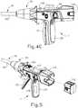
- FIG. 1depicts a motor-driven surgical cutting and fastening instrument (10) that includes a handle assembly (11) and a removable shaft assembly (16).
- handle assembly (11) and shaft assembly (16)are each provided a single-use, disposable components.
- handle assembly (11) and shaft assembly (16)are each provided as reusable components.
- shaft assembly (16)may be provided as a single-use, disposable component while handle assembly is provided as a reusable component.
- reusable versions of handle assembly (11) and shaft assembly (16)may be suitable reprocessed for reuse will be apparent to those of ordinary skill in the art in view of the teachings herein.
- Handle assembly (11) of the present exampleincludes a housing (12), a closure trigger (32), and a firing trigger (33). At least a portion of housing (12) forms a handle (14) that is configured to be grasped, manipulated and actuated by the clinician. Housing (12) is configured for operative attachment to shaft assembly (16), which has a surgical end effector (18) operatively coupled thereto. As described below, end effector (18) is configured to perform one or more surgical tasks or procedures. In particular, end effector (18) of the example shown in FIG. 1 is operable to perform a surgical cutting and stapling procedure, in a manner similar to an end effector of a conventional endocutter, though it should be understood that this is just one merely illustrative example.
- FIG. 1illustrates surgical instrument (10) with interchangeable shaft assembly (16) operatively coupled to handle assembly (11).
- FIGS. 2-3illustrate attachment of interchangeable shaft assembly (16) to housing (12) of handle (14).
- Handle (14)includes a pair of interconnectable handle housing segments (22, 24) that may be interconnected by screws, snap features, adhesive, etc. In the illustrated arrangement, handle housing segments (22, 24) cooperate to form a pistol grip portion (26) that can be grasped and manipulated by the clinician.
- handle (14)operatively supports a plurality of drive systems therein that are configured to generate and apply various control motions to corresponding portions of interchangeable shaft assembly (16) that is operatively attached thereto.
- triggers (32, 33)are pivotable toward pistol grip portion (26) to activate at least some of the drive systems in handle (14).
- motor (118)is located in pistol grip portion (26), though it should be understood that motor (118) may be located at any other suitable position.
- Motor (118)receives power from a battery pack (110), which is secured to handle (14).
- battery pack (110)is removable from handle (14).
- battery pack (110)is not removable from handle (14).
- battery pack (110)(or a variation thereof) is fully contained within handle housing segments (22, 24).
- motor (118) and battery pack (110) may takewill be apparent to those of ordinary skill in the art in view of the teachings herein.
- control circuit (117)is contained within handle (14).
- control circuit (117)may comprise a microcontroller and/or various other components as will be apparent to those of ordinary skill in the art in view of the teachings herein.
- Control circuit (117)is configured to store and execute control algorithms to drive motor (118).
- Control circuit (117)is also configured to drive a graphical user interface (116), which is located at the proximal end of handle assembly (11).
- control circuit (117)is configured to receive and process one or more signals from shaft assembly (16).
- control circuit (117)may be configured and operable in accordance with at least some of the teachings of U.S. Pub. No. 2015/0272575 , entitled "Surgical Instrument Comprising a Sensor System," published October 1, 2015. Other suitable ways in which control circuit (117) may be configured and operable will be apparent to those of ordinary skill in the art in view of the teachings herein.
- a frame (28) of handle (14)operatively supports a plurality of drive systems.
- frame (28)operatively supports a "first" or closure drive system, generally designated as (30), which may be employed to apply closing and opening motions to interchangeable shaft assembly (16) that is operatively attached or coupled thereto.
- closure drive system (30)includes an actuator in the form of a closure trigger (32) that is pivotally supported by frame (28). More specifically, closure trigger (32) is pivotally coupled to housing (14) by a pin (not shown).
- closure trigger (32)to be manipulated by a clinician such that when the clinician grasps pistol grip portion (26) of handle (14), closure trigger (32) may be easily pivoted from a starting or “unactuated” position ( FIG. 4A ) toward pistol grip portion (26) to an "actuated” position; and more particularly to a fully compressed or fully actuated position ( FIG. 4B ).
- Closure trigger (32)may be biased into the unactuated position by spring or other biasing arrangement (not shown).
- closure drive system (30)further includes a closure linkage assembly (36) pivotally coupled to closure trigger (32).
- Closure linkage assembly (36)may include a first closure link (not shown) and a second closure link (38) that are pivotally coupled to closure trigger (32) by a pin (not shown).
- Second closure link (38)may also be referred to herein as an "attachment member” and includes a transverse attachment pin (42). As shown in FIG. 3 , attachment pin (42) is exposed when shaft assembly (16) is detached from handle assembly (11). Attachment pin (42) may thus couple with a complementary feature of a shaft assembly (16) when shaft assembly (16) is coupled with handle assembly (11), as described in greater detail below.
- first closure link(not shown) is configured to cooperate with a closure release assembly (44) that is pivotally coupled to frame (28).
- closure release assembly (44)has a release button assembly (46) with a distally protruding locking pawl (not shown) formed thereon. Release button assembly (46) may be pivoted in a counterclockwise direction by a release spring (not shown). As the clinician depresses closure trigger (32) from its unactuated position toward pistol grip portion (26) of handle (14), first closure link (not shown) pivots upwardly to a point where a locking pawl (not shown) drops into retaining engagement with first closure link (not shown), thereby preventing closure trigger (32) from returning to the unactuated position. Thus, closure release assembly (44) serves to lock closure trigger (32) in the fully actuated position.
- closure release button assembly (46)When the clinician desires to unlock closure trigger (32) from the actuated position to return to the unactuated position, the clinician simply pivots closure release button assembly (46) by urging release button assembly (46) distally, such that locking pawl (not shown) is moved out of engagement with the first closure link (not shown). When the locking pawl (not shown) has been moved out of engagement with first closure link (not shown), closure trigger (32) may return back to the unactuated position in response to a resilient bias urging closure trigger (32) back to the unactuated position.
- Other closure trigger locking and release arrangementsmay also be employed.
- Interchangeable shaft assembly (16)further includes an articulation joint (52) and an articulation lock (not shown) that can be configured to releasably hold end effector (18) in a desired position relative to a longitudinal axis of shaft assembly (16).
- articulation joint (52)is configured to allow end effector (18) to be laterally deflected away from the longitudinal axis of shaft assembly (16), as is known in the art.
- end effector (18), articulation joint (52), and the articulation lock (not shown)may be configured and operable in accordance with at least some of the teachings of U.S. Pub. No. 2014/0263541 , entitled "Articulatable Surgical Instrument Comprising an Articulation Lock," published September 18, 2014.
- articulation at articulation joint (52)is motorized via motor (118), based on control input from the operator via an articulation control rocker (112) on handle assembly (11).
- end effector (18)may laterally pivot to the right (viewing instrument (10) from above) at articulation joint (52); and when the operator presses on the lower portion of articulation control rocker (112), end effector (18) may laterally pivot to the left (viewing instrument (10) from above) at articulation joint (52).
- the other side of handle assembly (11)includes another articulation control rocker (112).
- the articulation control rocker (112) on the other side of handle assembly (11)may be configured to provide pivoting of end effector (18) in directions opposite to those listed above in response to upper actuation of articulation control rocker (112) and lower actuation of articulation control rocker (112).
- articulation control rocker (112) and the rest of the features that provide motorized articulation of end effector (18) at articulation joint (52)may be configured and operable in accordance with at least some of the teachings of U.S. Pub. No. 2015/0280384 , entitled "Surgical Instrument Comprising a Rotatable Shaft,” published October 1, 2015.
- End effector (18) of the present examplecomprises a lower jaw in the form of an elongated channel (48) that is configured to operatively a support staple cartridge (20) therein.
- End effector (18) of the present examplefurther includes an upper jaw in the form of an anvil (50) that is pivotally supported relative to elongated channel (48).
- Interchangeable shaft assembly (16)further includes a proximal housing or nozzle (54) comprised of nozzle portions (56, 58); and a closure tube (60) that can be utilized to close and/or open anvil (50) of end effector (18).
- Shaft assembly (16)also includes a closure shuttle (62) that is slidably supported within a chassis (64) of shaft assembly (16) such that closure shuttle (62) may be axially moved relative to chassis (64).
- Closure shuttle (62)includes a pair of proximally-protruding hooks (66) that are configured for attachment to attachment pin (42) that is attached to second closure link (38).
- a proximal end (not shown) of closure tube (60)is coupled to closure shuttle (62) for relative rotation thereto, though the coupling of closure tube (60) with closure shuttle (62) provides that closure tube (60) and closure shuttle (62) will translate longitudinally with each other.
- a closure spring(not shown) is journaled on closure tube (60) and serves to bias closure tube (60) in the proximal direction (PD), which can serve to pivot closure trigger (32) into the unactuated position when shaft assembly (16) is operatively coupled to handle (14).
- articulation joint (52)includes a double pivot closure sleeve assembly (70).
- Double pivot closure sleeve assembly (70)includes an end effector closure sleeve assembly (72) for engaging an opening tab on anvil (50) in the various manners described in U.S. Pub. No. 2014/0263541 .
- double pivot closure sleeve assembly (70)is coupled with closure tube (60) such that double pivot closure sleeve assembly (70) translates with closure tube (60) in response to pivotal movement of closure trigger (32), even when articulation joint (52) is in an articulated state (i.e., when end effector (18) is pivotally deflected laterally away from the longitudinal axis of shaft assembly (16) at articulation joint (52)).
- end effector closure sleeve assembly (72) with anvil (50)provides pivotal movement of anvil (50) toward staple cartridge (20) in response to distal translation of double pivot closure sleeve assembly (70) and closure tube (60); and pivotal movement of anvil (50) away from staple cartridge (20) in response to proximal translation of double pivot closure sleeve assembly (70) and closure tube (60).
- shaft assembly (16) of the present exampleincludes articulation joint (52), other interchangeable shaft assemblies may lack articulation capabilities.
- chassis (64)includes a pair of tapered attachment portions (74) formed thereon that are adapted to be received within corresponding dovetail slots (76) formed within a distal attachment flange portion (78) of frame (28). Each dovetail slot (76) may be tapered or generally V-shaped to seatingly receive attachment portions (74) therein.
- a shaft attachment lug (80)is formed on the proximal end of an intermediate firing shaft (82). Thus, when interchangeable shaft assembly (16) is coupled to handle (14), shaft attachment lug (80) is received in a firing shaft attachment cradle (84) formed in a distal end of a longitudinal drive member (86).
- intermediate firing shaft (82)When shaft attachment lug (80) is received in firing shaft attachment cradle (84), intermediate firing shaft (82) will translate longitudinally with longitudinal drive member (86). When intermediate firing shaft (82) translates distally, intermediate firing shaft (82) actuates end effector (18) to drive staples into tissue and cut the tissue, as is known in the art.
- this actuation of end effector (18)may be carried out in accordance with at least some of the teachings of U.S. Pub. No. 2015/0280384 ; and/or in accordance with the teachings of various other references cited herein.
- FIGS. 4A-4Cshow the different states of handle assembly (11) during the different states of actuation of end effector (18).
- handle assembly (11)is in a state where closure trigger (32) is in a non-actuated pivotal position and firing trigger (33) is in a non-actuated pivotal position.
- end effector (18)is in an opened state where anvil (50) is pivoted away from staple cartridge (20).
- handle assembly (11)is in a state where closure trigger (32) is in an actuated pivotal position.
- closure trigger (32)will be locked in this position until the operator actuates release button assembly (46).
- end effectoris in a closed but unfired state where anvil (50) is pivoted toward staple cartridge (20), such that tissue is being compressed between anvil (50) and cartridge (20).
- firing shaft (82)has not yet been driven distally to actuate staples from staple cartridge (20), and the knife at the distal end of firing shaft (82) has not yet severed the tissue between anvil (20) and staple cartridge (20).
- firing trigger (33)is in a partially-actuated pivotal position in FIG.
- handle assemblyis in a state where closure trigger (32) remains in the actuated pivotal position, and firing trigger (33) has been pivoted to an actuated pivotal position.
- This actuation of firing trigger (33)activates motor (118) to drive longitudinal drive member (86) longitudinally, which in turn drives firing shaft (82) longitudinally.
- the longitudinal movement of firing shaft (82)results in actuation of staples from staple cartridge (20) into the tissue compressed between anvil (50) and staple cartridge (20); and further results in the severing of the tissue compressed between anvil (50) and staple cartridge (20).
- an additional safety triggeris provided.
- the additional safety triggermay prevent actuation of firing trigger (33) until the safety trigger is actuated.
- the actuation of anvil (50) toward staple cartridge (20)is provided through purely mechanical couplings between closure trigger (32) and anvil (50), such that motor (118) is not used to actuate anvil (50).
- the actuation of firing shaft (82)(and, hence, the actuation of staple cartridge (20)) is provided through activation of motor (118).
- the actuation of articulation joint (52)is provided through activation of motor (118) in the present example. This motorized actuation of articulation joint (52) is provided via longitudinal translation of drive member (86).
- a clutch assembly(not shown) within shaft assembly (16) is operable to selectively couple longitudinal translation of drive member (86) with features to either drive articulation joint (52) or actuate staple cartridge (20).
- Such selective coupling via the clutch assemblyis based on the pivotal position of closure trigger (32).
- closure trigger (32)when closure trigger (32) is in the non-actuated position shown in FIG. 4A , activation of motor (118) (in response to activation of articulation control rocker (112)) will drive articulation joint (52).
- closure trigger (32)is in the actuated position shown in FIG. 4B , activation of motor (118) (in response to actuation of firing trigger (33)) will actuate staple cartridge (20).
- the clutch assemblymay be configured and operable in accordance with at least some of the teachings of U.S. Pub. No. 2015/0280384
- handle assembly (11)also includes a "home” button (114).
- "home” button (114)may be operable to activate motor (118) to retract drive member (86) proximally to a proximal-most, "home” position.
- "home” button (114)may be operable to activate motor (118) to drive articulation joint (52) to achieve a non-articulated state, such that end effector (18) is coaxially aligned with shaft assembly (16).
- "home” button (114)may activate graphical user interface (116) to return to a "home” screen.
- Other suitable operations that may be provided in response to activation of "home” button (114)will be apparent to those of ordinary skill in the art in view of the teachings herein.
- Shaft assembly (16) of the present examplefurther includes a latch system for removably coupling shaft assembly (16) to handle assembly (11) and, more specifically, to frame (28).
- this latch systemmay include a lock yoke or other kind of lock member that is movably coupled to chassis (64).
- a lock yokemay include two proximally protruding lock lugs (96) that are configured for releasable engagement with corresponding lock detents or grooves (98) in frame (28).
- the lock yokeis biased in the proximal direction by a resilient member (e.g., a spring, etc.).
- Actuation of the lock yokemay be accomplished by a latch button (100) that is slidably mounted on a latch actuator assembly (102) that is mounted to chassis (64).
- Latch button (100)may be biased in a proximal direction relative to the lock yoke.
- the lock yokemay be moved to an unlocked position by urging latch button (100) the in distal direction, which also causes the lock yoke to pivot out of retaining engagement with frame (28).
- lock lugs (96)are retainingly seated within the corresponding lock detents or grooves (98).
- shaft assembly (16)may be removably coupled with handle assembly (11) in accordance with at least some of the teachings of U.S. Pub. No. 2017/0086823 , entitled “Surgical Stapling Instrument with Shaft Release, Powered Firing, and Powered Articulation,” published March 30, 2017; in accordance with at least some of the teachings of U.S. Pub. No. 2015/0280384 ; and/or in any other suitable fashion.
- the clinicianmay position chassis (64) of interchangeable shaft assembly (16) above or adjacent to frame (28) such that tapered attachment portions (74) formed on chassis (64) are aligned with dovetail slots (76) in frame (28).
- the clinicianmay then move shaft assembly (16) along an installation axis (IA) that is perpendicular to the longitudinal axis of shaft assembly (16) to seat attachment portions (74) in "operative engagement" with the corresponding dovetail receiving slots (76).
- shaft attachment lug (80) on intermediate firing shaft (82)will also be seated in cradle (84) in the longitudinally movable drive member (86) and the portions of pin (42) on second closure link (38) will be seated in the corresponding hooks (66) in closure shuttle (62).
- operative engagementin the context of two components means that the two components are sufficiently engaged with each other so that upon application of an actuation motion thereto, the components may carry out their intended action, function, and/or procedure.
- a first systemcomprises a frame system that couples and/or aligns the frame or spine of shaft assembly (16) with frame (28) of the handle (14).
- a second systemis the latch system that releasably locks the shaft assembly (16) to the handle (14).
- a third systemis closure drive system (30) that may operatively connect closure trigger (32) of handle (14) and closure tube (60) and anvil (50) of shaft assembly (16).
- closure shuttle (62) of shaft assembly (16)engages with pin (42) on second closure link (38).
- anvil (50)pivots toward and away from staple cartridge (20) based on pivotal movement of closure trigger (32) toward and away from pistol grip (26).
- a fourth systemis an articulation and firing drive system operatively connecting firing trigger (33) of handle (14) with intermediate firing shaft (82) of the shaft assembly (16).
- the shaft attachment lug (80)operatively connects with the cradle (84) of the longitudinal drive member (86).
- This fourth systemprovides motorized actuation of either articulation joint (52) or staple cartridge (20), depending on the pivotal position of closure trigger (32).
- closure trigger (32)is in a non-actuated pivotal position
- the fourth systemoperatively connects articulation control rocker (112) with articulation joint (52), thereby providing motorized pivotal deflection of end effector (18) toward and away from the longitudinal axis of shaft assembly (11) at articulation joint (52).
- closure trigger (32)When closure trigger (32) is in an actuated pivotal position, the fourth system operatively connects firing trigger (33) with staple cartridge (20), resulting in stapling and cutting of tissue captured between anvil (50) and staple cartridge (20) in response to actuation of firing trigger (33).
- a fifth systemis an electrical system that can signal to control circuit (117) in handle (14) that the shaft assembly (16) has been operatively engaged with the handle (14), to conduct power and/or communicate signals between the shaft assembly (16) and the handle (14).
- shaft assembly (16)includes an electrical connector (106) that is operatively mounted to a shaft circuit board (not shown). Electrical connector (106) is configured for mating engagement with a corresponding electrical connector (108) on a handle control board (not shown). Further details regarding the circuitry and control systems may be found in U.S. Pub. No. 2014/0263541 and/or U.S. Pub. No. 2015/0272575 .
- handle assembly (11) of the present exampleincludes a graphical user interface (116).
- graphical user interface (116)may be used to display various information about the operational state of battery (110), the operational state of end effector (18), the operational state of articulation joint (52), the operational state of triggers (32, 33), and/or any other kinds of information.
- Other suitable kinds of information that may be displayed via graphical user interfacewill be apparent to those of ordinary skill in the art in view of the teachings herein.
- Handle assembly (11)may be configured for use in connection with interchangeable shaft assemblies that include end effectors that are adapted to support different sizes and types of staple cartridges, have different shaft lengths, sizes, and types, etc.
- FIG. 6shows various different kinds of shaft assemblies (16, 120, 130, 140) that may be used with handle assembly (11).
- FIG. 16shows various different kinds of shaft assemblies (16, 120, 130, 140) that may be used with handle assembly (11).
- FIG. 6shows a circular stapler shaft assembly (120) with an end effector (122) that is operable to perform a circular stapling operation (e.g., end-to-end anastomosis); a liner stapler shaft assembly (130) with an end effector (132) that is operable to perform a linear stapling operation; and a second endocutter shaft assembly (140) with an end effector (142) that is operable to perform the same kind of stapling and cutting operation as end effector (18).
- shaft assembly (140)is shorter than shaft assembly (16)
- shaft assembly (140)has a smaller diameter than shaft assembly (16)
- end effector (142)is smaller than end effector (18).
- control circuit (117)may be configured to detect the kind of shaft assembly (16, 120, 130, 140) coupled with handle assembly (11), and select a control algorithm suited for that particular kind of shaft assembly (16, 120, 130, 140).
- each shaft assembly (16, 120, 130, 140)may have a chip or other memory device storing the control algorithm suited for that particular kind of shaft assembly (16, 120, 130, 140); and control circuit (117) may receive and execute that control algorithm after shaft assembly (16, 120, 130, 140) is coupled with handle assembly (11).
- handle assembly (11)may also be effectively employed with a variety of other interchangeable shaft assemblies including those assemblies that are configured to apply other motions and kinds of energy such as, for example, radio frequency (RF) energy, ultrasonic energy and/or motion to end effector arrangements adapted for use in connection with various surgical applications and procedures.
- RFradio frequency
- end effectors, shaft assemblies, handles, surgical instruments, and/or surgical instrument systemscan utilize any suitable fastener, or fasteners, to fasten tissue.
- a fastener cartridgecomprising a plurality of fasteners removably stored therein can be removably inserted into and/or attached to the end effector of a shaft assembly.
- a fastener cartridgecomprising a plurality of fasteners removably stored therein can be removably inserted into and/or attached to the end effector of a shaft assembly.
- Various examples of such cartridgesare disclosed in various references that are cited herein.
- the various shaft assemblies (16) disclosed hereinmay employ sensors and various other components that require electrical communication with control circuit (117) in handled assembly (11).
- the electrical communicationsmay be provided via mating electrical connectors (106, 108).
- sensors and other componentsmay be constructed and operable in accordance with at least some of the teachings of U.S. Pub. No. 2015/0272575 .
- instrument (10)may be constructed and operable in accordance with at least some of the teachings of any of the various other references that are cited herein.
- housingor “body” may also encompass a housing, body, or similar portion of a robotic system that houses or otherwise operatively supports at least one drive system that is configured to generate and apply at least one control motion which could be used to actuate the interchangeable shaft assemblies disclosed herein and their respective equivalents.
- framemay refer to a portion of a handheld surgical instrument.
- framemay also represent a portion of a robotically controlled surgical instrument and/or a portion of the robotic system that may be used to operatively control a surgical instrument.
- interchangeable shaft assemblies disclosed hereinmay be employed with any of the various robotic systems, instruments, components and methods disclosed in U.S. Pat. No. 9,072,535 , entitled “Surgical Stapling Instruments with Rotatable Staple Deployment Arrangements,” issued July 7, 2015.
- handle assembly (11)includes battery pack (110), control circuit (117), first drive system (30) including closure trigger (32), and motor (118) configured to longitudinally drive intermediate firing shaft (82).
- Battery pack (110)is configured to power motor (118), while control circuit (117) is configured to store and execute control algorithms to drive motor (118).
- motor (118)may be driven by control rocker (112) (the position shown in FIG. 4A ), or firing trigger (33) (the position shown in FIGS. 4B-4C ). Therefore, first drive system (30) may also be in communication with control circuit (117) such that control circuit (117) enables either control rocker (112) or firing trigger (33) to actuate motor (118).
- Control circuit (117)may be configured to draw power from battery pack (110) such that control circuit (117) may perform the functions described above. Additionally, since control circuit (117) is configured to store and execute control algorithms to drive motor (118), control circuit (117) may instruct battery pack (110) when to power motor (118). Therefore, control circuit (117) may draw power from battery pack (110) to provide power to control circuit (117), motor (118), and other suitable components of handle assembly (11) such as graphical user interface (116).
- Control circuit (117)may also be configured to enter and control a "sleep mode" for handle assembly (11). In sleep mode, control circuit (117) may stop performing some functions, such as powering graphic user interface (116) and motor (118), thereby draining less energy from battery pack (110) as compared to operation in a non-sleep mode. However, control circuit (117) may still drain some energy from battery pack (110) when control circuit (117) is in control of its own sleep mode.
- control circuit (117)may control its own sleep mode, control circuit (117) may still drain some energy from battery pack (110) such that control circuit (117) may remain alert to the possibility of being fully reactivated in response to a general or specific user input, such as pressing home button (114) or control rocker (112).
- Control circuit (117)may enter its own sleep mode for any suitable reason that would be apparent to one having ordinary skill in the art in view of the teachings herein. For example, if control circuit (117) does not receive any user input/instructions from various sources in a predetermined period of time, control circuit (117) may go into sleep mode. As another example, control circuit (117) may go into sleep mode in response to specific user input such as holding home button (114) for a predetermined amount of time. As yet another example, control circuit (117) may enter sleep mode in the absence of input from a motion sensor (e.g., accelerometer, etc.) after a predetermined duration of time.
- a motion sensore.g., accelerometer, etc.
- control circuit (117)may unnecessarily drain energy stored within battery pack (110) when control circuit (117) enters and controls its own sleep mode, it may be beneficial to provide an alternative battery pack having its own independent circuitry that may function autonomously relative to control circuit (117) of handle assembly (11).
- the independent circuitry of the alternative battery packmay allow a battery pack to control when the battery pack provides power to its own circuitry and to control circuit (117); rather than allowing control circuit (117) to dictate when battery pack provides power to handle assembly (11), like battery pack (110) described above.
- the alternative battery pack with independent circuitrymay control when the battery pack provides power to motor (118), graphical user interface (116), or other suitable components of handle assembly (11).
- the alternative battery packmay independently shut down relative to handle assembly (11) or independently enter and control its own "sleep mode.”
- the alternative battery packmay therefore prevent control circuit (117) from unnecessarily draining the power supply of the alternative battery pack.
- the independent circuity of the alternative battery packmay communicate with control circuit (117) to further exchange information. Examples of alternative battery packs will be described in greater detail below; while further examples will be apparent to those of ordinary skill in the art in view of the teachings herein.
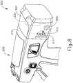
- FIGS. 7A-8show an exemplary handle assembly (200) and a complementary battery pack assembly (300) that may be readily incorporated into surgical instrument (10) in replacement of handle assembly (11) described above.
- Handle assembly (200)is substantially similar to handle assembly (11) assembly described above, with differences described below.
- battery pack assembly (300)is substantially similar to battery pack (110) described above, with difference described below.
- battery pack assembly (300)includes its own independent control circuit (317) controls when battery pack assembly (300) provides power to handle assembly (200), enters its own sleep mode, and/or communicates with handle assembly (200).
- Handle assembly (200)includes a battery coupling assembly (210) while battery pack assembly (300) includes a handle coupling assembly (310).
- Battery coupling assembly (210) and handle coupling assembly (310)are configured to allow battery pack assembly (300) and handle assembly (200) to operatively engage each other such that battery pack assembly (300) may power suitable components of handle assembly (200). Therefore, when battery pack assembly (300) and handle assembly (200) are operatively disengaged via coupling assemblies (210, 310), battery pack assembly (300) may be prevented from powering suitable components of handle assembly (200).
- Coupling assemblies (210, 310)may include any suitable features used for operative engagement that would be apparent to one having ordinary skill in the art in view of the teachings herein.
- coupling assemblies (210, 310)may include electrical connectors, similar to electrical connectors (106, 108) described above, that are used to establish electrical communication between handle assembly (11) and shaft assembly (16).
- Handle assembly (200) and battery pack assembly (300)may also include any suitable features (e.g., latches, etc.) to mechanically attach to each other as would be apparent to one having ordinary skill in the art in view of the teachings herein.
- battery pack assembly (300)may mechanically attach and detach from handle assembly (200) via features of respective coupling assemblies (310, 210).
- battery pack assembly (300)is not removable from handle assembly (200).
- battery pack assembly (300)(or a variation thereof) is fixed to, configured to permanently affix to, or fully contained within a housing (212) of handle assembly (200).
- Various suitable ways in which battery pack assembly (300) may couple to handle assembly (200)will be apparent to those of ordinary skill in the art in view of the teachings herein.
- handle assembly (200)further includes housing (212), a control circuit (217), a first drive system (230), a second drive system (250), and a shaft coupling assembly (220).
- Housing (212)is substantially similar to housing (12) described above.
- Control circuit (217)is substantially similar to control circuit (117) described above, with differences described below. Therefore, control circuit (217) may store and execute control algorithms, drive a graphical user interface, communicate with a connected shaft assembly (16), or any other suitable functions described above regarding control circuit (117).
- Control circuit (217)is in communication with battery coupling assembly (210) via electrical connection (204) such that control circuit (217) may receive power from battery pack assembly (300), and/or communicate with battery pack assembly (300), as will be described in greater detail below.
- First drive system (230)is substantially similar to closure (first) drive system (30) described above. First drive system (230) may perform substantially the same functions of closure (first) drive system (30) as described above. Therefore, first drive system (230) may include a closure trigger substantially similar to closure trigger (32) described above, and any other components associated with closure (first) drive system (30). First drive system (230) may be in communication with control circuit (217) via electrical connection (204).
- Second drive system (250)is substantially similar to the drive system of handle assembly (11) including motor (118). Therefore, second drive system (250) may include a motor that is controlled by control circuit (217). Additionally, second drive system (250) may include all other suitable components of handle assembly (11) used in conjunction with motor (118), as described above. Second drive system (250) may be in communication with control circuit (217) via electrical connection (204). In the current example, second drive system (250) may receive power from battery pack assembly (300) via control circuit (217), however, this is merely optional. Second drive system (250) may alternatively be directly connected to battery coupling assembly (210) to satisfy suitable power requirements. Any other suitable power connection between second drive system (250) and battery pack assembly (300) may be utilized as would be apparent to one having ordinary skill in the art in view of the teachings herein.
- Shaft coupling assembly (220)is configured to selectively couple handle assembly (200) with shaft assembly (16) for operative engagement, similar to operative engagement between shaft assembly (16) and handle assembly (11) described above.
- Shaft coupling assembly (220)may include any suitable components similar to handle assembly (11) used to couple with shaft assembly (16) for operative engagement.
- Shaft coupling assembly (220)may interface with shaft assembly (16) such that first drive system (230) and second drive system (250) are operatively engaged with corresponding components of shaft assembly (16). Therefore, first drive system (230) and second drive system (250) may generate and apply various control motions to corresponding portions of shaft assembly (16) when operatively attached, similar to handle assembly (11) described above.
- Shaft coupling assembly (220)may be in communication with control circuit (217) via electrical connection (204) so that control circuit (217) may communicate with corresponding electrical components of shaft assembly (16), such as circuit board (not shown), via electrical connector (106).
- Battery pack assembly (300)includes a casing (302), handle coupling assembly (310), control circuit (317), an accelerometer (315), a power button (320), and a power supply (330).
- control circuit (317)is configured to control when battery pack assembly (300) provides power to handle assembly (200), enters its own sleep mode, and/or communicates with handle assembly (200).
- power button (320) and accelerometer (315)may be configured to command control circuit (317) to exit sleep mode to provide full power to handle assembly (200).
- Power supply (330)is in communication with handle coupling assembly (310) and control circuit (317) via electrical wires (304).
- Control circuit (317)is also in communication with handle coupling assembly (310) via electrical wire (304).
- Control circuit (317)is operable to direct power supply (330) to power control circuit (317). Therefore, control circuit (317) may draw power from power supply (330) such that control circuit (317) may perform its intended functions as described herein.
- Control circuit (317)may also command selected portions of battery pack assembly (300) to operatively engage or operatively disengage selected portions of handle assembly (200).
- power supply (330)may direct power to handle coupling assembly (310) such that power supply (330) may provide power to various components of handle assembly (200), such as control circuit (217). Additionally, when handle assembly (200) and battery pack assembly (300) are operatively engaged via coupling assemblies (210, 310), control circuit (317) may communicate with the corresponding control circuit (217) of handle assembly (200). Therefore, when handle assembly (200) and battery pack assembly (300) are operatively disengaged, power supply (330) may not direct power to components of handle assembly (200).
- Control circuit (317)is an independent circuit that functions autonomously relative to control circuit (217) of handle assembly (200). Control circuit (317) may enter into its own sleep mode, similar to that described above for sleep mode of control circuit (117). Control circuit (317) of battery pack assembly (300) may have independent sleep algorithms, independent switching circuits, and independent control circuits that allow control circuit (317) of battery pack assembly (300) to completely or partially restrict power provided from power source (330) to itself as well as handle assembly (200) while in sleep mode. Therefore, control circuit (317) may control whether battery pack assembly (300) is operatively engaged or operatively disengaged with handle assembly (200). In other words, control circuit (317) is configured to control when power supply (330) may provide power to handle assembly (200) or control circuit (317).
- control circuit (317)When control circuit (317) completely restricts power provided from power source (330) to handle assembly (200), handle assembly (200) may essentially shut down. Therefore, when control circuit (317) exits sleep mode to provide power to handle assembly (200), handle assembly (200) may reboot as if handle assembly (200) is receiving a new battery pack assembly (300). Control circuit (317) may also completely restrict power provided by power source (330) to control circuit (317) such that control circuit (317) uses no power as well.
- control circuit (317)does not completely restrict power provided to itself by power source (330). In instances where control circuit (317) is not completely restricted from power, control circuit (317) may keep track of the duration through which battery pack assembly (300) is in sleep mode, temperature of battery pack assembly (300) while in sleep mode, and other suitable factors necessary such that control circuit (317) may calculate the estimated remaining battery life ofpower supply (330) as affected by the time and environment of battery pack assembly (300) while in sleep mode. Once control circuit (317) exits sleep mode and battery pack assembly (300) is returned to operative engagement with handle assembly (200), control circuit (317) may communicate the estimated remaining life to control circuit (217) of handle assembly (200).
- Handle assembly (200)may then display such information to an operator via a graphical user interface similar to graphical user interface (116) described above.
- This featuremay be advantageous if control circuit (317) places handle assembly (200) and battery pack assembly (300) in sleep mode for prolonged periods of time.
- control circuit (317)may also keep track of time elapsed while battery pack assembly (300) is not in sleep mode, temperature of battery pack assembly (330) while not in sleep mode, and other suitable factors such that control circuit (317) may calculate estimated remaining battery life of power supply (330) as affected by the time, environment, and usage of battery pack assembly (300) while not in sleep mode.
- coupling assemblies (210, 310)may include any suitable features for operative engagement that would be apparent to one having skill in the art in view of the teachings herein, such as electrical connectors.
- electrical connectors of coupling assemblies (210, 310)may physically disconnect from each other when battery pack assembly (300) and handle assembly (200) are operatively disengaged from each other. Therefore, electrical connectors of coupling assemblies (210, 310) may then physically reconnect to each other when battery pack assembly (300) and handle assembly (200) are operatively engaged with each other. This could be accomplished through any suitable means known to a person having ordinary skill in the art in view of the teachings herein.
- battery pack assembly (300)may be spring loaded, or otherwise biased, such that electrical connectors of coupling assembly (310) are naturally disconnected from electrical connectors of coupling assembly (210), thereby rendering battery pack assembly (300) and handle assembly (200) operatively disengaged.
- the operatormay push battery pack assembly (300) toward handle assembly (200), overcoming the biasing force.
- a physical latch or electromagnetic forcemay then further overcome the biasing force to keep battery pack assembly (300) and handle assembly (200) operatively engaged without further assistance of an operator pushing battery pack assembly (300) toward handle assembly (200).
- control circuit (317)is to go into sleep mode, the latching member or the electromagnet force may release, and the biasing force may return battery pack assembly (300) to the operatively disengaged position.
- power supply (330)is in direct communication with handle coupling assembly (310) such that power supply (330) may directly transfer power to handle coupling assembly (310).
- power supply (330)may be in communication with handle coupling assembly (310) via control circuit (317).
- control circuit (317)may transfer power to control circuit (317), which in turn may then transfer power to handle coupling assembly (310), which may in turn transfer power to suitable components of handle assembly (200) when operatively engaged.
- control circuit (317)may be configured to exchange information with control circuit (217) of handle assembly (200) when battery pack assembly (300) and handle assembly (200) are operatively engaged.
- control circuit (217) of handle assembly (200)may communicate to control circuit (317) of battery pack assembly (300) that an operator has requested control circuit (317) go into sleep mode.
- An operatormay request control circuit (317) go into sleep mode through any suitable user input that would be apparent to one having ordinary skill in the art in view of the teachings herein.
- control circuit (217)may keep track of handle assembly (200) inactivity. If control circuit (217) determines that handle assembly (200) has been inactive for a predetermined amount of time, control circuit (217) may communicate a signal indicative of this inactivity to control circuit (317), causing control circuit (317) to initiate sleep mode.
- handle assembly (200)may communicate to control circuit (317) to go into sleep mode
- handle assembly (200)may also be restricted from communicating to control circuit (317) while in sleep mode, such that only battery pack assembly (300) may command control circuit (317) to exit sleep mode.
- power button (320) and accelerometer (315)may be configured to command control circuit (317) to exit sleep mode and to provide full power to handle assembly (200).
- power button (320)is in communication with control circuit (317) via electrical wire (304). Power button (320) is accessible from an external portion of casing (302) such than an operator may easily access power button (320). If an operator desired to reactivate battery pack assembly (300) out of sleep mode, the operator may push power button (320), which may command control circuit (317) to exit sleep mode.
- Accelerometer (315)is connected to control circuit (317), such that accelerometer (315) may detect and communicate movement of battery pack assembly (300) to control circuit (317). Accelerometer (315) is configured to command control circuit (317) to exit sleep mode if accelerometer (315) detects movement above a predetermined threshold. When battery pack assembly (300) re-powers itself from exiting sleep mode, control circuit could check other control parameters before energizing handle assembly (200), such as a number of motions within a predefined time, or another accelerometer-detected change after power button (320) is pressed.
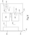
- FIG. 9shows another alternative battery pack assembly (350) that may be readily incorporated into handle assembly (200) in replacement of battery pack assembly (300) described above.
- Battery pack assembly (350)is substantially similar to battery pack assembly (300) described above, with differences described below.
- Battery pack assembly (350)includes a casing (352), a handle coupling assembly (360), a power supply (380), a control circuit (367), an accelerometer (365), and a power button (370); which are substantially similar to casing (302), handle coupling assembly (310), power supply (330), control circuit (317), accelerometer (315), and power button (320) described above, respectively, with difference elaborated below.
- Control circuit (367)is in communication with power button (370), handle coupling assembly (360), and power supply (380) via electrical connections (354); while power supply (380) is in communication with handle coupling assembly (360) via electrical connection (354).
- Accelerometer (365)is in communication with control circuit (367).
- Battery pack assembly (350)also includes a secondary control circuit (390) in communication with both power supply (380) and control circuit (367) via electrical connections (354).
- Secondary control circuit (390)includes its own independent power source (392), such that secondary control circuit (390) does not draw any power from power supply (380).
- Secondary control circuit (390)may include a low power micro controller.
- Independent power source (392)may include a coin battery cell that may keep secondary control circuit (390) in lower power mode such that secondary control circuit (390) does not draw any power from power supply (380) in a low power mode (i.e. when control circuit (317) is in sleep mode).
- Secondary control circuit (390)may be configured to calculate and/or archive the battery life remaining of power supply (380), similar to how control circuit (317) may calculate the battery life remaining of power supply (330) described above. Additionally, secondary control circuit (390) may receive information from control circuit (217) of handle assembly (200). For instance, control circuit (217) from handle assembly (200) may communicate to secondary control circuit (390) a remaining number of sterilization procedures to the non-volatile member of secondary control circuit (390) if handle assembly (200) is designed for multiple uses. Additionally, secondary control circuit (390) may be configured to exit low power mode from signals received by either control circuit (367, 217).
- secondary control circuit (390)may contain a very low electrical current drain range sleep mode monitoring circuit. When the electrical current range is measured as exceeding the range ability of the low drain circuit, secondary control circuit (390) could then poll the control circuit (367, 217) that contains the high range draw, and then control circuit (367, 217) could measure the battery life of power supply (380) from that point on.
- the communication linkage that allows the high range current measure from handle assembly (200) of battery pack assembly (300)may be the same linkage used to communicate usage from the handle assembly (200) and communicate uses left (after sterilization) back to the handle assembly (200) for display.
- FIG. 10shows an exemplary pre-sterilization fluid distribution assembly (400) that may be used to perform a pre-sterilization cleaning procedure on handle assembly (11, 200) after a surgical procedure, and before a full sterilization process.
- Pre-sterilization fluid distribution assembly (400)includes a manifold assembly (410), a support rack assembly (430), and a plurality of alternative handle assemblies (450).
- Handle assemblies (450)are substantially similar to handle assemblies (11, 200) described above, with difference elaborated below.
- Each handle assembly (450)includes a housing (452) extending from a distal portion (454) to a proximal portion (456), a pistol grip (458), internal fluid passageways (460) extending throughout housing (452), and quick connect fluid port (464).
- quick connect fluid port (464)is configured to couple with a portion of manifold assembly (410) such that manifold assembly (410) is in fluid communication with internal fluid passageways (460).
- Handle assembly (450)also defines a drain port (462) located at proximal portion (456) of handle assembly (450) and also in fluid communication with internal fluid passageway (460). Drain port (462) allows fluid within internal fluid passageways (460) to escape.
- Internal fluid passageways (460)may be in fluid communication with any suitable portions of handle assembly (450) that need to be cleaned in a pre-sterilization cleaning procedure, such as portions that may potentially accumulate debris and/or fluids during operational use in a surgical procedure.
- Handle assembly (450)may be designed such that handle assembly (450) does not accumulate debris and/or fluids during operational use in a surgical procedure.
- handle assembly (450)may be designed to avoid having pockets, crevices, etc. that will hold onto contaminants that are products of operational use.
- handle assembly (450)may be designed with large radii instead of tight corners.
- handle assembly (450)may be designed to break into pieces to simplify cleaning.
- Internal fluid passageways (460)may take different paths for different components or difference levels of dirtiness. Therefore, internal fluid passageways (460) may be dimensioned to allow more fluid to go into locations requiting more cleaning during the pre-sterilization cleaning process.
- handle assembly (450)includes a display
- the displaymay easily pop out of handle assembly (450) prior to the pre-sterilization cleaning procedure. Additionally, the display could be behind a window in handle assembly (450) so that it does not come into direct contact with any contaminants.
- Handle assembly (450)may also include a means to sense when handle assembly (450) is ready for the sterilization process. In other words, handle assembly (450) may have a means to sense when handle assembly (450) has completed the pre-sterilization cleaning process, as described below.
- handle assemblymay include a triaxial water sensor cupped to hold water, a super hydrophobic coating, a plurality of water sensors at the lowest points on each surface that can be the lowers points for water to settle into, or a window into handle assembly (450) to look for water and contaminants.
- Handle assembly (450)may indicate via the display when a sensor does not detect any more water.
- Support rack assembly (430)is configured to support each handle assembly (450) such that drain port (462) may receive excess fluid from portions of internal fluid passageways (460).
- Support rack assembly (430)includes a base structure (432), a first plurality of vertical columns (434), a second plurality of vertical columns (438), a first top rail (436), and a second top rail (440).
- First plurality of vertical columns (434)extend from base structure (432) to first top rail (436) while second plurality of vertical columns (438) extend from an opposite end of base structure (432) to second top rail (440).
- Second top rail (440)is elevated higher than first top rail (436).
- Top rails (436, 440)are spaced apart a distance to support proximal portions (456) and distal portions (454) of handle assembly (450) respectively.
- top rails (436, 440)support handle assembly (450) such that handle assembly (450) is tilted at an angle conducive of gravity feeding excess fluid within portions of internal fluid passageways (460) toward drain ports (462).
- Manifold assembly (410) and support rack assembly (430)are configured to work in tandem such that manifold assembly (410) may provide fluid communication to handle assembly (450) while support rack assembly (430) holds handle assemblies (450).
- Manifold assembly (410)includes a primary fluid supply tube (412) extending into a Y-fitting (414), which diverts fluid from fluid supply tube (412) into a first secondary fluid supply tube (416) and a second secondary fluid supply tube (420).
- First secondary fluid supply tube (416)has a plurality of external fluid distribution ports (418) while second secondary fluid supply tube (420) includes a plurality of internal fluid distribution ports (422) terminating into a quick connect fluid port (424).
- External fluid distribution ports (418)are placed along first secondary fluid supply tube (416) such that external fluid distribution ports (418) align with respective handle assemblies (450). External fluid distribution ports (418) are configured to spray fluid on an exterior of handle assemblies (420). In particular, external fluid distribution ports (418) may spray any suitable washing media onto handle assembly (420) to wash off excess debris. Then external fluid distribution ports (418) may spray any suitable gas to dry off excess washing media accumulated on the exterior of handle assembly (420).
- Internal fluid distribution ports (4212)are placed along second secondary fluid supply tube (420) such that quick connect fluid ports (424) may couple with quick connect fluid ports (464) of handle assembly (450).
- Quick connect fluid ports (424, 464)provide fluid communication between second secondary fluid supply tube (420) and internal fluid passageways (460) such that integral fluid distribution port (422) may supply internal fluid passages (460) with fluid for the pre-sterilization process.
- internal fluid distribution ports (422)may spray any suitable washing media into internal fluid passageways (460) of handle assembly (450) to wash off excess debris located within suitable locations of handle assembly (450).
- external fluid distribution ports (418)may spray any suitable gas to dry o ff excess washing media accumulated within the internal fluid passageways (460) of handle assembly (420).
- Quick connect fluid ports (424, 464)may include one way valves that allow fluid to enter within internal fluid passageways (460), but prevents fluid from exiting internal fluid passageways (460) back into secondary second fluid supply tube (420).
- any ranges of values referred to hereinshould be read to include the upper and lower boundaries of such ranges. For instance, a range expressed as ranging "between approximately 1.0 inches and approximately 1.5 inches” should be read to include approximately 1.0 inches and approximately 1.5 inches, in addition to including the values between those upper and lower boundaries.
- Versions of the devices described abovemay have application in conventional medical treatments and procedures conducted by a medical professional, as well as application in robotic-assisted medical treatments and procedures.
- various teachings hereinmay be readily incorporated into a robotic surgical system such as the DAVINCITM system by Intuitive Surgical, Inc., of Sunnyvale, California.
- DAVINCITM systemby Intuitive Surgical, Inc., of Sunnyvale, California.
- teachings hereinmay be readily combined with various teachings of U.S. Pat. No. 6,783,524 , entitled “Robotic Surgical Tool with Ultrasound Cauterizing and Cutting Instrument,” published August 31, 2004.
- Versions described abovemay be designed to be disposed of after a single use, or they can be designed to be used multiple times. Versions may, in either or both cases, be reconditioned for reuse after at least one use. Reconditioning may include any combination of the steps of disassembly of the device, followed by cleaning or replacement of particular pieces, and subsequent reassembly. In particular, some versions of the device may be disassembled, and any number of the particular pieces or parts of the device may be selectively replaced or removed in any combination. Upon cleaning and/or replacement of particular parts, some versions of the device may be reassembled for subsequent use either at a reconditioning facility, or by an operator immediately prior to a procedure.
- reconditioning of a devicemay utilize a variety of techniques for disassembly, cleaning/replacement, and reassembly. Use of such techniques, and the resulting reconditioned device, are all within the scope of the present application.
- versions described hereinmay be sterilized before and/or after a procedure.
- the deviceis placed in a closed and sealed container, such as a plastic or TYVEK bag.
- the container and devicemay then be placed in a field of radiation that can penetrate the container, such as gamma radiation, x-rays, or high-energy electrons.
- the radiationmay kill bacteria on the device and in the container.
- the sterilized devicemay then be stored in the sterile container for later use.
- a devicemay also be sterilized using any other technique known in the art, including but not limited to beta or gamma radiation, ethylene oxide, or steam.
Landscapes
- Health & Medical Sciences (AREA)
- Surgery (AREA)
- Life Sciences & Earth Sciences (AREA)
- Engineering & Computer Science (AREA)
- Veterinary Medicine (AREA)
- Biomedical Technology (AREA)
- Heart & Thoracic Surgery (AREA)
- Medical Informatics (AREA)
- Molecular Biology (AREA)
- Animal Behavior & Ethology (AREA)
- General Health & Medical Sciences (AREA)
- Public Health (AREA)
- Nuclear Medicine, Radiotherapy & Molecular Imaging (AREA)
- Pathology (AREA)
- Oral & Maxillofacial Surgery (AREA)
- Chemical & Material Sciences (AREA)
- Chemical Kinetics & Catalysis (AREA)
- Electrochemistry (AREA)
- General Chemical & Material Sciences (AREA)
- Manufacturing & Machinery (AREA)
- Microelectronics & Electronic Packaging (AREA)
- Physics & Mathematics (AREA)
- Electromagnetism (AREA)
- Surgical Instruments (AREA)
- Power Engineering (AREA)
Description
- In some settings, endoscopic surgical instruments may be preferred over traditional open surgical devices since a smaller incision may reduce the post-operative recovery time and complications. Consequently, some endoscopic surgical instruments may be suitable for placement of a distal end effector at a desired surgical site through the cannula of a trocar. These distal end effectors may engage tissue in various ways to achieve a diagnostic or therapeutic effect (e.g., endocutter, grasper, cutter, stapler, clip applier, access device, drug/gene therapy delivery device, and energy delivery device using ultrasonic vibration, RF, laser, etc.). Endoscopic surgical instruments may include a shaft between the end effector and a handle portion, which is manipulated by the clinician. Such a shaft may enable insertion to a desired depth and rotation about the longitudinal axis of the shaft, thereby facilitating positioning of the end effector within the patient. Positioning of an end effector may be further facilitated through inclusion of one or more articulation joints or features, enabling the end effector to be selectively articulated or otherwise deflected relative to the longitudinal axis of the shaft.
- Examples of endoscopic surgical instruments include surgical staplers. Some such staplers are operable to clamp down on layers of tissue, cut through the clamped layers of tissue, and drive staples through the layers of tissue to substantially seal the severed layers of tissue together near the severed ends of the tissue layers. Merely exemplary surgical staplers are disclosed in
U.S. Pat. No. 7,000,818 , entitled "Surgical Stapling Instrument Having Separate Distinct Closing and Firing Systems," issued February 21, 2006;U.S. Pat. No. 7,380,696 , entitled "Articulating Surgical Stapling Instrument Incorporating a Two-Piece E-Beam Firing Mechanism," issued June 3, 2008;U.S. Pat. No. 7,404,508 , entitled "Surgical Stapling and Cutting Device," issued July 29, 2008;U.S. Pat. No. 7,434,715 , entitled "Surgical Stapling Instrument Having Multistroke Firing with Opening Lockout," issued October 14, 2008;U.S. Pat. No. 7,721,930 , entitled "Disposable Cartridge with Adhesive for Use with a Stapling Device," issued May 25, 2010;U.S. Pat. No. 8,408,439 , entitled "Surgical Stapling Instrument with An Articulatable End Effector," issued April 2, 2013; andU.S. Pat. No. 8,453,914 , entitled "Motor-Driven Surgical Cutting Instrument with Electric Actuator Directional Control Assembly," issued June 4, 2013. - While the surgical staplers referred to above are described as being used in endoscopic procedures, it should be understood that such surgical staplers may also be used in open procedures and/or other non-endoscopic procedures. By way of example only, a surgical stapler may be inserted through a thoracotomy, and thereby between a patient's ribs, to reach one or more organs in a thoracic surgical procedure that does not use a trocar as a conduit for the stapler. Such procedures may include the use of the stapler to sever and close a vessel leading to a lung. For instance, the vessels leading to an organ may be severed and closed by a stapler before removal of the organ from the thoracic cavity. Of course, surgical staplers may be used in various other settings and procedures.
- Examples of surgical staplers that may be particularly suited or use through a thoracotomy are disclosed in
U.S. Patent Application Publication No. 2014/0243801 , entitled "Surgical Instrument End Effector Articulation Drive with Pinion and Opposing Racks," published on August 28, 2014;U.S. Patent Application Publication No. 2014/0239041 , entitled "Lockout Feature for Movable Cutting Member of Surgical Instrument," Published August 28, 2014;U.S. Patent Application Publication No. 2014/0239038 , entitled "Surgical Instrument with Multi-Diameter Shaft," published August 28, 2014; andU.S. Patent Application Publication No. 2014/0239044 , entitled "Installation Features for Surgical Instrument End Effector Cartridge," published August 28,2014. US 2011/288573 A1 relates to a surgical cutting and fastening instrument. The instrument comprises an end effector that has a shaft coupled thereto that is coupled to a robotic system. A tool mounting portion includes an electric, DC motor connected to a drive train in the shaft for powering the drive train. A power pack that comprises at least one charge-accumulating device connected to the DC motor for powering the DC motor is provided.US 2011/137361 A1 relates to a system and method that provides a status indicator to a battery pack of a medical device. The battery pack includes a power supply capable of being connected to the medical device. The battery pack also includes an indicator to automatically indicate a status of at least a portion of at least one of the battery pack and the medical device. For example, the indicator can indicate a status of the power supply.EP 2923661 A1 discloses a surgical instrument comprising a segmented circuit. All circuit segments except an accelerometer, or other designated sensors and/or switches, and a safety processor are deactivated when in sleep mode. The safety processor monitors the accelerometer, or other designated sensors and/or switches. When the accelerometer indicates movement of the surgical instrument, the safety processor initiates a transition from sleep mode to operational mode. In operational mode, all of the circuit segments are fully energized and the surgical instrument is ready for use. The safety processor transitions the segmented circuit to the operational mode by providing a signal to the primary processor to transition the primary processor from sleep mode to a full power mode. The primary processor, then transitions each of the remaining circuit segments to operational mode.- While several surgical instruments and systems have been made and used, it is believed that no one prior to the inventors has made or used the invention described in the appended claims.
- While the specification concludes with claims which particularly point out and distinctly claim this technology, it is believed this technology will be better understood from the following description of certain examples taken in conjunction with the accompanying drawings, in which like reference numerals identify the same elements and in which:
FIG. 1 depicts a perspective view of an exemplary surgical instrument including an interchangeable shaft assembly and a handle assembly;FIG. 2 depicts a perspective view of the instrument ofFIG. 1 , showing the shaft assembly disassembled from the handle assembly of the instrument;FIG. 3 depicts a partial perspective view of the instrument ofFIG. 1 , showing the shaft assembly disassembled from the handle assembly of the instrument;FIG. 4A depicts a side elevational view of a proximal portion of the instrument ofFIG. 1 , with a closure trigger in a first pivotal position and a firing trigger in a first pivotal position;FIG. 4B depicts a side elevational view of a proximal portion of the instrument ofFIG. 1 , with the closure trigger in a second pivotal position and the firing trigger in a second pivotal position;FIG. 4C depicts a side elevational view of a proximal portion of the instrument ofFIG. 1 , with the closure trigger in the second pivotal position and the firing trigger in a third pivotal position;FIG. 5 depicts a perspective view of a proximal portion of the instrument ofFIG. 1 , with a battery removed from the handle assembly;FIG. 6 depicts a side elevational view of an array of alternative shaft assemblies that may be used with the instrument ofFIG. 1 ;FIG. 7A depicts a schematic view of an exemplary alternative handle assembly and an exemplary alternative battery pack according to the present invention that may be readily incorporated into the surgical instrument ofFIG. 1 , where the handle assembly and the battery pack are decoupled from each other;FIG. 7B depicts a schematic view of the handle assembly and battery pack ofFIG. 7A , where the handle assembly and the battery pack are coupled to each other;FIG. 8 depicts a partial perspective view of the handle assembly and battery pack ofFIG. 7A , with a portion broken away to reveal internal components;FIG. 9 depicts a schematic view of another exemplary alternative battery pack not falling under the present invention that may be readily incorporated into the handle assembly ofFIG. 7A or the surgical instrument ofFIG. 1 ; andFIG. 10 depicts a perspective view of an exemplary pre-sterilization fluid distribution assembly.- The drawings are not intended to be limiting in any way, and it is contemplated that various embodiments of the technology may be carried out in a variety of other ways, including those not necessarily depicted in the drawings. The accompanying drawings incorporated in and forming a part of the specification illustrate several aspects of the present technology, and together with the description explain the principles of the technology; it being understood, however, that this technology is not limited to the precise arrangements shown.
- The following description of certain examples of the technology should not be used to limit its scope. Other examples, features, aspects, embodiments, and advantages of the technology will become apparent to those skilled in the art from the following description, which is by way of illustration, one of the best modes contemplated for carrying out the technology. As will be realized, the technology described herein is capable of other different and obvious aspects, all without departing from the technology. Accordingly, the drawings and descriptions should be regarded as illustrative in nature and not restrictive.
- It is further understood that any one or more of the teachings, expressions, embodiments, examples, etc. described herein may be combined with any one or more of the other teachings, expressions, embodiments, examples, etc. that are described herein. The following-described teachings, expressions, embodiments, examples, etc. should therefore not be viewed in isolation relative to each other. Various suitable ways in which the teachings herein may be combined will be readily apparent to those of ordinary skill in the art in view of the teachings herein.
- For clarity of disclosure, the terms "proximal" and "distal" are defined herein relative to an operator or other operator grasping a surgical instrument having a distal surgical end effector. The term "proximal" refers the position of an element closer to the operator or other operator and the term "distal" refers to the position of an element closer to the surgical end effector of the surgical instrument and further away from the operator or other operator. Although the surgical instruments described herein comprise motorized implements for cutting and stapling, it will be appreciated that the configurations described herein may be used with any suitable type of electrical surgical instrument such as cutters, claspers, staplers, RF cutter/coagulators, ultrasonic cutter/coagulators, and laser cutter/coagulators, for example.
FIG. 1 depicts a motor-driven surgical cutting and fastening instrument (10) that includes a handle assembly (11) and a removable shaft assembly (16). In some versions, handle assembly (11) and shaft assembly (16) are each provided a single-use, disposable components. In some other versions, handle assembly (11) and shaft assembly (16) are each provided as reusable components. As another merely illustrative example, shaft assembly (16) may be provided as a single-use, disposable component while handle assembly is provided as a reusable component. Various suitable ways in which reusable versions of handle assembly (11) and shaft assembly (16) may be suitable reprocessed for reuse will be apparent to those of ordinary skill in the art in view of the teachings herein.- Handle assembly (11) of the present example includes a housing (12), a closure trigger (32), and a firing trigger (33). At least a portion of housing (12) forms a handle (14) that is configured to be grasped, manipulated and actuated by the clinician. Housing (12) is configured for operative attachment to shaft assembly (16), which has a surgical end effector (18) operatively coupled thereto. As described below, end effector (18) is configured to perform one or more surgical tasks or procedures. In particular, end effector (18) of the example shown in
FIG. 1 is operable to perform a surgical cutting and stapling procedure, in a manner similar to an end effector of a conventional endocutter, though it should be understood that this is just one merely illustrative example. FIG. 1 illustrates surgical instrument (10) with interchangeable shaft assembly (16) operatively coupled to handle assembly (11).FIGS. 2-3 illustrate attachment of interchangeable shaft assembly (16) to housing (12) of handle (14). Handle (14) includes a pair of interconnectable handle housing segments (22, 24) that may be interconnected by screws, snap features, adhesive, etc. In the illustrated arrangement, handle housing segments (22, 24) cooperate to form a pistol grip portion (26) that can be grasped and manipulated by the clinician. As will be discussed in further detail below, handle (14) operatively supports a plurality of drive systems therein that are configured to generate and apply various control motions to corresponding portions of interchangeable shaft assembly (16) that is operatively attached thereto. As will also be discussed in further detail below, triggers (32, 33) are pivotable toward pistol grip portion (26) to activate at least some of the drive systems in handle (14).- At least some of the drive systems in handle assembly (11) are ultimately driven by a motor (118), which is shown schematically in
FIG. 5 . In the present example, motor (118) is located in pistol grip portion (26), though it should be understood that motor (118) may be located at any other suitable position. Motor (118) receives power from a battery pack (110), which is secured to handle (14). In the present example, and as shown inFIG. 5 , battery pack (110) is removable from handle (14). In some other versions, battery pack (110) is not removable from handle (14). In some such versions, battery pack (110) (or a variation thereof) is fully contained within handle housing segments (22, 24). Various suitable forms that motor (118) and battery pack (110) may take will be apparent to those of ordinary skill in the art in view of the teachings herein. - As also shown schematically in
FIG. 5 , a control circuit (117) is contained within handle (14). By way of example only, control circuit (117) may comprise a microcontroller and/or various other components as will be apparent to those of ordinary skill in the art in view of the teachings herein. Control circuit (117) is configured to store and execute control algorithms to drive motor (118). Control circuit (117) is also configured to drive a graphical user interface (116), which is located at the proximal end of handle assembly (11). In some versions, control circuit (117) is configured to receive and process one or more signals from shaft assembly (16). By way of example only, control circuit (117) may be configured and operable in accordance with at least some of the teachings ofU.S. Pub. No. 2015/0272575 , entitled "Surgical Instrument Comprising a Sensor System," published October 1, 2015. Other suitable ways in which control circuit (117) may be configured and operable will be apparent to those of ordinary skill in the art in view of the teachings herein. - As best seen in
FIG. 3 , a frame (28) of handle (14) operatively supports a plurality of drive systems. In this particular example, frame (28) operatively supports a "first" or closure drive system, generally designated as (30), which may be employed to apply closing and opening motions to interchangeable shaft assembly (16) that is operatively attached or coupled thereto. Also in this particular example, closure drive system (30) includes an actuator in the form of a closure trigger (32) that is pivotally supported by frame (28). More specifically, closure trigger (32) is pivotally coupled to housing (14) by a pin (not shown). Such arrangement enables closure trigger (32) to be manipulated by a clinician such that when the clinician grasps pistol grip portion (26) of handle (14), closure trigger (32) may be easily pivoted from a starting or "unactuated" position (FIG. 4A ) toward pistol grip portion (26) to an "actuated" position; and more particularly to a fully compressed or fully actuated position (FIG. 4B ). Closure trigger (32) may be biased into the unactuated position by spring or other biasing arrangement (not shown). - In the present example, closure drive system (30) further includes a closure linkage assembly (36) pivotally coupled to closure trigger (32). A portion of closure linkage assembly (36) is shown in
FIG. 3 . Closure linkage assembly (36) may include a first closure link (not shown) and a second closure link (38) that are pivotally coupled to closure trigger (32) by a pin (not shown). Second closure link (38) may also be referred to herein as an "attachment member" and includes a transverse attachment pin (42). As shown inFIG. 3 , attachment pin (42) is exposed when shaft assembly (16) is detached from handle assembly (11). Attachment pin (42) may thus couple with a complementary feature of a shaft assembly (16) when shaft assembly (16) is coupled with handle assembly (11), as described in greater detail below. - Still referring to
FIGS. 1-3 , first closure link (not shown) is configured to cooperate with a closure release assembly (44) that is pivotally coupled to frame (28). In at least one example, closure release assembly (44) has a release button assembly (46) with a distally protruding locking pawl (not shown) formed thereon. Release button assembly (46) may be pivoted in a counterclockwise direction by a release spring (not shown). As the clinician depresses closure trigger (32) from its unactuated position toward pistol grip portion (26) of handle (14), first closure link (not shown) pivots upwardly to a point where a locking pawl (not shown) drops into retaining engagement with first closure link (not shown), thereby preventing closure trigger (32) from returning to the unactuated position. Thus, closure release assembly (44) serves to lock closure trigger (32) in the fully actuated position. - When the clinician desires to unlock closure trigger (32) from the actuated position to return to the unactuated position, the clinician simply pivots closure release button assembly (46) by urging release button assembly (46) distally, such that locking pawl (not shown) is moved out of engagement with the first closure link (not shown). When the locking pawl (not shown) has been moved out of engagement with first closure link (not shown), closure trigger (32) may return back to the unactuated position in response to a resilient bias urging closure trigger (32) back to the unactuated position. Other closure trigger locking and release arrangements may also be employed.
- Interchangeable shaft assembly (16) further includes an articulation joint (52) and an articulation lock (not shown) that can be configured to releasably hold end effector (18) in a desired position relative to a longitudinal axis of shaft assembly (16). In the present example, articulation joint (52) is configured to allow end effector (18) to be laterally deflected away from the longitudinal axis of shaft assembly (16), as is known in the art. By way of example only, end effector (18), articulation joint (52), and the articulation lock (not shown) may be configured and operable in accordance with at least some of the teachings of
U.S. Pub. No. 2014/0263541 , entitled "Articulatable Surgical Instrument Comprising an Articulation Lock," published September 18, 2014. - In the present example, articulation at articulation joint (52) is motorized via motor (118), based on control input from the operator via an articulation control rocker (112) on handle assembly (11). By way of example only, when the operator presses on the upper portion of articulation control rocker (112), end effector (18) may laterally pivot to the right (viewing instrument (10) from above) at articulation joint (52); and when the operator presses on the lower portion of articulation control rocker (112), end effector (18) may laterally pivot to the left (viewing instrument (10) from above) at articulation joint (52). In some versions, the other side of handle assembly (11) includes another articulation control rocker (112). In such versions, the articulation control rocker (112) on the other side of handle assembly (11) may be configured to provide pivoting of end effector (18) in directions opposite to those listed above in response to upper actuation of articulation control rocker (112) and lower actuation of articulation control rocker (112). By way of example only, articulation control rocker (112) and the rest of the features that provide motorized articulation of end effector (18) at articulation joint (52) may be configured and operable in accordance with at least some of the teachings of
U.S. Pub. No. 2015/0280384 , entitled "Surgical Instrument Comprising a Rotatable Shaft," published October 1, 2015. Other suitable ways in which articulation control rocker (112) and the rest of the features that provide motorized articulation of end effector (18) at articulation joint (52) may be configured and operable will be apparent to those of ordinary skill in the art in view of the teachings herein. - End effector (18) of the present example comprises a lower jaw in the form of an elongated channel (48) that is configured to operatively a support staple cartridge (20) therein. End effector (18) of the present example further includes an upper jaw in the form of an anvil (50) that is pivotally supported relative to elongated channel (48). Interchangeable shaft assembly (16) further includes a proximal housing or nozzle (54) comprised of nozzle portions (56, 58); and a closure tube (60) that can be utilized to close and/or open anvil (50) of end effector (18). Shaft assembly (16) also includes a closure shuttle (62) that is slidably supported within a chassis (64) of shaft assembly (16) such that closure shuttle (62) may be axially moved relative to chassis (64). Closure shuttle (62) includes a pair of proximally-protruding hooks (66) that are configured for attachment to attachment pin (42) that is attached to second closure link (38). A proximal end (not shown) of closure tube (60) is coupled to closure shuttle (62) for relative rotation thereto, though the coupling of closure tube (60) with closure shuttle (62) provides that closure tube (60) and closure shuttle (62) will translate longitudinally with each other. A closure spring (not shown) is journaled on closure tube (60) and serves to bias closure tube (60) in the proximal direction (PD), which can serve to pivot closure trigger (32) into the unactuated position when shaft assembly (16) is operatively coupled to handle (14).
- In the present example, articulation joint (52) includes a double pivot closure sleeve assembly (70). Double pivot closure sleeve assembly (70) includes an end effector closure sleeve assembly (72) for engaging an opening tab on anvil (50) in the various manners described in
U.S. Pub. No. 2014/0263541 . It should be understood that double pivot closure sleeve assembly (70) is coupled with closure tube (60) such that double pivot closure sleeve assembly (70) translates with closure tube (60) in response to pivotal movement of closure trigger (32), even when articulation joint (52) is in an articulated state (i.e., when end effector (18) is pivotally deflected laterally away from the longitudinal axis of shaft assembly (16) at articulation joint (52)). Moreover, the engagement of end effector closure sleeve assembly (72) with anvil (50) provides pivotal movement of anvil (50) toward staple cartridge (20) in response to distal translation of double pivot closure sleeve assembly (70) and closure tube (60); and pivotal movement of anvil (50) away from staple cartridge (20) in response to proximal translation of double pivot closure sleeve assembly (70) and closure tube (60). While shaft assembly (16) of the present example includes articulation joint (52), other interchangeable shaft assemblies may lack articulation capabilities. - As shown in
FIG. 3 , chassis (64) includes a pair of tapered attachment portions (74) formed thereon that are adapted to be received within corresponding dovetail slots (76) formed within a distal attachment flange portion (78) of frame (28). Each dovetail slot (76) may be tapered or generally V-shaped to seatingly receive attachment portions (74) therein. A shaft attachment lug (80) is formed on the proximal end of an intermediate firing shaft (82). Thus, when interchangeable shaft assembly (16) is coupled to handle (14), shaft attachment lug (80) is received in a firing shaft attachment cradle (84) formed in a distal end of a longitudinal drive member (86). When shaft attachment lug (80) is received in firing shaft attachment cradle (84), intermediate firing shaft (82) will translate longitudinally with longitudinal drive member (86). When intermediate firing shaft (82) translates distally, intermediate firing shaft (82) actuates end effector (18) to drive staples into tissue and cut the tissue, as is known in the art. By way of example only, this actuation of end effector (18) may be carried out in accordance with at least some of the teachings ofU.S. Pub. No. 2015/0280384 ; and/or in accordance with the teachings of various other references cited herein. FIGS. 4A-4C show the different states of handle assembly (11) during the different states of actuation of end effector (18). InFIG. 4A , handle assembly (11) is in a state where closure trigger (32) is in a non-actuated pivotal position and firing trigger (33) is in a non-actuated pivotal position. At this stage, end effector (18) is in an opened state where anvil (50) is pivoted away from staple cartridge (20).- In
FIG. 4B , handle assembly (11) is in a state where closure trigger (32) is in an actuated pivotal position. As noted above, closure trigger (32) will be locked in this position until the operator actuates release button assembly (46). At this stage, end effector is in a closed but unfired state where anvil (50) is pivoted toward staple cartridge (20), such that tissue is being compressed between anvil (50) and cartridge (20). However, firing shaft (82) has not yet been driven distally to actuate staples from staple cartridge (20), and the knife at the distal end of firing shaft (82) has not yet severed the tissue between anvil (20) and staple cartridge (20). It should be noted that firing trigger (33) is in a partially-actuated pivotal position inFIG. 4B , due to the travel of closure trigger (32) from the non-actuated pivotal position to the actuated pivotal position. However, this movementof firing trigger (33) is only provided in order to improve access to firing trigger (33) for the operator. In other words, this movement of firing trigger (33) from the position shown inFIG. 4A to the position shown inFIG. 4B does not yet activate a firing sequence. - In
FIG. 4C , handle assembly is in a state where closure trigger (32) remains in the actuated pivotal position, and firing trigger (33) has been pivoted to an actuated pivotal position. This actuation of firing trigger (33) activates motor (118) to drive longitudinal drive member (86) longitudinally, which in turn drives firing shaft (82) longitudinally. The longitudinal movement of firing shaft (82) results in actuation of staples from staple cartridge (20) into the tissue compressed between anvil (50) and staple cartridge (20); and further results in the severing of the tissue compressed between anvil (50) and staple cartridge (20). In some versions, an additional safety trigger is provided. For instance, the additional safety trigger may prevent actuation of firing trigger (33) until the safety trigger is actuated. In other words, after reaching the state shown inFIG. 4B , when the operator is ready to actuate firing trigger (33), the operator must first actuate the safety trigger and then actuate firing trigger (33). It should be understood that the presence of a safety trigger may prevent inadvertent actuation of firing trigger (33). - It should also be understood that, in the present example, the actuation of anvil (50) toward staple cartridge (20) is provided through purely mechanical couplings between closure trigger (32) and anvil (50), such that motor (118) is not used to actuate anvil (50). It should also be understood that, in the present example, the actuation of firing shaft (82) (and, hence, the actuation of staple cartridge (20)) is provided through activation of motor (118). In addition, the actuation of articulation joint (52) is provided through activation of motor (118) in the present example. This motorized actuation of articulation joint (52) is provided via longitudinal translation of drive member (86). A clutch assembly (not shown) within shaft assembly (16) is operable to selectively couple longitudinal translation of drive member (86) with features to either drive articulation joint (52) or actuate staple cartridge (20). Such selective coupling via the clutch assembly is based on the pivotal position of closure trigger (32). In particular, when closure trigger (32) is in the non-actuated position shown in
FIG. 4A , activation of motor (118) (in response to activation of articulation control rocker (112)) will drive articulation joint (52). When closure trigger (32) is in the actuated position shown inFIG. 4B , activation of motor (118) (in response to actuation of firing trigger (33)) will actuate staple cartridge (20). By way of example only, the clutch assembly may be configured and operable in accordance with at least some of the teachings ofU.S. Pub. No. 2015/0280384 - In the present example, handle assembly (11) also includes a "home" button (114). By way of example only, when anvil (50) is in a closed position, "home" button (114) may be operable to activate motor (118) to retract drive member (86) proximally to a proximal-most, "home" position. In addition, or in the alternative, when anvil (50) is in an open position, "home" button (114) may be operable to activate motor (118) to drive articulation joint (52) to achieve a non-articulated state, such that end effector (18) is coaxially aligned with shaft assembly (16). In addition, or in the alternative, "home" button (114) may activate graphical user interface (116) to return to a "home" screen. Other suitable operations that may be provided in response to activation of "home" button (114) will be apparent to those of ordinary skill in the art in view of the teachings herein.
- Shaft assembly (16) of the present example further includes a latch system for removably coupling shaft assembly (16) to handle assembly (11) and, more specifically, to frame (28). By way of example only, this latch system may include a lock yoke or other kind of lock member that is movably coupled to chassis (64). As shown in
FIG. 3 , such a lock yoke may include two proximally protruding lock lugs (96) that are configured for releasable engagement with corresponding lock detents or grooves (98) in frame (28). In some versions, the lock yoke is biased in the proximal direction by a resilient member (e.g., a spring, etc.). Actuation of the lock yoke may be accomplished by a latch button (100) that is slidably mounted on a latch actuator assembly (102) that is mounted to chassis (64). Latch button (100) may be biased in a proximal direction relative to the lock yoke. The lock yoke may be moved to an unlocked position by urging latch button (100) the in distal direction, which also causes the lock yoke to pivot out of retaining engagement with frame (28). When the lock yoke is in "retaining engagement" with frame (28), lock lugs (96) are retainingly seated within the corresponding lock detents or grooves (98). By way of further example only, shaft assembly (16) may be removably coupled with handle assembly (11) in accordance with at least some of the teachings ofU.S. Pub. No. 2017/0086823 , entitled "Surgical Stapling Instrument with Shaft Release, Powered Firing, and Powered Articulation," published March 30, 2017; in accordance with at least some of the teachings ofU.S. Pub. No. 2015/0280384 ; and/or in any other suitable fashion. - To commence the coupling process between shaft assembly (16) and handle assembly (11), the clinician may position chassis (64) of interchangeable shaft assembly (16) above or adjacent to frame (28) such that tapered attachment portions (74) formed on chassis (64) are aligned with dovetail slots (76) in frame (28). The clinician may then move shaft assembly (16) along an installation axis (IA) that is perpendicular to the longitudinal axis of shaft assembly (16) to seat attachment portions (74) in "operative engagement" with the corresponding dovetail receiving slots (76). In doing so, shaft attachment lug (80) on intermediate firing shaft (82) will also be seated in cradle (84) in the longitudinally movable drive member (86) and the portions of pin (42) on second closure link (38) will be seated in the corresponding hooks (66) in closure shuttle (62). As used herein, the term "operative engagement" in the context of two components means that the two components are sufficiently engaged with each other so that upon application of an actuation motion thereto, the components may carry out their intended action, function, and/or procedure.
- As discussed above, at least five systems of interchangeable shaft assembly (16) may be operatively coupled with at least five corresponding systems of handle (14). A first system comprises a frame system that couples and/or aligns the frame or spine of shaft assembly (16) with frame (28) of the handle (14). A second system is the latch system that releasably locks the shaft assembly (16) to the handle (14).
- A third system is closure drive system (30) that may operatively connect closure trigger (32) of handle (14) and closure tube (60) and anvil (50) of shaft assembly (16). As outlined above, closure shuttle (62) of shaft assembly (16) engages with pin (42) on second closure link (38). Through closure drive system (30), anvil (50) pivots toward and away from staple cartridge (20) based on pivotal movement of closure trigger (32) toward and away from pistol grip (26).
- A fourth system is an articulation and firing drive system operatively connecting firing trigger (33) of handle (14) with intermediate firing shaft (82) of the shaft assembly (16). As outlined above, the shaft attachment lug (80) operatively connects with the cradle (84) of the longitudinal drive member (86). This fourth system provides motorized actuation of either articulation joint (52) or staple cartridge (20), depending on the pivotal position of closure trigger (32). When closure trigger (32) is in a non-actuated pivotal position, the fourth system operatively connects articulation control rocker (112) with articulation joint (52), thereby providing motorized pivotal deflection of end effector (18) toward and away from the longitudinal axis of shaft assembly (11) at articulation joint (52). When closure trigger (32) is in an actuated pivotal position, the fourth system operatively connects firing trigger (33) with staple cartridge (20), resulting in stapling and cutting of tissue captured between anvil (50) and staple cartridge (20) in response to actuation of firing trigger (33).
- A fifth system is an electrical system that can signal to control circuit (117) in handle (14) that the shaft assembly (16) has been operatively engaged with the handle (14), to conduct power and/or communicate signals between the shaft assembly (16) and the handle (14). In the present example, and as shown in
FIG. 3 , shaft assembly (16) includes an electrical connector (106) that is operatively mounted to a shaft circuit board (not shown). Electrical connector (106) is configured for mating engagement with a corresponding electrical connector (108) on a handle control board (not shown). Further details regarding the circuitry and control systems may be found inU.S. Pub. No. 2014/0263541 and/orU.S. Pub. No. 2015/0272575 . - Other kinds of systems of interchangeable shaft assembly (16) that may be operatively coupled with at corresponding systems of the handle (14) will be apparent to those of ordinary skill in the art in view of the teachings herein.
- As noted above, handle assembly (11) of the present example includes a graphical user interface (116). By way of example only, graphical user interface (116) may be used to display various information about the operational state of battery (110), the operational state of end effector (18), the operational state of articulation joint (52), the operational state of triggers (32, 33), and/or any other kinds of information. Other suitable kinds of information that may be displayed via graphical user interface will be apparent to those of ordinary skill in the art in view of the teachings herein.
- Handle assembly (11) may be configured for use in connection with interchangeable shaft assemblies that include end effectors that are adapted to support different sizes and types of staple cartridges, have different shaft lengths, sizes, and types, etc. By way of example only,
FIG. 6 shows various different kinds of shaft assemblies (16, 120, 130, 140) that may be used with handle assembly (11). In particular,FIG. 6 shows a circular stapler shaft assembly (120) with an end effector (122) that is operable to perform a circular stapling operation (e.g., end-to-end anastomosis); a liner stapler shaft assembly (130) with an end effector (132) that is operable to perform a linear stapling operation; and a second endocutter shaft assembly (140) with an end effector (142) that is operable to perform the same kind of stapling and cutting operation as end effector (18). However, in this example, shaft assembly (140) is shorter than shaft assembly (16), shaft assembly (140) has a smaller diameter than shaft assembly (16), and end effector (142) is smaller than end effector (18). It should be understood that these various surgical stapling shaft assemblies (16, 120, 130, 140) are merely illustrative examples. - It should also be understood that control circuit (117) may be configured to detect the kind of shaft assembly (16, 120, 130, 140) coupled with handle assembly (11), and select a control algorithm suited for that particular kind of shaft assembly (16, 120, 130, 140). As another merely illustrative example, each shaft assembly (16, 120, 130, 140) may have a chip or other memory device storing the control algorithm suited for that particular kind of shaft assembly (16, 120, 130, 140); and control circuit (117) may receive and execute that control algorithm after shaft assembly (16, 120, 130, 140) is coupled with handle assembly (11).
- In addition, handle assembly (11) may also be effectively employed with a variety of other interchangeable shaft assemblies including those assemblies that are configured to apply other motions and kinds of energy such as, for example, radio frequency (RF) energy, ultrasonic energy and/or motion to end effector arrangements adapted for use in connection with various surgical applications and procedures. Furthermore, end effectors, shaft assemblies, handles, surgical instruments, and/or surgical instrument systems can utilize any suitable fastener, or fasteners, to fasten tissue. For instance, a fastener cartridge comprising a plurality of fasteners removably stored therein can be removably inserted into and/or attached to the end effector of a shaft assembly. Various examples of such cartridges are disclosed in various references that are cited herein.
- The various shaft assemblies (16) disclosed herein may employ sensors and various other components that require electrical communication with control circuit (117) in handled assembly (11). The electrical communications may be provided via mating electrical connectors (106, 108). By way of example only, such sensors and other components may be constructed and operable in accordance with at least some of the teachings of
U.S. Pub. No. 2015/0272575 . In addition or in the alternative, instrument (10) may be constructed and operable in accordance with at least some of the teachings of any of the various other references that are cited herein. - It will be appreciated that the various teachings herein may also be effectively employed in connection with robotically-controlled surgical systems. Thus, the term "housing" or "body" may also encompass a housing, body, or similar portion of a robotic system that houses or otherwise operatively supports at least one drive system that is configured to generate and apply at least one control motion which could be used to actuate the interchangeable shaft assemblies disclosed herein and their respective equivalents. The term "frame" may refer to a portion of a handheld surgical instrument. The term "frame" may also represent a portion of a robotically controlled surgical instrument and/or a portion of the robotic system that may be used to operatively control a surgical instrument. By way of example only, the interchangeable shaft assemblies disclosed herein may be employed with any of the various robotic systems, instruments, components and methods disclosed in
U.S. Pat. No. 9,072,535 - As noted above, handle assembly (11) includes battery pack (110), control circuit (117), first drive system (30) including closure trigger (32), and motor (118) configured to longitudinally drive intermediate firing shaft (82). Battery pack (110) is configured to power motor (118), while control circuit (117) is configured to store and execute control algorithms to drive motor (118). Depending on the pivotal position of closure trigger (32) of first drive system (30), motor (118) may be driven by control rocker (112) (the position shown in
FIG. 4A ), or firing trigger (33) (the position shown inFIGS. 4B-4C ). Therefore, first drive system (30) may also be in communication with control circuit (117) such that control circuit (117) enables either control rocker (112) or firing trigger (33) to actuate motor (118). - Control circuit (117) may be configured to draw power from battery pack (110) such that control circuit (117) may perform the functions described above. Additionally, since control circuit (117) is configured to store and execute control algorithms to drive motor (118), control circuit (117) may instruct battery pack (110) when to power motor (118). Therefore, control circuit (117) may draw power from battery pack (110) to provide power to control circuit (117), motor (118), and other suitable components of handle assembly (11) such as graphical user interface (116).
- Control circuit (117) may also be configured to enter and control a "sleep mode" for handle assembly (11). In sleep mode, control circuit (117) may stop performing some functions, such as powering graphic user interface (116) and motor (118), thereby draining less energy from battery pack (110) as compared to operation in a non-sleep mode. However, control circuit (117) may still drain some energy from battery pack (110) when control circuit (117) is in control of its own sleep mode. As one mere example, because control circuit (117) may control its own sleep mode, control circuit (117) may still drain some energy from battery pack (110) such that control circuit (117) may remain alert to the possibility of being fully reactivated in response to a general or specific user input, such as pressing home button (114) or control rocker (112).
- Control circuit (117) may enter its own sleep mode for any suitable reason that would be apparent to one having ordinary skill in the art in view of the teachings herein. For example, if control circuit (117) does not receive any user input/instructions from various sources in a predetermined period of time, control circuit (117) may go into sleep mode. As another example, control circuit (117) may go into sleep mode in response to specific user input such as holding home button (114) for a predetermined amount of time. As yet another example, control circuit (117) may enter sleep mode in the absence of input from a motion sensor (e.g., accelerometer, etc.) after a predetermined duration of time.
- Because control circuit (117) may unnecessarily drain energy stored within battery pack (110) when control circuit (117) enters and controls its own sleep mode, it may be beneficial to provide an alternative battery pack having its own independent circuitry that may function autonomously relative to control circuit (117) of handle assembly (11). The independent circuitry of the alternative battery pack may allow a battery pack to control when the battery pack provides power to its own circuitry and to control circuit (117); rather than allowing control circuit (117) to dictate when battery pack provides power to handle assembly (11), like battery pack (110) described above. Similarly, the alternative battery pack with independent circuitry may control when the battery pack provides power to motor (118), graphical user interface (116), or other suitable components of handle assembly (11). In other words, the alternative battery pack may independently shut down relative to handle assembly (11) or independently enter and control its own "sleep mode." The alternative battery pack may therefore prevent control circuit (117) from unnecessarily draining the power supply of the alternative battery pack. Additionally, the independent circuity of the alternative battery pack may communicate with control circuit (117) to further exchange information. Examples of alternative battery packs will be described in greater detail below; while further examples will be apparent to those of ordinary skill in the art in view of the teachings herein.
FIGS. 7A-8 show an exemplary handle assembly (200) and a complementary battery pack assembly (300) that may be readily incorporated into surgical instrument (10) in replacement of handle assembly (11) described above. Handle assembly (200) is substantially similar to handle assembly (11) assembly described above, with differences described below. Similarly, battery pack assembly (300) is substantially similar to battery pack (110) described above, with difference described below. As will be described in greater detail below, battery pack assembly (300) includes its own independent control circuit (317) controls when battery pack assembly (300) provides power to handle assembly (200), enters its own sleep mode, and/or communicates with handle assembly (200).- Handle assembly (200) includes a battery coupling assembly (210) while battery pack assembly (300) includes a handle coupling assembly (310). Battery coupling assembly (210) and handle coupling assembly (310) are configured to allow battery pack assembly (300) and handle assembly (200) to operatively engage each other such that battery pack assembly (300) may power suitable components of handle assembly (200). Therefore, when battery pack assembly (300) and handle assembly (200) are operatively disengaged via coupling assemblies (210, 310), battery pack assembly (300) may be prevented from powering suitable components of handle assembly (200). Coupling assemblies (210, 310) may include any suitable features used for operative engagement that would be apparent to one having ordinary skill in the art in view of the teachings herein. For example, coupling assemblies (210, 310) may include electrical connectors, similar to electrical connectors (106, 108) described above, that are used to establish electrical communication between handle assembly (11) and shaft assembly (16).
- Handle assembly (200) and battery pack assembly (300) may also include any suitable features (e.g., latches, etc.) to mechanically attach to each other as would be apparent to one having ordinary skill in the art in view of the teachings herein. In the present example, as shown in
FIGS. 7A-7B , battery pack assembly (300) may mechanically attach and detach from handle assembly (200) via features of respective coupling assemblies (310, 210). However, in some other versions, battery pack assembly (300) is not removable from handle assembly (200). In some such versions, battery pack assembly (300) (or a variation thereof) is fixed to, configured to permanently affix to, or fully contained within a housing (212) of handle assembly (200). Various suitable ways in which battery pack assembly (300) may couple to handle assembly (200) will be apparent to those of ordinary skill in the art in view of the teachings herein. - In addition to battery coupling assembly (210), handle assembly (200) further includes housing (212), a control circuit (217), a first drive system (230), a second drive system (250), and a shaft coupling assembly (220). Housing (212) is substantially similar to housing (12) described above. Control circuit (217) is substantially similar to control circuit (117) described above, with differences described below. Therefore, control circuit (217) may store and execute control algorithms, drive a graphical user interface, communicate with a connected shaft assembly (16), or any other suitable functions described above regarding control circuit (117). Control circuit (217) is in communication with battery coupling assembly (210) via electrical connection (204) such that control circuit (217) may receive power from battery pack assembly (300), and/or communicate with battery pack assembly (300), as will be described in greater detail below.
- First drive system (230) is substantially similar to closure (first) drive system (30) described above. First drive system (230) may perform substantially the same functions of closure (first) drive system (30) as described above. Therefore, first drive system (230) may include a closure trigger substantially similar to closure trigger (32) described above, and any other components associated with closure (first) drive system (30). First drive system (230) may be in communication with control circuit (217) via electrical connection (204).
- Second drive system (250) is substantially similar to the drive system of handle assembly (11) including motor (118). Therefore, second drive system (250) may include a motor that is controlled by control circuit (217). Additionally, second drive system (250) may include all other suitable components of handle assembly (11) used in conjunction with motor (118), as described above. Second drive system (250) may be in communication with control circuit (217) via electrical connection (204). In the current example, second drive system (250) may receive power from battery pack assembly (300) via control circuit (217), however, this is merely optional. Second drive system (250) may alternatively be directly connected to battery coupling assembly (210) to satisfy suitable power requirements. Any other suitable power connection between second drive system (250) and battery pack assembly (300) may be utilized as would be apparent to one having ordinary skill in the art in view of the teachings herein.
- Shaft coupling assembly (220) is configured to selectively couple handle assembly (200) with shaft assembly (16) for operative engagement, similar to operative engagement between shaft assembly (16) and handle assembly (11) described above. Shaft coupling assembly (220) may include any suitable components similar to handle assembly (11) used to couple with shaft assembly (16) for operative engagement. Shaft coupling assembly (220) may interface with shaft assembly (16) such that first drive system (230) and second drive system (250) are operatively engaged with corresponding components of shaft assembly (16). Therefore, first drive system (230) and second drive system (250) may generate and apply various control motions to corresponding portions of shaft assembly (16) when operatively attached, similar to handle assembly (11) described above. Shaft coupling assembly (220) may be in communication with control circuit (217) via electrical connection (204) so that control circuit (217) may communicate with corresponding electrical components of shaft assembly (16), such as circuit board (not shown), via electrical connector (106).
- Battery pack assembly (300) includes a casing (302), handle coupling assembly (310), control circuit (317), an accelerometer (315), a power button (320), and a power supply (330). As mentioned above, and as will be described in greater detail below, control circuit (317) is configured to control when battery pack assembly (300) provides power to handle assembly (200), enters its own sleep mode, and/or communicates with handle assembly (200). As will also be described in greater detail below, power button (320) and accelerometer (315) may be configured to command control circuit (317) to exit sleep mode to provide full power to handle assembly (200).
- Power supply (330) is in communication with handle coupling assembly (310) and control circuit (317) via electrical wires (304). Control circuit (317) is also in communication with handle coupling assembly (310) via electrical wire (304). Control circuit (317) is operable to direct power supply (330) to power control circuit (317). Therefore, control circuit (317) may draw power from power supply (330) such that control circuit (317) may perform its intended functions as described herein. Control circuit (317) may also command selected portions of battery pack assembly (300) to operatively engage or operatively disengage selected portions of handle assembly (200). When handle assembly (200) and battery pack assembly (300) are operatively engaged via coupling assemblies (210, 310), power supply (330) may direct power to handle coupling assembly (310) such that power supply (330) may provide power to various components of handle assembly (200), such as control circuit (217). Additionally, when handle assembly (200) and battery pack assembly (300) are operatively engaged via coupling assemblies (210, 310), control circuit (317) may communicate with the corresponding control circuit (217) of handle assembly (200). Therefore, when handle assembly (200) and battery pack assembly (300) are operatively disengaged, power supply (330) may not direct power to components of handle assembly (200).
- Control circuit (317) is an independent circuit that functions autonomously relative to control circuit (217) of handle assembly (200). Control circuit (317) may enter into its own sleep mode, similar to that described above for sleep mode of control circuit (117). Control circuit (317) of battery pack assembly (300) may have independent sleep algorithms, independent switching circuits, and independent control circuits that allow control circuit (317) of battery pack assembly (300) to completely or partially restrict power provided from power source (330) to itself as well as handle assembly (200) while in sleep mode. Therefore, control circuit (317) may control whether battery pack assembly (300) is operatively engaged or operatively disengaged with handle assembly (200). In other words, control circuit (317) is configured to control when power supply (330) may provide power to handle assembly (200) or control circuit (317). When control circuit (317) completely restricts power provided from power source (330) to handle assembly (200), handle assembly (200) may essentially shut down. Therefore, when control circuit (317) exits sleep mode to provide power to handle assembly (200), handle assembly (200) may reboot as if handle assembly (200) is receiving a new battery pack assembly (300). Control circuit (317) may also completely restrict power provided by power source (330) to control circuit (317) such that control circuit (317) uses no power as well.
- In some instances while in sleep mode, control circuit (317) does not completely restrict power provided to itself by power source (330). In instances where control circuit (317) is not completely restricted from power, control circuit (317) may keep track of the duration through which battery pack assembly (300) is in sleep mode, temperature of battery pack assembly (300) while in sleep mode, and other suitable factors necessary such that control circuit (317) may calculate the estimated remaining battery life ofpower supply (330) as affected by the time and environment of battery pack assembly (300) while in sleep mode. Once control circuit (317) exits sleep mode and battery pack assembly (300) is returned to operative engagement with handle assembly (200), control circuit (317) may communicate the estimated remaining life to control circuit (217) of handle assembly (200). Handle assembly (200) may then display such information to an operator via a graphical user interface similar to graphical user interface (116) described above. This feature may be advantageous if control circuit (317) places handle assembly (200) and battery pack assembly (300) in sleep mode for prolonged periods of time. Of course, control circuit (317) may also keep track of time elapsed while battery pack assembly (300) is not in sleep mode, temperature of battery pack assembly (330) while not in sleep mode, and other suitable factors such that control circuit (317) may calculate estimated remaining battery life of power supply (330) as affected by the time, environment, and usage of battery pack assembly (300) while not in sleep mode.
- As mentioned above, coupling assemblies (210, 310) may include any suitable features for operative engagement that would be apparent to one having skill in the art in view of the teachings herein, such as electrical connectors. In some instances, electrical connectors of coupling assemblies (210, 310) may physically disconnect from each other when battery pack assembly (300) and handle assembly (200) are operatively disengaged from each other. Therefore, electrical connectors of coupling assemblies (210, 310) may then physically reconnect to each other when battery pack assembly (300) and handle assembly (200) are operatively engaged with each other. This could be accomplished through any suitable means known to a person having ordinary skill in the art in view of the teachings herein. For example, battery pack assembly (300) may be spring loaded, or otherwise biased, such that electrical connectors of coupling assembly (310) are naturally disconnected from electrical connectors of coupling assembly (210), thereby rendering battery pack assembly (300) and handle assembly (200) operatively disengaged. When an operator desires to operatively engage battery pack assembly (300) and handle assembly (200), the operator may push battery pack assembly (300) toward handle assembly (200), overcoming the biasing force. A physical latch or electromagnetic force may then further overcome the biasing force to keep battery pack assembly (300) and handle assembly (200) operatively engaged without further assistance of an operator pushing battery pack assembly (300) toward handle assembly (200). When control circuit (317) is to go into sleep mode, the latching member or the electromagnet force may release, and the biasing force may return battery pack assembly (300) to the operatively disengaged position.
- In the current example, power supply (330) is in direct communication with handle coupling assembly (310) such that power supply (330) may directly transfer power to handle coupling assembly (310). However, it should be understood this is merely optional. In some instances, power supply (330) may be in communication with handle coupling assembly (310) via control circuit (317). In other words, power supply (330) may transfer power to control circuit (317), which in turn may then transfer power to handle coupling assembly (310), which may in turn transfer power to suitable components of handle assembly (200) when operatively engaged.
- As mentioned above, control circuit (317) may be configured to exchange information with control circuit (217) of handle assembly (200) when battery pack assembly (300) and handle assembly (200) are operatively engaged. In some instances, control circuit (217) of handle assembly (200) may communicate to control circuit (317) of battery pack assembly (300) that an operator has requested control circuit (317) go into sleep mode. An operator may request control circuit (317) go into sleep mode through any suitable user input that would be apparent to one having ordinary skill in the art in view of the teachings herein. Additionally, or alternatively, control circuit (217) may keep track of handle assembly (200) inactivity. If control circuit (217) determines that handle assembly (200) has been inactive for a predetermined amount of time, control circuit (217) may communicate a signal indicative of this inactivity to control circuit (317), causing control circuit (317) to initiate sleep mode.
- While in some instances, handle assembly (200) may communicate to control circuit (317) to go into sleep mode, handle assembly (200) may also be restricted from communicating to control circuit (317) while in sleep mode, such that only battery pack assembly (300) may command control circuit (317) to exit sleep mode. As mentioned above, power button (320) and accelerometer (315) may be configured to command control circuit (317) to exit sleep mode and to provide full power to handle assembly (200). As seen in
FIGS 7A-7B , power button (320) is in communication with control circuit (317) via electrical wire (304). Power button (320) is accessible from an external portion of casing (302) such than an operator may easily access power button (320). If an operator desired to reactivate battery pack assembly (300) out of sleep mode, the operator may push power button (320), which may command control circuit (317) to exit sleep mode. - Accelerometer (315) is connected to control circuit (317), such that accelerometer (315) may detect and communicate movement of battery pack assembly (300) to control circuit (317). Accelerometer (315) is configured to command control circuit (317) to exit sleep mode if accelerometer (315) detects movement above a predetermined threshold. When battery pack assembly (300) re-powers itself from exiting sleep mode, control circuit could check other control parameters before energizing handle assembly (200), such as a number of motions within a predefined time, or another accelerometer-detected change after power button (320) is pressed.
FIG. 9 shows another alternative battery pack assembly (350) that may be readily incorporated into handle assembly (200) in replacement of battery pack assembly (300) described above. Battery pack assembly (350) is substantially similar to battery pack assembly (300) described above, with differences described below. Battery pack assembly (350) includes a casing (352), a handle coupling assembly (360), a power supply (380), a control circuit (367), an accelerometer (365), and a power button (370); which are substantially similar to casing (302), handle coupling assembly (310), power supply (330), control circuit (317), accelerometer (315), and power button (320) described above, respectively, with difference elaborated below. Control circuit (367) is in communication with power button (370), handle coupling assembly (360), and power supply (380) via electrical connections (354); while power supply (380) is in communication with handle coupling assembly (360) via electrical connection (354). Accelerometer (365) is in communication with control circuit (367).- Battery pack assembly (350) also includes a secondary control circuit (390) in communication with both power supply (380) and control circuit (367) via electrical connections (354). Secondary control circuit (390) includes its own independent power source (392), such that secondary control circuit (390) does not draw any power from power supply (380). Secondary control circuit (390) may include a low power micro controller. Independent power source (392) may include a coin battery cell that may keep secondary control circuit (390) in lower power mode such that secondary control circuit (390) does not draw any power from power supply (380) in a low power mode (i.e. when control circuit (317) is in sleep mode). Secondary control circuit (390) may be configured to calculate and/or archive the battery life remaining of power supply (380), similar to how control circuit (317) may calculate the battery life remaining of power supply (330) described above. Additionally, secondary control circuit (390) may receive information from control circuit (217) of handle assembly (200). For instance, control circuit (217) from handle assembly (200) may communicate to secondary control circuit (390) a remaining number of sterilization procedures to the non-volatile member of secondary control circuit (390) if handle assembly (200) is designed for multiple uses. Additionally, secondary control circuit (390) may be configured to exit low power mode from signals received by either control circuit (367, 217).
- Additionally, secondary control circuit (390) may contain a very low electrical current drain range sleep mode monitoring circuit. When the electrical current range is measured as exceeding the range ability of the low drain circuit, secondary control circuit (390) could then poll the control circuit (367, 217) that contains the high range draw, and then control circuit (367, 217) could measure the battery life of power supply (380) from that point on. The communication linkage that allows the high range current measure from handle assembly (200) of battery pack assembly (300) may be the same linkage used to communicate usage from the handle assembly (200) and communicate uses left (after sterilization) back to the handle assembly (200) for display.
- In some instances, it may be desirable to perform a pre-sterilization cleaning procedure on handle assembly (11, 200) after a surgical procedure, either with or without battery pack (116, 300, 350) attached. A pre-sterilization cleaning procedure may flush out or remove excess debris on or within handle assembly (11, 200), thereby facilitating a subsequent sterilization procedure.
FIG. 10 shows an exemplary pre-sterilization fluid distribution assembly (400) that may be used to perform a pre-sterilization cleaning procedure on handle assembly (11, 200) after a surgical procedure, and before a full sterilization process. - Pre-sterilization fluid distribution assembly (400) includes a manifold assembly (410), a support rack assembly (430), and a plurality of alternative handle assemblies (450). Handle assemblies (450) are substantially similar to handle assemblies (11, 200) described above, with difference elaborated below. Each handle assembly (450) includes a housing (452) extending from a distal portion (454) to a proximal portion (456), a pistol grip (458), internal fluid passageways (460) extending throughout housing (452), and quick connect fluid port (464). As will be described in greater detail below, quick connect fluid port (464) is configured to couple with a portion of manifold assembly (410) such that manifold assembly (410) is in fluid communication with internal fluid passageways (460). Handle assembly (450) also defines a drain port (462) located at proximal portion (456) of handle assembly (450) and also in fluid communication with internal fluid passageway (460). Drain port (462) allows fluid within internal fluid passageways (460) to escape. Internal fluid passageways (460) may be in fluid communication with any suitable portions of handle assembly (450) that need to be cleaned in a pre-sterilization cleaning procedure, such as portions that may potentially accumulate debris and/or fluids during operational use in a surgical procedure.
- Handle assembly (450) may be designed such that handle assembly (450) does not accumulate debris and/or fluids during operational use in a surgical procedure. For instance, handle assembly (450) may be designed to avoid having pockets, crevices, etc. that will hold onto contaminants that are products of operational use. For instance, handle assembly (450) may be designed with large radii instead of tight corners. Additionally, handle assembly (450) may be designed to break into pieces to simplify cleaning. Internal fluid passageways (460) may take different paths for different components or difference levels of dirtiness. Therefore, internal fluid passageways (460) may be dimensioned to allow more fluid to go into locations requiting more cleaning during the pre-sterilization cleaning process. If handle assembly (450) includes a display, the display may easily pop out of handle assembly (450) prior to the pre-sterilization cleaning procedure. Additionally, the display could be behind a window in handle assembly (450) so that it does not come into direct contact with any contaminants. Handle assembly (450) may also include a means to sense when handle assembly (450) is ready for the sterilization process. In other words, handle assembly (450) may have a means to sense when handle assembly (450) has completed the pre-sterilization cleaning process, as described below. For instance, handle assembly may include a triaxial water sensor cupped to hold water, a super hydrophobic coating, a plurality of water sensors at the lowest points on each surface that can be the lowers points for water to settle into, or a window into handle assembly (450) to look for water and contaminants. Handle assembly (450) may indicate via the display when a sensor does not detect any more water.
- Support rack assembly (430) is configured to support each handle assembly (450) such that drain port (462) may receive excess fluid from portions of internal fluid passageways (460). Support rack assembly (430) includes a base structure (432), a first plurality of vertical columns (434), a second plurality of vertical columns (438), a first top rail (436), and a second top rail (440). First plurality of vertical columns (434) extend from base structure (432) to first top rail (436) while second plurality of vertical columns (438) extend from an opposite end of base structure (432) to second top rail (440). Second top rail (440) is elevated higher than first top rail (436). Top rails (436, 440) are spaced apart a distance to support proximal portions (456) and distal portions (454) of handle assembly (450) respectively. In particular, top rails (436, 440) support handle assembly (450) such that handle assembly (450) is tilted at an angle conducive of gravity feeding excess fluid within portions of internal fluid passageways (460) toward drain ports (462).
- Manifold assembly (410) and support rack assembly (430) are configured to work in tandem such that manifold assembly (410) may provide fluid communication to handle assembly (450) while support rack assembly (430) holds handle assemblies (450). Manifold assembly (410) includes a primary fluid supply tube (412) extending into a Y-fitting (414), which diverts fluid from fluid supply tube (412) into a first secondary fluid supply tube (416) and a second secondary fluid supply tube (420). First secondary fluid supply tube (416) has a plurality of external fluid distribution ports (418) while second secondary fluid supply tube (420) includes a plurality of internal fluid distribution ports (422) terminating into a quick connect fluid port (424).
- External fluid distribution ports (418) are placed along first secondary fluid supply tube (416) such that external fluid distribution ports (418) align with respective handle assemblies (450). External fluid distribution ports (418) are configured to spray fluid on an exterior of handle assemblies (420). In particular, external fluid distribution ports (418) may spray any suitable washing media onto handle assembly (420) to wash off excess debris. Then external fluid distribution ports (418) may spray any suitable gas to dry off excess washing media accumulated on the exterior of handle assembly (420).
- Internal fluid distribution ports (4212) are placed along second secondary fluid supply tube (420) such that quick connect fluid ports (424) may couple with quick connect fluid ports (464) of handle assembly (450). Quick connect fluid ports (424, 464) provide fluid communication between second secondary fluid supply tube (420) and internal fluid passageways (460) such that integral fluid distribution port (422) may supply internal fluid passages (460) with fluid for the pre-sterilization process. In particular, internal fluid distribution ports (422) may spray any suitable washing media into internal fluid passageways (460) of handle assembly (450) to wash off excess debris located within suitable locations of handle assembly (450). Then external fluid distribution ports (418) may spray any suitable gas to dry o ff excess washing media accumulated within the internal fluid passageways (460) of handle assembly (420). Quick connect fluid ports (424, 464) may include one way valves that allow fluid to enter within internal fluid passageways (460), but prevents fluid from exiting internal fluid passageways (460) back into secondary second fluid supply tube (420).
- It should be understood that any of the versions of instruments described herein may include various other features in addition to or in lieu of those described above. It should also be understood that the teachings herein may be readily applied to any of the instruments described in any of the other references cited herein, such that the teachings herein may be readily combined with the teachings of any of the references cited herein in numerous ways. Other types of instruments into which the teachings herein may be incorporated will be apparent to those of ordinary skill in the art.
- It should also be understood that any ranges of values referred to herein should be read to include the upper and lower boundaries of such ranges. For instance, a range expressed as ranging "between approximately 1.0 inches and approximately 1.5 inches" should be read to include approximately 1.0 inches and approximately 1.5 inches, in addition to including the values between those upper and lower boundaries.
- Versions of the devices described above may have application in conventional medical treatments and procedures conducted by a medical professional, as well as application in robotic-assisted medical treatments and procedures. By way of example only, various teachings herein may be readily incorporated into a robotic surgical system such as the DAVINCI™ system by Intuitive Surgical, Inc., of Sunnyvale, California. Similarly, those of ordinary skill in the art will recognize that various teachings herein may be readily combined with various teachings of
U.S. Pat. No. 6,783,524 , entitled "Robotic Surgical Tool with Ultrasound Cauterizing and Cutting Instrument," published August 31, 2004. - Versions described above may be designed to be disposed of after a single use, or they can be designed to be used multiple times. Versions may, in either or both cases, be reconditioned for reuse after at least one use. Reconditioning may include any combination of the steps of disassembly of the device, followed by cleaning or replacement of particular pieces, and subsequent reassembly. In particular, some versions of the device may be disassembled, and any number of the particular pieces or parts of the device may be selectively replaced or removed in any combination. Upon cleaning and/or replacement of particular parts, some versions of the device may be reassembled for subsequent use either at a reconditioning facility, or by an operator immediately prior to a procedure. Those skilled in the art will appreciate that reconditioning of a device may utilize a variety of techniques for disassembly, cleaning/replacement, and reassembly. Use of such techniques, and the resulting reconditioned device, are all within the scope of the present application.
- By way of example only, versions described herein may be sterilized before and/or after a procedure. In one sterilization technique, the device is placed in a closed and sealed container, such as a plastic or TYVEK bag. The container and device may then be placed in a field of radiation that can penetrate the container, such as gamma radiation, x-rays, or high-energy electrons. The radiation may kill bacteria on the device and in the container. The sterilized device may then be stored in the sterile container for later use. A device may also be sterilized using any other technique known in the art, including but not limited to beta or gamma radiation, ethylene oxide, or steam.
- Having shown and described various embodiments of the present invention, further adaptations of the methods and systems described herein may be accomplished by appropriate modifications by one of ordinary skill in the art without departing from the scope of the present invention. Several of such potential modifications have been mentioned, and others will be apparent to those skilled in the art. For instance, the examples, embodiments, geometries, materials, dimensions, ratios, steps, and the like discussed above are illustrative and are not required. Accordingly, the scope of the present invention should be considered in terms of the following claims and is understood not to be limited to the details of structure and operation shown and described in the specification and drawings.
Claims (14)
- An apparatus, comprising:(a) a handle assembly (200), wherein the handle assembly comprises:(i) a housing (212), and(ii) a first control circuit (217) located within the housing; and(b) a battery pack assembly (300), wherein the battery pack assembly comprises:(i) a power supply (330) configured to selectively transition from a first state to a second state, wherein the power supply is configured to energize the first control circuit of the handle assembly in the first state, wherein the power supply is configured to not energize the first control circuit of the handle assembly in the second state, and(ii) a second control circuit (317) in communication with the power supply, wherein the second control circuit is configured to transition the power supply between the first state and the second state;characterised in that the battery pack assembly further comprises an accelerometer (315) in communication with the second control circuit, wherein the accelerometer is configured to detect movement of the battery pack assembly, wherein the accelerometer is configured to instruct the second control circuit to transition the power supply from the second state to the first state in response to the accelerometer detecting movement of the battery pack assembly; and
in that the second control circuit is configured to draw power from the power supply when the power supply is in the second state. - The apparatus of claim 1, wherein the handle assembly further comprises a first coupling assembly (210) in communication with the first control circuit, wherein the battery pack assembly further comprises a second coupling assembly (310) configured to communicate with the first coupling assembly of the handle assembly such that the power supply may selectively energize the first control circuit.
- The apparatus of claim 2, wherein the second control circuit is in communication with the second coupling assembly.
- The apparatus of claim 2 or claim 3, wherein the first coupling assembly comprises a first set of electrical contacts, wherein the second coupling assembly comprises a second set of electrical contacts.
- The apparatus of any one of claims 2 to 4, wherein the first coupling assembly is configured to selectively attach with the second coupling assembly.
- The apparatus of any one of the preceding claims, wherein the battery pack assembly further comprises a power button (320) in communication with the second control circuit, wherein the power button is configured to instruct the second control circuit to transition the power supply from the second state to the first state in response to activation of the power button.
- The apparatus of claim 1, wherein the second control circuit is configured to calculate an estimated battery life of the power supply while the power supply is in the second state.
- The apparatus of claim 7, wherein the second control circuit is configured to track a time value associated with the power supply in the second state.
- The apparatus of claim 7 or claim 8, wherein the second control circuit is configured to track a temperature value associated with the power supply in the second state.
- The apparatus of any one of the preceding claims, wherein the first control circuit and the second control circuit are in communication while the power supply is in the first state.
- The apparatus of claim 10, wherein the first control circuit is configured to instruct the second control circuit to transition the power supply from the first state to the second state.
- The apparatus of claim 11, wherein the first control circuit is prohibited from instructing the second control circuit to transition the power supply from the second state to the first state.
- The apparatus of any one of the preceding claims, further comprising a modular shaft (16), wherein the handle assembly further comprises a shaft coupling assembly (220) configured to selectively couple with the modular shaft.
- The apparatus of claim 13, wherein the first control circuit is configured to communicate with the modular shaft when the handle assembly is coupled with the modular shaft.
Applications Claiming Priority (1)
| Application Number | Priority Date | Filing Date | Title |
|---|---|---|---|
| US15/634,436US10639018B2 (en) | 2017-06-27 | 2017-06-27 | Battery pack with integrated circuit providing sleep mode to battery pack and associated surgical instrument |
Publications (2)
| Publication Number | Publication Date |
|---|---|
| EP3420966A1 EP3420966A1 (en) | 2019-01-02 |
| EP3420966B1true EP3420966B1 (en) | 2020-11-04 |
Family
ID=62631140
Family Applications (1)
| Application Number | Title | Priority Date | Filing Date |
|---|---|---|---|
| EP18180162.2AActiveEP3420966B1 (en) | 2017-06-27 | 2018-06-27 | Battery pack with integrated circuit providing sleep mode to battery pack and associated surgical instrument |
Country Status (5)
| Country | Link |
|---|---|
| US (1) | US10639018B2 (en) |
| EP (1) | EP3420966B1 (en) |
| JP (2) | JP7520514B2 (en) |
| CN (1) | CN110799117B (en) |
| WO (1) | WO2019002970A1 (en) |
Families Citing this family (417)
| Publication number | Priority date | Publication date | Assignee | Title |
|---|---|---|---|---|
| US20070084897A1 (en) | 2003-05-20 | 2007-04-19 | Shelton Frederick E Iv | Articulating surgical stapling instrument incorporating a two-piece e-beam firing mechanism |
| US9060770B2 (en) | 2003-05-20 | 2015-06-23 | Ethicon Endo-Surgery, Inc. | Robotically-driven surgical instrument with E-beam driver |
| US11890012B2 (en) | 2004-07-28 | 2024-02-06 | Cilag Gmbh International | Staple cartridge comprising cartridge body and attached support |
| US8215531B2 (en) | 2004-07-28 | 2012-07-10 | Ethicon Endo-Surgery, Inc. | Surgical stapling instrument having a medical substance dispenser |
| US11998198B2 (en) | 2004-07-28 | 2024-06-04 | Cilag Gmbh International | Surgical stapling instrument incorporating a two-piece E-beam firing mechanism |
| US9072535B2 (en) | 2011-05-27 | 2015-07-07 | Ethicon Endo-Surgery, Inc. | Surgical stapling instruments with rotatable staple deployment arrangements |
| US7669746B2 (en) | 2005-08-31 | 2010-03-02 | Ethicon Endo-Surgery, Inc. | Staple cartridges for forming staples having differing formed staple heights |
| US9237891B2 (en) | 2005-08-31 | 2016-01-19 | Ethicon Endo-Surgery, Inc. | Robotically-controlled surgical stapling devices that produce formed staples having different lengths |
| US11246590B2 (en) | 2005-08-31 | 2022-02-15 | Cilag Gmbh International | Staple cartridge including staple drivers having different unfired heights |
| US11484312B2 (en) | 2005-08-31 | 2022-11-01 | Cilag Gmbh International | Staple cartridge comprising a staple driver arrangement |
| US10159482B2 (en) | 2005-08-31 | 2018-12-25 | Ethicon Llc | Fastener cartridge assembly comprising a fixed anvil and different staple heights |
| US7934630B2 (en) | 2005-08-31 | 2011-05-03 | Ethicon Endo-Surgery, Inc. | Staple cartridges for forming staples having differing formed staple heights |
| US20070106317A1 (en) | 2005-11-09 | 2007-05-10 | Shelton Frederick E Iv | Hydraulically and electrically actuated articulation joints for surgical instruments |
| US20110024477A1 (en) | 2009-02-06 | 2011-02-03 | Hall Steven G | Driven Surgical Stapler Improvements |
| US7845537B2 (en) | 2006-01-31 | 2010-12-07 | Ethicon Endo-Surgery, Inc. | Surgical instrument having recording capabilities |
| US11278279B2 (en) | 2006-01-31 | 2022-03-22 | Cilag Gmbh International | Surgical instrument assembly |
| US8708213B2 (en) | 2006-01-31 | 2014-04-29 | Ethicon Endo-Surgery, Inc. | Surgical instrument having a feedback system |
| US20110295295A1 (en) | 2006-01-31 | 2011-12-01 | Ethicon Endo-Surgery, Inc. | Robotically-controlled surgical instrument having recording capabilities |
| US11224427B2 (en) | 2006-01-31 | 2022-01-18 | Cilag Gmbh International | Surgical stapling system including a console and retraction assembly |
| US20120292367A1 (en) | 2006-01-31 | 2012-11-22 | Ethicon Endo-Surgery, Inc. | Robotically-controlled end effector |
| US11793518B2 (en) | 2006-01-31 | 2023-10-24 | Cilag Gmbh International | Powered surgical instruments with firing system lockout arrangements |
| US8820603B2 (en) | 2006-01-31 | 2014-09-02 | Ethicon Endo-Surgery, Inc. | Accessing data stored in a memory of a surgical instrument |
| US7753904B2 (en) | 2006-01-31 | 2010-07-13 | Ethicon Endo-Surgery, Inc. | Endoscopic surgical instrument with a handle that can articulate with respect to the shaft |
| US8186555B2 (en) | 2006-01-31 | 2012-05-29 | Ethicon Endo-Surgery, Inc. | Motor-driven surgical cutting and fastening instrument with mechanical closure system |
| US8992422B2 (en) | 2006-03-23 | 2015-03-31 | Ethicon Endo-Surgery, Inc. | Robotically-controlled endoscopic accessory channel |
| US8322455B2 (en) | 2006-06-27 | 2012-12-04 | Ethicon Endo-Surgery, Inc. | Manually driven surgical cutting and fastening instrument |
| US7506791B2 (en) | 2006-09-29 | 2009-03-24 | Ethicon Endo-Surgery, Inc. | Surgical stapling instrument with mechanical mechanism for limiting maximum tissue compression |
| US10568652B2 (en) | 2006-09-29 | 2020-02-25 | Ethicon Llc | Surgical staples having attached drivers of different heights and stapling instruments for deploying the same |
| US11980366B2 (en) | 2006-10-03 | 2024-05-14 | Cilag Gmbh International | Surgical instrument |
| US8632535B2 (en) | 2007-01-10 | 2014-01-21 | Ethicon Endo-Surgery, Inc. | Interlock and surgical instrument including same |
| US8652120B2 (en) | 2007-01-10 | 2014-02-18 | Ethicon Endo-Surgery, Inc. | Surgical instrument with wireless communication between control unit and sensor transponders |
| US8684253B2 (en) | 2007-01-10 | 2014-04-01 | Ethicon Endo-Surgery, Inc. | Surgical instrument with wireless communication between a control unit of a robotic system and remote sensor |
| US11291441B2 (en) | 2007-01-10 | 2022-04-05 | Cilag Gmbh International | Surgical instrument with wireless communication between control unit and remote sensor |
| US20080169333A1 (en) | 2007-01-11 | 2008-07-17 | Shelton Frederick E | Surgical stapler end effector with tapered distal end |
| US11039836B2 (en) | 2007-01-11 | 2021-06-22 | Cilag Gmbh International | Staple cartridge for use with a surgical stapling instrument |
| US7673782B2 (en) | 2007-03-15 | 2010-03-09 | Ethicon Endo-Surgery, Inc. | Surgical stapling instrument having a releasable buttress material |
| US8893946B2 (en) | 2007-03-28 | 2014-11-25 | Ethicon Endo-Surgery, Inc. | Laparoscopic tissue thickness and clamp load measuring devices |
| US8931682B2 (en) | 2007-06-04 | 2015-01-13 | Ethicon Endo-Surgery, Inc. | Robotically-controlled shaft based rotary drive systems for surgical instruments |
| US11564682B2 (en) | 2007-06-04 | 2023-01-31 | Cilag Gmbh International | Surgical stapler device |
| US7753245B2 (en) | 2007-06-22 | 2010-07-13 | Ethicon Endo-Surgery, Inc. | Surgical stapling instruments |
| US11849941B2 (en) | 2007-06-29 | 2023-12-26 | Cilag Gmbh International | Staple cartridge having staple cavities extending at a transverse angle relative to a longitudinal cartridge axis |
| US8636736B2 (en) | 2008-02-14 | 2014-01-28 | Ethicon Endo-Surgery, Inc. | Motorized surgical cutting and fastening instrument |
| US8573465B2 (en) | 2008-02-14 | 2013-11-05 | Ethicon Endo-Surgery, Inc. | Robotically-controlled surgical end effector system with rotary actuated closure systems |
| US7866527B2 (en) | 2008-02-14 | 2011-01-11 | Ethicon Endo-Surgery, Inc. | Surgical stapling apparatus with interlockable firing system |
| US11986183B2 (en) | 2008-02-14 | 2024-05-21 | Cilag Gmbh International | Surgical cutting and fastening instrument comprising a plurality of sensors to measure an electrical parameter |
| US9179912B2 (en) | 2008-02-14 | 2015-11-10 | Ethicon Endo-Surgery, Inc. | Robotically-controlled motorized surgical cutting and fastening instrument |
| JP5410110B2 (en) | 2008-02-14 | 2014-02-05 | エシコン・エンド−サージェリィ・インコーポレイテッド | Surgical cutting / fixing instrument with RF electrode |
| US7819298B2 (en) | 2008-02-14 | 2010-10-26 | Ethicon Endo-Surgery, Inc. | Surgical stapling apparatus with control features operable with one hand |
| US8758391B2 (en) | 2008-02-14 | 2014-06-24 | Ethicon Endo-Surgery, Inc. | Interchangeable tools for surgical instruments |
| US9585657B2 (en) | 2008-02-15 | 2017-03-07 | Ethicon Endo-Surgery, Llc | Actuator for releasing a layer of material from a surgical end effector |
| US9005230B2 (en) | 2008-09-23 | 2015-04-14 | Ethicon Endo-Surgery, Inc. | Motorized surgical instrument |
| US11648005B2 (en) | 2008-09-23 | 2023-05-16 | Cilag Gmbh International | Robotically-controlled motorized surgical instrument with an end effector |
| US9386983B2 (en) | 2008-09-23 | 2016-07-12 | Ethicon Endo-Surgery, Llc | Robotically-controlled motorized surgical instrument |
| US8210411B2 (en) | 2008-09-23 | 2012-07-03 | Ethicon Endo-Surgery, Inc. | Motor-driven surgical cutting instrument |
| US8608045B2 (en) | 2008-10-10 | 2013-12-17 | Ethicon Endo-Sugery, Inc. | Powered surgical cutting and stapling apparatus with manually retractable firing system |
| US8517239B2 (en) | 2009-02-05 | 2013-08-27 | Ethicon Endo-Surgery, Inc. | Surgical stapling instrument comprising a magnetic element driver |
| RU2525225C2 (en) | 2009-02-06 | 2014-08-10 | Этикон Эндо-Серджери, Инк. | Improvement of drive surgical suturing instrument |
| US8444036B2 (en) | 2009-02-06 | 2013-05-21 | Ethicon Endo-Surgery, Inc. | Motor driven surgical fastener device with mechanisms for adjusting a tissue gap within the end effector |
| US8851354B2 (en) | 2009-12-24 | 2014-10-07 | Ethicon Endo-Surgery, Inc. | Surgical cutting instrument that analyzes tissue thickness |
| US8220688B2 (en) | 2009-12-24 | 2012-07-17 | Ethicon Endo-Surgery, Inc. | Motor-driven surgical cutting instrument with electric actuator directional control assembly |
| US8783543B2 (en) | 2010-07-30 | 2014-07-22 | Ethicon Endo-Surgery, Inc. | Tissue acquisition arrangements and methods for surgical stapling devices |
| US9016542B2 (en) | 2010-09-30 | 2015-04-28 | Ethicon Endo-Surgery, Inc. | Staple cartridge comprising compressible distortion resistant components |
| US11925354B2 (en) | 2010-09-30 | 2024-03-12 | Cilag Gmbh International | Staple cartridge comprising staples positioned within a compressible portion thereof |
| US11812965B2 (en) | 2010-09-30 | 2023-11-14 | Cilag Gmbh International | Layer of material for a surgical end effector |
| US9351730B2 (en) | 2011-04-29 | 2016-05-31 | Ethicon Endo-Surgery, Llc | Tissue thickness compensator comprising channels |
| US9386988B2 (en) | 2010-09-30 | 2016-07-12 | Ethicon End-Surgery, LLC | Retainer assembly including a tissue thickness compensator |
| US9629814B2 (en) | 2010-09-30 | 2017-04-25 | Ethicon Endo-Surgery, Llc | Tissue thickness compensator configured to redistribute compressive forces |
| US12213666B2 (en) | 2010-09-30 | 2025-02-04 | Cilag Gmbh International | Tissue thickness compensator comprising layers |
| US10945731B2 (en) | 2010-09-30 | 2021-03-16 | Ethicon Llc | Tissue thickness compensator comprising controlled release and expansion |
| US9788834B2 (en) | 2010-09-30 | 2017-10-17 | Ethicon Llc | Layer comprising deployable attachment members |
| US11298125B2 (en) | 2010-09-30 | 2022-04-12 | Cilag Gmbh International | Tissue stapler having a thickness compensator |
| US8695866B2 (en) | 2010-10-01 | 2014-04-15 | Ethicon Endo-Surgery, Inc. | Surgical instrument having a power control circuit |
| AU2012250197B2 (en) | 2011-04-29 | 2017-08-10 | Ethicon Endo-Surgery, Inc. | Staple cartridge comprising staples positioned within a compressible portion thereof |
| US11207064B2 (en) | 2011-05-27 | 2021-12-28 | Cilag Gmbh International | Automated end effector component reloading system for use with a robotic system |
| US9044230B2 (en) | 2012-02-13 | 2015-06-02 | Ethicon Endo-Surgery, Inc. | Surgical cutting and fastening instrument with apparatus for determining cartridge and firing motion status |
| MX358135B (en) | 2012-03-28 | 2018-08-06 | Ethicon Endo Surgery Inc | Tissue thickness compensator comprising a plurality of layers. |
| JP6224070B2 (en) | 2012-03-28 | 2017-11-01 | エシコン・エンド−サージェリィ・インコーポレイテッドEthicon Endo−Surgery,Inc. | Retainer assembly including tissue thickness compensator |
| BR112014024098B1 (en) | 2012-03-28 | 2021-05-25 | Ethicon Endo-Surgery, Inc. | staple cartridge |
| US9101358B2 (en) | 2012-06-15 | 2015-08-11 | Ethicon Endo-Surgery, Inc. | Articulatable surgical instrument comprising a firing drive |
| US20140005718A1 (en) | 2012-06-28 | 2014-01-02 | Ethicon Endo-Surgery, Inc. | Multi-functional powered surgical device with external dissection features |
| US20140001231A1 (en) | 2012-06-28 | 2014-01-02 | Ethicon Endo-Surgery, Inc. | Firing system lockout arrangements for surgical instruments |
| US9289256B2 (en) | 2012-06-28 | 2016-03-22 | Ethicon Endo-Surgery, Llc | Surgical end effectors having angled tissue-contacting surfaces |
| US12383267B2 (en) | 2012-06-28 | 2025-08-12 | Cilag Gmbh International | Robotically powered surgical device with manually-actuatable reversing system |
| US11278284B2 (en) | 2012-06-28 | 2022-03-22 | Cilag Gmbh International | Rotary drive arrangements for surgical instruments |
| US9282974B2 (en) | 2012-06-28 | 2016-03-15 | Ethicon Endo-Surgery, Llc | Empty clip cartridge lockout |
| US9408606B2 (en) | 2012-06-28 | 2016-08-09 | Ethicon Endo-Surgery, Llc | Robotically powered surgical device with manually-actuatable reversing system |
| BR112014032776B1 (en) | 2012-06-28 | 2021-09-08 | Ethicon Endo-Surgery, Inc | SURGICAL INSTRUMENT SYSTEM AND SURGICAL KIT FOR USE WITH A SURGICAL INSTRUMENT SYSTEM |
| JP6290201B2 (en) | 2012-06-28 | 2018-03-07 | エシコン・エンド−サージェリィ・インコーポレイテッドEthicon Endo−Surgery,Inc. | Lockout for empty clip cartridge |
| RU2672520C2 (en) | 2013-03-01 | 2018-11-15 | Этикон Эндо-Серджери, Инк. | Hingedly turnable surgical instruments with conducting ways for signal transfer |
| BR112015021082B1 (en) | 2013-03-01 | 2022-05-10 | Ethicon Endo-Surgery, Inc | surgical instrument |
| US9808244B2 (en) | 2013-03-14 | 2017-11-07 | Ethicon Llc | Sensor arrangements for absolute positioning system for surgical instruments |
| US9629629B2 (en) | 2013-03-14 | 2017-04-25 | Ethicon Endo-Surgey, LLC | Control systems for surgical instruments |
| BR112015026109B1 (en) | 2013-04-16 | 2022-02-22 | Ethicon Endo-Surgery, Inc | surgical instrument |
| US9826976B2 (en) | 2013-04-16 | 2017-11-28 | Ethicon Llc | Motor driven surgical instruments with lockable dual drive shafts |
| US9775609B2 (en) | 2013-08-23 | 2017-10-03 | Ethicon Llc | Tamper proof circuit for surgical instrument battery pack |
| MX369362B (en) | 2013-08-23 | 2019-11-06 | Ethicon Endo Surgery Llc | Firing member retraction devices for powered surgical instruments. |
| US9962161B2 (en) | 2014-02-12 | 2018-05-08 | Ethicon Llc | Deliverable surgical instrument |
| US10013049B2 (en) | 2014-03-26 | 2018-07-03 | Ethicon Llc | Power management through sleep options of segmented circuit and wake up control |
| BR112016021943B1 (en) | 2014-03-26 | 2022-06-14 | Ethicon Endo-Surgery, Llc | SURGICAL INSTRUMENT FOR USE BY AN OPERATOR IN A SURGICAL PROCEDURE |
| US12232723B2 (en) | 2014-03-26 | 2025-02-25 | Cilag Gmbh International | Systems and methods for controlling a segmented circuit |
| US20150272580A1 (en) | 2014-03-26 | 2015-10-01 | Ethicon Endo-Surgery, Inc. | Verification of number of battery exchanges/procedure count |
| US10004497B2 (en) | 2014-03-26 | 2018-06-26 | Ethicon Llc | Interface systems for use with surgical instruments |
| US10327764B2 (en) | 2014-09-26 | 2019-06-25 | Ethicon Llc | Method for creating a flexible staple line |
| BR112016023825B1 (en) | 2014-04-16 | 2022-08-02 | Ethicon Endo-Surgery, Llc | STAPLE CARTRIDGE FOR USE WITH A SURGICAL STAPLER AND STAPLE CARTRIDGE FOR USE WITH A SURGICAL INSTRUMENT |
| CN106456176B (en) | 2014-04-16 | 2019-06-28 | 伊西康内外科有限责任公司 | Fastener Cartridge Including Extensions With Different Configurations |
| US10470768B2 (en) | 2014-04-16 | 2019-11-12 | Ethicon Llc | Fastener cartridge including a layer attached thereto |
| CN106456159B (en) | 2014-04-16 | 2019-03-08 | 伊西康内外科有限责任公司 | Fastener Cartridge Assembly and Nail Retainer Cover Arrangement |
| US20150297225A1 (en) | 2014-04-16 | 2015-10-22 | Ethicon Endo-Surgery, Inc. | Fastener cartridges including extensions having different configurations |
| US11311294B2 (en) | 2014-09-05 | 2022-04-26 | Cilag Gmbh International | Powered medical device including measurement of closure state of jaws |
| US10135242B2 (en) | 2014-09-05 | 2018-11-20 | Ethicon Llc | Smart cartridge wake up operation and data retention |
| BR112017004361B1 (en) | 2014-09-05 | 2023-04-11 | Ethicon Llc | ELECTRONIC SYSTEM FOR A SURGICAL INSTRUMENT |
| US10105142B2 (en) | 2014-09-18 | 2018-10-23 | Ethicon Llc | Surgical stapler with plurality of cutting elements |
| US11523821B2 (en) | 2014-09-26 | 2022-12-13 | Cilag Gmbh International | Method for creating a flexible staple line |
| CN107427300B (en) | 2014-09-26 | 2020-12-04 | 伊西康有限责任公司 | Surgical suture buttresses and auxiliary materials |
| US10076325B2 (en) | 2014-10-13 | 2018-09-18 | Ethicon Llc | Surgical stapling apparatus comprising a tissue stop |
| US9924944B2 (en) | 2014-10-16 | 2018-03-27 | Ethicon Llc | Staple cartridge comprising an adjunct material |
| US11141153B2 (en) | 2014-10-29 | 2021-10-12 | Cilag Gmbh International | Staple cartridges comprising driver arrangements |
| US10517594B2 (en) | 2014-10-29 | 2019-12-31 | Ethicon Llc | Cartridge assemblies for surgical staplers |
| US9844376B2 (en) | 2014-11-06 | 2017-12-19 | Ethicon Llc | Staple cartridge comprising a releasable adjunct material |
| US10736636B2 (en) | 2014-12-10 | 2020-08-11 | Ethicon Llc | Articulatable surgical instrument system |
| US9943309B2 (en) | 2014-12-18 | 2018-04-17 | Ethicon Llc | Surgical instruments with articulatable end effectors and movable firing beam support arrangements |
| US10085748B2 (en) | 2014-12-18 | 2018-10-02 | Ethicon Llc | Locking arrangements for detachable shaft assemblies with articulatable surgical end effectors |
| US9844374B2 (en) | 2014-12-18 | 2017-12-19 | Ethicon Llc | Surgical instrument systems comprising an articulatable end effector and means for adjusting the firing stroke of a firing member |
| US9844375B2 (en) | 2014-12-18 | 2017-12-19 | Ethicon Llc | Drive arrangements for articulatable surgical instruments |
| US9987000B2 (en) | 2014-12-18 | 2018-06-05 | Ethicon Llc | Surgical instrument assembly comprising a flexible articulation system |
| MX389118B (en) | 2014-12-18 | 2025-03-20 | Ethicon Llc | SURGICAL INSTRUMENT WITH AN ANVIL THAT CAN BE SELECTIVELY MOVED ON A DISCRETE, NON-MOBILE AXIS RELATIVE TO A STAPLE CARTRIDGE. |
| US11154301B2 (en) | 2015-02-27 | 2021-10-26 | Cilag Gmbh International | Modular stapling assembly |
| US9993248B2 (en) | 2015-03-06 | 2018-06-12 | Ethicon Endo-Surgery, Llc | Smart sensors with local signal processing |
| US10441279B2 (en) | 2015-03-06 | 2019-10-15 | Ethicon Llc | Multiple level thresholds to modify operation of powered surgical instruments |
| US10617412B2 (en) | 2015-03-06 | 2020-04-14 | Ethicon Llc | System for detecting the mis-insertion of a staple cartridge into a surgical stapler |
| US9808246B2 (en) | 2015-03-06 | 2017-11-07 | Ethicon Endo-Surgery, Llc | Method of operating a powered surgical instrument |
| JP2020121162A (en) | 2015-03-06 | 2020-08-13 | エシコン エルエルシーEthicon LLC | Time dependent evaluation of sensor data to determine stability element, creep element and viscoelastic element of measurement |
| US10687806B2 (en) | 2015-03-06 | 2020-06-23 | Ethicon Llc | Adaptive tissue compression techniques to adjust closure rates for multiple tissue types |
| US10548504B2 (en) | 2015-03-06 | 2020-02-04 | Ethicon Llc | Overlaid multi sensor radio frequency (RF) electrode system to measure tissue compression |
| US9924961B2 (en) | 2015-03-06 | 2018-03-27 | Ethicon Endo-Surgery, Llc | Interactive feedback system for powered surgical instruments |
| US10245033B2 (en) | 2015-03-06 | 2019-04-02 | Ethicon Llc | Surgical instrument comprising a lockable battery housing |
| US9901342B2 (en) | 2015-03-06 | 2018-02-27 | Ethicon Endo-Surgery, Llc | Signal and power communication system positioned on a rotatable shaft |
| US10433844B2 (en) | 2015-03-31 | 2019-10-08 | Ethicon Llc | Surgical instrument with selectively disengageable threaded drive systems |
| US10835249B2 (en) | 2015-08-17 | 2020-11-17 | Ethicon Llc | Implantable layers for a surgical instrument |
| US10105139B2 (en) | 2015-09-23 | 2018-10-23 | Ethicon Llc | Surgical stapler having downstream current-based motor control |
| US10238386B2 (en) | 2015-09-23 | 2019-03-26 | Ethicon Llc | Surgical stapler having motor control based on an electrical parameter related to a motor current |
| US10299878B2 (en) | 2015-09-25 | 2019-05-28 | Ethicon Llc | Implantable adjunct systems for determining adjunct skew |
| US10433846B2 (en) | 2015-09-30 | 2019-10-08 | Ethicon Llc | Compressible adjunct with crossing spacer fibers |
| US11890015B2 (en) | 2015-09-30 | 2024-02-06 | Cilag Gmbh International | Compressible adjunct with crossing spacer fibers |
| US10478188B2 (en) | 2015-09-30 | 2019-11-19 | Ethicon Llc | Implantable layer comprising a constricted configuration |
| US10980539B2 (en) | 2015-09-30 | 2021-04-20 | Ethicon Llc | Implantable adjunct comprising bonded layers |
| US10265068B2 (en) | 2015-12-30 | 2019-04-23 | Ethicon Llc | Surgical instruments with separable motors and motor control circuits |
| US10292704B2 (en) | 2015-12-30 | 2019-05-21 | Ethicon Llc | Mechanisms for compensating for battery pack failure in powered surgical instruments |
| US10368865B2 (en) | 2015-12-30 | 2019-08-06 | Ethicon Llc | Mechanisms for compensating for drivetrain failure in powered surgical instruments |
| BR112018016098B1 (en) | 2016-02-09 | 2023-02-23 | Ethicon Llc | SURGICAL INSTRUMENT |
| US10413291B2 (en) | 2016-02-09 | 2019-09-17 | Ethicon Llc | Surgical instrument articulation mechanism with slotted secondary constraint |
| US11213293B2 (en) | 2016-02-09 | 2022-01-04 | Cilag Gmbh International | Articulatable surgical instruments with single articulation link arrangements |
| US10448948B2 (en) | 2016-02-12 | 2019-10-22 | Ethicon Llc | Mechanisms for compensating for drivetrain failure in powered surgical instruments |
| US11224426B2 (en) | 2016-02-12 | 2022-01-18 | Cilag Gmbh International | Mechanisms for compensating for drivetrain failure in powered surgical instruments |
| US10617413B2 (en) | 2016-04-01 | 2020-04-14 | Ethicon Llc | Closure system arrangements for surgical cutting and stapling devices with separate and distinct firing shafts |
| US10357247B2 (en) | 2016-04-15 | 2019-07-23 | Ethicon Llc | Surgical instrument with multiple program responses during a firing motion |
| US10492783B2 (en) | 2016-04-15 | 2019-12-03 | Ethicon, Llc | Surgical instrument with improved stop/start control during a firing motion |
| US10456137B2 (en) | 2016-04-15 | 2019-10-29 | Ethicon Llc | Staple formation detection mechanisms |
| US10335145B2 (en) | 2016-04-15 | 2019-07-02 | Ethicon Llc | Modular surgical instrument with configurable operating mode |
| US10828028B2 (en) | 2016-04-15 | 2020-11-10 | Ethicon Llc | Surgical instrument with multiple program responses during a firing motion |
| US11607239B2 (en) | 2016-04-15 | 2023-03-21 | Cilag Gmbh International | Systems and methods for controlling a surgical stapling and cutting instrument |
| US11179150B2 (en) | 2016-04-15 | 2021-11-23 | Cilag Gmbh International | Systems and methods for controlling a surgical stapling and cutting instrument |
| US10426467B2 (en) | 2016-04-15 | 2019-10-01 | Ethicon Llc | Surgical instrument with detection sensors |
| US11317917B2 (en) | 2016-04-18 | 2022-05-03 | Cilag Gmbh International | Surgical stapling system comprising a lockable firing assembly |
| US10363037B2 (en) | 2016-04-18 | 2019-07-30 | Ethicon Llc | Surgical instrument system comprising a magnetic lockout |
| US20170296173A1 (en) | 2016-04-18 | 2017-10-19 | Ethicon Endo-Surgery, Llc | Method for operating a surgical instrument |
| US10500000B2 (en) | 2016-08-16 | 2019-12-10 | Ethicon Llc | Surgical tool with manual control of end effector jaws |
| US10542982B2 (en) | 2016-12-21 | 2020-01-28 | Ethicon Llc | Shaft assembly comprising first and second articulation lockouts |
| JP7010957B2 (en) | 2016-12-21 | 2022-01-26 | エシコン エルエルシー | Shaft assembly with lockout |
| US10973516B2 (en) | 2016-12-21 | 2021-04-13 | Ethicon Llc | Surgical end effectors and adaptable firing members therefor |
| US10758229B2 (en) | 2016-12-21 | 2020-09-01 | Ethicon Llc | Surgical instrument comprising improved jaw control |
| US10582928B2 (en) | 2016-12-21 | 2020-03-10 | Ethicon Llc | Articulation lock arrangements for locking an end effector in an articulated position in response to actuation of a jaw closure system |
| US10695055B2 (en) | 2016-12-21 | 2020-06-30 | Ethicon Llc | Firing assembly comprising a lockout |
| US10813638B2 (en) | 2016-12-21 | 2020-10-27 | Ethicon Llc | Surgical end effectors with expandable tissue stop arrangements |
| US20180168615A1 (en) | 2016-12-21 | 2018-06-21 | Ethicon Endo-Surgery, Llc | Method of deforming staples from two different types of staple cartridges with the same surgical stapling instrument |
| US10485543B2 (en) | 2016-12-21 | 2019-11-26 | Ethicon Llc | Anvil having a knife slot width |
| US11134942B2 (en) | 2016-12-21 | 2021-10-05 | Cilag Gmbh International | Surgical stapling instruments and staple-forming anvils |
| JP2020501815A (en) | 2016-12-21 | 2020-01-23 | エシコン エルエルシーEthicon LLC | Surgical stapling system |
| US10568625B2 (en) | 2016-12-21 | 2020-02-25 | Ethicon Llc | Staple cartridges and arrangements of staples and staple cavities therein |
| US10426471B2 (en) | 2016-12-21 | 2019-10-01 | Ethicon Llc | Surgical instrument with multiple failure response modes |
| US10980536B2 (en) | 2016-12-21 | 2021-04-20 | Ethicon Llc | No-cartridge and spent cartridge lockout arrangements for surgical staplers |
| US11090048B2 (en) | 2016-12-21 | 2021-08-17 | Cilag Gmbh International | Method for resetting a fuse of a surgical instrument shaft |
| MX2019007295A (en) | 2016-12-21 | 2019-10-15 | Ethicon Llc | Surgical instrument system comprising an end effector lockout and a firing assembly lockout. |
| CN110087565A (en) | 2016-12-21 | 2019-08-02 | 爱惜康有限责任公司 | Surgical stapling system |
| JP6983893B2 (en) | 2016-12-21 | 2021-12-17 | エシコン エルエルシーEthicon LLC | Lockout configuration for surgical end effectors and replaceable tool assemblies |
| US20180168625A1 (en) | 2016-12-21 | 2018-06-21 | Ethicon Endo-Surgery, Llc | Surgical stapling instruments with smart staple cartridges |
| US10898186B2 (en) | 2016-12-21 | 2021-01-26 | Ethicon Llc | Staple forming pocket arrangements comprising primary sidewalls and pocket sidewalls |
| JP7010956B2 (en) | 2016-12-21 | 2022-01-26 | エシコン エルエルシー | How to staple tissue |
| US11419606B2 (en) | 2016-12-21 | 2022-08-23 | Cilag Gmbh International | Shaft assembly comprising a clutch configured to adapt the output of a rotary firing member to two different systems |
| US10881399B2 (en) | 2017-06-20 | 2021-01-05 | Ethicon Llc | Techniques for adaptive control of motor velocity of a surgical stapling and cutting instrument |
| US10779820B2 (en) | 2017-06-20 | 2020-09-22 | Ethicon Llc | Systems and methods for controlling motor speed according to user input for a surgical instrument |
| US11517325B2 (en) | 2017-06-20 | 2022-12-06 | Cilag Gmbh International | Closed loop feedback control of motor velocity of a surgical stapling and cutting instrument based on measured displacement distance traveled over a specified time interval |
| US10307170B2 (en) | 2017-06-20 | 2019-06-04 | Ethicon Llc | Method for closed loop control of motor velocity of a surgical stapling and cutting instrument |
| US10813639B2 (en) | 2017-06-20 | 2020-10-27 | Ethicon Llc | Closed loop feedback control of motor velocity of a surgical stapling and cutting instrument based on system conditions |
| US10881396B2 (en) | 2017-06-20 | 2021-01-05 | Ethicon Llc | Surgical instrument with variable duration trigger arrangement |
| USD890784S1 (en) | 2017-06-20 | 2020-07-21 | Ethicon Llc | Display panel with changeable graphical user interface |
| US10624633B2 (en) | 2017-06-20 | 2020-04-21 | Ethicon Llc | Systems and methods for controlling motor velocity of a surgical stapling and cutting instrument |
| US10980537B2 (en) | 2017-06-20 | 2021-04-20 | Ethicon Llc | Closed loop feedback control of motor velocity of a surgical stapling and cutting instrument based on measured time over a specified number of shaft rotations |
| USD879808S1 (en) | 2017-06-20 | 2020-03-31 | Ethicon Llc | Display panel with graphical user interface |
| US11653914B2 (en) | 2017-06-20 | 2023-05-23 | Cilag Gmbh International | Systems and methods for controlling motor velocity of a surgical stapling and cutting instrument according to articulation angle of end effector |
| US11071554B2 (en) | 2017-06-20 | 2021-07-27 | Cilag Gmbh International | Closed loop feedback control of motor velocity of a surgical stapling and cutting instrument based on magnitude of velocity error measurements |
| US10646220B2 (en) | 2017-06-20 | 2020-05-12 | Ethicon Llc | Systems and methods for controlling displacement member velocity for a surgical instrument |
| USD879809S1 (en) | 2017-06-20 | 2020-03-31 | Ethicon Llc | Display panel with changeable graphical user interface |
| US11382638B2 (en) | 2017-06-20 | 2022-07-12 | Cilag Gmbh International | Closed loop feedback control of motor velocity of a surgical stapling and cutting instrument based on measured time over a specified displacement distance |
| US11090046B2 (en) | 2017-06-20 | 2021-08-17 | Cilag Gmbh International | Systems and methods for controlling displacement member motion of a surgical stapling and cutting instrument |
| US10888321B2 (en) | 2017-06-20 | 2021-01-12 | Ethicon Llc | Systems and methods for controlling velocity of a displacement member of a surgical stapling and cutting instrument |
| US10993716B2 (en) | 2017-06-27 | 2021-05-04 | Ethicon Llc | Surgical anvil arrangements |
| US10856869B2 (en) | 2017-06-27 | 2020-12-08 | Ethicon Llc | Surgical anvil arrangements |
| US11090049B2 (en) | 2017-06-27 | 2021-08-17 | Cilag Gmbh International | Staple forming pocket arrangements |
| US10888324B2 (en) | 2017-06-27 | 2021-01-12 | Ethicon Llc | Powered surgical instrument with independent selectively applied rotary and linear drivetrains |
| US11266405B2 (en) | 2017-06-27 | 2022-03-08 | Cilag Gmbh International | Surgical anvil manufacturing methods |
| US10835218B2 (en) | 2017-06-27 | 2020-11-17 | Ethicon Llc | Apparatus and method to determine end of life of battery powered surgical instrument |
| US11071548B2 (en) | 2017-06-27 | 2021-07-27 | Cilag Gmbh International | Powered circular stapler with reciprocating drive member to provide independent stapling and cutting of tissue |
| US11324503B2 (en) | 2017-06-27 | 2022-05-10 | Cilag Gmbh International | Surgical firing member arrangements |
| US10772629B2 (en) | 2017-06-27 | 2020-09-15 | Ethicon Llc | Surgical anvil arrangements |
| US10828029B2 (en) | 2017-06-27 | 2020-11-10 | Ethicon Llc | Surgical stapler with independently actuated drivers to provide varying staple heights |
| USD854151S1 (en)* | 2017-06-28 | 2019-07-16 | Ethicon Llc | Surgical instrument shaft |
| US10758232B2 (en) | 2017-06-28 | 2020-09-01 | Ethicon Llc | Surgical instrument with positive jaw opening features |
| USD906355S1 (en) | 2017-06-28 | 2020-12-29 | Ethicon Llc | Display screen or portion thereof with a graphical user interface for a surgical instrument |
| US11246592B2 (en) | 2017-06-28 | 2022-02-15 | Cilag Gmbh International | Surgical instrument comprising an articulation system lockable to a frame |
| US10903685B2 (en) | 2017-06-28 | 2021-01-26 | Ethicon Llc | Surgical shaft assemblies with slip ring assemblies forming capacitive channels |
| USD869655S1 (en) | 2017-06-28 | 2019-12-10 | Ethicon Llc | Surgical fastener cartridge |
| EP3420947B1 (en) | 2017-06-28 | 2022-05-25 | Cilag GmbH International | Surgical instrument comprising selectively actuatable rotatable couplers |
| US11564686B2 (en) | 2017-06-28 | 2023-01-31 | Cilag Gmbh International | Surgical shaft assemblies with flexible interfaces |
| US10716614B2 (en) | 2017-06-28 | 2020-07-21 | Ethicon Llc | Surgical shaft assemblies with slip ring assemblies with increased contact pressure |
| US11484310B2 (en) | 2017-06-28 | 2022-11-01 | Cilag Gmbh International | Surgical instrument comprising a shaft including a closure tube profile |
| US10765427B2 (en) | 2017-06-28 | 2020-09-08 | Ethicon Llc | Method for articulating a surgical instrument |
| US11259805B2 (en) | 2017-06-28 | 2022-03-01 | Cilag Gmbh International | Surgical instrument comprising firing member supports |
| US11007022B2 (en) | 2017-06-29 | 2021-05-18 | Ethicon Llc | Closed loop velocity control techniques based on sensed tissue parameters for robotic surgical instrument |
| US10898183B2 (en) | 2017-06-29 | 2021-01-26 | Ethicon Llc | Robotic surgical instrument with closed loop feedback techniques for advancement of closure member during firing |
| US10932772B2 (en) | 2017-06-29 | 2021-03-02 | Ethicon Llc | Methods for closed loop velocity control for robotic surgical instrument |
| US11974742B2 (en) | 2017-08-03 | 2024-05-07 | Cilag Gmbh International | Surgical system comprising an articulation bailout |
| US11944300B2 (en) | 2017-08-03 | 2024-04-02 | Cilag Gmbh International | Method for operating a surgical system bailout |
| US11304695B2 (en) | 2017-08-03 | 2022-04-19 | Cilag Gmbh International | Surgical system shaft interconnection |
| US11471155B2 (en) | 2017-08-03 | 2022-10-18 | Cilag Gmbh International | Surgical system bailout |
| US10695060B2 (en) | 2017-09-01 | 2020-06-30 | RevMedica, Inc. | Loadable power pack for surgical instruments |
| US10966720B2 (en) | 2017-09-01 | 2021-04-06 | RevMedica, Inc. | Surgical stapler with removable power pack |
| US11331099B2 (en) | 2017-09-01 | 2022-05-17 | Rev Medica, Inc. | Surgical stapler with removable power pack and interchangeable battery pack |
| US11399829B2 (en) | 2017-09-29 | 2022-08-02 | Cilag Gmbh International | Systems and methods of initiating a power shutdown mode for a surgical instrument |
| US10729501B2 (en) | 2017-09-29 | 2020-08-04 | Ethicon Llc | Systems and methods for language selection of a surgical instrument |
| US10796471B2 (en) | 2017-09-29 | 2020-10-06 | Ethicon Llc | Systems and methods of displaying a knife position for a surgical instrument |
| USD907647S1 (en) | 2017-09-29 | 2021-01-12 | Ethicon Llc | Display screen or portion thereof with animated graphical user interface |
| USD907648S1 (en) | 2017-09-29 | 2021-01-12 | Ethicon Llc | Display screen or portion thereof with animated graphical user interface |
| US10743872B2 (en) | 2017-09-29 | 2020-08-18 | Ethicon Llc | System and methods for controlling a display of a surgical instrument |
| USD917500S1 (en) | 2017-09-29 | 2021-04-27 | Ethicon Llc | Display screen or portion thereof with graphical user interface |
| US10765429B2 (en) | 2017-09-29 | 2020-09-08 | Ethicon Llc | Systems and methods for providing alerts according to the operational state of a surgical instrument |
| US11134944B2 (en) | 2017-10-30 | 2021-10-05 | Cilag Gmbh International | Surgical stapler knife motion controls |
| US11090075B2 (en) | 2017-10-30 | 2021-08-17 | Cilag Gmbh International | Articulation features for surgical end effector |
| US10779903B2 (en) | 2017-10-31 | 2020-09-22 | Ethicon Llc | Positive shaft rotation lock activated by jaw closure |
| US10842490B2 (en) | 2017-10-31 | 2020-11-24 | Ethicon Llc | Cartridge body design with force reduction based on firing completion |
| US10743875B2 (en) | 2017-12-15 | 2020-08-18 | Ethicon Llc | Surgical end effectors with jaw stiffener arrangements configured to permit monitoring of firing member |
| US10687813B2 (en) | 2017-12-15 | 2020-06-23 | Ethicon Llc | Adapters with firing stroke sensing arrangements for use in connection with electromechanical surgical instruments |
| US11006955B2 (en) | 2017-12-15 | 2021-05-18 | Ethicon Llc | End effectors with positive jaw opening features for use with adapters for electromechanical surgical instruments |
| US11033267B2 (en) | 2017-12-15 | 2021-06-15 | Ethicon Llc | Systems and methods of controlling a clamping member firing rate of a surgical instrument |
| US10966718B2 (en) | 2017-12-15 | 2021-04-06 | Ethicon Llc | Dynamic clamping assemblies with improved wear characteristics for use in connection with electromechanical surgical instruments |
| US10779826B2 (en) | 2017-12-15 | 2020-09-22 | Ethicon Llc | Methods of operating surgical end effectors |
| US11071543B2 (en) | 2017-12-15 | 2021-07-27 | Cilag Gmbh International | Surgical end effectors with clamping assemblies configured to increase jaw aperture ranges |
| US10743874B2 (en) | 2017-12-15 | 2020-08-18 | Ethicon Llc | Sealed adapters for use with electromechanical surgical instruments |
| US10828033B2 (en) | 2017-12-15 | 2020-11-10 | Ethicon Llc | Handheld electromechanical surgical instruments with improved motor control arrangements for positioning components of an adapter coupled thereto |
| US10869666B2 (en) | 2017-12-15 | 2020-12-22 | Ethicon Llc | Adapters with control systems for controlling multiple motors of an electromechanical surgical instrument |
| US11197670B2 (en) | 2017-12-15 | 2021-12-14 | Cilag Gmbh International | Surgical end effectors with pivotal jaws configured to touch at their respective distal ends when fully closed |
| US10779825B2 (en) | 2017-12-15 | 2020-09-22 | Ethicon Llc | Adapters with end effector position sensing and control arrangements for use in connection with electromechanical surgical instruments |
| US11045270B2 (en) | 2017-12-19 | 2021-06-29 | Cilag Gmbh International | Robotic attachment comprising exterior drive actuator |
| US10716565B2 (en) | 2017-12-19 | 2020-07-21 | Ethicon Llc | Surgical instruments with dual articulation drivers |
| US11020112B2 (en) | 2017-12-19 | 2021-06-01 | Ethicon Llc | Surgical tools configured for interchangeable use with different controller interfaces |
| US10835330B2 (en) | 2017-12-19 | 2020-11-17 | Ethicon Llc | Method for determining the position of a rotatable jaw of a surgical instrument attachment assembly |
| USD910847S1 (en) | 2017-12-19 | 2021-02-16 | Ethicon Llc | Surgical instrument assembly |
| US10729509B2 (en) | 2017-12-19 | 2020-08-04 | Ethicon Llc | Surgical instrument comprising closure and firing locking mechanism |
| US11076853B2 (en) | 2017-12-21 | 2021-08-03 | Cilag Gmbh International | Systems and methods of displaying a knife position during transection for a surgical instrument |
| US11179151B2 (en) | 2017-12-21 | 2021-11-23 | Cilag Gmbh International | Surgical instrument comprising a display |
| US12336705B2 (en) | 2017-12-21 | 2025-06-24 | Cilag Gmbh International | Continuous use self-propelled stapling instrument |
| US11311290B2 (en) | 2017-12-21 | 2022-04-26 | Cilag Gmbh International | Surgical instrument comprising an end effector dampener |
| US11129680B2 (en) | 2017-12-21 | 2021-09-28 | Cilag Gmbh International | Surgical instrument comprising a projector |
| US11045192B2 (en) | 2018-08-20 | 2021-06-29 | Cilag Gmbh International | Fabricating techniques for surgical stapler anvils |
| US11207065B2 (en) | 2018-08-20 | 2021-12-28 | Cilag Gmbh International | Method for fabricating surgical stapler anvils |
| US11039834B2 (en) | 2018-08-20 | 2021-06-22 | Cilag Gmbh International | Surgical stapler anvils with staple directing protrusions and tissue stability features |
| US11324501B2 (en) | 2018-08-20 | 2022-05-10 | Cilag Gmbh International | Surgical stapling devices with improved closure members |
| US11291440B2 (en) | 2018-08-20 | 2022-04-05 | Cilag Gmbh International | Method for operating a powered articulatable surgical instrument |
| USD914878S1 (en) | 2018-08-20 | 2021-03-30 | Ethicon Llc | Surgical instrument anvil |
| US20200054321A1 (en) | 2018-08-20 | 2020-02-20 | Ethicon Llc | Surgical instruments with progressive jaw closure arrangements |
| US10856870B2 (en) | 2018-08-20 | 2020-12-08 | Ethicon Llc | Switching arrangements for motor powered articulatable surgical instruments |
| US11253256B2 (en) | 2018-08-20 | 2022-02-22 | Cilag Gmbh International | Articulatable motor powered surgical instruments with dedicated articulation motor arrangements |
| US10842492B2 (en) | 2018-08-20 | 2020-11-24 | Ethicon Llc | Powered articulatable surgical instruments with clutching and locking arrangements for linking an articulation drive system to a firing drive system |
| US10912559B2 (en) | 2018-08-20 | 2021-02-09 | Ethicon Llc | Reinforced deformable anvil tip for surgical stapler anvil |
| US10779821B2 (en) | 2018-08-20 | 2020-09-22 | Ethicon Llc | Surgical stapler anvils with tissue stop features configured to avoid tissue pinch |
| US11083458B2 (en) | 2018-08-20 | 2021-08-10 | Cilag Gmbh International | Powered surgical instruments with clutching arrangements to convert linear drive motions to rotary drive motions |
| US11147553B2 (en) | 2019-03-25 | 2021-10-19 | Cilag Gmbh International | Firing drive arrangements for surgical systems |
| US11696761B2 (en) | 2019-03-25 | 2023-07-11 | Cilag Gmbh International | Firing drive arrangements for surgical systems |
| US11147551B2 (en) | 2019-03-25 | 2021-10-19 | Cilag Gmbh International | Firing drive arrangements for surgical systems |
| US11172929B2 (en) | 2019-03-25 | 2021-11-16 | Cilag Gmbh International | Articulation drive arrangements for surgical systems |
| US11426251B2 (en) | 2019-04-30 | 2022-08-30 | Cilag Gmbh International | Articulation directional lights on a surgical instrument |
| US11253254B2 (en) | 2019-04-30 | 2022-02-22 | Cilag Gmbh International | Shaft rotation actuator on a surgical instrument |
| US11648009B2 (en) | 2019-04-30 | 2023-05-16 | Cilag Gmbh International | Rotatable jaw tip for a surgical instrument |
| US11432816B2 (en) | 2019-04-30 | 2022-09-06 | Cilag Gmbh International | Articulation pin for a surgical instrument |
| US11471157B2 (en) | 2019-04-30 | 2022-10-18 | Cilag Gmbh International | Articulation control mapping for a surgical instrument |
| US11903581B2 (en) | 2019-04-30 | 2024-02-20 | Cilag Gmbh International | Methods for stapling tissue using a surgical instrument |
| US11452528B2 (en) | 2019-04-30 | 2022-09-27 | Cilag Gmbh International | Articulation actuators for a surgical instrument |
| US11399837B2 (en) | 2019-06-28 | 2022-08-02 | Cilag Gmbh International | Mechanisms for motor control adjustments of a motorized surgical instrument |
| US11219455B2 (en) | 2019-06-28 | 2022-01-11 | Cilag Gmbh International | Surgical instrument including a lockout key |
| US11298127B2 (en) | 2019-06-28 | 2022-04-12 | Cilag GmbH Interational | Surgical stapling system having a lockout mechanism for an incompatible cartridge |
| US11464601B2 (en) | 2019-06-28 | 2022-10-11 | Cilag Gmbh International | Surgical instrument comprising an RFID system for tracking a movable component |
| US11638587B2 (en) | 2019-06-28 | 2023-05-02 | Cilag Gmbh International | RFID identification systems for surgical instruments |
| US11553971B2 (en) | 2019-06-28 | 2023-01-17 | Cilag Gmbh International | Surgical RFID assemblies for display and communication |
| US11376098B2 (en) | 2019-06-28 | 2022-07-05 | Cilag Gmbh International | Surgical instrument system comprising an RFID system |
| US11051807B2 (en) | 2019-06-28 | 2021-07-06 | Cilag Gmbh International | Packaging assembly including a particulate trap |
| US11246678B2 (en) | 2019-06-28 | 2022-02-15 | Cilag Gmbh International | Surgical stapling system having a frangible RFID tag |
| US11684434B2 (en) | 2019-06-28 | 2023-06-27 | Cilag Gmbh International | Surgical RFID assemblies for instrument operational setting control |
| US11291451B2 (en) | 2019-06-28 | 2022-04-05 | Cilag Gmbh International | Surgical instrument with battery compatibility verification functionality |
| US11627959B2 (en) | 2019-06-28 | 2023-04-18 | Cilag Gmbh International | Surgical instruments including manual and powered system lockouts |
| US11224497B2 (en) | 2019-06-28 | 2022-01-18 | Cilag Gmbh International | Surgical systems with multiple RFID tags |
| US12004740B2 (en) | 2019-06-28 | 2024-06-11 | Cilag Gmbh International | Surgical stapling system having an information decryption protocol |
| US11771419B2 (en) | 2019-06-28 | 2023-10-03 | Cilag Gmbh International | Packaging for a replaceable component of a surgical stapling system |
| US11497492B2 (en) | 2019-06-28 | 2022-11-15 | Cilag Gmbh International | Surgical instrument including an articulation lock |
| US11241235B2 (en) | 2019-06-28 | 2022-02-08 | Cilag Gmbh International | Method of using multiple RFID chips with a surgical assembly |
| US11660163B2 (en) | 2019-06-28 | 2023-05-30 | Cilag Gmbh International | Surgical system with RFID tags for updating motor assembly parameters |
| US11259803B2 (en) | 2019-06-28 | 2022-03-01 | Cilag Gmbh International | Surgical stapling system having an information encryption protocol |
| US11298132B2 (en) | 2019-06-28 | 2022-04-12 | Cilag GmbH Inlernational | Staple cartridge including a honeycomb extension |
| US11426167B2 (en) | 2019-06-28 | 2022-08-30 | Cilag Gmbh International | Mechanisms for proper anvil attachment surgical stapling head assembly |
| US11523822B2 (en) | 2019-06-28 | 2022-12-13 | Cilag Gmbh International | Battery pack including a circuit interrupter |
| US11478241B2 (en) | 2019-06-28 | 2022-10-25 | Cilag Gmbh International | Staple cartridge including projections |
| US12357307B2 (en) | 2022-05-13 | 2025-07-15 | RevMedica, Inc. | Power pack for activating surgical instruments and providing user feedback |
| US12290257B2 (en) | 2019-07-19 | 2025-05-06 | RevMedica, Inc. | Surgical clip applier with removable power pack |
| US12279770B2 (en) | 2019-07-19 | 2025-04-22 | RevMedica, Inc. | Power pack for activating surgical instruments and providing user feedback |
| US12279771B2 (en) | 2019-07-19 | 2025-04-22 | RevMedica, Inc. | Power pack for activating surgical instruments and providing user feedback |
| EP3998960A4 (en) | 2019-07-19 | 2022-12-14 | Revmedica, Inc. | Surgical stapler with removable power pack |
| US11504122B2 (en) | 2019-12-19 | 2022-11-22 | Cilag Gmbh International | Surgical instrument comprising a nested firing member |
| US11559304B2 (en) | 2019-12-19 | 2023-01-24 | Cilag Gmbh International | Surgical instrument comprising a rapid closure mechanism |
| US11529137B2 (en) | 2019-12-19 | 2022-12-20 | Cilag Gmbh International | Staple cartridge comprising driver retention members |
| US11931033B2 (en) | 2019-12-19 | 2024-03-19 | Cilag Gmbh International | Staple cartridge comprising a latch lockout |
| US11234698B2 (en) | 2019-12-19 | 2022-02-01 | Cilag Gmbh International | Stapling system comprising a clamp lockout and a firing lockout |
| US12035913B2 (en) | 2019-12-19 | 2024-07-16 | Cilag Gmbh International | Staple cartridge comprising a deployable knife |
| US11844520B2 (en) | 2019-12-19 | 2023-12-19 | Cilag Gmbh International | Staple cartridge comprising driver retention members |
| US11529139B2 (en) | 2019-12-19 | 2022-12-20 | Cilag Gmbh International | Motor driven surgical instrument |
| US11291447B2 (en) | 2019-12-19 | 2022-04-05 | Cilag Gmbh International | Stapling instrument comprising independent jaw closing and staple firing systems |
| US11576672B2 (en) | 2019-12-19 | 2023-02-14 | Cilag Gmbh International | Surgical instrument comprising a closure system including a closure member and an opening member driven by a drive screw |
| US11464512B2 (en) | 2019-12-19 | 2022-10-11 | Cilag Gmbh International | Staple cartridge comprising a curved deck surface |
| US11607219B2 (en) | 2019-12-19 | 2023-03-21 | Cilag Gmbh International | Staple cartridge comprising a detachable tissue cutting knife |
| US11911032B2 (en) | 2019-12-19 | 2024-02-27 | Cilag Gmbh International | Staple cartridge comprising a seating cam |
| US11446029B2 (en) | 2019-12-19 | 2022-09-20 | Cilag Gmbh International | Staple cartridge comprising projections extending from a curved deck surface |
| US11701111B2 (en) | 2019-12-19 | 2023-07-18 | Cilag Gmbh International | Method for operating a surgical stapling instrument |
| US11304696B2 (en) | 2019-12-19 | 2022-04-19 | Cilag Gmbh International | Surgical instrument comprising a powered articulation system |
| USD976401S1 (en) | 2020-06-02 | 2023-01-24 | Cilag Gmbh International | Staple cartridge |
| USD966512S1 (en) | 2020-06-02 | 2022-10-11 | Cilag Gmbh International | Staple cartridge |
| USD975850S1 (en) | 2020-06-02 | 2023-01-17 | Cilag Gmbh International | Staple cartridge |
| USD975851S1 (en) | 2020-06-02 | 2023-01-17 | Cilag Gmbh International | Staple cartridge |
| USD975278S1 (en) | 2020-06-02 | 2023-01-10 | Cilag Gmbh International | Staple cartridge |
| USD974560S1 (en) | 2020-06-02 | 2023-01-03 | Cilag Gmbh International | Staple cartridge |
| USD967421S1 (en) | 2020-06-02 | 2022-10-18 | Cilag Gmbh International | Staple cartridge |
| US11871925B2 (en) | 2020-07-28 | 2024-01-16 | Cilag Gmbh International | Surgical instruments with dual spherical articulation joint arrangements |
| CN114052809B (en)* | 2020-08-04 | 2022-12-23 | 苏州英途康医疗科技有限公司 | Electric anastomat, handle low-power-consumption control method and device thereof, and storage medium |
| USD1013170S1 (en) | 2020-10-29 | 2024-01-30 | Cilag Gmbh International | Surgical instrument assembly |
| USD980425S1 (en) | 2020-10-29 | 2023-03-07 | Cilag Gmbh International | Surgical instrument assembly |
| US11534259B2 (en) | 2020-10-29 | 2022-12-27 | Cilag Gmbh International | Surgical instrument comprising an articulation indicator |
| US11617577B2 (en) | 2020-10-29 | 2023-04-04 | Cilag Gmbh International | Surgical instrument comprising a sensor configured to sense whether an articulation drive of the surgical instrument is actuatable |
| US11717289B2 (en) | 2020-10-29 | 2023-08-08 | Cilag Gmbh International | Surgical instrument comprising an indicator which indicates that an articulation drive is actuatable |
| US11452526B2 (en) | 2020-10-29 | 2022-09-27 | Cilag Gmbh International | Surgical instrument comprising a staged voltage regulation start-up system |
| US11779330B2 (en) | 2020-10-29 | 2023-10-10 | Cilag Gmbh International | Surgical instrument comprising a jaw alignment system |
| US12053175B2 (en) | 2020-10-29 | 2024-08-06 | Cilag Gmbh International | Surgical instrument comprising a stowed closure actuator stop |
| US11931025B2 (en) | 2020-10-29 | 2024-03-19 | Cilag Gmbh International | Surgical instrument comprising a releasable closure drive lock |
| US11896217B2 (en) | 2020-10-29 | 2024-02-13 | Cilag Gmbh International | Surgical instrument comprising an articulation lock |
| US11844518B2 (en) | 2020-10-29 | 2023-12-19 | Cilag Gmbh International | Method for operating a surgical instrument |
| US11517390B2 (en) | 2020-10-29 | 2022-12-06 | Cilag Gmbh International | Surgical instrument comprising a limited travel switch |
| US11627960B2 (en) | 2020-12-02 | 2023-04-18 | Cilag Gmbh International | Powered surgical instruments with smart reload with separately attachable exteriorly mounted wiring connections |
| US11890010B2 (en) | 2020-12-02 | 2024-02-06 | Cllag GmbH International | Dual-sided reinforced reload for surgical instruments |
| US11737751B2 (en) | 2020-12-02 | 2023-08-29 | Cilag Gmbh International | Devices and methods of managing energy dissipated within sterile barriers of surgical instrument housings |
| US11653915B2 (en) | 2020-12-02 | 2023-05-23 | Cilag Gmbh International | Surgical instruments with sled location detection and adjustment features |
| US11944296B2 (en) | 2020-12-02 | 2024-04-02 | Cilag Gmbh International | Powered surgical instruments with external connectors |
| US11653920B2 (en) | 2020-12-02 | 2023-05-23 | Cilag Gmbh International | Powered surgical instruments with communication interfaces through sterile barrier |
| US11678882B2 (en) | 2020-12-02 | 2023-06-20 | Cilag Gmbh International | Surgical instruments with interactive features to remedy incidental sled movements |
| US11849943B2 (en) | 2020-12-02 | 2023-12-26 | Cilag Gmbh International | Surgical instrument with cartridge release mechanisms |
| US11744581B2 (en) | 2020-12-02 | 2023-09-05 | Cilag Gmbh International | Powered surgical instruments with multi-phase tissue treatment |
| US11812964B2 (en) | 2021-02-26 | 2023-11-14 | Cilag Gmbh International | Staple cartridge comprising a power management circuit |
| US11950779B2 (en) | 2021-02-26 | 2024-04-09 | Cilag Gmbh International | Method of powering and communicating with a staple cartridge |
| US12324580B2 (en) | 2021-02-26 | 2025-06-10 | Cilag Gmbh International | Method of powering and communicating with a staple cartridge |
| US11749877B2 (en) | 2021-02-26 | 2023-09-05 | Cilag Gmbh International | Stapling instrument comprising a signal antenna |
| US11744583B2 (en) | 2021-02-26 | 2023-09-05 | Cilag Gmbh International | Distal communication array to tune frequency of RF systems |
| US11793514B2 (en) | 2021-02-26 | 2023-10-24 | Cilag Gmbh International | Staple cartridge comprising sensor array which may be embedded in cartridge body |
| US11723657B2 (en) | 2021-02-26 | 2023-08-15 | Cilag Gmbh International | Adjustable communication based on available bandwidth and power capacity |
| US11980362B2 (en) | 2021-02-26 | 2024-05-14 | Cilag Gmbh International | Surgical instrument system comprising a power transfer coil |
| US11751869B2 (en) | 2021-02-26 | 2023-09-12 | Cilag Gmbh International | Monitoring of multiple sensors over time to detect moving characteristics of tissue |
| US11925349B2 (en) | 2021-02-26 | 2024-03-12 | Cilag Gmbh International | Adjustment to transfer parameters to improve available power |
| US12108951B2 (en) | 2021-02-26 | 2024-10-08 | Cilag Gmbh International | Staple cartridge comprising a sensing array and a temperature control system |
| US11950777B2 (en) | 2021-02-26 | 2024-04-09 | Cilag Gmbh International | Staple cartridge comprising an information access control system |
| US11730473B2 (en) | 2021-02-26 | 2023-08-22 | Cilag Gmbh International | Monitoring of manufacturing life-cycle |
| US11701113B2 (en) | 2021-02-26 | 2023-07-18 | Cilag Gmbh International | Stapling instrument comprising a separate power antenna and a data transfer antenna |
| US11696757B2 (en) | 2021-02-26 | 2023-07-11 | Cilag Gmbh International | Monitoring of internal systems to detect and track cartridge motion status |
| US12178535B2 (en) | 2021-03-01 | 2024-12-31 | RevMedica, Inc. | Power pack for activating surgical instruments |
| US11737749B2 (en) | 2021-03-22 | 2023-08-29 | Cilag Gmbh International | Surgical stapling instrument comprising a retraction system |
| US11759202B2 (en) | 2021-03-22 | 2023-09-19 | Cilag Gmbh International | Staple cartridge comprising an implantable layer |
| US11717291B2 (en) | 2021-03-22 | 2023-08-08 | Cilag Gmbh International | Staple cartridge comprising staples configured to apply different tissue compression |
| US11723658B2 (en) | 2021-03-22 | 2023-08-15 | Cilag Gmbh International | Staple cartridge comprising a firing lockout |
| US11806011B2 (en) | 2021-03-22 | 2023-11-07 | Cilag Gmbh International | Stapling instrument comprising tissue compression systems |
| US11826042B2 (en) | 2021-03-22 | 2023-11-28 | Cilag Gmbh International | Surgical instrument comprising a firing drive including a selectable leverage mechanism |
| US11826012B2 (en) | 2021-03-22 | 2023-11-28 | Cilag Gmbh International | Stapling instrument comprising a pulsed motor-driven firing rack |
| US11896219B2 (en) | 2021-03-24 | 2024-02-13 | Cilag Gmbh International | Mating features between drivers and underside of a cartridge deck |
| US11896218B2 (en) | 2021-03-24 | 2024-02-13 | Cilag Gmbh International | Method of using a powered stapling device |
| US11786243B2 (en) | 2021-03-24 | 2023-10-17 | Cilag Gmbh International | Firing members having flexible portions for adapting to a load during a surgical firing stroke |
| US11944336B2 (en) | 2021-03-24 | 2024-04-02 | Cilag Gmbh International | Joint arrangements for multi-planar alignment and support of operational drive shafts in articulatable surgical instruments |
| US11903582B2 (en) | 2021-03-24 | 2024-02-20 | Cilag Gmbh International | Leveraging surfaces for cartridge installation |
| US11786239B2 (en) | 2021-03-24 | 2023-10-17 | Cilag Gmbh International | Surgical instrument articulation joint arrangements comprising multiple moving linkage features |
| US11744603B2 (en) | 2021-03-24 | 2023-09-05 | Cilag Gmbh International | Multi-axis pivot joints for surgical instruments and methods for manufacturing same |
| US11849945B2 (en) | 2021-03-24 | 2023-12-26 | Cilag Gmbh International | Rotary-driven surgical stapling assembly comprising eccentrically driven firing member |
| US11849944B2 (en) | 2021-03-24 | 2023-12-26 | Cilag Gmbh International | Drivers for fastener cartridge assemblies having rotary drive screws |
| US12102323B2 (en) | 2021-03-24 | 2024-10-01 | Cilag Gmbh International | Rotary-driven surgical stapling assembly comprising a floatable component |
| US11793516B2 (en) | 2021-03-24 | 2023-10-24 | Cilag Gmbh International | Surgical staple cartridge comprising longitudinal support beam |
| US11832816B2 (en) | 2021-03-24 | 2023-12-05 | Cilag Gmbh International | Surgical stapling assembly comprising nonplanar staples and planar staples |
| US11857183B2 (en) | 2021-03-24 | 2024-01-02 | Cilag Gmbh International | Stapling assembly components having metal substrates and plastic bodies |
| US11826047B2 (en) | 2021-05-28 | 2023-11-28 | Cilag Gmbh International | Stapling instrument comprising jaw mounts |
| US20230399822A1 (en)* | 2021-06-16 | 2023-12-14 | Nippon Seiki Co., Ltd. | Labor assistance system, management method for labor assistance system, and management program for labor assistance system |
| WO2023054444A1 (en) | 2021-09-29 | 2023-04-06 | 工機ホールディングス株式会社 | Battery pack and electrical device |
| US11980363B2 (en) | 2021-10-18 | 2024-05-14 | Cilag Gmbh International | Row-to-row staple array variations |
| US11877745B2 (en) | 2021-10-18 | 2024-01-23 | Cilag Gmbh International | Surgical stapling assembly having longitudinally-repeating staple leg clusters |
| US12239317B2 (en) | 2021-10-18 | 2025-03-04 | Cilag Gmbh International | Anvil comprising an arrangement of forming pockets proximal to tissue stop |
| US11957337B2 (en) | 2021-10-18 | 2024-04-16 | Cilag Gmbh International | Surgical stapling assembly with offset ramped drive surfaces |
| US11937816B2 (en) | 2021-10-28 | 2024-03-26 | Cilag Gmbh International | Electrical lead arrangements for surgical instruments |
| US12432790B2 (en) | 2021-10-28 | 2025-09-30 | Cilag Gmbh International | Method and device for transmitting UART communications over a security short range wireless communication |
| US12089841B2 (en) | 2021-10-28 | 2024-09-17 | Cilag CmbH International | Staple cartridge identification systems |
Family Cites Families (30)
| Publication number | Priority date | Publication date | Assignee | Title |
|---|---|---|---|---|
| US6783524B2 (en) | 2001-04-19 | 2004-08-31 | Intuitive Surgical, Inc. | Robotic surgical tool with ultrasound cauterizing and cutting instrument |
| US6955864B1 (en) | 2001-09-21 | 2005-10-18 | Defibtech, Llc | Medical device battery pack with active status indication |
| US6978921B2 (en) | 2003-05-20 | 2005-12-27 | Ethicon Endo-Surgery, Inc. | Surgical stapling instrument incorporating an E-beam firing mechanism |
| US7380696B2 (en) | 2003-05-20 | 2008-06-03 | Ethicon Endo-Surgery, Inc. | Articulating surgical stapling instrument incorporating a two-piece E-beam firing mechanism |
| US7434715B2 (en) | 2003-09-29 | 2008-10-14 | Ethicon Endo-Surgery, Inc. | Surgical stapling instrument having multistroke firing with opening lockout |
| US9072535B2 (en) | 2011-05-27 | 2015-07-07 | Ethicon Endo-Surgery, Inc. | Surgical stapling instruments with rotatable staple deployment arrangements |
| US8579176B2 (en) | 2005-07-26 | 2013-11-12 | Ethicon Endo-Surgery, Inc. | Surgical stapling and cutting device and method for using the device |
| US8627995B2 (en)* | 2006-05-19 | 2014-01-14 | Ethicon Endo-Sugery, Inc. | Electrically self-powered surgical instrument with cryptographic identification of interchangeable part |
| US7721930B2 (en) | 2006-11-10 | 2010-05-25 | Thicon Endo-Surgery, Inc. | Disposable cartridge with adhesive for use with a stapling device |
| US8408439B2 (en) | 2007-06-22 | 2013-04-02 | Ethicon Endo-Surgery, Inc. | Surgical stapling instrument with an articulatable end effector |
| US8657174B2 (en)* | 2008-02-14 | 2014-02-25 | Ethicon Endo-Surgery, Inc. | Motorized surgical cutting and fastening instrument having handle based power source |
| US9179912B2 (en) | 2008-02-14 | 2015-11-10 | Ethicon Endo-Surgery, Inc. | Robotically-controlled motorized surgical cutting and fastening instrument |
| US8430824B2 (en)* | 2009-10-29 | 2013-04-30 | Bard Peripheral Vascular, Inc. | Biopsy driver assembly having a control circuit for conserving battery power |
| US8220688B2 (en) | 2009-12-24 | 2012-07-17 | Ethicon Endo-Surgery, Inc. | Motor-driven surgical cutting instrument with electric actuator directional control assembly |
| US20120028085A1 (en) | 2010-07-08 | 2012-02-02 | James Wurth | Lithium ion battery for railroad locomotive |
| US9289212B2 (en)* | 2010-09-17 | 2016-03-22 | Ethicon Endo-Surgery, Inc. | Surgical instruments and batteries for surgical instruments |
| US9186142B2 (en) | 2013-02-28 | 2015-11-17 | Ethicon Endo-Surgery, Inc. | Surgical instrument end effector articulation drive with pinion and opposing racks |
| US9808248B2 (en) | 2013-02-28 | 2017-11-07 | Ethicon Llc | Installation features for surgical instrument end effector cartridge |
| US9717497B2 (en) | 2013-02-28 | 2017-08-01 | Ethicon Llc | Lockout feature for movable cutting member of surgical instrument |
| US9795379B2 (en) | 2013-02-28 | 2017-10-24 | Ethicon Llc | Surgical instrument with multi-diameter shaft |
| US9808244B2 (en) | 2013-03-14 | 2017-11-07 | Ethicon Llc | Sensor arrangements for absolute positioning system for surgical instruments |
| US9775609B2 (en) | 2013-08-23 | 2017-10-03 | Ethicon Llc | Tamper proof circuit for surgical instrument battery pack |
| MX370810B (en)* | 2013-08-23 | 2020-01-07 | Ethicon Endo Surgery Llc | Conductor arrangements for electrically powered surgical instruments with rotatable end effectors. |
| US9913642B2 (en)* | 2014-03-26 | 2018-03-13 | Ethicon Llc | Surgical instrument comprising a sensor system |
| US20150272580A1 (en)* | 2014-03-26 | 2015-10-01 | Ethicon Endo-Surgery, Inc. | Verification of number of battery exchanges/procedure count |
| JP6573904B2 (en)* | 2014-03-26 | 2019-09-11 | エシコン エルエルシーEthicon LLC | Power management via segmented circuit sleep option and wake-up control |
| JP2016170034A (en)* | 2015-03-12 | 2016-09-23 | エスアイアイ・セミコンダクタ株式会社 | Remaining battery life prediction device and battery pack |
| EP3741309A1 (en) | 2015-04-22 | 2020-11-25 | Covidien LP | Handheld electromechanical surgical system |
| JP6113389B1 (en)* | 2015-06-17 | 2017-04-12 | オリンパス株式会社 | Energy treatment tool |
| US10182813B2 (en) | 2015-09-29 | 2019-01-22 | Ethicon Llc | Surgical stapling instrument with shaft release, powered firing, and powered articulation |
- 2017
- 2017-06-27USUS15/634,436patent/US10639018B2/enactiveActive
- 2018
- 2018-05-23CNCN201880043283.4Apatent/CN110799117B/enactiveActive
- 2018-05-23WOPCT/IB2018/053668patent/WO2019002970A1/ennot_activeCeased
- 2018-05-23JPJP2019571727Apatent/JP7520514B2/enactiveActive
- 2018-06-27EPEP18180162.2Apatent/EP3420966B1/enactiveActive
- 2023
- 2023-03-07JPJP2023034373Apatent/JP7571179B2/enactiveActive
Non-Patent Citations (1)
| Title |
|---|
| None* |
Also Published As
| Publication number | Publication date |
|---|---|
| CN110799117A (en) | 2020-02-14 |
| BR112019026933A2 (en) | 2020-07-07 |
| JP2020525165A (en) | 2020-08-27 |
| JP2023065645A (en) | 2023-05-12 |
| US10639018B2 (en) | 2020-05-05 |
| JP7520514B2 (en) | 2024-07-23 |
| US20180368822A1 (en) | 2018-12-27 |
| JP7571179B2 (en) | 2024-10-22 |
| CN110799117B (en) | 2022-11-25 |
| EP3420966A1 (en) | 2019-01-02 |
| WO2019002970A1 (en) | 2019-01-03 |
Similar Documents
| Publication | Publication Date | Title |
|---|---|---|
| EP3420966B1 (en) | Battery pack with integrated circuit providing sleep mode to battery pack and associated surgical instrument | |
| EP3420965B1 (en) | Battery powered surgical instrument with dual power utilization circuits for dual modes | |
| EP3542731B1 (en) | Surgical instrument with electrical contact under membrane | |
| JP7278975B2 (en) | Surgical instrument handle assembly with mechanism for cleaning electrical contacts at modular shaft boundary | |
| CN110799116B (en) | Powered surgical instrument with latch feature to prevent battery pack removal | |
| EP3420969B1 (en) | Surgical instrument with integrated and independently powered displays | |
| EP3420970B1 (en) | Powered surgical instrument with independent selectively applied rotary and linear drivetrains | |
| EP3420967B1 (en) | Apparatus to determine end of life of battery powered surgical instrument | |
| EP3420964B1 (en) | Modular powered electrical connection for surgical instrument with features to prevent electrical discharge |
Legal Events
| Date | Code | Title | Description |
|---|---|---|---|
| PUAI | Public reference made under article 153(3) epc to a published international application that has entered the european phase | Free format text:ORIGINAL CODE: 0009012 | |
| STAA | Information on the status of an ep patent application or granted ep patent | Free format text:STATUS: THE APPLICATION HAS BEEN PUBLISHED | |
| AK | Designated contracting states | Kind code of ref document:A1 Designated state(s):AL AT BE BG CH CY CZ DE DK EE ES FI FR GB GR HR HU IE IS IT LI LT LU LV MC MK MT NL NO PL PT RO RS SE SI SK SM TR | |
| AX | Request for extension of the european patent | Extension state:BA ME | |
| STAA | Information on the status of an ep patent application or granted ep patent | Free format text:STATUS: REQUEST FOR EXAMINATION WAS MADE | |
| 17P | Request for examination filed | Effective date:20190524 | |
| RBV | Designated contracting states (corrected) | Designated state(s):AL AT BE BG CH CY CZ DE DK EE ES FI FR GB GR HR HU IE IS IT LI LT LU LV MC MK MT NL NO PL PT RO RS SE SI SK SM TR | |
| STAA | Information on the status of an ep patent application or granted ep patent | Free format text:STATUS: EXAMINATION IS IN PROGRESS | |
| 17Q | First examination report despatched | Effective date:20190912 | |
| GRAP | Despatch of communication of intention to grant a patent | Free format text:ORIGINAL CODE: EPIDOSNIGR1 | |
| STAA | Information on the status of an ep patent application or granted ep patent | Free format text:STATUS: GRANT OF PATENT IS INTENDED | |
| INTG | Intention to grant announced | Effective date:20200515 | |
| GRAS | Grant fee paid | Free format text:ORIGINAL CODE: EPIDOSNIGR3 | |
| GRAA | (expected) grant | Free format text:ORIGINAL CODE: 0009210 | |
| STAA | Information on the status of an ep patent application or granted ep patent | Free format text:STATUS: THE PATENT HAS BEEN GRANTED | |
| AK | Designated contracting states | Kind code of ref document:B1 Designated state(s):AL AT BE BG CH CY CZ DE DK EE ES FI FR GB GR HR HU IE IS IT LI LT LU LV MC MK MT NL NO PL PT RO RS SE SI SK SM TR | |
| REG | Reference to a national code | Ref country code:GB Ref legal event code:FG4D | |
| REG | Reference to a national code | Ref country code:CH Ref legal event code:EP | |
| REG | Reference to a national code | Ref country code:AT Ref legal event code:REF Ref document number:1329798 Country of ref document:AT Kind code of ref document:T Effective date:20201115 | |
| REG | Reference to a national code | Ref country code:IE Ref legal event code:FG4D | |
| REG | Reference to a national code | Ref country code:DE Ref legal event code:R096 Ref document number:602018009327 Country of ref document:DE | |
| REG | Reference to a national code | Ref country code:NL Ref legal event code:MP Effective date:20201104 | |
| REG | Reference to a national code | Ref country code:AT Ref legal event code:MK05 Ref document number:1329798 Country of ref document:AT Kind code of ref document:T Effective date:20201104 | |
| PG25 | Lapsed in a contracting state [announced via postgrant information from national office to epo] | Ref country code:NO Free format text:LAPSE BECAUSE OF FAILURE TO SUBMIT A TRANSLATION OF THE DESCRIPTION OR TO PAY THE FEE WITHIN THE PRESCRIBED TIME-LIMIT Effective date:20210204 Ref country code:GR Free format text:LAPSE BECAUSE OF FAILURE TO SUBMIT A TRANSLATION OF THE DESCRIPTION OR TO PAY THE FEE WITHIN THE PRESCRIBED TIME-LIMIT Effective date:20210205 Ref country code:FI Free format text:LAPSE BECAUSE OF FAILURE TO SUBMIT A TRANSLATION OF THE DESCRIPTION OR TO PAY THE FEE WITHIN THE PRESCRIBED TIME-LIMIT Effective date:20201104 Ref country code:PT Free format text:LAPSE BECAUSE OF FAILURE TO SUBMIT A TRANSLATION OF THE DESCRIPTION OR TO PAY THE FEE WITHIN THE PRESCRIBED TIME-LIMIT Effective date:20210304 Ref country code:RS Free format text:LAPSE BECAUSE OF FAILURE TO SUBMIT A TRANSLATION OF THE DESCRIPTION OR TO PAY THE FEE WITHIN THE PRESCRIBED TIME-LIMIT Effective date:20201104 | |
| PG25 | Lapsed in a contracting state [announced via postgrant information from national office to epo] | Ref country code:ES Free format text:LAPSE BECAUSE OF FAILURE TO SUBMIT A TRANSLATION OF THE DESCRIPTION OR TO PAY THE FEE WITHIN THE PRESCRIBED TIME-LIMIT Effective date:20201104 Ref country code:AT Free format text:LAPSE BECAUSE OF FAILURE TO SUBMIT A TRANSLATION OF THE DESCRIPTION OR TO PAY THE FEE WITHIN THE PRESCRIBED TIME-LIMIT Effective date:20201104 Ref country code:BG Free format text:LAPSE BECAUSE OF FAILURE TO SUBMIT A TRANSLATION OF THE DESCRIPTION OR TO PAY THE FEE WITHIN THE PRESCRIBED TIME-LIMIT Effective date:20210204 Ref country code:PL Free format text:LAPSE BECAUSE OF FAILURE TO SUBMIT A TRANSLATION OF THE DESCRIPTION OR TO PAY THE FEE WITHIN THE PRESCRIBED TIME-LIMIT Effective date:20201104 Ref country code:IS Free format text:LAPSE BECAUSE OF FAILURE TO SUBMIT A TRANSLATION OF THE DESCRIPTION OR TO PAY THE FEE WITHIN THE PRESCRIBED TIME-LIMIT Effective date:20210304 Ref country code:LV Free format text:LAPSE BECAUSE OF FAILURE TO SUBMIT A TRANSLATION OF THE DESCRIPTION OR TO PAY THE FEE WITHIN THE PRESCRIBED TIME-LIMIT Effective date:20201104 Ref country code:SE Free format text:LAPSE BECAUSE OF FAILURE TO SUBMIT A TRANSLATION OF THE DESCRIPTION OR TO PAY THE FEE WITHIN THE PRESCRIBED TIME-LIMIT Effective date:20201104 | |
| REG | Reference to a national code | Ref country code:LT Ref legal event code:MG9D | |
| PG25 | Lapsed in a contracting state [announced via postgrant information from national office to epo] | Ref country code:HR Free format text:LAPSE BECAUSE OF FAILURE TO SUBMIT A TRANSLATION OF THE DESCRIPTION OR TO PAY THE FEE WITHIN THE PRESCRIBED TIME-LIMIT Effective date:20201104 | |
| PG25 | Lapsed in a contracting state [announced via postgrant information from national office to epo] | Ref country code:LT Free format text:LAPSE BECAUSE OF FAILURE TO SUBMIT A TRANSLATION OF THE DESCRIPTION OR TO PAY THE FEE WITHIN THE PRESCRIBED TIME-LIMIT Effective date:20201104 Ref country code:SK Free format text:LAPSE BECAUSE OF FAILURE TO SUBMIT A TRANSLATION OF THE DESCRIPTION OR TO PAY THE FEE WITHIN THE PRESCRIBED TIME-LIMIT Effective date:20201104 Ref country code:RO Free format text:LAPSE BECAUSE OF FAILURE TO SUBMIT A TRANSLATION OF THE DESCRIPTION OR TO PAY THE FEE WITHIN THE PRESCRIBED TIME-LIMIT Effective date:20201104 Ref country code:SM Free format text:LAPSE BECAUSE OF FAILURE TO SUBMIT A TRANSLATION OF THE DESCRIPTION OR TO PAY THE FEE WITHIN THE PRESCRIBED TIME-LIMIT Effective date:20201104 Ref country code:CZ Free format text:LAPSE BECAUSE OF FAILURE TO SUBMIT A TRANSLATION OF THE DESCRIPTION OR TO PAY THE FEE WITHIN THE PRESCRIBED TIME-LIMIT Effective date:20201104 Ref country code:EE Free format text:LAPSE BECAUSE OF FAILURE TO SUBMIT A TRANSLATION OF THE DESCRIPTION OR TO PAY THE FEE WITHIN THE PRESCRIBED TIME-LIMIT Effective date:20201104 | |
| REG | Reference to a national code | Ref country code:DE Ref legal event code:R097 Ref document number:602018009327 Country of ref document:DE | |
| PG25 | Lapsed in a contracting state [announced via postgrant information from national office to epo] | Ref country code:DK Free format text:LAPSE BECAUSE OF FAILURE TO SUBMIT A TRANSLATION OF THE DESCRIPTION OR TO PAY THE FEE WITHIN THE PRESCRIBED TIME-LIMIT Effective date:20201104 | |
| PLBE | No opposition filed within time limit | Free format text:ORIGINAL CODE: 0009261 | |
| STAA | Information on the status of an ep patent application or granted ep patent | Free format text:STATUS: NO OPPOSITION FILED WITHIN TIME LIMIT | |
| 26N | No opposition filed | Effective date:20210805 | |
| PG25 | Lapsed in a contracting state [announced via postgrant information from national office to epo] | Ref country code:AL Free format text:LAPSE BECAUSE OF FAILURE TO SUBMIT A TRANSLATION OF THE DESCRIPTION OR TO PAY THE FEE WITHIN THE PRESCRIBED TIME-LIMIT Effective date:20201104 Ref country code:NL Free format text:LAPSE BECAUSE OF FAILURE TO SUBMIT A TRANSLATION OF THE DESCRIPTION OR TO PAY THE FEE WITHIN THE PRESCRIBED TIME-LIMIT Effective date:20201104 | |
| PG25 | Lapsed in a contracting state [announced via postgrant information from national office to epo] | Ref country code:SI Free format text:LAPSE BECAUSE OF FAILURE TO SUBMIT A TRANSLATION OF THE DESCRIPTION OR TO PAY THE FEE WITHIN THE PRESCRIBED TIME-LIMIT Effective date:20201104 | |
| PG25 | Lapsed in a contracting state [announced via postgrant information from national office to epo] | Ref country code:MC Free format text:LAPSE BECAUSE OF FAILURE TO SUBMIT A TRANSLATION OF THE DESCRIPTION OR TO PAY THE FEE WITHIN THE PRESCRIBED TIME-LIMIT Effective date:20201104 | |
| REG | Reference to a national code | Ref country code:CH Ref legal event code:PL | |
| REG | Reference to a national code | Ref country code:BE Ref legal event code:MM Effective date:20210630 | |
| PG25 | Lapsed in a contracting state [announced via postgrant information from national office to epo] | Ref country code:LU Free format text:LAPSE BECAUSE OF NON-PAYMENT OF DUE FEES Effective date:20210627 | |
| PG25 | Lapsed in a contracting state [announced via postgrant information from national office to epo] | Ref country code:LI Free format text:LAPSE BECAUSE OF NON-PAYMENT OF DUE FEES Effective date:20210630 Ref country code:IE Free format text:LAPSE BECAUSE OF NON-PAYMENT OF DUE FEES Effective date:20210627 Ref country code:CH Free format text:LAPSE BECAUSE OF NON-PAYMENT OF DUE FEES Effective date:20210630 | |
| PG25 | Lapsed in a contracting state [announced via postgrant information from national office to epo] | Ref country code:IS Free format text:LAPSE BECAUSE OF FAILURE TO SUBMIT A TRANSLATION OF THE DESCRIPTION OR TO PAY THE FEE WITHIN THE PRESCRIBED TIME-LIMIT Effective date:20210304 | |
| PG25 | Lapsed in a contracting state [announced via postgrant information from national office to epo] | Ref country code:BE Free format text:LAPSE BECAUSE OF NON-PAYMENT OF DUE FEES Effective date:20210630 | |
| PG25 | Lapsed in a contracting state [announced via postgrant information from national office to epo] | Ref country code:CY Free format text:LAPSE BECAUSE OF FAILURE TO SUBMIT A TRANSLATION OF THE DESCRIPTION OR TO PAY THE FEE WITHIN THE PRESCRIBED TIME-LIMIT Effective date:20201104 | |
| PG25 | Lapsed in a contracting state [announced via postgrant information from national office to epo] | Ref country code:HU Free format text:LAPSE BECAUSE OF FAILURE TO SUBMIT A TRANSLATION OF THE DESCRIPTION OR TO PAY THE FEE WITHIN THE PRESCRIBED TIME-LIMIT; INVALID AB INITIO Effective date:20180627 | |
| PG25 | Lapsed in a contracting state [announced via postgrant information from national office to epo] | Ref country code:MK Free format text:LAPSE BECAUSE OF FAILURE TO SUBMIT A TRANSLATION OF THE DESCRIPTION OR TO PAY THE FEE WITHIN THE PRESCRIBED TIME-LIMIT Effective date:20201104 | |
| PG25 | Lapsed in a contracting state [announced via postgrant information from national office to epo] | Ref country code:TR Free format text:LAPSE BECAUSE OF FAILURE TO SUBMIT A TRANSLATION OF THE DESCRIPTION OR TO PAY THE FEE WITHIN THE PRESCRIBED TIME-LIMIT Effective date:20201104 | |
| PG25 | Lapsed in a contracting state [announced via postgrant information from national office to epo] | Ref country code:MT Free format text:LAPSE BECAUSE OF FAILURE TO SUBMIT A TRANSLATION OF THE DESCRIPTION OR TO PAY THE FEE WITHIN THE PRESCRIBED TIME-LIMIT Effective date:20201104 | |
| PGFP | Annual fee paid to national office [announced via postgrant information from national office to epo] | Ref country code:DE Payment date:20250429 Year of fee payment:8 | |
| PGFP | Annual fee paid to national office [announced via postgrant information from national office to epo] | Ref country code:GB Payment date:20250508 Year of fee payment:8 | |
| PGFP | Annual fee paid to national office [announced via postgrant information from national office to epo] | Ref country code:IT Payment date:20250522 Year of fee payment:8 | |
| PGFP | Annual fee paid to national office [announced via postgrant information from national office to epo] | Ref country code:FR Payment date:20250508 Year of fee payment:8 |