EP3420883B1 - Ultrasound transducers on predetermined radii of balloon catheter - Google Patents
Ultrasound transducers on predetermined radii of balloon catheterDownload PDFInfo
- Publication number
- EP3420883B1 EP3420883B1EP18180310.7AEP18180310AEP3420883B1EP 3420883 B1EP3420883 B1EP 3420883B1EP 18180310 AEP18180310 AEP 18180310AEP 3420883 B1EP3420883 B1EP 3420883B1
- Authority
- EP
- European Patent Office
- Prior art keywords
- balloon
- ablation
- transducers
- electrodes
- catheter
- Prior art date
- Legal status (The legal status is an assumption and is not a legal conclusion. Google has not performed a legal analysis and makes no representation as to the accuracy of the status listed.)
- Active
Links
Images


Classifications
- A—HUMAN NECESSITIES
- A61—MEDICAL OR VETERINARY SCIENCE; HYGIENE
- A61B—DIAGNOSIS; SURGERY; IDENTIFICATION
- A61B18/00—Surgical instruments, devices or methods for transferring non-mechanical forms of energy to or from the body
- A61B18/04—Surgical instruments, devices or methods for transferring non-mechanical forms of energy to or from the body by heating
- A61B18/12—Surgical instruments, devices or methods for transferring non-mechanical forms of energy to or from the body by heating by passing a current through the tissue to be heated, e.g. high-frequency current
- A61B18/14—Probes or electrodes therefor
- A61B18/1492—Probes or electrodes therefor having a flexible, catheter-like structure, e.g. for heart ablation
- A—HUMAN NECESSITIES
- A61—MEDICAL OR VETERINARY SCIENCE; HYGIENE
- A61B—DIAGNOSIS; SURGERY; IDENTIFICATION
- A61B8/00—Diagnosis using ultrasonic, sonic or infrasonic waves
- A61B8/12—Diagnosis using ultrasonic, sonic or infrasonic waves in body cavities or body tracts, e.g. by using catheters
- A—HUMAN NECESSITIES
- A61—MEDICAL OR VETERINARY SCIENCE; HYGIENE
- A61B—DIAGNOSIS; SURGERY; IDENTIFICATION
- A61B18/00—Surgical instruments, devices or methods for transferring non-mechanical forms of energy to or from the body
- A61B18/04—Surgical instruments, devices or methods for transferring non-mechanical forms of energy to or from the body by heating
- A61B18/12—Surgical instruments, devices or methods for transferring non-mechanical forms of energy to or from the body by heating by passing a current through the tissue to be heated, e.g. high-frequency current
- A61B18/1206—Generators therefor
- A—HUMAN NECESSITIES
- A61—MEDICAL OR VETERINARY SCIENCE; HYGIENE
- A61B—DIAGNOSIS; SURGERY; IDENTIFICATION
- A61B34/00—Computer-aided surgery; Manipulators or robots specially adapted for use in surgery
- A61B34/20—Surgical navigation systems; Devices for tracking or guiding surgical instruments, e.g. for frameless stereotaxis
- A—HUMAN NECESSITIES
- A61—MEDICAL OR VETERINARY SCIENCE; HYGIENE
- A61B—DIAGNOSIS; SURGERY; IDENTIFICATION
- A61B8/00—Diagnosis using ultrasonic, sonic or infrasonic waves
- A61B8/08—Clinical applications
- A61B8/0833—Clinical applications involving detecting or locating foreign bodies or organic structures
- A61B8/0841—Clinical applications involving detecting or locating foreign bodies or organic structures for locating instruments
- A—HUMAN NECESSITIES
- A61—MEDICAL OR VETERINARY SCIENCE; HYGIENE
- A61B—DIAGNOSIS; SURGERY; IDENTIFICATION
- A61B8/00—Diagnosis using ultrasonic, sonic or infrasonic waves
- A61B8/42—Details of probe positioning or probe attachment to the patient
- A—HUMAN NECESSITIES
- A61—MEDICAL OR VETERINARY SCIENCE; HYGIENE
- A61B—DIAGNOSIS; SURGERY; IDENTIFICATION
- A61B8/00—Diagnosis using ultrasonic, sonic or infrasonic waves
- A61B8/44—Constructional features of the ultrasonic, sonic or infrasonic diagnostic device
- A61B8/4444—Constructional features of the ultrasonic, sonic or infrasonic diagnostic device related to the probe
- A61B8/445—Details of catheter construction
- A—HUMAN NECESSITIES
- A61—MEDICAL OR VETERINARY SCIENCE; HYGIENE
- A61B—DIAGNOSIS; SURGERY; IDENTIFICATION
- A61B8/00—Diagnosis using ultrasonic, sonic or infrasonic waves
- A61B8/44—Constructional features of the ultrasonic, sonic or infrasonic diagnostic device
- A61B8/4483—Constructional features of the ultrasonic, sonic or infrasonic diagnostic device characterised by features of the ultrasound transducer
- A61B8/4494—Constructional features of the ultrasonic, sonic or infrasonic diagnostic device characterised by features of the ultrasound transducer characterised by the arrangement of the transducer elements
- A—HUMAN NECESSITIES
- A61—MEDICAL OR VETERINARY SCIENCE; HYGIENE
- A61M—DEVICES FOR INTRODUCING MEDIA INTO, OR ONTO, THE BODY; DEVICES FOR TRANSDUCING BODY MEDIA OR FOR TAKING MEDIA FROM THE BODY; DEVICES FOR PRODUCING OR ENDING SLEEP OR STUPOR
- A61M25/00—Catheters; Hollow probes
- A61M25/10—Balloon catheters
- A—HUMAN NECESSITIES
- A61—MEDICAL OR VETERINARY SCIENCE; HYGIENE
- A61B—DIAGNOSIS; SURGERY; IDENTIFICATION
- A61B1/00—Instruments for performing medical examinations of the interior of cavities or tubes of the body by visual or photographical inspection, e.g. endoscopes; Illuminating arrangements therefor
- A61B1/00064—Constructional details of the endoscope body
- A61B1/00071—Insertion part of the endoscope body
- A61B1/0008—Insertion part of the endoscope body characterised by distal tip features
- A61B1/00082—Balloons
- A—HUMAN NECESSITIES
- A61—MEDICAL OR VETERINARY SCIENCE; HYGIENE
- A61B—DIAGNOSIS; SURGERY; IDENTIFICATION
- A61B17/00—Surgical instruments, devices or methods
- A61B2017/00017—Electrical control of surgical instruments
- A61B2017/00022—Sensing or detecting at the treatment site
- A61B2017/00106—Sensing or detecting at the treatment site ultrasonic
- A—HUMAN NECESSITIES
- A61—MEDICAL OR VETERINARY SCIENCE; HYGIENE
- A61B—DIAGNOSIS; SURGERY; IDENTIFICATION
- A61B17/00—Surgical instruments, devices or methods
- A61B17/32—Surgical cutting instruments
- A61B17/320068—Surgical cutting instruments using mechanical vibrations, e.g. ultrasonic
- A61B2017/320069—Surgical cutting instruments using mechanical vibrations, e.g. ultrasonic for ablating tissue
- A—HUMAN NECESSITIES
- A61—MEDICAL OR VETERINARY SCIENCE; HYGIENE
- A61B—DIAGNOSIS; SURGERY; IDENTIFICATION
- A61B18/00—Surgical instruments, devices or methods for transferring non-mechanical forms of energy to or from the body
- A61B2018/00053—Mechanical features of the instrument of device
- A61B2018/00214—Expandable means emitting energy, e.g. by elements carried thereon
- A61B2018/0022—Balloons
- A—HUMAN NECESSITIES
- A61—MEDICAL OR VETERINARY SCIENCE; HYGIENE
- A61B—DIAGNOSIS; SURGERY; IDENTIFICATION
- A61B18/00—Surgical instruments, devices or methods for transferring non-mechanical forms of energy to or from the body
- A61B2018/00315—Surgical instruments, devices or methods for transferring non-mechanical forms of energy to or from the body for treatment of particular body parts
- A61B2018/00345—Vascular system
- A61B2018/00351—Heart
- A—HUMAN NECESSITIES
- A61—MEDICAL OR VETERINARY SCIENCE; HYGIENE
- A61B—DIAGNOSIS; SURGERY; IDENTIFICATION
- A61B18/00—Surgical instruments, devices or methods for transferring non-mechanical forms of energy to or from the body
- A61B2018/00571—Surgical instruments, devices or methods for transferring non-mechanical forms of energy to or from the body for achieving a particular surgical effect
- A61B2018/00577—Ablation
- A—HUMAN NECESSITIES
- A61—MEDICAL OR VETERINARY SCIENCE; HYGIENE
- A61B—DIAGNOSIS; SURGERY; IDENTIFICATION
- A61B18/00—Surgical instruments, devices or methods for transferring non-mechanical forms of energy to or from the body
- A61B2018/00994—Surgical instruments, devices or methods for transferring non-mechanical forms of energy to or from the body combining two or more different kinds of non-mechanical energy or combining one or more non-mechanical energies with ultrasound
- A—HUMAN NECESSITIES
- A61—MEDICAL OR VETERINARY SCIENCE; HYGIENE
- A61B—DIAGNOSIS; SURGERY; IDENTIFICATION
- A61B34/00—Computer-aided surgery; Manipulators or robots specially adapted for use in surgery
- A61B34/20—Surgical navigation systems; Devices for tracking or guiding surgical instruments, e.g. for frameless stereotaxis
- A61B2034/2046—Tracking techniques
- A61B2034/2063—Acoustic tracking systems, e.g. using ultrasound
- A—HUMAN NECESSITIES
- A61—MEDICAL OR VETERINARY SCIENCE; HYGIENE
- A61B—DIAGNOSIS; SURGERY; IDENTIFICATION
- A61B90/00—Instruments, implements or accessories specially adapted for surgery or diagnosis and not covered by any of the groups A61B1/00 - A61B50/00, e.g. for luxation treatment or for protecting wound edges
- A61B90/36—Image-producing devices or illumination devices not otherwise provided for
- A61B90/37—Surgical systems with images on a monitor during operation
- A61B2090/378—Surgical systems with images on a monitor during operation using ultrasound
- A61B2090/3782—Surgical systems with images on a monitor during operation using ultrasound transmitter or receiver in catheter or minimal invasive instrument
- A61B2090/3784—Surgical systems with images on a monitor during operation using ultrasound transmitter or receiver in catheter or minimal invasive instrument both receiver and transmitter being in the instrument or receiver being also transmitter
Definitions
- This inventionrelates to transferring non-mechanical forms of energy to or from the body. More particularly, this invention relates to an apparatus for determining the position of a medical instrument in the body using ultrasound energy to measure a location parameter.
- Cardiac arrhythmiassuch as atrial fibrillation, occur when regions of cardiac tissue abnormally conduct electric signals to adjacent tissue, thereby disrupting the normal cardiac cycle and causing asynchronous rhythm.
- Procedures for treating arrhythmiainclude surgically disrupting the origin of the signals causing the arrhythmia, as well as disrupting the conducting pathway for such signals.
- By selectively ablating cardiac tissue by application of energy via a catheterit is sometimes possible to cease or modify the propagation ofunwanted electrical signals from one portion of the heart to another.
- the ablation processdestroys the unwanted electrical pathways by formation ofnon-conducting lesions.
- Circumferential lesions at or near the ostia of the pulmonary veinshave been created to treat atrial arrhythmias.
- U.S. Patent Nos. 6,012,457 and 6,024,740both to Lesh, disclose a radially expandable ablation device, which includes a radiofrequency electrode. Using this device, it is proposed to deliver radiofrequency energy to the pulmonary veins in order to establish a circumferential conduction block, thereby electrically isolating the pulmonary veins from the left atrium.
- U.S. Patent No. 6,814,733 to Schwartz et al.describes a catheter introduction apparatus having a radially expandable helical coil as a radiofrequency emitter.
- the emitteris introduced percutaneously, and transseptally advanced to the ostium of a pulmonary vein.
- the emitteris radially expanded, which can be accomplished by inflating an anchoring balloon about which the emitter is wrapped, in order to cause the emitter to make circumferential contact with the inner wall of the pulmonary vein.
- the coilis energized by a radiofrequency generator, and a circumferential ablation lesion is produced in the myocardial sleeve of the pulmonary vein, which effectively blocks electrical propagation between the pulmonary vein and the left atrium.
- the inflated balloonis positioned against the pulmonary vein ostium, so that the ablation electrodes are in galvanic contact with the pulmonary vein, and electrical energy is conducted through the ablation electrodes to produce a circumferential lesion that circumscribes the pulmonary vein.
- Ultrasound transducershave been used to provide information to aid cardiac ablation.
- U.S. Patent No. 8,628,473 to Sliva et al.proposes an ablation catheter comprising an ablation element to ablate a biological member at a target region outside the catheter body and one or more acoustic transducers each configured to direct an acoustic beam toward a respective target ablation region and receive reflection echoes therefrom.
- the distal memberincludes a transducer housing in which the acoustic transducers are disposed, the transducer housing including at least one transducer window, which is the only portion in the distal member through which the acoustic beam passes. There is at least the at least one transducer window portion of the distal member.
- Wall thickness of a cavityis determined by inserting a catheter into contact with a wall of a cavity in a body of a subject.
- the distal segment of the catheteris provided with a contact force sensor and an ultrasound transducer.
- the transduceris actuated to acquire ultrasound reflection data from the wall of the cavity, and while the transducer is actuated, the catheter is reciprocated against the wall of the cavity and the contact force measured between the catheter and the wall of the cavity.
- the reflection datais correlated with the contact force.
- a set of the correlated reflection data having the highest correlation with the contact forceis identified.
- the tissue thickness between the inner surface and the identified set of the reflection datais calculated according to the time-of-flight therebetween.
- WO2015/200518 A1discloses Tissue ablation devices, systems, and methods for monitoring or analysing one or more aspects of tissue ablation.
- the disclosureincludes ablation catheters comprising an elongate shaft; an inflatable balloon carried by a distal region of the shaft; a flexible circuit, including a conductor in electrical communication with an ablation electrode, disposed outside of and carried by an outer surface of the inflatable balloon; and an ultrasound monitoring member, configured for use in monitoring at least one aspect of tissue ablation with the ablation electrode.
- US2016/0051321 A1discloses similar tissue ablation devices, systems, and methods for monitoring or analysing one or more aspects of tissue ablation.
- A-mode transducersare distributed along two or more different "latitudes" of the balloon, e.g., 30° and 60° (between the equator and the distal pole of the balloon). Positioning the transducers on different latitudes enables a controller using measurements from the transducers to determine that the balloon is correctly positioned at the entrance to the pulmonary vein.
- the entranceis effectively a funnel, so that correct positioning of the balloon means that the transducers at, for example, 60° latitude, as well as those at 30° latitude, all give distance readings to the tissue close to zero.
- first set of five ultrasound transducerslocated on latitude 30°
- second set of five transducerslocated on latitude 60°.
- ablation electrodesThere are ten ablation electrodes, and the transducers are positioned at the electrodes, and are staggered so as to alternate with one another on different lines of longitude.
- Fig. 1is a pictorial illustration of a system 10 for performing ablative procedures on a heart 12 of a living subject, which is constructed and operative in accordance with a disclosed embodiment of the invention.
- the systemcomprises a catheter 14, which is percutaneously inserted by an operator 16 through the patient's vascular system into a chamber or vascular structure of the heart 12.
- the operator 16who is typically a physician, brings the catheter's distal tip 18 into contact with the heart wall, for example, at an ablation target site.
- Electrical activation mapsmay be prepared, according to the methods disclosed in U.S. Patent Nos. 6,226,542 , and 6,301,496 , and in commonly assigned U.S. Patent No. 6,892,091 .
- the system 10may comprise a general purpose or embedded computer processor, which is programmed with suitable software for carrying out the functions described hereinbelow.
- portions of the system 10 shown in other drawing figures hereinare shown as comprising a number of separate functional blocks, these blocks are not necessarily separate physical entities, but rather may represent, for example, different computing tasks or data objects stored in a memory that is accessible to the processor. These tasks may be carried out in software running on a single processor, or on multiple processors.
- the softwaremay be provided to the processor or processors on tangible non-transitory media, such as CD-ROM or non-volatile memory.
- the system 10may comprise a digital signal processor or hard-wired logic.
- CARTO® 3 Systemavailable from Biosense Webster, Inc., 3333 Diamond Canyon Road, Diamond Bar, CA 91765. This system may be modified by those skilled in the art to embody the principles of the invention described herein.
- Areas determined to be abnormalcan be ablated by application of thermal energy, e.g., by passage of radiofrequency electrical current through wires in the catheter to one or more electrodes at the distal tip 18, which apply the radiofrequency energy to the myocardium.
- the energyis absorbed in the tissue, heating it to a point (typically above 50°C) at which it permanently loses its electrical excitability.
- this procedurecreates non-conducting lesions in the cardiac tissue, which disrupt the abnormal electrical pathway causing the arrhythmia.
- the principles of the inventioncan be applied to different heart chambers to diagnose and treat many different cardiac arrhythmias.
- the catheter 14typically comprises a handle 20, having suitable controls on the handle to enable the operator 16 to steer, position and orient the distal end of the catheter as desired for the ablation.
- the distal portion of the catheter 14contains position sensors (not shown) that provide signals to a processor 22, located in a console 24.
- the processor 22may fulfill several processing functions as described below.
- the distal end of catheter 14is an expandable balloon 37, having multiple electrodes 32, which are used primarily as ablation electrodes and have known locations on the surface of the balloon, and known relationships to one another.
- the location of each of the electrodes 32 in the heartis known.
- One method for generation of a current position mapis described in commonly assigned U.S. Patent No. 8,478,383 to Bar-Tal et al.
- Ultrasound transducers 39 positioned on the balloon 37operate in A-mode to determine respective distances from target tissue, as described below.
- the console 24typically includes an ultrasound processor 41 to interpret signals from the transducers 39.
- Pacing signals and other control signalsmay be conveyed from the console 24 through the cable 34 and the electrodes 32 to the heart 12.
- Wire connections 35link the console 24 with body surface electrodes 30 and other components of a positioning sub-system for measuring location and orientation coordinates of the catheter 14.
- the processor 22, or another processormay be an element of the positioning subsystem.
- the electrodes 32 and the body surface electrodes 30may be used to measure tissue impedance at the ablation site as taught in U.S. Patent No. 7,536,218 , issued to Govari et al.
- a temperature sensor(not shown), typically a thermocouple or thermistor, may be mounted near the distal tip 18 of the catheter 14.
- the console 24typically contains one or more ablation power generators 25.
- the catheter 14may be adapted to conduct ablative energy to the heart using any known ablation technique, e.g., radiofrequency energy, ultrasound energy, and laser-produced light energy. Such methods are disclosed in commonly assigned U.S. Patent Nos. 6,814,733 , 6,997,924 , and 7,156,816 .
- the positioning subsystemcomprises a magnetic position tracking arrangement that determines the position and orientation of the catheter 14 by generating magnetic fields in a predefined working volume and sensing these fields at the catheter, using field generating coils 28.
- a suitable positioning subsystemis described in U.S. Patent No. 7,756,576 and in the above-noted U.S. Patent No. 7,536,218 .
- the catheter 14is coupled to the console 24, which enables the operator 16 to observe and regulate the functions of the catheter 14.
- Console 24includes a processor, preferably a computer with appropriate signal processing circuits.
- the processoris coupled to drive a monitor 29.
- the signal processing circuitstypically receive, amplify, filter and digitize signals from the catheter 14, including signals generated by the above-noted sensors and a plurality of location sensing electrodes (not shown) located distally in the catheter 14.
- the digitized signalsare received and used by the console 24 and the positioning system to compute the position and orientation of the catheter 14 and to analyze the electrical signals from the electrodes as described in further detail below.
- the system 10includes other elements, which are not shown in the figures for the sake of simplicity.
- the system 10may include an electrocardiogram (ECG) monitor, coupled to receive signals from one or more body surface electrodes, so as to provide an ECG synchronization signal to the console 24.
- ECGelectrocardiogram
- the system 10typically also includes a reference position sensor, either on an externally applied reference patch attached to the exterior of the subject's body, or on an internally-placed catheter, which is inserted into the heart 12 and maintained in a fixed position relative to the heart 12.
- the system 10may receive image data from an external imaging modality, such as an MRI unit or the like and includes image processors that can be incorporated in or invoked by the processor 22 for generating and displaying images that are described below.
- FIG. 2is a schematic diagram of an ablation and active current location (ACL) circuit 44 for use with the system shown in Fig. 1 .
- ACLablation and active current location
- a plurality of body surface electrodes 46which can be adhesive skin patches, are coupled to a body surface 48 (e.g., the skin) of subject 50.
- the body surface electrodes 46are sometimes referred to herein as "patches". In cardiac applications the body surface electrodes 46 are usually distributed so as to surround the heart, three on the chest of the subject and three on the back. However, the number of the body surface electrodes 46 is not critical, and they may be placed at convenient locations on the body surface 48 in the general vicinity of the site of the medical procedure.
- a control unit 52normally disposed in the console 24 ( Fig. 1 ), includes current measurement circuitry 54 and one or more catheter electrode transmitters 56 for driving a current through one or more of the electrodes 46 to one or more of the body surface electrodes 46 at respective working frequencies.
- the control unit 52is linked to the positioning processor 22 ( Fig. 1 ).
- the control unit 52is linked to an ablator 58, which comprises at least one ablation generator 60.
- Currents through the body surface electrodes 46 and an ablator body surface electrode 62flow in a circuit with the ablation generator 60 and are measured by respective current measurement circuits that are disposed within body electrode receivers 64, sometimes referred to herein as "patch measurement circuits".
- the body electrode receivers 64are typically incorporated in the control unit 52.
- Catheter electrodesare represented in Fig. 2 as measurement electrodes 66 (circles) and a dual-purpose electrode 68 (ellipse).
- the dual-purpose electrode 68functions as an ablation electrode and also serves as one of the measurement electrodes.
- the body surface electrodes 46are connected to the body electrode receivers 64 via a patch box 70, which protects the system from ablation and defibrillation currents.
- a patch box 70which protects the system from ablation and defibrillation currents.
- the systemis configured with six body electrode receivers 64.
- the patch box parasitic impedances 72 (Z)are measured during production and thus known a priori. These impedances are discussed below.
- measurement electrodes 66typically, although only two measurement electrodes 66 are shown for convenience, about 80 measurement electrodes are used for impedance measurements. Typically there are one or two ablation electrodes.
- the coordinates of a catheter inside the bodyare determined by passing currents between electrodes on the catheter and the body surface electrodes 46.
- the control unit 52may also control an ablation circuit, comprising ablator 58, and the dual-purpose electrode 68.
- the ablator 58is typically disposed externally to the control unit 52 and incorporates the ablation generator 60. It connects with the ablator body surface electrode 62 and to an ablator filter 76, which in this example is shown within the control unit 52. However this location is not essential.
- a switch 78configures the ablator circuit for different modes of operation as described below. It will be noted from inspection of Fig. 2 that the ablation circuit is connected to one of the catheter electrode transmitters 56.
- FIG. 3is a sectional schematic view of a transducer assembly 82 in an operational position at a pulmonary vein ostium 84 in accordance with a preferred embodiment of the invention.
- Transducer assembly 82is disposed proximate the ostium 84, external to an optional anchoring balloon (not shown).
- the use of ultrasonic beam focusing techniqueseliminates the difficulty of physically conforming the transducer to the wall of the pulmonary vein, as is required by conventional techniques, which often required multiple versions of the catheter, each dimensioned to one of many anatomic variations of the structures near the target ablation zone.
- the transducer assembly 82has a lumen 88.
- a body section 90is preferably shaped as a truncated cone, preferably having an inclination angle 92 of approximately 20 degrees.
- the cross section of a proximal portion of the body section 90is larger than the cross section of its distal portion.
- a piezoelectric element 94 of known type, such as a ceramic,is present within the body section 90.
- the transducer assembly 82functions as an omnidirectional ultrasonic lens, forming a generally forward-directed circumferential beam 96, indicated by dashed lines. The beam 96 converges onto target tissue 98.
- the piezoelectric element 94may be realized as an array of transducers, which can be tuned, under control of a control unit 100, so as to shape the beam 96 as may be required for a particular ablation procedure, in order to adapt the beam to the local anatomy. This can be done in a known manner, for example by operating elements of the array out of phase with one another.
- the transducer assembly 82is connected by a cable 102 to a suitable power source 104 and to the control unit 100 and can be operated in A-mode.
- the transducer assembly 82is 4.0 mm in length, and has an OD of 2.6 mm.
- the transducer assembly 82is quarter-wave impedance matched, using air-backing material within the body section 90. It preferably operates at an excitation frequency of 3 - 4 MHz, and has a focal depth of 15 mm. Typical driving power is 30 - 40W. Structures suitable for the components of the transducer assembly 82 are disclosed, for example, in U.S. Pat. No. 6,296,619 , and the above-noted U.S. Pat. No. 6,117,101 .
- transducer assembly 82it is also possible to construct the transducer assembly 82 as a thin-film polymer wrapped about the outer surface of the catheter.
- the active sites to be ablatedmay be identified using the location and mapping system disclosed in commonly assigned U.S. Pat. No. 5,840,025 .
- Fig. 4is an oblique elevation of a balloon assembly 106 at the distal end of a catheter shaft 108 in accordance with an embodiment of the invention.
- the balloon assembly 106includes an expanded balloon 110, which typically is in the form of a sphere or an oblate sphere, in which a diameter 112 through a distal pole 114, coaxial with a longitudinal axis of the shaft, is less than an equatorial diameter (not shown) that is perpendicular to the diameter 112.
- Parallel lines of latitudesare shown at 60° (latitude 116) and 30° (latitude 118) measured from the equator of the balloon 110 toward the distal pole 114.
- a variation of ⁇ 10°may be tolerated in the latitudes, so that in different embodiments the latitudes could vary from 50° - 70° and 20° - 40°, respectively.
- Situated on the surface wall of the balloon 110are multiple longitudinal substrate strips 120 made of polyimide upon which ablation electrodes 122 are formed. In the example of Fig. 4 there are 10 electrodes 122 distributed about the circumference of the balloon 110.
- the electrodes 122 and transducers 124may be incorporated into the balloon 110 in different ways, for example, by adhering with an adhesive, stamping, printing, wire bonding, soldering, or combinations thereof, as known in the art. Flexible circuitry may be employed.
- the expanded balloon 110is deployable through a lumen in the shaft 108.
- the balloon 110is configured to engage and ablate the wall of a pulmonary vein in order to correct aberrant conduction, as described, for example in commonly assigned U.S. Patent No. 6,997,924 and U.S. Patent Application Publication No. 20160175041 .
- Multiple A-mode ultrasound transducers 124are distributed on the balloon 110 It has been found that a near-optimal arrangement of the transducers 124 is a circumferential distribution of one set of the transducers 124 at 60° latitude 116 and another set at 30° latitude 118.
- the pulmonary veinstaper from widest diameters at their ostia, when the balloon 110 is navigated and expanded within the pulmonary vein, as described, for example in the above noted U.S. Patent Application Publication No. 20160175041 , its surface closely approximates the pulmonary vein intima both at 60° latitude 116, where the diameter of the pulmonary vein is relatively small and at 30° latitude 118, where it is relatively large.
- the signals from the transducers 124correspond to a distance between the transducers 124 and the wall of the pulmonary vein of nearly zero.
- transducers 124there are a total of 10 transducers 124: five each in the sets at 60° latitude 116 and 30° latitude 118. The two sets are staggered with respect to one another so as to lie on alternate lines of longitude. Each set is equally distributed around the circumference of the balloon 110.
- the sets of transducers 124are associated with respective sets of strips 120 as shown in Fig. 4 , wherein the transducers 124 and the strips 120 are superimposed.
- the transducers 124may be superimposed on the electrodes 122.
- the number and configuration of the electrodes 122 and transducers 124may be varied as required for a particular medical application and the geometry of the vessel being ablated. While the embodiment of Fig. 4 is suitable for most pulmonary veins, the latitudes for the transducers 124 may be chosen such that the contact zones between the balloon and the intima match a particular taper of the target vessel.
- Fig. 5is a projection of a portion of the balloon assembly 106 ( Fig. 4 ) showing the layout of the strips 120 in relation to the electrodes 122, and the sets of transducers 124 on two concentric circles representing lines of latitude in accordance with an embodiment of the invention.
- FIG. 6is a flow chart illustrating a method of cardiac catheterization and pulmonary vein isolation in accordance with an embodiment of the invention.
- a cardiac balloon catheterconfigured as described above in Fig. 1 and Fig. 4 is conventionally introduced into the left atrium of a heart.
- the balloonis navigated to engage the interior wall of a pulmonary vein. This may be done using a guide, such as the lasso guide described in the above-noted U.S. Patent Application Publication No. 20160175041 .
- a guidesuch as the lasso guide described in the above-noted U.S. Patent Application Publication No. 20160175041 .
- the balloonmay be extended over the guide into an operating position.
- the balloonis inflated.
- a radio-opaque contrast agentmay then be injected through the lumen of the catheter in order to confirm that the balloon is in a correct position against the pulmonary vein ostium.
- step 132determines whether the transducers and the inner wall of the pulmonary vein. If the determination at decision step 132 is affirmative, then control proceeds to step 136. A-mode readings are taken from the ultrasound transducers on the balloon to determine the respective distances between the transducers and the inner wall of the pulmonary vein.
- ablationis performed, e.g., using the electrodes 122 of the electrode of the balloon assembly 106 ( Fig. 4 ).
- a circumferential lesionis created in a region of tissue that circumscribes the pulmonary vein. The lesion blocks electrical propagation and effectively electrically isolates the pulmonary vein from the heart. Post-ablation electrograms may be obtained in order to confirm functional isolation of the pulmonary vein.
- the proceduremay be iterated using another pulmonary vein ostium by withdrawal of the balloon. Control may then return to step 128. Alternatively, the procedure may end by removal of the catheter at final step 140.
Landscapes
- Health & Medical Sciences (AREA)
- Life Sciences & Earth Sciences (AREA)
- Engineering & Computer Science (AREA)
- Surgery (AREA)
- Heart & Thoracic Surgery (AREA)
- Public Health (AREA)
- Biomedical Technology (AREA)
- Animal Behavior & Ethology (AREA)
- General Health & Medical Sciences (AREA)
- Veterinary Medicine (AREA)
- Medical Informatics (AREA)
- Molecular Biology (AREA)
- Nuclear Medicine, Radiotherapy & Molecular Imaging (AREA)
- Physics & Mathematics (AREA)
- Biophysics (AREA)
- Radiology & Medical Imaging (AREA)
- Pathology (AREA)
- Plasma & Fusion (AREA)
- Otolaryngology (AREA)
- Cardiology (AREA)
- Robotics (AREA)
- Gynecology & Obstetrics (AREA)
- Hematology (AREA)
- Anesthesiology (AREA)
- Optics & Photonics (AREA)
- Pulmonology (AREA)
- Child & Adolescent Psychology (AREA)
- Surgical Instruments (AREA)
- Measurement And Recording Of Electrical Phenomena And Electrical Characteristics Of The Living Body (AREA)
Description
- This invention relates to transferring non-mechanical forms of energy to or from the body. More particularly, this invention relates to an apparatus for determining the position of a medical instrument in the body using ultrasound energy to measure a location parameter.
- Cardiac arrhythmias, such as atrial fibrillation, occur when regions of cardiac tissue abnormally conduct electric signals to adjacent tissue, thereby disrupting the normal cardiac cycle and causing asynchronous rhythm.
- Procedures for treating arrhythmia include surgically disrupting the origin of the signals causing the arrhythmia, as well as disrupting the conducting pathway for such signals. By selectively ablating cardiac tissue by application of energy via a catheter, it is sometimes possible to cease or modify the propagation ofunwanted electrical signals from one portion of the heart to another. The ablation process destroys the unwanted electrical pathways by formation ofnon-conducting lesions.
- Circumferential lesions at or near the ostia of the pulmonary veins have been created to treat atrial arrhythmias.
U.S. Patent Nos. 6,012,457 and6,024,740 , both to Lesh, disclose a radially expandable ablation device, which includes a radiofrequency electrode. Using this device, it is proposed to deliver radiofrequency energy to the pulmonary veins in order to establish a circumferential conduction block, thereby electrically isolating the pulmonary veins from the left atrium. U.S. Patent No. 6,814,733 to Schwartz et al. describes a catheter introduction apparatus having a radially expandable helical coil as a radiofrequency emitter. In one application the emitter is introduced percutaneously, and transseptally advanced to the ostium of a pulmonary vein. The emitter is radially expanded, which can be accomplished by inflating an anchoring balloon about which the emitter is wrapped, in order to cause the emitter to make circumferential contact with the inner wall of the pulmonary vein. The coil is energized by a radiofrequency generator, and a circumferential ablation lesion is produced in the myocardial sleeve of the pulmonary vein, which effectively blocks electrical propagation between the pulmonary vein and the left atrium.- Commonly assigned
U.S. Patent Application Publication No. 20160175041 , entitledBalloon for Ablation around Pulmonary Veins describes cardiac ablation that is carried out by introducing a catheter into the left atrium, extending a lasso guide through the lumen of the catheter to engage the wall of a pulmonary vein, and deploying a balloon over the lasso guide. The balloon has an electrode assembly disposed its exterior. The electrode assembly includes a plurality of ablation electrodes circumferentially arranged about the longitudinal axis of the catheter. The inflated balloon is positioned against the pulmonary vein ostium, so that the ablation electrodes are in galvanic contact with the pulmonary vein, and electrical energy is conducted through the ablation electrodes to produce a circumferential lesion that circumscribes the pulmonary vein. - Ultrasound transducers have been used to provide information to aid cardiac ablation. For example,
U.S. Patent No. 8,628,473 to Sliva et al. proposes an ablation catheter comprising an ablation element to ablate a biological member at a target region outside the catheter body and one or more acoustic transducers each configured to direct an acoustic beam toward a respective target ablation region and receive reflection echoes therefrom. The distal member includes a transducer housing in which the acoustic transducers are disposed, the transducer housing including at least one transducer window, which is the only portion in the distal member through which the acoustic beam passes. There is at least the at least one transducer window portion of the distal member. - Another example is commonly assigned U.S. Patent Application Publication No.
20160183915 , entitledMeasurement of Tissue Thickness using Ultrasound and Force Measurements. Wall thickness of a cavity is determined by inserting a catheter into contact with a wall of a cavity in a body of a subject. The distal segment of the catheter is provided with a contact force sensor and an ultrasound transducer. The transducer is actuated to acquire ultrasound reflection data from the wall of the cavity, and while the transducer is actuated, the catheter is reciprocated against the wall of the cavity and the contact force measured between the catheter and the wall of the cavity. The reflection data is correlated with the contact force. A set of the correlated reflection data having the highest correlation with the contact force is identified. The tissue thickness between the inner surface and the identified set of the reflection data is calculated according to the time-of-flight therebetween. WO2015/200518 A1 discloses Tissue ablation devices, systems, and methods for monitoring or analysing one or more aspects of tissue ablation. The disclosure includes ablation catheters comprising an elongate shaft; an inflatable balloon carried by a distal region of the shaft; a flexible circuit, including a conductor in electrical communication with an ablation electrode, disposed outside of and carried by an outer surface of the inflatable balloon; and an ultrasound monitoring member, configured for use in monitoring at least one aspect of tissue ablation with the ablation electrode.US2016/0051321 A1 , discloses similar tissue ablation devices, systems, and methods for monitoring or analysing one or more aspects of tissue ablation.- However, even with catheters that use A-mode ultrasound transducers to find distances from the transducers to the pulmonary vein tissue, there is difficulty in ensuring that a balloon catheter is properly positioned in the pulmonary vein before ablation, and that the ablation electrodes are touching the tissue.
- According to disclosed embodiments of the invention, A-mode transducers are distributed along two or more different "latitudes" of the balloon, e.g., 30° and 60° (between the equator and the distal pole of the balloon). Positioning the transducers on different latitudes enables a controller using measurements from the transducers to determine that the balloon is correctly positioned at the entrance to the pulmonary vein. The entrance is effectively a funnel, so that correct positioning of the balloon means that the transducers at, for example, 60° latitude, as well as those at 30° latitude, all give distance readings to the tissue close to zero.
- In one embodiment, there are a first set of five ultrasound transducers located on
latitude 30°, and a second set of five transducers located onlatitude 60°. There are ten ablation electrodes, and the transducers are positioned at the electrodes, and are staggered so as to alternate with one another on different lines of longitude. - There is provided according to the invention an apparatus as claimed hereinafter. The invention is defined in claim 1. Further aspects and preferred embodiments are defined in the appended claims. Aspects, embodiments and examples of the present disclosure which do not fall under the scope of the appended claims do not form part of the invention and are merely provided for illustrative purposes. Furthermore, the methods presented in the present description are provided for illustrative purposes only and do not form part of the present invention.
- For a better understanding of the present invention, reference is made to the detailed description of the invention, by way of example, which is to be read in conjunction with the following drawings, wherein like elements are given like reference numerals, and wherein:
Fig. 1 is a pictorial illustration of a system for performing catheterization procedures on a heart, in accordance with a disclosed embodiment of the invention;Fig. 2 is a schematic diagram of an ablation and active current location (ACL) circuit for use with the system shown inFig. 1 ;Fig. 3 is a sectional schematic view of a transducer assembly in an operational position in accordance with an embodiment of the invention;Fig. 4 is an oblique elevation of a balloon assembly at the distal end of a catheter shaft in accordance with an embodiment of the invention;Fig. 5 is a projection of a portion of the balloon assembly shown inFig. 4 in accordance with an embodiment of the invention; andFig. 6 is a flow chart illustrating a method of cardiac catheterization and pulmonary vein isolation in accordance with an embodiment of the invention.- In the following description, numerous specific details are set forth in order to provide a thorough understanding of the various principles of the present invention. It will be apparent to one skilled in the art, however, that not all these details are necessarily needed for practicing the present invention. In this instance, well-known circuits, control logic, and the details of computer program instructions for conventional algorithms and processes have not been shown in detail in order not to obscure the general concepts unnecessarily.
- Turning now to the drawings, reference is initially made to
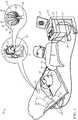
Fig. 1 , which is a pictorial illustration of asystem 10 for performing ablative procedures on aheart 12 of a living subject, which is constructed and operative in accordance with a disclosed embodiment of the invention. The system comprises acatheter 14, which is percutaneously inserted by anoperator 16 through the patient's vascular system into a chamber or vascular structure of theheart 12. Theoperator 16, who is typically a physician, brings the catheter'sdistal tip 18 into contact with the heart wall, for example, at an ablation target site. Electrical activation maps may be prepared, according to the methods disclosed inU.S. Patent Nos. 6,226,542 , and6,301,496 , and in commonly assignedU.S. Patent No. 6,892,091 . - The
system 10 may comprise a general purpose or embedded computer processor, which is programmed with suitable software for carrying out the functions described hereinbelow. Thus, although portions of thesystem 10 shown in other drawing figures herein are shown as comprising a number of separate functional blocks, these blocks are not necessarily separate physical entities, but rather may represent, for example, different computing tasks or data objects stored in a memory that is accessible to the processor. These tasks may be carried out in software running on a single processor, or on multiple processors. The software may be provided to the processor or processors on tangible non-transitory media, such as CD-ROM or non-volatile memory. Alternatively or additionally, thesystem 10 may comprise a digital signal processor or hard-wired logic. One commercial product embodying elements of thesystem 10 is available as the CARTO® 3 System, available from Biosense Webster, Inc., 3333 Diamond Canyon Road, Diamond Bar, CA 91765. This system may be modified by those skilled in the art to embody the principles of the invention described herein. - Areas determined to be abnormal, for example by evaluation of the electrical activation maps, can be ablated by application of thermal energy, e.g., by passage of radiofrequency electrical current through wires in the catheter to one or more electrodes at the
distal tip 18, which apply the radiofrequency energy to the myocardium. The energy is absorbed in the tissue, heating it to a point (typically above 50°C) at which it permanently loses its electrical excitability. When successful, this procedure creates non-conducting lesions in the cardiac tissue, which disrupt the abnormal electrical pathway causing the arrhythmia. The principles of the invention can be applied to different heart chambers to diagnose and treat many different cardiac arrhythmias. - The
catheter 14 typically comprises ahandle 20, having suitable controls on the handle to enable theoperator 16 to steer, position and orient the distal end of the catheter as desired for the ablation. To aid theoperator 16, the distal portion of thecatheter 14 contains position sensors (not shown) that provide signals to aprocessor 22, located in aconsole 24. Theprocessor 22 may fulfill several processing functions as described below. - The distal end of
catheter 14 is anexpandable balloon 37, havingmultiple electrodes 32, which are used primarily as ablation electrodes and have known locations on the surface of the balloon, and known relationships to one another. Thus, once the catheter is located in the heart, for example by constructing a current position map, the location of each of theelectrodes 32 in the heart is known. One method for generation of a current position map is described in commonly assignedU.S. Patent No. 8,478,383 to Bar-Tal et al. Ultrasound transducers 39 positioned on theballoon 37 operate in A-mode to determine respective distances from target tissue, as described below. Theconsole 24 typically includes anultrasound processor 41 to interpret signals from thetransducers 39. - In addition to conducting radiofrequency current through the
electrodes 32, other electrical signals can be conveyed to and from theheart 12 from theelectrodes 32 viacable 34 to theconsole 24. Pacing signals and other control signals may be conveyed from theconsole 24 through thecable 34 and theelectrodes 32 to theheart 12. Wire connections 35 link theconsole 24 withbody surface electrodes 30 and other components of a positioning sub-system for measuring location and orientation coordinates of thecatheter 14. Theprocessor 22, or another processor (not shown) may be an element of the positioning subsystem. Theelectrodes 32 and thebody surface electrodes 30 may be used to measure tissue impedance at the ablation site as taught inU.S. Patent No. 7,536,218 , issued to Govariet al. A temperature sensor (not shown), typically a thermocouple or thermistor, may be mounted near thedistal tip 18 of thecatheter 14.- The
console 24 typically contains one or moreablation power generators 25. Thecatheter 14 may be adapted to conduct ablative energy to the heart using any known ablation technique, e.g., radiofrequency energy, ultrasound energy, and laser-produced light energy. Such methods are disclosed in commonly assignedU.S. Patent Nos. 6,814,733 ,6,997,924 , and7,156,816 . - In one embodiment, the positioning subsystem comprises a magnetic position tracking arrangement that determines the position and orientation of the
catheter 14 by generating magnetic fields in a predefined working volume and sensing these fields at the catheter, using field generating coils 28. A suitable positioning subsystem is described inU.S. Patent No. 7,756,576 and in the above-notedU.S. Patent No. 7,536,218 . - As noted above, the
catheter 14 is coupled to theconsole 24, which enables theoperator 16 to observe and regulate the functions of thecatheter 14.Console 24 includes a processor, preferably a computer with appropriate signal processing circuits. The processor is coupled to drive amonitor 29. The signal processing circuits typically receive, amplify, filter and digitize signals from thecatheter 14, including signals generated by the above-noted sensors and a plurality of location sensing electrodes (not shown) located distally in thecatheter 14. The digitized signals are received and used by theconsole 24 and the positioning system to compute the position and orientation of thecatheter 14 and to analyze the electrical signals from the electrodes as described in further detail below. - Typically, the
system 10 includes other elements, which are not shown in the figures for the sake of simplicity. For example, thesystem 10 may include an electrocardiogram (ECG) monitor, coupled to receive signals from one or more body surface electrodes, so as to provide an ECG synchronization signal to theconsole 24. As mentioned above, thesystem 10 typically also includes a reference position sensor, either on an externally applied reference patch attached to the exterior of the subject's body, or on an internally-placed catheter, which is inserted into theheart 12 and maintained in a fixed position relative to theheart 12. Thesystem 10 may receive image data from an external imaging modality, such as an MRI unit or the like and includes image processors that can be incorporated in or invoked by theprocessor 22 for generating and displaying images that are described below. - Reference is now made to
Fig. 2 , which is a schematic diagram of an ablation and active current location (ACL)circuit 44 for use with the system shown inFig. 1 . This arrangement is similar to that described in U.S. Patent Application Publications2006/0173251, to Govari et al. , and2007/0038078, to Osadchy . The arrangement can be modified to operate in accordance with the principles of the present invention. A brief description follows for convenience of presentation. - A plurality of
body surface electrodes 46, which can be adhesive skin patches, are coupled to a body surface 48 (e.g., the skin) ofsubject 50. Thebody surface electrodes 46 are sometimes referred to herein as "patches". In cardiac applications thebody surface electrodes 46 are usually distributed so as to surround the heart, three on the chest of the subject and three on the back. However, the number of thebody surface electrodes 46 is not critical, and they may be placed at convenient locations on thebody surface 48 in the general vicinity of the site of the medical procedure. - A
control unit 52, normally disposed in the console 24 (Fig. 1 ), includescurrent measurement circuitry 54 and one or morecatheter electrode transmitters 56 for driving a current through one or more of theelectrodes 46 to one or more of thebody surface electrodes 46 at respective working frequencies. Thecontrol unit 52 is linked to the positioning processor 22 (Fig. 1 ). Thecontrol unit 52 is linked to anablator 58, which comprises at least oneablation generator 60. Currents through thebody surface electrodes 46 and an ablator body surface electrode 62 flow in a circuit with theablation generator 60 and are measured by respective current measurement circuits that are disposed withinbody electrode receivers 64, sometimes referred to herein as "patch measurement circuits". Thebody electrode receivers 64 are typically incorporated in thecontrol unit 52. Alternatively, they may be affixed to thebody surface electrodes 46. Catheter electrodes are represented inFig. 2 as measurement electrodes 66 (circles) and a dual-purpose electrode 68 (ellipse). The dual-purpose electrode 68 functions as an ablation electrode and also serves as one of the measurement electrodes. - The
body surface electrodes 46 are connected to thebody electrode receivers 64 via apatch box 70, which protects the system from ablation and defibrillation currents. Typically the system is configured with sixbody electrode receivers 64. The patch box parasitic impedances 72 (Z), are measured during production and thus known a priori. These impedances are discussed below. - Typically, although only two
measurement electrodes 66 are shown for convenience, about 80 measurement electrodes are used for impedance measurements. Typically there are one or two ablation electrodes. The coordinates of a catheter inside the body are determined by passing currents between electrodes on the catheter and thebody surface electrodes 46. - The
control unit 52 may also control an ablation circuit, comprisingablator 58, and the dual-purpose electrode 68. Theablator 58 is typically disposed externally to thecontrol unit 52 and incorporates theablation generator 60. It connects with the ablator body surface electrode 62 and to an ablator filter 76, which in this example is shown within thecontrol unit 52. However this location is not essential. Aswitch 78 configures the ablator circuit for different modes of operation as described below. It will be noted from inspection ofFig. 2 that the ablation circuit is connected to one of thecatheter electrode transmitters 56. - Reference is now made to
Fig. 3 , which is a sectional schematic view of atransducer assembly 82 in an operational position at apulmonary vein ostium 84 in accordance with a preferred embodiment of the invention.Transducer assembly 82 is disposed proximate theostium 84, external to an optional anchoring balloon (not shown). The use of ultrasonic beam focusing techniques eliminates the difficulty of physically conforming the transducer to the wall of the pulmonary vein, as is required by conventional techniques, which often required multiple versions of the catheter, each dimensioned to one of many anatomic variations of the structures near the target ablation zone. - The
transducer assembly 82 has alumen 88. Abody section 90 is preferably shaped as a truncated cone, preferably having aninclination angle 92 of approximately 20 degrees. Thus, the cross section of a proximal portion of thebody section 90 is larger than the cross section of its distal portion. Apiezoelectric element 94 of known type, such as a ceramic, is present within thebody section 90. Thetransducer assembly 82 functions as an omnidirectional ultrasonic lens, forming a generally forward-directedcircumferential beam 96, indicated by dashed lines. Thebeam 96 converges ontotarget tissue 98. Thepiezoelectric element 94 may be realized as an array of transducers, which can be tuned, under control of acontrol unit 100, so as to shape thebeam 96 as may be required for a particular ablation procedure, in order to adapt the beam to the local anatomy. This can be done in a known manner, for example by operating elements of the array out of phase with one another. - The
transducer assembly 82 is connected by acable 102 to asuitable power source 104 and to thecontrol unit 100 and can be operated in A-mode. Preferably thetransducer assembly 82 is 4.0 mm in length, and has an OD of 2.6 mm. Thetransducer assembly 82 is quarter-wave impedance matched, using air-backing material within thebody section 90. It preferably operates at an excitation frequency of 3 - 4 MHz, and has a focal depth of 15 mm. Typical driving power is 30 - 40W. Structures suitable for the components of thetransducer assembly 82 are disclosed, for example, inU.S. Pat. No. 6,296,619 , and the above-notedU.S. Pat. No. 6,117,101 . It is also possible to construct thetransducer assembly 82 as a thin-film polymer wrapped about the outer surface of the catheter. The active sites to be ablated may be identified using the location and mapping system disclosed in commonly assignedU.S. Pat. No. 5,840,025 . - Reference is now made to
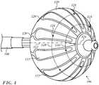
Fig. 4 , which is an oblique elevation of aballoon assembly 106 at the distal end of acatheter shaft 108 in accordance with an embodiment of the invention. Theballoon assembly 106 includes an expandedballoon 110, which typically is in the form of a sphere or an oblate sphere, in which adiameter 112 through adistal pole 114, coaxial with a longitudinal axis of the shaft, is less than an equatorial diameter (not shown) that is perpendicular to thediameter 112. Parallel lines of latitudes are shown at 60° (latitude 116) and 30° (latitude 118) measured from the equator of theballoon 110 toward thedistal pole 114. A variation of ±10° may be tolerated in the latitudes, so that in different embodiments the latitudes could vary from 50° - 70° and 20° - 40°, respectively. Situated on the surface wall of theballoon 110 are multiple longitudinal substrate strips 120 made of polyimide upon whichablation electrodes 122 are formed. In the example ofFig. 4 there are 10electrodes 122 distributed about the circumference of theballoon 110. Theelectrodes 122 andtransducers 124 may be incorporated into theballoon 110 in different ways, for example, by adhering with an adhesive, stamping, printing, wire bonding, soldering, or combinations thereof, as known in the art. Flexible circuitry may be employed. - The expanded
balloon 110 is deployable through a lumen in theshaft 108. Theballoon 110 is configured to engage and ablate the wall of a pulmonary vein in order to correct aberrant conduction, as described, for example in commonly assignedU.S. Patent No. 6,997,924 and U.S. Patent Application Publication No.20160175041 . MultipleA-mode ultrasound transducers 124 are distributed on theballoon 110 It has been found that a near-optimal arrangement of thetransducers 124 is a circumferential distribution of one set of thetransducers 124 at 60°latitude 116 and another set at 30°latitude 118. Because the pulmonary veins taper from widest diameters at their ostia, when theballoon 110 is navigated and expanded within the pulmonary vein, as described, for example in the above notedU.S. Patent Application Publication No. 20160175041 , its surface closely approximates the pulmonary vein intima both at 60°latitude 116, where the diameter of the pulmonary vein is relatively small and at 30°latitude 118, where it is relatively large. The signals from thetransducers 124 correspond to a distance between thetransducers 124 and the wall of the pulmonary vein of nearly zero. - In the embodiment of
Fig. 4 , there are a total of 10 transducers 124: five each in the sets at 60°latitude latitude 118. The two sets are staggered with respect to one another so as to lie on alternate lines of longitude. Each set is equally distributed around the circumference of theballoon 110. Preferably the sets oftransducers 124 are associated with respective sets ofstrips 120 as shown inFig. 4 , wherein thetransducers 124 and thestrips 120 are superimposed. Thetransducers 124 may be superimposed on theelectrodes 122. - The number and configuration of the
electrodes 122 andtransducers 124 may be varied as required for a particular medical application and the geometry of the vessel being ablated. While the embodiment ofFig. 4 is suitable for most pulmonary veins, the latitudes for thetransducers 124 may be chosen such that the contact zones between the balloon and the intima match a particular taper of the target vessel. - Reference is now made to
Fig. 5 , which is a projection of a portion of the balloon assembly 106 (Fig. 4 ) showing the layout of thestrips 120 in relation to theelectrodes 122, and the sets oftransducers 124 on two concentric circles representing lines of latitude in accordance with an embodiment of the invention. - Reference is now made to
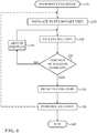
Fig. 6 , which is a flow chart illustrating a method of cardiac catheterization and pulmonary vein isolation in accordance with an embodiment of the invention. - At initial step 126 a cardiac balloon catheter configured as described above in
Fig. 1 andFig. 4 is conventionally introduced into the left atrium of a heart. - Next, at
step 128 the balloon is navigated to engage the interior wall of a pulmonary vein. This may be done using a guide, such as the lasso guide described in the above-notedU.S. Patent Application Publication No. 20160175041 . When a guide is used, the balloon may be extended over the guide into an operating position. - Next, at
step 130 the balloon is inflated. Optionally, a radio-opaque contrast agent may then be injected through the lumen of the catheter in order to confirm that the balloon is in a correct position against the pulmonary vein ostium. - Control now proceeds to
decision step 132, where it is determined if the balloon is correctly positioned. This is the case when the distance readings from at least one set of transducers obtained instep 130 are essentially zero. If the determination atdecision step 132 is negative, then control proceeds to step 134. The balloon is repositioned, which can include being partially or fully deflated during the repositioning process. Control returns to step 130 to iterate the placement until the position is determined to be correct. - If the determination at
decision step 132 is affirmative, then control proceeds to step 136. A-mode readings are taken from the ultrasound transducers on the balloon to determine the respective distances between the transducers and the inner wall of the pulmonary vein. - Next, at
step 138, ablation is performed, e.g., using theelectrodes 122 of the electrode of the balloon assembly 106 (Fig. 4 ). Typically, a circumferential lesion is created in a region of tissue that circumscribes the pulmonary vein. The lesion blocks electrical propagation and effectively electrically isolates the pulmonary vein from the heart. Post-ablation electrograms may be obtained in order to confirm functional isolation of the pulmonary vein. - After completion of the ablation, the procedure may be iterated using another pulmonary vein ostium by withdrawal of the balloon. Control may then return to step 128. Alternatively, the procedure may end by removal of the catheter at final step 140.
- It will be appreciated by persons skilled in the art that the present invention is not limited to what has been particularly shown and described hereinabove. Rather, the scope of the present invention includes both combinations and sub-combinations of the various features described hereinabove, as well as variations and modifications thereof that are not in the prior art, which would occur to persons skilled in the art upon reading the foregoing description.
Claims (8)
- An apparatus comprising:a probe having a distal portion and a lumen;an inflatable balloon (106) deployable through the lumen beyond the distal portion, the balloon having a surface wall, a longitudinal axis and latitudes between an equator and a distal pole on the surface wall;a plurality of ablation electrodes (122) arranged circumferentially on the balloon about the longitudinal axis;a first plurality of ultrasound transducers (124) circumferentially distributed on the balloon along a first one of the latitudes and superimposed on a first set of the plurality of ablation electrodes, the first set of electrodes spanning the first one of the latitudes and a second one of the latitudes;a second plurality of ultrasound transducers circumferentially distributed on the balloon along the second one of the latitudes and superimposed on a second set of ablation electrodes of the plurality of ablation electrodes, each of the second set of ablation electrodes spanning the first one of the latitudes and the second one of the latitudes; andwherein the probe is connectable to circuitry configured for powering the ablation electrodes (122) and processing signals from the transducers (124).
- The apparatus according to claim 1, further comprising a substrate configured as a plurality of longitudinal strips (120) circumferentially distributed on the balloon wherein the ablation electrodes are disposed on the strips.
- The apparatus according to claim 2, wherein the strips (120) and the transducers (124) are superimposed.
- The apparatus according to claim 1, wherein there are ten ablation electrodes (122), and the first plurality of ultrasound transducers and the second plurality of ultrasound transducers each comprise five transducers (124).
- The apparatus according to claim 1, wherein the first latitude is at 30° above the equator and the second latitude is at 60° above the equator toward the distal pole.
- The apparatus according to claim 1, wherein the first latitude is from 20° - 40° and the second latitude is from 50°-70° above the equator toward the distal pole.
- The apparatus according to claim 1, wherein the first plurality of ultrasound transducers is staggered with the second plurality of ultrasound transducers on respective first and second sets of longitudes.
- The apparatus according to claim 1, wherein the plurality of ultrasound transducers (124) is configured for A-mode operation.
Applications Claiming Priority (1)
| Application Number | Priority Date | Filing Date | Title |
|---|---|---|---|
| US15/637,191US10751121B2 (en) | 2017-06-29 | 2017-06-29 | Ultrasound transducers on predetermined radii of balloon catheter |
Publications (2)
| Publication Number | Publication Date |
|---|---|
| EP3420883A1 EP3420883A1 (en) | 2019-01-02 |
| EP3420883B1true EP3420883B1 (en) | 2020-05-20 |
Family
ID=62814960
Family Applications (1)
| Application Number | Title | Priority Date | Filing Date |
|---|---|---|---|
| EP18180310.7AActiveEP3420883B1 (en) | 2017-06-29 | 2018-06-28 | Ultrasound transducers on predetermined radii of balloon catheter |
Country Status (7)
| Country | Link |
|---|---|
| US (1) | US10751121B2 (en) |
| EP (1) | EP3420883B1 (en) |
| JP (1) | JP7118771B2 (en) |
| CN (1) | CN109199454A (en) |
| AU (1) | AU2018203836A1 (en) |
| CA (1) | CA3009757A1 (en) |
| IL (1) | IL259488B (en) |
Families Citing this family (10)
| Publication number | Priority date | Publication date | Assignee | Title |
|---|---|---|---|---|
| US11660121B2 (en) | 2016-10-18 | 2023-05-30 | East End Medical Llc | Transseptal insertion device |
| CA3141251A1 (en) | 2019-06-11 | 2020-12-17 | East End Medical, Llc | Directional balloon transseptal insertion device for medical procedures with improved transseptal puncture system with puncture member balloon seal |
| CN112494106A (en)* | 2019-09-16 | 2021-03-16 | 重庆海扶医疗科技股份有限公司 | Ultrasonic ablation device and equipment |
| AU2020349508A1 (en) | 2019-09-20 | 2022-04-14 | East End Medical, Llc | Directional balloon transseptal insertion device for medical procedures with improved transseptal puncture system with puncture member balloon seal |
| AU2020357991A1 (en) | 2019-10-04 | 2022-04-21 | East End Medical, Llc | Directional balloon transseptal insertion device for medical procedures with improved handle |
| US20210128106A1 (en)* | 2019-11-04 | 2021-05-06 | Boston Scientific Scimed, Inc | Introducer sheath with imaging capability |
| US12137967B2 (en)* | 2019-11-12 | 2024-11-12 | Biosense Webster (Israel) Ltd. | Accurate positioning and shape visualization of balloon catheter ablation tags |
| AU2021221979A1 (en) | 2020-02-18 | 2022-09-15 | East End Medical, Llc | Deflectable anchor balloon catheter for vascular procedures |
| JP2023067583A (en)* | 2021-11-01 | 2023-05-16 | 株式会社カネカ | Balloon catheter and balloon catheter system provided with the same |
| CN114983560B (en)* | 2022-06-22 | 2025-01-21 | 苏州海宇新辰医疗科技有限公司 | A pulse ablation device |
Family Cites Families (36)
| Publication number | Priority date | Publication date | Assignee | Title |
|---|---|---|---|---|
| US5860974A (en) | 1993-07-01 | 1999-01-19 | Boston Scientific Corporation | Heart ablation catheter with expandable electrode and method of coupling energy to an electrode on a catheter shaft |
| US5391199A (en) | 1993-07-20 | 1995-02-21 | Biosense, Inc. | Apparatus and method for treating cardiac arrhythmias |
| US6012457A (en) | 1997-07-08 | 2000-01-11 | The Regents Of The University Of California | Device and method for forming a circumferential conduction block in a pulmonary vein |
| US6024740A (en) | 1997-07-08 | 2000-02-15 | The Regents Of The University Of California | Circumferential ablation device assembly |
| US6117101A (en) | 1997-07-08 | 2000-09-12 | The Regents Of The University Of California | Circumferential ablation device assembly |
| US6514249B1 (en)* | 1997-07-08 | 2003-02-04 | Atrionix, Inc. | Positioning system and method for orienting an ablation element within a pulmonary vein ostium |
| US6301496B1 (en) | 1998-07-24 | 2001-10-09 | Biosense, Inc. | Vector mapping of three-dimensionally reconstructed intrabody organs and method of display |
| US6226542B1 (en) | 1998-07-24 | 2001-05-01 | Biosense, Inc. | Three-dimensional reconstruction of intrabody organs |
| US6296619B1 (en) | 1998-12-30 | 2001-10-02 | Pharmasonics, Inc. | Therapeutic ultrasonic catheter for delivering a uniform energy dose |
| US6892091B1 (en) | 2000-02-18 | 2005-05-10 | Biosense, Inc. | Catheter, method and apparatus for generating an electrical map of a chamber of the heart |
| ES2240470T3 (en) | 2000-06-13 | 2005-10-16 | Atrionix, Inc. | SURGICAL ABLATION PROBE THAT ALLOWS TO PERFORM A CIRCULAR INJURY. |
| US6814733B2 (en) | 2002-01-31 | 2004-11-09 | Biosense, Inc. | Radio frequency pulmonary vein isolation |
| US6997924B2 (en) | 2002-09-17 | 2006-02-14 | Biosense Inc. | Laser pulmonary vein isolation |
| US7156816B2 (en) | 2002-11-26 | 2007-01-02 | Biosense, Inc. | Ultrasound pulmonary vein isolation |
| US7670335B2 (en) | 2003-07-21 | 2010-03-02 | Biosense Webster, Inc. | Ablation device with spiral array ultrasound transducer |
| DE202004021953U1 (en) | 2003-09-12 | 2013-06-19 | Vessix Vascular, Inc. | Selectable eccentric remodeling and / or ablation of atherosclerotic material |
| WO2006060053A2 (en) | 2004-09-13 | 2006-06-08 | Biosense Webster, Inc. | Ablation device with phased array ultrasound transducer |
| US7869865B2 (en) | 2005-01-07 | 2011-01-11 | Biosense Webster, Inc. | Current-based position sensing |
| US7848787B2 (en) | 2005-07-08 | 2010-12-07 | Biosense Webster, Inc. | Relative impedance measurement |
| US7536218B2 (en) | 2005-07-15 | 2009-05-19 | Biosense Webster, Inc. | Hybrid magnetic-based and impedance-based position sensing |
| US7756576B2 (en) | 2005-08-26 | 2010-07-13 | Biosense Webster, Inc. | Position sensing and detection of skin impedance |
| JP5660890B2 (en)* | 2007-06-26 | 2015-01-28 | バソノバ・インコーポレイテッドVasonova, Inc. | Vascular access and guidance system |
| US8235903B2 (en) | 2007-10-12 | 2012-08-07 | Innoscion, Llc | Remotely controlled implantable transducer and associated displays and controls |
| US9545216B2 (en)* | 2011-08-05 | 2017-01-17 | Mc10, Inc. | Catheter balloon methods and apparatus employing sensing elements |
| EP3378391B1 (en) | 2010-10-27 | 2020-12-02 | Dignity Health | Uterine electrical stimulation system |
| US8478383B2 (en) | 2010-12-14 | 2013-07-02 | Biosense Webster (Israel), Ltd. | Probe tracking using multiple tracking methods |
| US9757044B2 (en) | 2011-03-10 | 2017-09-12 | Acutus Medical, Inc. | Device and method for the geometric determination of electrical dipole densities on the cardiac wall |
| US8628473B2 (en) | 2011-04-13 | 2014-01-14 | St. Jude Medical, Inc. | Acoustic transducer for pulse-echo monitoring and control of thermally ablative lesioning in layered and nonlayered tissues, catheter contact monitoring, tissue thickness measurement and pre-pop warning |
| EP2809253B8 (en) | 2012-01-31 | 2016-09-21 | Boston Scientific Scimed, Inc. | Ablation probe with fluid-based acoustic coupling for ultrasonic tissue imaging |
| WO2014159276A1 (en) | 2013-03-14 | 2014-10-02 | Recor Medical, Inc. | Ultrasound-based neuromodulation system |
| US10098694B2 (en)* | 2013-04-08 | 2018-10-16 | Apama Medical, Inc. | Tissue ablation and monitoring thereof |
| US10568686B2 (en)* | 2013-11-21 | 2020-02-25 | Biosense Webster (Israel) Ltd. | Multi-electrode balloon catheter with circumferential and point electrodes |
| HK1232111A1 (en) | 2014-06-24 | 2018-01-05 | Apama Medical, Inc. | Tissue ablation and monitoring thereof |
| US10271893B2 (en)* | 2014-12-15 | 2019-04-30 | Medtronic Ablation Frontiers Llc | Timed energy delivery |
| US20160175041A1 (en)* | 2014-12-22 | 2016-06-23 | Biosense Webster (Israel) Ltd. | Balloon for ablation around pulmonary veins |
| US10327734B2 (en) | 2014-12-30 | 2019-06-25 | Biosense Webster (Israel) Ltd. | Measurement of tissue thickness using ultrasound and force measurements |
- 2017
- 2017-06-29USUS15/637,191patent/US10751121B2/enactiveActive
- 2018
- 2018-05-21ILIL259488Apatent/IL259488B/enactiveIP Right Grant
- 2018-05-31AUAU2018203836Apatent/AU2018203836A1/ennot_activeAbandoned
- 2018-06-28JPJP2018122903Apatent/JP7118771B2/enactiveActive
- 2018-06-28CACA3009757Apatent/CA3009757A1/ennot_activeAbandoned
- 2018-06-28EPEP18180310.7Apatent/EP3420883B1/enactiveActive
- 2018-06-29CNCN201810722443.XApatent/CN109199454A/enactivePending
Non-Patent Citations (1)
| Title |
|---|
| None* |
Also Published As
| Publication number | Publication date |
|---|---|
| CN109199454A (en) | 2019-01-15 |
| AU2018203836A1 (en) | 2019-01-17 |
| IL259488A (en) | 2018-06-28 |
| JP2019034119A (en) | 2019-03-07 |
| IL259488B (en) | 2021-05-31 |
| JP7118771B2 (en) | 2022-08-16 |
| US10751121B2 (en) | 2020-08-25 |
| US20190000544A1 (en) | 2019-01-03 |
| CA3009757A1 (en) | 2018-12-29 |
| EP3420883A1 (en) | 2019-01-02 |
Similar Documents
| Publication | Publication Date | Title |
|---|---|---|
| EP3420883B1 (en) | Ultrasound transducers on predetermined radii of balloon catheter | |
| AU2018204229B2 (en) | Lasso catheter with tip electrode | |
| US11638610B2 (en) | Using force sensor to give angle of ultrasound beam | |
| EP3037034B1 (en) | Balloon for ablation around pulmonary veins | |
| US11382530B2 (en) | Symmetric short contact force sensor with four coils | |
| CN109700523B (en) | Esophageal probe with transmission coil | |
| US5954649A (en) | Catheter system having ultrasound locating capabilities | |
| EP3178431A1 (en) | Ablating and sensing electrodes | |
| CN101766502B (en) | Dual-purpose lasso catheter with irrigation | |
| US6246899B1 (en) | Ultrasound locating system having ablation capabilities | |
| JP2016144642A (en) | Basket catheter with far-field electrode | |
| EP3731774A1 (en) | Balloon catheter with internal distal end | |
| JP6732425B2 (en) | Minimization of effective parasitic capacitance for microablation electrodes | |
| JP2005052641A (en) | Apparatus for pulmonary vein mapping and ablation |
Legal Events
| Date | Code | Title | Description |
|---|---|---|---|
| PUAI | Public reference made under article 153(3) epc to a published international application that has entered the european phase | Free format text:ORIGINAL CODE: 0009012 | |
| STAA | Information on the status of an ep patent application or granted ep patent | Free format text:STATUS: REQUEST FOR EXAMINATION WAS MADE | |
| 17P | Request for examination filed | Effective date:20181122 | |
| AK | Designated contracting states | Kind code of ref document:A1 Designated state(s):AL AT BE BG CH CY CZ DE DK EE ES FI FR GB GR HR HU IE IS IT LI LT LU LV MC MK MT NL NO PL PT RO RS SE SI SK SM TR | |
| AX | Request for extension of the european patent | Extension state:BA ME | |
| STAA | Information on the status of an ep patent application or granted ep patent | Free format text:STATUS: EXAMINATION IS IN PROGRESS | |
| 17Q | First examination report despatched | Effective date:20190315 | |
| GRAP | Despatch of communication of intention to grant a patent | Free format text:ORIGINAL CODE: EPIDOSNIGR1 | |
| STAA | Information on the status of an ep patent application or granted ep patent | Free format text:STATUS: GRANT OF PATENT IS INTENDED | |
| INTG | Intention to grant announced | Effective date:20200225 | |
| RIN1 | Information on inventor provided before grant (corrected) | Inventor name:BEECKLER, CHRISTOPHER THOMAS Inventor name:GOVARI, ASSAF | |
| GRAS | Grant fee paid | Free format text:ORIGINAL CODE: EPIDOSNIGR3 | |
| GRAA | (expected) grant | Free format text:ORIGINAL CODE: 0009210 | |
| STAA | Information on the status of an ep patent application or granted ep patent | Free format text:STATUS: THE PATENT HAS BEEN GRANTED | |
| AK | Designated contracting states | Kind code of ref document:B1 Designated state(s):AL AT BE BG CH CY CZ DE DK EE ES FI FR GB GR HR HU IE IS IT LI LT LU LV MC MK MT NL NO PL PT RO RS SE SI SK SM TR | |
| REG | Reference to a national code | Ref country code:GB Ref legal event code:FG4D | |
| REG | Reference to a national code | Ref country code:CH Ref legal event code:EP | |
| REG | Reference to a national code | Ref country code:DE Ref legal event code:R096 Ref document number:602018004727 Country of ref document:DE | |
| REG | Reference to a national code | Ref country code:AT Ref legal event code:REF Ref document number:1272050 Country of ref document:AT Kind code of ref document:T Effective date:20200615 | |
| REG | Reference to a national code | Ref country code:NL Ref legal event code:FP | |
| REG | Reference to a national code | Ref country code:LT Ref legal event code:MG4D | |
| PG25 | Lapsed in a contracting state [announced via postgrant information from national office to epo] | Ref country code:IS Free format text:LAPSE BECAUSE OF FAILURE TO SUBMIT A TRANSLATION OF THE DESCRIPTION OR TO PAY THE FEE WITHIN THE PRESCRIBED TIME-LIMIT Effective date:20200920 Ref country code:FI Free format text:LAPSE BECAUSE OF FAILURE TO SUBMIT A TRANSLATION OF THE DESCRIPTION OR TO PAY THE FEE WITHIN THE PRESCRIBED TIME-LIMIT Effective date:20200520 Ref country code:NO Free format text:LAPSE BECAUSE OF FAILURE TO SUBMIT A TRANSLATION OF THE DESCRIPTION OR TO PAY THE FEE WITHIN THE PRESCRIBED TIME-LIMIT Effective date:20200820 Ref country code:PT Free format text:LAPSE BECAUSE OF FAILURE TO SUBMIT A TRANSLATION OF THE DESCRIPTION OR TO PAY THE FEE WITHIN THE PRESCRIBED TIME-LIMIT Effective date:20200921 Ref country code:SE Free format text:LAPSE BECAUSE OF FAILURE TO SUBMIT A TRANSLATION OF THE DESCRIPTION OR TO PAY THE FEE WITHIN THE PRESCRIBED TIME-LIMIT Effective date:20200520 Ref country code:GR Free format text:LAPSE BECAUSE OF FAILURE TO SUBMIT A TRANSLATION OF THE DESCRIPTION OR TO PAY THE FEE WITHIN THE PRESCRIBED TIME-LIMIT Effective date:20200821 Ref country code:LT Free format text:LAPSE BECAUSE OF FAILURE TO SUBMIT A TRANSLATION OF THE DESCRIPTION OR TO PAY THE FEE WITHIN THE PRESCRIBED TIME-LIMIT Effective date:20200520 | |
| PG25 | Lapsed in a contracting state [announced via postgrant information from national office to epo] | Ref country code:BG Free format text:LAPSE BECAUSE OF FAILURE TO SUBMIT A TRANSLATION OF THE DESCRIPTION OR TO PAY THE FEE WITHIN THE PRESCRIBED TIME-LIMIT Effective date:20200820 Ref country code:RS Free format text:LAPSE BECAUSE OF FAILURE TO SUBMIT A TRANSLATION OF THE DESCRIPTION OR TO PAY THE FEE WITHIN THE PRESCRIBED TIME-LIMIT Effective date:20200520 Ref country code:LV Free format text:LAPSE BECAUSE OF FAILURE TO SUBMIT A TRANSLATION OF THE DESCRIPTION OR TO PAY THE FEE WITHIN THE PRESCRIBED TIME-LIMIT Effective date:20200520 Ref country code:HR Free format text:LAPSE BECAUSE OF FAILURE TO SUBMIT A TRANSLATION OF THE DESCRIPTION OR TO PAY THE FEE WITHIN THE PRESCRIBED TIME-LIMIT Effective date:20200520 | |
| REG | Reference to a national code | Ref country code:AT Ref legal event code:MK05 Ref document number:1272050 Country of ref document:AT Kind code of ref document:T Effective date:20200520 | |
| PG25 | Lapsed in a contracting state [announced via postgrant information from national office to epo] | Ref country code:AL Free format text:LAPSE BECAUSE OF FAILURE TO SUBMIT A TRANSLATION OF THE DESCRIPTION OR TO PAY THE FEE WITHIN THE PRESCRIBED TIME-LIMIT Effective date:20200520 | |
| PG25 | Lapsed in a contracting state [announced via postgrant information from national office to epo] | Ref country code:EE Free format text:LAPSE BECAUSE OF FAILURE TO SUBMIT A TRANSLATION OF THE DESCRIPTION OR TO PAY THE FEE WITHIN THE PRESCRIBED TIME-LIMIT Effective date:20200520 Ref country code:AT Free format text:LAPSE BECAUSE OF FAILURE TO SUBMIT A TRANSLATION OF THE DESCRIPTION OR TO PAY THE FEE WITHIN THE PRESCRIBED TIME-LIMIT Effective date:20200520 Ref country code:SM Free format text:LAPSE BECAUSE OF FAILURE TO SUBMIT A TRANSLATION OF THE DESCRIPTION OR TO PAY THE FEE WITHIN THE PRESCRIBED TIME-LIMIT Effective date:20200520 Ref country code:DK Free format text:LAPSE BECAUSE OF FAILURE TO SUBMIT A TRANSLATION OF THE DESCRIPTION OR TO PAY THE FEE WITHIN THE PRESCRIBED TIME-LIMIT Effective date:20200520 Ref country code:CZ Free format text:LAPSE BECAUSE OF FAILURE TO SUBMIT A TRANSLATION OF THE DESCRIPTION OR TO PAY THE FEE WITHIN THE PRESCRIBED TIME-LIMIT Effective date:20200520 Ref country code:RO Free format text:LAPSE BECAUSE OF FAILURE TO SUBMIT A TRANSLATION OF THE DESCRIPTION OR TO PAY THE FEE WITHIN THE PRESCRIBED TIME-LIMIT Effective date:20200520 Ref country code:ES Free format text:LAPSE BECAUSE OF FAILURE TO SUBMIT A TRANSLATION OF THE DESCRIPTION OR TO PAY THE FEE WITHIN THE PRESCRIBED TIME-LIMIT Effective date:20200520 | |
| REG | Reference to a national code | Ref country code:DE Ref legal event code:R097 Ref document number:602018004727 Country of ref document:DE | |
| PG25 | Lapsed in a contracting state [announced via postgrant information from national office to epo] | Ref country code:MC Free format text:LAPSE BECAUSE OF FAILURE TO SUBMIT A TRANSLATION OF THE DESCRIPTION OR TO PAY THE FEE WITHIN THE PRESCRIBED TIME-LIMIT Effective date:20200520 Ref country code:PL Free format text:LAPSE BECAUSE OF FAILURE TO SUBMIT A TRANSLATION OF THE DESCRIPTION OR TO PAY THE FEE WITHIN THE PRESCRIBED TIME-LIMIT Effective date:20200520 Ref country code:SK Free format text:LAPSE BECAUSE OF FAILURE TO SUBMIT A TRANSLATION OF THE DESCRIPTION OR TO PAY THE FEE WITHIN THE PRESCRIBED TIME-LIMIT Effective date:20200520 | |
| PLBE | No opposition filed within time limit | Free format text:ORIGINAL CODE: 0009261 | |
| STAA | Information on the status of an ep patent application or granted ep patent | Free format text:STATUS: NO OPPOSITION FILED WITHIN TIME LIMIT | |
| PG25 | Lapsed in a contracting state [announced via postgrant information from national office to epo] | Ref country code:LU Free format text:LAPSE BECAUSE OF NON-PAYMENT OF DUE FEES Effective date:20200628 | |
| REG | Reference to a national code | Ref country code:BE Ref legal event code:MM Effective date:20200630 | |
| 26N | No opposition filed | Effective date:20210223 | |
| PG25 | Lapsed in a contracting state [announced via postgrant information from national office to epo] | Ref country code:IE Free format text:LAPSE BECAUSE OF NON-PAYMENT OF DUE FEES Effective date:20200628 | |
| PG25 | Lapsed in a contracting state [announced via postgrant information from national office to epo] | Ref country code:BE Free format text:LAPSE BECAUSE OF NON-PAYMENT OF DUE FEES Effective date:20200630 Ref country code:SI Free format text:LAPSE BECAUSE OF FAILURE TO SUBMIT A TRANSLATION OF THE DESCRIPTION OR TO PAY THE FEE WITHIN THE PRESCRIBED TIME-LIMIT Effective date:20200520 | |
| REG | Reference to a national code | Ref country code:CH Ref legal event code:PL | |
| PG25 | Lapsed in a contracting state [announced via postgrant information from national office to epo] | Ref country code:LI Free format text:LAPSE BECAUSE OF NON-PAYMENT OF DUE FEES Effective date:20210630 Ref country code:CH Free format text:LAPSE BECAUSE OF NON-PAYMENT OF DUE FEES Effective date:20210630 | |
| PG25 | Lapsed in a contracting state [announced via postgrant information from national office to epo] | Ref country code:TR Free format text:LAPSE BECAUSE OF FAILURE TO SUBMIT A TRANSLATION OF THE DESCRIPTION OR TO PAY THE FEE WITHIN THE PRESCRIBED TIME-LIMIT Effective date:20200520 Ref country code:MT Free format text:LAPSE BECAUSE OF FAILURE TO SUBMIT A TRANSLATION OF THE DESCRIPTION OR TO PAY THE FEE WITHIN THE PRESCRIBED TIME-LIMIT Effective date:20200520 Ref country code:CY Free format text:LAPSE BECAUSE OF FAILURE TO SUBMIT A TRANSLATION OF THE DESCRIPTION OR TO PAY THE FEE WITHIN THE PRESCRIBED TIME-LIMIT Effective date:20200520 | |
| PG25 | Lapsed in a contracting state [announced via postgrant information from national office to epo] | Ref country code:MK Free format text:LAPSE BECAUSE OF FAILURE TO SUBMIT A TRANSLATION OF THE DESCRIPTION OR TO PAY THE FEE WITHIN THE PRESCRIBED TIME-LIMIT Effective date:20200520 | |
| PGFP | Annual fee paid to national office [announced via postgrant information from national office to epo] | Ref country code:NL Payment date:20220513 Year of fee payment:5 | |
| REG | Reference to a national code | Ref country code:NL Ref legal event code:MM Effective date:20230701 | |
| PG25 | Lapsed in a contracting state [announced via postgrant information from national office to epo] | Ref country code:NL Free format text:LAPSE BECAUSE OF NON-PAYMENT OF DUE FEES Effective date:20230701 | |
| PGFP | Annual fee paid to national office [announced via postgrant information from national office to epo] | Ref country code:DE Payment date:20250507 Year of fee payment:8 | |
| PGFP | Annual fee paid to national office [announced via postgrant information from national office to epo] | Ref country code:GB Payment date:20250508 Year of fee payment:8 | |
| PGFP | Annual fee paid to national office [announced via postgrant information from national office to epo] | Ref country code:IT Payment date:20250522 Year of fee payment:8 | |
| PGFP | Annual fee paid to national office [announced via postgrant information from national office to epo] | Ref country code:FR Payment date:20250508 Year of fee payment:8 |