EP3420735B1 - Multitalker optimised beamforming system and method - Google Patents
Multitalker optimised beamforming system and methodDownload PDFInfo
- Publication number
- EP3420735B1 EP3420735B1EP17708148.6AEP17708148AEP3420735B1EP 3420735 B1EP3420735 B1EP 3420735B1EP 17708148 AEP17708148 AEP 17708148AEP 3420735 B1EP3420735 B1EP 3420735B1
- Authority
- EP
- European Patent Office
- Prior art keywords
- sound objects
- microphones
- array
- recent
- microphone
- Prior art date
- Legal status (The legal status is an assumption and is not a legal conclusion. Google has not performed a legal analysis and makes no representation as to the accuracy of the status listed.)
- Active
Links
Images


Classifications
- H—ELECTRICITY
- H04—ELECTRIC COMMUNICATION TECHNIQUE
- H04R—LOUDSPEAKERS, MICROPHONES, GRAMOPHONE PICK-UPS OR LIKE ACOUSTIC ELECTROMECHANICAL TRANSDUCERS; DEAF-AID SETS; PUBLIC ADDRESS SYSTEMS
- H04R3/00—Circuits for transducers, loudspeakers or microphones
- H04R3/005—Circuits for transducers, loudspeakers or microphones for combining the signals of two or more microphones
- H—ELECTRICITY
- H04—ELECTRIC COMMUNICATION TECHNIQUE
- H04M—TELEPHONIC COMMUNICATION
- H04M3/00—Automatic or semi-automatic exchanges
- H04M3/42—Systems providing special services or facilities to subscribers
- H04M3/56—Arrangements for connecting several subscribers to a common circuit, i.e. affording conference facilities
- H04M3/568—Arrangements for connecting several subscribers to a common circuit, i.e. affording conference facilities audio processing specific to telephonic conferencing, e.g. spatial distribution, mixing of participants
- H—ELECTRICITY
- H04—ELECTRIC COMMUNICATION TECHNIQUE
- H04R—LOUDSPEAKERS, MICROPHONES, GRAMOPHONE PICK-UPS OR LIKE ACOUSTIC ELECTROMECHANICAL TRANSDUCERS; DEAF-AID SETS; PUBLIC ADDRESS SYSTEMS
- H04R1/00—Details of transducers, loudspeakers or microphones
- H04R1/20—Arrangements for obtaining desired frequency or directional characteristics
- H04R1/32—Arrangements for obtaining desired frequency or directional characteristics for obtaining desired directional characteristic only
- H04R1/40—Arrangements for obtaining desired frequency or directional characteristics for obtaining desired directional characteristic only by combining a number of identical transducers
- H04R1/406—Arrangements for obtaining desired frequency or directional characteristics for obtaining desired directional characteristic only by combining a number of identical transducers microphones
- H—ELECTRICITY
- H04—ELECTRIC COMMUNICATION TECHNIQUE
- H04L—TRANSMISSION OF DIGITAL INFORMATION, e.g. TELEGRAPHIC COMMUNICATION
- H04L65/00—Network arrangements, protocols or services for supporting real-time applications in data packet communication
- H04L65/40—Support for services or applications
- H04L65/403—Arrangements for multi-party communication, e.g. for conferences
- H—ELECTRICITY
- H04—ELECTRIC COMMUNICATION TECHNIQUE
- H04M—TELEPHONIC COMMUNICATION
- H04M2203/00—Aspects of automatic or semi-automatic exchanges
- H04M2203/50—Aspects of automatic or semi-automatic exchanges related to audio conference
- H04M2203/509—Microphone arrays
- H—ELECTRICITY
- H04—ELECTRIC COMMUNICATION TECHNIQUE
- H04R—LOUDSPEAKERS, MICROPHONES, GRAMOPHONE PICK-UPS OR LIKE ACOUSTIC ELECTROMECHANICAL TRANSDUCERS; DEAF-AID SETS; PUBLIC ADDRESS SYSTEMS
- H04R2201/00—Details of transducers, loudspeakers or microphones covered by H04R1/00 but not provided for in any of its subgroups
- H04R2201/40—Details of arrangements for obtaining desired directional characteristic by combining a number of identical transducers covered by H04R1/40 but not provided for in any of its subgroups
- H04R2201/401—2D or 3D arrays of transducers
- H—ELECTRICITY
- H04—ELECTRIC COMMUNICATION TECHNIQUE
- H04R—LOUDSPEAKERS, MICROPHONES, GRAMOPHONE PICK-UPS OR LIKE ACOUSTIC ELECTROMECHANICAL TRANSDUCERS; DEAF-AID SETS; PUBLIC ADDRESS SYSTEMS
- H04R2430/00—Signal processing covered by H04R, not provided for in its groups
- H04R2430/20—Processing of the output signals of the acoustic transducers of an array for obtaining a desired directivity characteristic
Definitions
- the present inventionrelates to the monitoring of voice conferencing conversations with multiple talkers talking at various times, and, in particular, discloses the utilisation of beamforming to provide a more optimised audio conferencing experience.
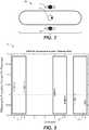
- an audio conference 1is carried out, where a series (e.g., set) of participants 2, 3, 4 are positioned around a Conferencing Audio Input/Output Device 6.
- the Device 6is interconnected to a networking environment 7 for the transmission of the audio conversation.
- the conferencing audio input/output device 6includes one or more microphones e.g. 9. Where multiple microphones (e.g., an array of microphones) are provided, there exists opportunities for improving the voice capture through beamforming or beamsteering of the microphones.
- Beamformingis the process by which a signal or signals are captured by multiple microphones, and in order to capture the best quality signal for a given source or sound of interest, some linear combination of the microphones is selected in order to maximize the signal to noise ratio.
- beamformingaims to optimize for a current talker. It virtually steers a directional beam towards the most salient talker at a particular instance in time in the hope that it will improve the quality and clarity of pick up. In voice beamforming applications, this is typically achieved by looking for the direction which contains the most energy.
- this signalcan be smoothed with a low pass filter to stabilize the estimate.
- Beamformingcan be seen to have two benefits when considered in a room or reverberant environment.
- One aspect of beam formingis to improve the isolation of the desired sound to undesired audio and noise coming from other directions.
- the beam selective processfocuses on the desired sound object using the linear combination of the microphones suited to the pattern of signal response that object creates at the microphones.
- US 2011/038486 A1discloses a system and method that automatically disables and/or enables an acoustic beamformer.
- the system and methodautomatically generate an output audio signal by applying beamforming to a plurality of audio signals produced by an array of microphones when it is determined that such beamforming is working effectively and generate the output audio signal based on an audio signal produced by a designated microphone within the array of microphones when it is determined that the beamforming is not working effectively.
- the determination of whether the beamforming is working effectivelymay be based upon a measure of distortion associated with the beamformer response, an estimated level of reverberation, and/or the rate at which a computed look direction used to control the beamformer changes.
- a systemthat selects and/or steers a directional steerable microphone system based on input from an optical transducer.
- An optical transducersuch as a video camera, provides video input to a processor that controls a steerable directional microphone (such as a microphone array) in the direction of audience members that exhibit physical cues commonly expressed by persons who are speaking or are about to speak.
- the present inventionprovides methods of processing a series of microphone inputs of an audio conference and apparatus for the selective processing of a series of microphone inputs of an audio conference, having the features of the respective independent claims. Preferred embodiments are described in the dependent claims.
- a method of processing a series (e.g., set) of microphone inputs of an audio conferenceeach microphone input being captured by a respective one among an array of microphones, the method including the steps of: (a) conducting a spatial analysis and feature extraction of the audio conference (e.g., of the series of microphone inputs of the audio conference) based on current audio activity, e.g., to obtain information about the approximate relative location of currently active sound objects (e.g., sound objects currently producing sound) relative to the array of microphones; (b) aggregating historical information to obtain information about the approximate relative location of recent sound objects relative to the series of microphone inputs; (c) utilising the relative location or distance of the sound objects from the series of microphone inputs to determine if beam forming should be utilised to enhance the audio reception from recent sound objects.
- a spatial analysis and feature extraction of the audio conferencee.g., of the series of microphone inputs of the audio conference
- current audio activitye.g., to obtain information about the approximate relative location of currently active sound objects (
- Step (b)may relate to aggregating, e.g., over time, e.g., as historical information, the information about the approximate relative location of currently active sound objects relative to the array of microphones to obtain information about the approximate relative location of recent sound objects (e.g., recently active sound objects) relative to the array of microphones.
- Step (c)may relate to utilising the relative location of the recent sound objects relative to the array of microphones to determine if beam forming should be (e.g., is to be) utilised to enhance the audio reception from recent sound objects.
- the sound objectsmay relate to sound sources.
- step (c)preferably can include selectively applying beamforming to objects at an estimated distance of between about 300 and about 3000mm.
- step (c)further preferably can include selectively applying beamforming to objects with an estimated direct to reverb ratio of between about lOdB and about 0dB.
- a method of processing a series (e.g., set) of microphone inputs of an audio conferenceincluding the steps of: (a) conducting a spatial analysis and feature extraction of the audio conference (e.g., of the series of microphone inputs of the audio conference) based on current audio activity, e.g., to obtain information about the approximate relative location of currently active sound objects (e.g., sound objects currently producing sound) relative to the array of microphones; (b) aggregating historical information to retain information about recent sound objects in terms of their optimal microphone beam characteristics and degree of direct to reverb ratio or coherence; and, (c) utilising the recently active objects in the historical context in order to adjust or derate the optimal beam for an active source in such a way as to avoid a null or excessive penalty on the set of likely overlapping or adjacent speaker activity.
- a spatial analysis and feature extraction of the audio conferencee.g., of the series of microphone inputs of the audio conference
- current audio activitye.g., to obtain information about the approximate relative location of currently active sound
- Step (b)may relate to aggregating, e.g., over time, e.g., as historical information, the information about the approximate relative location of the currently active sound objects relative to the array of microphones to retain (e.g., obtain) information about recent sound objects in terms of their (e.g., optimal) microphone beam characteristics and their degree of direct to reverb ratio or coherence.
- Step (c)may relate to adjusting, based on the information about the recent sound objects, the optimal beam for an active sound object in such a way as to reduce a suppression of sound capture of currently inactive sound objects (e.g., among the recent sound objects) in case that they become active.
- the optimal beammay be adjusted to avoid placing nulls towards any others of the recent sound objects.
- an apparatus for the selective processing of a series of microphone inputs of an audio conferenceincluding: a series of microphone inputs (e.g., an array of microphones, each microphone capturing a respective microphone input); a beamformer interconnected to the microphone inputs (e.g., to the array of microphones) for producing a beamformed audio output of the microphone inputs; a first location determination unit for estimating the location of audio objects (e.g., sound objects) detected by the series of microphone inputs; and a beamformer actuation unit, interconnected to the first location determination unit and to the beamformer so as to actuate the beamformer when audio objects (e.g., sound objects) of a predetermined estimated distance range from the series of microphone inputs are detected.
- a series of microphone inputse.g., an array of microphones, each microphone capturing a respective microphone input
- a beamformerinterconnected to the microphone inputs (e.g., to the array of microphones) for producing a beamformed audio output of the microphone input
- the beamformer actuation unitoptimises the beamforming pattern to reduce the impact on the audio objects located by the first location determination unit, e.g., to reduce an adverse impact on the quality of audio capture of the sound objects located by the first location determination unit.
- a series (e.g., set) of microphone inputsis captured, e.g., each microphone input is captured by a respective one among a series (e.g., array) of microphones.
- a beamformermay cause large changes in the absolute level of each source as it switches to the instantaneously dominant energy signal (direction). This can impede the intelligibility and perceived audio quality of the conversation.
- the value of a beamformeris reduced and is therefore less critical.
- the benefits of the beamformerare lower, for very near and very distant sources, on balance it may be preferential to not apply any beamforming for such talkers.
- sources having a direct to reverb ratio in excess of lOdBdid not benefit from beam forming, whilst source with a direct to reverb ration below 0dB suffered degradation due to beam stability issues estimation error.
- Fig. 2A number of concurrent speaker intelligibility tests were conducted to determine the complexity of these issues.
- a first testillustrated 20 in Fig. 2 , the speakers 21, 22 were placed close to the microphone 23.
- Fig. 3illustrates a resulting intelligibility test measure.
- a first system, 31, which operated without using beamforming,was found to have high intelligibility.
- Two other systems 32, 33,utilised a form of microphone switching or beam forming.
- the systemwas found to perform best without beamforming. This is related to the problematic switching between dominant talkers.
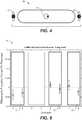
- Fig. 4In a second arrangement, illustrated 40 in Fig. 4 , speakers 41, 42, were placed about 2m from the audio input device 43.
- Fig. 5illustrates a resulting intelligibility test measure. In this arrangement, beamforming was found to provide for a significant advantage.
- the embodimentstherefore utilise beamforming in conjunction with scene analysis to better control the directivity of beams. Further, the beamforming is selectively implemented for appropriate distance sources.
- the embodiments of the inventioncan utilise information in the form of Scene Analysis to attempt to locate the participants around the audio input devices.
- One form of suitable scene analysisis that disclosed in United States Patent Application Publication US 2014/0241528 entitled “Sound Field Analysis System”.
- the suitable form of scene analysisis also disclosed in " On the potential for Scene Analysis from Compact Microphone Arrays", Glenn Dickins, David Gunawan, Dong Shi, AES 52nd International Conference, (2013 ).
- methods and apparatusconduct a spatial analysis and feature extraction of the series of microphone inputs of the audio conference based on current audio activity to thereby obtain information about the approximate relative location of currently active sound objects relative to the array of microphones, This information may relate to a feature space related to the direction and the direct to reverb ratio, or the estimated relevant distance of a source from the microphones.
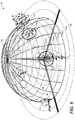
- Fig. 6illustrates a resulting scene analysis from the techniques outlined in the aforementioned application.
- the azimuthal anglerepresents the direction of arrival, and the elevation is related to (e.g., represents) the effective distance or reverberant energy.
- a resulting series of speaker sources e.g. 61 to 64was derived from the scene analysis.
- a source such as 62is intermediate and would be a candidate for enabling beamforming when there is activity of this object, as represented by the detection of audio at the input having spatial features corresponding to the location or elevation on the scene map.
- beamformingis most effective for sources some distance above the equator and some distance away from the pole, representing a band around the hemisphere.
- the selection of beamforming applied to the prime directionmay be based on the instantaneous spatial audio features (e.g., based on information about approximate relative locations of currently active sound objects relative to the array of microphones).
- the addition of heuristics or tracking and selective hypothesis filtering in the scene analysiscan improve the robustness of the object distance (direct to reverb) estimation and choice of application of the beam former.
- the systemmay select to adjust the directivity factor of the beamformer between unity for very near or very far sources and some maximum value for the intermediate distance sources.
- Some embodimentsalso provide a process for optimizing the beamforming pattern at any point in time for sound objects (e.g., participants) in a room based on the statistical probability that they will be the next to become active (e.g., talk), thereby avoiding placing the beamformer nulls in positions that may adversely affect the quality of the capture. That is, an optimal beam is adjusted to avoid suppression of sound objects (e.g., participants) in the room that are currently not active (e.g., not talking), based on the statistical probability that these sound objects will become active next.
- sound objectse.g., participants
- Fig. 7illustrates a flow chart of the steps 50 of an embodiment. The embodiments can proceed by the following steps:
- the main talker directionis determined by analyzing the capture pattern of the microphones (e.g., by scene analysis and/or feature extraction). Ideally the state of the talker is tracked over time and a statistical model of that talker's angle is stored for future use. Mechanisms may be designed to prohibit certain angles to be considered a main talker.
- This salience mapcan be determined by, for any instance of a block of time, the signals from multiple microphones being processed to determine angle of the most salient talker.
- the salience mapis a non-limiting example of information about the approximate relative location of recent sound objects relative to the array of microphones.
- classifiersmay be involved to determine if the signal is a voice signal, room noise or some other form of nuisance. These can all be used to build up a model of all the talkers over the duration of the conference (or even multiple conferences) to improve the system confidence for determining if the current signal contains a talker of interest.
- a weightcan be assigned that is considered the direction of that talker over a certain angular region (e.g. +/-5 degrees).
- the completion of the salience mapprovides an indication of the likelihood or importance of a person talking from a particular angle in the current or subsequent time period.
- This mapis based on previous verbosity or transition probabilities aggregated over time. Additionally, the map may be designed using an arbitrary mechanism of determining importance (e.g. based on classifiers for nuisances which would deprioritize their weight).
- the salience mapcan also be a combination of the two.
- the salience mapis a comprised of the current talker weighting and the angular likelihood or importance of other talkers.
- optimal beamformer patternscan be determined. There are obviously limitations on the physical shape of the beam depending on the geometry and number of microphones used and these parameters must be known to determine the range of beams that may be exploited.
- An optimal beam patterncan be determined by maximizing the beam amplitude map B, such that: where w ⁇ is the salience map for each angle ⁇ , and ⁇ is the parameterization of the beam pattern.
- the (optimal) beam for the currently active sound objectis adjusted, based on the information about the recent sound objects (e.g., based on the salience map), in such a way as to reduce a suppression of sound capture of currently inactive sound objects (e.g., currently inactive talkers) in case that they become active.
- This adjustmentis based on the statistical probability that currently inactive sound objects become active (e.g., within a predetermined time interval from the present point of time).
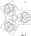
- the audio sceneis captured by 3 directional microphones which are configured for first order soundfield capture.
- the basic microphone layout and responsesare shown schematically in Fig. 8 .
- the proposed techniquecan also be extended to other topologies that may include additional microphones with different microphones and/or orientation.
- the signals from the 3 microphoneswere time based windowed into 'frames'. They were subsequently transformed into the frequency domain and banded. A covariance matrix was calculated for each frame and smoothed over time.
- the covariance matrixprovides the information necessary to extract features for localizing the predominant objects at any time instant and this information is used by higher order logic to determine the location of talkers.
- a spatial analysis and/or feature extractionis conducted for the microphone signals (e.g., microphone inputs).
- Thisprovides the system with information about the approximate relative location of currently active sound objects relative to the array of microphones, e.g., the angular location of each of the potential objects in the room (which could be a talker or a source of noise/ nuisancesance). For each object, information is gathered relating to their angle, average levels, duration of speech activity and duration of non speech activity.
- any time instant tif the estimate of the current dominant angle lies within a standard deviation ⁇ i of the angular statistics of a known talker object i , it is assumed that the current observation is associated with talker i and the mean angle ⁇ i of talker i, is set as the main beam angle ⁇ . This angle is taken as the direction that the beam is steered towards. This is allowed to deviate up to ⁇ i . The beam steered towards this direction may be referred to as an optimal beam for the talker i. With this information and the historical information of all other objects, a salience map S ( ⁇ ,t ) can be derived for angle ⁇ for each time instant t.
- S ( ⁇ ,t )may be derived from the talk activity or verbosity of a particular object such that where N ⁇ j ⁇ j 2 denotes a Gaussian function for each object j classified as a talker such that the characteristics of the Gaussian correspond the angular mean ⁇ j and variance ⁇ j 2 of the object.
- Each Gaussianis scaled by: where a j is the count of talk frames for object j .
- the salience map S ( ⁇ ,t )thus is a mixture of Gaussians describing the angular probability a person is talking based on previous observations in a particular conference or aggregated over many conferences.
- the Gaussiansmay be scaled using various other information such as talker importance (either learnt or provided through user input) or next talker prediction (e.g. previous talker, or utilising Markov models). These methods provide alternative mechanisms for deriving the weighting function w j .
- the main beam angle ⁇is relatively fixed (within ⁇ i ), but in an alternate embodiments, the current object could just exist as a higher weighted w j on the salience map such that w i > w j , ⁇ j ⁇ i . This would require the next step to calculate both the optimal beam and the optimal angle. So for computational simplicity, the main beam angle ⁇ is fixed and the optimal beam pattern calculated.
- a beam pattern optimizationcan then be calculated.
- the optimal beam patterncan be determined using the main beam angle ⁇ , the salience map S ( ⁇ ,t ), and the beam pattern equation r ( ⁇ ). For a given ⁇ , it is desirable to find the optimal ⁇ to maximize the inner product of the salience map and the beam pattern equation:
- ⁇can be limited to ⁇ ⁇ [0,0.5] so that only figure 8 to cardioid patterns are allowed. This may be solved for ⁇ iteratively or with a closed form solution.
- Fig. 9illustrates a response when the source is at about 0.3m
- Fig. 10illustrates a typical response when the source is at about 1m
- Fig. 11illustrates a typical response from a distance of about 5m.
- the vertical axisrepresents energy
- the horizontal axis time of arrivalthree different distances of sources are shown. It can be seen that sources further away have lower initial signal level at the microphones and more reverberant energy. It has been found that sources further away may not be improved from beamforming with a limited number of microphones as the signal to noise ratio degrades, making beam direction estimation difficult, and even the ideal beam may contain significant reverberation already.
- the scene analysisis able to estimate the direct to reverb ratio, or related distance of each source (e.g., each source in the salience map). In this way, beamforming can be applied when there is a sound object of interest at a moderate distance ( Fig. 10 ).
- the methodcan proceed as follows:
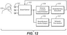
- FIG. 12An example form of hardware/software implementation is illustrated 120 in Fig. 12 .
- microphone inputs 121are input and sampled by beamformer 122.
- the audiois output to source location determination unit 124.
- the source location determination unitimplements the source analysis of Fig. 6 estimating the radial and distance location of any source 123 of audio.
- beam forming actuation unit 125which determined whether beamforming should be implemented and of what form, given the distance and radial direction of sources.
- the beamforming parametersare passed back to beamformer 122 to process the audio inputs.
- the beamformed outputis also copied to beamformed audio output unit 126 where it is further output as required.
Landscapes
- Engineering & Computer Science (AREA)
- Health & Medical Sciences (AREA)
- Otolaryngology (AREA)
- Signal Processing (AREA)
- Physics & Mathematics (AREA)
- Acoustics & Sound (AREA)
- Multimedia (AREA)
- General Health & Medical Sciences (AREA)
- Circuit For Audible Band Transducer (AREA)
- Obtaining Desirable Characteristics In Audible-Bandwidth Transducers (AREA)
Description
- The present invention relates to the monitoring of voice conferencing conversations with multiple talkers talking at various times, and, in particular, discloses the utilisation of beamforming to provide a more optimised audio conferencing experience.
- Any discussion of the background art throughout the specification should in no way be considered as an admission that such art is widely known or forms part of common general knowledge in the field.
- In voice conferencing applications with multiple talkers talking around a single endpoint, the ability to capture the voice of an individual is important to the intelligibility and quality of the conferencing experience.
- In an example arrangement, as illustrated in
Fig. 1 , anaudio conference 1 is carried out, where a series (e.g., set) ofparticipants networking environment 7 for the transmission of the audio conversation. - Typically, the conferencing audio input/output device 6 includes one or more microphones e.g. 9. Where multiple microphones (e.g., an array of microphones) are provided, there exists opportunities for improving the voice capture through beamforming or beamsteering of the microphones.
- Beamforming is the process by which a signal or signals are captured by multiple microphones, and in order to capture the best quality signal for a given source or sound of interest, some linear combination of the microphones is selected in order to maximize the signal to noise ratio. Traditionally beamforming aims to optimize for a current talker. It virtually steers a directional beam towards the most salient talker at a particular instance in time in the hope that it will improve the quality and clarity of pick up. In voice beamforming applications, this is typically achieved by looking for the direction which contains the most energy.
- Since instantaneous estimates (or small frames of speech) are typically noisy, this signal can be smoothed with a low pass filter to stabilize the estimate.
- While beam forming offers benefits in single talker pick up, the reality is that the majority of conferences contain multiple talkers who occasionally talk and sometimes talk simultaneously. This greatly impacts the quality of the beamformed signal, often resulting in a person being relatively inaudible for brief periods of time until the beamformer determines a correct course of action.
- Beamforming can be seen to have two benefits when considered in a room or reverberant environment. One aspect of beam forming is to improve the isolation of the desired sound to undesired audio and noise coming from other directions. The beam selective process focuses on the desired sound object using the linear combination of the microphones suited to the pattern of signal response that object creates at the microphones.
- In addition to noise, a critical problem in rooms and internal spaces is reverberation. This is effectively a later arrival of sound from a wide range of directions at the microphone. In such a situation, there is a direction that can be identified for the early sound energy, and steering a beam in this direction is advantageous as the diffuse reverberant energy is decreased. The ideas behind beamforming for selective source capture, and dereverberation are generally known in the art.
US 2011/038486 A1 discloses a system and method that automatically disables and/or enables an acoustic beamformer. The system and method automatically generate an output audio signal by applying beamforming to a plurality of audio signals produced by an array of microphones when it is determined that such beamforming is working effectively and generate the output audio signal based on an audio signal produced by a designated microphone within the array of microphones when it is determined that the beamforming is not working effectively. Depending upon the implementation, the determination of whether the beamforming is working effectively may be based upon a measure of distortion associated with the beamformer response, an estimated level of reverberation, and/or the rate at which a computed look direction used to control the beamformer changes.- From
US 5940118 A a system is known that selects and/or steers a directional steerable microphone system based on input from an optical transducer. An optical transducer, such as a video camera, provides video input to a processor that controls a steerable directional microphone (such as a microphone array) in the direction of audience members that exhibit physical cues commonly expressed by persons who are speaking or are about to speak. - It is an object of the present invention to provide an improved monitoring of voice conferencing conversations with multiple talkers.
- In view of this object, the present invention provides methods of processing a series of microphone inputs of an audio conference and apparatus for the selective processing of a series of microphone inputs of an audio conference, having the features of the respective independent claims. Preferred embodiments are described in the dependent claims.
- In accordance with a first example that is useful for understanding the present invention, but that does not form part of the present invention as claimed, there is provided a method of processing a series (e.g., set) of microphone inputs of an audio conference, each microphone input being captured by a respective one among an array of microphones, the method including the steps of: (a) conducting a spatial analysis and feature extraction of the audio conference (e.g., of the series of microphone inputs of the audio conference) based on current audio activity, e.g., to obtain information about the approximate relative location of currently active sound objects (e.g., sound objects currently producing sound) relative to the array of microphones; (b) aggregating historical information to obtain information about the approximate relative location of recent sound objects relative to the series of microphone inputs; (c) utilising the relative location or distance of the sound objects from the series of microphone inputs to determine if beam forming should be utilised to enhance the audio reception from recent sound objects. Step (b) may relate to aggregating, e.g., over time, e.g., as historical information, the information about the approximate relative location of currently active sound objects relative to the array of microphones to obtain information about the approximate relative location of recent sound objects (e.g., recently active sound objects) relative to the array of microphones. Step (c) may relate to utilising the relative location of the recent sound objects relative to the array of microphones to determine if beam forming should be (e.g., is to be) utilised to enhance the audio reception from recent sound objects. The sound objects may relate to sound sources.
- In some implementations of this example, the degree of direct to reverberation ratio or the signal coherence can be utilised to estimate the distance of a sound object from the series of microphone inputs. In some implementations, step (c) preferably can include selectively applying beamforming to objects at an estimated distance of between about 300 and about 3000mm.
- In some implementations of this example, step (c) further preferably can include selectively applying beamforming to objects with an estimated direct to reverb ratio of between about lOdB and about 0dB.
- In accordance with a further example that is useful for understanding the present invention, but that does not form part of the invention as claimed, there is provided a method of processing a series (e.g., set) of microphone inputs of an audio conference, each microphone input being captured by a respective one among an array of microphones, the method including the steps of: (a) conducting a spatial analysis and feature extraction of the audio conference (e.g., of the series of microphone inputs of the audio conference) based on current audio activity, e.g., to obtain information about the approximate relative location of currently active sound objects (e.g., sound objects currently producing sound) relative to the array of microphones; (b) aggregating historical information to retain information about recent sound objects in terms of their optimal microphone beam characteristics and degree of direct to reverb ratio or coherence; and, (c) utilising the recently active objects in the historical context in order to adjust or derate the optimal beam for an active source in such a way as to avoid a null or excessive penalty on the set of likely overlapping or adjacent speaker activity. Step (b) may relate to aggregating, e.g., over time, e.g., as historical information, the information about the approximate relative location of the currently active sound objects relative to the array of microphones to retain (e.g., obtain) information about recent sound objects in terms of their (e.g., optimal) microphone beam characteristics and their degree of direct to reverb ratio or coherence. Step (c) may relate to adjusting, based on the information about the recent sound objects, the optimal beam for an active sound object in such a way as to reduce a suppression of sound capture of currently inactive sound objects (e.g., among the recent sound objects) in case that they become active. In general, the optimal beam may be adjusted to avoid placing nulls towards any others of the recent sound objects.
- In accordance with a further example that is useful for understanding the present invention, but that does not form part of the invention as claimed, there is provided an apparatus for the selective processing of a series of microphone inputs of an audio conference, the apparatus including: a series of microphone inputs (e.g., an array of microphones, each microphone capturing a respective microphone input); a beamformer interconnected to the microphone inputs (e.g., to the array of microphones) for producing a beamformed audio output of the microphone inputs; a first location determination unit for estimating the location of audio objects (e.g., sound objects) detected by the series of microphone inputs; and a beamformer actuation unit, interconnected to the first location determination unit and to the beamformer so as to actuate the beamformer when audio objects (e.g., sound objects) of a predetermined estimated distance range from the series of microphone inputs are detected.
- In some implementations of this example, the beamformer actuation unit optimises the beamforming pattern to reduce the impact on the audio objects located by the first location determination unit, e.g., to reduce an adverse impact on the quality of audio capture of the sound objects located by the first location determination unit.
- Embodiments of the invention will now be described, by way of example only, with reference to the accompanying drawings in which:
Fig. 1 illustrates schematically an example audio conferencing environment;Fig. 2 illustrates schematically a first example conferencing environment;Fig. 3 illustrates a graph of the system performance of the arrangement ofFig. 2 ;Fig. 4 illustrates schematically a second example conferencing environment;Fig 5 illustrates a graph of the system performance of the arrangement ofFig. 4 ;Fig. 6 illustrates the results of a scene analysis technique used with an embodiment;Fig 7 illustrates a flowchart of the steps of an embodiment;Fig. 8 illustrates an example of the response of three microphones;Fig. 9 illustrates an example microphone response of a closely spaced speaker;Fig. 10 illustrates an example microphone response of a speaker at about 1 meter;Fig. 11 illustrates an example microphone response of a speaker at about 5 meters;Fig. 12 illustrates schematically an example system of a system for implementation of the embodiments.- The embodiments of the invention utilise an optimisation of beamforming to provide for improved reception techniques in multi talking environments. According to embodiments, a series (e.g., set) of microphone inputs is captured, e.g., each microphone input is captured by a respective one among a series (e.g., array) of microphones.
- In the case of using beam forming for dereverberation, it has been surprisingly found that there is a delicate balance or trade off depending on the distance of the source from the microphones. For near sound sources, the reverberation at the microphones is already low, and there is only small advantage in beamforming. For far sound sources, the direct sound energy is low, and it becomes increasingly difficult to estimate a stable beam that focuses on the early response, and again beamforming can become less valuable. So, there is a certain intermediate distance, having a range of a 'direct to reverb' ratio for a particular source, where beamforming is more advantageous.
- The following two issues and complications can arise with the generic use of beamforming in communications systems: In the case of multiple talkers near the conferencing audio input/output device, a beamformer may cause large changes in the absolute level of each source as it switches to the instantaneously dominant energy signal (direction). This can impede the intelligibility and perceived audio quality of the conversation. In the case of very near and very far audio sources, the value of a beamformer is reduced and is therefore less critical. Thus there is a balance between the benefits of beamforming, and these two issues. Where the benefits of the beamformer are lower, for very near and very distant sources, on balance it may be preferential to not apply any beamforming for such talkers.
- In some embodiments, it was found that sources having a direct to reverb ratio in excess of lOdB did not benefit from beam forming, whilst source with a direct to reverb ration below 0dB suffered degradation due to beam stability issues estimation error.
- A number of concurrent speaker intelligibility tests were conducted to determine the complexity of these issues. In a first test, illustrated 20 in
Fig. 2 , thespeakers microphone 23.Fig. 3 illustrates a resulting intelligibility test measure. A first system, 31, which operated without using beamforming, was found to have high intelligibility. Twoother systems Fig. 2 ), the system was found to perform best without beamforming. This is related to the problematic switching between dominant talkers. - In a second arrangement, illustrated 40 in
Fig. 4 ,speakers audio input device 43.Fig. 5 illustrates a resulting intelligibility test measure. In this arrangement, beamforming was found to provide for a significant advantage. - The embodiments therefore utilise beamforming in conjunction with scene analysis to better control the directivity of beams. Further, the beamforming is selectively implemented for appropriate distance sources.
- The embodiments of the invention can utilise information in the form of Scene Analysis to attempt to locate the participants around the audio input devices. One form of suitable scene analysis is that disclosed in United States Patent Application Publication
US 2014/0241528 entitled "Sound Field Analysis System". The suitable form of scene analysis is also disclosed in "On the potential for Scene Analysis from Compact Microphone Arrays", Glenn Dickins, David Gunawan, Dong Shi, AES 52nd International Conference, (2013). In general, methods and apparatus according to the present disclosure conduct a spatial analysis and feature extraction of the series of microphone inputs of the audio conference based on current audio activity to thereby obtain information about the approximate relative location of currently active sound objects relative to the array of microphones, This information may relate to a feature space related to the direction and the direct to reverb ratio, or the estimated relevant distance of a source from the microphones. - From the foregoing publications there is the potential for drawing (e.g., determining), from a microphone array, the feature space related to the direction and the direct to reverb ratio, or the estimated relevant distance of a source from the microphones. Also in this work, it is noted the benefit of considering the direction of arrival which is difficult to estimate as the effective distance increases (or direct to reverb ratio decreases).
Fig. 6 illustrates a resulting scene analysis from the techniques outlined in the aforementioned application. The azimuthal angle represents the direction of arrival, and the elevation is related to (e.g., represents) the effective distance or reverberant energy. A resulting series of speaker sources e.g. 61 to 64 was derived from the scene analysis.- Sources which have acoustic features mapping onto points lower on the hemisphere, such as
point 61, have a higher direct to reverberant ratio and represent sources close to the device and microphones. Sources having more reverberant energy and therefore harder to identify a dominant direction for are located closer to the top or pole 66 of the hemisphere, such assource 64. In the figure, the difference in uncertainty or angular variation estimation of the source is evident from comparing forexample sources Fig. 6 . The addition of heuristics or tracking and selective hypothesis filtering in the scene analysis can improve the robustness of the object distance (direct to reverb) estimation and choice of application of the beam former. - In some embodiments, rather than a binary decision to apply beamforming, the system may select to adjust the directivity factor of the beamformer between unity for very near or very far sources and some maximum value for the intermediate distance sources.
- Some embodiments also provide a process for optimizing the beamforming pattern at any point in time for sound objects (e.g., participants) in a room based on the statistical probability that they will be the next to become active (e.g., talk), thereby avoiding placing the beamformer nulls in positions that may adversely affect the quality of the capture. That is, an optimal beam is adjusted to avoid suppression of sound objects (e.g., participants) in the room that are currently not active (e.g., not talking), based on the statistical probability that these sound objects will become active next.
Fig. 7 illustrates a flow chart of thesteps 50 of an embodiment. The embodiments can proceed by the following steps:- Obviously the predominant talker at any point in time is highly likely to be the main talker. So in this step, the main talker direction is determined by analyzing the capture pattern of the microphones (e.g., by scene analysis and/or feature extraction). Ideally the state of the talker is tracked over time and a statistical model of that talker's angle is stored for future use. Mechanisms may be designed to prohibit certain angles to be considered a main talker.
- For the beamformer to know which angles to optimize for, it is necessary to derive a running 'salience' map that describes the weighted importance of each angle for capture. This salience map can be determined by, for any instance of a block of time, the signals from multiple microphones being processed to determine angle of the most salient talker. The salience map is a non-limiting example of information about the approximate relative location of recent sound objects relative to the array of microphones.
- Other classifiers may be involved to determine if the signal is a voice signal, room noise or some other form of nuisance. These can all be used to build up a model of all the talkers over the duration of the conference (or even multiple conferences) to improve the system confidence for determining if the current signal contains a talker of interest.
- Given the angular information of the current talker is known, a weight can be assigned that is considered the direction of that talker over a certain angular region (e.g. +/-5 degrees).
- Next, the completion of the salience map provides an indication of the likelihood or importance of a person talking from a particular angle in the current or subsequent time period. This map is based on previous verbosity or transition probabilities aggregated over time. Additionally, the map may be designed using an arbitrary mechanism of determining importance (e.g. based on classifiers for nuisances which would deprioritize their weight). The salience map can also be a combination of the two.
- Thus the salience map is a comprised of the current talker weighting and the angular likelihood or importance of other talkers.
- Once the salience map is determined, optimal beamformer patterns can be determined. There are obviously limitations on the physical shape of the beam depending on the geometry and number of microphones used and these parameters must be known to determine the range of beams that may be exploited.
- An optimal beam pattern can be determined by maximizing the beam amplitude map B, such that:

- This effectively ensures that the likelihood of picking up the current talker as well as potential talkers is maximized, reducing the possibility of talkers ending up in a null of the beamformer. In other words, the (optimal) beam for the currently active sound object (e.g., current talker) is adjusted, based on the information about the recent sound objects (e.g., based on the salience map), in such a way as to reduce a suppression of sound capture of currently inactive sound objects (e.g., currently inactive talkers) in case that they become active. This adjustment is based on the statistical probability that currently inactive sound objects become active (e.g., within a predetermined time interval from the present point of time).
- In a first example, the audio scene is captured by 3 directional microphones which are configured for first order soundfield capture. The basic microphone layout and responses are shown schematically in
Fig. 8 . Of course, the proposed technique can also be extended to other topologies that may include additional microphones with different microphones and/or orientation. - The signals from the 3 microphones were time based windowed into 'frames'. They were subsequently transformed into the frequency domain and banded. A covariance matrix was calculated for each frame and smoothed over time. In accordance with the procedures outlined in United States Patent Application Publication
US 2014/0241528 , the covariance matrix provides the information necessary to extract features for localizing the predominant objects at any time instant and this information is used by higher order logic to determine the location of talkers. In general, a spatial analysis and/or feature extraction is conducted for the microphone signals (e.g., microphone inputs). - This provides the system with information about the approximate relative location of currently active sound objects relative to the array of microphones, e.g., the angular location of each of the potential objects in the room (which could be a talker or a source of noise/nuisance). For each object, information is gathered relating to their angle, average levels, duration of speech activity and duration of non speech activity.
- In one embodiment, at any time instantt, if the estimate of the current dominant angle lies within a standard deviationσi of the angular statistics of a known talker objecti, it is assumed that the current observation is associated with talker i and the mean angleµi of talkeri, is set as the main beam angleφ. This angle is taken as the direction that the beam is steered towards. This is allowed to deviate up toσi. The beam steered towards this direction may be referred to as an optimal beam for the talkeri. With this information and the historical information of all other objects, a salience mapS(θ,t) can be derived for angleθ for each time instantt. S(θ,t) may be derived from the talk activity or verbosity of a particular object such that


variance 
- Each Gaussian is scaled by:

- The salience mapS(θ,t) thus is a mixture of Gaussians describing the angular probability a person is talking based on previous observations in a particular conference or aggregated over many conferences.
- In other embodiments, the Gaussians may be scaled using various other information such as talker importance (either learnt or provided through user input) or next talker prediction (e.g. previous talker, or utilising Markov models). These methods provide alternative mechanisms for deriving the weighting functionwj.
- In this particular embodiment, the main beam angleφ is relatively fixed (withinσi), but in an alternate embodiments, the current object could just exist as a higher weightedwj on the salience map such thatwi >wj, ∀j ≠i. This would require the next step to calculate both the optimal beam and the optimal angle. So for computational simplicity, the main beam angleφ is fixed and the optimal beam pattern calculated.
- Once the salience mapS(θ,t) has been determined, a beam pattern optimization can then be calculated. For the given 3 microphone array of
Fig. 8 , a variety of beams are possible which can be represented in the polar representation:
figure 8 pattern (β = 0) through to cardioid pattern (β = 0.5) through to omnidirectional pattern (β = 1). - The optimal beam pattern can be determined using the main beam angleφ, the salience mapS(θ,t), and the beam pattern equationr(θ). For a givenφ, it is desirable to find the optimalβ to maximize the inner product of the salience map and the beam pattern equation:

- For maximum noise rejection,β can be limited toβ ∈ [0,0.5] so that only
figure 8 to cardioid patterns are allowed. This may be solved forβ iteratively or with a closed form solution. - Consider the typical estimated acoustic response in a room for different distances of source emitter as shown in
Fig. 9 to Fig. 11. Fig. 9 illustrates a response when the source is at about 0.3m,Fig. 10 illustrates a typical response when the source is at about 1m, andFig. 11 illustrates a typical response from a distance of about 5m. The vertical axis represents energy, and the horizontal axis time of arrival, three different distances of sources are shown. It can be seen that sources further away have lower initial signal level at the microphones and more reverberant energy. It has been found that sources further away may not be improved from beamforming with a limited number of microphones as the signal to noise ratio degrades, making beam direction estimation difficult, and even the ideal beam may contain significant reverberation already. - As set out in the aforementioned patent specification, using coherence or alternatively using other techniques based on the power spectrum decay rate over time, the scene analysis is able to estimate the direct to reverb ratio, or related distance of each source (e.g., each source in the salience map). In this way, beamforming can be applied when there is a sound object of interest at a moderate distance (
Fig. 10 ). - In its simplest form, for a single active source, and with a system having three closely spaced cardioid microphones, the method can proceed as follows:
- 1. If there is only one recent active source, and the direct to reverb ratio is greater than OdB, then select the microphone having the largest signal. This is a common case where there is a single user of the system such as on a desk, in a small room, or with limited interaction from the room such as a presenter nearby the device.
- 2. If there is more than one recent active source within a reasonable time of, for example 5 minutes or since the start of the call, and no sources have a direct to reverb ratio <10dB, then do not apply any microphone selection. This is the case of multiple speakers sitting close or around the device such as in a small room with significant interaction.
- 3. If there is one or more recent active source with direct to reverb ratio < lOdB and >0dB, then apply beamforming such that a beam is instantaneously steered to the active source, and where applicable this beam may be optimized to avoid placing nulls directly towards any other recently active sources with 0-10dB direct to reverb ratio range.
- 4. If there is a multiplicity of sources, some of which have direct to reverb ratios < 0dB or > lOdB then enable selective beamforming only when the moderate distance sources are active (0-10dB DRR). When sources are > lOdB DRR or < 0dB no beamforming is applied. For sources that are < 0dB DRR, then do not apply beamforming when active, and do not include such sources in the saliency map for optimizing any other beams.
- An example form of hardware/software implementation is illustrated 120 in
Fig. 12 . In this arrangement,microphone inputs 121 are input and sampled bybeamformer 122. The audio is output to sourcelocation determination unit 124. The source location determination unit implements the source analysis ofFig. 6 estimating the radial and distance location of anysource 123 of audio. These details are then passed to beam formingactuation unit 125 which determined whether beamforming should be implemented and of what form, given the distance and radial direction of sources. The beamforming parameters are passed back tobeamformer 122 to process the audio inputs. The beamformed output is also copied to beamformedaudio output unit 126 where it is further output as required.


Claims (12)
- A method of processing a series of microphone inputs (121) of an audio conference, each microphone input being captured by a respective one among an array of microphones, the method including the steps of:(a) conducting a spatial analysis and feature extraction of the series of microphone inputs of the audio conference based on current audio activity to obtain information about approximate relative locations of currently active sound objects relative to the array of microphones;(b) aggregating the information about the approximate relative locations of currently active sound objects relative to the array of microphones over time to obtain information about approximate relative locations of recent sound objects relative to the array of microphones; and(c) utilising the approximate relative locations of the recent sound objects relative to the array of microphones to determine whether beamforming is to be utilised to enhance an audio reception from recent sound objects when these recent sound objects are detected,wherein it is determined that beamforming is to be utilized to enhance the audio reception from the recent sound objects when recent sound objects are detected in a predetermined estimated distance range from the array of microphones.
- The method as claimed in claim 1, wherein step (b) includes determining clusters of locations among the aggregated approximate locations.
- A method as claimed in any previous claim, wherein a degree of direct to reverberation ratio or a signal coherence from the series of microphone inputs is utilised to estimate the distance of a sound object from the array of microphones.
- A method as claimed in any previous claim, wherein step (c) includes selectively applying beamforming to sound objects among the recent sound objects at the predetermined estimated distance range of between about 300 and about 3000mm.
- A method as claimed in any previous claim, wherein step (c) further includes selectively applying beamforming to sound objects among the recent sound objects with an estimated direct to reverb ratio of between about lOdB and about 0dB.
- A method of processing a series of microphone inputs (121) of an audio conference, each microphone input being captured by a respective one among an array of microphones, the method including the steps of:(a) conducting a spatial analysis and feature extraction of the series of microphone inputs of the audio conference based on current audio activity to obtain information about approximate relative locations of currently active sound objects relative to the array of microphones;(b) aggregating the information about the approximate relative locations of currently active sound objects relative to the array of microphones over time to obtain information about recent sound objects in terms of their optimal microphone beam characteristics and their degree of direct to reverb ratio, wherein an optimal microphone beam characteristics for a recent sound object is chosen so as to maximize a beam amplitude for the recent sound object; and(c) adjusting, based on the information about the recent sound objects, an optimal microphone beam for an active sound object so as to reduce a suppression of sound capture of currently inactive sound objects in case that they become active and avoid a null or suppression above a given threshold for the currently inactive sound objects that are likely to become active, andwherein a likelihood that the currently inactive sound objects will become active is estimated based on a statistical analysis of the information about the recent sound objects.
- An apparatus for selective processing of a series of microphone inputs (121) of an audio conference, the apparatus including:an array of microphones, each microphone capturing a respective microphone input;a beamformer (122) interconnected to the array of microphones for producing a beamformed audio output of the microphone inputs (121) ;a location determination unit (124) for estimating locations of sound objects detected by the series of microphone inputs, wherein estimating the locations of sound objects involves conducting a spatial analysis and feature extraction of the microphone inputs of the audio conference based on current audio activity to obtain information about approximate relative locations of currently active sound objects relative to the array of microphones; anda beamformer actuation unit (125), interconnected to said location determination unit (124) and to said beamformer (122), for actuating the beamformer (122),wherein the beamformer actuation unit (125) is adapted to:aggregate the information about the approximate relative locations of currently active sound objects relative to the array of microphones over time to obtain information about approximate relative locations of recent sound objects relative to the array of microphones; andutilise the approximate relative locations of the recent sound objects relative to the array of microphones to determine whether beamforming is to be utilised to enhance an audio reception from recent sound objects when these recent sound objects are detected; anddetermining that beamforming is to be utilized to enhance the audio reception from the recent sound objects when recent sound objects are detected in a predetermined estimated distance range from the array of microphones.
- An apparatus as claimed in claim 7, wherein aggregating the information about the approximate relative locations of currently active sound objects relative to the array of microphones over time includes determining clusters of locations among the aggregated approximate locations.
- An apparatus as claimed in claim 7 or 8, wherein a degree of direct to reverberation ratio or a signal coherence from the series of microphone inputs is utilised to estimate the distance of a sound object from the the array of microphones.
- An apparatus as claimed in any one of claims 7 to 9, wherein utilising the approximate relative locations of the recent sound objects relative to the array of microphones includes selectively applying beamforming to sound objects among the recent sound objects at the predetermined estimated distance range of between about 300 and about 3000mm.
- An apparatus as claimed in any one of claims 7 to 10, wherein utilising the approximate relative locations of the recent sound objects relative to the array of microphones further includes selectively applying beamforming to sound objects among the recent sound objects with an estimated direct to reverb ratio of between about lOdB and about 0dB.
- An apparatus for selective processing of a series of microphone inputs (121) of an audio conference, the apparatus including:an array of microphones, each microphone capturing a respective microphone input;a beamformer (122) interconnected to the array of microphones for producing a beamformed audio output of the microphone inputs (121);a location determination unit (124) for estimating locations of sound objects detected by the series of microphone inputs (121), wherein estimating the locations of sound objects involves conducting a spatial analysis and feature extraction of the microphone inputs of the audio conference based on current audio activity to obtain information about approximate relative locations of currently active sound objects relative to the array of microphones; anda beamformer actuation unit (125), interconnected to said location determination unit (124) and to said beamformer (122), for actuating the beamformer (122),wherein the beamformer actuation unit (125) is adapted to:aggregate the information about the approximate relative locations of currently active sound objects relative to the array of microphones over time to obtain information about recent sound objects in terms of their optimal microphone beam characteristics and their degree of direct to reverb ratio, wherein an optimal microphone beam characteristics for a recent sound object is chosen so as to maximize a beam amplitude for the recent sound object;adjust, based on the information about the recent sound objects, an optimal microphone beam for an active sound object so as to reduce a suppression of sound capture of currently inactive sound objects in case that they become active and null or suppression above a given threshold for the currently inactive sound objects that are likely to become active,wherein a likelihood that the currently inactive sound objects will become active is estimated based on a statistical analysis of the information about the recent sound objects.
Applications Claiming Priority (3)
| Application Number | Priority Date | Filing Date | Title |
|---|---|---|---|
| US201662299700P | 2016-02-25 | 2016-02-25 | |
| EP16157358 | 2016-02-25 | ||
| PCT/US2017/019182WO2017147325A1 (en) | 2016-02-25 | 2017-02-23 | Multitalker optimised beamforming system and method |
Publications (2)
| Publication Number | Publication Date |
|---|---|
| EP3420735A1 EP3420735A1 (en) | 2019-01-02 |
| EP3420735B1true EP3420735B1 (en) | 2020-06-10 |
Family
ID=55486501
Family Applications (1)
| Application Number | Title | Priority Date | Filing Date |
|---|---|---|---|
| EP17708148.6AActiveEP3420735B1 (en) | 2016-02-25 | 2017-02-23 | Multitalker optimised beamforming system and method |
Country Status (3)
| Country | Link |
|---|---|
| US (1) | US10412490B2 (en) |
| EP (1) | EP3420735B1 (en) |
| WO (1) | WO2017147325A1 (en) |
Families Citing this family (7)
| Publication number | Priority date | Publication date | Assignee | Title |
|---|---|---|---|---|
| JP7186375B2 (en)* | 2018-03-29 | 2022-12-09 | パナソニックIpマネジメント株式会社 | Speech processing device, speech processing method and speech processing system |
| US10694285B2 (en)* | 2018-06-25 | 2020-06-23 | Biamp Systems, LLC | Microphone array with automated adaptive beam tracking |
| CN112292870A (en)* | 2018-08-14 | 2021-01-29 | 阿里巴巴集团控股有限公司 | Audio signal processing apparatus and method |
| WO2020191380A1 (en)* | 2019-03-21 | 2020-09-24 | Shure Acquisition Holdings,Inc. | Auto focus, auto focus within regions, and auto placement of beamformed microphone lobes with inhibition functionality |
| EP3994874A4 (en) | 2019-07-03 | 2023-01-18 | Hewlett-Packard Development Company, L.P. | Acoustic echo cancellation |
| US11937056B2 (en)* | 2019-08-22 | 2024-03-19 | Rensselaer Polytechnic Institute | Multi-talker separation using 3-tuple coprime microphone array |
| EP3944633A1 (en)* | 2020-07-22 | 2022-01-26 | EPOS Group A/S | A method for optimizing speech pickup in a speakerphone system |
Family Cites Families (28)
| Publication number | Priority date | Publication date | Assignee | Title |
|---|---|---|---|---|
| US5940118A (en)* | 1997-12-22 | 1999-08-17 | Nortel Networks Corporation | System and method for steering directional microphones |
| US7970151B2 (en) | 2004-10-15 | 2011-06-28 | Lifesize Communications, Inc. | Hybrid beamforming |
| US7970150B2 (en) | 2005-04-29 | 2011-06-28 | Lifesize Communications, Inc. | Tracking talkers using virtual broadside scan and directed beams |
| JP4929740B2 (en)* | 2006-01-31 | 2012-05-09 | ヤマハ株式会社 | Audio conferencing equipment |
| US8934640B2 (en) | 2007-05-17 | 2015-01-13 | Creative Technology Ltd | Microphone array processor based on spatial analysis |
| RU2438197C2 (en) | 2007-07-13 | 2011-12-27 | Долби Лэборетериз Лайсенсинг Корпорейшн | Audio signal processing using auditory scene analysis and spectral skewness |
| US8503653B2 (en) | 2008-03-03 | 2013-08-06 | Alcatel Lucent | Method and apparatus for active speaker selection using microphone arrays and speaker recognition |
| US8521530B1 (en) | 2008-06-30 | 2013-08-27 | Audience, Inc. | System and method for enhancing a monaural audio signal |
| JP5229053B2 (en) | 2009-03-30 | 2013-07-03 | ソニー株式会社 | Signal processing apparatus, signal processing method, and program |
| US8644517B2 (en)* | 2009-08-17 | 2014-02-04 | Broadcom Corporation | System and method for automatic disabling and enabling of an acoustic beamformer |
| US9100734B2 (en) | 2010-10-22 | 2015-08-04 | Qualcomm Incorporated | Systems, methods, apparatus, and computer-readable media for far-field multi-source tracking and separation |
| JP4945675B2 (en) | 2010-11-12 | 2012-06-06 | 株式会社東芝 | Acoustic signal processing apparatus, television apparatus, and program |
| GB2495130B (en) | 2011-09-30 | 2018-10-24 | Skype | Processing audio signals |
| GB2495129B (en) | 2011-09-30 | 2017-07-19 | Skype | Processing signals |
| EP2766901B1 (en) | 2011-10-17 | 2016-09-21 | Nuance Communications, Inc. | Speech signal enhancement using visual information |
| WO2013093565A1 (en) | 2011-12-22 | 2013-06-27 | Nokia Corporation | Spatial audio processing apparatus |
| JP5738218B2 (en)* | 2012-02-28 | 2015-06-17 | 日本電信電話株式会社 | Acoustic signal emphasizing device, perspective determination device, method and program thereof |
| US9736604B2 (en) | 2012-05-11 | 2017-08-15 | Qualcomm Incorporated | Audio user interaction recognition and context refinement |
| US9497544B2 (en) | 2012-07-02 | 2016-11-15 | Qualcomm Incorporated | Systems and methods for surround sound echo reduction |
| WO2014046941A1 (en) | 2012-09-19 | 2014-03-27 | Dolby Laboratories Licensing Corporation | Method and system for object-dependent adjustment of levels of audio objects |
| US9286898B2 (en) | 2012-11-14 | 2016-03-15 | Qualcomm Incorporated | Methods and apparatuses for providing tangible control of sound |
| US9460732B2 (en) | 2013-02-13 | 2016-10-04 | Analog Devices, Inc. | Signal source separation |
| CN104019885A (en) | 2013-02-28 | 2014-09-03 | 杜比实验室特许公司 | Sound field analysis system |
| US9338551B2 (en) | 2013-03-15 | 2016-05-10 | Broadcom Corporation | Multi-microphone source tracking and noise suppression |
| WO2014151813A1 (en) | 2013-03-15 | 2014-09-25 | Dolby Laboratories Licensing Corporation | Normalization of soundfield orientations based on auditory scene analysis |
| JP2014219467A (en) | 2013-05-02 | 2014-11-20 | ソニー株式会社 | Sound signal processing apparatus, sound signal processing method, and program |
| US9420368B2 (en) | 2013-09-24 | 2016-08-16 | Analog Devices, Inc. | Time-frequency directional processing of audio signals |
| US9799322B2 (en)* | 2014-10-22 | 2017-10-24 | Google Inc. | Reverberation estimator |
- 2017
- 2017-02-23EPEP17708148.6Apatent/EP3420735B1/enactiveActive
- 2017-02-23USUS16/078,563patent/US10412490B2/enactiveActive
- 2017-02-23WOPCT/US2017/019182patent/WO2017147325A1/ennot_activeCeased
Non-Patent Citations (1)
| Title |
|---|
| None* |
Also Published As
| Publication number | Publication date |
|---|---|
| EP3420735A1 (en) | 2019-01-02 |
| WO2017147325A1 (en) | 2017-08-31 |
| US10412490B2 (en) | 2019-09-10 |
| US20190058944A1 (en) | 2019-02-21 |
Similar Documents
| Publication | Publication Date | Title |
|---|---|---|
| EP3420735B1 (en) | Multitalker optimised beamforming system and method | |
| US10546593B2 (en) | Deep learning driven multi-channel filtering for speech enhancement | |
| CN110741434B (en) | Dual microphone speech processing for headphones with variable microphone array orientation | |
| US9837099B1 (en) | Method and system for beam selection in microphone array beamformers | |
| US10331396B2 (en) | Filter and method for informed spatial filtering using multiple instantaneous direction-of-arrival estimates | |
| US9734822B1 (en) | Feedback based beamformed signal selection | |
| Zohourian et al. | Binaural speaker localization integrated into an adaptive beamformer for hearing aids | |
| CN110140360B (en) | Method and apparatus for audio capture using beamforming | |
| Marquardt et al. | Theoretical analysis of linearly constrained multi-channel Wiener filtering algorithms for combined noise reduction and binaural cue preservation in binaural hearing aids | |
| EP4005228B1 (en) | Acoustic echo cancellation control for distributed audio devices | |
| US20130083942A1 (en) | Processing Signals | |
| CN110140359B (en) | Audio capture using beamforming | |
| CN101278337A (en) | Robust separation of speech signals in a noisy environment | |
| WO2014019596A2 (en) | Processing audio signals | |
| US9532138B1 (en) | Systems and methods for suppressing audio noise in a communication system | |
| Woods et al. | A real-world recording database for ad hoc microphone arrays | |
| Zheng et al. | BSS for improved interference estimation for blind speech signal extraction with two microphones | |
| Zohourian et al. | GSC-based binaural speaker separation preserving spatial cues | |
| Hadad et al. | Comparison of two binaural beamforming approaches for hearing aids | |
| EP4430861A1 (en) | Distributed audio device ducking | |
| Tashev et al. | Cost function for sound source localization with arbitrary microphone arrays | |
| Brutti et al. | A Phase-Based Time-Frequency Masking for Multi-Channel Speech Enhancement in Domestic Environments. | |
| Braun et al. | Directional interference suppression using a spatial relative transfer function feature | |
| Reindl et al. | An acoustic front-end for interactive TV incorporating multichannel acoustic echo cancellation and blind signal extraction | |
| Pan et al. | Combined spatial/beamforming and time/frequency processing for blind source separation |
Legal Events
| Date | Code | Title | Description |
|---|---|---|---|
| STAA | Information on the status of an ep patent application or granted ep patent | Free format text:STATUS: UNKNOWN | |
| STAA | Information on the status of an ep patent application or granted ep patent | Free format text:STATUS: THE INTERNATIONAL PUBLICATION HAS BEEN MADE | |
| PUAI | Public reference made under article 153(3) epc to a published international application that has entered the european phase | Free format text:ORIGINAL CODE: 0009012 | |
| STAA | Information on the status of an ep patent application or granted ep patent | Free format text:STATUS: REQUEST FOR EXAMINATION WAS MADE | |
| 17P | Request for examination filed | Effective date:20180925 | |
| AK | Designated contracting states | Kind code of ref document:A1 Designated state(s):AL AT BE BG CH CY CZ DE DK EE ES FI FR GB GR HR HU IE IS IT LI LT LU LV MC MK MT NL NO PL PT RO RS SE SI SK SM TR | |
| AX | Request for extension of the european patent | Extension state:BA ME | |
| DAV | Request for validation of the european patent (deleted) | ||
| DAX | Request for extension of the european patent (deleted) | ||
| GRAP | Despatch of communication of intention to grant a patent | Free format text:ORIGINAL CODE: EPIDOSNIGR1 | |
| STAA | Information on the status of an ep patent application or granted ep patent | Free format text:STATUS: GRANT OF PATENT IS INTENDED | |
| RIC1 | Information provided on ipc code assigned before grant | Ipc:H04R 1/40 20060101AFI20200129BHEP Ipc:H04M 3/56 20060101ALI20200129BHEP Ipc:H04R 3/00 20060101ALI20200129BHEP | |
| INTG | Intention to grant announced | Effective date:20200226 | |
| GRAS | Grant fee paid | Free format text:ORIGINAL CODE: EPIDOSNIGR3 | |
| GRAA | (expected) grant | Free format text:ORIGINAL CODE: 0009210 | |
| STAA | Information on the status of an ep patent application or granted ep patent | Free format text:STATUS: THE PATENT HAS BEEN GRANTED | |
| AK | Designated contracting states | Kind code of ref document:B1 Designated state(s):AL AT BE BG CH CY CZ DE DK EE ES FI FR GB GR HR HU IE IS IT LI LT LU LV MC MK MT NL NO PL PT RO RS SE SI SK SM TR | |
| REG | Reference to a national code | Ref country code:GB Ref legal event code:FG4D | |
| REG | Reference to a national code | Ref country code:AT Ref legal event code:REF Ref document number:1280119 Country of ref document:AT Kind code of ref document:T Effective date:20200615 Ref country code:CH Ref legal event code:EP | |
| REG | Reference to a national code | Ref country code:DE Ref legal event code:R096 Ref document number:602017017962 Country of ref document:DE | |
| REG | Reference to a national code | Ref country code:IE Ref legal event code:FG4D | |
| REG | Reference to a national code | Ref country code:LT Ref legal event code:MG4D | |
| PG25 | Lapsed in a contracting state [announced via postgrant information from national office to epo] | Ref country code:GR Free format text:LAPSE BECAUSE OF FAILURE TO SUBMIT A TRANSLATION OF THE DESCRIPTION OR TO PAY THE FEE WITHIN THE PRESCRIBED TIME-LIMIT Effective date:20200911 Ref country code:SE Free format text:LAPSE BECAUSE OF FAILURE TO SUBMIT A TRANSLATION OF THE DESCRIPTION OR TO PAY THE FEE WITHIN THE PRESCRIBED TIME-LIMIT Effective date:20200610 Ref country code:NO Free format text:LAPSE BECAUSE OF FAILURE TO SUBMIT A TRANSLATION OF THE DESCRIPTION OR TO PAY THE FEE WITHIN THE PRESCRIBED TIME-LIMIT Effective date:20200910 Ref country code:FI Free format text:LAPSE BECAUSE OF FAILURE TO SUBMIT A TRANSLATION OF THE DESCRIPTION OR TO PAY THE FEE WITHIN THE PRESCRIBED TIME-LIMIT Effective date:20200610 Ref country code:LT Free format text:LAPSE BECAUSE OF FAILURE TO SUBMIT A TRANSLATION OF THE DESCRIPTION OR TO PAY THE FEE WITHIN THE PRESCRIBED TIME-LIMIT Effective date:20200610 | |
| REG | Reference to a national code | Ref country code:NL Ref legal event code:MP Effective date:20200610 | |
| PG25 | Lapsed in a contracting state [announced via postgrant information from national office to epo] | Ref country code:BG Free format text:LAPSE BECAUSE OF FAILURE TO SUBMIT A TRANSLATION OF THE DESCRIPTION OR TO PAY THE FEE WITHIN THE PRESCRIBED TIME-LIMIT Effective date:20200910 Ref country code:HR Free format text:LAPSE BECAUSE OF FAILURE TO SUBMIT A TRANSLATION OF THE DESCRIPTION OR TO PAY THE FEE WITHIN THE PRESCRIBED TIME-LIMIT Effective date:20200610 Ref country code:LV Free format text:LAPSE BECAUSE OF FAILURE TO SUBMIT A TRANSLATION OF THE DESCRIPTION OR TO PAY THE FEE WITHIN THE PRESCRIBED TIME-LIMIT Effective date:20200610 Ref country code:RS Free format text:LAPSE BECAUSE OF FAILURE TO SUBMIT A TRANSLATION OF THE DESCRIPTION OR TO PAY THE FEE WITHIN THE PRESCRIBED TIME-LIMIT Effective date:20200610 | |
| REG | Reference to a national code | Ref country code:AT Ref legal event code:MK05 Ref document number:1280119 Country of ref document:AT Kind code of ref document:T Effective date:20200610 | |
| PG25 | Lapsed in a contracting state [announced via postgrant information from national office to epo] | Ref country code:AL Free format text:LAPSE BECAUSE OF FAILURE TO SUBMIT A TRANSLATION OF THE DESCRIPTION OR TO PAY THE FEE WITHIN THE PRESCRIBED TIME-LIMIT Effective date:20200610 Ref country code:NL Free format text:LAPSE BECAUSE OF FAILURE TO SUBMIT A TRANSLATION OF THE DESCRIPTION OR TO PAY THE FEE WITHIN THE PRESCRIBED TIME-LIMIT Effective date:20200610 | |
| PG25 | Lapsed in a contracting state [announced via postgrant information from national office to epo] | Ref country code:AT Free format text:LAPSE BECAUSE OF FAILURE TO SUBMIT A TRANSLATION OF THE DESCRIPTION OR TO PAY THE FEE WITHIN THE PRESCRIBED TIME-LIMIT Effective date:20200610 Ref country code:IT Free format text:LAPSE BECAUSE OF FAILURE TO SUBMIT A TRANSLATION OF THE DESCRIPTION OR TO PAY THE FEE WITHIN THE PRESCRIBED TIME-LIMIT Effective date:20200610 Ref country code:RO Free format text:LAPSE BECAUSE OF FAILURE TO SUBMIT A TRANSLATION OF THE DESCRIPTION OR TO PAY THE FEE WITHIN THE PRESCRIBED TIME-LIMIT Effective date:20200610 Ref country code:SM Free format text:LAPSE BECAUSE OF FAILURE TO SUBMIT A TRANSLATION OF THE DESCRIPTION OR TO PAY THE FEE WITHIN THE PRESCRIBED TIME-LIMIT Effective date:20200610 Ref country code:EE Free format text:LAPSE BECAUSE OF FAILURE TO SUBMIT A TRANSLATION OF THE DESCRIPTION OR TO PAY THE FEE WITHIN THE PRESCRIBED TIME-LIMIT Effective date:20200610 Ref country code:PT Free format text:LAPSE BECAUSE OF FAILURE TO SUBMIT A TRANSLATION OF THE DESCRIPTION OR TO PAY THE FEE WITHIN THE PRESCRIBED TIME-LIMIT Effective date:20201012 Ref country code:ES Free format text:LAPSE BECAUSE OF FAILURE TO SUBMIT A TRANSLATION OF THE DESCRIPTION OR TO PAY THE FEE WITHIN THE PRESCRIBED TIME-LIMIT Effective date:20200610 Ref country code:CZ Free format text:LAPSE BECAUSE OF FAILURE TO SUBMIT A TRANSLATION OF THE DESCRIPTION OR TO PAY THE FEE WITHIN THE PRESCRIBED TIME-LIMIT Effective date:20200610 | |
| PG25 | Lapsed in a contracting state [announced via postgrant information from national office to epo] | Ref country code:IS Free format text:LAPSE BECAUSE OF FAILURE TO SUBMIT A TRANSLATION OF THE DESCRIPTION OR TO PAY THE FEE WITHIN THE PRESCRIBED TIME-LIMIT Effective date:20201010 Ref country code:SK Free format text:LAPSE BECAUSE OF FAILURE TO SUBMIT A TRANSLATION OF THE DESCRIPTION OR TO PAY THE FEE WITHIN THE PRESCRIBED TIME-LIMIT Effective date:20200610 Ref country code:PL Free format text:LAPSE BECAUSE OF FAILURE TO SUBMIT A TRANSLATION OF THE DESCRIPTION OR TO PAY THE FEE WITHIN THE PRESCRIBED TIME-LIMIT Effective date:20200610 | |
| REG | Reference to a national code | Ref country code:DE Ref legal event code:R097 Ref document number:602017017962 Country of ref document:DE | |
| PLBE | No opposition filed within time limit | Free format text:ORIGINAL CODE: 0009261 | |
| STAA | Information on the status of an ep patent application or granted ep patent | Free format text:STATUS: NO OPPOSITION FILED WITHIN TIME LIMIT | |
| PG25 | Lapsed in a contracting state [announced via postgrant information from national office to epo] | Ref country code:DK Free format text:LAPSE BECAUSE OF FAILURE TO SUBMIT A TRANSLATION OF THE DESCRIPTION OR TO PAY THE FEE WITHIN THE PRESCRIBED TIME-LIMIT Effective date:20200610 | |
| 26N | No opposition filed | Effective date:20210311 | |
| PG25 | Lapsed in a contracting state [announced via postgrant information from national office to epo] | Ref country code:SI Free format text:LAPSE BECAUSE OF FAILURE TO SUBMIT A TRANSLATION OF THE DESCRIPTION OR TO PAY THE FEE WITHIN THE PRESCRIBED TIME-LIMIT Effective date:20200610 | |
| PG25 | Lapsed in a contracting state [announced via postgrant information from national office to epo] | Ref country code:MC Free format text:LAPSE BECAUSE OF FAILURE TO SUBMIT A TRANSLATION OF THE DESCRIPTION OR TO PAY THE FEE WITHIN THE PRESCRIBED TIME-LIMIT Effective date:20200610 | |
| REG | Reference to a national code | Ref country code:BE Ref legal event code:MM Effective date:20210228 | |
| PG25 | Lapsed in a contracting state [announced via postgrant information from national office to epo] | Ref country code:CH Free format text:LAPSE BECAUSE OF NON-PAYMENT OF DUE FEES Effective date:20210228 Ref country code:LU Free format text:LAPSE BECAUSE OF NON-PAYMENT OF DUE FEES Effective date:20210223 Ref country code:LI Free format text:LAPSE BECAUSE OF NON-PAYMENT OF DUE FEES Effective date:20210228 | |
| PG25 | Lapsed in a contracting state [announced via postgrant information from national office to epo] | Ref country code:IE Free format text:LAPSE BECAUSE OF NON-PAYMENT OF DUE FEES Effective date:20210223 | |
| PG25 | Lapsed in a contracting state [announced via postgrant information from national office to epo] | Ref country code:BE Free format text:LAPSE BECAUSE OF NON-PAYMENT OF DUE FEES Effective date:20210228 | |
| P01 | Opt-out of the competence of the unified patent court (upc) registered | Effective date:20230513 | |
| PG25 | Lapsed in a contracting state [announced via postgrant information from national office to epo] | Ref country code:CY Free format text:LAPSE BECAUSE OF FAILURE TO SUBMIT A TRANSLATION OF THE DESCRIPTION OR TO PAY THE FEE WITHIN THE PRESCRIBED TIME-LIMIT Effective date:20200610 | |
| PG25 | Lapsed in a contracting state [announced via postgrant information from national office to epo] | Ref country code:HU Free format text:LAPSE BECAUSE OF FAILURE TO SUBMIT A TRANSLATION OF THE DESCRIPTION OR TO PAY THE FEE WITHIN THE PRESCRIBED TIME-LIMIT; INVALID AB INITIO Effective date:20170223 | |
| PG25 | Lapsed in a contracting state [announced via postgrant information from national office to epo] | Ref country code:MK Free format text:LAPSE BECAUSE OF FAILURE TO SUBMIT A TRANSLATION OF THE DESCRIPTION OR TO PAY THE FEE WITHIN THE PRESCRIBED TIME-LIMIT Effective date:20200610 | |
| PG25 | Lapsed in a contracting state [announced via postgrant information from national office to epo] | Ref country code:TR Free format text:LAPSE BECAUSE OF FAILURE TO SUBMIT A TRANSLATION OF THE DESCRIPTION OR TO PAY THE FEE WITHIN THE PRESCRIBED TIME-LIMIT Effective date:20200610 | |
| PG25 | Lapsed in a contracting state [announced via postgrant information from national office to epo] | Ref country code:MT Free format text:LAPSE BECAUSE OF FAILURE TO SUBMIT A TRANSLATION OF THE DESCRIPTION OR TO PAY THE FEE WITHIN THE PRESCRIBED TIME-LIMIT Effective date:20200610 | |
| PGFP | Annual fee paid to national office [announced via postgrant information from national office to epo] | Ref country code:DE Payment date:20250122 Year of fee payment:9 | |
| PGFP | Annual fee paid to national office [announced via postgrant information from national office to epo] | Ref country code:FR Payment date:20250122 Year of fee payment:9 | |
| PGFP | Annual fee paid to national office [announced via postgrant information from national office to epo] | Ref country code:GB Payment date:20250124 Year of fee payment:9 |