EP3419582B1 - Fluid transfer connector - Google Patents
Fluid transfer connectorDownload PDFInfo
- Publication number
- EP3419582B1 EP3419582B1EP17710441.1AEP17710441AEP3419582B1EP 3419582 B1EP3419582 B1EP 3419582B1EP 17710441 AEP17710441 AEP 17710441AEP 3419582 B1EP3419582 B1EP 3419582B1
- Authority
- EP
- European Patent Office
- Prior art keywords
- coupling
- bottle
- male
- bottle adapter
- connector
- Prior art date
- Legal status (The legal status is an assumption and is not a legal conclusion. Google has not performed a legal analysis and makes no representation as to the accuracy of the status listed.)
- Active
Links
Images


Classifications
- A—HUMAN NECESSITIES
- A61—MEDICAL OR VETERINARY SCIENCE; HYGIENE
- A61J—CONTAINERS SPECIALLY ADAPTED FOR MEDICAL OR PHARMACEUTICAL PURPOSES; DEVICES OR METHODS SPECIALLY ADAPTED FOR BRINGING PHARMACEUTICAL PRODUCTS INTO PARTICULAR PHYSICAL OR ADMINISTERING FORMS; DEVICES FOR ADMINISTERING FOOD OR MEDICINES ORALLY; BABY COMFORTERS; DEVICES FOR RECEIVING SPITTLE
- A61J1/00—Containers specially adapted for medical or pharmaceutical purposes
- A61J1/14—Details; Accessories therefor
- A61J1/20—Arrangements for transferring or mixing fluids, e.g. from vial to syringe
- A61J1/2096—Combination of a vial and a syringe for transferring or mixing their contents
- A—HUMAN NECESSITIES
- A61—MEDICAL OR VETERINARY SCIENCE; HYGIENE
- A61J—CONTAINERS SPECIALLY ADAPTED FOR MEDICAL OR PHARMACEUTICAL PURPOSES; DEVICES OR METHODS SPECIALLY ADAPTED FOR BRINGING PHARMACEUTICAL PRODUCTS INTO PARTICULAR PHYSICAL OR ADMINISTERING FORMS; DEVICES FOR ADMINISTERING FOOD OR MEDICINES ORALLY; BABY COMFORTERS; DEVICES FOR RECEIVING SPITTLE
- A61J1/00—Containers specially adapted for medical or pharmaceutical purposes
- A61J1/14—Details; Accessories therefor
- A61J1/1412—Containers with closing means, e.g. caps
- A61J1/1425—Snap-fit type
- A—HUMAN NECESSITIES
- A61—MEDICAL OR VETERINARY SCIENCE; HYGIENE
- A61J—CONTAINERS SPECIALLY ADAPTED FOR MEDICAL OR PHARMACEUTICAL PURPOSES; DEVICES OR METHODS SPECIALLY ADAPTED FOR BRINGING PHARMACEUTICAL PRODUCTS INTO PARTICULAR PHYSICAL OR ADMINISTERING FORMS; DEVICES FOR ADMINISTERING FOOD OR MEDICINES ORALLY; BABY COMFORTERS; DEVICES FOR RECEIVING SPITTLE
- A61J1/00—Containers specially adapted for medical or pharmaceutical purposes
- A61J1/14—Details; Accessories therefor
- A61J1/1475—Inlet or outlet ports
- A61J1/1481—Inlet or outlet ports with connection retaining means, e.g. thread or snap-fit
- A—HUMAN NECESSITIES
- A61—MEDICAL OR VETERINARY SCIENCE; HYGIENE
- A61J—CONTAINERS SPECIALLY ADAPTED FOR MEDICAL OR PHARMACEUTICAL PURPOSES; DEVICES OR METHODS SPECIALLY ADAPTED FOR BRINGING PHARMACEUTICAL PRODUCTS INTO PARTICULAR PHYSICAL OR ADMINISTERING FORMS; DEVICES FOR ADMINISTERING FOOD OR MEDICINES ORALLY; BABY COMFORTERS; DEVICES FOR RECEIVING SPITTLE
- A61J1/00—Containers specially adapted for medical or pharmaceutical purposes
- A61J1/14—Details; Accessories therefor
- A61J1/1475—Inlet or outlet ports
- A61J1/1487—Inlet or outlet ports with friction fit, e.g. connecting tubes directly to a protruding port
- A—HUMAN NECESSITIES
- A61—MEDICAL OR VETERINARY SCIENCE; HYGIENE
- A61J—CONTAINERS SPECIALLY ADAPTED FOR MEDICAL OR PHARMACEUTICAL PURPOSES; DEVICES OR METHODS SPECIALLY ADAPTED FOR BRINGING PHARMACEUTICAL PRODUCTS INTO PARTICULAR PHYSICAL OR ADMINISTERING FORMS; DEVICES FOR ADMINISTERING FOOD OR MEDICINES ORALLY; BABY COMFORTERS; DEVICES FOR RECEIVING SPITTLE
- A61J1/00—Containers specially adapted for medical or pharmaceutical purposes
- A61J1/14—Details; Accessories therefor
- A61J1/20—Arrangements for transferring or mixing fluids, e.g. from vial to syringe
- A61J1/2003—Accessories used in combination with means for transfer or mixing of fluids, e.g. for activating fluid flow, separating fluids, filtering fluid or venting
- A61J1/2048—Connecting means
- A61J1/2065—Connecting means having aligning and guiding means
- B—PERFORMING OPERATIONS; TRANSPORTING
- B65—CONVEYING; PACKING; STORING; HANDLING THIN OR FILAMENTARY MATERIAL
- B65D—CONTAINERS FOR STORAGE OR TRANSPORT OF ARTICLES OR MATERIALS, e.g. BAGS, BARRELS, BOTTLES, BOXES, CANS, CARTONS, CRATES, DRUMS, JARS, TANKS, HOPPERS, FORWARDING CONTAINERS; ACCESSORIES, CLOSURES, OR FITTINGS THEREFOR; PACKAGING ELEMENTS; PACKAGES
- B65D41/00—Caps, e.g. crown caps or crown seals, i.e. members having parts arranged for engagement with the external periphery of a neck or wall defining a pouring opening or discharge aperture; Protective cap-like covers for closure members, e.g. decorative covers of metal foil or paper
- B65D41/02—Caps or cap-like covers without lines of weakness, tearing strips, tags, or like opening or removal devices
- B65D41/04—Threaded or like caps or cap-like covers secured by rotation
- B65D41/0485—Threaded or like caps or cap-like covers secured by rotation with means specially adapted for facilitating the operation of opening or closing
- B—PERFORMING OPERATIONS; TRANSPORTING
- B65—CONVEYING; PACKING; STORING; HANDLING THIN OR FILAMENTARY MATERIAL
- B65D—CONTAINERS FOR STORAGE OR TRANSPORT OF ARTICLES OR MATERIALS, e.g. BAGS, BARRELS, BOTTLES, BOXES, CANS, CARTONS, CRATES, DRUMS, JARS, TANKS, HOPPERS, FORWARDING CONTAINERS; ACCESSORIES, CLOSURES, OR FITTINGS THEREFOR; PACKAGING ELEMENTS; PACKAGES
- B65D43/00—Lids or covers for rigid or semi-rigid containers
- B65D43/14—Non-removable lids or covers
- B65D43/16—Non-removable lids or covers hinged for upward or downward movement
- B65D43/163—Non-removable lids or covers hinged for upward or downward movement the container and the lid being made separately
- B—PERFORMING OPERATIONS; TRANSPORTING
- B65—CONVEYING; PACKING; STORING; HANDLING THIN OR FILAMENTARY MATERIAL
- B65D—CONTAINERS FOR STORAGE OR TRANSPORT OF ARTICLES OR MATERIALS, e.g. BAGS, BARRELS, BOTTLES, BOXES, CANS, CARTONS, CRATES, DRUMS, JARS, TANKS, HOPPERS, FORWARDING CONTAINERS; ACCESSORIES, CLOSURES, OR FITTINGS THEREFOR; PACKAGING ELEMENTS; PACKAGES
- B65D47/00—Closures with filling and discharging, or with discharging, devices
- B65D47/04—Closures with discharging devices other than pumps
- B65D47/06—Closures with discharging devices other than pumps with pouring spouts or tubes; with discharge nozzles or passages
- B65D47/12—Closures with discharging devices other than pumps with pouring spouts or tubes; with discharge nozzles or passages having removable closures
- B65D47/14—Closures with discharging devices other than pumps with pouring spouts or tubes; with discharge nozzles or passages having removable closures and closure-retaining means
- B65D47/141—Closures with discharging devices other than pumps with pouring spouts or tubes; with discharge nozzles or passages having removable closures and closure-retaining means for stoppers
- B—PERFORMING OPERATIONS; TRANSPORTING
- B65—CONVEYING; PACKING; STORING; HANDLING THIN OR FILAMENTARY MATERIAL
- B65D—CONTAINERS FOR STORAGE OR TRANSPORT OF ARTICLES OR MATERIALS, e.g. BAGS, BARRELS, BOTTLES, BOXES, CANS, CARTONS, CRATES, DRUMS, JARS, TANKS, HOPPERS, FORWARDING CONTAINERS; ACCESSORIES, CLOSURES, OR FITTINGS THEREFOR; PACKAGING ELEMENTS; PACKAGES
- B65D51/00—Closures not otherwise provided for
- B65D51/24—Closures not otherwise provided for combined or co-operating with auxiliary devices for non-closing purposes
- B—PERFORMING OPERATIONS; TRANSPORTING
- B67—OPENING, CLOSING OR CLEANING BOTTLES, JARS OR SIMILAR CONTAINERS; LIQUID HANDLING
- B67D—DISPENSING, DELIVERING OR TRANSFERRING LIQUIDS, NOT OTHERWISE PROVIDED FOR
- B67D7/00—Apparatus or devices for transferring liquids from bulk storage containers or reservoirs into vehicles or into portable containers, e.g. for retail sale purposes
- B67D7/02—Apparatus or devices for transferring liquids from bulk storage containers or reservoirs into vehicles or into portable containers, e.g. for retail sale purposes for transferring liquids other than fuel or lubricants
- B67D7/0288—Container connection means
Definitions
- the present inventionrelates generally to the field of containment, storage and delivery of fluids, and more particularly to a capping device, bottle adaptor or fluid transfer coupling for facilitating the transfer of fluids between a container or pharmacy bottle and a syringe.
- Various containersare used for the collection, storage and delivery of fluids such as medications, supplements, breast milk, formula, and the like.
- fluidssuch as medications, supplements, breast milk, formula, and the like.
- a syringemay be used to measure and transfer the fluid.
- a transfer lid or capis used on the larger volume container, allowing easy repeated dispensation from the container.
- Smaller volume containerstypically accept "press-in” or stepped enteral-only adapters for transferring the fluids between the syringe and container.
- Figures 1-29show several example embodiments of fluid transfer connectors and adapters for providing the transfer of fluid or medicine from a container or pharmacy bottle to a syringe S, or for example, from the syringe S to the bottle.
- the fluid transfer connectors and adapters of the present inventionare configured for providing engagement between an end connector FC of a syringe S and a conventional enteral-only ported press-in bottle adapter, or for example, a stepped adapter comprising an enteral-only port.
- the fluid transfer connectors of the present inventioncomprise ENFit compatible connectors and are configured for coupling engagement with ENFit connectors, for example, according to the ENFit design standard, ISO 80369-3.
- the fluid transfer connectorscan be sized as desired, for example, to accommodate coupling with containers or bottles of different sized openings.
- the fluid transfer connectorscomprise both enteral-only connectors and ENFit compatible connectors, for example, for providing compatible coupling engagement with enteral-only connectors and ENFit compatible connectors.
- any of the fluid transfer connectors as described hereincan comprise both enteral-only and ENFit compatible connectors as desired.
- Figures 1-4show a bottle adapter connector 10 according to an example embodiment of the present invention.
- the bottle adapter connector 10comprises a cylindrical body 12 comprising an outer peripheral surface 13 that defines a plurality of outer peripheral flanges or steps 14.
- the flanges or steps 14are preferably flexible, resilient and sized to engage with bottle openings of a desirable size.
- the bottle adapter connector 10is in the form of a "press-in" adapter, for example, such that the flanges or steps 14 along the outer peripheral surface 13 generally frictionally engage the opening of a bottle, for example, the opening of a pharmacy or medicine bottle.
- the connector 10can be sized as desired, but can at least be provided in sizes compatible with bottle sizes (and the openings thereof) most frequently used in medicine practice, for example, between a diameter D 1 of about 10 - 40 millimeters, and between about 12 - 38 millimeters according to one example embodiment (see Figures 1 and 5 ).
- the bottle opening or inner diameter thereofis generally between about 12 - 33 millimeters.
- the flanges 14are generally laterally offset from each other and extend around the entirety of the body to define a continuous flange for providing frictional and sealing engagement with an internal surface or opening of a bottle or container.
- the flanges 14are laterally offset and extend along the length or height H of the connector 10, for example, between the upper and lower surfaces of the body 15a, 15b.
- the flanges 14are resilient and flexible such that the adapter connector 10 can engage a bottle opening having an inner diameter range of up to about 4-5 millimeters difference with respect to the adapter connector diameter. For example, if the bottle opening inner diameter is about 12 millimeters, the diameter D 1 of the connector 10 can be up to about 17 millimeters and still provide for fitting and sealing engagement with the bottle opening.
- the connector 10comprises a recess 16 defined by an inner peripheral surface 18 of the body 12, a base member or floor 20, and a male coupling generally centrally-positioned on the floor 20 and extending towards the upper surface 15a.
- a central conduit 24extends entirely through the male coupling 22 along an elongate axis Y that is generally centrally-positioned in the floor 20 and axially aligned with the body 12.
- the end coupling FC of a syringe Sis compatible for removable engagement with the male coupling 22, for example, such that the syringe can be coupled to the connector 10 to allow transfer of the fluids or medicine between the syringe S and the pharmacy bottle, from the pharmacy bottle to the syringe or from the syringe to the pharmacy bottle.
- the male coupling 22can comprise a male ENFit compatible coupling and the end coupling FC can comprise a female ENFit compatible coupling.
- the syringe Scan comprise a dosing control coupling or low dose tip LT, for example, which is compatible for fitting within the conduit 24 when the end coupling FC is coupled with the male coupling 22, and which preferably substantially if not entirely eliminates dosing inaccuracies (see Figure 4 ).
- a dosing control coupling or low dose tip LTfor example, which is compatible for fitting within the conduit 24 when the end coupling FC is coupled with the male coupling 22, and which preferably substantially if not entirely eliminates dosing inaccuracies (see Figure 4 ).
- U.S. Published Patent Application Serial No. 15/210,282Patent Application Publication No. US 2016/0317393 , shows a syringe including a dosing control coupling.
- Figures 5-6show a connector 100 according to another example embodiment of the present invention.
- the connector 100is generally similar to the connector 10 as described above and comprises an outer collar body comprising a plurality of outer peripheral flanges or steps 114, a recess portion 116 defined by a floor surface 120, a male coupling 122 centrally positioned and extending from the floor surface 120, and a central conduit 124 extending entirely through the male coupling 122.
- the male coupling 122extends from the floor surface 120 a distance X above the upper surface 115a of the body 112 comprising the outer peripheral surface 113 having the flanges or steps 114.
- the distance Xis generally between about 0.5 - 6 millimeters.
- closure of a lid or cap L atop the connector 100causes engagement of a surface of the cap L with an end of the male coupling 122, for example, such that the male coupling 122 is generally axially displaced along axis Y within the recess portion 116.
- the floor surface 120is preferably at least partially resilient and flexible to allow for axial displacement of the male coupling 122.
- the floor surface 120undergoes at least some amount of elastic deformation between when the male coupling 122 is in its neutral state and when the cap L is fastened to the bottle to cause displacement of the male coupling 122.
- an end portion of the male coupling 122is sealingly engaged with the surface of the cap L, for example, such that fluids or medicine within the bottle are prevented from passing through the conduit 124 when the cap L is coupled to the bottle.
- the cap Lcan comprise an anti-tamper or child-resistant lid.
- the end portion of the male coupling 122can be configured as desired, for example, to be generally recessed below the upper portion of the collar body, or to be generally flush or planar with the end portion of the collar body.
- a one-way or two-way sealcan be provided within at least a portion of the conduit 124, for example, to provide a seal within the conduit 124 when not in use and allow for functionality and transfer of the fluids during use.
- the sealis provided in the conduit rear an upper portion of the male coupling 122.
- the sealis provided in the conduit 124 near the floor surface 120. Further optional, the seal is provided in the conduit 124 between the ends of the male coupling 122.
- the floor surface 120can be configured to provide at least some amount of flexure or elasticity such that the male coupling 122 can axially move when engaged with the cap L.
- the floor surface 120can be substantially thin relative to the other portions of the connector 100, or can be formed from one or more flexible and resilient materials that allow for at least some displacement.
- the floor surface 120can be formed from a different material relative to the material forming the rest of the connector 100.
- the floor surface 120can be co-molded or comprise a mixture of two or more materials such that the floor surface 120 exhibits a greater amount of flexibility and elasticity compared to the other components or features of the connector 100.
- Figures 7-9show a connector 200 according to another example embodiment of the present invention.
- the connector 200is generally similar to the connectors 10, 100 as described above and comprising a body 12 comprising an outer peripheral surface 213 having a plurality of outer peripheral flanges or steps 214, a recess portion 216 defining a floor surface 220, a male coupling 222 centrally positioned and extending from the floor surface 220, and a central conduit 224 extending entirely through the male coupling 222.
- the connector 200further comprises an outer collar 226 generally centrally positioned and surrounding the male coupling 222.
- a sealing mechanism 228is preferably provided for substantially sealing the conduit 224 of the male coupling 222 from the elements, for example, by fitting itself around the male coupling 222 and within the outer collar 226.
- the seal mechanismcomprises a substantially resilient grommet or sleeve 230 that is substantially cylindrical with a first open end for receiving the male coupling 222 and whereby the collar is fitted within a recessed portion defined between the outer collar 226 and the male coupling 222.
- the sleeve 230comprises a second open end that is substantially closed except for a substantially small central opening 232, for example, which generally defines an opening sized between about 0.10 -1.5 millimeters, for example about 0.50 millimeter according to one example embodiment.
- engagement of the end coupling FC of the syringe S with the male coupling 222causes deformation of the sleeve 230, for example, such that the sleeve 230 is generally deformed and displaced within the recess so that fluid communication is provided between the end coupling FC and the male coupling 222 (e.g., the male coupling is received within the end coupling FC).
- the opening 232is substantially flexible and elastic so that the entirety of the sleeve 230 passes beyond the end portion of the male coupling 222 to permit communication of the conduit 224 with the end coupling FC.
- Retraction of the end coupling FCpreferably causes the sleeve 230 to expand back to its neutral state such that the sleeve substantially seals the conduit 224 from the elements.
- the sleeve 230is formed from silicone or other resilient and substantially deformable materials (or combinations thereof). Accordingly, when the connector 200 is fitted within a bottle opening, the sleeve 230 preferably substantially seals the conduit 224 of the male coupling 222 such that the fluid or medicine within the bottle is not exposed to the elements.
- the end coupling FCis pressed atop the sleeve 230 such that the sleeve 230 deforms to retract therein to expose the male coupling 222 for engaging the end coupling FC.
- a portion of the cape.g., internal surface
- Figures 10-13show a connector 300 according to another example embodiment of the present invention.
- the connector 300is generally similar to the connectors 10, 100, 200 as described above and comprising a body 312 comprising an outer peripheral surface 313 having a plurality of outer peripheral flanges or steps 314, a recess portion 316 defining a floor 320, a male coupling 322 centrally positioned and extending from the floor 320, and a central conduit 324 extending entirely through the male coupling 222.
- the connectorcomprises a cap or closure 326 that is hingedly mounted to a portion of the connector 300 for pivoting between an open configuration (see Figure 12 ) and a closed configuration (see Figure 13 ).
- the closure 326comprises an outer collar 330, a central plug 322, and a tether 334 connecting the closure 326 to a portion of the connector 300.
- the tether 334integrally couples the closure 326 to the connector 300.
- the tethercan be removably coupled to the connector 300.
- the tether 334extends outwardly from an upper portion of the body 12 near the outer peripheral flanges 314.
- the tether 334comprises a living hinge such that the closure 326 coupled thereto is pivotable between the open and closed configurations.
- the living hingeis substantially flexible and resilient to permit the closure 326 to pivot at least about 180 degrees.
- the male coupling 322is substantially shorter than the male couplings as described above, for example, such that a cap L can be fitted and coupled to the bottle with the closure 326 in the closed configuration and sealed with the male coupling 322.
- the closure 326when sealingly engaged with the male coupling 322 and in the closed configuration (e.g., with the central plug 332 fitted within the conduit 324 and the collar 330 surrounding the male coupling 322), is generally at least about flush with the upper portion of the outer collar body, for example, to allow coupling engagement of the cap L with the bottle.
- the tether 334(and hinge thereof) is generally configured to be about concentric with the outermost surfaces of the flanges 314.
- the tether and hingecan be sized as desired, for example, wherein in the closed position the hinge remains inwardly offset from the outermost surfaces of the flanges and does not engage with a surface of the bottle opening when engaged therewith.
- Figures 14-16show a bottle adapter transfer connector 400 according to an example not in accordance with the present invention.
- the connector 400provides for the transfer of fluids between a syringe S and a medicine bottle, for example wherein a stepped adapter SA is configured for engagement with the opening of the bottle and wherein the connector 400 removably couples to the connector 400 and facilitates the coupling engagement of the end connector FC of the syringe S therewith.
- the connector 400comprises a cylindrical cap 412, a collar 414 generally extending perpendicularly from the cap 412, a male coupling 416 centrally-positioned and extending from the cap 412 in a first direction, and an engagement port 420 axially aligned with the male coupling 416 and extending in the second direction.
- a conduitextends entirely through the male coupling and engagement port, for example, such that fluids are permitted to flow therethrough.
- the engagement port 420comprises a barbed feature 424, which preferably provides a surface feature capable of engagement with a port or conduit of the stepped adapter SA (see Figure 15 ).
- the collar 414is preferably sized and shaped to be fitted around an upper outer periphery portion of the stepped adapter SA.
- the male coupling 416comprises a male ENFit compatible coupling.
- the engagement port 420is preferably sized to provide sufficient frictional engagement with the conduit of the stepped adapter SA.
- the conduit of the stepped adapter SAis generally sized to be compatible with a male enteral-only coupling.
- a closure 430can be provided for sealing the conduit 422 from the elements.
- the closure 430comprises an outer collar member 432, a central plug configured for frictional engagement with the conduit 422.
- the closure 430can be tethered to the connector 400, for example wherein tether 436 is generally flexible and resilient to allow for positioning the closure 430 in either of the open or closed configurations.
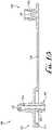
- Figures 17-18show a transfer lid 500 according to another example not in accordance with the present invention.
- the transfer lid 500is configured to be removably mounted to a bottle or container such that fluids or medicine contained within the container can be withdrawn or transferred therefrom and into a syringe S.
- the transfer lid 500is compatible with multiple fittings or couplings, for example, both enteral-only connectors and ENFit compatible connectors.
- the transfer lid 500comprises a generally circular top panel 510 with first and second transfer ports 512, 516 extending from the top panel 510 outwardly in a first or distal direction.
- the first transfer port 512comprises a conduit 514 and the second transfer port 516 comprises a conduit 520.
- the first transfer port 512comprises a male ENFit compatible connector and the second transfer port 516 comprises an enteral-only connector.
- An attachment collar 522extends in a second or proximal direction from the top panel 510, and an internal circumferential face thereof is threaded to releasably engage corresponding threads at the top of the containment shell of the container.
- An exterior circumferential face of the attachment collar 522 of the transfer lid 500optionally comprises spaced intentions, ridges, recesses, or other gripping features 524 to assist a user in installing and removing the transfer lid 500 onto and from the containment shell of the container.
- closures 540are provided for sealing with the first and second transfer ports 512, 516.
- one of the closures 540(e.g., for sealing with the first transfer port 512) comprises a first closure 542 comprising a flange or lip 544, a plug (unshown), an outer collar or lip 546, and a tether 547.
- a second closure 550is provided for sealingly engaging the second transfer port 516.
- the second closure 550comprises a flange or lip 552, a plug 554 and a tether 556.
- closures 540can be used independently of each other, for example such that one of them can be in the closed position and engaged with one of the transfer ports while the other one is in the open position and an end connector of a syringe is removably mounted to the other of the transfer ports.
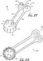
- Figures 19-20show a transfer lid 600 according to another example not in accordance with the present invention.
- the transfer lid 600is similarly configured to be removably mounted to a bottle or container such that fluids or medicine contained within the container can be withdrawn or transferred therefrom and into a syringe S.
- the transfer lid 500is compatible with multiple fittings or couplings, for example, both enteral-only connectors and ENFit compatible connectors.
- the transfer lid 600comprises a generally circular top panel 610 with a transfer port 612 extending from the top panel 610 outwardly in a first or distal direction.
- the transfer port 612comprises a conduit 614 extending entirely through the transfer port 612.
- the transfer port 612comprises an enteral-only connector, for example a female enteral-only connector according to one example.
- An attachment collar 616extends in a second or proximal direction from the top panel 610, and an internal circumferential face thereof is threaded to releasably engage corresponding threads at the top of the containment shell of the container or bottle.
- An exterior circumferential face of the attachment collar 616 of the transfer lid 600optionally comprises spaced intentions, ridges, recesses, or other gripping features 620 to assist a user in installing and removing the transfer lid 600 onto and from the containment shell of the container.
- an adapter 630 and a closure 642can be provided with the transfer lid 600.
- the adapter 630comprises a central flange member 632, a first connector 634, a second connector 636, and a conduit 640 extending entirely through the connectors 634, 636.
- the closure 642comprises a flange or lip 644, a plug 646, and an outer collar or lip 650.
- a tethergenerally connects the adapter 630 and closure 642 with the transfer lid 600.
- a first tether 652is provided for connecting the transfer lid 600 with the adapter 630
- a second tether 654is provided for connecting the adapter 630 with the closure 642.
- the transfer lid 600can be fastened to a bottle for facilitating the transfer of fluids between the bottle and the syringe.
- the transfer port 612can be utilized to facilitate the transfer of fluids therebetween.
- the adapter 630is connected with the transfer port 612, for example, such that the first connector 634 is coupled with the transfer port 612 and the second connector 636 is coupled with the ENFit compatible coupling of the syringe.
- the transfer lid 600accommodates both enteral-only and ENFit compatible connectors.
- a transfer lidcomprises a female enteral only coupling, and comprises an adapter tethered thereto such that the lid can accommodate both enteral-only and ENFit compatible connectors.
- the transfer lids 500, 600preferably provide multiple couplings such that connectors or syringes having either enteral-only or ENFit compatible couplings can be fitted therewith to facilitate the transfer of fluids between the bottle and syringe.
- Figures 21-25show a fluid transfer adapter 700 according to another example not in accordance with the present invention.
- the adapter 700comprises a flange or disc-shaped body 710 comprising a first end 712 and a second end 714.
- the disc-shaped body 710comprises a first surface 720 defining a first coupling 722 and a second surface 724 comprising a second coupling 726.
- a conduit 730extends entirely through the couplings 722, 726 from the first end 712 to the second end 714.
- the first coupling 722is generally centrally-positioned on the body and extends towards the first end 712
- the second coupling 726is generally axially aligned with the first coupling 722 and extends towards the second end 714.
- the first coupling 722comprises a male ENFit compatible coupling and the second coupling 726 comprises a male enteral-only coupling.
- the adapter 700can preferably be used with both conventional "press-in" and stepped bottle adapters PA, SA.
- conventional bottle adaptersgenerally comprise an enteral-only fitting
- the second coupling 726is configured for engagement with the enteral-only fitting of the bottle adapters PA, SA
- the first coupling 722is a male ENFit compatible coupling configured for providing engagement with an ENFit compatible coupling, for example, a female ENFit compatible coupling FC of a syringe S.
- the male ENFit compatible connectorcan be configured for a slip / friction fit connection, or can comprise one or more coupling elements for permanent / removable engagement with a portion of the female ENFit compatible connector of the syringe, for example, one or more ribs or threads of the female ENFit compatible connector.
- the male ENFit compatible connectorcan comprise other coupling or engagement features, for example, one or more flexible clips or other couplings such that permanent or removable engagement can be provided between the male ENFit connector and the female ENFit connector of the syringe.
- the disc-shaped body 710is preferably sized and configured to prevent the fluid transfer adapter or any portions thereof from presenting a choking hazard, for example for young children.
- the fluid transfer adapter including the flangehas a minimum dimension of at least about 2.25 inches (57.2 mm) by at least about 1.25 inches (31.8 mm), or is otherwise sized and configured to prevent the fluid transfer adapterfrom passing through a 2.25 inches ⁇ 1.25 inches (57.2 ⁇ 31.8 mm) choke test cylinder in compliance with 37 C.F.R. 1501.4
- the flangecomprises a circular disc having a diameter D 2 of at least about 2.25 inches (57.2 mm), for example 21 ⁇ 2 inches (63.5 mm) or 3 inches (76.2 mm).
- the flangemay have a square, rectangular, polygonal, elliptical or otherwise shaped configuration, and/or may be larger or smaller than the above specified dimensions, for example 11 ⁇ 2 inches (38.1 mm), 4 inches (101.6 mm), etc.
- one or more openingscan be formed within one or more portions of the body as desired.
- at least a portion of the bodyis shaped to provide a gripping surface or feature to facilitate the gripping thereof, for example, when connecting the adapter with the bottle adapter and the syringe, or for example, when it is desired to disengage the adapter from either of the syringe or the bottle adapter.
- the male ENFit compatible connector of the adapteris replaced with a female ENFit compatible connector, for example, such that a syringe comprising a male ENFit compatible connector can be connected to the pharmacy bottle adapter.
- the disc-shaped body 710is substantially uniform and comprises a substantially radiused outer periphery, for example, wherein a generally uniform radiused edge is defined between the upper and lower surfaces of the disc-shaped body, and wherein a substantially smooth transition is provided between the surfaces 720, 724.
- the outer diameter D 2 of the body 710is at least about 2.25 inches (57.2 mm)
- a thickness T 1 that is defined between the upper and lower surfaces 720, 724is between about 1 - 10 millimeters, for example between about 2 - 8 millimeters according to some examples.
- the thickness T 1is about 2 millimeters.
- the thickness, at least of the outer periphery portion of the adaptercan be more or less than 2 millimeters as desired.
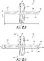
- Figures 26-29show a plurality of fluid transfer adapters 800, 900, 1000, 1100 according to additional examples.
- the outer periphery of each of the adapters 800, 900, 1000 and 1100has been modified with respect to the substantially radiused outer periphery 732 of the adapter 700.
- the radiused outer periphery 832further includes an outer rim extension 834 extending towards the second end 814, and thereby defining a recess 836 therein.
- the thickness T 2is between about 3 - 5 millimeters.
- the recess 836is sized for receiving the large coupling end of the stepped connector (see Figure 22 ).
- Figure 27shows a similar adapter 900, for example, comprising an outer rim extension 934 and a recess 936.
- one or more openings 940can be formed through the body 910.
- the thickness T 3is between about 2 - 5 millimeters.
- the openingsare generally cylindrical.
- the openingscan be spaced along a radial and/or linear array, and can be sized and shaped as desired.
- a circular array of five generally cylindrical openingsextend entirely through the body.
- the openingsare substantially uniform (e.g., generally the same size and equally spaced apart), and an edge defining each opening is radiused to provide a smooth transition between the surfaces of the body.
- the bodycan define a plurality of openings, for example, an outer and inner array of circular openings.
- the outer arraycomprises about twelve openings and the inner array comprises about twelve openings.
- the openings of the outer and inner arrayare both generally circular in shape, and wherein the openings of the outer array are substantially larger than the openings of the inner array.
- the disc-shaped bodycan comprise a matrix of openings formed through at least a portion of the disc-shaped body.
- the disc-shaped bodycan comprise a matrix of square openings formed through the body.
- the openingscan be shaped as desired. According to examples, the openings provide for an enhanced gripping surface, for example, such that the body can be easily grasped by a user and manipulated.
- Figure 28shows an adapter 1000 comprising an outer periphery having a T-shaped cross-sectional shape, for example comprising outer rim extensions 1034 extending oppositely therefrom towards their respective ends 1012, 1014.
- the thickness T 4is between about 3 - 8 millimeters.
- Figure 29shows an adapter 1100 according to another example.
- the body 1110comprises a radiused outer periphery 1132 and recesses 1036.
- the radiused outer periphery 1132protrudes at least partially above the first and second surfaces 1120, 1124 and defines a thickness T 5 of between about 1 - 4 millimeters.
- the at least partially raised radiused outer periphery 1132provides a gripping feature.
Landscapes
- Health & Medical Sciences (AREA)
- General Health & Medical Sciences (AREA)
- Pharmacology & Pharmacy (AREA)
- Life Sciences & Earth Sciences (AREA)
- Animal Behavior & Ethology (AREA)
- Public Health (AREA)
- Veterinary Medicine (AREA)
- Mechanical Engineering (AREA)
- Engineering & Computer Science (AREA)
- Physics & Mathematics (AREA)
- Fluid Mechanics (AREA)
- Infusion, Injection, And Reservoir Apparatuses (AREA)
- Medical Preparation Storing Or Oral Administration Devices (AREA)
Description
- The present invention relates generally to the field of containment, storage and delivery of fluids, and more particularly to a capping device, bottle adaptor or fluid transfer coupling for facilitating the transfer of fluids between a container or pharmacy bottle and a syringe.
- Various containers are used for the collection, storage and delivery of fluids such as medications, supplements, breast milk, formula, and the like. For example, when dispensing fluid medications that are commonly stored in larger volumes in a pharmacy bottle, and dispensed in smaller prescribed quantities into a smaller container, a syringe may be used to measure and transfer the fluid. Often a transfer lid or cap is used on the larger volume container, allowing easy repeated dispensation from the container. Smaller volume containers typically accept "press-in" or stepped enteral-only adapters for transferring the fluids between the syringe and container.
- Continued improvements to the transfer and dispensation of fluids such as fluid medications is sought. It is to the provision of an improved fluid transfer connectors meeting these and other needs that the present invention is primarily directed.
WO2013/081699 ,US2006/0217679 ,GB2379253 US4,230,112 ,US5,921,419 ,US5,902,298 ,US2008/0015539 ,US2014/0299568 ,WO2014/077670 disclose prior art devices.- The invention is defined in the attached independent claim to which reference should now be made. Further, optional features may be found in the sub-claims appended thereto.
FIGURES 1 shows a bottle adapter connector according to an example embodiment of the present invention.FIGURE 2 shows the bottle adapter connector ofFigure 1 comprising a syringe coupled to a male port of the bottle adapter connector.FIGURE 3 shows the bottle adapter ofFigure 2 and showing the end coupling of the syringe removed from engagement with the male port.FIGURE 4 shows the bottle adapter and end coupling of the syringe ofFigure 3 , and showing the end coupling of the syringe comprising a dosing control coupling and being compatible for fitting with the male port of the bottle adapter connector.FIGURES 5-6 show a sequence of operation of a bottle adapter connector comprising a flexible floor surface and showing that closing a cap atop the connector causes retraction of the male port and sealing engagement with an interior surface of the cap.FIGURE 7 shows a bottle adapter connector according to another example embodiment of the present invention, showing a silicone sleeve wrapped around the male port for engagement with the end coupling of the syringe.FIGURE 8 shows a cross-sectional view ofFigure 7 taken along line8-8.FIGURE 9 shows the cross-sectional view ofFigure 8 , and showing the end coupling of the syringe engaging the male port such that the silicone sleeve is displaced to permit fluid flow between the syringe end coupling and the male coupling of the bottle adapter connector.FIGURE 10 shows a bottle adapter connector according to another example embodiment of the present invention, and showing the bottle adapter comprising a tethered cap for engagement with a male port of the connector.FIGURE 11 shows a perspective view of a cross-sectional view of the connector ofFigure 10 .FIGURES 12-13 show a sequence of operation of the bottle adapter connector and tethered cap ofFigure 10 , and showing cap being generally hinged to the connector to be moved between an open configuration and a closed or capped configuration.FIGURE 14 shows a perspective view of a bottle adapter transfer connector according to an example not in accordance with the present invention, and showing a bottle adapter connector engaged with a portion of the bottle adapter transfer connector.FIGURE 15 shows a perspective cross-sectional view of the bottle adapter transfer connector coupled to a portion of the bottle adapter connector shown inFigure 14 .FIGURE 16 shows a cross-sectional view of the bottle adapter transfer connector ofFigure 15 .FIGURE 17 shows a perspective view of a fluid transfer lid according to another example not in accordance with the present invention.FIGURE 18 shows a rear perspective view of the fluid transfer lid ofFigure 17 .FIGURE 19 shows a perspective view of a fluid transfer lid according to another example not in accordance with the present invention.FIGURE 20 shows a rear perspective view of the fluid transfer lid ofFigure 19 .FIGURES 21-22 show a fluid transfer adapter according to another example not in accordance with the present invention, the fluid transfer adapter being compatible for removable engagement with both a conventional enteral-only ported press-in bottle adapter and an enteral-only stepped bottle adapter.FIGURE 23 shows a perspective view of a first side of the fluid transfer adapter ofFigures 21-22 .FIGURE 24 shows a second side of the fluid transfer adapter ofFigure 23 .FIGURE 25 shows a cross-sectional view of the fluid transfer adapter ofFigure 23 taken along line25-25.FIGURE 26 shows a cross-sectional view of a fluid transfer adapter according to another example not in accordance with the present invention.FIGURE 27 shows a cross-sectional view of a fluid transfer adapter according to another example not in accordance with the present invention.FIGURE 28 shows a cross-sectional view of a fluid transfer adapter according to another example not in accordance with the present invention.FIGURE 29 shows a cross-sectional view of a fluid transfer adapter according to another example not in accordance with the present invention.- The present invention may be understood more readily by reference to the following detailed description of the invention taken in connection with the accompanying drawing figures, which form a part of this disclosure.
- The invention is defined by the claims. Some of the example embodiments in the following description and the accompanying drawing figures fall under the claimed subject-matter, some of them do not.
- With reference now to the drawing figures, wherein like reference numbers represent corresponding parts throughout the several views,
Figures 1-29 show several example embodiments of fluid transfer connectors and adapters for providing the transfer of fluid or medicine from a container or pharmacy bottle to a syringe S, or for example, from the syringe S to the bottle. According to other example embodiments, the fluid transfer connectors and adapters of the present invention are configured for providing engagement between an end connector FC of a syringe S and a conventional enteral-only ported press-in bottle adapter, or for example, a stepped adapter comprising an enteral-only port. - According to example embodiments, the fluid transfer connectors of the present invention comprise ENFit compatible connectors and are configured for coupling engagement with ENFit connectors, for example, according to the ENFit design standard, ISO 80369-3. Preferably, the fluid transfer connectors can be sized as desired, for example, to accommodate coupling with containers or bottles of different sized openings. According to some example forms of the invention, the fluid transfer connectors comprise both enteral-only connectors and ENFit compatible connectors, for example, for providing compatible coupling engagement with enteral-only connectors and ENFit compatible connectors. Preferably, any of the fluid transfer connectors as described herein can comprise both enteral-only and ENFit compatible connectors as desired.
Figures 1-4 show abottle adapter connector 10 according to an example embodiment of the present invention. In example embodiments, thebottle adapter connector 10 comprises acylindrical body 12 comprising an outerperipheral surface 13 that defines a plurality of outer peripheral flanges orsteps 14. In example embodiments, the flanges orsteps 14 are preferably flexible, resilient and sized to engage with bottle openings of a desirable size. For example, according to example embodiments, thebottle adapter connector 10 is in the form of a "press-in" adapter, for example, such that the flanges orsteps 14 along the outerperipheral surface 13 generally frictionally engage the opening of a bottle, for example, the opening of a pharmacy or medicine bottle. In example forms, commonly used bottles most frequently used in medicine practice range between about 2 - 16 ounces (56.7 - 453.6 g), and the opening thereof will generally vary according to its volume. In example embodiments, theconnector 10 can be sized as desired, but can at least be provided in sizes compatible with bottle sizes (and the openings thereof) most frequently used in medicine practice, for example, between a diameter D1 of about 10 - 40 millimeters, and between about 12 - 38 millimeters according to one example embodiment (seeFigures 1 and5 ). In example embodiments, the bottle opening or inner diameter thereof is generally between about 12 - 33 millimeters. In example embodiments, theflanges 14 are generally laterally offset from each other and extend around the entirety of the body to define a continuous flange for providing frictional and sealing engagement with an internal surface or opening of a bottle or container. In example embodiments, theflanges 14 are laterally offset and extend along the length or height H of theconnector 10, for example, between the upper and lower surfaces of thebody flanges 14 are resilient and flexible such that theadapter connector 10 can engage a bottle opening having an inner diameter range of up to about 4-5 millimeters difference with respect to the adapter connector diameter. For example, if the bottle opening inner diameter is about 12 millimeters, the diameter D1 of theconnector 10 can be up to about 17 millimeters and still provide for fitting and sealing engagement with the bottle opening.- In example embodiments, the
connector 10 comprises arecess 16 defined by an innerperipheral surface 18 of thebody 12, a base member orfloor 20, and a male coupling generally centrally-positioned on thefloor 20 and extending towards theupper surface 15a. In example embodiments, acentral conduit 24 extends entirely through themale coupling 22 along an elongate axis Y that is generally centrally-positioned in thefloor 20 and axially aligned with thebody 12. In example embodiments, the end coupling FC of a syringe S is compatible for removable engagement with themale coupling 22, for example, such that the syringe can be coupled to theconnector 10 to allow transfer of the fluids or medicine between the syringe S and the pharmacy bottle, from the pharmacy bottle to the syringe or from the syringe to the pharmacy bottle. In example embodiments, themale coupling 22 can comprise a male ENFit compatible coupling and the end coupling FC can comprise a female ENFit compatible coupling. According to some example embodiments, the syringe S can comprise a dosing control coupling or low dose tip LT, for example, which is compatible for fitting within theconduit 24 when the end coupling FC is coupled with themale coupling 22, and which preferably substantially if not entirely eliminates dosing inaccuracies (seeFigure 4 ).U.S. Published Patent Application Serial No. 15/210,282 , Patent Application Publication No.US 2016/0317393 , shows a syringe including a dosing control coupling. Figures 5-6 show aconnector 100 according to another example embodiment of the present invention. In example embodiments, theconnector 100 is generally similar to theconnector 10 as described above and comprises an outer collar body comprising a plurality of outer peripheral flanges orsteps 114, arecess portion 116 defined by afloor surface 120, amale coupling 122 centrally positioned and extending from thefloor surface 120, and acentral conduit 124 extending entirely through themale coupling 122. According to example embodiments, themale coupling 122 extends from the floor surface 120 a distance X above the upper surface 115a of thebody 112 comprising the outerperipheral surface 113 having the flanges or steps 114. In example embodiments, the distance X is generally between about 0.5 - 6 millimeters. As depicted inFigure 6 , closure of a lid or cap L atop theconnector 100 causes engagement of a surface of the cap L with an end of themale coupling 122, for example, such that themale coupling 122 is generally axially displaced along axis Y within therecess portion 116. In example embodiments, thefloor surface 120 is preferably at least partially resilient and flexible to allow for axial displacement of themale coupling 122. Thus, according to example embodiments of the present invention, thefloor surface 120 undergoes at least some amount of elastic deformation between when themale coupling 122 is in its neutral state and when the cap L is fastened to the bottle to cause displacement of themale coupling 122. Preferably, by displacing the male coupling within therecess 116 when the cap L is coupled to the bottle, an end portion of themale coupling 122 is sealingly engaged with the surface of the cap L, for example, such that fluids or medicine within the bottle are prevented from passing through theconduit 124 when the cap L is coupled to the bottle. In example embodiments, the cap L can comprise an anti-tamper or child-resistant lid. Alternatively, the end portion of themale coupling 122 can be configured as desired, for example, to be generally recessed below the upper portion of the collar body, or to be generally flush or planar with the end portion of the collar body. Optionally, a one-way or two-way seal can be provided within at least a portion of theconduit 124, for example, to provide a seal within theconduit 124 when not in use and allow for functionality and transfer of the fluids during use. In one example embodiment, the seal is provided in the conduit rear an upper portion of themale coupling 122. Optionally, the seal is provided in theconduit 124 near thefloor surface 120. Further optional, the seal is provided in theconduit 124 between the ends of themale coupling 122.- In example embodiments, the
floor surface 120 can be configured to provide at least some amount of flexure or elasticity such that themale coupling 122 can axially move when engaged with the cap L. In some example embodiments, thefloor surface 120 can be substantially thin relative to the other portions of theconnector 100, or can be formed from one or more flexible and resilient materials that allow for at least some displacement. According to one example embodiment, thefloor surface 120 can be formed from a different material relative to the material forming the rest of theconnector 100. For example, in some example embodiments, thefloor surface 120 can be co-molded or comprise a mixture of two or more materials such that thefloor surface 120 exhibits a greater amount of flexibility and elasticity compared to the other components or features of theconnector 100. Figures 7-9 show aconnector 200 according to another example embodiment of the present invention. In example embodiments, theconnector 200 is generally similar to theconnectors body 12 comprising an outerperipheral surface 213 having a plurality of outer peripheral flanges orsteps 214, arecess portion 216 defining afloor surface 220, amale coupling 222 centrally positioned and extending from thefloor surface 220, and acentral conduit 224 extending entirely through themale coupling 222. In example embodiments, theconnector 200 further comprises anouter collar 226 generally centrally positioned and surrounding themale coupling 222. In example embodiments, asealing mechanism 228 is preferably provided for substantially sealing theconduit 224 of themale coupling 222 from the elements, for example, by fitting itself around themale coupling 222 and within theouter collar 226. In example embodiments, the seal mechanism comprises a substantially resilient grommet orsleeve 230 that is substantially cylindrical with a first open end for receiving themale coupling 222 and whereby the collar is fitted within a recessed portion defined between theouter collar 226 and themale coupling 222. In example embodiments, thesleeve 230 comprises a second open end that is substantially closed except for a substantially smallcentral opening 232, for example, which generally defines an opening sized between about 0.10 -1.5 millimeters, for example about 0.50 millimeter according to one example embodiment.- As depicted in
Figures 8-9 , engagement of the end coupling FC of the syringe S with themale coupling 222 causes deformation of thesleeve 230, for example, such that thesleeve 230 is generally deformed and displaced within the recess so that fluid communication is provided between the end coupling FC and the male coupling 222 (e.g., the male coupling is received within the end coupling FC). As shown inFigure 9 , theopening 232 is substantially flexible and elastic so that the entirety of thesleeve 230 passes beyond the end portion of themale coupling 222 to permit communication of theconduit 224 with the end coupling FC. Retraction of the end coupling FC preferably causes thesleeve 230 to expand back to its neutral state such that the sleeve substantially seals theconduit 224 from the elements. In example embodiments, thesleeve 230 is formed from silicone or other resilient and substantially deformable materials (or combinations thereof). Accordingly, when theconnector 200 is fitted within a bottle opening, thesleeve 230 preferably substantially seals theconduit 224 of themale coupling 222 such that the fluid or medicine within the bottle is not exposed to the elements. And when it is desired to transfer fluids between the bottle and the syringe S, without any additional steps of removing a closure or other seal, the end coupling FC is pressed atop thesleeve 230 such that thesleeve 230 deforms to retract therein to expose themale coupling 222 for engaging the end coupling FC. Furthermore, when a cap L is coupled to the opening of the bottle with theconnector 200 fitted therein, a portion of the cap (e.g., internal surface) can engage with thesleeve 230 to apply a force thereon. Figures 10-13 show aconnector 300 according to another example embodiment of the present invention. In example embodiments, theconnector 300 is generally similar to theconnectors body 312 comprising an outerperipheral surface 313 having a plurality of outer peripheral flanges orsteps 314, arecess portion 316 defining afloor 320, amale coupling 322 centrally positioned and extending from thefloor 320, and acentral conduit 324 extending entirely through themale coupling 222. According to example embodiments, the connector comprises a cap orclosure 326 that is hingedly mounted to a portion of theconnector 300 for pivoting between an open configuration (seeFigure 12 ) and a closed configuration (seeFigure 13 ). In example embodiments, theclosure 326 comprises anouter collar 330, acentral plug 322, and atether 334 connecting theclosure 326 to a portion of theconnector 300. In example embodiment, thetether 334 integrally couples theclosure 326 to theconnector 300. Optionally, the tether can be removably coupled to theconnector 300.- In example embodiments, the
tether 334 extends outwardly from an upper portion of thebody 12 near the outerperipheral flanges 314. Preferably, thetether 334 comprises a living hinge such that theclosure 326 coupled thereto is pivotable between the open and closed configurations. In example embodiments, the living hinge is substantially flexible and resilient to permit theclosure 326 to pivot at least about 180 degrees. In example embodiments, themale coupling 322 is substantially shorter than the male couplings as described above, for example, such that a cap L can be fitted and coupled to the bottle with theclosure 326 in the closed configuration and sealed with themale coupling 322. Thus, according to one example embodiment of the present invention, theclosure 326, when sealingly engaged with themale coupling 322 and in the closed configuration (e.g., with thecentral plug 332 fitted within theconduit 324 and thecollar 330 surrounding the male coupling 322), is generally at least about flush with the upper portion of the outer collar body, for example, to allow coupling engagement of the cap L with the bottle. As depicted inFigure 13 , the tether 334 (and hinge thereof) is generally configured to be about concentric with the outermost surfaces of theflanges 314. Optionally, the tether and hinge can be sized as desired, for example, wherein in the closed position the hinge remains inwardly offset from the outermost surfaces of the flanges and does not engage with a surface of the bottle opening when engaged therewith. Figures 14-16 show a bottleadapter transfer connector 400 according to an example not in accordance with the present invention. In examples, theconnector 400 provides for the transfer of fluids between a syringe S and a medicine bottle, for example wherein a stepped adapter SA is configured for engagement with the opening of the bottle and wherein theconnector 400 removably couples to theconnector 400 and facilitates the coupling engagement of the end connector FC of the syringe S therewith. In examples, theconnector 400 comprises acylindrical cap 412, acollar 414 generally extending perpendicularly from thecap 412, amale coupling 416 centrally-positioned and extending from thecap 412 in a first direction, and anengagement port 420 axially aligned with themale coupling 416 and extending in the second direction. In examples, a conduit extends entirely through the male coupling and engagement port, for example, such that fluids are permitted to flow therethrough. In examples, theengagement port 420 comprises abarbed feature 424, which preferably provides a surface feature capable of engagement with a port or conduit of the stepped adapter SA (seeFigure 15 ). In examples, thecollar 414 is preferably sized and shaped to be fitted around an upper outer periphery portion of the stepped adapter SA. In examples, themale coupling 416 comprises a male ENFit compatible coupling. In examples, theengagement port 420 is preferably sized to provide sufficient frictional engagement with the conduit of the stepped adapter SA. In examples, the conduit of the stepped adapter SA is generally sized to be compatible with a male enteral-only coupling.- In examples, a
closure 430 can be provided for sealing theconduit 422 from the elements. In examples, theclosure 430 comprises anouter collar member 432, a central plug configured for frictional engagement with theconduit 422. In examples, theclosure 430 can be tethered to theconnector 400, for example whereintether 436 is generally flexible and resilient to allow for positioning theclosure 430 in either of the open or closed configurations. Figures 17-18 show atransfer lid 500 according to another example not in accordance with the present invention. In examples, thetransfer lid 500 is configured to be removably mounted to a bottle or container such that fluids or medicine contained within the container can be withdrawn or transferred therefrom and into a syringe S. Preferably, thetransfer lid 500 is compatible with multiple fittings or couplings, for example, both enteral-only connectors and ENFit compatible connectors. In examples, thetransfer lid 500 comprises a generally circulartop panel 510 with first andsecond transfer ports top panel 510 outwardly in a first or distal direction. In examples, thefirst transfer port 512 comprises aconduit 514 and thesecond transfer port 516 comprises aconduit 520. In examples, thefirst transfer port 512 comprises a male ENFit compatible connector and thesecond transfer port 516 comprises an enteral-only connector.- An
attachment collar 522 extends in a second or proximal direction from thetop panel 510, and an internal circumferential face thereof is threaded to releasably engage corresponding threads at the top of the containment shell of the container. An exterior circumferential face of theattachment collar 522 of thetransfer lid 500 optionally comprises spaced intentions, ridges, recesses, or othergripping features 524 to assist a user in installing and removing thetransfer lid 500 onto and from the containment shell of the container. Optionally,closures 540 are provided for sealing with the first andsecond transfer ports first closure 542 comprising a flange orlip 544, a plug (unshown), an outer collar orlip 546, and atether 547. Similarly, asecond closure 550 is provided for sealingly engaging thesecond transfer port 516. In examples, thesecond closure 550 comprises a flange orlip 552, aplug 554 and atether 556. In examples, theclosures 540 can be used independently of each other, for example such that one of them can be in the closed position and engaged with one of the transfer ports while the other one is in the open position and an end connector of a syringe is removably mounted to the other of the transfer ports. Figures 19-20 show atransfer lid 600 according to another example not in accordance with the present invention. In examples, thetransfer lid 600 is similarly configured to be removably mounted to a bottle or container such that fluids or medicine contained within the container can be withdrawn or transferred therefrom and into a syringe S. Preferably, thetransfer lid 500 is compatible with multiple fittings or couplings, for example, both enteral-only connectors and ENFit compatible connectors. In examples, thetransfer lid 600 comprises a generally circulartop panel 610 with atransfer port 612 extending from thetop panel 610 outwardly in a first or distal direction. In examples, thetransfer port 612 comprises aconduit 614 extending entirely through thetransfer port 612. In examples, thetransfer port 612 comprises an enteral-only connector, for example a female enteral-only connector according to one example. Anattachment collar 616 extends in a second or proximal direction from thetop panel 610, and an internal circumferential face thereof is threaded to releasably engage corresponding threads at the top of the containment shell of the container or bottle. An exterior circumferential face of theattachment collar 616 of thetransfer lid 600 optionally comprises spaced intentions, ridges, recesses, or othergripping features 620 to assist a user in installing and removing thetransfer lid 600 onto and from the containment shell of the container.- In examples, an
adapter 630 and aclosure 642 can be provided with thetransfer lid 600. For example, according to examples, theadapter 630 comprises acentral flange member 632, afirst connector 634, asecond connector 636, and aconduit 640 extending entirely through theconnectors closure 642 comprises a flange orlip 644, aplug 646, and an outer collar orlip 650. In examples, a tether generally connects theadapter 630 andclosure 642 with thetransfer lid 600. For example, according to one example, afirst tether 652 is provided for connecting thetransfer lid 600 with theadapter 630, and asecond tether 654 is provided for connecting theadapter 630 with theclosure 642. In use, thetransfer lid 600 can be fastened to a bottle for facilitating the transfer of fluids between the bottle and the syringe. If the syringe comprises a male enteral-only end coupling, thetransfer port 612 can be utilized to facilitate the transfer of fluids therebetween. If the syringe S comprises a ENFit compatible coupling, theadapter 630 is connected with thetransfer port 612, for example, such that thefirst connector 634 is coupled with thetransfer port 612 and thesecond connector 636 is coupled with the ENFit compatible coupling of the syringe. - Accordingly, by the tethered
adapter 630, thetransfer lid 600 accommodates both enteral-only and ENFit compatible connectors. Accordingly, according to one example, a transfer lid comprises a female enteral only coupling, and comprises an adapter tethered thereto such that the lid can accommodate both enteral-only and ENFit compatible connectors. As such, thetransfer lids Figures 21-25 show afluid transfer adapter 700 according to another example not in accordance with the present invention. As depicted, theadapter 700 comprises a flange or disc-shapedbody 710 comprising afirst end 712 and asecond end 714. The disc-shapedbody 710 comprises afirst surface 720 defining afirst coupling 722 and asecond surface 724 comprising asecond coupling 726. Aconduit 730 extends entirely through thecouplings first end 712 to thesecond end 714. In examples, thefirst coupling 722 is generally centrally-positioned on the body and extends towards thefirst end 712, and thesecond coupling 726 is generally axially aligned with thefirst coupling 722 and extends towards thesecond end 714. In examples, thefirst coupling 722 comprises a male ENFit compatible coupling and thesecond coupling 726 comprises a male enteral-only coupling.- As shown in
Figures 21-22 , theadapter 700 can preferably be used with both conventional "press-in" and stepped bottle adapters PA, SA. For example, as conventional bottle adapters generally comprise an enteral-only fitting, thesecond coupling 726 is configured for engagement with the enteral-only fitting of the bottle adapters PA, SA, while thefirst coupling 722 is a male ENFit compatible coupling configured for providing engagement with an ENFit compatible coupling, for example, a female ENFit compatible coupling FC of a syringe S. In example forms, the male ENFit compatible connector can be configured for a slip / friction fit connection, or can comprise one or more coupling elements for permanent / removable engagement with a portion of the female ENFit compatible connector of the syringe, for example, one or more ribs or threads of the female ENFit compatible connector. In alternate examples, the male ENFit compatible connector can comprise other coupling or engagement features, for example, one or more flexible clips or other couplings such that permanent or removable engagement can be provided between the male ENFit connector and the female ENFit connector of the syringe. - In examples, the disc-shaped
body 710 is preferably sized and configured to prevent the fluid transfer adapter or any portions thereof from presenting a choking hazard, for example for young children. In examples, the fluid transfer adapter including the flange has a minimum dimension of at least about 2.25 inches (57.2 mm) by at least about 1.25 inches (31.8 mm), or is otherwise sized and configured to prevent the fluid transfer adapterfrom passing through a 2.25 inches × 1.25 inches (57.2 × 31.8 mm) choke test cylinder in compliance with 37 C.F.R. 1501.4 According to one example, the flange comprises a circular disc having a diameter D2 of at least about 2.25 inches (57.2 mm), for example 2½ inches (63.5 mm) or 3 inches (76.2 mm). In alternate examples, the flange may have a square, rectangular, polygonal, elliptical or otherwise shaped configuration, and/or may be larger or smaller than the above specified dimensions, for example 1½ inches (38.1 mm), 4 inches (101.6 mm), etc. Optionally, one or more openings can be formed within one or more portions of the body as desired. In examples, at least a portion of the body is shaped to provide a gripping surface or feature to facilitate the gripping thereof, for example, when connecting the adapter with the bottle adapter and the syringe, or for example, when it is desired to disengage the adapter from either of the syringe or the bottle adapter. According to another example, the male ENFit compatible connector of the adapter is replaced with a female ENFit compatible connector, for example, such that a syringe comprising a male ENFit compatible connector can be connected to the pharmacy bottle adapter. - As shown in
Figure 25 , the disc-shapedbody 710 is substantially uniform and comprises a substantially radiused outer periphery, for example, wherein a generally uniform radiused edge is defined between the upper and lower surfaces of the disc-shaped body, and wherein a substantially smooth transition is provided between thesurfaces body 710 is at least about 2.25 inches (57.2 mm), and a thickness T1 that is defined between the upper andlower surfaces Figures 26-29 show a plurality offluid transfer adapters adapters outer periphery 732 of theadapter 700. As depicted inFigure 26 , the radiusedouter periphery 832 further includes anouter rim extension 834 extending towards thesecond end 814, and thereby defining arecess 836 therein. In examples, the thickness T2 is between about 3 - 5 millimeters. According to one example form, therecess 836 is sized for receiving the large coupling end of the stepped connector (seeFigure 22 ).Figure 27 shows asimilar adapter 900, for example, comprising anouter rim extension 934 and arecess 936. According to one example, one ormore openings 940 can be formed through thebody 910. The thickness T3 is between about 2 - 5 millimeters. According to one example, the openings are generally cylindrical. Optionally, the openings can be spaced along a radial and/or linear array, and can be sized and shaped as desired.- According to one example, a circular array of five generally cylindrical openings extend entirely through the body. In examples, the openings are substantially uniform (e.g., generally the same size and equally spaced apart), and an edge defining each opening is radiused to provide a smooth transition between the surfaces of the body. According to another example, the body can define a plurality of openings, for example, an outer and inner array of circular openings. According to examples, the outer array comprises about twelve openings and the inner array comprises about twelve openings. In examples, the openings of the outer and inner array are both generally circular in shape, and wherein the openings of the outer array are substantially larger than the openings of the inner array. In alternate examples, the disc-shaped body can comprise a matrix of openings formed through at least a portion of the disc-shaped body. For example, the disc-shaped body can comprise a matrix of square openings formed through the body. Optionally, the openings can be shaped as desired. According to examples, the openings provide for an enhanced gripping surface, for example, such that the body can be easily grasped by a user and manipulated.
Figure 28 shows anadapter 1000 comprising an outer periphery having a T-shaped cross-sectional shape, for example comprisingouter rim extensions 1034 extending oppositely therefrom towards theirrespective ends Figure 29 shows anadapter 1100 according to another example. As depicted, thebody 1110 comprises a radiusedouter periphery 1132 and recesses 1036. According to one example, the radiusedouter periphery 1132 protrudes at least partially above the first andsecond surfaces outer periphery 1132 provides a gripping feature.- While the invention has been described with reference to preferred and example embodiments, it will be understood by those skilled in the art that a variety of modifications, additions and deletions are within the scope of the invention, as defined by the following claims.
Claims (12)
- A bottle adapter connector comprising:a generally cylindrical body comprising an outer peripheral surface (13, 113, 213, 313) having an outer diameter (Di) at an upper end and a lower end of the body and a length (H) extending from the upper end to the lower end of the body, and an inner peripheral surface (18); anda recess (16, 116, 216, 316) defined by the inner peripheral surface (18) of the body, a base member (20, 120, 220), and a male coupling (22, 122, 222, 322, 416) generally centrally positioned on the base member (20, 120, 220), the male coupling (22, 122, 222, 322, 416) comprising a conduit (124, 224, 422, 514, 520, 614, 640, 730) extending therethrough;characterized in that:the outer peripheral surface (13, 113, 213, 313) of the body defines a plurality of outer peripheral flanges or steps (14, 114, 214, 314) that are flexible, resilient and configured to press-in and frictionally engage the opening of a bottle, wherein the plurality of outer peripheral flanges or steps (14, 114, 214, 314) are laterally offset from each other extending along the entire length (H) of the body; andthe bottle adapter connector is configured to engage a bottle opening having an interior diameter of up to 5 millimetres difference with respect to the diameter (D1) of the body.
- The bottle adapter of Claim 1, wherein the male coupling (22, 122, 222, 322, 416) comprises a male ENFit compatible coupling.
- The bottle adapter of Claim 2, wherein the male ENFit compatible coupling is configured for engagement with a female ENFit compatible coupling.
- The bottle adapter of Claim 3, wherein the female ENFit compatible coupling further comprises a dosing control coupling for extension within a portion of the conduit (124, 224, 422, 514, 520, 614, 640, 730) of the male ENFit compatible coupling.
- The bottle adapter of Claim 1, wherein the male coupling (22, 122, 222, 322, 416) extends from the base member (20, 120, 220) into the recess (16, 116, 216, 316).
- The bottle adapter of Claim 5, wherein the bottle adapter comprises a diameter of between about 12 - 28 millimeters.
- The bottle adapter of Claim 1, further comprising an outer collar (226) and a sealing mechanism (228), the sealing mechanism (228) configured for fitting around the male coupling (22, 122, 222, 322, 416) and within a recess defined between the outer collar (226) and the male coupling (22, 122, 222, 322, 416).
- The bottle adapter of Claim 7, wherein the sealing mechanism (228) comprises a resilient grommet (230) comprising a first open end for receiving the male coupling (22, 122, 222, 322, 416) and a substantially closed second end (714, 814).
- The bottle adapter of Claim 8, wherein the resilient grommet (230) is formed from silicone.
- The bottle adapter of Claim 1, further comprising a cap (412) tethered to the body of the bottle adapter.
- The bottle adapter of Claim 1, wherein the base member (20, 120, 220) is substantially flexible and elastically deformable such that the male coupling (22, 122, 222, 322, 416) is movable in an axial direction.
- The bottle adapter of Claim 11, wherein the male coupling (22, 122, 222, 322, 416) extends beyond an end of the body such that closure of a cap (412) atop the connector causes axial displacement of the male coupling (22, 122, 222, 322, 416), and wherein the conduit (124, 224, 422, 514, 520, 614, 640, 730) is generally sealed with the cap (412).
Applications Claiming Priority (4)
| Application Number | Priority Date | Filing Date | Title |
|---|---|---|---|
| US201662299210P | 2016-02-24 | 2016-02-24 | |
| US201662384848P | 2016-09-08 | 2016-09-08 | |
| US201662423484P | 2016-11-17 | 2016-11-17 | |
| PCT/US2017/019021WO2017147233A2 (en) | 2016-02-24 | 2017-02-23 | Fluid transfer connector |
Publications (2)
| Publication Number | Publication Date |
|---|---|
| EP3419582A2 EP3419582A2 (en) | 2019-01-02 |
| EP3419582B1true EP3419582B1 (en) | 2022-07-13 |
Family
ID=58266732
Family Applications (1)
| Application Number | Title | Priority Date | Filing Date |
|---|---|---|---|
| EP17710441.1AActiveEP3419582B1 (en) | 2016-02-24 | 2017-02-23 | Fluid transfer connector |
Country Status (4)
| Country | Link |
|---|---|
| US (2) | US10857068B2 (en) |
| EP (1) | EP3419582B1 (en) |
| CA (1) | CA3015885A1 (en) |
| WO (1) | WO2017147233A2 (en) |
Families Citing this family (46)
| Publication number | Priority date | Publication date | Assignee | Title |
|---|---|---|---|---|
| US10773863B2 (en) | 2011-06-22 | 2020-09-15 | Sartorius Stedim North America Inc. | Vessel closures and methods for using and manufacturing same |
| US10576020B2 (en) | 2015-06-18 | 2020-03-03 | Neomed, Inc. | Syringe-to-syringe coupler |
| US10773067B2 (en) | 2014-09-08 | 2020-09-15 | Neomed, Inc. | Enteral connectors having coupling features |
| USD802743S1 (en) | 2014-12-08 | 2017-11-14 | Neomed, Inc. | Fluid transfer lid |
| USD825746S1 (en) | 2015-06-18 | 2018-08-14 | Neomed, Inc. | Syringe-to-syringe coupler |
| EP3424554B1 (en) | 2015-07-15 | 2023-11-22 | Avent, Inc. | Enteral adaptor couplings |
| US11166876B2 (en) | 2016-02-24 | 2021-11-09 | Neomed, Inc. | Fluid transfer connector |
| CA3015885A1 (en) | 2016-02-24 | 2017-08-31 | Neomed, Inc. | Fluid transfer connector |
| US11103676B2 (en) | 2016-04-22 | 2021-08-31 | Hollister Incorporated | Medical device package with flip cap having a snap fit |
| AU2017254706B2 (en) | 2016-04-22 | 2022-04-28 | Hollister Incorporated | Medical device package with a twist cap |
| USD833006S1 (en)* | 2016-11-28 | 2018-11-06 | Neomed, Inc. | Fluid transfer connector |
| US11097071B1 (en) | 2016-12-14 | 2021-08-24 | International Medical Industries Inc. | Tamper evident assembly |
| WO2018156589A2 (en) | 2017-02-21 | 2018-08-30 | Hollister Incorporated | Medical device package with flip cap having a snap fit |
| US10575887B2 (en)* | 2017-08-04 | 2020-03-03 | Medtronic Holding Company Sàrl | Dispensing system and methods of use |
| CA3079893A1 (en) | 2017-10-25 | 2019-05-02 | Hollister Incorporated | Caps for catheter packages |
| US12252391B2 (en) | 2017-11-14 | 2025-03-18 | Sartorius Stedim North America Inc. | System for simultaneous distribution of fluid to multiple vessels and method of using the same |
| JP2021503304A (en) | 2017-11-14 | 2021-02-12 | ザルトリウス ステディム ノース アメリカ インコーポレイテッド | Fluid transfer assembly with junctions with multiple fluid paths |
| US11691866B2 (en) | 2017-11-14 | 2023-07-04 | Sartorius Stedim North America Inc. | System for simultaneous distribution of fluid to multiple vessels and method of using the same |
| US11319201B2 (en) | 2019-07-23 | 2022-05-03 | Sartorius Stedim North America Inc. | System for simultaneous filling of multiple containers |
| US11577953B2 (en) | 2017-11-14 | 2023-02-14 | Sartorius Stedim North America, Inc. | System for simultaneous distribution of fluid to multiple vessels and method of using the same |
| US11666730B2 (en) | 2017-12-08 | 2023-06-06 | Hollister Incorporated | Package for medical device for ergonomic device removal |
| US11541180B1 (en) | 2017-12-21 | 2023-01-03 | Patrick Vitello | Closure assembly having a snap-fit construction |
| US11278681B1 (en) | 2018-02-20 | 2022-03-22 | Robert Banik | Tamper evident adaptor closure |
| US11413406B1 (en) | 2018-03-05 | 2022-08-16 | Jonathan J. Vitello | Tamper evident assembly |
| US11857751B1 (en) | 2018-07-02 | 2024-01-02 | International Medical Industries Inc. | Assembly for a medical connector |
| US11793987B1 (en) | 2018-07-02 | 2023-10-24 | Patrick Vitello | Flex tec closure assembly for a medical dispenser |
| US11779520B1 (en) | 2018-07-02 | 2023-10-10 | Patrick Vitello | Closure for a medical dispenser including a one-piece tip cap |
| US11690994B1 (en)* | 2018-07-13 | 2023-07-04 | Robert Banik | Modular medical connector |
| US11426328B1 (en) | 2018-08-31 | 2022-08-30 | Alexander Ollmann | Closure for a medical container |
| CA186896S (en)* | 2018-10-04 | 2020-12-14 | Univ Yeditepe | Cap for a bottle |
| US11471610B1 (en) | 2018-10-18 | 2022-10-18 | Robert Banik | Asymmetrical closure for a medical device |
| USD948713S1 (en) | 2019-09-03 | 2022-04-12 | International Medical Industries, Inc. | Asymmetrical self righting tip cap |
| US11911339B1 (en) | 2019-08-15 | 2024-02-27 | Peter Lehel | Universal additive port cap |
| US11697527B1 (en) | 2019-09-11 | 2023-07-11 | Logan Hendren | Tamper evident closure assembly |
| US11357588B1 (en) | 2019-11-25 | 2022-06-14 | Patrick Vitello | Needle packaging and disposal assembly |
| US11904149B1 (en) | 2020-02-18 | 2024-02-20 | Jonathan Vitello | Oral tamper evident closure with retained indicator |
| US11918540B2 (en)* | 2020-04-23 | 2024-03-05 | Vonco Products, Llc | Cap for spout and modified spout |
| WO2022040108A1 (en)* | 2020-08-17 | 2022-02-24 | LactaLogics, Inc. | Enteral feeding system |
| US11523970B1 (en) | 2020-08-28 | 2022-12-13 | Jonathan Vitello | Tamper evident shield |
| US12433709B2 (en) | 2020-09-04 | 2025-10-07 | Hollister Incorporated | Medical device package with first use indicator label |
| US12070591B1 (en) | 2020-12-14 | 2024-08-27 | Patrick Vitello | Snap action tamper evident closure assembly |
| US11872187B1 (en) | 2020-12-28 | 2024-01-16 | Jonathan Vitello | Tamper evident seal for a vial cover |
| US12239127B2 (en) | 2021-07-28 | 2025-03-04 | Sartorius Stedim North America Inc. | Thermal capacitors, systems, and methods for rapid freezing or heating of biological materials |
| US12172803B1 (en) | 2021-10-04 | 2024-12-24 | Patrick Vitello | Tamper evident integrated closure |
| US11903902B2 (en) | 2022-01-03 | 2024-02-20 | Benjamin Martin DAVIS | Fluid transfer couplings |
| US12403244B2 (en) | 2023-05-18 | 2025-09-02 | Adavation Llc | Syringe infusion pump |
Citations (10)
| Publication number | Priority date | Publication date | Assignee | Title |
|---|---|---|---|---|
| US4230112A (en)* | 1978-08-07 | 1980-10-28 | Smith Philip E | Syringe-type liquid container dispenser adapter |
| US5902298A (en)* | 1997-11-07 | 1999-05-11 | Bracco Research Usa | Medicament container stopper with integral spike access means |
| US5921419A (en)* | 1998-05-04 | 1999-07-13 | Bracco Research Usa | Universal stopper |
| GB2379253A (en)* | 2001-09-04 | 2003-03-05 | Clinical Product Dev Ltd | Coupling for a medical fluid delivery system |
| WO2005087127A1 (en)* | 2004-02-13 | 2005-09-22 | Paradis Joeseph R | Swabbable needleless vial access |
| US20080015539A1 (en)* | 2006-02-28 | 2008-01-17 | Robert Pieroni | Bottle with adapter for receiving needleless syringe |
| WO2014077670A1 (en)* | 2012-11-16 | 2014-05-22 | Meneses Fernandez Leopoldo | Drug dispensing system |
| US20140299568A1 (en)* | 2011-12-15 | 2014-10-09 | Ge Healthcare As | Package |
| WO2015146831A1 (en)* | 2014-03-27 | 2015-10-01 | 株式会社ジェイ・エム・エス | Cleaning adapter |
| EP2959877A1 (en)* | 2010-05-27 | 2015-12-30 | J&J Solutions, Inc. | Closed fluid transfer system |
Family Cites Families (188)
| Publication number | Priority date | Publication date | Assignee | Title |
|---|---|---|---|---|
| DE7740288U1 (en) | 1978-05-24 | Templin, Gernot, 6000 Frankfurt | ||
| US2477598A (en) | 1948-02-16 | 1949-08-02 | George M Hain | Microworker for lubricating greases |
| US3307752A (en) | 1965-03-15 | 1967-03-07 | Johnson & Son Inc S C | Captive plastic closure for container with integral container handle |
| US3473833A (en) | 1967-12-28 | 1969-10-21 | Nat Distillers Chem Corp | Plastic pipe coupling |
| US3572337A (en) | 1968-12-26 | 1971-03-23 | George J Schunk | Syringe for oral administration of medicine |
| FR2329536A1 (en) | 1973-07-02 | 1977-05-27 | Somepla Sa | NEW TIGHT AND TAPPED SCREW CAPSULE |
| US4046145A (en) | 1976-06-29 | 1977-09-06 | American Hospital Supply Corporation | Syringe connector |
| US4303071A (en) | 1978-08-07 | 1981-12-01 | Baxa Corporation | Syringe-type liquid container dispenser adapter |
| US4493348A (en) | 1981-06-29 | 1985-01-15 | Pur/Acc Corporation | Method and apparatus for orally dispensing liquid medication |
| US4449640A (en) | 1982-09-01 | 1984-05-22 | Mpl, Inc. | Tamper-resistant pharmaceutical vial and cap assembly |
| US4508236A (en) | 1982-09-13 | 1985-04-02 | Baxter Travenol Laboratories, Inc. | Container and associated cap assembly for plasma collection and the like |
| GB8519734D0 (en) | 1985-08-06 | 1985-09-11 | Gill D C | Connector for conveying fluid |
| US4662878A (en) | 1985-11-13 | 1987-05-05 | Patents Unlimited Ltd. | Medicine vial adaptor for needleless injector |
| DE8613738U1 (en) | 1986-05-21 | 1986-07-10 | Bremi Auto-Elektrik Bremicker GmbH + Co, 5883 Kierspe | Assembly tool for cables |
| US4685173A (en) | 1986-07-07 | 1987-08-11 | Chrysler Motors Corporation | Grommet with angularly positionable tubular portion |
| US4743229A (en) | 1986-09-29 | 1988-05-10 | Collagen Corporation | Collagen/mineral mixing device and method |
| USD303710S (en) | 1986-12-29 | 1989-09-26 | Kontes Glass Company | Connector for joining laboratory glassware |
| US4842592A (en) | 1987-05-06 | 1989-06-27 | Teleflex Incorporated | Connector assembly |
| EP0544653B1 (en) | 1988-01-25 | 1996-06-05 | Baxter International Inc. | Injection site |
| US4997429A (en) | 1988-12-28 | 1991-03-05 | Sherwood Medical Company | Enteral bottle cap with vent valve |
| US4944736A (en) | 1989-07-05 | 1990-07-31 | Holtz Leonard J | Adaptor cap for centering, sealing, and holding a syringe to a bottle |
| USD327318S (en) | 1989-10-10 | 1992-06-23 | Baxter International Inc. | Locking cannula |
| JPH05508569A (en) | 1990-07-06 | 1993-12-02 | ジョンズ,マーティン ネイル | liquid oral administration device |
| GB9103291D0 (en) | 1991-02-15 | 1991-04-03 | Waverley Pharma Ltd | Transfer adaptor |
| US5090583A (en) | 1991-03-27 | 1992-02-25 | Magenta Corporation | Tamper-evident, tamper-resistant closure |
| US5224937A (en) | 1991-06-21 | 1993-07-06 | Npbi Nederlands Produktielaboratorium Voor Bloedtransfusieapparatuur En Infusievloeistoffen B.V. | Closed syringe-filling system |
| US5242423A (en) | 1992-03-09 | 1993-09-07 | American Home Products Corporation | Needleless syringe |
| US5238130A (en) | 1992-04-06 | 1993-08-24 | 9866143 Ontario Inc. | Closure for a container |
| US5509911A (en) | 1992-11-27 | 1996-04-23 | Maxxim Medical, Inc. | Rotating adapter for a catheterization system |
| US5356406A (en) | 1993-01-08 | 1994-10-18 | Steven Schraga | Adaptor to facilitate interconnection of medicine bottle and syringe |
| US5848994A (en) | 1993-07-28 | 1998-12-15 | Richmond; Frank M. | IV sets with needleless spikeless fittings and valves |
| US5451374A (en) | 1993-08-23 | 1995-09-19 | Incutech, Inc. | Medicine vessel stopper |
| US5405339A (en) | 1993-09-03 | 1995-04-11 | Medtronic, Inc. | Medical connector and method for connecting medical tubing |
| AU1433995A (en) | 1993-12-28 | 1995-07-17 | Jaleh Shaban-Watson | Bottle with closure element for receiving a syringe |
| US5429256A (en) | 1994-01-24 | 1995-07-04 | Kestenbaum; Alan D. | Drug withdrawal system for container |
| US5484070A (en) | 1994-03-14 | 1996-01-16 | Graham; D. Scott | Child-proof closure with syringe-tip connector |
| US5620434A (en) | 1994-03-14 | 1997-04-15 | Brony; Seth K. | Medicine vial link for needleless syringes |
| CN1066649C (en) | 1994-06-24 | 2001-06-06 | 泰隆工业有限公司 | Wire tying tool with drive mechanism |
| US5573516A (en) | 1995-09-18 | 1996-11-12 | Medical Connexions, Inc. | Needleless connector |
| CA2185494A1 (en) | 1995-09-27 | 1997-03-28 | Jean-Pierre Grimard | Resealable vial with connector assembly having a membrane and pusher |
| USD395502S (en) | 1996-03-19 | 1998-06-23 | Mcgaw, Inc. | Catheter plug |
| US7387216B1 (en) | 1996-07-17 | 2008-06-17 | Smith James C | Closure device for containers |
| US5814017A (en) | 1996-07-18 | 1998-09-29 | Safegard Medical Products, Inc. | Single use syringe device |
| US6106502A (en) | 1996-12-18 | 2000-08-22 | Richmond; Frank M. | IV sets with needleless fittings and valves |
| US5924584A (en) | 1997-02-28 | 1999-07-20 | Abbott Laboratories | Container closure with a frangible seal and a connector for a fluid transfer device |
| USD398060S (en) | 1997-03-13 | 1998-09-08 | Brown Daniel G | Pulmonary filter |
| DE69817796T2 (en) | 1997-04-16 | 2004-07-15 | Bausch & Lomb Inc. | LOCKING AND VENTILATION SYSTEM FOR THE OXIDATIVE DISINFECTING OF CONTACT LENSES |
| US5957166A (en) | 1997-06-16 | 1999-09-28 | Fusion Medical Technologies, Inc. | Method and apparatus for dispersing fluid into a material |
| US6056135A (en) | 1997-12-16 | 2000-05-02 | Widman; Michael L. | Liquid transfer device to facilitate removal of liquid from a container by a syringe |
| ES2299223T3 (en) | 1997-12-19 | 2008-05-16 | United States Surgical Corporation | DISPENSER SET. |
| US20110130740A1 (en) | 1998-03-06 | 2011-06-02 | Abner Levy | Medication Bottle for Use with Oral Syringe |
| US6692478B1 (en) | 1998-05-04 | 2004-02-17 | Paradis Joseph R | Swabbable needleless vial access |
| CA2262477C (en) | 1998-05-16 | 2008-02-12 | Bracco International B.V. | Multiple use universal stopper |
| US6726672B1 (en) | 1998-09-28 | 2004-04-27 | Icu Medical, Inc. | Intravenous drug access system |
| USD435652S (en) | 1999-03-30 | 2000-12-26 | Alcon Laboratories, Inc. | Shielded female connector |
| US6126679A (en) | 1999-04-12 | 2000-10-03 | Botts; Lynne Marie | Nipple for use with liquid and medicine dispensing bottle |
| US7799009B2 (en) | 2000-01-24 | 2010-09-21 | Bracco Diagnostics Inc. | Tabletop drug dispensing vial access adapter |
| US6499617B1 (en) | 2000-07-17 | 2002-12-31 | Brocco Diagnostics, Inc. | Rotary seal stopper |
| US6666852B2 (en) | 2000-12-04 | 2003-12-23 | Bracco Diagnostics, Inc. | Axially activated vial access adapter |
| US6592251B2 (en) | 2001-01-26 | 2003-07-15 | Howmedica Osteonics Corp. | Cement mixing and dispensing device |
| US20030088232A1 (en) | 2001-11-08 | 2003-05-08 | Todd Duell | Container cap including a luer connector |
| US6875205B2 (en) | 2002-02-08 | 2005-04-05 | Alaris Medical Systems, Inc. | Vial adapter having a needle-free valve for use with vial closures of different sizes |
| USD474839S1 (en) | 2002-03-26 | 2003-05-20 | Becton, Dickinson And Company | Adaptor for point of care testing cartridge |
| USD473647S1 (en) | 2002-03-26 | 2003-04-22 | Becton, Dickinson And Company | Adaptor for point of care testing cartridge |
| EP1549385B1 (en) | 2002-06-25 | 2019-12-25 | Radiometer Medical ApS | A sampler cap |
| USD534796S1 (en) | 2002-08-02 | 2007-01-09 | Falkenburg Charles W | Bottle coupling device |
| US7135027B2 (en) | 2002-10-04 | 2006-11-14 | Baxter International, Inc. | Devices and methods for mixing and extruding medically useful compositions |
| GB0226347D0 (en) | 2002-11-12 | 2002-12-18 | Boots Healthcare Int Ltd | Improvements in and relating to liquid dispensing |
| DE20302788U1 (en) | 2003-02-20 | 2004-06-24 | Nietzke, Mathias | Tubing system for an infusion bottle, comprises connecting sites in the form of insertion and insertion-rotating connections with fixing locks or blocking elements, especially clamps |
| EP1631496B1 (en) | 2003-04-28 | 2014-02-26 | Medical Instill Technologies, Inc. | Container with valve assembly for filling and dispensing substances, and apparatus and method for filling |
| US7914502B2 (en) | 2003-07-31 | 2011-03-29 | Nypro Inc. | Anti-drawback medical valve |
| FR2858931B1 (en) | 2003-08-21 | 2007-04-13 | Becton Dickinson France | DEVICE FOR ORAL ADMINISTRATION OF A MEDICINAL PRODUCT |
| FR2863162B1 (en) | 2003-12-05 | 2006-12-08 | Vygon | MALE FITTINGS AND FEMALE FITTINGS FOR REALIZING LIQUID TRANSMISSION CONNECTIONS, IN PARTICULAR FOR ENTERALE NUTRITION LINES |
| HK1077154A2 (en) | 2003-12-30 | 2006-02-03 | Icu Medical, Inc. | Valve assembly |
| US7717281B2 (en) | 2004-02-06 | 2010-05-18 | L'oreal | Closure cap with a sealing stud having increased deformability and a receptacle fitted with such a cap |
| US20050209555A1 (en) | 2004-03-18 | 2005-09-22 | Lance Middleton | Systems and methods for mixing fluids |
| USD530200S1 (en) | 2004-08-17 | 2006-10-17 | G.G. Marck & Associates, Inc. | Lid and strap assembly |
| US20060108319A1 (en) | 2004-11-24 | 2006-05-25 | Meittunen Eric J | Vial attachment to prevent needle sticks |
| USD528910S1 (en) | 2004-12-10 | 2006-09-26 | G.G. Marck & Associates, Inc. | Lid having a cap and a strap |
| US7523967B2 (en) | 2004-12-13 | 2009-04-28 | Alcon, Inc. | Tubing fitting |
| US8328768B2 (en) | 2005-02-11 | 2012-12-11 | Angiodynamics, Inc | Pressure activated safety valve with improved flow characteristics and durability |
| US7740288B2 (en) | 2005-05-09 | 2010-06-22 | Northgate Technologies Inc. | High-flow luer lock connector for a luer lock connection |
| DE102005030510A1 (en) | 2005-06-30 | 2007-01-18 | Beller, Klaus-Dieter, Dipl.-Ing. Dr. med. | Adapter element for joining two syringes, comprising wide insertion area and connecting duct |
| US7998134B2 (en) | 2007-05-16 | 2011-08-16 | Icu Medical, Inc. | Medical connector |
| ITTO20050515A1 (en) | 2005-07-25 | 2007-01-26 | Borla Ind | MEDICAL VALVE CONNECTOR |
| US7985205B2 (en) | 2005-09-14 | 2011-07-26 | Boston Scientific Scimed, Inc. | Medical catheter external bolster having strain relief member |
| US7503905B2 (en) | 2005-10-03 | 2009-03-17 | Ultradent Products, Inc. | Venting syringe plunger |
| CN101282757B (en) | 2005-10-05 | 2012-07-04 | Acu瑞特有限公司 | A controlled flow administration set |
| US8852167B2 (en) | 2005-12-01 | 2014-10-07 | Bayer Medical Care Inc. | Medical connector |
| FR2894150B1 (en) | 2005-12-05 | 2008-01-04 | Ace Dev Solution Soc A Respons | CONNECTOR FOR MEDICAL USE |
| US20070214692A1 (en) | 2006-03-16 | 2007-09-20 | Ferrara Kenneth D | System for facilitating preparation of medication doses |
| US9345639B2 (en) | 2006-03-16 | 2016-05-24 | Kenneth D. Ferrara | System for facilitating preparation of medication doses |
| US7857284B2 (en) | 2006-04-11 | 2010-12-28 | Nypro Inc. | Medical valve with movable member |
| US8051997B2 (en) | 2006-10-16 | 2011-11-08 | Michael Buckley | Daily water bottle consumption system |
| BRPI0717401A2 (en) | 2006-10-25 | 2013-11-12 | Icu Medical Inc | CONNECTOR FOR MEDICAL USE |
| US7605339B1 (en) | 2006-11-21 | 2009-10-20 | Moberg Clifford A | Methods of forming an annular undercut |
| US20080183153A1 (en) | 2007-01-31 | 2008-07-31 | Benlan, Inc. | Enteral Feeding Tube Connector |
| DE102007005407A1 (en) | 2007-02-03 | 2008-08-07 | Fresenius Kabi Deutschland Gmbh | Cap for a container for holding medical fluids and container for receiving medical fluids |
| US7811278B2 (en) | 2007-02-11 | 2010-10-12 | Cuffco, Llc | Fluid connector |
| USD588693S1 (en) | 2007-06-12 | 2009-03-17 | Nordson Corporation | Liquid dispensing syringe |
| US20080312640A1 (en) | 2007-06-14 | 2008-12-18 | Sabin Corporation | Modified luer fittings for feeding tube adapter |
| US7594681B2 (en) | 2007-07-19 | 2009-09-29 | Tyco Healthcare Group Lp | Fluid line coupling |
| CA2928681C (en) | 2007-08-29 | 2018-03-27 | Etex Corporation | Bone cement mixing and delivery system and methods of use thereof |
| US20100022951A1 (en) | 2008-05-19 | 2010-01-28 | Luce, Forward, Hamilton 7 Scripps, Llp | Detachable hub/luer device and processes |
| ITMI20072251A1 (en) | 2007-11-29 | 2009-05-30 | Inge Spa | ADAPTER FOR RIBBONS OF PRODUCT RIBBONS |
| ATE526933T1 (en) | 2008-01-17 | 2011-10-15 | Teva Medical Ltd | SYRINGE ADAPTER ELEMENT IN A MEDICINAL MIXING SYSTEM |
| US20090230075A1 (en) | 2008-03-11 | 2009-09-17 | Springer Kenny J | Easy pour low profile flow control dispensing cap |
| US8926840B2 (en) | 2008-03-18 | 2015-01-06 | Rubbermaid Incorporated | Drinking container and filter assembly |
| US8245870B2 (en) | 2008-03-18 | 2012-08-21 | Rubbermaid Incorporated | Container cap with tether |
| FR2930428B1 (en) | 2008-04-25 | 2011-12-23 | Plastef Investissements | SAFETY PIPETTE DEVICE |
| JP4743229B2 (en) | 2008-05-29 | 2011-08-10 | 国立大学法人東北大学 | Method for forming semiconductor device using neutral particles |
| EP2331043A4 (en) | 2008-08-22 | 2014-11-19 | Circle Biolog Inc | Fluid management devices and methods |
| CN102143733B (en) | 2008-09-05 | 2013-12-18 | 肿瘤疗法·科学股份有限公司 | Device and method for automatically adjusting emulsion formulations |
| USD644618S1 (en) | 2008-10-01 | 2011-09-06 | Aqua Science Corporation | Nozzle for cleaning substrate |
| US8679090B2 (en) | 2008-12-19 | 2014-03-25 | Icu Medical, Inc. | Medical connector with closeable luer connector |
| US8182452B2 (en) | 2009-04-06 | 2012-05-22 | Carefusion 303, Inc. | Closed male luer device for use with needleless access devices |
| US8459312B2 (en) | 2009-06-30 | 2013-06-11 | Comar, Inc. | Press in bottle adapter |
| US7955317B2 (en) | 2009-06-30 | 2011-06-07 | Tyco Healthcare Group Lp | Female adaptor for feeding line |
| US20110054436A1 (en) | 2009-08-14 | 2011-03-03 | Griffis Iii Jack C | Method and system for maintaining aseptic conditions in the storage of biologics |
| USD630094S1 (en)* | 2009-08-28 | 2011-01-04 | Tablecraft Products Company | Spout top for bottle |
| USD630732S1 (en) | 2009-09-29 | 2011-01-11 | Medimop Medical Projects Ltd. | Vial adapter with female connector |
| USD627899S1 (en) | 2009-10-26 | 2010-11-23 | Daniel Cofie | Specimen cup lid with spigot |
| US10711930B2 (en) | 2009-12-09 | 2020-07-14 | Nordson Corporation | Releasable connection assembly |
| US9388929B2 (en) | 2009-12-09 | 2016-07-12 | Nordson Corporation | Male bayonet connector |
| US9296531B2 (en) | 2010-01-12 | 2016-03-29 | Medela Holding Ag | Container with sealed cap and venting system |
| DK2512398T3 (en) | 2010-02-24 | 2014-10-13 | Medimop Medical Projects Ltd | Liquid drug transfer device with vented ampoule adapter |
| US9205248B2 (en) | 2010-02-24 | 2015-12-08 | Becton, Dickinson And Company | Safety Drug delivery connectors |
| US8758306B2 (en) | 2010-05-17 | 2014-06-24 | Icu Medical, Inc. | Medical connectors and methods of use |
| US9433562B2 (en) | 2010-07-27 | 2016-09-06 | Neomed, Inc. | System for aseptic collection and enteral delivery |
| US8303571B2 (en) | 2010-07-30 | 2012-11-06 | Errorless Medical, Llc | Multiple-line connective devices for infusing medication |
| US9814870B2 (en) | 2010-08-17 | 2017-11-14 | Becton, Dickinson And Company | Non-luer connectors |
| US9017295B2 (en) | 2010-09-02 | 2015-04-28 | Skill Partner Limited | Syringe adapter with a ball-typed valve |
| US20120104054A1 (en) | 2010-10-28 | 2012-05-03 | Robert Terwilliger | Fluid safety dispenser |
| US20120103470A1 (en) | 2010-10-28 | 2012-05-03 | Robert Terwilliger | Fluid safety dispenser |
| US20120216909A1 (en)* | 2010-11-01 | 2012-08-30 | Abner Levy | Dosing Adapter for Use with Oral Syringe |
| USD693923S1 (en) | 2011-03-17 | 2013-11-19 | Fresenius Medical Care Holdings, Inc. | Visual aid transducer protector |
| US20120315353A1 (en)* | 2011-06-13 | 2012-12-13 | Steve Becsi | Breast Milk Collection, Storage, and Feeding System, Method, and Apparatus |
| USD691261S1 (en) | 2011-06-28 | 2013-10-08 | Daikyo Seiko, Ltd. | Nozzle cap for syringe |
| USD712025S1 (en) | 2011-06-28 | 2014-08-26 | Daikyo Seiko, Ltd. | Syringe barrel |
| EP2554214A1 (en) | 2011-08-04 | 2013-02-06 | B. Braun Melsungen AG | Needle free connector with a collapsible resilient membrane fitting and corresponding method |
| ES2664517T3 (en) | 2011-09-09 | 2018-04-19 | Icu Medical, Inc. | Medical connectors with fluid resistant coupling interfaces |
| US8758322B2 (en) | 2011-10-25 | 2014-06-24 | Target Brands, Inc. | Dispensing insert for a medicine containment and dispensing system and associated method |
| WO2013081699A2 (en)* | 2011-11-28 | 2013-06-06 | Neomed, Inc. | Female enteral coupling |
| BR112014002257A2 (en) | 2011-12-13 | 2017-06-13 | Oridion Medical 1987 Ltd | luer connectors |
| US9156569B2 (en) | 2011-12-21 | 2015-10-13 | Berry Plastics Corporation | Pediatric dosing dispenser |
| USD714142S1 (en) | 2012-04-03 | 2014-09-30 | World Create, Inc. | Liquid container |
| USD686339S1 (en) | 2012-06-14 | 2013-07-16 | Towa Pharmaceutical Co., Ltd. | Elastomeric stopper for containers of pharmaceutical preparations |
| BR102012019335A2 (en) | 2012-08-02 | 2016-02-02 | Norival Caetano | lid assembly with connection for hypodermic syringe coupling, and overcap for use in closure of vials for filling pharmaceutical and injectable drugs |
| USD674277S1 (en) | 2012-08-13 | 2013-01-15 | Magic Tap, LLC | Container cap |
| EP2916905A4 (en) | 2012-11-12 | 2016-11-09 | Icu Medical Inc | MEDICAL CONNECTION |
| USD705059S1 (en)* | 2012-12-07 | 2014-05-20 | Frederick A. Hutchison | Container cap |
| HK1212203A1 (en) | 2012-12-21 | 2016-06-10 | 费森尤斯卡比德国有限公司 | Milk bottle adapter |
| USD714935S1 (en) | 2013-01-10 | 2014-10-07 | Fuso Pharmaeutical Industries, Ltd. | Adapter for connecting a needle to a syringe |
| USD731065S1 (en) | 2013-03-08 | 2015-06-02 | Covidien Lp | EVQ pressure sensor filter of an exhalation module |
| US9974941B2 (en) | 2013-03-13 | 2018-05-22 | Joseph P. Schultz | Medical connector contamination prevention systems |
| USD706135S1 (en) | 2013-03-13 | 2014-06-03 | Frederick A. Hutchison | Container cap |
| WO2014143584A1 (en) | 2013-03-14 | 2014-09-18 | Pharmajet Inc. | Vial adapter for a needle-free syringe |
| US8708976B1 (en) | 2013-03-14 | 2014-04-29 | Carefusion 303, Inc. | Needleless connector with a tortuous fluid flow path |
| USD725284S1 (en) | 2013-04-11 | 2015-03-24 | Hemcheck Sweden Aktiebolag | Detection instrument |
| US20140323995A1 (en) | 2013-04-24 | 2014-10-30 | Transcend Medical, Inc. | Targeted Drug Delivery Devices and Methods |
| CN105228676B (en) | 2013-05-10 | 2018-01-05 | 麦迪麦珀医疗工程有限公司 | Include the medical treatment device of the vial adapter with inline dry kit |
| USD723181S1 (en) | 2013-07-09 | 2015-02-24 | Daikyo Seiko, Ltd. | Microtube |
| JP2015051092A (en) | 2013-09-06 | 2015-03-19 | 株式会社ジェイ・エム・エス | Double male connector |
| US20150096646A1 (en) | 2013-10-08 | 2015-04-09 | Stephanie Davidson | Needle-less vial assembly for use with needle-free system |
| USD756200S1 (en) | 2013-11-26 | 2016-05-17 | Curt McDonald | Rebar cap |
| USD716637S1 (en) | 2013-11-26 | 2014-11-04 | Curt McDonald | Rebar cap |
| USD737962S1 (en) | 2014-01-29 | 2015-09-01 | Joseph P. Schultz | Medical connector with spiral guard |
| USD736914S1 (en) | 2014-01-29 | 2015-08-18 | Joseph P. Schultz | Shielded medical connector |
| USD736915S1 (en) | 2014-01-29 | 2015-08-18 | Joseph P. Schultz | Double shielded medical connector |
| US20150238747A1 (en) | 2014-02-24 | 2015-08-27 | Dale Medical Products, Inc. | Connector with non-luer compatible access ports' |
| US9776779B2 (en) | 2014-03-10 | 2017-10-03 | Phillip John Campbell | Closure with spring loaded tether docking |
| US9149623B1 (en) | 2014-03-18 | 2015-10-06 | Oridion Medical 1987 Ltd. | Adapters |
| WO2016019138A1 (en) | 2014-07-30 | 2016-02-04 | Covidien Lp | Vented connector for feeding syringe |
| DE102014215901A1 (en) | 2014-08-11 | 2016-02-11 | Raumedic Ag | syringe adapter |
| US11027901B2 (en) | 2014-09-08 | 2021-06-08 | Neomed, Inc. | Transfer lid |
| US10688251B2 (en) | 2014-09-08 | 2020-06-23 | Neomed, Inc. | Self-righting tip cap |
| EP3191158B1 (en) | 2014-09-08 | 2019-11-20 | Neomed, Inc. | Self-righting tip cap |
| EP3191166B1 (en) | 2014-09-08 | 2019-11-20 | Neomed, Inc. | Vented connector for medical fluid vessels |
| US10576020B2 (en) | 2015-06-18 | 2020-03-03 | Neomed, Inc. | Syringe-to-syringe coupler |
| US10071234B2 (en) | 2014-11-25 | 2018-09-11 | Avent, Inc. | Dual material Y-connector |
| WO2016089869A1 (en) | 2014-12-02 | 2016-06-09 | Covidien Lp | Adapter assembly for enteral feeding and method of making |
| US9926185B2 (en)* | 2014-12-08 | 2018-03-27 | Neomed, Inc. | Fluid transfer lid |
| US10532007B2 (en)* | 2014-12-19 | 2020-01-14 | Kpr U.S., Llc | System, apparatus and method employed with enteral systems |
| US10420925B2 (en) | 2015-01-20 | 2019-09-24 | Oridion Medical 1987 Ltd. | Adapter |
| AU2016294538B2 (en) | 2015-07-14 | 2020-04-02 | Neomed, Inc. | Dosing control coupling for enteral fluid transfer |
| EP3424554B1 (en) | 2015-07-15 | 2023-11-22 | Avent, Inc. | Enteral adaptor couplings |
| CA3015885A1 (en) | 2016-02-24 | 2017-08-31 | Neomed, Inc. | Fluid transfer connector |
| AU2017301621B2 (en) | 2016-07-25 | 2021-11-18 | Neomed, Inc. | Dosing control coupling for enteral fluid transfer and enteral couplings and syringes |
- 2017
- 2017-02-23CACA3015885Apatent/CA3015885A1/enactivePending
- 2017-02-23USUS15/440,105patent/US10857068B2/enactiveActive
- 2017-02-23WOPCT/US2017/019021patent/WO2017147233A2/ennot_activeCeased
- 2017-02-23EPEP17710441.1Apatent/EP3419582B1/enactiveActive
- 2020
- 2020-11-04USUS17/088,915patent/US12036183B2/enactiveActive
Patent Citations (10)
| Publication number | Priority date | Publication date | Assignee | Title |
|---|---|---|---|---|
| US4230112A (en)* | 1978-08-07 | 1980-10-28 | Smith Philip E | Syringe-type liquid container dispenser adapter |
| US5902298A (en)* | 1997-11-07 | 1999-05-11 | Bracco Research Usa | Medicament container stopper with integral spike access means |
| US5921419A (en)* | 1998-05-04 | 1999-07-13 | Bracco Research Usa | Universal stopper |
| GB2379253A (en)* | 2001-09-04 | 2003-03-05 | Clinical Product Dev Ltd | Coupling for a medical fluid delivery system |
| WO2005087127A1 (en)* | 2004-02-13 | 2005-09-22 | Paradis Joeseph R | Swabbable needleless vial access |
| US20080015539A1 (en)* | 2006-02-28 | 2008-01-17 | Robert Pieroni | Bottle with adapter for receiving needleless syringe |
| EP2959877A1 (en)* | 2010-05-27 | 2015-12-30 | J&J Solutions, Inc. | Closed fluid transfer system |
| US20140299568A1 (en)* | 2011-12-15 | 2014-10-09 | Ge Healthcare As | Package |
| WO2014077670A1 (en)* | 2012-11-16 | 2014-05-22 | Meneses Fernandez Leopoldo | Drug dispensing system |
| WO2015146831A1 (en)* | 2014-03-27 | 2015-10-01 | 株式会社ジェイ・エム・エス | Cleaning adapter |
Also Published As
| Publication number | Publication date |
|---|---|
| US12036183B2 (en) | 2024-07-16 |
| WO2017147233A3 (en) | 2017-10-26 |
| US20210045971A1 (en) | 2021-02-18 |
| EP3419582A2 (en) | 2019-01-02 |
| US10857068B2 (en) | 2020-12-08 |
| WO2017147233A2 (en) | 2017-08-31 |
| CA3015885A1 (en) | 2017-08-31 |
| US20170239141A1 (en) | 2017-08-24 |
Similar Documents
| Publication | Publication Date | Title |
|---|---|---|
| EP3419582B1 (en) | Fluid transfer connector | |
| US11166876B2 (en) | Fluid transfer connector | |
| EP2598408B1 (en) | Fluid containment and dispensing system | |
| US12048789B2 (en) | System for aseptic collection and enteral delivery | |
| US11065181B2 (en) | Syringe-to-syringe coupler | |
| US9926185B2 (en) | Fluid transfer lid | |
| US5529202A (en) | Closure for containers and the like | |
| TWI277410B (en) | Device for connection between a recipient and a container and ready-to-use assembly comprising such a device | |
| KR102349983B1 (en) | Caps for connectors and connectors with caps | |
| EP3664767B1 (en) | Fluid transfer connector | |
| US20240325249A1 (en) | Fluid Transfer Connector | |
| US11903902B2 (en) | Fluid transfer couplings | |
| TWI866393B (en) | Dispenser configured for aseptic transfer of a liquid product | |
| US20240058216A1 (en) | Dispenser configured for aseptic transfer of a liquid product |
Legal Events
| Date | Code | Title | Description |
|---|---|---|---|
| STAA | Information on the status of an ep patent application or granted ep patent | Free format text:STATUS: UNKNOWN | |
| STAA | Information on the status of an ep patent application or granted ep patent | Free format text:STATUS: THE INTERNATIONAL PUBLICATION HAS BEEN MADE | |
| PUAI | Public reference made under article 153(3) epc to a published international application that has entered the european phase | Free format text:ORIGINAL CODE: 0009012 | |
| STAA | Information on the status of an ep patent application or granted ep patent | Free format text:STATUS: REQUEST FOR EXAMINATION WAS MADE | |
| 17P | Request for examination filed | Effective date:20180918 | |
| AK | Designated contracting states | Kind code of ref document:A2 Designated state(s):AL AT BE BG CH CY CZ DE DK EE ES FI FR GB GR HR HU IE IS IT LI LT LU LV MC MK MT NL NO PL PT RO RS SE SI SK SM TR | |
| AX | Request for extension of the european patent | Extension state:BA ME | |
| DAV | Request for validation of the european patent (deleted) | ||
| DAX | Request for extension of the european patent (deleted) | ||
| TPAC | Observations filed by third parties | Free format text:ORIGINAL CODE: EPIDOSNTIPA | |
| STAA | Information on the status of an ep patent application or granted ep patent | Free format text:STATUS: EXAMINATION IS IN PROGRESS | |
| 17Q | First examination report despatched | Effective date:20201027 | |
| STAA | Information on the status of an ep patent application or granted ep patent | Free format text:STATUS: REQUEST FOR EXAMINATION WAS MADE | |
| STAA | Information on the status of an ep patent application or granted ep patent | Free format text:STATUS: EXAMINATION IS IN PROGRESS | |
| 17Q | First examination report despatched | Effective date:20210419 | |
| GRAP | Despatch of communication of intention to grant a patent | Free format text:ORIGINAL CODE: EPIDOSNIGR1 | |
| STAA | Information on the status of an ep patent application or granted ep patent | Free format text:STATUS: GRANT OF PATENT IS INTENDED | |
| INTG | Intention to grant announced | Effective date:20220105 | |
| GRAS | Grant fee paid | Free format text:ORIGINAL CODE: EPIDOSNIGR3 | |
| GRAA | (expected) grant | Free format text:ORIGINAL CODE: 0009210 | |
| STAA | Information on the status of an ep patent application or granted ep patent | Free format text:STATUS: THE PATENT HAS BEEN GRANTED | |
| RAP1 | Party data changed (applicant data changed or rights of an application transferred) | Owner name:AVENT, INC. | |
| AK | Designated contracting states | Kind code of ref document:B1 Designated state(s):AL AT BE BG CH CY CZ DE DK EE ES FI FR GB GR HR HU IE IS IT LI LT LU LV MC MK MT NL NO PL PT RO RS SE SI SK SM TR | |
| REG | Reference to a national code | Ref country code:CH Ref legal event code:EP | |
| REG | Reference to a national code | Ref country code:DE Ref legal event code:R096 Ref document number:602017059424 Country of ref document:DE | |
| REG | Reference to a national code | Ref country code:AT Ref legal event code:REF Ref document number:1503896 Country of ref document:AT Kind code of ref document:T Effective date:20220815 | |
| REG | Reference to a national code | Ref country code:IE Ref legal event code:FG4D | |
| REG | Reference to a national code | Ref country code:LT Ref legal event code:MG9D | |
| REG | Reference to a national code | Ref country code:NL Ref legal event code:MP Effective date:20220713 | |
| PG25 | Lapsed in a contracting state [announced via postgrant information from national office to epo] | Ref country code:SE Free format text:LAPSE BECAUSE OF FAILURE TO SUBMIT A TRANSLATION OF THE DESCRIPTION OR TO PAY THE FEE WITHIN THE PRESCRIBED TIME-LIMIT Effective date:20220713 Ref country code:RS Free format text:LAPSE BECAUSE OF FAILURE TO SUBMIT A TRANSLATION OF THE DESCRIPTION OR TO PAY THE FEE WITHIN THE PRESCRIBED TIME-LIMIT Effective date:20220713 Ref country code:PT Free format text:LAPSE BECAUSE OF FAILURE TO SUBMIT A TRANSLATION OF THE DESCRIPTION OR TO PAY THE FEE WITHIN THE PRESCRIBED TIME-LIMIT Effective date:20221114 Ref country code:NO Free format text:LAPSE BECAUSE OF FAILURE TO SUBMIT A TRANSLATION OF THE DESCRIPTION OR TO PAY THE FEE WITHIN THE PRESCRIBED TIME-LIMIT Effective date:20221013 Ref country code:NL Free format text:LAPSE BECAUSE OF FAILURE TO SUBMIT A TRANSLATION OF THE DESCRIPTION OR TO PAY THE FEE WITHIN THE PRESCRIBED TIME-LIMIT Effective date:20220713 Ref country code:LV Free format text:LAPSE BECAUSE OF FAILURE TO SUBMIT A TRANSLATION OF THE DESCRIPTION OR TO PAY THE FEE WITHIN THE PRESCRIBED TIME-LIMIT Effective date:20220713 Ref country code:LT Free format text:LAPSE BECAUSE OF FAILURE TO SUBMIT A TRANSLATION OF THE DESCRIPTION OR TO PAY THE FEE WITHIN THE PRESCRIBED TIME-LIMIT Effective date:20220713 Ref country code:FI Free format text:LAPSE BECAUSE OF FAILURE TO SUBMIT A TRANSLATION OF THE DESCRIPTION OR TO PAY THE FEE WITHIN THE PRESCRIBED TIME-LIMIT Effective date:20220713 Ref country code:ES Free format text:LAPSE BECAUSE OF FAILURE TO SUBMIT A TRANSLATION OF THE DESCRIPTION OR TO PAY THE FEE WITHIN THE PRESCRIBED TIME-LIMIT Effective date:20220713 | |
| REG | Reference to a national code | Ref country code:AT Ref legal event code:MK05 Ref document number:1503896 Country of ref document:AT Kind code of ref document:T Effective date:20220713 | |
| PG25 | Lapsed in a contracting state [announced via postgrant information from national office to epo] | Ref country code:PL Free format text:LAPSE BECAUSE OF FAILURE TO SUBMIT A TRANSLATION OF THE DESCRIPTION OR TO PAY THE FEE WITHIN THE PRESCRIBED TIME-LIMIT Effective date:20220713 Ref country code:IS Free format text:LAPSE BECAUSE OF FAILURE TO SUBMIT A TRANSLATION OF THE DESCRIPTION OR TO PAY THE FEE WITHIN THE PRESCRIBED TIME-LIMIT Effective date:20221113 Ref country code:HR Free format text:LAPSE BECAUSE OF FAILURE TO SUBMIT A TRANSLATION OF THE DESCRIPTION OR TO PAY THE FEE WITHIN THE PRESCRIBED TIME-LIMIT Effective date:20220713 Ref country code:GR Free format text:LAPSE BECAUSE OF FAILURE TO SUBMIT A TRANSLATION OF THE DESCRIPTION OR TO PAY THE FEE WITHIN THE PRESCRIBED TIME-LIMIT Effective date:20221014 | |
| REG | Reference to a national code | Ref country code:DE Ref legal event code:R097 Ref document number:602017059424 Country of ref document:DE | |
| PG25 | Lapsed in a contracting state [announced via postgrant information from national office to epo] | Ref country code:SM Free format text:LAPSE BECAUSE OF FAILURE TO SUBMIT A TRANSLATION OF THE DESCRIPTION OR TO PAY THE FEE WITHIN THE PRESCRIBED TIME-LIMIT Effective date:20220713 Ref country code:RO Free format text:LAPSE BECAUSE OF FAILURE TO SUBMIT A TRANSLATION OF THE DESCRIPTION OR TO PAY THE FEE WITHIN THE PRESCRIBED TIME-LIMIT Effective date:20220713 Ref country code:DK Free format text:LAPSE BECAUSE OF FAILURE TO SUBMIT A TRANSLATION OF THE DESCRIPTION OR TO PAY THE FEE WITHIN THE PRESCRIBED TIME-LIMIT Effective date:20220713 Ref country code:CZ Free format text:LAPSE BECAUSE OF FAILURE TO SUBMIT A TRANSLATION OF THE DESCRIPTION OR TO PAY THE FEE WITHIN THE PRESCRIBED TIME-LIMIT Effective date:20220713 Ref country code:AT Free format text:LAPSE BECAUSE OF FAILURE TO SUBMIT A TRANSLATION OF THE DESCRIPTION OR TO PAY THE FEE WITHIN THE PRESCRIBED TIME-LIMIT Effective date:20220713 | |
| PLBE | No opposition filed within time limit | Free format text:ORIGINAL CODE: 0009261 | |
| STAA | Information on the status of an ep patent application or granted ep patent | Free format text:STATUS: NO OPPOSITION FILED WITHIN TIME LIMIT | |
| PG25 | Lapsed in a contracting state [announced via postgrant information from national office to epo] | Ref country code:SK Free format text:LAPSE BECAUSE OF FAILURE TO SUBMIT A TRANSLATION OF THE DESCRIPTION OR TO PAY THE FEE WITHIN THE PRESCRIBED TIME-LIMIT Effective date:20220713 Ref country code:EE Free format text:LAPSE BECAUSE OF FAILURE TO SUBMIT A TRANSLATION OF THE DESCRIPTION OR TO PAY THE FEE WITHIN THE PRESCRIBED TIME-LIMIT Effective date:20220713 | |
| 26N | No opposition filed | Effective date:20230414 | |
| P01 | Opt-out of the competence of the unified patent court (upc) registered | Effective date:20230518 | |
| PG25 | Lapsed in a contracting state [announced via postgrant information from national office to epo] | Ref country code:AL Free format text:LAPSE BECAUSE OF FAILURE TO SUBMIT A TRANSLATION OF THE DESCRIPTION OR TO PAY THE FEE WITHIN THE PRESCRIBED TIME-LIMIT Effective date:20220713 | |
| PG25 | Lapsed in a contracting state [announced via postgrant information from national office to epo] | Ref country code:SI Free format text:LAPSE BECAUSE OF FAILURE TO SUBMIT A TRANSLATION OF THE DESCRIPTION OR TO PAY THE FEE WITHIN THE PRESCRIBED TIME-LIMIT Effective date:20220713 | |
| REG | Reference to a national code | Ref country code:DE Ref legal event code:R119 Ref document number:602017059424 Country of ref document:DE | |
| PG25 | Lapsed in a contracting state [announced via postgrant information from national office to epo] | Ref country code:MC Free format text:LAPSE BECAUSE OF FAILURE TO SUBMIT A TRANSLATION OF THE DESCRIPTION OR TO PAY THE FEE WITHIN THE PRESCRIBED TIME-LIMIT Effective date:20220713 | |
| REG | Reference to a national code | Ref country code:CH Ref legal event code:PL | |
| REG | Reference to a national code | Ref country code:BE Ref legal event code:MM Effective date:20230228 | |
| PG25 | Lapsed in a contracting state [announced via postgrant information from national office to epo] | Ref country code:LU Free format text:LAPSE BECAUSE OF NON-PAYMENT OF DUE FEES Effective date:20230223 Ref country code:LI Free format text:LAPSE BECAUSE OF NON-PAYMENT OF DUE FEES Effective date:20230228 Ref country code:CH Free format text:LAPSE BECAUSE OF NON-PAYMENT OF DUE FEES Effective date:20230228 | |
| REG | Reference to a national code | Ref country code:IE Ref legal event code:MM4A | |
| PG25 | Lapsed in a contracting state [announced via postgrant information from national office to epo] | Ref country code:IT Free format text:LAPSE BECAUSE OF FAILURE TO SUBMIT A TRANSLATION OF THE DESCRIPTION OR TO PAY THE FEE WITHIN THE PRESCRIBED TIME-LIMIT Effective date:20220713 Ref country code:IE Free format text:LAPSE BECAUSE OF NON-PAYMENT OF DUE FEES Effective date:20230223 Ref country code:DE Free format text:LAPSE BECAUSE OF NON-PAYMENT OF DUE FEES Effective date:20230901 | |
| PG25 | Lapsed in a contracting state [announced via postgrant information from national office to epo] | Ref country code:BE Free format text:LAPSE BECAUSE OF NON-PAYMENT OF DUE FEES Effective date:20230228 | |
| PGFP | Annual fee paid to national office [announced via postgrant information from national office to epo] | Ref country code:GB Payment date:20240108 Year of fee payment:8 | |
| PGFP | Annual fee paid to national office [announced via postgrant information from national office to epo] | Ref country code:FR Payment date:20240103 Year of fee payment:8 | |
| PG25 | Lapsed in a contracting state [announced via postgrant information from national office to epo] | Ref country code:BG Free format text:LAPSE BECAUSE OF FAILURE TO SUBMIT A TRANSLATION OF THE DESCRIPTION OR TO PAY THE FEE WITHIN THE PRESCRIBED TIME-LIMIT Effective date:20220713 | |
| PG25 | Lapsed in a contracting state [announced via postgrant information from national office to epo] | Ref country code:BG Free format text:LAPSE BECAUSE OF FAILURE TO SUBMIT A TRANSLATION OF THE DESCRIPTION OR TO PAY THE FEE WITHIN THE PRESCRIBED TIME-LIMIT Effective date:20220713 | |
| PG25 | Lapsed in a contracting state [announced via postgrant information from national office to epo] | Ref country code:CY Free format text:LAPSE BECAUSE OF FAILURE TO SUBMIT A TRANSLATION OF THE DESCRIPTION OR TO PAY THE FEE WITHIN THE PRESCRIBED TIME-LIMIT; INVALID AB INITIO Effective date:20170223 | |
| PG25 | Lapsed in a contracting state [announced via postgrant information from national office to epo] | Ref country code:HU Free format text:LAPSE BECAUSE OF FAILURE TO SUBMIT A TRANSLATION OF THE DESCRIPTION OR TO PAY THE FEE WITHIN THE PRESCRIBED TIME-LIMIT; INVALID AB INITIO Effective date:20170223 |