EP3419117B1 - Horn antenna - Google Patents
Horn antennaDownload PDFInfo
- Publication number
- EP3419117B1 EP3419117B1EP16918168.2AEP16918168AEP3419117B1EP 3419117 B1EP3419117 B1EP 3419117B1EP 16918168 AEP16918168 AEP 16918168AEP 3419117 B1EP3419117 B1EP 3419117B1
- Authority
- EP
- European Patent Office
- Prior art keywords
- dielectric
- dielectric slab
- fss
- frequency
- slab
- Prior art date
- Legal status (The legal status is an assumption and is not a legal conclusion. Google has not performed a legal analysis and makes no representation as to the accuracy of the status listed.)
- Active
Links
Images
Classifications
- H—ELECTRICITY
- H01—ELECTRIC ELEMENTS
- H01Q—ANTENNAS, i.e. RADIO AERIALS
- H01Q19/00—Combinations of primary active antenna elements and units with secondary devices, e.g. with quasi-optical devices, for giving the antenna a desired directional characteristic
- H01Q19/10—Combinations of primary active antenna elements and units with secondary devices, e.g. with quasi-optical devices, for giving the antenna a desired directional characteristic using reflecting surfaces
- H01Q19/18—Combinations of primary active antenna elements and units with secondary devices, e.g. with quasi-optical devices, for giving the antenna a desired directional characteristic using reflecting surfaces having two or more spaced reflecting surfaces
- H01Q19/19—Combinations of primary active antenna elements and units with secondary devices, e.g. with quasi-optical devices, for giving the antenna a desired directional characteristic using reflecting surfaces having two or more spaced reflecting surfaces comprising one main concave reflecting surface associated with an auxiliary reflecting surface
- H—ELECTRICITY
- H01—ELECTRIC ELEMENTS
- H01Q—ANTENNAS, i.e. RADIO AERIALS
- H01Q13/00—Waveguide horns or mouths; Slot antennas; Leaky-waveguide antennas; Equivalent structures causing radiation along the transmission path of a guided wave
- H01Q13/02—Waveguide horns
- H—ELECTRICITY
- H01—ELECTRIC ELEMENTS
- H01Q—ANTENNAS, i.e. RADIO AERIALS
- H01Q15/00—Devices for reflection, refraction, diffraction or polarisation of waves radiated from an antenna, e.g. quasi-optical devices
- H01Q15/0006—Devices acting selectively as reflecting surface, as diffracting or as refracting device, e.g. frequency filtering or angular spatial filtering devices
- H01Q15/0013—Devices acting selectively as reflecting surface, as diffracting or as refracting device, e.g. frequency filtering or angular spatial filtering devices said selective devices working as frequency-selective reflecting surfaces, e.g. FSS, dichroic plates, surfaces being partly transmissive and reflective
- H—ELECTRICITY
- H01—ELECTRIC ELEMENTS
- H01Q—ANTENNAS, i.e. RADIO AERIALS
- H01Q19/00—Combinations of primary active antenna elements and units with secondary devices, e.g. with quasi-optical devices, for giving the antenna a desired directional characteristic
- H01Q19/10—Combinations of primary active antenna elements and units with secondary devices, e.g. with quasi-optical devices, for giving the antenna a desired directional characteristic using reflecting surfaces
- H01Q19/12—Combinations of primary active antenna elements and units with secondary devices, e.g. with quasi-optical devices, for giving the antenna a desired directional characteristic using reflecting surfaces wherein the surfaces are concave
- H01Q19/13—Combinations of primary active antenna elements and units with secondary devices, e.g. with quasi-optical devices, for giving the antenna a desired directional characteristic using reflecting surfaces wherein the surfaces are concave the primary radiating source being a single radiating element, e.g. a dipole, a slot, a waveguide termination
- H01Q19/132—Horn reflector antennas; Off-set feeding
- H—ELECTRICITY
- H01—ELECTRIC ELEMENTS
- H01Q—ANTENNAS, i.e. RADIO AERIALS
- H01Q19/00—Combinations of primary active antenna elements and units with secondary devices, e.g. with quasi-optical devices, for giving the antenna a desired directional characteristic
- H01Q19/10—Combinations of primary active antenna elements and units with secondary devices, e.g. with quasi-optical devices, for giving the antenna a desired directional characteristic using reflecting surfaces
- H01Q19/18—Combinations of primary active antenna elements and units with secondary devices, e.g. with quasi-optical devices, for giving the antenna a desired directional characteristic using reflecting surfaces having two or more spaced reflecting surfaces
- H01Q19/19—Combinations of primary active antenna elements and units with secondary devices, e.g. with quasi-optical devices, for giving the antenna a desired directional characteristic using reflecting surfaces having two or more spaced reflecting surfaces comprising one main concave reflecting surface associated with an auxiliary reflecting surface
- H01Q19/191—Combinations of primary active antenna elements and units with secondary devices, e.g. with quasi-optical devices, for giving the antenna a desired directional characteristic using reflecting surfaces having two or more spaced reflecting surfaces comprising one main concave reflecting surface associated with an auxiliary reflecting surface wherein the primary active element uses one or more deflecting surfaces, e.g. beam waveguide feeds
Definitions
- the present inventionrelates to the field of wireless communications technologies, and in particular, to a horn antenna that can be used in a dual-band parabolic antenna.
- an E-band (71 to 76 GHz, 81 to 86 GHz) frequency band microwave deviceplays an increasingly important role in a base station backhaul network.
- an E-band microwave single-hop distanceis usually less than 3 kilometers.
- the E-band frequency band microwave device and another low frequency microwave deviceare cooperatively used. When there is relatively heavy rain, even if the E-band microwave device cannot normally work, the low frequency microwave device can still normally work.
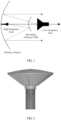
- a dual-band parabolic antennais used in this solution, and a structure is shown in FIG. 1 .
- the dual-band parabolic antennaincludes a primary reflector, a secondary reflector, a low frequency feed, and a high frequency feed. Both the low frequency feed and the high frequency feed are a type of horn antenna, and are usually referred to as a horn feed when being applied to another antenna structure. The two feeds share the primary reflector.
- a frequency selective surface(Frequency Selective Surface, FSS) is used as the secondary reflector.
- the secondary reflectoris designed as a hyperboloid, a virtual focus of the hyperboloid and a real focus of the primary reflector are overlapped, and the feeds of different frequencies are respectively disposed at the virtual focus and a real focus of the hyperboloid.
- the secondary reflectortransmits an electromagnetic wave transmitted by the low frequency feed located at the virtual focus, and reflects an electromagnetic wave transmitted by the high frequency feed located at the real focus, so as to implement a dual-band multiplexing function.
- KR 100 976 535 B1describes a frequency selector for improving selectivity by forming a metal film on both sides of a dielectric foam.
- the frequency selectorcomprises a dielectric foam, a dielectric film, a metal film and a bracket.
- the dielectric foamis a honeycomb structure.
- the dielectric filmis attached to both sides of the dielectric foam.
- the metal filmis attached to the dielectric film to be interposed between the dielectric foam and the dielectric film.
- the metal filmincludes the arrangement of a plurality of filter patterns.
- the bracketis comprised of a front bracket and a rear bracket. The front bracket and the rear bracket are combined to surround the dielectric foam, the dielectric film, and the metal film.
- a splashplate support for a reflector antennacomprises a first engaging portion for engaging with a dual-band waveguide feed, a second engaging portion for engaging with a splashplate, and a supporting portion connecting the first engaging portion to the second engaging portion, and arranged to define a space between the waveguide feed aperture and the splashplate.
- the supporting portioncan be spaced apart from the aperture of the waveguide feed, and may have a thickness corresponding to half a wavelength of a beam emitted from the aperture.
- the shape of the supporting portionmay preferably correspond to a shape of the beam wavefront after it has been reflected from the splashplate.
- the waveguide feedmay include means for converting a transmission mode of a first frequency band from a first transmission mode to a mixed transmission mode.
- US 2010/238082 A1provides an improved antenna system on moving platform that is in communication with multiple satellites for simultaneous reception and transmission of RF energy at multiple frequencies.
- the antennais implemented as a multi-beam, multi-band antenna having a main reflector with multiple feed horns and a sub-reflector having a reflective surface defining an image focus for a Ka band frequency signal and a prime focus for a Ku band frequency signal.
- US 3,231,892 Adescribes an antenna feed system simultaneuously operable at two frequencies utilizing a polarization independent frequency selective intermediate reflector.
- Embodiments of the present inventionprovide a horn antenna, which integrates functions of a low frequency horn feed and an FSS, so as to resolve prior-art problems that a large assembly error causes a low antenna gain, and a beam direction deviates from a boresight axis direction.
- a horn antennaincludes a frequency selective surface FSS, a connection structure, and a waveguide tube
- the connection structureincludes a first dielectric slab, a second dielectric slab, and a dielectric wall
- a first surface of the first dielectric slabis a hyperboloid whose surface is protruding
- a second surface of the first dielectric slabis connected to the dielectric wall
- a spacing between the two surfaces of the first dielectric slabis a thickness of the first dielectric slab
- the dielectric wallhas a tubular structure
- a first surface of the dielectric wallis covered by the first dielectric slab
- a second surface of the dielectric wallis covered by the second dielectric slab
- a spacing between the two surfaces of the dielectric wallis a height of the dielectric wall
- an area of the first surface of the dielectric wallis not less than an area of the second surface of the dielectric wall, there is a hole at a middle position of the second dielectric slab, and the first dielectric slab, the dielectric wall, the
- the horn antenna provided in the embodiments of the present inventionintegrates functions of the FSS and the low frequency horn feed, so as to greatly reduce an error of alignment with a high frequency horn feed, reduce an assembly difficulty, and a degradation degree of a beam shape of the electromagnetic wave.
- the thickness of the first dielectric slabis half of a wavelength corresponding to a first frequency in the first dielectric slab, and the first frequency is a transmission band center frequency of the FSS.
- reflection of the transmitted electromagnetic wave from a front facet of the first dielectric slabis mutually offset with that from a back facet of the first dielectric slab, and therefore, transmission bandwidth of the FSS at a low frequency band is increased.
- another part of the waveguide tubeis inserted into the hollow structure.
- the horn antennafurther includes a choke groove located around the waveguide tube inserted into the hollow structure, a groove depth of the choke groove is 1/4 of a wavelength corresponding to the first frequency in the air, and the first frequency is the transmission band center frequency of the FSS.
- energy of an electromagnetic wavecan be radiated forward in a more concentrated manner, to improve the radiation efficiency of the horn antenna.
- the horn antennaincludes multiple choke grooves, so as to further improve the radiation efficiency of the horn antenna.
- a horn antennaintegrates functions of an FSS and a low frequency horn feed, so as to greatly reduce an error of alignment with a high frequency horn feed, and reduce an assembly difficulty.
- the horn antenna provided in the embodiments of the present inventionfurther provides relatively high radiation efficiency.
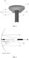
- a horn antennais a widely used antenna. Both a low frequency feed and a high frequency feed in FIG. 1 are horn antennas.
- An existing horn antennagenerally includes a solid dielectric block and a waveguide tube. As shown in FIG. 2 , the solid dielectric block is a cone with a curved-surface top, and a tip opposite to the curved-surface top is inserted into the waveguide tube and is connected to the waveguide tube, to form a horn feed.
- an FSS and a low frequency horn feed(a horn antenna used in an antenna structure is usually referred to as a horn feed) are two independent components. This results in a large assembly error, and further causes problems that an antenna gain is reduced, and a beam direction deviates from a boresight axis direction.
- An embodiment of the present inventionprovides a horn antenna 300.
- the horn antennaintegrates functions of an FSS and a low frequency horn feed.
- a structure of the horn antennais shown in FIG. 3 , and includes an FSS 310, a connection structure 320, and a waveguide tube 330.
- the connection structure 320includes a first dielectric slab 321, a second dielectric slab 322, and a dielectric wall 323.
- a first surface of the first dielectric slab 321is a hyperboloid whose surface is protruding, a second surface of the first dielectric slab 321 is connected to the dielectric wall 323, and a spacing between the two surfaces of the first dielectric slab 321 is a thickness of the first dielectric slab 321.
- the dielectric wall 323has a tubular structure, a first surface of the dielectric wall 323 is covered by the first dielectric slab 321, a second surface of the dielectric wall is covered by the second dielectric slab 322, a spacing between the two surfaces of the dielectric wall 323 is a height of the dielectric wall 323, and an area of the first surface of the dielectric wall 323 is not less than an area of the second surface of the dielectric wall 323.
- the first dielectric slab 321, the dielectric wall 323, and the second dielectric slab 322jointly form a hollow structure.
- the FSS 310covers the first surface of the first dielectric slab 321. A part of the waveguide tube 330 is inserted into the hole of the second dielectric slab 322.
- an area of the hole of the second dielectric slab 322is consistent with a cross-sectional area of the waveguide tube 330, and the second dielectric slab and the waveguide tube 330 are tightly combined, and play a connection part.
- the dielectric wall 323has a tubular structure, and may be in a shape of a cylinder, a horn, or the like.
- a material with a relatively low transmission electromagnetic wave lossneeds to be used for the first dielectric slab 321, and a dielectric material in an existing horn antenna may be used.
- the second dielectric slab and the dielectric wallmainly play a support part, and a hard material may be used. These are not limited in this embodiment of the present invention.
- the FSS 310 in this embodiment of the present inventionhas functions of transmitting a low frequency band electromagnetic wave and reflecting a high frequency band electromagnetic wave. Any existing FSS having the foregoing functions may be used, and this is not limited in this embodiment of the present invention.
- FIG. 4shows a dual-band parabolic antenna applying the horn antenna 300 provided in this embodiment of the present invention. It can be learned from the figure that the horn antenna 300 provided in this embodiment of the present invention integrates the functions of the FSS and the low frequency feed, and only alignment between the horn antenna 300 and a high frequency horn feed needs to be considered. This implements a function of reducing an alignment error, and can control the alignment error within a range from -0.2 mm to +0.2 mm. In addition, propagation of an electromagnetic wave in a dielectric can be reduced as much as possible by using the connection structure 320 with the hollow structure.
- Radiation efficiency of the horn antenna 300 provided in this embodiment of the present inventioncan reach 98%.
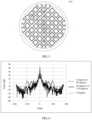
- an array arrangement direction of the FSS 310is 45 degrees or 135 degrees to a polarization direction of an incident electromagnetic wave.
- a solid line arrowrepresents a polarization direction of the incident electromagnetic wave
- a dashed line arrowrepresents the array arrangement direction of the FSS 310.
- the electromagnetic waveis usually a sine wave
- the arrangement manner proposed in this embodiment of the present inventioncan reduce a side lobe height of a transmitted electromagnetic wave.
- energyis more concentrated, directivity of the horn antenna 300 is improved, and interference to a surrounding site is reduced.
- a distance from the waveguide tube 330 to the first dielectric slab 321needs to be determined according to both a curvature of the first surface of the first dielectric slab 321 and a phase center of the horn antenna 300.
- the FSS 310needs to be used as a secondary reflector of the dual-band parabolic antenna, the phase center of the horn antenna 300 and a virtual focus of the FSS 310 need to be overlapped.
- the FSS 310covers the first surface of the first dielectric slab 321, and a curvature of the FSS 310 is consistent with that of the first surface of the first dielectric slab 321.
- a position of the virtual focus of the FSS 310may be determined according to the curvature of the first surface of the first dielectric slab 321.
- the phase centeris a theoretical point, and a center of signals radiated by the antenna is considered as the phase center of the antenna.
- a phase center of the actual antennais usually a region.
- the phase center of the horn antenna 300may be changed by adjusting a specific shape of the dielectric wall 323 or the distance from the waveguide tube 330 to the first dielectric slab 321, so as to overlap the virtual focus of the FSS 310 and the phase center of the antenna.
- the horn antenna 300further includes a choke groove 340, located around the waveguide tube 330 inserted into the hollow structure.
- a groove depth of the choke groove 340is 1/4 of a wavelength corresponding to a first frequency in the air.
- the first frequencyis a transmission band center frequency of the FSS 310.
- the choke groove 340can suppress transverse propagation of a surface current around the waveguide tube 330 inserted into the hollow structure, so that energy of the transmitted electromagnetic wave can be radiated forward in a more concentrated manner, to improve the radiation efficiency of the horn antenna 300.
- there is more than one choke groove 340and a groove spacing between multiple choke grooves 340 is 1/10 of the wavelength corresponding to the first frequency in the air.
- the energy of the transmitted electromagnetic wavecan be further concentrated and radiated forward, so as to improve the radiation efficiency of the horn antenna 300.
- a larger quantity of choke grooves 340may not indicate a better effect.
- a first choke groove 340 that is closest to the waveguide tube 330has a most obvious effect. From a second to an N th choke grooves 340, distances to the waveguide tube 330 progressively increase, and effects progressively degrade.
- the quantity of choke grooves 340needs to be determined according to an actual case, and is not limited in this embodiment of the present invention.
- vf ⁇ ⁇
- va speed of light in a dielectric.
- vis equal to the speed of light, that is, 3 ⁇ 10 8 m/s.
- the thickness of the first dielectric slab 321is half of a wavelength corresponding to the first frequency in the first dielectric slab 321.
- the first frequencyis the transmission band center frequency of the FSS. In this case, if the thickness of the first dielectric slab 321 is unchanged, curvatures of the first surface and the second surface that are of the first dielectric slab 321 are definitely consistent.
- low frequency transmission bandwidth of the FSS 310is related to the thickness of the first dielectric slab 321
- the thickness of the first dielectric slab 321is half of the dielectric wavelength corresponding to the first frequency
- reflection generated on the first surface of the first dielectric slab 321is mutually offset with that generated on the second surface of the first dielectric slab 321 (the reflection generated on the first surface and that generated on the second surface have a same amplitude and opposite phases) in a process in which a low frequency electromagnetic wave is propagated from the air to a dielectric and then to the air.
- the thickness of the first dielectric slab 321 in this embodiment of the present inventionis half of the dielectric wavelength corresponding to the first frequency.
- the low frequency band transmission bandwidthcan be increased.
- a reason that the connection structure 320 uses the hollow structure instead of a solid structure in this embodiment of the present inventionis further related to the low frequency band transmission bandwidth.
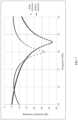
- FIG. 7shows a reflection coefficient of the FSS for a low frequency band electromagnetic wave. It can be learned from the figure that, when a solid dielectric is used, FSS transmission bandwidth is approximately 1 GHz (a reflection coefficient is below -15 dB). When the hollow structure in this embodiment of the present invention is used, the FSS transmission bandwidth can reach approximately 1.85 GHz. The low frequency band transmission bandwidth can be significantly increased.
- a low frequency horn feedis integrated with an FSS in this embodiment of the present invention, so as to greatly reduce an error of alignment with a high frequency horn feed.
- a connection structure 320 with a hollow structureis used to reduce propagation of an electromagnetic wave in a dielectric as much as possible, so as to reduce a meaningless loss and improve radiation efficiency of a horn antenna 300.
- the hallow structurelarger low frequency band transmission bandwidth can be obtained.
- an array arrangement direction of the FSS 310is 45 degrees or 135 degrees to a polarization direction of an incident electromagnetic wave. This can alleviate degradation of a beam shape of the transmitted electromagnetic wave, and reduce a side lobe height of the transmitted electromagnetic wave, so as to improve directivity of the horn antenna 300, and reduce interference with a surrounding site.
Landscapes
- Waveguide Aerials (AREA)
- Aerials With Secondary Devices (AREA)
Description
- The present invention relates to the field of wireless communications technologies, and in particular, to a horn antenna that can be used in a dual-band parabolic antenna.
- With rapid development of wireless communications technologies, a transmission capacity in microwave point-to-point communication continuously increases, and an E-band (71 to 76 GHz, 81 to 86 GHz) frequency band microwave device plays an increasingly important role in a base station backhaul network. However, because "rain fade" on an E-band frequency band electromagnetic wave is extremely severe, an E-band microwave single-hop distance is usually less than 3 kilometers. To increase the E-band microwave single-hop distance and reduce site deployment costs, a solution is provided, in which the E-band frequency band microwave device and another low frequency microwave device are cooperatively used. When there is relatively heavy rain, even if the E-band microwave device cannot normally work, the low frequency microwave device can still normally work.
- A dual-band parabolic antenna is used in this solution, and a structure is shown in
FIG. 1 . The dual-band parabolic antenna includes a primary reflector, a secondary reflector, a low frequency feed, and a high frequency feed. Both the low frequency feed and the high frequency feed are a type of horn antenna, and are usually referred to as a horn feed when being applied to another antenna structure. The two feeds share the primary reflector. A frequency selective surface (Frequency Selective Surface, FSS) is used as the secondary reflector. The secondary reflector is designed as a hyperboloid, a virtual focus of the hyperboloid and a real focus of the primary reflector are overlapped, and the feeds of different frequencies are respectively disposed at the virtual focus and a real focus of the hyperboloid. The secondary reflector transmits an electromagnetic wave transmitted by the low frequency feed located at the virtual focus, and reflects an electromagnetic wave transmitted by the high frequency feed located at the real focus, so as to implement a dual-band multiplexing function. - In the prior art, a low frequency horn feed and an FSS are two independent components. Therefore, there are problems that a large assembly error exists, an antenna gain is low, and a beam direction deviates from a boresight axis direction.
KR 100 976 535 B1 - In
EP 2 590 264 A1 a splashplate support for a reflector antenna comprises a first engaging portion for engaging with a dual-band waveguide feed, a second engaging portion for engaging with a splashplate, and a supporting portion connecting the first engaging portion to the second engaging portion, and arranged to define a space between the waveguide feed aperture and the splashplate. The supporting portion can be spaced apart from the aperture of the waveguide feed, and may have a thickness corresponding to half a wavelength of a beam emitted from the aperture. The shape of the supporting portion may preferably correspond to a shape of the beam wavefront after it has been reflected from the splashplate. The waveguide feed may include means for converting a transmission mode of a first frequency band from a first transmission mode to a mixed transmission mode. US 2010/238082 A1 provides an improved antenna system on moving platform that is in communication with multiple satellites for simultaneous reception and transmission of RF energy at multiple frequencies. The antenna is implemented as a multi-beam, multi-band antenna having a main reflector with multiple feed horns and a sub-reflector having a reflective surface defining an image focus for a Ka band frequency signal and a prime focus for a Ku band frequency signal.US 3,231,892 A describes an antenna feed system simultaneuously operable at two frequencies utilizing a polarization independent frequency selective intermediate reflector.- According to the present application, the above objects are solved by the claimed matter according to the independent claims. Embodiments of the present invention provide a horn antenna, which integrates functions of a low frequency horn feed and an FSS, so as to resolve prior-art problems that a large assembly error causes a low antenna gain, and a beam direction deviates from a boresight axis direction. According to a first aspect, a horn antenna is provided, and includes a frequency selective surface FSS, a connection structure, and a waveguide tube, where the connection structure includes a first dielectric slab, a second dielectric slab, and a dielectric wall, a first surface of the first dielectric slab is a hyperboloid whose surface is protruding, a second surface of the first dielectric slab is connected to the dielectric wall, a spacing between the two surfaces of the first dielectric slab is a thickness of the first dielectric slab, the dielectric wall has a tubular structure, a first surface of the dielectric wall is covered by the first dielectric slab, a second surface of the dielectric wall is covered by the second dielectric slab, a spacing between the two surfaces of the dielectric wall is a height of the dielectric wall, an area of the first surface of the dielectric wall is not less than an area of the second surface of the dielectric wall, there is a hole at a middle position of the second dielectric slab, and the first dielectric slab, the dielectric wall, and the second dielectric slab jointly form a hollow structure; the FSS covers the first surface of the first dielectric slab; and a part of the waveguide tube is inserted into the hole of the second dielectric slab.
- The horn antenna provided in the embodiments of the present invention integrates functions of the FSS and the low frequency horn feed, so as to greatly reduce an error of alignment with a high frequency horn feed, reduce an assembly difficulty, and a degradation degree of a beam shape of the electromagnetic wave.
- With reference to the first aspect, in a second possible implementation of the first aspect, the thickness of the first dielectric slab is half of a wavelength corresponding to a first frequency in the first dielectric slab, and the first frequency is a transmission band center frequency of the FSS. In the embodiments of the present invention, reflection of the transmitted electromagnetic wave from a front facet of the first dielectric slab is mutually offset with that from a back facet of the first dielectric slab, and therefore, transmission bandwidth of the FSS at a low frequency band is increased.
- With reference to the first aspect, or the first or the second possible implementation of the first aspect, in a third possible implementation of the first aspect, another part of the waveguide tube is inserted into the hollow structure.
- With reference to the third possible implementation of the first aspect, in a fourth possible implementation of the first aspect, the horn antenna further includes a choke groove located around the waveguide tube inserted into the hollow structure, a groove depth of the choke groove is 1/4 of a wavelength corresponding to the first frequency in the air, and the first frequency is the transmission band center frequency of the FSS. In the embodiments of the present invention, energy of an electromagnetic wave can be radiated forward in a more concentrated manner, to improve the radiation efficiency of the horn antenna.
- With reference to the fourth possible implementation of the first aspect, in a fifth possible implementation of the first aspect, there is more than one choke groove, and a spacing between the grooves is 1/10 of the wavelength corresponding to the first frequency in the air. In the embodiments, the horn antenna includes multiple choke grooves, so as to further improve the radiation efficiency of the horn antenna.
- In the solutions provided in the embodiments of the present invention, a horn antenna integrates functions of an FSS and a low frequency horn feed, so as to greatly reduce an error of alignment with a high frequency horn feed, and reduce an assembly difficulty. In addition, the horn antenna provided in the embodiments of the present invention further provides relatively high radiation efficiency.
- To describe the technical solutions in the embodiments of the present invention or in the prior art more clearly, the following briefly describes the accompanying drawings required for describing the embodiments or the prior art. Apparently, the accompanying drawings in the following description show merely some embodiments of the present invention, and a person of ordinary skill in the art may still derive other drawings from these accompanying drawings without creative efforts.
FIG. 1 is a schematic structural diagram of an existing dual-band parabolic antenna;FIG. 2 is a schematic structural diagram of an existing horn antenna;FIG. 3 is a schematic structural diagram of a horn antenna according to an embodiment of the present invention;FIG. 4 is a schematic structural diagram of a dual-band parabolic antenna applying an embodiment of the present invention;FIG. 5 is a diagram of a relationship between an FSS array arrangement direction in a horn antenna and an incident electromagnetic wave polarization direction according to an embodiment of the present invention;FIG. 6 is a diagram of a comparison between electromagnetic wave patterns obtained after an electromagnetic wave is separately transmitted through an existing FSS and- an FSS in a horn antenna provided in the present invention; and
FIG. 7 is a diagram of a comparison between reflection coefficients of low frequency band electromagnetic waves after the low frequency band electromagnetic waves are respectively transmitted through a horn antenna using a hollow connection structure and a horn antenna using a solid connection structure.- The following clearly and completely describes the technical solutions in the embodiments of the present invention with reference to the accompanying drawings in the embodiments of the present invention. Apparently, the described embodiments are a part rather than all of the embodiments of the present invention. All other embodiments obtained by a person of ordinary skill in the art based on the embodiments of the present invention without creative efforts shall fall within the protection scope of the present invention.
- In the following description, to illustrate rather than limit, specific details such as a particular system structure, an interface, and a technology are provided to make a thorough understanding of the present invention. However, a person skilled in the art should know that the present invention may be practiced in other embodiments without these specific details. In other cases, detailed descriptions of well-known apparatuses, circuits, and methods are omitted, so that the present invention is described without being obscured by unnecessary details.
- It should be understood that ordinal numbers such as "first" and "second", if mentioned in the embodiments of the present invention, are only used for distinguishing, unless the ordinal numbers definitely represent a sequence according to the context.
- To facilitate understanding of a person skilled in the art, the following embodiments are used in the present invention to describe the technical solutions provided in the present invention.
- As known to all, a horn antenna is a widely used antenna. Both a low frequency feed and a high frequency feed in
FIG. 1 are horn antennas. An existing horn antenna generally includes a solid dielectric block and a waveguide tube. As shown inFIG. 2 , the solid dielectric block is a cone with a curved-surface top, and a tip opposite to the curved-surface top is inserted into the waveguide tube and is connected to the waveguide tube, to form a horn feed. However, in an existing dual-band parabolic antenna, an FSS and a low frequency horn feed (a horn antenna used in an antenna structure is usually referred to as a horn feed) are two independent components. This results in a large assembly error, and further causes problems that an antenna gain is reduced, and a beam direction deviates from a boresight axis direction. - An embodiment of the present invention provides a
horn antenna 300. The horn antenna integrates functions of an FSS and a low frequency horn feed. A structure of the horn antenna is shown inFIG. 3 , and includes anFSS 310, aconnection structure 320, and awaveguide tube 330. - The
connection structure 320 includes a firstdielectric slab 321, a seconddielectric slab 322, and adielectric wall 323. A first surface of the firstdielectric slab 321 is a hyperboloid whose surface is protruding, a second surface of the firstdielectric slab 321 is connected to thedielectric wall 323, and a spacing between the two surfaces of the firstdielectric slab 321 is a thickness of the firstdielectric slab 321. Thedielectric wall 323 has a tubular structure, a first surface of thedielectric wall 323 is covered by the firstdielectric slab 321, a second surface of the dielectric wall is covered by the seconddielectric slab 322, a spacing between the two surfaces of thedielectric wall 323 is a height of thedielectric wall 323, and an area of the first surface of thedielectric wall 323 is not less than an area of the second surface of thedielectric wall 323. There is a hole at a middle position of the seconddielectric slab 322. The firstdielectric slab 321, thedielectric wall 323, and the seconddielectric slab 322 jointly form a hollow structure. TheFSS 310 covers the first surface of the firstdielectric slab 321. A part of thewaveguide tube 330 is inserted into the hole of the seconddielectric slab 322. - It should be understood that an area of the hole of the second
dielectric slab 322 is consistent with a cross-sectional area of thewaveguide tube 330, and the second dielectric slab and thewaveguide tube 330 are tightly combined, and play a connection part. Thedielectric wall 323 has a tubular structure, and may be in a shape of a cylinder, a horn, or the like. In addition, a material with a relatively low transmission electromagnetic wave loss needs to be used for the firstdielectric slab 321, and a dielectric material in an existing horn antenna may be used. The second dielectric slab and the dielectric wall mainly play a support part, and a hard material may be used. These are not limited in this embodiment of the present invention. - The
FSS 310 in this embodiment of the present invention has functions of transmitting a low frequency band electromagnetic wave and reflecting a high frequency band electromagnetic wave. Any existing FSS having the foregoing functions may be used, and this is not limited in this embodiment of the present invention. FIG. 4 shows a dual-band parabolic antenna applying thehorn antenna 300 provided in this embodiment of the present invention. It can be learned from the figure that thehorn antenna 300 provided in this embodiment of the present invention integrates the functions of the FSS and the low frequency feed, and only alignment between thehorn antenna 300 and a high frequency horn feed needs to be considered. This implements a function of reducing an alignment error, and can control the alignment error within a range from -0.2 mm to +0.2 mm. In addition, propagation of an electromagnetic wave in a dielectric can be reduced as much as possible by using theconnection structure 320 with the hollow structure. Because a transmission loss of the electromagnetic wave in the dielectric is always greater than a transmission loss of the electromagnetic wave in the air, to reduce the propagation of the electromagnetic wave in the dielectric is to reduce a meaningless loss and increase transmit power. Radiation efficiency of thehorn antenna 300 provided in this embodiment of the present invention can reach 98%.- Optionally, in another embodiment, an array arrangement direction of the
FSS 310 is 45 degrees or 135 degrees to a polarization direction of an incident electromagnetic wave. As shown inFIG. 5 , a solid line arrow represents a polarization direction of the incident electromagnetic wave, and a dashed line arrow represents the array arrangement direction of theFSS 310. Because the electromagnetic wave is usually a sine wave, there are two electromagnetic wave polarization directions that have an angle difference of 180 degrees, as shown by the arrows at both ends of a solid line inFIG. 4 . Therefore, the array arrangement direction of theFSS 310 is 45 degrees to the polarization direction of the incident electromagnetic wave at a moment, and may be 135 degrees to the polarization direction at a next moment. The arrangement manner proposed in this embodiment of the present invention can reduce a side lobe height of a transmitted electromagnetic wave. - Specifically, in an example in which a low frequency electromagnetic wave transmitted by the
horn antenna 300 is incident on theFSS 310, when this incident electromagnetic wave is transmitted through theFSS 310, an induced current is generated on a surface of theFSS 310, and a scattered electromagnetic wave generated by the induced current interacts with the incident electromagnetic wave, to form a transmitted electromagnetic wave. When the array arrangement direction of theFSS 310 is consistent (0 degrees) with or perpendicular (90 degrees) to a polarization direction of the incident electromagnetic wave, no induced current is generated on metal on both sides of a gap that is consistent with the polarization direction, induced currents are generated on metal on both sides of a gap that is perpendicular to the polarization direction, and a scattered electromagnetic wave generated in this case is asymmetric in relative to the polarization direction of the incident electromagnetic wave. In this case, a pattern change result obtained after the transmitted electromagnetic wave passes through theFSS 310 is shown inFIG. 6 , and cannot meet a radiation pattern envelope (Radiation Pattern Envelope, RPE) template specified by the European Telecommunications Standards Institute (European Telecommunications Standards Institute, ETSI). However, when the array arrangement direction of theFSS 310 is 45 degrees or 135 degrees to the polarization direction of the incident electromagnetic wave, induced currents are generated on metal on both sides of gaps in the foregoing two directions, and a scattered electromagnetic wave formed in this case is symmetric in relative to the polarization direction of the incident electromagnetic wave. In this case, a pattern change result obtained after the transmitted electromagnetic wave passes through the FSS is shown inFIG. 6 . This can greatly reduce a degradation degree of a beam shape of the transmitted electromagnetic wave, reduce a side lobe height of the transmitted electromagnetic wave, and meet the RPE template specified by the ETSI. In addition, in comparison with an existing arrangement direction (0 degrees or 90 degrees), energy is more concentrated, directivity of thehorn antenna 300 is improved, and interference to a surrounding site is reduced. - Optionally, another part of the
waveguide tube 330 is inserted into theconnection structure 320. A distance from thewaveguide tube 330 to the firstdielectric slab 321 needs to be determined according to both a curvature of the first surface of the firstdielectric slab 321 and a phase center of thehorn antenna 300. Because theFSS 310 needs to be used as a secondary reflector of the dual-band parabolic antenna, the phase center of thehorn antenna 300 and a virtual focus of theFSS 310 need to be overlapped. TheFSS 310 covers the first surface of the firstdielectric slab 321, and a curvature of theFSS 310 is consistent with that of the first surface of the firstdielectric slab 321. Therefore, a position of the virtual focus of theFSS 310 may be determined according to the curvature of the first surface of the firstdielectric slab 321. The phase center is a theoretical point, and a center of signals radiated by the antenna is considered as the phase center of the antenna. However, because an actual antenna cannot be perfectly prepared, a phase center of the actual antenna is usually a region. In this embodiment of the present invention, the phase center of thehorn antenna 300 may be changed by adjusting a specific shape of thedielectric wall 323 or the distance from thewaveguide tube 330 to the firstdielectric slab 321, so as to overlap the virtual focus of theFSS 310 and the phase center of the antenna. - In addition, the
horn antenna 300 further includes achoke groove 340, located around thewaveguide tube 330 inserted into the hollow structure. A groove depth of thechoke groove 340 is 1/4 of a wavelength corresponding to a first frequency in the air. The first frequency is a transmission band center frequency of theFSS 310. Thechoke groove 340 can suppress transverse propagation of a surface current around thewaveguide tube 330 inserted into the hollow structure, so that energy of the transmitted electromagnetic wave can be radiated forward in a more concentrated manner, to improve the radiation efficiency of thehorn antenna 300. Further, there is more than onechoke groove 340, and a groove spacing betweenmultiple choke grooves 340 is 1/10 of the wavelength corresponding to the first frequency in the air. - In this embodiment, if the
horn antenna 300 includesmultiple choke grooves 340, the energy of the transmitted electromagnetic wave can be further concentrated and radiated forward, so as to improve the radiation efficiency of thehorn antenna 300. - It should be noted that, a larger quantity of
choke grooves 340 may not indicate a better effect. Afirst choke groove 340 that is closest to thewaveguide tube 330 has a most obvious effect. From a second to an Nth choke grooves 340, distances to thewaveguide tube 330 progressively increase, and effects progressively degrade. The quantity ofchoke grooves 340 needs to be determined according to an actual case, and is not limited in this embodiment of the present invention. - It should be noted that a relationship between a frequency (f) and a wavelength (λ) is v = f × λ, and v represents a speed of light in a dielectric. In vacuum, v is equal to the speed of light, that is, 3 × 10⁸ m/s. In a dielectric, v is related to a refractive index of the dielectric. If the refractive index of the dielectric is n, v = Speed of light/n. Optionally, in another embodiment, the thickness of the first
dielectric slab 321 is half of a wavelength corresponding to the first frequency in the firstdielectric slab 321. The first frequency is the transmission band center frequency of the FSS. In this case, if the thickness of the firstdielectric slab 321 is unchanged, curvatures of the first surface and the second surface that are of the firstdielectric slab 321 are definitely consistent. - Because low frequency transmission bandwidth of the
FSS 310 is related to the thickness of the firstdielectric slab 321, when the thickness of the firstdielectric slab 321 is half of the dielectric wavelength corresponding to the first frequency, reflection generated on the first surface of the firstdielectric slab 321 is mutually offset with that generated on the second surface of the first dielectric slab 321 (the reflection generated on the first surface and that generated on the second surface have a same amplitude and opposite phases) in a process in which a low frequency electromagnetic wave is propagated from the air to a dielectric and then to the air. This can increase the low frequency transmission bandwidth of theFSS 310. Therefore, the thickness of the firstdielectric slab 321 in this embodiment of the present invention is half of the dielectric wavelength corresponding to the first frequency. In comparison with another thickness, the low frequency band transmission bandwidth can be increased. In addition, except that theconnection structure 320 with the hollow structure can reduce an electromagnetic wave loss and improve the radiation efficiency of thehorn antenna 300, a reason that theconnection structure 320 uses the hollow structure instead of a solid structure in this embodiment of the present invention is further related to the low frequency band transmission bandwidth.FIG. 7 shows a reflection coefficient of the FSS for a low frequency band electromagnetic wave. It can be learned from the figure that, when a solid dielectric is used, FSS transmission bandwidth is approximately 1 GHz (a reflection coefficient is below -15 dB). When the hollow structure in this embodiment of the present invention is used, the FSS transmission bandwidth can reach approximately 1.85 GHz. The low frequency band transmission bandwidth can be significantly increased. - In conclusion, a low frequency horn feed is integrated with an FSS in this embodiment of the present invention, so as to greatly reduce an error of alignment with a high frequency horn feed. A
connection structure 320 with a hollow structure is used to reduce propagation of an electromagnetic wave in a dielectric as much as possible, so as to reduce a meaningless loss and improve radiation efficiency of ahorn antenna 300. In addition, in comparison with a solid dielectric, by using the hallow structure, larger low frequency band transmission bandwidth can be obtained. In this embodiment of the present invention, an array arrangement direction of theFSS 310 is 45 degrees or 135 degrees to a polarization direction of an incident electromagnetic wave. This can alleviate degradation of a beam shape of the transmitted electromagnetic wave, and reduce a side lobe height of the transmitted electromagnetic wave, so as to improve directivity of thehorn antenna 300, and reduce interference with a surrounding site. - The foregoing descriptions are merely specific implementations of the present invention, but are not intended to limit the protection scope of the present invention. Any variation or replacement readily figured out by a person skilled in the art within the technical scope disclosed in the present invention shall fall within the protection scope of the present invention. Therefore, the protection scope of the present invention shall be subject to the protection scope of the claims.
Claims (6)
- A horn antenna (300), comprising a frequency selective surface (310), FSS, a connection structure (320), and a waveguide tube (330), whereinthe connection structure (320) comprises a first dielectric slab (321), a second dielectric slab (322), and a dielectric wall (323), a first surface of the first dielectric slab (321) is a hyperboloid whose surface is protruding, a second surface of the first dielectric slab (321) is connected to the dielectric wall (323), a spacing between the two surfaces of the first dielectric slab (321) is a thickness of the first dielectric slab (321), the dielectric wall (323) has a tubular structure, a first surface of the dielectric wall (323) is covered by the first dielectric slab (321), a second surface of the dielectric wall (323) is covered by the second dielectric slab (322), a spacing between the two surfaces of the dielectric wall (323) is a height of the dielectric wall (323), an area of the first surface of the dielectric wall (323) is not less than an area of the second surface of the dielectric wall (323), there is a hole at a middle position of the second dielectric slab (322), and the first dielectric slab (321), the dielectric wall (323), and the second dielectric slab (322) jointly form a hollow structure;the FSS (310) covers the first surface of the first dielectric slab (321), wherein an array arrangement direction of the FSS (310) is 45 degrees or 135 degrees to a polarization direction of an incident electromagnetic wave;a part of the waveguide tube (330) is inserted into the hole of the second dielectric slab (322).
- The horn antenna (300) according to claim 1, wherein the thickness of the first dielectric slab (321) is half of a wavelength in the first dielectric slab (321), the wavelength in the first dielectric slab (321) corresponding to a first frequency, and the first frequency is a transmission band center frequency of the FSS (310).
- The horn antenna (300) according to claim 1 or 2, wherein the part of the waveguide tube (330) that is inserted into the hole of the second dielectric slab (322) extends into the hollow structure.
- The horn antenna (300) according to claim 3, wherein the horn antenna (300) further comprises a choke groove (340) located around the waveguide tube (330) inserted into the hollow structure, a groove depth of the choke groove (340) is 1/4 of a wavelength in air contained in the hollow structure, the wavelength in air contained in the hollow structure corresponding to the first frequency, and the first frequency is the transmission band center frequency of the FSS.
- The horn antenna (300) according to claim 4, wherein there is more than one choke groove (340), and a spacing between the grooves is 1/10 of the wavelength in the air corresponding to the first frequency.
- A dual-band parabolic antenna, comprising a high frequency feed, a primary reflector and the horn antenna (300) according to any one of claims 1 to 5.
Applications Claiming Priority (1)
| Application Number | Priority Date | Filing Date | Title |
|---|---|---|---|
| PCT/CN2016/101595WO2018064835A1 (en) | 2016-10-09 | 2016-10-09 | Horn antenna |
Publications (3)
| Publication Number | Publication Date |
|---|---|
| EP3419117A1 EP3419117A1 (en) | 2018-12-26 |
| EP3419117A4 EP3419117A4 (en) | 2019-05-22 |
| EP3419117B1true EP3419117B1 (en) | 2023-04-26 |
Family
ID=61831606
Family Applications (1)
| Application Number | Title | Priority Date | Filing Date |
|---|---|---|---|
| EP16918168.2AActiveEP3419117B1 (en) | 2016-10-09 | 2016-10-09 | Horn antenna |
Country Status (6)
| Country | Link |
|---|---|
| US (1) | US10727607B2 (en) |
| EP (1) | EP3419117B1 (en) |
| JP (1) | JP6706722B2 (en) |
| CN (1) | CN108701905B (en) |
| BR (1) | BR112019004151B1 (en) |
| WO (1) | WO2018064835A1 (en) |
Families Citing this family (14)
| Publication number | Priority date | Publication date | Assignee | Title |
|---|---|---|---|---|
| USD864173S1 (en) | 2017-08-25 | 2019-10-22 | Shenzhen Antop Technology Limited | Antenna |
| USD864923S1 (en)* | 2017-09-15 | 2019-10-29 | Shenzhen Antop Technology Limited | Antenna |
| CN108767464A (en)* | 2018-06-01 | 2018-11-06 | 航天恒星科技有限公司 | A kind of efficient tubaeform medium light nano-antenna of miniaturization |
| WO2020019264A1 (en)* | 2018-07-26 | 2020-01-30 | 华为技术有限公司 | Feed device, dual-frequency microwave antenna and dual-frequency antenna device |
| FR3085552B1 (en)* | 2018-08-28 | 2020-11-20 | Arianegroup Sas | ANTENNA FOR A SPACE SATELLITE |
| TR201819490A2 (en)* | 2018-12-14 | 2019-02-21 | Profen Iletisim Teknolojileri Ve Hizmetleri Sanayi Ticaret Anonim Sirketi | SECONDARY REFLECTOR WITH FREQUENCY SELECTOR SURFACE |
| CN109509990B (en)* | 2018-12-29 | 2024-05-28 | 四川睿迪澳科技有限公司 | All-metal FP resonant cavity antenna based on choke groove and non-uniform covering layer |
| USD891404S1 (en)* | 2019-01-28 | 2020-07-28 | King Saud University | Omnidirectional ultra-wideband antenna |
| USD889445S1 (en)* | 2019-01-28 | 2020-07-07 | King Saud University | Omnidirectional multiband antenna |
| USD890145S1 (en)* | 2019-01-29 | 2020-07-14 | King Saud University | Ultra-wideband unipole antenna |
| CN110334480B (en)* | 2019-07-26 | 2022-11-22 | 中国电子科技集团公司第五十四研究所 | Design method of secondary surface extended curved surface of double-offset antenna for reducing noise temperature |
| WO2022040750A1 (en)* | 2020-08-27 | 2022-03-03 | Safety Connect IT Pty Ltd | A vehicle, equipment and machinery control method and systems |
| US12160041B2 (en)* | 2021-04-30 | 2024-12-03 | The Board Of Trustees Of The University Of Alabama | Miniaturized reflector antenna |
| TWI832328B (en)* | 2022-07-12 | 2024-02-11 | 國立臺灣大學 | Integrated antenna device |
Citations (1)
| Publication number | Priority date | Publication date | Assignee | Title |
|---|---|---|---|---|
| US3231892A (en)* | 1962-06-26 | 1966-01-25 | Philco Corp | Antenna feed system simultaneously operable at two frequencies utilizing polarization independent frequency selective intermediate reflector |
Family Cites Families (42)
| Publication number | Priority date | Publication date | Assignee | Title |
|---|---|---|---|---|
| US4017865A (en)* | 1975-11-10 | 1977-04-12 | Rca Corporation | Frequency selective reflector system |
| CA1262773A (en)* | 1985-12-25 | 1989-11-07 | Mitsuhiro Kusano | Horn antenna with a choke surface-wave structure on the outer surface thereof |
| US5373302A (en)* | 1992-06-24 | 1994-12-13 | The United States Of America As Represented By The Administrator Of The National Aeronautics And Space Administration | Double-loop frequency selective surfaces for multi frequency division multiplexing in a dual reflector antenna |
| JPH07226623A (en)* | 1994-02-15 | 1995-08-22 | Mitsubishi Electric Corp | Dual polarization antenna |
| US6121939A (en)* | 1996-11-15 | 2000-09-19 | Yagi Antenna Co., Ltd. | Multibeam antenna |
| SE508356C2 (en)* | 1997-02-24 | 1998-09-28 | Ericsson Telefon Ab L M | Antenna Installations |
| JP3784715B2 (en)* | 2001-12-26 | 2006-06-14 | シャープ株式会社 | Feed horn structure, manufacturing method thereof, converter and antenna for satellite communication reception |
| US6870511B2 (en)* | 2002-05-15 | 2005-03-22 | Hrl Laboratories, Llc | Method and apparatus for multilayer frequency selective surfaces |
| US6774861B2 (en)* | 2002-06-19 | 2004-08-10 | Northrop Grumman Corporation | Dual band hybrid offset reflector antenna system |
| JP4263166B2 (en)* | 2004-12-10 | 2009-05-13 | シャープ株式会社 | Feed horn, radio wave receiving converter and antenna |
| JP2007096868A (en)* | 2005-09-29 | 2007-04-12 | Mitsubishi Electric Corp | Reflector and reflector antenna equipped with the reflector |
| US7242360B2 (en)* | 2005-11-14 | 2007-07-10 | Northrop Grumman Corporation | High power dual band high gain antenna system and method of making the same |
| US8212734B1 (en)* | 2007-11-15 | 2012-07-03 | Lockheed Martin Corporation | Hybrid reflector with radiating subreflector |
| US8638267B2 (en)* | 2007-12-07 | 2014-01-28 | Nec Corporation | Parabolic antenna |
| WO2010023827A1 (en)* | 2008-08-29 | 2010-03-04 | 日本電気株式会社 | Waveguide, waveguide connection structure, and waveguide connection method |
| US8497810B2 (en)* | 2009-03-18 | 2013-07-30 | Kvh Industries, Inc. | Multi-band antenna system for satellite communications |
| EP2494655B1 (en)* | 2009-10-29 | 2018-07-18 | Technische Universität Dresden | Antenna arrangement for signal transmission |
| KR100976535B1 (en)* | 2010-01-07 | 2010-08-17 | 삼성탈레스 주식회사 | Frequency selective surface |
| FR2959611B1 (en)* | 2010-04-30 | 2012-06-08 | Thales Sa | COMPRISING RADIANT ELEMENT WITH RESONANT CAVITIES. |
| CN201758183U (en)* | 2010-05-19 | 2011-03-09 | 广东通宇通讯设备有限公司 | Feed source of microwave antenna and microwave antenna |
| WO2013003453A2 (en)* | 2011-06-27 | 2013-01-03 | Triton Systems, Inc. | Insert for radomes and methods of manufacturing insert for radomes |
| CN102394374B (en)* | 2011-06-29 | 2013-08-28 | 西安空间无线电技术研究所 | Double frequency feed source |
| US9551820B2 (en)* | 2011-08-03 | 2017-01-24 | The United States Of America As Represented By The Secretary Of The Army | Electromagnetic composite-based reflecting terahertz waveplate |
| JP5854888B2 (en) | 2011-08-29 | 2016-02-09 | 三菱電機株式会社 | Primary radiator and antenna device |
| CN103036026B (en)* | 2011-09-29 | 2016-01-13 | 深圳光启高等理工研究院 | A kind of horn antenna |
| CN103036029B (en)* | 2011-09-29 | 2016-01-13 | 深圳光启高等理工研究院 | A kind of horn antenna |
| EP2590264A1 (en)* | 2011-11-02 | 2013-05-08 | Astrium Limited | Dual band splashplate support for a reflector antenna |
| CN202487779U (en)* | 2012-03-12 | 2012-10-10 | 中国电子科技集团公司第五十四研究所 | A Broadband Four-Band Shared Antenna Using Frequency Selective Surface Technology |
| CN102694255B (en)* | 2012-04-27 | 2014-08-13 | 深圳光启创新技术有限公司 | Meta-material microwave antenna housing and antenna system |
| EP2752941A1 (en)* | 2013-01-03 | 2014-07-09 | VEGA Grieshaber KG | Parabolic antenna with a sub reflector integrated into the radome |
| US20150009083A1 (en)* | 2013-04-03 | 2015-01-08 | Prime Electronics And Satellitics Incorporation | Feed horn having dielectric layers and assembly of feed horn and radome |
| US9379457B2 (en)* | 2013-04-03 | 2016-06-28 | Prime Electronics And Satellitics Incorporation | Radome for feed horn and assembly of feed horn and radome |
| CN104425875A (en)* | 2013-08-30 | 2015-03-18 | 深圳光启创新技术有限公司 | Metamaterial antenna reinforcing device, antenna and antenna array |
| JP6198647B2 (en)* | 2014-03-19 | 2017-09-20 | 三菱電機株式会社 | Antenna device |
| US9685712B2 (en)* | 2015-01-29 | 2017-06-20 | Harris Corporation | Multi-band satellite antenna assembly with dual feeds in a coaxial relationship and associated methods |
| US10193234B2 (en)* | 2015-01-29 | 2019-01-29 | Speedcast International Limited | Method for upgrading a satellite antenna assembly and an associated upgradable satellite antenna assembly |
| US9893417B2 (en)* | 2015-01-29 | 2018-02-13 | Speedcast International Limited | Satellite communications terminal for a ship and associated methods |
| US9859621B2 (en)* | 2015-01-29 | 2018-01-02 | Speedcast International Ltd | Multi-band satellite antenna assembly and associated methods |
| US10014589B2 (en)* | 2015-01-29 | 2018-07-03 | Speedcast International Limited | Method for upgrading a satellite antenna assembly having a subreflector and an associated satellite antenna assembly |
| CN204632922U (en)* | 2015-04-28 | 2015-09-09 | 电子科技大学 | A High Gain Horn Antenna Based on Metamaterial Loading |
| US10658757B2 (en)* | 2015-06-19 | 2020-05-19 | Hughes Network Systems, Llc | Satellite ground terminal utilizing frequency-selective surface subreflector |
| CN105870641A (en)* | 2016-05-11 | 2016-08-17 | 广东通宇通讯股份有限公司 | Dual-band dual-reflector antenna |
- 2016
- 2016-10-09EPEP16918168.2Apatent/EP3419117B1/enactiveActive
- 2016-10-09CNCN201680082894.0Apatent/CN108701905B/enactiveActive
- 2016-10-09BRBR112019004151-6Apatent/BR112019004151B1/enactiveIP Right Grant
- 2016-10-09JPJP2019529307Apatent/JP6706722B2/enactiveActive
- 2016-10-09WOPCT/CN2016/101595patent/WO2018064835A1/ennot_activeCeased
- 2018
- 2018-10-12USUS16/159,494patent/US10727607B2/enactiveActive
Patent Citations (1)
| Publication number | Priority date | Publication date | Assignee | Title |
|---|---|---|---|---|
| US3231892A (en)* | 1962-06-26 | 1966-01-25 | Philco Corp | Antenna feed system simultaneously operable at two frequencies utilizing polarization independent frequency selective intermediate reflector |
Also Published As
| Publication number | Publication date |
|---|---|
| BR112019004151A2 (en) | 2019-05-28 |
| WO2018064835A1 (en) | 2018-04-12 |
| JP2019525689A (en) | 2019-09-05 |
| EP3419117A4 (en) | 2019-05-22 |
| CN108701905A (en) | 2018-10-23 |
| US10727607B2 (en) | 2020-07-28 |
| BR112019004151B1 (en) | 2022-10-04 |
| JP6706722B2 (en) | 2020-06-10 |
| US20190051990A1 (en) | 2019-02-14 |
| EP3419117A1 (en) | 2018-12-26 |
| CN108701905B (en) | 2020-12-15 |
Similar Documents
| Publication | Publication Date | Title |
|---|---|---|
| EP3419117B1 (en) | Horn antenna | |
| US20220247076A1 (en) | High Gain Relay Antenna System With Multiple Passive Reflect Arrays | |
| EP3005481B1 (en) | Lens antenna | |
| JP5450106B2 (en) | In-vehicle antenna and method for transmitting and receiving signals | |
| US6172654B1 (en) | Conical omni-directional coverage multibeam antenna | |
| US9478861B2 (en) | Dual-band multiple beam reflector antenna for broadband satellites | |
| EP3005482B1 (en) | Antenna for multiple frequency bands | |
| CN104025383A (en) | Reflector antenna including dual band splashplate support | |
| US20220021111A1 (en) | Low Profile Multi Band Antenna System | |
| CA2316751C (en) | Frequency selective reflector | |
| JP2000315910A (en) | Multimode, multistep antenna power feeding horn | |
| US4525719A (en) | Dual-band antenna system of a beam waveguide type | |
| US9503131B2 (en) | Antenna for receiving and/or transmitting polarized communication signals | |
| CN110739547B (en) | A Cassegrain antenna | |
| KR102513226B1 (en) | Parabolic antenna system | |
| US6980170B2 (en) | Co-located antenna design | |
| KR100987367B1 (en) | Triple band directional antenna | |
| JP3322897B2 (en) | Mirror modified antenna | |
| CN210074129U (en) | Multibeam Offset Feed Reflector Antenna | |
| US4516129A (en) | Waveguide with dielectric coated flange antenna feed | |
| HK40068029A (en) | Dual polarized horn antenna with asymmetric radiation pattern | |
| CN119297572A (en) | Dual-frequency dual-beam common aperture antenna | |
| Foo et al. | Adjustable dual beam wireless base station antenna | |
| Greco et al. | mm-Wave Antennas For Satellite And Mobile Communications | |
| WO2020124490A1 (en) | Multiple-input multiple-output antenna, base station and communication system |
Legal Events
| Date | Code | Title | Description |
|---|---|---|---|
| STAA | Information on the status of an ep patent application or granted ep patent | Free format text:STATUS: THE INTERNATIONAL PUBLICATION HAS BEEN MADE | |
| PUAI | Public reference made under article 153(3) epc to a published international application that has entered the european phase | Free format text:ORIGINAL CODE: 0009012 | |
| STAA | Information on the status of an ep patent application or granted ep patent | Free format text:STATUS: REQUEST FOR EXAMINATION WAS MADE | |
| 17P | Request for examination filed | Effective date:20180917 | |
| AK | Designated contracting states | Kind code of ref document:A1 Designated state(s):AL AT BE BG CH CY CZ DE DK EE ES FI FR GB GR HR HU IE IS IT LI LT LU LV MC MK MT NL NO PL PT RO RS SE SI SK SM TR | |
| AX | Request for extension of the european patent | Extension state:BA ME | |
| A4 | Supplementary search report drawn up and despatched | Effective date:20190423 | |
| RIC1 | Information provided on ipc code assigned before grant | Ipc:H01Q 15/00 20060101ALI20190415BHEP Ipc:H01Q 19/10 20060101AFI20190415BHEP Ipc:H01Q 19/13 20060101ALI20190415BHEP Ipc:H01Q 13/02 20060101ALI20190415BHEP | |
| DAV | Request for validation of the european patent (deleted) | ||
| DAX | Request for extension of the european patent (deleted) | ||
| STAA | Information on the status of an ep patent application or granted ep patent | Free format text:STATUS: EXAMINATION IS IN PROGRESS | |
| 17Q | First examination report despatched | Effective date:20210510 | |
| GRAP | Despatch of communication of intention to grant a patent | Free format text:ORIGINAL CODE: EPIDOSNIGR1 | |
| STAA | Information on the status of an ep patent application or granted ep patent | Free format text:STATUS: GRANT OF PATENT IS INTENDED | |
| INTG | Intention to grant announced | Effective date:20221209 | |
| GRAS | Grant fee paid | Free format text:ORIGINAL CODE: EPIDOSNIGR3 | |
| GRAA | (expected) grant | Free format text:ORIGINAL CODE: 0009210 | |
| STAA | Information on the status of an ep patent application or granted ep patent | Free format text:STATUS: THE PATENT HAS BEEN GRANTED | |
| AK | Designated contracting states | Kind code of ref document:B1 Designated state(s):AL AT BE BG CH CY CZ DE DK EE ES FI FR GB GR HR HU IE IS IT LI LT LU LV MC MK MT NL NO PL PT RO RS SE SI SK SM TR | |
| REG | Reference to a national code | Ref country code:GB Ref legal event code:FG4D | |
| REG | Reference to a national code | Ref country code:CH Ref legal event code:EP | |
| REG | Reference to a national code | Ref country code:DE Ref legal event code:R096 Ref document number:602016079113 Country of ref document:DE | |
| REG | Reference to a national code | Ref country code:AT Ref legal event code:REF Ref document number:1563510 Country of ref document:AT Kind code of ref document:T Effective date:20230515 | |
| REG | Reference to a national code | Ref country code:IE Ref legal event code:FG4D | |
| REG | Reference to a national code | Ref country code:LT Ref legal event code:MG9D | |
| REG | Reference to a national code | Ref country code:NL Ref legal event code:MP Effective date:20230426 | |
| REG | Reference to a national code | Ref country code:AT Ref legal event code:MK05 Ref document number:1563510 Country of ref document:AT Kind code of ref document:T Effective date:20230426 | |
| PG25 | Lapsed in a contracting state [announced via postgrant information from national office to epo] | Ref country code:NL Free format text:LAPSE BECAUSE OF FAILURE TO SUBMIT A TRANSLATION OF THE DESCRIPTION OR TO PAY THE FEE WITHIN THE PRESCRIBED TIME-LIMIT Effective date:20230426 | |
| PG25 | Lapsed in a contracting state [announced via postgrant information from national office to epo] | Ref country code:SE Free format text:LAPSE BECAUSE OF FAILURE TO SUBMIT A TRANSLATION OF THE DESCRIPTION OR TO PAY THE FEE WITHIN THE PRESCRIBED TIME-LIMIT Effective date:20230426 Ref country code:PT Free format text:LAPSE BECAUSE OF FAILURE TO SUBMIT A TRANSLATION OF THE DESCRIPTION OR TO PAY THE FEE WITHIN THE PRESCRIBED TIME-LIMIT Effective date:20230828 Ref country code:NO Free format text:LAPSE BECAUSE OF FAILURE TO SUBMIT A TRANSLATION OF THE DESCRIPTION OR TO PAY THE FEE WITHIN THE PRESCRIBED TIME-LIMIT Effective date:20230726 Ref country code:ES Free format text:LAPSE BECAUSE OF FAILURE TO SUBMIT A TRANSLATION OF THE DESCRIPTION OR TO PAY THE FEE WITHIN THE PRESCRIBED TIME-LIMIT Effective date:20230426 Ref country code:AT Free format text:LAPSE BECAUSE OF FAILURE TO SUBMIT A TRANSLATION OF THE DESCRIPTION OR TO PAY THE FEE WITHIN THE PRESCRIBED TIME-LIMIT Effective date:20230426 | |
| PG25 | Lapsed in a contracting state [announced via postgrant information from national office to epo] | Ref country code:RS Free format text:LAPSE BECAUSE OF FAILURE TO SUBMIT A TRANSLATION OF THE DESCRIPTION OR TO PAY THE FEE WITHIN THE PRESCRIBED TIME-LIMIT Effective date:20230426 Ref country code:PL Free format text:LAPSE BECAUSE OF FAILURE TO SUBMIT A TRANSLATION OF THE DESCRIPTION OR TO PAY THE FEE WITHIN THE PRESCRIBED TIME-LIMIT Effective date:20230426 Ref country code:LV Free format text:LAPSE BECAUSE OF FAILURE TO SUBMIT A TRANSLATION OF THE DESCRIPTION OR TO PAY THE FEE WITHIN THE PRESCRIBED TIME-LIMIT Effective date:20230426 Ref country code:LT Free format text:LAPSE BECAUSE OF FAILURE TO SUBMIT A TRANSLATION OF THE DESCRIPTION OR TO PAY THE FEE WITHIN THE PRESCRIBED TIME-LIMIT Effective date:20230426 Ref country code:IS Free format text:LAPSE BECAUSE OF FAILURE TO SUBMIT A TRANSLATION OF THE DESCRIPTION OR TO PAY THE FEE WITHIN THE PRESCRIBED TIME-LIMIT Effective date:20230826 Ref country code:HR Free format text:LAPSE BECAUSE OF FAILURE TO SUBMIT A TRANSLATION OF THE DESCRIPTION OR TO PAY THE FEE WITHIN THE PRESCRIBED TIME-LIMIT Effective date:20230426 Ref country code:GR Free format text:LAPSE BECAUSE OF FAILURE TO SUBMIT A TRANSLATION OF THE DESCRIPTION OR TO PAY THE FEE WITHIN THE PRESCRIBED TIME-LIMIT Effective date:20230727 | |
| PG25 | Lapsed in a contracting state [announced via postgrant information from national office to epo] | Ref country code:FI Free format text:LAPSE BECAUSE OF FAILURE TO SUBMIT A TRANSLATION OF THE DESCRIPTION OR TO PAY THE FEE WITHIN THE PRESCRIBED TIME-LIMIT Effective date:20230426 | |
| PG25 | Lapsed in a contracting state [announced via postgrant information from national office to epo] | Ref country code:SK Free format text:LAPSE BECAUSE OF FAILURE TO SUBMIT A TRANSLATION OF THE DESCRIPTION OR TO PAY THE FEE WITHIN THE PRESCRIBED TIME-LIMIT Effective date:20230426 | |
| REG | Reference to a national code | Ref country code:DE Ref legal event code:R097 Ref document number:602016079113 Country of ref document:DE | |
| PG25 | Lapsed in a contracting state [announced via postgrant information from national office to epo] | Ref country code:SM Free format text:LAPSE BECAUSE OF FAILURE TO SUBMIT A TRANSLATION OF THE DESCRIPTION OR TO PAY THE FEE WITHIN THE PRESCRIBED TIME-LIMIT Effective date:20230426 Ref country code:SK Free format text:LAPSE BECAUSE OF FAILURE TO SUBMIT A TRANSLATION OF THE DESCRIPTION OR TO PAY THE FEE WITHIN THE PRESCRIBED TIME-LIMIT Effective date:20230426 Ref country code:RO Free format text:LAPSE BECAUSE OF FAILURE TO SUBMIT A TRANSLATION OF THE DESCRIPTION OR TO PAY THE FEE WITHIN THE PRESCRIBED TIME-LIMIT Effective date:20230426 Ref country code:EE Free format text:LAPSE BECAUSE OF FAILURE TO SUBMIT A TRANSLATION OF THE DESCRIPTION OR TO PAY THE FEE WITHIN THE PRESCRIBED TIME-LIMIT Effective date:20230426 Ref country code:DK Free format text:LAPSE BECAUSE OF FAILURE TO SUBMIT A TRANSLATION OF THE DESCRIPTION OR TO PAY THE FEE WITHIN THE PRESCRIBED TIME-LIMIT Effective date:20230426 Ref country code:CZ Free format text:LAPSE BECAUSE OF FAILURE TO SUBMIT A TRANSLATION OF THE DESCRIPTION OR TO PAY THE FEE WITHIN THE PRESCRIBED TIME-LIMIT Effective date:20230426 | |
| PLBE | No opposition filed within time limit | Free format text:ORIGINAL CODE: 0009261 | |
| STAA | Information on the status of an ep patent application or granted ep patent | Free format text:STATUS: NO OPPOSITION FILED WITHIN TIME LIMIT | |
| 26N | No opposition filed | Effective date:20240129 | |
| PG25 | Lapsed in a contracting state [announced via postgrant information from national office to epo] | Ref country code:SI Free format text:LAPSE BECAUSE OF FAILURE TO SUBMIT A TRANSLATION OF THE DESCRIPTION OR TO PAY THE FEE WITHIN THE PRESCRIBED TIME-LIMIT Effective date:20230426 | |
| PG25 | Lapsed in a contracting state [announced via postgrant information from national office to epo] | Ref country code:SI Free format text:LAPSE BECAUSE OF FAILURE TO SUBMIT A TRANSLATION OF THE DESCRIPTION OR TO PAY THE FEE WITHIN THE PRESCRIBED TIME-LIMIT Effective date:20230426 Ref country code:IT Free format text:LAPSE BECAUSE OF FAILURE TO SUBMIT A TRANSLATION OF THE DESCRIPTION OR TO PAY THE FEE WITHIN THE PRESCRIBED TIME-LIMIT Effective date:20230426 Ref country code:MC Free format text:LAPSE BECAUSE OF FAILURE TO SUBMIT A TRANSLATION OF THE DESCRIPTION OR TO PAY THE FEE WITHIN THE PRESCRIBED TIME-LIMIT Effective date:20230426 | |
| REG | Reference to a national code | Ref country code:CH Ref legal event code:PL | |
| REG | Reference to a national code | Ref country code:BE Ref legal event code:MM Effective date:20231031 | |
| PG25 | Lapsed in a contracting state [announced via postgrant information from national office to epo] | Ref country code:LU Free format text:LAPSE BECAUSE OF NON-PAYMENT OF DUE FEES Effective date:20231009 | |
| PG25 | Lapsed in a contracting state [announced via postgrant information from national office to epo] | Ref country code:LU Free format text:LAPSE BECAUSE OF NON-PAYMENT OF DUE FEES Effective date:20231009 | |
| PG25 | Lapsed in a contracting state [announced via postgrant information from national office to epo] | Ref country code:CH Free format text:LAPSE BECAUSE OF NON-PAYMENT OF DUE FEES Effective date:20231031 | |
| PG25 | Lapsed in a contracting state [announced via postgrant information from national office to epo] | Ref country code:FR Free format text:LAPSE BECAUSE OF NON-PAYMENT OF DUE FEES Effective date:20231031 Ref country code:CH Free format text:LAPSE BECAUSE OF NON-PAYMENT OF DUE FEES Effective date:20231031 | |
| PG25 | Lapsed in a contracting state [announced via postgrant information from national office to epo] | Ref country code:BE Free format text:LAPSE BECAUSE OF NON-PAYMENT OF DUE FEES Effective date:20231031 | |
| PG25 | Lapsed in a contracting state [announced via postgrant information from national office to epo] | Ref country code:IE Free format text:LAPSE BECAUSE OF NON-PAYMENT OF DUE FEES Effective date:20231009 | |
| PGFP | Annual fee paid to national office [announced via postgrant information from national office to epo] | Ref country code:GB Payment date:20240829 Year of fee payment:9 | |
| PG25 | Lapsed in a contracting state [announced via postgrant information from national office to epo] | Ref country code:IE Free format text:LAPSE BECAUSE OF NON-PAYMENT OF DUE FEES Effective date:20231009 | |
| PG25 | Lapsed in a contracting state [announced via postgrant information from national office to epo] | Ref country code:BG Free format text:LAPSE BECAUSE OF FAILURE TO SUBMIT A TRANSLATION OF THE DESCRIPTION OR TO PAY THE FEE WITHIN THE PRESCRIBED TIME-LIMIT Effective date:20230426 | |
| PG25 | Lapsed in a contracting state [announced via postgrant information from national office to epo] | Ref country code:BG Free format text:LAPSE BECAUSE OF FAILURE TO SUBMIT A TRANSLATION OF THE DESCRIPTION OR TO PAY THE FEE WITHIN THE PRESCRIBED TIME-LIMIT Effective date:20230426 | |
| PGFP | Annual fee paid to national office [announced via postgrant information from national office to epo] | Ref country code:DE Payment date:20240904 Year of fee payment:9 | |
| PG25 | Lapsed in a contracting state [announced via postgrant information from national office to epo] | Ref country code:CY Free format text:LAPSE BECAUSE OF FAILURE TO SUBMIT A TRANSLATION OF THE DESCRIPTION OR TO PAY THE FEE WITHIN THE PRESCRIBED TIME-LIMIT; INVALID AB INITIO Effective date:20161009 | |
| PG25 | Lapsed in a contracting state [announced via postgrant information from national office to epo] | Ref country code:HU Free format text:LAPSE BECAUSE OF FAILURE TO SUBMIT A TRANSLATION OF THE DESCRIPTION OR TO PAY THE FEE WITHIN THE PRESCRIBED TIME-LIMIT; INVALID AB INITIO Effective date:20161009 |