EP3417907B1 - Syringe adapter and valve fitting - Google Patents
Syringe adapter and valve fittingDownload PDFInfo
- Publication number
- EP3417907B1 EP3417907B1EP18186483.6AEP18186483AEP3417907B1EP 3417907 B1EP3417907 B1EP 3417907B1EP 18186483 AEP18186483 AEP 18186483AEP 3417907 B1EP3417907 B1EP 3417907B1
- Authority
- EP
- European Patent Office
- Prior art keywords
- catheter
- drainage
- tube
- adapter
- secondary tube
- Prior art date
- Legal status (The legal status is an assumption and is not a legal conclusion. Google has not performed a legal analysis and makes no representation as to the accuracy of the status listed.)
- Active
Links
Images


Classifications
- A—HUMAN NECESSITIES
- A61—MEDICAL OR VETERINARY SCIENCE; HYGIENE
- A61M—DEVICES FOR INTRODUCING MEDIA INTO, OR ONTO, THE BODY; DEVICES FOR TRANSDUCING BODY MEDIA OR FOR TAKING MEDIA FROM THE BODY; DEVICES FOR PRODUCING OR ENDING SLEEP OR STUPOR
- A61M25/00—Catheters; Hollow probes
- A—HUMAN NECESSITIES
- A61—MEDICAL OR VETERINARY SCIENCE; HYGIENE
- A61M—DEVICES FOR INTRODUCING MEDIA INTO, OR ONTO, THE BODY; DEVICES FOR TRANSDUCING BODY MEDIA OR FOR TAKING MEDIA FROM THE BODY; DEVICES FOR PRODUCING OR ENDING SLEEP OR STUPOR
- A61M25/00—Catheters; Hollow probes
- A61M25/0097—Catheters; Hollow probes characterised by the hub
- A—HUMAN NECESSITIES
- A61—MEDICAL OR VETERINARY SCIENCE; HYGIENE
- A61M—DEVICES FOR INTRODUCING MEDIA INTO, OR ONTO, THE BODY; DEVICES FOR TRANSDUCING BODY MEDIA OR FOR TAKING MEDIA FROM THE BODY; DEVICES FOR PRODUCING OR ENDING SLEEP OR STUPOR
- A61M25/00—Catheters; Hollow probes
- A61M25/0017—Catheters; Hollow probes specially adapted for long-term hygiene care, e.g. urethral or indwelling catheters to prevent infections
- A—HUMAN NECESSITIES
- A61—MEDICAL OR VETERINARY SCIENCE; HYGIENE
- A61M—DEVICES FOR INTRODUCING MEDIA INTO, OR ONTO, THE BODY; DEVICES FOR TRANSDUCING BODY MEDIA OR FOR TAKING MEDIA FROM THE BODY; DEVICES FOR PRODUCING OR ENDING SLEEP OR STUPOR
- A61M25/00—Catheters; Hollow probes
- A61M25/0021—Catheters; Hollow probes characterised by the form of the tubing
- A61M25/0023—Catheters; Hollow probes characterised by the form of the tubing by the form of the lumen, e.g. cross-section, variable diameter
- A61M25/0026—Multi-lumen catheters with stationary elements
- A61M25/003—Multi-lumen catheters with stationary elements characterized by features relating to least one lumen located at the distal part of the catheter, e.g. filters, plugs or valves
- A—HUMAN NECESSITIES
- A61—MEDICAL OR VETERINARY SCIENCE; HYGIENE
- A61M—DEVICES FOR INTRODUCING MEDIA INTO, OR ONTO, THE BODY; DEVICES FOR TRANSDUCING BODY MEDIA OR FOR TAKING MEDIA FROM THE BODY; DEVICES FOR PRODUCING OR ENDING SLEEP OR STUPOR
- A61M25/00—Catheters; Hollow probes
- A61M25/0067—Catheters; Hollow probes characterised by the distal end, e.g. tips
- A61M25/0068—Static characteristics of the catheter tip, e.g. shape, atraumatic tip, curved tip or tip structure
- A61M25/007—Side holes, e.g. their profiles or arrangements; Provisions to keep side holes unblocked
- A—HUMAN NECESSITIES
- A61—MEDICAL OR VETERINARY SCIENCE; HYGIENE
- A61M—DEVICES FOR INTRODUCING MEDIA INTO, OR ONTO, THE BODY; DEVICES FOR TRANSDUCING BODY MEDIA OR FOR TAKING MEDIA FROM THE BODY; DEVICES FOR PRODUCING OR ENDING SLEEP OR STUPOR
- A61M25/00—Catheters; Hollow probes
- A61M25/0067—Catheters; Hollow probes characterised by the distal end, e.g. tips
- A61M25/0074—Dynamic characteristics of the catheter tip, e.g. openable, closable, expandable or deformable
- A61M25/0075—Valve means
- A—HUMAN NECESSITIES
- A61—MEDICAL OR VETERINARY SCIENCE; HYGIENE
- A61M—DEVICES FOR INTRODUCING MEDIA INTO, OR ONTO, THE BODY; DEVICES FOR TRANSDUCING BODY MEDIA OR FOR TAKING MEDIA FROM THE BODY; DEVICES FOR PRODUCING OR ENDING SLEEP OR STUPOR
- A61M25/00—Catheters; Hollow probes
- A61M25/10—Balloon catheters
- A—HUMAN NECESSITIES
- A61—MEDICAL OR VETERINARY SCIENCE; HYGIENE
- A61M—DEVICES FOR INTRODUCING MEDIA INTO, OR ONTO, THE BODY; DEVICES FOR TRANSDUCING BODY MEDIA OR FOR TAKING MEDIA FROM THE BODY; DEVICES FOR PRODUCING OR ENDING SLEEP OR STUPOR
- A61M31/00—Devices for introducing or retaining media, e.g. remedies, in cavities of the body
- A—HUMAN NECESSITIES
- A61—MEDICAL OR VETERINARY SCIENCE; HYGIENE
- A61M—DEVICES FOR INTRODUCING MEDIA INTO, OR ONTO, THE BODY; DEVICES FOR TRANSDUCING BODY MEDIA OR FOR TAKING MEDIA FROM THE BODY; DEVICES FOR PRODUCING OR ENDING SLEEP OR STUPOR
- A61M39/00—Tubes, tube connectors, tube couplings, valves, access sites or the like, specially adapted for medical use
- A61M39/10—Tube connectors; Tube couplings
- A—HUMAN NECESSITIES
- A61—MEDICAL OR VETERINARY SCIENCE; HYGIENE
- A61M—DEVICES FOR INTRODUCING MEDIA INTO, OR ONTO, THE BODY; DEVICES FOR TRANSDUCING BODY MEDIA OR FOR TAKING MEDIA FROM THE BODY; DEVICES FOR PRODUCING OR ENDING SLEEP OR STUPOR
- A61M39/00—Tubes, tube connectors, tube couplings, valves, access sites or the like, specially adapted for medical use
- A61M39/22—Valves or arrangement of valves
- A61M39/26—Valves closing automatically on disconnecting the line and opening on reconnection thereof
- A—HUMAN NECESSITIES
- A61—MEDICAL OR VETERINARY SCIENCE; HYGIENE
- A61M—DEVICES FOR INTRODUCING MEDIA INTO, OR ONTO, THE BODY; DEVICES FOR TRANSDUCING BODY MEDIA OR FOR TAKING MEDIA FROM THE BODY; DEVICES FOR PRODUCING OR ENDING SLEEP OR STUPOR
- A61M25/00—Catheters; Hollow probes
- A61M2025/0018—Catheters; Hollow probes having a plug, e.g. an inflatable plug for closing catheter lumens
- A—HUMAN NECESSITIES
- A61—MEDICAL OR VETERINARY SCIENCE; HYGIENE
- A61M—DEVICES FOR INTRODUCING MEDIA INTO, OR ONTO, THE BODY; DEVICES FOR TRANSDUCING BODY MEDIA OR FOR TAKING MEDIA FROM THE BODY; DEVICES FOR PRODUCING OR ENDING SLEEP OR STUPOR
- A61M25/00—Catheters; Hollow probes
- A61M25/0021—Catheters; Hollow probes characterised by the form of the tubing
- A61M25/0023—Catheters; Hollow probes characterised by the form of the tubing by the form of the lumen, e.g. cross-section, variable diameter
- A61M25/0026—Multi-lumen catheters with stationary elements
- A61M25/003—Multi-lumen catheters with stationary elements characterized by features relating to least one lumen located at the distal part of the catheter, e.g. filters, plugs or valves
- A61M2025/0031—Multi-lumen catheters with stationary elements characterized by features relating to least one lumen located at the distal part of the catheter, e.g. filters, plugs or valves characterized by lumina for withdrawing or delivering, i.e. used for extracorporeal circuit treatment
- A—HUMAN NECESSITIES
- A61—MEDICAL OR VETERINARY SCIENCE; HYGIENE
- A61M—DEVICES FOR INTRODUCING MEDIA INTO, OR ONTO, THE BODY; DEVICES FOR TRANSDUCING BODY MEDIA OR FOR TAKING MEDIA FROM THE BODY; DEVICES FOR PRODUCING OR ENDING SLEEP OR STUPOR
- A61M25/00—Catheters; Hollow probes
- A61M25/0043—Catheters; Hollow probes characterised by structural features
- A61M2025/0062—Catheters; Hollow probes characterised by structural features having features to improve the sliding of one part within another by using lubricants or surfaces with low friction
- A—HUMAN NECESSITIES
- A61—MEDICAL OR VETERINARY SCIENCE; HYGIENE
- A61M—DEVICES FOR INTRODUCING MEDIA INTO, OR ONTO, THE BODY; DEVICES FOR TRANSDUCING BODY MEDIA OR FOR TAKING MEDIA FROM THE BODY; DEVICES FOR PRODUCING OR ENDING SLEEP OR STUPOR
- A61M25/00—Catheters; Hollow probes
- A61M25/01—Introducing, guiding, advancing, emplacing or holding catheters
- A61M2025/0175—Introducing, guiding, advancing, emplacing or holding catheters having telescopic features, interengaging nestable members movable in relations to one another
- A—HUMAN NECESSITIES
- A61—MEDICAL OR VETERINARY SCIENCE; HYGIENE
- A61M—DEVICES FOR INTRODUCING MEDIA INTO, OR ONTO, THE BODY; DEVICES FOR TRANSDUCING BODY MEDIA OR FOR TAKING MEDIA FROM THE BODY; DEVICES FOR PRODUCING OR ENDING SLEEP OR STUPOR
- A61M25/00—Catheters; Hollow probes
- A61M25/01—Introducing, guiding, advancing, emplacing or holding catheters
- A61M25/02—Holding devices, e.g. on the body
- A61M2025/024—Holding devices, e.g. on the body having a clip or clamp system
- A—HUMAN NECESSITIES
- A61—MEDICAL OR VETERINARY SCIENCE; HYGIENE
- A61M—DEVICES FOR INTRODUCING MEDIA INTO, OR ONTO, THE BODY; DEVICES FOR TRANSDUCING BODY MEDIA OR FOR TAKING MEDIA FROM THE BODY; DEVICES FOR PRODUCING OR ENDING SLEEP OR STUPOR
- A61M25/00—Catheters; Hollow probes
- A61M25/01—Introducing, guiding, advancing, emplacing or holding catheters
- A61M25/02—Holding devices, e.g. on the body
- A61M2025/0266—Holding devices, e.g. on the body using pads, patches, tapes or the like
- A—HUMAN NECESSITIES
- A61—MEDICAL OR VETERINARY SCIENCE; HYGIENE
- A61M—DEVICES FOR INTRODUCING MEDIA INTO, OR ONTO, THE BODY; DEVICES FOR TRANSDUCING BODY MEDIA OR FOR TAKING MEDIA FROM THE BODY; DEVICES FOR PRODUCING OR ENDING SLEEP OR STUPOR
- A61M39/00—Tubes, tube connectors, tube couplings, valves, access sites or the like, specially adapted for medical use
- A61M39/10—Tube connectors; Tube couplings
- A61M2039/1077—Adapters, e.g. couplings adapting a connector to one or several other connectors
- A—HUMAN NECESSITIES
- A61—MEDICAL OR VETERINARY SCIENCE; HYGIENE
- A61M—DEVICES FOR INTRODUCING MEDIA INTO, OR ONTO, THE BODY; DEVICES FOR TRANSDUCING BODY MEDIA OR FOR TAKING MEDIA FROM THE BODY; DEVICES FOR PRODUCING OR ENDING SLEEP OR STUPOR
- A61M39/00—Tubes, tube connectors, tube couplings, valves, access sites or the like, specially adapted for medical use
- A61M39/10—Tube connectors; Tube couplings
- A61M2039/1094—Tube connectors; Tube couplings at least partly incompatible with standard connectors, e.g. to prevent fatal mistakes in connection
- A—HUMAN NECESSITIES
- A61—MEDICAL OR VETERINARY SCIENCE; HYGIENE
- A61M—DEVICES FOR INTRODUCING MEDIA INTO, OR ONTO, THE BODY; DEVICES FOR TRANSDUCING BODY MEDIA OR FOR TAKING MEDIA FROM THE BODY; DEVICES FOR PRODUCING OR ENDING SLEEP OR STUPOR
- A61M25/00—Catheters; Hollow probes
- A61M25/0021—Catheters; Hollow probes characterised by the form of the tubing
- A61M25/0023—Catheters; Hollow probes characterised by the form of the tubing by the form of the lumen, e.g. cross-section, variable diameter
- A61M25/0026—Multi-lumen catheters with stationary elements
- A—HUMAN NECESSITIES
- A61—MEDICAL OR VETERINARY SCIENCE; HYGIENE
- A61M—DEVICES FOR INTRODUCING MEDIA INTO, OR ONTO, THE BODY; DEVICES FOR TRANSDUCING BODY MEDIA OR FOR TAKING MEDIA FROM THE BODY; DEVICES FOR PRODUCING OR ENDING SLEEP OR STUPOR
- A61M25/00—Catheters; Hollow probes
- A61M25/01—Introducing, guiding, advancing, emplacing or holding catheters
Definitions
- the disclosurerelates to catheters for draining fluids from body cavities of human or animal subjects and especially for those catheters that can also instil a medicament into the cavity following drainage.
- the disclosureis especially concerned with such catheters for draining urine from the urinary bladder of a subject and instilling a medicament
- the inventionrelates particularly to an adapter of a connector for connecting a syringe to a catheter wherein the adaptor prevents the connector from being used with standard Luer fixtures.
- a urinary cannulathat comprises a number of channels extending from a proximal to a distal end of the catheter.
- a further channelis provided to allow delivery of a fluid to a balloon adjacent to the external wall of the catheter, known as a Foley balloon, which may be inflated to secure the end of the catheter at the correct position in the bladder after insertion via the urethra.
- the inventionprovides an adapter for connecting a syringe to a catheter, said adapter comprising:
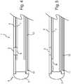
- Figure 1illustrates, in axial cross-sectional view, the distal end of a catheter generally indicated by 1.
- a drainage tube 2that extends from a drainage opening 3 adjacent the distal end 4 of the catheter to a drainage outlet adjacent a proximal end of the catheter (not illustrated).
- the drainage tube 2is constructed of a flexible material, such as a silicone-based plastics material or latex.
- the diameter of the catheteris so sized as to be able to be introduced into a body cavity of a subject for example through a urethra.
- the drainage tube 2is sealed at its distal end by a cap 5 securely fitted to the end of the tube 2.
- the bore of the drainage tube 2 and the outside diameter of the secondary tube 7are so sized as to provide a relatively snug fit, whilst allowing the secondary tube 7 to slide within the drainage tube 2 along its full length.
- the secondary tube 7is provided with an aperture 8 in its wall that, in a first position as illustrated in figure 1 , fluidly communicates with the drainage opening 3 in the drainage tube and thus with the lumen of the secondary tube 7.
- the secondary tube 7may be slid within the drainage tube to a second position, illustrated in figure 2 , such that the aperture 8 is no longer in fluid communication with the drainage opening 3 thereby blocking flow of a fluid through the drainage opening 3 and down the drainage tube or secondary tube.
- the end of the secondary tube 7is also sealed, for example with a cap or a plug 9. In this way, if the end of the secondary tube 7 is withdrawn to a distance past the drainage opening 3 towards the proximal end of the catheter, fluid can still not flow through the drainage tube and down the secondary tube.
- an installation lumen 10located within the wall of the drainage tube 2, that extends from an installation outlet 11 adjacent the distal end 4 of the catheter to an installation port adjacent the proximal end of the catheter (not illustrated).
- Figure 3shows a particularly preferred configuration of this example, as a transverse cross-section along the line A-A of figure 1 .
- the bore of the drainage tube 2is provided with a shaped profile, in the form of a flat section 12 running the length of the drainage tube, and the outside surface of the secondary tube 7 is provided with a similarly shaped flat surface portion 13 that co-operates with the flat 12 to resist rotational movement of the secondary tube with respect to the drainage tube.
- the configurationensures that the aperture 8 in the secondary tube can be correctly aligned with the drainage opening 3.
- multiple drainage openings 3may be provided around the periphery of the drainage tube, for example two such outlets, to ensure that flow can be maintained even if one outlet becomes blocked. It will be understood that in this situation, corresponding multiple apertures 8 in the secondary tube will also be provided.
- FIGS 4 and 5illustrate alternative configurations of the distal end of a catheter 1 of the present invention again in axial cross-section.
- FIG. 4The key difference between this example and the example of figures 1 and 2 is that the secondary tube 7 is not provided with an end cap 9. It can be seen that if the drainage tube 2 and secondary tube 7 are arranged in such a way that the secondary tube 7 can only be moved from its first position (illustrated in figure 4 ) to a second position (illustrated in figure 5 ) by moving the secondary tube 7 towards the distal end 4 of the catheter, then such a cap on the secondary tube becomes unnecessary, as the wall of the secondary tube will always provide an adequate seal for the drainage opening 3.
- Figure 6illustrates an alternative configuration of a cross-section of a catheter taken at a position equivalent to A-A of Figure 1 and in which two drainage openings 3 are provided, together with two apertures 8 in the wall of a secondary tube 7.
- an installation lumen 10is provided, moulded into the wall of the drainage tube 2.
- the installation lumendefines a protuberance 13 in the inner wall of the drainage tube 2 that matches a longitudinal groove 14 along the outside wall of the secondary tube 7.
- Figure 7illustrates an alternative cross-section, again at a position corresponding to section A-A of Figure 1 in which the sliding movement of the secondary tube 7 relative to the drainage tube 2 is a relative rotational movement such that the drainage opening 3 may be aligned or, as illustrated, set out of alignment with the aperture 8 in the wall of the secondary tube 7.
- Figure 8illustrates a preferred variant of the feature illustrated in Figure 7 , wherein a corresponding indent 15 and detent 16 are provided on the outside surface of the secondary tube 7 and the internal wall of the drainage tube 2 to allow rotational movement between the secondary tube 7 and the drainage tube 2, but to resist relative axial movement there between. Again, such a configuration allows the drainage outlet 3 and aperture 7 to be reliably positioned either in or out of alignment.
- detent and indent mechanismcould be arranged to provide a combination of rotational and axial movement by, for example, providing a helically disposed indent 15 that co-operates with a protruding detent 16.
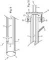
- Figure 9 and Figure 10illustrate respectively the distal and proximal ends of a catheter.
- the intervening length of catheteris not illustrated, for clarity, but would typically have a length of between for example 30cm to 1m.
- Features common to those illustrated in earlier embodimentsare correspondingly numbered.
- the end of the secondary tube 7is illustrated as being sealed with a plug 9, but could be equally open, as illustrated in the examples of Figures 3 and 4 due to the arrangement at the proximal end, to be described.
- Figure 10illustrates the proximal end of the catheter 1 showing the exit of the installation lumen 10 to an installation port 17 adjacent the proximal end of the catheter.
- the port 17is shown merely as the end of a tube, but could preferably and conveniently be provided with an appropriate connector such as a Luer connector, or in particularly preferred examples a self-sealing septum and/or a one-way valve (not illustrated).
- FIG 10illustrates that in this example the secondary tube 7 is connected to the drainage tube 2 by means of a ratchet mechanism, generally indicated by 18.
- the ratchet mechanism 18has co-operating barbs 19 attached to elongate members 20 and connected to the secondary tube 7 via a pressure plate 21 connected to the outside of the secondary tube 7.
- the drainage tube 2is connected to the receiving portion 22 of the ratchet mechanism 18.
- the pressure plate 21 of the mechanismcan be pushed toward the distal end of the catheter thereby moving the secondary tube 7 slidably within the drainage tube 2 and moving the tubes from the configuration shown in Figure 9 to that illustrated in Figure 5 , thereby closing the flow path between the distal and proximal ends of the catheter through the lumen of the secondary tube 7.
- the ratchet mechanism 18prevents the catheter being returned to its flow configuration, thereby preventing re-use of the device and hence preventing cross-infection that might result from re-use of the device.
- Figure 11illustrates in axial cross-sectional view, the distal end of a further example of a catheter.
- the catheteris further provided with a balloon 23 and 23' adjacent an external wall of the drainage tube 2 near the distal end 4 of the catheter but proximal of the drainage opening 3 and preferably the installation opening 11.
- the interior of the balloon 23is connected through a balloon control channel 24 to a balloon control port at the proximal end of the catheter (not illustrated) allowing the balloon to be inflated from a first position 23 to an inflated position 23' to anchor the catheter within the body cavity, for example at the neck of the urinary bladder.
- the balloonmay subsequently be deflated to allow the catheter to be removed once drainage and/or installation of medicament have been carried out.
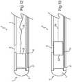
- Figures 12 and 13illustrate the distal end of an alternative catheter, generally indicated by 1.
- a drainage tube 2again having a drainage opening 3 in its side wall.
- the drainage tube 2is again sealed at its distal end 4 by means of a cap 5.
- the closure memberis in the form of a plug 25 located within the lumen of the drainage tube 2 and so shaped and sized as to provide a slidable but generally fluid-tight seal between the outside surface of the plug 25 and the inner surface of the drainage tube 2.
- the plug 25is connected to a filament 26 that extends to a proximal end of the catheter and exiting the drainage tube 2 either at its end or, more preferably, through a side wall of the drainage tube 2.
- tensionmay be applied to the filament 26 to bring the plug 25 across the face of the drainage outlet 3 (or even further down the drainage tube) thereby sealing the flow path.
- a filamentsuch as a length of nylon thread, renders the closure mechanism effectively irreversible due to the fact that the filament 25 is capable of transmitting forces in tension, but not in compression.
- a fluidsuch as a light silicone grease be applied between the interior face of the drainage tube and the outer face of the closure member, either when the closure member is a plug 26 or a secondary tube 7.
- a fluidserves two purposes: firstly to lubricate the relative sliding movement of the closure member and the drainage tube and, secondly to provide a more water tight seal there between.
- the catheterIn use, the catheter would be initially configured such that there is an open passage between the drainage opening 3 and the drainage outlet port 27.
- the catheterwould be inserted into the body cavity, for example into the urinary bladder via the urethra, until fluid, such as urine, was seen to discharge from the drainage outlet port 27, which could be conveniently connected to a collection bag via, e.g. a catheter tip connector. Once fluid was seen to discharge from the port, this would indicate that the catheter was in a suitable position within e.g. the bladder and, if one were provided, the location balloon 23 could be inflated to secure the catheter in place.
- proximal end of the cathetercould merely be taped in to position on an extremity of a patient, for example on the patient's leg to secure the catheter in place whilst the drainage and/or installation of a drug were carried out.
- a clip membermay be provided into which the proximal end of the catheter can be secured and the clip fastened to the patient either with adhesive tape or some other releasable means.
- the closure membermay be actuated to close the flow path between the drainage opening and the drainage outlet.
- medicamentif medicament is to be administered, it can be introduced into the body cavity by injection through the installation port 17 at the proximal end of the catheter, to emerge at the installation outlet 11 via the installation lumen 10.
- FIG. 14-16An adaptor of a connector for connecting a syringe to a catheter for the administration of a medicament of the present invention is illustrated in figures 14-16 .
- a standard syringe 140is utilised to retain and deliver a measured volume through the syringe outlet 141.
- the syringe outlet 141is housed in, and connected to, the installation port 17 ( figure 10 ), by an adapted Luer slip connector.
- the adaptations described belowprevent the connector from being used in conjunction with standard Luer fixtures.
- the connectorcomprises two main elements.
- the first elementis an adapter 142 having, at a first end, a tapered recess 143 to receive the syringe outlet 141.
- the outlet 141 and recess 143connect via a push fit connection although additional bonding means can be included to provide a more secure connection.
- the second end of the adapter 142shown in the end view figure 14a has recessed channels 144 and raised ribs 145, which achieve the prevention of the fitment of the adapter 142 to a standard Luer as mentioned above.
- the adaptor 142itself is seated in a one-way valve fitting 146 having at a first end a recess 147 of shape complementary to that of the channels 144 and ribs 145 to provide a secure fitting.
- the raised ribs 148 within the recess 147prevent a standard Luer fitting from being inserted.
- the second end of the valve fitting 146can be fitted to the installation port 17.
- the one-way valve fitting 146includes a spring 149 or other resilient means known in the art to bias the valve 146 to the closed position when no pressure is exerted on the fluid in the syringe 140.
- the assembled syringe and connector, including the adapter 142 and valve fitting 146is shown in Figure 16 .
- the locational balloon 23(if present) may be deflated, and the catheter withdrawn from the body cavity for disposal.
Landscapes
- Health & Medical Sciences (AREA)
- Life Sciences & Earth Sciences (AREA)
- Heart & Thoracic Surgery (AREA)
- Hematology (AREA)
- Public Health (AREA)
- Anesthesiology (AREA)
- Biomedical Technology (AREA)
- Engineering & Computer Science (AREA)
- Veterinary Medicine (AREA)
- Animal Behavior & Ethology (AREA)
- General Health & Medical Sciences (AREA)
- Pulmonology (AREA)
- Biophysics (AREA)
- Epidemiology (AREA)
- Urology & Nephrology (AREA)
- Child & Adolescent Psychology (AREA)
- External Artificial Organs (AREA)
- Media Introduction/Drainage Providing Device (AREA)
- Infusion, Injection, And Reservoir Apparatuses (AREA)
Description
- The disclosure relates to catheters for draining fluids from body cavities of human or animal subjects and especially for those catheters that can also instil a medicament into the cavity following drainage. The disclosure is especially concerned with such catheters for draining urine from the urinary bladder of a subject and instilling a medicament The invention relates particularly to an adapter of a connector for connecting a syringe to a catheter wherein the adaptor prevents the connector from being used with standard Luer fixtures.
- There are a number of conditions that require patients to manually drain urine from the bladder at intervals, and this can be performed either under the supervision of an attending physician or healthcare worker, or on occasions can be performed by a patient themselves. One such common condition is an overactive bladder. For many conditions it is also necessary to deliver a medicament to the bladder. For this to be successful, it is important that the bladder is initially drained of any accumulated urine to prevent dilution of the medicament, so allowing a pre-determined dose to be applied. Direct application of medicaments to the interior of the bladder, known as "intravesical" administration is becoming more common, and one such specialised catheter to allow drainage and intravesical administration is described in UK patent
GB 2448892 - Accordingly, the invention provides an adapter for connecting a syringe to a catheter, said adapter comprising:
- (a) at a first end, a tapered recess to receive an outlet from a syringe; and
- (b) at a second end, a male connector having recessed channels and raised ribs disposed on the surface of said male connector.
Figures 1 and 2 illustrate an axial cross-section of the distal end of a catheter;Figure 3 illustrates a transverse cross-section of a catheter;Figures 4 and 5 illustrate transverse cross-sections of the distal end of a catheter;Figures 6-8 illustrate transverse cross-sections of embodiments of a catheter;Figures 9 and 10 illustrate axial cross-sections of a distal and proximal end respectively of an example of a catheter;Figures 11-13 illustrate axial cross-sections of a distal end of another catheter; andFigures 14-16 illustrate a delivery means for a medicament suitable for use with a catheter ilustrating the adapter for connecting a syringe to a catheter in accordance with the invention.Figure 1 illustrates, in axial cross-sectional view, the distal end of a catheter generally indicated by 1. In this exemplary catheter, there is provided adrainage tube 2 that extends from adrainage opening 3 adjacent thedistal end 4 of the catheter to a drainage outlet adjacent a proximal end of the catheter (not illustrated). Thedrainage tube 2 is constructed of a flexible material, such as a silicone-based plastics material or latex.- The diameter of the catheter is so sized as to be able to be introduced into a body cavity of a subject for example through a urethra. In the embodiment of
figure 1 thedrainage tube 2 is sealed at its distal end by acap 5 securely fitted to the end of thetube 2. - A closure member in the form of a
secondary tube 7 located within thedrainage tube 2. The bore of thedrainage tube 2 and the outside diameter of thesecondary tube 7 are so sized as to provide a relatively snug fit, whilst allowing thesecondary tube 7 to slide within thedrainage tube 2 along its full length. In this example, thesecondary tube 7 is provided with anaperture 8 in its wall that, in a first position as illustrated infigure 1 , fluidly communicates with the drainage opening 3 in the drainage tube and thus with the lumen of thesecondary tube 7. - The
secondary tube 7 may be slid within the drainage tube to a second position, illustrated infigure 2 , such that theaperture 8 is no longer in fluid communication with thedrainage opening 3 thereby blocking flow of a fluid through thedrainage opening 3 and down the drainage tube or secondary tube. In the example shown infigures 1 and 2 , the end of thesecondary tube 7 is also sealed, for example with a cap or aplug 9. In this way, if the end of thesecondary tube 7 is withdrawn to a distance past the drainage opening 3 towards the proximal end of the catheter, fluid can still not flow through the drainage tube and down the secondary tube. - Also included in this example is an
installation lumen 10, located within the wall of thedrainage tube 2, that extends from aninstallation outlet 11 adjacent thedistal end 4 of the catheter to an installation port adjacent the proximal end of the catheter (not illustrated). Figure 3 shows a particularly preferred configuration of this example, as a transverse cross-section along the line A-A offigure 1 . In this example, the bore of thedrainage tube 2 is provided with a shaped profile, in the form of aflat section 12 running the length of the drainage tube, and the outside surface of thesecondary tube 7 is provided with a similarly shapedflat surface portion 13 that co-operates with the flat 12 to resist rotational movement of the secondary tube with respect to the drainage tube. In this way, the configuration ensures that theaperture 8 in the secondary tube can be correctly aligned with thedrainage opening 3.- It will be appreciated that in examples of the catheter,
multiple drainage openings 3 may be provided around the periphery of the drainage tube, for example two such outlets, to ensure that flow can be maintained even if one outlet becomes blocked. It will be understood that in this situation, correspondingmultiple apertures 8 in the secondary tube will also be provided. Figures 4 and 5 illustrate alternative configurations of the distal end of acatheter 1 of the present invention again in axial cross-section. Features in these embodiments that correspond with those offigures 1 and 2 are numbered accordingly. The key difference between this example and the example offigures 1 and 2 is that thesecondary tube 7 is not provided with anend cap 9. It can be seen that if thedrainage tube 2 andsecondary tube 7 are arranged in such a way that thesecondary tube 7 can only be moved from its first position (illustrated infigure 4 ) to a second position (illustrated infigure 5 ) by moving thesecondary tube 7 towards thedistal end 4 of the catheter, then such a cap on the secondary tube becomes unnecessary, as the wall of the secondary tube will always provide an adequate seal for thedrainage opening 3.Figure 6 illustrates an alternative configuration of a cross-section of a catheter taken at a position equivalent to A-A ofFigure 1 and in which twodrainage openings 3 are provided, together with twoapertures 8 in the wall of asecondary tube 7. Again, aninstallation lumen 10 is provided, moulded into the wall of thedrainage tube 2. In this embodiment, the installation lumen defines aprotuberance 13 in the inner wall of thedrainage tube 2 that matches alongitudinal groove 14 along the outside wall of thesecondary tube 7. These correspondingly-shaped profiles again provide a resistance against relative rotational movement between the drainage tube and the secondary tube, ensuring axial alignment of theapertures 8 with thedrainage openings 3.Figure 7 illustrates an alternative cross-section, again at a position corresponding to section A-A ofFigure 1 in which the sliding movement of thesecondary tube 7 relative to thedrainage tube 2 is a relative rotational movement such that thedrainage opening 3 may be aligned or, as illustrated, set out of alignment with theaperture 8 in the wall of thesecondary tube 7.Figure 8 illustrates a preferred variant of the feature illustrated inFigure 7 , wherein acorresponding indent 15 anddetent 16 are provided on the outside surface of thesecondary tube 7 and the internal wall of thedrainage tube 2 to allow rotational movement between thesecondary tube 7 and thedrainage tube 2, but to resist relative axial movement there between. Again, such a configuration allows thedrainage outlet 3 andaperture 7 to be reliably positioned either in or out of alignment.- It will be appreciated that such a detent and indent mechanism could be arranged to provide a combination of rotational and axial movement by, for example, providing a helically disposed indent 15 that co-operates with a protruding
detent 16. Figure 9 and Figure 10 illustrate respectively the distal and proximal ends of a catheter. The intervening length of catheter is not illustrated, for clarity, but would typically have a length of between for example 30cm to 1m. Features common to those illustrated in earlier embodiments are correspondingly numbered. At the distal end of thecatheter 1 illustrated inFigure 9 , the end of thesecondary tube 7 is illustrated as being sealed with aplug 9, but could be equally open, as illustrated in the examples ofFigures 3 and4 due to the arrangement at the proximal end, to be described.Figure 10 illustrates the proximal end of thecatheter 1 showing the exit of theinstallation lumen 10 to aninstallation port 17 adjacent the proximal end of the catheter. In this illustration, theport 17 is shown merely as the end of a tube, but could preferably and conveniently be provided with an appropriate connector such as a Luer connector, or in particularly preferred examples a self-sealing septum and/or a one-way valve (not illustrated).Figure 10 illustrates that in this example thesecondary tube 7 is connected to thedrainage tube 2 by means of a ratchet mechanism, generally indicated by 18. Theratchet mechanism 18 has co-operatingbarbs 19 attached toelongate members 20 and connected to thesecondary tube 7 via a pressure plate 21 connected to the outside of thesecondary tube 7. Thedrainage tube 2 is connected to thereceiving portion 22 of theratchet mechanism 18. In use, the pressure plate 21 of the mechanism can be pushed toward the distal end of the catheter thereby moving thesecondary tube 7 slidably within thedrainage tube 2 and moving the tubes from the configuration shown inFigure 9 to that illustrated inFigure 5 , thereby closing the flow path between the distal and proximal ends of the catheter through the lumen of thesecondary tube 7. Theratchet mechanism 18 prevents the catheter being returned to its flow configuration, thereby preventing re-use of the device and hence preventing cross-infection that might result from re-use of the device.Figure 11 illustrates in axial cross-sectional view, the distal end of a further example of a catheter. Again, features corresponding to those illustrated in other figures are numbered accordingly. In this example, the catheter is further provided with aballoon 23 and 23' adjacent an external wall of thedrainage tube 2 near thedistal end 4 of the catheter but proximal of thedrainage opening 3 and preferably theinstallation opening 11. The interior of theballoon 23 is connected through aballoon control channel 24 to a balloon control port at the proximal end of the catheter (not illustrated) allowing the balloon to be inflated from afirst position 23 to an inflated position 23' to anchor the catheter within the body cavity, for example at the neck of the urinary bladder. The balloon may subsequently be deflated to allow the catheter to be removed once drainage and/or installation of medicament have been carried out.Figures 12 and 13 illustrate the distal end of an alternative catheter, generally indicated by 1. In this example, there is provided adrainage tube 2 again having adrainage opening 3 in its side wall. Thedrainage tube 2 is again sealed at itsdistal end 4 by means of acap 5. In this example, the closure member is in the form of aplug 25 located within the lumen of thedrainage tube 2 and so shaped and sized as to provide a slidable but generally fluid-tight seal between the outside surface of theplug 25 and the inner surface of thedrainage tube 2. Theplug 25 is connected to afilament 26 that extends to a proximal end of the catheter and exiting thedrainage tube 2 either at its end or, more preferably, through a side wall of thedrainage tube 2. In use, when it is required to seal thedrainage outlet 3, tension may be applied to thefilament 26 to bring theplug 25 across the face of the drainage outlet 3 (or even further down the drainage tube) thereby sealing the flow path. The use of a filament, such as a length of nylon thread, renders the closure mechanism effectively irreversible due to the fact that thefilament 25 is capable of transmitting forces in tension, but not in compression.- In any exemplary catheter described herein, it is particularly preferred that a fluid such as a light silicone grease be applied between the interior face of the drainage tube and the outer face of the closure member, either when the closure member is a
plug 26 or asecondary tube 7. The use of such a fluid serves two purposes: firstly to lubricate the relative sliding movement of the closure member and the drainage tube and, secondly to provide a more water tight seal there between. - In use, the catheter would be initially configured such that there is an open passage between the
drainage opening 3 and thedrainage outlet port 27. The catheter would be inserted into the body cavity, for example into the urinary bladder via the urethra, until fluid, such as urine, was seen to discharge from thedrainage outlet port 27, which could be conveniently connected to a collection bag via, e.g. a catheter tip connector. Once fluid was seen to discharge from the port, this would indicate that the catheter was in a suitable position within e.g. the bladder and, if one were provided, thelocation balloon 23 could be inflated to secure the catheter in place. It is particularly preferred and envisaged, however, that nosuch balloon 23 is provided, but that the proximal end of the catheter could merely be taped in to position on an extremity of a patient, for example on the patient's leg to secure the catheter in place whilst the drainage and/or installation of a drug were carried out. To aid such securement, a clip member may be provided into which the proximal end of the catheter can be secured and the clip fastened to the patient either with adhesive tape or some other releasable means. - Once sufficient fluid (e.g. urine) had been drained from the body cavity, the closure member may be actuated to close the flow path between the drainage opening and the drainage outlet. At this stage, if medicament is to be administered, it can be introduced into the body cavity by injection through the
installation port 17 at the proximal end of the catheter, to emerge at theinstallation outlet 11 via theinstallation lumen 10. - An adaptor of a connector for connecting a syringe to a catheter for the administration of a medicament of the present invention is illustrated in
figures 14-16 . Astandard syringe 140 is utilised to retain and deliver a measured volume through thesyringe outlet 141. Thesyringe outlet 141 is housed in, and connected to, the installation port 17 (figure 10 ), by an adapted Luer slip connector. The adaptations described below prevent the connector from being used in conjunction with standard Luer fixtures. - The connector comprises two main elements. The first element is an
adapter 142 having, at a first end, atapered recess 143 to receive thesyringe outlet 141. Theoutlet 141 andrecess 143 connect via a push fit connection although additional bonding means can be included to provide a more secure connection. The second end of theadapter 142, shown in the end viewfigure 14a has recessedchannels 144 and raisedribs 145, which achieve the prevention of the fitment of theadapter 142 to a standard Luer as mentioned above. - The
adaptor 142 itself is seated in a one-way valve fitting 146 having at a first end arecess 147 of shape complementary to that of thechannels 144 andribs 145 to provide a secure fitting. The raisedribs 148 within therecess 147 prevent a standard Luer fitting from being inserted. The second end of the valve fitting 146 can be fitted to theinstallation port 17. The one-way valve fitting 146 includes aspring 149 or other resilient means known in the art to bias thevalve 146 to the closed position when no pressure is exerted on the fluid in thesyringe 140. The assembled syringe and connector, including theadapter 142 and valve fitting 146 is shown inFigure 16 . - Once administration is complete, the locational balloon 23 (if present) may be deflated, and the catheter withdrawn from the body cavity for disposal.
Claims (5)
- An adapter (142) for connecting a syringe (140) to a catheter, said adapter comprising:(a) at a first end, a tapered recess (143) to receive an outlet from a syringe; and(b) at a second end, a male connector having recessed channels (144) and raised ribs (145) disposed on the surface of said male connector.
- A one-way valve fitting (146) comprising a recess having a shape complimentary to the channels and ribs of an adapter according to Claim 1.
- A one-way valve fitting according to Claim 2 fitted to an instillation port of a catheter.
- A connector comprising an adapter according to Claim 1 and a one-way valve fitting according to either Claim 2 or Claim 3.
- An adapter, valve fitting or connector according to any preceding claim wherein said catheter is a urinary catheter.
Applications Claiming Priority (3)
| Application Number | Priority Date | Filing Date | Title |
|---|---|---|---|
| GB1118126.0AGB2484598B (en) | 2011-10-20 | 2011-10-20 | Improvements in catheters |
| EP12780784.0AEP2793988B1 (en) | 2011-10-20 | 2012-10-22 | Improvements in catheters |
| PCT/GB2012/052617WO2013057517A1 (en) | 2011-10-20 | 2012-10-22 | Improvements in catheters |
Related Parent Applications (2)
| Application Number | Title | Priority Date | Filing Date |
|---|---|---|---|
| EP12780784.0ADivisionEP2793988B1 (en) | 2011-10-20 | 2012-10-22 | Improvements in catheters |
| EP12780784.0ADivision-IntoEP2793988B1 (en) | 2011-10-20 | 2012-10-22 | Improvements in catheters |
Publications (3)
| Publication Number | Publication Date |
|---|---|
| EP3417907A1 EP3417907A1 (en) | 2018-12-26 |
| EP3417907B1true EP3417907B1 (en) | 2020-04-22 |
| EP3417907B8 EP3417907B8 (en) | 2020-06-10 |
Family
ID=45220009
Family Applications (2)
| Application Number | Title | Priority Date | Filing Date |
|---|---|---|---|
| EP12780784.0AActiveEP2793988B1 (en) | 2011-10-20 | 2012-10-22 | Improvements in catheters |
| EP18186483.6AActiveEP3417907B8 (en) | 2011-10-20 | 2012-10-22 | Syringe adapter and valve fitting |
Family Applications Before (1)
| Application Number | Title | Priority Date | Filing Date |
|---|---|---|---|
| EP12780784.0AActiveEP2793988B1 (en) | 2011-10-20 | 2012-10-22 | Improvements in catheters |
Country Status (15)
| Country | Link |
|---|---|
| US (2) | US10188827B2 (en) |
| EP (2) | EP2793988B1 (en) |
| JP (1) | JP6198739B2 (en) |
| KR (3) | KR102057348B1 (en) |
| CN (1) | CN104010689B (en) |
| AU (1) | AU2012324578B2 (en) |
| CA (2) | CA3085705C (en) |
| DK (2) | DK2793988T3 (en) |
| EA (1) | EA027271B1 (en) |
| ES (2) | ES2808375T3 (en) |
| GB (2) | GB2484598B (en) |
| PT (2) | PT3417907T (en) |
| SG (1) | SG11201402368SA (en) |
| TR (1) | TR201818927T4 (en) |
| WO (1) | WO2013057517A1 (en) |
Families Citing this family (44)
| Publication number | Priority date | Publication date | Assignee | Title |
|---|---|---|---|---|
| US9675237B2 (en) | 2005-01-26 | 2017-06-13 | Mayser, Llc | Illuminating balloon catheter and method for using the catheter |
| US9586022B2 (en) | 2006-01-25 | 2017-03-07 | Mayser, Llc | Stretch valve balloon catheter and methods for producing and using same |
| US9272120B2 (en) | 2006-01-25 | 2016-03-01 | Mayser, Llc | Stretch valve balloon catheter and methods for producing and using same |
| US9642992B2 (en) | 2005-01-26 | 2017-05-09 | Mayser, Llc | Stretch valve balloon catheter and methods for producing and using same |
| US9713698B2 (en) | 2006-01-25 | 2017-07-25 | Mayser, Llc | Stretch valve balloon catheter and methods for producing and using same |
| WO2009135141A1 (en) | 2008-05-01 | 2009-11-05 | Bristol-Myers Squibb Company | Rectal drain appliance |
| US11813421B2 (en) | 2010-11-10 | 2023-11-14 | Mayser, Llc | Stretch valve balloon catheter and methods for producing and using same |
| US10137282B2 (en) | 2010-11-10 | 2018-11-27 | Mayser, Llc | Stretch valve balloon catheter and methods for producing and using same |
| CN108578044A (en) | 2011-03-17 | 2018-09-28 | 康沃特克科技公司 | High barrier elastomer excrement conduit or ostomy bag |
| GB2484598B (en) | 2011-10-20 | 2014-02-12 | Uropharma Ltd | Improvements in catheters |
| US9332998B2 (en) | 2012-08-13 | 2016-05-10 | Covidien Lp | Apparatus and methods for clot disruption and evacuation |
| US9332999B2 (en) | 2012-08-13 | 2016-05-10 | Covidien Lp | Apparatus and methods for clot disruption and evacuation |
| US20140163530A1 (en)* | 2012-12-01 | 2014-06-12 | Wake Forest University Health Sciences | Non-pressure transducing flushable catheter |
| EP2931353B1 (en)* | 2012-12-07 | 2019-07-17 | Leonard Pinchuk | Stretch valve balloon catheter |
| US9108019B2 (en)* | 2013-03-13 | 2015-08-18 | Boston Scientific Limited | Catheter system |
| PL3027266T3 (en) | 2013-08-01 | 2023-09-04 | Convatec Technologies Inc. | Self-closing bag connector |
| US10112031B2 (en) | 2013-09-02 | 2018-10-30 | Coloplast A/S | Catheter packaged inside of a handle attached to a container |
| US20150265805A1 (en)* | 2014-02-21 | 2015-09-24 | Ahmad D. Vakili | Catheter with Gills |
| CN104338229A (en)* | 2014-09-12 | 2015-02-11 | 朱瀚林 | Disposable multifunctional painless catheter |
| CN107485778A (en)* | 2017-08-07 | 2017-12-19 | 梁靖华 | A kind of anal intestine analgesia apparatus and indwelling equipment |
| US10632280B2 (en)* | 2017-09-15 | 2020-04-28 | Neosinus Health Inc. | Devices and methods for delivering fluid to a nasal cavity |
| GB201721955D0 (en) | 2017-12-27 | 2018-02-07 | Convatec Ltd | Catheter wetting devices |
| GB201721956D0 (en) | 2017-12-27 | 2018-02-07 | Convatec Ltd | Female catheter locator tip |
| CN112292174A (en)* | 2018-06-04 | 2021-01-29 | 艾普斯顿姆外围技术有限公司 | Axial sharp needle reentry device |
| US11235134B2 (en) | 2018-07-11 | 2022-02-01 | Becton, Dickinson And Company | Neuraxial connector |
| US11318262B2 (en) | 2018-07-11 | 2022-05-03 | Becton, Dickinson And Company | Neuraxial connector |
| KR102074438B1 (en)* | 2018-08-01 | 2020-02-06 | 이치영 | Catheter |
| CN113347932B (en)* | 2018-11-07 | 2025-05-27 | 伯恩森斯韦伯斯特(以色列)有限责任公司 | Cryoballoon with directional gas control |
| US20200376249A1 (en)* | 2019-05-29 | 2020-12-03 | Penumbra, Inc. | Flushing catheter |
| US11052205B2 (en) | 2019-06-11 | 2021-07-06 | Neosinus Health Inc | Devices and methods for delivering fluid to a nasal cavity |
| CA3140906A1 (en) | 2019-06-11 | 2020-12-17 | Convatec Technologies Inc. | Urine collection bags for use with catheter products, kits incorporating the same, and methods therefor |
| US11766191B2 (en) | 2019-06-28 | 2023-09-26 | Battelle Memorial Institute | Neurosleeve for closed loop EMG-FES based control of pathological tremors |
| CA3144695A1 (en)* | 2019-07-09 | 2021-01-14 | Becton, Dickinson And Company | Neuraxial connector |
| EP3795196B1 (en)* | 2019-09-18 | 2022-05-11 | Heraeus Medical GmbH | Device for temporary local application of fluids |
| CA3169505A1 (en)* | 2020-02-25 | 2021-09-02 | Bioflow Inc | Isolating drainage catheter |
| US20210290247A1 (en)* | 2020-03-23 | 2021-09-23 | Becton, Dickinson And Company | Vascular instrument delivery device and related systems and methods |
| WO2022170187A1 (en)* | 2021-02-05 | 2022-08-11 | Pyne Devaraj | Detachable balloon embolization device and methods |
| CN112915301A (en)* | 2021-03-03 | 2021-06-08 | 周义龙 | Multifunctional medical drainage and flushing device and operation method thereof |
| WO2023272352A1 (en)* | 2021-06-29 | 2023-01-05 | All Vascular Pty Limited | Vascular access device for introducing a catheter |
| CN115702957A (en)* | 2021-08-05 | 2023-02-17 | 苏州市立普医疗科技有限公司 | A seal structure and drainage catheter for drainage catheter |
| US20230073708A1 (en)* | 2021-09-07 | 2023-03-09 | Purewick Corporation | Fluid collection with multiport valve assembly |
| US20230096007A1 (en)* | 2021-09-24 | 2023-03-30 | Medtronic Vascular, Inc. | Introducer assembly with selectable side holes |
| CN114748714A (en)* | 2022-04-27 | 2022-07-15 | 首都医科大学附属北京朝阳医院 | Intracranial hematoma directional drainage device and drainage method |
| US12377243B1 (en) | 2024-10-01 | 2025-08-05 | Uropharma Limited | Intermittent intravesical therapeutic administration system |
Family Cites Families (35)
| Publication number | Priority date | Publication date | Assignee | Title |
|---|---|---|---|---|
| EP0245211A1 (en) | 1986-03-04 | 1987-11-11 | HOECHST ITALIA SUD S.p.A. | Kidney-ureter catheter unit particularly adapated to evacuate crumbled calculi |
| JPS648980A (en)* | 1987-07-02 | 1989-01-12 | Terumo Corp | Balloon catheter and its preparation |
| WO1995015193A1 (en)* | 1993-11-30 | 1995-06-08 | Medex, Inc. | Anti-reflux valve with environmental barrier |
| US6007479A (en)* | 1996-07-08 | 1999-12-28 | H.D.S. Systems Ltd. | Heart assist system and method |
| CN1145260A (en) | 1995-09-15 | 1997-03-19 | 丁超美 | Guiding device of soft catheter |
| JPH09253215A (en) | 1996-03-26 | 1997-09-30 | Nippon Sherwood Kk | Multiplex lumen catheter |
| US6402207B1 (en) | 1997-06-09 | 2002-06-11 | Qd Enterprises, Llc | Safety indexed medical connectors |
| WO1999051293A1 (en)* | 1998-04-05 | 1999-10-14 | Johannes Dohmen | Bladder-neck indwelling catheter with an opening and closing device which can be controlled in a contactless manner to empty urine from the bladder |
| JP2001137350A (en)* | 1999-11-15 | 2001-05-22 | Akio Kawamura | Hemodialysis catheter |
| US6270053B1 (en)* | 2000-03-28 | 2001-08-07 | Eumedicaltech, Ltd. | Catheter valve |
| DE10112630C2 (en) | 2000-12-21 | 2003-03-27 | Gernot Martin Pfaff | drainage device |
| US8323228B2 (en)* | 2007-04-12 | 2012-12-04 | Rex Medical L.P. | Dialysis catheter |
| US8353895B2 (en)* | 2002-04-16 | 2013-01-15 | Ronald D Russo | Closed system irrigation connector for urinary catheters |
| AU2003282886B2 (en)* | 2002-09-30 | 2009-07-23 | Board Of Regents, The University Of Texas System | Stent delivery system and method of use |
| US7300429B2 (en)* | 2003-03-18 | 2007-11-27 | Catharos Medical Systems, Inc. | Methods and devices for retrieval of a medical agent from a physiological efferent fluid collection site |
| US7211074B2 (en)* | 2003-08-12 | 2007-05-01 | Sherwood Services Ag | Valved catheter |
| FR2863162B1 (en) | 2003-12-05 | 2006-12-08 | Vygon | MALE FITTINGS AND FEMALE FITTINGS FOR REALIZING LIQUID TRANSMISSION CONNECTIONS, IN PARTICULAR FOR ENTERALE NUTRITION LINES |
| US20070213671A1 (en) | 2005-09-07 | 2007-09-13 | Hiatt Mark J | Infusion catheter system with telescoping cannula |
| US8052659B2 (en)* | 2005-11-10 | 2011-11-08 | Phase One Medical Llc | Catheter device |
| US8007488B2 (en) | 2005-11-10 | 2011-08-30 | Phase One Medical Llc | Catheter device |
| WO2007079152A2 (en)* | 2005-12-28 | 2007-07-12 | Ams Research Corporation | Devices amd systems for delivery of fluid to tissue |
| US20080140020A1 (en)* | 2006-12-08 | 2008-06-12 | Utah Medical Products Inc. | Lockable enteral feeding adapter |
| CA2676787A1 (en) | 2007-02-05 | 2008-08-14 | Boston Scientific Limited | System with catheter system and an adaptor comprising a friction reducing sleeve, and methods of use |
| GB2448892B (en)* | 2007-05-01 | 2009-04-29 | Jotillou Entpr Ltd | Catheter |
| GB2451891A (en)* | 2007-08-17 | 2009-02-18 | Univ Sheffield Hallam | Medical fluid connector with features to ensure correct coupling |
| US8920403B2 (en)* | 2008-03-18 | 2014-12-30 | Anthony Doerr | Catheter with biologic adhesive injection ports and method of injecting biologic adhesive therewith |
| US8888758B2 (en)* | 2008-09-05 | 2014-11-18 | Carefusion 303, Inc. | Closed male luer device for minimizing leakage during connection and disconnection |
| US8292940B2 (en)* | 2009-02-11 | 2012-10-23 | Boston Scientific Scimed, Inc. | Medical device having a rotatable shaft |
| WO2011014201A1 (en)* | 2009-07-29 | 2011-02-03 | C. R. Bard, Inc. | Catheter having improved drainage and/or a retractable sleeve and method of using the same |
| WO2011019359A1 (en)* | 2009-08-13 | 2011-02-17 | C. R. Bard, Inc. | Catheter having internal hydrating fluid storage and/or catheter package using the same and method of making and/or using the same |
| US20120203357A1 (en) | 2009-10-15 | 2012-08-09 | I.B.I Israel Biomedical Innovations Ltd. | Urethral anastomosis device |
| US9814870B2 (en)* | 2010-08-17 | 2017-11-14 | Becton, Dickinson And Company | Non-luer connectors |
| US20120239006A1 (en)* | 2011-03-15 | 2012-09-20 | Bandula Wijay | External control valve for indwelling urethral catheters |
| US9433768B2 (en)* | 2011-03-25 | 2016-09-06 | Becton, Dickinson And Company | Drug delivery connectors |
| GB2484598B (en) | 2011-10-20 | 2014-02-12 | Uropharma Ltd | Improvements in catheters |
- 2011
- 2011-10-20GBGB1118126.0Apatent/GB2484598B/enactiveActive
- 2012
- 2012-10-22ESES18186483Tpatent/ES2808375T3/enactiveActive
- 2012-10-22DKDK12780784.0Tpatent/DK2793988T3/enactive
- 2012-10-22JPJP2014536337Apatent/JP6198739B2/enactiveActive
- 2012-10-22CNCN201280063486.2Apatent/CN104010689B/enactiveActive
- 2012-10-22ESES12780784Tpatent/ES2699968T3/enactiveActive
- 2012-10-22KRKR1020147013492Apatent/KR102057348B1/enactiveActive
- 2012-10-22SGSG11201402368SApatent/SG11201402368SA/enunknown
- 2012-10-22CACA3085705Apatent/CA3085705C/enactiveActive
- 2012-10-22PTPT181864836Tpatent/PT3417907T/enunknown
- 2012-10-22EPEP12780784.0Apatent/EP2793988B1/enactiveActive
- 2012-10-22USUS14/351,936patent/US10188827B2/enactiveActive
- 2012-10-22DKDK18186483.6Tpatent/DK3417907T3/enactive
- 2012-10-22KRKR1020187007828Apatent/KR20180032671A/ennot_activeCeased
- 2012-10-22WOPCT/GB2012/052617patent/WO2013057517A1/enactiveApplication Filing
- 2012-10-22AUAU2012324578Apatent/AU2012324578B2/enactiveActive
- 2012-10-22EAEA201490787Apatent/EA027271B1/ennot_activeIP Right Cessation
- 2012-10-22CACA2858303Apatent/CA2858303C/enactiveActive
- 2012-10-22KRKR1020207021243Apatent/KR102341816B1/ennot_activeExpired - Fee Related
- 2012-10-22PTPT12780784Tpatent/PT2793988T/enunknown
- 2012-10-22GBGB1408634.2Apatent/GB2510086C/ennot_activeExpired - Fee Related
- 2012-10-22TRTR2018/18927Tpatent/TR201818927T4/enunknown
- 2012-10-22EPEP18186483.6Apatent/EP3417907B8/enactiveActive
- 2018
- 2018-04-25USUS15/962,227patent/US20180304039A1/enactivePending
Non-Patent Citations (1)
| Title |
|---|
| None* |
Also Published As
Similar Documents
| Publication | Publication Date | Title |
|---|---|---|
| EP3417907B1 (en) | Syringe adapter and valve fitting | |
| US20230166093A1 (en) | Catheter valves | |
| JP2014530699A5 (en) | ||
| AU2009202621B8 (en) | Discriminating oral tip adaptor | |
| JP6272760B2 (en) | Intravenous catheter with duckbill valve | |
| US7331949B2 (en) | Urinary catheter with check valve | |
| US9795766B2 (en) | Catheter assembly blood control device and related methods | |
| US9408971B2 (en) | Self-capping syringe assembly with one-way valve | |
| CN202844312U (en) | Catheter assembly | |
| BR112012021414B1 (en) | drug delivery connector and method of delivering liquid medication to a catheter connector | |
| HK40000491A (en) | Syringe adapter and valve fitting | |
| HK40000491B (en) | Syringe adapter and valve fitting | |
| US20120004644A1 (en) | Pleural drainage system locking dilator |
Legal Events
| Date | Code | Title | Description |
|---|---|---|---|
| PUAI | Public reference made under article 153(3) epc to a published international application that has entered the european phase | Free format text:ORIGINAL CODE: 0009012 | |
| STAA | Information on the status of an ep patent application or granted ep patent | Free format text:STATUS: THE APPLICATION HAS BEEN PUBLISHED | |
| AC | Divisional application: reference to earlier application | Ref document number:2793988 Country of ref document:EP Kind code of ref document:P | |
| AK | Designated contracting states | Kind code of ref document:A1 Designated state(s):AL AT BE BG CH CY CZ DE DK EE ES FI FR GB GR HR HU IE IS IT LI LT LU LV MC MK MT NL NO PL PT RO RS SE SI SK SM TR | |
| STAA | Information on the status of an ep patent application or granted ep patent | Free format text:STATUS: REQUEST FOR EXAMINATION WAS MADE | |
| 17P | Request for examination filed | Effective date:20190513 | |
| RBV | Designated contracting states (corrected) | Designated state(s):AL AT BE BG CH CY CZ DE DK EE ES FI FR GB GR HR HU IE IS IT LI LT LU LV MC MK MT NL NO PL PT RO RS SE SI SK SM TR | |
| RIC1 | Information provided on ipc code assigned before grant | Ipc:A61M 25/01 20060101ALI20190925BHEP Ipc:A61M 25/00 20060101ALI20190925BHEP Ipc:A61M 39/26 20060101AFI20190925BHEP Ipc:A61M 39/10 20060101ALI20190925BHEP | |
| GRAP | Despatch of communication of intention to grant a patent | Free format text:ORIGINAL CODE: EPIDOSNIGR1 | |
| STAA | Information on the status of an ep patent application or granted ep patent | Free format text:STATUS: GRANT OF PATENT IS INTENDED | |
| INTG | Intention to grant announced | Effective date:20191205 | |
| REG | Reference to a national code | Ref country code:HK Ref legal event code:DE Ref document number:40000491 Country of ref document:HK | |
| GRAS | Grant fee paid | Free format text:ORIGINAL CODE: EPIDOSNIGR3 | |
| GRAA | (expected) grant | Free format text:ORIGINAL CODE: 0009210 | |
| STAA | Information on the status of an ep patent application or granted ep patent | Free format text:STATUS: THE PATENT HAS BEEN GRANTED | |
| AC | Divisional application: reference to earlier application | Ref document number:2793988 Country of ref document:EP Kind code of ref document:P | |
| AK | Designated contracting states | Kind code of ref document:B1 Designated state(s):AL AT BE BG CH CY CZ DE DK EE ES FI FR GB GR HR HU IE IS IT LI LT LU LV MC MK MT NL NO PL PT RO RS SE SI SK SM TR | |
| REG | Reference to a national code | Ref country code:CH Ref legal event code:EP | |
| REG | Reference to a national code | Ref country code:IE Ref legal event code:FG4D | |
| REG | Reference to a national code | Ref country code:DE Ref legal event code:R096 Ref document number:602012069600 Country of ref document:DE | |
| REG | Reference to a national code | Ref country code:CH Ref legal event code:PK Free format text:BERICHTIGUNG B8 Ref country code:AT Ref legal event code:REF Ref document number:1259284 Country of ref document:AT Kind code of ref document:T Effective date:20200515 | |
| RBV | Designated contracting states (corrected) | Designated state(s):AL AT BE BG CH CY CZ DE DK EE ES FI FR GR HR HU IE IS IT LI LT LU LV MC MK MT NL NO PL PT RO RS SE SI SK SM TR | |
| REG | Reference to a national code | Ref country code:PT Ref legal event code:SC4A Ref document number:3417907 Country of ref document:PT Date of ref document:20200723 Kind code of ref document:T Free format text:AVAILABILITY OF NATIONAL TRANSLATION Effective date:20200717 | |
| REG | Reference to a national code | Ref country code:DK Ref legal event code:T3 Effective date:20200722 | |
| REG | Reference to a national code | Ref country code:CH Ref legal event code:NV Representative=s name:NOVAGRAAF INTERNATIONAL SA, CH | |
| REG | Reference to a national code | Ref country code:NL Ref legal event code:FP | |
| REG | Reference to a national code | Ref country code:SE Ref legal event code:TRGR | |
| REG | Reference to a national code | Ref country code:NO Ref legal event code:T2 Effective date:20200422 | |
| REG | Reference to a national code | Ref country code:LT Ref legal event code:MG4D | |
| PG25 | Lapsed in a contracting state [announced via postgrant information from national office to epo] | Ref country code:FI Free format text:LAPSE BECAUSE OF FAILURE TO SUBMIT A TRANSLATION OF THE DESCRIPTION OR TO PAY THE FEE WITHIN THE PRESCRIBED TIME-LIMIT Effective date:20200422 Ref country code:LT Free format text:LAPSE BECAUSE OF FAILURE TO SUBMIT A TRANSLATION OF THE DESCRIPTION OR TO PAY THE FEE WITHIN THE PRESCRIBED TIME-LIMIT Effective date:20200422 Ref country code:IS Free format text:LAPSE BECAUSE OF FAILURE TO SUBMIT A TRANSLATION OF THE DESCRIPTION OR TO PAY THE FEE WITHIN THE PRESCRIBED TIME-LIMIT Effective date:20200822 Ref country code:GR Free format text:LAPSE BECAUSE OF FAILURE TO SUBMIT A TRANSLATION OF THE DESCRIPTION OR TO PAY THE FEE WITHIN THE PRESCRIBED TIME-LIMIT Effective date:20200723 | |
| REG | Reference to a national code | Ref country code:AT Ref legal event code:MK05 Ref document number:1259284 Country of ref document:AT Kind code of ref document:T Effective date:20200422 | |
| PG25 | Lapsed in a contracting state [announced via postgrant information from national office to epo] | Ref country code:BG Free format text:LAPSE BECAUSE OF FAILURE TO SUBMIT A TRANSLATION OF THE DESCRIPTION OR TO PAY THE FEE WITHIN THE PRESCRIBED TIME-LIMIT Effective date:20200722 Ref country code:HR Free format text:LAPSE BECAUSE OF FAILURE TO SUBMIT A TRANSLATION OF THE DESCRIPTION OR TO PAY THE FEE WITHIN THE PRESCRIBED TIME-LIMIT Effective date:20200422 Ref country code:LV Free format text:LAPSE BECAUSE OF FAILURE TO SUBMIT A TRANSLATION OF THE DESCRIPTION OR TO PAY THE FEE WITHIN THE PRESCRIBED TIME-LIMIT Effective date:20200422 Ref country code:RS Free format text:LAPSE BECAUSE OF FAILURE TO SUBMIT A TRANSLATION OF THE DESCRIPTION OR TO PAY THE FEE WITHIN THE PRESCRIBED TIME-LIMIT Effective date:20200422 | |
| PG25 | Lapsed in a contracting state [announced via postgrant information from national office to epo] | Ref country code:AL Free format text:LAPSE BECAUSE OF FAILURE TO SUBMIT A TRANSLATION OF THE DESCRIPTION OR TO PAY THE FEE WITHIN THE PRESCRIBED TIME-LIMIT Effective date:20200422 | |
| REG | Reference to a national code | Ref country code:DE Ref legal event code:R097 Ref document number:602012069600 Country of ref document:DE | |
| PG25 | Lapsed in a contracting state [announced via postgrant information from national office to epo] | Ref country code:AT Free format text:LAPSE BECAUSE OF FAILURE TO SUBMIT A TRANSLATION OF THE DESCRIPTION OR TO PAY THE FEE WITHIN THE PRESCRIBED TIME-LIMIT Effective date:20200422 Ref country code:RO Free format text:LAPSE BECAUSE OF FAILURE TO SUBMIT A TRANSLATION OF THE DESCRIPTION OR TO PAY THE FEE WITHIN THE PRESCRIBED TIME-LIMIT Effective date:20200422 Ref country code:SM Free format text:LAPSE BECAUSE OF FAILURE TO SUBMIT A TRANSLATION OF THE DESCRIPTION OR TO PAY THE FEE WITHIN THE PRESCRIBED TIME-LIMIT Effective date:20200422 Ref country code:CZ Free format text:LAPSE BECAUSE OF FAILURE TO SUBMIT A TRANSLATION OF THE DESCRIPTION OR TO PAY THE FEE WITHIN THE PRESCRIBED TIME-LIMIT Effective date:20200422 Ref country code:EE Free format text:LAPSE BECAUSE OF FAILURE TO SUBMIT A TRANSLATION OF THE DESCRIPTION OR TO PAY THE FEE WITHIN THE PRESCRIBED TIME-LIMIT Effective date:20200422 | |
| PG25 | Lapsed in a contracting state [announced via postgrant information from national office to epo] | Ref country code:PL Free format text:LAPSE BECAUSE OF FAILURE TO SUBMIT A TRANSLATION OF THE DESCRIPTION OR TO PAY THE FEE WITHIN THE PRESCRIBED TIME-LIMIT Effective date:20200422 Ref country code:SK Free format text:LAPSE BECAUSE OF FAILURE TO SUBMIT A TRANSLATION OF THE DESCRIPTION OR TO PAY THE FEE WITHIN THE PRESCRIBED TIME-LIMIT Effective date:20200422 | |
| PLBE | No opposition filed within time limit | Free format text:ORIGINAL CODE: 0009261 | |
| REG | Reference to a national code | Ref country code:ES Ref legal event code:FG2A Ref document number:2808375 Country of ref document:ES Kind code of ref document:T3 Effective date:20210226 | |
| STAA | Information on the status of an ep patent application or granted ep patent | Free format text:STATUS: NO OPPOSITION FILED WITHIN TIME LIMIT | |
| 26N | No opposition filed | Effective date:20210125 | |
| PG25 | Lapsed in a contracting state [announced via postgrant information from national office to epo] | Ref country code:SI Free format text:LAPSE BECAUSE OF FAILURE TO SUBMIT A TRANSLATION OF THE DESCRIPTION OR TO PAY THE FEE WITHIN THE PRESCRIBED TIME-LIMIT Effective date:20200422 | |
| PG25 | Lapsed in a contracting state [announced via postgrant information from national office to epo] | Ref country code:LU Free format text:LAPSE BECAUSE OF NON-PAYMENT OF DUE FEES Effective date:20201022 | |
| REG | Reference to a national code | Ref country code:BE Ref legal event code:MM Effective date:20201031 | |
| PG25 | Lapsed in a contracting state [announced via postgrant information from national office to epo] | Ref country code:BE Free format text:LAPSE BECAUSE OF NON-PAYMENT OF DUE FEES Effective date:20201031 | |
| PG25 | Lapsed in a contracting state [announced via postgrant information from national office to epo] | Ref country code:MT Free format text:LAPSE BECAUSE OF FAILURE TO SUBMIT A TRANSLATION OF THE DESCRIPTION OR TO PAY THE FEE WITHIN THE PRESCRIBED TIME-LIMIT Effective date:20200422 Ref country code:CY Free format text:LAPSE BECAUSE OF FAILURE TO SUBMIT A TRANSLATION OF THE DESCRIPTION OR TO PAY THE FEE WITHIN THE PRESCRIBED TIME-LIMIT Effective date:20200422 | |
| PG25 | Lapsed in a contracting state [announced via postgrant information from national office to epo] | Ref country code:MK Free format text:LAPSE BECAUSE OF FAILURE TO SUBMIT A TRANSLATION OF THE DESCRIPTION OR TO PAY THE FEE WITHIN THE PRESCRIBED TIME-LIMIT Effective date:20200422 | |
| P01 | Opt-out of the competence of the unified patent court (upc) registered | Effective date:20230517 | |
| PGFP | Annual fee paid to national office [announced via postgrant information from national office to epo] | Ref country code:NL Payment date:20231023 Year of fee payment:12 | |
| PGFP | Annual fee paid to national office [announced via postgrant information from national office to epo] | Ref country code:MC Payment date:20231020 Year of fee payment:12 | |
| PGFP | Annual fee paid to national office [announced via postgrant information from national office to epo] | Ref country code:ES Payment date:20231117 Year of fee payment:12 | |
| PGFP | Annual fee paid to national office [announced via postgrant information from national office to epo] | Ref country code:TR Payment date:20231013 Year of fee payment:12 Ref country code:SE Payment date:20231025 Year of fee payment:12 Ref country code:PT Payment date:20231016 Year of fee payment:12 Ref country code:NO Payment date:20231023 Year of fee payment:12 Ref country code:IT Payment date:20231031 Year of fee payment:12 Ref country code:IE Payment date:20231019 Year of fee payment:12 Ref country code:FR Payment date:20231023 Year of fee payment:12 Ref country code:DK Payment date:20231025 Year of fee payment:12 Ref country code:DE Payment date:20231018 Year of fee payment:12 Ref country code:CH Payment date:20231102 Year of fee payment:12 | |
| REG | Reference to a national code | Ref country code:DE Ref legal event code:R119 Ref document number:602012069600 Country of ref document:DE | |
| REG | Reference to a national code | Ref country code:DK Ref legal event code:EBP Effective date:20241031 | |
| REG | Reference to a national code | Ref country code:CH Ref legal event code:PL | |
| REG | Reference to a national code | Ref country code:SE Ref legal event code:EUG | |
| REG | Reference to a national code | Ref country code:NL Ref legal event code:MM Effective date:20241101 | |
| PG25 | Lapsed in a contracting state [announced via postgrant information from national office to epo] | Ref country code:MC Free format text:LAPSE BECAUSE OF NON-PAYMENT OF DUE FEES Effective date:20241031 | |
| PG25 | Lapsed in a contracting state [announced via postgrant information from national office to epo] | Ref country code:DE Free format text:LAPSE BECAUSE OF NON-PAYMENT OF DUE FEES Effective date:20250501 | |
| PG25 | Lapsed in a contracting state [announced via postgrant information from national office to epo] | Ref country code:NO Free format text:LAPSE BECAUSE OF NON-PAYMENT OF DUE FEES Effective date:20241031 | |
| PG25 | Lapsed in a contracting state [announced via postgrant information from national office to epo] | Ref country code:NL Free format text:LAPSE BECAUSE OF NON-PAYMENT OF DUE FEES Effective date:20241101 | |
| PG25 | Lapsed in a contracting state [announced via postgrant information from national office to epo] | Ref country code:PT Free format text:LAPSE BECAUSE OF NON-PAYMENT OF DUE FEES Effective date:20250422 | |
| PG25 | Lapsed in a contracting state [announced via postgrant information from national office to epo] | Ref country code:FR Free format text:LAPSE BECAUSE OF NON-PAYMENT OF DUE FEES Effective date:20241031 | |
| PG25 | Lapsed in a contracting state [announced via postgrant information from national office to epo] | Ref country code:CH Free format text:LAPSE BECAUSE OF NON-PAYMENT OF DUE FEES Effective date:20241031 |