EP3417824B1 - Systems for interventional procedure planning - Google Patents
Systems for interventional procedure planningDownload PDFInfo
- Publication number
- EP3417824B1 EP3417824B1EP18188100.4AEP18188100AEP3417824B1EP 3417824 B1EP3417824 B1EP 3417824B1EP 18188100 AEP18188100 AEP 18188100AEP 3417824 B1EP3417824 B1EP 3417824B1
- Authority
- EP
- European Patent Office
- Prior art keywords
- location
- deployment
- interventional instrument
- identifying
- target structure
- Prior art date
- Legal status (The legal status is an assumption and is not a legal conclusion. Google has not performed a legal analysis and makes no representation as to the accuracy of the status listed.)
- Active
Links
Images


Classifications
- A—HUMAN NECESSITIES
- A61—MEDICAL OR VETERINARY SCIENCE; HYGIENE
- A61B—DIAGNOSIS; SURGERY; IDENTIFICATION
- A61B8/00—Diagnosis using ultrasonic, sonic or infrasonic waves
- A61B8/12—Diagnosis using ultrasonic, sonic or infrasonic waves in body cavities or body tracts, e.g. by using catheters
- A—HUMAN NECESSITIES
- A61—MEDICAL OR VETERINARY SCIENCE; HYGIENE
- A61B—DIAGNOSIS; SURGERY; IDENTIFICATION
- A61B10/00—Instruments for taking body samples for diagnostic purposes; Other methods or instruments for diagnosis, e.g. for vaccination diagnosis, sex determination or ovulation-period determination; Throat striking implements
- A61B10/02—Instruments for taking cell samples or for biopsy
- A61B10/04—Endoscopic instruments, e.g. catheter-type instruments
- A—HUMAN NECESSITIES
- A61—MEDICAL OR VETERINARY SCIENCE; HYGIENE
- A61B—DIAGNOSIS; SURGERY; IDENTIFICATION
- A61B17/00—Surgical instruments, devices or methods
- A61B17/00234—Surgical instruments, devices or methods for minimally invasive surgery
- A—HUMAN NECESSITIES
- A61—MEDICAL OR VETERINARY SCIENCE; HYGIENE
- A61B—DIAGNOSIS; SURGERY; IDENTIFICATION
- A61B34/00—Computer-aided surgery; Manipulators or robots specially adapted for use in surgery
- A61B34/10—Computer-aided planning, simulation or modelling of surgical operations
- A—HUMAN NECESSITIES
- A61—MEDICAL OR VETERINARY SCIENCE; HYGIENE
- A61B—DIAGNOSIS; SURGERY; IDENTIFICATION
- A61B5/00—Measuring for diagnostic purposes; Identification of persons
- A61B5/06—Devices, other than using radiation, for detecting or locating foreign bodies ; Determining position of diagnostic devices within or on the body of the patient
- A61B5/065—Determining position of the probe employing exclusively positioning means located on or in the probe, e.g. using position sensors arranged on the probe
- A—HUMAN NECESSITIES
- A61—MEDICAL OR VETERINARY SCIENCE; HYGIENE
- A61B—DIAGNOSIS; SURGERY; IDENTIFICATION
- A61B8/00—Diagnosis using ultrasonic, sonic or infrasonic waves
- A61B8/08—Clinical applications
- A61B8/0833—Clinical applications involving detecting or locating foreign bodies or organic structures
- A61B8/0841—Clinical applications involving detecting or locating foreign bodies or organic structures for locating instruments
- A—HUMAN NECESSITIES
- A61—MEDICAL OR VETERINARY SCIENCE; HYGIENE
- A61B—DIAGNOSIS; SURGERY; IDENTIFICATION
- A61B8/00—Diagnosis using ultrasonic, sonic or infrasonic waves
- A61B8/08—Clinical applications
- A61B8/0833—Clinical applications involving detecting or locating foreign bodies or organic structures
- A61B8/085—Clinical applications involving detecting or locating foreign bodies or organic structures for locating body or organic structures, e.g. tumours, calculi, blood vessels, nodules
- A—HUMAN NECESSITIES
- A61—MEDICAL OR VETERINARY SCIENCE; HYGIENE
- A61B—DIAGNOSIS; SURGERY; IDENTIFICATION
- A61B8/00—Diagnosis using ultrasonic, sonic or infrasonic waves
- A61B8/42—Details of probe positioning or probe attachment to the patient
- A61B8/4245—Details of probe positioning or probe attachment to the patient involving determining the position of the probe, e.g. with respect to an external reference frame or to the patient
- A61B8/4263—Details of probe positioning or probe attachment to the patient involving determining the position of the probe, e.g. with respect to an external reference frame or to the patient using sensors not mounted on the probe, e.g. mounted on an external reference frame
- A—HUMAN NECESSITIES
- A61—MEDICAL OR VETERINARY SCIENCE; HYGIENE
- A61B—DIAGNOSIS; SURGERY; IDENTIFICATION
- A61B34/00—Computer-aided surgery; Manipulators or robots specially adapted for use in surgery
- A61B34/10—Computer-aided planning, simulation or modelling of surgical operations
- A61B2034/101—Computer-aided simulation of surgical operations
- A61B2034/102—Modelling of surgical devices, implants or prosthesis
- A—HUMAN NECESSITIES
- A61—MEDICAL OR VETERINARY SCIENCE; HYGIENE
- A61B—DIAGNOSIS; SURGERY; IDENTIFICATION
- A61B34/00—Computer-aided surgery; Manipulators or robots specially adapted for use in surgery
- A61B34/10—Computer-aided planning, simulation or modelling of surgical operations
- A61B2034/107—Visualisation of planned trajectories or target regions
- A—HUMAN NECESSITIES
- A61—MEDICAL OR VETERINARY SCIENCE; HYGIENE
- A61B—DIAGNOSIS; SURGERY; IDENTIFICATION
- A61B34/00—Computer-aided surgery; Manipulators or robots specially adapted for use in surgery
- A61B34/20—Surgical navigation systems; Devices for tracking or guiding surgical instruments, e.g. for frameless stereotaxis
- A61B2034/2046—Tracking techniques
- A61B2034/2051—Electromagnetic tracking systems
- A—HUMAN NECESSITIES
- A61—MEDICAL OR VETERINARY SCIENCE; HYGIENE
- A61B—DIAGNOSIS; SURGERY; IDENTIFICATION
- A61B90/00—Instruments, implements or accessories specially adapted for surgery or diagnosis and not covered by any of the groups A61B1/00 - A61B50/00, e.g. for luxation treatment or for protecting wound edges
- A61B90/36—Image-producing devices or illumination devices not otherwise provided for
- A61B2090/364—Correlation of different images or relation of image positions in respect to the body
- A—HUMAN NECESSITIES
- A61—MEDICAL OR VETERINARY SCIENCE; HYGIENE
- A61B—DIAGNOSIS; SURGERY; IDENTIFICATION
- A61B5/00—Measuring for diagnostic purposes; Identification of persons
- A61B5/0059—Measuring for diagnostic purposes; Identification of persons using light, e.g. diagnosis by transillumination, diascopy, fluorescence
- A61B5/0062—Arrangements for scanning
- A61B5/0066—Optical coherence imaging
Definitions
- the present disclosureis directed to systems for navigating a patient anatomy to conduct a minimally invasive procedure, and more particularly to systems for planning a procedure to deploy an interventional instrument.
- Minimally invasive medical techniquesare intended to reduce the amount of tissue that is damaged during interventional procedures, thereby reducing patient recovery time, discomfort, and deleterious side effects.
- Such minimally invasive techniquesmay be performed through natural orifices in a patient anatomy or through one or more surgical incisions. Through these natural orifices or incisions clinicians may insert interventional instruments (including surgical, diagnostic, therapeutic, or biopsy instruments) to reach a target tissue location.
- interventional instrumentsincluding surgical, diagnostic, therapeutic, or biopsy instruments
- a minimally invasive interventional instrumentmay navigate natural or surgically created passageways in anatomical systems such as the lungs, the colon, the intestines, the kidneys, the heart, the circulatory system, or the like.
- models of the passagewayare prepared using pre-operative or inter-operative imaging.
- Current systems for deploying an interventional instrumentidentify an instrument deployment location as the point within the modeled passageways closest to the target tissue location. This closest-point deployment location may be difficult to access given the constraints of the interventional instrument or the anatomy. Improved systems are needed to determine a planned instrument deployment location for conducting a procedure on the target tissue location.
- US 2002/0133057 A1discloses a method for determining instructions for handling a flexible instrument which comprises parameterizing the flexible instrument according to a plurality of parameters for handling the instrument, determining at least one instrument configuration, wherein the configuration describes at least one parameter, and determining instructions for handling the instrument according to the configuration.
- US 2009/0156895 A1discloses that endoscopic poses are used to indicate the exact location and direction in which a physician must orient the endoscope to sample a region of interest (ROI) in an airway tree or other luminal structure.
- ROIregion of interest
- posesare chosen to be realizable given the physical characteristics of the endoscope and the relative geometry of the patient's airways and the ROI.
- the calculationsalso account for obstacles such as the aorta and pulmonary arteries, precluding the puncture of these sensitive blood vessels.
- a real-time visualization systemconveys the calculated pose orientation and the quality of any arbitrary bronchoscopic pose orientation.
- a suggested pose orientationis represented as an icon within a virtual rendering of the patient's airway tree or other structure. The location and orientation of the icon indicates the suggested pose orientation to which the physician should align during the procedure.
- WO 2005/082246 A1discloses a device and a method for the determination of the position of a catheter in a vascular system.
- the measured positions (r 1 , r 2 ) of two magnetic localizers at the tip of a catheterare displaced by correction vectors (k 1 , k 2 ) while optimizing a quality dimension.
- the quality dimensionincludes a component taking account both of the deviation of the measured positions (r 1 , r 2 ) from the vascular layout and of the deviation of the associated orientation (r 2 -r 1 ) from the orientation of the vascular layout according to a vascular map.
- the quality dimensionmay include components which evaluate the measured shape of the catheter compared to the vascular map.
- EP 2 377 457 A1discloses a medical apparatus which comprises: a treatment instrument which is provided with a sensor for detecting a position, a direction and a roll angle at a distal end portion, and a bending portion, and is adapted to be inserted to a target site in a bronchus; a CT image data storing unit which stores three-dimensional image data of the bronchus acquired in advance; an input unit for setting the target site; a virtual endoscopic image generating unit which generates a virtual endoscopic image using a line-of-sight parameter including the position, the direction and the roll angle of the distal end portion detected by the sensor based on the three-dimensional image data; and an image processing unit which performs a superimposition process and thus display operation information for inserting the distal end portion to the target site in superimposition on the virtual endoscopic image.
- US 2005/0182295 A1discloses visual-assisted guidance of an ultra-thin flexible endoscope to a predetermined region of interest within a lung during a bronchoscopy procedure.
- the regionmay be an opacity-identified by non-invasive imaging methods, such as high-resolution computed tomography (HRCT) or as a malignant lung mass that was diagnosed in a previous examination.
- HRCThigh-resolution computed tomography
- An embedded position sensor on the flexible endoscopeindicates the position of the distal tip of the probe in a Cartesian coordinate system during the procedure.
- a visual displayis continually updated, showing the present position and orientation of the marker in a 3-D graphical airway model generated from image reconstruction.
- the visual displayalso includes windows depicting a virtual fly-through perspective and real-time video images acquired at the head of the endoscope, which can be stored as data, with an audio or textual account.
- US 2009/0227861 A1discloses a system and method for navigating a medical instrument in a branched structure of a body employs a tracking system, for collecting positional information for the medical instrument, and data, which defines a geometrical model of the branched structure, in particular, coordinates for predetermined points defining a pathway extending along branches of the model. Coordinates are identified for each Euclidean distance of the instrument, from an anchor point of a coordinate system for the tracking system, that corresponds to a Euclidean distance of a designated point, of the predetermined points, from a reference point of a coordinate system for the model, wherein the anchor point of the tracking coordinate system has been established to correspond to the reference point of the model coordinate system.
- the two coordinate systemsare registered to one another via a mathematical transformation using the identified coordinates of the instrument and the corresponding coordinates of each designated point.
- US 2012/0203067 A1discloses measurements of a bronchoscope's movement to predict its position in 3D virtual space.
- a bronchoscope modeldefining the device's shape in the airway tree to a given point p, provides an insertion depth to p.
- the inventioncompares an observed bronchoscope insertion depth and roll angle, measured by an optical sensor, to precalculated insertion depths along a predefined route in the virtual airway tree to predict a bronchoscope's location and orientation.
- the inventionprovides a system as set out in the appended claims.
- a method of planning a procedure to deploy an interventional instrumentcomprises receiving a model of an anatomic structure, which is not part of the invention.
- the anatomic structureincludes a plurality of passageways.
- the methodfurther includes identifying a target structure in the model and receiving information about an operational capability of the interventional instrument within the plurality of passageways.
- the methodfurther comprises identifying a planned deployment location for positioning a distal tip of the interventional instrument to perform the procedure on the target structure based upon the operational capability of the interventional instrument.
- a systemcomprises a non-transitory computer readable media containing computer executable instructions for planning a procedure to deploy an interventional instrument.
- the computer executable instructionsinclude instructions for receiving a model of an anatomic structure including a plurality of passageways and instructions for identifying a target structure in the model.
- the computer executable instructionsalso include instructions for receiving information about an operational capability of the interventional instrument within the plurality of passageways and instructions for identifying a planned deployment location for positioning a distal tip of the interventional instrument to perform the procedure on the target structure based upon the operational capability of the interventional instrument.
- positionrefers to the location of an object or a portion of an object in a three-dimensional space (e.g., three degrees of translational freedom along Cartesian X, Y, Z coordinates).
- orientationrefers to the rotational placement of an object or a portion of an object (three degrees of rotational freedom - e.g., roll, pitch, and yaw).
- the term “pose”refers to the position of an object or a portion of an object in at least one degree of translational freedom and to the orientation of that object or portion of the object in at least one degree of rotational freedom (up to six total degrees of freedom).
- the term “shape”refers to a set of poses, positions, or orientations measured along an object.
- a teleoperated interventional systemfor use in, for example, surgical, diagnostic, therapeutic, or biopsy procedures, is generally indicated by the reference numeral 100.
- the teleoperated system 100generally includes an interventional manipulator assembly 102 for operating an interventional instrument 104 in performing various procedures on the patient P.
- the assembly 102is mounted to or near an operating table O.
- a master assembly 106allows the surgeon S to view the surgical site and to control the slave manipulator assembly 102.
- the master assembly 106may be located at a surgeon's console C which is usually located in the same room as operating table O. However, it should be understood that the surgeon S can be located in a different room or a completely different building from the patient P.
- Master assembly 106generally includes an optional support 108 and one or more control device(s) 112 for controlling the manipulator assemblies 102.
- the control device(s) 112may include any number of a variety of input devices, such as joysticks, trackballs, data gloves, trigger-guns, hand-operated controllers, voice recognition devices, body motion or presence sensors, or the like.
- control device(s) 112will be provided with the same degrees of freedom as the associated interventional instruments 104 to provide the surgeon with telepresence, or the perception that the control device(s) 112 are integral with the instruments 104 so that the surgeon has a strong sense of directly controlling instruments 104.
- the control device(s) 112may have more or fewer degrees of freedom than the associated interventional instruments 104 and still provide the surgeon with telepresence.
- the control device(s) 112are manual input devices which move with six degrees of freedom, and which may also include an actuatable handle for actuating instruments (for example, for closing grasping jaws, applying an electrical potential to an electrode, delivering a medicinal treatment, or the like).
- the teleoperated systemmay include more than one slave manipulator assembly and/or more than one master assembly.
- the exact number of manipulator assemblieswill depend on the surgical procedure and the space constraints within the operating room, among other factors.
- the master assembliesmay be collocated, or they may be positioned in separate locations. Multiple master assemblies allow more than one operator to control one or more slave manipulator assemblies in various combinations.
- An optional visualization system 110may include an endoscope system such that a concurrent (real-time) image of the surgical site is provided to surgeon console C.
- the concurrent imagemay be, for example, a two- or three-dimensional image captured by an endoscopic probe positioned within the surgical site.
- the visualization system 110includes endoscopic components that may be integrally or removably coupled to the interventional instrument 104.
- a separate endoscope attached to a separate manipulator assemblymay be used to image the surgical site.
- a separate endoscope assemblymay be directly operated by a user, without teleoperational control.
- the endoscope assemblymay include active steering (e.g., via teleoperated steering wires) or passive steering (e.g., via guide wires or direct user guidance).
- the visualization system 110may be implemented as hardware, firmware, software, or a combination thereof, which interacts with or is otherwise executed by one or more computer processors, which may include the processor(s) of a control system 116.
- a display system 111may display an image of the surgical site and interventional instruments captured by the visualization system 110.
- the display 111 and the master control device(s) 112may be oriented such that the relative positions of the imaging device in the scope assembly and the interventional instruments are similar to the relative positions of the surgeon's eyes and hand(s) so the operator can manipulate the interventional instrument 104 and the master control device(s) 112 as if viewing the workspace in substantially true presence.
- True presencemeans that the displayed tissue image appears to an operator as if the operator was physically present at the imager location and directly viewing the tissue from the imager's perspective.
- display system 111may present images of the surgical site recorded and/or modeled preoperatively using imaging technology such as computerized tomography (CT), magnetic resonance imaging (MRI), fluoroscopy, thermography, ultrasound, optical coherence tomography (OCT), thermal imaging, impedance imaging, laser imaging, nanotube X-ray imaging, or the like.
- imaging technologysuch as computerized tomography (CT), magnetic resonance imaging (MRI), fluoroscopy, thermography, ultrasound, optical coherence tomography (OCT), thermal imaging, impedance imaging, laser imaging, nanotube X-ray imaging, or the like.
- CTcomputerized tomography
- MRImagnetic resonance imaging
- fluoroscopyfluoroscopy
- thermographythermography
- ultrasoundultrasound
- OCToptical coherence tomography
- thermal imagingimpedance imaging
- laser imaginglaser imaging
- nanotube X-ray imagingor the like.
- the presented preoperative imagesmay include two-dimensional, three-dimensional, or four-dimensional (including e.g., time based or velocity
- the display system 111may display a virtual visualization image in which the actual location of the interventional instrument is registered (e.g., dynamically referenced) with preoperative or concurrent images from the modeled anatomy to present the surgeon S with a virtual image of the internal surgical site at the location of the tip of the surgical instrument.
- a virtual visualization imagein which the actual location of the interventional instrument is registered (e.g., dynamically referenced) with preoperative or concurrent images from the modeled anatomy to present the surgeon S with a virtual image of the internal surgical site at the location of the tip of the surgical instrument.
- the display system 111may display a virtual visualization image in which the actual location of the interventional instrument is registered with prior images (including preoperatively recorded images) or concurrent images from the modeled anatomy to present the surgeon S with a virtual image of an interventional instrument at the surgical site.
- An image of a portion of the interventional instrumentmay be superimposed on the virtual image to assist the surgeon controlling the interventional instrument.
- a control system 116includes at least one processor (not shown), and typically a plurality of processors, for effecting control between the slave surgical manipulator assembly 102, the master assembly 106, the visualization system 110, and the display system 111.
- the control system 116also includes programmed instructions (e.g., a computer-readable medium storing the instructions) to implement some or all of the methods described herein. While control system 116 is shown as a single block in the simplified schematic of Fig.
- the systemmay comprise a number of data processing circuits (e.g., on the slave surgical manipulator assembly 102 and/or on the master assembly 106), with at least a portion of the processing optionally being performed adjacent the slave surgical manipulator assembly, a portion being performed at the master assembly, and the like. Any of a wide variety of centralized or distributed data processing architectures may be employed. Similarly, the programmed instructions may be implemented as a number of separate programs or subroutines, or they may be integrated into a number of other aspects of the teleoperational systems described herein. In one embodiment, control system 116 supports wireless communication protocols such as Bluetooth, IrDA, HomeRF, IEEE 802.11, DECT, and Wireless Telemetry.
- wireless communication protocolssuch as Bluetooth, IrDA, HomeRF, IEEE 802.11, DECT, and Wireless Telemetry.
- control system 116may include one or more servo controllers to provide force and torque feedback from the interventional instruments 104 to one or more corresponding servomotors for the control device(s) 112.
- the servo controller(s)may also transmit signals instructing manipulator assembly 102 to move instruments which extend into an internal surgical site within the patient body via openings in the body. Any suitable conventional or specialized servo controller may be used.
- a servo controllermay be separate from, or integrated with, manipulator assembly 102.
- the servo controller and manipulator assemblyare provided as part of a manipulator arm cart positioned adjacent to the patient's body.
- Each manipulator assembly 102supports a interventional instrument 104 and may comprise a kinematic structure of one or more non-servo controlled links (e.g., one or more links that may be manually positioned and locked in place, generally referred to as a set-up structure) and a teleoperated manipulator.
- the teleoperated manipulator assembly 102is driven by a plurality of actuators (e.g., motors). These motors actively move the teleoperated manipulators in response to commands from the control system 116.
- the motorsare further coupled to the interventional instrument so as to advance the interventional instrument into a naturally or surgically created anatomical orifice and to move the distal end of the interventional instrument in multiple degrees of freedom, which may include three degrees of linear motion (e.g., linear motion along the X, Y, Z Cartesian axes) and three degrees of rotational motion (e.g., rotation about the X, Y, Z Cartesian axes). Additionally, the motors can be used to actuate an articulable end effector of the instrument for grasping tissue in the jaws of a biopsy device or the like.
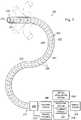
- FIG. 2illustrates a minimally invasive system 200 utilizing aspects of the present disclosure.
- the system 200may be incorporated into a teleoperated interventional system, such as system 100. Alternatively, the system 200 may be used for exploratory procedures or in procedures involving traditional manually operated interventional instruments, such as laparoscopic instruments.
- the system 200includes a catheter system 202 (e.g., part of the instrument 104) coupled by an interface unit 204 to a tracking system 206.
- a navigation system 210e.g., part of the control system 116) processes information from a virtual visualization system 208, one or more imaging systems 212, and/or the tracking system 206 to generate one or more image displays on a display system 214 (e.g., part of the display system 111).
- the system 200may further include optional operation and support systems (not shown) such as illumination systems, steering control systems, irrigation systems, and/or suction systems.
- the catheter system 202includes an elongated flexible body 216 having a proximal end 217 and a distal end 218. A channel 219 extends within the flexible body 216. In one embodiment, the flexible body 216 has an approximately 3 mm outer diameter. Other flexible body outer diameters may be larger or smaller.
- the catheter system 202optionally includes a sensor system which includes a position sensor system 220 (e.g., an electromagnetic (EM) sensor system) and/or a shape sensor system 222 for determining the position, orientation, speed, pose, and/or shape of the catheter tip at distal end 218 and/or of one or more segments 224 along the body 216.
- EMelectromagnetic
- the entire length of the body 216, between the distal end 218 and the proximal end 217may be effectively divided into the segments 224.
- the position sensor system 220 and the shape sensor system 222interface with the tracking system 206.
- the tracking system 206may be implemented as hardware, firmware, software or a combination thereof which interact with or are otherwise executed by one or more computer processors, which may include the processors of a control system 116.
- the position sensor system 220may be an EM sensor system that includes one or more conductive coils that may be subjected to an externally generated electromagnetic field. Each coil of the EM sensor system 220 then produces an induced electrical signal having characteristics that depend on the position and orientation of the coil relative to the externally generated electromagnetic field.
- the EM sensor systemmay be configured and positioned to measure six degrees of freedom, e.g., three position coordinates X, Y, Z and three orientation angles indicating pitch, yaw, and roll of a base point. Further description of an EM sensor system is provided in U.S. Pat. No. 6,380,732, filed August 11, 1999 , disclosing "Six-Degree of Freedom Tracking System Having a Passive Transponder on the Object Being Tracked".
- the shape sensor system 222includes an optical fiber aligned with the flexible body 216 (e.g., provided within an interior channel (not shown) or mounted externally).
- the tracking system 206may be coupled to a proximal end of the optical fiber.
- the optical fiberhas a diameter of approximately 200 ⁇ m. In other embodiments, the dimensions may be larger or smaller.
- the optical fiber of the shape sensor system 222forms a fiber optic bend sensor for determining the shape of the catheter system 202.
- optical fibers including Fiber Bragg Gratings (FBGs)are used to provide strain measurements in structures in one or more dimensions.
- FBGsFiber Bragg Gratings
- Various systems and methods for monitoring the shape and relative position of an optical fiber in three dimensionsare described in U.S. Pat. App. No. 11/180,389, filed July, 13, 2005 , disclosing "Fiber optic position and shape sensing device and method relating thereto;" U.S. Provisional Pat. App. No. 60/588,336, filed on Jul. 16, 2004 , disclosing "Fiber-optic shape and relative position sensing;" and U.S. Pat. No. 6,389,187, filed on Jun.
- the shape of the cathetermay be determined using other techniques. For example, if the history of the catheter's distal tip pose is stored for an interval of time that is smaller than the period for refreshing the navigation display or for alternating motion (e.g., inhalation and exhalation), the pose history can be used to reconstruct the shape of the device over the interval of time. As another example, historical pose, position, or orientation data may be stored for a known point of an instrument along a cycle of alternating motion, such as breathing.
- This stored datamay be used to develop shape information about the catheter.
- a series of positional sensorssuch as EM sensors, positioned along the catheter can be used for shape sensing.
- a history of data from a positional sensor, such as an EM sensor, on the instrument during a proceduremay be used to represent the shape of the instrument, particularly if an anatomical passageway is generally static.
- a wireless device with position or orientation controlled by an external magnetic fieldmay be used for shape sensing. The history of its position may be used to determine a shape for the navigated passageways.
- the optical fibermay include multiple cores within a single cladding.
- Each coremay be single-mode with sufficient distance and cladding separating the cores such that the light in each core does not interact significantly with the light carried in other cores.
- the number of coresmay vary or each core may be contained in a separate optical fiber.
- an array of FBG'sis provided within each core.
- Each FBGcomprises a series of modulations of the core's refractive index so as to generate a spatial periodicity in the refraction index.
- the spacingmay be chosen so that the partial reflections from each index change add coherently for a narrow band of wavelengths, and therefore reflect only this narrow band of wavelengths while passing through a much broader band.
- the modulationsare spaced by a known distance, thereby causing reflection of a known band of wavelengths.
- the spacing of the modulationswill change, depending on the amount of strain in the core.
- backscatter or other optical phenomena that vary with bending of the optical fibercan be used to determine strain within each core.
- FBGFBG's produce a reflected wavelength that is a function of the strain on the fiber and its temperature.
- This FBG technologyis commercially available from a variety of sources, such as Smart Fibres Ltd. of Bracknell, England.
- Use of FBG technology in position sensors for teleoperational surgeryis described in U.S. Pat. No. 7,930,065, filed July 20, 2006 , disclosing "Robotic Surgery System Including Position Sensors Using Fiber Bragg Gratings".
- bending of the optical fiberWhen applied to a multicore fiber, bending of the optical fiber induces strain on the cores that can be measured by monitoring the wavelength shifts in each core.
- bending of the fiberinduces different strains on each of the cores. These strains are a function of the local degree of bending of the fiber. For example, regions of the cores containing FBG's, if located at points where the fiber is bent, can thereby be used to determine the amount of bending at those points.
- These datacombined with the known spacings of the FBG regions, can be used to reconstruct the shape of the fiber.
- Such a systemhas been described by Luna Innovations. Inc. of Blacksburg, Va.
- the optical fibermay be used to monitor the shape of at least a portion of the catheter system 202. More specifically, light passing through the optical fiber is processed by the tracking system 206 for detecting the shape of the catheter system 202 and for utilizing that information to assist in surgical procedures.
- the tracking system 206may include a detection system for generating and detecting the light used for determining the shape of the catheter system 202. This information, in turn, in can be used to determine other related variables, such as velocity and acceleration of the parts of an interventional instrument.
- the sensingmay be limited only to the degrees of freedom that are actuated by the teleoperational system, or may be applied to both passive (e.g., unactuated bending of the rigid members between joints) and active (e.g., actuated movement of the instrument) degrees of freedom.
- the flexible body 216may optionally house one or more image capture probes 226 that transmit captured image data to the imaging system(s) 212.
- the image capture probe 226may be an endoscopic probe including a tip portion with a stereoscopic or monoscopic camera disposed near the distal end 218 of the flexible body 216 for capturing images (including video images) that are transmitted to the imaging system 212.
- the image capture probe 226may include a cable coupled to the camera for transmitting the captured image data.
- the image capture instrumentmay be a fiber-optic bundle, such as a fiberscope, that couples to the imaging system.
- the image capture instrumentmay be single or multi-spectral, for example capturing image data in the visible spectrum, or capturing image data in the visible and infrared or ultraviolet spectrums.
- the image capture probe 226may be a sensor probe for use with a reflective imaging technology such as ultrasound or optical coherence tomography (OCT).
- the probemay include a transmitter and receiver arrangement, such as an ultrasound transducer.
- the ultrasonic transducercan be mounted at an end of an elongated shaft.
- Such a sourcecan be used to obtain a preoperative or intraoperative two-dimensional or three-dimensional image, or model, of the anatomic region where the interventional procedure is to be performed.
- the ultrasonic transducercan be used to obtain a single ultrasound image.
- a three-dimensional sourceit can be used to obtain a plurality of spaced ultrasonic images, or cuts, thereby to provide sufficient information for construction of a three-dimensional model. Accordingly, it can be arranged to move, including rotate, within an anatomic site to capture such images, or cuts. This can typically be achieved, for example, in accordance with a pre-programmed sequence for moving the ultrasound transducer by teleoperational control, manual movement of the ultrasound transducer, or the like.
- the body 216may also house cables, linkages, or other steering controls (not shown) that extend between the interface 204 and the tip distal end 218 to controllably bend or turn the distal end 218 as shown for example by the dotted line versions of the distal end.
- the catheter systemmay be steerable or, alternatively, may be non-steerable with no integrated mechanism for operator control of the instrument bending.
- the flexible body 216may further house control mechanisms (not shown) for operating a surgical end effector or another working distal part that is manipulable for a medical function, e.g., for effecting a predetermined treatment of a target tissue.
- some end effectorshave a single working member such as a scalpel, a blade, an optical fiber, or an electrode.
- Other end effectorsmay include pair or plurality of working members such as forceps, graspers, scissors, or clip appliers, for example. Examples of electrically activated end effectors include electrosurgical electrodes, transducers, sensors, and the like.
- interventional tool(s) 228 for such procedures as surgery, biopsy, ablation, illumination, irrigation, or suctioncan be deployed through the channel 219 of the and used at a target location within the anatomy.
- the intervertebral tool 228may also be the image capture probe.
- the tool 228may be advanced from the opening of the channel 219 to perform the procedure and then retracted back into the channel when the procedure is complete.
- the interventional tool 228may be removed from the proximal end 217 of the catheter flexible body or from another optional instrument port (not shown) along the flexible body.
- the virtual visualization system 208provides navigation assistance to the catheter system 202.
- Virtual navigation using the virtual visualization systemis based upon reference to an acquired dataset associated with the three dimensional structure of the anatomical passageways. More specifically, the virtual visualization system 208 processes images of the surgical site recorded and/or modeled using imaging technology such as computerized tomography (CT), magnetic resonance imaging (MRI), fluoroscopy, thermography, ultrasound, optical coherence tomography (OCT), thermal imaging, impedance imaging, laser imaging, nanotube X-ray imaging, or the like.
- Softwareis used to convert the recorded images into a two dimensional or three dimensional model of a partial or an entire anatomical organ or anatomical region. The model describes the various locations and shapes of the passageways and their connectivity.
- the images used to generate the modelmay be recorded preoperatively or intra-operatively during a clinical procedure.
- a virtual visualization systemmay use standard models (i.e., not patient specific) or hybrids of a standard model and patient specific data.
- the model and any virtual images generated by the modelmay represent the static posture of a deformable anatomic region during one or more phases of motion (e.g., during an inspiration/ expiration cycle of a lung).
- the sensor systemsmay be used to compute an approximate location of the instrument with respect to the patient anatomy.
- the locationcan be used to produce both macro-level tracking images of the patient anatomy and virtual internal images of the patient anatomy.
- Various systems for using fiber optic sensors to register and display an interventional implement together with preoperatively recorded surgical images, such as those from a virtual visualization system,are known.
- U.S. Patent Application No. 13/107,562filed May 13, 2011 , disclosing, "Medical System Providing Dynamic Registration of a Model of an Anatomical Structure for Image-Guided Surgery".
- the navigation system 210processes information from the virtual visualization system 208, the one or more imaging systems 212, and/or the tracking system 206 to determine a navigational path for the interventional instrument through the anatomical system to the target anatomical structure.
- the navigation system 210may also monitor the navigational path of the interventional instrument as it moves through the anatomical system to a target structure.
- the navigation system 210includes a planning module 211 that allows a clinician to locate a target anatomical structure (e.g., a tumor) in the anatomical model prepared by the virtual visualization system 208 and to identify a navigational path through anatomical passageways to reach the target structure to perform an interventional procedure (e.g., a biopsy) with the interventional instrument.
- a target anatomical structuree.g., a tumor
- an interventional proceduree.g., a biopsy
- the target localization and navigational path determinationmay be automated such that the navigation system identifies one or more navigational paths.
- a clinicianmay determine the navigational path from the anatomic model and optionally communicate the selected path to the navigational system.
- the planning moduleuses a hybrid automated/ clinician selected navigational path determination in which the clinician may modify a system planned path or in which the clinician may enter parameters such as anatomical areas to avoid or instrument limitations that constrain the planned navigational path suggested by the planning module 212.
- the navigation planning modulegenerates or allows the clinician to select a planned deployment location within an anatomical passageway for parking a distal end of the interventional instrument to conduct the interventional procedure.
- a virtual image 300 of target structure 302, such as a tumor, and nearby anatomic passageways 304is depicted.
- the passagewaysinclude passageway walls 306 and carina 308.
- the anatomic passagewaysare bronchial passageways of the lung, but the systems and methods of this disclosure may be suitable for use in other natural or surgically created passageways in anatomical systems such as the colon, the intestines, the kidneys, the heart, or the circulatory system.
- a navigation planning moduleidentifies the planned deployment location as a location 312 along a wall of an anatomic passageway closest to or nearby to the target structure.
- selecting the deployment location entirely on the basis of proximity to the target structuremay result in a selected deployment location that is inaccessible or not easily accessible by the interventional instrument.
- the interventional instrumentmay be incapable of bending sufficiently within the passageway to access the proximity based deployment location.
- the selected deployment location or the navigational path to the deployment locationmay not consider anatomical constraints, such as scar or diseased tissue to avoid.
- a navigation planning moduleselects the deployment location based upon a plurality of factors, which in some instances may be procedural characteristics, such as the distance to the target structure, and/or the position of the target structure relative to other anatomic features. In other embodiments, the navigation planning module may additionally or alternatively receive and use information about the operational capability of the interventional instrument to determine a deployment location.
- information pertaining to the bending capability of the instrumentmay be considered, such as the flexibility and elasticity of the catheter material, any preformed shape characteristics of the catheter or tools passed through the channel of the catheter, the steerability of the distal end of the catheter or tool (e.g., the degree to which the distal tip of the catheter may be curved relative to the main axis of the catheter), and the curvature along the length of the catheter.
- Other characteristics of the interventional instrumentmay also be used to determine the deployment location including the diameter of the catheter, the diameter of the tool, the trajectory of the tool when extended from the catheter (e.g., curved, straight), the movement of the tool (e.g., sweeping, spinning, linear), the maximum angulation of the axis of the tool versus the axis of the catheter, the maximum length the tool can be extended from the catheter, and any anchoring structures at the distal tip of the catheter providing frictional contact with the passageway wall.
- the information pertaining to the bending capability and/or the information related to the characteristics of the interventional instrumentare exemplary factors that can be used to determine the operational capability of the interventional instrument within the anatomical passageways.
- the navigation planning modulemay also or alternatively receive and use information about the patient anatomy to determine a deployment location.
- informationmay include, for example, the location of the carinas of the anatomical passageways nearest to the target structure and the size of the passageways nearest to the target structure.
- Other anatomic informationmay include the elasticity of the anatomical passageways including the impact that any disease processes may have had on the elasticity of the passageways.
- the navigation planning modelmay also consider the surrounding anatomic tissue to, for example, select a deployment location that reduces the risk to surrounding tissue. As one example, a deployment location away from the perimeter of a lung may be selected to avoid the risk of puncturing the lung with the deployed tool.
- the navigation planning modelmay also consider the anatomy of the target structure to access a preferred location of the target structure. For example, the deployment location may be selected such that a biopsy tool avoids a calcified part of a tumor.
- the navigation planning modulemay also consider information about the relationship between the interventional instrument and the patient anatomy such as the distance of the target structure from the end of the catheter. Referring to FIG. 5 , the navigation planning module may also consider the angle of approach 320 between the interventional tool and the passageway wall. For example, an approach angle of 90° may impracticable due to the small size of the passageway and the bendability of the distal tip of the catheter. An approach angle of 1° may also be unsuitable because of the risk that the interventional tool may graze the surface of the passageway wall without penetrating. For these reasons, the navigation planning module may select a deployment location such that the approach angle is between approximately 30° and 90°.
- a deployment location 314 on the wall of an anatomic passagewayis identified.
- the navigation planning modulemay provide a suggested navigational path to the deployment location.
- the cliniciancan then direct the distal end of the interventional instrument to the deployment location.
- the clinicianmay manually control the navigation of the interventional instrument based upon virtual or real image guidance.
- the cliniciancan teleoperationally control the navigation of the interventional instrument or allow computer-controlled navigation of the interventional instrument along the suggested navigational path.
- the deployment locationmay be located within the lumen of the passageway, rather than on the wall of the passageway.
- the deployment locationmay be on a surface of the target structure.
- FIG. 7is a flowchart describing a method 400 used by the navigation planning module for identifying a planned deployment location for an interventional instrument.
- a model of an anatomic structureis received.
- the anatomic structureincludes a plurality of anatomic passageways which are illustrated by the model.
- the modelis formed from two or three dimensional images of the surgical site recorded and/or modeled preoperatively or interoperatively using imaging technology such as CT, MRI, fluoroscopy, thermography, ultrasound, OCT, thermal imaging, impedance imaging, laser imaging, nanotube X-ray imaging, or the like. Receipt of the model may include receiving information about the patient anatomy derived from the model, from user inputs describing the patient anatomy, or from other reference sources.
- Such information about the patient anatomymay include, for example, the closest location(s) within an anatomic passageway(s) to the target structure, the location of the carinas of the anatomical passageways nearest to the target structure, and the size of the passageways nearest to the target structure.
- Other anatomic informationmay include the elasticity of the anatomical passageways, the anatomy of the target structure to access a preferred location of the target structure, and the type of surrounding tissue and any risk associated with contacting the surrounding tissue.
- a location of a target structureis identified in the model. Identifying the target structure may include determining or receiving information about the target structure from the model, from user inputs describing the target structure, or from other reference sources. Such information about the target structure may include, for example, the shape of the target structure, the one or more substances that form the target structure, and the location of the surfaces of the target structure relative to nearby anatomic passageways.
- the information received to determine the operational capability of the interventional instrumentmay include, for example, information pertaining to the bending capability of the instrument such as the flexibility and elasticity of the catheter material, any preformed shape characteristics of the catheter or tools passed through the channel of the catheter, the steerability of the distal end of the catheter or tool, and the curvature along the length of the catheter.
- the operational capability of the interventional instrumentmay also be determined from characteristics of the interventional instrument such as the diameter of the catheter, the diameter of the tool, the maximum angulation of the axis of the tool versus the axis of the catheter, the maximum length the tool can be extended from the catheter, and any anchoring structures at the distal tip of the catheter providing frictional contact with the passageway wall.
- a planned deployment location for the interventional instrumentis located.
- the planned deployment locationmay be marked on the model of the plurality of passageways.
- the planned deployment locationcan be selected based upon the instrument operational capability information, the target structure information, the patient anatomy information, or a combination of the types of information.
- the selected deployment locationmay be at a point in an anatomic passageway nearest to the target structure.
- a more suitable deployment locationmay be at a point on an anatomic passageway wall where the interventional instrument has an approach angle to the passageway wall that is within the bending capability of the instrument.
- a suitable deployment locationmay be at a carina near the target structure.
- the interventional instrumentmay be deployed at an approximately 90° approach angle to the passageway wall with minimal bending of the distal end of the instrument.
- the navigation planning modulemay select a deployment location such that the approach angle is between approximately 30° and 90°.
- the planning systemalso confirms that the interventional tool is capable of extending from the catheter a sufficient distance to reach the target structure to perform the interventional procedure.
- the planned deployment locationmay be located based on the analysis of the instrument operational capability, the target structure, and the patient anatomy. Alternatively or in combination with the system assessment, the planned deployment location may be identified by a clinician and communicated to the navigation planning module to locate or mark the clinician-identified planned deployment location in the model. When the navigation planning module receives the clinician-identified planned deployment location, the module may compare it with the system-identified deployment location. A visual or audible feedback cue may be issued if the clinician-identified deployment location is objectionable (e.g., "The chosen biopsy needle is not long enough to reach the target from this deployment location.”).
- the navigation planning moduleidentifies multiple elective deployment locations.
- the elective deployment locationsare coded (e.g., with color on the display) to provide information about the relative quality of the elective deployment locations for deploying the interventional instrument to perform the procedure.
- a clinicianmay select one of elective deployment locations to be the planned deployment location. Alternatively, more than one planned deployment location may be selected from the elective deployment locations, allowing the interventional procedure to be performed from different approaches. The selection of elective deployment locations may also occur during the interventional procedure if the clinician determines that an initially chosen deployment location is unsuitable.
- one or more of the imaging systems 212may be used to gather additional information about the location of the target structure after the interventional instrument has been deployed to the identified deployment location or the general vicinity thereof.
- FIG. 6the virtual image 300 of target structure 302 and nearby anatomic passageways 304 is again depicted.
- the distal end of the flexible body 309is first positioned at a target confirmation location such as location 312.
- the image capture probe 226is operated to determine if the target structure 302 is in the expected position relative to the target confirmation location. If the target structure 302 is not found or not in the expected position, the flexible body and image capture probe can be moved around until the target structure is located.
- the location of the distal end of the flexible body 309 or image capture probeis recorded at a new location 322.
- the navigation planning module 211then updates the location of the target structure 302'.
- the operational capability information for the interventional instrumentis used to identify a revised planned deployment location 324.
- the navigation planning modulemay use the difference between locations 312 and 322 to update location 314 to location 322 and to update the location of the target structure 302 to 302'.
- the image capture probeuses one or more sensors for reflective imaging technology such as ultrasound or OCT to refine the location of the target structure. Alternatively, other non-imaging sensors may be used to identify the location of the target structure.
- FIG. 8is a flowchart describing a method 450 used by the navigation planning module for revising a planned deployment location for an interventional instrument.
- informationis received from the image capture probe after the probe has been operated at the initial planned deployment location or at a target confirmation location.
- a revised location of the target structureis identified using the information received from the image capture probe.
- a revised planned deployment locationis identified in the model of the plurality of passageways.
- An alternative method 500 for identifying the target structure using the imaging systems 212is described at FIG. 9 and illustrated at FIGS. 10 and 11 .
- the method 500may be performed to identify an initial interventional deployment location or may be used to identify a revised deployment location as described below.
- the catheteris navigated to a passageway location such as location 312 or 314 with the guidance of the navigation system including, for example, visual, EM or shape sensor information.
- a confirmation from the clinician or from the interventional instrumentmay be provided when the catheter has reached the location.
- an imaging probee.g., an ultrasound probe
- the movement of the imaging probe relative to a portion of the cathetere.g., the catheter tip
- the same imaging probee.g., the same ultrasound probe
- the movement of the imaging probemay be tracked, for example using a positional sensor such as a 5 or 6 degree of freedom EM sensor.
- the movementmay be tracked using an insertion sensor such as an encoder located outside the patient anatomy.
- the movementmay be tracked by engaging a stepping motor to control the insertion motion of the imaging probe.
- the roll angle of an imaging coordinate system for the imaging probeis determined with respect to the catheter.
- the roll anglemay be determined using a roll alignment feature of the axial imaging probe and the catheter (e.g. a key system).
- a roll sensor located outside of the patient anatomymay be used.
- the roll anglemay be determined by viewing one or more markers or other features with a known angle relative to the catheter in the image recorded by the imaging probe.
- the feature or markermay be located on the circumference of the catheter and have a contrast (e.g. an ultrasound contrast) to the catheter.
- the catheter and/or the imaging probeis moved around in the anatomic passageways to detect the target structure in the image generated by the probe.
- a clinicianmay identify the target structure in the image using a pointing device at a pointer location.
- the imagee.g. an ultrasound image
- a three-dimensional imagemay be constructed from two-dimensional scans.
- the pointer locationis transformed to the catheter coordinate system or to the patient coordinate system (which has been previously registered to the catheter coordinate system).
- the pointer locationcan be used to apply an offset to the location of the target structure identified in the preoperative anatomic model.
- a revised target structure locationis computed based upon the offset.
- the imaging probemay then be removed and a biopsy tool or other interventional tool may be inserted through the catheter to perform a procedure (e.g., a biopsy) at the revised location.
- One or more elements in embodiments of the inventionmay be implemented in software to execute on a processor of a computer system such as control system 116.
- the elements of the embodiments of the inventionare essentially the code segments to perform the necessary tasks.
- the program or code segmentscan be stored in a processor readable storage medium or device that may have been downloaded by way of a computer data signal embodied in a carrier wave over a transmission medium or a communication link.
- the processor readable storage devicemay include any medium that can store information including an optical medium, semiconductor medium, and magnetic medium.
- Processor readable storage device examplesinclude an electronic circuit; a semiconductor device, a semiconductor memory device, a read only memory (ROM), a flash memory, an erasable programmable read only memory (EPROM); a floppy diskette, a CD-ROM, an optical disk, a hard disk, or other storage device,
- the code segmentsmay be downloaded via computer networks such as the Internet, Intranet, etc.
Landscapes
- Health & Medical Sciences (AREA)
- Life Sciences & Earth Sciences (AREA)
- Surgery (AREA)
- Engineering & Computer Science (AREA)
- Public Health (AREA)
- Animal Behavior & Ethology (AREA)
- Veterinary Medicine (AREA)
- General Health & Medical Sciences (AREA)
- Biomedical Technology (AREA)
- Heart & Thoracic Surgery (AREA)
- Medical Informatics (AREA)
- Molecular Biology (AREA)
- Nuclear Medicine, Radiotherapy & Molecular Imaging (AREA)
- Pathology (AREA)
- Radiology & Medical Imaging (AREA)
- Biophysics (AREA)
- Physics & Mathematics (AREA)
- Vascular Medicine (AREA)
- Robotics (AREA)
- Human Computer Interaction (AREA)
- Ultra Sonic Daignosis Equipment (AREA)
- Endoscopes (AREA)
- Magnetic Resonance Imaging Apparatus (AREA)
Description
- The present disclosure is directed to systems for navigating a patient anatomy to conduct a minimally invasive procedure, and more particularly to systems for planning a procedure to deploy an interventional instrument.
- Minimally invasive medical techniques are intended to reduce the amount of tissue that is damaged during interventional procedures, thereby reducing patient recovery time, discomfort, and deleterious side effects. Such minimally invasive techniques may be performed through natural orifices in a patient anatomy or through one or more surgical incisions. Through these natural orifices or incisions clinicians may insert interventional instruments (including surgical, diagnostic, therapeutic, or biopsy instruments) to reach a target tissue location. To reach the target tissue location, a minimally invasive interventional instrument may navigate natural or surgically created passageways in anatomical systems such as the lungs, the colon, the intestines, the kidneys, the heart, the circulatory system, or the like. To assist the clinician in navigating the instrument through the passageways, models of the passageway are prepared using pre-operative or inter-operative imaging. Current systems for deploying an interventional instrument identify an instrument deployment location as the point within the modeled passageways closest to the target tissue location. This closest-point deployment location may be difficult to access given the constraints of the interventional instrument or the anatomy. Improved systems are needed to determine a planned instrument deployment location for conducting a procedure on the target tissue location.
US 2002/0133057 A1 discloses a method for determining instructions for handling a flexible instrument which comprises parameterizing the flexible instrument according to a plurality of parameters for handling the instrument, determining at least one instrument configuration, wherein the configuration describes at least one parameter, and determining instructions for handling the instrument according to the configuration.US 2009/0156895 A1 discloses that endoscopic poses are used to indicate the exact location and direction in which a physician must orient the endoscope to sample a region of interest (ROI) in an airway tree or other luminal structure. Using a patient-specific model of the anatomy derived from a 3D MDCT image, poses are chosen to be realizable given the physical characteristics of the endoscope and the relative geometry of the patient's airways and the ROI. The calculations also account for obstacles such as the aorta and pulmonary arteries, precluding the puncture of these sensitive blood vessels. A real-time visualization system conveys the calculated pose orientation and the quality of any arbitrary bronchoscopic pose orientation. A suggested pose orientation is represented as an icon within a virtual rendering of the patient's airway tree or other structure. The location and orientation of the icon indicates the suggested pose orientation to which the physician should align during the procedure.WO 2005/082246 A1 discloses a device and a method for the determination of the position of a catheter in a vascular system. In this, the measured positions (r1, r2) of two magnetic localizers at the tip of a catheter are displaced by correction vectors (k1, k2) while optimizing a quality dimension. The quality dimension includes a component taking account both of the deviation of the measured positions (r1, r2) from the vascular layout and of the deviation of the associated orientation (r2-r1) from the orientation of the vascular layout according to a vascular map. In addition, the quality dimension may include components which evaluate the measured shape of the catheter compared to the vascular map.EP 2 377 457 A1 discloses a medical apparatus which comprises: a treatment instrument which is provided with a sensor for detecting a position, a direction and a roll angle at a distal end portion, and a bending portion, and is adapted to be inserted to a target site in a bronchus; a CT image data storing unit which stores three-dimensional image data of the bronchus acquired in advance; an input unit for setting the target site; a virtual endoscopic image generating unit which generates a virtual endoscopic image using a line-of-sight parameter including the position, the direction and the roll angle of the distal end portion detected by the sensor based on the three-dimensional image data; and an image processing unit which performs a superimposition process and thus display operation information for inserting the distal end portion to the target site in superimposition on the virtual endoscopic image.US 2005/0182295 A1 discloses visual-assisted guidance of an ultra-thin flexible endoscope to a predetermined region of interest within a lung during a bronchoscopy procedure. The region may be an opacity-identified by non-invasive imaging methods, such as high-resolution computed tomography (HRCT) or as a malignant lung mass that was diagnosed in a previous examination. An embedded position sensor on the flexible endoscope indicates the position of the distal tip of the probe in a Cartesian coordinate system during the procedure. A visual display is continually updated, showing the present position and orientation of the marker in a 3-D graphical airway model generated from image reconstruction. The visual display also includes windows depicting a virtual fly-through perspective and real-time video images acquired at the head of the endoscope, which can be stored as data, with an audio or textual account.US 2009/0227861 A1 discloses a system and method for navigating a medical instrument in a branched structure of a body employs a tracking system, for collecting positional information for the medical instrument, and data, which defines a geometrical model of the branched structure, in particular, coordinates for predetermined points defining a pathway extending along branches of the model. Coordinates are identified for each Euclidean distance of the instrument, from an anchor point of a coordinate system for the tracking system, that corresponds to a Euclidean distance of a designated point, of the predetermined points, from a reference point of a coordinate system for the model, wherein the anchor point of the tracking coordinate system has been established to correspond to the reference point of the model coordinate system. The two coordinate systems are registered to one another via a mathematical transformation using the identified coordinates of the instrument and the corresponding coordinates of each designated point.US 2012/0203067 A1 discloses measurements of a bronchoscope's movement to predict its position in 3D virtual space. To achieve this, a bronchoscope model, defining the device's shape in the airway tree to a given point p, provides an insertion depth to p. In real time, the invention compares an observed bronchoscope insertion depth and roll angle, measured by an optical sensor, to precalculated insertion depths along a predefined route in the virtual airway tree to predict a bronchoscope's location and orientation.- The invention provides a system as set out in the appended claims.
- Described herein is a method of planning a procedure to deploy an interventional instrument comprises receiving a model of an anatomic structure, which is not part of the invention. The anatomic structure includes a plurality of passageways. The method further includes identifying a target structure in the model and receiving information about an operational capability of the interventional instrument within the plurality of passageways. The method further comprises identifying a planned deployment location for positioning a distal tip of the interventional instrument to perform the procedure on the target structure based upon the operational capability of the interventional instrument.
- In an example, a system comprises a non-transitory computer readable media containing computer executable instructions for planning a procedure to deploy an interventional instrument. The computer executable instructions include instructions for receiving a model of an anatomic structure including a plurality of passageways and instructions for identifying a target structure in the model. The computer executable instructions also include instructions for receiving information about an operational capability of the interventional instrument within the plurality of passageways and instructions for identifying a planned deployment location for positioning a distal tip of the interventional instrument to perform the procedure on the target structure based upon the operational capability of the interventional instrument.
- Aspects of the present disclosure are best understood from the following detailed description when read with the accompanying figures. It is emphasized that, in accordance with the standard practice in the industry, various features are not drawn to scale. In fact, the dimensions of the various features may be arbitrarily increased or reduced for clarity of discussion. In addition, the present disclosure may repeat reference numerals and/or letters in the various examples. This repetition is for the purpose of simplicity and clarity and does not in itself dictate a relationship between the various embodiments and/or configurations discussed.
FIG. 1 is a teleoperated interventional system, in accordance with embodiments of the present disclosure.FIG. 2 illustrates an interventional instrument system utilizing aspects of the present disclosure.FIG. 3 illustrates a distal end of the interventional instrument system ofFIG. 2 with an extended interventional tool.FIG. 4 illustrates an anatomic model image with a distal end of an interventional instrument at a deployment location.FIG. 5 is a view of a portion of theFIG. 4 .FIG. 6 illustrates an anatomic model image with a distal end of an interventional instrument at a revised deployment location based on sensor feedback.FIG. 7 is a flowchart describing a method for identifying a planned deployment location for an interventional instrument.FIG. 8 is a flowchart describing a method for revising the planned deployment location based upon sensor feedback.FIG. 9 is a flowchart describing a method for identifying the target structure using the imaging systems.FIGS. 10 and 11 are illustrations of the method ofFIG. 9 .- In the following detailed description of the aspects of the invention, numerous specific details are set forth in order to provide a thorough understanding of the disclosed embodiments. However, it will be obvious to one skilled in the art that the embodiments of this disclosure may be practiced without these specific details. In other instances well known methods, procedures, components, and circuits have not been described in detail so as not to unnecessarily obscure aspects of the embodiments of the invention. And, to avoid needless descriptive repetition, one or more components or actions described in accordance with one illustrative embodiment can be used or omitted as applicable from other illustrative embodiments.
- The embodiments below will describe various instruments and portions of instruments in terms of their state in three-dimensional space. As used herein, the term "position" refers to the location of an object or a portion of an object in a three-dimensional space (e.g., three degrees of translational freedom along Cartesian X, Y, Z coordinates). As used herein, the term "orientation" refers to the rotational placement of an object or a portion of an object (three degrees of rotational freedom - e.g., roll, pitch, and yaw). As used herein, the term "pose" refers to the position of an object or a portion of an object in at least one degree of translational freedom and to the orientation of that object or portion of the object in at least one degree of rotational freedom (up to six total degrees of freedom). As used herein, the term "shape" refers to a set of poses, positions, or orientations measured along an object.
- Referring to
FIG. 1 of the drawings, a teleoperated interventional system for use in, for example, surgical, diagnostic, therapeutic, or biopsy procedures, is generally indicated by thereference numeral 100. As shown inFIG. 1 , theteleoperated system 100 generally includes aninterventional manipulator assembly 102 for operating aninterventional instrument 104 in performing various procedures on the patient P. Theassembly 102 is mounted to or near an operating table O.A master assembly 106 allows the surgeon S to view the surgical site and to control theslave manipulator assembly 102. - The
master assembly 106 may be located at a surgeon's console C which is usually located in the same room as operating table O. However, it should be understood that the surgeon S can be located in a different room or a completely different building from the patientP. Master assembly 106 generally includes anoptional support 108 and one or more control device(s) 112 for controlling themanipulator assemblies 102. The control device(s) 112 may include any number of a variety of input devices, such as joysticks, trackballs, data gloves, trigger-guns, hand-operated controllers, voice recognition devices, body motion or presence sensors, or the like. In some embodiments, the control device(s) 112 will be provided with the same degrees of freedom as the associatedinterventional instruments 104 to provide the surgeon with telepresence, or the perception that the control device(s) 112 are integral with theinstruments 104 so that the surgeon has a strong sense of directly controllinginstruments 104. In other embodiments, the control device(s) 112 may have more or fewer degrees of freedom than the associatedinterventional instruments 104 and still provide the surgeon with telepresence. In some embodiments, the control device(s) 112 are manual input devices which move with six degrees of freedom, and which may also include an actuatable handle for actuating instruments (for example, for closing grasping jaws, applying an electrical potential to an electrode, delivering a medicinal treatment, or the like). - In alternative embodiments, the teleoperated system may include more than one slave manipulator assembly and/or more than one master assembly. The exact number of manipulator assemblies will depend on the surgical procedure and the space constraints within the operating room, among other factors. The master assemblies may be collocated, or they may be positioned in separate locations. Multiple master assemblies allow more than one operator to control one or more slave manipulator assemblies in various combinations.
- An
optional visualization system 110 may include an endoscope system such that a concurrent (real-time) image of the surgical site is provided to surgeon console C. The concurrent image may be, for example, a two- or three-dimensional image captured by an endoscopic probe positioned within the surgical site. In this embodiment, thevisualization system 110 includes endoscopic components that may be integrally or removably coupled to theinterventional instrument 104. In alternative embodiments, however, a separate endoscope attached to a separate manipulator assembly may be used to image the surgical site. Alternatively, a separate endoscope assembly may be directly operated by a user, without teleoperational control. The endoscope assembly may include active steering (e.g., via teleoperated steering wires) or passive steering (e.g., via guide wires or direct user guidance). Thevisualization system 110 may be implemented as hardware, firmware, software, or a combination thereof, which interacts with or is otherwise executed by one or more computer processors, which may include the processor(s) of acontrol system 116. - A
display system 111 may display an image of the surgical site and interventional instruments captured by thevisualization system 110. Thedisplay 111 and the master control device(s) 112 may be oriented such that the relative positions of the imaging device in the scope assembly and the interventional instruments are similar to the relative positions of the surgeon's eyes and hand(s) so the operator can manipulate theinterventional instrument 104 and the master control device(s) 112 as if viewing the workspace in substantially true presence. True presence means that the displayed tissue image appears to an operator as if the operator was physically present at the imager location and directly viewing the tissue from the imager's perspective. - Alternatively or additionally,
display system 111 may present images of the surgical site recorded and/or modeled preoperatively using imaging technology such as computerized tomography (CT), magnetic resonance imaging (MRI), fluoroscopy, thermography, ultrasound, optical coherence tomography (OCT), thermal imaging, impedance imaging, laser imaging, nanotube X-ray imaging, or the like. The presented preoperative images may include two-dimensional, three-dimensional, or four-dimensional (including e.g., time based or velocity based information) images. - In some embodiments, the
display system 111 may display a virtual visualization image in which the actual location of the interventional instrument is registered (e.g., dynamically referenced) with preoperative or concurrent images from the modeled anatomy to present the surgeon S with a virtual image of the internal surgical site at the location of the tip of the surgical instrument. - In other embodiments, the
display system 111 may display a virtual visualization image in which the actual location of the interventional instrument is registered with prior images (including preoperatively recorded images) or concurrent images from the modeled anatomy to present the surgeon S with a virtual image of an interventional instrument at the surgical site. An image of a portion of the interventional instrument may be superimposed on the virtual image to assist the surgeon controlling the interventional instrument. - In
FIG. 1 , acontrol system 116 includes at least one processor (not shown), and typically a plurality of processors, for effecting control between the slavesurgical manipulator assembly 102, themaster assembly 106, thevisualization system 110, and thedisplay system 111. Thecontrol system 116 also includes programmed instructions (e.g., a computer-readable medium storing the instructions) to implement some or all of the methods described herein. Whilecontrol system 116 is shown as a single block in the simplified schematic ofFig. 1 , the system may comprise a number of data processing circuits (e.g., on the slavesurgical manipulator assembly 102 and/or on the master assembly 106), with at least a portion of the processing optionally being performed adjacent the slave surgical manipulator assembly, a portion being performed at the master assembly, and the like. Any of a wide variety of centralized or distributed data processing architectures may be employed. Similarly, the programmed instructions may be implemented as a number of separate programs or subroutines, or they may be integrated into a number of other aspects of the teleoperational systems described herein. In one embodiment,control system 116 supports wireless communication protocols such as Bluetooth, IrDA, HomeRF, IEEE 802.11, DECT, and Wireless Telemetry. - In some embodiments,
control system 116 may include one or more servo controllers to provide force and torque feedback from theinterventional instruments 104 to one or more corresponding servomotors for the control device(s) 112. The servo controller(s) may also transmit signals instructingmanipulator assembly 102 to move instruments which extend into an internal surgical site within the patient body via openings in the body. Any suitable conventional or specialized servo controller may be used. A servo controller may be separate from, or integrated with,manipulator assembly 102. In some embodiments, the servo controller and manipulator assembly are provided as part of a manipulator arm cart positioned adjacent to the patient's body. - Each
manipulator assembly 102 supports ainterventional instrument 104 and may comprise a kinematic structure of one or more non-servo controlled links (e.g., one or more links that may be manually positioned and locked in place, generally referred to as a set-up structure) and a teleoperated manipulator. Theteleoperated manipulator assembly 102 is driven by a plurality of actuators (e.g., motors). These motors actively move the teleoperated manipulators in response to commands from thecontrol system 116. The motors are further coupled to the interventional instrument so as to advance the interventional instrument into a naturally or surgically created anatomical orifice and to move the distal end of the interventional instrument in multiple degrees of freedom, which may include three degrees of linear motion (e.g., linear motion along the X, Y, Z Cartesian axes) and three degrees of rotational motion (e.g., rotation about the X, Y, Z Cartesian axes). Additionally, the motors can be used to actuate an articulable end effector of the instrument for grasping tissue in the jaws of a biopsy device or the like. FIG. 2 illustrates a minimallyinvasive system 200 utilizing aspects of the present disclosure. Thesystem 200 may be incorporated into a teleoperated interventional system, such assystem 100. Alternatively, thesystem 200 may be used for exploratory procedures or in procedures involving traditional manually operated interventional instruments, such as laparoscopic instruments. Thesystem 200 includes a catheter system 202 (e.g., part of the instrument 104) coupled by aninterface unit 204 to atracking system 206. A navigation system 210 (e.g., part of the control system 116) processes information from avirtual visualization system 208, one ormore imaging systems 212, and/or thetracking system 206 to generate one or more image displays on a display system 214 (e.g., part of the display system 111). Thesystem 200 may further include optional operation and support systems (not shown) such as illumination systems, steering control systems, irrigation systems, and/or suction systems.- The
catheter system 202 includes an elongatedflexible body 216 having aproximal end 217 and adistal end 218. Achannel 219 extends within theflexible body 216. In one embodiment, theflexible body 216 has an approximately 3 mm outer diameter. Other flexible body outer diameters may be larger or smaller. Thecatheter system 202 optionally includes a sensor system which includes a position sensor system 220 (e.g., an electromagnetic (EM) sensor system) and/or ashape sensor system 222 for determining the position, orientation, speed, pose, and/or shape of the catheter tip atdistal end 218 and/or of one ormore segments 224 along thebody 216. The entire length of thebody 216, between thedistal end 218 and theproximal end 217 may be effectively divided into thesegments 224. Theposition sensor system 220 and theshape sensor system 222 interface with thetracking system 206. Thetracking system 206 may be implemented as hardware, firmware, software or a combination thereof which interact with or are otherwise executed by one or more computer processors, which may include the processors of acontrol system 116. - The
position sensor system 220 may be an EM sensor system that includes one or more conductive coils that may be subjected to an externally generated electromagnetic field. Each coil of theEM sensor system 220 then produces an induced electrical signal having characteristics that depend on the position and orientation of the coil relative to the externally generated electromagnetic field. In one embodiment, the EM sensor system may be configured and positioned to measure six degrees of freedom, e.g., three position coordinates X, Y, Z and three orientation angles indicating pitch, yaw, and roll of a base point. Further description of an EM sensor system is provided inU.S. Pat. No. 6,380,732, filed August 11, 1999 , disclosing "Six-Degree of Freedom Tracking System Having a Passive Transponder on the Object Being Tracked". - The
shape sensor system 222 includes an optical fiber aligned with the flexible body 216 (e.g., provided within an interior channel (not shown) or mounted externally). Thetracking system 206 may be coupled to a proximal end of the optical fiber. In one embodiment, the optical fiber has a diameter of approximately 200 µm. In other embodiments, the dimensions may be larger or smaller. - The optical fiber of the
shape sensor system 222 forms a fiber optic bend sensor for determining the shape of thecatheter system 202. In one alternative, optical fibers including Fiber Bragg Gratings (FBGs) are used to provide strain measurements in structures in one or more dimensions. Various systems and methods for monitoring the shape and relative position of an optical fiber in three dimensions are described inU.S. Pat. App. No. 11/180,389, filed July, 13, 2005 U.S. Provisional Pat. App. No. 60/588,336, filed on Jul. 16, 2004 U.S. Pat. No. 6,389,187, filed on Jun. 17, 1998 , disclosing "Optical Fibre Bend Sensor". In other alternatives, sensors employing other strain sensing techniques such as Rayleigh scattering, Raman scattering, Brillouin scattering, and Fluorescence scattering may be suitable. In other alternative embodiments, the shape of the catheter may be determined using other techniques. For example, if the history of the catheter's distal tip pose is stored for an interval of time that is smaller than the period for refreshing the navigation display or for alternating motion (e.g., inhalation and exhalation), the pose history can be used to reconstruct the shape of the device over the interval of time. As another example, historical pose, position, or orientation data may be stored for a known point of an instrument along a cycle of alternating motion, such as breathing. This stored data may be used to develop shape information about the catheter. Alternatively, a series of positional sensors, such as EM sensors, positioned along the catheter can be used for shape sensing. Alternatively, a history of data from a positional sensor, such as an EM sensor, on the instrument during a procedure may be used to represent the shape of the instrument, particularly if an anatomical passageway is generally static. Alternatively, a wireless device with position or orientation controlled by an external magnetic field may be used for shape sensing. The history of its position may be used to determine a shape for the navigated passageways. - In this embodiment, the optical fiber may include multiple cores within a single cladding. Each core may be single-mode with sufficient distance and cladding separating the cores such that the light in each core does not interact significantly with the light carried in other cores. In other embodiments, the number of cores may vary or each core may be contained in a separate optical fiber.
- In some embodiments, an array of FBG's is provided within each core. Each FBG comprises a series of modulations of the core's refractive index so as to generate a spatial periodicity in the refraction index. The spacing may be chosen so that the partial reflections from each index change add coherently for a narrow band of wavelengths, and therefore reflect only this narrow band of wavelengths while passing through a much broader band. During fabrication of the FBG's, the modulations are spaced by a known distance, thereby causing reflection of a known band of wavelengths. However, when a strain is induced on the fiber core, the spacing of the modulations will change, depending on the amount of strain in the core. Alternatively, backscatter or other optical phenomena that vary with bending of the optical fiber can be used to determine strain within each core.
- Thus, to measure strain, light is sent down the fiber, and characteristics of the returning light are measured. For example, FBG's produce a reflected wavelength that is a function of the strain on the fiber and its temperature. This FBG technology is commercially available from a variety of sources, such as Smart Fibres Ltd. of Bracknell, England. Use of FBG technology in position sensors for teleoperational surgery is described in
U.S. Pat. No. 7,930,065, filed July 20, 2006 , disclosing "Robotic Surgery System Including Position Sensors Using Fiber Bragg Gratings". - When applied to a multicore fiber, bending of the optical fiber induces strain on the cores that can be measured by monitoring the wavelength shifts in each core. By having two or more cores disposed off-axis in the fiber, bending of the fiber induces different strains on each of the cores. These strains are a function of the local degree of bending of the fiber. For example, regions of the cores containing FBG's, if located at points where the fiber is bent, can thereby be used to determine the amount of bending at those points. These data, combined with the known spacings of the FBG regions, can be used to reconstruct the shape of the fiber. Such a system has been described by Luna Innovations. Inc. of Blacksburg, Va.
- As described, the optical fiber may be used to monitor the shape of at least a portion of the
catheter system 202. More specifically, light passing through the optical fiber is processed by thetracking system 206 for detecting the shape of thecatheter system 202 and for utilizing that information to assist in surgical procedures. Thetracking system 206 may include a detection system for generating and detecting the light used for determining the shape of thecatheter system 202. This information, in turn, in can be used to determine other related variables, such as velocity and acceleration of the parts of an interventional instrument. The sensing may be limited only to the degrees of freedom that are actuated by the teleoperational system, or may be applied to both passive (e.g., unactuated bending of the rigid members between joints) and active (e.g., actuated movement of the instrument) degrees of freedom. - The
flexible body 216 may optionally house one or more image capture probes 226 that transmit captured image data to the imaging system(s) 212. For example, theimage capture probe 226 may be an endoscopic probe including a tip portion with a stereoscopic or monoscopic camera disposed near thedistal end 218 of theflexible body 216 for capturing images (including video images) that are transmitted to theimaging system 212. Theimage capture probe 226 may include a cable coupled to the camera for transmitting the captured image data. Alternatively, the image capture instrument may be a fiber-optic bundle, such as a fiberscope, that couples to the imaging system. The image capture instrument may be single or multi-spectral, for example capturing image data in the visible spectrum, or capturing image data in the visible and infrared or ultraviolet spectrums. - Additionally or alternatively, the
image capture probe 226 may be a sensor probe for use with a reflective imaging technology such as ultrasound or optical coherence tomography (OCT). For example, the probe may include a transmitter and receiver arrangement, such as an ultrasound transducer. The ultrasonic transducer can be mounted at an end of an elongated shaft. Such a source can be used to obtain a preoperative or intraoperative two-dimensional or three-dimensional image, or model, of the anatomic region where the interventional procedure is to be performed. As a two-dimensional source, the ultrasonic transducer can be used to obtain a single ultrasound image. As a three-dimensional source it can be used to obtain a plurality of spaced ultrasonic images, or cuts, thereby to provide sufficient information for construction of a three-dimensional model. Accordingly, it can be arranged to move, including rotate, within an anatomic site to capture such images, or cuts. This can typically be achieved, for example, in accordance with a pre-programmed sequence for moving the ultrasound transducer by teleoperational control, manual movement of the ultrasound transducer, or the like. - The
body 216 may also house cables, linkages, or other steering controls (not shown) that extend between theinterface 204 and the tipdistal end 218 to controllably bend or turn thedistal end 218 as shown for example by the dotted line versions of the distal end. The catheter system may be steerable or, alternatively, may be non-steerable with no integrated mechanism for operator control of the instrument bending. Theflexible body 216 may further house control mechanisms (not shown) for operating a surgical end effector or another working distal part that is manipulable for a medical function, e.g., for effecting a predetermined treatment of a target tissue. For instance, some end effectors have a single working member such as a scalpel, a blade, an optical fiber, or an electrode. Other end effectors may include pair or plurality of working members such as forceps, graspers, scissors, or clip appliers, for example. Examples of electrically activated end effectors include electrosurgical electrodes, transducers, sensors, and the like. - As shown in greater detail in
FIG. 3 , interventional tool(s) 228 for such procedures as surgery, biopsy, ablation, illumination, irrigation, or suction can be deployed through thechannel 219 of the and used at a target location within the anatomy. Theintervertebral tool 228 may also be the image capture probe. Thetool 228 may be advanced from the opening of thechannel 219 to perform the procedure and then retracted back into the channel when the procedure is complete. Theinterventional tool 228 may be removed from theproximal end 217 of the catheter flexible body or from another optional instrument port (not shown) along the flexible body. - The
virtual visualization system 208 provides navigation assistance to thecatheter system 202. Virtual navigation using the virtual visualization system is based upon reference to an acquired dataset associated with the three dimensional structure of the anatomical passageways. More specifically, thevirtual visualization system 208 processes images of the surgical site recorded and/or modeled using imaging technology such as computerized tomography (CT), magnetic resonance imaging (MRI), fluoroscopy, thermography, ultrasound, optical coherence tomography (OCT), thermal imaging, impedance imaging, laser imaging, nanotube X-ray imaging, or the like. Software is used to convert the recorded images into a two dimensional or three dimensional model of a partial or an entire anatomical organ or anatomical region. The model describes the various locations and shapes of the passageways and their connectivity. The images used to generate the model may be recorded preoperatively or intra-operatively during a clinical procedure. In an alternative embodiment, a virtual visualization system may use standard models (i.e., not patient specific) or hybrids of a standard model and patient specific data. The model and any virtual images generated by the model may represent the static posture of a deformable anatomic region during one or more phases of motion (e.g., during an inspiration/ expiration cycle of a lung). - During a virtual navigation procedure, the sensor systems may be used to compute an approximate location of the instrument with respect to the patient anatomy. The location can be used to produce both macro-level tracking images of the patient anatomy and virtual internal images of the patient anatomy. Various systems for using fiber optic sensors to register and display an interventional implement together with preoperatively recorded surgical images, such as those from a virtual visualization system, are known. For example
U.S. Patent Application No. 13/107,562, filed May 13, 2011 - The
navigation system 210, as part of thecontrol system 116, processes information from thevirtual visualization system 208, the one ormore imaging systems 212, and/or thetracking system 206 to determine a navigational path for the interventional instrument through the anatomical system to the target anatomical structure. Thenavigation system 210 may also monitor the navigational path of the interventional instrument as it moves through the anatomical system to a target structure. Thenavigation system 210 includes aplanning module 211 that allows a clinician to locate a target anatomical structure (e.g., a tumor) in the anatomical model prepared by thevirtual visualization system 208 and to identify a navigational path through anatomical passageways to reach the target structure to perform an interventional procedure (e.g., a biopsy) with the interventional instrument. The target localization and navigational path determination may be automated such that the navigation system identifies one or more navigational paths. Alternatively, a clinician may determine the navigational path from the anatomic model and optionally communicate the selected path to the navigational system. In still another alternative, the planning module uses a hybrid automated/ clinician selected navigational path determination in which the clinician may modify a system planned path or in which the clinician may enter parameters such as anatomical areas to avoid or instrument limitations that constrain the planned navigational path suggested by theplanning module 212. - The navigation planning module generates or allows the clinician to select a planned deployment location within an anatomical passageway for parking a distal end of the interventional instrument to conduct the interventional procedure. Referring now to
FIG. 4 , avirtual image 300 oftarget structure 302, such as a tumor, and nearbyanatomic passageways 304 is depicted. The passageways includepassageway walls 306 andcarina 308. In this embodiment, the anatomic passageways are bronchial passageways of the lung, but the systems and methods of this disclosure may be suitable for use in other natural or surgically created passageways in anatomical systems such as the colon, the intestines, the kidneys, the heart, or the circulatory system. An interventional instrument with a flexible body 309 (substantially similar to flexible body 216) and an extendedinterventional tool 310 are shown. In one embodiment, a navigation planning module identifies the planned deployment location as alocation 312 along a wall of an anatomic passageway closest to or nearby to the target structure. However, selecting the deployment location entirely on the basis of proximity to the target structure may result in a selected deployment location that is inaccessible or not easily accessible by the interventional instrument. For example, the interventional instrument may be incapable of bending sufficiently within the passageway to access the proximity based deployment location. Additionally the selected deployment location or the navigational path to the deployment location may not consider anatomical constraints, such as scar or diseased tissue to avoid. - In other embodiments, a navigation planning module selects the deployment location based upon a plurality of factors, which in some instances may be procedural characteristics, such as the distance to the target structure, and/or the position of the target structure relative to other anatomic features. In other embodiments, the navigation planning module may additionally or alternatively receive and use information about the operational capability of the interventional instrument to determine a deployment location. For example, information pertaining to the bending capability of the instrument may be considered, such as the flexibility and elasticity of the catheter material, any preformed shape characteristics of the catheter or tools passed through the channel of the catheter, the steerability of the distal end of the catheter or tool (e.g., the degree to which the distal tip of the catheter may be curved relative to the main axis of the catheter), and the curvature along the length of the catheter. Other characteristics of the interventional instrument may also be used to determine the deployment location including the diameter of the catheter, the diameter of the tool, the trajectory of the tool when extended from the catheter (e.g., curved, straight), the movement of the tool (e.g., sweeping, spinning, linear), the maximum angulation of the axis of the tool versus the axis of the catheter, the maximum length the tool can be extended from the catheter, and any anchoring structures at the distal tip of the catheter providing frictional contact with the passageway wall. The information pertaining to the bending capability and/or the information related to the characteristics of the interventional instrument are exemplary factors that can be used to determine the operational capability of the interventional instrument within the anatomical passageways.
- The navigation planning module may also or alternatively receive and use information about the patient anatomy to determine a deployment location. Such information may include, for example, the location of the carinas of the anatomical passageways nearest to the target structure and the size of the passageways nearest to the target structure. Other anatomic information may include the elasticity of the anatomical passageways including the impact that any disease processes may have had on the elasticity of the passageways. The navigation planning model may also consider the surrounding anatomic tissue to, for example, select a deployment location that reduces the risk to surrounding tissue. As one example, a deployment location away from the perimeter of a lung may be selected to avoid the risk of puncturing the lung with the deployed tool. The navigation planning model may also consider the anatomy of the target structure to access a preferred location of the target structure. For example, the deployment location may be selected such that a biopsy tool avoids a calcified part of a tumor.
- The navigation planning module may also consider information about the relationship between the interventional instrument and the patient anatomy such as the distance of the target structure from the end of the catheter. Referring to
FIG. 5 , the navigation planning module may also consider the angle ofapproach 320 between the interventional tool and the passageway wall. For example, an approach angle of 90° may impracticable due to the small size of the passageway and the bendability of the distal tip of the catheter. An approach angle of 1° may also be unsuitable because of the risk that the interventional tool may graze the surface of the passageway wall without penetrating. For these reasons, the navigation planning module may select a deployment location such that the approach angle is between approximately 30° and 90°. - Referring again to PIG. 4, after the navigation planning module evaluates the factors related to the interventional instrument and the patient anatomy, a
deployment location 314 on the wall of an anatomic passageway is identified. Optionally, the navigation planning module may provide a suggested navigational path to the deployment location. The clinician can then direct the distal end of the interventional instrument to the deployment location. The clinician may manually control the navigation of the interventional instrument based upon virtual or real image guidance. Alternatively, the clinician can teleoperationally control the navigation of the interventional instrument or allow computer-controlled navigation of the interventional instrument along the suggested navigational path. After the distal end of the interventional instrument is positioned at the deployment location, the interventional tool is extended from the catheter, through the passageway wall and into contact with the target structure. In some circumstances, for example when a target structure is located within an anatomic passageway, the deployment location may be located within the lumen of the passageway, rather than on the wall of the passageway. For example when the target structure is within the passageway, the deployment location may be on a surface of the target structure. FIG. 7 is a flowchart describing amethod 400 used by the navigation planning module for identifying a planned deployment location for an interventional instrument. At 402, a model of an anatomic structure is received. The anatomic structure includes a plurality of anatomic passageways which are illustrated by the model. The model is formed from two or three dimensional images of the surgical site recorded and/or modeled preoperatively or interoperatively using imaging technology such as CT, MRI, fluoroscopy, thermography, ultrasound, OCT, thermal imaging, impedance imaging, laser imaging, nanotube X-ray imaging, or the like. Receipt of the model may include receiving information about the patient anatomy derived from the model, from user inputs describing the patient anatomy, or from other reference sources. Such information about the patient anatomy may include, for example, the closest location(s) within an anatomic passageway(s) to the target structure, the location of the carinas of the anatomical passageways nearest to the target structure, and the size of the passageways nearest to the target structure. Other anatomic information may include the elasticity of the anatomical passageways, the anatomy of the target structure to access a preferred location of the target structure, and the type of surrounding tissue and any risk associated with contacting the surrounding tissue.- At 404, a location of a target structure (e.g., a tumor) is identified in the model. Identifying the target structure may include determining or receiving information about the target structure from the model, from user inputs describing the target structure, or from other reference sources. Such information about the target structure may include, for example, the shape of the target structure, the one or more substances that form the target structure, and the location of the surfaces of the target structure relative to nearby anatomic passageways.
- At 406, information about the operational capability of the interventional instrument is received. The information received to determine the operational capability of the interventional instrument may include, for example, information pertaining to the bending capability of the instrument such as the flexibility and elasticity of the catheter material, any preformed shape characteristics of the catheter or tools passed through the channel of the catheter, the steerability of the distal end of the catheter or tool, and the curvature along the length of the catheter. The operational capability of the interventional instrument may also be determined from characteristics of the interventional instrument such as the diameter of the catheter, the diameter of the tool, the maximum angulation of the axis of the tool versus the axis of the catheter, the maximum length the tool can be extended from the catheter, and any anchoring structures at the distal tip of the catheter providing frictional contact with the passageway wall.
- At 408, a planned deployment location for the interventional instrument is located. The planned deployment location may be marked on the model of the plurality of passageways. The planned deployment location can be selected based upon the instrument operational capability information, the target structure information, the patient anatomy information, or a combination of the types of information. The selected deployment location may be at a point in an anatomic passageway nearest to the target structure. However, in many patients a nearest point deployment location may be impossible for the distal end of the interventional instrument to reach because the instrument has insufficient bend capability within the size and elasticity constraints of the selected anatomic passageway. A more suitable deployment location may be at a point on an anatomic passageway wall where the interventional instrument has an approach angle to the passageway wall that is within the bending capability of the instrument. For example, if the interventional instrument has an inflexible distal end that permits little or no bending, a suitable deployment location may be at a carina near the target structure. At the carina the interventional instrument may be deployed at an approximately 90° approach angle to the passageway wall with minimal bending of the distal end of the instrument. As another example, the navigation planning module may select a deployment location such that the approach angle is between approximately 30° and 90°. When selecting a deployment location, the planning system also confirms that the interventional tool is capable of extending from the catheter a sufficient distance to reach the target structure to perform the interventional procedure.
- As described, the planned deployment location may be located based on the analysis of the instrument operational capability, the target structure, and the patient anatomy. Alternatively or in combination with the system assessment, the planned deployment location may be identified by a clinician and communicated to the navigation planning module to locate or mark the clinician-identified planned deployment location in the model. When the navigation planning module receives the clinician-identified planned deployment location, the module may compare it with the system-identified deployment location. A visual or audible feedback cue may be issued if the clinician-identified deployment location is objectionable (e.g., "The chosen biopsy needle is not long enough to reach the target from this deployment location.").
- The navigation planning module identifies multiple elective deployment locations. The elective deployment locations are coded (e.g., with color on the display) to provide information about the relative quality of the elective deployment locations for deploying the interventional instrument to perform the procedure. A clinician may select one of elective deployment locations to be the planned deployment location. Alternatively, more than one planned deployment location may be selected from the elective deployment locations, allowing the interventional procedure to be performed from different approaches. The selection of elective deployment locations may also occur during the interventional procedure if the clinician determines that an initially chosen deployment location is unsuitable.
- To further refine the step of identifying the target structure, one or more of the
imaging systems 212 may be used to gather additional information about the location of the target structure after the interventional instrument has been deployed to the identified deployment location or the general vicinity thereof. Referring now toFIG. 6 , thevirtual image 300 oftarget structure 302 and nearbyanatomic passageways 304 is again depicted. The distal end of theflexible body 309 is first positioned at a target confirmation location such aslocation 312. Theimage capture probe 226 is operated to determine if thetarget structure 302 is in the expected position relative to the target confirmation location. If thetarget structure 302 is not found or not in the expected position, the flexible body and image capture probe can be moved around until the target structure is located. When the target structure is located, the location of the distal end of theflexible body 309 or image capture probe is recorded at anew location 322. Thenavigation planning module 211 then updates the location of the target structure 302'. With the new location of the target structure identified, the operational capability information for the interventional instrument is used to identify a revised planneddeployment location 324. For example, the navigation planning module may use the difference betweenlocations location 314 tolocation 322 and to update the location of thetarget structure 302 to 302'. In one embodiment, the image capture probe uses one or more sensors for reflective imaging technology such as ultrasound or OCT to refine the location of the target structure. Alternatively, other non-imaging sensors may be used to identify the location of the target structure. FIG. 8 is a flowchart describing amethod 450 used by the navigation planning module for revising a planned deployment location for an interventional instrument. At 452, information is received from the image capture probe after the probe has been operated at the initial planned deployment location or at a target confirmation location. At 454, a revised location of the target structure is identified using the information received from the image capture probe. At 456, a revised planned deployment location is identified in the model of the plurality of passageways.- An
alternative method 500 for identifying the target structure using theimaging systems 212 is described atFIG. 9 and illustrated atFIGS. 10 and 11 . Themethod 500 may be performed to identify an initial interventional deployment location or may be used to identify a revised deployment location as described below. - At 502, the catheter is navigated to a passageway location such as
location - At 506, the roll angle of an imaging coordinate system for the imaging probe is determined with respect to the catheter. For example, the roll angle may be determined using a roll alignment feature of the axial imaging probe and the catheter (e.g. a key system). Alternatively, a roll sensor located outside of the patient anatomy may be used. In still another alternative, the roll angle may be determined by viewing one or more markers or other features with a known angle relative to the catheter in the image recorded by the imaging probe. For example, the feature or marker may be located on the circumference of the catheter and have a contrast (e.g. an ultrasound contrast) to the catheter.
- At 508, the catheter and/or the imaging probe is moved around in the anatomic passageways to detect the target structure in the image generated by the probe. At 510, after the target structure is detected by the imaging probe, a clinician may identify the target structure in the image using a pointing device at a pointer location. The image (e.g. an ultrasound image) may be generated by a scan that is gated for respiratory and/or cardiac cycles. A three-dimensional image may be constructed from two-dimensional scans.
- At 512, the pointer location is transformed to the catheter coordinate system or to the patient coordinate system (which has been previously registered to the catheter coordinate system). At 514, the pointer location can be used to apply an offset to the location of the target structure identified in the preoperative anatomic model. A revised target structure location is computed based upon the offset. The imaging probe may then be removed and a biopsy tool or other interventional tool may be inserted through the catheter to perform a procedure (e.g., a biopsy) at the revised location.
- Although the systems and methods of this disclosure have been described for use in the connected bronchial passageways of the lung, they are also suited for navigation and treatment of other tissues, via natural or surgically created connected passageways, in any of a variety of anatomical systems including the colon, the intestines, the kidneys, the brain, the heart, the circulatory system, or the like. The methods and embodiments of this disclosure are also suitable for non-interventional applications.
- One or more elements in embodiments of the invention may be implemented in software to execute on a processor of a computer system such as
control system 116. When implemented in software, the elements of the embodiments of the invention are essentially the code segments to perform the necessary tasks. The program or code segments can be stored in a processor readable storage medium or device that may have been downloaded by way of a computer data signal embodied in a carrier wave over a transmission medium or a communication link. The processor readable storage device may include any medium that can store information including an optical medium, semiconductor medium, and magnetic medium. Processor readable storage device examples include an electronic circuit; a semiconductor device, a semiconductor memory device, a read only memory (ROM), a flash memory, an erasable programmable read only memory (EPROM); a floppy diskette, a CD-ROM, an optical disk, a hard disk, or other storage device, The code segments may be downloaded via computer networks such as the Internet, Intranet, etc. - Note that the processes and displays presented may not inherently be related to any particular computer or other apparatus. The required structure for a variety of these systems will appear as elements in the claims. In addition, the embodiments of the invention are not described with reference to any particular programming language. It will be appreciated that a variety of programming languages may be used to implement the teachings of the invention as described herein.
- While certain exemplary embodiments of the invention have been described and shown in the accompanying drawings, it is to be understood that such embodiments are merely illustrative of and not restrictive on the broad invention, and that the embodiments of the invention not be limited to the specific constructions and arrangements shown and described, since various other modifications may occur to those ordinarily skilled in the art.
Claims (14)
- A system comprising:
non-transitory computer readable media containing computer executable instructions for planning a procedure to deploy an interventional instrument including:instructions for receiving a model of an anatomic structure, the anatomic structure including a plurality of passageways (304);instructions for identifying a target structure (302) in the model;instructions for receiving information about an operational capability of the interventional instrument within the plurality of passageways (304); andinstructions for identifying a plurality of deployment locations, said system beingcharacterized in that the non-transitory computer readable media containing computer executable instructions further includes instructions for identifying a relative quality of each of the plurality of deployment locations for positioning a distal tip of the interventional instrument to perform the procedure on the target structure (302) based upon the information received about the operational capability of the interventional instrument;wherein identifying the plurality of deployment locations includes identifying a preliminary deployment location in one of the plurality of passageways (304) and revising the preliminary deployment location to a deployment location based upon receipt of sensor data indicating a revised location of the target structure (302);identifying the plurality of deployment locations in the model on a display system, wherein each of the plurality of deployment locations is displayed using a code that provides information about the relative quality of each of the plurality of deployment locations for deploying the interventional instrument to perform the procedure; andidentifying a planned deployment location (324) from the plurality of deployment locations. - The system of claim 1 further comprising the interventional instrument.
- The system of claim 1 wherein identifying the plurality of deployment locations includes receiving data representing one or more characteristics of the interventional instrument, the one or more characteristics including at least one of: a tool deployment length and the bending capability of the interventional instrument.
- The system of claim 1 wherein identifying the plurality of deployment locations includes receiving data representing one or more characteristics of the interventional instrument and wherein the interventional instrument includes a catheter body and an interventional tool (310), the one or more characteristics including movement characteristics of the interventional tool (310) relative to the catheter body.
- The system of claim 1 wherein identifying the plurality of deployment locations includes receiving data representing a characteristic of the plurality of passageways (304).
- The system of claim 5 wherein the characteristic of the plurality of passageways includes at least one of: the size of the plurality of passageways (304) nearest the target structure (302), the location of a carina between two of the plurality of passageways, and the elasticities of the plurality of passageways.
- The system of claim 1 wherein identifying the plurality of deployment locations includes receiving data representing a characteristic of the target structure (302).
- The system of claim 7 wherein the characteristic of the target structure (302) includes a location of a calcification.
- The system of claim 1 wherein the sensor data includes at least one of: ultrasound sensor data representing the location of the target structure relative to the distal end of the interventional instrument, and OCT sensor data representing the location of the target structure (302) relative to the distal end of the interventional instrument.
- The system of claim 1 wherein the code for a corresponding deployment location of the plurality of deployment locations is a color that indicates the relative quality of the corresponding deployment location.
- The system of claim 1 wherein the procedure is a biopsy procedure.
- The system of claim 1 wherein identifying the preliminary deployment location (324) includes receiving a clinician-identified deployment location.
- The system of claim 12 further comprising instructions for providing an alert indicating that the clinician-identified deployment location is objectionable.
- The system of claim 1 wherein at the planned deployment location (324) an approach angle between a distal tip of the interventional instrument and a passageway wall is between approximately 30 and 90 degrees.
Applications Claiming Priority (4)
| Application Number | Priority Date | Filing Date | Title |
|---|---|---|---|
| US201261747920P | 2012-12-31 | 2012-12-31 | |
| US14/144,232US20140188440A1 (en) | 2012-12-31 | 2013-12-30 | Systems And Methods For Interventional Procedure Planning |
| PCT/US2013/078508WO2014106253A1 (en) | 2012-12-31 | 2013-12-31 | Systems and methods for interventional procedure planning |
| EP13868283.6AEP2938284B1 (en) | 2012-12-31 | 2013-12-31 | Methods for interventional procedure planning |
Related Parent Applications (1)
| Application Number | Title | Priority Date | Filing Date |
|---|---|---|---|
| EP13868283.6ADivisionEP2938284B1 (en) | 2012-12-31 | 2013-12-31 | Methods for interventional procedure planning |
Publications (2)
| Publication Number | Publication Date |
|---|---|
| EP3417824A1 EP3417824A1 (en) | 2018-12-26 |
| EP3417824B1true EP3417824B1 (en) | 2020-03-11 |
Family
ID=51017972
Family Applications (3)
| Application Number | Title | Priority Date | Filing Date |
|---|---|---|---|
| EP18188100.4AActiveEP3417824B1 (en) | 2012-12-31 | 2013-12-31 | Systems for interventional procedure planning |
| EP13868283.6AActiveEP2938284B1 (en) | 2012-12-31 | 2013-12-31 | Methods for interventional procedure planning |
| EP13867391.8AActiveEP2938283B1 (en) | 2012-12-31 | 2013-12-31 | Systems for interventional procedure planning |
Family Applications After (2)
| Application Number | Title | Priority Date | Filing Date |
|---|---|---|---|
| EP13868283.6AActiveEP2938284B1 (en) | 2012-12-31 | 2013-12-31 | Methods for interventional procedure planning |
| EP13867391.8AActiveEP2938283B1 (en) | 2012-12-31 | 2013-12-31 | Systems for interventional procedure planning |
Country Status (6)
| Country | Link |
|---|---|
| US (7) | US10588597B2 (en) |
| EP (3) | EP3417824B1 (en) |
| JP (3) | JP6806441B2 (en) |
| KR (2) | KR102475654B1 (en) |
| CN (2) | CN104936545B (en) |
| WO (2) | WO2014106249A1 (en) |
Families Citing this family (263)
| Publication number | Priority date | Publication date | Assignee | Title |
|---|---|---|---|---|
| US8218847B2 (en) | 2008-06-06 | 2012-07-10 | Superdimension, Ltd. | Hybrid registration method |
| WO2014039096A1 (en) | 2012-09-06 | 2014-03-13 | Avinger, Inc. | Re-entry stylet for catheter |
| US11382653B2 (en) | 2010-07-01 | 2022-07-12 | Avinger, Inc. | Atherectomy catheter |
| US10548478B2 (en) | 2010-07-01 | 2020-02-04 | Avinger, Inc. | Balloon atherectomy catheters with imaging |
| US9949754B2 (en) | 2011-03-28 | 2018-04-24 | Avinger, Inc. | Occlusion-crossing devices |
| WO2013172970A1 (en) | 2012-05-14 | 2013-11-21 | Avinger, Inc. | Atherectomy catheters with imaging |
| US9557156B2 (en) | 2012-05-14 | 2017-01-31 | Avinger, Inc. | Optical coherence tomography with graded index fiber for biological imaging |
| EP2849660B1 (en) | 2012-05-14 | 2021-08-25 | Avinger, Inc. | Atherectomy catheter drive assemblies |
| US11871901B2 (en) | 2012-05-20 | 2024-01-16 | Cilag Gmbh International | Method for situational awareness for surgical network or surgical network connected device capable of adjusting function based on a sensed situation or usage |
| US11284916B2 (en) | 2012-09-06 | 2022-03-29 | Avinger, Inc. | Atherectomy catheters and occlusion crossing devices |
| US9498247B2 (en) | 2014-02-06 | 2016-11-22 | Avinger, Inc. | Atherectomy catheters and occlusion crossing devices |
| US10588597B2 (en)* | 2012-12-31 | 2020-03-17 | Intuitive Surgical Operations, Inc. | Systems and methods for interventional procedure planning |
| CN105228514B (en) | 2013-03-15 | 2019-01-22 | 阿维格公司 | Optical Pressure Sensor Assembly |
| WO2014143064A1 (en) | 2013-03-15 | 2014-09-18 | Avinger, Inc. | Chronic total occlusion crossing devices with imaging |
| US11096717B2 (en) | 2013-03-15 | 2021-08-24 | Avinger, Inc. | Tissue collection device for catheter |
| JP2016513540A (en)* | 2013-03-15 | 2016-05-16 | ザ クリーブランド クリニック ファウンデーションThe Cleveland ClinicFoundation | System that facilitates positioning and guidance during surgery |
| US20240382104A1 (en)* | 2013-03-15 | 2024-11-21 | The Cleveland Clinic Foundation | Method and system to facilitate intraoperative positioning and guidance |
| EP3019096B1 (en) | 2013-07-08 | 2023-07-05 | Avinger, Inc. | System for identification of elastic lamina to guide interventional therapy |
| WO2015110928A1 (en)* | 2014-01-24 | 2015-07-30 | Koninklijke Philips N.V. | Virtual image with optical shape sensing device perspective |
| MX2016010141A (en) | 2014-02-06 | 2017-04-06 | Avinger Inc | Atherectomy catheters and occlusion crossing devices. |
| DE102014203097A1 (en)* | 2014-02-20 | 2015-08-20 | Siemens Aktiengesellschaft | A method of assisting navigation of an endoscopic device |
| US9633431B2 (en) | 2014-07-02 | 2017-04-25 | Covidien Lp | Fluoroscopic pose estimation |
| US9603668B2 (en) | 2014-07-02 | 2017-03-28 | Covidien Lp | Dynamic 3D lung map view for tool navigation inside the lung |
| JP6604977B2 (en) | 2014-07-02 | 2019-11-13 | コヴィディエン リミテッド パートナーシップ | System that provides distance and orientation feedback during 3D navigation |
| US9770216B2 (en)* | 2014-07-02 | 2017-09-26 | Covidien Lp | System and method for navigating within the lung |
| WO2016004302A1 (en) | 2014-07-02 | 2016-01-07 | Covidien Lp | Alignment ct |
| US10357277B2 (en) | 2014-07-08 | 2019-07-23 | Avinger, Inc. | High speed chronic total occlusion crossing devices |
| US11351000B2 (en) | 2014-07-28 | 2022-06-07 | Intuitive Surgical Operations, Inc. | Systems and methods for planning multiple interventional procedures |
| US20160051221A1 (en)* | 2014-08-25 | 2016-02-25 | Covidien Lp | System and Method for Planning, Monitoring, and Confirming Treatment |
| US11504192B2 (en) | 2014-10-30 | 2022-11-22 | Cilag Gmbh International | Method of hub communication with surgical instrument systems |
| JP2017532146A (en)* | 2014-10-30 | 2017-11-02 | コーニンクレッカ フィリップス エヌ ヴェKoninklijke Philips N.V. | Ultrasonic visualization of curved structures |
| US9974525B2 (en) | 2014-10-31 | 2018-05-22 | Covidien Lp | Computed tomography enhanced fluoroscopic system, device, and method of utilizing the same |
| JP6825789B2 (en) | 2014-11-19 | 2021-02-03 | エピックス セラピューティクス,インコーポレイテッド | Systems and methods for high resolution mapping of tissues |
| WO2016081611A1 (en) | 2014-11-19 | 2016-05-26 | Advanced Cardiac Therapeutics, Inc. | High-resolution mapping of tissue with pacing |
| JP6725178B2 (en) | 2014-11-19 | 2020-07-15 | エピックス セラピューティクス,インコーポレイテッド | Ablation apparatus, systems and methods using high resolution electrode assemblies |
| EP3224804B1 (en) | 2014-11-27 | 2021-02-24 | Koninklijke Philips N.V. | Apparatus for determining positions of an interventional instrument in a projection image |
| US9636164B2 (en) | 2015-03-25 | 2017-05-02 | Advanced Cardiac Therapeutics, Inc. | Contact sensing systems and methods |
| US10278616B2 (en) | 2015-05-12 | 2019-05-07 | Navix International Limited | Systems and methods for tracking an intrabody catheter |
| WO2016181317A2 (en) | 2015-05-12 | 2016-11-17 | Navix International Limited | Calculation of an ablation plan |
| CN107635503B (en) | 2015-05-12 | 2021-09-07 | 纳维斯国际有限公司 | Damage estimation by dielectric property analysis |
| EP3294174B1 (en) | 2015-05-12 | 2022-12-14 | Navix International Limited | Contact quality assessment by dielectric property analysis |
| US10568520B2 (en) | 2015-07-13 | 2020-02-25 | Avinger, Inc. | Micro-molded anamorphic reflector lens for image guided therapeutic/diagnostic catheters |
| US10716525B2 (en) | 2015-08-06 | 2020-07-21 | Covidien Lp | System and method for navigating to target and performing procedure on target utilizing fluoroscopic-based local three dimensional volume reconstruction |
| US10674982B2 (en) | 2015-08-06 | 2020-06-09 | Covidien Lp | System and method for local three dimensional volume reconstruction using a standard fluoroscope |
| US10702226B2 (en) | 2015-08-06 | 2020-07-07 | Covidien Lp | System and method for local three dimensional volume reconstruction using a standard fluoroscope |
| WO2017028916A1 (en)* | 2015-08-19 | 2017-02-23 | Brainlab Ag | Reference array holder |
| WO2017075545A1 (en)* | 2015-10-29 | 2017-05-04 | Blue Belt Technologies, Inc. | Movable tracker system |
| EP3200719B1 (en)* | 2015-11-02 | 2019-05-22 | Brainlab AG | Determining a configuration of a medical robotic arm |
| CN108366832B (en)* | 2015-12-15 | 2022-01-25 | 皇家飞利浦有限公司 | Navigation assistance system |
| EP3397184A1 (en)* | 2015-12-29 | 2018-11-07 | Koninklijke Philips N.V. | System, control unit and method for control of a surgical robot |
| US20190021699A1 (en)* | 2016-01-15 | 2019-01-24 | Koninklijke Philips N.V. | Automatic probe steering to clinical views using annotations in a fused image guidance system |
| JP6927986B2 (en) | 2016-01-25 | 2021-09-01 | アビンガー・インコーポレイテッドAvinger, Inc. | OCT imaging catheter with delay compensation |
| EP3413830B1 (en) | 2016-02-12 | 2022-06-15 | Intuitive Surgical Operations, Inc. | Computer program for using registered fluoroscopic images in image-guided surgery |
| WO2017160808A1 (en) | 2016-03-15 | 2017-09-21 | Advanced Cardiac Therapeutics, Inc. | Improved devices, systems and methods for irrigated ablation |
| CN109069207B (en)* | 2016-03-17 | 2021-09-10 | 皇家飞利浦有限公司 | Robot system, control unit thereof, and computer-readable storage medium |
| EP3435892B1 (en) | 2016-04-01 | 2024-04-03 | Avinger, Inc. | Atherectomy catheter with serrated cutter |
| US10328195B2 (en) | 2016-05-03 | 2019-06-25 | Covidien Lp | Vascular isolation systems and methods |
| US11344327B2 (en) | 2016-06-03 | 2022-05-31 | Avinger, Inc. | Catheter device with detachable distal end |
| WO2017220603A1 (en)* | 2016-06-22 | 2017-12-28 | Koninklijke Philips N.V. | Steerable introducer for minimally invasive surgery |
| CN109982656B (en)* | 2016-06-30 | 2022-04-08 | 皇家飞利浦有限公司 | Medical navigation system employing optical position sensing and method of operation thereof |
| EP4620418A2 (en) | 2016-06-30 | 2025-09-24 | Intuitive Surgical Operations, Inc. | Graphical user interface for displaying guidance information during an image-guided procedure |
| WO2018006041A1 (en) | 2016-06-30 | 2018-01-04 | Avinger, Inc. | Atherectomy catheter with shapeable distal tip |
| US11020563B2 (en) | 2016-07-14 | 2021-06-01 | C. R. Bard, Inc. | Automated catheter-to-vessel size comparison tool and related methods |
| US11350996B2 (en) | 2016-07-14 | 2022-06-07 | Navix International Limited | Characteristic track catheter navigation |
| KR101848027B1 (en)* | 2016-08-16 | 2018-04-12 | 주식회사 고영테크놀러지 | Surgical robot system for stereotactic surgery and method for controlling a stereotactic surgery robot |
| US10238455B2 (en)* | 2016-08-31 | 2019-03-26 | Covidien Lp | Pathway planning for use with a navigation planning and procedure system |
| US10631933B2 (en)* | 2016-08-31 | 2020-04-28 | Covidien Lp | Pathway planning for use with a navigation planning and procedure system |
| US10939963B2 (en) | 2016-09-01 | 2021-03-09 | Covidien Lp | Systems and methods for providing proximity awareness to pleural boundaries, vascular structures, and other critical intra-thoracic structures during electromagnetic navigation bronchoscopy |
| CN110072449B (en) | 2016-11-16 | 2023-02-24 | 纳维斯国际有限公司 | Esophageal position detection by electrical mapping |
| US20190313941A1 (en)* | 2016-11-16 | 2019-10-17 | Avinger, Inc. | Methods, systems and apparatuses for displaying real-time catheter position |
| WO2018092059A1 (en) | 2016-11-16 | 2018-05-24 | Navix International Limited | Tissue model dynamic visual rendering |
| WO2018092062A1 (en) | 2016-11-16 | 2018-05-24 | Navix International Limited | Real-time display of tissue deformation by interactions with an intra-body probe |
| WO2018092071A1 (en) | 2016-11-16 | 2018-05-24 | Navix International Limited | Estimators for ablation effectiveness |
| US10709507B2 (en) | 2016-11-16 | 2020-07-14 | Navix International Limited | Real-time display of treatment-related tissue changes using virtual material |
| CN106510845B (en)* | 2016-11-23 | 2019-09-10 | 常州朗合医疗器械有限公司 | Medical path navigation methods and systems |
| US11653853B2 (en)* | 2016-11-29 | 2023-05-23 | Biosense Webster (Israel) Ltd. | Visualization of distances to walls of anatomical cavities |
| CN109922753B (en)* | 2016-12-08 | 2023-04-14 | 直观外科手术操作公司 | Systems and methods for navigation in image-guided medical procedures |
| KR101886933B1 (en)* | 2016-12-22 | 2018-08-08 | 고려대학교 산학협력단 | System for intelligent energy based device |
| US11793579B2 (en) | 2017-02-22 | 2023-10-24 | Covidien Lp | Integration of multiple data sources for localization and navigation |
| WO2018195216A1 (en)* | 2017-04-18 | 2018-10-25 | Intuitive Surgical Operations, Inc. | Graphical user interface for monitoring an image-guided procedure |
| US11571262B2 (en)* | 2017-04-18 | 2023-02-07 | Intuitive Surgical Operations, Inc. | Graphical user interface for planning a procedure |
| US11026747B2 (en)* | 2017-04-25 | 2021-06-08 | Biosense Webster (Israel) Ltd. | Endoscopic view of invasive procedures in narrow passages |
| CN110809448B (en) | 2017-04-27 | 2022-11-25 | Epix疗法公司 | Determining properties of contact between catheter tip and tissue |
| CA3064678A1 (en)* | 2017-05-24 | 2018-11-29 | Dorian Averbuch | Methods for using radial endobronchial ultrasound probes for three-dimensional reconstruction of images and improved target localization |
| US10699448B2 (en) | 2017-06-29 | 2020-06-30 | Covidien Lp | System and method for identifying, marking and navigating to a target using real time two dimensional fluoroscopic data |
| US10506991B2 (en)* | 2017-08-31 | 2019-12-17 | Biosense Webster (Israel) Ltd. | Displaying position and optical axis of an endoscope in an anatomical image |
| EP3694412A4 (en) | 2017-10-10 | 2021-08-18 | Covidien LP | SYSTEM AND METHOD FOR IDENTIFYING AND MARKING A TARGET IN A FLUOROSCOPIC THREE-DIMENSIONAL RECONSTRUCTION |
| US11911045B2 (en) | 2017-10-30 | 2024-02-27 | Cllag GmbH International | Method for operating a powered articulating multi-clip applier |
| US11291510B2 (en) | 2017-10-30 | 2022-04-05 | Cilag Gmbh International | Method of hub communication with surgical instrument systems |
| US11925373B2 (en) | 2017-10-30 | 2024-03-12 | Cilag Gmbh International | Surgical suturing instrument comprising a non-circular needle |
| US11801098B2 (en) | 2017-10-30 | 2023-10-31 | Cilag Gmbh International | Method of hub communication with surgical instrument systems |
| US11026687B2 (en) | 2017-10-30 | 2021-06-08 | Cilag Gmbh International | Clip applier comprising clip advancing systems |
| US11317919B2 (en) | 2017-10-30 | 2022-05-03 | Cilag Gmbh International | Clip applier comprising a clip crimping system |
| US11311342B2 (en) | 2017-10-30 | 2022-04-26 | Cilag Gmbh International | Method for communicating with surgical instrument systems |
| US11564756B2 (en) | 2017-10-30 | 2023-01-31 | Cilag Gmbh International | Method of hub communication with surgical instrument systems |
| US11510741B2 (en) | 2017-10-30 | 2022-11-29 | Cilag Gmbh International | Method for producing a surgical instrument comprising a smart electrical system |
| US10413363B2 (en)* | 2017-12-15 | 2019-09-17 | Medtronic, Inc. | Augmented reality solution to optimize the directional approach and therapy delivery of interventional cardiology tools |
| US11132462B2 (en) | 2017-12-28 | 2021-09-28 | Cilag Gmbh International | Data stripping method to interrogate patient records and create anonymized record |
| US10918310B2 (en) | 2018-01-03 | 2021-02-16 | Biosense Webster (Israel) Ltd. | Fast anatomical mapping (FAM) using volume filling |
| US11464559B2 (en) | 2017-12-28 | 2022-10-11 | Cilag Gmbh International | Estimating state of ultrasonic end effector and control system therefor |
| US20190206569A1 (en) | 2017-12-28 | 2019-07-04 | Ethicon Llc | Method of cloud based data analytics for use with the hub |
| US11903601B2 (en) | 2017-12-28 | 2024-02-20 | Cilag Gmbh International | Surgical instrument comprising a plurality of drive systems |
| US11308075B2 (en) | 2017-12-28 | 2022-04-19 | Cilag Gmbh International | Surgical network, instrument, and cloud responses based on validation of received dataset and authentication of its source and integrity |
| US11529187B2 (en) | 2017-12-28 | 2022-12-20 | Cilag Gmbh International | Surgical evacuation sensor arrangements |
| US11013563B2 (en) | 2017-12-28 | 2021-05-25 | Ethicon Llc | Drive arrangements for robot-assisted surgical platforms |
| US11602393B2 (en) | 2017-12-28 | 2023-03-14 | Cilag Gmbh International | Surgical evacuation sensing and generator control |
| US11446052B2 (en) | 2017-12-28 | 2022-09-20 | Cilag Gmbh International | Variation of radio frequency and ultrasonic power level in cooperation with varying clamp arm pressure to achieve predefined heat flux or power applied to tissue |
| US11786251B2 (en) | 2017-12-28 | 2023-10-17 | Cilag Gmbh International | Method for adaptive control schemes for surgical network control and interaction |
| US11166772B2 (en) | 2017-12-28 | 2021-11-09 | Cilag Gmbh International | Surgical hub coordination of control and communication of operating room devices |
| US20190201039A1 (en) | 2017-12-28 | 2019-07-04 | Ethicon Llc | Situational awareness of electrosurgical systems |
| US11179175B2 (en) | 2017-12-28 | 2021-11-23 | Cilag Gmbh International | Controlling an ultrasonic surgical instrument according to tissue location |
| US11832899B2 (en) | 2017-12-28 | 2023-12-05 | Cilag Gmbh International | Surgical systems with autonomously adjustable control programs |
| US11257589B2 (en) | 2017-12-28 | 2022-02-22 | Cilag Gmbh International | Real-time analysis of comprehensive cost of all instrumentation used in surgery utilizing data fluidity to track instruments through stocking and in-house processes |
| US11540855B2 (en) | 2017-12-28 | 2023-01-03 | Cilag Gmbh International | Controlling activation of an ultrasonic surgical instrument according to the presence of tissue |
| US11317937B2 (en) | 2018-03-08 | 2022-05-03 | Cilag Gmbh International | Determining the state of an ultrasonic end effector |
| US11026751B2 (en) | 2017-12-28 | 2021-06-08 | Cilag Gmbh International | Display of alignment of staple cartridge to prior linear staple line |
| US11612444B2 (en) | 2017-12-28 | 2023-03-28 | Cilag Gmbh International | Adjustment of a surgical device function based on situational awareness |
| US12127729B2 (en) | 2017-12-28 | 2024-10-29 | Cilag Gmbh International | Method for smoke evacuation for surgical hub |
| US11559308B2 (en) | 2017-12-28 | 2023-01-24 | Cilag Gmbh International | Method for smart energy device infrastructure |
| US11857152B2 (en) | 2017-12-28 | 2024-01-02 | Cilag Gmbh International | Surgical hub spatial awareness to determine devices in operating theater |
| US12396806B2 (en) | 2017-12-28 | 2025-08-26 | Cilag Gmbh International | Adjustment of a surgical device function based on situational awareness |
| US11389164B2 (en) | 2017-12-28 | 2022-07-19 | Cilag Gmbh International | Method of using reinforced flexible circuits with multiple sensors to optimize performance of radio frequency devices |
| US11419667B2 (en) | 2017-12-28 | 2022-08-23 | Cilag Gmbh International | Ultrasonic energy device which varies pressure applied by clamp arm to provide threshold control pressure at a cut progression location |
| US11410259B2 (en) | 2017-12-28 | 2022-08-09 | Cilag Gmbh International | Adaptive control program updates for surgical devices |
| US11291495B2 (en) | 2017-12-28 | 2022-04-05 | Cilag Gmbh International | Interruption of energy due to inadvertent capacitive coupling |
| US11832840B2 (en) | 2017-12-28 | 2023-12-05 | Cilag Gmbh International | Surgical instrument having a flexible circuit |
| US11744604B2 (en) | 2017-12-28 | 2023-09-05 | Cilag Gmbh International | Surgical instrument with a hardware-only control circuit |
| US11666331B2 (en) | 2017-12-28 | 2023-06-06 | Cilag Gmbh International | Systems for detecting proximity of surgical end effector to cancerous tissue |
| US20190201112A1 (en) | 2017-12-28 | 2019-07-04 | Ethicon Llc | Computer implemented interactive surgical systems |
| US12376855B2 (en) | 2017-12-28 | 2025-08-05 | Cilag Gmbh International | Safety systems for smart powered surgical stapling |
| US11202570B2 (en) | 2017-12-28 | 2021-12-21 | Cilag Gmbh International | Communication hub and storage device for storing parameters and status of a surgical device to be shared with cloud based analytics systems |
| US11304699B2 (en) | 2017-12-28 | 2022-04-19 | Cilag Gmbh International | Method for adaptive control schemes for surgical network control and interaction |
| US11576677B2 (en) | 2017-12-28 | 2023-02-14 | Cilag Gmbh International | Method of hub communication, processing, display, and cloud analytics |
| US11864728B2 (en) | 2017-12-28 | 2024-01-09 | Cilag Gmbh International | Characterization of tissue irregularities through the use of mono-chromatic light refractivity |
| US11896322B2 (en) | 2017-12-28 | 2024-02-13 | Cilag Gmbh International | Sensing the patient position and contact utilizing the mono-polar return pad electrode to provide situational awareness to the hub |
| US11109866B2 (en) | 2017-12-28 | 2021-09-07 | Cilag Gmbh International | Method for circular stapler control algorithm adjustment based on situational awareness |
| US11324557B2 (en) | 2017-12-28 | 2022-05-10 | Cilag Gmbh International | Surgical instrument with a sensing array |
| US10758310B2 (en) | 2017-12-28 | 2020-09-01 | Ethicon Llc | Wireless pairing of a surgical device with another device within a sterile surgical field based on the usage and situational awareness of devices |
| US12062442B2 (en) | 2017-12-28 | 2024-08-13 | Cilag Gmbh International | Method for operating surgical instrument systems |
| US11633237B2 (en) | 2017-12-28 | 2023-04-25 | Cilag Gmbh International | Usage and technique analysis of surgeon / staff performance against a baseline to optimize device utilization and performance for both current and future procedures |
| US11419630B2 (en) | 2017-12-28 | 2022-08-23 | Cilag Gmbh International | Surgical system distributed processing |
| US11969142B2 (en) | 2017-12-28 | 2024-04-30 | Cilag Gmbh International | Method of compressing tissue within a stapling device and simultaneously displaying the location of the tissue within the jaws |
| US11571234B2 (en) | 2017-12-28 | 2023-02-07 | Cilag Gmbh International | Temperature control of ultrasonic end effector and control system therefor |
| US20190201090A1 (en) | 2017-12-28 | 2019-07-04 | Ethicon Llc | Capacitive coupled return path pad with separable array elements |
| WO2019133144A1 (en) | 2017-12-28 | 2019-07-04 | Ethicon Llc | Detection and escalation of security responses of surgical instruments to increasing severity threats |
| US11376002B2 (en) | 2017-12-28 | 2022-07-05 | Cilag Gmbh International | Surgical instrument cartridge sensor assemblies |
| US10892995B2 (en) | 2017-12-28 | 2021-01-12 | Ethicon Llc | Surgical network determination of prioritization of communication, interaction, or processing based on system or device needs |
| US11659023B2 (en) | 2017-12-28 | 2023-05-23 | Cilag Gmbh International | Method of hub communication |
| US11696760B2 (en) | 2017-12-28 | 2023-07-11 | Cilag Gmbh International | Safety systems for smart powered surgical stapling |
| US12096916B2 (en) | 2017-12-28 | 2024-09-24 | Cilag Gmbh International | Method of sensing particulate from smoke evacuated from a patient, adjusting the pump speed based on the sensed information, and communicating the functional parameters of the system to the hub |
| US11364075B2 (en) | 2017-12-28 | 2022-06-21 | Cilag Gmbh International | Radio frequency energy device for delivering combined electrical signals |
| US11424027B2 (en) | 2017-12-28 | 2022-08-23 | Cilag Gmbh International | Method for operating surgical instrument systems |
| US11937769B2 (en) | 2017-12-28 | 2024-03-26 | Cilag Gmbh International | Method of hub communication, processing, storage and display |
| US11678881B2 (en) | 2017-12-28 | 2023-06-20 | Cilag Gmbh International | Spatial awareness of surgical hubs in operating rooms |
| US11432885B2 (en) | 2017-12-28 | 2022-09-06 | Cilag Gmbh International | Sensing arrangements for robot-assisted surgical platforms |
| US11589888B2 (en) | 2017-12-28 | 2023-02-28 | Cilag Gmbh International | Method for controlling smart energy devices |
| US11998193B2 (en) | 2017-12-28 | 2024-06-04 | Cilag Gmbh International | Method for usage of the shroud as an aspect of sensing or controlling a powered surgical device, and a control algorithm to adjust its default operation |
| US11818052B2 (en) | 2017-12-28 | 2023-11-14 | Cilag Gmbh International | Surgical network determination of prioritization of communication, interaction, or processing based on system or device needs |
| US11311306B2 (en) | 2017-12-28 | 2022-04-26 | Cilag Gmbh International | Surgical systems for detecting end effector tissue distribution irregularities |
| US11423007B2 (en) | 2017-12-28 | 2022-08-23 | Cilag Gmbh International | Adjustment of device control programs based on stratified contextual data in addition to the data |
| US11559307B2 (en) | 2017-12-28 | 2023-01-24 | Cilag Gmbh International | Method of robotic hub communication, detection, and control |
| US11896443B2 (en) | 2017-12-28 | 2024-02-13 | Cilag Gmbh International | Control of a surgical system through a surgical barrier |
| US20190201142A1 (en) | 2017-12-28 | 2019-07-04 | Ethicon Llc | Automatic tool adjustments for robot-assisted surgical platforms |
| US11076921B2 (en) | 2017-12-28 | 2021-08-03 | Cilag Gmbh International | Adaptive control program updates for surgical hubs |
| US11969216B2 (en) | 2017-12-28 | 2024-04-30 | Cilag Gmbh International | Surgical network recommendations from real time analysis of procedure variables against a baseline highlighting differences from the optimal solution |
| US11464535B2 (en) | 2017-12-28 | 2022-10-11 | Cilag Gmbh International | Detection of end effector emersion in liquid |
| US11786245B2 (en) | 2017-12-28 | 2023-10-17 | Cilag Gmbh International | Surgical systems with prioritized data transmission capabilities |
| US11304763B2 (en) | 2017-12-28 | 2022-04-19 | Cilag Gmbh International | Image capturing of the areas outside the abdomen to improve placement and control of a surgical device in use |
| US10893842B2 (en) | 2018-02-08 | 2021-01-19 | Covidien Lp | System and method for pose estimation of an imaging device and for determining the location of a medical device with respect to a target |
| US10930064B2 (en) | 2018-02-08 | 2021-02-23 | Covidien Lp | Imaging reconstruction system and method |
| US10905498B2 (en) | 2018-02-08 | 2021-02-02 | Covidien Lp | System and method for catheter detection in fluoroscopic images and updating displayed position of catheter |
| US11464576B2 (en) | 2018-02-09 | 2022-10-11 | Covidien Lp | System and method for displaying an alignment CT |
| US11534196B2 (en) | 2018-03-08 | 2022-12-27 | Cilag Gmbh International | Using spectroscopy to determine device use state in combo instrument |
| US11259830B2 (en) | 2018-03-08 | 2022-03-01 | Cilag Gmbh International | Methods for controlling temperature in ultrasonic device |
| US11986233B2 (en) | 2018-03-08 | 2024-05-21 | Cilag Gmbh International | Adjustment of complex impedance to compensate for lost power in an articulating ultrasonic device |
| US12303159B2 (en) | 2018-03-08 | 2025-05-20 | Cilag Gmbh International | Methods for estimating and controlling state of ultrasonic end effector |
| EP3545849A1 (en)* | 2018-03-27 | 2019-10-02 | Koninklijke Philips N.V. | Apparatus, system and method for visualizing a periodically moving anatomy |
| US11090047B2 (en) | 2018-03-28 | 2021-08-17 | Cilag Gmbh International | Surgical instrument comprising an adaptive control system |
| US11471156B2 (en) | 2018-03-28 | 2022-10-18 | Cilag Gmbh International | Surgical stapling devices with improved rotary driven closure systems |
| US11589865B2 (en) | 2018-03-28 | 2023-02-28 | Cilag Gmbh International | Methods for controlling a powered surgical stapler that has separate rotary closure and firing systems |
| US11278280B2 (en) | 2018-03-28 | 2022-03-22 | Cilag Gmbh International | Surgical instrument comprising a jaw closure lockout |
| US11213294B2 (en) | 2018-03-28 | 2022-01-04 | Cilag Gmbh International | Surgical instrument comprising co-operating lockout features |
| US12167867B2 (en) | 2018-04-19 | 2024-12-17 | Avinger, Inc. | Occlusion-crossing devices |
| WO2019209767A1 (en)* | 2018-04-25 | 2019-10-31 | Intuitive Surgical Operations, Inc. | Systems and methods related to elongate devices |
| US11071591B2 (en) | 2018-07-26 | 2021-07-27 | Covidien Lp | Modeling a collapsed lung using CT data |
| US11705238B2 (en) | 2018-07-26 | 2023-07-18 | Covidien Lp | Systems and methods for providing assistance during surgery |
| WO2020033318A1 (en)* | 2018-08-07 | 2020-02-13 | Auris Health, Inc. | Combining strain-based shape sensing with catheter control |
| JP7112077B2 (en)* | 2018-09-03 | 2022-08-03 | 学校法人 久留米大学 | CONTROLLER, CONTROLLER MANUFACTURING METHOD, SIMULATED EXPERIENCE SYSTEM, AND SIMULATED EXPERIENCE METHOD |
| US11883232B2 (en)* | 2018-09-11 | 2024-01-30 | Olympus Medical Systems Corporation | Radial ultrasound capsule and system |
| US11944388B2 (en) | 2018-09-28 | 2024-04-02 | Covidien Lp | Systems and methods for magnetic interference correction |
| CN113015489B (en)* | 2018-10-25 | 2024-07-16 | 皇家飞利浦有限公司 | System and method for estimating the position of the tip of an interventional device in acoustic imaging |
| US11877806B2 (en) | 2018-12-06 | 2024-01-23 | Covidien Lp | Deformable registration of computer-generated airway models to airway trees |
| US11045075B2 (en) | 2018-12-10 | 2021-06-29 | Covidien Lp | System and method for generating a three-dimensional model of a surgical site |
| US11617493B2 (en) | 2018-12-13 | 2023-04-04 | Covidien Lp | Thoracic imaging, distance measuring, surgical awareness, and notification system and method |
| US11801113B2 (en) | 2018-12-13 | 2023-10-31 | Covidien Lp | Thoracic imaging, distance measuring, and notification system and method |
| US11357593B2 (en) | 2019-01-10 | 2022-06-14 | Covidien Lp | Endoscopic imaging with augmented parallax |
| US11625825B2 (en) | 2019-01-30 | 2023-04-11 | Covidien Lp | Method for displaying tumor location within endoscopic images |
| US11925333B2 (en) | 2019-02-01 | 2024-03-12 | Covidien Lp | System for fluoroscopic tracking of a catheter to update the relative position of a target and the catheter in a 3D model of a luminal network |
| US11564751B2 (en) | 2019-02-01 | 2023-01-31 | Covidien Lp | Systems and methods for visualizing navigation of medical devices relative to targets |
| US11744643B2 (en) | 2019-02-04 | 2023-09-05 | Covidien Lp | Systems and methods facilitating pre-operative prediction of post-operative tissue function |
| US11317915B2 (en) | 2019-02-19 | 2022-05-03 | Cilag Gmbh International | Universal cartridge based key feature that unlocks multiple lockout arrangements in different surgical staplers |
| US11464511B2 (en) | 2019-02-19 | 2022-10-11 | Cilag Gmbh International | Surgical staple cartridges with movable authentication key arrangements |
| US11357503B2 (en) | 2019-02-19 | 2022-06-14 | Cilag Gmbh International | Staple cartridge retainers with frangible retention features and methods of using same |
| US11331100B2 (en) | 2019-02-19 | 2022-05-17 | Cilag Gmbh International | Staple cartridge retainer system with authentication keys |
| US11369377B2 (en) | 2019-02-19 | 2022-06-28 | Cilag Gmbh International | Surgical stapling assembly with cartridge based retainer configured to unlock a firing lockout |
| US11819285B2 (en) | 2019-04-05 | 2023-11-21 | Covidien Lp | Magnetic interference detection systems and methods |
| USD964564S1 (en) | 2019-06-25 | 2022-09-20 | Cilag Gmbh International | Surgical staple cartridge retainer with a closure system authentication key |
| USD950728S1 (en) | 2019-06-25 | 2022-05-03 | Cilag Gmbh International | Surgical staple cartridge |
| USD952144S1 (en) | 2019-06-25 | 2022-05-17 | Cilag Gmbh International | Surgical staple cartridge retainer with firing system authentication key |
| CN112168348A (en)* | 2019-07-03 | 2021-01-05 | 钜旺生技股份有限公司 | Positioning and navigation system for operation and operation method thereof |
| US12089902B2 (en) | 2019-07-30 | 2024-09-17 | Coviden Lp | Cone beam and 3D fluoroscope lung navigation |
| US12059281B2 (en) | 2019-08-19 | 2024-08-13 | Covidien Lp | Systems and methods of fluoro-CT imaging for initial registration |
| US11269173B2 (en) | 2019-08-19 | 2022-03-08 | Covidien Lp | Systems and methods for displaying medical video images and/or medical 3D models |
| US11864935B2 (en) | 2019-09-09 | 2024-01-09 | Covidien Lp | Systems and methods for pose estimation of a fluoroscopic imaging device and for three-dimensional imaging of body structures |
| US11931111B2 (en) | 2019-09-09 | 2024-03-19 | Covidien Lp | Systems and methods for providing surgical guidance |
| US11759166B2 (en) | 2019-09-20 | 2023-09-19 | Bard Access Systems, Inc. | Automatic vessel detection tools and methods |
| US11627924B2 (en) | 2019-09-24 | 2023-04-18 | Covidien Lp | Systems and methods for image-guided navigation of percutaneously-inserted devices |
| CN114746033B (en) | 2019-10-18 | 2025-01-10 | 阿维格公司 | Blocking crossing device |
| US20230023521A1 (en)* | 2019-10-21 | 2023-01-26 | Koninklijke Philips N.V. | Interventional procedure optimization |
| US12144564B2 (en)* | 2019-11-08 | 2024-11-19 | Intuitive Surgical Operations, Inc. | Systems and methods for registering an instrument to an image using change in instrument position data |
| US12102298B2 (en) | 2019-12-10 | 2024-10-01 | Covidien Lp | Lymphatic system tracking |
| US11819242B2 (en)* | 2019-12-29 | 2023-11-21 | Biosense Webster (Israel) Ltd. | Navigated trocar with internal camera |
| US20210196230A1 (en)* | 2019-12-29 | 2021-07-01 | Biosense Webster (Israel) Ltd. | Position registered sideview ultrasound (us) imager inserted into brain via trocar |
| EP4087512A4 (en) | 2020-01-09 | 2024-02-14 | Canon U.S.A. Inc. | IMPROVED PLANNING AND VISUALIZATION WITH A CURVED INSTRUMENT PATH AND CURVED INSTRUMENT |
| US11380060B2 (en) | 2020-01-24 | 2022-07-05 | Covidien Lp | System and method for linking a segmentation graph to volumetric data |
| US11847730B2 (en) | 2020-01-24 | 2023-12-19 | Covidien Lp | Orientation detection in fluoroscopic images |
| DE102020205804A1 (en)* | 2020-05-08 | 2021-11-11 | Siemens Healthcare Gmbh | Medical intervention support |
| US12064191B2 (en) | 2020-06-03 | 2024-08-20 | Covidien Lp | Surgical tool navigation using sensor fusion |
| US11877810B2 (en) | 2020-07-21 | 2024-01-23 | Bard Access Systems, Inc. | System, method and apparatus for magnetic tracking of ultrasound probe and generation of 3D visualization thereof |
| US11950950B2 (en) | 2020-07-24 | 2024-04-09 | Covidien Lp | Zoom detection and fluoroscope movement detection for target overlay |
| EP4185209A1 (en) | 2020-08-04 | 2023-05-31 | Bard Access Systems, Inc. | System and method for optimized medical component insertion monitoring and imaging enhancement |
| WO2022035760A1 (en) | 2020-08-10 | 2022-02-17 | Bard Access Systems, Inc. | System and method for generating vessel representations in mixed reality/virtual reality |
| US12383352B2 (en) | 2020-08-13 | 2025-08-12 | Covidien Lp | Endoluminal robotic (ELR) systems and methods |
| US12256923B2 (en) | 2020-08-13 | 2025-03-25 | Covidien Lp | Endoluminal robotic systems and methods for suturing |
| US11890139B2 (en) | 2020-09-03 | 2024-02-06 | Bard Access Systems, Inc. | Portable ultrasound systems |
| US11992363B2 (en) | 2020-09-08 | 2024-05-28 | Bard Access Systems, Inc. | Dynamically adjusting ultrasound-imaging systems and methods thereof |
| CN216257185U (en) | 2020-09-10 | 2022-04-12 | 巴德阿克塞斯系统股份有限公司 | Ultrasound Probes and Ultrasound Systems |
| US12161309B2 (en) | 2020-09-24 | 2024-12-10 | Covidien Lp | Articulating mechanism for the laparoscopic ablation device for blunt dissection |
| WO2022067101A1 (en) | 2020-09-25 | 2022-03-31 | Bard Access Systems, Inc. | Minimum catheter length tool |
| WO2022072727A2 (en) | 2020-10-02 | 2022-04-07 | Bard Access Systems, Inc. | Ultrasound systems and methods for sustained spatial attention |
| EP4228516A1 (en) | 2020-10-15 | 2023-08-23 | Bard Access Systems, Inc. | Ultrasound imaging system for generation of a three-dimensional ultrasound image |
| CN216933458U (en) | 2020-11-24 | 2022-07-12 | 巴德阿克塞斯系统股份有限公司 | Object recognition and needle guidance system |
| CN114569155A (en) | 2020-12-01 | 2022-06-03 | 巴德阿克塞斯系统股份有限公司 | Ultrasound imaging system and method for obtaining ultrasound image by the same |
| US20240033005A1 (en)* | 2020-12-01 | 2024-02-01 | Intuitive Surgical Operations, Inc. | Systems and methods for generating virtual reality guidance |
| CN114569156A (en) | 2020-12-01 | 2022-06-03 | 巴德阿克塞斯系统股份有限公司 | Ultrasound imaging system and method for identifying one or more of a plurality of blood vessels |
| EP4258997A1 (en) | 2020-12-14 | 2023-10-18 | Bard Access Systems, Inc. | Securement of hands-free ultrasound probe |
| US20240153113A1 (en)* | 2021-03-10 | 2024-05-09 | Intuitive Surgical Operations, Inc. | Systems and methods for registering intraoperative image data |
| CN217960146U (en) | 2021-04-15 | 2022-12-06 | 巴德阿克塞斯系统股份有限公司 | Ultrasound imaging system |
| US20230053189A1 (en)* | 2021-08-11 | 2023-02-16 | Terumo Cardiovascular Systems Corporation | Augmented-reality endoscopic vessel harvesting |
| CN116058873A (en) | 2021-11-03 | 2023-05-05 | 巴德阿克塞斯系统股份有限公司 | Interoperation optimization function through Doppler and image-based vessel discrimination |
| CN118402013A (en)* | 2021-12-16 | 2024-07-26 | 皇家飞利浦有限公司 | Guidewire and catheter selection and real-time guidance |
| US12303220B2 (en) | 2022-01-26 | 2025-05-20 | Covidien Lp | Autonomous endobronchial access with an EM guided catheter |
| US12433567B2 (en) | 2022-03-16 | 2025-10-07 | Bard Access Systems, Inc. | Ultrasound imaging system |
| US12102481B2 (en) | 2022-06-03 | 2024-10-01 | Bard Access Systems, Inc. | Ultrasound probe with smart accessory |
| EP4298984A3 (en) | 2022-06-27 | 2024-02-28 | Cook Medical Technologies LLC | Endoscope lighting control with camera extension |
| US12257082B2 (en) | 2022-06-30 | 2025-03-25 | Covidien Lp | Cone beam computed tomography integration for creating a navigation pathway to a target in the lung and method of navigating to the target |
| US12137989B2 (en) | 2022-07-08 | 2024-11-12 | Bard Access Systems, Inc. | Systems and methods for intelligent ultrasound probe guidance |
| EP4590228A1 (en)* | 2022-09-22 | 2025-07-30 | Koninklijke Philips N.V. | Re-routing in lung-related interventions |
| EP4342410A1 (en)* | 2022-09-22 | 2024-03-27 | Koninklijke Philips N.V. | Re-routing in lung-related interventions |
| CN115998433A (en)* | 2022-12-30 | 2023-04-25 | 上海术之道机器人有限公司 | Motion planning method, system, program element and storage medium for an interventional instrument |
| WO2024216131A2 (en)* | 2023-04-13 | 2024-10-17 | Capstan Medical Inc. | Robotic delivery system for cardiac implants |
| US20240350121A1 (en)* | 2023-04-21 | 2024-10-24 | Intuitive Surgical Operations, Inc. | Systems and methods for three-dimensional imaging |
| US12426961B2 (en)* | 2023-09-14 | 2025-09-30 | GE Precision Healthcare LLC | System and method for automatic medical device placement in an anatomical structure using a locking mechanism |
Family Cites Families (101)
| Publication number | Priority date | Publication date | Assignee | Title |
|---|---|---|---|---|
| US20020115941A1 (en) | 1993-04-15 | 2002-08-22 | Scimed Life Systems, Inc. | Systems and methods using annotated images for controlling the use of diagnostic or therapeutic instruments in interior body regions |
| US5740808A (en) | 1996-10-28 | 1998-04-21 | Ep Technologies, Inc | Systems and methods for guilding diagnostic or therapeutic devices in interior tissue regions |
| WO1997044089A1 (en)* | 1996-05-17 | 1997-11-27 | Biosense Inc. | Self-aligning catheter |
| WO1998036236A1 (en) | 1997-02-13 | 1998-08-20 | Super Dimension Ltd. | Six-degree tracking system |
| GB9713018D0 (en) | 1997-06-20 | 1997-08-27 | Secr Defence | Optical fibre bend sensor |
| US5999837A (en)* | 1997-09-26 | 1999-12-07 | Picker International, Inc. | Localizing and orienting probe for view devices |
| US20030163142A1 (en)* | 1997-11-27 | 2003-08-28 | Yoav Paltieli | System and method for guiding the movements of a device to a target particularly for medical applications |
| US6468265B1 (en) | 1998-11-20 | 2002-10-22 | Intuitive Surgical, Inc. | Performing cardiac surgery without cardioplegia |
| US10820949B2 (en) | 1999-04-07 | 2020-11-03 | Intuitive Surgical Operations, Inc. | Medical robotic system with dynamically adjustable slave manipulator characteristics |
| US6709667B1 (en)* | 1999-08-23 | 2004-03-23 | Conceptus, Inc. | Deployment actuation system for intrafallopian contraception |
| US8239001B2 (en)* | 2003-10-17 | 2012-08-07 | Medtronic Navigation, Inc. | Method and apparatus for surgical navigation |
| US7206462B1 (en)* | 2000-03-17 | 2007-04-17 | The General Hospital Corporation | Method and system for the detection, comparison and volumetric quantification of pulmonary nodules on medical computed tomography scans |
| US6468203B2 (en) | 2000-04-03 | 2002-10-22 | Neoguide Systems, Inc. | Steerable endoscope and improved method of insertion |
| US20050165276A1 (en)* | 2004-01-28 | 2005-07-28 | Amir Belson | Methods and apparatus for accessing and treating regions of the body |
| US8517923B2 (en) | 2000-04-03 | 2013-08-27 | Intuitive Surgical Operations, Inc. | Apparatus and methods for facilitating treatment of tissue via improved delivery of energy based and non-energy based modalities |
| US20040068187A1 (en)* | 2000-04-07 | 2004-04-08 | Krause Norman M. | Computer-aided orthopedic surgery |
| EP1365686A4 (en)* | 2000-09-23 | 2009-12-02 | Ramin Shahidi | Endoscopic targeting method and system |
| US7179220B2 (en)* | 2001-02-07 | 2007-02-20 | Siemens Corporate Research, Inc. | Method for guiding flexible instrument procedures |
| US7607440B2 (en)* | 2001-06-07 | 2009-10-27 | Intuitive Surgical, Inc. | Methods and apparatus for surgical planning |
| GB2383245B (en)* | 2001-11-05 | 2005-05-18 | Canon Europa Nv | Image processing apparatus |
| US20030093067A1 (en)* | 2001-11-09 | 2003-05-15 | Scimed Life Systems, Inc. | Systems and methods for guiding catheters using registered images |
| CA2472207A1 (en) | 2002-01-09 | 2003-07-24 | Neoguide Systems, Inc. | Apparatus and method for endoscopic colectomy |
| US7599730B2 (en)* | 2002-11-19 | 2009-10-06 | Medtronic Navigation, Inc. | Navigation system for cardiac therapies |
| US7090639B2 (en)* | 2003-05-29 | 2006-08-15 | Biosense, Inc. | Ultrasound catheter calibration system |
| US7901348B2 (en) | 2003-12-12 | 2011-03-08 | University Of Washington | Catheterscope 3D guidance and interface system |
| US20050182319A1 (en)* | 2004-02-17 | 2005-08-18 | Glossop Neil D. | Method and apparatus for registration, verification, and referencing of internal organs |
| WO2005082246A1 (en) | 2004-02-18 | 2005-09-09 | Philips Intellectual Property & Standards Gmbh | Device and method for the determination of the position of a catheter in a vascular system |
| US10227063B2 (en) | 2004-02-26 | 2019-03-12 | Geelux Holdings, Ltd. | Method and apparatus for biological evaluation |
| US8209027B2 (en) | 2004-07-07 | 2012-06-26 | The Cleveland Clinic Foundation | System and method to design structure for delivering electrical energy to tissue |
| US7781724B2 (en) | 2004-07-16 | 2010-08-24 | Luna Innovations Incorporated | Fiber optic position and shape sensing device and method relating thereto |
| US20060013523A1 (en) | 2004-07-16 | 2006-01-19 | Luna Innovations Incorporated | Fiber optic position and shape sensing device and method relating thereto |
| US7772541B2 (en) | 2004-07-16 | 2010-08-10 | Luna Innnovations Incorporated | Fiber optic position and/or shape sensing based on rayleigh scatter |
| US8611983B2 (en) | 2005-01-18 | 2013-12-17 | Philips Electronics Ltd | Method and apparatus for guiding an instrument to a target in the lung |
| EP1858408A2 (en) | 2005-03-16 | 2007-11-28 | Cornell Research Foundation Inc. | Method for expanding the domain of imaging software in a diagnostic work-up |
| US10555775B2 (en) | 2005-05-16 | 2020-02-11 | Intuitive Surgical Operations, Inc. | Methods and system for performing 3-D tool tracking by fusion of sensor and/or camera derived data during minimally invasive robotic surgery |
| US9526587B2 (en)* | 2008-12-31 | 2016-12-27 | Intuitive Surgical Operations, Inc. | Fiducial marker design and detection for locating surgical instrument in images |
| US8398541B2 (en) | 2006-06-06 | 2013-03-19 | Intuitive Surgical Operations, Inc. | Interactive user interfaces for robotic minimally invasive surgical systems |
| CA2625162C (en) | 2005-10-11 | 2017-01-17 | Carnegie Mellon University | Sensor guided catheter navigation system |
| DE202005016721U1 (en) | 2005-10-24 | 2007-03-08 | Cas Innovations Ag | System for medical navigations comprises an X-ray device for adjusting a spatial structural image of an object and for adjusting two projection images of a medical instrument within the object from different angles |
| US20070106147A1 (en) | 2005-11-01 | 2007-05-10 | Altmann Andres C | Controlling direction of ultrasound imaging catheter |
| US8303505B2 (en) | 2005-12-02 | 2012-11-06 | Abbott Cardiovascular Systems Inc. | Methods and apparatuses for image guided medical procedures |
| US20070167700A1 (en)* | 2005-12-21 | 2007-07-19 | Norbert Rahn | Method for accurate in vivo delivery of a therapeutic agent to a target area of an organ |
| US7930065B2 (en) | 2005-12-30 | 2011-04-19 | Intuitive Surgical Operations, Inc. | Robotic surgery system including position sensors using fiber bragg gratings |
| US7804990B2 (en)* | 2006-01-25 | 2010-09-28 | Siemens Medical Solutions Usa, Inc. | System and method for labeling and identifying lymph nodes in medical images |
| US20070213583A1 (en)* | 2006-03-10 | 2007-09-13 | Kim Daniel H | Percutaneous access and visualization of the spine |
| US20120035540A1 (en) | 2006-04-12 | 2012-02-09 | Searete Llc, A Limited Liability Corporation Of The State Of Delaware | Event-based control of a lumen traveling device |
| US8112292B2 (en) | 2006-04-21 | 2012-02-07 | Medtronic Navigation, Inc. | Method and apparatus for optimizing a therapy |
| KR101477133B1 (en)* | 2006-06-13 | 2014-12-29 | 인튜어티브 서지컬 인코포레이티드 | Minimally invasive surgical system |
| JP5457178B2 (en) | 2006-06-30 | 2014-04-02 | ブロンカス テクノロジーズ, インコーポレイテッド | Airway bypass site selection and treatment planning |
| US8160676B2 (en) | 2006-09-08 | 2012-04-17 | Medtronic, Inc. | Method for planning a surgical procedure |
| WO2008031077A2 (en) | 2006-09-08 | 2008-03-13 | Hansen Medical, Inc. | Robotic surgical system with forward-oriented field of view guide instrument navigation |
| US8248414B2 (en) | 2006-09-18 | 2012-08-21 | Stryker Corporation | Multi-dimensional navigation of endoscopic video |
| US20090156895A1 (en) | 2007-01-31 | 2009-06-18 | The Penn State Research Foundation | Precise endoscopic planning and visualization |
| DE102007009016A1 (en) | 2007-02-23 | 2008-08-28 | Siemens Ag | Marker for determining position of target tissue of human brain during e.g. surgery, has capsule which is biologically degradable after medical intrusion, and containing substance detected by detection system |
| WO2008118481A2 (en)* | 2007-03-26 | 2008-10-02 | Hansen Medical, Inc. | Robotic catheter systems and methods |
| US20080287805A1 (en) | 2007-05-16 | 2008-11-20 | General Electric Company | System and method to guide an instrument through an imaged subject |
| US8428690B2 (en) | 2007-05-16 | 2013-04-23 | General Electric Company | Intracardiac echocardiography image reconstruction in combination with position tracking system |
| US8175677B2 (en) | 2007-06-07 | 2012-05-08 | MRI Interventions, Inc. | MRI-guided medical interventional systems and methods |
| US20090003528A1 (en)* | 2007-06-19 | 2009-01-01 | Sankaralingam Ramraj | Target location by tracking of imaging device |
| EP2626030A3 (en) | 2007-08-14 | 2017-03-08 | Koninklijke Philips N.V. | Robotic instrument systems and methods utilizing optical fiber sensors |
| US8315689B2 (en)* | 2007-09-24 | 2012-11-20 | MRI Interventions, Inc. | MRI surgical systems for real-time visualizations using MRI image data and predefined data of surgical tools |
| US8271068B2 (en)* | 2007-10-02 | 2012-09-18 | Siemens Aktiengesellschaft | Method for dynamic road mapping |
| CN101375805A (en) | 2007-12-29 | 2009-03-04 | 清华大学深圳研究生院 | Method and system for guiding operation of electronic endoscope by auxiliary computer |
| US8986246B2 (en)* | 2008-01-16 | 2015-03-24 | Catheter Robotics Inc. | Remotely controlled catheter insertion system |
| US8219179B2 (en) | 2008-03-06 | 2012-07-10 | Vida Diagnostics, Inc. | Systems and methods for navigation within a branched structure of a body |
| WO2009120953A2 (en) | 2008-03-27 | 2009-10-01 | Mayo Foundation For Medical Education And Research | Navigation and tissue capture systems and methods |
| US8340751B2 (en)* | 2008-04-18 | 2012-12-25 | Medtronic, Inc. | Method and apparatus for determining tracking a virtual point defined relative to a tracked member |
| US8169468B2 (en) | 2008-04-26 | 2012-05-01 | Intuitive Surgical Operations, Inc. | Augmented stereoscopic visualization for a surgical robot |
| CN102076274A (en) | 2008-06-25 | 2011-05-25 | 皇家飞利浦电子股份有限公司 | Nested cannulae for minimally invasive surgery |
| JP2012505695A (en) | 2008-10-20 | 2012-03-08 | コーニンクレッカ フィリップス エレクトロニクス エヌ ヴィ | Image-based localization method and system |
| EP2349049A1 (en) | 2008-10-31 | 2011-08-03 | Koninklijke Philips Electronics N.V. | Method and system of electromagnetic tracking in a medical procedure |
| US8317746B2 (en) | 2008-11-20 | 2012-11-27 | Hansen Medical, Inc. | Automated alignment |
| JP5685546B2 (en) | 2008-12-03 | 2015-03-18 | コーニンクレッカ フィリップス エヌ ヴェ | A feedback system that integrates interventional planning and navigation |
| US10004387B2 (en) | 2009-03-26 | 2018-06-26 | Intuitive Surgical Operations, Inc. | Method and system for assisting an operator in endoscopic navigation |
| US8223193B2 (en) | 2009-03-31 | 2012-07-17 | Intuitive Surgical Operations, Inc. | Targets, fixtures, and workflows for calibrating an endoscopic camera |
| US8611984B2 (en) | 2009-04-08 | 2013-12-17 | Covidien Lp | Locatable catheter |
| US10980508B2 (en) | 2009-06-05 | 2021-04-20 | Koninklijke Philips N.V. | System and method for integrated biopsy and therapy |
| WO2011041489A2 (en) | 2009-09-30 | 2011-04-07 | Mayo Foundation For Medical Education And Research | Enhanced signal navigation and capture systems and methods |
| EP3556308B1 (en) | 2009-11-05 | 2023-12-20 | Stratus Medical, LLC | Systems for spinal radio frequency neurotomy |
| US20120059378A1 (en) | 2009-11-25 | 2012-03-08 | James David Farrell | Efficient Sculpting System |
| AU2010337104B2 (en) | 2009-12-14 | 2016-04-14 | Smith & Nephew, Inc. | Visualization guided ACL localization system |
| EP2377457B1 (en) | 2010-02-22 | 2016-07-27 | Olympus Corporation | Medical apparatus |
| US10105485B2 (en)* | 2010-04-16 | 2018-10-23 | MRI Interventions, Inc. | MRI surgical systems including MRI-compatible surgical cannulae for transferring a substance to and/or from a patient |
| US8787635B2 (en)* | 2010-05-03 | 2014-07-22 | Siemens Aktiengesellschaft | Optimization of multiple candidates in medical device or feature tracking |
| US9858475B2 (en)* | 2010-05-14 | 2018-01-02 | Intuitive Surgical Operations, Inc. | Method and system of hand segmentation and overlay using depth data |
| CN101862205A (en) | 2010-05-25 | 2010-10-20 | 中国人民解放军第四军医大学 | An Intraoperative Tissue Tracking Method Combined with Preoperative Imaging |
| CN102406517B (en) | 2010-09-21 | 2013-06-19 | 上海爱申科技发展股份有限公司 | Magnetic resonance guiding and ultrasound focusing tumor ablating machine and locating method thereof |
| US9364171B2 (en)* | 2010-12-22 | 2016-06-14 | Veebot Systems, Inc. | Systems and methods for autonomous intravenous needle insertion |
| WO2012106310A1 (en) | 2011-02-04 | 2012-08-09 | The Penn State Research Foundation | Method and device for determining the location of an endoscope |
| US8900131B2 (en) | 2011-05-13 | 2014-12-02 | Intuitive Surgical Operations, Inc. | Medical system providing dynamic registration of a model of an anatomical structure for image-guided surgery |
| US8709034B2 (en)* | 2011-05-13 | 2014-04-29 | Broncus Medical Inc. | Methods and devices for diagnosing, monitoring, or treating medical conditions through an opening through an airway wall |
| US8827934B2 (en) | 2011-05-13 | 2014-09-09 | Intuitive Surgical Operations, Inc. | Method and system for determining information of extrema during expansion and contraction cycles of an object |
| DE102011076188B4 (en) | 2011-05-20 | 2013-03-21 | Siemens Aktiengesellschaft | Apparatus and method for planning an endovascular procedure with a medical instrument |
| US9105200B2 (en)* | 2011-10-04 | 2015-08-11 | Quantant Technology, Inc. | Semi-automated or fully automated, network and/or web-based, 3D and/or 4D imaging of anatomy for training, rehearsing and/or conducting medical procedures, using multiple standard X-ray and/or other imaging projections, without a need for special hardware and/or systems and/or pre-processing/analysis of a captured image data |
| US10734116B2 (en)* | 2011-10-04 | 2020-08-04 | Quantant Technology, Inc. | Remote cloud based medical image sharing and rendering semi-automated or fully automated network and/or web-based, 3D and/or 4D imaging of anatomy for training, rehearsing and/or conducting medical procedures, using multiple standard X-ray and/or other imaging projections, without a need for special hardware and/or systems and/or pre-processing/analysis of a captured image data |
| US9192438B2 (en)* | 2011-12-21 | 2015-11-24 | Neuwave Medical, Inc. | Energy delivery systems and uses thereof |
| WO2013149034A2 (en)* | 2012-03-28 | 2013-10-03 | Cibiem, Inc. | Carotid body modulation planning and assessment |
| JP2015514494A (en)* | 2012-04-17 | 2015-05-21 | カレッジ メディカル イメージング リミテッド | Organ mapping system using optical coherence tomography probe |
| US10213130B2 (en)* | 2012-07-12 | 2019-02-26 | Siemens Healthcare Gmbh | Compressable catheter tip with image-based force sensing |
| WO2014036499A1 (en)* | 2012-08-30 | 2014-03-06 | Truevision Systems, Inc. | Imaging system and methods displaying a fused multidimensional reconstructed image |
| US10588597B2 (en) | 2012-12-31 | 2020-03-17 | Intuitive Surgical Operations, Inc. | Systems and methods for interventional procedure planning |
- 2013
- 2013-12-30USUS14/144,186patent/US10588597B2/enactiveActive
- 2013-12-30USUS14/144,232patent/US20140188440A1/ennot_activeAbandoned
- 2013-12-31CNCN201380068398.6Apatent/CN104936545B/enactiveActive
- 2013-12-31CNCN201810647802.XApatent/CN109009431B/enactiveActive
- 2013-12-31JPJP2015550865Apatent/JP6806441B2/enactiveActive
- 2013-12-31EPEP18188100.4Apatent/EP3417824B1/enactiveActive
- 2013-12-31WOPCT/US2013/078497patent/WO2014106249A1/enactiveApplication Filing
- 2013-12-31EPEP13868283.6Apatent/EP2938284B1/enactiveActive
- 2013-12-31KRKR1020217028965Apatent/KR102475654B1/enactiveActive
- 2013-12-31EPEP13867391.8Apatent/EP2938283B1/enactiveActive
- 2013-12-31WOPCT/US2013/078508patent/WO2014106253A1/enactiveApplication Filing
- 2013-12-31KRKR1020157016951Apatent/KR102302934B1/enactiveActive
- 2018
- 2018-09-05JPJP2018165726Apatent/JP6695946B2/enactiveActive
- 2019
- 2019-01-14USUS16/247,057patent/US10582909B2/enactiveActive
- 2020
- 2020-01-24USUS16/751,797patent/US11426141B2/enactiveActive
- 2020-02-17USUS16/792,697patent/US20200214664A1/enactivePending
- 2020-04-22JPJP2020075774Apatent/JP7133582B2/enactiveActive
- 2022
- 2022-07-18USUS17/867,212patent/US11871898B2/enactiveActive
- 2023
- 2023-11-21USUS18/516,835patent/US12408891B2/enactiveActive
Non-Patent Citations (1)
| Title |
|---|
| None* |
Also Published As
Similar Documents
| Publication | Publication Date | Title |
|---|---|---|
| US11871898B2 (en) | Systems and methods for interventional procedure planning | |
| US11957424B2 (en) | Systems and methods for planning multiple interventional procedures | |
| US20210100627A1 (en) | Systems and methods related to elongate devices | |
| US9918659B2 (en) | Shape sensor systems for tracking interventional instruments and mehods of use |
Legal Events
| Date | Code | Title | Description |
|---|---|---|---|
| PUAI | Public reference made under article 153(3) epc to a published international application that has entered the european phase | Free format text:ORIGINAL CODE: 0009012 | |
| STAA | Information on the status of an ep patent application or granted ep patent | Free format text:STATUS: THE APPLICATION HAS BEEN PUBLISHED | |
| AC | Divisional application: reference to earlier application | Ref document number:2938284 Country of ref document:EP Kind code of ref document:P | |
| AK | Designated contracting states | Kind code of ref document:A1 Designated state(s):AL AT BE BG CH CY CZ DE DK EE ES FI FR GB GR HR HU IE IS IT LI LT LU LV MC MK MT NL NO PL PT RO RS SE SI SK SM TR | |
| STAA | Information on the status of an ep patent application or granted ep patent | Free format text:STATUS: REQUEST FOR EXAMINATION WAS MADE | |
| 17P | Request for examination filed | Effective date:20190626 | |
| RBV | Designated contracting states (corrected) | Designated state(s):AL AT BE BG CH CY CZ DE DK EE ES FI FR GB GR HR HU IE IS IT LI LT LU LV MC MK MT NL NO PL PT RO RS SE SI SK SM TR | |
| GRAP | Despatch of communication of intention to grant a patent | Free format text:ORIGINAL CODE: EPIDOSNIGR1 | |
| STAA | Information on the status of an ep patent application or granted ep patent | Free format text:STATUS: GRANT OF PATENT IS INTENDED | |
| INTG | Intention to grant announced | Effective date:20191002 | |
| GRAS | Grant fee paid | Free format text:ORIGINAL CODE: EPIDOSNIGR3 | |
| GRAA | (expected) grant | Free format text:ORIGINAL CODE: 0009210 | |
| STAA | Information on the status of an ep patent application or granted ep patent | Free format text:STATUS: THE PATENT HAS BEEN GRANTED | |
| AC | Divisional application: reference to earlier application | Ref document number:2938284 Country of ref document:EP Kind code of ref document:P | |
| AK | Designated contracting states | Kind code of ref document:B1 Designated state(s):AL AT BE BG CH CY CZ DE DK EE ES FI FR GB GR HR HU IE IS IT LI LT LU LV MC MK MT NL NO PL PT RO RS SE SI SK SM TR | |
| REG | Reference to a national code | Ref country code:GB Ref legal event code:FG4D | |
| REG | Reference to a national code | Ref country code:CH Ref legal event code:EP | |
| REG | Reference to a national code | Ref country code:AT Ref legal event code:REF Ref document number:1242192 Country of ref document:AT Kind code of ref document:T Effective date:20200315 | |
| REG | Reference to a national code | Ref country code:DE Ref legal event code:R096 Ref document number:602013066867 Country of ref document:DE | |
| REG | Reference to a national code | Ref country code:IE Ref legal event code:FG4D | |
| PG25 | Lapsed in a contracting state [announced via postgrant information from national office to epo] | Ref country code:RS Free format text:LAPSE BECAUSE OF FAILURE TO SUBMIT A TRANSLATION OF THE DESCRIPTION OR TO PAY THE FEE WITHIN THE PRESCRIBED TIME-LIMIT Effective date:20200311 Ref country code:NO Free format text:LAPSE BECAUSE OF FAILURE TO SUBMIT A TRANSLATION OF THE DESCRIPTION OR TO PAY THE FEE WITHIN THE PRESCRIBED TIME-LIMIT Effective date:20200611 Ref country code:FI Free format text:LAPSE BECAUSE OF FAILURE TO SUBMIT A TRANSLATION OF THE DESCRIPTION OR TO PAY THE FEE WITHIN THE PRESCRIBED TIME-LIMIT Effective date:20200311 | |
| REG | Reference to a national code | Ref country code:NL Ref legal event code:MP Effective date:20200311 | |
| PG25 | Lapsed in a contracting state [announced via postgrant information from national office to epo] | Ref country code:BG Free format text:LAPSE BECAUSE OF FAILURE TO SUBMIT A TRANSLATION OF THE DESCRIPTION OR TO PAY THE FEE WITHIN THE PRESCRIBED TIME-LIMIT Effective date:20200611 Ref country code:GR Free format text:LAPSE BECAUSE OF FAILURE TO SUBMIT A TRANSLATION OF THE DESCRIPTION OR TO PAY THE FEE WITHIN THE PRESCRIBED TIME-LIMIT Effective date:20200612 Ref country code:HR Free format text:LAPSE BECAUSE OF FAILURE TO SUBMIT A TRANSLATION OF THE DESCRIPTION OR TO PAY THE FEE WITHIN THE PRESCRIBED TIME-LIMIT Effective date:20200311 Ref country code:SE Free format text:LAPSE BECAUSE OF FAILURE TO SUBMIT A TRANSLATION OF THE DESCRIPTION OR TO PAY THE FEE WITHIN THE PRESCRIBED TIME-LIMIT Effective date:20200311 Ref country code:LV Free format text:LAPSE BECAUSE OF FAILURE TO SUBMIT A TRANSLATION OF THE DESCRIPTION OR TO PAY THE FEE WITHIN THE PRESCRIBED TIME-LIMIT Effective date:20200311 | |
| REG | Reference to a national code | Ref country code:LT Ref legal event code:MG4D | |
| PG25 | Lapsed in a contracting state [announced via postgrant information from national office to epo] | Ref country code:NL Free format text:LAPSE BECAUSE OF FAILURE TO SUBMIT A TRANSLATION OF THE DESCRIPTION OR TO PAY THE FEE WITHIN THE PRESCRIBED TIME-LIMIT Effective date:20200311 | |
| PG25 | Lapsed in a contracting state [announced via postgrant information from national office to epo] | Ref country code:IS Free format text:LAPSE BECAUSE OF FAILURE TO SUBMIT A TRANSLATION OF THE DESCRIPTION OR TO PAY THE FEE WITHIN THE PRESCRIBED TIME-LIMIT Effective date:20200711 Ref country code:SK Free format text:LAPSE BECAUSE OF FAILURE TO SUBMIT A TRANSLATION OF THE DESCRIPTION OR TO PAY THE FEE WITHIN THE PRESCRIBED TIME-LIMIT Effective date:20200311 Ref country code:PT Free format text:LAPSE BECAUSE OF FAILURE TO SUBMIT A TRANSLATION OF THE DESCRIPTION OR TO PAY THE FEE WITHIN THE PRESCRIBED TIME-LIMIT Effective date:20200805 Ref country code:CZ Free format text:LAPSE BECAUSE OF FAILURE TO SUBMIT A TRANSLATION OF THE DESCRIPTION OR TO PAY THE FEE WITHIN THE PRESCRIBED TIME-LIMIT Effective date:20200311 Ref country code:RO Free format text:LAPSE BECAUSE OF FAILURE TO SUBMIT A TRANSLATION OF THE DESCRIPTION OR TO PAY THE FEE WITHIN THE PRESCRIBED TIME-LIMIT Effective date:20200311 Ref country code:LT Free format text:LAPSE BECAUSE OF FAILURE TO SUBMIT A TRANSLATION OF THE DESCRIPTION OR TO PAY THE FEE WITHIN THE PRESCRIBED TIME-LIMIT Effective date:20200311 Ref country code:EE Free format text:LAPSE BECAUSE OF FAILURE TO SUBMIT A TRANSLATION OF THE DESCRIPTION OR TO PAY THE FEE WITHIN THE PRESCRIBED TIME-LIMIT Effective date:20200311 Ref country code:SM Free format text:LAPSE BECAUSE OF FAILURE TO SUBMIT A TRANSLATION OF THE DESCRIPTION OR TO PAY THE FEE WITHIN THE PRESCRIBED TIME-LIMIT Effective date:20200311 | |
| REG | Reference to a national code | Ref country code:AT Ref legal event code:MK05 Ref document number:1242192 Country of ref document:AT Kind code of ref document:T Effective date:20200311 | |
| REG | Reference to a national code | Ref country code:DE Ref legal event code:R097 Ref document number:602013066867 Country of ref document:DE | |
| PLBE | No opposition filed within time limit | Free format text:ORIGINAL CODE: 0009261 | |
| STAA | Information on the status of an ep patent application or granted ep patent | Free format text:STATUS: NO OPPOSITION FILED WITHIN TIME LIMIT | |
| PG25 | Lapsed in a contracting state [announced via postgrant information from national office to epo] | Ref country code:DK Free format text:LAPSE BECAUSE OF FAILURE TO SUBMIT A TRANSLATION OF THE DESCRIPTION OR TO PAY THE FEE WITHIN THE PRESCRIBED TIME-LIMIT Effective date:20200311 Ref country code:IT Free format text:LAPSE BECAUSE OF FAILURE TO SUBMIT A TRANSLATION OF THE DESCRIPTION OR TO PAY THE FEE WITHIN THE PRESCRIBED TIME-LIMIT Effective date:20200311 Ref country code:AT Free format text:LAPSE BECAUSE OF FAILURE TO SUBMIT A TRANSLATION OF THE DESCRIPTION OR TO PAY THE FEE WITHIN THE PRESCRIBED TIME-LIMIT Effective date:20200311 Ref country code:ES Free format text:LAPSE BECAUSE OF FAILURE TO SUBMIT A TRANSLATION OF THE DESCRIPTION OR TO PAY THE FEE WITHIN THE PRESCRIBED TIME-LIMIT Effective date:20200311 | |
| 26N | No opposition filed | Effective date:20201214 | |
| PG25 | Lapsed in a contracting state [announced via postgrant information from national office to epo] | Ref country code:PL Free format text:LAPSE BECAUSE OF FAILURE TO SUBMIT A TRANSLATION OF THE DESCRIPTION OR TO PAY THE FEE WITHIN THE PRESCRIBED TIME-LIMIT Effective date:20200311 Ref country code:SI Free format text:LAPSE BECAUSE OF FAILURE TO SUBMIT A TRANSLATION OF THE DESCRIPTION OR TO PAY THE FEE WITHIN THE PRESCRIBED TIME-LIMIT Effective date:20200311 | |
| REG | Reference to a national code | Ref country code:CH Ref legal event code:PL | |
| GBPC | Gb: european patent ceased through non-payment of renewal fee | Effective date:20201231 | |
| PG25 | Lapsed in a contracting state [announced via postgrant information from national office to epo] | Ref country code:MC Free format text:LAPSE BECAUSE OF FAILURE TO SUBMIT A TRANSLATION OF THE DESCRIPTION OR TO PAY THE FEE WITHIN THE PRESCRIBED TIME-LIMIT Effective date:20200311 | |
| REG | Reference to a national code | Ref country code:BE Ref legal event code:MM Effective date:20201231 | |
| PG25 | Lapsed in a contracting state [announced via postgrant information from national office to epo] | Ref country code:IE Free format text:LAPSE BECAUSE OF NON-PAYMENT OF DUE FEES Effective date:20201231 Ref country code:FR Free format text:LAPSE BECAUSE OF NON-PAYMENT OF DUE FEES Effective date:20201231 Ref country code:LU Free format text:LAPSE BECAUSE OF NON-PAYMENT OF DUE FEES Effective date:20201231 | |
| PG25 | Lapsed in a contracting state [announced via postgrant information from national office to epo] | Ref country code:CH Free format text:LAPSE BECAUSE OF NON-PAYMENT OF DUE FEES Effective date:20201231 Ref country code:GB Free format text:LAPSE BECAUSE OF NON-PAYMENT OF DUE FEES Effective date:20201231 Ref country code:LI Free format text:LAPSE BECAUSE OF NON-PAYMENT OF DUE FEES Effective date:20201231 | |
| PG25 | Lapsed in a contracting state [announced via postgrant information from national office to epo] | Ref country code:TR Free format text:LAPSE BECAUSE OF FAILURE TO SUBMIT A TRANSLATION OF THE DESCRIPTION OR TO PAY THE FEE WITHIN THE PRESCRIBED TIME-LIMIT Effective date:20200311 Ref country code:MT Free format text:LAPSE BECAUSE OF FAILURE TO SUBMIT A TRANSLATION OF THE DESCRIPTION OR TO PAY THE FEE WITHIN THE PRESCRIBED TIME-LIMIT Effective date:20200311 Ref country code:CY Free format text:LAPSE BECAUSE OF FAILURE TO SUBMIT A TRANSLATION OF THE DESCRIPTION OR TO PAY THE FEE WITHIN THE PRESCRIBED TIME-LIMIT Effective date:20200311 | |
| PG25 | Lapsed in a contracting state [announced via postgrant information from national office to epo] | Ref country code:MK Free format text:LAPSE BECAUSE OF FAILURE TO SUBMIT A TRANSLATION OF THE DESCRIPTION OR TO PAY THE FEE WITHIN THE PRESCRIBED TIME-LIMIT Effective date:20200311 Ref country code:AL Free format text:LAPSE BECAUSE OF FAILURE TO SUBMIT A TRANSLATION OF THE DESCRIPTION OR TO PAY THE FEE WITHIN THE PRESCRIBED TIME-LIMIT Effective date:20200311 | |
| PG25 | Lapsed in a contracting state [announced via postgrant information from national office to epo] | Ref country code:BE Free format text:LAPSE BECAUSE OF NON-PAYMENT OF DUE FEES Effective date:20201231 | |
| P01 | Opt-out of the competence of the unified patent court (upc) registered | Effective date:20230510 | |
| PGFP | Annual fee paid to national office [announced via postgrant information from national office to epo] | Ref country code:DE Payment date:20241227 Year of fee payment:12 |