EP3417792A1 - Self-contained handheld biopsy needle - Google Patents
Self-contained handheld biopsy needleDownload PDFInfo
- Publication number
- EP3417792A1 EP3417792A1EP18188448.7AEP18188448AEP3417792A1EP 3417792 A1EP3417792 A1EP 3417792A1EP 18188448 AEP18188448 AEP 18188448AEP 3417792 A1EP3417792 A1EP 3417792A1
- Authority
- EP
- European Patent Office
- Prior art keywords
- port
- sample
- cylindrical member
- biopsy needle
- vacuum
- Prior art date
- Legal status (The legal status is an assumption and is not a legal conclusion. Google has not performed a legal analysis and makes no representation as to the accuracy of the status listed.)
- Granted
Links
- 238000001574biopsyMethods0.000titleclaimsabstractdescription213
- 238000005520cutting processMethods0.000claimsdescription115
- 238000003780insertionMethods0.000claimsdescription36
- 230000037431insertionEffects0.000claimsdescription36
- 238000005070samplingMethods0.000abstractdescription56
- 238000013461designMethods0.000abstractdescription6
- 238000011084recoveryMethods0.000abstractdescription3
- 239000000523sampleSubstances0.000description219
- 210000001519tissueAnatomy0.000description101
- 230000005540biological transmissionEffects0.000description78
- 230000007246mechanismEffects0.000description71
- 238000006073displacement reactionMethods0.000description51
- 238000000034methodMethods0.000description15
- 230000008859changeEffects0.000description11
- 230000002441reversible effectEffects0.000description8
- 238000012163sequencing techniqueMethods0.000description6
- 230000004913activationEffects0.000description5
- 239000012530fluidSubstances0.000description5
- 230000036961partial effectEffects0.000description5
- 230000033001locomotionEffects0.000description4
- 206010028980NeoplasmDiseases0.000description3
- 238000007689inspectionMethods0.000description3
- 230000002452interceptive effectEffects0.000description3
- 230000002829reductive effectEffects0.000description3
- 230000009471actionEffects0.000description2
- 238000004891communicationMethods0.000description2
- 230000003111delayed effectEffects0.000description2
- 238000003745diagnosisMethods0.000description2
- 208000037265diseases, disorders, signs and symptomsDiseases0.000description2
- 239000000284extractSubstances0.000description2
- 230000005484gravityEffects0.000description2
- 230000003902lesionEffects0.000description2
- 230000014759maintenance of locationEffects0.000description2
- 238000004519manufacturing processMethods0.000description2
- 210000000056organAnatomy0.000description2
- 241001465754MetazoaSpecies0.000description1
- 208000006994Precancerous ConditionsDiseases0.000description1
- 230000004075alterationEffects0.000description1
- 238000004873anchoringMethods0.000description1
- 230000006835compressionEffects0.000description1
- 238000007906compressionMethods0.000description1
- 238000011161developmentMethods0.000description1
- 238000010586diagramMethods0.000description1
- 201000010099diseaseDiseases0.000description1
- 208000035475disorderDiseases0.000description1
- 238000007387excisional biopsyMethods0.000description1
- 239000012634fragmentSubstances0.000description1
- 230000002962histologic effectEffects0.000description1
- 239000011796hollow space materialSubstances0.000description1
- 238000007386incisional biopsyMethods0.000description1
- 238000010348incorporationMethods0.000description1
- 239000000314lubricantSubstances0.000description1
- 238000012986modificationMethods0.000description1
- 230000004048modificationEffects0.000description1
- 210000003205muscleAnatomy0.000description1
- 230000001151other effectEffects0.000description1
- 230000035515penetrationEffects0.000description1
- 229920000642polymerPolymers0.000description1
- 230000000750progressive effectEffects0.000description1
- 238000005086pumpingMethods0.000description1
- 230000001105regulatory effectEffects0.000description1
- 230000000717retained effectEffects0.000description1
- 239000007787solidSubstances0.000description1
- 238000012285ultrasound imagingMethods0.000description1
Images


Classifications
- A—HUMAN NECESSITIES
- A61—MEDICAL OR VETERINARY SCIENCE; HYGIENE
- A61B—DIAGNOSIS; SURGERY; IDENTIFICATION
- A61B10/00—Instruments for taking body samples for diagnostic purposes; Other methods or instruments for diagnosis, e.g. for vaccination diagnosis, sex determination or ovulation-period determination; Throat striking implements
- A61B10/02—Instruments for taking cell samples or for biopsy
- A61B10/0233—Pointed or sharp biopsy instruments
- A61B10/0283—Pointed or sharp biopsy instruments with vacuum aspiration, e.g. caused by retractable plunger or by connected syringe
- A—HUMAN NECESSITIES
- A61—MEDICAL OR VETERINARY SCIENCE; HYGIENE
- A61B—DIAGNOSIS; SURGERY; IDENTIFICATION
- A61B10/00—Instruments for taking body samples for diagnostic purposes; Other methods or instruments for diagnosis, e.g. for vaccination diagnosis, sex determination or ovulation-period determination; Throat striking implements
- A61B10/02—Instruments for taking cell samples or for biopsy
- A61B10/0233—Pointed or sharp biopsy instruments
- A61B10/0266—Pointed or sharp biopsy instruments means for severing sample
- A61B10/0275—Pointed or sharp biopsy instruments means for severing sample with sample notch, e.g. on the side of inner stylet
- A—HUMAN NECESSITIES
- A61—MEDICAL OR VETERINARY SCIENCE; HYGIENE
- A61B—DIAGNOSIS; SURGERY; IDENTIFICATION
- A61B10/00—Instruments for taking body samples for diagnostic purposes; Other methods or instruments for diagnosis, e.g. for vaccination diagnosis, sex determination or ovulation-period determination; Throat striking implements
- A61B10/02—Instruments for taking cell samples or for biopsy
- A61B2010/0208—Biopsy devices with actuators, e.g. with triggered spring mechanisms
- A—HUMAN NECESSITIES
- A61—MEDICAL OR VETERINARY SCIENCE; HYGIENE
- A61B—DIAGNOSIS; SURGERY; IDENTIFICATION
- A61B17/00—Surgical instruments, devices or methods
- A61B2017/00367—Details of actuation of instruments, e.g. relations between pushing buttons, or the like, and activation of the tool, working tip, or the like
- A61B2017/00398—Details of actuation of instruments, e.g. relations between pushing buttons, or the like, and activation of the tool, working tip, or the like using powered actuators, e.g. stepper motors, solenoids
- A—HUMAN NECESSITIES
- A61—MEDICAL OR VETERINARY SCIENCE; HYGIENE
- A61B—DIAGNOSIS; SURGERY; IDENTIFICATION
- A61B17/00—Surgical instruments, devices or methods
- A61B2017/00535—Surgical instruments, devices or methods pneumatically or hydraulically operated
Definitions
- This inventionrelates to a tissue biopsy sampling device. More specifically, the invention relates to mechanical features of an automatic biopsy sampling device.
- a biopsycan be done either by an open or percutaneous technique.
- Open biopsyis an invasive procedure using a scalpel, whereby either a portion (incisional biopsy) or the entire mass (excisional biopsy) is removed.
- Percutaneous biopsyis usually done with a needle-like instrument through a relatively small incision, and can be performed by fine needle aspiration (FNA) or through the taking of a core biopsy sample.
- FNA biopsyindividual cells or clusters of cells are obtained for cytologic examination and can be prepared such as in a Papanicolaou smear.
- a core or fragment of the tissueis obtained for histologic examination.
- Intact tissue from the organ, lesion, or tumoris preferred by medical personnel in order to arrive at a definitive diagnosis regarding the patient's condition. In most cases only part of the tissue in question needs to be sampled. The portions of tissue extracted must be indicative of the organ, lesion, or tumor as a whole. Often, multiple tissue samples from various locations of the mass being sampled may be taken.
- the percutaneous biopsy procedurecan be performed utilizing various techniques and devices.
- An exampleis a method and a device that employs a biopsy needle for cutting tissue sample as described in British Patent Publication No. GB 2018601A .
- living tissueis sucked into a cutting region under vacuum.
- the vacuumis created in the needle by employing connecting lines to a vacuum generator situated outside of a hand piece that holds the cannula.
- the cutting of the sampleis done using a cutting mechanism that moves axially over the cannula.
- the needleis withdrawn from the host and the sample is flushed out from the tip of the needle.
- the vacuum established in the hollow needleis regulated externally from the hand-piece.
- a biopsy needle with a cutting mechanismare integrated into a hand piece.
- the needleis connected via a connections lines to an external vacuum generator and controls.
- the cutting deviceis moveable axially in the hollow space of the biopsy needle.
- a rotary movement, combined with a manual lengthwise pushcauses the cutting device to sample the tissue from the host.
- the sampleis transported in the hollow channel of the needle.
- U.S. Patent No. 5,526,822A similar arrangement is also shown by U.S. Patent No. 5,526,822 .
- the vacuum generation mechanisms and controlsare costly and tend to be provided in permanent fixtures that are separate from the disposable components.
- a manual biopsy deviceis known from German Patent No. DE 40 41 614 C1 .
- a partial vacuum sourceis provided by a piston and cylinder pump.
- a similar partial vacuum-assisted biopsy devicecan be found in International Publication No. WO 96/28097 , which has a syringe plunger arrangement located inside a manual device to create partial vacuum.
- a vacuum-assisted biopsy deviceis described in U.S. Patent Publication No. 2001/0011156 A1 , provides for a compactly configured hand device, in whose housing all drive elements necessary for propelling the needle of the biopsy needle arrangement are provided.
- a partial vacuum sourceis provided separate from the hand device, which can be connected via an appropriate supply line to the needle arrangement inside the hand device at a suitable connection location.
- US Patent No. 20050203439hereby incorporated herein by reference in its entirety, describes a biopsy device for taking tissue samples, which includes a housing, a removable element and a control panel.
- the removable parthas a vacuum pump in the form of a syringe which is driven by a first motor and a biopsy needle which is driven by a separate motor under the control of a controller built into a permanent hand set.
- the needle and syringeare provided as a sterile package unit.
- the embodiments disclosed hereinrelate to self-contained hand-held biopsy needles with various features relating to automated sampling and recovery.
- the disclosed featuresare ones suited to fully-disposable single-use automatic biopsy devices, such as light weight, low cost, and simple design.
- a biopsy devicewhich has a housing and a biopsy needle projecting from the housing.
- the biopsy needlehas a first member that defines a sample chamber and a second member that defines a sample volume within the sample chamber.
- a pumpgenerates a vacuum in the sample volume.
- a primary drive elementhas a first drive interval and a second drive interval.
- a first transmissionis driven by the primary drive element during the first drive interval to operate the pump and a second transmission driven by the primary drive element during the second drive interval to position the first and second members of the biopsy needle to define the sample volume.
- a housingencloses the pump, the primary drive element, the first transmission, the second transmission, and a portion of the biopsy needle.
- the first and second drive intervalsare sequential.
- the first drive intervaloverlaps the second drive interval.
- the second drive intervalfollows after the start of the first drive interval.
- the first and second drive intervalsare physical displacement intervals.
- the first and second drive intervalshave identical endpoints and the second drive interval begins after the beginning of the first drive interval.
- the deviceincludes a motor with an output connected to the primary drive element and a controller selectively operates the motor in forward and reverse directions.
- a biopsy devicewhich has a biopsy needle with tissue-penetration and tissue-sampling configurations.
- a pumpis connected to the biopsy needle to generate a vacuum in the biopsy needle.
- a first drive elementis connected to operate the pump.
- a second drive elementis provided to configure the biopsy needle.
- the first drive elementhas a first displacement interval and a second displacement interval such that during the first displacement interval, the first drive element operates the pump to generate a vacuum in the biopsy needle, and during the second displacement interval, the first drive element engages the second drive element to configure the biopsy needle into the tissue-sampling configuration.
- the second displacement intervalfollows the first displacement interval.
- the first displacement intervaloverlaps the second displacement interval.
- the second displacement intervalfollows after the start of the first displacement interval.
- the first and second displacement intervalscan have the same endpoints and the second displacement interval preferably starts after the start of the first displacement interval.
- a motorprovides an output connected to the first drive element and a controller selectively operates the motor in forward and reverse directions.
- a housingencloses the pump, the first and second drive elements, and a portion of the biopsy needle.
- a biopsy devicewhich has a biopsy needle selectively configurable into a sampling configuration for creating a tissue sample and an insertion/removal configuration for inserting or extracting the biopsy needle from living tissue.
- a pump connected to the biopsy needlegenerates a vacuum therein.
- a first drive elementis provided which is connected to drive the pump.
- a second drive elementis also connected to configure the biopsy needle.
- a primary drive memberis displaced through a continuous range having a first interval and a second interval. During the first interval, a motive force is transmitted through the primary drive member to the first drive element to cause the pump to generate a vacuum and, during the second interval, a motive force is transmitted to the second drive element to configure the biopsy needle from the insertion/removal configuration to the sampling configuration.
- the continuous rangehas a third interval, following the second interval, during which the second drive element configures the biopsy needle from the sampling configuration to the insertion/withdrawal configuration.
- the first drive elementis spaced apart from the second drive element such that the primary drive member engages the first drive element during the first interval and, as it moves toward the second drive element, engages the second drive element during the second interval.
- a biopsy devicewhich has a biopsy needle selectively configurable into a cutting configuration, for cutting a tissue sample, and an insertion configuration, for insertion into a host.
- a pumpis connected to the biopsy needle to generate a vacuum therein.
- a prime moveris provided with a primary output element, which can be displaced through first and second intervals.
- a transmission mechanismis connected to the primary output element. The transmission mechanism has at least a first transmission output to configure the biopsy needle and at least a second transmission output to operate the pump. The transmission mechanism is configured to cause the pump to generate a vacuum during a first displacement of the primary output element and to configure the biopsy needle from the insertion configuration to the cutting configuration during a second displacement of the primary output element.
- the transmission mechanismincludes a first drive element and a second drive element spaced apart therefrom.
- the first and second drive elementsdrive the first and second transmission outputs, respectively.
- the primary output elementis arranged to drive the first drive element during the first displacement and to move at least one of the first drive element and the primary drive element toward the second drive element until it engages and drives the second drive element and thereafter drive the second drive element during the second displacement.
- a biopsy devicewhich has a biopsy needle that is selectively configurable into a sampling configuration and an insertion configuration.
- the devicehas a pump connected to the biopsy needle to generate a vacuum therein.
- a motor and a transmission mechanismis provided where the transmission mechanism is configured to transmit motive force from the motor to the pump during a first interval upon activation of the motor, and, during a second interval, following the first interval, to transmit motive force from the motor to the biopsy needle to change its configuration from the insertion configuration to the sampling configuration such that a substantial vacuum is generated by the pump before the biopsy needle is configured into the sampling configuration.
- the motoroperates continuously during the first and second intervals. More preferably, both the pump and the motor operate continuously during the first and second intervals, in an embodiment, the pump is operates continuously during the first and second intervals.
- the sampling configurationcan include a continuous cycle that includes receiving a tissue sample within the biopsy needle and cutting the tissue sample from a host.
- the biopsy needlehas fixed shaft, a longitudinal axis, and a rotating shaft movably connected to the fixed shaft to rotate around the longitudinal axis.
- the rotating shaftcan include a cutting blade to cut tissue samples.
- the sampling configurationcan also include a continuous sampling cycle, during the second interval, in which a tissue sample is cut and received within the biopsy needle, the transmission mechanism being configured to urge the rotating shaft progressively during the second interval to cut a tissue sample and cause it to be received in the biopsy needle.
- a biopsy devicewhich has a biopsy needle, selectively configurable into a sample access configuration and an insertion configuration.
- the biopsy needlehas a sample chamber.
- the devicealso has a pump connected to the sample chamber to generate a vacuum therein and a motor with a transmission mechanism.
- the transmission mechanismis connected to configure the biopsy needle and drive the pump, upon activation of the motor in a first direction.
- the transmission mechanismtransmits motive force from the motor to the pump during a first interval and, as the motor continues during a second interval that follows the first interval, the transmission mechanism transmits motive force to the biopsy needle to change its configuration from the insertion configuration to the sample access configuration such that a substantial vacuum is generated in the sample chamber before the biopsy needle is configured into the sample access configuration.
- the transmission mechanismtransmits a motive force from the motor to the pump during a third interval following the second interval and simultaneously change the biopsy needle configuration from the insertion configuration to the sample access configuration to generate pressure in the sample chamber to eject a sample therefrom.
- the pumpis preferably operated during at least part of the second interval.
- the pumpis operated throughout the second interval.
- a housingencloses the pump, the transmission mechanism, and a portion of the biopsy needle.
- a biopsy devicewhich has a biopsy needle with an elongate inner cylindrical member and an elongate outer cylindrical member, the outer cylindrical member being coaxially aligned with the inner cylindrical member and rotatable with respect to it.
- the inner cylindrical memberhas a port and the outer cylindrical member has a cover portion capable of being aligned with the port to cover it for insertion of the biopsy needle.
- the outer cylindrical memberhas a cutting edge adjacent to the cover portion such that, as the outer cylindrical member is rotated progressively about the inner cylindrical member through a specified interval, the cutting edge passes over the port and covers the port.
- the cutting edge and portis shaped such may as the outer cylindrical member rotates, a progressively greater fraction of the cutting edge passes over the port.
- the inner cylindrical memberhas a trocar affixed to a distal tip thereof.
- the cutting edgehas at least a portion that is angled relative to the perpendicular to the direction of advance of the cutting edge.
- the inner cylindrical memberhas a surface with at least one barb aligned with an port edge of the port opposite the cutting edge as the cutting edge advances toward the port edge prior to covering the port.
- the inner cylindrical membercan have a sharp edge partly defining the port, the sharp edge having a portion extending toward the axis of the inner cylindrical member and opposite the cutting edge as the cutting edge advances toward the port edge prior to covering the port.
- a biopsy devicewhich has a housing that defines a chamber with a biopsy needle partially disposed in the chamber.
- the biopsy needlehas a first member that defines a sample chamber and a second member may defines a sample volume with the sample chamber.
- the devicehas a pump that generates a vacuum at the sample chamber and a primary drive element positioned with the housing.
- the primary drive elementhas a first drive interval and a sequential second drive interval. A first transmission driven by the primary drive element during the first drive interval operates the pump. A second transmission driven by the primary drive element during the second drive interval positions the first and second members of the biopsy needle to define the sample volume.
- a biopsy devicewhich has a biopsy needle with a sample chamber that has an access opening.
- the biopsy needlehas a cover member movable relative to the access opening to cover the access opening.
- a pumpis connected to the biopsy needle to generate a vacuum in the sample chamber.
- a drive elementis provided that simultaneously drives the pump and moves the cover member relative to the access opening through a sampling cycle over which the pump generates a vacuum in the sample chamber and the cover member moves relative to the sample chamber through a delay interval in which the access opening remains covered by the cover member and through a sampling interval, following the delay interval, in which the access opening is uncovered.
- the cover memberhas a cutting edge which cuts a sample free of a host after the access opening is uncovered.
- a biopsy deviceincludes an elongate inner cylindrical member and an elongate outer cylindrical member.
- the outer cylindrical memberis coaxially aligned with the inner cylindrical member and movable with respect to it along a common axis of the inner and outer cylindrical members.
- the inner cylindrical memberhas a port and the outer cylindrical member has a cover portion capable of being aligned with the port to cover it for insertion of the biopsy needle.
- a drive mechanismdrives a first transmission member connected to a vacuum pump.
- the first transmission memberdrives a second transmission member connected to the outer cylindrical member to displace it without rotating it.
- the outer cylindrical memberhas a cutting edge adjacent to the cover portion such that, as the outer cylindrical member is displaced along the inner cylindrical member by the drive mechanism, the cutting edge passes over the port and covers the port.
- the vacuum pumpis connected to the inner cylindrical member to create a vacuum in communication with the port.
- the inner cylindrical memberwould ordinarily have a cutting tip, such as a trocar affixed to a distal tip thereof.
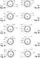
- Figs. 1A to 1Fillustrate a biopsy needle 100 with an outer sheath 105.
- the outer sheath 105in the present embodiment, is cylindrical and has an opening 150 with at least one sharp edge defining a blade 120.
- a cylinder-shaped inner sheath 136has a port 130, which, in Fig. 1A , is aligned with the opening 150.
- the port 130provides access to a sample chamber 125 which is defined by a sample volume within the inner sheath 136.
- a trocar 112is affixed to a distal end of the inner sheath 136.
- a handle(not shown) is presumed to be provided, opposite the trocar 112, to support the biopsy needle 100.
- Figs. 1B through 1Fshow, in section A-A, the needle 100 of Fig. 1A in successive stages of a sampling operation. These stages occur after the needle 100 is inserted into living tissue, a sample of which is to be excised for a biopsy.
- the outer sheath 105begins in a position in which it covers the port 130. The needle 100 is inserted while the outer sheath 105 is in this position relative to the inner sheath 136. Once the biopsy needle 100 is in position for sampling, the outer sheath 105 is rotated progressively in a counter-clockwise direction. The counter-clockwise rotation of the outer sheath 105 proceeds progressively through the stages indicated by Figs. 1C through 1F .
- the outer sheath 105may be driven by any suitable drive mechanism including pneumatic, electrical, magnetic, hydraulic, etc. Embodiments of suitable drive mechanisms are discussed below.
- a vacuumis generated in the sample chamber 125 by withdrawing air from the inner sheath 136.
- the vacuummay be generated by any suitable device. Embodiments of suitable vacuum mechanisms are discussed below.
- the outer sheath 105begins to rotate in the counter-clockwise direction.
- the opening 150is shown after having moved partly toward a position of coincidence with the port 130. As the rotation proceeds, the blade 120 advances toward the port 130. In this position, the vacuum, created in the sample chamber 125, draws tissue to be sampled through the opening 150 and port 130 until it begins to enter the sample chamber 125.
- the outer sheath 105moves counter-clockwise toward the position shown in Fig. 1D where the port 130 is fully uncovered, the opening 150 having moved into coincidence with the opening 130.
- the vacuumcauses tissue to be drawn into the sample chamber 125 and the outer sheath 105 continues rotating in the counter-clockwise direction to the position shown in Fig. 1E .
- the blade 120As the outer sheath 105 rotates toward the position shown in Fig. 1E , the blade 120 partly slices the tissue that has been drawn into the sample chamber 125. As the blade 120 continues toward the position of Fig. 1F , the tissue sample is completely severed from the host and held within the sample chamber 125 while a portion of the outer sheath 105, behind the blade 120, covers the port 130. The biopsy needle 100 can then be withdrawn from the inserted position as it retains the sample.
- the present cutting mechanismmay be replaced by suitable alternative cutting devices such as levered or rotating knives with blades of varying shape, radio-frequency (RF) cutting tools, laser cutters, or any other suitable cutting device.
- RFradio-frequency
- a positive pressuremay be generated in sample chamber 125 before starting the cycle.
- a pressureis applied to the sample chamber 125 and the port 130 is uncovered. This causes the pressure in sample chamber 125 to force the tissue sample out through the uncovered port (about the position shown in Fig. 1D ).
- the cyclemay then continue to the point shown in Fig. 1B .
- sample-removal mechanismsmay also be employed, such as a mechanical member pushing the sample from the sample chamber 125, a fluid wash.
- a sample chamber linersuch as of thermoformed polymer, may be preinstalled and removed by hand.
- the outer sheath 105could rotate in either direction, or both directions, in alternative embodiments.
- the port 130could be uncovered by rotating in one direction and the cutting operation and covering could occur after reversing the direction of rotation immediately after uncovering the port 130.
- This alternativemay be provided for all of the embodiments described herein.
- the blade 120may be on either or both sides of the opening 150.
- the speed of rotation of the outer sheath 105may be constant or variable.
- a reduced force/torque transmission ratio of the drivemay be provided to level the prime mover load through the cutting phase.
- an alternative shape for the port 130is indicated in Fig. 1A at 104.
- This alternative port 104may also be used to help reduce the instantaneous torque load on the outer sheath 105 drive mechanism (not shown).
- the shape of the port 130is such that the blade 120 advances through only a fraction of the longitudinal extent of the sample at a given instant of time.
- FIGs. 2A through 2Fillustrate a biopsy needle 101 with an outer sheath 106.
- the outer sheath 106in the present embodiment, is cylindrical and has an opening 151 with at least one sharp edge defining an angled blade 121.
- a cylinder-shaped inner sheath 136has a port 131, which, in Fig. 2A , is aligned with the opening 151.
- the port 131provides access to a sample chamber 126 which is defined by a volume within the inner sheath 136.
- a trocar 112is affixed to a distal end of the inner sheath 136 and a handle (not shown) is presumed to be affixed, opposite the trocar 112, to support the biopsy needle 101.
- a handle(not shown) is presumed to be affixed, opposite the trocar 112, to support the biopsy needle 101.
- the embodiment of Figs. 2A through 2Fis similar in structure and operation to the embodiment of Figs, 1A through 1F with a cutting blade 121 that forms a non-zero angle with the longitudinal axis of the outer sheath 106.
- This angled shapemay help reduce the instantaneous torque load on the outer sheath 105 drive mechanism (not shown).
- the shape of the port 131is such that the blade 121 advances through only a fraction of the longitudinal extent of the sample at a given instant of time. Because the blade 121 is angled, it defines a helical contour with the outer sheath 106.
- the blade 121could have a curved or multiple-angle configuration to achieve the same function of reducing the instantaneous force required to perform cutting.
- Figs. 2B through 2Fshow, in section B-B, the needle 100 of Fig. 2A in successive stages of a sampling operation. These stages occur after the needle 101 is inserted into living tissue to sample the tissue of a host.
- the outer sheath 106begins in a position in which it covers the port 130. The needle 100 is inserted while the outer sheath 106 is in this position relative to the inner sheath 136. Once the biopsy needle 101 is in position for sampling, the outer sheath 106 is rotated progressively in a counter-clockwise direction. The counter-clockwise rotation of the outer sheath 106 proceeds progressively through the stages indicated by Figs. 2C through 2F .
- the outer sheath 106may be driven by any suitable drive mechanism. Embodiments of suitable drive mechanisms are discussed below.
- a vacuumis generated in the sample chamber 126 by drawing air through the inner sheath 136.
- the vacuummay be generated by any suitable device. Embodiments of suitable vacuum mechanisms are discussed below.
- the outer sheath 106begins to rotate in the counter-clockwise direction.
- the opening 151is shown after having moved partly toward a position of coincidence with the port 131. As the rotation proceeds, the blade 121 advances toward the port 131. In this position, the vacuum, created in the sample chamber 126, draws tissue to be sampled through the opening 151 and port 131 until it begins to enter the sample chamber 126.
- the outer sheath 106moves counter-clockwise toward the position shown in Fig. 2D where the port 131 is fully uncovered, the opening 151 having moved into coincidence with the opening 131.
- the vacuumcauses tissue to be drawn into the sample chamber 126 and the outer sheath 106 continues rotating in the counter-clockwise direction to the position shown in Fig. 2E .
- the blade 121partly slices the tissue that has been drawn into the sample chamber 126. As the blade 121 continues toward the position of Fig. 2F , the tissue sample is completely severed from the host and held within the sample chamber 126 while a portion of the outer sheath 106 behind the blade 121 covers the port 131. The biopsy needle 101 can then be withdrawn from the inserted position as it retains the sample.
- a positive pressuremay be generated in sample chamber 126 before starting the cycle.
- a pressureis applied to the sample chamber 126 and the port 131 is uncovered. This causes the pressure in sample chamber 126 to force the tissue sample out through the uncovered port (about the position shown in Fig. 2D ).
- the cyclemay then continue to the point shown in Fig. 2B .
- the outer sheath 106could rotate in either direction with an appropriate repositioning of the blade 121.
- the blade 121may be on both sides of the opening 151.
- the speed of rotation of the outer sheath 106may be constant or variable to amplify torque from the drive mechanism.
- the alternative shape for the port 131 indicated in Fig. 2A at 104is substantially as discussed with reference to Fig. 1A .
- this alternative port 104may provide even lower instantaneous torque load for a given angle because the angle of the cutting blade 121 causes the cutting front to be even smaller for a given angle of the port 131.
- the movement of the outer sheath 105 or 106 of the foregoing embodimentsmay be permitted by providing that the inner sheath 135 or 136 be journaled within the outer sheath 105 or 106.
- a lubricantmay or may not be provided.
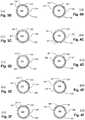
- the opening 150may be made narrow enough, in a circumferential direction, such that the port 130 is barely uncovered before severing of a tissue sample begins. However, it may be desirable to provide a wider opening 150 to provide more time for tissue to be drawn into the sample chamber 125. There is a tradeoff against structural strength in making the opening 150 wider. However, in alternative embodiments, the opening 150 may be made wider in a circumferential direction and in the extreme, only enough of the outer sheath 105 may remain to barely cover the port 130. Such an embodiment is shown in Figs. 3A to 3F and described immediately below.
- Figs. 3A to 3Fillustrate a biopsy needle 200 with an outer sheath 205.
- the outer sheath 205in the present embodiment, is cylindrical and has an opening 250 with at least one sharp edge defining a blade 220.
- a cylinder-shaped inner sheath 236has a port 230, which, in Fig. 3A , is aligned with the opening 250.
- the port 230provides access to a sample chamber 225 which is defined by a volume within the inner sheath 236.
- a trocar 212is affixed to a distal end of the inner sheath 236.
- a handle(not shown) is presumed to be provided, opposite the trocar 212, to support the biopsy needle 201.
- Figs. 3B through 3Fshow, in section C-C, the needle 200 of Fig. 3A in successive stages of a sampling operation. These stages occur after the needle 200 is inserted into living tissue, a sample of which is to be excised for a biopsy.
- the outer sheath 205begins in a position in which it covers the port 230. The needle 200 is inserted while the outer sheath 205 is in this position relative to the inner sheath 236. Once the biopsy needle 200 is in position for sampling, the outer sheath 205 is rotated progressively in a counter-clockwise direction. The counter-clockwise rotation of the outer sheath 205 proceeds progressively through the stages indicated by Figs. 3C through 3F .
- the outer sheath 205may be driven by any suitable drive mechanism. Embodiments of suitable drive mechanisms are discussed below.
- a vacuumis generated in the sample chamber 225 by drawing air through the inner sheath 236.
- the vacuummay be generated by any suitable device. Embodiments of suitable vacuum mechanisms are discussed below.
- the outer sheath 205begins to rotate in the counter-clockwise direction.
- the opening 250is shown after having moved partly toward a position of coincidence with the port 230. As the rotation proceeds, the blade 220 advances toward the port 230. In this position, the vacuum, created in the sample chamber 225, draws tissue to be sampled through the opening 250 and port 230 until it begins to enter the sample chamber 225.
- the outer sheath 205moves counter-clockwise toward the position shown in Fig. 3D where the port 230 is fully uncovered, the opening 250 having moved into coincidence with the opening 230.
- the vacuumcauses tissue to be drawn into the sample chamber 225 and the outer sheath 205 continues rotating in the counter-clockwise direction to the position shown in Fig. 3E .
- the blade 220partly slices the tissue that has been drawn into the sample chamber 225.
- the tissue sampleis completely severed from the host and held within the sample chamber 225 while a portion of the outer sheath 205 behind the blade 220 covers the port 230.
- the biopsy needle 200can then be withdrawn from the inserted position as it retains the sample.
- a positive pressuremay be generated in sample chamber 225 before starting the cycle.
- a pressureis applied to the sample chamber 225 and the port 230 is uncovered. This causes the pressure in sample chamber 225 to force the tissue sample out through the uncovered port (about the position shown in Fig. 3D ).
- the cyclemay then continue to the point shown in Fig. 3B .
- the outer sheath 205could rotate in either direction, or both directions, in alternative embodiments.
- the port 130could be uncovered by rotating in one direction and the cutting operation and covering could occur after reversing the direction of rotation immediately after uncovering the port 130.
- the blade 220may be on either or both sides of the opening 250.
- the speed of rotation of the outer sheath 205may be constant or variable.
- a reduced force/torque transmission ratio of the drivemay be provided to level the prime mover load through the cutting phase.
- the port 130may have angled edges (as has port 104 in the embodiment of Fig. 1A ) to help reduce the instantaneous torque load on the outer sheath 205 drive mechanism (not shown).
- Figs. 4A through 4Fis similar to the embodiment of Figs. 3A through 3F except that an angled blade 221 is provided to level the cutting load, as described with reference to the embodiment of Figs. 2A through 2F .
- Figs. 4A to 4Fillustrate a biopsy needle 201 with an outer sheath 206.
- the outer sheath 206in the present embodiment, is cylindrical and has an opening 251 with at least one sharp edge defining a blade 221.
- a cylinder-shaped inner sheath 236has a port 231, which, in Fig. 4A , is aligned with the opening 251.
- the port 231provides access to a sample chamber 226 which is defined by a volume within the inner sheath 236.
- a trocar 212is affixed to a distal end of the inner sheath 236.
- a handle(not shown) is presumed to be provided, opposite the trocar 212, to support the biopsy needle 200.
- Figs. 4B through 4Fshow, in section D-D, the needle 201 of Fig. 4A in successive stages of a sampling operation. These stages occur after the needle 201 is inserted into living tissue, a sample of which is to be excised for a biopsy.
- the outer sheath 206begins in a position in which it covers the port 231. The needle 201 is inserted while the outer sheath 206 is in this position relative to the inner sheath 236. Once the biopsy needle 201 is in position for sampling, the outer sheath 206 is rotated progressively in a counter-clockwise direction. The counter-clockwise rotation of the outer sheath 206 proceeds progressively through the stages indicated by Figs. 4C through 4F .
- the outer sheath 206may be driven by any suitable drive mechanism. Embodiments of suitable drive mechanisms are discussed below.
- a vacuumis generated in the sample chamber 226 by drawing air through the inner sheath 236.
- the vacuummay be generated by any suitable device. Embodiments of suitable vacuum mechanisms are discussed below.
- the outer sheath 206begins to rotate in the counter-clockwise direction.
- the opening 251is shown after having moved partly toward a position of coincidence with the port 231. As the rotation proceeds, the blade 221 advances toward the port 231. In this position, the vacuum, created in the sample chamber 226, draws tissue to be sampled through the opening 251 and port 231 until it begins to enter the sample chamber 226.
- the outer sheath 206moves counter-clockwise toward the position shown in Fig. 4D where the port 231 is fully uncovered, the opening 251 having moved into coincidence with the opening 231.
- the vacuumcauses tissue to be drawn into the sample chamber 226 and the outer sheath 206 continues rotating in the counter-clockwise direction to the position shown in Fig. 4E .
- the blade 221partly slices the tissue that has been drawn into the sample chamber 226.
- the tissue sampleis completely severed from the host and held within the sample chamber 226 while a portion of the outer sheath 206 behind the blade 221 covers the port 231.
- the biopsy needle 201can then be withdrawn from the inserted position as it retains the sample.
- a positive pressuremay be generated in sample chamber 226 before starting the cycle.
- a pressureis applied to the sample chamber 226 and the port 231 is uncovered. This causes the pressure in sample chamber 226 to force the tissue sample out through the uncovered port (about the position shown in Fig. 4D ).
- the cyclemay then continue to the point shown in Fig. 4B .
- the outer sheath 206could rotate in either direction, or both directions, in alternative embodiments.
- the port 231could be uncovered by rotating in one direction and the cutting operation and covering could occur after reversing the direction of rotation immediately after uncovering the port 231.
- This alternativemay be provided for all of the embodiments described herein.
- the blade 221may be on either or both sides of the opening 251.
- the speed of rotation of the outer sheath 206may be constant or variable.
- a reduced force/torque transmission ratio of the drivemay be provided to level the prime mover load through the cutting phase.
- the port 231may be angled (as is 104 relative to 130 in Fig. 1A ) to help reduce the instantaneous torque load on the outer sheath 206 drive mechanism (not shown).
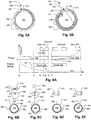
- Fig. 5Ais a section view of a biopsy needle 300 sample chamber 315 with a sharpened, curved, or jagged edge of a chamber opening 309.
- the edge 302helps to keep a tissue sample drawn into the sample chamber 315 by a vacuum, from retreating during the cutting operation.
- the configuration of the biopsy needle 300may be similar to the configurations of any of the foregoing embodiments but the configuration shown is similar to that of Figs. 3A to 3F .
- the cutting blade 310advances across the opening 309 while the edge 302 helps to ensure the tissue does not retreat. Because the cutting blade 310 is on the outside sheath 306, an inwardly-directed edge treatment, represented as edge 302, may be provided without interfering with the operation of the cutting blade 310 or outer sheath 306.
- the embodiment of Fig. 5Bis similar to that of Fig. 5A except that the biopsy needle 301 configuration is closest to that of Figs. 1A to 1F , although any of the foregoing configurations may be employed.
- the embodiment of Fig. 5Bhas an insert 328 which fits inside the sample chamber 316.
- the inserthas a portion 321 with a barbed surface 320 that is opposite the cutting blade 332.
- the cutting blade 332advances across the opening 329 while the barbed surface 320 helps to ensure the tissue does not retreat. Because the cutting blade 332 is on the outer sheath 330, inwardly-directed barbs may be provided without interfering with the operation of the cutting blade 332 or outer sheath 330.
- a substantial vacuumto be generated before the biopsy needle is actuated for cutting. This is so that a poor sample specimen does not result due to the cutting operation getting underway before the tissue sample is drawn well into the sample chamber.
- Thiscan be ensured in a variety of ways, for example by providing a drive system with independently controlled vacuum source and biopsy needle that are sequenced to generate the vacuum before the biopsy needle is placed into a configuration for sampling.
- Fig. 6Aillustrates various sequencing operations and will be used to discuss the sequencing and variations of it.
- a self-contained devicesuch as described hereinbelow or, for example, in US Patent Application No. 20050203439 , incorporated by reference above, or any other vacuum source, may take a finite period of time to generate a terminal negative pressure.
- a displacement pumpthat increases a contained volume, at a linear rate, produces a vacuum - assuming there are no leaks - characterized by an exponential pressure curve as indicated at 408.
- such a pump operated in reversegenerates a pressure according to an inclining exponential positive pressure curve as indicated at 410.
- the vacuumis preferably established when the sample chamber is uncovered. This may ensure that the severing operation can be completed and the sample secured without the sample chamber being open for a long interval. In principle this is not essential, but in practice it may be desirable for various reasons: (1) an imperfect fluid seal may exist so that a progressive vacuum may not reach a desired peak level; (2) excess fluid may be drawn from the host, thereby compromising the vacuum and producing an undesirable result when a solid specimen is required; and (3) excessive fluid may be accumulated in the tissue sample due to an extended exposure to the vacuum, while attached to the host. Other effects such as compliance in the biopsy device's fluid circuit and other factors may also favor an operating sequence in which the host is exposed to the vacuum as briefly as possible.
- means of anchoring tissue samples other than vacuummay be employed.
- external pressure on the host tissue from outside the patient bodye.g. by means of a tissue compression device or manual pressure by the practitioner
- tissue compression devicee.g. by means of a tissue compression device or manual pressure by the practitioner
- the time during which a vacuum pump is operated to create the pressure curve, shown at 408,is indicated by the bar 402.
- a vacuum pumpmay be operated.
- the sample openinge.g., as port 130 in Fig. 1A
- the tissue samplehaving been drawn in, will be cut 420 at a later time t 3 and the opening subsequently closed 424 during interval t 4 to t 5 .
- the opening and cutting operationsare performed toward the end of the vacuum generation cycle 402 which takes place over the interval from t 0 to t 5 , although it may be paused earlier, depending on the various factors mentioned.
- the above sequencingmay be achieved by employing independent drive mechanisms for the vacuum and biopsy needle.
- a design suitable for a disposable biopsy needleit may be preferred to have a single drive system that can achieve the same operation sequence as just described in a manner that is reliable, with a simple a structure and low cost, by employing a single mechanical drive, as discussed below.
- FIG. 6B through 6EAn embodiment of a biopsy needle 448, similar to the embodiment of Figs. 1A and 1B , is illustrated by Figs. 6B through 6E .
- the outer sheath 105corresponds to the outer sheath 450, which has an opening 452.
- the inner sheath 130corresponds to the inner sheath 456 which has an opening 454.
- Either of the outer sheath 450 or the inner sheath 456can have a cutting edge (for example at 451 on outer sheath 450) to cut a tissue sample, as discussed above, which is drawn into a sample chamber 458 by a vacuum generated therein.
- the present embodimentoperates in a manner that is similar to what is described with reference to Figs. 1B through 1F , except that the total angular displacement of the outer sheath 450 is greater in the present embodiment, to generate a delay from the onset of the operation of the vacuum generating device and the opening of the sampling device, as will be explained, presently.
- a positive-displacement pumpis shown at 480.
- the outer sheath 450is progressively rotated counter-clockwise as a piston 472 of the pump 480 is progressively displaced from the initial position indicated at 485, to create a vacuum in a line 474 connected to the sample chamber 458.
- the piston 472is displaced, progressively as shown to draw a negative pressure in the line 474.
- the above operation of the needle 448 and pump 480is effective to provide the sequencing of the vacuum creation and sampling cycle described above with reference to Fig. 6A . That is, the sample chamber 458 remains closed as the pump 480 is continuously operated to create a vacuum until the sample chamber 458 is opened at the final phase of vacuum generation.
- the outer sheath and the vacuum sourceare both operated continuously during the entire cycle so that a single drive 481 can move both the outer sheath 450 and the pump piston 472 continuously without any additional provisions for sequencing because a delay can be incorporated in the arrangement and configuration of the inner 456 and outer 450 sheaths. Referring particularly to Fig.
- a single drive 483may also drive the pump 480 which in turn may drive the outer sheath 450 through a drive element 485 or the drive element 485 may be a single drive element that drives both the pump 480 and the outer sheath 450.
- a transmissionconfigured to apply motive force, simultaneously, to rotate the sheath and to drive the vacuum source, will provide the desired operational sequence.
- a samplemay be removed from a biopsy device by releasing pressurized air into the sample chamber 458 to eject the sample.
- a devicemay have a positive displacement pump that generates the pressure 406 gradually during an operating cycle, for example extending from a time t6 to a time t10 after the sample is taken.
- a positive pressuremay be generated after the sample is retained in the sample chamber 458, as indicated by the curve 410. In this case, it may be desirable for a significant initial pressure to exist before the sample chamber 458 is opened 426 to release the sample.
- the desired point, during the operating cycle 406 of the pump, at which the sample chamber 458 is openedmay vary, e.g., 426 or 428, based on the arrangement of the biopsy device and designer preference.
- the mechanism of Figs. 6B to 6Emay be employed to provide a delay between the operation of the pump and the point at which the sample chamber 458 is opened. For example, if the pump 490 is operated in reverse, and the outer sheath 450 is rotated counter-clockwise, a pressure will accrue in the pump 480, while the sample chamber 458 remains closed until near the end of the pump cycle.
- the point at which the sample chamber 458 openscan be selected by selecting the initial position of the outer sheath 450 opening 452 relative to the inner sheath 456 opening 454.
- both the pump 480 and the outer sheathmay be moved in a reverse direction during the sample-ejection cycle, which may allow a simpler driving system.
- the opening of the sample chamberwill occur in the middle of the pumping cycle in both the sampling and sample-ejection operations.
- the entire drive systemmay simply be reversed to obtain a sampling sequence in which the sample chamber opening is delayed relative to both the start of the vacuum cycle 402 during sampling and the start of the pressure-generating cycle 406 during sample-ejection.
- the total angular displacementneed not be 360° as illustrated above.
- a sampling sequencemay be delayed after initial operation of a pump without requiring independent drive systems for the pump and sampling device by another means.
- a prime mover 700has an output represented by the bar 702 which translates to the right (as shown in the sequence of Figs. 7A, 7B, and 7C ) which indicates the displacement of the output 702. This is an illustration of the output 702, which could correspond to the shaft of a rotary motor, a linear actuator, a worm drive, or any kind of drive device.
- a first transmission 708receives motive force from a drive input 704 and applies an output to a pump 712.
- a second transmission 710receives motive force from a drive input 706 and applies an output to a sampling device 714.
- the prime mover output 702advances it first engages the first transmission input 704 as shown in Fig. 7A causing the pump to begin an operating cycle. As it progresses, the prime mover output 702 continues to advance to the point shown in Fig. 7B and as it advances, it continues to remain in engagement with the first transmission input 704, but has not yet reached the second transmission input 706. Eventually, the prime mover output 702 advances to the point shown in Fig. 7C and, as it advances, it engages and continues to remain in engagement with the first transmission input 704 and the second transmission input 706 to drive both the pump 712 and the sampling device 714.
- the pump 712it is possible to allow the pump 712 to disengage from the prime mover output 702 at a desired point in the cycle. This may be desirable to level the load on the prime mover 700 so that it does not require the capacity to operate the pump 712 and the sampling device 714, simultaneously.
- FIGs. 8A to 8Canother mechanism to provide the sequencing of a pump 712 and sampling device 714, in a similar manner to that of Figs. 7A to 7C is to connect the prime mover directly to a combined first transmission input and prime mover output 705.
- This combined first transmission inputapplies motive force to the pump 712 and, as it translates to the right, continues to operate the pump 712 until, as indicated in Fig. 8C , it engages the second transmission input 706 and operates the sampling device 714.
- a pump 502in the form of a syringe, has a piston 508 with a rack 510 which functions as a piston rod, forcing the piston 508.
- a screw gear 507engages the rack 510 by means of an internal screw (not shown) to advance the rack 510 to the right.
- a rotary motor 500drives a primary drive gear 506 through an output shaft 501.
- the primary drive gear 506engages the screw gear 507 to move the rack 510 causing the pump 502 to generate a vacuum.
- the vacuumis conveyed by a tube 512, connected to a biopsy needle 524.
- the vacuumis channeled by the biopsy needle 524 to a sample chamber (not shown) near the tip 530 of the biopsy needle 524.
- the biopsy needle 524has an outer sheath 526 and an inner sheath 532, which may be as described with reference to any of the embodiments described above.
- the outer sheath 526is able to be rotated relative to the inner sheath 532 which is affixed to a housing 540 enclosing all of the components except distal portion 542 of the biopsy needle 524.
- the rack 510engages a pinion 514 which has a driving bevel gear 516 that engages a driven bevel gear 518.
- the driven bevel gear 518is affixed to a sheath driving gear 520 which engages a sheath driven gear affixed concentrically to the outer sheath 526.
- the sample chamberis exposed, and a sample is cut, when an opening 528 in the outer sheath 526 is rotated by the sheath driven gear 522 at a point in time when the rack 510 engages the pinion 514.
- the motoris run continuously in a single direction causing the rack 510 to advance to the right, driven by the screw gear 507.
- the piston 508is also advanced, generating a partial vacuum.
- the rack 510moves further it reaches a point where it just engages the pinion 516 as shown in Fig. 9C .
- the pinionis driven along with the rack 510 causing the vacuum to increase and the outer sheath 526 to begin rotating about the inner sheath 532.
- the rackcontinues to advance and, at a point illustrated in Fig.
- the inner sheath opening 527 and the outer sheath opening 528are brought into coincidence thereby opening sample chamber and drawing in a sample due to the suction of the vacuum.
- the rackadvances further ( Fig. 9F ) causing the sample to be cut placing the outer sheath 526 in a final position.
- the motor 500may be operated in reverse to eject a sample by using the pump 502 to generate a pressure and force a tissue sample out of the sample chamber.
- the mechanism used to displace the rack 510can be any suitable mechanism.
- a pinion gear 574may be used with a drive motor 572 which may itself include a gear train, such as a planetary gear, to amplify torque.
- a worm gear 576as illustrated driven by a suitably arranged motor 570.
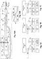
- FIG. 10Aanother design for a biopsy device has a housing 605 that encloses most of the illustrated assembly, as shown.
- a motor 600drives a drive gear 614 which meshes with a screw gear 615 which is internally threaded to engage and drive a threaded rod 608.
- the threaded rod 608is attached to a piston 607 of a pump 602 which generates a vacuum in a tube 606.
- the tube 606conveys the vacuum to a biopsy needle 618.
- the biopsy needle 618has an outer sheath 623 and an inner sheath 637.
- the outer sheath 623rotates around the inner sheath 637 to bring an opening 620 in the outer sheath 623 into coincidence with an opening 621 in the inner sheath 637 and perform a cutting operation as the outer sheath.
- a pin 624is affixed to the outer sheath 623 which can rotate around the inner sheath 637.
- a pushrod 602is connected to the threaded rod 608 and is open at the bottom to define a channel 604 so that the pushrod 602 can move without interfering with the tube 606.
- the pushroddisplaces a cam drive 630 with a slot 631.
- the slot 631has a helical portion 626 and a straight portion 638.
- a pin 624is affixed to the outer sheath 623 and engaged in the slot 631.
- the cam drive 630moves to the right as the piston 607 is displaced, the cam drive 630 being moved by the piston 607, threaded rod 608, pushrod 602, all of which move together.
- the straight portion 638 of the slot 631allows the cam drive 630 to move without affecting the position of the pin 624.
- the cam drive 630provides for an operation that is similar to that of Figs. 9A to 9F .
- Figs. 11A and 11Bshow a stylet 804 that has an axial cutting sheath 806 which may be used in embodiments of the invention.
- a cutting tip 814such as a trocar, may be provided.
- the axial cutting sheath 806has a has a cutting edge 808 at a distal end which severs tissue samples from the host causing them to be deposited in a tissue basket 802 at the end of the stylet.
- the cutting sheath 806closes over the tissue basket 802, thereby enclosing it. Note that the relative sizes and proportions of the elements shown in Figs. 11A and 11B are not essential features of the invention.
- tissue basket 802may be a hollow recess configured a manner similar to the embodiments of the figures discussed above.
- Known axially-displacing cutting sheathsrotate about the axis as they are displaced.
- the cutting sheathis displaced with no, or nearly no, rotational motion. It is believed that for some kinds of tissue sampling, that this results in a higher quality sample, which may result from less rubbing of tissue sticking to a rotating cutting sheath.
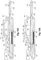
- Figs. 12A to 12Fshow a biopsy needle embodiment for illustrating features including a linear actuator 901, an axial cutting sheath, and a spring-activated cutting action.
- a linear actuator 901draws a shaft 903 attached to a piston 909 attached to a carriage 907 to generate a vacuum by expanding a volume 940 within a cylinder 905.
- An interior channel (not shown) of the stylet 931which runs along its entire length of the stylet 931 from the hose 911 to the sample basket 915, is connected by a flexible hose 911 to the displaced volume 940.
- the displaced volume 940expands. This draws air through the hose 911, through the interior channel of the stylet 931, thereby creating a vacuum in a sample basket 915.
- a pivot arm 933is pivotally connected to the carriage 907 about a first end 939 thereof.
- a spring 943generates a torque between a pivot arm 933 and a boss 905 on the carriage 907 to keep the free end 935 in engagement with a shelf 937.
- the catch plate 925is affixed to a cutting sheath 913 which conforms to the description attending Figs. 10A and 10B .
- a spring 921connects the catch plate 925 and a boss 923, the boss 923 being fixed relative to the stylet 931.
- the cutting sheath 913is retracted by the pivot arm 933 stretching the spring 921 thereby increasing a restoring force that urges the cutting sheath back toward a home position shown in Fig. 12A .
- the sample basket 915is opened and the vacuum created in the sample basket 915 draws host tissue (not shown) into it.
- the cutting sheath 921is further retracted as the carriage 907 moves further while the free end 935 slides up a ramp portion 927 of the shelf 937 as shown in Fig. 12D .
- the cylinder 905 interior volume 940continues to expand increasing or maintaining the vacuum in the sample basket 915.
- the free end 935is moved to position in which it disengages from the catch plate 925 releasing the cutting sheath 913, thereby permitting the spring 921 to force it back to the home position of Fig. 12F .
- the displacement between the positions of Figs. 12E and 12Fcauses a tissue sample to be severed by the movement of the cutting sheath 913.
- the carriage 907may then be moved in an opposite direction to cause the free end 935 to return to a position in which it can retract the cutting sheath 913 again.
- the motors or prime movers disclosed in each embodimentmay be replaced by rotary or linear motors which may be driven by electromotive force, by spring motors, hydraulic of pneumatic motors, thermal motors, or by any means of generating a motive force.
- Different types of displacemente.g., rotary or linear
- a drivesuch as the one shown in Figs. 9A to 9F or 10A could be used as well.
- the linear actuator 901may be a screw drive, an electronically controlled linear motor, a wax motor, a hydraulic or pneumatic motor, an artificial muscle or any suitable motor with a suitable kinematic mechanism to couple it to the cutting sheath and vacuum pump.
- a syringeis preferred as a vacuum generating device, other types of vacuum generating devices may be employed in other embodiments of the invention, for example, a diaphragm pump, multiple-stroke positive displacement pump, screw pump, etc.
Landscapes
- Health & Medical Sciences (AREA)
- Life Sciences & Earth Sciences (AREA)
- Surgery (AREA)
- Animal Behavior & Ethology (AREA)
- Biomedical Technology (AREA)
- Heart & Thoracic Surgery (AREA)
- Medical Informatics (AREA)
- Molecular Biology (AREA)
- Pathology (AREA)
- Engineering & Computer Science (AREA)
- General Health & Medical Sciences (AREA)
- Public Health (AREA)
- Veterinary Medicine (AREA)
- Surgical Instruments (AREA)
- Measurement Of The Respiration, Hearing Ability, Form, And Blood Characteristics Of Living Organisms (AREA)
- Sampling And Sample Adjustment (AREA)
Abstract
Description
- This application claims priority to
US Provisional Application Serial No. 60/823038. filed August 21, 2006 - This invention relates to a tissue biopsy sampling device. More specifically, the invention relates to mechanical features of an automatic biopsy sampling device.
- Often, it is either desirable or necessary to obtain specimens of tissue from humans and other animals, particularly in the diagnosis and treatment of patients with cancerous tumors, premalignant conditions, and other diseases or disorders. For example, when it is discovered that suspicious conditions exist, either by means of x-ray or ultrasound imaging in various tissues of the body, a physician typically performs a biopsy to determine if the cells at the suspected site are cancerous.
- A biopsy can be done either by an open or percutaneous technique. Open biopsy is an invasive procedure using a scalpel, whereby either a portion (incisional biopsy) or the entire mass (excisional biopsy) is removed. Percutaneous biopsy is usually done with a needle-like instrument through a relatively small incision, and can be performed by fine needle aspiration (FNA) or through the taking of a core biopsy sample. In FNA biopsy, individual cells or clusters of cells are obtained for cytologic examination and can be prepared such as in a Papanicolaou smear. In a core biopsy, a core or fragment of the tissue is obtained for histologic examination.
- Intact tissue from the organ, lesion, or tumor is preferred by medical personnel in order to arrive at a definitive diagnosis regarding the patient's condition. In most cases only part of the tissue in question needs to be sampled. The portions of tissue extracted must be indicative of the organ, lesion, or tumor as a whole. Often, multiple tissue samples from various locations of the mass being sampled may be taken.
- The percutaneous biopsy procedure can be performed utilizing various techniques and devices. An example is a method and a device that employs a biopsy needle for cutting tissue sample as described in British Patent Publication No.
GB 2018601A - Another biopsy mechanism is described in European Patent Publication No.
EP 0890 339 A1 . A biopsy needle with a cutting mechanism are integrated into a hand piece. The needle is connected via a connections lines to an external vacuum generator and controls. The cutting device is moveable axially in the hollow space of the biopsy needle. A rotary movement, combined with a manual lengthwise push causes the cutting device to sample the tissue from the host. The sample is transported in the hollow channel of the needle. A similar arrangement is also shown byU.S. Patent No. 5,526,822 . In these devices, the vacuum generation mechanisms and controls are costly and tend to be provided in permanent fixtures that are separate from the disposable components. A manual biopsy device is known from German Patent No.DE 40 41 614 C1 . In this device, a partial vacuum source is provided by a piston and cylinder pump. A similar partial vacuum-assisted biopsy device can be found in International Publication No.WO 96/28097 - A vacuum-assisted biopsy device is described in
U.S. Patent Publication No. 2001/0011156 A1 , provides for a compactly configured hand device, in whose housing all drive elements necessary for propelling the needle of the biopsy needle arrangement are provided. However, a partial vacuum source is provided separate from the hand device, which can be connected via an appropriate supply line to the needle arrangement inside the hand device at a suitable connection location. US Patent No. 20050203439 , hereby incorporated herein by reference in its entirety, describes a biopsy device for taking tissue samples, which includes a housing, a removable element and a control panel. The removable part has a vacuum pump in the form of a syringe which is driven by a first motor and a biopsy needle which is driven by a separate motor under the control of a controller built into a permanent hand set. The needle and syringe are provided as a sterile package unit.- There is a need for improvements in biopsy devices that provide for high performance with low manufacturing cost, simplicity, reliability, and ease of use. Current devices are complex, either requiring many parts such as motors and drive components or providing low performance such as weak low penetration force, small sample size, poor sample integrity, etc. There is a need for design features that permit a biopsy device to be fully automated, yet fully disposable as well as economical, susceptible to efficient manufacture, simple, and reliable.
- The embodiments disclosed herein relate to self-contained hand-held biopsy needles with various features relating to automated sampling and recovery. Among the disclosed features are ones suited to fully-disposable single-use automatic biopsy devices, such as light weight, low cost, and simple design.
- According to an embodiment, a biopsy device is provided which has a housing and a biopsy needle projecting from the housing. The biopsy needle has a first member that defines a sample chamber and a second member that defines a sample volume within the sample chamber. A pump generates a vacuum in the sample volume. A primary drive element has a first drive interval and a second drive interval. A first transmission is driven by the primary drive element during the first drive interval to operate the pump and a second transmission driven by the primary drive element during the second drive interval to position the first and second members of the biopsy needle to define the sample volume.
- Preferably, a housing encloses the pump, the primary drive element, the first transmission, the second transmission, and a portion of the biopsy needle. The first and second drive intervals are sequential. The first drive interval overlaps the second drive interval. The second drive interval follows after the start of the first drive interval. The first and second drive intervals are physical displacement intervals. The first and second drive intervals have identical endpoints and the second drive interval begins after the beginning of the first drive interval. The device includes a motor with an output connected to the primary drive element and a controller selectively operates the motor in forward and reverse directions.
- According to another embodiment a biopsy device is provided which has a biopsy needle with tissue-penetration and tissue-sampling configurations. A pump is connected to the biopsy needle to generate a vacuum in the biopsy needle. A first drive element is connected to operate the pump. A second drive element is provided to configure the biopsy needle. The first drive element has a first displacement interval and a second displacement interval such that during the first displacement interval, the first drive element operates the pump to generate a vacuum in the biopsy needle, and during the second displacement interval, the first drive element engages the second drive element to configure the biopsy needle into the tissue-sampling configuration.
- Preferably, the second displacement interval follows the first displacement interval. Also, preferably, the first displacement interval overlaps the second displacement interval. Also, preferably, the second displacement interval follows after the start of the first displacement interval. The first and second displacement intervals can have the same endpoints and the second displacement interval preferably starts after the start of the first displacement interval. Preferably, a motor provides an output connected to the first drive element and a controller selectively operates the motor in forward and reverse directions. Also, preferably, a housing encloses the pump, the first and second drive elements, and a portion of the biopsy needle.
- According to another embodiment a biopsy device is provided which has a biopsy needle selectively configurable into a sampling configuration for creating a tissue sample and an insertion/removal configuration for inserting or extracting the biopsy needle from living tissue. A pump connected to the biopsy needle generates a vacuum therein. A first drive element is provided which is connected to drive the pump. A second drive element is also connected to configure the biopsy needle. A primary drive member is displaced through a continuous range having a first interval and a second interval. During the first interval, a motive force is transmitted through the primary drive member to the first drive element to cause the pump to generate a vacuum and, during the second interval, a motive force is transmitted to the second drive element to configure the biopsy needle from the insertion/removal configuration to the sampling configuration. During the second interval, a motive force continues to be transmitted to the first drive element to cause the pump to continue generating a vacuum. Preferably, the continuous range has a third interval, following the second interval, during which the second drive element configures the biopsy needle from the sampling configuration to the insertion/withdrawal configuration. Also, preferably, the first drive element is spaced apart from the second drive element such that the primary drive member engages the first drive element during the first interval and, as it moves toward the second drive element, engages the second drive element during the second interval.
- According to another embodiment a biopsy device is provided which has a biopsy needle selectively configurable into a cutting configuration, for cutting a tissue sample, and an insertion configuration, for insertion into a host. A pump is connected to the biopsy needle to generate a vacuum therein. A prime mover is provided with a primary output element, which can be displaced through first and second intervals. A transmission mechanism is connected to the primary output element. The transmission mechanism has at least a first transmission output to configure the biopsy needle and at least a second transmission output to operate the pump. The transmission mechanism is configured to cause the pump to generate a vacuum during a first displacement of the primary output element and to configure the biopsy needle from the insertion configuration to the cutting configuration during a second displacement of the primary output element. Preferably, the transmission mechanism includes a first drive element and a second drive element spaced apart therefrom. Also, preferably, the first and second drive elements drive the first and second transmission outputs, respectively. In this case, the primary output element is arranged to drive the first drive element during the first displacement and to move at least one of the first drive element and the primary drive element toward the second drive element until it engages and drives the second drive element and thereafter drive the second drive element during the second displacement.
- According to another embodiment a biopsy device is provided which has a biopsy needle that is selectively configurable into a sampling configuration and an insertion configuration. The device has a pump connected to the biopsy needle to generate a vacuum therein. A motor and a transmission mechanism is provided where the transmission mechanism is configured to transmit motive force from the motor to the pump during a first interval upon activation of the motor, and, during a second interval, following the first interval, to transmit motive force from the motor to the biopsy needle to change its configuration from the insertion configuration to the sampling configuration such that a substantial vacuum is generated by the pump before the biopsy needle is configured into the sampling configuration. Preferably, the motor operates continuously during the first and second intervals. More preferably, both the pump and the motor operate continuously during the first and second intervals, in an embodiment, the pump is operates continuously during the first and second intervals.
- The sampling configuration can include a continuous cycle that includes receiving a tissue sample within the biopsy needle and cutting the tissue sample from a host. The biopsy needle has fixed shaft, a longitudinal axis, and a rotating shaft movably connected to the fixed shaft to rotate around the longitudinal axis. The rotating shaft can include a cutting blade to cut tissue samples. The sampling configuration can also include a continuous sampling cycle, during the second interval, in which a tissue sample is cut and received within the biopsy needle, the transmission mechanism being configured to urge the rotating shaft progressively during the second interval to cut a tissue sample and cause it to be received in the biopsy needle.
- According to another embodiment a biopsy device is provided which has a biopsy needle, selectively configurable into a sample access configuration and an insertion configuration. The biopsy needle has a sample chamber. The device also has a pump connected to the sample chamber to generate a vacuum therein and a motor with a transmission mechanism. The transmission mechanism is connected to configure the biopsy needle and drive the pump, upon activation of the motor in a first direction. The transmission mechanism transmits motive force from the motor to the pump during a first interval and, as the motor continues during a second interval that follows the first interval, the transmission mechanism transmits motive force to the biopsy needle to change its configuration from the insertion configuration to the sample access configuration such that a substantial vacuum is generated in the sample chamber before the biopsy needle is configured into the sample access configuration.
- Preferably, upon activation of the motor in a second direction, the transmission mechanism transmits a motive force from the motor to the pump during a third interval following the second interval and simultaneously change the biopsy needle configuration from the insertion configuration to the sample access configuration to generate pressure in the sample chamber to eject a sample therefrom. The pump is preferably operated during at least part of the second interval. Preferably, the pump is operated throughout the second interval. Also, preferably, a housing encloses the pump, the transmission mechanism, and a portion of the biopsy needle.
- According to another embodiment a biopsy device is provided which has a biopsy needle with an elongate inner cylindrical member and an elongate outer cylindrical member, the outer cylindrical member being coaxially aligned with the inner cylindrical member and rotatable with respect to it. The inner cylindrical member has a port and the outer cylindrical member has a cover portion capable of being aligned with the port to cover it for insertion of the biopsy needle. The outer cylindrical member has a cutting edge adjacent to the cover portion such that, as the outer cylindrical member is rotated progressively about the inner cylindrical member through a specified interval, the cutting edge passes over the port and covers the port. The cutting edge and port is shaped such may as the outer cylindrical member rotates, a progressively greater fraction of the cutting edge passes over the port.
- Preferably, the inner cylindrical member has a trocar affixed to a distal tip thereof. Preferably, also, the cutting edge has at least a portion that is angled relative to the perpendicular to the direction of advance of the cutting edge. The inner cylindrical member has a surface with at least one barb aligned with an port edge of the port opposite the cutting edge as the cutting edge advances toward the port edge prior to covering the port. The inner cylindrical member can have a sharp edge partly defining the port, the sharp edge having a portion extending toward the axis of the inner cylindrical member and opposite the cutting edge as the cutting edge advances toward the port edge prior to covering the port.
- According to another embodiment a biopsy device is provided which has a housing that defines a chamber with a biopsy needle partially disposed in the chamber. The biopsy needle has a first member that defines a sample chamber and a second member may defines a sample volume with the sample chamber. The device has a pump that generates a vacuum at the sample chamber and a primary drive element positioned with the housing. The primary drive element has a first drive interval and a sequential second drive interval. A first transmission driven by the primary drive element during the first drive interval operates the pump. A second transmission driven by the primary drive element during the second drive interval positions the first and second members of the biopsy needle to define the sample volume.
- According to another embodiment a biopsy device is provided which has a biopsy needle with a sample chamber that has an access opening. The biopsy needle has a cover member movable relative to the access opening to cover the access opening. A pump is connected to the biopsy needle to generate a vacuum in the sample chamber. A drive element is provided that simultaneously drives the pump and moves the cover member relative to the access opening through a sampling cycle over which the pump generates a vacuum in the sample chamber and the cover member moves relative to the sample chamber through a delay interval in which the access opening remains covered by the cover member and through a sampling interval, following the delay interval, in which the access opening is uncovered. The cover member has a cutting edge which cuts a sample free of a host after the access opening is uncovered.
- According to another embodiment, a biopsy device includes an elongate inner cylindrical member and an elongate outer cylindrical member. The outer cylindrical member is coaxially aligned with the inner cylindrical member and movable with respect to it along a common axis of the inner and outer cylindrical members. The inner cylindrical member has a port and the outer cylindrical member has a cover portion capable of being aligned with the port to cover it for insertion of the biopsy needle. A drive mechanism drives a first transmission member connected to a vacuum pump. The first transmission member drives a second transmission member connected to the outer cylindrical member to displace it without rotating it. The outer cylindrical member has a cutting edge adjacent to the cover portion such that, as the outer cylindrical member is displaced along the inner cylindrical member by the drive mechanism, the cutting edge passes over the port and covers the port. Preferably, the vacuum pump is connected to the inner cylindrical member to create a vacuum in communication with the port. The inner cylindrical member would ordinarily have a cutting tip, such as a trocar affixed to a distal tip thereof.
- The accompanying drawings, which are incorporated herein and constitute part of this specification, illustrate presently preferred exemplary embodiments of the invention, and, together with the general description given above and the detailed description given below, serve to explain features of the invention.
Figs. 1A to 1F illustrate a biopsy needle with an external cutting sheath according to an embodiment.Figs. 2A to 2F illustrate a biopsy needle with an external cutting sheath according to another embodiment.Figs. 3A to 3F illustrate a biopsy needle with an external cutting sheath according to a yet another embodiment.Figs. 4A to 4F illustrate a biopsy needle with an external cutting sheath according to another embodiment.Fig. 5A is a section view of a biopsy needle sample chamber with a tissue retention feature on an edge of the chamber.Fig. 5B is a section view of a biopsy needle sample chamber with a tissue retention feature including barbs on an insert.Fig. 6A is a graph of pressure and a timing diagram showing the operation of a vacuum pump and a biopsy needle.Figs. 6B to 6E are illustrations of a sequence of operation of a sampling needle.Figs. 7A to 7C are illustrations of the operation of a biopsy needle and drive mechanism in successive stages of an operating cycle.Figs. 8A to 8C are illustrations of the operation of a biopsy needle and drive mechanism in successive stages of an operating cycle according to a further embodiment.Figs, 9A to 9F illustrate, respectively, a preferred embodiment of a biopsy needle and drive mechanism in several stages of an operating cycle.Fig. 9G shows alternative drives that may be used to a rack in various embodiments.Fig. 10A illustrates another embodiment of a biopsy needle and drive mechanism employing a cam mechanism.Fig. 10B is a planar development of a variation on the cam drive mechanism ofFig. 8A .Figs. 11A and 11C show a stylet and axial cutting sheath which may be used in embodiments of the invention.Figs. 12A to 12F show a biopsy needle embodiment for illustrating features including a linear actuator, an axial cutting sheath, and a spring-activated cutting action.Figs. 1A to 1F illustrate abiopsy needle 100 with anouter sheath 105. Referring toFig. 1A , theouter sheath 105, in the present embodiment, is cylindrical and has anopening 150 with at least one sharp edge defining ablade 120. A cylinder-shapedinner sheath 136 has aport 130, which, inFig. 1A , is aligned with theopening 150. Theport 130 provides access to asample chamber 125 which is defined by a sample volume within theinner sheath 136. Atrocar 112 is affixed to a distal end of theinner sheath 136. A handle (not shown) is presumed to be provided, opposite thetrocar 112, to support thebiopsy needle 100.Figs. 1B through 1F show, in section A-A, theneedle 100 ofFig. 1A in successive stages of a sampling operation. These stages occur after theneedle 100 is inserted into living tissue, a sample of which is to be excised for a biopsy. InFig. 1B , theouter sheath 105 begins in a position in which it covers theport 130. Theneedle 100 is inserted while theouter sheath 105 is in this position relative to theinner sheath 136. Once thebiopsy needle 100 is in position for sampling, theouter sheath 105 is rotated progressively in a counter-clockwise direction. The counter-clockwise rotation of theouter sheath 105 proceeds progressively through the stages indicated byFigs. 1C through 1F . Theouter sheath 105 may be driven by any suitable drive mechanism including pneumatic, electrical, magnetic, hydraulic, etc. Embodiments of suitable drive mechanisms are discussed below.- While the biopsy needle is in the insertion position shown in
Fig. 1B , and after insertion into the tissue to be sampled (not shown), a vacuum is generated in thesample chamber 125 by withdrawing air from theinner sheath 136. The vacuum may be generated by any suitable device. Embodiments of suitable vacuum mechanisms are discussed below. Once a vacuum has been generated, theouter sheath 105 begins to rotate in the counter-clockwise direction. InFig. 1C , theopening 150 is shown after having moved partly toward a position of coincidence with theport 130. As the rotation proceeds, theblade 120 advances toward theport 130. In this position, the vacuum, created in thesample chamber 125, draws tissue to be sampled through theopening 150 andport 130 until it begins to enter thesample chamber 125. Theouter sheath 105, at this point, moves counter-clockwise toward the position shown inFig. 1D where theport 130 is fully uncovered, theopening 150 having moved into coincidence with theopening 130. The vacuum causes tissue to be drawn into thesample chamber 125 and theouter sheath 105 continues rotating in the counter-clockwise direction to the position shown inFig. 1E . - As the
outer sheath 105 rotates toward the position shown inFig. 1E , theblade 120 partly slices the tissue that has been drawn into thesample chamber 125. As theblade 120 continues toward the position ofFig. 1F , the tissue sample is completely severed from the host and held within thesample chamber 125 while a portion of theouter sheath 105, behind theblade 120, covers theport 130. Thebiopsy needle 100 can then be withdrawn from the inserted position as it retains the sample. Note that the present cutting mechanism, as well as others disclosed in the present application, may be replaced by suitable alternative cutting devices such as levered or rotating knives with blades of varying shape, radio-frequency (RF) cutting tools, laser cutters, or any other suitable cutting device. - To remove the tissue sample, the operation depicted in
Figs. 1B through 1F may be repeated. However, in this case, a positive pressure may be generated insample chamber 125 before starting the cycle. As theouter sheath 105 rotates clockwise through the successive positions starting with the one shown inFig. 1F , a pressure is applied to thesample chamber 125 and theport 130 is uncovered. This causes the pressure insample chamber 125 to force the tissue sample out through the uncovered port (about the position shown inFig. 1D ). The cycle may then continue to the point shown inFig. 1B . Note that other sample-removal mechanisms may also be employed, such as a mechanical member pushing the sample from thesample chamber 125, a fluid wash. Alternatively, a sample chamber liner, such as of thermoformed polymer, may be preinstalled and removed by hand. - Note that the
outer sheath 105 could rotate in either direction, or both directions, in alternative embodiments. For example, theport 130 could be uncovered by rotating in one direction and the cutting operation and covering could occur after reversing the direction of rotation immediately after uncovering theport 130. This alternative may be provided for all of the embodiments described herein. In addition, theblade 120 may be on either or both sides of theopening 150. - The speed of rotation of the
outer sheath 105 may be constant or variable. For example, to reduce or amplify torque from the drive mechanism, a reduced force/torque transmission ratio of the drive may be provided to level the prime mover load through the cutting phase. - Referring again to
Fig. 1A , an alternative shape for theport 130 is indicated inFig. 1A at 104. Thisalternative port 104 may also be used to help reduce the instantaneous torque load on theouter sheath 105 drive mechanism (not shown). The shape of theport 130, as may be confirmed by inspection, is such that theblade 120 advances through only a fraction of the longitudinal extent of the sample at a given instant of time. - The embodiment of
Figs. 2A through 2F is similar to the embodiment ofFigs. 1A through 1F except that anangled blade 121 is provided to level the cutting load.Figs. 2A to 2F illustrate abiopsy needle 101 with anouter sheath 106. Referring toFig. 2A , theouter sheath 106, in the present embodiment, is cylindrical and has anopening 151 with at least one sharp edge defining anangled blade 121. A cylinder-shapedinner sheath 136 has aport 131, which, inFig. 2A , is aligned with theopening 151. Theport 131 provides access to asample chamber 126 which is defined by a volume within theinner sheath 136. As in the previous embodiment, atrocar 112 is affixed to a distal end of theinner sheath 136 and a handle (not shown) is presumed to be affixed, opposite thetrocar 112, to support thebiopsy needle 101. Again, it should be clear that other cutting mechanisms may be employed and the mechanical details of the disclosed embodiments can be modified while still providing the functionality disclosed. - As mentioned, the embodiment of
Figs. 2A through 2F is similar in structure and operation to the embodiment ofFigs, 1A through 1F with acutting blade 121 that forms a non-zero angle with the longitudinal axis of theouter sheath 106. This angled shape may help reduce the instantaneous torque load on theouter sheath 105 drive mechanism (not shown). The shape of theport 131, as may be confirmed by inspection, is such that theblade 121 advances through only a fraction of the longitudinal extent of the sample at a given instant of time. Because theblade 121 is angled, it defines a helical contour with theouter sheath 106. In alternative embodiments, theblade 121 could have a curved or multiple-angle configuration to achieve the same function of reducing the instantaneous force required to perform cutting. Figs. 2B through 2F show, in section B-B, theneedle 100 ofFig. 2A in successive stages of a sampling operation. These stages occur after theneedle 101 is inserted into living tissue to sample the tissue of a host. InFig. 2B , theouter sheath 106 begins in a position in which it covers theport 130. Theneedle 100 is inserted while theouter sheath 106 is in this position relative to theinner sheath 136. Once thebiopsy needle 101 is in position for sampling, theouter sheath 106 is rotated progressively in a counter-clockwise direction. The counter-clockwise rotation of theouter sheath 106 proceeds progressively through the stages indicated byFigs. 2C through 2F . Theouter sheath 106 may be driven by any suitable drive mechanism. Embodiments of suitable drive mechanisms are discussed below.- While the biopsy needle is in the insertion position shown in
Fig. 2B , and after insertion into the tissue to be sampled (not shown), a vacuum is generated in thesample chamber 126 by drawing air through theinner sheath 136. The vacuum may be generated by any suitable device. Embodiments of suitable vacuum mechanisms are discussed below. Once a vacuum has been generated, theouter sheath 106 begins to rotate in the counter-clockwise direction. InFig. 2C , theopening 151 is shown after having moved partly toward a position of coincidence with theport 131. As the rotation proceeds, theblade 121 advances toward theport 131. In this position, the vacuum, created in thesample chamber 126, draws tissue to be sampled through theopening 151 andport 131 until it begins to enter thesample chamber 126. Theouter sheath 106, at this point, moves counter-clockwise toward the position shown inFig. 2D where theport 131 is fully uncovered, theopening 151 having moved into coincidence with theopening 131. The vacuum causes tissue to be drawn into thesample chamber 126 and theouter sheath 106 continues rotating in the counter-clockwise direction to the position shown inFig. 2E . - As the
outer sheath 106 rotates toward the position shown inFig. 2E , theblade 121 partly slices the tissue that has been drawn into thesample chamber 126. As theblade 121 continues toward the position ofFig. 2F , the tissue sample is completely severed from the host and held within thesample chamber 126 while a portion of theouter sheath 106 behind theblade 121 covers theport 131. Thebiopsy needle 101 can then be withdrawn from the inserted position as it retains the sample. - To remove the tissue sample, the operation depicted in
Figs. 2B through 2F may be repeated. However, in this case, a positive pressure may be generated insample chamber 126 before starting the cycle. As theouter sheath 106 rotates clockwise through the successive positions starting with the one shown inFig. 2F , a pressure is applied to thesample chamber 126 and theport 131 is uncovered. This causes the pressure insample chamber 126 to force the tissue sample out through the uncovered port (about the position shown inFig. 2D ). The cycle may then continue to the point shown inFig. 2B . - Note that the
outer sheath 106 could rotate in either direction with an appropriate repositioning of theblade 121. In addition, theblade 121 may be on both sides of theopening 151. As in the prior embodiment, the speed of rotation of theouter sheath 106 may be constant or variable to amplify torque from the drive mechanism. Referring again toFig. 2A , the alternative shape for theport 131 indicated inFig. 2A at 104 is substantially as discussed with reference toFig. 1A . However, thisalternative port 104 may provide even lower instantaneous torque load for a given angle because the angle of thecutting blade 121 causes the cutting front to be even smaller for a given angle of theport 131. - The movement of the
outer sheath inner sheath 135 or 136 be journaled within theouter sheath - Referring back to
Figs. 1A and1B , theopening 150 may be made narrow enough, in a circumferential direction, such that theport 130 is barely uncovered before severing of a tissue sample begins. However, it may be desirable to provide awider opening 150 to provide more time for tissue to be drawn into thesample chamber 125. There is a tradeoff against structural strength in making theopening 150 wider. However, in alternative embodiments, theopening 150 may be made wider in a circumferential direction and in the extreme, only enough of theouter sheath 105 may remain to barely cover theport 130. Such an embodiment is shown inFigs. 3A to 3F and described immediately below. Figs. 3A to 3F illustrate abiopsy needle 200 with anouter sheath 205. Referring toFig. 3A , theouter sheath 205, in the present embodiment, is cylindrical and has anopening 250 with at least one sharp edge defining ablade 220. A cylinder-shapedinner sheath 236 has aport 230, which, inFig. 3A , is aligned with theopening 250. Theport 230 provides access to asample chamber 225 which is defined by a volume within theinner sheath 236. Atrocar 212 is affixed to a distal end of theinner sheath 236. A handle (not shown) is presumed to be provided, opposite thetrocar 212, to support thebiopsy needle 201.Figs. 3B through 3F show, in section C-C, theneedle 200 ofFig. 3A in successive stages of a sampling operation. These stages occur after theneedle 200 is inserted into living tissue, a sample of which is to be excised for a biopsy. InFig. 3B , theouter sheath 205 begins in a position in which it covers theport 230. Theneedle 200 is inserted while theouter sheath 205 is in this position relative to theinner sheath 236. Once thebiopsy needle 200 is in position for sampling, theouter sheath 205 is rotated progressively in a counter-clockwise direction. The counter-clockwise rotation of theouter sheath 205 proceeds progressively through the stages indicated byFigs. 3C through 3F . Theouter sheath 205 may be driven by any suitable drive mechanism. Embodiments of suitable drive mechanisms are discussed below.- While the biopsy needle is in the insertion position shown in
Fig. 3B , and after insertion into the tissue to be sampled (not shown), a vacuum is generated in thesample chamber 225 by drawing air through theinner sheath 236. The vacuum may be generated by any suitable device. Embodiments of suitable vacuum mechanisms are discussed below. Once a vacuum has been generated, theouter sheath 205 begins to rotate in the counter-clockwise direction. InFig. 3C , theopening 250 is shown after having moved partly toward a position of coincidence with theport 230. As the rotation proceeds, theblade 220 advances toward theport 230. In this position, the vacuum, created in thesample chamber 225, draws tissue to be sampled through theopening 250 andport 230 until it begins to enter thesample chamber 225. Theouter sheath 205, at this point, moves counter-clockwise toward the position shown inFig. 3D where theport 230 is fully uncovered, theopening 250 having moved into coincidence with theopening 230. The vacuum causes tissue to be drawn into thesample chamber 225 and theouter sheath 205 continues rotating in the counter-clockwise direction to the position shown inFig. 3E . - As the
outer sheath 205 rotates toward the position shown inFig. 3E , theblade 220 partly slices the tissue that has been drawn into thesample chamber 225. As theblade 220 continues toward the position ofFig. 3F , the tissue sample is completely severed from the host and held within thesample chamber 225 while a portion of theouter sheath 205 behind theblade 220 covers theport 230. Thebiopsy needle 200 can then be withdrawn from the inserted position as it retains the sample. - To remove the tissue sample, the operation depicted in
Figs. 3B through 3F may be repeated. However, in this case, a positive pressure may be generated insample chamber 225 before starting the cycle. As theouter sheath 205 rotates clockwise through the successive positions starting with the one shown inFig. 3F , a pressure is applied to thesample chamber 225 and theport 230 is uncovered. This causes the pressure insample chamber 225 to force the tissue sample out through the uncovered port (about the position shown inFig. 3D ). The cycle may then continue to the point shown inFig. 3B . - As in the previous embodiments, the
outer sheath 205 could rotate in either direction, or both directions, in alternative embodiments. For example, theport 130 could be uncovered by rotating in one direction and the cutting operation and covering could occur after reversing the direction of rotation immediately after uncovering theport 130. This alternative may be provided for all of the embodiments described herein. In addition, theblade 220 may be on either or both sides of theopening 250. As in the previous embodiments, the speed of rotation of theouter sheath 205 may be constant or variable. For example, to reduce amplify torque from the drive mechanism, a reduced force/torque transmission ratio of the drive may be provided to level the prime mover load through the cutting phase. As in the prior embodiments, theport 130 may have angled edges (as hasport 104 in the embodiment ofFig. 1A ) to help reduce the instantaneous torque load on theouter sheath 205 drive mechanism (not shown). - The embodiment of
Figs. 4A through 4F is similar to the embodiment ofFigs. 3A through 3F except that anangled blade 221 is provided to level the cutting load, as described with reference to the embodiment ofFigs. 2A through 2F . Figs. 4A to 4F illustrate abiopsy needle 201 with anouter sheath 206. Referring toFig. 4A , theouter sheath 206, in the present embodiment, is cylindrical and has anopening 251 with at least one sharp edge defining ablade 221. A cylinder-shapedinner sheath 236 has aport 231, which, inFig. 4A , is aligned with theopening 251. Theport 231 provides access to asample chamber 226 which is defined by a volume within theinner sheath 236. Atrocar 212 is affixed to a distal end of theinner sheath 236. A handle (not shown) is presumed to be provided, opposite thetrocar 212, to support thebiopsy needle 200.Figs. 4B through 4F show, in section D-D, theneedle 201 ofFig. 4A in successive stages of a sampling operation. These stages occur after theneedle 201 is inserted into living tissue, a sample of which is to be excised for a biopsy. InFig. 4B , theouter sheath 206 begins in a position in which it covers theport 231. Theneedle 201 is inserted while theouter sheath 206 is in this position relative to theinner sheath 236. Once thebiopsy needle 201 is in position for sampling, theouter sheath 206 is rotated progressively in a counter-clockwise direction. The counter-clockwise rotation of theouter sheath 206 proceeds progressively through the stages indicated byFigs. 4C through 4F . Theouter sheath 206 may be driven by any suitable drive mechanism. Embodiments of suitable drive mechanisms are discussed below.- While the biopsy needle is in the insertion position shown in
Fig. 4B , and after insertion into the tissue to be sampled (not shown), a vacuum is generated in thesample chamber 226 by drawing air through theinner sheath 236. The vacuum may be generated by any suitable device. Embodiments of suitable vacuum mechanisms are discussed below. Once a vacuum has been generated, theouter sheath 206 begins to rotate in the counter-clockwise direction. InFig. 4C , theopening 251 is shown after having moved partly toward a position of coincidence with theport 231. As the rotation proceeds, theblade 221 advances toward theport 231. In this position, the vacuum, created in thesample chamber 226, draws tissue to be sampled through theopening 251 andport 231 until it begins to enter thesample chamber 226. Theouter sheath 206, at this point, moves counter-clockwise toward the position shown inFig. 4D where theport 231 is fully uncovered, theopening 251 having moved into coincidence with theopening 231. The vacuum causes tissue to be drawn into thesample chamber 226 and theouter sheath 206 continues rotating in the counter-clockwise direction to the position shown inFig. 4E . - As the
outer sheath 206 rotates toward the position shown inFig. 4E , theblade 221 partly slices the tissue that has been drawn into thesample chamber 226. As theblade 221 continues toward the position ofFig. 4F , the tissue sample is completely severed from the host and held within thesample chamber 226 while a portion of theouter sheath 206 behind theblade 221 covers theport 231. Thebiopsy needle 201 can then be withdrawn from the inserted position as it retains the sample. - To remove the tissue sample, the operation depicted in
Figs. 4B through 4F may be repeated. However, in this case, a positive pressure may be generated insample chamber 226 before starting the cycle. As theouter sheath 206 rotates clockwise through the successive positions starting with the one shown inFig. 4F , a pressure is applied to thesample chamber 226 and theport 231 is uncovered. This causes the pressure insample chamber 226 to force the tissue sample out through the uncovered port (about the position shown inFig. 4D ). The cycle may then continue to the point shown inFig. 4B . - As in the previous embodiments, the
outer sheath 206 could rotate in either direction, or both directions, in alternative embodiments. For example, theport 231 could be uncovered by rotating in one direction and the cutting operation and covering could occur after reversing the direction of rotation immediately after uncovering theport 231. This alternative may be provided for all of the embodiments described herein. In addition, theblade 221 may be on either or both sides of theopening 251. As in the previous embodiments, the speed of rotation of theouter sheath 206 may be constant or variable. For example, to reduce amplify torque from the drive mechanism, a reduced force/torque transmission ratio of the drive may be provided to level the prime mover load through the cutting phase. As in the prior embodiments, theport 231 may be angled (as is 104 relative to 130 inFig. 1A ) to help reduce the instantaneous torque load on theouter sheath 206 drive mechanism (not shown). Fig. 5A is a section view of abiopsy needle 300sample chamber 315 with a sharpened, curved, or jagged edge of achamber opening 309. Theedge 302 helps to keep a tissue sample drawn into thesample chamber 315 by a vacuum, from retreating during the cutting operation. The configuration of thebiopsy needle 300 may be similar to the configurations of any of the foregoing embodiments but the configuration shown is similar to that ofFigs. 3A to 3F . As anouter sheath 306 rotates around aninner sheath 304, thecutting blade 310 advances across theopening 309 while theedge 302 helps to ensure the tissue does not retreat. Because thecutting blade 310 is on theoutside sheath 306, an inwardly-directed edge treatment, represented asedge 302, may be provided without interfering with the operation of thecutting blade 310 orouter sheath 306.- The embodiment of
Fig. 5B is similar to that ofFig. 5A except that thebiopsy needle 301 configuration is closest to that ofFigs. 1A to 1F , although any of the foregoing configurations may be employed. Instead of anedge 302 as in the embodiment ofFig. 5A , the embodiment ofFig. 5B has aninsert 328 which fits inside thesample chamber 316. The insert has aportion 321 with abarbed surface 320 that is opposite thecutting blade 332. As in the previous embodiment, as anouter sheath 330 rotates around aninner sheath 334, thecutting blade 332 advances across theopening 329 while thebarbed surface 320 helps to ensure the tissue does not retreat. Because thecutting blade 332 is on theouter sheath 330, inwardly-directed barbs may be provided without interfering with the operation of thecutting blade 332 orouter sheath 330. - In the foregoing embodiments, it is preferable for a substantial vacuum to be generated before the biopsy needle is actuated for cutting. This is so that a poor sample specimen does not result due to the cutting operation getting underway before the tissue sample is drawn well into the sample chamber. This can be ensured in a variety of ways, for example by providing a drive system with independently controlled vacuum source and biopsy needle that are sequenced to generate the vacuum before the biopsy needle is placed into a configuration for sampling.
Fig. 6A illustrates various sequencing operations and will be used to discuss the sequencing and variations of it. - Referring now to
Fig. 6A , a self-contained device such as described hereinbelow or, for example, inUS Patent Application No. 20050203439 , incorporated by reference above, or any other vacuum source, may take a finite period of time to generate a terminal negative pressure. For example, a displacement pump that increases a contained volume, at a linear rate, produces a vacuum - assuming there are no leaks - characterized by an exponential pressure curve as indicated at 408. Similarly, such a pump operated in reverse generates a pressure according to an inclining exponential positive pressure curve as indicated at 410. - The vacuum is preferably established when the sample chamber is uncovered. This may ensure that the severing operation can be completed and the sample secured without the sample chamber being open for a long interval. In principle this is not essential, but in practice it may be desirable for various reasons: (1) an imperfect fluid seal may exist so that a progressive vacuum may not reach a desired peak level; (2) excess fluid may be drawn from the host, thereby compromising the vacuum and producing an undesirable result when a solid specimen is required; and (3) excessive fluid may be accumulated in the tissue sample due to an extended exposure to the vacuum, while attached to the host. Other effects such as compliance in the biopsy device's fluid circuit and other factors may also favor an operating sequence in which the host is exposed to the vacuum as briefly as possible. In all of the disclosed embodiments, means of anchoring tissue samples other than vacuum may be employed. For example, external pressure on the host tissue from outside the patient body (e.g. by means of a tissue compression device or manual pressure by the practitioner) may be employed alone, or in addition to vacuum, for forcing samples into the sample chamber.
- The time during which a vacuum pump is operated to create the pressure curve, shown at 408, is indicated by the
bar 402. For the entire period t0 to t5, a vacuum pump may be operated. At a point after a substantial vacuum is generated, for example t2, the sample opening (e.g., asport 130 inFig. 1A ) may be opened 422. After the sample chamber is opened 424, the tissue sample, having been drawn in, will be cut 420 at a later time t3 and the opening subsequently closed 424 during interval t4 to t5. In this way the opening and cutting operations are performed toward the end of thevacuum generation cycle 402 which takes place over the interval from t0 to t5, although it may be paused earlier, depending on the various factors mentioned. - The above sequencing may be achieved by employing independent drive mechanisms for the vacuum and biopsy needle. In a design suitable for a disposable biopsy needle it may be preferred to have a single drive system that can achieve the same operation sequence as just described in a manner that is reliable, with a simple a structure and low cost, by employing a single mechanical drive, as discussed below.
- An embodiment of a
biopsy needle 448, similar to the embodiment ofFigs. 1A and1B , is illustrated byFigs. 6B through 6E . In this embodiment, the outer sheath 105 (Fig. 1A ) corresponds to theouter sheath 450, which has anopening 452. The inner sheath 130 (Fig. 1A ) corresponds to theinner sheath 456 which has anopening 454. Either of theouter sheath 450 or theinner sheath 456 can have a cutting edge (for example at 451 on outer sheath 450) to cut a tissue sample, as discussed above, which is drawn into asample chamber 458 by a vacuum generated therein. The present embodiment operates in a manner that is similar to what is described with reference toFigs. 1B through 1F , except that the total angular displacement of theouter sheath 450 is greater in the present embodiment, to generate a delay from the onset of the operation of the vacuum generating device and the opening of the sampling device, as will be explained, presently. - In the series of figures,
Figs. 6B through 6E , a positive-displacement pump is shown at 480. In the series of figures, theouter sheath 450 is progressively rotated counter-clockwise as apiston 472 of thepump 480 is progressively displaced from the initial position indicated at 485, to create a vacuum in aline 474 connected to thesample chamber 458. As theouter sheath 450 is rotated from the insertion position shown inFig. 6B to the position shown inFig. 6C , thepiston 472 is displaced, progressively as shown to draw a negative pressure in theline 474. As theouter sheath 450 is rotated further through the positions ofFigs, 6D and 6E , thepiston 472 is displaced further until thesample chamber 458 is exposed and a sample is drawn into thesample chamber 458 and separated from the host. The final state is indicated atFig. 6B with thepump 480 in the position indicated at 486, rather than the initial position indicated at Fig. 485. - It will be observed that the above operation of the
needle 448 and pump 480 is effective to provide the sequencing of the vacuum creation and sampling cycle described above with reference toFig. 6A . That is, thesample chamber 458 remains closed as thepump 480 is continuously operated to create a vacuum until thesample chamber 458 is opened at the final phase of vacuum generation. Referring particularly toFig. 6B , it will also be observed that the outer sheath and the vacuum source are both operated continuously during the entire cycle so that asingle drive 481 can move both theouter sheath 450 and thepump piston 472 continuously without any additional provisions for sequencing because a delay can be incorporated in the arrangement and configuration of the inner 456 and outer 450 sheaths. Referring particularly toFig. 6C , asingle drive 483 may also drive thepump 480 which in turn may drive theouter sheath 450 through adrive element 485 or thedrive element 485 may be a single drive element that drives both thepump 480 and theouter sheath 450. Thus, a transmission configured to apply motive force, simultaneously, to rotate the sheath and to drive the vacuum source, will provide the desired operational sequence. - Referring again to
Fig. 6A , a sample may be removed from a biopsy device by releasing pressurized air into thesample chamber 458 to eject the sample. A device may have a positive displacement pump that generates thepressure 406 gradually during an operating cycle, for example extending from a time t6 to a time t10 after the sample is taken. A positive pressure may be generated after the sample is retained in thesample chamber 458, as indicated by thecurve 410. In this case, it may be desirable for a significant initial pressure to exist before thesample chamber 458 is opened 426 to release the sample. The desired point, during theoperating cycle 406 of the pump, at which thesample chamber 458 is opened may vary, e.g., 426 or 428, based on the arrangement of the biopsy device and designer preference. - The mechanism of
Figs. 6B to 6E may be employed to provide a delay between the operation of the pump and the point at which thesample chamber 458 is opened. For example, if the pump 490 is operated in reverse, and theouter sheath 450 is rotated counter-clockwise, a pressure will accrue in thepump 480, while thesample chamber 458 remains closed until near the end of the pump cycle. The point at which thesample chamber 458 opens can be selected by selecting the initial position of theouter sheath 450opening 452 relative to theinner sheath 456opening 454. - Depending on the desired timing, both the
pump 480 and the outer sheath may be moved in a reverse direction during the sample-ejection cycle, which may allow a simpler driving system. For example, if the initial and final positions of theouter sheath 450 are as shown inFig. 6C , the opening of the sample chamber will occur in the middle of the pumping cycle in both the sampling and sample-ejection operations. In that case, the entire drive system may simply be reversed to obtain a sampling sequence in which the sample chamber opening is delayed relative to both the start of thevacuum cycle 402 during sampling and the start of the pressure-generatingcycle 406 during sample-ejection. Also, the total angular displacement need not be 360° as illustrated above. - Referring now to
Figs. 7A to 7B , a sampling sequence may be delayed after initial operation of a pump without requiring independent drive systems for the pump and sampling device by another means. Aprime mover 700 has an output represented by thebar 702 which translates to the right (as shown in the sequence ofFigs. 7A, 7B, and 7C ) which indicates the displacement of theoutput 702. This is an illustration of theoutput 702, which could correspond to the shaft of a rotary motor, a linear actuator, a worm drive, or any kind of drive device. Afirst transmission 708 receives motive force from adrive input 704 and applies an output to apump 712. Asecond transmission 710 receives motive force from adrive input 706 and applies an output to asampling device 714. As theprime mover output 702 advances it first engages thefirst transmission input 704 as shown inFig. 7A causing the pump to begin an operating cycle. As it progresses, theprime mover output 702 continues to advance to the point shown inFig. 7B and as it advances, it continues to remain in engagement with thefirst transmission input 704, but has not yet reached thesecond transmission input 706. Eventually, theprime mover output 702 advances to the point shown inFig. 7C and, as it advances, it engages and continues to remain in engagement with thefirst transmission input 704 and thesecond transmission input 706 to drive both thepump 712 and thesampling device 714. - In the foregoing mechanism, it is possible to allow the
pump 712 to disengage from theprime mover output 702 at a desired point in the cycle. This may be desirable to level the load on theprime mover 700 so that it does not require the capacity to operate thepump 712 and thesampling device 714, simultaneously. - Referring now to
Figs. 8A to 8C , another mechanism to provide the sequencing of apump 712 andsampling device 714, in a similar manner to that ofFigs. 7A to 7C is to connect the prime mover directly to a combined first transmission input andprime mover output 705. This combined first transmission input applies motive force to thepump 712 and, as it translates to the right, continues to operate thepump 712 until, as indicated inFig. 8C , it engages thesecond transmission input 706 and operates thesampling device 714. - Referring now to
Figs. 9A to 9F , a mechanism that conforms to the descriptions ofFigs. 7A to 7C and8A to 8C is illustrated. Apump 502, in the form of a syringe, has apiston 508 with arack 510 which functions as a piston rod, forcing thepiston 508. Ascrew gear 507 engages therack 510 by means of an internal screw (not shown) to advance therack 510 to the right. Arotary motor 500 drives aprimary drive gear 506 through anoutput shaft 501. Theprimary drive gear 506 engages thescrew gear 507 to move therack 510 causing thepump 502 to generate a vacuum. The vacuum is conveyed by atube 512, connected to abiopsy needle 524. The vacuum is channeled by thebiopsy needle 524 to a sample chamber (not shown) near thetip 530 of thebiopsy needle 524. Thebiopsy needle 524 has anouter sheath 526 and aninner sheath 532, which may be as described with reference to any of the embodiments described above. Theouter sheath 526 is able to be rotated relative to theinner sheath 532 which is affixed to ahousing 540 enclosing all of the components exceptdistal portion 542 of thebiopsy needle 524. - The
rack 510 engages apinion 514 which has a drivingbevel gear 516 that engages a drivenbevel gear 518. The drivenbevel gear 518 is affixed to asheath driving gear 520 which engages a sheath driven gear affixed concentrically to theouter sheath 526. The sample chamber is exposed, and a sample is cut, when anopening 528 in theouter sheath 526 is rotated by the sheath drivengear 522 at a point in time when therack 510 engages thepinion 514. - During a sampling procedure, the motor is run continuously in a single direction causing the
rack 510 to advance to the right, driven by thescrew gear 507. As therack 510 moves to the right as illustrated inFig. 9B , thepiston 508 is also advanced, generating a partial vacuum. As therack 510 moves further it reaches a point where it just engages thepinion 516 as shown inFig. 9C . As the rack moves further still, as shown inFig. 9D , the pinion is driven along with therack 510 causing the vacuum to increase and theouter sheath 526 to begin rotating about theinner sheath 532. The rack continues to advance and, at a point illustrated inFig. 9E , theinner sheath opening 527 and theouter sheath opening 528 are brought into coincidence thereby opening sample chamber and drawing in a sample due to the suction of the vacuum. The rack advances further (Fig. 9F ) causing the sample to be cut placing theouter sheath 526 in a final position. As may be confirmed by inspection, themotor 500 may be operated in reverse to eject a sample by using thepump 502 to generate a pressure and force a tissue sample out of the sample chamber. - The mechanism used to displace the
rack 510 can be any suitable mechanism. For example apinion gear 574 may be used with adrive motor 572 which may itself include a gear train, such as a planetary gear, to amplify torque. Another example is aworm gear 576 as illustrated driven by a suitably arrangedmotor 570. - Referring now to
Fig, 10A , another design for a biopsy device has ahousing 605 that encloses most of the illustrated assembly, as shown. Amotor 600 drives adrive gear 614 which meshes with ascrew gear 615 which is internally threaded to engage and drive a threadedrod 608. The threadedrod 608 is attached to apiston 607 of apump 602 which generates a vacuum in atube 606. Thetube 606 conveys the vacuum to abiopsy needle 618. - The
biopsy needle 618 has anouter sheath 623 and aninner sheath 637. Theouter sheath 623 rotates around theinner sheath 637 to bring anopening 620 in theouter sheath 623 into coincidence with anopening 621 in theinner sheath 637 and perform a cutting operation as the outer sheath. Apin 624 is affixed to theouter sheath 623 which can rotate around theinner sheath 637. - A
pushrod 602 is connected to the threadedrod 608 and is open at the bottom to define achannel 604 so that thepushrod 602 can move without interfering with thetube 606. The pushrod displaces acam drive 630 with aslot 631. Theslot 631 has ahelical portion 626 and astraight portion 638. Apin 624 is affixed to theouter sheath 623 and engaged in theslot 631. Thecam drive 630 moves to the right as thepiston 607 is displaced, thecam drive 630 being moved by thepiston 607, threadedrod 608,pushrod 602, all of which move together. During an initial displacement of thepiston 607, in which a vacuum is generated, thestraight portion 638 of theslot 631 allows thecam drive 630 to move without affecting the position of thepin 624. When thehelical portion 626 of theslot 631 reaches thepin 624, however, theouter sheath 623 is rotated as thepiston 607 continues to be displaced. In this way, thecam drive 630 provides for an operation that is similar to that ofFigs. 9A to 9F . Figs. 11A and 11B show astylet 804 that has anaxial cutting sheath 806 which may be used in embodiments of the invention. At the end of thestylet 804, acutting tip 814 such as a trocar, may be provided. Theaxial cutting sheath 806 has a has acutting edge 808 at a distal end which severs tissue samples from the host causing them to be deposited in atissue basket 802 at the end of the stylet. At the same time, the cuttingsheath 806 closes over thetissue basket 802, thereby enclosing it. Note that the relative sizes and proportions of the elements shown inFigs. 11A and 11B are not essential features of the invention. Note also that thetissue basket 802 may be a hollow recess configured a manner similar to the embodiments of the figures discussed above. Known axially-displacing cutting sheaths rotate about the axis as they are displaced. In one embodiment, the cutting sheath is displaced with no, or nearly no, rotational motion. It is believed that for some kinds of tissue sampling, that this results in a higher quality sample, which may result from less rubbing of tissue sticking to a rotating cutting sheath.Figs. 12A to 12F show a biopsy needle embodiment for illustrating features including alinear actuator 901, an axial cutting sheath, and a spring-activated cutting action. Alinear actuator 901 draws ashaft 903 attached to a piston 909 attached to acarriage 907 to generate a vacuum by expanding avolume 940 within acylinder 905. An interior channel (not shown) of thestylet 931, which runs along its entire length of thestylet 931 from thehose 911 to thesample basket 915, is connected by aflexible hose 911 to the displacedvolume 940. As thecarriage 907 moves along the displacement interval betweenFigs. 12A and 12B , the displacedvolume 940 expands. This draws air through thehose 911, through the interior channel of thestylet 931, thereby creating a vacuum in asample basket 915.- A
pivot arm 933 is pivotally connected to thecarriage 907 about afirst end 939 thereof. Aspring 943 generates a torque between apivot arm 933 and aboss 905 on thecarriage 907 to keep thefree end 935 in engagement with ashelf 937. As thecarriage 907 moves, rides along theshelf 937, from the position shown inFig. 12A , until itsfree end 935 engages acatch plate 925 at the position shown inFig. 12B . Thecatch plate 925 is affixed to a cuttingsheath 913 which conforms to the description attendingFigs. 10A and 10B . Aspring 921 connects thecatch plate 925 and aboss 923, theboss 923 being fixed relative to thestylet 931. As thecarriage 907 moves beyond the position ofFig. 12B toward the position ofFig. 12C , the cuttingsheath 913 is retracted by thepivot arm 933 stretching thespring 921 thereby increasing a restoring force that urges the cutting sheath back toward a home position shown inFig. 12A . As the cuttingsheath 921 is retracted, thesample basket 915 is opened and the vacuum created in thesample basket 915 draws host tissue (not shown) into it. - The cutting
sheath 921 is further retracted as thecarriage 907 moves further while thefree end 935 slides up aramp portion 927 of theshelf 937 as shown inFig. 12D . At the same time, thecylinder 905interior volume 940 continues to expand increasing or maintaining the vacuum in thesample basket 915. At the point shown inFig. 12E , thefree end 935 is moved to position in which it disengages from thecatch plate 925 releasing the cuttingsheath 913, thereby permitting thespring 921 to force it back to the home position ofFig. 12F . The displacement between the positions ofFigs. 12E and 12F causes a tissue sample to be severed by the movement of the cuttingsheath 913. Thecarriage 907 may then be moved in an opposite direction to cause thefree end 935 to return to a position in which it can retract the cuttingsheath 913 again. - In any of the foregoing embodiments, the motors or prime movers disclosed in each embodiment may be replaced by rotary or linear motors which may be driven by electromotive force, by spring motors, hydraulic of pneumatic motors, thermal motors, or by any means of generating a motive force. Different types of displacement (e.g., rotary or linear) can be mapped to the required forms by means of suitable transmissions according to well-known techniques of kinematic design. For example, although the embodiment of
Figs. 12A to 12F shows alinear actuator 901, a drive such as the one shown inFigs. 9A to 9F or10A could be used as well. Thelinear actuator 901 may be a screw drive, an electronically controlled linear motor, a wax motor, a hydraulic or pneumatic motor, an artificial muscle or any suitable motor with a suitable kinematic mechanism to couple it to the cutting sheath and vacuum pump. In addition, although a syringe is preferred as a vacuum generating device, other types of vacuum generating devices may be employed in other embodiments of the invention, for example, a diaphragm pump, multiple-stroke positive displacement pump, screw pump, etc. - The above-disclosed embodiments may provide at least one of a variety of advantages including:
- 1. Substantial tissue sample-size can be recovered. For example, a 14 gauge needle with a suitably-sized sample opening, a 30 to 100 mg. tissue sample, and preferably a 50-60 mg. tissue sample, may be reliably recovered.
- 2. A single motor may be employed, according to some embodiments, to provide for vacuum and pressure generation, tissue sample cutting and recovery, etc.
- 3. The disclosed apparatuses and methods may provide a unitary disposable device or a unit with a disposable part and a re-usable part according to different embodiments. For example, the motor and part of the transmission, the housing and support elements may be provided in a durable component and the needle, vacuum generator, and other support elements may be provided in a disposable part.
- 4. The small number of elements, the power requirements, etc. are such that the biopsy needle may be provided in a lightweight and compact form making it easier to handle.
- 5. It is preferable for the biopsy device to have a center of gravity at its natural hand-hold position. The illustrated arrangements of elements makes it convenient for the biopsy device to be arrange for a housing to have a hand-grip that coincides with the center of gravity.
- While the present invention has been disclosed with reference to certain preferred exemplary embodiments, numerous modifications, alterations, and changes to the described exemplary embodiments are possible without departing from the sphere and scope of the present invention. Accordingly, it is intended that the present invention not be limited to the described exemplary embodiments, but that it have the full scope.
- The following numbered items correspond to the original claims of the parent application. They are included to preserve their disclosure in the present application.
- 1. A biopsy device, comprising:
- a housing;
- a biopsy needle projecting from the housing, the biopsy needle having a first member that defines a sample chamber and a second member that defines a sample volume within the sample chamber;
- a pump that generates a vacuum in the sample volume;
- a primary drive element having a first drive interval and a second drive interval;
- a first transmission driven by the primary drive element during the first drive interval to operate the pump;
- a second transmission, driven by the primary drive element during the second drive interval that positions the first and second members of the biopsy needle to define the sample volume.
- 2. The device of
item 1, further comprising a housing enclosing the pump, the primary drive element, the first transmission, the second transmission, and a portion of the biopsy needle. - 3. The device of
item 1, wherein the first and second drive intervals are sequential. - 4. The device of
item 1, wherein the first drive interval overlaps the second drive interval. - 5. The device of item 4, wherein the second drive interval follows after the start of the first drive interval.
- 6. The device of
item 1, wherein the first and second drive intervals are displacement intervals. - 7. The device of
item 1, wherein the first and second drive intervals have identical start and stop points and the second drive interval begins after the beginning of the first drive interval. - 8. The device of
item 1, further comprising a motor with an output connected to the primary drive element and a controller that selectively operates the motor in forward and reverse directions. - 9. A biopsy device, comprising:
- a biopsy needle having tissue-penetration and tissue-sampling modes;
- a pump connected to the biopsy needle to generate a vacuum in the biopsy needle;
- a first drive element connected to operate the pump;
- a second drive element to change the biopsy needle mode;
- the first drive element having a first displacement interval and a second displacement interval such that:
- during the first displacement interval, the first drive element operates the pump to generate a vacuum in the biopsy needle; and
- during the second displacement interval, the first drive element engages the second drive element to change the biopsy needle from the insertion mode to the tissue-sampling mode.
- 10. The device of item 9, wherein the second displacement interval follows the first displacement interval.
- 11. The device of item 9, wherein the first displacement interval overlaps the second displacement interval.
- 12. The device of item 11, wherein the second displacement interval follows after the start of the first displacement interval.
- 13. The device of item 9, wherein the first and second displacement intervals have the same endpoints and the second displacement interval starts after the start of the first displacement interval.
- 14. The device of item 9, further comprising a motor with an output
connected to the first drive element and a controller that selectively operates the motor in forward and reverse directions. - 15. The device of item 9, further comprising a housing enclosing the pump, the first and second drive elements, and a portion of the biopsy needle.
- 16. A biopsy device, comprising:
- a biopsy needle having a sampling mode for creating a tissue sample and an insertion/removal mode for inserting or extracting the biopsy needle from living tissue;
- a pump connected to the biopsy needle to generate a vacuum therein; a first drive element connected to drive the pump;
- a second drive element connected to place the biopsy needle in a selected mode;
- a primary drive member that is displaced through a continuous range having a first interval and a second interval;
- during the first interval, a motive force being transmitted through the primary drive member to the first drive element to cause the pump to generate a vacuum and, during the second interval, a motive force being transmitted to the second drive element to change the biopsy needle from the insertion/removal mode to the sampling mode.
- 17. The device of item 16, wherein, during the second interval, a motive force continues to be transmitted to the first drive element to cause the pump to continue generating a vacuum.
- 18. The device of item 16, wherein, the continuous range has a third interval, following the second interval, during which the second drive element changes the biopsy needle mode from the sampling mode to the insertion/withdrawal mode.
- 19. The device of item 16, wherein the first drive element is spaced apart from the second drive element such that the primary drive member engages the first drive element during the first interval and, as it moves toward the second drive element, engages the second drive element during the second interval.
- 20. A biopsy device, comprising:
- a biopsy needle having a cutting mode, used to cut a tissue sample, and an insertion mode in which the needle is insertable into a host;
- a pump connected to the biopsy needle to generate a vacuum therein;
- a prime mover, with a primary output element, which can be displaced through first and second displacement intervals;
- a transmission mechanism connected to the primary output element;
- the transmission mechanism having at least a first transmission output to change the biopsy needle mode and at least a second transmission output to operate the pump;
- the transmission mechanism cause the pump to generate a vacuum during a first displacement of the primary output element and to change the biopsy needle from the insertion mode to the cutting mode during a second displacement of the primary output element.
- 21. The device of item 20, wherein the transmission mechanism includes a first drive element and a second drive element spaced apart therefrom, the first and second drive elements driving the first and second transmission outputs, respectively, the primary output element being arranged to drive the first drive element during the first displacement and to move at least one of the first drive element and the primary output element toward the second drive element until it engages and drives the second drive element and thereafter drives the second drive element during the second displacement.
- 22. A biopsy device, comprising:
- a biopsy needle that has sampling and insertion modes;
- a pump connected to the biopsy needle to generate a vacuum therein;
- a motor and a transmission mechanism, the transmission mechanism applying a motive force from the motor to the pump during a first interval upon activation of the motor, and, during a second interval, following the first interval, to transmit motive force from the motor to the biopsy needle to change it from the insertion mode to the sampling mode such that a substantial vacuum is generated by the pump before the biopsy needle is placed in the sampling mode.
- 23. The device of item 22, wherein the motor operates continuously during the first and second intervals.
- 24. The device of item 22, wherein both the pump and the motor are operated continuously during the first and second intervals.
- 25. The device of item 22, wherein the pump is operated continuously during the first and second intervals.
- 26. The device of item 22, wherein the sampling mode includes a continuous cycle that includes a cycle portion operative for receiving a tissue sample within the biopsy needle and a cycle portion operative for cutting the tissue sample from a host.
- 27. The device of item 22, wherein:
- the biopsy needle has fixed shaft defining a longitudinal axis, and a rotating shaft movably connected to the fixed shaft to rotate around the longitudinal axis;
- the rotating shaft includes a cutting blade to cut tissue samples;
the sampling mode includes a continuous sampling cycle, during the second interval, in which a tissue sample is cut and received within the biopsy needle; - the transmission mechanism urging the rotating shaft progressively during the second interval to cut a tissue sample and cause it to be received in the biopsy needle.
- 28. A biopsy device, comprising:
- a biopsy needle, having a sample access mode and an insertion mode, the biopsy needle having a sample chamber;
- a pump connected to the sample chamber to generate a vacuum therein;
- a transmission mechanism with a drive input, the transmission mechanism being configured to change the mode of the biopsy needle and drive the pump;
- upon displacing the drive input in a first direction, the transmission mechanism transmitting motive force from the motor to the pump during a first interval and, upon further displacing the drive input over a second interval that follows the first interval, the transmission mechanism transmitting motive force to the biopsy needle to change it from the insertion mode to the sample access mode such that a substantial vacuum is generated in the sample chamber before the biopsy needle mode is changed to the sample access mode.
- 29. The device of item 28, wherein upon activation of the motor in a second direction, the transmission mechanism transmits a motive force from the motor to the pump during a third interval following the second interval, and simultaneously changes the biopsy needle from the insertion mode to the sample access mode to generate pressure in the sample chamber to eject a sample therefrom.
- 30. The device of item 28, wherein the pump is operated during at least part of the second interval.
- 31. The device of item 28, wherein the pump is operated throughout the second interval.
- 32. The device of item 28, further comprising a housing enclosing the pump, the transmission mechanism, and a portion of the biopsy needle.
- 33. A biopsy device, comprising:
an elongate inner cylindrical member and an elongate outer cylindrical member:- the outer cylindrical member being coaxially aligned with the inner cylindrical member and rotatable with respect to it;
- the inner cylindrical member having a port;
- the outer cylindrical member having a cover portion capable of being aligned with the port to cover it for insertion of the biopsy needle; and
- the outer cylindrical member further having a cutting edge adjacent to the cover portion such that, as the outer cylindrical member is rotated progressively about the inner cylindrical member through a specified interval, the cutting edge passes over the port and covers the port.
- 34. The biopsy device of item 33, wherein cutting edge and port are shaped such that as the outer cylindrical member rotates, a progressively greater fraction of the cutting edge passes over the port.
- 35. The biopsy device of item 33, wherein the inner cylindrical member has a trocar affixed to a distal tip thereof.
- 36. The biopsy device of item 33, wherein cutting edge is shaped such that as the outer cylindrical member rotates, a progressively greater fraction of the cutting edge passes over the port, the cutting edge having at least a portion that is angled relative to the perpendicular to the direction of advance of the cutting edge.
- 37. The biopsy device of item 33, wherein the inner cylindrical member has a surface with at least one barb aligned with an port edge of the port opposite the cutting edge as the cutting edge advances toward the port edge prior to covering the port.
- 38. The biopsy device of item 33, wherein the inner cylindrical member has a sharp edge partly defining the port, the sharp edge having a portion extending toward the axis of the inner cylindrical member and opposite the cutting edge as the cutting edge advances toward the port edge prior to covering the port.
- 39. A biopsy device, comprising:
- a housing that defines a chamber;
- a biopsy needle partially disposed in the chamber, the biopsy needle having a first member that defines a sample chamber and a second member that defines a sample volume with the sample chamber;
- a pump that generates a vacuum at the sample chamber;
a primary drive element positioned with the housing, the primary drive element having a first drive interval and a sequential second drive interval; - a first transmission driven by the primary drive element during the first drive interval to operate the pump;
a second transmission driven by the primary drive element during the second drive interval that positions the first and second members of the biopsy needle to define the sample volume.
- 40. A biopsy device, comprising:
- a biopsy needle with a sample chamber having an access opening; the biopsy needle having a cover member movable relative to the access opening to cover the access opening;
- a pump, the pump being connected to the biopsy needle to generate a vacuum in the sample chamber;
- a drive element simultaneously driving the pump and moving the cover member relative to the access opening through a sampling cycle over which the pump generates a vacuum in the sample chamber and the cover member moves relative to the sample chamber through a delay interval in which the access opening remains covered by the cover member and through a sampling interval, following the delay interval, in which the access opening is uncovered.
- 41. The device of item 40, wherein the cover member has a cutting edge which cuts a sample free of a host after the access opening is uncovered.
- 42. A biopsy device, comprising:
- a cannula with a sample recess that has a cover that can be selectively positioned to cover and uncover the sample recess, thereby permitting the recess to be selectively exposed to, and isolated from, an external environment;
- a vacuum pump connected to the sample recess to create a vacuum therein;
- a drive having a first transmission element which, when displaced, drives the pump and a second transmission element which, when displaced, moves the sample recess cover to cover and uncover the sample recess;
- the drive being in engagement with the first transmission element such that, during an operational cycle of the drive, the first transmission element is initially displaced at least to begin generating a vacuum, and then, subsequently, the first transmission element engages and displaces the second transmission element to uncover the sample recess.
- 43. The device of item 42, wherein the first transmission element drives the pump and progressively uncovers the sample recess for at least a portion of the operation cycle.
- 44. A biopsy device, comprising:
- a cannula with a sample recess that has a cover that can be selectively positioned to cover and uncover, thereby permitting the recess to be selectively exposed to, and isolated from, an external environment;
- a vacuum pump connected to the sample recess to create a vacuum therein;
- a drive having an output element, a first transmission element which, when displaced, drives the pump, and a second transmission element which, when displaced, moves the sample recess cover between covered and uncovered positions;
- during an operational cycle, the drive output being initially in engagement with the first transmission element such that as the output is displaced, the first transmission element is displaced at least to begin generating a vacuum, and then, subsequently, as the output is further displaced, the output moves toward and engages the second transmission element to uncover the sample recess.
- 45. The device of item 44, wherein the pump is driven and the sample recess is simultaneously progressively uncovered for at least a portion of the operation cycle.
- 46. A method of obtaining tissue sample comprising:
- inserting a sampling probe having a first component and a second component into biological tissue mass; and
- directing motive force from a single motor output member to generate a vacuum proximate the first component and extract a tissue sample by the second component.
- 47. The method of item 46, wherein the directing comprises generating a positive pressure to expel the tissue sample.
- 48. The method of item 46, wherein the second component extracts a tissue sample by cutting the tissue from the tissue mass.
- 49. The method of item 46, wherein the directing includes initially applying motive force by said output member to a vacuum pump and later, by moving the output member a specified distance, engaging the second component to cut the tissue sample.
- 50. A method of obtaining tissue sample comprising:
- moving a drive member, which is in engagement with a vacuum pump, over a first displacement interval to create a vacuum in a tissue sample chamber of a biopsy device;
- moving the drive member further until, at the end of the first displacement interval, it engages with a cutter and causes the cutter to resect a tissue sample from a host.
- 51. The method of item 50, further comprising receiving the tissue sample in the tissue sample chamber.
- 52. The method of item 50, wherein moving the drive member beyond the first displacement interval causes it to uncover the sample chamber.
- 53. A biopsy device, comprising:
- an elongate inner cylindrical member and an elongate outer cylindrical member;
- the outer cylindrical member being coaxially aligned with the inner cylindrical member and movable with respect to it along a common axis of the inner and outer cylindrical members;
- the inner cylindrical member having a port;
- the outer cylindrical member having a cover portion capable of being aligned with the port to cover it for insertion of the biopsy needle; and
- a drive mechanism that drives a first transmission member connected to a vacuum pump, which first transmission member drives a second transmission member connected to the outer cylindrical member to displace it without rotating it;
- the outer cylindrical member further having a cutting edge adjacent to the cover portion such that, as the outer cylindrical member is displaced along the inner cylindrical member by the drive mechanism, the cutting edge passes over the port and covers the port.
- 54. The biopsy device of item 53, wherein the vacuum pump is connected to the inner cylindrical member to create a vacuum in communication with the port.
- 55. The biopsy device of item 53, wherein the inner cylindrical member has a trocar affixed to a distal tip thereof.
Claims (6)
- A biopsy device, comprising:
an elongate inner cylindrical member and an elongate outer cylindrical member:the outer cylindrical member being coaxially aligned with the inner cylindrical member and rotatable with respect to it;the inner cylindrical member having a port;the outer cylindrical member having a cover portion capable of being aligned with the port to cover it for insertion of the biopsy needle; andthe outer cylindrical member further having a cutting edge adjacent to the cover portion such that, as the outer cylindrical member is rotated progressively about the inner cylindrical member through a specified interval, the cutting edge passes over the port and covers the port. - The biopsy device of claim 1, wherein cutting edge and port are shaped such that as the outer cylindrical member rotates, a progressively greater fraction of the cutting edge passes over the port.
- The biopsy device of claim 1, wherein the inner cylindrical member has a trocar affixed to a distal tip thereof.
- The biopsy device of claim 1, wherein cutting edge is shaped such that as the outer cylindrical member rotates, a progressively greater fraction of the cutting edge passes over the port, the cutting edge having at least a portion that is angled relative to the perpendicular to the direction of advance of the cutting edge.
- The biopsy device of claim 1, wherein the inner cylindrical member has a surface with at least one barb aligned with an port edge of the port opposite the cutting edge as the cutting edge advances toward the port edge prior to covering the port.
- The biopsy device of claim 1, wherein the inner cylindrical member has a sharp edge partly defining the port, the sharp edge having a portion extending toward the axis of the inner cylindrical member and opposite the cutting edge as the cutting edge advances toward the port edge prior to covering the port.
Applications Claiming Priority (3)
| Application Number | Priority Date | Filing Date | Title |
|---|---|---|---|
| US82303806P | 2006-08-21 | 2006-08-21 | |
| PCT/US2007/076214WO2008024684A2 (en) | 2006-08-21 | 2007-08-17 | Self-contained handheld biopsy needle |
| EP07841059.4AEP2061378B1 (en) | 2006-08-21 | 2007-08-17 | Self-contained handheld biopsy needle |
Related Parent Applications (2)
| Application Number | Title | Priority Date | Filing Date |
|---|---|---|---|
| EP07841059.4ADivision-IntoEP2061378B1 (en) | 2006-08-21 | 2007-08-17 | Self-contained handheld biopsy needle |
| EP07841059.4ADivisionEP2061378B1 (en) | 2006-08-21 | 2007-08-17 | Self-contained handheld biopsy needle |
Publications (2)
| Publication Number | Publication Date |
|---|---|
| EP3417792A1true EP3417792A1 (en) | 2018-12-26 |
| EP3417792B1 EP3417792B1 (en) | 2022-03-02 |
Family
ID=39107549
Family Applications (2)
| Application Number | Title | Priority Date | Filing Date |
|---|---|---|---|
| EP18188448.7AActiveEP3417792B1 (en) | 2006-08-21 | 2007-08-17 | Self-contained handheld biopsy needle |
| EP07841059.4ANot-in-forceEP2061378B1 (en) | 2006-08-21 | 2007-08-17 | Self-contained handheld biopsy needle |
Family Applications After (1)
| Application Number | Title | Priority Date | Filing Date |
|---|---|---|---|
| EP07841059.4ANot-in-forceEP2061378B1 (en) | 2006-08-21 | 2007-08-17 | Self-contained handheld biopsy needle |
Country Status (3)
| Country | Link |
|---|---|
| US (4) | US8251917B2 (en) |
| EP (2) | EP3417792B1 (en) |
| WO (1) | WO2008024684A2 (en) |
Families Citing this family (63)
| Publication number | Priority date | Publication date | Assignee | Title |
|---|---|---|---|---|
| EP1524940B1 (en) | 2002-03-19 | 2011-08-24 | Bard Dublin ITC Limited | Biopsy device and biopsy needle module that can be inserted into the biopsy device |
| US8109885B2 (en) | 2002-03-19 | 2012-02-07 | C. R. Bard, Inc. | Biopsy device for removing tissue specimens using a vacuum |
| JP4814229B2 (en) | 2004-07-09 | 2011-11-16 | バード ペリフェラル ヴァスキュラー インコーポレイテッド | Transport device for biopsy device |
| US7517321B2 (en) | 2005-01-31 | 2009-04-14 | C. R. Bard, Inc. | Quick cycle biopsy system |
| ES2539578T3 (en) | 2005-08-10 | 2015-07-02 | C.R. Bard, Inc. | Multi-sample biopsy device and single insert with various transport systems |
| EP1921998B8 (en) | 2005-08-10 | 2021-07-07 | C.R.Bard, Inc. | Single-insertion, multiple sampling biopsy device with linear drive |
| JP4991723B2 (en) | 2005-08-10 | 2012-08-01 | シー・アール・バード・インコーポレーテッド | Single insertion multiple sampling biopsy device with integrated marker |
| EP3417792B1 (en) | 2006-08-21 | 2022-03-02 | C. R. Bard, Inc. | Self-contained handheld biopsy needle |
| SI2086418T1 (en) | 2006-10-06 | 2011-05-31 | Bard Peripheral Vascular Inc | Tissue handling system with reduced operator exposure |
| US8262586B2 (en) | 2006-10-24 | 2012-09-11 | C. R. Bard, Inc. | Large sample low aspect ratio biopsy needle |
| US8241225B2 (en) | 2007-12-20 | 2012-08-14 | C. R. Bard, Inc. | Biopsy device |
| US7854706B2 (en) | 2007-12-27 | 2010-12-21 | Devicor Medical Products, Inc. | Clutch and valving system for tetherless biopsy device |
| US9782565B2 (en) | 2008-10-01 | 2017-10-10 | Covidien Lp | Endoscopic ultrasound-guided biliary access system |
| US9186128B2 (en) | 2008-10-01 | 2015-11-17 | Covidien Lp | Needle biopsy device |
| US8968210B2 (en) | 2008-10-01 | 2015-03-03 | Covidien LLP | Device for needle biopsy with integrated needle protection |
| US11298113B2 (en) | 2008-10-01 | 2022-04-12 | Covidien Lp | Device for needle biopsy with integrated needle protection |
| KR101167529B1 (en)* | 2008-11-18 | 2012-07-20 | 박희붕 | Biopsy device |
| US8167815B2 (en)* | 2008-12-18 | 2012-05-01 | Devicor Medical Products, Inc. | Biopsy device with retractable cutter |
| US8366635B2 (en) | 2008-12-18 | 2013-02-05 | Devicor Medical Products, Inc. | Biopsy probe and targeting set interface |
| DE102009011972A1 (en)* | 2009-03-05 | 2010-09-09 | Heske, Norbert F., Dr. h. c. | Biopsy device, has battery box utilized as locking element, shells whose distal sides are kept together over nose, and biopsy needle guided into courage hollow needle and housing, so that needle longitudinally moves in longitudinal axis |
| WO2010107424A1 (en)* | 2009-03-16 | 2010-09-23 | C.R. Bard, Inc. | Biopsy device having rotational cutting |
| AU2009344276B2 (en) | 2009-04-15 | 2014-06-05 | C.R. Bard, Inc. | Biopsy apparatus having integrated fluid management |
| US8206316B2 (en) | 2009-06-12 | 2012-06-26 | Devicor Medical Products, Inc. | Tetherless biopsy device with reusable portion |
| US9173641B2 (en) | 2009-08-12 | 2015-11-03 | C. R. Bard, Inc. | Biopsy apparatus having integrated thumbwheel mechanism for manual rotation of biopsy cannula |
| US8430824B2 (en) | 2009-10-29 | 2013-04-30 | Bard Peripheral Vascular, Inc. | Biopsy driver assembly having a control circuit for conserving battery power |
| US8485989B2 (en) | 2009-09-01 | 2013-07-16 | Bard Peripheral Vascular, Inc. | Biopsy apparatus having a tissue sample retrieval mechanism |
| US8283890B2 (en) | 2009-09-25 | 2012-10-09 | Bard Peripheral Vascular, Inc. | Charging station for battery powered biopsy apparatus |
| US8597206B2 (en) | 2009-10-12 | 2013-12-03 | Bard Peripheral Vascular, Inc. | Biopsy probe assembly having a mechanism to prevent misalignment of components prior to installation |
| US8465490B1 (en)* | 2010-01-29 | 2013-06-18 | Greatbatch Ltd. | Disposable neucleotomy shaver |
| US8486097B2 (en) | 2010-02-04 | 2013-07-16 | Nico Corporation | Tissue cutting device |
| AU2013203051B2 (en)* | 2010-02-04 | 2015-04-09 | Nico Corporation | Tissue cutting device |
| US8986334B2 (en) | 2010-02-04 | 2015-03-24 | Nico Corporation | Tissue removal device with tissue grip |
| US9980707B2 (en) | 2011-04-04 | 2018-05-29 | Cook Medical Technologies Llc | Endoscopic ultrasound-guided biopsy needle |
| US9968337B2 (en)* | 2010-12-20 | 2018-05-15 | Cook Medical Technologies Llc | Coring tissue biopsy needle and method of use |
| GB2487899A (en) | 2011-02-01 | 2012-08-15 | Olberon Ltd | Needle holder with grip means |
| US8882681B2 (en)* | 2011-06-29 | 2014-11-11 | Cook Medical Technologies Llc | Through-cradle soft tissue biopsy device |
| WO2013068017A1 (en)* | 2011-11-09 | 2013-05-16 | Tomas Gundberg | Handheld tissue sample extraction device |
| EP2838435B1 (en) | 2012-04-16 | 2020-03-25 | Hathaway, Jeff M. | Biopsy device |
| US9474511B2 (en)* | 2012-10-08 | 2016-10-25 | Devicor Medical Products, Inc. | Tissue biopsy device with selectively rotatable linked thumbwheel and tissue sample holder |
| ES2924635T3 (en) | 2012-11-21 | 2022-10-10 | Bard Inc C R | Core needle biopsy device |
| US9301735B2 (en)* | 2012-12-19 | 2016-04-05 | Cook Medical Technologies Llc | Drive system for a biopsy member |
| GB201301866D0 (en) | 2013-02-01 | 2013-03-20 | Olberon Ltd | Needle location device |
| USD735332S1 (en) | 2013-03-06 | 2015-07-28 | C. R. Bard, Inc. | Biopsy device |
| USD737440S1 (en) | 2013-03-07 | 2015-08-25 | C. R. Bard, Inc. | Biopsy device |
| CN108433732B (en)* | 2013-03-12 | 2021-05-28 | 木兰医药技术股份有限公司 | Apparatus and method for selectively occluding a lumen of a needle body |
| US9119609B2 (en)* | 2013-03-13 | 2015-09-01 | Cook Medical Technologies Llc | Rotating cell collection device |
| CA2902221A1 (en) | 2013-03-20 | 2014-09-25 | Bard Peripheral Vascular, Inc. | Biopsy device |
| USD735333S1 (en) | 2013-06-26 | 2015-07-28 | C. R. Bard, Inc. | Biopsy device |
| ES2726985T3 (en) | 2013-11-05 | 2019-10-11 | Bard Inc C R | Biopsy device that has integrated vacuum |
| CN106028791B (en)* | 2014-02-07 | 2019-10-01 | 易姿美植有限责任公司 | Handheld device and method for pruning plants |
| US20160287794A1 (en)* | 2015-04-02 | 2016-10-06 | Xend Medical Systems, Llc | Hypodermic needle system activation mechanism |
| WO2016178656A1 (en) | 2015-05-01 | 2016-11-10 | C. R. Bard, Inc. | Biopsy device |
| EP4215124B1 (en)* | 2016-11-21 | 2024-11-27 | C. R. Bard, Inc. | Biopsy device having a hydraulic drive assembly |
| JP7071364B2 (en)* | 2016-12-07 | 2022-05-18 | セクレタリー・デパートメント・オブ・バイオテクノロジー | Equipment and methods for extracting and collecting tissue samples |
| DK3554387T3 (en)* | 2016-12-15 | 2022-01-31 | Bard Inc C R | BIOPSY DEVICE WITH A LINEAR ENGINE DRIVE |
| US11844500B2 (en) | 2017-05-19 | 2023-12-19 | Merit Medical Systems, Inc. | Semi-automatic biopsy needle device and methods of use |
| US11793498B2 (en) | 2017-05-19 | 2023-10-24 | Merit Medical Systems, Inc. | Biopsy needle devices and methods of use |
| US11116483B2 (en) | 2017-05-19 | 2021-09-14 | Merit Medical Systems, Inc. | Rotating biopsy needle |
| US11234684B2 (en) | 2019-04-19 | 2022-02-01 | Transmed7, Llc | Devices and methods for portable, adjunctive vacuum source and cytology/histology collection systems for biopsy devices |
| CN110537941A (en)* | 2019-09-17 | 2019-12-06 | 哈尔滨理工大学 | A rotary oblique biopsy needle |
| US12295556B2 (en) | 2019-09-27 | 2025-05-13 | Merit Medical Systems, Inc. | Rotation biopsy system and handle |
| US12150627B2 (en) | 2019-12-11 | 2024-11-26 | Merit Medical Systems, Inc. | Bone biopsy device and related methods |
| KR102264136B1 (en)* | 2020-01-07 | 2021-06-11 | 제주대학교병원 | A double cylinder structure type biopsy syringe having a rotating needle |
Citations (10)
| Publication number | Priority date | Publication date | Assignee | Title |
|---|---|---|---|---|
| OA00052A (en)* | 1960-06-17 | 1966-01-15 | Collin Gentile Et Cie | Instrument for biopsy of solid viscera. |
| GB2018601A (en) | 1978-03-28 | 1979-10-24 | Microsurgical Administrative S | Surgical cutting apparatus |
| WO1992007500A2 (en)* | 1990-10-25 | 1992-05-14 | Devices For Vascular Intervention, Inc. | Atherectomy catheter having axially-disposed cutting edge |
| DE4041614C1 (en) | 1990-12-22 | 1992-10-15 | Ronald Dr.Med. O-3101 Gerwisch De Luther | Tissue sample taking suction biopsy appts. - has rotary cannula fastener and vacuum cylinder at opposite ends in rotary drive handpiece |
| US5526822A (en) | 1994-03-24 | 1996-06-18 | Biopsys Medical, Inc. | Method and apparatus for automated biopsy and collection of soft tissue |
| WO1996028097A1 (en) | 1995-03-16 | 1996-09-19 | Okko Nanning Oosterhof | Aspiration instrument for cell biopsy purposes |
| EP0890339A1 (en) | 1997-06-18 | 1999-01-13 | Ethicon Endo-Surgery, Inc. | Vacuum control system and method for automated biopsy device |
| US20010011156A1 (en) | 1998-02-20 | 2001-08-02 | Viola Frank J. | Biopsy instrument driver apparatus |
| WO2003077767A1 (en)* | 2002-03-19 | 2003-09-25 | Bard Dublin Itc Limited | Vacuum biopsy device |
| WO2004075719A2 (en)* | 2003-02-24 | 2004-09-10 | Senorx, Inc. | Biopsy device with inner cutting member |
Family Cites Families (465)
| Publication number | Priority date | Publication date | Assignee | Title |
|---|---|---|---|---|
| US33258A (en) | 1861-09-10 | Improvement in gas-burners | ||
| US737293A (en) | 1900-11-01 | 1903-08-25 | George H Summerfeldt | Veterinary surgical instrument. |
| US1585934A (en) | 1923-12-29 | 1926-05-25 | Radium Emanation Corp | Diagnostic needle |
| US1663761A (en) | 1927-02-07 | 1928-03-27 | George A Johnson | Surgical instrument |
| US3019733A (en) | 1957-05-21 | 1962-02-06 | Harvey Machine Co Inc | Projectile construction |
| US2953934A (en) | 1958-04-28 | 1960-09-27 | Sundt Edward Victor | Mechanism for operating telescopic antennas or the like |
| US3224434A (en) | 1962-11-06 | 1965-12-21 | Waldemar Medical Res Foundatio | Cell collector |
| FR1345429A (en) | 1963-01-22 | 1963-12-06 | Hypodermic needle | |
| US3289669A (en) | 1964-02-25 | 1966-12-06 | Donald J Dwyer | Biopsy capsule arrangement |
| US3477423A (en) | 1967-01-09 | 1969-11-11 | Baxter Laboratories Inc | Biopsy instrument |
| US3512519A (en) | 1967-10-26 | 1970-05-19 | Robert M Hall | Anatomical biopsy sampler |
| US3561429A (en) | 1968-05-23 | 1971-02-09 | Eversharp Inc | Instrument for obtaining a biopsy specimen |
| US3732858A (en) | 1968-09-16 | 1973-05-15 | Surgical Design Corp | Apparatus for removing blood clots, cataracts and other objects from the eye |
| US3606878A (en) | 1968-10-04 | 1971-09-21 | Howard B Kellogg Jr | Needle instrument for extracting biopsy sections |
| US3844272A (en) | 1969-02-14 | 1974-10-29 | A Banko | Surgical instruments |
| US3565074A (en) | 1969-04-24 | 1971-02-23 | Becton Dickinson Co | Indwelling arterial cannula assembly |
| SE353016B (en) | 1970-06-15 | 1973-01-22 | Hyden V | |
| US3785380A (en) | 1972-02-22 | 1974-01-15 | R Brumfield | Filtering blood sucker |
| US3800783A (en) | 1972-06-22 | 1974-04-02 | K Jamshidi | Muscle biopsy device |
| US3916948A (en) | 1973-07-27 | 1975-11-04 | Medical Environment Devices In | Control valve for medicinal fluids |
| US3889682A (en) | 1973-08-17 | 1975-06-17 | Said Roger Denis By Said Jewel | Vacuum curettage device |
| US3882849A (en) | 1974-03-25 | 1975-05-13 | Khosrow Jamshidi | Soft Tissue Biopsy Device |
| GB2022421B (en) | 1978-06-08 | 1982-09-15 | Wolf Gmbh Richard | Devices for obtaining tissure samples |
| JPS5824124B2 (en) | 1978-10-05 | 1983-05-19 | 松下電器産業株式会社 | hair adjustment tool |
| US4275730A (en) | 1979-11-05 | 1981-06-30 | Becton, Dickinson And Company | Syringe with pressure-limited delivery |
| US4393879A (en) | 1980-04-11 | 1983-07-19 | Milex Products, Inc. | Tissue-collecting apparatus |
| US4306570A (en) | 1980-08-20 | 1981-12-22 | Matthews Larry S | Counter rotating biopsy needle |
| US4445509A (en) | 1982-02-04 | 1984-05-01 | Auth David C | Method and apparatus for removal of enclosed abnormal deposits |
| US4490137A (en) | 1982-09-30 | 1984-12-25 | Moukheibir Nabil W | Surgically implantable peritoneal dialysis apparatus |
| US4603694A (en) | 1983-03-08 | 1986-08-05 | Richards Medical Company | Arthroscopic shaver |
| SE434332B (en) | 1983-03-23 | 1984-07-23 | Jan Ingemar Neslund | CELL SAMPLING DEVICE |
| JPS59200644A (en) | 1983-04-27 | 1984-11-14 | オリンパス光学工業株式会社 | Surgical incision instrument |
| US4620539A (en) | 1983-07-11 | 1986-11-04 | Andrews E Trent | Pistol grip, bone drill |
| US4577629A (en) | 1983-10-28 | 1986-03-25 | Coopervision, Inc. | Surgical cutting instrument for ophthalmic surgery |
| US4549554A (en) | 1984-01-03 | 1985-10-29 | Markham Charles W | Aspiration biopsy device |
| US4776346A (en) | 1984-02-10 | 1988-10-11 | Dan Beraha | Biopsy instrument |
| US4617430A (en) | 1984-04-19 | 1986-10-14 | General Electric Company | Swivel mount |
| USRE33258E (en) | 1984-07-23 | 1990-07-10 | Surgical Dynamics Inc. | Irrigating, cutting and aspirating system for percutaneous surgery |
| US4678459A (en) | 1984-07-23 | 1987-07-07 | E-Z-Em, Inc. | Irrigating, cutting and aspirating system for percutaneous surgery |
| US4616215A (en) | 1984-07-31 | 1986-10-07 | Maddalena's, Inc. | Vacuum monitoring and signaling apparatus |
| US4706687A (en) | 1985-02-28 | 1987-11-17 | Alcon Instrumentation, Inc. | Linear suction control system |
| US4702260A (en) | 1985-04-16 | 1987-10-27 | Ko Pen Wang | Flexible bronchoscopic needle assembly |
| US4643197A (en) | 1985-05-10 | 1987-02-17 | E-Z-Em, Inc. | Suction collection and drainage apparatus |
| US4645153A (en) | 1985-05-23 | 1987-02-24 | Ncr Corporation | Tilt and swivel support |
| US4750488A (en) | 1986-05-19 | 1988-06-14 | Sonomed Technology, Inc. | Vibration apparatus preferably for endoscopic ultrasonic aspirator |
| US4696298A (en) | 1985-11-19 | 1987-09-29 | Storz Instrument Company | Vitrectomy cutting mechanism |
| US4792327A (en) | 1986-09-15 | 1988-12-20 | Barry Swartz | Lipectomy cannula |
| US4893635A (en) | 1986-10-15 | 1990-01-16 | Groot William J De | Apparatus for performing a biopsy |
| US4735215A (en) | 1987-01-05 | 1988-04-05 | Goto David S | Soft tissue biopsy instrument |
| IT210260Z2 (en) | 1987-05-05 | 1988-12-06 | Bauer Alberto | GUILLOTINE BIOPSY NEEDLE WITH FLEXIBLE STYLE AND CANNULA. |
| US4850354A (en) | 1987-08-13 | 1989-07-25 | Baxter Travenol Laboratories, Inc. | Surgical cutting instrument |
| US4832044A (en) | 1987-09-16 | 1989-05-23 | Garg Rakesh K | Cannula including a valve structure and associated instrument elements |
| US4844087A (en) | 1987-09-16 | 1989-07-04 | Garg Rakesh K | First method for using cannula including a valve structure and associated instrument element |
| US4844064A (en) | 1987-09-30 | 1989-07-04 | Baxter Travenol Laboratories, Inc. | Surgical cutting instrument with end and side openings |
| US5048538A (en) | 1989-11-27 | 1991-09-17 | Vance Products Incorporated | Biopsy instrument |
| US5146921A (en) | 1987-11-27 | 1992-09-15 | Vance Products Inc. | Biopsy instrument stylet and cannula assembly |
| US4989614A (en) | 1988-02-23 | 1991-02-05 | Vance Products Incorporated | Fine-needle aspiration cell sampling methods |
| DE3825120A1 (en) | 1988-05-11 | 1989-11-23 | Wella Ag | DEVICE FOR AN ELECTRICAL DEVICE |
| US5301685A (en) | 1989-01-10 | 1994-04-12 | Guirguis Raouf A | Method and apparatus for obtaining a cytology monolayer |
| IL88947A (en) | 1989-01-13 | 1993-02-21 | Mordechai Ravid Tel Aviv Uzi K | Biopsy syringe device and method of using same |
| US4986807A (en) | 1989-01-23 | 1991-01-22 | Interventional Technologies, Inc. | Atherectomy cutter with radially projecting blade |
| US5669394A (en) | 1989-02-06 | 1997-09-23 | The Board Of Regents Of The Univ. Of Oklahoma | Biosample aspirator |
| US4986279A (en) | 1989-03-01 | 1991-01-22 | National-Standard Company | Localization needle assembly with reinforced needle assembly |
| US5617874A (en) | 1989-03-29 | 1997-04-08 | Baran; Gregory W. | Automated biopsy instrument |
| US5400798A (en) | 1989-03-29 | 1995-03-28 | Baran; Gregory W. | Automated biopsy instrument |
| US5025797A (en) | 1989-03-29 | 1991-06-25 | Baran Gregory W | Automated biopsy instrument |
| US4967762A (en) | 1989-05-05 | 1990-11-06 | Dlp, Inc. | Biopsy syringe with suction vent |
| US4952817A (en) | 1989-05-31 | 1990-08-28 | Dallas Semiconductor Corporation | Self-starting test station |
| US5290253A (en) | 1989-06-09 | 1994-03-01 | Terumo Kabushiki Kaisha | Cap for medical tool connection and medical tool |
| US4958625A (en) | 1989-07-18 | 1990-09-25 | Boston Scientific Corporation | Biopsy needle instrument |
| DE3924291C2 (en) | 1989-07-22 | 2000-07-13 | Bip Acquisition Company Inc | Biopsy channels for taking tissue samples |
| US5535755A (en) | 1989-07-22 | 1996-07-16 | Heske; Norbert | Tissue sampler |
| US5078603A (en) | 1989-09-22 | 1992-01-07 | Howard Cohen | Filtering suction nozzle |
| US5176628A (en) | 1989-10-27 | 1993-01-05 | Alcon Surgical, Inc. | Vitreous cutter |
| US5335671A (en) | 1989-11-06 | 1994-08-09 | Mectra Labs, Inc. | Tissue removal assembly with provision for an electro-cautery device |
| US5415169A (en) | 1989-11-21 | 1995-05-16 | Fischer Imaging Corporation | Motorized mammographic biopsy apparatus |
| US5172702A (en) | 1989-11-24 | 1992-12-22 | Medical Device Technologies, Inc. | Disposable spring-loaded soft tissue biopsy apparatus |
| US4940061A (en) | 1989-11-27 | 1990-07-10 | Ingress Technologies, Inc. | Biopsy instrument |
| DE8914941U1 (en) | 1989-12-19 | 1990-09-27 | B. Braun Melsungen Ag, 34212 Melsungen | Puncture equipment |
| DE4017071A1 (en) | 1990-05-26 | 1991-11-28 | Heimbach Gmbh Thomas Josef | FILTER CANDLE |
| US5158528A (en) | 1990-06-15 | 1992-10-27 | Sherwood Medical Company | Peristaltic infusion device and charger unit |
| US5156160A (en) | 1990-06-22 | 1992-10-20 | Bennett Lavon L | Adjustable biopsy device capable of controlling tissue sample size collected thereby |
| US5057822A (en) | 1990-09-07 | 1991-10-15 | Puritan-Bennett Corporation | Medical gas alarm system |
| US5111828A (en) | 1990-09-18 | 1992-05-12 | Peb Biopsy Corporation | Device for percutaneous excisional breast biopsy |
| US5282476A (en) | 1990-11-07 | 1994-02-01 | Terwilliger Richard A | Biopsy apparatus with tapered vacuum chamber |
| US5183052A (en) | 1990-11-07 | 1993-02-02 | Terwilliger Richard A | Automatic biopsy instrument with cutting cannula |
| US5249583A (en) | 1991-02-01 | 1993-10-05 | Vance Products Incorporated | Electronic biopsy instrument with wiperless position sensors |
| US5211627A (en) | 1991-02-12 | 1993-05-18 | C. R. Bard, Inc. | Catheter and method for infusion of aerated liquid |
| US5225763A (en) | 1991-03-20 | 1993-07-06 | Sherwood Medical Company | Battery charging circuit and method for an ambulatory feeding pump |
| GB2256369B (en) | 1991-06-04 | 1995-10-25 | Chiou Rei Kwen | Improved biopsy device |
| US5290310A (en) | 1991-10-30 | 1994-03-01 | Howmedica, Inc. | Hemostatic implant introducer |
| US5383874A (en) | 1991-11-08 | 1995-01-24 | Ep Technologies, Inc. | Systems for identifying catheters and monitoring their use |
| US5236334A (en) | 1991-12-16 | 1993-08-17 | Bennett Lavon L | Core biopsy needle units for use with automated biopsy guns |
| IT1252234B (en) | 1991-12-18 | 1995-06-05 | Bauer Di Bauer Albeto | DEVICE FOR THE SAFE PERFORMANCE OF A BIOPSY, IN PARTICULAR OSTEO-BONE MARROW |
| US5242404A (en) | 1992-02-12 | 1993-09-07 | American Cyanamid Company | Aspiration control system |
| US5254117A (en) | 1992-03-17 | 1993-10-19 | Alton Dean Medical | Multi-functional endoscopic probe apparatus |
| US5602449A (en) | 1992-04-13 | 1997-02-11 | Smith & Nephew Endoscopy, Inc. | Motor controlled surgical system and method having positional control |
| US5368029A (en) | 1992-04-16 | 1994-11-29 | Holcombe; David A. | Integral catheter and blood tester |
| US5305762A (en) | 1992-09-21 | 1994-04-26 | Medical Graphics Corporation | Patient valve incorporating one-way check valves for infection control |
| US5234000A (en) | 1992-09-25 | 1993-08-10 | Hakky Said I | Automatic biopsy device housing a plurality of stylets |
| JP2849300B2 (en) | 1993-03-15 | 1999-01-20 | ローム株式会社 | Cordless telephone |
| US5509918A (en) | 1993-05-11 | 1996-04-23 | David Romano | Method and apparatus for drilling a curved bore in an object |
| US5397462A (en) | 1993-08-24 | 1995-03-14 | Matsushita Electric Industrial Co., Ltd. | Filter with laterally removable element and valve means |
| DE9414727U1 (en) | 1993-09-09 | 1994-12-08 | Heske, Norbert, 82299 Türkenfeld | Biopsy system |
| CA2172129A1 (en) | 1993-09-20 | 1995-04-06 | Bruce H. Diamond | Multiple biopsy sampling device |
| US5601585A (en) | 1994-02-08 | 1997-02-11 | Boston Scientific Corporation | Multi-motion side-cutting biopsy sampling device |
| US5439474A (en) | 1993-10-08 | 1995-08-08 | Li Medical Technologies, Inc. | Morcellator system |
| US5485917A (en) | 1993-12-06 | 1996-01-23 | Ethicon-Endo-Surgery | Quick release package for surgical instrument |
| DE59502334D1 (en) | 1994-01-07 | 1998-07-02 | Qiagen Gmbh | METHOD FOR CRUSHING HIGH MOLECULAR STRUCTURES |
| US5649547A (en) | 1994-03-24 | 1997-07-22 | Biopsys Medical, Inc. | Methods and devices for automated biopsy and collection of soft tissue |
| US5817033A (en) | 1994-04-11 | 1998-10-06 | Desantis; Stephen A. | Needle core biopsy device |
| US5511556A (en) | 1994-04-11 | 1996-04-30 | Desantis; Stephen A. | Needle core biopsy instrument |
| US5560373A (en) | 1994-04-11 | 1996-10-01 | De Santis; Stephen A. | Needle core biopsy instrument with durable or disposable cannula assembly |
| KR0150056B1 (en) | 1994-08-12 | 1998-12-01 | 이대원 | Camera having ability of color correcting |
| US5458112A (en) | 1994-08-15 | 1995-10-17 | Arrow Precision Products, Inc. | Biliary biopsy device |
| JPH10508504A (en) | 1994-09-16 | 1998-08-25 | バイオプシス メディカル インコーポレイテッド | Method and apparatus for identifying and marking tissue |
| US5569284A (en) | 1994-09-23 | 1996-10-29 | United States Surgical Corporation | Morcellator |
| US5554151A (en) | 1994-09-27 | 1996-09-10 | United States Surgical Corporation | Specimen retrieval container |
| US6032673A (en) | 1994-10-13 | 2000-03-07 | Femrx, Inc. | Methods and devices for tissue removal |
| US5591170A (en) | 1994-10-14 | 1997-01-07 | Genesis Orthopedics | Intramedullary bone cutting saw |
| IT1272870B (en) | 1995-01-10 | 1997-07-01 | Ing Ruggeri Guido Dr | MULTIPLE COLLECTION OF LIQUID SAMPLES AND PROCEDURE FOR ITS USE |
| US5665062A (en) | 1995-01-23 | 1997-09-09 | Houser; Russell A. | Atherectomy catheter and RF cutting method |
| US5655542A (en) | 1995-01-26 | 1997-08-12 | Weilandt; Anders | Instrument and apparatus for biopsy and a method thereof |
| US6126617A (en) | 1995-01-26 | 2000-10-03 | Ascendia Ab | Impact-damped biopsy instrument |
| US5575293A (en) | 1995-02-06 | 1996-11-19 | Promex, Inc. | Apparatus for collecting and staging tissue |
| US5601583A (en) | 1995-02-15 | 1997-02-11 | Smith & Nephew Endoscopy Inc. | Surgical instrument |
| WO1996027329A1 (en) | 1995-03-08 | 1996-09-12 | Terwilliger Richard A | Echogenic needle |
| US5766135A (en) | 1995-03-08 | 1998-06-16 | Terwilliger; Richard A. | Echogenic needle tip |
| US5879365A (en) | 1995-04-04 | 1999-03-09 | United States Surgical Corporation | Surgical cutting apparatus |
| US5857982A (en) | 1995-09-08 | 1999-01-12 | United States Surgical Corporation | Apparatus and method for removing tissue |
| US5817034A (en) | 1995-09-08 | 1998-10-06 | United States Surgical Corporation | Apparatus and method for removing tissue |
| US5564436A (en) | 1995-09-21 | 1996-10-15 | Hakky; Said I. | Automatic rotating cassette multiple biopsy device |
| US5655657A (en) | 1995-09-25 | 1997-08-12 | Ethicon, Inc. | Package for specimen retrieval bag |
| FR2739293A1 (en) | 1995-11-15 | 1997-04-04 | Nogitek Sa | Suction device for removal of fatty tissue |
| US5709697A (en) | 1995-11-22 | 1998-01-20 | United States Surgical Corporation | Apparatus and method for removing tissue |
| US5769086A (en) | 1995-12-06 | 1998-06-23 | Biopsys Medical, Inc. | Control system and method for automated biopsy device |
| US5807282A (en) | 1995-12-28 | 1998-09-15 | Mayo Foundation For Medical Education And Research | Endometrial tissue curette and method |
| US5827305A (en) | 1996-01-24 | 1998-10-27 | Gordon; Mark G. | Tissue sampling device |
| US5916229A (en) | 1996-02-07 | 1999-06-29 | Evans; Donald | Rotating needle biopsy device and method |
| US5951575A (en) | 1996-03-01 | 1999-09-14 | Heartport, Inc. | Apparatus and methods for rotationally deploying needles |
| US5823970A (en) | 1996-03-22 | 1998-10-20 | Medical Device Technologies, Inc. | Biopsy needle set |
| US5665101A (en) | 1996-04-01 | 1997-09-09 | Linvatec Corporation | Endoscopic or open lipectomy instrument |
| US5980545A (en) | 1996-05-13 | 1999-11-09 | United States Surgical Corporation | Coring device and method |
| US5817032A (en) | 1996-05-14 | 1998-10-06 | Biopath Automation Llc. | Means and method for harvesting and handling tissue samples for biopsy analysis |
| US20020010406A1 (en) | 1996-05-17 | 2002-01-24 | Douglas Joel S. | Methods and apparatus for expressing body fluid from an incision |
| USD403405S (en) | 1996-06-24 | 1998-12-29 | Medical Device Technologies, Inc. | Biopsy needle set |
| US5752923A (en) | 1996-06-24 | 1998-05-19 | Medical Device Technologies, Inc. | Biopsy instrument with handle and needle set |
| US6071247A (en) | 1996-07-21 | 2000-06-06 | Kennedy; William R. | Skin blister biopsy apparatus and method |
| US5699909A (en) | 1996-08-07 | 1997-12-23 | United States Surgical Corporation | Surgical instrument package |
| US5913857A (en) | 1996-08-29 | 1999-06-22 | Ethicon End0-Surgery, Inc. | Methods and devices for collection of soft tissue |
| US5792167A (en) | 1996-09-13 | 1998-08-11 | Stryker Corporation | Surgical irrigation pump and tool system |
| US5976164A (en) | 1996-09-13 | 1999-11-02 | Eclipse Surgical Technologies, Inc. | Method and apparatus for myocardial revascularization and/or biopsy of the heart |
| US5755714A (en) | 1996-09-17 | 1998-05-26 | Eclipse Surgical Technologies, Inc. | Shaped catheter for transmyocardial revascularization |
| US7347828B2 (en) | 1996-11-25 | 2008-03-25 | Boston Scientific Miami Corporation | Suction adapter for medical instrument |
| US6331165B1 (en) | 1996-11-25 | 2001-12-18 | Scimed Life Systems, Inc. | Biopsy instrument having irrigation and aspiration capabilities |
| US6142956A (en) | 1996-11-25 | 2000-11-07 | Symbiosis Corporation | Proximal actuation handle for a biopsy forceps instrument having irrigation and aspiration capabilities |
| IT1287512B1 (en) | 1996-12-11 | 1998-08-06 | Angela Martone | NEEDLE FOR BIOPSY |
| US5779649A (en) | 1996-12-17 | 1998-07-14 | Pabban Development, Inc. | Surgical suction wand with filter |
| US6027458A (en) | 1996-12-23 | 2000-02-22 | Janssens; Jacques Phillibert | Device for taking a tissue sample |
| US6053871A (en) | 1997-01-21 | 2000-04-25 | William Cook Australia Pty. Ltd | Calibrated hollow probe for use with ultrasound imaging |
| CA2275249C (en) | 1997-01-30 | 2004-03-23 | Boston Scientific Corporation | Pneumatically actuated tissue sampling device |
| US5830219A (en) | 1997-02-24 | 1998-11-03 | Trex Medical Corporation | Apparatus for holding and driving a surgical cutting device using stereotactic mammography guidance |
| KR100213463B1 (en) | 1997-03-31 | 1999-08-02 | 신명철 | Needle for sampling of tissue of living body and method for making of the same and operating device of the same |
| GB2323288B (en) | 1997-04-11 | 1999-02-24 | Vacsax Limited | Apparatus for separating tissue from aspirates |
| US6123957A (en) | 1997-07-16 | 2000-09-26 | Jernberg; Gary R. | Delivery of agents and method for regeneration of periodontal tissues |
| US5916198A (en) | 1997-08-05 | 1999-06-29 | Femrx, Inc. | Non-binding surgical valve |
| US6434507B1 (en) | 1997-09-05 | 2002-08-13 | Surgical Navigation Technologies, Inc. | Medical instrument and method for use with computer-assisted image guided surgery |
| DE19758619C2 (en) | 1997-09-11 | 2003-12-18 | Biopsytec Gmbh | Device for sampling and labeling a living being |
| US6019733A (en) | 1997-09-19 | 2000-02-01 | United States Surgical Corporation | Biopsy apparatus and method |
| US6050955A (en) | 1997-09-19 | 2000-04-18 | United States Surgical Corporation | Biopsy apparatus and method |
| US6142955A (en) | 1997-09-19 | 2000-11-07 | United States Surgical Corporation | Biopsy apparatus and method |
| US5908233A (en) | 1997-11-26 | 1999-06-01 | Heskett Bryon Kenneth | Auto rechargeable flashlight |
| US20030163142A1 (en) | 1997-11-27 | 2003-08-28 | Yoav Paltieli | System and method for guiding the movements of a device to a target particularly for medical applications |
| IL122792A0 (en) | 1997-12-29 | 1998-08-16 | T C T Products Ltd | Suction tissue collecting device |
| US6022324A (en) | 1998-01-02 | 2000-02-08 | Skinner; Bruce A. J. | Biopsy instrument |
| US6007495A (en) | 1998-01-22 | 1999-12-28 | United States Surgical Corporation | Biopsy apparatus and method |
| US6261241B1 (en) | 1998-03-03 | 2001-07-17 | Senorx, Inc. | Electrosurgical biopsy device and method |
| US6659105B2 (en) | 1998-02-26 | 2003-12-09 | Senorx, Inc. | Tissue specimen isolating and damaging device and method |
| US6331166B1 (en) | 1998-03-03 | 2001-12-18 | Senorx, Inc. | Breast biopsy system and method |
| US6758848B2 (en) | 1998-03-03 | 2004-07-06 | Senorx, Inc. | Apparatus and method for accessing a body site |
| US6283925B1 (en) | 1998-05-12 | 2001-09-04 | Medical Device Technologies, Inc. | Biopsy needle handle |
| US6083176A (en) | 1998-08-11 | 2000-07-04 | Medical Device Technologies, Inc. | Automated biopsy needle handle |
| US6106484A (en) | 1998-05-12 | 2000-08-22 | Medical Device Technologies, Inc. | Reusable automated biopsy needle handle |
| US5964716A (en) | 1998-05-14 | 1999-10-12 | Ethicon Endo-Surgery, Inc. | Method of use for a multi-port biopsy instrument |
| US6077230A (en) | 1998-05-14 | 2000-06-20 | Ethicon Endo-Surgery, Inc. | Biopsy instrument with removable extractor |
| US5944673A (en) | 1998-05-14 | 1999-08-31 | Ethicon Endo-Surgery, Inc. | Biopsy instrument with multi-port needle |
| US6018227A (en) | 1998-06-22 | 2000-01-25 | Stryker Corporation | Battery charger especially useful with sterilizable, rechargeable battery packs |
| US6007497A (en) | 1998-06-30 | 1999-12-28 | Ethicon Endo-Surgery, Inc. | Surgical biopsy device |
| US6110129A (en) | 1998-07-13 | 2000-08-29 | Medical Device Technologies, Inc. | Biopsy needle and surgical instrument |
| CA2338203A1 (en) | 1998-07-21 | 2000-02-03 | Spectrx, Inc. | System and method for continuous analyte monitoring |
| US6022362A (en) | 1998-09-03 | 2000-02-08 | Rubicor Medical, Inc. | Excisional biopsy devices and methods |
| US6220248B1 (en) | 1998-10-21 | 2001-04-24 | Ethicon Endo-Surgery, Inc. | Method for implanting a biopsy marker |
| US20010047183A1 (en) | 2000-04-05 | 2001-11-29 | Salvatore Privitera | Surgical device for the collection of soft tissue |
| US20080146965A1 (en) | 2003-08-11 | 2008-06-19 | Salvatore Privitera | Surgical Device for The Collection of Soft Tissue |
| US6632182B1 (en) | 1998-10-23 | 2003-10-14 | The Trustees Of Columbia University In The City Of New York | Multiple bit, multiple specimen endoscopic biopsy forceps |
| US6083237A (en) | 1998-10-23 | 2000-07-04 | Ethico Endo-Surgery, Inc. | Biopsy instrument with tissue penetrating spiral |
| CA2287087C (en) | 1998-10-23 | 2007-12-04 | Ethicon Endo-Surgery, Inc. | Surgical device for the collection of soft tissue |
| JP4559630B2 (en) | 1998-11-25 | 2010-10-13 | ユナイテッド ステイツ サージカル コーポレイション | Biopsy system |
| US6165136A (en) | 1998-12-23 | 2000-12-26 | Scimed Life Systems, Inc. | Semi-automatic biopsy device and related method of use |
| US8282573B2 (en) | 2003-02-24 | 2012-10-09 | Senorx, Inc. | Biopsy device with selectable tissue receiving aperture orientation and site illumination |
| US7651505B2 (en) | 2002-06-17 | 2010-01-26 | Senorx, Inc. | Plugged tip delivery for marker placement |
| US7983734B2 (en) | 2003-05-23 | 2011-07-19 | Senorx, Inc. | Fibrous marker and intracorporeal delivery thereof |
| US7189206B2 (en) | 2003-02-24 | 2007-03-13 | Senorx, Inc. | Biopsy device with inner cutter |
| AU3306500A (en) | 1999-03-19 | 2000-10-09 | Paul Cervi | Biopsy needle |
| US6402701B1 (en) | 1999-03-23 | 2002-06-11 | Fna Concepts, Llc | Biopsy needle instrument |
| US6086544A (en) | 1999-03-31 | 2000-07-11 | Ethicon Endo-Surgery, Inc. | Control apparatus for an automated surgical biopsy device |
| US6120462A (en) | 1999-03-31 | 2000-09-19 | Ethicon Endo-Surgery, Inc. | Control method for an automated surgical biopsy device |
| US6267759B1 (en) | 1999-06-22 | 2001-07-31 | Senorx, Inc. | Shaped scalpel |
| US20040015079A1 (en) | 1999-06-22 | 2004-01-22 | Teratech Corporation | Ultrasound probe with integrated electronics |
| US6055870A (en) | 1999-06-22 | 2000-05-02 | Jaeger; Ben E. | Sampler for fluidized product |
| US6702832B2 (en) | 1999-07-08 | 2004-03-09 | Med Logics, Inc. | Medical device for cutting a cornea that has a vacuum ring with a slitted vacuum opening |
| US6162187A (en) | 1999-08-02 | 2000-12-19 | Ethicon Endo-Surgery, Inc. | Fluid collection apparatus for a surgical device |
| JP2001104313A (en) | 1999-10-06 | 2001-04-17 | Asahi Optical Co Ltd | Endoscope tissue collection tool |
| US6280398B1 (en) | 1999-10-18 | 2001-08-28 | Ethicon Endo-Surgery | Methods and devices for collection of soft tissue |
| US6471659B2 (en) | 1999-12-27 | 2002-10-29 | Neothermia Corporation | Minimally invasive intact recovery of tissue |
| US6461302B1 (en) | 1999-12-17 | 2002-10-08 | Medworks Corp. | Device for retrieval of ovum |
| US6432065B1 (en) | 1999-12-17 | 2002-08-13 | Ethicon Endo-Surgery, Inc. | Method for using a surgical biopsy system with remote control for selecting and operational mode |
| US6428487B1 (en) | 1999-12-17 | 2002-08-06 | Ethicon Endo-Surgery, Inc. | Surgical biopsy system with remote control for selecting an operational mode |
| US7490048B2 (en) | 1999-12-18 | 2009-02-10 | Raymond Anthony Joao | Apparatus and method for processing and/or for providing healthcare information and/or healthcare-related information |
| US7464040B2 (en) | 1999-12-18 | 2008-12-09 | Raymond Anthony Joao | Apparatus and method for processing and/or for providing healthcare information and/or healthcare-related information |
| US20010034530A1 (en) | 2000-01-27 | 2001-10-25 | Malackowski Donald W. | Surgery system |
| US6358217B1 (en) | 2000-01-31 | 2002-03-19 | Hugh Bourassa | Automatic and semi-automatic disposable biopsy needle device |
| US6808505B2 (en) | 2000-02-01 | 2004-10-26 | Kadan Jeffrey S | Diagnostic needle arthroscopy and lavage system |
| US6241687B1 (en) | 2000-02-18 | 2001-06-05 | Ethicon Endo-Surgery, Inc. | Method of use for a biopsy instrument with breakable sample segments |
| US6231522B1 (en) | 2000-02-18 | 2001-05-15 | Ethicon Endo-Surgery, Inc. | Biopsy instrument with breakable sample segments |
| US7010332B1 (en) | 2000-02-21 | 2006-03-07 | Telefonaktiebolaget Lm Ericsson(Publ) | Wireless headset with automatic power control |
| US8016855B2 (en) | 2002-01-08 | 2011-09-13 | Tyco Healthcare Group Lp | Surgical device |
| AU2001233165A1 (en) | 2000-03-29 | 2001-10-08 | Apple Medical Corporation | Uterine sampler |
| WO2001083017A1 (en) | 2000-05-02 | 2001-11-08 | Wilson-Cook Medical, Inc. | Introducer device for catheters o.t.l. with eversible sleeve |
| JP4404445B2 (en) | 2000-05-17 | 2010-01-27 | テルモ株式会社 | Blood filter and blood filter manufacturing method |
| US6482158B2 (en) | 2000-05-19 | 2002-11-19 | Healthetech, Inc. | System and method of ultrasonic mammography |
| DE10026303A1 (en) | 2000-05-26 | 2002-02-07 | Pajunk Gmbh | Biopsy needle has triangular cross section needle improves suction of tissue samples |
| US6494844B1 (en) | 2000-06-21 | 2002-12-17 | Sanarus Medical, Inc. | Device for biopsy and treatment of breast tumors |
| US6585664B2 (en) | 2000-08-02 | 2003-07-01 | Ethicon Endo-Surgery, Inc. | Calibration method for an automated surgical biopsy device |
| US6485436B1 (en) | 2000-08-10 | 2002-11-26 | Csaba Truckai | Pressure-assisted biopsy needle apparatus and technique |
| DE10042519C1 (en) | 2000-08-30 | 2002-04-04 | Karlsruhe Forschzent | Biopsy device for MRI use |
| US6585694B1 (en) | 2000-09-07 | 2003-07-01 | Syntheon, Llc | Knob-controlled endoscopic needle device |
| US6712773B1 (en) | 2000-09-11 | 2004-03-30 | Tyco Healthcare Group Lp | Biopsy system |
| AUPR044000A0 (en) | 2000-09-28 | 2000-10-26 | Norwood Abbey Ltd | Diagnostic device |
| US6602203B2 (en) | 2000-10-13 | 2003-08-05 | Ethicon Endo-Surgery, Inc. | Remote thumbwheel for a surgical biopsy device |
| IT1319207B1 (en) | 2000-10-13 | 2003-09-26 | Istituto Giannina Gaslini | IMPROVED SURGICAL INSTRUMENT, IN PARTICULAR FOR BIOPSIES OF THE RECTAL MUCOSA. |
| US6712774B2 (en) | 2000-10-13 | 2004-03-30 | James W. Voegele | Lockout for a surgical biopsy device |
| US6656133B2 (en) | 2000-10-13 | 2003-12-02 | Ethicon Endo-Surgery, Inc. | Transmission assembly for a surgical biopsy device |
| AU2002211568B2 (en) | 2000-10-16 | 2005-11-17 | Sanarus Medical, Inc. | Device for biopsy of tumors |
| US6540694B1 (en) | 2000-10-16 | 2003-04-01 | Sanarus Medical, Inc. | Device for biopsy tumors |
| US6527736B1 (en) | 2000-10-23 | 2003-03-04 | Grieshaber & Co. Ag Schaffhausen | Device for use in ophthalmologic procedures |
| US6758824B1 (en) | 2000-11-06 | 2004-07-06 | Suros Surgical Systems, Inc. | Biopsy apparatus |
| WO2002069808A2 (en) | 2000-11-06 | 2002-09-12 | Suros Surgical Systems, Inc. | Biopsy apparatus |
| US7458940B2 (en) | 2000-11-06 | 2008-12-02 | Suros Surgical Systems, Inc. | Biopsy apparatus |
| CA2427967C (en) | 2000-11-13 | 2012-01-10 | Atossa Healthcare, Inc. | Methods and devices for collecting, handling and processing mammary fluid samples for evaluating breast diseases, including cancer |
| US6592530B1 (en) | 2000-11-20 | 2003-07-15 | Ashkan Farhadi | Automated hot biopsy needle and device |
| EP1339326B1 (en) | 2000-11-27 | 2013-03-06 | Covidien LP | Tissue sampling and removal apparatus |
| US6419641B1 (en) | 2000-11-28 | 2002-07-16 | Promex, Llc | Flexible tip medical instrument |
| JP3077968U (en) | 2000-11-28 | 2001-06-12 | 谷下工業株式会社 | Mobile phone charger |
| IL140494A0 (en) | 2000-12-22 | 2002-02-10 | Pneumatic control system for a biopsy device | |
| US20050004559A1 (en) | 2003-06-03 | 2005-01-06 | Senorx, Inc. | Universal medical device control console |
| US20020107043A1 (en) | 2001-01-19 | 2002-08-08 | Adamson Alan D. | Cordless phone apparatus |
| US6840950B2 (en) | 2001-02-20 | 2005-01-11 | Scimed Life Systems, Inc. | Low profile emboli capture device |
| US6673023B2 (en) | 2001-03-23 | 2004-01-06 | Stryker Puerto Rico Limited | Micro-invasive breast biopsy device |
| US6984213B2 (en) | 2001-03-15 | 2006-01-10 | Specialized Health Products, Inc. | Biopsy needle device |
| US6695786B2 (en) | 2001-03-16 | 2004-02-24 | U-Systems, Inc. | Guide and position monitor for invasive medical instrument |
| US20020138021A1 (en) | 2001-03-23 | 2002-09-26 | Devonrex, Inc. | Micro-invasive tissue removal device |
| US6626848B2 (en) | 2001-03-30 | 2003-09-30 | Eric M. Neuenfeldt | Method and device to reduce needle insertion force |
| US6432064B1 (en) | 2001-04-09 | 2002-08-13 | Ethicon Endo-Surgery, Inc. | Biopsy instrument with tissue marking element |
| US6753671B1 (en) | 2001-04-17 | 2004-06-22 | Thomas Patrick Harvey | Recharger for use with a portable electronic device and which includes a proximally located light emitting device |
| US6620111B2 (en) | 2001-04-20 | 2003-09-16 | Ethicon Endo-Surgery, Inc. | Surgical biopsy device having automatic rotation of the probe for taking multiple samples |
| US6850159B1 (en) | 2001-05-15 | 2005-02-01 | Brian P. Platner | Self-powered long-life occupancy sensors and sensor circuits |
| JP3783576B2 (en) | 2001-05-25 | 2006-06-07 | 日立工機株式会社 | DC power supply with charging function |
| US6866994B2 (en) | 2001-05-30 | 2005-03-15 | Neomatrix, Llc | Noninvasive intraductal fluid diagnostic screen |
| US7510534B2 (en) | 2001-07-20 | 2009-03-31 | Ethicon Endo-Surgery, Inc. | Method for operating biopsy device |
| US6719691B2 (en) | 2001-07-26 | 2004-04-13 | Common Sense Ltd. | Method, device and kit for obtaining biological samples |
| US7077842B1 (en) | 2001-08-03 | 2006-07-18 | Cosman Jr Eric R | Over-the-wire high frequency electrode |
| EP2314233B1 (en) | 2001-08-08 | 2013-06-12 | Stryker Corporation | A surgical tool system with an intermediate attachment located between the handpiece and an accessory or an implant, the attachment able to transmit energy from the handpiece to the accessory or the implant and the transmission of data signals from the accessory or implant to the handpiece |
| US6709408B2 (en) | 2001-08-09 | 2004-03-23 | Biopsy Sciences, Llc | Dual action aspiration biopsy needle |
| JP2005502861A (en) | 2001-08-10 | 2005-01-27 | サイミックス テクノロジーズ, インコーポレイテッド | Apparatus and method for making and testing pre-formulations and system therefor |
| US10595710B2 (en) | 2001-10-19 | 2020-03-24 | Visionscope Technologies Llc | Portable imaging system employing a miniature endoscope |
| US7510563B2 (en) | 2001-10-26 | 2009-03-31 | Smith & Nephew, Inc. | Reciprocating rotary arthroscopic surgical instrument |
| US6626849B2 (en) | 2001-11-01 | 2003-09-30 | Ethicon Endo-Surgery, Inc. | MRI compatible surgical biopsy device |
| US6695791B2 (en) | 2002-01-04 | 2004-02-24 | Spiration, Inc. | System and method for capturing body tissue samples |
| DE20204363U1 (en) | 2002-03-19 | 2002-05-29 | Heske, Norbert F., 82288 Kottgeisering | biopsy device |
| DE10235480A1 (en) | 2002-08-02 | 2004-02-19 | Bard Dublin Itc Ltd., Crawley | Handheld biopsy unit for the removal of tissue, comprises at least one tensioning and launching unit, and a needle unit with an outer hollow needle and a hollow biopsy needle |
| DE20209525U1 (en) | 2002-06-19 | 2002-11-07 | Heske, Norbert F., 82288 Kottgeisering | Plastic coaxial cannula |
| EP1524940B1 (en) | 2002-03-19 | 2011-08-24 | Bard Dublin ITC Limited | Biopsy device and biopsy needle module that can be inserted into the biopsy device |
| WO2003079907A1 (en) | 2002-03-20 | 2003-10-02 | Board Of Regents, The University Of Texas System | Biopsy needle |
| GB0208627D0 (en) | 2002-04-16 | 2002-05-22 | Imprint Pharm Ltd | Needle |
| US7374544B2 (en) | 2002-04-19 | 2008-05-20 | Pelikan Technologies, Inc. | Method and apparatus for penetrating tissue |
| US7316726B2 (en) | 2002-04-23 | 2008-01-08 | Tissue Extraction Devices, Llc | Evaporation valve |
| US6755802B2 (en) | 2002-05-06 | 2004-06-29 | Beckman Coulter, Inc. | Whole blood sampling device |
| US7658718B2 (en) | 2002-05-31 | 2010-02-09 | Promex Technologies, Llc | Biopsy needle with integrated guide pin |
| US9451968B2 (en) | 2002-05-31 | 2016-09-27 | Vidacare LLC | Powered drivers, intraosseous devices and methods to access bone marrow |
| US7004174B2 (en) | 2002-05-31 | 2006-02-28 | Neothermia Corporation | Electrosurgery with infiltration anesthesia |
| US7066893B2 (en) | 2002-06-06 | 2006-06-27 | Ethicon Endo-Surgery, Inc. | Biopsy method |
| US7182754B2 (en) | 2002-06-19 | 2007-02-27 | N.M. Beale Company | Containerless tissue sample collection trap |
| US20040030367A1 (en) | 2002-08-09 | 2004-02-12 | Olympus Optical Co., Ltd. | Medical control device, control method for medical control device, medical system device and control system |
| US7347829B2 (en) | 2002-10-07 | 2008-03-25 | Suros Surgical Systems, Inc. | Introduction system for minimally invasive surgical instruments |
| US20080161720A1 (en) | 2002-10-07 | 2008-07-03 | Nicoson Zachary R | Registration system |
| US20040092992A1 (en) | 2002-10-23 | 2004-05-13 | Kenneth Adams | Disposable battery powered rotary tissue cutting instruments and methods therefor |
| US6981948B2 (en) | 2002-11-18 | 2006-01-03 | Depuy Spine, Inc. | Bone marrow aspiration system |
| US7740597B2 (en) | 2002-12-11 | 2010-06-22 | Ethicon Endo-Surgery, Inc. | Biopsy device with sample tube |
| US7351210B2 (en) | 2002-12-11 | 2008-04-01 | Ethicon-Endo-Surgery, Inc. | Biopsy device with piston advance |
| US6889833B2 (en) | 2002-12-30 | 2005-05-10 | Calypso Medical Technologies, Inc. | Packaged systems for implanting markers in a patient and methods for manufacturing and using such systems |
| US7573212B2 (en) | 2003-01-22 | 2009-08-11 | Avis Deborah K | Automatic power control module for battery powered devices |
| JP4754474B2 (en) | 2003-02-25 | 2011-08-24 | エシコン・エンド−サージェリィ・インコーポレイテッド | Biopsy device with variable speed cutter |
| CA2877504C (en) | 2003-02-25 | 2017-07-25 | Bennie Thompson | Biopsy device with variable speed cutter advance |
| US7156815B2 (en) | 2003-03-19 | 2007-01-02 | Biomedical Resources, Inc. | Soft tissue biopsy instrument |
| DE10314240B4 (en) | 2003-03-29 | 2025-05-28 | Bard Dublin Itc Ltd. | Pressure generation unit |
| US7311673B2 (en) | 2003-04-24 | 2007-12-25 | Acueity, Inc. | Biopsy device |
| US20040230188A1 (en) | 2003-05-12 | 2004-11-18 | Iulian Cioanta | Treatment catheters with thermally insulated regions |
| US7244236B2 (en) | 2003-05-16 | 2007-07-17 | M D Technologies Inc. | Specimen trap with strainer |
| US7169114B2 (en) | 2003-06-04 | 2007-01-30 | Krause William R | Biopsy and delivery device |
| US20050020909A1 (en) | 2003-07-10 | 2005-01-27 | Moctezuma De La Barrera Jose Luis | Display device for surgery and method for using the same |
| US7494473B2 (en) | 2003-07-30 | 2009-02-24 | Intact Medical Corp. | Electrical apparatus and system with improved tissue capture component |
| AT413790B (en) | 2003-08-07 | 2006-06-15 | Frass Michael Dr | DEVICE FOR NEEDLE BIOPSIA |
| US7452367B2 (en) | 2003-08-12 | 2008-11-18 | William R. Rassman | Method and apparatus for transplanting a hair graft |
| US7001341B2 (en) | 2003-08-13 | 2006-02-21 | Scimed Life Systems, Inc. | Marking biopsy sites |
| US7608048B2 (en) | 2003-08-28 | 2009-10-27 | Goldenberg Alec S | Rotating soft tissue biopsy needle |
| US8034003B2 (en) | 2003-09-11 | 2011-10-11 | Depuy Mitek, Inc. | Tissue extraction and collection device |
| US7419472B2 (en) | 2003-09-30 | 2008-09-02 | Ethicon Endo-Surgery, Inc. | Biopsy instrument with internal specimen collection mechanism |
| US7405536B2 (en) | 2003-10-08 | 2008-07-29 | Black & Decker Inc. | Battery pack-detecting charger |
| US20070213590A1 (en) | 2003-10-09 | 2007-09-13 | Gyntec Medical, Inc. | Apparatus and methods for examining, visualizing, diagnosing, manipulating, treating and recording of abnormalities within interior regions of body cavities |
| US8048003B2 (en) | 2003-10-14 | 2011-11-01 | Suros Surgical Systems, Inc. | Vacuum assisted biopsy device |
| US7988642B2 (en) | 2003-10-14 | 2011-08-02 | Suros Surgical Systems, Inc. | Vacuum assisted biopsy device |
| US8357103B2 (en) | 2003-10-14 | 2013-01-22 | Suros Surgical Systems, Inc. | Vacuum assisted biopsy needle set |
| JP4500315B2 (en) | 2003-10-14 | 2010-07-14 | シュロス・サージカル・システムズ・インコーポレーテッド | Vacuum assisted biopsy needle set |
| US20050101879A1 (en) | 2003-11-06 | 2005-05-12 | Shidham Vinod B. | Needle aspiration biopsy device and method |
| US7304573B2 (en) | 2003-11-26 | 2007-12-04 | Ge Medical Systems, Inc | Method and system for determining hardware configuration of medical equipment using RF tags |
| US20050124914A1 (en) | 2003-12-04 | 2005-06-09 | Dicarlo Paul | Medical instrument |
| US20050153309A1 (en) | 2003-12-22 | 2005-07-14 | David Hoon | Method and apparatus for in vivo surveillance of circulating biological components |
| US20050193451A1 (en) | 2003-12-30 | 2005-09-01 | Liposonix, Inc. | Articulating arm for medical procedures |
| US20050165329A1 (en) | 2004-01-22 | 2005-07-28 | Reflux Corporation | Multiple biopsy collection device |
| US7402140B2 (en) | 2004-02-12 | 2008-07-22 | Sanarus Medical, Inc. | Rotational core biopsy device with liquid cryogen adhesion probe |
| US20060100610A1 (en) | 2004-03-05 | 2006-05-11 | Wallace Daniel T | Methods using a robotic catheter system |
| US7328794B2 (en) | 2004-03-05 | 2008-02-12 | Boston Scientific Scimed, Inc. | Packaging for elongate medical devices and methods of manufacture and use thereof |
| CA2561913A1 (en) | 2004-03-11 | 2005-09-22 | Medrad, Inc. | Energy assisted medical devices, systems and methods |
| US7445739B2 (en) | 2004-03-24 | 2008-11-04 | Ethicon Endo-Surgery, Inc. | Method of forming a biopsy device |
| EP1727464B1 (en) | 2004-03-25 | 2008-01-23 | Olympus Corporation | In-vivo information acquisition apparatus and in-vivo information acquisition apparatus system |
| US7708721B2 (en) | 2004-04-05 | 2010-05-04 | University Of Medicine & Dentistry Of New Jersey | Vascular access needle |
| GB0424046D0 (en) | 2004-10-29 | 2004-12-01 | Smith & Nephew | Apparatus |
| ATE444712T1 (en) | 2004-05-21 | 2009-10-15 | Ethicon Endo Surgery Inc | MRI BIOPSY DEVICE WITH A DISPLAYABLE PENETRATION PART |
| US8932233B2 (en) | 2004-05-21 | 2015-01-13 | Devicor Medical Products, Inc. | MRI biopsy device |
| US9638770B2 (en) | 2004-05-21 | 2017-05-02 | Devicor Medical Products, Inc. | MRI biopsy apparatus incorporating an imageable penetrating portion |
| US7708751B2 (en) | 2004-05-21 | 2010-05-04 | Ethicon Endo-Surgery, Inc. | MRI biopsy device |
| US7963928B2 (en) | 2004-06-01 | 2011-06-21 | Krause William R | Automated biopsy and delivery device |
| JP2008505346A (en) | 2004-06-07 | 2008-02-21 | アイキューム, インク. | Sample multi-processing |
| US8075568B2 (en) | 2004-06-11 | 2011-12-13 | Selis James E | Biopsy devices and methods |
| US20050275378A1 (en) | 2004-06-14 | 2005-12-15 | Serafino Canino | Apparatus and method for illuminated battery charging device |
| US20050283148A1 (en) | 2004-06-17 | 2005-12-22 | Janssen William M | Ablation apparatus and system to limit nerve conduction |
| USD508458S1 (en) | 2004-06-25 | 2005-08-16 | Harman International Industries, Incorporated | Audio and charging station for a handheld electronic device |
| JP4814229B2 (en) | 2004-07-09 | 2011-11-16 | バード ペリフェラル ヴァスキュラー インコーポレイテッド | Transport device for biopsy device |
| US20060184175A1 (en) | 2004-07-29 | 2006-08-17 | X-Sten, Inc. | Spinal ligament modification devices |
| DE102004037270B4 (en) | 2004-07-31 | 2008-01-31 | Roche Diagnostics Gmbh | Blood collection system for taking blood for diagnostic purposes |
| US20060074345A1 (en) | 2004-09-29 | 2006-04-06 | Hibner John A | Biopsy apparatus and method |
| US20060074344A1 (en) | 2004-09-29 | 2006-04-06 | Hibner John A | Fluid control for biopsy device |
| US7740596B2 (en) | 2004-09-29 | 2010-06-22 | Ethicon Endo-Surgery, Inc. | Biopsy device with sample storage |
| US7740594B2 (en) | 2004-09-29 | 2010-06-22 | Ethicon Endo-Surgery, Inc. | Cutter for biopsy device |
| US7276032B2 (en) | 2004-09-29 | 2007-10-02 | Ethicon Endo-Surgery, Inc. | Biopsy apparatus and method |
| US8083671B2 (en) | 2004-09-30 | 2011-12-27 | Boston Scientific Scimed, Inc. | Fluid delivery system for use with an endoscope |
| US7445604B2 (en) | 2004-10-04 | 2008-11-04 | Biosensors International Usa | Blood sampling kit and method of using same |
| CN100539936C (en) | 2004-10-05 | 2009-09-16 | 奥林巴斯株式会社 | Endoscope system, biological sample storage container, biological sample collection method, and biological sample processing method |
| US7557536B2 (en) | 2004-11-07 | 2009-07-07 | Milwaukee Electric Tool Corporation | Light |
| JP2006141441A (en) | 2004-11-16 | 2006-06-08 | Olympus Corp | Biopsy device and biopsy device container |
| US8795195B2 (en) | 2004-11-29 | 2014-08-05 | Senorx, Inc. | Graphical user interface for tissue biopsy system |
| US20060122535A1 (en) | 2004-12-08 | 2006-06-08 | Wolfgang Daum | Method and device to obtain percutaneous tissue samples |
| USD524730S1 (en) | 2005-01-20 | 2006-07-11 | Braun Gmbh | Charger unit for a toothbrush |
| US7517321B2 (en) | 2005-01-31 | 2009-04-14 | C. R. Bard, Inc. | Quick cycle biopsy system |
| US7860556B2 (en) | 2005-02-02 | 2010-12-28 | Voyage Medical, Inc. | Tissue imaging and extraction systems |
| US20060184063A1 (en) | 2005-02-15 | 2006-08-17 | Miller Michael E | Single motor handheld biopsy device |
| US20060200041A1 (en) | 2005-03-04 | 2006-09-07 | Ethicon Endo-Surgery, Inc. | Biopsy device incorporating an adjustable probe sleeve |
| US7517322B2 (en) | 2005-03-04 | 2009-04-14 | Ethicon Endo-Surgery, Inc. | Biopsy device with variable side aperture |
| US20060241515A1 (en) | 2005-04-21 | 2006-10-26 | Jones Jeffrey L | Single-hand operated syringe-like device that provides electronic chain of custody when securing a sample for analysis |
| US7556622B2 (en) | 2005-05-18 | 2009-07-07 | Suros Surgical Systems, Inc. | Selectively openable tissue filter |
| US7397654B2 (en) | 2005-06-07 | 2008-07-08 | Belkin International Inc. | Uninterruptible power supply and method of manufacturing same |
| US20070016101A1 (en) | 2005-07-13 | 2007-01-18 | Feldman Dennis D | Core Biopsy Device |
| US7219867B2 (en) | 2005-07-14 | 2007-05-22 | Garmin Ltd. | Mount assembly for electronic devices |
| US7854707B2 (en) | 2005-08-05 | 2010-12-21 | Devicor Medical Products, Inc. | Tissue sample revolver drum biopsy device |
| US7662109B2 (en) | 2006-02-01 | 2010-02-16 | Ethicon Endo-Surgery, Inc. | Biopsy device with replaceable probe incorporating static vacuum source dual valve sample stacking retrieval and saline flush |
| US8317725B2 (en) | 2005-08-05 | 2012-11-27 | Senorx, Inc. | Biopsy device with fluid delivery to tissue specimens |
| US7828748B2 (en) | 2005-08-05 | 2010-11-09 | Devicor Medical Products, Inc. | Vacuum syringe assisted biopsy device |
| US20080004545A1 (en) | 2005-08-05 | 2008-01-03 | Garrison William A | Trigger Fired Radial Plate Specimen Retrieval Biopsy Instrument |
| US7867173B2 (en) | 2005-08-05 | 2011-01-11 | Devicor Medical Products, Inc. | Biopsy device with replaceable probe and incorporating vibration insertion assist and static vacuum source sample stacking retrieval |
| EP1921998B8 (en) | 2005-08-10 | 2021-07-07 | C.R.Bard, Inc. | Single-insertion, multiple sampling biopsy device with linear drive |
| ES2539578T3 (en) | 2005-08-10 | 2015-07-02 | C.R. Bard, Inc. | Multi-sample biopsy device and single insert with various transport systems |
| JP4991723B2 (en) | 2005-08-10 | 2012-08-01 | シー・アール・バード・インコーポレーテッド | Single insertion multiple sampling biopsy device with integrated marker |
| US20070055173A1 (en) | 2005-08-23 | 2007-03-08 | Sanarus Medical, Inc. | Rotational core biopsy device with liquid cryogen adhesion probe |
| US8187294B2 (en) | 2005-09-26 | 2012-05-29 | Suros Surgical Systems, Inc. | Rotating surgical cutter |
| US8380126B1 (en) | 2005-10-13 | 2013-02-19 | Abbott Medical Optics Inc. | Reliable communications for wireless devices |
| DE602006018510D1 (en) | 2005-10-21 | 2011-01-05 | Stryker Corp | SYSTEM AND METHOD FOR RECHARGING A HARSH ENVIRONMENT EXPOSED BATTERY |
| US8764664B2 (en) | 2005-11-28 | 2014-07-01 | Vizyontech Imaging, Inc. | Methods and apparatus for conformable medical data acquisition pad and configurable imaging system |
| US8190238B2 (en) | 2005-12-09 | 2012-05-29 | Hansen Medical, Inc. | Robotic catheter system and methods |
| US7491177B2 (en) | 2006-02-03 | 2009-02-17 | Ethicon Endo-Surgery, Inc. | Biopsy needle and method |
| WO2007095330A2 (en) | 2006-02-15 | 2007-08-23 | Hologic Inc | Breast biopsy and needle localization using tomosynthesis systems |
| US7473232B2 (en) | 2006-02-24 | 2009-01-06 | Boston Scientific Scimed, Inc. | Obtaining a tissue sample |
| US7766843B2 (en) | 2006-03-03 | 2010-08-03 | Ethicon Endo-Surgery, Inc. | Biopsy method |
| US20070208272A1 (en) | 2006-03-03 | 2007-09-06 | Voegele James W | Biopsy device |
| US7670299B2 (en) | 2006-03-07 | 2010-03-02 | Ethincon Endo-Surgery, Inc. | Device for minimally invasive internal tissue removal |
| US7806834B2 (en) | 2006-03-07 | 2010-10-05 | Devicor Medical Products, Inc. | Device for minimally invasive internal tissue removal |
| JP4950277B2 (en) | 2006-03-20 | 2012-06-13 | ロンシャン リ | Cell block production system and method of use thereof |
| US7465278B2 (en)* | 2006-03-29 | 2008-12-16 | Ethicon Endo-Surgery, Inc. | Device for minimally invasive internal tissue removal |
| JP5086332B2 (en) | 2006-03-31 | 2012-11-28 | バード・ペリフェラル・バスキュラー・インコーポレーテツド | Tissue sample collection system for visual inspection of samples |
| US8013572B2 (en) | 2006-04-11 | 2011-09-06 | Andrew Rodgers | Recharging device for use with portable electronic devices |
| US8073008B2 (en) | 2006-04-28 | 2011-12-06 | Medtronic Minimed, Inc. | Subnetwork synchronization and variable transmit synchronization techniques for a wireless medical device network |
| US20070287933A1 (en) | 2006-06-08 | 2007-12-13 | Chris Phan | Tissue debulking device and method of using the same |
| WO2007147058A2 (en) | 2006-06-14 | 2007-12-21 | Cornova, Inc. | Method and apparatus for identifying and treating myocardial infarction |
| US20070293788A1 (en) | 2006-06-19 | 2007-12-20 | Vita Special Purpose Corporation | Bone harvest system |
| US20080007217A1 (en) | 2006-07-06 | 2008-01-10 | Riley Louis F | Method and apparatus for recharging a hearing device |
| US7666200B2 (en) | 2006-07-19 | 2010-02-23 | Target Medical Innovations Llc | Endoscopic cutting instrument with axial and rotary motion |
| DE102006034756A1 (en) | 2006-07-24 | 2008-01-31 | Karl Storz Gmbh & Co. Kg | Medical instrument for cutting tissue |
| US20080030170A1 (en) | 2006-08-03 | 2008-02-07 | Bruno Dacquay | Safety charging system for surgical hand piece |
| US7829021B2 (en) | 2006-08-15 | 2010-11-09 | Cytyc Corporation | Cell block processing station |
| US20080042861A1 (en) | 2006-08-16 | 2008-02-21 | Bruno Dacquay | Safety battery meter system for surgical hand piece |
| EP3417792B1 (en)* | 2006-08-21 | 2022-03-02 | C. R. Bard, Inc. | Self-contained handheld biopsy needle |
| EP1906506B1 (en) | 2006-09-29 | 2009-04-22 | W & H Dentalwerk Bürmoos GmbH | Device for charging accumulators |
| SI2086418T1 (en) | 2006-10-06 | 2011-05-31 | Bard Peripheral Vascular Inc | Tissue handling system with reduced operator exposure |
| US20100030020A1 (en) | 2006-10-20 | 2010-02-04 | Femsuite Llc | Optical surgical device and method of use |
| US8262586B2 (en) | 2006-10-24 | 2012-09-11 | C. R. Bard, Inc. | Large sample low aspect ratio biopsy needle |
| US8600299B2 (en) | 2006-11-10 | 2013-12-03 | Siemens Medical Solutions Usa, Inc. | Transducer array imaging system |
| US8042689B2 (en) | 2006-11-22 | 2011-10-25 | Becton, Dickinson And Company | Extravascular system packaging systems |
| US8251916B2 (en) | 2006-12-13 | 2012-08-28 | Devicor Medical Products, Inc. | Revolving tissue sample holder for biopsy device |
| US8480595B2 (en) | 2006-12-13 | 2013-07-09 | Devicor Medical Products, Inc. | Biopsy device with motorized needle cocking |
| US9345457B2 (en) | 2006-12-13 | 2016-05-24 | Devicor Medical Products, Inc. | Presentation of biopsy sample by biopsy device |
| US9220573B2 (en) | 2007-01-02 | 2015-12-29 | Medtronic Navigation, Inc. | System and method for tracking positions of uniform marker geometries |
| US20080208194A1 (en) | 2007-02-13 | 2008-08-28 | Christine Bickenbach | Double cut shaver |
| US20080221478A1 (en) | 2007-03-07 | 2008-09-11 | Ritchie Paul G | Integrated Imaging and Biopsy System with Integrated Control Interface |
| US8594339B2 (en) | 2007-03-23 | 2013-11-26 | 3M Innovative Properties Company | Power management for medical sensing devices employing multiple sensor signal feature detection |
| US20080281301A1 (en) | 2007-04-20 | 2008-11-13 | Deboer Charles | Personal Surgical Center |
| US20090062624A1 (en) | 2007-04-26 | 2009-03-05 | Thomas Neville | Methods and systems of delivering a probability of a medical condition |
| US7731072B2 (en) | 2007-06-18 | 2010-06-08 | Ethicon Endo-Surgery, Inc. | Surgical stapling and cutting instrument with improved anvil opening features |
| US20090082695A1 (en) | 2007-06-25 | 2009-03-26 | Led Medical Diagnostics, Inc. | Methods, systems and apparatus relating to colposcopic-type viewing extension devices |
| US7906076B2 (en) | 2007-07-02 | 2011-03-15 | University Of Massachusetts | Method and apparatus for biopsy sample processing |
| EP2015421B1 (en) | 2007-07-13 | 2016-03-09 | Black & Decker, Inc. | Reset mechanism for a battery pack |
| US20090204022A1 (en) | 2007-09-13 | 2009-08-13 | Tissue Extraction Devices, Llc | Pneumatic Circuit and Biopsy Device |
| US8202229B2 (en) | 2007-10-01 | 2012-06-19 | Suros Surgical Systems, Inc. | Surgical device |
| FR2923151B1 (en) | 2007-11-02 | 2010-09-03 | Commissariat Energie Atomique | BLOOD SAMPLING DEVICE COMPRISING AT LEAST ONE FILTER. |
| US8241331B2 (en) | 2007-11-08 | 2012-08-14 | Spine21 Ltd. | Spinal implant having a post-operative adjustable dimension |
| US8241225B2 (en) | 2007-12-20 | 2012-08-14 | C. R. Bard, Inc. | Biopsy device |
| US8057402B2 (en) | 2007-12-27 | 2011-11-15 | Devicor Medical Products, Inc. | Vacuum sensor and pressure pump for tetherless biopsy device |
| US7854706B2 (en) | 2007-12-27 | 2010-12-21 | Devicor Medical Products, Inc. | Clutch and valving system for tetherless biopsy device |
| US8172771B2 (en) | 2008-02-13 | 2012-05-08 | Suros Surgical Systems, Inc. | Tissue collection system |
| US8622924B2 (en) | 2008-02-27 | 2014-01-07 | Devicor Medical Products, Inc. | Needle tip for biopsy device |
| JP2009247434A (en) | 2008-04-02 | 2009-10-29 | Olympus Medical Systems Corp | Surgery system |
| US8197419B2 (en) | 2008-05-30 | 2012-06-12 | Inrad, Inc. | Biopsy device having specimen length adjustment |
| US8075495B2 (en) | 2008-06-18 | 2011-12-13 | Devicor Medical Products, Inc. | Biopsy devices with universal probe |
| US8287465B2 (en) | 2008-07-29 | 2012-10-16 | Suros Surgical Systems, Inc. | Disposable automated tissue excision and collection device |
| KR101167529B1 (en) | 2008-11-18 | 2012-07-20 | 박희붕 | Biopsy device |
| US20100152610A1 (en) | 2008-12-16 | 2010-06-17 | Parihar Shailendra K | Hand Actuated Tetherless Biopsy Device with Pistol Grip |
| US8574167B2 (en) | 2008-12-16 | 2013-11-05 | Devicor Medical Products, Inc. | Needle for biopsy device |
| US8430825B2 (en) | 2008-12-16 | 2013-04-30 | Nico Corporation | Tissue removal device for neurosurgical and spinal surgery applications |
| US8162850B2 (en) | 2008-12-16 | 2012-04-24 | Devicor Medical Products, Inc. | Hand actuated tetherless biopsy device with scissors grip |
| US8366635B2 (en) | 2008-12-18 | 2013-02-05 | Devicor Medical Products, Inc. | Biopsy probe and targeting set interface |
| US7846109B2 (en) | 2008-12-18 | 2010-12-07 | Devicor Medical Products, Inc. | Biopsy device with sliding cutter cover |
| US8083687B2 (en) | 2008-12-18 | 2011-12-27 | Devicor Medical Products, Inc. | Tissue biopsy device with rotatably linked thumbwheel and tissue sample holder |
| US7862518B2 (en) | 2008-12-18 | 2011-01-04 | Devicor Medical Products, Inc. | Biopsy device with telescoping cutter cover |
| US20100185179A1 (en) | 2009-01-21 | 2010-07-22 | Abbott Cardiovascular Systems Inc. | Needled cannula with filter device |
| WO2010107424A1 (en) | 2009-03-16 | 2010-09-23 | C.R. Bard, Inc. | Biopsy device having rotational cutting |
| AU2009344276B2 (en) | 2009-04-15 | 2014-06-05 | C.R. Bard, Inc. | Biopsy apparatus having integrated fluid management |
| US8672860B2 (en) | 2009-05-18 | 2014-03-18 | Devicor Medical Products, Inc. | Tetherless biopsy device with self-reversing cutter drive mechanism |
| US8206316B2 (en) | 2009-06-12 | 2012-06-26 | Devicor Medical Products, Inc. | Tetherless biopsy device with reusable portion |
| US8529468B2 (en) | 2009-07-01 | 2013-09-10 | Suros Surgical Systems, Inc. | Surgical system |
| US9173641B2 (en) | 2009-08-12 | 2015-11-03 | C. R. Bard, Inc. | Biopsy apparatus having integrated thumbwheel mechanism for manual rotation of biopsy cannula |
| US8430824B2 (en) | 2009-10-29 | 2013-04-30 | Bard Peripheral Vascular, Inc. | Biopsy driver assembly having a control circuit for conserving battery power |
| US8485989B2 (en) | 2009-09-01 | 2013-07-16 | Bard Peripheral Vascular, Inc. | Biopsy apparatus having a tissue sample retrieval mechanism |
| US8283890B2 (en) | 2009-09-25 | 2012-10-09 | Bard Peripheral Vascular, Inc. | Charging station for battery powered biopsy apparatus |
| US8597206B2 (en) | 2009-10-12 | 2013-12-03 | Bard Peripheral Vascular, Inc. | Biopsy probe assembly having a mechanism to prevent misalignment of components prior to installation |
| US20110105946A1 (en) | 2009-10-31 | 2011-05-05 | Sorensen Peter L | Biopsy system with infrared communications |
| US20110152715A1 (en) | 2009-12-22 | 2011-06-23 | Cook Incorporated | Biopsy needle with vacuum assist |
- 2007
- 2007-08-17EPEP18188448.7Apatent/EP3417792B1/enactiveActive
- 2007-08-17WOPCT/US2007/076214patent/WO2008024684A2/enactiveApplication Filing
- 2007-08-17USUS12/438,020patent/US8251917B2/enactiveActive
- 2007-08-17EPEP07841059.4Apatent/EP2061378B1/ennot_activeNot-in-force
- 2012
- 2012-08-13USUS13/572,782patent/US8951208B2/enactiveActive
- 2015
- 2015-01-21USUS14/601,342patent/US9439632B2/ennot_activeExpired - Fee Related
- 2016
- 2016-08-29USUS15/249,995patent/US10617399B2/enactiveActive
Patent Citations (11)
| Publication number | Priority date | Publication date | Assignee | Title |
|---|---|---|---|---|
| OA00052A (en)* | 1960-06-17 | 1966-01-15 | Collin Gentile Et Cie | Instrument for biopsy of solid viscera. |
| GB2018601A (en) | 1978-03-28 | 1979-10-24 | Microsurgical Administrative S | Surgical cutting apparatus |
| WO1992007500A2 (en)* | 1990-10-25 | 1992-05-14 | Devices For Vascular Intervention, Inc. | Atherectomy catheter having axially-disposed cutting edge |
| DE4041614C1 (en) | 1990-12-22 | 1992-10-15 | Ronald Dr.Med. O-3101 Gerwisch De Luther | Tissue sample taking suction biopsy appts. - has rotary cannula fastener and vacuum cylinder at opposite ends in rotary drive handpiece |
| US5526822A (en) | 1994-03-24 | 1996-06-18 | Biopsys Medical, Inc. | Method and apparatus for automated biopsy and collection of soft tissue |
| WO1996028097A1 (en) | 1995-03-16 | 1996-09-19 | Okko Nanning Oosterhof | Aspiration instrument for cell biopsy purposes |
| EP0890339A1 (en) | 1997-06-18 | 1999-01-13 | Ethicon Endo-Surgery, Inc. | Vacuum control system and method for automated biopsy device |
| US20010011156A1 (en) | 1998-02-20 | 2001-08-02 | Viola Frank J. | Biopsy instrument driver apparatus |
| WO2003077767A1 (en)* | 2002-03-19 | 2003-09-25 | Bard Dublin Itc Limited | Vacuum biopsy device |
| US20050203439A1 (en) | 2002-03-19 | 2005-09-15 | Norbert Heske | Vacuum biopsy device |
| WO2004075719A2 (en)* | 2003-02-24 | 2004-09-10 | Senorx, Inc. | Biopsy device with inner cutting member |
Also Published As
| Publication number | Publication date |
|---|---|
| WO2008024684A3 (en) | 2008-07-03 |
| EP2061378B1 (en) | 2018-10-03 |
| US9439632B2 (en) | 2016-09-13 |
| EP2061378A2 (en) | 2009-05-27 |
| US8251917B2 (en) | 2012-08-28 |
| US10617399B2 (en) | 2020-04-14 |
| EP3417792B1 (en) | 2022-03-02 |
| US20150133814A1 (en) | 2015-05-14 |
| US20120310109A1 (en) | 2012-12-06 |
| US20160367230A1 (en) | 2016-12-22 |
| US20100234760A1 (en) | 2010-09-16 |
| WO2008024684A2 (en) | 2008-02-28 |
| US8951208B2 (en) | 2015-02-10 |
| EP2061378A4 (en) | 2017-07-26 |
Similar Documents
| Publication | Publication Date | Title |
|---|---|---|
| US10617399B2 (en) | Self-contained handheld biopsy needle | |
| US11937792B2 (en) | Soft tissue coring biopsy devices and methods | |
| US10166010B2 (en) | Surgical device for the collection of soft tissue | |
| US7419472B2 (en) | Biopsy instrument with internal specimen collection mechanism | |
| US10231750B2 (en) | Excisional device distal working end actuation mechanism and method | |
| US10070884B2 (en) | Soft tissue coring biopsy devices and methods | |
| AU5602799A (en) | A surgical device for the collection of soft tissue | |
| CN107205734A (en) | Trochar arrangement for tissue sampling device | |
| US12369894B2 (en) | Biopsy arrangement | |
| WO2016115433A1 (en) | Excisional device distal working end actuation mechanism and method | |
| CN114630624A (en) | User interface for biopsy device |
Legal Events
| Date | Code | Title | Description |
|---|---|---|---|
| PUAI | Public reference made under article 153(3) epc to a published international application that has entered the european phase | Free format text:ORIGINAL CODE: 0009012 | |
| STAA | Information on the status of an ep patent application or granted ep patent | Free format text:STATUS: THE APPLICATION HAS BEEN PUBLISHED | |
| AC | Divisional application: reference to earlier application | Ref document number:2061378 Country of ref document:EP Kind code of ref document:P | |
| AK | Designated contracting states | Kind code of ref document:A1 Designated state(s):AT BE BG CH CY CZ DE DK EE ES FI FR GB GR HU IE IS IT LI LT LU LV MC MT NL PL PT RO SE SI SK TR | |
| STAA | Information on the status of an ep patent application or granted ep patent | Free format text:STATUS: REQUEST FOR EXAMINATION WAS MADE | |
| 17P | Request for examination filed | Effective date:20190614 | |
| RBV | Designated contracting states (corrected) | Designated state(s):AT BE BG CH CY CZ DE DK EE ES FI FR GB GR HU IE IS IT LI LT LU LV MC MT NL PL PT RO SE SI SK TR | |
| GRAP | Despatch of communication of intention to grant a patent | Free format text:ORIGINAL CODE: EPIDOSNIGR1 | |
| STAA | Information on the status of an ep patent application or granted ep patent | Free format text:STATUS: GRANT OF PATENT IS INTENDED | |
| RIC1 | Information provided on ipc code assigned before grant | Ipc:A61B 17/00 20060101ALI20210830BHEP Ipc:A61B 10/02 20060101ALI20210830BHEP Ipc:A61B 10/00 20060101AFI20210830BHEP | |
| INTG | Intention to grant announced | Effective date:20210923 | |
| GRAS | Grant fee paid | Free format text:ORIGINAL CODE: EPIDOSNIGR3 | |
| GRAA | (expected) grant | Free format text:ORIGINAL CODE: 0009210 | |
| STAA | Information on the status of an ep patent application or granted ep patent | Free format text:STATUS: THE PATENT HAS BEEN GRANTED | |
| RAP3 | Party data changed (applicant data changed or rights of an application transferred) | Owner name:C. R. BARD, INC. | |
| AC | Divisional application: reference to earlier application | Ref document number:2061378 Country of ref document:EP Kind code of ref document:P | |
| AK | Designated contracting states | Kind code of ref document:B1 Designated state(s):AT BE BG CH CY CZ DE DK EE ES FI FR GB GR HU IE IS IT LI LT LU LV MC MT NL PL PT RO SE SI SK TR | |
| REG | Reference to a national code | Ref country code:GB Ref legal event code:FG4D | |
| REG | Reference to a national code | Ref country code:CH Ref legal event code:EP Ref country code:AT Ref legal event code:REF Ref document number:1471605 Country of ref document:AT Kind code of ref document:T Effective date:20220315 | |
| REG | Reference to a national code | Ref country code:DE Ref legal event code:R096 Ref document number:602007061441 Country of ref document:DE | |
| REG | Reference to a national code | Ref country code:IE Ref legal event code:FG4D | |
| REG | Reference to a national code | Ref country code:LT Ref legal event code:MG9D | |
| REG | Reference to a national code | Ref country code:NL Ref legal event code:MP Effective date:20220302 | |
| PG25 | Lapsed in a contracting state [announced via postgrant information from national office to epo] | Ref country code:SE Free format text:LAPSE BECAUSE OF FAILURE TO SUBMIT A TRANSLATION OF THE DESCRIPTION OR TO PAY THE FEE WITHIN THE PRESCRIBED TIME-LIMIT Effective date:20220302 Ref country code:LT Free format text:LAPSE BECAUSE OF FAILURE TO SUBMIT A TRANSLATION OF THE DESCRIPTION OR TO PAY THE FEE WITHIN THE PRESCRIBED TIME-LIMIT Effective date:20220302 Ref country code:ES Free format text:LAPSE BECAUSE OF FAILURE TO SUBMIT A TRANSLATION OF THE DESCRIPTION OR TO PAY THE FEE WITHIN THE PRESCRIBED TIME-LIMIT Effective date:20220302 Ref country code:BG Free format text:LAPSE BECAUSE OF FAILURE TO SUBMIT A TRANSLATION OF THE DESCRIPTION OR TO PAY THE FEE WITHIN THE PRESCRIBED TIME-LIMIT Effective date:20220602 | |
| REG | Reference to a national code | Ref country code:AT Ref legal event code:MK05 Ref document number:1471605 Country of ref document:AT Kind code of ref document:T Effective date:20220302 | |
| PG25 | Lapsed in a contracting state [announced via postgrant information from national office to epo] | Ref country code:PL Free format text:LAPSE BECAUSE OF FAILURE TO SUBMIT A TRANSLATION OF THE DESCRIPTION OR TO PAY THE FEE WITHIN THE PRESCRIBED TIME-LIMIT Effective date:20220302 Ref country code:LV Free format text:LAPSE BECAUSE OF FAILURE TO SUBMIT A TRANSLATION OF THE DESCRIPTION OR TO PAY THE FEE WITHIN THE PRESCRIBED TIME-LIMIT Effective date:20220302 Ref country code:GR Free format text:LAPSE BECAUSE OF FAILURE TO SUBMIT A TRANSLATION OF THE DESCRIPTION OR TO PAY THE FEE WITHIN THE PRESCRIBED TIME-LIMIT Effective date:20220603 Ref country code:FI Free format text:LAPSE BECAUSE OF FAILURE TO SUBMIT A TRANSLATION OF THE DESCRIPTION OR TO PAY THE FEE WITHIN THE PRESCRIBED TIME-LIMIT Effective date:20220302 | |
| PG25 | Lapsed in a contracting state [announced via postgrant information from national office to epo] | Ref country code:NL Free format text:LAPSE BECAUSE OF FAILURE TO SUBMIT A TRANSLATION OF THE DESCRIPTION OR TO PAY THE FEE WITHIN THE PRESCRIBED TIME-LIMIT Effective date:20220302 | |
| PG25 | Lapsed in a contracting state [announced via postgrant information from national office to epo] | Ref country code:SK Free format text:LAPSE BECAUSE OF FAILURE TO SUBMIT A TRANSLATION OF THE DESCRIPTION OR TO PAY THE FEE WITHIN THE PRESCRIBED TIME-LIMIT Effective date:20220302 Ref country code:RO Free format text:LAPSE BECAUSE OF FAILURE TO SUBMIT A TRANSLATION OF THE DESCRIPTION OR TO PAY THE FEE WITHIN THE PRESCRIBED TIME-LIMIT Effective date:20220302 Ref country code:PT Free format text:LAPSE BECAUSE OF FAILURE TO SUBMIT A TRANSLATION OF THE DESCRIPTION OR TO PAY THE FEE WITHIN THE PRESCRIBED TIME-LIMIT Effective date:20220704 Ref country code:EE Free format text:LAPSE BECAUSE OF FAILURE TO SUBMIT A TRANSLATION OF THE DESCRIPTION OR TO PAY THE FEE WITHIN THE PRESCRIBED TIME-LIMIT Effective date:20220302 Ref country code:CZ Free format text:LAPSE BECAUSE OF FAILURE TO SUBMIT A TRANSLATION OF THE DESCRIPTION OR TO PAY THE FEE WITHIN THE PRESCRIBED TIME-LIMIT Effective date:20220302 Ref country code:AT Free format text:LAPSE BECAUSE OF FAILURE TO SUBMIT A TRANSLATION OF THE DESCRIPTION OR TO PAY THE FEE WITHIN THE PRESCRIBED TIME-LIMIT Effective date:20220302 | |
| PGFP | Annual fee paid to national office [announced via postgrant information from national office to epo] | Ref country code:GB Payment date:20220721 Year of fee payment:16 Ref country code:DE Payment date:20220616 Year of fee payment:16 | |
| PG25 | Lapsed in a contracting state [announced via postgrant information from national office to epo] | Ref country code:IS Free format text:LAPSE BECAUSE OF FAILURE TO SUBMIT A TRANSLATION OF THE DESCRIPTION OR TO PAY THE FEE WITHIN THE PRESCRIBED TIME-LIMIT Effective date:20220702 | |
| PGFP | Annual fee paid to national office [announced via postgrant information from national office to epo] | Ref country code:FR Payment date:20220721 Year of fee payment:16 | |
| REG | Reference to a national code | Ref country code:DE Ref legal event code:R097 Ref document number:602007061441 Country of ref document:DE | |
| PLBE | No opposition filed within time limit | Free format text:ORIGINAL CODE: 0009261 | |
| STAA | Information on the status of an ep patent application or granted ep patent | Free format text:STATUS: NO OPPOSITION FILED WITHIN TIME LIMIT | |
| PG25 | Lapsed in a contracting state [announced via postgrant information from national office to epo] | Ref country code:DK Free format text:LAPSE BECAUSE OF FAILURE TO SUBMIT A TRANSLATION OF THE DESCRIPTION OR TO PAY THE FEE WITHIN THE PRESCRIBED TIME-LIMIT Effective date:20220302 | |
| 26N | No opposition filed | Effective date:20221205 | |
| PG25 | Lapsed in a contracting state [announced via postgrant information from national office to epo] | Ref country code:SI Free format text:LAPSE BECAUSE OF FAILURE TO SUBMIT A TRANSLATION OF THE DESCRIPTION OR TO PAY THE FEE WITHIN THE PRESCRIBED TIME-LIMIT Effective date:20220302 | |
| PG25 | Lapsed in a contracting state [announced via postgrant information from national office to epo] | Ref country code:MC Free format text:LAPSE BECAUSE OF FAILURE TO SUBMIT A TRANSLATION OF THE DESCRIPTION OR TO PAY THE FEE WITHIN THE PRESCRIBED TIME-LIMIT Effective date:20220302 | |
| REG | Reference to a national code | Ref country code:CH Ref legal event code:PL | |
| PG25 | Lapsed in a contracting state [announced via postgrant information from national office to epo] | Ref country code:LU Free format text:LAPSE BECAUSE OF NON-PAYMENT OF DUE FEES Effective date:20220817 Ref country code:LI Free format text:LAPSE BECAUSE OF NON-PAYMENT OF DUE FEES Effective date:20220831 Ref country code:CH Free format text:LAPSE BECAUSE OF NON-PAYMENT OF DUE FEES Effective date:20220831 | |
| REG | Reference to a national code | Ref country code:BE Ref legal event code:MM Effective date:20220831 | |
| PG25 | Lapsed in a contracting state [announced via postgrant information from national office to epo] | Ref country code:IT Free format text:LAPSE BECAUSE OF FAILURE TO SUBMIT A TRANSLATION OF THE DESCRIPTION OR TO PAY THE FEE WITHIN THE PRESCRIBED TIME-LIMIT Effective date:20220302 Ref country code:IE Free format text:LAPSE BECAUSE OF NON-PAYMENT OF DUE FEES Effective date:20220817 | |
| PG25 | Lapsed in a contracting state [announced via postgrant information from national office to epo] | Ref country code:BE Free format text:LAPSE BECAUSE OF NON-PAYMENT OF DUE FEES Effective date:20220831 | |
| REG | Reference to a national code | Ref country code:DE Ref legal event code:R119 Ref document number:602007061441 Country of ref document:DE | |
| PG25 | Lapsed in a contracting state [announced via postgrant information from national office to epo] | Ref country code:HU Free format text:LAPSE BECAUSE OF FAILURE TO SUBMIT A TRANSLATION OF THE DESCRIPTION OR TO PAY THE FEE WITHIN THE PRESCRIBED TIME-LIMIT; INVALID AB INITIO Effective date:20070817 | |
| GBPC | Gb: european patent ceased through non-payment of renewal fee | Effective date:20230817 | |
| PG25 | Lapsed in a contracting state [announced via postgrant information from national office to epo] | Ref country code:CY Free format text:LAPSE BECAUSE OF FAILURE TO SUBMIT A TRANSLATION OF THE DESCRIPTION OR TO PAY THE FEE WITHIN THE PRESCRIBED TIME-LIMIT Effective date:20220302 | |
| PG25 | Lapsed in a contracting state [announced via postgrant information from national office to epo] | Ref country code:GB Free format text:LAPSE BECAUSE OF NON-PAYMENT OF DUE FEES Effective date:20230817 | |
| PG25 | Lapsed in a contracting state [announced via postgrant information from national office to epo] | Ref country code:GB Free format text:LAPSE BECAUSE OF NON-PAYMENT OF DUE FEES Effective date:20230817 Ref country code:FR Free format text:LAPSE BECAUSE OF NON-PAYMENT OF DUE FEES Effective date:20230831 Ref country code:DE Free format text:LAPSE BECAUSE OF NON-PAYMENT OF DUE FEES Effective date:20240301 | |
| PG25 | Lapsed in a contracting state [announced via postgrant information from national office to epo] | Ref country code:MT Free format text:LAPSE BECAUSE OF FAILURE TO SUBMIT A TRANSLATION OF THE DESCRIPTION OR TO PAY THE FEE WITHIN THE PRESCRIBED TIME-LIMIT Effective date:20220302 |