EP3416570B1 - Endoscope tool - Google Patents
Endoscope toolDownload PDFInfo
- Publication number
- EP3416570B1 EP3416570B1EP16713092.1AEP16713092AEP3416570B1EP 3416570 B1EP3416570 B1EP 3416570B1EP 16713092 AEP16713092 AEP 16713092AEP 3416570 B1EP3416570 B1EP 3416570B1
- Authority
- EP
- European Patent Office
- Prior art keywords
- controller
- basket device
- plunger
- tool
- basket
- Prior art date
- Legal status (The legal status is an assumption and is not a legal conclusion. Google has not performed a legal analysis and makes no representation as to the accuracy of the status listed.)
- Active
Links
Images


Classifications
- A—HUMAN NECESSITIES
- A61—MEDICAL OR VETERINARY SCIENCE; HYGIENE
- A61B—DIAGNOSIS; SURGERY; IDENTIFICATION
- A61B17/00—Surgical instruments, devices or methods
- A61B17/22—Implements for squeezing-off ulcers or the like on inner organs of the body; Implements for scraping-out cavities of body organs, e.g. bones; for invasive removal or destruction of calculus using mechanical vibrations; for removing obstructions in blood vessels, not otherwise provided for
- A61B17/221—Gripping devices in the form of loops or baskets for gripping calculi or similar types of obstructions
- A—HUMAN NECESSITIES
- A61—MEDICAL OR VETERINARY SCIENCE; HYGIENE
- A61B—DIAGNOSIS; SURGERY; IDENTIFICATION
- A61B1/00—Instruments for performing medical examinations of the interior of cavities or tubes of the body by visual or photographical inspection, e.g. endoscopes; Illuminating arrangements therefor
- A61B1/00064—Constructional details of the endoscope body
- A61B1/00071—Insertion part of the endoscope body
- A61B1/0008—Insertion part of the endoscope body characterised by distal tip features
- A61B1/00085—Baskets
- A—HUMAN NECESSITIES
- A61—MEDICAL OR VETERINARY SCIENCE; HYGIENE
- A61B—DIAGNOSIS; SURGERY; IDENTIFICATION
- A61B1/00—Instruments for performing medical examinations of the interior of cavities or tubes of the body by visual or photographical inspection, e.g. endoscopes; Illuminating arrangements therefor
- A61B1/00131—Accessories for endoscopes
- A61B1/00133—Drive units for endoscopic tools inserted through or with the endoscope
- A—HUMAN NECESSITIES
- A61—MEDICAL OR VETERINARY SCIENCE; HYGIENE
- A61B—DIAGNOSIS; SURGERY; IDENTIFICATION
- A61B17/00—Surgical instruments, devices or methods
- A61B2017/00367—Details of actuation of instruments, e.g. relations between pushing buttons, or the like, and activation of the tool, working tip, or the like
- A—HUMAN NECESSITIES
- A61—MEDICAL OR VETERINARY SCIENCE; HYGIENE
- A61B—DIAGNOSIS; SURGERY; IDENTIFICATION
- A61B17/00—Surgical instruments, devices or methods
- A61B2017/0042—Surgical instruments, devices or methods with special provisions for gripping
- A—HUMAN NECESSITIES
- A61—MEDICAL OR VETERINARY SCIENCE; HYGIENE
- A61B—DIAGNOSIS; SURGERY; IDENTIFICATION
- A61B17/00—Surgical instruments, devices or methods
- A61B2017/0046—Surgical instruments, devices or methods with a releasable handle; with handle and operating part separable
- A—HUMAN NECESSITIES
- A61—MEDICAL OR VETERINARY SCIENCE; HYGIENE
- A61B—DIAGNOSIS; SURGERY; IDENTIFICATION
- A61B17/00—Surgical instruments, devices or methods
- A61B2017/00477—Coupling
Definitions
- the exemplary and non-limiting embodimentsrelate generally to an endoscope and, more particularly, to an apparatus used with an endoscope.
- U.S. Patent No. 6,764,499discloses a medical device with a basket.
- U.S. Patent No. 8,211,115discloses a variable size retrieval basket.
- U.S. Patent No. 6,419,679discloses an endoscopic stone extraction device including a basket, and a handle for rotating the basket.
- U.S. Patent Application 2013/0035695discloses a basket device with an operating handle comprising a spring-loaded plunger assembly.
- U.S. Patent Application 2009/0157060discloses an operating handle for a medical device with a rack-and-pinion transmission, wherein the rack and the pinion are urged out of engagement by means of a biasing element.
- U.S. Patent No. 4,691,705discloses a basket device for crushing calculi, comprising a control section for operating the basket.
- U.S. Patent No. 6,053,934discloses a replaceable handle for operating a basket device.
- an example embodimentmay be provided in a tool for use by a surgeon for operating a basket device for capturing an object to be removed from a body of an animal, the tool comprising: a first controller adapted to be coupled to the basket device for selectively controlling the basket device and moving the basket device between a first, closed position and a second, open position, the first controller comprising: a plunger and cylinder mechanism; and a handle coupled to the plunger for operating the relative position of the plunger with respect to the cylinder; and a second controller positioned adjacent to the first controller and adapted to be coupled to the basket device for selectively controlling the rotation of the basket device independent of the first controller.
- an example embodimentmay be provided in a tool for use by a surgeon for operating a basket device for capturing an object to be removed from a body of an animal, the tool comprising a housing having a longitudinal axis and including a passage; a first controller including a first portion located in the passage in the housing and a second portion extending from the housing; wherein the first controller is adapted to be coupled to the basket device for selectively controlling the basket device and wherein the first controller is axially movable in the passage of the housing for moving the basket device between a first, closed position and a second, open position, and wherein the first controller is rotationally movable in the passage of the housing for rotating the basket device when in the second, open position; and an end surface coupled to the second portion of the first controller wherein the end surface moves axially with the first controller and wherein the end surface moves independently rotationally of the first controller such that the end surface may remain rotationally stationary while the first controller is rotated.
- the apparatus 10 in this exampleis an endoscope medical device configured to be partially inserted into a patient's body, such as in through the patient's urethra for example.
- the endoscope 10generally comprises a control section 12 and a flexible or semi-flexible shaft 14 connected to the control section 12.
- the control section 12forms a handle for the apparatus.
- the shaft 14includes a passive deflection section 16 and an active deflection section (bending section) 18 at the distal end of the shaft 14.
- a control system 22 to control the active deflection section 18extends from the control section 12 to the active deflection section 18.
- the control system 22generally comprises bending control wires, wire sheaths, and an actuator 28. The wires are connected to the actuator 28 at one end and are connected to the active deflection section 18 at a second end.
- the control section 12has a user operated slide or lever (control lever) 30.
- the lever 30is connected to the actuator 28.
- the actuator 28is adapted to pull and release the wires of the control system 22.
- the actuator 28may be, for example, a drum or pulley rotatably connected to the control section 12 to pull one wire while releasing the other.
- the actuatormay be any suitable type of device, such as a rocker arm adapted to pull and release the wires of the control system 22.
- the control sectionwill have additional actuators and corresponding controls to drive the additional pairs of bending control wires.
- the control sectionmay have knobs with rack and pinion mechanisms or other suitable user operated controls for the control system.
- the shaft 14is cantilevered from the control section 12.
- the flexible shaft 14includes the bending control wires of the control system 22, a fiber optical image bundle, a fiber optical illumination bundle, and a working channel.
- a port 60 for inserting instruments into the working channel 24 of the shaftis located on the control section 12.
- the control section 12also has a light source post 62 for connecting a light source (not shown) to the illumination bundle.
- the control section 12has an eyepiece 63 for a user to view an image transmitted by the image bundle from the front end 20.
- the flexible shaftmay house different systems within.
- the shaft 14generally comprises a frame 26, a cover 32 and an objective head 34.
- the tool 36is attached to the apparatus 10 and is configured to extend out of the distal end 20 of the shaft 14 from the working channel 24.
- the tool 36in this example, is a Surgeon Controlled Basket Device (SCBD).
- SCBDSurgeon Controlled Basket Device
- the tool 36includes an assembly 33 which comprises a basket device 50 and a sheath 56.
- the basket device 50comprises a basket section 52 at a distal end, and a shaft section 54 extending through the sheath 56 to a proximal end of the tool 36.
- the shaft section 54functions as a control wire for moving the basket section 52.
- the sheath 56 and basket device 50are longitudinally movable relative to each other to move the basket device 50 between a forward position and a rearward position relative to the sheath 56.
- Figs. 2 and 3show the shaft section (control wire) 54 moved forward relative to the sheath 56 such that the basket section 52 is located out from a front end aperture 66 of the sheath 56.
- the basket section 52In the forward position of the sheath 56 on the basket device 50, the basket section 52 is located inside the sheath 56; the basket section 52 being collapsed by the sheath 56 into a smaller shape to fit inside the sheath 56.
- the tool 36 in this examplecomprises a control assembly 70.
- the control assembly 70is connected to proximal ends of the basket device 50 and sheath 56.
- the control assembly 70is configured to be attached to the control section 12 at the port 60 into the working channel 24.
- control assembly 70comprises an outer sleeve 72, a connector 74 and a plunger 76.
- the connector 74is configured to connect the control assembly 70 to the control section 12 at the port 60.
- the outer sleeve 72is slidably connected to the connector 74 as indicated by arrow A in Fig. 4 .
- the proximal end of the sheath 56is attached to the outer sleeve 72 to longitudinally move the sheath 56 when the outer sleeve 72 is moved.
- the plunger 76is movably mounted to the outer sleeve 72 to also slide as indicated by arrow A.
- Fig. 4shows the plunger 76 is an outward home position relative to the outer sleeve 72.
- the plunger 76can be depressed into the outer sleeve 72 as indicated by arrow B.
- the proximal end of the shaft section 54 of the basket device 50is attached to the plunger 76 for the plunger to be able to longitudinally move the shaft section 54 of the basket device 50 when the plunger 76 is longitudinally moved.
- the distal end of the basket device 50is extended out of the front end aperture 66 of the sheath 54.
- the distal end 52 of the basket device 50is retracted towards the front end aperture 66 of the sheath 54.
- the proximal end of the sheath 56may be connected to the plunger 76, and a proximal end of the shaft section 54 of the basket device 50 may be connected to the outer sleeve 72.
- the plunger 76may be depressed from its extended home position towards its depressed position on the outer sleeve 72 to move the sheath 56 over the basket section 52, and the plunger may be released from its depressed position to its extended home position to move the sheath 56 off of the basket section 52.
- the control assembly 70comprises two springs 78, 79 and a top button 80.
- the top spring 78is located in area 82 of the outer sleeve 72 and the bottom spring 79 is located in the area 83 of the outer sleeve 72. This is also shown in Fig. 8 , but with a slightly different button 80'.
- the top spring 78is compressed between surface 92 shown in Fig. 7 and the bottom end 90 of the plunger 76 to bias the plunger 76 in its extending home position relative to the outer sleeve 72 as shown in Figs. 4 and 8 .
- a top member 88is connected to the top end of the outer sleeve 72 to keep the bottom end 90 of the plunger 76 inside the area 82.
- the bottom spring 79biases the outer sleeve 72 away from the connector 74.
- a bottom member 84is connected to the bottom end of the outer sleeve 72.
- the bottom member 84is adjustably located on the connector 74.
- the bottom member 84has projections which are configured to engage recesses 86 in the connector 74 to adjustable lock the longitudinal position of the outer sleeve 72 on the connector 74 at one of a plurality of different longitudinal positions of the connector 74.
- the outer sleeve 72can be axially rotated with the bottom member 84 to disengage from the recesses 86. Then, the outer sleeve 72 can be longitudinally slid along the connector 74 to a new longitudinal position.
- the outer sleeve 72can then be axially rotated with the bottom member 84 in an opposite direct to reengage with a new pair of the recesses 86. This may be used to act as a fine adjustment for moving both the basket device 50 and sheath 56 together relative to the apparatus 10.
- the top button 80is attached to the top of the plunger 76.
- the top button 80is adapted to axially rotate on the top of the plunger 76.
- Figs. 4 and 6show a top button 80 which covers less than half of the top side of the plunger.
- Figs. 8 and 9show a top button 80' which covers a majority of the top surface.
- both top buttons 80, 80'function the same way.
- the top buttons 80, 80'provide a top surface for a user's finger to press against, but still allow the plunger 76 to be easily axially rotated on the outer sleeve 72.
- the plunger 76has a top end 94.
- the top end 94has finger grooves 96 to provide better frictional engagement with a user's finger(s).
- the top end 94has a hole 98.
- the top button 80, 80'has a projection 100 which extends into the hole 98.
- the button 80, 80'is rotatably mounted to the plunger 76 at this projection/hole interface.
- the proximal end of the shaft section 54 of the basket device 50is fixedly connected to the plunger 76 in the channel leading to the hole 98. However, the shaft section 54 of the basket device 50 is not directly connected to the button 80, 80'.
- the usermay axially rotate the basket device 50 by axially rotating the plunger 76 while the button 80, 80' and the user's finger on the button do not axially rotate.
- Thisprovides a more comfortable feel to the user's finger and less possibility that the user's finger might slip off of the button/plunger assembly while the plunger is being rotated.
- the above identified example embodimentprovides a tool comprising a first controller and a second controller.
- the first controlleris formed by a plunger and cylinder mechanism comprising the button 80 and the outer sleeve 72. This first controller is adapted to linearly move the basket device.
- the second controlleris formed by the plunger 76 and is adapted to rotate the basket device independently of the first controller's control of the linear movement or position of the basket device 50.
- the plunger 76connects the button 80 to the basket device 50 and the cylinder formed by the outer sleeve 72.
- the connector 102is configured to replace the connector 74.
- the connector 102generally comprises an extension shaft 104, and inner insert 106, a plunger shaft 108 and two buttons 110.
- the front end 112 of the plunger shaft 108is adapted to be located at the port 60 into the working channel 24.
- the inwardly facing projections of the bottom member 84 on the outer sleeve 72are located in the grooves 114.
- the bottom spring 79biases the outer sleeve 72 away from the extension shaft 104, but the inward projections on the bottom member 84 being located in the grooves 114 keeps the outer sleeve 72 connected to the extension shaft 104.
- the bottom spring 79may be compressed to move the outer sleeve 72 downward on the outside of the extension shaft 104. This allows the sheath 56 and basket device 50 to be moved together relative to the connector 102 and apparatus 10.
- the outer sleeve 72 and attached bottom member 84may be axially rotated on the extension shaft 104 to move the inward projections on the bottom member 84 to rotate into areas 116 to lock the longitudinal position outer sleeve 72 on the connector 102 at a forward location.
- the plunger shaft 108comprises lateral slots 118 and teeth pockets 120 on opposite sides of the slots 118.
- the slots 118allow for relative movement of the buttons 110 along the longitudinal length of the plunger shaft 108.
- the teeth pockets 120allow the teeth 122 to engage in the teeth pockets 120 to adjustably lock the position of the buttons 110 relative to the plunger shaft 108.
- the buttons 110project into the slots 118 through the button holes 124 in the inner insert 106.
- the buttons 110may be outwardly biased by springs (not shown).
- the buttons 110may be inwardly depressed to move the teeth 112 out of the teeth pockets 120 and allow longitudinal extension or retraction of the extension shaft 104 (with attached inner insert 106) along to the plunger shaft 108.
- This featuremay be used to allow use of the tool with different endoscopes having different length working channels.
- the length of the connector 102can be adjusted to adjust for the different length working channels.
- the toolcan be used with different types of endoscopes.
- an endoscope toolmay be provided having a spin plate, such as the plunger 76 for example, for axially rotating another member, such as a basket device for example.
- a spin platesuch as the plunger 76 for example
- another membersuch as a basket device for example.
- SCBDSurgeon Controlled Basket Device
- SCBDSurgeon Controlled Basket Device
- a mechanismmay be provided which allows the operator's finger to keep pressure on the plunger while the plunger is rotated without subjecting the finger, used to maintain pressure, to the rotation.
- the top surfacewill spin independently relative to the plunger. This allows the plunger to be rotated freely without requiring adjustment by the finger used to apply the downward pressure.
- a top surfacesuch as button 80 or 80' for example, may be attached to the plunger in a manner which holds the top surface steady relative to the plunger in the direction of movement resulting in deployment of the basket (axial direction), but does not link the radial position of the top surface to the radial position or motion of the plunger mechanism. This allows the two components to rotate independent of each other while still maintaining a linear position relationship.
- a tool for use by a surgeon for operating a basket device for capturing an object to be removed from a body of an animalcomprising a first controller adapted to be coupled to the basket device for selectively controlling the basket device and moving the basket device between a first, closed position and a second, open position, the first controller comprising: a plunger and cylinder mechanism; and a handle coupled to the plunger for operating the relative position of the plunger with respect to the cylinder; and a second controller positioned adjacent to the first controller and adapted to be coupled to the basket device for selectively controlling the rotation of the basket device independent of the first controller.
- the toolmay further comprise a sheath having a first end and a second end, the sheath adapted to receive the basket device and to have the basket device longitudinally slide with respect thereto between the first, closed position and the second, open position; and wherein the sheath is coupled to the first controller for translational movement relative to the basket device and the basket device is coupled to the second controller for rotational movement with respect to the first controller.
- the toolmay further comprise a first biasing mechanism operatively located for biasing the plunger with respect to the cylinder to move the basket device toward the first, closed position.
- the toolmay further comprise a locking mechanism coupled to the first controller for locking the plunger in the second, open position. The second controller may remain operative when the locking mechanism locks the first controller.
- the second controllermay continue to rotate the basket device while the first controller is locked.
- the toolmay further comprise a second biasing mechanism for biasing the basket device toward the first, closed position with respect to the handle and the sheath; and wherein the basket device is rigidly rotationally coupled to second controller.
- the second biasing mechanismmay be coupled to the second controller to bias the plunger 76 towards moving the basket to a first, closed position.
- the toolmay further comprise a luer coupler, such as connector 74 for example, for selectively coupling the tool to an endoscope.
- An example embodimentmay be provided in a tool for use by a surgeon for operating a basket device for capturing an object to be removed from a body of an animal, the tool comprising a housing having a longitudinal axis and including a passage; a first controller including a first portion located in the passage in the housing and a second portion extending from the housing; wherein the first controller is adapted to be coupled to the basket device for selectively controlling the basket device and wherein the first controller is axially movable in the passage of the housing for moving the basket device between a first, closed position and a second, open position, and wherein the first controller is rotationally movable in the passage of the housing for rotating the basket device when in the second, open position; and an end surface coupled to the second portion of the first controller wherein the end surface moves axially with the first controller and wherein the end surface moves independently rotationally of the first controller such that the end surface may remain rotationally stationary while the first controller is rotated.
- the toolmay further comprise a sheath having a first end and a second end, the sheath adapted to receive the basket device and to have the basket device longitudinally slide with respect thereto between the first, closed position and the second, open position; and wherein the basket device is coupled to first controller for translational movement relative to the sheath and wherein the sheath is coupled to housing.
- the toolmay further comprise a first biasing mechanism operatively located for biasing the first controller with respect to the passage in the housing to urge the basket device toward the first, closed position.
- the toolmay further comprise a locking mechanism coupled to the housing for locking the first controller in the second, open position. The first controller may remain rotationally operative when the locking mechanism locks the first controller in the second, open position.
- the toolmay further comprise a luer coupler for selectively coupling the tool to an endoscope.
Landscapes
- Health & Medical Sciences (AREA)
- Life Sciences & Earth Sciences (AREA)
- Surgery (AREA)
- Molecular Biology (AREA)
- General Health & Medical Sciences (AREA)
- Veterinary Medicine (AREA)
- Engineering & Computer Science (AREA)
- Biomedical Technology (AREA)
- Heart & Thoracic Surgery (AREA)
- Medical Informatics (AREA)
- Public Health (AREA)
- Animal Behavior & Ethology (AREA)
- Nuclear Medicine, Radiotherapy & Molecular Imaging (AREA)
- Physics & Mathematics (AREA)
- Biophysics (AREA)
- Optics & Photonics (AREA)
- Pathology (AREA)
- Radiology & Medical Imaging (AREA)
- Orthopedic Medicine & Surgery (AREA)
- Vascular Medicine (AREA)
- Surgical Instruments (AREA)
- Endoscopes (AREA)
Description
- The exemplary and non-limiting embodiments relate generally to an endoscope and, more particularly, to an apparatus used with an endoscope.
U.S. Patent No. 6,764,499 discloses a medical device with a basket.U.S. Patent No. 8,211,115 discloses a variable size retrieval basket.U.S. Patent No. 6,419,679 discloses an endoscopic stone extraction device including a basket, and a handle for rotating the basket.U.S. Patent Application 2013/0035695 discloses a basket device with an operating handle comprising a spring-loaded plunger assembly.U.S. Patent Application 2009/0157060 discloses an operating handle for a medical device with a rack-and-pinion transmission, wherein the rack and the pinion are urged out of engagement by means of a biasing element.U.S. Patent No. 4,691,705 discloses a basket device for crushing calculi, comprising a control section for operating the basket.U.S. Patent No. 6,053,934 discloses a replaceable handle for operating a basket device.- The following summary is merely intended to be exemplary. The summary is not intended to limit the scope of the claims. The invention provides a tool according to claim 1. Further embodiments of the invention are provided in the dependent claims.
- In accordance with one aspect, an example embodiment may be provided in a tool for use by a surgeon for operating a basket device for capturing an object to be removed from a body of an animal, the tool comprising: a first controller adapted to be coupled to the basket device for selectively controlling the basket device and moving the basket device between a first, closed position and a second, open position, the first controller comprising: a plunger and cylinder mechanism; and a handle coupled to the plunger for operating the relative position of the plunger with respect to the cylinder; and a second controller positioned adjacent to the first controller and adapted to be coupled to the basket device for selectively controlling the rotation of the basket device independent of the first controller.
- In accordance with another aspect, an example embodiment may be provided in a tool for use by a surgeon for operating a basket device for capturing an object to be removed from a body of an animal, the tool comprising a housing having a longitudinal axis and including a passage; a first controller including a first portion located in the passage in the housing and a second portion extending from the housing; wherein the first controller is adapted to be coupled to the basket device for selectively controlling the basket device and wherein the first controller is axially movable in the passage of the housing for moving the basket device between a first, closed position and a second, open position, and wherein the first controller is rotationally movable in the passage of the housing for rotating the basket device when in the second, open position; and an end surface coupled to the second portion of the first controller wherein the end surface moves axially with the first controller and wherein the end surface moves independently rotationally of the first controller such that the end surface may remain rotationally stationary while the first controller is rotated.
- The foregoing aspects and other features are explained in the following description, taken in connection with the accompanying drawings, wherein:
Fig. 1 is a side view of an endoscope;Fig. 2 is a side view of a distal end of an endoscopic tool;Fig. 3 is a side view illustrating extension of the tool shown inFig. 2 from the distal end of the endoscope shown inFig. 1 ;Fig. 4 is a perspective view of a proximal end of the endoscopic tool shown inFigs. 2-3 ;Fig. 5 is a schematic view illustrating connections of the sheath and basket device to the assembly shown inFig. 4 ;Fig. 6 is an exploded perspective view of the assembly shown inFig. 4 ;Fig. 7 is a cross sectional view of the outer sleeve of the assembly shown inFigs. 4 and6 ;Fig. 8 is a cross sectional view of the assembly shown inFigs. 4 and6 ;Fig. 9 is a partial cross sectional view of the top button and plunger shown inFig. 8 ;Fig. 10 is a perspective view of the plunger shown inFig. 4 ,6 and8 ;Fig. 11 is a cross sectional view of the plunger shown inFig. 10 ;Fig. 12 is a perspective view of an alternate embodiment of the connector shown inFigs. 4 and8 ; andFig. 13 is an exploded perspective view of the connector shown inFig. 12 .- Referring to
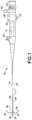
Fig. 1 , there is shown a side view of anexample apparatus 10. Theapparatus 10 in this example is an endoscope medical device configured to be partially inserted into a patient's body, such as in through the patient's urethra for example. Theendoscope 10 generally comprises acontrol section 12 and a flexible orsemi-flexible shaft 14 connected to thecontrol section 12. In this example thecontrol section 12 forms a handle for the apparatus. Theshaft 14 includes apassive deflection section 16 and an active deflection section (bending section) 18 at the distal end of theshaft 14. Acontrol system 22 to control theactive deflection section 18 extends from thecontrol section 12 to theactive deflection section 18. Thecontrol system 22 generally comprises bending control wires, wire sheaths, and anactuator 28. The wires are connected to theactuator 28 at one end and are connected to theactive deflection section 18 at a second end. - In the example embodiment shown, the
control section 12 has a user operated slide or lever (control lever) 30. Thelever 30 is connected to theactuator 28. Theactuator 28 is adapted to pull and release the wires of thecontrol system 22. When thelever 30 is moved by the user, theactuator 28 is moved. Theactuator 28 may be, for example, a drum or pulley rotatably connected to thecontrol section 12 to pull one wire while releasing the other. In an alternate embodiment, the actuator may be any suitable type of device, such as a rocker arm adapted to pull and release the wires of thecontrol system 22. In another alternate embodiment, where the control system may have two or more pairs of control wires, the control section will have additional actuators and corresponding controls to drive the additional pairs of bending control wires. In still other alternate embodiments, the control section may have knobs with rack and pinion mechanisms or other suitable user operated controls for the control system. - The
shaft 14 is cantilevered from thecontrol section 12. Theflexible shaft 14 includes the bending control wires of thecontrol system 22, a fiber optical image bundle, a fiber optical illumination bundle, and a working channel. Aport 60 for inserting instruments into the workingchannel 24 of the shaft is located on thecontrol section 12. Thecontrol section 12 also has alight source post 62 for connecting a light source (not shown) to the illumination bundle. In addition, thecontrol section 12 has aneyepiece 63 for a user to view an image transmitted by the image bundle from thefront end 20. In alternate embodiments, the flexible shaft may house different systems within. Theshaft 14 generally comprises aframe 26, acover 32 and anobjective head 34. - Referring also to
Figs. 2-3 , a distal end of anendoscopic tool 36 is shown. Thetool 36 is attached to theapparatus 10 and is configured to extend out of thedistal end 20 of theshaft 14 from the workingchannel 24. Thetool 36, in this example, is a Surgeon Controlled Basket Device (SCBD). Thetool 36 includes anassembly 33 which comprises abasket device 50 and asheath 56. Thebasket device 50 comprises abasket section 52 at a distal end, and ashaft section 54 extending through thesheath 56 to a proximal end of thetool 36. Theshaft section 54 functions as a control wire for moving thebasket section 52. Thesheath 56 andbasket device 50 are longitudinally movable relative to each other to move thebasket device 50 between a forward position and a rearward position relative to thesheath 56.Figs. 2 and 3 show the shaft section (control wire) 54 moved forward relative to thesheath 56 such that thebasket section 52 is located out from afront end aperture 66 of thesheath 56. In the forward position of thesheath 56 on thebasket device 50, thebasket section 52 is located inside thesheath 56; thebasket section 52 being collapsed by thesheath 56 into a smaller shape to fit inside thesheath 56. - Referring also to
Figs. 4-5 , thetool 36 in this example comprises acontrol assembly 70. Thecontrol assembly 70 is connected to proximal ends of thebasket device 50 andsheath 56. Thecontrol assembly 70 is configured to be attached to thecontrol section 12 at theport 60 into the workingchannel 24. Although the features will be described with reference to the example embodiments of the control assembly shown in the drawings, it should be understood that features can be embodied in many alternate forms of embodiments. In addition, any suitable size, shape or type of elements or materials could be used. - In this example the
control assembly 70 comprises anouter sleeve 72, aconnector 74 and aplunger 76. Theconnector 74 is configured to connect thecontrol assembly 70 to thecontrol section 12 at theport 60. Theouter sleeve 72 is slidably connected to theconnector 74 as indicated by arrow A inFig. 4 . In this example the proximal end of thesheath 56 is attached to theouter sleeve 72 to longitudinally move thesheath 56 when theouter sleeve 72 is moved. Theplunger 76 is movably mounted to theouter sleeve 72 to also slide as indicated by arrow A.Fig. 4 shows theplunger 76 is an outward home position relative to theouter sleeve 72. From this outward home position theplunger 76 can be depressed into theouter sleeve 72 as indicated by arrow B. The proximal end of theshaft section 54 of thebasket device 50 is attached to theplunger 76 for the plunger to be able to longitudinally move theshaft section 54 of thebasket device 50 when theplunger 76 is longitudinally moved. Thus, when theplunger 76 is depressed relative to theouter sleeve 72, the distal end of thebasket device 50 is extended out of thefront end aperture 66 of thesheath 54. When theplunger 76 is not depressed, thedistal end 52 of thebasket device 50 is retracted towards thefront end aperture 66 of thesheath 54. - In an alternate example, the proximal end of the
sheath 56 may be connected to theplunger 76, and a proximal end of theshaft section 54 of thebasket device 50 may be connected to theouter sleeve 72. In this alternate example theplunger 76 may be depressed from its extended home position towards its depressed position on theouter sleeve 72 to move thesheath 56 over thebasket section 52, and the plunger may be released from its depressed position to its extended home position to move thesheath 56 off of thebasket section 52. - Referring also to
Fig. 6 an exploded view of thecontrol assembly 70 is shown. In the example shown, thecontrol assembly 70 comprises twosprings top button 80. Referring also toFig. 7 , thetop spring 78 is located inarea 82 of theouter sleeve 72 and thebottom spring 79 is located in thearea 83 of theouter sleeve 72. This is also shown inFig. 8 , but with a slightly different button 80'. Thetop spring 78 is compressed betweensurface 92 shown inFig. 7 and thebottom end 90 of theplunger 76 to bias theplunger 76 in its extending home position relative to theouter sleeve 72 as shown inFigs. 4 and8 . Atop member 88 is connected to the top end of theouter sleeve 72 to keep thebottom end 90 of theplunger 76 inside thearea 82. - The
bottom spring 79 biases theouter sleeve 72 away from theconnector 74. However, abottom member 84 is connected to the bottom end of theouter sleeve 72. Thebottom member 84 is adjustably located on theconnector 74. Thebottom member 84 has projections which are configured to engagerecesses 86 in theconnector 74 to adjustable lock the longitudinal position of theouter sleeve 72 on theconnector 74 at one of a plurality of different longitudinal positions of theconnector 74. In the example shown, theouter sleeve 72 can be axially rotated with thebottom member 84 to disengage from therecesses 86. Then, theouter sleeve 72 can be longitudinally slid along theconnector 74 to a new longitudinal position. Theouter sleeve 72 can then be axially rotated with thebottom member 84 in an opposite direct to reengage with a new pair of therecesses 86. This may be used to act as a fine adjustment for moving both thebasket device 50 andsheath 56 together relative to theapparatus 10. - The
top button 80 is attached to the top of theplunger 76. Thetop button 80 is adapted to axially rotate on the top of theplunger 76.Figs. 4 and6 show atop button 80 which covers less than half of the top side of the plunger.Figs. 8 and9 show a top button 80' which covers a majority of the top surface. However, bothtop buttons 80, 80' function the same way. In particular, thetop buttons 80, 80' provide a top surface for a user's finger to press against, but still allow theplunger 76 to be easily axially rotated on theouter sleeve 72. - As seen in
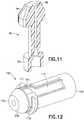
Figs. 9-11 , theplunger 76 has atop end 94. Thetop end 94 hasfinger grooves 96 to provide better frictional engagement with a user's finger(s). Thetop end 94 has ahole 98. Thetop button 80, 80' has aprojection 100 which extends into thehole 98. Thebutton 80, 80' is rotatably mounted to theplunger 76 at this projection/hole interface. The proximal end of theshaft section 54 of thebasket device 50 is fixedly connected to theplunger 76 in the channel leading to thehole 98. However, theshaft section 54 of thebasket device 50 is not directly connected to thebutton 80, 80'. Thus, when the user has his or her finger on thebutton 80, 80', the user may axially rotate thebasket device 50 by axially rotating theplunger 76 while thebutton 80, 80' and the user's finger on the button do not axially rotate. This provides a more comfortable feel to the user's finger and less possibility that the user's finger might slip off of the button/plunger assembly while the plunger is being rotated. - The above identified example embodiment provides a tool comprising a first controller and a second controller. The first controller is formed by a plunger and cylinder mechanism comprising the
button 80 and theouter sleeve 72. This first controller is adapted to linearly move the basket device. The second controller is formed by theplunger 76 and is adapted to rotate the basket device independently of the first controller's control of the linear movement or position of thebasket device 50. In the example described above, theplunger 76 connects thebutton 80 to thebasket device 50 and the cylinder formed by theouter sleeve 72. - Referring also to
Figs. 12 and13 , an alternate example of the connector is shown. In this example embodiment theconnector 102 is configured to replace theconnector 74. Theconnector 102 generally comprises anextension shaft 104, andinner insert 106, aplunger shaft 108 and twobuttons 110. Thefront end 112 of theplunger shaft 108 is adapted to be located at theport 60 into the workingchannel 24. The inwardly facing projections of thebottom member 84 on theouter sleeve 72 are located in thegrooves 114. Thebottom spring 79 biases theouter sleeve 72 away from theextension shaft 104, but the inward projections on thebottom member 84 being located in thegrooves 114 keeps theouter sleeve 72 connected to theextension shaft 104. Thebottom spring 79 may be compressed to move theouter sleeve 72 downward on the outside of theextension shaft 104. This allows thesheath 56 andbasket device 50 to be moved together relative to theconnector 102 andapparatus 10. Theouter sleeve 72 and attachedbottom member 84 may be axially rotated on theextension shaft 104 to move the inward projections on thebottom member 84 to rotate into areas 116 to lock the longitudinal positionouter sleeve 72 on theconnector 102 at a forward location. - The
plunger shaft 108 compriseslateral slots 118 andteeth pockets 120 on opposite sides of theslots 118. Theslots 118 allow for relative movement of thebuttons 110 along the longitudinal length of theplunger shaft 108. The teeth pockets 120 allow theteeth 122 to engage in the teeth pockets 120 to adjustably lock the position of thebuttons 110 relative to theplunger shaft 108. Thebuttons 110 project into theslots 118 through the button holes 124 in theinner insert 106. Thebuttons 110 may be outwardly biased by springs (not shown). Thebuttons 110 may be inwardly depressed to move theteeth 112 out of the teeth pockets 120 and allow longitudinal extension or retraction of the extension shaft 104 (with attached inner insert 106) along to theplunger shaft 108. This feature may be used to allow use of the tool with different endoscopes having different length working channels. The length of theconnector 102 can be adjusted to adjust for the different length working channels. Thus, the tool can be used with different types of endoscopes. - With features as described herein, an endoscope tool may be provided having a spin plate, such as the
plunger 76 for example, for axially rotating another member, such as a basket device for example. Features as described herein are not necessarily limited to a Surgeon Controlled Basket Device (SCBD). Features as described herein may be used to integrate into a single simplified design a plunger mechanism with an axial rotation mechanism. - In a conventional Surgeon Controlled Basket Device (SCBD) device, if the operator of the plunger style basket wants to hold the basket open and rotate the basket it is difficult to maintain a steady position and pressure of the finger on the plunger while the plunger is rotating.
- With features as described herein, a mechanism may be provided which allows the operator's finger to keep pressure on the plunger while the plunger is rotated without subjecting the finger, used to maintain pressure, to the rotation. The top surface will spin independently relative to the plunger. This allows the plunger to be rotated freely without requiring adjustment by the finger used to apply the downward pressure. A top surface, such as
button 80 or 80' for example, may be attached to the plunger in a manner which holds the top surface steady relative to the plunger in the direction of movement resulting in deployment of the basket (axial direction), but does not link the radial position of the top surface to the radial position or motion of the plunger mechanism. This allows the two components to rotate independent of each other while still maintaining a linear position relationship. - In one type of example embodiment a tool for use by a surgeon for operating a basket device for capturing an object to be removed from a body of an animal may be provided, the tool comprising a first controller adapted to be coupled to the basket device for selectively controlling the basket device and moving the basket device between a first, closed position and a second, open position, the first controller comprising: a plunger and cylinder mechanism; and a handle coupled to the plunger for operating the relative position of the plunger with respect to the cylinder; and a second controller positioned adjacent to the first controller and adapted to be coupled to the basket device for selectively controlling the rotation of the basket device independent of the first controller.
- The tool may further comprise a sheath having a first end and a second end, the sheath adapted to receive the basket device and to have the basket device longitudinally slide with respect thereto between the first, closed position and the second, open position; and wherein the sheath is coupled to the first controller for translational movement relative to the basket device and the basket device is coupled to the second controller for rotational movement with respect to the first controller. The tool may further comprise a first biasing mechanism operatively located for biasing the plunger with respect to the cylinder to move the basket device toward the first, closed position. The tool may further comprise a locking mechanism coupled to the first controller for locking the plunger in the second, open position. The second controller may remain operative when the locking mechanism locks the first controller. The second controller may continue to rotate the basket device while the first controller is locked. The tool may further comprise a second biasing mechanism for biasing the basket device toward the first, closed position with respect to the handle and the sheath; and wherein the basket device is rigidly rotationally coupled to second controller. The second biasing mechanism may be coupled to the second controller to bias the
plunger 76 towards moving the basket to a first, closed position. The tool may further comprise a luer coupler, such asconnector 74 for example, for selectively coupling the tool to an endoscope. - An example embodiment may be provided in a tool for use by a surgeon for operating a basket device for capturing an object to be removed from a body of an animal, the tool comprising a housing having a longitudinal axis and including a passage; a first controller including a first portion located in the passage in the housing and a second portion extending from the housing; wherein the first controller is adapted to be coupled to the basket device for selectively controlling the basket device and wherein the first controller is axially movable in the passage of the housing for moving the basket device between a first, closed position and a second, open position, and wherein the first controller is rotationally movable in the passage of the housing for rotating the basket device when in the second, open position; and an end surface coupled to the second portion of the first controller wherein the end surface moves axially with the first controller and wherein the end surface moves independently rotationally of the first controller such that the end surface may remain rotationally stationary while the first controller is rotated.
- The tool may further comprise a sheath having a first end and a second end, the sheath adapted to receive the basket device and to have the basket device longitudinally slide with respect thereto between the first, closed position and the second, open position; and wherein the basket device is coupled to first controller for translational movement relative to the sheath and wherein the sheath is coupled to housing. The tool may further comprise a first biasing mechanism operatively located for biasing the first controller with respect to the passage in the housing to urge the basket device toward the first, closed position. The tool may further comprise a locking mechanism coupled to the housing for locking the first controller in the second, open position. The first controller may remain rotationally operative when the locking mechanism locks the first controller in the second, open position. The tool may further comprise a luer coupler for selectively coupling the tool to an endoscope.
- It should be understood that the foregoing description is only illustrative. Various alternatives and modifications can be devised by those skilled in the art. In addition, features from different embodiments described above could be selectively combined into a new embodiment. Accordingly, the description is intended to embrace all such alternatives, modifications and variances which fall within the scope of the appended claims.
Claims (4)
- A tool for use by a surgeon for operating a basket device (50) for capturing an object to be removed from a body of a human or an animal, the tool comprising:a first controller adapted to be coupled to the basket device (50) for selectively controlling the basket device (50) and moving the basket device (50) between a first, closed position and a second, open position, the first controller comprising:a plunger and cylinder mechanism (70); anda handle (80) coupled to a plunger (76) of the plunger and cylinder mechanism (70) for operating the relative position of a plunger (76) with respect to a cylinder (72) of the plunger and cylinder mechanism (70); anda second controller (94) positioned adjacent to the first controller (70) and adapted to be coupled to the basket device (50) for selectively controlling rotation of the basket device (50) independent of the first controller (70);the tool further comprisinga sheath (56) having a first end and a second end, the sheath (56) adapted to receive the basket device (50) and to have the basket device (50) longitudinally slide with respect thereto between the first, closed position and the second, open position; andwherein the sheath (56) is coupled to the first controller (70) for translational movement relative to the basket device (50), and the basket device (50) is coupled to the second controller (94) for rotational movement with respect to the first controller (70); anda first biasing mechanism (78) operatively located for biasing the plunger (76) with respect to the cylinder (72) to move the basket device (50) toward the first, closed position,characterized in that
the tool further comprises a locking mechanism coupled to the first controller for locking the plunger (76) in the second, open position. - The tool of Claim 1 wherein the second controller (94) remains operative when the locking mechanism locks the first controller.
- The tool of any one of Claims 1-2 further comprising a second biasing mechanism (79) for biasing the basket device (50) toward the first, closed position with respect to the handle and the sheath (56); and wherein the basket device (50) is rigidly rotationally coupled to second controller (94) .
- The tool of any one of Claims 1-3 further comprising a luer coupler for selectively coupling the tool to an endoscope.
Priority Applications (2)
| Application Number | Priority Date | Filing Date | Title |
|---|---|---|---|
| EP21196787.2AEP3973894B1 (en) | 2016-03-09 | 2016-03-09 | Endoscope tool |
| EP19218914.0AEP3656318B1 (en) | 2016-03-09 | 2016-03-09 | Endoscope tool |
Applications Claiming Priority (1)
| Application Number | Priority Date | Filing Date | Title |
|---|---|---|---|
| PCT/IB2016/051346WO2017153806A1 (en) | 2016-03-09 | 2016-03-09 | Endoscope tool |
Related Child Applications (3)
| Application Number | Title | Priority Date | Filing Date |
|---|---|---|---|
| EP19218914.0ADivisionEP3656318B1 (en) | 2016-03-09 | 2016-03-09 | Endoscope tool |
| EP19218914.0ADivision-IntoEP3656318B1 (en) | 2016-03-09 | 2016-03-09 | Endoscope tool |
| EP21196787.2ADivisionEP3973894B1 (en) | 2016-03-09 | 2016-03-09 | Endoscope tool |
Publications (2)
| Publication Number | Publication Date |
|---|---|
| EP3416570A1 EP3416570A1 (en) | 2018-12-26 |
| EP3416570B1true EP3416570B1 (en) | 2020-03-18 |
Family
ID=55642535
Family Applications (3)
| Application Number | Title | Priority Date | Filing Date |
|---|---|---|---|
| EP16713092.1AActiveEP3416570B1 (en) | 2016-03-09 | 2016-03-09 | Endoscope tool |
| EP19218914.0AActiveEP3656318B1 (en) | 2016-03-09 | 2016-03-09 | Endoscope tool |
| EP21196787.2AActiveEP3973894B1 (en) | 2016-03-09 | 2016-03-09 | Endoscope tool |
Family Applications After (2)
| Application Number | Title | Priority Date | Filing Date |
|---|---|---|---|
| EP19218914.0AActiveEP3656318B1 (en) | 2016-03-09 | 2016-03-09 | Endoscope tool |
| EP21196787.2AActiveEP3973894B1 (en) | 2016-03-09 | 2016-03-09 | Endoscope tool |
Country Status (6)
| Country | Link |
|---|---|
| US (1) | US11172947B2 (en) |
| EP (3) | EP3416570B1 (en) |
| JP (1) | JP7181085B2 (en) |
| CN (2) | CN114711893B (en) |
| ES (1) | ES2901446T3 (en) |
| WO (1) | WO2017153806A1 (en) |
Cited By (1)
| Publication number | Priority date | Publication date | Assignee | Title |
|---|---|---|---|---|
| US11172947B2 (en) | 2016-03-09 | 2021-11-16 | Gyrus Acmi, Inc. | Endoscope tool |
Families Citing this family (4)
| Publication number | Priority date | Publication date | Assignee | Title |
|---|---|---|---|---|
| US10702280B2 (en)* | 2015-11-10 | 2020-07-07 | Covidien Lp | Endoscopic reposable surgical clip applier |
| CN108601601B (en)* | 2016-03-10 | 2022-03-08 | 捷锐士阿希迈公司(以奥林巴斯美国外科技术名义) | Surgical tool |
| WO2020052355A1 (en)* | 2018-09-13 | 2020-03-19 | 杭州唯强医疗科技有限公司 | Intravascular foreign body extraction apparatus |
| CN117462188B (en)* | 2023-12-28 | 2024-03-29 | 杭州德晋医疗科技有限公司 | Interventional medical instrument |
Family Cites Families (33)
| Publication number | Priority date | Publication date | Assignee | Title |
|---|---|---|---|---|
| DE1069835B (en) | 1954-09-16 | 1959-11-26 | S. ß- R. J. Everett & Co. Limited, Thornton Heath, Surrey, und Bernard Camber, London (Großbritannien) | Syringe rack for an ampoule that can be inserted through a side rack opening |
| US3955578A (en) | 1974-12-23 | 1976-05-11 | Cook Inc. | Rotatable surgical snare |
| JPS61181453A (en)* | 1985-02-08 | 1986-08-14 | オリンパス光学工業株式会社 | Stone crushing apparatus |
| ATE197906T1 (en) | 1990-10-09 | 2000-12-15 | Medtronic Inc | DEVICE FOR MANIPULATING MATTER |
| US5147303A (en) | 1991-05-23 | 1992-09-15 | Martin Bret C | Disposable safety syringe |
| US5403324A (en)* | 1994-01-14 | 1995-04-04 | Microsonic Engineering Devices Company, Inc. | Flexible catheter with stone basket and ultrasonic conductor |
| JP3417778B2 (en) | 1997-01-17 | 2003-06-16 | ペンタックス株式会社 | Endoscope treatment tool |
| US6053934A (en)* | 1997-06-02 | 2000-04-25 | Cook Urological, Incorporated | Replaceable, medical device handle |
| CZ297361B6 (en) | 1998-01-30 | 2006-11-15 | Novo Nordisk A/S | Injection syringe |
| JP3122718B2 (en)* | 1998-08-06 | 2001-01-09 | オリンパス光学工業株式会社 | Sheath slide crushed stone basket |
| US6228023B1 (en) | 1999-02-17 | 2001-05-08 | Abiomed, Inc. | Tissue pick and method for use in minimally invasive surgical procedures |
| WO2001087166A2 (en) | 2000-05-18 | 2001-11-22 | Cook Urological Inc. | Medical device handle |
| US6494885B1 (en)* | 2001-01-17 | 2002-12-17 | Avtar S. Dhindsa | Endoscopic stone extraction device with rotatable basket |
| US8021372B2 (en) | 2001-07-05 | 2011-09-20 | Annex Medical, Inc. | Medical retrieval device with independent rotational means |
| US6652537B2 (en)* | 2001-12-12 | 2003-11-25 | C. R. Bard, Inc. | Articulating stone basket |
| US7744583B2 (en) | 2003-02-03 | 2010-06-29 | Boston Scientific Scimed | Systems and methods of de-endothelialization |
| US20040153025A1 (en) | 2003-02-03 | 2004-08-05 | Seifert Paul S. | Systems and methods of de-endothelialization |
| JP2005230132A (en) | 2004-02-18 | 2005-09-02 | Asahi Intecc Co Ltd | Medical treatment tool |
| EP1746943A1 (en) | 2004-05-06 | 2007-01-31 | Boston Scientific Limited | Variable size retrieval basket |
| JP4663345B2 (en) | 2005-01-31 | 2011-04-06 | オリンパスメディカルシステムズ株式会社 | Endoscopic treatment tool |
| EP1871453B1 (en) | 2005-04-20 | 2010-02-24 | Cook Incorporated | Melt-bonded joint for medical devices |
| US7651493B2 (en) | 2006-03-03 | 2010-01-26 | Covidien Ag | System and method for controlling electrosurgical snares |
| US9456877B2 (en) | 2006-12-01 | 2016-10-04 | Boston Scientific Scimed, Inc. | Direct drive instruments and methods of use |
| EP2109474B2 (en) | 2007-02-05 | 2019-01-30 | Novo Nordisk A/S | Injection button |
| US9675369B2 (en) | 2007-12-18 | 2017-06-13 | Boston Scientific Scimed, Inc. | Multi-functional medical device |
| DE102010010798A1 (en)* | 2010-03-09 | 2011-09-15 | Epflex Feinwerktechnik Gmbh | Hand-operated functional hose instrument and operating device therefor |
| WO2013119918A1 (en) | 2012-02-09 | 2013-08-15 | Boston Scientific Scimed, Inc. | Steerable tissue manipulation medical devices and related |
| US20140257253A1 (en)* | 2013-03-11 | 2014-09-11 | Boston Scientific Scimed, Inc. | Medical device handles and related methods of use |
| JP6163887B2 (en)* | 2013-06-03 | 2017-07-19 | 住友ベークライト株式会社 | High frequency treatment tool |
| US9943322B2 (en)* | 2014-07-09 | 2018-04-17 | Boston Scientific Scimed, Inc. | Medical retrieval devices and methods |
| WO2016061297A1 (en)* | 2014-10-15 | 2016-04-21 | Cyrus Acmi, D.B.A. Olympus Surgical Technologies America | Surgical tool for removing kidney stone |
| EP3416570B1 (en) | 2016-03-09 | 2020-03-18 | Gyrus Acmi Inc., D.B.A. Olympus Surgical Technologies America | Endoscope tool |
| JP7217244B2 (en) | 2020-02-18 | 2023-02-02 | ジャイラス エーシーエムアイ インク ディー/ビー/エー オリンパス サージカル テクノロジーズ アメリカ | endoscopic instruments |
- 2016
- 2016-03-09EPEP16713092.1Apatent/EP3416570B1/enactiveActive
- 2016-03-09EPEP19218914.0Apatent/EP3656318B1/enactiveActive
- 2016-03-09CNCN202210201632.9Apatent/CN114711893B/enactiveActive
- 2016-03-09CNCN201680081223.2Apatent/CN108601600B/enactiveActive
- 2016-03-09ESES19218914Tpatent/ES2901446T3/enactiveActive
- 2016-03-09USUS16/081,095patent/US11172947B2/enactiveActive
- 2016-03-09WOPCT/IB2016/051346patent/WO2017153806A1/ennot_activeCeased
- 2016-03-09JPJP2018542138Apatent/JP7181085B2/enactiveActive
- 2016-03-09EPEP21196787.2Apatent/EP3973894B1/enactiveActive
Non-Patent Citations (1)
| Title |
|---|
| None* |
Cited By (1)
| Publication number | Priority date | Publication date | Assignee | Title |
|---|---|---|---|---|
| US11172947B2 (en) | 2016-03-09 | 2021-11-16 | Gyrus Acmi, Inc. | Endoscope tool |
Also Published As
| Publication number | Publication date |
|---|---|
| EP3973894A1 (en) | 2022-03-30 |
| CN114711893B (en) | 2025-09-19 |
| CN108601600A (en) | 2018-09-28 |
| EP3656318A1 (en) | 2020-05-27 |
| EP3973894B1 (en) | 2024-08-28 |
| JP2019509090A (en) | 2019-04-04 |
| EP3416570A1 (en) | 2018-12-26 |
| US20190069915A1 (en) | 2019-03-07 |
| WO2017153806A1 (en) | 2017-09-14 |
| CN108601600B (en) | 2022-03-08 |
| ES2901446T3 (en) | 2022-03-22 |
| JP7181085B2 (en) | 2022-11-30 |
| EP3656318B1 (en) | 2021-10-06 |
| CN114711893A (en) | 2022-07-08 |
| US11172947B2 (en) | 2021-11-16 |
Similar Documents
| Publication | Publication Date | Title |
|---|---|---|
| EP3416570B1 (en) | Endoscope tool | |
| US9456736B2 (en) | Endoscope, and treatment instrument for endoscope | |
| JP5302019B2 (en) | Treatment endoscope | |
| JP7089008B2 (en) | Endoscope | |
| JP6082553B2 (en) | Brake release mechanism and medical manipulator having the same | |
| JP7061584B2 (en) | Endoscope | |
| US11202556B2 (en) | Control of a basket retrieval device | |
| JP6042678B2 (en) | Brake mechanism and medical manipulator having the same | |
| JP6290376B2 (en) | Surgeon-controlled endoscopic device | |
| CN112469346B (en) | Medical handle | |
| CN108601601B (en) | Surgical tool | |
| US20090287044A1 (en) | Endoscopic apparatus | |
| CN116867416A (en) | Medical device actuator lock | |
| CN117503027A (en) | Endoscope and operating handle thereof | |
| JP7523606B2 (en) | Endoscopic Instruments | |
| KR102378014B1 (en) | Mobile device for moving tubal members | |
| JP2022540883A (en) | Endoscopic Tool Stabilization and Related Uses |
Legal Events
| Date | Code | Title | Description |
|---|---|---|---|
| STAA | Information on the status of an ep patent application or granted ep patent | Free format text:STATUS: THE INTERNATIONAL PUBLICATION HAS BEEN MADE | |
| PUAI | Public reference made under article 153(3) epc to a published international application that has entered the european phase | Free format text:ORIGINAL CODE: 0009012 | |
| STAA | Information on the status of an ep patent application or granted ep patent | Free format text:STATUS: REQUEST FOR EXAMINATION WAS MADE | |
| 17P | Request for examination filed | Effective date:20180903 | |
| AK | Designated contracting states | Kind code of ref document:A1 Designated state(s):AL AT BE BG CH CY CZ DE DK EE ES FI FR GB GR HR HU IE IS IT LI LT LU LV MC MK MT NL NO PL PT RO RS SE SI SK SM TR | |
| AX | Request for extension of the european patent | Extension state:BA ME | |
| DAV | Request for validation of the european patent (deleted) | ||
| DAX | Request for extension of the european patent (deleted) | ||
| RIC1 | Information provided on ipc code assigned before grant | Ipc:A61B 17/221 20060101AFI20190913BHEP Ipc:A61B 1/00 20060101ALI20190913BHEP Ipc:A61B 17/00 20060101ALN20190913BHEP | |
| GRAP | Despatch of communication of intention to grant a patent | Free format text:ORIGINAL CODE: EPIDOSNIGR1 | |
| STAA | Information on the status of an ep patent application or granted ep patent | Free format text:STATUS: GRANT OF PATENT IS INTENDED | |
| RAP1 | Party data changed (applicant data changed or rights of an application transferred) | Owner name:GYRUS ACMI INC., D.B.A. OLYMPUS SURGICAL TECHNOLOG | |
| INTG | Intention to grant announced | Effective date:20191113 | |
| GRAS | Grant fee paid | Free format text:ORIGINAL CODE: EPIDOSNIGR3 | |
| GRAA | (expected) grant | Free format text:ORIGINAL CODE: 0009210 | |
| STAA | Information on the status of an ep patent application or granted ep patent | Free format text:STATUS: THE PATENT HAS BEEN GRANTED | |
| AK | Designated contracting states | Kind code of ref document:B1 Designated state(s):AL AT BE BG CH CY CZ DE DK EE ES FI FR GB GR HR HU IE IS IT LI LT LU LV MC MK MT NL NO PL PT RO RS SE SI SK SM TR | |
| REG | Reference to a national code | Ref country code:GB Ref legal event code:FG4D | |
| REG | Reference to a national code | Ref country code:DE Ref legal event code:R096 Ref document number:602016031979 Country of ref document:DE | |
| REG | Reference to a national code | Ref country code:AT Ref legal event code:REF Ref document number:1245000 Country of ref document:AT Kind code of ref document:T Effective date:20200415 Ref country code:IE Ref legal event code:FG4D | |
| PG25 | Lapsed in a contracting state [announced via postgrant information from national office to epo] | Ref country code:NO Free format text:LAPSE BECAUSE OF FAILURE TO SUBMIT A TRANSLATION OF THE DESCRIPTION OR TO PAY THE FEE WITHIN THE PRESCRIBED TIME-LIMIT Effective date:20200618 Ref country code:FI Free format text:LAPSE BECAUSE OF FAILURE TO SUBMIT A TRANSLATION OF THE DESCRIPTION OR TO PAY THE FEE WITHIN THE PRESCRIBED TIME-LIMIT Effective date:20200318 Ref country code:RS Free format text:LAPSE BECAUSE OF FAILURE TO SUBMIT A TRANSLATION OF THE DESCRIPTION OR TO PAY THE FEE WITHIN THE PRESCRIBED TIME-LIMIT Effective date:20200318 | |
| REG | Reference to a national code | Ref country code:NL Ref legal event code:MP Effective date:20200318 | |
| PG25 | Lapsed in a contracting state [announced via postgrant information from national office to epo] | Ref country code:GR Free format text:LAPSE BECAUSE OF FAILURE TO SUBMIT A TRANSLATION OF THE DESCRIPTION OR TO PAY THE FEE WITHIN THE PRESCRIBED TIME-LIMIT Effective date:20200619 Ref country code:SE Free format text:LAPSE BECAUSE OF FAILURE TO SUBMIT A TRANSLATION OF THE DESCRIPTION OR TO PAY THE FEE WITHIN THE PRESCRIBED TIME-LIMIT Effective date:20200318 Ref country code:LV Free format text:LAPSE BECAUSE OF FAILURE TO SUBMIT A TRANSLATION OF THE DESCRIPTION OR TO PAY THE FEE WITHIN THE PRESCRIBED TIME-LIMIT Effective date:20200318 Ref country code:HR Free format text:LAPSE BECAUSE OF FAILURE TO SUBMIT A TRANSLATION OF THE DESCRIPTION OR TO PAY THE FEE WITHIN THE PRESCRIBED TIME-LIMIT Effective date:20200318 Ref country code:BG Free format text:LAPSE BECAUSE OF FAILURE TO SUBMIT A TRANSLATION OF THE DESCRIPTION OR TO PAY THE FEE WITHIN THE PRESCRIBED TIME-LIMIT Effective date:20200618 | |
| REG | Reference to a national code | Ref country code:LT Ref legal event code:MG4D | |
| PG25 | Lapsed in a contracting state [announced via postgrant information from national office to epo] | Ref country code:NL Free format text:LAPSE BECAUSE OF FAILURE TO SUBMIT A TRANSLATION OF THE DESCRIPTION OR TO PAY THE FEE WITHIN THE PRESCRIBED TIME-LIMIT Effective date:20200318 | |
| PG25 | Lapsed in a contracting state [announced via postgrant information from national office to epo] | Ref country code:LT Free format text:LAPSE BECAUSE OF FAILURE TO SUBMIT A TRANSLATION OF THE DESCRIPTION OR TO PAY THE FEE WITHIN THE PRESCRIBED TIME-LIMIT Effective date:20200318 Ref country code:EE Free format text:LAPSE BECAUSE OF FAILURE TO SUBMIT A TRANSLATION OF THE DESCRIPTION OR TO PAY THE FEE WITHIN THE PRESCRIBED TIME-LIMIT Effective date:20200318 Ref country code:PT Free format text:LAPSE BECAUSE OF FAILURE TO SUBMIT A TRANSLATION OF THE DESCRIPTION OR TO PAY THE FEE WITHIN THE PRESCRIBED TIME-LIMIT Effective date:20200812 Ref country code:IS Free format text:LAPSE BECAUSE OF FAILURE TO SUBMIT A TRANSLATION OF THE DESCRIPTION OR TO PAY THE FEE WITHIN THE PRESCRIBED TIME-LIMIT Effective date:20200718 Ref country code:CZ Free format text:LAPSE BECAUSE OF FAILURE TO SUBMIT A TRANSLATION OF THE DESCRIPTION OR TO PAY THE FEE WITHIN THE PRESCRIBED TIME-LIMIT Effective date:20200318 Ref country code:RO Free format text:LAPSE BECAUSE OF FAILURE TO SUBMIT A TRANSLATION OF THE DESCRIPTION OR TO PAY THE FEE WITHIN THE PRESCRIBED TIME-LIMIT Effective date:20200318 Ref country code:SK Free format text:LAPSE BECAUSE OF FAILURE TO SUBMIT A TRANSLATION OF THE DESCRIPTION OR TO PAY THE FEE WITHIN THE PRESCRIBED TIME-LIMIT Effective date:20200318 Ref country code:SM Free format text:LAPSE BECAUSE OF FAILURE TO SUBMIT A TRANSLATION OF THE DESCRIPTION OR TO PAY THE FEE WITHIN THE PRESCRIBED TIME-LIMIT Effective date:20200318 | |
| REG | Reference to a national code | Ref country code:AT Ref legal event code:MK05 Ref document number:1245000 Country of ref document:AT Kind code of ref document:T Effective date:20200318 | |
| REG | Reference to a national code | Ref country code:DE Ref legal event code:R097 Ref document number:602016031979 Country of ref document:DE | |
| PLBE | No opposition filed within time limit | Free format text:ORIGINAL CODE: 0009261 | |
| STAA | Information on the status of an ep patent application or granted ep patent | Free format text:STATUS: NO OPPOSITION FILED WITHIN TIME LIMIT | |
| PG25 | Lapsed in a contracting state [announced via postgrant information from national office to epo] | Ref country code:ES Free format text:LAPSE BECAUSE OF FAILURE TO SUBMIT A TRANSLATION OF THE DESCRIPTION OR TO PAY THE FEE WITHIN THE PRESCRIBED TIME-LIMIT Effective date:20200318 Ref country code:DK Free format text:LAPSE BECAUSE OF FAILURE TO SUBMIT A TRANSLATION OF THE DESCRIPTION OR TO PAY THE FEE WITHIN THE PRESCRIBED TIME-LIMIT Effective date:20200318 Ref country code:AT Free format text:LAPSE BECAUSE OF FAILURE TO SUBMIT A TRANSLATION OF THE DESCRIPTION OR TO PAY THE FEE WITHIN THE PRESCRIBED TIME-LIMIT Effective date:20200318 Ref country code:IT Free format text:LAPSE BECAUSE OF FAILURE TO SUBMIT A TRANSLATION OF THE DESCRIPTION OR TO PAY THE FEE WITHIN THE PRESCRIBED TIME-LIMIT Effective date:20200318 | |
| 26N | No opposition filed | Effective date:20201221 | |
| PG25 | Lapsed in a contracting state [announced via postgrant information from national office to epo] | Ref country code:PL Free format text:LAPSE BECAUSE OF FAILURE TO SUBMIT A TRANSLATION OF THE DESCRIPTION OR TO PAY THE FEE WITHIN THE PRESCRIBED TIME-LIMIT Effective date:20200318 | |
| PG25 | Lapsed in a contracting state [announced via postgrant information from national office to epo] | Ref country code:SI Free format text:LAPSE BECAUSE OF FAILURE TO SUBMIT A TRANSLATION OF THE DESCRIPTION OR TO PAY THE FEE WITHIN THE PRESCRIBED TIME-LIMIT Effective date:20200318 | |
| PG25 | Lapsed in a contracting state [announced via postgrant information from national office to epo] | Ref country code:MC Free format text:LAPSE BECAUSE OF FAILURE TO SUBMIT A TRANSLATION OF THE DESCRIPTION OR TO PAY THE FEE WITHIN THE PRESCRIBED TIME-LIMIT Effective date:20200318 | |
| REG | Reference to a national code | Ref country code:CH Ref legal event code:PL | |
| REG | Reference to a national code | Ref country code:BE Ref legal event code:MM Effective date:20210331 | |
| PG25 | Lapsed in a contracting state [announced via postgrant information from national office to epo] | Ref country code:CH Free format text:LAPSE BECAUSE OF NON-PAYMENT OF DUE FEES Effective date:20210331 Ref country code:LI Free format text:LAPSE BECAUSE OF NON-PAYMENT OF DUE FEES Effective date:20210331 Ref country code:LU Free format text:LAPSE BECAUSE OF NON-PAYMENT OF DUE FEES Effective date:20210309 Ref country code:IE Free format text:LAPSE BECAUSE OF NON-PAYMENT OF DUE FEES Effective date:20210309 Ref country code:FR Free format text:LAPSE BECAUSE OF NON-PAYMENT OF DUE FEES Effective date:20210331 | |
| PG25 | Lapsed in a contracting state [announced via postgrant information from national office to epo] | Ref country code:BE Free format text:LAPSE BECAUSE OF NON-PAYMENT OF DUE FEES Effective date:20210331 | |
| P01 | Opt-out of the competence of the unified patent court (upc) registered | Effective date:20230514 | |
| PG25 | Lapsed in a contracting state [announced via postgrant information from national office to epo] | Ref country code:CY Free format text:LAPSE BECAUSE OF FAILURE TO SUBMIT A TRANSLATION OF THE DESCRIPTION OR TO PAY THE FEE WITHIN THE PRESCRIBED TIME-LIMIT Effective date:20200318 | |
| PG25 | Lapsed in a contracting state [announced via postgrant information from national office to epo] | Ref country code:HU Free format text:LAPSE BECAUSE OF FAILURE TO SUBMIT A TRANSLATION OF THE DESCRIPTION OR TO PAY THE FEE WITHIN THE PRESCRIBED TIME-LIMIT; INVALID AB INITIO Effective date:20160309 | |
| PG25 | Lapsed in a contracting state [announced via postgrant information from national office to epo] | Ref country code:MK Free format text:LAPSE BECAUSE OF FAILURE TO SUBMIT A TRANSLATION OF THE DESCRIPTION OR TO PAY THE FEE WITHIN THE PRESCRIBED TIME-LIMIT Effective date:20200318 | |
| PG25 | Lapsed in a contracting state [announced via postgrant information from national office to epo] | Ref country code:TR Free format text:LAPSE BECAUSE OF FAILURE TO SUBMIT A TRANSLATION OF THE DESCRIPTION OR TO PAY THE FEE WITHIN THE PRESCRIBED TIME-LIMIT Effective date:20200318 | |
| PG25 | Lapsed in a contracting state [announced via postgrant information from national office to epo] | Ref country code:MT Free format text:LAPSE BECAUSE OF FAILURE TO SUBMIT A TRANSLATION OF THE DESCRIPTION OR TO PAY THE FEE WITHIN THE PRESCRIBED TIME-LIMIT Effective date:20200318 | |
| PGFP | Annual fee paid to national office [announced via postgrant information from national office to epo] | Ref country code:DE Payment date:20250327 Year of fee payment:10 | |
| PGFP | Annual fee paid to national office [announced via postgrant information from national office to epo] | Ref country code:GB Payment date:20250327 Year of fee payment:10 |