EP3415866B1 - Device, system, and method for displaying measurement gaps - Google Patents
Device, system, and method for displaying measurement gapsDownload PDFInfo
- Publication number
- EP3415866B1 EP3415866B1EP17175589.5AEP17175589AEP3415866B1EP 3415866 B1EP3415866 B1EP 3415866B1EP 17175589 AEP17175589 AEP 17175589AEP 3415866 B1EP3415866 B1EP 3415866B1
- Authority
- EP
- European Patent Office
- Prior art keywords
- remeasurement
- measured data
- indications
- environment
- computer
- Prior art date
- Legal status (The legal status is an assumption and is not a legal conclusion. Google has not performed a legal analysis and makes no representation as to the accuracy of the status listed.)
- Active
Links
Images

Classifications
- G—PHYSICS
- G01—MEASURING; TESTING
- G01C—MEASURING DISTANCES, LEVELS OR BEARINGS; SURVEYING; NAVIGATION; GYROSCOPIC INSTRUMENTS; PHOTOGRAMMETRY OR VIDEOGRAMMETRY
- G01C15/00—Surveying instruments or accessories not provided for in groups G01C1/00 - G01C13/00
- G01C15/002—Active optical surveying means
- G—PHYSICS
- G01—MEASURING; TESTING
- G01C—MEASURING DISTANCES, LEVELS OR BEARINGS; SURVEYING; NAVIGATION; GYROSCOPIC INSTRUMENTS; PHOTOGRAMMETRY OR VIDEOGRAMMETRY
- G01C15/00—Surveying instruments or accessories not provided for in groups G01C1/00 - G01C13/00
- G—PHYSICS
- G06—COMPUTING OR CALCULATING; COUNTING
- G06T—IMAGE DATA PROCESSING OR GENERATION, IN GENERAL
- G06T11/00—2D [Two Dimensional] image generation
- G06T11/60—Editing figures and text; Combining figures or text
- G—PHYSICS
- G06—COMPUTING OR CALCULATING; COUNTING
- G06T—IMAGE DATA PROCESSING OR GENERATION, IN GENERAL
- G06T19/00—Manipulating 3D models or images for computer graphics
- G06T19/006—Mixed reality
- H—ELECTRICITY
- H04—ELECTRIC COMMUNICATION TECHNIQUE
- H04L—TRANSMISSION OF DIGITAL INFORMATION, e.g. TELEGRAPHIC COMMUNICATION
- H04L67/00—Network arrangements or protocols for supporting network services or applications
- H04L67/01—Protocols
- H04L67/12—Protocols specially adapted for proprietary or special-purpose networking environments, e.g. medical networks, sensor networks, networks in vehicles or remote metering networks
- H—ELECTRICITY
- H04—ELECTRIC COMMUNICATION TECHNIQUE
- H04L—TRANSMISSION OF DIGITAL INFORMATION, e.g. TELEGRAPHIC COMMUNICATION
- H04L67/00—Network arrangements or protocols for supporting network services or applications
- H04L67/01—Protocols
- H04L67/131—Protocols for games, networked simulations or virtual reality
- G—PHYSICS
- G06—COMPUTING OR CALCULATING; COUNTING
- G06T—IMAGE DATA PROCESSING OR GENERATION, IN GENERAL
- G06T2200/00—Indexing scheme for image data processing or generation, in general
- G06T2200/24—Indexing scheme for image data processing or generation, in general involving graphical user interfaces [GUIs]
- G—PHYSICS
- G06—COMPUTING OR CALCULATING; COUNTING
- G06T—IMAGE DATA PROCESSING OR GENERATION, IN GENERAL
- G06T2207/00—Indexing scheme for image analysis or image enhancement
- G06T2207/30—Subject of image; Context of image processing
- G06T2207/30244—Camera pose
- G—PHYSICS
- G06—COMPUTING OR CALCULATING; COUNTING
- G06T—IMAGE DATA PROCESSING OR GENERATION, IN GENERAL
- G06T7/00—Image analysis
- G06T7/70—Determining position or orientation of objects or cameras
Definitions
- the present inventionrelates to an Augmented Reality (AR)-device according to claim 1, to a surveying system according to claim 5, to a method according to claim 7, and to a computer programme product according to claim 12.
- ARAugmented Reality
- the technical fields of the present inventionare metrology, geodesy and civil engineering. Accordingly, typical application areas of the present invention are production halls, measuring rooms, construction sites, excavation sites, or any other land, buildings and/or objects to be surveyed.
- US 2013/0176305 A1presents a surveying instrument having a display that can show a 3D model based on a point cloud that was obtained with the surveying instrument. An area which requires additional obtaining can be shown on the display.
- Augmented Realityis an advanced way to provide such information to users, and thus, surveying systems are already popular auxiliaries in the mentioned technical fields for supporting users with referenced visualisations of AR-data, such as measurement data (e.g. point clouds), descriptive texts, descriptive numbers, instructions, check plans, surveying plans, two- or three-dimensional objects, navigational indications, navigational maps, images, and/or video clips.
- a pose of the AR-device relative to a reference systemis detected permanently.
- Known referencing proceduresare image based determinations of the pose of the AR-device relative to the reference system which itself has a known pose. For example, such pose detections can be achieved by computer vision, in particular image resection.
- Common means for referencing an AR-device relative to a reference systemare markers, in particular QR-markers, or characteristic physical features distinctive by according image features.
- At least one of these improvementsis achieved by at least one of the AR-device according to claim 1, the surveying system according to claim 5, the method according to claim 7, the computer programme product according to claim 12, and the dependent claims of the present invention.
- the AR-devicemay further comprise a pose sensor configured for tracking a position and an orientation of the AR-device, wherein the computer may be configured for reading and controlling the pose sensor.
- the computermay further be configured for performing a Visual Simultaneous Localisation and Mapping (VSLAM)-process.
- VSLAMVisual Simultaneous Localisation and Mapping
- This VSLAM-processmay be based on images captured with the visual sensor.
- the VSLAM-processmay be supported by pose data outputted by the pose sensor.
- the VSLAM-processmay be utilised to at least one of establish and maintain a referenced status of the AR-device relative to the reference system.
- the VSLAM-processmay also be utilised to obtain measured data by generating a point cloud of the structure of the environment.
- the computermay be configured for at least one of receiving results of the evaluation, receiving results of the analysis, processing the evaluation, and processing the analysis.
- At least one of the surveying instrument and the computer of the servermay be configured for at least one of processing the evaluations, transmitting the results of the evaluation to the AR-device, processing the analysis, and transmitting the results of the analysis to the AR-device.
- at least one of the computer of the surveying instrument and the computer of the serveris configured for processing at least one of the evaluation and the analysis.
- the inventionalso relates to a method for providing indications of locations to be remeasured and remeasurement instructions to a user of one of an AR-device according to the description herein, and a surveying system according to the description herein, the method comprising the steps: evaluating the measured data in terms of quality, generating the remeasurement indications based on the evaluation of the measured data, wherein the remeasurement indications are spatially linked to the reference system at corresponding locations of the environment where the measured data lack a target quality, providing the remeasurement indications as overlays on the display of the AR-device, analysing the remeasurement indications in context of the structure of the environment, and generating the remeasurement instructions based on the analysis of the remeasurement indications, wherein the remeasurement instructions are spatially linked to the reference system at corresponding locations of the environment where a surveying instrument is required to be set up for a remeasurement.
- At least one of evaluating the measured data and generating the remeasurement indicationsmay be performed by a computer of at least one of the AR-device, the surveying instrument of the surveying system, and a server, which each may comprise a computer configured for the mentioned steps.
- At least one of analysing the remeasurement indications and generating the remeasurement instructionsmay be performed by a computer of at least one of the AR-device, the surveying instrument of the surveying system, and a server, which each may comprise a computer configured for the mentioned steps.
- the measured datamay be provided to the AR-device by at least one of generating the measured data with the visual sensor of the AR device, generating the measured data with the surveying instrument and transmitting the measured data from the surveying instrument to the AR-device, transmitting the measured data from a server to the AR-device, and storing the measured data on the computer of the AR-device.
- the results of the evaluationmay be provided to the AR device by at least one of processing the evaluation with the computer of the AR-device, and receiving the results of the evaluation with the AR device from at least one of the surveying instrument of the surveying system and a server.
- the results of the analysismay be provided to the AR device by at least one of processing the analysis with the computer of the AR device, and receiving the results of the analysis with the AR device from at least one of the surveying instrument of the surveying system and a server.
- the methodmay further comprise at least one of the steps
- the inventionfurther relates to a computer programme product having computer-executable instructions for controlling and executing a method according to the description herein, in particular when being run by a computer of an AR-device according to the description herein.
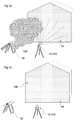
- Figure 1ashows a scene with a house front to be measured by a laser scanner 11.
- a disk saw 12is raising dust 120 which covers direct sight of the object to be measured from the perspective of the laser scanner 11. Since the dust 120 is porous, some measuring laser beams get through and some do not.
- the measured data 13comprise areas 130 which have a low density, as is shown in figure 1b .
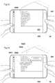
- AR-device 10A user is notified about this defect 130 in the measured data 13 by an Augmented-Reality (AR)-device 10 according to the invention.
- this AR-devicemay be a handheld computer device, such as a smart phone or tablet PC, being referenced relative to the environment and therefore capable of overlaying AR-data onto the camera output 101 on the display 100 of the AR-device 10.
- the AR-datacomprise remeasurement indications 1020.
- the remeasurement indications 1020are representing said defective areas 130 of the measured data 13.
- the remeasurement indications 1020are overlaid at the corresponding location of the display 100 to precisely indicate where the measured data lack a target quality, and in particular where a remeasurement should accordingly take place.
- the AR-device and the surveying instrumentare adapted for cooperating in that the results of the evaluation of the measured data or even the remeasurement indications are transmitted to the AR-device.
- the surveying instrumentis configured to evaluate the measured data or even to generate the remeasurement indications.
- Both AR-device and surveying instrumentare each configured to establish a referenced status relative to the reference system, so that the measured data are spatially linked to the reference system, and the pose of the AR-device is continuously determined relative to the reference system. Therefore, the remeasurement indications and remeasurement instructions are spatially linked to the reference system as well.
- the reference systemcan be defined by the setup of the surveying instrument, i.e. the AR-device is establishing a referenced status with respect to the surveying instrument. All measurement data per se are given in the (local) reference system of the surveying instrument.
- AR-data other than the measured data and the remeasurement indicationsi.e. designed data such as descriptive texts, descriptive numbers, instructions, check plans, surveying plans, two- or three-dimensional objects, navigational indications, navigational maps, images, and video clips
- a serverwhich is linked to at least the AR-device and optionally also to the surveying instrument.
- the computer of the AR-deviceis configured for generating overlays for the display of the AR-device.
- the measured data 13are evaluated in terms of quality. As described above, this evaluation may take place on the surveying instrument (by means of a computer 113 thereof), on the AR-device (by means of the computer 103 thereof), or on a server.
- the quality of the measured datamay for example refer to a measurement point density or to a digitised waveform of the measurement points.
- the quality evaluation of the measured datamay be liable to an absolute criterion (e.g. a specific amount of points per cm 2 ) or a relative criterion (e.g. a statistical mean value of the adjacent region or of the whole point cloud).
- the quality evaluationmay also be based on a countercheck with a photographic image of the measured scene captured by the visual sensor of the AR-device or a visual sensor comprised by a surveying instrument.
- remeasurement indicationsare generated, either by the AR-device, the surveying instrument, or a server.
- the remeasurement indicationsare spatially linked to the reference system at corresponding locations of the environment where the measured data lack a target quality. Referring to figure 1b , this is the case in the area 130.
- These remeasurement indicationsare then provided on the display 100 of the AR-device 10 as overlay (e.g. as highlighted or coloured area) 1020. This will notify the user of the AR-device in a simple and ergonomic way, where the existing measured data are insufficient and, accordingly, where a remeasurement should take place.
- the AR-devicecan be configured to show more specific remeasurement indications 1021, 1022, and 1023.
- the remeasurement indication 1020 described abovemay be tagged with a short explanation for why the measured data 13 are defective in the area 130.
- the point cloudhas a poor density which is shown with a remeasurement indication 1021.
- a further indication 1022may be overlaid, e.g. in form of a warning sign, which -when tapped- unfolds a detailed remeasurement indication 1023 explaining the consequences.
- the remeasurement indications 1020, shown in figures 1c and 1dare based on the evaluation of the measured data, and therefore "only" indicate where and what is wrong with the measured data.
- Figure 2ashows a surveying situation in which an obstacle embodied as a wall 220 causes the room scan obtained with the laser scanner 21 to comprise a gap 230 and therefore to be incomplete.
- the laser scanner 21may comprise a computer 213 for control, and in particular for data communication.
- the total structure of the environmentmay be known and stored on a server or on the AR-device as a BIM (building information management) model, or may be obtained with the AR-device itself by performing a Visual Simultaneous Localisation and Mapping (VSLAM)-process.
- the analysismay comprise a countercheck with a photographic image of the measured scene captured by the visual sensor of the AR-device or a visual sensor comprised by a surveying instrument.
- VSLAMStructure from Motion
- SfMStructure from Motion
- the AR-device in the example of figure 2bis an AR-glasses 20 having a display 200 configured to overlay AR-data, e.g. by a projector (not shown).
- the AR-glasses 20has a visual sensor (not shown) for capturing the environment and a computer 203 for reading and controlling the visual sensor, for determining a pose of the AR-device relative to the reference system, for at least one of receiving, generating and storing the AR-data, and for generating the overlays.
- the visual sensoris a camera, in particular a camera configured to operate on visual light, (near) infra-red light, or thermal radiation.
- the AR-devicemay be embodied as an AR-helmet.
- a remeasurement instruction 2040is overlaid onto the view of the environment.
- a tag 2041explains the instruction 2040.
- the placement of the remeasurement instruction 2040is subject to an analysis of the remeasurement indication 2020 in context of the shape of the environment. In the shown example, the wall 220 is taken into account. Also other factors are taken into account, e.g. features of a specific surveying instrument that require certain distances or angles.
- Overlaying the remeasurement indicationsmay also be used in a multi-user workflow: If two or more users equipped with an AR-device each carry out a measurement task simultaneously or shortly after each other at a site or on a larger work piece, each AR-device may provide overlaid information to the user about which measurements have already been performed or which are still missing.
- the output of the evaluation of the measured datamay also be used for quality control.
- said quality of measurement datadoes not or not only relate to completeness or density of measurements, but rather to a deviation of the actual measurement from a pre-defined geometry or layout.
- the AR-deviceis configured to overlay information (e.g. a color map) about the as-built-condition of a construction site or work piece while the measurements are carried out or after the measurements have been carried out.
- the evaluationmay also be processed to report on at least one of the efficiency of the surveying instrument, tracking deviations, changes in performance, user performance, and a comparative amount of errors or remeasurements.
- the output of the evaluation of the measured datamay also be used for machine learning enhancement for an automatic or robotic measurement.
- the computer of the surveying instrument or a coordinating serveris configured to learn from such remeasurement indications (i.e. failures in measurement quality) in order to provide higher quality measurements in the future, e.g. by an improved positioning of the surveying instrument or an improved choice of a surveying instrument based on the surveying conditions (such as topography, geometry, indoor or outdoor climate).
- the real view provided by the displaymay be embodied by
Landscapes
- Engineering & Computer Science (AREA)
- General Physics & Mathematics (AREA)
- Physics & Mathematics (AREA)
- Theoretical Computer Science (AREA)
- Radar, Positioning & Navigation (AREA)
- Remote Sensing (AREA)
- Signal Processing (AREA)
- Computer Networks & Wireless Communication (AREA)
- Computer Graphics (AREA)
- Computer Hardware Design (AREA)
- General Engineering & Computer Science (AREA)
- Software Systems (AREA)
- Health & Medical Sciences (AREA)
- Computing Systems (AREA)
- General Health & Medical Sciences (AREA)
- Medical Informatics (AREA)
- Computer Vision & Pattern Recognition (AREA)
- Processing Or Creating Images (AREA)
- Length Measuring Devices With Unspecified Measuring Means (AREA)
Description
- The present invention relates to an Augmented Reality (AR)-device according to claim 1, to a surveying system according to claim 5, to a method according to claim 7, and to a computer programme product according to
claim 12. - The technical fields of the present invention are metrology, geodesy and civil engineering. Accordingly, typical application areas of the present invention are production halls, measuring rooms, construction sites, excavation sites, or any other land, buildings and/or objects to be surveyed.
- In these arts, it is of particular interest for persons at said application areas to get visualised information on survey jobs already performed or survey jobs planned to be performed.
EP 3 086 283 A1 suggests a way to fill measurement gaps by means of a camera, wherein the gaps to be filled can be shown on a display of the camera.US 2013/0176305 A1 presents a surveying instrument having a display that can show a 3D model based on a point cloud that was obtained with the surveying instrument. An area which requires additional obtaining can be shown on the display.- As a trending technology, Augmented Reality (AR) is an advanced way to provide such information to users, and thus, surveying systems are already popular auxiliaries in the mentioned technical fields for supporting users with referenced visualisations of AR-data, such as measurement data (e.g. point clouds), descriptive texts, descriptive numbers, instructions, check plans, surveying plans, two- or three-dimensional objects, navigational indications, navigational maps, images, and/or video clips.
- In order to overlay the AR-data at the correct place within a display of an AR-device, such as within a head-mounted display (HMD) of an AR helmet or within a screen of a tablet computer, so that an observer (the user of the AR-device) perceives the AR-data as being spatially linked to his environment, a pose of the AR-device relative to a reference system is detected permanently. These overlays augment the reality with artificial visualisations. Known referencing procedures are image based determinations of the pose of the AR-device relative to the reference system which itself has a known pose. For example, such pose detections can be achieved by computer vision, in particular image resection. Common means for referencing an AR-device relative to a reference system are markers, in particular QR-markers, or characteristic physical features distinctive by according image features.
- In the mentioned work environment, the complexity of information and with that the volumes of data are growing such that clarity and comprehensibility emerge as serious challenges. Evermore, users are relying on assistive means to regain overview in order to fulfil jobs in time, in the right quality, and completely.
- It is therefore an object of the present invention to provide an AR-device, a Surveying system and a method allowing for a more ergonomic user-experience regarding AR-visualisations. In particular, it is an object to provide an AR-device, a Surveying system and a method allowing for a more overseeable and more purposeful job assignment AR-visualisations.
- At least one of these improvements is achieved by at least one of the AR-device according to claim 1, the surveying system according to claim 5, the method according to claim 7, the computer programme product according to
claim 12, and the dependent claims of the present invention. - The invention relates to an Augmented Reality (AR)-device, comprising a visual sensor configured for capturing an environment of the AR device; a display configured for providing a real view of the environment, and overlays onto the real view according to AR-data, wherein the AR data are spatially linked to a reference system and comprise designed data, measured data, and remeasurement indications; a computer configured for reading and controlling the visual sensor, determining a pose of the AR-device relative to the reference system, at least one of receiving, generating and storing the AR-data, and generating the overlays; wherein the remeasurement indications are based on an evaluation of the measured data, and spatially linked to the reference system at corresponding locations of the environment where the measured data lack a target quality, wherein the AR-data further comprise remeasurement instructions which are based on an analysis of the remeasurement indications in context of the structure of the environment, and spatially linked to the reference system at corresponding locations of the environment where a surveying instrument is required to be set up for a remeasurement. The computer may be configured to control the display, or to control a projector, which is configured to project the AR-data onto the display.
- The evaluation may be adapted to match the quality of the measured data with the target quality.
- The AR-device may further comprise a pose sensor configured for tracking a position and an orientation of the AR-device, wherein the computer may be configured for reading and controlling the pose sensor.
- The computer may further be configured for performing a Visual Simultaneous Localisation and Mapping (VSLAM)-process. This VSLAM-process may be based on images captured with the visual sensor. The VSLAM-process may be supported by pose data outputted by the pose sensor. The VSLAM-process may be utilised to at least one of establish and maintain a referenced status of the AR-device relative to the reference system. The VSLAM-process may also be utilised to obtain measured data by generating a point cloud of the structure of the environment.
- The computer may be configured for at least one of receiving results of the evaluation, receiving results of the analysis, processing the evaluation, and processing the analysis.
- The invention also relates to a surveying system, comprising an AR-device according to the description herein, and a surveying instrument configured for generating measured data of the environment and transmitting the measured data to the AR-device. The surveying instrument particularly is a laser scanner, theodolite, or a total station. The surveying instrument may comprise a computer and may be wirelessly connected to the AR-device.
- The surveying system may also comprise a server, which may also comprise a computer and may be wirelessly connected to at least one of the AR-device and the surveying instrument.
- At least one of the surveying instrument and the computer of the server may be configured for at least one of processing the evaluations, transmitting the results of the evaluation to the AR-device, processing the analysis, and transmitting the results of the analysis to the AR-device. In particular, at least one of the computer of the surveying instrument and the computer of the server is configured for processing at least one of the evaluation and the analysis.
- The invention also relates to a method for providing indications of locations to be remeasured and remeasurement instructions to a user of one of an AR-device according to the description herein, and a surveying system according to the description herein, the method comprising the steps: evaluating the measured data in terms of quality, generating the remeasurement indications based on the evaluation of the measured data, wherein the remeasurement indications are spatially linked to the reference system at corresponding locations of the environment where the measured data lack a target quality, providing the remeasurement indications as overlays on the display of the AR-device, analysing the remeasurement indications in context of the structure of the environment, and generating the remeasurement instructions based on the analysis of the remeasurement indications, wherein the remeasurement instructions are spatially linked to the reference system at corresponding locations of the environment where a surveying instrument is required to be set up for a remeasurement.
- At least one of evaluating the measured data and generating the remeasurement indications may be performed by a computer of at least one of the AR-device, the surveying instrument of the surveying system, and a server, which each may comprise a computer configured for the mentioned steps.
- At least one of analysing the remeasurement indications and generating the remeasurement instructions may be performed by a computer of at least one of the AR-device, the surveying instrument of the surveying system, and a server, which each may comprise a computer configured for the mentioned steps.
- The measured data may be provided to the AR-device by at least one of generating the measured data with the visual sensor of the AR device, generating the measured data with the surveying instrument and transmitting the measured data from the surveying instrument to the AR-device, transmitting the measured data from a server to the AR-device, and storing the measured data on the computer of the AR-device.
- The results of the evaluation may be provided to the AR device by at least one of processing the evaluation with the computer of the AR-device, and receiving the results of the evaluation with the AR device from at least one of the surveying instrument of the surveying system and a server.
- The results of the analysis may be provided to the AR device by at least one of processing the analysis with the computer of the AR device, and receiving the results of the analysis with the AR device from at least one of the surveying instrument of the surveying system and a server.
- The method may further comprise at least one of the steps
- determining a pose of the AR-device relative to the reference system,
- generating and providing overlays according to the remeasurement indications onto a real view of the environment provided by a display of the AR-device, wherein the remeasurement indications are spatially linked to the reference system,
- generating and providing overlays according to the remeasurement instructions onto the real view of the environment provided by a display of the AR-device, wherein the remeasurement instructions are spatially linked to the reference system,
- reading and controlling a visual sensor of the AR-device,
- reading and controlling a pose sensor of the AR-device, and
- performing a Visual Simultaneous Localisation and Mapping (VSLAM)-process.
- The invention further relates to a computer programme product having computer-executable instructions for controlling and executing a method according to the description herein, in particular when being run by a computer of an AR-device according to the description herein.
- In the following, the invention will be described in detail by referring to exemplary embodiments that are accompanied by figures, in which:
- Fig. 1a-b:
- show an exemplary surveying situation which leads to unsatisfactory measured data;
- Fig. 1c:
- shows a first embodiment of an AR-device, a surveying system, and a method according to the invention;
- Fig. 1d:
- shows a second embodiment of an AR-device, a surveying system, and a method according to the invention;
- Fig. 2a-b:
- show a particular third embodiment of an AR-device, a surveying system, and a method in a further exemplary surveying situation, which leads to unsatisfactory measured data;
Figure 1a shows a scene with a house front to be measured by a laser scanner 11. As an exemplary obstacle, adisk saw 12 is raisingdust 120 which covers direct sight of the object to be measured from the perspective of the laser scanner 11. Since thedust 120 is porous, some measuring laser beams get through and some do not.- In the situation shown in
figure 1b , the dust has settled. As a consequence of the disturbed situation (fig. 1a ), the measureddata 13 compriseareas 130 which have a low density, as is shown infigure 1b . - A user is notified about this
defect 130 in the measureddata 13 by an Augmented-Reality (AR)-device 10 according to the invention. As shown infigure 1c , this AR-device may be a handheld computer device, such as a smart phone or tablet PC, being referenced relative to the environment and therefore capable of overlaying AR-data onto thecamera output 101 on thedisplay 100 of the AR-device 10. According to the invention, the AR-data compriseremeasurement indications 1020. Theremeasurement indications 1020 are representing saiddefective areas 130 of the measureddata 13. - As the AR-device is continuously referenced in real-time with regard to a reference system, and the AR-data are spatially linked to the reference system, the
remeasurement indications 1020 are overlaid at the corresponding location of thedisplay 100 to precisely indicate where the measured data lack a target quality, and in particular where a remeasurement should accordingly take place. - One embodiment of the surveying system according to the invention may comprise the shown AR-
device 10 and the shown surveying instrument 11. The AR-device and the surveying instrument are adapted for cooperating in that measured data generated by the surveying instrument are transmitted to the AR-device, e.g. by wireless technologies like wi-fi, radio link, and/or bluetooth. The computer of the AR-device may be configured to evaluate these measured data with respect to their quality, and generate the remeasurement indications out of it. - Alternatively, the AR-device and the surveying instrument are adapted for cooperating in that the results of the evaluation of the measured data or even the remeasurement indications are transmitted to the AR-device. In this case, the surveying instrument is configured to evaluate the measured data or even to generate the remeasurement indications.
- Both AR-device and surveying instrument are each configured to establish a referenced status relative to the reference system, so that the measured data are spatially linked to the reference system, and the pose of the AR-device is continuously determined relative to the reference system. Therefore, the remeasurement indications and remeasurement instructions are spatially linked to the reference system as well.
- The reference system can be defined by the setup of the surveying instrument, i.e. the AR-device is establishing a referenced status with respect to the surveying instrument. All measurement data per se are given in the (local) reference system of the surveying instrument.
- For example, the referencing method presented in European Patent Application
EP 16 170 479 - AR-data other than the measured data and the remeasurement indications, i.e. designed data such as descriptive texts, descriptive numbers, instructions, check plans, surveying plans, two- or three-dimensional objects, navigational indications, navigational maps, images, and video clips may be provided to the AR-device by a server which is linked to at least the AR-device and optionally also to the surveying instrument. According to the AR-data, the computer of the AR-device is configured for generating overlays for the display of the AR-device.
- One embodiment of the method according to the invention provides indications of
objects 130 to be remeasured to a user of the shown AR-device 10. Another embodiment of the inventive method provides such remeasurement indications to a user of the above described surveying system, which comprises the shown AR-device 10 and the shown surveying instrument 11. - In said method, the measured
data 13 are evaluated in terms of quality. As described above, this evaluation may take place on the surveying instrument (by means of a computer 113 thereof), on the AR-device (by means of thecomputer 103 thereof), or on a server. The quality of the measured data may for example refer to a measurement point density or to a digitised waveform of the measurement points. The quality evaluation of the measured data may be liable to an absolute criterion (e.g. a specific amount of points per cm2) or a relative criterion (e.g. a statistical mean value of the adjacent region or of the whole point cloud). The quality evaluation may also be based on a countercheck with a photographic image of the measured scene captured by the visual sensor of the AR-device or a visual sensor comprised by a surveying instrument. - Furthermore, the quality evaluation may additionally or optionally be based on the "age" of the measured data, wherein an evaluation criterion may e.g. be a relative or an absolute expiry date associated to measured data. The age of measured data may be significant in monitoring processes where a measurement needs to be repeated within defined time intervals. Thus, a specific embodiment of the AR-device can warn in case that measured data are outdated (too old to be reliable) and therefore lack a target quality. The remeasurement indications may further refer to a time when the measured data have been acquired or a time when the next measurement is due.
- Based on the evaluation of the measured data, remeasurement indications are generated, either by the AR-device, the surveying instrument, or a server. The remeasurement indications are spatially linked to the reference system at corresponding locations of the environment where the measured data lack a target quality. Referring to
figure 1b , this is the case in thearea 130. These remeasurement indications are then provided on thedisplay 100 of the AR-device 10 as overlay (e.g. as highlighted or coloured area) 1020. This will notify the user of the AR-device in a simple and ergonomic way, where the existing measured data are insufficient and, accordingly, where a remeasurement should take place. - The named different types qualities, i.e. measurement gaps, low-density, low-accuracy, outdated measurements, may be visualised in different appearance, in particular different colours of the overlay.
- In a particular embodiment of the inventive AR-device, surveying system, or method, respectively, as shown in
figure 1d , the AR-device can be configured to show morespecific remeasurement indications remeasurement indication 1020 described above may be tagged with a short explanation for why the measureddata 13 are defective in thearea 130. In the shown case, the point cloud has a poor density which is shown with a remeasurement indication 1021. Optionally afurther indication 1022 may be overlaid, e.g. in form of a warning sign, which -when tapped- unfolds adetailed remeasurement indication 1023 explaining the consequences. Theremeasurement indications 1020, shown infigures 1c and 1d are based on the evaluation of the measured data, and therefore "only" indicate where and what is wrong with the measured data. Figure 2a shows a surveying situation in which an obstacle embodied as awall 220 causes the room scan obtained with the laser scanner 21 to comprise agap 230 and therefore to be incomplete. The laser scanner 21 may comprise a computer 213 for control, and in particular for data communication.Figure 2b shows a particular embodiment of the inventive AR-device, surveying system, or method, respectively. Here, remeasurement instructions are displayed on an AR-device spatially linked to the reference system at corresponding locations of the environment where a (the) surveying instrument (of the surveying system) is required to be set up for a remeasurement. This will guide the user of the AR-device in simple and ergonomic way, and provide him instructions on how to accomplish the remeasurement. The remeasurement instructions as shown infigure 2b are based on an analysis of the remeasurement indications in context of the structure of the environment, and therefore also guide the user how to achieve correction of the measured data. The total structure of the environment may be known and stored on a server or on the AR-device as a BIM (building information management) model, or may be obtained with the AR-device itself by performing a Visual Simultaneous Localisation and Mapping (VSLAM)-process. The analysis may comprise a countercheck with a photographic image of the measured scene captured by the visual sensor of the AR-device or a visual sensor comprised by a surveying instrument.- In VSLAM, which is very similar to Structure from Motion (SfM), the trajectory of the device and - often as a side product - the 3D structure of the surrounding environment is determined. The algorithm uses visual correspondences of features detected in images, in particular combined with other sensor data, e.g. inertial measurement units, as input. The correspondences can be established by algorithms like feature tracking or feature matching. Exemplarily, in an alternating process
- new poses of the AR-device are determined based on corresponding features and 3D-points representing the environment by resection, and
- new 3D-points are determined based on corresponding features and poses of the device by forward-intersection.
- The AR-device in the example of
figure 2b is an AR-glasses 20 having adisplay 200 configured to overlay AR-data, e.g. by a projector (not shown). As well, the AR-glasses 20 has a visual sensor (not shown) for capturing the environment and acomputer 203 for reading and controlling the visual sensor, for determining a pose of the AR-device relative to the reference system, for at least one of receiving, generating and storing the AR-data, and for generating the overlays. For example, the visual sensor is a camera, in particular a camera configured to operate on visual light, (near) infra-red light, or thermal radiation. With similar equipment, the AR-device may be embodied as an AR-helmet. - In order to instruct the user of the AR-
device 20 how to perform the remeasurement and therewith obtain measurement data from the gap (indicated with 2020), aremeasurement instruction 2040 is overlaid onto the view of the environment. Optionally, atag 2041 explains theinstruction 2040. The placement of theremeasurement instruction 2040 is subject to an analysis of theremeasurement indication 2020 in context of the shape of the environment. In the shown example, thewall 220 is taken into account. Also other factors are taken into account, e.g. features of a specific surveying instrument that require certain distances or angles. - Optional
additional remeasurement indications 2024 are notifications that there are more AR-data to see beyond the current field of view of the user. In the shown case, an arrow and a tag are indicating that the shownmeasurement gap 2020 is extending further to the top. Atag 2021 may label theindication 2020. - Overlaying the remeasurement indications may also be used in a multi-user workflow: If two or more users equipped with an AR-device each carry out a measurement task simultaneously or shortly after each other at a site or on a larger work piece, each AR-device may provide overlaid information to the user about which measurements have already been performed or which are still missing.
- The output of the evaluation of the measured data may also be used for quality control. In such an embodiment, said quality of measurement data does not or not only relate to completeness or density of measurements, but rather to a deviation of the actual measurement from a pre-defined geometry or layout. Accordingly, the AR-device is configured to overlay information (e.g. a color map) about the as-built-condition of a construction site or work piece while the measurements are carried out or after the measurements have been carried out. The evaluation may also be processed to report on at least one of the efficiency of the surveying instrument, tracking deviations, changes in performance, user performance, and a comparative amount of errors or remeasurements. The output of the evaluation of the measured data may also be used for machine learning enhancement for an automatic or robotic measurement. This may imply that the computer of the surveying instrument or a coordinating server is configured to learn from such remeasurement indications (i.e. failures in measurement quality) in order to provide higher quality measurements in the future, e.g. by an improved positioning of the surveying instrument or an improved choice of a surveying instrument based on the surveying conditions (such as topography, geometry, indoor or outdoor climate).
- Relating to all shown and specified examples, the following steps may be continuously performed by the computer of the AR-device:
- determining a pose of the AR-device relative to a reference system,
- generating and providing overlays according to a remeasurement indications onto a real view of the environment provided by a display of the AR-device, wherein the remeasurement indications are spatially linked to the reference system,
- reading and controlling a visual sensor of the AR-device,
- reading and controlling a pose sensor of the AR-device, and
- performing a Visual Simultaneous Localisation and Mapping (VSLAM)-process.
- The real view provided by the display may be embodied by
- transparent glasses or a transparent hood allowing the user to look through and one-to-one see the reality, or
- by a screen reproducing the reality by displaying the output of a camera capturing the reality allowing the user to see the reproduction of the reality.
- At least one of the evaluation of the measured data, the generation of the remeasurement indications, and the analysis of the remeasurement indications may be performed by at least one of the AR-
device 20, the surveying instrument 21, and a server (not shown). In a particular embodiment, at least one of the evaluation and the analysis is based on an output of the visual sensor. - The AR-device according to the invention may be provided with the measured data by the measured data being transmitted to the AR-device, e.g. from a server or from the surveying instrument itself. The AR-device may process the evaluation of the measured by itself, or the results of the evaluation may be transmitted to the AR-device, e.g. from a server or from the surveying instrument itself.
- Although the invention is illustrated above, partly with reference to some preferred embodiments, it must be understood that numerous modifications and combinations of different features of the embodiments can be made.
Claims (12)
- An Augmented Reality (AR)-device (10, 20), comprising• a visual sensor configured for capturing an environment of the AR-device;• a display (100, 200) configured for providing□ a real view of the environment, wherein a reference system is linked to the environment, and□ overlays onto the real view (101) according to AR-data, wherein the AR-data are spatially linked to a reference system, and comprise designed data and measured data (13, 23);• a computer (103, 203) configured for□ reading and controlling the visual sensor,□ determining a pose of the AR-device relative to the reference system,□ at least one of receiving, generating and storing the AR-data, and□ generating the overlays;characterised in that
the AR-data further comprise remeasurement indications (1020, 1021, 1022, 1023, 2020, 2021, 2024, 2041) which are• based on an evaluation of the measured data in terms of quality, and• spatially linked to the reference system at corresponding locations of the environment where the measured data lack a target quality,
wherein the AR-data further comprise remeasurement instructions (2040) which are• based on an analysis of the remeasurement indications in context of the structure of the environment, and• spatially linked to the reference system at corresponding locations of the environment where a surveying instrument is required to be set up for a remeasurement. - The AR-device according to any of the preceding claims, comprising• a pose sensor configured for tracking a position and an orientation of the AR-device (10, 20);wherein the computer (103, 203) is configured for
▪ reading and controlling the pose sensor. - The AR-device according to any of the preceding claims,
wherein the computer (103, 203) is configured for
▪ performing a Visual Simultaneous Localisation and Mapping (VSLAM)-process. - The AR-device according to any of the preceding claims,
wherein the computer (103, 203) is configured for at least one of□ receiving results of the evaluation,□ receiving results of the analysis,□ processing the evaluation, and□ processing the analysis. - A surveying system, comprising• an AR-device (10, 20) according to any of the preceding claims, and• a surveying instrument (11, 21) configured for□ generating measured data (13, 23) of the environment and□ transmitting the measured data to the AR-device.
- The surveying system according to claim 5,
wherein the surveying instrument (11, 21) is configured for at least one of□ processing the evaluations,□ transmitting the results of the evaluation to the AR-device,□ processing the analysis,□ transmitting the results of the analysis to the AR-device. - A method for providing indications (1020, 1021, 1022, 1023, 2020, 2021, 2024, 2041) of locations to be remeasured and remeasurement instructions (2040) to a user of one of• an AR-device (10, 20) according to any of claims 1 to 4, and• a surveying system (11, 21) according to claim 5 or 6, comprising the steps:• evaluating the measured data (13, 23) in terms of quality,• generating the remeasurement indications based on the evaluation of the measured data, wherein the remeasurement indications are spatially linked to the reference system at corresponding locations of the environment where the measured data lack a target quality,• providing the remeasurement indications as overlays on the display (100, 200) of the AR-device,• analysing the remeasurement indications in context of the structure of the environment, and• generating the remeasurement instructions based on the analysis of the remeasurement indications, wherein the remeasurement instructions are spatially linked to the reference system at corresponding locations of the environment where a surveying instrument is required to be set up for a remeasurement.
- The method according to claim 7 ,
wherein at least one of□ evaluating the measured data (13, 23),□ generating the remeasurement indications (1020, 1021, 1022, 1023, 2020, 2021, 2024, 2041),□ analysing the remeasurement indications, and□ generating the remeasurement instructions (2040),
is performed by at least one of□ the AR-device (10, 20),□ the surveying instrument (11, 21) of the surveying system, and□ a server. - The method according to claim 7 or 8,
wherein the measured data (13, 23) are provided to the AR-device (10, 20) by at least one of• generating the measured data with the visual sensor of the AR-device,• generating the measured data with the surveying instrument (11, 21) and transmitting the measured data from the surveying instrument to the AR-device,• transmitting the measured data from a server to the AR-device, and• storing the measured data on the computer of the AR-device. - The method according to one of claims 7 to 9,
wherein the results of the evaluation are provided to the AR-device (10, 20) by at least one of• processing the evaluation with the computer (103, 203) of the AR-device, and• receiving the results of the evaluation with the AR-device from at least one of the surveying instrument (11, 21) of the surveying system and a server. - The method according to one of claims 7 to 10,
wherein the results of the analysis are provided to the AR-device (10, 20) by at least one of• processing the analysis with the computer (103, 203) of the AR-device, and• receiving the results of the analysis with the AR-device from at least one of the surveying instrument (11, 21) of the surveying system and a server. - A computer programme product having computer-executable instructions for controlling and executing a method of one of the claims 7 to 11.
Priority Applications (3)
| Application Number | Priority Date | Filing Date | Title |
|---|---|---|---|
| EP17175589.5AEP3415866B1 (en) | 2017-06-12 | 2017-06-12 | Device, system, and method for displaying measurement gaps |
| CN201810521409.6ACN109029389A (en) | 2017-06-12 | 2018-05-28 | For showing the devices, systems, and methods in measurement gap |
| US16/006,620US10890447B2 (en) | 2017-06-12 | 2018-06-12 | Device, system and method for displaying measurement gaps |
Applications Claiming Priority (1)
| Application Number | Priority Date | Filing Date | Title |
|---|---|---|---|
| EP17175589.5AEP3415866B1 (en) | 2017-06-12 | 2017-06-12 | Device, system, and method for displaying measurement gaps |
Publications (2)
| Publication Number | Publication Date |
|---|---|
| EP3415866A1 EP3415866A1 (en) | 2018-12-19 |
| EP3415866B1true EP3415866B1 (en) | 2020-06-03 |
Family
ID=59054036
Family Applications (1)
| Application Number | Title | Priority Date | Filing Date |
|---|---|---|---|
| EP17175589.5AActiveEP3415866B1 (en) | 2017-06-12 | 2017-06-12 | Device, system, and method for displaying measurement gaps |
Country Status (3)
| Country | Link |
|---|---|
| US (1) | US10890447B2 (en) |
| EP (1) | EP3415866B1 (en) |
| CN (1) | CN109029389A (en) |
Families Citing this family (10)
| Publication number | Priority date | Publication date | Assignee | Title |
|---|---|---|---|---|
| JP2018005091A (en)* | 2016-07-06 | 2018-01-11 | 富士通株式会社 | Display control program, display control method and display controller |
| EP3978874B1 (en) | 2018-10-31 | 2024-07-10 | Leica Geosystems AG | Surveying system and auxiliary measuring instrument |
| US12025467B2 (en) | 2018-10-31 | 2024-07-02 | Leica Geosystems Ag | Surveying system and auxiliary measuring instrument |
| US20220299318A1 (en)* | 2021-03-19 | 2022-09-22 | Topcon Corporation | Surveying system, surveying method, and storage medium storing surveying program |
| JP7674887B2 (en)* | 2021-03-31 | 2025-05-12 | 株式会社トプコン | Information processing device and information processing method |
| JP2023077246A (en)* | 2021-11-24 | 2023-06-05 | 株式会社トプコン | Survey support system and survey support method |
| EP4220080B1 (en)* | 2022-01-27 | 2025-09-10 | Leica Geosystems AG | Method for ascertaining suitable positioning of measuring devices and simplified moving in measuring areas using vis data and reference trajectories |
| CN118614073A (en)* | 2022-02-03 | 2024-09-06 | 索尼集团公司 | Program, information processing device, and information processing method |
| EP4311999A1 (en)* | 2022-07-29 | 2024-01-31 | Leica Geosystems AG | Automatic, reference-free precise stationing of a geodetic survey instrument based on environment information |
| EP4459227A1 (en) | 2023-05-05 | 2024-11-06 | Hexagon Technology Center GmbH | Virtual 3d-scanning environment |
Family Cites Families (13)
| Publication number | Priority date | Publication date | Assignee | Title |
|---|---|---|---|---|
| JP5462093B2 (en)* | 2010-07-05 | 2014-04-02 | 株式会社トプコン | Point cloud data processing device, point cloud data processing system, point cloud data processing method, and point cloud data processing program |
| DE102010038507A1 (en)* | 2010-07-28 | 2012-02-02 | Robert Bosch Gmbh | Parallel online-offline reconstruction for three-dimensional space measurement |
| JP5465128B2 (en)* | 2010-08-11 | 2014-04-09 | 株式会社トプコン | Point cloud position data processing device, point cloud position data processing system, point cloud position data processing method, and point cloud position data processing program |
| US8411083B2 (en) | 2011-04-06 | 2013-04-02 | General Electric Company | Method and device for displaying an indication of the quality of the three-dimensional data for a surface of a viewed object |
| US9336629B2 (en)* | 2013-01-30 | 2016-05-10 | F3 & Associates, Inc. | Coordinate geometry augmented reality process |
| CN105190232A (en)* | 2013-03-15 | 2015-12-23 | 法罗技术股份有限公司 | Three-dimensional coordinate scanner and method of operation |
| US10262462B2 (en)* | 2014-04-18 | 2019-04-16 | Magic Leap, Inc. | Systems and methods for augmented and virtual reality |
| EP3228982B1 (en)* | 2014-05-05 | 2025-01-22 | Hexagon Technology Center GmbH | Surveying system |
| US10060729B2 (en)* | 2014-10-21 | 2018-08-28 | Hand Held Products, Inc. | Handheld dimensioner with data-quality indication |
| EP3086283B1 (en)* | 2015-04-21 | 2019-01-16 | Hexagon Technology Center GmbH | Providing a point cloud using a surveying instrument and a camera device |
| US10146194B2 (en)* | 2015-10-14 | 2018-12-04 | Hand Held Products, Inc. | Building lighting and temperature control with an augmented reality system |
| EP3246660B1 (en) | 2016-05-19 | 2019-10-30 | Hexagon Technology Center GmbH | System and method for referencing a displaying device relative to a surveying instrument |
| CN106017436B (en)* | 2016-07-27 | 2019-05-21 | 廖卫东 | BIM augmented reality setting-out system based on total station and photogrammetric technology |
- 2017
- 2017-06-12EPEP17175589.5Apatent/EP3415866B1/enactiveActive
- 2018
- 2018-05-28CNCN201810521409.6Apatent/CN109029389A/enactivePending
- 2018-06-12USUS16/006,620patent/US10890447B2/enactiveActive
Non-Patent Citations (1)
| Title |
|---|
| None* |
Also Published As
| Publication number | Publication date |
|---|---|
| EP3415866A1 (en) | 2018-12-19 |
| CN109029389A (en) | 2018-12-18 |
| US20180356222A1 (en) | 2018-12-13 |
| US10890447B2 (en) | 2021-01-12 |
Similar Documents
| Publication | Publication Date | Title |
|---|---|---|
| EP3415866B1 (en) | Device, system, and method for displaying measurement gaps | |
| CN109556580B (en) | Surveying instrument, AR system and method for positioning an AR device relative to a reference frame | |
| US11847747B2 (en) | Displaying a virtual image of a building information model | |
| EP3246660B1 (en) | System and method for referencing a displaying device relative to a surveying instrument | |
| US10878633B2 (en) | Augmented reality-based measuring system | |
| EP3086283B1 (en) | Providing a point cloud using a surveying instrument and a camera device | |
| US9448758B2 (en) | Projecting airplane location specific maintenance history using optical reference points | |
| JP6896688B2 (en) | Position calculation device, position calculation program, position calculation method, and content addition system | |
| EP4068218A1 (en) | Automated update of object-models in geometrical digital representation | |
| US20210029497A1 (en) | Field cooperation system and management device | |
| CA3208119A1 (en) | Aligning multiple coordinate systems for information model rendering | |
| JP7341861B2 (en) | Management system and method using eyewear device | |
| US11294456B2 (en) | Perspective or gaze based visual identification and location system | |
| US10890430B2 (en) | Augmented reality-based system with perimeter definition functionality | |
| US10950054B2 (en) | Seamless bridging AR-device and AR-system | |
| CN112558008B (en) | Navigation method, system, equipment and medium based on optical communication device | |
| WO2021234711A1 (en) | System and method for assessing imaged object location | |
| WO2020079487A1 (en) | Systems and methods for customized presentation of digital information in a physical space | |
| HK40033375B (en) | Displaying a virtual image of a building information model | |
| HK40033375A (en) | Displaying a virtual image of a building information model |
Legal Events
| Date | Code | Title | Description |
|---|---|---|---|
| PUAI | Public reference made under article 153(3) epc to a published international application that has entered the european phase | Free format text:ORIGINAL CODE: 0009012 | |
| STAA | Information on the status of an ep patent application or granted ep patent | Free format text:STATUS: THE APPLICATION HAS BEEN PUBLISHED | |
| AK | Designated contracting states | Kind code of ref document:A1 Designated state(s):AL AT BE BG CH CY CZ DE DK EE ES FI FR GB GR HR HU IE IS IT LI LT LU LV MC MK MT NL NO PL PT RO RS SE SI SK SM TR | |
| AX | Request for extension of the european patent | Extension state:BA ME | |
| STAA | Information on the status of an ep patent application or granted ep patent | Free format text:STATUS: REQUEST FOR EXAMINATION WAS MADE | |
| 17P | Request for examination filed | Effective date:20190619 | |
| RBV | Designated contracting states (corrected) | Designated state(s):AL AT BE BG CH CY CZ DE DK EE ES FI FR GB GR HR HU IE IS IT LI LT LU LV MC MK MT NL NO PL PT RO RS SE SI SK SM TR | |
| STAA | Information on the status of an ep patent application or granted ep patent | Free format text:STATUS: EXAMINATION IS IN PROGRESS | |
| 17Q | First examination report despatched | Effective date:20190918 | |
| GRAP | Despatch of communication of intention to grant a patent | Free format text:ORIGINAL CODE: EPIDOSNIGR1 | |
| STAA | Information on the status of an ep patent application or granted ep patent | Free format text:STATUS: GRANT OF PATENT IS INTENDED | |
| RIC1 | Information provided on ipc code assigned before grant | Ipc:G06T 11/60 20060101ALI20191202BHEP Ipc:G01C 15/00 20060101AFI20191202BHEP | |
| INTG | Intention to grant announced | Effective date:20200108 | |
| RIN1 | Information on inventor provided before grant (corrected) | Inventor name:FJELLVANG, RUNE Inventor name:METZLER, BERNHARD | |
| GRAS | Grant fee paid | Free format text:ORIGINAL CODE: EPIDOSNIGR3 | |
| GRAA | (expected) grant | Free format text:ORIGINAL CODE: 0009210 | |
| STAA | Information on the status of an ep patent application or granted ep patent | Free format text:STATUS: THE PATENT HAS BEEN GRANTED | |
| AK | Designated contracting states | Kind code of ref document:B1 Designated state(s):AL AT BE BG CH CY CZ DE DK EE ES FI FR GB GR HR HU IE IS IT LI LT LU LV MC MK MT NL NO PL PT RO RS SE SI SK SM TR | |
| REG | Reference to a national code | Ref country code:GB Ref legal event code:FG4D | |
| REG | Reference to a national code | Ref country code:CH Ref legal event code:EP Ref country code:AT Ref legal event code:REF Ref document number:1277461 Country of ref document:AT Kind code of ref document:T Effective date:20200615 | |
| REG | Reference to a national code | Ref country code:DE Ref legal event code:R096 Ref document number:602017017546 Country of ref document:DE | |
| REG | Reference to a national code | Ref country code:LT Ref legal event code:MG4D | |
| PG25 | Lapsed in a contracting state [announced via postgrant information from national office to epo] | Ref country code:NO Free format text:LAPSE BECAUSE OF FAILURE TO SUBMIT A TRANSLATION OF THE DESCRIPTION OR TO PAY THE FEE WITHIN THE PRESCRIBED TIME-LIMIT Effective date:20200903 Ref country code:GR Free format text:LAPSE BECAUSE OF FAILURE TO SUBMIT A TRANSLATION OF THE DESCRIPTION OR TO PAY THE FEE WITHIN THE PRESCRIBED TIME-LIMIT Effective date:20200904 Ref country code:LT Free format text:LAPSE BECAUSE OF FAILURE TO SUBMIT A TRANSLATION OF THE DESCRIPTION OR TO PAY THE FEE WITHIN THE PRESCRIBED TIME-LIMIT Effective date:20200603 Ref country code:SE Free format text:LAPSE BECAUSE OF FAILURE TO SUBMIT A TRANSLATION OF THE DESCRIPTION OR TO PAY THE FEE WITHIN THE PRESCRIBED TIME-LIMIT Effective date:20200603 Ref country code:FI Free format text:LAPSE BECAUSE OF FAILURE TO SUBMIT A TRANSLATION OF THE DESCRIPTION OR TO PAY THE FEE WITHIN THE PRESCRIBED TIME-LIMIT Effective date:20200603 | |
| REG | Reference to a national code | Ref country code:NL Ref legal event code:MP Effective date:20200603 | |
| PG25 | Lapsed in a contracting state [announced via postgrant information from national office to epo] | Ref country code:HR Free format text:LAPSE BECAUSE OF FAILURE TO SUBMIT A TRANSLATION OF THE DESCRIPTION OR TO PAY THE FEE WITHIN THE PRESCRIBED TIME-LIMIT Effective date:20200603 Ref country code:LV Free format text:LAPSE BECAUSE OF FAILURE TO SUBMIT A TRANSLATION OF THE DESCRIPTION OR TO PAY THE FEE WITHIN THE PRESCRIBED TIME-LIMIT Effective date:20200603 Ref country code:RS Free format text:LAPSE BECAUSE OF FAILURE TO SUBMIT A TRANSLATION OF THE DESCRIPTION OR TO PAY THE FEE WITHIN THE PRESCRIBED TIME-LIMIT Effective date:20200603 Ref country code:BG Free format text:LAPSE BECAUSE OF FAILURE TO SUBMIT A TRANSLATION OF THE DESCRIPTION OR TO PAY THE FEE WITHIN THE PRESCRIBED TIME-LIMIT Effective date:20200903 | |
| REG | Reference to a national code | Ref country code:AT Ref legal event code:MK05 Ref document number:1277461 Country of ref document:AT Kind code of ref document:T Effective date:20200603 | |
| PG25 | Lapsed in a contracting state [announced via postgrant information from national office to epo] | Ref country code:AL Free format text:LAPSE BECAUSE OF FAILURE TO SUBMIT A TRANSLATION OF THE DESCRIPTION OR TO PAY THE FEE WITHIN THE PRESCRIBED TIME-LIMIT Effective date:20200603 Ref country code:NL Free format text:LAPSE BECAUSE OF FAILURE TO SUBMIT A TRANSLATION OF THE DESCRIPTION OR TO PAY THE FEE WITHIN THE PRESCRIBED TIME-LIMIT Effective date:20200603 | |
| PG25 | Lapsed in a contracting state [announced via postgrant information from national office to epo] | Ref country code:PT Free format text:LAPSE BECAUSE OF FAILURE TO SUBMIT A TRANSLATION OF THE DESCRIPTION OR TO PAY THE FEE WITHIN THE PRESCRIBED TIME-LIMIT Effective date:20201006 Ref country code:CZ Free format text:LAPSE BECAUSE OF FAILURE TO SUBMIT A TRANSLATION OF THE DESCRIPTION OR TO PAY THE FEE WITHIN THE PRESCRIBED TIME-LIMIT Effective date:20200603 Ref country code:ES Free format text:LAPSE BECAUSE OF FAILURE TO SUBMIT A TRANSLATION OF THE DESCRIPTION OR TO PAY THE FEE WITHIN THE PRESCRIBED TIME-LIMIT Effective date:20200603 Ref country code:RO Free format text:LAPSE BECAUSE OF FAILURE TO SUBMIT A TRANSLATION OF THE DESCRIPTION OR TO PAY THE FEE WITHIN THE PRESCRIBED TIME-LIMIT Effective date:20200603 Ref country code:AT Free format text:LAPSE BECAUSE OF FAILURE TO SUBMIT A TRANSLATION OF THE DESCRIPTION OR TO PAY THE FEE WITHIN THE PRESCRIBED TIME-LIMIT Effective date:20200603 Ref country code:IT Free format text:LAPSE BECAUSE OF FAILURE TO SUBMIT A TRANSLATION OF THE DESCRIPTION OR TO PAY THE FEE WITHIN THE PRESCRIBED TIME-LIMIT Effective date:20200603 Ref country code:SM Free format text:LAPSE BECAUSE OF FAILURE TO SUBMIT A TRANSLATION OF THE DESCRIPTION OR TO PAY THE FEE WITHIN THE PRESCRIBED TIME-LIMIT Effective date:20200603 Ref country code:EE Free format text:LAPSE BECAUSE OF FAILURE TO SUBMIT A TRANSLATION OF THE DESCRIPTION OR TO PAY THE FEE WITHIN THE PRESCRIBED TIME-LIMIT Effective date:20200603 | |
| REG | Reference to a national code | Ref country code:CH Ref legal event code:PL | |
| PG25 | Lapsed in a contracting state [announced via postgrant information from national office to epo] | Ref country code:PL Free format text:LAPSE BECAUSE OF FAILURE TO SUBMIT A TRANSLATION OF THE DESCRIPTION OR TO PAY THE FEE WITHIN THE PRESCRIBED TIME-LIMIT Effective date:20200603 Ref country code:SK Free format text:LAPSE BECAUSE OF FAILURE TO SUBMIT A TRANSLATION OF THE DESCRIPTION OR TO PAY THE FEE WITHIN THE PRESCRIBED TIME-LIMIT Effective date:20200603 Ref country code:IS Free format text:LAPSE BECAUSE OF FAILURE TO SUBMIT A TRANSLATION OF THE DESCRIPTION OR TO PAY THE FEE WITHIN THE PRESCRIBED TIME-LIMIT Effective date:20201003 | |
| REG | Reference to a national code | Ref country code:DE Ref legal event code:R097 Ref document number:602017017546 Country of ref document:DE | |
| PG25 | Lapsed in a contracting state [announced via postgrant information from national office to epo] | Ref country code:LU Free format text:LAPSE BECAUSE OF NON-PAYMENT OF DUE FEES Effective date:20200612 Ref country code:MC Free format text:LAPSE BECAUSE OF FAILURE TO SUBMIT A TRANSLATION OF THE DESCRIPTION OR TO PAY THE FEE WITHIN THE PRESCRIBED TIME-LIMIT Effective date:20200603 | |
| PLBE | No opposition filed within time limit | Free format text:ORIGINAL CODE: 0009261 | |
| STAA | Information on the status of an ep patent application or granted ep patent | Free format text:STATUS: NO OPPOSITION FILED WITHIN TIME LIMIT | |
| REG | Reference to a national code | Ref country code:BE Ref legal event code:MM Effective date:20200630 | |
| PG25 | Lapsed in a contracting state [announced via postgrant information from national office to epo] | Ref country code:IE Free format text:LAPSE BECAUSE OF NON-PAYMENT OF DUE FEES Effective date:20200612 Ref country code:FR Free format text:LAPSE BECAUSE OF NON-PAYMENT OF DUE FEES Effective date:20200803 Ref country code:LI Free format text:LAPSE BECAUSE OF NON-PAYMENT OF DUE FEES Effective date:20200630 Ref country code:DK Free format text:LAPSE BECAUSE OF FAILURE TO SUBMIT A TRANSLATION OF THE DESCRIPTION OR TO PAY THE FEE WITHIN THE PRESCRIBED TIME-LIMIT Effective date:20200603 Ref country code:CH Free format text:LAPSE BECAUSE OF NON-PAYMENT OF DUE FEES Effective date:20200630 | |
| 26N | No opposition filed | Effective date:20210304 | |
| PG25 | Lapsed in a contracting state [announced via postgrant information from national office to epo] | Ref country code:BE Free format text:LAPSE BECAUSE OF NON-PAYMENT OF DUE FEES Effective date:20200630 Ref country code:SI Free format text:LAPSE BECAUSE OF FAILURE TO SUBMIT A TRANSLATION OF THE DESCRIPTION OR TO PAY THE FEE WITHIN THE PRESCRIBED TIME-LIMIT Effective date:20200603 | |
| PG25 | Lapsed in a contracting state [announced via postgrant information from national office to epo] | Ref country code:TR Free format text:LAPSE BECAUSE OF FAILURE TO SUBMIT A TRANSLATION OF THE DESCRIPTION OR TO PAY THE FEE WITHIN THE PRESCRIBED TIME-LIMIT Effective date:20200603 Ref country code:MT Free format text:LAPSE BECAUSE OF FAILURE TO SUBMIT A TRANSLATION OF THE DESCRIPTION OR TO PAY THE FEE WITHIN THE PRESCRIBED TIME-LIMIT Effective date:20200603 Ref country code:CY Free format text:LAPSE BECAUSE OF FAILURE TO SUBMIT A TRANSLATION OF THE DESCRIPTION OR TO PAY THE FEE WITHIN THE PRESCRIBED TIME-LIMIT Effective date:20200603 | |
| PG25 | Lapsed in a contracting state [announced via postgrant information from national office to epo] | Ref country code:MK Free format text:LAPSE BECAUSE OF FAILURE TO SUBMIT A TRANSLATION OF THE DESCRIPTION OR TO PAY THE FEE WITHIN THE PRESCRIBED TIME-LIMIT Effective date:20200603 | |
| PGFP | Annual fee paid to national office [announced via postgrant information from national office to epo] | Ref country code:DE Payment date:20250618 Year of fee payment:9 | |
| PGFP | Annual fee paid to national office [announced via postgrant information from national office to epo] | Ref country code:GB Payment date:20250618 Year of fee payment:9 |