EP3414094B1 - Method for automated composite-based additive manufacturing - Google Patents
Method for automated composite-based additive manufacturingDownload PDFInfo
- Publication number
- EP3414094B1 EP3414094B1EP17750965.0AEP17750965AEP3414094B1EP 3414094 B1EP3414094 B1EP 3414094B1EP 17750965 AEP17750965 AEP 17750965AEP 3414094 B1EP3414094 B1EP 3414094B1
- Authority
- EP
- European Patent Office
- Prior art keywords
- sheet
- powder
- gripper
- substrate
- printer
- Prior art date
- Legal status (The legal status is an assumption and is not a legal conclusion. Google has not performed a legal analysis and makes no representation as to the accuracy of the status listed.)
- Active
Links
Images


Classifications
- B—PERFORMING OPERATIONS; TRANSPORTING
- B29—WORKING OF PLASTICS; WORKING OF SUBSTANCES IN A PLASTIC STATE IN GENERAL
- B29C—SHAPING OR JOINING OF PLASTICS; SHAPING OF MATERIAL IN A PLASTIC STATE, NOT OTHERWISE PROVIDED FOR; AFTER-TREATMENT OF THE SHAPED PRODUCTS, e.g. REPAIRING
- B29C64/00—Additive manufacturing, i.e. manufacturing of three-dimensional [3D] objects by additive deposition, additive agglomeration or additive layering, e.g. by 3D printing, stereolithography or selective laser sintering
- B29C64/10—Processes of additive manufacturing
- B29C64/165—Processes of additive manufacturing using a combination of solid and fluid materials, e.g. a powder selectively bound by a liquid binder, catalyst, inhibitor or energy absorber
- B—PERFORMING OPERATIONS; TRANSPORTING
- B29—WORKING OF PLASTICS; WORKING OF SUBSTANCES IN A PLASTIC STATE IN GENERAL
- B29B—PREPARATION OR PRETREATMENT OF THE MATERIAL TO BE SHAPED; MAKING GRANULES OR PREFORMS; RECOVERY OF PLASTICS OR OTHER CONSTITUENTS OF WASTE MATERIAL CONTAINING PLASTICS
- B29B15/00—Pretreatment of the material to be shaped, not covered by groups B29B7/00 - B29B13/00
- B29B15/08—Pretreatment of the material to be shaped, not covered by groups B29B7/00 - B29B13/00 of reinforcements or fillers
- B29B15/10—Coating or impregnating independently of the moulding or shaping step
- B29B15/105—Coating or impregnating independently of the moulding or shaping step of reinforcement of definite length with a matrix in solid form, e.g. powder, fibre or sheet form
- B—PERFORMING OPERATIONS; TRANSPORTING
- B29—WORKING OF PLASTICS; WORKING OF SUBSTANCES IN A PLASTIC STATE IN GENERAL
- B29C—SHAPING OR JOINING OF PLASTICS; SHAPING OF MATERIAL IN A PLASTIC STATE, NOT OTHERWISE PROVIDED FOR; AFTER-TREATMENT OF THE SHAPED PRODUCTS, e.g. REPAIRING
- B29C31/00—Handling, e.g. feeding of the material to be shaped, storage of plastics material before moulding; Automation, i.e. automated handling lines in plastics processing plants, e.g. using manipulators or robots
- B29C31/04—Feeding of the material to be moulded, e.g. into a mould cavity
- B29C31/08—Feeding of the material to be moulded, e.g. into a mould cavity of preforms to be moulded, e.g. tablets, fibre reinforced preforms, extruded ribbons, tubes or profiles; Manipulating means specially adapted for feeding preforms, e.g. supports conveyors
- B29C31/085—Feeding of the material to be moulded, e.g. into a mould cavity of preforms to be moulded, e.g. tablets, fibre reinforced preforms, extruded ribbons, tubes or profiles; Manipulating means specially adapted for feeding preforms, e.g. supports conveyors combined with positioning the preforms according to predetermined patterns, e.g. positioning extruded preforms on conveyors
- B—PERFORMING OPERATIONS; TRANSPORTING
- B29—WORKING OF PLASTICS; WORKING OF SUBSTANCES IN A PLASTIC STATE IN GENERAL
- B29C—SHAPING OR JOINING OF PLASTICS; SHAPING OF MATERIAL IN A PLASTIC STATE, NOT OTHERWISE PROVIDED FOR; AFTER-TREATMENT OF THE SHAPED PRODUCTS, e.g. REPAIRING
- B29C64/00—Additive manufacturing, i.e. manufacturing of three-dimensional [3D] objects by additive deposition, additive agglomeration or additive layering, e.g. by 3D printing, stereolithography or selective laser sintering
- B29C64/10—Processes of additive manufacturing
- B29C64/141—Processes of additive manufacturing using only solid materials
- B29C64/147—Processes of additive manufacturing using only solid materials using sheet material, e.g. laminated object manufacturing [LOM] or laminating sheet material precut to local cross sections of the 3D object
- B—PERFORMING OPERATIONS; TRANSPORTING
- B29—WORKING OF PLASTICS; WORKING OF SUBSTANCES IN A PLASTIC STATE IN GENERAL
- B29C—SHAPING OR JOINING OF PLASTICS; SHAPING OF MATERIAL IN A PLASTIC STATE, NOT OTHERWISE PROVIDED FOR; AFTER-TREATMENT OF THE SHAPED PRODUCTS, e.g. REPAIRING
- B29C64/00—Additive manufacturing, i.e. manufacturing of three-dimensional [3D] objects by additive deposition, additive agglomeration or additive layering, e.g. by 3D printing, stereolithography or selective laser sintering
- B29C64/10—Processes of additive manufacturing
- B29C64/188—Processes of additive manufacturing involving additional operations performed on the added layers, e.g. smoothing, grinding or thickness control
- B—PERFORMING OPERATIONS; TRANSPORTING
- B29—WORKING OF PLASTICS; WORKING OF SUBSTANCES IN A PLASTIC STATE IN GENERAL
- B29C—SHAPING OR JOINING OF PLASTICS; SHAPING OF MATERIAL IN A PLASTIC STATE, NOT OTHERWISE PROVIDED FOR; AFTER-TREATMENT OF THE SHAPED PRODUCTS, e.g. REPAIRING
- B29C64/00—Additive manufacturing, i.e. manufacturing of three-dimensional [3D] objects by additive deposition, additive agglomeration or additive layering, e.g. by 3D printing, stereolithography or selective laser sintering
- B29C64/20—Apparatus for additive manufacturing; Details thereof or accessories therefor
- B29C64/227—Driving means
- B29C64/232—Driving means for motion along the axis orthogonal to the plane of a layer
- B—PERFORMING OPERATIONS; TRANSPORTING
- B29—WORKING OF PLASTICS; WORKING OF SUBSTANCES IN A PLASTIC STATE IN GENERAL
- B29C—SHAPING OR JOINING OF PLASTICS; SHAPING OF MATERIAL IN A PLASTIC STATE, NOT OTHERWISE PROVIDED FOR; AFTER-TREATMENT OF THE SHAPED PRODUCTS, e.g. REPAIRING
- B29C64/00—Additive manufacturing, i.e. manufacturing of three-dimensional [3D] objects by additive deposition, additive agglomeration or additive layering, e.g. by 3D printing, stereolithography or selective laser sintering
- B29C64/30—Auxiliary operations or equipment
- B29C64/307—Handling of material to be used in additive manufacturing
- B29C64/314—Preparation
- B—PERFORMING OPERATIONS; TRANSPORTING
- B29—WORKING OF PLASTICS; WORKING OF SUBSTANCES IN A PLASTIC STATE IN GENERAL
- B29C—SHAPING OR JOINING OF PLASTICS; SHAPING OF MATERIAL IN A PLASTIC STATE, NOT OTHERWISE PROVIDED FOR; AFTER-TREATMENT OF THE SHAPED PRODUCTS, e.g. REPAIRING
- B29C64/00—Additive manufacturing, i.e. manufacturing of three-dimensional [3D] objects by additive deposition, additive agglomeration or additive layering, e.g. by 3D printing, stereolithography or selective laser sintering
- B29C64/30—Auxiliary operations or equipment
- B29C64/307—Handling of material to be used in additive manufacturing
- B29C64/321—Feeding
- B—PERFORMING OPERATIONS; TRANSPORTING
- B29—WORKING OF PLASTICS; WORKING OF SUBSTANCES IN A PLASTIC STATE IN GENERAL
- B29C—SHAPING OR JOINING OF PLASTICS; SHAPING OF MATERIAL IN A PLASTIC STATE, NOT OTHERWISE PROVIDED FOR; AFTER-TREATMENT OF THE SHAPED PRODUCTS, e.g. REPAIRING
- B29C64/00—Additive manufacturing, i.e. manufacturing of three-dimensional [3D] objects by additive deposition, additive agglomeration or additive layering, e.g. by 3D printing, stereolithography or selective laser sintering
- B29C64/30—Auxiliary operations or equipment
- B29C64/35—Cleaning
- B—PERFORMING OPERATIONS; TRANSPORTING
- B29—WORKING OF PLASTICS; WORKING OF SUBSTANCES IN A PLASTIC STATE IN GENERAL
- B29C—SHAPING OR JOINING OF PLASTICS; SHAPING OF MATERIAL IN A PLASTIC STATE, NOT OTHERWISE PROVIDED FOR; AFTER-TREATMENT OF THE SHAPED PRODUCTS, e.g. REPAIRING
- B29C64/00—Additive manufacturing, i.e. manufacturing of three-dimensional [3D] objects by additive deposition, additive agglomeration or additive layering, e.g. by 3D printing, stereolithography or selective laser sintering
- B29C64/30—Auxiliary operations or equipment
- B29C64/386—Data acquisition or data processing for additive manufacturing
- B29C64/393—Data acquisition or data processing for additive manufacturing for controlling or regulating additive manufacturing processes
- B—PERFORMING OPERATIONS; TRANSPORTING
- B29—WORKING OF PLASTICS; WORKING OF SUBSTANCES IN A PLASTIC STATE IN GENERAL
- B29C—SHAPING OR JOINING OF PLASTICS; SHAPING OF MATERIAL IN A PLASTIC STATE, NOT OTHERWISE PROVIDED FOR; AFTER-TREATMENT OF THE SHAPED PRODUCTS, e.g. REPAIRING
- B29C64/00—Additive manufacturing, i.e. manufacturing of three-dimensional [3D] objects by additive deposition, additive agglomeration or additive layering, e.g. by 3D printing, stereolithography or selective laser sintering
- B29C64/40—Structures for supporting 3D objects during manufacture and intended to be sacrificed after completion thereof
- B—PERFORMING OPERATIONS; TRANSPORTING
- B29—WORKING OF PLASTICS; WORKING OF SUBSTANCES IN A PLASTIC STATE IN GENERAL
- B29C—SHAPING OR JOINING OF PLASTICS; SHAPING OF MATERIAL IN A PLASTIC STATE, NOT OTHERWISE PROVIDED FOR; AFTER-TREATMENT OF THE SHAPED PRODUCTS, e.g. REPAIRING
- B29C70/00—Shaping composites, i.e. plastics material comprising reinforcements, fillers or preformed parts, e.g. inserts
- B29C70/04—Shaping composites, i.e. plastics material comprising reinforcements, fillers or preformed parts, e.g. inserts comprising reinforcements only, e.g. self-reinforcing plastics
- B29C70/28—Shaping operations therefor
- B29C70/54—Component parts, details or accessories; Auxiliary operations, e.g. feeding or storage of prepregs or SMC after impregnation or during ageing
- B—PERFORMING OPERATIONS; TRANSPORTING
- B33—ADDITIVE MANUFACTURING TECHNOLOGY
- B33Y—ADDITIVE MANUFACTURING, i.e. MANUFACTURING OF THREE-DIMENSIONAL [3-D] OBJECTS BY ADDITIVE DEPOSITION, ADDITIVE AGGLOMERATION OR ADDITIVE LAYERING, e.g. BY 3-D PRINTING, STEREOLITHOGRAPHY OR SELECTIVE LASER SINTERING
- B33Y10/00—Processes of additive manufacturing
- B—PERFORMING OPERATIONS; TRANSPORTING
- B33—ADDITIVE MANUFACTURING TECHNOLOGY
- B33Y—ADDITIVE MANUFACTURING, i.e. MANUFACTURING OF THREE-DIMENSIONAL [3-D] OBJECTS BY ADDITIVE DEPOSITION, ADDITIVE AGGLOMERATION OR ADDITIVE LAYERING, e.g. BY 3-D PRINTING, STEREOLITHOGRAPHY OR SELECTIVE LASER SINTERING
- B33Y30/00—Apparatus for additive manufacturing; Details thereof or accessories therefor
- B—PERFORMING OPERATIONS; TRANSPORTING
- B33—ADDITIVE MANUFACTURING TECHNOLOGY
- B33Y—ADDITIVE MANUFACTURING, i.e. MANUFACTURING OF THREE-DIMENSIONAL [3-D] OBJECTS BY ADDITIVE DEPOSITION, ADDITIVE AGGLOMERATION OR ADDITIVE LAYERING, e.g. BY 3-D PRINTING, STEREOLITHOGRAPHY OR SELECTIVE LASER SINTERING
- B33Y40/00—Auxiliary operations or equipment, e.g. for material handling
- B—PERFORMING OPERATIONS; TRANSPORTING
- B33—ADDITIVE MANUFACTURING TECHNOLOGY
- B33Y—ADDITIVE MANUFACTURING, i.e. MANUFACTURING OF THREE-DIMENSIONAL [3-D] OBJECTS BY ADDITIVE DEPOSITION, ADDITIVE AGGLOMERATION OR ADDITIVE LAYERING, e.g. BY 3-D PRINTING, STEREOLITHOGRAPHY OR SELECTIVE LASER SINTERING
- B33Y50/00—Data acquisition or data processing for additive manufacturing
- B33Y50/02—Data acquisition or data processing for additive manufacturing for controlling or regulating additive manufacturing processes
- B—PERFORMING OPERATIONS; TRANSPORTING
- B33—ADDITIVE MANUFACTURING TECHNOLOGY
- B33Y—ADDITIVE MANUFACTURING, i.e. MANUFACTURING OF THREE-DIMENSIONAL [3-D] OBJECTS BY ADDITIVE DEPOSITION, ADDITIVE AGGLOMERATION OR ADDITIVE LAYERING, e.g. BY 3-D PRINTING, STEREOLITHOGRAPHY OR SELECTIVE LASER SINTERING
- B33Y40/00—Auxiliary operations or equipment, e.g. for material handling
- B33Y40/20—Post-treatment, e.g. curing, coating or polishing
- Y—GENERAL TAGGING OF NEW TECHNOLOGICAL DEVELOPMENTS; GENERAL TAGGING OF CROSS-SECTIONAL TECHNOLOGIES SPANNING OVER SEVERAL SECTIONS OF THE IPC; TECHNICAL SUBJECTS COVERED BY FORMER USPC CROSS-REFERENCE ART COLLECTIONS [XRACs] AND DIGESTS
- Y02—TECHNOLOGIES OR APPLICATIONS FOR MITIGATION OR ADAPTATION AGAINST CLIMATE CHANGE
- Y02P—CLIMATE CHANGE MITIGATION TECHNOLOGIES IN THE PRODUCTION OR PROCESSING OF GOODS
- Y02P10/00—Technologies related to metal processing
- Y02P10/25—Process efficiency
Definitions
- the present inventionrelates to additive manufacturing and, in particular to an apparatus for automated manufacturing of three-dimensional composite-based objects.
- Additive manufacturingsuch as three-dimensional printing
- Additive manufacturingcan be seen as largely a materials problem.
- One of the limitations of current methodsis a limited materials palette and slow build speeds.
- CBAMComposite-Based Additive Manufacturing
- WO2014/134224 A2discloses a method for fabricating three-dimensional object using printing technology, that involves removing some negative regions from stacked layers to form object and portions of stacked substrate layers are infiltrated or coated.
- This applicationdescribes a particular method and apparatus for automating Composite-Based Additive Manufacturing (CBAM).
- CBAMComposite-Based Additive Manufacturing
- the material feeder 102holds a stack of substrate sheets, such as the example carbon fiber sheets (202a, 202b) shown in FIG. 2 , and moves them into proper position so that a single sheet at a time can be transferred to the printer 104. Sheets are transferred to, and positioned for, the printer 104 by means of the transfer system. The printer 104 then deposits fluid onto a substrate sheet as in the prior applications ( U.S. Patent Application Nos. 13/582,939 , 14/835,690 , and 14/835,635 , corresponding respectively to U.S.
- the printerprints a layer of a 3D model of which a stack of the successive layers are used use to produce a 3D object as described in the above-mentioned applications.
- the powder applicator 108then deposits thermoplastic powder onto the substrate sheet, whereupon the powder adheres to the areas of the sheet that have been made wet by the printer 104.
- the powder removerremoves powder that did not adhere to the sheet.
- the fuser 112which is optional, heats the powder on the substrate sheet in a manner sufficient to cause the powder to melt and thereby affix to the sheet, so that the powder remains on the sheet when and if the underlying fluid from the printer 104 dries.
- This cycleis repeated for as many additional substrate sheets 202 as required for making a specified three-dimensional (3D) part, with each sheet 202 normally representing a layer of the 3D part.
- the sheetsare transferred from the material feeder 102 to the printer 104, and from the printer 104 to the powder applicator, by a transfer system.
- One of the problems with feeding the sheets used in the CBAM processis that, in the case of non-woven carbon fiber sheets and other non-woven substrate sheets, the sheets are porous, and so conventional means for picking up the sheets do not work.
- most lithography pressesuses vacuum grippers to pick up single sheets of paper, but this only works because/when the paper sheets are non-porous, and so that the vacuum holds tightly against the top sheet in a stack but not the sheets below the top sheet.
- a conventional approach to solving this problemis to feed single sheets using rollers, such as are used in laser printers and photocopiers.
- the problem with this approachis that sheets of non-woven materials, especially non-woven carbon fiber, and other non-wovens such as fiberglass, tend to stick together, so attempting to pick up or slide one sheet from a stack of sheets causes multiple sheets to be picked up or slide. This is due in part to the fact that fibers at the edges of each sheet are slightly frayed, causing them to tangle with the frayed edge fibers or other surfaces of the sheets directly above or below the target sheet. Also, stray fibers occur elsewhere thereby entangling with the sheet above or below.
- the sheetsare not only porous, but are also a matrix of fibers held together with a binder and having holes or areas where there is no fiber. In these areas, the fiber from the sheet below can become entangled with the sheet above, causing them to stick together.
- a grippercomprising certain kinds of felt, and particularly needle-felted, non-woven filamentous or fiber material (hereinafter “felted material”), such as, but not limited to, that used as the eraser material in model number 81505 "Expo White Board Care” block eraser made by Newell Rubbermaid Office Products.
- felted materialneedle-felted, non-woven filamentous or fiber material
- the gripper subsystemcomprises a framework of rails 114 and belt drivers defining two XY positioners 116 further including stepper motors to additionally provide movement in the Z direction as further described below (collectively an "XYZ Positioner").
- the systemcan be devised so that for each positioner, only X movement or XZ movement is required in which case an X or XZ positioner rather than an XY or XYZ positioner could be used.
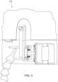
- a Coanda gripper 118FIG. 3
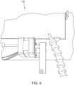
- a needle gripper 120FIG. 7
- AY positioner 128is also shown in FIG. 1 .
- the printer 104is mounted on the Y positioner 128.
- the Coanda gripper 118is also depicted in FIGS. 4-6 .
- the Coanda gripper 118is used for transferring substrate sheets 202 from the material feeder 102 to the printer 104.
- the needle gripper 120is used for transferring substrate sheets 202 from the printer 104 to the powder applicator 108.
- Belt driverscontribute to moving the positioners in the XY-direction and stepper motors connected to lead screws move the grippers in the Z-direction (in some implementations, while in other implementations pneumatic cylinders or solenoids in addition to stepper motors move the grippers in the Z-direction).
- Both grippersare activated with forced air, through air hoses 122 connected at one end to each gripper and at the other end to a manifold (not shown), with air valves for starting and stopping the flow of air to the grippers.
- the manifoldis connected to the controller, which sends signals at the appropriate time to open and close the air valves.
- Both the belt drivers and the stepper motorsare in also in communication with the controller, which sends signals to the drivers and motors to turn them on and off, thereby causing the XYZ positioners 116 to move in the X-direction, the Y-direction, and/or up or down (the Z-direction), at the appropriate times and for the appropriate distances.
- the Z positioningcan be done by solenoids or pneumatic positioners.
- the systemcan operate so that substrate sheets 202 travel through the entirety of the subsystems only one at a time.
- the next substrate sheet on the material feeder 102does not advance from the feeder 102 to the printer 104 until the prior substrate sheet completes its journey through the final component in the system.
- the systemcan operate so that once a given substrate sheet is transferred from a given component, a next substrate sheet can be advanced to that component or another prior component in the system.
- a next substrate sheet 202a...ncan be transferred by the Coanda gripper 118 to the printer 104 (that is, from the material feeder 102), and so on.
- a grippercomprising felted material is used in lieu of the Coanda gripper.
- felted gripperforced air need not be used as part of either the gripper or to blow air between or across surfaces of the substrate sheets 202, though it may be used if desired.
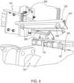
- the felted gripper 124comprises a plate 300 on which felted material 304 is mounted. The exposed surface of the felted material 304 is disposed so that it faces downward and is generally parallel to the top surface of a top substrate sheet when sitting on the platform 132 of the material feeder 102.
- hold-down prongs 142are used to hold down the second sheet.
- the XYZ positioner 116lowers the felted gripper 124 until the felted material 304 comes into contact with the top surface of the top sheet.
- the felted material 304entangles with the substrate sheet material and thusly grips the substrate sheet (such as topmost substrate sheet 202a).
- the XYZ positioner 116retracts and picks up the sheet, the sheet is die cut with notches which are alternated as shown in FIG. 2 and using the prongs the top sheet is stripped from the sheet below.
- the sheetsare stacked on top of compliant foam material on the material feeder 102 to improve the compliance of the stack to improve the adherence of the felt to the sheet.
- the XYZ positioner 116then moves the felted gripper 124 to the printer platen 140 and the substrate sheet is placed onto the platen 140. Because the felted gripper 124 is typically a needle felted or similar material, where the fibers of the felt are entangled and frizzy, they entangle in the matrix of the non-woven substrate, thus allowing it to be picked up by the gripper 124.
- the felted gripper 124further comprises one or more spring-loaded pins 306 with magnetic tips 308 at one end and a bearing surface 310 at the other end.
- the spring-loaded pins 306are disposed so that, in their rest position, the bottom surfaces of the magnetic pins are about even with the bottom surface of the felted material 304, or the bottom surfaces of the magnetic pins may be above the bottom surface of the felted material 304.
- the springis disposed between upper surfaces of the plate 300 and the bearing surface 310 of the pin 306.
- the surface of the platen 140comprises ferromagnetic material.
- the entire platen 140may be made of a ferromagnetic material, or only the surface of the platen 140, or only certain portions of the surface of the platen 140 may comprise a ferromagnetic material.
- the platen 140may be aluminum with a thin sheet of steel disposed on its top surface.
- the XYZ positioner 116lowers the felted gripper 124 to the surface of the platen 140. As the bottom surface of the gripper nears the top surface of the platen 140, the magnetic tips 308 of the spring-loaded pins 306 are attracted to and engage the ferromagnetic material comprising the surface of the platen 140.
- the substrate sheetis captured between the tips of the spring-loaded pins 306 and the platen 140.
- the XYZ positioner 116then lifts the felted gripper 124 away from the platen 140. Due to the magnetic forces, the spring-loaded pins 306 remain engaged with the platen 140 as the felted gripper 124 begins to move away from the platen 140. As the gripper continues to move away, the substrate sheet remains pinned to the platen 140 due to the magnetic forces, at least until the sheet detaches from the felted material 304 of the gripper 124.
- the springsbecomes compressed so that the forces of the springs eventually overcome the magnetic forces causing the tips of the spring-loaded pins 306 to disengage from the platen 140, thereby leaving the substrate sheet 202a... n on the surface of the platen 140.
- the length of the spring-loaded pins 306, the strength of the springs used therein, and the strength of the magnets comprising the tips 308 of the spring-loaded pins 306are selected so that the magnetic forces are stronger than the bond between the felted gripper 124 and the substrate sheet 202a... n, and the spring forces of the pins 306 as they compress become stronger than the magnetic forces between the tips 308 of the pins 306 and the platen 140.
- pins without springscan be used.
- the pinis light enough or otherwise disposed so that when the felted material 304 grips a substrate sheet 202a...n on the material feeder 102, the pins will not defeat the bond between the gripper 124 and the sheet 202a...n.
- the gripper 124is moved to the platen 140, it will operate as otherwise described above.
- the bearing surfaces 310 of the pins 306are constrained by the plate 300 and thusly break the magnetic bond between the pins 306 and the platen 140.
- a material other than felted material suitable to engage a substrate sheet through entanglement or other techniquemay be used.
- Such alternative materialmay comprise, for example, but is not limited to, tape or other adhesive, or electrostatic forces.
- electrostatic forcesthe use of pins - spring-loaded or otherwise - may be eliminated.
- an electrical current to the gripper for generating the electrostatic forcesmay be turned on for purposes of gripping a substrate sheet and turned off for purposes of releasing the substrate sheet.
- magnets 306 with magnetic tips 308may be electromagnets.
- an electrical current to the gripper 124 for generating a magnetic fieldmay be turned on for purposes of causing the pins - spring-loaded or otherwise - to engage the surface of the platen 140 and turned off for purposes of disengaging the pins 306 from the surface of the platen 140.
- the tips of the pins - spring-loaded or otherwise -may comprise vacuum grippers.
- the platenneed not comprise a ferromagnetic surface.
- the vacuum grippersare turned on and thusly engage the surface of the platen 140, thereby clamping the substrate sheet 202a...n to the platen 140.
- the vacuum forcesare sufficient to remain engaged with the platen 140 surface until the substrate sheet 202a...n disengages from the felted material 304.
- spring-loaded pins 306are used, as the gripper 124 continues to move away from the platen 140, the spring forces overcome the vacuum forces to disengage the vacuum grippers from the surface of the platen 140. Where springs are not used, the bearing surfaces 310 of the pins as they are constrained by the plate 300 can overcome the vacuum forces. Alternatively, instead of relying on springs or constraining of the pins, the vacuum gripper could simply be turned off so that the pins disengage from the surface of the platen 140 at the appropriate time.
- the material feeder 102has several subparts/systems, including the frame and platform, sheet openings, and hold-down prongs and gripper.
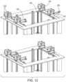
- the material feeder 102comprises a frame 130, which houses a platform 132.
- the platform 132is capable of holding a stack of substrate sheets 202, which are placed onto the platform 132 as needed.
- the material feeder 102can have adjustable features to hold different size sheets.
- the platform 132is raised or lowered using one or more lead screws 134 driven by one or more motors 136. While the embodiment in FIGS.
- 11 and 12shows four lead screws 134 and a single stepper motor 136 with a belt for driving the lead screws 134
- the platform 132could be driven by a single lead screw and stepper motor, or any other combination of lead screws and stepper motors, or by a belt-driven system, or by any other suitable mechanisms known in the art or hereafter invented.
- the motors 136are turned on and off by signals from a controller.
- a distance sensor 138is mounted on or in relation to the frame 130.
- the distance sensor 138detects, as the platform 132 moves upward, when the top of the stack of substrate sheets 202 reaches a pre-defined distance from the sensor, known as the "sheet feed position."
- the distance sensor 138can be any type of suitable sensor, including an optical distance sensor, such as, but not limited to, an encoder, a time of flight distance sensor or IR sensor.
- the distance sensor 138is in communication with the controller. As the platform 132 moves upward, when the distance sensor 138 detects that the top of the stack of substrate sheets 202 has reached the pre-defined distance from the sensor 138 (the sheet feed position), the sensor 138 sends a signal to the controller indicating this condition.
- the controllerUpon receiving the signal from the distance sensor 138, the controller causes the motors to stop so that the platform 132 comes to a rest.
- a different kind of sensorcan be used based on a switch which has a probe which moves up and down as the plate is pressed on the sheets.
- each substrate sheetincludes at least two notches 204 or areas and at or near its edges, where material is removed or otherwise not present, as shown in Fig 2 .
- These notches 204can be created for example by laser cutting, die cutting, or another method.
- the notches 204are at or near the top of the right-hand side of the sheet 202 and the bottom of the left-hand side of the sheet 202.
- the notches 204are at or near the top of the left-hand side of the sheet and the bottom of the right-hand side of the sheet.
- the sheets 202are stacked in alternating fashion, so that a sheet of the first orientation is always between two sheets of the second orientation and vice versa, as shown in FIG. 2 .
- Notchesmay serve usefully for orderly feeding of sequential sheets, registration among multiple processed sheets, or both. In preferred embodiments, printer-punched holes are used for such registration.
- Hold-Down Prongs and GripperTwo pairs of hold-down prongs 142 are mounted on the frame 130 for the material feeder 102. Each hold-down prong 142 is operably connected to a shaft 144 of a stepper motor 146 for pressing the prong 142 about the shaft 144. The stepper motors 146 are in communication with the controller. Each hold-down prong 142 comprises an optional foot 148 that includes a sheet-engaging surface. One pair of hold-down prongs 142 is positioned so that the feet 148 thereof align with the openings in substrate sheets of the first orientation and the other pair of hold-down prongs 142 is positioned so that the feet 148 thereof align with the openings in substrate sheets of the second orientation.
- the controllersends a signal to the stepper motor of the XYZ positioner 116 that controls the Z movement of the Coanda gripper 118 to lower the gripper towards the top of the stack of substrate sheets 202.
- the controllersends a signal to turn on the forced air to the Coanda gripper 118 thereby activating it.
- the controlleralso sends a signal to stepper motors 146 causing their shafts 144 to rotate so that the hold-down prongs 142 connected to the shaft 144 which are pressed into the stack of sheets 202 and the feet 148 and thereof pass through the notches 204 in the top substrate sheet 202 and engage the surface of the substrate sheet below the top sheet (hereinafter "second sheet"). This could occur before, during, or after the movement of the Coanda gripper 118.
- the sheet-engaging surfaces of the feet 148can optionally include a textured surface to ensure a better grip with the substrate sheet 202.
- the textured surfacecan be integral to the foot 148 or, for example, can be an additional material adhered, fastened or applied to the sheet-engaging surface of the foot 148, such as, but not limited to, sandpaper.
- Each foot 148can further include a connector 156 for attaching a forced air hose 122, conduits for channeling forced air through the foot 148, and vents 158 for forced air to pass out of the foot 148.
- the opposite ends of the forced air hoses 122are connected to a manifold (not shown) comprising air valves so that the forced air to each hose 122 can be turned on or off.
- the manifoldis in communication with the controller.
- the stepper motor 146sends a signal to the controller and then the controller sends a signal to the manifold instructing it to open the valves supplying air to the feet 148.
- Thiscauses forced air to pass through the vents 158 and thus between the top substrate sheet and the sheet engaged by the feet 148, i.e., a second sheet.
- the Coanda forces from the gripperthen lift the top substrate sheet.
- the vents 158are designed so that the air blows in spread fashion across a desired angle, for example to both the left and right of center, and slightly downward from the horizontal plane.
- the spread anglecan vary based on a number of factors, such as the pressure of the forced air, the weight and porosity of the substrate sheets, the size of the sheets, and the location of the openings in the sheets. In general, this spread angle may be chosen so that the air flow maximizes separation between the top sheet and the second sheet.
- the combination of the feet 148 engaging the surface of the second sheet and the forced air between the top sheet and second sheetenables the Coanda gripper 118 to be able to lift and move the top sheet without also lifting the second sheet (or any sheets below the second sheet), and also without the second sheet sticking to the top sheet due to frayed fiber entanglement or otherwise.
- the second sheetthen becomes the top sheet of the stack to be transferred, and the process described above is repeated, but the other pair of hold-down prongs 142 are used, since they align with the openings in the second sheet and thus will pass through those openings to engage the surface of the sheet below the second sheet (which is now the top sheet).
- air nozzles 150 or other blowerscan be mounted on, or in relationship to, the frame 130 and used to blow air above or across the top surface of the top substrate sheet, creating Bernoulli forces to help lift the sheet. Such additional nozzles or blowers 150 can also be used to provide additional air between the top sheet and the one below it.
- forced airis not supplied through the feet 148 of the hold-down prongs 142 and is provided through the above-described independent nozzles or blowers 150 mounted on or in relationship to the frame 130. Any of the many alternative ways of providing forced air could also be used, for example, but not limited to, through areas of the prongs 142 other than the feet 148 or through nozzles mounted on the prongs 142.
- hold-down prongs 142are eliminated and forced air need not be directed between the sheets.
- the sheets 202need not include notches 204. Instead, a non-porous slip sheet, such as paper, is added between each pair of substrate sheets in the stack of sheets 202.
- a suitable grippersuch as a needle gripper, is then able to pick up the top substrate sheet without picking up any other substrate sheets.
- the slip sheetwill reside at the top of the stack of sheets 202 and can then be picked up and discarded using a suitable gripper or any other means.
- slip sheetcan be removed at a later step in the process.
- This approach using slip sheetscan be generally less preferable, because it requires an additional area to place the slip sheets after they are lifted from the stack, requires more pre-processing to create the stack of sheets (i.e., with a slip sheet interleaved between each pair of substrate sheets), and produces a large number of slip sheets which have to be either discarded or recycled, but it is contemplated that it might be useful in certain applications/embodiments.
- the controllersends a signal to the stepper motor causing the gripper 118 to move upward a pre-defined distance.
- the distance sensor 138can be used to confirm that the gripper 118 is holding a sheet. Once confirmed, or when the gripper 118 otherwise begins to move away from the stack of sheets 202, the controller sends a signal to the manifold turning off the air to the hold-down prongs 142 and then sends a signal to the stepper motor 146 to rotate the hold-down prongs 142 off of the second sheet. Meanwhile, the controller also sends a signal to the XY positioner, causing the gripper 118 to move towards the printer platen 140.
- the controllersends signals to the stepper motor 146 and air manifold so that the substrate sheet is lowered and placed on the platen 140 and the gripper 118 releases the sheet so that the substrate sheet is resting on the platen 140.
- the gripper 118 and XYZ positioner 116are designed so that they locate the sheet on the printer platen 140 with good precision. The controller then sends a signal to the XYZ positioner 116 causing the gripper 118 to return to its initial position above the material feeder 102.
- the printer 104is activated using a controller typical under program control of a computer to print the layer shapes onto the substrate sheet in the manner previously described.
- the positioner on which the print heads 105 are mountedcan be stationary, such that the print heads 105 move only in the Y-direction and the sheet is advanced under the print heads 105 by movement of the platen 140 in the X-direction.
- the platen 140can be held stationary during the printing operation and the positioner on which the print heads 105 are mounted can be advanced along the length of the substrate sheet as the print heads 105 are moved in either the X- or Y-direction.
- the printer 104operates such that when the printing of layer shapes onto the substrate sheet is completed, the platen 140 is positioned so that the substrate is situated between the location of the positioner hosting the print heads 105 and the location of the powder applicator 108.
- the printer 104may also optionally include one or more punches, either mounted on the same positioner arm as the print heads 105 or separately mounted in relation to the printer platen 140, so that, during or immediately prior to or after the printing operation, holes can be punched in the substrate sheet in desired locations.
- the holesare used later in the process to align the substrate sheets by loading them onto registration or alignment pins.
- Those pinscan be part of a stacker subsystem, or part of a subsequent stacking operation, or both.
- the diameter of the holesis similar to the outer diameter of the registration pins to get the best registration.
- the punchcan be, for example, a hole punch, a paper drill, or any other suitable mechanism known in the art.
- the punchcan optionally include a mechanism for vacuuming the chads that are punched from the substrate sheets, or a separate vacuum, sweeping, or blowing mechanism can optionally be provided.
- the locations for the holes on the substrate sheetare defined in relationship to where the layer shapes for the 3D part will be printed on the substrate sheet.
- the information about the hole locationsis provided to the printer 104 along with the layer shape information.
- the computer for the printer 104can generate signals to cause holes to be punched at the desired locations.
- holescan optionally be created in the sheets as a precursor or post processing step. Alternatively the corners of the sheet can be used for registration.
- the layercan also be die cut using a die cutting station that is well known in the art and this can be done before or after printing and should in register with the printing. There are also a number of other ways of making holes that are well known in the art such as laser cutting.
- the needle gripper 120Upon completion of printing and, if included, punching, the needle gripper 120 is used to transfer the substrate sheet 202a...n to the powder system 106, which includes a conveyor 152 for feeding the substrate sheet into the powder applicator 108. More specifically, the printer 104 sends a signal to the controller, which then sends signals to the XYZ positioner 116, stepper motor 146, and air manifold so that the XY positioner moves the needle gripper 120 to a position above the substrate sheet (resting on the printer platen 140), the stepper motor moves the gripper downward until the needle gripper 120 contacts the top of the substrate sheet, and the manifold opens the air valve attached to the needle gripper 120 to activate it and thereby grip the substrate sheet.
- a preferred implementationuses a pneumatic cylinder for Z-movement, and only an X-positioner is used. As previously mentioned, a roll / web based system for feed can be used.
- the controllerthen sends further signals so that the stepper motor lifts the gripper (and thus the substrate sheet) upward, the XY positioner moves the gripper to an appropriate position above the conveyor 152 of the powder applicator 108, the stepper motor moves the gripper downward until the substrate sheet is placed on the surface of the conveyor 152, and then the gripper releases the substrate sheet onto the conveyor 152.
- the needle gripper 120 and XYZ positioner 116are designed so that they locate the sheet on the conveyor 152 with good precision. The XY positioner then moves the gripper upwards and back to its original position to await the next sheet to be run through the printer 104.
- the printer 104can send an indicating signal to the controller and the controller can send a signal to the XYZ positioner 116 for the needle gripper 120 so that, instead of transferring the substrate sheet to the powder applicator 108, the sheet is transferred to a discard area.
- a needle gripper 120suffices to pick up a substrate sheet 202a...n resting on the printer platen 140. This is facilitated by the fact that a single sheet is resting on the surface of the platen 140 rather than on a stack of substrate sheets 202.
- a felted gripperconfigured so that the felted material and pins do not interfere with or materially disturb the printing fluid that the printer 104 deposits onto the substrate sheet, could alternatively be used.
- other gripper embodiments described herein or known in the artcould be used.
- a Coanda gripperis not as suitable for use in this configuration to transfer sheets from the printer platen 140 to the powder applicator 108. This is because there is no airflow under the sheet on the platen 140, which is a requirement for a Coanda gripper. This problem can be solved by introducing air below the sheet resting on the printer.
- the powder applicator 108 and powder remover 110are integrated to form a single component, the powder system 106. They may alternatively be provided as separate components. In either case, the powder system 106 can be set to run continuously so that, once a substrate sheet 202a... n is placed upon the conveyor 152, it automatically travels through the powder system 106. Alternatively, a controller in communication with both the XYZ positioner 116 and the powder system 106 can instruct the powder applicator 108 and powder remover 110 or subsystems thereof to turn on and off at the appropriate times.
- the powder applicator 108deposits powder, such as, but not limited to, thermoplastic powder, onto the surface of the substrate sheet (on which layer shapes have just been printed). The powder sticks to the printed (wet) areas on the sheet. The powder remover 110 then removes any powder that did not adhere to the sheet.
- powdersuch as, but not limited to, thermoplastic powder
- the powdercan be applied by a device that is used in thermography machines such as those made by THERM-O-TYPE Corp, in which the powder applicator 108 and powder remover 110 are integrated into a single component.
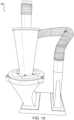
- a deviceis shown in FIG. 1 and FIGS. 13-17 and consists of (i) a series of conveyors, (ii) a vibrating trough that holds typically polymer powder and has a slit through which powder flows to deposit powder on the sheet while it moves under the trough, and (iii) a vacuum 110 that removes the powder that did not adhere to the sheet while it moves under the vacuum 110.
- the vacuum subsystemwhich includes a vacuum motor and cyclone 154 sits above the conveyor 152.
- a series of star wheelsare configured to hold the sheet down while it is exposed to the airflow of the vacuum subsystem.
- the cyclone 154also re-circulates the vacuumed powder back to the trough for reuse.
- the cyclone 154 that is used in the THERM-O-TYPE and other similar machinesremoves, through its exhaust, a high percentage of particles and has a cutoff point of about 50 microns, that is, it does not recycle most particles that are smaller than 50 microns. It has been discovered that, when this happens, it substantially reduces the amount of powder deposited on the sheet and further means that a significant amount of powder is wasted, since the purpose of the cyclone 154 is to permit recycling of the powder. Part of the reason that the amount of powder deposited is decreased is that smaller particles are no longer deposited, which in turn reduces the total amount of powder deposited and, over time, most of the smaller particles are removed through the recycling process. When there are smaller particles in the distribution, the amount of powder deposited increases. Having a powder with a distribution of powder sizes centered at 50 microns works well, so the cutoff point of 50 microns removes a large percentage of particles, about 30%.
- the dump valve assembly 180consists of a dump valve body 181, a dump valve 182, a washer bearing 183, a dump valve shaft 184, a retaining ring 185 (of size, e.g., 5/16"), a gear motor 186 (e.g., 1/120 hp), a flexible coupling 187, and a dump valve motor bracket 188.
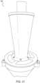
- the cyclone designis replaced with a conical design, such as, for example, the design used in the Dust Deputy.
- the cyclone-based implementationhas a "valve" 195 on the powder removal system that collects the powder in a tube 189 with oval holes 190 that revolves inside a housing ( FIG. 22 ) and that alternately collects and then dumps the powder into the trough of the Thermograph.
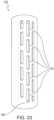
- this tubeis replaced with a delrin tube 189 ( FIG. 23 ) having multiple slots 191 instead of the oval opening 190. This produces a better seal and stops air from coming in from below, preventing the powder from falling into the tube 189.
- an air knife 160such as, but not limited to, the X-Stream Air Blade Air Knife from Nex Flow Air Products Corp., can be added after the vacuum stage so that any remaining excess powder on the substrate sheet is removed ( FIG. 1 ).
- the air knife 160can be controlled by a programmed microcontroller.
- the powder system 106can be configured so that sheets go through the powder applicator and powder removal stages more than one time.
- the advantageis that depositing powder onto a substrate sheet in multiple trips can increase the amount of powder that adheres to the printed areas of the substrate sheet, which sometimes is desirable for making the 3D part.
- the conveyors 152may be reversed so that the sheet travels back to the entrance of the powder applicator 108 and then reversed again (now going forward) so that the sheet goes back through the powder system 106 again. In this embodiment, during travel in the reverse direction, one or both of the powder applicator 108 and powder vacuum 110 could be turned off.
- a separate conveyor or transfer systemcan carry the sheet back to the conveyor associated with the entrance to the powder applicator 108, whereupon the sheet will travel back through the powder system 106.
- the sheetmay be flipped using any suitable mechanism known in the art, so that powder is applied the other side of the sheet.
- an optional fuser component 112may be disposed after the powder system 106.
- the fuser 112may be disposed above, below, or adjacent to the conveyor 152 leading out of the powder remover 110.
- the fuser 112may be, for example but not limited to, radiant, IR, or other heating method sufficient to melt and thus fix the powder to the sheet. As the sheet travels out of the powder applicator 108, the heat from the fuser 112 melts the powder on the substrate sheet causing it to fix to the sheet.
- the transfer systemcan be adapted so that the gripper is rotatable.
- the sheets picked up by the grippercan be rotated, for example by 30, 45, or 90 degrees, before they are placed on the printer platen 140, so that when the sheets are finally stacked to make the 3D part, they have varying angles of fiber orientation relative to one another.
- Thisenables production of objects with better mechanical properties in multiple directions.
- the sheetsmay be rotated at any one of several other points along the process.
- the sheetsmay, for example, be rotated just after printing, using a turntable, by rotating the needle gripper 120, or by other rotating means.
- the sheetsmay also be rotated after powder removal or after fusing, in either case also using a turntable, by introducing another gripper at those locations that is capable of rotating the sheets, or by other rotating means known in the art.
- Another way to adjust directionality of the fibersis to use multiple sheet trays, with each sheet tray holding sheets in a different direction.
- the printer 104prints the layers shapes of the 3D part in a corollary rotation so that, when the substrate sheets are stacked, the layer shapes from one substrate sheet to another are properly oriented for making the 3D part.
- Substrate sheet shapes other than squares or rectanglesmay also be used so that, when sheets are rotated and then stacked, all of the edges of the sheets in the stack will be aligned.
- such other sheet shapescould include, but are not limited to, circles, octagons, and any other symmetric regular polygons.
- sheetsmay be cut on different biases so that the fiber orientation can be varied, such as, for example, by 45 and 90 degrees, and then stacked in the appropriate order (at the sheet feeding step), thus eliminating the need to rotate the sheets.
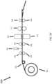
- FIG. 24depicts a continuous feed roll implementation 400
- FIG. 25depicts a roll to sheet implementation 500
- a roll of substrate material 402is mounted and situated ahead of the printer 104.
- a tensioning system 404 together with feed rollers 406are used to hold and advance the web defined by the length of the roll material fed through the system.
- the web 402can extend through all of the components of the system - printer 104, powder applicator 108, powder remover 110, and, if present, fuser 112 - and then be cut by a cutter 408 into single sheets prior to stacking. This is depicted in FIG. 24 .
- the web 402may be cut by the cutter 408 into single sheets at any prior point in the process.
- the web 402may be converted to a single sheet prior to advancing the resulting sheet onto the printer platen 140.
- the web 402may be converted to a single sheet after the leading edge is situated on the platen 140.
- the web 402may be converted to a single sheet after the printing operation is completed and before the resulting sheet is fed into the powder applicator 108, and so on.
- This apparatuscan also optionally have a camera with vision software to ensure that it has not malfunctioned, that the appropriate amount of powder is deposited, that the sheets are moving as desired, and other quality assurance aspects of the process. Additional sensors may optionally be attached to the sheet feeder 102 to make sure that a sheet has been picked up, or that not more than one sheet has been picked up, or that no other malfunction has occurred. If the machine has not picked up a sheet, the operation can be run again. If two sheets are picked up, then rather than being transferred to the printer platen 140, they can be placed into a separate pile for reuse later or discarding. The machine may optionally have a light, buzzer, other alert, or any combination thereof, to inform the operator of the malfunction, at which point the problem can be addressed.
- the process carried out by the systemmay be sequenced and monitored using microcontrollers or PLCs as follows.
- the sheet feeder 102is informed by the control program to feed a sheet. After feeding a sheet onto the printer platen 140, the feeder 102 informs the control program which tells the printer 104 to begin printing. When the printer 104 has completed printing, it informs the positioner to move the needle gripper 120, which picks up the sheet 202a...n and deposits it on the powdering conveyor 152 and then informs the control program it has completed its task.
- These stepscan optionally be overlapped, i.e., run in parallel as described above, in order to increase the speed of the process.
- the printheads 105are designed for rastering movement to deposit printing fluid on the substrate sheets 202.
- the need for rasteringcan be eliminated. This enables the system to print much faster.
- the systemcan be made to run at rates of up to 60 pages per minute or much higher, thus producing parts at speeds that rival injection molding speeds.
- the print heads 105may optionally be equipped with a bulk ink delivery system, so that the fluid used will need to be replaced less frequently.
Landscapes
- Engineering & Computer Science (AREA)
- Chemical & Material Sciences (AREA)
- Materials Engineering (AREA)
- Manufacturing & Machinery (AREA)
- Mechanical Engineering (AREA)
- Physics & Mathematics (AREA)
- Optics & Photonics (AREA)
- Composite Materials (AREA)
- Robotics (AREA)
- Feeding Of Articles By Means Other Than Belts Or Rollers (AREA)
- Sheets, Magazines, And Separation Thereof (AREA)
Description
- The present invention relates to additive manufacturing and, in particular to an apparatus for automated manufacturing of three-dimensional composite-based objects.
- Additive manufacturing, such as three-dimensional printing, can be seen as largely a materials problem. One of the limitations of current methods is a limited materials palette and slow build speeds.
- These and other limitations of the prior art are avoided by a methodology known as Composite-Based Additive Manufacturing (CBAM). CBAM is described in full in co-pending
U.S. Patent Application Nos. 13/582,939, filed November 2, 2012 14/835,690, filed August 25, 2015 14/835,635, filed August 25, 2015 US2013/0171431A1 ,US2016/0082657A1 andUS2017/0057100A1 . WO2014/134224 A2 discloses a method for fabricating three-dimensional object using printing technology, that involves removing some negative regions from stacked layers to form object and portions of stacked substrate layers are infiltrated or coated.- This application describes a particular method and apparatus for automating Composite-Based Additive Manufacturing (CBAM). The invention provides a method according to
claim 1. - Other aspects, advantages and novel features of the invention will become more apparent from the following detailed description of the invention when considered in conjunction with the accompanying drawings wherein:
FIG. 1 is a schematic of an example embodiment of an apparatus for composite-based additive manufacturing, according to one aspect of the invention.FIG. 2 is an example substrate layer useable in the present invention.FIG. 3 depicts aspects of an example embodiment of a Coanda gripper element of an example transfer system according to one aspect that is not according to the claimed invention .FIG. 4 is a different view of the aspects of the Coanda gripper element depicted inFIG. 3 .FIG. 5 is another view of the aspects of the Coanda gripper element depicted inFIG. 3 .FIG. 6 is another view of the aspects of the Coanda gripper element depicted inFIG. 3 .FIG. 7 depicts an example embodiment of a needle gripper element of an example transfer system according to one aspect of the invention.FIG. 8 depicts aspects of an example embodiment of a felted gripper element of a transfer system.FIG. 9 is another view of the aspects of a felted gripper element depicted inFIG. 8 .FIG. 10 is another view of the aspects of a felted gripper element depicted inFIG. 8 .FIG. 11 depicts an example embodiment of a material feeder according to one aspect of the invention.FIG. 12 shows another view of an example embodiment of a material feeder according to one aspect of the invention.FIG. 13 is a top-side view of an example implementation of aspects of a powder system according to one aspect of the invention.FIG. 14 is a front-side view of an example implementation of aspects of a powder system according to one aspect of the invention.FIG. 15 is another top-side view of an example implementation of aspects of a powder system according to one aspect of the invention.FIG. 16 is a rear-side view of an example implementation of aspects of a powder system according to one aspect of the invention.FIG. 17 is another side view of an example implementation of aspects of a powder system according to one aspect of the invention.FIG. 18 is a schematic diagram of an alternative example implementation of aspects of a powder system according to one aspect of the invention.FIG. 19 depicts an example implementation of the alternative powder system ofFIG. 18 .FIG. 20 is another view of the example implementation of the alternative powder system shown inFIG. 19 .FIG. 21 is another view of the example implementation of the alternative powder system shown inFIG. 19 .FIG. 22 depicts an example valve part of the alternative powder system ofFIG. 18 .FIG. 23 depicts an alternative design of the valve part of the alternative powder system ofFIG. 18 .FIG. 24 depicts a roll-based continuous feed implementation that is not according to the claimed invention.FIG. 25 depicts a roll-based roll to sheet implementation- The above Figures show all or part of illustrative embodiments of this invention. The Figures do not show all of the possible details of the invention.
- The CBAM process described in the prior applications (
U.S. Patent Application Nos. 13/582,939 ,14/835,690 14/835,635 US2013/0171431A1 ,US2016/0082657A1 andUS2017/0057100A1 ) is automated by performing the steps through a number of components or subsystems that operate in a coordinated manner. The main components of an example embodiment are shown inFIG. 1 , and include amaterial feeder 102, aprinter 104, apowder system 106 comprising apowder applicator 108 andpowder remover 110, anoptional fuser 112, a transfer system, and other elements that serve to connect and control the various components. While example components are shown inFIG. 1 , various alternative and optional components described below are also suitable for use with the invention and are therefore to be considered as being within the scope of the invention, as defined by the appended claims. - General Device Operation. The
material feeder 102 holds a stack of substrate sheets, such as the example carbon fiber sheets (202a, 202b) shown inFIG. 2 , and moves them into proper position so that a single sheet at a time can be transferred to theprinter 104. Sheets are transferred to, and positioned for, theprinter 104 by means of the transfer system. Theprinter 104 then deposits fluid onto a substrate sheet as in the prior applications (U.S. Patent Application Nos. 13/582,939 ,14/835,690 14/835,635 US2013/0171431A1 ,US2016/0082657A1 andUS2017/0057100A1 ), and may optionally include a punching mechanism for placing holes in the sheet at desired locations. For example the printer prints a layer of a 3D model of which a stack of the successive layers are used use to produce a 3D object as described in the above-mentioned applications. Thepowder applicator 108 then deposits thermoplastic powder onto the substrate sheet, whereupon the powder adheres to the areas of the sheet that have been made wet by theprinter 104. The powder remover removes powder that did not adhere to the sheet. Thefuser 112, which is optional, heats the powder on the substrate sheet in a manner sufficient to cause the powder to melt and thereby affix to the sheet, so that the powder remains on the sheet when and if the underlying fluid from theprinter 104 dries. This cycle is repeated for as manyadditional substrate sheets 202 as required for making a specified three-dimensional (3D) part, with eachsheet 202 normally representing a layer of the 3D part. - The sheets are transferred from the
material feeder 102 to theprinter 104, and from theprinter 104 to the powder applicator, by a transfer system. One of the problems with feeding the sheets used in the CBAM process is that, in the case of non-woven carbon fiber sheets and other non-woven substrate sheets, the sheets are porous, and so conventional means for picking up the sheets do not work. For example, most lithography presses uses vacuum grippers to pick up single sheets of paper, but this only works because/when the paper sheets are non-porous, and so that the vacuum holds tightly against the top sheet in a stack but not the sheets below the top sheet. - A conventional approach to solving this problem is to feed single sheets using rollers, such as are used in laser printers and photocopiers. The problem with this approach is that sheets of non-woven materials, especially non-woven carbon fiber, and other non-wovens such as fiberglass, tend to stick together, so attempting to pick up or slide one sheet from a stack of sheets causes multiple sheets to be picked up or slide. This is due in part to the fact that fibers at the edges of each sheet are slightly frayed, causing them to tangle with the frayed edge fibers or other surfaces of the sheets directly above or below the target sheet. Also, stray fibers occur elsewhere thereby entangling with the sheet above or below. For example, in the case of carbon fiber sheets, the sheets are not only porous, but are also a matrix of fibers held together with a binder and having holes or areas where there is no fiber. In these areas, the fiber from the sheet below can become entangled with the sheet above, causing them to stick together.
- Different approaches are therefore needed for porous non-woven substrate sheets. These approaches may include the use of Coanda grippers, this approach is not according to the claimed invention, such as, but not limited to, those supplied by Schmalz Inc. (for example the series SCG-1 composite grippers, and particularly Model No. SCG 1xE100 A MA), and/or needle grippers, according to the claimed invention, such as, but not limited to, those supplied by Schmalz Inc. (for example the series SNG-V needle grippers and particularly Model No. SNG-V 10 1.2 V7). These approaches may also include the use of a gripper comprising certain kinds of felt, and particularly needle-felted, non-woven filamentous or fiber material (hereinafter "felted material"), such as, but not limited to, that used as the eraser material in model number 81505 "Expo White Board Care" block eraser made by Newell Rubbermaid Office Products.
- As shown in
FIGS. 1 and3-7 , the gripper subsystem comprises a framework ofrails 114 and belt drivers defining twoXY positioners 116 further including stepper motors to additionally provide movement in the Z direction as further described below (collectively an "XYZ Positioner"). The system can be devised so that for each positioner, only X movement or XZ movement is required in which case an X or XZ positioner rather than an XY or XYZ positioner could be used. In this embodiment, a Coanda gripper 118 (FIG. 3 ) is mounted on thefirst XYZ positioner 116 and a needle gripper 120 (FIG. 7 ) is mounted on thesecond XYZ positioner 116.AY positioner 128 is also shown inFIG. 1 . Theprinter 104 is mounted on theY positioner 128. The Coanda gripper 118 is also depicted inFIGS. 4-6 . The Coanda gripper 118 is used for transferringsubstrate sheets 202 from thematerial feeder 102 to theprinter 104. Theneedle gripper 120 is used for transferringsubstrate sheets 202 from theprinter 104 to thepowder applicator 108. Belt drivers contribute to moving the positioners in the XY-direction and stepper motors connected to lead screws move the grippers in the Z-direction (in some implementations, while in other implementations pneumatic cylinders or solenoids in addition to stepper motors move the grippers in the Z-direction). Both grippers are activated with forced air, throughair hoses 122 connected at one end to each gripper and at the other end to a manifold (not shown), with air valves for starting and stopping the flow of air to the grippers. The manifold is connected to the controller, which sends signals at the appropriate time to open and close the air valves. Both the belt drivers and the stepper motors are in also in communication with the controller, which sends signals to the drivers and motors to turn them on and off, thereby causing theXYZ positioners 116 to move in the X-direction, the Y-direction, and/or up or down (the Z-direction), at the appropriate times and for the appropriate distances. The Z positioning can be done by solenoids or pneumatic positioners. - Serial or Parallel Operation. The system can operate so that
substrate sheets 202 travel through the entirety of the subsystems only one at a time. In this embodiment, the next substrate sheet on thematerial feeder 102 does not advance from thefeeder 102 to theprinter 104 until the prior substrate sheet completes its journey through the final component in the system. Alternatively, the system can operate so that once a given substrate sheet is transferred from a given component, a next substrate sheet can be advanced to that component or another prior component in the system. In such an embodiment, for example, as a given substrate sheet is being transferred by theneedle gripper 120 away from the printer 104 (that is, to the powder applicator 108), anext substrate sheet 202a...n) can be transferred by the Coanda gripper 118 to the printer 104 (that is, from the material feeder 102), and so on. - Felted Material Gripper Embodiment according to the claimed invention.
- According to the claimed invention, a gripper comprising felted material is used in lieu of the Coanda gripper. In this embodiment, hereinafter "felted gripper," forced air need not be used as part of either the gripper or to blow air between or across surfaces of the
substrate sheets 202, though it may be used if desired. As shown inFIGS. 8-10 , the feltedgripper 124 comprises aplate 300 on which feltedmaterial 304 is mounted. The exposed surface of the feltedmaterial 304 is disposed so that it faces downward and is generally parallel to the top surface of a top substrate sheet when sitting on theplatform 132 of thematerial feeder 102. To pick up asubstrate sheet 202a...n from theplatform 132, hold-downprongs 142 are used to hold down the second sheet. TheXYZ positioner 116 lowers the feltedgripper 124 until the feltedmaterial 304 comes into contact with the top surface of the top sheet. The feltedmaterial 304 entangles with the substrate sheet material and thusly grips the substrate sheet (such astopmost substrate sheet 202a). TheXYZ positioner 116 retracts and picks up the sheet, the sheet is die cut with notches which are alternated as shown inFIG. 2 and using the prongs the top sheet is stripped from the sheet below. In some instances the sheets are stacked on top of compliant foam material on thematerial feeder 102 to improve the compliance of the stack to improve the adherence of the felt to the sheet. TheXYZ positioner 116 then moves the feltedgripper 124 to theprinter platen 140 and the substrate sheet is placed onto theplaten 140. Because the feltedgripper 124 is typically a needle felted or similar material, where the fibers of the felt are entangled and frizzy, they entangle in the matrix of the non-woven substrate, thus allowing it to be picked up by thegripper 124. - The felted
gripper 124 further comprises one or more spring-loadedpins 306 withmagnetic tips 308 at one end and abearing surface 310 at the other end. The spring-loadedpins 306 are disposed so that, in their rest position, the bottom surfaces of the magnetic pins are about even with the bottom surface of the feltedmaterial 304, or the bottom surfaces of the magnetic pins may be above the bottom surface of the feltedmaterial 304. Thus, when the feltedgripper 124 comes into contact with the top surface of a substrate sheet on thematerial feeder 102, thepins 306 will not defeat the ability of the feltedmaterial 304 of the feltedgripper 124 to engage and hold asubstrate sheet 202a...n. The spring is disposed between upper surfaces of theplate 300 and thebearing surface 310 of thepin 306. - In one embodiment, the surface of the
platen 140 comprises ferromagnetic material. Theentire platen 140 may be made of a ferromagnetic material, or only the surface of theplaten 140, or only certain portions of the surface of theplaten 140 may comprise a ferromagnetic material. For example, theplaten 140 may be aluminum with a thin sheet of steel disposed on its top surface. To place a substrate sheet onto theplaten 140, theXYZ positioner 116 lowers the feltedgripper 124 to the surface of theplaten 140. As the bottom surface of the gripper nears the top surface of theplaten 140, themagnetic tips 308 of the spring-loadedpins 306 are attracted to and engage the ferromagnetic material comprising the surface of theplaten 140. At this point, the substrate sheet is captured between the tips of the spring-loadedpins 306 and theplaten 140. TheXYZ positioner 116 then lifts the feltedgripper 124 away from theplaten 140. Due to the magnetic forces, the spring-loadedpins 306 remain engaged with theplaten 140 as the feltedgripper 124 begins to move away from theplaten 140. As the gripper continues to move away, the substrate sheet remains pinned to theplaten 140 due to the magnetic forces, at least until the sheet detaches from the feltedmaterial 304 of thegripper 124. Then, as thegripper 124 further continues to move away from theplaten 140, the springs becomes compressed so that the forces of the springs eventually overcome the magnetic forces causing the tips of the spring-loadedpins 306 to disengage from theplaten 140, thereby leaving thesubstrate sheet 202a... n on the surface of theplaten 140. The length of the spring-loadedpins 306, the strength of the springs used therein, and the strength of the magnets comprising thetips 308 of the spring-loadedpins 306 are selected so that the magnetic forces are stronger than the bond between the feltedgripper 124 and thesubstrate sheet 202a... n, and the spring forces of thepins 306 as they compress become stronger than the magnetic forces between thetips 308 of thepins 306 and theplaten 140. - In an alternative embodiment of the felted
gripper 124, pins without springs can be used. In this embodiment, the pin is light enough or otherwise disposed so that when the feltedmaterial 304 grips asubstrate sheet 202a...n on thematerial feeder 102, the pins will not defeat the bond between thegripper 124 and thesheet 202a...n. When thegripper 124 is moved to theplaten 140, it will operate as otherwise described above. However, instead of relying on spring forces to cause themagnetic tips 308 of the pins to disengage from theplaten 140, as thegripper 124 moves away from theplaten 140, the bearing surfaces 310 of thepins 306 are constrained by theplate 300 and thusly break the magnetic bond between thepins 306 and theplaten 140. - In any of the embodiments of the felted
gripper 124, a material other than felted material suitable to engage a substrate sheet through entanglement or other technique may be used. Such alternative material may comprise, for example, but is not limited to, tape or other adhesive, or electrostatic forces. In the case where electrostatic forces are used, the use of pins - spring-loaded or otherwise - may be eliminated. Instead, an electrical current to the gripper for generating the electrostatic forces may be turned on for purposes of gripping a substrate sheet and turned off for purposes of releasing the substrate sheet. - Additionally, where pins 306 with
magnetic tips 308 are used, such magnets may be electromagnets. In this embodiment, an electrical current to thegripper 124 for generating a magnetic field may be turned on for purposes of causing the pins - spring-loaded or otherwise - to engage the surface of theplaten 140 and turned off for purposes of disengaging thepins 306 from the surface of theplaten 140. - In a further alternative embodiment, rather than magnetic tips, the tips of the pins - spring-loaded or otherwise - may comprise vacuum grippers. In this embodiment, the platen need not comprise a ferromagnetic surface. When the gripper lowers a
substrate sheet 202a...n onto theplaten 140, the vacuum grippers are turned on and thusly engage the surface of theplaten 140, thereby clamping thesubstrate sheet 202a...n to theplaten 140. As thegripper 124 moves away from theplaten 140, the vacuum forces are sufficient to remain engaged with theplaten 140 surface until thesubstrate sheet 202a...n disengages from the feltedmaterial 304. Where spring-loadedpins 306 are used, as thegripper 124 continues to move away from theplaten 140, the spring forces overcome the vacuum forces to disengage the vacuum grippers from the surface of theplaten 140. Where springs are not used, the bearing surfaces 310 of the pins as they are constrained by theplate 300 can overcome the vacuum forces. Alternatively, instead of relying on springs or constraining of the pins, the vacuum gripper could simply be turned off so that the pins disengage from the surface of theplaten 140 at the appropriate time. - In some embodiments, the
material feeder 102 has several subparts/systems, including the frame and platform, sheet openings, and hold-down prongs and gripper. - Frame and Platform. In one embodiment, shown in
FIG. 1 and in detail inFIGS. 11 and12 , thematerial feeder 102 comprises aframe 130, which houses aplatform 132. Theplatform 132 is capable of holding a stack ofsubstrate sheets 202, which are placed onto theplatform 132 as needed. Thematerial feeder 102 can have adjustable features to hold different size sheets. Theplatform 132 is raised or lowered using one or morelead screws 134 driven by one ormore motors 136. While the embodiment inFIGS. 11 and12 shows fourlead screws 134 and asingle stepper motor 136 with a belt for driving the lead screws 134, theplatform 132 could be driven by a single lead screw and stepper motor, or any other combination of lead screws and stepper motors, or by a belt-driven system, or by any other suitable mechanisms known in the art or hereafter invented. Themotors 136 are turned on and off by signals from a controller. - A
distance sensor 138 is mounted on or in relation to theframe 130. Thedistance sensor 138 detects, as theplatform 132 moves upward, when the top of the stack ofsubstrate sheets 202 reaches a pre-defined distance from the sensor, known as the "sheet feed position." Thedistance sensor 138 can be any type of suitable sensor, including an optical distance sensor, such as, but not limited to, an encoder, a time of flight distance sensor or IR sensor. Thedistance sensor 138 is in communication with the controller. As theplatform 132 moves upward, when thedistance sensor 138 detects that the top of the stack ofsubstrate sheets 202 has reached the pre-defined distance from the sensor 138 (the sheet feed position), thesensor 138 sends a signal to the controller indicating this condition. Upon receiving the signal from thedistance sensor 138, the controller causes the motors to stop so that theplatform 132 comes to a rest. Alternatively, a different kind of sensor can be used based on a switch which has a probe which moves up and down as the plate is pressed on the sheets. - Sheet Openings. In one embodiment, each substrate sheet includes at least two
notches 204 or areas and at or near its edges, where material is removed or otherwise not present, as shown inFig 2 . Thesenotches 204 can be created for example by laser cutting, die cutting, or another method. In a first orientation, thenotches 204 are at or near the top of the right-hand side of thesheet 202 and the bottom of the left-hand side of thesheet 202. In a second orientation, thenotches 204 are at or near the top of the left-hand side of the sheet and the bottom of the right-hand side of the sheet. Thesheets 202 are stacked in alternating fashion, so that a sheet of the first orientation is always between two sheets of the second orientation and vice versa, as shown inFIG. 2 . Notches may serve usefully for orderly feeding of sequential sheets, registration among multiple processed sheets, or both. In preferred embodiments, printer-punched holes are used for such registration. - Hold-Down Prongs and Gripper. Two pairs of hold-down
prongs 142 are mounted on theframe 130 for thematerial feeder 102. Each hold-downprong 142 is operably connected to ashaft 144 of astepper motor 146 for pressing theprong 142 about theshaft 144. Thestepper motors 146 are in communication with the controller. Each hold-downprong 142 comprises anoptional foot 148 that includes a sheet-engaging surface. One pair of hold-downprongs 142 is positioned so that thefeet 148 thereof align with the openings in substrate sheets of the first orientation and the other pair of hold-downprongs 142 is positioned so that thefeet 148 thereof align with the openings in substrate sheets of the second orientation. - Detailed Operation. When the
platform 132 reaches the sheet feed position (and assuming it is time to advance the next sheet from thefeeder 102 to the printer 104), the controller sends a signal to the stepper motor of theXYZ positioner 116 that controls the Z movement of the Coanda gripper 118 to lower the gripper towards the top of the stack ofsubstrate sheets 202. As theCoanda gripper 118 nears the top of the stack ofsubstrate sheets 202, the controller sends a signal to turn on the forced air to theCoanda gripper 118 thereby activating it. The controller also sends a signal tostepper motors 146 causing theirshafts 144 to rotate so that the hold-downprongs 142 connected to theshaft 144 which are pressed into the stack ofsheets 202 and thefeet 148 and thereof pass through thenotches 204 in thetop substrate sheet 202 and engage the surface of the substrate sheet below the top sheet (hereinafter "second sheet"). This could occur before, during, or after the movement of theCoanda gripper 118. The sheet-engaging surfaces of thefeet 148 can optionally include a textured surface to ensure a better grip with thesubstrate sheet 202. The textured surface can be integral to thefoot 148 or, for example, can be an additional material adhered, fastened or applied to the sheet-engaging surface of thefoot 148, such as, but not limited to, sandpaper. - Each
foot 148 can further include aconnector 156 for attaching a forcedair hose 122, conduits for channeling forced air through thefoot 148, and vents 158 for forced air to pass out of thefoot 148. The opposite ends of the forcedair hoses 122 are connected to a manifold (not shown) comprising air valves so that the forced air to eachhose 122 can be turned on or off. The manifold is in communication with the controller. - When the
Coanda gripper 118 comes near the top sheet of the stack ofsubstrate sheets 202, thestepper motor 146 sends a signal to the controller and then the controller sends a signal to the manifold instructing it to open the valves supplying air to thefeet 148. This causes forced air to pass through thevents 158 and thus between the top substrate sheet and the sheet engaged by thefeet 148, i.e., a second sheet. The Coanda forces from the gripper then lift the top substrate sheet. Thevents 158 are designed so that the air blows in spread fashion across a desired angle, for example to both the left and right of center, and slightly downward from the horizontal plane. The spread angle can vary based on a number of factors, such as the pressure of the forced air, the weight and porosity of the substrate sheets, the size of the sheets, and the location of the openings in the sheets. In general, this spread angle may be chosen so that the air flow maximizes separation between the top sheet and the second sheet. The combination of thefeet 148 engaging the surface of the second sheet and the forced air between the top sheet and second sheet enables the Coanda gripper 118 to be able to lift and move the top sheet without also lifting the second sheet (or any sheets below the second sheet), and also without the second sheet sticking to the top sheet due to frayed fiber entanglement or otherwise. - After the first sheet is transferred to the
printer 104, as further described below, the second sheet then becomes the top sheet of the stack to be transferred, and the process described above is repeated, but the other pair of hold-downprongs 142 are used, since they align with the openings in the second sheet and thus will pass through those openings to engage the surface of the sheet below the second sheet (which is now the top sheet). - In the embodiment described above, in addition to supplying forced air through the
feet 148 of the hold-downprongs 142,air nozzles 150 or other blowers can be mounted on, or in relationship to, theframe 130 and used to blow air above or across the top surface of the top substrate sheet, creating Bernoulli forces to help lift the sheet. Such additional nozzles orblowers 150 can also be used to provide additional air between the top sheet and the one below it. In a further alternative embodiment, forced air is not supplied through thefeet 148 of the hold-downprongs 142 and is provided through the above-described independent nozzles orblowers 150 mounted on or in relationship to theframe 130. Any of the many alternative ways of providing forced air could also be used, for example, but not limited to, through areas of theprongs 142 other than thefeet 148 or through nozzles mounted on theprongs 142. - In an alternative embodiment of the
material feeder 102, hold-downprongs 142 are eliminated and forced air need not be directed between the sheets. Additionally, thesheets 202 need not includenotches 204. Instead, a non-porous slip sheet, such as paper, is added between each pair of substrate sheets in the stack ofsheets 202. A suitable gripper, such as a needle gripper, is then able to pick up the top substrate sheet without picking up any other substrate sheets. In this embodiment, depending on the gripper used, after the top substrate sheet is transferred to theprinter 104, the slip sheet will reside at the top of the stack ofsheets 202 and can then be picked up and discarded using a suitable gripper or any other means. If the gripper used to pick up the substrate sheet is such that it also picks up the slip sheet, then the slip sheet can be removed at a later step in the process. This approach using slip sheets can be generally less preferable, because it requires an additional area to place the slip sheets after they are lifted from the stack, requires more pre-processing to create the stack of sheets (i.e., with a slip sheet interleaved between each pair of substrate sheets), and produces a large number of slip sheets which have to be either discarded or recycled, but it is contemplated that it might be useful in certain applications/embodiments. - After the
gripper 118 grips the top sheet in any of the manners described above, the controller sends a signal to the stepper motor causing thegripper 118 to move upward a pre-defined distance. Thedistance sensor 138 can be used to confirm that thegripper 118 is holding a sheet. Once confirmed, or when thegripper 118 otherwise begins to move away from the stack ofsheets 202, the controller sends a signal to the manifold turning off the air to the hold-downprongs 142 and then sends a signal to thestepper motor 146 to rotate the hold-downprongs 142 off of the second sheet. Meanwhile, the controller also sends a signal to the XY positioner, causing thegripper 118 to move towards theprinter platen 140. When thegripper 118 reaches a pre-defined position over theplaten 140, the controller sends signals to thestepper motor 146 and air manifold so that the substrate sheet is lowered and placed on theplaten 140 and thegripper 118 releases the sheet so that the substrate sheet is resting on theplaten 140. Thegripper 118 andXYZ positioner 116 are designed so that they locate the sheet on theprinter platen 140 with good precision. The controller then sends a signal to theXYZ positioner 116 causing thegripper 118 to return to its initial position above thematerial feeder 102. - Although the present description uses an XYZ positioner, it will be clear to one of skill in the art that the system can be built with simply an XZ positioner moving the grippers left and right and up and down or even an X positioner moving the grippers left and right but with the positioners located in such a manner as not to require up and down movement.
- The
printer 104 is activated using a controller typical under program control of a computer to print the layer shapes onto the substrate sheet in the manner previously described. In this operation, the positioner on which the print heads 105 are mounted can be stationary, such that the print heads 105 move only in the Y-direction and the sheet is advanced under the print heads 105 by movement of theplaten 140 in the X-direction. Alternatively, theplaten 140 can be held stationary during the printing operation and the positioner on which the print heads 105 are mounted can be advanced along the length of the substrate sheet as the print heads 105 are moved in either the X- or Y-direction. In either case, it is preferred that theprinter 104 operates such that when the printing of layer shapes onto the substrate sheet is completed, theplaten 140 is positioned so that the substrate is situated between the location of the positioner hosting the print heads 105 and the location of thepowder applicator 108. - The
printer 104 may also optionally include one or more punches, either mounted on the same positioner arm as the print heads 105 or separately mounted in relation to theprinter platen 140, so that, during or immediately prior to or after the printing operation, holes can be punched in the substrate sheet in desired locations. The holes are used later in the process to align the substrate sheets by loading them onto registration or alignment pins. Those pins can be part of a stacker subsystem, or part of a subsequent stacking operation, or both. In either case, preferably, the diameter of the holes is similar to the outer diameter of the registration pins to get the best registration. The punch can be, for example, a hole punch, a paper drill, or any other suitable mechanism known in the art. The punch can optionally include a mechanism for vacuuming the chads that are punched from the substrate sheets, or a separate vacuum, sweeping, or blowing mechanism can optionally be provided. - The locations for the holes on the substrate sheet are defined in relationship to where the layer shapes for the 3D part will be printed on the substrate sheet. The information about the hole locations is provided to the
printer 104 along with the layer shape information. The computer for theprinter 104 can generate signals to cause holes to be punched at the desired locations. - If the system does not include a punch or other mechanism for forming holes in the substrate sheets, then holes can optionally be created in the sheets as a precursor or post processing step. Alternatively the corners of the sheet can be used for registration. The layer can also be die cut using a die cutting station that is well known in the art and this can be done before or after printing and should in register with the printing. There are also a number of other ways of making holes that are well known in the art such as laser cutting.
- Upon completion of printing and, if included, punching, the
needle gripper 120 is used to transfer thesubstrate sheet 202a...n to thepowder system 106, which includes aconveyor 152 for feeding the substrate sheet into thepowder applicator 108. More specifically, theprinter 104 sends a signal to the controller, which then sends signals to theXYZ positioner 116,stepper motor 146, and air manifold so that the XY positioner moves theneedle gripper 120 to a position above the substrate sheet (resting on the printer platen 140), the stepper motor moves the gripper downward until theneedle gripper 120 contacts the top of the substrate sheet, and the manifold opens the air valve attached to theneedle gripper 120 to activate it and thereby grip the substrate sheet. A preferred implementation uses a pneumatic cylinder for Z-movement, and only an X-positioner is used. As previously mentioned, a roll / web based system for feed can be used. The controller then sends further signals so that the stepper motor lifts the gripper (and thus the substrate sheet) upward, the XY positioner moves the gripper to an appropriate position above theconveyor 152 of thepowder applicator 108, the stepper motor moves the gripper downward until the substrate sheet is placed on the surface of theconveyor 152, and then the gripper releases the substrate sheet onto theconveyor 152. Theneedle gripper 120 andXYZ positioner 116 are designed so that they locate the sheet on theconveyor 152 with good precision. The XY positioner then moves the gripper upwards and back to its original position to await the next sheet to be run through theprinter 104. - If there is an error with the sheet, detected for example by a camera, the
printer 104 can send an indicating signal to the controller and the controller can send a signal to theXYZ positioner 116 for theneedle gripper 120 so that, instead of transferring the substrate sheet to thepowder applicator 108, the sheet is transferred to a discard area. - A
needle gripper 120 suffices to pick up asubstrate sheet 202a...n resting on theprinter platen 140. This is facilitated by the fact that a single sheet is resting on the surface of theplaten 140 rather than on a stack ofsubstrate sheets 202. A felted gripper configured so that the felted material and pins do not interfere with or materially disturb the printing fluid that theprinter 104 deposits onto the substrate sheet, could alternatively be used. Likewise, other gripper embodiments described herein or known in the art could be used. In general, a Coanda gripper is not as suitable for use in this configuration to transfer sheets from theprinter platen 140 to thepowder applicator 108. This is because there is no airflow under the sheet on theplaten 140, which is a requirement for a Coanda gripper. This problem can be solved by introducing air below the sheet resting on the printer. - As shown in
FIG. 1 , thepowder applicator 108 andpowder remover 110 are integrated to form a single component, thepowder system 106. They may alternatively be provided as separate components. In either case, thepowder system 106 can be set to run continuously so that, once asubstrate sheet 202a... n is placed upon theconveyor 152, it automatically travels through thepowder system 106. Alternatively, a controller in communication with both theXYZ positioner 116 and thepowder system 106 can instruct thepowder applicator 108 andpowder remover 110 or subsystems thereof to turn on and off at the appropriate times. - The
powder applicator 108 deposits powder, such as, but not limited to, thermoplastic powder, onto the surface of the substrate sheet (on which layer shapes have just been printed). The powder sticks to the printed (wet) areas on the sheet. Thepowder remover 110 then removes any powder that did not adhere to the sheet. - As an example, the powder can be applied by a device that is used in thermography machines such as those made by THERM-O-TYPE Corp, in which the
powder applicator 108 andpowder remover 110 are integrated into a single component. Such a device is shown inFIG. 1 andFIGS. 13-17 and consists of (i) a series of conveyors, (ii) a vibrating trough that holds typically polymer powder and has a slit through which powder flows to deposit powder on the sheet while it moves under the trough, and (iii) avacuum 110 that removes the powder that did not adhere to the sheet while it moves under thevacuum 110. The vacuum subsystem which includes a vacuum motor andcyclone 154 sits above theconveyor 152. In the area below the vacuum subsystem, a series of star wheels are configured to hold the sheet down while it is exposed to the airflow of the vacuum subsystem. Thecyclone 154 also re-circulates the vacuumed powder back to the trough for reuse. By use of thepowder system 106, in addition to removing powder that does not adhere to the sheet, powder remains on the printed areas as previously described. - The
cyclone 154 that is used in the THERM-O-TYPE and other similar machines removes, through its exhaust, a high percentage of particles and has a cutoff point of about 50 microns, that is, it does not recycle most particles that are smaller than 50 microns. It has been discovered that, when this happens, it substantially reduces the amount of powder deposited on the sheet and further means that a significant amount of powder is wasted, since the purpose of thecyclone 154 is to permit recycling of the powder. Part of the reason that the amount of powder deposited is decreased is that smaller particles are no longer deposited, which in turn reduces the total amount of powder deposited and, over time, most of the smaller particles are removed through the recycling process. When there are smaller particles in the distribution, the amount of powder deposited increases. Having a powder with a distribution of powder sizes centered at 50 microns works well, so the cutoff point of 50 microns removes a large percentage of particles, about 30%. - This problem is resolved by an alternative
powder system embodiment 180, shown inFIGS. 18-23 , or adump valve assembly 180. Thedump valve assembly 180 consists of adump valve body 181, adump valve 182, awasher bearing 183, adump valve shaft 184, a retaining ring 185 (of size, e.g., 5/16"), a gear motor 186 (e.g., 1/120 hp), aflexible coupling 187, and a dumpvalve motor bracket 188. In this embodiment, the cyclone design is replaced with a conical design, such as, for example, the design used in the Dust Deputy. This design has a cutoff point that is much lower, on the order of a few microns, and therefore recycles over 95% of the powder. This leads to a high powder load deposition, since it does not lose smaller particles, and there is much less waste of particles. Additionally, the cyclone-based implementation has a "valve" 195 on the powder removal system that collects the powder in atube 189 withoval holes 190 that revolves inside a housing (FIG. 22 ) and that alternately collects and then dumps the powder into the trough of the Thermograph. In the alternative embodiment, in addition to modification/replacement of the cyclone with a conical design, this tube is replaced with a delrin tube 189 (FIG. 23 ) havingmultiple slots 191 instead of theoval opening 190. This produces a better seal and stops air from coming in from below, preventing the powder from falling into thetube 189. - In certain circumstances the amount of powder removal from the
vacuum 110 is insufficient since some unwanted powder may still reside within the substrate sheet material. For this reason anair knife 160, such as, but not limited to, the X-Stream Air Blade Air Knife from Nex Flow Air Products Corp., can be added after the vacuum stage so that any remaining excess powder on the substrate sheet is removed (FIG. 1 ). Theair knife 160 can be controlled by a programmed microcontroller. - In addition, the
powder system 106 can be configured so that sheets go through the powder applicator and powder removal stages more than one time. The advantage is that depositing powder onto a substrate sheet in multiple trips can increase the amount of powder that adheres to the printed areas of the substrate sheet, which sometimes is desirable for making the 3D part. After the sheet completes transit through the powder system, theconveyors 152 may be reversed so that the sheet travels back to the entrance of thepowder applicator 108 and then reversed again (now going forward) so that the sheet goes back through thepowder system 106 again. In this embodiment, during travel in the reverse direction, one or both of thepowder applicator 108 andpowder vacuum 110 could be turned off. In an alternative embodiment, after a sheet exits thepowder remover 110, a separate conveyor or transfer system can carry the sheet back to the conveyor associated with the entrance to thepowder applicator 108, whereupon the sheet will travel back through thepowder system 106. In these embodiments, the sheet may be flipped using any suitable mechanism known in the art, so that powder is applied the other side of the sheet. These steps can be repeated as many times as desired. - After the sheet has had powder applied and excess powder has been removed, it can be advantageous to melt the remaining powder on the sheet (i.e., the powder adhered to the printed areas of the sheet) so that the powder more permanently affixes to the sheet and is thus protected from displacement, disruption, or falling off during subsequent processing steps. To this end, an optional fuser component 112 (
FIG. 1 ) may be disposed after thepowder system 106. Thefuser 112 may be disposed above, below, or adjacent to theconveyor 152 leading out of thepowder remover 110. Thefuser 112 may be, for example but not limited to, radiant, IR, or other heating method sufficient to melt and thus fix the powder to the sheet. As the sheet travels out of thepowder applicator 108, the heat from thefuser 112 melts the powder on the substrate sheet causing it to fix to the sheet. - If one is using substrates in which the fibers are arranged in a particular direction, such as unidirectional material or woven materials, the transfer system can be adapted so that the gripper is rotatable. This way, the sheets picked up by the gripper can be rotated, for example by 30, 45, or 90 degrees, before they are placed on the
printer platen 140, so that when the sheets are finally stacked to make the 3D part, they have varying angles of fiber orientation relative to one another. This enables production of objects with better mechanical properties in multiple directions. Alternatively, instead of rotating the sheets prior to printing, the sheets may be rotated at any one of several other points along the process. The sheets may, for example, be rotated just after printing, using a turntable, by rotating theneedle gripper 120, or by other rotating means. The sheets may also be rotated after powder removal or after fusing, in either case also using a turntable, by introducing another gripper at those locations that is capable of rotating the sheets, or by other rotating means known in the art. Another way to adjust directionality of the fibers is to use multiple sheet trays, with each sheet tray holding sheets in a different direction. - With an understanding of where along the process and to what degree the sheets will be rotated, the
printer 104 prints the layers shapes of the 3D part in a corollary rotation so that, when the substrate sheets are stacked, the layer shapes from one substrate sheet to another are properly oriented for making the 3D part. Substrate sheet shapes other than squares or rectangles may also be used so that, when sheets are rotated and then stacked, all of the edges of the sheets in the stack will be aligned. For example, such other sheet shapes could include, but are not limited to, circles, octagons, and any other symmetric regular polygons. Additionally, sheets may be cut on different biases so that the fiber orientation can be varied, such as, for example, by 45 and 90 degrees, and then stacked in the appropriate order (at the sheet feeding step), thus eliminating the need to rotate the sheets. - Roll or Web Feeding, which is not according to the claimed invention.
- Instead of using substrate sheets, a roll of substrate material may be used in the CBAM process and system described herein.
FIG. 24 depicts a continuousfeed roll implementation 400, andFIG. 25 depicts a roll tosheet implementation 500. In these embodiments, a roll ofsubstrate material 402 is mounted and situated ahead of theprinter 104. Atensioning system 404 together withfeed rollers 406 are used to hold and advance the web defined by the length of the roll material fed through the system. Theweb 402 can extend through all of the components of the system -printer 104,powder applicator 108,powder remover 110, and, if present, fuser 112 - and then be cut by acutter 408 into single sheets prior to stacking. This is depicted inFIG. 24 . Alternatively, as depicted inFIG. 25 theweb 402 may be cut by thecutter 408 into single sheets at any prior point in the process. For example, theweb 402 may be converted to a single sheet prior to advancing the resulting sheet onto theprinter platen 140. Theweb 402 may be converted to a single sheet after the leading edge is situated on theplaten 140. Theweb 402 may be converted to a single sheet after the printing operation is completed and before the resulting sheet is fed into thepowder applicator 108, and so on. - This apparatus can also optionally have a camera with vision software to ensure that it has not malfunctioned, that the appropriate amount of powder is deposited, that the sheets are moving as desired, and other quality assurance aspects of the process. Additional sensors may optionally be attached to the
sheet feeder 102 to make sure that a sheet has been picked up, or that not more than one sheet has been picked up, or that no other malfunction has occurred. If the machine has not picked up a sheet, the operation can be run again. If two sheets are picked up, then rather than being transferred to theprinter platen 140, they can be placed into a separate pile for reuse later or discarding. The machine may optionally have a light, buzzer, other alert, or any combination thereof, to inform the operator of the malfunction, at which point the problem can be addressed. - The process carried out by the system may be sequenced and monitored using microcontrollers or PLCs as follows. The
sheet feeder 102 is informed by the control program to feed a sheet. After feeding a sheet onto theprinter platen 140, thefeeder 102 informs the control program which tells theprinter 104 to begin printing. When theprinter 104 has completed printing, it informs the positioner to move theneedle gripper 120, which picks up thesheet 202a...n and deposits it on the powderingconveyor 152 and then informs the control program it has completed its task. These steps can optionally be overlapped, i.e., run in parallel as described above, in order to increase the speed of the process. - In embodiments described above, the
printheads 105 are designed for rastering movement to deposit printing fluid on thesubstrate sheets 202. Alternatively, by using multiple inkjet heads staged across the width of the substrate sheet (or roll/web), or by using page-width heads like the Memjet head, the need for rastering can be eliminated. This enables the system to print much faster. For example, with certain heads, the system can be made to run at rates of up to 60 pages per minute or much higher, thus producing parts at speeds that rival injection molding speeds. Additionally, the print heads 105 may optionally be equipped with a bulk ink delivery system, so that the fluid used will need to be replaced less frequently. - It will further be clear to one of skill in the art that any of the elements of this design can be replaced with other elements with similar functions. This design can also be configured to be field-upgradable, so that individual elements can be replaced, improving the performance of the machine.
- While preferred embodiments are disclosed, many other implementations will occur to one of ordinary skill in the art and are all within the scope of the invention as defined by the appended claims. Each of the various embodiments described above may be combined with other described embodiments in order to provide multiple features. Furthermore, while the foregoing describes a number of separate embodiments of the apparatus and method of the present invention, what has been described herein is merely illustrative of the application of the principles of the present invention. Other arrangements, methods, modifications, and substitutions by one of ordinary skill in the art are therefore also considered to be within the scope of the present invention defined by the claims that follow.
Claims (14)
- An apparatus for the automated preparation of areas on substrate layers that correspond to cross sections of a three-dimensional (3D) object manufactured by additive manufacturing of composite-based objects, comprising:a material feeder (102) configured to hold a plurality of substrate sheets (202) in a stack;a printer (104) for depositing fluid onto a sheet from the plurality of sheets;a powder system (106) having a powder applicator (108) and a powder remover (110), wherein the powder applicator (108) is configured to deposit powder onto the substrate sheet (202); anda transfer system for transferring a sheet from the material feeder (102) to the printer (104), and from the printer (104) to the powder system (106), wherein the transfer system comprises a felted-material gripper (124) configured for lifting a single substrate sheet (202) from the stack and transferring the sheet from the material feeder (102) to the printer (104);whereby the powder can adhere to the areas of the sheet onto which the printer (104) has deposited fluid, and the powder remover (110) is configured to remove powder that did not adhere to the sheet.
- The apparatus of claim 1, wherein a controller coupled to the material feeder (102), printer (104) and transfer system cycles the substrate sheets (202) through the material feeder (102), transfer system, printer (104), and powder system (106) for as many substrate sheets (202) as required for manufacturing a three-dimensional (3D) part.
- The apparatus of claim 1, further comprising a fuser (112) to heat powder on the substrate sheet (202), said fuser (112) configured such that powder having the property of forming a composite material with the substrate sheet (202) can melt and affix to the sheet in the areas onto which the printer (104) has deposited fluid.
- The apparatus of claim 1, wherein the printer (104) includes a punching mechanism configured for placing holes in the sheet at desired locations.
- The apparatus of claim 4, wherein the punching mechanism is configured for placing holes that are used for registration and are in the same relationship to the printed area for each sheet.
- The apparatus of claim 1, wherein the apparatus is configured for substrate sheets (202) that are porous non-woven carbon fiber or other non-woven materials.
- The apparatus of claim 1, wherein the powder remover (110) is a vacuum.
- The apparatus of claim 1, wherein the powder remover (110) is from the group consisting of an air blower, a vibrating device, and a mechanical device.
- The apparatus of claim 1, wherein the transfer system comprisesa needle gripper for transferring a sheet from the printer (104) to the powder system (106); andone or more positioners (116, 128) for positioning one or more of the grippers.
- The apparatus of claim 9, wherein the grippers are configured for activation with forced air through air hoses (122) connected at one end to each gripper and at the other end to a manifold, with air valves for starting and stopping the flow of air to the grippers.
- The apparatus of claim 10, wherein belt drivers are configured to move the grippers in the XY-direction, and stepper motors, solenoids, or pneumatic positions are configured to move the grippers in the Z-direction.
- The apparatus of claim 11, further comprising a controller in communication with at least one of the manifold, belt drivers, stepper motors, solenoids, or pneumatic pistons, the controller sending signals to open and dose the air valves or to turn the belt drivers and motors on and off, causing the pneumatic positions to move at appropriate times for the appropriate distances.
- The apparatus of claim 9, wherein the felted-material gripper comprises:a plate (300) on which felted material (304) is mounted, the exposed surface of the felted material disposed so that it faces downward and is substantially parallel to the top surface of a top substrate sheet (202) when sitting on a platform (132) of the material feeder (102); andone or more spring-loaded pins (306) with magnetic tips (308) at one end and a bearing surface (310) at the other end, the spring-loaded pins (306) disposed such that in their rest position, the bottom surfaces of the magnetic pins are substantially even with the bottom surface of the felted material, or the bottom surfaces of the magnetic pins are above the bottom surface of the felted material (304), the spring disposed between upper surfaces of the plate and the bearing surface of the pin;the material feeder (102) comprising hold-down prongs (142) to hold down a sheet adjacent to a substrate sheet (202) to be gripped; andwhereby when the felted gripper (124) comes into contact with the top surface of a substrate sheet (202) on the material feeder (102), the felted material entangles with the substrate sheet (202) material thusly gripping the substrate sheet (202).
- The apparatus of claim 13wherein spring forces of the spring-loaded pins (306) are configured such that when the felted-material gripper (124) places a substrate sheet (202) onto a platen (140), a positioner lowers the felted-material gripper (124) to the surface of the platen (140), and as the bottom surface of the gripper nears the top surface of the platen, the magnetic tips (308) of the spring-loaded pins (306) are attracted to and engage ferromagnetic material comprising the surface of the platen 8140); andas the gripper moves away from the platen (140), the springs (306) become compressed so that the forces of the springs eventually overcome magnetic forces causing the tips (308) of the spring-loaded pins to disengage from the platen (140), thereby leaving the substrate sheet (202) on the surface of the platen.
Applications Claiming Priority (2)
| Application Number | Priority Date | Filing Date | Title |
|---|---|---|---|
| US201662294997P | 2016-02-12 | 2016-02-12 | |
| PCT/US2017/017672WO2017139766A1 (en) | 2016-02-12 | 2017-02-13 | Method and apparatus for automated composite-based additive manufacturing |
Publications (4)
| Publication Number | Publication Date |
|---|---|
| EP3414094A1 EP3414094A1 (en) | 2018-12-19 |
| EP3414094A4 EP3414094A4 (en) | 2020-01-15 |
| EP3414094C0 EP3414094C0 (en) | 2024-04-24 |
| EP3414094B1true EP3414094B1 (en) | 2024-04-24 |
Family
ID=59563473
Family Applications (1)
| Application Number | Title | Priority Date | Filing Date |
|---|---|---|---|
| EP17750965.0AActiveEP3414094B1 (en) | 2016-02-12 | 2017-02-13 | Method for automated composite-based additive manufacturing |
Country Status (6)
| Country | Link |
|---|---|
| US (5) | US10046552B2 (en) |
| EP (1) | EP3414094B1 (en) |
| JP (1) | JP6895445B2 (en) |
| KR (1) | KR20190019899A (en) |
| CN (1) | CN109476147B (en) |
| WO (1) | WO2017139766A1 (en) |
Families Citing this family (42)
| Publication number | Priority date | Publication date | Assignee | Title |
|---|---|---|---|---|
| US9776376B2 (en) | 2011-08-29 | 2017-10-03 | Impossible Objects, LLC | Methods and apparatus for three-dimensional printed composites based on flattened substrate sheets |
| US9833949B2 (en) | 2011-08-29 | 2017-12-05 | Impossible Objects, Inc. | Apparatus for fabricating three-dimensional printed composites |
| US10343243B2 (en) | 2013-02-26 | 2019-07-09 | Robert Swartz | Methods and apparatus for construction of machine tools |
| EP3414094B1 (en) | 2016-02-12 | 2024-04-24 | Impossible Objects, Inc. | Method for automated composite-based additive manufacturing |
| WO2018022190A1 (en) | 2016-07-29 | 2018-02-01 | Molecular Imprints, Inc. | Substrate loading in microlithography |
| CN108327411B (en)* | 2017-01-20 | 2022-01-11 | 精工爱普生株式会社 | Conveying device and printing device |
| US10759158B2 (en)* | 2017-04-03 | 2020-09-01 | Xerox Corporation | Object holder for a direct-to-object printer |
| CN108160999A (en)* | 2017-11-10 | 2018-06-15 | 广西大学 | It is a kind of based on draught head can automatic powder feeding metal 3D printer |
| FR3081369B1 (en) | 2018-05-28 | 2020-05-08 | Stelia Aerospace | DEVICE AND METHOD FOR SHAPING A BLANK PART FOR FORMING A STRUCTURAL THERMOPLASTIC PART |
| US10894395B2 (en) | 2018-08-02 | 2021-01-19 | Ford Motor Company | Methods for making 3D parts using composite based additive manufacturing with perforated sheets and parts formed therefrom |
| US11203027B2 (en) | 2018-08-21 | 2021-12-21 | General Electric Company | Lower gas flow injection system and method for additive manufacturing system |
| WO2020132300A1 (en)* | 2018-12-20 | 2020-06-25 | Jabil Inc. | Apparatus, system and method of combining additive manufacturing print types |
| US11541434B2 (en) | 2019-01-09 | 2023-01-03 | Raytheon Technologies Corporation | Vortex assisted powder removal end effector |
| EP3917448A4 (en) | 2019-01-28 | 2022-10-19 | Impossible Objects, LLC | Three-dimensional printed composites using substrates with sodium silicate binder |
| EP3924121A1 (en) | 2019-02-11 | 2021-12-22 | The Provost, Fellows, Scholars and other Members of Board of Trinity College Dublin | A product and method for powder feeding in powder bed 3d printers |
| US11485110B2 (en)* | 2019-03-29 | 2022-11-01 | Xerox Corporation | Cross layer fiber entanglement to increase strength of 3D part |
| US11130291B2 (en) | 2019-03-29 | 2021-09-28 | Xerox Corporation | Composite-based additive manufacturing (CBAM) use of gravity for excess polymer removal |
| US10920351B2 (en) | 2019-03-29 | 2021-02-16 | Xerox Corporation | Sewing method and apparatus to increase 3D object strength |
| US11117325B2 (en) | 2019-03-29 | 2021-09-14 | Xerox Corporation | Composite-based additive manufacturing (CBAM) augmented reality assisted sand blasting |
| US11104077B2 (en) | 2019-03-29 | 2021-08-31 | Xerox Corporation | Composite-based additive manufacturing (CBAM) image quality (IQ) verification and rejection handling |
| US11731352B2 (en) | 2019-03-29 | 2023-08-22 | Xerox Corporation | Apparatus and method for fabricating multi-polymer composite structures |
| US11046002B2 (en) | 2019-03-29 | 2021-06-29 | Xerox Corporation | Wetting agent additive for an in-line quality check of composite-based additive manufacturing (CBAM) substrates |
| US11312049B2 (en) | 2019-04-03 | 2022-04-26 | Xerox Corporation | Additive manufacturing system for halftone colored 3D objects |
| US11214000B2 (en) | 2019-04-03 | 2022-01-04 | Xerox Corporation | Apparatus and method for fabricating multi-sided printed composite sheet structures |
| US11679601B2 (en) | 2019-05-16 | 2023-06-20 | Impossible Objects, Inc. | Holdown process and system for platen |
| US11318671B2 (en) | 2019-05-21 | 2022-05-03 | Xerox Corporation | System and method for sheeting and stacking 3D composite printed sheets |
| CN110193940A (en)* | 2019-05-30 | 2019-09-03 | 西安增材制造国家研究院有限公司 | Powder cleaning structure and powder removing method in a kind of increasing material manufacturing equipment |
| US11518092B2 (en) | 2019-06-19 | 2022-12-06 | Xerox Corporation | Patterned pre-stop for finishing additive manufactured 3D objects |
| US20220281171A1 (en)* | 2019-09-25 | 2022-09-08 | Hewlett-Packard Development Company, L.P. | Removing build material particles |
| JP7363418B2 (en)* | 2019-11-29 | 2023-10-18 | 株式会社リコー | Three-dimensional object manufacturing method, three-dimensional object manufacturing device |
| US11806931B2 (en) | 2020-01-23 | 2023-11-07 | Impossible Objects, Inc. | Bulk ink bags for 3-dimensional printing |
| US11413821B2 (en) | 2020-01-23 | 2022-08-16 | Impossible Objects, Inc. | Powder refill system for 3-dimensional printing |
| JP7601419B2 (en)* | 2020-01-23 | 2024-12-17 | インポッシブル オブジェクツ、インコーポレイテッド | Camera-based monitoring system for 3D printing |
| US11904532B2 (en) | 2020-01-23 | 2024-02-20 | Impossible Objects, Inc. | Carbon fiber sheet separation with flickers for 3-dimensional printing |
| WO2021173135A1 (en)* | 2020-02-27 | 2021-09-02 | Hewlett-Packard Development Company, L.P. | 3d printed object cleaning |
| US20220281531A1 (en) | 2021-03-04 | 2022-09-08 | Ford Global Technologies, Llc | Additively manufactured composite parts having voids for weight reduction |
| US11964437B1 (en) | 2021-03-30 | 2024-04-23 | Mark Lamoncha | Additive manufacturing by solvent melding of build material |
| US12186852B2 (en)* | 2021-08-03 | 2025-01-07 | Impossible Objects, Inc. | Method and apparatus for 3D printing using a stacker |
| US11904549B2 (en)* | 2021-08-03 | 2024-02-20 | Impossible Objects, Inc. | Method and apparatus for 3D printing using a material feeder |
| CN114407347B (en)* | 2022-01-25 | 2023-06-20 | 湖南汽车工程职业学院 | An industrial robot for 3D printing based on intelligent manufacturing |
| US11938537B2 (en) | 2022-08-01 | 2024-03-26 | Xerox Corporation | System and method for high throughput additive manufacturing of sintered parts with low anisotropy |
| KR102509614B1 (en)* | 2022-08-09 | 2023-03-13 | 김학수 | Method and apparatus of manufacturing nonwoven fabric panel |
Citations (1)
| Publication number | Priority date | Publication date | Assignee | Title |
|---|---|---|---|---|
| JPH09117963A (en)* | 1995-10-25 | 1997-05-06 | Tamura Seisakusho Co Ltd | Method and apparatus for forming three-dimensional image |
Family Cites Families (93)
| Publication number | Priority date | Publication date | Assignee | Title |
|---|---|---|---|---|
| GB1071706A (en) | 1964-10-14 | 1967-06-14 | Mishima Paper Mfg Co Ltd | A method of making paper which dissolves or rapidly disintegrates in water |
| GB1335313A (en)* | 1972-02-28 | 1973-10-24 | Low Bonar Textiles Packaging L | Apparatus for controlling the width of open net fabrics |
| US4076479A (en)* | 1973-02-01 | 1978-02-28 | Fiberglas Canada Ltd. | Apparatus for forming articles of fibrous materials |
| US4312268A (en) | 1979-12-10 | 1982-01-26 | The Standard Register Company | Apparatus and method for coating of inks applied at high speed |
| US4393389A (en) | 1981-01-26 | 1983-07-12 | Wang Laboratories, Inc. | Magnetic toner transfer method and apparatus |
| US4453694A (en) | 1982-03-31 | 1984-06-12 | Detroit Reamer And Tool Company | Machine base |
| DE3611101A1 (en)* | 1986-04-03 | 1987-10-08 | Basf Ag | DEVICE FOR RECEIVING FLEXIBLE AND / OR POROESE AND / OR STICKY AREA OR SHAPED BODY |
| JPS6371400A (en)* | 1986-09-13 | 1988-03-31 | フジワラ化学株式会社 | Sand picture material and cubic sand picture and manufacture thereof |
| US4863538A (en) | 1986-10-17 | 1989-09-05 | Board Of Regents, The University Of Texas System | Method and apparatus for producing parts by selective sintering |
| GB8823269D0 (en)* | 1988-10-04 | 1988-11-09 | Courtaulds Plc | Feeding of flexible sheets |
| US5637175A (en) | 1988-10-05 | 1997-06-10 | Helisys Corporation | Apparatus for forming an integral object from laminations |
| US5876550A (en) | 1988-10-05 | 1999-03-02 | Helisys, Inc. | Laminated object manufacturing apparatus and method |
| FR2638390B1 (en) | 1988-10-28 | 1991-03-22 | Brochier Sa | TEXTILE STRUCTURES HAVING IMPROVED SUITABILITY FOR USE AS REINFORCEMENTS FOR COMPOSITE MATERIALS AND THEIR PRODUCTION |
| US5204055A (en) | 1989-12-08 | 1993-04-20 | Massachusetts Institute Of Technology | Three-dimensional printing techniques |
| US5364657A (en) | 1990-04-06 | 1994-11-15 | The University Of Akron | Method of depositing and fusing polymer particles onto moistened continuous filaments |
| EP0500225B1 (en) | 1991-01-31 | 1995-12-06 | Texas Instruments Incorporated | Method and system for computer-controlled manufacture of three dimensional objects from computer data |
| US5369192A (en) | 1993-06-28 | 1994-11-29 | Minnesota Mining And Manufacturing Company | Binder resin for resin transfer molding preforms |
| US5514232A (en)* | 1993-11-24 | 1996-05-07 | Burns; Marshall | Method and apparatus for automatic fabrication of three-dimensional objects |
| JPH09216291A (en)* | 1996-02-09 | 1997-08-19 | Ricoh Co Ltd | Three-dimensional object forming method, three-dimensional object forming apparatus, and three-dimensional object |
| US6596224B1 (en) | 1996-05-24 | 2003-07-22 | Massachusetts Institute Of Technology | Jetting layers of powder and the formation of fine powder beds thereby |
| DE19745233B4 (en) | 1996-10-19 | 2006-02-16 | Horkos Corp., Fukuyama | Spindle mounting box device for machine tools |
| DE19723892C1 (en)* | 1997-06-06 | 1998-09-03 | Rainer Hoechsmann | Method for producing components by build-up technology |
| JPH115255A (en)* | 1997-06-17 | 1999-01-12 | Ricoh Co Ltd | Three-dimensional object forming method, three-dimensional object forming apparatus, and three-dimensional object |
| EP1402994B1 (en) | 1997-07-24 | 2007-08-29 | Jtekt Corporation | Machine tool |
| JP3965759B2 (en) | 1998-02-19 | 2007-08-29 | チッソ株式会社 | Liquid crystal alignment film using ultraviolet dimerization polymer compound, and liquid crystal display element using the alignment film |
| JP3168328B2 (en) | 1999-07-12 | 2001-05-21 | ホーコス株式会社 | Machine tool and its cover device |
| EP1186371A1 (en) | 2000-09-08 | 2002-03-13 | Mikron Comp-Tec AG | Portal Milling Machine |
| US6471800B2 (en) | 2000-11-29 | 2002-10-29 | Nanotek Instruments, Inc. | Layer-additive method and apparatus for freeform fabrication of 3-D objects |
| DE10101675A1 (en) | 2001-01-10 | 2002-07-18 | Chiron Werke Gmbh | Machine tool with swiveling control panel |
| AUPR292501A0 (en)* | 2001-02-07 | 2001-03-01 | Silverbrook Research Pty. Ltd. | A method and apparatus (ART100) |
| US6740185B2 (en) | 2001-02-06 | 2004-05-25 | General Electric Company | Method of preparing preforms for RTM molding processes |
| US6780368B2 (en) | 2001-04-10 | 2004-08-24 | Nanotek Instruments, Inc. | Layer manufacturing of a multi-material or multi-color 3-D object using electrostatic imaging and lamination |
| US6825838B2 (en) | 2002-10-11 | 2004-11-30 | Sonocine, Inc. | 3D modeling system |
| US20040112523A1 (en) | 2002-10-15 | 2004-06-17 | Crom Elden Wendell | Three dimensional printing from two dimensional printing devices |
| US6823781B2 (en)* | 2002-11-27 | 2004-11-30 | Car. Strutz & Co., Inc. | Workpiece steady for a decorating machine |
| US20050059757A1 (en) | 2003-08-29 | 2005-03-17 | Z Corporation | Absorbent fillers for three-dimensional printing |
| US6974169B1 (en)* | 2004-07-12 | 2005-12-13 | Federal-Mogul World Wide, Inc. | Pulling grip with shroud |
| JP4224438B2 (en) | 2004-07-16 | 2009-02-12 | 日信工業株式会社 | Method for producing carbon fiber composite metal material |
| US7387359B2 (en) | 2004-09-21 | 2008-06-17 | Z Corporation | Apparatus and methods for servicing 3D printers |
| KR100606457B1 (en)* | 2004-11-11 | 2006-11-23 | 한국기계연구원 | 3D Printing Molding System |
| US20080260954A1 (en) | 2005-10-11 | 2008-10-23 | Rowan Johnson Paton | Method of Binding Dry Reinforcement Fibres |
| DE102006051219A1 (en) | 2006-01-31 | 2007-08-09 | Koenig & Bauer Aktiengesellschaft | Printing unit with several printing units |
| WO2007114895A2 (en) | 2006-04-06 | 2007-10-11 | Z Corporation | Production of three-dimensional objects by use of electromagnetic radiation |
| KR101537494B1 (en) | 2006-05-26 | 2015-07-16 | 3디 시스템즈 인코오퍼레이티드 | Apparatus and methods for handling materials in a 3-d printer |
| JP5224092B2 (en) | 2007-09-14 | 2013-07-03 | 株式会社リコー | Ink for recording, ink media set, ink cartridge, ink record, ink jet recording apparatus, and ink jet recording method |
| CN101181776A (en) | 2007-12-07 | 2008-05-21 | 西安交通大学 | A moving beam type gantry machine tool composite structural beam |
| KR101249273B1 (en) | 2008-05-05 | 2013-04-01 | 다우 글로벌 테크놀로지스 엘엘씨 | Improved method for encapsulating the edge of a flexible sheet |
| ITVI20080109A1 (en) | 2008-05-14 | 2009-11-15 | Ettore Maurizio Costabeber | METHOD OF PRODUCTION OF THREE-DIMENSIONAL OBJECTS AND MACHINE USING THIS METHOD |
| US8282866B2 (en) | 2008-06-30 | 2012-10-09 | Seiko Epson Corporation | Method and device for forming three-dimensional model, sheet material processing method, and sheet material processing device |
| US8062693B2 (en)* | 2008-09-22 | 2011-11-22 | Sunpower Corporation | Generation of contact masks for inkjet printing on solar cell substrates |
| CN201329424Y (en) | 2008-12-29 | 2009-10-21 | 北京机电院高技术股份有限公司 | Headstock structure with six sliding blocks |
| US8298969B2 (en) | 2009-08-19 | 2012-10-30 | Milliken & Company | Multi-layer composite material |
| FI20096106A7 (en) | 2009-10-28 | 2011-04-29 | Upm Kymmene Corp | Method for manufacturing a composite product, composite product and use thereof |
| US8282380B2 (en)* | 2010-08-18 | 2012-10-09 | Makerbot Industries | Automated 3D build processes |
| US8414280B2 (en)* | 2010-08-18 | 2013-04-09 | Makerbot Industries, Llc | Networked three-dimensional printing |
| DE202011003443U1 (en)* | 2011-03-02 | 2011-12-23 | Bego Medical Gmbh | Device for the generative production of three-dimensional components |
| WO2013010108A1 (en) | 2011-07-13 | 2013-01-17 | Nuvotronics, Llc | Methods of fabricating electronic and mechanical structures |
| US20180126666A9 (en) | 2011-08-29 | 2018-05-10 | Impossible Objects Llc | Methods for Fabricating Three-Dimensional Printed Composites |
| EP3345744B1 (en) | 2011-08-29 | 2024-06-26 | Impossible Objects, Inc. | Methods and apparatus for 3d fabrication |
| US20180141305A9 (en) | 2011-08-29 | 2018-05-24 | Impossible Objects Llc | Three-Dimensional Printed Composite Articles |
| US9776376B2 (en) | 2011-08-29 | 2017-10-03 | Impossible Objects, LLC | Methods and apparatus for three-dimensional printed composites based on flattened substrate sheets |
| US9833949B2 (en) | 2011-08-29 | 2017-12-05 | Impossible Objects, Inc. | Apparatus for fabricating three-dimensional printed composites |
| US20130082416A1 (en)* | 2011-10-04 | 2013-04-04 | E I Du Pont De Nemours And Company | Compression overmolding process, device therefor and part made therefrom |
| US9373923B2 (en)* | 2011-11-22 | 2016-06-21 | Savannah River Nuclear Solutions, Llc | Rapid prototype extruded conductive pathways |
| ITVR20120177A1 (en)* | 2012-09-04 | 2014-03-05 | Projecta Engineering S R L | MACHINE AND METHOD FOR THE DIGITAL DECORATION OF PRODUCTS WITH GRANULAR AND SIMILAR MATERIALS |
| US8888480B2 (en)* | 2012-09-05 | 2014-11-18 | Aprecia Pharmaceuticals Company | Three-dimensional printing system and equipment assembly |
| US10343243B2 (en) | 2013-02-26 | 2019-07-09 | Robert Swartz | Methods and apparatus for construction of machine tools |
| EP2961585B1 (en) | 2013-02-26 | 2020-05-27 | Impossible Objects LLC | Methods and apparatus for three-dimensional printed composites |
| US9393770B2 (en) | 2013-03-06 | 2016-07-19 | Impossible Objects, LLC | Methods for photosculpture |
| TWI671141B (en)* | 2013-08-30 | 2019-09-11 | 半導體能源研究所股份有限公司 | Support supply apparatus and method for supplying support |
| US20150094837A1 (en)* | 2013-10-01 | 2015-04-02 | Summet Sys Inc. | Moldless three-dimensional printing apparatus and method |
| TWI548535B (en) | 2013-11-18 | 2016-09-11 | 三緯國際立體列印科技股份有限公司 | Method of three-dimensional printing |
| US20150158246A1 (en) | 2013-12-10 | 2015-06-11 | Impossible Objects Llc | Tow Stabilization Method and Apparatus |
| WO2015171182A1 (en)* | 2014-05-04 | 2015-11-12 | Eoplex Limited | Multi-material three dimensional printer |
| DE102014208519A1 (en)* | 2014-05-07 | 2015-11-12 | Homag Holzbearbeitungssysteme Gmbh | Processing device and processing method |
| CN104037061B (en)* | 2014-06-07 | 2016-08-03 | 北京工业大学 | The direct nanolithographic of electron beam or the method for printing under wet environment |
| CN104150915B (en) | 2014-08-06 | 2015-08-26 | 西安交通大学 | A kind of powder 3D Method of printing based on water-based inorganic binding agent |
| US9776361B2 (en)* | 2014-10-17 | 2017-10-03 | Applied Materials, Inc. | Polishing articles and integrated system and methods for manufacturing chemical mechanical polishing articles |
| EP3228404A4 (en)* | 2014-12-30 | 2018-09-19 | Yuanmeng Precision Technology (Shenzhen) Institut | Multi-electron-beam melting and milling composite 3d printing apparatus |
| US10272618B2 (en)* | 2015-02-23 | 2019-04-30 | Xactiv, Inc. | Fabrication of 3D objects via electrostatic powder deposition |
| JP6520288B2 (en)* | 2015-03-26 | 2019-05-29 | セイコーエプソン株式会社 | Modeling device, modeling method of modeling object |
| EP3117985A1 (en)* | 2015-07-13 | 2017-01-18 | Airbus Operations GmbH | Additive manufacturing system and method for performing additive manufacturing on thermoplastic sheets |
| JP6801173B2 (en)* | 2015-10-29 | 2020-12-16 | セイコーエプソン株式会社 | Manufacturing method of three-dimensional structure, its manufacturing equipment and its control program |
| EP3377249B1 (en)* | 2015-11-17 | 2022-11-02 | Impossible Objects, Inc. | Process for producing additive manufactured metal matrix composites |
| EP3377322B1 (en) | 2015-11-17 | 2020-10-28 | Impossible Objects, LLC | Additive manufacturing method and apparatus |
| EP3392012B1 (en)* | 2015-12-18 | 2019-10-30 | Teijin Limited | Method for manufacturing press-molded body |
| EP3414094B1 (en)* | 2016-02-12 | 2024-04-24 | Impossible Objects, Inc. | Method for automated composite-based additive manufacturing |
| WO2017170024A1 (en)* | 2016-03-31 | 2017-10-05 | コニカミノルタ株式会社 | Three-dimensionally shaped product production method and production device |
| US20170291355A1 (en)* | 2016-04-12 | 2017-10-12 | Jing Zhang | Apparatus for 3D printing |
| US20170297106A1 (en)* | 2016-04-14 | 2017-10-19 | Desktop Metal, Inc. | System for fabricating an interface layer to separate binder jetted objects from support structures |
| US10800104B2 (en)* | 2017-03-24 | 2020-10-13 | Korea Institute Of Machinery & Materials | 3D printing device for multiple materials and 3D printing method for multiple materials |
| US9925799B1 (en)* | 2017-04-03 | 2018-03-27 | Xerox Corporation | Air pressure loaded membrane and pin array gripper |
| US10238600B2 (en)* | 2017-04-13 | 2019-03-26 | Richard C. Fuisz | Package, system and methods for custody and control of drugs, and method and composition for making an oral soluble film, containing at least one active agent |
- 2017
- 2017-02-13EPEP17750965.0Apatent/EP3414094B1/enactiveActive
- 2017-02-13CNCN201780022914.XApatent/CN109476147B/enactiveActive
- 2017-02-13WOPCT/US2017/017672patent/WO2017139766A1/ennot_activeCeased
- 2017-02-13JPJP2018542738Apatent/JP6895445B2/enactiveActive
- 2017-02-13KRKR1020187026331Apatent/KR20190019899A/ennot_activeCeased
- 2017-06-01USUS15/611,320patent/US10046552B2/enactiveActive
- 2018
- 2018-08-09USUS16/059,275patent/US10384437B2/enactiveActive
- 2019
- 2019-08-20USUS16/544,906patent/US10751987B2/enactiveActive
- 2020
- 2020-08-25USUS17/002,589patent/US11413790B2/enactiveActive
- 2022
- 2022-08-16USUS17/820,048patent/US11904536B2/enactiveActive
Patent Citations (1)
| Publication number | Priority date | Publication date | Assignee | Title |
|---|---|---|---|---|
| JPH09117963A (en)* | 1995-10-25 | 1997-05-06 | Tamura Seisakusho Co Ltd | Method and apparatus for forming three-dimensional image |
Also Published As
| Publication number | Publication date |
|---|---|
| CN109476147A (en) | 2019-03-15 |
| WO2017139766A4 (en) | 2017-10-12 |
| JP6895445B2 (en) | 2021-06-30 |
| US11413790B2 (en) | 2022-08-16 |
| EP3414094A1 (en) | 2018-12-19 |
| US20230042869A1 (en) | 2023-02-09 |
| US10751987B2 (en) | 2020-08-25 |
| US11904536B2 (en) | 2024-02-20 |
| US10384437B2 (en) | 2019-08-20 |
| JP2019505416A (en) | 2019-02-28 |
| US20190366701A1 (en) | 2019-12-05 |
| EP3414094A4 (en) | 2020-01-15 |
| US20210138783A1 (en) | 2021-05-13 |
| US20180345648A1 (en) | 2018-12-06 |
| EP3414094C0 (en) | 2024-04-24 |
| US10046552B2 (en) | 2018-08-14 |
| WO2017139766A1 (en) | 2017-08-17 |
| KR20190019899A (en) | 2019-02-27 |
| CN109476147B (en) | 2021-12-31 |
| US20170274595A1 (en) | 2017-09-28 |
Similar Documents
| Publication | Publication Date | Title |
|---|---|---|
| US11904536B2 (en) | Method and apparatus for automated composite-based additive manufacturing | |
| EP2225045B1 (en) | Layered object manufacturing system and method | |
| JP2020514144A (en) | Method and apparatus for powder system recycle equipment for printing process | |
| CN108472824B (en) | Apparatus for manipulating substrates | |
| WO1993024288A1 (en) | Automatic feeding device for adhesive sheet-like material | |
| GB2129761A (en) | Label applicator for automatically controlled cutting machine | |
| CN105916788A (en) | Device and method for producing fibre mats | |
| US11318671B2 (en) | System and method for sheeting and stacking 3D composite printed sheets | |
| JP2022525242A (en) | A method of inspecting at least one portion of a sheet processing machine and at least one sheet that has been machined by a shape-imparting device and remains. | |
| KR100996423B1 (en) | Bookbinding Device | |
| JP2005205641A (en) | Automatic marking device | |
| JP2008258630A (en) | Coverlay attaching system and method thereof | |
| JP7230282B2 (en) | A substrate handling system comprising a sheet processing machine and at least one alignment device, and a method for aligning and/or sorting at least one partial pile of sheets | |
| CN105835412B (en) | It is a kind of to automate paper web pressing system and press the method for paper circle using it | |
| CN113573997B (en) | Gripper assembly, device for recycling layout from sheet material and method for separating layout from scrap of sheet material | |
| JP6938783B2 (en) | Sheet feeders for machines that process sheet materials such as paper, cardboard or film | |
| JP3805511B2 (en) | Automatic feeder for breathable thin objects | |
| JP2005272089A (en) | Image recording device |
Legal Events
| Date | Code | Title | Description |
|---|---|---|---|
| STAA | Information on the status of an ep patent application or granted ep patent | Free format text:STATUS: THE INTERNATIONAL PUBLICATION HAS BEEN MADE | |
| PUAI | Public reference made under article 153(3) epc to a published international application that has entered the european phase | Free format text:ORIGINAL CODE: 0009012 | |
| STAA | Information on the status of an ep patent application or granted ep patent | Free format text:STATUS: REQUEST FOR EXAMINATION WAS MADE | |
| 17P | Request for examination filed | Effective date:20180910 | |
| AK | Designated contracting states | Kind code of ref document:A1 Designated state(s):AL AT BE BG CH CY CZ DE DK EE ES FI FR GB GR HR HU IE IS IT LI LT LU LV MC MK MT NL NO PL PT RO RS SE SI SK SM TR | |
| AX | Request for extension of the european patent | Extension state:BA ME | |
| DAV | Request for validation of the european patent (deleted) | ||
| DAX | Request for extension of the european patent (deleted) | ||
| A4 | Supplementary search report drawn up and despatched | Effective date:20191213 | |
| RIC1 | Information provided on ipc code assigned before grant | Ipc:B29C 31/08 20060101ALI20191209BHEP Ipc:B29C 70/28 20060101ALI20191209BHEP Ipc:B05C 19/00 20060101ALI20191209BHEP Ipc:B29C 64/35 20170101ALI20191209BHEP Ipc:B29C 64/147 20170101ALI20191209BHEP Ipc:B29C 70/54 20060101ALI20191209BHEP Ipc:B33Y 30/00 20150101AFI20191209BHEP Ipc:B29B 15/10 20060101ALI20191209BHEP Ipc:B29C 64/314 20170101ALI20191209BHEP | |
| STAA | Information on the status of an ep patent application or granted ep patent | Free format text:STATUS: EXAMINATION IS IN PROGRESS | |
| 17Q | First examination report despatched | Effective date:20220512 | |
| RAP1 | Party data changed (applicant data changed or rights of an application transferred) | Owner name:IMPOSSIBLE OBJECTS, INC. | |
| P01 | Opt-out of the competence of the unified patent court (upc) registered | Effective date:20230510 | |
| RIC1 | Information provided on ipc code assigned before grant | Ipc:B33Y 40/00 20150101ALI20230831BHEP Ipc:B29C 64/188 20170101ALI20230831BHEP Ipc:B29C 64/165 20170101ALI20230831BHEP Ipc:B05C 19/00 20060101ALI20230831BHEP Ipc:B29C 31/08 20060101ALI20230831BHEP Ipc:B29C 70/54 20060101ALI20230831BHEP Ipc:B29C 64/314 20170101ALI20230831BHEP Ipc:B29C 64/35 20170101ALI20230831BHEP Ipc:B29B 15/10 20060101ALI20230831BHEP Ipc:B29C 70/28 20060101ALI20230831BHEP Ipc:B29C 64/147 20170101ALI20230831BHEP Ipc:B33Y 30/00 20150101AFI20230831BHEP | |
| GRAP | Despatch of communication of intention to grant a patent | Free format text:ORIGINAL CODE: EPIDOSNIGR1 | |
| STAA | Information on the status of an ep patent application or granted ep patent | Free format text:STATUS: GRANT OF PATENT IS INTENDED | |
| INTG | Intention to grant announced | Effective date:20231120 | |
| GRAS | Grant fee paid | Free format text:ORIGINAL CODE: EPIDOSNIGR3 | |
| GRAA | (expected) grant | Free format text:ORIGINAL CODE: 0009210 | |
| STAA | Information on the status of an ep patent application or granted ep patent | Free format text:STATUS: THE PATENT HAS BEEN GRANTED | |
| AK | Designated contracting states | Kind code of ref document:B1 Designated state(s):AL AT BE BG CH CY CZ DE DK EE ES FI FR GB GR HR HU IE IS IT LI LT LU LV MC MK MT NL NO PL PT RO RS SE SI SK SM TR | |
| REG | Reference to a national code | Ref country code:GB Ref legal event code:FG4D | |
| REG | Reference to a national code | Ref country code:CH Ref legal event code:EP | |
| REG | Reference to a national code | Ref country code:DE Ref legal event code:R096 Ref document number:602017081281 Country of ref document:DE | |
| REG | Reference to a national code | Ref country code:IE Ref legal event code:FG4D | |
| U01 | Request for unitary effect filed | Effective date:20240524 | |
| U07 | Unitary effect registered | Designated state(s):AT BE BG DE DK EE FI FR IT LT LU LV MT NL PT SE SI Effective date:20240605 | |
| P04 | Withdrawal of opt-out of the competence of the unified patent court (upc) registered | Free format text:CASE NUMBER: APP_32472/2024 Effective date:20240531 | |
| PG25 | Lapsed in a contracting state [announced via postgrant information from national office to epo] | Ref country code:IS Free format text:LAPSE BECAUSE OF FAILURE TO SUBMIT A TRANSLATION OF THE DESCRIPTION OR TO PAY THE FEE WITHIN THE PRESCRIBED TIME-LIMIT Effective date:20240824 | |
| PG25 | Lapsed in a contracting state [announced via postgrant information from national office to epo] | Ref country code:HR Free format text:LAPSE BECAUSE OF FAILURE TO SUBMIT A TRANSLATION OF THE DESCRIPTION OR TO PAY THE FEE WITHIN THE PRESCRIBED TIME-LIMIT Effective date:20240424 | |
| PG25 | Lapsed in a contracting state [announced via postgrant information from national office to epo] | Ref country code:GR Free format text:LAPSE BECAUSE OF FAILURE TO SUBMIT A TRANSLATION OF THE DESCRIPTION OR TO PAY THE FEE WITHIN THE PRESCRIBED TIME-LIMIT Effective date:20240725 | |
| PG25 | Lapsed in a contracting state [announced via postgrant information from national office to epo] | Ref country code:ES Free format text:LAPSE BECAUSE OF FAILURE TO SUBMIT A TRANSLATION OF THE DESCRIPTION OR TO PAY THE FEE WITHIN THE PRESCRIBED TIME-LIMIT Effective date:20240424 | |
| PG25 | Lapsed in a contracting state [announced via postgrant information from national office to epo] | Ref country code:PL Free format text:LAPSE BECAUSE OF FAILURE TO SUBMIT A TRANSLATION OF THE DESCRIPTION OR TO PAY THE FEE WITHIN THE PRESCRIBED TIME-LIMIT Effective date:20240424 | |
| PG25 | Lapsed in a contracting state [announced via postgrant information from national office to epo] | Ref country code:PL Free format text:LAPSE BECAUSE OF FAILURE TO SUBMIT A TRANSLATION OF THE DESCRIPTION OR TO PAY THE FEE WITHIN THE PRESCRIBED TIME-LIMIT Effective date:20240424 Ref country code:NO Free format text:LAPSE BECAUSE OF FAILURE TO SUBMIT A TRANSLATION OF THE DESCRIPTION OR TO PAY THE FEE WITHIN THE PRESCRIBED TIME-LIMIT Effective date:20240724 Ref country code:IS Free format text:LAPSE BECAUSE OF FAILURE TO SUBMIT A TRANSLATION OF THE DESCRIPTION OR TO PAY THE FEE WITHIN THE PRESCRIBED TIME-LIMIT Effective date:20240824 Ref country code:HR Free format text:LAPSE BECAUSE OF FAILURE TO SUBMIT A TRANSLATION OF THE DESCRIPTION OR TO PAY THE FEE WITHIN THE PRESCRIBED TIME-LIMIT Effective date:20240424 Ref country code:GR Free format text:LAPSE BECAUSE OF FAILURE TO SUBMIT A TRANSLATION OF THE DESCRIPTION OR TO PAY THE FEE WITHIN THE PRESCRIBED TIME-LIMIT Effective date:20240725 Ref country code:ES Free format text:LAPSE BECAUSE OF FAILURE TO SUBMIT A TRANSLATION OF THE DESCRIPTION OR TO PAY THE FEE WITHIN THE PRESCRIBED TIME-LIMIT Effective date:20240424 Ref country code:RS Free format text:LAPSE BECAUSE OF FAILURE TO SUBMIT A TRANSLATION OF THE DESCRIPTION OR TO PAY THE FEE WITHIN THE PRESCRIBED TIME-LIMIT Effective date:20240724 | |
| P05 | Withdrawal of opt-out of the competence of the unified patent court (upc) changed | Free format text:CASE NUMBER: APP_32472/2024 Effective date:20240605 | |
| PG25 | Lapsed in a contracting state [announced via postgrant information from national office to epo] | Ref country code:CZ Free format text:LAPSE BECAUSE OF FAILURE TO SUBMIT A TRANSLATION OF THE DESCRIPTION OR TO PAY THE FEE WITHIN THE PRESCRIBED TIME-LIMIT Effective date:20240424 | |
| PG25 | Lapsed in a contracting state [announced via postgrant information from national office to epo] | Ref country code:RO Free format text:LAPSE BECAUSE OF FAILURE TO SUBMIT A TRANSLATION OF THE DESCRIPTION OR TO PAY THE FEE WITHIN THE PRESCRIBED TIME-LIMIT Effective date:20240424 Ref country code:SK Free format text:LAPSE BECAUSE OF FAILURE TO SUBMIT A TRANSLATION OF THE DESCRIPTION OR TO PAY THE FEE WITHIN THE PRESCRIBED TIME-LIMIT Effective date:20240424 | |
| REG | Reference to a national code | Ref country code:DE Ref legal event code:R097 Ref document number:602017081281 Country of ref document:DE | |
| PG25 | Lapsed in a contracting state [announced via postgrant information from national office to epo] | Ref country code:SM Free format text:LAPSE BECAUSE OF FAILURE TO SUBMIT A TRANSLATION OF THE DESCRIPTION OR TO PAY THE FEE WITHIN THE PRESCRIBED TIME-LIMIT Effective date:20240424 | |
| PG25 | Lapsed in a contracting state [announced via postgrant information from national office to epo] | Ref country code:SM Free format text:LAPSE BECAUSE OF FAILURE TO SUBMIT A TRANSLATION OF THE DESCRIPTION OR TO PAY THE FEE WITHIN THE PRESCRIBED TIME-LIMIT Effective date:20240424 Ref country code:SK Free format text:LAPSE BECAUSE OF FAILURE TO SUBMIT A TRANSLATION OF THE DESCRIPTION OR TO PAY THE FEE WITHIN THE PRESCRIBED TIME-LIMIT Effective date:20240424 Ref country code:RO Free format text:LAPSE BECAUSE OF FAILURE TO SUBMIT A TRANSLATION OF THE DESCRIPTION OR TO PAY THE FEE WITHIN THE PRESCRIBED TIME-LIMIT Effective date:20240424 Ref country code:CZ Free format text:LAPSE BECAUSE OF FAILURE TO SUBMIT A TRANSLATION OF THE DESCRIPTION OR TO PAY THE FEE WITHIN THE PRESCRIBED TIME-LIMIT Effective date:20240424 | |
| PLBE | No opposition filed within time limit | Free format text:ORIGINAL CODE: 0009261 | |
| STAA | Information on the status of an ep patent application or granted ep patent | Free format text:STATUS: NO OPPOSITION FILED WITHIN TIME LIMIT | |
| U20 | Renewal fee for the european patent with unitary effect paid | Year of fee payment:9 Effective date:20250204 | |
| 26N | No opposition filed | Effective date:20250127 | |
| PGFP | Annual fee paid to national office [announced via postgrant information from national office to epo] | Ref country code:CH Payment date:20250301 Year of fee payment:9 | |
| PGFP | Annual fee paid to national office [announced via postgrant information from national office to epo] | Ref country code:GB Payment date:20250220 Year of fee payment:9 | |
| PG25 | Lapsed in a contracting state [announced via postgrant information from national office to epo] | Ref country code:MC Free format text:LAPSE BECAUSE OF FAILURE TO SUBMIT A TRANSLATION OF THE DESCRIPTION OR TO PAY THE FEE WITHIN THE PRESCRIBED TIME-LIMIT Effective date:20240424 |