EP3412252B1 - Polymer interlock support structure - Google Patents
Polymer interlock support structureDownload PDFInfo
- Publication number
- EP3412252B1 EP3412252B1EP18176659.3AEP18176659AEP3412252B1EP 3412252 B1EP3412252 B1EP 3412252B1EP 18176659 AEP18176659 AEP 18176659AEP 3412252 B1EP3412252 B1EP 3412252B1
- Authority
- EP
- European Patent Office
- Prior art keywords
- metallic
- thickness
- layer
- insert
- orthopedic implant
- Prior art date
- Legal status (The legal status is an assumption and is not a legal conclusion. Google has not performed a legal analysis and makes no representation as to the accuracy of the status listed.)
- Active
Links
Images


Classifications
- A—HUMAN NECESSITIES
- A61—MEDICAL OR VETERINARY SCIENCE; HYGIENE
- A61L—METHODS OR APPARATUS FOR STERILISING MATERIALS OR OBJECTS IN GENERAL; DISINFECTION, STERILISATION OR DEODORISATION OF AIR; CHEMICAL ASPECTS OF BANDAGES, DRESSINGS, ABSORBENT PADS OR SURGICAL ARTICLES; MATERIALS FOR BANDAGES, DRESSINGS, ABSORBENT PADS OR SURGICAL ARTICLES
- A61L27/00—Materials for grafts or prostheses or for coating grafts or prostheses
- A61L27/14—Macromolecular materials
- A61L27/16—Macromolecular materials obtained by reactions only involving carbon-to-carbon unsaturated bonds
- A—HUMAN NECESSITIES
- A61—MEDICAL OR VETERINARY SCIENCE; HYGIENE
- A61F—FILTERS IMPLANTABLE INTO BLOOD VESSELS; PROSTHESES; DEVICES PROVIDING PATENCY TO, OR PREVENTING COLLAPSING OF, TUBULAR STRUCTURES OF THE BODY, e.g. STENTS; ORTHOPAEDIC, NURSING OR CONTRACEPTIVE DEVICES; FOMENTATION; TREATMENT OR PROTECTION OF EYES OR EARS; BANDAGES, DRESSINGS OR ABSORBENT PADS; FIRST-AID KITS
- A61F2/00—Filters implantable into blood vessels; Prostheses, i.e. artificial substitutes or replacements for parts of the body; Appliances for connecting them with the body; Devices providing patency to, or preventing collapsing of, tubular structures of the body, e.g. stents
- A61F2/02—Prostheses implantable into the body
- A61F2/28—Bones
- A—HUMAN NECESSITIES
- A61—MEDICAL OR VETERINARY SCIENCE; HYGIENE
- A61F—FILTERS IMPLANTABLE INTO BLOOD VESSELS; PROSTHESES; DEVICES PROVIDING PATENCY TO, OR PREVENTING COLLAPSING OF, TUBULAR STRUCTURES OF THE BODY, e.g. STENTS; ORTHOPAEDIC, NURSING OR CONTRACEPTIVE DEVICES; FOMENTATION; TREATMENT OR PROTECTION OF EYES OR EARS; BANDAGES, DRESSINGS OR ABSORBENT PADS; FIRST-AID KITS
- A61F2/00—Filters implantable into blood vessels; Prostheses, i.e. artificial substitutes or replacements for parts of the body; Appliances for connecting them with the body; Devices providing patency to, or preventing collapsing of, tubular structures of the body, e.g. stents
- A61F2/02—Prostheses implantable into the body
- A61F2/30—Joints
- A61F2/30767—Special external or bone-contacting surface, e.g. coating for improving bone ingrowth
- A61F2/30907—Nets or sleeves applied to surface of prostheses or in cement
- A—HUMAN NECESSITIES
- A61—MEDICAL OR VETERINARY SCIENCE; HYGIENE
- A61F—FILTERS IMPLANTABLE INTO BLOOD VESSELS; PROSTHESES; DEVICES PROVIDING PATENCY TO, OR PREVENTING COLLAPSING OF, TUBULAR STRUCTURES OF THE BODY, e.g. STENTS; ORTHOPAEDIC, NURSING OR CONTRACEPTIVE DEVICES; FOMENTATION; TREATMENT OR PROTECTION OF EYES OR EARS; BANDAGES, DRESSINGS OR ABSORBENT PADS; FIRST-AID KITS
- A61F2/00—Filters implantable into blood vessels; Prostheses, i.e. artificial substitutes or replacements for parts of the body; Appliances for connecting them with the body; Devices providing patency to, or preventing collapsing of, tubular structures of the body, e.g. stents
- A61F2/02—Prostheses implantable into the body
- A61F2/30—Joints
- A61F2/32—Joints for the hip
- A61F2/34—Acetabular cups
- A—HUMAN NECESSITIES
- A61—MEDICAL OR VETERINARY SCIENCE; HYGIENE
- A61F—FILTERS IMPLANTABLE INTO BLOOD VESSELS; PROSTHESES; DEVICES PROVIDING PATENCY TO, OR PREVENTING COLLAPSING OF, TUBULAR STRUCTURES OF THE BODY, e.g. STENTS; ORTHOPAEDIC, NURSING OR CONTRACEPTIVE DEVICES; FOMENTATION; TREATMENT OR PROTECTION OF EYES OR EARS; BANDAGES, DRESSINGS OR ABSORBENT PADS; FIRST-AID KITS
- A61F2/00—Filters implantable into blood vessels; Prostheses, i.e. artificial substitutes or replacements for parts of the body; Appliances for connecting them with the body; Devices providing patency to, or preventing collapsing of, tubular structures of the body, e.g. stents
- A61F2/02—Prostheses implantable into the body
- A61F2/30—Joints
- A61F2/38—Joints for elbows or knees
- A61F2/3877—Patellae or trochleae
- A—HUMAN NECESSITIES
- A61—MEDICAL OR VETERINARY SCIENCE; HYGIENE
- A61F—FILTERS IMPLANTABLE INTO BLOOD VESSELS; PROSTHESES; DEVICES PROVIDING PATENCY TO, OR PREVENTING COLLAPSING OF, TUBULAR STRUCTURES OF THE BODY, e.g. STENTS; ORTHOPAEDIC, NURSING OR CONTRACEPTIVE DEVICES; FOMENTATION; TREATMENT OR PROTECTION OF EYES OR EARS; BANDAGES, DRESSINGS OR ABSORBENT PADS; FIRST-AID KITS
- A61F2/00—Filters implantable into blood vessels; Prostheses, i.e. artificial substitutes or replacements for parts of the body; Appliances for connecting them with the body; Devices providing patency to, or preventing collapsing of, tubular structures of the body, e.g. stents
- A61F2/02—Prostheses implantable into the body
- A61F2/30—Joints
- A61F2/38—Joints for elbows or knees
- A61F2/389—Tibial components
- A—HUMAN NECESSITIES
- A61—MEDICAL OR VETERINARY SCIENCE; HYGIENE
- A61F—FILTERS IMPLANTABLE INTO BLOOD VESSELS; PROSTHESES; DEVICES PROVIDING PATENCY TO, OR PREVENTING COLLAPSING OF, TUBULAR STRUCTURES OF THE BODY, e.g. STENTS; ORTHOPAEDIC, NURSING OR CONTRACEPTIVE DEVICES; FOMENTATION; TREATMENT OR PROTECTION OF EYES OR EARS; BANDAGES, DRESSINGS OR ABSORBENT PADS; FIRST-AID KITS
- A61F2/00—Filters implantable into blood vessels; Prostheses, i.e. artificial substitutes or replacements for parts of the body; Appliances for connecting them with the body; Devices providing patency to, or preventing collapsing of, tubular structures of the body, e.g. stents
- A61F2/02—Prostheses implantable into the body
- A61F2/30—Joints
- A61F2/40—Joints for shoulders
- A61F2/4081—Glenoid components, e.g. cups
- A—HUMAN NECESSITIES
- A61—MEDICAL OR VETERINARY SCIENCE; HYGIENE
- A61F—FILTERS IMPLANTABLE INTO BLOOD VESSELS; PROSTHESES; DEVICES PROVIDING PATENCY TO, OR PREVENTING COLLAPSING OF, TUBULAR STRUCTURES OF THE BODY, e.g. STENTS; ORTHOPAEDIC, NURSING OR CONTRACEPTIVE DEVICES; FOMENTATION; TREATMENT OR PROTECTION OF EYES OR EARS; BANDAGES, DRESSINGS OR ABSORBENT PADS; FIRST-AID KITS
- A61F2/00—Filters implantable into blood vessels; Prostheses, i.e. artificial substitutes or replacements for parts of the body; Appliances for connecting them with the body; Devices providing patency to, or preventing collapsing of, tubular structures of the body, e.g. stents
- A61F2/02—Prostheses implantable into the body
- A61F2/30—Joints
- A61F2/42—Joints for wrists or ankles; for hands, e.g. fingers; for feet, e.g. toes
- A61F2/4202—Joints for wrists or ankles; for hands, e.g. fingers; for feet, e.g. toes for ankles
- A—HUMAN NECESSITIES
- A61—MEDICAL OR VETERINARY SCIENCE; HYGIENE
- A61F—FILTERS IMPLANTABLE INTO BLOOD VESSELS; PROSTHESES; DEVICES PROVIDING PATENCY TO, OR PREVENTING COLLAPSING OF, TUBULAR STRUCTURES OF THE BODY, e.g. STENTS; ORTHOPAEDIC, NURSING OR CONTRACEPTIVE DEVICES; FOMENTATION; TREATMENT OR PROTECTION OF EYES OR EARS; BANDAGES, DRESSINGS OR ABSORBENT PADS; FIRST-AID KITS
- A61F2/00—Filters implantable into blood vessels; Prostheses, i.e. artificial substitutes or replacements for parts of the body; Appliances for connecting them with the body; Devices providing patency to, or preventing collapsing of, tubular structures of the body, e.g. stents
- A61F2/02—Prostheses implantable into the body
- A61F2/30—Joints
- A61F2/42—Joints for wrists or ankles; for hands, e.g. fingers; for feet, e.g. toes
- A61F2/4225—Joints for wrists or ankles; for hands, e.g. fingers; for feet, e.g. toes for feet, e.g. toes
- A—HUMAN NECESSITIES
- A61—MEDICAL OR VETERINARY SCIENCE; HYGIENE
- A61F—FILTERS IMPLANTABLE INTO BLOOD VESSELS; PROSTHESES; DEVICES PROVIDING PATENCY TO, OR PREVENTING COLLAPSING OF, TUBULAR STRUCTURES OF THE BODY, e.g. STENTS; ORTHOPAEDIC, NURSING OR CONTRACEPTIVE DEVICES; FOMENTATION; TREATMENT OR PROTECTION OF EYES OR EARS; BANDAGES, DRESSINGS OR ABSORBENT PADS; FIRST-AID KITS
- A61F2/00—Filters implantable into blood vessels; Prostheses, i.e. artificial substitutes or replacements for parts of the body; Appliances for connecting them with the body; Devices providing patency to, or preventing collapsing of, tubular structures of the body, e.g. stents
- A61F2/02—Prostheses implantable into the body
- A61F2/30—Joints
- A61F2/42—Joints for wrists or ankles; for hands, e.g. fingers; for feet, e.g. toes
- A61F2/4261—Joints for wrists or ankles; for hands, e.g. fingers; for feet, e.g. toes for wrists
- A—HUMAN NECESSITIES
- A61—MEDICAL OR VETERINARY SCIENCE; HYGIENE
- A61F—FILTERS IMPLANTABLE INTO BLOOD VESSELS; PROSTHESES; DEVICES PROVIDING PATENCY TO, OR PREVENTING COLLAPSING OF, TUBULAR STRUCTURES OF THE BODY, e.g. STENTS; ORTHOPAEDIC, NURSING OR CONTRACEPTIVE DEVICES; FOMENTATION; TREATMENT OR PROTECTION OF EYES OR EARS; BANDAGES, DRESSINGS OR ABSORBENT PADS; FIRST-AID KITS
- A61F2/00—Filters implantable into blood vessels; Prostheses, i.e. artificial substitutes or replacements for parts of the body; Appliances for connecting them with the body; Devices providing patency to, or preventing collapsing of, tubular structures of the body, e.g. stents
- A61F2/02—Prostheses implantable into the body
- A61F2/30—Joints
- A61F2/44—Joints for the spine, e.g. vertebrae, spinal discs
- A—HUMAN NECESSITIES
- A61—MEDICAL OR VETERINARY SCIENCE; HYGIENE
- A61L—METHODS OR APPARATUS FOR STERILISING MATERIALS OR OBJECTS IN GENERAL; DISINFECTION, STERILISATION OR DEODORISATION OF AIR; CHEMICAL ASPECTS OF BANDAGES, DRESSINGS, ABSORBENT PADS OR SURGICAL ARTICLES; MATERIALS FOR BANDAGES, DRESSINGS, ABSORBENT PADS OR SURGICAL ARTICLES
- A61L27/00—Materials for grafts or prostheses or for coating grafts or prostheses
- A61L27/02—Inorganic materials
- A61L27/04—Metals or alloys
- A—HUMAN NECESSITIES
- A61—MEDICAL OR VETERINARY SCIENCE; HYGIENE
- A61L—METHODS OR APPARATUS FOR STERILISING MATERIALS OR OBJECTS IN GENERAL; DISINFECTION, STERILISATION OR DEODORISATION OF AIR; CHEMICAL ASPECTS OF BANDAGES, DRESSINGS, ABSORBENT PADS OR SURGICAL ARTICLES; MATERIALS FOR BANDAGES, DRESSINGS, ABSORBENT PADS OR SURGICAL ARTICLES
- A61L27/00—Materials for grafts or prostheses or for coating grafts or prostheses
- A61L27/50—Materials characterised by their function or physical properties, e.g. injectable or lubricating compositions, shape-memory materials, surface modified materials
- A61L27/56—Porous materials, e.g. foams or sponges
- A—HUMAN NECESSITIES
- A61—MEDICAL OR VETERINARY SCIENCE; HYGIENE
- A61F—FILTERS IMPLANTABLE INTO BLOOD VESSELS; PROSTHESES; DEVICES PROVIDING PATENCY TO, OR PREVENTING COLLAPSING OF, TUBULAR STRUCTURES OF THE BODY, e.g. STENTS; ORTHOPAEDIC, NURSING OR CONTRACEPTIVE DEVICES; FOMENTATION; TREATMENT OR PROTECTION OF EYES OR EARS; BANDAGES, DRESSINGS OR ABSORBENT PADS; FIRST-AID KITS
- A61F2/00—Filters implantable into blood vessels; Prostheses, i.e. artificial substitutes or replacements for parts of the body; Appliances for connecting them with the body; Devices providing patency to, or preventing collapsing of, tubular structures of the body, e.g. stents
- A61F2/02—Prostheses implantable into the body
- A61F2/30—Joints
- A61F2/3094—Designing or manufacturing processes
- A—HUMAN NECESSITIES
- A61—MEDICAL OR VETERINARY SCIENCE; HYGIENE
- A61F—FILTERS IMPLANTABLE INTO BLOOD VESSELS; PROSTHESES; DEVICES PROVIDING PATENCY TO, OR PREVENTING COLLAPSING OF, TUBULAR STRUCTURES OF THE BODY, e.g. STENTS; ORTHOPAEDIC, NURSING OR CONTRACEPTIVE DEVICES; FOMENTATION; TREATMENT OR PROTECTION OF EYES OR EARS; BANDAGES, DRESSINGS OR ABSORBENT PADS; FIRST-AID KITS
- A61F2/00—Filters implantable into blood vessels; Prostheses, i.e. artificial substitutes or replacements for parts of the body; Appliances for connecting them with the body; Devices providing patency to, or preventing collapsing of, tubular structures of the body, e.g. stents
- A61F2/02—Prostheses implantable into the body
- A61F2/30—Joints
- A61F2002/30001—Additional features of subject-matter classified in A61F2/28, A61F2/30 and subgroups thereof
- A61F2002/30003—Material related properties of the prosthesis or of a coating on the prosthesis
- A61F2002/30004—Material related properties of the prosthesis or of a coating on the prosthesis the prosthesis being made from materials having different values of a given property at different locations within the same prosthesis
- A61F2002/30011—Material related properties of the prosthesis or of a coating on the prosthesis the prosthesis being made from materials having different values of a given property at different locations within the same prosthesis differing in porosity
- A—HUMAN NECESSITIES
- A61—MEDICAL OR VETERINARY SCIENCE; HYGIENE
- A61F—FILTERS IMPLANTABLE INTO BLOOD VESSELS; PROSTHESES; DEVICES PROVIDING PATENCY TO, OR PREVENTING COLLAPSING OF, TUBULAR STRUCTURES OF THE BODY, e.g. STENTS; ORTHOPAEDIC, NURSING OR CONTRACEPTIVE DEVICES; FOMENTATION; TREATMENT OR PROTECTION OF EYES OR EARS; BANDAGES, DRESSINGS OR ABSORBENT PADS; FIRST-AID KITS
- A61F2/00—Filters implantable into blood vessels; Prostheses, i.e. artificial substitutes or replacements for parts of the body; Appliances for connecting them with the body; Devices providing patency to, or preventing collapsing of, tubular structures of the body, e.g. stents
- A61F2/02—Prostheses implantable into the body
- A61F2/30—Joints
- A61F2002/30001—Additional features of subject-matter classified in A61F2/28, A61F2/30 and subgroups thereof
- A61F2002/30108—Shapes
- A61F2002/30199—Three-dimensional shapes
- A61F2002/3028—Three-dimensional shapes polyhedral different from parallelepipedal and pyramidal
- A—HUMAN NECESSITIES
- A61—MEDICAL OR VETERINARY SCIENCE; HYGIENE
- A61F—FILTERS IMPLANTABLE INTO BLOOD VESSELS; PROSTHESES; DEVICES PROVIDING PATENCY TO, OR PREVENTING COLLAPSING OF, TUBULAR STRUCTURES OF THE BODY, e.g. STENTS; ORTHOPAEDIC, NURSING OR CONTRACEPTIVE DEVICES; FOMENTATION; TREATMENT OR PROTECTION OF EYES OR EARS; BANDAGES, DRESSINGS OR ABSORBENT PADS; FIRST-AID KITS
- A61F2/00—Filters implantable into blood vessels; Prostheses, i.e. artificial substitutes or replacements for parts of the body; Appliances for connecting them with the body; Devices providing patency to, or preventing collapsing of, tubular structures of the body, e.g. stents
- A61F2/02—Prostheses implantable into the body
- A61F2/30—Joints
- A61F2002/30001—Additional features of subject-matter classified in A61F2/28, A61F2/30 and subgroups thereof
- A61F2002/30316—The prosthesis having different structural features at different locations within the same prosthesis; Connections between prosthetic parts; Special structural features of bone or joint prostheses not otherwise provided for
- A61F2002/30329—Connections or couplings between prosthetic parts, e.g. between modular parts; Connecting elements
- A61F2002/30331—Connections or couplings between prosthetic parts, e.g. between modular parts; Connecting elements made by longitudinally pushing a protrusion into a complementarily-shaped recess, e.g. held by friction fit
- A—HUMAN NECESSITIES
- A61—MEDICAL OR VETERINARY SCIENCE; HYGIENE
- A61F—FILTERS IMPLANTABLE INTO BLOOD VESSELS; PROSTHESES; DEVICES PROVIDING PATENCY TO, OR PREVENTING COLLAPSING OF, TUBULAR STRUCTURES OF THE BODY, e.g. STENTS; ORTHOPAEDIC, NURSING OR CONTRACEPTIVE DEVICES; FOMENTATION; TREATMENT OR PROTECTION OF EYES OR EARS; BANDAGES, DRESSINGS OR ABSORBENT PADS; FIRST-AID KITS
- A61F2/00—Filters implantable into blood vessels; Prostheses, i.e. artificial substitutes or replacements for parts of the body; Appliances for connecting them with the body; Devices providing patency to, or preventing collapsing of, tubular structures of the body, e.g. stents
- A61F2/02—Prostheses implantable into the body
- A61F2/30—Joints
- A61F2002/30001—Additional features of subject-matter classified in A61F2/28, A61F2/30 and subgroups thereof
- A61F2002/30316—The prosthesis having different structural features at different locations within the same prosthesis; Connections between prosthetic parts; Special structural features of bone or joint prostheses not otherwise provided for
- A61F2002/30535—Special structural features of bone or joint prostheses not otherwise provided for
- A61F2002/30604—Special structural features of bone or joint prostheses not otherwise provided for modular
- A61F2002/30609—Sets comprising both coated and non-coated endoprostheses
- A—HUMAN NECESSITIES
- A61—MEDICAL OR VETERINARY SCIENCE; HYGIENE
- A61F—FILTERS IMPLANTABLE INTO BLOOD VESSELS; PROSTHESES; DEVICES PROVIDING PATENCY TO, OR PREVENTING COLLAPSING OF, TUBULAR STRUCTURES OF THE BODY, e.g. STENTS; ORTHOPAEDIC, NURSING OR CONTRACEPTIVE DEVICES; FOMENTATION; TREATMENT OR PROTECTION OF EYES OR EARS; BANDAGES, DRESSINGS OR ABSORBENT PADS; FIRST-AID KITS
- A61F2/00—Filters implantable into blood vessels; Prostheses, i.e. artificial substitutes or replacements for parts of the body; Appliances for connecting them with the body; Devices providing patency to, or preventing collapsing of, tubular structures of the body, e.g. stents
- A61F2/02—Prostheses implantable into the body
- A61F2/30—Joints
- A61F2/30721—Accessories
- A61F2002/30733—Inserts placed into an endoprosthetic cavity, e.g. for modifying a material property
- A—HUMAN NECESSITIES
- A61—MEDICAL OR VETERINARY SCIENCE; HYGIENE
- A61F—FILTERS IMPLANTABLE INTO BLOOD VESSELS; PROSTHESES; DEVICES PROVIDING PATENCY TO, OR PREVENTING COLLAPSING OF, TUBULAR STRUCTURES OF THE BODY, e.g. STENTS; ORTHOPAEDIC, NURSING OR CONTRACEPTIVE DEVICES; FOMENTATION; TREATMENT OR PROTECTION OF EYES OR EARS; BANDAGES, DRESSINGS OR ABSORBENT PADS; FIRST-AID KITS
- A61F2/00—Filters implantable into blood vessels; Prostheses, i.e. artificial substitutes or replacements for parts of the body; Appliances for connecting them with the body; Devices providing patency to, or preventing collapsing of, tubular structures of the body, e.g. stents
- A61F2/02—Prostheses implantable into the body
- A61F2/30—Joints
- A61F2/30767—Special external or bone-contacting surface, e.g. coating for improving bone ingrowth
- A61F2/30771—Special external or bone-contacting surface, e.g. coating for improving bone ingrowth applied in original prostheses, e.g. holes or grooves
- A61F2002/30772—Apertures or holes, e.g. of circular cross section
- A61F2002/30784—Plurality of holes
- A—HUMAN NECESSITIES
- A61—MEDICAL OR VETERINARY SCIENCE; HYGIENE
- A61F—FILTERS IMPLANTABLE INTO BLOOD VESSELS; PROSTHESES; DEVICES PROVIDING PATENCY TO, OR PREVENTING COLLAPSING OF, TUBULAR STRUCTURES OF THE BODY, e.g. STENTS; ORTHOPAEDIC, NURSING OR CONTRACEPTIVE DEVICES; FOMENTATION; TREATMENT OR PROTECTION OF EYES OR EARS; BANDAGES, DRESSINGS OR ABSORBENT PADS; FIRST-AID KITS
- A61F2/00—Filters implantable into blood vessels; Prostheses, i.e. artificial substitutes or replacements for parts of the body; Appliances for connecting them with the body; Devices providing patency to, or preventing collapsing of, tubular structures of the body, e.g. stents
- A61F2/02—Prostheses implantable into the body
- A61F2/30—Joints
- A61F2/30767—Special external or bone-contacting surface, e.g. coating for improving bone ingrowth
- A61F2002/3092—Special external or bone-contacting surface, e.g. coating for improving bone ingrowth having an open-celled or open-pored structure
- A—HUMAN NECESSITIES
- A61—MEDICAL OR VETERINARY SCIENCE; HYGIENE
- A61F—FILTERS IMPLANTABLE INTO BLOOD VESSELS; PROSTHESES; DEVICES PROVIDING PATENCY TO, OR PREVENTING COLLAPSING OF, TUBULAR STRUCTURES OF THE BODY, e.g. STENTS; ORTHOPAEDIC, NURSING OR CONTRACEPTIVE DEVICES; FOMENTATION; TREATMENT OR PROTECTION OF EYES OR EARS; BANDAGES, DRESSINGS OR ABSORBENT PADS; FIRST-AID KITS
- A61F2/00—Filters implantable into blood vessels; Prostheses, i.e. artificial substitutes or replacements for parts of the body; Appliances for connecting them with the body; Devices providing patency to, or preventing collapsing of, tubular structures of the body, e.g. stents
- A61F2/02—Prostheses implantable into the body
- A61F2/30—Joints
- A61F2/30767—Special external or bone-contacting surface, e.g. coating for improving bone ingrowth
- A61F2002/3093—Special external or bone-contacting surface, e.g. coating for improving bone ingrowth for promoting ingrowth of bone tissue
- A—HUMAN NECESSITIES
- A61—MEDICAL OR VETERINARY SCIENCE; HYGIENE
- A61F—FILTERS IMPLANTABLE INTO BLOOD VESSELS; PROSTHESES; DEVICES PROVIDING PATENCY TO, OR PREVENTING COLLAPSING OF, TUBULAR STRUCTURES OF THE BODY, e.g. STENTS; ORTHOPAEDIC, NURSING OR CONTRACEPTIVE DEVICES; FOMENTATION; TREATMENT OR PROTECTION OF EYES OR EARS; BANDAGES, DRESSINGS OR ABSORBENT PADS; FIRST-AID KITS
- A61F2/00—Filters implantable into blood vessels; Prostheses, i.e. artificial substitutes or replacements for parts of the body; Appliances for connecting them with the body; Devices providing patency to, or preventing collapsing of, tubular structures of the body, e.g. stents
- A61F2/02—Prostheses implantable into the body
- A61F2/30—Joints
- A61F2/3094—Designing or manufacturing processes
- A61F2002/30971—Laminates, i.e. layered products
- A—HUMAN NECESSITIES
- A61—MEDICAL OR VETERINARY SCIENCE; HYGIENE
- A61F—FILTERS IMPLANTABLE INTO BLOOD VESSELS; PROSTHESES; DEVICES PROVIDING PATENCY TO, OR PREVENTING COLLAPSING OF, TUBULAR STRUCTURES OF THE BODY, e.g. STENTS; ORTHOPAEDIC, NURSING OR CONTRACEPTIVE DEVICES; FOMENTATION; TREATMENT OR PROTECTION OF EYES OR EARS; BANDAGES, DRESSINGS OR ABSORBENT PADS; FIRST-AID KITS
- A61F2/00—Filters implantable into blood vessels; Prostheses, i.e. artificial substitutes or replacements for parts of the body; Appliances for connecting them with the body; Devices providing patency to, or preventing collapsing of, tubular structures of the body, e.g. stents
- A61F2/02—Prostheses implantable into the body
- A61F2/30—Joints
- A61F2/3094—Designing or manufacturing processes
- A61F2002/30985—Designing or manufacturing processes using three dimensional printing [3DP]
- A—HUMAN NECESSITIES
- A61—MEDICAL OR VETERINARY SCIENCE; HYGIENE
- A61L—METHODS OR APPARATUS FOR STERILISING MATERIALS OR OBJECTS IN GENERAL; DISINFECTION, STERILISATION OR DEODORISATION OF AIR; CHEMICAL ASPECTS OF BANDAGES, DRESSINGS, ABSORBENT PADS OR SURGICAL ARTICLES; MATERIALS FOR BANDAGES, DRESSINGS, ABSORBENT PADS OR SURGICAL ARTICLES
- A61L2430/00—Materials or treatment for tissue regeneration
- A61L2430/02—Materials or treatment for tissue regeneration for reconstruction of bones; weight-bearing implants
- A—HUMAN NECESSITIES
- A61—MEDICAL OR VETERINARY SCIENCE; HYGIENE
- A61L—METHODS OR APPARATUS FOR STERILISING MATERIALS OR OBJECTS IN GENERAL; DISINFECTION, STERILISATION OR DEODORISATION OF AIR; CHEMICAL ASPECTS OF BANDAGES, DRESSINGS, ABSORBENT PADS OR SURGICAL ARTICLES; MATERIALS FOR BANDAGES, DRESSINGS, ABSORBENT PADS OR SURGICAL ARTICLES
- A61L2430/00—Materials or treatment for tissue regeneration
- A61L2430/38—Materials or treatment for tissue regeneration for reconstruction of the spine, vertebrae or intervertebral discs
Definitions
- the present inventiongenerally relates to a support structure for a bearing surface, and in particular to a device having an at least partially porous structure to support a bearing surface.
- the tibial component of the Triathlon® Total Knee System by Stryker Corporationoptionally includes the Triathlon® Tritanium® Tibial Baseplate having a metallic insert with a porous layer for bone ingrowth, a substantially solid intermediate layer, and a porous bearing support layer into which a polymeric layer is molded to form a bearing surface for articulation of a femoral component.
- the intermediate layerprevents interdigitation of the polymeric layer from the bearing support layer to the porous bone ingrowth layer.
- Document US 2004/133275describes a permanent non-resorbable implant using a hydrogel material (such as a synthetic polyacrylonitrile polymer) reinforced by a flexible fibrous matrix.
- Document US 2010/331981describes methods for manufacturing an internal thread in a porous orthopedic implant, such as an orthopedic anchor.
- the inventionproposes an orthopedic implant as defined in claim 1 and embodiments as described in the dependent claims.
- porous structure 10which is a component of a medical implant in accordance with the prior art, includes monolithic metal insert 11 and bearing structure 20 defining bearing surface 12 extending along superior surface 16.
- the medical implantmay be a tibial component, patellar component of a knee implant, glenoid component of a shoulder implant, an interbody fusion spinal implant, an intervertebral spinal implant, a wrist implant, a foot implant, an ankle implant, or an acetabular cup of a hip implant, as disclosed in U.S. Patent No 8,728,387 .
- Insert 11includes porous first layer 50 defining outer, inferior surface 14, porous interlock layer 30, and intermediate layer 40 between and integral with the first layer and the interlock layer such that the intermediate layer is inseparable from the first layer and the interlock layer.
- Interlock layer 30may have a porosity that allows for a flowable polymeric material to interdigitate into and adhere to the construct of the interlock layer.
- Bearing structure 20may be made of any appropriate material, including ultra-high molecular weight polyethylene (“UHMWPE”), polyether ether ketone (“PEEK”), polyurethane, or other flowable polymer, that may be interdigitated into interlock layer 30, such as by a compression molding process or an injection molding process.
- UHMWPEultra-high molecular weight polyethylene
- PEEKpolyether ether ketone
- polyurethaneor other flowable polymer
- interlock layeracts as a bearing support structure that supports the polymeric material.
- intermediate layer 40may be solid or substantially solid such that bearing structure 20 does not flow from interlock layer 30 to first layer 50.
- porous structure 10is a medical implant in which first layer 50 is a bone ingrowth layer defining outer surface 14 that may be placed against bone stock.
- bearing surface 12 of bearing structure 20is configured to contact a corresponding bearing surface of another component of the medical implant with reduced friction, relative to non-bearing surfaces, during relative movement, which may be either of or both translational and rotational movement, between the surfaces.
- first layer 50, intermediate layer 40, and interlock layer 30are each of substantially uniform thicknesses, as measured along a longitudinal axis through each of these layers.
- the thickness of bearing structure 20is often greater than the individual thicknesses of the other three layers to provide adequate strength for the bearing structure.
- metallic insert 11 of porous structure 10may be formed, at least in part, in a layer-by-layer fashion using an additive layer manufacturing (ALM), i.e. 3D printing, process using a high energy beam, such as a laser beam or an electron beam.
- ALM processespreferably may be powder-bed based processes including selective laser sintering (SLS), selective laser melting (SLM), and electron beam melting (EBM), as disclosed in U.S. Patent Nos. 7,537,664 ("the '664 Patent”) and 9,456,901 (“the '901 Patent”), or other ALM processes such as powder-fed based processes including fused filament fabrication (FFF), e.g., fused deposition modeling (FDM).
- FFFfused filament fabrication
- FDMfused deposition modeling
- insert 11When utilizing the SLM or EBM processes, insert 11 may be formed using the beam overlap process disclosed in the '664 Patent or may be formed through the use of unit cells as employed in the '901 Patent. In forming insert 11, various metals and metal alloys may be employed including stainless steel, cobalt chromium alloys, titanium and its alloys, tantalum and niobium.
- Porous structure 10may be fabricated at least in part by forming structures having solid or substantially solid as well as porous metallic layers using an additive manufacturing process.
- metallic insert 11may be made by building porous first layer 50, intermediate layer 40, and interlock layer 30 in a continuous operation. The polymeric material is then attached to the metallic insert.
- porous first layer 50 and interlock layer 30may be constructed of porous geometries which have been digitally modeled using unit cells, as further described in U.S. Patent Nos. 9,180,010 ("the '010 Patent”) and 9,135,374 .
- a first layer or portion of a layer of powderis deposited and then scanned with a high energy beam to create a portion of a plurality of predetermined porous geometries, as further described below.
- Successive layers of powderare then deposited onto previous layers of the powder and then scanned with the high energy beam. The scanning and depositing of successive layers of the powder continues the building process of the predetermined porous geometries.
- porous geometries of the formed porous layersmay define pores that may be interconnecting to provide an interconnected porosity.
- the high energy beammay be an electron beam (e-beam) or laser beam and may be applied continuously to the powder or pulsed at a predetermined frequency. In some arrangements, the use of the laser or e-beam melting process may preclude the requirement for subsequent heat treatment of the structure fabricated by the additive manufacturing process.
- the high energy beamis emitted from a beam-generating apparatus to heat the metal powder sufficiently to sinter and preferably to at least partially melt or melt the metal powder.
- High energy beam generation equipment for manufacturing such structuresmay be one of many currently available including the MCP REALIZER, the EOS M270, TRUMPF TRUMAFORM 250, the ARCAM EBM S12, and the like.
- the beam generation equipmentmay also be a custom-produced laboratory device.
- the pore density, pore size and pore size distribution of the at least partially porous first and interlock layerscan be controlled (varied) from one location on the structure to another.
- Successive powder layersmay differ in porosity by varying factors used for scanning powder layers.
- the porosity of successive layers of powdercan be varied by either creating a specific type of unit cell or manipulating various dimensions of a given unit cell. Further, the porosity of each structure is preferably dependent on the function of that structure.
- porous first layer 50 and interlock layer 30the nature of the material formed as a result of laser melting of powdered particles is principally dependent on the thermal profile involved (heating rate, soaking time, cooling rate); the condition of the raw material (size and size distribution of powder particles); and atmospheric conditions (reducing, inert or oxidizing chamber gas).
- Porous first layer 50 and interlock layer 30each may be modeled using a plurality of unit cells that are then filled by struts that may be attached at vertices of the unit cells to define modeled porous geometries.
- Unit cell configurationsmay be dodecahedral, octahedral, diamond, as well as other various regular geometric shapes. Besides such regular geometric shapes, unit cells may be configured to have irregular shapes where various sides and dimensions have little if any repeating sequences.
- the modeled porous geometries within the unit cellsmay be configured to constructs that closely mimic the structure of trabecular bone for instance.
- Unit cellsmay be space filling, where all the space filled within a three-dimensional model of an object is filled with unit cells, or interconnected, where there may be some space left between cells but the cells are connected together by their edges.
- the unit cellsmay be distributed within the construct in a number of ways. They may be made into a block within a computer automated design (CAD) system, i.e., the frame defining a boundary or boundaries within a CAD model, where the dimensions correspond to the extent of the solid geometry to be fabricated. This block may then be intersected with a wireframe geometry representing a component or other construct to be fabricated to produce a porous cellular representation of the geometry.
- the unit cellsmay be deformed so as to drape over an object as disclosed in the'901 Patent, and allow the unit cells to follow the surface of the geometry or so as to conform to the frame of the CAD model as disclosed in the '010 Patent. The cells may be populated through the geometry following the contours of the selected surface.
- Modifications to the dimensions of the strutscan be used to control the mechanical strength of the porous geometries. Modifications can be in a number of key areas.
- the strut dimensionscan be adjusted by careful selection of build parameters or specifically by changing any of the shape of the cross-section and the length of each strut.
- the density of the latticecan similarly be adjusted by modifying the density of the unit cells as can the extent and shape of porosity or a combination thereof.
- the overall design of the unit cells and their corresponding porous geometrieswill have an effect on the structural performance of a formed construct. For example, the use of dodecahedral unit cells will lead to different mechanical performance as compared with the use of tetrahedral unit cells.
- the polymeric materialmay be integrated with interlock layer 30 by compression molding, injection molding, or a heat forming process.
- the metallic inserti.e ., the first layer 50, intermediate layer 40, and interlock layer 30, but specifically the interlock layer 30, may be joined to bearing structure 20 by a compression molding process using a matched metal die.
- the metal insertis placed into a cavity part of a metal die.
- the polymer powdermay then be added to the cavity of the metal die and desirably is dispersed against the interlock layer 30.
- the cavity of the metal dieis sealed and the metal die is then heated to a required temperature.
- the polymer powderbegins to soften or melt so as to be flowable.
- Increased pressure onto the polymer powdermay also aid in the melting process. Fusion of the polymer powder and attachment to interlock layer 30 is achieved when the acquired application of heat and pressure is reached. Subsequent cooling under pressure allows solidification of the polymer powder, which thus forms bearing structure 20 that is securely attached to interlock layer 30. A final machining operation may be required to complete the construct of bearing structure 20.
- an injection molding processmay be carried out in order to fuse the bearing structure 20 to the interlock layer 30.
- An injection molding processmay be preferred when the material used to create the bearing structure 20 is a polyurethane or chopped-fiber-reinforced poly (ETHERETHERKETONE) ("CFR-PEEK").
- CFR-PEEKpolyurethane or chopped-fiber-reinforced poly
- the metal insertis secured into a cavity of an injection molding machine and the mold closed.
- the selected materiale.g., polyurethane or CFR-PEEK, is heated in a barrel of the injection molding machine. Once the selected material is heated in the barrel of the injection mold, the pressure may be applied to the selected material to urge the heated selected material from the barrel into the mold cavity and onto a surface of interlock layer 30.
- bearing structure 20Upon cooling, the selected material is fused to interlock layer 30 so as to form bearing structure 20. Upon cooling, the completed part may be removed from the injection mold and machined if so required.
- the mold cavitymay be configured such that particular features, designs and contours of bearing structure 20 may be formed.
- the bearing structure 20may be formed using a heat forming process.
- materialssuch as UHMWPE, are supplied as fabricated rod stock suitable for machining. Profiles can be produced by machining the fabricated rod stock to represent a near net shape of intended bearing structure 20.
- porous structure 110which may be any one of the medical implants as described previously herein with respect to porous structure 10, extends from a superior surface 116 to an inferior surface 114 opposite the superior surface and includes monolithic insert 111 having porous first layer 150, intermediate layer 140, and porous interlock layer 130, which may be formed serially or simultaneously using an additive manufacturing process, such as those described previously herein with respect to porous structure 10.
- Porous structure 110further includes non-metallic bearing structure 120 attached to interlock layer 130, which may be integrated with the interlock layer in the same manner as described above in reference to porous structure 10.
- First layer 150may be a bone ingrowth layer having a porosity within a range that promotes bone ingrowth.
- Intermediate layer 140may be substantially the same as intermediate layer 40 with the exception that intermediate layer 140 includes central region 146 and side regions 142 disposed on lateral sides of the central region that define a chamfered interior surface of the intermediate layer.
- Side region 142includes outer top surface 143, which may be flat or substantially flat, and tapered surface 144, which may be flat or substantially flat.
- Central region 146is flat or substantially flat.
- Each side region 142has a thickness that varies at certain points within the side region. For example, the thickness of side region 142 at a portion along outer top surface 143 is greater than a thickness of the side region at a portion along tapered surface 144.
- Central region 146has a thickness that is less than the thickness of side regions 142.
- tapered surface 144may be oriented at a variety of angles with respect to a horizontal axis of porous structure 110, which in the example shown is parallel to outer top surface 143.
- porous interlock layer 130includes central section 136, which lies along the entirety of the length of central region 146 of intermediate layer 140, and side sections 132, which lie along the entirety of the lengths of respective side regions 142 of intermediate layer 140 on a side of the intermediate layer opposite the first layer.
- Side sections 132 and central section 136together form base 133 of interlock layer 130.
- base 133may have a substantially constant thickness, although in other arrangements, the thickness of the base may vary.
- Interlock layer 130further includes projection 131 projecting from each side section 132.
- Projection 131includes rim 131A extending outwardly from wall 131B. As illustrated, the thickness of projection 131 may be greater than the thickness of base 133.
- projection 131reinforces the outer portion of interlock layer 130 to allow for thinner base 133 in the inner portion of the interlock layer.
- projection 131extends from a portion of outer top surface 143 and a portion of tapered surface 144 of side region 142.
- the projectionmay extend from the side region at only one of the outer top surface 143 or tapered surface 144.
- the intermediate layermay not include a flat surface such that the projection may extend from only a tapered surface.
- Intermediate layer 140is solid or substantially solid and thus provides a barrier between porous first layer 150 and porous interlock layer 130 such that when the polymeric material is molded into interlock layer 130, the polymeric material does not seep through and into the first layer.
- first layer 150maintains its porosity after the molding of the polymeric material. Such porosity is advantageous when first layer 150 acts as a bone ingrowth layer for a medical implant.
- porous structure 210is the same or substantially the same as porous structure 110 with the notable exception that porous structure 210 includes porous first layer 250, intermediate layer 240, interlock layer 230, and bearing structure 220.
- porous structure 210is the same as porous structure 110 with the exception that, as shown, bearing structure 220 extends through the entire thickness of intermediate layer 240 and first layer 250.
- Porous structure 210includes a tapered surface similar to tapered surface 144 of intermediate layer 140 of porous structure 110. However, tapered surface 244 of intermediate layer 240 extends through the entire thickness of the intermediate layer. As a result, intermediate layer 240 does not include a central region similar to central region 146 of porous structure 110. Further, the tapered surface continues through the entire thickness of first layer 250 such that the first layer includes tapered surface 254. Thus, porous structure 210 has a maximum thickness equal to the thickness of bearing structure 220.
- Projections 131, 231 of porous structures 110, 210may increase the interlock strength of the interlock layers and may allow for mechanical interlocking of the polymeric material onto the solid material. In this manner, the thickness along a majority of the length of interlock layer 130 of porous structures 110, 210 may be less than interlock layer 130 of porous structure 10. Further, projections 131, 231 may provide structural rigidity and support to the porous structures 110, 210. Projections 131, 231 provide additional strength to the bearing structure at a point where the bearing structure is thinner. As can be seen by FIGS. 2 and 3 , bearing structures 120, 220 have a decreased thickness in the area superior to side regions 142 and projections 131, 231. In this manner, projections 131, 231 provide additional support to the portion of the bearing structure 120, 220 having less thickness.
- bearing structures 120, 220 of porous structures 110, 210cover all or substantially all of corresponding interlock layers 130, 230.
- this configurationminimizes tissue irritation.
- projections 131, 231are positioned within bearing structures 120, 220, respectively. In this manner, projections 131, 231 resist movement of bearing structures 120, 220 away from their respective intermediate layers, 140, 240. This minimizes the exposure of the projections to soft tissue, which may reduce the potential for corrosion of the projections. Additionally, the embedding of projections 131, 231 may reduce irritation and abrasion of the soft tissue and may minimize soft tissue ingrowth. However, in other examples, projections 131, 231 may be external to bearing structures 120, 220.
- the preferred pore size of porous structures 110, 210is between about 600 and 800 ⁇ m, which may be generated by a minimum unit cell size of between about 600 and 800 ⁇ m.
- a feature similar to projections 131, 231may be employed within first layers 150, 250 to enhance mechanical rigidity of the porous structure.
- the projectionmay extend from any location of the first layer and may act as a porous strut for insertion into a mating structure, such as bone, providing further rigidity of the structure and a stronger mechanical connection with the mating structure.
- Such interfacesmay allow a decreased thickness of the porous first layer, which advantageously decreases the overall profile of the porous structure.
- the projection on the first layermay be used as an alternative to or in addition to the projection of the interlock layer.
- a porous structure similar to porous structure 210may include intermediate layer 240 continuing to extend along first layer 250 between the first layer and interlock layer 230, such that the intermediate layer is a barrier to prevent the polymeric material from seeping into the first layer.
- porous structures 110, 210include metal inserts 111, 211 which are monolithic, it is contemplated that the first layer, the intermediate layer, and the interlock layer are modular. In such an arrangement, the layers may be fixed to each other using bone cement or another biocompatible adhesive. Alternatively, or in addition to an adhesive, the layers may be secured using fasteners, including screws or rivets.
- the intermediate layermay include a solid or substantially solid barrier section along an interface between the intermediate layer and the first layer 150, a solid or substantially solid barrier section along an interface between the intermediate layer and the interlock layer, and a porous bridging section between both of the barrier sections or otherwise throughout the rest of the intermediate layer.
- a solid or substantially solid barrier sectionalong an interface between the intermediate layer and the first layer 150
- a solid or substantially solid barrier sectionalong an interface between the intermediate layer and the interlock layer
- a porous bridging sectionbetween both of the barrier sections or otherwise throughout the rest of the intermediate layer.
Landscapes
- Health & Medical Sciences (AREA)
- Orthopedic Medicine & Surgery (AREA)
- Life Sciences & Earth Sciences (AREA)
- Veterinary Medicine (AREA)
- Oral & Maxillofacial Surgery (AREA)
- Transplantation (AREA)
- Public Health (AREA)
- General Health & Medical Sciences (AREA)
- Animal Behavior & Ethology (AREA)
- Biomedical Technology (AREA)
- Engineering & Computer Science (AREA)
- Vascular Medicine (AREA)
- Heart & Thoracic Surgery (AREA)
- Cardiology (AREA)
- Chemical & Material Sciences (AREA)
- Physical Education & Sports Medicine (AREA)
- Dermatology (AREA)
- Medicinal Chemistry (AREA)
- Epidemiology (AREA)
- Neurology (AREA)
- Chemical Kinetics & Catalysis (AREA)
- Inorganic Chemistry (AREA)
- Dispersion Chemistry (AREA)
- Prostheses (AREA)
Description
- The present invention generally relates to a support structure for a bearing surface, and in particular to a device having an at least partially porous structure to support a bearing surface.
- Generally, orthopedic devices are mated with natural bone using bone cement or by providing a rough or porous surface on the device for bone tissue ingrowth, in which such orthopedic devices are commonly referred to as cementless implants. Cementless implants often utilize a plurality of layers, each configured for their own purpose. For example, the tibial component of the Triathlon® Total Knee System by Stryker Corporation optionally includes the Triathlon® Tritanium® Tibial Baseplate having a metallic insert with a porous layer for bone ingrowth, a substantially solid intermediate layer, and a porous bearing support layer into which a polymeric layer is molded to form a bearing surface for articulation of a femoral component. The intermediate layer prevents interdigitation of the polymeric layer from the bearing support layer to the porous bone ingrowth layer.
- In cementless implants having a plurality of layers, the thickness of these implants is generally greater than the thickness of their cemented counterparts. This increased thickness requires more bone removal and is more invasive to the natural tissue than that necessary for cemented implants. Document
US 2014/257507 describes a method for removing a stem portion of an orthopedic implant from a bone comprising exposing an implanted orthopedic implant having a body portion, a stem portion interconnected to the body and a porous metal section forming an interconnection between the body and the stem portion. A cutting tool is mounted on a holder connected to an exposed surface of the orthopedic implant. The porous section is aligned with the cutting tool mounted on the holder. DocumentUS 2004/133275 describes a permanent non-resorbable implant using a hydrogel material (such as a synthetic polyacrylonitrile polymer) reinforced by a flexible fibrous matrix. DocumentUS 2010/331981 describes methods for manufacturing an internal thread in a porous orthopedic implant, such as an orthopedic anchor. - Thus, there is a need for a cementless implant having a thinner profile without sacrificing strength or implant stability.
- In that purpose, the invention proposes an orthopedic implant as defined in claim 1 and embodiments as described in the dependent claims.
- A more complete appreciation of the subject matter of the present invention and the various advantages thereof can be realized by reference to the following detailed description and accompanying drawings to which reference is made, in which:
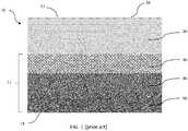
FIG. 1 is a cross-sectional elevation view of a porous structure as known in the prior art;FIG. 2 is a cross-sectional elevation view of a porous structure according to an embodiment; andFIG. 3 is a cross-sectional elevation view of a porous structure according to another embodiment.- Referring to
FIG. 1 ,porous structure 10, which is a component of a medical implant in accordance with the prior art, includesmonolithic metal insert 11 andbearing structure 20 defining bearingsurface 12 extending alongsuperior surface 16. The medical implant may be a tibial component, patellar component of a knee implant, glenoid component of a shoulder implant, an interbody fusion spinal implant, an intervertebral spinal implant, a wrist implant, a foot implant, an ankle implant, or an acetabular cup of a hip implant, as disclosed inU.S. Patent No 8,728,387 . Insert 11 includes porousfirst layer 50 defining outer,inferior surface 14,porous interlock layer 30, andintermediate layer 40 between and integral with the first layer and the interlock layer such that the intermediate layer is inseparable from the first layer and the interlock layer.Interlock layer 30 may have a porosity that allows for a flowable polymeric material to interdigitate into and adhere to the construct of the interlock layer.Bearing structure 20 may be made of any appropriate material, including ultra-high molecular weight polyethylene ("UHMWPE"), polyether ether ketone ("PEEK"), polyurethane, or other flowable polymer, that may be interdigitated intointerlock layer 30, such as by a compression molding process or an injection molding process. In this manner, the interlock layer acts as a bearing support structure that supports the polymeric material. As in the example shown,intermediate layer 40 may be solid or substantially solid such that bearingstructure 20 does not flow frominterlock layer 30 tofirst layer 50. In one example,porous structure 10 is a medical implant in whichfirst layer 50 is a bone ingrowth layer definingouter surface 14 that may be placed against bone stock. Generally, bearingsurface 12 ofbearing structure 20 is configured to contact a corresponding bearing surface of another component of the medical implant with reduced friction, relative to non-bearing surfaces, during relative movement, which may be either of or both translational and rotational movement, between the surfaces.- As represented in
FIG. 1 ,first layer 50,intermediate layer 40, andinterlock layer 30 are each of substantially uniform thicknesses, as measured along a longitudinal axis through each of these layers. As in the example shown, the thickness ofbearing structure 20 is often greater than the individual thicknesses of the other three layers to provide adequate strength for the bearing structure. - In preferred arrangements,
metallic insert 11 ofporous structure 10 may be formed, at least in part, in a layer-by-layer fashion using an additive layer manufacturing (ALM),i.e. 3D printing, process using a high energy beam, such as a laser beam or an electron beam. Such ALM processes preferably may be powder-bed based processes including selective laser sintering (SLS), selective laser melting (SLM), and electron beam melting (EBM), as disclosed inU.S. Patent Nos. 7,537,664 ("the '664 Patent") and9,456,901 insert 11 may be formed using the beam overlap process disclosed in the '664 Patent or may be formed through the use of unit cells as employed in the '901 Patent. In forminginsert 11, various metals and metal alloys may be employed including stainless steel, cobalt chromium alloys, titanium and its alloys, tantalum and niobium. Porous structure 10 may be fabricated at least in part by forming structures having solid or substantially solid as well as porous metallic layers using an additive manufacturing process. In this manner,metallic insert 11 may be made by building porousfirst layer 50,intermediate layer 40, andinterlock layer 30 in a continuous operation. The polymeric material is then attached to the metallic insert.- As in the example of
metallic insert 11, porousfirst layer 50 andinterlock layer 30 may be constructed of porous geometries which have been digitally modeled using unit cells, as further described inU.S. Patent Nos. 9,180,010 9,135,374 - The high energy beam may be an electron beam (e-beam) or laser beam and may be applied continuously to the powder or pulsed at a predetermined frequency. In some arrangements, the use of the laser or e-beam melting process may preclude the requirement for subsequent heat treatment of the structure fabricated by the additive manufacturing process. The high energy beam is emitted from a beam-generating apparatus to heat the metal powder sufficiently to sinter and preferably to at least partially melt or melt the metal powder. High energy beam generation equipment for manufacturing such structures may be one of many currently available including the MCP REALIZER, the EOS M270, TRUMPF TRUMAFORM 250, the ARCAM EBM S12, and the like. The beam generation equipment may also be a custom-produced laboratory device.
- The pore density, pore size and pore size distribution of the at least partially porous first and interlock layers can be controlled (varied) from one location on the structure to another. Successive powder layers may differ in porosity by varying factors used for scanning powder layers. The porosity of successive layers of powder can be varied by either creating a specific type of unit cell or manipulating various dimensions of a given unit cell. Further, the porosity of each structure is preferably dependent on the function of that structure.
- In producing porous
first layer 50 andinterlock layer 30, the nature of the material formed as a result of laser melting of powdered particles is principally dependent on the thermal profile involved (heating rate, soaking time, cooling rate); the condition of the raw material (size and size distribution of powder particles); and atmospheric conditions (reducing, inert or oxidizing chamber gas). - Porous
first layer 50 andinterlock layer 30 each may be modeled using a plurality of unit cells that are then filled by struts that may be attached at vertices of the unit cells to define modeled porous geometries. Many configurations of unit cells are possible to give the shape, type, degree and size of porosity required. Unit cell configurations may be dodecahedral, octahedral, diamond, as well as other various regular geometric shapes. Besides such regular geometric shapes, unit cells may be configured to have irregular shapes where various sides and dimensions have little if any repeating sequences. The modeled porous geometries within the unit cells may be configured to constructs that closely mimic the structure of trabecular bone for instance. Unit cells may be space filling, where all the space filled within a three-dimensional model of an object is filled with unit cells, or interconnected, where there may be some space left between cells but the cells are connected together by their edges. - The unit cells may be distributed within the construct in a number of ways. They may be made into a block within a computer automated design (CAD) system, i.e., the frame defining a boundary or boundaries within a CAD model, where the dimensions correspond to the extent of the solid geometry to be fabricated. This block may then be intersected with a wireframe geometry representing a component or other construct to be fabricated to produce a porous cellular representation of the geometry. The unit cells may be deformed so as to drape over an object as disclosed in the'901 Patent, and allow the unit cells to follow the surface of the geometry or so as to conform to the frame of the CAD model as disclosed in the '010 Patent. The cells may be populated through the geometry following the contours of the selected surface.
- Modifications to the dimensions of the struts can be used to control the mechanical strength of the porous geometries. Modifications can be in a number of key areas. The strut dimensions can be adjusted by careful selection of build parameters or specifically by changing any of the shape of the cross-section and the length of each strut. The density of the lattice can similarly be adjusted by modifying the density of the unit cells as can the extent and shape of porosity or a combination thereof. The overall design of the unit cells and their corresponding porous geometries will have an effect on the structural performance of a formed construct. For example, the use of dodecahedral unit cells will lead to different mechanical performance as compared with the use of tetrahedral unit cells.
- Depending on the material used to create
bearing structure 20, the polymeric material may be integrated withinterlock layer 30 by compression molding, injection molding, or a heat forming process. If the polymeric material to be used to form bearingstructure 20 is UHMWPE or the like, the metallic insert,i.e., thefirst layer 50,intermediate layer 40, and interlocklayer 30, but specifically theinterlock layer 30, may be joined to bearingstructure 20 by a compression molding process using a matched metal die. The metal insert is placed into a cavity part of a metal die. The polymer powder may then be added to the cavity of the metal die and desirably is dispersed against theinterlock layer 30. The cavity of the metal die is sealed and the metal die is then heated to a required temperature. As the temperature of the polymer powder is increased, the polymer powder begins to soften or melt so as to be flowable. Increased pressure onto the polymer powder may also aid in the melting process. Fusion of the polymer powder and attachment to interlocklayer 30 is achieved when the acquired application of heat and pressure is reached. Subsequent cooling under pressure allows solidification of the polymer powder, which thus forms bearingstructure 20 that is securely attached to interlocklayer 30. A final machining operation may be required to complete the construct of bearingstructure 20. - In an alternate embodiment, an injection molding process may be carried out in order to fuse the bearing
structure 20 to theinterlock layer 30. An injection molding process may be preferred when the material used to create the bearingstructure 20 is a polyurethane or chopped-fiber-reinforced poly (ETHERETHERKETONE) ("CFR-PEEK"). Similar to the compression molding process, in the injection molding process, the metal insert is secured into a cavity of an injection molding machine and the mold closed. The selected material, e.g., polyurethane or CFR-PEEK, is heated in a barrel of the injection molding machine. Once the selected material is heated in the barrel of the injection mold, the pressure may be applied to the selected material to urge the heated selected material from the barrel into the mold cavity and onto a surface ofinterlock layer 30. Upon cooling, the selected material is fused to interlocklayer 30 so as to form bearingstructure 20. Upon cooling, the completed part may be removed from the injection mold and machined if so required. The mold cavity may be configured such that particular features, designs and contours of bearingstructure 20 may be formed. - In yet another embodiment, the bearing
structure 20 may be formed using a heat forming process. In a heat forming process, materials such as UHMWPE, are supplied as fabricated rod stock suitable for machining. Profiles can be produced by machining the fabricated rod stock to represent a near net shape of intended bearingstructure 20. Once bearingstructure 20 has been produced, bothmetal insert 11 and the shaped polymer machine part are placed into a mold and heated to the required temperature. Upon application of heat and pressure, the softened polymer is forced into and against the metal insert, specifically interlocklayer 30. Upon cooling, solidification takes place and the polymer is secured to the metal insert and specifically interlocklayer 30. Further machining may be required if necessary once the part has been allowed to cool and is removed from the mold. - As shown in
FIG. 2 ,porous structure 110, which may be any one of the medical implants as described previously herein with respect toporous structure 10, extends from asuperior surface 116 to aninferior surface 114 opposite the superior surface and includesmonolithic insert 111 having porousfirst layer 150,intermediate layer 140, andporous interlock layer 130, which may be formed serially or simultaneously using an additive manufacturing process, such as those described previously herein with respect toporous structure 10.Porous structure 110 further includesnon-metallic bearing structure 120 attached to interlocklayer 130, which may be integrated with the interlock layer in the same manner as described above in reference toporous structure 10. First layer 150 may be a bone ingrowth layer having a porosity within a range that promotes bone ingrowth.Intermediate layer 140 may be substantially the same asintermediate layer 40 with the exception thatintermediate layer 140 includescentral region 146 andside regions 142 disposed on lateral sides of the central region that define a chamfered interior surface of the intermediate layer.Side region 142 includes outertop surface 143, which may be flat or substantially flat, and taperedsurface 144, which may be flat or substantially flat.Central region 146 is flat or substantially flat. Eachside region 142 has a thickness that varies at certain points within the side region. For example, the thickness ofside region 142 at a portion along outertop surface 143 is greater than a thickness of the side region at a portion along taperedsurface 144.Central region 146 has a thickness that is less than the thickness ofside regions 142. In other examples, taperedsurface 144 may be oriented at a variety of angles with respect to a horizontal axis ofporous structure 110, which in the example shown is parallel to outertop surface 143.- As further shown,
porous interlock layer 130 includescentral section 136, which lies along the entirety of the length ofcentral region 146 ofintermediate layer 140, andside sections 132, which lie along the entirety of the lengths ofrespective side regions 142 ofintermediate layer 140 on a side of the intermediate layer opposite the first layer.Side sections 132 andcentral section 136 togetherform base 133 ofinterlock layer 130. As shown in the illustrated embodiment,base 133 may have a substantially constant thickness, although in other arrangements, the thickness of the base may vary.Interlock layer 130 further includesprojection 131 projecting from eachside section 132.Projection 131 includesrim 131A extending outwardly fromwall 131B. As illustrated, the thickness ofprojection 131 may be greater than the thickness ofbase 133. In this manner,projection 131 reinforces the outer portion ofinterlock layer 130 to allow forthinner base 133 in the inner portion of the interlock layer. As in the example shown,projection 131 extends from a portion of outertop surface 143 and a portion of taperedsurface 144 ofside region 142. In some alternative arrangements having outer top surfaces and tapered surfaces, the projection may extend from the side region at only one of the outertop surface 143 or taperedsurface 144. In still other arrangements, the intermediate layer may not include a flat surface such that the projection may extend from only a tapered surface. Intermediate layer 140 is solid or substantially solid and thus provides a barrier between porousfirst layer 150 andporous interlock layer 130 such that when the polymeric material is molded intointerlock layer 130, the polymeric material does not seep through and into the first layer. As a result,first layer 150 maintains its porosity after the molding of the polymeric material. Such porosity is advantageous whenfirst layer 150 acts as a bone ingrowth layer for a medical implant.- Referring now to
FIG. 3 ,porous structure 210 is the same or substantially the same asporous structure 110 with the notable exception thatporous structure 210 includes porousfirst layer 250,intermediate layer 240,interlock layer 230, andbearing structure 220. In this example,porous structure 210 is the same asporous structure 110 with the exception that, as shown, bearingstructure 220 extends through the entire thickness ofintermediate layer 240 andfirst layer 250. Porous structure 210 includes a tapered surface similar to taperedsurface 144 ofintermediate layer 140 ofporous structure 110. However, taperedsurface 244 ofintermediate layer 240 extends through the entire thickness of the intermediate layer. As a result,intermediate layer 240 does not include a central region similar tocentral region 146 ofporous structure 110. Further, the tapered surface continues through the entire thickness offirst layer 250 such that the first layer includes taperedsurface 254. Thus,porous structure 210 has a maximum thickness equal to the thickness of bearingstructure 220.Projections porous structures interlock layer 130 ofporous structures interlock layer 130 ofporous structure 10. Further,projections porous structures Projections FIGS. 2 and3 , bearingstructures side regions 142 andprojections projections bearing structure - Advantageously, as in the examples of
FIGS. 2 and3 , bearingstructures porous structures porous structures porous structures - As shown in
FIGS. 2 and3 ,projections structures projections structures projections projections structures - The preferred pore size of
porous structures - Further, in another arrangement, a feature similar to
projections first layers - In another arrangement, a porous structure similar to
porous structure 210 may includeintermediate layer 240 continuing to extend alongfirst layer 250 between the first layer andinterlock layer 230, such that the intermediate layer is a barrier to prevent the polymeric material from seeping into the first layer. - Although
porous structures - In alternative arrangements of the porous structures described previously herein, including
porous structures first layer 150, a solid or substantially solid barrier section along an interface between the intermediate layer and the interlock layer, and a porous bridging section between both of the barrier sections or otherwise throughout the rest of the intermediate layer. In this manner, less material is used for the intermediate layer while at the same time still providing a barrier which may used, for example, to prevent polymeric material from seeping into the first layer. An example of such an intermediate layer is disclosed inU.S. Patent No 8,728,387 . - Furthermore, although the invention disclosed herein has been described with reference to particular features, it is to be understood that these features are merely illustrative of the principles and applications of the present invention. It is therefore to be understood that numerous modifications, including changes in the sizes of the various features described herein, may be made to the illustrative embodiments and that other arrangements may be devised without departing from the scope of the present invention, as defined by the claims below.
Claims (15)
- An orthopedic implant (110, 210) comprising:a porous insert (111, 211) having a first insert portion having a first insert thickness and a second insert portion having a second insert thickness and having a porous first layer (150, 250), an intermediate layer (140, 240) attached to the first layer, and a porous second layer (130, 230) attached to the intermediate layer on a side of the intermediate layer opposite the first layer; anda non-metallic structure (120, 220) having a first non-metallic portion having a first non-metallic thickness and a second non-metallic portion having a second non-metallic thickness, the first non-metallic portion being attached to the first insert portion and the second non-metallic portion being attached to the second insert portion,wherein either one or both of (i) the second insert thickness is different from the first insert thickness and (ii) the second non-metallic thickness is different from the first non-metallic thickness,the orthopedic implant (110, 210) beingcharacterized in that the second layer includes a base (133) having a base thickness and a porous projection (131, 231) extending from the base into the non-metallic structure and having a projection thickness greater than the base thickness, and wherein the first insert thickness, the second insert thickness, the first non-metallic thickness, the second non-metallic thickness, the base thickness, and the projection thickness are all defined in a same direction.
- The orthopedic implant of claim 1, wherein the porous projection of the porous insert has a perimeter surrounded by the non-metallic structure.
- The orthopedic implant of claim 1 or claim 2, wherein the first layer is a bone ingrowth layer having a porosity sufficient to promote bone ingrowth.
- The orthopedic implant of any one of the preceding claims, wherein the orthopedic implant includes a superior surface (114) and an inferior surface (116) opposite the superior surface, wherein the first, the intermediate, and the second layers and the non-metallic structure each have a maximum thickness defined in superior-inferior directions along an axis passing through the superior and the inferior surfaces, the maximum thickness of the non-metallic structure being greater than the thickness of each of the other layers.
- The orthopedic implant of claim 1, wherein the non-metallic structure is made of a polyethylene.
- The orthopedic implant of claim 1, wherein the orthopedic implant has a superior surface (114) and an inferior surface (116) opposite the superior surface, a section of the non-metallic structure extending from the superior surface to the inferior surface of the orthopedic implant.
- The orthopedic implant of claim 1, wherein the first non-metallic thickness is less than the second non-metallic thickness, and wherein the projection extends into the first non-metallic portion of the non-metallic structure.
- The orthopedic implant of any one of the preceding claims, wherein the insert includes a metallic tapered surface, and wherein the non-metallic structure includes a non-metallic tapered surface extending along the metallic tapered surface (144, 244) between the first non-metallic portion and the second non-metallic portion.
- The orthopedic implant of any one of the preceding claims, wherein the first insert portion and the second insert portion define an insert width, and wherein the non-metallic structure extends along the entirety of the insert width.
- The orthopedic implant of any one of the preceding claims, wherein the non-metallic structure is a bearing having a bearing surface.
- The orthopedic implant of any one of the preceding claims, wherein the orthopedic implant is a tibial component, a glenoid component, a patellar component, a wrist implant, a foot implant, an ankle implant, a spinal implant, or an acetabular cup.
- The orthopedic implant of any one of claims 1-6, wherein the first insert thickness and the second insert thickness are the same.
- The orthopedic implant of any one of claims 1-5, wherein the first non-metallic thickness and the second non-metallic thickness are the same.
- The orthopedic implant of any one of the preceding claims, wherein the porous insert is metallic and the intermediate layer prevents interdigitation of the non-metallic portion from the first layer to the second layer.
- The orthopedic implant of any one of claims 1-8, wherein the porous projection defines an outer edge of the second layer.
Applications Claiming Priority (1)
| Application Number | Priority Date | Filing Date | Title |
|---|---|---|---|
| US201762517456P | 2017-06-09 | 2017-06-09 |
Publications (2)
| Publication Number | Publication Date |
|---|---|
| EP3412252A1 EP3412252A1 (en) | 2018-12-12 |
| EP3412252B1true EP3412252B1 (en) | 2020-02-12 |
Family
ID=62567514
Family Applications (1)
| Application Number | Title | Priority Date | Filing Date |
|---|---|---|---|
| EP18176659.3AActiveEP3412252B1 (en) | 2017-06-09 | 2018-06-07 | Polymer interlock support structure |
Country Status (3)
| Country | Link |
|---|---|
| US (2) | US11400181B2 (en) |
| EP (1) | EP3412252B1 (en) |
| AU (1) | AU2018204123B2 (en) |
Cited By (4)
| Publication number | Priority date | Publication date | Assignee | Title |
|---|---|---|---|---|
| US12144739B2 (en) | 2014-01-03 | 2024-11-19 | Howmedica Osteonics Corp. | Reverse shoulder systems and methods |
| US12290447B2 (en) | 2011-02-01 | 2025-05-06 | Tornier Sas | Glenoid implant for a shoulder prosthesis, and surgical kit |
| US12329659B2 (en) | 2019-08-09 | 2025-06-17 | Howmedica Osteonics Corp. | Apparatuses and methods for implanting glenoid prostheses |
| US12396862B2 (en) | 2019-05-13 | 2025-08-26 | Howmedica Osteonics Corp. | Glenoid baseplate and implant assemblies |
Families Citing this family (8)
| Publication number | Priority date | Publication date | Assignee | Title |
|---|---|---|---|---|
| EP3412252B1 (en)* | 2017-06-09 | 2020-02-12 | Howmedica Osteonics Corp. | Polymer interlock support structure |
| US12220863B2 (en)* | 2019-04-11 | 2025-02-11 | Smith & Nephew, Inc. | Medical devices and methods for forming medical devices containing a build plate |
| US11540926B2 (en) | 2019-11-01 | 2023-01-03 | Stryker European Operations Limited | Implant for restoring height of a vertebral body |
| CA3205639A1 (en) | 2021-01-27 | 2022-08-04 | Jean-Francois Oglaza | Implant for restoring height of a vertebral body |
| WO2022174027A1 (en) | 2021-02-11 | 2022-08-18 | Howmedica Osteonics Corp. | Fixation mechanism for glenoid implants |
| US11944549B2 (en) | 2021-03-31 | 2024-04-02 | DePuy Synthes Products, Inc. | 3D printed monoblock orthopaedic surgical implant with customized patient-specific augment |
| WO2023208388A1 (en)* | 2022-04-29 | 2023-11-02 | Depuy Ireland Unlimited Company | Three-dimensional porous structures for bone ingrowth and methods for producing |
| WO2025083516A1 (en)* | 2023-10-18 | 2025-04-24 | Warsaw Orthopedic, Inc. | Polymer interbody device with metal endcaps and endplate grooves and manufacturing method thereof |
Family Cites Families (47)
| Publication number | Priority date | Publication date | Assignee | Title |
|---|---|---|---|---|
| US3906550A (en) | 1973-12-27 | 1975-09-23 | William Rostoker | Prosthetic device having a porous fiber metal structure |
| CA1227002A (en) | 1982-02-18 | 1987-09-22 | Robert V. Kenna | Bone prosthesis with porous coating |
| FR2595562B1 (en) | 1986-03-13 | 1992-08-28 | Rhenter Jean Luc | PROSTHESIS CUP |
| GB8718627D0 (en) | 1987-08-06 | 1987-09-09 | Showell A W Sugicraft Ltd | Spinal implants |
| US4944756A (en) | 1988-02-03 | 1990-07-31 | Pfizer Hospital Products Group | Prosthetic knee joint with improved patellar component tracking |
| US4919667A (en) | 1988-12-02 | 1990-04-24 | Stryker Corporation | Implant |
| US4997445A (en) | 1989-12-08 | 1991-03-05 | Zimmer, Inc. | Metal-backed prosthetic implant with enhanced bonding of polyethylene portion to metal base |
| GB9102348D0 (en) | 1991-02-04 | 1991-03-20 | Inst Of Orthopaedics The | Prosthesis for knee replacement |
| US5879398A (en) | 1995-02-14 | 1999-03-09 | Zimmer, Inc. | Acetabular cup |
| US6087553A (en)* | 1996-02-26 | 2000-07-11 | Implex Corporation | Implantable metallic open-celled lattice/polyethylene composite material and devices |
| DE19731442A1 (en) | 1997-07-22 | 1999-02-11 | Plus Endoprothetik Ag | Cup for a joint endoprosthesis |
| US7341602B2 (en) | 1999-05-10 | 2008-03-11 | Fell Barry M | Proportioned surgically implantable knee prosthesis |
| US6923831B2 (en) | 1999-05-10 | 2005-08-02 | Barry M. Fell | Surgically implantable knee prosthesis having attachment apertures |
| US6277150B1 (en) | 1999-06-11 | 2001-08-21 | Gore Enterprise Holdings, Inc. | Facial implant having one porous surface |
| US9314339B2 (en)* | 2000-03-27 | 2016-04-19 | Formae, Inc. | Implants for replacing cartilage, with negatively-charged hydrogel surfaces and flexible matrix reinforcement |
| US7597715B2 (en) | 2005-04-21 | 2009-10-06 | Biomet Manufacturing Corp. | Method and apparatus for use of porous implants |
| US7326253B2 (en) | 2001-11-16 | 2008-02-05 | Depuy Products, Inc. | Prosthetic cup assembly having increased assembly congruency |
| US20060147332A1 (en) | 2004-12-30 | 2006-07-06 | Howmedica Osteonics Corp. | Laser-produced porous structure |
| AU2003261497B2 (en) | 2002-11-08 | 2009-02-26 | Howmedica Osteonics Corp. | Laser-produced porous surface |
| US6994730B2 (en) | 2003-01-31 | 2006-02-07 | Howmedica Osteonics Corp. | Meniscal and tibial implants |
| US20040262809A1 (en)* | 2003-06-30 | 2004-12-30 | Smith Todd S. | Crosslinked polymeric composite for orthopaedic implants |
| EP1648348B1 (en) | 2003-07-24 | 2015-06-17 | Tecomet Inc. | Assembled non-random foams |
| US8500843B2 (en) | 2004-07-02 | 2013-08-06 | Praxis Powder Technology, Inc. | Controlled porosity article |
| US8728387B2 (en) | 2005-12-06 | 2014-05-20 | Howmedica Osteonics Corp. | Laser-produced porous surface |
| DE602007012654D1 (en) | 2006-01-13 | 2011-04-07 | Barry M Fell | SURGICAL IMPLANTED PROSTHESIS WITH AN ACTIVE COMPONENT |
| US20080167723A1 (en)* | 2006-03-20 | 2008-07-10 | Zimmer, Inc. | Prosthetic hip implants |
| WO2008088869A1 (en)* | 2007-01-19 | 2008-07-24 | Spinemedica Corporation | Methods and systems for forming implants with selectively exposed mesh for fixation |
| US20110035018A1 (en)* | 2007-09-25 | 2011-02-10 | Depuy Products, Inc. | Prosthesis with composite component |
| US20090112315A1 (en) | 2007-10-29 | 2009-04-30 | Zimmer, Inc. | Medical implants and methods for delivering biologically active agents |
| JP5571580B2 (en) | 2008-01-30 | 2014-08-13 | ジンマー,インコーポレイティド | Low rigidity orthopedic parts |
| US20100042226A1 (en) | 2008-08-13 | 2010-02-18 | Nebosky Paul S | Orthopaedic implant with spatially varying porosity |
| US8012216B2 (en)* | 2008-10-17 | 2011-09-06 | Biomet Manufacturing Corp. | High flexion tibial tray |
| US20110257753A1 (en) | 2009-04-02 | 2011-10-20 | Synvasive Technology, Inc. | Implant having a convex surface surrounding a concave articular surface |
| CN102470035A (en)* | 2009-06-30 | 2012-05-23 | 捷迈公司 | Screw thread placement in a porous medical device |
| GB0922339D0 (en) | 2009-12-21 | 2010-02-03 | Mcminn Derek J W | Acetabular cup prothesis and introducer thereof |
| IT1398443B1 (en) | 2010-02-26 | 2013-02-22 | Lima Lto S P A Ora Limacorporate Spa | INTEGRATED PROSTHETIC ELEMENT |
| WO2012021812A2 (en) | 2010-08-13 | 2012-02-16 | Smith & Nephew, Inc. | Patellar implants |
| CN101947149B (en) | 2010-10-08 | 2013-01-02 | 李亚东 | Artificial hip joint consisting of multilayer shell core composite structural components |
| US8911501B2 (en) | 2011-12-29 | 2014-12-16 | Mako Surgical Corp. | Cruciate-retaining tibial prosthesis |
| US9237950B2 (en) | 2012-02-02 | 2016-01-19 | Biomet Manufacturing, Llc | Implant with patient-specific porous structure |
| US9364896B2 (en) | 2012-02-07 | 2016-06-14 | Medical Modeling Inc. | Fabrication of hybrid solid-porous medical implantable devices with electron beam melting technology |
| US9135374B2 (en)* | 2012-04-06 | 2015-09-15 | Howmedica Osteonics Corp. | Surface modified unit cell lattice structures for optimized secure freeform fabrication |
| US9180010B2 (en) | 2012-04-06 | 2015-11-10 | Howmedica Osteonics Corp. | Surface modified unit cell lattice structures for optimized secure freeform fabrication |
| US9345578B2 (en) | 2013-02-22 | 2016-05-24 | Stryker Corporation | Bicruciate retaining tibial implant system |
| US9949837B2 (en)* | 2013-03-07 | 2018-04-24 | Howmedica Osteonics Corp. | Partially porous bone implant keel |
| CN105392450B (en) | 2013-03-15 | 2017-09-29 | 马科外科公司 | Tibial knee list condyle implant |
| EP3412252B1 (en)* | 2017-06-09 | 2020-02-12 | Howmedica Osteonics Corp. | Polymer interlock support structure |
- 2018
- 2018-06-07EPEP18176659.3Apatent/EP3412252B1/enactiveActive
- 2018-06-08AUAU2018204123Apatent/AU2018204123B2/enactiveActive
- 2018-06-08USUS16/003,411patent/US11400181B2/enactiveActive
- 2022
- 2022-07-21USUS17/870,005patent/US12263271B2/enactiveActive
Non-Patent Citations (1)
| Title |
|---|
| None* |
Cited By (4)
| Publication number | Priority date | Publication date | Assignee | Title |
|---|---|---|---|---|
| US12290447B2 (en) | 2011-02-01 | 2025-05-06 | Tornier Sas | Glenoid implant for a shoulder prosthesis, and surgical kit |
| US12144739B2 (en) | 2014-01-03 | 2024-11-19 | Howmedica Osteonics Corp. | Reverse shoulder systems and methods |
| US12396862B2 (en) | 2019-05-13 | 2025-08-26 | Howmedica Osteonics Corp. | Glenoid baseplate and implant assemblies |
| US12329659B2 (en) | 2019-08-09 | 2025-06-17 | Howmedica Osteonics Corp. | Apparatuses and methods for implanting glenoid prostheses |
Also Published As
| Publication number | Publication date |
|---|---|
| US20180353642A1 (en) | 2018-12-13 |
| US20220354989A1 (en) | 2022-11-10 |
| US12263271B2 (en) | 2025-04-01 |
| EP3412252A1 (en) | 2018-12-12 |
| AU2018204123B2 (en) | 2024-03-14 |
| US11400181B2 (en) | 2022-08-02 |
| AU2018204123A1 (en) | 2019-01-03 |
Similar Documents
| Publication | Publication Date | Title |
|---|---|---|
| EP3412252B1 (en) | Polymer interlock support structure | |
| US12011355B2 (en) | Laser-produced porous surface | |
| AU2019213392B2 (en) | Interbody implants and optimization features thereof | |
| US8350186B2 (en) | Laser-produced implants | |
| US20050100578A1 (en) | Bone and tissue scaffolding and method for producing same | |
| CA2529884A1 (en) | Laser-produced porous structure | |
| US20230380983A1 (en) | Spinal Interbody Implants | |
| EP4101563A2 (en) | Additive manufacturing of porous coatings separate from substrate | |
| AU2012216789B2 (en) | Laser-produced porous surface |
Legal Events
| Date | Code | Title | Description |
|---|---|---|---|
| PUAI | Public reference made under article 153(3) epc to a published international application that has entered the european phase | Free format text:ORIGINAL CODE: 0009012 | |
| STAA | Information on the status of an ep patent application or granted ep patent | Free format text:STATUS: THE APPLICATION HAS BEEN PUBLISHED | |
| AK | Designated contracting states | Kind code of ref document:A1 Designated state(s):AL AT BE BG CH CY CZ DE DK EE ES FI FR GB GR HR HU IE IS IT LI LT LU LV MC MK MT NL NO PL PT RO RS SE SI SK SM TR | |
| AX | Request for extension of the european patent | Extension state:BA ME | |
| STAA | Information on the status of an ep patent application or granted ep patent | Free format text:STATUS: REQUEST FOR EXAMINATION WAS MADE | |
| 17P | Request for examination filed | Effective date:20190612 | |
| GRAP | Despatch of communication of intention to grant a patent | Free format text:ORIGINAL CODE: EPIDOSNIGR1 | |
| RIC1 | Information provided on ipc code assigned before grant | Ipc:A61F 2/30 20060101AFI20190712BHEP | |
| STAA | Information on the status of an ep patent application or granted ep patent | Free format text:STATUS: GRANT OF PATENT IS INTENDED | |
| INTG | Intention to grant announced | Effective date:20190822 | |
| GRAS | Grant fee paid | Free format text:ORIGINAL CODE: EPIDOSNIGR3 | |
| GRAA | (expected) grant | Free format text:ORIGINAL CODE: 0009210 | |
| STAA | Information on the status of an ep patent application or granted ep patent | Free format text:STATUS: THE PATENT HAS BEEN GRANTED | |
| AK | Designated contracting states | Kind code of ref document:B1 Designated state(s):AL AT BE BG CH CY CZ DE DK EE ES FI FR GB GR HR HU IE IS IT LI LT LU LV MC MK MT NL NO PL PT RO RS SE SI SK SM TR | |
| REG | Reference to a national code | Ref country code:GB Ref legal event code:FG4D | |
| REG | Reference to a national code | Ref country code:CH Ref legal event code:EP | |
| REG | Reference to a national code | Ref country code:AT Ref legal event code:REF Ref document number:1231119 Country of ref document:AT Kind code of ref document:T Effective date:20200215 | |
| REG | Reference to a national code | Ref country code:IE Ref legal event code:FG4D | |
| REG | Reference to a national code | Ref country code:DE Ref legal event code:R096 Ref document number:602018002369 Country of ref document:DE | |
| PG25 | Lapsed in a contracting state [announced via postgrant information from national office to epo] | Ref country code:FI Free format text:LAPSE BECAUSE OF FAILURE TO SUBMIT A TRANSLATION OF THE DESCRIPTION OR TO PAY THE FEE WITHIN THE PRESCRIBED TIME-LIMIT Effective date:20200212 Ref country code:NO Free format text:LAPSE BECAUSE OF FAILURE TO SUBMIT A TRANSLATION OF THE DESCRIPTION OR TO PAY THE FEE WITHIN THE PRESCRIBED TIME-LIMIT Effective date:20200512 Ref country code:RS Free format text:LAPSE BECAUSE OF FAILURE TO SUBMIT A TRANSLATION OF THE DESCRIPTION OR TO PAY THE FEE WITHIN THE PRESCRIBED TIME-LIMIT Effective date:20200212 | |
| REG | Reference to a national code | Ref country code:LT Ref legal event code:MG4D | |
| REG | Reference to a national code | Ref country code:NL Ref legal event code:MP Effective date:20200212 | |
| PG25 | Lapsed in a contracting state [announced via postgrant information from national office to epo] | Ref country code:GR Free format text:LAPSE BECAUSE OF FAILURE TO SUBMIT A TRANSLATION OF THE DESCRIPTION OR TO PAY THE FEE WITHIN THE PRESCRIBED TIME-LIMIT Effective date:20200513 Ref country code:BG Free format text:LAPSE BECAUSE OF FAILURE TO SUBMIT A TRANSLATION OF THE DESCRIPTION OR TO PAY THE FEE WITHIN THE PRESCRIBED TIME-LIMIT Effective date:20200512 Ref country code:IS Free format text:LAPSE BECAUSE OF FAILURE TO SUBMIT A TRANSLATION OF THE DESCRIPTION OR TO PAY THE FEE WITHIN THE PRESCRIBED TIME-LIMIT Effective date:20200612 Ref country code:HR Free format text:LAPSE BECAUSE OF FAILURE TO SUBMIT A TRANSLATION OF THE DESCRIPTION OR TO PAY THE FEE WITHIN THE PRESCRIBED TIME-LIMIT Effective date:20200212 Ref country code:SE Free format text:LAPSE BECAUSE OF FAILURE TO SUBMIT A TRANSLATION OF THE DESCRIPTION OR TO PAY THE FEE WITHIN THE PRESCRIBED TIME-LIMIT Effective date:20200212 Ref country code:LV Free format text:LAPSE BECAUSE OF FAILURE TO SUBMIT A TRANSLATION OF THE DESCRIPTION OR TO PAY THE FEE WITHIN THE PRESCRIBED TIME-LIMIT Effective date:20200212 | |
| PG25 | Lapsed in a contracting state [announced via postgrant information from national office to epo] | Ref country code:NL Free format text:LAPSE BECAUSE OF FAILURE TO SUBMIT A TRANSLATION OF THE DESCRIPTION OR TO PAY THE FEE WITHIN THE PRESCRIBED TIME-LIMIT Effective date:20200212 | |
| PG25 | Lapsed in a contracting state [announced via postgrant information from national office to epo] | Ref country code:CZ Free format text:LAPSE BECAUSE OF FAILURE TO SUBMIT A TRANSLATION OF THE DESCRIPTION OR TO PAY THE FEE WITHIN THE PRESCRIBED TIME-LIMIT Effective date:20200212 Ref country code:PT Free format text:LAPSE BECAUSE OF FAILURE TO SUBMIT A TRANSLATION OF THE DESCRIPTION OR TO PAY THE FEE WITHIN THE PRESCRIBED TIME-LIMIT Effective date:20200705 Ref country code:RO Free format text:LAPSE BECAUSE OF FAILURE TO SUBMIT A TRANSLATION OF THE DESCRIPTION OR TO PAY THE FEE WITHIN THE PRESCRIBED TIME-LIMIT Effective date:20200212 Ref country code:ES Free format text:LAPSE BECAUSE OF FAILURE TO SUBMIT A TRANSLATION OF THE DESCRIPTION OR TO PAY THE FEE WITHIN THE PRESCRIBED TIME-LIMIT Effective date:20200212 Ref country code:SM Free format text:LAPSE BECAUSE OF FAILURE TO SUBMIT A TRANSLATION OF THE DESCRIPTION OR TO PAY THE FEE WITHIN THE PRESCRIBED TIME-LIMIT Effective date:20200212 Ref country code:EE Free format text:LAPSE BECAUSE OF FAILURE TO SUBMIT A TRANSLATION OF THE DESCRIPTION OR TO PAY THE FEE WITHIN THE PRESCRIBED TIME-LIMIT Effective date:20200212 Ref country code:LT Free format text:LAPSE BECAUSE OF FAILURE TO SUBMIT A TRANSLATION OF THE DESCRIPTION OR TO PAY THE FEE WITHIN THE PRESCRIBED TIME-LIMIT Effective date:20200212 Ref country code:SK Free format text:LAPSE BECAUSE OF FAILURE TO SUBMIT A TRANSLATION OF THE DESCRIPTION OR TO PAY THE FEE WITHIN THE PRESCRIBED TIME-LIMIT Effective date:20200212 Ref country code:DK Free format text:LAPSE BECAUSE OF FAILURE TO SUBMIT A TRANSLATION OF THE DESCRIPTION OR TO PAY THE FEE WITHIN THE PRESCRIBED TIME-LIMIT Effective date:20200212 | |
| REG | Reference to a national code | Ref country code:DE Ref legal event code:R097 Ref document number:602018002369 Country of ref document:DE | |
| REG | Reference to a national code | Ref country code:AT Ref legal event code:MK05 Ref document number:1231119 Country of ref document:AT Kind code of ref document:T Effective date:20200212 | |
| PLBE | No opposition filed within time limit | Free format text:ORIGINAL CODE: 0009261 | |
| STAA | Information on the status of an ep patent application or granted ep patent | Free format text:STATUS: NO OPPOSITION FILED WITHIN TIME LIMIT | |
| 26N | No opposition filed | Effective date:20201113 | |
| PG25 | Lapsed in a contracting state [announced via postgrant information from national office to epo] | Ref country code:MC Free format text:LAPSE BECAUSE OF FAILURE TO SUBMIT A TRANSLATION OF THE DESCRIPTION OR TO PAY THE FEE WITHIN THE PRESCRIBED TIME-LIMIT Effective date:20200212 Ref country code:IT Free format text:LAPSE BECAUSE OF FAILURE TO SUBMIT A TRANSLATION OF THE DESCRIPTION OR TO PAY THE FEE WITHIN THE PRESCRIBED TIME-LIMIT Effective date:20200212 Ref country code:AT Free format text:LAPSE BECAUSE OF FAILURE TO SUBMIT A TRANSLATION OF THE DESCRIPTION OR TO PAY THE FEE WITHIN THE PRESCRIBED TIME-LIMIT Effective date:20200212 | |
| PG25 | Lapsed in a contracting state [announced via postgrant information from national office to epo] | Ref country code:PL Free format text:LAPSE BECAUSE OF FAILURE TO SUBMIT A TRANSLATION OF THE DESCRIPTION OR TO PAY THE FEE WITHIN THE PRESCRIBED TIME-LIMIT Effective date:20200212 Ref country code:SI Free format text:LAPSE BECAUSE OF FAILURE TO SUBMIT A TRANSLATION OF THE DESCRIPTION OR TO PAY THE FEE WITHIN THE PRESCRIBED TIME-LIMIT Effective date:20200212 | |
| PG25 | Lapsed in a contracting state [announced via postgrant information from national office to epo] | Ref country code:LU Free format text:LAPSE BECAUSE OF NON-PAYMENT OF DUE FEES Effective date:20200607 | |
| REG | Reference to a national code | Ref country code:BE Ref legal event code:MM Effective date:20200630 | |
| PG25 | Lapsed in a contracting state [announced via postgrant information from national office to epo] | Ref country code:BE Free format text:LAPSE BECAUSE OF NON-PAYMENT OF DUE FEES Effective date:20200630 | |
| PG25 | Lapsed in a contracting state [announced via postgrant information from national office to epo] | Ref country code:TR Free format text:LAPSE BECAUSE OF FAILURE TO SUBMIT A TRANSLATION OF THE DESCRIPTION OR TO PAY THE FEE WITHIN THE PRESCRIBED TIME-LIMIT Effective date:20200212 Ref country code:MT Free format text:LAPSE BECAUSE OF FAILURE TO SUBMIT A TRANSLATION OF THE DESCRIPTION OR TO PAY THE FEE WITHIN THE PRESCRIBED TIME-LIMIT Effective date:20200212 Ref country code:CY Free format text:LAPSE BECAUSE OF FAILURE TO SUBMIT A TRANSLATION OF THE DESCRIPTION OR TO PAY THE FEE WITHIN THE PRESCRIBED TIME-LIMIT Effective date:20200212 | |
| PG25 | Lapsed in a contracting state [announced via postgrant information from national office to epo] | Ref country code:MK Free format text:LAPSE BECAUSE OF FAILURE TO SUBMIT A TRANSLATION OF THE DESCRIPTION OR TO PAY THE FEE WITHIN THE PRESCRIBED TIME-LIMIT Effective date:20200212 Ref country code:AL Free format text:LAPSE BECAUSE OF FAILURE TO SUBMIT A TRANSLATION OF THE DESCRIPTION OR TO PAY THE FEE WITHIN THE PRESCRIBED TIME-LIMIT Effective date:20200212 | |
| P01 | Opt-out of the competence of the unified patent court (upc) registered | Effective date:20230522 | |
| PGFP | Annual fee paid to national office [announced via postgrant information from national office to epo] | Ref country code:CH Payment date:20240701 Year of fee payment:7 | |
| PGFP | Annual fee paid to national office [announced via postgrant information from national office to epo] | Ref country code:DE Payment date:20250402 Year of fee payment:8 | |
| PGFP | Annual fee paid to national office [announced via postgrant information from national office to epo] | Ref country code:GB Payment date:20250401 Year of fee payment:8 | |
| PGFP | Annual fee paid to national office [announced via postgrant information from national office to epo] | Ref country code:FR Payment date:20250401 Year of fee payment:8 | |
| PGFP | Annual fee paid to national office [announced via postgrant information from national office to epo] | Ref country code:IE Payment date:20250402 Year of fee payment:8 |