EP3409214A2 - Self-retaining sutures for surgical procedures - Google Patents
Self-retaining sutures for surgical proceduresDownload PDFInfo
- Publication number
- EP3409214A2 EP3409214A2EP18181513.5AEP18181513AEP3409214A2EP 3409214 A2EP3409214 A2EP 3409214A2EP 18181513 AEP18181513 AEP 18181513AEP 3409214 A2EP3409214 A2EP 3409214A2
- Authority
- EP
- European Patent Office
- Prior art keywords
- suture
- retainer
- retainers
- primary
- tissue
- Prior art date
- Legal status (The legal status is an assumption and is not a legal conclusion. Google has not performed a legal analysis and makes no representation as to the accuracy of the status listed.)
- Withdrawn
Links
- 238000001356surgical procedureMethods0.000titleabstractdescription29
- 230000007704transitionEffects0.000claimsdescription71
- 230000000149penetrating effectEffects0.000claimsdescription63
- 239000003795chemical substances by applicationSubstances0.000claimsdescription38
- 229920000642polymerPolymers0.000claimsdescription27
- 238000000576coating methodMethods0.000claimsdescription20
- 239000000203mixtureSubstances0.000claimsdescription19
- 239000000463materialSubstances0.000claimsdescription18
- 239000011248coating agentSubstances0.000claimsdescription13
- 206010016654FibrosisDiseases0.000claimsdescription7
- 229940035676analgesicsDrugs0.000claimsdescription7
- 239000000730antalgic agentSubstances0.000claimsdescription7
- 230000001028anti-proliverative effectEffects0.000claimsdescription7
- 229960005475antiinfective agentDrugs0.000claimsdescription7
- 239000004599antimicrobialSubstances0.000claimsdescription7
- 230000004761fibrosisEffects0.000claimsdescription7
- 230000001939inductive effectEffects0.000claimsdescription7
- 229940123587Cell cycle inhibitorDrugs0.000claimsdescription6
- 239000002260anti-inflammatory agentSubstances0.000claimsdescription6
- 229940121363anti-inflammatory agentDrugs0.000claimsdescription6
- 239000004037angiogenesis inhibitorSubstances0.000claimsdescription5
- 229940044684anti-microtubule agentDrugs0.000claimsdescription4
- 238000000034methodMethods0.000abstractdescription88
- 238000004519manufacturing processMethods0.000abstractdescription20
- 210000001519tissueAnatomy0.000description264
- 238000005520cutting processMethods0.000description205
- 208000027418Wounds and injuryDiseases0.000description62
- 206010052428WoundDiseases0.000description61
- 230000002457bidirectional effectEffects0.000description38
- 230000007246mechanismEffects0.000description34
- 239000011295pitchSubstances0.000description25
- 239000003356suture materialSubstances0.000description21
- 230000033001locomotionEffects0.000description17
- 230000001965increasing effectEffects0.000description14
- 238000013519translationMethods0.000description11
- 230000035876healingEffects0.000description10
- 230000000694effectsEffects0.000description9
- 238000000227grindingMethods0.000description9
- 238000006073displacement reactionMethods0.000description8
- 210000000887faceAnatomy0.000description8
- 230000008439repair processEffects0.000description8
- 230000008901benefitEffects0.000description7
- -1polytetrafluoroethylenePolymers0.000description7
- 230000006870functionEffects0.000description6
- 239000007943implantSubstances0.000description6
- RKDVKSZUMVYZHH-UHFFFAOYSA-N1,4-dioxane-2,5-dioneChemical compoundO=C1COC(=O)CO1RKDVKSZUMVYZHH-UHFFFAOYSA-N0.000description5
- 229920001577copolymerPolymers0.000description5
- 230000001815facial effectEffects0.000description5
- 241001465754MetazoaSpecies0.000description4
- 208000002847Surgical WoundDiseases0.000description4
- 238000013461designMethods0.000description4
- 238000009826distributionMethods0.000description4
- 238000009472formulationMethods0.000description4
- 210000003041ligamentAnatomy0.000description4
- 238000002406microsurgeryMethods0.000description4
- 230000008569processEffects0.000description4
- 230000000472traumatic effectEffects0.000description4
- YFHICDDUDORKJB-UHFFFAOYSA-Ntrimethylene carbonateChemical compoundO=C1OCCCO1YFHICDDUDORKJB-UHFFFAOYSA-N0.000description4
- 239000003082abrasive agentSubstances0.000description3
- 210000000481breastAnatomy0.000description3
- 238000012668chain scissionMethods0.000description3
- 230000008859changeEffects0.000description3
- 239000002537cosmeticSubstances0.000description3
- 230000007423decreaseEffects0.000description3
- MTHSVFCYNBDYFN-UHFFFAOYSA-Ndiethylene glycolChemical compoundOCCOCCOMTHSVFCYNBDYFN-UHFFFAOYSA-N0.000description3
- 238000001125extrusionMethods0.000description3
- 208000015181infectious diseaseDiseases0.000description3
- 208000014674injuryDiseases0.000description3
- 230000003993interactionEffects0.000description3
- 238000005304joiningMethods0.000description3
- 239000002184metalSubstances0.000description3
- 229910052751metalInorganic materials0.000description3
- 229920002635polyurethanePolymers0.000description3
- 239000004814polyurethaneSubstances0.000description3
- 230000009467reductionEffects0.000description3
- 238000009877renderingMethods0.000description3
- 210000004872soft tissueAnatomy0.000description3
- 229910001220stainless steelInorganic materials0.000description3
- VPVXHAANQNHFSF-UHFFFAOYSA-N1,4-dioxan-2-oneChemical compoundO=C1COCCO1VPVXHAANQNHFSF-UHFFFAOYSA-N0.000description2
- 208000010392Bone FracturesDiseases0.000description2
- 102000008186CollagenHuman genes0.000description2
- 108010035532CollagenProteins0.000description2
- 229920000742CottonPolymers0.000description2
- AEMRFAOFKBGASW-UHFFFAOYSA-NGlycolic acidChemical compoundOCC(O)=OAEMRFAOFKBGASW-UHFFFAOYSA-N0.000description2
- 239000004677NylonSubstances0.000description2
- 239000004952PolyamideSubstances0.000description2
- 239000004743PolypropyleneSubstances0.000description2
- 230000009471actionEffects0.000description2
- 238000007792additionMethods0.000description2
- 238000013459approachMethods0.000description2
- 239000000560biocompatible materialSubstances0.000description2
- 230000015572biosynthetic processEffects0.000description2
- 210000000988bone and boneAnatomy0.000description2
- 230000015556catabolic processEffects0.000description2
- 239000000919ceramicSubstances0.000description2
- 238000006243chemical reactionMethods0.000description2
- 229920001436collagenPolymers0.000description2
- 150000001875compoundsChemical class0.000description2
- 230000006378damageEffects0.000description2
- 230000007547defectEffects0.000description2
- 238000006731degradation reactionMethods0.000description2
- 229940079593drugDrugs0.000description2
- 239000003814drugSubstances0.000description2
- 230000007247enzymatic mechanismEffects0.000description2
- 230000003628erosive effectEffects0.000description2
- 238000005227gel permeation chromatographyMethods0.000description2
- 230000007062hydrolysisEffects0.000description2
- 238000006460hydrolysis reactionMethods0.000description2
- 230000008595infiltrationEffects0.000description2
- 238000001764infiltrationMethods0.000description2
- 208000028867ischemiaDiseases0.000description2
- JVTAAEKCZFNVCJ-UHFFFAOYSA-Nlactic acidChemical compoundCC(O)C(O)=OJVTAAEKCZFNVCJ-UHFFFAOYSA-N0.000description2
- JJTUDXZGHPGLLC-UHFFFAOYSA-NlactideChemical compoundCC1OC(=O)C(C)OC1=OJJTUDXZGHPGLLC-UHFFFAOYSA-N0.000description2
- 230000014759maintenance of locationEffects0.000description2
- 229910001092metal group alloyInorganic materials0.000description2
- 239000007769metal materialSubstances0.000description2
- 230000004048modificationEffects0.000description2
- 238000012986modificationMethods0.000description2
- 210000003205muscleAnatomy0.000description2
- 229920001778nylonPolymers0.000description2
- 210000000056organAnatomy0.000description2
- 230000003647oxidationEffects0.000description2
- 238000007254oxidation reactionMethods0.000description2
- 230000035515penetrationEffects0.000description2
- 229920002647polyamidePolymers0.000description2
- 229920001155polypropylenePolymers0.000description2
- 229920001343polytetrafluoroethylenePolymers0.000description2
- 239000004810polytetrafluoroethyleneSubstances0.000description2
- 238000002278reconstructive surgeryMethods0.000description2
- 230000036573scar formationEffects0.000description2
- 230000037390scarringEffects0.000description2
- 230000003319supportive effectEffects0.000description2
- 210000002435tendonAnatomy0.000description2
- 230000017423tissue regenerationEffects0.000description2
- 238000012546transferMethods0.000description2
- 238000011282treatmentMethods0.000description2
- KIUKXJAPPMFGSW-DNGZLQJQSA-N(2S,3S,4S,5R,6R)-6-[(2S,3R,4R,5S,6R)-3-Acetamido-2-[(2S,3S,4R,5R,6R)-6-[(2R,3R,4R,5S,6R)-3-acetamido-2,5-dihydroxy-6-(hydroxymethyl)oxan-4-yl]oxy-2-carboxy-4,5-dihydroxyoxan-3-yl]oxy-5-hydroxy-6-(hydroxymethyl)oxan-4-yl]oxy-3,4,5-trihydroxyoxane-2-carboxylic acidChemical compoundCC(=O)N[C@H]1[C@H](O)O[C@H](CO)[C@@H](O)[C@@H]1O[C@H]1[C@H](O)[C@@H](O)[C@H](O[C@H]2[C@@H]([C@@H](O[C@H]3[C@@H]([C@@H](O)[C@H](O)[C@H](O3)C(O)=O)O)[C@H](O)[C@@H](CO)O2)NC(C)=O)[C@@H](C(O)=O)O1KIUKXJAPPMFGSW-DNGZLQJQSA-N0.000description1
- WSQZNZLOZXSBHA-UHFFFAOYSA-N3,8-dioxabicyclo[8.2.2]tetradeca-1(12),10,13-triene-2,9-dioneChemical compoundO=C1OCCCCOC(=O)C2=CC=C1C=C2WSQZNZLOZXSBHA-UHFFFAOYSA-N0.000description1
- 206010002091AnaesthesiaDiseases0.000description1
- 241000894006BacteriaSpecies0.000description1
- 208000002177CataractDiseases0.000description1
- 206010009269Cleft palateDiseases0.000description1
- 208000035473Communicable diseaseDiseases0.000description1
- 206010010356Congenital anomalyDiseases0.000description1
- 206010074180Craniofacial deformityDiseases0.000description1
- 208000000193Dentofacial DeformitiesDiseases0.000description1
- 241001481760Erethizon dorsatumSpecies0.000description1
- 206010016717FistulaDiseases0.000description1
- 206010019909HerniaDiseases0.000description1
- 102100026933Myelin-associated neurite-outgrowth inhibitorHuman genes0.000description1
- 206010028980NeoplasmDiseases0.000description1
- 229920002292Nylon 6Polymers0.000description1
- 208000007871Odontogenic TumorsDiseases0.000description1
- 239000004698PolyethyleneSubstances0.000description1
- 229920000954PolyglycolidePolymers0.000description1
- 206010061363Skeletal injuryDiseases0.000description1
- RTAQQCXQSZGOHL-UHFFFAOYSA-NTitaniumChemical compound[Ti]RTAQQCXQSZGOHL-UHFFFAOYSA-N0.000description1
- 210000001015abdomenAnatomy0.000description1
- 239000002253acidSubstances0.000description1
- 239000000853adhesiveSubstances0.000description1
- 230000001070adhesive effectEffects0.000description1
- 210000000577adipose tissueAnatomy0.000description1
- 230000037005anaesthesiaEffects0.000description1
- 230000003872anastomosisEffects0.000description1
- 238000004873anchoringMethods0.000description1
- 210000001557animal structureAnatomy0.000description1
- 230000002924anti-infective effectEffects0.000description1
- 230000000712assemblyEffects0.000description1
- 238000000429assemblyMethods0.000description1
- 230000003416augmentationEffects0.000description1
- 229920001400block copolymerPolymers0.000description1
- 230000017531blood circulationEffects0.000description1
- 239000004067bulking agentSubstances0.000description1
- 210000001217buttockAnatomy0.000description1
- 150000001720carbohydratesChemical class0.000description1
- 235000014633carbohydratesNutrition0.000description1
- 239000002729catgutSubstances0.000description1
- 230000001413cellular effectEffects0.000description1
- 210000000038chestAnatomy0.000description1
- 206010009259cleft lipDiseases0.000description1
- 230000001010compromised effectEffects0.000description1
- 239000012141concentrateSubstances0.000description1
- 238000002788crimpingMethods0.000description1
- 230000003247decreasing effectEffects0.000description1
- 230000023753dehiscenceEffects0.000description1
- 239000004053dental implantSubstances0.000description1
- 230000000994depressogenic effectEffects0.000description1
- 238000007598dipping methodMethods0.000description1
- 201000010099diseaseDiseases0.000description1
- 208000037265diseases, disorders, signs and symptomsDiseases0.000description1
- 230000008030eliminationEffects0.000description1
- 238000003379elimination reactionMethods0.000description1
- 230000002708enhancing effectEffects0.000description1
- 229920000295expanded polytetrafluoroethylenePolymers0.000description1
- 210000003054facial boneAnatomy0.000description1
- 210000003195fasciaAnatomy0.000description1
- 210000004996female reproductive systemAnatomy0.000description1
- 210000002950fibroblastAnatomy0.000description1
- 230000003890fistulaEffects0.000description1
- 238000007667floatingMethods0.000description1
- 230000004927fusionEffects0.000description1
- 230000002068genetic effectEffects0.000description1
- 230000005484gravityEffects0.000description1
- 230000012010growthEffects0.000description1
- 238000001631haemodialysisMethods0.000description1
- 230000036541healthEffects0.000description1
- 210000003709heart valveAnatomy0.000description1
- 230000000322hemodialysisEffects0.000description1
- 229920002674hyaluronanPolymers0.000description1
- 229960003160hyaluronic acidDrugs0.000description1
- 239000000017hydrogelSubstances0.000description1
- 230000001771impaired effectEffects0.000description1
- 238000011065in-situ storageMethods0.000description1
- 238000001746injection mouldingMethods0.000description1
- 238000003780insertionMethods0.000description1
- 230000037431insertionEffects0.000description1
- 230000007794irritationEffects0.000description1
- 210000001503jointAnatomy0.000description1
- 235000014655lactic acidNutrition0.000description1
- 239000004310lactic acidSubstances0.000description1
- 238000003698laser cuttingMethods0.000description1
- 230000000670limiting effectEffects0.000description1
- 210000004995male reproductive systemAnatomy0.000description1
- 239000011159matrix materialSubstances0.000description1
- 230000001404mediated effectEffects0.000description1
- 150000002739metalsChemical class0.000description1
- 239000012229microporous materialSubstances0.000description1
- 238000002324minimally invasive surgeryMethods0.000description1
- 239000000178monomerSubstances0.000description1
- 230000000399orthopedic effectEffects0.000description1
- 230000036407painEffects0.000description1
- 206010033675panniculitisDiseases0.000description1
- 230000036961partial effectEffects0.000description1
- 210000004197pelvisAnatomy0.000description1
- 210000000578peripheral nerveAnatomy0.000description1
- 230000035790physiological processes and functionsEffects0.000description1
- 239000004033plasticSubstances0.000description1
- 229920003023plasticPolymers0.000description1
- 229920001606poly(lactic acid-co-glycolic acid)Polymers0.000description1
- 229920000728polyesterPolymers0.000description1
- 229920000573polyethylenePolymers0.000description1
- 239000004633polyglycolic acidSubstances0.000description1
- 239000004626polylactic acidSubstances0.000description1
- 238000012667polymer degradationMethods0.000description1
- 229920000909polytetrahydrofuranPolymers0.000description1
- 239000011148porous materialSubstances0.000description1
- 102000004169proteins and genesHuman genes0.000description1
- 108090000623proteins and genesProteins0.000description1
- 230000004044responseEffects0.000description1
- 230000000284resting effectEffects0.000description1
- 230000002207retinal effectEffects0.000description1
- 230000002441reversible effectEffects0.000description1
- 238000007665saggingMethods0.000description1
- 210000003752saphenous veinAnatomy0.000description1
- 231100000241scarToxicity0.000description1
- 239000000565sealantSubstances0.000description1
- 238000000926separation methodMethods0.000description1
- 238000009958sewingMethods0.000description1
- 229910052710siliconInorganic materials0.000description1
- 239000010703siliconSubstances0.000description1
- 238000004513sizingMethods0.000description1
- 239000000243solutionSubstances0.000description1
- 238000005507sprayingMethods0.000description1
- 239000010935stainless steelSubstances0.000description1
- 238000007920subcutaneous administrationMethods0.000description1
- 210000004304subcutaneous tissueAnatomy0.000description1
- 239000000126substanceSubstances0.000description1
- 150000003467sulfuric acid derivativesChemical class0.000description1
- 230000003874surgical anastomosisEffects0.000description1
- 208000024891symptomDiseases0.000description1
- 230000002195synergetic effectEffects0.000description1
- 229920002994synthetic fiberPolymers0.000description1
- 230000002123temporal effectEffects0.000description1
- 229920001897terpolymerPolymers0.000description1
- 230000009772tissue formationEffects0.000description1
- 239000002407tissue scaffoldSubstances0.000description1
- 229910052719titaniumInorganic materials0.000description1
- 239000010936titaniumSubstances0.000description1
- 230000008733traumaEffects0.000description1
- 230000008736traumatic injuryEffects0.000description1
- 210000000689upper legAnatomy0.000description1
- 230000002792vascularEffects0.000description1
- 230000029663wound healingEffects0.000description1
- PAPBSGBWRJIAAV-UHFFFAOYSA-Nε-CaprolactoneChemical compoundO=C1CCCCCO1PAPBSGBWRJIAAV-UHFFFAOYSA-N0.000description1
Images


Classifications
- A—HUMAN NECESSITIES
- A61—MEDICAL OR VETERINARY SCIENCE; HYGIENE
- A61L—METHODS OR APPARATUS FOR STERILISING MATERIALS OR OBJECTS IN GENERAL; DISINFECTION, STERILISATION OR DEODORISATION OF AIR; CHEMICAL ASPECTS OF BANDAGES, DRESSINGS, ABSORBENT PADS OR SURGICAL ARTICLES; MATERIALS FOR BANDAGES, DRESSINGS, ABSORBENT PADS OR SURGICAL ARTICLES
- A61L33/00—Antithrombogenic treatment of surgical articles, e.g. sutures, catheters, prostheses, or of articles for the manipulation or conditioning of blood; Materials for such treatment
- A—HUMAN NECESSITIES
- A61—MEDICAL OR VETERINARY SCIENCE; HYGIENE
- A61B—DIAGNOSIS; SURGERY; IDENTIFICATION
- A61B17/00—Surgical instruments, devices or methods
- A61B17/04—Surgical instruments, devices or methods for suturing wounds; Holders or packages for needles or suture materials
- A61B17/06—Needles ; Sutures; Needle-suture combinations; Holders or packages for needles or suture materials
- A61B17/06166—Sutures
- A—HUMAN NECESSITIES
- A61—MEDICAL OR VETERINARY SCIENCE; HYGIENE
- A61B—DIAGNOSIS; SURGERY; IDENTIFICATION
- A61B17/00—Surgical instruments, devices or methods
- A61B17/064—Surgical staples, i.e. penetrating the tissue
- A—HUMAN NECESSITIES
- A61—MEDICAL OR VETERINARY SCIENCE; HYGIENE
- A61B—DIAGNOSIS; SURGERY; IDENTIFICATION
- A61B17/00—Surgical instruments, devices or methods
- A61B17/04—Surgical instruments, devices or methods for suturing wounds; Holders or packages for needles or suture materials
- A61B17/0469—Suturing instruments for use in minimally invasive surgery, e.g. endoscopic surgery
- A—HUMAN NECESSITIES
- A61—MEDICAL OR VETERINARY SCIENCE; HYGIENE
- A61B—DIAGNOSIS; SURGERY; IDENTIFICATION
- A61B17/00—Surgical instruments, devices or methods
- A61B2017/00526—Methods of manufacturing
- A—HUMAN NECESSITIES
- A61—MEDICAL OR VETERINARY SCIENCE; HYGIENE
- A61B—DIAGNOSIS; SURGERY; IDENTIFICATION
- A61B17/00—Surgical instruments, devices or methods
- A61B17/04—Surgical instruments, devices or methods for suturing wounds; Holders or packages for needles or suture materials
- A61B17/06—Needles ; Sutures; Needle-suture combinations; Holders or packages for needles or suture materials
- A61B2017/06057—Double-armed sutures, i.e. sutures having a needle attached to each end
- A—HUMAN NECESSITIES
- A61—MEDICAL OR VETERINARY SCIENCE; HYGIENE
- A61B—DIAGNOSIS; SURGERY; IDENTIFICATION
- A61B17/00—Surgical instruments, devices or methods
- A61B17/04—Surgical instruments, devices or methods for suturing wounds; Holders or packages for needles or suture materials
- A61B17/06—Needles ; Sutures; Needle-suture combinations; Holders or packages for needles or suture materials
- A61B17/06166—Sutures
- A61B2017/06176—Sutures with protrusions, e.g. barbs
- Y—GENERAL TAGGING OF NEW TECHNOLOGICAL DEVELOPMENTS; GENERAL TAGGING OF CROSS-SECTIONAL TECHNOLOGIES SPANNING OVER SEVERAL SECTIONS OF THE IPC; TECHNICAL SUBJECTS COVERED BY FORMER USPC CROSS-REFERENCE ART COLLECTIONS [XRACs] AND DIGESTS
- Y10—TECHNICAL SUBJECTS COVERED BY FORMER USPC
- Y10T—TECHNICAL SUBJECTS COVERED BY FORMER US CLASSIFICATION
- Y10T29/00—Metal working
- Y10T29/49—Method of mechanical manufacture
- Y10T29/49995—Shaping one-piece blank by removing material
- Y—GENERAL TAGGING OF NEW TECHNOLOGICAL DEVELOPMENTS; GENERAL TAGGING OF CROSS-SECTIONAL TECHNOLOGIES SPANNING OVER SEVERAL SECTIONS OF THE IPC; TECHNICAL SUBJECTS COVERED BY FORMER USPC CROSS-REFERENCE ART COLLECTIONS [XRACs] AND DIGESTS
- Y10—TECHNICAL SUBJECTS COVERED BY FORMER USPC
- Y10T—TECHNICAL SUBJECTS COVERED BY FORMER US CLASSIFICATION
- Y10T83/00—Cutting
- Y10T83/02—Other than completely through work thickness
Definitions
- the present inventionrelates generally to self-retaining systems for surgical procedures, methods of manufacturing self-retaining systems for surgical procedures, and their uses.
- Wound closure devicessuch as sutures and staples have been widely used in superficial and deep surgical procedures in humans and animals for closing wounds, repairing traumatic injuries or defects, joining tissues together [bringing severed tissues into approximation, closing an anatomical space, affixing single or multiple tissue layers together, creating anastomoses between two hollow (luminal) structures, adjoining tissues, attaching or reattaching tissues to their proper anatomical location], attaching foreign elements to tissues (affixing medical implants, devices, prostheses and other functional or supportive devices), and for repositioning tissues to new anatomical locations (repairs, tissue elevations, tissue grafting and related procedures) to name but a few examples.
- Suturestypically consist of a filamentous suture thread attached to a needle with a sharp point (attachment of sutures and surgical needles is described in U.S. Patent Nos. 3,981,307 , 5,084,063 , 5,102,418 , 5,123,911 , 5,500,991 , 5,722,991 , 6,012,216 , and 6,163,948 , and U.S. Patent Application Publication No. U.S. 2004/0088003 ).
- the needleis advanced through the desired tissue on one side of the wound and then through the adjacent side of the wound to form a "loop" which is then completed by tying a knot in the suture.
- Sutures materialsare broadly classified as being bioabsorbable (i.e., they break down completely in the body over time), such as those composed of catgut, glycolic acid polymers and copolymers, lactic acid polymers and copolymers; or as being non-absorbable (permanent; nondegradable), such as those made of polyamide, polytetrafluoroethylene, polyether-ester, polyurethane, metal alloys, metal ( e . g ., stainless steel wire), polypropylene, polyethelene, silk, and cotton.
- bioabsorbablei.e., they break down completely in the body over time
- non-absorbablepermanent; nondegradable
- Nondegradable (non-absorbable) suturesare used in wounds where healing may be expected to be protracted or where the suture material is needed to provide physical support to the wound for long periods of time; as in, for example, deep tissue repairs, high tension wounds, many orthopedic repairs and some types of surgical anastomoses.
- the present inventionprovides for polymeric formulations, surface properties, configurations and diameters designed to increase the holding power, durability and strength of self-retaining closure systems composed of both bioabsorbable and non-absorbable polymers.
- a new type of suturehas been designed with barbs, or with frusto-conical retainers, for engaging tissue when the suture is pulled in a direction other than that in which it was originally deployed in the tissue.
- Knotless tissue-approximating devices having barbshave been previously described in, for example, U.S. Pat. No. 5,374,268 , disclosing armed anchors having barb-like projections, while suture assemblies having barbed lateral members have been described in U.S. Pat Nos. 5,584,859 and 6,264,675 .
- novel tissue retainer configurations, secondary retainer structures and expanded segment suture configurationsare described that increase the ability of the self-retaining sutures to anchor into their surrounding tissue, strengthen their hold, increase the amount of tension they can withstand (without breakage or slippage) and increase their clinical performance.
- Suturesmay be configured to more effectively distribute or resist tensions upon them when deployed in tissue.
- a suturemay include an expanded section disposed away from either end of the suture.
- a suturemay include one or more tissue retainers having an uneven or roughened surface.
- a suturemay include a continuous helical tissue retainer that is unidirectional
- a suturemay include a continuous helical tissue retainer that is bidirectional.
- the helixIn the bidirectional configuration, the helix is oriented in one direction projecting "away" from the needle until the midpoint (or transition point) of the suture is reached; at this point the configuration of the helix reverses itself 180° along the remaining length of the suture thread before attaching to a second needle at the opposite end.
- a method of manufacturing a helical self-retaining suturemay include cutting a continuous helical tissue retainer in one chiral direction angled away from the suture deployment end, and a second continuous helical tissue retainer cut in the opposite chiral direction also angled away from the deployment end.
- a method of manufacturing a bidirectional helical self-retaining suturemay include cutting a continuous helical tissue retainer in one chiral direction angled away from a first suture deployment end and a second continuous helical tissue retainer cut in the opposite chiral direction also angled away from the first suture deployment end, both at a first portion of the suture that is proximal to the first suture deployment end.
- the methodmay further include cutting a continuous helical tissue retainer in one chiral direction angled away from a second suture deployment end and a second continuous helical tissue retainer cut in the opposite chiral direction also angled away from the second suture deployment end, both at a second portion of the suture that is proximal to the second suture deployment end and that is disposed away from the first portion
- a suturemay include tissue retainer "scales” that increase the percentage of the surface area covered by retaining elements as compared to intermittent "barb" configurations.
- tissue retainer scalesmay include pointed or rounded tissue penetrating edges.
- a method of manufacturing a "scaled" self-retaining suturemay include cutting a continuous helical tissue retainer in one chiral direction angled away from the suture deployment end, while a second continuous helical tissue retainer is cut in the opposite chiral direction and (also angled away from the suture deployment end).
- a suturemay include one or more primary tissue retainers, with at least one such primary tissue retainer that further includes one or more secondary tissue retainers.
- Such secondary tissue retainersmay include flanges, barbs, and filaments.
- the surface of the portion of the suture material that is not composed of primary tissue retainersare modified such that they further include one or more secondary tissue retainers
- Such secondary tissue retainersmay include flanges, barbs, and filaments.
- the surface of the portion of the suture material that is not composed of primary tissue retainers (i.e., the "non-harhed" areas of the thread) and the primary tissue retainers themselvesare both modified to further include one or more secondary tissue retainers.
- secondary tissue retainersmay include flanges, barbs, and filaments.
- a method of making a self-retaining sutureincludes the step of cutting intersecting helical escarpments into the circumferential periphery of a suture body. Such helical escarpments may intersect due to differing pitches or opposing chirality of the helices.
- a method of making a self retaining sutureincludes an expanded section of the thread such that the diameter of the expanded portion of the thread is greater than the diameter the end of the suture, or, if the suture is adapted for deployment with a needle, than the diameter of the needle.
- a method of making a bidirectional self retaining sutureincludes an expanded section of the tread such that the diameter of the thread at a specified distance from either needle attachment site (this distance will vary depending upon the clinical indication) is greater than the diameter of the needles that are attached to it; from the point where the barbed suture thread diameter is greatest, the diameter of the thread then tapers down (the rate and length of the tapering segment will vary depending upon the clinical indication) as it approaches the needle attachment sites until the thread diameter is equal to, or smaller than, the diameter of the needles it is attached to.
- Self-retaining systemrefers to a self-retaining suture together with means for deploying the suture into tissue.
- deployment meansinclude, without limitation, suture needles and other deployment devices as well as sufficiently rigid and sharp ends on the suture itself to penetrate tissue.
- Self-retaining suturerefers to a suture that does not require a knot or a suture anchor at its end in order to maintain its position into which it is deployed during a surgical procedure. These may be monofilament sutures or braided sutures, and are positioned in tissue in two stages, namely deployment and affixation, and include at least one tissue retainer.
- tissue retainer(or simply “retainer”) or “barb” refers to a suture element having a retainer body projecting from the suture body and a retainer end adapted to penetrate tissue.
- Each retaineris adapted to resist movement of the suture in a direction other than the direction in which the suture is deployed into the tissue by the surgeon, by being oriented to substantially face the deployment direction (i.e. they lie flat when pulled in the deployment direction; and open or “fan out” when pulled in a direction contrary to the deployment direction).
- the tissue retainersshould not catch or grab tissue during this phase.
- a force exerted in another directioncauses the retainers to be displaced from their deployment positions (i.e. resting substantially along the suture body), forces the retainer ends to open (or “fan out") from the suture body in a manner that catches and penetrates into the surrounding tissue, and results in tissue being caught between the retainer and the suture body; thereby “anchoring” or affixing the self retaining suture in place.
- Retainer configurationsrefers to configurations of tissue retainers and can include features such as size, shape, surface characteristics, and so forth. These are sometimes also referred to as “barb configurations”.
- Bidirectional suturerefers to a self-retaining suture having retainers oriented in one direction at one end and retainers oriented in the other direction at the other end.
- a bidirectional sutureis typically armed with a needle at each end of the suture thread.
- Many bidirectional sutureshave a transitional segment located between the two barb orientations.
- Transition segmentrefers to a retainer-free (barb-free) portion of a bidirectional suture located between a first set of retainers (barbs) oriented in one direction and a second set of retainers (barbs) oriented in another direction.
- Suture threadrefers to the filamentary body component of the suture, and, for sutures requiring needle deployment, does not include the suture needle.
- the suture threadmay be monofilamentary, or, multifilamentary.
- “Monofilament suture”refers to a suture comprising a monofilamentary suture thread.
- Braided suturerefers to a suture comprising a multifilamentary suture thread.
- the filaments in such suture threadsare typically braided, twisted, or woven together.
- “Degradable (also referred to as “biodegradable” or “bioabsorbable”) suture”refers to a suture which, after introduction into a tissue is broken down and absorbed by the body. Typically, the degradation process is at least partially mediated by, or performed in, a biological system, “Degradation” refers to a chain scission process by which a polymer chain is cleaved into oligomers and monomers. Chain scission may occur through various mechanisms, including, for example, by chemical reaction (e.g., hydrolysis, oxidation/reduction, enzymatic mechanisms or a combination or these) or by a thermal or photolytic process.
- chemical reactione.g., hydrolysis, oxidation/reduction, enzymatic mechanisms or a combination or these
- Polymer degradationmay be characterized, for example, using gel permeation chromatography (GPC), which monitors the polymer molecular mass changes during erosion and breakdown.
- Degradable suture materialmay include polymers such as polyglycolic acid, copolymers of glycolide and lactide, copolymers of trimethylene carbonate and glycolide with diethylene glycol ( e . g ., MAXONTM. Tyco Healthcare Group), terpolymer composed of glycolide, trimethylene carbonate, and dioxanone ( e .
- suturescan be in either a braided multifilament form or a monofilament form.
- the polymers used in the present inventioncan be linear polymers, branched polymers or multi-axial polymers. Examples of multi-axial polymers used in sutures are described in U.S. Patent Application Publication Nos 20020161168 , 20040024169 , and 20040116620 . Sutures made from degradable suture material lose tensile strength as the material degrades.
- Non-degradable (also referred to as non-absorbable”) suturerefers to a suture comprising material that is not degraded by chain scission such as chemical reaction processes (e.g., hydrolysis, oxidation/reduction, enzymatic mechanisms or a combination or these) or by a thermal or photolytic process.
- Non-degradable suture materialincludes polyamide (also known as nylon, such as nylon 6 and nylon 6.6), polyester ( e . g ., polyethylene terephthlate), polytetrafluoroethylene ( e .
- Suture diameterrefers to the diameter of the body of the suture. It is to be understood that a variety of suture lengths may be used with the sutures described herein and that while the term “diameter” is often associated with a circular periphery, it is to be understood herein to indicate a cross-sectional dimension associated with a periphery of any shape. Suture sizing is based upon diameter. United States Pharmacopeia (“USP”) designation of suture size runs from 0 to 7 in the larger range and 1-0 to 11-0 in the smaller range; in the smaller range, the higher the value preceding the hyphenated zero, the smaller the suture diameter. The actual diameter of a.
- USPUnited States Pharmacopeia
- suturewill depend on the suture material, so that, by way of example, a suture of size 5-0 and made of collagen will have a diameter of 0,15 mm, while sutures having the same USP size designation but made of a synthetic absorbable material or a non-absorbable material will each have a diameter of 0.1 mm.
- the selection of suture size for a particular purposedepends upon factors such as the nature of the tissue to be sutured and the importance of cosmetic concerns; while smaller sutures may be more easily manipulated through tight surgical sites and are associated with less scarring, the tensile strength of a suture manufactured from a given material tends to decrease with decreasing size.
- sutures and methods of manufacturing sutures disclosed hereinare suited to a variety of diameters, including without limitation 7, 6, 5, 4, 3, 2, 1, 0, 1-0, 2-0, 3-0, 4-0, 5-0, 6-0, 7-0, 8-0, 9-0, 10-0 and 11-0.
- Suture deployment endrefers to an end of the suture to be deployed into tissue; one or both ends of the suture may be suture deployment ends.
- the suture deployment endmay be attached to deployment, means such as a suture needle, or may be sufficiently sharp and rigid to penetrate tissue on its own
- Armed suturerefers to a suture having a suture needle on at least one suture deployment end.
- Needle attachmentrefers to the attachment of a needle to a suture requiring same for deployment into tissue, and can include methods such as crimping, swaging, using adhesives, and so forth. The point of attachment of the suture to the needle is known as the swage.
- Traumatic needleshave channels or drilled ends (that is, holes or eyes) and are supplied separate from the suture thread and are threaded on site.
- Atraumatic needlesare eyeless and are attached to the suture at the factory by swaging whereby the suture material is inserted into a channel at the blunt end of the needle which is then deformed to a final shape to hold the suture and needle together.
- atraumatic needlesdo not require extra time on site for threading and the suture end at the needle attachment site is smaller than the needle body.
- Atraumatic needleIn the traumatic needle the thread comes out of the needle's hole on both sides and often the suture rips the tissues to a certain extent as it passes through.
- Most modem suturesare swaged atraumatic needles.
- Atraumatic needlesmay be permanently swaged to the suture or may be designed to come off the suture with a sharp straight tug. These "pop-offs" are commonly used for interrupted sutures, where each suture is only passed once and then tied. For barbed sutures that are uninterrupted, these atraumatic needles would be ideal.
- Suture needlesmay also be classified according to their point geometry.
- needlesmay be (i) “tapered” whereby the needle body is round and tapers smoothly to a point; (ii) “cutting” whereby the needle body is triangular and has sharpened cutting edge on the inside; (iii) “reverse cutting” whereby the cutting edge is on the outside; (iv) “trocar point” or “tapercut” whereby the needle body is round and tapered, but ends in a small triangular cutting point; (v) “blunt” points for sewing friable tissues; (vi) “side cutting” or “spatula points” whereby the needle is flat on top and bottom with a cutting edge along the front to one side (these are typically used for eye surgery).
- Suture needlesmay also be of several shapes including, (i) straight, (ii) half curved or ski, (iii) 1/4 circle, (iv) 3/8 circle, (v) 1/2 circle, (vi) 5/8 circle, (v) and compound curve.
- Suturing needlesare described, for example, in US Patent Nos. 6,322,581 and 6,214,030 (Mani, Inc., Japan); and 5,464,422 (W.L. Gore, Newark, DE); and 5,941,899 ; 5,425,746 ; 5,306,288 and 5,156,615 (US Surgical Corp., Norwalk, CT); and 5,312,422 (Linvatec Corp., Largo, FL); and 7,063,716 (Tyco Healthcare, North Haven, CT).
- Other suturing needlesare described, for example, in US Patent Nos 6,129,741 ; 5,897,572 ; 5,676,675 ; and 5,693,072 .
- the sutures described hereinmay be deployed with a variety of needle types (including without limitation curved, straight, long, short, micro, and so forth), needle cutting surfaces (including without limitation, cutting, tapered, and so forth), and needle attachment techniques (including without limitation, drilled end, crimped, and so forth). Moreover, the sutures described herein may themselves include sufficiently rigid and sharp ends so as to dispense with the requirement for deployment needles altogether
- Needle diameterrefers to the diameter of a suture deployment needle at the widest point of that needle While the term “diameter” is often associated with a circular periphery, it is to be understood herein to indicate a cross-sectional dimension associated with a periphery of any shape.
- wound closurerefers to a surgical procedure for closing of a wound.
- An injuryespecially one in which the skin or another external or internal surface is cut, torn, pierced, or otherwise broken is known as a wound.
- a woundcommonly occurs when the integrity of any tissue is compromised (e.g., skin breaks or burns, muscle tears, or bone fractures).
- a woundmay be caused by an act such a.s a gunshot, fall, or surgical procedure; by an infectious disease; or by an underlying medical condition.
- Surgical wound closurefacilitates the biological event of healing by joining, or closely approximating, the edges of those wounds where the tissue has been torn, cut, or otherwise separated.
- Surgical wound closuredirectly apposes or approximates the tissue layers, which serves to minimize the volume new tissue formation required to bridge the gap between the two edges of the wound. Closure can serve both functional and aesthetic purposes. These purposes include elimination of dead space by approximating the subcutaneous tissues, minimization of scar formation by careful epidermal alignment, and avoidance of a depressed scar by precise eversion of skin edges.
- tissue elevation procedurerefers to a surgical procedure for repositioning tissue from a lower elevation to a higher elevation (i.e. moving the tissue in a direction opposite to the direction of gravity).
- the retaining ligaments of the facesupport facial soft tissue in the normal anatomic position.
- Face-lift proceduresare designed to lift these sagging tissues, and are one example of a more general class of medical procedure known as a tissue elevation procedure.
- tissue elevation procedurereverses the appearance change that results from gravitation effects over time, and other temporal effects that cause tissue to sag, such as genetic effects- It should be noted that tissue can also be repositioned without elevation; in some procedures tissues are repositioned laterally (away from the midline), medially (towards the midline) or interiorly (lowered) in order to restore symmetry (i.e. repositioned such that the left and right sides of the body "match").
- Medical devicerefers to any object placed in the body for the purpose of restoring physiological function, reducing/alleviating symptoms associated with disease, and/or repairing/replacing damaged or diseased organs and tissues. While normally composed of biologically compatible synthetic materials (e.g., medical-grade stainless steel, titanium and other metals: polymers such as polyurethane, silicon, PLA, PLGA and other materials) that are exogenous, some medical devices and implants include materials derived from animals (e.g., "xenografts" such as whole animal organs; animal tissues such as heart valves; naturally occurring or chemically-modified molecules such as collagen, hyaluronic acid, proteins, carbohydrates and others), human donors (e.g., "allografts” such as whole organs; tissues such as bone grafts, skin grafts and others), or from the patients themselves (e.g., "autografts” such as saphenous vein grafts, skin grafts, tendon/ligament/
- autograftssuch
- Medical devicesthat can be used in procedures in conjunction with the present invention include, but are not restricted to, orthopaedic implants (artificial joints, ligaments and tendons; screws, plates, and other implantable hardware), dental implants, intravascular implants (arterial and venous vascular bypass grafts, hemodialysis access grafts; both autologous and synthetic), skin grafts (autologous, synthetic), tubes, drains, implantable tissue bulking agents, pumps, shunts, sealants, surgical meshes (e.g., hernia repair meshes, tissue scaffolds), fistula treatments, spinal implants (e.g., artificial intervertebral discs, spinal fusion devices, etc.) and the like
- the present inventionprovides compositions, configurations, methods of manufacturing and methods of using self-retaining systems in surgical procedures which greatly increase their ability to anchor into the surrounding tissue to provide superior holding strength and improve clinical performance.
- Self-retaining suturesdiffer from conventional sutures in that they possess numerous tiny tissue retainers (such as barbs) which anchor into the tissue following deployment and resist movement of the suture in a direction opposite to that in which the retainers face, thereby eliminating the need to tie knots to affix adjacent tissues together (a "knotless" closure).
- knot tyingBy eliminating knot tying, associated complications are eliminated, including, but not limited to (i) spitting (a condition where the suture, usually a knot) pushes through the skin after a subcutaneous closure), (ii) infection (bacteria are often able to attach and grow in the spaces created by a knot), (iii) bulk/mass (a significant amount of suture material left in a wound is the portion that comprises the knot), (iv) slippage (knots can slip or come untied), and (v) irritation (knots serve as a bulk "foreign body" in a wound).
- Knot tyingmay lead to ischemia (they create tension points that can strangulate tissue and limit blood flow to the region) and increased risk of dehiscence or rupture at the surgical wound.
- Knot tyingis also labor intensive and can comprise a significant percentage of the time spent closing a surgical wound. Additional operative procedure time is not only bad for the patient (complication rates rise with time spent under anesthesia), but it also adds to the overall cost of the operation (many surgical procedures are estimated to cost between $15 and $30 per minute of operating time).
- knotless suturesnot only allow patients to experience an improved clinical outcome, but they also save time and costs associated with extended surgeries and follow-up treatments.
- Self-retaining systems for wound closurealso result in better approximation of the wound edges, evenly distribute the tension along the length of the wound (reducing areas of tension that can break or lead to ischemia), decrease the bulk of suture material remaining in the wound (by eliminating knots) and reduce spitting (the extrusion of suture material typically knots - through the surface of the skin . All of these features are thought to reduce scarring, improve cosmesis, and increase wound strength relative to wound closures effected with plain sutures or staples.
- self retaining suturesprovide easier handling in anatomically tight or deep places (such as the pelvis, abdomen and thorax) and make it easier to approximate tissues in laparoscopic and minimally invasive procedures; all without having to secure the closure via a knot
- Greater accuracyallows self-retaining sutures to be used for more complex closures (such as those with diameter mismatches, larger defects or purse string suturing) than can be accomplished with plain sutures.
- Self retaining suturesalso lend themselves to a variety of specialized indications; for example, they are suitable for tissue elevation procedures where tissue is moved from its previous location and repositioned into a new anatomical location (this is typically performed in cosmetic procedures where "drooping" tissue is elevated and fixed in a more "youthful” position; or where "out-of-position” tissue is moved back to its correct anatomical location).
- tissue elevation procedureswhere tissue is moved from its previous location and repositioned into a new anatomical location (this is typically performed in cosmetic procedures where "drooping" tissue is elevated and fixed in a more "youthful” position; or where "out-of-position” tissue is moved back to its correct anatomical location).
- Such proceduresinclude facelifts, brow lifts, breast lifts, buttocks lifts, and so forth
- a self-retaining suturemay be unidirectional, having one or more retainers oriented in one direction along the length of the suture thread; or bidirectional, typically having one or more retainers oriented in one direction along a portion of the thread, followed by one or more retainers oriented in another (often opposite) direction over the remainder of the thread (as described with barbed retainers in U.S. Pat Nos. 5,931,855 and. 6,241,747 ).
- a common forminvolves a needle at one end, followed by barbs projecting "away” from the needle until the transition point (often the midpoint) of the suture is reached; at the transition point the configuration of barbs reverses itself about 180° (such that the barbs are now facing in the opposite direction) along the remaining length of the suture thread before attaching to a second needle at the opposite end (with the result that the barbs on this portion of the suture also face away from the nearest needle).
- the barbs on both “halves” of a bidirectional self-retaining suture point towards the middlewith a transition segment (lacking retainers) interspersed between them, and with a needle attached to either end.
- suture 100includes retainer 104 projecting from suture body 102, where retainer 104 includes retainer body 106, tissue-penetrating end 108, and tissue engagement surface 110. As shown in FIG.
- the tissue engagement surface 110 of retainer 104can be provided with an uneven configuration thereby increasing the surface area in contact with tissue and enhancing the resistance of the suture 100 to movement in a direction other than the deployment direction,
- the term "uneven” as used hereinindicates any surface configuration that is not flat and therefore comprises a greater surface area than would a comparably-sized flat surface.
- the termmay encompass, without limitation, surfaces that are rippled, corrugated, rough, dimpled, serrated, knobby, ridged, filamented, concave, convex, and so forth.
- the increased surface areanot only increases the interaction between the suture material and the tissue, it also provides a supportive matrix for cellular attachment and ingrowth that can facilitate healing.
- a method of forming retainers on a suturecan include: providing a suture having a longitudinal axis and a circumferential periphery, a cutter, a displacer for pivoting the cutter, the suture, or both about the longitudinal axis; engaging the cutter with the suture, and, cutting an uneven-surfaced escarpment into the periphery of the suture.
- the cuttermay be a grinding wheel, a burr grinder, have an abrasive surface, etc., while other uneven surface configurations may be achieved with cutters such as, without limitation" arcuate or corrugated blades.
- providing the surface 162 of the body 152 of suture 150 that faces the inner surface 160 of retainer 154 with an uneven configurationcan further enhance surface area, increase the interaction between the suture material and the tissue, increase tissue retention and increase resistance to movement in a direction other than the deployment direction.
- uneven tissue engagement surfaces on both retainer and suture body in suturessuch as the one in FIG. 1d may similarly be formed during or after the manufacture of the self-retaining suture.
- the cuttermay be a grinding wheel (roughened on both sides), a burr grinder, have an double-sided abrasive surface, etc., while other uneven surface configurations may be achieved with cutters such as, without limitation, arcuate or corrugated blades.
- cutters creating uneven tissue engagement surfaces on both suture body and retainermay be employed during suture manufacture and, if desired, selected tissue engagement surfaces having the resultant uneven configurations may subsequently be scraped or polished to provide a smoother surface.
- This embodimentcan be expected to further increase the immediate holding power of the self retaining suture acutely due to the increased area of contact between the suture and the tissue and provide greater holding strength as healing tissue attaches and grows onto both sulfates.
- a method of forming retainers on a suturecan include: providing a suture having a longitudinal axis and a circumferential periphery, a cutter, and a displacer for pivoting the cutter, the suture, or both about the longitudinal axis; engaging the cutter with the suture; cutting an escarpment into the periphery of the suture; and rendering uneven at least a portion of at least one (or both) cut surface(s) of the escarpment.
- the last stepmay include, without limitation, treating that portion with an abrasive agent, a polymerising agent, an acid etchant, or a base etchant.
- Both unidirectional and bidirectional self retaining suturescan be provided with an expanded thread section between the two ends.
- a suturemay include an expanded section of the thread such that the diameter of the expanded portion of the thread is greater than the diameter of the end of the suture, or, if the suture is adapted for deployment with a needle that has a greater diameter than the end of the suture, than the diameter of the needle.
- the diameter of the thread at a specified distance from the needle attachment siteis greater than the diameter of the needle that is attached to it.
- the diameter of the threadthen tapers down as it approaches the needle attachment site until the thread diameter is equal to, or smaller than, the diameter of the needle to be used to deploy the suture (at the needle's widest point).
- the rate, distance, degree and length of the tapering of the threadcan be adjusted depending upon the clinical indication.
- a bidirectional barbed suturemay include an expanded segment of the thread which is located at the transition point where the barb configurations change orientation (typically, but not always, located at or near the middle of the thread).
- the maximum diameter of the suture threadoccurs somewhere along the transition segment and is greater than the diameter of either end of the suture, or, in the case of armed sutures, the deployment needle attached to the suture end.
- the diameter of the threadis greatest at the transition point (typically in the middle) and then tapers down from this segment in both directions towards the needle attachment point until the thread diameter is equal to, or smaller than, the diameter of the ends of the suture or, in the case of armed sutures, the diameter of the needle (at the needle's widest point) attached to it.
- the rate, distance, degree and length of the tapering of the threadcan be adjusted depending upon the clinical indication.
- one end of the sutureis deployed into the tissue at a substantially central first point of the suture path and then the other end is deployed from a second point near the first point but in the opposite direction, in order to avoid engaging the retainers in tissue prior to completing the full deployment of the suture along the desired path.
- a transitional segment of the suturemay be the portion of the suture upon which the greatest tension is exerted and therefore most likely to fail (break and/or pull through), both during deployment and/or after affixation, as the suture is effectively pulled from substantially opposing directions during both deployment and affixation,
- the portion of the suture upon which the magnitude of the longitudinal forces is greatestcan be enhanced to resist those forces by increasing the diameter of the suture thread at that portion; thus reducing the likelihood that it will break.
- the larger diameter suture threadwill be forced into a smaller diameter "hole” created by the needle (or the smaller diameter suture end); this has the effect of "sinking" the expanded suture thread into the needle track, increasing the likelihood that the retainers will contact and embed in the surrounding tissue, and reducing the probability that the self retaining suture will pull through the tissue when tension is applied to it (something that is more prevalent when the needle track is larger than the thread diameter, as is the case with previously described barbed sutures).
- This embodimentis not only useful for wound closure applications, but is particularly helpful for tissue retention applications, an example of which is described below in relation to FIG. 3e .
- the expanded thread segmentcan be created during manufacture of the suture thread (by for example, extruding a larger amount of suture material for a particular length of a suture thread during an extrusion manufacturing process, cutting or stamping a suture thread with an expanded diameter portion, and so forth), or after the manufacture of the suture thread (by, for example, cutting material away from the ends of a suture thread, adding material to the desired portion of the thread, and so forth).
- bidirectional suture 200includes first plurality of retainers 210 facing substantially toward and pointing substantially away from first suture end 204 and second plurality of retainers 212 facing substantially toward and pointing substantially away from second suture end 206 (which may or may not correspond to the actual mid-point of the suture, depending on the arrangement of retainers).
- first plurality of retainers 210facing substantially toward and pointing substantially away from first suture end 204
- second plurality of retainers 212facing substantially toward and pointing substantially away from second suture end 206 (which may or may not correspond to the actual mid-point of the suture, depending on the arrangement of retainers).
- transition segment 208can be expanded such that the diameter at transition segment 208 of suture 200 is greater than the diameter of suture 200 at either end 204 or 206 Further, as shown in FIG.
- such expansioncan be incremental, with the diameter increasing from each end 204 and 206 of suture 200 and reaching a maximum at transition segment 208; the incremental expansion may commence at a point outside the transitional segment, such that some part the retainer-bearing portions of the suture thread may also have a greater diameter than that of a suture end.
- the proportion of the diameter increasewill depend on several factors, including without limitation the initial diameter at the ends of the suture, the nature of the tissue being sutured, the strength and flexibility of the suture material, the degree of tissue "anchorage" required, the amount of tension across the wound, etc
- any particular self-retaining suture having an expanded diameter at least some portion of the transition segmentwill vary depending on the purpose of the suture, the tissues for which it is intended, the suture material, and so forth. It should also be noted that for many indications the transition segment may be quite short; it is exaggerated in these figures for illustrative purposes.
- FIG. 3eA use of a bidirectional self-retaining suture 300 having an expanded transition segment 368 is depicted in FIG. 3e .
- suture 300 attached to needle 314 at suture end 304is deployed in a subcuticular stitch through wound edges at about the central portion of the wound
- First plurality of retainers 310, disposed proximal to and facing suture end 304,are pulled through tissue at the wound edges in the deployment direction.
- FIG. 3bupon subcuticularly connecting wound edges with two stitches 318 running from the center to the end of the wound, suture 300 is pulled in the deployment direction to approximate the wound edges together.
- suture 300is pulled in the deployment direction to progressively approximate wound edges until the last stitch in that deployment direction is at an end of the wound and the portion of the wound stitched together is closed, as shown in FIG 3c , with the retainer-free segment (the part of the thread where one barb orientation transitions into the opposite barb orientation) remaining at the central portion of the wound. Then, as illustrated in FIG. 3d , the process is repeated for the rest of the wound with a second set of subcuticular stitches 319 deployed with needle 316 at suture end 306 and second plurality of retainers 312, resulting in a closed wound.
- the suture 300renders the suture 300 more resistant to failure (breakage) caused by the resultant opposing longitudinal tissue engagement forces and the expanded segment also anchors better into the subcuticular tissue, lessening the chances that the retainers will "pull through” or disengage if the wound is under tension.
- the transition segmentis the last portion of the suture 300 to be deployed into the tissue and as the diameter of the tissue perforation made by the needle (or sharpened end of the suture or other deployment element, whatever the case may be) is smaller than the diameter of the expansion portion of the suture, the engagement of the expansion portion of the suture in the tissue entails the exertion of an outwardly radial force from the expansion portion of the suture on the surrounding tissue.
- the tissueis elastic and so in return exerts a force back upon the expansion portion of the suture, the positioning of the expansion portion of the suture in the tissue is better secured and thus the suture 300 can better resist movement in the tissue due to the longitudinal forces acting on the deployed suture.
- Expanded diameter self-retaining suturesare also useful for tissue approximation procedures, that is, those used to bring wounds under high tension closer together to hold them in place while a definitive surface closure is performed; this is illustrated by way of example in FIG. 3e .
- tissue approximation proceduresthat is, those used to bring wounds under high tension closer together to hold them in place while a definitive surface closure is performed; this is illustrated by way of example in FIG. 3e .
- a bidirectional self-retaining suture 350is deployed to bring the tissues into closer approximation.
- needle 364 at suture end 354(and proximal to first plurality of retainers 360, which are oriented or pointing away from needle 364) is inserted through the wound edge, passed radially outwards from wound, and withdrawn at a distance from the wound edge; the distance is selected to suit the nature of the wound and surrounding tissues, while bearing in mind that the farther the distance, the greater the holding strength).
- the procedureis then repeated on the other side of the wound with the opposite needle 366 at suture end 356 and the second plurality of retainers 362 oriented or pointing in the opposite direction opposite to the first plurality of retainers 360.
- several self-retaining suturesmay be required.
- the tissuecan then be progressively "ratcheted” together over the retainers until it is as close together as is required (or as is prudent). Having an expanded diameter at the transition segment 368 that tapers down towards a needle (on either end of suture 350) not only provides additional strength where it is needed most (at the center), but also increases the anchorage of the retainers 360 and 362 into the tissue on either side of the wound; thereby increasing the amount of tension the suture can withstand without pulling through the tissue.
- a self-retaining suturecan include improved retainer configurations, such as helical retainers (along the continuous length of which tension is distributed substantially evenly) and scaled retainers (which provide maximal tissue engagement surface area, thereby optimising the tension distribution). For example, with reference to FIG.
- a self-retaining suture 400can include a helical retainer 404 disposed along at least part of the suture body 402, the helical retainer 404 including a retainer body 408 and a tissue penetrating edge 410, the retainer 404 facing in a direction and being adapted for resisting movement of the suture, when in tissue, in an opposite direction from the direction in which it faces.
- Such helical self-retaining suturemay be unidirectional or bidirectional, wherein the latter can have the helical retainer disposed at least in part proximal to and with the penetrating edge 410 facing away from one end of the suture and can include a second helical retainer disposed at least in part proximal to and with the penetrating edge 410 facing away from the other end of the suture, the suture including a retainer-free mid-section.
- FIG. 4balso discloses a helical self-retaining suture in the deployment position (that is, the unexpanded position), the suture 401 including a helical retainer 405 disposed along at least part of the suture body 403, the helical retainer 405 including a retainer body 409 and a tissue penetrating edge 411.
- the retainer 405also faces in a direction and is adapted for resisting movement of the suture, when in tissue, in an opposite direction from the direction in which it faces.
- helical retainer 404 of suture 400is chirally opposite to helical retainer 405 of suture 401.
- the helical self-retaining sutures of FIGS. 4a and 4bcan be produced by a method including (i) providing a suture having a longitudinal axis and a circumference; a cutter; and, a displacer for longitudinally displacing and pivoting about the longitudinal axis at least one of the cutter and suture relative to one another; (ii) placing the cutter and suture into cutting engagement at a transverse cut angle; and, (iii) cutting a first helical circumferential escarpment about the suture.
- the pivoting displacement of the cutter and/or suture relative to each othercan be effected in one of several ways.
- one of the cutter or suturemay be moved: the cutter may revolve in a path about the circumference of the suture or the suture may be rotated on its longitudinal axis.
- both suture and cuttermay be pivotally displaced about the longitudinal axis of the suture, the suture being rotated while the cutter revolves.
- suture and cuttermay be pivoted either in the same direction or in opposing directions about the longitudinal axis. If both cutter and suture are pivoted in the same direction, the angular velocity at which each is pivoted about the longitudinal axis must differ in order to effect a circumferential escarpment on the suture. Where only one of the two is moved, or both are moved in opposing directions, the pivot velocity does not affect the cutting of the circumferential escarpment, although there may be operational limitations on the pivot velocity.
- the longitudinal displacement of the suture and cutter relative to one anothermay be achieved in several ways. If it is desired to only move one of the two, then either the suture can be moved while the cutter remains longitudinally stationary (for example, without limitation, by pulling the suture past the location of the cutter) or the cutter can be moved along the length of the suture. Alternatively, both the cutter and suture can be moved longitudinally, either in opposing directions or in the same direction at differing longitudinal speeds.
- the "net" velocity of longitudinal displacementthat is, the velocity at which the cutter and suture move longitudinally relative to one another) affects the pitch of the helical circumferential escarpment, and so may be varied to achieve the desired pitch: the greater the net longitudinal displacement velocity, the longer the helical pitch. It is to be understood that the displacer of this method can be either a single component effecting both longitudinal displacement and pivoting displacement or a combination of components to effect both types of displacement.
- the transverse cut anglecan be an angle selected in the range between 90° and 180° relative to the longitudinal axis of the suture away from the suture deployment end that the retainer is to face; the transverse cut angle can typically be selected to be greater that 135° and less than 180° from the suture end that the retainer is to face, and can often be in the range of about 160° to about 170° from the suture deployment end. The greater the transverse cut angle, the deeper the cut creating the circumferential escarpment may be without eroding the integrity of the suture.
- the selection of the transverse cut anglemay depend on the strength and/or resilience and/or rigidity of the suture material, the tissues for which the suture is intended, and so forth.
- the selection of the depth of the circumferential cutmay depend on factors including without limitation the aforementioned transverse cut angle, the diameter of the suture, and the tissues for which the suture is intended; exemplary parameters such as transverse cut angles, ratios of cut depth to suture diameter and cut distance to suture diameter and so forth are described in U.S. Pat. App. Ser. No. 10/065,279 , incorporated by reference. Where smaller retainer configurations are desired or larger suture diameters are present, a series of parallel helical cuts may be provided, as opposed to a single cut.
- a step of cutting a second helical circumferential escarpmentcan be added to this method; such second helical escarpment may or may not intersect the first helical escarpment.
- the first and second helical escarpmentsmay have the same or differing pitches (which depend on the rate of longitudinal displacement during the cutting of the escarpment) and cut depths, and/or the same or opposing chiralities. Depending upon the length of the escarpments and the respective transverse cut angles, a difference in pitch or chirality can result in intersection of the escarpments to create an escarpment point.
- the cuttercan be, without limitation, a laser, a blade, a grinding wheel, or a cutting disc; the cutting surface can be abraded or "roughened” on one or both sides (as described in Section B above) to increase the surface area of one or both sides of the retainer.
- the cuttermay be selected to cause the cut surfaces to disengage from one another, in order to facilitate engagement of the retainer with the tissue during affixation of the suture. Where a grinding wheel is selected as the cutter, the grinding action of the wheel removes some of the suture material in forming the escarpment and thereby increases the likelihood that the cut surfaces of the escarpment would disengage from one another during affixation.
- the cutteris a blade or cutting wheel, for example, it may be selected to have slightly thicker or wedge-shaped configuration to achieve this separation of cut surfaces.
- Cutting devices for cutting helical retainers and cutting fixtures for creating relative motion of cutting device and suture body to cut an escarpment in a helical patternare described in more detail in Section F below.
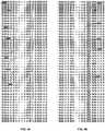
- FIG. 4cdiscloses a scaled self-retaining suture 450 in an unexpanded position, produced by the foregoing method, wherein two intersecting helical escarpments are cut having substantially similar transverse cut angles, pitches, and cut depths, but opposing chiralities (i.e. the effect of combining 4a and 4b together).
- the resultant overlap of escarpment points 452 of suture 450produces a pattern of scale-like retainers 454 having tissue-penetrating edges 456 and tissue-engaging surfaces 458; as the retainers 454 created by this method cover the entire circumferential suture surface on which they are cut, the tension on the suture 450 is optimally distributed and the risk of suture failure minimized.
- retainers 454 of suture 450engage tissue, retainers 454 flare away from the suture body, as shown in the expanded position in FIG. 4d .
- the foregoing stepsmay be carried out at the opposite end of the suture to create a bidirectional scaled self-retaining suture.
- a transition segment at some point between the ends of the sutureis left retainer-free; the length of the transitional segment may be selected depending on the purpose of the suture, and the transitional segment may be located at or near the middle of the suture
- the first pair of helical escarpmentsis cut along one end of the suture to a selected point some distance from the other suture end while the second pair of helical escarpments is cut to a selected point away from the first pair, so as to avoid having the first and second pair of escarpments from overlapping with one another and thereby providing a retainer-free transitional segment.
- the orientation of one pair of helical escarpments at one endis about 180° in orientation from the other pair of helical escarpments at the other end, thus creating an identical "mirrored" pattern of helical escarpments.
- a series of parallel helical cutsmay be provided, as opposed to a single cut. Both ends of the resulting bidirectional scaled self-retaining suture can function as suture deployment ends, and can therefore be adapted for attachment to deployment devices such as suture needles or for direct deployment into tissue without a deployment device.
- bidirectional scaled self-retaining suture 500includes a first plurality of scale-like retainers 504 having retainer bodies 508 and tissue-penetrating edges 510 and a second plurality 514 of retainers 516 having retainer bodies 518 and tissue-penetrating edges 520.
- First retainer plurality 504is disposed proximally to first suture deployment end 502, thus retainers 508 are oriented or pointed substantially away from end 502.
- second retainer plurality 514is disposed proximally to second suture deployment end 512, being accordingly oriented or pointed substantially away from end 512
- First and second retainer pluralities 504 and 514are separated by transition segment 522, that portion of a self-retaining bidirectional suture that is retainer-free.
- a scaled self-retaining suturemay be modified by rounding off or blunting the escarpment points.
- FIG. 6there is disclosed a scaled self-retaining suture 600 including on the suture body scale-like retainers 604 having retainer bodies 606 and tissue-penetrating edges 608.
- the tissue-penetrating edges 608are rounded, producing a fish-scale effect, and are less likely bend or break without penetrating through and engaging the tissue.
- a bidirectional self-retaining suturemay be provided with rounded "scales", as shown in FIG. 7 .
- bidirectional scaled self-retaining suture 700(shown in the expanded position) includes a first plurality of scale-like retainers 704 having retainer bodies 708 and rounded tissue-penetrating edges 710 and a second plurality of retainers 714 having retainer bodies 718 and rounded tissue-penetrating edges 720.
- First retainer plurality 704is disposed proximally to first suture deployment end 702, thus retainers 708 are oriented substantially away from end 702.
- second retainer plurality 714is disposed proximally to second suture deployment end 712, being separated from first retainer plurality 704 by transition segment 722, with retainers 718 being accordingly oriented substantially away from end 712.
- bidirectional scaled self-retaining suture 800(shown in the expanded position) includes a first plurality 804 of scale-like retainers 806 having retainer bodies 808 and tissue-penetrating edges 810 and a second plurality 814 of retainers 816 having retainer bodies 818 and tissue-penetrating edges 821.
- First retainer plurality 804is disposed proximally to first suture deployment end 802, thus retainers 808 are oriented or pointed substantially away from end 802.
- second retainer plurality 814is disposed proximally to second suture deployment end 812, being separated from first retainer plurality 804 by transition segment 820, with retainers 818 being accordingly oriented or pointed substantially away from end 812.
- suture 800has a greater diameter than at either end 802 or 812.
- such expansioncan be incremental, with the diameter increasing from each end 802 and 812 of suture 800 and reaching a maximum at transition segment 820; the incremental expansion may commence at a point outside the transitional segment such that some part of the retainer-bearing portions of the suture thread may also have a greater diameter than that of a suture end.
- the bidirectional scaled self-retaining suture 900 in FIGS. 9a and 9b(shown in the expanded position) includes a first plurality 904 of scale-like retainers 906 having retainer bodies 908 and rounded tissue-penetrating edges 910 and a second plurality 914 of retainers 916 having retainer bodies 918 and rounded tissue-penetrating edges 921.
- First retainer plurality 904is disposed proximally to first suture deployment end 902, and the retainers 906 are oriented or pointed substantially away from end 902.
- second retainer plurality 914is disposed proximally to second suture deployment end 912, being separated from first retainer plurality 904 by transition segment 920.
- Retainers 918are oriented or pointed substantially away from end 912 Suture 900 has a greater diameter at transition segment 920 than at either end 902 or 912.
- the expansionis shown in this example to be incremental, with the diameter increasing from each end 902 and 912 of suture 900 and reaching a maximum at transition segment 920; the incremental expansion may commence at a point outside the transitional segment, such that some part of the retainer-bearing portions of the suture thread may also have a greater diameter than that of a suture end
- Bidirectional scaled self-retaining suturesmay further be provided with expanded diameter transitional segments as described in Section C herein, increased surface area provided by the tissue engagement surface configurations described in Section B, and secondary retainer structure configurations as described in Section E.
- self-retaining suturesmay be provided with a secondary retainer structure, that is, secondary retainers upon the primary retainers.
- Secondary retainersfurther increase the surface area of the suture and thereby increase the amount of interaction between the suture and tissue.
- providing secondary retainers on the primary retainersincreases the total number of retainers on the suture (and thus the total number of points of tissue penetration) without a reduction in suture tensile strength that may occur by cutting additional primary retainers into the suture body.
- the increase in the number of retainers and the increase in the suture's tissue engagement surface arearesults in better distribution of tension on the suture and increased tissue hold.
- a self-retaining suturecan include at least one primary retainer having a primary retainer body projecting from the suture body and a tissue penetrating end, and an inner surface substantially facing the suture body and an outer surface facing substantially away from the suture body, the primary retainer facing and deployed in a direction and being adapted for resisting movement of the suture when in tissue, in an opposite direction from the direction in which the primary retainer faces and is deployed.
- the primary retainercan further include at least one secondary retainer projecting from the primary retainer body.
- Such secondary retainerscan be oriented in a direction at least about 90° away from the direction in which the primary retainer faces and is deployed, thus facilitating "double-hooking" of tissue, and may be located on any surface of the primary retainer.
- the primary retainercan be a barb, it can be frusto-conical, helical, and so forth.
- the secondary retainercan also be a barb, frusto-conical, helical, as well as filamentary
- a self-retaining suture 1000is shown, the suture 1000 including a suture body 1002 and a plurality of primary retainers 1004 with face 1005 extending from suture body 1002 and having primary retainer bodies 1006 and primary retainer edges 1008 and primary retainer tissue engagement surfaces 1016.
- the primary retainers 1004further include a secondary retainer 1010 disposed on the tissue engagement surface 1016 at the primary retainer edge 1008 with face 1009 and with the primary retainer 1004 facing the deployment direction and with the second retainer 1010 facing substantially away from the deployment direction.
- the secondary retainers 1010include a secondary retainer body 1012 and a secondary retainer edge 1014.
- Both primary and secondary retainers 1004 and 1010are configured as barbs, such that the combination of the two have a "fishhook" appearance and function much the same way. That is, during suture deployment, primary retainers 1004 rest along suture body 1002 and secondary retainers 1010 in turn rest between primary retainers 1004 and suture body 1002. During affixation, primary retainers 1004 are displaced away from suture body 1002 thereby exposing secondary retainers 1010 and allowing them to further engage tissue being engaged between primary retainers 1004 and suture body 1002.
- Such a "fishhook" combination of primary and secondary retainersmay be produced by forming a primary retainer on the suture thread by a single transverse cut and then removing some suture material from the tissue engagement surface of the retainer (such as by hand-cutting or laser-cutting) to form the secondary retainer Alternatively, this combination may be made by making a first transverse cut on the suture thread to form the primary retainer, followed by back-cutting a second transverse cut onto the primary retainer to form the secondary retainer, these cuts may be made in a single continuous motion or may be made in separate motions.
- the combination of primary retainers with "breakback" secondary retainers disposed on the tissue engagement surfaces of the primary retainersmay be provided with frusto-conical and helical primary retainers; the secondary retainers may be cut onto the tissue engagement surfaces of such primary retainers to provide a secondary retainer lip along at least part of the length of the tissue penetrating edge of the primary retainer.
- FIG. 11discloses a primary/secondary retainer combination as well, but with a plurality of secondary retainers 1110 with face 1111 on primary retainer 1104 with face 1105.
- self-retaining suture 1100includes suture body 11.02 and primary retainers 1104 having a plurality of secondary retainers 1110 projecting from primary retainer body 1106 and with the secondary retainer 1110 located between the primary retainer 1104 and the suture body 1102 facing away from the direction of deployment
- Both primary and secondary retainers 1104 and 1110, respectively,are configured as barbs, such that the combination of the two resemble the microstructure of a porcupine's quill and function in much the same way.
- primary retainers 1104rest along suture body 1102 and secondary retainers 1110 disposed on inner surface 1116 in turn rest between primary retainers 1104 and suture body 1102.
- tissue resistance during deploymentmay increase slightly.
- the secondary retainers 1110can enhance the hold or positioning of the primary retainers 1104.
- the uneven primary retainer surface resulting from these secondary retainers 1110may increase local tissue disruption and increase surface area, both of which can promote healing and fixation. It is to be understood that such pluralities of secondary retainers may be provided on frusto-conical and helical primary retainers as well.
- Self-retaining sutures having secondary retainers associated with primary retainersmay further be provided with secondary retainers along the suture body, as disclosed in FIG. 12 .
- Suture 1200 in FIG. 12includes suture body 1202 and primary retainers 1204 having a plurality of secondary retainers 1210 (that project from primary retainer body 1206) and with the secondary retainer 1210 located between the primary retainer 1204 and the suture body 1202 facing away from the direction of deployment
- Suture body 1202further includes secondary retainers 1212, which point away from the direction of deployment and face the directly of deployment; given their orientation, secondary retainers 1212 rest along body 1202 during deployment of suture 1200 and so do not increase tissue resistance as suture 1200 is deployed through it.
- secondary retainers 1212fan away from suture body 1202 and engage tissue during affixation of the suture 1200. Provision of secondary retainers 1212 along suture body 1202 further increases surface area and therefore the holding strength of the suture. While retainers 1212 are configured as barbs, it is to be understood that other retainer configurations may be used.
- FIG. 13shows a self-retaining suture 1300 including a suture body 1302 and primary retainers 1304 having a plurality of secondary retainers 1310 extending from primary retainer bodies 1306, which secondary retainers 1310 are filamentary.
- These filamentary retainers 1310may be created on the primary retainers 1304 by polymer grafting or growing techniques, by which polymer chains grown off of the surface of the primary retainers 1304 increase the microscopic surface area of the primary retainers 1304 thereby improving tissue engagement.
- Suture threads described hereinmay be produced by any suitable method, including without limitation injection moulding, stamping, cutting, laser, extrusion, and so forth.
- polymeric thread or filamentsmay be manufactured or purchased for the suture body, and the retainers can be subsequently cut onto the suture body; they may be hand-cut, laser-cut, or mechanically machine-cut using blades, cutting wheels, grinding wheels, and so forth.
- the suturesmay be made of any suitable biocompatible material, and may be further treated with any suitable biocompatible material, whether to enhance the sutures' strength, resilience, longevity, or other qualities, or to equip the sutures to fulfill additional functions besides joining tissues together, repositioning tissues, or attaching foreign elements to tissues.
- helical or spiral self-retaining suturescan be produced by a method including (i) providing a suture having a longitudinal axis and a circumference; a cutter; and, a displacer for longitudinally displacing and pivoting about the longitudinal axis at least one of the cutter and suture relative to one another; (ii) placing the cutter and suture into cutting engagement at a transverse cut angle; and, (iii) cutting a helical circumferential escarpment about the suture.
- FIG 14ashows an embodiment of a cutting device for forming a helical retainer 405 disposed along a suture body 403 of a self-retaining suture 401, the helical retainer 405 including a retainer body 409 and a tissue penetrating edge 411.
- a cutting device 1410creates an escarpment in the surface of suture body 403.
- the cutting device 1410comprises, in one embodiment, a rotary cutting head 1412 can be, if desired, positioned adjacent suture body 403.
- Rotary cutting headis driven by motor 1418.
- Rotary cutting head 1412is mounted such that the depth of tip 1414 of rotary cutting head 1412 is precisely controlled so that the depth of the escarpment is kept constant.
- rotary cutting headmay be held in fixed relationship with a roller 1416 which rides on suture body 403 thereby controlling the depth of the escarpment relative to the surface of the suture body 403. This allows for a constant escarpment depth even where the suture body varies in diameter. This is particular useful where the suture body has an expanded region of greater diameter as described above.
- Roller 1416 and rotary cutting head 1412are mounted to a floating armature 1430 which is pushed into contact with suture body 403 by springs 1432.
- the drive mechanism 1434 connecting motor 1418 and rotary cutting head 1412allows movement of rotary cutting head 1412 without binding.
- Rotary cutting head 1412is driven at a very high rotation rate compared to the translation and rotation of suture body 403.
- other cutting devicesmay be used including knives, abrasive wheels, lasers and the like.
- Alternative mechanismsmay also be utilized to control the depth of cut including an electronically controlled sensor/servo system or other mechanical "following" systems. Where the diameter of suture body 403 is sufficiently uniform, the distance between roller 1416 and cutter support 1420 may be fixed rather than varying with the diameter of the suture body
- An anvil or cutter support 1420is provided on the opposite side of suture body 403 from cutting device 1410 to support the suture body 403 during the cutting operation.
- the cutter support 1420is designed to allow suture body 403 to translate longitudinally (arrow 1404) and rotate (arrow 1402) relative to cutting device 1410 but not to move laterally or vertically while passing through cutting device 1410. Cutter support 1420 thus maintains suture body 403 in the correct alignment with rotary cutting head 1412 during the cutting action.
- Suture body 403is held between roller 1416 and cutter support 1420.
- Roller 1416may also function to prevent lateral and vertical motion of suture body 403.
- both suture body 403 and cutting device 1410may be rotated about the longitudinal axis of the suture body 403, the suture body 403 being rotated while the cutting device 1410 revolves.
- suture body 403 and cutting device 1410may be rotated either in the same direction or in opposing directions about the longitudinal axis of suture body 403. If both cutting device 1410 and suture body 403 are rotated in the same direction, the angular velocity at which each is rotated about the longitudinal axis must differ in order to effect a circumferential escarpment on the suture.
- the speed of translation compared to the relative rate of rotation of cutting device 1410 and suture body 403controls the pitch of the helical retainer 405.
- the pitch of the helical retainer 405is the distance between turns.
- the pitch of helical retainer 405is shown in FIG 14a as dimension 1406.
- the translation velocity and the rotational velocitywill have a fixed relationship along the length of the suture body 403.
- FIG. 14bshows one embodiment of a cutting fixture 1440 for forming a helical retainer 405 disposed along a suture body 403 of a self-retaining suture 401.
- Cutting fixture 1440includes cutting device 1410 along with a mechanism for rotating suture body 403 and translating cutting device 1410 along suture body 403.
- suture body 403is tensioned between two supports 1442.
- Suture body 403is held to each support 1442 by a gear driven chuck 1444.
- a drive mechanism 1446which may be an electric motor, drives a screw drive 1448 which runs between the supports 1442. Gears 1450 at each end of screw drive 1448 rotate chucks 1444 at the same speed and in the same direction as shown by arrows 1445. Screw drive 1448 also passes through a threaded passage in the base 1452 of cutting device 1410. As screw drive 1448 turns, screw drive 1448 drives cutting device 1410 linearly along the length of suture body 403 as shown by arrow 1454. Thus in cutting fixture 1440, suture body 403 is rotated relative to cutting device 1410 and cutting device 1410 is translated relative to suture body 403 thereby cutting a helical retainer 405 on suture body 403.
- gears 1450fix the ratio of translation speed of cutting device 1410 compared to the rate of rotation of suture body 403.
- Cutting fixture 1440will, therefore, produce a helical retainer 405 with a constant pitch.
- Gears 1450may be changed in order to change the pitch.
- a separate drive mechanism 1446may be provided for the chucks 1444 thereby allowing the rate of rotation of suture body 403 to be varied independent of the rate of translation of cutting device 1410.
- chucks 1446 and screw drive 1548may be driven by separate computer-controlled electric drive systems.
- FIG. 14cshows an alternative cutting fixture 1460 for forming a helical retainer 405 disposed along a suture body 403 of a self-retaining suture 401.
- Cutting fixture 1460includes cutting device 1410 along with a mechanism for rotating suture body 403 and translating suture body 403 relative to cutting device 1410. As shown in Fig 14c , suture body 403 is tensioned between two supports 1442. Suture body 403 is held to each support 1442 by a feed spool 1461 or uptake spool 1462.
- Spools 1461 and 1462rotate about their axes in the same speed and direction such that as the suture body 403 is played out by feed spool 1461 it is taken up uptake spool 1462 translating suture body 403 in the direction of arrows 1463.
- a mechanical tensioning mechanism(not shown) may also be provided to help maintain a constant tension in suture body 403 during the cutting process and to take up any slack cause by slight variation in the rate of suture play out and take up.
- a linear drive mechanismsuch as a screw drive may be used to translate suture body 403 as an alternative to drums or spools 1461, 1462.
- a drive mechanism 1464drives shaft 1468 which runs between the supports 1442.
- Gears 1466 at each end of shaft 1468rotate gimbles 1469 which hold spools 1461, 1462 to supports 1442.
- the gimbles 1469rotate the spools 1461, 1462 about the longitudinal axis of suture body 403 as shown by arrows 1465.
- suture body 403is rotated and translated relative to a fixed-position cutting device 1410 thereby cutting a helical retainer 405 on suture body 403.
- a separate drive mechanism 1446may be provided for the rotation of the spools 1461, 1462 than the drive mechanism 1464 for shaft 1468 and gimbles 1469, thereby allowing the rate of rotation of suture body 403 to be varied independent of the rate of suture body 403.
- FIG. 14dshows an alternative cutting fixture 1470 for forming a helical retainer 405 disposed along a suture body 403 of a self-retaining suture 401.
- Cutting fixture 1470includes cutting device 1410 along with a mechanism for rotating cutting device 1410 and translating cutting device 1410 relative to suture body 403.
- suture body 403is tensioned between two supports 1442.
- Suture body 403is held to each support 1442 by a fixed chuck 1472.
- a tensioning mechanism(not shown) may also be provided to help maintain a constant tension in suture body 403 during the cutting process,
- a drive mechanism 1474drives screw drive 1478 which runs between the supports 1442.
- Screw drive 1478passes through a threaded passage 1476 in the base 1486 of cutting device 1410 such that, as screw drive 1478 turns, cutting device 1410 is translated along the length of suture body 403 as shown by arrow 1475.
- a separate drive mechanism 1480drives a belt 1482 which rotates cutting device 1410 along a circular track within base 1486 as shown by arrow 1484.
- the cutting device 1410is thereby moved along a helical path relative to the fixed suture body 403.
- suture body 403remains in a fixed position and cutting device 1410 is rotated and translated relative to suture body 403 thereby cutting a helical retainer 405 on suture body 403.
- the pitch of helical retainer 405may be controlled, in this embodiment, by adjusting the relative speeds of drive mechanism 1480 and drive mechanism 1474 which may be computer-controlled electric motors. If a fixed pitch is desired, a gear linkage may be used to drive the rotation of cutting device 1410 within base 1452 from screw drive 1478.
- FIG. 14eshows an alternative cutting fixture 1490 for forming a helical or spiral retainer 405 disposed along a suture body 403 of a self-retaining suture.
- Cutting fixture 1490includes cutting device 1410 along with a mechanism for rotating cutting device 1410 relative to suture body 403 and translating suture body 403 relative to cutting device 1410.
- suture body 403is tensioned between two spools 1491, 1492.
- Feed spool 1491 and uptake spool 1492rotate about their axes in the same speed and direction such that as the suture body 403 is played out by spool 1491 it is taken up spool 1492 translating suture body 403 in the direction of arrows 1493.
- a tensioning mechanism(not shown) may also be provided to help maintain a constant tension in suture body 403 during the cutting process and to take up any slack cause by slight variation in the rate of suture play out and take up
- a linear drive mechanismsuch as a screw drive may be used to translate suture body 403 as an alternative to spools 1491, 1492.
- a drive mechanism 1480drives a belt 1482 which rotates cutting device 1410 within base 1486 as shown by arrow 1484. However, in cutting fixture 1490 base 1486 is stationary while suture body 403 translates. Thus in cutting fixture 1490.
- suture body 403translates relative to cutting device 1410 and cutting device 1410 rotates relative to suture body 403 thereby cutting a helical retainer 405 on suture body 403.
- the pitch of helical retainer 405may be controlled in this embodiment by adjusting the relative speeds of drive mechanism 1480 and spools 1491, 1492, If a fixed pitch is desired, a gear linkage may be used to drive spools 1491, 1492 from drive mechanism 1480. Alternatively separate drive mechanisms may be used and electronically controlled to maintain constant or varying rotational and translational speeds to create the constant of varying pitch desired.
- Fig. 14c and Fig. 14ecan be combined if it is desired to have the cutter revolve or rotate about the suture, and translate or be displaced along the longitudinal length of the suture in combination with having the suture both translate or be displaced along the longitudinal length, as well rotate or revolve about the axis of said suture.
- the mechanism that longitudinally displaces or translates, and rotates the suturewhich includes for example, the spools and gimbles and gears in Fig. 14c would replace the fixed chuck of Fig. 14d .
- the cutter 14ecan be combined, if it is desired, to have the cutter revolve or rotate about the suture and translate or be displaced along the longitudinal length of the suture, in combination with the suture being rotated about the axis of the suture.
- the driven chucks of Fig 14bwould replace the fixed chucks of Fig 14d
- the suture translation mechanism of Fig. 14ecan be added to the device of Fig. 14d .
- the fixed chucks of Fig. 14d that hold the suturecan be replaced in Fig. 14d with the spools of Fig. 14e so that the suture can translate or be displaced longitudinally.
- FIG. 14fshows an alternative cutting fixture 1471 for forming a helical retainer 405 disposed along a suture body 403 of a self-retaining suture 401.
- Cutting fixture 1471includes cutting device 1410 along with a mechanism for rotating cutting device 1410 and translating cutting device 1410 relative to suture body 403.
- suture body 403is tensioned between two supports 1442, Suture body 403 is held to each support 1442 by a fixed chuck 1472.
- a tensioning mechanismmay also be provided to help maintain a constant tension in suture body 403 during the cutting process.
- Cutting device 1410which includes a cutting head 1412 and a cutter support 1420 travels along a helical track 1479 as shown by arrow 1477.
- the cutting device 1410is thereby moved along a helical path relative to the fixed suture body 403.
- suture body 403remains in a fixed position and cutting device 1410 is rotated and translated relative to suture body 403 thereby cutting a helical retainer 405 on suture body 403.
- the pitch of helical retainer 405is fixed by the pitch of helical track 1479.
- a helical or spiral cutis made on the suture body 403.
- a helical track or a cylinder with an interior helical or spiral trackcan be made with any of the other embodiments herein, if it is desired, to have the cutter both rotate or revolve about the suture and have the cutter translate along the length of the suture. Still further, if desired in any of these embodiments, the suture can itself be pre-twisted prior to being loaded into any of the fixtures described.
- FIG. 15ashows an alternative cutting device 1510 that may be used in the cutting fixtures of FIGS. 14b-14f .
- the suture body 403passes between cutter support 1520 and support 1522.
- a rotary cutting blade 1512rotates as shown by arrow 1514.
- Rotary cutting blade 1512is mounted on shaft 1516 which passes through support 1522.
- the geometry of rotary cutting blade 1512is thereby fixed relative to suture body 403. It may, however, be desirable to provide set screws or the like in order to adjust the angle and depth of the rotary cutting blade 1512 relative to the suture body 403.
- Rotary cutting blademay be a knife blade in which case the rotation of the blade may be either passive or driven.
- the knife blademade of a suitable ceramic or metal material for cutting into suture body 403.
- Rotary cutting blade 1512may be an abrasive wheel or the like in which case rotary cutting blade 1512 is preferably driven at high speed or very high speed relative to the rotation of suture body 403. If the rotation of rotary cutting blade 1512 is driven, it may be driven in the same direction as suture body 403 or in the opposite direction.
- Rotary cutting blade 1512is moved along a helical path relative to suture body 403 utilizing a cutting fixture which provides for relative translation and rotation of cutting device 1510 and the suture body 403 as shown by arrows 1502 and 1504 respectively.
- Suitable cutting fixturesare described with respect to FIGS. 14b-14f above.
- either or both of cutting device 1510 and suture body 403may be moved in order to generate the desired helical path of the cutting device 1510 about the suture body 403.
- FIG. 15bshows an end view of cutting device 1510 illustrating the entrance aperture 1506 into cutting device 1510.
- Entrance aperture 1506 into cutting device 1510is defined by the space between supports 1520 and 1522.
- Supports 1520 and 1522are each provided with a polished radius or polished chamfer 1521 to guide suture body 403 (position shown by dashed line) into aperture 1506 without abrading suture body 403.
- Rotary cutting blade 1512can seen protruding into aperture 1506 adjacent support 1521.
- a plurality of cutting bladesmay be provide in order to cut a plurality of helical retainers at the same time.
- suture body 403enters aperture 1506 (into the page) suture body 403 rotates in the direction of arrow 1508 relative to cutting device. 1510. Note that either the suture body 403 or the cutting device 1510 may be rotated to achieve the desired relative rotation of cutting device 1510 and suture body 403.
- FiG. 15cshows another alternative cutting device 1530 that may be used in the cutting fixtures of FIGS. 14b-14f .
- the suture body 403passes between cutter support 1520 and support 1522.
- a fixed cutting blade 1532is mounted to support 1522 by machine screw 1534.
- Machine screw 1534allows the position of cutting blade 1532 to be adjusted relative to suture body 403. It may be desirable to provide further set screws or the like in order to better adjust the angle and depth of the rotary cutting blade 1512 relative to the suture body 403.
- Cutting blademay be a knife blade made of a suitable ceramic or metal material for cutting into suture body 403.
- Cutting blade 1532is moved along a helical path relative to suture body 403 utilizing a cutting fixture which provides for relative translation and rotation of cutting device 1510 and the suture body 403 as shown by arrows 1502 and 1504 respectively. Suitable cutting fixtures are described with respect to FIGS. 14b-14f above. As described above, either or both of cutting device 1510 and suture body 403 may be moved in order to generate the desired helical path of the cutting device 1510 about the suture body 403.
- Self-retaining sutures described hereinmay also incorporate materials that further promote tissue engagement.
- tissue engagement-promoting materialsin at least part of the suture bodies (whether or not such materials also make up all or part of the retainers) can enhance the ability of the sutures to stay in place.
- tissue engagement-promoting materialsare porous polymers that can be extruded to form suture bodies, including both microporous polymers and polymers that can be extruded with bubbles (whether bioabsorbable or nonbioabsorbable).
- a suture synthesized with such materialscan have a three-dimensional lattice structure that increases tissue engagement surface area and permits tissue infiltration into the suture body itself, thus having a primary structure that promotes successful suture use.
- fibroblast ingrowthcan be encouraged, further facilitating the suture to be anchored in the tissue.
- ePTFEexpanded polytetra-fiuoroethylene
- Self-retaining incorporating ePTFEare well-suited to uses requiring a strong and permanent lift (such as breast lifts, face lifts, and other tissue repositioning procedures), as tissue infiltration of the suture results in improved fixation and engraftment of the suture and the surrounding tissue thus providing superior hold and greater longevity of the lift.
- self-retaining sutures described hereinmay be provided with compositions to promote healing and prevent undesirable effects such as scar formation, infection, pain, and so forth.
- Thiscan be accomplished in a variety of manners, including for example: (a) by directly affixing to the suture a formulation (e,g., by either spraying the suture with a polymer/drug film, or by dipping the suture into a polymer/drug solution), (b) by coating the suture with a substance such as a hydrogel which will in turn absorb the composition, (c) by interweaving formulation-coated thread (or the polymer itself formed into a thread) into the suture structure in the case of multi-filamentary sutures, (d) by inserting the suture into a sleeve or mesh which is comprised of, or coated with, a formulation, or (e) constructing the suture itself with a composition.
- compositionsmay include without limitation anti-proliferative agents, anti-angiogenic agents, anti-infective agents, fibrosis-inducing agents, anti-scarring agents, lubricious agents, echogenic agents, anti-inflammatory agents, cell cycle inhibitors, analgesics, and anti-nucrotubule agents.
- a compositioncan be applied to the suture before the retainers are formed, so that when the retainers engage, the engaging surface is substantially free of the coating. In this way, tissue being sutured contacts a coated surface of the suture as the suture is introduced, but when the retainer engages, a non-coated surface of the retainer contacts the tissue.
- the suturemay be coated after or during formation of retainers on the suture if, for example, a fully-coated rather than selectively-coated suture is desired.
- a suturemay be selectively coated either during or after formation of retainers by exposing only selected portions of the suture to the coating.
- the particular purpose to which the suture is to be put or the compositionmay determine whether a fully-coated or selectively-coated suture is appropriate, for example, with lubricious coatings, it may be desirable to selectively coat the suture, leaving, for instance, the tissue-engaging surfaces of the sutures uncoated in order to prevent the tissue engagement function of those surfaces from being impaired.
- coatings such as those comprising such compounds as anti-infective agentsmay suitably be applied to the entire suture, while coatings such as those comprising fibrosing agents may suitably be applied to all or part of the suture (such as the tissue-engaging surfaces).
- the purpose of the suturemay also determine the sort of coating that is applied to the suture; for example, self-retaining sutures having anti-proliferative coatings may be used in closing tumour excision sites, while self-retaining sutures with fibrosing coatings may be used in tissue repositioning procedures and those having anti-scarring coatings may be used for wound closure on the skin.
- sutures having an expanded segmentmay include a fibrosis-inducing composition on the expanded segment to further secure the segment in position in the tissue.
- Coatingsmay also include a plurality of compositions either together or on different portions of the suture, where the multiple compositions can be selected either for different purposes (such as combinations of analgesics, anti-infective and anti-scarring agents) or for their synergistic effects.
- Self-retaining sutures described hereinmay be used in various dental procedures, i.e., oral and maxillofacial surgical procedures and thus may be referred to as "self-retaining dental sutures.”
- the above-mentioned proceduresinclude, but are not limited to, oral surgery (e.g., removal of impacted or broken teeth), surgery to provide bone augmentation, surgery to repair dentofacial deformities, repair following trauma (e.g., facial bone fractures and injuries), surgical treatment of odontogenic and non-odontogenic tumors, reconstructive surgeries, repair of cleft lip or cleft palate, congenital craniofacial deformities, and esthetic facial surgery.
- Self-retaining dental suturesmay be degradable or non-degradable, and may typically range in size from USP 2-0 to USP 6-0.
- Self-retaining sutures described hereinmay also be used in tissue repositioning surgical procedures and thus may be referred to as "self-retaining tissue repositioning sutures". Such surgical procedures include, without limitation, face lifts, neck lifts, brow lifts, thigh lifts, and breast lifts. Self-retaining sutures used in tissue repositioning procedures may vary depending on the tissue being repositioned; for example, sutures with larger and further spaced-apart retainers may be suitably employed with relatively soft tissues such as fatty tissues.
- Self-retaining sutures described hereinmay also be used in microsurgical procedures that are performed under a surgical microscope (and thus may be referred to as "self-retaining microsutures"). Such surgical procedures include, but are not limited to, reattachment and repair of peripheral nerves, spinal microsurgery, microsurgery of the hand, various plastic microsurgical procedures (e.g., facial reconstruction), microsurgery of the male or female reproductive systems, and various types of reconstructive microsurgery. Microsurgical reconstruction is used for complex reconstructive surgery problems when other options such as primary closure, healing by secondary intention, skin grafting, local flap transfer, and distant flap transfer are not adequate. Self-retaining microsutures have a very small caliber, often as small as USP 9-0 or USP 10-0, and may have an attached needle of corresponding size. They may he degradable or non-degradable.
- Ophthalmic self-retaining suturesmay be used in similarly small caliber ranges for ophthalmic surgical procedures and thus may be referred to as "ophthalmic self-retaining sutures". Such procedures include but are not limited to keratoplasty, cataract, and vitreous retinal microsurgical procedures. Ophthalmic self-retaining sutures may be degradable or non-degradable, and have an attached needle of correspondingly-small caliber.
- Self retaining suturescan be used in a variety of veterinary applications for a wide number of surgical and traumatic purposes in animal health.
Landscapes
- Health & Medical Sciences (AREA)
- Surgery (AREA)
- Life Sciences & Earth Sciences (AREA)
- Animal Behavior & Ethology (AREA)
- Veterinary Medicine (AREA)
- Public Health (AREA)
- General Health & Medical Sciences (AREA)
- Engineering & Computer Science (AREA)
- Molecular Biology (AREA)
- Medical Informatics (AREA)
- Heart & Thoracic Surgery (AREA)
- Biomedical Technology (AREA)
- Nuclear Medicine, Radiotherapy & Molecular Imaging (AREA)
- Hematology (AREA)
- Epidemiology (AREA)
- Materials For Medical Uses (AREA)
- Surgical Instruments (AREA)
Abstract
Description
- This application claims benefit to the following U.S. patent applications each of which is incorporated herein by reference:
- U.S. Provisional Application No.
60/911,814, filed April 13, 2007 - U.S. Utility Application No.
12/062,214, filed April 3, 2008 - U.S. Utility Application No.
12/062,256, filed April 3, 2008 - The present invention relates generally to self-retaining systems for surgical procedures, methods of manufacturing self-retaining systems for surgical procedures, and their uses.
- Wound closure devices such as sutures and staples have been widely used in superficial and deep surgical procedures in humans and animals for closing wounds, repairing traumatic injuries or defects, joining tissues together [bringing severed tissues into approximation, closing an anatomical space, affixing single or multiple tissue layers together, creating anastomoses between two hollow (luminal) structures, adjoining tissues, attaching or reattaching tissues to their proper anatomical location], attaching foreign elements to tissues (affixing medical implants, devices, prostheses and other functional or supportive devices), and for repositioning tissues to new anatomical locations (repairs, tissue elevations, tissue grafting and related procedures) to name but a few examples. Sutures typically consist of a filamentous suture thread attached to a needle with a sharp point (attachment of sutures and surgical needles is described in
U.S. Patent Nos. 3,981,307 ,5,084,063 ,5,102,418 ,5,123,911 ,5,500,991 ,5,722,991 ,6,012,216 , and6,163,948 , and U.S. Patent Application Publication No.U.S. 2004/0088003 ). Classically, the needle is advanced through the desired tissue on one side of the wound and then through the adjacent side of the wound to form a "loop" which is then completed by tying a knot in the suture. - Sutures materials are broadly classified as being bioabsorbable (i.e., they break down completely in the body over time), such as those composed of catgut, glycolic acid polymers and copolymers, lactic acid polymers and copolymers; or as being non-absorbable (permanent; nondegradable), such as those made of polyamide, polytetrafluoroethylene, polyether-ester, polyurethane, metal alloys, metal (e.g., stainless steel wire), polypropylene, polyethelene, silk, and cotton. Absorbable sutures have been found to be particularly useful in situations where suture removal might jeopardize the repair or where the natural healing process renders the support provided by the suture material unnecessary after wound healing has been completed; as in, for example, completing an uncomplicated skin closure. Nondegradable (non-absorbable) sutures are used in wounds where healing may be expected to be protracted or where the suture material is needed to provide physical support to the wound for long periods of time; as in, for example, deep tissue repairs, high tension wounds, many orthopedic repairs and some types of surgical anastomoses. The present invention provides for polymeric formulations, surface properties, configurations and diameters designed to increase the holding power, durability and strength of self-retaining closure systems composed of both bioabsorbable and non-absorbable polymers.
- A new type of suture has been designed with barbs, or with frusto-conical retainers, for engaging tissue when the suture is pulled in a direction other than that in which it was originally deployed in the tissue. Knotless tissue-approximating devices having barbs have been previously described in, for example,
U.S. Pat. No. 5,374,268 , disclosing armed anchors having barb-like projections, while suture assemblies having barbed lateral members have been described inU.S. Pat Nos. 5,584,859 and6,264,675 . One of the earlier patents describing a barbed suture isU.S. Pat. No. 3,716,058 , which discloses a suture having one or more relatively rigid barbs at its opposite ends; the presence of the barbs just at the ends of the suture would limit the barbs' effectiveness. Sutures having a plurality of barbs positioned along a greater portion of the suture are described inU.S. Pat No. 5,931,855 , which discloses a unidirectional barbed suture, andU.S. Pat. No. 6,241,747 , which discloses a bidirectional barbed suture. Methods and apparatus for forming barbs on sutures have been described in, for example,U.S. Pat. Nos. 6,848,152 , while methods of manufacturing sutures with frusto-conical retainers have also been described in European Patent1 075 843 . - Despite their advantages over conventional sutures, current designs of barbed sutures can break, slip through tissue, incompletely deploy, not fully anchor and/or rotatein situ, leading to suboptimal clinical results and limiting their utility. In the present invention, novel tissue retainer configurations, secondary retainer structures and expanded segment suture configurations are described that increase the ability of the self-retaining sutures to anchor into their surrounding tissue, strengthen their hold, increase the amount of tension they can withstand (without breakage or slippage) and increase their clinical performance.
- Sutures may be configured to more effectively distribute or resist tensions upon them when deployed in tissue.
- In one aspect, a suture may include an expanded section disposed away from either end of the suture.
- In another aspect, a suture may include one or more tissue retainers having an uneven or roughened surface.
- In another aspect, a suture may include a continuous helical tissue retainer that is unidirectional
- In another aspect, a suture may include a continuous helical tissue retainer that is bidirectional. In the bidirectional configuration, the helix is oriented in one direction projecting "away" from the needle until the midpoint (or transition point) of the suture is reached; at this point the configuration of the helix reverses itself 180° along the remaining length of the suture thread before attaching to a second needle at the opposite end.
- In another aspect, a method of manufacturing a helical self-retaining suture may include cutting a continuous helical tissue retainer in one chiral direction angled away from the suture deployment end, and a second continuous helical tissue retainer cut in the opposite chiral direction also angled away from the deployment end.
- In another aspect, a method of manufacturing a bidirectional helical self-retaining suture may include cutting a continuous helical tissue retainer in one chiral direction angled away from a first suture deployment end and a second continuous helical tissue retainer cut in the opposite chiral direction also angled away from the first suture deployment end, both at a first portion of the suture that is proximal to the first suture deployment end. The method may further include cutting a continuous helical tissue retainer in one chiral direction angled away from a second suture deployment end and a second continuous helical tissue retainer cut in the opposite chiral direction also angled away from the second suture deployment end, both at a second portion of the suture that is proximal to the second suture deployment end and that is disposed away from the first portion
- In yet another aspect, a suture may include tissue retainer "scales" that increase the percentage of the surface area covered by retaining elements as compared to intermittent "barb" configurations. Such tissue retainer scales may include pointed or rounded tissue penetrating edges.
- In another aspect a method of manufacturing a "scaled" self-retaining suture may include cutting a continuous helical tissue retainer in one chiral direction angled away from the suture deployment end, while a second continuous helical tissue retainer is cut in the opposite chiral direction and (also angled away from the suture deployment end).
- In yet another aspect, a suture may include one or more primary tissue retainers, with at least one such primary tissue retainer that further includes one or more secondary tissue retainers. Such secondary tissue retainers may include flanges, barbs, and filaments.
- In yet another aspect, the surface of the portion of the suture material that is not composed of primary tissue retainers (i.e., the "unbarbed" areas of the thread), are modified such that they further include one or more secondary tissue retainers Such secondary tissue retainers may include flanges, barbs, and filaments.
- In yet another aspect, the surface of the portion of the suture material that is not composed of primary tissue retainers (i.e., the "non-harhed" areas of the thread) and the primary tissue retainers themselves are both modified to further include one or more secondary tissue retainers. Such secondary tissue retainers may include flanges, barbs, and filaments.
- In a further aspect, a method of making a self-retaining suture includes the step of cutting intersecting helical escarpments into the circumferential periphery of a suture body. Such helical escarpments may intersect due to differing pitches or opposing chirality of the helices.
- In another aspect, a method of making a self retaining suture includes an expanded section of the thread such that the diameter of the expanded portion of the thread is greater than the diameter the end of the suture, or, if the suture is adapted for deployment with a needle, than the diameter of the needle.
- In yet another aspect, a method of making a bidirectional self retaining suture includes an expanded section of the tread such that the diameter of the thread at a specified distance from either needle attachment site (this distance will vary depending upon the clinical indication) is greater than the diameter of the needles that are attached to it; from the point where the barbed suture thread diameter is greatest, the diameter of the thread then tapers down (the rate and length of the tapering segment will vary depending upon the clinical indication) as it approaches the needle attachment sites until the thread diameter is equal to, or smaller than, the diameter of the needles it is attached to.
- The details of one or more embodiments are set forth in the description below. Other features, objects and advantages will be apparent from the description, the drawings, and the claims. In addition, the disclosures of all patents and patent applications referenced herein are incorporated by reference in their entirety.
FIGS. 1a, 1b, and 1c are perspective views of an embodiment according to the present invention of a self-retaining suture having uneven-surfaced retainers.FIG. 1d is a perspective view of a further embodiment according to the present invention of a self-retaining suture having uneven-surfaced retainers.FIG. 2a and 2b are perspective views of an embodiment according to the present invention of a self-retaining suture having an expanded transition segment.FIGS. 3a, 3b ,3c, and 3d are perspective views of a use of an embodiment according to the present invention of a self-retaining suture having an expanded transition segment.FIG. 3e is a perspective view of a use of an embodiment according to the present invention of a self-retaining suture having an expanded transition segment.FIGS. 4a and 4b are perspective views of embodiments according to the present invention of single helix self-retaining sutures.FIG. 4c is perspective view of an embodiment according to the present invention of a double helix self-retaining suture in an unexpanded position.FIG. 4d is perspective view of an embodiment according to the present invention of a double helix self-retaining suture in an expanded position.FIG. 5 is a perspective view of an embodiment according to the present invention of a bidirectional double helix self-retaining suture in an expanded position.FIG. 6 is a perspective view of a further embodiment according to the present invention of a scaled self-retaining suture having rounded retainers.FIG. 7 is a perspective view of a further embodiment according to the present invention of a bidirectional scaled self-retaining suture having rounded retainers in an expanded position.FIGS. 8a and 8b are perspective views of an embodiment according to the present invention of a bidirectional double helix self-retaining suture having an expanded transition segment.FIGS. 9a and 9b are perspective views of a further embodiment according to the present invention of a bidirectional scaled self-retaining suture having rounded retainers and an expanded transition segment.FIG. 10 is a perspective view of an embodiment according to the present invention of a self-retaining suture having a secondary retainer on a primary retainer.FIG. 11 is a perspective view of a further embodiment according to the present invention of a self-retaining suture having a plurality of secondary retainers on a primary retainer.FIG. 12 is a perspective view of a further embodiment according to the present invention of a self-retaining suture having a plurality of secondary retainers on a primary retainer and secondary retainers on the body of the suture.FIG. 13 is a perspective view of a further embodiment according to the present invention of a self-retaining suture having primary retainers and filamentary secondary retainers.FIG. 14a is a partial cut away view of a cutting device for cutting a helical retainer in a suture body according to an embodiment of the present invention.FIGS. 14b-14f are plan views of cutting fixtures for providing relative helical motion between a cutting device and a suture body according to embodiments of the present invention.FIGS. 15a-15b are side and end views of an alternative cutting device according to embodiments of the present invention.FIG. 15c is a side view of an alternative cutting device according to an embodiment of the present invention.- Prior to setting forth the invention, it may be helpful to an understanding thereof to first set forth definitions of certain terms that are used hereinafter
- "Self-retaining system" refers to a self-retaining suture together with means for deploying the suture into tissue. Such deployment means include, without limitation, suture needles and other deployment devices as well as sufficiently rigid and sharp ends on the suture itself to penetrate tissue.
- "Self-retaining suture" refers to a suture that does not require a knot or a suture anchor at its end in order to maintain its position into which it is deployed during a surgical procedure. These may be monofilament sutures or braided sutures, and are positioned in tissue in two stages, namely deployment and affixation, and include at least one tissue retainer.
- "Tissue retainer" (or simply "retainer") or "barb" refers to a suture element having a retainer body projecting from the suture body and a retainer end adapted to penetrate tissue. Each retainer is adapted to resist movement of the suture in a direction other than the direction in which the suture is deployed into the tissue by the surgeon, by being oriented to substantially face the deployment direction (i.e. they lie flat when pulled in the deployment direction; and open or "fan out" when pulled in a direction contrary to the deployment direction). As the tissue-penetrating end of each retainer faces or points away from the deployment direction when moving through tissue during deployment, the tissue retainers should not catch or grab tissue during this phase. Once the self-retaining suture has been deployed, a force exerted in another direction (often substantially opposite to the deployment direction) causes the retainers to be displaced from their deployment positions (i.e. resting substantially along the suture body), forces the retainer ends to open (or "fan out") from the suture body in a manner that catches and penetrates into the surrounding tissue, and results in tissue being caught between the retainer and the suture body; thereby "anchoring" or affixing the self retaining suture in place.
- "Retainer configurations" refers to configurations of tissue retainers and can include features such as size, shape, surface characteristics, and so forth. These are sometimes also referred to as "barb configurations".
- "Bidirectional suture" refers to a self-retaining suture having retainers oriented in one direction at one end and retainers oriented in the other direction at the other end. A bidirectional suture is typically armed with a needle at each end of the suture thread. Many bidirectional sutures have a transitional segment located between the two barb orientations.
- "Transition segment" refers to a retainer-free (barb-free) portion of a bidirectional suture located between a first set of retainers (barbs) oriented in one direction and a second set of retainers (barbs) oriented in another direction.
- "Suture thread" refers to the filamentary body component of the suture, and, for sutures requiring needle deployment, does not include the suture needle. The suture thread may be monofilamentary, or, multifilamentary.
- "Monofilament suture" refers to a suture comprising a monofilamentary suture thread.
- "Braided suture" refers to a suture comprising a multifilamentary suture thread. The filaments in such suture threads are typically braided, twisted, or woven together.
- "Degradable (also referred to as "biodegradable" or "bioabsorbable") suture" refers to a suture which, after introduction into a tissue is broken down and absorbed by the body. Typically, the degradation process is at least partially mediated by, or performed in, a biological system, "Degradation" refers to a chain scission process by which a polymer chain is cleaved into oligomers and monomers. Chain scission may occur through various mechanisms, including, for example, by chemical reaction (e.g., hydrolysis, oxidation/reduction, enzymatic mechanisms or a combination or these) or by a thermal or photolytic process. Polymer degradation may be characterized, for example, using gel permeation chromatography (GPC), which monitors the polymer molecular mass changes during erosion and breakdown. Degradable suture material may include polymers such as polyglycolic acid, copolymers of glycolide and lactide, copolymers of trimethylene carbonate and glycolide with diethylene glycol (e.g., MAXON™. Tyco Healthcare Group), terpolymer composed of glycolide, trimethylene carbonate, and dioxanone (e.g., BIOSYN™ [glycolide (60%), trimethylene carbonate (26%), and dioxanone (14%)], Tyco Healthcare Group), copolymers of glycolide, caprolactone, trimethylene carbonate, and lactide (e.g., CAPROSYN™, Tyco Healthcare Group). These sutures can be in either a braided multifilament form or a monofilament form. The polymers used in the present invention can be linear polymers, branched polymers or multi-axial polymers. Examples of multi-axial polymers used in sutures are described in
U.S. Patent Application Publication Nos 20020161168 ,20040024169 , and20040116620 . Sutures made from degradable suture material lose tensile strength as the material degrades. - "Non-degradable (also referred to as non-absorbable") suture" refers to a suture comprising material that is not degraded by chain scission such as chemical reaction processes (e.g., hydrolysis, oxidation/reduction, enzymatic mechanisms or a combination or these) or by a thermal or photolytic process. Non-degradable suture material includes polyamide (also known as nylon, such as nylon 6 and nylon 6.6), polyester (e.g., polyethylene terephthlate), polytetrafluoroethylene (e.g., expanded polytetrafluoroethylene), poly ether-ester such as polybutester (block copolymer of butylene terephthalate and polytetra methylene ether glycol), polyurethane, metal alloys, metal (e.g., stainless steel wire), polypropylene, polyethelene, silk, and cotton. Sutures made of non-degradable suture material are suitable for applications in which the suture is meant to remain permanently or is meant to be physically removed from the body
- "Suture diameter" refers to the diameter of the body of the suture. It is to be understood that a variety of suture lengths may be used with the sutures described herein and that while the term "diameter" is often associated with a circular periphery, it is to be understood herein to indicate a cross-sectional dimension associated with a periphery of any shape. Suture sizing is based upon diameter. United States Pharmacopeia ("USP") designation of suture size runs from 0 to 7 in the larger range and 1-0 to 11-0 in the smaller range; in the smaller range, the higher the value preceding the hyphenated zero, the smaller the suture diameter. The actual diameter of a. suture will depend on the suture material, so that, by way of example, a suture of size 5-0 and made of collagen will have a diameter of 0,15 mm, while sutures having the same USP size designation but made of a synthetic absorbable material or a non-absorbable material will each have a diameter of 0.1 mm. The selection of suture size for a particular purpose depends upon factors such as the nature of the tissue to be sutured and the importance of cosmetic concerns; while smaller sutures may be more easily manipulated through tight surgical sites and are associated with less scarring, the tensile strength of a suture manufactured from a given material tends to decrease with decreasing size. It is to be understood that the sutures and methods of manufacturing sutures disclosed herein are suited to a variety of diameters, including without limitation 7, 6, 5, 4, 3, 2, 1, 0, 1-0, 2-0, 3-0, 4-0, 5-0, 6-0, 7-0, 8-0, 9-0, 10-0 and 11-0.
- "Suture deployment end" refers to an end of the suture to be deployed into tissue; one or both ends of the suture may be suture deployment ends. The suture deployment end may be attached to deployment, means such as a suture needle, or may be sufficiently sharp and rigid to penetrate tissue on its own
- "Armed suture" refers to a suture having a suture needle on at least one suture deployment end.
- "Needle attachment" refers to the attachment of a needle to a suture requiring same for deployment into tissue, and can include methods such as crimping, swaging, using adhesives, and so forth. The point of attachment of the suture to the needle is known as the swage.
- "Suture needle" refers to needles used to deploy sutures into tissue, which come in many different shapes, forms and compositions. There are two main types of needles, traumatic needles and atraumatic needles. Traumatic needles have channels or drilled ends (that is, holes or eyes) and are supplied separate from the suture thread and are threaded on site. Atraumatic needles are eyeless and are attached to the suture at the factory by swaging whereby the suture material is inserted into a channel at the blunt end of the needle which is then deformed to a final shape to hold the suture and needle together. As such, atraumatic needles do not require extra time on site for threading and the suture end at the needle attachment site is smaller than the needle body. In the traumatic needle the thread comes out of the needle's hole on both sides and often the suture rips the tissues to a certain extent as it passes through. Most modem sutures are swaged atraumatic needles. Atraumatic needles may be permanently swaged to the suture or may be designed to come off the suture with a sharp straight tug. These "pop-offs" are commonly used for interrupted sutures, where each suture is only passed once and then tied. For barbed sutures that are uninterrupted, these atraumatic needles would be ideal.
- Suture needles may also be classified according to their point geometry. For example, needles may be (i) "tapered" whereby the needle body is round and tapers smoothly to a point; (ii) "cutting" whereby the needle body is triangular and has sharpened cutting edge on the inside; (iii) "reverse cutting" whereby the cutting edge is on the outside; (iv) "trocar point" or "tapercut" whereby the needle body is round and tapered, but ends in a small triangular cutting point; (v) "blunt" points for sewing friable tissues; (vi) "side cutting" or "spatula points" whereby the needle is flat on top and bottom with a cutting edge along the front to one side (these are typically used for eye surgery).
- Suture needles may also be of several shapes including, (i) straight, (ii) half curved or ski, (iii) 1/4 circle, (iv) 3/8 circle, (v) 1/2 circle, (vi) 5/8 circle, (v) and compound curve.
- Suturing needles are described, for example, in
US Patent Nos. 6,322,581 and6,214,030 (Mani, Inc., Japan); and5,464,422 (W.L. Gore, Newark, DE); and5,941,899 ;5,425,746 ;5,306,288 and5,156,615 (US Surgical Corp., Norwalk, CT); and5,312,422 (Linvatec Corp., Largo, FL); and7,063,716 (Tyco Healthcare, North Haven, CT). Other suturing needles are described, for example, inUS Patent Nos 6,129,741 ;5,897,572 ;5,676,675 ; and5,693,072 . The sutures described herein may be deployed with a variety of needle types (including without limitation curved, straight, long, short, micro, and so forth), needle cutting surfaces (including without limitation, cutting, tapered, and so forth), and needle attachment techniques (including without limitation, drilled end, crimped, and so forth). Moreover, the sutures described herein may themselves include sufficiently rigid and sharp ends so as to dispense with the requirement for deployment needles altogether - "Needle diameter" refers to the diameter of a suture deployment needle at the widest point of that needle While the term "diameter" is often associated with a circular periphery, it is to be understood herein to indicate a cross-sectional dimension associated with a periphery of any shape.
- "Wound closure" refers to a surgical procedure for closing of a wound. An injury, especially one in which the skin or another external or internal surface is cut, torn, pierced, or otherwise broken is known as a wound. A wound commonly occurs when the integrity of any tissue is compromised (e.g., skin breaks or burns, muscle tears, or bone fractures). A wound may be caused by an act such a.s a gunshot, fall, or surgical procedure; by an infectious disease; or by an underlying medical condition. Surgical wound closure facilitates the biological event of healing by joining, or closely approximating, the edges of those wounds where the tissue has been torn, cut, or otherwise separated. Surgical wound closure directly apposes or approximates the tissue layers, which serves to minimize the volume new tissue formation required to bridge the gap between the two edges of the wound. Closure can serve both functional and aesthetic purposes. These purposes include elimination of dead space by approximating the subcutaneous tissues, minimization of scar formation by careful epidermal alignment, and avoidance of a depressed scar by precise eversion of skin edges.
- "Tissue elevation procedure" refers to a surgical procedure for repositioning tissue from a lower elevation to a higher elevation (i.e. moving the tissue in a direction opposite to the direction of gravity). The retaining ligaments of the face support facial soft tissue in the normal anatomic position. However, with age, gravitational effects achieve a downward pull on this tissue and the underlying ligaments, and fat descends into the plane between the superficial and deep facial fascia, thus allowing facial tissue to sag. Face-lift procedures are designed to lift these sagging tissues, and are one example of a more general class of medical procedure known as a tissue elevation procedure. More generally, a tissue elevation procedure reverses the appearance change that results from gravitation effects over time, and other temporal effects that cause tissue to sag, such as genetic effects- It should be noted that tissue can also be repositioned without elevation; in some procedures tissues are repositioned laterally (away from the midline), medially (towards the midline) or interiorly (lowered) in order to restore symmetry (i.e. repositioned such that the left and right sides of the body "match").
- "Medical device" or "implant" refers to any object placed in the body for the purpose of restoring physiological function, reducing/alleviating symptoms associated with disease, and/or repairing/replacing damaged or diseased organs and tissues. While normally composed of biologically compatible synthetic materials (e.g., medical-grade stainless steel, titanium and other metals: polymers such as polyurethane, silicon, PLA, PLGA and other materials) that are exogenous, some medical devices and implants include materials derived from animals (e.g., "xenografts" such as whole animal organs; animal tissues such as heart valves; naturally occurring or chemically-modified molecules such as collagen, hyaluronic acid, proteins, carbohydrates and others), human donors (e.g., "allografts" such as whole organs; tissues such as bone grafts, skin grafts and others), or from the patients themselves (e.g., "autografts" such as saphenous vein grafts, skin grafts, tendon/ligament/muscle transplants). Medical devices that can be used in procedures in conjunction with the present invention include, but are not restricted to, orthopaedic implants (artificial joints, ligaments and tendons; screws, plates, and other implantable hardware), dental implants, intravascular implants (arterial and venous vascular bypass grafts, hemodialysis access grafts; both autologous and synthetic), skin grafts (autologous, synthetic), tubes, drains, implantable tissue bulking agents, pumps, shunts, sealants, surgical meshes (e.g., hernia repair meshes, tissue scaffolds), fistula treatments, spinal implants (e.g., artificial intervertebral discs, spinal fusion devices, etc.) and the like
- As discussed above, the present invention provides compositions, configurations, methods of manufacturing and methods of using self-retaining systems in surgical procedures which greatly increase their ability to anchor into the surrounding tissue to provide superior holding strength and improve clinical performance.
- Self-retaining sutures (including barbed sutures) differ from conventional sutures in that they possess numerous tiny tissue retainers (such as barbs) which anchor into the tissue following deployment and resist movement of the suture in a direction opposite to that in which the retainers face, thereby eliminating the need to tie knots to affix adjacent tissues together (a "knotless" closure). By eliminating knot tying, associated complications are eliminated, including, but not limited to (i) spitting (a condition where the suture, usually a knot) pushes through the skin after a subcutaneous closure), (ii) infection (bacteria are often able to attach and grow in the spaces created by a knot), (iii) bulk/mass (a significant amount of suture material left in a wound is the portion that comprises the knot), (iv) slippage (knots can slip or come untied), and (v) irritation (knots serve as a bulk "foreign body" in a wound). Suture loops associated with knot tying may lead to ischemia (they create tension points that can strangulate tissue and limit blood flow to the region) and increased risk of dehiscence or rupture at the surgical wound. Knot tying is also labor intensive and can comprise a significant percentage of the time spent closing a surgical wound. Additional operative procedure time is not only bad for the patient (complication rates rise with time spent under anesthesia), but it also adds to the overall cost of the operation (many surgical procedures are estimated to cost between $15 and $30 per minute of operating time). Thus, knotless sutures not only allow patients to experience an improved clinical outcome, but they also save time and costs associated with extended surgeries and follow-up treatments.
- Self-retaining systems for wound closure also result in better approximation of the wound edges, evenly distribute the tension along the length of the wound (reducing areas of tension that can break or lead to ischemia), decrease the bulk of suture material remaining in the wound (by eliminating knots) and reduce spitting (the extrusion of suture material typically knots - through the surface of the skin . All of these features are thought to reduce scarring, improve cosmesis, and increase wound strength relative to wound closures effected with plain sutures or staples.
- The ability of self-retaining sutures to anchor and hold tissues in place even in the absence of tension applied to the suture is a feature that also provides superiority over plain sutures. When closing a wound that is under tension, this advantage manifests itself in several ways: (i) a multiplicity of retainers can dissipate tension along the entire length of the suture (providing hundreds of "anchor" points as opposed to knotted interrupted sutures which concentrate the tension at discrete points; this produces a superior cosmetic result and lessens the chance that the suture will "slip" or pull through); (ii) complicated wound geometries can be closed (circles, arcs, jagged edges) in a uniform manner with more precision and accuracy than can be achieved with interrupted sutures; (iii) they eliminate the need for a "third hand" which is often required for maintaining tension across the wound during traditional suturing and knot tuying (to prevent "slippage" when tension is momentarily released during tying); (iv) they are superior in procedures where knot tying is technically difficult, such as in deep wounds or laparoscopic procedures; and (v) they can be used to approximate and hold the wound prior to definitive closure. As a result, self retaining sutures provide easier handling in anatomically tight or deep places (such as the pelvis, abdomen and thorax) and make it easier to approximate tissues in laparoscopic and minimally invasive procedures; all without having to secure the closure via a knot Greater accuracy allows self-retaining sutures to be used for more complex closures (such as those with diameter mismatches, larger defects or purse string suturing) than can be accomplished with plain sutures.
- Self retaining sutures also lend themselves to a variety of specialized indications; for example, they are suitable for tissue elevation procedures where tissue is moved from its previous location and repositioned into a new anatomical location (this is typically performed in cosmetic procedures where "drooping" tissue is elevated and fixed in a more "youthful" position; or where "out-of-position" tissue is moved back to its correct anatomical location). Such procedures include facelifts, brow lifts, breast lifts, buttocks lifts, and so forth
- A self-retaining suture may be unidirectional, having one or more retainers oriented in one direction along the length of the suture thread; or bidirectional, typically having one or more retainers oriented in one direction along a portion of the thread, followed by one or more retainers oriented in another (often opposite) direction over the remainder of the thread (as described with barbed retainers in
U.S. Pat Nos. 5,931,855 and.6,241,747 ). - Although any number of sequential or intermittent configurations of retainers are possible, a common form involves a needle at one end, followed by barbs projecting "away" from the needle until the transition point (often the midpoint) of the suture is reached; at the transition point the configuration of barbs reverses itself about 180° (such that the barbs are now facing in the opposite direction) along the remaining length of the suture thread before attaching to a second needle at the opposite end (with the result that the barbs on this portion of the suture also face away from the nearest needle). Put another way, the barbs on both "halves" of a bidirectional self-retaining suture point towards the middle, with a transition segment (lacking retainers) interspersed between them, and with a needle attached to either end.
- Despite the multitude of advantages of unidirectional and bidirectional self retaining sutures, there remains a need to improve upon the design of the suture such that a variety of common limitations can be eliminated. Specifically, several problems common to existing self retaining sutures can be addressed by the embodiments of this invention, including, but not limited to: (i) retainers or barbs that are fragile and break (or bend back) when deployed in tissue; (ii) inadequate "hold" provided by the retainers for some surgical procedures; resulting in retainers or barbs do not sufficiently anchor in the surrounding tissue and "pull through," (iii) insufficient contact between the retainers and the surrounding tissue (often occurring when the thread diameter is too small relative to the diameter of the hole created by a larger needle; this limits the ability of the retainers to contact and "grip" the surrounding tissue); (iv) breakage of the self retaining suture during tensioning and wound apposition; and (v) rotation and slippage of the retainers after deployment. The following self retaining sutures solve many of the aforementioned problems.
- The affixation of self-retaining sutures after deployment entails the penetration of retainer ends into the surrounding tissue resulting in tissue being caught between the retainer and the suture body. The inner surface of the retainer that is actually in contact with the tissue that is caught between the retainer and the suture body, herein referred to as the "tissue engagement surface" or "inner retainer surface," can be adapted to better engage the tissue. With reference to
FIG. 1 ,suture 100 includesretainer 104 projecting fromsuture body 102, whereretainer 104 includes retainer body 106, tissue-penetratingend 108, andtissue engagement surface 110. As shown inFIG. 1 , thetissue engagement surface 110 ofretainer 104 can be provided with an uneven configuration thereby increasing the surface area in contact with tissue and enhancing the resistance of thesuture 100 to movement in a direction other than the deployment direction, It is to be understood that the term "uneven" as used herein indicates any surface configuration that is not flat and therefore comprises a greater surface area than would a comparably-sized flat surface. As such, the term may encompass, without limitation, surfaces that are rippled, corrugated, rough, dimpled, serrated, knobby, ridged, filamented, concave, convex, and so forth. The increased surface area not only increases the interaction between the suture material and the tissue, it also provides a supportive matrix for cellular attachment and ingrowth that can facilitate healing. This can be expected not only to increase the holding power of the self retaining suture acutely (i.e. shortly after deployment) due to the increased area of contact between the suture and the tissue, but as healing progresses, the holding strength will be further increased due to the attachment and growth of healing tissue onto the tissue engagement surface. - The tissue engagement surface can be provided with an uneven configuration either during or after the manufacture of the self-retaining suture in the former case, a method of forming retainers on a suture can include: providing a suture having a longitudinal axis and a circumferential periphery, a cutter, a displacer for pivoting the cutter, the suture, or both about the longitudinal axis; engaging the cutter with the suture, and, cutting an uneven-surfaced escarpment into the periphery of the suture. To achieve a rough surface, the cutter may be a grinding wheel, a burr grinder, have an abrasive surface, etc., while other uneven surface configurations may be achieved with cutters such as, without limitation" arcuate or corrugated blades.
- As shown in
FIG. 1d , providing thesurface 162 of thebody 152 ofsuture 150 that faces theinner surface 160 ofretainer 154 with an uneven configuration can further enhance surface area, increase the interaction between the suture material and the tissue, increase tissue retention and increase resistance to movement in a direction other than the deployment direction. As with self-retaining sutures having an uneven inner retainer surface, uneven tissue engagement surfaces on both retainer and suture body in sutures such as the one inFIG. 1d may similarly be formed during or after the manufacture of the self-retaining suture. To achieve a rough surfaces on both aspects of the suture, the cutter may be a grinding wheel (roughened on both sides), a burr grinder, have an double-sided abrasive surface, etc., while other uneven surface configurations may be achieved with cutters such as, without limitation, arcuate or corrugated blades. Further, cutters creating uneven tissue engagement surfaces on both suture body and retainer may be employed during suture manufacture and, if desired, selected tissue engagement surfaces having the resultant uneven configurations may subsequently be scraped or polished to provide a smoother surface. This embodiment can be expected to further increase the immediate holding power of the self retaining suture acutely due to the increased area of contact between the suture and the tissue and provide greater holding strength as healing tissue attaches and grows onto both sulfates. - Alternatively, an uneven tissue engagement surface and/or suture body surface configuration can be obtained after the manufacture of the self-retaining suture. A method of forming retainers on a suture can include: providing a suture having a longitudinal axis and a circumferential periphery, a cutter, and a displacer for pivoting the cutter, the suture, or both about the longitudinal axis; engaging the cutter with the suture; cutting an escarpment into the periphery of the suture; and rendering uneven at least a portion of at least one (or both) cut surface(s) of the escarpment. The last step may include, without limitation, treating that portion with an abrasive agent, a polymerising agent, an acid etchant, or a base etchant.
- Both unidirectional and bidirectional self retaining sutures can be provided with an expanded thread section between the two ends. For example, a suture may include an expanded section of the thread such that the diameter of the expanded portion of the thread is greater than the diameter of the end of the suture, or, if the suture is adapted for deployment with a needle that has a greater diameter than the end of the suture, than the diameter of the needle. For sutures adapted for deployment with one or more needles, the diameter of the thread at a specified distance from the needle attachment site (this distance will vary depending upon the clinical indication) is greater than the diameter of the needle that is attached to it. From the point where the barbed suture thread diameter is greatest, the diameter of the thread then tapers down as it approaches the needle attachment site until the thread diameter is equal to, or smaller than, the diameter of the needle to be used to deploy the suture (at the needle's widest point). The rate, distance, degree and length of the tapering of the thread can be adjusted depending upon the clinical indication.
- In another aspect, a bidirectional barbed suture may include an expanded segment of the thread which is located at the transition point where the barb configurations change orientation (typically, but not always, located at or near the middle of the thread). The maximum diameter of the suture thread occurs somewhere along the transition segment and is greater than the diameter of either end of the suture, or, in the case of armed sutures, the deployment needle attached to the suture end In this aspect, the diameter of the thread is greatest at the transition point (typically in the middle) and then tapers down from this segment in both directions towards the needle attachment point until the thread diameter is equal to, or smaller than, the diameter of the ends of the suture or, in the case of armed sutures, the diameter of the needle (at the needle's widest point) attached to it. The rate, distance, degree and length of the tapering of the thread can be adjusted depending upon the clinical indication. In the case of bidirectional self-retaining sutures, one end of the suture is deployed into the tissue at a substantially central first point of the suture path and then the other end is deployed from a second point near the first point but in the opposite direction, in order to avoid engaging the retainers in tissue prior to completing the full deployment of the suture along the desired path. Thus, in the case of bidirectional sutures, a transitional segment of the suture, that segment between a first retainer or plurality of retainers facing away from a first end of the suture and a second retainer or plurality of retainers facing away from a second end of the suture, may be the portion of the suture upon which the greatest tension is exerted and therefore most likely to fail (break and/or pull through), both during deployment and/or after affixation, as the suture is effectively pulled from substantially opposing directions during both deployment and affixation, The portion of the suture upon which the magnitude of the longitudinal forces is greatest can be enhanced to resist those forces by increasing the diameter of the suture thread at that portion; thus reducing the likelihood that it will break. In addition, the larger diameter suture thread will be forced into a smaller diameter "hole" created by the needle (or the smaller diameter suture end); this has the effect of "sinking" the expanded suture thread into the needle track, increasing the likelihood that the retainers will contact and embed in the surrounding tissue, and reducing the probability that the self retaining suture will pull through the tissue when tension is applied to it (something that is more prevalent when the needle track is larger than the thread diameter, as is the case with previously described barbed sutures). This embodiment is not only useful for wound closure applications, but is particularly helpful for tissue retention applications, an example of which is described below in relation to
FIG. 3e . - The expanded thread segment can be created during manufacture of the suture thread (by for example, extruding a larger amount of suture material for a particular length of a suture thread during an extrusion manufacturing process, cutting or stamping a suture thread with an expanded diameter portion, and so forth), or after the manufacture of the suture thread (by, for example, cutting material away from the ends of a suture thread, adding material to the desired portion of the thread, and so forth).
- Referring now to
FIGS. 2a and 2b ,bidirectional suture 200 includes first plurality ofretainers 210 facing substantially toward and pointing substantially away from first suture end 204 and second plurality of retainers 212 facing substantially toward and pointing substantially away from second suture end 206 (which may or may not correspond to the actual mid-point of the suture, depending on the arrangement of retainers). As shown inFIG. 2a , to enhance the ability oftransition segment 208 to withstand tension and increase tissue hold during clinical deployment,transition segment 208 can be expanded such that the diameter attransition segment 208 ofsuture 200 is greater than the diameter ofsuture 200 at either end 204 or 206 Further, as shown inFIG. 2b , such expansion can be incremental, with the diameter increasing from each end 204 and 206 ofsuture 200 and reaching a maximum attransition segment 208; the incremental expansion may commence at a point outside the transitional segment, such that some part the retainer-bearing portions of the suture thread may also have a greater diameter than that of a suture end. The actual proportion of the diameter increase will depend on several factors, including without limitation the initial diameter at the ends of the suture, the nature of the tissue being sutured, the strength and flexibility of the suture material, the degree of tissue "anchorage" required, the amount of tension across the wound, etc InFIG 2b , for instance, the ratio of the suture diameter at ends 204 and 206 to increasingly central suture diameter at positions x and x', y and y', and z and z', where z and z' define the boundaries oftransition segment 208, rise respectively from 1:1, 1:1.5, and 1:2. The precise values and ratios suitable for any particular self-retaining suture having an expanded diameter at least some portion of the transition segment will vary depending on the purpose of the suture, the tissues for which it is intended, the suture material, and so forth. It should also be noted that for many indications the transition segment may be quite short; it is exaggerated in these figures for illustrative purposes. - A use of a bidirectional self-retaining
suture 300 having an expanded transition segment 368 is depicted inFIG. 3e . With reference toFIG. 3a ,suture 300 attached toneedle 314 atsuture end 304 is deployed in a subcuticular stitch through wound edges at about the central portion of the wound First plurality ofretainers 310, disposed proximal to and facingsuture end 304, are pulled through tissue at the wound edges in the deployment direction. As illustrated inFIG. 3b , upon subcuticularly connecting wound edges with twostitches 318 running from the center to the end of the wound,suture 300 is pulled in the deployment direction to approximate the wound edges together. With each pair ofsubcuticular stitches 318,suture 300 is pulled in the deployment direction to progressively approximate wound edges until the last stitch in that deployment direction is at an end of the wound and the portion of the wound stitched together is closed, as shown inFIG 3c , with the retainer-free segment (the part of the thread where one barb orientation transitions into the opposite barb orientation) remaining at the central portion of the wound. Then, as illustrated inFIG. 3d , the process is repeated for the rest of the wound with a second set ofsubcuticular stitches 319 deployed withneedle 316 atsuture end 306 and second plurality ofretainers 312, resulting in a closed wound. When, on the second half of the wound closure surgery,suture 300 is drawn through the tissue to approximate the wound edges on the open remainder of the wound, the act of pulling thesuture 300 in the second deployment direction (that is, towards the second end of the wound) comprises the necessary affixation force for the first plurality of retainers 3 10, thus causing first plurality ofretainers 310 to engage the tissue. Conversely, oncesuture 300 is pulled sufficiently tightly to close the second half of the wound, the engagement force of the tissue exerted against the first plurality ofretainers 310 affixes the second plurality ofretainers 312. The expansion of some or part of the transition segment (208 inFig. 2b , 368 inFig. 3e ) renders thesuture 300 more resistant to failure (breakage) caused by the resultant opposing longitudinal tissue engagement forces and the expanded segment also anchors better into the subcuticular tissue, lessening the chances that the retainers will "pull through" or disengage if the wound is under tension. Moreover, as the transition segment is the last portion of thesuture 300 to be deployed into the tissue and as the diameter of the tissue perforation made by the needle (or sharpened end of the suture or other deployment element, whatever the case may be) is smaller than the diameter of the expansion portion of the suture, the engagement of the expansion portion of the suture in the tissue entails the exertion of an outwardly radial force from the expansion portion of the suture on the surrounding tissue. As the tissue is elastic and so in return exerts a force back upon the expansion portion of the suture, the positioning of the expansion portion of the suture in the tissue is better secured and thus thesuture 300 can better resist movement in the tissue due to the longitudinal forces acting on the deployed suture. - Expanded diameter self-retaining sutures are also useful for tissue approximation procedures, that is, those used to bring wounds under high tension closer together to hold them in place while a definitive surface closure is performed; this is illustrated by way of example in
FIG. 3e . In a gaping wound (or a wound that would be difficult to bring together because of tension across it), a bidirectional self-retainingsuture 350 is deployed to bring the tissues into closer approximation. In this procedure,needle 364 at suture end 354 (and proximal to first plurality ofretainers 360, which are oriented or pointing away from needle 364) is inserted through the wound edge, passed radially outwards from wound, and withdrawn at a distance from the wound edge; the distance is selected to suit the nature of the wound and surrounding tissues, while bearing in mind that the farther the distance, the greater the holding strength). The procedure is then repeated on the other side of the wound with theopposite needle 366 at suture end 356 and the second plurality ofretainers 362 oriented or pointing in the opposite direction opposite to the first plurality ofretainers 360. For large wounds, several self-retaining sutures may be required. The tissue can then be progressively "ratcheted" together over the retainers until it is as close together as is required (or as is prudent). Having an expanded diameter at the transition segment 368 that tapers down towards a needle (on either end of suture 350) not only provides additional strength where it is needed most (at the center), but also increases the anchorage of theretainers - While these examples illustrate the deployment of a self-retaining suture in skin closure and in tissue approximation procedures, it is to be understood that the benefits of using a suture with an expanded diameter along part or all of its transition segment (or, in the case of sutures that are not bidirectional, at some portion away from an end of the suture) can be enjoyed in other suture applications, such as other types of wound closure, tissue repositioning, and so forth. It should also be obvious to one of skill in the art that an expanded diameter segment would be of utility in the creation of any self retaining suture including retainer designs described in the prior art as well as in all the novel retainer designs disclosed in the present invention (in Sections B, D and E).
- Uneven tension distribution on retainers may also cause suture failure, particularly where retainers are spaced too far apart from one another, the retainer configuration allows "twisting" after deployment, or where there are not enough retainers (or anchorage points) present to provide sufficient holding strength. A self-retaining suture can include improved retainer configurations, such as helical retainers (along the continuous length of which tension is distributed substantially evenly) and scaled retainers (which provide maximal tissue engagement surface area, thereby optimising the tension distribution). For example, with reference to
FIG. 4a , a self-retainingsuture 400 can include ahelical retainer 404 disposed along at least part of thesuture body 402, thehelical retainer 404 including aretainer body 408 and atissue penetrating edge 410, theretainer 404 facing in a direction and being adapted for resisting movement of the suture, when in tissue, in an opposite direction from the direction in which it faces. Such helical self-retaining suture may be unidirectional or bidirectional, wherein the latter can have the helical retainer disposed at least in part proximal to and with the penetratingedge 410 facing away from one end of the suture and can include a second helical retainer disposed at least in part proximal to and with the penetratingedge 410 facing away from the other end of the suture, the suture including a retainer-free mid-section. FIG. 4b also discloses a helical self-retaining suture in the deployment position (that is, the unexpanded position), thesuture 401 including ahelical retainer 405 disposed along at least part of thesuture body 403, thehelical retainer 405 including aretainer body 409 and atissue penetrating edge 411. Theretainer 405 also faces in a direction and is adapted for resisting movement of the suture, when in tissue, in an opposite direction from the direction in which it faces. However,helical retainer 404 ofsuture 400 is chirally opposite tohelical retainer 405 ofsuture 401.- The helical self-retaining sutures of
FIGS. 4a and 4b can be produced by a method including (i) providing a suture having a longitudinal axis and a circumference; a cutter; and, a displacer for longitudinally displacing and pivoting about the longitudinal axis at least one of the cutter and suture relative to one another; (ii) placing the cutter and suture into cutting engagement at a transverse cut angle; and, (iii) cutting a first helical circumferential escarpment about the suture. - The pivoting displacement of the cutter and/or suture relative to each other can be effected in one of several ways. For example, one of the cutter or suture may be moved: the cutter may revolve in a path about the circumference of the suture or the suture may be rotated on its longitudinal axis. Alternatively, both suture and cutter may be pivotally displaced about the longitudinal axis of the suture, the suture being rotated while the cutter revolves. In the latter case, suture and cutter may be pivoted either in the same direction or in opposing directions about the longitudinal axis. If both cutter and suture are pivoted in the same direction, the angular velocity at which each is pivoted about the longitudinal axis must differ in order to effect a circumferential escarpment on the suture. Where only one of the two is moved, or both are moved in opposing directions, the pivot velocity does not affect the cutting of the circumferential escarpment, although there may be operational limitations on the pivot velocity.
- Similarly, the longitudinal displacement of the suture and cutter relative to one another may be achieved in several ways. If it is desired to only move one of the two, then either the suture can be moved while the cutter remains longitudinally stationary (for example, without limitation, by pulling the suture past the location of the cutter) or the cutter can be moved along the length of the suture. Alternatively, both the cutter and suture can be moved longitudinally, either in opposing directions or in the same direction at differing longitudinal speeds. The "net" velocity of longitudinal displacement (that is, the velocity at which the cutter and suture move longitudinally relative to one another) affects the pitch of the helical circumferential escarpment, and so may be varied to achieve the desired pitch: the greater the net longitudinal displacement velocity, the longer the helical pitch. It is to be understood that the displacer of this method can be either a single component effecting both longitudinal displacement and pivoting displacement or a combination of components to effect both types of displacement.
- As the angle at which the cutter cuts into the suture (that is, the transverse cut angle) bears upon the direction in which the tissue retainer will face, the transverse cut angle can be an angle selected in the range between 90° and 180° relative to the longitudinal axis of the suture away from the suture deployment end that the retainer is to face; the transverse cut angle can typically be selected to be greater that 135° and less than 180° from the suture end that the retainer is to face, and can often be in the range of about 160° to about 170° from the suture deployment end. The greater the transverse cut angle, the deeper the cut creating the circumferential escarpment may be without eroding the integrity of the suture. Of course, as the transverse cut angle increases, the thickness of the resulting escarpment decreases, so the selection of the transverse cut angle may depend on the strength and/or resilience and/or rigidity of the suture material, the tissues for which the suture is intended, and so forth. Similarly, the selection of the depth of the circumferential cut may depend on factors including without limitation the aforementioned transverse cut angle, the diameter of the suture, and the tissues for which the suture is intended; exemplary parameters such as transverse cut angles, ratios of cut depth to suture diameter and cut distance to suture diameter and so forth are described in
U.S. Pat. App. Ser. No. 10/065,279 , incorporated by reference. Where smaller retainer configurations are desired or larger suture diameters are present, a series of parallel helical cuts may be provided, as opposed to a single cut. - A step of cutting a second helical circumferential escarpment can be added to this method; such second helical escarpment may or may not intersect the first helical escarpment. The first and second helical escarpments may have the same or differing pitches (which depend on the rate of longitudinal displacement during the cutting of the escarpment) and cut depths, and/or the same or opposing chiralities. Depending upon the length of the escarpments and the respective transverse cut angles, a difference in pitch or chirality can result in intersection of the escarpments to create an escarpment point. The cutter can be, without limitation, a laser, a blade, a grinding wheel, or a cutting disc; the cutting surface can be abraded or "roughened" on one or both sides (as described in Section B above) to increase the surface area of one or both sides of the retainer. The cutter may be selected to cause the cut surfaces to disengage from one another, in order to facilitate engagement of the retainer with the tissue during affixation of the suture. Where a grinding wheel is selected as the cutter, the grinding action of the wheel removes some of the suture material in forming the escarpment and thereby increases the likelihood that the cut surfaces of the escarpment would disengage from one another during affixation. Further, where the cutter is a blade or cutting wheel, for example, it may be selected to have slightly thicker or wedge-shaped configuration to achieve this separation of cut surfaces. Cutting devices for cutting helical retainers and cutting fixtures for creating relative motion of cutting device and suture body to cut an escarpment in a helical pattern are described in more detail in Section F below.
FIG. 4c discloses a scaled self-retainingsuture 450 in an unexpanded position, produced by the foregoing method, wherein two intersecting helical escarpments are cut having substantially similar transverse cut angles, pitches, and cut depths, but opposing chiralities (i.e. the effect of combining 4a and 4b together). The resultant overlap of escarpment points 452 ofsuture 450 produces a pattern of scale-like retainers 454 having tissue-penetratingedges 456 and tissue-engagingsurfaces 458; as theretainers 454 created by this method cover the entire circumferential suture surface on which they are cut, the tension on thesuture 450 is optimally distributed and the risk of suture failure minimized. Whensuch retainers 454 ofsuture 450 engage tissue,retainers 454 flare away from the suture body, as shown in the expanded position inFIG. 4d .- The foregoing steps may be carried out at the opposite end of the suture to create a bidirectional scaled self-retaining suture. For such a suture, a transition segment at some point between the ends of the suture is left retainer-free; the length of the transitional segment may be selected depending on the purpose of the suture, and the transitional segment may be located at or near the middle of the suture Thus, to manufacture bidirectional scaled self-retaining sutures, the first pair of helical escarpments is cut along one end of the suture to a selected point some distance from the other suture end while the second pair of helical escarpments is cut to a selected point away from the first pair, so as to avoid having the first and second pair of escarpments from overlapping with one another and thereby providing a retainer-free transitional segment. For some bidirectional scaled self-retaining sutures, the orientation of one pair of helical escarpments at one end is about 180° in orientation from the other pair of helical escarpments at the other end, thus creating an identical "mirrored" pattern of helical escarpments. Where smaller retainer configurations are desired or larger suture diameters are present, a series of parallel helical cuts may be provided, as opposed to a single cut. Both ends of the resulting bidirectional scaled self-retaining suture can function as suture deployment ends, and can therefore be adapted for attachment to deployment devices such as suture needles or for direct deployment into tissue without a deployment device. Referring now to
FIG. 5 , bidirectional scaled self-retainingsuture 500 includes a first plurality of scale-like retainers 504 havingretainer bodies 508 and tissue-penetrating edges 510 and asecond plurality 514 of retainers 516 havingretainer bodies 518 and tissue-penetratingedges 520. First retainer plurality 504 is disposed proximally to firstsuture deployment end 502, thus retainers 508 are oriented or pointed substantially away fromend 502. Conversely,second retainer plurality 514 is disposed proximally to second suture deployment end 512, being accordingly oriented or pointed substantially away from end 512 First andsecond retainer pluralities 504 and 514 are separated bytransition segment 522, that portion of a self-retaining bidirectional suture that is retainer-free. - If desired, a scaled self-retaining suture may be modified by rounding off or blunting the escarpment points. Referring now to
FIG. 6 , there is disclosed a scaled self-retainingsuture 600 including on the suture body scale-like retainers 604 having retainer bodies 606 and tissue-penetratingedges 608. The tissue-penetratingedges 608 are rounded, producing a fish-scale effect, and are less likely bend or break without penetrating through and engaging the tissue. Similarly, a bidirectional self-retaining suture may be provided with rounded "scales", as shown inFIG. 7 . Referring to that figure, bidirectional scaled self-retaining suture 700 (shown in the expanded position) includes a first plurality of scale-like retainers 704 havingretainer bodies 708 and rounded tissue-penetratingedges 710 and a second plurality of retainers 714 havingretainer bodies 718 and rounded tissue-penetratingedges 720.First retainer plurality 704 is disposed proximally to firstsuture deployment end 702, thus retainers 708 are oriented substantially away fromend 702. Conversely, second retainer plurality 714 is disposed proximally to secondsuture deployment end 712, being separated fromfirst retainer plurality 704 bytransition segment 722, withretainers 718 being accordingly oriented substantially away fromend 712. - The bidirectional sutures described herein may be further provided with an expanded transition segment for to further resist movement in tissue. Referring now to
FIGS. 8a and 8b , bidirectional scaled self-retaining suture 800 (shown in the expanded position) includes a first plurality 804 of scale-like retainers 806 having retainer bodies 808 and tissue-penetrating edges 810 and a second plurality 814 of retainers 816 havingretainer bodies 818 and tissue-penetrating edges 821. First retainer plurality 804 is disposed proximally to first suture deployment end 802, thus retainers 808 are oriented or pointed substantially away from end 802. Conversely, second retainer plurality 814 is disposed proximally to second suture deployment end 812, being separated from first retainer plurality 804 by transition segment 820, withretainers 818 being accordingly oriented or pointed substantially away from end 812. At transition segment 820, suture 800 has a greater diameter than at either end 802 or 812. As shown in this example, such expansion can be incremental, with the diameter increasing from each end 802 and 812 of suture 800 and reaching a maximum at transition segment 820; the incremental expansion may commence at a point outside the transitional segment such that some part of the retainer-bearing portions of the suture thread may also have a greater diameter than that of a suture end. - In like fashion, the bidirectional scaled self-retaining suture 900 in
FIGS. 9a and 9b (shown in the expanded position) includes a first plurality 904 of scale-like retainers 906 having retainer bodies 908 and rounded tissue-penetrating edges 910 and a second plurality 914 ofretainers 916 having retainer bodies 918 and rounded tissue-penetrating edges 921. First retainer plurality 904 is disposed proximally to first suture deployment end 902, and the retainers 906 are oriented or pointed substantially away from end 902. Conversely, second retainer plurality 914 is disposed proximally to second suture deployment end 912, being separated from first retainer plurality 904 by transition segment 920. Retainers 918 are oriented or pointed substantially away from end 912 Suture 900 has a greater diameter at transition segment 920 than at either end 902 or 912. The expansion is shown in this example to be incremental, with the diameter increasing from each end 902 and 912 of suture 900 and reaching a maximum at transition segment 920; the incremental expansion may commence at a point outside the transitional segment, such that some part of the retainer-bearing portions of the suture thread may also have a greater diameter than that of a suture end - Bidirectional scaled self-retaining sutures may further be provided with expanded diameter transitional segments as described in Section C herein, increased surface area provided by the tissue engagement surface configurations described in Section B, and secondary retainer structure configurations as described in Section E.
- To further reduce issues of uneven tension distribution or insufficient tissue engagement from arising and potentially leading to suture failure, self-retaining sutures may be provided with a secondary retainer structure, that is, secondary retainers upon the primary retainers. Secondary retainers further increase the surface area of the suture and thereby increase the amount of interaction between the suture and tissue. Moreover, providing secondary retainers on the primary retainers increases the total number of retainers on the suture (and thus the total number of points of tissue penetration) without a reduction in suture tensile strength that may occur by cutting additional primary retainers into the suture body. The increase in the number of retainers and the increase in the suture's tissue engagement surface area results in better distribution of tension on the suture and increased tissue hold.
FIGS. 6 through 8 , inclusive, show self-retaining sutures having secondary retainers projecting from the primary retainers; the sutures can be unidirectional or bidirectional. In this connection, a self-retaining suture can include at least one primary retainer having a primary retainer body projecting from the suture body and a tissue penetrating end, and an inner surface substantially facing the suture body and an outer surface facing substantially away from the suture body, the primary retainer facing and deployed in a direction and being adapted for resisting movement of the suture when in tissue, in an opposite direction from the direction in which the primary retainer faces and is deployed. The primary retainer can further include at least one secondary retainer projecting from the primary retainer body. Such secondary retainers can be oriented in a direction at least about 90° away from the direction in which the primary retainer faces and is deployed, thus facilitating "double-hooking" of tissue, and may be located on any surface of the primary retainer. The primary retainer can be a barb, it can be frusto-conical, helical, and so forth. The secondary retainer can also be a barb, frusto-conical, helical, as well as filamentary - Referring to
FIG. 10 , a self-retainingsuture 1000 is shown, thesuture 1000 including a suture body 1002 and a plurality ofprimary retainers 1004 withface 1005 extending from suture body 1002 and havingprimary retainer bodies 1006 andprimary retainer edges 1008 and primary retainer tissue engagement surfaces 1016. Theprimary retainers 1004 further include asecondary retainer 1010 disposed on the tissue engagement surface 1016 at theprimary retainer edge 1008 with face 1009 and with theprimary retainer 1004 facing the deployment direction and with thesecond retainer 1010 facing substantially away from the deployment direction. Thesecondary retainers 1010 include asecondary retainer body 1012 and asecondary retainer edge 1014. Both primary andsecondary retainers primary retainers 1004 rest along suture body 1002 andsecondary retainers 1010 in turn rest betweenprimary retainers 1004 and suture body 1002. During affixation,primary retainers 1004 are displaced away from suture body 1002 thereby exposingsecondary retainers 1010 and allowing them to further engage tissue being engaged betweenprimary retainers 1004 and suture body 1002. Such a "fishhook" combination of primary and secondary retainers may be produced by forming a primary retainer on the suture thread by a single transverse cut and then removing some suture material from the tissue engagement surface of the retainer (such as by hand-cutting or laser-cutting) to form the secondary retainer Alternatively, this combination may be made by making a first transverse cut on the suture thread to form the primary retainer, followed by back-cutting a second transverse cut onto the primary retainer to form the secondary retainer, these cuts may be made in a single continuous motion or may be made in separate motions. Similarly, the combination of primary retainers with "breakback" secondary retainers disposed on the tissue engagement surfaces of the primary retainers may be provided with frusto-conical and helical primary retainers; the secondary retainers may be cut onto the tissue engagement surfaces of such primary retainers to provide a secondary retainer lip along at least part of the length of the tissue penetrating edge of the primary retainer. FIG. 11 discloses a primary/secondary retainer combination as well, but with a plurality ofsecondary retainers 1110 withface 1111 onprimary retainer 1104 with face 1105. Thus, self-retaining suture 1100 includes suture body 11.02 andprimary retainers 1104 having a plurality ofsecondary retainers 1110 projecting from primary retainer body 1106 and with thesecondary retainer 1110 located between theprimary retainer 1104 and thesuture body 1102 facing away from the direction of deployment Both primary andsecondary retainers primary retainers 1104 rest alongsuture body 1102 andsecondary retainers 1110 disposed oninner surface 1116 in turn rest betweenprimary retainers 1104 andsuture body 1102. Assecondary retainers 1110 on the surfaces of theprimary retainers 1104 other thaninner surface 1116 are exposed during suture deployment, tissue resistance during deployment may increase slightly. However, once theprimary barbs 1104 are affixed, thesecondary retainers 1110 can enhance the hold or positioning of theprimary retainers 1104. In addition, the uneven primary retainer surface resulting from thesesecondary retainers 1110 may increase local tissue disruption and increase surface area, both of which can promote healing and fixation. It is to be understood that such pluralities of secondary retainers may be provided on frusto-conical and helical primary retainers as well.- Self-retaining sutures having secondary retainers associated with primary retainers may further be provided with secondary retainers along the suture body, as disclosed in
FIG. 12 .Suture 1200 inFIG. 12 includes suture body 1202 andprimary retainers 1204 having a plurality of secondary retainers 1210 (that project from primary retainer body 1206) and with the secondary retainer 1210 located between theprimary retainer 1204 and the suture body 1202 facing away from the direction of deployment Suture body 1202 further includessecondary retainers 1212, which point away from the direction of deployment and face the directly of deployment; given their orientation,secondary retainers 1212 rest along body 1202 during deployment ofsuture 1200 and so do not increase tissue resistance assuture 1200 is deployed through it. As doprimary retainers 1204,secondary retainers 1212 fan away from suture body 1202 and engage tissue during affixation of thesuture 1200. Provision ofsecondary retainers 1212 along suture body 1202 further increases surface area and therefore the holding strength of the suture. Whileretainers 1212 are configured as barbs, it is to be understood that other retainer configurations may be used. - Yet another secondary retainer structure is illustrated in
FIG. 13 , which shows a self-retainingsuture 1300 including asuture body 1302 andprimary retainers 1304 having a plurality ofsecondary retainers 1310 extending from primary retainer bodies 1306, whichsecondary retainers 1310 are filamentary. Thesefilamentary retainers 1310 may be created on theprimary retainers 1304 by polymer grafting or growing techniques, by which polymer chains grown off of the surface of theprimary retainers 1304 increase the microscopic surface area of theprimary retainers 1304 thereby improving tissue engagement. - Suture threads described herein may be produced by any suitable method, including without limitation injection moulding, stamping, cutting, laser, extrusion, and so forth. With respect to cutting, polymeric thread or filaments may be manufactured or purchased for the suture body, and the retainers can be subsequently cut onto the suture body; they may be hand-cut, laser-cut, or mechanically machine-cut using blades, cutting wheels, grinding wheels, and so forth. The sutures may be made of any suitable biocompatible material, and may be further treated with any suitable biocompatible material, whether to enhance the sutures' strength, resilience, longevity, or other qualities, or to equip the sutures to fulfill additional functions besides joining tissues together, repositioning tissues, or attaching foreign elements to tissues.
- As described above, helical or spiral self-retaining sutures can be produced by a method including (i) providing a suture having a longitudinal axis and a circumference; a cutter; and, a displacer for longitudinally displacing and pivoting about the longitudinal axis at least one of the cutter and suture relative to one another; (ii) placing the cutter and suture into cutting engagement at a transverse cut angle; and, (iii) cutting a helical circumferential escarpment about the suture.
FIG 14a shows an embodiment of a cutting device for forming ahelical retainer 405 disposed along asuture body 403 of a self-retainingsuture 401, thehelical retainer 405 including aretainer body 409 and atissue penetrating edge 411. - As shown in
FIG. 14a , acutting device 1410 creates an escarpment in the surface ofsuture body 403. As shown inFIG. 14A thecutting device 1410 comprises, in one embodiment, arotary cutting head 1412 can be, if desired, positionedadjacent suture body 403. Rotary cutting head is driven bymotor 1418.Rotary cutting head 1412 is mounted such that the depth oftip 1414 ofrotary cutting head 1412 is precisely controlled so that the depth of the escarpment is kept constant. In one embodiment, rotary cutting head may be held in fixed relationship with aroller 1416 which rides onsuture body 403 thereby controlling the depth of the escarpment relative to the surface of thesuture body 403. This allows for a constant escarpment depth even where the suture body varies in diameter. This is particular useful where the suture body has an expanded region of greater diameter as described above. Roller 1416 androtary cutting head 1412 are mounted to a floating armature 1430 which is pushed into contact withsuture body 403 bysprings 1432. Thedrive mechanism 1434 connectingmotor 1418 androtary cutting head 1412 allows movement ofrotary cutting head 1412 without binding.Rotary cutting head 1412 is driven at a very high rotation rate compared to the translation and rotation ofsuture body 403. In alternative embodiments other cutting devices may be used including knives, abrasive wheels, lasers and the like. Alternative mechanisms may also be utilized to control the depth of cut including an electronically controlled sensor/servo system or other mechanical "following" systems. Where the diameter ofsuture body 403 is sufficiently uniform, the distance betweenroller 1416 andcutter support 1420 may be fixed rather than varying with the diameter of the suture body- An anvil or
cutter support 1420 is provided on the opposite side ofsuture body 403 from cuttingdevice 1410 to support thesuture body 403 during the cutting operation. Thecutter support 1420 is designed to allowsuture body 403 to translate longitudinally (arrow 1404) and rotate (arrow 1402) relative to cuttingdevice 1410 but not to move laterally or vertically while passing throughcutting device 1410.Cutter support 1420 thus maintainssuture body 403 in the correct alignment withrotary cutting head 1412 during the cutting action.Suture body 403 is held betweenroller 1416 andcutter support 1420.Roller 1416 may also function to prevent lateral and vertical motion ofsuture body 403. - In order for cutting
device 1410 to create a helical escarpment in the surface ofsuture body 403 one ofcutting device 1410 orsuture body 403 is rotated (arrow 1402) relative to the longitudinal axis ofsuture body 403 and translated (arrow 1404) along the longitudinal axis of suture body 403at the same time. Alternatively, bothsuture body 403 andcutting device 1410 may be rotated about the longitudinal axis of thesuture body 403, thesuture body 403 being rotated while thecutting device 1410 revolves. In the latter case,suture body 403 andcutting device 1410 may be rotated either in the same direction or in opposing directions about the longitudinal axis ofsuture body 403. If both cuttingdevice 1410 andsuture body 403 are rotated in the same direction, the angular velocity at which each is rotated about the longitudinal axis must differ in order to effect a circumferential escarpment on the suture. - The speed of translation compared to the relative rate of rotation of cutting
device 1410 andsuture body 403 controls the pitch of thehelical retainer 405. The pitch of thehelical retainer 405 is the distance between turns. The pitch ofhelical retainer 405 is shown inFIG 14a asdimension 1406. The faster the translation for a given rotation, the larger the pitch. Conversely, the faster the relative rotation for a given translational speed, the smaller the pitch. In some embodiments, the translation velocity and the rotational velocity will have a fixed relationship along the length of thesuture body 403. However, in other embodiments it may be desirable for the pitch of the helical escarpment to be larger in some regions of thesuture 401 than in others. This may be achieved by altering either or both of the relative rate of rotation and speed of translation during the passage of thesuture body 403 through thecutting device 1410. - In order to form a helical retainer, a mechanism is used to generate the desired rate of rotation and speed of translation of the
suture body 403 relative to thecutting device 1410.FIG. 14b shows one embodiment of acutting fixture 1440 for forming ahelical retainer 405 disposed along asuture body 403 of a self-retainingsuture 401.Cutting fixture 1440 includes cuttingdevice 1410 along with a mechanism for rotatingsuture body 403 and translatingcutting device 1410 alongsuture body 403. As shown inFig 14b ,suture body 403 is tensioned between twosupports 1442.Suture body 403 is held to eachsupport 1442 by a gear drivenchuck 1444. Adrive mechanism 1446, which may be an electric motor, drives ascrew drive 1448 which runs between thesupports 1442.Gears 1450 at each end ofscrew drive 1448 rotatechucks 1444 at the same speed and in the same direction as shown byarrows 1445.Screw drive 1448 also passes through a threaded passage in thebase 1452 of cuttingdevice 1410. Asscrew drive 1448 turns,screw drive 1448drives cutting device 1410 linearly along the length ofsuture body 403 as shown byarrow 1454. Thus in cuttingfixture 1440,suture body 403 is rotated relative to cuttingdevice 1410 andcutting device 1410 is translated relative to suturebody 403 thereby cutting ahelical retainer 405 onsuture body 403. Note that gears 1450 fix the ratio of translation speed ofcutting device 1410 compared to the rate of rotation ofsuture body 403.Cutting fixture 1440 will, therefore, produce ahelical retainer 405 with a constant pitch.Gears 1450 may be changed in order to change the pitch. Alternatively, if a variable pitch is desired, aseparate drive mechanism 1446 may be provided for thechucks 1444 thereby allowing the rate of rotation ofsuture body 403 to be varied independent of the rate of translation ofcutting device 1410. For example chucks 1446 and screw drive 1548 may be driven by separate computer-controlled electric drive systems. FIG. 14c shows analternative cutting fixture 1460 for forming ahelical retainer 405 disposed along asuture body 403 of a self-retainingsuture 401.Cutting fixture 1460 includes cuttingdevice 1410 along with a mechanism for rotatingsuture body 403 and translatingsuture body 403 relative to cuttingdevice 1410. As shown inFig 14c ,suture body 403 is tensioned between twosupports 1442.Suture body 403 is held to eachsupport 1442 by afeed spool 1461 oruptake spool 1462.Spools suture body 403 is played out byfeed spool 1461 it is taken upuptake spool 1462 translatingsuture body 403 in the direction ofarrows 1463. A mechanical tensioning mechanism (not shown) may also be provided to help maintain a constant tension insuture body 403 during the cutting process and to take up any slack cause by slight variation in the rate of suture play out and take up. A linear drive mechanism such as a screw drive may be used to translatesuture body 403 as an alternative to drums or spools 1461, 1462. Adrive mechanism 1464 drivesshaft 1468 which runs between thesupports 1442.Gears 1466 at each end ofshaft 1468 rotate gimbles 1469 which holdspools gimbles 1469 rotate thespools suture body 403 as shown byarrows 1465. Thus, in cuttingfixture 1460,suture body 403 is rotated and translated relative to a fixed-position cutting device 1410 thereby cutting ahelical retainer 405 onsuture body 403. If a variable pitch is desired, aseparate drive mechanism 1446 may be provided for the rotation of thespools drive mechanism 1464 forshaft 1468 and gimbles 1469, thereby allowing the rate of rotation ofsuture body 403 to be varied independent of the rate ofsuture body 403.FIG. 14d shows analternative cutting fixture 1470 for forming ahelical retainer 405 disposed along asuture body 403 of a self-retainingsuture 401.Cutting fixture 1470 includes cuttingdevice 1410 along with a mechanism for rotatingcutting device 1410 and translatingcutting device 1410 relative to suturebody 403. As shown inFig 14d ,suture body 403 is tensioned between twosupports 1442.Suture body 403 is held to eachsupport 1442 by a fixedchuck 1472. A tensioning mechanism (not shown) may also be provided to help maintain a constant tension insuture body 403 during the cutting process, Adrive mechanism 1474 drivesscrew drive 1478 which runs between thesupports 1442.Screw drive 1478 passes through a threadedpassage 1476 in thebase 1486 of cuttingdevice 1410 such that, asscrew drive 1478 turns,cutting device 1410 is translated along the length ofsuture body 403 as shown byarrow 1475. Aseparate drive mechanism 1480 drives abelt 1482 which rotates cuttingdevice 1410 along a circular track withinbase 1486 as shown byarrow 1484. In cuttingfixture 1470 thecutting device 1410 is thereby moved along a helical path relative to the fixedsuture body 403. Thus, in cuttingfixture 1470,suture body 403 remains in a fixed position andcutting device 1410 is rotated and translated relative to suturebody 403 thereby cutting ahelical retainer 405 onsuture body 403. The pitch ofhelical retainer 405 may be controlled, in this embodiment, by adjusting the relative speeds ofdrive mechanism 1480 anddrive mechanism 1474 which may be computer-controlled electric motors. If a fixed pitch is desired, a gear linkage may be used to drive the rotation of cuttingdevice 1410 within base 1452 fromscrew drive 1478.FIG. 14e shows analternative cutting fixture 1490 for forming a helical orspiral retainer 405 disposed along asuture body 403 of a self-retaining suture.Cutting fixture 1490 includes cuttingdevice 1410 along with a mechanism for rotatingcutting device 1410 relative to suturebody 403 and translatingsuture body 403 relative to cuttingdevice 1410. As shown inFig 14e ,suture body 403 is tensioned between twospools Feed spool 1491 anduptake spool 1492 rotate about their axes in the same speed and direction such that as thesuture body 403 is played out byspool 1491 it is taken upspool 1492 translatingsuture body 403 in the direction ofarrows 1493. A tensioning mechanism (not shown) may also be provided to help maintain a constant tension insuture body 403 during the cutting process and to take up any slack cause by slight variation in the rate of suture play out and take up A linear drive mechanism such as a screw drive may be used to translatesuture body 403 as an alternative tospools fixture 1470 ofFIG. 14d , adrive mechanism 1480 drives abelt 1482 which rotates cuttingdevice 1410 withinbase 1486 as shown byarrow 1484. However, in cuttingfixture 1490base 1486 is stationary whilesuture body 403 translates. Thus in cuttingfixture 1490.suture body 403 translates relative to cuttingdevice 1410 andcutting device 1410 rotates relative tosuture body 403 thereby cutting ahelical retainer 405 onsuture body 403. The pitch ofhelical retainer 405 may be controlled in this embodiment by adjusting the relative speeds ofdrive mechanism 1480 and spools 1491, 1492, If a fixed pitch is desired, a gear linkage may be used to drivespools drive mechanism 1480. Alternatively separate drive mechanisms may be used and electronically controlled to maintain constant or varying rotational and translational speeds to create the constant of varying pitch desired.- Still alternatively, the mechanisms of
Fig. 14c andFig. 14e can be combined if it is desired to have the cutter revolve or rotate about the suture, and translate or be displaced along the longitudinal length of the suture in combination with having the suture both translate or be displaced along the longitudinal length, as well rotate or revolve about the axis of said suture. To accomplish this functionality the mechanism that longitudinally displaces or translates, and rotates the suture, which includes for example, the spools and gimbles and gears inFig. 14c would replace the fixed chuck ofFig. 14d . Additionally, the mechanisms ofFig. 14b andFig. 14e can be combined, if it is desired, to have the cutter revolve or rotate about the suture and translate or be displaced along the longitudinal length of the suture, in combination with the suture being rotated about the axis of the suture. To accomplish this functionality, the driven chucks ofFig 14b would replace the fixed chucks ofFig 14d Alternatively to have the suture translate longitudinally and be in combination with having the cutter revolve or rotate and translate, the suture translation mechanism ofFig. 14e can be added to the device ofFig. 14d . Thus, the fixed chucks ofFig. 14d that hold the suture can be replaced inFig. 14d with the spools ofFig. 14e so that the suture can translate or be displaced longitudinally. - As, shown in
FIG. 14f , as an alternative embodiment, the cutter rotating or revolving and cutter translating mechanism ofFig. 14d can be replaced with a spiral track or cylinder having an interior helical track that the cutter can be moved on.FIG. 14f shows analternative cutting fixture 1471 for forming ahelical retainer 405 disposed along asuture body 403 of a self-retainingsuture 401.Cutting fixture 1471 includes cuttingdevice 1410 along with a mechanism for rotatingcutting device 1410 and translatingcutting device 1410 relative to suturebody 403. As shown inFig 14f ,suture body 403 is tensioned between twosupports 1442,Suture body 403 is held to eachsupport 1442 by a fixedchuck 1472. A tensioning mechanism (not shown) may also be provided to help maintain a constant tension insuture body 403 during the cutting process.Cutting device 1410 which includes acutting head 1412 and acutter support 1420 travels along ahelical track 1479 as shown byarrow 1477. In cuttingfixture 1471 thecutting device 1410 is thereby moved along a helical path relative to the fixedsuture body 403. Thus, in cuttingfixture 1471,suture body 403 remains in a fixed position andcutting device 1410 is rotated and translated relative to suturebody 403 thereby cutting ahelical retainer 405 onsuture body 403. The pitch ofhelical retainer 405 is fixed by the pitch ofhelical track 1479. As thecutting device 1410 is moved on the helical or spiral track, a helical or spiral cut is made on thesuture body 403. It is to be noted that use of a helical track or a cylinder with an interior helical or spiral track can be made with any of the other embodiments herein, if it is desired, to have the cutter both rotate or revolve about the suture and have the cutter translate along the length of the suture. Still further, if desired in any of these embodiments, the suture can itself be pre-twisted prior to being loaded into any of the fixtures described. FIG. 15a shows analternative cutting device 1510 that may be used in the cutting fixtures ofFIGS. 14b-14f . As shown inFIG. 15a thesuture body 403 passes betweencutter support 1520 andsupport 1522. Arotary cutting blade 1512 rotates as shown by arrow 1514.Rotary cutting blade 1512 is mounted on shaft 1516 which passes throughsupport 1522. The geometry ofrotary cutting blade 1512 is thereby fixed relative to suturebody 403. It may, however, be desirable to provide set screws or the like in order to adjust the angle and depth of therotary cutting blade 1512 relative to thesuture body 403. Rotary cutting blade may be a knife blade in which case the rotation of the blade may be either passive or driven. The knife blade made of a suitable ceramic or metal material for cutting intosuture body 403. If the rotation is passive,rotary cutting blade 1512 turns in response to the rotation ofsuture body 403 againstrotary cutting blade 1512. If the rotation ofrotary cutting blade 1512 is driven,rotary cutting blade 1512 is driven bymotor 1515.Rotary cutting blade 1512 may be an abrasive wheel or the like in which caserotary cutting blade 1512 is preferably driven at high speed or very high speed relative to the rotation ofsuture body 403. If the rotation ofrotary cutting blade 1512 is driven, it may be driven in the same direction assuture body 403 or in the opposite direction.Rotary cutting blade 1512 is moved along a helical path relative tosuture body 403 utilizing a cutting fixture which provides for relative translation and rotation of cuttingdevice 1510 and thesuture body 403 as shown byarrows FIGS. 14b-14f above. As described above, either or both ofcutting device 1510 andsuture body 403 may be moved in order to generate the desired helical path of thecutting device 1510 about thesuture body 403.FIG. 15b shows an end view ofcutting device 1510 illustrating theentrance aperture 1506 intocutting device 1510.Entrance aperture 1506 intocutting device 1510 is defined by the space betweensupports Supports polished chamfer 1521 to guide suture body 403 (position shown by dashed line) intoaperture 1506 without abradingsuture body 403.Rotary cutting blade 1512 can seen protruding intoaperture 1506adjacent support 1521. In alternative embodiments a plurality of cutting blades may be provide in order to cut a plurality of helical retainers at the same time. Assuture body 403 enters aperture 1506 (into the page)suture body 403 rotates in the direction ofarrow 1508 relative to cutting device. 1510. Note that either thesuture body 403 or thecutting device 1510 may be rotated to achieve the desired relative rotation of cuttingdevice 1510 andsuture body 403.FiG. 15c shows anotheralternative cutting device 1530 that may be used in the cutting fixtures ofFIGS. 14b-14f . As shown inFIG. 15a thesuture body 403 passes betweencutter support 1520 andsupport 1522. A fixedcutting blade 1532 is mounted to support 1522 bymachine screw 1534.Machine screw 1534 allows the position ofcutting blade 1532 to be adjusted relative to suturebody 403. It may be desirable to provide further set screws or the like in order to better adjust the angle and depth of therotary cutting blade 1512 relative to thesuture body 403. Cutting blade may be a knife blade made of a suitable ceramic or metal material for cutting intosuture body 403.Cutting blade 1532 is moved along a helical path relative tosuture body 403 utilizing a cutting fixture which provides for relative translation and rotation of cuttingdevice 1510 and thesuture body 403 as shown byarrows FIGS. 14b-14f above. As described above, either or both ofcutting device 1510 andsuture body 403 may be moved in order to generate the desired helical path of thecutting device 1510 about thesuture body 403.- Self-retaining sutures described herein may also incorporate materials that further promote tissue engagement. In addition to tissue engagement at the retainers, use of tissue engagement-promoting materials in at least part of the suture bodies (whether or not such materials also make up all or part of the retainers) can enhance the ability of the sutures to stay in place. One such class of tissue engagement-promoting materials are porous polymers that can be extruded to form suture bodies, including both microporous polymers and polymers that can be extruded with bubbles (whether bioabsorbable or nonbioabsorbable). A suture synthesized with such materials can have a three-dimensional lattice structure that increases tissue engagement surface area and permits tissue infiltration into the suture body itself, thus having a primary structure that promotes successful suture use. Moreover, by optimizing pore size, fibroblast ingrowth can be encouraged, further facilitating the suture to be anchored in the tissue.
- One such microporous polymer is ePTFE (expanded polytetra-fiuoroethylene). Self-retaining incorporating ePTFE (and related microporous materials) are well-suited to uses requiring a strong and permanent lift (such as breast lifts, face lifts, and other tissue repositioning procedures), as tissue infiltration of the suture results in improved fixation and engraftment of the suture and the surrounding tissue thus providing superior hold and greater longevity of the lift.
- Additionally, self-retaining sutures described herein may be provided with compositions to promote healing and prevent undesirable effects such as scar formation, infection, pain, and so forth. This can be accomplished in a variety of manners, including for example: (a) by directly affixing to the suture a formulation (e,g., by either spraying the suture with a polymer/drug film, or by dipping the suture into a polymer/drug solution), (b) by coating the suture with a substance such as a hydrogel which will in turn absorb the composition, (c) by interweaving formulation-coated thread (or the polymer itself formed into a thread) into the suture structure in the case of multi-filamentary sutures, (d) by inserting the suture into a sleeve or mesh which is comprised of, or coated with, a formulation, or (e) constructing the suture itself with a composition. Such compositions may include without limitation anti-proliferative agents, anti-angiogenic agents, anti-infective agents, fibrosis-inducing agents, anti-scarring agents, lubricious agents, echogenic agents, anti-inflammatory agents, cell cycle inhibitors, analgesics, and anti-nucrotubule agents. For example, a composition can be applied to the suture before the retainers are formed, so that when the retainers engage, the engaging surface is substantially free of the coating. In this way, tissue being sutured contacts a coated surface of the suture as the suture is introduced, but when the retainer engages, a non-coated surface of the retainer contacts the tissue. Alternatively, the suture may be coated after or during formation of retainers on the suture if, for example, a fully-coated rather than selectively-coated suture is desired. In yet another alternative, a suture may be selectively coated either during or after formation of retainers by exposing only selected portions of the suture to the coating. The particular purpose to which the suture is to be put or the composition may determine whether a fully-coated or selectively-coated suture is appropriate, for example, with lubricious coatings, it may be desirable to selectively coat the suture, leaving, for instance, the tissue-engaging surfaces of the sutures uncoated in order to prevent the tissue engagement function of those surfaces from being impaired. On the other hand, coatings such as those comprising such compounds as anti-infective agents may suitably be applied to the entire suture, while coatings such as those comprising fibrosing agents may suitably be applied to all or part of the suture (such as the tissue-engaging surfaces). The purpose of the suture may also determine the sort of coating that is applied to the suture; for example, self-retaining sutures having anti-proliferative coatings may be used in closing tumour excision sites, while self-retaining sutures with fibrosing coatings may be used in tissue repositioning procedures and those having anti-scarring coatings may be used for wound closure on the skin. As well, the structure of the suture may influence the choice and extent of coating; for example, sutures having an expanded segment may include a fibrosis-inducing composition on the expanded segment to further secure the segment in position in the tissue. Coatings may also include a plurality of compositions either together or on different portions of the suture, where the multiple compositions can be selected either for different purposes (such as combinations of analgesics, anti-infective and anti-scarring agents) or for their synergistic effects.
- In addition to the general wound closure and soft tissue repair applications described in the preceding sections, self retaining sutures can be used in a variety of other inidcations.
- Self-retaining sutures described herein may be used in various dental procedures, i.e., oral and maxillofacial surgical procedures and thus may be referred to as "self-retaining dental sutures." The above-mentioned procedures include, but are not limited to, oral surgery (e.g., removal of impacted or broken teeth), surgery to provide bone augmentation, surgery to repair dentofacial deformities, repair following trauma (e.g., facial bone fractures and injuries), surgical treatment of odontogenic and non-odontogenic tumors, reconstructive surgeries, repair of cleft lip or cleft palate, congenital craniofacial deformities, and esthetic facial surgery. Self-retaining dental sutures may be degradable or non-degradable, and may typically range in size from USP 2-0 to USP 6-0.
- Self-retaining sutures described herein may also be used in tissue repositioning surgical procedures and thus may be referred to as "self-retaining tissue repositioning sutures". Such surgical procedures include, without limitation, face lifts, neck lifts, brow lifts, thigh lifts, and breast lifts. Self-retaining sutures used in tissue repositioning procedures may vary depending on the tissue being repositioned; for example, sutures with larger and further spaced-apart retainers may be suitably employed with relatively soft tissues such as fatty tissues.
- Self-retaining sutures described herein may also be used in microsurgical procedures that are performed under a surgical microscope (and thus may be referred to as "self-retaining microsutures"). Such surgical procedures include, but are not limited to, reattachment and repair of peripheral nerves, spinal microsurgery, microsurgery of the hand, various plastic microsurgical procedures (e.g., facial reconstruction), microsurgery of the male or female reproductive systems, and various types of reconstructive microsurgery. Microsurgical reconstruction is used for complex reconstructive surgery problems when other options such as primary closure, healing by secondary intention, skin grafting, local flap transfer, and distant flap transfer are not adequate. Self-retaining microsutures have a very small caliber, often as small as USP 9-0 or USP 10-0, and may have an attached needle of corresponding size. They may he degradable or non-degradable.
- Sell-retaining sutures as described herein may be used in similarly small caliber ranges for ophthalmic surgical procedures and thus may be referred to as "ophthalmic self-retaining sutures". Such procedures include but are not limited to keratoplasty, cataract, and vitreous retinal microsurgical procedures. Ophthalmic self-retaining sutures may be degradable or non-degradable, and have an attached needle of correspondingly-small caliber.
- Self retaining sutures can be used in a variety of veterinary applications for a wide number of surgical and traumatic purposes in animal health.
- Although the present invention has been shown and described in detail with regard to only a few exemplary embodiments of the invention, it should be understood by those skilled in the art that it is not intended to limit the invention to the specific embodiments disclosed. Various modifications, omissions, and additions may be made to the disclosed embodiments without materially departing from the novel teachings and advantages of the invention, particularly in light of the foregoing teachings. Accordingly, it is intended to cover all such modifications, omissions, additions, and equivalents as may be included within the spirit and scope of the invention as defined by the following claims.
- 1. A self-retaining suture that can be inserted into tissue comprising:
- an elongated suture body having a first end, a second end, and a transition segment;
- a plurality of first retainers extending from said suture body and located between the first end and the transition segment, with each of said first retainers having a first tissue penetrating end and with the first tissue penetrating end pointing away from the first end;
- a plurality of second retainers extending from said suture body and located between the second end and the transition segment, with each of said second retainers having a second tissue penetrating end and with the second tissue penetrating end pointing away from the second end;
- said transition segment having a transition segment diameter, said first end having a first diameter, and said second end having a second diameter;
- said transition segment diameter being larger than either of said first diameter and said second diameter so that with said self-retaining suture deployed in tissue, said transition segment diameter can increase tissue hold due to the transition segment being urged into a tract created by one of the smaller first diameter of said first end and the smaller second diameter of said second end.
- 2. The suture of embodiment; 1 wherein the suture incrementally expands in diameter from the first diameter at the first end to the transition segment diameter and incrementally expands in diameter from the second diameter at the second end to the transition segment diameter.
The suture of embodiment; 1 wherein a ratio of the first diameter to the transition segment diameter is about 1:2. - 4. The suture of embodiment; 1 wherein a ratio of the first diameter to the transition segment diameter is about 1:2 and the ratio of the second diameter to the transition segment diameter is about 1:2.
- 5. The suture of embodiment; 1 including a first needle secured to the first end and a second needle secured to the second end.
- 6. The suture of embodiment 1 wherein said suture body includes a third diameter located between said transition segment and the first end and wherein a ratio of the first diameter to the third diameter is about 1: 1.5 and a ratio of the first diameter to the transition segment diameter is about 1:2.
- 7. A self-retaining suture that can be inserted into tissue comprising:
- an elongated suture body having a first end and a second end;
- a plurality of primary retainers extending from said suture body and with the primary retainers having a primary tissue penetrating end and with the primary tissue penetrating end pointing away from the first end;
- each of said primary retainers including an inner retainer surface that substantially faces the suture body;
- each of said primary retainers including a secondary retainer with a secondary tissue penetrating end, which secondary retainer extends from the inner retainer surface, and which secondary tissue penetrating end pointed toward said first end, such that during deployment of the suture into tissue with the first end entering the tissue first in a first deployment direction, the secondary retainer is shielded between the suture body and the primary retainer so as not to engage the tissue and such that when the suture is deployed in a direction opposite the first deployment direction, the secondary retainer can engage the tissue.
- 8. The suture of embodiment 7 wherein the secondary retainer extends from the primary tissue penetrating end of said primary retainer.
- 9. The suture of embodiment 7 including a plurality of secondary retainers extending from the inner retainer surface of the primary retainers.
- 10. The suture of embodiment 7 including a plurality of secondary retainers extending from the inner retainer surfaces of the primary retainers, with each secondary retainer including a secondary tissue penetrating end that pointed toward said first end.
- 11. The suture of embodiment 7 wherein said primary retainers include an outer retainer surface, and with a plurality of secondary retainers on said outer retainer surface
- 12. The suture of embodiment 7 wherein said primary retainers include an outer retainer surface, and with plurality of secondary retainers on said outer retainer surface and wherein each of said secondary retainers on said outer retainer has a secondary tissue penetrating end that is directed toward said first end.
- 13. The suture of embodiment 7 wherein said secondary retainer is formed from material that initially defined the primary retainer.
- 14. The suture of embodiment 7 wherein said secondary retainer is cut from said primary retainer.
- 15. The suture of embodiment 7 wherein said secondary retainer is formed at least in part from the inner retainer surface.
- 16. The suture of embodiment 7 including another plurality of secondary retainers extending from said suture body.
- 17. The suture of embodiment 7 including another plurality of secondary retainers extending from said suture body, which each said secondary retainers including a secondary tissue penetrating end, which each secondary tissue penetrating end directed away from the first end.
- 18. A self-retaining suture that can be inserted into tissue comprising:
- an elongated suture body having a first end and a second end;
- a plurality of primary retainers extending from said suture body and with the primary retainers having a primary tissue penetrating end and with the primary tissue penetrating end pointing away from the first end;
- each of said primary retainers include an inner retainer surface that substantially faces the suture body;
- a secondary retainer which is filamentary and said secondary retainer extending from the inner retainer surface, such that during deployment of the suture into tissue with the first end entering the tissue first in a first deployment direction, the secondary retainer is shielded between the suture body and the primary retainer.
- 19. The suture of embodiment 18 wherein said filamentary second retainers are created on the primary retainer by polymer grafting.
- 20. The suture of embodiment 18 wherein said filamentary second retainers are created on the primary retainer by polymer chains grown off of the primary retainer.
- 21. The suture of embodiment 18 including filamentary second retainers extending from at least one of the suture body and an outer retainer surface.
- 22. The suture of embodiment 18 wherein said filamentary second retainers increase the microscopic surface area of the primary retainers and are adapted for tissue engagement.
- 23. A self-retaining suture that can be inserted into tissue comprising:
an elongated suture body having a first end and a second end;
a plurality of primary retainers extending from said suture body and with the primary retainers having a primary tissue penetrating end and with the primary tissue penetrating end pointing away from the first end; and
a secondary retainer which is filamentary and said secondary retainer extending from at least one of said primary retainers and said suture body. - 24. The suture of embodiment 23 wherein said filamentary second retainers are created on the primary retainer by polymer grafting.
- 25. The suture of embodiment 23 wherein said filamentary second retainers are created on the primary retainer by polymer chains grown off of the primary retainer.
- 26. A self-retaining suture that can be inserted into tissue comprising:
- an elongated suture body having a first end and a second end;
- a plurality of primary retainers extending from said suture body and with the primary retainers having a primary tissue penetrating end and with the primary tissue penetrating end pointing away from the first end; and
- a secondary retainer with a secondary tissue penetrating end, which secondary retainer extends from the primary retainer, and which secondary tissue penetrating end pointed toward said first end.
- 27. The suture of embodiment 26 including a plurality of secondary retainers extending from an inner retainer surface of the primary retainers.
- 28. The suture of embodiment 26 wherein said primary retainers include an outer retainer surface and with a plurality of secondary retainers on said outer retainer surface.
- 29. The suture of embodiment 26 wherein said secondary retainer is formed from material that initially defined the primary retainer.
- 30. The suture of embodiment 26 wherein said secondary retainer is cut from said primary retainer.
- 31. The suture of embodiment 26 wherein said secondary retainer is formed at least in part from an inner retainer surf ace of said primary retainer.
- 32. The suture of embodiment 26 including another plurality of secondary retainers extending from said suture body.
- 33. The suture of embodiment 7 wherein said suture body includes a transition segment located between said first end and said second end and wherein said transition segment includes a transition segment diameter and said first end includes a first end diameter and said second end includes a second end diameter and wherein said transition segment diameter is larger than at least one of said first end diameter and said second end diameter such that said transition segment diameter can increase tissue hold due to the transition segment being urged into a tract created by a smaller diameter created by one of said first end diameter and said second end diameter.
- 34. The suture of embodiment 26 wherein said suture body includes a transition segment located between said first end and said second end and wherein said transition segment includes a transition segment diameter and said first end includes a first end diameter and said second end includes a second end diameter and wherein said transition segment diameter is larger than at least one of said first end diameter and said second end diamettfr such that said transition segment diameter can increase tissue hold due to the transition segment being urged into a tract created by a smaller diameter created by one of said first end diameter and said second end diameter.
- 35. The suture of embodiment 7 including a coating and wherein said coating comprises at least one composition selected from anti-proliferative agents anti-angiogentic agents anti-infective agents fibrosis-inducing agents anti-scarring agents lubricious agents echogenic agents anti-inflammatory agents cell cycle inhibitors analgesics and anti-microtuble agents.
- 36. A method of forming retainers on a surface of a suture comprising the steps of cutting a retainer in the surface of a suture such that the retainer has an inner surface adjacent to the suture and an outer surface facing away from said suture;
as part of the cutting step or subsequent to the cutting set using one of a grinder, an abrasive, an etchant or a polymeriser in order to render at least a portion of at least one of said inner surface and said outer surface uneven and adapted to engage tissue. - 37. A self-retaining suture that can be inserted into tissue comprising:
- a suture body;
- a first helical escarpment formed in a first direction in the suture body;
- a second helical escarpment formed in a second direction in the suture body;
- said first helical escarpment intersecting said second helical escarpment in order to form a plurality of retainers in the suture body, with each retainer being deployable to a position expanded from the suture body.
- 38. The suture of embodiment 37 wherein:
each retainer includes an escarpment apex formed at the intersection of said first helical escarpment and said second helical escarpment. - 39. The suture of embodiment 37 wherein:
- said first helical escarpment includes a first tissue penetrating edge; and
- said second helical escarpment includes a second tissue penetrating edge.
- 40. The suture of embodiment 37 wherein:
- said first helical escarpment includes a first tissue penetrating edge; and
- said second helical escarpment includes a second tissue penetrating edge; and
- said first tissue penetrating edge intersects said second tissue penetrating edge to form an escapement point that is adapted to penetrate tissue.
- 41. The suture of embodiment 37 wherein:
said retainers are substantially evenly distributed over at least a portion of said suture body. - 42. The suture of embodiment 38 wherein-said each escapement point is rounded.
- 43. The suture of embodiment 37 wherein:
said first helical escarpment is chirally opposed to said second helical escarpment. - 44. The suture of embodiment 37 wherein
said suture body has a first end and a second end
wherein said plurality of retainers each include a first escarpment apex at the intersection of the first helical escarpment and said second helical escarpment;
wherein each first escarpment apex points toward said first end;
a third helical escarpment formed in a third direction in the suture body;
a fourth helical escarpment formed in a fourth direction in the suture body;
said third helical escarpment intersecting said fourth helical escarpment in order to form a plurality of another retainers in said suture body, with each another retainer being deployable to a position expanded from said suture body;
wherein said plurality of another retainers each include a second escarpment apex at the intersection of the third helical escarpment and said fourth helical escarpment; and
wherein each second escarpment apex points toward said second end. - 45. The suture of embodiment 44 wherein said suture body includes a transition segment between the plurality of retainers and the plurality of another retainers.
- 46. The suture of embodiment 45 wherein said transition segment has a diameter that is larger than the diameter of either the first end of the suture body and the second end of the suture body.
- 47. The suture of embodiment 37 wherein:
- said suture body has a first end;
- each retainer includes an escarpment apex formed at the intersection of said first helical escarpment and said second helical escarpment and said escarpment apex is directed away from said first end; and
- said first end of said suture body has a first diameter;
- the suture body has a second diameter located distally from the first end; and
- said second diameter is larger than said first diameter.
- 48. The suture of embodiment 44 wherein said third helical escarpment and said fourth helical escarpment are chirally opposed.
- 49. The suture of embodiment 44 wherein said plurality of retainers and said plurality of another retainers are distributed substantially evenly.
- 50. The suture of embodiment 37 wherein said plurality of retainers define scales.
- 51. The suture of embodiment 37 including a coating consisting of at least one selected from the
class consisting of anti-proliferative agents, anti-angiogenic agents, anti-infective agents, fibrosis-inducing agents, anti-scarring agents, lubricious agents, echogenic agents, anti-inflammatory agents, cell cycle inhibitors, analgesics, and anti-microtubule agents. - 52. The suture of embodiment 37 wherein at least one of the first escarpment and the second escarpment include an uneven surface.
- 53. The suture of embodiment 37 wherein at least one of the first escarpment and the second escarpment is formed by one of a cutting blade, a grinding wheel, an abrasive surface.
- 54. The suture of embodiment 37 wherein at least one of the first escarpment and the second escarpment is treated with an agent selected from the class consisting of abrasives, polymerisers, and etchants.
- 55. A self-retaining suture that can be inserted into tissue comprising:
- a suture body;
- a first helical escarpment formed in a first direction in the suture body and said first helical escarpment includes a first tissue penetrating edge;
- a second helical escarpment formed in a second direction in the suture body and said second helical escarpment includes a second tissue penetrating edge;
- said first helical escarpment intersecting said second helical escarpment in order to form a plurality of retainers in the suture body, with each retainer being deployable to a position expanded from the suture body and
- wherein each said retainers includes a portion of said first tissue penetrating edge and a portion of said second tissue penetrating edge.
- 56. A method to form a self-retaining suture comprising the steps of:
- first cutting a first helical escarpment in a first direction in the body of a suture;
- second cutting a second helical escarpment in second direction in the body of a suture;
- wherein said second cutting step causes the second helical escarpment to intersect the first helical escarpment in order to form a plurality of retainers in the suture body.
- 57. The method of embodiment 56 wherein:
- the first cutting step cuts a first tissue penetrating edge in the first helical escarpment;
- the second cutting step cuts a second tissue penetrating edge in the second helical escarpment; and
- the second cutting step causes the second tissue penetrating edge to intersect the first tissue penetrating edge.
- 58. The method of embodiment 56 wherein the first cutting step and the second cutting step are simultaneous.
- 59. A method of forming retainers on a suture, said method comprising:
- providing a suture having a longitudinal axis and a circumference;
- providing a cutter;
- providing a displacer that can longitudinally displace at least one of the suture and the cutter relative to the other, and can at least one of revolve the cutter about the suture and rotate the suture;
- placing the cutter and suture into cutting engagement to form a first helical escarpment about the suture circumference
- 60. The method of embodiment 59, further comprising cutting a second helical escarpment.
- 61. The method of embodiment 60, comprising cutting the second escarpment to intersect the first escarpment at least one escarpment point.
- 62. The method of embodiment 60, comprising cutting the first and second escarpments to have differing pitches.
- 63. The method of embodiment 60, comprising cutting the first and second escarpments to be chirally opposing.
- 64. The method of embodiment 60, comprising cutting the first and second escarpments to have substantially similar cut depths.
- 65. The method of embodiment 60, comprising cutting the first and second escarpments to have differing cut depths.
- 66. The method of embodiment 61, further comprising the step of rounding off the at least one escarpment point.
- 67. The method of embodiment 64, comprising cutting the first and second escarpments proximal to an end of the suture.
- 68. The method of embodiment 59, comprising using the cutter selected from the class comprised of lasers, blades, grinding wheels, and cutting discs.
- 69. The method of embodiment 59, comprising providing on the suture a coating.
- 70. The method of embodiment 69, comprising providing a coating that comprises at least one composition selected from the class consisting of anti-proliferative agents, anti-angiogenic agents, anti-infective agents, fibrosis-inducing agents, anti-scarring agents, lubricious agents, echogenic agents, anti-inflammatory agents, cell cycle inhibitors, analgesics, and anti-microtubule agents.
- 71. The method of embodiment 59, comprising providing a coating on the suture that comprises at least in part in at least one composition selected from the class consisting of anti-proliferative agents, anti-angiogenic agents, anti-infective agents, fibrosis-inducing agents, anti-scarring agents, lubricious agents, echogenic agents, anti-inflammatory agents, cell cycle inhibitors, analgesics, and anti-microtubule agents.
- 72. The method of embodiment 59, wherein the placing step includes placing the cutter and the suture into cutting engagement at a transverse cut angle; and the step of cutting at a cut angle to form the first helical escarpment about the suture circumference.
- 73. A method of forming retainers on a suture, said method comprising:
- providing a suture having a longitudinal axis and a circumferential periphery,
- providing a cutter;
- providing a displacer to at least one of revolve the cutter about the suture and rotate the suture
- placing the cutter and suture into cutting engagement to cut an escarpment into the periphery of the suture.
- 74. The method of embodiment 73, wherein the step of providing the cutter comprises providing one of a grinding wheel, an abrasive surface, a laser, a blade and a cutting disc.
- 75. The method of embodiment 73 wherein the placing step includes cutting an uneven -surfaced escarpment into the periphery of the suture.
- 76. A method of forming retainers on a suture, said method comprising the steps of:
- i. providing (a) a suture having a longitudinal axis and a circumferential periphery; (b) a cutter; and, (c) a displacer to at least one of revolve the cutter about the suture and rotate the suture;
- ii. placing the cutter and suture into cutting engagement to cut an escarpment having two cut surfaces into the periphery of the suture.
- 77. The method of embodiment 76 including rendering uneven at least a portion of at least one surface.
- 78. The method of embodiment 77, wherein rendering step comprises treating at least a portion of at least one cut surface with an agent selected from the class consisting of abrasives, polymerisers, and etchants.
- 79. The method of embodiment 59 wherein the step of providing a displacer comprises both the cutter revolving and the suture rotating relative to the other.
- 80. The method of embodiment 73 wherein the step of providing a displacer comprises both the cutter revolving and the suture rotating relative to the other.
- 81. The method of embodiment 76 wherein the step of providing a displacer comprises both the cutter revolving and the suture rotating relative to the other.
- 82. The method of embodiment 59 wherein the step of providing a displacer comprises selectively one of the cutters revolving and the suture rotating relative to the other.
- 83. The method of embodiment 73 wherein the step of providing a displacer comprises selectively one of the cutters revolving and the suture rotating relative to the other.
- 84. The method of embodiment 76 wherein the step of providing a displacer comprises selectively one of the cutters revolving and the suture rotating relative to the other.
- 85. The method of embodiment 59 comprising the step of rotating the cutter about a cutter axis.
- 86. The method of embodiment 73 comprising the step of rotating the cutter about a cutter axis.
- 87. The method of embodiment 76 comprising the step of rotating the cutter about a cutter axis.
- 88. The method of embodiment 59 wherein said suture providing step includes providing a twisted suture.
- 89. An apparatus to form a retainer on a suture comprising:
- a suture holding frame adapted to hold a suture along a longitudinal axis;
- a cutter that can cut the retainer; and
- displacer that can (1) displace at least one of the suture holding frame, the suture in the suture holding frame and the cutter along the longitudinal axis, and (2) can at least one of revolve the cutter about the suture, and rotate the suture.
- 90. The apparatus of embodiment 89 comprising:
a placer that can place the cutter in cutting engagement with the suture in order to cut the retainer - 91. The apparatus of embodiment 89 comprising a cutter rotating motor engaged with the cutter to rotate the cutter about a cutter axis.
- 92. The apparatus of embodiment 89 wherein said displacer includes, in said suture holding frame, a suture feeding mechanism that is adapted to move the suture along the longitudinal axis.
- 93. The apparatus of embodiment 89 wherein said displacer can rotate the suture holding frame.
- 94. The apparatus of embodiment 89 wherein said displacer includes a spiraling track, and can revolve said cutter along the spiraling track.
- 95. The apparatus of embodiment 85 wherein said displacer includes a track,
and can move te cutter along te track. - 96. The apparatus of embodiment 85 wherein said displacer includes a trac k, and can move the cutter along the track, and can move the track along the longitudinal axis.
- 97. A self-retaining suture for insertion into tissue comprising:
- a. an elongated suture body having a first end, a second end, and a diameter; and,
- b. a first helical primary retainer disposed along at least part of the suture body and (i) having a primary retainer body projecting from the suture body and a tissue penetrating edge, (ii) a first endpoint and second endpoint, and (iii) facing in a direction and being adapted for resisting movement of the suture, when in tissue, in an opposite direction from the direction in which the first primary retainer faces.
- 98. The suture of embodiment 97, wherein the first endpoint of the first primary retainer is disposed proximally to the first end of the suture body.
- 99. The suture of embodiment 97, wherein the second endpoint of the first primary retainer is disposed away from the second end of the suture body.
- 100. The suture of embodiment 97, further comprising a second helical primary retainer (i) having a primary retainer body projecting from the suture body and a tissue penetrating edge, (ii) a first endpoint and second endpoint, and (iii) facing in a direction and being adapted for resisting movement of the suture, when in tissue, in an opposite direction from the direction in which the second primary retainer faces
- 101. The suture of embodiment 97, wherein the first endpoint of the second primary retainer is disposed proximally to the second end of the suture body.
- 102. The suture of embodiment 97, wherein the second endpoint of the second primary retainer is disposed in a spaced relationship from the second endpoint of the first primary retainer.
- 103. The suture of embodiment 97, further comprising at least one secondary retainer projecting from the primary retainer body.
Claims (21)
- A self-retaining suture that can be inserted into tissue comprising:an elongated suture body having a first end and a second end;a plurality of primary retainers extending from said suture body and with the primary retainers having a primary tissue penetrating end and with the primary tissue penetrating end pointing away from the first end;each of said primary retainers including an inner retainer surface that substantially faces the suture body;each of said primary retainers including a secondary retainer with a secondary tissue penetrating end, which secondary retainer extends from the inner retainer surface, and which secondary tissue penetrating end pointed toward said first end, such that during deployment of the suture into tissue with the first end entering the tissue first in a first deployment direction, the secondary retainer is shielded between the suture body and the primary retainer so as not to engage the tissue and such that when the suture is deployed in a direction opposite the first deployment direction, the secondary retainer can engage the tissue.
- The suture of claim 1 wherein the secondary retainer extends from the primary tissue penetrating end of said primary retainer.
- The suture of claim 1 including a plurality of secondary retainers extending from the inner retainer surface of the primary retainers.
- The suture of claim 1 including a plurality of secondary retainers extending from the inner retainer surfaces of the primary retainers, with each secondary retainer including a secondary tissue penetrating end that pointed toward said first end.
- The suture of claim 1 wherein said primary retainers include an outer retainer surface, and with a plurality of secondary retainers on said outer retainer surface, and optionally, wherein each of said secondary retainers on said outer retainer surface has a secondary tissue penetrating end that is directed toward said first end.
- The suture of claim1 including another plurality of secondary retainers extending from said suture body, which each said secondary retainers including a secondary tissue penetrating end, which each secondary tissue penetrating end directed away from the first end.
- A self-retaining suture that can be inserted into tissue comprising:an elongated suture body having a first end and a second end;a plurality of primary retainers extending from said suture body and with the primary retainers having a primary tissue penetrating end and with the primary tissue penetrating end pointing away from the first end;each of said primary retainers include an inner retainer surface that substantially faces the suture body;a secondary retainer which is filamentary and said secondary retainer extending from the inner retainer surface, such that during deployment of the suture into tissue with the first end entering the tissue first in a first deployment direction, the secondary retainer is shielded between the suture body and the primary retainer.
- The suture of claim 7 including filamentary second retainers extending from at least one of the suture body, and an outer retainer surface of the retainer.
- The suture of claim 7 wherein said filamentary second retainers increase the microscopic surface area of the primary retainers and are adapted for tissue engagement.
- A self-retaining suture that can be inserted into tissue comprising:an elongated suture body having a first end and a second end;a plurality of primary retainers extending from said suture body and with the primary retainers having a primary tissue penetrating end and with the primary tissue penetrating end pointing away from the first end; anda secondary retainer which is filamentary and said secondary retainer extending from at least one of said primary retainers and said suture body.
- The suture of claim 7 or claim 10 wherein said filamentary second retainers are created on the primary retainer by polymer grafting.
- The suture of claim 7 or claim 10 wherein said filamentary second retainers are created on the primary retainer by polymer chains grown off of the primary retainer.
- A self-retaining suture that can be inserted into tissue comprising:an elongated suture body having a first end and a second end;a plurality of primary retainers extending from said suture body and with the primary retainers having a primary tissue penetrating end and with the primary tissue penetrating end pointing away from the first end; and a secondary retainer with a secondary tissue penetrating end, which secondary retainer extends from the primary retainer, and which secondary tissue penetrating end pointed toward said first end.
- The suture of claim 13 including a plurality of secondary retainers extending from an inner retainer surface of the primary retainers.
- The suture of claim 13 wherein said primary retainers include an outer retainer surface, and with a plurality of secondary retainers on said outer retainer surface.
- The suture of claim 1 or claim 13 wherein said secondary retainer is formed from material that initially defined the primary retainer.
- The suture of claim 1 or claim 13 wherein said secondary retainer is cut from said primary retainer.
- The suture of claim 1 or claim 13 wherein said secondary retainer is formed at least in part from an inner retainer surface of said primary retainer.
- The suture of claim 1 or claim 13 including another plurality of secondary retainers extending from said suture body.
- The suture of claim 1 or claim 13 wherein said suture body includes a transition segment located between said first end and said second end, and wherein said transition segment includes a transition segment diameter and said first end includes a first end diameter and said second end includes a second end diameter, and wherein said transition segment diameter is larger than at least one of said first end diameter and said second end diameter such that said transition segment diameter can increase tissue hold due to the transition segment being urged into a tract created by a smaller diameter created by one of said first end diameter and said second end diameter.
- The suture of claim 1 including a coating and wherein said coating comprises at least one composition selected from anti-proliferative agents, anti-angiogenic agents, anti-infective agents, fibrosis-inducing agents, anti-scarring agents, lubricious agents, echogenic agents, anti-inflammatory agents, cell cycle inhibitors, analgesics, and anti-microtubule agents.
Applications Claiming Priority (5)
| Application Number | Priority Date | Filing Date | Title |
|---|---|---|---|
| US91181407P | 2007-04-13 | 2007-04-13 | |
| US12/062,256US20080255612A1 (en) | 2007-04-13 | 2008-04-03 | Self-retaining systems for surgical procedures |
| US12/062,214US8915943B2 (en) | 2007-04-13 | 2008-04-03 | Self-retaining systems for surgical procedures |
| PCT/US2008/060127WO2008128113A1 (en) | 2007-04-13 | 2008-04-11 | Self retaining systems for surgical procedures |
| EP08745687.7AEP2146646B1 (en) | 2007-04-13 | 2008-04-11 | Self-retaining sutures for surgical procedures |
Related Parent Applications (1)
| Application Number | Title | Priority Date | Filing Date |
|---|---|---|---|
| EP08745687.7ADivisionEP2146646B1 (en) | 2007-04-13 | 2008-04-11 | Self-retaining sutures for surgical procedures |
Publications (2)
| Publication Number | Publication Date |
|---|---|
| EP3409214A2true EP3409214A2 (en) | 2018-12-05 |
| EP3409214A3 EP3409214A3 (en) | 2018-12-19 |
Family
ID=39854436
Family Applications (2)
| Application Number | Title | Priority Date | Filing Date |
|---|---|---|---|
| EP08745687.7ANot-in-forceEP2146646B1 (en) | 2007-04-13 | 2008-04-11 | Self-retaining sutures for surgical procedures |
| EP18181513.5AWithdrawnEP3409214A3 (en) | 2007-04-13 | 2008-04-11 | Self-retaining sutures for surgical procedures |
Family Applications Before (1)
| Application Number | Title | Priority Date | Filing Date |
|---|---|---|---|
| EP08745687.7ANot-in-forceEP2146646B1 (en) | 2007-04-13 | 2008-04-11 | Self-retaining sutures for surgical procedures |
Country Status (6)
| Country | Link |
|---|---|
| US (3) | US8915943B2 (en) |
| EP (2) | EP2146646B1 (en) |
| JP (1) | JP5562829B2 (en) |
| KR (1) | KR101485327B1 (en) |
| CA (1) | CA2683819C (en) |
| WO (1) | WO2008128113A1 (en) |
Families Citing this family (102)
| Publication number | Priority date | Publication date | Assignee | Title |
|---|---|---|---|---|
| US8795332B2 (en) | 2002-09-30 | 2014-08-05 | Ethicon, Inc. | Barbed sutures |
| US6241747B1 (en) | 1993-05-03 | 2001-06-05 | Quill Medical, Inc. | Barbed Bodily tissue connector |
| US5931855A (en) | 1997-05-21 | 1999-08-03 | Frank Hoffman | Surgical methods using one-way suture |
| US7056331B2 (en)* | 2001-06-29 | 2006-06-06 | Quill Medical, Inc. | Suture method |
| US6848152B2 (en) | 2001-08-31 | 2005-02-01 | Quill Medical, Inc. | Method of forming barbs on a suture and apparatus for performing same |
| US6773450B2 (en) | 2002-08-09 | 2004-08-10 | Quill Medical, Inc. | Suture anchor and method |
| US8100940B2 (en) | 2002-09-30 | 2012-01-24 | Quill Medical, Inc. | Barb configurations for barbed sutures |
| US20040088003A1 (en) | 2002-09-30 | 2004-05-06 | Leung Jeffrey C. | Barbed suture in combination with surgical needle |
| US7624487B2 (en) | 2003-05-13 | 2009-12-01 | Quill Medical, Inc. | Apparatus and method for forming barbs on a suture |
| US10548592B2 (en) | 2004-05-14 | 2020-02-04 | Ethicon, Inc. | Suture methods and devices |
| US8915943B2 (en) | 2007-04-13 | 2014-12-23 | Ethicon, Inc. | Self-retaining systems for surgical procedures |
| JP5178821B2 (en)* | 2007-05-08 | 2013-04-10 | ヒョンジン ヤン, | Anti-compression / fiber-reinforced adhesion suture tool |
| US8747436B2 (en)* | 2007-06-13 | 2014-06-10 | Ethicon, Inc. | Bi-directional barbed suture |
| ES2398779T3 (en) | 2007-09-27 | 2013-03-21 | Ethicon Llc | Self-retaining sutures that include tissue retention elements with enhanced strength |
| US8916077B1 (en) | 2007-12-19 | 2014-12-23 | Ethicon, Inc. | Self-retaining sutures with retainers formed from molten material |
| WO2009086172A2 (en) | 2007-12-19 | 2009-07-09 | Angiotech Pharmaceuticals, Inc. | Self-retaining sutures with heat-contact mediated retainers |
| US8118834B1 (en) | 2007-12-20 | 2012-02-21 | Angiotech Pharmaceuticals, Inc. | Composite self-retaining sutures and method |
| US8615856B1 (en) | 2008-01-30 | 2013-12-31 | Ethicon, Inc. | Apparatus and method for forming self-retaining sutures |
| US8875607B2 (en) | 2008-01-30 | 2014-11-04 | Ethicon, Inc. | Apparatus and method for forming self-retaining sutures |
| ES2706295T3 (en) | 2008-02-21 | 2019-03-28 | Ethicon Llc | Method and apparatus for raising retainers in self-retaining sutures |
| US8216273B1 (en) | 2008-02-25 | 2012-07-10 | Ethicon, Inc. | Self-retainers with supporting structures on a suture |
| US8641732B1 (en) | 2008-02-26 | 2014-02-04 | Ethicon, Inc. | Self-retaining suture with variable dimension filament and method |
| US20090228021A1 (en)* | 2008-03-06 | 2009-09-10 | Leung Jeffrey C | Matrix material |
| SG188784A1 (en) | 2008-04-15 | 2013-04-30 | Ethicon Llc | Self-retaining sutures with bi-directional retainers or uni-directional retainers |
| US8961560B2 (en) | 2008-05-16 | 2015-02-24 | Ethicon, Inc. | Bidirectional self-retaining sutures with laser-marked and/or non-laser marked indicia and methods |
| EP2352440B1 (en) | 2008-11-03 | 2019-02-20 | Ethicon LLC | Length of self-retaining suture and device for using the same |
| DE102008057213A1 (en)* | 2008-11-06 | 2010-05-12 | Aesculap Ag | Medical device product, a surgical kit and a manufacturing process for the medical device product |
| DE102008057218A1 (en)* | 2008-11-06 | 2010-05-12 | Aesculap Ag | Surgical sutures with barbs incised in the unstretched state |
| US20100256676A1 (en)* | 2009-04-06 | 2010-10-07 | Hay Alan R | Suture clips for securing sutures |
| US8402621B2 (en) | 2009-04-29 | 2013-03-26 | Covidien Lp | System and method for forming barbs on a suture |
| EP3085313B1 (en)* | 2009-06-29 | 2021-11-17 | Aesculap AG | Surgical thread comprising cells and method of manufacturing the thread |
| US9636109B2 (en)* | 2009-07-22 | 2017-05-02 | Wisconsin Alumni Research Foundation | Biologically active sutures for regenerative medicine |
| US9011487B2 (en)* | 2009-08-27 | 2015-04-21 | Ethicon, Inc. | Barbed sutures having pledget stoppers and methods therefor |
| US20130226234A1 (en)* | 2009-11-16 | 2013-08-29 | Angiotech Pharmaceuticals, Inc. | Braided self-retaining sutures and methods |
| US10959840B2 (en) | 2010-01-20 | 2021-03-30 | Micro Interventional Devices, Inc. | Systems and methods for affixing a prosthesis to tissue |
| US10743854B2 (en) | 2010-01-20 | 2020-08-18 | Micro Interventional Devices, Inc. | Tissue closure device and method |
| US10058314B2 (en) | 2010-01-20 | 2018-08-28 | Micro Interventional Devices, Inc. | Tissue closure device and method |
| US9980708B2 (en) | 2010-01-20 | 2018-05-29 | Micro Interventional Devices, Inc. | Tissue closure device and method |
| US20110178537A1 (en)* | 2010-01-20 | 2011-07-21 | Whitman Michael P | Tissue repair implant and delivery device and method |
| EP2549933A4 (en)* | 2010-03-25 | 2015-10-14 | Covidien Lp | Chemical knots for sutures |
| US9044224B2 (en) | 2010-04-12 | 2015-06-02 | Covidien Lp | Barbed medical device and method |
| CA2797582C (en)* | 2010-04-29 | 2018-04-10 | Ethicon, Llc | High-density self-retaining sutures, manufacturing equipment and methods |
| NZ626274A (en)* | 2010-05-04 | 2015-03-27 | Ethicon Llc | Laser cutting system and methods for creating self-retaining sutures |
| MX2012012757A (en)* | 2010-05-05 | 2013-04-09 | Ethicon Llc | Surface texture configuration for self-retaining sutures and methods for forming same. |
| US8858577B2 (en) | 2010-05-19 | 2014-10-14 | University Of Utah Research Foundation | Tissue stabilization system |
| US8945156B2 (en) | 2010-05-19 | 2015-02-03 | University Of Utah Research Foundation | Tissue fixation |
| EP3155978B1 (en) | 2010-06-11 | 2022-04-13 | Cilag GmbH International | Suture delivery tools for endoscopic and robot-assisted surgery |
| US11007296B2 (en)* | 2010-11-03 | 2021-05-18 | Ethicon, Inc. | Drug-eluting self-retaining sutures and methods relating thereto |
| JP6013352B2 (en) | 2010-11-09 | 2016-10-25 | エシコン・エルエルシーEthicon LLC | Emergency indwelling suture and package |
| US8852214B2 (en) | 2011-02-04 | 2014-10-07 | University Of Utah Research Foundation | System for tissue fixation to bone |
| CN103889340B (en) | 2011-03-23 | 2018-09-28 | 伊西康有限责任公司 | Self-retaining variable loop suture |
| US9687227B2 (en) | 2011-04-29 | 2017-06-27 | Covidien Lp | Apparatus and method of forming barbs on a suture |
| US20130172931A1 (en) | 2011-06-06 | 2013-07-04 | Jeffrey M. Gross | Methods and devices for soft palate tissue elevation procedures |
| CN107137114A (en)* | 2011-06-17 | 2017-09-08 | 库拉希尔公司 | The device and method treated for fistula |
| US8911466B2 (en)* | 2011-12-02 | 2014-12-16 | Ethicon, Inc. | Medical insertion device and method of use |
| US10278694B2 (en) | 2012-02-23 | 2019-05-07 | Northwestern University | Indirect attachment of a needle to a mesh suture |
| ES2655821T3 (en) | 2012-02-23 | 2018-02-21 | Northwestern University | Enhanced Suture |
| US9585654B2 (en) | 2012-05-01 | 2017-03-07 | Dean & Webb, LLC | Segmentally rigid suture and suturing technique |
| US11957334B2 (en) | 2012-07-30 | 2024-04-16 | Conextions, Inc. | Devices, systems, and methods for repairing soft tissue and attaching soft tissue to bone |
| US11253252B2 (en) | 2012-07-30 | 2022-02-22 | Conextions, Inc. | Devices, systems, and methods for repairing soft tissue and attaching soft tissue to bone |
| US10219804B2 (en) | 2012-07-30 | 2019-03-05 | Conextions, Inc. | Devices, systems, and methods for repairing soft tissue and attaching soft tissue to bone |
| US9427309B2 (en) | 2012-07-30 | 2016-08-30 | Conextions, Inc. | Soft tissue repair devices, systems, and methods |
| US11944531B2 (en) | 2012-07-30 | 2024-04-02 | Conextions, Inc. | Devices, systems, and methods for repairing soft tissue and attaching soft tissue to bone |
| US10835241B2 (en) | 2012-07-30 | 2020-11-17 | Conextions, Inc. | Devices, systems, and methods for repairing soft tissue and attaching soft tissue to bone |
| US10390935B2 (en) | 2012-07-30 | 2019-08-27 | Conextions, Inc. | Soft tissue to bone repair devices, systems, and methods |
| CN103571804B (en)* | 2012-08-10 | 2015-08-12 | 中国科学院生物物理研究所 | 3-pyrazolyl tyrosine translation system and application thereof |
| NL2009404C2 (en)* | 2012-09-03 | 2014-03-04 | Medishield B V | SETON FOR TREATMENT OF A FISTLE, METHOD FOR FORMING A CLOSED LOOP FROM A SETON, AND THE MELT CLAMP THEREFOR. |
| WO2014116780A1 (en)* | 2013-01-25 | 2014-07-31 | Genesee Biomedical, Inc. | Dual diameter, dual density eptfe suture |
| US9986999B2 (en) | 2013-08-29 | 2018-06-05 | Teleflex Medical Incorporated | High-strength multi-component suture |
| KR101432497B1 (en)* | 2013-09-27 | 2014-08-25 | 유원석 | Fixed barbed suture |
| WO2015138760A1 (en) | 2014-03-12 | 2015-09-17 | Conextions, Inc. | Soft tissue repair devices, systems, and methods |
| US11583384B2 (en) | 2014-03-12 | 2023-02-21 | Conextions, Inc. | Devices, systems, and methods for repairing soft tissue and attaching soft tissue to bone |
| DE102014004772A1 (en)* | 2014-04-01 | 2015-10-01 | Ruprecht-Karls-Universität Heidelberg | Surgical device, method of using the surgical device and suture |
| US10512457B2 (en) | 2015-01-16 | 2019-12-24 | Boston Scientific Scimed, Inc. | Delivery tools for medical implants and methods of using the same |
| WO2016154609A1 (en)* | 2015-03-26 | 2016-09-29 | Central Park Diagnostics, Inc. | Suture delivery device, and suture, for facilitating fibrosis and healing |
| US11684358B2 (en)* | 2015-04-20 | 2023-06-27 | Boston Scientific Scimed, Inc. | Fusible biodegradable sutures utilizing tissue soldering technology |
| KR101692693B1 (en)* | 2015-05-13 | 2017-01-04 | 김대중 | apparatus of manufacturing surgical thread |
| DE202016100026U1 (en) | 2016-01-05 | 2016-01-25 | Torsten Kern | Cutting device for cutting thread-like materials |
| US11696822B2 (en) | 2016-09-28 | 2023-07-11 | Conextions, Inc. | Devices, systems, and methods for repairing soft tissue and attaching soft tissue to bone |
| CN107049388B (en)* | 2016-11-25 | 2019-03-05 | 温州科技职业学院 | A kind of surgical cable thread cutter |
| CN111432749B (en) | 2017-10-19 | 2023-04-04 | C.R.巴德公司 | Self-gripping hernia prosthesis |
| US12102317B2 (en) | 2017-12-20 | 2024-10-01 | Conextions, Inc. | Devices, systems, and methods for repairing soft tissue and attaching soft tissue to bone |
| US11547397B2 (en) | 2017-12-20 | 2023-01-10 | Conextions, Inc. | Devices, systems, and methods for repairing soft tissue and attaching soft tissue to bone |
| US10973509B2 (en) | 2017-12-20 | 2021-04-13 | Conextions, Inc. | Devices, systems, and methods for repairing soft tissue and attaching soft tissue to bone |
| US11272924B2 (en) | 2018-07-18 | 2022-03-15 | Arthrex, Inc. | Knotless closure sutures and methods of tissue fixation |
| CN111419297A (en)* | 2019-01-09 | 2020-07-17 | 张国正 | Suture with helical projections and method of making same |
| EP3721813A1 (en)* | 2019-04-12 | 2020-10-14 | B. Braun Surgical S.A. | Wound closure device |
| CN110151240A (en)* | 2019-05-07 | 2019-08-23 | 张为 | Annulus fibrosus disci intervertebralis crackle suture instrument |
| US11129968B2 (en)* | 2019-09-13 | 2021-09-28 | Ethicon, Inc. | Methods of making and implanting barbed microcatheters having fluid egress openings for infusing therapeutic fluids |
| US11576666B2 (en) | 2019-10-04 | 2023-02-14 | Arthrex, Inc | Surgical constructs for tissue fixation and methods of tissue repairs |
| JP6896241B2 (en)* | 2019-12-11 | 2021-06-30 | ケイセイ医科工業株式会社 | Medical suture |
| KR102307404B1 (en)* | 2020-04-10 | 2021-09-30 | 21세기메디칼 주식회사 | Suture for surgical and facial lift |
| US20240041450A1 (en)* | 2020-04-26 | 2024-02-08 | Eurothreads LLC | Ten-dimensional barbed surgical thread |
| KR20230012396A (en) | 2020-05-15 | 2023-01-26 | 엠디 팩스 클레이턴 엘. 몰리버 | Knotless Sutures Containing Integrated Closures |
| WO2022094434A1 (en) | 2020-10-30 | 2022-05-05 | Anderson M D Christian | Dynamic ligament repair device |
| KR102516369B1 (en)* | 2021-03-03 | 2023-03-30 | 장미경 | Method for manufacturing filament-yarn having cogs and apparatus therefor |
| GR1010233B (en)* | 2021-07-26 | 2022-05-17 | Αγγελος Νικολαου Γιαλαμας | Self-secured surgical suture |
| KR102390262B1 (en)* | 2021-08-18 | 2022-04-25 | 주식회사 필코리아 | Cog Thread For Lifting |
| KR102786896B1 (en)* | 2021-11-04 | 2025-03-27 | 주식회사 필코리아 | Lifting Thread of Pressing Use |
| EP4509064A3 (en)* | 2023-08-14 | 2025-05-21 | Sang Joon Yoon | Medical mesh assembly |
| US20250228546A1 (en)* | 2024-01-12 | 2025-07-17 | Arthrex, Inc. | Locking ferrules with side openings that provide one-way locking mechanism |
| WO2025171125A1 (en)* | 2024-02-09 | 2025-08-14 | Axogen Corporation | Barbed devices for securing tissue |
Citations (31)
| Publication number | Priority date | Publication date | Assignee | Title |
|---|---|---|---|---|
| US3716058A (en) | 1970-07-17 | 1973-02-13 | Atlanta Res Inst | Barbed suture |
| US3981307A (en) | 1974-07-01 | 1976-09-21 | Ethicon, Inc. | Thermal attachment of surgical sutures to needles |
| US5084063A (en) | 1989-09-27 | 1992-01-28 | United States Surgical Corporation | Surgical needle-suture attachment |
| US5102418A (en) | 1989-09-27 | 1992-04-07 | United States Surgical Corporation | Method for attaching a surgical needle to a suture |
| US5123911A (en) | 1989-09-27 | 1992-06-23 | United States Surgical Corporation | Method for attaching a surgical needle to a suture |
| US5156615A (en) | 1989-09-27 | 1992-10-20 | United States Surgical Corporation | Surgical needle-suture attachment for controlled suture release |
| US5306288A (en) | 1990-09-05 | 1994-04-26 | United States Surgical Corporation | Combined surgical needle-suture device |
| US5312422A (en) | 1992-07-16 | 1994-05-17 | Linvatec Corporation | Endoscopic suturing needle |
| US5374268A (en) | 1991-05-13 | 1994-12-20 | United States Surgical Corporation | Device and method for repairing torn tissue |
| US5425746A (en) | 1990-12-13 | 1995-06-20 | United States Surgical Corporation | Suture-needle combination with cyanoacrylate tipped sutures |
| US5464422A (en) | 1993-07-01 | 1995-11-07 | W. L. Gore & Associates, Inc. | Suture needle |
| US5500991A (en) | 1994-01-13 | 1996-03-26 | Ethicon, Inc. | Needle and suture swaging and pull-testing method |
| US5584859A (en) | 1993-10-12 | 1996-12-17 | Brotz; Gregory R. | Suture assembly |
| US5676675A (en) | 1992-09-10 | 1997-10-14 | Grice; O. Drew | Laparo-suture needle and method for use thereof |
| US5693072A (en) | 1990-11-07 | 1997-12-02 | Mcintosh; Charles L. | Blunt tip surgical needle |
| US5722991A (en) | 1995-06-07 | 1998-03-03 | United States Surgical Corporation | Apparatus and method for attaching surgical needle suture components |
| US5897572A (en) | 1996-10-11 | 1999-04-27 | Cornell Research Foundation, Inc. | Microsurgical suture needle |
| US5931855A (en) | 1997-05-21 | 1999-08-03 | Frank Hoffman | Surgical methods using one-way suture |
| US5941899A (en) | 1995-03-03 | 1999-08-24 | United States Surgical Corporation | Channel-bodied surgical needle and method of manufacture |
| US6012216A (en) | 1997-04-30 | 2000-01-11 | Ethicon, Inc. | Stand alone swage apparatus |
| US6129741A (en) | 1995-06-10 | 2000-10-10 | Forschungszentrum Karlsruhe Gmbh | Surgical suturing needle |
| EP1075843A1 (en) | 1999-03-03 | 2001-02-14 | Marlen Andreevich Sulamanidze | Surgical thread for plastic surgery operations |
| US6214030B1 (en) | 1998-08-10 | 2001-04-10 | Mani, Inc. | Suture needle |
| US6241747B1 (en) | 1993-05-03 | 2001-06-05 | Quill Medical, Inc. | Barbed Bodily tissue connector |
| US6264675B1 (en) | 2000-02-04 | 2001-07-24 | Gregory R. Brotz | Single suture structure |
| US6322581B1 (en) | 1999-08-26 | 2001-11-27 | Mani, Inc. | Suturing needle for medical use |
| US20020161168A1 (en) | 2000-10-27 | 2002-10-31 | Shalaby Shalaby W. | Amorphous polymeric polyaxial initiators and compliant crystalline copolymers therefrom |
| US6527902B1 (en) | 1998-06-01 | 2003-03-04 | Kimberly-Clark Worldwide, Inc. | Process and apparatus for cutting of discrete components of a multi-component workpiece and depositing them with registration on a moving web of material |
| US20040088003A1 (en) | 2002-09-30 | 2004-05-06 | Leung Jeffrey C. | Barbed suture in combination with surgical needle |
| US6848152B2 (en) | 2001-08-31 | 2005-02-01 | Quill Medical, Inc. | Method of forming barbs on a suture and apparatus for performing same |
| US7063716B2 (en) | 2002-07-17 | 2006-06-20 | Tyco Healthcare Group, Lp | Uniform stress needle |
Family Cites Families (792)
| Publication number | Priority date | Publication date | Assignee | Title |
|---|---|---|---|---|
| US3123077A (en)* | 1964-03-03 | Surgical suture | ||
| US1321011A (en) | 1919-11-04 | Surgical | ||
| US709392A (en) | 1902-05-06 | 1902-09-16 | Haydn Brown | Suture-clamp. |
| US733723A (en) | 1903-02-16 | 1903-07-14 | Clarence D Lukens | Serrefin. |
| US789401A (en) | 1904-07-15 | 1905-05-09 | Ernest V Acheson | Umbilical forceps and metal sealing-band. |
| US816026A (en) | 1905-03-09 | 1906-03-27 | Albert J Meier | Surgical clip. |
| US879758A (en) | 1907-06-14 | 1908-02-18 | Frank Brooks Foster | Needle. |
| US1142510A (en) | 1914-11-04 | 1915-06-08 | Lillian K Engle | Fastening device. |
| US1248825A (en) | 1915-04-08 | 1917-12-04 | Carleton Dederer | Surgical needle. |
| US1558037A (en) | 1925-06-17 | 1925-10-20 | Harry D Morton | Surgical needle and suture assembly and method of making the same |
| GB267007A (en) | 1926-09-04 | 1927-03-10 | Mayr Alfred | Improvements in containers for surgical suture material |
| US1728316A (en) | 1927-07-02 | 1929-09-17 | Kirurgiska Instr Fabriks Aktie | Wound clasp |
| US1886721A (en) | 1928-08-10 | 1932-11-08 | Rubber Products Corp | Road marker |
| US2094578A (en) | 1932-09-13 | 1937-10-05 | Blumenthal Bernhard | Material for surgical ligatures and sutures |
| US2201610A (en) | 1938-05-20 | 1940-05-21 | Jr James C Dawson | Wound clip |
| US2254620A (en) | 1939-11-14 | 1941-09-02 | George I Miller | Clip |
| US2232142A (en)* | 1940-09-27 | 1941-02-18 | Schumann Seymour | Wound clip |
| US2347956A (en) | 1943-02-06 | 1944-05-02 | Earl P Lansing | Cable sheath cutting and stripping tool |
| US2421193A (en) | 1943-08-02 | 1947-05-27 | Cleveland Clinic Foundation | Surgical dressing |
| US2355907A (en) | 1943-11-12 | 1944-08-15 | Johnson & Johnson | Method and apparatus for grinding and polishing ligatures |
| US2480271A (en) | 1945-02-27 | 1949-08-30 | Sumner Thomas | Soap dispenser with reciprocating cutter blade |
| US2472009A (en) | 1945-08-01 | 1949-05-31 | Cleveland Clinic Foundation | Surgical dressing |
| US2452734A (en) | 1945-10-26 | 1948-11-02 | John F Costelow | Insulation cutter |
| US2572936A (en) | 1947-02-27 | 1951-10-30 | American Viscose Corp | Process for making crimped artificial filaments |
| US2591063A (en) | 1949-05-14 | 1952-04-01 | Goldberg Harry | Surgical suture |
| US2910067A (en) | 1952-10-13 | 1959-10-27 | Technical Oil Tool Corp | Wound clip and extractor therefor |
| US2684070A (en) | 1953-03-23 | 1954-07-20 | Walter L Kelsey | Surgical clip |
| US2817339A (en) | 1953-08-10 | 1957-12-24 | Norman M Sullivan | Rigid fascial suture |
| US2814296A (en) | 1954-04-15 | 1957-11-26 | S & R J Everett & Co Ltd | Surgical needles |
| US2736964A (en) | 1954-05-18 | 1956-03-06 | Lieberman Frank | Chiropodist's knife |
| US2779083A (en)* | 1955-02-09 | 1957-01-29 | Edward N Eaton | Lip and mouth adjuster |
| US2830366A (en) | 1955-08-11 | 1958-04-15 | Ernest F Chisena | Cutting implements for electric cables |
| US2866256A (en) | 1956-04-05 | 1958-12-30 | Rohm & Haas | Wool-like artificial fibers |
| US3003155A (en) | 1956-07-06 | 1961-10-10 | Felix C Mielzynski | Hair darts for implanting in live or artificial media |
| US2988028A (en) | 1956-08-13 | 1961-06-13 | John H Alcamo | Surgeon's suturing device |
| US2928395A (en) | 1957-06-20 | 1960-03-15 | Ethicon Inc | Sutures |
| US3066452A (en) | 1959-04-23 | 1962-12-04 | American Cyanamid Co | Precision grinding of surgical sutures |
| US3066673A (en)* | 1959-04-23 | 1962-12-04 | American Cyanamid Co | Surgical sutures |
| US3068869A (en) | 1959-10-01 | 1962-12-18 | Sheiden Charles Hunter | Tissue suture clamp |
| US3273562A (en) | 1960-02-24 | 1966-09-20 | Rene G Le Vaux | Skin and surgical clips |
| US3068870A (en) | 1960-03-18 | 1962-12-18 | Levin Abraham | Wound clip |
| US3209652A (en) | 1961-03-30 | 1965-10-05 | Burgsmueller Karl | Thread whirling method |
| US3209754A (en) | 1961-08-10 | 1965-10-05 | Ernest C Wood | Surgical clip |
| US3082523A (en) | 1961-09-26 | 1963-03-26 | Imp Eastman Corp | Stripping tool |
| US3234636A (en)* | 1962-03-19 | 1966-02-15 | Ernest C Wood | Clip applicator |
| US3187752A (en) | 1962-04-27 | 1965-06-08 | American Cyanamid Co | Non-absorbable silicone coated sutures and method of making |
| US3166072A (en)* | 1962-10-22 | 1965-01-19 | Jr John T Sullivan | Barbed clips |
| US3221746A (en) | 1963-01-25 | 1965-12-07 | Noble John William | Surgical connecting device |
| US3212187A (en) | 1963-03-27 | 1965-10-19 | Bard Parker Company Inc | Suture cutting and removing instrument |
| US3214810A (en) | 1963-05-23 | 1965-11-02 | Robert V Mathison | Fastener devices |
| GB1091282A (en) | 1963-07-09 | 1967-11-15 | Nat Res Dev | Sutures |
| US3206018A (en) | 1963-07-10 | 1965-09-14 | Ethicon Inc | Wire suturing device |
| US3352191A (en) | 1965-04-23 | 1967-11-14 | Allan H Crawford | Dowel |
| US3378010A (en) | 1965-07-28 | 1968-04-16 | Coldling | Surgical clip with means for releasing the clamping pressure |
| US3394704A (en) | 1965-10-20 | 1968-07-30 | Torrington Co | Surgical needle with bonded suture |
| US3385299A (en) | 1965-10-23 | 1968-05-28 | New Res And Dev Lab Inc | Wound clip |
| US3527223A (en) | 1967-09-01 | 1970-09-08 | Melvin Shein | Ear stud and hollow piercer for insertion thereof |
| US3525340A (en) | 1967-10-31 | 1970-08-25 | Joseph G Gilbert | Surgical dressing with skin clips thereon |
| US3586002A (en) | 1968-01-08 | 1971-06-22 | Ernest C Wood | Surgical skin clip |
| US3494006A (en) | 1968-01-12 | 1970-02-10 | George C Brumlik | Self-gripping fastening device |
| US3522637A (en)* | 1968-03-06 | 1970-08-04 | George C Brumlik | Self-gripping fastening filament |
| US3557795A (en)* | 1968-06-19 | 1971-01-26 | Weck & Co Inc Edward | Suture provided with wound healing coating |
| US3545608A (en) | 1968-06-28 | 1970-12-08 | Ethicon Inc | Suture package |
| AT326803B (en) | 1968-08-26 | 1975-12-29 | Binder Fa G | MESHWARE AND METHOD OF MANUFACTURING THE SAME |
| US3608539A (en) | 1968-11-06 | 1971-09-28 | Daniel G Miller | Method for the biopsy of subcutaneous masses |
| US3570497A (en) | 1969-01-16 | 1971-03-16 | Gerald M Lemole | Suture apparatus and methods |
| US3833972A (en) | 1969-09-11 | 1974-09-10 | G Brumlik | Self-adhering fastening filament |
| US3618447A (en) | 1969-09-15 | 1971-11-09 | Phillips Petroleum Co | Deterioration fasteners |
| US3646615A (en) | 1970-01-26 | 1972-03-07 | Richard A Ness | Reinforcing element for muscles |
| US3608095A (en) | 1970-03-05 | 1971-09-28 | Federal Tool Eng Co | Method of fixing hair pieces to scalps |
| FR2084475A5 (en) | 1970-03-16 | 1971-12-17 | Brumlik George | |
| CH521459A (en) | 1970-03-20 | 1972-04-15 | Sobico Inc | Textile yarn and process for its manufacture |
| CH515699A (en) | 1970-04-29 | 1971-11-30 | Velcro Sa Soulie | Multi-hook, tablecloth-shaped article |
| US3683926A (en) | 1970-07-09 | 1972-08-15 | Dainippon Pharmaceutical Co | Tube for connecting blood vessels |
| US3700433A (en) | 1971-07-12 | 1972-10-24 | United Aircraft Corp | Enhancement of transverse properties of directionally solidified superalloys |
| US4008303A (en) | 1971-08-30 | 1977-02-15 | American Cyanamid Company | Process for extruding green polyglycolic acid sutures and surgical elements |
| US3889322A (en) | 1971-10-22 | 1975-06-17 | Ingrip Fasteners | Multi-element self-gripping device |
| US4198734A (en) | 1972-04-04 | 1980-04-22 | Brumlik George C | Self-gripping devices with flexible self-gripping means and method |
| US4182340A (en)* | 1972-05-12 | 1980-01-08 | Spencer Dudley W C | Hoof repair |
| US3762418A (en) | 1972-05-17 | 1973-10-02 | W Wasson | Surgical suture |
| US3922455A (en) | 1972-05-23 | 1975-11-25 | Ingrip Fasteners | Linear element with grafted nibs and method therefor |
| US3847156A (en) | 1972-07-17 | 1974-11-12 | Sherwood Medical Ind Inc | Suture |
| AU476672B2 (en) | 1972-07-24 | 1976-09-30 | Ethicon Inc. | Braided suture dimension control |
| US3985138A (en) | 1972-08-25 | 1976-10-12 | Jarvik Robert K | Preformed ligatures for bleeders and methods of applying such ligatures |
| US3825010A (en) | 1973-04-23 | 1974-07-23 | Donald B Mc | Surgical apparatus for closing wounds |
| US3977937A (en) | 1973-10-10 | 1976-08-31 | Candor James T | System for making a non-woven sheet by creating an electrostatic field action |
| US3980177A (en) | 1973-10-26 | 1976-09-14 | Johnson & Johnson | Controlled release suture |
| US3987797A (en) | 1974-02-25 | 1976-10-26 | Ethicon, Inc. | Antimicrobial sutures |
| US3918455A (en) | 1974-04-29 | 1975-11-11 | Albany Int Corp | Combined surgical suture and needle |
| US3951261A (en) | 1974-08-28 | 1976-04-20 | Ethicon, Inc. | Needled suture mounting and dispensing device and package |
| US3963031A (en) | 1974-12-11 | 1976-06-15 | Ethicon, Inc. | Juncture-lubricated needle-suture combination |
| US3941164A (en) | 1975-02-13 | 1976-03-02 | Musgrave Daniel D | Process for making barbed material |
| US4006747A (en)* | 1975-04-23 | 1977-02-08 | Ethicon, Inc. | Surgical method |
| US3990144A (en) | 1975-06-30 | 1976-11-09 | Boris Schwartz | Suture cutter and removal means |
| US3985227A (en) | 1975-11-05 | 1976-10-12 | Ethicon, Inc. | Package for armed sutures |
| JPS5315191Y2 (en) | 1975-11-17 | 1978-04-21 | ||
| GB1508627A (en) | 1975-11-26 | 1978-04-26 | Ethicon Inc | Rapid closure suture |
| US4052988A (en) | 1976-01-12 | 1977-10-11 | Ethicon, Inc. | Synthetic absorbable surgical devices of poly-dioxanone |
| US4069825A (en)* | 1976-01-28 | 1978-01-24 | Taichiro Akiyama | Surgical thread and cutting apparatus for the same |
| US4027608A (en) | 1976-02-20 | 1977-06-07 | Raymond Kelder | Suturing device |
| USD246911S (en) | 1976-02-27 | 1978-01-10 | Bess Jr Kenneth B | Automatic blind suturing machine |
| US4073298A (en)* | 1976-08-03 | 1978-02-14 | New Research & Development Lab., Inc. | Wound clip |
| CA1101289A (en)* | 1976-09-07 | 1981-05-19 | Vsesojuzny Nauchno-Issledovatelsky I Ispytatelny Institut Meditsinskoi T Ekhniki | Surgical apparatus for suturing soft tissues with lengths of suturing material with spicules |
| US4043344A (en) | 1976-09-20 | 1977-08-23 | American Cyanamid Company | Non-absorbable surgical sutures coated with polyoxyethylene-polyoxypropylene copolymer lubricant |
| US4186239A (en) | 1976-12-06 | 1980-01-29 | Berkley & Company, Inc. | Monofilament weed cutters |
| SU715082A1 (en) | 1977-01-24 | 1980-02-15 | Всесоюзный научно-исследовательский и испытательный институт медицинской техники | Surgical suturing apparatus |
| US4098210A (en) | 1977-02-18 | 1978-07-04 | Wright V Gene | Canvasworking method and article |
| US4075962A (en) | 1977-03-02 | 1978-02-28 | Mabry Patricia D | Needlework technique using ribbon |
| US4300424A (en) | 1977-03-14 | 1981-11-17 | American Greetings Corporation | Candle manufacturing system including wick cutting means |
| US4137921A (en)* | 1977-06-24 | 1979-02-06 | Ethicon, Inc. | Addition copolymers of lactide and glycolide and method of preparation |
| US4204542A (en) | 1977-08-03 | 1980-05-27 | Carbomedics, Inc. | Multistrand carbon coated sutures |
| US4311002A (en)* | 1977-09-22 | 1982-01-19 | Kabel Metallwerke Ghh | Forming stranded stock |
| CA1107989A (en) | 1978-05-16 | 1981-09-01 | Alexandre Wolosianski | Apparatus for screw-threading |
| US5147382A (en) | 1978-12-08 | 1992-09-15 | Ethicon, Inc. | Elastomeric surgical sutures comprising segmented copolyether/esters |
| US4259959A (en) | 1978-12-20 | 1981-04-07 | Walker Wesley W | Suturing element |
| FR2457583A1 (en) | 1979-05-21 | 1980-12-19 | Matra | IMPROVEMENTS IN METHODS AND APPARATUS FOR STRIPPING ELECTRIC WIRES |
| US4313448A (en) | 1980-01-28 | 1982-02-02 | Medtronic, Inc. | Myocardial sutureless lead |
| US4317451A (en) | 1980-02-19 | 1982-03-02 | Ethicon, Inc. | Plastic surgical staple |
| US4428376A (en)* | 1980-05-02 | 1984-01-31 | Ethicon Inc. | Plastic surgical staple |
| US4505274A (en) | 1980-10-17 | 1985-03-19 | Propper Manufacturing Co., Inc. | Suture clip |
| US4372293A (en) | 1980-12-24 | 1983-02-08 | Vijil Rosales Cesar A | Apparatus and method for surgical correction of ptotic breasts |
| SU982676A1 (en) | 1981-04-07 | 1982-12-23 | Всесоюзный научно-исследовательский и испытательный институт медицинской техники | Surgical cramp |
| DE3214479C2 (en) | 1981-07-22 | 1986-05-15 | Siemens AG, 1000 Berlin und 8000 München | Hand tool for peeling off the outer sheath of electrical lines and cables |
| US4490326A (en) | 1981-07-30 | 1984-12-25 | Ethicon, Inc. | Molding process for polydioxanone polymers |
| FR2520390B1 (en)* | 1982-01-26 | 1984-05-25 | Asa Sa | |
| US4454875A (en) | 1982-04-15 | 1984-06-19 | Techmedica, Inc. | Osteal medical staple |
| US4741330A (en) | 1983-05-19 | 1988-05-03 | Hayhurst John O | Method and apparatus for anchoring and manipulating cartilage |
| US5417691A (en) | 1982-05-20 | 1995-05-23 | Hayhurst; John O. | Apparatus and method for manipulating and anchoring tissue |
| US5601557A (en) | 1982-05-20 | 1997-02-11 | Hayhurst; John O. | Anchoring and manipulating tissue |
| US6656182B1 (en) | 1982-05-20 | 2003-12-02 | John O. Hayhurst | Tissue manipulation |
| US4430998A (en) | 1982-06-01 | 1984-02-14 | Thoratec Laboratories Corporation | Wound closing device |
| US4467805A (en) | 1982-08-25 | 1984-08-28 | Mamoru Fukuda | Skin closure stapling device for surgical procedures |
| US4553544A (en) | 1982-09-20 | 1985-11-19 | Janome Sewing Machine Co. Ltd. | Suturing instrument for surgical operation |
| US4493323A (en)* | 1982-12-13 | 1985-01-15 | University Of Iowa Research Foundation | Suturing device and method for using same |
| US4676245A (en) | 1983-02-09 | 1987-06-30 | Mamoru Fukuda | Interlocking surgical staple assembly |
| US4535772A (en) | 1983-03-10 | 1985-08-20 | Kells Medical, Incorporated | Skin closure device |
| US4595007A (en) | 1983-03-14 | 1986-06-17 | Ethicon, Inc. | Split ring type tissue fastener |
| US4510934A (en) | 1983-05-13 | 1985-04-16 | Batra Subhash K | Suture |
| US4548202A (en) | 1983-06-20 | 1985-10-22 | Ethicon, Inc. | Mesh tissue fasteners |
| US4531522A (en) | 1983-06-20 | 1985-07-30 | Ethicon, Inc. | Two-piece tissue fastener with locking top and method for applying same |
| US4532926A (en) | 1983-06-20 | 1985-08-06 | Ethicon, Inc. | Two-piece tissue fastener with ratchet leg staple and sealable latching receiver |
| IL74460A (en) | 1983-09-02 | 1990-01-18 | Istec Ind & Technologies Ltd | Surgical implement particularly useful for suturing prosthetic valves |
| US5104399A (en) | 1986-12-10 | 1992-04-14 | Endovascular Technologies, Inc. | Artificial graft and implantation method |
| US7166125B1 (en) | 1988-03-09 | 2007-01-23 | Endovascular Technologies, Inc. | Intraluminal grafting system |
| US4873976A (en) | 1984-02-28 | 1989-10-17 | Schreiber Saul N | Surgical fasteners and method |
| US4635637A (en) | 1984-03-29 | 1987-01-13 | Schreiber Saul N | Surgical suture |
| US4653486A (en) | 1984-04-12 | 1987-03-31 | Coker Tom P | Fastener, particularly suited for orthopedic use |
| JPS61502379A (en) | 1984-06-14 | 1986-10-23 | バイオリサ−チ インコ−ポレイテツド | composite surgical suture |
| US4689882A (en) | 1984-10-22 | 1987-09-01 | United Technologies Automotive, Inc. | Hand tool and method for removing insulation from wire-wound ignition cable |
| US4610251A (en) | 1985-04-19 | 1986-09-09 | Kumar Sarbjeet S | Surgical staple |
| US4712553A (en) | 1985-05-30 | 1987-12-15 | Cordis Corporation | Sutures having a porous surface |
| US4637380A (en)* | 1985-06-24 | 1987-01-20 | Orejola Wilmo C | Surgical wound closures |
| US4669473A (en) | 1985-09-06 | 1987-06-02 | Acufex Microsurgical, Inc. | Surgical fastener |
| US4610250A (en) | 1985-10-08 | 1986-09-09 | United States Surgical Corporation | Two-part surgical fastener for fascia wound approximation |
| US4733665C2 (en) | 1985-11-07 | 2002-01-29 | Expandable Grafts Partnership | Expandable intraluminal graft and method and apparatus for implanting an expandable intraluminal graft |
| US4750910A (en) | 1986-01-22 | 1988-06-14 | Mitsui Toatsu Chemicals, Incorporated | Indigo blue-colored bioabsorbable surgical fibers and production process thereof |
| US4895148A (en)* | 1986-05-20 | 1990-01-23 | Concept, Inc. | Method of joining torn parts of bodily tissue in vivo with a biodegradable tack member |
| US4884572A (en) | 1986-05-20 | 1989-12-05 | Concept, Inc. | Tack and applicator for treating torn bodily material in vivo |
| US4751621A (en) | 1986-08-28 | 1988-06-14 | Jenkins Edward L | Light knife |
| US4841960A (en) | 1987-02-10 | 1989-06-27 | Garner Eric T | Method and apparatus for interosseous bone fixation |
| US4719917A (en) | 1987-02-17 | 1988-01-19 | Minnesota Mining And Manufacturing Company | Surgical staple |
| US4865026A (en) | 1987-04-23 | 1989-09-12 | Barrett David M | Sealing wound closure device |
| US5478353A (en) | 1987-05-14 | 1995-12-26 | Yoon; Inbae | Suture tie device system and method for suturing anatomical tissue proximate an opening |
| US5437680A (en) | 1987-05-14 | 1995-08-01 | Yoon; Inbae | Suturing method, apparatus and system for use in endoscopic procedures |
| US4898156A (en)* | 1987-05-18 | 1990-02-06 | Mitek Surgical Products, Inc. | Suture anchor |
| JPS63288146A (en) | 1987-05-20 | 1988-11-25 | Nippon Medical Supply Corp | Base paper for packing suture |
| US4832025A (en) | 1987-07-30 | 1989-05-23 | American Cyanamid Company | Thermoplastic surgical suture with a melt fused length |
| FR2619129B1 (en) | 1987-08-07 | 1990-02-09 | Mas Richard | SEWING THREAD NEEDLE |
| WO1989001841A1 (en) | 1987-08-28 | 1989-03-09 | Tsentralnoe Konstruktorskoe Bjuro Unikalnogo Pribo | Method and device for laser processing of an object |
| FR2620633B1 (en) | 1987-09-23 | 1991-09-20 | Lyonnaise Eaux | PROCESS AND DEVICE FOR MAKING A BEAM OF FILAMENTS, IN PARTICULAR SEMI-PERMEABLE HOLLOW FIBERS |
| DE3884743T2 (en) | 1987-10-30 | 1994-01-27 | Howmedica | Device for restoring a tendon or ligament. |
| US4887601A (en) | 1987-11-06 | 1989-12-19 | Ophthalmic Ventures Limited Partnership | Adjustable surgical staple and method of using the same |
| US4899743A (en)* | 1987-12-15 | 1990-02-13 | Mitek Surgical Products, Inc. | Suture anchor installation tool |
| US4968315A (en) | 1987-12-15 | 1990-11-06 | Mitek Surgical Products, Inc. | Suture anchor and suture anchor installation tool |
| JP2561853B2 (en) | 1988-01-28 | 1996-12-11 | 株式会社ジェイ・エム・エス | Shaped memory molded article and method of using the same |
| US4930945A (en) | 1988-05-20 | 1990-06-05 | Mitsubishi Metal Corporation | Insert rotary cutter |
| US5002562A (en) | 1988-06-03 | 1991-03-26 | Oberlander Michael A | Surgical clip |
| US4900605A (en)* | 1988-09-16 | 1990-02-13 | Harold Thorgersen | Bristle pile textile for garment applications |
| DE68921762T2 (en) | 1988-10-04 | 1995-08-03 | Peter Emmanuel Petros | SURGICAL INSTRUMENT, PROSTHESIS. |
| US5047047A (en) | 1988-10-26 | 1991-09-10 | Inbae Yoon | Wound closing device |
| US4905367A (en) | 1988-11-08 | 1990-03-06 | Corvita Corporation | Manufacture of stretchable porous sutures |
| US5217494A (en) | 1989-01-12 | 1993-06-08 | Coggins Peter R | Tissue supporting prosthesis |
| US4997439A (en) | 1989-01-26 | 1991-03-05 | Chen Fusen H | Surgical closure or anastomotic device |
| US4994073A (en) | 1989-02-22 | 1991-02-19 | United States Surgical Corp. | Skin fastener |
| US4981149A (en) | 1989-05-16 | 1991-01-01 | Inbae Yoon | Method for suturing with a bioabsorbable needle |
| US4932962A (en) | 1989-05-16 | 1990-06-12 | Inbae Yoon | Suture devices particularly useful in endoscopic surgery and methods of suturing |
| US5053047A (en) | 1989-05-16 | 1991-10-01 | Inbae Yoon | Suture devices particularly useful in endoscopic surgery and methods of suturing |
| US5222976A (en) | 1989-05-16 | 1993-06-29 | Inbae Yoon | Suture devices particularly useful in endoscopic surgery |
| US4946468A (en) | 1989-06-06 | 1990-08-07 | Mitek Surgical Products, Inc. | Suture anchor and suture anchor installation tool |
| US5002550A (en) | 1989-06-06 | 1991-03-26 | Mitek Surgical Products, Inc. | Suture anchor installation tool |
| US4994084A (en)* | 1989-06-23 | 1991-02-19 | Brennan H George | Reconstructive surgery method and implant |
| DE3928677C2 (en) | 1989-08-30 | 1998-05-14 | Kimberly Clark Gmbh | Tampon for medical or hygienic purposes and process for its manufacture |
| US5451461A (en) | 1989-09-01 | 1995-09-19 | Ethicon, Inc. | Thermal treatment of thermoplastic filaments for the preparation of surgical sutures |
| US5129906A (en) | 1989-09-08 | 1992-07-14 | Linvatec Corporation | Bioabsorbable tack for joining bodily tissue and in vivo method and apparatus for deploying same |
| US5089010A (en) | 1989-09-27 | 1992-02-18 | United States Surgical Corporation | Surgical needle-suture attachment possessing weakened suture segment for controlled suture release |
| CA2026200A1 (en) | 1989-09-27 | 1991-03-28 | Herbert W. Korthoff | Combined surgical needle-suture device and method for its manufacture |
| US5133738A (en) | 1989-09-27 | 1992-07-28 | United States Surgical Corporation | Combined surgical needle-spiroid braided suture device |
| US5007921A (en) | 1989-10-26 | 1991-04-16 | Brown Alan W | Surgical staple |
| US5026390A (en) | 1989-10-26 | 1991-06-25 | Brown Alan W | Surgical staple |
| US5007922A (en) | 1989-11-13 | 1991-04-16 | Ethicon, Inc. | Method of making a surgical suture |
| US5156788A (en) | 1989-11-14 | 1992-10-20 | United States Surgical Corporation | Method and apparatus for heat tipping sutures |
| US5123913A (en) | 1989-11-27 | 1992-06-23 | Wilk Peter J | Suture device |
| US4950285A (en) | 1989-11-27 | 1990-08-21 | Wilk Peter J | Suture device |
| JP2528602B2 (en) | 1989-12-04 | 1996-08-28 | ケンゼー・ナッシュ・コーポレーション | Plug device for sealing the opening |
| US5037433A (en) | 1990-05-17 | 1991-08-06 | Wilk Peter J | Endoscopic suturing device and related method and suture |
| US5197597A (en) | 1990-06-05 | 1993-03-30 | United States Surgical Corporation | Suture retainer |
| US5102421A (en) | 1990-06-14 | 1992-04-07 | Wm. E. Anpach, III | Suture anchor and method of forming |
| US6203565B1 (en) | 1990-06-28 | 2001-03-20 | Peter M. Bonutti | Surgical devices assembled using heat bondable materials |
| SU1752358A1 (en) | 1990-06-29 | 1992-08-07 | Крымский Медицинский Институт | Surgical sutural material |
| US5041129A (en) | 1990-07-02 | 1991-08-20 | Acufex Microsurgical, Inc. | Slotted suture anchor and method of anchoring a suture |
| US5224946A (en) | 1990-07-02 | 1993-07-06 | American Cyanamid Company | Bone anchor and method of anchoring a suture to a bone |
| US5037422A (en) | 1990-07-02 | 1991-08-06 | Acufex Microsurgical, Inc. | Bone anchor and method of anchoring a suture to a bone |
| US5269809A (en) | 1990-07-02 | 1993-12-14 | American Cyanamid Company | Locking mechanism for use with a slotted suture anchor |
| SU1745214A1 (en) | 1990-07-04 | 1992-07-07 | Межотраслевой научно-технический комплекс "Микрохирургия глаза" | Head of an automatic appliance for application of a surgical thread suture |
| US5342395A (en) | 1990-07-06 | 1994-08-30 | American Cyanamid Co. | Absorbable surgical repair devices |
| JP2890063B2 (en) | 1990-08-09 | 1999-05-10 | グンゼ株式会社 | Manufacturing method of surgical suture |
| US5127413A (en) | 1990-08-09 | 1992-07-07 | Ebert Edward A | Sinous suture |
| CA2048464A1 (en) | 1990-08-17 | 1992-02-18 | Michael P. Chesterfield | Apparatus and method for producing braided suture products |
| CA2049123C (en) | 1990-09-13 | 2002-01-15 | David T. Green | Apparatus and method for subcuticular stapling of body tissue |
| US5372146A (en) | 1990-11-06 | 1994-12-13 | Branch; Thomas P. | Method and apparatus for re-approximating tissue |
| US5259846A (en) | 1991-01-07 | 1993-11-09 | United States Surgical Corporation | Loop threaded combined surgical needle-suture device |
| US5258013A (en) | 1991-01-07 | 1993-11-02 | United States Surgical Corporation | Siliconized surgical needle and method for its manufacture |
| US5320629B1 (en) | 1991-01-07 | 2000-05-02 | Advanced Surgical Inc | Device and method for applying suture |
| US5234006A (en) | 1991-01-18 | 1993-08-10 | Eaton Alexander M | Adjustable sutures and method of using the same |
| US5312456A (en) | 1991-01-31 | 1994-05-17 | Carnegie Mellon University | Micromechanical barb and method for making the same |
| JP3124564B2 (en) | 1991-02-21 | 2001-01-15 | マニー株式会社 | Medical suture needle and manufacturing method thereof |
| US5354298A (en) | 1991-03-22 | 1994-10-11 | United States Surgical Corporation | Suture anchor installation system |
| US5480403A (en) | 1991-03-22 | 1996-01-02 | United States Surgical Corporation | Suture anchoring device and method |
| US5101968A (en) | 1991-05-07 | 1992-04-07 | Lukens Medical Corporation | Retainers for needled surgical sutures |
| US5192274A (en) | 1991-05-08 | 1993-03-09 | Bierman Steven F | Anchor pad for catheterization system |
| DE4115836C2 (en) | 1991-05-15 | 1999-11-25 | Jordan Reflektoren Gmbh & Co | Luminaire with a reflector arrangement and a dimming body |
| SE9101752D0 (en) | 1991-06-10 | 1991-06-10 | Procordia Ortech Ab | METHOD OF PRODUCING A MICROSTRUCTURE IN A BIORESORBABLE ELEMENT |
| US5263973A (en) | 1991-08-30 | 1993-11-23 | Cook Melvin S | Surgical stapling method |
| US5179964A (en) | 1991-08-30 | 1993-01-19 | Cook Melvin S | Surgical stapling method |
| US5207679A (en) | 1991-09-26 | 1993-05-04 | Mitek Surgical Products, Inc. | Suture anchor and installation tool |
| US5141520A (en) | 1991-10-29 | 1992-08-25 | Marlowe Goble E | Harpoon suture anchor |
| DE4136266A1 (en) | 1991-11-04 | 1993-05-06 | Kabelmetal Electro Gmbh | DEVICE FOR STRINGING STRAND-SHAPED GOODS, IN PARTICULAR LARGER CROSS-SECTIONS WITH ALTERNATING PUNCHING DIRECTION |
| US5123919A (en) | 1991-11-21 | 1992-06-23 | Carbomedics, Inc. | Combined prosthetic aortic heart valve and vascular graft |
| US5176692A (en) | 1991-12-09 | 1993-01-05 | Wilk Peter J | Method and surgical instrument for repairing hernia |
| US5765560A (en) | 1991-12-16 | 1998-06-16 | Adeva Medical, Gesellschaft Fur Entwicklung Und Vertrieb Von Medizinischen, Implantat-Artikeln Mbh | Trachostoma valve and tissue connector and housing for use as a part thereof |
| US5249673A (en) | 1992-02-07 | 1993-10-05 | United States Surgical Corporation | Package and method of loading for resilient surgical sutures |
| US5217486A (en) | 1992-02-18 | 1993-06-08 | Mitek Surgical Products, Inc. | Suture anchor and installation tool |
| US5352515A (en) | 1992-03-02 | 1994-10-04 | American Cyanamid Company | Coating for tissue drag reduction |
| US5225485A (en)* | 1992-03-03 | 1993-07-06 | United States Surgical Corporation | Polyetherimide ester suture and its method of manufacture and method of use |
| CA2090371A1 (en) | 1992-03-27 | 1993-09-28 | William Frank Banholzer | Water jet mixing tubes used in water jet cutting devices and method of preparation thereof |
| FR2690840B1 (en) | 1992-05-07 | 1994-08-19 | Patrick Frechet | Living tissue extension device. |
| US5242457A (en) | 1992-05-08 | 1993-09-07 | Ethicon, Inc. | Surgical instrument and staples for applying purse string sutures |
| US5484451A (en) | 1992-05-08 | 1996-01-16 | Ethicon, Inc. | Endoscopic surgical instrument and staples for applying purse string sutures |
| US5766246A (en) | 1992-05-20 | 1998-06-16 | C. R. Bard, Inc. | Implantable prosthesis and method and apparatus for loading and delivering an implantable prothesis |
| FR2693108B3 (en) | 1992-06-10 | 1994-08-12 | Hexabio | Absorbable surgical material, in particular absorbable suture thread. |
| CA2094111C (en) | 1992-06-15 | 1999-02-16 | Daniel R. Lee | Suture anchoring device and method |
| US5366756A (en) | 1992-06-15 | 1994-11-22 | United States Surgical Corporation | Method for treating bioabsorbable implant material |
| US5207694A (en) | 1992-06-18 | 1993-05-04 | Surgical Invent Ab | Method for performing a surgical occlusion, and kit and applicator for carrying out the method |
| FR2692774B1 (en) | 1992-06-25 | 1999-05-21 | Bfl Medical Sarl | MATERIAL THAT CAN BE USED FOR THE REPAIR OF THE BROKEN TENDON. |
| US5540704A (en) | 1992-09-04 | 1996-07-30 | Laurus Medical Corporation | Endoscopic suture system |
| CA2100532C (en) | 1992-09-21 | 2004-04-20 | David T. Green | Device for applying a meniscal staple |
| CN1091315A (en) | 1992-10-08 | 1994-08-31 | E·R·斯奎布父子公司 | Fibrin sealant compositions and methods of use thereof |
| US5282832A (en)* | 1992-10-09 | 1994-02-01 | United States Surgical Corporation | Suture clip |
| US5222508A (en) | 1992-10-09 | 1993-06-29 | Osvaldo Contarini | Method for suturing punctures of the human body |
| DE4304353A1 (en) | 1992-10-24 | 1994-04-28 | Helmut Dipl Ing Wurster | Suturing device used in endoscopic surgical operations - has helical needle with fixed non-traumatic thread held and rotated by rollers attached to instrument head extended into patients body. |
| IL103737A (en) | 1992-11-13 | 1997-02-18 | Technion Res & Dev Foundation | Stapler device particularly useful in medical suturing |
| US5649939A (en) | 1992-12-08 | 1997-07-22 | Reddick; Eddie J. | Laparoscopic suture introducer |
| US5417699A (en) | 1992-12-10 | 1995-05-23 | Perclose Incorporated | Device and method for the percutaneous suturing of a vascular puncture site |
| US20020095164A1 (en) | 1997-06-26 | 2002-07-18 | Andreas Bernard H. | Device and method for suturing tissue |
| US6387363B1 (en) | 1992-12-31 | 2002-05-14 | United States Surgical Corporation | Biocompatible medical devices |
| US5632753A (en) | 1992-12-31 | 1997-05-27 | Loeser; Edward A. | Surgical procedures |
| US5403346A (en) | 1992-12-31 | 1995-04-04 | Loeser; Edward A. | Self-affixing suture assembly |
| US5336239A (en) | 1993-01-15 | 1994-08-09 | Gimpelson Richard J | Surgical needle |
| DE4302895C2 (en) | 1993-02-02 | 1996-03-28 | Wiessner Serag Gmbh & Co Kg | Surgical thread |
| US5306290A (en) | 1993-02-12 | 1994-04-26 | Mitek Surgical Products, Inc. | Suture button |
| US5380334A (en)* | 1993-02-17 | 1995-01-10 | Smith & Nephew Dyonics, Inc. | Soft tissue anchors and systems for implantation |
| US5341922A (en) | 1993-02-24 | 1994-08-30 | Ethicon, Inc. | Peelable foil suture packaging |
| US5330488A (en) | 1993-03-23 | 1994-07-19 | Goldrath Milton H | Verres needle suturing kit |
| US5395126A (en) | 1993-04-05 | 1995-03-07 | The Bentley-Harris Manufacturing Company | Braided tubular gasket with integral attachment means |
| US5350385A (en) | 1993-04-28 | 1994-09-27 | Christy William J | Surgical stab wound closure device and method |
| US8795332B2 (en) | 2002-09-30 | 2014-08-05 | Ethicon, Inc. | Barbed sutures |
| US5342376A (en) | 1993-05-03 | 1994-08-30 | Dermagraphics, Inc. | Inserting device for a barbed tissue connector |
| ES2152957T3 (en) | 1993-05-13 | 2001-02-16 | American Cyanamid Co | SILICONE WATERPROOF COMPOSITIONS FOR COATING, METHOD FOR COATING SUBSTRATES WITH THE SAME AND SURGICAL NEEDLES COVERED IN THIS MODE. |
| US5464426A (en) | 1993-05-14 | 1995-11-07 | Bonutti; Peter M. | Method of closing discontinuity in tissue |
| US5500000A (en) | 1993-07-01 | 1996-03-19 | United States Surgical Corporation | Soft tissue repair system and method |
| US5921982A (en) | 1993-07-30 | 1999-07-13 | Lesh; Michael D. | Systems and methods for ablating body tissue |
| US5354271A (en) | 1993-08-05 | 1994-10-11 | Voda Jan K | Vascular sheath |
| US5462561A (en) | 1993-08-05 | 1995-10-31 | Voda; Jan K. | Suture device |
| US5899911A (en) | 1993-08-25 | 1999-05-04 | Inlet Medical, Inc. | Method of using needle-point suture passer to retract and reinforce ligaments |
| US5450860A (en) | 1993-08-31 | 1995-09-19 | W. L. Gore & Associates, Inc. | Device for tissue repair and method for employing same |
| DE9414727U1 (en) | 1993-09-09 | 1994-12-08 | Heske, Norbert, 82299 Türkenfeld | Biopsy system |
| US5540718A (en) | 1993-09-20 | 1996-07-30 | Bartlett; Edwin C. | Apparatus and method for anchoring sutures |
| US5411613A (en) | 1993-10-05 | 1995-05-02 | United States Surgical Corporation | Method of making heat treated stainless steel needles |
| US5425747A (en) | 1993-10-12 | 1995-06-20 | Brotz; Gregory R. | Suture |
| CA2117967A1 (en) | 1993-10-27 | 1995-04-28 | Thomas W. Sander | Tissue repair device and apparatus and method for fabricating same |
| US5566822A (en) | 1993-12-09 | 1996-10-22 | United States Surgical Corporation | Suture retainer |
| US5545180A (en) | 1993-12-13 | 1996-08-13 | Ethicon, Inc. | Umbrella-shaped suture anchor device with actuating ring member |
| US5527342A (en) | 1993-12-14 | 1996-06-18 | Pietrzak; William S. | Method and apparatus for securing soft tissues, tendons and ligaments to bone |
| US5728122A (en) | 1994-01-18 | 1998-03-17 | Datascope Investment Corp. | Guide wire with releaseable barb anchor |
| US5571216A (en) | 1994-01-19 | 1996-11-05 | The General Hospital Corporation | Methods and apparatus for joining collagen-containing materials |
| US5662714A (en) | 1994-01-21 | 1997-09-02 | M.X.M. | Device for extending living tissues |
| US5391173A (en) | 1994-02-10 | 1995-02-21 | Wilk; Peter J. | Laparoscopic suturing technique and associated device |
| US5626611A (en) | 1994-02-10 | 1997-05-06 | United States Surgical Corporation | Composite bioabsorbable materials and surgical articles made therefrom |
| US6315788B1 (en) | 1994-02-10 | 2001-11-13 | United States Surgical Corporation | Composite materials and surgical articles made therefrom |
| GB9404268D0 (en) | 1994-03-05 | 1994-04-20 | Univ Nottingham | Surface treatment of shape memory alloys |
| US5486197A (en) | 1994-03-24 | 1996-01-23 | Ethicon, Inc. | Two-piece suture anchor with barbs |
| US5411523A (en) | 1994-04-11 | 1995-05-02 | Mitek Surgical Products, Inc. | Suture anchor and driver combination |
| US5950505A (en) | 1994-05-24 | 1999-09-14 | Locher; Beat | Process for stripping an insulated wire or cable having a cross-section which may be non-circular and stripping device for carrying out the process |
| CA2192103C (en) | 1994-06-06 | 2002-02-05 | Arnold I. Caplan | Biomatrix for tissue regeneration |
| US5494154A (en) | 1994-07-12 | 1996-02-27 | Look Incorporated | Surgical suture package |
| US5593424A (en) | 1994-08-10 | 1997-01-14 | Segmed, Inc. | Apparatus and method for reducing and stabilizing the circumference of a vascular structure |
| US5549633A (en) | 1994-08-24 | 1996-08-27 | Kensey Nash Corporation | Apparatus and methods of use for preventing blood seepage at a percutaneous puncture site |
| US5472452A (en) | 1994-08-30 | 1995-12-05 | Linvatec Corporation | Rectilinear anchor for soft tissue fixation |
| US6206908B1 (en) | 1994-09-16 | 2001-03-27 | United States Surgical Corporation | Absorbable polymer and surgical articles fabricated therefrom |
| US5562685A (en) | 1994-09-16 | 1996-10-08 | General Surgical Innovations, Inc. | Surgical instrument for placing suture or fasteners |
| US5522845A (en) | 1994-09-27 | 1996-06-04 | Mitek Surgical Products, Inc. | Bone anchor and bone anchor installation |
| US5464427A (en) | 1994-10-04 | 1995-11-07 | Synthes (U.S.A.) | Expanding suture anchor |
| JPH10506817A (en) | 1994-10-06 | 1998-07-07 | テラテクノロジーズ インコーポレイテッド | Closure of wounds with harness and cast elements without using thread |
| US5807406A (en) | 1994-10-07 | 1998-09-15 | Baxter International Inc. | Porous microfabricated polymer membrane structures |
| US5938668A (en) | 1994-10-07 | 1999-08-17 | United States Surgical | Surgical suturing apparatus |
| DE4440095A1 (en) | 1994-11-10 | 1996-05-15 | Braun B Surgical Gmbh | Surgical sutures, their use in surgery, and methods of making them |
| US5716358A (en)* | 1994-12-02 | 1998-02-10 | Johnson & Johnson Professional, Inc. | Directional bone fixation device |
| US5643295A (en) | 1994-12-29 | 1997-07-01 | Yoon; Inbae | Methods and apparatus for suturing tissue |
| US5653716A (en) | 1994-12-29 | 1997-08-05 | Acufex Microsurgical, Inc. | Suture manipulating instrument with grasping members |
| US5665109A (en) | 1994-12-29 | 1997-09-09 | Yoon; Inbae | Methods and apparatus for suturing tissue |
| US5531760A (en) | 1995-04-14 | 1996-07-02 | Alwafaie; Mohammed G. | Skin closure clip |
| US5540705A (en) | 1995-05-19 | 1996-07-30 | Suturtek, Inc. | Suturing instrument with thread management |
| US5571139A (en) | 1995-05-19 | 1996-11-05 | Jenkins, Jr.; Joseph R. | Bidirectional suture anchor |
| EP0910287B1 (en) | 1995-06-06 | 2007-12-19 | Raymond Thal | Knotless suture anchor assembly |
| US6814748B1 (en) | 1995-06-07 | 2004-11-09 | Endovascular Technologies, Inc. | Intraluminal grafting system |
| US5571175A (en) | 1995-06-07 | 1996-11-05 | St. Jude Medical, Inc. | Suture guard for prosthetic heart valve |
| US5662654A (en) | 1995-06-14 | 1997-09-02 | Incont, Inc. | Bone anchor, insertion tool and surgical kit employing same |
| EP0836428A2 (en) | 1995-06-14 | 1998-04-22 | Incont, Inc. | Surgical kit and method for performing laparoscopic urethropexy, and apparatus employed in same |
| US5643288A (en) | 1995-06-14 | 1997-07-01 | Incont, Inc. | Apparatus and method for laparoscopic urethropexy |
| US5997554A (en) | 1995-06-14 | 1999-12-07 | Medworks Corporation | Surgical template and surgical method employing same |
| US6042583A (en) | 1995-06-14 | 2000-03-28 | Medworks Corporation | Bone anchor-insertion tool and surgical method employing same |
| EP0896541A1 (en) | 1995-06-30 | 1999-02-17 | CAPELLI, Christopher C. | Silver-based pharmaceutical compositions |
| US6102947A (en) | 1995-07-20 | 2000-08-15 | Gordon; Leonard | Splint with flexible body for repair of tendons or ligaments and method |
| US5723008A (en) | 1995-07-20 | 1998-03-03 | Gordon; Leonard | Splint for repair of tendons or ligaments and method |
| US5669935A (en) | 1995-07-28 | 1997-09-23 | Ethicon, Inc. | One-way suture retaining device for braided sutures |
| JPH0990421A (en) | 1995-09-27 | 1997-04-04 | Sharp Corp | Liquid crystal display device and manufacturing method thereof |
| JPH09103477A (en) | 1995-10-12 | 1997-04-22 | Unitika Ltd | Suture |
| US6509098B1 (en) | 1995-11-17 | 2003-01-21 | Massachusetts Institute Of Technology | Poly(ethylene oxide) coated surfaces |
| US5645568A (en)* | 1995-11-20 | 1997-07-08 | Medicinelodge, Inc. | Expandable body suture |
| USD386583S (en) | 1996-01-02 | 1997-11-18 | Acufex Microsurgical, Inc. | Proximal end of a surgical suture slotted knot pusher |
| USD387161S (en) | 1996-01-02 | 1997-12-02 | Acufex Microsurgical, Inc. | Surgical suture knot pusher with hooks |
| US5810853A (en) | 1996-01-16 | 1998-09-22 | Yoon; Inbae | Knotting element for use in suturing anatomical tissue and methods therefor |
| US5702462A (en) | 1996-01-24 | 1997-12-30 | Oberlander; Michael | Method of meniscal repair |
| JP3327765B2 (en) | 1996-02-16 | 2002-09-24 | 株式会社アズウェル | Equipment for manufacturing sutures with needles |
| JP3659525B2 (en) | 1996-02-16 | 2005-06-15 | アルフレッサファーマ株式会社 | Manufacturing device for suture with needle |
| US5702397A (en) | 1996-02-20 | 1997-12-30 | Medicinelodge, Inc. | Ligament bone anchor and method for its use |
| FI107124B (en) | 1996-03-01 | 2001-06-15 | Rolf E A Nordstroem | Surgical sewing thread |
| RU2139690C1 (en) | 1996-03-25 | 1999-10-20 | Плетиков Сергей Михайлович | Method of application of tendon suture |
| US6149660A (en) | 1996-04-22 | 2000-11-21 | Vnus Medical Technologies, Inc. | Method and apparatus for delivery of an appliance in a vessel |
| US6491714B1 (en) | 1996-05-03 | 2002-12-10 | William F. Bennett | Surgical tissue repair and attachment apparatus and method |
| DE19618891C1 (en) | 1996-05-10 | 1997-04-03 | Barbara Bloch | Grass cutting monofilament |
| US5893856A (en) | 1996-06-12 | 1999-04-13 | Mitek Surgical Products, Inc. | Apparatus and method for binding a first layer of material to a second layer of material |
| US6063105A (en) | 1996-06-18 | 2000-05-16 | United States Surgical | Medical devices fabricated from elastomeric alpha-olefins |
| US5843178A (en) | 1996-06-20 | 1998-12-01 | St. Jude Medical, Inc. | Suture guard for annuloplasty ring |
| US5716376A (en) | 1996-06-28 | 1998-02-10 | United States Surgical Corporation | Absorbable mixture and coatings for surgical articles fabricated therefrom |
| US6117162A (en) | 1996-08-05 | 2000-09-12 | Arthrex, Inc. | Corkscrew suture anchor |
| US5683417A (en) | 1996-08-14 | 1997-11-04 | Cooper; William I. | Suture and method for endoscopic surgery |
| US5919234A (en) | 1996-08-19 | 1999-07-06 | Macropore, Inc. | Resorbable, macro-porous, non-collapsing and flexible membrane barrier for skeletal repair and regeneration |
| US7611521B2 (en) | 1996-09-13 | 2009-11-03 | Tendon Technology, Ltd. | Apparatus and methods for tendon or ligament repair |
| US6083244A (en) | 1996-09-13 | 2000-07-04 | Tendon Technology, Ltd. | Apparatus and method for tendon or ligament repair |
| US6984241B2 (en) | 1996-09-13 | 2006-01-10 | Tendon Technology, Ltd. | Apparatus and methods for tendon or ligament repair |
| CA2217406C (en) | 1996-10-04 | 2006-05-30 | United States Surgical Corporation | Suture anchor installation system with disposable loading unit |
| US5891166A (en) | 1996-10-30 | 1999-04-06 | Ethicon, Inc. | Surgical suture having an ultrasonically formed tip, and apparatus and method for making same |
| US5817129A (en)* | 1996-10-31 | 1998-10-06 | Ethicon, Inc. | Process and apparatus for coating surgical sutures |
| US6331181B1 (en) | 1998-12-08 | 2001-12-18 | Intuitive Surgical, Inc. | Surgical robotic tools, data architecture, and use |
| FR2757371B1 (en) | 1996-12-20 | 1999-03-26 | Mxm | ELASTIC DEVICE WITH LARGE ELONGATION CAPACITY FOR LIVE TISSUE EXTENSION |
| US5972024A (en) | 1996-12-24 | 1999-10-26 | Metacardia, Inc. | Suture-staple apparatus and method |
| US6074419A (en) | 1996-12-31 | 2000-06-13 | St. Jude Medical, Inc. | Indicia for prosthetic device |
| US5843087A (en) | 1997-01-30 | 1998-12-01 | Ethicon, Inc. | Suture anchor installation tool |
| US5884859A (en) | 1997-02-07 | 1999-03-23 | Ma; Mark Joen-Shen | Coil winder for use in large umbrellas |
| US5782864A (en) | 1997-04-03 | 1998-07-21 | Mitek Surgical Products, Inc. | Knotless suture system and method |
| US6867248B1 (en) | 1997-05-12 | 2005-03-15 | Metabolix, Inc. | Polyhydroxyalkanoate compositions having controlled degradation rates |
| US5814051A (en) | 1997-06-06 | 1998-09-29 | Mitex Surgical Products, Inc. | Suture anchor insertion system |
| JPH1113091A (en) | 1997-06-23 | 1999-01-19 | Hitachi Constr Mach Co Ltd | Hydraulic drive unit for construction machine |
| US6071292A (en) | 1997-06-28 | 2000-06-06 | Transvascular, Inc. | Transluminal methods and devices for closing, forming attachments to, and/or forming anastomotic junctions in, luminal anatomical structures |
| US5916224A (en) | 1997-07-09 | 1999-06-29 | The United States Of America As Represented By The Secretary Of The Army | Tendon repair clip implant |
| US5895395A (en) | 1997-07-17 | 1999-04-20 | Yeung; Teresa T. | Partial to full thickness suture device & method for endoscopic surgeries |
| US6159234A (en) | 1997-08-01 | 2000-12-12 | Peter M. Bonutti | Method and apparatus for securing a suture |
| US20050216059A1 (en) | 2002-09-05 | 2005-09-29 | Bonutti Peter M | Method and apparatus for securing a suture |
| US6241771B1 (en) | 1997-08-13 | 2001-06-05 | Cambridge Scientific, Inc. | Resorbable interbody spinal fusion devices |
| US5906617A (en) | 1997-08-15 | 1999-05-25 | Meislin; Robert J. | Surgical repair with hook-and-loop fastener |
| IL121752A0 (en) | 1997-09-11 | 1998-02-22 | Gaber Benny | Stitching tool |
| US5887594A (en) | 1997-09-22 | 1999-03-30 | Beth Israel Deaconess Medical Center Inc. | Methods and devices for gastroesophageal reflux reduction |
| US5935138A (en) | 1997-09-24 | 1999-08-10 | Ethicon, Inc. | Spiral needle for endoscopic surgery |
| US5950633A (en) | 1997-10-02 | 1999-09-14 | Ethicon, Inc. | Microsurgical technique for cosmetic surgery |
| US6027523A (en) | 1997-10-06 | 2000-02-22 | Arthrex, Inc. | Suture anchor with attached disk |
| DE69834375T2 (en) | 1997-10-10 | 2007-03-15 | Ethicon, Inc. | Braided suture with improved knot strength |
| CA2346011C (en) | 1997-10-10 | 2009-01-20 | Drexel University | Hybrid nanofibril matrices for use as tissue engineering devices |
| US6409674B1 (en) | 1998-09-24 | 2002-06-25 | Data Sciences International, Inc. | Implantable sensor with wireless communication |
| US6056778A (en) | 1997-10-29 | 2000-05-02 | Arthrex, Inc. | Meniscal repair device |
| WO1999021488A1 (en) | 1997-10-29 | 1999-05-06 | Oh Nahm Gun | Suture needle |
| US5964783A (en) | 1997-11-07 | 1999-10-12 | Arthrex, Inc. | Suture anchor with insert-molded suture |
| US5954747A (en) | 1997-11-20 | 1999-09-21 | Clark; Ron | Meniscus repair anchor system |
| US6015410A (en)* | 1997-12-23 | 2000-01-18 | Bionx Implants Oy | Bioabsorbable surgical implants for endoscopic soft tissue suspension procedure |
| US6001111A (en) | 1998-01-16 | 1999-12-14 | Cardiothoracic Systems, Inc. | Low profile vessel occluder with and without detachable applicator |
| IL122994A (en) | 1998-01-19 | 2001-12-23 | Wisebands Ltd | Suture tightening device for closing wounds and a method for its use |
| US6146406A (en) | 1998-02-12 | 2000-11-14 | Smith & Nephew, Inc. | Bone anchor |
| ATE266434T1 (en) | 1998-02-23 | 2004-05-15 | Massachusetts Inst Technology | BIODEGRADABLE POLYMERS WITH SHAPE MEMORY |
| DE69931474T2 (en) | 1998-02-23 | 2007-05-10 | Mnemoscience Gmbh | SHAPE MEMORY POLYMER |
| US20020095175A1 (en) | 1998-02-24 | 2002-07-18 | Brock David L. | Flexible instrument |
| US7297142B2 (en) | 1998-02-24 | 2007-11-20 | Hansen Medical, Inc. | Interchangeable surgical instrument |
| US6494898B1 (en) | 1998-02-25 | 2002-12-17 | United States Surgical Corporation | Absorbable copolymers and surgical articles fabricated therefrom |
| WO1999049792A1 (en) | 1998-04-01 | 1999-10-07 | Bionx Implants Oy | Bioabsorbable surgical fastener for tissue treatment |
| US6024757A (en)* | 1998-04-14 | 2000-02-15 | Ethicon, Inc. | Method for cutting a surgical suture tip |
| US5964765A (en) | 1998-04-16 | 1999-10-12 | Axya Medical, Inc. | Soft tissue fixation device |
| US6056751A (en) | 1998-04-16 | 2000-05-02 | Axya Medical, Inc. | Sutureless soft tissue fixation assembly |
| US6106545A (en) | 1998-04-16 | 2000-08-22 | Axya Medical, Inc. | Suture tensioning and fixation device |
| NL1009028C2 (en) | 1998-04-28 | 1999-10-29 | Adri Marinus Blomme | Adhesives for connecting a tubular vascular prosthesis to a blood vessel in the body as well as branching means, a vascular prosthesis, a device for inserting and adhering a vascular prosthesis and a vascular prosthesis system. |
| JP3983888B2 (en) | 1998-05-07 | 2007-09-26 | オリンパス株式会社 | Suture tool and suture assembly for transendoscope |
| ATE371409T1 (en)* | 1998-05-21 | 2007-09-15 | Christopher J Walshe | SYSTEM FOR FIXING TISSUE |
| US6974450B2 (en) | 1999-12-30 | 2005-12-13 | Pearl Technology Holdings, Llc | Face-lifting device |
| FI981203A7 (en) | 1998-05-29 | 1999-11-30 | Rolf E A Nordstroem | The connection between a silicone elastomer surgical suture and a needle |
| EP1087727B1 (en) | 1998-06-02 | 2004-11-10 | Cook Incorporated | Multiple-sided intraluminal medical device |
| US7452371B2 (en) | 1999-06-02 | 2008-11-18 | Cook Incorporated | Implantable vascular device |
| US6514265B2 (en) | 1999-03-01 | 2003-02-04 | Coalescent Surgical, Inc. | Tissue connector apparatus with cable release |
| US6641593B1 (en) | 1998-06-03 | 2003-11-04 | Coalescent Surgical, Inc. | Tissue connector apparatus and methods |
| US6945980B2 (en) | 1998-06-03 | 2005-09-20 | Medtronic, Inc. | Multiple loop tissue connector apparatus and methods |
| US6613059B2 (en) | 1999-03-01 | 2003-09-02 | Coalescent Surgical, Inc. | Tissue connector apparatus and methods |
| US6607541B1 (en) | 1998-06-03 | 2003-08-19 | Coalescent Surgical, Inc. | Tissue connector apparatus and methods |
| US6599302B2 (en) | 1998-06-10 | 2003-07-29 | Converge Medical, Inc. | Aortic aneurysm treatment systems |
| US6045561A (en)* | 1998-06-23 | 2000-04-04 | Orthopaedic Biosystems Ltd., Inc. | Surgical knot manipulator |
| US6174324B1 (en)* | 1998-07-13 | 2001-01-16 | Axya Medical, Inc. | Suture guide and fastener |
| DE19833703A1 (en) | 1998-07-27 | 2000-02-03 | Cetex Chemnitzer Textilmaschin | Tension control during precision winding of yarn packages involves periodic variation of winding speed to compensate for yarn displacement due to action of traverse |
| US6334865B1 (en)* | 1998-08-04 | 2002-01-01 | Fusion Medical Technologies, Inc. | Percutaneous tissue track closure assembly and method |
| US6168633B1 (en) | 1998-08-10 | 2001-01-02 | Itzhak Shoher | Composite surface composition for an implant structure |
| US6355066B1 (en) | 1998-08-19 | 2002-03-12 | Andrew C. Kim | Anterior cruciate ligament reconstruction hamstring tendon fixation system |
| US6146407A (en) | 1998-09-11 | 2000-11-14 | Bio Innovation, Ltd. | Suture anchor installation devices and methods |
| US6183499B1 (en)* | 1998-09-11 | 2001-02-06 | Ethicon, Inc. | Surgical filament construction |
| US6165203A (en) | 1998-09-11 | 2000-12-26 | Bio Innovation, Ltd. | Suture anchor installation devices and methods |
| US6921811B2 (en) | 1998-09-22 | 2005-07-26 | Biosurface Engineering Technologies, Inc. | Bioactive coating composition and methods |
| US6235869B1 (en) | 1998-10-20 | 2001-05-22 | United States Surgical Corporation | Absorbable polymers and surgical articles fabricated therefrom |
| US7044134B2 (en) | 1999-11-08 | 2006-05-16 | Ev3 Sunnyvale, Inc | Method of implanting a device in the left atrial appendage |
| US7387634B2 (en) | 1998-11-23 | 2008-06-17 | Benderev Theodore V | System for securing sutures, grafts and soft tissue to bone and periosteum |
| US6110484A (en) | 1998-11-24 | 2000-08-29 | Cohesion Technologies, Inc. | Collagen-polymer matrices with differential biodegradability |
| US7125403B2 (en) | 1998-12-08 | 2006-10-24 | Intuitive Surgical | In vivo accessories for minimally invasive robotic surgery |
| US6522906B1 (en) | 1998-12-08 | 2003-02-18 | Intuitive Surgical, Inc. | Devices and methods for presenting and regulating auxiliary information on an image display of a telesurgical system to assist an operator in performing a surgical procedure |
| US6645228B2 (en) | 2001-11-13 | 2003-11-11 | Playtex Products, Inc. | Nipple |
| US6395029B1 (en) | 1999-01-19 | 2002-05-28 | The Children's Hospital Of Philadelphia | Sustained delivery of polyionic bioactive agents |
| US7211088B2 (en) | 1999-02-02 | 2007-05-01 | Arthrex, Inc. | Bioabsorbable tissue tack with oval-shaped head and method of tissue fixation using the same |
| US20070225764A1 (en) | 1999-02-02 | 2007-09-27 | Benavitz William C | Insert molded suture anchor |
| FR2789314B1 (en) | 1999-02-09 | 2001-04-27 | Virsol | WOUND SUTURE MATERIAL BASED ON METHYLIDENE MALONATE |
| US6656489B1 (en) | 1999-02-10 | 2003-12-02 | Isotis N.V. | Scaffold for tissue engineering cartilage having outer surface layers of copolymer and ceramic material |
| US6319231B1 (en) | 1999-02-12 | 2001-11-20 | Abiomed, Inc. | Medical connector |
| JP2002538176A (en) | 1999-03-01 | 2002-11-12 | オーソ−マクニール・フアーマシユーチカル・インコーポレーテツド | Compositions comprising tramadol substances and selective COX-2 inhibitors |
| US8118822B2 (en) | 1999-03-01 | 2012-02-21 | Medtronic, Inc. | Bridge clip tissue connector apparatus and methods |
| CA2368470C (en) | 1999-03-25 | 2011-05-17 | Metabolix, Inc. | Medical devices and applications of polyhydroxyalkanoate polymers |
| US6554802B1 (en) | 1999-03-31 | 2003-04-29 | Medtronic, Inc. | Medical catheter anchor |
| US6981983B1 (en)* | 1999-03-31 | 2006-01-03 | Rosenblatt Peter L | System and methods for soft tissue reconstruction |
| US6045571A (en) | 1999-04-14 | 2000-04-04 | Ethicon, Inc. | Multifilament surgical cord |
| US6689153B1 (en) | 1999-04-16 | 2004-02-10 | Orthopaedic Biosystems Ltd, Inc. | Methods and apparatus for a coated anchoring device and/or suture |
| GB9909301D0 (en) | 1999-04-22 | 1999-06-16 | Kci Medical Ltd | Wound treatment apparatus employing reduced pressure |
| US6383201B1 (en) | 1999-05-14 | 2002-05-07 | Tennison S. Dong | Surgical prosthesis for repairing a hernia |
| WO2000072761A1 (en) | 1999-05-29 | 2000-12-07 | Tyco Health Care Group, Lp | Bioabsorbable blends and surgical articles therefrom |
| US6251143B1 (en) | 1999-06-04 | 2001-06-26 | Depuy Orthopaedics, Inc. | Cartilage repair unit |
| JP4290363B2 (en) | 1999-06-09 | 2009-07-01 | エシコン・インコーポレイテッド | Method and apparatus for conditioning flexible medical polymer implants |
| US6626899B2 (en) | 1999-06-25 | 2003-09-30 | Nidus Medical, Llc | Apparatus and methods for treating tissue |
| US6991643B2 (en) | 2000-12-20 | 2006-01-31 | Usgi Medical Inc. | Multi-barbed device for retaining tissue in apposition and methods of use |
| US7160312B2 (en)* | 1999-06-25 | 2007-01-09 | Usgi Medical, Inc. | Implantable artificial partition and methods of use |
| US6565597B1 (en) | 1999-07-16 | 2003-05-20 | Med Institute, Inc. | Stent adapted for tangle-free deployment |
| US6776340B2 (en) | 1999-07-23 | 2004-08-17 | Tri Star Technologies, A General Partnership | Duplicate laser marking discrete consumable articles |
| US6610071B1 (en) | 1999-07-26 | 2003-08-26 | Beth Israel Deaconess Medical Center | Suture system |
| EP1206254A1 (en) | 1999-08-06 | 2002-05-22 | The Board Of Regents, The University Of Texas System | Drug releasing biodegradable fiber implant |
| US7033603B2 (en) | 1999-08-06 | 2006-04-25 | Board Of Regents The University Of Texas | Drug releasing biodegradable fiber for delivery of therapeutics |
| US6592609B1 (en) | 1999-08-09 | 2003-07-15 | Bonutti 2003 Trust-A | Method and apparatus for securing tissue |
| US6554852B1 (en) | 1999-08-25 | 2003-04-29 | Michael A. Oberlander | Multi-anchor suture |
| DE60042414D1 (en) | 1999-08-27 | 2009-07-30 | Angiodevice Internat Gmbh | INTERPENETRATING POLYMER NETWORKS FOR USE |
| EP1210014A1 (en) | 1999-09-07 | 2002-06-05 | Microvena Corporation | Retrievable septal defect closure device |
| USD433753S (en) | 1999-09-24 | 2000-11-14 | Wisebands Ltd. | Suture band tightening device for closing wounds |
| US6613254B1 (en) | 1999-10-19 | 2003-09-02 | Ethicon, Inc. | Method for making extruded, oriented fiber |
| US7004970B2 (en) | 1999-10-20 | 2006-02-28 | Anulex Technologies, Inc. | Methods and devices for spinal disc annulus reconstruction and repair |
| US7615076B2 (en) | 1999-10-20 | 2009-11-10 | Anulex Technologies, Inc. | Method and apparatus for the treatment of the intervertebral disc annulus |
| US6592625B2 (en) | 1999-10-20 | 2003-07-15 | Anulex Technologies, Inc. | Spinal disc annulus reconstruction method and spinal disc annulus stent |
| US6626930B1 (en) | 1999-10-21 | 2003-09-30 | Edwards Lifesciences Corporation | Minimally invasive mitral valve repair method and apparatus |
| US6231911B1 (en) | 1999-10-29 | 2001-05-15 | Clarence Steinback | Ultra high speed hot dog incisor |
| US6641592B1 (en) | 1999-11-19 | 2003-11-04 | Lsi Solutions, Inc. | System for wound closure |
| US6623492B1 (en) | 2000-01-25 | 2003-09-23 | Smith & Nephew, Inc. | Tissue fastener |
| EP1251888A1 (en) | 2000-02-03 | 2002-10-30 | Nexia Biotechnologies, Inc. | Surgical sutures containing spider silk |
| US6270517B1 (en) | 2000-02-04 | 2001-08-07 | Gregory R. Brotz | Suture assembly and method |
| US6478809B1 (en) | 2000-02-04 | 2002-11-12 | Gregory R. Brotz | Suture and method of use |
| US6296659B1 (en) | 2000-02-29 | 2001-10-02 | Opus Medical, Inc. | Single-tailed suturing method and apparatus |
| US9138222B2 (en) | 2000-03-13 | 2015-09-22 | P Tech, Llc | Method and device for securing body tissue |
| US6712830B2 (en) | 2000-03-15 | 2004-03-30 | Esplin Medical Inventions, L.L.C. | Soft tissue anchor |
| DE10019604C2 (en)* | 2000-04-20 | 2002-06-27 | Ethicon Gmbh | implant |
| DE10021122C1 (en) | 2000-04-29 | 2001-11-08 | Aesculap Ag & Co Kg | Thread anchor system for connecting tissue parts and instrument for inserting an anchor implant |
| US20040010275A1 (en)* | 2000-05-19 | 2004-01-15 | Daniel Jacobs | Multi-point tissue tension distribution device and method, a custom-fittable variation |
| US7510566B2 (en)* | 2000-05-19 | 2009-03-31 | Coapt Systems, Inc. | Multi-point tissue tension distribution device and method, a chin lift variation |
| US6645226B1 (en) | 2000-05-19 | 2003-11-11 | Coapt Systems, Inc. | Multi-point tension distribution system device and method of tissue approximation using that device to improve wound healing |
| US7156862B2 (en) | 2000-05-19 | 2007-01-02 | Coapt Systems, Inc. | Multi-point tension distribution system device and method of tissue approximation using that device to improve wound healing |
| US7172615B2 (en) | 2000-05-19 | 2007-02-06 | Coapt Systems, Inc. | Remotely anchored tissue fixation device |
| US20050119694A1 (en) | 2000-05-19 | 2005-06-02 | Jacobs Daniel I. | Remotely anchored tissue fixation device and method |
| US20040260340A1 (en) | 2000-05-19 | 2004-12-23 | Jacobs Daniel Irwin | Remotely anchored tissue fixation device and method |
| US6485503B2 (en) | 2000-05-19 | 2002-11-26 | Coapt Systems, Inc. | Multi-point tissue tension distribution device, a brow and face lift variation, and a method of tissue approximation using the device |
| US6575976B2 (en) | 2000-06-12 | 2003-06-10 | Arthrex, Inc. | Expandable tissue anchor |
| US8158143B2 (en) | 2000-07-14 | 2012-04-17 | Helmholtz-Zentrum Geesthacht Zentrum Fuer Material- Und Kuestenforschung Gmbh | Systems for releasing active ingredients, based on biodegradable or biocompatible polymers with a shape memory effect |
| US6746443B1 (en) | 2000-07-27 | 2004-06-08 | Intuitive Surgical Inc. | Roll-pitch-roll surgical tool |
| JP3471004B2 (en) | 2000-08-09 | 2003-11-25 | 株式会社医研工業 | Manufacturing method of suture needle with thread |
| EP1309279A4 (en) | 2000-08-17 | 2008-04-09 | Tyco Healthcare | Sutures and coatings made from therapeutic absorbable glass |
| US20020029011A1 (en) | 2000-09-05 | 2002-03-07 | Dyer Wallace K. | Methods and devices for surgery |
| US6746458B1 (en) | 2000-09-07 | 2004-06-08 | William G. Cloud | Mesh material to repair hernias |
| US6994725B1 (en) | 2000-10-03 | 2006-02-07 | Medicinelodge, Inc. | Method and apparatus for reconstructing a ligament |
| US6756000B2 (en) | 2000-10-03 | 2004-06-29 | Ethicon, Inc. | Process of making multifilament yarn |
| US6527795B1 (en) | 2000-10-18 | 2003-03-04 | Ethicon, Inc. | Knotless suture anchor system and method of use |
| US7083648B2 (en) | 2000-10-31 | 2006-08-01 | East Carolina University | Tissue lockable connecting structures |
| WO2002064012A2 (en) | 2000-11-07 | 2002-08-22 | Artemis Medical, Inc. | Target tissue localization assembly and method |
| US6506197B1 (en) | 2000-11-15 | 2003-01-14 | Ethicon, Inc. | Surgical method for affixing a valve to a heart using a looped suture combination |
| US6463719B2 (en) | 2000-12-13 | 2002-10-15 | Ethicon | Suture winding machine, suture tray package, and method of winding sutures |
| DE10062881A1 (en) | 2000-12-16 | 2002-07-11 | Inst Textil & Faserforschung | Suture material for surgery, process for its manufacture and use |
| US20020111641A1 (en) | 2001-01-08 | 2002-08-15 | Incisive Surgical, Inc. | Bioabsorbable surgical clip with engageable expansion structure |
| RU2175855C1 (en) | 2001-01-22 | 2001-11-20 | Московская медицинская академия им. И.М. Сеченова | Device for guiding ligature |
| USD462766S1 (en) | 2001-02-16 | 2002-09-10 | Coapt Systems, Inc. | Brow lift device |
| US6783554B2 (en) | 2001-02-20 | 2004-08-31 | Atrium Medical Corporation | Pile mesh prosthesis |
| US20040254609A1 (en) | 2001-03-14 | 2004-12-16 | Esplin Vermon S. | Soft tissue anchor |
| US7048748B1 (en) | 2001-03-21 | 2006-05-23 | Uestuener Emin Tuncay | Automatic surgical suturing instrument and method |
| GB0107175D0 (en) | 2001-03-22 | 2001-05-09 | Michel David | Chassis for grass treatment machine |
| CA2380689A1 (en) | 2001-04-05 | 2002-10-05 | Mcgill University | Shape memory surgical polypectomy tool |
| US6776789B2 (en) | 2001-04-16 | 2004-08-17 | Todd Bryant | Cinch suture and method for using |
| US20020173803A1 (en) | 2001-05-01 | 2002-11-21 | Stephen Ainsworth | Self-closing surgical clip for tissue |
| US20020173822A1 (en) | 2001-05-17 | 2002-11-21 | Justin Daniel F. | Threaded suture anchor |
| ATE516759T1 (en) | 2001-05-29 | 2011-08-15 | Microvention Inc | METHOD FOR PRODUCING EXPANDABLE FILAMENTOUS EMBOLIZATION DEVICES |
| US20050065533A1 (en) | 2001-05-31 | 2005-03-24 | Magen Hugh E. | Apparatus for assembling anterior cruciate ligament reconstruction system |
| US20030040795A1 (en) | 2001-05-31 | 2003-02-27 | Elson Robert J. | Anterior cruciate ligament reconstruction system |
| US20040153153A1 (en) | 2001-05-31 | 2004-08-05 | Elson Robert J. | Anterior cruciate ligament reconstruction system and method of implementing same |
| GB0113697D0 (en) | 2001-06-06 | 2001-07-25 | Smith & Nephew | Fixation devices for tissue repair |
| US7144401B2 (en) | 2001-06-07 | 2006-12-05 | Olympus Optical Co., Ltd. | Suturing device for endoscope |
| US7033379B2 (en) | 2001-06-08 | 2006-04-25 | Incisive Surgical, Inc. | Suture lock having non-through bore capture zone |
| EP2308391B1 (en) | 2001-06-14 | 2016-08-31 | Endoevolution, Llc | Apparatus for surgical suturing with thread management |
| US6712859B2 (en) | 2001-06-28 | 2004-03-30 | Ethicon, Inc. | Hernia repair prosthesis and methods for making same |
| US6599310B2 (en) | 2001-06-29 | 2003-07-29 | Quill Medical, Inc. | Suture method |
| US7056331B2 (en) | 2001-06-29 | 2006-06-06 | Quill Medical, Inc. | Suture method |
| GB0116247D0 (en) | 2001-07-04 | 2001-08-29 | Univ Loughborough | Surgical techniques and devices |
| WO2003010198A1 (en) | 2001-07-26 | 2003-02-06 | Kenton Srl | Identification of specific tumour antigens by selection of cdna libraries with sera and use of said antigens in diagnostic techniques |
| BE1014364A6 (en) | 2001-09-07 | 2003-09-02 | Collette Michel | SUTURE BODY. |
| US20050055051A1 (en) | 2001-09-13 | 2005-03-10 | Grafton R. Donald | High strength suture with silk trace |
| US6716234B2 (en) | 2001-09-13 | 2004-04-06 | Arthrex, Inc. | High strength suture material |
| US6860891B2 (en) | 2001-09-28 | 2005-03-01 | Ethicen, Inc. | Arrangement and method for vascular anastomosis |
| US7294357B2 (en) | 2001-09-28 | 2007-11-13 | Tyco Healthcare Group Lp | Plasma coated sutures |
| US6648921B2 (en) | 2001-10-03 | 2003-11-18 | Ams Research Corporation | Implantable article |
| GB0125746D0 (en) | 2001-10-26 | 2001-12-19 | Cathnet Science Holding | Anti-restenosis agent |
| US6749616B1 (en) | 2001-11-21 | 2004-06-15 | Baylor College Of Medicine | Surgical system for repairing and grafting severed nerves and methods of repairing and grafting severed nerves |
| US6645227B2 (en) | 2001-11-21 | 2003-11-11 | Stryker Endoscopy | Suture anchor |
| US7182771B1 (en) | 2001-12-20 | 2007-02-27 | Russell A. Houser | Vascular couplers, techniques, methods, and accessories |
| US20030149447A1 (en) | 2002-02-01 | 2003-08-07 | Morency Steven David | Barbed surgical suture |
| DE10208211A1 (en) | 2002-02-26 | 2003-09-11 | Mnemoscience Gmbh | Polymer networks |
| CA2477220C (en) | 2002-03-14 | 2007-11-06 | Jeffrey E. Yeung | Suture anchor and approximating device |
| AU2003226016A1 (en) | 2002-03-26 | 2003-10-13 | Ethicon, Inc. | Surgical element delivery system and method |
| JP3841710B2 (en) | 2002-03-26 | 2006-11-01 | 泉工医科工業株式会社 | Vascular clip |
| US7070610B2 (en) | 2002-03-30 | 2006-07-04 | Samyang Corporation | Monofilament suture and manufacturing method thereof |
| DE10217350C1 (en) | 2002-04-18 | 2003-12-18 | Mnemoscience Gmbh | polyesterurethanes |
| EP3311759B1 (en)* | 2002-04-18 | 2020-12-09 | Helmholtz-Zentrum Geesthacht Zentrum für Material- und Küstenforschung GmbH | Shape memory polymeric sutures |
| DE10217351B3 (en) | 2002-04-18 | 2004-02-12 | Mnemoscience Gmbh | Interpenetrating networks |
| US6951565B2 (en) | 2002-04-24 | 2005-10-04 | Linvatec Biomaterials Ltd. | Device for inserting surgical implants |
| US20030204193A1 (en) | 2002-04-25 | 2003-10-30 | Stefan Gabriel | Suture anchor insertion tool |
| US6960233B1 (en) | 2002-12-10 | 2005-11-01 | Torax Medical, Inc. | Methods and apparatus for improving the function of biological passages |
| WO2003092546A2 (en) | 2002-04-30 | 2003-11-13 | Cook Urological Inc. | Sling for supporting tissue |
| DE10219860A1 (en) | 2002-05-03 | 2003-11-20 | Ethicon Gmbh | Surgical thread and surgical implant with such a thread |
| GB0212976D0 (en) | 2002-06-06 | 2002-07-17 | Tonejet Corp Pty Ltd | Ejection method and apparatus |
| US7416556B2 (en) | 2002-06-06 | 2008-08-26 | Abbott Laboratories | Stop-cock suture clamping system |
| RU2268752C2 (en) | 2002-06-07 | 2006-01-27 | Марлен Андреевич Суламанидзе | Surgical thread "artos" for cosmetic operations |
| CA2487263A1 (en) | 2002-06-07 | 2003-12-18 | Marlen Andreevich Sulamanidze | Surgical thread "aptos" for cosmetic surgery |
| US7442198B2 (en) | 2002-06-12 | 2008-10-28 | Boston Scientific Scimed, Inc. | Suturing instrument with multi-load cartridge |
| US8287555B2 (en) | 2003-02-06 | 2012-10-16 | Guided Delivery Systems, Inc. | Devices and methods for heart valve repair |
| US7125413B2 (en) | 2002-06-20 | 2006-10-24 | Scimed Life Systems, Inc. | Endoscopic fundoplication devices and methods for treatment of gastroesophageal reflux disease |
| US7112214B2 (en) | 2002-06-25 | 2006-09-26 | Incisive Surgical, Inc. | Dynamic bioabsorbable fastener for use in wound closure |
| US8074857B2 (en) | 2002-06-25 | 2011-12-13 | Incisive Surgical, Inc. | Method and apparatus for tissue fastening with single translating trigger operation |
| US6726705B2 (en) | 2002-06-25 | 2004-04-27 | Incisive Surgical, Inc. | Mechanical method and apparatus for bilateral tissue fastening |
| US7950559B2 (en) | 2002-06-25 | 2011-05-31 | Incisive Surgical, Inc. | Mechanical method and apparatus for bilateral tissue fastening |
| AU2002335565A1 (en) | 2002-07-10 | 2004-02-02 | Georgii Marlenovich Sulamanidze | Endoprosthesis for reparative anaplastic surgery. |
| US8016881B2 (en) | 2002-07-31 | 2011-09-13 | Icon Interventional Systems, Inc. | Sutures and surgical staples for anastamoses, wound closures, and surgical closures |
| US6773450B2 (en) | 2002-08-09 | 2004-08-10 | Quill Medical, Inc. | Suture anchor and method |
| US7351250B2 (en) | 2002-08-21 | 2008-04-01 | Kci Licensing, Inc. | Circumferential medical closure device and method |
| US7413570B2 (en) | 2002-08-21 | 2008-08-19 | Kci Licensing, Inc. | Medical closure screen installation systems and methods |
| US7413571B2 (en) | 2002-08-21 | 2008-08-19 | Kci Licensing, Inc. | Flexible medical closure screen and method |
| US7410495B2 (en) | 2002-08-21 | 2008-08-12 | Kci Licensing, Inc. | Medical closure clip system and method |
| US7381211B2 (en) | 2002-08-21 | 2008-06-03 | Kci Licensing, Inc. | Medical closure screen device and method |
| US8707959B2 (en) | 2002-09-06 | 2014-04-29 | Koninklijke Philips N.V. | Implantable devices, systems, and methods for maintaining desired orientations in targeted tissue regions |
| US8074654B2 (en) | 2002-09-06 | 2011-12-13 | Koninklijke Philips Electronics N.V. | Implantable devices, systems, and methods for maintaining desired orientations in targeted tissue regions |
| US20080066764A1 (en) | 2002-09-06 | 2008-03-20 | Apneon, Inc. | Implantable devices, systems, and methods for maintaining desired orientations in targeted tissue regions |
| US7845356B2 (en) | 2002-09-06 | 2010-12-07 | Koninklijke Philips Electronics N.V. | Implantable devices, systems, and methods for maintaining desired orientations in targeted tissue regions |
| DE10245025A1 (en) | 2002-09-25 | 2004-04-15 | Gerdes Kunststoff-Technik Gmbh & Co. | Hole production in plastic parts uses a punch with heated cutting edge which just penetrates to the other side of the supported plastic material |
| WO2004030600A2 (en) | 2002-09-30 | 2004-04-15 | Damage Control Surgical Technologies, Inc. | Rapid deployment chest drainage |
| US8100940B2 (en) | 2002-09-30 | 2012-01-24 | Quill Medical, Inc. | Barb configurations for barbed sutures |
| US20040068294A1 (en) | 2002-10-04 | 2004-04-08 | Howard Scalzo | Braided antimicrobial suture |
| US6877934B2 (en) | 2002-10-28 | 2005-04-12 | Rem Sales, Inc. | Milling head for thread whirling |
| DE10253391A1 (en) | 2002-11-15 | 2004-06-03 | Mnemoscience Gmbh | Amorphous polymer networks |
| RU2241389C2 (en) | 2002-12-15 | 2004-12-10 | Зотов Вадим Александрович | Method and device for suturing cutaneous wounds |
| DE10300271A1 (en) | 2003-01-08 | 2004-07-22 | Mnemoscience Gmbh | Photosensitive polymer networks |
| US20040138683A1 (en) | 2003-01-09 | 2004-07-15 | Walter Shelton | Suture arrow device and method of using |
| GB0303362D0 (en) | 2003-02-13 | 2003-03-19 | Enact Pharma Plc | Tissue regeneration |
| US20040167572A1 (en) | 2003-02-20 | 2004-08-26 | Roth Noah M. | Coated medical devices |
| DE602004018908D1 (en) | 2003-03-31 | 2009-02-26 | Memry Corp | MEDICAL DEVICES WITH MEDICAMENT ELUTION PROPERTIES AND METHOD OF PREPARATION THEREOF |
| US6996880B2 (en) | 2003-04-01 | 2006-02-14 | Velcro Industries B.V. | Fastener elements and methods of manufacture |
| DE10316573A1 (en) | 2003-04-10 | 2004-11-04 | Mnemoscience Gmbh | Blends with shape-memory properties |
| WO2004096305A1 (en) | 2003-04-29 | 2004-11-11 | The University Of Hong Kong | Coded surgical aids |
| US7803574B2 (en) | 2003-05-05 | 2010-09-28 | Nanosys, Inc. | Medical device applications of nanostructured surfaces |
| US7624487B2 (en) | 2003-05-13 | 2009-12-01 | Quill Medical, Inc. | Apparatus and method for forming barbs on a suture |
| US7081135B2 (en) | 2003-06-09 | 2006-07-25 | Lane Fielding Smith | Mastopexy stabilization apparatus and method |
| US7150757B2 (en) | 2003-06-11 | 2006-12-19 | Fallin T Wade | Adjustable line locks and methods |
| WO2004112853A1 (en) | 2003-06-20 | 2004-12-29 | Trevino Schwarz Jose | Surgical threads with anchoring teeth |
| USD532107S1 (en) | 2003-06-25 | 2006-11-14 | Incisive Surgical, Inc. | Tissue fastening instrument |
| US7144412B2 (en) | 2003-06-25 | 2006-12-05 | Wolf Medical Enterprises, Inc. | Gold suture and method of use in wound closure |
| US7972347B2 (en) | 2003-06-27 | 2011-07-05 | Surgical Security, Llc | Device for surgical repair, closure, and reconstruction |
| US20040267309A1 (en) | 2003-06-27 | 2004-12-30 | Garvin Dennis D. | Device for sutureless wound closure |
| US20050004602A1 (en) | 2003-07-02 | 2005-01-06 | Applied Medical Resources Corporation | Interlocking suture clinch |
| EP1646327A2 (en) | 2003-07-14 | 2006-04-19 | Dexteus | Guard for forceps to avoid accidental needle pricks |
| US20070134292A1 (en) | 2003-07-17 | 2007-06-14 | Esa Suokas | Synthetic, bioabsorbable polymer materials and implants |
| US7021316B2 (en) | 2003-08-07 | 2006-04-04 | Tools For Surgery, Llc | Device and method for tacking a prosthetic screen |
| US6915623B2 (en) | 2003-08-14 | 2005-07-12 | Ethicon, Inc. | Method for assembling a package for sutures |
| CN2640420Y (en) | 2003-08-19 | 2004-09-15 | 邵立 | Face care zigzag line |
| JP2007504885A (en) | 2003-09-11 | 2007-03-08 | エヌエムティー メディカル, インコーポレイティッド | Devices, systems and methods for suturing tissue |
| US7901381B2 (en) | 2003-09-15 | 2011-03-08 | Allergan, Inc. | Implantable device fastening system and methods of use |
| US7481826B2 (en) | 2003-09-30 | 2009-01-27 | Ethicon, Inc. | Fluid emitting suture needle |
| US7678134B2 (en) | 2003-10-10 | 2010-03-16 | Arthrex, Inc. | Knotless anchor for tissue repair |
| US7682374B2 (en) | 2003-10-21 | 2010-03-23 | Arthrocare Corporation | Knotless suture lock and bone anchor implant method |
| US20050096698A1 (en) | 2003-10-29 | 2005-05-05 | Lederman Andrew B. | Suture needles and methods of use |
| WO2005042646A2 (en) | 2003-10-30 | 2005-05-12 | Applied Medical Resources Corporation | Surface treatments and modifications using nanostructure materials |
| US20050148512A1 (en) | 2003-11-10 | 2005-07-07 | Angiotech International Ag | Medical implants and fibrosis-inducing agents |
| US7217279B2 (en) | 2003-11-14 | 2007-05-15 | Ethicon, Inc. | Suture loop anchor |
| JPWO2005049516A1 (en)* | 2003-11-18 | 2007-06-07 | 株式会社フジクラ | Optical fiber bare wire drawing method, optical fiber strand manufacturing method, optical fiber strand |
| AU2004293075A1 (en) | 2003-11-20 | 2005-06-09 | Angiotech International Ag | Soft tissue implants and anti-scarring agents |
| US20050154255A1 (en) | 2003-11-20 | 2005-07-14 | The Children's Hospital Of Philadelphia | Surgical device |
| US8257393B2 (en) | 2003-12-04 | 2012-09-04 | Ethicon, Inc. | Active suture for the delivery of therapeutic fluids |
| AU2004305450B2 (en) | 2003-12-09 | 2009-01-08 | Gi Dynamics, Inc. | Intestinal sleeve |
| US7329271B2 (en) | 2003-12-18 | 2008-02-12 | Ethicon, Inc. | High strength suture with absorbable core |
| US7357810B2 (en) | 2003-12-18 | 2008-04-15 | Ethicon, Inc. | High strength suture with absorbable core and suture anchor combination |
| KR20050072908A (en) | 2004-01-08 | 2005-07-13 | 황연희 | Multi-directional multi-density wrinkle remove suture |
| WO2005074913A2 (en) | 2004-01-30 | 2005-08-18 | Angiotech International Ag | Compositions and methods for treating contracture |
| US20050197699A1 (en) | 2004-02-10 | 2005-09-08 | Jacobs Daniel I. | Tissue repair apparatus and method |
| US20060058799A1 (en) | 2004-02-10 | 2006-03-16 | Robert Elson | Ligament repair apparatus and method |
| DE102004009218B4 (en)* | 2004-02-26 | 2006-03-09 | Olympus Winter & Ibe Gmbh | Coupling connection of a light conductor connection cable with an endoscope optic |
| US20050209612A1 (en) | 2004-03-02 | 2005-09-22 | Nakao Naomi L | Endoscopic suturing assembly and associated methodology using a temperature biased suture needle |
| US7057135B2 (en) | 2004-03-04 | 2006-06-06 | Matsushita Electric Industrial, Co. Ltd. | Method of precise laser nanomachining with UV ultrafast laser pulses |
| US20050199249A1 (en) | 2004-03-15 | 2005-09-15 | Karram Mickey M. | Apparatus and method for incision-free vaginal prolapse repair |
| US7513904B2 (en) | 2004-03-15 | 2009-04-07 | Marlen Andreevich Sulamanidze | Surgical thread and cosmetic surgery method |
| US20050209542A1 (en) | 2004-03-16 | 2005-09-22 | Jacobs Daniel I | Tissue approximation sling and method |
| WO2005096955A1 (en) | 2004-04-07 | 2005-10-20 | Tze Liang Woffles Wu | Surgical thread |
| US8236027B2 (en) | 2004-04-07 | 2012-08-07 | Tze Liang Woffles Wu | Surgical thread |
| WO2005096956A1 (en) | 2004-04-07 | 2005-10-20 | Tze Liang Woffles Wu | Surgical thread |
| US7645293B2 (en) | 2004-04-21 | 2010-01-12 | United States Surgical Corporation | Suture anchor installation system and method |
| US10548592B2 (en) | 2004-05-14 | 2020-02-04 | Ethicon, Inc. | Suture methods and devices |
| US7862583B2 (en) | 2004-05-27 | 2011-01-04 | Ethicon Endo-Surgery, Inc. | Fusible suture and method for suturing therewith |
| EP3087949B1 (en) | 2004-06-14 | 2018-07-25 | Boston Scientific Limited | System relating to implantable supportive slings |
| KR20070039065A (en) | 2004-06-24 | 2007-04-11 | 필립 엘. 길덴버그 | Anti-robot sealing device |
| US7468068B2 (en) | 2004-06-30 | 2008-12-23 | Alwin Kolster | Suture for wound closure, tissue approximation, tissue support, suspension and/or fixation |
| US7582105B2 (en) | 2004-06-30 | 2009-09-01 | Silhouette Lift Societad Limitada | Suture for wound closure, tissue approximation, tissue support, suspension and/or fixation |
| BRPI0402762C1 (en) | 2004-07-13 | 2006-04-11 | Jose Antonio Encinas Beramendi | flexible wire for repair surgery and device for its manufacture |
| ES2362217T3 (en) | 2004-08-03 | 2011-06-29 | Tepha, Inc. | NON-RIZED POLYHYDROXIALCANOATE SUTURES. |
| EP1778752B1 (en) | 2004-08-19 | 2012-02-15 | Tyco Healthcare Group LP | Water-swellable copolymers and articles and coating made therefrom |
| US20090105753A1 (en) | 2004-08-26 | 2009-04-23 | Prodesco, Inc. | Sutures and methods of making the same |
| WO2006026325A2 (en) | 2004-08-26 | 2006-03-09 | Pathak Chandrashekhar P | Implantable tissue compositions and method |
| US20060058844A1 (en) | 2004-09-13 | 2006-03-16 | St. Jude Medical Puerto Rico B.V. | Vascular sealing device with locking system |
| US7244270B2 (en) | 2004-09-16 | 2007-07-17 | Evera Medical | Systems and devices for soft tissue augmentation |
| GB2418159B (en) | 2004-09-17 | 2008-02-13 | Quill Internat Ind Plc | A blasting nozzle |
| DE102004047974A1 (en) | 2004-10-01 | 2006-04-06 | Ethicon Gmbh | Surgical hook |
| US20060085016A1 (en) | 2004-10-15 | 2006-04-20 | Sorin Eremia | Suture instrument and method of suturing in cosmetic surgery |
| US20060089672A1 (en) | 2004-10-25 | 2006-04-27 | Jonathan Martinek | Yarns containing filaments made from shape memory alloys |
| US7144415B2 (en) | 2004-11-16 | 2006-12-05 | The Anspach Effort, Inc. | Anchor/suture used for medical procedures |
| US8308761B2 (en) | 2004-12-06 | 2012-11-13 | Ecole De Technologie Superieure | Binding component |
| ITRM20040599A1 (en) | 2004-12-06 | 2005-03-06 | Promoitalia Internat S R L | SURGICAL THREAD FOR PLASTIC, DERMATOLOGICAL, AESTHETIC AND SURGICAL SURGERY OPERATIONS. |
| US7572275B2 (en) | 2004-12-08 | 2009-08-11 | Stryker Endoscopy | System and method for anchoring suture to bone |
| US20060142784A1 (en) | 2004-12-28 | 2006-06-29 | Stavros Kontos | Device and method for suturing internal structures puncture wounds |
| DE102005004317B3 (en) | 2005-01-31 | 2006-06-01 | Ethicon Gmbh | Polypropylene tissue connector comprises a longitudinal core having active substances, helical structures as a rear cut thread spirally coiled around the core and needle type applicator with ends covered by casing |
| DE102005004318A1 (en) | 2005-01-31 | 2006-08-10 | Ethicon Gmbh | Surgical seam system |
| DE102005006718A1 (en) | 2005-02-04 | 2006-08-17 | Aesculap Ag & Co. Kg | Resorbable suture material |
| JP4981690B2 (en) | 2005-02-08 | 2012-07-25 | コーニンクレッカ フィリップス エレクトロニクス エヌ ヴィ | System and method for percutaneous lingual plastic surgery |
| WO2006096791A2 (en) | 2005-03-07 | 2006-09-14 | Georgia Tech Research Corporation | Nanofilament scaffold for tissue regeneration |
| WO2006099703A2 (en) | 2005-03-21 | 2006-09-28 | Jose Antonio Encinas Beramendi | Surgery thread and surgery thread manufacturing device |
| US7981140B2 (en) | 2005-03-30 | 2011-07-19 | Arthrex, Inc. | Knotless fixation of tissue to bone with suture chain |
| US7591850B2 (en) | 2005-04-01 | 2009-09-22 | Arthrocare Corporation | Surgical methods for anchoring and implanting tissues |
| US20060229671A1 (en) | 2005-04-08 | 2006-10-12 | Musculoskeletal Transplant Foundation | Suture anchor and suture anchor installation tool |
| US7833244B2 (en) | 2005-04-20 | 2010-11-16 | Arthroscopic Innovations Llc | Suture fixation device and method for surgical repair |
| US7467710B2 (en) | 2005-05-04 | 2008-12-23 | Ethicon, Inc. | Molded package |
| US20060253126A1 (en) | 2005-05-04 | 2006-11-09 | Bernard Medical, Llc | Endoluminal suturing device and method |
| US10555775B2 (en) | 2005-05-16 | 2020-02-11 | Intuitive Surgical Operations, Inc. | Methods and system for performing 3-D tool tracking by fusion of sensor and/or camera derived data during minimally invasive robotic surgery |
| US20060276808A1 (en) | 2005-06-06 | 2006-12-07 | Arnal Kevin R | Minimally Invasive Methods and Apparatus for Accessing and Ligating Uterine Arteries with Sutures |
| US20060272979A1 (en) | 2005-06-07 | 2006-12-07 | Lubbers Lawrence M | Surgical Tray |
| US9545191B2 (en) | 2005-06-13 | 2017-01-17 | Ethicon Endo-Surgery, Inc. | Method for suture lacing |
| US20060286289A1 (en) | 2005-06-15 | 2006-12-21 | Rita Prajapati | Method of intraoperative coating therapeutic agents onto sutures |
| EP1890638A2 (en) | 2005-06-15 | 2008-02-27 | Poly-Med, Inc. | Bioswellable sutures |
| US20060287675A1 (en) | 2005-06-15 | 2006-12-21 | Prajapati Rita T | Method of intra-operative coating therapeutic agents onto sutures composite sutures and methods of use |
| US20060287676A1 (en) | 2005-06-15 | 2006-12-21 | Rita Prajapati | Method of intra-operative coating therapeutic agents onto sutures, composite sutures and methods of use |
| US8267961B2 (en) | 2005-06-29 | 2012-09-18 | Ethicon, Inc. | Barbed suture |
| US8663277B2 (en) | 2005-06-29 | 2014-03-04 | Ethicon, Inc. | Braided barbed suture |
| AU2006202427A1 (en)* | 2005-07-13 | 2007-02-01 | Tyco Healthcare Group Lp | Monofilament sutures made from a composition containing ultra high molecular weight polyethylene |
| US20070027475A1 (en)* | 2005-08-01 | 2007-02-01 | Ancel Surgical R&D, Inc. | Scaled suture thread |
| WO2007029296A1 (en) | 2005-09-02 | 2007-03-15 | Fujitsu Limited | Rf tag and method for manufacturing rf tag |
| BRPI0616894B8 (en) | 2005-10-05 | 2021-07-27 | Commw Scient Ind Res Org | recombinant silk polypeptide, exogenous polynucleotide, expression vector, bacterial or yeast host cell, process for preparing a silk polypeptide, product, composition, use and kit |
| DE602006018184D1 (en) | 2005-10-18 | 2010-12-23 | Cook Biotech Inc | MEDICAL DEVICE WITH FIXING AGENTS |
| WO2007053812A2 (en) | 2005-10-31 | 2007-05-10 | Ethicon, Inc. | Delivery system for a barbed fastener |
| US7322105B2 (en) | 2005-11-18 | 2008-01-29 | Ultradent Products, Inc. | Methods for manufacturing endodontic instruments by milling |
| US20070135840A1 (en) | 2005-12-14 | 2007-06-14 | Arthrex, Inc. | High strength suture formed of UHMWPE and PBT |
| US20070156175A1 (en) | 2005-12-29 | 2007-07-05 | Weadock Kevin S | Device for attaching, relocating and reinforcing tissue and methods of using same |
| US20070151961A1 (en) | 2006-01-03 | 2007-07-05 | Klaus Kleine | Fabrication of an implantable medical device with a modified laser beam |
| WO2007081876A2 (en) | 2006-01-04 | 2007-07-19 | Liquidia Technologies, Inc. | Nanostructured surfaces for biomedical/biomaterial applications and processes thereof |
| WO2007089864A2 (en) | 2006-01-30 | 2007-08-09 | Angiotech Pharmaceuticals, Inc. | Sutures and fibrosing agents |
| WO2007089878A2 (en) | 2006-01-31 | 2007-08-09 | Angiotech Pharmaceuticals, Inc. | Sutures and anti-scarring agents |
| EP1832238A3 (en)* | 2006-03-07 | 2008-03-26 | Arthrex, Inc. | Tapered suture |
| US20070225763A1 (en) | 2006-03-23 | 2007-09-27 | Ethicon Endo-Surgery, Inc. | Marked Suture |
| US20070224237A1 (en) | 2006-03-24 | 2007-09-27 | Julia Hwang | Barbed sutures having a therapeutic agent thereon |
| US20070227914A1 (en) | 2006-03-30 | 2007-10-04 | Cerwin Robert J | Suture package |
| US20070239206A1 (en) | 2006-03-31 | 2007-10-11 | Shelton Frederick E Iv | Suture with adhesive/sealant delivery mechanism |
| WO2007131019A2 (en) | 2006-05-04 | 2007-11-15 | Ethicon, Inc. | Tissue holding devices and methods for making the same |
| US8192462B2 (en) | 2006-05-16 | 2012-06-05 | Marlen Andreevich Sulamanidze | Surgical suture material and method for the application thereof |
| WO2007145614A2 (en) | 2006-06-08 | 2007-12-21 | Eremia Sorin M D | Suture instrument and method of suturing in cosmetic surgery |
| JP4255960B2 (en) | 2006-06-16 | 2009-04-22 | 克弥 高須 | Plastic surgery surgical thread |
| WO2008002409A2 (en) | 2006-06-26 | 2008-01-03 | Vance Products Incorporated Doing Business As Cook Urological Incorporated | Tension free pelvic floor repair |
| US20080046094A1 (en) | 2006-06-27 | 2008-02-21 | Kwang Hee Han | Linear tension material for plastic surgery |
| US9718190B2 (en) | 2006-06-29 | 2017-08-01 | Intuitive Surgical Operations, Inc. | Tool position and identification indicator displayed in a boundary area of a computer display screen |
| US8151661B2 (en) | 2006-06-30 | 2012-04-10 | Intuituve Surgical Operations, Inc. | Compact capstan |
| US8870916B2 (en) | 2006-07-07 | 2014-10-28 | USGI Medical, Inc | Low profile tissue anchors, tissue anchor systems, and methods for their delivery and use |
| US7923075B2 (en) | 2006-07-17 | 2011-04-12 | The Hong Kong University Of Science And Technology | Methods for preparing nanotextured surfaces and applications thereof |
| US8480557B2 (en)* | 2006-07-27 | 2013-07-09 | Refine, Llc | Nonaugmentive mastopexy |
| US20080086170A1 (en) | 2006-07-28 | 2008-04-10 | Angiotech Pharmaceuticals, Inc. | Minimally-invasive mastoplasty procedure and apparatus |
| WO2008091386A2 (en) | 2006-08-04 | 2008-07-31 | Northwestern University | Biomimetic modular adhesive complex: material, methods and applications therefore |
| EP2279700B1 (en) | 2006-09-06 | 2018-10-03 | Covidien LP | Barbed suture with bioactive substance |
| US8348973B2 (en) | 2006-09-06 | 2013-01-08 | Covidien Lp | Bioactive substance in a barbed suture |
| US20080082113A1 (en) | 2006-10-03 | 2008-04-03 | Alure Medical, Inc. | Minimally invasive tissue support |
| US8353931B2 (en) | 2006-11-02 | 2013-01-15 | Covidien Lp | Long term bioabsorbable barbed sutures |
| US8128393B2 (en) | 2006-12-04 | 2012-03-06 | Liquidia Technologies, Inc. | Methods and materials for fabricating laminate nanomolds and nanoparticles therefrom |
| US20080132943A1 (en) | 2006-12-05 | 2008-06-05 | Nicholas Maiorino | Knotless wound closure device |
| US20080195147A1 (en) | 2007-02-09 | 2008-08-14 | Tyco Healthcare Group Lp | Surface eroding barbed sutures |
| US20080215072A1 (en) | 2007-02-15 | 2008-09-04 | Graham Kelly | Methods and apparatus for utilization of barbed sutures in human tissue including a method for eliminating or improving blood flow in veins |
| US20080221618A1 (en) | 2007-03-09 | 2008-09-11 | Gaoyuan Chen | Co-extruded tissue grasping monofilament |
| US8915943B2 (en) | 2007-04-13 | 2014-12-23 | Ethicon, Inc. | Self-retaining systems for surgical procedures |
| US20080281357A1 (en) | 2007-05-09 | 2008-11-13 | An-Min Jason Sung | Looped tissue-grasping device |
| WO2008150773A1 (en) | 2007-05-29 | 2008-12-11 | Angiotech Pharmaceuticals, Inc. | Suture packaging |
| US8747436B2 (en) | 2007-06-13 | 2014-06-10 | Ethicon, Inc. | Bi-directional barbed suture |
| US8562644B2 (en) | 2007-08-06 | 2013-10-22 | Ethicon, Inc. | Barbed suture with non-symmetric barbs |
| US8161618B2 (en) | 2007-09-17 | 2012-04-24 | Tyco Healthcare Group Lp | Method of forming barbs on a suture |
| ATE537857T1 (en) | 2007-09-21 | 2012-01-15 | Boston Scient Scimed Inc | MEDICAL DEVICES HAVING SURFACES WITH A NANOFIBER STRUCTURE |
| ES2398779T3 (en) | 2007-09-27 | 2013-03-21 | Ethicon Llc | Self-retaining sutures that include tissue retention elements with enhanced strength |
| US7956100B2 (en) | 2007-09-28 | 2011-06-07 | Abbott Cardiovascular Systems Inc. | Implantable medical devices fabricated from block copolymers |
| US20090099597A1 (en) | 2007-10-12 | 2009-04-16 | Isse Nicanor G | Suture assembly with tissue engaging elements |
| EP2995276B1 (en) | 2007-10-17 | 2017-07-05 | Davol, Inc. | Fixating means between a mesh and mesh deployment means especially useful for hernia repair surgeries |
| US20090112236A1 (en) | 2007-10-29 | 2009-04-30 | Tyco Healthcare Group Lp | Filament-Reinforced Composite Fiber |
| US20090112259A1 (en) | 2007-10-31 | 2009-04-30 | Angiotech Pharmaceuticals, Inc. | Recombinant expressed bioadsorbable polyhydroxyalkonate monofilament and multi-filaments self-retaining sutures |
| US8225673B2 (en) | 2007-10-31 | 2012-07-24 | Ethicon, Inc. | Method of manufacturing and testing monofilament and multi-filaments self-retaining sutures |
| US20110022086A1 (en) | 2007-10-31 | 2011-01-27 | Angiotech Pharmaceuticals, Inc. | Combining synthetic, natural polymers and recombinant polymers to form monofilament and multifilament self-retaining sutures |
| US20090143819A1 (en) | 2007-10-31 | 2009-06-04 | D Agostino William L | Coatings for modifying monofilament and multi-filaments self-retaining sutures |
| JP2009118967A (en) | 2007-11-13 | 2009-06-04 | Daitaro Fukuoka | Thread for plastic operation |
| DE102007058256A1 (en) | 2007-11-26 | 2009-05-28 | Aesculap Ag | Surgical thread mesh |
| US9439746B2 (en) | 2007-12-13 | 2016-09-13 | Insightra Medical, Inc. | Methods and apparatus for treating ventral wall hernia |
| WO2009086172A2 (en) | 2007-12-19 | 2009-07-09 | Angiotech Pharmaceuticals, Inc. | Self-retaining sutures with heat-contact mediated retainers |
| US8118834B1 (en) | 2007-12-20 | 2012-02-21 | Angiotech Pharmaceuticals, Inc. | Composite self-retaining sutures and method |
| DE102008004574A1 (en) | 2008-01-09 | 2009-07-16 | Aesculap Ag | Surgical suture with anchoring elements |
| US8875607B2 (en) | 2008-01-30 | 2014-11-04 | Ethicon, Inc. | Apparatus and method for forming self-retaining sutures |
| US8615856B1 (en) | 2008-01-30 | 2013-12-31 | Ethicon, Inc. | Apparatus and method for forming self-retaining sutures |
| US8222564B2 (en) | 2008-02-13 | 2012-07-17 | Tyco Healthcare Group, Lp | Methods of altering surgical fiber |
| US8888810B2 (en) | 2008-02-20 | 2014-11-18 | Covidien Lp | Compound barb medical device and method |
| US8454653B2 (en) | 2008-02-20 | 2013-06-04 | Covidien Lp | Compound barb medical device and method |
| US8273105B2 (en) | 2008-02-20 | 2012-09-25 | Tyco Healthcare Group Lp | Compound barb medical device and method |
| ES2706295T3 (en) | 2008-02-21 | 2019-03-28 | Ethicon Llc | Method and apparatus for raising retainers in self-retaining sutures |
| US8216273B1 (en) | 2008-02-25 | 2012-07-10 | Ethicon, Inc. | Self-retainers with supporting structures on a suture |
| US8641732B1 (en) | 2008-02-26 | 2014-02-04 | Ethicon, Inc. | Self-retaining suture with variable dimension filament and method |
| US20090228021A1 (en) | 2008-03-06 | 2009-09-10 | Leung Jeffrey C | Matrix material |
| US20090248066A1 (en) | 2008-03-28 | 2009-10-01 | David Hjalmar Wilkie | Elastic barbed suture and tissue support system |
| US10376261B2 (en) | 2008-04-01 | 2019-08-13 | Covidien Lp | Anchoring suture |
| US8932327B2 (en) | 2008-04-01 | 2015-01-13 | Covidien Lp | Anchoring device |
| US8256613B2 (en) | 2008-04-07 | 2012-09-04 | Tyco Healthcare Group Lp | Suture packaging for barbed sutures |
| US20090259251A1 (en) | 2008-04-11 | 2009-10-15 | Cohen Matthew D | Loop suture |
| US8864776B2 (en) | 2008-04-11 | 2014-10-21 | Covidien Lp | Deployment system for surgical suture |
| SG188784A1 (en) | 2008-04-15 | 2013-04-30 | Ethicon Llc | Self-retaining sutures with bi-directional retainers or uni-directional retainers |
| CA2722455C (en) | 2008-04-24 | 2016-05-31 | Angiotech Pharmaceuticals, Inc. | Shape-memory self-retaining sutures, methods of manufacture, and methods of use |
| US9011489B2 (en) | 2008-05-14 | 2015-04-21 | Boston Scientific Scimed, Inc. | Surgical composite barbed suture |
| US8961560B2 (en) | 2008-05-16 | 2015-02-24 | Ethicon, Inc. | Bidirectional self-retaining sutures with laser-marked and/or non-laser marked indicia and methods |
| CA2724663C (en) | 2008-05-16 | 2018-06-19 | Angiotech Pharmaceuticals, Inc. | Coded heterofunctional sutures and methods |
| US7967841B2 (en) | 2008-06-02 | 2011-06-28 | Ethicon, Inc. | Methods for using looped tissue-grasping devices |
| US8888796B2 (en) | 2008-06-07 | 2014-11-18 | Ethicon, Inc. | Devices for tensioning barbed sutures and methods therefor |
| US8403947B2 (en) | 2008-06-17 | 2013-03-26 | Derek H. OCHIAI | Method of suturing |
| US8202531B2 (en) | 2008-07-23 | 2012-06-19 | Warsaw Orthopedic, Inc. | Drug depots having one or more anchoring members |
| US8821539B2 (en) | 2008-07-23 | 2014-09-02 | Ethicon, Inc. | Collapsible barbed sutures having reduced drag and methods therefor |
| US10016196B2 (en) | 2008-09-11 | 2018-07-10 | Covidien Lp | Tapered looped suture |
| US8056599B2 (en) | 2008-09-24 | 2011-11-15 | Tyco Healthcare Group Lp | System and method of making tapered looped suture |
| US8403017B2 (en) | 2008-10-27 | 2013-03-26 | Covidien Lp | System, method and apparatus for making tapered looped suture |
| EP2352440B1 (en) | 2008-11-03 | 2019-02-20 | Ethicon LLC | Length of self-retaining suture and device for using the same |
| DE102008057218A1 (en) | 2008-11-06 | 2010-05-12 | Aesculap Ag | Surgical sutures with barbs incised in the unstretched state |
| US20100140115A1 (en) | 2008-12-08 | 2010-06-10 | David Kirsch | Suture Packaging |
| US8226684B2 (en) | 2008-12-22 | 2012-07-24 | Ethicon, Inc. | Surgical sutures having collapsible tissue anchoring protrusions and methods therefor |
| EP2204148B1 (en) | 2008-12-30 | 2012-03-28 | Medartis AG | Implant for treatment of obstructive sleep apnea |
| WO2010111232A2 (en) | 2009-03-23 | 2010-09-30 | Micell Technologies, Inc. | Drug delivery medical device |
| RU2558459C2 (en) | 2009-08-25 | 2015-08-10 | АРГУС НЬЮРООПТИКС, ЭлЭлСи | Systems and methods for stimulation of neuronal activity |
| US20110106110A1 (en) | 2009-10-30 | 2011-05-05 | Warsaw Orthopedic, Inc. | Devices and methods for implanting a plurality of drug depots having one or more anchoring members |
| US20130226234A1 (en) | 2009-11-16 | 2013-08-29 | Angiotech Pharmaceuticals, Inc. | Braided self-retaining sutures and methods |
| US9398943B2 (en) | 2009-11-30 | 2016-07-26 | Covidien Lp | Ventral hernia repair with barbed suture |
| CA2797582C (en) | 2010-04-29 | 2018-04-10 | Ethicon, Llc | High-density self-retaining sutures, manufacturing equipment and methods |
| NZ626274A (en) | 2010-05-04 | 2015-03-27 | Ethicon Llc | Laser cutting system and methods for creating self-retaining sutures |
| MX2012012757A (en) | 2010-05-05 | 2013-04-09 | Ethicon Llc | Surface texture configuration for self-retaining sutures and methods for forming same. |
| IT1400838B1 (en) | 2010-07-08 | 2013-07-02 | Assut Europ S P A | SUTURE WIRE. |
| US8900616B2 (en) | 2010-10-22 | 2014-12-02 | Covidien Lp | System and method for satellite drug delivery |
| US9220499B2 (en) | 2010-10-28 | 2015-12-29 | Covidien Lp | Wound closure device including barbed pins |
| US11007296B2 (en) | 2010-11-03 | 2021-05-18 | Ethicon, Inc. | Drug-eluting self-retaining sutures and methods relating thereto |
| KR101057377B1 (en) | 2011-03-24 | 2011-08-17 | 한스바이오메드 주식회사 | Medical suture having a fine protrusion on the surface and a manufacturing method thereof |
| US20130172931A1 (en) | 2011-06-06 | 2013-07-04 | Jeffrey M. Gross | Methods and devices for soft palate tissue elevation procedures |
- 2008
- 2008-04-03USUS12/062,214patent/US8915943B2/enactiveActive
- 2008-04-03USUS12/062,256patent/US20080255612A1/ennot_activeAbandoned
- 2008-04-11CACA2683819Apatent/CA2683819C/ennot_activeExpired - Fee Related
- 2008-04-11EPEP08745687.7Apatent/EP2146646B1/ennot_activeNot-in-force
- 2008-04-11EPEP18181513.5Apatent/EP3409214A3/ennot_activeWithdrawn
- 2008-04-11WOPCT/US2008/060127patent/WO2008128113A1/enactiveApplication Filing
- 2008-04-11KRKR1020097023593Apatent/KR101485327B1/ennot_activeExpired - Fee Related
- 2008-04-11USUS12/101,885patent/US8793863B2/enactiveActive
- 2008-04-11JPJP2010503254Apatent/JP5562829B2/ennot_activeExpired - Fee Related
Patent Citations (34)
| Publication number | Priority date | Publication date | Assignee | Title |
|---|---|---|---|---|
| US3716058A (en) | 1970-07-17 | 1973-02-13 | Atlanta Res Inst | Barbed suture |
| US3981307A (en) | 1974-07-01 | 1976-09-21 | Ethicon, Inc. | Thermal attachment of surgical sutures to needles |
| US5084063A (en) | 1989-09-27 | 1992-01-28 | United States Surgical Corporation | Surgical needle-suture attachment |
| US5102418A (en) | 1989-09-27 | 1992-04-07 | United States Surgical Corporation | Method for attaching a surgical needle to a suture |
| US5123911A (en) | 1989-09-27 | 1992-06-23 | United States Surgical Corporation | Method for attaching a surgical needle to a suture |
| US5156615A (en) | 1989-09-27 | 1992-10-20 | United States Surgical Corporation | Surgical needle-suture attachment for controlled suture release |
| US5306288A (en) | 1990-09-05 | 1994-04-26 | United States Surgical Corporation | Combined surgical needle-suture device |
| US5693072A (en) | 1990-11-07 | 1997-12-02 | Mcintosh; Charles L. | Blunt tip surgical needle |
| US5425746A (en) | 1990-12-13 | 1995-06-20 | United States Surgical Corporation | Suture-needle combination with cyanoacrylate tipped sutures |
| US5374268A (en) | 1991-05-13 | 1994-12-20 | United States Surgical Corporation | Device and method for repairing torn tissue |
| US5312422A (en) | 1992-07-16 | 1994-05-17 | Linvatec Corporation | Endoscopic suturing needle |
| US5676675A (en) | 1992-09-10 | 1997-10-14 | Grice; O. Drew | Laparo-suture needle and method for use thereof |
| US6241747B1 (en) | 1993-05-03 | 2001-06-05 | Quill Medical, Inc. | Barbed Bodily tissue connector |
| US5464422A (en) | 1993-07-01 | 1995-11-07 | W. L. Gore & Associates, Inc. | Suture needle |
| US5584859A (en) | 1993-10-12 | 1996-12-17 | Brotz; Gregory R. | Suture assembly |
| US5500991A (en) | 1994-01-13 | 1996-03-26 | Ethicon, Inc. | Needle and suture swaging and pull-testing method |
| US5941899A (en) | 1995-03-03 | 1999-08-24 | United States Surgical Corporation | Channel-bodied surgical needle and method of manufacture |
| US5722991A (en) | 1995-06-07 | 1998-03-03 | United States Surgical Corporation | Apparatus and method for attaching surgical needle suture components |
| US6129741A (en) | 1995-06-10 | 2000-10-10 | Forschungszentrum Karlsruhe Gmbh | Surgical suturing needle |
| US5897572A (en) | 1996-10-11 | 1999-04-27 | Cornell Research Foundation, Inc. | Microsurgical suture needle |
| US6012216A (en) | 1997-04-30 | 2000-01-11 | Ethicon, Inc. | Stand alone swage apparatus |
| US6163948A (en) | 1997-04-30 | 2000-12-26 | Ethicon, Inc. | Stand alone swage method |
| US5931855A (en) | 1997-05-21 | 1999-08-03 | Frank Hoffman | Surgical methods using one-way suture |
| US6527902B1 (en) | 1998-06-01 | 2003-03-04 | Kimberly-Clark Worldwide, Inc. | Process and apparatus for cutting of discrete components of a multi-component workpiece and depositing them with registration on a moving web of material |
| US6214030B1 (en) | 1998-08-10 | 2001-04-10 | Mani, Inc. | Suture needle |
| EP1075843A1 (en) | 1999-03-03 | 2001-02-14 | Marlen Andreevich Sulamanidze | Surgical thread for plastic surgery operations |
| US6322581B1 (en) | 1999-08-26 | 2001-11-27 | Mani, Inc. | Suturing needle for medical use |
| US6264675B1 (en) | 2000-02-04 | 2001-07-24 | Gregory R. Brotz | Single suture structure |
| US20020161168A1 (en) | 2000-10-27 | 2002-10-31 | Shalaby Shalaby W. | Amorphous polymeric polyaxial initiators and compliant crystalline copolymers therefrom |
| US20040024169A1 (en) | 2000-10-27 | 2004-02-05 | Shalaby Shalaby W. | Amorphous polymeric polyaxial initiators and compliant crystalline copolymers therefrom |
| US20040116620A1 (en) | 2000-10-27 | 2004-06-17 | Shalaby Shalaby W. | Amorphous polymeric polyaxial initiators and compliant crystalline copolymers therefrom |
| US6848152B2 (en) | 2001-08-31 | 2005-02-01 | Quill Medical, Inc. | Method of forming barbs on a suture and apparatus for performing same |
| US7063716B2 (en) | 2002-07-17 | 2006-06-20 | Tyco Healthcare Group, Lp | Uniform stress needle |
| US20040088003A1 (en) | 2002-09-30 | 2004-05-06 | Leung Jeffrey C. | Barbed suture in combination with surgical needle |
Also Published As
| Publication number | Publication date |
|---|---|
| KR101485327B1 (en) | 2015-01-22 |
| WO2008128113A1 (en) | 2008-10-23 |
| EP2146646A1 (en) | 2010-01-27 |
| EP3409214A3 (en) | 2018-12-19 |
| JP2010523288A (en) | 2010-07-15 |
| US20080255612A1 (en) | 2008-10-16 |
| CA2683819C (en) | 2016-02-23 |
| US8915943B2 (en) | 2014-12-23 |
| KR20100016471A (en) | 2010-02-12 |
| US20080255611A1 (en) | 2008-10-16 |
| US20090012560A1 (en) | 2009-01-08 |
| CA2683819A1 (en) | 2008-10-23 |
| EP2146646B1 (en) | 2018-07-04 |
| US8793863B2 (en) | 2014-08-05 |
| JP5562829B2 (en) | 2014-07-30 |
Similar Documents
| Publication | Publication Date | Title |
|---|---|---|
| EP2146646B1 (en) | Self-retaining sutures for surgical procedures | |
| US8641732B1 (en) | Self-retaining suture with variable dimension filament and method | |
| CA2709328C (en) | Self-retaining sutures with heat-contact mediated retainers | |
| EP2282681B1 (en) | Self-retaining sutures with bi-directional retainers or uni-directional retainers | |
| CA2781107C (en) | Braided self-retaining sutures and methods | |
| US9044225B1 (en) | Composite self-retaining sutures and method | |
| WO2009105663A2 (en) | Method and apparatus for elevating retainers on self-retaining sutures | |
| US8916077B1 (en) | Self-retaining sutures with retainers formed from molten material | |
| HK1140662B (en) | Self-retaining sutures for surgical procedures | |
| HK1140662A (en) | Self-retaining sutures for surgical procedures | |
| NZ617993B2 (en) | Methods and devices for soft palate tissue elevation procedures | |
| NZ617993A (en) | Methods and devices for soft palate tissue elevation procedures |
Legal Events
| Date | Code | Title | Description |
|---|---|---|---|
| PUAI | Public reference made under article 153(3) epc to a published international application that has entered the european phase | Free format text:ORIGINAL CODE: 0009012 | |
| PUAL | Search report despatched | Free format text:ORIGINAL CODE: 0009013 | |
| AC | Divisional application: reference to earlier application | Ref document number:2146646 Country of ref document:EP Kind code of ref document:P | |
| AK | Designated contracting states | Kind code of ref document:A2 Designated state(s):AT BE BG CH CY CZ DE DK EE ES FI FR GB GR HR HU IE IS IT LI LT LU LV MC MT NL NO PL PT RO SE SI SK TR | |
| AK | Designated contracting states | Kind code of ref document:A3 Designated state(s):AT BE BG CH CY CZ DE DK EE ES FI FR GB GR HR HU IE IS IT LI LT LU LV MC MT NL NO PL PT RO SE SI SK TR | |
| RIC1 | Information provided on ipc code assigned before grant | Ipc:A61B 17/06 20060101AFI20181113BHEP Ipc:A61B 17/04 20060101ALI20181113BHEP | |
| 17P | Request for examination filed | Effective date:20190619 | |
| RBV | Designated contracting states (corrected) | Designated state(s):AT BE BG CH CY CZ DE DK EE ES FI FR GB GR HR HU IE IS IT LI LT LU LV MC MT NL NO PL PT RO SE SI SK TR | |
| GRAP | Despatch of communication of intention to grant a patent | Free format text:ORIGINAL CODE: EPIDOSNIGR1 | |
| INTG | Intention to grant announced | Effective date:20191115 | |
| STAA | Information on the status of an ep patent application or granted ep patent | Free format text:STATUS: THE APPLICATION IS DEEMED TO BE WITHDRAWN | |
| 18D | Application deemed to be withdrawn | Effective date:20200603 |