EP3405640B1 - Electrical pulse drill bit having spiral electrodes - Google Patents
Electrical pulse drill bit having spiral electrodesDownload PDFInfo
- Publication number
- EP3405640B1 EP3405640B1EP17741997.5AEP17741997AEP3405640B1EP 3405640 B1EP3405640 B1EP 3405640B1EP 17741997 AEP17741997 AEP 17741997AEP 3405640 B1EP3405640 B1EP 3405640B1
- Authority
- EP
- European Patent Office
- Prior art keywords
- drill bit
- electrodes
- assembly
- potential
- pulse generator
- Prior art date
- Legal status (The legal status is an assumption and is not a legal conclusion. Google has not performed a legal analysis and makes no representation as to the accuracy of the status listed.)
- Active
Links
Images


Classifications
- E—FIXED CONSTRUCTIONS
- E21—EARTH OR ROCK DRILLING; MINING
- E21B—EARTH OR ROCK DRILLING; OBTAINING OIL, GAS, WATER, SOLUBLE OR MELTABLE MATERIALS OR A SLURRY OF MINERALS FROM WELLS
- E21B7/00—Special methods or apparatus for drilling
- E21B7/14—Drilling by use of heat, e.g. flame drilling
- E21B7/15—Drilling by use of heat, e.g. flame drilling of electrically generated heat
- E—FIXED CONSTRUCTIONS
- E21—EARTH OR ROCK DRILLING; MINING
- E21B—EARTH OR ROCK DRILLING; OBTAINING OIL, GAS, WATER, SOLUBLE OR MELTABLE MATERIALS OR A SLURRY OF MINERALS FROM WELLS
- E21B10/00—Drill bits
Definitions
- the present disclosureis related to the subterranean drilling and, more specifically, utilizing electrical impulses to break rock while drilling.
- a pipe or other conduitis lowered into a borehole in an earth formation during or after drilling operations.
- Such pipesare generally configured as multiple pipe segments to form a "string", such as a drill string or production string.
- stringsuch as a drill string or production string.
- additional pipe segmentsare coupled to the string by various coupling mechanisms, such as threaded couplings.
- a bitis coupled to a leading end of the drill string. Due to rotation of the string or the rotation of a mud motor (or both) the bit is caused to rotate and crush or otherwise break rock or other materials that it contacts. The crushed rock is then removed to the surface by a drilling fluid pumped through the drill string to region at or near the drill bit. Such drilling relies on pressure and contact between the rock and drill bit to crush/break the rock.
- drill bitsthat can accomplish such rock breaking are known and include, for example, rolling cutter bits that drill largely by fracturing or crushing the formation with "tooth" shaped cutting elements on two or more cone-shaped elements that roll across the face of the borehole as the bit is rotated.
- Another type of bitis a fixed cutter bit that employs a set of blades with very hard cutting elements, most commonly natural or synthetic diamond, to remove material by scraping or grinding action as the bit is rotated.
- Another approach to crushing rockincludes application of high-voltage electrical pulses to the rock to crush or break the rock.
- One such approachcauses plasma-channel formation inside the rock ahead of the drill region due the application of high voltage pulses.
- the extremely rapid expansion of this plasma channel within the rockwhich occurs in less than a millionth of a second, causes the local region of rock to fracture and fragment.
- This and other approachesmay include providing electrodes at the tip bottom hole assembly (BHA).
- the BHAincludes electronics that deliver the pulses to the electrodes and the discharge that causes the rock to break occurs through the rock and/or drilling fluid between the electrodes.
- Electrodes and rockhave to be electrical contacted only. Less or no weight on bit is required to maintain the electrical contact and the drilling process therefore. Drilling to vertical depth deeper than 30.000 ft (10.000 m) and extreme long laterals will be enabled due to the absence of heavy weight drill pipes within the BHA. The utilization of deep high enthalpy reservoirs, as environmental friendly energy source, will be possible in the future including the build of down hole heat exchangers with multiple lateral wellbores in crystalline rock. Examples of pulsed-electric drilling systems comprising electrode-type drill bits can be seen in US 2013/0032398 A1 and US 2005/0150688 A1 .
- a drill bit assemblyincludes a drill bit body and an insulating layer disposed on an end of the drill bit body and that defines a drill bit face.
- the assemblyalso includes two electrodes formed such that they both extend from the drill bit face, the two electrodes forming a spiral on the drill bit face and being equidistant from each other at all locations of the drill bit face.
- a drill bit assemblythat includes a drill bit body and an insulating layer disposed around the drill bit body is disclosed.
- the assemblyalso includes two electrodes formed such that they both surround a radial outer surface of the insulating layer, the two electrodes forming a helical spiral shape about the radial outer surface and being equidistant from each other.
- a method of drilling a boreholeincludes: coupling a drill bit assembly to a drill string.
- the assemblyincludes a drill bit body, an insulating layer disposed on an end of the drill bit body and that defines a drill bit face and two electrodes formed such that they both extend form the drill bit and are equidistant from each other at all locations on the drill bit.
- the assemblyalso includes a pulse generator electrically coupled to the two electrodes.
- the methodfurther includes: forming a potential between the two electrodes by providing power to the pulse generator; allowing the potential to discharge through a formation at or near the drill bit face; and removing formation fragments from the borehole caused by the discharge.
- prior electrical pulse drilling methodsincluded electrodes between which electric potential fields were created.
- the fieldsmay cause impact ionization to occur in the rock which will eventually cause the rock to break and the potential between the electrodes to discharge though the rock and cause localized rock breakage near the location between the electrodes where the breakdown occurred. That is, the location of the electrodes determined where the rock was broken and regions not between the electrodes may not be effectively broken.
- Disclosed hereinis a system that includes a drill bit with electrodes that allow for rock breakage at different locations.
- the electrodesmay be configured as spirals that are equidistant distant from each other and disposed on a leading end of a drill bit. Such a configuration may provide from more distributed electric fields and allow for improved hole cleaning in some embodiments.
- FIG. 1shows a schematic diagram of a drilling system 10 with a drillstring 20 carrying a drilling assembly 90 (also referred to as the bottom hole assembly, or "BHA") conveyed in a "wellbore" or “borehole” 26 for drilling the wellbore.
- the drilling system 10includes a conventional derrick 11 erected on a floor 12 which supports a rotary table 14 that is rotated by a prime mover such as an electric motor (not shown) at a desired rotational speed.
- the drillstring 20includes a tubing such as a drill pipe 22 extending downward from the surface into the borehole 26.
- the drill bit 50 attached to the end of the drillstringbreaks up the geological formations.
- rotation and pressuree.g,.
- weight-on-bitcauses rocks or other elements forming the formation to break when the bit is rotated to drill the borehole 26.
- the bitmay include electrodes that cause the rock to break.
- the bit 50may also include blades or other elements to side cut the rock.
- the drillstring 20is coupled to a drawworks 30 via a Kelly joint 21, swivel 28, and line 29 through a pulley 23.
- the drawworks 30is operated to control the weight on bit, which is an important parameter that affects the rate of penetration.
- the operation of the drawworksis well known in the art and is thus not described in detail herein.
- a suitable drilling fluid 31 from a mud pit (source) 32is circulated under pressure through a channel in the drillstring 20 by a mud pump 34.
- the drilling fluidpasses from the mud pump 34 into the drillstring 20 via a desurger (not shown), fluid line 38 and Kelly joint 21.
- the drilling fluid 31is discharged at the borehole bottom 51 through an opening in the drill bit 50.
- the drilling fluid 31circulates uphole through the annular space 27 between the drillstring 20 and the borehole 26 and returns to the mud pit 32 via a return line 35.
- the drilling fluidacts to lubricate the drill bit 50 and to carry borehole cutting or chips away from the drill bit 50.
- a sensor S 1preferably placed in the line 38 provides information about the fluid flow rate.
- a surface torque sensor S 2 and a sensor S 3 associated with the drillstring 20respectively provide information about the torque and rotational speed of the drillstring.
- a sensor (not shown) associated with line 29is used to provide the hook load of the drillstring 20.
- the drill bit 50is rotated by only rotating the drill pipe 22.
- a downhole motor 55(mud motor) is disposed in the drilling assembly 90 to rotate the drill bit 50 and the drill pipe 22 is rotated usually to supplement the rotational power, if required, and to effect changes in the drilling direction.
- the mud motor 55is coupled to the drill bit 50 via a drive shaft (not shown) disposed in a bearing assembly 57.
- the mud motorrotates the drill bit 50 when the drilling fluid 31 passes through the mud motor 55 under pressure.
- the bearing assembly 57supports the radial and axial forces of the drill bit.
- a stabilizer 58 coupled to the bearing assembly 57acts as a centralizer for the lowermost portion of the mud motor assembly.
- a drilling sensor module 59is placed near the drill bit 50.
- the drilling sensor modulecontains sensors, circuitry and processing software and algorithms relating to the dynamic drilling parameters. Such parameters preferably include bit bounce, stick-slip of the drilling assembly, backward rotation, torque, shocks, borehole and annulus pressure, acceleration measurements and other measurements of the drill bit condition.
- a suitable telemetry or communication sub 72 using, for example, two-way telemetry,is also provided as illustrated in the drilling assembly 90.
- the drilling sensor moduleprocesses the sensor information and transmits it to the surface control unit 40 via the telemetry system 72.
- the communication sub 72, a power unit 78 and an MWD tool 79are all connected in tandem with the drillstring 20. Flex subs, for example, are used in connecting the MWD tool 79 in the drilling assembly 90. Such subs and tools form the bottom hole drilling assembly 90 between the drillstring 20 and the drill bit 50.
- the drilling assembly 90may make various measurements while the borehole 26 is being drilled.
- the communication sub 72obtains the signals and measurements and transfers the signals, using two-way telemetry, for example, to be processed on the surface. Alternatively, the signals can be processed using a downhole processor in the drilling assembly 90.
- the telemetry systemmay include a wired pipe system which may be used to bi-directionally transfer data as well as transfer energy from surface to downhole in order to power the drill bit.
- the surface control unit or processor 40also receives signals from other downhole sensors and devices and signals from sensors S 1 -S 3 and other sensors used in the system 10 and processes such signals according to programmed instructions provided to the surface control unit 40.
- the surface control unit 40displays desired drilling parameters and other information on a display/monitor 42 utilized by an operator to control the drilling operations.
- the surface control unit 40preferably includes a computer or a microprocessor-based processing system, memory for storing programs or models and data, a recorder for recording data, and other peripherals.
- the control unit 40is preferably adapted to activate alarms 44 when certain unsafe or undesirable operating conditions occur.
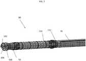
- FIG. 2shows an example of a portion of the BHA 90 of FIG. 1 according to one embodiment.
- the BHA 90includes a drill bit 50 that breaks rock or other formations by providing high power impulses to the rock.
- the drill bitincludes two electrodes 102, 104.
- the electrodes 102, 104are formed as equidistant spirals separated by an isolator 106.
- a power supplysuch as power unit 78 provides power to a high voltage pulse generator 110.
- the power unit 78may be part of a mud motor. a turbine or may be a battery. In one instance, the power unit 78 is a battery that is charged by a mud motor.
- a high voltage pulse generator 110(pulse generator) is electrically coupled between the power unit 78 and the electrodes 102, 104 and causes a rapid voltage to build up between the electrodes 102, 104. When the voltage reaches a threshold level, the voltage in the pulse generator 110 may discharge through the rock located between or in the vicinity of the electrodes 102, 104. It shall be understood to the skilled artisan that in this manner the electrodes 102, 104 operate as a capacitor and, as such, may be collectively referred to as a "bit capacitor" from time to time herein.
- FIG. 2Also included in FIG. 2 is an optional steering unit 112. Such units are known in the art and not discussed further herein.
- FIG. 3shows an equivalent circuit 300 of an embodiment of the present invention.
- the circuitincludes the pulse generator 110.
- the power unit 78provide an input voltage Vin to the pulse generator 110. This voltage causes the one or more high voltage capacitors 302 to be charged. When the switches S are closed, the charged voltage in the capacitors 302 causes the voltage between the electrodes 102, 104 that form the bit capacitor to quickly rise and then discharge through the rock.
- the pulse generator 110 shown in FIG. 3is an example only and also includes various resistors R the purpose of which the skilled artisan will understand and the values of which may be selected to cause the desired rise times of the potential between the electrodes 102, 104 described below. Other types of generators that cause a voltage between the electrodes 102, 104 to rise as described below may be utilized as the pulse generator 110 in other embodiments without departing from the teachings herein.
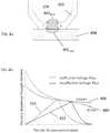
- FIG. 4aWith reference now to FIG. 3 and FIGs. 4a-4b , as the pulse generator 110 is allowed to charge the capacitor formed by electrodes 102, 104 (e.g., while switches S are closed) an electric potential builds up between the electrodes 102, 104.
- the potentialcauses an electric field to develop which is illustrated in FIG. 4a by illustrative electric field lines. As shown, some of the electric field lines pass through the drilling mud as indicated by field lines 402 fluid and another portion passes through the rock 404 as indicated by field lines 402 rock .
- FIG. 4bshows a ratio for granite (curve 406) and water (curve 408) that illustrates a relationship between an electric potential rise time and breakdown strength. That is, each of curves 406 and 408 show how fast a potential has to reach a particular level in order to cause a break down through the substance.
- FIG. 4bshows that, at the extremes (e.g., the rock is granite and drilling mud is pure water) that if the rise time of the buildup in the electric field is fast enough (trace 410) the breakdown will occur through the rock, not the fluid. If it is too slow (trace 412) the breakdown will occur through the fluid, not the rock.
- the so called “breakdown”refers to the condition where the energy between the electrodes is allowed to pass to ground.
- FIGs. 3 and 4a-4bare examples only and the particular build up speeds may be different. What is needed, however, is that the pulse generator be selected such that it can build a potential between the electrodes 102, 104 fast enough that the breakdown (e.g., current discharge) occurs through the rock, not the fluid.
- the breakdowne.g., current discharge
- the breakdown(and rock destruction) will occur where rock is between or near the electrodes 102, 104.
- the electrodes 102, 104are formed such the breakdown may occur at any or most locations on a face of the bit rather than a single location or several discrete locations. This may be achieved, in one embodiment, by providing spiral electrodes that are equidistant from each other on the face of the bit. Any of the electrodes described herein may individually be formed as bifilar coil. Alternatively, the electrodes 102, 104 may collectively form a bifilar coil.
- FIG. 5shows a bit 50 that includes a bit body 502.
- the body 502may be formed or any suitable drill bit material and may be formed of metal in one embodiment.
- the bit 50includes an insulating layer 106 that electrically separates the body 502 from the electrodes 102, 104.
- the insulating layer 106may be formed of Ceramic (e.g. Zirconium-Oxide), Plastic Material (e.g. PEEK, PTFE), Elastomers (Silicon) or insulating composites fiber materials depending on and in alignment with the electrical strength of the formation and/or the drilling fluid, as well as the design of the electrodes.
- the electrodes 102, 104are disposed on a face 504 of the bit 50 that is intended to be the forward most point of a drill string while in operation.
- the face 504may be defined by insulating layer 106 in one embodiment and the electrodes 102, 104 may extend outwardly from the insulating layer 106. It shall be understood that the electrodes may be on the surface of the insulating layer 106 or may have portions that are embedded therein.
- the electrodes 102, 104are formed of a conductive metal in one embodiment.
- the electrodes 102, 104may be connected to any type of pulse generator and the connection may take the form as shown in FIG. 3 , for example. Such connections may be made within the body 502. It shall be understood that, in one embodiment, the electrodes 102, 104 may have a protective coating disposed on them or may otherwise be protected from damage due to harsh drilling conditions. Such a coating is generally shown by element 640 in FIG. 6 .
- the bit body 502may include an internal passage that allows a drilling fluid to be pumped through it. That fluid may exit the face 504 via jets 520. Such fluid may be directed in outwardly in a spiral direction between the electrodes 102, 104 as indicate by flow arrows 540. This may help clear cuttings caused by discharges between electrodes 102, 104.
- each electrode 102, 104is formed as a spiral.
- the two spiralsare arranged on the face 504 such that they are at constant distance D from each other at most or all locations on the face. If the electrodes 102, 104 are closer to each other at any particular location a situation where discharge may occur at that location more often than other locations may arise. This may make forming a consistent "cutting" across the face 504 of the bit 50 more difficult to achieve.
- the body 502may also include a side cutter 510.
- the side cutter 510may include a mechanical blade 512 that, due to mechanical interaction between it and surrounding rock causes the rock to be removed.
- Such side cuttersare known and may take the form any known form including, for example, straight or spiraled gauge blades that may be coated or otherwise include very hard cutting elements such as natural or synthetic diamond.
- electrodes numbered 102will be positive and those numbered 104 will be negative. Also, to distinguish between locations, portions of an electrode on the face of the bit will have a suffix "a" and those surrounding the body will have a suffix "b" even though they are one continuous electrode.
- reference number 102awill refer to a face located portion of electrode 102 and reference number 102b will refer to body located portions of electrode 102.
- a leading edge 602 of the insulating layer 106 or the blade 512may have a portion of electrode 102 disposed on it. Such a portion is called a first side cutting electrode herein and shown as element 102b in FIG. 6 .
- the insulating layer 106may include an extension 606 that extends radially outward and supports a second side cutting electrode 104b that is an extension of the second electrode 104a.
- the first and second side cutting electrodes 604, 608are also separated by a distance D and serve to cut rock located lateral to the drill bit in the same manner as described above relative to the face.
- a bit 700includes helical spiral electrodes 102, 104 that surround a radial outer surface 702 of the insulating layer 106 that surrounds an outer perimeter of the drill bit 700.
- the portions of the electrodes 102, 104 (102a/104b) disposed on this outer surface 702may also be separated by the same distance D which they are separated on the face 112 or the blade 512 (or both).
- the portion of the first electrode 102 that surrounds surface 702is referred to as a first side cutting electrode 102b and the portion of the second electrode 104 that surrounds surface 702 is referred to as a second side cutting element 104b.
- the first and second side cutting electrodes 102b, 104bare also separated by a distance D and serve to cut rock located lateral to the drill bit in the same manner as described above relative to the face.
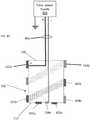
- FIG. 8shows a cross section taken along line 8-8 of FIG. 7 and an additional pulse power supply unit 804.
- the power supply unit 804can be located in the BHA or other location and provides one or more pulses in the manner as described above. In operation, the pulses can be generated by, for example, the circuit shown above in FIG. 3 or that shown in FIG. 9 below.
- a connector 806electrically connects the power supply unit 804 to the first electrode 102a on the face 112 of the bit.
- the connector 806may but need not, include a direct connection from the power supply 804 to the second, ground electrode 104a.
- the connection shown in FIG. 8could be utilized for bits in all embodiments disclosed above.
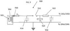
- the power supply unit 804has a circuit 900 that includes an input 902 that is provided to a transformer 904.
- the transformer 904can transform the voltage provided to a desired level.
- An optional diode 910can be provided for isolation.
- the power unit 78can provide an input voltage 902. This voltage causes the one or more high voltage capacitors 914, 916 separated by a spark gap 912 to be charged. When the voltage jumps the spark gap 912, both capacitors 914, 916 can discharge into the electrodes 102, 104. This allows for the electrodes 102, 104 that form the bit capacitor to quickly rise and then discharge through the rock. The timing of the discharges can be controlled based on capacitor values of capacitor 914, 916 and one or more resistors 920, 922 and RL. Capacitor 916 may be referred as a load capacitor and capacitor 914 can be referred to as a surge or spark capacitor herein.
- first and second electrodes 102, 104include side cutting electrodes 604, 608, that connecting to the face 112 located electrode 102 lead to the formation of parasitic capacitance C p that can reduce the power or otherwise effect the discharge between the bit electrodes.
- the connector 806could be connected to the first side cutting electrode 102b at or near the back end 720 of the bit 700 as shown in FIG. 10 . This will reduce the length of the connector 806 and, thereby, reduce the inductance provided by the conductor. This may also increase room for drilling mud in the bit 700.
- the negative portion of the connector 806is connected to the second side cutting electrode 104b
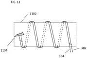
- FIG. 11shows an alternative embodiment.
- the power 102 and ground electrodes 104can be located near each other as is indicated in FIG. 11 .
- the spacing between themis constant and the two electrodes can be on the sides or face or both of the drill bit 1102.
- spark 1104When a discharge occurs (as indicated by spark 1104) the power and ground electrodes behave as a bifilar coil with currents flowing in the directions as indicated on electrodes 102/104.
- Such a configurationmay reduce the inductivity of the electrodes 102/104 as the magnetic fields created in them will cancel each other out.
- the circuit of FIG. 10could include a toggle or other type of switch 1202 that allows for the power to be delivered to either end of the electrodes.
- the toggle switch 1202is connecting the circuit to the face electrodes 102a, 104a.
- the individual switches in switch 1202may be insulated gate bipolar transistors or other types of transistors.
- Switching the togglewill allow connections to any configuration of the four possible connection locations (e.g., 102a, 102b, 104a, 104b) shown in FIG. 13 .
- the selection of how each switch is configurede.g., the how the circuit 900 is connected to the bit
- the performancecan be measured based on logging while drill data, a rate of penetration, fluid analysis, a combination of such information or based on other factors.
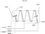
- the electrodeshave all had a face component 102a/104a.
- only side electrodesmay be included as is illustrated in FIG. 14 .
- the connectionscan be made at first end of the side electrodes 102b/104b as shown by the solid connection lines or the other end as shown by the dashed lines. Or course, other configurations are possible as well.
- various analyses and/or analytical componentsmay be used, including digital and/or analog systems.
- the systemmay have components such as a processor, storage media, memory, input, output, communications link (wired, wireless, pulsed mud, optical or other), user interfaces, software programs, signal processors (digital or analog) and other such components (such as resistors, capacitors, inductors and others) to provide for operation and analyses of the apparatus and methods disclosed herein in any of several manners well-appreciated in the art.
- teachingsmay be, but need not be, implemented in conjunction with a set of computer executable instructions stored on a computer readable medium, including memory (ROMs, RAMs), optical (CD-ROMs), or magnetic (disks, hard drives), or any other type that when executed causes a computer to implement the method of the present invention.
- ROMs, RAMsrandom access memory
- CD-ROMscompact disc-read only memory
- magnetic (disks, hard drives)any other type that when executed causes a computer to implement the method of the present invention.
- These instructionsmay provide for equipment operation, control, data collection and analysis and other functions deemed relevant by a system designer, owner, user or other such personnel, in addition to the functions described in this disclosure.
Landscapes
- Engineering & Computer Science (AREA)
- Life Sciences & Earth Sciences (AREA)
- Geology (AREA)
- Mining & Mineral Resources (AREA)
- Physics & Mathematics (AREA)
- Environmental & Geological Engineering (AREA)
- Fluid Mechanics (AREA)
- General Life Sciences & Earth Sciences (AREA)
- Geochemistry & Mineralogy (AREA)
- Mechanical Engineering (AREA)
- Earth Drilling (AREA)
- Drilling And Exploitation, And Mining Machines And Methods (AREA)
Description
- The present disclosure is related to the subterranean drilling and, more specifically, utilizing electrical impulses to break rock while drilling.
- During subterranean drilling and completion operations, a pipe or other conduit is lowered into a borehole in an earth formation during or after drilling operations. Such pipes are generally configured as multiple pipe segments to form a "string", such as a drill string or production string. As the string is lowered into the borehole, additional pipe segments are coupled to the string by various coupling mechanisms, such as threaded couplings.
- During drilling, a bit is coupled to a leading end of the drill string. Due to rotation of the string or the rotation of a mud motor (or both) the bit is caused to rotate and crush or otherwise break rock or other materials that it contacts. The crushed rock is then removed to the surface by a drilling fluid pumped through the drill string to region at or near the drill bit. Such drilling relies on pressure and contact between the rock and drill bit to crush/break the rock. Several different types of drill bits that can accomplish such rock breaking are known and include, for example, rolling cutter bits that drill largely by fracturing or crushing the formation with "tooth" shaped cutting elements on two or more cone-shaped elements that roll across the face of the borehole as the bit is rotated. Another type of bit is a fixed cutter bit that employs a set of blades with very hard cutting elements, most commonly natural or synthetic diamond, to remove material by scraping or grinding action as the bit is rotated.
- Another approach to crushing rock includes application of high-voltage electrical pulses to the rock to crush or break the rock. One such approach causes plasma-channel formation inside the rock ahead of the drill region due the application of high voltage pulses. The extremely rapid expansion of this plasma channel within the rock, which occurs in less than a millionth of a second, causes the local region of rock to fracture and fragment. This and other approaches may include providing electrodes at the tip bottom hole assembly (BHA). The BHA includes electronics that deliver the pulses to the electrodes and the discharge that causes the rock to break occurs through the rock and/or drilling fluid between the electrodes.
- Electrodes and rock have to be electrical contacted only. Less or no weight on bit is required to maintain the electrical contact and the drilling process therefore. Drilling to vertical depth deeper than 30.000 ft (10.000 m) and extreme long laterals will be enabled due to the absence of heavy weight drill pipes within the BHA. The utilization of deep high enthalpy reservoirs, as environmental friendly energy source, will be possible in the future including the build of down hole heat exchangers with multiple lateral wellbores in crystalline rock. Examples of pulsed-electric drilling systems comprising electrode-type drill bits can be seen in
US 2013/0032398 A1 andUS 2005/0150688 A1 . - According to one embodiment, a drill bit assembly is disclosed. The assembly includes a drill bit body and an insulating layer disposed on an end of the drill bit body and that defines a drill bit face. The assembly also includes two electrodes formed such that they both extend from the drill bit face, the two electrodes forming a spiral on the drill bit face and being equidistant from each other at all locations of the drill bit face.
- According to one embodiment, a drill bit assembly that includes a drill bit body and an insulating layer disposed around the drill bit body is disclosed. The assembly also includes two electrodes formed such that they both surround a radial outer surface of the insulating layer, the two electrodes forming a helical spiral shape about the radial outer surface and being equidistant from each other.
- According to another embodiment, a method of drilling a borehole is disclosed. The method includes: coupling a drill bit assembly to a drill string. The assembly includes a drill bit body, an insulating layer disposed on an end of the drill bit body and that defines a drill bit face and two electrodes formed such that they both extend form the drill bit and are equidistant from each other at all locations on the drill bit. The assembly also includes a pulse generator electrically coupled to the two electrodes. The method further includes: forming a potential between the two electrodes by providing power to the pulse generator; allowing the potential to discharge through a formation at or near the drill bit face; and removing formation fragments from the borehole caused by the discharge.
- The following descriptions should not be considered limiting in any way. With reference to the accompanying drawings, like elements are numbered alike:
FIG. 1 shows a drilling rig that may be used to deliver and drive a drill bit to a downhole location to drill a borehole;FIG. 2 is a perspective view of a portion of drill string including a drilling assembly according to one embodiment;FIG. 3 is an equivalent circuit representation of a pulse generator connected to a drill bit according to one embodiment;FIGs. 4a-4b show, respectively, fields that may be generated when a pulse generator provides a voltage between two electrodes contacting a formation and a rise time for the potential between the electrodes that cause discharge through rock or a fluid;FIG. 5 is a perspective view a drill bit according to one embodiment;FIG. 6 shows a portion of alternative drill bit according to another embodiment;FIG. 7 shows helical spiral electrodes surrounding a radial outer surface of the insulating layer of a drill bit according to one embodiment;FIG. 8 shows a cross section taken along line 8-8 ofFIG. 7 and an additional pulse power supply unit;FIG. 9 shows an example of a circuit that may drive any of the embodiments disclosed herein;FIG. 10 shows connection of the pulse power supply connected to a different location than that shown inFIG. 8 ;FIG. 11 shows the electrodes arranged such a bifilar coil is formed when a discharge occurs between them;FIG. 12 shows the circuit ofFIG. 9 with an additional output toggle element;FIG. 13 shows possible configurations of drill bit ofFIG. 7 connected to the circuit shown inFIG. 12 ; andFIG. 14 shows the output toggle element ofFIG. 12 connected in two manners to side electrodes implemented as a bifilar coil.- A detailed description of one or more embodiments of the disclosed system, apparatus and method are presented herein by way of exemplification and not limitation with reference to the Figures.
- As discussed above, prior electrical pulse drilling methods included electrodes between which electric potential fields were created. The fields may cause impact ionization to occur in the rock which will eventually cause the rock to break and the potential between the electrodes to discharge though the rock and cause localized rock breakage near the location between the electrodes where the breakdown occurred. That is, the location of the electrodes determined where the rock was broken and regions not between the electrodes may not be effectively broken. Disclosed herein is a system that includes a drill bit with electrodes that allow for rock breakage at different locations. As more fully disclosed below, the electrodes may be configured as spirals that are equidistant distant from each other and disposed on a leading end of a drill bit. Such a configuration may provide from more distributed electric fields and allow for improved hole cleaning in some embodiments.
FIG. 1 shows a schematic diagram of a drilling system 10 with adrillstring 20 carrying a drilling assembly 90 (also referred to as the bottom hole assembly, or "BHA") conveyed in a "wellbore" or "borehole" 26 for drilling the wellbore. The drilling system 10 includes a conventional derrick 11 erected on a floor 12 which supports a rotary table 14 that is rotated by a prime mover such as an electric motor (not shown) at a desired rotational speed. Thedrillstring 20 includes a tubing such as adrill pipe 22 extending downward from the surface into theborehole 26. Thedrill bit 50 attached to the end of the drillstring breaks up the geological formations. In typical systems, rotation and pressure (e.g,. weight-on-bit) causes rocks or other elements forming the formation to break when the bit is rotated to drill theborehole 26. Herein, the bit may include electrodes that cause the rock to break. In one embodiment, thebit 50 may also include blades or other elements to side cut the rock.- If a
drill pipe 22 is used, thedrillstring 20 is coupled to adrawworks 30 via a Kelly joint 21,swivel 28, and line 29 through apulley 23. During drilling operations, thedrawworks 30 is operated to control the weight on bit, which is an important parameter that affects the rate of penetration. The operation of the drawworks is well known in the art and is thus not described in detail herein. - During drilling operations, a
suitable drilling fluid 31 from a mud pit (source) 32 is circulated under pressure through a channel in thedrillstring 20 by amud pump 34. The drilling fluid passes from themud pump 34 into thedrillstring 20 via a desurger (not shown),fluid line 38 and Kelly joint 21. Thedrilling fluid 31 is discharged at the borehole bottom 51 through an opening in thedrill bit 50. Thedrilling fluid 31 circulates uphole through theannular space 27 between the drillstring 20 and theborehole 26 and returns to themud pit 32 via areturn line 35. The drilling fluid acts to lubricate thedrill bit 50 and to carry borehole cutting or chips away from thedrill bit 50. A sensor S1 preferably placed in theline 38 provides information about the fluid flow rate. A surface torque sensor S2 and a sensor S3 associated with thedrillstring 20 respectively provide information about the torque and rotational speed of the drillstring. Additionally, a sensor (not shown) associated with line 29 is used to provide the hook load of thedrillstring 20. - In one embodiment of the disclosure, the
drill bit 50 is rotated by only rotating thedrill pipe 22. In another embodiment of the disclosure, a downhole motor 55 (mud motor) is disposed in thedrilling assembly 90 to rotate thedrill bit 50 and thedrill pipe 22 is rotated usually to supplement the rotational power, if required, and to effect changes in the drilling direction. - In the embodiment of
FIG. 1 , the mud motor 55 is coupled to thedrill bit 50 via a drive shaft (not shown) disposed in a bearingassembly 57. The mud motor rotates thedrill bit 50 when thedrilling fluid 31 passes through the mud motor 55 under pressure. The bearingassembly 57 supports the radial and axial forces of the drill bit. A stabilizer 58 coupled to the bearingassembly 57 acts as a centralizer for the lowermost portion of the mud motor assembly. - In one embodiment of the disclosure, a
drilling sensor module 59 is placed near thedrill bit 50. The drilling sensor module contains sensors, circuitry and processing software and algorithms relating to the dynamic drilling parameters. Such parameters preferably include bit bounce, stick-slip of the drilling assembly, backward rotation, torque, shocks, borehole and annulus pressure, acceleration measurements and other measurements of the drill bit condition. A suitable telemetry orcommunication sub 72 using, for example, two-way telemetry, is also provided as illustrated in thedrilling assembly 90. The drilling sensor module processes the sensor information and transmits it to thesurface control unit 40 via thetelemetry system 72. - The
communication sub 72, apower unit 78 and anMWD tool 79 are all connected in tandem with thedrillstring 20. Flex subs, for example, are used in connecting theMWD tool 79 in thedrilling assembly 90. Such subs and tools form the bottomhole drilling assembly 90 between the drillstring 20 and thedrill bit 50. Thedrilling assembly 90 may make various measurements while theborehole 26 is being drilled. Thecommunication sub 72 obtains the signals and measurements and transfers the signals, using two-way telemetry, for example, to be processed on the surface. Alternatively, the signals can be processed using a downhole processor in thedrilling assembly 90. The telemetry system may include a wired pipe system which may be used to bi-directionally transfer data as well as transfer energy from surface to downhole in order to power the drill bit. - The surface control unit or
processor 40 also receives signals from other downhole sensors and devices and signals from sensors S1-S3 and other sensors used in the system 10 and processes such signals according to programmed instructions provided to thesurface control unit 40. Thesurface control unit 40 displays desired drilling parameters and other information on a display/monitor 42 utilized by an operator to control the drilling operations. Thesurface control unit 40 preferably includes a computer or a microprocessor-based processing system, memory for storing programs or models and data, a recorder for recording data, and other peripherals. Thecontrol unit 40 is preferably adapted to activatealarms 44 when certain unsafe or undesirable operating conditions occur. FIG. 2 shows an example of a portion of theBHA 90 ofFIG. 1 according to one embodiment. TheBHA 90 includes adrill bit 50 that breaks rock or other formations by providing high power impulses to the rock. As shown, the drill bit includes twoelectrodes electrodes isolator 106. A power supply such aspower unit 78 provides power to a highvoltage pulse generator 110. Thepower unit 78 may be part of a mud motor. a turbine or may be a battery. In one instance, thepower unit 78 is a battery that is charged by a mud motor.- A high voltage pulse generator 110 (pulse generator) is electrically coupled between the
power unit 78 and theelectrodes electrodes pulse generator 110 may discharge through the rock located between or in the vicinity of theelectrodes electrodes - Also included in
FIG. 2 is anoptional steering unit 112. Such units are known in the art and not discussed further herein. FIG. 3 shows anequivalent circuit 300 of an embodiment of the present invention. The circuit includes thepulse generator 110. Thepower unit 78 provide an input voltage Vin to thepulse generator 110. This voltage causes the one or morehigh voltage capacitors 302 to be charged. When the switches S are closed, the charged voltage in thecapacitors 302 causes the voltage between theelectrodes pulse generator 110 shown inFIG. 3 is an example only and also includes various resistors R the purpose of which the skilled artisan will understand and the values of which may be selected to cause the desired rise times of the potential between theelectrodes electrodes pulse generator 110 in other embodiments without departing from the teachings herein.- With reference now to
FIG. 3 andFIGs. 4a-4b , as thepulse generator 110 is allowed to charge the capacitor formed byelectrodes 102, 104 (e.g., while switches S are closed) an electric potential builds up between theelectrodes FIG. 4a by illustrative electric field lines. As shown, some of the electric field lines pass through the drilling mud as indicated byfield lines 402fluid and another portion passes through therock 404 as indicated byfield lines 402rock. FIG. 4b shows a ratio for granite (curve 406) and water (curve 408) that illustrates a relationship between an electric potential rise time and breakdown strength. That is, each ofcurves FIG. 4b shows that, at the extremes (e.g., the rock is granite and drilling mud is pure water) that if the rise time of the buildup in the electric field is fast enough (trace 410) the breakdown will occur through the rock, not the fluid. If it is too slow (trace 412) the breakdown will occur through the fluid, not the rock. The so called "breakdown" refers to the condition where the energy between the electrodes is allowed to pass to ground.- It shall be understood that
FIGs. 3 and4a-4b are examples only and the particular build up speeds may be different. What is needed, however, is that the pulse generator be selected such that it can build a potential between theelectrodes - Given the fast rise times, to the extent rock is present between the electrodes, the breakdown (and rock destruction) will occur where rock is between or near the
electrodes electrodes electrodes FIG. 5 shows abit 50 that includes abit body 502. Thebody 502 may be formed or any suitable drill bit material and may be formed of metal in one embodiment. Thebit 50 includes an insulatinglayer 106 that electrically separates thebody 502 from theelectrodes layer 106 may be formed of Ceramic (e.g. Zirconium-Oxide), Plastic Material (e.g. PEEK, PTFE), Elastomers (Silicon) or insulating composites fiber materials depending on and in alignment with the electrical strength of the formation and/or the drilling fluid, as well as the design of the electrodes. As illustrated, theelectrodes face 504 of thebit 50 that is intended to be the forward most point of a drill string while in operation. Theface 504 may be defined by insulatinglayer 106 in one embodiment and theelectrodes layer 106. It shall be understood that the electrodes may be on the surface of the insulatinglayer 106 or may have portions that are embedded therein.- The
electrodes electrodes FIG. 3 , for example. Such connections may be made within thebody 502. It shall be understood that, in one embodiment, theelectrodes element 640 inFIG. 6 . - The
bit body 502 may include an internal passage that allows a drilling fluid to be pumped through it. That fluid may exit theface 504 viajets 520. Such fluid may be directed in outwardly in a spiral direction between theelectrodes flow arrows 540. This may help clear cuttings caused by discharges betweenelectrodes - As shown, each
electrode face 504 such that they are at constant distance D from each other at most or all locations on the face. If theelectrodes face 504 of thebit 50 more difficult to achieve. - In one embodiment, the
body 502 may also include aside cutter 510. Theside cutter 510 may include amechanical blade 512 that, due to mechanical interaction between it and surrounding rock causes the rock to be removed. Such side cutters are known and may take the form any known form including, for example, straight or spiraled gauge blades that may be coated or otherwise include very hard cutting elements such as natural or synthetic diamond. - In the following description, electrodes numbered 102 will be positive and those numbered 104 will be negative. Also, to distinguish between locations, portions of an electrode on the face of the bit will have a suffix "a" and those surrounding the body will have a suffix "b" even though they are one continuous electrode. For example,
reference number 102a will refer to a face located portion ofelectrode 102 andreference number 102b will refer to body located portions ofelectrode 102. - In another embodiment, and with reference now to
FIG. 6 , a leading edge 602 of the insulatinglayer 106 or the blade 512 (or both) may have a portion ofelectrode 102 disposed on it. Such a portion is called a first side cutting electrode herein and shown aselement 102b inFIG. 6 . The insulatinglayer 106 may include anextension 606 that extends radially outward and supports a secondside cutting electrode 104b that is an extension of thesecond electrode 104a. The first and secondside cutting electrodes 604, 608 are also separated by a distance D and serve to cut rock located lateral to the drill bit in the same manner as described above relative to the face. - In another embodiment, and with reference now to
FIG. 7 , abit 700 includes helicalspiral electrodes outer surface 702 of the insulatinglayer 106 that surrounds an outer perimeter of thedrill bit 700. In such a case, the portions of theelectrodes 102, 104 (102a/104b) disposed on thisouter surface 702 may also be separated by the same distance D which they are separated on theface 112 or the blade 512 (or both). The portion of thefirst electrode 102 that surroundssurface 702 is referred to as a firstside cutting electrode 102b and the portion of thesecond electrode 104 that surroundssurface 702 is referred to as a secondside cutting element 104b. The first and secondside cutting electrodes FIG. 8 shows a cross section taken along line 8-8 ofFIG. 7 and an additional pulsepower supply unit 804. Thepower supply unit 804 can be located in the BHA or other location and provides one or more pulses in the manner as described above. In operation, the pulses can be generated by, for example, the circuit shown above inFIG. 3 or that shown inFIG. 9 below. Aconnector 806 electrically connects thepower supply unit 804 to thefirst electrode 102a on theface 112 of the bit. Of course, theconnector 806 may but need not, include a direct connection from thepower supply 804 to the second,ground electrode 104a. The connection shown inFIG. 8 could be utilized for bits in all embodiments disclosed above.- In more detail, and now with reference to
FIG. 9 , thepower supply unit 804 has acircuit 900 that includes aninput 902 that is provided to atransformer 904. Thetransformer 904 can transform the voltage provided to a desired level. Anoptional diode 910 can be provided for isolation. - As described above, the power unit 78 (
FIG. 2 ) can provide aninput voltage 902. This voltage causes the one or morehigh voltage capacitors spark gap 912 to be charged. When the voltage jumps thespark gap 912, bothcapacitors electrodes electrodes capacitor more resistors Capacitor 916 may be referred as a load capacitor andcapacitor 914 can be referred to as a surge or spark capacitor herein. - Referring back to
FIG. 7 , it has been discovered in embodiments where the first andsecond electrodes side cutting electrodes 604, 608, that connecting to theface 112 locatedelectrode 102 lead to the formation of parasitic capacitance Cp that can reduce the power or otherwise effect the discharge between the bit electrodes. - In an alternative embodiment, the
connector 806 could be connected to the firstside cutting electrode 102b at or near theback end 720 of thebit 700 as shown inFIG. 10 . This will reduce the length of theconnector 806 and, thereby, reduce the inductance provided by the conductor. This may also increase room for drilling mud in thebit 700. In this embodiment, the negative portion of theconnector 806 is connected to the secondside cutting electrode 104b FIG. 11 shows an alternative embodiment. In this embodiment, rather than having a two separate helical spirals shaped electrodes, thepower 102 andground electrodes 104 can be located near each other as is indicated inFIG. 11 . The spacing between them is constant and the two electrodes can be on the sides or face or both of thedrill bit 1102. When a discharge occurs (as indicated by spark 1104) the power and ground electrodes behave as a bifilar coil with currents flowing in the directions as indicated onelectrodes 102/104. Such a configuration may reduce the inductivity of theelectrodes 102/104 as the magnetic fields created in them will cancel each other out.- With reference to
FIG. 12 , in another embodiment, the circuit ofFIG. 10 could include a toggle or other type ofswitch 1202 that allows for the power to be delivered to either end of the electrodes. For example, as shown inFIG. 12 , thetoggle switch 1202 is connecting the circuit to theface electrodes switch 1202 may be insulated gate bipolar transistors or other types of transistors. - Switching the toggle will allow connections to any configuration of the four possible connection locations (e.g., 102a, 102b, 104a, 104b) shown in
FIG. 13 . The selection of how each switch is configured (e.g., the how thecircuit 900 is connected to the bit) can be made randomly or based on performance. The performance can be measured based on logging while drill data, a rate of penetration, fluid analysis, a combination of such information or based on other factors. - In the previous examples the electrodes have all had a
face component 102a/104a. In one embodiment, only side electrodes may be included as is illustrated inFIG. 14 . In such a case, the connections can be made at first end of theside electrodes 102b/104b as shown by the solid connection lines or the other end as shown by the dashed lines. Or course, other configurations are possible as well. - In support of the teachings herein, various analyses and/or analytical components may be used, including digital and/or analog systems. The system may have components such as a processor, storage media, memory, input, output, communications link (wired, wireless, pulsed mud, optical or other), user interfaces, software programs, signal processors (digital or analog) and other such components (such as resistors, capacitors, inductors and others) to provide for operation and analyses of the apparatus and methods disclosed herein in any of several manners well-appreciated in the art. It is considered that these teachings may be, but need not be, implemented in conjunction with a set of computer executable instructions stored on a computer readable medium, including memory (ROMs, RAMs), optical (CD-ROMs), or magnetic (disks, hard drives), or any other type that when executed causes a computer to implement the method of the present invention. These instructions may provide for equipment operation, control, data collection and analysis and other functions deemed relevant by a system designer, owner, user or other such personnel, in addition to the functions described in this disclosure.
- One skilled in the art will recognize that the various components or technologies may provide certain necessary or beneficial functionality or features. Accordingly, these functions and features as may be needed in support of the appended claims and variations thereof, are recognized as being inherently included as a part of the teachings herein and a part of the invention disclosed.
- While the invention has been described with reference to exemplary embodiments, it will be understood by those skilled in the art that various changes may be made and equivalents may be substituted for elements thereof without departing from the scope of the invention. In addition, many modifications will be appreciated by those skilled in the art to adapt a particular instrument, situation or material to the teachings of the invention without departing from the essential scope thereof. Therefore, it is intended that the invention not be limited to the particular embodiment disclosed as the best mode contemplated for carrying out this invention, but that the invention will include all embodiments falling within the scope of the appended claims.
Claims (16)
- A drill bit assembly comprising:a drill bit body (502);an insulating layer (106) disposed on an end of the drill bit body and that defines a drill bit face (112);characterised in that the assembly further comprises: two electrodes (102a/104a) formed such that they both extend from the drill bit face, the two electrodes forming a spiral on the drill bit face and being equidistant (D) from each other at all locations of the drill bit face.
- A drill bit assembly comprising:a drill bit body (502);an insulating layer (106) disposed around the drill bit body;characterised in that the assembly further comprises: two electrodes formed such that they both surround a radial outer surface of the insulating layer, the two electrodes (102b/104b) forming a helical shape about the radial outer surface (702) and being equidistant from each other.
- The drill bit assembly of any preceding claim, wherein the electrodes form a bifilar coil when a discharge occurs between them.
- The drill bit assembly of any preceding claim, further comprising:
a pulse generator (110) electrically coupled to the two electrodes. - The drill bit assembly of claim 4, wherein the pulse generator causes the formation of a potential between the two electrodes.
- The drill bit assembly of claim 5, wherein the pulse generator causes the potential to be formed at a rise time (410) that is below a threshold rise time.
- The drill bit assembly of claim 6, wherein the threshold rise time is less than a rise time where the potential will discharge through a fluid between the two electrodes.
- The drill bit assembly of claim 7, wherein the threshold rise time is equal to a rise time where the potential will discharge through a rock near or between the two electrodes.
- The drill bit assembly of claim 4, further comprising:
a power unit (78) that provides power to the pulse generator. - The drill bit assembly of claim 9, wherein the power unit is one of a battery, turbine or a mud motor.
- The drill bit assembly of claim 1, wherein the two electrodes also surround a radial outer surface (702) of the insulating layer and are equidistance around from each other around the radial outer surface.
- The drill bit assembly of claim 4, wherein the pulse generator includes a toggle switch (1202) that allows for the potential to be provided to either end of both electrodes.
- A method of drilling a borehole comprising:
coupling a drill bit assembly to a drill string (20), the assembly comprising:a drill bit body (502);an insulating layer (106) disposed on an end of the drill bit body and that defines a drill bit face (112);two electrodes (102/104) formed such that they both extend form the drill bit, the two electrodes being equidistant from each other at all locations on the drill bit; anda pulse generator (110) electrically coupled to the two electrodes;forming a potential between the two electrodes by providing power to the pulse generator;allowing the potential to discharge through a formation at or near the drill bit face; andremoving formation fragments from the borehole caused by the discharge. - The method of claim 13, wherein the pulse generator causes the potential to be formed at a rise time (410) that is below a threshold rise time.
- The method of claim 14, wherein the threshold rise time is less than a rise time where the potential will discharge through a fluid between the two electrodes and is equal to a rise time where the potential will discharge through a rock near or between the two electrodes.
- The method of claim 15, further comprising:
switching a configuration of a switch (1202) in the pulse generator to change a location where the pulse generator provides forms the potential.
Applications Claiming Priority (2)
| Application Number | Priority Date | Filing Date | Title |
|---|---|---|---|
| US201662280842P | 2016-01-20 | 2016-01-20 | |
| PCT/US2017/014305WO2017127659A1 (en) | 2016-01-20 | 2017-01-20 | Electrical pulse drill bit having spiral electrodes |
Publications (3)
| Publication Number | Publication Date |
|---|---|
| EP3405640A1 EP3405640A1 (en) | 2018-11-28 |
| EP3405640A4 EP3405640A4 (en) | 2019-10-09 |
| EP3405640B1true EP3405640B1 (en) | 2020-11-11 |
Family
ID=59314467
Family Applications (1)
| Application Number | Title | Priority Date | Filing Date |
|---|---|---|---|
| EP17741997.5AActiveEP3405640B1 (en) | 2016-01-20 | 2017-01-20 | Electrical pulse drill bit having spiral electrodes |
Country Status (3)
| Country | Link |
|---|---|
| US (1) | US10370903B2 (en) |
| EP (1) | EP3405640B1 (en) |
| WO (1) | WO2017127659A1 (en) |
Families Citing this family (15)
| Publication number | Priority date | Publication date | Assignee | Title |
|---|---|---|---|---|
| US10060195B2 (en)* | 2006-06-29 | 2018-08-28 | Sdg Llc | Repetitive pulsed electric discharge apparatuses and methods of use |
| US10407995B2 (en)* | 2012-07-05 | 2019-09-10 | Sdg Llc | Repetitive pulsed electric discharge drills including downhole formation evaluation |
| US10584585B2 (en) | 2016-11-15 | 2020-03-10 | Arcbyt, Inc. | Tunneling for underground power and pipelines |
| CN108661554B (en)* | 2018-05-11 | 2019-08-30 | 东北石油大学 | Combination device based on plasma channel and mechanical drilling tool and its drilling method |
| EP3874114B1 (en)* | 2018-10-30 | 2025-08-13 | The Texas A&M University System | Systems and methods for forming a subterranean borehole |
| EP3679219A4 (en)* | 2018-11-14 | 2020-07-15 | Arcbyt, Inc. | TUNNELING FOR UNDERGROUND POWER AND PIPELINES |
| EP3997304B1 (en)* | 2019-07-09 | 2024-05-01 | Baker Hughes Oilfield Operations LLC | Electrical impulse earth-boring tools and related systems and methods |
| US20210062639A1 (en)* | 2019-09-03 | 2021-03-04 | Halliburton Energy Services, Inc. | Pulsed power sculpting methods |
| US11585156B2 (en) | 2020-04-06 | 2023-02-21 | Halliburton Energy Services, Inc. | Pulsed-power drill bit ground ring with abrasive material |
| US11525306B2 (en) | 2020-04-06 | 2022-12-13 | Halliburton Energy Services, Inc. | Pulsed-power drill bit ground ring with two portions |
| WO2022109056A1 (en)* | 2020-11-17 | 2022-05-27 | Sdg Llc | Configurable electrocrushing mining apparatus |
| US11591909B2 (en) | 2021-01-12 | 2023-02-28 | EarthGrid PBC | Tunnel boring system |
| US11136886B1 (en) | 2021-01-12 | 2021-10-05 | EarthGrid PBC | Tunnel boring system |
| CN115341844B (en)* | 2022-10-14 | 2023-01-17 | 沧州格锐特钻头有限公司 | Short-bending impact-resistant large-torque screw drill |
| US20250240001A1 (en)* | 2024-01-19 | 2025-07-24 | Halliburton Energy Services, Inc. | Pulse generating systems, pulse generating circuits, and methods to improve performance of a pulsed power drilling system |
Family Cites Families (40)
| Publication number | Priority date | Publication date | Assignee | Title |
|---|---|---|---|---|
| US4741405A (en) | 1987-01-06 | 1988-05-03 | Tetra Corporation | Focused shock spark discharge drill using multiple electrodes |
| RU2083824C1 (en) | 1995-06-13 | 1997-07-10 | Научно-исследовательский институт высоких напряжений при Томском политехническом университете | Rock crushing method |
| US5896938A (en) | 1995-12-01 | 1999-04-27 | Tetra Corporation | Portable electrohydraulic mining drill |
| RU2123596C1 (en) | 1996-10-14 | 1998-12-20 | Научно-исследовательский институт высоких напряжений при Томском политехническом университете | Method for electric-pulse drilling of wells, and drilling unit |
| US6427774B2 (en) | 2000-02-09 | 2002-08-06 | Conoco Inc. | Process and apparatus for coupled electromagnetic and acoustic stimulation of crude oil reservoirs using pulsed power electrohydraulic and electromagnetic discharge |
| GB0203252D0 (en) | 2002-02-12 | 2002-03-27 | Univ Strathclyde | Plasma channel drilling process |
| NO322323B2 (en)* | 2003-12-01 | 2016-09-13 | Unodrill As | Method and apparatus for ground drilling |
| US7527108B2 (en) | 2004-08-20 | 2009-05-05 | Tetra Corporation | Portable electrocrushing drill |
| US7559378B2 (en) | 2004-08-20 | 2009-07-14 | Tetra Corporation | Portable and directional electrocrushing drill |
| US7416032B2 (en)* | 2004-08-20 | 2008-08-26 | Tetra Corporation | Pulsed electric rock drilling apparatus |
| US8172006B2 (en) | 2004-08-20 | 2012-05-08 | Sdg, Llc | Pulsed electric rock drilling apparatus with non-rotating bit |
| EP3620605B1 (en) | 2004-08-20 | 2022-08-24 | Sdg, Llc | Pulsed electric rock drilling, fracturing, and crushing methods and apparatus |
| US8186454B2 (en) | 2004-08-20 | 2012-05-29 | Sdg, Llc | Apparatus and method for electrocrushing rock |
| US9016359B2 (en)* | 2004-08-20 | 2015-04-28 | Sdg, Llc | Apparatus and method for supplying electrical power to an electrocrushing drill |
| GB2420358B (en) | 2004-11-17 | 2008-09-03 | Schlumberger Holdings | System and method for drilling a borehole |
| US9416594B2 (en) | 2004-11-17 | 2016-08-16 | Schlumberger Technology Corporation | System and method for drilling a borehole |
| WO2014100255A1 (en) | 2012-12-18 | 2014-06-26 | Sdg, Llc | Repetitive pulsed electric discharge apparatuses and methods of use |
| UA83281C2 (en) | 2006-07-28 | 2008-06-25 | Институт Импульсных Процессов И Технологий Нан Украины | High-voltage pulse capacitor for drilling installations |
| DE202006018980U1 (en) | 2006-12-15 | 2007-04-12 | Herrenknecht Ag | Drilling device for breaking up hard rock in the construction of tunnels comprises electrodes arranged on the front side of the drill head and clamping units with a voltage being formed between the electrodes |
| NO330103B1 (en) | 2007-02-09 | 2011-02-21 | Statoil Asa | Assembly for drilling and logging, method for electropulse drilling and logging |
| WO2009073475A2 (en) | 2007-11-30 | 2009-06-11 | Chevron U.S.A. Inc. | Pulse fracturing device and method |
| US7984773B2 (en)* | 2008-05-13 | 2011-07-26 | Longyear Tm, Inc. | Sonic drill bit for core sampling |
| RU2388908C1 (en) | 2009-04-03 | 2010-05-10 | Общество С Ограниченной Ответственностью "Соновита" | Method of electric hydraulic impact on oil formation and device for its implementation |
| EA016999B1 (en) | 2009-06-24 | 2012-09-28 | Анатолий Яковлевич КАРТЕЛЕВ | Device for producing an electrohydraulic effect on a well bottom-hole zone |
| WO2012142738A1 (en)* | 2011-04-18 | 2012-10-26 | Empire Technology Development Llc | Improved drilling technology |
| RU2471987C1 (en) | 2011-07-08 | 2013-01-10 | Государственное образовательное учреждение высшего профессионального образования "Национальный исследовательский Томский политехнический университет" | Electric pulse drilling bit |
| US20130032398A1 (en)* | 2011-08-02 | 2013-02-07 | Halliburton Energy Services, Inc. | Pulsed-Electric Drilling Systems and Methods with Reverse Circulation |
| US9027669B2 (en) | 2011-08-02 | 2015-05-12 | Halliburton Energy Services, Inc. | Cooled-fluid systems and methods for pulsed-electric drilling |
| RU2477370C1 (en) | 2011-09-21 | 2013-03-10 | Федеральное государственное бюджетное образовательное учреждение высшего профессионального образования "Национальный исследовательский Томский политехнический университет" | Submerged-type electric pulse drill |
| EP2574148A2 (en) | 2011-09-26 | 2013-03-27 | Toshiba Lighting & Technology Corporation | Lighting device, lighting equipment, and lighting control system |
| US8746365B2 (en)* | 2011-10-03 | 2014-06-10 | Chevron U.S.A. Inc. | Electro-hydraulic drilling with shock wave reflection |
| RU2500873C1 (en) | 2012-04-28 | 2013-12-10 | Федеральное государственное бюджетное образовательное учреждение высшего профессионального образования "Национальный исследовательский Томский политехнический университет" | Electric pulse drilling assembly |
| CN103527077B (en) | 2012-07-04 | 2015-08-19 | 长江大学 | Downhole turbine motor plasma drilling tool |
| SK500062013A3 (en) | 2013-03-05 | 2014-10-03 | Ga Drilling, A. S. | Electric arc generating, that affects on material (directly, planar, thermally, mechanicaly) and device for generating an electric arc |
| CN203738235U (en) | 2014-02-13 | 2014-07-30 | 温州大学 | Auxiliary laser drilling device with electric field and magnetic field coupled |
| FR3017897B1 (en) | 2014-02-21 | 2019-09-27 | I.T.H.P.P | ROTARY DRILLING SYSTEM BY ELECTRIC DISCHARGES |
| CN103878459A (en) | 2014-03-05 | 2014-06-25 | 洛阳信成精密机械有限公司 | Portable type spark-erosion drilling machine |
| DE102014106843B4 (en) | 2014-05-15 | 2020-09-17 | Thyssenkrupp Ag | Method of drilling a borehole |
| CN204024644U (en) | 2014-05-22 | 2014-12-17 | 北京六合伟业科技股份有限公司 | Ground and underground equipment two-way communication inclinometer |
| CN104201666B (en) | 2014-08-21 | 2019-10-29 | 中国石油化工集团公司 | Oil-well rig DC micro power grid system |
- 2017
- 2017-01-20USUS15/410,955patent/US10370903B2/enactiveActive
- 2017-01-20WOPCT/US2017/014305patent/WO2017127659A1/ennot_activeCeased
- 2017-01-20EPEP17741997.5Apatent/EP3405640B1/enactiveActive
Non-Patent Citations (1)
| Title |
|---|
| None* |
Also Published As
| Publication number | Publication date |
|---|---|
| EP3405640A4 (en) | 2019-10-09 |
| EP3405640A1 (en) | 2018-11-28 |
| WO2017127659A1 (en) | 2017-07-27 |
| US20170204669A1 (en) | 2017-07-20 |
| US10370903B2 (en) | 2019-08-06 |
Similar Documents
| Publication | Publication Date | Title |
|---|---|---|
| EP3405640B1 (en) | Electrical pulse drill bit having spiral electrodes | |
| EP2554777B1 (en) | Systems and methods for drilling boreholes with noncircular or variable cross-sections | |
| US8567527B2 (en) | System and method for drilling a borehole | |
| US10738536B2 (en) | Drilling a rock formation with a drill bit assembly-with electrodes | |
| US9416594B2 (en) | System and method for drilling a borehole | |
| WO2014100255A1 (en) | Repetitive pulsed electric discharge apparatuses and methods of use | |
| US9175515B2 (en) | Wired mud motor components, methods of fabricating the same, and downhole motors incorporating the same | |
| AU2017355453B2 (en) | Debris bridge monitoring and removal for uphole milling system | |
| US20160326806A1 (en) | A method for energy efficient and fast rotary drilling in inhomogeneous and/or hard rock formations | |
| US10167702B2 (en) | Electrical power generation system | |
| US20170204668A1 (en) | Electric pulse drilling apparatus with hole cleaning passages | |
| US12228016B2 (en) | Tapered string pulse power rock excavation system | |
| US20140360784A1 (en) | Through Casing Coring | |
| WO2016200374A1 (en) | Watermelon mill | |
| WO2022060383A1 (en) | Electroactive polymer vibration dampener for downhole drilling tools |
Legal Events
| Date | Code | Title | Description |
|---|---|---|---|
| STAA | Information on the status of an ep patent application or granted ep patent | Free format text:STATUS: THE INTERNATIONAL PUBLICATION HAS BEEN MADE | |
| PUAI | Public reference made under article 153(3) epc to a published international application that has entered the european phase | Free format text:ORIGINAL CODE: 0009012 | |
| STAA | Information on the status of an ep patent application or granted ep patent | Free format text:STATUS: REQUEST FOR EXAMINATION WAS MADE | |
| 17P | Request for examination filed | Effective date:20180815 | |
| AK | Designated contracting states | Kind code of ref document:A1 Designated state(s):AL AT BE BG CH CY CZ DE DK EE ES FI FR GB GR HR HU IE IS IT LI LT LU LV MC MK MT NL NO PL PT RO RS SE SI SK SM TR | |
| AX | Request for extension of the european patent | Extension state:BA ME | |
| DAV | Request for validation of the european patent (deleted) | ||
| DAX | Request for extension of the european patent (deleted) | ||
| A4 | Supplementary search report drawn up and despatched | Effective date:20190905 | |
| RIC1 | Information provided on ipc code assigned before grant | Ipc:E21B 7/15 20060101AFI20190830BHEP Ipc:E21B 10/00 20060101ALI20190830BHEP | |
| GRAP | Despatch of communication of intention to grant a patent | Free format text:ORIGINAL CODE: EPIDOSNIGR1 | |
| STAA | Information on the status of an ep patent application or granted ep patent | Free format text:STATUS: GRANT OF PATENT IS INTENDED | |
| INTG | Intention to grant announced | Effective date:20200612 | |
| RAP1 | Party data changed (applicant data changed or rights of an application transferred) | Owner name:BAKER HUGHES HOLDINGS LLC | |
| GRAS | Grant fee paid | Free format text:ORIGINAL CODE: EPIDOSNIGR3 | |
| GRAA | (expected) grant | Free format text:ORIGINAL CODE: 0009210 | |
| STAA | Information on the status of an ep patent application or granted ep patent | Free format text:STATUS: THE PATENT HAS BEEN GRANTED | |
| AK | Designated contracting states | Kind code of ref document:B1 Designated state(s):AL AT BE BG CH CY CZ DE DK EE ES FI FR GB GR HR HU IE IS IT LI LT LU LV MC MK MT NL NO PL PT RO RS SE SI SK SM TR | |
| REG | Reference to a national code | Ref country code:GB Ref legal event code:FG4D | |
| REG | Reference to a national code | Ref country code:CH Ref legal event code:EP | |
| REG | Reference to a national code | Ref country code:AT Ref legal event code:REF Ref document number:1333649 Country of ref document:AT Kind code of ref document:T Effective date:20201115 | |
| REG | Reference to a national code | Ref country code:DE Ref legal event code:R096 Ref document number:602017027378 Country of ref document:DE | |
| REG | Reference to a national code | Ref country code:IE Ref legal event code:FG4D | |
| REG | Reference to a national code | Ref country code:NO Ref legal event code:T2 Effective date:20201111 | |
| REG | Reference to a national code | Ref country code:NL Ref legal event code:MP Effective date:20201111 | |
| REG | Reference to a national code | Ref country code:AT Ref legal event code:MK05 Ref document number:1333649 Country of ref document:AT Kind code of ref document:T Effective date:20201111 | |
| PG25 | Lapsed in a contracting state [announced via postgrant information from national office to epo] | Ref country code:GR Free format text:LAPSE BECAUSE OF FAILURE TO SUBMIT A TRANSLATION OF THE DESCRIPTION OR TO PAY THE FEE WITHIN THE PRESCRIBED TIME-LIMIT Effective date:20210212 Ref country code:FI Free format text:LAPSE BECAUSE OF FAILURE TO SUBMIT A TRANSLATION OF THE DESCRIPTION OR TO PAY THE FEE WITHIN THE PRESCRIBED TIME-LIMIT Effective date:20201111 Ref country code:RS Free format text:LAPSE BECAUSE OF FAILURE TO SUBMIT A TRANSLATION OF THE DESCRIPTION OR TO PAY THE FEE WITHIN THE PRESCRIBED TIME-LIMIT Effective date:20201111 Ref country code:PT Free format text:LAPSE BECAUSE OF FAILURE TO SUBMIT A TRANSLATION OF THE DESCRIPTION OR TO PAY THE FEE WITHIN THE PRESCRIBED TIME-LIMIT Effective date:20210311 | |
| PG25 | Lapsed in a contracting state [announced via postgrant information from national office to epo] | Ref country code:AT Free format text:LAPSE BECAUSE OF FAILURE TO SUBMIT A TRANSLATION OF THE DESCRIPTION OR TO PAY THE FEE WITHIN THE PRESCRIBED TIME-LIMIT Effective date:20201111 Ref country code:BG Free format text:LAPSE BECAUSE OF FAILURE TO SUBMIT A TRANSLATION OF THE DESCRIPTION OR TO PAY THE FEE WITHIN THE PRESCRIBED TIME-LIMIT Effective date:20210211 Ref country code:PL Free format text:LAPSE BECAUSE OF FAILURE TO SUBMIT A TRANSLATION OF THE DESCRIPTION OR TO PAY THE FEE WITHIN THE PRESCRIBED TIME-LIMIT Effective date:20201111 Ref country code:LV Free format text:LAPSE BECAUSE OF FAILURE TO SUBMIT A TRANSLATION OF THE DESCRIPTION OR TO PAY THE FEE WITHIN THE PRESCRIBED TIME-LIMIT Effective date:20201111 Ref country code:IS Free format text:LAPSE BECAUSE OF FAILURE TO SUBMIT A TRANSLATION OF THE DESCRIPTION OR TO PAY THE FEE WITHIN THE PRESCRIBED TIME-LIMIT Effective date:20210311 Ref country code:SE Free format text:LAPSE BECAUSE OF FAILURE TO SUBMIT A TRANSLATION OF THE DESCRIPTION OR TO PAY THE FEE WITHIN THE PRESCRIBED TIME-LIMIT Effective date:20201111 | |
| REG | Reference to a national code | Ref country code:LT Ref legal event code:MG9D | |
| PG25 | Lapsed in a contracting state [announced via postgrant information from national office to epo] | Ref country code:HR Free format text:LAPSE BECAUSE OF FAILURE TO SUBMIT A TRANSLATION OF THE DESCRIPTION OR TO PAY THE FEE WITHIN THE PRESCRIBED TIME-LIMIT Effective date:20201111 | |
| PG25 | Lapsed in a contracting state [announced via postgrant information from national office to epo] | Ref country code:SK Free format text:LAPSE BECAUSE OF FAILURE TO SUBMIT A TRANSLATION OF THE DESCRIPTION OR TO PAY THE FEE WITHIN THE PRESCRIBED TIME-LIMIT Effective date:20201111 Ref country code:RO Free format text:LAPSE BECAUSE OF FAILURE TO SUBMIT A TRANSLATION OF THE DESCRIPTION OR TO PAY THE FEE WITHIN THE PRESCRIBED TIME-LIMIT Effective date:20201111 Ref country code:SM Free format text:LAPSE BECAUSE OF FAILURE TO SUBMIT A TRANSLATION OF THE DESCRIPTION OR TO PAY THE FEE WITHIN THE PRESCRIBED TIME-LIMIT Effective date:20201111 Ref country code:EE Free format text:LAPSE BECAUSE OF FAILURE TO SUBMIT A TRANSLATION OF THE DESCRIPTION OR TO PAY THE FEE WITHIN THE PRESCRIBED TIME-LIMIT Effective date:20201111 Ref country code:CZ Free format text:LAPSE BECAUSE OF FAILURE TO SUBMIT A TRANSLATION OF THE DESCRIPTION OR TO PAY THE FEE WITHIN THE PRESCRIBED TIME-LIMIT Effective date:20201111 Ref country code:LT Free format text:LAPSE BECAUSE OF FAILURE TO SUBMIT A TRANSLATION OF THE DESCRIPTION OR TO PAY THE FEE WITHIN THE PRESCRIBED TIME-LIMIT Effective date:20201111 | |
| REG | Reference to a national code | Ref country code:DE Ref legal event code:R119 Ref document number:602017027378 Country of ref document:DE | |
| PG25 | Lapsed in a contracting state [announced via postgrant information from national office to epo] | Ref country code:DK Free format text:LAPSE BECAUSE OF FAILURE TO SUBMIT A TRANSLATION OF THE DESCRIPTION OR TO PAY THE FEE WITHIN THE PRESCRIBED TIME-LIMIT Effective date:20201111 Ref country code:MC Free format text:LAPSE BECAUSE OF FAILURE TO SUBMIT A TRANSLATION OF THE DESCRIPTION OR TO PAY THE FEE WITHIN THE PRESCRIBED TIME-LIMIT Effective date:20201111 | |
| REG | Reference to a national code | Ref country code:CH Ref legal event code:PL | |
| PLBE | No opposition filed within time limit | Free format text:ORIGINAL CODE: 0009261 | |
| STAA | Information on the status of an ep patent application or granted ep patent | Free format text:STATUS: NO OPPOSITION FILED WITHIN TIME LIMIT | |
| PG25 | Lapsed in a contracting state [announced via postgrant information from national office to epo] | Ref country code:LU Free format text:LAPSE BECAUSE OF NON-PAYMENT OF DUE FEES Effective date:20210120 | |
| REG | Reference to a national code | Ref country code:BE Ref legal event code:MM Effective date:20210131 | |
| 26N | No opposition filed | Effective date:20210812 | |
| PG25 | Lapsed in a contracting state [announced via postgrant information from national office to epo] | Ref country code:AL Free format text:LAPSE BECAUSE OF FAILURE TO SUBMIT A TRANSLATION OF THE DESCRIPTION OR TO PAY THE FEE WITHIN THE PRESCRIBED TIME-LIMIT Effective date:20201111 Ref country code:FR Free format text:LAPSE BECAUSE OF NON-PAYMENT OF DUE FEES Effective date:20210131 Ref country code:NL Free format text:LAPSE BECAUSE OF FAILURE TO SUBMIT A TRANSLATION OF THE DESCRIPTION OR TO PAY THE FEE WITHIN THE PRESCRIBED TIME-LIMIT Effective date:20201111 Ref country code:IT Free format text:LAPSE BECAUSE OF FAILURE TO SUBMIT A TRANSLATION OF THE DESCRIPTION OR TO PAY THE FEE WITHIN THE PRESCRIBED TIME-LIMIT Effective date:20201111 | |
| PG25 | Lapsed in a contracting state [announced via postgrant information from national office to epo] | Ref country code:DE Free format text:LAPSE BECAUSE OF NON-PAYMENT OF DUE FEES Effective date:20210803 Ref country code:CH Free format text:LAPSE BECAUSE OF NON-PAYMENT OF DUE FEES Effective date:20210131 Ref country code:SI Free format text:LAPSE BECAUSE OF FAILURE TO SUBMIT A TRANSLATION OF THE DESCRIPTION OR TO PAY THE FEE WITHIN THE PRESCRIBED TIME-LIMIT Effective date:20201111 Ref country code:LI Free format text:LAPSE BECAUSE OF NON-PAYMENT OF DUE FEES Effective date:20210131 | |
| PG25 | Lapsed in a contracting state [announced via postgrant information from national office to epo] | Ref country code:IE Free format text:LAPSE BECAUSE OF NON-PAYMENT OF DUE FEES Effective date:20210120 Ref country code:ES Free format text:LAPSE BECAUSE OF FAILURE TO SUBMIT A TRANSLATION OF THE DESCRIPTION OR TO PAY THE FEE WITHIN THE PRESCRIBED TIME-LIMIT Effective date:20201111 | |
| PG25 | Lapsed in a contracting state [announced via postgrant information from national office to epo] | Ref country code:IS Free format text:LAPSE BECAUSE OF FAILURE TO SUBMIT A TRANSLATION OF THE DESCRIPTION OR TO PAY THE FEE WITHIN THE PRESCRIBED TIME-LIMIT Effective date:20210311 | |
| PG25 | Lapsed in a contracting state [announced via postgrant information from national office to epo] | Ref country code:BE Free format text:LAPSE BECAUSE OF NON-PAYMENT OF DUE FEES Effective date:20210131 | |
| PG25 | Lapsed in a contracting state [announced via postgrant information from national office to epo] | Ref country code:CY Free format text:LAPSE BECAUSE OF FAILURE TO SUBMIT A TRANSLATION OF THE DESCRIPTION OR TO PAY THE FEE WITHIN THE PRESCRIBED TIME-LIMIT Effective date:20201111 | |
| P01 | Opt-out of the competence of the unified patent court (upc) registered | Effective date:20230526 | |
| PG25 | Lapsed in a contracting state [announced via postgrant information from national office to epo] | Ref country code:HU Free format text:LAPSE BECAUSE OF FAILURE TO SUBMIT A TRANSLATION OF THE DESCRIPTION OR TO PAY THE FEE WITHIN THE PRESCRIBED TIME-LIMIT; INVALID AB INITIO Effective date:20170120 | |
| PG25 | Lapsed in a contracting state [announced via postgrant information from national office to epo] | Ref country code:MK Free format text:LAPSE BECAUSE OF FAILURE TO SUBMIT A TRANSLATION OF THE DESCRIPTION OR TO PAY THE FEE WITHIN THE PRESCRIBED TIME-LIMIT Effective date:20201111 | |
| PG25 | Lapsed in a contracting state [announced via postgrant information from national office to epo] | Ref country code:TR Free format text:LAPSE BECAUSE OF FAILURE TO SUBMIT A TRANSLATION OF THE DESCRIPTION OR TO PAY THE FEE WITHIN THE PRESCRIBED TIME-LIMIT Effective date:20201111 | |
| PG25 | Lapsed in a contracting state [announced via postgrant information from national office to epo] | Ref country code:MT Free format text:LAPSE BECAUSE OF FAILURE TO SUBMIT A TRANSLATION OF THE DESCRIPTION OR TO PAY THE FEE WITHIN THE PRESCRIBED TIME-LIMIT Effective date:20201111 | |
| PGFP | Annual fee paid to national office [announced via postgrant information from national office to epo] | Ref country code:NO Payment date:20241219 Year of fee payment:9 | |
| PGFP | Annual fee paid to national office [announced via postgrant information from national office to epo] | Ref country code:GB Payment date:20241224 Year of fee payment:9 |