EP3404169B1 - Gondola device - Google Patents
Gondola deviceDownload PDFInfo
- Publication number
- EP3404169B1 EP3404169B1EP16885078.2AEP16885078AEP3404169B1EP 3404169 B1EP3404169 B1EP 3404169B1EP 16885078 AEP16885078 AEP 16885078AEP 3404169 B1EP3404169 B1EP 3404169B1
- Authority
- EP
- European Patent Office
- Prior art keywords
- scaffold frame
- frame
- blade
- guide
- lifting device
- Prior art date
- Legal status (The legal status is an assumption and is not a legal conclusion. Google has not performed a legal analysis and makes no representation as to the accuracy of the status listed.)
- Active
Links
- 230000000087stabilizing effectEffects0.000claimsdescription24
- 238000012423maintenanceMethods0.000claimsdescription15
- 239000011435rockSubstances0.000claimsdescription6
- 230000008859changeEffects0.000description3
- 230000002542deteriorative effectEffects0.000description2
- 239000000463materialSubstances0.000description2
- 238000010422paintingMethods0.000description2
- 238000007792additionMethods0.000description1
- 230000004075alterationEffects0.000description1
- 238000013459approachMethods0.000description1
- 230000001174ascending effectEffects0.000description1
- 238000010276constructionMethods0.000description1
- 238000012937correctionMethods0.000description1
- 238000013461designMethods0.000description1
- 230000000694effectsEffects0.000description1
- 230000002452interceptive effectEffects0.000description1
- 230000007246mechanismEffects0.000description1
- 238000012986modificationMethods0.000description1
- 230000004048modificationEffects0.000description1
- 239000003973paintSubstances0.000description1
- 230000000149penetrating effectEffects0.000description1
- 239000003381stabilizerSubstances0.000description1
- 239000000725suspensionSubstances0.000description1
Images


Classifications
- E—FIXED CONSTRUCTIONS
- E04—BUILDING
- E04G—SCAFFOLDING; FORMS; SHUTTERING; BUILDING IMPLEMENTS OR AIDS, OR THEIR USE; HANDLING BUILDING MATERIALS ON THE SITE; REPAIRING, BREAKING-UP OR OTHER WORK ON EXISTING BUILDINGS
- E04G3/00—Scaffolds essentially supported by building constructions, e.g. adjustable in height
- E04G3/28—Mobile scaffolds; Scaffolds with mobile platforms
- E04G3/30—Mobile scaffolds; Scaffolds with mobile platforms suspended by flexible supporting elements, e.g. cables
- E04G3/32—Hoisting devices; Safety devices
- E04G3/325—Safety devices for stabilising the mobile platform, e.g. to avoid it swinging in the wind
- E—FIXED CONSTRUCTIONS
- E04—BUILDING
- E04G—SCAFFOLDING; FORMS; SHUTTERING; BUILDING IMPLEMENTS OR AIDS, OR THEIR USE; HANDLING BUILDING MATERIALS ON THE SITE; REPAIRING, BREAKING-UP OR OTHER WORK ON EXISTING BUILDINGS
- E04G5/00—Component parts or accessories for scaffolds
- E04G5/08—Scaffold boards or planks
- F—MECHANICAL ENGINEERING; LIGHTING; HEATING; WEAPONS; BLASTING
- F03—MACHINES OR ENGINES FOR LIQUIDS; WIND, SPRING, OR WEIGHT MOTORS; PRODUCING MECHANICAL POWER OR A REACTIVE PROPULSIVE THRUST, NOT OTHERWISE PROVIDED FOR
- F03D—WIND MOTORS
- F03D80/00—Details, components or accessories not provided for in groups F03D1/00 - F03D17/00
- F03D80/50—Maintenance or repair
- E—FIXED CONSTRUCTIONS
- E04—BUILDING
- E04G—SCAFFOLDING; FORMS; SHUTTERING; BUILDING IMPLEMENTS OR AIDS, OR THEIR USE; HANDLING BUILDING MATERIALS ON THE SITE; REPAIRING, BREAKING-UP OR OTHER WORK ON EXISTING BUILDINGS
- E04G3/00—Scaffolds essentially supported by building constructions, e.g. adjustable in height
- E04G3/28—Mobile scaffolds; Scaffolds with mobile platforms
- E04G2003/283—Mobile scaffolds; Scaffolds with mobile platforms mobile horizontally
- E—FIXED CONSTRUCTIONS
- E04—BUILDING
- E04G—SCAFFOLDING; FORMS; SHUTTERING; BUILDING IMPLEMENTS OR AIDS, OR THEIR USE; HANDLING BUILDING MATERIALS ON THE SITE; REPAIRING, BREAKING-UP OR OTHER WORK ON EXISTING BUILDINGS
- E04G3/00—Scaffolds essentially supported by building constructions, e.g. adjustable in height
- E04G3/28—Mobile scaffolds; Scaffolds with mobile platforms
- E04G2003/286—Mobile scaffolds; Scaffolds with mobile platforms mobile vertically
- E—FIXED CONSTRUCTIONS
- E04—BUILDING
- E04G—SCAFFOLDING; FORMS; SHUTTERING; BUILDING IMPLEMENTS OR AIDS, OR THEIR USE; HANDLING BUILDING MATERIALS ON THE SITE; REPAIRING, BREAKING-UP OR OTHER WORK ON EXISTING BUILDINGS
- E04G5/00—Component parts or accessories for scaffolds
- E04G5/14—Railings
- F—MECHANICAL ENGINEERING; LIGHTING; HEATING; WEAPONS; BLASTING
- F05—INDEXING SCHEMES RELATING TO ENGINES OR PUMPS IN VARIOUS SUBCLASSES OF CLASSES F01-F04
- F05B—INDEXING SCHEME RELATING TO WIND, SPRING, WEIGHT, INERTIA OR LIKE MOTORS, TO MACHINES OR ENGINES FOR LIQUIDS COVERED BY SUBCLASSES F03B, F03D AND F03G
- F05B2240/00—Components
- F05B2240/20—Rotors
- F05B2240/21—Rotors for wind turbines
- F05B2240/221—Rotors for wind turbines with horizontal axis
- F—MECHANICAL ENGINEERING; LIGHTING; HEATING; WEAPONS; BLASTING
- F05—INDEXING SCHEMES RELATING TO ENGINES OR PUMPS IN VARIOUS SUBCLASSES OF CLASSES F01-F04
- F05B—INDEXING SCHEME RELATING TO WIND, SPRING, WEIGHT, INERTIA OR LIKE MOTORS, TO MACHINES OR ENGINES FOR LIQUIDS COVERED BY SUBCLASSES F03B, F03D AND F03G
- F05B2240/00—Components
- F05B2240/90—Mounting on supporting structures or systems
- F05B2240/91—Mounting on supporting structures or systems on a stationary structure
- F05B2240/912—Mounting on supporting structures or systems on a stationary structure on a tower
- Y—GENERAL TAGGING OF NEW TECHNOLOGICAL DEVELOPMENTS; GENERAL TAGGING OF CROSS-SECTIONAL TECHNOLOGIES SPANNING OVER SEVERAL SECTIONS OF THE IPC; TECHNICAL SUBJECTS COVERED BY FORMER USPC CROSS-REFERENCE ART COLLECTIONS [XRACs] AND DIGESTS
- Y02—TECHNOLOGIES OR APPLICATIONS FOR MITIGATION OR ADAPTATION AGAINST CLIMATE CHANGE
- Y02E—REDUCTION OF GREENHOUSE GAS [GHG] EMISSIONS, RELATED TO ENERGY GENERATION, TRANSMISSION OR DISTRIBUTION
- Y02E10/00—Energy generation through renewable energy sources
- Y02E10/70—Wind energy
- Y02E10/72—Wind turbines with rotation axis in wind direction
- Y—GENERAL TAGGING OF NEW TECHNOLOGICAL DEVELOPMENTS; GENERAL TAGGING OF CROSS-SECTIONAL TECHNOLOGIES SPANNING OVER SEVERAL SECTIONS OF THE IPC; TECHNICAL SUBJECTS COVERED BY FORMER USPC CROSS-REFERENCE ART COLLECTIONS [XRACs] AND DIGESTS
- Y02—TECHNOLOGIES OR APPLICATIONS FOR MITIGATION OR ADAPTATION AGAINST CLIMATE CHANGE
- Y02E—REDUCTION OF GREENHOUSE GAS [GHG] EMISSIONS, RELATED TO ENERGY GENERATION, TRANSMISSION OR DISTRIBUTION
- Y02E10/00—Energy generation through renewable energy sources
- Y02E10/70—Wind energy
- Y02E10/728—Onshore wind turbines
Definitions
- the present inventionrelates to a gondola apparatus suitable for maintenance of the blades of an aerogenerator.
- This type of aerogeneratorincludes a columnar tower, a nacelle mounted on the tower, and blades provided to the nacelle, and rotates the blades to operate a generator.
- the bladeseach have the paint on an outer surface peel off or deteriorate due to exposure to wind pressure, lightning strikes, or ultraviolet rays after several years of construction, and thus not only the blades do not function but also external appearance is unfavorable.
- the bladesneed maintenance, such as outer surface painting or repairing. Therefore, gondola apparatuses for the maintenance have been developed as disclosed in JP 2004-293455 A and JP 2012-7525 A .
- the gondola apparatus described in JP 2004-293455 Araises or lowers a gondola attached along a guide rail angularly adjustable with a cylinder on the outer surface of a tower, to a work position for a blade, through a wire rope suspended from the side of a nacelle.
- the gondola apparatus for the maintenance described in JP 2012-7525 Araises or lowers a workbench attached to a rack rail on the outer surface of a tower, to a work position for a blade, through a suspended wire suspended from a nacelle.
- CN 202625760 Udisclose a gondola apparatus to be used for maintenance of an aerogenerator blade.
- each of the conventional gondola apparatuses for the maintenancethe guide or the rack rail is provided to the tower and then the gondola is attached to the guide or the rack rail.
- each apparatusis massive and has an intricate structure.
- Each apparatusis difficult to assemble or remove, and has disadvantages in processability, economic efficiency, and workability.
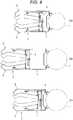
- a gondola apparatus 100 illustrated in Figs. 11 and 12includes: laterally paired platforms 102 and 103 that ascend or descend along the outer surface of a tower 101; laterally paired hoist trapezoidal supports 104 and 105 erecting on both sides of the platforms 102 and 103; laterally paired parallelogram parallel frames 106 provided to the upper centers of the supports 104 and 105; laterally paired traction ropes 108 wound on lifters 107 provided to the centers of the parallel frames 106 and 106, the laterally paired traction ropes 108 being suspended from a nacelle 101A; paired wires 109 and 110 adjustable in length disposed between each of the hoist trapezoidal supports 104 and 105 and both sides of the parallel frame 106; laterally paired support frames 112 extendable and contractable provided to lower portions of the lateral platforms 102 and
- the gondola apparatus 100is suspended with the two traction ropes 108 and 108 to have the lateral platforms 102 and 103 disposed on both sides of a blade 114, and additionally extends the presser frames 112 such that the stabilizing rollers 113 abut on the outer surface of the tower 101. Then, the gondola apparatus 100 drives the lifters 107 to raise or lower the lateral platforms 102 and 103 to a predetermined maintenance work position to the blade 114.
- the inclination angles of the traction ropes 108vary every time the platforms 102 and 103 move left or right in Fig. 12 .
- the tension of the traction ropes 108 by the extension of the support frames 12causes a clockwise moment to increase, and thus there is a risk that the gondola apparatus 100 clockwise inclines.
- the gondola apparatus illustrated in Fig. 11causes, for example, an adjuster 111 to extend the one wire 110 and an adjuster 111 to contract the other wire 109 to change each of the angles of the parallel frames 106. Then, the angles of the traction ropes 108 are corrected, so that the gondola apparatus is prevented from inclining.
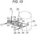
- a gondola 200 illustrated in Fig. 13includes: a horizontal work floor 201 extending in a direction crossing a tower 101; longitudinally paired lifters 202 provided to the work floor 201; props 203 erecting from the housings of the lifters 202; sheaves 204 provided to the upper portions of the props 203; longitudinally paired traction ropes 205 wound on the lifters 202 through the sheaves 204, the longitudinally paired traction ropes 205 being suspended from a nacelle 101A; a support frame 207 inserted into each pipe 206 provided on both sides of the work floor 201 such that the support frame 207 is extendable and contractable; a counterweight 208 provided at a leading end of the support frame 207; and a stabilizing roller 209 provided at a base end of the support frame 207, the stabilizing roller 209 abutting on the outer surface of the tower 101 such that the stabilizing roller 209 is rollable.
- the gondola 200is suspended through the traction ropes 205 suspended from the nacelle 101A to have the work floor 201 disposed outside or inside a blade 114, and drives the lifters 202 to ascend or descend to a predetermined work position.
- the support frames 207are extended toward the tower 101 such that the rollers 209 abut on the tower 101.
- a clockwise momentincreases by the extension of the support frames 207 and thus there is a risk that the work floor 201 clockwise inclines and has difficulty in remaining horizontally.
- the counterweights 208are extended opposite to the support frame 207 to balance with the increased moment, so that the work floor 201 constantly remains horizontally.
- the gondola apparatus 100 of Fig. 12needs the parallelogram parallel frames 106 and the wires 109 and 110 adjustable in length on both sides of each of the parallelogram parallel frames 106, and thus has the structure intricate.
- the extending or contracting operation of the wiresis required on each platform each time the horizontality is maintained, and thus the gondola apparatus 100 has disadvantages in processability, economic efficiency, and workability.
- the gondola apparatus 200 illustrated in Fig. 14has the counterweights 208 in order to remain horizontally, and thus has the structure intricate.
- the extending or contracting operation of each of the counterweights 208is required each time the horizontality is maintained, and thus the gondola apparatus 200 has also disadvantages in processability, economic efficiency, and workability.
- the gondola apparatus 200since the gondola apparatus 200 has the work floor disposed only outside or inside the blade 114, a work range to the blade 114 is limitative. In addition, for example, when the work floor is disposed on the outside, inconveniently, there is a risk that the traction ropes 205 obliquely cross the blade 114 to interfere with each other and then the blade 114 and the traction ropes 205 damage.
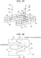
- the gondola apparatus 300includes: work floors 301, 302, and 303 having a U shape in plan view; a lifter 304 provided at a center of each of the work floors 301, 302, and 303; a prop 305 erecting from the housing of each lifter 304; a sheave 306 provided at the upper end of each prop 305; and three traction ropes 307 each wound on the lifter 304 through the sheave 306, the three traction ropes 307 being suspended from an origin on the side of a nacelle.
- the work floors 301, 302, and 303are each disposed at the circumference of a blade 114, so that a work area is large. Furthermore, since suspended through the three traction ropes 307 at the apexes of a triangle, the gondola apparatus 300 can remain horizontally at any position in ascending or descending. Thus, no redundant device that maintains the horizontality is required, so that the inconvenience of the gondola illustrated in Fig. 11 or Fig. 13 can be solved.
- the gondola apparatus 300has the U shape in plan view, and the blade 114 has a thick portion and a thin portion in sectional area and a teardrop shape when viewed in horizontal section.
- the suspension with the traction ropes 307 from abovecannot make the work floors 301, 302, and 303 close to each region, specifically, the thin portion. Therefore, an assist rope not illustrated is suspended from the gondola apparatus 300, and then the assist rope is operated on the ground to adjust the work position of each of the work floors 301, 302, and 303.
- the operation of the assist ropeis inconvenient and there is a risk that safety lowers.
- the work floorshave the U shape, corners being the joints between the longitudinal work floor 301 and the lateral work floors 302 and 303, increase in floor area.
- each jointincreases in weight and thus there is a risk that the gondola apparatus 300 overturns.
- one traction rope 307 bearing a load in the inclination direction at the centeris overloaded and thus there is a risk that the durability thereof deteriorates. Therefore, it is desirable to solve the risks.
- An object of the present inventionis to provide a gondola apparatus for maintenance of blades in an aerogenerator, capable of solving the inconvenience of the conventional gondola apparatuses, with adoption of advantages of the conventional gondola apparatuses.
- a first object of the present inventionis to allow the entire gondola apparatus to easily remain horizontally; a second object is to require no redundant unit or work for maintaining the horizontality; a third object is to enable the position of a scaffold board to be adjusted in accordance with a thick portion and a thin portion of a blade in horizontally sectional view; and a fourth object is to improve the durability of one specific traction rope without overloading the rope.
- a gondola apparatusbe used for maintenance of a blade in an aerogenerator including a columnar tower, a nacelle provided on the tower, and the blade rotatably provided to the nacelle, the aerogenerator being configured to rotate the blade to operate a generator
- the gondola apparatusincluding: a front scaffold frame horizontally extending in a direction crossing the tower, the front scaffold frame facing a back of the blade; a first side scaffold frame horizontally movably attached to the front scaffold frame, the first side scaffold frame facing a side surface of the blade; a second side scaffold frame horizontally movably attached to the front scaffold frame, the second side scaffold frame facing a side surface of the blade, the second side scaffold frame being paired with the first side scaffold frame; a stabilizing member attached over both sides of the front scaffold frame such that the stabilizing member is extendable and contractable, the stabilizing member abutting on an outer surface of the tower; a first lifting device provided to the front scaffold frame; a
- the present inventionrelates to a gondola apparatus A to be applied for maintenance of an aerogenerator including a columnar tower 1, a nacelle 2 mounted on the tower 1, blades 3 rotatably provided to the nacelle 2, as illustrated in Fig. 5 , particularly, the gondola apparatus A being suitable for maintenance work of the blades 3.
- the gondola apparatus Araises scaffold frames 4, 5, and 6 suspended with three traction ropes 12, 13, and 14 suspended from the nacelle 2, respectively, with, for example, publicly known endless lifters on which the traction ropes 12, 13, and 14 are wound, from a ground position C to an intermediate position B or an upper position A, as illustrated in Fig. 5 .
- maintenance work of the outer circumferential surface of a blade 3is performed, such as painting or repairing.
- the gondola apparatus Aincludes a stabilizing member 7 extendable and contractable as to be described later.
- the stabilizing member 7contracts and abuts on the outer surface of the tower 1 as illustrated in Fig. 6(C) when the gondola apparatus A is positioned on the ground C.
- the stabilizing member 7extends to make the scaffold frames 4, 5, and 6 close to a work position in proximity to the narrow leading end of the blade 3 as illustrated in Fig. 6(B) at the intermediate position B.
- the stabilizing member 7contracts again to make the scaffold frames 4, 5, and 6 close to the tower 1 as illustrated in Fig. 6(A) at the position A corresponding to a work position to a thick portion of the blade 3.
- the longitudinal direction of the gondola apparatus A and each member included in the gondola apparatus Ais based on a front view of Fig. 3 .
- Expression of the longitudinal directionindicates a direction penetrating through the plane in the front view illustrated in Fig. 3 even when a description is given with reference to a different figure.
- the basic structure of the gondola apparatus Aincludes: the front scaffold frame 4 horizontally extending in the longitudinal direction, namely, in a direction crossing the tower 1, the front scaffold frame 4 facing the back on the tower side of the blade 3 of the aerogenerator; the paired first and second side scaffold frames 5 and 6 longitudinally movably attached to the front scaffold frame 4, each facing a side surface of the blade 3; the stabilizing member 7 attached over both lateral sides of the front scaffold frame 4 such that the stabilizing member 7 is extendable and contractable, the stabilizing member 7 abutting on the outer surface of the tower 1; a first lifting device 9 provided to the front scaffold frame 4; second and third lifting devices 10 and 11 attached to the paired side scaffold frames 5 and 6, respectively, such that the second and third lifting devices 10 and 11 are rockable; first and second drive devices 15 and 16 provided to the front scaffold frame 4, the first and second drive devices 15 and 16 being configured to horizontally drive the side scaffold frames 5 and 6, respectively; and the first, second, and third
- the front scaffold frame 4includes a scaffold board 4a and a handrail 4b circumferentially erecting on the scaffold board 4a.
- the side scaffold frames 5 and 6include scaffold boards 5a and 6a and handrails 5b and 6b circumferentially erecting on the scaffold boards 5a and 6a, respectively.
- the leading ends of the scaffold boards 5a and 6a and the leading ends of the handrails 5b and 6bbend toward the blade 3 as illustrated.
- the first side scaffold frame 5 and the second side scaffold frame 6have base ends coupled to the front scaffold frame 4 through the first and second drive devices 15 and 16, respectively, and additionally have the sides of the leading ends extending in a V shape from the base ends, each facing the side surface of the blade 3.
- the lateral scaffold frames 5 and 6can be made close to or away from the outer surface of the blade 3. Furthermore, when, for example, a sectionally teardrop-shaped blade 3 illustrated in Fig. 16 is handled, the lateral scaffold frames 5 and 6 can be disposed in accordance with a thick portion and a thin portion of the blade 3 in horizontal section view, and thus no positioning with, for example, an assist rope from the ground is required.
- the first lifting device 9includes: an endless first lifter 9a; a front prop 9b erecting upward from the housing of the first lifter 9a; and a sheave 9c provided at the upper end of the prop 9b, the sheave 9c guiding the first traction rope 12.
- the second and third lifting devices 10 and 11include: endless second and third lifters 10a and 11a; side props 10b and 11b erecting upward from the housings of the lifters 10a and 11a; and laterally paired sheaves 10c and 11c provided at the upper ends of the side props 10b and 11b, the sheaves 10c and 11c guiding the second and third traction ropes 13 and 14, respectively.
- the traction ropes 12, 13, and 14are pulled up along the props 9b, 10b, and 11b, respectively, so that the traction ropes 12, 13, and 14 are prevented from interfering with the handrails 4b, 5b, and 6b, respectively.
- a workeris prevented from being tangled with the traction ropes 12, 13, and 14 while walking.
- this arrangementis safe.
- the traction ropes 12, 13, and 14may be directly wound on the lifters 9a, 10a, and 11a, respectively, but the traction ropes 12, 13, and 14 are preferably pulled up through the props 9b, 10b, and 11b and the sheaves 9c, 10c, and 11c, respectively, since there is a risk that the traction ropes 12, 13, and 14 interfere with the handrails 4b, 5b, and 6b, respectively.
- the lower ends of the second and third lifters 10a and 11aare coupled to the side scaffold frames 5 and 6 through brackets 10d and 11d with pins, respectively, such that the lower ends of the second and third lifters 10a and 11a are rockable.
- the second and third lifters 10a and 11amay be each a winding-type lifter.
- the lower ends of the lifters 10a and 11amay be coupled to the side scaffold frames 5 and 6 through universal joints, respectively.
- the lifting devices according to the present inventionare rockable, but the lifting devices perpendicularly erecting with the base ends of the lifters 10a and 11a fixed and the side props 10b and 11b fixed, can be adopted, as illustrated in a reference example of Fig. 10 (B) .
- the gondola apparatus of Fig. 10(B) corresponding to a conventional type illustrated in Fig. 15can be adopted.
- horizontally parallel inverse force Pacts on sheave portions P1 and roller portions P2 when the second and third traction ropes 13 and 14 incline as illustrated in Fig. 10(B) .
- the gondola apparatushas the entire second and third lifting devices 10 and 11 rockable through the pins provided to the brackets 10d and 11d, respectively, as illustrated in Figs. 1 and 10(A) .
- pin portions P3each act as a point of application and these positions are lower than each point of application P1 of Fig. 10(B) .
- the rotation moment acting on the gondola apparatus Acan be reduced.
- the first traction rope 12 of the front scaffold frame 4can be prevented from being overloaded and the durability thereof can be prevented from deteriorating, so that the first traction rope 12 can be formed of a small-rigidity material.
- guide frames 5c and 6care provided inside the handrails 5b and 6b of the first and second side scaffold frames 5 and 6, respectively.
- a roller Ris provided to each of the side props 10b and 11b through a bracket B.
- the guide frames 5c and 6cguide the rock of the side props 10b and 11b through the rollers R, respectively, so that the props 10b and 11b are stabilized and interference with the worker is also prevented.
- the first drive device 15includes: vertically paired horizontal guide props 17a and 17b provided to the front scaffold frame 4; vertically paired guide rollers 18a and 18b attached to the base end of the first side scaffold frame 5 through a bracket 22, the vertically paired guide rollers 18a and 18b being slidably inserted into the guide props 17a and 17b, respectively; and a cylinder 19 provided between the lower guide roller 18b and the front scaffold frame 4.
- the second drive device 16includes: the vertically paired horizontal guide props 17a and 17b provided to the front scaffold frame 4; vertically paired guide rollers 18a and 18b attached to the base end of the second side scaffold frame 6 through a bracket 22, the vertically paired guide rollers 18a and 18b being slidably inserted into the guide props 17a and 17b, respectively; and a cylinder 19 provided between the lower guide roller 18b and the front scaffold frame 4, the cylinder 19 being paired with the cylinder 19 of the first drive device 15.
- the first and second side scaffold frames 5 and 6each move horizontally to the front scaffold frame 4 along the guide props 17a and 17b through the guide rollers 18a and 18b.
- the first and second side scaffold frames 5 and 6are made close or away in accordance with the thickness of the blade 3, so that the work position can be adjusted.
- the stabilizing member 7includes: paired guide pipes 7a provided on both longitudinal sides of the front scaffold frame 4; a rack 7b inserted into each of the guide pipes 7a such that the rack 7b is extendable and contractable, the rack 7b being to be driven with a pinion 7d; a rockable bracket 7c provided to an end portion of the rack 7b; and a roller 8 provided to each of the brackets 7c and 7c, the roller 8 abutting on the outer surface of the tower 1 such that the roller 8 is rollable.
- the pinion 7dis rotationally driven by a motor M provided to the front scaffold frame 4 and a propeller shaft PS rotationally driven by the motor M, as illustrated in Fig. 8 .
- drive of the motor Mcan operate the stabilizing member 7 to extend or contract, and improve operability.
- the drive of the motor Mallows the stabilizing member 7 to extend toward or contract against the tower 1, so that the scaffold frames 4, 5, and 6 can be moved to an optimum position for the maintenance of the blade 3.
- the roller 8is coupled to the rack 7b through the bracket 7c adjustable in horizontal angle. Note that, the number of rollers 8 to be provided can be arbitrarily changed in design.
- the bracket 7cis coupled to an arm 7e provided to the end portion of the rack 7b, through a bolt or a pin such that the bracket 7c is adjustable in position. Therefore, change of the attached position can adjust the position of the roller 8 in accordance with various outer diameters of the tower 1 of the aerogenerator.
- a plurality of casters 20is provided to each of lower portions of the side scaffold frames 5 and 6, and a plurality of casters 21 is provided to each of lower portions of the guide pipes 7a.
- the gondola apparatus Aitself can be moved to a predetermined position with the casters 20 and 21.
Landscapes
- Engineering & Computer Science (AREA)
- Architecture (AREA)
- Mechanical Engineering (AREA)
- Civil Engineering (AREA)
- Structural Engineering (AREA)
- Life Sciences & Earth Sciences (AREA)
- Sustainable Development (AREA)
- Sustainable Energy (AREA)
- Chemical & Material Sciences (AREA)
- Combustion & Propulsion (AREA)
- General Engineering & Computer Science (AREA)
- Movable Scaffolding (AREA)
- Wind Motors (AREA)
Description
- The present invention relates to a gondola apparatus suitable for maintenance of the blades of an aerogenerator.
- This type of aerogenerator includes a columnar tower, a nacelle mounted on the tower, and blades provided to the nacelle, and rotates the blades to operate a generator.
- The blades each have the paint on an outer surface peel off or deteriorate due to exposure to wind pressure, lightning strikes, or ultraviolet rays after several years of construction, and thus not only the blades do not function but also external appearance is unfavorable.
- Thus, the blades need maintenance, such as outer surface painting or repairing. Therefore, gondola apparatuses for the maintenance have been developed as disclosed in
JP 2004-293455 A JP 2012-7525 A - The gondola apparatus described in
JP 2004-293455 A - Similarly, the gondola apparatus for the maintenance described in
JP 2012-7525 A CN 202625760 U ,DE 102011100912 A1 andDE 202007002930 U1 disclose a gondola apparatus to be used for maintenance of an aerogenerator blade. - However, for each of the conventional gondola apparatuses for the maintenance, the guide or the rack rail is provided to the tower and then the gondola is attached to the guide or the rack rail. Thus, each apparatus is massive and has an intricate structure. Each apparatus is difficult to assemble or remove, and has disadvantages in processability, economic efficiency, and workability.
- Therefore, a gondola apparatus for blade maintenance that raises or lowers a gondola with only lifters and traction ropes has been developed. For example, a
gondola apparatus 100 illustrated inFigs. 11 and12 , includes: laterally pairedplatforms tower 101; laterally paired hoisttrapezoidal supports platforms parallel frames 106 provided to the upper centers of thesupports traction ropes 108 wound onlifters 107 provided to the centers of theparallel frames traction ropes 108 being suspended from anacelle 101A; pairedwires trapezoidal supports parallel frame 106; laterally pairedsupport frames 112 extendable and contractable provided to lower portions of thelateral platforms presser roller 113 provided at an end portion of each of thesupport frames 112, thepresser roller 113 abutting on the outer surface of thetower 101. - As illustrated in
Fig. 12 , thegondola apparatus 100 is suspended with the twotraction ropes lateral platforms blade 114, and additionally extends thepresser frames 112 such that the stabilizingrollers 113 abut on the outer surface of thetower 101. Then, thegondola apparatus 100 drives thelifters 107 to raise or lower thelateral platforms blade 114. - Then, as illustrated in
Fig. 12 , when thelateral platforms support frames 112 abuts on thetower 101 with a change in extending amount, in accordance with the raised or lowered position. - Therefore, the inclination angles of the
traction ropes 108 vary every time theplatforms Fig. 12 . Simultaneously, the tension of the traction ropes 108 by the extension of thesupport frames 12 causes a clockwise moment to increase, and thus there is a risk that thegondola apparatus 100 clockwise inclines. - Therefore, the gondola apparatus illustrated in
Fig. 11 causes, for example, anadjuster 111 to extend the onewire 110 and anadjuster 111 to contract theother wire 109 to change each of the angles of theparallel frames 106. Then, the angles of thetraction ropes 108 are corrected, so that the gondola apparatus is prevented from inclining. - On the other hand, a
gondola 200 illustrated inFig. 13 includes: ahorizontal work floor 201 extending in a direction crossing atower 101; longitudinally pairedlifters 202 provided to thework floor 201;props 203 erecting from the housings of thelifters 202;sheaves 204 provided to the upper portions of theprops 203; longitudinally pairedtraction ropes 205 wound on thelifters 202 through thesheaves 204, the longitudinally pairedtraction ropes 205 being suspended from anacelle 101A; asupport frame 207 inserted into eachpipe 206 provided on both sides of thework floor 201 such that thesupport frame 207 is extendable and contractable; acounterweight 208 provided at a leading end of thesupport frame 207; and a stabilizingroller 209 provided at a base end of thesupport frame 207, the stabilizingroller 209 abutting on the outer surface of thetower 101 such that the stabilizingroller 209 is rollable. - Then, the
gondola 200 is suspended through thetraction ropes 205 suspended from thenacelle 101A to have thework floor 201 disposed outside or inside ablade 114, and drives thelifters 202 to ascend or descend to a predetermined work position. - Then, for example, as illustrated in
Fig. 14 , when the gondola is disposed outside theblade 114, thesupport frames 207 are extended toward thetower 101 such that therollers 209 abut on thetower 101. However, a clockwise moment increases by the extension of thesupport frames 207 and thus there is a risk that thework floor 201 clockwise inclines and has difficulty in remaining horizontally. Thus, thecounterweights 208 are extended opposite to thesupport frame 207 to balance with the increased moment, so that thework floor 201 constantly remains horizontally. - However, since the conventional gondola apparatuses each ascend or descend through the traction ropes, the structure can be simplified in comparison to the gondola apparatuses described in
JP 2004-293455 A JP 2012-7525 A - That is, the
gondola apparatus 100 ofFig. 12 needs the parallelogramparallel frames 106 and thewires parallel frames 106, and thus has the structure intricate. The extending or contracting operation of the wires is required on each platform each time the horizontality is maintained, and thus thegondola apparatus 100 has disadvantages in processability, economic efficiency, and workability. - The
gondola apparatus 200 illustrated inFig. 14 has thecounterweights 208 in order to remain horizontally, and thus has the structure intricate. The extending or contracting operation of each of thecounterweights 208 is required each time the horizontality is maintained, and thus thegondola apparatus 200 has also disadvantages in processability, economic efficiency, and workability. - Furthermore, since the
gondola apparatus 200 has the work floor disposed only outside or inside theblade 114, a work range to theblade 114 is limitative. In addition, for example, when the work floor is disposed on the outside, inconveniently, there is a risk that the traction ropes 205 obliquely cross theblade 114 to interfere with each other and then theblade 114 and the traction ropes 205 damage. - Therefore, another gondola apparatus that easily remains horizontally has been developed as illustrated in
Fig. 15 . - The
gondola apparatus 300 includes:work floors lifter 304 provided at a center of each of thework floors prop 305 erecting from the housing of eachlifter 304; asheave 306 provided at the upper end of eachprop 305; and threetraction ropes 307 each wound on thelifter 304 through thesheave 306, the threetraction ropes 307 being suspended from an origin on the side of a nacelle. - When the
gondola apparatus 300 illustrated inFig. 15 is suspended, as illustrated inFig. 16 , thework floors blade 114, so that a work area is large. Furthermore, since suspended through the threetraction ropes 307 at the apexes of a triangle, thegondola apparatus 300 can remain horizontally at any position in ascending or descending. Thus, no redundant device that maintains the horizontality is required, so that the inconvenience of the gondola illustrated inFig. 11 orFig. 13 can be solved. - However, the
gondola apparatus 300 has the U shape in plan view, and theblade 114 has a thick portion and a thin portion in sectional area and a teardrop shape when viewed in horizontal section. When thework floors blade 114 as illustrated inFig. 16 , the suspension with thetraction ropes 307 from above cannot make thework floors gondola apparatus 300, and then the assist rope is operated on the ground to adjust the work position of each of thework floors - Since the work floors have the U shape, corners being the joints between the
longitudinal work floor 301 and thelateral work floors gondola apparatus 300 overturns. Furthermore, onetraction rope 307 bearing a load in the inclination direction at the center is overloaded and thus there is a risk that the durability thereof deteriorates. Therefore, it is desirable to solve the risks. - An object of the present invention is to provide a gondola apparatus for maintenance of blades in an aerogenerator, capable of solving the inconvenience of the conventional gondola apparatuses, with adoption of advantages of the conventional gondola apparatuses.
- A first object of the present invention is to allow the entire gondola apparatus to easily remain horizontally; a second object is to require no redundant unit or work for maintaining the horizontality; a third object is to enable the position of a scaffold board to be adjusted in accordance with a thick portion and a thin portion of a blade in horizontally sectional view; and a fourth object is to improve the durability of one specific traction rope without overloading the rope.
- In order to achieve the objects there is provided a gondola apparatus according to
claim 1 be used for maintenance of a blade in an aerogenerator including a columnar tower, a nacelle provided on the tower, and the blade rotatably provided to the nacelle, the aerogenerator being configured to rotate the blade to operate a generator, the gondola apparatus including: a front scaffold frame horizontally extending in a direction crossing the tower, the front scaffold frame facing a back of the blade; a first side scaffold frame horizontally movably attached to the front scaffold frame, the first side scaffold frame facing a side surface of the blade; a second side scaffold frame horizontally movably attached to the front scaffold frame, the second side scaffold frame facing a side surface of the blade, the second side scaffold frame being paired with the first side scaffold frame; a stabilizing member attached over both sides of the front scaffold frame such that the stabilizing member is extendable and contractable, the stabilizing member abutting on an outer surface of the tower; a first lifting device provided to the front scaffold frame; a second lifting device provided to the first side scaffold frame such that the second lifting device is rockable; a third lifting device provided to the second side scaffold frame such that the third lifting device is rockable; a first drive device provided to the front scaffold frame, the first drive device being configured to horizontally drive the first side scaffold frame; a second drive device provided to the front scaffold frame, the second drive device being configured to horizontally drive the second side scaffold frame; a first traction rope provided between the first lifting device and an origin on a side of the nacelle; a second traction rope provided between the second lifting device and the origin on the side of the nacelle; and a third traction rope provided between the third lifting device and the origin on the side of the nacelle. Fig. 1 is an entire perspective view of a gondola apparatus partially omitted according to the present invention.Fig. 2 is a plan view of the gondola apparatus according to the present invention.Fig. 3 is a front view of the gondola apparatus.Fig. 4 is a partially left side view ofFig. 3 .Fig. 5 is a front view of the disposition of the gondola apparatus according to the present invention, attached to an aerogenerator.Fig. 6(A) is a plan view of the gondola apparatus disposed at a position of (A) ofFig. 5 .Fig. 6(B) is a plan view of the gondola apparatus disposed at a position of (B) ofFig. 5 .Fig. 6(C) is a plan view of the gondola apparatus disposed at a position of (C) ofFig. 5 .Fig. 7 is a plan view of a drive device.Fig. 8 is a plan view of a stabilizer and a drive unit thereof.Fig. 9 is a perspective view of a guide mechanism of a side prop.Fig. 10(A) is a front view of side second and third lifting devices that have been rockable.Fig. 10(B) is a front view of the side second and third lifting devices that have been fixed.Fig. 11 is a perspective view of a conventional gondola apparatus.Fig. 12 is a front view of the conventional gondola apparatus illustrated inFig. 11 disposed at an aerogenerator.Fig. 13 is a perspective view of another conventional gondola apparatus.Fig. 14 is a front view of the other conventional gondola apparatus illustrated inFig. 13 disposed at an aerogenerator.Fig. 15 is a perspective view of still another conventional gondola apparatus.Fig. 16 is a simplified plan view of the other different conventional gondola apparatus illustrated inFig. 15 disposed at the circumference of a blade.- An embodiment of the present invention will be described below on the basis of the drawings. The present invention relates to a gondola apparatus A to be applied for maintenance of an aerogenerator including a
columnar tower 1, anacelle 2 mounted on thetower 1,blades 3 rotatably provided to thenacelle 2, as illustrated inFig. 5 , particularly, the gondola apparatus A being suitable for maintenance work of theblades 3. - That is, the gondola apparatus A raises scaffold frames 4, 5, and 6 suspended with three
traction ropes nacelle 2, respectively, with, for example, publicly known endless lifters on which thetraction ropes Fig. 5 . For example, each time the scaffold frames 4, 5, and 6 are stopped, for example, at the intermediate position B or the upper position A, maintenance work of the outer circumferential surface of ablade 3 is performed, such as painting or repairing. - The gondola apparatus A includes a stabilizing
member 7 extendable and contractable as to be described later. The stabilizingmember 7 contracts and abuts on the outer surface of thetower 1 as illustrated inFig. 6(C) when the gondola apparatus A is positioned on the ground C. The stabilizingmember 7 extends to make the scaffold frames 4, 5, and 6 close to a work position in proximity to the narrow leading end of theblade 3 as illustrated inFig. 6(B) at the intermediate position B. The stabilizingmember 7 contracts again to make the scaffold frames 4, 5, and 6 close to thetower 1 as illustrated inFig. 6(A) at the position A corresponding to a work position to a thick portion of theblade 3. - In the descriptions of the gondola apparatus A, the longitudinal direction of the gondola apparatus A and each member included in the gondola apparatus A, is based on a front view of
Fig. 3 . Expression of the longitudinal direction indicates a direction penetrating through the plane in the front view illustrated inFig. 3 even when a description is given with reference to a different figure. - As illustrated in
Figs. 1 and 2 , the basic structure of the gondola apparatus A includes: the front scaffold frame 4 horizontally extending in the longitudinal direction, namely, in a direction crossing the tower 1, the front scaffold frame 4 facing the back on the tower side of the blade 3 of the aerogenerator; the paired first and second side scaffold frames 5 and 6 longitudinally movably attached to the front scaffold frame 4, each facing a side surface of the blade 3; the stabilizing member 7 attached over both lateral sides of the front scaffold frame 4 such that the stabilizing member 7 is extendable and contractable, the stabilizing member 7 abutting on the outer surface of the tower 1; a first lifting device 9 provided to the front scaffold frame 4; second and third lifting devices 10 and 11 attached to the paired side scaffold frames 5 and 6, respectively, such that the second and third lifting devices 10 and 11 are rockable; first and second drive devices 15 and 16 provided to the front scaffold frame 4, the first and second drive devices 15 and 16 being configured to horizontally drive the side scaffold frames 5 and 6, respectively; and the first, second, and third traction ropes 12, 13, and 14 provided between the first, second, and third lifting devices 9, 10, and 11, and the origin on the side of the nacelle 2, respectively. - The
front scaffold frame 4 includes ascaffold board 4a and ahandrail 4b circumferentially erecting on thescaffold board 4a. Similarly, the side scaffold frames 5 and 6 includescaffold boards handrails scaffold boards scaffold boards handrails blade 3 as illustrated. - The first
side scaffold frame 5 and the secondside scaffold frame 6 have base ends coupled to thefront scaffold frame 4 through the first andsecond drive devices blade 3. - Therefore, the lateral scaffold frames 5 and 6 can be made close to or away from the outer surface of the
blade 3. Furthermore, when, for example, a sectionally teardrop-shapedblade 3 illustrated inFig. 16 is handled, the lateral scaffold frames 5 and 6 can be disposed in accordance with a thick portion and a thin portion of theblade 3 in horizontal section view, and thus no positioning with, for example, an assist rope from the ground is required. - The
first lifting device 9 includes: an endlessfirst lifter 9a; afront prop 9b erecting upward from the housing of thefirst lifter 9a; and asheave 9c provided at the upper end of theprop 9b, thesheave 9c guiding thefirst traction rope 12. - Similarly, the second and
third lifting devices third lifters side props lifters sheaves side props sheaves third traction ropes - Therefore, the
traction ropes props traction ropes handrails traction ropes - The
traction ropes lifters traction ropes props sheaves traction ropes handrails - The lower ends of the second and
third lifters brackets third lifters third lifters lifters - The lifting devices according to the present invention are rockable, but the lifting devices perpendicularly erecting with the base ends of the
lifters side props Fig. 10 (B) . - That is, the gondola apparatus of
Fig. 10(B) corresponding to a conventional type illustrated inFig. 15 can be adopted. However, with the lifting devices each having this type of fixed structure, horizontally parallel inverse force P acts on sheave portions P1 and roller portions P2 when the second andthird traction ropes Fig. 10(B) . - Since the difference in altitude by the length of each of the
side props first traction rope 12. Therefore, it is necessary to use a high-rigidity traction rope 12 that bears the moment, and additionally the durability thereof deteriorates. - In contrast to this, the gondola apparatus according to the embodiment of the present invention has the entire second and
third lifting devices brackets Figs. 1 and10(A) . In other words, since thelifters side props Fig. 10(B) . - Therefore, since the difference in altitude between P2 and P3 being each a point of application, is smaller than that in
Fig. 10(B) , the rotation moment acting on the gondola apparatus A can be reduced. Thus, thefirst traction rope 12 of thefront scaffold frame 4 can be prevented from being overloaded and the durability thereof can be prevented from deteriorating, so that thefirst traction rope 12 can be formed of a small-rigidity material. - In addition, since the
side props - Note that, as illustrated in
Fig. 9 , guide frames 5c and 6c are provided inside thehandrails side props side props props - Next, the
first drive device 15 includes: vertically pairedhorizontal guide props front scaffold frame 4; vertically pairedguide rollers side scaffold frame 5 through abracket 22, the vertically pairedguide rollers guide props cylinder 19 provided between thelower guide roller 18b and thefront scaffold frame 4. Thesecond drive device 16 includes: the vertically pairedhorizontal guide props front scaffold frame 4; vertically pairedguide rollers side scaffold frame 6 through abracket 22, the vertically pairedguide rollers guide props cylinder 19 provided between thelower guide roller 18b and thefront scaffold frame 4, thecylinder 19 being paired with thecylinder 19 of thefirst drive device 15. - As illustrated in
Fig. 7 , when thecylinders front scaffold frame 4 along theguide props guide rollers side scaffold frame 5 and the secondside scaffold frame 6 are attached to thefront scaffold frame 4 such that the firstside scaffold frame 5 and the secondside scaffold frame 6 are horizontally movable, the first and second side scaffold frames 5 and 6 are made close or away in accordance with the thickness of theblade 3, so that the work position can be adjusted. - The stabilizing
member 7 includes: pairedguide pipes 7a provided on both longitudinal sides of thefront scaffold frame 4; arack 7b inserted into each of theguide pipes 7a such that therack 7b is extendable and contractable, therack 7b being to be driven with apinion 7d; arockable bracket 7c provided to an end portion of therack 7b; and aroller 8 provided to each of thebrackets roller 8 abutting on the outer surface of thetower 1 such that theroller 8 is rollable. - The
pinion 7d is rotationally driven by a motor M provided to thefront scaffold frame 4 and a propeller shaft PS rotationally driven by the motor M, as illustrated inFig. 8 . - Thus, drive of the motor M can operate the stabilizing
member 7 to extend or contract, and improve operability. The drive of the motor M allows the stabilizingmember 7 to extend toward or contract against thetower 1, so that the scaffold frames 4, 5, and 6 can be moved to an optimum position for the maintenance of theblade 3. Theroller 8 is coupled to therack 7b through thebracket 7c adjustable in horizontal angle. Note that, the number ofrollers 8 to be provided can be arbitrarily changed in design. - The
bracket 7c is coupled to anarm 7e provided to the end portion of therack 7b, through a bolt or a pin such that thebracket 7c is adjustable in position. Therefore, change of the attached position can adjust the position of theroller 8 in accordance with various outer diameters of thetower 1 of the aerogenerator. - A plurality of
casters 20 is provided to each of lower portions of the side scaffold frames 5 and 6, and a plurality ofcasters 21 is provided to each of lower portions of theguide pipes 7a. The gondola apparatus A itself can be moved to a predetermined position with thecasters - According to the present invention, the following effects can be achieved.
- 1) There are provided: the
front scaffold frame 4 horizontally extending in the direction crossing thetower 1, thefront scaffold frame 4 facing the back of theblade 3; and the second and third side scaffold frames 5 and 6 horizontally movably attached to thefront scaffold frame 4, each facing the side surface of theblade 3. Thus, the scaffold frames 4, 5, and 6 can be disposed over the entire circumferential region of theblade 3. - 2) The stabilizing
member 7 is attached over both sides of thefront scaffold frame 4 such that the stabilizingmember 7 is extendable and contractable to thetower 1, the stabilizingmember 7 abutting on the outer surface of thetower 1. Thus, the scaffold frames 4, 5, and 6 can be raised or lowered along thetower 1, prevented from joggling. - 3) The first, second, and
third traction ropes third lifting devices traction ropes - 4) The second and
third lifting devices third lifting devices third traction ropes third lifting devices third lifting devices third traction ropes lifting devices first traction rope 12 can be prevented from being overloaded or the overload can be reduced, and the durability can be prevented from deteriorating. As a result, the frontfirst traction rope 12 can be formed of a small-rigidity material. - 5) Since the first and
second drive devices blade 3. Thus, the side scaffold frames 5 and 6 can be disposed in accordance with the teardrop sectional shape of theblade 3. Thus, no assist rope for approach to theblade 3 and no operation work thereof are required. - Furthermore, when the base ends of the side scaffold frames 5 and 6 move to the center of the
front scaffold frame 4, movable loads disappear on both end portions of thefront scaffold frame 4, so that the entire gondola apparatus is prevented from joggling or inclining. - The preferred embodiment of the present invention has been described above, but additions, modifications, and alterations may be made without departing from the scope of the claims.
Claims (7)
- A gondola apparatus to be used for maintenance of a blade (3) in an aerogenerator including a columnar tower (1), a nacelle (2) provided on the tower (1), and the blade (3) rotatably provided to the nacelle (2), the aerogenerator being configured to rotate the blade to operate a generator, the gondola apparatus comprising:a front scaffold frame (4) horizontally extending in a direction crossing the tower (1), the front scaffold frame (4) facing a back of the blade (3);a first side scaffold frame (5) horizontally movably attached to the front scaffold frame (4), the first side scaffold frame (5) facing a side surface of the blade (3);a second side scaffold frame (6) horizontally movably attached to the front scaffold frame (4), the second side scaffold frame (6) facing a side surface of the blade (3);a stabilizing member (7) attached over both sides of the front scaffold frame (4) such that the stabilizing member (7) is extendable and contractable to the tower (1), the stabilizing member abutting on an outer surface of the tower (1);a first lifting device (9) provided to the front scaffold frame (4);a second lifting device (10) attached to the first side scaffold frame (5) such that the second lifting device (10) is rockable;a third lifting device (11) attached to the second side scaffold frame (6) such that the third lifting device (11) is rockable;a first drive device (15) provided to the front scaffold frame (4), the first drive device (15) being configured to horizontally drive the first side scaffold frame (5);a second drive device (16) provided to the front scaffold frame (4), the second drive device (16) being configured to horizontally drive the second side scaffold frame (6);a first traction rope (12) provided between the first lifting device (9) and an origin on a side of the nacelle (2);a second traction rope (13) provided between the second lifting device (10) and the origin on the side of the nacelle (2); anda third traction rope (14) provided between the third lifting device (11) and the origin on the side of the nacelle (2).
- The gondola apparatus according to claim 1, wherein
the first side scaffold frame (5) and the second side scaffold frame (6) are each provided in a V shape to the front scaffold frame (4). - The gondola apparatus according to claim 1, wherein
the front scaffold frame (4) includes a scaffold board (4a) and a handrail (4b) circumferentially erecting on the scaffold board (4a),
the first side scaffold frame (5) and the second side scaffold frame (6) each include a scaffold board (5a, 6a) and a handrail (5b, 6b) circumferentially erecting on the scaffold board (5a, 6a),
the first side scaffold frame (5) has a base end coupled to the front scaffold frame (4) through the first drive device (15) and has a side of a leading end extending in a V shape from the base end, the side of the leading end facing the side surface of the blade (3), and
the second side scaffold frame (6) has a base end coupled to the front scaffold frame (4) through the second drive device (16) and has a side of a leading end extending in a V shape from the base end, the side of the leading end facing the side surface of the blade (3). - The gondola apparatus according to claim 1, wherein
the first lifting device (9) includes: an endless first lifter (9a); a front prop (9b) erecting upward from a housing of the lifter (9a); and a sheave (9c) provided at an upper end of the prop (9b), the sheave (9c) guiding the first traction rope (12),
the second lifting device (10) includes: an endless lifter (10a); a side prop (10b) erecting upward from a housing of the lifter (10a); and a sheave (10c) provided at an upper end of the prop (10b), the sheave (10c) guiding the second traction rope (13),
the third lifting device (11) includes: an endless lifter (11a); a side prop (11b) erecting upward from a housing of the lifter (11a); and a sheave (11c) provided at an upper end of the prop (11b), the sheave (11c) guiding the third traction rope (14), the sheave (11c) being laterally paired with the sheave (10c) of the second lifting device (10),
a lower end of the second lifter (10a) is coupled to the first side scaffold frame (5) through a bracket (10d) or a universal joint such that the lower end of the second lifter (10a) is rockable, and
a lower end of the third lifter (11a) is coupled to the second side scaffold frame (6) through a bracket (11d) or a universal joint such that the lower end of the third lifter (11a) is rockable. - The gondola apparatus according to claim 4, wherein
a guide frame (5c) is provided inside a handrail (5b) of the first side scaffold frame (5) such that the guide frame (5c) guides rock of the first side prop (10b) through a roller (R), and
a guide frame (6c) is provided inside a handrail (6b) of the second side scaffold frame (6) such that the guide frame (6c) guides rock of the second side prop (11b) through a roller (R). - The gondola apparatus according to claim 1, wherein
the first drive device (15) includes: vertically paired horizontal guide props (17a, 17b) provided to the front scaffold frame (4); vertically paired guide rollers (18a, 18b) attached to a base end of the first side scaffold frame (5) through a bracket (22), the vertically paired guide rollers (18a, 18b) being slidably inserted into the respective guide props (17a, 17b); and a cylinder (19) provided between a lower guide roller (18b) from the vertically paired guide rollers and the front scaffold frame (4), and
the second drive device (16) includes: the vertically paired horizontal guide props (17a, 17b) provided the front scaffold frame (4); vertically paired guide rollers (18a, 18b) attached to a base end of the second side scaffold frame (6) through a bracket (22), the vertically paired guide rollers (18a, 18b) being slidably inserted into the respective guide props (17a, 17b); and a cylinder (19) provided between a lower guide roller (18b) from the vertically paired guide rollers and the front scaffold frame (4), the cylinder (19) being paired with the cylinder (19) of the first drive device (15). - The gondola apparatus according to claim 1, wherein
the stabilizing member (7) includes: paired guide pipes (7a) provided on both of the sides of the front scaffold frame (4); a rack (7b) inserted into each of the guide pipes (7a) such that the rack (7b) is extendable and contractable, the rack (7b) being to be driven with a pinion (7d); a rockable bracket (7c) provided to an end portion of the rack (7b); and a roller (8) provided to each bracket (7c), the roller (8) abutting on the outer surface of the tower (1) such that the roller (8) is rollable, and
the pinion (7d) is rotationally driven by a motor (M) provided to the first front scaffold frame (4) and a propeller shaft (PS) rotationally driven by the motor (M).
Applications Claiming Priority (2)
| Application Number | Priority Date | Filing Date | Title |
|---|---|---|---|
| JP2016005808AJP6154921B1 (en) | 2016-01-15 | 2016-01-15 | Gondola for blade maintenance in wind power generators |
| PCT/JP2016/086745WO2017122475A1 (en) | 2016-01-15 | 2016-12-09 | Gondola device |
Publications (3)
| Publication Number | Publication Date |
|---|---|
| EP3404169A1 EP3404169A1 (en) | 2018-11-21 |
| EP3404169A4 EP3404169A4 (en) | 2019-09-18 |
| EP3404169B1true EP3404169B1 (en) | 2021-01-27 |
Family
ID=59218531
Family Applications (1)
| Application Number | Title | Priority Date | Filing Date |
|---|---|---|---|
| EP16885078.2AActiveEP3404169B1 (en) | 2016-01-15 | 2016-12-09 | Gondola device |
Country Status (9)
| Country | Link |
|---|---|
| US (1) | US10801220B2 (en) |
| EP (1) | EP3404169B1 (en) |
| JP (1) | JP6154921B1 (en) |
| KR (1) | KR102127056B1 (en) |
| CN (1) | CN108431346B (en) |
| AU (1) | AU2016386566B2 (en) |
| CA (1) | CA3011212C (en) |
| DK (1) | DK3404169T3 (en) |
| WO (1) | WO2017122475A1 (en) |
Families Citing this family (32)
| Publication number | Priority date | Publication date | Assignee | Title |
|---|---|---|---|---|
| US20160069094A1 (en)* | 2006-08-05 | 2016-03-10 | Donald F. Lombardi | Mason's adjustable chimney-platform arrangement |
| SG10201607680RA (en)* | 2016-09-14 | 2018-04-27 | Tiong Bin Seow | A height accessible working platform with horizontally displaceable cradle |
| DE202017105483U1 (en)* | 2017-09-11 | 2017-09-25 | WP Systems GmbH | Device for arranging an elevator system |
| CN111279073B (en)* | 2017-11-03 | 2022-03-11 | 维斯塔斯风力系统有限公司 | Method of performing maintenance on wind turbine components |
| CN107740568B (en)* | 2017-11-08 | 2018-12-04 | 扬州市君睿创智工业设计有限公司 | A kind of nacelle device of construction |
| CN107605144B (en)* | 2017-11-08 | 2018-08-10 | 重庆三原色节能建筑工程有限公司 | A kind of nacelle device of construction |
| US11536039B2 (en)* | 2017-12-08 | 2022-12-27 | Seaway Painting, L.L.C. | Tower apparatus |
| US11885142B2 (en)* | 2019-04-26 | 2024-01-30 | WIFCO Steel Products, Inc. | Stair and walkway system and method |
| CN110158460A (en)* | 2019-05-24 | 2019-08-23 | 中铁十局集团第一工程有限公司 | Construction operation movable hanging basket and its construction method under across electric railway Bridge Beam |
| CA3148984A1 (en)* | 2019-08-02 | 2021-02-11 | LiftWerx Holdings Inc. | Clamp for wind turbine rotor blade |
| CN112441532B (en)* | 2019-09-04 | 2022-08-23 | 江苏金风科技有限公司 | Position control system of blade repairing platform of wind generating set |
| CA3152408A1 (en)* | 2019-09-05 | 2021-03-11 | Pp Energy Aps | Blade access arrangement for a rotor blade of a wind power plant |
| WO2021043948A1 (en) | 2019-09-05 | 2021-03-11 | Pp Energy Aps | Blade access arrangement for a rotor blade of a wind power plant |
| CN111749452A (en)* | 2020-08-10 | 2020-10-09 | 中建七局建筑装饰工程有限公司 | Suspension operation platform for building inclined structural column construction and construction method |
| CN111764629A (en)* | 2020-08-21 | 2020-10-13 | 中冶建工集团有限公司 | Method for mounting and dismounting inclined roof hanging basket without counterweight |
| CN112160580A (en)* | 2020-09-23 | 2021-01-01 | 西安外事学院 | Construction work platform for building external wall |
| DK181164B1 (en) | 2020-10-01 | 2023-03-21 | Pp Energy Aps | Hoist arrangement for a wind turbine blade access platform |
| EP3995693A1 (en)* | 2020-11-10 | 2022-05-11 | PP Energy ApS | Temporary enclosure for at least a part of a rotor blade |
| DK181299B1 (en)* | 2020-11-26 | 2023-08-02 | Pp Energy Aps | Blade access arrangement for a wind turbine blade |
| DK181218B1 (en)* | 2020-11-26 | 2023-05-10 | Pp Energy Aps | Blade access arrangement for a wind turbine blade |
| CN112814359A (en)* | 2020-12-31 | 2021-05-18 | 象山中宇模具有限公司 | Fixable safety hanging basket for high-rise building |
| KR102560658B1 (en)* | 2021-03-05 | 2023-07-26 | 박인재 | Work boarding device |
| CN113482311B (en)* | 2021-06-29 | 2023-01-03 | 中交二公局第七工程有限公司 | Construction auxiliary mounting frame for green engineering construction |
| CN114809571B (en)* | 2022-04-22 | 2023-09-19 | 中国建筑第二工程局有限公司 | Method for lifting high-altitude operation platform by adopting shoulder pole beam |
| CN114991542B (en)* | 2022-06-10 | 2023-03-17 | 吉林大学 | A rope traction buffer release device |
| EP4306798A1 (en)* | 2022-07-15 | 2024-01-17 | General Electric Renovables España S.L. | Cabins and methods for wind turbine maintenance |
| CN115247491A (en)* | 2022-08-25 | 2022-10-28 | 中国五冶集团有限公司 | Roof flower stand counterweight-free hanging basket suspension mechanism and construction method thereof |
| CN116216597A (en)* | 2022-09-09 | 2023-06-06 | 中际联合(天津)科技有限公司 | Blade maintenance platform |
| CN115387611B (en)* | 2022-09-30 | 2023-10-20 | 中国建筑第五工程局有限公司 | Construction method of 360-degree vertical glue-clamping seam-locking light steel roof |
| KR102580809B1 (en)* | 2023-01-27 | 2023-09-20 | 주식회사 비전테크 | Deck for SCacker crane inspection |
| US20240263454A1 (en)* | 2023-02-06 | 2024-08-08 | Kevin Blackwood | Walkway System and Method |
| CN119593975B (en)* | 2024-11-28 | 2025-08-12 | 三峡新能源海上风电运维江苏有限公司 | Tower platform device for wind turbine blade lightning arrester maintenance |
Family Cites Families (47)
| Publication number | Priority date | Publication date | Assignee | Title |
|---|---|---|---|---|
| US4424884A (en)* | 1980-11-24 | 1984-01-10 | Smith Jr Charles P | Emergency rescue system |
| US4602698A (en)* | 1985-05-13 | 1986-07-29 | Grant Walter R | Hunting chair |
| JPH0475163U (en)* | 1990-11-08 | 1992-06-30 | ||
| EP1390593A1 (en)* | 2001-05-31 | 2004-02-25 | Azran Construction Automation Ltd. | A scaffold |
| US7521083B2 (en)* | 2001-12-06 | 2009-04-21 | Pp Energy Aps | Method and apparatus for treatment of a rotor blade on a windmill |
| WO2004022970A1 (en)* | 2002-09-04 | 2004-03-18 | Pp Energy Aps | A method and a device for lifting and/or lowering of objects at a wind turbine or the like and uses hereof |
| DE10311674B4 (en)* | 2003-03-11 | 2007-02-01 | aeroconcept Ingenieurgesellschaft für Luftfahrttechnik und Faserverbundtechnologie mbH | maintenance platform |
| JP4210540B2 (en) | 2003-03-27 | 2009-01-21 | 株式会社荏原製作所 | Windmill and wind power generator with easy blade maintenance |
| CA2520168C (en)* | 2003-04-15 | 2009-08-11 | Vestas Wind Systems A/S | Method of servicing the outer components of a wind turbine such as the wind turbine blades and the tower with a work platform and work platform |
| DE10318675B4 (en)* | 2003-04-24 | 2007-11-22 | Greifzug Hebezeugbau Gmbh | hydraulic ramp |
| ES2244292A1 (en)* | 2003-09-19 | 2005-12-01 | Peri, S.A. | Lifting device for lifting persons along the shaft of a wind generator. |
| NZ548485A (en)* | 2003-12-30 | 2009-06-26 | Pp Energy Aps | Device for enabling access to a structure above ground level |
| AU2007209637B2 (en)* | 2006-01-27 | 2011-07-07 | Pp Energy Aps | Device for enabling access to a structure above ground level |
| US7527006B2 (en)* | 2006-03-29 | 2009-05-05 | Jon Khachaturian | Marine lifting apparatus |
| DE202007002930U1 (en)* | 2007-02-28 | 2008-04-03 | Greifzug Hebezeugbau Gmbh | Lifting platform for wind turbines |
| WO2009101697A1 (en)* | 2008-02-15 | 2009-08-20 | Sakuraigiken Co., Ltd. | Method and apparatus for maintenance of windmill vane of wind power equipment |
| WO2009121792A2 (en)* | 2008-04-02 | 2009-10-08 | Skyspider Aps | Maintenance platform for wind turbines |
| AU2009262651B2 (en)* | 2008-06-26 | 2011-09-01 | Pp Energy Aps | Device for enabling access to a wind turbine |
| CN201424805Y (en)* | 2009-02-04 | 2010-03-17 | 中际联合工业技术(北京)有限公司 | Support system |
| US9624901B2 (en)* | 2009-04-02 | 2017-04-18 | Lm Glasfiber A/S | Work platform |
| EP2433001B1 (en)* | 2009-05-18 | 2012-11-28 | Vestas Wind Systems A/S | A hub for a wind turbine |
| US8397382B2 (en)* | 2010-01-08 | 2013-03-19 | Sky Climber Wind Solutions Llc | Method of repairing a wind turbine blade |
| NL2004871C2 (en)* | 2010-06-10 | 2011-12-13 | Special Blade Service B V | MAIN WORKER FOR WIND TURBINES. |
| WO2011163498A2 (en)* | 2010-06-23 | 2011-12-29 | Jensen dustin | Wind turbine blade treatment apparatuses and methods |
| JP5349411B2 (en) | 2010-06-24 | 2013-11-20 | 櫻井技研工業株式会社 | Maintenance method for wind turbine blades of wind power generation equipment |
| US8171809B2 (en)* | 2010-06-25 | 2012-05-08 | General Electric Company | System and method for wind turbine inspection |
| US8641374B2 (en)* | 2010-06-30 | 2014-02-04 | Vestas Wind Systems A/S | Cleaning and inspecting apparatus for wind turbine and related methods |
| DE202011110372U1 (en)* | 2010-09-15 | 2013-10-02 | Hailo-Werk Rudolf Loh Gmbh & Co. Kg | Rotor blade access system |
| US8013619B2 (en)* | 2010-11-29 | 2011-09-06 | General Electric Company | System and method for performing a continuity test on a lightning conduction system of a wind turbine |
| CN102031863A (en)* | 2010-12-01 | 2011-04-27 | 沈阳建筑大学 | Three-suspension-point combined L-shaped high work platform |
| US8579085B2 (en)* | 2010-12-29 | 2013-11-12 | Sky Climber Llc | Suspended access chair with rescue system |
| EP2481912B1 (en)* | 2011-01-28 | 2014-08-27 | LM WP Patent Holding A/S | Method of attaching a repair platform to a wind turbine |
| ES2401648B1 (en)* | 2011-03-04 | 2014-07-25 | Inneo Torres S.L. | PROCEDURE FOR ACCESS TO THE OUTSIDE SURFACE OF WIND TURBINES AND DEVICE FOR USE WITH THE SAME |
| CN202625760U (en)* | 2012-01-17 | 2012-12-26 | 上海东锐风电技术有限公司 | Overhaul platform used for wind machine blades |
| CN102583198A (en)* | 2012-01-17 | 2012-07-18 | 上海东锐风电技术有限公司 | Overhauling platform for wind turbine blade |
| DE102012001725A1 (en)* | 2012-01-31 | 2013-08-01 | Fachhochschule Aachen | Climbing robot for masts |
| JP6066266B2 (en)* | 2012-07-24 | 2017-01-25 | 光洋機械産業株式会社 | Lifting scaffolding device |
| US9410331B2 (en)* | 2013-06-17 | 2016-08-09 | Sky Climber Access Solutions Atlanta Llc | Magnetic anchor system for suspension work equipment, method of remotely attaching a suspended work platform to a work structure, and a system and device for same |
| US9638163B2 (en)* | 2014-02-20 | 2017-05-02 | General Electric Company | Methods and systems for removing and/or installing wind turbine rotor blades |
| KR101496226B1 (en)* | 2014-08-01 | 2015-02-26 | 주식회사 경신산기 | Gondola for blade of wind generator |
| US10443580B2 (en)* | 2014-10-07 | 2019-10-15 | Mhi Vestas Offshore Wind A/S | Wind turbine generator assemblies |
| CN104746864B (en)* | 2015-03-27 | 2016-08-24 | 河北工业大学 | A kind of high-altitude construction robot operation plateform system |
| US9896852B2 (en)* | 2015-10-06 | 2018-02-20 | Paul Kristen, Inc. | Quad-chord truss and platform containing same |
| FR3067017B1 (en)* | 2017-06-02 | 2019-07-26 | Saipem S.A. | DEVICE AND MAINTENANCE VESSEL FOR OFFSHORE WIND TURBINES |
| US11319193B2 (en)* | 2017-07-28 | 2022-05-03 | Brandt Industries Canada Ltd. | Monitoring system and method |
| EP3450752B1 (en)* | 2017-09-04 | 2020-06-17 | Siemens Gamesa Renewable Energy A/S | Wind turbine having an access arrangement for a nacelle |
| US11536039B2 (en)* | 2017-12-08 | 2022-12-27 | Seaway Painting, L.L.C. | Tower apparatus |
- 2016
- 2016-01-15JPJP2016005808Apatent/JP6154921B1/enactiveActive
- 2016-12-09AUAU2016386566Apatent/AU2016386566B2/enactiveActive
- 2016-12-09WOPCT/JP2016/086745patent/WO2017122475A1/ennot_activeCeased
- 2016-12-09CNCN201680075058.XApatent/CN108431346B/enactiveActive
- 2016-12-09EPEP16885078.2Apatent/EP3404169B1/enactiveActive
- 2016-12-09CACA3011212Apatent/CA3011212C/enactiveActive
- 2016-12-09KRKR1020187015576Apatent/KR102127056B1/enactiveActive
- 2016-12-09DKDK16885078.2Tpatent/DK3404169T3/enactive
- 2016-12-09USUS16/064,249patent/US10801220B2/enactiveActive
Non-Patent Citations (1)
| Title |
|---|
| None* |
Also Published As
| Publication number | Publication date |
|---|---|
| CA3011212A1 (en) | 2017-07-20 |
| JP2017125363A (en) | 2017-07-20 |
| US10801220B2 (en) | 2020-10-13 |
| CA3011212C (en) | 2021-05-25 |
| WO2017122475A1 (en) | 2017-07-20 |
| KR20180077264A (en) | 2018-07-06 |
| CN108431346A (en) | 2018-08-21 |
| AU2016386566A1 (en) | 2018-07-19 |
| DK3404169T3 (en) | 2021-04-26 |
| JP6154921B1 (en) | 2017-06-28 |
| AU2016386566B2 (en) | 2020-03-12 |
| CN108431346B (en) | 2020-07-07 |
| US20190010714A1 (en) | 2019-01-10 |
| EP3404169A1 (en) | 2018-11-21 |
| KR102127056B1 (en) | 2020-06-25 |
| EP3404169A4 (en) | 2019-09-18 |
Similar Documents
| Publication | Publication Date | Title |
|---|---|---|
| EP3404169B1 (en) | Gondola device | |
| EP3617127B1 (en) | Jump elevator and jumping method | |
| US10023443B2 (en) | Tower crane and method of mounting a wind turbine rotor blade | |
| EP3210650B1 (en) | Rope guidance | |
| EP1967482A1 (en) | Window crane | |
| KR20220033153A (en) | Gondola for tower maintenance work | |
| DK180448B1 (en) | A load guiding arrangement arranged for mounting to a crane | |
| CN211173012U (en) | Suspension device for building construction | |
| KR20100097863A (en) | Tower crane capable of positioning structural elements | |
| CN109678067B (en) | Auxiliary removal device for tower crane | |
| CN106144980A (en) | Multi-functional ten word operation machines | |
| JP6673612B2 (en) | Method and apparatus for adjusting clearance under compensive | |
| CN112093682A (en) | Arm support telescopic tower crane with attachment mechanism and working method thereof | |
| EP2462046B1 (en) | Parts handling device | |
| CN206466917U (en) | A kind of pivoting support structure on rotary type tower next time | |
| CN206530037U (en) | A kind of elevating platform assembly for Construction of Silo | |
| JP2007210708A (en) | Lifting device and lifting method for elevator hoisting machine. | |
| KR101834355B1 (en) | Quadric crank mechanism using joint type lift | |
| CN219219846U (en) | Plate loading machine | |
| EP2911971B1 (en) | Hoisting platform system | |
| CN216190876U (en) | Leveling system for working bucket of aerial working platform | |
| CN209853616U (en) | Raise lifting device | |
| CN113931425B (en) | Elevator shaft construction platform | |
| JP6862056B2 (en) | Pile driver | |
| KR102094676B1 (en) | Rope climbing Apparatus of Pendant type Scaffolding system |
Legal Events
| Date | Code | Title | Description |
|---|---|---|---|
| STAA | Information on the status of an ep patent application or granted ep patent | Free format text:STATUS: THE INTERNATIONAL PUBLICATION HAS BEEN MADE | |
| PUAI | Public reference made under article 153(3) epc to a published international application that has entered the european phase | Free format text:ORIGINAL CODE: 0009012 | |
| STAA | Information on the status of an ep patent application or granted ep patent | Free format text:STATUS: REQUEST FOR EXAMINATION WAS MADE | |
| 17P | Request for examination filed | Effective date:20180808 | |
| AK | Designated contracting states | Kind code of ref document:A1 Designated state(s):AL AT BE BG CH CY CZ DE DK EE ES FI FR GB GR HR HU IE IS IT LI LT LU LV MC MK MT NL NO PL PT RO RS SE SI SK SM TR | |
| AX | Request for extension of the european patent | Extension state:BA ME | |
| DAV | Request for validation of the european patent (deleted) | ||
| DAX | Request for extension of the european patent (deleted) | ||
| A4 | Supplementary search report drawn up and despatched | Effective date:20190820 | |
| RIC1 | Information provided on ipc code assigned before grant | Ipc:E04G 3/30 20060101AFI20190813BHEP Ipc:E04G 3/32 20060101ALI20190813BHEP Ipc:F03D 80/50 20160101ALI20190813BHEP Ipc:E04G 3/28 20060101ALI20190813BHEP Ipc:E04G 5/14 20060101ALI20190813BHEP | |
| GRAP | Despatch of communication of intention to grant a patent | Free format text:ORIGINAL CODE: EPIDOSNIGR1 | |
| STAA | Information on the status of an ep patent application or granted ep patent | Free format text:STATUS: GRANT OF PATENT IS INTENDED | |
| INTG | Intention to grant announced | Effective date:20200709 | |
| GRAS | Grant fee paid | Free format text:ORIGINAL CODE: EPIDOSNIGR3 | |
| GRAA | (expected) grant | Free format text:ORIGINAL CODE: 0009210 | |
| STAA | Information on the status of an ep patent application or granted ep patent | Free format text:STATUS: THE PATENT HAS BEEN GRANTED | |
| AK | Designated contracting states | Kind code of ref document:B1 Designated state(s):AL AT BE BG CH CY CZ DE DK EE ES FI FR GB GR HR HU IE IS IT LI LT LU LV MC MK MT NL NO PL PT RO RS SE SI SK SM TR | |
| REG | Reference to a national code | Ref country code:GB Ref legal event code:FG4D | |
| REG | Reference to a national code | Ref country code:CH Ref legal event code:EP | |
| REG | Reference to a national code | Ref country code:AT Ref legal event code:REF Ref document number:1358475 Country of ref document:AT Kind code of ref document:T Effective date:20210215 | |
| REG | Reference to a national code | Ref country code:IE Ref legal event code:FG4D | |
| REG | Reference to a national code | Ref country code:DE Ref legal event code:R096 Ref document number:602016052257 Country of ref document:DE | |
| REG | Reference to a national code | Ref country code:DK Ref legal event code:T3 Effective date:20210420 | |
| REG | Reference to a national code | Ref country code:NL Ref legal event code:FP | |
| REG | Reference to a national code | Ref country code:LT Ref legal event code:MG9D | |
| REG | Reference to a national code | Ref country code:AT Ref legal event code:MK05 Ref document number:1358475 Country of ref document:AT Kind code of ref document:T Effective date:20210127 | |
| PG25 | Lapsed in a contracting state [announced via postgrant information from national office to epo] | Ref country code:PT Free format text:LAPSE BECAUSE OF FAILURE TO SUBMIT A TRANSLATION OF THE DESCRIPTION OR TO PAY THE FEE WITHIN THE PRESCRIBED TIME-LIMIT Effective date:20210527 Ref country code:NO Free format text:LAPSE BECAUSE OF FAILURE TO SUBMIT A TRANSLATION OF THE DESCRIPTION OR TO PAY THE FEE WITHIN THE PRESCRIBED TIME-LIMIT Effective date:20210427 Ref country code:GR Free format text:LAPSE BECAUSE OF FAILURE TO SUBMIT A TRANSLATION OF THE DESCRIPTION OR TO PAY THE FEE WITHIN THE PRESCRIBED TIME-LIMIT Effective date:20210428 Ref country code:FI Free format text:LAPSE BECAUSE OF FAILURE TO SUBMIT A TRANSLATION OF THE DESCRIPTION OR TO PAY THE FEE WITHIN THE PRESCRIBED TIME-LIMIT Effective date:20210127 Ref country code:HR Free format text:LAPSE BECAUSE OF FAILURE TO SUBMIT A TRANSLATION OF THE DESCRIPTION OR TO PAY THE FEE WITHIN THE PRESCRIBED TIME-LIMIT Effective date:20210127 Ref country code:BG Free format text:LAPSE BECAUSE OF FAILURE TO SUBMIT A TRANSLATION OF THE DESCRIPTION OR TO PAY THE FEE WITHIN THE PRESCRIBED TIME-LIMIT Effective date:20210427 Ref country code:LT Free format text:LAPSE BECAUSE OF FAILURE TO SUBMIT A TRANSLATION OF THE DESCRIPTION OR TO PAY THE FEE WITHIN THE PRESCRIBED TIME-LIMIT Effective date:20210127 | |
| PG25 | Lapsed in a contracting state [announced via postgrant information from national office to epo] | Ref country code:SE Free format text:LAPSE BECAUSE OF FAILURE TO SUBMIT A TRANSLATION OF THE DESCRIPTION OR TO PAY THE FEE WITHIN THE PRESCRIBED TIME-LIMIT Effective date:20210127 Ref country code:AT Free format text:LAPSE BECAUSE OF FAILURE TO SUBMIT A TRANSLATION OF THE DESCRIPTION OR TO PAY THE FEE WITHIN THE PRESCRIBED TIME-LIMIT Effective date:20210127 Ref country code:RS Free format text:LAPSE BECAUSE OF FAILURE TO SUBMIT A TRANSLATION OF THE DESCRIPTION OR TO PAY THE FEE WITHIN THE PRESCRIBED TIME-LIMIT Effective date:20210127 Ref country code:LV Free format text:LAPSE BECAUSE OF FAILURE TO SUBMIT A TRANSLATION OF THE DESCRIPTION OR TO PAY THE FEE WITHIN THE PRESCRIBED TIME-LIMIT Effective date:20210127 Ref country code:PL Free format text:LAPSE BECAUSE OF FAILURE TO SUBMIT A TRANSLATION OF THE DESCRIPTION OR TO PAY THE FEE WITHIN THE PRESCRIBED TIME-LIMIT Effective date:20210127 | |
| PG25 | Lapsed in a contracting state [announced via postgrant information from national office to epo] | Ref country code:IS Free format text:LAPSE BECAUSE OF FAILURE TO SUBMIT A TRANSLATION OF THE DESCRIPTION OR TO PAY THE FEE WITHIN THE PRESCRIBED TIME-LIMIT Effective date:20210527 | |
| REG | Reference to a national code | Ref country code:DE Ref legal event code:R097 Ref document number:602016052257 Country of ref document:DE | |
| PG25 | Lapsed in a contracting state [announced via postgrant information from national office to epo] | Ref country code:CZ Free format text:LAPSE BECAUSE OF FAILURE TO SUBMIT A TRANSLATION OF THE DESCRIPTION OR TO PAY THE FEE WITHIN THE PRESCRIBED TIME-LIMIT Effective date:20210127 Ref country code:EE Free format text:LAPSE BECAUSE OF FAILURE TO SUBMIT A TRANSLATION OF THE DESCRIPTION OR TO PAY THE FEE WITHIN THE PRESCRIBED TIME-LIMIT Effective date:20210127 Ref country code:SM Free format text:LAPSE BECAUSE OF FAILURE TO SUBMIT A TRANSLATION OF THE DESCRIPTION OR TO PAY THE FEE WITHIN THE PRESCRIBED TIME-LIMIT Effective date:20210127 | |
| PG25 | Lapsed in a contracting state [announced via postgrant information from national office to epo] | Ref country code:SK Free format text:LAPSE BECAUSE OF FAILURE TO SUBMIT A TRANSLATION OF THE DESCRIPTION OR TO PAY THE FEE WITHIN THE PRESCRIBED TIME-LIMIT Effective date:20210127 Ref country code:RO Free format text:LAPSE BECAUSE OF FAILURE TO SUBMIT A TRANSLATION OF THE DESCRIPTION OR TO PAY THE FEE WITHIN THE PRESCRIBED TIME-LIMIT Effective date:20210127 | |
| PLBE | No opposition filed within time limit | Free format text:ORIGINAL CODE: 0009261 | |
| STAA | Information on the status of an ep patent application or granted ep patent | Free format text:STATUS: NO OPPOSITION FILED WITHIN TIME LIMIT | |
| 26N | No opposition filed | Effective date:20211028 | |
| PG25 | Lapsed in a contracting state [announced via postgrant information from national office to epo] | Ref country code:AL Free format text:LAPSE BECAUSE OF FAILURE TO SUBMIT A TRANSLATION OF THE DESCRIPTION OR TO PAY THE FEE WITHIN THE PRESCRIBED TIME-LIMIT Effective date:20210127 Ref country code:ES Free format text:LAPSE BECAUSE OF FAILURE TO SUBMIT A TRANSLATION OF THE DESCRIPTION OR TO PAY THE FEE WITHIN THE PRESCRIBED TIME-LIMIT Effective date:20210127 | |
| PG25 | Lapsed in a contracting state [announced via postgrant information from national office to epo] | Ref country code:SI Free format text:LAPSE BECAUSE OF FAILURE TO SUBMIT A TRANSLATION OF THE DESCRIPTION OR TO PAY THE FEE WITHIN THE PRESCRIBED TIME-LIMIT Effective date:20210127 | |
| PG25 | Lapsed in a contracting state [announced via postgrant information from national office to epo] | Ref country code:IT Free format text:LAPSE BECAUSE OF FAILURE TO SUBMIT A TRANSLATION OF THE DESCRIPTION OR TO PAY THE FEE WITHIN THE PRESCRIBED TIME-LIMIT Effective date:20210127 | |
| PG25 | Lapsed in a contracting state [announced via postgrant information from national office to epo] | Ref country code:IS Free format text:LAPSE BECAUSE OF FAILURE TO SUBMIT A TRANSLATION OF THE DESCRIPTION OR TO PAY THE FEE WITHIN THE PRESCRIBED TIME-LIMIT Effective date:20210527 | |
| PG25 | Lapsed in a contracting state [announced via postgrant information from national office to epo] | Ref country code:MC Free format text:LAPSE BECAUSE OF FAILURE TO SUBMIT A TRANSLATION OF THE DESCRIPTION OR TO PAY THE FEE WITHIN THE PRESCRIBED TIME-LIMIT Effective date:20210127 | |
| REG | Reference to a national code | Ref country code:CH Ref legal event code:PL | |
| REG | Reference to a national code | Ref country code:BE Ref legal event code:MM Effective date:20211231 | |
| PG25 | Lapsed in a contracting state [announced via postgrant information from national office to epo] | Ref country code:LU Free format text:LAPSE BECAUSE OF NON-PAYMENT OF DUE FEES Effective date:20211209 Ref country code:IE Free format text:LAPSE BECAUSE OF NON-PAYMENT OF DUE FEES Effective date:20211209 | |
| PG25 | Lapsed in a contracting state [announced via postgrant information from national office to epo] | Ref country code:BE Free format text:LAPSE BECAUSE OF NON-PAYMENT OF DUE FEES Effective date:20211231 | |
| PG25 | Lapsed in a contracting state [announced via postgrant information from national office to epo] | Ref country code:LI Free format text:LAPSE BECAUSE OF NON-PAYMENT OF DUE FEES Effective date:20211231 Ref country code:CH Free format text:LAPSE BECAUSE OF NON-PAYMENT OF DUE FEES Effective date:20211231 | |
| PG25 | Lapsed in a contracting state [announced via postgrant information from national office to epo] | Ref country code:CY Free format text:LAPSE BECAUSE OF FAILURE TO SUBMIT A TRANSLATION OF THE DESCRIPTION OR TO PAY THE FEE WITHIN THE PRESCRIBED TIME-LIMIT Effective date:20210127 | |
| PG25 | Lapsed in a contracting state [announced via postgrant information from national office to epo] | Ref country code:HU Free format text:LAPSE BECAUSE OF FAILURE TO SUBMIT A TRANSLATION OF THE DESCRIPTION OR TO PAY THE FEE WITHIN THE PRESCRIBED TIME-LIMIT; INVALID AB INITIO Effective date:20161209 | |
| PG25 | Lapsed in a contracting state [announced via postgrant information from national office to epo] | Ref country code:MK Free format text:LAPSE BECAUSE OF FAILURE TO SUBMIT A TRANSLATION OF THE DESCRIPTION OR TO PAY THE FEE WITHIN THE PRESCRIBED TIME-LIMIT Effective date:20210127 | |
| PG25 | Lapsed in a contracting state [announced via postgrant information from national office to epo] | Ref country code:TR Free format text:LAPSE BECAUSE OF FAILURE TO SUBMIT A TRANSLATION OF THE DESCRIPTION OR TO PAY THE FEE WITHIN THE PRESCRIBED TIME-LIMIT Effective date:20210127 | |
| PG25 | Lapsed in a contracting state [announced via postgrant information from national office to epo] | Ref country code:MT Free format text:LAPSE BECAUSE OF FAILURE TO SUBMIT A TRANSLATION OF THE DESCRIPTION OR TO PAY THE FEE WITHIN THE PRESCRIBED TIME-LIMIT Effective date:20210127 | |
| PGFP | Annual fee paid to national office [announced via postgrant information from national office to epo] | Ref country code:DE Payment date:20241216 Year of fee payment:9 | |
| PGFP | Annual fee paid to national office [announced via postgrant information from national office to epo] | Ref country code:DK Payment date:20241217 Year of fee payment:9 | |
| PGFP | Annual fee paid to national office [announced via postgrant information from national office to epo] | Ref country code:NL Payment date:20241217 Year of fee payment:9 | |
| PGFP | Annual fee paid to national office [announced via postgrant information from national office to epo] | Ref country code:GB Payment date:20241218 Year of fee payment:9 | |
| PGFP | Annual fee paid to national office [announced via postgrant information from national office to epo] | Ref country code:FR Payment date:20241219 Year of fee payment:9 |