EP3402737B1 - Cartridge receiver, cartridge system, drink preparation machine and method for producing a drink - Google Patents
Cartridge receiver, cartridge system, drink preparation machine and method for producing a drinkDownload PDFInfo
- Publication number
- EP3402737B1 EP3402737B1EP17700343.1AEP17700343AEP3402737B1EP 3402737 B1EP3402737 B1EP 3402737B1EP 17700343 AEP17700343 AEP 17700343AEP 3402737 B1EP3402737 B1EP 3402737B1
- Authority
- EP
- European Patent Office
- Prior art keywords
- cartridge
- beverage
- piercing
- cartridge receptacle
- reservoir
- Prior art date
- Legal status (The legal status is an assumption and is not a legal conclusion. Google has not performed a legal analysis and makes no representation as to the accuracy of the status listed.)
- Active
Links
Images


Classifications
- B—PERFORMING OPERATIONS; TRANSPORTING
- B67—OPENING, CLOSING OR CLEANING BOTTLES, JARS OR SIMILAR CONTAINERS; LIQUID HANDLING
- B67D—DISPENSING, DELIVERING OR TRANSFERRING LIQUIDS, NOT OTHERWISE PROVIDED FOR
- B67D1/00—Apparatus or devices for dispensing beverages on draught
- B67D1/08—Details
- B—PERFORMING OPERATIONS; TRANSPORTING
- B67—OPENING, CLOSING OR CLEANING BOTTLES, JARS OR SIMILAR CONTAINERS; LIQUID HANDLING
- B67D—DISPENSING, DELIVERING OR TRANSFERRING LIQUIDS, NOT OTHERWISE PROVIDED FOR
- B67D1/00—Apparatus or devices for dispensing beverages on draught
- B67D1/0042—Details of specific parts of the dispensers
- B67D1/0078—Ingredient cartridges
- A—HUMAN NECESSITIES
- A23—FOODS OR FOODSTUFFS; TREATMENT THEREOF, NOT COVERED BY OTHER CLASSES
- A23L—FOODS, FOODSTUFFS OR NON-ALCOHOLIC BEVERAGES, NOT OTHERWISE PROVIDED FOR; PREPARATION OR TREATMENT THEREOF
- A23L2/00—Non-alcoholic beverages; Dry compositions or concentrates therefor; Preparation or treatment thereof
- A23L2/385—Concentrates of non-alcoholic beverages
- A23L2/39—Dry compositions
- A—HUMAN NECESSITIES
- A23—FOODS OR FOODSTUFFS; TREATMENT THEREOF, NOT COVERED BY OTHER CLASSES
- A23L—FOODS, FOODSTUFFS OR NON-ALCOHOLIC BEVERAGES, NOT OTHERWISE PROVIDED FOR; PREPARATION OR TREATMENT THEREOF
- A23L2/00—Non-alcoholic beverages; Dry compositions or concentrates therefor; Preparation or treatment thereof
- A23L2/52—Adding ingredients
- A23L2/54—Mixing with gases
- A—HUMAN NECESSITIES
- A47—FURNITURE; DOMESTIC ARTICLES OR APPLIANCES; COFFEE MILLS; SPICE MILLS; SUCTION CLEANERS IN GENERAL
- A47J—KITCHEN EQUIPMENT; COFFEE MILLS; SPICE MILLS; APPARATUS FOR MAKING BEVERAGES
- A47J31/00—Apparatus for making beverages
- A47J31/06—Filters or strainers for coffee or tea makers ; Holders therefor
- A47J31/0657—Filters or strainers for coffee or tea makers ; Holders therefor for brewing coffee under pressure, e.g. for espresso machines
- A47J31/0668—Filters or strainers for coffee or tea makers ; Holders therefor for brewing coffee under pressure, e.g. for espresso machines specially adapted for cartridges
- A47J31/0673—Means to perforate the cartridge for creating the beverage outlet
- A—HUMAN NECESSITIES
- A47—FURNITURE; DOMESTIC ARTICLES OR APPLIANCES; COFFEE MILLS; SPICE MILLS; SUCTION CLEANERS IN GENERAL
- A47J—KITCHEN EQUIPMENT; COFFEE MILLS; SPICE MILLS; APPARATUS FOR MAKING BEVERAGES
- A47J31/00—Apparatus for making beverages
- A47J31/24—Coffee-making apparatus in which hot water is passed through the filter under pressure, i.e. in which the coffee grounds are extracted under pressure
- A47J31/34—Coffee-making apparatus in which hot water is passed through the filter under pressure, i.e. in which the coffee grounds are extracted under pressure with hot water under liquid pressure
- A47J31/36—Coffee-making apparatus in which hot water is passed through the filter under pressure, i.e. in which the coffee grounds are extracted under pressure with hot water under liquid pressure with mechanical pressure-producing means
- A47J31/3604—Coffee-making apparatus in which hot water is passed through the filter under pressure, i.e. in which the coffee grounds are extracted under pressure with hot water under liquid pressure with mechanical pressure-producing means with a mechanism arranged to move the brewing chamber between loading, infusing and ejecting stations
- A47J31/3623—Cartridges being employed
- A47J31/3628—Perforating means therefor
- A—HUMAN NECESSITIES
- A47—FURNITURE; DOMESTIC ARTICLES OR APPLIANCES; COFFEE MILLS; SPICE MILLS; SUCTION CLEANERS IN GENERAL
- A47J—KITCHEN EQUIPMENT; COFFEE MILLS; SPICE MILLS; APPARATUS FOR MAKING BEVERAGES
- A47J31/00—Apparatus for making beverages
- A47J31/40—Beverage-making apparatus with dispensing means for adding a measured quantity of ingredients, e.g. coffee, water, sugar, cocoa, milk, tea
- A47J31/407—Beverage-making apparatus with dispensing means for adding a measured quantity of ingredients, e.g. coffee, water, sugar, cocoa, milk, tea with ingredient-containing cartridges; Cartridge-perforating means
- A—HUMAN NECESSITIES
- A47—FURNITURE; DOMESTIC ARTICLES OR APPLIANCES; COFFEE MILLS; SPICE MILLS; SUCTION CLEANERS IN GENERAL
- A47J—KITCHEN EQUIPMENT; COFFEE MILLS; SPICE MILLS; APPARATUS FOR MAKING BEVERAGES
- A47J31/00—Apparatus for making beverages
- A47J31/44—Parts or details or accessories of beverage-making apparatus
- A47J31/4403—Constructional details
- A47J31/441—Warming devices or supports for beverage containers
- A47J31/4425—Supports for beverage containers when filled or while being filled
- A—HUMAN NECESSITIES
- A47—FURNITURE; DOMESTIC ARTICLES OR APPLIANCES; COFFEE MILLS; SPICE MILLS; SUCTION CLEANERS IN GENERAL
- A47J—KITCHEN EQUIPMENT; COFFEE MILLS; SPICE MILLS; APPARATUS FOR MAKING BEVERAGES
- A47J31/00—Apparatus for making beverages
- A47J31/44—Parts or details or accessories of beverage-making apparatus
- A47J31/4492—Means to read code provided on ingredient pod or cartridge
- B—PERFORMING OPERATIONS; TRANSPORTING
- B65—CONVEYING; PACKING; STORING; HANDLING THIN OR FILAMENTARY MATERIAL
- B65D—CONTAINERS FOR STORAGE OR TRANSPORT OF ARTICLES OR MATERIALS, e.g. BAGS, BARRELS, BOTTLES, BOXES, CANS, CARTONS, CRATES, DRUMS, JARS, TANKS, HOPPERS, FORWARDING CONTAINERS; ACCESSORIES, CLOSURES, OR FITTINGS THEREFOR; PACKAGING ELEMENTS; PACKAGES
- B65D51/00—Closures not otherwise provided for
- B65D51/18—Arrangements of closures with protective outer cap-like covers or of two or more co-operating closures
- B65D51/20—Caps, lids, or covers co-operating with an inner closure arranged to be opened by piercing, cutting, or tearing
- B65D51/22—Caps, lids, or covers co-operating with an inner closure arranged to be opened by piercing, cutting, or tearing having means for piercing, cutting, or tearing the inner closure
- B65D51/221—Caps, lids, or covers co-operating with an inner closure arranged to be opened by piercing, cutting, or tearing having means for piercing, cutting, or tearing the inner closure a major part of the inner closure being left inside the container after the opening
- B65D51/222—Caps, lids, or covers co-operating with an inner closure arranged to be opened by piercing, cutting, or tearing having means for piercing, cutting, or tearing the inner closure a major part of the inner closure being left inside the container after the opening the piercing or cutting means being integral with, or fixedly attached to, the outer closure
- B65D51/223—Caps, lids, or covers co-operating with an inner closure arranged to be opened by piercing, cutting, or tearing having means for piercing, cutting, or tearing the inner closure a major part of the inner closure being left inside the container after the opening the piercing or cutting means being integral with, or fixedly attached to, the outer closure the outer closure having to be removed or inverted for piercing or cutting
- B—PERFORMING OPERATIONS; TRANSPORTING
- B65—CONVEYING; PACKING; STORING; HANDLING THIN OR FILAMENTARY MATERIAL
- B65D—CONTAINERS FOR STORAGE OR TRANSPORT OF ARTICLES OR MATERIALS, e.g. BAGS, BARRELS, BOTTLES, BOXES, CANS, CARTONS, CRATES, DRUMS, JARS, TANKS, HOPPERS, FORWARDING CONTAINERS; ACCESSORIES, CLOSURES, OR FITTINGS THEREFOR; PACKAGING ELEMENTS; PACKAGES
- B65D51/00—Closures not otherwise provided for
- B65D51/18—Arrangements of closures with protective outer cap-like covers or of two or more co-operating closures
- B65D51/20—Caps, lids, or covers co-operating with an inner closure arranged to be opened by piercing, cutting, or tearing
- B65D51/22—Caps, lids, or covers co-operating with an inner closure arranged to be opened by piercing, cutting, or tearing having means for piercing, cutting, or tearing the inner closure
- B65D51/221—Caps, lids, or covers co-operating with an inner closure arranged to be opened by piercing, cutting, or tearing having means for piercing, cutting, or tearing the inner closure a major part of the inner closure being left inside the container after the opening
- B65D51/226—Caps, lids, or covers co-operating with an inner closure arranged to be opened by piercing, cutting, or tearing having means for piercing, cutting, or tearing the inner closure a major part of the inner closure being left inside the container after the opening the piercing or cutting means being non integral with, or not fixedly attached to, the outer closure
- B—PERFORMING OPERATIONS; TRANSPORTING
- B65—CONVEYING; PACKING; STORING; HANDLING THIN OR FILAMENTARY MATERIAL
- B65D—CONTAINERS FOR STORAGE OR TRANSPORT OF ARTICLES OR MATERIALS, e.g. BAGS, BARRELS, BOTTLES, BOXES, CANS, CARTONS, CRATES, DRUMS, JARS, TANKS, HOPPERS, FORWARDING CONTAINERS; ACCESSORIES, CLOSURES, OR FITTINGS THEREFOR; PACKAGING ELEMENTS; PACKAGES
- B65D85/00—Containers, packaging elements or packages, specially adapted for particular articles or materials
- B65D85/70—Containers, packaging elements or packages, specially adapted for particular articles or materials for materials not otherwise provided for
- B65D85/804—Disposable containers or packages with contents which are mixed, infused or dissolved in situ, i.e. without having been previously removed from the package
- B65D85/8043—Packages adapted to allow liquid to pass through the contents
- B65D85/8055—Means for influencing the liquid flow inside the package
- B—PERFORMING OPERATIONS; TRANSPORTING
- B67—OPENING, CLOSING OR CLEANING BOTTLES, JARS OR SIMILAR CONTAINERS; LIQUID HANDLING
- B67D—DISPENSING, DELIVERING OR TRANSFERRING LIQUIDS, NOT OTHERWISE PROVIDED FOR
- B67D1/00—Apparatus or devices for dispensing beverages on draught
- B67D1/0015—Apparatus or devices for dispensing beverages on draught the beverage being prepared by mixing at least two liquid components
- B67D1/0021—Apparatus or devices for dispensing beverages on draught the beverage being prepared by mixing at least two liquid components the components being mixed at the time of dispensing, i.e. post-mix dispensers
- B67D1/0022—Apparatus or devices for dispensing beverages on draught the beverage being prepared by mixing at least two liquid components the components being mixed at the time of dispensing, i.e. post-mix dispensers the apparatus comprising means for automatically controlling the amount to be dispensed
- B—PERFORMING OPERATIONS; TRANSPORTING
- B67—OPENING, CLOSING OR CLEANING BOTTLES, JARS OR SIMILAR CONTAINERS; LIQUID HANDLING
- B67D—DISPENSING, DELIVERING OR TRANSFERRING LIQUIDS, NOT OTHERWISE PROVIDED FOR
- B67D1/00—Apparatus or devices for dispensing beverages on draught
- B67D1/0042—Details of specific parts of the dispensers
- B67D1/0043—Mixing devices for liquids
- B67D1/0044—Mixing devices for liquids for mixing inside the dispensing nozzle
- B67D1/0046—Mixing chambers
- B—PERFORMING OPERATIONS; TRANSPORTING
- B67—OPENING, CLOSING OR CLEANING BOTTLES, JARS OR SIMILAR CONTAINERS; LIQUID HANDLING
- B67D—DISPENSING, DELIVERING OR TRANSFERRING LIQUIDS, NOT OTHERWISE PROVIDED FOR
- B67D1/00—Apparatus or devices for dispensing beverages on draught
- B67D1/0042—Details of specific parts of the dispensers
- B67D1/0078—Ingredient cartridges
- B67D1/0079—Ingredient cartridges having their own dispensing means
- B—PERFORMING OPERATIONS; TRANSPORTING
- B67—OPENING, CLOSING OR CLEANING BOTTLES, JARS OR SIMILAR CONTAINERS; LIQUID HANDLING
- B67D—DISPENSING, DELIVERING OR TRANSFERRING LIQUIDS, NOT OTHERWISE PROVIDED FOR
- B67D1/00—Apparatus or devices for dispensing beverages on draught
- B67D1/04—Apparatus utilising compressed air or other gas acting directly or indirectly on beverages in storage containers
- B67D1/045—Apparatus utilising compressed air or other gas acting directly or indirectly on beverages in storage containers using elastic bags and pistons actuated by air or other gas
- B—PERFORMING OPERATIONS; TRANSPORTING
- B67—OPENING, CLOSING OR CLEANING BOTTLES, JARS OR SIMILAR CONTAINERS; LIQUID HANDLING
- B67D—DISPENSING, DELIVERING OR TRANSFERRING LIQUIDS, NOT OTHERWISE PROVIDED FOR
- B67D1/00—Apparatus or devices for dispensing beverages on draught
- B67D1/08—Details
- B67D1/0857—Cooling arrangements
- B—PERFORMING OPERATIONS; TRANSPORTING
- B67—OPENING, CLOSING OR CLEANING BOTTLES, JARS OR SIMILAR CONTAINERS; LIQUID HANDLING
- B67D—DISPENSING, DELIVERING OR TRANSFERRING LIQUIDS, NOT OTHERWISE PROVIDED FOR
- B67D3/00—Apparatus or devices for controlling flow of liquids under gravity from storage containers for dispensing purposes
- B67D3/0012—Apparatus or devices for controlling flow of liquids under gravity from storage containers for dispensing purposes provided with mixing devices
- B—PERFORMING OPERATIONS; TRANSPORTING
- B67—OPENING, CLOSING OR CLEANING BOTTLES, JARS OR SIMILAR CONTAINERS; LIQUID HANDLING
- B67D—DISPENSING, DELIVERING OR TRANSFERRING LIQUIDS, NOT OTHERWISE PROVIDED FOR
- B67D3/00—Apparatus or devices for controlling flow of liquids under gravity from storage containers for dispensing purposes
- B67D3/0019—Apparatus or devices for controlling flow of liquids under gravity from storage containers for dispensing purposes using ingredient cartridges
- B—PERFORMING OPERATIONS; TRANSPORTING
- B67—OPENING, CLOSING OR CLEANING BOTTLES, JARS OR SIMILAR CONTAINERS; LIQUID HANDLING
- B67D—DISPENSING, DELIVERING OR TRANSFERRING LIQUIDS, NOT OTHERWISE PROVIDED FOR
- B67D7/00—Apparatus or devices for transferring liquids from bulk storage containers or reservoirs into vehicles or into portable containers, e.g. for retail sale purposes
- B67D7/02—Apparatus or devices for transferring liquids from bulk storage containers or reservoirs into vehicles or into portable containers, e.g. for retail sale purposes for transferring liquids other than fuel or lubricants
- B67D7/0227—Apparatus or devices for transferring liquids from bulk storage containers or reservoirs into vehicles or into portable containers, e.g. for retail sale purposes for transferring liquids other than fuel or lubricants by an ejection plunger
- B67D7/0233—Apparatus or devices for transferring liquids from bulk storage containers or reservoirs into vehicles or into portable containers, e.g. for retail sale purposes for transferring liquids other than fuel or lubricants by an ejection plunger the plunger being gas driven
- A—HUMAN NECESSITIES
- A23—FOODS OR FOODSTUFFS; TREATMENT THEREOF, NOT COVERED BY OTHER CLASSES
- A23V—INDEXING SCHEME RELATING TO FOODS, FOODSTUFFS OR NON-ALCOHOLIC BEVERAGES AND LACTIC OR PROPIONIC ACID BACTERIA USED IN FOODSTUFFS OR FOOD PREPARATION
- A23V2002/00—Food compositions, function of food ingredients or processes for food or foodstuffs
- A—HUMAN NECESSITIES
- A47—FURNITURE; DOMESTIC ARTICLES OR APPLIANCES; COFFEE MILLS; SPICE MILLS; SUCTION CLEANERS IN GENERAL
- A47J—KITCHEN EQUIPMENT; COFFEE MILLS; SPICE MILLS; APPARATUS FOR MAKING BEVERAGES
- A47J31/00—Apparatus for making beverages
- A47J31/24—Coffee-making apparatus in which hot water is passed through the filter under pressure, i.e. in which the coffee grounds are extracted under pressure
- A47J31/34—Coffee-making apparatus in which hot water is passed through the filter under pressure, i.e. in which the coffee grounds are extracted under pressure with hot water under liquid pressure
- A47J31/36—Coffee-making apparatus in which hot water is passed through the filter under pressure, i.e. in which the coffee grounds are extracted under pressure with hot water under liquid pressure with mechanical pressure-producing means
- A47J31/3666—Coffee-making apparatus in which hot water is passed through the filter under pressure, i.e. in which the coffee grounds are extracted under pressure with hot water under liquid pressure with mechanical pressure-producing means whereby the loading of the brewing chamber with the brewing material is performed by the user
- A47J31/3676—Cartridges being employed
- A47J31/369—Impermeable cartridges being employed
- A47J31/3695—Cartridge perforating means for creating the hot water inlet
- B—PERFORMING OPERATIONS; TRANSPORTING
- B65—CONVEYING; PACKING; STORING; HANDLING THIN OR FILAMENTARY MATERIAL
- B65D—CONTAINERS FOR STORAGE OR TRANSPORT OF ARTICLES OR MATERIALS, e.g. BAGS, BARRELS, BOTTLES, BOXES, CANS, CARTONS, CRATES, DRUMS, JARS, TANKS, HOPPERS, FORWARDING CONTAINERS; ACCESSORIES, CLOSURES, OR FITTINGS THEREFOR; PACKAGING ELEMENTS; PACKAGES
- B65D51/00—Closures not otherwise provided for
- B65D51/24—Closures not otherwise provided for combined or co-operating with auxiliary devices for non-closing purposes
- B65D51/28—Closures not otherwise provided for combined or co-operating with auxiliary devices for non-closing purposes with auxiliary containers for additional articles or materials
- B65D51/2807—Closures not otherwise provided for combined or co-operating with auxiliary devices for non-closing purposes with auxiliary containers for additional articles or materials the closure presenting means for placing the additional articles or materials in contact with the main contents by acting on a part of the closure without removing the closure, e.g. by pushing down, pulling up, rotating or turning a part of the closure, or upon initial opening of the container
- B65D51/2814—Closures not otherwise provided for combined or co-operating with auxiliary devices for non-closing purposes with auxiliary containers for additional articles or materials the closure presenting means for placing the additional articles or materials in contact with the main contents by acting on a part of the closure without removing the closure, e.g. by pushing down, pulling up, rotating or turning a part of the closure, or upon initial opening of the container the additional article or materials being released by piercing, cutting or tearing an element enclosing it
- B65D51/2828—Closures not otherwise provided for combined or co-operating with auxiliary devices for non-closing purposes with auxiliary containers for additional articles or materials the closure presenting means for placing the additional articles or materials in contact with the main contents by acting on a part of the closure without removing the closure, e.g. by pushing down, pulling up, rotating or turning a part of the closure, or upon initial opening of the container the additional article or materials being released by piercing, cutting or tearing an element enclosing it said element being a film or a foil
- B65D51/2835—Closures not otherwise provided for combined or co-operating with auxiliary devices for non-closing purposes with auxiliary containers for additional articles or materials the closure presenting means for placing the additional articles or materials in contact with the main contents by acting on a part of the closure without removing the closure, e.g. by pushing down, pulling up, rotating or turning a part of the closure, or upon initial opening of the container the additional article or materials being released by piercing, cutting or tearing an element enclosing it said element being a film or a foil ruptured by a sharp element, e.g. a cutter or a piercer
- B—PERFORMING OPERATIONS; TRANSPORTING
- B67—OPENING, CLOSING OR CLEANING BOTTLES, JARS OR SIMILAR CONTAINERS; LIQUID HANDLING
- B67D—DISPENSING, DELIVERING OR TRANSFERRING LIQUIDS, NOT OTHERWISE PROVIDED FOR
- B67D1/00—Apparatus or devices for dispensing beverages on draught
- B67D2001/0091—Component storage means
- B—PERFORMING OPERATIONS; TRANSPORTING
- B67—OPENING, CLOSING OR CLEANING BOTTLES, JARS OR SIMILAR CONTAINERS; LIQUID HANDLING
- B67D—DISPENSING, DELIVERING OR TRANSFERRING LIQUIDS, NOT OTHERWISE PROVIDED FOR
- B67D1/00—Apparatus or devices for dispensing beverages on draught
- B67D1/08—Details
- B67D1/0801—Details of beverage containers, e.g. casks, kegs
- B67D2001/0811—Details of beverage containers, e.g. casks, kegs provided with coded information
- B—PERFORMING OPERATIONS; TRANSPORTING
- B67—OPENING, CLOSING OR CLEANING BOTTLES, JARS OR SIMILAR CONTAINERS; LIQUID HANDLING
- B67D—DISPENSING, DELIVERING OR TRANSFERRING LIQUIDS, NOT OTHERWISE PROVIDED FOR
- B67D1/00—Apparatus or devices for dispensing beverages on draught
- B67D1/08—Details
- B67D1/0801—Details of beverage containers, e.g. casks, kegs
- B67D2001/0812—Bottles, cartridges or similar containers
Definitions
- the present inventionis based on a cartridge system that can be used in a beverage preparation machine for producing a beverage, in particular a cold beverage, comprising a cartridge which has a reservoir filled with a beverage substance and a cartridge receptacle which can be reversibly connected to the cartridge and in which the cartridge can be reversibly inserted , and with a cartridge unloading device which brings about an at least partial transfer of the beverage substance from the reservoir into a mixing chamber.
- Such systemsare known in principle from the prior art, for example from EP2 080 454 or the WO 2013/036564 , and are used to make beverages from pre-portioned cartridges.
- the production of beverages with such systemsis extremely convenient for the user, since he only has to insert a cartridge and press a start button.
- the beverage preparation machinethen takes on the production of the same in a fully automated manner, that is to say in particular that the beverage substance is mixed with a predetermined amount of liquid, in particular cold and carbonated water, and is passed into a drinking vessel.
- mixed drinks in particularcan be produced for the user much more easily, quickly and with less effort.
- the usercan choose from a large number of different cartridges so that he can produce different drinks as he wishes.
- a major challenge with such systemsis to safely and completely prevent recontamination of the beverage preparation machine during the production of the beverage, since otherwise there is a risk of contamination or even mold formation inside the beverage preparation machine. This applies in particular to cartridges that contain fructose, alcoholic or milk-containing beverage substances.
- the cartridgeis usually inserted into a cartridge receptacle designed as an integral part of the beverage preparation machine inserted and then the cartridge is opened on both sides, ie on an inlet side and on an outlet side.
- wateris then introduced into the cartridge by means of a fluid feed, so that the beverage is already formed within the reservoir in the cartridge by mixing the beverage substance with the water.
- the beverageleaves the cartridge on the outlet side and is directed to a drinking vessel. The water flows through the reservoir completely and thus causes the beverage substance to drain out of the reservoir.
- Another problemis to close the cartridge airtight and liquid-tight after it has been filled with the beverage substance, so that the aroma of the beverage substance is retained. At the same time, however, it must also be ensured that the cartridge in the beverage preparation machine can be opened again easily, reliably and completely in order to be able to use the beverage substance.
- the cartridge receptacle according to the invention and the cartridge system according to the inventionhave the advantage over the prior art that the fluid supply, unlike in the prior art, is not into the reservoir of the cartridge, but into that of the reservoir separated mixing chamber opens. This effectively and in a manner that can be implemented simply and inexpensively prevents the beverage preparation machine from being contaminated back by the fluid supply.
- the reservoiris not flushed through by the fluid, but rather, according to the present invention, the beverage substance and the fluid enter the mixing chamber separately from one another.
- the fluidis fed directly into the mixing chamber, while the beverage substance is transferred through the cartridge discharge device and independently of the fluid into the mixing chamber.
- the cartridge receptacle according to the inventionalso has the piercing spike mounted displaceably in the spike guide.
- the piercing spikeIn the initial state of the cartridge receptacle, the piercing spike is in a retracted position and can be transferred from the retracted position to the extended position in order to open a sealing element of the cartridge.
- the sealing elementIn the extended position, the sealing element is perforated by the piercing spike, so that the beverage substance passes through the at least one side channel past the sealing element and into the mixing chamber.
- the reservoiris closed in particular airtight and liquid-tight by means of the sealing element. A simple and reliable opening of a previously aroma-tight sealed cartridge in a beverage preparation machine is thus made possible.
- the piercing mandrelcomprises a cylindrical or frustoconical base part and a piercing part extending in the direction of the reservoir, the piercing part being designed in the form of an obliquely cut truncated cone.
- the piercing partis preferably also designed such that an inclined cut surface of the inclined truncated cone essentially faces the reservoir, the oval circumference of the cut surface at least partially representing a cut edge for perforating the sealing element.
- the cut surfacewhich is caused by an oblique cut through the truncated cone is generated, on the one hand cuts the sealing element easily and with sufficiently little effort and on the other hand does not cut off any chips or loose pieces from the sealing element which would otherwise contaminate the beverage in an unwanted manner.
- the sealing element perforationadvantageously looks such that the material of the sealing element is severed with a smooth cut on that side of the piercing mandrel on which the cutting edge protruding maximally in the direction of the reservoir, while the cut material of the sealing element is cut through in the area of the cut surface of the piercing part is still connected to the rest of the sealing element and is preferably rolled up or folded up.
- the erecting mandrelpreferably comprises an intermediate part which is arranged between the base part and the piercing part and is designed in the shape of a truncated cone, a circumferential shoulder being formed between the base part and the intermediate part and a circumferential edge being formed between the piercing part and the intermediate part.
- a stable piercing spikeis thus advantageously formed.
- the formation of the edgehas the advantage that the side channels, provided they extend over the edge, have an enlarged inlet on the reservoir side and thus the transfer of the beverage substance towards the mixing chamber is facilitated.
- the shoulderserves to strike against a stop of the mandrel guide when the piercing mandrel is in the opened position, so that the moving out movement of the piercing mandrel in the direction of the cartridge is limited.
- the cartridge receptaclehas a plurality of side channels, each side channel extending parallel to the piercing spike in the area of the piercing part and in the area of the intermediate part.
- the side channelsare each designed in particular in the form of a groove that is open on one side and made in the outer surface of the piercing spike.
- the side channelsare preferably formed at least partially in a circumferential region of the piercing spike that is rearward to the cut surface. This has the advantage that the side channels are arranged on that side of the sealing element perforation on which a cut was made in the material, and not on the opposite side on which the cut material is still connected to the remaining sealing element. The beverage substance can thus flow into the side channels relatively unhindered.
- the cross section of the side channels and / or the number of side channelsis adapted to the viscosity of the beverage substance, so that the side channels control or limit the flow of the beverage substance in the direction of the mixing chamber. If the viscosity is high, several side channels or side channels with a larger cross-section are used, while at a lower viscosity fewer side channels or side channels with a smaller cross section are provided. There is therefore a suitable cartridge holder for each cartridge.
- the piercing spikehas an anti-twist device in the form of a web protruding radially from the base part.
- a twisting of the piercing spike during the transfer from the retracted position to the extended positionis thus advantageously prevented.
- the side channelsare arranged on that side of the piercing spike which faces away from the beverage outlet of the mixing chamber and, in particular, faces the fluid supply. In this way, an improved mixing of the beverage substance and the fluid within the mixing chamber is achieved.
- the piercing mandrelhas an integrated compressed air line, which is the cartridge discharge device, the compressed air line extending along the piercing mandrel in particular from a first end of the piercing mandrel to a second end of the piercing mandrel.
- the piercing spikeincludes the piercing part to perforate the sealing element and thus open the cartridge 2.
- the piercing spikeincludes the side channels to enable the beverage substance to be transferred into the mixing chamber 3
- the piercing spikecomprises the integrated compressed air line in order to blow compressed air into the reservoir, whereby the beverage substance is pressed into the mixing chamber under pressure.
- a compressed air connection for connection to a compressed air sourceis preferably configured at the second end and a compressed air outlet for blowing compressed air into the reservoir is configured at the first end.
- the cartridge unloading device integrated in the cartridge receptaclethus initially comprises only one compressed air line, through which compressed air can be introduced from the outside into the reservoir.
- the cartridge receptacleis designed in such a way that the beverage substance is pressed out of the reservoir into the mixing chamber by the compressed air.
- the compressed airis provided in particular by the beverage preparation machine. It is conceivable that a compressed air source is coupled directly to the compressed air connection as soon as the cartridge system is inserted into the beverage preparation machine.
- the compressed air outletis designed as an opening in the cut surface. This has the advantage that the air flowing into the reservoir is blown in on a side of the piercing spike facing away from the side channels, so that the drainage of the beverage substance into the mixing chamber is not hindered. A vortex thus preferably forms in the reservoir, which favors an almost complete emptying of the reservoir.
- the compressed air connectionis designed in particular as an opening in the base part, the base part being arranged in the cartridge receptacle in such a way that the compressed air connection is accessible from outside the cartridge receptacle. In this way, the connection of the compressed air line to the compressed air source is facilitated.
- the mandrel guidehas a guide part with an internal guide channel for receiving the piercing mandrel, the guide channel of the guide part being essentially cylindrical or frustoconical and with a circumferential guide part at one end of the guide part facing the cartridge Stop is formed, which limits the movement of the piercing spike in the direction of the reservoir, the stop in particular comprising an area with a reduced diameter. Reliable guidance of the piercing spike during the movement from the retracted position into the extended position is thus advantageously achieved.
- a groove corresponding to the webis formed within the wall of the guide channel as an anti-twist device, so that undesired twisting of the piercing spike is prevented.
- the guide partis preferably arranged in the mixing chamber and protrudes from a base of the mixing chamber in the direction of the cartridge.
- the piercing spikeis designed as a plastic part and in particular as a plastic injection-molded part. In this way, inexpensive production is made possible. In principle, however, it would also alternatively be conceivable to design the piercing spike as a metal part.
- the piercing spikeis designed in such a way that it can be removed when the cartridge system is inserted can be transferred from the retracted position to the extended position in the beverage preparation machine by a trigger element of the beverage preparation machine.
- the cartridgehas a cartridge opening which is in fluid connection with the reservoir, the cartridge opening being closed by the sealing element in the initial state, the sealing element in particular comprising a sealing film which is used up on the edge of the cartridge opening and is preferably sealed.
- the reservoiris thus advantageously hermetically sealed and aroma-tight.
- the sealing filmis designed in particular to be largely air-tight and liquid-tight.
- the sealing element in the area of the cartridge openingmust be opened, for example by perforating the sealing film through the piercing spike, so that the beverage substance can be transferred from the reservoir to the mixing chamber by introducing the compressed air.
- the mixing chamberhas a beverage outlet through which the beverage formed by mixing the beverage substance with the fluid is dispensed, the cartridge receptacle preferably being designed such that the beverage can be introduced directly into a portable vessel from the beverage outlet.
- Cartridge holderaccording to one of the preceding claims, wherein the cartridge holder can be releasably connected to the cartridge via a latching connection.
- the cartridge receptacleis therefore reversibly attached to the cartridge, particularly preferably by means of the latching connection.
- the cartridgecomprises a type of bottle neck (having the cartridge opening) with a circumferential retaining flange and the cartridge receptacle is clipped onto the bottle neck.
- elastic latching elementssuch as retaining arms, engage behind the retaining flange.
- the cartridgeis intended in particular as a disposable container for the beverage substance, in particular it is recyclable.
- the cartridge holdercan be used multiple times by being attachable to different cartridges.
- the cartridgecomprises in particular an angular, round or rounded bottle.
- the cartridgeis made in particular from plastic in a blow-injection molding process or in an injection molding process or with other molding processes. In principle, however, a deep-drawing process for producing the cartridge would also be conceivable. It would of course also be conceivable for the cartridge to be reusable. In principle, it would also be conceivable for the cartridge to include a glass bottle, while only the cartridge holder is a plastic part.
- the mixing chamberhas a beverage outlet through which the beverage formed by mixing the beverage substance with the fluid is dispensed, the cartridge system preferably being designed such that the beverage flows out of the beverage outlet directly into a portable vessel can be introduced.
- the beverage substance nor the beverage producedcomes into contact with part of the beverage preparation machine, so that almost any (re) contamination of the beverage preparation machine is prevented.
- the fluidis fed separately to the mixing chamber.
- the fluidis preferably introduced into the mixing chamber under pressure.
- the fluidis provided in particular by the beverage preparation machine. It is conceivable that a fluid source is coupled directly to a corresponding fluid connection of the cartridge receptacle as soon as the cartridge system is inserted into the beverage preparation machine.
- the fluid connectionis in fluid connection with the mixing chamber via a fluid line.
- Thishas the advantage that back-contamination in the direction of the beverage preparation machine is effectively avoided because the fluid connection is under pressure immediately when the cartridge system is inserted, thus preventing beverage substance from migrating in the direction of the fluid line and in particular in the direction of the fluid source of the beverage preparation machine.
- the beverage substance and the beveragecan therefore only move in the direction of the beverage outlet starting from the mixing chamber.
- the fluidincludes in particular water, preferably pressurized, cooled and / or carbonated drinking water.
- the mixing chamberis provided with mixing structures.
- the mixing structuresadvantageously ensure improved mixing of beverage substance and fluid.
- the mixing structuresare designed in particular in such a way that the fluid flowing into the mixing chamber is swirled.
- the mixing structurecomprises one or more mixing webs which are located in the area of the fluid supply at the bottom of the mixing chamber are arranged and extend substantially perpendicular to the inflow direction of the fluid. The mixing webs thus function as barriers for the fluid, as a result of which the fluid is whirled up and better mixing with the beverage substance is achieved.
- the fluid supplyis fed with fluid which is cooled by a cooling unit, the cooling unit being part of the beverage preparation machine or a separate refrigerator that is operatively connected to the beverage preparation machine.
- Cold drinkscan thus advantageously be produced even if the cartridge is not cooled and, for example, is at room temperature.
- the integration of the system in an existing refrigeratorhas the advantage that the existing cooling unit of the refrigerator for the beverage preparation machine can easily be used in an efficient manner.
- so-called "side-by-side" refrigerators(often also referred to as American refrigerators) there is sufficient space in the front to integrate the system.
- the beverage preparation machineis a retrofit set for such a refrigerator.
- the cooling unitpreferably comprises a compressor cooling unit, an absorber cooling unit or a thermoelectric cooler.
- the fluid supplyis fed with fluid which is carbonated by a carbonizer.
- the carbonizeris part of the beverage preparation machine and wherein the carbonizer has a receptacle for a CO 2 cartridge and a feed device for adding CO 2 to the fluid from the CO 2 cartridge.
- carbonated soft drinkscan also be produced with the system.
- the carbonizerhas an external CO 2 connection.
- the cartridgehas a further cartridge opening on a side opposite the cartridge opening, which is closed by a further sealing element, in particular a further sealing film.
- the cartridgecan thus advantageously also be produced in a favorable injection molding process.
- the cartridge and / or the cartridge holderhas a product identification code and the beverage preparation machine or the cartridge holder has an identification detector to identify the product identification code.
- the product identification codeis preferably embedded in a bar code, an RFID code, a QR code, a data matrix code, a color code, a hologram code or the like. An automatic reading of the product identification code is thus advantageously possible.
- the identification detectorcomprises in particular an optical sensor, such as a CCD camera, which automatically reads the barcode or QR code or data matrix code when the cartridge is inserted into the beverage preparation machine.
- the identification detectorcomprises a transmitting and receiving antenna for automatically reading out the RFID codes.
- the product identification codeis also embedded in other automatically readable computer chips.
- QR codeincludes in particular any data matrix code.
- QR code and data matrix codeare used synonymously.
- the product identification codecomprises a bar code, a point code, a binary code, a Morse code, Braille code (Braille) or the like.
- the codecan also be embedded in a three-dimensional structure, such as a relief.
- the product identification codeincludes in particular the so-called product identification number, in particular a Universal Product Code (UPC), a European Article Number (EAN), a GS1 code, a Global Trade Item Number (GTIN) or the like. In this way, no new code system needs to be introduced for this. In particular, the product identification code runs under the GS1 standard.
- the product identification codeserves in particular to indicate the beverage substance located in the cartridge. During or before the start of the beverage preparation process, the product identification code is read out with the code detector. On the part of the beverage preparation machine, it is therefore known which type of cartridge is inserted into the beverage preparation machine. It is conceivable that an evaluation and control unit of the beverage preparation machine has a large number of pre-stored beverage production programs, which are provided for the preparation of different beverages and differ from one another, for example, in terms of the delivery rate, delivery time, delivery pauses, temperature, degree of carbonation and / or pressure of the supplied fluid. It is also conceivable that different compressed air supplies are used in different beverage production programs (e.g. different pressure). Each beverage manufacturing program is associated with one or more product identifiers.
- the product identification code on the cartridgeis read out with the code detector and then compared with the pre-stored data.
- a beverage production programis thus selected from the plurality of pre-stored beverage production programs and the beverage production process is then started with the selected beverage production program.
- the parameterssuch as delivery rate, delivery time, delivery pauses, temperature, degree of carbonation and / or pressure of the supplied fluid are specified or controlled by the selected beverage production program in order to achieve optimal results for the beverage to be produced with the respective beverage substance.
- the beverage production processdoes not even start if no product identification code can be identified or the identified product identification code does not match a pre-stored beverage production program. In this way it is prevented that a non-system cartridge is used in the beverage production machine which is not certified for operation in the beverage production machine and thus the risk of damage to the beverage production machine or endangering the user, for example through the cartridge bursting open (if this is for operation at lower pressures is intended), would exist.
- the product identification codeis preferably printed or glued onto the wall of the cartridge or onto the sealing element (in particular the sealing film) for sealing the cartridge opening.
- the product identification identifieris positioned on the cartridge in such a way that the product identification identifier is arranged within the detection area of the identifier detector of the beverage preparation machine when the cartridge is inserted into the beverage preparation machine.
- the product identification codeis not arranged accordingly on the cartridge but rather on an outer wall of the cartridge receptacle.
- Another object of the present inventionis a cartridge system for producing a beverage, the cartridge system being insertable into the beverage preparation machine, the cartridge system having the cartridge which comprises the reservoir filled with the beverage substance and the inventive cartridge receptacle connected to the cartridge.
- Another object of the present invention to achieve the object set out aboveis a beverage preparation machine in which the cartridge system according to the invention can be used, the beverage preparation machine having a holding unit into which the cartridge receptacle connected to the cartridge can be inserted, a fluid source for feeding the fluid into the Fluid supply and a compressed air source for blowing compressed air into the compressed air connection.
- the beverage preparation machinepreferably has the release element for transferring the piercing spike from the retracted position to the extended position.
- the trigger elementis preferably designed to be fixed in such a way that the piercing spike is transferred from the retracted position to the extended position by a movement of the capsule receptacle relative to the trigger element.
- the holding unitcomprises in particular a fastening flange which engages around the cartridge receptacle during or after it is inserted into the holding unit, and wherein the fastening flange is coupled to a manually or motor-operated release mechanism which is provided for moving the fastening flange in such a way that a relative movement between the capsule receptacle and the trigger element in contact with the piercing mandrel is generated, whereby the piercing mandrel is transferred from the retracted position to the extended position.
- the cartridge receptacleis therefore moved by the fastening flange against the fixed release element, so that the fixed release element presses against the piercing spike and moves it from the retracted position into the extended position. This perforates the sealing film and the beverage production process begins.
- the beverage preparation machinepreferably has the evaluation and control unit, which is coupled to the identifier detector and is provided for determining the product identification identifier by analyzing the detected QR code.
- the evaluation electronicspreferably determine the GS1 code from the QR code, which allows the cartridge arranged in the beverage preparation machine to be clearly identified.
- the beverage preparation machinepreferably also has a comparison unit, which is provided for comparing the determined product identification code with a list of pre-stored product identification codes and, based on the comparison, selects a beverage production program.
- the beverage preparation machinehas an algorithm recognition which recognizes on the basis of an algorithm whether the detected QR code belongs to the system (that is, known) or is alien to the system. The algorithm works according to the known cryptographic encryption / decryption process.
- the fluidis preferably cooled and / or carbonized before it is fed into the mixing chamber, so that cold drinks and carbonated soft drinks can be produced.
- a piercing spike of the cartridge receptacleis transferred from a retracted position to an extended position, and a sealing element at the cartridge opening is thus perforated by the piercing spike .
- the reservoiris thus advantageously opened automatically so that the beverage substance can be transferred into the mixing chamber.
- Compressed air and fluidare preferably introduced into the cartridge receptacle during the opening process, so that the beverage preparation machine is prevented from being contaminated back by the beverage substance.
- the piercing spikeis preferably transferred from the retracted position to the extended position by a trigger element of the beverage preparation machine, the cartridge receptacle preferably moving in this way against the stationary trigger element that the piercing mandrel is transferred from the retracted position to the extended position.
- the cartridge receptacleis encompassed by a fastening flange of the holding unit during or after the insertion of the cartridge system into the holding unit, and the fastening flange is operated and in particular displaced by a manually or motor-operated trigger mechanism in such a way that a Relative movement is generated between the capsule receptacle and the trigger element which is in contact with the piercing spike, as a result of which the piercing spike is transferred from the retracted position into the extended position.
- FIG. 1a schematic sectional view of a cartridge system 1 according to the invention, which is inserted into a beverage preparation machine 3 and by means of which a beverage 70 is prepared, is shown in order to illustrate the general functional principle.
- the present systemcomprises the beverage preparation machine 3 (only illustrated schematically), in which exchangeable cartridge systems 1 can be used.
- Each cartridge system 2has a cartridge 2 which is filled with a specific beverage substance 7 and a cartridge receptacle 10 connected to the cartridge 2.
- a corresponding beverage 70is produced within the beverage preparation machine 3 with the aid of the beverage substance 7 and an additional water source, hereinafter referred to as fluid source 41.
- the cartridge 2is preferably filled with a pre-portioned amount of beverage substance 7, which is necessary to produce a specific drink portion, for example a drinking glass filling of the desired beverage 70.
- a plurality of different cartridge systems 1are available, the cartridges 2 or reservoirs 6 of which are filled with different beverage substances 7 for producing different beverages 70.
- the user of the system 1would like to drink a certain drink 70, he only needs to select the cartridge system 1 from the plurality of different cartridge systems 1 which contains the corresponding drink substance 7 for producing the desired drink 70 in a holding unit 90 of FIG
- the beverage production processstarts automatically when the insertion of a new cartridge system 1 into the holding unit 90 is recognized.
- the desired beverage 70is then automatically generated, passed into a drinking vessel and thus made available to the user.
- the used cartridge system 1is then removed and disposed of.
- the beverage preparation machine 3is now ready again to be filled with any new cartridge system 1 in order to produce another beverage 70.
- the beverage substance 7preferably comprises liquid pre-mix components for soft drinks, such as caffeine, carbonic acid, fruit and / or sugar-containing lemonades and juices, beer (mixed) drinks or other alcoholic or non-alcoholic (mixed) drinks.
- the cartridge system 1comprises a cartridge 2 in the form of a cylindrical container with rounded corners.
- the containeris hollow and thus contains a reservoir 6 for the beverage substance 7.
- a typical cartridge 2is shown in detail in FIG Figures 2a , 7a, 7b and 7c shown.
- the cartridge 2is made in particular of plastic and is produced by a blow-injection molding process.
- the cartridge 2also has a cartridge opening 63 through which the reservoir 6 is filled with the liquid beverage substance 7.
- the bottom of the reservoir 6is in the example of Figure 2a funnel-shaped, the cartridge opening 63 being arranged in the center of the funnel-shaped bottom.
- the cartridge 2is firmly or reversibly connected to a cartridge holder 10 according to the invention.
- the cartridge receptacle 10is connected to the cartridge 2 by means of a latching connection 50 in the area of the cartridge opening 63, in particular after the cartridge 2 has been filled.
- the cartridge holder 10has for this purpose, for example, lateral locking elements 51 in the form of elastic retaining arms or a circumferential locking strip 51 ( Figures 8a to 8c ), which one ( Figure 2a ) or two ( Figures 7a to 7c ) encompasses circumferential retaining flanges 52 of the cartridge 2 arranged in the area of the cartridge opening 63.
- the cartridge receptacle 10is clipped onto the cartridge 2 after the cartridge 2 has been filled.
- the exact design of the cartridge receptacle 10is shown in detail in Figures 8a, 8b and 8c illustrated.
- the cartridge receptacle 10has a mixing chamber 8 which is in fluid connection with the reservoir 6 during the beverage production process, so that the beverage substance 7 can at least partially be transferred from the reservoir 6 into the mixing chamber 8 with the aid of a cartridge discharge device 34 of the cartridge receptacle 10.
- the cartridge discharge device 34comprises a compressed air line 40 for this purpose.
- One end of the compressed air line 40is connected to a compressed air connection 42, which can be connected to a compressed air source 41 of the beverage preparation machine 3 in order to introduce compressed air into the compressed air line 40, while the other end into a compressed air outlet 43 opens, which is open in the direction of the reservoir 6 and introduces compressed air into the reservoir 6.
- the introduction of the compressed aircauses the beverage substance 7 to be pressed into the mixing chamber 8.
- the fluid feed 12has a quick-release coupling with which the fluid feed 12 can be connected to the fluid source 91 of the beverage preparation machine 3.
- the quick couplingcan be designed, for example, in such a way that when the cartridge system 1 is inserted into the holding unit 90, a fluid connection is automatically established between the fluid source 91 and the mixing chamber 8 via the fluid supply 12.
- fluidin particular cooled and carbonated drinking water, passes from the fluid supply 12 into the mixing chamber 8 via this fluid connection.
- beverage substance 7passes from the reservoir 6 into the mixing chamber 8, as described above. By mixing the beverage substance 7 with the fluid in the mixing chamber 8, the beverage 70 is formed, which then leaves the mixing chamber 8 through a beverage outlet 11.
- the cartridge receptacle 10has the beverage outlet 11 through which the beverage 70 produced within the mixing chamber 8 leaves the mixing chamber 8 and in particular is guided directly into the drinking vessel (not shown), i.e. without parts of the beverage preparation machine 3 coming into contact with the beverage 70. In this way, back contamination of the beverage preparation machine 3 is prevented.
- the drinking vesselis arranged in particular directly below the beverage outlet 11.
- the cartridge system 1is removed from the holding unit 90 so that the beverage production machine 3 can be equipped with a new and unused cartridge system 1.
- the cartridge holder 10can be reused in that it is separated from the used cartridge 2 by releasing the locking connection 50 and clipped onto a new cartridge 2.
- FIGS 2a to 2cschematic views of a cartridge 2, a cartridge receptacle 10 and a cartridge system 1 according to an exemplary embodiment of the present invention are illustrated.
- the cartridge receptacle 10is clipped onto the cartridge 2 in the manner described above and has the mixing chamber 8, the beverage outlet 11, the cartridge discharge device 34 and the fluid supply 12. So that the cartridge 2 is sealed aroma-tight during storage and transport of the cartridge system 1, in the present embodiment the cartridge opening 63 is closed with a sealing element 18 in the form of a thin sealing film. After the cartridge 2 has been produced using the blow-molding process, the sealing film is glued or sealed onto the edge of the cartridge opening 63 (see FIG. 2a). Only then is the cartridge holder 10 clipped onto the cartridge 2 (see FIG Figure 2b ).
- FIG 2can alternative is shown in which the cartridge 2 is not produced by the blow-injection molding process, but rather by the injection molding process.
- the cartridge 2here has a further cartridge opening which is closed by a further sealing film 19, in that the further sealing film 19 is similarly sealed onto the edge of the further cartridge opening.
- this alternativeis less preferred.
- the Figures 3a to 4aare therefore based on the in Figures 2a and 2b shown cartridge 2.
- FIGS 3a to 3cschematic views of a cartridge receptacle 10 and a cartridge system 1 according to an exemplary embodiment of the present invention are illustrated.
- the cartridge receptacle 10has a mandrel guide 80 in which a piercing mandrel 73 is slidably mounted.
- the sealing element 18is moved by transferring the displaceable piercing mandrel 73 between a retracted position in which the piercing mandrel 73 is spaced from the sealing element 18 (cf. Figure 3b ), and an extended position in which the piercing spike 73 pierces the sealing element 18 (cf. Figure 3c ) and protrudes into the cartridge opening 63 or into the reservoir 6, perforated.
- the outer wall of the piercing spike 73is provided with the plurality of side channels 71 for guiding the beverage substance 7 from the reservoir 6 in the direction of the mixing chamber 8 when the sealing element 18 is pierced.
- the side channels 71are designed in the form of grooves that run parallel to one another and are open on one side. After the sealing element 18 has been pierced, the side channels 71 come into fluid connection with the reservoir 6, so that the beverage substance 7 can flow around the edges of the pierced sealing element 18 in the direction of the mixing chamber 8.
- the cross section of the side channels 71 and / or the number of side channels 71is preferably adapted to the viscosity of the beverage substance 7, so that the side channels 71 control or limit the flow of the beverage substance 7 in the direction of the mixing chamber 8.
- a high viscositya plurality of side channels 71 and / or side channels 71 with a larger cross section are used, while with a lower viscosity fewer side channels 71 and / or side channels 71 with a smaller cross section are provided.
- the compressed air line 40which functions as a cartridge discharge device 34, is also integrated in the piercing spike 73.
- the compressed air line 40opens through a fixed compressed air tip 72 at the end of the piercing mandrel 73 into the cartridge opening 63 when the piercing mandrel 73 is in the extended position.
- the compressed air tip 72thus automatically protrudes into the cartridge opening 63 when the piercing spike 73 has been moved into the extended position and as a result has pierced the sealing element 18.
- the compressed air connection 42is formed on a side of the piercing spike 73, in particular facing away from the reservoir 6, and is thus accessible from outside the cartridge receptacle 10 and can be connected to the compressed air source 41 of the beverage preparation machine 3.
- the piercing spike 73is preferably transferred from the retracted position to the extended position during or after the insertion of the cartridge system 10 into the beverage preparation machine 3 or after starting the beverage production process, preferably by a fixed release element of the holding unit 90, against which the piercing spike 73 is pressed.
- both the fluid source 91 and the compressed air source 41are coupled directly to the fluid supply 12 or the compressed air connection 42 as soon as the cartridge system 1 is inserted into the beverage preparation machine 3 or a beverage production process is started and in particular before the sealing element 18 is pierced becomes.
- the cartridge unloading device 34is under overpressure and this prevents the beverage substance 7 from migrating in the direction of the fluid source 91 or compressed air source 41.
- the beverage substance 7, starting from the reservoir 6,can therefore only move in the direction of the mixing chamber 8 as soon as the sealing element 18 is opened.
- FIGs 4aa schematic view of a cartridge receptacle 10 and a cartridge system 1 according to the exemplary embodiment of the present invention inserted in a holding unit 90 of a beverage preparation machine 3 is shown.
- Figure 4bA detailed view of the holding unit 90 is shown, which essentially consists of a receptacle for the cartridge receptacle 10, as well as a line running to the fluid source 91 of the beverage preparation machine 3 for connection to the fluid supply of the cartridge system 1.
- the holding unit 90has, in particular, a fastening flange (not shown) which encompasses the cartridge receptacle 10 in a form-fitting manner after it has been inserted into the holding unit 90.
- the holding unit 90can preferably be operated manually, for example via an operating lever. When a user operates the operating lever, the cartridge holder 10 is moved relative to the beverage preparation machine 3 in such a way that the outer end of the piercing spike 73 is pressed against a fixed trigger element (not shown) of the holding unit 90, whereby the piercing spike 73 moves from the retracted position into the moved to the extended position and perforated the sealing element.
- the compressed air line 40 running along the piercing mandrel 73is integrated into the piercing mandrel 73.
- the compressed air line 40runs from a first end 109 of the piercing mandrel 73 to a second end 108 of the piercing mandrel 73.
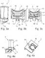
- the piercing spike 73is essentially constructed in one piece from three parts: a cylindrical base part 100, a piercing part 101 extending in the direction of the reservoir 6 in the form of an obliquely cut truncated cone and an intermediate part 102, which is arranged between the base part 100 and the piercing part 101 and is frustoconical is. There is a circumferential shoulder between the base part 100 and the intermediate part 102 103, while a circumferential edge 104 is formed between the piercing part 101 and the intermediate part 102.
- the piercing part 101has an inclined cut surface 105 with an oval circumference 106, which partially functions as a cut edge for perforating the sealing element 18. That part of the cut edge which protrudes the furthest in the direction of the reservoir 6 separates the sealing element 18 when it is perforated with a smooth cut. Due to the inclined cut surface 105, the part of the sealing element 18 partially separated from the sealing element 18 is not completely separated from the rest of the sealing element 18, but rather the partially separated part of the sealing element 18 rolls or partially folds together over the cut surface 105. This prevents separated parts of the sealing element from getting into the mixing chamber 8.
- the side channels 71are formed on that side of the piercing element 73 which lies opposite the cut surface 105. This has the advantage that the side channels 71 are arranged in the area of the smooth cut in the sealing element 18, as a result of which the beverage substance 7 can enter the side channels 71 undisturbed. Preferably, exactly five side channels 71 running almost parallel to one another are provided.
- the side channels 71each extend from the piercing part 101 over the circumferential edge 104 into the intermediate part 102, whereby the beverage substance 7 can better reach the side channels 71.
- the compressed air outlet 43lies within the cut surface 105, while the compressed air inlet or connection 42 is formed in the base part 100.
- a rotation lock in the form of a web 107 protruding radially from the base part 100is also provided on the base part 100.
- the mandrel guide 80has a groove corresponding to the web 107 within the wall of the guide channel 110, so that the piercing mandrel 73 is mounted so that it cannot rotate relative to the mandrel guide 80.
- the piercing spike 71is preferably designed as a plastic part and particularly preferably as a plastic injection-molded part.
- FIGS 7a, 7b and 7cschematic views of the cartridge 2 of the cartridge system 1 according to an exemplary embodiment are shown. It can be seen that the cartridge 2 comprises a bottle-shaped object with rounded edges, flattened longitudinal sides and a cartridge opening 63. In the area of the cartridge opening 63 the cartridge 2 has two circumferential retaining flanges 52 onto which the cartridge receptacle 10 is clipped.
- the Figures 8a, 8b and 8cshow schematic views of a cartridge receptacle 10 of the exemplary embodiment of the present invention.
- the cartridge receptacle 10has an at least partially circumferential locking strip 51 on both sides, with which the cartridge receptacle 10 is clipped onto the retaining flanges 52 of the cartridge 2.
- the cartridge receptacle 10has a mixing chamber 8 in which the fluid supply 12 is formed on its rear side in the form of a simple through opening in the wall of the cartridge receptacle 10.
- the beverage outlet 11is formed in the bottom of the mixing chamber 8.
- the bottom of the mixing chamber 8forms a continuously deepening depression in the direction of the beverage outlet 11, so that no liquid residues remain in the mixing chamber 8 after the beverage production process has ended.
- Almost centrally within the mixing chamber 8is in the Figures 8a to 8c also see the mandrel guide 80,
- the mandrel guide 80comprises a guide part with an internal guide channel 110 in which the piercing mandrel 73 is slidably received.
- the guide channel 110is essentially cylindrical and protrudes almost perpendicularly from the bottom of the mixing chamber 8 in the direction of the cartridge 2.
- a circumferential stop 111 with a reduced diameteris formed, against which the circumferential shoulder 103 of the piercing mandrel 73 strikes when the piercing mandrel 73 arrives in the extended position. The stop thus limits the movement of the piercing spike 73 in the direction of the reservoir 6.
- mixing structuresare arranged on the bottom of the mixing chamber 8.
- the above-described anti-twist device in the form of the web 107which engages in the corresponding groove on the mandrel guide 80, prevents the piercing mandrel 73 from rotating during the transfer from the retracted position to the extended position. In addition, this ensures that the side channels 71 are always arranged on that half-side of the piercing spike 73 which faces away from the beverage outlet 11 of the mixing chamber 8 and faces the fluid supply 12. In this way, an improved mixing of the beverage substance 7 and the fluid within the mixing chamber 8 is achieved.
Landscapes
- Engineering & Computer Science (AREA)
- Mechanical Engineering (AREA)
- Food Science & Technology (AREA)
- Health & Medical Sciences (AREA)
- Nutrition Science (AREA)
- Life Sciences & Earth Sciences (AREA)
- Chemical & Material Sciences (AREA)
- Polymers & Plastics (AREA)
- Physics & Mathematics (AREA)
- Thermal Sciences (AREA)
- Devices For Dispensing Beverages (AREA)
- Apparatus For Making Beverages (AREA)
- Packging For Living Organisms, Food Or Medicinal Products That Are Sensitive To Environmental Conditiond (AREA)
- Containers And Packaging Bodies Having A Special Means To Remove Contents (AREA)
- Non-Alcoholic Beverages (AREA)
- Coating Apparatus (AREA)
- Packages (AREA)
- Packaging Of Annular Or Rod-Shaped Articles, Wearing Apparel, Cassettes, Or The Like (AREA)
- Basic Packing Technique (AREA)
- Accessories For Mixers (AREA)
- Processing And Handling Of Plastics And Other Materials For Molding In General (AREA)
- Package Specialized In Special Use (AREA)
- Separation Using Semi-Permeable Membranes (AREA)
Description
Translated fromGermanDie vorliegende Erfindung geht aus von einem in eine Getränkezubereitungsmaschine einsetzbares Kartuschensystem zur Herstellung eines Getränks, insbesondere eines Kaltgetränks, aufweisend eine Kartusche, die ein mit einer Getränkesubstanz gefülltes Reservoir aufweist, und eine mit der Kartusche reversibel verbindbare Kartuschenaufnahme, in welche die Kartusche reversibel einsetzbar ist, und mit einer Kartuschenentladeeinrichtung, welche ein zumindest teilweises Überführen der Getränkesubstanz vom Reservoir in eine Mischkammer bewirkt.The present invention is based on a cartridge system that can be used in a beverage preparation machine for producing a beverage, in particular a cold beverage, comprising a cartridge which has a reservoir filled with a beverage substance and a cartridge receptacle which can be reversibly connected to the cartridge and in which the cartridge can be reversibly inserted , and with a cartridge unloading device which brings about an at least partial transfer of the beverage substance from the reservoir into a mixing chamber.
Solche Systeme sind aus dem Stand der Technik grundsätzlich bekannt, etwa aus der
Eine große Herausforderung bei solchen Systemen ist, während der Herstellung des Getränks eine Rückkontamination der Getränkezubereitungsmaschine sicher und vollständig zu unterbinden, da andernfalls die Gefahr einer Verunreinigung bis hin zur Schimmelpilzbildung innerhalb der Getränkezubereitungsmaschine besteht. Dies gilt insbesondere für Kartuschen die fruchtzuckerhaltige, alkoholhaltige oder milchhaltige Getränkesubstanzen enthalten.A major challenge with such systems is to safely and completely prevent recontamination of the beverage preparation machine during the production of the beverage, since otherwise there is a risk of contamination or even mold formation inside the beverage preparation machine. This applies in particular to cartridges that contain fructose, alcoholic or milk-containing beverage substances.
Bei aus dem Stand der Technik bekannten Systemen wird üblicherweise die Kartusche in eine als fester Bestandteil der Getränkezubereitungsmaschine ausgebildete Kartuschenaufnahme eingesetzt und sodann die Kartusche auf beiden Seiten, d.h. auf einer Einlassseite und auf einer Auslassseite geöffnet. Auf der Einlassseite wird anschließend mittels einer Fluidzuführung Wasser in die Kartusche eingeleitet, so dass sich das Getränk durch Vermischen der Getränkesubstanz mit dem Wasser schon innerhalb des Reservoirs in der Kartusche bildet. Auf der Auslassseite verlässt das Getränk die Kartusche und wird zu einem Trinkgefäß geleitet. Das Wasser durchströmt das Reservoir hierbei vollständig und bewirkt somit ein Ausleiten der Getränkesubstanz aus dem Reservoir.In systems known from the prior art, the cartridge is usually inserted into a cartridge receptacle designed as an integral part of the beverage preparation machine inserted and then the cartridge is opened on both sides, ie on an inlet side and on an outlet side. On the inlet side, water is then introduced into the cartridge by means of a fluid feed, so that the beverage is already formed within the reservoir in the cartridge by mixing the beverage substance with the water. The beverage leaves the cartridge on the outlet side and is directed to a drinking vessel. The water flows through the reservoir completely and thus causes the beverage substance to drain out of the reservoir.
Es hat sich gezeigt, dass beim Einleiten des Wassers direkt in das mit der Getränkesubstanz gefüllte Reservoir eine Rückkontamination der Zuführung nicht vollständig verhindert werden kann, weil das Reservoir üblicherweise vollständig mit der Getränkesubstanz gefüllt ist und dadurch beim Einleiten des Wassers ein erheblicher Druckanstieg im Reservoir stattfindet. Sowohl dieser Druckanstieg im Reservoir als auch das Durchspülen des Reservoirs sorgt dafür, dass während und/oder kurz nach der Getränkeherstellung kleinste Tropfen, Partikel und/oder Schwebestoffe der Getränkesubstanz in die Fluidzuführung gelangen und dort zu einer kontinuierlichen Verunreinigung der Getränkezubereitungsmaschine führen.It has been shown that when the water is introduced directly into the reservoir filled with the beverage substance, back-contamination of the feed cannot be completely prevented because the reservoir is usually completely filled with the beverage substance and a considerable increase in pressure takes place in the reservoir when the water is introduced . Both this pressure increase in the reservoir and the flushing through of the reservoir ensure that the smallest drops, particles and / or suspended matter of the beverage substance get into the fluid supply during and / or shortly after the beverage production process and lead to continuous contamination of the beverage preparation machine there.
Eine weitere Problematik besteht darin, die Kartusche nach der Befüllung mit der Getränkesubstanz luft- und flüssigkeitsdicht zu verschließen, damit das Aroma der Getränkesubstanz erhalten bleibt. Gleichzeitig muss aber auch gewährleistet werden, dass die Kartusche in der Getränkezubereitungsmaschine leicht, zuverlässig und vollständig wieder geöffnet werden kann, um die Getränkesubstanz verwenden zu können.Another problem is to close the cartridge airtight and liquid-tight after it has been filled with the beverage substance, so that the aroma of the beverage substance is retained. At the same time, however, it must also be ensured that the cartridge in the beverage preparation machine can be opened again easily, reliably and completely in order to be able to use the beverage substance.
Es ist daher eine Aufgabe der vorliegenden Erfindung eine Kartuschenaufnahme, ein Kartuschensystem, eine Getränkezubereitungsmaschine und ein Verfahren zur Herstellung eines Getränks durch Einsetzen des Kartuschensystems in eine Getränkezubereitungsmaschine zur Verfügung zu stellen, bei welchem eine Rückkontamination der Getränkezubereitungsmaschine wirksam vermieden wird sowie eine einfache und zuverlässige Öffnung einer zuvor aromadicht verschlossenen Kartusche in einer Getränkezubereitungsmaschine ermöglicht.It is therefore an object of the present invention to provide a cartridge receptacle, a cartridge system, a beverage preparation machine and a method for producing a beverage by inserting the cartridge system into a beverage preparation machine, in which a recontamination of the beverage preparation machine is effectively avoided and a simple and reliable opening a previously aroma-tight sealed cartridge in a beverage preparation machine.
Diese Aufgabe wird durch eine Kartuschenaufnahme gemäß Anspruch 1 gelöst.This object is achieved by a cartridge holder according to
Die erfindungsgemäße Kartuschenaufnahme und das erfindungsgemäße Kartuschensystem haben gegenüber dem Stand der Technik den Vorteil, dass die Fluidzuführung anders als beim Stand der Technik nicht in das Reservoir der Kartusche, sondern in die vom Reservoir separierte Mischkammer mündet. Hierdurch wird wirksam und in einer einfach und kostengünstig zu realisierenden Weise verhindert, dass durch die Fluidzuführung eine Rückkontamination der Getränkezubereitungsmaschine erfolgt. Hierfür wird das Reservoir nicht von dem Fluid durchspült, sondern gemäß der vorliegenden Erfindung gelangen die Getränkesubstanz und das Fluid getrennt voneinander in die Mischkammer. Das Fluid wird direkt in die Mischkammer geleitet, während die Getränkesubstanz durch die Kartuschenentladeeinrichtung und unabhängig vom Fluid in die Mischkammer überführt wird. Zu diesem Zweck weist die erfindungsgemäße Kartuschenaufnahme ferner den in der Dornführung verschiebbar gelagerten Aufstechdorn auf. Der Aufstechdorn ist im Ausgangszustand der Kartuschenaufnahme in einer eingefahrenen Position und kann zum Öffnen eines Dichtelements der Kartusche von der eingefahrenen Position in die ausgefahrene Position überführt werden. In der ausgefahrenen Position wird das Dichtelement von dem Aufstechdorn perforiert, so dass die Getränkesubstanz durch den wenigstens einen Seitenkanal an dem Dichtelement vorbei in die Mischkammer gelangt. Zuvor ist das Reservoir mittels des Dichtelements insbesondere luft- und flüssigkeitsdicht verschlossen. Es wird somit eine einfache und zuverlässige Öffnung einer zuvor aromadicht verschlossenen Kartusche in einer Getränkezubereitungsmaschine ermöglicht. Zudem hat sich gezeigt, dass eine Rückkontamination der Getränkezubereitungsmaschine in einer im Vergleich zum Stand der Technik deutlich wirksameren Art und Weise unterbunden wird, insbesondere da im Reservoir kein direkt auf die Fluidzuführung wirkender Überdruck erzeugt wird. Die Ausbildung der Mischkammer in der Kartuschenaufnahme, die in die Getränkezubereitungsmaschine reversibel einsetzbar ist, sorgt vorteilhafterweise dafür, dass die Mischkammer Teil des austauschbaren Kartuschensystem ist. Auf diese Weise wird eine Verunreinigung der Getränkezubereitungsmaschine durch die Getränkesubstanz wirksam vermieden, weil lediglich Teile des austauschbaren Einweg- oder Mehrwegkartuschensystems mit der Getränkesubstanz in Kontakt gelangen.The cartridge receptacle according to the invention and the cartridge system according to the invention have the advantage over the prior art that the fluid supply, unlike in the prior art, is not into the reservoir of the cartridge, but into that of the reservoir separated mixing chamber opens. This effectively and in a manner that can be implemented simply and inexpensively prevents the beverage preparation machine from being contaminated back by the fluid supply. For this purpose, the reservoir is not flushed through by the fluid, but rather, according to the present invention, the beverage substance and the fluid enter the mixing chamber separately from one another. The fluid is fed directly into the mixing chamber, while the beverage substance is transferred through the cartridge discharge device and independently of the fluid into the mixing chamber. For this purpose, the cartridge receptacle according to the invention also has the piercing spike mounted displaceably in the spike guide. In the initial state of the cartridge receptacle, the piercing spike is in a retracted position and can be transferred from the retracted position to the extended position in order to open a sealing element of the cartridge. In the extended position, the sealing element is perforated by the piercing spike, so that the beverage substance passes through the at least one side channel past the sealing element and into the mixing chamber. Before this, the reservoir is closed in particular airtight and liquid-tight by means of the sealing element. A simple and reliable opening of a previously aroma-tight sealed cartridge in a beverage preparation machine is thus made possible. In addition, it has been shown that recontamination of the beverage preparation machine is prevented in a manner that is significantly more effective than in the prior art, in particular since no overpressure acting directly on the fluid supply is generated in the reservoir. The design of the mixing chamber in the cartridge receptacle, which can be reversibly inserted into the beverage preparation machine, advantageously ensures that the mixing chamber is part of the exchangeable cartridge system. In this way, contamination of the beverage preparation machine by the beverage substance is effectively avoided because only parts of the exchangeable disposable or reusable cartridge system come into contact with the beverage substance.
Vorteilhafte Ausgestaltungen und Weiterbildungen der Erfindung sind den Unteransprüchen, sowie der Beschreibung unter Bezugnahme auf die Zeichnungen entnehmbar.Advantageous refinements and developments of the invention can be found in the subclaims and the description with reference to the drawings.
Gemäß einer bevorzugten Ausführungsform der vorliegenden Erfindung ist vorgesehen, dass der Aufstechdorn ein zylinder- oder kegelstumpfförmiges Basisteil und ein sich in Richtung des Reservoirs erstreckendes Aufstechteil umfasst, wobei das Aufstechteil in Form eines schräg abgeschnittenen Kegelstumpfs ausgebildet ist. Vorzugsweise ist das Aufstechteil ferner derart ausgebildet ist, dass eine schräge Schnittfläche des schräg abgeschnittenen Kegelstumpfs im Wesentlichen dem Reservoir zugewandt ist, wobei der ovale Umfang der Schnittfläche zumindest teilweise eine Schnittkante zum Perforieren des Dichtelements darstellt. Es hat sich gezeigt, dass die Schnittfläche, welche durch einen schrägen Schnitt durch den Kegelstumpf erzeugt wird, einerseits das Dichtelement einfach und mit ausreichend wenig Kraftaufwand schneidet und andererseits keine Späne oder lose Stücke von dem Dichtelement abtrennt, welche ansonsten das Getränk in ungewollter Weise verunreinigen würden. Die Dichtelementperforation sieht vorteilhafterweise derart aus, dass an derjenigen Seite des Aufstechdorns, an welchem die maximal in Richtung des Reservoirs überstehende Schnittkante ausgebildet ist, das Material des Dichtelements mit einem glatten Schnitt durchtrennt ist, während im Bereich der Schnittfläche des Aufstechteils das abgeschnittene Material des Dichtelements noch mit dem übrigen Dichtelement verbunden ist und vorzugsweise aufrollt oder zusammengefaltet ist.According to a preferred embodiment of the present invention it is provided that the piercing mandrel comprises a cylindrical or frustoconical base part and a piercing part extending in the direction of the reservoir, the piercing part being designed in the form of an obliquely cut truncated cone. The piercing part is preferably also designed such that an inclined cut surface of the inclined truncated cone essentially faces the reservoir, the oval circumference of the cut surface at least partially representing a cut edge for perforating the sealing element. It has been shown that the cut surface, which is caused by an oblique cut through the truncated cone is generated, on the one hand cuts the sealing element easily and with sufficiently little effort and on the other hand does not cut off any chips or loose pieces from the sealing element which would otherwise contaminate the beverage in an unwanted manner. The sealing element perforation advantageously looks such that the material of the sealing element is severed with a smooth cut on that side of the piercing mandrel on which the cutting edge protruding maximally in the direction of the reservoir, while the cut material of the sealing element is cut through in the area of the cut surface of the piercing part is still connected to the rest of the sealing element and is preferably rolled up or folded up.
Vorzugsweise umfasst der Aufstrechdorn ein zwischen dem Basisteil und dem Aufstechteil angeordnetes Zwischenteil, welcher kegelstumpfförmig ausgebildet ist, wobei zwischen dem Basisteil und dem Zwischenteil eine umlaufender Absatz ausgebildet ist und wobei zwischen dem Aufstechteil und dem Zwischenteil eine umlaufende Kante ausgebildet ist. Vorteilhafterweise wird somit ein stabiler Aufstechdorn gebildet. Der Ausbildung der Kante hat den Vorteil, dass die Seitenkanäle, sofern sie sich über die Kante erstrecken, reservoirseitig einen vergrößerten Eingang aufweisen und somit die Überführung der Getränkesubstanz in Richtung Mischkammer erleichtert wird. Der Absatz dient dazu gegen einen Anschlag der Dornführung anzuschlagen, wenn der Aufstechdorn in der aufgefahrenen Position ist, sodass die Ausfahrbewegung des Aufstechdorns in Richtung der Kartusche begrenzt wird.The erecting mandrel preferably comprises an intermediate part which is arranged between the base part and the piercing part and is designed in the shape of a truncated cone, a circumferential shoulder being formed between the base part and the intermediate part and a circumferential edge being formed between the piercing part and the intermediate part. A stable piercing spike is thus advantageously formed. The formation of the edge has the advantage that the side channels, provided they extend over the edge, have an enlarged inlet on the reservoir side and thus the transfer of the beverage substance towards the mixing chamber is facilitated. The shoulder serves to strike against a stop of the mandrel guide when the piercing mandrel is in the opened position, so that the moving out movement of the piercing mandrel in the direction of the cartridge is limited.
Gemäß einer bevorzugten Ausführungsform der vorliegenden Erfindung ist vorgesehen, dass die Kartuschenaufnahme eine Mehrzahl von Seitenkanälen aufweist, wobei sich jeder Seitenkanal parallel zum Aufstechdorn im Bereich des Aufstechteils und im Bereich des Zwischenteils erstreckt. Die Seitenkanäle sind dabei insbesondere jeweils in Form einer in die Außenfläche des Aufstechdorns eingebrachte einseitig offene Nut ausgebildet. Vorzugsweise sind die Seitenkanäle zumindest teilweise in einem zur Schnittfläche rückwärtigen Umfangsbereich des Aufstechdorns ausgebildet. Dies hat den Vorteil, dass die Seitenkanäle an derjenigen Seite der Dichtelementperforation angeordnet sind, an welcher ein Schnitt im Material erzeugt wurde, und nicht an der gegenüberliegenden Seite, an welcher das abgeschnittene Material noch mit dem übrigen Dichtelement verbunden ist. Die Getränkesubstanz kann somit vergleichsweise ungehindert in die Seitenkanäle einströmen.According to a preferred embodiment of the present invention it is provided that the cartridge receptacle has a plurality of side channels, each side channel extending parallel to the piercing spike in the area of the piercing part and in the area of the intermediate part. The side channels are each designed in particular in the form of a groove that is open on one side and made in the outer surface of the piercing spike. The side channels are preferably formed at least partially in a circumferential region of the piercing spike that is rearward to the cut surface. This has the advantage that the side channels are arranged on that side of the sealing element perforation on which a cut was made in the material, and not on the opposite side on which the cut material is still connected to the remaining sealing element. The beverage substance can thus flow into the side channels relatively unhindered.
Denkbar ist, dass der Querschnitt der Seitenkanäle und/oder die Anzahl der Seitenkanäle an die Viskosität der Getränkesubstanz angepasst ist, so dass die Seitenkanäle den Fluss der Getränkesubstanz in Richtung Mischkammer kontrollieren bzw. begrenzen. Bei einer hohen Viskosität werden mehrere Seitenkanäle oder Seitenkanäle mit größerem Querschnitt verwendet, während bei einer niedrigeren Viskosität weniger Seitenkanäle oder Seitenkanäle mit geringerem Querschnitt vorgesehen sind. Für jede Kartusche existiert somit eine passende Kartuschenaufnahme.It is conceivable that the cross section of the side channels and / or the number of side channels is adapted to the viscosity of the beverage substance, so that the side channels control or limit the flow of the beverage substance in the direction of the mixing chamber. If the viscosity is high, several side channels or side channels with a larger cross-section are used, while at a lower viscosity fewer side channels or side channels with a smaller cross section are provided. There is therefore a suitable cartridge holder for each cartridge.
Gemäß einer bevorzugten Ausführungsform der vorliegenden Erfindung ist vorgesehen, dass der Aufstechdorn eine Verdrehsicherung in Form eines vom Basisteil radial abstehenden Steges aufweist. In vorteilhafter Weise wird somit eine Verdrehung des Aufstechdorns bei der Überführung von der eingezogenen Position in die ausgefahrene Position verhindert. Zudem wird sichergestellt, dass die Seitenkanäle auf derjenigen Seite des Aufstechdorns angeordnet ist, welche dem Getränkeauslauf der Mischkammer abgewandt und insbesondere der Fluidzuführung zugewandt ist. Auf diese Weise wird eine verbesserte Durchmischung der Getränkesubstanz und dem Fluid innerhalb der Mischkammer erzielt.According to a preferred embodiment of the present invention it is provided that the piercing spike has an anti-twist device in the form of a web protruding radially from the base part. A twisting of the piercing spike during the transfer from the retracted position to the extended position is thus advantageously prevented. In addition, it is ensured that the side channels are arranged on that side of the piercing spike which faces away from the beverage outlet of the mixing chamber and, in particular, faces the fluid supply. In this way, an improved mixing of the beverage substance and the fluid within the mixing chamber is achieved.
Gemäß einer bevorzugten Ausführungsform der vorliegenden Erfindung ist vorgesehen, dass der Aufstechdorn eine integrierte Druckluftleitung, welche die Kartuschenentladeeinrichtung ist, aufweist, wobei sich die Druckluftleitung entlang des Aufstechdorns insbesondere von einem ersten Ende des Aufstechdorns bis zu einem zweiten Ende des Aufstechdorns erstreckt. In vorteilhafter Weise sind somit drei Funktionen in den Aufstechdorn integriert: 1. Der Aufstechdorn umfasst den Aufstechteil, um das Dichtelement zu perforieren und somit die Kartusche zu öffnen 2. Der Aufstechdorn umfasst die Seitenkanäle, um ein Überführen der Getränkesubstanz in die Mischkammer zu ermöglichen 3. Der Aufstechdorn umfasst die integrierte Druckluftleitung, um Druckluft in das Reservoir zu blasen, wodurch die Getränkesubstanz unter Druck in die Mischkammer gedrückt wird.According to a preferred embodiment of the present invention it is provided that the piercing mandrel has an integrated compressed air line, which is the cartridge discharge device, the compressed air line extending along the piercing mandrel in particular from a first end of the piercing mandrel to a second end of the piercing mandrel. Thus, three functions are advantageously integrated into the piercing spike: 1. The piercing spike includes the piercing part to perforate the sealing element and thus open the
Vorzugsweise ist am zweiten Ende ein Druckluftanschluss zum Anschluss an eine Druckluftquelle und am ersten Ende ein Druckluftauslass zum Einblasen von Druckluft in das Reservior ausgebildet. Die in die Kartuschenaufnahme integrierte Kartuschenentladeeinrichtung umfasst im Sinne der vorliegenden Erfindung also zunächst nur eine Druckluftleitung, durch welche Druckluft von außen in das Reservoir eingeleitet werden kann. Die Kartuschenaufnahme ist derart ausgebildet, dass durch die Druckluft die Getränkesubstanz aus dem Reservoir in die Mischkammer gedrückt wird. Die Druckluft wird insbesondere von der Getränkezubereitungsmaschine bereitgestellt. Denkbar ist, dass eine Druckluftquelle direkt an den Druckluftanschluss angekoppelt wird, sobald das Kartuschensystem in die Getränkezubereitungsmaschine eingesetzt wird. Dies hat den Vorteil, dass eine Rückkontamination in Richtung der Getränkezubereitungsmaschine wirksam vermieden wird, weil die Kartuschenentladeeinrichtung sofort beim Einsetzen des Kartuschensystems unter Druck steht und somit verhindert wird, dass Getränkesubstanz in Richtung der Druckluftleitung und insbesondere in Richtung der Druckluftquelle der Getränkezubereitungsmaschine wandert. Die Getränkesubstanz kann sich ausgehend vom Reservoir somit lediglich in Richtung der Mischkammer bewegen.A compressed air connection for connection to a compressed air source is preferably configured at the second end and a compressed air outlet for blowing compressed air into the reservoir is configured at the first end. In the context of the present invention, the cartridge unloading device integrated in the cartridge receptacle thus initially comprises only one compressed air line, through which compressed air can be introduced from the outside into the reservoir. The cartridge receptacle is designed in such a way that the beverage substance is pressed out of the reservoir into the mixing chamber by the compressed air. The compressed air is provided in particular by the beverage preparation machine. It is conceivable that a compressed air source is coupled directly to the compressed air connection as soon as the cartridge system is inserted into the beverage preparation machine. This has the advantage that back-contamination in the direction of the beverage preparation machine is effectively avoided because the cartridge unloader is under pressure immediately when the cartridge system is inserted, thus preventing beverage substance from flowing in the direction of the compressed air line and in particular in The direction of the compressed air source of the beverage preparation machine migrates. The beverage substance can therefore only move in the direction of the mixing chamber starting from the reservoir.
Gemäß einer bevorzugten Ausführungsform der vorliegenden Erfindung ist vorgesehen, dass der Druckluftauslass als Öffnung in der Schnittfläche ausgebildet ist. Dies hat den Vorteil, dass die in das Reservoir einströmende Luft auf einer den Seitenkanälen abgewandten Seite des Aufstechdorns eingeblasen wird, so dass das Ableiten der Getränkesubstanz in die Mischkammer nicht behindert wird. Vorzugsweise bildet sich im Reservoir somit ein Wirbel aus, welche eine nahezu restlose Entleerung des Reservoirs begünstigt.According to a preferred embodiment of the present invention it is provided that the compressed air outlet is designed as an opening in the cut surface. This has the advantage that the air flowing into the reservoir is blown in on a side of the piercing spike facing away from the side channels, so that the drainage of the beverage substance into the mixing chamber is not hindered. A vortex thus preferably forms in the reservoir, which favors an almost complete emptying of the reservoir.
Der Druckluftanschluss ist insbesondere als Öffnung im Basisteil ausgebildet, wobei der Basisteil derart in der Kartuschenaufnahme angeordnet ist, dass der Druckluftanschluss von außerhalb der Kartuschenaufnahme zugänglich ist. Auf diese Weise wird das Anschließen der Druckluftleitung an die Druckluftquelle begünstigt.The compressed air connection is designed in particular as an opening in the base part, the base part being arranged in the cartridge receptacle in such a way that the compressed air connection is accessible from outside the cartridge receptacle. In this way, the connection of the compressed air line to the compressed air source is facilitated.
Gemäß einer bevorzugten Ausführungsform der vorliegenden Erfindung ist vorgesehen, dass die Dornführung ein Führungsteil mit einem innenliegenden Führungskanal zur Aufnahme des Aufstechdorns aufweist, wobei der Führungskanal des Führungsteils im Wesentlichen zylinder- oder kegelstumpfförmig ausgebildet ist und wobei an einem der Kartusche zugewandten Ende des Führungsteils ein umlaufender Anschlag ausgebildet ist, welcher die Bewegung des Aufstechdorns in Richtung des Reservoirs begrenzt, wobei der Anschlag insbesondere einen Bereich mit verringertem Durchmesser umfasst. Vorteilhafterweise wird somit eine zuverlässige Führung des Aufstechdorns bei der Bewegung von der eingefahrenen Position in die ausgefahrene Position erzielt. Vorzugsweise ist innerhalb der Wandung des Führungskanals eine zum Steg korrespondierende Nut als Verdrehsicherung ausgebildet, so dass eine ungewollte Verdrehung des Aufstechdorns unterbunden wird. Das Führungssteil ist vorzugsweise in der Mischkammer angeordnet und steht dabei von einem Boden der Mischkammer in Richtung der Kartusche vor.According to a preferred embodiment of the present invention, it is provided that the mandrel guide has a guide part with an internal guide channel for receiving the piercing mandrel, the guide channel of the guide part being essentially cylindrical or frustoconical and with a circumferential guide part at one end of the guide part facing the cartridge Stop is formed, which limits the movement of the piercing spike in the direction of the reservoir, the stop in particular comprising an area with a reduced diameter. Reliable guidance of the piercing spike during the movement from the retracted position into the extended position is thus advantageously achieved. Preferably, a groove corresponding to the web is formed within the wall of the guide channel as an anti-twist device, so that undesired twisting of the piercing spike is prevented. The guide part is preferably arranged in the mixing chamber and protrudes from a base of the mixing chamber in the direction of the cartridge.
Gemäß einer bevorzugten Ausführungsform der vorliegenden Erfindung ist vorgesehen, dass der Aufstechdorn als Kunststoffteil und insbesondere als Kunststoff-Spritzgussteil ausgebildet ist. Auf diese Weise wird eine kostengünstige Herstellung ermöglicht. Grundsätzlich wäre es alternativ aber auch denkbar, den Aufstechdorn als Metallteil auszubilden.According to a preferred embodiment of the present invention it is provided that the piercing spike is designed as a plastic part and in particular as a plastic injection-molded part. In this way, inexpensive production is made possible. In principle, however, it would also alternatively be conceivable to design the piercing spike as a metal part.
Gemäß einer bevorzugten Ausführungsform der vorliegenden Erfindung ist vorgesehen, dass der Aufstechdorn derart ausgebildet ist, dass er beim Einsetzen des Kartuschensystems in die Getränkezubereitungsmaschine von einem Auslöseelement der Getränkezubereitungsmaschine von der eingefahrenen Position in die ausgefahrene Position überführbar ist.According to a preferred embodiment of the present invention it is provided that the piercing spike is designed in such a way that it can be removed when the cartridge system is inserted can be transferred from the retracted position to the extended position in the beverage preparation machine by a trigger element of the beverage preparation machine.
Gemäß einer bevorzugten Ausführungsform der vorliegenden Erfindung ist vorgesehen, dass die Kartusche eine mit dem Reservoir in Fluidverbindung stehende Kartuschenöffnung aufweist, wobei die Kartuschenöffnung im Ausgangszustand durch das Dichtelement verschlossen ist, wobei das Dichtelement insbesondere eine Dichtfolie umfasst, die auf den Rand der Kartuschenöffnung aufgebraucht und vorzugsweise aufgesiegelt ist. In vorteilhafter Weise wird somit das Reservoir hermetisch und aromadicht verschlossen. Die Dichtfolie ist hierfür insbesondere weitgehend luft- und flüssigkeitsdicht ausgebildet. Zur Herstellung dieses Kartuschensystems wird zunächst die Kartusche mit der Kartuschenöffnung erzeugt, dann die Kartusche durch die Kartuschenöffnung mit der Getränkesubstanz befüllt, anschließend die Kartuschenöffnung durch das Dichtelement verschlossen und zuletzt die Kartuschenaufnahme auf die Kartusche im Bereich der verschlossenen Kartuschenöffnung aufgeclipst. Vor, während oder nach dem Einsetzen des Kartuschensystems in die Getränkezubereitungsmaschine muss das Dichtelement im Bereich der Kartuschenöffnung geöffnet werden, beispielsweise durch Perforieren der Dichtfolie durch den Aufstechdorn, damit die Getränkesubstanz durch Einleiten der Druckluft vom Reservoir in die Mischkammer überführt werden kann.According to a preferred embodiment of the present invention it is provided that the cartridge has a cartridge opening which is in fluid connection with the reservoir, the cartridge opening being closed by the sealing element in the initial state, the sealing element in particular comprising a sealing film which is used up on the edge of the cartridge opening and is preferably sealed. The reservoir is thus advantageously hermetically sealed and aroma-tight. For this purpose, the sealing film is designed in particular to be largely air-tight and liquid-tight. To manufacture this cartridge system, the cartridge with the cartridge opening is first created, then the cartridge is filled with the beverage substance through the cartridge opening, then the cartridge opening is closed by the sealing element and finally the cartridge holder is clipped onto the cartridge in the area of the closed cartridge opening. Before, during or after inserting the cartridge system into the beverage preparation machine, the sealing element in the area of the cartridge opening must be opened, for example by perforating the sealing film through the piercing spike, so that the beverage substance can be transferred from the reservoir to the mixing chamber by introducing the compressed air.
Vorzugsweise ist vorgesehen, dass die Mischkammer einen Getränkeauslauf aufweist, durch welchen das aus einer Vermischung der Getränkesubstanz mit dem Fluid gebildete Getränk abgegeben wird, wobei die Kartuschenaufnahme vorzugsweise derart ausgebildet ist, dass das Getränk aus dem Getränkeauslauf direkt in ein portables Gefäß einleitbar ist.It is preferably provided that the mixing chamber has a beverage outlet through which the beverage formed by mixing the beverage substance with the fluid is dispensed, the cartridge receptacle preferably being designed such that the beverage can be introduced directly into a portable vessel from the beverage outlet.
Kartuschenaufnahme nach einem der vorhergehenden Ansprüche, wobei die Kartuschenaufnahme mit der Kartusche über eine Rastverbindung lösbar verbindbar ist. Vorzugsweise ist die Kartuschenaufnahme demnach reversibel an der Kartusche befestigt, besonders bevorzugt durch die Rastverbindung. Denkbar ist beispielsweise, dass die Kartusche eine Art Flaschenhals (aufweisend die Kartuschenöffnung) mit einem umlaufenden Halteflansch umfasst und die Kartuschenaufnahme auf den Flaschenhals geclipst wird. Dabei hintergreifen insbesondere elastische Rastelemente, wie beispielsweise Halteärmchen den Halteflansch. Die Kartusche ist insbesondere als Einmalbehältnis für die Getränkesubstanz vorgesehen, insbesondere recycelbar. Vorteilhafterweise kann die Kartuschenaufnahme mehrfach verwendet werden, indem sie an verschiedenen Kartuschen befestigbar ist. Zudem wird die Herstellung des Kartuschensystem vereinfacht, da die Kartusche und die Kartuschenaufnahme separat hergestellt werden können und lediglich die Kartuschenaufnahme anschließend auf die Kartusche aufgeclipst wird. Die Kartusche umfasst insbesondere eine eckige, runde oder abgerundete Flasche. Die Kartusche ist insbesondere aus Kunststoff in einem Blas-Spritzform-Formverfahren oder in einem Spritzformverfahren oder mit weiteren Formverfahren hergestellt. Grundsätzlich wäre aber auch ein Tiefziehverfahren zur Herstellung der Kartusche vorstellbar. Ebenso wäre es natürlich auch denkbar, dass die Kartusche mehrfach verwendbar ist. Im Prinzip wäre es auch denkbar, dass die Kartusche eine Glasflasche umfasst, während nur die Kartuschenaufnahme ein Kunststoffteil ist.Cartridge holder according to one of the preceding claims, wherein the cartridge holder can be releasably connected to the cartridge via a latching connection. Preferably, the cartridge receptacle is therefore reversibly attached to the cartridge, particularly preferably by means of the latching connection. It is conceivable, for example, that the cartridge comprises a type of bottle neck (having the cartridge opening) with a circumferential retaining flange and the cartridge receptacle is clipped onto the bottle neck. In particular, elastic latching elements, such as retaining arms, engage behind the retaining flange. The cartridge is intended in particular as a disposable container for the beverage substance, in particular it is recyclable. Advantageously, the cartridge holder can be used multiple times by being attachable to different cartridges. In addition, the manufacture of the cartridge system is simplified because the cartridge and the cartridge holder can be manufactured separately and only the cartridge holder is then clipped onto the cartridge. The cartridge comprises in particular an angular, round or rounded bottle. The cartridge is made in particular from plastic in a blow-injection molding process or in an injection molding process or with other molding processes. In principle, however, a deep-drawing process for producing the cartridge would also be conceivable. It would of course also be conceivable for the cartridge to be reusable. In principle, it would also be conceivable for the cartridge to include a glass bottle, while only the cartridge holder is a plastic part.
Gemäß einer weiteren bevorzugten Ausführungsform der vorliegenden Erfindung ist vorgesehen, dass die Mischkammer einen Getränkeauslauf aufweist, durch welchen das aus einer Vermischung der Getränkesubstanz mit dem Fluid gebildete Getränk abgegeben wird, wobei das Kartuschensystem vorzugsweise derart ausgebildet ist, dass das Getränk aus dem Getränkeauslauf direkt in ein portables Gefäß einleitbar ist. In vorteilhafter Weise gerät somit weder die Getränkesubstanz noch das erzeugte Getränk in Kontakt mit einem Teil der Getränkezubereitungsmaschine, so dass nahezu jegliche (Rück-)Kontamination der Getränkezubereitungsmaschine verhindert wird. Das Fluid wird der Mischkammer separat zugeführt. Vorzugsweise wird das Fluid unter Druck in die Mischkammer eingeleitet. Das Fluid wird insbesondere von der Getränkezubereitungsmaschine bereitgestellt. Denkbar ist, dass eine Fluidquelle direkt an einen entsprechenden Fluidanschluss der Kartuschenaufnahme angekoppelt wird, sobald das Kartuschensystem in die Getränkezubereitungsmaschine eingesetzt wird. Der Fluidanschluss steht dabei über eine Fluidleitung in Fluidverbindung mit der Mischkammer. Dies hat den Vorteil, dass eine Rückkontamination in Richtung der Getränkezubereitungsmaschine wirksam vermieden wird, weil der Fluidanschluss sofort beim Einsetzen des Kartuschensystems unter Druck steht und somit verhindert wird, dass Getränkesubstanz in Richtung der Fluidleitung und insbesondere in Richtung der Fluidquelle der Getränkezubereitungsmaschine wandert. Die Getränkesubstanz und das Getränk kann sich ausgehend von der Mischkammer somit lediglich in Richtung des Getränkeauslasses bewegen. Das Fluid umfasst insbesondere Wasser, vorzugsweise unter Druck stehendes, gekühltes und/oder karbonisiertes Trinkwasser.According to a further preferred embodiment of the present invention, it is provided that the mixing chamber has a beverage outlet through which the beverage formed by mixing the beverage substance with the fluid is dispensed, the cartridge system preferably being designed such that the beverage flows out of the beverage outlet directly into a portable vessel can be introduced. Advantageously, neither the beverage substance nor the beverage produced comes into contact with part of the beverage preparation machine, so that almost any (re) contamination of the beverage preparation machine is prevented. The fluid is fed separately to the mixing chamber. The fluid is preferably introduced into the mixing chamber under pressure. The fluid is provided in particular by the beverage preparation machine. It is conceivable that a fluid source is coupled directly to a corresponding fluid connection of the cartridge receptacle as soon as the cartridge system is inserted into the beverage preparation machine. The fluid connection is in fluid connection with the mixing chamber via a fluid line. This has the advantage that back-contamination in the direction of the beverage preparation machine is effectively avoided because the fluid connection is under pressure immediately when the cartridge system is inserted, thus preventing beverage substance from migrating in the direction of the fluid line and in particular in the direction of the fluid source of the beverage preparation machine. The beverage substance and the beverage can therefore only move in the direction of the beverage outlet starting from the mixing chamber. The fluid includes in particular water, preferably pressurized, cooled and / or carbonated drinking water.
Gemäß einer bevorzugten Ausführungsform der vorliegenden Erfindung ist vorgesehen, dass die Mischkammer mit Mischstrukturen versehen ist. Die Mischstrukturen sorgen in vorteilhafter Weise für eine verbesserte Durchmischung von Getränkesubstanz und Fluid. Hierfür sind die Mischstrukturen insbesondere derart ausgebildet, dass das in die Mischkammer einströmende Fluid verwirbelt wird. Denkbar ist, dass die Mischstruktur einen oder mehrere Mischstege umfasst, welche im Bereich der Fluidzuführung am Boden der Mischkammer angeordnet sind und sich im Wesentlichen senkrecht zum Einströmrichtung des Fluides erstrecken. Die Mischstege fungieren somit als Barrieren für das Fluid, wodurch das Fluid aufgewirbelt wird und eine bessere Durchmischung mit der Getränkesubstanz erzielt wird.According to a preferred embodiment of the present invention it is provided that the mixing chamber is provided with mixing structures. The mixing structures advantageously ensure improved mixing of beverage substance and fluid. For this purpose, the mixing structures are designed in particular in such a way that the fluid flowing into the mixing chamber is swirled. It is conceivable that the mixing structure comprises one or more mixing webs which are located in the area of the fluid supply at the bottom of the mixing chamber are arranged and extend substantially perpendicular to the inflow direction of the fluid. The mixing webs thus function as barriers for the fluid, as a result of which the fluid is whirled up and better mixing with the beverage substance is achieved.
Gemäß einer weiteren bevorzugten Ausführungsform der vorliegenden Erfindung ist vorgesehen, dass die Fluidzuführung mit Fluid gespeist wird, welches durch ein Kühlaggregat gekühlt wird, wobei das Kühlaggregat Teil der Getränkezubereitungsmaschine oder eines mit der Getränkezubereitungsmaschine in Wirkverbindung stehenden separaten Kühlschranks ist. In vorteilhafter Weise sind somit Kaltgetränke herstellbar, auch wenn die Kartusche nicht gekühlt ist und beispielweise Zimmertemperatur aufweist. Die Integration des Systems in einen bestehenden Kühlschrank hat den Vorteil, dass das bestehende Kühlaggregat des Kühlschranks für die Getränkezubereitungsmaschine in effizienter Weise einfach mitgenutzt werden kann. Insbesondere bei sogenannten "side-by-side"-Kühlschränken (oft auch als amerikanische Kühlschränke bezeichnet) findet sich in der Front ausreichend Bauraum zur Integration des Systems. Denkbar ist, dass es sich bei der Getränkezubereitungsmaschine um ein Nachrüstset für einen solchen Kühlschrank handelt. Das Kühlaggregat umfasst vorzugsweise eine Kompressorkühleinheit, eine Absorberkühleinheit oder einen thermoelektrischen Kühler.According to a further preferred embodiment of the present invention, it is provided that the fluid supply is fed with fluid which is cooled by a cooling unit, the cooling unit being part of the beverage preparation machine or a separate refrigerator that is operatively connected to the beverage preparation machine. Cold drinks can thus advantageously be produced even if the cartridge is not cooled and, for example, is at room temperature. The integration of the system in an existing refrigerator has the advantage that the existing cooling unit of the refrigerator for the beverage preparation machine can easily be used in an efficient manner. In particular with so-called "side-by-side" refrigerators (often also referred to as American refrigerators) there is sufficient space in the front to integrate the system. It is conceivable that the beverage preparation machine is a retrofit set for such a refrigerator. The cooling unit preferably comprises a compressor cooling unit, an absorber cooling unit or a thermoelectric cooler.
Gemäß einer weiteren bevorzugten Ausführungsform der vorliegenden Erfindung ist vorgesehen, dass die Fluidzuführung mit Fluid gespeist wird, welches durch einen Karbonisierer mit Kohlensäure versetzt wird. Denkbar ist, dass der Karbonisierer Teil der Getränkezubereitungsmaschine ist und wobei der Karbonisierer eine Aufnahme für eine CO2-Patrone und eine Zuführeinrichtung zum Versetzen des Fluides mit CO2 aus der CO2-Patrone aufweist. Vorteilhafterweise lassen sich mit dem System somit auch mit Kohlensäure versetzte Erfrischungsgetränke herstellen. Alternativ wäre auch denkbar, dass der Karbonisierer einen externen CO2-Anschluss aufweist.According to a further preferred embodiment of the present invention, it is provided that the fluid supply is fed with fluid which is carbonated by a carbonizer. It is conceivable that the carbonizer is part of the beverage preparation machine and wherein the carbonizer has a receptacle for a CO2 cartridge and a feed device for adding CO2 to the fluid from the CO2 cartridge. Advantageously, carbonated soft drinks can also be produced with the system. Alternatively, it would also be conceivable that the carbonizer has an external CO2 connection.
Gemäß einer bevorzugten weiteren Ausführungsform der vorliegenden Erfindung ist vorgesehen, dass die Kartusche auf einer der Kartuschenöffnung gegenüberliegenden Seite eine weitere Kartuschenöffnung aufweist, welche durch ein weiteres Dichtelement, insbesondere eine weitere Dichtfolie, verschlossen ist. In vorteilhafter Weise kann die Kartusche somit auch in einem günstigen Spritzformverfahren hergestellt werden.According to a preferred further embodiment of the present invention it is provided that the cartridge has a further cartridge opening on a side opposite the cartridge opening, which is closed by a further sealing element, in particular a further sealing film. The cartridge can thus advantageously also be produced in a favorable injection molding process.
Gemäß einer bevorzugten Ausführungsform der vorliegenden Erfindung ist vorgesehen, dass die Kartusche und/oder die Kartuschenaufnahme eine Produktidentifikationskennung aufweist und die Getränkezubereitungsmaschine oder die Kartuschenaufnahme einen Kennungsdetektor zum Identifizieren der Produktidentifikationskennung aufweist. Vorzugsweise ist die Produktidentifikationskennung in einen Barcode, einen RFID-Code, einen QR-Code, einen Data-Matrix-Code, einen Farbcode, einen Hologrammcode oder dergleichen eingebettet. In vorteilhafter Weise wird somit ein automatisches Auslesen der Produktidentifikationskennung möglich. Der Kennungsdetektor umfasst insbesondere einen optischen Sensor, wie beispielsweise eine CCD-Kamera, welche den Barcode oder QR-Code oder Data-Matrix-Code automatisch ausliest, wenn die Kartusche in die Getränkezubereitungsmaschine eingesetzt ist. Alternativ umfasst der Kennungsdetektor eine Sende- und Empfangsantenne zum automatischen Auslesen der RFID-Codes. Alternativ wäre denkbar, dass die Produktidentifikationskennung auch in andere automatisch auslesbare Computerchips eingebettet wird. Der Begriff QR-Code umfasst im Sinne der vorliegenden Erfindung insbesondere jedweden Data-Matrix-Code. Insofern werden die Begriff QR-Code und Data-Matrix-Code synonym verwendet. Alternativ oder zusätzlich wäre auch denkbar, dass die Produktidentifikationskennung einen Strichcode, einen Punktcode, einen Binärcode, einen Morsecode, Braillezeichencode (Blindenschrift) oder dergleichen umfasst. Der Code kann dabei auch in eine dreidimensionale Struktur, wie beispielweise ein Relief eingebettet sein. Die Produktidentifikationskennung umfasst insbesondere die sogenannte Produktidentifikationsnummer, insbesondere einen Universal Product Code (UPC), eine European Article Number (EAN), einen GS1-Code, eine Global Trade Item Number (GTIN) oder dergleichen. Auf diese Weise braucht hierfür kein neues Codesystem eingeführt werden. Insbesondere läuft die Produktidentifikationskennung unter dem GS1-Standard.According to a preferred embodiment of the present invention it is provided that the cartridge and / or the cartridge holder has a product identification code and the beverage preparation machine or the cartridge holder has an identification detector to identify the product identification code. The product identification code is preferably embedded in a bar code, an RFID code, a QR code, a data matrix code, a color code, a hologram code or the like. An automatic reading of the product identification code is thus advantageously possible. The identification detector comprises in particular an optical sensor, such as a CCD camera, which automatically reads the barcode or QR code or data matrix code when the cartridge is inserted into the beverage preparation machine. Alternatively, the identification detector comprises a transmitting and receiving antenna for automatically reading out the RFID codes. Alternatively, it would be conceivable that the product identification code is also embedded in other automatically readable computer chips. In the context of the present invention, the term QR code includes in particular any data matrix code. In this respect, the terms QR code and data matrix code are used synonymously. As an alternative or in addition, it would also be conceivable that the product identification code comprises a bar code, a point code, a binary code, a Morse code, Braille code (Braille) or the like. The code can also be embedded in a three-dimensional structure, such as a relief. The product identification code includes in particular the so-called product identification number, in particular a Universal Product Code (UPC), a European Article Number (EAN), a GS1 code, a Global Trade Item Number (GTIN) or the like. In this way, no new code system needs to be introduced for this. In particular, the product identification code runs under the GS1 standard.
Die Produktidentifikationskennung dient insbesondere dazu, die in der Kartusche befindliche Getränkesubstanz anzugeben. Während oder vor dem Start des Getränkezubereitungsprozesses wird die Produktidentifikationskennung mit dem Kennungsdetektor ausgelesen. Auf Seiten der Getränkezubereitungsmaschine ist somit bekannt, welche Art von Kartusche in die Getränkezubereitungsmaschine eingelegt ist. Denkbar ist, dass eine Auswerte- und Steuereinheit der Getränkezubereitungsmaschine eine Vielzahl von vorgespeicherten Getränkeherstellungsprogrammen aufweist, welche zur Zubereitung unterschiedlicher Getränke vorgesehen sind und sich beispielsweise in der Fördermenge, Förderzeit, Förderpausen, Temperatur, Karbonisierungsgrad und/oder Druck des zugeführten Fluids voneinander unterscheiden. Denkbar ist auch, dass bei verschiedenen Getränkeherstellungsprogrammen unterschiedliche Druckluftzufuhren Verwendung finden (bspw. anderer Druck). Jedes Getränkeherstellungsprogramm ist mit einem oder mehreren Produktidentifikationskennungen verknüpft. Wenn eine Kartusche in die Getränkezubereitungsmaschine eingelegt wird, wird die Produktidentifikationskennung auf der Kartusche mit dem Kennungsdetektor ausgelesen und anschließend mit den vorgespeicherten Daten verglichen. Anhand der Produktidentifikationskennung wird somit ein Getränkeherstellungsprogramm aus der Mehrzahl von vorgespeicherten Getränkeherstellungsprogrammen ausgewählt und anschließend der Getränkeherstellungsprozess mit dem ausgewählten Getränkeherstellungsprogramm gestartet. Die Parameter wie Fördermenge, Förderzeit, Förderpausen, Temperatur, Karbonisierungsgrad und/oder Druck des zugeführten Fluids werden durch das ausgewählte Getränkeherstellungsprogramm vorgegeben bzw. gesteuert, um für das mit der jeweiligen Getränkesubstanz herzustellende Getränk optimale Ergebnisse zu erzielen.The product identification code serves in particular to indicate the beverage substance located in the cartridge. During or before the start of the beverage preparation process, the product identification code is read out with the code detector. On the part of the beverage preparation machine, it is therefore known which type of cartridge is inserted into the beverage preparation machine. It is conceivable that an evaluation and control unit of the beverage preparation machine has a large number of pre-stored beverage production programs, which are provided for the preparation of different beverages and differ from one another, for example, in terms of the delivery rate, delivery time, delivery pauses, temperature, degree of carbonation and / or pressure of the supplied fluid. It is also conceivable that different compressed air supplies are used in different beverage production programs (e.g. different pressure). Each beverage manufacturing program is associated with one or more product identifiers. When a cartridge is inserted into the beverage preparation machine, the product identification code on the cartridge is read out with the code detector and then compared with the pre-stored data. Using the product identification code a beverage production program is thus selected from the plurality of pre-stored beverage production programs and the beverage production process is then started with the selected beverage production program. The parameters such as delivery rate, delivery time, delivery pauses, temperature, degree of carbonation and / or pressure of the supplied fluid are specified or controlled by the selected beverage production program in order to achieve optimal results for the beverage to be produced with the respective beverage substance.
Denkbar ist, dass der Getränkeherstellungsprozess gar nicht erst startet, wenn keine Produktidentifikationskennung identifizierbar ist oder die identifizierte Produktidentifikationskennung zu keinem vorgespeicherten Getränkeherstellungsprogramm passt. Auf diese Weise wird verhindert, dass eine systemfremde Kartusche in der Getränkeherstellungsmaschine verwendet wird, welche für den Betrieb in der Getränkeherstellungsmaschine nicht zertifiziert ist und somit die Gefahr einer Beschädigung der Getränkeherstellungsmaschine oder einer Gefährdung des Benutzers, beispielsweise durch ein Aufplatzen der Kartusche (wenn diese für den Betrieb bei geringeren Drücken vorgesehen ist), bestünde.It is conceivable that the beverage production process does not even start if no product identification code can be identified or the identified product identification code does not match a pre-stored beverage production program. In this way it is prevented that a non-system cartridge is used in the beverage production machine which is not certified for operation in the beverage production machine and thus the risk of damage to the beverage production machine or endangering the user, for example through the cartridge bursting open (if this is for operation at lower pressures is intended), would exist.
Die Produktidentifikationskennung ist vorzugsweise auf die Wandung der Kartusche oder auf das Dichtelement (insbesondere die Dichtfolie) zum Abdichten der Kartuschenöffnung aufgedruckt oder aufgeklebt. Insbesondere ist die Produktidentifikationskennung derart auf der Kartusche positioniert, dass die Produktidentifikationskennung innerhalb des Detektionsbereichs des Kennungsdetektors der Getränkezubereitungsmaschine angeordnet ist, wenn die Kartusche in die Getränkezubereitungsmaschine eingesetzt ist. Alternativ wäre auch denkbar, dass die Produktidentifikationskennung nicht auf der Kartusche, sondern auf einer Außenwandung der Kartuschenaufnahme entsprechend angeordnet ist.The product identification code is preferably printed or glued onto the wall of the cartridge or onto the sealing element (in particular the sealing film) for sealing the cartridge opening. In particular, the product identification identifier is positioned on the cartridge in such a way that the product identification identifier is arranged within the detection area of the identifier detector of the beverage preparation machine when the cartridge is inserted into the beverage preparation machine. Alternatively, it would also be conceivable that the product identification code is not arranged accordingly on the cartridge but rather on an outer wall of the cartridge receptacle.
Ein weiterer Gegenstand der vorliegenden Erfindung ist ein Kartuschensystem zur Herstellung eines Getränks, wobei das Kartuschensystem in die Getränkezubereitungsmaschine einsetzbar ist, wobei das Kartuschensystem die Kartusche, die das mit der Getränkesubstanz gefülltes Reservoir umfasst, und die mit der Kartusche verbundene erfindungsgemäße Kartuschenaufnahme aufweist.Another object of the present invention is a cartridge system for producing a beverage, the cartridge system being insertable into the beverage preparation machine, the cartridge system having the cartridge which comprises the reservoir filled with the beverage substance and the inventive cartridge receptacle connected to the cartridge.
Ein weiterer Gegenstand der vorliegenden Erfindung zur Lösung der eingangs gestellten Aufgabe ist eine Getränkezubereitungsmaschine, in welche das erfindungsgemäße Kartuschensystem einsetzbar ist, wobei die Getränkezubereitungsmaschine eine Halteeinheit aufweist, in welche die mit der Kartusche verbundene Kartuschenaufnahme einsetzbar ist, eine Fluidquelle zum Einspeisen des Fluid in die Fluidzuführung und eine Druckluftquelle zum Einblasen von Druckluft in den Druckluftanschluss. Vorzugsweise weist die Getränkezubereitungsmaschine das Auslöseelement zum Überführen der Aufstechdorns von der eingefahrenen Position in die ausgefahrene Position auf.Another object of the present invention to achieve the object set out above is a beverage preparation machine in which the cartridge system according to the invention can be used, the beverage preparation machine having a holding unit into which the cartridge receptacle connected to the cartridge can be inserted, a fluid source for feeding the fluid into the Fluid supply and a compressed air source for blowing compressed air into the compressed air connection. The beverage preparation machine preferably has the release element for transferring the piercing spike from the retracted position to the extended position.
Vorzugsweise ist das Auslöseelement derart feststehend ausgebildet, dass durch eine Bewegung der Kapselaufnahme relativ zum Auslöseelement der Aufstechdorn von der eingefahrenen Position in die ausgefahrene Position überführt wird. Die Halteeinheit umfasst hierfür insbesondere einen Befestigungsflansch umfasst, welcher die Kartuschenaufnahme beim oder nach dem Einsetzen in die Halteeinheit umgreift, und wobei der Befestigungsflansch mit einer manuell oder motorisch betriebenen Auslösemechanik gekoppelt ist, welche zum Verschieben des Befestigungsflansches derart vorgesehen ist, dass eine Relativbewegung zwischen Kapselaufnahme und dem in Kontakt mit dem Aufstechdorn stehenden Auslöseelement erzeugt wird, wodurch der Aufstechdorn von der eingefahrenen Position in die ausgefahrene Position überführt wird. Die Kartuschenaufnahme wird von dem Befestigungsflansch also gegen das feststehende Auslöseelement bewegt, so dass das feststehende Auslöseelement gegen den Aufstechdorn drückt und diesen von der eingefahrenen Position in die ausgefahrene Position verfährt. Hierdurch wird die Dichtfolie perforiert und der Getränkeherstellungsprozess beginnt.The trigger element is preferably designed to be fixed in such a way that the piercing spike is transferred from the retracted position to the extended position by a movement of the capsule receptacle relative to the trigger element. For this purpose, the holding unit comprises in particular a fastening flange which engages around the cartridge receptacle during or after it is inserted into the holding unit, and wherein the fastening flange is coupled to a manually or motor-operated release mechanism which is provided for moving the fastening flange in such a way that a relative movement between the capsule receptacle and the trigger element in contact with the piercing mandrel is generated, whereby the piercing mandrel is transferred from the retracted position to the extended position. The cartridge receptacle is therefore moved by the fastening flange against the fixed release element, so that the fixed release element presses against the piercing spike and moves it from the retracted position into the extended position. This perforates the sealing film and the beverage production process begins.
Vorzugsweise weist die Getränkezubereitungsmaschine die Auswerte- und Steuereinheit auf, welche mit dem Kennungsdetektor gekoppelt ist und zum Bestimmen der Produktidentifikationskennung durch Analyse des detektierten QR-Codes vorgesehen ist. Vorzugsweise ermittelt die Auswerteelektronik aus dem QR-Code den GS1-Code, welcher eine eindeutige Identifizierung der in der Getränkezubereitungsmaschine angeordneten Kartusche erlaubt. Die Getränkezubereitungsmaschine weist vorzugsweise ferner eine Vergleichseinheit auf, welche zum Vergleichen der bestimmten Produktidentifikationskennung mit einer Liste von vorgespeicherten Produktidentifikationskennungen vorgesehen ist und anhand des Vergleichs ein Getränkeherstellungsprogramm auswählt. Alternativ ist denkbar, dass die Getränkezubereitungsmaschine eine Algorithmus-Erkennung aufweist, welche anhand eines Algorithmus erkennt, ob der detektierte QR-Code systemzugehörig (also bekannt) oder systemfremd ist. Der Algorithmus funktioniert dabei nach den bekannten kryptographischen Ver-/Entschlüsselungsverfahren.The beverage preparation machine preferably has the evaluation and control unit, which is coupled to the identifier detector and is provided for determining the product identification identifier by analyzing the detected QR code. The evaluation electronics preferably determine the GS1 code from the QR code, which allows the cartridge arranged in the beverage preparation machine to be clearly identified. The beverage preparation machine preferably also has a comparison unit, which is provided for comparing the determined product identification code with a list of pre-stored product identification codes and, based on the comparison, selects a beverage production program. Alternatively, it is conceivable that the beverage preparation machine has an algorithm recognition which recognizes on the basis of an algorithm whether the detected QR code belongs to the system (that is, known) or is alien to the system. The algorithm works according to the known cryptographic encryption / decryption process.
Ein weiterer Gegenstand der vorliegenden Erfindung zur Lösung der eingangs gestellten Aufgabe ist ein Verfahren zur Herstellung eines Getränks mit dem erfindungsgemäßen Kartuschensystem, mit den folgenden Schritten:
- Einsetzen des Kartuschensystems in eine Halteeinheit einer Getränkezubereitungsmaschine,
- Herstellen einer Fluidverbindung zwischen einer Fluidquelle der Getränkezubereitungsmaschine und der Fluidzuführung der Kartuschenaufnahme,
- Herstellen einer Druckluftverbindung zwischen einer Druckluftquelle der Getränkezubereitungsmaschine und des Druckluftanschlusses der Kartuschenaufnahme,
- Perforieren des Dichtelements durch Überführen des Aufstechdorns von der eingefahrenen Position in die ausgefahrene Position,
- Überführen der Getränkesubstanz von dem Reservoir in die Mischkammer durch Einspeisen von Druckluft in das Reservoir,
- Einspeisen eines Fluides in die Mischkammer durch die Fluidzugührung und
- Ableiten des in der Mischkammer durch Vermischung der Getränkesubstanz mit dem Fluid erzeugten Getränks mittels eines Getränkeauslaufs.
- Inserting the cartridge system into a holding unit of a beverage preparation machine,
- Establishing a fluid connection between a fluid source of the beverage preparation machine and the fluid supply of the cartridge receptacle,
- Establishing a compressed air connection between a compressed air source of the beverage preparation machine and the compressed air connection of the cartridge holder,
- Perforating the sealing element by moving the piercing spike from the retracted position to the extended position,
- Transferring the beverage substance from the reservoir into the mixing chamber by feeding compressed air into the reservoir,
- Feeding a fluid into the mixing chamber through the fluid supply and
- Discharge of the beverage produced in the mixing chamber by mixing the beverage substance with the fluid by means of a beverage outlet.
Die vorstehend aufgeführten Verfahrensschritte sind nicht als zwingende zeitliche Abfolge zu betrachten, sondern können auch gleichzeitig oder in anderer Reihenfolge erfolgen. Vorzugsweise werden beispielsweise die Betätigung der Kartuschenentladeeinrichtung und die Einspeisung des Fluides parallel durchgeführt.The method steps listed above are not to be viewed as a mandatory chronological sequence, but can also take place simultaneously or in a different order. For example, the actuation of the cartridge discharge device and the feeding of the fluid are preferably carried out in parallel.
Vorzugsweise wird das Fluid vor dem Einspeisen in die Mischkammer gekühlt und/oder karbonisiert wird, so dass Kaltgetränke und kohlensäurehaltige Softdrinks herstellbar sind.The fluid is preferably cooled and / or carbonized before it is fed into the mixing chamber, so that cold drinks and carbonated soft drinks can be produced.
Gemäß einer bevorzugten weiteren Ausführungsform der vorliegenden Erfindung ist vorgesehen, dass vor, beim oder nach dem Einsetzen des Kartuschensystems in die Halteeinheit ein Aufstechdorns der Kartuschenaufnahme von einer eingefahrenen Position in eine ausgefahrene Position überführt wird und somit von dem Aufstechdorn ein Dichtelement an der Kartuschenöffnung perforiert wird. In vorteilhafter Weise wird das Reservoir somit automatisch geöffnet, so dass ein Überführen der Getränkesubstanz in die Mischkammer erfolgen kann. Vorzugsweise wird während des Öffnungsvorgangs bereits Druckluft und Fluid in die Kartuschenaufnahme eingeleitet, so dass eine Rückkontamination der Getränkezubereitungsmaschine durch Getränkesubstanz verhindert wird.According to a preferred further embodiment of the present invention it is provided that before, during or after the insertion of the cartridge system into the holding unit, a piercing spike of the cartridge receptacle is transferred from a retracted position to an extended position, and a sealing element at the cartridge opening is thus perforated by the piercing spike . The reservoir is thus advantageously opened automatically so that the beverage substance can be transferred into the mixing chamber. Compressed air and fluid are preferably introduced into the cartridge receptacle during the opening process, so that the beverage preparation machine is prevented from being contaminated back by the beverage substance.
Vorzugsweise wird der Aufstechdorn von einem Auslöseelement der Getränkezubereitungsmaschine von der eingefahrenen Position in die ausgefahrene Position überführt, wobei die Kartuschenaufnahme vorzugsweise derart gegen das feststehende Auslöseelement bewegt wird, dass der Aufstechdorn von der eingefahrenen Position in die ausgefahrene Position überführt wird.The piercing spike is preferably transferred from the retracted position to the extended position by a trigger element of the beverage preparation machine, the cartridge receptacle preferably moving in this way against the stationary trigger element that the piercing mandrel is transferred from the retracted position to the extended position.
Gemäß einer bevorzugten Ausführungsform der vorliegenden Erfindung ist vorgesehen, dass die Kartuschenaufnahme beim oder nach dem Einsetzen des Kartuschensystems in die Halteeinheit von einem Befestigungsflansch der Halteeinheit umgriffen wird und wobei der Befestigungsflansch von einer manuell oder motorisch betriebenen Auslösemechanik derart betrieben und insbesondere verschoben wird, dass eine Relativbewegung zwischen der Kapselaufnahme und dem in Kontakt mit dem Aufstechdorn stehenden Auslöseelement erzeugt wird, wodurch der Aufstechdorn von der eingefahrenen Position in die ausgefahrene Position überführt wird.According to a preferred embodiment of the present invention, it is provided that the cartridge receptacle is encompassed by a fastening flange of the holding unit during or after the insertion of the cartridge system into the holding unit, and the fastening flange is operated and in particular displaced by a manually or motor-operated trigger mechanism in such a way that a Relative movement is generated between the capsule receptacle and the trigger element which is in contact with the piercing spike, as a result of which the piercing spike is transferred from the retracted position into the extended position.
Weitere Einzelheiten, Merkmale und Vorteile der Erfindung ergeben sich aus den Zeichnungen, sowie aus der nachfolgenden Beschreibung von bevorzugten Ausführungsformen anhand der Zeichnungen. Die Zeichnungen illustrieren dabei lediglich beispielhafte Ausführungsformen der Erfindung, welche den wesentlichen Erfindungsgedanken nicht einschränken.Further details, features and advantages of the invention emerge from the drawings and from the following description of preferred embodiments with reference to the drawings. The drawings merely illustrate exemplary embodiments of the invention, which do not restrict the essential inventive concept.
- Figur 1Figure 1
- zeigt das Grundprinzip des Verfahrens zur Herstellung eines Getränks mit einer Kartuschenaufnahme und einem Kartuschensystem eingesetzt in eine Getränkezubereitungsmaschine gemäß einer beispielhaften Ausführungsform der vorliegenden Erfindung.shows the basic principle of the method for producing a beverage with a cartridge receptacle and a cartridge system used in a beverage preparation machine according to an exemplary embodiment of the present invention.
- Figuren 2a bis 2cFigures 2a to 2c
- zeigen schematische Ansichten einer Kartusche, einer Kartuschenaufnahme und eines Kartuschensystems gemäß einer beispielhaften Ausführungsform der vorliegenden Erfindung.show schematic views of a cartridge, a cartridge receptacle and a cartridge system according to an exemplary embodiment of the present invention.
- Figuren 3a bis 3cFigures 3a to 3c
- zeigen schematische Ansichten einer Kartuschenaufnahme und eines Kartuschensystems gemäß einer beispielhaften Ausführungsform der vorliegenden Erfindung.show schematic views of a cartridge receptacle and a cartridge system according to an exemplary embodiment of the present invention.
- Figuren 4a und 4bFigures 4a and 4b
- zeigen schematische Ansichten einer Kartuschenaufnahme und eines Kartuschensystems eingesetzt in eine Halteeinheit einer Getränkezubereitungsmaschine gemäß einer beispielhaftem Ausführungsform der vorliegenden Erfindung.show schematic views of a cartridge receptacle and a cartridge system inserted in a holding unit of a beverage preparation machine according to an exemplary embodiment of the present invention.
- Figuren 5a bis 6bFigures 5a to 6b
- zeigen Detailansichten des Aufstechdorns der Kartuschenaufnahme gemäß einer beispielhaften Ausführungsform der vorliegenden Erfindung.show detailed views of the piercing spike of the cartridge receptacle according to an exemplary embodiment of the present invention.
- Figuren 7a bis 7cFigures 7a to 7c
- sind schematische Ansichten der Kartusche des Kartuschensystems gemäß einer beispielhaften Ausführungsform der vorliegenden Erfindung.12 are schematic views of the cartridge of the cartridge system according to an exemplary embodiment of the present invention.
- Figuren 8a bis 8cFigures 8a to 8c
- zeigen schematische Ansichten einer Kartuschenaufnahme der beispielshaften Ausführungsform der vorliegenden Erfindung.show schematic views of a cartridge receptacle of the exemplary embodiment of the present invention.
In den verschiedenen Figuren sind gleiche Teile stets mit den gleichen Bezugszeichen versehen und werden daher in der Regel auch jeweils nur einmal benannt bzw. erwähnt.In the various figures, the same parts are always provided with the same reference numerals and are therefore usually only named or mentioned once.
In
Das vorliegende System umfasst die Getränkezubereitungsmaschine 3 (nur schematisch illustriert), in welche austauschbare Kartuschensysteme 1 einsetzbar sind. Jedes Kartuschensystem 2 weist eine Kartusche 2, die mit einer bestimmten Getränkesubstanz 7 gefüllt ist, und eine mit der Kartusche 2 verbundene Kartuschenaufnahme 10 auf. Innerhalb der Getränkezubereitungsmaschine 3 wird mit Hilfe der Getränkesubstanz 7 und einer zusätzlichen Wasserquelle, im Folgenden als Fluidquelle 41 bezeichnet, ein entsprechendes Getränk 70 erzeugt. Die Kartusche 2 ist dabei vorzugsweise mit einer vorportionierten Menge an Getränkesubstanz 7, die zur Erzeugung einer gezielten Trinkportion, beispielsweise eine Trinkglasfüllung des gewünschten Getränks 70, notwendig ist, befüllt. Es stehen insbesondere eine Mehrzahl unterschiedlicher Kartuschensysteme 1 zur Verfügung, deren Kartuschen 2 bzw. Reservoirs 6 zur Erzeugung verschiedener Getränke 70 mit unterschiedlichen Getränkesubstanzen 7 befüllt sind. Wenn der Anwender des Systems 1 ein bestimmtes Getränk 70 trinken möchte, braucht er lediglich aus der Mehrzahl der unterschiedlichen Kartuschensysteme 1 dasjenige Kartuschensystem 1, welche die entsprechende Getränkesubstanz 7 zur Erzeugung des gewünschten Getränks 70 enthält, auswählen, in eine Halteeinheit 90 der Getränkezubereitungsmaschine 3 einsetzen und den Getränkeherstellungsprozess an der Getränkezubereitungsmaschine 3 ggf. starten, beispielsweise durch Drücken eines Startknopfs, entsprechendes Berühren eines berührungssensitiven Displays, durch Gestik- oder Sprachsteuerung oder mittels einer geeigneten Applikation auf einem Mobiltelefon. Denkbar ist auch, dass der Getränkeherstellungsprozess automatisch startet, wenn das Einlegen eines neuen Kartuschensystems 1 in die Halteeinheit 90 erkannt wird. In jedem der vorgenannten Fälle wird das gewünschte Getränk 70 sodann automatisch erzeugt, in ein Trinkgefäß geleitet und dem Anwender somit bereitgestellt. Anschließend wird das verbrauchte Kartuschensystem 1 entfernt und entsorgt. Die Getränkezubereitungsmaschine 3 ist nun wieder bereit, um mit einem beliebigen neuen Kartuschensystem 1 befüllt zu werden, um ein weiteres Getränk 70 zu erzeugen.The present system comprises the beverage preparation machine 3 (only illustrated schematically), in which
Die Getränkesubstanz 7 umfasst vorzugsweise flüssige Pre-Mix-Bestandteile für Erfrischungsgetränke, wie koffein-, kohlensäure-, frucht- und/oder zuckerhaltige Limonaden und Säfte, Bier(misch)getränke oder sonstige alkoholische oder nicht alkoholische (Misch-)Getränke.The
Das Kartuschensystem 1 umfasst eine Kartusche 2 in Form eines zylinderförmigen Behälters mit abgerundeten Ecken. Der Behälter ist hohl und beinhaltet somit ein Reservoir 6 für die Getränkesubstanz 7. Eine typische Kartusche 2 ist im Detail in
Die Kartuschenaufnahme 10 weist eine Mischkammer 8 auf, welche während des Getränkeherstellungsprozesses in Fluidverbindung mit dem Reservoir 6 steht, so dass mit Hilfe einer Kartuschenentladeeinrichtung 34 der Kartuschenaufnahme 10 die Getränkesubstanz 7 zumindest teilweise aus dem Reservoir 6 in die Mischkammer 8 überführt werden kann. Die Kartuschenentladeeinrichtung 34 umfasst zu diesem Zweck eine Druckluftleitung 40. Ein Ende der Druckluftleitung 40 ist mit einem Druckluftanschluss 42 verbunden, der mit einer Druckluftquelle 41 der Getränkezubereitungsmaschine 3 verbunden werden kann, um Druckluft in die Druckluftleitung 40 einzuleiten, während das andere Ende in einen Druckluftauslass 43 mündet, der in Richtung des Reservoirs 6 geöffnet ist und Druckluft in das Reservoir 6 einleitet. Das Einleiten der Druckluft bewirkt, dass die Getränkesubstanz 7 in die Mischkammer 8 gedrückt wird.The
In die Mischkammer 8 mündet ferner eine Fluidzuführung 12 der Kartuschenaufnahme 10, welche durch eine Fluidquelle 91 der Getränkezubereitungsmaschine 3 gespeist wird. Denkbar ist, dass die Fluidzuführung 12 eine Schnellkupplung aufweist, mit welcher die Fluidzuführung 12 an die Fluidquelle 91 der Getränkezubereitungsmaschine 3 angeschlossen werden kann. Die Schnellkupplung kann beispielsweise derart ausgebildet sein, dass beim Einsetzen des Kartuschensystems 1 in die Halteeinheit 90 automatisch eine Fluidverbindung zwischen der Fluidquelle 91 und der Mischkammer 8 über die Fluidzuführung 12 hergestellt wird. Während des Getränkeherstellungsprozesses gelangt über diese Fluidverbindung Fluid, insbesondere gekühltes und karbonisiertes Trinkwasser, von der Fluidzuführung 12 in die Mischkammer 8. Ferner gelangt während des Getränkeherstellungsprozesses Getränkesubstanz 7 von dem Reservoir 6 in die Mischkammer 8, wie vorstehend beschrieben. Durch Vermischung der Getränkesubstanz 7 mit dem Fluid in der Mischkammer 8 bildet sich das Getränk 70, welches die Mischkammer 8 sodann durch einen Getränkeauslauf 11 verlässt.A
Die Kartuschenaufnahme 10 weist den Getränkeauslauf 11 auf, durch welchen das innerhalb der Mischkammer 8 erzeugte Getränk 70 die Mischkammer 8 verlässt und insbesondere direkt in das Trinkgefäß (nicht abgebildet) geleitet wird, d.h. ohne dass Teile der Getränkezubereitungsmaschine 3 in Kontakt mit dem Getränk 70 gelangen. Auf diese Weise wird Rückkontamination der Getränkezubereitungsmaschine 3 verhindert. Das Trinkgefäß wird insbesondere direkt unterhalb des Getränkeauslaufs 11 angeordnet.The
Nach Beendigung des Getränkeherstellungsprozesses wird das Kartuschensystem 1 aus der Halteeinheit 90 entnommen, so dass die Getränkeherstellungsmaschine 3 mit einem neuen und unverbrauchten Kartuschensystem 1 bestückt werden kann. Die Kartuschenaufnahme 10 kann wiederverwendet werden, indem es von der benutzten Kartusche 2 durch Lösen der Rastverbindung 50 abgetrennt und auf eine neue Kartusche 2 geclipst wird.After the beverage production process has ended, the
In
Die Kartuschenaufnahme 10 ist auf die Kartusche 2 in oben beschriebener Weise aufgeclipst und weist die Mischkammer 8, den Getränkeauslauf 11, die Kartuschenentladeeinrichtung 34 und die Fluidzuführung 12 auf. Damit die Kartusche 2 während der Lagerung und des Transports des Kartuschensystems 1 aromadicht verschlossen ist, wird bei der vorliegenden Ausführungsform die Kartuschenöffnung 63 mit einem Dichtelement 18 in Form einer dünnen Dichtfolie verschlossen. Nach der Herstellung der Kartusche 2 im Blas-Spritzform-Verfahren wird die Dichtfolie auf den Rand der Kartuschenöffnung 63 geklebt oder gesiegelt (siehe Figur 2a). Erst anschließend wird die Kartuschenaufnahme 10 auf die Kartusche 2 aufgeclipst (siehe
In
In
Die Kartuschenaufnahme 10 weist eine Dornführung 80 auf, in welcher ein Aufstechdorn 73 verschiebbar gelagert ist. Das Dichtelement 18 wird durch eine Überführung des verschiebbaren Aufstechdorns 73 zwischen einer eingefahrenen Position, in welcher der Aufstechdorn 73 von dem Dichtelement 18 beabstandet ist (Vgl.
Die Außenwandung des Aufstechdorns 73 ist mit der Mehrzahl von Seitenkanälen 71 zum Leiten der Getränkesubstanz 7 vom Reservoir 6 in Richtung der Mischkammer 8, wenn das Dichtelement 18 durchstochen ist, versehen. Die Seitenkanäle 71 sind in Form von parallel zueinander verlaufenden einseitig offenen Nuten ausgebildet. Nach dem Durchstechen des Dichtelements 18 gelangen die Seitenkanäle 71 in Fluidverbindung mit dem Reservoir 6, so dass die Getränkesubstanz 7 die Ränder des durchstochenen Dichtelements 18 in Richtung der Mischkammer 8 umfließen kann.The outer wall of the piercing
Der Querschnitt der Seitenkanäle 71 und/oder die Anzahl der Seitenkanäle 71 ist dabei vorzugsweise an die Viskosität der Getränkesubstanz 7 angepasst ist, so dass die Seitenkanäle 71 den Fluss der Getränkesubstanz 7 in Richtung Mischkammer 8 kontrollieren bzw. begrenzen. Bei einer hohen Viskosität werden mehrere Seitenkanäle 71 und/oder Seitenkanäle 71 mit größerem Querschnitt verwendet, während bei einer niedrigeren Viskosität weniger Seitenkanäle 71 und/oder Seitenkanäle 71 mit geringerem Querschnitt vorgesehen sind.The cross section of the
In den Aufstechdorn 73 ist ferner die Druckluftleitung 40 integriert, welche als Kartuschenentladeeinrichtung 34 fungiert. Die Druckluftleitung 40 mündet durch eine feststehende Druckluftspitze 72 am Ende des Aufstechdorns 73 in die Kartuschenöffnung 63, wenn sich der Aufstechdorn 73 in der ausgefahrenen Position befindet. Die Druckluftspitze 72 ragt also automatisch in die Kartuschenöffnung 63, wenn der Aufstechdorn 73 in die ausgefahrene Position verschoben wurde und infolgedessen das Dichtelement 18 durchstochen hat.The
An einer dem Reservoir 6 insbesondere abgewandten Seite des Aufstechdorns 73 ist der Druckluftanschluss 42 ausgebildet, der somit von außerhalb der Kartuschenaufnahme 10 zugänglich und an die Druckluftquelle 41 der Getränkezubereitungsmaschine 3 anschließbar ist. Vorzugsweise wird der Aufstechdorn 73 beim oder nach dem Einsetzen des Kartuschensystems 10 in die Getränkezubereitungsmaschine 3 oder nach dem Starten des Getränkeherstellungsprozesses von der eingefahrenen Position in die ausgefahrene Position überführt, vorzugsweise durch ein feststehendes Auslöseelement der Halteeinheit 90, gegen welches der Aufstechdorn 73 gedrückt wird.The
Es ist vorzugsweise vorgesehen, dass sowohl die Fluidquelle 91 als auch die Druckluftquelle 41 direkt an die Fluidzuführung 12 bzw. den Druckluftanschluss 42 angekoppelt werden, sobald das Kartuschensystem 1 in die Getränkezubereitungsmaschine 3 eingesetzt wird oder ein Getränkeherstellungsprozess gestartet wird und insbesondere bevor das Dichtelement 18 durchstochen wird. Auf diese Weise wird eine Rückkontamination in Richtung der Getränkezubereitungsmaschine 3 wirksam vermieden, weil die Fluidzuführung 12 und die Kartuschenentladeeinrichtung 34 sofort beim Einsetzen des Kartuschensystems 1 unter Überdruck stehen und somit verhindert wird, dass Getränkesubstanz 7 in Richtung der Fluidquelle 91 bzw. Druckluftquelle 41 wandert. Die Getränkesubstanz 7 kann sich ausgehend vom Reservoir 6 somit lediglich in Richtung der Mischkammer 8 bewegen, sobald das Dichtelement 18 geöffnet wird.It is preferably provided that both the
In
Die Halteeinheit 90 weist insbesondere einen Befestigungsflansch (nicht dargestellt) auf, welcher die Kartuschenaufnahme 10 nach dem Einsetzen in die Halteeinheit 90 formschlüssig umgreift. Die Halteeinheit 90 ist vorzugsweise manuell bedienbar, beispielsweise über einen Bedienhebel. Wenn ein Benutzer den Bedienhebel betätigt, wird die Kartuschenaufnahme 10 relativ zur Getränkezubereitungsmaschine 3 derart bewegt, dass das äußere Ende des Aufstechdorns 73 gegen ein feststehendes Auslöseelement (nicht dargestellt) der Halteeinheit 90 gedrückt wird, wodurch sich der Aufstechdorn 73 von der eingefahrenen Position in die ausgefahrene Position bewegt und das Dichtelement perforiert.The holding
In
In den Aufstechdorn 73 ist die entlang des Aufstechdorns 73 verlaufende Druckluftleitung 40 integriert. Die Druckluftleitung 40 verläuft von einem ersten Ende 109 des Aufstechdorns 73 bis zu einem zweiten Ende 108 des Aufstechdorns 73.The
Der Aufstechdorn 73 ist im Wesentlichen einstückig aus drei Teilen aufgebaut: Ein zylinderförmiges Basisteil 100, ein sich in Richtung des Reservoirs 6 erstreckendes Aufstechteil 101 in Form eines schräg abgeschnittenen Kegelstumpfs und ein zwischen dem Basisteil 100 und dem Aufstechteil 101 angeordnetes Zwischenteil 102, welches kegelstumpfförmig ausgebildet ist. Zwischen dem Basisteil 100 und dem Zwischenteil 102 ist ein umlaufender Absatz 103 ausgebildet, während zwischen dem Aufstechteil 101 und dem Zwischenteil 102 eine umlaufende Kante 104 ausgebildet ist.The piercing
Durch die Ausbildung des Aufstechteils 101 als schräg abgeschnittener Kegelstumpf weist das Aufstechteil 101 eine schräge Schnittfläche 105 mit einem ovalen Umfang 106 auf, welcher teilweise als Schnittkante zum Perforieren des Dichtelements 18 fungiert. Derjenige Teil der Schnittkante, welcher am weitesten in Richtung des Reservoirs 6 vorsteht, zertrennt das Dichtelement 18 beim Perforieren desselben mit einem glatten Schnitt. Durch die schräge Schnittfläche 105 wird der teilweise vom Dichtelement 18 abgetrennte Teil des Dichtelements 18 aber nicht vollständig vom übrigen Dichtelement 18 abgetrennt, sondern der teilweise abgetrennte Teil des Dichtelements 18 rollt oder faltet sich teilweise über der Schnittfläche 105 zusammen. Somit wird verhindert, dass abgetrennte Teile des Dichtelements in die Mischkammer 8 gelangen.As a result of the design of the piercing
Auf derjenigen Seite des Aufstechelements 73, welcher der Schnittfläche 105 gegenüberliegt, sind die Seitenkanäle 71 ausgebildet. Dies hat den Vorteil, dass die Seitenkanäle 71 im Bereich des glatten Schnittes im Dichtelement 18 angeordnet sind, wodurch die Getränkesubstanz 7 ungestört in die Seitenkanäle 71 gelangen kann. Vorzugsweise sind genau fünf nahezu parallel zueinander verlaufende Seitenkanäle 71 vorgesehen. Die Seitenkanäle 71 erstrecken sich jeweils vom Aufstechteil 101 über die umlaufende Kante 104 in das Zwischenteil 102, wodurch die Getränkesubstanz 7 besser in die Seitenkanäle 71 gelangen kann.The
Der Druckluftauslass 43 liegt innerhalb der Schnittfläche 105, während der Drucklufteinlass bzw. -anschluss 42 im Basisteil 100 ausgebildet ist.The
Am Basisteil 100 ist ferner eine Verdrehsicherung in Form eines vom Basisteil 100 radial abstehenden Steges 107 vorgesehen. Die Dornführung 80 weist innerhalb der Wandung des Führungskanals 110 eine zum Steg 107 korrespondierende Nut auf, so dass der Aufstechdorn 73 gegenüber der Dornführung 80 verdrehsicher gelagert ist.A rotation lock in the form of a
Der Aufstechdorn 71 ist vorzugsweise als Kunststoffteil und besonders bevorzugt als Kunststoff-Spritzgussteil ausgebildet.The piercing
In den
Die
Die Dornführung 80 umfasst ein Führungsteil mit einem innenliegenden Führungskanal 110, in welchem der Aufstechdorns 73 verschiebbar aufgenommen ist. Der Führungskanal 110 ist im Wesentlichen zylinderförmig ausgebildet ist und steht nahezu senkrecht vom Boden der Mischkammer 8 in Richtung der Kartusche 2 hervor. An einem der Kartusche 2 zugewandten Ende des Führungsteils ist ein umlaufender Anschlag 111 mit verringertem Durchmesser ausgebildet, an welchem der umlaufende Absatz 103 des Aufstechdorns 73 anschlägt, wenn der Aufstechdorn 73 in der ausgefahrenen Position ankommt. Der Anschlag begrenzt somit die Bewegung des Aufstechdorns 73 in Richtung des Reservoirs 6. Auf dem Boden der Mischkammer 8 sind optional Mischstrukturen angeordnet.The
Durch die vorstehend beschriebene Verdrehsicherung in Form des Steges 107, der in die entsprechende Nut an der Dornführung 80 eingreift, wird eine Verdrehung des Aufstechdorns 73 bei der Überführung von der eingezogenen Position in die ausgefahrene Position verhindert. Zudem wird somit sichergestellt, dass die Seitenkanäle 71 stets auf derjenigen Halbseite des Aufstechdorns 73 angeordnet sind, welche dem Getränkeauslauf 11 der Mischkammer 8 abgewandt und der Fluidzuführung 12 zugewandt ist. Auf diese Weise wird eine verbesserte Durchmischung der Getränkesubstanz 7 und dem Fluid innerhalb der Mischkammer 8 erzielt.The above-described anti-twist device in the form of the
In den
- 11
- KartuschensystemCartridge system
- 22
- Kartuschecartridge
- 33
- GetränkezubereitungsmaschineBeverage making machine
- 66th
- Reservoirreservoir
- 77th
- GetränkesubstanzBeverage substance
- 88th
- MischkammerMixing chamber
- 1010
- KartuschenaufnahmeCartridge holder
- 1111
- GetränkeauslaufBeverage outlet
- 1212
- FluidzuführungFluid supply
- 1818th
- DichtelementSealing element
- 1919th
- Weiteres DichtelementAnother sealing element
- 3434
- KartuschenentladeeinrichtungCartridge unloader
- 4040
- DruckluftleitungCompressed air line
- 4141
- DruckluftquelleCompressed air source
- 4242
- DruckluftanschlussCompressed air connection
- 4343
- DruckluftauslassCompressed air outlet
- 5050
- RastverbindungLocking connection
- 5151
- Rastelemente/RastleisteLocking elements / locking bar
- 5252
- HalteflanschRetaining flange
- 6363
- KartuschenöffnungCartridge opening
- 7171
- SeitenkanalSide channel
- 7070
- Getränkdrink
- 7373
- AufstechdornPiercing spike
- 8080
- DornführungMandrel guide
- 9090
- HalteeinheitHolding unit
- 9191
- FluidquelleFluid source
- 100100
- BasisteilBase part
- 101101
- AufstechteilPiercing part
- 102102
- ZwischenteilIntermediate part
- 103103
- Absatzparagraph
- 104104
- KanteEdge
- 105105
- SchnittflächeCut surface
- 106106
- Umfangscope
- 107107
- Stegweb
- 108108
- Erstes EndeFirst end
- 109109
- Zweites EndeSecond ending
- 110110
- FührungskanalGuide channel
- 111111
- Anschlagattack
Claims (18)
- Cartridge receptacle (10) for producing a beverage (70) by means of a cartridge (2) which comprises a reservoir (6) filled with a beverage substance (7), wherein the cartridge receptacle (10) is insertable into a beverage preparation machine (3) and is connectable to the cartridge (2), wherein the cartridge receptacle (10) has a mixing chamber (8) that is fluidically connectable to the reservoir (6) and a fluid feed (12) that leads into the mixing chamber (8), wherein the cartridge receptacle (10) comprises a spike guide (80) and a piercing spike (73) mounted in a displaceable manner within the spike guide (80),characterized in that the piercing spike (73) is displaceable between a retracted position, in which the piercing spike (73) is spaced apart from a sealing element (18) of the cartridge (2), and an extended position, in which the piercing spike (73) pierces the sealing element (18) and projects into the reservoir (6), wherein the outer wall of the piercing spike (73) has at least one lateral channel (71) for conveying the beverage substance (7) in the direction of the mixing chamber (8) when the sealing element (18) is pierced.
- Cartridge receptacle (10) according to Claim 1, wherein the piercing spike (73) comprises a cylindrical or frustoconical base part (100) and a piercing part (101) that extends in the direction of the reservoir (6), wherein the piercing part (101) is configured in the form of an obliquely truncated cone.
- Cartridge receptacle (10) according to Claim 2, wherein the piercing spike (73) comprises an intermediate part (102) arranged between the base part (100) and the piercing part (101), said intermediate part being configured in a frustoconical manner, wherein a circumferential shoulder (103) is formed between the base part (100) and the intermediate part (102), and wherein a circumferential edge (104) is formed between the piercing part (101) and the intermediate part (102) .
- Cartridge receptacle (10) according to Claim 3, wherein the piercing part (101) is configured such that an oblique cut face (105) of the obliquely truncated cone substantially faces the reservoir (6), wherein the oval circumference (106) of the cut face (105) at least partially represents a cutting edge for perforating the sealing element (18) .
- Cartridge receptacle (10) according to Claim 4, wherein the cartridge receptacle (10) has a plurality of lateral channels (71), wherein each lateral channel (71) extends parallel to the piercing spike (73) in the region of the piercing part (101) and in the region of the intermediate part (102).
- Cartridge receptacle (10) according to Claim 5, wherein the lateral channels (71) are each configured in the form of a groove, open on one side, introduced into the outer face of the piercing spike (73).
- Cartridge receptacle (10) according to either of Claims 5 and 6, wherein the lateral channels (71) are formed at least partially in a rear circumferential region, with respect to the cut face (105), of the piercing spike (72).
- Cartridge receptacle (10) according to one of Claims 5 to 7, wherein the lateral channels (71) are formed on that side of the piercing spike (72) that faces away from a beverage outlet (11) of the mixing chamber (8) and in particular faces the fluid feed (12) .
- Cartridge receptacle (10) according to one of the preceding claims, wherein the piercing spike (73) has a twist prevention means in the form of a rib (107) protruding radially from the base part (100).
- Cartridge receptacle (10) according to one of the preceding claims, wherein the piercing spike (73) has an integrated compressed-air line (40), which is the cartridge emptying device (34), wherein the compressed-air line (40) extends along the piercing spike (73) in particular from a first end (109) of the piercing spike (73) to a second end (108) of the piercing spike (73).
- Cartridge receptacle (10) according to Claim 10, wherein a compressed-air connection (42) for connecting to a compressed-air source (41) is formed at the second end (109), and a compressed-air outlet (43) for blowing compressed air into the reservoir (6) is formed at the first end (108), wherein the compressed-air outlet (43) is configured as an opening in the cut face (105).
- Cartridge receptacle (10) according to either of Claims 10 and 11, wherein the compressed-air connection (42) is configured as an opening in the base part (100), and wherein the base part (100) is arranged in the cartridge receptacle (10) such that the compressed-air connection (42) is accessible from outside the cartridge receptacle (10) .
- Cartridge receptacle (10) according to one of the preceding claims, wherein the spike guide (80) has a guide part with an internal guide channel (110) for receiving the piercing spike (73), wherein the guide channel (110) of the guide part is configured in a substantially cylindrical or frustoconical manner, and wherein a circumferential stop (111) is formed at an end of the guide part that faces the cartridge (2), said stop limiting the movement of the piercing spike (73) in the direction of the reservoir (6), wherein the stop (111) comprises in particular a region with a reduced diameter.
- Cartridge receptacle (10) according to Claim 13, wherein a groove corresponding to the rib (107) is formed as twist prevention means within the wall of the guide channel (110).
- Cartridge receptacle (10) according to either of Claims 13 and 14, wherein the guide part is arranged in the mixing chamber (8) and protrudes from a bottom of the mixing chamber (8) in the direction of the cartridge (2).
- Cartridge system (1) for producing a beverage (70), wherein the cartridge system (1) is insertable into a beverage preparation machine (3), wherein the cartridge system (1) has a cartridge (2), which comprises a reservoir (6) filled with a beverage substance (7), and a cartridge receptacle (10), connected to the cartridge (2), according to one of the preceding claims.
- Beverage preparation machine (3) for producing a beverage (70), into which a cartridge system (1) according to Claim 16 is insertable, wherein the beverage preparation machine (3) has a retaining unit (90) into which the cartridge receptacle (10) connected to the cartridge (2) is insertable, a fluid source (91) for injecting the fluid into the fluid feed (12), and a compressed-air source (41) for blowing compressed air into the compressed-air connection (42).
- Method for producing a beverage (70) with a cartridge system (1) according to Claim 16, having the following steps:- inserting the cartridge system (1) into a retaining unit (90) of a beverage preparation machine (3),- establishing a fluidic connection between a fluid source (91) of the beverage preparation machine (3) and the fluid feed (12) of the cartridge receptacle (10),- establishing a compressed-air connection between a compressed-air source (41) of the beverage preparation machine (3) and the compressed-air connection (42) of the cartridge receptacle (10),- perforating the sealing element (18) by transferring the piercing spike (73) from the retracted position into the extended position,- transferring the beverage substance (7) from the reservoir (6) into the mixing chamber (8) by injecting compressed air into the reservoir (12),- injecting a fluid into the mixing chamber (8) through the fluid feed (12), and- discharging the beverage (70) created in the mixing chamber (8) by blending the beverage substance (7) with the fluid, by means of a beverage outlet (11).
Priority Applications (3)
| Application Number | Priority Date | Filing Date | Title |
|---|---|---|---|
| PL17700343TPL3402737T3 (en) | 2016-01-12 | 2017-01-12 | Cartridge receiver, cartridge system, drink preparation machine and method for producing a drink |
| HRP20210168TTHRP20210168T1 (en) | 2016-01-12 | 2017-01-12 | Cartridge receiver, cartridge system, drink preparation machine and method for producing a drink |
| RS20210122ARS61386B1 (en) | 2016-01-12 | 2017-01-12 | Cartridge receiver, cartridge system, drink preparation machine and method for producing a drink |
Applications Claiming Priority (7)
| Application Number | Priority Date | Filing Date | Title |
|---|---|---|---|
| DE102016200254 | 2016-01-12 | ||
| DE102016212012 | 2016-07-01 | ||
| DE102016212013 | 2016-07-01 | ||
| DE102016218509 | 2016-09-27 | ||
| DE102016218507 | 2016-09-27 | ||
| DE102016218884 | 2016-09-29 | ||
| PCT/EP2017/050565WO2017121800A1 (en) | 2016-01-12 | 2017-01-12 | Cartridge receiver, cartridge system, drink preparation machine and method for producing a drink |
Publications (2)
| Publication Number | Publication Date |
|---|---|
| EP3402737A1 EP3402737A1 (en) | 2018-11-21 |
| EP3402737B1true EP3402737B1 (en) | 2020-11-11 |
Family
ID=57796360
Family Applications (22)
| Application Number | Title | Priority Date | Filing Date |
|---|---|---|---|
| EP19157802.0AActiveEP3517494B1 (en) | 2016-01-12 | 2017-01-12 | System, cartridge, drink preparation unit and method for preparing a beverage |
| EP17700344.9AActiveEP3402738B1 (en) | 2016-01-12 | 2017-01-12 | Cartridge receptacle, cartridge system, beverage preparation machine, and method for producing a beverage |
| EP19157799.8AActiveEP3517488B1 (en) | 2016-01-12 | 2017-01-12 | Dispenser with a cartridge holder |
| EP19157803.8AActiveEP3517489B1 (en) | 2016-01-12 | 2017-01-12 | Dispenser with a cartridge holder |
| EP17700342.3AActiveEP3402742B1 (en) | 2016-01-12 | 2017-01-12 | System, cartridge, beverage preparation unit and method for producing a beverage |
| EP17700340.7AActiveEP3402736B1 (en) | 2016-01-12 | 2017-01-12 | Dispenser having a cartridge holder |
| EP19157792.3AActiveEP3517487B1 (en) | 2016-01-12 | 2017-01-12 | Cartridge holder, cartridge system, beverage preparation machine and method for preparing a beverage |
| EP20157883.8AActiveEP3674255B1 (en) | 2016-01-12 | 2017-01-12 | Dispenser with a cartridge holder |
| EP19157794.9AWithdrawnEP3514107A1 (en) | 2016-01-12 | 2017-01-12 | Cartridge holder, cartridge system, beverage preparation machine and method for preparing a beverage |
| EP17700343.1AActiveEP3402737B1 (en) | 2016-01-12 | 2017-01-12 | Cartridge receiver, cartridge system, drink preparation machine and method for producing a drink |
| EP19157795.6AActiveEP3517485B1 (en) | 2016-01-12 | 2017-01-12 | Cartridge holder, cartridge system, beverage preparation machine and method for preparing a beverage |
| EP17700341.5AActiveEP3402735B1 (en) | 2016-01-12 | 2017-01-12 | Cartridge housing for a beverage or food cartridge |
| EP19157804.6AActiveEP3514106B1 (en) | 2016-01-12 | 2017-01-12 | System comprising a dispenser, a cartridge holder and a cartridge |
| EP17700803.4AActiveEP3402739B1 (en) | 2016-01-12 | 2017-01-12 | Cartridge system, drink preparation machine and method for producing a drink |
| EP20157884.6AActiveEP3674256B1 (en) | 2016-01-12 | 2017-01-12 | Dispenser with a cartridge holder |
| EP20157886.1AActiveEP3674257B1 (en) | 2016-01-12 | 2017-01-12 | Dispensersystem with a cartridge holder |
| EP19157796.4AActiveEP3517491B1 (en) | 2016-01-12 | 2017-01-12 | System, cartridge, drink preparation unit and method for preparing a beverage |
| EP20157882.0AActiveEP3674254B1 (en) | 2016-01-12 | 2017-01-12 | Cartridge for a beverage or food substrate |
| EP17701429.7AActiveEP3402740B1 (en) | 2016-01-12 | 2017-01-12 | Cartridge for a beverage or food substrate |
| EP19157798.0AActiveEP3517493B1 (en) | 2016-01-12 | 2017-01-12 | System, cartridge, drink preparation unit and method for preparing a beverage |
| EP19157800.4AActiveEP3517486B1 (en) | 2016-01-12 | 2017-01-12 | Cartridge holder for a beverage or food cartridge |
| EP19157797.2AActiveEP3517492B1 (en) | 2016-01-12 | 2017-01-12 | System, cartridge, drink preparation unit and method for preparing a beverage |
Family Applications Before (9)
| Application Number | Title | Priority Date | Filing Date |
|---|---|---|---|
| EP19157802.0AActiveEP3517494B1 (en) | 2016-01-12 | 2017-01-12 | System, cartridge, drink preparation unit and method for preparing a beverage |
| EP17700344.9AActiveEP3402738B1 (en) | 2016-01-12 | 2017-01-12 | Cartridge receptacle, cartridge system, beverage preparation machine, and method for producing a beverage |
| EP19157799.8AActiveEP3517488B1 (en) | 2016-01-12 | 2017-01-12 | Dispenser with a cartridge holder |
| EP19157803.8AActiveEP3517489B1 (en) | 2016-01-12 | 2017-01-12 | Dispenser with a cartridge holder |
| EP17700342.3AActiveEP3402742B1 (en) | 2016-01-12 | 2017-01-12 | System, cartridge, beverage preparation unit and method for producing a beverage |
| EP17700340.7AActiveEP3402736B1 (en) | 2016-01-12 | 2017-01-12 | Dispenser having a cartridge holder |
| EP19157792.3AActiveEP3517487B1 (en) | 2016-01-12 | 2017-01-12 | Cartridge holder, cartridge system, beverage preparation machine and method for preparing a beverage |
| EP20157883.8AActiveEP3674255B1 (en) | 2016-01-12 | 2017-01-12 | Dispenser with a cartridge holder |
| EP19157794.9AWithdrawnEP3514107A1 (en) | 2016-01-12 | 2017-01-12 | Cartridge holder, cartridge system, beverage preparation machine and method for preparing a beverage |
Family Applications After (12)
| Application Number | Title | Priority Date | Filing Date |
|---|---|---|---|
| EP19157795.6AActiveEP3517485B1 (en) | 2016-01-12 | 2017-01-12 | Cartridge holder, cartridge system, beverage preparation machine and method for preparing a beverage |
| EP17700341.5AActiveEP3402735B1 (en) | 2016-01-12 | 2017-01-12 | Cartridge housing for a beverage or food cartridge |
| EP19157804.6AActiveEP3514106B1 (en) | 2016-01-12 | 2017-01-12 | System comprising a dispenser, a cartridge holder and a cartridge |
| EP17700803.4AActiveEP3402739B1 (en) | 2016-01-12 | 2017-01-12 | Cartridge system, drink preparation machine and method for producing a drink |
| EP20157884.6AActiveEP3674256B1 (en) | 2016-01-12 | 2017-01-12 | Dispenser with a cartridge holder |
| EP20157886.1AActiveEP3674257B1 (en) | 2016-01-12 | 2017-01-12 | Dispensersystem with a cartridge holder |
| EP19157796.4AActiveEP3517491B1 (en) | 2016-01-12 | 2017-01-12 | System, cartridge, drink preparation unit and method for preparing a beverage |
| EP20157882.0AActiveEP3674254B1 (en) | 2016-01-12 | 2017-01-12 | Cartridge for a beverage or food substrate |
| EP17701429.7AActiveEP3402740B1 (en) | 2016-01-12 | 2017-01-12 | Cartridge for a beverage or food substrate |
| EP19157798.0AActiveEP3517493B1 (en) | 2016-01-12 | 2017-01-12 | System, cartridge, drink preparation unit and method for preparing a beverage |
| EP19157800.4AActiveEP3517486B1 (en) | 2016-01-12 | 2017-01-12 | Cartridge holder for a beverage or food cartridge |
| EP19157797.2AActiveEP3517492B1 (en) | 2016-01-12 | 2017-01-12 | System, cartridge, drink preparation unit and method for preparing a beverage |
Country Status (22)
| Country | Link |
|---|---|
| US (18) | US11148926B2 (en) |
| EP (22) | EP3517494B1 (en) |
| JP (19) | JP6882333B2 (en) |
| KR (18) | KR20180121499A (en) |
| CN (18) | CN110577180A (en) |
| AU (18) | AU2017207774B2 (en) |
| BR (7) | BR112018014087A2 (en) |
| CA (17) | CA3011183A1 (en) |
| DK (9) | DK3517486T3 (en) |
| ES (16) | ES2939370T3 (en) |
| FI (6) | FI3674257T3 (en) |
| HR (3) | HRP20210168T1 (en) |
| HU (14) | HUE061337T2 (en) |
| IL (16) | IL260524B (en) |
| PH (14) | PH12018501482A1 (en) |
| PL (19) | PL3517493T3 (en) |
| PT (9) | PT3402737T (en) |
| RS (3) | RS61386B1 (en) |
| RU (13) | RU2731493C2 (en) |
| SG (18) | SG10202004045YA (en) |
| WO (7) | WO2017121796A1 (en) |
| ZA (17) | ZA201805339B (en) |
Families Citing this family (56)
| Publication number | Priority date | Publication date | Assignee | Title |
|---|---|---|---|---|
| ES2939370T3 (en) | 2016-01-12 | 2023-04-21 | Freezio Ag | Dispensing system with cartridge holder |
| CH712695A1 (en) | 2016-07-07 | 2018-01-15 | Mühlemann Ip Gmbh | One-serving pack for making a beverage from a beverage concentrate. |
| DE112017005622T5 (en)* | 2016-11-08 | 2019-07-25 | Ngk Insulators, Ltd. | Process for drying a separation membrane and process for producing a separation membrane structure |
| CN113859780B (en)* | 2016-12-01 | 2024-03-01 | 贝德福德系统有限责任公司 | System for beverage production |
| US11643269B2 (en) | 2016-12-01 | 2023-05-09 | Bedford Systems, LLC | Container and opening arrangement for beverage production |
| WO2019002293A1 (en)* | 2017-06-26 | 2019-01-03 | Freezio Ag | DEVICE FOR PRODUCING A DRINK |
| HRP20220532T1 (en) | 2017-11-27 | 2022-06-10 | Freezio Ag | Cartridge receptacle, cartridge system, beverage preparation machine, and method for producing a beverage |
| WO2019183474A1 (en)* | 2018-03-22 | 2019-09-26 | Bedford Systems Llc | Reconstitution of independent beverage flows |
| CN112040820A (en)* | 2018-03-22 | 2020-12-04 | 贝德福德系统有限责任公司 | pod assembly for beverage machine |
| CA3094751A1 (en) | 2018-03-22 | 2019-09-26 | Bedford Systems Llc | Puncture mechanism for beverage machine |
| CN108577560B (en)* | 2018-04-30 | 2020-06-26 | 瑞安市捷达机械制造有限公司 | Movable water drinking device for office |
| SG11202102708UA (en)* | 2018-10-25 | 2021-05-28 | Nestle Sa | Pack for preparing food or beverage products |
| WO2020089404A1 (en)* | 2018-11-01 | 2020-05-07 | Société des Produits Nestlé S.A. | Capsule system with recognition means and adaptable opening and injection mechanism |
| WO2020097558A1 (en) | 2018-11-08 | 2020-05-14 | Bedford Systems Llc | Multi-use beverage system |
| CA3147474A1 (en)* | 2019-07-15 | 2021-01-21 | Freezio Ag | Cartridge receptacle, cartridge system, beverage preparation machine, and method for producing a beverage |
| US20220232859A1 (en)* | 2019-07-22 | 2022-07-28 | Good Design, Inc. | Beverage dispensing apparatus and methods for preparing beverages |
| WO2021018760A1 (en) | 2019-07-26 | 2021-02-04 | Freezio Ag | Cartridge system and method for producing a cartridge system |
| GB201912089D0 (en) | 2019-08-22 | 2019-10-09 | Diageo Ireland | A beverage dispense apparatus and method relating to same |
| US20220287495A1 (en) | 2019-08-22 | 2022-09-15 | Freezio Ag | Cartridge System and Method for Producing a Cartridge System |
| US20220297930A1 (en)* | 2019-09-18 | 2022-09-22 | II Angelo PETRINI | Improved capsule for the infusion of drinks |
| AU2020354429A1 (en)* | 2019-09-23 | 2022-03-10 | Carlsberg Breweries A/S | RFID-equipped pressure chamber for keg |
| AU2020383624B2 (en) | 2019-11-14 | 2024-05-02 | Product Ventures, Ltd. | Automated pet food dispenser |
| KR20220108121A (en)* | 2019-12-04 | 2022-08-02 | 소시에떼 데 프로듀이 네슬레 소시에떼아노님 | Fluid handling device for beverage making machine |
| PH12022551128A1 (en)* | 2019-12-04 | 2023-08-23 | SociaTa Des Produits Nestla S A | Beverage preparation machine |
| US11337438B2 (en)* | 2020-01-15 | 2022-05-24 | Coldsnap, Corp. | Rapidly cooling food and drinks |
| EP4188806A1 (en)* | 2020-07-30 | 2023-06-07 | Société des Produits Nestlé S.A. | Beverage preparation system |
| WO2022084475A1 (en) | 2020-10-22 | 2022-04-28 | Freezio Ag | Cartridge system; beverage preparation machine; and process for manufacturing a cartridge system |
| JP7471208B2 (en)* | 2020-12-02 | 2024-04-19 | 株式会社 ゼンショーホールディングス | Juice supplying device, juice supplying method and program |
| CA3202180A1 (en) | 2021-01-07 | 2022-07-14 | Marc Kruger | Cartridge receptacle, cartridge system, beverage preparation system and method for preparing a beverage |
| JP2024510592A (en)* | 2021-03-11 | 2024-03-08 | フリーツィオ、アクチエンゲゼルシャフト | Beverage preparation machines and beverage preparation systems with locking means and coupling elements |
| CN117083240A (en)* | 2021-03-11 | 2023-11-17 | 弗里奇奥股份公司 | Beverage preparation machine with actuator and beverage preparation system |
| GB202104233D0 (en)* | 2021-03-25 | 2021-05-12 | Edwards Harrison | Brewing cartridge |
| HUE070492T2 (en) | 2021-03-25 | 2025-06-28 | Freezio Ag | Cartridge to be inserted in a beverage preparing apparatus, method for using such a cartridge |
| EP4370466A1 (en) | 2021-07-15 | 2024-05-22 | Freezio AG | Cartridge system comprising a cartridge closed by a valve |
| US11647860B1 (en) | 2022-05-13 | 2023-05-16 | Sharkninja Operating Llc | Flavored beverage carbonation system |
| US12096880B2 (en) | 2022-05-13 | 2024-09-24 | Sharkninja Operating Llc | Flavorant for beverage carbonation system |
| US11751585B1 (en) | 2022-05-13 | 2023-09-12 | Sharkninja Operating Llc | Flavored beverage carbonation system |
| AU2022457789A1 (en) | 2022-05-13 | 2024-11-21 | Sharkninja Operating Llc | Agitator for a carbonation system |
| US12213617B2 (en)* | 2022-05-13 | 2025-02-04 | Sharkninja Operating Llc | Flavored beverage carbonation process |
| DE102022115715A1 (en) | 2022-06-23 | 2023-12-28 | Pressure Wave Systems Gmbh | Compressor device and cooling device with compressor device |
| US12005404B2 (en) | 2022-08-22 | 2024-06-11 | Sharkninja Operating Llc | Beverage carbonation system flow control |
| CN218683765U (en)* | 2022-11-01 | 2023-03-24 | 康富(天津)有限公司 | Beverage machine |
| US11745996B1 (en) | 2022-11-17 | 2023-09-05 | Sharkninja Operating Llc | Ingredient containers for use with beverage dispensers |
| US11634314B1 (en) | 2022-11-17 | 2023-04-25 | Sharkninja Operating Llc | Dosing accuracy |
| US12103840B2 (en) | 2022-11-17 | 2024-10-01 | Sharkninja Operating Llc | Ingredient container with sealing valve |
| US11738988B1 (en) | 2022-11-17 | 2023-08-29 | Sharkninja Operating Llc | Ingredient container valve control |
| US12084334B2 (en) | 2022-11-17 | 2024-09-10 | Sharkninja Operating Llc | Ingredient container |
| USD1092208S1 (en) | 2022-12-23 | 2025-09-09 | Sharkninja Operating Llc | Cap of ingredient container |
| USD1091308S1 (en) | 2022-12-23 | 2025-09-02 | Sharkninja Operating Llc | Ingredient container |
| US11871867B1 (en) | 2023-03-22 | 2024-01-16 | Sharkninja Operating Llc | Additive container with bottom cover |
| US12116257B1 (en) | 2023-03-22 | 2024-10-15 | Sharkninja Operating Llc | Adapter for beverage dispenser |
| US11925287B1 (en) | 2023-03-22 | 2024-03-12 | Sharkninja Operating Llc | Additive container with inlet tube |
| US12005408B1 (en) | 2023-04-14 | 2024-06-11 | Sharkninja Operating Llc | Mixing funnel |
| WO2025018455A1 (en)* | 2023-07-19 | 2025-01-23 | 주식회사 만상코리아 | Cup lid capable of keeping beverage concentration constant |
| WO2025045731A1 (en)* | 2023-08-25 | 2025-03-06 | Société des Produits Nestlé S.A. | Piercing and fluid processing device |
| WO2025099239A1 (en)* | 2023-11-09 | 2025-05-15 | Freezio Ag | Piercing spike, cartridge holder, system for preparing a drink, method for preparing a drink, and use of a piercing spike |
Family Cites Families (260)
| Publication number | Priority date | Publication date | Assignee | Title |
|---|---|---|---|---|
| LU57420A1 (en) | 1968-11-02 | 1969-03-04 | ||
| SE378409B (en)* | 1968-12-18 | 1975-09-01 | Kantor Int Sa | |
| US3685694A (en)* | 1969-12-18 | 1972-08-22 | Yan Nell Corp | Liquid dispenser plastic bottle and receptacle with piercing units |
| US3904083A (en) | 1974-04-19 | 1975-09-09 | Gen Electric | Self-sealing viscous material dispenser loading apparatus |
| US4098434A (en) | 1975-06-20 | 1978-07-04 | Owens-Illinois, Inc. | Fluid product dispenser |
| US4012823A (en)* | 1975-12-08 | 1977-03-22 | American Optical Corporation | Method of making artificial intraocular lenses |
| SU1071220A3 (en) | 1978-05-05 | 1984-01-30 | , Луиджи Гольо и Альдо Бас сети (Итали ) | Device for preparing and dispensing drink |
| US4216885A (en) | 1978-10-20 | 1980-08-12 | The Coca-Cola Company | Disposable package for dispensing liquids with a controlled rate of flow |
| JPS56500817A (en)* | 1979-07-02 | 1981-06-18 | ||
| US4306667A (en)* | 1979-10-12 | 1981-12-22 | The Coca-Cola Company | Post-mix beverage dispensing system syrup package, valving system, and carbonator therefor |
| US4376496A (en) | 1979-10-12 | 1983-03-15 | The Coca-Cola Company | Post-mix beverage dispensing system syrup package, valving system, and carbonator therefor |
| US4408701A (en)* | 1980-04-16 | 1983-10-11 | Cadbury Schweppes Plc | Liquid dispensing valve |
| US4363424A (en)* | 1980-10-23 | 1982-12-14 | Cadbury Schweppes Pcl | Quick coupling device for a gas pressurization system |
| DK162369C (en) | 1982-07-19 | 1992-03-23 | Mars G B Ltd | METHOD AND DISPENSES FOR THE PREPARATION OF AN INFUSIONAL BEVERAGE |
| JPS6181991A (en)* | 1984-09-28 | 1986-04-25 | 日世冷機株式会社 | Feeder for drink liquid |
| US4708266A (en) | 1986-03-21 | 1987-11-24 | The Coca-Cola Company | Concentrate dispensing system for a post-mix beverage dispenser |
| CA1280903C (en) | 1987-05-30 | 1991-03-05 | Hirosato Takeuchi | Dispenser |
| JPH0424949Y2 (en)* | 1988-02-29 | 1992-06-12 | ||
| JPH01226387A (en) | 1988-03-07 | 1989-09-11 | Nitto Denko Corp | Thermal recording material and method |
| JP2656935B2 (en)* | 1988-03-08 | 1997-09-24 | キリンビバレッジ株式会社 | Dispenser with bag-in-box |
| GB8806666D0 (en) | 1988-03-21 | 1988-04-20 | Gen Foods Ltd | Method for preparing beverages & beverage preparing machines |
| JPH01254597A (en)* | 1988-04-05 | 1989-10-11 | Sanden Corp | Mixing valve device of post-mix carbonated beverage dispensing device |
| SE462713B (en) | 1988-04-27 | 1990-08-20 | Drinx Productions Ab | DOSAGE AND MIXING DEVICE |
| CN88205971U (en)* | 1988-05-20 | 1988-12-28 | 罗宁 | Bulk beer retail device |
| US4901890A (en)* | 1988-06-24 | 1990-02-20 | Mivelaz Michael B | Watering system automatic additive dispenser kit |
| JPH0279300A (en)* | 1988-09-16 | 1990-03-19 | Sanyo Electric Co Ltd | Sound recording/reproducing device |
| US5025953A (en)* | 1988-10-17 | 1991-06-25 | Doundoulakis George J | Deformable beverage containers for preserving carbonation |
| JPH049360Y2 (en) | 1988-11-30 | 1992-03-09 | ||
| JPH02269696A (en)* | 1989-04-04 | 1990-11-05 | Sanyo Electric Co Ltd | Beverage supply apparatus |
| US4984711A (en)* | 1989-10-23 | 1991-01-15 | Ellis Charles V | Wine dispenser |
| DK533789D0 (en) | 1989-10-26 | 1989-10-26 | Torben Peter Petersen | ICE MACHINE FOR DINING WITH ROTATING MIX ORGAN |
| US6460734B1 (en) | 1990-06-06 | 2002-10-08 | Lancer Partnership | Dispensing apparatus including a pump package system |
| US5842603A (en)* | 1990-06-06 | 1998-12-01 | The Coca-Cola Company | Postmix juice dispenser |
| CN1042415C (en)* | 1990-06-23 | 1999-03-10 | 伊索沃思有限公司 | Apparatus for making or dispensing drinks |
| US5301838A (en) | 1991-01-23 | 1994-04-12 | Continental Pet Technologies, Inc. | Multilayer bottle with separable inner layer and method for forming same |
| US5897899A (en)* | 1991-05-08 | 1999-04-27 | Nestec S.A. | Cartridges containing substances for beverage preparation |
| TW199884B (en) | 1991-05-08 | 1993-02-11 | Sociere Des Produits Nestle S A | |
| JPH05138101A (en)* | 1991-11-21 | 1993-06-01 | Kawasaki Steel Corp | Dropping device for high-viscosity coating material |
| JPH05270592A (en) | 1992-03-25 | 1993-10-19 | Hidefusa Kudo | Cartridge device for liquid |
| JP2591744Y2 (en) | 1993-01-20 | 1999-03-10 | ノードソン株式会社 | Dispenser for liquid discharge with liquid enclosing cartridge storage case |
| US5425404A (en)* | 1993-04-20 | 1995-06-20 | Minnesota Mining And Manufacturing Company | Gravity feed fluid dispensing system |
| US5494194A (en) | 1993-12-10 | 1996-02-27 | White Consolidated Industries, Inc. | Viscous material dispenser |
| JPH07309397A (en)* | 1994-05-12 | 1995-11-28 | Sanyo Electric Co Ltd | Bag-in-box undiluted solution extracting device |
| US5876995A (en) | 1996-02-06 | 1999-03-02 | Bryan; Bruce | Bioluminescent novelty items |
| JPH10245099A (en) | 1997-03-06 | 1998-09-14 | Fuji Electric Co Ltd | Beverage dispenser |
| US5836482A (en)* | 1997-04-04 | 1998-11-17 | Ophardt; Hermann | Automated fluid dispenser |
| US5992685A (en)* | 1998-01-23 | 1999-11-30 | The Coca-Cola Company | Fountain dispensing module |
| GB2335412B (en) | 1998-03-18 | 2003-03-05 | Alan David Somerfield | Improved fluid dispenser |
| DE29825074U1 (en) | 1998-10-08 | 2004-09-09 | Sumitomo Rubber Industries Ltd., Kobe | Sealing equipment, for inflatable object e.g. tyre, has gas source connector, that allows sealant container to be removed |
| US6689108B2 (en) | 1998-11-13 | 2004-02-10 | Elan Pharma International Limited | Device for measuring a volume of drug |
| US6267496B1 (en)* | 1998-12-03 | 2001-07-31 | Bryan Real | Beverage supply apparatus for dispensing machine |
| US6079315A (en) | 1999-01-19 | 2000-06-27 | Keurig, Inc. | Beverage filter cartridge holder |
| AU3666000A (en) | 1999-04-08 | 2000-11-14 | Crossflow International Limited | Method and apparatus for dispensing viscous material |
| US7597922B2 (en) | 1999-05-18 | 2009-10-06 | Nestec S.A. | System for dispensing a liquid beverage concentrate |
| SE515590C2 (en) | 1999-09-24 | 2001-09-03 | Asept Int Ab | Process and apparatus for making beverages on which foam is to be formed |
| DE69910053T2 (en) | 1999-12-01 | 2004-04-15 | The Procter & Gamble Company, Cincinnati | Device for product delivery |
| AUPQ450999A0 (en) | 1999-12-07 | 2000-01-06 | Perna Pty Ltd | Storage and dispensing of carbonated beverages |
| EP1118301A1 (en)* | 2000-01-19 | 2001-07-25 | Cws International Ag | Soap solution dispensing device in a dispenser |
| NL1015368C2 (en)* | 2000-05-31 | 2001-12-12 | Heineken Tech Services | Beverage dispensing assembly as well as container for beverage, in particular carbonated beverage, and beverage dispensing conduit for use in such an assembly. |
| US6896159B2 (en) | 2000-06-08 | 2005-05-24 | Beverage Works, Inc. | Beverage dispensing apparatus having fluid director |
| JP4552969B2 (en)* | 2000-08-24 | 2010-09-29 | 日本軽金属株式会社 | Anaerobic opener for beverage containers |
| US20030036725A1 (en)* | 2000-09-21 | 2003-02-20 | Gilad Lavi | Reconstitution and injection system |
| FR2815328B1 (en) | 2000-10-17 | 2002-12-20 | Biodome | CONNECTION DEVICE BETWEEN A CONTAINER AND A CONTAINER AND READY-TO-USE ASSEMBLY COMPRISING SUCH A DEVICE |
| US6740345B2 (en) | 2000-12-22 | 2004-05-25 | Edward Zhihua Cai | Beverage making cartridge |
| US6554165B2 (en)* | 2001-03-15 | 2003-04-29 | Cactrus Drink Systems Inc. | Beverage dispenser |
| EP1247481B1 (en)* | 2001-04-03 | 2004-11-17 | Societe Des Produits Nestle S.A. | Extraction apparatus with integrated cartridge supply system |
| US6606938B2 (en) | 2001-04-06 | 2003-08-19 | Keurig, Incorporated | Two step puncturing and venting of single serve filter cartridge in a beverage brewer |
| US6655260B2 (en) | 2001-04-11 | 2003-12-02 | Keurig, Incorporated | Beverage filter cartridge holder |
| ITTO20010902A1 (en) | 2001-09-21 | 2003-03-21 | Sgl Italia Srl | COFFEE MACHINE'. |
| NL1019054C2 (en)* | 2001-09-28 | 2003-03-31 | Heineken Tech Services | Beverage dispensing device provided with a double closure. |
| JP2003141625A (en)* | 2001-11-06 | 2003-05-16 | Fuji Electric Co Ltd | Cup-type beverage vending machine |
| CA2421128C (en)* | 2002-03-14 | 2008-05-20 | Robert Hale | Beverage cartridge and filter assembly |
| CA2432814C (en)* | 2003-06-19 | 2012-05-08 | Hygiene-Technik Inc. | Manual or pump assist fluid dispenser |
| CA2484926C (en)* | 2002-05-06 | 2013-07-16 | Bunn-O-Matic Corporation | Spray head |
| CN1313896C (en)* | 2002-06-13 | 2007-05-02 | 荷兰联合利华有限公司 | Beverage dispenser |
| US20040055472A1 (en) | 2002-09-24 | 2004-03-25 | Sto Corporation | One-cup coffee brewer |
| NZ540479A (en) | 2002-11-29 | 2007-03-30 | Interbrew Sa | Beer dispensing system with gas pressure reservoir |
| US7097074B2 (en)* | 2003-01-24 | 2006-08-29 | Kraft Foods R&D, Inc. | Machine for the preparation of beverages |
| US7316178B2 (en) | 2003-01-24 | 2008-01-08 | Kraft Foods R & D, Inc. | Machine for the preparation of beverages |
| CA2513765C (en) | 2003-01-24 | 2012-08-07 | Steven Carter | Cartridge for the preparation of beverages and method of manufacturing a cartridge |
| JP4402687B2 (en) | 2003-01-24 | 2010-01-20 | クラフト・フーヅ・リサーチ・アンド・ディベロップメント・インコーポレイテッド | Machine for preparing beverages |
| MXPA05008160A (en) | 2003-01-31 | 2005-10-06 | Nestec Sa | VISCOSE FOOD AND DRINK DISPENSING SYSTEM. |
| US6959839B2 (en)* | 2003-02-10 | 2005-11-01 | Donna Roth | Flavoring component holding dispenser for use with consumable beverages |
| US6971549B2 (en)* | 2003-04-18 | 2005-12-06 | S.C. Johnson & Son, Inc. | Bottle adapter for dispensing of cleanser from bottle used in an automated cleansing sprayer |
| US20050001095A1 (en)* | 2003-05-05 | 2005-01-06 | Christensen Donald J. | Self-aligning thrust reverser system lock assembly |
| ATE517841T1 (en) | 2003-05-06 | 2011-08-15 | Carlsberg Breweries As | METHOD FOR PRODUCING A BEVERAGE DISPENSER |
| US6955116B2 (en)* | 2003-06-13 | 2005-10-18 | Robert Hale | Beverage dispensing machine including cartridge ejector assembly |
| US8327754B2 (en)* | 2003-07-22 | 2012-12-11 | The Coca-Cola Company | Coffee and tea pod |
| DK1500357T3 (en) | 2003-07-23 | 2006-06-19 | Monodor Sa | Process for preparing a beverage from a capsule and device for initiating the process |
| ATE529027T1 (en)* | 2003-08-25 | 2011-11-15 | Nestec Sa | METHOD AND DEVICE FOR PRODUCING A BEVERAGE FROM A CAPSULE CONTAINING A SUBSTANCE |
| CA2536986C (en) | 2003-08-25 | 2012-11-20 | Henry Macler | Portable water cooler for use with bagged fluids and bagged fluids for use therewith |
| US6983863B2 (en)* | 2003-08-28 | 2006-01-10 | Lancer Partnership, Ltd. | Method and apparatus for beverage dispensing nozzle |
| US7234787B2 (en) | 2004-01-08 | 2007-06-26 | Eastman Kodak Company | Liquid level detection method and apparatus |
| DE102004004314B4 (en) | 2004-01-28 | 2014-05-15 | Tchibo Gmbh | Brewing device for a coffee machine |
| CN1997585B (en) | 2004-02-13 | 2013-11-06 | 美商智高咖啡公司 | Liquid concentrate/extract beverage dispenser with replaceable concentrate/extract cartridge |
| US7651015B2 (en)* | 2004-02-13 | 2010-01-26 | Intelligent Coffee Company, Llc | Liquid concentrate/extract beverage dispenser with replaceable concentrate/extract cartridge |
| GB2413480B (en)* | 2004-02-17 | 2006-08-30 | Kraft Foods R & D Inc | An insert and a system for the preparation of beverages |
| EP1579793B1 (en) | 2004-03-26 | 2007-07-11 | ILLYCAFFE' S.p.A. | Beverage extraction assembly for extracting a beverage from a particulate substance contained in a cartridge |
| JP4727658B2 (en) | 2004-05-05 | 2011-07-20 | コロムブス イー.エーピーエス | Disposable compounding equipment |
| US7347345B2 (en) | 2004-06-02 | 2008-03-25 | Nestec S.A. | Device and method for hygienically delivering a liquid food |
| ES2348020T3 (en)* | 2004-07-09 | 2010-11-26 | Nestec S.A. | SYSTEM AND DEVICE FOR THE PREPARATION AND SUPPLY OF FOOD PRODUCTS FROM A COMPOSITE MIXTURE OF A FOOD LIQUID AND A DILUENT. |
| JP4349985B2 (en) | 2004-07-15 | 2009-10-21 | フジテクノ株式会社 | Beverage server and connection for beverage server |
| GB2416757A (en)* | 2004-08-06 | 2006-02-08 | Imi Vision Ltd | Apparatus for dispensing a flowable foodstuff |
| US20060047250A1 (en) | 2004-08-30 | 2006-03-02 | Hickingbotham Dyson W | Fluid delivery device |
| US7661352B2 (en)* | 2004-08-31 | 2010-02-16 | Nestec S.A. | Method and system for in-cup dispensing, mixing and foaming hot and cold beverages from liquid concentrates |
| NL1029155C2 (en)* | 2004-10-19 | 2006-04-20 | Sara Lee De Nv | System and method for preparing a drink suitable for consumption. |
| CN101080358B (en)* | 2004-10-19 | 2016-02-10 | 皇家戴维艾格伯茨有限公司 | Systems and methods for preparing beverages fit for consumption |
| US20060115570A1 (en)* | 2004-11-30 | 2006-06-01 | Guerrero Arturo F | Beverage dispenser with variable-concentration additive dispensing |
| US7621426B2 (en) | 2004-12-15 | 2009-11-24 | Joseph Kanfer | Electronically keyed dispensing systems and related methods utilizing near field frequency response |
| JP4419854B2 (en)* | 2005-01-21 | 2010-02-24 | 富士電機リテイルシステムズ株式会社 | Drinking water dispenser |
| US20060249536A1 (en) | 2005-05-09 | 2006-11-09 | Hartman Eric E | Device and method for dispensing a food product using a reclosable resilient valve |
| US20060278657A1 (en)* | 2005-06-14 | 2006-12-14 | Roatis Calin V | Concentrate dispensing units and disposable concentrate packages including impeller pumps |
| US7866508B2 (en) | 2005-09-19 | 2011-01-11 | JMF Group LLC | Beverage dispensing system and method |
| US7651010B2 (en)* | 2005-09-23 | 2010-01-26 | Nestec S.A. | Food dispenser with pump for dispensing from a plurality of sources |
| EP1806314A1 (en)* | 2006-01-09 | 2007-07-11 | Nestec S.A. | Device for dispensing a beverage with a controlled air inlet, and method therefor |
| NL1033412C2 (en)* | 2006-02-17 | 2007-11-13 | Meccano Asia Ltd | Package for preparation of food product e.g. beverage, includes reservoir and mixing element which are produced monolithically by injection molding |
| NL1031177C2 (en) | 2006-02-17 | 2007-08-20 | Meccano Asia Ltd | Package for preparation of food product e.g. beverage, includes reservoir and mixing element which are produced monolithically by injection molding |
| US7905373B2 (en)* | 2006-03-06 | 2011-03-15 | Deka Products Limited Partnership | System and method for generating a drive signal |
| NL1031622C2 (en)* | 2006-04-19 | 2007-10-22 | Sara Lee De Nv | System for preparing a drink suitable for consumption, as well as an exchangeable holder for such a system. |
| NL1032081C2 (en) | 2006-04-19 | 2007-10-22 | Sara Lee De Nv | Beverage preparation system, container and device. |
| EP1908706B1 (en) | 2006-06-06 | 2009-12-23 | Nestec S.A. | Capsule with reduced dripping |
| JP5012160B2 (en) | 2006-06-13 | 2012-08-29 | 富士電機リテイルシステムズ株式会社 | Beverage extractor |
| DE502007003099D1 (en) | 2006-08-25 | 2010-04-22 | Delica Ag | MEANS FOR PENETRATING A PORTION PACKAGING CONTAINING EXTRACTION GOODS, DEVICE FOR EXTRACTING THE EXTRACTION GUN CONTAINED IN THE PORTION PACKAGING, AND METHOD FOR PRODUCING THE MEDIUM |
| ITMI20061989A1 (en) | 2006-10-17 | 2008-04-18 | Maddalena Ricotti | INFUSION APPARATUS FOR COFFEE MACHINE AND RELATED DRIVING METHOD |
| NL1032893C2 (en)* | 2006-11-17 | 2008-05-20 | Heineken Supply Chain Bv | Container for dispensing liquor. |
| EP2129618A4 (en) | 2006-12-18 | 2011-04-20 | Avishai Hatuka | System for the preparation and distribution of beverages in a transportation unit |
| ES2661027T3 (en)* | 2007-01-15 | 2018-03-27 | Swiss Caffe Asia Ltd. | Capsule, means of penetration of the bottom of a capsule and device for preparing a beverage |
| PL1967099T3 (en) | 2007-03-06 | 2010-06-30 | Nestec Sa | Device for preparing a food liquid from a capsule |
| ATE431712T1 (en) | 2007-03-06 | 2009-06-15 | Nestec Sa | SYSTEM FOR PRODUCING A BEVERAGE FROM A CAPSULE AND METHOD |
| DE602007008214D1 (en) | 2007-06-05 | 2010-09-16 | Criali Invest Sa | Process for the preparation of a drink and device and capsule for the application of this method |
| CN101742918A (en)* | 2007-06-11 | 2010-06-16 | 艾斯普瑞西股份有限公司 | Portable brewing device and method of making and operating same |
| EP2017220B1 (en)* | 2007-07-19 | 2010-09-15 | Nestec, Ltd. | Device for dispensing a liquid |
| EP2017221A1 (en) | 2007-07-19 | 2009-01-21 | Nestec, Ltd. | Device for dispensing a liquid |
| ES2348931T3 (en) | 2007-07-19 | 2010-12-17 | Nestec, Ltd. | DEVICE FOR DISPENSING A LIQUID. |
| DK2181063T3 (en)* | 2007-08-20 | 2012-04-02 | Carlsberg Breweries As | Modular pressure distribution system for beverages and module therefor |
| MX2010002673A (en)* | 2007-09-06 | 2010-06-01 | Deka Products Lp | Product dispensing system. |
| CN201105986Y (en)* | 2007-10-16 | 2008-08-27 | 犍为一中外国语实验学校 | Edible oil quantitative dispenser |
| PT2080454E (en)* | 2008-01-18 | 2010-08-27 | Nestec Sa | Beverage machine and piercing member for an opening device of a beverage machine |
| EP2082975A1 (en)* | 2008-01-23 | 2009-07-29 | Rychiger AG | Capsule for infusion beverages. |
| EP2265156B1 (en) | 2008-03-14 | 2013-05-15 | Mocoffee AG | Apparatus and capsule for making a drink |
| DE102008021778A1 (en)* | 2008-04-30 | 2009-11-05 | Eugster/Frismag Ag | Process for the preparation and administration of milk froth or a beverage, device for carrying out the process, espresso machine with such a device and preparation vessel for use in such a device or espresso machine |
| DE102008021777A1 (en) | 2008-04-30 | 2009-11-05 | Eugster/Frismag Ag | Process for the preparation of a drink and beverage preparation device for carrying out the method |
| US8522841B2 (en)* | 2008-06-11 | 2013-09-03 | Enpulz, L.L.C. | Soft drink container supporting additive containment and selective release |
| EP2837580B1 (en) | 2008-08-29 | 2018-10-10 | PepsiCo, Inc. | Post-mix beverage system comprising a cartridge having two chambers |
| US9272827B2 (en) | 2008-08-29 | 2016-03-01 | Pepsico, Inc. | Post-mix beverage system |
| IT1391885B1 (en)* | 2008-11-03 | 2012-01-27 | Hausbrandt Trieste 1892 Spa | PERFORATOR DEVICE FOR CAPSULES AND MACHINE FOR THE PREPARATION OF DRINKING DRINKS SUCH A DEVICE. |
| EP2184259A1 (en)* | 2008-11-05 | 2010-05-12 | Carlsberg Breweries A/S | Pressure generating device for beverage dispensing system |
| WO2010080707A1 (en)* | 2009-01-09 | 2010-07-15 | Vitality Foodservice, Inc. | Coupling for pump and container |
| PT2210826E (en)* | 2009-01-22 | 2012-09-21 | Nestec Sa | Capsule with integrated piercing member and system for preparing a beverage |
| PT2236437E (en) | 2009-03-31 | 2012-04-13 | Nestec Sa | Capsule with filter for preparing a liquid nutritional or food composition and related beverage production system |
| CA2757509A1 (en) | 2009-04-15 | 2010-10-21 | Luna Technology Systems Lts Gmbh | Device for discharging an extraction product out of a portion packaging; puncturing device and extraction apparatus |
| GB2469873B (en)* | 2009-05-01 | 2011-09-07 | Kraft Foods R & D Inc | Beverage preparation machines |
| SA110310345B1 (en) | 2009-05-05 | 2013-12-30 | Nestec Sa | Capsule for Preparing a Nutritional Product Including a Water Filter |
| PT2966007T (en) | 2009-06-17 | 2017-12-20 | Douwe Egberts Bv | Capsule, system and method for preparing a predetermined quantity of beverage suitable for consumption |
| AU2010297421A1 (en) | 2009-09-23 | 2012-04-12 | Nestec S.A. | Container holding assembly and receiving assembly adapted for connecting a container to a machine |
| AU2010305408B2 (en) | 2009-10-08 | 2016-06-30 | Société des Produits Nestlé S.A. | Portioned system for preparing a nutritional product |
| IT1396016B1 (en) | 2009-10-15 | 2012-11-09 | Swiss Caffe Asia Ltd | INFUSION DEVICE FOR INFUSION AND SIMILAR CAPSULES, PARTICULARLY FOR ESPRESSO AND SIMILAR COFFEE MACHINES. |
| DE102009049945A1 (en)* | 2009-10-19 | 2011-04-21 | Krüger Gmbh & Co. Kg | Brewing device and method for extracting a portion capsule |
| DE102009052513A1 (en)* | 2009-11-11 | 2011-05-12 | K System Gmbh | Brewing device for extracting portion capsule, particularly preparation of hot drinks, has brewing chamber elements, where brewing chamber elements are at distance from each other between loading position and extraction position |
| BR112012011161A8 (en)* | 2009-11-12 | 2019-02-12 | Formulanow Llc | punching, cartridge and mixing equipment and method for combining mixing and liquid |
| GB2475291B (en) | 2009-11-12 | 2012-03-28 | Kraft Foods R & D Inc | Beverage preparation machines |
| AU2010339892A1 (en) | 2009-12-16 | 2012-07-05 | Intelligent Coffee Company, Llc | Pump and appliances containing a pump |
| CN102843938B (en) | 2010-02-01 | 2016-01-20 | 库里格绿山股份有限公司 | Method and apparatus for cartridge-based carbonation of beverages |
| WO2011091542A1 (en)* | 2010-02-01 | 2011-08-04 | Medmix Systems Ag | Device for removing a fluid from a vial |
| US9936834B2 (en) | 2010-02-01 | 2018-04-10 | Bedford Systems Llc | Method and apparatus for cartridge-based carbonation of beverages |
| CN102970906B (en)* | 2010-02-17 | 2017-03-15 | 皇家戴维艾格伯茨有限公司 | Coffee bean packaging cartridge and the coffee beverage system including it |
| ES2398896T3 (en) | 2010-03-30 | 2013-03-22 | Capitani S.R.L. | Capsule or pod for the production of an infused beverage |
| CN101897544B (en) | 2010-03-31 | 2012-02-15 | 宁波西文电器有限公司 | Coffee machine capable of making coffee package fallen off automatically |
| EP2384996A1 (en) | 2010-05-04 | 2011-11-09 | Luna Technology Systems LTS GmbH | Capsule for coffee, method for its production and device for brewing coffee |
| JP2011235905A (en)* | 2010-05-06 | 2011-11-24 | Sakagami Kogyo Kk | Floating prevention device for synthetic resin bottle in drinking water dispenser |
| TW201200433A (en) | 2010-05-06 | 2012-01-01 | Brita Gmbh | Container and device with such a container |
| DK2571405T3 (en) | 2010-05-19 | 2014-06-23 | Nestec Sa | BEVERAGE MAKING CAPSULES |
| DE102010044945A1 (en) | 2010-05-28 | 2011-12-01 | Eugster/Frismag Ag | Brewing device for extracting a portion capsule, method for operating a brewing device, method for producing a brewing device and use of a brewing device |
| GB2481068B (en)* | 2010-06-11 | 2012-06-20 | Kraft Foods R & D Inc | Cartridge for the preparation of beverages |
| ES2907932T3 (en) | 2010-07-16 | 2022-04-27 | Nestle Sa | Device for the preparation of a drink by centrifugation |
| WO2012019903A1 (en) | 2010-08-13 | 2012-02-16 | Sara Lee/De B.V. | Device, system and method for preparing a beverage suitable for consumption from a capsule |
| US8505777B2 (en) | 2010-08-16 | 2013-08-13 | Lancer Corporation | Method and apparatus for a sanitizable mixing nozzle |
| DE102011012881A1 (en)* | 2010-09-22 | 2012-03-22 | Krüger Gmbh & Co. Kg | Portion capsule and method of making a beverage with a portion capsule |
| JP5909494B2 (en)* | 2010-10-08 | 2016-04-26 | コーニンクレッカ フィリップス エヌ ヴェKoninklijke Philips N.V. | Extraction unit using horizontal motion |
| JP3164948U (en)* | 2010-10-12 | 2010-12-24 | 慎一 矢野 | Needle for water server |
| US8646379B2 (en) | 2010-11-15 | 2014-02-11 | Conair Corporation | Brewed beverage appliance and method |
| EP2651270B1 (en) | 2010-12-16 | 2017-02-15 | Briggo, LLC | Apparatus and method for brewed and espresso drink generation |
| CN202186881U (en)* | 2011-01-13 | 2012-04-11 | 阮志燕 | Oil filling device |
| AU2012213611A1 (en) | 2011-01-31 | 2013-07-25 | Nestec S.A. | Beverage production machine comprising features to facilitate capsule loading and unloading |
| US8596498B2 (en) | 2011-05-02 | 2013-12-03 | Mouse Trap Design, Llc | Mixing and dispensing device |
| US20140130678A1 (en) | 2011-06-01 | 2014-05-15 | Alain Frydman | Capsule for pressurized drink extraction |
| CN102838076A (en)* | 2011-06-23 | 2012-12-26 | 可口可乐公司 | Close over assembly and beverage distributor provided with same |
| JP5514777B2 (en)* | 2011-08-03 | 2014-06-04 | 富士山の銘水株式会社 | Punching device for drinking water packaging bag in water server |
| AU2012290003A1 (en) | 2011-08-03 | 2014-02-27 | Keurig Green Mountain, Inc. | Method and apparatus for cartridge-based carbonation of beverages |
| ITRE20110065A1 (en) | 2011-09-05 | 2013-03-06 | Raimondi Spa | LEVELING SPACER DEVICE FOR INSTALLING LASTRIFORM FACTS FOR SURFACE COATING |
| DE102011053294A1 (en) | 2011-09-06 | 2013-03-07 | Eugster/Frismag Ag | Method and device for producing a coffee preparation |
| EP2782485B1 (en) | 2011-09-09 | 2018-10-24 | Fountain Master, LLC | Beverage maker |
| DE102011086420A1 (en) | 2011-11-15 | 2013-05-16 | BSH Bosch und Siemens Hausgeräte GmbH | Cartridge receptacle for a brewing chamber of a hot beverage vending machine based on dimensionally stable beverage cartridges |
| CN103202653B (en)* | 2012-01-17 | 2015-07-15 | 唐锋机电科技(深圳)有限公司 | Jiuce extractor |
| ITTO20120061A1 (en) | 2012-01-25 | 2013-07-26 | Lavazza Luigi Spa | SYSTEM AND MACHINE FOR THE PREPARATION OF DRINKS WITH THE USE OF CAPSULES |
| BR112014018853A8 (en) | 2012-02-02 | 2017-07-11 | Sodastream Ind Ltd | CAPSULE FOR STORING A FIXED AMOUNT OF SYRUP; SYRUP RELEASE METHOD FROM A CAPSULE INTO A BOTTLE OF SOAR WATER |
| GB2499004A (en) | 2012-02-02 | 2013-08-07 | Kraft Foods R & D Inc | Clamping mechanism for a beverage preparation machine |
| AU2013217593B9 (en) | 2012-02-09 | 2017-02-16 | Keurig Green Mountain, Inc. | Beverage forming device and method with moving beverage cartridge holder |
| CN104254268B (en) | 2012-02-09 | 2018-03-20 | 库里格绿山股份有限公司 | Beverage forming apparatus and method with actuation button |
| MY185241A (en) | 2012-02-09 | 2021-04-30 | Keurig Green Mountain Inc | Beverage forming device and method with cartridge retainer |
| US8622246B2 (en)* | 2012-02-13 | 2014-01-07 | Ecolab Usa Inc. | Fluid reservoir docking station |
| US9365405B2 (en)* | 2012-02-17 | 2016-06-14 | Gus Stratton | Beverage dispensing system |
| US20130224340A1 (en) | 2012-02-27 | 2013-08-29 | Hanan BenDavid | Optimal extraction rate coffee capsule with effective seal for diverse group heads |
| EP2819560B1 (en) | 2012-02-29 | 2015-10-07 | Nestec S.A. | Filtration unit for use in machine for preparing ready-to-drink nutritional liquids |
| US9795245B2 (en) | 2012-03-14 | 2017-10-24 | Hamilton Beach Brands, Inc. | Kitchen appliance for preparing a beverage and method of operating same |
| GB201204999D0 (en) | 2012-03-21 | 2012-05-02 | Bacardi & Company Ltd | Method and system for providing drinks, drinks container and drinks device |
| KR102075814B1 (en) | 2012-06-22 | 2020-02-10 | 터치 커피 & 베버리지스, 엘엘씨. | Beverage brewing system |
| US20140079856A1 (en)* | 2012-06-29 | 2014-03-20 | Darren Hatherell | Beverage Carbonating System and Method for Carbonating a Beverage |
| WO2014008926A1 (en)* | 2012-07-10 | 2014-01-16 | Foster Jody James | System for the preparation of nursing bottles |
| US20140013958A1 (en) | 2012-07-12 | 2014-01-16 | Select Brands, Inc. | Hybrid coffee maker with multiple brewing modes |
| DE102012108653A1 (en) | 2012-08-20 | 2014-02-20 | Eugster/Frismag Ag Elektrohaushaltgeräte | Brewing device and method for operating a brewing device |
| WO2014041539A2 (en)* | 2012-09-13 | 2014-03-20 | Strauss Water Ltd. | Beverage dispensing apparatus with a carbonation system |
| JP2014076814A (en)* | 2012-10-09 | 2014-05-01 | Muramoto Kosakusho:Kk | Water server |
| JP2016502414A (en) | 2012-10-12 | 2016-01-28 | ネステク ソシエテ アノニム | Card for containing food or beverage ingredients |
| NL2009864C2 (en)* | 2012-11-22 | 2014-05-27 | Heineken Supply Chain Bv | Beverage dispensing assembly and container for use in a beverage dispensing assembly. |
| ITTO20121076A1 (en)* | 2012-12-14 | 2014-06-15 | Lavazza Luigi Spa | CAPSULE OR POD AND INFUSION GROUP FOR THE PREPARATION OF A BEVERAGE, IN PARTICULAR COFFEE |
| US9415990B2 (en)* | 2013-02-13 | 2016-08-16 | Cryovac, Inc. | Bag-in-box system for use in dispensing a pumpable product |
| NL2011917C2 (en)* | 2013-02-20 | 2014-12-18 | At Venture B V | SYSTEM FOR PREPARING A DRINK AND METHOD FOR THIS. |
| US20140245893A1 (en) | 2013-03-02 | 2014-09-04 | Robert Bao Vu | Methods, apparatus and products for grinding brewable materials into a filter cartridge |
| US10524609B2 (en)* | 2013-03-14 | 2020-01-07 | Altria Client Services Llc | Disposable beverage pod and apparatus for making a beverage |
| CA2905217C (en) | 2013-04-03 | 2016-11-08 | 2266170 Ontario Inc. | Capsule machine and components |
| CN105473031B (en) | 2013-05-10 | 2018-11-02 | 竹斯柔公司 | Juicing system and method |
| US10154752B2 (en)* | 2013-05-23 | 2018-12-18 | 2266170 Ontario Inc. | Capsule housing |
| JP6240006B2 (en) | 2013-06-05 | 2017-11-29 | シャープ株式会社 | Image forming apparatus |
| CN105283408A (en) | 2013-06-12 | 2016-01-27 | 雀巢产品技术援助有限公司 | Mixing nozzle |
| DE102013110121A1 (en)* | 2013-09-13 | 2015-03-19 | Krones Ag | Disposable emptying system for containers |
| GB201318315D0 (en) | 2013-10-16 | 2013-11-27 | Sab Miller Plc | Dispensing apparatus |
| ZA201409085B (en)* | 2013-12-11 | 2015-11-25 | Bergen Broodryk | Fluid dispensing apparatus and system |
| US9821993B2 (en) | 2013-12-16 | 2017-11-21 | Paul Hertensen | Dispenser platform apparatus and method |
| JP2015134645A (en) | 2013-12-16 | 2015-07-27 | パナソニックIpマネジメント株式会社 | Beverage dispenser |
| JP6150725B2 (en)* | 2013-12-27 | 2017-06-21 | サントリーホールディングス株式会社 | Dilution bottle and beverage delivery device |
| BR112016015443B1 (en) | 2014-01-03 | 2021-09-28 | Koninklijke Douwe Egberts B.V. | SYSTEM FOR PREPARATION OF DRINK CONSUMPTION, DOSING, PARTS KIT, REPLACEABLE REFILLS, AND METHOD FOR POSITIONING AT LEAST ONE REPLACEABLE REFILLS |
| US9474406B2 (en) | 2014-01-17 | 2016-10-25 | Keurig Green Mountain, Inc. | Apparatus with beverage cartridge holder having movable outlet |
| US10136754B2 (en) | 2014-01-17 | 2018-11-27 | Keurig Green Mountain, Inc. | Beverage machine cartridge holder |
| US9462911B2 (en) | 2014-02-03 | 2016-10-11 | Aroma Polti Sa | Coffee machine for preparation of coffee |
| US9788682B2 (en) | 2014-02-25 | 2017-10-17 | Newco Enterprises, Inc. | Beverage brewing device for automatically brewing and dispensing single cup quantities of beverage through a vending machine with minimal manual participation |
| WO2015148710A1 (en) | 2014-03-26 | 2015-10-01 | Secor Water, Llc | Water station with integrated qr code-reading system for user access |
| CA2886358A1 (en)* | 2014-03-28 | 2015-09-28 | C.H. & I. Technologies, Inc. | Aerosol refill cartridge |
| KR101433602B1 (en) | 2014-05-21 | 2014-08-26 | 주식회사 크로버 | Beverage machine with rotatable brew chamber |
| US9521921B2 (en)* | 2014-05-31 | 2016-12-20 | Steven W. Joseph | Integrated hybrid water and beverage dispenser and brewing cups for use therewith |
| GB2527292A (en) | 2014-06-13 | 2015-12-23 | Kraft Foods R&D Inc | Cartridge for the preparation of beverages |
| ES2711854T3 (en) | 2014-09-04 | 2019-05-07 | Nestec Sa | A beverage preparation machine |
| US9327900B2 (en) | 2014-09-09 | 2016-05-03 | Keurig Green Mountain, Inc. | Method and apparatus for cartridge-based carbonation of beverages |
| EP3209952B1 (en) | 2014-10-20 | 2019-12-11 | Bedford Systems LLC | Beverage machine with thermoelectric cooler, heat pipe and heat sink arrangement |
| US10334871B2 (en) | 2014-11-17 | 2019-07-02 | Apiqe Holdings, Llc | System, disposable cartridge, and method for the preparation of a liquid product |
| CN204474309U (en)* | 2015-01-27 | 2015-07-15 | 永骏塑胶制品(深圳)有限公司 | Bidentate list mouth foaming type beer brewing machine |
| BE1022703B1 (en) | 2015-02-10 | 2016-08-17 | CARDIFF GROUP,naamloze vennootschap | Barrel for CO2-containing drinks and their use |
| US9364018B1 (en)* | 2015-02-11 | 2016-06-14 | Keurig Green Mountain, Inc. | Adsorbent particle sizing for gas dissolution in beverages |
| CN107405022B (en) | 2015-03-09 | 2019-11-15 | 雀巢产品有限公司 | Automated fluid injection head for beverage preparation equipment |
| US9346611B1 (en) | 2015-03-20 | 2016-05-24 | Meltz, LLC | Apparatus and processes for creating a consumable liquid food or beverage product from frozen contents |
| US20160338527A1 (en) | 2015-03-20 | 2016-11-24 | Bruce Burrows | Coffee brewing system and method of using the same |
| US9968217B2 (en) | 2015-06-16 | 2018-05-15 | Starbucks Corporation | Beverage preparation systems with brew chamber securing mechanisms |
| EP3322539A1 (en)* | 2015-07-15 | 2018-05-23 | Gary Rayner | Systems and methods for producing a foamable and/or flowable material for consumption |
| CN105110278A (en)* | 2015-08-31 | 2015-12-02 | 成都创想智造科技有限公司 | Intelligent loose-packed white spirit selling machine |
| CN105118175A (en)* | 2015-08-31 | 2015-12-02 | 成都创想智造科技有限公司 | Intelligent self-service bulk liquor vending machine capable of automatically recognizing identity |
| AU2016346005B2 (en) | 2015-10-27 | 2022-05-19 | Koninklijke Douwe Egberts B.V. | Capsule, system and method for preparing a beverage |
| US20170135516A1 (en) | 2015-11-12 | 2017-05-18 | Giancarlo Fantappiè | System for mixing and dispensing a beverage |
| ES2939370T3 (en)* | 2016-01-12 | 2023-04-21 | Freezio Ag | Dispensing system with cartridge holder |
| CN113859780B (en) | 2016-12-01 | 2024-03-01 | 贝德福德系统有限责任公司 | System for beverage production |
| WO2018170054A1 (en) | 2017-03-14 | 2018-09-20 | Saudi Arabian Oil Company | Process for ethylene oligomerization to produce alpha-olefins |
- 2017
- 2017-01-01ESES20157886Tpatent/ES2939370T3/enactiveActive
- 2017-01-12ESES19157804Tpatent/ES3034778T3/enactiveActive
- 2017-01-12CNCN201910730224.0Apatent/CN110577180A/enactivePending
- 2017-01-12JPJP2018554630Apatent/JP6882333B2/ennot_activeExpired - Fee Related
- 2017-01-12HUHUE20157886Apatent/HUE061337T2/enunknown
- 2017-01-12HRHRP20210168TTpatent/HRP20210168T1/enunknown
- 2017-01-12EPEP19157802.0Apatent/EP3517494B1/enactiveActive
- 2017-01-12JPJP2018554628Apatent/JP7190904B2/enactiveActive
- 2017-01-12SGSG10202004045YApatent/SG10202004045YA/enunknown
- 2017-01-12KRKR1020187023016Apatent/KR20180121499A/ennot_activeCeased
- 2017-01-12FIFIEP20157886.1Tpatent/FI3674257T3/enactive
- 2017-01-12EPEP17700344.9Apatent/EP3402738B1/enactiveActive
- 2017-01-12EPEP19157799.8Apatent/EP3517488B1/enactiveActive
- 2017-01-12PTPT177003431Tpatent/PT3402737T/enunknown
- 2017-01-12CNCN201780006595.3Apatent/CN108473298B/enactiveActive
- 2017-01-12CNCN201910280032.4Apatent/CN110127581B/enactiveActive
- 2017-01-12PLPL19157798.0Tpatent/PL3517493T3/enunknown
- 2017-01-12HUHUE19157800Apatent/HUE061789T2/enunknown
- 2017-01-12CNCN201910730225.5Apatent/CN110577181B/enactiveActive
- 2017-01-12FIFIEP19157803.8Tpatent/FI3517489T3/enactive
- 2017-01-12CACA3011183Apatent/CA3011183A1/enactivePending
- 2017-01-12EPEP19157803.8Apatent/EP3517489B1/enactiveActive
- 2017-01-12SGSG10202004416UApatent/SG10202004416UA/enunknown
- 2017-01-12CNCN201910756082.5Apatent/CN110655030B/enactiveActive
- 2017-01-12ESES19157800Tpatent/ES2945420T3/enactiveActive
- 2017-01-12FIFIEP17700803.4Tpatent/FI3402739T3/enactive
- 2017-01-12EPEP17700342.3Apatent/EP3402742B1/enactiveActive
- 2017-01-12RSRS20210122Apatent/RS61386B1/enunknown
- 2017-01-12WOPCT/EP2017/050561patent/WO2017121796A1/ennot_activeCeased
- 2017-01-12KRKR1020197008567Apatent/KR20190034701A/enactivePending
- 2017-01-12KRKR1020197008039Apatent/KR20190033652A/ennot_activeWithdrawn
- 2017-01-12WOPCT/EP2017/050567patent/WO2017121802A1/ennot_activeCeased
- 2017-01-12PLPL17700343Tpatent/PL3402737T3/enunknown
- 2017-01-12ESES19157803Tpatent/ES2939118T3/enactiveActive
- 2017-01-12CACA3038373Apatent/CA3038373A1/ennot_activeAbandoned
- 2017-01-12HUHUE20157882Apatent/HUE065334T2/enunknown
- 2017-01-12RURU2018128360Apatent/RU2731493C2/enactive
- 2017-01-12PLPL17701429.7Tpatent/PL3402740T3/enunknown
- 2017-01-12HUHUE17700341Apatent/HUE051841T2/enunknown
- 2017-01-12CNCN201780007504.8Apatent/CN108495808B/enactiveActive
- 2017-01-12PLPL19157800.4Tpatent/PL3517486T3/enunknown
- 2017-01-12PTPT191578038Tpatent/PT3517489T/enunknown
- 2017-01-12RURU2020116542Apatent/RU2739371C1/enactive
- 2017-01-12ESES19157795Tpatent/ES2966039T3/enactiveActive
- 2017-01-12PLPL17700803.4Tpatent/PL3402739T3/enunknown
- 2017-01-12CACA3038629Apatent/CA3038629C/enactiveActive
- 2017-01-12AUAU2017207774Apatent/AU2017207774B2/ennot_activeCeased
- 2017-01-12CACA3038403Apatent/CA3038403A1/ennot_activeAbandoned
- 2017-01-12ESES20157883Tpatent/ES2939235T3/enactiveActive
- 2017-01-12RURU2018128660Apatent/RU2725774C2/enactive
- 2017-01-12RURU2020116550Apatent/RU2746240C1/enactive
- 2017-01-12CACA3038296Apatent/CA3038296C/enactiveActive
- 2017-01-12EPEP17700340.7Apatent/EP3402736B1/enactiveActive
- 2017-01-12HRHRP20201976TTpatent/HRP20201976T1/enunknown
- 2017-01-12ESES20157884Tpatent/ES2964462T3/enactiveActive
- 2017-01-12HUHUE19157803Apatent/HUE061283T2/enunknown
- 2017-01-12PLPL20157884.6Tpatent/PL3674256T3/enunknown
- 2017-01-12AUAU2017207769Apatent/AU2017207769B2/enactiveActive
- 2017-01-12SGSG10202004046XApatent/SG10202004046XA/enunknown
- 2017-01-12FIFIEP19157799.8Tpatent/FI3517488T3/enactive
- 2017-01-12PLPL19157796.4Tpatent/PL3517491T3/enunknown
- 2017-01-12SGSG11201805979RApatent/SG11201805979RA/enunknown
- 2017-01-12JPJP2018554631Apatent/JP7088845B2/enactiveActive
- 2017-01-12EPEP19157792.3Apatent/EP3517487B1/enactiveActive
- 2017-01-12CNCN201780006520.5Apatent/CN108463426B/ennot_activeExpired - Fee Related
- 2017-01-12EPEP20157883.8Apatent/EP3674255B1/enactiveActive
- 2017-01-12DKDK19157800.4Tpatent/DK3517486T3/enactive
- 2017-01-12DKDK17700340.7Tpatent/DK3402736T3/enactive
- 2017-01-12SGSG10202004417YApatent/SG10202004417YA/enunknown
- 2017-01-12HUHUE19157799Apatent/HUE061284T2/enunknown
- 2017-01-12PTPT177003407Tpatent/PT3402736T/enunknown
- 2017-01-12DKDK19157803.8Tpatent/DK3517489T3/enactive
- 2017-01-12RSRS20230388Apatent/RS64211B1/enunknown
- 2017-01-12EPEP19157794.9Apatent/EP3514107A1/ennot_activeWithdrawn
- 2017-01-12DKDK19157799.8Tpatent/DK3517488T3/enactive
- 2017-01-12USUS16/069,633patent/US11148926B2/enactiveActive
- 2017-01-12CACA3038295Apatent/CA3038295C/enactiveActive
- 2017-01-12AUAU2017207771Apatent/AU2017207771B2/ennot_activeCeased
- 2017-01-12BRBR112018014087-2Apatent/BR112018014087A2/ennot_activeApplication Discontinuation
- 2017-01-12SGSG10202004048TApatent/SG10202004048TA/enunknown
- 2017-01-12WOPCT/EP2017/050565patent/WO2017121800A1/ennot_activeCeased
- 2017-01-12RURU2018128570Apatent/RU2720570C2/enactive
- 2017-01-12ESES17700803Tpatent/ES2937684T3/enactiveActive
- 2017-01-12PLPL17700341Tpatent/PL3402735T3/enunknown
- 2017-01-12EPEP17700343.1Apatent/EP3402737B1/enactiveActive
- 2017-01-12EPEP19157795.6Apatent/EP3517485B1/enactiveActive
- 2017-01-12SGSG11201805982YApatent/SG11201805982YA/enunknown
- 2017-01-12KRKR1020197008235Apatent/KR20190034353A/ennot_activeCeased
- 2017-01-12WOPCT/EP2017/050562patent/WO2017121797A1/ennot_activeCeased
- 2017-01-12CNCN201910279995.2Apatent/CN110028031B/enactiveActive
- 2017-01-12CNCN201910279763.7Apatent/CN110150978A/enactivePending
- 2017-01-12AUAU2017207770Apatent/AU2017207770A1/ennot_activeAbandoned
- 2017-01-12CNCN201910275875.5Apatent/CN110054137B/enactiveActive
- 2017-01-12JPJP2018554634Apatent/JP7015247B2/enactiveActive
- 2017-01-12EPEP17700341.5Apatent/EP3402735B1/enactiveActive
- 2017-01-12USUS16/069,766patent/US10562751B2/enactiveActive
- 2017-01-12EPEP19157804.6Apatent/EP3514106B1/enactiveActive
- 2017-01-12AUAU2017207772Apatent/AU2017207772B2/enactiveActive
- 2017-01-12BRBR122020000674-9Apatent/BR122020000674B1/enactiveIP Right Grant
- 2017-01-12PLPL17700340.7Tpatent/PL3402736T3/enunknown
- 2017-01-12HUHUE20157883Apatent/HUE061196T2/enunknown
- 2017-01-12CACA3038406Apatent/CA3038406C/enactiveActive
- 2017-01-12EPEP17700803.4Apatent/EP3402739B1/enactiveActive
- 2017-01-12ESES17700340Tpatent/ES2936402T3/enactiveActive
- 2017-01-12HUHUE17700340Apatent/HUE060829T2/enunknown
- 2017-01-12SGSG11201805989SApatent/SG11201805989SA/enunknown
- 2017-01-12RURU2018128718Apatent/RU2719693C2/ennot_activeIP Right Cessation
- 2017-01-12CACA3038223Apatent/CA3038223C/enactiveActive
- 2017-01-12CACA3038409Apatent/CA3038409C/enactiveActive
- 2017-01-12WOPCT/EP2017/050564patent/WO2017121799A1/ennot_activeCeased
- 2017-01-12RURU2020116548Apatent/RU2755088C1/enactive
- 2017-01-12HUHUE17700343Apatent/HUE053324T2/enunknown
- 2017-01-12BRBR112018014063-5Apatent/BR112018014063A2/ennot_activeApplication Discontinuation
- 2017-01-12BRBR112018014074-0Apatent/BR112018014074B1/enactiveIP Right Grant
- 2017-01-12FIFIEP20157883.8Tpatent/FI3674255T3/enactive
- 2017-01-12KRKR1020187022818Apatent/KR102522460B1/enactiveActive
- 2017-01-12EPEP20157884.6Apatent/EP3674256B1/enactiveActive
- 2017-01-12KRKR1020197008239Apatent/KR20190034355A/ennot_activeCeased
- 2017-01-12SGSG11201805987XApatent/SG11201805987XA/enunknown
- 2017-01-12HUHUE20157884Apatent/HUE064064T2/enunknown
- 2017-01-12SGSG11201805975YApatent/SG11201805975YA/enunknown
- 2017-01-12CACA3011078Apatent/CA3011078C/enactiveActive
- 2017-01-12ESES19157799Tpatent/ES2939306T3/enactiveActive
- 2017-01-12KRKR1020187022819Apatent/KR102592621B1/enactiveActive
- 2017-01-12PTPT201578861Tpatent/PT3674257T/enunknown
- 2017-01-12RSRS20201495Apatent/RS61240B1/enunknown
- 2017-01-12CNCN201780006605.3Apatent/CN108463429B/enactiveActive
- 2017-01-12CACA3011064Apatent/CA3011064C/enactiveActive
- 2017-01-12ESES17700344Tpatent/ES2969813T3/enactiveActive
- 2017-01-12PLPL19157795.6Tpatent/PL3517485T3/enunknown
- 2017-01-12SGSG10202004042QApatent/SG10202004042QA/enunknown
- 2017-01-12CNCN201780006608.7Apatent/CN108463428B/enactiveActive
- 2017-01-12PLPL19157797.2Tpatent/PL3517492T3/enunknown
- 2017-01-12FIFIEP19157800.4Tpatent/FI3517486T3/enactive
- 2017-01-12PLPL19157799.8Tpatent/PL3517488T3/enunknown
- 2017-01-12KRKR1020197008237Apatent/KR20190034354A/ennot_activeCeased
- 2017-01-12PLPL19157802.0Tpatent/PL3517494T3/enunknown
- 2017-01-12HUHUE17700803Apatent/HUE060969T2/enunknown
- 2017-01-12PLPL19157803.8Tpatent/PL3517489T3/enunknown
- 2017-01-12KRKR1020197008568Apatent/KR102592667B1/enactiveActive
- 2017-01-12RURU2018128620Apatent/RU2742642C2/enactive
- 2017-01-12USUS16/069,752patent/US11518667B2/enactiveActive
- 2017-01-12EPEP20157886.1Apatent/EP3674257B1/enactiveActive
- 2017-01-12RURU2020116554Apatent/RU2751585C1/enactive
- 2017-01-12KRKR1020197008236Apatent/KR20190032663A/ennot_activeCeased
- 2017-01-12CNCN201780006609.1Apatent/CN108463425B/enactiveActive
- 2017-01-12KRKR1020187022817Apatent/KR20180121496A/ennot_activeCeased
- 2017-01-12EPEP19157796.4Apatent/EP3517491B1/enactiveActive
- 2017-01-12PLPL17700344.9Tpatent/PL3402738T3/enunknown
- 2017-01-12CACA3011071Apatent/CA3011071C/enactiveActive
- 2017-01-12SGSG10202006647PApatent/SG10202006647PA/enunknown
- 2017-01-12EPEP20157882.0Apatent/EP3674254B1/enactiveActive
- 2017-01-12KRKR1020197008569Apatent/KR102522464B1/enactiveActive
- 2017-01-12USUS16/069,627patent/US11993505B2/enactiveActive
- 2017-01-12CNCN201910730839.3Apatent/CN110577183A/enactivePending
- 2017-01-12SGSG10202004413SApatent/SG10202004413SA/enunknown
- 2017-01-12KRKR1020197008374Apatent/KR20190034692A/ennot_activeCeased
- 2017-01-12HUHUE19157795Apatent/HUE064622T2/enunknown
- 2017-01-12KRKR1020197008041Apatent/KR102449618B1/enactiveActive
- 2017-01-12RURU2018129054Apatent/RU2744424C2/enactive
- 2017-01-12USUS16/069,771patent/US10968093B2/enactiveActive
- 2017-01-12WOPCT/EP2017/050563patent/WO2017121798A1/ennot_activeCeased
- 2017-01-12PTPT191577998Tpatent/PT3517488T/enunknown
- 2017-01-12JPJP2018554632Apatent/JP6956108B2/enactiveActive
- 2017-01-12AUAU2017207773Apatent/AU2017207773B2/enactiveActive
- 2017-01-12RURU2020117477Apatent/RU2741289C1/enactive
- 2017-01-12SGSG10202004044UApatent/SG10202004044UA/enunknown
- 2017-01-12PTPT177003415Tpatent/PT3402735T/enunknown
- 2017-01-12USUS16/069,817patent/US11021358B2/enactiveActive
- 2017-01-12JPJP2018554633Apatent/JP6823078B2/enactiveActive
- 2017-01-12ESES17701429Tpatent/ES2965724T3/enactiveActive
- 2017-01-12PLPL20157886.1Tpatent/PL3674257T3/enunknown
- 2017-01-12HUHUE17701429Apatent/HUE064626T2/enunknown
- 2017-01-12DKDK17700341.5Tpatent/DK3402735T3/enactive
- 2017-01-12BRBR112018014091-0Apatent/BR112018014091A2/ennot_activeIP Right Cessation
- 2017-01-12SGSG10202004043WApatent/SG10202004043WA/enunknown
- 2017-01-12HUHUE17700344Apatent/HUE065214T2/enunknown
- 2017-01-12CNCN201780006548.9Apatent/CN108463427B/enactiveActive
- 2017-01-12EPEP17701429.7Apatent/EP3402740B1/enactiveActive
- 2017-01-12EPEP19157798.0Apatent/EP3517493B1/enactiveActive
- 2017-01-12BRBR112018014080-5Apatent/BR112018014080B1/enactiveIP Right Grant
- 2017-01-12CNCN201910753977.3Apatent/CN110589747B/enactiveActive
- 2017-01-12PTPT177008034Tpatent/PT3402739T/enunknown
- 2017-01-12BRBR112018014135-6Apatent/BR112018014135B1/enactiveIP Right Grant
- 2017-01-12EPEP19157800.4Apatent/EP3517486B1/enactiveActive
- 2017-01-12RURU2018128700Apatent/RU2741893C2/enactive
- 2017-01-12ESES17700341Tpatent/ES2826329T3/enactiveActive
- 2017-01-12WOPCT/EP2017/050566patent/WO2017121801A1/ennot_activeCeased
- 2017-01-12PLPL20157883.8Tpatent/PL3674255T3/enunknown
- 2017-01-12EPEP19157797.2Apatent/EP3517492B1/enactiveActive
- 2017-01-12ESES20157882Tpatent/ES2969229T3/enactiveActive
- 2017-01-12AUAU2017207768Apatent/AU2017207768B2/enactiveActive
- 2017-01-12PTPT201578838Tpatent/PT3674255T/enunknown
- 2017-01-12CACA3011191Apatent/CA3011191A1/ennot_activeAbandoned
- 2017-01-12ESES17700343Tpatent/ES2846903T3/enactiveActive
- 2017-01-12SGSG11201805976XApatent/SG11201805976XA/enunknown
- 2017-01-12ESES17700342Tpatent/ES2831078T3/enactiveActive
- 2017-01-12DKDK17700343.1Tpatent/DK3402737T3/enactive
- 2017-01-12PTPT191578004Tpatent/PT3517486T/enunknown
- 2017-01-12CNCN201910730818.1Apatent/CN110577182B/ennot_activeExpired - Fee Related
- 2017-01-12KRKR1020187023142Apatent/KR102592645B1/enactiveActive
- 2017-01-12DKDK20157886.1Tpatent/DK3674257T3/enactive
- 2017-01-12HRHRP20230485TTpatent/HRP20230485T1/enunknown
- 2017-01-12KRKR1020187023015Apatent/KR20180121498A/ennot_activeCeased
- 2017-01-12SGSG10202004047VApatent/SG10202004047VA/enunknown
- 2017-01-12USUS16/069,732patent/US10407291B2/enactiveActive
- 2017-01-12CNCN201910753982.4Apatent/CN110615397B/enactiveActive
- 2017-01-12CACA3010898Apatent/CA3010898A1/enactivePending
- 2017-01-12JPJP2018554629Apatent/JP6880066B2/enactiveActive
- 2017-01-12CACA3010892Apatent/CA3010892C/enactiveActive
- 2017-01-12PLPL19157804.6Tpatent/PL3514106T3/enunknown
- 2017-01-12RURU2020117475Apatent/RU2739334C1/enactive
- 2017-01-12PLPL20157882.0Tpatent/PL3674254T3/enunknown
- 2017-01-12CACA3038630Apatent/CA3038630A1/enactivePending
- 2017-01-12SGSG11201805985UApatent/SG11201805985UA/enunknown
- 2017-01-12CACA3038635Apatent/CA3038635C/enactiveActive
- 2017-01-12DKDK20157883.8Tpatent/DK3674255T3/enactive
- 2017-01-12KRKR1020197008038Apatent/KR20190032646A/ennot_activeCeased
- 2017-01-12DKDK17700803.4Tpatent/DK3402739T3/enactive
- 2017-01-12KRKR1020187023145Apatent/KR20180121501A/ennot_activeCeased
- 2018
- 2018-07-10ILIL260524Apatent/IL260524B/enunknown
- 2018-07-10ILIL260533Apatent/IL260533B/enunknown
- 2018-07-10ILIL260520Apatent/IL260520B/enunknown
- 2018-07-10ILIL260527Apatent/IL260527B/enunknown
- 2018-07-11PHPH12018501482Apatent/PH12018501482A1/enunknown
- 2018-07-11PHPH12018501479Apatent/PH12018501479A1/enunknown
- 2018-07-11PHPH12018501478Apatent/PH12018501478A1/enunknown
- 2018-07-11PHPH12018501481Apatent/PH12018501481A1/enunknown
- 2018-07-11PHPH12018501484Apatent/PH12018501484A1/enunknown
- 2018-07-11ILIL260538Apatent/IL260538B2/enunknown
- 2018-07-11PHPH12018501483Apatent/PH12018501483A1/enunknown
- 2018-07-11PHPH12018501480Apatent/PH12018501480A1/enunknown
- 2018-07-11ILIL260535Apatent/IL260535B/enunknown
- 2018-08-10ZAZA201805339Apatent/ZA201805339B/enunknown
- 2018-08-10ZAZA201805343Apatent/ZA201805343B/enunknown
- 2018-08-10ZAZA201805345Apatent/ZA201805345B/enunknown
- 2018-08-10ZAZA201805342Apatent/ZA201805342B/enunknown
- 2018-08-10ZAZA201805341Apatent/ZA201805341B/enunknown
- 2018-08-10ZAZA201805340Apatent/ZA201805340B/enunknown
- 2018-08-10ZAZA201805344Apatent/ZA201805344B/enunknown
- 2019
- 2019-03-07AUAU2019201570Apatent/AU2019201570B2/ennot_activeCeased
- 2019-03-07AUAU2019201571Apatent/AU2019201571B2/ennot_activeCeased
- 2019-03-07AUAU2019201574Apatent/AU2019201574B2/ennot_activeCeased
- 2019-03-07AUAU2019201568Apatent/AU2019201568A1/ennot_activeAbandoned
- 2019-03-07AUAU2019201569Apatent/AU2019201569B2/ennot_activeCeased
- 2019-03-08AUAU2019201605Apatent/AU2019201605B2/enactiveActive
- 2019-03-08AUAU2019201601Apatent/AU2019201601B2/enactiveActive
- 2019-03-08AUAU2019201610Apatent/AU2019201610B2/enactiveActive
- 2019-03-13AUAU2019201727Apatent/AU2019201727B2/ennot_activeCeased
- 2019-03-13AUAU2019201732Apatent/AU2019201732B2/ennot_activeCeased
- 2019-03-13JPJP2019045610Apatent/JP6888040B2/enactiveActive
- 2019-03-13JPJP2019045603Apatent/JP2019116321A/enactivePending
- 2019-03-13AUAU2019201736Apatent/AU2019201736B2/enactiveActive
- 2019-03-13JPJP2019045607Apatent/JP2019116322A/enactivePending
- 2019-03-15JPJP2019047926Apatent/JP7042232B2/enactiveActive
- 2019-03-18JPJP2019050227Apatent/JP2019116324A/ennot_activeWithdrawn
- 2019-03-18JPJP2019050224Apatent/JP6909253B2/ennot_activeExpired - Fee Related
- 2019-03-18JPJP2019050229Apatent/JP6872576B2/enactiveActive
- 2019-03-27USUS16/366,575patent/US10669143B2/enactiveActive
- 2019-03-28JPJP2019062732Apatent/JP6974382B2/ennot_activeExpired - Fee Related
- 2019-03-28JPJP2019062730Apatent/JP7036762B2/enactiveActive
- 2019-03-28JPJP2019062721Apatent/JP6963580B2/ennot_activeExpired - Fee Related
- 2019-03-28JPJP2019062723Apatent/JP7036761B2/enactiveActive
- 2019-03-28USUS16/368,016patent/US11274027B2/enactiveActive
- 2019-03-29USUS16/370,092patent/US11479457B2/enactiveActive
- 2019-03-29USUS16/369,946patent/US11542144B2/enactiveActive
- 2019-04-09USUS16/379,277patent/US20190233274A1/ennot_activeAbandoned
- 2019-04-09USUS16/378,982patent/US11167973B2/enactiveActive
- 2019-04-22USUS16/390,726patent/US20190248640A1/ennot_activeAbandoned
- 2019-04-22USUS16/390,105patent/US11167974B2/enactiveActive
- 2019-04-22USUS16/390,471patent/US11565926B2/enactiveActive
- 2019-04-24USUS16/392,987patent/US11174146B2/enactiveActive
- 2019-04-24USUS16/393,005patent/US11254555B2/enactiveActive
- 2019-08-12ZAZA2019/05299Apatent/ZA201905299B/enunknown
- 2019-08-12ZAZA2019/05301Apatent/ZA201905301B/enunknown
- 2019-08-12ZAZA2019/05304Apatent/ZA201905304B/enunknown
- 2019-08-12ZAZA2019/05298Apatent/ZA201905298B/enunknown
- 2019-08-12ZAZA2019/05300Apatent/ZA201905300B/enunknown
- 2019-08-12ZAZA2019/05295Apatent/ZA201905295B/enunknown
- 2019-08-12ZAZA2019/05294Apatent/ZA201905294B/enunknown
- 2019-08-12ZAZA2019/05303Apatent/ZA201905303B/enunknown
- 2019-08-12ZAZA2019/05296Apatent/ZA201905296B/enunknown
- 2019-08-12ZAZA2019/05302Apatent/ZA201905302B/enunknown
- 2020
- 2020-04-26ILIL274232Apatent/IL274232B/enunknown
- 2020-04-26ILIL274260Apatent/IL274260B/enunknown
- 2020-04-26ILIL274252Apatent/IL274252B/enunknown
- 2020-04-26ILIL274255Apatent/IL274255B/enunknown
- 2020-04-26ILIL274253Apatent/IL274253B/enunknown
- 2020-04-26ILIL274261Apatent/IL274261B/enunknown
- 2020-04-26ILIL274227Apatent/IL274227B/enunknown
- 2020-04-26ILIL274259Apatent/IL274259B2/enunknown
- 2020-04-26ILIL274228Apatent/IL274228B/enunknown
- 2020-04-26ILIL274251Apatent/IL274251B/enunknown
- 2020-04-30PHPH12020550546Apatent/PH12020550546A1/enunknown
- 2020-04-30PHPH12020550545Apatent/PH12020550545A1/enunknown
- 2020-04-30PHPH12020550548Apatent/PH12020550548A1/enunknown
- 2020-05-04PHPH12020550565Apatent/PH12020550565A1/enunknown
- 2020-05-04PHPH12020550559Apatent/PH12020550559A1/enunknown
- 2020-05-04PHPH12020550566Apatent/PH12020550566A1/enunknown
- 2020-05-04PHPH12020550562Apatent/PH12020550562A1/enunknown
- 2023
- 2023-04-28JPJP2023074732Apatent/JP7581414B2/enactiveActive
Non-Patent Citations (1)
| Title |
|---|
| None* |
Also Published As
Similar Documents
| Publication | Publication Date | Title |
|---|---|---|
| EP3402737B1 (en) | Cartridge receiver, cartridge system, drink preparation machine and method for producing a drink | |
| EP4003899B1 (en) | Method for producing a cartridge system | |
| EP4304976B1 (en) | Beverage preparation machine with a locking means and a coupling element, and beverage preparation system | |
| WO2019101997A1 (en) | Cartridge receptacle, cartridge system, beverage preparation machine, and method for producing a beverage | |
| WO2021032892A1 (en) | Cartridge system and method for producing a cartridge system | |
| WO2019025195A1 (en) | CAPSULE AND BEVERAGE SYSTEM FOR MANUFACTURE OF A BEVERAGE | |
| EP4274452B1 (en) | Cartridge receptacle, cartridge system, beverage preparation system, and method for preparing a beverage | |
| EP4232399B1 (en) | Cartridge system, beverage preparation machine, and process for manufacturing a cartridge system | |
| WO2025099239A1 (en) | Piercing spike, cartridge holder, system for preparing a drink, method for preparing a drink, and use of a piercing spike | |
| WO2018162758A1 (en) | Set for use in the preparation of a beverage by means of a beverage preparation device |
Legal Events
| Date | Code | Title | Description |
|---|---|---|---|
| STAA | Information on the status of an ep patent application or granted ep patent | Free format text:STATUS: UNKNOWN | |
| STAA | Information on the status of an ep patent application or granted ep patent | Free format text:STATUS: THE INTERNATIONAL PUBLICATION HAS BEEN MADE | |
| PUAI | Public reference made under article 153(3) epc to a published international application that has entered the european phase | Free format text:ORIGINAL CODE: 0009012 | |
| STAA | Information on the status of an ep patent application or granted ep patent | Free format text:STATUS: REQUEST FOR EXAMINATION WAS MADE | |
| 17P | Request for examination filed | Effective date:20180813 | |
| AK | Designated contracting states | Kind code of ref document:A1 Designated state(s):AL AT BE BG CH CY CZ DE DK EE ES FI FR GB GR HR HU IE IS IT LI LT LU LV MC MK MT NL NO PL PT RO RS SE SI SK SM TR | |
| AX | Request for extension of the european patent | Extension state:BA ME | |
| DAV | Request for validation of the european patent (deleted) | ||
| DAX | Request for extension of the european patent (deleted) | ||
| GRAP | Despatch of communication of intention to grant a patent | Free format text:ORIGINAL CODE: EPIDOSNIGR1 | |
| STAA | Information on the status of an ep patent application or granted ep patent | Free format text:STATUS: GRANT OF PATENT IS INTENDED | |
| INTG | Intention to grant announced | Effective date:20200803 | |
| GRAS | Grant fee paid | Free format text:ORIGINAL CODE: EPIDOSNIGR3 | |
| GRAA | (expected) grant | Free format text:ORIGINAL CODE: 0009210 | |
| STAA | Information on the status of an ep patent application or granted ep patent | Free format text:STATUS: THE PATENT HAS BEEN GRANTED | |
| AK | Designated contracting states | Kind code of ref document:B1 Designated state(s):AL AT BE BG CH CY CZ DE DK EE ES FI FR GB GR HR HU IE IS IT LI LT LU LV MC MK MT NL NO PL PT RO RS SE SI SK SM TR | |
| REG | Reference to a national code | Ref country code:GB Ref legal event code:FG4D Free format text:NOT ENGLISH | |
| REG | Reference to a national code | Ref country code:CH Ref legal event code:EP | |
| REG | Reference to a national code | Ref country code:AT Ref legal event code:REF Ref document number:1333276 Country of ref document:AT Kind code of ref document:T Effective date:20201115 | |
| REG | Reference to a national code | Ref country code:DE Ref legal event code:R096 Ref document number:502017008146 Country of ref document:DE | |
| REG | Reference to a national code | Ref country code:IE Ref legal event code:FG4D Free format text:LANGUAGE OF EP DOCUMENT: GERMAN | |
| REG | Reference to a national code | Ref country code:PT Ref legal event code:SC4A Ref document number:3402737 Country of ref document:PT Date of ref document:20210201 Kind code of ref document:T Free format text:AVAILABILITY OF NATIONAL TRANSLATION Effective date:20210125 | |
| REG | Reference to a national code | Ref country code:HR Ref legal event code:TUEP Ref document number:P20210168T Country of ref document:HR | |
| REG | Reference to a national code | Ref country code:RO Ref legal event code:EPE | |
| REG | Reference to a national code | Ref country code:DK Ref legal event code:T3 Effective date:20210204 Ref country code:FI Ref legal event code:FGE | |
| REG | Reference to a national code | Ref country code:SE Ref legal event code:TRGR | |
| REG | Reference to a national code | Ref country code:NO Ref legal event code:T2 Effective date:20201111 | |
| REG | Reference to a national code | Ref country code:NL Ref legal event code:FP | |
| REG | Reference to a national code | Ref country code:HR Ref legal event code:T1PR Ref document number:P20210168 Country of ref document:HR Ref country code:HR Ref legal event code:ODRP Ref document number:P20210168 Country of ref document:HR Payment date:20210303 Year of fee payment:5 | |
| REG | Reference to a national code | Ref country code:SK Ref legal event code:T3 Ref document number:E 36412 Country of ref document:SK | |
| REG | Reference to a national code | Ref country code:GR Ref legal event code:EP Ref document number:20210400359 Country of ref document:GR Effective date:20210316 | |
| PG25 | Lapsed in a contracting state [announced via postgrant information from national office to epo] | Ref country code:BG Free format text:LAPSE BECAUSE OF FAILURE TO SUBMIT A TRANSLATION OF THE DESCRIPTION OR TO PAY THE FEE WITHIN THE PRESCRIBED TIME-LIMIT Effective date:20210211 Ref country code:IS Free format text:LAPSE BECAUSE OF FAILURE TO SUBMIT A TRANSLATION OF THE DESCRIPTION OR TO PAY THE FEE WITHIN THE PRESCRIBED TIME-LIMIT Effective date:20210311 Ref country code:LV Free format text:LAPSE BECAUSE OF FAILURE TO SUBMIT A TRANSLATION OF THE DESCRIPTION OR TO PAY THE FEE WITHIN THE PRESCRIBED TIME-LIMIT Effective date:20201111 | |
| REG | Reference to a national code | Ref country code:LT Ref legal event code:MG9D | |
| REG | Reference to a national code | Ref country code:HU Ref legal event code:AG4A Ref document number:E053324 Country of ref document:HU | |
| PG25 | Lapsed in a contracting state [announced via postgrant information from national office to epo] | Ref country code:SM Free format text:LAPSE BECAUSE OF FAILURE TO SUBMIT A TRANSLATION OF THE DESCRIPTION OR TO PAY THE FEE WITHIN THE PRESCRIBED TIME-LIMIT Effective date:20201111 Ref country code:LT Free format text:LAPSE BECAUSE OF FAILURE TO SUBMIT A TRANSLATION OF THE DESCRIPTION OR TO PAY THE FEE WITHIN THE PRESCRIBED TIME-LIMIT Effective date:20201111 Ref country code:EE Free format text:LAPSE BECAUSE OF FAILURE TO SUBMIT A TRANSLATION OF THE DESCRIPTION OR TO PAY THE FEE WITHIN THE PRESCRIBED TIME-LIMIT Effective date:20201111 | |
| REG | Reference to a national code | Ref country code:ES Ref legal event code:FG2A Ref document number:2846903 Country of ref document:ES Kind code of ref document:T3 Effective date:20210730 | |
| REG | Reference to a national code | Ref country code:DE Ref legal event code:R097 Ref document number:502017008146 Country of ref document:DE | |
| PG25 | Lapsed in a contracting state [announced via postgrant information from national office to epo] | Ref country code:MC Free format text:LAPSE BECAUSE OF FAILURE TO SUBMIT A TRANSLATION OF THE DESCRIPTION OR TO PAY THE FEE WITHIN THE PRESCRIBED TIME-LIMIT Effective date:20201111 | |
| PLBE | No opposition filed within time limit | Free format text:ORIGINAL CODE: 0009261 | |
| STAA | Information on the status of an ep patent application or granted ep patent | Free format text:STATUS: NO OPPOSITION FILED WITHIN TIME LIMIT | |
| 26N | No opposition filed | Effective date:20210812 | |
| PG25 | Lapsed in a contracting state [announced via postgrant information from national office to epo] | Ref country code:AL Free format text:LAPSE BECAUSE OF FAILURE TO SUBMIT A TRANSLATION OF THE DESCRIPTION OR TO PAY THE FEE WITHIN THE PRESCRIBED TIME-LIMIT Effective date:20201111 | |
| PG25 | Lapsed in a contracting state [announced via postgrant information from national office to epo] | Ref country code:SI Free format text:LAPSE BECAUSE OF FAILURE TO SUBMIT A TRANSLATION OF THE DESCRIPTION OR TO PAY THE FEE WITHIN THE PRESCRIBED TIME-LIMIT Effective date:20201111 | |
| REG | Reference to a national code | Ref country code:HR Ref legal event code:ODRP Ref document number:P20210168 Country of ref document:HR Payment date:20220103 Year of fee payment:6 | |
| PG25 | Lapsed in a contracting state [announced via postgrant information from national office to epo] | Ref country code:IS Free format text:LAPSE BECAUSE OF FAILURE TO SUBMIT A TRANSLATION OF THE DESCRIPTION OR TO PAY THE FEE WITHIN THE PRESCRIBED TIME-LIMIT Effective date:20210311 | |
| REG | Reference to a national code | Ref country code:HR Ref legal event code:ODRP Ref document number:P20210168 Country of ref document:HR Payment date:20230104 Year of fee payment:7 | |
| P01 | Opt-out of the competence of the unified patent court (upc) registered | Effective date:20230509 | |
| PG25 | Lapsed in a contracting state [announced via postgrant information from national office to epo] | Ref country code:CY Free format text:LAPSE BECAUSE OF FAILURE TO SUBMIT A TRANSLATION OF THE DESCRIPTION OR TO PAY THE FEE WITHIN THE PRESCRIBED TIME-LIMIT Effective date:20201111 | |
| REG | Reference to a national code | Ref country code:HR Ref legal event code:ODRP Ref document number:P20210168 Country of ref document:HR Payment date:20240105 Year of fee payment:8 | |
| PG25 | Lapsed in a contracting state [announced via postgrant information from national office to epo] | Ref country code:MK Free format text:LAPSE BECAUSE OF FAILURE TO SUBMIT A TRANSLATION OF THE DESCRIPTION OR TO PAY THE FEE WITHIN THE PRESCRIBED TIME-LIMIT Effective date:20201111 | |
| PG25 | Lapsed in a contracting state [announced via postgrant information from national office to epo] | Ref country code:MT Free format text:LAPSE BECAUSE OF FAILURE TO SUBMIT A TRANSLATION OF THE DESCRIPTION OR TO PAY THE FEE WITHIN THE PRESCRIBED TIME-LIMIT Effective date:20201111 | |
| REG | Reference to a national code | Ref country code:HR Ref legal event code:ODRP Ref document number:P20210168 Country of ref document:HR Payment date:20250107 Year of fee payment:9 | |
| PGFP | Annual fee paid to national office [announced via postgrant information from national office to epo] | Ref country code:NL Payment date:20250122 Year of fee payment:9 Ref country code:LU Payment date:20250121 Year of fee payment:9 | |
| PGFP | Annual fee paid to national office [announced via postgrant information from national office to epo] | Ref country code:HU Payment date:20250111 Year of fee payment:9 | |
| PGFP | Annual fee paid to national office [announced via postgrant information from national office to epo] | Ref country code:PT Payment date:20241230 Year of fee payment:9 Ref country code:DE Payment date:20250120 Year of fee payment:9 Ref country code:HR Payment date:20250107 Year of fee payment:9 | |
| PGFP | Annual fee paid to national office [announced via postgrant information from national office to epo] | Ref country code:DK Payment date:20250122 Year of fee payment:9 Ref country code:FI Payment date:20250121 Year of fee payment:9 Ref country code:RO Payment date:20250109 Year of fee payment:9 | |
| PGFP | Annual fee paid to national office [announced via postgrant information from national office to epo] | Ref country code:ES Payment date:20250214 Year of fee payment:9 | |
| PGFP | Annual fee paid to national office [announced via postgrant information from national office to epo] | Ref country code:IE Payment date:20250119 Year of fee payment:9 Ref country code:SE Payment date:20250122 Year of fee payment:9 | |
| PGFP | Annual fee paid to national office [announced via postgrant information from national office to epo] | Ref country code:NO Payment date:20250121 Year of fee payment:9 | |
| PGFP | Annual fee paid to national office [announced via postgrant information from national office to epo] | Ref country code:AT Payment date:20250120 Year of fee payment:9 Ref country code:GR Payment date:20250120 Year of fee payment:9 Ref country code:CH Payment date:20250201 Year of fee payment:9 Ref country code:BE Payment date:20250121 Year of fee payment:9 | |
| PGFP | Annual fee paid to national office [announced via postgrant information from national office to epo] | Ref country code:FR Payment date:20250123 Year of fee payment:9 Ref country code:PL Payment date:20250102 Year of fee payment:9 Ref country code:CZ Payment date:20241231 Year of fee payment:9 | |
| PGFP | Annual fee paid to national office [announced via postgrant information from national office to epo] | Ref country code:IT Payment date:20250131 Year of fee payment:9 Ref country code:SK Payment date:20250102 Year of fee payment:9 Ref country code:GB Payment date:20250123 Year of fee payment:9 | |
| PGFP | Annual fee paid to national office [announced via postgrant information from national office to epo] | Ref country code:RS Payment date:20250109 Year of fee payment:9 | |
| PGFP | Annual fee paid to national office [announced via postgrant information from national office to epo] | Ref country code:TR Payment date:20250107 Year of fee payment:9 |