EP3398833B1 - Worm reducer and electric power steering system - Google Patents
Worm reducer and electric power steering systemDownload PDFInfo
- Publication number
- EP3398833B1 EP3398833B1EP18167502.6AEP18167502AEP3398833B1EP 3398833 B1EP3398833 B1EP 3398833B1EP 18167502 AEP18167502 AEP 18167502AEP 3398833 B1EP3398833 B1EP 3398833B1
- Authority
- EP
- European Patent Office
- Prior art keywords
- bearing
- housing
- worm
- shaft
- worm shaft
- Prior art date
- Legal status (The legal status is an assumption and is not a legal conclusion. Google has not performed a legal analysis and makes no representation as to the accuracy of the status listed.)
- Active
Links
Images


Classifications
- B—PERFORMING OPERATIONS; TRANSPORTING
- B62—LAND VEHICLES FOR TRAVELLING OTHERWISE THAN ON RAILS
- B62D—MOTOR VEHICLES; TRAILERS
- B62D3/00—Steering gears
- B62D3/02—Steering gears mechanical
- B62D3/04—Steering gears mechanical of worm type
- B62D3/10—Steering gears mechanical of worm type with worm engaging in sector or roller gear
- B—PERFORMING OPERATIONS; TRANSPORTING
- B62—LAND VEHICLES FOR TRAVELLING OTHERWISE THAN ON RAILS
- B62D—MOTOR VEHICLES; TRAILERS
- B62D5/00—Power-assisted or power-driven steering
- B62D5/04—Power-assisted or power-driven steering electrical, e.g. using an electric servo-motor connected to, or forming part of, the steering gear
- B62D5/0409—Electric motor acting on the steering column
- B—PERFORMING OPERATIONS; TRANSPORTING
- B62—LAND VEHICLES FOR TRAVELLING OTHERWISE THAN ON RAILS
- B62D—MOTOR VEHICLES; TRAILERS
- B62D5/00—Power-assisted or power-driven steering
- B62D5/04—Power-assisted or power-driven steering electrical, e.g. using an electric servo-motor connected to, or forming part of, the steering gear
- B62D5/0403—Power-assisted or power-driven steering electrical, e.g. using an electric servo-motor connected to, or forming part of, the steering gear characterised by constructional features, e.g. common housing for motor and gear box
- B—PERFORMING OPERATIONS; TRANSPORTING
- B62—LAND VEHICLES FOR TRAVELLING OTHERWISE THAN ON RAILS
- B62D—MOTOR VEHICLES; TRAILERS
- B62D5/00—Power-assisted or power-driven steering
- B62D5/04—Power-assisted or power-driven steering electrical, e.g. using an electric servo-motor connected to, or forming part of, the steering gear
- B62D5/0457—Power-assisted or power-driven steering electrical, e.g. using an electric servo-motor connected to, or forming part of, the steering gear characterised by control features of the drive means as such
- B62D5/046—Controlling the motor
- B62D5/0463—Controlling the motor calculating assisting torque from the motor based on driver input
- B—PERFORMING OPERATIONS; TRANSPORTING
- B62—LAND VEHICLES FOR TRAVELLING OTHERWISE THAN ON RAILS
- B62D—MOTOR VEHICLES; TRAILERS
- B62D6/00—Arrangements for automatically controlling steering depending on driving conditions sensed and responded to, e.g. control circuits
- F—MECHANICAL ENGINEERING; LIGHTING; HEATING; WEAPONS; BLASTING
- F16—ENGINEERING ELEMENTS AND UNITS; GENERAL MEASURES FOR PRODUCING AND MAINTAINING EFFECTIVE FUNCTIONING OF MACHINES OR INSTALLATIONS; THERMAL INSULATION IN GENERAL
- F16C—SHAFTS; FLEXIBLE SHAFTS; ELEMENTS OR CRANKSHAFT MECHANISMS; ROTARY BODIES OTHER THAN GEARING ELEMENTS; BEARINGS
- F16C27/00—Elastic or yielding bearings or bearing supports, for exclusively rotary movement
- F16C27/04—Ball or roller bearings, e.g. with resilient rolling bodies
- F—MECHANICAL ENGINEERING; LIGHTING; HEATING; WEAPONS; BLASTING
- F16—ENGINEERING ELEMENTS AND UNITS; GENERAL MEASURES FOR PRODUCING AND MAINTAINING EFFECTIVE FUNCTIONING OF MACHINES OR INSTALLATIONS; THERMAL INSULATION IN GENERAL
- F16C—SHAFTS; FLEXIBLE SHAFTS; ELEMENTS OR CRANKSHAFT MECHANISMS; ROTARY BODIES OTHER THAN GEARING ELEMENTS; BEARINGS
- F16C27/00—Elastic or yielding bearings or bearing supports, for exclusively rotary movement
- F16C27/06—Elastic or yielding bearings or bearing supports, for exclusively rotary movement by means of parts of rubber or like materials
- F—MECHANICAL ENGINEERING; LIGHTING; HEATING; WEAPONS; BLASTING
- F16—ENGINEERING ELEMENTS AND UNITS; GENERAL MEASURES FOR PRODUCING AND MAINTAINING EFFECTIVE FUNCTIONING OF MACHINES OR INSTALLATIONS; THERMAL INSULATION IN GENERAL
- F16H—GEARING
- F16H1/00—Toothed gearings for conveying rotary motion
- F16H1/02—Toothed gearings for conveying rotary motion without gears having orbital motion
- F16H1/04—Toothed gearings for conveying rotary motion without gears having orbital motion involving only two intermeshing members
- F16H1/12—Toothed gearings for conveying rotary motion without gears having orbital motion involving only two intermeshing members with non-parallel axes
- F16H1/16—Toothed gearings for conveying rotary motion without gears having orbital motion involving only two intermeshing members with non-parallel axes comprising worm and worm-wheel
- F—MECHANICAL ENGINEERING; LIGHTING; HEATING; WEAPONS; BLASTING
- F16—ENGINEERING ELEMENTS AND UNITS; GENERAL MEASURES FOR PRODUCING AND MAINTAINING EFFECTIVE FUNCTIONING OF MACHINES OR INSTALLATIONS; THERMAL INSULATION IN GENERAL
- F16H—GEARING
- F16H55/00—Elements with teeth or friction surfaces for conveying motion; Worms, pulleys or sheaves for gearing mechanisms
- F16H55/02—Toothed members; Worms
- F16H55/22—Toothed members; Worms for transmissions with crossing shafts, especially worms, worm-gears
- F16H55/24—Special devices for taking up backlash
- F—MECHANICAL ENGINEERING; LIGHTING; HEATING; WEAPONS; BLASTING
- F16—ENGINEERING ELEMENTS AND UNITS; GENERAL MEASURES FOR PRODUCING AND MAINTAINING EFFECTIVE FUNCTIONING OF MACHINES OR INSTALLATIONS; THERMAL INSULATION IN GENERAL
- F16C—SHAFTS; FLEXIBLE SHAFTS; ELEMENTS OR CRANKSHAFT MECHANISMS; ROTARY BODIES OTHER THAN GEARING ELEMENTS; BEARINGS
- F16C2326/00—Articles relating to transporting
- F16C2326/20—Land vehicles
- F16C2326/24—Steering systems, e.g. steering rods or columns
Definitions
- the inventionrelates to a worm reducer and an electric power steering system.
- a worm shaft of an electric power steering systemthat transmits rotation output of an electric motor to a steering shaft
- backlashoccurs between the worm shaft and a worm wheel.
- the worm shafthas an end that is drivingly coupled to the electric motor and the worm wheel is coupled to the steering shaft.
- the other end of the worm shaftis urged toward the worm wheel by an urging member via a bearing, in order to suppress the backlash.
- a technologyhas been proposed, in which a striking noise due to contact between a housing that houses the worm shaft and the bearing is suppressed, by absorbing load that acts on the bearing through the worm shaft from the worm wheel side.
- a striking noise due to contact between a housing that houses the worm shaft and the bearingis suppressed, by absorbing load that acts on the bearing through the worm shaft from the worm wheel side.
- an inner peripheral surface of a gear case (housing) and an outer peripheral surface of a bearingface each other across a prescribed clearance.
- An annular elastic portionthat extends along the whole circumference of the outer peripheral surface of the bearing is interposed between an annular groove provided on the inner peripheral surface of the gear case and the outer peripheral surface of the bearing.
- the direction of the load that acts on the bearing via the worm shaft due to a meshing reaction force of the worm shaft and the worm wheel during assistanceis determined by the gear specifications. If an arc-shaped elastic portion is used, which extends in a range including the direction in which the load acts, it will be necessary to regulate the position so that the elastic portion does not rotate in the circumferential direction of the bearing.
- JP 2013-155789 Aa resin bearing holder is used.
- the bearing holderinterposes an arc-shaped body portion between an outer peripheral surface of a bearing and an inner peripheral surface of a housing.
- a solid positioning protrusion that protrudes radially outward from the arc-shaped body portionis housed in a recess of the inner peripheral surface of the housing.
- Document GB 2 528 517 Adiscloses a worm reducer comprising the features of the preamble of claim 1.
- An object of the inventionis to provide a low-noise worm reducer and an electric power steering system.
- the worm reducerincludes: a worm shaft that has a first end portion and a second end portion in an axial direction of the worm shaft, the second end portion coupled to an electric motor; a worm wheel that meshes with the worm shaft; a bearing that supports the first end portion of the worm shaft; a housing including an inner surface having a portion that defines a first end housing portion that houses the first end portion of the worm shaft and the bearing, the portion of the inner surface provided with a recess having a pair of inner wall surfaces that face each other in a circumferential direction of the bearing; an urging member that urges the first end portion of the worm shaft toward the worm wheel via the bearing; and an elastic member including an arc-shaped buffer portion that is interposed between the portion of the inner surface of the housing and an outer peripheral surface of the bearing and that opens toward the worm wheel, and a rotation regulation portion that extends from the buffer portion and is housed in the recess and that regulates the buffer portion from rotating in the
- FIG. 1is a schematic diagram of an electric power steering system 2 to which a worm reducer 1 of the first embodiment of the invention is applied.
- the electric power steering system 2has a steering mechanism 3 and a steering operation mechanism 4.
- the electric power steering system 2turns steered wheels 6 based on the operation of a steering wheel 5 (steering member) by a driver.
- the steering mechanism 3has an assist mechanism 7 that assists the operation of the steering wheel 5 by the driver.
- the steering mechanism 3includes a steering shaft 8 that rotates in association with the rotation of the steering wheel 5.
- the steering shaft 8includes a column shaft 9, an intermediate shaft 10, and a pinion shaft 11.
- the column shaft 9includes an input shaft 9a, an output shaft 9b, and a torsion bar 9c.
- the input shaft 9ais coupled to the steering wheel 5.
- the output shaft 9bis coupled to the intermediate shaft 10.
- the torsion bar 9cis coaxially coupled to the input shaft 9a and the output shaft 9b.
- the output shaft 9bis coupled to the intermediate shaft 10 via a universal joint 12.
- the intermediate shaft 10is coupled to the pinion shaft 11 via a universal joint 13.
- a pinion 11ais formed on the pinion shaft 11.
- the steering operation mechanism 4has a rack shaft 14 and tie rods 15.
- a rack 14a that meshes with the pinion 11ais formed on the rack shaft 14.
- One end of each tie rod 15is coupled to the rack shaft 14, and the other end is coupled to a corresponding one of the steered wheels 6.
- the pinion shaft 11rotates via the column shaft 9 and the intermediate shaft 10.
- the rotation of the pinion shaft 11is converted to a reciprocating motion in the axial direction of the rack shaft 14 by a rack and pinion mechanism.
- the reciprocating motion of the rack shaft 14changes the turning angle of the steered wheels 6.
- the assist mechanism 7has a torque sensor 16, a vehicle speed sensor 17, an electronic control unit (ECU) 18, an electric motor 19, and the worm reducer 1.
- the torque sensor 16detects a steering torque T based on a torsion amount between the input shaft 9a and the output shaft 9b.
- the ECU 18determines an assist torque based on the steering torque T detected by the torque sensor 16 and a vehicle speed V detected by the vehicle speed sensor 17.
- Driving of the electric motor 19is controlled by the ECU 18.
- the rotational force (power) of the electric motor 19is transmitted to the output shaft 9b of the column shaft 9 of the steering shaft 8 via the worm reducer 1. As a result, the assist torque is applied to the output shaft 9b and the steering operation of the driver is assisted.
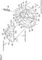
- FIG. 2is a sectional view of a main part of the worm reducer 1.
- FIG. 3is a schematic cross-sectional view taken along line III-III in FIG. 2 .
- FIG. 4is a schematic cross-sectional view taken along line IV-IV in FIG. 2 .
- the worm reducer 1includes a housing 20, a worm shaft 21, a first bearing 22, a second bearing 23, a worm wheel 24, an urging member 25, an elastic member 60, and a lid member 29.
- the worm shaft 21includes a first end portion 21a and a second end portion 21b that are separated from each other in an axial direction X, and a tooth portion 21c that is an intermediate portion between the first end portion 21a and the second end portion 21b.
- the first end portion 21ais an axial end portion of the worm shaft 21 away from the electric motor 19.
- the second end portion 21bis the end portion of the worm shaft 21 closer to the electric motor 19.
- the worm wheel 24is coupled to the output shaft 9b of the column shaft 9 to be rotatable together with the output shaft 9b of the column shaft 9.
- the worm wheel 24includes an annular core metal 24a, and an annular resin member 24b fitted onto the core metal 24a.
- the core metal 24ais connected to the output shaft 9b to be rotatable together with the output shaft 9b.
- the resin member 24bis fitted onto the core metal 24a.
- a tooth portion 24cis formed on an outer peripheral surface of the resin member 24b.
- the tooth portion 24c of the worm wheel 24meshes with the tooth portion 21c of the worm shaft 21.
- the worm shaft 21is generally coaxially disposed with an output shaft 19a of the electric motor 19.
- the second end portion 21b of the worm shaft 21 and an end portion of the output shaft 19a of the electric motor 19are coupled so as to be able to transmit a torque and pivot, via a power transmission joint 27.
- the power transmission joint 27has a first rotation element 27a, a second rotation element 27b, and an intermediate element 27c.
- the first rotation element 27ais coupled to the second end portion 21b of the worm shaft 21 to be rotatable together with the second end portion 21b of the worm shaft 21.
- the second rotation element 27bis coupled to the output shaft 19a of the electric motor 19 to be rotatable together with the output shaft 19a of the electric motor 19.
- the intermediate element 27cis interposed between the first rotation element 27a and the second rotation element 27b, and transmits torque between the rotation elements 27a, 27b.
- the intermediate element 27cis formed of an elastic body, such as rubber.
- the first bearing 22is attached to the first end portion 21a of the worm shaft 21.
- the first end portion 21a of the worm shaft 21is rotatably supported in the housing 20 via the first bearing 22.
- the second bearing 23is attached to the second end portion 21b of the worm shaft 21.
- the second end portion 21b of the worm shaft 21is rotatably supported in the housing 20 via the second bearing 23.
- the intermediate element 27c of the power transmission joint 27elastically deforms.
- the worm shaft 21is allowed to pivot about the bearing center of the second bearing 23 relative to the output shaft 19a of the electric motor 19.
- the first bearing 22is formed of a ball bearing, for example.
- the first bearing 22includes an inner ring 40, an outer ring 41, and a plurality of rolling elements 42.
- the inner ring 40 of the first bearing 22is fitted to a fitting recess 43 provided on the outer periphery of the first end portion 21a of the worm shaft 21.
- the inner ring 40is rotatable together with the worm shaft 21.
- the inner ring 40abuts on a positioning step part 44 provided on the outer periphery of the first end portion 21a of the worm shaft 21 in the axial direction.
- the movement of the inner ring 40 in the axial direction relative to the worm shaft 21is regulated.
- the second bearing 23is formed of a ball bearing, for example.
- the second bearing 23includes an inner ring 30, an outer ring 31, and a plurality of rolling elements 32.
- the inner ring 30 of the second bearing 23is fitted to the second end portion 21b of the worm shaft 21 by clearance fit to be rotatable together with the second end portion 21b of the worm shaft 21.
- the outer ring 31is held between a positioning step part 34 and a clamping member 35 in the axial direction X.
- the positioning step part 34is provided in the housing 20 and the clamping member 35 is screw-fitted on to a screw portion provided on an inner surface 20a of the housing 20.
- movement of the outer ring 31 in the axial directionis regulated.
- the urging member 25is a compression coil spring, for example.
- the urging member 25elastically urges the first end portion 21a of the worm shaft 21 toward the worm wheel 24 via the first bearing 22.
- the elastic member 60is made of an elastic material such as rubber.
- FIG. 5is a sectional view of the surrounding structure of the first end portion 21a of the worm shaft 21.
- FIG. 6is a sectional view of a main part of the housing 20.
- FIG. 7is an exploded perspective view of a main part of the housing 20, the urging member 25, and the elastic member 60.
- FIG. 8is a perspective view of the elastic member 60 in a different direction from in FIG. 7 .
- the elastic member 60includes a buffer portion 61, a rotation regulation portion 62, a coupling portion 63, and an axial urging portion 64.
- the buffer portion 61has an arc shape, and is interposed between the inner surface 20a of the housing 20 and the outer peripheral surface of the outer ring 41 of the first bearing 22.
- the rotation regulation portion 62extends from the buffer portion 61 outward in a radial direction R of the first bearing 22 (in the direction away from the worm wheel).
- the rotation regulation portion 62is housed in a rotation regulation portion housing recess 80 provided in the inner surface 20a of the housing 20.
- the coupling portion 63couples a pair of arc end portions 611 of the buffer portion 61. As shown in FIG. 5 , the coupling portion 63 is interposed between the lid member 29 and the first end portion 21a of the worm shaft 21.
- the axial urging portion 64is a protrusion protruded towards the lid member 29 from the coupling portion 63 (see also FIG. 7 ).
- the lid member 29includes a tubular portion 29a, an end wall portion 29b, and an annular flange portion 29c.
- the end wall portion 29bcloses an end of the tubular portion 29a in the axial direction.
- the flange portion 29cextends in the radially outward direction of the tubular portion 29a from the other end of the tubular portion 29a in the axial direction.
- the housing 20has an internal space 28 that houses the worm shaft 21, the first bearing 22, the second bearing 23, the worm wheel 24, the urging member 25, the elastic member 60, and the lid member 29.
- the internal space 28is defined by the inner surface 20a of the housing 20.
- the internal space 28has a worm shaft housing space 100, a worm wheel housing space 110, a first opening 51, and a second opening 52.
- the worm shaft 21is housed in the worm shaft housing space 100.
- the worm wheel 24is housed in the worm wheel housing space 110.
- the openings 51, 52connect the worm shaft housing space 100 and the outside of the internal space 28.
- the worm shaft housing space 100is a cylindrical space that extends in the axial direction X.
- the worm shaft housing space 100has a first end housing portion 101, a second end housing portion 102, and a tooth housing portion 103.
- a lid member fitting recess 53, an elastic member fitting recess 54, and a bearing housing recess 55are formed in this order from the first opening 51 side on the inner surface 20a of the housing 20.
- the lid member fitting recess 53is an annular recess that defines the first opening 51 and into which the tubular portion 29a of the lid member 29 is fitted.
- the elastic member fitting recess 54is an annular recess into which the buffer portion 61 of the elastic member 60 is fitted.
- the rotation regulation portion housing recess 80is formed on a portion of the elastic member fitting recess 54 in the circumferential direction.
- the bearing housing recess 55is an annular recess that surrounds the outer peripheral surface of the outer ring 41 of the first bearing 22 with a clearance interposed therebetween.
- the bearing housing recess 55houses the first bearing 22 which is fitted onto the first end portion 21a of the worm shaft 21.
- an inner diameter D4 of the elastic member fitting recess 54is smaller than an inner diameter D3 of the lid member fitting recess 53, and is larger than an inner diameter D5 of the bearing housing recess 55 (D3 > D4 > D5).
- An annular first step portion 56 that faces the first opening 51 sideis formed on the boundary between the lid member fitting recess 53 and the elastic member fitting recess 54.
- the first step portion 56faces the end wall portion 29b of the lid member 29.
- An annular second step portion 57 that faces the first opening 51 sideis formed on the boundary between the elastic member fitting recess 54 and the bearing housing recess 55. As shown in FIG. 5 , the second step portion 57 abuts on an edge 61d, on the electric motor side, of the buffer portion 61 of the elastic member 60 that is fitted to the elastic member fitting recess 54. Then, the second step portion 57 positions the buffer portion 61 in the axial direction X relative to the housing 20.
- the first end housing portion 101 of the worm shaft housing space 100is defined by the elastic member fitting recess 54 provided on the inner surface 20a of the housing 20, and the bearing housing recess 55.
- the first end housing portion 101is an end of the worm shaft housing space 100 in the axial direction X.
- the first end housing portion 101is in communication with the outside of the internal space 28 via the first opening 51.
- the first end housing portion 101functions as a bearing moving hole in which the first bearing 22 moves in the direction that a core-to-core distance D1 of the worm shaft 21 and the worm wheel 24 increases and decreases (see also FIG. 3 ).
- the core-to-core distance D1is the distance between a central axis C1 of the worm shaft 21 and a central axis C2 of the worm wheel 24.
- an urging member housing hole 70that opens to the side that does not face the worm wheel 24 relative to the first bearing 22 is formed on the inner surface 20a of the housing 20.
- the urging member 25is housed in the urging member housing hole 70.
- An inner opening 70a that opens to the first end housing portion 101 and an outer opening 70b that opens to the outside of the internal space 28are formed in the urging member housing hole 70.
- the outer opening 70bis closed by a closing member 71.
- the urging member 25is interposed between the closing member 71 and the outer peripheral surface of the outer ring 41 of the first bearing 22, and elastically urges the first end portion 21a of the worm shaft 21 toward the worm wheel 24 via the first bearing 22.
- the rotation regulation portion housing recess 80that houses the rotation regulation portion 62 of the elastic member 60 is formed in the elastic member fitting recess 54.
- the rotation regulation portion housing recess 80is defined by a bottom portion 81 that is depressed from the elastic member fitting recess 54, and a pair of inner wall surfaces 82, 83 that are spaced away from each other in the circumferential direction.
- Inlet corner portions 84 of the rotation regulation portion housing recess 80are formed by the crossing of the inner wall surfaces 82, 83 and the elastic member fitting recess 54.
- the buffer portion 61 of the elastic member 60is interposed between the inner surface 20a of the housing 20 and the outer peripheral surface of the outer ring 41 of the first bearing 22. Additionally, the buffer portion 61 is formed by an arc-shaped plate that opens to the worm wheel 24 side. As shown in FIGS. 7 and 8 , the buffer portion 61 includes an outer surface 61a and an inner surface 61b both formed of an arc-shaped surface, an edge 61c on the lid member 29 side, and the edge 61d on the electric motor 19 side. As shown in FIG. 5 , the outer surface 61a of the buffer portion 61 is fitted to the elastic member fitting recess 54. The inner surface 61b of the buffer portion 61 is fitted to the outer peripheral surface of the outer ring 41 of the first bearing 22.
- a clearancemay be interposed between the inner surface 61b of the buffer portion 61 and the outer peripheral surface of the outer ring 41 of the first bearing 22.
- the outer surface 61a of the buffer portion 61is fitted to the elastic member fitting recess 54 of the inner surface 20a of the housing 20.
- the inner surface 61b of the buffer portion 61is fitted to the outer peripheral surface of the outer ring 41 of the first bearing 22. In this state, when the buffer portion 61 is in a non-compressed state, a clearance S1 is provided between the bearing housing recess 55 and the outer peripheral surface of the outer ring 41 of the first bearing 22.
- the buffer portion 61is elastically compressed when the first bearing 22 is moved in the direction away from the worm wheel, by a load acting on the first bearing 22 from the worm wheel via the worm shaft 21.
- the buffer portion 61attenuates the movement of the first bearing 22 by elastic resiliency.
- the load acting on the first bearing 22is excessive, the outer peripheral surface of the outer ring 41 of the first bearing 22 and the bearing housing recess 55 abut against each other, and the clearance S1 becomes zero.
- the durability of the buffer portion 61is ensured, by the amount of compression of the buffer portion 61 being limited to the amount of the clearance S1 or lower.
- a semicircular clearance groove 61efor example, is formed in the buffer portion 61.
- the clearance groove 61eextends through the outer surface 61a and the inner surface 61b to open to the edge 61d on the electric motor 19 side, in order to avoid interference with the urging member 25.
- the rotation regulation portion 62is extended radially outward (in the direction away from the worm wheel) from the outer surface 61a of the buffer portion 61.
- the rotation regulation portion 62has a generally rectangular shape that extends in a circumferential direction C and has a prescribed thickness in the axial direction X (not shown in FIG. 9 , the direction orthogonal to the sheet on which FIG. 9 is drawn).
- the rotation regulation portion 62 housed in the rotation regulation portion housing recess 80engages with the inner wall surfaces 82, 83 of the rotation regulation portion housing recess 80.
- the rotation of the buffer portion 61 in the circumferential direction C of the first bearing 22is regulated.
- the rotation regulation portion 62includes a pair of engagement portions 65, a bridge portion 66, and a hollow portion 67.
- Each of the engagement portions 65is a columnar portion that has a base end portion 65a and a distal end 65b.
- the base end portion 65ais connected to the buffer portion 61.
- the distal end 65bis spaced from the base end portion 65a in the direction away from the worm wheel.
- the engagement portions 65are spaced away from each other in the circumferential direction C, and can be engaged with the inner wall surfaces 82, 83 of the rotation regulation portion housing recess 80. Specifically, either one of the engagement portions 65 is engaged with the corresponding one of the inner wall surfaces 82, 83 depending on the direction of the rotation of the buffer portion 61.
- a clearance portion 68that has a recessed curved shape for example, is formed in the base end portions 65a of each of the engagement portions 65.
- the clearance portion 68suppresses interference of the base end portion 65a and the corresponding inlet corner portion 84 of the rotation regulation portion housing recess 80, during rotation regulation of the buffer portion 61.
- the bridge portion 66extends between the distal ends 65b of the engagement portions 65, and connects the distal ends 65b together.
- the hollow portion 67is interposed between the engagement portions 65 in the circumferential direction C.
- the hollow portion 67is interposed between the bridge portion 66 and the outer surface 61a of the buffer portion 61 in the radial direction R.
- the hollow portion 67is formed of a though hole (see also FIG. 7 ) that extends through in the direction parallel to the axial direction X of the worm shaft 21, between the engagement portions 65.
- the coupling portion 63has a generally rectangular plate shape, and couples the edges, on the lid member 29 side, in the arc end portions 611 of the arc-shaped buffer portion 61. As shown in FIG. 5 , the coupling portion 63 faces the end face of the first end portion 21a of the worm shaft 21 and the end wall portion 29b of the lid member 29. As shown in FIG. 8 , the coupling portion 63 and the arc end portions 611 are assembled, and a groove shape is formed.
- the elastic member 60can be easily installed by gripping the coupling portion 63.
- the coupling portion 63can be gripped by a robot hand during assembly, and is thus suitable for automatic assembly.
- the axial urging portion 64is formed of a protrusion that protrudes from the surface of the coupling portion 63 on the lid member 29 side. As shown in FIG. 5 , the axial urging portion 64 elastically abuts on the end wall portion 29b of the lid member 29. The contact reaction force acts to press the edge 61d of the buffer portion 61 on the electric motor 19 side onto the second step portion 57 of the inner surface 20a of the housing 20. Thus, holding of the axial position of the buffer portion 61 with respect to the housing 20 becomes stable.
- the second end portion 21b, the second bearing 23, and the power transmission joint 27are housed in the second end housing portion 102.
- the second bearing 23is attached to the second end portion 21b.
- the power transmission joint 27is coupled to the second end portion 21b.
- the second end housing portion 102is the other end of the worm shaft housing space 100 in the axial direction X.
- the second opening 52is formed in the other end of the housing 20 in the axial direction X.
- the second end housing portion 102is in communication with the outside of the internal space 28 via the second opening 52.
- the tooth portion 21cis housed in the tooth housing portion 103.
- the tooth housing portion 103is in communication with the worm wheel housing space 110.
- the rotation regulation portion 62engages with the inner wall surface 82 or 83 of the rotation regulation portion housing recess 80 of the housing 20 and deforms, during rotation regulation of the elastic member 60 by the rotation regulation portion 62.
- the hollow portion 67is provided in the rotation regulation portion 62, and thus the rotation regulation portion 62 is easily deformed. Therefore, it is possible to suppress deformation of the buffer portion 61 due to transmission of the deformation load of the rotation regulation portion 62 to the buffer portion 61.
- the buffer portion 61can attenuate the movement of the first bearing 22 in the radial direction R, without being influenced by the deformation of the rotation regulation portion 62. Thus, it is possible to suppress the striking noise due to contact between the first bearing 22 and the housing 20, and achieve the low-noise worm reducer 1.
- the rotation regulation portion 62regulates rotation of the elastic member 60
- the engagement portions 65 of the rotation regulation portion 62are easily deformed toward the through hole (hollow portion 67) interposed between the engagement portions 65.
- the clearance portions 68 provided on the rotation regulation portion 62suppress interference of the rotation regulation portion 62 and the inlet corner portions 84 of the rotation regulation portion housing recess 80.
- the durability of the rotation regulation portion 62is improved.
- the low-noise electric power steering system 2By lowering the noise of the worm reducer 1, the low-noise electric power steering system 2 can be achieved.
- the inventionis not limited to the above-described embodiment.
- the hollow portion 67 formed of a through holeis provided in the rotation regulation portion 62 of the elastic member 60.
- a hollow portion 67P formed of a non-through holemay be provided, as of the first variation shown in FIG. 10A and FIG. 10B which is a sectional view taken along line Xb-Xb in FIG. 10A .
- the durability of the engagement portions 65is improved.
- a rotation regulation portion 62Q of an elastic member 60Qmay be formed of a pair of engagement portions 65Q that are independent of each other.
- a hollow portion 67Q formed of a through holeis opened to the side opposite to the buffer portion 61.
Landscapes
- Engineering & Computer Science (AREA)
- Mechanical Engineering (AREA)
- General Engineering & Computer Science (AREA)
- Chemical & Material Sciences (AREA)
- Combustion & Propulsion (AREA)
- Transportation (AREA)
- Power Steering Mechanism (AREA)
- Gear Transmission (AREA)
- Gears, Cams (AREA)
Description
- The invention relates to a worm reducer and an electric power steering system.
- In a worm shaft of an electric power steering system that transmits rotation output of an electric motor to a steering shaft, backlash occurs between the worm shaft and a worm wheel. The worm shaft has an end that is drivingly coupled to the electric motor and the worm wheel is coupled to the steering shaft. In a conventionally known structure, the other end of the worm shaft is urged toward the worm wheel by an urging member via a bearing, in order to suppress the backlash.
- A technology has been proposed, in which a striking noise due to contact between a housing that houses the worm shaft and the bearing is suppressed, by absorbing load that acts on the bearing through the worm shaft from the worm wheel side. For example, in Japanese Patent Application Publication No.
2014-125113 2014-125113 A - The direction of the load that acts on the bearing via the worm shaft due to a meshing reaction force of the worm shaft and the worm wheel during assistance, is determined by the gear specifications. If an arc-shaped elastic portion is used, which extends in a range including the direction in which the load acts, it will be necessary to regulate the position so that the elastic portion does not rotate in the circumferential direction of the bearing. In Japanese Patent Application Publication No.
2013-155789 JP 2013-155789 A - When regulating the rotation of the arc-shaped elastic portion with the solid positioning protrusion that protrudes radially outward from the arc-shaped elastic portion, for disposing the arc-shaped elastic portion around the bearing, as in
JP 2013-155789 A Document GB 2 528 517 A claim 1.- An object of the invention is to provide a low-noise worm reducer and an electric power steering system.
- According to an aspect of the invention, the worm reducer includes: a worm shaft that has a first end portion and a second end portion in an axial direction of the worm shaft, the second end portion coupled to an electric motor; a worm wheel that meshes with the worm shaft; a bearing that supports the first end portion of the worm shaft; a housing including an inner surface having a portion that defines a first end housing portion that houses the first end portion of the worm shaft and the bearing, the portion of the inner surface provided with a recess having a pair of inner wall surfaces that face each other in a circumferential direction of the bearing; an urging member that urges the first end portion of the worm shaft toward the worm wheel via the bearing; and an elastic member including an arc-shaped buffer portion that is interposed between the portion of the inner surface of the housing and an outer peripheral surface of the bearing and that opens toward the worm wheel, and a rotation regulation portion that extends from the buffer portion and is housed in the recess and that regulates the buffer portion from rotating in the circumferential direction by engaging with the inner wall surfaces. The rotation regulation portion includes a hollow portion which suppresses load transmission from the rotation regulation portion to the buffer portion.
- The foregoing and further features and advantages of the invention will become apparent from the following description of example embodiments with reference to the accompanying drawings, wherein like numerals are used to represent like elements and wherein:
FIG. 1 is a schematic diagram of an electric power steering system to which a worm reducer of the first embodiment of the invention is applied;FIG. 2 is a sectional view of a main part of the worm reducer;FIG. 3 is a schematic cross-sectional view taken along line III-III inFIG. 2 ;FIG. 4 is a schematic cross-sectional view taken along line IV-IV inFIG. 2 ;FIG. 5 is a sectional view of the surrounding structure of a first end portion of a worm shaft;FIG. 6 is a sectional view of the first end housing portion of a housing;FIG. 7 is an exploded perspective view of the periphery a first opening of the housing, an urging member, and an elastic member;FIG. 8 is a perspective view of the elastic member in a different direction fromFIG. 7 ;FIG. 9 is an explanatory diagram of the state of rotation regulation by a rotation regulation portion;FIG. 10A is a schematic view of an elastic member in the first variation;FIG. 10B is a cross section taken along line Xb-Xb inFIG. 10A ; andFIG. 11 is a schematic view of an elastic member in the second variation.- Hereinafter, embodiments of the invention will be described with reference to the accompanying drawings.
FIG. 1 is a schematic diagram of an electricpower steering system 2 to which a worm reducer 1 of the first embodiment of the invention is applied. With reference toFIG. 1 , the electricpower steering system 2 has asteering mechanism 3 and asteering operation mechanism 4. The electricpower steering system 2 turns steeredwheels 6 based on the operation of a steering wheel 5 (steering member) by a driver. Thesteering mechanism 3 has anassist mechanism 7 that assists the operation of thesteering wheel 5 by the driver. - The
steering mechanism 3 includes asteering shaft 8 that rotates in association with the rotation of thesteering wheel 5. Thesteering shaft 8 includes a column shaft 9, anintermediate shaft 10, and apinion shaft 11. The column shaft 9 includes aninput shaft 9a, anoutput shaft 9b, and a torsion bar 9c. Theinput shaft 9a is coupled to thesteering wheel 5. Theoutput shaft 9b is coupled to theintermediate shaft 10. The torsion bar 9c is coaxially coupled to theinput shaft 9a and theoutput shaft 9b. - The
output shaft 9b is coupled to theintermediate shaft 10 via auniversal joint 12. Theintermediate shaft 10 is coupled to thepinion shaft 11 via auniversal joint 13. Apinion 11a is formed on thepinion shaft 11. Thesteering operation mechanism 4 has arack shaft 14 andtie rods 15. Arack 14a that meshes with thepinion 11a is formed on therack shaft 14. One end of eachtie rod 15 is coupled to therack shaft 14, and the other end is coupled to a corresponding one of the steeredwheels 6. - When the
steering wheel 5 rotates according to the operation of thesteering wheel 5 by the driver, thepinion shaft 11 rotates via the column shaft 9 and theintermediate shaft 10. The rotation of thepinion shaft 11 is converted to a reciprocating motion in the axial direction of therack shaft 14 by a rack and pinion mechanism. The reciprocating motion of therack shaft 14 changes the turning angle of the steeredwheels 6. - The
assist mechanism 7 has atorque sensor 16, avehicle speed sensor 17, an electronic control unit (ECU) 18, anelectric motor 19, and theworm reducer 1. Thetorque sensor 16 detects a steering torque T based on a torsion amount between theinput shaft 9a and theoutput shaft 9b. TheECU 18 determines an assist torque based on the steering torque T detected by thetorque sensor 16 and a vehicle speed V detected by thevehicle speed sensor 17. Driving of theelectric motor 19 is controlled by theECU 18. The rotational force (power) of theelectric motor 19 is transmitted to theoutput shaft 9b of the column shaft 9 of thesteering shaft 8 via theworm reducer 1. As a result, the assist torque is applied to theoutput shaft 9b and the steering operation of the driver is assisted. - In the embodiment, an electric power steering system, in which power from the
electric motor 19 is applied to the column shaft 9, will be described as an example. However, the invention is not limited to this, and can be applied to the electric power steering system that has a worm reducer. Next, the structure of theworm reducer 1 will be described.FIG. 2 is a sectional view of a main part of theworm reducer 1.FIG. 3 is a schematic cross-sectional view taken along line III-III inFIG. 2 .FIG. 4 is a schematic cross-sectional view taken along line IV-IV inFIG. 2 . - Referring to
FIG. 2 , theworm reducer 1 includes ahousing 20, aworm shaft 21, afirst bearing 22, asecond bearing 23, aworm wheel 24, an urgingmember 25, anelastic member 60, and alid member 29. Theworm shaft 21 includes afirst end portion 21a and asecond end portion 21b that are separated from each other in an axial direction X, and atooth portion 21c that is an intermediate portion between thefirst end portion 21a and thesecond end portion 21b. Thefirst end portion 21a is an axial end portion of theworm shaft 21 away from theelectric motor 19. Thesecond end portion 21b is the end portion of theworm shaft 21 closer to theelectric motor 19. - The
worm wheel 24 is coupled to theoutput shaft 9b of the column shaft 9 to be rotatable together with theoutput shaft 9b of the column shaft 9. Theworm wheel 24 includes anannular core metal 24a, and anannular resin member 24b fitted onto thecore metal 24a. Thecore metal 24a is connected to theoutput shaft 9b to be rotatable together with theoutput shaft 9b. Theresin member 24b is fitted onto thecore metal 24a. Atooth portion 24c is formed on an outer peripheral surface of theresin member 24b. Thetooth portion 24c of theworm wheel 24 meshes with thetooth portion 21c of theworm shaft 21. - The
worm shaft 21 is generally coaxially disposed with anoutput shaft 19a of theelectric motor 19. Thesecond end portion 21b of theworm shaft 21 and an end portion of theoutput shaft 19a of theelectric motor 19 are coupled so as to be able to transmit a torque and pivot, via apower transmission joint 27. The power transmission joint 27 has afirst rotation element 27a, asecond rotation element 27b, and anintermediate element 27c. Thefirst rotation element 27a is coupled to thesecond end portion 21b of theworm shaft 21 to be rotatable together with thesecond end portion 21b of theworm shaft 21. Thesecond rotation element 27b is coupled to theoutput shaft 19a of theelectric motor 19 to be rotatable together with theoutput shaft 19a of theelectric motor 19. Theintermediate element 27c is interposed between thefirst rotation element 27a and thesecond rotation element 27b, and transmits torque between therotation elements intermediate element 27c is formed of an elastic body, such as rubber. - The
first bearing 22 is attached to thefirst end portion 21a of theworm shaft 21. Thefirst end portion 21a of theworm shaft 21 is rotatably supported in thehousing 20 via thefirst bearing 22. Thesecond bearing 23 is attached to thesecond end portion 21b of theworm shaft 21. Thesecond end portion 21b of theworm shaft 21 is rotatably supported in thehousing 20 via thesecond bearing 23. Theintermediate element 27c of the power transmission joint 27 elastically deforms. Thus, theworm shaft 21 is allowed to pivot about the bearing center of thesecond bearing 23 relative to theoutput shaft 19a of theelectric motor 19. - The
first bearing 22 is formed of a ball bearing, for example. Thefirst bearing 22 includes aninner ring 40, anouter ring 41, and a plurality of rollingelements 42. Theinner ring 40 of thefirst bearing 22 is fitted to afitting recess 43 provided on the outer periphery of thefirst end portion 21a of theworm shaft 21. Thus, theinner ring 40 is rotatable together with theworm shaft 21. Theinner ring 40 abuts on apositioning step part 44 provided on the outer periphery of thefirst end portion 21a of theworm shaft 21 in the axial direction. Thus, the movement of theinner ring 40 in the axial direction relative to theworm shaft 21 is regulated. - The
second bearing 23 is formed of a ball bearing, for example. Thesecond bearing 23 includes aninner ring 30, anouter ring 31, and a plurality of rollingelements 32. Theinner ring 30 of thesecond bearing 23 is fitted to thesecond end portion 21b of theworm shaft 21 by clearance fit to be rotatable together with thesecond end portion 21b of theworm shaft 21. Theouter ring 31 is held between apositioning step part 34 and a clampingmember 35 in the axial direction X. Thepositioning step part 34 is provided in thehousing 20 and the clampingmember 35 is screw-fitted on to a screw portion provided on aninner surface 20a of thehousing 20. Thus, movement of theouter ring 31 in the axial direction is regulated. - As shown in
FIG. 3 , the urgingmember 25 is a compression coil spring, for example. The urgingmember 25 elastically urges thefirst end portion 21a of theworm shaft 21 toward theworm wheel 24 via thefirst bearing 22. Theelastic member 60 is made of an elastic material such as rubber.FIG. 5 is a sectional view of the surrounding structure of thefirst end portion 21a of theworm shaft 21.FIG. 6 is a sectional view of a main part of thehousing 20.FIG. 7 is an exploded perspective view of a main part of thehousing 20, the urgingmember 25, and theelastic member 60.FIG. 8 is a perspective view of theelastic member 60 in a different direction from inFIG. 7 . - First, the overall structure of the
elastic member 60 will be described. As shown inFIGS. 4 ,5 , and7 , theelastic member 60 includes abuffer portion 61, arotation regulation portion 62, acoupling portion 63, and anaxial urging portion 64. As shown inFIG. 4 , thebuffer portion 61 has an arc shape, and is interposed between theinner surface 20a of thehousing 20 and the outer peripheral surface of theouter ring 41 of thefirst bearing 22. Therotation regulation portion 62 extends from thebuffer portion 61 outward in a radial direction R of the first bearing 22 (in the direction away from the worm wheel). Therotation regulation portion 62 is housed in a rotation regulationportion housing recess 80 provided in theinner surface 20a of thehousing 20. As shown inFIG. 7 , thecoupling portion 63 couples a pair ofarc end portions 611 of thebuffer portion 61. As shown inFIG. 5 , thecoupling portion 63 is interposed between thelid member 29 and thefirst end portion 21a of theworm shaft 21. Theaxial urging portion 64 is a protrusion protruded towards thelid member 29 from the coupling portion 63 (see alsoFIG. 7 ). - As shown in
FIG. 5 , thelid member 29 includes atubular portion 29a, anend wall portion 29b, and anannular flange portion 29c. Theend wall portion 29b closes an end of thetubular portion 29a in the axial direction. Theflange portion 29c extends in the radially outward direction of thetubular portion 29a from the other end of thetubular portion 29a in the axial direction. Referring toFIG. 2 , thehousing 20 has aninternal space 28 that houses theworm shaft 21, thefirst bearing 22, thesecond bearing 23, theworm wheel 24, the urgingmember 25, theelastic member 60, and thelid member 29. Theinternal space 28 is defined by theinner surface 20a of thehousing 20. Theinternal space 28 has a wormshaft housing space 100, a wormwheel housing space 110, afirst opening 51, and asecond opening 52. - The
worm shaft 21 is housed in the wormshaft housing space 100. Theworm wheel 24 is housed in the wormwheel housing space 110. Theopenings shaft housing space 100 and the outside of theinternal space 28. The wormshaft housing space 100 is a cylindrical space that extends in the axial direction X. The wormshaft housing space 100 has a firstend housing portion 101, a secondend housing portion 102, and atooth housing portion 103. - As shown in
FIGS. 5 ,6 , and7 , a lidmember fitting recess 53, an elastic memberfitting recess 54, and a bearinghousing recess 55 are formed in this order from thefirst opening 51 side on theinner surface 20a of thehousing 20. The lidmember fitting recess 53 is an annular recess that defines thefirst opening 51 and into which thetubular portion 29a of thelid member 29 is fitted. The elastic memberfitting recess 54 is an annular recess into which thebuffer portion 61 of theelastic member 60 is fitted. The rotation regulationportion housing recess 80 is formed on a portion of the elastic memberfitting recess 54 in the circumferential direction. - As shown in
FIG. 5 , the bearinghousing recess 55 is an annular recess that surrounds the outer peripheral surface of theouter ring 41 of thefirst bearing 22 with a clearance interposed therebetween. The bearinghousing recess 55 houses thefirst bearing 22 which is fitted onto thefirst end portion 21a of theworm shaft 21. As shown inFIG. 6 , an inner diameter D4 of the elastic memberfitting recess 54 is smaller than an inner diameter D3 of the lidmember fitting recess 53, and is larger than an inner diameter D5 of the bearing housing recess 55 (D3 > D4 > D5). - An annular
first step portion 56 that faces thefirst opening 51 side is formed on the boundary between the lidmember fitting recess 53 and the elastic memberfitting recess 54. Thefirst step portion 56 faces theend wall portion 29b of thelid member 29. An annularsecond step portion 57 that faces thefirst opening 51 side is formed on the boundary between the elastic memberfitting recess 54 and the bearinghousing recess 55. As shown inFIG. 5 , thesecond step portion 57 abuts on anedge 61d, on the electric motor side, of thebuffer portion 61 of theelastic member 60 that is fitted to the elastic memberfitting recess 54. Then, thesecond step portion 57 positions thebuffer portion 61 in the axial direction X relative to thehousing 20. - As shown in
FIGS. 5 and6 , the firstend housing portion 101 of the wormshaft housing space 100 is defined by the elastic memberfitting recess 54 provided on theinner surface 20a of thehousing 20, and the bearinghousing recess 55. The firstend housing portion 101 is an end of the wormshaft housing space 100 in the axial direction X. The firstend housing portion 101 is in communication with the outside of theinternal space 28 via thefirst opening 51. - Referring to
FIG. 2 , the firstend housing portion 101 functions as a bearing moving hole in which thefirst bearing 22 moves in the direction that a core-to-core distance D1 of theworm shaft 21 and theworm wheel 24 increases and decreases (see alsoFIG. 3 ). As shown inFIG. 2 , the core-to-core distance D1 is the distance between a central axis C1 of theworm shaft 21 and a central axis C2 of theworm wheel 24. As shown inFIGS. 5 and6 , an urgingmember housing hole 70 that opens to the side that does not face theworm wheel 24 relative to thefirst bearing 22 is formed on theinner surface 20a of thehousing 20. The urgingmember 25 is housed in the urgingmember housing hole 70. Aninner opening 70a that opens to the firstend housing portion 101 and anouter opening 70b that opens to the outside of theinternal space 28 are formed in the urgingmember housing hole 70. Theouter opening 70b is closed by a closingmember 71. The urgingmember 25 is interposed between the closingmember 71 and the outer peripheral surface of theouter ring 41 of thefirst bearing 22, and elastically urges thefirst end portion 21a of theworm shaft 21 toward theworm wheel 24 via thefirst bearing 22. - As shown in
FIGS. 4 and5 , andFIG. 9 that is an explanatory diagram, the rotation regulationportion housing recess 80 that houses therotation regulation portion 62 of theelastic member 60 is formed in the elastic memberfitting recess 54. As shown inFIG. 9 , the rotation regulationportion housing recess 80 is defined by abottom portion 81 that is depressed from the elastic memberfitting recess 54, and a pair of inner wall surfaces 82, 83 that are spaced away from each other in the circumferential direction.Inlet corner portions 84 of the rotation regulationportion housing recess 80 are formed by the crossing of the inner wall surfaces 82, 83 and the elastic memberfitting recess 54. - Next, the structure of the
elastic member 60 will be described. As shown inFIG. 4 , thebuffer portion 61 of theelastic member 60 is interposed between theinner surface 20a of thehousing 20 and the outer peripheral surface of theouter ring 41 of thefirst bearing 22. Additionally, thebuffer portion 61 is formed by an arc-shaped plate that opens to theworm wheel 24 side. As shown inFIGS. 7 and8 , thebuffer portion 61 includes anouter surface 61a and aninner surface 61b both formed of an arc-shaped surface, anedge 61c on thelid member 29 side, and theedge 61d on theelectric motor 19 side. As shown inFIG. 5 , theouter surface 61a of thebuffer portion 61 is fitted to the elastic memberfitting recess 54. Theinner surface 61b of thebuffer portion 61 is fitted to the outer peripheral surface of theouter ring 41 of thefirst bearing 22. - A clearance may be interposed between the
inner surface 61b of thebuffer portion 61 and the outer peripheral surface of theouter ring 41 of thefirst bearing 22. Theouter surface 61a of thebuffer portion 61 is fitted to the elastic memberfitting recess 54 of theinner surface 20a of thehousing 20. Theinner surface 61b of thebuffer portion 61 is fitted to the outer peripheral surface of theouter ring 41 of thefirst bearing 22. In this state, when thebuffer portion 61 is in a non-compressed state, a clearance S1 is provided between the bearinghousing recess 55 and the outer peripheral surface of theouter ring 41 of thefirst bearing 22. - The
buffer portion 61 is elastically compressed when thefirst bearing 22 is moved in the direction away from the worm wheel, by a load acting on thefirst bearing 22 from the worm wheel via theworm shaft 21. Thebuffer portion 61 attenuates the movement of thefirst bearing 22 by elastic resiliency. When the load acting on thefirst bearing 22 is excessive, the outer peripheral surface of theouter ring 41 of thefirst bearing 22 and the bearinghousing recess 55 abut against each other, and the clearance S1 becomes zero. Thus, the durability of thebuffer portion 61 is ensured, by the amount of compression of thebuffer portion 61 being limited to the amount of the clearance S1 or lower. - As shown in
FIGS. 5 and8 , asemicircular clearance groove 61e for example, is formed in thebuffer portion 61. Theclearance groove 61e extends through theouter surface 61a and theinner surface 61b to open to theedge 61d on theelectric motor 19 side, in order to avoid interference with the urgingmember 25. As shown inFIG. 9 , therotation regulation portion 62 is extended radially outward (in the direction away from the worm wheel) from theouter surface 61a of thebuffer portion 61. Therotation regulation portion 62 has a generally rectangular shape that extends in a circumferential direction C and has a prescribed thickness in the axial direction X (not shown inFIG. 9 , the direction orthogonal to the sheet on whichFIG. 9 is drawn). Therotation regulation portion 62 housed in the rotation regulationportion housing recess 80 engages with the inner wall surfaces 82, 83 of the rotation regulationportion housing recess 80. Thus, the rotation of thebuffer portion 61 in the circumferential direction C of thefirst bearing 22 is regulated. - The
rotation regulation portion 62 includes a pair ofengagement portions 65, abridge portion 66, and ahollow portion 67. Each of theengagement portions 65 is a columnar portion that has abase end portion 65a and adistal end 65b. Thebase end portion 65a is connected to thebuffer portion 61. Thedistal end 65b is spaced from thebase end portion 65a in the direction away from the worm wheel. Theengagement portions 65 are spaced away from each other in the circumferential direction C, and can be engaged with the inner wall surfaces 82, 83 of the rotation regulationportion housing recess 80. Specifically, either one of theengagement portions 65 is engaged with the corresponding one of the inner wall surfaces 82, 83 depending on the direction of the rotation of thebuffer portion 61. Thus, rotation of thebuffer portion 61 is regulated. Aclearance portion 68 that has a recessed curved shape for example, is formed in thebase end portions 65a of each of theengagement portions 65. Theclearance portion 68 suppresses interference of thebase end portion 65a and the correspondinginlet corner portion 84 of the rotation regulationportion housing recess 80, during rotation regulation of thebuffer portion 61. - The
bridge portion 66 extends between the distal ends 65b of theengagement portions 65, and connects the distal ends 65b together. Thehollow portion 67 is interposed between theengagement portions 65 in the circumferential direction C. Thehollow portion 67 is interposed between thebridge portion 66 and theouter surface 61a of thebuffer portion 61 in the radial direction R. Thus, thehollow portion 67 is formed of a though hole (see alsoFIG. 7 ) that extends through in the direction parallel to the axial direction X of theworm shaft 21, between theengagement portions 65. - As shown in
FIGS. 7 and8 , thecoupling portion 63 has a generally rectangular plate shape, and couples the edges, on thelid member 29 side, in thearc end portions 611 of the arc-shapedbuffer portion 61. As shown inFIG. 5 , thecoupling portion 63 faces the end face of thefirst end portion 21a of theworm shaft 21 and theend wall portion 29b of thelid member 29. As shown inFIG. 8 , thecoupling portion 63 and thearc end portions 611 are assembled, and a groove shape is formed. When installing theelastic member 60 in thehousing 20, during the assembly of theworm reducer 1 theelastic member 60 can be easily installed by gripping thecoupling portion 63. In particular, thecoupling portion 63 can be gripped by a robot hand during assembly, and is thus suitable for automatic assembly. - The
axial urging portion 64 is formed of a protrusion that protrudes from the surface of thecoupling portion 63 on thelid member 29 side. As shown inFIG. 5 , theaxial urging portion 64 elastically abuts on theend wall portion 29b of thelid member 29. The contact reaction force acts to press theedge 61d of thebuffer portion 61 on theelectric motor 19 side onto thesecond step portion 57 of theinner surface 20a of thehousing 20. Thus, holding of the axial position of thebuffer portion 61 with respect to thehousing 20 becomes stable. - Referring to
FIG. 2 , thesecond end portion 21b, thesecond bearing 23, and the power transmission joint 27 are housed in the secondend housing portion 102. Thesecond bearing 23 is attached to thesecond end portion 21b. The power transmission joint 27 is coupled to thesecond end portion 21b. The secondend housing portion 102 is the other end of the wormshaft housing space 100 in the axial direction X. Thesecond opening 52 is formed in the other end of thehousing 20 in the axial direction X. The secondend housing portion 102 is in communication with the outside of theinternal space 28 via thesecond opening 52. - The
tooth portion 21c is housed in thetooth housing portion 103. Thetooth housing portion 103 is in communication with the wormwheel housing space 110. In the embodiment, as shown inFIG. 9 , therotation regulation portion 62 engages with theinner wall surface portion housing recess 80 of thehousing 20 and deforms, during rotation regulation of theelastic member 60 by therotation regulation portion 62. Thehollow portion 67 is provided in therotation regulation portion 62, and thus therotation regulation portion 62 is easily deformed. Therefore, it is possible to suppress deformation of thebuffer portion 61 due to transmission of the deformation load of therotation regulation portion 62 to thebuffer portion 61. Thebuffer portion 61 can attenuate the movement of thefirst bearing 22 in the radial direction R, without being influenced by the deformation of therotation regulation portion 62. Thus, it is possible to suppress the striking noise due to contact between thefirst bearing 22 and thehousing 20, and achieve the low-noise worm reducer 1. - When the
rotation regulation portion 62 regulates rotation of theelastic member 60, theengagement portions 65 of therotation regulation portion 62 are easily deformed toward the through hole (hollow portion 67) interposed between theengagement portions 65. Thus, it is possible to effectively suppress deformation load of therotation regulation portion 62 from being applied to thebuffer portion 61. Theclearance portions 68 provided on therotation regulation portion 62 suppress interference of therotation regulation portion 62 and theinlet corner portions 84 of the rotation regulationportion housing recess 80. Thus, the durability of therotation regulation portion 62 is improved. - By lowering the noise of the
worm reducer 1, the low-noise electricpower steering system 2 can be achieved. The invention is not limited to the above-described embodiment. For example, in the embodiment shown inFIG. 9 , thehollow portion 67 formed of a through hole is provided in therotation regulation portion 62 of theelastic member 60. However, in arotation regulation portion 62P of anelastic member 60P, ahollow portion 67P formed of a non-through hole may be provided, as of the first variation shown inFIG. 10A and FIG. 10B which is a sectional view taken along line Xb-Xb inFIG. 10A . In the first variation, the durability of theengagement portions 65 is improved. - In the embodiment shown in
FIG. 9 , the distal ends 65b of thecolumnar engagement portions 65 of theelastic member 60 are connected via thebridge portion 66. However, as of the second variation shown inFIG. 11 , arotation regulation portion 62Q of anelastic member 60Q may be formed of a pair ofengagement portions 65Q that are independent of each other. Ahollow portion 67Q formed of a through hole is opened to the side opposite to thebuffer portion 61. In the second variation, theengagement portions 65Q are more easily deformed and transmission of load to thebuffer portion 61 is further suppressed, during rotation regulation of theelastic member 60Q by therotation regulation portion 62Q. - In addition, various modifications can be made to the invention within the scope of the claims.
Claims (3)
- A worm reducer (1) for an electric power steering system comprising:a worm shaft (21) that has a first end portion (21a) and a second end portion (21b) in an axial direction of the worm shaft (21), the second end portion (21b) coupled to an electric motor (19);a worm wheel (24) that meshes with the worm shaft (21);a bearing (22) that supports the first end portion (21a) of the worm shaft (21);a housing (20) including an inner surface (20a) having a portion that defines a first end housing portion (101) that houses the first end portion (21a) of the worm shaft (21) and the bearing (22), the portion of the inner surface (20a) provided with a recess (80) having a pair of inner wall surfaces (82, 83) that face each other in a circumferential direction of the bearing (22);an urging member (25) that urges the first end portion (21a) of the worm shaft (21) toward the worm wheel (24) via the bearing (22); andan elastic member (60) including an arc-shaped buffer portion (61) that is interposed between the portion of the inner surface (20a) of the housing (20) and an outer peripheral surface of the bearing (22) and that opens toward the worm wheel (24), and a rotation regulation portion (62) that extends from the buffer portion (61) and is housed in the recess (80) and that regulates the buffer portion (61) from rotating in the circumferential direction by engaging with the inner wall surfaces (82, 83), whereinthe rotation regulation portion (62) includes a hollow portion (67),characterized in thatthe hollow portion (67) is configured to suppress load transmission from the rotation regulation portion (62) to the buffer portion (61),the rotation regulation portion (62) includes a pair of engagement portions (65) that are spaced away from each other in the circumferential direction of the bearing (22) and each engage with a corresponding one of the pair of inner wall surfaces (82, 83) of the recess (80) of the housing (20), andthe hollow portion (67) is interposed between the engagement portions (65), and is formed of a through hole or a non-through hole that has a depth in a direction parallel to the axial direction of the worm shaft (21).
- The worm reducer (1) according to claim 1, wherein
an inlet corner portion (84) of the recess (80) is formed of each of the inner wall surfaces (82, 83) and the portion of the inner surface (20a) of the housing (20), and
the rotation regulation portion (62) has a clearance portion (68) that suppresses interference with the inlet corner portion (84). - An electric power steering system, wherein
power from the electric motor (19) is transmitted to a steering shaft (8) via the worm reducer (1) according to claim 1 or 2.
Applications Claiming Priority (1)
| Application Number | Priority Date | Filing Date | Title |
|---|---|---|---|
| JP2017082913AJP6876249B2 (en) | 2017-04-19 | 2017-04-19 | Warm reducer and electric power steering device |
Publications (2)
| Publication Number | Publication Date |
|---|---|
| EP3398833A1 EP3398833A1 (en) | 2018-11-07 |
| EP3398833B1true EP3398833B1 (en) | 2020-06-10 |
Family
ID=62002544
Family Applications (1)
| Application Number | Title | Priority Date | Filing Date |
|---|---|---|---|
| EP18167502.6AActiveEP3398833B1 (en) | 2017-04-19 | 2018-04-16 | Worm reducer and electric power steering system |
Country Status (4)
| Country | Link |
|---|---|
| US (1) | US10661822B2 (en) |
| EP (1) | EP3398833B1 (en) |
| JP (1) | JP6876249B2 (en) |
| CN (1) | CN108725572B (en) |
Families Citing this family (9)
| Publication number | Priority date | Publication date | Assignee | Title |
|---|---|---|---|---|
| FR3067084B1 (en)* | 2017-05-31 | 2019-07-19 | Jtekt Europe | SEAL PLUG FOR REDUCER HOUSING CARRYING A GEAR SET COMPENSATION TROLLEY |
| KR101993295B1 (en)* | 2017-12-19 | 2019-06-26 | 주식회사 만도 | Reducer of Electric Power Steering Apparatus |
| KR102033558B1 (en)* | 2018-05-18 | 2019-10-17 | 주식회사 만도 | Reducer of Electric power steering apparatus |
| DE102018217459A1 (en)* | 2018-10-12 | 2020-04-16 | Robert Bosch Gmbh | Steering gear and steering system for a motor vehicle |
| DE102018125887B4 (en)* | 2018-10-18 | 2023-02-16 | Thyssenkrupp Ag | Spring element for a reduction gear of an electromechanical steering system |
| JP7167691B2 (en)* | 2018-12-19 | 2022-11-09 | 株式会社ジェイテクト | Worm reducer and electric power steering device |
| WO2020166261A1 (en)* | 2019-02-12 | 2020-08-20 | 日本精工株式会社 | Worm reducer and electric assist device |
| EP4005901B1 (en)* | 2019-07-30 | 2024-10-16 | Bosch Huayu Steering Systems Co., Ltd. | Bearing bushing, preload structure, housing of transmission mechanism, and assembling structure of worm gear and worm |
| KR20220120219A (en)* | 2021-02-23 | 2022-08-30 | 주식회사 만도 | Steer-By-Wire Type Steering Apparatus |
Family Cites Families (22)
| Publication number | Priority date | Publication date | Assignee | Title |
|---|---|---|---|---|
| JPS6470267A (en)* | 1987-09-11 | 1989-03-15 | Koyo Seiko Co | Power steering device |
| GB9718574D0 (en)* | 1997-09-03 | 1997-11-05 | Lucas Ind Plc | Improvements relating to gears |
| JP4516431B2 (en)* | 2004-04-26 | 2010-08-04 | 本田技研工業株式会社 | Worm gear mechanism and electric power steering device equipped with the worm gear mechanism |
| KR100816401B1 (en)* | 2006-07-05 | 2008-03-27 | 주식회사 만도 | Electric Steering |
| KR101364930B1 (en)* | 2006-07-18 | 2014-02-20 | 현대모비스 주식회사 | Gear's teeth contact upkeep typed motor driven power steering system in vehicle |
| DE102009046386A1 (en)* | 2009-11-04 | 2011-05-05 | Zf Lenksysteme Gmbh | Electric power steering system i.e. servo steering mechanism, for passenger car, has gear housing including heat transfer portion, and roller bearing whose inner ring is directly or indirectly heated by transfer portion |
| JP5625676B2 (en)* | 2010-09-24 | 2014-11-19 | アイシン精機株式会社 | Torque fluctuation absorber |
| JP5645070B2 (en)* | 2010-11-09 | 2014-12-24 | 株式会社ジェイテクト | Electric power steering device |
| JP6130988B2 (en)* | 2011-03-22 | 2017-05-17 | Kyb株式会社 | Power steering device |
| JP2013071679A (en)* | 2011-09-28 | 2013-04-22 | Showa Corp | Electric power steering device |
| JP5941683B2 (en) | 2012-01-27 | 2016-06-29 | 本田技研工業株式会社 | Worm gear mechanism and electric power steering device having worm gear mechanism |
| JP6020893B2 (en) | 2012-07-27 | 2016-11-02 | 株式会社ジェイテクト | Electric power steering device |
| JP5908380B2 (en)* | 2012-09-24 | 2016-04-26 | 日立オートモティブシステムズステアリング株式会社 | Power steering device and reduction gear for power steering device |
| JP6052988B2 (en) | 2012-12-26 | 2016-12-27 | Kyb株式会社 | Power steering device |
| DE102013007883A1 (en)* | 2013-05-08 | 2014-11-13 | Thyssenkrupp Presta Ag | Springing eccentric rocker in CEPS application |
| JP6118750B2 (en)* | 2014-03-26 | 2017-04-19 | 株式会社ショーワ | Worm biasing structure |
| JP2016016784A (en)* | 2014-07-09 | 2016-02-01 | 株式会社ジェイテクト | Worm reduction gear and electric power steering device using the same |
| JP6108358B2 (en)* | 2014-07-23 | 2017-04-05 | 株式会社ショーワ | Worm biasing structure |
| JP6458982B2 (en)* | 2014-09-08 | 2019-01-30 | 株式会社ジェイテクト | Worm reducer |
| JP2016055732A (en)* | 2014-09-09 | 2016-04-21 | 日立オートモティブシステムズステアリング株式会社 | Backlash adjustment mechanism, and power steering device using the same |
| JP2016211615A (en) | 2015-04-30 | 2016-12-15 | 株式会社ジェイテクト | Worm reducer and steering device |
| JP6569892B2 (en)* | 2015-04-30 | 2019-09-04 | 株式会社ジェイテクト | Worm reducer and steering device |
- 2017
- 2017-04-19JPJP2017082913Apatent/JP6876249B2/enactiveActive
- 2018
- 2018-04-12USUS15/951,532patent/US10661822B2/enactiveActive
- 2018-04-16EPEP18167502.6Apatent/EP3398833B1/enactiveActive
- 2018-04-18CNCN201810349419.6Apatent/CN108725572B/enactiveActive
Non-Patent Citations (1)
| Title |
|---|
| None* |
Also Published As
| Publication number | Publication date |
|---|---|
| CN108725572B (en) | 2022-04-19 |
| CN108725572A (en) | 2018-11-02 |
| JP6876249B2 (en) | 2021-05-26 |
| US10661822B2 (en) | 2020-05-26 |
| EP3398833A1 (en) | 2018-11-07 |
| JP2018179237A (en) | 2018-11-15 |
| US20180304915A1 (en) | 2018-10-25 |
Similar Documents
| Publication | Publication Date | Title |
|---|---|---|
| EP3398833B1 (en) | Worm reducer and electric power steering system | |
| EP3388309B1 (en) | Steering system | |
| JP6020893B2 (en) | Electric power steering device | |
| JP6313969B2 (en) | Power steering device | |
| JP6569892B2 (en) | Worm reducer and steering device | |
| EP3135940A1 (en) | Shaft coupling structure and electric power steering system | |
| EP2966318B1 (en) | Worm speed reducer and method for manufacturing worm wheel included in worm speed reducer | |
| EP3248855B1 (en) | Electric power steering system | |
| JP3763347B2 (en) | Electric steering device | |
| JP3658683B2 (en) | Electric steering device | |
| JP6396201B2 (en) | Electric power steering device | |
| JP2016003760A (en) | Worm reduction gear and electric power steering device including the same | |
| CN115701403A (en) | Steer-by-wire steering apparatus | |
| EP3376070A1 (en) | Method for manufacturing worm reducer, worm reducer, and electric power steering system | |
| JP5967420B2 (en) | Electric power steering device | |
| EP1970290B1 (en) | Center take-off rack-and-pinion steering apparatus | |
| JP2004338450A (en) | Electric power steering device | |
| JP5011706B2 (en) | Vehicle steering system | |
| JP7021966B2 (en) | Steering device | |
| JP6714845B2 (en) | Worm reducer and electric power steering device | |
| JP2009040076A (en) | Steering device | |
| JP2012236489A (en) | Rack shaft support device and steering device for vehicle | |
| US12377904B2 (en) | Steer by wire type steering apparatus | |
| JP2006206005A (en) | Electric power steering device | |
| JP2012041014A (en) | Rack and pinion type steering gear unit |
Legal Events
| Date | Code | Title | Description |
|---|---|---|---|
| PUAI | Public reference made under article 153(3) epc to a published international application that has entered the european phase | Free format text:ORIGINAL CODE: 0009012 | |
| STAA | Information on the status of an ep patent application or granted ep patent | Free format text:STATUS: THE APPLICATION HAS BEEN PUBLISHED | |
| AK | Designated contracting states | Kind code of ref document:A1 Designated state(s):AL AT BE BG CH CY CZ DE DK EE ES FI FR GB GR HR HU IE IS IT LI LT LU LV MC MK MT NL NO PL PT RO RS SE SI SK SM TR | |
| AX | Request for extension of the european patent | Extension state:BA ME | |
| STAA | Information on the status of an ep patent application or granted ep patent | Free format text:STATUS: REQUEST FOR EXAMINATION WAS MADE | |
| 17P | Request for examination filed | Effective date:20190402 | |
| RBV | Designated contracting states (corrected) | Designated state(s):AL AT BE BG CH CY CZ DE DK EE ES FI FR GB GR HR HU IE IS IT LI LT LU LV MC MK MT NL NO PL PT RO RS SE SI SK SM TR | |
| RIC1 | Information provided on ipc code assigned before grant | Ipc:F16H 55/24 20060101ALI20191025BHEP Ipc:B62D 5/04 20060101AFI20191025BHEP | |
| GRAP | Despatch of communication of intention to grant a patent | Free format text:ORIGINAL CODE: EPIDOSNIGR1 | |
| STAA | Information on the status of an ep patent application or granted ep patent | Free format text:STATUS: GRANT OF PATENT IS INTENDED | |
| INTG | Intention to grant announced | Effective date:20200102 | |
| GRAS | Grant fee paid | Free format text:ORIGINAL CODE: EPIDOSNIGR3 | |
| GRAA | (expected) grant | Free format text:ORIGINAL CODE: 0009210 | |
| STAA | Information on the status of an ep patent application or granted ep patent | Free format text:STATUS: THE PATENT HAS BEEN GRANTED | |
| AK | Designated contracting states | Kind code of ref document:B1 Designated state(s):AL AT BE BG CH CY CZ DE DK EE ES FI FR GB GR HR HU IE IS IT LI LT LU LV MC MK MT NL NO PL PT RO RS SE SI SK SM TR | |
| REG | Reference to a national code | Ref country code:GB Ref legal event code:FG4D | |
| REG | Reference to a national code | Ref country code:CH Ref legal event code:EP Ref country code:AT Ref legal event code:REF Ref document number:1278955 Country of ref document:AT Kind code of ref document:T Effective date:20200615 | |
| REG | Reference to a national code | Ref country code:DE Ref legal event code:R096 Ref document number:602018005141 Country of ref document:DE | |
| REG | Reference to a national code | Ref country code:IE Ref legal event code:FG4D | |
| REG | Reference to a national code | Ref country code:LT Ref legal event code:MG4D | |
| PG25 | Lapsed in a contracting state [announced via postgrant information from national office to epo] | Ref country code:LT Free format text:LAPSE BECAUSE OF FAILURE TO SUBMIT A TRANSLATION OF THE DESCRIPTION OR TO PAY THE FEE WITHIN THE PRESCRIBED TIME-LIMIT Effective date:20200610 Ref country code:FI Free format text:LAPSE BECAUSE OF FAILURE TO SUBMIT A TRANSLATION OF THE DESCRIPTION OR TO PAY THE FEE WITHIN THE PRESCRIBED TIME-LIMIT Effective date:20200610 Ref country code:GR Free format text:LAPSE BECAUSE OF FAILURE TO SUBMIT A TRANSLATION OF THE DESCRIPTION OR TO PAY THE FEE WITHIN THE PRESCRIBED TIME-LIMIT Effective date:20200911 Ref country code:NO Free format text:LAPSE BECAUSE OF FAILURE TO SUBMIT A TRANSLATION OF THE DESCRIPTION OR TO PAY THE FEE WITHIN THE PRESCRIBED TIME-LIMIT Effective date:20200910 Ref country code:SE Free format text:LAPSE BECAUSE OF FAILURE TO SUBMIT A TRANSLATION OF THE DESCRIPTION OR TO PAY THE FEE WITHIN THE PRESCRIBED TIME-LIMIT Effective date:20200610 | |
| REG | Reference to a national code | Ref country code:NL Ref legal event code:MP Effective date:20200610 | |
| PG25 | Lapsed in a contracting state [announced via postgrant information from national office to epo] | Ref country code:BG Free format text:LAPSE BECAUSE OF FAILURE TO SUBMIT A TRANSLATION OF THE DESCRIPTION OR TO PAY THE FEE WITHIN THE PRESCRIBED TIME-LIMIT Effective date:20200910 Ref country code:HR Free format text:LAPSE BECAUSE OF FAILURE TO SUBMIT A TRANSLATION OF THE DESCRIPTION OR TO PAY THE FEE WITHIN THE PRESCRIBED TIME-LIMIT Effective date:20200610 Ref country code:RS Free format text:LAPSE BECAUSE OF FAILURE TO SUBMIT A TRANSLATION OF THE DESCRIPTION OR TO PAY THE FEE WITHIN THE PRESCRIBED TIME-LIMIT Effective date:20200610 Ref country code:LV Free format text:LAPSE BECAUSE OF FAILURE TO SUBMIT A TRANSLATION OF THE DESCRIPTION OR TO PAY THE FEE WITHIN THE PRESCRIBED TIME-LIMIT Effective date:20200610 | |
| REG | Reference to a national code | Ref country code:AT Ref legal event code:MK05 Ref document number:1278955 Country of ref document:AT Kind code of ref document:T Effective date:20200610 | |
| PG25 | Lapsed in a contracting state [announced via postgrant information from national office to epo] | Ref country code:AL Free format text:LAPSE BECAUSE OF FAILURE TO SUBMIT A TRANSLATION OF THE DESCRIPTION OR TO PAY THE FEE WITHIN THE PRESCRIBED TIME-LIMIT Effective date:20200610 Ref country code:NL Free format text:LAPSE BECAUSE OF FAILURE TO SUBMIT A TRANSLATION OF THE DESCRIPTION OR TO PAY THE FEE WITHIN THE PRESCRIBED TIME-LIMIT Effective date:20200610 | |
| PG25 | Lapsed in a contracting state [announced via postgrant information from national office to epo] | Ref country code:RO Free format text:LAPSE BECAUSE OF FAILURE TO SUBMIT A TRANSLATION OF THE DESCRIPTION OR TO PAY THE FEE WITHIN THE PRESCRIBED TIME-LIMIT Effective date:20200610 Ref country code:IT Free format text:LAPSE BECAUSE OF FAILURE TO SUBMIT A TRANSLATION OF THE DESCRIPTION OR TO PAY THE FEE WITHIN THE PRESCRIBED TIME-LIMIT Effective date:20200610 Ref country code:SM Free format text:LAPSE BECAUSE OF FAILURE TO SUBMIT A TRANSLATION OF THE DESCRIPTION OR TO PAY THE FEE WITHIN THE PRESCRIBED TIME-LIMIT Effective date:20200610 Ref country code:CZ Free format text:LAPSE BECAUSE OF FAILURE TO SUBMIT A TRANSLATION OF THE DESCRIPTION OR TO PAY THE FEE WITHIN THE PRESCRIBED TIME-LIMIT Effective date:20200610 Ref country code:ES Free format text:LAPSE BECAUSE OF FAILURE TO SUBMIT A TRANSLATION OF THE DESCRIPTION OR TO PAY THE FEE WITHIN THE PRESCRIBED TIME-LIMIT Effective date:20200610 Ref country code:AT Free format text:LAPSE BECAUSE OF FAILURE TO SUBMIT A TRANSLATION OF THE DESCRIPTION OR TO PAY THE FEE WITHIN THE PRESCRIBED TIME-LIMIT Effective date:20200610 Ref country code:PT Free format text:LAPSE BECAUSE OF FAILURE TO SUBMIT A TRANSLATION OF THE DESCRIPTION OR TO PAY THE FEE WITHIN THE PRESCRIBED TIME-LIMIT Effective date:20201012 Ref country code:EE Free format text:LAPSE BECAUSE OF FAILURE TO SUBMIT A TRANSLATION OF THE DESCRIPTION OR TO PAY THE FEE WITHIN THE PRESCRIBED TIME-LIMIT Effective date:20200610 | |
| PG25 | Lapsed in a contracting state [announced via postgrant information from national office to epo] | Ref country code:SK Free format text:LAPSE BECAUSE OF FAILURE TO SUBMIT A TRANSLATION OF THE DESCRIPTION OR TO PAY THE FEE WITHIN THE PRESCRIBED TIME-LIMIT Effective date:20200610 Ref country code:PL Free format text:LAPSE BECAUSE OF FAILURE TO SUBMIT A TRANSLATION OF THE DESCRIPTION OR TO PAY THE FEE WITHIN THE PRESCRIBED TIME-LIMIT Effective date:20200610 Ref country code:IS Free format text:LAPSE BECAUSE OF FAILURE TO SUBMIT A TRANSLATION OF THE DESCRIPTION OR TO PAY THE FEE WITHIN THE PRESCRIBED TIME-LIMIT Effective date:20201010 | |
| REG | Reference to a national code | Ref country code:DE Ref legal event code:R097 Ref document number:602018005141 Country of ref document:DE | |
| PLBE | No opposition filed within time limit | Free format text:ORIGINAL CODE: 0009261 | |
| STAA | Information on the status of an ep patent application or granted ep patent | Free format text:STATUS: NO OPPOSITION FILED WITHIN TIME LIMIT | |
| PG25 | Lapsed in a contracting state [announced via postgrant information from national office to epo] | Ref country code:DK Free format text:LAPSE BECAUSE OF FAILURE TO SUBMIT A TRANSLATION OF THE DESCRIPTION OR TO PAY THE FEE WITHIN THE PRESCRIBED TIME-LIMIT Effective date:20200610 | |
| 26N | No opposition filed | Effective date:20210311 | |
| PG25 | Lapsed in a contracting state [announced via postgrant information from national office to epo] | Ref country code:SI Free format text:LAPSE BECAUSE OF FAILURE TO SUBMIT A TRANSLATION OF THE DESCRIPTION OR TO PAY THE FEE WITHIN THE PRESCRIBED TIME-LIMIT Effective date:20200610 | |
| PG25 | Lapsed in a contracting state [announced via postgrant information from national office to epo] | Ref country code:MC Free format text:LAPSE BECAUSE OF FAILURE TO SUBMIT A TRANSLATION OF THE DESCRIPTION OR TO PAY THE FEE WITHIN THE PRESCRIBED TIME-LIMIT Effective date:20200610 | |
| PG25 | Lapsed in a contracting state [announced via postgrant information from national office to epo] | Ref country code:LU Free format text:LAPSE BECAUSE OF NON-PAYMENT OF DUE FEES Effective date:20210416 | |
| REG | Reference to a national code | Ref country code:BE Ref legal event code:MM Effective date:20210430 | |
| PG25 | Lapsed in a contracting state [announced via postgrant information from national office to epo] | Ref country code:CH Free format text:LAPSE BECAUSE OF NON-PAYMENT OF DUE FEES Effective date:20210430 Ref country code:LI Free format text:LAPSE BECAUSE OF NON-PAYMENT OF DUE FEES Effective date:20210430 | |
| PG25 | Lapsed in a contracting state [announced via postgrant information from national office to epo] | Ref country code:IE Free format text:LAPSE BECAUSE OF NON-PAYMENT OF DUE FEES Effective date:20210416 | |
| PG25 | Lapsed in a contracting state [announced via postgrant information from national office to epo] | Ref country code:IS Free format text:LAPSE BECAUSE OF FAILURE TO SUBMIT A TRANSLATION OF THE DESCRIPTION OR TO PAY THE FEE WITHIN THE PRESCRIBED TIME-LIMIT Effective date:20201010 | |
| PG25 | Lapsed in a contracting state [announced via postgrant information from national office to epo] | Ref country code:BE Free format text:LAPSE BECAUSE OF NON-PAYMENT OF DUE FEES Effective date:20210430 | |
| GBPC | Gb: european patent ceased through non-payment of renewal fee | Effective date:20220416 | |
| PG25 | Lapsed in a contracting state [announced via postgrant information from national office to epo] | Ref country code:GB Free format text:LAPSE BECAUSE OF NON-PAYMENT OF DUE FEES Effective date:20220416 | |
| PG25 | Lapsed in a contracting state [announced via postgrant information from national office to epo] | Ref country code:CY Free format text:LAPSE BECAUSE OF FAILURE TO SUBMIT A TRANSLATION OF THE DESCRIPTION OR TO PAY THE FEE WITHIN THE PRESCRIBED TIME-LIMIT Effective date:20200610 | |
| PG25 | Lapsed in a contracting state [announced via postgrant information from national office to epo] | Ref country code:HU Free format text:LAPSE BECAUSE OF FAILURE TO SUBMIT A TRANSLATION OF THE DESCRIPTION OR TO PAY THE FEE WITHIN THE PRESCRIBED TIME-LIMIT; INVALID AB INITIO Effective date:20180416 | |
| PG25 | Lapsed in a contracting state [announced via postgrant information from national office to epo] | Ref country code:MK Free format text:LAPSE BECAUSE OF FAILURE TO SUBMIT A TRANSLATION OF THE DESCRIPTION OR TO PAY THE FEE WITHIN THE PRESCRIBED TIME-LIMIT Effective date:20200610 | |
| PG25 | Lapsed in a contracting state [announced via postgrant information from national office to epo] | Ref country code:TR Free format text:LAPSE BECAUSE OF FAILURE TO SUBMIT A TRANSLATION OF THE DESCRIPTION OR TO PAY THE FEE WITHIN THE PRESCRIBED TIME-LIMIT Effective date:20200610 | |
| PG25 | Lapsed in a contracting state [announced via postgrant information from national office to epo] | Ref country code:MT Free format text:LAPSE BECAUSE OF FAILURE TO SUBMIT A TRANSLATION OF THE DESCRIPTION OR TO PAY THE FEE WITHIN THE PRESCRIBED TIME-LIMIT Effective date:20200610 | |
| PGFP | Annual fee paid to national office [announced via postgrant information from national office to epo] | Ref country code:FR Payment date:20250310 Year of fee payment:8 | |
| PGFP | Annual fee paid to national office [announced via postgrant information from national office to epo] | Ref country code:DE Payment date:20250305 Year of fee payment:8 |