EP3398063B1 - Controlled deployment of application feature - Google Patents
Controlled deployment of application featureDownload PDFInfo
- Publication number
- EP3398063B1 EP3398063B1EP16823408.6AEP16823408AEP3398063B1EP 3398063 B1EP3398063 B1EP 3398063B1EP 16823408 AEP16823408 AEP 16823408AEP 3398063 B1EP3398063 B1EP 3398063B1
- Authority
- EP
- European Patent Office
- Prior art keywords
- feature
- mobile application
- group
- tenant
- tenants
- Prior art date
- Legal status (The legal status is an assumption and is not a legal conclusion. Google has not performed a legal analysis and makes no representation as to the accuracy of the status listed.)
- Active
Links
Images


Classifications
- G—PHYSICS
- G06—COMPUTING OR CALCULATING; COUNTING
- G06F—ELECTRIC DIGITAL DATA PROCESSING
- G06F8/00—Arrangements for software engineering
- G06F8/60—Software deployment
- G06F8/65—Updates
- G—PHYSICS
- G06—COMPUTING OR CALCULATING; COUNTING
- G06F—ELECTRIC DIGITAL DATA PROCESSING
- G06F9/00—Arrangements for program control, e.g. control units
- G06F9/06—Arrangements for program control, e.g. control units using stored programs, i.e. using an internal store of processing equipment to receive or retain programs
- G06F9/44—Arrangements for executing specific programs
- G06F9/445—Program loading or initiating
- G06F9/44505—Configuring for program initiating, e.g. using registry, configuration files
Definitions
- a deployment servicemay receive a definition of a feature of a mobile application and a group of tenants of a mobile application from a developer.
- the deployment servicemay also receive a tenant identification from the mobile application.
- the tenant identificationmay be detected within the group of tenants.
- an instructionmay be transmitted to the mobile application associated with the tenant identification to activate the feature.
- a deployment serviceprovides controlled deployment of an application feature.
- the deployment servicemay receive a definition of a feature of a mobile application and a group of tenants of the mobile application from a developer.
- the definitionmay be used to allow the mobile application associated with the group of tenants to activate the feature.
- the featuremay include an existing component, a new component, and/or a feedback component, among other components of the mobile application.
- a tenant identificationmay be received from the mobile application.
- the tenant identificationmay include a unique identifier associated with a tenant accessing the mobile application
- the tenant identificationmay be compared to the group of tenants to detect the tenant identification as within the group of tenants.
- the group of tenantsmay include a subset of a tenant base classified to test the feature, and/or use the feature, among others.
- an instructionmay be transmitted to the mobile application associated with the tenant identification to activate the feature.
- program modulesinclude routines, programs, components, data structures, and other types of structures that perform particular tasks or implement particular abstract data types.
- embodimentsmay be practiced with other computer system configurations, including hand-held devices, multiprocessor systems, microprocessor-based or programmable consumer electronics, minicomputers, mainframe computers, and comparable computing devices.
- Embodimentsmay also be practiced in distributed computing environments where tasks are performed by remote processing devices that are linked through a communications network.
- program modulesmay be located in both local and remote memory storage devices.
- Some embodimentsmay be implemented as a computer-implemented process (method), a computing system, or as an article of manufacture, such as a computer program product or computer readable media.
- the computer program productmay be a computer storage medium readable by a computer system and encoding a computer program that comprises instructions for causing a computer or computing system to perform example process(es).
- the computer-readable storage mediumis a physical computer-readable memory device.
- the computer-readable storage mediumcan for example be implemented via one or more of a volatile computer memory, a non-volatile memory, a hard drive, a flash drive, a floppy disk, or a compact disk, and comparable hardware media.
- platformmay be a combination of software and hardware components to provide controlled deployment of an application feature
- platformsinclude, but are not limited to, a hosted service executed over a plurality of servers, an application executed on a single computing device, and comparable systems.
- servergenerally refers to a computing device executing one or more software programs typically in a networked environment. More detail on these technologies and example operations is provided below.
- a computing devicerefers to a device comprising at least a memory and a processor that includes a desktop computer, a laptop computer, a tablet computer, a smart phone, a vehicle mount computer, or a wearable computer.
- a memorymay be a removable or non-removable component of a computing device configured to store one or more instructions to be executed by one or more processors.
- a processormay be a component of a computing device coupled to a memory and configured to execute programs in conjunction with instructions stored by the memory.
- a fileis any form of structured data that is associated with audio, video, or similar content.
- An operating systemis a system configured to manage hardware and software components of a computing device that provides common services and applications.
- An integrated moduleis a component of an application or service that is integrated within the application or service such that the application or service is configured to execute the component.
- a computer-readable memory deviceis a physical computer-readable storage medium implemented via one or more of a volatile computer memory, a non-volatile memory, a hard drive, a flash drive, a floppy disk, or a compact disk, and comparable hardware media that includes instructions thereon to automatically save content to a location.
- a user actionrefers to an interaction between a user and a user experience of an application or a user experience provided by a service that includes one of touch input, gesture input, voice command, eye tracking, gyroscopic input, pen input, mouse input, and keyboards input.
- An application programming interfacemay be a set of routines, protocols, and tools for an application or service that enable the application or service to interact or communicate with one or more other applications and services managed by separate entities.
- FIG. 1is a conceptual diagram illustrating an example of providing controlled deployment of an application feature, according to embodiments.
- a server 108may execute a deployment service 102.
- the server 108may include a physical server providing one or more services to client devices.
- a servicemay include an application performing operations in relation to a client application and/or a subscriber, among others.
- the server 108may include and/or is part of a workstation, a data warehouse, and/or a data center, among others.
- the server 108may execute the deployment service 102 to manage features provided by a mobile application 103. Release of a feature 105 may be controlled to test the feature 105 prior to deployment to an entirety of a tenant base of a mobile application 103.
- the mobile application 103may be rendered by a client device 104 to a tenant 110.
- a developer 112may provide a definition to the deployment service 102 to create a group of tenants and the feature 105 to activate at the mobile application 103.
- the deployment service 102may relate the feature 105 with the group of the tenants.
- the deployment service 102may compare a tenant identification of a tenant 110 against the group of tenants to detect the tenant identification within the group of tenants. In response to detecting the tenant identification within the group of tenants, the deployment service 102 may transmit an instruction to the mobile application 103 to activate the feature 105 for consumption by the tenant 110.
- the server 108may communicate with the client device 104 through a network.
- the networkmay provide wired or wireless communications between nodes such as the client device 104, or the server 108, among others.
- Previous example(s) to control features at the mobile application 103is not provided in a limiting sense.
- the deployment service 102may control deployment of the feature 105 at a desktop application, a workstation application, and/or a server application, among others.
- the mobile application 103may also include a client interface of the deployment service 102.
- the tenant 110may interact with the mobile application 103 with a keyboard based input, a mouse based input, a voice based input, a pen based input, and a gesture based input, among others.
- the gesture based inputmay include one or more touch based actions such as a touch action, a swipe action, and a combination of each, among others.
- FIG. 1has been described with specific components including the server 108, the deployment service 102, embodiments are not limited to these components or system configurations and can be implemented with other system configuration employing fewer or additional components.
- FIG. 2is a display diagram illustrating an example of a scheme to provide controlled deployment of an application feature, according to embodiments.
- a server 208may provide a deployment service 202 to allow a developer to control deployment of features (205, 207) to a mobile application 203.
- the features (205, 207)may include components of the mobile application 203 such as a user experience module and/or a feedback module, among others.
- the mobile application 203may be installed with the features (205, 207) at a client device and which may be activated and/or deactivated.
- the features (205, 207)may be installed through an update operation subsequent to an initial installation of the mobile application 203 at the client device.
- the features (205, 207) installed through the update operationmay be activated and/or deactivated.
- Activation of the features (205, 207)may include rendering user interface(s) associated with the features (205, 207) or enabling operations associated with the features (205, 207) at the mobile application 203.
- Deactivation of the features (205, 207)may include hiding user interfaces associated with the features (205, 207) or disabling operations associated with the features (205, 207) at the mobile application 203.
- the deployment service 202may receive a definition of a group of tenants 216 and a feature 205 to activate at the mobile application 203 from a developer.
- the deployment service 202may also receive a tenant identification 212 from the mobile application 203, in response to an initiation (or an execution) of the mobile application 203 at the client device.
- the tenant identification 212may be compared to the group of tenants 216.
- an instructionmay be transmitted to the mobile application 203 to activate the feature 205.
- the developermay choose to stagger deployment of the feature 205 to thoroughly test the feature 205 prior to deployment to entirety of a tenant base of the mobile application 203.
- the test groupsuch as the group of tenants 216 may be selected by the developer to try out the features (205, 207).
- the mobile application 203may also be instructed to provide feedback feature(s) to allow the test group to evaluate the feature 205. Feedback may allow the developer to identify faults and/or bugs in the feature 205 and fix any issues with the feature prior to deployment to the tenant base of the mobile application.
- the deployment service 202may receive a definition from the developer to deploy the feature 205 to a percentage of the group of tenants 216. After receiving a request to activate the feature 205 in a mobile application 203 from the developer, the deployment service 202 may wait to receive a tenant identification 212 of a tenant 210 from the mobile application 203.
- the mobile application 203may transmit the tenant identification 212 at an initiation of the mobile application 203 in a client device in response to an input by the tenant 210.
- the tenant identification 212may include a unique identifier assigned to the tenant 210 such as a credential.
- the group of tenantsmay be analyzed to determine an availability of an allocation within the percentage of the group of tenants 216. If the availability of the allocation is detected, the deployment service 202 may transmit an instruction to the mobile application 203 to activate the feature 205. If an unavailability of the allocation is detected, the deployment service 202 may transmit an instruction to the mobile application 203 to not activate the feature.
- the deployment service 202may receive an instruction to deactivate a feature 207 deployed to the mobile application 203 from the developer.
- the deployment service 202may wait to receive the tenant identification 212 in response to an initiation of the mobile application 203 at the client device to transmit an instruction to deactivate a feature 207.
- the deployment service 202may transmit an instruction to deactivate the feature 207 to the mobile application 203 and other mobile applications identified to have an activated version of the feature 207.
- a tenant attribute 214may be identified by the deployment service 202 to classify the tenant 210 as within the group of tenants 216. For example, a tenant location as the tenant attribute 214 may be compared to a geographic location (such as a city, a country, a continent, and/or a marketing zone, among others). The tenant identification 212 may be identified as within the group of tenants 216 in response to detecting the tenant location as encompassed within the geographical location of the group of tenants 216 may determine. Alternatively, the tenant location outside the geographical location of the group of tenants 216 may be used to deactivate the feature 207 deployed to the mobile application 203 associated with the tenant 210.
- a tenant rolemay also be used as the tenant attribute 214 to compare against the group attribute associated with the group of tenants 216.
- An example of tenant rolemay include a tester, a supervisor, and/or a power user, among others.
- a matchmay be used to classify the tenant identification 212 as within the group of tenants 216.
- a failure to matchmay be used to transmit an instruction to deactivate a deployed feature such as the feature 207 to the mobile application 203 associated with a tenant who has the tenant role.
- FIG. 3is a display diagram illustrating another example of a scheme to provide controlled deployment of an application feature, according to embodiments.
- a deployment service 302(executed by a server 308) may receive a definition that includes a feature 305 and a group of tenants 310.
- the definitionmay be used to activate the feature 305 at a mobile application 303.
- a tenant identification transmitted from the mobile application 303may be matched to the group of tenants and an instruction may be transmitted to the mobile application 303 to activate the feature 305.
- the deployment service 302may receive a new request to deploy a feature 307 from the developer.
- the requestmay include a definition of a new group of the tenants and the feature 307.
- the feature 307may be a new feature of a mobile application 313 that the developer may wish test with the new group of the tenants.
- the feature 307may be deployed to the mobile application 313 by the deployment service 302 in a deactivated state. Alternatively the feature 307 may be deployed to the mobile application 313 using a third party deployment scheme.
- the deployment service 302may wait to receive a tenant identification of a tenant 320 to instruct the mobile application 313 to activate the feature 307.
- the tenant identification of the tenant 320may be compared to the new group of the tenants. If the tenant identification is found within the new group of the tenants, the mobile application 313 may be instructed to activate the feature 307 for consumption by the tenant 320.
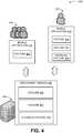
- FIG. 4is a display diagram illustrating activation of a feedback scheme to provide controlled deployment of an application feature, according to embodiments.
- a deployment service 402(executed by a server 408) may be used by a developer to control deployment of features (405, 407) and a feedback feature 409.
- the deployment service 402may receive a definition of the feature 405 and a group of tenants 410 for deployment at a mobile application 403.
- the deployment service 402may receive an tenant identification in response to an initiation of the mobile application 403.
- the tenant identificationmay be detected within the group of tenants 410.
- the deployment service 402may instruct the mobile application 403 to activate the feature 405 for consumption by a tenant associated with the tenant identification.
- the deployment service 402may receive a definition to deploy the features (405, 407) and a feedback feature 409 to other group of tenants, from the developer.
- a tenant identification of a tenant 420may be compared to the other group of tenants to identify the tenant identification as within the other group of tenants.
- the mobile application 413may be instructed to activate the features (405, 407) and the feedback feature 409.
- a positive feedback received from the mobile application 413 regarding the feature 407may be used to instruct the mobile application 403 to activate the feature 407 for consumption by the group of tenants 410.
- the mobile application for the tenant basemay be instructed to activate the feature 407 in response to the positive feedback from the mobile application 413 automatically or based on a request from the developer.
- the mobile application 413may also be instructed to deactivate the feature 407 in response to a negative feedback received from the mobile application 413.
- the developermay be notified of the negative feedback to prompt the developer to address the issue causing the negative feedback.
- the deployment servicemay be employed to perform operations to automate controlled deployment of an application feature.
- An increased user efficiency with the mobile application 103may occur as a result of providing controlled deployment of an application feature through the deployment service 102.
- feature management for group of tenants consuming the feature of the mobile application 103 by the deployment service 102may reduce processor load, increase processing speed, conserve memory, and reduce network bandwidth usage.
- the actions/operations described hereinare not a mere use of a computer, but address results that are a direct consequence of software used as a service offered to large numbers of users and applications.
- FIG. 1 through 4The example scenarios and schemas in FIG. 1 through 4 are shown with specific components, data types, and configurations. Embodiments are not limited to systems according to these example configurations. Providing controlled deployment of an application feature may be implemented in configurations employing fewer or additional components in applications and user interfaces. Furthermore, the example schema and components shown in FIG. 1 through 4 and their subcomponents may be implemented in a similar manner with other values using the principles described herein.
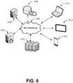
- FIG. 5is an example networked environment, where embodiments may be implemented.
- a deployment service configured to provide controlled deployment of an application featuremay be implemented via software executed over one or more servers 514 such as a hosted service.
- the platformmay communicate with client applications on individual computing devices such as a smart phone 513, a mobile computer 512, or desktop computer 511 ('client devices') through network(s) 510.
- Client applications executed on any of the client devices 511-513may facilitate communications via application(s) executed by servers 514, or on individual server 516.
- a deployment servicemay receive a definition of a feature of a mobile application and a group of tenants of a mobile application from a developer and a tenant identification from the mobile application. Next, the tenant identification may be detected within the group of tenants. In response, an instruction may be transmitted to the mobile application associated with the tenant identification to activate the feature.
- the deployment servicemay store data associated with the feature in data store(s) 519 directly or through database server 518.
- Network(s) 510may comprise any topology of servers, clients, Internet service providers, and communication media.
- a system according to embodimentsmay have a static or dynamic topology.
- Network(s) 510may include secure networks such as an enterprise network, an unsecure network such as a wireless open network, or the Internet.
- Network(s) 510may also coordinate communication over other networks such as Public Switched Telephone Network (PSTN) or cellular networks.
- PSTNPublic Switched Telephone Network
- network(s) 510may include short range wireless networks such as Bluetooth or similar ones.
- Network(s) 510provide communication between the nodes described herein.
- network(s) 510may include wireless media such as acoustic, RF, infrared and other wireless media.
- FIG. 6is a block diagram of an example computing device, which may be used to provide controlled deployment of an application feature, according to embodiments.
- computing device 600may be used as a server, desktop computer, portable computer, smart phone, special purpose computer, or similar device.
- the computing device 600may include one or more processors 604 and a system memory 606.
- a memory bus 608may be used for communication between the processor 604 and the system memory 606.
- the basic configuration 602may be illustrated in FIG. 6 by those components within the inner dashed line.
- the processor 604may be of any type, including but not limited to a microprocessor ( ⁇ P), a microcontroller ( ⁇ C), a digital signal processor (DSP), or any combination thereof.
- the processor 604may include one more levels of caching, such as a level cache memory 612, one or more processor cores 614, and registers 616.
- the example processor cores 614may (each) include an arithmetic logic unit (ALU), a floating point unit (FPU), a digital signal processing core (DSP Core), or any combination thereof.
- An example memory controller 618may also be used with the processor 604, or in some implementations, the memory controller 618 may be an internal part of the processor 604.
- the system memory 606may be of any type including but not limited to volatile memory (such as RAM), non-volatile memory (such as ROM, flash memory, etc.), or any combination thereof.
- the system memory 606may include an operating system 620, a deployment service 622, and a program data 624.
- the deployment service 622may include components such as a feature module 626 and a communication module 627.
- the feature module 626 and the communication module 627may execute the processes associated with the deployment service 622.
- the feature module 626may receive a definition of a feature of a mobile application and a group of tenants of a mobile application from a developer, a tenant identification from the mobile application. Next, the tenant identification may be detected within the group of tenants.
- the communication module 627may transmit an instruction to the mobile application associated with the tenant identification to activate the feature.
- Input to and output out of the deployment service 622may be transmitted through a communication device associated with the computing device 600.
- An example of the communication devicemay include a networking device that may be communicatively coupled to the computing device 600.
- the networking devicemay provide wired and/or wireless communication.
- the program data 624may also include, among other data, feature data 628, or the like, as described herein.
- the feature data 628may include a tenant identification, a tenant attribute, among others.
- the computing device 600may have additional features or functionality, and additional interfaces to facilitate communications between the basic configuration 602 and any desired devices and interfaces.
- a bus/interface controller 630may be used to facilitate communications between the basic configuration 602 and one or more data storage devices 632 via a storage interface bus 634.
- the data storage devices 632may be one or more removable storage devices 636, one or more non-removable storage devices 638, or a combination thereof.
- Examples of the removable storage and the non-removable storage devicesmay include magnetic disk devices, such as flexible disk drives and hard-disk drives (HDD), optical disk drives such as compact disk (CD) drives or digital versatile disk (DVD) drives, solid state drives (SSD), and tape drives, to name a few.
- Example computer storage mediamay include volatile and nonvolatile, removable, and non-removable media implemented in any method or technology for storage of information, such as computer-readable instructions, data structures, program modules, or other data.
- the system memory 606, the removable storage devices 636 and the non-removable storage devices 638are examples of computer storage media.
- Computer storage mediaincludes, but is not limited to, RAM, ROM, EEPROM, flash memory or other memory technology, CD-ROM, digital versatile disks (DVDs), solid state drives, or other optical storage, magnetic cassettes, magnetic tape, magnetic disk storage or other magnetic storage devices, or any other medium which may be used to store the desired information and which may be accessed by the computing device 600. Any such computer storage media may be part of the computing device 600.
- the computing device 600may also include an interface bus 640 for facilitating communication from various interface devices (for example, one or more output devices 642, one or more peripheral interfaces 644, and one or more communication devices 666) to the basic configuration 602 via the bus/interface controller 630.
- interface devicesfor example, one or more output devices 642, one or more peripheral interfaces 644, and one or more communication devices 666
- Some of the example output devices 642include a graphics processing unit 648 and an audio processing unit 650, which may be configured to communicate to various external devices such as a display or speakers via one or more A/V ports 652.
- One or more example peripheral interfaces 644may include a serial interface controller 654 or a parallel interface controller 656, which may be configured to communicate with external devices such as input devices (for example, keyboard, mouse, pen, voice input device, touch input device, etc.) or other peripheral devices (for example, printer, scanner, etc.) via one or more I/O ports 658.
- An example of the communication device(s) 666includes a network controller 660, which may be arranged to facilitate communications with one or more other computing devices 662 over a network communication link via one or more communication ports 664.
- the one or more other computing devices 662may include servers, computing devices, and comparable devices.
- the network communication linkmay be one example of a communication media.
- Communication mediamay typically be embodied by computer readable instructions, data structures, program modules, or other data in a modulated data signal, such as a carrier wave or other transport mechanism, and may include any information delivery media.
- a "modulated data signal"may be a signal that has one or more of its characteristics set or changed in such a manner as to encode information in the signal.
- communication mediamay include wired media such as a wired network or direct-wired connection, and wireless media such as acoustic, radio frequency (RF), microwave, infrared (IR) and other wireless media.
- RFradio frequency
- IRinfrared
- the term computer readable media as used hereinmay include both storage media and communication media.
- the computing device 600may be implemented as a part of a general purpose or specialized server, mainframe, or similar computer, which includes any of the above functions.
- the computing device 600may also be implemented as a personal computer including both laptop computer and non-laptop computer configurations.
- Example embodimentsmay also include methods to provide controlled deployment of an application feature. These methods can be implemented in any number of ways, including the structures described herein. One such way may be by machine operations, of devices of the type described in the present disclosure. Another optional way may be for one or more of the individual operations of the methods to be performed in conjunction with one or more human operators performing some of the operations while other operations may be performed by machines. These human operators need not be collocated with each other, but each can be only with a machine that performs a portion of the program. In other embodiments, the human interaction can be automated such as by pre-selected criteria that may be machine automated.
- FIG. 7is a logic flow diagram illustrating a process for providing controlled deployment of an application feature, according to embodiments.
- Process 700may be implemented on a computing device, such as the computing device 600 or another system.
- Process 700begins with operation 710, where the deployment service may receive a definition of a feature of a mobile application and a group of tenants of the mobile application from a developer.
- the definitionmay be used to allow the mobile application associated with the group of tenants to activate the feature.
- the featuremay include an existing component, a new component, and/or a feedback component, among other components of the mobile application.
- a tenant identificationmay be received from the mobile application at operation 720.
- the tenant identificationmay include a unique identifier associated with a tenant accessing the mobile application.
- the tenant identificationmay be compared to the group of tenants to detect the tenant identification as within the group of tenants at operation 730.
- the group of tenantsmay include a subset of a tenant base classified to test the feature, and/or use the feature, among others.
- an instructionmay be transmitted to the mobile application associated with the tenant identification to activate the feature at operation 740.
- process 700The operations included in process 700 are for illustration purposes. Providing a controlled deployment of an application feature may be implemented by similar processes with fewer or additional steps, as well as in different order of operations using the principles described herein.
- the operations described hereinmay be executed by one or more processors operated on one or more computing devices, one or more processor cores, specialized processing devices, and/or general purpose processors, among other examples.
- a server for providing controlled deployment of an application featureincludes a communication device, a memory configured to store instructions associated with a deployment service, and one or more processors coupled to the memory and the communication device.
- the one or more processorsexecute a deployment service in conjunction with the instructions stored in the memory.
- the deployment serviceincludes a feature module and a communication module.
- the feature moduleis configured to receive a definition of a feature of a mobile application and a group of tenants of the mobile application from a developer, receive a tenant identification from the mobile application, and detect the tenant identification within the group of tenants.
- the communication moduleis configured to transmit, through the communication device, an instruction to the mobile application associated with the tenant identification to activate the feature.
- the tenant identificationis detected within the group of tenants in response to a request from the developer to activate the feature within the mobile application associated with the group of tenants.
- the feature moduleis further configured to receive a request from the developer to activate the feature within the mobile application associated with a percentage of the group of tenants and query an availability of an allocation within the percentage of the group of tenants.
- the feature moduleis further configured to detect the availability of the allocation within the percentage of the group of tenants and prompt the communication module to transmit the instruction to the mobile application associated with the tenant identification to activate the feature.
- the feature moduleis further configured to detect an unavailability of the allocation within the percentage of the group of tenants and prompt the communication module to transmit another instruction to the mobile application associated with the tenant identification to not activate the feature.
- the feature moduleis further configured to identify a tenant attribute associated with the tenant identification, compare the tenant attribute with a group attribute of the group of tenants, and search for a match between the tenant attribute and the group attribute to classify the tenant identification as within the group of tenants.
- the feature moduleis further configured to detect a tenant location associated with the tenant identification as the tenant attribute, identify the tenant location as encompassed by a geographic location of the group of tenants, where the geographic location is detected as the group attribute, and affirm the match between the tenant attribute and the group attribute to classify the tenant identification as within the group of tenants.
- the feature moduleis further configured to detect a tenant location associated with the tenant identification as the tenant attribute, identify the tenant location as outside a geographic location of the group of tenants, where the geographic location is detected as the group attribute, identify a mismatch between the tenant attribute and the group attribute to classify the tenant identification as within the group of tenants, and prompt the communication module to transmit another instruction to the mobile application associated with the tenant identification to not activate the feature.
- the feature moduleis further configured to detect a tenant role associated with the tenant identification as the tenant attribute, identify the tenant role as encompassed by a group role of the group of tenants, where the group role is detected as the group attribute, and affirm the match between the tenant attribute and the group attribute to classify the tenant identification as within the group of tenants.
- the feature moduleis further configured to detect a tenant role associated with the tenant identification as the tenant attribute, identify tenant role as outside a group role of the group of tenants, where the group role is detected as the group attribute, identify a mismatch between the tenant attribute and the group attribute to classify the tenant identification as within the group of tenants, and prompt the communication module to transmit another instruction to the mobile application associated with the tenant identification to not activate the feature.
- the tenant identificationincludes a unique identifier associated with a tenant of the mobile application and a tenant attribute that is matched to a group attribute of the group of tenants for a classification of the tenant identification as within the group of tenants.
- a method executed on a computing device for controlled deployment of an application featureincludes receiving a definition of a feature of a mobile application and a group of tenants from a developer, receiving a request from the developer to activate the feature within the mobile application associated with the group of tenants, receiving a tenant identification from the mobile application, detecting the tenant identification within the group of tenants, and transmitting an instruction to the mobile application associated with the tenant identification to activate the feature.
- the methodfurther includes receiving other definition of other feature and other group of tenants from the developer, receiving other request from the developer to activate the other feature within the mobile application associated with the other group of tenants, and receiving other tenant identification from the mobile application.
- the methodfurther includes detecting the other tenant identification within the other group of tenants and transmitting other instruction to the mobile application associated with the other tenant identification to activate the other feature.
- the methodfurther includes receiving other request from the developer to deactivate the feature within the mobile application associated with the group of tenants and transmitting other instruction to the mobile application associated with the tenant identification to deactivate the feature.
- the methodfurther includes receiving a feedback definition of a feedback feature for the group of tenants from the developer, receiving a feedback request from the developer to activate the feedback feature within the mobile application associated with the group of the tenants, and transmitting other instruction to the mobile application associated with the tenant identification to activate the feedback feature.
- the methodfurther includes receiving feedback from the mobile application associated with the tenant identification, analyzing a feedback to identify a negative impression associated with the feature, and transmitting a new instruction to the mobile application associated with the tenant identification to deactivate the feature and the feedback feature.
- a computer-readable memory device with instructions stored thereon for providing controlled deployment of an application featureis described.
- the instructionsinclude actions that are similar to the actions of the method.
- a means for providing controlled deployment of an application featureincludes a means for receiving a definition of a feature of a mobile application and a group of tenants of the mobile application from a developer, a means for receiving a tenant identification from the mobile application, a means for detecting the tenant identification within the group of tenants, and a means for transmitting an instruction to the mobile application associated with the tenant identification to activate the feature.
Landscapes
- Engineering & Computer Science (AREA)
- Software Systems (AREA)
- Theoretical Computer Science (AREA)
- General Engineering & Computer Science (AREA)
- Physics & Mathematics (AREA)
- General Physics & Mathematics (AREA)
- Computer Security & Cryptography (AREA)
- Telephone Function (AREA)
- Telephonic Communication Services (AREA)
- Mobile Radio Communication Systems (AREA)
Description
- People interact with computer applications through user interfaces. While audio, tactile, and similar forms of user interfaces are available, visual user interfaces through a display device are the most common form of a user interface. With the development of faster and smaller electronics for computing devices, smaller size devices such as handheld computers, smart phones, tablet devices, and comparable devices have become common. Such devices execute a wide variety of applications ranging from communication applications to complicated analysis tools. Many such applications are updated frequently with features that are rarely tested.
- Vast number of feature requests and feature deployments complicate stable application deployment. Indeed, updates, changes, and/or additions to applications cause difficulties in upkeep by developers. While maintaining an application, an additional layer of complication faced by a developer includes feature requests associated by consumers of the application. Complications with multiple feature requests and vast number of applications may lead to mismanagement of issues that arises with introduction of new features.
- In the publication "Efficient customization of multi-tenant Software-as-a-Service applications with service lines" (Walraven et al. / The Journal of Systems and Software 91 (2014), pages 48 to 62) an integrated service engineering method that supports co-existing tenant-specific configurations is disclosed.
- This summary is provided to introduce a selection of concepts in a simplified form that are further described below in the Detailed Description. This summary is not intended to exclusively identify key features or essential features of the claimed subject matter, nor is it intended as an aid in determining the scope of the claimed subject matter.
- The present invention is directed to controlled deployment of an application feature according to the appended claims 1-9. In some examples, a deployment service may receive a definition of a feature of a mobile application and a group of tenants of a mobile application from a developer. The deployment service may also receive a tenant identification from the mobile application. Next, the tenant identification may be detected within the group of tenants. In response, an instruction may be transmitted to the mobile application associated with the tenant identification to activate the feature.
- These and other features and advantages will be apparent from a reading of the following detailed description and a review of the associated drawings. It is to be understood that both the foregoing general description and the following detailed description are explanatory and do not restrict aspects as claimed.
FIG. 1 is a conceptual diagram illustrating an example of providing controlled deployment of an application feature, according to embodiments;FIG. 2 is a display diagram illustrating an example of a scheme to provide controlled deployment of an application feature, according to embodiments;FIG. 3 is a display diagram illustrating another example of a scheme to provide controlled deployment of an application feature, according to embodiments;FIG. 4 is a display diagram illustrating activation of a feedback scheme to provide controlled deployment of an application feature, according to embodiments;FIG. 5 is a simplified networked environment, where a system according to embodiments may be implemented;FIG. 6 is a block diagram of an example computing device, which may be used to provide controlled deployment of an application feature, according to embodiments; andFIG. 7 is a logic flow diagram illustrating a process for providing controlled deployment of an application feature, according to embodiments.- As briefly described above, a deployment service provides controlled deployment of an application feature. In an example scenario, the deployment service may receive a definition of a feature of a mobile application and a group of tenants of the mobile application from a developer. The definition may be used to allow the mobile application associated with the group of tenants to activate the feature. The feature may include an existing component, a new component, and/or a feedback component, among other components of the mobile application. Next, a tenant identification may be received from the mobile application. The tenant identification may include a unique identifier associated with a tenant accessing the mobile application
- The tenant identification may be compared to the group of tenants to detect the tenant identification as within the group of tenants. The group of tenants may include a subset of a tenant base classified to test the feature, and/or use the feature, among others. Next, an instruction may be transmitted to the mobile application associated with the tenant identification to activate the feature.
- In the following detailed description, references are made to the accompanying drawings that form a part hereof, and in which are shown by way of illustrations, specific embodiments, or examples. These aspects may be combined, other
aspects may be utilized, and structural changes may be made without departing from the scope of the present disclosure. The following detailed description is therefore not to be taken in a limiting sense, and the scope of the present invention is defined by the appended claims and their equivalents. - While some embodiments will be described in the general context of program modules that execute in conjunction with an application program that runs on an operating system on a personal computer, those skilled in the art will recognize that aspects may also be implemented in combination with other program modules.
- Generally, program modules include routines, programs, components, data structures, and other types of structures that perform particular tasks or implement particular abstract data types. Moreover, those skilled in the art will appreciate that embodiments may be practiced with other computer system configurations, including hand-held devices, multiprocessor systems, microprocessor-based or programmable consumer electronics, minicomputers, mainframe computers, and comparable computing devices. Embodiments may also be practiced in distributed computing environments where tasks are performed by remote processing devices that are linked through a communications network. In a distributed computing environment, program modules may be located in both local and remote memory storage devices.
- Some embodiments may be implemented as a computer-implemented process (method), a computing system, or as an article of manufacture, such as a computer program product or computer readable media. The computer program product may be a computer storage medium readable by a computer system and encoding a computer program that comprises instructions for causing a computer or computing system to perform example process(es). The computer-readable storage medium is a physical computer-readable memory device. The computer-readable storage medium can for example be implemented via one or more of a volatile computer memory, a non-volatile memory, a hard drive, a flash drive, a floppy disk, or a compact disk, and comparable hardware media.
- Throughout this specification, the term "platform" may be a combination of software and hardware components to provide controlled deployment of an application feature Examples of platforms include, but are not limited to, a hosted service executed over a plurality of servers, an application executed on a single computing device, and comparable systems. The term "server" generally refers to a computing device executing one or more software programs typically in a networked environment. More detail on these technologies and example operations is provided below.
- A computing device, as used herein, refers to a device comprising at least a memory and a processor that includes a desktop computer, a laptop computer, a tablet computer, a smart phone, a vehicle mount computer, or a wearable computer. A memory may be a removable or non-removable component of a computing device configured to store one or more instructions to be executed by one or more processors. A processor may be a component of a computing device coupled to a memory and configured to execute programs in conjunction with instructions stored by the memory. A file is any form of structured data that is associated with audio, video, or similar content. An operating system is a system configured to manage hardware and software components of a computing device that provides common services and applications. An integrated module is a component of an application or service that is integrated within the application or service such that the application or service is configured to execute the component. A computer-readable memory device is a physical computer-readable storage medium implemented via one or more of a volatile computer memory, a non-volatile memory, a hard drive, a flash drive, a floppy disk, or a compact disk, and comparable hardware media that includes instructions thereon to automatically save content to a location. A user experience - a visual display associated with an application or service through which a user interacts with the application or service. A user action refers to an interaction between a user and a user experience of an application or a user experience provided by a service that includes one of touch input, gesture input, voice command, eye tracking, gyroscopic input, pen input, mouse input, and keyboards input. An application programming interface (API) may be a set of routines, protocols, and tools for an application or service that enable the application or service to interact or communicate with one or more other applications and services managed by separate entities.
FIG. 1 is a conceptual diagram illustrating an example of providing controlled deployment of an application feature, according to embodiments.- In a diagram 100, a
server 108 may execute adeployment service 102. Theserver 108 may include a physical server providing one or more services to client devices. A service may include an application performing operations in relation to a client application and/or a subscriber, among others. Theserver 108 may include and/or is part of a workstation, a data warehouse, and/or a data center, among others. - The
server 108 may execute thedeployment service 102 to manage features provided by amobile application 103. Release of afeature 105 may be controlled to test thefeature 105 prior to deployment to an entirety of a tenant base of amobile application 103. Themobile application 103 may be rendered by aclient device 104 to atenant 110. Adeveloper 112 may provide a definition to thedeployment service 102 to create a group of tenants and thefeature 105 to activate at themobile application 103. Thedeployment service 102 may relate thefeature 105 with the group of the tenants. - Next, the
deployment service 102 may compare a tenant identification of atenant 110 against the group of tenants to detect the tenant identification within the group of tenants. In response to detecting the tenant identification within the group of tenants, thedeployment service 102 may transmit an instruction to themobile application 103 to activate thefeature 105 for consumption by thetenant 110. - The
server 108 may communicate with theclient device 104 through a network. The network may provide wired or wireless communications between nodes such as theclient device 104, or theserver 108, among others. Previous example(s) to control features at themobile application 103 is not provided in a limiting sense. Alternatively, thedeployment service 102 may control deployment of thefeature 105 at a desktop application, a workstation application, and/or a server application, among others. Themobile application 103 may also include a client interface of thedeployment service 102. - The
tenant 110 may interact with themobile application 103 with a keyboard based input, a mouse based input, a voice based input, a pen based input, and a gesture based input, among others. The gesture based input may include one or more touch based actions such as a touch action, a swipe action, and a combination of each, among others. - While the example system in
FIG. 1 has been described with specific components including theserver 108, thedeployment service 102, embodiments are not limited to these components or system configurations and can be implemented with other system configuration employing fewer or additional components. FIG. 2 is a display diagram illustrating an example of a scheme to provide controlled deployment of an application feature, according to embodiments.- In a diagram 200, a
server 208 may provide adeployment service 202 to allow a developer to control deployment of features (205, 207) to amobile application 203. The features (205, 207) may include components of themobile application 203 such as a user experience module and/or a feedback module, among others. Themobile application 203 may be installed with the features (205, 207) at a client device and which may be activated and/or deactivated. - Alternatively, the features (205, 207) may be installed through an update operation subsequent to an initial installation of the
mobile application 203 at the client device. The features (205, 207) installed through the update operation may be activated and/or deactivated. Activation of the features (205, 207) may include rendering user interface(s) associated with the features (205, 207) or enabling operations associated with the features (205, 207) at themobile application 203. Deactivation of the features (205, 207) may include hiding user interfaces associated with the features (205, 207) or disabling operations associated with the features (205, 207) at themobile application 203. - For example, the
deployment service 202 may receive a definition of a group oftenants 216 and afeature 205 to activate at themobile application 203 from a developer. Thedeployment service 202 may also receive atenant identification 212 from themobile application 203, in response to an initiation (or an execution) of themobile application 203 at the client device. Next, thetenant identification 212 may be compared to the group oftenants 216. In response to detecting thetenant identification 212 within the group oftenants 216, an instruction may be transmitted to themobile application 203 to activate thefeature 205. - The developer may choose to stagger deployment of the
feature 205 to thoroughly test thefeature 205 prior to deployment to entirety of a tenant base of themobile application 203. The test group such as the group oftenants 216 may be selected by the developer to try out the features (205, 207). Themobile application 203 may also be instructed to provide feedback feature(s) to allow the test group to evaluate thefeature 205. Feedback may allow the developer to identify faults and/or bugs in thefeature 205 and fix any issues with the feature prior to deployment to the tenant base of the mobile application. - Alternatively, the
deployment service 202 may receive a definition from the developer to deploy thefeature 205 to a percentage of the group oftenants 216. After receiving a request to activate thefeature 205 in amobile application 203 from the developer, thedeployment service 202 may wait to receive atenant identification 212 of atenant 210 from themobile application 203. Themobile application 203 may transmit thetenant identification 212 at an initiation of themobile application 203 in a client device in response to an input by thetenant 210. Thetenant identification 212 may include a unique identifier assigned to thetenant 210 such as a credential. - The group of tenants may be analyzed to determine an availability of an allocation within the percentage of the group of
tenants 216. If the availability of the allocation is detected, thedeployment service 202 may transmit an instruction to themobile application 203 to activate thefeature 205. If an unavailability of the allocation is detected, thedeployment service 202 may transmit an instruction to themobile application 203 to not activate the feature. - Alternatively, the
deployment service 202 may receive an instruction to deactivate afeature 207 deployed to themobile application 203 from the developer. Thedeployment service 202 may wait to receive thetenant identification 212 in response to an initiation of themobile application 203 at the client device to transmit an instruction to deactivate afeature 207. Alternatively, thedeployment service 202 may transmit an instruction to deactivate thefeature 207 to themobile application 203 and other mobile applications identified to have an activated version of thefeature 207. - In another example scenario, a
tenant attribute 214 may be identified by thedeployment service 202 to classify thetenant 210 as within the group oftenants 216. For example, a tenant location as thetenant attribute 214 may be compared to a geographic location (such as a city, a country, a continent, and/or a marketing zone, among others). Thetenant identification 212 may be identified as within the group oftenants 216 in response to detecting the tenant location as encompassed within the geographical location of the group oftenants 216 may determine. Alternatively, the tenant location outside the geographical location of the group oftenants 216 may be used to deactivate thefeature 207 deployed to themobile application 203 associated with thetenant 210. - Similarly, a tenant role may also be used as the
tenant attribute 214 to compare against the group attribute associated with the group oftenants 216. An example of tenant role may include a tester, a supervisor, and/or a power user, among others. A match may be used to classify thetenant identification 212 as within the group oftenants 216. A failure to match may be used to transmit an instruction to deactivate a deployed feature such as thefeature 207 to themobile application 203 associated with a tenant who has the tenant role. FIG. 3 is a display diagram illustrating another example of a scheme to provide controlled deployment of an application feature, according to embodiments.- In a diagram 300, a deployment service 302 (executed by a server 308) may receive a definition that includes a
feature 305 and a group oftenants 310. The definition may be used to activate thefeature 305 at amobile application 303. At an initiation of themobile application 303, a tenant identification transmitted from themobile application 303 may be matched to the group of tenants and an instruction may be transmitted to themobile application 303 to activate thefeature 305. - The
deployment service 302 may receive a new request to deploy afeature 307 from the developer. The request may include a definition of a new group of the tenants and thefeature 307. Thefeature 307 may be a new feature of amobile application 313 that the developer may wish test with the new group of the tenants. Thefeature 307 may be deployed to themobile application 313 by thedeployment service 302 in a deactivated state. Alternatively thefeature 307 may be deployed to themobile application 313 using a third party deployment scheme. - The
deployment service 302 may wait to receive a tenant identification of atenant 320 to instruct themobile application 313 to activate thefeature 307. The tenant identification of thetenant 320 may be compared to the new group of the tenants. If the tenant identification is found within the new group of the tenants, themobile application 313 may be instructed to activate thefeature 307 for consumption by thetenant 320. FIG. 4 is a display diagram illustrating activation of a feedback scheme to provide controlled deployment of an application feature, according to embodiments.- In a diagram 400, a deployment service 402 (executed by a server 408) may be used by a developer to control deployment of features (405, 407) and a
feedback feature 409. Thedeployment service 402 may receive a definition of thefeature 405 and a group oftenants 410 for deployment at amobile application 403. Thedeployment service 402 may receive an tenant identification in response to an initiation of themobile application 403. The tenant identification may be detected within the group oftenants 410. Next, thedeployment service 402 may instruct themobile application 403 to activate thefeature 405 for consumption by a tenant associated with the tenant identification. - Alternatively, the
deployment service 402 may receive a definition to deploy the features (405, 407) and afeedback feature 409 to other group of tenants, from the developer. A tenant identification of atenant 420 may be compared to the other group of tenants to identify the tenant identification as within the other group of tenants. In response, themobile application 413 may be instructed to activate the features (405, 407) and thefeedback feature 409. - A positive feedback received from the
mobile application 413 regarding thefeature 407 may be used to instruct themobile application 403 to activate thefeature 407 for consumption by the group oftenants 410. Alternatively, the mobile application for the tenant base may be instructed to activate thefeature 407 in response to the positive feedback from themobile application 413 automatically or based on a request from the developer. Themobile application 413 may also be instructed to deactivate thefeature 407 in response to a negative feedback received from themobile application 413. The developer may be notified of the negative feedback to prompt the developer to address the issue causing the negative feedback. - As discussed above, the deployment service may be employed to perform operations to automate controlled deployment of an application feature. An increased user efficiency with the
mobile application 103 may occur as a result of providing controlled deployment of an application feature through thedeployment service 102. Additionally, feature management for group of tenants consuming the feature of themobile application 103 by thedeployment service 102 may reduce processor load, increase processing speed, conserve memory, and reduce network bandwidth usage. - Embodiments, as described herein, address a need that arises from a lack of efficiency to manage features of a
mobile application 103 of aclient device 104 managed by adeployment service 102. The actions/operations described herein are not a mere use of a computer, but address results that are a direct consequence of software used as a service offered to large numbers of users and applications. - The example scenarios and schemas in
FIG. 1 through 4 are shown with specific components, data types, and configurations. Embodiments are not limited to systems according to these example configurations. Providing controlled deployment of an application feature may be implemented in configurations employing fewer or additional components in applications and user interfaces. Furthermore, the example schema and components shown inFIG. 1 through 4 and their subcomponents may be implemented in a similar manner with other values using the principles described herein. FIG. 5 is an example networked environment, where embodiments may be implemented. A deployment service configured to provide controlled deployment of an application feature may be implemented via software executed over one ormore servers 514 such as a hosted service. The platform may communicate with client applications on individual computing devices such as asmart phone 513, amobile computer 512, or desktop computer 511 ('client devices') through network(s) 510.- Client applications executed on any of the client devices 511-513 may facilitate communications via application(s) executed by
servers 514, or onindividual server 516. A deployment service may receive a definition of a feature of a mobile application and a group of tenants of a mobile application from a developer and a tenant identification from the mobile application. Next, the tenant identification may be detected within the group of tenants. In response, an instruction may be transmitted to the mobile application associated with the tenant identification to activate the feature. The deployment service may store data associated with the feature in data store(s) 519 directly or throughdatabase server 518. - Network(s) 510 may comprise any topology of servers, clients, Internet service providers, and communication media. A system according to embodiments may have a static or dynamic topology. Network(s) 510 may include secure networks such as an enterprise network, an unsecure network such as a wireless open network, or the Internet. Network(s) 510 may also coordinate communication over other networks such as Public Switched Telephone Network (PSTN) or cellular networks. Furthermore, network(s) 510 may include short range wireless networks such as Bluetooth or similar ones. Network(s) 510 provide communication between the nodes described herein. By way of example, and not limitation, network(s) 510 may include wireless media such as acoustic, RF, infrared and other wireless media.
- Many other configurations of computing devices, applications, data sources, and data distribution systems may be employed to provide controlled deployment of an application feature. Furthermore, the networked environments discussed in
FIG. 5 are for illustration purposes only. Embodiments are not limited to the example applications, modules, or processes. FIG. 6 is a block diagram of an example computing device, which may be used to provide controlled deployment of an application feature, according to embodiments.- For example,
computing device 600 may be used as a server, desktop computer, portable computer, smart phone, special purpose computer, or similar device. In an example basic configuration 602, thecomputing device 600 may include one ormore processors 604 and asystem memory 606. A memory bus 608 may be used for communication between theprocessor 604 and thesystem memory 606. The basic configuration 602 may be illustrated inFIG. 6 by those components within the inner dashed line. - Depending on the desired configuration, the
processor 604 may be of any type, including but not limited to a microprocessor (µP), a microcontroller (µC), a digital signal processor (DSP), or any combination thereof. Theprocessor 604 may include one more levels of caching, such as alevel cache memory 612, one ormore processor cores 614, and registers 616. Theexample processor cores 614 may (each) include an arithmetic logic unit (ALU), a floating point unit (FPU), a digital signal processing core (DSP Core), or any combination thereof. Anexample memory controller 618 may also be used with theprocessor 604, or in some implementations, thememory controller 618 may be an internal part of theprocessor 604. - Depending on the desired configuration, the
system memory 606 may be of any type including but not limited to volatile memory (such as RAM), non-volatile memory (such as ROM, flash memory, etc.), or any combination thereof. Thesystem memory 606 may include anoperating system 620, adeployment service 622, and aprogram data 624. Thedeployment service 622 may include components such as afeature module 626 and acommunication module 627. Thefeature module 626 and thecommunication module 627 may execute the processes associated with thedeployment service 622. Thefeature module 626 may receive a definition of a feature of a mobile application and a group of tenants of a mobile application from a developer, a tenant identification from the mobile application. Next, the tenant identification may be detected within the group of tenants. In response, thecommunication module 627 may transmit an instruction to the mobile application associated with the tenant identification to activate the feature. - Input to and output out of the
deployment service 622 may be transmitted through a communication device associated with thecomputing device 600. An example of the communication device may include a networking device that may be communicatively coupled to thecomputing device 600. The networking device may provide wired and/or wireless communication. Theprogram data 624 may also include, among other data,feature data 628, or the like, as described herein. Thefeature data 628 may include a tenant identification, a tenant attribute, among others. - The
computing device 600 may have additional features or functionality, and additional interfaces to facilitate communications between the basic configuration 602 and any desired devices and interfaces. For example, a bus/interface controller 630 may be used to facilitate communications between the basic configuration 602 and one or moredata storage devices 632 via a storage interface bus 634. Thedata storage devices 632 may be one or moreremovable storage devices 636, one or morenon-removable storage devices 638, or a combination thereof. Examples of the removable storage and the non-removable storage devices may include magnetic disk devices, such as flexible disk drives and hard-disk drives (HDD), optical disk drives such as compact disk (CD) drives or digital versatile disk (DVD) drives, solid state drives (SSD), and tape drives, to name a few. Example computer storage media may include volatile and nonvolatile, removable, and non-removable media implemented in any method or technology for storage of information, such as computer-readable instructions, data structures, program modules, or other data. - The
system memory 606, theremovable storage devices 636 and thenon-removable storage devices 638 are examples of computer storage media. Computer storage media includes, but is not limited to, RAM, ROM, EEPROM, flash memory or other memory technology, CD-ROM, digital versatile disks (DVDs), solid state drives, or other optical storage, magnetic cassettes, magnetic tape, magnetic disk storage or other magnetic storage devices, or any other medium which may be used to store the desired information and which may be accessed by thecomputing device 600. Any such computer storage media may be part of thecomputing device 600. - The
computing device 600 may also include an interface bus 640 for facilitating communication from various interface devices (for example, one ormore output devices 642, one or moreperipheral interfaces 644, and one or more communication devices 666) to the basic configuration 602 via the bus/interface controller 630. Some of theexample output devices 642 include agraphics processing unit 648 and an audio processing unit 650, which may be configured to communicate to various external devices such as a display or speakers via one or more A/V ports 652. One or more exampleperipheral interfaces 644 may include aserial interface controller 654 or aparallel interface controller 656, which may be configured to communicate with external devices such as input devices (for example, keyboard, mouse, pen, voice input device, touch input device, etc.) or other peripheral devices (for example, printer, scanner, etc.) via one or more I/O ports 658. An example of the communication device(s) 666 includes anetwork controller 660, which may be arranged to facilitate communications with one or moreother computing devices 662 over a network communication link via one ormore communication ports 664. The one or moreother computing devices 662 may include servers, computing devices, and comparable devices. - The network communication link may be one example of a communication media. Communication media may typically be embodied by computer readable instructions, data structures, program modules, or other data in a modulated data signal, such as a carrier wave or other transport mechanism, and may include any information delivery media. A "modulated data signal" may be a signal that has one or more of its characteristics set or changed in such a manner as to encode information in the signal. By way of example, and not limitation, communication media may include wired media such as a wired network or direct-wired connection, and wireless media such as acoustic, radio frequency (RF), microwave, infrared (IR) and other wireless media. The term computer readable media as used herein may include both storage media and communication media.
- The
computing device 600 may be implemented as a part of a general purpose or specialized server, mainframe, or similar computer, which includes any of the above functions. Thecomputing device 600 may also be implemented as a personal computer including both laptop computer and non-laptop computer configurations. - Example embodiments may also include methods to provide controlled deployment of an application feature. These methods can be implemented in any number of ways, including the structures described herein. One such way may be by machine operations, of devices of the type described in the present disclosure. Another optional way may be for one or more of the individual operations of the methods to be performed in conjunction with one or more human operators performing some of the operations while other operations may be performed by machines. These human operators need not be collocated with each other, but each can be only with a machine that performs a portion of the program. In other embodiments, the human interaction can be automated such as by pre-selected criteria that may be machine automated.
FIG. 7 is a logic flow diagram illustrating a process for providing controlled deployment of an application feature, according to embodiments.Process 700 may be implemented on a computing device, such as thecomputing device 600 or another system.Process 700 begins withoperation 710, where the deployment service may receive a definition of a feature of a mobile application and a group of tenants of the mobile application from a developer. The definition may be used to allow the mobile application associated with the group of tenants to activate the feature. The feature may include an existing component, a new component, and/or a feedback component, among other components of the mobile application. Next, a tenant identification may be received from the mobile application atoperation 720. The tenant identification may include a unique identifier associated with a tenant accessing the mobile application.- The tenant identification may be compared to the group of tenants to detect the tenant identification as within the group of tenants at
operation 730. The group of tenants may include a subset of a tenant base classified to test the feature, and/or use the feature, among others. Next, an instruction may be transmitted to the mobile application associated with the tenant identification to activate the feature atoperation 740. - The operations included in
process 700 are for illustration purposes. Providing a controlled deployment of an application feature may be implemented by similar processes with fewer or additional steps, as well as in different order of operations using the principles described herein. The operations described herein may be executed by one or more processors operated on one or more computing devices, one or more processor cores, specialized processing devices, and/or general purpose processors, among other examples. - In some examples, a server for providing controlled deployment of an application feature is described. The server includes a communication device, a memory configured to store instructions associated with a deployment service, and one or more processors coupled to the memory and the communication device. The one or more processors execute a deployment service in conjunction with the instructions stored in the memory. The deployment service includes a feature module and a communication module. The feature module is configured to receive a definition of a feature of a mobile application and a group of tenants of the mobile application from a developer, receive a tenant identification from the mobile application, and detect the tenant identification within the group of tenants. The communication module is configured to transmit, through the communication device, an instruction to the mobile application associated with the tenant identification to activate the feature.
- In other examples, the tenant identification is detected within the group of tenants in response to a request from the developer to activate the feature within the mobile application associated with the group of tenants. The feature module is further configured to receive a request from the developer to activate the feature within the mobile application associated with a percentage of the group of tenants and query an availability of an allocation within the percentage of the group of tenants. The feature module is further configured to detect the availability of the allocation within the percentage of the group of tenants and prompt the communication module to transmit the instruction to the mobile application associated with the tenant identification to activate the feature. The feature module is further configured to detect an unavailability of the allocation within the percentage of the group of tenants and prompt the communication module to transmit another instruction to the mobile application associated with the tenant identification to not activate the feature.
- In further examples, the feature module is further configured to identify a tenant attribute associated with the tenant identification, compare the tenant attribute with a group attribute of the group of tenants, and search for a match between the tenant attribute and the group attribute to classify the tenant identification as within the group of tenants. The feature module is further configured to detect a tenant location associated with the tenant identification as the tenant attribute, identify the tenant location as encompassed by a geographic location of the group of tenants, where the geographic location is detected as the group attribute, and affirm the match between the tenant attribute and the group attribute to classify the tenant identification as within the group of tenants.
- In other examples, the feature module is further configured to detect a tenant location associated with the tenant identification as the tenant attribute, identify the tenant location as outside a geographic location of the group of tenants, where the geographic location is detected as the group attribute, identify a mismatch between the tenant attribute and the group attribute to classify the tenant identification as within the group of tenants, and prompt the communication module to transmit another instruction to the mobile application associated with the tenant identification to not activate the feature. The feature module is further configured to detect a tenant role associated with the tenant identification as the tenant attribute, identify the tenant role as encompassed by a group role of the group of tenants, where the group role is detected as the group attribute, and affirm the match between the tenant attribute and the group attribute to classify the tenant identification as within the group of tenants.
- In further examples, the feature module is further configured to detect a tenant role associated with the tenant identification as the tenant attribute, identify tenant role as outside a group role of the group of tenants, where the group role is detected as the group attribute, identify a mismatch between the tenant attribute and the group attribute to classify the tenant identification as within the group of tenants, and prompt the communication module to transmit another instruction to the mobile application associated with the tenant identification to not activate the feature. The tenant identification includes a unique identifier associated with a tenant of the mobile application and a tenant attribute that is matched to a group attribute of the group of tenants for a classification of the tenant identification as within the group of tenants.
- In some examples, a method executed on a computing device for controlled deployment of an application feature is described. The method includes receiving a definition of a feature of a mobile application and a group of tenants from a developer, receiving a request from the developer to activate the feature within the mobile application associated with the group of tenants, receiving a tenant identification from the mobile application, detecting the tenant identification within the group of tenants, and transmitting an instruction to the mobile application associated with the tenant identification to activate the feature.
- In other examples, the method further includes receiving other definition of other feature and other group of tenants from the developer, receiving other request from the developer to activate the other feature within the mobile application associated with the other group of tenants, and receiving other tenant identification from the mobile application. The method further includes detecting the other tenant identification within the other group of tenants and transmitting other instruction to the mobile application associated with the other tenant identification to activate the other feature.
- In further examples, the method further includes receiving other request from the developer to deactivate the feature within the mobile application associated with the group of tenants and transmitting other instruction to the mobile application associated with the tenant identification to deactivate the feature. The method further includes receiving a feedback definition of a feedback feature for the group of tenants from the developer, receiving a feedback request from the developer to activate the feedback feature within the mobile application associated with the group of the tenants, and transmitting other instruction to the mobile application associated with the tenant identification to activate the feedback feature. The method further includes receiving feedback from the mobile application associated with the tenant identification, analyzing a feedback to identify a negative impression associated with the feature, and transmitting a new instruction to the mobile application associated with the tenant identification to deactivate the feature and the feedback feature.
- In some examples a computer-readable memory device with instructions stored thereon for providing controlled deployment of an application feature is described. The instructions include actions that are similar to the actions of the method.
- In some examples, a means for providing controlled deployment of an application feature is described. The means for providing controlled deployment of an application feature includes a means for receiving a definition of a feature of a mobile application and a group of tenants of the mobile application from a developer, a means for receiving a tenant identification from the mobile application, a means for detecting the tenant identification within the group of tenants, and a means for transmitting an instruction to the mobile application associated with the tenant identification to activate the feature.
- The above specification, examples and data provide a complete description of the manufacture and use of the composition of the embodiments. Although the subject matter has been described in language specific to structural features and/or methodological acts, it is to be understood that the subject matter defined in the appended claims is not necessarily limited to the specific features or acts described above. Rather, the specific features and acts described above are disclosed as example forms of implementing the claims and embodiments.
Claims (9)
- A server (600) for providing controlled deployment of an application feature, the controlled deployment for testing the application feature prior to deployment to an entirety of a tenant base of the mobile application, the server comprising:a communication device (666);a memory (606) configured to store instructions associated with a deployment service (622);one or more processors (604) coupled to the memory and the communication device (666), the one or more processors executing a deployment service in conjunction with the instructions stored in the memory, wherein the deployment service (622) includes:
a feature module (626) configured to perform the following steps of the process for providing the controlled deployment of the feature of a mobile application:receive a definition of the feature of the mobile application and a group of tenants of the mobile application from a developer;receive a request from the developer to activate the feature within the mobile application associated with the group of tenants;receive a tenant identification from the mobile application in response to an initiation of the mobile application;detect the tenant identification within the group of tenants; anda communication module (627) configured to perform the following steps of the process for providing the controlled deployment of the feature of the mobile application:transmit, through the communication device (666), an instruction to the mobile application associated with the tenant identification to activate the feature,wherein the deployment service is configured for receiving feedback from the mobile application associated with the tenant identification and if a positive feedback is received, instructing the mobile application to activate the feature for consumption by the group of tenants and if a negative feedback is received transmitting a new instruction to the mobile application associated with the tenant identification to deactivate the feature. - The server of claim 1, wherein the feature module (626) is further configured to:receive a request from the developer to activate the feature within the mobile application associated with a percentage of the group of tenants; andquery an availability of an allocation within the percentage of the group of tenants.
- The server of claim 2, wherein the feature module (626) is further configured to:detect the availability of the allocation within the percentage of the group of tenants; andprompt the communication module (627) to transmit the instruction to the mobile application associated with the tenant identification to activate the feature.
- The server of claim 1, wherein the feature module (626) is further configured to:identify a tenant attribute associated with the tenant identification;compare the tenant attribute with a group attribute of the group of tenants; andsearch for a match between the tenant attribute and the group attribute to classify the tenant identification as within the group of tenants.
- The server of claim 4, wherein the feature module (626) is further configured to:detect a tenant location associated with the tenant identification as the tenant attribute;identify the tenant location as encompassed by a geographic location of the group of tenants, wherein the geographic location is detected as the group attribute; andaffirm the match between the tenant attribute and the group attribute to classify the tenant identification as within the group of tenants.
- The server of claim 4, wherein the feature module (626) is further configured to:detect a tenant role associated with the tenant identification as the tenant attribute;identify tenant role as outside a group role of the group of tenants, wherein the group role is detected as the group attribute;identify a mismatch between the tenant attribute and the group attribute to classify the tenant identification as within the group of tenants; andprompt the communication module (627) to transmit another instruction to the mobile application associated with the tenant identification to not activate the feature.
- A method executed on a computing device (600) for controlled deployment of an application feature to a mobile application installed at a client device, the controlled deployment for testing the application feature prior to deployment to an entirety of a tenant base of the mobile application, the method for controlled deployment comprising:receiving a definition of a feature of a mobile application and a group of tenants from a developer;receiving a request from the developer to activate the feature within the mobile application associated with the group of tenants;receiving a tenant identification from the mobile application in response to an initiation of the mobile application;detecting the tenant identification within the group of tenants;transmitting an instruction to the mobile application associated with the tenant identification to activate the feature; andreceiving feedback from the mobile application associated with the tenant identification and if a positive feedback is received, instructing the mobile application to activate the feature for consumption by the group of tenants and if a negative feedback is received transmitting a new instruction to the mobile application associated with the tenant identification to deactivate the feature.
- The method of claim 7, further comprising:receiving a feedback definition of a feedback feature for the group of tenants from the developer;receiving a feedback request from the developer to activate the feedback feature within the mobile application associated with the group of the tenants; andtransmitting other instruction to the mobile application associated with the tenant identification to activate the feedback feature.
- A computer-readable memory device with instructions stored thereon for providing controlled deployment of an application feature to a mobile application installed at a client device, the controlled deployment for testing the application feature prior to deployment of a tenant base of the mobile application, the instructions for providing controlled deployment comprising:receiving a definition of a feature of a mobile application and a group of tenants from a developer;receiving a request from the developer to activate the feature within the mobile application associated with the group of tenants;receiving a tenant identification from the mobile application in response to an initiation of the mobile application;detecting the tenant identification within the group of tenants;transmitting an instruction to the mobile application associated with the tenant identification to activate the feature; andreceiving feedback from the mobile application associated with the tenant identification and if a positive feedback is received, instructing the mobile application to activate the feature for consumption by the group of tenants and if a negative feedback is received transmitting a new instruction to the mobile application associated with the tenant identification to deactivate the feature.
Applications Claiming Priority (2)
| Application Number | Priority Date | Filing Date | Title |
|---|---|---|---|
| US14/983,598US9823919B2 (en) | 2015-12-30 | 2015-12-30 | Controlled deployment of application feature in mobile environment |
| PCT/US2016/066745WO2017116720A1 (en) | 2015-12-30 | 2016-12-15 | Controlled deployment of application feature |
Publications (2)
| Publication Number | Publication Date |
|---|---|
| EP3398063A1 EP3398063A1 (en) | 2018-11-07 |
| EP3398063B1true EP3398063B1 (en) | 2021-04-21 |
Family
ID=57758730
Family Applications (1)
| Application Number | Title | Priority Date | Filing Date |
|---|---|---|---|
| EP16823408.6AActiveEP3398063B1 (en) | 2015-12-30 | 2016-12-15 | Controlled deployment of application feature |
Country Status (4)
| Country | Link |
|---|---|
| US (3) | US9823919B2 (en) |
| EP (1) | EP3398063B1 (en) |
| CN (1) | CN108431768B (en) |
| WO (1) | WO2017116720A1 (en) |
Families Citing this family (9)
| Publication number | Priority date | Publication date | Assignee | Title |
|---|---|---|---|---|
| CN105281955B (en)* | 2015-10-27 | 2018-10-09 | 上海华为技术有限公司 | A kind of system, the method and device of business and resource layout |
| US10409643B2 (en)* | 2017-08-31 | 2019-09-10 | Oracle International Corporation | Service request based application feature activation |
| US10764384B2 (en) | 2018-05-08 | 2020-09-01 | Microsoft Technology Licensing, Llc | Control system based on collaborative interaction detection and graph construction |
| US11070540B1 (en) | 2018-12-28 | 2021-07-20 | Juniper Networks, Inc. | Dynamic provisioning of user groups within computer networks based on user attributes |
| US11516220B1 (en) | 2018-12-28 | 2022-11-29 | Juniper Networks, Inc. | Creating roles and controlling access within a computer network |
| CN110413348B (en)* | 2019-07-31 | 2023-01-06 | 中国工商银行股份有限公司 | Data processing method, device, system and medium |
| US11782695B2 (en) | 2021-11-29 | 2023-10-10 | Microsoft Technology Licensing, Llc | Dynamic ring structure for deployment policies for improved reliability of cloud service |
| US11797293B2 (en)* | 2021-12-23 | 2023-10-24 | Rakuten Mobile, Inc. | Relationship-apparent application artifact registration |
| CN114615318B (en)* | 2022-01-24 | 2023-04-28 | 阿里云计算有限公司 | Data processing method and device |
Family Cites Families (67)
| Publication number | Priority date | Publication date | Assignee | Title |
|---|---|---|---|---|
| US5473772A (en)* | 1991-04-02 | 1995-12-05 | International Business Machines Corporation | Automatic update of static and dynamic files at a remote network node in response to calls issued by or for application programs |
| US5956505A (en) | 1991-12-24 | 1999-09-21 | Pitney Bowes Inc. | Remote activation of software features in a data processing device |
| DE69318631T2 (en)* | 1992-07-17 | 1999-01-28 | Philips Electronics N.V., Eindhoven | X-ray examination facility |
| US6769009B1 (en)* | 1994-05-31 | 2004-07-27 | Richard R. Reisman | Method and system for selecting a personalized set of information channels |
| US7743089B2 (en)* | 1999-10-13 | 2010-06-22 | Intel Corporation | Method and system for dynamic application layer gateways |
| US6665867B1 (en)* | 2000-07-06 | 2003-12-16 | International Business Machines Corporation | Self-propagating software objects and applications |
| US10176476B2 (en)* | 2005-10-06 | 2019-01-08 | Mastercard Mobile Transactions Solutions, Inc. | Secure ecosystem infrastructure enabling multiple types of electronic wallets in an ecosystem of issuers, service providers, and acquires of instruments |
| US7587250B2 (en)* | 2003-07-22 | 2009-09-08 | Siemens Building Technologies, Inc. | Controller with configurable connections between data processing components |
| US7900201B1 (en)* | 2004-12-21 | 2011-03-01 | Zenprise, Inc. | Automated remedying of problems in software application deployments |
| CN101120311B (en)* | 2004-12-24 | 2010-10-20 | 意大利电信股份公司 | Method and system for upgrading software of a telecommunications terminal |
| US8819659B2 (en)* | 2005-09-14 | 2014-08-26 | Millennial Media, Inc. | Mobile search service instant activation |
| US8745223B2 (en)* | 2005-10-14 | 2014-06-03 | Psion Inc. | System and method of distributed license management |
| US7730478B2 (en) | 2006-10-04 | 2010-06-01 | Salesforce.Com, Inc. | Method and system for allowing access to developed applications via a multi-tenant on-demand database service |
| US8095618B2 (en) | 2007-03-30 | 2012-01-10 | Microsoft Corporation | In-memory caching of shared customizable multi-tenant data |
| US8122055B2 (en) | 2007-04-26 | 2012-02-21 | Microsoft Corporation | Hosted multi-tenant application with per-tenant unshared private databases |
| US8893141B2 (en)* | 2008-01-28 | 2014-11-18 | Microsoft Corporation | System and method for describing applications for manageability and efficient scale-up deployment |
| CN102037444B (en)* | 2008-05-20 | 2014-07-30 | 思杰系统有限公司 | Methods and systems for patching multiple disk images derived from a common base disk image |
| US8849971B2 (en)* | 2008-05-28 | 2014-09-30 | Red Hat, Inc. | Load balancing in cloud-based networks |
| US8239509B2 (en)* | 2008-05-28 | 2012-08-07 | Red Hat, Inc. | Systems and methods for management of virtual appliances in cloud-based network |
| US8291490B1 (en)* | 2008-06-30 | 2012-10-16 | Emc Corporation | Tenant life cycle management for a software as a service platform |
| US8869099B2 (en) | 2008-07-28 | 2014-10-21 | Infosys Limited | System and method of enabling multi-tenancy for software as a service application |
| US8275116B2 (en) | 2008-08-29 | 2012-09-25 | 8X8, Inc. | Networked contact center |
| US8424059B2 (en) | 2008-09-22 | 2013-04-16 | International Business Machines Corporation | Calculating multi-tenancy resource requirements and automated tenant dynamic placement in a multi-tenant shared environment |
| US8271536B2 (en) | 2008-11-14 | 2012-09-18 | Microsoft Corporation | Multi-tenancy using suite of authorization manager components |
| CN101754466B (en)* | 2008-12-10 | 2012-09-05 | 运软网络科技(上海)有限公司 | Mobile virtualized base installation and mobile virtualized base platform |
| US8473943B2 (en)* | 2009-08-31 | 2013-06-25 | Oracle International Corporation | Using ecoprint for cloning of applications |
| US8887144B1 (en)* | 2009-09-04 | 2014-11-11 | Amazon Technologies, Inc. | Firmware updates during limited time period |
| US8984503B2 (en)* | 2009-12-31 | 2015-03-17 | International Business Machines Corporation | Porting virtual images between platforms |
| US8631333B2 (en)* | 2010-06-07 | 2014-01-14 | Microsoft Corporation | Feature set differentiation by tenant and user |
| US8762505B2 (en) | 2010-06-14 | 2014-06-24 | Microsoft Corporation | Definition configuration and administration of distributed server systems through structured data model |
| US8904511B1 (en)* | 2010-08-23 | 2014-12-02 | Amazon Technologies, Inc. | Virtual firewalls for multi-tenant distributed services |
| US20120060149A1 (en)* | 2010-09-03 | 2012-03-08 | Brad Kimura | Integrated multimedia application for mobile devices |
| US8627310B2 (en)* | 2010-09-30 | 2014-01-07 | International Business Machines Corporation | Capturing multi-disk virtual machine images automatically |
| US8914789B2 (en)* | 2010-11-23 | 2014-12-16 | International Business Machines Corporation | Systematic migration of workload based on classification |
| KR20120062514A (en) | 2010-12-06 | 2012-06-14 | 한국전자통신연구원 | Authorization apparatus and method under software as a service platform |
| US8875122B2 (en)* | 2010-12-30 | 2014-10-28 | Sap Se | Tenant move upgrade |
| US9104514B2 (en) | 2011-01-11 | 2015-08-11 | International Business Machines Corporation | Automated deployment of applications with tenant-isolation requirements |
| US8566648B2 (en)* | 2011-02-02 | 2013-10-22 | Salesforce, Inc. | Automated testing on devices |
| US9009697B2 (en)* | 2011-02-08 | 2015-04-14 | International Business Machines Corporation | Hybrid cloud integrator |
| US8620897B2 (en) | 2011-03-11 | 2013-12-31 | Microsoft Corporation | Indexing and searching features including using reusable index fields |
| CN102135883B (en)* | 2011-03-14 | 2014-05-14 | 山东大学 | Software-as-a-service (SaaS) application generation and deployment supporting method and device |
| US20120323643A1 (en) | 2011-03-24 | 2012-12-20 | Premier Parking LLC | Parking management systems and methods |
| EP2710486B1 (en)* | 2011-05-20 | 2021-06-30 | Citrix Systems, Inc. | Shell integration on a mobile device for an application executing remotely on a server |
| US8881129B1 (en)* | 2011-05-24 | 2014-11-04 | Okta, Inc. | Updating integration metadata in a multi-tenant system |
| US8631099B2 (en)* | 2011-05-27 | 2014-01-14 | Red Hat, Inc. | Systems and methods for cloud deployment engine for selective workload migration or federation based on workload conditions |
| US8707289B2 (en)* | 2011-07-20 | 2014-04-22 | Google Inc. | Multiple application versions |
| US8875120B2 (en)* | 2011-08-01 | 2014-10-28 | Salesforce.Com, Inc. | Methods and apparatus for providing software bug-fix notifications for networked computing systems |
| US9372733B2 (en)* | 2011-08-30 | 2016-06-21 | Open Text S.A. | System and method for a distribution manager |
| US8726264B1 (en)* | 2011-11-02 | 2014-05-13 | Amazon Technologies, Inc. | Architecture for incremental deployment |
| US8813076B2 (en)* | 2011-11-17 | 2014-08-19 | International Business Machines Corporation | Virtual machine updates |
| US8819661B2 (en)* | 2011-11-28 | 2014-08-26 | Echostar Technologies L.L.C. | Systems and methods for determining times to perform software updates on receiving devices |
| US20130239192A1 (en)* | 2012-03-09 | 2013-09-12 | RAPsphere, Inc. | Method and apparatus for securing mobile applications |
| US8881136B2 (en)* | 2012-03-13 | 2014-11-04 | International Business Machines Corporation | Identifying optimal upgrade scenarios in a networked computing environment |
| US8997038B2 (en)* | 2012-03-30 | 2015-03-31 | Anypresence, Inc. | Systems and methods for building and deploying mobile applications |
| US9354485B2 (en)* | 2012-05-01 | 2016-05-31 | Imra America, Inc. | Optical frequency ruler |
| US8775599B2 (en)* | 2012-06-19 | 2014-07-08 | Microsoft Corporation | Multi-tenant middleware cloud service technology |
| US9256412B2 (en)* | 2012-07-04 | 2016-02-09 | Sap Se | Scheduled and quarantined software deployment based on dependency analysis |
| US8856382B2 (en)* | 2012-07-30 | 2014-10-07 | International Business Machines Corporation | On-boarding services to a cloud environment |
| US9569193B2 (en)* | 2012-09-07 | 2017-02-14 | Oracle International Corporation | System and method for patching java cloud services for use with a cloud computing environment |
| US9442778B2 (en)* | 2012-10-01 | 2016-09-13 | Salesforce.Com, Inc. | Method and system for secured inter-application communication in mobile devices |
| US9185342B2 (en)* | 2012-10-10 | 2015-11-10 | Salesforce.Com, Inc. | Systems and methods for implementing instant social image cobrowsing through the cloud |
| US9274935B1 (en)* | 2013-01-15 | 2016-03-01 | Google Inc. | Application testing system with application programming interface |
| US9256424B1 (en)* | 2014-09-26 | 2016-02-09 | Oracle International Corporation | Managing software configurations across different target software deployments |
| US9177122B1 (en)* | 2013-06-26 | 2015-11-03 | Amazon Technologies, Inc. | Managing secure firmware updates |
| US9733921B1 (en)* | 2014-01-23 | 2017-08-15 | NetSuite Inc. | System and methods for management of cloud application extensions |
| US9996321B2 (en)* | 2015-06-23 | 2018-06-12 | Microsoft Technology Licensing, Llc | Multi-tenant, tenant-specific applications |
| US10001983B2 (en)* | 2016-07-27 | 2018-06-19 | Salesforce.Com, Inc. | Rolling version update deployment utilizing dynamic node allocation |
- 2015
- 2015-12-30USUS14/983,598patent/US9823919B2/enactiveActive
- 2016
- 2016-12-15EPEP16823408.6Apatent/EP3398063B1/enactiveActive
- 2016-12-15CNCN201680077221.6Apatent/CN108431768B/enactiveActive
- 2016-12-15WOPCT/US2016/066745patent/WO2017116720A1/ennot_activeCeased
- 2017
- 2017-10-10USUS15/728,668patent/US10235160B2/enactiveActive
- 2019
- 2019-01-29USUS16/260,618patent/US10871954B2/enactiveActive
Non-Patent Citations (1)
| Title |
|---|
| None* |
Also Published As
| Publication number | Publication date |
|---|---|
| US20180032325A1 (en) | 2018-02-01 |
| US10235160B2 (en) | 2019-03-19 |
| US20190155593A1 (en) | 2019-05-23 |
| WO2017116720A1 (en) | 2017-07-06 |
| US9823919B2 (en) | 2017-11-21 |
| CN108431768B (en) | 2022-04-26 |
| CN108431768A (en) | 2018-08-21 |
| US10871954B2 (en) | 2020-12-22 |
| EP3398063A1 (en) | 2018-11-07 |
| US20170192767A1 (en) | 2017-07-06 |
Similar Documents
| Publication | Publication Date | Title |
|---|---|---|
| EP3398063B1 (en) | Controlled deployment of application feature | |
| US11425059B2 (en) | Chatbot support platform | |
| US10042636B1 (en) | End-to end project management platform with artificial intelligence integration | |
| US10025758B2 (en) | Support for non-native file types in web application environment | |
| US9697070B2 (en) | Predicting service issues by detecting anomalies in event signal | |
| US11620444B2 (en) | Providing action associated with event detected within communication | |
| US10592470B2 (en) | Discovery of calling application for control of file hydration behavior | |
| US20190222616A1 (en) | Join feature restoration to online meeting | |
| US20170374001A1 (en) | Providing communication ranking scheme based on relationship graph | |
| US10509641B2 (en) | Optimizing feature deployment based on usage pattern | |
| US10277688B2 (en) | Automatic installation activation selection for hosted services | |
| US20180052696A1 (en) | Providing teaching user interface activated by user action | |
| US20180061258A1 (en) | Data driven feature discovery | |
| US20190227678A1 (en) | Providing document feature management in relation to communication | |
| US10872486B2 (en) | Enriched polling user experience | |
| WO2018217406A1 (en) | Providing instant preview of cloud based file | |
| US9720817B2 (en) | Hierarchical system-capability testing | |
| US20170270480A1 (en) | Enhancement of product or service by optimizing success factors | |
| US20180039955A1 (en) | Meeting time polling | |
| US20250244992A1 (en) | Autonomous configuration-based release orchestration | |
| US20160364667A1 (en) | Providing dynamically responsive availability view | |
| US20160316040A1 (en) | Providing pipeline for unified service and client interface |
Legal Events
| Date | Code | Title | Description |
|---|---|---|---|
| STAA | Information on the status of an ep patent application or granted ep patent | Free format text:STATUS: UNKNOWN | |
| STAA | Information on the status of an ep patent application or granted ep patent | Free format text:STATUS: THE INTERNATIONAL PUBLICATION HAS BEEN MADE | |
| PUAI | Public reference made under article 153(3) epc to a published international application that has entered the european phase | Free format text:ORIGINAL CODE: 0009012 | |
| STAA | Information on the status of an ep patent application or granted ep patent | Free format text:STATUS: REQUEST FOR EXAMINATION WAS MADE | |
| 17P | Request for examination filed | Effective date:20180601 | |
| AK | Designated contracting states | Kind code of ref document:A1 Designated state(s):AL AT BE BG CH CY CZ DE DK EE ES FI FR GB GR HR HU IE IS IT LI LT LU LV MC MK MT NL NO PL PT RO RS SE SI SK SM TR | |
| AX | Request for extension of the european patent | Extension state:BA ME | |
| DAV | Request for validation of the european patent (deleted) | ||
| DAX | Request for extension of the european patent (deleted) | ||
| STAA | Information on the status of an ep patent application or granted ep patent | Free format text:STATUS: EXAMINATION IS IN PROGRESS | |
| 17Q | First examination report despatched | Effective date:20190710 | |
| REG | Reference to a national code | Ref country code:DE Ref legal event code:R079 Ref document number:602016056609 Country of ref document:DE Free format text:PREVIOUS MAIN CLASS: G06F0009445000 Ipc:G06F0008650000 | |
| RIC1 | Information provided on ipc code assigned before grant | Ipc:G06F 9/445 20180101ALI20201208BHEP Ipc:G06F 8/65 20180101AFI20201208BHEP | |
| GRAP | Despatch of communication of intention to grant a patent | Free format text:ORIGINAL CODE: EPIDOSNIGR1 | |
| STAA | Information on the status of an ep patent application or granted ep patent | Free format text:STATUS: GRANT OF PATENT IS INTENDED | |
| INTG | Intention to grant announced | Effective date:20210118 | |
| GRAS | Grant fee paid | Free format text:ORIGINAL CODE: EPIDOSNIGR3 | |
| GRAA | (expected) grant | Free format text:ORIGINAL CODE: 0009210 | |
| STAA | Information on the status of an ep patent application or granted ep patent | Free format text:STATUS: THE PATENT HAS BEEN GRANTED | |
| AK | Designated contracting states | Kind code of ref document:B1 Designated state(s):AL AT BE BG CH CY CZ DE DK EE ES FI FR GB GR HR HU IE IS IT LI LT LU LV MC MK MT NL NO PL PT RO RS SE SI SK SM TR | |
| REG | Reference to a national code | Ref country code:GB Ref legal event code:FG4D | |
| REG | Reference to a national code | Ref country code:CH Ref legal event code:EP | |
| REG | Reference to a national code | Ref country code:DE Ref legal event code:R096 Ref document number:602016056609 Country of ref document:DE Ref country code:IE Ref legal event code:FG4D | |
| REG | Reference to a national code | Ref country code:AT Ref legal event code:REF Ref document number:1385360 Country of ref document:AT Kind code of ref document:T Effective date:20210515 | |
| REG | Reference to a national code | Ref country code:LT Ref legal event code:MG9D | |
| REG | Reference to a national code | Ref country code:AT Ref legal event code:MK05 Ref document number:1385360 Country of ref document:AT Kind code of ref document:T Effective date:20210421 | |
| REG | Reference to a national code | Ref country code:NL Ref legal event code:MP Effective date:20210421 | |
| PG25 | Lapsed in a contracting state [announced via postgrant information from national office to epo] | Ref country code:FI Free format text:LAPSE BECAUSE OF FAILURE TO SUBMIT A TRANSLATION OF THE DESCRIPTION OR TO PAY THE FEE WITHIN THE PRESCRIBED TIME-LIMIT Effective date:20210421 Ref country code:NL Free format text:LAPSE BECAUSE OF FAILURE TO SUBMIT A TRANSLATION OF THE DESCRIPTION OR TO PAY THE FEE WITHIN THE PRESCRIBED TIME-LIMIT Effective date:20210421 Ref country code:LT Free format text:LAPSE BECAUSE OF FAILURE TO SUBMIT A TRANSLATION OF THE DESCRIPTION OR TO PAY THE FEE WITHIN THE PRESCRIBED TIME-LIMIT Effective date:20210421 Ref country code:BG Free format text:LAPSE BECAUSE OF FAILURE TO SUBMIT A TRANSLATION OF THE DESCRIPTION OR TO PAY THE FEE WITHIN THE PRESCRIBED TIME-LIMIT Effective date:20210721 Ref country code:AT Free format text:LAPSE BECAUSE OF FAILURE TO SUBMIT A TRANSLATION OF THE DESCRIPTION OR TO PAY THE FEE WITHIN THE PRESCRIBED TIME-LIMIT Effective date:20210421 Ref country code:HR Free format text:LAPSE BECAUSE OF FAILURE TO SUBMIT A TRANSLATION OF THE DESCRIPTION OR TO PAY THE FEE WITHIN THE PRESCRIBED TIME-LIMIT Effective date:20210421 | |
| RAP4 | Party data changed (patent owner data changed or rights of a patent transferred) | Owner name:MICROSOFT TECHNOLOGY LICENSING, LLC | |
| PG25 | Lapsed in a contracting state [announced via postgrant information from national office to epo] | Ref country code:GR Free format text:LAPSE BECAUSE OF FAILURE TO SUBMIT A TRANSLATION OF THE DESCRIPTION OR TO PAY THE FEE WITHIN THE PRESCRIBED TIME-LIMIT Effective date:20210722 Ref country code:IS Free format text:LAPSE BECAUSE OF FAILURE TO SUBMIT A TRANSLATION OF THE DESCRIPTION OR TO PAY THE FEE WITHIN THE PRESCRIBED TIME-LIMIT Effective date:20210821 Ref country code:LV Free format text:LAPSE BECAUSE OF FAILURE TO SUBMIT A TRANSLATION OF THE DESCRIPTION OR TO PAY THE FEE WITHIN THE PRESCRIBED TIME-LIMIT Effective date:20210421 Ref country code:RS Free format text:LAPSE BECAUSE OF FAILURE TO SUBMIT A TRANSLATION OF THE DESCRIPTION OR TO PAY THE FEE WITHIN THE PRESCRIBED TIME-LIMIT Effective date:20210421 Ref country code:SE Free format text:LAPSE BECAUSE OF FAILURE TO SUBMIT A TRANSLATION OF THE DESCRIPTION OR TO PAY THE FEE WITHIN THE PRESCRIBED TIME-LIMIT Effective date:20210421 Ref country code:PT Free format text:LAPSE BECAUSE OF FAILURE TO SUBMIT A TRANSLATION OF THE DESCRIPTION OR TO PAY THE FEE WITHIN THE PRESCRIBED TIME-LIMIT Effective date:20210823 Ref country code:PL Free format text:LAPSE BECAUSE OF FAILURE TO SUBMIT A TRANSLATION OF THE DESCRIPTION OR TO PAY THE FEE WITHIN THE PRESCRIBED TIME-LIMIT Effective date:20210421 Ref country code:NO Free format text:LAPSE BECAUSE OF FAILURE TO SUBMIT A TRANSLATION OF THE DESCRIPTION OR TO PAY THE FEE WITHIN THE PRESCRIBED TIME-LIMIT Effective date:20210721 | |
| REG | Reference to a national code | Ref country code:DE Ref legal event code:R097 Ref document number:602016056609 Country of ref document:DE | |
| PG25 | Lapsed in a contracting state [announced via postgrant information from national office to epo] | Ref country code:RO Free format text:LAPSE BECAUSE OF FAILURE TO SUBMIT A TRANSLATION OF THE DESCRIPTION OR TO PAY THE FEE WITHIN THE PRESCRIBED TIME-LIMIT Effective date:20210421 Ref country code:ES Free format text:LAPSE BECAUSE OF FAILURE TO SUBMIT A TRANSLATION OF THE DESCRIPTION OR TO PAY THE FEE WITHIN THE PRESCRIBED TIME-LIMIT Effective date:20210421 Ref country code:DK Free format text:LAPSE BECAUSE OF FAILURE TO SUBMIT A TRANSLATION OF THE DESCRIPTION OR TO PAY THE FEE WITHIN THE PRESCRIBED TIME-LIMIT Effective date:20210421 Ref country code:EE Free format text:LAPSE BECAUSE OF FAILURE TO SUBMIT A TRANSLATION OF THE DESCRIPTION OR TO PAY THE FEE WITHIN THE PRESCRIBED TIME-LIMIT Effective date:20210421 Ref country code:CZ Free format text:LAPSE BECAUSE OF FAILURE TO SUBMIT A TRANSLATION OF THE DESCRIPTION OR TO PAY THE FEE WITHIN THE PRESCRIBED TIME-LIMIT Effective date:20210421 Ref country code:SM Free format text:LAPSE BECAUSE OF FAILURE TO SUBMIT A TRANSLATION OF THE DESCRIPTION OR TO PAY THE FEE WITHIN THE PRESCRIBED TIME-LIMIT Effective date:20210421 Ref country code:SK Free format text:LAPSE BECAUSE OF FAILURE TO SUBMIT A TRANSLATION OF THE DESCRIPTION OR TO PAY THE FEE WITHIN THE PRESCRIBED TIME-LIMIT Effective date:20210421 | |
| PLBE | No opposition filed within time limit | Free format text:ORIGINAL CODE: 0009261 | |
| STAA | Information on the status of an ep patent application or granted ep patent | Free format text:STATUS: NO OPPOSITION FILED WITHIN TIME LIMIT | |
| 26N | No opposition filed | Effective date:20220124 | |
| PG25 | Lapsed in a contracting state [announced via postgrant information from national office to epo] | Ref country code:IS Free format text:LAPSE BECAUSE OF FAILURE TO SUBMIT A TRANSLATION OF THE DESCRIPTION OR TO PAY THE FEE WITHIN THE PRESCRIBED TIME-LIMIT Effective date:20210821 Ref country code:AL Free format text:LAPSE BECAUSE OF FAILURE TO SUBMIT A TRANSLATION OF THE DESCRIPTION OR TO PAY THE FEE WITHIN THE PRESCRIBED TIME-LIMIT Effective date:20210421 | |
| PG25 | Lapsed in a contracting state [announced via postgrant information from national office to epo] | Ref country code:MC Free format text:LAPSE BECAUSE OF FAILURE TO SUBMIT A TRANSLATION OF THE DESCRIPTION OR TO PAY THE FEE WITHIN THE PRESCRIBED TIME-LIMIT Effective date:20210421 Ref country code:IT Free format text:LAPSE BECAUSE OF FAILURE TO SUBMIT A TRANSLATION OF THE DESCRIPTION OR TO PAY THE FEE WITHIN THE PRESCRIBED TIME-LIMIT Effective date:20210421 | |
| REG | Reference to a national code | Ref country code:CH Ref legal event code:PL | |
| REG | Reference to a national code | Ref country code:BE Ref legal event code:MM Effective date:20211231 | |
| PG25 | Lapsed in a contracting state [announced via postgrant information from national office to epo] | Ref country code:LU Free format text:LAPSE BECAUSE OF NON-PAYMENT OF DUE FEES Effective date:20211215 Ref country code:IE Free format text:LAPSE BECAUSE OF NON-PAYMENT OF DUE FEES Effective date:20211215 | |
| PG25 | Lapsed in a contracting state [announced via postgrant information from national office to epo] | Ref country code:BE Free format text:LAPSE BECAUSE OF NON-PAYMENT OF DUE FEES Effective date:20211231 | |
| PG25 | Lapsed in a contracting state [announced via postgrant information from national office to epo] | Ref country code:LI Free format text:LAPSE BECAUSE OF NON-PAYMENT OF DUE FEES Effective date:20211231 Ref country code:CH Free format text:LAPSE BECAUSE OF NON-PAYMENT OF DUE FEES Effective date:20211231 | |
| P01 | Opt-out of the competence of the unified patent court (upc) registered | Effective date:20230505 | |
| PG25 | Lapsed in a contracting state [announced via postgrant information from national office to epo] | Ref country code:CY Free format text:LAPSE BECAUSE OF FAILURE TO SUBMIT A TRANSLATION OF THE DESCRIPTION OR TO PAY THE FEE WITHIN THE PRESCRIBED TIME-LIMIT Effective date:20210421 | |
| PG25 | Lapsed in a contracting state [announced via postgrant information from national office to epo] | Ref country code:HU Free format text:LAPSE BECAUSE OF FAILURE TO SUBMIT A TRANSLATION OF THE DESCRIPTION OR TO PAY THE FEE WITHIN THE PRESCRIBED TIME-LIMIT; INVALID AB INITIO Effective date:20161215 | |
| PG25 | Lapsed in a contracting state [announced via postgrant information from national office to epo] | Ref country code:MK Free format text:LAPSE BECAUSE OF FAILURE TO SUBMIT A TRANSLATION OF THE DESCRIPTION OR TO PAY THE FEE WITHIN THE PRESCRIBED TIME-LIMIT Effective date:20210421 | |
| PG25 | Lapsed in a contracting state [announced via postgrant information from national office to epo] | Ref country code:TR Free format text:LAPSE BECAUSE OF FAILURE TO SUBMIT A TRANSLATION OF THE DESCRIPTION OR TO PAY THE FEE WITHIN THE PRESCRIBED TIME-LIMIT Effective date:20210421 | |
| PG25 | Lapsed in a contracting state [announced via postgrant information from national office to epo] | Ref country code:MT Free format text:LAPSE BECAUSE OF FAILURE TO SUBMIT A TRANSLATION OF THE DESCRIPTION OR TO PAY THE FEE WITHIN THE PRESCRIBED TIME-LIMIT Effective date:20210421 | |
| PGFP | Annual fee paid to national office [announced via postgrant information from national office to epo] | Ref country code:DE Payment date:20241121 Year of fee payment:9 | |
| PGFP | Annual fee paid to national office [announced via postgrant information from national office to epo] | Ref country code:GB Payment date:20241122 Year of fee payment:9 | |
| PGFP | Annual fee paid to national office [announced via postgrant information from national office to epo] | Ref country code:FR Payment date:20241121 Year of fee payment:9 |