EP3396939B1 - Camera housing and camera mount arrangement - Google Patents
Camera housing and camera mount arrangementDownload PDFInfo
- Publication number
- EP3396939B1 EP3396939B1EP17167747.9AEP17167747AEP3396939B1EP 3396939 B1EP3396939 B1EP 3396939B1EP 17167747 AEP17167747 AEP 17167747AEP 3396939 B1EP3396939 B1EP 3396939B1
- Authority
- EP
- European Patent Office
- Prior art keywords
- camera housing
- housing member
- mounting member
- end position
- camera
- Prior art date
- Legal status (The legal status is an assumption and is not a legal conclusion. Google has not performed a legal analysis and makes no representation as to the accuracy of the status listed.)
- Active
Links
Images


Classifications
- H—ELECTRICITY
- H04—ELECTRIC COMMUNICATION TECHNIQUE
- H04N—PICTORIAL COMMUNICATION, e.g. TELEVISION
- H04N23/00—Cameras or camera modules comprising electronic image sensors; Control thereof
- H04N23/60—Control of cameras or camera modules
- H04N23/69—Control of means for changing angle of the field of view, e.g. optical zoom objectives or electronic zooming
- G—PHYSICS
- G03—PHOTOGRAPHY; CINEMATOGRAPHY; ANALOGOUS TECHNIQUES USING WAVES OTHER THAN OPTICAL WAVES; ELECTROGRAPHY; HOLOGRAPHY
- G03B—APPARATUS OR ARRANGEMENTS FOR TAKING PHOTOGRAPHS OR FOR PROJECTING OR VIEWING THEM; APPARATUS OR ARRANGEMENTS EMPLOYING ANALOGOUS TECHNIQUES USING WAVES OTHER THAN OPTICAL WAVES; ACCESSORIES THEREFOR
- G03B17/00—Details of cameras or camera bodies; Accessories therefor
- G03B17/02—Bodies
- G—PHYSICS
- G03—PHOTOGRAPHY; CINEMATOGRAPHY; ANALOGOUS TECHNIQUES USING WAVES OTHER THAN OPTICAL WAVES; ELECTROGRAPHY; HOLOGRAPHY
- G03B—APPARATUS OR ARRANGEMENTS FOR TAKING PHOTOGRAPHS OR FOR PROJECTING OR VIEWING THEM; APPARATUS OR ARRANGEMENTS EMPLOYING ANALOGOUS TECHNIQUES USING WAVES OTHER THAN OPTICAL WAVES; ACCESSORIES THEREFOR
- G03B17/00—Details of cameras or camera bodies; Accessories therefor
- G03B17/55—Details of cameras or camera bodies; Accessories therefor with provision for heating or cooling, e.g. in aircraft
- G—PHYSICS
- G03—PHOTOGRAPHY; CINEMATOGRAPHY; ANALOGOUS TECHNIQUES USING WAVES OTHER THAN OPTICAL WAVES; ELECTROGRAPHY; HOLOGRAPHY
- G03B—APPARATUS OR ARRANGEMENTS FOR TAKING PHOTOGRAPHS OR FOR PROJECTING OR VIEWING THEM; APPARATUS OR ARRANGEMENTS EMPLOYING ANALOGOUS TECHNIQUES USING WAVES OTHER THAN OPTICAL WAVES; ACCESSORIES THEREFOR
- G03B17/00—Details of cameras or camera bodies; Accessories therefor
- G03B17/56—Accessories
- G03B17/561—Support related camera accessories
- G—PHYSICS
- G08—SIGNALLING
- G08B—SIGNALLING OR CALLING SYSTEMS; ORDER TELEGRAPHS; ALARM SYSTEMS
- G08B13/00—Burglar, theft or intruder alarms
- G08B13/18—Actuation by interference with heat, light, or radiation of shorter wavelength; Actuation by intruding sources of heat, light, or radiation of shorter wavelength
- G08B13/189—Actuation by interference with heat, light, or radiation of shorter wavelength; Actuation by intruding sources of heat, light, or radiation of shorter wavelength using passive radiation detection systems
- G08B13/194—Actuation by interference with heat, light, or radiation of shorter wavelength; Actuation by intruding sources of heat, light, or radiation of shorter wavelength using passive radiation detection systems using image scanning and comparing systems
- G08B13/196—Actuation by interference with heat, light, or radiation of shorter wavelength; Actuation by intruding sources of heat, light, or radiation of shorter wavelength using passive radiation detection systems using image scanning and comparing systems using television cameras
- G08B13/19617—Surveillance camera constructional details
- G08B13/19619—Details of casing
- G—PHYSICS
- G08—SIGNALLING
- G08B—SIGNALLING OR CALLING SYSTEMS; ORDER TELEGRAPHS; ALARM SYSTEMS
- G08B13/00—Burglar, theft or intruder alarms
- G08B13/18—Actuation by interference with heat, light, or radiation of shorter wavelength; Actuation by intruding sources of heat, light, or radiation of shorter wavelength
- G08B13/189—Actuation by interference with heat, light, or radiation of shorter wavelength; Actuation by intruding sources of heat, light, or radiation of shorter wavelength using passive radiation detection systems
- G08B13/194—Actuation by interference with heat, light, or radiation of shorter wavelength; Actuation by intruding sources of heat, light, or radiation of shorter wavelength using passive radiation detection systems using image scanning and comparing systems
- G08B13/196—Actuation by interference with heat, light, or radiation of shorter wavelength; Actuation by intruding sources of heat, light, or radiation of shorter wavelength using passive radiation detection systems using image scanning and comparing systems using television cameras
- G08B13/19617—Surveillance camera constructional details
- G08B13/19632—Camera support structures, e.g. attachment means, poles
- H—ELECTRICITY
- H04—ELECTRIC COMMUNICATION TECHNIQUE
- H04N—PICTORIAL COMMUNICATION, e.g. TELEVISION
- H04N23/00—Cameras or camera modules comprising electronic image sensors; Control thereof
- H04N23/50—Constructional details
- H—ELECTRICITY
- H04—ELECTRIC COMMUNICATION TECHNIQUE
- H04N—PICTORIAL COMMUNICATION, e.g. TELEVISION
- H04N23/00—Cameras or camera modules comprising electronic image sensors; Control thereof
- H04N23/50—Constructional details
- H04N23/51—Housings
Definitions
- the present inventionrelates to a camera housing arrangement.
- Surveillance camerasare commonly used to monitor objects or people within an area of surveillance by producing streams of video images that may be displayed to and/or recorded for use by security personnel. To obtain a clear view of the area of surveillance, the surveillance cameras are often mounted many meters off the ground, to a wall, to a post structure or to a ceiling structure. This complicates the installation procedure for an installer of the surveillance camera and also makes the maintenance harder to perform.
- EP 0 285 922 A2addresses this issue and discloses a casing for video cameras, which can easily be moved from a supporting stand and which allows easy access to a video-camera for maintenance or replacement purposes.
- the installation or maintenance personnelmay need a scaffold or a ladder further complicating the handling of the surveillance camera.
- an object of the present inventionto provide a camera housing arrangement allowing for efficient installation and/or handling.
- a further objectis to prevent accidental disassembly of the camera housing arrangement which may damage the camera housing arrangement or a part thereof during installation or maintenance.
- a camera housing arrangementcomprising a camera housing member having a bottom side and extending in a camera housing member extension plane, a camera housing mounting member defining a mounting plane and arranged for supporting the camera housing member by engagement with the bottom side of the camera housing member, an abutment, and a pivot joint arranged at a distance from the abutment, the pivot joint comprising an abutment, and a hook portion associated with one of the camera housing member and the camera housing mounting member and a pivot axis portion associated with the other of the camera housing member and the camera housing mounting member, wherein the camera housing member is releasably connectable to the camera housing mounting member by movement of the camera housing member relative the camera housing mounting member in a hooking direction parallel with the camera housing member extension plane such that the hook portion engages the pivot axis portion, wherein the camera housing member, in a state connected to the camera housing mounting member, is movable by means of articulation about the pivot joint between a first end position
- An advantageis that a camera housing arrangement is provided which allows for improved handling during installation and/or maintenance.
- the hook portion and the pivot axis portionprovide a releasable connection between the camera housing member and the camera housing mounting member.
- the camera housing arrangementmay thereby be assembled in a simpler manner.
- Installation and maintenance personnelmay also get access to the different parts of the camera housing member in a simple and safe manner.
- the installermay releasably connect the camera housing member by engaging the hook portion to the pivot axis portion by a movement of the camera housing member relative the camera housing mounting member in a hooking direction parallel with the camera housing member extension plane.
- hooking directionis defined in relation to the camera housing member extension plane and thus may vary in space depending on the orientation of the camera housing member extension plane in space.
- the camera housing membermay further be attached to the camera housing mounting member after the latter is mounted to a mount, for example, being attached to a wall or a post.
- the installation of the camera housing arrangementmay thereby be performed in a sequence of steps reducing the load for the installer.
- the articulation about the pivot jointfurther allows for a relative movement of the camera housing member and the camera housing mounting member when the camera housing arrangement is in the connected state.
- the camera housing membermay be tilted in respect to the camera housing mounting member.
- Access to the bottom side of the camera housing membermay, for example, be provided for the installer or maintenance personnel.
- An advantage of the abutment cooperating with and engaging the camera housing mounting member or the camera housing member,is that the abutment prevents disconnection of the camera housing member from the camera housing mounting member when the camera housing member is in the first end position.
- the camera housing arrangementallows the installation or maintenance personnel to rotate the camera housing member to the first end position at which the abutment may engage the camera housing mounting member or the camera housing member in response to relative motion therebetween. Any accidental disconnection due to movement of the camera housing member relative to the camera housing mounting member is in that way prevented in the first end position.
- the abutment cooperating with and engaging the camera housing mounting member or the camera housing member in response to movement of the camera housing member relative the camera housing mounting member in an un-hooking direction parallel to the camera housing member extension plane and opposite to said hooking directionprevents disconnection of the camera housing member from the camera housing mounting member.
- An advantageis that forces exerted on the hooking portion and/or the pivot portion are reduced for movements along the un-hooking direction. Hence, a simpler and less robust design of the hooking portion and/or the pivot portion may be used reducing the costs for manufacturing the camera housing arrangement. As a result the hooking portion may be chosen with larger flexibility.
- the installation or maintenance personnelmay, when the pivot joint is in the first position, let go of the camera housing member. At least one hand of the personnel is thereby freed improving handling of the camera housing arrangement. Under the condition that the camera housing mounting member is fixed to a mount, both hands may be freed when the pivot joint is in the first position.
- hooking and un-hooking directionare to be understood to be defined relative to the camera housing member extension plane and being parallel to the camera housing member extension plane.
- un-hooking directionmay vary in space depending on the orientation of the camera housing member extension plane in space as will be discussed below.
- the abutmentmay be arranged on the bottom side of the camera housing member.
- the pivot jointmay be arranged such that the articulation shifts between a first pivot axis of the pivot axis portion and a second pivot axis of the pivot axis portion during movement of the camera housing member between the first end position and the second end position.
- the pivot axis portionmay be associated with the camera housing mounting member, wherein the camera housing mounting member has a side edge provided with a shaft portion defining a second pivot axis of the pivot axis portion, wherein the camera housing mounting member has a top side provided with a recessed stepped configuration in a side portion of the top side associated with said side edge, the recessed stepped configuration comprises a top corner edge defining a first pivot axis of the pivot axis portion.
- the shaft portionmay be arranged to receive the hook portion, and play in-between the hook portion and shaft portion may be mitigated by means of the shift of articulation between the first axis portion and the second pivot axis. Constraints on the fabrication of the hook portion and/or the pivot axis portion are further reduced. A more cost effective fabrication of the camera housing arrangement may thus be achieved.
- the camera housing arrangementmay further comprise a cable interface arranged in the bottom side of the camera housing member and access to the cable interface may be provided when the camera housing member is in the first end position. Improved access to the cable interface is thereby provided for during installation and or maintenance of the camera housing arrangement.
- the wording cable interfacemay be construed as a portion of the camera housing member through which a cable may be inserted or connected.
- the cable interfaceshould therefore be interpreted broadly Mechanical and or electrical access to the interior of the camera housing member may thereby be provided. Powering of and data transmission to/from electrical components arranged within the camera housing member, such as a video camera may thereby be realized.
- the cable interfacemay, for example, be an opening with or without a grommet.
- the cable interfacemay alternatively comprise a cable connector such as an electrical connector or a fluid connector.
- the cable interfacemay, in the second end position, be arranged within a space defined by the bottom side of the camera housing member and the camera housing mounting member.
- An advantageis that the cable interface is protected within the defined space.
- the cable interfacemay thereby be protected from the environment surrounding the camera housing arrangement. Unauthorized tampering with cables may also be hampered. A less complex cable interface may further be used as it is protected within the space.
- the camera housing membermay comprise an overhang portion in the proximity of the pivot joint, wherein the centre of mass of the camera housing member is associated with said overhang portion.
- gravitywill cause, or at least reduce the force needed to move, the camera housing member, when connected to the camera housing mounting member, to pivot to the first end position.
- a simplified handling of the camera housing arrangementis thereby provided for installation or maintenance personnel.
- Gravityalso drives the camera housing member to a position, i.e. the first position, where the abutment engages the camera housing mounting member or the camera housing member in response to the relative motion.
- a "self-locking" of the two members of the camera housing arrangementmay thereby be obtained.
- Accidental disconnection of the camera housing member from the camera housing mounting memberis further prevented.
- the camera housing membermay comprise an overhang portion in the proximity of the pivot joint and camera means arranged at least partly in said overhang portion, wherein the centre of mass of the camera housing member is associated with said overhang portion.
- the weight of the camera meansmay thereby cause, or at least reduce the force needed to move, the camera housing member, when connected to the camera housing mounting member, to pivot to the first end position.
- the installation or maintenance personnelmay thereby to rotate the camera housing member to the first end position at which the abutment engages the camera housing mounting member or the camera housing member in response to relative motion.
- Access to the bottom side of the camera housing membermay be provided simplifying the connecting of the camera through for instance the cable interface discussed above.
- the bottom side of the camera housing membermay be arranged to engage with a side edge of the camera housing mounting member in said first end position, thereby defining the first end position.
- a well-defined first end positionis thereby achieved.
- the forces on the hook portion and/or the pivot axis portionmay further be reduced.
- a simpler construction of the hook portion and/or the pivot axis portionmay therefore be used when forming the camera housing arrangement.
- the camera housing membermay comprise an overhang portion in the proximity of the pivot joint and wherein the abutment is arranged in the overhang portion on the bottom side of the camera housing member at a distance from the pivot joint, the distance being sufficient for allowing the camera housing member to assume the first end position without the abutment engaging the camera housing mounting member.
- the center of massmay be understood as a single point in space representing a distribution of mass in space, i.e. the mean location of a distribution of mass in space.
- the wording associated with said overhang portionshould therefore be interpreted broadly.
- the centre of massmay geometrically be represented by a point inside or outside the material forming the overhang portion, i.e. the portion projecting away from the pivot joint, or by a point outside the material.
- the abutmentmay be formed by a cooling fin.
- the abutment formed by the cooling finmay be arranged on the camera housing member.
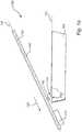
- FIGS 1a , 1b , and 1cillustrate a camera housing arrangement 100.
- the camera housing arrangement 100comprises a camera housing member 102 and a camera housing mounting member 104.
- the camera housing member 102has a bottom side 106 and is extending in a camera housing member extension plane 108.
- the camera housing mounting member 104defines a mounting plane 110.
- the mounting plane 110is arranged for supporting the camera housing member 102 by engagement with the bottom side 106 of the camera housing member 102.
- the camera housing member 100further comprises an abutment 112, and a pivot joint 114.
- the pivot joint 114comprises a hook portion 116 associated with the camera housing member 102 and a pivot axis portion 118 associated with camera housing mounting member 104.
- the camera housing member 102is releasably connectable to the camera housing mounting member 104 by movement of the camera housing member 102 relative the camera housing mounting member 104 in a hooking direction 120 parallel with the camera housing member extension plane 108.
- the hook portion 116may thereby engage the pivot axis portion 118, such that the camera housing member 102 is connected to the camera housing mounting member 104.
- the camera housing member 102is, when connected to the camera housing mounting member 104, movable by means of articulation 122 about the pivot joint 114. More specifically, the movable articulation 122 is between a first end position 124, see Fig.
- the camera housing member 102is movable relative to the camera housing mounting member 104 between a closed end position and an open end position, see Figs. 1b and 1c , respectively.
- the abutment 112is in Figs. 1a to 1c associated with the camera housing member 102.
- the abutment 112is arranged for cooperation with the camera housing mounting member 104 when the camera housing member 102 is in the first end position 124.
- the abutment 112engages the camera housing mounting member 104 in response to movement of the camera housing member 102 relative the camera housing mounting member 104 in an un-hooking direction 128 parallel to the camera housing member extension plane 108 and opposite to said hooking direction 120, see Fig. 1b .
- An advantage of the abutment 112 cooperating with and, in response to movement, engaging with the camera housing mounting member 104is that the abutment prevents disconnection of the camera housing member 102 from the camera housing mounting member 104 when the camera housing member 102 is in the first end position 124.
- the hooking direction 120 and the un-hooking direction 128are defined in relation to the camera housing member extension plane 108.
- the hooking direction 120 and the un-hooking direction 128may therefore vary in directionality in space depending on how the camera housing member extension plane 108 is varied in space as a result of the movement of the camera housing member 102.
- the abutment 112 illustrated in in Figs. 1a to 1cis arranged on the bottom side 106 of the camera housing member 102. It may, however be noted that the abutment may alternatively be associated with the camera housing mounting member and arranged for cooperation with the camera housing member when the camera housing member is in the first end position such that the abutment engages the camera housing member in response to movement thereof.
- the cooperation with the camera housing member when the camera housing member is in the first end positionmay be achieved by the abutment forming a protrusion extending into a recess formed on the bottom side of the camera housing member.
- the abutmentmay be arranged on a side surface or on the bottom side of the camera housing mounting member.
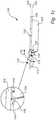
- the camera housing arrangement 100comprises a pivot joint 114 which is arranged such that the articulation 122 shifts between a first pivot axis 118a of the pivot axis portion 118 and a second pivot axis 118b of the pivot axis portion 118 during movement 122 of the camera housing member 102 between the first end position 124 and the second end position 126.
- Figures 2a to 2eillustrate the shift of the articulation 122 in a sequence. In the shown embodiment, the articulation 122 shifts between the first pivot axis 118a to the second pivot axis 118b during movement of the camera housing member 102 from the second end position 126 to the first end position 124.
- the camera housing member 102is illustrated, in the second end position 126.
- the camera housing member 102is releasably connected to the camera housing mounting member 104 by the hook portion 116 engaging the pivot axis portion 118, illustrated by the hook portion 116 extending through an opening 130 in the camera housing mounting member 104.
- Fig. 2afurther illustrates that the camera housing mounting member 104 has a side edge 132 and a top side 134.
- the side edge 132is provided with a shaft portion 136 defining the second pivot axis 118b of the pivot axis portion 118.
- the top side 134is provided with a recessed stepped configuration 138 in a side portion 140 of the top side 134 associated with the side edge 132.
- the recessed stepped configuration 138comprises a top corner edge 142 defining the first pivot axis 118a of the pivot axis portion 118.
- Figures 2b to 2dillustrate later stages of the sequence, showing how the pivot joint 114 allows for a shift in the articulation 122 between a first pivot axis 118a of the pivot axis portion 118 and a second pivot axis 118b of the pivot axis portion 118 during movement of the camera housing member 102 between the first end position 124 and the second end position 126. Play in-between the hook portion 116 and the shaft portion 136 may thereby be mitigated.
- Fig. 2billustrates that the articulation 122 initially occurs around the first pivot axis 118a when the camera housing member 102 is rotated from the second end position 126 towards the first end position 124.
- Figures 2c and 2dfurther illustrate when the camera housing member 102 is arranged, relative to the camera housing member 104, in two intermediate positions 127 and 129, between which the articulation 122 shifts from the first pivot axis 118a to the second pivot axis 118b, c.f. Figs. 2c and 2d .
- Fig. 2eillustrates the camera housing member 102 when it is completely rotated 122 to the first end position 124.
- Figures 3 to 5illustrate schematically a camera housing arrangement 100 in different perspective views.
- Figure 3illustrates the camera housing arrangement 100 in an intermediate state 131 of the movement from the second end position 126 to the first end position 124.
- the camera housing arrangement 100 of Fig. 3comprises a camera housing member 102 and a camera housing mounting member 104, as described above.
- the camera housing mounting member 104is attached to a mount 200.
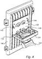
- Figures 4 and 5illustrate the same camera housing arrangement 100 in the first end position 124 and the second end position 126, respectively.
- the camera housing member 102has been releasably connected to the camera housing mounting member 104 by a relative movement of the camera housing member 102 and the camera housing mounting member 104, i.e. a movement in a hooking direction 120 parallel with the camera housing member extension plane 108 by which the hook portion 116 engages the pivot axis portion 118.
- Figures 3 and 4further illustrate that the camera housing arrangement 100 may comprise a cable interface 144 arranged in the bottom side 106 of the camera housing member 102. Access to the cable interface 144 is thereby provided when the camera housing member 102 is in the intermediate state 131.
- the cable interface 144comprises an opening.
- a grommet 145is further arranged in the opening.
- Access to the cable interface 144may also be provided when the camera housing member 102 is in the first end position 124, see Fig. 4 . Improved access to the cable interface 144 is thereby provided for during installation and or maintenance of the camera housing arrangement 100.
- the camera housing member 102may comprise an overhang portion 146, see Figs. 3 or 4 , in the proximity of the pivot joint, wherein the centre of mass of the camera housing member 102 is associated with the overhang portion 146.
- gravitywill cause, the camera housing member 102 to pivot towards or to the first end position 124, or at least reduce the force needed for pivoting.
- a simplified handling of the camera housing arrangement 100is thereby provided for installation or maintenance personnel.
- the camera housing member 104may further comprise camera means 148 arranged at least partly in the overhang portion 146, see Figs. 3 and 4 .
- the centre of mass of the camera housing member 102is thereby associated with the overhang portion 146.
- the weight of the camera means 148may thereby cause, or at least reduce the force needed to move, the camera housing member 102, when connected to the camera housing mounting member 104, to pivot to the first end position 124.
- Figure 4further illustrates that the bottom side 106 of the camera housing member 102 may be arranged to engage with a side edge 132 of the camera housing mounting member 104 in the first end position 124, thereby defining the first end position 124.
- a side edge 132 of the camera housing mounting member 104for clarity, such an engagement is also illustrated in Figs. 1b or 2e .
- the forces on the hook portion 116 and/or the pivot axis portion 118may thereby be reduced.
- Figures 3 and 4further illustrate that the abutment 112 may be arranged in the overhang portion 146 on the bottom side 106 of the camera housing member 102 at a distance from the pivot joint 114, the distance being sufficient for allowing the camera housing member 102 to assume the first end position 124 without the abutment 112 engaging the camera housing mounting member 104.
- Thisis advantageous as the gravity drives the camera housing member 102 to a position, i.e. the first position 124, where the abutment engages the camera housing mounting member 104 response to the relative motion.
- a "self-locking" of the two members 102, 104 of the camera housing arrangement 100may thereby be obtained.
- the camera housing member 100 illustrated in figures 3 and 4further comprise abutments 112 in the form of cooling fins 113.
- Figure 5illustrates the same camera housing arrangement 100 as in Figs 3 and 4 , but being set in the second end position 126.
- the cable interface 124may in the second end position 126 be arranged within a space 150 defined by the bottom side 106 of the camera housing member 102 and the camera housing mounting member 104.
- FIG. 6illustrates the same camera housing arrangement 100 as in Figs. 3 to 5 , but when the camera housing member is in the first end position 124, i.e. in a different view from that illustrated in Fig. 4 .
- the pivot jointmay comprise a hook portion associated with the camera housing mounting member and a pivot axis portion associated with camera housing member.
- the abutmentmay alternatively be associated with the camera housing mounting member and arranged for cooperation with the camera housing member when the camera housing member is in said first end position such that the abutment engages the camera housing mounting member.
Landscapes
- Physics & Mathematics (AREA)
- General Physics & Mathematics (AREA)
- Engineering & Computer Science (AREA)
- Multimedia (AREA)
- Signal Processing (AREA)
- Aviation & Aerospace Engineering (AREA)
- Accessories Of Cameras (AREA)
- Studio Devices (AREA)
Description
- The present invention relates to a camera housing arrangement.
- Surveillance cameras are commonly used to monitor objects or people within an area of surveillance by producing streams of video images that may be displayed to and/or recorded for use by security personnel. To obtain a clear view of the area of surveillance, the surveillance cameras are often mounted many meters off the ground, to a wall, to a post structure or to a ceiling structure. This complicates the installation procedure for an installer of the surveillance camera and also makes the maintenance harder to perform.
EP 0 285 922 A2- To this end, the installation or maintenance personnel may need a scaffold or a ladder further complicating the handling of the surveillance camera.
- Thus, there is a need for surveillance cameras that are simple to install. More specifically, there is a need to provide camera housing arrangements for surveillance cameras which may efficiently be installed and handled by installation and maintenance personnel.
- In view of the above, it is an object of the present invention to provide a camera housing arrangement allowing for efficient installation and/or handling. A further object is to prevent accidental disassembly of the camera housing arrangement which may damage the camera housing arrangement or a part thereof during installation or maintenance.
- According to a first aspect, a camera housing arrangement is provided, the camera housing arrangement comprising a camera housing member having a bottom side and extending in a camera housing member extension plane,
a camera housing mounting member defining a mounting plane and arranged for supporting the camera housing member by engagement with the bottom side of the camera housing member, an abutment, and a pivot joint arranged at a distance from the abutment, the pivot joint comprising an abutment, and a hook portion associated with one of the camera housing member and the camera housing mounting member and
a pivot axis portion associated with the other of the camera housing member and the camera housing mounting member,
wherein the camera housing member is releasably connectable to the camera housing mounting member by movement of the camera housing member relative the camera housing mounting member in a hooking direction parallel with the camera housing member extension plane such that the hook portion engages the pivot axis portion,
wherein the camera housing member, in a state connected to the camera housing mounting member, is movable by means of articulation about the pivot joint between
a first end position in which the camera housing member extension plane is tilted with respect to said mounting plane, and
a second end position in which the camera housing member extension plane is aligned with said mounting plane, and
the abutment being associated with one of the camera housing member and the camera housing mounting member and arranged for cooperation with the other of the camera housing mounting member and the camera housing member when the camera housing member is in said first end position such that the abutment engages the camera housing mounting member or the camera housing member, and thereby prevents disconnection of the camera housing member from the camera housing mounting member, in response to movement of the camera housing member relative the camera housing mounting member in an un-hooking direction parallel to the camera housing member extension plane and opposite to said hooking direction. - An advantage is that a camera housing arrangement is provided which allows for improved handling during installation and/or maintenance.
- The hook portion and the pivot axis portion provide a releasable connection between the camera housing member and the camera housing mounting member. The camera housing arrangement may thereby be assembled in a simpler manner.
- Installation and maintenance personnel may also get access to the different parts of the camera housing member in a simple and safe manner.
- In more detail, the installer may releasably connect the camera housing member by engaging the hook portion to the pivot axis portion by a movement of the camera housing member relative the camera housing mounting member in a hooking direction parallel with the camera housing member extension plane.
- It may be noted that the hooking direction is defined in relation to the camera housing member extension plane and thus may vary in space depending on the orientation of the camera housing member extension plane in space.
- The camera housing member may further be attached to the camera housing mounting member after the latter is mounted to a mount, for example, being attached to a wall or a post. The installation of the camera housing arrangement may thereby be performed in a sequence of steps reducing the load for the installer.
- The articulation about the pivot joint further allows for a relative movement of the camera housing member and the camera housing mounting member when the camera housing arrangement is in the connected state. In other words, the camera housing member may be tilted in respect to the camera housing mounting member. Access to the bottom side of the camera housing member may, for example, be provided for the installer or maintenance personnel.
- An advantage of the abutment cooperating with and engaging the camera housing mounting member or the camera housing member, is that the abutment prevents disconnection of the camera housing member from the camera housing mounting member when the camera housing member is in the first end position.
- Accidental disconnection of the camera housing member and the camera housing mounting member during installation and/or maintenance is therefore prevented. In more detail, the camera housing arrangement allows the installation or maintenance personnel to rotate the camera housing member to the first end position at which the abutment may engage the camera housing mounting member or the camera housing member in response to relative motion therebetween. Any accidental disconnection due to movement of the camera housing member relative to the camera housing mounting member is in that way prevented in the first end position.
- More specifically, the abutment cooperating with and engaging the camera housing mounting member or the camera housing member in response to movement of the camera housing member relative the camera housing mounting member in an un-hooking direction parallel to the camera housing member extension plane and opposite to said hooking direction prevents disconnection of the camera housing member from the camera housing mounting member.
- An advantage is that forces exerted on the hooking portion and/or the pivot portion are reduced for movements along the un-hooking direction. Hence, a simpler and less robust design of the hooking portion and/or the pivot portion may be used reducing the costs for manufacturing the camera housing arrangement. As a result the hooking portion may be chosen with larger flexibility.
- The installation or maintenance personnel may, when the pivot joint is in the first position, let go of the camera housing member. At least one hand of the personnel is thereby freed improving handling of the camera housing arrangement. Under the condition that the camera housing mounting member is fixed to a mount, both hands may be freed when the pivot joint is in the first position.
- It should be noted that in this application the hooking and un-hooking direction are to be understood to be defined relative to the camera housing member extension plane and being parallel to the camera housing member extension plane. Thus, also the un-hooking direction may vary in space depending on the orientation of the camera housing member extension plane in space as will be discussed below.
- The abutment may be arranged on the bottom side of the camera housing member.
- The pivot joint may be arranged such that the articulation shifts between a first pivot axis of the pivot axis portion and a second pivot axis of the pivot axis portion during movement of the camera housing member between the first end position and the second end position.
- The pivot axis portion may be associated with the camera housing mounting member, wherein the camera housing mounting member has a side edge provided with a shaft portion defining a second pivot axis of the pivot axis portion, wherein the camera housing mounting member has a top side provided with a recessed stepped configuration in a side portion of the top side associated with said side edge, the recessed stepped configuration comprises a top corner edge defining a first pivot axis of the pivot axis portion.
- A more well controlled pivot motion may thereby be obtained. The shaft portion may be arranged to receive the hook portion, and play in-between the hook portion and shaft portion may be mitigated by means of the shift of articulation between the first axis portion and the second pivot axis. Constraints on the fabrication of the hook portion and/or the pivot axis portion are further reduced. A more cost effective fabrication of the camera housing arrangement may thus be achieved.
- The camera housing arrangement may further comprise a cable interface arranged in the bottom side of the camera housing member and access to the cable interface may be provided when the camera housing member is in the first end position. Improved access to the cable interface is thereby provided for during installation and or maintenance of the camera housing arrangement.
- The wording cable interface may be construed as a portion of the camera housing member through which a cable may be inserted or connected. The cable interface should therefore be interpreted broadly Mechanical and or electrical access to the interior of the camera housing member may thereby be provided. Powering of and data transmission to/from electrical components arranged within the camera housing member, such as a video camera may thereby be realized.
- The cable interface may, for example, be an opening with or without a grommet. The cable interface may alternatively comprise a cable connector such as an electrical connector or a fluid connector.
- The cable interface may, in the second end position, be arranged within a space defined by the bottom side of the camera housing member and the camera housing mounting member.
- An advantage is that the cable interface is protected within the defined space. The cable interface may thereby be protected from the environment surrounding the camera housing arrangement. Unauthorized tampering with cables may also be hampered. A less complex cable interface may further be used as it is protected within the space.
- The camera housing member may comprise an overhang portion in the proximity of the pivot joint, wherein the centre of mass of the camera housing member is associated with said overhang portion.
- As a result, gravity will cause, or at least reduce the force needed to move, the camera housing member, when connected to the camera housing mounting member, to pivot to the first end position. A simplified handling of the camera housing arrangement is thereby provided for installation or maintenance personnel. Gravity also drives the camera housing member to a position, i.e. the first position, where the abutment engages the camera housing mounting member or the camera housing member in response to the relative motion. A "self-locking" of the two members of the camera housing arrangement may thereby be obtained. Accidental disconnection of the camera housing member from the camera housing mounting member is further prevented.
- The camera housing member may comprise an overhang portion in the proximity of the pivot joint and camera means arranged at least partly in said overhang portion, wherein the centre of mass of the camera housing member is associated with said overhang portion.
- The weight of the camera means may thereby cause, or at least reduce the force needed to move, the camera housing member, when connected to the camera housing mounting member, to pivot to the first end position. The installation or maintenance personnel may thereby to rotate the camera housing member to the first end position at which the abutment engages the camera housing mounting member or the camera housing member in response to relative motion. Access to the bottom side of the camera housing member may be provided simplifying the connecting of the camera through for instance the cable interface discussed above.
- The bottom side of the camera housing member may be arranged to engage with a side edge of the camera housing mounting member in said first end position, thereby defining the first end position.
- A well-defined first end position is thereby achieved. The forces on the hook portion and/or the pivot axis portion may further be reduced. A simpler construction of the hook portion and/or the pivot axis portion may therefore be used when forming the camera housing arrangement.
- The camera housing member may comprise an overhang portion in the proximity of the pivot joint and wherein the abutment is arranged in the overhang portion on the bottom side of the camera housing member at a distance from the pivot joint, the distance being sufficient for allowing the camera housing member to assume the first end position without the abutment engaging the camera housing mounting member.
- The center of mass may be understood as a single point in space representing a distribution of mass in space, i.e. the mean location of a distribution of mass in space. The wording associated with said overhang portion should therefore be interpreted broadly. The centre of mass may geometrically be represented by a point inside or outside the material forming the overhang portion, i.e. the portion projecting away from the pivot joint, or by a point outside the material.
- The abutment may be formed by a cooling fin.
- The abutment formed by the cooling fin may be arranged on the camera housing member.
- A further scope of applicability of the present invention will become apparent from the detailed description given below. However, it should be understood that the detailed description and specific examples, while indicating preferred embodiments of the invention, are given by way of illustration only, since various changes and modifications within the scope of the invention will become apparent to those skilled in the art from this detailed description.
- Hence, it is to be understood that this invention is not limited to the particular component parts of the device described or steps of the methods described as such device and method may vary. It is also to be understood that the terminology used herein is for purpose of describing particular embodiments only, and is not intended to be limiting. It must be noted that, as used in the specification and the appended claim, the articles "a," "an," "the," and "said" are intended to mean that there are one or more of the elements unless the context clearly dictates otherwise. Thus, for example, reference to "a unit" or "the unit" may include several devices, and the like. Furthermore, the words "comprising", "including", "containing" and similar wordings do not exclude other elements or steps.
- The above and other aspects of the present invention will now be described in more detail, with reference to appended drawings showing embodiments of the invention. The figures should not be considered limiting the invention to the specific embodiment; instead they are used for explaining and understanding the invention.
- As illustrated in the figures, the sizes of layers and regions are exaggerated for illustrative purposes and, thus, are provided to illustrate the general structures of embodiments of the present invention. Like reference numerals refer to like elements throughout.
Figs. 1a to 1c illustrate a camera housing arrangement.Figs. 2a to 2e illustrate a camera housing arrangement.Fig. 3 illustrates a perspective view of a camera housing arrangement.Fig. 4 illustrates a perspective view of a camera housing arrangement.Fig. 5 illustrates a side view of camera a housing arrangement.Fig. 6 illustrates a side view of a camera housing arrangement.- The present invention will now be described more fully hereinafter with reference to the accompanying drawings, in which currently preferred embodiments of the invention are shown. This invention may, however, be embodied in many different forms and should not be construed as limited to the embodiments set forth herein; rather, these embodiments are provided for thoroughness and completeness, and to fully convey the scope of the invention to the skilled person.
Figures 1a ,1b , and1c illustrate acamera housing arrangement 100. Thecamera housing arrangement 100 comprises acamera housing member 102 and a camerahousing mounting member 104. Thecamera housing member 102 has abottom side 106 and is extending in a camera housingmember extension plane 108. The camerahousing mounting member 104 defines a mountingplane 110. The mountingplane 110 is arranged for supporting thecamera housing member 102 by engagement with thebottom side 106 of thecamera housing member 102.- The
camera housing member 100 further comprises anabutment 112, and apivot joint 114. The pivot joint 114 comprises ahook portion 116 associated with thecamera housing member 102 and apivot axis portion 118 associated with camerahousing mounting member 104. - Referring to
Fig. 1a , thecamera housing member 102 is releasably connectable to the camerahousing mounting member 104 by movement of thecamera housing member 102 relative the camerahousing mounting member 104 in a hookingdirection 120 parallel with the camera housingmember extension plane 108. Thehook portion 116 may thereby engage thepivot axis portion 118, such that thecamera housing member 102 is connected to the camerahousing mounting member 104. Thecamera housing member 102 is, when connected to the camerahousing mounting member 104, movable by means ofarticulation 122 about thepivot joint 114. More specifically, themovable articulation 122 is between afirst end position 124, seeFig. 1b , in which the camera housingmember extension plane 108 is tilted with respect to said mountingplane 110, and asecond end position 126 in which the camera housingmember extension plane 108 is aligned with said mountingplane 110, seeFig. 1c . In other words, thecamera housing member 102 is movable relative to the camerahousing mounting member 104 between a closed end position and an open end position, seeFigs. 1b and1c , respectively. - The
abutment 112 is inFigs. 1a to 1c associated with thecamera housing member 102. Theabutment 112 is arranged for cooperation with the camerahousing mounting member 104 when thecamera housing member 102 is in thefirst end position 124. As a result, theabutment 112 engages the camerahousing mounting member 104 in response to movement of thecamera housing member 102 relative the camerahousing mounting member 104 in anun-hooking direction 128 parallel to the camera housingmember extension plane 108 and opposite to said hookingdirection 120, seeFig. 1b . - An advantage of the
abutment 112 cooperating with and, in response to movement, engaging with the camerahousing mounting member 104 is that the abutment prevents disconnection of thecamera housing member 102 from the camerahousing mounting member 104 when thecamera housing member 102 is in thefirst end position 124. - Accidental disconnection of the
camera housing member 102 and the camerahousing mounting member 104 during installation and/or maintenance is therefore prevented. - It may be noted that the hooking
direction 120 and theun-hooking direction 128 are defined in relation to the camera housingmember extension plane 108. The hookingdirection 120 and theun-hooking direction 128 may therefore vary in directionality in space depending on how the camera housingmember extension plane 108 is varied in space as a result of the movement of thecamera housing member 102. - The
abutment 112 illustrated in inFigs. 1a to 1c is arranged on thebottom side 106 of thecamera housing member 102. It may, however be noted that the abutment may alternatively be associated with the camera housing mounting member and arranged for cooperation with the camera housing member when the camera housing member is in the first end position such that the abutment engages the camera housing member in response to movement thereof. - As an example, the cooperation with the camera housing member when the camera housing member is in the first end position may be achieved by the abutment forming a protrusion extending into a recess formed on the bottom side of the camera housing member. Thus, the abutment may be arranged on a side surface or on the bottom side of the camera housing mounting member.
- In the following, a
camera housing arrangement 100 will be described for which thearticulation 122 shifts in position during movement of thecamera housing member 102 between thefirst end position 124 and thesecond end position 126. The shift ofarticulation 122 allows for a more well defined pivot motion. In more detail, thecamera housing arrangement 100 comprises a pivot joint 114 which is arranged such that thearticulation 122 shifts between afirst pivot axis 118a of thepivot axis portion 118 and asecond pivot axis 118b of thepivot axis portion 118 duringmovement 122 of thecamera housing member 102 between thefirst end position 124 and thesecond end position 126.Figures 2a to 2e illustrate the shift of thearticulation 122 in a sequence. In the shown embodiment, thearticulation 122 shifts between thefirst pivot axis 118a to thesecond pivot axis 118b during movement of thecamera housing member 102 from thesecond end position 126 to thefirst end position 124. - In a first state of the sequence, see
Fig. 2a , thecamera housing member 102 is illustrated, in thesecond end position 126. Thecamera housing member 102 is releasably connected to the camerahousing mounting member 104 by thehook portion 116 engaging thepivot axis portion 118, illustrated by thehook portion 116 extending through anopening 130 in the camerahousing mounting member 104.Fig. 2a further illustrates that the camerahousing mounting member 104 has aside edge 132 and atop side 134. Theside edge 132 is provided with ashaft portion 136 defining thesecond pivot axis 118b of thepivot axis portion 118. Thetop side 134 is provided with a recessed steppedconfiguration 138 in aside portion 140 of thetop side 134 associated with theside edge 132. The recessed steppedconfiguration 138 comprises atop corner edge 142 defining thefirst pivot axis 118a of thepivot axis portion 118. Figures 2b to 2d illustrate later stages of the sequence, showing how the pivot joint 114 allows for a shift in thearticulation 122 between afirst pivot axis 118a of thepivot axis portion 118 and asecond pivot axis 118b of thepivot axis portion 118 during movement of thecamera housing member 102 between thefirst end position 124 and thesecond end position 126. Play in-between thehook portion 116 and theshaft portion 136 may thereby be mitigated.- In more detail,
Fig. 2b illustrates that thearticulation 122 initially occurs around thefirst pivot axis 118a when thecamera housing member 102 is rotated from thesecond end position 126 towards thefirst end position 124.Figures 2c and 2d further illustrate when thecamera housing member 102 is arranged, relative to thecamera housing member 104, in twointermediate positions articulation 122 shifts from thefirst pivot axis 118a to thesecond pivot axis 118b, c.f.Figs. 2c and 2d . - In other words, in the intermediate state 127 a rotation around the
first pivot axis 118a is achieved whereas in the intermediate state 129 a rotation around thesecond pivot axis 118b is achieved. - Finally,
Fig. 2e illustrates thecamera housing member 102 when it is completely rotated 122 to thefirst end position 124. Figures 3 to 5 illustrate schematically acamera housing arrangement 100 in different perspective views.Figure 3 illustrates thecamera housing arrangement 100 in anintermediate state 131 of the movement from thesecond end position 126 to thefirst end position 124. Thecamera housing arrangement 100 ofFig. 3 comprises acamera housing member 102 and a camerahousing mounting member 104, as described above. The camerahousing mounting member 104 is attached to amount 200.Figures 4 and5 illustrate the samecamera housing arrangement 100 in thefirst end position 124 and thesecond end position 126, respectively.- As also discussed above, the
camera housing member 102 has been releasably connected to the camerahousing mounting member 104 by a relative movement of thecamera housing member 102 and the camerahousing mounting member 104, i.e. a movement in a hookingdirection 120 parallel with the camera housingmember extension plane 108 by which thehook portion 116 engages thepivot axis portion 118. Figures 3 and4 further illustrate that thecamera housing arrangement 100 may comprise acable interface 144 arranged in thebottom side 106 of thecamera housing member 102. Access to thecable interface 144 is thereby provided when thecamera housing member 102 is in theintermediate state 131. As a non-limiting example thecable interface 144 comprises an opening. Agrommet 145 is further arranged in the opening.- Access to the
cable interface 144 may also be provided when thecamera housing member 102 is in thefirst end position 124, seeFig. 4 . Improved access to thecable interface 144 is thereby provided for during installation and or maintenance of thecamera housing arrangement 100. - The
camera housing member 102 may comprise anoverhang portion 146, seeFigs. 3 or4 , in the proximity of the pivot joint, wherein the centre of mass of thecamera housing member 102 is associated with theoverhang portion 146. As a result, gravity will cause, thecamera housing member 102 to pivot towards or to thefirst end position 124, or at least reduce the force needed for pivoting. A simplified handling of thecamera housing arrangement 100 is thereby provided for installation or maintenance personnel. - The
camera housing member 104 may further comprise camera means 148 arranged at least partly in theoverhang portion 146, seeFigs. 3 and4 . The centre of mass of thecamera housing member 102 is thereby associated with theoverhang portion 146. The weight of the camera means 148 may thereby cause, or at least reduce the force needed to move, thecamera housing member 102, when connected to the camerahousing mounting member 104, to pivot to thefirst end position 124. Figure 4 further illustrates that thebottom side 106 of thecamera housing member 102 may be arranged to engage with aside edge 132 of the camerahousing mounting member 104 in thefirst end position 124, thereby defining thefirst end position 124. For clarity, such an engagement is also illustrated inFigs. 1b or2e . The forces on thehook portion 116 and/or thepivot axis portion 118 may thereby be reduced.Figures 3 and4 further illustrate that theabutment 112 may be arranged in theoverhang portion 146 on thebottom side 106 of thecamera housing member 102 at a distance from the pivot joint 114, the distance being sufficient for allowing thecamera housing member 102 to assume thefirst end position 124 without theabutment 112 engaging the camera housing mounting member 104.This is advantageous as the gravity drives thecamera housing member 102 to a position, i.e. thefirst position 124, where the abutment engages the camerahousing mounting member 104 response to the relative motion. A "self-locking" of the twomembers camera housing arrangement 100 may thereby be obtained.- The
camera housing member 100 illustrated infigures 3 and4 further compriseabutments 112 in the form of coolingfins 113. Figure 5 illustrates the samecamera housing arrangement 100 as inFigs 3 and4 , but being set in thesecond end position 126. Infigure 5 , thecable interface 124 may in thesecond end position 126 be arranged within aspace 150 defined by thebottom side 106 of thecamera housing member 102 and the camerahousing mounting member 104. An advantage is that the cable interface is protected within the definedspace 150.- For completeness,
Fig. 6 illustrates the samecamera housing arrangement 100 as inFigs. 3 to 5 , but when the camera housing member is in thefirst end position 124, i.e. in a different view from that illustrated inFig. 4 . - The person skilled in the art realizes that the present invention by no means is limited to the preferred embodiments described above. On the contrary, many modifications and variations are possible within the scope of the appended claims.
- For example, as an alternative to the description above, the pivot joint may comprise a hook portion associated with the camera housing mounting member and a pivot axis portion associated with camera housing member.
- Similarly, the abutment may alternatively be associated with the camera housing mounting member and arranged for cooperation with the camera housing member when the camera housing member is in said first end position such that the abutment engages the camera housing mounting member.
- Additionally, variations to the disclosed embodiments can be understood and effected by the skilled person in practicing the claimed invention, from a study of the drawings, the disclosure, and the appended claims.
Claims (11)
- Camera housing arrangement (100), comprising a camera housing member (102) having a bottom side (106) and extending in a camera housing member extension plane (108),
a camera housing mounting member (104) defining a mounting plane (110) and arranged for supporting the camera housing member (102) by engagement with the bottom side (106) of the camera housing member (102),
an abutment (112), c h a ra cte r i zed i n
a pivot joint (114) arranged at a distance from the abutment (112), the pivot joint (112) comprising:a hook portion (116) associated with one of the camera housing member (102) and the camera housing mounting member (104) anda pivot axis portion (118) associated with the other of the camera housing member (102) and the camera housing mounting member (104),wherein the camera housing member (102) is releasably connectable to the camera housing mounting member (104) by movement of the camera housing member (102) relative the camera housing mounting member (104) in a hooking direction (120) parallel with the camera housing member extension plane (108) such that the hook portion (116) engages the pivot axis portion (118),wherein the camera housing member (102), in a state connected to the camera housing mounting member (104), is movable by means of articulation (122) about the pivot joint (114) betweena first end position (124) in which the camera housing member extension plane (108) is tilted with respect to said mounting plane (110), anda second end position (126) in which the camera housing member extension plane (108) is aligned with said mounting plane (110), andthe abutment (112) being associated with one of the camera housing member (102) and the camera housing mounting member (104) and arranged for cooperation with the other of the camera housing mounting member (104) and the camera housing member (102) when the camera housing member (102) is in said first end position (124) such that the abutment (112) engages the camera housing mounting member (104) or the camera housing member (102), and thereby prevents disconnection of the camera housing member (102) from the camera housing mounting member (104), in response to movement of the camera housing member (102) relative the camera housing mounting member (104) in an un-hooking direction (128) parallel to the camera housing member extension plane (108) and opposite to said hooking direction (120). - The camera housing member according to claim 1, wherein the abutment (112) is arranged on the bottom side (106) of the camera housing member (102).
- The camera housing arrangement according to claim 1 or 2, wherein the pivot joint (114) is arranged such that the articulation shifts between a first pivot axis (118a) of the pivot axis portion (118) and a second pivot axis (118b) of the pivot axis portion (118) during movement of the camera housing member (102) between the first end position (124) and the second end position (126).
- The camera housing arrangement according to claim 3, wherein the pivot axis portion (118) is associated with the camera housing mounting member (104),
wherein the camera housing mounting member (104) has a side edge (132) provided with a shaft portion (136) defining a second pivot axis (118b) of the pivot axis portion (118),
wherein the camera housing mounting member (104) has a top side (134) provided with a recessed stepped configuration (138) in a side portion (140) of the top side (134) associated with said side edge (132),
the recessed stepped configuration (138) comprises a top corner edge (142) defining a first pivot axis (118a) of the pivot axis portion (118). - The camera housing arrangement according to any one of claims 1 to 4, wherein the camera housing arrangement (102) further comprises a cable interface (144) arranged in the bottom side (106) of the camera housing member (102) and wherein access to the cable interface (144) is provided when the camera housing member (102) is in the first end position (124).
- The camera housing arrangement according to claim 5, wherein the cable interface (144) in the second end position (126) is arranged within a space (150) defined by the bottom side (106) of the camera housing member (102) and the camera housing mounting member (104).
- The camera housing arrangement according to any one of claims 1 to 6, wherein the camera housing member (102) comprises an overhang portion (146) in the proximity of the pivot joint (114), wherein the centre of mass of the camera housing member (102) is associated with said overhang portion (146).
- The camera housing arrangement according to any one of claims 1 to 6, wherein the camera housing member (102) comprises an overhang portion (146) in the proximity of the pivot joint (114) and camera means (148) arranged at least partly in said overhang portion (146), wherein the centre of mass of the camera housing member (102) is associated with said overhang portion (146).
- The camera housing arrangement according to any one of claims 1 to 8, wherein the bottom side (106) of the camera housing member (102) is arranged to engage with a side edge (132) of the camera housing mounting member (104) in said first end position (124), thereby defining the first end position (124).
- The camera housing arrangement according to any one of claims 1 to 9, wherein the camera housing member (102) comprises an overhang portion (146) in the proximity of the pivot joint (114) and wherein the abutment (112) is arranged in the overhang portion (146) on the bottom side (106) of the camera housing member (102) at a distance from the pivot joint (114), the distance being sufficient for allowing the camera housing member (102) to assume the first end position (124) without the abutment (112) engaging the camera housing mounting member (104).
- The camera housing arrangement according to any one of claims 1 to 10, wherein the abutment (112) is formed by a cooling fin (113).
Priority Applications (6)
| Application Number | Priority Date | Filing Date | Title |
|---|---|---|---|
| EP17167747.9AEP3396939B1 (en) | 2017-04-24 | 2017-04-24 | Camera housing and camera mount arrangement |
| JP2018052305AJP6553764B2 (en) | 2017-04-24 | 2018-03-20 | Camera housing configuration |
| KR1020180033700AKR102051210B1 (en) | 2017-04-24 | 2018-03-23 | Camera housing arrangement |
| TW107111744ATWI686659B (en) | 2017-04-24 | 2018-04-03 | Camera housing device |
| CN201810336632.3ACN108737697B (en) | 2017-04-24 | 2018-04-16 | Camera casing device |
| US15/960,012US10447938B2 (en) | 2017-04-24 | 2018-04-23 | Camera housing arrangement |
Applications Claiming Priority (1)
| Application Number | Priority Date | Filing Date | Title |
|---|---|---|---|
| EP17167747.9AEP3396939B1 (en) | 2017-04-24 | 2017-04-24 | Camera housing and camera mount arrangement |
Publications (2)
| Publication Number | Publication Date |
|---|---|
| EP3396939A1 EP3396939A1 (en) | 2018-10-31 |
| EP3396939B1true EP3396939B1 (en) | 2019-08-14 |
Family
ID=58644859
Family Applications (1)
| Application Number | Title | Priority Date | Filing Date |
|---|---|---|---|
| EP17167747.9AActiveEP3396939B1 (en) | 2017-04-24 | 2017-04-24 | Camera housing and camera mount arrangement |
Country Status (6)
| Country | Link |
|---|---|
| US (1) | US10447938B2 (en) |
| EP (1) | EP3396939B1 (en) |
| JP (1) | JP6553764B2 (en) |
| KR (1) | KR102051210B1 (en) |
| CN (1) | CN108737697B (en) |
| TW (1) | TWI686659B (en) |
Families Citing this family (3)
| Publication number | Priority date | Publication date | Assignee | Title |
|---|---|---|---|---|
| US11609485B2 (en)* | 2020-03-09 | 2023-03-21 | Johnson Controls Tyco IP Holdings LLP | Modular camera mounts usable with security camera applications |
| US11622166B2 (en) | 2021-07-23 | 2023-04-04 | Robert Bosch Gmbh | Camera assembly and method for assembling |
| JP7681308B2 (en)* | 2021-09-27 | 2025-05-22 | i-PRO株式会社 | Camera device and method for mounting the camera device |
Family Cites Families (17)
| Publication number | Priority date | Publication date | Assignee | Title |
|---|---|---|---|---|
| IT1214304B (en)* | 1987-04-06 | 1990-01-10 | Tekno System Srl | CAMERA CASE. |
| DE4400475C1 (en)* | 1994-01-11 | 1994-12-15 | Hartig E Videor Tech | Protective housing for optical appliances |
| DE50000716D1 (en)* | 1999-09-08 | 2002-12-12 | Boudard Pierre Olivier | camera plate |
| AU2001243285A1 (en) | 2000-03-02 | 2001-09-12 | Donnelly Corporation | Video mirror systems incorporating an accessory module |
| JP2003219121A (en)* | 2002-01-18 | 2003-07-31 | Matsushita Electric Ind Co Ltd | Scanner for portable information terminal |
| WO2003065084A1 (en) | 2002-01-31 | 2003-08-07 | Donnelly Corporation | Vehicle accessory module |
| WO2004103772A2 (en)* | 2003-05-19 | 2004-12-02 | Donnelly Corporation | Mirror assembly for vehicle |
| JP4445322B2 (en)* | 2004-05-07 | 2010-04-07 | パナソニック株式会社 | Camera mounting device |
| US7857527B2 (en)* | 2008-09-12 | 2010-12-28 | Pelco, Inc. | Hinged camera sled |
| US20100239241A1 (en) | 2009-03-23 | 2010-09-23 | Chains Technology Co., Ltd. | Surveillance camera mounting structure |
| GB201202699D0 (en) | 2012-02-16 | 2012-04-04 | Overview Ltd | Camera housing |
| JP5946295B2 (en)* | 2012-03-08 | 2016-07-06 | 本田技研工業株式会社 | Camera unit |
| CN104125376A (en)* | 2013-04-28 | 2014-10-29 | 派尔高公司 | Monitoring camera possessing integrated installation characteristic |
| EP2801744B1 (en)* | 2013-05-07 | 2016-12-14 | Axis AB | Mount for a wired device |
| US20140334058A1 (en)* | 2013-05-13 | 2014-11-13 | David W. Galvan | Automated and remotely operated stun gun with integrated camera and laser sight |
| EP3179149B1 (en)* | 2015-12-10 | 2017-11-01 | Axis AB | A mounting bracket for mounting a monitoring camera |
| US10248008B2 (en)* | 2016-01-14 | 2019-04-02 | Avigilon Corporation | Removable hinge |
- 2017
- 2017-04-24EPEP17167747.9Apatent/EP3396939B1/enactiveActive
- 2018
- 2018-03-20JPJP2018052305Apatent/JP6553764B2/enactiveActive
- 2018-03-23KRKR1020180033700Apatent/KR102051210B1/enactiveActive
- 2018-04-03TWTW107111744Apatent/TWI686659B/enactive
- 2018-04-16CNCN201810336632.3Apatent/CN108737697B/enactiveActive
- 2018-04-23USUS15/960,012patent/US10447938B2/enactiveActive
Non-Patent Citations (1)
| Title |
|---|
| None* |
Also Published As
| Publication number | Publication date |
|---|---|
| CN108737697A (en) | 2018-11-02 |
| EP3396939A1 (en) | 2018-10-31 |
| JP2019032504A (en) | 2019-02-28 |
| CN108737697B (en) | 2020-03-17 |
| TWI686659B (en) | 2020-03-01 |
| TW201842394A (en) | 2018-12-01 |
| US20180309934A1 (en) | 2018-10-25 |
| KR20180119103A (en) | 2018-11-01 |
| KR102051210B1 (en) | 2019-12-02 |
| US10447938B2 (en) | 2019-10-15 |
| JP6553764B2 (en) | 2019-07-31 |
Similar Documents
| Publication | Publication Date | Title |
|---|---|---|
| US10447938B2 (en) | Camera housing arrangement | |
| EP3220036A1 (en) | A ball joint | |
| EP2801744B1 (en) | Mount for a wired device | |
| US9022339B2 (en) | Cabling for central axis pendant system | |
| US20080008467A1 (en) | Omni-directional surveillance network video camera | |
| US7704016B2 (en) | Subsea docking system for electronic modules in subsea installations | |
| CN110762357A (en) | Reinforcing arm, vertical stabilization mechanism and pan/tilt device | |
| US20200315042A1 (en) | Bracket Assembly and Method for Mounting Electrical Equipment In Between a Monitor and a Supporting Structure | |
| US7888609B2 (en) | Mounting assembly | |
| KR100802236B1 (en) | Security camera | |
| CN111786353A (en) | an integrated mount | |
| US20080168808A1 (en) | Device for Locking a Cover of a Manhole Top, and Manhole Top | |
| CN106051398B (en) | Coupling device, carrying arm and holding rod for coupling accessory to carrying arm | |
| CN215764057U (en) | Camera pan-tilt and camera pan-tilt system | |
| JP5718295B2 (en) | Ceiling mounted sensor | |
| CN215111668U (en) | Rotation connection structure, monitoring device and crane | |
| US20250037555A1 (en) | Pan-tilt-zoom camera for omni-directional 360-degree-detection and 360-degree surveillance method | |
| JP7602384B2 (en) | Camera equipment mounting box | |
| JP2009130668A (en) | Surveillance camera | |
| JP2025000070A (en) | Security tool | |
| CA2299830A1 (en) | Hinge for an enclosure | |
| KR20100070722A (en) | Apparatus for installing and uninstalling surveillance camera |
Legal Events
| Date | Code | Title | Description |
|---|---|---|---|
| PUAI | Public reference made under article 153(3) epc to a published international application that has entered the european phase | Free format text:ORIGINAL CODE: 0009012 | |
| STAA | Information on the status of an ep patent application or granted ep patent | Free format text:STATUS: REQUEST FOR EXAMINATION WAS MADE | |
| 17P | Request for examination filed | Effective date:20171129 | |
| AK | Designated contracting states | Kind code of ref document:A1 Designated state(s):AL AT BE BG CH CY CZ DE DK EE ES FI FR GB GR HR HU IE IS IT LI LT LU LV MC MK MT NL NO PL PT RO RS SE SI SK SM TR | |
| AX | Request for extension of the european patent | Extension state:BA ME | |
| GRAP | Despatch of communication of intention to grant a patent | Free format text:ORIGINAL CODE: EPIDOSNIGR1 | |
| STAA | Information on the status of an ep patent application or granted ep patent | Free format text:STATUS: GRANT OF PATENT IS INTENDED | |
| INTG | Intention to grant announced | Effective date:20181121 | |
| GRAS | Grant fee paid | Free format text:ORIGINAL CODE: EPIDOSNIGR3 | |
| GRAA | (expected) grant | Free format text:ORIGINAL CODE: 0009210 | |
| STAA | Information on the status of an ep patent application or granted ep patent | Free format text:STATUS: THE PATENT HAS BEEN GRANTED | |
| AK | Designated contracting states | Kind code of ref document:B1 Designated state(s):AL AT BE BG CH CY CZ DE DK EE ES FI FR GB GR HR HU IE IS IT LI LT LU LV MC MK MT NL NO PL PT RO RS SE SI SK SM TR | |
| REG | Reference to a national code | Ref country code:GB Ref legal event code:FG4D | |
| REG | Reference to a national code | Ref country code:CH Ref legal event code:EP Ref country code:AT Ref legal event code:REF Ref document number:1168418 Country of ref document:AT Kind code of ref document:T Effective date:20190815 | |
| REG | Reference to a national code | Ref country code:SE Ref legal event code:TRGR | |
| REG | Reference to a national code | Ref country code:IE Ref legal event code:FG4D | |
| REG | Reference to a national code | Ref country code:DE Ref legal event code:R096 Ref document number:602017006032 Country of ref document:DE | |
| REG | Reference to a national code | Ref country code:NL Ref legal event code:MP Effective date:20190814 | |
| REG | Reference to a national code | Ref country code:LT Ref legal event code:MG4D | |
| PG25 | Lapsed in a contracting state [announced via postgrant information from national office to epo] | Ref country code:FI Free format text:LAPSE BECAUSE OF FAILURE TO SUBMIT A TRANSLATION OF THE DESCRIPTION OR TO PAY THE FEE WITHIN THE PRESCRIBED TIME-LIMIT Effective date:20190814 Ref country code:LT Free format text:LAPSE BECAUSE OF FAILURE TO SUBMIT A TRANSLATION OF THE DESCRIPTION OR TO PAY THE FEE WITHIN THE PRESCRIBED TIME-LIMIT Effective date:20190814 Ref country code:PT Free format text:LAPSE BECAUSE OF FAILURE TO SUBMIT A TRANSLATION OF THE DESCRIPTION OR TO PAY THE FEE WITHIN THE PRESCRIBED TIME-LIMIT Effective date:20191216 Ref country code:HR Free format text:LAPSE BECAUSE OF FAILURE TO SUBMIT A TRANSLATION OF THE DESCRIPTION OR TO PAY THE FEE WITHIN THE PRESCRIBED TIME-LIMIT Effective date:20190814 Ref country code:NO Free format text:LAPSE BECAUSE OF FAILURE TO SUBMIT A TRANSLATION OF THE DESCRIPTION OR TO PAY THE FEE WITHIN THE PRESCRIBED TIME-LIMIT Effective date:20191114 Ref country code:BG Free format text:LAPSE BECAUSE OF FAILURE TO SUBMIT A TRANSLATION OF THE DESCRIPTION OR TO PAY THE FEE WITHIN THE PRESCRIBED TIME-LIMIT Effective date:20191114 Ref country code:NL Free format text:LAPSE BECAUSE OF FAILURE TO SUBMIT A TRANSLATION OF THE DESCRIPTION OR TO PAY THE FEE WITHIN THE PRESCRIBED TIME-LIMIT Effective date:20190814 | |
| REG | Reference to a national code | Ref country code:AT Ref legal event code:MK05 Ref document number:1168418 Country of ref document:AT Kind code of ref document:T Effective date:20190814 | |
| PG25 | Lapsed in a contracting state [announced via postgrant information from national office to epo] | Ref country code:ES Free format text:LAPSE BECAUSE OF FAILURE TO SUBMIT A TRANSLATION OF THE DESCRIPTION OR TO PAY THE FEE WITHIN THE PRESCRIBED TIME-LIMIT Effective date:20190814 Ref country code:AL Free format text:LAPSE BECAUSE OF FAILURE TO SUBMIT A TRANSLATION OF THE DESCRIPTION OR TO PAY THE FEE WITHIN THE PRESCRIBED TIME-LIMIT Effective date:20190814 Ref country code:LV Free format text:LAPSE BECAUSE OF FAILURE TO SUBMIT A TRANSLATION OF THE DESCRIPTION OR TO PAY THE FEE WITHIN THE PRESCRIBED TIME-LIMIT Effective date:20190814 Ref country code:IS Free format text:LAPSE BECAUSE OF FAILURE TO SUBMIT A TRANSLATION OF THE DESCRIPTION OR TO PAY THE FEE WITHIN THE PRESCRIBED TIME-LIMIT Effective date:20191214 Ref country code:GR Free format text:LAPSE BECAUSE OF FAILURE TO SUBMIT A TRANSLATION OF THE DESCRIPTION OR TO PAY THE FEE WITHIN THE PRESCRIBED TIME-LIMIT Effective date:20191115 Ref country code:RS Free format text:LAPSE BECAUSE OF FAILURE TO SUBMIT A TRANSLATION OF THE DESCRIPTION OR TO PAY THE FEE WITHIN THE PRESCRIBED TIME-LIMIT Effective date:20190814 | |
| PG25 | Lapsed in a contracting state [announced via postgrant information from national office to epo] | Ref country code:TR Free format text:LAPSE BECAUSE OF FAILURE TO SUBMIT A TRANSLATION OF THE DESCRIPTION OR TO PAY THE FEE WITHIN THE PRESCRIBED TIME-LIMIT Effective date:20190814 | |
| PG25 | Lapsed in a contracting state [announced via postgrant information from national office to epo] | Ref country code:EE Free format text:LAPSE BECAUSE OF FAILURE TO SUBMIT A TRANSLATION OF THE DESCRIPTION OR TO PAY THE FEE WITHIN THE PRESCRIBED TIME-LIMIT Effective date:20190814 Ref country code:AT Free format text:LAPSE BECAUSE OF FAILURE TO SUBMIT A TRANSLATION OF THE DESCRIPTION OR TO PAY THE FEE WITHIN THE PRESCRIBED TIME-LIMIT Effective date:20190814 Ref country code:DK Free format text:LAPSE BECAUSE OF FAILURE TO SUBMIT A TRANSLATION OF THE DESCRIPTION OR TO PAY THE FEE WITHIN THE PRESCRIBED TIME-LIMIT Effective date:20190814 Ref country code:PL Free format text:LAPSE BECAUSE OF FAILURE TO SUBMIT A TRANSLATION OF THE DESCRIPTION OR TO PAY THE FEE WITHIN THE PRESCRIBED TIME-LIMIT Effective date:20190814 Ref country code:RO Free format text:LAPSE BECAUSE OF FAILURE TO SUBMIT A TRANSLATION OF THE DESCRIPTION OR TO PAY THE FEE WITHIN THE PRESCRIBED TIME-LIMIT Effective date:20190814 Ref country code:IT Free format text:LAPSE BECAUSE OF FAILURE TO SUBMIT A TRANSLATION OF THE DESCRIPTION OR TO PAY THE FEE WITHIN THE PRESCRIBED TIME-LIMIT Effective date:20190814 | |
| PG25 | Lapsed in a contracting state [announced via postgrant information from national office to epo] | Ref country code:SK Free format text:LAPSE BECAUSE OF FAILURE TO SUBMIT A TRANSLATION OF THE DESCRIPTION OR TO PAY THE FEE WITHIN THE PRESCRIBED TIME-LIMIT Effective date:20190814 Ref country code:SM Free format text:LAPSE BECAUSE OF FAILURE TO SUBMIT A TRANSLATION OF THE DESCRIPTION OR TO PAY THE FEE WITHIN THE PRESCRIBED TIME-LIMIT Effective date:20190814 Ref country code:IS Free format text:LAPSE BECAUSE OF FAILURE TO SUBMIT A TRANSLATION OF THE DESCRIPTION OR TO PAY THE FEE WITHIN THE PRESCRIBED TIME-LIMIT Effective date:20200224 Ref country code:CZ Free format text:LAPSE BECAUSE OF FAILURE TO SUBMIT A TRANSLATION OF THE DESCRIPTION OR TO PAY THE FEE WITHIN THE PRESCRIBED TIME-LIMIT Effective date:20190814 | |
| REG | Reference to a national code | Ref country code:DE Ref legal event code:R097 Ref document number:602017006032 Country of ref document:DE | |
| PLBE | No opposition filed within time limit | Free format text:ORIGINAL CODE: 0009261 | |
| STAA | Information on the status of an ep patent application or granted ep patent | Free format text:STATUS: NO OPPOSITION FILED WITHIN TIME LIMIT | |
| PG2D | Information on lapse in contracting state deleted | Ref country code:IS | |
| 26N | No opposition filed | Effective date:20200603 | |
| PG25 | Lapsed in a contracting state [announced via postgrant information from national office to epo] | Ref country code:MC Free format text:LAPSE BECAUSE OF FAILURE TO SUBMIT A TRANSLATION OF THE DESCRIPTION OR TO PAY THE FEE WITHIN THE PRESCRIBED TIME-LIMIT Effective date:20190814 | |
| REG | Reference to a national code | Ref country code:CH Ref legal event code:PL | |
| PG25 | Lapsed in a contracting state [announced via postgrant information from national office to epo] | Ref country code:LI Free format text:LAPSE BECAUSE OF NON-PAYMENT OF DUE FEES Effective date:20200430 Ref country code:CH Free format text:LAPSE BECAUSE OF NON-PAYMENT OF DUE FEES Effective date:20200430 Ref country code:LU Free format text:LAPSE BECAUSE OF NON-PAYMENT OF DUE FEES Effective date:20200424 | |
| REG | Reference to a national code | Ref country code:BE Ref legal event code:MM Effective date:20200430 | |
| PG25 | Lapsed in a contracting state [announced via postgrant information from national office to epo] | Ref country code:BE Free format text:LAPSE BECAUSE OF NON-PAYMENT OF DUE FEES Effective date:20200430 | |
| PG25 | Lapsed in a contracting state [announced via postgrant information from national office to epo] | Ref country code:IE Free format text:LAPSE BECAUSE OF NON-PAYMENT OF DUE FEES Effective date:20200424 | |
| PG25 | Lapsed in a contracting state [announced via postgrant information from national office to epo] | Ref country code:MT Free format text:LAPSE BECAUSE OF FAILURE TO SUBMIT A TRANSLATION OF THE DESCRIPTION OR TO PAY THE FEE WITHIN THE PRESCRIBED TIME-LIMIT Effective date:20190814 Ref country code:CY Free format text:LAPSE BECAUSE OF FAILURE TO SUBMIT A TRANSLATION OF THE DESCRIPTION OR TO PAY THE FEE WITHIN THE PRESCRIBED TIME-LIMIT Effective date:20190814 | |
| PG25 | Lapsed in a contracting state [announced via postgrant information from national office to epo] | Ref country code:MK Free format text:LAPSE BECAUSE OF FAILURE TO SUBMIT A TRANSLATION OF THE DESCRIPTION OR TO PAY THE FEE WITHIN THE PRESCRIBED TIME-LIMIT Effective date:20190814 | |
| REG | Reference to a national code | Ref country code:DE Ref legal event code:R079 Ref document number:602017006032 Country of ref document:DE Free format text:PREVIOUS MAIN CLASS: H04N0005225000 Ipc:H04N0023000000 | |
| P01 | Opt-out of the competence of the unified patent court (upc) registered | Effective date:20230505 | |
| PG25 | Lapsed in a contracting state [announced via postgrant information from national office to epo] | Ref country code:SI Free format text:LAPSE BECAUSE OF FAILURE TO SUBMIT A TRANSLATION OF THE DESCRIPTION OR TO PAY THE FEE WITHIN THE PRESCRIBED TIME-LIMIT Effective date:20190814 | |
| PGFP | Annual fee paid to national office [announced via postgrant information from national office to epo] | Ref country code:SE Payment date:20250319 Year of fee payment:9 | |
| PGFP | Annual fee paid to national office [announced via postgrant information from national office to epo] | Ref country code:FR Payment date:20250319 Year of fee payment:9 | |
| PGFP | Annual fee paid to national office [announced via postgrant information from national office to epo] | Ref country code:GB Payment date:20250319 Year of fee payment:9 | |
| PGFP | Annual fee paid to national office [announced via postgrant information from national office to epo] | Ref country code:DE Payment date:20250319 Year of fee payment:9 |