EP3393554B1 - A drive-control system for an injection device - Google Patents
A drive-control system for an injection deviceDownload PDFInfo
- Publication number
- EP3393554B1 EP3393554B1EP16834116.2AEP16834116AEP3393554B1EP 3393554 B1EP3393554 B1EP 3393554B1EP 16834116 AEP16834116 AEP 16834116AEP 3393554 B1EP3393554 B1EP 3393554B1
- Authority
- EP
- European Patent Office
- Prior art keywords
- housing body
- sleeve
- piston rod
- setting sleeve
- blocking
- Prior art date
- Legal status (The legal status is an assumption and is not a legal conclusion. Google has not performed a legal analysis and makes no representation as to the accuracy of the status listed.)
- Active
Links
Images


Classifications
- A—HUMAN NECESSITIES
- A61—MEDICAL OR VETERINARY SCIENCE; HYGIENE
- A61M—DEVICES FOR INTRODUCING MEDIA INTO, OR ONTO, THE BODY; DEVICES FOR TRANSDUCING BODY MEDIA OR FOR TAKING MEDIA FROM THE BODY; DEVICES FOR PRODUCING OR ENDING SLEEP OR STUPOR
- A61M5/00—Devices for bringing media into the body in a subcutaneous, intra-vascular or intramuscular way; Accessories therefor, e.g. filling or cleaning devices, arm-rests
- A61M5/178—Syringes
- A61M5/31—Details
- A61M5/315—Pistons; Piston-rods; Guiding, blocking or restricting the movement of the rod or piston; Appliances on the rod for facilitating dosing ; Dosing mechanisms
- A61M5/31533—Dosing mechanisms, i.e. setting a dose
- A61M5/31535—Means improving security or handling thereof, e.g. blocking means, means preventing insufficient dosing, means allowing correction of overset dose
- A61M5/31541—Means preventing setting of a dose beyond the amount remaining in the cartridge
- A—HUMAN NECESSITIES
- A61—MEDICAL OR VETERINARY SCIENCE; HYGIENE
- A61M—DEVICES FOR INTRODUCING MEDIA INTO, OR ONTO, THE BODY; DEVICES FOR TRANSDUCING BODY MEDIA OR FOR TAKING MEDIA FROM THE BODY; DEVICES FOR PRODUCING OR ENDING SLEEP OR STUPOR
- A61M5/00—Devices for bringing media into the body in a subcutaneous, intra-vascular or intramuscular way; Accessories therefor, e.g. filling or cleaning devices, arm-rests
- A61M5/178—Syringes
- A61M5/20—Automatic syringes, e.g. with automatically actuated piston rod, with automatic needle injection, filling automatically
- A61M5/2033—Spring-loaded one-shot injectors with or without automatic needle insertion
- A—HUMAN NECESSITIES
- A61—MEDICAL OR VETERINARY SCIENCE; HYGIENE
- A61M—DEVICES FOR INTRODUCING MEDIA INTO, OR ONTO, THE BODY; DEVICES FOR TRANSDUCING BODY MEDIA OR FOR TAKING MEDIA FROM THE BODY; DEVICES FOR PRODUCING OR ENDING SLEEP OR STUPOR
- A61M5/00—Devices for bringing media into the body in a subcutaneous, intra-vascular or intramuscular way; Accessories therefor, e.g. filling or cleaning devices, arm-rests
- A61M5/178—Syringes
- A61M5/31—Details
- A61M5/315—Pistons; Piston-rods; Guiding, blocking or restricting the movement of the rod or piston; Appliances on the rod for facilitating dosing ; Dosing mechanisms
- A61M5/31501—Means for blocking or restricting the movement of the rod or piston
- A61M5/31505—Integral with the syringe barrel, i.e. connected to the barrel so as to make up a single complete piece or unit
- A—HUMAN NECESSITIES
- A61—MEDICAL OR VETERINARY SCIENCE; HYGIENE
- A61M—DEVICES FOR INTRODUCING MEDIA INTO, OR ONTO, THE BODY; DEVICES FOR TRANSDUCING BODY MEDIA OR FOR TAKING MEDIA FROM THE BODY; DEVICES FOR PRODUCING OR ENDING SLEEP OR STUPOR
- A61M5/00—Devices for bringing media into the body in a subcutaneous, intra-vascular or intramuscular way; Accessories therefor, e.g. filling or cleaning devices, arm-rests
- A61M5/178—Syringes
- A61M5/31—Details
- A61M5/315—Pistons; Piston-rods; Guiding, blocking or restricting the movement of the rod or piston; Appliances on the rod for facilitating dosing ; Dosing mechanisms
- A61M5/31533—Dosing mechanisms, i.e. setting a dose
- A61M5/31535—Means improving security or handling thereof, e.g. blocking means, means preventing insufficient dosing, means allowing correction of overset dose
- A61M5/31536—Blocking means to immobilize a selected dose, e.g. to administer equal doses
- A—HUMAN NECESSITIES
- A61—MEDICAL OR VETERINARY SCIENCE; HYGIENE
- A61M—DEVICES FOR INTRODUCING MEDIA INTO, OR ONTO, THE BODY; DEVICES FOR TRANSDUCING BODY MEDIA OR FOR TAKING MEDIA FROM THE BODY; DEVICES FOR PRODUCING OR ENDING SLEEP OR STUPOR
- A61M5/00—Devices for bringing media into the body in a subcutaneous, intra-vascular or intramuscular way; Accessories therefor, e.g. filling or cleaning devices, arm-rests
- A61M5/178—Syringes
- A61M5/31—Details
- A61M5/315—Pistons; Piston-rods; Guiding, blocking or restricting the movement of the rod or piston; Appliances on the rod for facilitating dosing ; Dosing mechanisms
- A61M5/31533—Dosing mechanisms, i.e. setting a dose
- A61M5/31545—Setting modes for dosing
- A61M5/31548—Mechanically operated dose setting member
- A61M5/3155—Mechanically operated dose setting member by rotational movement of dose setting member, e.g. during setting or filling of a syringe
- A61M5/31551—Mechanically operated dose setting member by rotational movement of dose setting member, e.g. during setting or filling of a syringe including axial movement of dose setting member
- A—HUMAN NECESSITIES
- A61—MEDICAL OR VETERINARY SCIENCE; HYGIENE
- A61M—DEVICES FOR INTRODUCING MEDIA INTO, OR ONTO, THE BODY; DEVICES FOR TRANSDUCING BODY MEDIA OR FOR TAKING MEDIA FROM THE BODY; DEVICES FOR PRODUCING OR ENDING SLEEP OR STUPOR
- A61M5/00—Devices for bringing media into the body in a subcutaneous, intra-vascular or intramuscular way; Accessories therefor, e.g. filling or cleaning devices, arm-rests
- A61M5/178—Syringes
- A61M5/31—Details
- A61M5/315—Pistons; Piston-rods; Guiding, blocking or restricting the movement of the rod or piston; Appliances on the rod for facilitating dosing ; Dosing mechanisms
- A61M5/31533—Dosing mechanisms, i.e. setting a dose
- A61M5/31545—Setting modes for dosing
- A61M5/31548—Mechanically operated dose setting member
- A61M5/3155—Mechanically operated dose setting member by rotational movement of dose setting member, e.g. during setting or filling of a syringe
- A61M5/31553—Mechanically operated dose setting member by rotational movement of dose setting member, e.g. during setting or filling of a syringe without axial movement of dose setting member
- A—HUMAN NECESSITIES
- A61—MEDICAL OR VETERINARY SCIENCE; HYGIENE
- A61M—DEVICES FOR INTRODUCING MEDIA INTO, OR ONTO, THE BODY; DEVICES FOR TRANSDUCING BODY MEDIA OR FOR TAKING MEDIA FROM THE BODY; DEVICES FOR PRODUCING OR ENDING SLEEP OR STUPOR
- A61M5/00—Devices for bringing media into the body in a subcutaneous, intra-vascular or intramuscular way; Accessories therefor, e.g. filling or cleaning devices, arm-rests
- A61M5/178—Syringes
- A61M5/31—Details
- A61M5/315—Pistons; Piston-rods; Guiding, blocking or restricting the movement of the rod or piston; Appliances on the rod for facilitating dosing ; Dosing mechanisms
- A61M5/31565—Administration mechanisms, i.e. constructional features, modes of administering a dose
- A61M5/31576—Constructional features or modes of drive mechanisms for piston rods
- A61M5/31578—Constructional features or modes of drive mechanisms for piston rods based on axial translation, i.e. components directly operatively associated and axially moved with plunger rod
Definitions
- the inventionrelates to devices for delivering liquid pharmaceutical substances by injection into patients.
- the inventionrelates to a drive-control system for an injection device for delivering settable doses of a pharmaceutical substance and an injection device equipped with such a system.
- the pharmaceutical substancemay be any injectable pharmaceutical substance e.g. growth hormone or insulin.
- WO/2010/033770describes a medical injector for delivering settable doses of a pharmaceutical substance having a body with a displaceable plunger.
- the plungeris moveable in the distal direction of the injector; proximal movement of the plunger is prevented.
- the injectorincludes an actuator for setting and delivering a dose of the substance.
- the plungeris provided with ratchet teeth cooperating with a blocking member for preventing proximal movement of the plunger and with an engagement portion of the actuator.
- the actuatoris displaced proximally and its engagement portion by-passes successive teeth of the immobilized plunger.
- a usermoves the actuator distally.
- the engagement portionpushes the teeth of the plunger causing it to move distally.
- the delivery of a doserequires manual (not automatic) operation of the actuator and hence the force applied thereto as well as the speed of the application depend on the user. This is disadvantageous because the patient must regulate the force applied to the injection button single-handed, which in turn influences the speed of the injection as well as involves additional stress and discomfort during injection.
- US 7,517,334describes a pen-type apparatus for dispensing settable doses of a medication, provided with different variants of mechanical advantage means.
- the medication dispensing apparatusis also provided with a spring-driven last dose locking feature. This apparatus is quite complicated and it does not enable the set dose of the medication to be dispensed automatically.
- WO2015007818discloses a drive-control system for an injection device having a piston rod with ratchet teeth and a setting sleeve moved axially along this plunger by rotation of a control sleeve.
- Still another objective of the inventionis to provide an injection device having a simpler design than similar devices known in the art.
- a drive-control systemfor an injection device for delivering settable doses of a pharmaceutical substance contained in a cartridge, the system comprising a tubular housing body having a longitudinal axis, a proximal end and a distal end connectable to the cartridge enclosure, the system further comprising a helical spring contained in the housing body and a piston rod moveable towards said distal end and blocked in translation towards the proximal end.
- the system according to the inventionis characterized in that the housing body further contains (i) a control sleeve on which the spring is mounted, the control sleeve being rotatable around said axis, and (ii) a setting sleeve translatable along said axis, wherein rotation of the control sleeve in a first direction combined with compression of the spring causes the setting sleeve to be translated towards the proximal end of the housing body, and extension of the spring causes the setting sleeve to be translated towards the distal end of the housing body and the control sleeve to be rotated in a second direction and the piston rod to be pushed towards the outside of the housing body.
- the rotatable control sleeveis threadably connected at its distal end to the setting sleeve; the setting sleeve is engaged with the internal wall of the housing body in a way preventing rotation of the setting sleeve in relation to the housing body; the setting sleeve is engaged with the piston rod in a way enabling the translation of the setting sleeve towards the proximal end of the housing body in relation to the piston rod and blocking the translation of the setting sleeve in the opposite direction in relation to the piston rod; a blocking member is provided on the distal end of the housing body, the blocking member being engaged with the piston rod in a way preventing translation of the piston rod towards the proximal end of the housing body and enabling the translation of the piston rod in the opposite direction.
- the setting sleevemay be engaged with the internal wall of the housing body by means of at least one pair of complementary longitudinal guiding means.
- the at least one pair of complementary longitudinal guiding meansconsists of a longitudinal groove located on the internal wall of the housing body and a longitudinal projection located on the external wall of the setting sleeve.
- the piston rodis provided with at least one series of ratchet teeth directed towards the proximal end of the housing body and the setting sleeve is provided with at least one resilient pawl engaging the ratchet teeth of the piston rod.
- the piston rodis provided with at least one series of ratchet teeth directed towards the proximal end of the housing body and the blocking member is provided with at least one resilient pawl engaging the ratchet teeth of the piston rod.
- the piston rodmay have a rectangular cross-section and the series of ratchet teeth may be located on its side wall.
- the blocking memberpreferably has a form of a blocking sleeve located inside the housing body, the piston rod extending through the blocking sleeve.
- the at least one resilient pawlis preferably integral with the setting sleeve.
- the blocking membermay have a form of a blocking sleeve located inside the housing body, the piston rod extending through the blocking sleeve, and the at least one resilient pawl may be integral with the blocking sleeve.
- the piston rod and the setting sleeveare provided with mutually cooperating blocking elements preventing the setting sleeve to be translated proximally when the piston rod extends out of the housing body by a defined distance.
- the blocking element of the piston rodis preferably selected from a group comprising an enlarged proximal ending of the piston rod, a projection located at the proximal ending of the piston rod and an annular flange located at the proximal ending of the piston rod.
- the blocking element of the setting sleeveis preferably a stop member projecting from the inside wall of the setting sleeve between the pawls and the proximal end of the setting sleeve.
- the setting sleevemay be provided with means for engagement of the setting sleeve with the housing body and the housing body may be provided with a resilient element, the engagement means cooperating with the resilient element to selectively block and release the translation of the setting sleeve along the housing body.
- the engagement means of the setting sleevehas a form of a series of ratchet teeth that are perpendicular to the axis of the housing body and directed towards the distal end of the housing body, and the resilient element of the housing body is an arm provided with an extension to be engaged with the teeth.
- the control sleevemay be provided with at least one blocking element enabling rotation of the control sleeve in relation to the housing body in one direction as well as selective blocking and releasing the rotation of the control sleeve in the opposite direction.
- the at least one blocking elementhas a form of a ratchet cooperating with a triggering activating means arranged on the housing body.
- the at least one blocking elementhas a form of a projection cooperating with a ratchet of a triggering activating means arranged on the housing body.
- an injection device for delivering settable doses of a liquid pharmaceutical substanceadapted to be coupled with a cartridge enclosure containing said substance, the distal end of the cartridge enclosure being adapted to be coupled with a disposable injection means.
- the injection device according to the inventionis characterized in that it is provided with the drive-control system according to the invention, and wherein
- the triggering activating meanscooperates with the resilient element of the housing body and it is adapted to be placed in a first and a second position, the first position being the position of engagement of the triggering activating means with the setting sleeve by means of the extension and the second position being the position of disengagement of the triggering activating means with the setting sleeve.
- an injection device for delivering settable doses of a liquid pharmaceutical substanceadapted to be coupled with a cartridge containing said substance, the distal end of the cartridge being adapted to be coupled with a disposable injection means.
- This another variantis characterized in that the injection device is provided with the drive-control system according to any of the invention, and wherein
- the triggering activating meansis provided with an extension cooperating with the blocking element of the control sleeve, the blocking element being adapted to be placed in a first and a second position, the first position being the position of engagement of the extension with the blocking element and the second position being the position of disengagement of the extension with the blocking element.
- the injection device according to the inventionhas a relatively simple construction and enables automatic delivery of a selected dose of pharmaceutical substance to a patient.
- the injection device according to the inventionis provided with a feature that prevents arming of the device upon delivery of a last dose.
- the device 1 shown in fig. 1 and fig. 2according to the first embodiment of the invention comprises a typical tubular housing body 2 connectable to a cartridge enclosure 3 containing a pharmaceutical substance.
- a protective cap 4is fitted on the cartridge enclosure 3.
- the housing body 2has a proximal end 2a on which a knob 5 is fitted and a distal end 2b which is connectable to the substance containing cartridge enclosure 3.
- the cartridge enclosure 3has a distal end 3b on which a disposable injection means, in particular a hollow needle, is fitted and a proximal end 3a to be fitted to the housing body 2 of the device 1.
- distal and proximalare used here in relation to various elements and they should be understood as meaning respectively “the side of the end applied to a patient” and “the side of the end held by a user”.
- a piston rod 6is arranged in a typical way in the housing body 2.
- the piston rod 6is translated along the axis of the device 1 so as to gradually move distally within the cartridge 3 and dispense a selected dose.
- the axial movement of the piston rod 6 along the housing body 2is caused by the action of a helical spring 7 arranged within the housing body 2.
- a helical compression springhas been used which is an important advantage in relation to the state of art solutions in which torsional helical springs are typically used.
- a compression springis easier to be produced than a torsional spring because it does not need special endings which are necessary for rotating the spring during pre-loading. Further, the helical compression spring needs fewer coils and hence it may be smaller and lighter.
- Operation of the device 1includes arming it by setting a dose by means of a knob 5, introducing the needle into the patient's body, activating the device 1 by a triggering activating means 8 which causes the dose of a pharmaceutical substance to be dispensed.
- the devicemay be used with only one pharmaceutical substance containing cartridge enclosure. Once the piston rod 6 has been pushed out of the housing body 2 it may not be retracted in order to allow fitting a new cartridge.
- Fig. 3shows an exploded view of the device 1 from the figs. 1 and 2 along with its parts constituting the drive-control system 9, the cartridge enclosure 3 containing a pharmaceutical substance and the cap 4.
- the components shown in fig. 3are arranged along a common longitudinal axis A-A in the device 1.
- the axis A-Ais the longitudinal axis of the device 1.
- the housing body 2is connected at its distal end 2b with the cartridge enclosure 3.
- a knob 5is mounted on the proximal end 2a of the housing body 2.
- the knob 5is rotatable around the axis A-A of the housing body 2.
- the drive-control system 9 of the device 1comprises:
- Fig. 4shows a perspective partially sectional view of the drive-control system 9 according to the first embodiment of the invention.
- the piston rod 6is immobilized during setting of a dose, and during delivery of the dose it is advanced outside the housing body 2 into the pharmaceutical substance containing cartridge enclosure 3, causing the set dose to be dispensed.
- the piston rod 6has a rectangular cross-section and transversal ratchet teeth 6.1 are formed on its two opposite side walls. The ratchet teeth 6.1 are directed proximally in the system 9 (towards upside in fig. 4 ).
- the ratchet teeth 6.1may be formed on at least one side wall of the piston rod 6, or optionally on all the four side walls. Also, the piston rod 6 may have a different cross-section provided that it comprises at least one side wall having transversal ratchet teeth directed proximally formed thereon. Exemplary cross-sections of the piston rod 6 are shown in figs. 8a-8c .
- the blocking memberis located having a form of the blocking sleeve 12 fixed to the housing body 2.
- the blocking sleeve 12is provided with two opposite resilient pawls 12.1 engaging the ratchet teeth 6.1 so as to block the translation of the piston rod 6 along the axis A-A in the proximal direction of the system 9.
- the number of the resilient pawls 12.1corresponds to the number of the side walls of the piston rod 6 with the ratchet teeth 6.1 formed thereon, i.e. there is at least one pawl 12.1.
- the resilient pawls 12.1constitute an integral part of the blocking sleeve 12, but they may also be attached to the sleeve 12 in any suitable way.
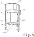
- a perspective partially sectional view of the setting sleeve 11is shown.
- the setting sleeve 11may have any number (at least one) of guiding means 11.1.
- Each guiding means 11.1engages with a corresponding complementary guiding means 2.2 located on the internal wall of the housing body 2.
- two guiding means 11.1 having a form of protrusionsengage with two grooves 2.2 on the internal wall of the housing body 2.
- the guiding means 11.1 and 2.2allow the setting sleeve 11 to move along the axis A-A in relation to the housing body 2 and prevent mutual rotation of both elements in relation to each other.
- the setting sleeve 11further comprises a series of transversal ratchet teeth 11.2 extending along the axis A-A on its inside surface.
- the ratchet teeth 11.2are directed distally in the system 9 (towards downside in fig. 5 ).
- the number of the ratchet teeth 11.2depends of the number of the doses foreseen to be set and dispensed.
- the setting sleeve 11is further provided with two opposite resilient pawls 11.3 projecting form its distal end 11b.
- the resilient pawls 11.3engage with the ratchet teeth 6.1 of the piston rod 6.
- the number of the resilient pawls 11.3corresponds to the number of the side walls of the piston rod 6 with the ratchet teeth 6.1 formed thereon, i.e. there is at least one pawl 12.1.
- the resilient pawls 11.3are shaped so as engage the ratchet teeth 6.1 (which are directed proximally in the system 9) and to allow distal translation of the piston rod 6 and to prevent its translation proximally in the system 9.
- the resilient pawls 11.3constitute an integral part of the setting sleeve 11, but they may also be attached to the sleeve 11 in any suitable way.
- An internal thread 11.4(see fig. 1 ) is formed inside the setting sleeve 11 for rotational engagement with an external thread 10.1 formed at the distal end 10b of the control sleeve 10.
- FIG. 6a perspective partially sectional view of the drive-control system 9 according to a second embodiment of the invention is shown. It differs from the above described first embodiment only in that the blocking member is not a sleeve 12 but it is integrated in the housing body 2 and comprises two resilient pawls 12.1 projecting from the inside surface of the housing body 2.
- the housing body 2is provided with a resilient element 13 projecting on the outside of the housing body 2.
- the resilient elementhas a form of an arm 13 with an extension 13.1 directed towards the housing body 2, to be engaged with the successive teeth 11.2 of the setting sleeve 11.
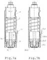
- Fig. 7ashows a starting stage in which the whole piston rod 6 is enclosed in the housing body 2 and the setting sleeve 11 is in its initial position close to the distal end 2b of the housing body 2.
- the setting of a doseis realized by rotation of the control sleeve 10 (indicated by an arrow on fig. 7a ) in a defined direction by a defined angle. Due to the thread engagement 10.1-11.4 of the setting sleeve 11 and the control sleeve 10, the rotation causes the setting sleeve 11 to move over the control sleeve 10.
- Fig. 7billustrates a situation during the setting of a dose, i.e. the translation of the setting sleeve 11 causing compression of the spring 7. Considering that during the translation of the setting sleeve 11 its successive teeth 11.2 pass over the extension 13.1 of the resilient element 13, translation of the setting sleeve 11 in the opposite direction is blocked.
- the setting sleeve 11may be unblocked by bending the resilient element 13 as shown by the arrow on fig. 7c which causes the extension 13.1 to unblock the teeth 11.2 of the setting sleeve 11. Consequently, the setting sleeve 11 is automatically translated distally to its initial position by the force accumulated in the formerly compressed spring 7.
- Figs. 8a- 8cshow alternative cross-sections of the piston rod 6.
- Fig. 9a, 9b and 9cshow partially sectional views of the drive-control system 9 according to a third embodiment of the invention.
- the setting of a dose after the substance in the cartridge has been exhaustedis blocked.
- the piston rod 6 and the setting sleeve 11are provided with mutually cooperating blocking elements 6.2, 11.5 providing blockage of the dose setting and consequently the dose delivery.
- the operation of the blocking elements 6.2, 11.5is such that they cooperate to prevent translation of the setting sleeve 11 in the proximal direction once the piston rod 6 has been advanced out of the housing body 2 by a defined distance.
- the pointis to prevent translation of the setting sleeve 11 in the proximal direction and hence further advancement of the piston rod 6 distally to deliver a dose, in a situation when a defined number of doses have already been dispensed from the container 3.
- the blocking element 6.2may have a form of a piston rod head, i.e. a widened proximal ending of the piston rod 6 as seen in figs. 9a-9c ; optionally it may have a form of any suitable projection or ring etc., located at the proximal ending of the piston rod 6.
- the blocking element 11.5may be constituted by any suitable stop member projecting from the internal wall of the setting sleeve 11 between its pawls 11.3 and its proximal ending.
- itmay be a flange with an opening having a shape adapted to the piston rod cross-section allowing the piston rod 6 to pass through it and interfering with the blocking element 6.2 to prevent its passage through.
- the cross-section of a complete device 1is shown in fig. 1 .
- the device 1comprises the drive-control system 9, the triggering activating means 8 and the knob 5.
- Fig. 10shows a partially sectional view of the drive-control system according to a fourth embodiment of the invention.
- the setting of a doseis also realized by rotation of the control sleeve 10 in a defined direction by a defined angle.
- the rotation of the control sleeve 10causes the setting sleeve 11 to move over the control sleeve 10 due to the thread engagement 10.1-11.4 of the setting sleeve 11 and the control sleeve 10.
- the setting sleeve 11being blocked by the guiding means 11.1 and 2.2 and unable to rotate in relation to the housing body 2, advances along the axis A-A proximally in the system 9 by a defined pitch defining in turn the set dose, causing compression of the spring 7.
- the setting sleeve 11does not have the series of the blocking teeth 11.2.
- the distance by which the setting sleeve 11 is translated proximallyis defined by the angle of rotation of the control sleeve 10.
- the control sleeve 10is provided with dedicated blocking elements 10.2. As shown in fig. 10 , the blocking elements 10.2 may have a form of ratchets integral with the control sleeve 10 or attached thereto.
- the blocking elements 10.2are distributed around the control sleeve 10 and have a shape adapted to cooperate with the triggering activating means of the injection device according to the invention.
- the triggering activating meansis provided with an extension 8.1.
- the cooperation of the ratchet 10.2 with the extension 8.1consists in that during the setting of a dose, the control sleeve 10 may be rotated by a desired angle until a respective ratchet 10.2 passes over the extension 8.1.
- the number of ratchets 10.2corresponds to the number of doses available in the injection device.
- the described embodimentmay also be realized as a reversed variant, i.e. the ratchet may be located on the triggering activating means and the control sleeve 10 may be provided with extensions instead of the ratchets (not shown).
- Fig. 11shows a preferred embodiment of the limitation of rotation of the control sleeve 10 and the translation of the setting sleeve 11.
- projections 10.3 and 11.6are provided respectively at the distal end of the control sleeve 10 and inside the setting sleeve 11. In a determined position the projections 10.3 and 11.6 abut each other and prevent further rotation of the setting sleeve 11. More than one projections 10.3 and 11.6 respectively may be foreseen.
- the function of blocking the rotation of the control sleeve 10 in a certain positionmay be accomplished by end surface of the control sleeve 10 coming into contact with the blocking element 11.5 shown in figs. 9a-9c .
- the variant with the projections 10.3 and 11.6is preferred because it enables a more precise stoppage of the control sleeve 10 rotation.
- the operation of the deviceis as follows.
- the setting of a dose of the pharmaceutical substance to be deliveredis done by the turning the knob 5 in the appropriate direction; the rotation activates the drive-control system 9 i.e. the rotation of the control sleeve 10 and the consequent movements of specific components of the system, as described with reference to figs. 7a and 7b . Passing over one teeth 11.2 of the setting sleeve 11 and respectively one teeth 6.1 of the piston rod 6 may correspond to setting one unitary dose of the pharmaceutical substance. By turning the knob 5 further the user may set a larger dose which is a multiple of the unitary dose.
- the setting of a doseis done in a situation when the triggering activating means 8 is a position of engagement of the resilient member 13 with the teeth 11.2 of the setting sleeve 11.
- the injection of the pharmaceutical substanceis done by pushing the triggering activating means 8 in a defined direction along the housing body 2.
- the triggering activating means 8is translated distally which causes the resilient member 13 to deform and dis-engage from the teeth 11.2 of the setting sleeve 11.
- the setting sleeve 11is automatically translated in the distal direction of the device, i.e. returns to its initial position causing the piston rod 6 to be advanced distally out of the housing body 2.
- the deviceis preferably provided with a feature allowing blockage of the setting of a dose after the pharmaceutical substance in the cartridge has been exhausted.
- the translation of the triggering activating means 8 in the distal directioncauses the blocking element 10.2 to be released and in consequence the rotation of the control sleeve 10, the translation of the setting sleeve 11 and the distal translation of the piston rod 6.
Landscapes
- Health & Medical Sciences (AREA)
- Vascular Medicine (AREA)
- Engineering & Computer Science (AREA)
- Anesthesiology (AREA)
- Biomedical Technology (AREA)
- Heart & Thoracic Surgery (AREA)
- Hematology (AREA)
- Life Sciences & Earth Sciences (AREA)
- Animal Behavior & Ethology (AREA)
- General Health & Medical Sciences (AREA)
- Public Health (AREA)
- Veterinary Medicine (AREA)
- Infusion, Injection, And Reservoir Apparatuses (AREA)
Description
- The invention relates to devices for delivering liquid pharmaceutical substances by injection into patients. In particular, the invention relates to a drive-control system for an injection device for delivering settable doses of a pharmaceutical substance and an injection device equipped with such a system. The pharmaceutical substance may be any injectable pharmaceutical substance e.g. growth hormone or insulin.
- The devices of the above described type are known in the art and commonly used.
WO/2010/033770 describes a medical injector for delivering settable doses of a pharmaceutical substance having a body with a displaceable plunger. The plunger is moveable in the distal direction of the injector; proximal movement of the plunger is prevented. The injector includes an actuator for setting and delivering a dose of the substance. The plunger is provided with ratchet teeth cooperating with a blocking member for preventing proximal movement of the plunger and with an engagement portion of the actuator. For setting of a dose the actuator is displaced proximally and its engagement portion by-passes successive teeth of the immobilized plunger. For delivery of a dose, a user moves the actuator distally. During this movement the engagement portion pushes the teeth of the plunger causing it to move distally. In the case of the described injector the delivery of a dose requires manual (not automatic) operation of the actuator and hence the force applied thereto as well as the speed of the application depend on the user. This is disadvantageous because the patient must regulate the force applied to the injection button single-handed, which in turn influences the speed of the injection as well as involves additional stress and discomfort during injection.US 7,517,334 describes a pen-type apparatus for dispensing settable doses of a medication, provided with different variants of mechanical advantage means. The medication dispensing apparatus is also provided with a spring-driven last dose locking feature. This apparatus is quite complicated and it does not enable the set dose of the medication to be dispensed automatically.WO2015007818 discloses a drive-control system for an injection device having a piston rod with ratchet teeth and a setting sleeve moved axially along this plunger by rotation of a control sleeve.- It is an objective of the invention to provide an improved drive-control system for an injection device for delivering settable doses of a pharmaceutical substance and a respective injection device, enabling automatic delivery of a medication after the dose has been set.
- It is another objective of the invention to provide a drive-control system and a respective injection device driven by a helical pressure spring.
- Still another objective of the invention is to provide an injection device having a simpler design than similar devices known in the art.
- According to the invention a drive-control system is provided for an injection device for delivering settable doses of a pharmaceutical substance contained in a cartridge, the system comprising a tubular housing body having a longitudinal axis, a proximal end and a distal end connectable to the cartridge enclosure, the system further comprising a helical spring contained in the housing body and a piston rod moveable towards said distal end and blocked in translation towards the proximal end.
- The system according to the invention is characterized in that the housing body further contains (i) a control sleeve on which the spring is mounted, the control sleeve being rotatable around said axis, and (ii) a setting sleeve translatable along said axis, wherein rotation of the control sleeve in a first direction combined with compression of the spring causes the setting sleeve to be translated towards the proximal end of the housing body, and extension of the spring causes the setting sleeve to be translated towards the distal end of the housing body and the control sleeve to be rotated in a second direction and the piston rod to be pushed towards the outside of the housing body.
- The rotatable control sleeve is threadably connected at its distal end to the setting sleeve; the setting sleeve is engaged with the internal wall of the housing body in a way preventing rotation of the setting sleeve in relation to the housing body; the setting sleeve is engaged with the piston rod in a way enabling the translation of the setting sleeve towards the proximal end of the housing body in relation to the piston rod and blocking the translation of the setting sleeve in the opposite direction in relation to the piston rod; a blocking member is provided on the distal end of the housing body, the blocking member being engaged with the piston rod in a way preventing translation of the piston rod towards the proximal end of the housing body and enabling the translation of the piston rod in the opposite direction.
- The setting sleeve may be engaged with the internal wall of the housing body by means of at least one pair of complementary longitudinal guiding means.
- Preferably, the at least one pair of complementary longitudinal guiding means consists of a longitudinal groove located on the internal wall of the housing body and a longitudinal projection located on the external wall of the setting sleeve.
- The piston rod is provided with at least one series of ratchet teeth directed towards the proximal end of the housing body and the setting sleeve is provided with at least one resilient pawl engaging the ratchet teeth of the piston rod.
- The piston rod is provided with at least one series of ratchet teeth directed towards the proximal end of the housing body and the blocking member is provided with at least one resilient pawl engaging the ratchet teeth of the piston rod.
- The piston rod may have a rectangular cross-section and the series of ratchet teeth may be located on its side wall.
- The blocking member preferably has a form of a blocking sleeve located inside the housing body, the piston rod extending through the blocking sleeve.
- The at least one resilient pawl is preferably integral with the setting sleeve.
- The blocking member may have a form of a blocking sleeve located inside the housing body, the piston rod extending through the blocking sleeve, and the at least one resilient pawl may be integral with the blocking sleeve.
- Preferably, the piston rod and the setting sleeve are provided with mutually cooperating blocking elements preventing the setting sleeve to be translated proximally when the piston rod extends out of the housing body by a defined distance.
- The blocking element of the piston rod is preferably selected from a group comprising an enlarged proximal ending of the piston rod, a projection located at the proximal ending of the piston rod and an annular flange located at the proximal ending of the piston rod.
- The blocking element of the setting sleeve is preferably a stop member projecting from the inside wall of the setting sleeve between the pawls and the proximal end of the setting sleeve.
- The setting sleeve may be provided with means for engagement of the setting sleeve with the housing body and the housing body may be provided with a resilient element, the engagement means cooperating with the resilient element to selectively block and release the translation of the setting sleeve along the housing body.
- Preferably, the engagement means of the setting sleeve has a form of a series of ratchet teeth that are perpendicular to the axis of the housing body and directed towards the distal end of the housing body, and the resilient element of the housing body is an arm provided with an extension to be engaged with the teeth.
- The control sleeve may be provided with at least one blocking element enabling rotation of the control sleeve in relation to the housing body in one direction as well as selective blocking and releasing the rotation of the control sleeve in the opposite direction.
- Preferably, the at least one blocking element has a form of a ratchet cooperating with a triggering activating means arranged on the housing body.
- Optionally, the at least one blocking element has a form of a projection cooperating with a ratchet of a triggering activating means arranged on the housing body.
- According to the invention an injection device for delivering settable doses of a liquid pharmaceutical substance is provided, adapted to be coupled with a cartridge enclosure containing said substance, the distal end of the cartridge enclosure being adapted to be coupled with a disposable injection means.
- The injection device according to the invention is characterized in that it is provided with the drive-control system according to the invention, and wherein
- the housing body is provided with the triggering activating means and a knob, the triggering activating means and the knob cooperating with the drive-control system;
- the knob is engaged with the rotatable control sleeve to enable the rotation of the control sleeve in a defined direction;
- the triggering activating means enabling selective blocking and releasing of the translation of the setting sleeve towards the distal end of the housing body, wherein
- Preferably, the triggering activating means cooperates with the resilient element of the housing body and it is adapted to be placed in a first and a second position, the first position being the position of engagement of the triggering activating means with the setting sleeve by means of the extension and the second position being the position of disengagement of the triggering activating means with the setting sleeve.
- According to the invention another variant of an injection device for delivering settable doses of a liquid pharmaceutical substance is also provided, adapted to be coupled with a cartridge containing said substance, the distal end of the cartridge being adapted to be coupled with a disposable injection means.
- This another variant is characterized in that the injection device is provided with the drive-control system according to any of the invention, and wherein
- the housing body is provided with the triggering activating means and a knob, the triggering activating means and the knob cooperating with the drive-control system;
- the knob is engaged with the rotatable control sleeve to enable the rotation of the control sleeve in a defined direction;
- the triggering activating means cooperates with the blocking element of the control sleeve to enable selective blocking and releasing rotation of the control sleeve in relation to the housing body in a first direction, said rotation being combined with proximal translation of the setting sleeve, and enabling rotation of the control sleeve in a second opposite direction, said direction being combined with translation of the setting sleeve towards the distal end of the housing body by the action of the extending spring.
- Preferably, the triggering activating means is provided with an extension cooperating with the blocking element of the control sleeve, the blocking element being adapted to be placed in a first and a second position, the first position being the position of engagement of the extension with the blocking element and the second position being the position of disengagement of the extension with the blocking element.
- The injection device according to the invention has a relatively simple construction and enables automatic delivery of a selected dose of pharmaceutical substance to a patient.
- In a preferred embodiment the injection device according to the invention is provided with a feature that prevents arming of the device upon delivery of a last dose.
- Preferred embodiments of the inventions are shown in the appended drawings in which:
Preferred embodiments of the inventions are shown in the appended drawings in which: Fig. 1 shows a longitudinal sectional view of a first embodiment of the device according to the invention;Fig. 2 shows a longitudinal sectional view of a first embodiment of the device shown infig. 1 , with a container for a pharmaceutical substance cartridge;Fig. 3 shows an exploded perspective view of the device according to the first embodiment and the associated container for a pharmaceutical substance cartridge;Fig. 4 shows a perspective partially sectional view of the drive-control system according to the first embodiment;Fig. 5 shows a perspective partially sectional view of selected parts of the drive-control system according to the invention;Fig. 6 shows a perspective partially sectional view of the drive-control system according to a second embodiment of the invention;Figs. 7a, 7b ,7c and 7d show successive stages of operation of the drive-control system according to the first embodiment;Figs. 8a, 8b and 8c show alternative cross-sections of the piston rod ;Fig. 9a, 9b and 9c show partially sectional views of the drive-control system according to a third embodiment of the invention;Fig. 10 shows a partially sectional view of the drive-control system according to a fourth embodiment of the invention;Fig. 11 shows another partially sectional view of the drive-control system according to the invention.- The
device 1 shown infig. 1 andfig. 2 according to the first embodiment of the invention comprises a typicaltubular housing body 2 connectable to acartridge enclosure 3 containing a pharmaceutical substance. Aprotective cap 4 is fitted on thecartridge enclosure 3. Thehousing body 2 has aproximal end 2a on which aknob 5 is fitted and adistal end 2b which is connectable to the substance containingcartridge enclosure 3. Thecartridge enclosure 3 has adistal end 3b on which a disposable injection means, in particular a hollow needle, is fitted and aproximal end 3a to be fitted to thehousing body 2 of thedevice 1. - The terms "distal" and "proximal" are used here in relation to various elements and they should be understood as meaning respectively "the side of the end applied to a patient" and "the side of the end held by a user".
- A
piston rod 6 is arranged in a typical way in thehousing body 2. Thepiston rod 6 is translated along the axis of thedevice 1 so as to gradually move distally within thecartridge 3 and dispense a selected dose. The axial movement of thepiston rod 6 along thehousing body 2 is caused by the action of ahelical spring 7 arranged within thehousing body 2. According to the invention a helical compression spring has been used which is an important advantage in relation to the state of art solutions in which torsional helical springs are typically used. A compression spring is easier to be produced than a torsional spring because it does not need special endings which are necessary for rotating the spring during pre-loading. Further, the helical compression spring needs fewer coils and hence it may be smaller and lighter. - Operation of the
device 1 includes arming it by setting a dose by means of aknob 5, introducing the needle into the patient's body, activating thedevice 1 by a triggering activatingmeans 8 which causes the dose of a pharmaceutical substance to be dispensed. As thepiston rod 6 is translatable distally and blocked in proximal translation, the device may be used with only one pharmaceutical substance containing cartridge enclosure. Once thepiston rod 6 has been pushed out of thehousing body 2 it may not be retracted in order to allow fitting a new cartridge. Fig. 3 shows an exploded view of thedevice 1 from thefigs. 1 and2 along with its parts constituting the drive-control system 9, thecartridge enclosure 3 containing a pharmaceutical substance and thecap 4.- The components shown in
fig. 3 are arranged along a common longitudinal axis A-A in thedevice 1. The axis A-A is the longitudinal axis of thedevice 1. Thehousing body 2 is connected at itsdistal end 2b with thecartridge enclosure 3. Aknob 5 is mounted on theproximal end 2a of thehousing body 2. Theknob 5 is rotatable around the axis A-A of thehousing body 2. - The drive-
control system 9 of thedevice 1 comprises: - ∘ a
control sleeve 10 rotatable within thehousing body 2, thecontrol sleeve 10 having aproximal part 10a fixed to theknob 5 and adistal part 10b on which ahelical compression spring 7 is mounted; - ∘ a setting
sleeve 11, threadably connected to thedistal end 10b of thecontrol sleeve 10, the settingsleeve 11 being translatable along the axis A-A in two directions; - ∘ a blocking member in the form of a blocking
sleeve 12 arranged within thehousing body 2 at itsdistal end 2b, the blockingsleeve 12 being fixed to thehousing body 2; - ∘ the
helical compression spring 7 abutting by itsproximal end 7a a projection 2.1 located inside thehousing body 2 and by itsdistal end 7b aproximal end 11a of the settingsleeve 11; - ∘ the
piston rod 6 extending along the axis A-A is arranged within thehousing body 2, thecontrol sleeve 10, the settingsleeve 11 and the blockingsleeve 12. Thepiston rod 6 is distally translatable along the axis A-A of thesystem 9 and proximally non-translatable. Fig. 4 shows a perspective partially sectional view of the drive-control system 9 according to the first embodiment of the invention. In thesystem 9 according to the invention, applied in thedevice 1 according to the invention, thepiston rod 6 is immobilized during setting of a dose, and during delivery of the dose it is advanced outside thehousing body 2 into the pharmaceutical substance containingcartridge enclosure 3, causing the set dose to be dispensed. In the described embodiment thepiston rod 6 has a rectangular cross-section and transversal ratchet teeth 6.1 are formed on its two opposite side walls. The ratchet teeth 6.1 are directed proximally in the system 9 (towards upside infig. 4 ). The ratchet teeth 6.1 may be formed on at least one side wall of thepiston rod 6, or optionally on all the four side walls. Also, thepiston rod 6 may have a different cross-section provided that it comprises at least one side wall having transversal ratchet teeth directed proximally formed thereon. Exemplary cross-sections of thepiston rod 6 are shown infigs. 8a-8c .- Inside the
housing body 2, at itsdistal end 2b the blocking member is located having a form of the blockingsleeve 12 fixed to thehousing body 2. The blockingsleeve 12 is provided with two opposite resilient pawls 12.1 engaging the ratchet teeth 6.1 so as to block the translation of thepiston rod 6 along the axis A-A in the proximal direction of thesystem 9. The number of the resilient pawls 12.1 corresponds to the number of the side walls of thepiston rod 6 with the ratchet teeth 6.1 formed thereon, i.e. there is at least one pawl 12.1. A man skilled in the art will select a suitable material for the blockingsleeve 12 and the resilient pawls 12.1 as well as the shape of the pawls 12.1 so as to ensure that their functions are accomplished. In the described embodiment, the resilient pawls 12.1 constitute an integral part of the blockingsleeve 12, but they may also be attached to thesleeve 12 in any suitable way. - In
fig. 5 a perspective partially sectional view of the settingsleeve 11 is shown. As shown in particular infigs. 4 and5 , on the outside surface of the settingsleeve 11 there are two guiding means 11.1 extending along the axis A-A of the device. The settingsleeve 11 may have any number (at least one) of guiding means 11.1. Each guiding means 11.1 engages with a corresponding complementary guiding means 2.2 located on the internal wall of thehousing body 2. In the described embodiment two guiding means 11.1 having a form of protrusions engage with two grooves 2.2 on the internal wall of thehousing body 2. The guiding means 11.1 and 2.2 allow the settingsleeve 11 to move along the axis A-A in relation to thehousing body 2 and prevent mutual rotation of both elements in relation to each other. - In the described embodiment the setting
sleeve 11 further comprises a series of transversal ratchet teeth 11.2 extending along the axis A-A on its inside surface. The ratchet teeth 11.2 are directed distally in the system 9 (towards downside infig. 5 ). The number of the ratchet teeth 11.2 depends of the number of the doses foreseen to be set and dispensed. - The setting
sleeve 11 is further provided with two opposite resilient pawls 11.3 projecting form itsdistal end 11b. The resilient pawls 11.3 engage with the ratchet teeth 6.1 of thepiston rod 6. As in the case of the resilient pawls 12.1, the number of the resilient pawls 11.3 corresponds to the number of the side walls of thepiston rod 6 with the ratchet teeth 6.1 formed thereon, i.e. there is at least one pawl 12.1. The resilient pawls 11.3 are shaped so as engage the ratchet teeth 6.1 (which are directed proximally in the system 9) and to allow distal translation of thepiston rod 6 and to prevent its translation proximally in thesystem 9. A man skilled in the art will select a suitable material for the settingsleeve 11 and the resilient pawls 11.3 as well as the shape of the pawls 11.3 so as to ensure that their functions are accomplished. In the described embodiment, the resilient pawls 11.3 constitute an integral part of the settingsleeve 11, but they may also be attached to thesleeve 11 in any suitable way. - An internal thread 11.4 (see
fig. 1 ) is formed inside the settingsleeve 11 for rotational engagement with an external thread 10.1 formed at thedistal end 10b of thecontrol sleeve 10. - In
fig. 6 a perspective partially sectional view of the drive-control system 9 according to a second embodiment of the invention is shown. It differs from the above described first embodiment only in that the blocking member is not asleeve 12 but it is integrated in thehousing body 2 and comprises two resilient pawls 12.1 projecting from the inside surface of thehousing body 2. - As shown in the figures, the
housing body 2 is provided with aresilient element 13 projecting on the outside of thehousing body 2. In the described embodiments the resilient element has a form of anarm 13 with an extension 13.1 directed towards thehousing body 2, to be engaged with the successive teeth 11.2 of the settingsleeve 11. - Operation of the drive-
control system 9 according to the invention is illustrated infigs. 7a, 7b ,7c and 7d . Fig. 7a shows a starting stage in which thewhole piston rod 6 is enclosed in thehousing body 2 and the settingsleeve 11 is in its initial position close to thedistal end 2b of thehousing body 2. The setting of a dose is realized by rotation of the control sleeve 10 (indicated by an arrow onfig. 7a ) in a defined direction by a defined angle. Due to the thread engagement 10.1-11.4 of the settingsleeve 11 and thecontrol sleeve 10, the rotation causes the settingsleeve 11 to move over thecontrol sleeve 10. Consequently the settingsleeve 11, being blocked by the guiding means 11.1 and 2.2 and unable to rotate in relation to thehousing body 2, advances along the axis A-A proximally in the system 9 (towards upside infig. 7a ) by a defined pitch defining in turn the set dose.Fig. 7b illustrates a situation during the setting of a dose, i.e. the translation of the settingsleeve 11 causing compression of thespring 7. Considering that during the translation of the settingsleeve 11 its successive teeth 11.2 pass over the extension 13.1 of theresilient element 13, translation of the settingsleeve 11 in the opposite direction is blocked. At the same time, during the proximal translation of the settingsleeve 11, its resilient pawls 11.3 pass over successive teeth 6.1 of thepiston rod 6 which may not be translated proximally because it is blocked by the resilient pawls 12.1 of the blockingsleeve 12. Thespring 7, which is blocked between theproximal end 11a of the settingsleeve 11 and the projection 2.1 located within thehousing body 2, remains compressed as long as the translation of the settingsleeve 11 in the distal direction is blocked.- In the situation shown in
fig. 7c , i.e. after the settingsleeve 11 has passed a selected number of the teeth and the dose has been set, the settingsleeve 11 may be unblocked by bending theresilient element 13 as shown by the arrow onfig. 7c which causes the extension 13.1 to unblock the teeth 11.2 of the settingsleeve 11. Consequently, the settingsleeve 11 is automatically translated distally to its initial position by the force accumulated in the formerlycompressed spring 7. - In
fig. 7d a situation is shown when the settingsleeve 11 has returned to its initial position. The pawls 11.3, engaged with the teeth 6.1 of thepiston rod 6, have caused its translation out of thehousing body 2. At the same time the resilient pawls 12.1 yield under the pressure of the successive teeth 6.1 of thepiston rod 6. The translation of the settingsleeve 11 in the distal direction under the force of the extendingspring 7 causes rotation of thecontrol sleeve 10 in a direction opposite to its former rotation, back to its initial position. The directions of movement of thecontrol sleeve 10, the settingsleeve 11, thepiston rod 6 and theresilient element 13 are indicated by the arrows onfigs. 7c and 7d . Infig. 7d thepiston rod 6 extends outside thehousing body 2 and theresilient element 13 is back to its position of engagement with the teeth 11.2 of the settingsleeve 11. Figs. 8a- 8c show alternative cross-sections of thepiston rod 6.Fig. 9a, 9b and 9c show partially sectional views of the drive-control system 9 according to a third embodiment of the invention. In this embodiment the setting of a dose after the substance in the cartridge has been exhausted is blocked. As shown infigs. 9a-9c , thepiston rod 6 and the settingsleeve 11 are provided with mutually cooperating blocking elements 6.2, 11.5 providing blockage of the dose setting and consequently the dose delivery. The operation of the blocking elements 6.2, 11.5 is such that they cooperate to prevent translation of the settingsleeve 11 in the proximal direction once thepiston rod 6 has been advanced out of thehousing body 2 by a defined distance. The point is to prevent translation of the settingsleeve 11 in the proximal direction and hence further advancement of thepiston rod 6 distally to deliver a dose, in a situation when a defined number of doses have already been dispensed from thecontainer 3.- The blocking element 6.2 may have a form of a piston rod head, i.e. a widened proximal ending of the
piston rod 6 as seen infigs. 9a-9c ; optionally it may have a form of any suitable projection or ring etc., located at the proximal ending of thepiston rod 6. - The blocking element 11.5 may be constituted by any suitable stop member projecting from the internal wall of the setting
sleeve 11 between its pawls 11.3 and its proximal ending. Preferably, it may be a flange with an opening having a shape adapted to the piston rod cross-section allowing thepiston rod 6 to pass through it and interfering with the blocking element 6.2 to prevent its passage through. - As mentioned above, the cross-section of a
complete device 1 is shown infig. 1 . As may be seen, thedevice 1 comprises the drive-control system 9, the triggering activatingmeans 8 and theknob 5. Fig. 10 shows a partially sectional view of the drive-control system according to a fourth embodiment of the invention. In this embodiment the setting of a dose is also realized by rotation of thecontrol sleeve 10 in a defined direction by a defined angle. As in the above described embodiments, the rotation of thecontrol sleeve 10 causes the settingsleeve 11 to move over thecontrol sleeve 10 due to the thread engagement 10.1-11.4 of the settingsleeve 11 and thecontrol sleeve 10. Consequently the settingsleeve 11, being blocked by the guiding means 11.1 and 2.2 and unable to rotate in relation to thehousing body 2, advances along the axis A-A proximally in thesystem 9 by a defined pitch defining in turn the set dose, causing compression of thespring 7. However, in this embodiment the settingsleeve 11 does not have the series of the blocking teeth 11.2. Instead, the distance by which the settingsleeve 11 is translated proximally is defined by the angle of rotation of thecontrol sleeve 10. To achieve this aim, thecontrol sleeve 10 is provided with dedicated blocking elements 10.2. As shown infig. 10 , the blocking elements 10.2 may have a form of ratchets integral with thecontrol sleeve 10 or attached thereto. The blocking elements 10.2 are distributed around thecontrol sleeve 10 and have a shape adapted to cooperate with the triggering activating means of the injection device according to the invention. The triggering activating means is provided with an extension 8.1. The cooperation of the ratchet 10.2 with the extension 8.1 consists in that during the setting of a dose, thecontrol sleeve 10 may be rotated by a desired angle until a respective ratchet 10.2 passes over the extension 8.1. The number of ratchets 10.2 corresponds to the number of doses available in the injection device. Translation of the triggering activating means along thehousing body 2 in the distal direction causes the ratchet to be unblocked which allows thecontrol sleeve 10 to be rotated in a direction opposite to the setting of dose direction. In consequence, thepiston rod 6 is advanced out and the dose is delivered. The described embodiment may also be realized as a reversed variant, i.e. the ratchet may be located on the triggering activating means and thecontrol sleeve 10 may be provided with extensions instead of the ratchets (not shown).Fig. 11 shows a preferred embodiment of the limitation of rotation of thecontrol sleeve 10 and the translation of the settingsleeve 11. As shown, projections 10.3 and 11.6 are provided respectively at the distal end of thecontrol sleeve 10 and inside the settingsleeve 11. In a determined position the projections 10.3 and 11.6 abut each other and prevent further rotation of the settingsleeve 11. More than one projections 10.3 and 11.6 respectively may be foreseen. In another variant, the function of blocking the rotation of thecontrol sleeve 10 in a certain position may be accomplished by end surface of thecontrol sleeve 10 coming into contact with the blocking element 11.5 shown infigs. 9a-9c . However, the variant with the projections 10.3 and 11.6 is preferred because it enables a more precise stoppage of thecontrol sleeve 10 rotation.- The operation of the device is as follows.
- The setting of a dose of the pharmaceutical substance to be delivered is done by the turning the
knob 5 in the appropriate direction; the rotation activates the drive-control system 9 i.e. the rotation of thecontrol sleeve 10 and the consequent movements of specific components of the system, as described with reference tofigs. 7a and 7b . Passing over one teeth 11.2 of the settingsleeve 11 and respectively one teeth 6.1 of thepiston rod 6 may correspond to setting one unitary dose of the pharmaceutical substance. By turning theknob 5 further the user may set a larger dose which is a multiple of the unitary dose. - The setting of a dose is done in a situation when the triggering activating
means 8 is a position of engagement of theresilient member 13 with the teeth 11.2 of the settingsleeve 11. - The injection of the pharmaceutical substance is done by pushing the triggering activating
means 8 in a defined direction along thehousing body 2. In the embodiments shown infigs. 1-9 the triggering activatingmeans 8 is translated distally which causes theresilient member 13 to deform and dis-engage from the teeth 11.2 of the settingsleeve 11. Due to the action of thecompressed spring 7 the settingsleeve 11 is automatically translated in the distal direction of the device, i.e. returns to its initial position causing thepiston rod 6 to be advanced distally out of thehousing body 2. As thepiston rod 6 is advanced out of thehousing body 2a it moves into thecartridge 3 and expels the dose of the pharmaceutical substance therefrom. The device is preferably provided with a feature allowing blockage of the setting of a dose after the pharmaceutical substance in the cartridge has been exhausted. - In the embodiment shown in
fig. 10 the translation of the triggering activatingmeans 8 in the distal direction causes the blocking element 10.2 to be released and in consequence the rotation of thecontrol sleeve 10, the translation of the settingsleeve 11 and the distal translation of thepiston rod 6.
Claims (15)
- A drive-control system for an injection device for delivering a settable dose of a pharmaceutical substance contained in a cartridge (3), the system comprising a tubular housing body (2) having a longitudinal axis (A-A), a proximal end (2a) and a distal end (2b) connectable to the cartridge enclosure (3), the system further comprising a helical spring (7) contained in the housing body and a piston rod (6) extending along the longitudinal axis (A-A) and moveable towards said distal end (2b) and blocked in translation towards the proximal end (2a), wherein the housing body (2) further contains (i) a control sleeve (10) on which the spring (7) is mounted, the control sleeve (10) being rotatable around the axis (A-A), and (ii) a setting sleeve (11) translatable along the axis (A-A), wherein- the control sleeve (10) is threadably connected at its distal end to the setting sleeve (11);- the setting sleeve (11) is engaged with the internal wall of the housing body (2) in a way preventing rotation of the setting sleeve (11) in relation to the housing body (2),- the setting sleeve (11) is engaged with the piston rod (6) by at least one series of ratchet teeth (6.1) on the piston rod (6) directed towards the proximal end (2a) of the housing body (2) and at least one resilient pawl (11.3) on the setting sleeve (11) engaging the ratchet teeth (6.1) of the piston rod (6), in a way enabling the translation of the setting sleeve (11) towards the proximal end (2a) of the housing body (2) and blocking the translation of the setting sleeve (11) in the opposite direction in relation to the piston rod (6);- a blocking member (12) is provided on the distal end (2b) of the housing body (2), the blocking member (12) being engaged with the piston rod (6) by the at least one series of ratchet teeth (6.1) and at least one resilient pawl (12.1) on the blocking member (12) engaging the ratchet teeth (6.1) of the piston rod (6) so as to block the translation of the piston rod 6 in the proximal direction, whereby- rotation of the control sleeve (10) in a first direction causes compression of the spring (7) and translation of the setting sleeve (11) towards the proximal end (2a) of the housing body (2), and extension of the spring (7) causes translation of the setting sleeve (11) towards the distal end (2b) of the housing body (2), rotation of the control sleeve (10) in a second direction and translation of the piston rod (6) towards the outside of the housing body (2),
- The system according to claim 1, wherein the setting sleeve (11) is engaged with the internal wall of the housing body (2) by means of at least one pair of complementary longitudinal guiding means (11.1, 2.2) .
- The system according to claim 2, wherein the at least one pair of complementary longitudinal guiding means consists of a longitudinal groove (2.2) located on the internal wall of the housing body (2) and a longitudinal protrusion (11.1) located on the external wall of the setting sleeve (11).
- The system according to claim 1, wherein the piston rod (6) has a rectangular cross-section and the series of ratchet teeth (6.1) is located on its side wall.
- The system according to any of the preceding claims, wherein the blocking member (12) has a form of a blocking sleeve located inside the housing body (2), the piston rod (6) extending through the blocking sleeve.
- The system according to claim 6 wherein the at least one resilient pawl (11.3) is integral with the setting sleeve (11).
- The system according to any of the preceding claims, wherein the blocking member (12) has a form of a blocking sleeve located inside the housing body (2), the piston rod (6) extending through the blocking sleeve, and the at least one resilient pawl (12.1) is integral with the blocking sleeve.
- The system according to any of the preceding claims, wherein the piston rod (6) and the setting sleeve (11) are provided with mutually cooperating blocking elements (6.2, 11.5) preventing the setting sleeve (11) to be translated proximally when the piston rod (6) extends out of the housing body (2) by a defined distance.
- The system according to claim 8, wherein the blocking element (6.2) of the piston rod (6) is selected from a group comprising an enlarged proximal ending of the piston rod (6), a projection located at the proximal ending of the piston rod (6) and an annular flange located at the proximal ending of the piston rod (6).
- The system according to claim 8, wherein the blocking element (11.5) of the setting sleeve (11) is a stop member projecting from the inside wall of the setting sleeve (11) between the pawls (11.3) and the proximal end of the setting sleeve (11).
- The system according to any of the preceding claims, wherein the the setting sleeve (11) is provided with means (11.2) for engagement of the setting sleeve (11) with the housing body (2) and the housing body (2) is provided with a resilient element (13), the engagement means (11.2) cooperating with the resilient element (13) to selectively block and release the translation of the setting sleeve (11) along the housing body (2).
- The system according to claim 11, wherein the engagement means (11.2) of the setting sleeve (11) has a form of a series of ratchet teeth (11.2) that are perpendicular to the axis (A-A) and directed towards the distal end (2b) of the housing body (2), and the resilient element of the housing body (2) is an arm (13) provided with an extension (13.1) to be engaged with the teeth (11.2).
- The system according to any of the preceding claims, wherein the control sleeve (10) is provided with at least one blocking element (10.2) enabling rotation of the control sleeve (10) in relation to the housing body (2) in one direction as well as selective blocking and releasing the rotation of the control sleeve (10) in the opposite direction.
- The system according to claim 13, wherein the at least one blocking element (10.2) has a form of a ratchet cooperating with a triggering activating means (8) arranged on the housing body (2).
- The system according to claim 13, wherein the at least one blocking element (10.2) has a form of a projection cooperating with a ratchet of a triggering activating means (8) arranged on the housing body (2).
Applications Claiming Priority (2)
| Application Number | Priority Date | Filing Date | Title |
|---|---|---|---|
| PL415473APL227678B1 (en) | 2015-12-22 | 2015-12-22 | Control and drive system for the device intended for injection and the device for making injections equipped with such a system |
| PCT/IB2016/057856WO2017109713A1 (en) | 2015-12-22 | 2016-12-21 | A drive-control system for an injection device |
Publications (2)
| Publication Number | Publication Date |
|---|---|
| EP3393554A1 EP3393554A1 (en) | 2018-10-31 |
| EP3393554B1true EP3393554B1 (en) | 2020-12-02 |
Family
ID=57963380
Family Applications (1)
| Application Number | Title | Priority Date | Filing Date |
|---|---|---|---|
| EP16834116.2AActiveEP3393554B1 (en) | 2015-12-22 | 2016-12-21 | A drive-control system for an injection device |
Country Status (6)
| Country | Link |
|---|---|
| US (2) | US10799643B2 (en) |
| EP (1) | EP3393554B1 (en) |
| CN (2) | CN112972831A (en) |
| ES (1) | ES2861518T3 (en) |
| PL (1) | PL227678B1 (en) |
| WO (1) | WO2017109713A1 (en) |
Families Citing this family (2)
| Publication number | Priority date | Publication date | Assignee | Title |
|---|---|---|---|---|
| PL431693A1 (en)* | 2019-10-31 | 2021-05-04 | Copernicus Spółka Z Ograniczoną Odpowiedzialnością | Device for drug delivery with a set for measuring fixed or applied dose |
| EP4247455A1 (en)* | 2020-11-20 | 2023-09-27 | SHL Medical AG | Torsion spring mechanism for medicament delivery device, and medicament delivery device comprising said mechanism |
Family Cites Families (74)
| Publication number | Priority date | Publication date | Assignee | Title |
|---|---|---|---|---|
| US2444570A (en) | 1948-07-06 | Drive for counter numeral wheels | ||
| US533575A (en) | 1895-02-05 | wilkens | ||
| US2717597A (en) | 1952-12-04 | 1955-09-13 | Jr George N Hein | Injection apparatus |
| IE52621B1 (en) | 1981-02-12 | 1988-01-06 | Turner Robert Charles | Dose metering plunger devices for use with syringes |
| DE3204178C2 (en) | 1982-02-06 | 1986-03-20 | Eppendorf Gerätebau Netheler + Hinz GmbH, 2000 Hamburg | Pipetting device |
| DE3609555A1 (en) | 1986-03-21 | 1987-09-24 | Josef Porner | Blood-collecting syringe |
| GB8713810D0 (en) | 1987-06-12 | 1987-07-15 | Hypoguard Uk Ltd | Measured dose dispensing device |
| GB8809115D0 (en) | 1988-04-18 | 1988-05-18 | Turner R C | Syringes |
| GB9007113D0 (en) | 1990-03-29 | 1990-05-30 | Sams Bernard | Dispensing device |
| DK0525525T3 (en) | 1991-07-24 | 1995-10-02 | Medico Dev Investment Co | Injector |
| DK175491D0 (en) | 1991-10-18 | 1991-10-18 | Novo Nordisk As | APPARATUS |
| US5320609A (en) | 1992-12-07 | 1994-06-14 | Habley Medical Technology Corporation | Automatic pharmaceutical dispensing syringe |
| ZA941881B (en) | 1993-04-02 | 1995-09-18 | Lilly Co Eli | Manifold medication injection apparatus and method |
| JP3568959B2 (en) | 1995-03-07 | 2004-09-22 | イーライ・リリー・アンド・カンパニー | Reusable dosing device |
| US5688251A (en) | 1995-09-19 | 1997-11-18 | Becton Dickinson And Company | Cartridge loading and priming mechanism for a pen injector |
| US5674204A (en) | 1995-09-19 | 1997-10-07 | Becton Dickinson And Company | Medication delivery pen cap actuated dose delivery clutch |
| US5899879A (en) | 1995-12-19 | 1999-05-04 | Genesis Medical Technologies, Inc. | Spring-actuated needleless injector |
| CZ297361B6 (en) | 1998-01-30 | 2006-11-15 | Novo Nordisk A/S | Injection syringe |
| US6221053B1 (en) | 1998-02-20 | 2001-04-24 | Becton, Dickinson And Company | Multi-featured medication delivery pen |
| GB0007071D0 (en) | 2000-03-24 | 2000-05-17 | Sams Bernard | One-way clutch mechanisms and injector devices |
| US6663602B2 (en) | 2000-06-16 | 2003-12-16 | Novo Nordisk A/S | Injection device |
| US6899699B2 (en) | 2001-01-05 | 2005-05-31 | Novo Nordisk A/S | Automatic injection device with reset feature |
| GB0304822D0 (en) | 2003-03-03 | 2003-04-09 | Dca Internat Ltd | Improvements in and relating to a pen-type injector |
| EP1541185A1 (en) | 2003-12-08 | 2005-06-15 | Novo Nordisk A/S | Automatic syringe with priming mechanism |
| EP1732629B1 (en) | 2004-03-30 | 2019-04-24 | Eli Lilly And Company | Medication dispensing apparatus with spring-driven locking feature enabled by administration of final dose |
| MX2007003682A (en)* | 2004-10-04 | 2007-08-07 | Sanofi Aventis Deutschland | Drive mechanism for a drug delivery device. |
| KR101278123B1 (en) | 2004-10-21 | 2013-06-24 | 노보 노르디스크 에이/에스 | Injection device with torsion spring and rotatable display |
| ATE444090T1 (en) | 2004-10-21 | 2009-10-15 | Novo Nordisk As | SELECTION MECHANISM FOR A ROTARY PIN |
| US20090054851A1 (en) | 2005-02-17 | 2009-02-26 | Novo Nordisk A/S | dose setting element for an injection device and having a dose setting limiting mechanism |
| PL208660B1 (en) | 2005-05-25 | 2011-05-31 | Kappa Medilab Społka Z Ograniczoną Odpowiedzialnością | Automatic applicator, particularly for application of the insulin |
| US9011386B2 (en) | 2005-06-01 | 2015-04-21 | Shl Group Ab | Device for delivering medicament |
| US7896850B2 (en) | 2005-06-01 | 2011-03-01 | Telefonaktiebolaget L M Ericsson (Publ) | Device for delivering medicament |
| ES2423199T3 (en) | 2005-06-01 | 2013-09-18 | Shl Group Ab | Device to deliver medication |
| EP1728529B2 (en) | 2005-06-01 | 2016-07-27 | SHL Group AB | Device for delivering medicament |
| US8920383B2 (en) | 2005-07-27 | 2014-12-30 | Novo Nordisk A/S | Dose mechanism for an injection device for limiting a dose setting corresponding to the amount of medicament left |
| GB0524604D0 (en) | 2005-12-02 | 2006-01-11 | Owen Mumford Ltd | Injection method and apparatus |
| GB2433032A (en)* | 2005-12-08 | 2007-06-13 | Owen Mumford Ltd | Syringe with dose adjustment means |
| DE102006038123C5 (en) | 2006-08-14 | 2012-05-03 | Tecpharma Licensing Ag | Injection device with mechanical lock |
| DE102006038103B4 (en) | 2006-08-14 | 2017-02-23 | Tecpharma Licensing Ag | Injection device with variable thread guide |
| WO2008087071A1 (en) | 2007-01-17 | 2008-07-24 | Shl Group Ab | Device for delivering medicament |
| BRPI0809265A2 (en)* | 2007-03-23 | 2014-10-07 | Novo Nordisk As | INJECTION DEVICE INCLUDING A TIGHTENING NUT |
| CA2702412C (en) | 2007-06-19 | 2012-07-17 | Shl Group Ab | Device for delivering medicament |
| CA2711653C (en) | 2008-01-23 | 2016-07-05 | Novo Nordisk A/S | Device for injecting apportioned doses of liquid drug |
| US8376993B2 (en) | 2008-08-05 | 2013-02-19 | Antares Pharma, Inc. | Multiple dosage injector |
| ES2766253T3 (en) | 2008-09-18 | 2020-06-12 | Becton Dickinson Co | Medical Plunger Injector with Ratchet Function |
| WO2010072229A1 (en) | 2008-12-22 | 2010-07-01 | Tecpharma Licensing Ag | Dosing device for an injection device |
| SE0900371A1 (en) | 2009-03-24 | 2010-09-25 | Istvan Bartha | Device for distribution of liquid drugs |
| WO2010150396A1 (en) | 2009-06-26 | 2010-12-29 | 昭和薬品化工株式会社 | Linear dental electric syringe |
| GB0918145D0 (en) | 2009-10-16 | 2009-12-02 | Owen Mumford Ltd | Injector apparatus |
| PL215310B1 (en) | 2009-10-30 | 2013-11-29 | Kappa Medilab Spolka Z Ograniczona Odpowiedzialnoscia | Automatic applicator, especially for insulin |
| ES2909887T3 (en) | 2009-12-01 | 2022-05-10 | Becton Dickinson Co | Injection pen with automatic return and last dose control |
| WO2011101349A1 (en) | 2010-02-17 | 2011-08-25 | Sanofi-Aventis Deutschland Gmbh | Automatic injection device with torsional spring |
| KR101870065B1 (en) | 2011-10-17 | 2018-06-21 | 에스에이치엘 그룹 에이비 | Medicament delivery device |
| WO2014060369A1 (en) | 2012-10-15 | 2014-04-24 | Novo Nordisk A/S | Spring driven injection device |
| EP2722930A1 (en) | 2012-10-16 | 2014-04-23 | Delphi Technologies, Inc. | Coated contact element |
| EP3738627B1 (en)* | 2012-10-17 | 2025-03-19 | Oval Medical Technologies Limited | Automatic drug delivery devices |
| PL2950853T3 (en) | 2013-02-01 | 2017-09-29 | Novo Nordisk A/S | A non-axial working end-of content mechanism and an injection device comprising the same |
| WO2014165142A1 (en) | 2013-03-13 | 2014-10-09 | Benjamin Newton | Multiple dosage injector with rotating screw dosage system |
| US10376645B2 (en)* | 2013-03-13 | 2019-08-13 | Sanofi-Aventis Deutschland Gmbh | Drive mechanism for a drug delivery device |
| DK2983735T3 (en)* | 2013-04-10 | 2021-03-01 | Sanofi Sa | DRIVE MECHANISM FOR A MEDICINE ADMINISTRATIVE DEVICE |
| EP2983763B1 (en)* | 2013-04-10 | 2017-05-24 | Sanofi | Drive mechanism for a drug delivery device |
| RU2015146766A (en) | 2013-04-10 | 2017-05-16 | Санофи | INJECTION DEVICE |
| JP6480924B2 (en) | 2013-07-17 | 2019-03-13 | サノフイSanofi | Drug delivery device |
| DK3021906T3 (en)* | 2013-07-17 | 2018-07-30 | Sanofi Sa | DRIVE MECHANISM FOR A DISPENSING DEVICE |
| CN104338210B (en)* | 2013-07-30 | 2017-04-12 | 广东东阳光药业有限公司 | Injection device |
| EP3035982B1 (en)* | 2013-08-22 | 2021-11-17 | Sanofi-Aventis Deutschland GmbH | Drive mechanism for a drug delivery device and a method for assembling a drug delivery device |
| CN105492043B (en)* | 2013-09-03 | 2020-10-02 | 赛诺菲 | Drive mechanism and injection device with same |
| DK3043842T3 (en)* | 2013-09-10 | 2019-02-18 | Sanofi Sa | DRIVE MECHANISM FOR A PHARMACEUTICAL ADMINISTRATION DEVICE |
| DK3071265T3 (en)* | 2013-11-22 | 2023-07-24 | Sanofi Aventis Deutschland | SPRING-ASSISTED DRUG ADMINISTRATION DEVICE |
| JP6559163B2 (en) | 2014-06-26 | 2019-08-14 | ノボ・ノルデイスク・エー/エス | Pen-type torsion spring driven injection device |
| US20170224924A1 (en) | 2014-07-28 | 2017-08-10 | Novo Nordisk A/S | A Stop Mechanism For A Hypocycloid End-Of-Content Mechanism In An Injection Device |
| EP3193980B1 (en) | 2014-09-15 | 2021-06-16 | Novo Nordisk A/S | Torsion spring driven injection device |
| CN107106783A (en) | 2014-12-29 | 2017-08-29 | 诺和诺德股份有限公司 | Multimode ratchet mechanism for medicament injection apparatus |
| DE202015006845U1 (en)* | 2015-09-30 | 2016-01-15 | Haselmeier Ag | injection device |
- 2015
- 2015-12-22PLPL415473Apatent/PL227678B1/enunknown
- 2016
- 2016-12-21CNCN202110332624.3Apatent/CN112972831A/enactivePending
- 2016-12-21EPEP16834116.2Apatent/EP3393554B1/enactiveActive
- 2016-12-21CNCN201680075462.7Apatent/CN108430542B/enactiveActive
- 2016-12-21USUS16/065,260patent/US10799643B2/enactiveActive
- 2016-12-21WOPCT/IB2016/057856patent/WO2017109713A1/ennot_activeCeased
- 2016-12-21ESES16834116Tpatent/ES2861518T3/enactiveActive
- 2020
- 2020-09-15USUS17/021,210patent/US11623050B2/enactiveActive
Non-Patent Citations (1)
| Title |
|---|
| None* |
Also Published As
| Publication number | Publication date |
|---|---|
| WO2017109713A1 (en) | 2017-06-29 |
| WO2017109713A4 (en) | 2017-08-24 |
| CN108430542B (en) | 2021-03-30 |
| US20190054248A1 (en) | 2019-02-21 |
| US10799643B2 (en) | 2020-10-13 |
| PL415473A1 (en) | 2017-07-03 |
| CN108430542A (en) | 2018-08-21 |
| ES2861518T3 (en) | 2021-10-06 |
| US20200405969A1 (en) | 2020-12-31 |
| EP3393554A1 (en) | 2018-10-31 |
| US11623050B2 (en) | 2023-04-11 |
| PL227678B1 (en) | 2018-01-31 |
| CN112972831A (en) | 2021-06-18 |
Similar Documents
| Publication | Publication Date | Title |
|---|---|---|
| CN104334217B (en) | drug delivery device | |
| KR101680437B1 (en) | Medicament delivery device | |
| DK3229872T3 (en) | DOSAGE ADJUSTMENT AND PHARMACEUTICAL DELIVERY CONTAINING THE DOSAGE ADJUSTMENT MECHANISM | |
| RU2621400C2 (en) | Drug delivery device | |
| EP2688616B1 (en) | Medicament delivery device | |
| JP4011543B2 (en) | Latching device for connecting the housing part of the administration device | |
| JP6637062B2 (en) | Drug delivery device with dose reset mechanism | |
| WO2017098460A1 (en) | Drive-control system for an injection device | |
| CN102448525A (en) | Medicament delivery device | |
| JP6382956B2 (en) | Forward-loading drug delivery device with dynamic axial stop feature | |
| EP3576822B1 (en) | Assembly for a medication delivery device and medication delivery device comprising such an assembly | |
| US11623050B2 (en) | Drive-control system for an injection device | |
| KR20190097134A (en) | Drug delivery devices | |
| EP3270989B1 (en) | Dose setting mechanism and medicament delivery device comprising the dose setting mechanism | |
| KR102231847B1 (en) | Working mechanism | |
| US20230226282A1 (en) | A drive mechanism for an applicator for delivering a dose of medicament and a corresponding applicator | |
| CN110891629A (en) | Clutch assembly with blocking system for a medical injection device |
Legal Events
| Date | Code | Title | Description |
|---|---|---|---|
| STAA | Information on the status of an ep patent application or granted ep patent | Free format text:STATUS: UNKNOWN | |
| STAA | Information on the status of an ep patent application or granted ep patent | Free format text:STATUS: THE INTERNATIONAL PUBLICATION HAS BEEN MADE | |
| PUAI | Public reference made under article 153(3) epc to a published international application that has entered the european phase | Free format text:ORIGINAL CODE: 0009012 | |
| STAA | Information on the status of an ep patent application or granted ep patent | Free format text:STATUS: REQUEST FOR EXAMINATION WAS MADE | |
| 17P | Request for examination filed | Effective date:20180626 | |
| AK | Designated contracting states | Kind code of ref document:A1 Designated state(s):AL AT BE BG CH CY CZ DE DK EE ES FI FR GB GR HR HU IE IS IT LI LT LU LV MC MK MT NL NO PL PT RO RS SE SI SK SM TR | |
| AX | Request for extension of the european patent | Extension state:BA ME | |
| DAV | Request for validation of the european patent (deleted) | ||
| DAX | Request for extension of the european patent (deleted) | ||
| GRAP | Despatch of communication of intention to grant a patent | Free format text:ORIGINAL CODE: EPIDOSNIGR1 | |
| STAA | Information on the status of an ep patent application or granted ep patent | Free format text:STATUS: GRANT OF PATENT IS INTENDED | |
| INTG | Intention to grant announced | Effective date:20200603 | |
| RAP1 | Party data changed (applicant data changed or rights of an application transferred) | Owner name:COPERNICUS SP. Z O.O. | |
| GRAS | Grant fee paid | Free format text:ORIGINAL CODE: EPIDOSNIGR3 | |
| GRAA | (expected) grant | Free format text:ORIGINAL CODE: 0009210 | |
| STAA | Information on the status of an ep patent application or granted ep patent | Free format text:STATUS: THE PATENT HAS BEEN GRANTED | |
| AK | Designated contracting states | Kind code of ref document:B1 Designated state(s):AL AT BE BG CH CY CZ DE DK EE ES FI FR GB GR HR HU IE IS IT LI LT LU LV MC MK MT NL NO PL PT RO RS SE SI SK SM TR | |
| REG | Reference to a national code | Ref country code:GB Ref legal event code:FG4D | |
| REG | Reference to a national code | Ref country code:AT Ref legal event code:REF Ref document number:1340198 Country of ref document:AT Kind code of ref document:T Effective date:20201215 Ref country code:CH Ref legal event code:EP | |
| REG | Reference to a national code | Ref country code:IE Ref legal event code:FG4D | |
| REG | Reference to a national code | Ref country code:DE Ref legal event code:R096 Ref document number:602016049170 Country of ref document:DE | |
| REG | Reference to a national code | Ref country code:CH Ref legal event code:PFA Owner name:NEMERA SZCZECIN SP. Z O.O., PL Free format text:FORMER OWNER: COPERNICUS SP. Z O.O., PL Ref country code:CH Ref legal event code:NV Representative=s name:COSMOVICI INTELLECTUAL PROPERTY SARL, CH | |
| PG25 | Lapsed in a contracting state [announced via postgrant information from national office to epo] | Ref country code:NO Free format text:LAPSE BECAUSE OF FAILURE TO SUBMIT A TRANSLATION OF THE DESCRIPTION OR TO PAY THE FEE WITHIN THE PRESCRIBED TIME-LIMIT Effective date:20210302 Ref country code:RS Free format text:LAPSE BECAUSE OF FAILURE TO SUBMIT A TRANSLATION OF THE DESCRIPTION OR TO PAY THE FEE WITHIN THE PRESCRIBED TIME-LIMIT Effective date:20201202 Ref country code:GR Free format text:LAPSE BECAUSE OF FAILURE TO SUBMIT A TRANSLATION OF THE DESCRIPTION OR TO PAY THE FEE WITHIN THE PRESCRIBED TIME-LIMIT Effective date:20210303 Ref country code:FI Free format text:LAPSE BECAUSE OF FAILURE TO SUBMIT A TRANSLATION OF THE DESCRIPTION OR TO PAY THE FEE WITHIN THE PRESCRIBED TIME-LIMIT Effective date:20201202 | |
| REG | Reference to a national code | Ref country code:NL Ref legal event code:MP Effective date:20201202 | |
| REG | Reference to a national code | Ref country code:AT Ref legal event code:MK05 Ref document number:1340198 Country of ref document:AT Kind code of ref document:T Effective date:20201202 | |
| PG25 | Lapsed in a contracting state [announced via postgrant information from national office to epo] | Ref country code:BG Free format text:LAPSE BECAUSE OF FAILURE TO SUBMIT A TRANSLATION OF THE DESCRIPTION OR TO PAY THE FEE WITHIN THE PRESCRIBED TIME-LIMIT Effective date:20210302 Ref country code:PL Free format text:LAPSE BECAUSE OF FAILURE TO SUBMIT A TRANSLATION OF THE DESCRIPTION OR TO PAY THE FEE WITHIN THE PRESCRIBED TIME-LIMIT Effective date:20201202 Ref country code:LV Free format text:LAPSE BECAUSE OF FAILURE TO SUBMIT A TRANSLATION OF THE DESCRIPTION OR TO PAY THE FEE WITHIN THE PRESCRIBED TIME-LIMIT Effective date:20201202 Ref country code:SE Free format text:LAPSE BECAUSE OF FAILURE TO SUBMIT A TRANSLATION OF THE DESCRIPTION OR TO PAY THE FEE WITHIN THE PRESCRIBED TIME-LIMIT Effective date:20201202 | |
| PG25 | Lapsed in a contracting state [announced via postgrant information from national office to epo] | Ref country code:NL Free format text:LAPSE BECAUSE OF FAILURE TO SUBMIT A TRANSLATION OF THE DESCRIPTION OR TO PAY THE FEE WITHIN THE PRESCRIBED TIME-LIMIT Effective date:20201202 Ref country code:HR Free format text:LAPSE BECAUSE OF FAILURE TO SUBMIT A TRANSLATION OF THE DESCRIPTION OR TO PAY THE FEE WITHIN THE PRESCRIBED TIME-LIMIT Effective date:20201202 | |
| REG | Reference to a national code | Ref country code:LT Ref legal event code:MG9D | |
| PG25 | Lapsed in a contracting state [announced via postgrant information from national office to epo] | Ref country code:CZ Free format text:LAPSE BECAUSE OF FAILURE TO SUBMIT A TRANSLATION OF THE DESCRIPTION OR TO PAY THE FEE WITHIN THE PRESCRIBED TIME-LIMIT Effective date:20201202 Ref country code:EE Free format text:LAPSE BECAUSE OF FAILURE TO SUBMIT A TRANSLATION OF THE DESCRIPTION OR TO PAY THE FEE WITHIN THE PRESCRIBED TIME-LIMIT Effective date:20201202 Ref country code:SM Free format text:LAPSE BECAUSE OF FAILURE TO SUBMIT A TRANSLATION OF THE DESCRIPTION OR TO PAY THE FEE WITHIN THE PRESCRIBED TIME-LIMIT Effective date:20201202 Ref country code:LT Free format text:LAPSE BECAUSE OF FAILURE TO SUBMIT A TRANSLATION OF THE DESCRIPTION OR TO PAY THE FEE WITHIN THE PRESCRIBED TIME-LIMIT Effective date:20201202 Ref country code:SK Free format text:LAPSE BECAUSE OF FAILURE TO SUBMIT A TRANSLATION OF THE DESCRIPTION OR TO PAY THE FEE WITHIN THE PRESCRIBED TIME-LIMIT Effective date:20201202 Ref country code:PT Free format text:LAPSE BECAUSE OF FAILURE TO SUBMIT A TRANSLATION OF THE DESCRIPTION OR TO PAY THE FEE WITHIN THE PRESCRIBED TIME-LIMIT Effective date:20210405 Ref country code:RO Free format text:LAPSE BECAUSE OF FAILURE TO SUBMIT A TRANSLATION OF THE DESCRIPTION OR TO PAY THE FEE WITHIN THE PRESCRIBED TIME-LIMIT Effective date:20201202 | |
| PG25 | Lapsed in a contracting state [announced via postgrant information from national office to epo] | Ref country code:AT Free format text:LAPSE BECAUSE OF FAILURE TO SUBMIT A TRANSLATION OF THE DESCRIPTION OR TO PAY THE FEE WITHIN THE PRESCRIBED TIME-LIMIT Effective date:20201202 | |
| REG | Reference to a national code | Ref country code:DE Ref legal event code:R097 Ref document number:602016049170 Country of ref document:DE Ref country code:BE Ref legal event code:MM Effective date:20201231 | |
| PG25 | Lapsed in a contracting state [announced via postgrant information from national office to epo] | Ref country code:MC Free format text:LAPSE BECAUSE OF FAILURE TO SUBMIT A TRANSLATION OF THE DESCRIPTION OR TO PAY THE FEE WITHIN THE PRESCRIBED TIME-LIMIT Effective date:20201202 Ref country code:IS Free format text:LAPSE BECAUSE OF FAILURE TO SUBMIT A TRANSLATION OF THE DESCRIPTION OR TO PAY THE FEE WITHIN THE PRESCRIBED TIME-LIMIT Effective date:20210402 | |
| REG | Reference to a national code | Ref country code:ES Ref legal event code:FG2A Ref document number:2861518 Country of ref document:ES Kind code of ref document:T3 Effective date:20211006 | |
| PLBE | No opposition filed within time limit | Free format text:ORIGINAL CODE: 0009261 | |
| STAA | Information on the status of an ep patent application or granted ep patent | Free format text:STATUS: NO OPPOSITION FILED WITHIN TIME LIMIT | |
| PG25 | Lapsed in a contracting state [announced via postgrant information from national office to epo] | Ref country code:LU Free format text:LAPSE BECAUSE OF NON-PAYMENT OF DUE FEES Effective date:20201221 Ref country code:IT Free format text:LAPSE BECAUSE OF FAILURE TO SUBMIT A TRANSLATION OF THE DESCRIPTION OR TO PAY THE FEE WITHIN THE PRESCRIBED TIME-LIMIT Effective date:20201202 Ref country code:AL Free format text:LAPSE BECAUSE OF FAILURE TO SUBMIT A TRANSLATION OF THE DESCRIPTION OR TO PAY THE FEE WITHIN THE PRESCRIBED TIME-LIMIT Effective date:20201202 Ref country code:IE Free format text:LAPSE BECAUSE OF NON-PAYMENT OF DUE FEES Effective date:20201221 | |
| 26N | No opposition filed | Effective date:20210903 | |
| PG25 | Lapsed in a contracting state [announced via postgrant information from national office to epo] | Ref country code:DK Free format text:LAPSE BECAUSE OF FAILURE TO SUBMIT A TRANSLATION OF THE DESCRIPTION OR TO PAY THE FEE WITHIN THE PRESCRIBED TIME-LIMIT Effective date:20201202 Ref country code:SI Free format text:LAPSE BECAUSE OF FAILURE TO SUBMIT A TRANSLATION OF THE DESCRIPTION OR TO PAY THE FEE WITHIN THE PRESCRIBED TIME-LIMIT Effective date:20201202 | |
| PG25 | Lapsed in a contracting state [announced via postgrant information from national office to epo] | Ref country code:IS Free format text:LAPSE BECAUSE OF FAILURE TO SUBMIT A TRANSLATION OF THE DESCRIPTION OR TO PAY THE FEE WITHIN THE PRESCRIBED TIME-LIMIT Effective date:20210402 Ref country code:TR Free format text:LAPSE BECAUSE OF FAILURE TO SUBMIT A TRANSLATION OF THE DESCRIPTION OR TO PAY THE FEE WITHIN THE PRESCRIBED TIME-LIMIT Effective date:20201202 Ref country code:MT Free format text:LAPSE BECAUSE OF FAILURE TO SUBMIT A TRANSLATION OF THE DESCRIPTION OR TO PAY THE FEE WITHIN THE PRESCRIBED TIME-LIMIT Effective date:20201202 Ref country code:CY Free format text:LAPSE BECAUSE OF FAILURE TO SUBMIT A TRANSLATION OF THE DESCRIPTION OR TO PAY THE FEE WITHIN THE PRESCRIBED TIME-LIMIT Effective date:20201202 | |
| PG25 | Lapsed in a contracting state [announced via postgrant information from national office to epo] | Ref country code:MK Free format text:LAPSE BECAUSE OF FAILURE TO SUBMIT A TRANSLATION OF THE DESCRIPTION OR TO PAY THE FEE WITHIN THE PRESCRIBED TIME-LIMIT Effective date:20201202 | |
| PG25 | Lapsed in a contracting state [announced via postgrant information from national office to epo] | Ref country code:BE Free format text:LAPSE BECAUSE OF NON-PAYMENT OF DUE FEES Effective date:20201231 | |
| P01 | Opt-out of the competence of the unified patent court (upc) registered | Effective date:20230523 | |
| PGFP | Annual fee paid to national office [announced via postgrant information from national office to epo] | Ref country code:DE Payment date:20241227 Year of fee payment:9 | |
| PGFP | Annual fee paid to national office [announced via postgrant information from national office to epo] | Ref country code:GB Payment date:20241211 Year of fee payment:9 | |
| PGFP | Annual fee paid to national office [announced via postgrant information from national office to epo] | Ref country code:FR Payment date:20241224 Year of fee payment:9 | |
| PGFP | Annual fee paid to national office [announced via postgrant information from national office to epo] | Ref country code:ES Payment date:20250102 Year of fee payment:9 | |
| PGFP | Annual fee paid to national office [announced via postgrant information from national office to epo] | Ref country code:CH Payment date:20250103 Year of fee payment:9 | |
| REG | Reference to a national code | Ref country code:DE Ref legal event code:R081 Ref document number:602016049170 Country of ref document:DE Owner name:NEMERA SZCZECIN SPOLKA Z OGRANICZONA ODPOWIEDZ, PL Free format text:FORMER OWNER: COPERNICUS SP. Z O.O., SZCZECIN, PL |