EP3391627B1 - Shared multi-tenant domain name system (dns) server for virtual networks and corresponding method - Google Patents
Shared multi-tenant domain name system (dns) server for virtual networks and corresponding methodDownload PDFInfo
- Publication number
- EP3391627B1 EP3391627B1EP16816123.0AEP16816123AEP3391627B1EP 3391627 B1EP3391627 B1EP 3391627B1EP 16816123 AEP16816123 AEP 16816123AEP 3391627 B1EP3391627 B1EP 3391627B1
- Authority
- EP
- European Patent Office
- Prior art keywords
- dns
- virtual network
- request
- virtual
- server
- Prior art date
- Legal status (The legal status is an assumption and is not a legal conclusion. Google has not performed a legal analysis and makes no representation as to the accuracy of the status listed.)
- Active
Links
- 238000000034methodMethods0.000titleclaimsdescription23
- 230000004044responseEffects0.000claimsdescription10
- 238000004891communicationMethods0.000claimsdescription8
- 230000008569processEffects0.000claimsdescription4
- 230000015654memoryEffects0.000description15
- 238000002955isolationMethods0.000description9
- 230000003287optical effectEffects0.000description9
- 238000005516engineering processMethods0.000description8
- 230000009466transformationEffects0.000description5
- 238000012546transferMethods0.000description4
- 238000000844transformationMethods0.000description4
- 230000006855networkingEffects0.000description3
- 238000012545processingMethods0.000description3
- 239000004065semiconductorSubstances0.000description3
- 239000007787solidSubstances0.000description3
- 238000010586diagramMethods0.000description2
- 230000007246mechanismEffects0.000description2
- 230000005055memory storageEffects0.000description2
- 230000002093peripheral effectEffects0.000description2
- 230000001131transforming effectEffects0.000description2
- 238000003491arrayMethods0.000description1
- 230000008901benefitEffects0.000description1
- 238000004364calculation methodMethods0.000description1
- 239000003990capacitorSubstances0.000description1
- 230000008859changeEffects0.000description1
- 235000014510cookyNutrition0.000description1
- 230000001419dependent effectEffects0.000description1
- 230000002708enhancing effectEffects0.000description1
- 239000004744fabricSubstances0.000description1
- 230000006870functionEffects0.000description1
- 238000013507mappingMethods0.000description1
- 230000005012migrationEffects0.000description1
- 238000013508migrationMethods0.000description1
- 238000005192partitionMethods0.000description1
- 230000002085persistent effectEffects0.000description1
- 229920001690polydopaminePolymers0.000description1
- 230000001360synchronised effectEffects0.000description1
- 230000007704transitionEffects0.000description1
- 238000013519translationMethods0.000description1
Images


Classifications
- H—ELECTRICITY
- H04—ELECTRIC COMMUNICATION TECHNIQUE
- H04L—TRANSMISSION OF DIGITAL INFORMATION, e.g. TELEGRAPHIC COMMUNICATION
- H04L61/00—Network arrangements, protocols or services for addressing or naming
- H04L61/45—Network directories; Name-to-address mapping
- H04L61/4505—Network directories; Name-to-address mapping using standardised directories; using standardised directory access protocols
- H04L61/4511—Network directories; Name-to-address mapping using standardised directories; using standardised directory access protocols using domain name system [DNS]
- H—ELECTRICITY
- H04—ELECTRIC COMMUNICATION TECHNIQUE
- H04L—TRANSMISSION OF DIGITAL INFORMATION, e.g. TELEGRAPHIC COMMUNICATION
- H04L67/00—Network arrangements or protocols for supporting network services or applications
- H04L67/01—Protocols
- H04L67/10—Protocols in which an application is distributed across nodes in the network
- H04L67/1001—Protocols in which an application is distributed across nodes in the network for accessing one among a plurality of replicated servers
- H—ELECTRICITY
- H04—ELECTRIC COMMUNICATION TECHNIQUE
- H04L—TRANSMISSION OF DIGITAL INFORMATION, e.g. TELEGRAPHIC COMMUNICATION
- H04L67/00—Network arrangements or protocols for supporting network services or applications
- H04L67/50—Network services
- H04L67/56—Provisioning of proxy services
- H04L67/561—Adding application-functional data or data for application control, e.g. adding metadata
Definitions
- DNSDomain Name System
- DNS serverstranslate domain names, which can be easily remembered and used by humans, to numerical IP addresses.
- DNS serverscan also store and provide other record types (such as Canonical Name (CNAME), free form text (TXT), mail exchanger record (MX record), Pointer records (such as PTR records) that do different functions.
- CNAMECanonical Name
- TXTfree form text
- MX recordmail exchanger record
- Pointer recordssuch as PTR records
- the Domain Name Systemmaintains the domain name hierarchy and provides translation services between it and the Internet Protocol (IP) address space.
- IPInternet Protocol
- a DNS name serveris a server that stores the DNS records for a domain name, receives DNS requests and responds with answers to queries against its database.
- DNS serversIn addition to the Domain names that it is responsible for, DNS servers typically cache DNS requests and responses that have been received from other DNS name servers.
- Caching name serversDNS caches
- DNS cachesstore DNS query results for a period of time determined in an associated time-to-live of a domain-name record.
- DNS cachesimprove the efficiency of the DNS by reducing DNS traffic across the Internet, and by reducing load on authoritative name-servers, particularly root name-servers. Because they can answer questions more quickly, they also increase the performance of end-user applications that use the DNS.
- WO 2012/065641relates to a Domain Name System server and a method for resolving DNS queries from a number of clients.
- the DNS servercomprises multiple virtual DNS server instances serving different clients.
- the DNS serverreceives a DNS query from a client and determines which virtual DNS server instance the DNS query belongs to.
- the specific DNS server instance used to resolve the DNS queryis determined in D1 based on several alternative criteria. These criteria include the source address of the DNS query, tunnel headers, Media Access Control headers and International Mobile Subscriber Identity.
- the DNS queryis resolved by the respective DNS server instance. All the records to resolve the DNS query may be found in the cache memory of the DNS server or stored in another DNS server.
- the cache memory of the DNS servermay include a shared cache that is shared between several of the virtual DNS server instances.
- Embodimentsconcern a DNS server that can be shared by multiple virtual networks in a cloud computing environment.
- a DNS proxytags DNS requests from a virtual network with an identifier, such as a virtual network ID, before forwarding them to a shared DNS server. This can allow each virtual network to have its own namespace and avoid naming conflicts.
- the shared DNS servercan examine the tagged DNS requests to respond to the DNS requests using the local namespace as identified by the virtual network ID.
- Embodimentsconcern a system and method for providing a shared domain name resolution services for a multitenant network.
- a cloud service provideris a company that offers some component of cloud computing, such as Infrastructure as a Service (IaaS), Software as a Service (SaaS) or Platform as a Service (PaaS), to other businesses or individuals.
- Cloud service providersoften aim to facilitate onboarding of the tenants' private networks into their environments for which they need to keep the addressing and naming properties of these networks intact while providing appropriate network isolation between tenants.
- the network virtualization technologiesallow tenants to bring their own IP addresses or IP address space in a managed cloud. Embodiments can solve the issue of providing name resolution services for the virtual networks where customers can bring their own domain names.
- the systemscan also ensure privacy by preventing private domains from being seen outside the virtual network.
- Embodimentsdefine the capabilities and interfaces for a shared DNS server composed of different virtualization instances that host isolated domain name databases, catering to different virtual networks.
- Embodimentsalso define a DNS proxy that listens to the virtual networks; identifies and adds tenant metadata into the DNS packets (in form of a EDNS0 option) which are received by the DNS server which processes the metadata to identify the virtualization instance.
- Benefitscan include:
- Figure 1is a network diagram that illustrates an exemplary computing system 100.
- the computing system 100 shown in Figure 1is merely exemplary and is not intended to suggest any limitation as to scope or functionality. Embodiments of the invention are operable with numerous other configurations.
- the computing system 100includes a cloud computing platform 110, cloud applications 120, and client devices 130.
- the cloud computing platform 110is configured to execute cloud applications 120 requested by the client devices 130.
- the cloud computing platform 110maintains computing devices that provide virtual machines, which execute the cloud application 120.
- the cloud computing platformalso includes storage resources that store applications and system information.
- the cloud computing platform 110connects to the client devices 130 via a communications network, such as a wireless network, local area network, wired network, or the Internet.
- the cloud applications 120are available to the client devices 130.
- the software executed on the cloud computing platform 110implements the cloud applications 120.
- virtual machines provided by the cloud computing platform 110execute the cloud applications 120.
- the cloud applications 120may include, but are not limited to, editing applications, network management applications, finance applications, or any application requested or developed by the client devices 130. In certain embodiments, some functionality of the cloud application 120 may be executed on the client devices 130.
- the client devices 130are utilized by a user to interact with cloud applications 120 provided by the cloud computing platform 110.
- the client devices 130in some embodiments, must register with the cloud computing platform 110 to access the cloud applications 120. Any client device 130 with an account from the cloud computing platform 110 may access the cloud applications 120 and other resources provided in the cloud computing platform 110.
- the client devices 130include, without limitation, personal digital assistants, smart phones, laptops, personal computers, gaming systems, set-top boxes, or any other suitable client computing device.
- the client devices 130include user and system information storage to store user and system information on the client devices 130.
- the user informationmay include search histories, cookies, and passwords.
- the system informationmay include internet protocol addresses, cached Web pages, and system utilization.
- the client devices 130communicate with the cloud computing platform 110 to receive results from the cloud applications 120.
- the computing system 100is configured with a cloud computing platform 110 that provides cloud applications 120 to the client devices 130.
- the cloud applications 120remove the burden of updating and managing multiple local client applications on the client devices 130.
- Cloud applications 120can also handle necessary scale, security and availability issues that the client devices 130 may not be setup for.
- Microsoft Azureuses a specialized operating system, also called Microsoft Azure, to run its "fabric layer": a cluster hosted at Microsoft's data centers that manage computing and storage resources of the computers and provisions the resources (or a subset of them) to applications running on top of Microsoft Azure.
- fabric layera cluster hosted at Microsoft's data centers that manage computing and storage resources of the computers and provisions the resources (or a subset of them) to applications running on top of Microsoft Azure.
- the cloud computing systemcan use cloud computing devices and software at a client data center, such as with Microsoft Azure Stack.
- Moving cloud computing techniques to a company datacentercan provide agility and productivity for application owners, flexibility and control for Information technology (IT) units, and assurance that corporate assets are protected.
- ITInformation technology
- FIG. 2shows an exemplary non-limiting server or computer 202 that can implement disclosed embodiments.
- a server or computercan be used to implement cloud computing, the DNS proxy, and DNS server.
- the computing environment 220comprises a computer 241, which typically includes a variety of computer readable media.
- Computer readable mediamay be any available media that may be accessed by computer 241 and includes both volatile and nonvolatile media, removable and non-removable media.
- the system memory 222includes computer storage media in the form of volatile and/or nonvolatile memory such as read only memory (ROM) 223 and random access memory (RAM) 260.
- ROMread only memory
- RAMrandom access memory
- a basic input/output system 224 (BIOS)containing the basic routines that help to transfer information between elements within computer 241, such as during start-up, is typically stored in ROM 223.
- BIOSbasic input/output system 224
- RAM 260typically contains data and/or program modules that are immediately accessible to and/or presently being operated on by processing unit 259.
- Figure 2illustrates operating system 225, application programs 226, other program modules 227, and program data 228.
- the computer 241may also include other removable/non-removable, volatile/nonvolatile computer storage media.
- Figure 2illustrates a hard disk drive 238 that reads from or writes to non-removable, nonvolatile magnetic media, a magnetic disk drive 239 that reads from or writes to a removable, nonvolatile magnetic disk 254, and an optical disk drive 240 that reads from or writes to a removable, nonvolatile optical disk 253 such as a CD ROM or other optical media.
- removable/non-removable, volatile/nonvolatile computer storage mediathat may be used in the exemplary operating environment include, but are not limited to, magnetic tape cassettes, flash memory cards, digital versatile disks, digital video tape, solid state RAM, solid state ROM, and the like.
- the hard disk drive 238is typically connected to the system bus 221 through a non-removable memory interface such as interface 234, and magnetic disk drive 239 and optical disk drive 240 are typically connected to the system bus 221 by a removable memory interface, such as interface 235.
- hard disk drive 238is illustrated as storing operating system 258, application programs 257, other program modules 256, and program data 255. Note that these components may either be the same as or different from operating system 225, application programs 226, other program modules 227, and program data 228. Operating system 258, application programs 257, other program modules 256, and program data 255 are given different numbers here to illustrate that, at a minimum, they are different copies.
- a usermay enter commands and information into the computer 241 through input devices such as a keyboard 251 and pointing device 252, which may take the form of a mouse, trackball, or touch pad, for instance.
- Other input devicesmay include a microphone, joystick, game pad, satellite dish, scanner, or the like. These and other input devices are often connected to the processing unit 259 through a user input interface 236 that is coupled to the system bus 221, but may be connected by other interface and bus structures, such as a parallel port, game port or a universal serial bus (USB).
- a monitor 242 or other type of display deviceis also connected to the system bus 221 via an interface, such as a video interface 232, which may operate in conjunction with a graphics interface 231, a graphics processing unit (GPU) 229, and/or a video memory 229.
- computersmay also include other peripheral output devices such as speakers 244 and printer 243, which may be connected through an output peripheral interface 233.
- the computer 241may operate in a networked environment using logical connections to one or more remote computers, such as a remote computer 246.
- the remote computer 246may be a personal computer, a server, a router, a network PC, a peer device or other common network node, and typically includes many or all of the elements described above relative to the computer 241, although only a memory storage device 247 has been illustrated in Figure 2 .
- the logical connections depicted in Figure 2include a local area network (LAN) 245 and a wide area network (WAN) 249, but may also include other networks.
- LANlocal area network
- WANwide area network
- Such networking environmentsare commonplace in offices, enterprise-wide computer networks, intranets and the Internet.
- the computer 241When used in a LAN networking environment, the computer 241 is connected to the LAN 245 through a network interface or adapter 237. When used in a WAN networking environment, the computer 241 typically includes a modem 250 or other means for establishing communications over the WAN 249, such as the Internet.
- the modem 250which may be internal or external, may be connected to the system bus 221 via the user input interface 236, or other appropriate mechanism.
- program modules depicted relative to the computer 241, or portions thereofmay be stored in the remote memory storage device.
- Figure 2illustrates remote application programs 248 as residing on memory device 247. It will be appreciated that the network connections shown are exemplary and other means of establishing a communications link between the computers may be used.
- a virtual networkis a computer network that consists, at least in part, of virtual network links.
- a virtual network linkis a link that does not consist of a physical (wired or wireless) connection between two computing devices but is implemented using methods of network virtualization.
- Multi-tenant architecturesmay use multiple virtual networks. As disclosed below, each virtual network may have need of a DNS server.
- VMvirtual machine
- This solutionis for each tenant (virtual network) to deploy one virtual machine (VM) as a DNS server in its network, where it manages and hosts the required domains.
- the tenant virtual machinespoint to this DNS server for name resolution.
- This DNS servermay double up as an authoritative server as well as a forwarder/recursive resolver for external queries.
- This solutionis non-optimal as it requires one dedicated VM per tenant which is dedicated for DNS and puts the management overhead on the clients.
- This solutionalso doesn't provide fault tolerance, e.g. if the VM dies.
- Another solutionis for each tenant virtual network to use restricted name spaces.
- the clientscannot bring their own domain name into the cloud. They are forced to keep some specific DNS suffixes (say in format ⁇ VM-Name>. ⁇ Tenant-ID>.myclouddomain.com).
- the DNS resolutionworks fine, but an extra access control list (ACL) has to be created on the query path to ensure that one tenant cannot resolve names for another tenant.
- a Multi-tenant DNS solutionmay have two major components, a (multi-tenant) DNS proxy 302 and a (multi-tenant) DNS Server 304.
- DNS proxy 302can comprise computer or server including one or more storage devices 302a and one or more processors 302b in communication with the one or more storage devices 302a.
- the one or more processors 302bmay be configured to do operations as described below.
- the DNS proxy 302can be considered to be a gateway for forwarding DNS traffic. It may listen to the DNS packets emanating from tenant networks and forwards the query to the DNS server 304 on the physical network. Apart from forwarding the multitenant proxy can also add an EDNS0 option ID, as defined by Internet standards track protocol RFC 2671 (Extension Mechanisms for DNS (EDNS0)), into the outgoing DNS packet. This optional ID can contain a separating identifier such as the Virtual Network ID (VNET identifier). This identifier is used by DNS server 304 to ensure isolation. On the return path the proxy may clean up the EDNS0 option and routes the packet back to the tenant VM
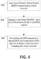
- Figure 4illustrates a method that can be done at the DNS proxy 302.
- a Domain Name System (DNS) requestis received from a virtual network.
- DNSDomain Name System
- the DNS proxy 302may intercept the DNS request as it is being sent to the shared DNS server 304.
- a DNS requestis tagged with a separating identifier.
- the separating identifiercan be any identifier that separates any two parties, e.g. it could be per company, per person, per application, per anything else.
- the separating identifiercan be a virtual network ID.
- the separating identifiersuch as the virtual network ID, is placed in an option field.
- the separating identifiermay be placed in an EDNS0 option field.
- the separating identifiercan be appended in some other way to the DNS request.
- step 406the DNS request is forwarded to a shared DNS server 304 that stores DNS data for multiple virtual networks including the virtual network.
- the DNS proxy 302receives a DNS request from a virtual network, such as virtual network 306.
- the DNS proxy 302tags a separating identifier (such as a virtual network ID for the virtual network 306) to the DNS request.
- the DNS proxy 302forwards the DNS request to a shared DNS server that stores DNS data for multiple virtual networks including the virtual network.
- the DNS proxy 302may also be configured to receive a DNS response to the DNS request from the shared DNS server 304.
- the DNS responsecan be also tagged with the separating identifier, such as the virtual network ID.
- This DNS responsecan then be forwarded to the correct virtual network as indicated by the separating identifier, such as the virtual network ID.
- the routing of the replydoesn't need to be done using the separating identifier, such as the virtual network ID.
- the DNS proxy 302can examine all DNS requests and DNS responses at a location.
- a hypervisor 310can include the DNS proxy 302.
- each physical devicecomputer or server
- Processors and storage devices at the physical devicesuch as a computer or server 202 shown in Figure 2 can be considered as implementing the functionality of the DNS proxy 302.
- a DNS server 304can comprise a shared DNS server that serves multiple virtual networks.
- the shared DNS servercan be provisioned and maintained with independent operation for each associated virtual network.
- the DNS server 304can comprise one or more storage devices 304a (memories) and one or more processors 304b in communication with one another.
- the DNS Server 302may be a DNS server capable of providing:
- the DNS servercan be composed of multiple virtualization instances with tenant specific data and settings, each mapped to a virtual network. Using the virtual network ID in the incoming query, the DNS server may perform the name resolution tasks. The DNS server may also be capable of performing public name resolution.
- Figure 5shows a method that can be performed at the DNS server 304.
- a separating identifier, such as the virtual network ID,allows the DNS server 304 to determine which virtual network the DNS request is for.
- a DNS local namespace dedicated to the virtual networkis checked using the separating identifier to process that request for the virtual network. Since local namespaces are used, each virtual network can independently map the same domain name to different IP address.
- step 506if the DNS request resolves at the DNS local namespace, a response is provided to the DNS request. Otherwise, the request can be resolved at a DNS cache or an external DNS server.
- the example of Figure 3shows how the local namespaces are allowed to conflict.
- the red tenant virtual network 306 and the blue tenant virtual network 308can independently define mappings of names such as "vm1.contoso.com” to different IP addresses.
- a DNS request(such as one tagged with the virtual network ID for the red tenant virtual network 306) is received for "vm1.contoso.com”
- the DNS server 304can supply the correct IP address back to the DNS proxy 302.
- the namespace for red tenant virtual network 306 and for the blue tenant virtual network 308can be allowed to conflict. This can allow an existing network to be converted into a virtual network without having to modify the namespace such that it does not conflict with another namespace. It is also possible that instances may not have a DNS record for a given name.
- the DNS requestcan be replied to with a response that is tagged with the separating identifier, such as the virtual network ID. Alternately, other addressing methods can be used.
- the DNS server 304can check a shared DNS cache for the DNS request if the request does not resolve at the DNS local namespace.
- the shared DNS cachecan be used for multiple virtual networks since it stores IP addresses for the external network. For example, when the DNS request concerns a request for an IP address of a location on an external network, the IP address may or may not be stored in this shared cache. If the IP address is stored in this shared cache, the DNS server 304 can respond with the IP address. The DNS server 304 can check with an external DNS server if the request does not resolve at the shared cache. The shared cache can then be updated with the IP address from the external DNS server.
- the resolutionmay be done in the following order until a match is found:
- the DNS proxy and DNS serverare instructed about the correspondence of the separating identifiers (such as the virtual network IDs) and the virtual network.
- the DNS serverthen creates a partition for the virtual network to store the local namespace.
- a management processcan set up and update the local namespace information at the DNS server.
- any software components described hereinmay, when loaded into a processor and executed, transform the processor from a general-purpose computing system into a special-purpose computing system customized to facilitate the functionality presented herein.
- the processormay be constructed from any number of transistors or other discrete circuit elements, which may individually or collectively assume any number of states. More specifically, the processor may operate as a finite-state machine, in response to executable instructions contained within the software modules disclosed herein. These processor-executable instructions may transform the processor by specifying how the processor transitions between states, thereby transforming the transistors or other discrete hardware elements constituting the processor.
- Encoding the software modules presented hereinalso may transform the physical structure of the computer-readable storage media presented herein.
- the specific transformation of physical structuremay depend on various factors, in different implementations of this description. Examples of such factors may include, but are not limited to, the technology used to implement the computer-readable storage media, whether the computer-readable storage media is characterized as primary or secondary storage, and the like.
- the computer-readable storage mediais implemented as semiconductor-based memory
- the software disclosed hereinmay be encoded on the computer-readable storage media by transforming the physical state of the semiconductor memory.
- the softwaremay transform the state of transistors, capacitors, or other discrete circuit elements constituting the semiconductor memory.
- the softwarealso may transform the physical state of such components in order to store data thereupon.
- the computer-readable storage media disclosed hereinmay be implemented using magnetic or optical technology.
- the software presented hereinmay transform the physical state of magnetic or optical media, when the software is encoded therein. These transformations may include altering the magnetic characteristics of particular locations within given magnetic media. These transformations also may include altering the physical features or characteristics of particular locations within given optical media, to change the optical characteristics of those locations. Other transformations of physical media are possible without departing from the scope and spirit of the present description, with the foregoing examples provided only to facilitate this discussion.
- the architecturemay include other types of computing devices, including hand-held computers, embedded computer systems, smartphones, PDAs, and other types of computing devices known to those skilled in the art. It is also contemplated that the architecture may not include all of the components shown in the figures, may include other components that are not explicitly shown in the figures, or may utilize an architecture completely different from that shown the figures.
- the functionally described hereinmay be performed, at least in part, by one or more hardware logic components.
- illustrative types of hardware logic componentsinclude Field-programmable Gate Arrays (FPGAs), Application-specific Integrated Circuits (ASICs), Application-specific Standard Products (ASSPs), System-on-a-chip systems (SOCs), Complex Programmable Logic Devices (CPLDs), etc.
- Computer-readable storage mediamay provide storage for instructions for the one or more processors. Although the description of computer-readable storage media contained herein refers to a mass storage device, such as a hard disk or CD-ROM drive, it should be appreciated by those skilled in the art that computer-readable media may be any available storage media.
- computer-readable storage mediamay include volatile and non-volatile, removable and non-removable media implemented in any method or technology for storage of information such as computer-readable instructions, data structures, program modules or other data.
- computer-readable mediaincludes, but is not limited to, RAM, ROM, EPROM (erasable programmable read only memory), EEPROM (electrically erasable programmable read only memory), Flash memory or other solid state memory technology, CD-ROM, DVDs, HD-DVD (High Definition DVD), BLU-RAY, or other optical storage, magnetic cassettes, magnetic tape, magnetic disk storage or other magnetic storage devices, or any other medium which may be used to store the desired information and instructions.
- the phrase "computer-readable storage medium” and variations thereofdoes not include waves, signals, and/or other transitory and/or intangible communication media.
Landscapes
- Engineering & Computer Science (AREA)
- Computer Networks & Wireless Communication (AREA)
- Signal Processing (AREA)
- Library & Information Science (AREA)
- Data Exchanges In Wide-Area Networks (AREA)
Description
- The Domain Name System (DNS) is a hierarchical distributed naming system for resources connected to networks, such as the Internet. The Domain Name System associates numerical IP addresses with domain names of network entities. DNS servers translate domain names, which can be easily remembered and used by humans, to numerical IP addresses. DNS servers can also store and provide other record types (such as Canonical Name (CNAME), free form text (TXT), mail exchanger record (MX record), Pointer records (such as PTR records) that do different functions.
- The Domain Name System maintains the domain name hierarchy and provides translation services between it and the Internet Protocol (IP) address space. Internet name servers and a communication protocol implement the Domain Name System. A DNS name server is a server that stores the DNS records for a domain name, receives DNS requests and responds with answers to queries against its database.
- In addition to the Domain names that it is responsible for, DNS servers typically cache DNS requests and responses that have been received from other DNS name servers. Caching name servers (DNS caches) store DNS query results for a period of time determined in an associated time-to-live of a domain-name record. DNS caches improve the efficiency of the DNS by reducing DNS traffic across the Internet, and by reducing load on authoritative name-servers, particularly root name-servers. Because they can answer questions more quickly, they also increase the performance of end-user applications that use the DNS.
WO 2012/065641 relates to a Domain Name System server and a method for resolving DNS queries from a number of clients. The DNS server comprises multiple virtual DNS server instances serving different clients. The DNS server receives a DNS query from a client and determines which virtual DNS server instance the DNS query belongs to. The specific DNS server instance used to resolve the DNS query is determined in D1 based on several alternative criteria. These criteria include the source address of the DNS query, tunnel headers, Media Access Control headers and International Mobile Subscriber Identity. The DNS query is resolved by the respective DNS server instance. All the records to resolve the DNS query may be found in the cache memory of the DNS server or stored in another DNS server. The cache memory of the DNS server may include a shared cache that is shared between several of the virtual DNS server instances. - It is the object of the present invention to provide an improved method of enhancing multi-tenant DNS resolution.
- This object is solved by the subject matter of the independent claims.
- Preferred embodiments are defined in the dependent claims.
- Embodiments concern a DNS server that can be shared by multiple virtual networks in a cloud computing environment.
- A DNS proxy tags DNS requests from a virtual network with an identifier, such as a virtual network ID, before forwarding them to a shared DNS server. This can allow each virtual network to have its own namespace and avoid naming conflicts.
- The shared DNS server can examine the tagged DNS requests to respond to the DNS requests using the local namespace as identified by the virtual network ID.
- This summary is provided to introduce a selection of concepts in a simplified form that are further described below in the Detailed Description. This Summary is not intended to identify key features or essential features of the claimed subject matter, nor is it intended to be used to limit the scope of the claimed subject matter.
- A more detailed understanding may be had from the following description, given by way of example in conjunction with accompanying drawings wherein:
Figure 1 is a network diagram that illustrates an exemplary computing system.Figure 2 shows an exemplary non-limiting server or computer that can implement disclosed embodiments.Figure 3 illustrates a system of one embodiment.Figure 4 illustrates a method that can be performed at the DNS proxy.Figure 5 and6 illustrate methods performed at a DNS server.- Embodiments concern a system and method for providing a shared domain name resolution services for a multitenant network.
- A cloud service provider (CSP) is a company that offers some component of cloud computing, such as Infrastructure as a Service (IaaS), Software as a Service (SaaS) or Platform as a Service (PaaS), to other businesses or individuals. Cloud service providers often aim to facilitate onboarding of the tenants' private networks into their environments for which they need to keep the addressing and naming properties of these networks intact while providing appropriate network isolation between tenants. The network virtualization technologies allow tenants to bring their own IP addresses or IP address space in a managed cloud. Embodiments can solve the issue of providing name resolution services for the virtual networks where customers can bring their own domain names. The systems can also ensure privacy by preventing private domains from being seen outside the virtual network.
- Embodiments define the capabilities and interfaces for a shared DNS server composed of different virtualization instances that host isolated domain name databases, catering to different virtual networks. Embodiments also define a DNS proxy that listens to the virtual networks; identifies and adds tenant metadata into the DNS packets (in form of a EDNS0 option) which are received by the DNS server which processes the metadata to identify the virtualization instance.
- Benefits can include:
- 1. Ability to allow tenants of a managed cloud to bring their own domain names.
- 2. Ability to use a shared authoritative DNS server that provides name resolution services for tenants with overlapping domain name spaces with appropriate tenant isolations.
- 3. Ability to provide the above services irrespective of the virtualization technologies used by the provider.
- 4. Isolation of tenant domain name databases from the query and management perspective
Figure 1 is a network diagram that illustrates anexemplary computing system 100. In an embodiment, thecomputing system 100 shown inFigure 1 is merely exemplary and is not intended to suggest any limitation as to scope or functionality. Embodiments of the invention are operable with numerous other configurations. With reference toFigure 1 , thecomputing system 100 includes acloud computing platform 110,cloud applications 120, andclient devices 130.- The
cloud computing platform 110 is configured to executecloud applications 120 requested by theclient devices 130. Thecloud computing platform 110 maintains computing devices that provide virtual machines, which execute thecloud application 120. The cloud computing platform also includes storage resources that store applications and system information. Thecloud computing platform 110 connects to theclient devices 130 via a communications network, such as a wireless network, local area network, wired network, or the Internet. - The
cloud applications 120 are available to theclient devices 130. The software executed on thecloud computing platform 110 implements thecloud applications 120. In one embodiment, virtual machines provided by thecloud computing platform 110 execute thecloud applications 120. Thecloud applications 120 may include, but are not limited to, editing applications, network management applications, finance applications, or any application requested or developed by theclient devices 130. In certain embodiments, some functionality of thecloud application 120 may be executed on theclient devices 130. - The
client devices 130 are utilized by a user to interact withcloud applications 120 provided by thecloud computing platform 110. Theclient devices 130, in some embodiments, must register with thecloud computing platform 110 to access thecloud applications 120. Anyclient device 130 with an account from thecloud computing platform 110 may access thecloud applications 120 and other resources provided in thecloud computing platform 110. Theclient devices 130 include, without limitation, personal digital assistants, smart phones, laptops, personal computers, gaming systems, set-top boxes, or any other suitable client computing device. Theclient devices 130 include user and system information storage to store user and system information on theclient devices 130. The user information may include search histories, cookies, and passwords. The system information may include internet protocol addresses, cached Web pages, and system utilization. Theclient devices 130 communicate with thecloud computing platform 110 to receive results from thecloud applications 120. - Accordingly, the
computing system 100 is configured with acloud computing platform 110 that providescloud applications 120 to theclient devices 130. Thecloud applications 120 remove the burden of updating and managing multiple local client applications on theclient devices 130.Cloud applications 120 can also handle necessary scale, security and availability issues that theclient devices 130 may not be setup for. - An exemplary cloud computing platform is Microsoft Azure. Microsoft Azure uses a specialized operating system, also called Microsoft Azure, to run its "fabric layer": a cluster hosted at Microsoft's data centers that manage computing and storage resources of the computers and provisions the resources (or a subset of them) to applications running on top of Microsoft Azure.
- The cloud computing system can use cloud computing devices and software at a client data center, such as with Microsoft Azure Stack. Moving cloud computing techniques to a company datacenter can provide agility and productivity for application owners, flexibility and control for Information technology (IT) units, and assurance that corporate assets are protected.
Figure 2 shows an exemplary non-limiting server or computer 202 that can implement disclosed embodiments. Such a server or computer can be used to implement cloud computing, the DNS proxy, and DNS server.- In
Figure 2 , thecomputing environment 220 comprises a computer 241, which typically includes a variety of computer readable media. Computer readable media may be any available media that may be accessed by computer 241 and includes both volatile and nonvolatile media, removable and non-removable media. Thesystem memory 222 includes computer storage media in the form of volatile and/or nonvolatile memory such as read only memory (ROM) 223 and random access memory (RAM) 260. A basic input/output system 224 (BIOS), containing the basic routines that help to transfer information between elements within computer 241, such as during start-up, is typically stored inROM 223.RAM 260 typically contains data and/or program modules that are immediately accessible to and/or presently being operated on by processing unit 259. By way of example, and not limitation,Figure 2 illustrates operating system 225,application programs 226,other program modules 227, and program data 228. - The computer 241 may also include other removable/non-removable, volatile/nonvolatile computer storage media. By way of example only,
Figure 2 illustrates ahard disk drive 238 that reads from or writes to non-removable, nonvolatile magnetic media, a magnetic disk drive 239 that reads from or writes to a removable, nonvolatile magnetic disk 254, and an optical disk drive 240 that reads from or writes to a removable, nonvolatile optical disk 253 such as a CD ROM or other optical media. Other removable/non-removable, volatile/nonvolatile computer storage media that may be used in the exemplary operating environment include, but are not limited to, magnetic tape cassettes, flash memory cards, digital versatile disks, digital video tape, solid state RAM, solid state ROM, and the like. Thehard disk drive 238 is typically connected to the system bus 221 through a non-removable memory interface such asinterface 234, and magnetic disk drive 239 and optical disk drive 240 are typically connected to the system bus 221 by a removable memory interface, such as interface 235. - The drives and their associated computer storage media discussed above provide storage of computer readable instructions, data structures, program modules and other data for the computer 241. In
Figure 2 , for example,hard disk drive 238 is illustrated as storing operating system 258, application programs 257,other program modules 256, and program data 255. Note that these components may either be the same as or different from operating system 225,application programs 226,other program modules 227, and program data 228. Operating system 258, application programs 257,other program modules 256, and program data 255 are given different numbers here to illustrate that, at a minimum, they are different copies. A user may enter commands and information into the computer 241 through input devices such as akeyboard 251 and pointing device 252, which may take the form of a mouse, trackball, or touch pad, for instance. Other input devices (not shown) may include a microphone, joystick, game pad, satellite dish, scanner, or the like. These and other input devices are often connected to the processing unit 259 through a user input interface 236 that is coupled to the system bus 221, but may be connected by other interface and bus structures, such as a parallel port, game port or a universal serial bus (USB). Amonitor 242 or other type of display device is also connected to the system bus 221 via an interface, such as a video interface 232, which may operate in conjunction with a graphics interface 231, a graphics processing unit (GPU) 229, and/or a video memory 229. In addition to the monitor, computers may also include other peripheral output devices such asspeakers 244 andprinter 243, which may be connected through an outputperipheral interface 233. - The computer 241 may operate in a networked environment using logical connections to one or more remote computers, such as a remote computer 246. The remote computer 246 may be a personal computer, a server, a router, a network PC, a peer device or other common network node, and typically includes many or all of the elements described above relative to the computer 241, although only a memory storage device 247 has been illustrated in
Figure 2 . The logical connections depicted inFigure 2 include a local area network (LAN) 245 and a wide area network (WAN) 249, but may also include other networks. Such networking environments are commonplace in offices, enterprise-wide computer networks, intranets and the Internet. - When used in a LAN networking environment, the computer 241 is connected to the LAN 245 through a network interface or adapter 237. When used in a WAN networking environment, the computer 241 typically includes a modem 250 or other means for establishing communications over the WAN 249, such as the Internet. The modem 250, which may be internal or external, may be connected to the system bus 221 via the user input interface 236, or other appropriate mechanism. In a networked environment, program modules depicted relative to the computer 241, or portions thereof, may be stored in the remote memory storage device. By way of example, and not limitation,
Figure 2 illustrates remote application programs 248 as residing on memory device 247. It will be appreciated that the network connections shown are exemplary and other means of establishing a communications link between the computers may be used. - A virtual network is a computer network that consists, at least in part, of virtual network links. A virtual network link is a link that does not consist of a physical (wired or wireless) connection between two computing devices but is implemented using methods of network virtualization.
- Multi-tenant architectures may use multiple virtual networks. As disclosed below, each virtual network may have need of a DNS server.
- One solution is for each tenant (virtual network) to deploy one virtual machine (VM) as a DNS server in its network, where it manages and hosts the required domains. The tenant virtual machines point to this DNS server for name resolution. This DNS server may double up as an authoritative server as well as a forwarder/recursive resolver for external queries. This solution is non-optimal as it requires one dedicated VM per tenant which is dedicated for DNS and puts the management overhead on the clients. This solution also doesn't provide fault tolerance, e.g. if the VM dies.
- Another solution is for each tenant virtual network to use restricted name spaces. In this solution, the clients cannot bring their own domain name into the cloud. They are forced to keep some specific DNS suffixes (say in format <VM-Name>.<Tenant-ID>.myclouddomain.com). In this solution, the DNS resolution works fine, but an extra access control list (ACL) has to be created on the query path to ensure that one tenant cannot resolve names for another tenant.
- These solutions may not be cost effective or may limit the capacity or functionality of the system. The following describes a solution that allows tenants to use a single DNS server to serve multiple clients with full isolation and allows customers to bring their own domain name to cloud. This facilitates seamless migration of tenant domains to/from private-public cloud.
- In one embodiment, as shown in
Figure 3 , a Multi-tenant DNS solution may have two major components, a (multi-tenant)DNS proxy 302 and a (multi-tenant)DNS Server 304. DNS proxy 302 can comprise computer or server including one ormore storage devices 302a and one ormore processors 302b in communication with the one ormore storage devices 302a. The one ormore processors 302b may be configured to do operations as described below.- The
DNS proxy 302 can be considered to be a gateway for forwarding DNS traffic. It may listen to the DNS packets emanating from tenant networks and forwards the query to theDNS server 304 on the physical network. Apart from forwarding the multitenant proxy can also add an EDNS0 option ID, as defined by Internet standards track protocol RFC 2671 (Extension Mechanisms for DNS (EDNS0)), into the outgoing DNS packet. This optional ID can contain a separating identifier such as the Virtual Network ID (VNET identifier). This identifier is used byDNS server 304 to ensure isolation. On the return path the proxy may clean up the EDNS0 option and routes the packet back to the tenant VM Figure 4 illustrates a method that can be done at theDNS proxy 302.- In
step 402, a Domain Name System (DNS) request is received from a virtual network. TheDNS proxy 302 may intercept the DNS request as it is being sent to the sharedDNS server 304. - In
step 404, a DNS request is tagged with a separating identifier. The separating identifier can be any identifier that separates any two parties, e.g. it could be per company, per person, per application, per anything else. The separating identifier can be a virtual network ID. - In one example, the separating identifier, such as the virtual network ID, is placed in an option field. For example, the separating identifier may be placed in an EDNS0 option field. Alternately, the separating identifier can be appended in some other way to the DNS request.
- In
step 406, the DNS request is forwarded to a sharedDNS server 304 that stores DNS data for multiple virtual networks including the virtual network. - Looking again at
Figure 3 , theDNS proxy 302 receives a DNS request from a virtual network, such asvirtual network 306. TheDNS proxy 302 tags a separating identifier (such as a virtual network ID for the virtual network 306) to the DNS request. TheDNS proxy 302 forwards the DNS request to a shared DNS server that stores DNS data for multiple virtual networks including the virtual network. - The
DNS proxy 302 may also be configured to receive a DNS response to the DNS request from the sharedDNS server 304. The DNS response can be also tagged with the separating identifier, such as the virtual network ID. This DNS response can then be forwarded to the correct virtual network as indicated by the separating identifier, such as the virtual network ID. In another embodiment, the routing of the reply doesn't need to be done using the separating identifier, such as the virtual network ID. - The
DNS proxy 302 can examine all DNS requests and DNS responses at a location. InFigure 3 , ahypervisor 310 can include theDNS proxy 302. In one embodiment, each physical device (computer or server) has ahypervisor 310 and associatedDNS proxy 302. Processors and storage devices at the physical device such as a computer or server 202 shown inFigure 2 can be considered as implementing the functionality of theDNS proxy 302. - A
DNS server 304 can comprise a shared DNS server that serves multiple virtual networks. The shared DNS server can be provisioned and maintained with independent operation for each associated virtual network. TheDNS server 304 can comprise one ormore storage devices 304a (memories) and one ormore processors 304b in communication with one another. - The
DNS Server 302 may be a DNS server capable of providing: - 1. Support for a "bring your own domain name" scenario, allowing DNS zones to be configured by multiple tenants. A DNS zone may be any contiguous portion of the domain name space in the Domain Name System (DNS) for which administrative responsibility has been delegated to a single manager.
- 2. Ability to perform name resolution for customer hosted domains, while providing tenant isolation during name resolution
- 3. Isolation of management interfaces and persistent store for DNS zones. Application Programing Interfaces (APIs) can be provided to create virtual instance on DNS server. The virtual instances can have DNS zones that contain DNS records. These APIs can be isolated so that other users cannot access them. The APIs can send info to an underlying system which can perform a Remote Procedure Call (RPC) to the
DNS Server 302. - 4. Isolation of server settings (forwarders, conditional forwarders etc.). Configuration settings for each of the virtual networks at the
DNS Server 302 may be independent. - 5. Ability to perform tenant specific Dynamic DNS (DDNS) updates.
- 6. Isolation of DNS zone transfers. DNS zone transfers allow two DNS servers to synchronize. A zone transfer request can include a tag of the virtual network ID to allow the correct local namespace information to be synchronized.
- 7. Support for traffic management within the tenant domain
- 8. Ability to perform public name resolution.
- The DNS server can be composed of multiple virtualization instances with tenant specific data and settings, each mapped to a virtual network. Using the virtual network ID in the incoming query, the DNS server may perform the name resolution tasks. The DNS server may also be capable of performing public name resolution.
Figure 5 shows a method that can be performed at theDNS server 304.- In
step 502, a DNS request that was tagged by a proxy with a separating identifier, such as a virtual network ID, is received. A separating identifier, such as the virtual network ID, allows theDNS server 304 to determine which virtual network the DNS request is for. - In
step 504, a DNS local namespace dedicated to the virtual network is checked using the separating identifier to process that request for the virtual network. Since local namespaces are used, each virtual network can independently map the same domain name to different IP address. - In
step 506 if the DNS request resolves at the DNS local namespace, a response is provided to the DNS request. Otherwise, the request can be resolved at a DNS cache or an external DNS server. - The example of
Figure 3 shows how the local namespaces are allowed to conflict. InFigure 3 , the red tenantvirtual network 306 and the blue tenantvirtual network 308 can independently define mappings of names such as "vm1.contoso.com" to different IP addresses. When a DNS request (such as one tagged with the virtual network ID for the red tenant virtual network 306) is received for "vm1.contoso.com", theDNS server 304 can supply the correct IP address back to theDNS proxy 302. The namespace for red tenantvirtual network 306 and for the blue tenantvirtual network 308 can be allowed to conflict. This can allow an existing network to be converted into a virtual network without having to modify the namespace such that it does not conflict with another namespace. It is also possible that instances may not have a DNS record for a given name. - The DNS request can be replied to with a response that is tagged with the separating identifier, such as the virtual network ID. Alternately, other addressing methods can be used.
- The
DNS server 304 can check a shared DNS cache for the DNS request if the request does not resolve at the DNS local namespace. The shared DNS cache can be used for multiple virtual networks since it stores IP addresses for the external network. For example, when the DNS request concerns a request for an IP address of a location on an external network, the IP address may or may not be stored in this shared cache. If the IP address is stored in this shared cache, theDNS server 304 can respond with the IP address. TheDNS server 304 can check with an external DNS server if the request does not resolve at the shared cache. The shared cache can then be updated with the IP address from the external DNS server. - As shown in
Figure 6 , at the sharedDNS server 304, the resolution may be done in the following order until a match is found: - 1) Checking the local namespace for the virtual network indicated by the separating identifier (step 602).
- 2) Checking a shared namespace (step 604).
- 3) Performing an external resolution (step 606).
- To provision the system, once a virtual network is created, the DNS proxy and DNS server are instructed about the correspondence of the separating identifiers (such as the virtual network IDs) and the virtual network. The DNS server then creates a partition for the virtual network to store the local namespace. A management process can set up and update the local namespace information at the DNS server.
- It should be appreciated that any software components described herein may, when loaded into a processor and executed, transform the processor from a general-purpose computing system into a special-purpose computing system customized to facilitate the functionality presented herein. The processor may be constructed from any number of transistors or other discrete circuit elements, which may individually or collectively assume any number of states. More specifically, the processor may operate as a finite-state machine, in response to executable instructions contained within the software modules disclosed herein. These processor-executable instructions may transform the processor by specifying how the processor transitions between states, thereby transforming the transistors or other discrete hardware elements constituting the processor.
- Encoding the software modules presented herein also may transform the physical structure of the computer-readable storage media presented herein. The specific transformation of physical structure may depend on various factors, in different implementations of this description. Examples of such factors may include, but are not limited to, the technology used to implement the computer-readable storage media, whether the computer-readable storage media is characterized as primary or secondary storage, and the like. For example, if the computer-readable storage media is implemented as semiconductor-based memory, the software disclosed herein may be encoded on the computer-readable storage media by transforming the physical state of the semiconductor memory. For example, the software may transform the state of transistors, capacitors, or other discrete circuit elements constituting the semiconductor memory. The software also may transform the physical state of such components in order to store data thereupon.
- As another example, the computer-readable storage media disclosed herein may be implemented using magnetic or optical technology. In such implementations, the software presented herein may transform the physical state of magnetic or optical media, when the software is encoded therein. These transformations may include altering the magnetic characteristics of particular locations within given magnetic media. These transformations also may include altering the physical features or characteristics of particular locations within given optical media, to change the optical characteristics of those locations. Other transformations of physical media are possible without departing from the scope and spirit of the present description, with the foregoing examples provided only to facilitate this discussion.
- In light of the above, it should be appreciated that many types of physical transformations take place in the architecture in order to store and execute the software components presented herein. It also should be appreciated that the architecture may include other types of computing devices, including hand-held computers, embedded computer systems, smartphones, PDAs, and other types of computing devices known to those skilled in the art. It is also contemplated that the architecture may not include all of the components shown in the figures, may include other components that are not explicitly shown in the figures, or may utilize an architecture completely different from that shown the figures.
- Alternatively, or in addition, the functionally described herein may be performed, at least in part, by one or more hardware logic components. For example, and without limitation, illustrative types of hardware logic components that may be used include Field-programmable Gate Arrays (FPGAs), Application-specific Integrated Circuits (ASICs), Application-specific Standard Products (ASSPs), System-on-a-chip systems (SOCs), Complex Programmable Logic Devices (CPLDs), etc.
- Computer-readable storage media may provide storage for instructions for the one or more processors. Although the description of computer-readable storage media contained herein refers to a mass storage device, such as a hard disk or CD-ROM drive, it should be appreciated by those skilled in the art that computer-readable media may be any available storage media.
- By way of example, and not limitation, computer-readable storage media may include volatile and non-volatile, removable and non-removable media implemented in any method or technology for storage of information such as computer-readable instructions, data structures, program modules or other data. For example, computer-readable media includes, but is not limited to, RAM, ROM, EPROM (erasable programmable read only memory), EEPROM (electrically erasable programmable read only memory), Flash memory or other solid state memory technology, CD-ROM, DVDs, HD-DVD (High Definition DVD), BLU-RAY, or other optical storage, magnetic cassettes, magnetic tape, magnetic disk storage or other magnetic storage devices, or any other medium which may be used to store the desired information and instructions. For purposes of this specification and the claims, the phrase "computer-readable storage medium" and variations thereof, does not include waves, signals, and/or other transitory and/or intangible communication media.
- Although the subject matter presented herein has been described in language specific to computer structural features, methodological and transformative acts, specific computing machinery, and computer-readable storage media, it is to be understood that the methods and devices defined in the appended claims is not necessarily limited to the specific features, acts, or media described herein. Rather, the specific features, acts, and mediums are disclosed as example forms of implementing the claims.
- Although the subject matter has been described in language specific to structural features and/or methodological acts, it is to be understood that the subject matter defined in the appended claims is not necessarily limited to the specific features or acts described above. Rather, the specific features and acts described above are disclosed as example forms of implementing the claims. It is intended that the scope of the technology be defined by the claims appended hereto.
Claims (15)
- A computer-implemented method comprising:receiving (402), by a Domain Name System (DNS) proxy (302) coupled between a shared multi-tenant DNS server (304) and a plurality of virtual networks (306, 308), a DNS request from a virtual network of the plurality of virtual networks, each virtual network of the plurality of virtual networks having a dedicated DNS local namespace;tagging (404), by the DNS proxy, a separating identifier to the DNS request, wherein the separating identifier identifies the virtual network; andforwarding (406), by the DNS proxy, the DNS request to the shared multi-tenant DNS server, the shared multi-tenant DNS server storing DNS data for each virtual network of the plurality of virtual networks.
- The method of claim 1, wherein the separating identifier is a virtual network ID.
- The method of claim 2, wherein the virtual network ID is placed in an EDNS0 option field.
- The method of claim 1, wherein the separating identifier is a virtual network ID or a function of a virtual network ID.
- The method of claim 1, wherein the DNS server hosts isolated domain name databases.
- The method of claim 5, wherein each domain name database is associated with a different virtual network of the plurality of virtual networks.
- A system for providing a multi-tenant Domain Name System (DNS) service, the system comprising:a Domain Name System (DNS) proxy (302) coupled between a shared multi-tenant DNS server (304) and a plurality of virtual networks (306, 308), the DNS proxy being configured to:receive (402) a DNS request from a virtual network of the plurality of virtual networks, each virtual network of the plurality of virtual networks having a dedicated DNS local namespace;tag (404) a separating identifier to the DNS request, wherein the separating identifier identifies the virtual network; andforward (406) the DNS request to the shared multi-tenant DNS server, the shared multi-tenant DNS server storing DNS data for each virtual network of the plurality of virtual networks; anda shared multi-tenant Domain Name System (DNS) server (304) configured to:receive (502) a DNS request from the DNS proxy (302);accessing (504) the DNS local namespace dedicated to the virtual network based on the separating identifier;using (504) the separating identifier to process the request for the virtual network to resolve the DNS request; andif the DNS request resolves at the DNS local namespace, providing (506) a response to the DNS request.
- The system of claim 7, wherein the separating identifier is a virtual network ID or a function of a virtual network ID.
- The system of claim 8, wherein the virtual network ID is in an EDNS0 option field.
- The system of claim 7, wherein the DNS Server is further configured to:access a shared DNS cache for the DNS request if the request does not resolve at the DNS local namespace; andif the DNS request resolves at the DNS cache, providing a response to the DNS request.
- The system of claim 7, wherein a shared DNS cache is used for multiple virtual networks including the virtual network.
- The system of claim 11, wherein the DNS Server is further configured to check an external DNS server if the request does not resolve at the shared DNS cache.
- A Domain Name System (DNS) proxy (302) coupled between a shared multi-tenant DNS server (304) and a plurality of virtual networks (306, 308), the DNS proxy comprising:one or more storage devices (222, 238, 239, 240); andone or more processors (259) in communication with the one or more storage devices, wherein the one or more processors are configured to:receive (402) a DNS request from a virtual network of the plurality of virtual networks, each virtual network of the plurality of virtual networks having a dedicated DNS local namespace;tag (404) a separating identifier to the DNS request, wherein the separating identifier identifies the virtual network; andforward (406) the DNS request to the shared multi-tenant DNS server, the shared multi-tenant DNS server storing DNS data for each virtual network of the plurality of virtual networks.
- The proxy of claim 13, wherein the separating identifier is a virtual network ID.
- The proxy of claim 13, wherein the separating identifier is in an EDNS0 option field.
Applications Claiming Priority (3)
| Application Number | Priority Date | Filing Date | Title |
|---|---|---|---|
| IN6691CH2015 | 2015-12-14 | ||
| US15/148,715US10356038B2 (en) | 2015-12-14 | 2016-05-06 | Shared multi-tenant domain name system (DNS) server for virtual networks |
| PCT/US2016/065040WO2017105906A1 (en) | 2015-12-14 | 2016-12-06 | Shared multi-tenant domain name system (dns) server for virtual networks |
Publications (2)
| Publication Number | Publication Date |
|---|---|
| EP3391627A1 EP3391627A1 (en) | 2018-10-24 |
| EP3391627B1true EP3391627B1 (en) | 2020-04-15 |
Family
ID=59020301
Family Applications (1)
| Application Number | Title | Priority Date | Filing Date |
|---|---|---|---|
| EP16816123.0AActiveEP3391627B1 (en) | 2015-12-14 | 2016-12-06 | Shared multi-tenant domain name system (dns) server for virtual networks and corresponding method |
Country Status (4)
| Country | Link |
|---|---|
| US (1) | US10356038B2 (en) |
| EP (1) | EP3391627B1 (en) |
| CN (1) | CN108370391B (en) |
| WO (1) | WO2017105906A1 (en) |
Families Citing this family (83)
| Publication number | Priority date | Publication date | Assignee | Title |
|---|---|---|---|---|
| US7991910B2 (en) | 2008-11-17 | 2011-08-02 | Amazon Technologies, Inc. | Updating routing information based on client location |
| US8028090B2 (en) | 2008-11-17 | 2011-09-27 | Amazon Technologies, Inc. | Request routing utilizing client location information |
| US8606996B2 (en) | 2008-03-31 | 2013-12-10 | Amazon Technologies, Inc. | Cache optimization |
| US8601090B1 (en) | 2008-03-31 | 2013-12-03 | Amazon Technologies, Inc. | Network resource identification |
| US7970820B1 (en) | 2008-03-31 | 2011-06-28 | Amazon Technologies, Inc. | Locality based content distribution |
| US8321568B2 (en) | 2008-03-31 | 2012-11-27 | Amazon Technologies, Inc. | Content management |
| US8447831B1 (en) | 2008-03-31 | 2013-05-21 | Amazon Technologies, Inc. | Incentive driven content delivery |
| US7962597B2 (en) | 2008-03-31 | 2011-06-14 | Amazon Technologies, Inc. | Request routing based on class |
| US9407681B1 (en) | 2010-09-28 | 2016-08-02 | Amazon Technologies, Inc. | Latency measurement in resource requests |
| US8073940B1 (en) | 2008-11-17 | 2011-12-06 | Amazon Technologies, Inc. | Managing content delivery network service providers |
| US8412823B1 (en) | 2009-03-27 | 2013-04-02 | Amazon Technologies, Inc. | Managing tracking information entries in resource cache components |
| US8756341B1 (en) | 2009-03-27 | 2014-06-17 | Amazon Technologies, Inc. | Request routing utilizing popularity information |
| US8688837B1 (en) | 2009-03-27 | 2014-04-01 | Amazon Technologies, Inc. | Dynamically translating resource identifiers for request routing using popularity information |
| US8782236B1 (en) | 2009-06-16 | 2014-07-15 | Amazon Technologies, Inc. | Managing resources using resource expiration data |
| US8397073B1 (en) | 2009-09-04 | 2013-03-12 | Amazon Technologies, Inc. | Managing secure content in a content delivery network |
| US8433771B1 (en) | 2009-10-02 | 2013-04-30 | Amazon Technologies, Inc. | Distribution network with forward resource propagation |
| US9495338B1 (en) | 2010-01-28 | 2016-11-15 | Amazon Technologies, Inc. | Content distribution network |
| US8468247B1 (en) | 2010-09-28 | 2013-06-18 | Amazon Technologies, Inc. | Point of presence management in request routing |
| US10958501B1 (en) | 2010-09-28 | 2021-03-23 | Amazon Technologies, Inc. | Request routing information based on client IP groupings |
| US9003035B1 (en) | 2010-09-28 | 2015-04-07 | Amazon Technologies, Inc. | Point of presence management in request routing |
| US9712484B1 (en) | 2010-09-28 | 2017-07-18 | Amazon Technologies, Inc. | Managing request routing information utilizing client identifiers |
| US8452874B2 (en) | 2010-11-22 | 2013-05-28 | Amazon Technologies, Inc. | Request routing processing |
| US10467042B1 (en) | 2011-04-27 | 2019-11-05 | Amazon Technologies, Inc. | Optimized deployment based upon customer locality |
| US10623408B1 (en) | 2012-04-02 | 2020-04-14 | Amazon Technologies, Inc. | Context sensitive object management |
| US9154551B1 (en) | 2012-06-11 | 2015-10-06 | Amazon Technologies, Inc. | Processing DNS queries to identify pre-processing information |
| US9323577B2 (en) | 2012-09-20 | 2016-04-26 | Amazon Technologies, Inc. | Automated profiling of resource usage |
| US10205698B1 (en) | 2012-12-19 | 2019-02-12 | Amazon Technologies, Inc. | Source-dependent address resolution |
| US9294391B1 (en) | 2013-06-04 | 2016-03-22 | Amazon Technologies, Inc. | Managing network computing components utilizing request routing |
| US10097448B1 (en) | 2014-12-18 | 2018-10-09 | Amazon Technologies, Inc. | Routing mode and point-of-presence selection service |
| US10225326B1 (en) | 2015-03-23 | 2019-03-05 | Amazon Technologies, Inc. | Point of presence based data uploading |
| US9819567B1 (en) | 2015-03-30 | 2017-11-14 | Amazon Technologies, Inc. | Traffic surge management for points of presence |
| US9832141B1 (en) | 2015-05-13 | 2017-11-28 | Amazon Technologies, Inc. | Routing based request correlation |
| US9774619B1 (en) | 2015-09-24 | 2017-09-26 | Amazon Technologies, Inc. | Mitigating network attacks |
| US10270878B1 (en) | 2015-11-10 | 2019-04-23 | Amazon Technologies, Inc. | Routing for origin-facing points of presence |
| US10257307B1 (en) | 2015-12-11 | 2019-04-09 | Amazon Technologies, Inc. | Reserved cache space in content delivery networks |
| US10250452B2 (en) | 2015-12-14 | 2019-04-02 | Microsoft Technology Licensing, Llc | Packaging tool for first and third party component deployment |
| US10666517B2 (en) | 2015-12-15 | 2020-05-26 | Microsoft Technology Licensing, Llc | End-to-end automated servicing model for cloud computing platforms |
| US10348639B2 (en) | 2015-12-18 | 2019-07-09 | Amazon Technologies, Inc. | Use of virtual endpoints to improve data transmission rates |
| US10075551B1 (en) | 2016-06-06 | 2018-09-11 | Amazon Technologies, Inc. | Request management for hierarchical cache |
| US10110694B1 (en) | 2016-06-29 | 2018-10-23 | Amazon Technologies, Inc. | Adaptive transfer rate for retrieving content from a server |
| US9992086B1 (en) | 2016-08-23 | 2018-06-05 | Amazon Technologies, Inc. | External health checking of virtual private cloud network environments |
| US10033691B1 (en)* | 2016-08-24 | 2018-07-24 | Amazon Technologies, Inc. | Adaptive resolution of domain name requests in virtual private cloud network environments |
| US10616250B2 (en) | 2016-10-05 | 2020-04-07 | Amazon Technologies, Inc. | Network addresses with encoded DNS-level information |
| US10547506B2 (en) | 2016-12-13 | 2020-01-28 | International Business Machines Corporation | Determining identities for executing cloud processing and approvers of the executing |
| US11153273B2 (en) | 2016-12-13 | 2021-10-19 | International Business Machines Corporation | Generating and managing names of instances |
| US10623252B2 (en) | 2016-12-13 | 2020-04-14 | International Business Machines Corporation | Performing actions that have been defined for provisioned instances |
| US11044145B2 (en)* | 2016-12-13 | 2021-06-22 | International Business Machines Corporation | Configuring and naming of cloud provisioning entities |
| US10476942B2 (en)* | 2016-12-21 | 2019-11-12 | International Business Machines Corporation | DNS resolution of overlapping domains in a multi-tenant computing environment |
| US10372499B1 (en) | 2016-12-27 | 2019-08-06 | Amazon Technologies, Inc. | Efficient region selection system for executing request-driven code |
| US10831549B1 (en) | 2016-12-27 | 2020-11-10 | Amazon Technologies, Inc. | Multi-region request-driven code execution system |
| US10938884B1 (en) | 2017-01-30 | 2021-03-02 | Amazon Technologies, Inc. | Origin server cloaking using virtual private cloud network environments |
| US10503613B1 (en) | 2017-04-21 | 2019-12-10 | Amazon Technologies, Inc. | Efficient serving of resources during server unavailability |
| US11075987B1 (en) | 2017-06-12 | 2021-07-27 | Amazon Technologies, Inc. | Load estimating content delivery network |
| US10447648B2 (en) | 2017-06-19 | 2019-10-15 | Amazon Technologies, Inc. | Assignment of a POP to a DNS resolver based on volume of communications over a link between client devices and the POP |
| US11265365B2 (en) | 2017-06-26 | 2022-03-01 | Net Law Group, Inc. | Platform-specific thin-client delivery of an application developed on a cloud-based enterprise-customizable multi-tenant service interface |
| US10776178B2 (en) | 2017-06-26 | 2020-09-15 | Net Law Group, Inc. | Cloud-based enterprise-customizable multi-tenant service interface |
| US10742593B1 (en) | 2017-09-25 | 2020-08-11 | Amazon Technologies, Inc. | Hybrid content request routing system |
| US10592578B1 (en) | 2018-03-07 | 2020-03-17 | Amazon Technologies, Inc. | Predictive content push-enabled content delivery network |
| CN108886540B (en)* | 2018-06-13 | 2021-07-23 | 达闼机器人有限公司 | Domain name resolution method, device and computer readable storage medium |
| US10862852B1 (en)* | 2018-11-16 | 2020-12-08 | Amazon Technologies, Inc. | Resolution of domain name requests in heterogeneous network environments |
| US11025747B1 (en) | 2018-12-12 | 2021-06-01 | Amazon Technologies, Inc. | Content request pattern-based routing system |
| US11329959B2 (en)* | 2018-12-21 | 2022-05-10 | Fortinet, Inc. | Virtual routing and forwarding (VRF)-aware socket |
| US11283763B2 (en) | 2018-12-28 | 2022-03-22 | Mcafee, Llc | On-device dynamic safe browsing |
| US11050837B2 (en)* | 2019-01-31 | 2021-06-29 | Hewlett Packard Enterprise Development Lp | Providing cloud services associated with unused hardware resources of private cloud providers |
| US11405237B2 (en) | 2019-03-29 | 2022-08-02 | Mcafee, Llc | Unencrypted client-only virtual private network |
| US11362999B2 (en) | 2019-03-29 | 2022-06-14 | Mcafee, Llc | Client-only virtual private network |
| US10972567B2 (en)* | 2019-04-04 | 2021-04-06 | International Business Machines Corporation | Multi-dimensional tagging namespace for cloud resource management |
| US10862854B2 (en) | 2019-05-07 | 2020-12-08 | Bitdefender IPR Management Ltd. | Systems and methods for using DNS messages to selectively collect computer forensic data |
| CN110324435B (en)* | 2019-06-19 | 2021-05-04 | 厦门网宿有限公司 | Network request processing method and system |
| CN110719343B (en)* | 2019-09-12 | 2022-04-22 | 厦门网宿有限公司 | Service acceleration processing method and system, and entrance and exit network equipment |
| CN112804366B (en)* | 2019-11-13 | 2023-05-12 | 北京百度网讯科技有限公司 | Method and device for resolving domain name |
| US10715484B1 (en) | 2019-12-11 | 2020-07-14 | CallFire, Inc. | Domain management and synchronization system |
| US11019022B1 (en) | 2020-01-28 | 2021-05-25 | F5 Networks, Inc. | Processing packets with returnable values |
| CN111371747B (en)* | 2020-02-21 | 2021-11-12 | 中山大学 | Method for preventing information leakage of domain name resolution server |
| CN112261086A (en)* | 2020-09-24 | 2021-01-22 | 北京天融信网络安全技术有限公司 | Synchronization method, device, equipment and storage medium of load balancing configuration information |
| US11363095B1 (en) | 2021-01-29 | 2022-06-14 | Netskope, Inc. | Policy-driven client and destination priority |
| US20230012224A1 (en)* | 2021-07-08 | 2023-01-12 | Citrix Systems, Inc. | Zero footprint vpn-less access to internal applications using per-tenant domain name system and keyless secure sockets layer techniques |
| US12095734B1 (en)* | 2021-09-29 | 2024-09-17 | Amazon Technologies, Inc. | Container-based association and sharing of domain name system configuration objects |
| CN114422456B (en)* | 2022-03-31 | 2022-08-16 | 阿里云计算有限公司 | Task processing method and device |
| CN115002072B (en)* | 2022-05-31 | 2024-06-14 | 郑州浪潮数据技术有限公司 | JMX-based data acquisition method, JMX-based data acquisition device and JMX-based data acquisition medium |
| CN115473760B (en)* | 2022-08-31 | 2023-12-26 | 上海仙途智能科技有限公司 | Data transmission method and device, terminal equipment and computer readable storage medium |
| CN115941646B (en)* | 2022-11-04 | 2024-11-22 | 江苏达科信息科技有限公司 | Multi-tenant shared domain name system and its use method, device and storage medium |
| CN116938877B (en)* | 2023-09-15 | 2024-01-05 | 阿里云计算有限公司 | Domain name resolution data configuration method, domain name resolution method and related device |
Family Cites Families (31)
| Publication number | Priority date | Publication date | Assignee | Title |
|---|---|---|---|---|
| US6480508B1 (en) | 1999-05-12 | 2002-11-12 | Westell, Inc. | Router-based domain name system proxy agent using address translation |
| US6587455B1 (en)* | 1999-05-27 | 2003-07-01 | Telefonaktiebolaget Lm Ericsson (Publ) | Automatic discovery of nodes associated with a virtual subnet |
| CA2333495A1 (en)* | 2000-01-31 | 2001-07-31 | Telecommunications Research Laboratory | Internet protocol-based computer network service |
| AU2001253613A1 (en)* | 2000-04-17 | 2001-10-30 | Circadence Corporation | System and method for shifting functionality between multiple web servers |
| JP3822031B2 (en)* | 2000-06-29 | 2006-09-13 | 日産自動車株式会社 | Method for producing replacement spring magnet powder |
| WO2002069608A2 (en)* | 2001-01-16 | 2002-09-06 | Akamai Technologies, Inc. | Using virtual domain name service (dns) zones for enterprise content delivery |
| US7185106B1 (en) | 2002-11-15 | 2007-02-27 | Juniper Networks, Inc. | Providing services for multiple virtual private networks |
| US7715380B2 (en) | 2003-06-19 | 2010-05-11 | Cisco Technology, Inc. | Apparatus and methods for handling shared services through virtual route forwarding (VRF)-aware-NAT |
| US7970765B1 (en) | 2006-03-14 | 2011-06-28 | Juniper Networks, Inc. | Network device for providing integrated DNS caching services |
| US8326956B2 (en) | 2006-03-31 | 2012-12-04 | Cisco Technology, Inc. | System and method for handling persistence information in a network |
| US8489716B2 (en)* | 2007-02-02 | 2013-07-16 | Silver Spring Networks, Inc. | Method and system of providing network addresses to in-premise devices in a utility network |
| US7694016B2 (en)* | 2007-02-07 | 2010-04-06 | Nominum, Inc. | Composite DNS zones |
| US7958246B2 (en) | 2007-08-09 | 2011-06-07 | Kount Inc. | Establishing unique sessions for DNS subscribers |
| US10263958B2 (en)* | 2010-03-18 | 2019-04-16 | Nominum, Inc. | Internet mediation |
| WO2011159842A2 (en) | 2010-06-15 | 2011-12-22 | Nimbula, Inc. | Virtual computing infrastructure |
| US8935427B2 (en) | 2010-09-23 | 2015-01-13 | Microsoft Corporation | Providing virtual networks using multi-tenant relays |
| US9525749B2 (en) | 2010-11-17 | 2016-12-20 | Telefonaktiebolaget L M Ericsson (Publ) | DNS server arrangement and method |
| US8825839B2 (en) | 2010-11-24 | 2014-09-02 | Unisys Corporation | Snooping DNS messages in a server hosting system providing overlapping address and name spaces |
| US20120173760A1 (en)* | 2010-12-30 | 2012-07-05 | International Business Machines Corporation | Domain name resolution for a hybrid cloud cluster |
| US8707429B2 (en) | 2011-03-31 | 2014-04-22 | Nominum, Inc. | DNS resolution, policies, and views for large volume systems |
| US8874790B2 (en) | 2011-12-30 | 2014-10-28 | Verisign, Inc. | DNS package in a partitioned network |
| US9407530B2 (en)* | 2012-09-21 | 2016-08-02 | Interdigital Patent Holdings, Inc. | Systems and methods for providing DNS server selection using ANDSF in multi-interface hosts |
| US9639338B2 (en)* | 2012-12-11 | 2017-05-02 | Deutsche Telekom Ag | Computer-implemented method, system and computer program product for deploying an application on a computing resource |
| US9100345B2 (en) | 2012-12-21 | 2015-08-04 | Software Ag Usa, Inc. | Systems and/or methods for supporting a generic framework for integration of on-premises and SaaS applications with security, service mediation, administrative, and/or monitoring capabilities |
| KR101908416B1 (en)* | 2013-02-22 | 2018-10-16 | 닛본 덴끼 가부시끼가이샤 | Wireless communication system, wireless station, wireless terminal, communication control method, and non-transitory computer-readable medium |
| US9374241B2 (en) | 2013-03-14 | 2016-06-21 | International Business Machines Corporation | Tagging virtual overlay packets in a virtual networking system |
| US9699082B2 (en) | 2013-08-27 | 2017-07-04 | Cisco Technology, Inc. | Inter-domain network tenant identifier |
| US9705847B2 (en) | 2013-11-13 | 2017-07-11 | Institute For Information Industry | Management server and management method thereof for managing cloud appliances in virtual local area networks |
| JP2015156168A (en)* | 2014-02-21 | 2015-08-27 | 株式会社日立製作所 | Data center resource allocation system and data center resource allocation method |
| US10277554B2 (en)* | 2014-03-04 | 2019-04-30 | Cisco Technology, Inc. | Transparent proxy authentication via DNS processing |
| US10218633B2 (en)* | 2014-03-28 | 2019-02-26 | Amazon Technologies, Inc. | Implementation of a service that coordinates the placement and execution of containers |
- 2016
- 2016-05-06USUS15/148,715patent/US10356038B2/enactiveActive
- 2016-12-06EPEP16816123.0Apatent/EP3391627B1/enactiveActive
- 2016-12-06CNCN201680072629.4Apatent/CN108370391B/enactiveActive
- 2016-12-06WOPCT/US2016/065040patent/WO2017105906A1/ennot_activeCeased
Non-Patent Citations (1)
| Title |
|---|
| None* |
Also Published As
| Publication number | Publication date |
|---|---|
| WO2017105906A1 (en) | 2017-06-22 |
| EP3391627A1 (en) | 2018-10-24 |
| US10356038B2 (en) | 2019-07-16 |
| US20170171146A1 (en) | 2017-06-15 |
| CN108370391B (en) | 2022-03-04 |
| CN108370391A (en) | 2018-08-03 |
Similar Documents
| Publication | Publication Date | Title |
|---|---|---|
| EP3391627B1 (en) | Shared multi-tenant domain name system (dns) server for virtual networks and corresponding method | |
| US11792041B2 (en) | Private alias endpoints for isolated virtual networks | |
| US10084746B2 (en) | High performance DNS traffic management | |
| US9258270B2 (en) | Selecting between domain name system servers of a plurality of networks | |
| US8813225B1 (en) | Provider-arbitrated mandatory access control policies in cloud computing environments | |
| US20190306231A1 (en) | Container cluster management | |
| US11303606B1 (en) | Hashing name resolution requests according to an identified routing policy | |
| CN107196982A (en) | A kind for the treatment of method and apparatus of user's request | |
| US11489814B1 (en) | Customized domain name resolution for virtual private clouds | |
| CN115242882B (en) | A method and device for accessing k8s container environment based on transport layer routing | |
| CN107135242B (en) | Mongodb cluster access method, device and system | |
| US11652746B1 (en) | Resilient consistent hashing for a distributed cache | |
| US10243920B1 (en) | Internet protocol address reassignment between virtual machine instances | |
| US10951479B1 (en) | User controlled fault domains | |
| CN117453380B (en) | Cluster container group scheduling method, system and computer equipment | |
| US11102141B2 (en) | Outbound request management | |
| US10452295B1 (en) | Data routing in information processing system utilizing persistent memory | |
| US10789179B1 (en) | Decentralized access management in information processing system utilizing persistent memory | |
| US12105840B2 (en) | Distributed DNS security infrastructure to preserve privacy data | |
| CN114338595B (en) | Distributed processing method and device for message, storage medium and processor | |
| Jin et al. | Acceleration of a client based DNSSEC validation system in parallel with two full-service resolvers | |
| CN120457668A (en) | Resource sharing between cloud-hosted virtual networks | |
| CN120547188A (en) | Data sharing method, system, device and computer-readable storage medium | |
| Saravanan et al. | An Effective Fusion Technique of Cloud Computing and Networking Series |
Legal Events
| Date | Code | Title | Description |
|---|---|---|---|
| STAA | Information on the status of an ep patent application or granted ep patent | Free format text:STATUS: UNKNOWN | |
| STAA | Information on the status of an ep patent application or granted ep patent | Free format text:STATUS: THE INTERNATIONAL PUBLICATION HAS BEEN MADE | |
| PUAI | Public reference made under article 153(3) epc to a published international application that has entered the european phase | Free format text:ORIGINAL CODE: 0009012 | |
| STAA | Information on the status of an ep patent application or granted ep patent | Free format text:STATUS: REQUEST FOR EXAMINATION WAS MADE | |
| 17P | Request for examination filed | Effective date:20180529 | |
| AK | Designated contracting states | Kind code of ref document:A1 Designated state(s):AL AT BE BG CH CY CZ DE DK EE ES FI FR GB GR HR HU IE IS IT LI LT LU LV MC MK MT NL NO PL PT RO RS SE SI SK SM TR | |
| AX | Request for extension of the european patent | Extension state:BA ME | |
| DAV | Request for validation of the european patent (deleted) | ||
| DAX | Request for extension of the european patent (deleted) | ||
| STAA | Information on the status of an ep patent application or granted ep patent | Free format text:STATUS: EXAMINATION IS IN PROGRESS | |
| 17Q | First examination report despatched | Effective date:20190603 | |
| GRAP | Despatch of communication of intention to grant a patent | Free format text:ORIGINAL CODE: EPIDOSNIGR1 | |
| STAA | Information on the status of an ep patent application or granted ep patent | Free format text:STATUS: GRANT OF PATENT IS INTENDED | |
| INTG | Intention to grant announced | Effective date:20191113 | |
| GRAS | Grant fee paid | Free format text:ORIGINAL CODE: EPIDOSNIGR3 | |
| GRAA | (expected) grant | Free format text:ORIGINAL CODE: 0009210 | |
| STAA | Information on the status of an ep patent application or granted ep patent | Free format text:STATUS: THE PATENT HAS BEEN GRANTED | |
| AK | Designated contracting states | Kind code of ref document:B1 Designated state(s):AL AT BE BG CH CY CZ DE DK EE ES FI FR GB GR HR HU IE IS IT LI LT LU LV MC MK MT NL NO PL PT RO RS SE SI SK SM TR | |
| REG | Reference to a national code | Ref country code:CH Ref legal event code:EP | |
| REG | Reference to a national code | Ref country code:DE Ref legal event code:R096 Ref document number:602016034200 Country of ref document:DE | |
| REG | Reference to a national code | Ref country code:IE Ref legal event code:FG4D | |
| REG | Reference to a national code | Ref country code:AT Ref legal event code:REF Ref document number:1258654 Country of ref document:AT Kind code of ref document:T Effective date:20200515 | |
| REG | Reference to a national code | Ref country code:NL Ref legal event code:MP Effective date:20200415 | |
| REG | Reference to a national code | Ref country code:LT Ref legal event code:MG4D | |
| PG25 | Lapsed in a contracting state [announced via postgrant information from national office to epo] | Ref country code:FI Free format text:LAPSE BECAUSE OF FAILURE TO SUBMIT A TRANSLATION OF THE DESCRIPTION OR TO PAY THE FEE WITHIN THE PRESCRIBED TIME-LIMIT Effective date:20200415 Ref country code:NO Free format text:LAPSE BECAUSE OF FAILURE TO SUBMIT A TRANSLATION OF THE DESCRIPTION OR TO PAY THE FEE WITHIN THE PRESCRIBED TIME-LIMIT Effective date:20200715 Ref country code:GR Free format text:LAPSE BECAUSE OF FAILURE TO SUBMIT A TRANSLATION OF THE DESCRIPTION OR TO PAY THE FEE WITHIN THE PRESCRIBED TIME-LIMIT Effective date:20200716 Ref country code:IS Free format text:LAPSE BECAUSE OF FAILURE TO SUBMIT A TRANSLATION OF THE DESCRIPTION OR TO PAY THE FEE WITHIN THE PRESCRIBED TIME-LIMIT Effective date:20200815 Ref country code:NL Free format text:LAPSE BECAUSE OF FAILURE TO SUBMIT A TRANSLATION OF THE DESCRIPTION OR TO PAY THE FEE WITHIN THE PRESCRIBED TIME-LIMIT Effective date:20200415 Ref country code:LT Free format text:LAPSE BECAUSE OF FAILURE TO SUBMIT A TRANSLATION OF THE DESCRIPTION OR TO PAY THE FEE WITHIN THE PRESCRIBED TIME-LIMIT Effective date:20200415 Ref country code:PT Free format text:LAPSE BECAUSE OF FAILURE TO SUBMIT A TRANSLATION OF THE DESCRIPTION OR TO PAY THE FEE WITHIN THE PRESCRIBED TIME-LIMIT Effective date:20200817 Ref country code:SE Free format text:LAPSE BECAUSE OF FAILURE TO SUBMIT A TRANSLATION OF THE DESCRIPTION OR TO PAY THE FEE WITHIN THE PRESCRIBED TIME-LIMIT Effective date:20200415 | |
| REG | Reference to a national code | Ref country code:AT Ref legal event code:MK05 Ref document number:1258654 Country of ref document:AT Kind code of ref document:T Effective date:20200415 | |
| PG25 | Lapsed in a contracting state [announced via postgrant information from national office to epo] | Ref country code:RS Free format text:LAPSE BECAUSE OF FAILURE TO SUBMIT A TRANSLATION OF THE DESCRIPTION OR TO PAY THE FEE WITHIN THE PRESCRIBED TIME-LIMIT Effective date:20200415 Ref country code:BG Free format text:LAPSE BECAUSE OF FAILURE TO SUBMIT A TRANSLATION OF THE DESCRIPTION OR TO PAY THE FEE WITHIN THE PRESCRIBED TIME-LIMIT Effective date:20200715 Ref country code:HR Free format text:LAPSE BECAUSE OF FAILURE TO SUBMIT A TRANSLATION OF THE DESCRIPTION OR TO PAY THE FEE WITHIN THE PRESCRIBED TIME-LIMIT Effective date:20200415 Ref country code:LV Free format text:LAPSE BECAUSE OF FAILURE TO SUBMIT A TRANSLATION OF THE DESCRIPTION OR TO PAY THE FEE WITHIN THE PRESCRIBED TIME-LIMIT Effective date:20200415 | |
| PG25 | Lapsed in a contracting state [announced via postgrant information from national office to epo] | Ref country code:AL Free format text:LAPSE BECAUSE OF FAILURE TO SUBMIT A TRANSLATION OF THE DESCRIPTION OR TO PAY THE FEE WITHIN THE PRESCRIBED TIME-LIMIT Effective date:20200415 | |
| REG | Reference to a national code | Ref country code:DE Ref legal event code:R097 Ref document number:602016034200 Country of ref document:DE | |
| PG25 | Lapsed in a contracting state [announced via postgrant information from national office to epo] | Ref country code:SM Free format text:LAPSE BECAUSE OF FAILURE TO SUBMIT A TRANSLATION OF THE DESCRIPTION OR TO PAY THE FEE WITHIN THE PRESCRIBED TIME-LIMIT Effective date:20200415 Ref country code:EE Free format text:LAPSE BECAUSE OF FAILURE TO SUBMIT A TRANSLATION OF THE DESCRIPTION OR TO PAY THE FEE WITHIN THE PRESCRIBED TIME-LIMIT Effective date:20200415 Ref country code:DK Free format text:LAPSE BECAUSE OF FAILURE TO SUBMIT A TRANSLATION OF THE DESCRIPTION OR TO PAY THE FEE WITHIN THE PRESCRIBED TIME-LIMIT Effective date:20200415 Ref country code:AT Free format text:LAPSE BECAUSE OF FAILURE TO SUBMIT A TRANSLATION OF THE DESCRIPTION OR TO PAY THE FEE WITHIN THE PRESCRIBED TIME-LIMIT Effective date:20200415 Ref country code:CZ Free format text:LAPSE BECAUSE OF FAILURE TO SUBMIT A TRANSLATION OF THE DESCRIPTION OR TO PAY THE FEE WITHIN THE PRESCRIBED TIME-LIMIT Effective date:20200415 Ref country code:ES Free format text:LAPSE BECAUSE OF FAILURE TO SUBMIT A TRANSLATION OF THE DESCRIPTION OR TO PAY THE FEE WITHIN THE PRESCRIBED TIME-LIMIT Effective date:20200415 Ref country code:RO Free format text:LAPSE BECAUSE OF FAILURE TO SUBMIT A TRANSLATION OF THE DESCRIPTION OR TO PAY THE FEE WITHIN THE PRESCRIBED TIME-LIMIT Effective date:20200415 Ref country code:IT Free format text:LAPSE BECAUSE OF FAILURE TO SUBMIT A TRANSLATION OF THE DESCRIPTION OR TO PAY THE FEE WITHIN THE PRESCRIBED TIME-LIMIT Effective date:20200415 | |
| PLBE | No opposition filed within time limit | Free format text:ORIGINAL CODE: 0009261 | |
| STAA | Information on the status of an ep patent application or granted ep patent | Free format text:STATUS: NO OPPOSITION FILED WITHIN TIME LIMIT | |
| PG25 | Lapsed in a contracting state [announced via postgrant information from national office to epo] | Ref country code:PL Free format text:LAPSE BECAUSE OF FAILURE TO SUBMIT A TRANSLATION OF THE DESCRIPTION OR TO PAY THE FEE WITHIN THE PRESCRIBED TIME-LIMIT Effective date:20200415 Ref country code:SK Free format text:LAPSE BECAUSE OF FAILURE TO SUBMIT A TRANSLATION OF THE DESCRIPTION OR TO PAY THE FEE WITHIN THE PRESCRIBED TIME-LIMIT Effective date:20200415 | |
| 26N | No opposition filed | Effective date:20210118 | |
| PG25 | Lapsed in a contracting state [announced via postgrant information from national office to epo] | Ref country code:SI Free format text:LAPSE BECAUSE OF FAILURE TO SUBMIT A TRANSLATION OF THE DESCRIPTION OR TO PAY THE FEE WITHIN THE PRESCRIBED TIME-LIMIT Effective date:20200415 | |
| REG | Reference to a national code | Ref country code:CH Ref legal event code:PL | |
| PG25 | Lapsed in a contracting state [announced via postgrant information from national office to epo] | Ref country code:MC Free format text:LAPSE BECAUSE OF FAILURE TO SUBMIT A TRANSLATION OF THE DESCRIPTION OR TO PAY THE FEE WITHIN THE PRESCRIBED TIME-LIMIT Effective date:20200415 | |
| REG | Reference to a national code | Ref country code:BE Ref legal event code:MM Effective date:20201231 | |
| PG25 | Lapsed in a contracting state [announced via postgrant information from national office to epo] | Ref country code:LU Free format text:LAPSE BECAUSE OF NON-PAYMENT OF DUE FEES Effective date:20201206 Ref country code:IE Free format text:LAPSE BECAUSE OF NON-PAYMENT OF DUE FEES Effective date:20201206 | |
| REG | Reference to a national code | Ref country code:DE Ref legal event code:R079 Ref document number:602016034200 Country of ref document:DE Free format text:PREVIOUS MAIN CLASS: H04L0029120000 Ipc:H04L0067286900 | |
| PG25 | Lapsed in a contracting state [announced via postgrant information from national office to epo] | Ref country code:CH Free format text:LAPSE BECAUSE OF NON-PAYMENT OF DUE FEES Effective date:20201231 Ref country code:LI Free format text:LAPSE BECAUSE OF NON-PAYMENT OF DUE FEES Effective date:20201231 | |
| PG25 | Lapsed in a contracting state [announced via postgrant information from national office to epo] | Ref country code:TR Free format text:LAPSE BECAUSE OF FAILURE TO SUBMIT A TRANSLATION OF THE DESCRIPTION OR TO PAY THE FEE WITHIN THE PRESCRIBED TIME-LIMIT Effective date:20200415 Ref country code:MT Free format text:LAPSE BECAUSE OF FAILURE TO SUBMIT A TRANSLATION OF THE DESCRIPTION OR TO PAY THE FEE WITHIN THE PRESCRIBED TIME-LIMIT Effective date:20200415 Ref country code:CY Free format text:LAPSE BECAUSE OF FAILURE TO SUBMIT A TRANSLATION OF THE DESCRIPTION OR TO PAY THE FEE WITHIN THE PRESCRIBED TIME-LIMIT Effective date:20200415 | |
| PG25 | Lapsed in a contracting state [announced via postgrant information from national office to epo] | Ref country code:MK Free format text:LAPSE BECAUSE OF FAILURE TO SUBMIT A TRANSLATION OF THE DESCRIPTION OR TO PAY THE FEE WITHIN THE PRESCRIBED TIME-LIMIT Effective date:20200415 | |
| PG25 | Lapsed in a contracting state [announced via postgrant information from national office to epo] | Ref country code:BE Free format text:LAPSE BECAUSE OF NON-PAYMENT OF DUE FEES Effective date:20201231 | |
| P01 | Opt-out of the competence of the unified patent court (upc) registered | Effective date:20230523 | |
| PGFP | Annual fee paid to national office [announced via postgrant information from national office to epo] | Ref country code:DE Payment date:20241121 Year of fee payment:9 | |
| PGFP | Annual fee paid to national office [announced via postgrant information from national office to epo] | Ref country code:GB Payment date:20241122 Year of fee payment:9 | |
| PGFP | Annual fee paid to national office [announced via postgrant information from national office to epo] | Ref country code:FR Payment date:20241121 Year of fee payment:9 |