EP3389763B1 - Electrical stimulation cuff devices and systems - Google Patents
Electrical stimulation cuff devices and systemsDownload PDFInfo
- Publication number
- EP3389763B1 EP3389763B1EP17708123.9AEP17708123AEP3389763B1EP 3389763 B1EP3389763 B1EP 3389763B1EP 17708123 AEP17708123 AEP 17708123AEP 3389763 B1EP3389763 B1EP 3389763B1
- Authority
- EP
- European Patent Office
- Prior art keywords
- cuff
- lead
- electrical stimulation
- electrodes
- connector
- Prior art date
- Legal status (The legal status is an assumption and is not a legal conclusion. Google has not performed a legal analysis and makes no representation as to the accuracy of the status listed.)
- Active
Links
Images

Classifications
- A—HUMAN NECESSITIES
- A61—MEDICAL OR VETERINARY SCIENCE; HYGIENE
- A61N—ELECTROTHERAPY; MAGNETOTHERAPY; RADIATION THERAPY; ULTRASOUND THERAPY
- A61N1/00—Electrotherapy; Circuits therefor
- A61N1/02—Details
- A61N1/04—Electrodes
- A61N1/05—Electrodes for implantation or insertion into the body, e.g. heart electrode
- A61N1/0551—Spinal or peripheral nerve electrodes
- A61N1/0556—Cuff electrodes
- A—HUMAN NECESSITIES
- A61—MEDICAL OR VETERINARY SCIENCE; HYGIENE
- A61N—ELECTROTHERAPY; MAGNETOTHERAPY; RADIATION THERAPY; ULTRASOUND THERAPY
- A61N1/00—Electrotherapy; Circuits therefor
- A61N1/02—Details
- A61N1/04—Electrodes
- A61N1/05—Electrodes for implantation or insertion into the body, e.g. heart electrode
- A61N1/0551—Spinal or peripheral nerve electrodes
- A61N1/0558—Anchoring or fixation means therefor
- A—HUMAN NECESSITIES
- A61—MEDICAL OR VETERINARY SCIENCE; HYGIENE
- A61N—ELECTROTHERAPY; MAGNETOTHERAPY; RADIATION THERAPY; ULTRASOUND THERAPY
- A61N1/00—Electrotherapy; Circuits therefor
- A61N1/18—Applying electric currents by contact electrodes
- A61N1/32—Applying electric currents by contact electrodes alternating or intermittent currents
- A61N1/36—Applying electric currents by contact electrodes alternating or intermittent currents for stimulation
- A61N1/36003—Applying electric currents by contact electrodes alternating or intermittent currents for stimulation of motor muscles, e.g. for walking assistance
- A—HUMAN NECESSITIES
- A61—MEDICAL OR VETERINARY SCIENCE; HYGIENE
- A61N—ELECTROTHERAPY; MAGNETOTHERAPY; RADIATION THERAPY; ULTRASOUND THERAPY
- A61N1/00—Electrotherapy; Circuits therefor
- A61N1/18—Applying electric currents by contact electrodes
- A61N1/32—Applying electric currents by contact electrodes alternating or intermittent currents
- A61N1/36—Applying electric currents by contact electrodes alternating or intermittent currents for stimulation
- A61N1/3605—Implantable neurostimulators for stimulating central or peripheral nerve system
- A—HUMAN NECESSITIES
- A61—MEDICAL OR VETERINARY SCIENCE; HYGIENE
- A61N—ELECTROTHERAPY; MAGNETOTHERAPY; RADIATION THERAPY; ULTRASOUND THERAPY
- A61N1/00—Electrotherapy; Circuits therefor
- A61N1/18—Applying electric currents by contact electrodes
- A61N1/32—Applying electric currents by contact electrodes alternating or intermittent currents
- A61N1/36—Applying electric currents by contact electrodes alternating or intermittent currents for stimulation
- A61N1/372—Arrangements in connection with the implantation of stimulators
- A61N1/375—Constructional arrangements, e.g. casings
- A61N1/3752—Details of casing-lead connections
Definitions
- the present inventionis directed to the area of implantable electrical stimulation systems.
- the present inventionis also directed to implantable electrical stimulation cuff devices.
- Implantable electrical stimulation systemshave proven therapeutic in a variety of diseases and disorders.
- spinal cord stimulation systemshave been used as a therapeutic modality for the treatment of chronic pain syndromes.
- Peripheral nerve stimulationhas been used to treat chronic pain syndrome and incontinence, with a number of other applications under investigation.
- Functional electrical stimulation systemshave been applied to restore some functionality to paralyzed extremities in spinal cord injury patients.
- Stimulation of the brainsuch as deep brain stimulation, can be used to treat a variety of diseases or disorders.
- a stimulatorcan include a control module (with a pulse generator), one or more leads, and an array of stimulator electrodes on each lead.
- the stimulator electrodesare in contact with or near the nerves, muscles, or other tissue to be stimulated.
- the pulse generator in the control modulegenerates electrical pulses that are delivered by the electrodes to body tissue.
- WO 2008/048471 A1discloses a nerve cuff electrode that includes electrode contacts imbedded in the body of the cuff, with their inside surface facing exposed to establish electrical contact with a nerve disposed therein.
- WO 2013/188871 A1discloses an implantable cuff that includes an elastic collar, at least one conductive segment disposed on or within the elastic collar, and at least one conductor in electrical communication with the at least one conductive segment.
- the elastic collardefines an internal opening configured to receive an internal body tissue.
- At least a portion of the elastic collarincludes a stiffening region having a stiffness greater than a second region of the elastic collar.
- the at least one conductoris configured to operably mate with an apparatus capable of delivering electrical stimulation to, and/or recording an electrical activity of, the internal body tissue.
- WO 2008/019483 A1discloses an implantable medical assembly comprising at least one electrode carried on an inside surface of a web comprising a biocompatible film wound into a generally tubular configuration, the film containing at least one aperture through the web to increase its flexibility and to create a means by which biological fluids can penetrate the assembly.
- the assemblymay further comprise at least one wire connected to the electrode to provide a stimulation signal.
- US 2003/0040785 A1discloses an electrode assembly to be installed on a patient's nerve has a thin, flexible, electrically insulating circumneural carrier with a split circumferential configuration longitudinally attached to a lead at the distal end thereof.
- the carrierpossesses circumferential resiliency and has at least one flexible, elastic electrode secured to the underside thereof and electrically connected to an electrical conductor in said lead.
- a fastenerserves to close the split configuration of the carrier to prevent separation from the nerve after installation of the electrode assembly onto the nerve. Tear away webbing secured to adjacent serpentine segments of the lead near the carrier enables the lead to lengthen with patient movements.
- US 2013/0172973 A1discloses a stimulation electrode assembly for stimulation of a vagus nerve within a carotid sheath.
- the stimulation electrode assemblycomprises an insulating sheath and at least one energy delivery element.
- the insulating sheathincludes a flexible sheet of electrically insulative material configured to assume a generally tubular shape to at least partially surround the carotid sheath when implanted, and having a first side and a second side, wherein the first side is positionable toward the carotid sheath when implanted.
- the at least one energy delivery elementis located on the first side of the insulating sheath and is configured to deliver energy to the vagus nerve when implanted.
- the present inventionrelates to an electrical stimulation lead according to claim 1. Preferred embodiments are defined by the dependent claims.
- an electrical stimulation leadthat includes a stimulation cuff having a length, an exterior surface and an interior surface that defines a nerve channel having a nerve channel axis.
- a plurality of electrodesare disposed on the interior surface of the cuff, wherein the plurality of electrodes is arranged into a plurality of rows with each row extending parallel to the nerve channel axis, wherein each row comprises at least two of the electrodes.
- a longitudinal openingextends through the cuff and further extends along an entire length of the cuff, wherein the opening is operable to receive a target nerve from a region outside of the cuff to within the nerve channel.
- a mountis disposed on the exterior surface of the cuff and is radially offset from the nerve channel axis.
- a lead body, with a lead body axis,is radially offset from the nerve channel axis and a plurality of conductors extend through the lead body, mount and cuff, with the plurality of conductors electrically coupled to the electrodes.
- the leadfurther comprises at least one slot defined by the stimulation cuff, wherein each of the at least one slot is located between two of the rows of electrodes and has a slot length that extends more than 50% of the entire length of the stimulation cuff and less than the entire length of the stimulation cuff.
- the slotmay permit tissue ingrowth at least from the exterior surface of the cuff into the nerve channel.
- the cuffcan also include end portions for receiving sutures.
- the electrical stimulation leadincludes cuff stiffeners embedded in the cuff proximate the longitudinal opening. At least one of the cuff stiffeners can extend less than the entire length of the cuff. Or, at least one of the cuff stiffeners can extend the entire length of the cuff.
- the cuff stiffenerscan be cylindrical.
- an electrical stimulating systemthat includes the electrical stimulation lead described above.
- the systemfurther includes a control module coupleable to the electrical stimulation lead includes a housing, and an electronic subassembly disposed in the housing.
- the systemalso includes a connector for receiving the electrical stimulation lead, the connector having a proximal end, a distal end, and a longitudinal length.
- the connectorincludes a connector housing and a plurality of connector contacts disposed in the connector housing.
- the connector housingdefines a port at the distal end of the connector, the port receiving the proximal end of the lead body of the electrical stimulation lead.
- the plurality of connector contactscouple to at least one of a plurality of terminals disposed on a proximal end of the lead body of the electrical stimulation lead.
- the systemalso includes a lead extension coupleable to both the electrical stimulation lead and the control module.
- an electrical stimulation leadincludes a stimulation cuff having a cuff body with an interior surface and an exterior surface, the interior surface defines a nerve channel having a nerve channel axis.
- a plurality of electrodesare disposed on the interior surface of the cuff body.
- a longitudinal openingextends through the cuff body and further extends along an entire length of the cuff body. The opening is operable to receive a target nerve from a region outside of the cuff to within the nerve channel.
- a plurality of slots, to permit tissue ingrowth, eachextends through the cuff body and each has a length that is less than the entire length of the cuff body.
- the electrical stimulation leadalso includes a lead body having a lead body axis and a plurality of conductors extending through the lead body, mount and cuff, such that the plurality of conductors are electrically coupled to the electrodes.
- a mountis disposed on the exterior surface of the cuff body and coupled to the lead body such that the lead body axis is radially offset from the nerve channel axis of the cuff body.
- At least one of the plurality of slotsis located between at least two of the electrodes.
- the cuff bodyincludes end portions configured to receive sutures.
- cuff stiffenerswhich may be cylindrical, may be embedded in the cuff body proximate the longitudinal opening.
- an electrical stimulating systemthat includes the electrical stimulation lead described above.
- the systemincludes a control module coupleable to the electrical stimulation lead, and the control module includes a housing, and an electronic subassembly disposed in the housing.
- the systemfurther includes a connector for receiving the electrical stimulation lead, the connector having a proximal end, a distal end, and a longitudinal length.
- the connectorincludes a connector housing and a plurality of connector contacts disposed in the connector housing.
- the connectordefines a port at the distal end of the connector for receiving the proximal end of the lead body of the electrical stimulation lead.
- the plurality of connector contactscouple to at least one of a plurality of terminals disposed on a proximal end of the lead body of the electrical stimulation lead.
- the systemalso includes a lead extension coupleable to both the electrical stimulation lead and the control module.
- the present inventionis directed to the area of implantable electrical stimulation systems.
- the present inventionis also directed to implantable electrical stimulation cuff devices.
- Suitable implantable electrical stimulation systemsinclude, but are not limited to, a least one lead with one or more electrodes disposed along a distal end of the lead.
- Leadsinclude, for example, percutaneous leads, paddle leads, and cuff leads. Examples of electrical stimulation systems with leads are found in, for example, U.S. Patents Nos.
- FIG 1illustrates schematically an electrical stimulation system 100.
- the electrical stimulation systemincludes a control module (e.g ., a stimulator or pulse generator) 102 and a lead 103 coupleable to the control module 102.
- the lead 103includes a distal end portion 105, shown schematically, but will be described in detail below ( e.g ., a distal end portion 300 in FIGURES 3A-3D and a distal end portion 400 in FIGURES 4A-4C .
- the lead 103includes one or more lead bodies 106, an array of electrodes 133, such as electrode 134, and an array of terminals ( e.g ., 210 in Figure 2A-2B ) disposed along the one or more lead bodies 106.
- the leadis isodiametric along a longitudinal length of the lead body 106.
- the lead 103can be coupled to the control module 102 in any suitable manner. In at least some examples, the lead 103 couples directly to the control module 102. In at least some other examples, the lead 103 couples to the control module 102 via one or more intermediate devices (200 in Figures 2A-2B ). For example, one or more lead extensions 224 (see e.g., Figure 2B ) can be disposed between the lead 103 and the control module 102 to extend the distance between the lead 103 and the control module 102. Other intermediate devices may be used in addition to, or in lieu of, one or more lead extensions including, for example, a splitter, an adaptor, or the like or combinations thereof. It will be understood that, in the case where the electrical stimulation system 100 includes multiple elongated devices disposed between the lead 103 and the control module 102, the intermediate devices may be configured into any suitable arrangement.
- the control module 102typically includes a connector housing 112 and a sealed electronics housing 114. Stimulation circuitry 110 and an optional power source 120 are disposed in the electronics housing 114. A control module connector 144 is disposed in the connector housing 112. The control module connector 144 is configured and arranged to make an electrical connection between the lead 103 and the stimulation circuitry 110 of the control module 102.
- the electrical stimulation system or components of the electrical stimulation systemare typically implanted into the body of a patient.
- the electrical stimulation systemcan be used for a variety of applications including, but not limited to, brain stimulation, neural stimulation, spinal cord stimulation, muscle stimulation, and the like.
- the electrodes 134can be formed using any conductive, biocompatible material. Examples of suitable materials include metals, alloys, conductive polymers, conductive carbon, and the like, as well as combinations thereof. In at least some examples, one or more of the electrodes 134 are formed from one or more of: platinum, platinum iridium, palladium, palladium rhodium, or titanium.
- the number of electrodes 134 in each array 133may vary. For example, there can be two, four, six, eight, ten, twelve, fourteen, sixteen, or more electrodes 134. As will be recognized, other numbers of electrodes 134 may also be used.
- the electrodes of the lead body 106are typically disposed in, or separated by, a non-conductive, biocompatible material such as, for example, silicone, polyurethane, polyetheretherketone ("PEEK”), epoxy, and the like or combinations thereof.
- the lead body 106may be formed in the desired shape by any process including, for example, molding (including injection molding), casting, and the like.
- the non-conductive materialtypically extends from the distal end of the lead body 106 to the proximal end of the lead body 106.
- Terminalsare typically disposed along the proximal end of the lead body 106 of the electrical stimulation system 100 (as well as any splitters, lead extensions, adaptors, or the like) for electrical connection to corresponding connector contacts (e.g ., 214 and 240 in Figure 2B ).
- the connector contactsare disposed in connectors ( e.g ., 144 in Figures 1-2B ; and 222 in Figure 2B ) which, in turn, are disposed on, for example, the control module 102 (or a lead extension, a splitter, an adaptor, or the like).
- Electrically conductive wires, cables, or the likeextend from the terminals to the electrodes 134.
- one or more electrodes 134are electrically coupled to each terminal. In at least some examples, each terminal is only connected to one electrode 134.
- the electrically conductive wiresmay be embedded in the non-conductive material of the lead body 106 or can be disposed in one or more lumens (not shown) extending along the lead body 106. In some examples, there is an individual lumen for each conductor. In other examples, two or more conductors extend through a lumen. There may also be one or more lumens (not shown) that open at, or near, the proximal end of the lead body 106, for example, for inserting a stylet to facilitate placement of the lead body 106 within a body of a patient.
- the lead body 106there may be one or more lumens (not shown) that open at, or near, the distal end of the lead body 106, for example, for infusion of drugs or medication into the site of implantation of the lead body 106.
- the one or more lumensare flushed continually, or on a regular basis, with saline, epidural fluid, or the like.
- the one or more lumensare permanently or removably sealable at the distal end.
- Figure 2Ais a schematic side view of a proximal end of one or more elongated devices 200 configured and arranged for coupling to the control module connector 144.
- the one or more elongated devicesmay include, for example, the lead body 106, one or more intermediate devices (e.g., the lead extension 224 of Figure 2B , an adaptor, or the like or combinations thereof), or a combination thereof.
- the control module connector 144defines at least one port into which a proximal end of the elongated device 200 can be inserted, as shown by directional arrow 212.
- the connector housing 112is shown having one port 204.
- the connector housing 112can define any suitable number of ports including, for example, one, two, three, four, five, six, seven, eight, or more ports.
- the control module connector 144also includes a plurality of connector contacts, such as connector contact 214, disposed within each port 204.
- the connector contacts 214can be aligned with a plurality of terminals 210 disposed along the proximal end(s) of the elongated device(s) 200 to electrically couple the control module 102 to the electrodes (134 of Figure 1 ) disposed at a distal end of the lead 103.
- Examples of connectors in control modulesare found in, for example, U.S. Patent No. 7,244,150 and 8,224,450 .
- FIG. 2Bis a schematic side view of another electrical stimulation system 100.
- the electrical stimulation system 100includes a lead extension 224 that is configured and arranged to couple one or more elongated devices 200 (e.g ., the lead body 106, an adaptor, another lead extension, or the like or combinations thereof) to the control module 102.
- the lead extension 224is shown coupled to a single port 204 defined in the control module connector 144.
- the lead extension 224is shown configured and arranged to couple to a single elongated device 200.
- the lead extension 224is configured and arranged to couple to multiple ports 204 defined in the control module connector 144, or to receive multiple elongated devices 200, or both.
- a lead extension connector 222is disposed on the lead extension 224.
- the lead extension connector 222is shown disposed at a distal end 226 of the lead extension 224.
- the lead extension connector 222includes a connector housing 228.
- the connector housing 228defines at least one port 230 into which terminals 210 of the elongated device 200 can be inserted, as shown by directional arrow 238.
- the connector housing 228also includes a plurality of connector contacts, such as connector contact 240.
- the connector contacts 240 disposed in the connector housing 228can be aligned with the terminals 210 of the elongated device 200 to electrically couple the lead extension 224 to the electrodes (134 of Figure 1 ) disposed along the lead (103 in Figure 1 ).
- the proximal end of the lead extension 224is similarly configured and arranged as a proximal end of the lead 103 (or other elongated device 200).
- the lead extension 224may include a plurality of electrically conductive wires (not shown) that electrically couple the connector contacts 240 to a proximal end 248 of the lead extension 224 that is opposite to the distal end 226.
- the conductive wires disposed in the lead extension 224can be electrically coupled to a plurality of terminals (not shown) disposed along the proximal end 248 of the lead extension 224.
- the proximal end 248 of the lead extension 224is configured and arranged for insertion into a connector disposed in another lead extension (or another intermediate device). In other examples (and as shown in Figure 2B ), the proximal end 248 of the lead extension 224 is configured and arranged for insertion into the control module connector 144.
- a large control modulesuch as the control module 102 illustrated in Figures 1-2B , is not desirable.
- a smaller, more compact control modulemay be suitable for situations such as, for example, short-term implantation (for example, 1 or 2 weeks, 1, 2, 3, 4, 6, 8, 12, or 18 months), short-term trial (for example, 1 or 2 weeks, 1, 2, 3, 4, 6, 8, 12, or 18 months), clinical studies (for example, for a period of 1 or 2 weeks, 1, 2, 3, 4, 6, 8, 12, or 18 months), or the like.
- Such a control modulemay also be useful when a less invasive surgical implantation is desired, recommended, or required. In some instances, a patient or clinician may be willing to charge the control module more frequently if the control module is smaller or the surgery is less invasive.
- a smaller control modulemay also be less expensive and particularly useful for trials to determine whether electrical stimulation is beneficial.
- the electrical stimulation system with the smaller control modulecan be upgraded to an electrical stimulation system such as that illustrated in Figures 1-2B if the trial shows sufficient benefit to the patient.
- the smaller control modulemay allow for the device to be MRI (magnetic resonance imaging) conditionally safe because of its implant location and size.
- control modulecan be made smaller by permanently affixing the lead (or a lead extension) to the control module.
- the leadcan be hardwired to the stimulation circuitry so that the control module does not need a connector and header.
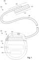
- Figure 3Aillustrates, schematically, a distal end portion 305 of the lead 103 ( Figure 1 ) that includes a cuff 350 with a cuff body 354, a mount 352 and a lead body 306.
- the lead body 306can be, for example, structurally the same or similar to the lead body 106 ( Figure 1 ), operates in a same or similar manner, and may be manufactured in accordance with one or more of the methods disclosed in U.S. Patent Application No. 2007/0150036 or in accordance with other methods or references cited herein.
- the cuff 350permits stimulation of a target nerve (not shown), for example a peripheral nerve located in soft tissue, and may be small in diameter.
- the cuff 350can operate to provide vagus or sympathetic nerve stimulation.
- the cuff 350may advantageously permit an easier implantation around the target nerve than conventional cuff leads that wrap helically around the target nerve.
- the cuff 350may also permit selective stimulation of different regions of the target nerve.
- the number of electrodes 334 as well as the arrangement of the electrodes 334can vary depending on the type of nerve being stimulated, a region of the nerve being stimulated, or any combination thereof.
- the electrodes 334can be formed using any conductive, biocompatible material. Examples of suitable materials include metals, alloys, conductive polymers, conductive carbon, and the like, as well as combinations thereof. In at least some examples, one or more of the electrodes 334 are formed from one or more of: platinum, platinum iridium, palladium, palladium rhodium, or titanium.
- the electrodes 334may take the form of segmented electrodes, have a variety of shapes such as, but not limited to, a concave, convex or otherwise curved shape, a box shape, a dish or parabolic shape, or any combination thereof. In at least some examples, the electrodes 334 may take the form of segmented electrodes having a shape complementary to a body or carrier onto which they are disposed.
- any suitable number of electrodes 334can be disposed on the cuff body 354 including, for example, four, five, six, seven, eight, nine, ten, eleven, twelve, fourteen, sixteen, twenty-four, thirty-two, or more electrodes 334.
- the electrodes 334may be arranged into columns or rows. In at least some examples, one column includes four electrodes 334.
- the arrangement of the electrode(s) 334may vary.
- the electrodes 334may be arranged in two or more parallel columns where such columns can be aligned or staggered from one another, or in any other desired column or row arrangement.
- the electrodesmay also be arranged, for example, in a row, or "in line," along the longitudinal axis of a small diameter lead body.
- the electrodesmay be placed linearly, circularly, or elliptically.
- the arrangement of electrodesmay be symmetrical or asymmetrical. As will be recognized, other arrangements of electrodes are also possible.
- the electrodes 334can be disposed on the cuff body 354 in any suitable arrangement. In at least some examples, an inward facing surface of the electrode 334 is flush with an inner surface of the cuff body 354. In yet other examples, the inward facing surface of the electrode 334 is recessed relative to the inner surface of the cuff body 354.
- the lead body 306, cuff body 354 and the mount 352can be made from a non-conductive, biocompatible material such as, for example, silicone, polyurethane, polyetheretherketone ("PEEK”), epoxy, and the like or combinations thereof.
- the lead body 306 and the cuff body 354may be formed in the desired shape by any process including, for example, molding (including injection molding), casting, and the like.
- the cuff body 354is made from silicone with electrodes 334 disposed in the silicone cuff body 354.
- the cuff 350may be manufactured by molding the electrodes 334 into the cuff body 354 while allowing for electrode alignment.
- the electrodes 334are molded into a thin, silicone carrier that allows for electrode alignment.
- conductors (not shown) from the lead body 306are connected ( e.g ., welded) to a backside of the electrodes 334.
- the carrieris wrapped around a pin or rod and then overmolded into the cuff body 354.
- the conductors (not shown) from within the lead body 306are received in the mount 352, which in turn is attached to the cuff body 354 such that each conductor passes through the mount 352 for a direct electrical connection with one of the electrodes 334 (e.g ., one conductor is electrically connected with one electrode and so on).
- the mount 352may be attached using a variety of means such as, but not limited to, molding or adhering the mount 352 to the cuff body 354.
- the conductors from within the lead body 306are electrically coupled to the electrodes 334 using jumper, intermediate or transition wires from the lead body 306 to the electrodes 334.
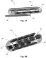
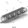
- Figures 3B-3Dshow the cuff 350 having the plurality of electrodes 334 disposed on an inner surface 356 of the cuff body 354.
- the cuff body 354takes the form of a C-shaped cuff having the inner surface 356, an outer surface 358, and a longitudinal opening 360 that extends through both the outer surface 358 and inner surface 356 of the cuff body 354.
- formation of the cuff 350 into the "C-shape"can include the steps of wrapping and overmolding to form the cuff body 354 in which the inner surface 356 defines a nerve channel 362 (best seen in Fig. 3D ).
- the opening 360is manipulated or initially sized to allow the target nerve (not shown) to be slipped, inserted, fed or otherwise received into nerve channel 362 of the cuff 350 such that the cuff 350 wraps around the target nerve.
- the opening 360allows the cuff 350 to be easily moved over and around the target nerve or relative to the target nerve whether rotationally or transitionally.
- the cuff 350may be rotated, translated or otherwise repositioned, if needed, along a target nerve axis 470 ( Fig. 4B ) that is parallel to or approximately parallel to a longitudinal axis of the nerve channel 362. Repositioning of the cuff 350 may permit intimate or selected stimulation between a particular region of the target nerve and one or more of the electrodes 334.
- the edges of the cuff body 354 defining the opening 360can be sutured to capture the target nerve without undesirably compressing the target nerve.
- suture holes 364are optionally incorporated into the edges of the cuff 350 to allow for closing or partially closing the cuff 350 around the target nerve.
- the suture holes 364can be used as points of manipulation or tool attachment during implantation ( e.g ., using forceps or an equivalent tool).
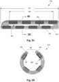
- the cuff 350includes one or more longitudinal slots 366 located between individual, adjacently-located electrodes 334 or rows of electrodes.
- the slots 366are sized and arranged to decrease a structural stiffness of the cuff 350.
- the slots 366provide for tissue ingrowth, which may eventually help anchor the cuff 350 relative to the target nerve after implantation.
- the slots 366may generally have a rectangular shape, but other shapes such as elliptical are possible.
- the slots 366extends some portion of a full length 367 of the cuff body 354.
- a slot length 369may be up to ten (10) percent, up to twenty (20) percent, up to thirty (30) percent, up to forty (40) percent, or up to fifty (50) percent of the full length 367 of the cuff body 354.
- the slot length 369may be more than fifty (50) percent, more than sixty (60) percent, more than seventy (70) percent, more than eighty (80) percent, or more than ninety (90) percent of the full length 367 of the cuff body 354.
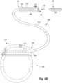
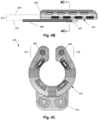
- Figure 4Aillustrates, schematically, another distal end portion 405 for the lead 103 ( Figure 1 ) that includes a cuff 450, a mount 452, a lead body 406, and cuff stiffeners 468. Similar to the mount shown in Figure 3A , the mount 452 may be attached to the cuff 450 such as, but not limited to, molding or adhering.
- the mount 452is attached to an exterior surface 458 of the cuff 450, which in turn allows for easier cuff implantation because a target nerve axis 470 is offset 473 from a lead body axis 472.
- the offset 473preferably operates to prevent the lead body 406 and the target nerve (not shown) from coming into physical contact downstream of the cuff 450 after implantation.
- Figure 4Cshows a cross-section of the cuff 450 with the cuff stiffeners 468 located in end portions 474 thereof.
- the cuff stiffeners 468can be molded into the end portions 474 of the cuff 450 or inserted after molding of the cuff 450.
- the cuff stiffeners 468may be sized and configured to make the end portions 474 of the cuff 450 easier to manipulate around the target nerve during implantation without significantly affecting an overall stiffness of the cuff 450.
- the cuff stiffeners 468may extend approximately the length of the cuff 450 or may be shorter such that a plurality of cuff stiffeners 468 may be linearly placed in the end portions 474.
- An overall length of one cuff stiffenermay be up to ten (10) percent, up to twenty (20) percent, up to thirty (30) percent, up to forty (40) percent, or up to fifty (50) percent of the full length 367 ( Fig. 3C ) of the cuff body 354.
- an overall length of one cuff stiffenermay be more than fifty (50) percent, more than sixty (60) percent, more than seventy (70) percent, more than eighty (80) percent, or more than ninety (90) percent of the full length 367 ( Fig. 3C ) of the cuff body 354.
- the cuff stiffeners 468may be cylindrical or any other shape.
- the cuff stiffeners 468may be made from a single material or more than one material to modify a bending stiffness of the cuff 450.
- the cuff stiffeners 468may be made from a rigid plastic or a metal material.
- a mount 476may take the form of a dual lead body mount attached to the outer surface 458 of the cuff 450, again offsetting the lead bodies from the target nerve.
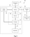
- FIG. 5is a schematic overview of components of an electrical stimulation arrangement 504 that includes an electrical stimulation system 500 with a lead 502, stimulation circuitry 506, a power source 508, and an antenna 510.
- the electrical stimulation systemcan be, for example, any of the electrical stimulation systems described above. It will be understood that the electrical stimulation arrangement can include more, fewer, or different components and can have a variety of different configurations including those configurations disclosed in the stimulator references cited herein.
- the power source 508is a rechargeable battery or chargeable capacitor
- the power sourcemay be recharged/charged using the antenna 510, if desired.
- Powercan be provided for recharging/charging by inductively coupling the power source 508 through the antenna 510 to a recharging unit 536 external to the user. Examples of such arrangements can be found in the references identified above.
- electrical currentis emitted by the electrodes (such as electrodes 134 in Figure 1 ) on the lead 502 to stimulate nerve fibers, muscle fibers, or other body tissues near the electrical stimulation system.
- the stimulation circuitry 506can include, among other components, a processor 534 and a receiver 532.
- the processor 534is generally included to control the timing and electrical characteristics of the electrical stimulation system. For example, the processor 534 can, if desired, control one or more of the timing, frequency, strength, duration, and waveform of the pulses.
- the processor 534can select which electrodes can be used to provide stimulation, if desired. In some examples, the processor 534 selects which electrode(s) are cathodes and which electrode(s) are anodes. In some examples, the processor 534 is used to identify which electrodes provide the most useful stimulation of the desired tissue.
- Any processorcan be used and can be as simple as an electronic device that, for example, produces pulses at a regular interval or the processor can be capable of receiving and interpreting instructions from an external programming unit 538 that, for example, allows modification of pulse characteristics.
- the processor 534is coupled to a receiver 532 which, in turn, is coupled to the antenna 510. This allows the processor 534 to receive instructions from an external source to, for example, direct the pulse characteristics and the selection of electrodes, if desired.
- the antenna 510is capable of receiving signals (e.g., RF signals) from an external telemetry unit 540 that is programmed by the programming unit 538.
- the programming unit 538can be external to, or part of, the telemetry unit 540.
- the telemetry unit 540can be a device that is worn on the skin of the user or can be carried by the user and can have a form similar to a pager, cellular phone, or remote control, if desired.
- the telemetry unit 540may not be worn or carried by the user but may only be available at a home station or at a clinician's office.
- the programming unit 538can be any unit that can provide information to the telemetry unit 540 for transmission to the electrical stimulation system 500.
- the programming unit 538can be part of the telemetry unit 540 or can provide signals or information to the telemetry unit 540 via a wireless or wired connection.
- One example of a suitable programming unitis a computer operated by the user or clinician to send signals to the telemetry unit 540.
- the signals sent to the processor 534 via the antenna 510 and the receiver 532can be used to modify or otherwise direct the operation of the electrical stimulation system 500.
- the signalsmay be used to modify the pulses of the electrical stimulation system such as modifying one or more of pulse duration, pulse frequency, pulse waveform, and pulse strength.
- the signalsmay also direct the electrical stimulation system 500 to cease operation, to start operation, to start charging the battery, or to stop charging the battery.
- the electrical stimulation system 500may include a transmitter (not shown) coupled to the processor 534 and the antenna 510 for transmitting signals back to the telemetry unit 540 or another unit capable of receiving the signals.
- the electrical stimulation system 500may transmit signals indicating whether the electrical stimulation system 500 is operating properly or not or indicating when the battery needs to be charged or the level of charge remaining in the battery.
- the processor 534may also be capable of transmitting information about the pulse characteristics so that a user or clinician can determine or verify the characteristics.
Landscapes
- Health & Medical Sciences (AREA)
- General Health & Medical Sciences (AREA)
- Veterinary Medicine (AREA)
- Biomedical Technology (AREA)
- Nuclear Medicine, Radiotherapy & Molecular Imaging (AREA)
- Radiology & Medical Imaging (AREA)
- Life Sciences & Earth Sciences (AREA)
- Engineering & Computer Science (AREA)
- Animal Behavior & Ethology (AREA)
- Public Health (AREA)
- Neurology (AREA)
- Neurosurgery (AREA)
- Orthopedic Medicine & Surgery (AREA)
- Cardiology (AREA)
- Heart & Thoracic Surgery (AREA)
- Physical Education & Sports Medicine (AREA)
- Electrotherapy Devices (AREA)
Description
- The present invention is directed to the area of implantable electrical stimulation systems. The present invention is also directed to implantable electrical stimulation cuff devices.
- Implantable electrical stimulation systems have proven therapeutic in a variety of diseases and disorders. For example, spinal cord stimulation systems have been used as a therapeutic modality for the treatment of chronic pain syndromes. Peripheral nerve stimulation has been used to treat chronic pain syndrome and incontinence, with a number of other applications under investigation. Functional electrical stimulation systems have been applied to restore some functionality to paralyzed extremities in spinal cord injury patients. Stimulation of the brain, such as deep brain stimulation, can be used to treat a variety of diseases or disorders.
- Stimulators have been developed to provide therapy for a variety of treatments. A stimulator can include a control module (with a pulse generator), one or more leads, and an array of stimulator electrodes on each lead. The stimulator electrodes are in contact with or near the nerves, muscles, or other tissue to be stimulated. The pulse generator in the control module generates electrical pulses that are delivered by the electrodes to body tissue.
WO 2008/048471 A1 discloses a nerve cuff electrode that includes electrode contacts imbedded in the body of the cuff, with their inside surface facing exposed to establish electrical contact with a nerve disposed therein.WO 2013/188871 A1 discloses an implantable cuff that includes an elastic collar, at least one conductive segment disposed on or within the elastic collar, and at least one conductor in electrical communication with the at least one conductive segment. The elastic collar defines an internal opening configured to receive an internal body tissue. At least a portion of the elastic collar includes a stiffening region having a stiffness greater than a second region of the elastic collar. The at least one conductor is configured to operably mate with an apparatus capable of delivering electrical stimulation to, and/or recording an electrical activity of, the internal body tissue.WO 2008/019483 A1 discloses an implantable medical assembly comprising at least one electrode carried on an inside surface of a web comprising a biocompatible film wound into a generally tubular configuration, the film containing at least one aperture through the web to increase its flexibility and to create a means by which biological fluids can penetrate the assembly. The assembly may further comprise at least one wire connected to the electrode to provide a stimulation signal.US 2003/0040785 A1 discloses an electrode assembly to be installed on a patient's nerve has a thin, flexible, electrically insulating circumneural carrier with a split circumferential configuration longitudinally attached to a lead at the distal end thereof. The carrier possesses circumferential resiliency and has at least one flexible, elastic electrode secured to the underside thereof and electrically connected to an electrical conductor in said lead. A fastener serves to close the split configuration of the carrier to prevent separation from the nerve after installation of the electrode assembly onto the nerve. Tear away webbing secured to adjacent serpentine segments of the lead near the carrier enables the lead to lengthen with patient movements.US 2013/0172973 A1 discloses a stimulation electrode assembly for stimulation of a vagus nerve within a carotid sheath. The stimulation electrode assembly comprises an insulating sheath and at least one energy delivery element. The insulating sheath includes a flexible sheet of electrically insulative material configured to assume a generally tubular shape to at least partially surround the carotid sheath when implanted, and having a first side and a second side, wherein the first side is positionable toward the carotid sheath when implanted. The at least one energy delivery element is located on the first side of the insulating sheath and is configured to deliver energy to the vagus nerve when implanted.- The present invention relates to an electrical stimulation lead according to
claim 1. Preferred embodiments are defined by the dependent claims. - Aspects, embodiments or examples of the present description which do not fall within the scope of the appended claims are not part of the present invention.
- The present description relates to an electrical stimulation lead that includes a stimulation cuff having a length, an exterior surface and an interior surface that defines a nerve channel having a nerve channel axis. A plurality of electrodes are disposed on the interior surface of the cuff, wherein the plurality of electrodes is arranged into a plurality of rows with each row extending parallel to the nerve channel axis, wherein each row comprises at least two of the electrodes. A longitudinal opening extends through the cuff and further extends along an entire length of the cuff, wherein the opening is operable to receive a target nerve from a region outside of the cuff to within the nerve channel. Further, a mount is disposed on the exterior surface of the cuff and is radially offset from the nerve channel axis. A lead body, with a lead body axis, is radially offset from the nerve channel axis and a plurality of conductors extend through the lead body, mount and cuff, with the plurality of conductors electrically coupled to the electrodes. The lead further comprises at least one slot defined by the stimulation cuff, wherein each of the at least one slot is located between two of the rows of electrodes and has a slot length that extends more than 50% of the entire length of the stimulation cuff and less than the entire length of the stimulation cuff.
- The slot may permit tissue ingrowth at least from the exterior surface of the cuff into the nerve channel. The cuff can also include end portions for receiving sutures.
- The electrical stimulation lead includes cuff stiffeners embedded in the cuff proximate the longitudinal opening. At least one of the cuff stiffeners can extend less than the entire length of the cuff. Or, at least one of the cuff stiffeners can extend the entire length of the cuff. The cuff stiffeners can be cylindrical.
- Also disclosed is an electrical stimulating system that includes the electrical stimulation lead described above. The system further includes a control module coupleable to the electrical stimulation lead includes a housing, and an electronic subassembly disposed in the housing. The system also includes a connector for receiving the electrical stimulation lead, the connector having a proximal end, a distal end, and a longitudinal length. The connector includes a connector housing and a plurality of connector contacts disposed in the connector housing. The connector housing defines a port at the distal end of the connector, the port receiving the proximal end of the lead body of the electrical stimulation lead. The plurality of connector contacts couple to at least one of a plurality of terminals disposed on a proximal end of the lead body of the electrical stimulation lead. In at least some embodiments, the system also includes a lead extension coupleable to both the electrical stimulation lead and the control module.
- In at least some examples, an electrical stimulation lead includes a stimulation cuff having a cuff body with an interior surface and an exterior surface, the interior surface defines a nerve channel having a nerve channel axis. A plurality of electrodes are disposed on the interior surface of the cuff body. A longitudinal opening extends through the cuff body and further extends along an entire length of the cuff body. The opening is operable to receive a target nerve from a region outside of the cuff to within the nerve channel. A plurality of slots, to permit tissue ingrowth, each extends through the cuff body and each has a length that is less than the entire length of the cuff body. The electrical stimulation lead also includes a lead body having a lead body axis and a plurality of conductors extending through the lead body, mount and cuff, such that the plurality of conductors are electrically coupled to the electrodes.
- In at least some examples, a mount is disposed on the exterior surface of the cuff body and coupled to the lead body such that the lead body axis is radially offset from the nerve channel axis of the cuff body.
- In at least some examples, at least one of the plurality of slots is located between at least two of the electrodes. The cuff body includes end portions configured to receive sutures. Further, cuff stiffeners, which may be cylindrical, may be embedded in the cuff body proximate the longitudinal opening.
- Also disclosed is an electrical stimulating system that includes the electrical stimulation lead described above. The system includes a control module coupleable to the electrical stimulation lead, and the control module includes a housing, and an electronic subassembly disposed in the housing. The system further includes a connector for receiving the electrical stimulation lead, the connector having a proximal end, a distal end, and a longitudinal length. The connector includes a connector housing and a plurality of connector contacts disposed in the connector housing. The connector defines a port at the distal end of the connector for receiving the proximal end of the lead body of the electrical stimulation lead. The plurality of connector contacts couple to at least one of a plurality of terminals disposed on a proximal end of the lead body of the electrical stimulation lead. In at least some embodiments, the system also includes a lead extension coupleable to both the electrical stimulation lead and the control module.
- Non-limiting and non-exhaustive embodiments of the present invention are described with reference to the following drawings. In the drawings, like reference numerals refer to like parts throughout the various figures unless otherwise specified.
- For a better understanding of the present invention, reference will be made to the following Detailed Description, which is to be read in association with the accompanying drawings, wherein:
FIG. 1 is a schematic view of an electrical stimulation system that includes a lead electrically coupled to a control module;FIG. 2A is a schematic view of the control module ofFIG. 1 configured and arranged to electrically couple to an elongated device;FIG. 2B is a schematic view of a lead extension configured and arranged to electrically couple the elongated device ofFIG. 2A to the control module ofFIG. 1 ;FIG. 3A is a schematic perspective view of a distal end portion of a lead that includes a stimulation cuff according to the present disclosure;FIG. 3B is a schematic, perspective close-up view of the cuff ofFIG. 3A ;FIG. 3C is a side elevational view of the cuff ofFIG. 3B ;FIG. 3D is a cross-sectional view of the cuff ofFIG. 3B taken alongline 3D-3D;FIG. 4A is a schematic perspective view of a distal end portion of a lead that includes a stimulation cuff having cuff stiffeners;FIG. 4B is a side elevational view of the cuff ofFIG. 4A ;FIG. 4C is a cross-sectional view of the cuff ofFIG. 4B taken alongline 4C-4C;FIG. 5 is a schematic overview of components of an electrical stimulation arrangement.- The present invention is directed to the area of implantable electrical stimulation systems. The present invention is also directed to implantable electrical stimulation cuff devices.
- Suitable implantable electrical stimulation systems include, but are not limited to, a least one lead with one or more electrodes disposed along a distal end of the lead. Leads include, for example, percutaneous leads, paddle leads, and cuff leads. Examples of electrical stimulation systems with leads are found in, for example,
U.S. Patents Nos. 6,181,969 ;6,516,227 ;6,609,029 ;6,609,032 ;6,741,892 ;7,203,548 ;7,244,150 ;7,450,997 ;7,596,414 ;7,610,103 ;7,672,734 ;7,761,165 ;7,783,359 ;7,792,590 ;7,809,446 ;7,949,395 ;7,974,706 ;6,175,710 ;6,224,450 ;6,271,094 ;6,295,944 ;6,364,278 ; and6,391,985 ;U.S. Patent Applications Publication Nos. 2007/0150036 ;2009/0187222 ;2009/0276021 ;2010/0076535 ;2010/0268298 ;2011/0004267 ;2011/0078900 ;2011/0130817 ;2011/0130818 ;2011/0238129 ;2011/0313500 ;2012/0016378 ;2012/0046710 ;2012/0071949 ;2012/0165911 ;2012/0197375 ;2012/0203316 ;2012/0203320 ;2012/0203321 ;2012/0316615 ; and2013/0105071 ; andU.S. Patent Applications Serial Nos. 12/177,823 and13/750,725 Figure 1 illustrates schematically anelectrical stimulation system 100. The electrical stimulation system includes a control module (e.g., a stimulator or pulse generator) 102 and a lead 103 coupleable to thecontrol module 102. Thelead 103 includes adistal end portion 105, shown schematically, but will be described in detail below (e.g., a distal end portion 300 inFIGURES 3A-3D and a distal end portion 400 inFIGURES 4A-4C . Thelead 103 includes one or morelead bodies 106, an array ofelectrodes 133, such aselectrode 134, and an array of terminals (e.g., 210 inFigure 2A-2B ) disposed along the one or morelead bodies 106. In at least some embodiments, the lead is isodiametric along a longitudinal length of thelead body 106.- The
lead 103 can be coupled to thecontrol module 102 in any suitable manner. In at least some examples, thelead 103 couples directly to thecontrol module 102. In at least some other examples, thelead 103 couples to thecontrol module 102 via one or more intermediate devices (200 inFigures 2A-2B ). For example, one or more lead extensions 224 (see e.g.,Figure 2B ) can be disposed between the lead 103 and thecontrol module 102 to extend the distance between the lead 103 and thecontrol module 102. Other intermediate devices may be used in addition to, or in lieu of, one or more lead extensions including, for example, a splitter, an adaptor, or the like or combinations thereof. It will be understood that, in the case where theelectrical stimulation system 100 includes multiple elongated devices disposed between the lead 103 and thecontrol module 102, the intermediate devices may be configured into any suitable arrangement. - The
control module 102 typically includes aconnector housing 112 and a sealedelectronics housing 114.Stimulation circuitry 110 and anoptional power source 120 are disposed in theelectronics housing 114. Acontrol module connector 144 is disposed in theconnector housing 112. Thecontrol module connector 144 is configured and arranged to make an electrical connection between the lead 103 and thestimulation circuitry 110 of thecontrol module 102. - The electrical stimulation system or components of the electrical stimulation system, including the
lead body 106 and thecontrol module 102, are typically implanted into the body of a patient. The electrical stimulation system can be used for a variety of applications including, but not limited to, brain stimulation, neural stimulation, spinal cord stimulation, muscle stimulation, and the like. - The
electrodes 134 can be formed using any conductive, biocompatible material. Examples of suitable materials include metals, alloys, conductive polymers, conductive carbon, and the like, as well as combinations thereof. In at least some examples, one or more of theelectrodes 134 are formed from one or more of: platinum, platinum iridium, palladium, palladium rhodium, or titanium. The number ofelectrodes 134 in eacharray 133 may vary. For example, there can be two, four, six, eight, ten, twelve, fourteen, sixteen, ormore electrodes 134. As will be recognized, other numbers ofelectrodes 134 may also be used. - The electrodes of the
lead body 106 are typically disposed in, or separated by, a non-conductive, biocompatible material such as, for example, silicone, polyurethane, polyetheretherketone ("PEEK"), epoxy, and the like or combinations thereof. Thelead body 106 may be formed in the desired shape by any process including, for example, molding (including injection molding), casting, and the like. The non-conductive material typically extends from the distal end of thelead body 106 to the proximal end of thelead body 106. - Terminals (e.g., 210 in
Figures 2A-2B ) are typically disposed along the proximal end of thelead body 106 of the electrical stimulation system 100 (as well as any splitters, lead extensions, adaptors, or the like) for electrical connection to corresponding connector contacts (e.g., 214 and 240 inFigure 2B ). The connector contacts are disposed in connectors (e.g., 144 inFigures 1-2B ; and 222 inFigure 2B ) which, in turn, are disposed on, for example, the control module 102 (or a lead extension, a splitter, an adaptor, or the like). Electrically conductive wires, cables, or the like (not shown) extend from the terminals to theelectrodes 134. Typically, one ormore electrodes 134 are electrically coupled to each terminal. In at least some examples, each terminal is only connected to oneelectrode 134. - The electrically conductive wires ("conductors") may be embedded in the non-conductive material of the
lead body 106 or can be disposed in one or more lumens (not shown) extending along thelead body 106. In some examples, there is an individual lumen for each conductor. In other examples, two or more conductors extend through a lumen. There may also be one or more lumens (not shown) that open at, or near, the proximal end of thelead body 106, for example, for inserting a stylet to facilitate placement of thelead body 106 within a body of a patient. Additionally, there may be one or more lumens (not shown) that open at, or near, the distal end of thelead body 106, for example, for infusion of drugs or medication into the site of implantation of thelead body 106. In at least one example, the one or more lumens are flushed continually, or on a regular basis, with saline, epidural fluid, or the like. In at least some examples, the one or more lumens are permanently or removably sealable at the distal end. Figure 2A is a schematic side view of a proximal end of one or moreelongated devices 200 configured and arranged for coupling to thecontrol module connector 144. The one or more elongated devices may include, for example, thelead body 106, one or more intermediate devices (e.g., thelead extension 224 ofFigure 2B , an adaptor, or the like or combinations thereof), or a combination thereof.- The
control module connector 144 defines at least one port into which a proximal end of theelongated device 200 can be inserted, as shown bydirectional arrow 212. InFigure 2A (and in other figures), theconnector housing 112 is shown having oneport 204. Theconnector housing 112 can define any suitable number of ports including, for example, one, two, three, four, five, six, seven, eight, or more ports. - The
control module connector 144 also includes a plurality of connector contacts, such asconnector contact 214, disposed within eachport 204. When theelongated device 200 is inserted into theport 204, theconnector contacts 214 can be aligned with a plurality ofterminals 210 disposed along the proximal end(s) of the elongated device(s) 200 to electrically couple thecontrol module 102 to the electrodes (134 ofFigure 1 ) disposed at a distal end of thelead 103. Examples of connectors in control modules are found in, for example,U.S. Patent No. 7,244,150 and8,224,450 . Figure 2B is a schematic side view of anotherelectrical stimulation system 100. Theelectrical stimulation system 100 includes alead extension 224 that is configured and arranged to couple one or more elongated devices 200 (e.g., thelead body 106, an adaptor, another lead extension, or the like or combinations thereof) to thecontrol module 102. InFigure 2B , thelead extension 224 is shown coupled to asingle port 204 defined in thecontrol module connector 144. Additionally, thelead extension 224 is shown configured and arranged to couple to a singleelongated device 200. In alternate examples, thelead extension 224 is configured and arranged to couple tomultiple ports 204 defined in thecontrol module connector 144, or to receive multipleelongated devices 200, or both.- A
lead extension connector 222 is disposed on thelead extension 224. InFigure 2B , thelead extension connector 222 is shown disposed at adistal end 226 of thelead extension 224. Thelead extension connector 222 includes aconnector housing 228. Theconnector housing 228 defines at least oneport 230 into whichterminals 210 of theelongated device 200 can be inserted, as shown bydirectional arrow 238. Theconnector housing 228 also includes a plurality of connector contacts, such asconnector contact 240. When theelongated device 200 is inserted into theport 230, theconnector contacts 240 disposed in theconnector housing 228 can be aligned with theterminals 210 of theelongated device 200 to electrically couple thelead extension 224 to the electrodes (134 ofFigure 1 ) disposed along the lead (103 inFigure 1 ). - In at least some examples, the proximal end of the
lead extension 224 is similarly configured and arranged as a proximal end of the lead 103 (or other elongated device 200). Thelead extension 224 may include a plurality of electrically conductive wires (not shown) that electrically couple theconnector contacts 240 to aproximal end 248 of thelead extension 224 that is opposite to thedistal end 226. In at least some examples, the conductive wires disposed in thelead extension 224 can be electrically coupled to a plurality of terminals (not shown) disposed along theproximal end 248 of thelead extension 224. In at least some examples, theproximal end 248 of thelead extension 224 is configured and arranged for insertion into a connector disposed in another lead extension (or another intermediate device). In other examples (and as shown inFigure 2B ), theproximal end 248 of thelead extension 224 is configured and arranged for insertion into thecontrol module connector 144. - In at least some instances, a large control module, such as the
control module 102 illustrated inFigures 1-2B , is not desirable. A smaller, more compact control module may be suitable for situations such as, for example, short-term implantation (for example, 1 or 2 weeks, 1, 2, 3, 4, 6, 8, 12, or 18 months), short-term trial (for example, 1 or 2 weeks, 1, 2, 3, 4, 6, 8, 12, or 18 months), clinical studies (for example, for a period of 1 or 2 weeks, 1, 2, 3, 4, 6, 8, 12, or 18 months), or the like. Such a control module may also be useful when a less invasive surgical implantation is desired, recommended, or required. In some instances, a patient or clinician may be willing to charge the control module more frequently if the control module is smaller or the surgery is less invasive. In addition, there may be more options in the body of the patient for implantation of a smaller control module than are available for the larger control module (which is often implanted in the thoracic body cavity or the buttocks due to the size of the device.) A smaller control module may also be less expensive and particularly useful for trials to determine whether electrical stimulation is beneficial. In at least some examples, the electrical stimulation system with the smaller control module can be upgraded to an electrical stimulation system such as that illustrated inFigures 1-2B if the trial shows sufficient benefit to the patient. In at least some examples, the smaller control module may allow for the device to be MRI (magnetic resonance imaging) conditionally safe because of its implant location and size. - In some examples, the control module can be made smaller by permanently affixing the lead (or a lead extension) to the control module. For example, the lead can be hardwired to the stimulation circuitry so that the control module does not need a connector and header.
Figure 3A illustrates, schematically, adistal end portion 305 of the lead 103 (Figure 1 ) that includes acuff 350 with acuff body 354, amount 352 and alead body 306. Thelead body 306 can be, for example, structurally the same or similar to the lead body 106 (Figure 1 ), operates in a same or similar manner, and may be manufactured in accordance with one or more of the methods disclosed inU.S. Patent Application No. 2007/0150036 or in accordance with other methods or references cited herein.- In at least some examples, the
cuff 350 permits stimulation of a target nerve (not shown), for example a peripheral nerve located in soft tissue, and may be small in diameter. By way of example, thecuff 350 can operate to provide vagus or sympathetic nerve stimulation. When using many conventional leads to stimulate the target nerve, it may be difficult to initiate and maintain contact between the conventional lead and the target nerve. In at least some examples, thecuff 350 may advantageously permit an easier implantation around the target nerve than conventional cuff leads that wrap helically around the target nerve. In at least some examples, thecuff 350 may also permit selective stimulation of different regions of the target nerve. The number ofelectrodes 334 as well as the arrangement of theelectrodes 334 can vary depending on the type of nerve being stimulated, a region of the nerve being stimulated, or any combination thereof. - The
electrodes 334 can be formed using any conductive, biocompatible material. Examples of suitable materials include metals, alloys, conductive polymers, conductive carbon, and the like, as well as combinations thereof. In at least some examples, one or more of theelectrodes 334 are formed from one or more of: platinum, platinum iridium, palladium, palladium rhodium, or titanium. Theelectrodes 334 may take the form of segmented electrodes, have a variety of shapes such as, but not limited to, a concave, convex or otherwise curved shape, a box shape, a dish or parabolic shape, or any combination thereof. In at least some examples, theelectrodes 334 may take the form of segmented electrodes having a shape complementary to a body or carrier onto which they are disposed. - Any suitable number of
electrodes 334 can be disposed on thecuff body 354 including, for example, four, five, six, seven, eight, nine, ten, eleven, twelve, fourteen, sixteen, twenty-four, thirty-two, ormore electrodes 334. Theelectrodes 334 may be arranged into columns or rows. In at least some examples, one column includes fourelectrodes 334. The arrangement of the electrode(s) 334 may vary. For example, theelectrodes 334 may be arranged in two or more parallel columns where such columns can be aligned or staggered from one another, or in any other desired column or row arrangement. The electrodes may also be arranged, for example, in a row, or "in line," along the longitudinal axis of a small diameter lead body. Optionally, the electrodes may be placed linearly, circularly, or elliptically. The arrangement of electrodes may be symmetrical or asymmetrical. As will be recognized, other arrangements of electrodes are also possible. - The
electrodes 334 can be disposed on thecuff body 354 in any suitable arrangement. In at least some examples, an inward facing surface of theelectrode 334 is flush with an inner surface of thecuff body 354. In yet other examples, the inward facing surface of theelectrode 334 is recessed relative to the inner surface of thecuff body 354. - The
lead body 306,cuff body 354 and themount 352 can be made from a non-conductive, biocompatible material such as, for example, silicone, polyurethane, polyetheretherketone ("PEEK"), epoxy, and the like or combinations thereof. Thelead body 306 and thecuff body 354 may be formed in the desired shape by any process including, for example, molding (including injection molding), casting, and the like. - In at least some examples, the
cuff body 354 is made from silicone withelectrodes 334 disposed in thesilicone cuff body 354. Thecuff 350 may be manufactured by molding theelectrodes 334 into thecuff body 354 while allowing for electrode alignment. In an initial step, theelectrodes 334 are molded into a thin, silicone carrier that allows for electrode alignment. Next, conductors (not shown) from thelead body 306 are connected (e.g., welded) to a backside of theelectrodes 334. Lastly, the carrier is wrapped around a pin or rod and then overmolded into thecuff body 354. - In at least some examples, the conductors (not shown) from within the
lead body 306 are received in themount 352, which in turn is attached to thecuff body 354 such that each conductor passes through themount 352 for a direct electrical connection with one of the electrodes 334 (e.g., one conductor is electrically connected with one electrode and so on). Themount 352 may be attached using a variety of means such as, but not limited to, molding or adhering themount 352 to thecuff body 354. In other examples, the conductors from within thelead body 306 are electrically coupled to theelectrodes 334 using jumper, intermediate or transition wires from thelead body 306 to theelectrodes 334. Figures 3B-3D show thecuff 350 having the plurality ofelectrodes 334 disposed on aninner surface 356 of thecuff body 354. InFigure 3B , thecuff body 354 takes the form of a C-shaped cuff having theinner surface 356, an outer surface 358, and alongitudinal opening 360 that extends through both the outer surface 358 andinner surface 356 of thecuff body 354. As noted above, formation of thecuff 350 into the "C-shape" can include the steps of wrapping and overmolding to form thecuff body 354 in which theinner surface 356 defines a nerve channel 362 (best seen inFig. 3D ).- The
opening 360 is manipulated or initially sized to allow the target nerve (not shown) to be slipped, inserted, fed or otherwise received intonerve channel 362 of thecuff 350 such that thecuff 350 wraps around the target nerve. In at least some examples, theopening 360 allows thecuff 350 to be easily moved over and around the target nerve or relative to the target nerve whether rotationally or transitionally. By way of example, thecuff 350 may be rotated, translated or otherwise repositioned, if needed, along a target nerve axis 470 (Fig. 4B ) that is parallel to or approximately parallel to a longitudinal axis of thenerve channel 362. Repositioning of thecuff 350 may permit intimate or selected stimulation between a particular region of the target nerve and one or more of theelectrodes 334. - In at least some examples, once the
cuff 350 has been placed in a desired position relative to the target nerve, the edges of thecuff body 354 defining theopening 360 can be sutured to capture the target nerve without undesirably compressing the target nerve. In at least some examples, suture holes 364 (Fig. 3D ) are optionally incorporated into the edges of thecuff 350 to allow for closing or partially closing thecuff 350 around the target nerve. Moreover, the suture holes 364 can be used as points of manipulation or tool attachment during implantation (e.g., using forceps or an equivalent tool). - Referring to
Figures 3B and3C , thecuff 350 includes one or morelongitudinal slots 366 located between individual, adjacently-locatedelectrodes 334 or rows of electrodes. In at least some examples, theslots 366 are sized and arranged to decrease a structural stiffness of thecuff 350. In at least some examples, theslots 366 provide for tissue ingrowth, which may eventually help anchor thecuff 350 relative to the target nerve after implantation. Theslots 366 may generally have a rectangular shape, but other shapes such as elliptical are possible. Theslots 366 extends some portion of afull length 367 of thecuff body 354. By way of example, aslot length 369 may be up to ten (10) percent, up to twenty (20) percent, up to thirty (30) percent, up to forty (40) percent, or up to fifty (50) percent of thefull length 367 of thecuff body 354. Alternatively, theslot length 369 may be more than fifty (50) percent, more than sixty (60) percent, more than seventy (70) percent, more than eighty (80) percent, or more than ninety (90) percent of thefull length 367 of thecuff body 354. Figure 4A illustrates, schematically, anotherdistal end portion 405 for the lead 103 (Figure 1 ) that includes acuff 450, amount 452, alead body 406, andcuff stiffeners 468. Similar to the mount shown inFigure 3A , themount 452 may be attached to thecuff 450 such as, but not limited to, molding or adhering.- Referring to
Figure 4B , themount 452 is attached to anexterior surface 458 of thecuff 450, which in turn allows for easier cuff implantation because atarget nerve axis 470 is offset 473 from alead body axis 472. In at least some of the examples, the offset 473 preferably operates to prevent thelead body 406 and the target nerve (not shown) from coming into physical contact downstream of thecuff 450 after implantation. Figure 4C shows a cross-section of thecuff 450 with thecuff stiffeners 468 located inend portions 474 thereof. The cuff stiffeners 468 can be molded into theend portions 474 of thecuff 450 or inserted after molding of thecuff 450. In at least some examples, thecuff stiffeners 468 may be sized and configured to make theend portions 474 of thecuff 450 easier to manipulate around the target nerve during implantation without significantly affecting an overall stiffness of thecuff 450. The cuff stiffeners 468 may extend approximately the length of thecuff 450 or may be shorter such that a plurality ofcuff stiffeners 468 may be linearly placed in theend portions 474. An overall length of one cuff stiffener may be up to ten (10) percent, up to twenty (20) percent, up to thirty (30) percent, up to forty (40) percent, or up to fifty (50) percent of the full length 367 (Fig. 3C ) of thecuff body 354. Alternatively, an overall length of one cuff stiffener may be more than fifty (50) percent, more than sixty (60) percent, more than seventy (70) percent, more than eighty (80) percent, or more than ninety (90) percent of the full length 367 (Fig. 3C ) of thecuff body 354.- The cuff stiffeners 468 may be cylindrical or any other shape. In addition, the
cuff stiffeners 468 may be made from a single material or more than one material to modify a bending stiffness of thecuff 450. By way of example, thecuff stiffeners 468 may be made from a rigid plastic or a metal material. Lastly, amount 476 may take the form of a dual lead body mount attached to theouter surface 458 of thecuff 450, again offsetting the lead bodies from the target nerve. Figure 5 is a schematic overview of components of anelectrical stimulation arrangement 504 that includes anelectrical stimulation system 500 with alead 502,stimulation circuitry 506, apower source 508, and anantenna 510. The electrical stimulation system can be, for example, any of the electrical stimulation systems described above. It will be understood that the electrical stimulation arrangement can include more, fewer, or different components and can have a variety of different configurations including those configurations disclosed in the stimulator references cited herein.- If the
power source 508 is a rechargeable battery or chargeable capacitor, the power source may be recharged/charged using theantenna 510, if desired. Power can be provided for recharging/charging by inductively coupling thepower source 508 through theantenna 510 to arecharging unit 536 external to the user. Examples of such arrangements can be found in the references identified above. - In at least some examples, electrical current is emitted by the electrodes (such as
electrodes 134 inFigure 1 ) on thelead 502 to stimulate nerve fibers, muscle fibers, or other body tissues near the electrical stimulation system. Thestimulation circuitry 506 can include, among other components, aprocessor 534 and areceiver 532. Theprocessor 534 is generally included to control the timing and electrical characteristics of the electrical stimulation system. For example, theprocessor 534 can, if desired, control one or more of the timing, frequency, strength, duration, and waveform of the pulses. In addition, theprocessor 534 can select which electrodes can be used to provide stimulation, if desired. In some examples, theprocessor 534 selects which electrode(s) are cathodes and which electrode(s) are anodes. In some examples, theprocessor 534 is used to identify which electrodes provide the most useful stimulation of the desired tissue. - Any processor can be used and can be as simple as an electronic device that, for example, produces pulses at a regular interval or the processor can be capable of receiving and interpreting instructions from an
external programming unit 538 that, for example, allows modification of pulse characteristics. In the illustrated example, theprocessor 534 is coupled to areceiver 532 which, in turn, is coupled to theantenna 510. This allows theprocessor 534 to receive instructions from an external source to, for example, direct the pulse characteristics and the selection of electrodes, if desired. - In at least some examples, the
antenna 510 is capable of receiving signals (e.g., RF signals) from anexternal telemetry unit 540 that is programmed by theprogramming unit 538. Theprogramming unit 538 can be external to, or part of, thetelemetry unit 540. Thetelemetry unit 540 can be a device that is worn on the skin of the user or can be carried by the user and can have a form similar to a pager, cellular phone, or remote control, if desired. As another alternative, thetelemetry unit 540 may not be worn or carried by the user but may only be available at a home station or at a clinician's office. Theprogramming unit 538 can be any unit that can provide information to thetelemetry unit 540 for transmission to theelectrical stimulation system 500. Theprogramming unit 538 can be part of thetelemetry unit 540 or can provide signals or information to thetelemetry unit 540 via a wireless or wired connection. One example of a suitable programming unit is a computer operated by the user or clinician to send signals to thetelemetry unit 540. - The signals sent to the
processor 534 via theantenna 510 and thereceiver 532 can be used to modify or otherwise direct the operation of theelectrical stimulation system 500. For example, the signals may be used to modify the pulses of the electrical stimulation system such as modifying one or more of pulse duration, pulse frequency, pulse waveform, and pulse strength. The signals may also direct theelectrical stimulation system 500 to cease operation, to start operation, to start charging the battery, or to stop charging the battery. - Optionally, the
electrical stimulation system 500 may include a transmitter (not shown) coupled to theprocessor 534 and theantenna 510 for transmitting signals back to thetelemetry unit 540 or another unit capable of receiving the signals. For example, theelectrical stimulation system 500 may transmit signals indicating whether theelectrical stimulation system 500 is operating properly or not or indicating when the battery needs to be charged or the level of charge remaining in the battery. Theprocessor 534 may also be capable of transmitting information about the pulse characteristics so that a user or clinician can determine or verify the characteristics. - The above specification provides a description of the invention. However, many modifications are possible without departing from the scope of the invention which is defined in the claims hereinafter appended.
Claims (15)
- An electrical stimulation lead comprising:a stimulation cuff having a length, an exterior surface, and an interior surface that defines a nerve channel having a nerve channel axis;a plurality of electrodes disposed on the interior surface of the cuff, wherein the plurality of electrodes is arranged into a plurality of rows with each row extending parallel to the nerve channel axis, wherein each row comprises at least two of the electrodes;a longitudinal opening extending through the cuff and further extending along an entire length of the cuff, the opening operable to receive a target nerve from a region outside of the cuff to within the nerve channel;at least one slot defined by the stimulation cuff, wherein each of the at least one slot is located between two of the rows of electrodes and has a slot length that extends more than 50% of the entire length of the stimulation cuff and less than the entire length of the stimulation cuff;a mount disposed on the exterior surface of the cuff and radially offset from the nerve channel axis;a lead body having a lead body axis radially offset from the nerve channel axis; anda plurality of conductors extending through the lead body, mount and cuff, with the plurality of conductors electrically coupled to the electrodes.
- The electrical stimulation lead of claim 1, wherein at least one of the at least one slot extends more than sixty percent of the entire length of the cuff.
- The electrical stimulation lead of claim 1, wherein at least one of the at least one slot extends more than eighty percent of the entire length of the cuff.
- The electrical stimulation lead of claim 1, wherein each of the slots has a rectangular shape.
- The electrical stimulation lead of claim 1, wherein each of the slots has an elliptical shape.
- The electrical stimulation lead of claim 1, wherein the at least one slot is two slots.
- The electrical stimulation lead of any of claims 1-6, wherein the slot is configured to permit tissue ingrowth.
- The electrical stimulation lead of any of claims 1-7, wherein the stimulation cuff includes end portions configured to receive sutures.
- The electrical stimulation lead of any of claims 1-8, further comprising cuff stiffeners embedded in the stimulation cuff proximate the longitudinal opening, wherein the cuff stiffeners are made of rigid plastic.
- The electrical stimulation lead of claim 9, wherein at least one of the cuff stiffeners extends less than the entire length of the stimulation cuff.
- The electrical stimulation lead of claim 9, wherein at least one of the cuff stiffeners extends the entire length of the stimulation cuff.
- The electrical stimulation lead of claim 9, wherein the cuff stiffeners are cylindrical.
- The electrical stimulation lead of claim 1, wherein the mount is a dual lead body mount.
- An electrical stimulating system comprising:the electrical stimulation lead of any of claims 1-13;a control module coupleable to the electrical stimulation lead, the control module comprisinga housing, andan electronic subassembly disposed in the housing; anda connector for receiving the electrical stimulation lead, the connector having a proximal end, a distal end, and a longitudinal length, the connector comprisinga connector housing defining a port at the distal end of the connector, the port configured and arranged for receiving a proximal end of the lead body of the electrical stimulation lead, anda plurality of connector contacts disposed in the connector housing, the plurality of connector contacts configured and arranged to couple to at least one of a plurality of terminals disposed on a proximal end of the lead body of the electrical stimulation lead.
- The electrical stimulation system of claim 14, further comprising a lead extension coupleable to both the electrical stimulation lead and the control module.
Applications Claiming Priority (2)
| Application Number | Priority Date | Filing Date | Title |
|---|---|---|---|
| US201662297616P | 2016-02-19 | 2016-02-19 | |
| PCT/US2017/018467WO2017143254A1 (en) | 2016-02-19 | 2017-02-17 | Electrical stimulation cuff devices and systems |
Publications (2)
| Publication Number | Publication Date |
|---|---|
| EP3389763A1 EP3389763A1 (en) | 2018-10-24 |
| EP3389763B1true EP3389763B1 (en) | 2023-06-28 |
Family
ID=58191690
Family Applications (1)
| Application Number | Title | Priority Date | Filing Date |
|---|---|---|---|
| EP17708123.9AActiveEP3389763B1 (en) | 2016-02-19 | 2017-02-17 | Electrical stimulation cuff devices and systems |
Country Status (4)
| Country | Link |
|---|---|
| US (1) | US10485969B2 (en) |
| EP (1) | EP3389763B1 (en) |
| AU (1) | AU2017220115B2 (en) |
| WO (1) | WO2017143254A1 (en) |
Families Citing this family (11)
| Publication number | Priority date | Publication date | Assignee | Title |
|---|---|---|---|---|
| US9974959B2 (en) | 2014-10-07 | 2018-05-22 | Boston Scientific Neuromodulation Corporation | Systems, devices, and methods for electrical stimulation using feedback to adjust stimulation parameters |
| EP3664889B1 (en) | 2017-08-11 | 2024-02-21 | Inspire Medical Systems, Inc. | Cuff electrode |
| CN110025886A (en)* | 2019-04-19 | 2019-07-19 | 桂林医学院 | Animal Naoliqing capsule is in body electrical stimulation device |
| US20220226641A1 (en) | 2021-01-19 | 2022-07-21 | Boston Scientific Neuromodulation Corporation | Electrical stimulation cuff devices and systems with directional electrode configurations |
| US12403315B2 (en) | 2021-04-27 | 2025-09-02 | Boston Scientific Neuromodulation Corporation | Systems and methods for automated programming of electrical stimulation |
| AU2022277556B2 (en)* | 2021-05-21 | 2025-03-06 | Boston Scientific Neuromodulation Corporation | Electrical stimulation cuff devices and systems with helical arrangement of electrodes |
| US12403313B2 (en) | 2021-06-15 | 2025-09-02 | Boston Scientific Neuromodulation Corporation | Methods and systems for estimating neural activation by stimulation using a stimulation system |
| EP4415807A1 (en) | 2021-12-10 | 2024-08-21 | Boston Scientific Neuromodulation Corporation | Methods and systems for determining and using an intensity index for electrical stimulation |
| WO2024220291A1 (en) | 2023-04-18 | 2024-10-24 | Retropsoas Technologies, Llc | Bipolar nerve stimulation/monitoring cuff |
| EP4565123A1 (en) | 2023-04-18 | 2025-06-11 | Retropsoas Technologies, Llc | Bipolar nerve stimulation/monitoring cuff |
| US20250099749A1 (en) | 2023-09-21 | 2025-03-27 | Boston Scientific Neuromodulation Corporation | Electrical stimulation cuff devices and systems and electrode arrangements therefor |
Citations (1)
| Publication number | Priority date | Publication date | Assignee | Title |
|---|---|---|---|---|
| US20130172973A1 (en)* | 2012-01-04 | 2013-07-04 | Bruce A. Tockman | Neural stimulation device with insulating sheath |
Family Cites Families (185)
| Publication number | Priority date | Publication date | Assignee | Title |
|---|---|---|---|---|
| US3769984A (en) | 1971-03-11 | 1973-11-06 | Sherwood Medical Ind Inc | Pacing catheter with frictional fit lead attachment |
| US3941136A (en) | 1973-11-21 | 1976-03-02 | Neuronyx Corporation | Method for artificially inducing urination, defecation, or sexual excitation |
| US4033357A (en) | 1975-02-07 | 1977-07-05 | Medtronic, Inc. | Non-fibrosing cardiac electrode |
| US4135518A (en) | 1976-05-21 | 1979-01-23 | Medtronic, Inc. | Body implantable lead and electrode |
| US4257428A (en) | 1977-12-09 | 1981-03-24 | Barton Steven A | Retractable stimulation electrode apparatus and method |
| US4301815A (en) | 1980-01-23 | 1981-11-24 | Telectronics Pty. Limited | Trailing tine electrode lead |
| US4409994A (en) | 1981-06-02 | 1983-10-18 | Telectronics Pty., Ltd. | Lap joint molding member for a pacemaker electrode lead |
| US5139539A (en) | 1981-12-15 | 1992-08-18 | Minnesota Mining And Manufacturing Company | Alumina bonded abrasive for cast iron |
| US4628944A (en) | 1982-02-08 | 1986-12-16 | Cordis Corporation | Cardiac pacing lead with biodegradable fixation structure |
| US4475560A (en) | 1982-04-29 | 1984-10-09 | Cordis Corporation | Temporary pacing lead assembly |
| US4506679A (en) | 1982-09-30 | 1985-03-26 | Mann Alfred E | Endocardial electrode |
| US4542753A (en) | 1982-12-22 | 1985-09-24 | Biosonics, Inc. | Apparatus and method for stimulating penile erectile tissue |
| US5025807A (en) | 1983-09-14 | 1991-06-25 | Jacob Zabara | Neurocybernetic prosthesis |
| US4702254A (en) | 1983-09-14 | 1987-10-27 | Jacob Zabara | Neurocybernetic prosthesis |
| US4867164A (en) | 1983-09-14 | 1989-09-19 | Jacob Zabara | Neurocybernetic prosthesis |
| US4585005A (en) | 1984-04-06 | 1986-04-29 | Regents Of University Of California | Method and pacemaker for stimulating penile erection |
| US4716888A (en) | 1985-06-17 | 1988-01-05 | Cordis Corporation | Tined leads |
| US4722353A (en) | 1985-09-16 | 1988-02-02 | Intermedics, Inc. | Stabilizer for implantable electrode |
| US4796643A (en) | 1986-09-30 | 1989-01-10 | Telectronics N.V. | Medical electrode leads |
| US4957118A (en) | 1988-01-15 | 1990-09-18 | Jay Erlebacher | Electrode lead |
| US4934368A (en) | 1988-01-21 | 1990-06-19 | Myo/Kinetics Systems, Inc. | Multi-electrode neurological stimulation apparatus |
| US4920979A (en) | 1988-10-12 | 1990-05-01 | Huntington Medical Research Institute | Bidirectional helical electrode for nerve stimulation |
| US5095905A (en) | 1990-06-07 | 1992-03-17 | Medtronic, Inc. | Implantable neural electrode |
| US5143067A (en) | 1990-06-07 | 1992-09-01 | Medtronic, Inc. | Tool for implantable neural electrode |
| US5239540A (en) | 1990-11-27 | 1993-08-24 | Scientific-Atlanta, Inc. | Method and apparatus for transmitting, receiving and communicating digital data signals with corresponding program data signals which describe the digital data signals |
| US5251634A (en) | 1991-05-03 | 1993-10-12 | Cyberonics, Inc. | Helical nerve electrode |
| JPH0511600A (en) | 1991-07-06 | 1993-01-22 | Fujitsu Ltd | Electrostatic recording device using one-component developer |
| US5312439A (en) | 1991-12-12 | 1994-05-17 | Loeb Gerald E | Implantable device having an electrolytic storage electrode |
| US5324327A (en) | 1991-12-17 | 1994-06-28 | Cohen Donald M | Low threshold cardiac pacing lead |
| US5193539A (en) | 1991-12-18 | 1993-03-16 | Alfred E. Mann Foundation For Scientific Research | Implantable microstimulator |
| US5193540A (en) | 1991-12-18 | 1993-03-16 | Alfred E. Mann Foundation For Scientific Research | Structure and method of manufacture of an implantable microstimulator |
| US5324322A (en) | 1992-04-20 | 1994-06-28 | Case Western Reserve University | Thin film implantable electrode and method of manufacture |
| US5257634A (en) | 1992-07-16 | 1993-11-02 | Angeion Corporation | Low impedence defibrillation catheter electrode |
| US5439938A (en) | 1993-04-07 | 1995-08-08 | The Johns Hopkins University | Treatments for male sexual dysfunction |
| US5314457A (en) | 1993-04-08 | 1994-05-24 | Jeutter Dean C | Regenerative electrical |
| US5376108A (en) | 1993-05-20 | 1994-12-27 | Telectronics Pacing Systems, Inc. | Electrode lead anchoring apparatus and method employing dual suture collars |
| SE9303120D0 (en) | 1993-09-24 | 1993-09-24 | Siemens Elema Ab | The electrode device |
| US5433735A (en) | 1993-09-27 | 1995-07-18 | Zanakis; Michael F. | Electrical stimulation technique for tissue regeneration |
| US5531781A (en) | 1993-11-02 | 1996-07-02 | Alferness; Clifton A. | Implantable lead having a steering distal guide tip |
| US5454840A (en) | 1994-04-05 | 1995-10-03 | Krakovsky; Alexander A. | Potency package |
| DE4433111A1 (en) | 1994-09-16 | 1996-03-21 | Fraunhofer Ges Forschung | Cuff electrode |
| US5487756A (en) | 1994-12-23 | 1996-01-30 | Simon Fraser University | Implantable cuff having improved closure |
| US5571118A (en) | 1995-01-05 | 1996-11-05 | Boutos; David | Apparatus for stimulating penile, scrotal, anal, vaginal and clitoral tissue |
| US5741319A (en) | 1995-01-27 | 1998-04-21 | Medtronic, Inc. | Biocompatible medical lead |
| US5775331A (en) | 1995-06-07 | 1998-07-07 | Uromed Corporation | Apparatus and method for locating a nerve |
| CA2229620A1 (en) | 1995-11-24 | 1997-05-29 | Advanced Bionics Corporation | System and method for conditioning pelvic musculature using an implanted microstimulator |
| US6051017A (en) | 1996-02-20 | 2000-04-18 | Advanced Bionics Corporation | Implantable microstimulator and systems employing the same |
| DE19611777C2 (en) | 1996-03-14 | 2001-09-27 | Biotronik Mess & Therapieg | Arrangement for electrical contacting |
| US5755762A (en) | 1996-06-14 | 1998-05-26 | Pacesetter, Inc. | Medical lead and method of making and using |
| US5782898A (en) | 1996-10-15 | 1998-07-21 | Angeion Corporation | System for anchoring mid-lead electrode on an endocardial catheter lead |
| SE9604143D0 (en) | 1996-11-13 | 1996-11-13 | Pacesetter Ab | Implantable electrode cable |
| US6208894B1 (en) | 1997-02-26 | 2001-03-27 | Alfred E. Mann Foundation For Scientific Research And Advanced Bionics | System of implantable devices for monitoring and/or affecting body parameters |
| WO1998037926A1 (en) | 1997-02-26 | 1998-09-03 | Alfred E. Mann Foundation For Scientific Research | Battery-powered patient implantable device |
| US5938596A (en) | 1997-03-17 | 1999-08-17 | Medtronic, Inc. | Medical electrical lead |
| DE69841076D1 (en) | 1997-03-27 | 2009-10-01 | Advanced Bionics Corp | SYSTEM OF IMPLANTABLE DEVICES FOR MONITORING AND INFLUENCING BODY PARAMETERS |
| US5876399A (en) | 1997-05-28 | 1999-03-02 | Irvine Biomedical, Inc. | Catheter system and methods thereof |
| US5922014A (en) | 1997-09-02 | 1999-07-13 | Medtronic, Inc. | Single pass lead and method of use |
| US5938584A (en) | 1997-11-14 | 1999-08-17 | Cybernetic Medical Systems Corporation | Cavernous nerve stimulation device |
| US6151526A (en) | 1998-04-29 | 2000-11-21 | Advanced Bionics Corporation | Ribbed electrode for cochlear stimulation |
| US6224450B1 (en) | 1998-08-28 | 2001-05-01 | Laurie J. Norton | Cycling activity belt |
| US6181969B1 (en) | 1998-06-26 | 2001-01-30 | Advanced Bionics Corporation | Programmable current output stimulus stage for implantable device |
| US6735474B1 (en) | 1998-07-06 | 2004-05-11 | Advanced Bionics Corporation | Implantable stimulator system and method for treatment of incontinence and pain |
| DE19847446B4 (en) | 1998-10-08 | 2010-04-22 | Biotronik Gmbh & Co. Kg | Nerve electrode assembly |
| US6278897B1 (en) | 1998-12-03 | 2001-08-21 | Medtronic, Inc | Medical electrical lead and introducer system |
| US6393325B1 (en) | 1999-01-07 | 2002-05-21 | Advanced Bionics Corporation | Directional programming for implantable electrode arrays |
| US6304786B1 (en) | 1999-03-29 | 2001-10-16 | Cardiac Pacemakers, Inc. | Implantable lead with dissolvable coating for improved fixation and extraction |
| DE69921447T2 (en) | 1999-04-02 | 2005-11-24 | Sorin Biomedica Crm S.R.L., Saluggia | Anchor structure for implantable electrodes |
| JP2003503119A (en) | 1999-06-25 | 2003-01-28 | エモリ ユニバーシティ | Vagal nerve stimulation device and method |
| US6308105B1 (en) | 1999-07-15 | 2001-10-23 | Medtronic Inc. | Medical electrical stimulation system using an electrode assembly having opposing semi-circular arms |
| US6516227B1 (en) | 1999-07-27 | 2003-02-04 | Advanced Bionics Corporation | Rechargeable spinal cord stimulator system |
| US6456866B1 (en) | 1999-09-28 | 2002-09-24 | Dustin Tyler | Flat interface nerve electrode and a method for use |
| US7949395B2 (en) | 1999-10-01 | 2011-05-24 | Boston Scientific Neuromodulation Corporation | Implantable microdevice with extended lead and remote electrode |
| US6463335B1 (en) | 1999-10-04 | 2002-10-08 | Medtronic, Inc. | Temporary medical electrical lead having electrode mounting pad with biodegradable adhesive |
| US6391985B1 (en) | 1999-10-21 | 2002-05-21 | Union Carbide Chemicals & Plastics Technology Corporation | High condensing mode polyolefin production under turbulent conditions in a fluidized bed |
| TW468807U (en) | 1999-11-05 | 2001-12-11 | Hon Hai Prec Ind Co Ltd | Fixed stand for the computer host |
| US6609029B1 (en) | 2000-02-04 | 2003-08-19 | Advanced Bionics Corporation | Clip lock mechanism for retaining lead |
| US6271094B1 (en) | 2000-02-14 | 2001-08-07 | International Business Machines Corporation | Method of making MOSFET with high dielectric constant gate insulator and minimum overlap capacitance |
| US6582441B1 (en) | 2000-02-24 | 2003-06-24 | Advanced Bionics Corporation | Surgical insertion tool |
| US6741892B1 (en) | 2000-03-10 | 2004-05-25 | Advanced Bionics Corporation | Movable contact locking mechanism for spinal cord stimulator lead connector |
| US6650943B1 (en) | 2000-04-07 | 2003-11-18 | Advanced Bionics Corporation | Fully implantable neurostimulator for cavernous nerve stimulation as a therapy for erectile dysfunction and other sexual dysfunction |
| US6295944B1 (en) | 2000-06-20 | 2001-10-02 | J Timothy Lovett | Automatic tethering system for a floating dock |
| US7499742B2 (en) | 2001-09-26 | 2009-03-03 | Cvrx, Inc. | Electrode structures and methods for their use in cardiovascular reflex control |
| SE0004765D0 (en) | 2000-12-20 | 2000-12-20 | St Jude Medical | An electrode head fixation arrangement |
| US7033326B1 (en) | 2000-12-29 | 2006-04-25 | Advanced Bionics Corporation | Systems and methods of implanting a lead for brain stimulation |
| US6788975B1 (en) | 2001-01-30 | 2004-09-07 | Advanced Bionics Corporation | Fully implantable miniature neurostimulator for stimulation as a therapy for epilepsy |
| US6643546B2 (en) | 2001-02-13 | 2003-11-04 | Quetzal Biomedical, Inc. | Multi-electrode apparatus and method for treatment of congestive heart failure |
| US6600956B2 (en)* | 2001-08-21 | 2003-07-29 | Cyberonics, Inc. | Circumneural electrode assembly |
| US6999819B2 (en) | 2001-08-31 | 2006-02-14 | Medtronic, Inc. | Implantable medical electrical stimulation lead fixation method and apparatus |
| US6934583B2 (en) | 2001-10-22 | 2005-08-23 | Pacesetter, Inc. | Implantable lead and method for stimulating the vagus nerve |
| US8364278B2 (en) | 2002-01-29 | 2013-01-29 | Boston Scientific Neuromodulation Corporation | Lead assembly for implantable microstimulator |
| US20030199938A1 (en) | 2002-04-22 | 2003-10-23 | Karel Smits | Precise cardiac lead placement based on impedance measurements |
| US7003352B1 (en) | 2002-05-24 | 2006-02-21 | Advanced Bionics Corporation | Treatment of epilepsy by brain stimulation |
| US7203548B2 (en) | 2002-06-20 | 2007-04-10 | Advanced Bionics Corporation | Cavernous nerve stimulation via unidirectional propagation of action potentials |
| US7292890B2 (en) | 2002-06-20 | 2007-11-06 | Advanced Bionics Corporation | Vagus nerve stimulation via unidirectional propagation of action potentials |
| ES2426255T3 (en) | 2002-06-28 | 2013-10-22 | Boston Scientific Neuromodulation Corporation | Microstimulator that has a built-in power source and a two-way telemetry system |
| US20040111139A1 (en) | 2002-12-10 | 2004-06-10 | Mccreery Douglas B. | Apparatus and methods for differential stimulation of nerve fibers |
| US7006875B1 (en) | 2003-03-26 | 2006-02-28 | Advanced Bionics Corporation | Curved paddle electrode for use with a neurostimulator |
| WO2004087256A1 (en) | 2003-04-02 | 2004-10-14 | Neurostream Technologies Inc. | Implantable nerve signal sensing and stimulation device for treating foot drop and other neurological disorders |
| US7499758B2 (en) | 2003-04-11 | 2009-03-03 | Cardiac Pacemakers, Inc. | Helical fixation elements for subcutaneous electrodes |
| US7317951B2 (en) | 2003-07-25 | 2008-01-08 | Integrated Sensing Systems, Inc. | Anchor for medical implant placement and method of manufacture |
| US7212869B2 (en) | 2004-02-04 | 2007-05-01 | Medtronic, Inc. | Lead retention means |
| US8019437B2 (en) | 2004-02-05 | 2011-09-13 | Medtronic, Inc. | Lead fixation means |
| WO2005110529A1 (en) | 2004-05-10 | 2005-11-24 | Advanced Bionics Corporation | Implantable electrode, insertion tool for use therewith, and insertion method |
| US7809446B2 (en) | 2005-01-05 | 2010-10-05 | Boston Scientific Neuromodulation Corporation | Devices and methods for brain stimulation |
| US7783359B2 (en) | 2005-01-05 | 2010-08-24 | Boston Scientific Neuromodulation Corporation | Devices and methods using an implantable pulse generator for brain stimulation |
| US7706892B2 (en) | 2005-01-20 | 2010-04-27 | Boston Scientific Neuromodulation Corporation | Implantable microstimulator with plastic housing and methods of manufacture and use |
| US7840279B2 (en) | 2005-02-11 | 2010-11-23 | Boston Scientific Neuromodulation Corporation | Implantable microstimulator having a separate battery unit and methods of use thereof |
| US7330756B2 (en) | 2005-03-18 | 2008-02-12 | Advanced Bionics Corporation | Implantable microstimulator with conductive plastic electrode and methods of manufacture and use |
| US7477946B2 (en) | 2005-04-26 | 2009-01-13 | Cardiac Pacemakers, Inc. | Fixation device for coronary venous lead |
| US7584004B2 (en) | 2005-06-13 | 2009-09-01 | Cardiac Pacemakers, Inc. | Vascularly stabilized peripheral nerve cuff assembly |
| US7761165B1 (en) | 2005-09-29 | 2010-07-20 | Boston Scientific Neuromodulation Corporation | Implantable stimulator with integrated plastic housing/metal contacts and manufacture and use |
| US8271094B1 (en) | 2005-09-30 | 2012-09-18 | Boston Scientific Neuromodulation Corporation | Devices with cannula and electrode lead for brain stimulation and methods of use and manufacture |
| US7596414B2 (en) | 2005-12-05 | 2009-09-29 | Boston Scientific Neuromodulation Corporation | Cuff electrode arrangement for nerve stimulation and methods of treating disorders |
| US7610103B2 (en) | 2005-12-19 | 2009-10-27 | Boston Scientific Neuromodulation Corporation | Electrode arrangement for nerve stimulation and methods of treating disorders |
| US7672734B2 (en) | 2005-12-27 | 2010-03-02 | Boston Scientific Neuromodulation Corporation | Non-linear electrode array |
| US8700178B2 (en) | 2005-12-27 | 2014-04-15 | Boston Scientific Neuromodulation Corporation | Stimulator leads and methods for lead fabrication |
| US7244150B1 (en) | 2006-01-09 | 2007-07-17 | Advanced Bionics Corporation | Connector and methods of fabrication |
| US8175710B2 (en) | 2006-03-14 | 2012-05-08 | Boston Scientific Neuromodulation Corporation | Stimulator system with electrode array and the method of making the same |
| US7953498B1 (en) | 2006-03-15 | 2011-05-31 | Boston Scientific Neuromodulation Corporation | Resorbable anchor arrangements for implantable devices and methods of making and using |
| US7974706B2 (en) | 2006-03-30 | 2011-07-05 | Boston Scientific Neuromodulation Corporation | Electrode contact configurations for cuff leads |
| US8321025B2 (en) | 2006-07-31 | 2012-11-27 | Cranial Medical Systems, Inc. | Lead and methods for brain monitoring and modulation |
| EP2056927A4 (en)* | 2006-08-14 | 2010-07-07 | Med El Elektro Medizinische Ge | Implantable medical cuff with electrode array |
| US8868211B2 (en) | 2006-08-15 | 2014-10-21 | Case Western Reserve University | Nerve cuff for implantable electrode |
| US8224450B2 (en) | 2006-09-18 | 2012-07-17 | Boston Scientific Neuromodulation Corporation | Feed through interconnect assembly for an implantable stimulation system and methods of making and using |
| CA2666529A1 (en) | 2006-10-13 | 2008-04-24 | Apnex Medical, Inc. | Obstructive sleep apnea treatment devices, systems and methods |
| US8155757B1 (en) | 2007-07-26 | 2012-04-10 | Advanced Neuromodulation Systems, Inc. | Cuff electrode having tubular body with controlled closing force |
| US9192409B2 (en) | 2008-01-23 | 2015-11-24 | Boston Scientific Neuromodulation Corporation | Steerable stylet handle assembly |
| US8019443B2 (en) | 2008-04-01 | 2011-09-13 | Boston Scientific Neuromodulation Corporation | Anchoring units for leads of implantable electric stimulation systems and methods of making and using |
| US8600518B2 (en) | 2008-04-30 | 2013-12-03 | Boston Scientific Neuromodulation Corporation | Electrodes for stimulation leads and methods of manufacture and use |
| ES2461353T3 (en) | 2008-05-15 | 2014-05-19 | Intelect Medical Inc. | Clinical programmer system and method to calculate activation volumes |
| DE102008002861A1 (en) | 2008-05-28 | 2009-12-03 | Schneider Electric Gmbh | Communication platform (CoPla) architecture |
| US8688235B1 (en) | 2008-07-22 | 2014-04-01 | Boston Scientific Neuromodulation Corporation | Lead with transition and methods of manufacture and use |
| US20100076535A1 (en) | 2008-09-25 | 2010-03-25 | Boston Scientific Neuromodulation Corporation | Leads with non-circular-shaped distal ends for brain stimulation systems and methods of making and using |
| AU2010236196B2 (en) | 2009-04-16 | 2015-11-12 | Boston Scientific Neuromodulation Corporation | Deep brain stimulation current steering with split electrodes |
| US20120185027A1 (en) | 2009-04-27 | 2012-07-19 | Boston Scientific Neuromodulation Corporation | Torque lock anchor and methods and devices using the anchor |
| US20100298916A1 (en) | 2009-05-22 | 2010-11-25 | Pierre Rabischong | Pelvic implanted neural electrode and method for implanting same |
| US8875391B2 (en) | 2009-07-07 | 2014-11-04 | Boston Scientific Neuromodulation Corporation | Methods for making leads with radially-aligned segmented electrodes for electrical stimulation systems |
| US8887387B2 (en) | 2009-07-07 | 2014-11-18 | Boston Scientific Neuromodulation Corporation | Methods of manufacture of leads with a radially segmented electrode array |
| US8788063B2 (en) | 2009-11-30 | 2014-07-22 | Boston Scientific Neuromodulation Corporation | Electrode array having a rail system and methods of manufacturing the same |
| US8295944B2 (en) | 2009-11-30 | 2012-10-23 | Boston Scientific Neuromodulation Corporation | Electrode array with electrodes having cutout portions and methods of making the same |
| US8874232B2 (en) | 2009-11-30 | 2014-10-28 | Boston Scientific Neuromodulation Corporation | Electrode array having concentric split ring electrodes and methods of making the same |
| US8391985B2 (en) | 2009-11-30 | 2013-03-05 | Boston Scientific Neuromodulation Corporation | Electrode array having concentric windowed cylinder electrodes and methods of making the same |
| US8571665B2 (en) | 2010-03-23 | 2013-10-29 | Boston Scientific Neuromodulation Corporation | Helical radial spacing of contacts on a cylindrical lead |
| EP2582425B1 (en) | 2010-06-18 | 2018-04-04 | Boston Scientific Neuromodulation Corporation | Method of making electrode array having embedded electrodes |
| US9675795B2 (en) | 2010-07-16 | 2017-06-13 | Boston Scientific Neuromodulation Corporation | Systems and methods for radial steering of electrode arrays |
| US20120046710A1 (en) | 2010-08-18 | 2012-02-23 | Boston Scientific Neuromodulation Corporation | Methods, systems, and devices for deep brain stimulation using helical movement of the centroid of stimulation |
| AU2011305914B2 (en) | 2010-09-21 | 2016-05-12 | Boston Scientific Neuromodulation Corporation | Systems and methods for making and using radially-aligned segmented electrodes for leads of electrical stimulation systems |
| CA2822343A1 (en) | 2010-12-23 | 2012-06-28 | Boston Scientific Neuromodulation Corporation | Methods for making leads with segmented electrodes for electrical stimulation systems |
| US8700179B2 (en) | 2011-02-02 | 2014-04-15 | Boston Scientific Neuromodulation Corporation | Leads with spiral of helical segmented electrode arrays and methods of making and using the leads |
| ES2801326T3 (en) | 2011-02-08 | 2021-01-11 | Boston Scient Neuromodulation Corp | Spirally arranged lead wires with segmented electrodes and lead wire manufacturing and use procedures |
| US20120203316A1 (en) | 2011-02-08 | 2012-08-09 | Boston Scientific Neuromodulation Corporation | Leads with segmented electrodes for electrical stimulation of planar regions and methods of making and using |
| JP2014511227A (en) | 2011-02-08 | 2014-05-15 | ボストン サイエンティフィック ニューロモデュレイション コーポレイション | Method of manufacturing a lead having segmented electrodes for an electrical stimulation system |
| JP6460790B2 (en) | 2011-06-07 | 2019-01-30 | ボストン サイエンティフィック ニューロモデュレイション コーポレイション | Systems and methods for making and using improved leads for electrical stimulation systems |
| WO2013016268A1 (en) | 2011-07-22 | 2013-01-31 | Amrani Jacob | Implantable lead with tethers |
| JP5849158B2 (en) | 2011-08-23 | 2016-01-27 | カーディアック ペースメイカーズ, インコーポレイテッド | System and method for detecting vagus nerve capture |
| US8934992B2 (en) | 2011-09-01 | 2015-01-13 | Inspire Medical Systems, Inc. | Nerve cuff |
| EP2773420B1 (en) | 2011-11-02 | 2016-10-26 | Boston Scientific Neuromodulation Corporation | Methods for making improved leads for electrical stimulation systems |
| WO2013112905A1 (en) | 2012-01-26 | 2013-08-01 | Boston Scientific Neuromodulation Corporation | Systems and methods for identifying the circumferential positioning of electrodes of leads for electrical stimulation systems |
| WO2013148092A1 (en) | 2012-03-30 | 2013-10-03 | Boston Scientific Neuromodulation Corporation | Leads with x-ray fluorescent capsules for electrode identification and methods of manufacture and use |
| WO2013177145A1 (en) | 2012-05-25 | 2013-11-28 | Boston Scientific Neuromodulation Corporation | Methods for stimulating the dorsal root ganglion with a lead having segmented electrodes |
| US8718790B2 (en) | 2012-05-25 | 2014-05-06 | Boston Scientific Neuromodulation Corporation | Systems and methods for providing electrical stimulation of multiple dorsal root ganglia with a single lead |
| EP2854935A1 (en) | 2012-05-25 | 2015-04-08 | Boston Scientific Neuromodulation Corporation | Systems and methods for electrically stimulating patient tissue on or around one or more bony structures |
| US9283378B2 (en) | 2012-05-25 | 2016-03-15 | Boston Scientific Neuromodulation Corporation | Systems and methods for implanting an electrical stimulation lead using a sheath |
| AU2013266290B2 (en) | 2012-05-25 | 2016-03-10 | Boston Scientific Neuromodulation Corporation | Percutaneous implantation of an electrical stimulation lead for stimulating dorsal root ganglion |
| EP3111989B1 (en) | 2012-06-01 | 2021-09-01 | Boston Scientific Neuromodulation Corporation | Leads with tip electrode for electrical stimulation systems |
| EP2861297B1 (en)* | 2012-06-15 | 2017-04-12 | Case Western Reserve University | Implantable cuff for functional electrical stimulation and monitoring |
| US8897891B2 (en) | 2012-08-03 | 2014-11-25 | Boston Scientific Neuromodulation Corporation | Leads with electrode carrier for segmented electrodes and methods of making and using |
| WO2014055393A1 (en)* | 2012-10-02 | 2014-04-10 | Cardiac Pacemakers, Inc. | Pinch to open cuff electrode |
| US9114250B2 (en)* | 2012-10-02 | 2015-08-25 | Cardiac Pacemakers, Inc. | Pinch to open cuff electrode |
| WO2014106023A1 (en)* | 2012-12-28 | 2014-07-03 | Cardiac Pacemakers, Inc. | Stimulation cuff and implantation tool |
| AU2014227964B2 (en) | 2013-03-15 | 2016-12-15 | Boston Scientific Neuromodulation Corporation | Clinical response data mapping |
| WO2014193762A2 (en) | 2013-05-31 | 2014-12-04 | Boston Scientific Neuromodulation Corporation | Leads containing segmented electrodes with non-perpendicular legs and methods of making and using |
| CA2911236A1 (en) | 2013-05-31 | 2014-12-04 | Boston Scientific Neuromodulation Corporation | Methods for manufacturing segmented electrode leads using a removable ring and the leads formed thereby |
| AU2014274414A1 (en) | 2013-05-31 | 2015-11-19 | Boston Scientific Neuromodulation Corporation | Leads with segmented electrodes and methods of making the leads |
| JP2016519984A (en) | 2013-05-31 | 2016-07-11 | ボストン サイエンティフィック ニューロモデュレイション コーポレイション | Segment electrode lead formed from a pre-electrode having a recess or a hole, and a method for manufacturing the same |
| JP6072986B2 (en) | 2013-07-12 | 2017-02-01 | ボストン サイエンティフィック ニューロモデュレイション コーポレイション | Lead having segment electrode and method of manufacturing and using lead |
| AU2014293477A1 (en) | 2013-07-22 | 2016-01-28 | Boston Scientific Neuromodulation Corporation | Methods of manufacturing molded segmented electrode leads |
| WO2015021069A1 (en) | 2013-08-07 | 2015-02-12 | Boston Scientific Neuromodulation Corporation | Systems and methods for making and using segmented tip electrodes for leads of electrical simulation systems |
| US9089689B2 (en) | 2013-08-30 | 2015-07-28 | Boston Scientific Neuromodulation Corporation | Methods of making segmented electrode leads using flanged carrier |
| US9302094B2 (en) | 2013-10-25 | 2016-04-05 | Boston Scientific Neuromodulation Corporation | Lead anchor with pivotable paddles and systems and methods using the lead anchor |
| WO2015084745A1 (en) | 2013-12-02 | 2015-06-11 | Boston Scientific Neuromodulation Corporation | Electrical stimulation leads with helically arranged electrodes and methods for their manufacture |
| US10201709B2 (en) | 2014-01-17 | 2019-02-12 | Cardiac Pacemakers, Inc. | Depletion block to block nerve communication |
| WO2015108909A1 (en) | 2014-01-17 | 2015-07-23 | Cardiac Pacemakers, Inc. | System for directed propagation of neural stimulation |
| CN106659386B (en) | 2014-06-19 | 2020-03-13 | 心脏起搏器股份公司 | Baroreceptor mapping system |
| US10814127B2 (en) | 2016-02-05 | 2020-10-27 | Boston Scientific Neuromodulation Corporation | Slotted sleeve neurostimulation device |
- 2017
- 2017-02-17EPEP17708123.9Apatent/EP3389763B1/enactiveActive
- 2017-02-17AUAU2017220115Apatent/AU2017220115B2/ennot_activeCeased
- 2017-02-17WOPCT/US2017/018467patent/WO2017143254A1/ennot_activeCeased
- 2017-02-17USUS15/436,544patent/US10485969B2/enactiveActive
Patent Citations (1)
| Publication number | Priority date | Publication date | Assignee | Title |
|---|---|---|---|---|
| US20130172973A1 (en)* | 2012-01-04 | 2013-07-04 | Bruce A. Tockman | Neural stimulation device with insulating sheath |
Also Published As
| Publication number | Publication date |
|---|---|
| US20170239462A1 (en) | 2017-08-24 |
| EP3389763A1 (en) | 2018-10-24 |
| AU2017220115A1 (en) | 2018-07-19 |
| US10485969B2 (en) | 2019-11-26 |
| WO2017143254A1 (en) | 2017-08-24 |
| AU2017220115B2 (en) | 2019-11-21 |
Similar Documents
| Publication | Publication Date | Title |
|---|---|---|
| EP3389763B1 (en) | Electrical stimulation cuff devices and systems | |
| US10814127B2 (en) | Slotted sleeve neurostimulation device | |
| US9833611B2 (en) | Systems and methods for making and using improved contact arrays for electrical stimulation systems | |
| US9839787B2 (en) | Systems and methods for making and using connector contact arrays for electrical stimulation systems | |
| US9956394B2 (en) | Connectors for electrical stimulation systems and methods of making and using | |
| US10232169B2 (en) | Burr hole plugs for electrical stimulation systems and methods of making and using | |
| US10071242B2 (en) | Lead anchor for an electrical stimulation system | |
| US9533141B2 (en) | Electrical stimulation leads and systems with elongate anchoring elements | |
| US8792994B2 (en) | Torsed sleeve lead anchor and systems and methods of manufacture and use thereof | |
| US9782581B2 (en) | Methods and systems for electrical stimulation including a shielded sheath | |
| AU2022210245B2 (en) | Electrical stimulation cuff devices and systems with directional electrode configurations | |
| EP4313262B1 (en) | Electrical stimulation devices | |
| US10179234B2 (en) | Distally reinforced lead and methods of making and using | |
| US10124161B2 (en) | Neurostimulation lead with conductive elements and methods for making the same | |
| US20250249236A1 (en) | Electrical stimulation cuff leads with conjoined distal end portions | |
| US20170072206A1 (en) | Electrical stimulation systems suitable for short-term implantation and methods of making and using |
Legal Events
| Date | Code | Title | Description |
|---|---|---|---|
| STAA | Information on the status of an ep patent application or granted ep patent | Free format text:STATUS: UNKNOWN | |
| STAA | Information on the status of an ep patent application or granted ep patent | Free format text:STATUS: THE INTERNATIONAL PUBLICATION HAS BEEN MADE | |
| PUAI | Public reference made under article 153(3) epc to a published international application that has entered the european phase | Free format text:ORIGINAL CODE: 0009012 | |
| STAA | Information on the status of an ep patent application or granted ep patent | Free format text:STATUS: REQUEST FOR EXAMINATION WAS MADE | |
| 17P | Request for examination filed | Effective date:20180716 | |
| AK | Designated contracting states | Kind code of ref document:A1 Designated state(s):AL AT BE BG CH CY CZ DE DK EE ES FI FR GB GR HR HU IE IS IT LI LT LU LV MC MK MT NL NO PL PT RO RS SE SI SK SM TR | |
| AX | Request for extension of the european patent | Extension state:BA ME | |
| DAV | Request for validation of the european patent (deleted) | ||
| DAX | Request for extension of the european patent (deleted) | ||
| STAA | Information on the status of an ep patent application or granted ep patent | Free format text:STATUS: EXAMINATION IS IN PROGRESS | |
| 17Q | First examination report despatched | Effective date:20220504 | |
| GRAP | Despatch of communication of intention to grant a patent | Free format text:ORIGINAL CODE: EPIDOSNIGR1 | |
| STAA | Information on the status of an ep patent application or granted ep patent | Free format text:STATUS: GRANT OF PATENT IS INTENDED | |
| INTG | Intention to grant announced | Effective date:20230116 | |
| GRAS | Grant fee paid | Free format text:ORIGINAL CODE: EPIDOSNIGR3 | |
| GRAA | (expected) grant | Free format text:ORIGINAL CODE: 0009210 | |
| STAA | Information on the status of an ep patent application or granted ep patent | Free format text:STATUS: THE PATENT HAS BEEN GRANTED | |
| AK | Designated contracting states | Kind code of ref document:B1 Designated state(s):AL AT BE BG CH CY CZ DE DK EE ES FI FR GB GR HR HU IE IS IT LI LT LU LV MC MK MT NL NO PL PT RO RS SE SI SK SM TR | |
| REG | Reference to a national code | Ref country code:CH Ref legal event code:EP | |
| REG | Reference to a national code | Ref country code:AT Ref legal event code:REF Ref document number:1582177 Country of ref document:AT Kind code of ref document:T Effective date:20230715 | |
| REG | Reference to a national code | Ref country code:IE Ref legal event code:FG4D | |
| REG | Reference to a national code | Ref country code:DE Ref legal event code:R096 Ref document number:602017070627 Country of ref document:DE | |
| REG | Reference to a national code | Ref country code:LT Ref legal event code:MG9D | |
| PG25 | Lapsed in a contracting state [announced via postgrant information from national office to epo] | Ref country code:SE Free format text:LAPSE BECAUSE OF FAILURE TO SUBMIT A TRANSLATION OF THE DESCRIPTION OR TO PAY THE FEE WITHIN THE PRESCRIBED TIME-LIMIT Effective date:20230628 Ref country code:NO Free format text:LAPSE BECAUSE OF FAILURE TO SUBMIT A TRANSLATION OF THE DESCRIPTION OR TO PAY THE FEE WITHIN THE PRESCRIBED TIME-LIMIT Effective date:20230928 | |
| REG | Reference to a national code | Ref country code:NL Ref legal event code:MP Effective date:20230628 | |
| REG | Reference to a national code | Ref country code:AT Ref legal event code:MK05 Ref document number:1582177 Country of ref document:AT Kind code of ref document:T Effective date:20230628 | |
| PG25 | Lapsed in a contracting state [announced via postgrant information from national office to epo] | Ref country code:RS Free format text:LAPSE BECAUSE OF FAILURE TO SUBMIT A TRANSLATION OF THE DESCRIPTION OR TO PAY THE FEE WITHIN THE PRESCRIBED TIME-LIMIT Effective date:20230628 Ref country code:NL Free format text:LAPSE BECAUSE OF FAILURE TO SUBMIT A TRANSLATION OF THE DESCRIPTION OR TO PAY THE FEE WITHIN THE PRESCRIBED TIME-LIMIT Effective date:20230628 Ref country code:LV Free format text:LAPSE BECAUSE OF FAILURE TO SUBMIT A TRANSLATION OF THE DESCRIPTION OR TO PAY THE FEE WITHIN THE PRESCRIBED TIME-LIMIT Effective date:20230628 Ref country code:LT Free format text:LAPSE BECAUSE OF FAILURE TO SUBMIT A TRANSLATION OF THE DESCRIPTION OR TO PAY THE FEE WITHIN THE PRESCRIBED TIME-LIMIT Effective date:20230628 Ref country code:HR Free format text:LAPSE BECAUSE OF FAILURE TO SUBMIT A TRANSLATION OF THE DESCRIPTION OR TO PAY THE FEE WITHIN THE PRESCRIBED TIME-LIMIT Effective date:20230628 Ref country code:GR Free format text:LAPSE BECAUSE OF FAILURE TO SUBMIT A TRANSLATION OF THE DESCRIPTION OR TO PAY THE FEE WITHIN THE PRESCRIBED TIME-LIMIT Effective date:20230929 | |
| PG25 | Lapsed in a contracting state [announced via postgrant information from national office to epo] | Ref country code:FI Free format text:LAPSE BECAUSE OF FAILURE TO SUBMIT A TRANSLATION OF THE DESCRIPTION OR TO PAY THE FEE WITHIN THE PRESCRIBED TIME-LIMIT Effective date:20230628 | |
| PG25 | Lapsed in a contracting state [announced via postgrant information from national office to epo] | Ref country code:SK Free format text:LAPSE BECAUSE OF FAILURE TO SUBMIT A TRANSLATION OF THE DESCRIPTION OR TO PAY THE FEE WITHIN THE PRESCRIBED TIME-LIMIT Effective date:20230628 | |
| PG25 | Lapsed in a contracting state [announced via postgrant information from national office to epo] | Ref country code:ES Free format text:LAPSE BECAUSE OF FAILURE TO SUBMIT A TRANSLATION OF THE DESCRIPTION OR TO PAY THE FEE WITHIN THE PRESCRIBED TIME-LIMIT Effective date:20230628 | |
| PG25 | Lapsed in a contracting state [announced via postgrant information from national office to epo] | Ref country code:IS Free format text:LAPSE BECAUSE OF FAILURE TO SUBMIT A TRANSLATION OF THE DESCRIPTION OR TO PAY THE FEE WITHIN THE PRESCRIBED TIME-LIMIT Effective date:20231028 | |
| PG25 | Lapsed in a contracting state [announced via postgrant information from national office to epo] | Ref country code:SM Free format text:LAPSE BECAUSE OF FAILURE TO SUBMIT A TRANSLATION OF THE DESCRIPTION OR TO PAY THE FEE WITHIN THE PRESCRIBED TIME-LIMIT Effective date:20230628 Ref country code:SK Free format text:LAPSE BECAUSE OF FAILURE TO SUBMIT A TRANSLATION OF THE DESCRIPTION OR TO PAY THE FEE WITHIN THE PRESCRIBED TIME-LIMIT Effective date:20230628 Ref country code:RO Free format text:LAPSE BECAUSE OF FAILURE TO SUBMIT A TRANSLATION OF THE DESCRIPTION OR TO PAY THE FEE WITHIN THE PRESCRIBED TIME-LIMIT Effective date:20230628 Ref country code:PT Free format text:LAPSE BECAUSE OF FAILURE TO SUBMIT A TRANSLATION OF THE DESCRIPTION OR TO PAY THE FEE WITHIN THE PRESCRIBED TIME-LIMIT Effective date:20231030 Ref country code:IS Free format text:LAPSE BECAUSE OF FAILURE TO SUBMIT A TRANSLATION OF THE DESCRIPTION OR TO PAY THE FEE WITHIN THE PRESCRIBED TIME-LIMIT Effective date:20231028 Ref country code:ES Free format text:LAPSE BECAUSE OF FAILURE TO SUBMIT A TRANSLATION OF THE DESCRIPTION OR TO PAY THE FEE WITHIN THE PRESCRIBED TIME-LIMIT Effective date:20230628 Ref country code:EE Free format text:LAPSE BECAUSE OF FAILURE TO SUBMIT A TRANSLATION OF THE DESCRIPTION OR TO PAY THE FEE WITHIN THE PRESCRIBED TIME-LIMIT Effective date:20230628 Ref country code:CZ Free format text:LAPSE BECAUSE OF FAILURE TO SUBMIT A TRANSLATION OF THE DESCRIPTION OR TO PAY THE FEE WITHIN THE PRESCRIBED TIME-LIMIT Effective date:20230628 Ref country code:AT Free format text:LAPSE BECAUSE OF FAILURE TO SUBMIT A TRANSLATION OF THE DESCRIPTION OR TO PAY THE FEE WITHIN THE PRESCRIBED TIME-LIMIT Effective date:20230628 | |
| PG25 | Lapsed in a contracting state [announced via postgrant information from national office to epo] | Ref country code:PL Free format text:LAPSE BECAUSE OF FAILURE TO SUBMIT A TRANSLATION OF THE DESCRIPTION OR TO PAY THE FEE WITHIN THE PRESCRIBED TIME-LIMIT Effective date:20230628 | |
| REG | Reference to a national code | Ref country code:DE Ref legal event code:R097 Ref document number:602017070627 Country of ref document:DE | |
| PGFP | Annual fee paid to national office [announced via postgrant information from national office to epo] | Ref country code:IE Payment date:20240125 Year of fee payment:8 | |
| PG25 | Lapsed in a contracting state [announced via postgrant information from national office to epo] | Ref country code:DK Free format text:LAPSE BECAUSE OF FAILURE TO SUBMIT A TRANSLATION OF THE DESCRIPTION OR TO PAY THE FEE WITHIN THE PRESCRIBED TIME-LIMIT Effective date:20230628 | |
| PGFP | Annual fee paid to national office [announced via postgrant information from national office to epo] | Ref country code:DE Payment date:20240123 Year of fee payment:8 Ref country code:GB Payment date:20240123 Year of fee payment:8 | |
| PLBE | No opposition filed within time limit | Free format text:ORIGINAL CODE: 0009261 | |
| STAA | Information on the status of an ep patent application or granted ep patent | Free format text:STATUS: NO OPPOSITION FILED WITHIN TIME LIMIT | |
| PG25 | Lapsed in a contracting state [announced via postgrant information from national office to epo] | Ref country code:IT Free format text:LAPSE BECAUSE OF FAILURE TO SUBMIT A TRANSLATION OF THE DESCRIPTION OR TO PAY THE FEE WITHIN THE PRESCRIBED TIME-LIMIT Effective date:20230628 | |
| PGFP | Annual fee paid to national office [announced via postgrant information from national office to epo] | Ref country code:FR Payment date:20240123 Year of fee payment:8 | |
| 26N | No opposition filed | Effective date:20240402 | |
| PG25 | Lapsed in a contracting state [announced via postgrant information from national office to epo] | Ref country code:SI Free format text:LAPSE BECAUSE OF FAILURE TO SUBMIT A TRANSLATION OF THE DESCRIPTION OR TO PAY THE FEE WITHIN THE PRESCRIBED TIME-LIMIT Effective date:20230628 | |
| PG25 | Lapsed in a contracting state [announced via postgrant information from national office to epo] | Ref country code:MC Free format text:LAPSE BECAUSE OF FAILURE TO SUBMIT A TRANSLATION OF THE DESCRIPTION OR TO PAY THE FEE WITHIN THE PRESCRIBED TIME-LIMIT Effective date:20230628 | |
| REG | Reference to a national code | Ref country code:CH Ref legal event code:PL | |
| PG25 | Lapsed in a contracting state [announced via postgrant information from national office to epo] | Ref country code:LU Free format text:LAPSE BECAUSE OF NON-PAYMENT OF DUE FEES Effective date:20240217 | |
| PG25 | Lapsed in a contracting state [announced via postgrant information from national office to epo] | Ref country code:CH Free format text:LAPSE BECAUSE OF NON-PAYMENT OF DUE FEES Effective date:20240229 | |
| PG25 | Lapsed in a contracting state [announced via postgrant information from national office to epo] | Ref country code:LU Free format text:LAPSE BECAUSE OF NON-PAYMENT OF DUE FEES Effective date:20240217 Ref country code:CH Free format text:LAPSE BECAUSE OF NON-PAYMENT OF DUE FEES Effective date:20240229 | |
| PG25 | Lapsed in a contracting state [announced via postgrant information from national office to epo] | Ref country code:BG Free format text:LAPSE BECAUSE OF FAILURE TO SUBMIT A TRANSLATION OF THE DESCRIPTION OR TO PAY THE FEE WITHIN THE PRESCRIBED TIME-LIMIT Effective date:20230628 | |
| PG25 | Lapsed in a contracting state [announced via postgrant information from national office to epo] | Ref country code:BG Free format text:LAPSE BECAUSE OF FAILURE TO SUBMIT A TRANSLATION OF THE DESCRIPTION OR TO PAY THE FEE WITHIN THE PRESCRIBED TIME-LIMIT Effective date:20230628 | |
| REG | Reference to a national code | Ref country code:BE Ref legal event code:MM Effective date:20240229 | |
| PG25 | Lapsed in a contracting state [announced via postgrant information from national office to epo] | Ref country code:BE Free format text:LAPSE BECAUSE OF NON-PAYMENT OF DUE FEES Effective date:20240229 | |
| PG25 | Lapsed in a contracting state [announced via postgrant information from national office to epo] | Ref country code:BE Free format text:LAPSE BECAUSE OF NON-PAYMENT OF DUE FEES Effective date:20240229 | |
| PG25 | Lapsed in a contracting state [announced via postgrant information from national office to epo] | Ref country code:CY Free format text:LAPSE BECAUSE OF FAILURE TO SUBMIT A TRANSLATION OF THE DESCRIPTION OR TO PAY THE FEE WITHIN THE PRESCRIBED TIME-LIMIT; INVALID AB INITIO Effective date:20170217 | |
| PG25 | Lapsed in a contracting state [announced via postgrant information from national office to epo] | Ref country code:HU Free format text:LAPSE BECAUSE OF FAILURE TO SUBMIT A TRANSLATION OF THE DESCRIPTION OR TO PAY THE FEE WITHIN THE PRESCRIBED TIME-LIMIT; INVALID AB INITIO Effective date:20170217 |