EP3389525B1 - Method and apparatus for attachment and evacuation - Google Patents
Method and apparatus for attachment and evacuationDownload PDFInfo
- Publication number
- EP3389525B1 EP3389525B1EP16876602.0AEP16876602AEP3389525B1EP 3389525 B1EP3389525 B1EP 3389525B1EP 16876602 AEP16876602 AEP 16876602AEP 3389525 B1EP3389525 B1EP 3389525B1
- Authority
- EP
- European Patent Office
- Prior art keywords
- opening
- operable
- adjustable element
- motor
- evacuation
- Prior art date
- Legal status (The legal status is an assumption and is not a legal conclusion. Google has not performed a legal analysis and makes no representation as to the accuracy of the status listed.)
- Active
Links
Images


Classifications
- B—PERFORMING OPERATIONS; TRANSPORTING
- B08—CLEANING
- B08B—CLEANING IN GENERAL; PREVENTION OF FOULING IN GENERAL
- B08B15/00—Preventing escape of dirt or fumes from the area where they are produced; Collecting or removing dirt or fumes from that area
- B—PERFORMING OPERATIONS; TRANSPORTING
- B08—CLEANING
- B08B—CLEANING IN GENERAL; PREVENTION OF FOULING IN GENERAL
- B08B15/00—Preventing escape of dirt or fumes from the area where they are produced; Collecting or removing dirt or fumes from that area
- B08B15/007—Fume suction nozzles arranged on a closed or semi-closed surface, e.g. on a circular, ring-shaped or rectangular surface adjacent the area where fumes are produced
- A—HUMAN NECESSITIES
- A61—MEDICAL OR VETERINARY SCIENCE; HYGIENE
- A61B—DIAGNOSIS; SURGERY; IDENTIFICATION
- A61B18/00—Surgical instruments, devices or methods for transferring non-mechanical forms of energy to or from the body
- A—HUMAN NECESSITIES
- A61—MEDICAL OR VETERINARY SCIENCE; HYGIENE
- A61B—DIAGNOSIS; SURGERY; IDENTIFICATION
- A61B90/00—Instruments, implements or accessories specially adapted for surgery or diagnosis and not covered by any of the groups A61B1/00 - A61B50/00, e.g. for luxation treatment or for protecting wound edges
- B—PERFORMING OPERATIONS; TRANSPORTING
- B01—PHYSICAL OR CHEMICAL PROCESSES OR APPARATUS IN GENERAL
- B01D—SEPARATION
- B01D46/00—Filters or filtering processes specially modified for separating dispersed particles from gases or vapours
- B01D46/0039—Filters or filtering processes specially modified for separating dispersed particles from gases or vapours with flow guiding by feed or discharge devices
- B01D46/0041—Filters or filtering processes specially modified for separating dispersed particles from gases or vapours with flow guiding by feed or discharge devices for feeding
- F—MECHANICAL ENGINEERING; LIGHTING; HEATING; WEAPONS; BLASTING
- F24—HEATING; RANGES; VENTILATING
- F24F—AIR-CONDITIONING; AIR-HUMIDIFICATION; VENTILATION; USE OF AIR CURRENTS FOR SCREENING
- F24F7/00—Ventilation
- F24F7/04—Ventilation with ducting systems, e.g. by double walls; with natural circulation
- F24F7/06—Ventilation with ducting systems, e.g. by double walls; with natural circulation with forced air circulation, e.g. by fan positioning of a ventilator in or against a conduit
- F24F7/08—Ventilation with ducting systems, e.g. by double walls; with natural circulation with forced air circulation, e.g. by fan positioning of a ventilator in or against a conduit with separate ducts for supplied and exhausted air with provisions for reversal of the input and output systems
- H—ELECTRICITY
- H01—ELECTRIC ELEMENTS
- H01R—ELECTRICALLY-CONDUCTIVE CONNECTIONS; STRUCTURAL ASSOCIATIONS OF A PLURALITY OF MUTUALLY-INSULATED ELECTRICAL CONNECTING ELEMENTS; COUPLING DEVICES; CURRENT COLLECTORS
- H01R24/00—Two-part coupling devices, or either of their cooperating parts, characterised by their overall structure
- H01R24/66—Two-part coupling devices, or either of their cooperating parts, characterised by their overall structure with pins, blades or analogous contacts and secured to apparatus or structure, e.g. to a wall
- H01R24/68—Two-part coupling devices, or either of their cooperating parts, characterised by their overall structure with pins, blades or analogous contacts and secured to apparatus or structure, e.g. to a wall mounted on directly pluggable apparatus
- A—HUMAN NECESSITIES
- A61—MEDICAL OR VETERINARY SCIENCE; HYGIENE
- A61B—DIAGNOSIS; SURGERY; IDENTIFICATION
- A61B18/00—Surgical instruments, devices or methods for transferring non-mechanical forms of energy to or from the body
- A61B18/04—Surgical instruments, devices or methods for transferring non-mechanical forms of energy to or from the body by heating
- A61B18/12—Surgical instruments, devices or methods for transferring non-mechanical forms of energy to or from the body by heating by passing a current through the tissue to be heated, e.g. high-frequency current
- A61B18/14—Probes or electrodes therefor
- A—HUMAN NECESSITIES
- A61—MEDICAL OR VETERINARY SCIENCE; HYGIENE
- A61B—DIAGNOSIS; SURGERY; IDENTIFICATION
- A61B18/00—Surgical instruments, devices or methods for transferring non-mechanical forms of energy to or from the body
- A61B18/18—Surgical instruments, devices or methods for transferring non-mechanical forms of energy to or from the body by applying electromagnetic radiation, e.g. microwaves
- A61B18/20—Surgical instruments, devices or methods for transferring non-mechanical forms of energy to or from the body by applying electromagnetic radiation, e.g. microwaves using laser
- A—HUMAN NECESSITIES
- A61—MEDICAL OR VETERINARY SCIENCE; HYGIENE
- A61B—DIAGNOSIS; SURGERY; IDENTIFICATION
- A61B17/00—Surgical instruments, devices or methods
- A61B2017/00477—Coupling
- A—HUMAN NECESSITIES
- A61—MEDICAL OR VETERINARY SCIENCE; HYGIENE
- A61B—DIAGNOSIS; SURGERY; IDENTIFICATION
- A61B17/00—Surgical instruments, devices or methods
- A61B2017/00477—Coupling
- A61B2017/00486—Adaptors for coupling parts with incompatible geometries
- A—HUMAN NECESSITIES
- A61—MEDICAL OR VETERINARY SCIENCE; HYGIENE
- A61B—DIAGNOSIS; SURGERY; IDENTIFICATION
- A61B18/00—Surgical instruments, devices or methods for transferring non-mechanical forms of energy to or from the body
- A61B2018/00053—Mechanical features of the instrument of device
- A61B2018/00172—Connectors and adapters therefor
- A61B2018/00178—Electrical connectors
- A—HUMAN NECESSITIES
- A61—MEDICAL OR VETERINARY SCIENCE; HYGIENE
- A61B—DIAGNOSIS; SURGERY; IDENTIFICATION
- A61B2218/00—Details of surgical instruments, devices or methods for transferring non-mechanical forms of energy to or from the body
- A61B2218/001—Details of surgical instruments, devices or methods for transferring non-mechanical forms of energy to or from the body having means for irrigation and/or aspiration of substances to and/or from the surgical site
- A61B2218/007—Aspiration
- A61B2218/008—Aspiration for smoke evacuation
- B—PERFORMING OPERATIONS; TRANSPORTING
- B01—PHYSICAL OR CHEMICAL PROCESSES OR APPARATUS IN GENERAL
- B01D—SEPARATION
- B01D2279/00—Filters adapted for separating dispersed particles from gases or vapours specially modified for specific uses
- B01D2279/35—Filters adapted for separating dispersed particles from gases or vapours specially modified for specific uses for venting arrangements
- B—PERFORMING OPERATIONS; TRANSPORTING
- B08—CLEANING
- B08B—CLEANING IN GENERAL; PREVENTION OF FOULING IN GENERAL
- B08B15/00—Preventing escape of dirt or fumes from the area where they are produced; Collecting or removing dirt or fumes from that area
- B08B15/04—Preventing escape of dirt or fumes from the area where they are produced; Collecting or removing dirt or fumes from that area from a small area, e.g. a tool
- H—ELECTRICITY
- H01—ELECTRIC ELEMENTS
- H01R—ELECTRICALLY-CONDUCTIVE CONNECTIONS; STRUCTURAL ASSOCIATIONS OF A PLURALITY OF MUTUALLY-INSULATED ELECTRICAL CONNECTING ELEMENTS; COUPLING DEVICES; CURRENT COLLECTORS
- H01R2103/00—Two poles
Definitions
- the present inventionrelates generally to the field of surgical smoke evacuation, and more particularly to a dual surgical smoke evacuation and universal hose attachment system and a method of using such a system for safe and efficient filtration of smoke plume generated by laser-surgical, electrosurgical, radiosurgical, cautery, hyfrecators and electrocautery devices.
- Surgical smoke evacuation systemsare designed to capture the smoke and plume generated during surgical procedures in which there is thermal destruction of tissue or bone.
- the plume from vaporized tissuecontains small particles and gases that could be potentially hazardous. If not evacuated the materials can become airborne and deposit in the respiratory tracts of the surgical team.
- the type of surgical instruments, the characteristics of tissue, and the surgeon's techniqueaffect the quantity and characteristics of the smoke plume.
- An ordinary vacuum cleanerwhich has a dust chamber, is disclosed in DE 28 06 271 A1 .
- a dust bagis held on a suction pipe.
- a device for secondary air regulationconsists of an actuating disk having a number of openings, with varying areas, located along a curve.
- the adjusting diskmay be rotated so that a particular opening is aligned with a suction opening for influencing secondary air regulation.
- the adjusting diskis rotated via a rotary knob.
- US 4 986 839 Adiscloses a laser plume evacuation system, which has a system housing, a suction canister, and a suction wand connected with the suction canister via a suction wand leader tube.
- a suction control panelis provided in the system housing such that medical personnel can control the amount of suction at the surgical site.
- variable diameter orifice forming mechanismutilizing an iris shutter arrangement adapted to control gas flow is described in US 4 094 492 A .
- US 6 592 543 B1discloses a smoke filtration system and a fluid flow regulator for use with laparoscopic and endoscopic surgery.
- the fluid flow regulatorincludes a flow regulating system having one or more orifices of predetermined diameter to provide significant obstruction to the flow of fluid through the smoke filtration system.
- the flow regulating systemincludes a first disk and a second disk such that rotation of the second disk relative to the first disk aligns one of three secondary orifices with a primary orifice of the first disk. The first and second disks are held in slidable engagement by means of first and second mating edges.
- a first exemplary embodiment of the present disclosureprovides a method of surgical smoke evacuation.
- the methodincludes providing an evacuation system comprising an apparatus according to anyone of claims 1 to 4.
- the methodfurther includes evacuating, by the motor, surgical smoke through the opening.
- a second exemplary embodiment of the present disclosureprovides an apparatus for evacuation.
- the apparatuscomprises the features of claims 1 or 4.
- An example of the present disclosureprovides an apparatus for evacuation.
- the apparatusincludes a blower having a housing that maintains a motor, a user interface, an opening, a blower power supply, a filter, a blower connector, and an adjustable element, the motor operable to urge a fluid to pass through the opening and the adjustable element, the filter operable to filter extraneous materials from the fluid that passes through the opening and the adjustable element, the adjustable element operable to change a size of the opening to a plurality of different diameters, the user interface operable to control the motor.
- the apparatusfurther includes a pump having a housing that maintains a pump motor, a pump user interface, a pump port, a pump power supply, a pump connector, and a pump filter, the pump motor operable to urge a fluid to pass through the pump port, the pump filter operable to filter extraneous materials from the fluid that passes through the pump port, wherein the blower connector and the pump connector are operable to be coupled to each other thereby affixing the blower and the pump.
- a pumphaving a housing that maintains a pump motor, a pump user interface, a pump port, a pump power supply, a pump connector, and a pump filter, the pump motor operable to urge a fluid to pass through the pump port, the pump filter operable to filter extraneous materials from the fluid that passes through the pump port, wherein the blower connector and the pump connector are operable to be coupled to each other thereby affixing the blower and the pump.
- the terms “horizontal”, “vertical”, “left”, “right”, “up” and “down”, as well as adjectival and adverbial derivatives thereof,simply refer to the orientation of the illustrated structure as the particular drawing figure faces the reader.
- the terms “inwardly” and “outwardly”generally refer to the orientation of a surface relative to its axis of elongation, or of rotation, as appropriate.
- Embodiments of the present disclosureprovide an evacuation unit having housing that maintains a motor.
- the housinghas an opening with an adjustable element (e.g., a mechanical iris, rotatable plate, etc.) that is operable to change the diameter of the opening such that the opening with the adjustable element can be removeably affixed to a tube or hose to create a sealed interface between the opening, the adjustable element and the tube or hose.
- the motoris operable to urge or evacuate a fluid (e.g., smoke or air) from a surgical site through the tube or hose and the opening.
- a fluide.g., smoke or air
- Embodiments of the present disclosurealso provide a blower unit and a pump unit that are each operable separately to evacuate or pump a fluid (e.g., smoke or air) from a surgical site.
- a fluide.g., smoke or air
- Embodimentsfurther provide that the blower unit and the pump unit can be operably affixed to one another such that they can share the use of each other's filter and/or power and/or user interface.
- this inventionprovides a universal hose attachment mechanism 20 (also referred to as an adjustable element) that adjusts to receive hoses having different diameters (e.g 9.525 mm; 6.35 mm; or 22.225 mm ( 3/8"; 1/4"; or 7/8' ) ).
- the attachment mechanism 20has a central opening 23 for receiving a tube or hose.
- a knob 26may be provided on the front panel 29 of the smoke evacuator 32. Pushing the knob 26 along a raceway 35 disposed in the panel 29, in the direction of arrow 38, causes a mechanical iris 41 ( FIG.
- the mechanical iris 41is formed from a plurality of curved panels 44 that are constructed from a flexible material capable of sealing the outside surface of the tube.
- the iris 41is constructed from the curved panels 44 in a known manner and the position of the iris 41 may be adjusted by means of a gear or the like as will be evident to those of ordinary skill in the art based on this disclosure.
- the integration of a mechanical iris 41 into the hose inlet for a smoke evacuation systemprovides numerous advantages including the ability to easily interchange different diameter tubing into the smoke evacuator system.
- an alternate embodiment of the universal hose attachment mechanismprovides a mechanism 50 with a central opening 53.
- the central opening 53receives a flexible insert 55 ( FIG. 4 ) that is capable of receiving a tube.
- a knob 56is turned which turns an internal gear.
- the gearis mechanically connected to a sleeve 57 surrounding the flexible insert 55.
- the knob 56is turned the gear causes the sleeve 57 to be tightened around the flexible insert 55.
- the tightening of the sleeve 57causes the flexible insert 55 to compress around the tube 54 to seal it for use.
- FIG. 5another alternative embodiment of the universal hose attachment mechanism is shown.
- the attachment mechanism 60has a knob 63 connected to a rotating plate 66 having a plurality of openings 69a, 69b, and 69c disposed therein. Rotation of the knob 63 causes the plate 66 to turn which brings one of the openings 69a, 69b, and 69c on the plate 66 into registry with an opening in the front panel 72 of the smoke evacuation system 75.
- a dual surgical smoke evacuator system 100includes a blower unit 103 with a blower motor 104 and a pump unit 106 with a pump 107.
- Each unit 103, 106has separate power sources, interfaces and filters.
- Blowers and pumps suitable for smoke evacuation systemsare known to those of ordinary skill in the art, and specific applications where a blower or pump is suitable are also known. For example, higher volume, lower pressure applications may be suitable for a blower, and a higher pressure, lower volume application may be suitable for a pump.
- the units 103, 106are shown separate with a first power supply 109 for the blower unit 103 and a second power supply 112 for the pump unit 106.
- the blower unit 103has a user interface 115 which allows for setting parameters associated with the blower unit 103 such as the speed of the motor.
- the pump unit 106has a user interface 118 that provides for control of the pump unit 106 by the user.
- the blower unit 103has a filter assembly 121, and the pump unit 106 has a filter assembly 124.
- the two units 103, 106may be physically combined into a single attached system. When the units 103, 106 are attached, they form a dual smoke evacuation system that is capable of providing for smoke evacuation from either a blower unit 103 or a pump unit 106 depending on the application and the system requirements.
- the blower unit 103 and pump unit 106may be provided with mechanical connectors 130a and 130b such as male/female connectors on the housing to provide for detachably connecting the units.
- the units 103, 106may be provided with a universal hose attachment mechanism 138 as described above for receiving tubes having different diameters for different smoke removal applications and flow rates.
- connectors 130a, 130bmay engage with openings 140a and 140b to connect the blower unit 103 to the pump unit 106.
- FIGS. 10-14an alternate embodiment of the dual smoke evacuation system is shown.
- This embodimentprovides two separate blower and pump units that can operate separately or that can be connected both mechanically and electrically to form a single combined unit.
- the unitshave separate power sources, separate interfaces and separate filters when apart, but share a power source, filter, and user interface when linked together.
- a blower unit 200includes a blower motor 202, a power supply 203, a user interface 206, and a filter assembly 209.
- a pump unit 212includes a pump 214, a power supply 217, a user interface 220, and a filter assembly 223.
- the two units 200 and 212may be used separately and individually or may be combined into a single unit capable of being used in either a pump or blower mode. As illustrated, the two units 200 and 212 may be combined by removing the filter assembly 223 from the pump unit 212 and mounting the pump unit 212 onto the blower unit 200.
- the combined unitutilizes user interface 206 and filter assembly 209.
- the blower unit 200includes the filter assembly 209 which has keyhole inlet ports 210 for receiving a tube for evacuation of surgical smoke.
- the tubeconveys surgical smoke from the surgical theater to the unit 200 by means of suction created by the dual smoke evacuation system or the blower unit 200.
- the pump unit 212is shown with an electrical linkage plug 230 disposed on the front panel.
- Filter assembly 223is located on the right hand side of unit 212 and may be removed. Filter assembly 223 also includes an air inlet 225 for connection to a tube for conveying surgical smoke.
- the pump unit 212may be attached to the rear of the blower unit 200.
- An electrical connector 270 ( FIG. 13 ) for the blower unit 200is connected to the electrical linkage plug 230 so that power to both units may be supplied by power supply 217.
- An air inlet 250is disposed at the front of the pump unit 212 where the filter assembly 223 has been removed. The air inlet 250 engages with an outlet 275 in the blower unit 200.
- User interface 206includes a control for selecting either the blower unit 200 or the pump unit 212 to convey the surgical smoke.
- FIGS. 13-14show the conversion of the individual units into a single dual smoke evacuation system.
- the blower unit 200may be provided with mechanical connectors 260, 263 for engaging with corresponding openings in the pump unit 212.
- the electrical connector 270engages with the electrical linkage plug 230.
- the air outlet 275engages with the air inlet 250 on the pump unit 212.
Landscapes
- Health & Medical Sciences (AREA)
- Surgery (AREA)
- Life Sciences & Earth Sciences (AREA)
- Engineering & Computer Science (AREA)
- General Health & Medical Sciences (AREA)
- Public Health (AREA)
- Veterinary Medicine (AREA)
- Biomedical Technology (AREA)
- Heart & Thoracic Surgery (AREA)
- Medical Informatics (AREA)
- Molecular Biology (AREA)
- Animal Behavior & Ethology (AREA)
- Nuclear Medicine, Radiotherapy & Molecular Imaging (AREA)
- Chemical & Material Sciences (AREA)
- Pathology (AREA)
- Oral & Maxillofacial Surgery (AREA)
- Otolaryngology (AREA)
- Combustion & Propulsion (AREA)
- Mechanical Engineering (AREA)
- General Engineering & Computer Science (AREA)
- Chemical Kinetics & Catalysis (AREA)
- Respiratory Apparatuses And Protective Means (AREA)
- Surgical Instruments (AREA)
- Structures Of Non-Positive Displacement Pumps (AREA)
Description
- The present invention relates generally to the field of surgical smoke evacuation, and more particularly to a dual surgical smoke evacuation and universal hose attachment system and a method of using such a system for safe and efficient filtration of smoke plume generated by laser-surgical, electrosurgical, radiosurgical, cautery, hyfrecators and electrocautery devices.
- Surgical smoke evacuation systems are designed to capture the smoke and plume generated during surgical procedures in which there is thermal destruction of tissue or bone. The plume from vaporized tissue contains small particles and gases that could be potentially hazardous. If not evacuated the materials can become airborne and deposit in the respiratory tracts of the surgical team. The type of surgical instruments, the characteristics of tissue, and the surgeon's technique affect the quantity and characteristics of the smoke plume.
- An ordinary vacuum cleaner, which has a dust chamber, is disclosed in
DE 28 06 271 A1 . Within the dust chamber, a dust bag is held on a suction pipe. A device for secondary air regulation consists of an actuating disk having a number of openings, with varying areas, located along a curve. The adjusting disk may be rotated so that a particular opening is aligned with a suction opening for influencing secondary air regulation. The adjusting disk is rotated via a rotary knob. US 4 986 839 A discloses a laser plume evacuation system, which has a system housing, a suction canister, and a suction wand connected with the suction canister via a suction wand leader tube. A suction control panel is provided in the system housing such that medical personnel can control the amount of suction at the surgical site.- A variable diameter orifice forming mechanism utilizing an iris shutter arrangement adapted to control gas flow is described in
US 4 094 492 A . US 6 592 543 B1 discloses a smoke filtration system and a fluid flow regulator for use with laparoscopic and endoscopic surgery. The fluid flow regulator includes a flow regulating system having one or more orifices of predetermined diameter to provide significant obstruction to the flow of fluid through the smoke filtration system. The flow regulating system includes a first disk and a second disk such that rotation of the second disk relative to the first disk aligns one of three secondary orifices with a primary orifice of the first disk. The first and second disks are held in slidable engagement by means of first and second mating edges.- In view of the foregoing, it is an object of the present disclosure to provide a method and apparatus for attachment and evacuation as disclosed in appended
independent claims 1, 4 and 5. - A first exemplary embodiment of the present disclosure provides a method of surgical smoke evacuation. The method includes providing an evacuation system comprising an apparatus according to anyone of
claims 1 to 4. The method further includes evacuating, by the motor, surgical smoke through the opening. - A second exemplary embodiment of the present disclosure provides an apparatus for evacuation. The apparatus comprises the features of
claims 1 or 4. - An example of the present disclosure provides an apparatus for evacuation. The apparatus includes a blower having a housing that maintains a motor, a user interface, an opening, a blower power supply, a filter, a blower connector, and an adjustable element, the motor operable to urge a fluid to pass through the opening and the adjustable element, the filter operable to filter extraneous materials from the fluid that passes through the opening and the adjustable element, the adjustable element operable to change a size of the opening to a plurality of different diameters, the user interface operable to control the motor. The apparatus further includes a pump having a housing that maintains a pump motor, a pump user interface, a pump port, a pump power supply, a pump connector, and a pump filter, the pump motor operable to urge a fluid to pass through the pump port, the pump filter operable to filter extraneous materials from the fluid that passes through the pump port, wherein the blower connector and the pump connector are operable to be coupled to each other thereby affixing the blower and the pump.
- The following will describe embodiments of the present disclosure, but it should be appreciated that the present disclosure is not limited to the described embodiments and various modifications of the invention are possible without departing from the basic principles. The scope of the present disclosure is therefore to be determined solely by the appended claims.
FIG. 1 is a perspective view of a first example of the universal hose attachment mechanism of the present invention shown in the open position.FIG. 2 is a front elevational view of the front of the universal hose attachment ofFIG. 1 shown in the closed position.FIG. 3 is a perspective view of an alternate embodiment of the mechanism ofFIG. 1 shown in the open position.FIG. 4 is a front elevational view of the front of the universal hose attachment ofFIG. 3 shown in the closed position.FIG. 5 is a perspective view of another alternate embodiment of the universal hose attachment mechanism of the present invention.FIG. 6 is a schematic diagram showing a dual surgical smoke evacuator system.FIG. 7 is a front elevational view of the dual surgical smoke evacuator system ofFIG. 6 .FIG. 8 is another front elevational view of the dual surgical smoke evacuator system ofFIG. 6 .FIG. 9 is a perspective view of the dual surgical smoke evacuator system ofFIG. 6 .FIG. 10 is a schematic of an alternative embodiment of the dual surgical smoke evacuator system.FIG. 11 is a perspective view of the dual surgical smoke evacuator system ofFIG. 10 .FIG. 12 is another perspective view of the dual surgical smoke evacuator system ofFIG. 10 .FIG. 13 is a top plan view of the dual surgical smoke evacuator system ofFIG. 10 .FIG. 14 is a side elevational view of the dual surgical smoke evacuator system ofFIG. 10 .- At the outset, it should be clearly understood that like reference numerals are intended to identify the same structural elements, portions or surfaces consistently throughout the several drawing figures, as such elements, portions or surfaces may be further described or explained by the entire written specification, of which this detailed description is an integral part. Unless otherwise indicated, the drawings are intended to be read (e.g., cross-hatching, arrangement of parts, proportion, debris, etc.) together with the specification, and are to be considered a portion of the entire written description of this invention. As used in the following description, the terms "horizontal", "vertical", "left", "right", "up" and "down", as well as adjectival and adverbial derivatives thereof, (e.g., "horizontally", "rightwardly", "upwardly", etc.), simply refer to the orientation of the illustrated structure as the particular drawing figure faces the reader. Similarly, the terms "inwardly" and "outwardly" generally refer to the orientation of a surface relative to its axis of elongation, or of rotation, as appropriate.
- Embodiments of the present disclosure provide an evacuation unit having housing that maintains a motor. The housing has an opening with an adjustable element (e.g., a mechanical iris, rotatable plate, etc.) that is operable to change the diameter of the opening such that the opening with the adjustable element can be removeably affixed to a tube or hose to create a sealed interface between the opening, the adjustable element and the tube or hose. In practice, the motor is operable to urge or evacuate a fluid (e.g., smoke or air) from a surgical site through the tube or hose and the opening. Thus, the evacuation unit through the adjustable element is able to accommodate tubes or hoses with different diameters. Embodiments of the present disclosure also provide a blower unit and a pump unit that are each operable separately to evacuate or pump a fluid (e.g., smoke or air) from a surgical site. Embodiments further provide that the blower unit and the pump unit can be operably affixed to one another such that they can share the use of each other's filter and/or power and/or user interface.
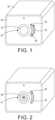
- Referring now to the drawings, and more particularly to
FIG. 1 thereof, this invention provides a universal hose attachment mechanism 20 (also referred to as an adjustable element) that adjusts to receive hoses having different diameters (e.g 9.525 mm; 6.35 mm; or 22.225 mm ( 3/8"; 1/4"; or 7/8' ) ). Depending on the surgical procedure and the instrument being used, the diameter of the suction tube for removing surgical smoke may vary. Theattachment mechanism 20 has acentral opening 23 for receiving a tube or hose. Aknob 26 may be provided on thefront panel 29 of thesmoke evacuator 32. Pushing theknob 26 along araceway 35 disposed in thepanel 29, in the direction of arrow 38, causes a mechanical iris 41 (FIG. 2 ) to close around the tube inside the opening 23. Turning toFIG. 2 , when theknob 26 is pushed toward the end of theraceway 35, the opening 23 is substantially closed. Themechanical iris 41 is formed from a plurality ofcurved panels 44 that are constructed from a flexible material capable of sealing the outside surface of the tube. Theiris 41 is constructed from thecurved panels 44 in a known manner and the position of theiris 41 may be adjusted by means of a gear or the like as will be evident to those of ordinary skill in the art based on this disclosure. The integration of amechanical iris 41 into the hose inlet for a smoke evacuation system provides numerous advantages including the ability to easily interchange different diameter tubing into the smoke evacuator system. - Turning to
FIG. 3 , an alternate embodiment of the universal hose attachment mechanism provides amechanism 50 with acentral opening 53. Thecentral opening 53 receives a flexible insert 55 (FIG. 4 ) that is capable of receiving a tube. Once atube 54 is inserted into theflexible insert 55 in thecentral opening 53 as shown inFIG. 4 , aknob 56 is turned which turns an internal gear. The gear is mechanically connected to asleeve 57 surrounding theflexible insert 55. When theknob 56 is turned the gear causes thesleeve 57 to be tightened around theflexible insert 55. The tightening of thesleeve 57 causes theflexible insert 55 to compress around thetube 54 to seal it for use. - Turning to
FIG. 5 , another alternative embodiment of the universal hose attachment mechanism is shown. Theattachment mechanism 60 has aknob 63 connected to arotating plate 66 having a plurality ofopenings knob 63 causes theplate 66 to turn which brings one of theopenings plate 66 into registry with an opening in thefront panel 72 of thesmoke evacuation system 75. - In
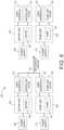
FIG. 6 , a dual surgicalsmoke evacuator system 100 includes ablower unit 103 with ablower motor 104 and apump unit 106 with apump 107. Eachunit
where a blower or pump is suitable are also known. For example, higher volume, lower pressure applications may be suitable for a blower, and a higher pressure, lower volume application may be suitable for a pump. On the left hand side of the figure, theunits first power supply 109 for theblower unit 103 and asecond power supply 112 for thepump unit 106. Theblower unit 103 has auser interface 115 which allows for setting parameters associated with theblower unit 103 such as the speed of the motor. Thepump unit 106 has auser interface 118 that provides for control of thepump unit 106 by the user. Theblower unit 103 has afilter assembly 121, and thepump unit 106 has afilter assembly 124. As shown in the right hand side of the figure, the twounits units blower unit 103 or apump unit 106 depending on the application and the system requirements. - Turning to
FIGS. 7-9 , theblower unit 103 andpump unit 106 may be provided withmechanical connectors units FIG. 7 , the user may select either unit for the specific application. Theunits hose attachment mechanism 138 as described above for receiving tubes having different diameters for different smoke removal applications and flow rates. As shown inFIG. 8 ,connectors openings blower unit 103 to thepump unit 106. - In
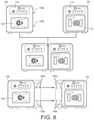
FIGS. 10-14 , an alternate embodiment of the dual smoke evacuation system is shown. This embodiment provides two separate blower and pump units that can operate separately or that can be connected both mechanically and electrically to form a single combined unit. The units have separate power sources, separate interfaces and separate filters when apart, but share a power source, filter, and user interface when linked together. Ablower unit 200 includes ablower motor 202, apower supply 203, auser interface 206, and afilter assembly 209. Apump unit 212 includes apump 214, apower supply 217, auser interface 220, and afilter assembly 223. The twounits units filter assembly 223 from thepump unit 212 and mounting thepump unit 212 onto theblower unit 200. The combined unit utilizesuser interface 206 andfilter assembly 209. - Turning to
FIG. 11 , on the left hand side of the figure, theblower unit 200 includes thefilter assembly 209 which haskeyhole inlet ports 210 for receiving a tube for evacuation of surgical smoke. The tube conveys surgical smoke from the surgical theater to theunit 200 by means of suction created by the dual smoke evacuation system or theblower unit 200. On the right hand side ofFIG. 11 , thepump unit 212 is shown with anelectrical linkage plug 230 disposed on the front panel.Filter assembly 223 is located on the right hand side ofunit 212 and may be removed.Filter assembly 223 also includes anair inlet 225 for connection to a tube for conveying surgical smoke. - Turning to
FIG. 12 , with thefilter assembly 223 removed, thepump unit 212 may be attached to the rear of theblower unit 200. An electrical connector 270 (FIG. 13 ) for theblower unit 200 is connected to theelectrical linkage plug 230 so that power to both units may be supplied bypower supply 217. Anair inlet 250 is disposed at the front of thepump unit 212 where thefilter assembly 223 has been removed. Theair inlet 250 engages with anoutlet 275 in theblower unit 200.User interface 206 includes a control for selecting either theblower unit 200 or thepump unit 212 to convey the surgical smoke.FIGS. 13-14 show the conversion of the individual units into a single dual smoke evacuation system. Theblower unit 200 may be provided withmechanical connectors pump unit 212. Theelectrical connector 270 engages with theelectrical linkage plug 230. Theair outlet 275 engages with theair inlet 250 on thepump unit 212. - This disclosure has been described in detail with particular reference to a presently preferred embodiment, but it will be understood that variations and modifications can be effected within the scope of the invention. The presently disclosed embodiments are therefore considered in all respects to be illustrative and not restrictive. The scope of the invention is indicated by the appended claims, and all changes that come within the meaning and range of equivalents thereof are intended to be embraced therein.
Claims (7)
- An apparatus for evacuation of a fluid from a surgical site, the apparatus comprising:a housing having an opening (23), the opening capable of receiving a hose;a motor (104, 107) maintained within the housing, the motor (104, 107) operable to urge the fluid to pass through the opening (23); anda knob (63);characterised by an adjustable element (66) maintained within the opening (23), the adjustable element (66) operable to change a size of the opening (23) to a plurality of different diameters;wherein the knob (63) is moveably affixed to the housing and operable to change the adjustable element (66) to the plurality of different diameters;wherein the adjustable element (66) comprises a plate (66) having a plurality of different sized holes (69a, 69b, 69c) rotatably affixed to the housing;wherein the plate (66) with the knob (63) is operable to locate each one of the plurality of different sized holes (69a, 69b, 69c) with the opening (23);wherein the adjustable element (66) is operable to form a sealed interface with the hose and the opening (23).
- The apparatus according to claim 1, the apparatus further comprising a hose;
wherein the hose is removeably affixed at the opening (23) by the adjustable element (66). - The apparatus according to claim 1 or 2, wherein the motor is one of an evacuation motor (104) and a pump motor (107).
- An apparatus for evacuation of a fluid from a surgical site, the apparatus comprising:a housing having an opening (53), the opening capable of receiving a hose;a motor (104, 107) maintained within the housing, the motor (104, 107) operable to urge the fluid to pass through the opening (53); anda knob (56);characterised by an adjustable element (55) maintained within the opening (53), the adjustable element (55) operable to change a size of the opening (53) to a plurality of different diameters;wherein the knob (56) is moveably affixed to the housing and operable to change the adjustable element (55) to the plurality of different diameters;wherein the adjustable element (55) comprises a gear mechanically connected to a sleeve (57) surrounding a flexible insert (55) operable to change a diameter of the opening (53);wherein the adjustable element (55) is operable to form a sealed interface with the hose and the opening (53).
- A method of surgical smoke evacuation, the method comprising:(a) providing an evacuation system comprising an apparatus according to anyone of the claims 1 to 4; and(b) evacuating, by the motor (104, 107), surgical smoke through the opening (23) from a surgical site.
- The method according to claim 5, the evacuation system further comprising a hose removeably affixed at the opening (23, 53) by the adjustable element (55, 66).
- The method according to claim 5, wherein the motor (104, 107) is one of an evacuation motor (104) and a pump motor (107).
Priority Applications (1)
| Application Number | Priority Date | Filing Date | Title |
|---|---|---|---|
| EP21202994.6AEP3964149B1 (en) | 2015-12-14 | 2016-12-14 | Apparatus for attachment and evacuation |
Applications Claiming Priority (2)
| Application Number | Priority Date | Filing Date | Title |
|---|---|---|---|
| US201562267123P | 2015-12-14 | 2015-12-14 | |
| PCT/US2016/066678WO2017106360A1 (en) | 2015-12-14 | 2016-12-14 | Method and apparatus for attachment and evacuation |
Related Child Applications (2)
| Application Number | Title | Priority Date | Filing Date |
|---|---|---|---|
| EP21202994.6ADivisionEP3964149B1 (en) | 2015-12-14 | 2016-12-14 | Apparatus for attachment and evacuation |
| EP21202994.6ADivision-IntoEP3964149B1 (en) | 2015-12-14 | 2016-12-14 | Apparatus for attachment and evacuation |
Publications (3)
| Publication Number | Publication Date |
|---|---|
| EP3389525A1 EP3389525A1 (en) | 2018-10-24 |
| EP3389525A4 EP3389525A4 (en) | 2019-08-14 |
| EP3389525B1true EP3389525B1 (en) | 2022-02-02 |
Family
ID=59019043
Family Applications (2)
| Application Number | Title | Priority Date | Filing Date |
|---|---|---|---|
| EP21202994.6AActiveEP3964149B1 (en) | 2015-12-14 | 2016-12-14 | Apparatus for attachment and evacuation |
| EP16876602.0AActiveEP3389525B1 (en) | 2015-12-14 | 2016-12-14 | Method and apparatus for attachment and evacuation |
Family Applications Before (1)
| Application Number | Title | Priority Date | Filing Date |
|---|---|---|---|
| EP21202994.6AActiveEP3964149B1 (en) | 2015-12-14 | 2016-12-14 | Apparatus for attachment and evacuation |
Country Status (6)
| Country | Link |
|---|---|
| US (2) | US10751768B2 (en) |
| EP (2) | EP3964149B1 (en) |
| AU (3) | AU2016370636B2 (en) |
| CA (2) | CA3005094C (en) |
| ES (2) | ES3014388T3 (en) |
| WO (1) | WO2017106360A1 (en) |
Families Citing this family (141)
| Publication number | Priority date | Publication date | Assignee | Title |
|---|---|---|---|---|
| US11871901B2 (en) | 2012-05-20 | 2024-01-16 | Cilag Gmbh International | Method for situational awareness for surgical network or surgical network connected device capable of adjusting function based on a sensed situation or usage |
| US11504192B2 (en) | 2014-10-30 | 2022-11-22 | Cilag Gmbh International | Method of hub communication with surgical instrument systems |
| US10682129B2 (en)* | 2017-03-23 | 2020-06-16 | Mobius Imaging, Llc | Robotic end effector with adjustable inner diameter |
| US11317919B2 (en) | 2017-10-30 | 2022-05-03 | Cilag Gmbh International | Clip applier comprising a clip crimping system |
| US11911045B2 (en) | 2017-10-30 | 2024-02-27 | Cllag GmbH International | Method for operating a powered articulating multi-clip applier |
| US11510741B2 (en) | 2017-10-30 | 2022-11-29 | Cilag Gmbh International | Method for producing a surgical instrument comprising a smart electrical system |
| US11925373B2 (en) | 2017-10-30 | 2024-03-12 | Cilag Gmbh International | Surgical suturing instrument comprising a non-circular needle |
| US11801098B2 (en) | 2017-10-30 | 2023-10-31 | Cilag Gmbh International | Method of hub communication with surgical instrument systems |
| US11564756B2 (en) | 2017-10-30 | 2023-01-31 | Cilag Gmbh International | Method of hub communication with surgical instrument systems |
| US11026687B2 (en) | 2017-10-30 | 2021-06-08 | Cilag Gmbh International | Clip applier comprising clip advancing systems |
| US11229436B2 (en) | 2017-10-30 | 2022-01-25 | Cilag Gmbh International | Surgical system comprising a surgical tool and a surgical hub |
| US11291510B2 (en) | 2017-10-30 | 2022-04-05 | Cilag Gmbh International | Method of hub communication with surgical instrument systems |
| US11311342B2 (en) | 2017-10-30 | 2022-04-26 | Cilag Gmbh International | Method for communicating with surgical instrument systems |
| USD868287S1 (en) | 2017-11-29 | 2019-11-26 | Megadyne Medical Products, Inc. | Remote activation clip |
| US10758855B2 (en) | 2017-11-29 | 2020-09-01 | Megadyne Medical Products, Inc. | Smoke evacuation system fluid trap |
| USD886976S1 (en) | 2017-11-29 | 2020-06-09 | Megadyne Medical Products, Inc. | Filter cartridge |
| US10758856B2 (en) | 2017-11-29 | 2020-09-01 | Megadyne Medical Products, Inc. | Filter medium compression system for smoke evacuation |
| US10758293B2 (en) | 2017-11-29 | 2020-09-01 | Megadyne Medical Products, Inc. | Smoke evacuation device inlet and outlet manifolds |
| US11234754B2 (en) | 2017-11-29 | 2022-02-01 | Megadyne Medical Products, Inc. | Smoke evacuation device |
| USD868236S1 (en) | 2017-11-29 | 2019-11-26 | Megadyne Medical Products, Inc. | Smoke evacuation device control panel |
| US11389225B2 (en) | 2017-11-29 | 2022-07-19 | Megadyne Medical Products, Inc. | Smoke evacuation device remote activation system |
| USD912762S1 (en) | 2017-11-29 | 2021-03-09 | Megadyne Medical Products, Inc. | Fluid trap |
| US10631916B2 (en) | 2017-11-29 | 2020-04-28 | Megadyne Medical Products, Inc. | Filter connection for a smoke evacuation device |
| US11725664B2 (en) | 2017-11-29 | 2023-08-15 | Megadyne Medical Products, Inc. | Noise and vibration management for smoke evacuation system |
| US12376855B2 (en) | 2017-12-28 | 2025-08-05 | Cilag Gmbh International | Safety systems for smart powered surgical stapling |
| US12127729B2 (en) | 2017-12-28 | 2024-10-29 | Cilag Gmbh International | Method for smoke evacuation for surgical hub |
| US11559308B2 (en) | 2017-12-28 | 2023-01-24 | Cilag Gmbh International | Method for smart energy device infrastructure |
| US11013563B2 (en) | 2017-12-28 | 2021-05-25 | Ethicon Llc | Drive arrangements for robot-assisted surgical platforms |
| US11308075B2 (en) | 2017-12-28 | 2022-04-19 | Cilag Gmbh International | Surgical network, instrument, and cloud responses based on validation of received dataset and authentication of its source and integrity |
| US11273001B2 (en) | 2017-12-28 | 2022-03-15 | Cilag Gmbh International | Surgical hub and modular device response adjustment based on situational awareness |
| US11304763B2 (en) | 2017-12-28 | 2022-04-19 | Cilag Gmbh International | Image capturing of the areas outside the abdomen to improve placement and control of a surgical device in use |
| US11389164B2 (en) | 2017-12-28 | 2022-07-19 | Cilag Gmbh International | Method of using reinforced flexible circuits with multiple sensors to optimize performance of radio frequency devices |
| US11744604B2 (en) | 2017-12-28 | 2023-09-05 | Cilag Gmbh International | Surgical instrument with a hardware-only control circuit |
| US11786245B2 (en) | 2017-12-28 | 2023-10-17 | Cilag Gmbh International | Surgical systems with prioritized data transmission capabilities |
| US11179175B2 (en) | 2017-12-28 | 2021-11-23 | Cilag Gmbh International | Controlling an ultrasonic surgical instrument according to tissue location |
| US11696760B2 (en) | 2017-12-28 | 2023-07-11 | Cilag Gmbh International | Safety systems for smart powered surgical stapling |
| US10892899B2 (en) | 2017-12-28 | 2021-01-12 | Ethicon Llc | Self describing data packets generated at an issuing instrument |
| US11464535B2 (en) | 2017-12-28 | 2022-10-11 | Cilag Gmbh International | Detection of end effector emersion in liquid |
| US10943454B2 (en) | 2017-12-28 | 2021-03-09 | Ethicon Llc | Detection and escalation of security responses of surgical instruments to increasing severity threats |
| US11234756B2 (en) | 2017-12-28 | 2022-02-01 | Cilag Gmbh International | Powered surgical tool with predefined adjustable control algorithm for controlling end effector parameter |
| US20190201112A1 (en) | 2017-12-28 | 2019-07-04 | Ethicon Llc | Computer implemented interactive surgical systems |
| US11202570B2 (en) | 2017-12-28 | 2021-12-21 | Cilag Gmbh International | Communication hub and storage device for storing parameters and status of a surgical device to be shared with cloud based analytics systems |
| US11056244B2 (en) | 2017-12-28 | 2021-07-06 | Cilag Gmbh International | Automated data scaling, alignment, and organizing based on predefined parameters within surgical networks |
| US11076921B2 (en) | 2017-12-28 | 2021-08-03 | Cilag Gmbh International | Adaptive control program updates for surgical hubs |
| US10966791B2 (en) | 2017-12-28 | 2021-04-06 | Ethicon Llc | Cloud-based medical analytics for medical facility segmented individualization of instrument function |
| US10918310B2 (en) | 2018-01-03 | 2021-02-16 | Biosense Webster (Israel) Ltd. | Fast anatomical mapping (FAM) using volume filling |
| US11659023B2 (en) | 2017-12-28 | 2023-05-23 | Cilag Gmbh International | Method of hub communication |
| US10755813B2 (en) | 2017-12-28 | 2020-08-25 | Ethicon Llc | Communication of smoke evacuation system parameters to hub or cloud in smoke evacuation module for interactive surgical platform |
| US20190201142A1 (en) | 2017-12-28 | 2019-07-04 | Ethicon Llc | Automatic tool adjustments for robot-assisted surgical platforms |
| US11571234B2 (en) | 2017-12-28 | 2023-02-07 | Cilag Gmbh International | Temperature control of ultrasonic end effector and control system therefor |
| US11291495B2 (en) | 2017-12-28 | 2022-04-05 | Cilag Gmbh International | Interruption of energy due to inadvertent capacitive coupling |
| US11786251B2 (en) | 2017-12-28 | 2023-10-17 | Cilag Gmbh International | Method for adaptive control schemes for surgical network control and interaction |
| US11633237B2 (en) | 2017-12-28 | 2023-04-25 | Cilag Gmbh International | Usage and technique analysis of surgeon / staff performance against a baseline to optimize device utilization and performance for both current and future procedures |
| US11069012B2 (en) | 2017-12-28 | 2021-07-20 | Cilag Gmbh International | Interactive surgical systems with condition handling of devices and data capabilities |
| US11051876B2 (en)* | 2017-12-28 | 2021-07-06 | Cilag Gmbh International | Surgical evacuation flow paths |
| US11464559B2 (en) | 2017-12-28 | 2022-10-11 | Cilag Gmbh International | Estimating state of ultrasonic end effector and control system therefor |
| US20190206569A1 (en) | 2017-12-28 | 2019-07-04 | Ethicon Llc | Method of cloud based data analytics for use with the hub |
| US11903601B2 (en) | 2017-12-28 | 2024-02-20 | Cilag Gmbh International | Surgical instrument comprising a plurality of drive systems |
| US11529187B2 (en) | 2017-12-28 | 2022-12-20 | Cilag Gmbh International | Surgical evacuation sensor arrangements |
| US11602393B2 (en) | 2017-12-28 | 2023-03-14 | Cilag Gmbh International | Surgical evacuation sensing and generator control |
| US10892995B2 (en) | 2017-12-28 | 2021-01-12 | Ethicon Llc | Surgical network determination of prioritization of communication, interaction, or processing based on system or device needs |
| US11832899B2 (en) | 2017-12-28 | 2023-12-05 | Cilag Gmbh International | Surgical systems with autonomously adjustable control programs |
| US11304745B2 (en) | 2017-12-28 | 2022-04-19 | Cilag Gmbh International | Surgical evacuation sensing and display |
| US20190201090A1 (en) | 2017-12-28 | 2019-07-04 | Ethicon Llc | Capacitive coupled return path pad with separable array elements |
| US11540855B2 (en) | 2017-12-28 | 2023-01-03 | Cilag Gmbh International | Controlling activation of an ultrasonic surgical instrument according to the presence of tissue |
| US12396806B2 (en) | 2017-12-28 | 2025-08-26 | Cilag Gmbh International | Adjustment of a surgical device function based on situational awareness |
| US11284936B2 (en) | 2017-12-28 | 2022-03-29 | Cilag Gmbh International | Surgical instrument having a flexible electrode |
| US11832840B2 (en) | 2017-12-28 | 2023-12-05 | Cilag Gmbh International | Surgical instrument having a flexible circuit |
| US10849697B2 (en) | 2017-12-28 | 2020-12-01 | Ethicon Llc | Cloud interface for coupled surgical devices |
| US11666331B2 (en) | 2017-12-28 | 2023-06-06 | Cilag Gmbh International | Systems for detecting proximity of surgical end effector to cancerous tissue |
| US11304699B2 (en) | 2017-12-28 | 2022-04-19 | Cilag Gmbh International | Method for adaptive control schemes for surgical network control and interaction |
| US11857152B2 (en) | 2017-12-28 | 2024-01-02 | Cilag Gmbh International | Surgical hub spatial awareness to determine devices in operating theater |
| US11896322B2 (en) | 2017-12-28 | 2024-02-13 | Cilag Gmbh International | Sensing the patient position and contact utilizing the mono-polar return pad electrode to provide situational awareness to the hub |
| US11376002B2 (en) | 2017-12-28 | 2022-07-05 | Cilag Gmbh International | Surgical instrument cartridge sensor assemblies |
| US11132462B2 (en) | 2017-12-28 | 2021-09-28 | Cilag Gmbh International | Data stripping method to interrogate patient records and create anonymized record |
| US12062442B2 (en) | 2017-12-28 | 2024-08-13 | Cilag Gmbh International | Method for operating surgical instrument systems |
| US11419630B2 (en) | 2017-12-28 | 2022-08-23 | Cilag Gmbh International | Surgical system distributed processing |
| US11266468B2 (en) | 2017-12-28 | 2022-03-08 | Cilag Gmbh International | Cooperative utilization of data derived from secondary sources by intelligent surgical hubs |
| US12096916B2 (en) | 2017-12-28 | 2024-09-24 | Cilag Gmbh International | Method of sensing particulate from smoke evacuated from a patient, adjusting the pump speed based on the sensed information, and communicating the functional parameters of the system to the hub |
| US11424027B2 (en) | 2017-12-28 | 2022-08-23 | Cilag Gmbh International | Method for operating surgical instrument systems |
| US10987178B2 (en) | 2017-12-28 | 2021-04-27 | Ethicon Llc | Surgical hub control arrangements |
| US11937769B2 (en) | 2017-12-28 | 2024-03-26 | Cilag Gmbh International | Method of hub communication, processing, storage and display |
| US11364075B2 (en) | 2017-12-28 | 2022-06-21 | Cilag Gmbh International | Radio frequency energy device for delivering combined electrical signals |
| US11324557B2 (en) | 2017-12-28 | 2022-05-10 | Cilag Gmbh International | Surgical instrument with a sensing array |
| US11026751B2 (en) | 2017-12-28 | 2021-06-08 | Cilag Gmbh International | Display of alignment of staple cartridge to prior linear staple line |
| US11998193B2 (en) | 2017-12-28 | 2024-06-04 | Cilag Gmbh International | Method for usage of the shroud as an aspect of sensing or controlling a powered surgical device, and a control algorithm to adjust its default operation |
| US11818052B2 (en) | 2017-12-28 | 2023-11-14 | Cilag Gmbh International | Surgical network determination of prioritization of communication, interaction, or processing based on system or device needs |
| US11559307B2 (en) | 2017-12-28 | 2023-01-24 | Cilag Gmbh International | Method of robotic hub communication, detection, and control |
| US11147607B2 (en) | 2017-12-28 | 2021-10-19 | Cilag Gmbh International | Bipolar combination device that automatically adjusts pressure based on energy modality |
| US10932872B2 (en) | 2017-12-28 | 2021-03-02 | Ethicon Llc | Cloud-based medical analytics for linking of local usage trends with the resource acquisition behaviors of larger data set |
| WO2019133144A1 (en) | 2017-12-28 | 2019-07-04 | Ethicon Llc | Detection and escalation of security responses of surgical instruments to increasing severity threats |
| US11576677B2 (en) | 2017-12-28 | 2023-02-14 | Cilag Gmbh International | Method of hub communication, processing, display, and cloud analytics |
| US11096693B2 (en) | 2017-12-28 | 2021-08-24 | Cilag Gmbh International | Adjustment of staple height of at least one row of staples based on the sensed tissue thickness or force in closing |
| US11100631B2 (en) | 2017-12-28 | 2021-08-24 | Cilag Gmbh International | Use of laser light and red-green-blue coloration to determine properties of back scattered light |
| US11896443B2 (en) | 2017-12-28 | 2024-02-13 | Cilag Gmbh International | Control of a surgical system through a surgical barrier |
| US11423007B2 (en) | 2017-12-28 | 2022-08-23 | Cilag Gmbh International | Adjustment of device control programs based on stratified contextual data in addition to the data |
| US11589888B2 (en) | 2017-12-28 | 2023-02-28 | Cilag Gmbh International | Method for controlling smart energy devices |
| US11253315B2 (en) | 2017-12-28 | 2022-02-22 | Cilag Gmbh International | Increasing radio frequency to create pad-less monopolar loop |
| US11678881B2 (en) | 2017-12-28 | 2023-06-20 | Cilag Gmbh International | Spatial awareness of surgical hubs in operating rooms |
| US10944728B2 (en) | 2017-12-28 | 2021-03-09 | Ethicon Llc | Interactive surgical systems with encrypted communication capabilities |
| US11278281B2 (en) | 2017-12-28 | 2022-03-22 | Cilag Gmbh International | Interactive surgical system |
| US11612444B2 (en) | 2017-12-28 | 2023-03-28 | Cilag Gmbh International | Adjustment of a surgical device function based on situational awareness |
| US11166772B2 (en) | 2017-12-28 | 2021-11-09 | Cilag Gmbh International | Surgical hub coordination of control and communication of operating room devices |
| US10898622B2 (en) | 2017-12-28 | 2021-01-26 | Ethicon Llc | Surgical evacuation system with a communication circuit for communication between a filter and a smoke evacuation device |
| US11446052B2 (en) | 2017-12-28 | 2022-09-20 | Cilag Gmbh International | Variation of radio frequency and ultrasonic power level in cooperation with varying clamp arm pressure to achieve predefined heat flux or power applied to tissue |
| US11257589B2 (en) | 2017-12-28 | 2022-02-22 | Cilag Gmbh International | Real-time analysis of comprehensive cost of all instrumentation used in surgery utilizing data fluidity to track instruments through stocking and in-house processes |
| US11304720B2 (en) | 2017-12-28 | 2022-04-19 | Cilag Gmbh International | Activation of energy devices |
| US11109866B2 (en) | 2017-12-28 | 2021-09-07 | Cilag Gmbh International | Method for circular stapler control algorithm adjustment based on situational awareness |
| US11969142B2 (en) | 2017-12-28 | 2024-04-30 | Cilag Gmbh International | Method of compressing tissue within a stapling device and simultaneously displaying the location of the tissue within the jaws |
| US11432885B2 (en) | 2017-12-28 | 2022-09-06 | Cilag Gmbh International | Sensing arrangements for robot-assisted surgical platforms |
| US11311306B2 (en) | 2017-12-28 | 2022-04-26 | Cilag Gmbh International | Surgical systems for detecting end effector tissue distribution irregularities |
| US11969216B2 (en) | 2017-12-28 | 2024-04-30 | Cilag Gmbh International | Surgical network recommendations from real time analysis of procedure variables against a baseline highlighting differences from the optimal solution |
| US11160605B2 (en) | 2017-12-28 | 2021-11-02 | Cilag Gmbh International | Surgical evacuation sensing and motor control |
| US20190201039A1 (en) | 2017-12-28 | 2019-07-04 | Ethicon Llc | Situational awareness of electrosurgical systems |
| US10758310B2 (en) | 2017-12-28 | 2020-09-01 | Ethicon Llc | Wireless pairing of a surgical device with another device within a sterile surgical field based on the usage and situational awareness of devices |
| US11864728B2 (en) | 2017-12-28 | 2024-01-09 | Cilag Gmbh International | Characterization of tissue irregularities through the use of mono-chromatic light refractivity |
| US11179208B2 (en) | 2017-12-28 | 2021-11-23 | Cilag Gmbh International | Cloud-based medical analytics for security and authentication trends and reactive measures |
| US11410259B2 (en) | 2017-12-28 | 2022-08-09 | Cilag Gmbh International | Adaptive control program updates for surgical devices |
| US11317937B2 (en) | 2018-03-08 | 2022-05-03 | Cilag Gmbh International | Determining the state of an ultrasonic end effector |
| US11419667B2 (en) | 2017-12-28 | 2022-08-23 | Cilag Gmbh International | Ultrasonic energy device which varies pressure applied by clamp arm to provide threshold control pressure at a cut progression location |
| US11534196B2 (en) | 2018-03-08 | 2022-12-27 | Cilag Gmbh International | Using spectroscopy to determine device use state in combo instrument |
| US11986233B2 (en) | 2018-03-08 | 2024-05-21 | Cilag Gmbh International | Adjustment of complex impedance to compensate for lost power in an articulating ultrasonic device |
| US12303159B2 (en) | 2018-03-08 | 2025-05-20 | Cilag Gmbh International | Methods for estimating and controlling state of ultrasonic end effector |
| US11259830B2 (en) | 2018-03-08 | 2022-03-01 | Cilag Gmbh International | Methods for controlling temperature in ultrasonic device |
| US11219453B2 (en) | 2018-03-28 | 2022-01-11 | Cilag Gmbh International | Surgical stapling devices with cartridge compatible closure and firing lockout arrangements |
| US10973520B2 (en) | 2018-03-28 | 2021-04-13 | Ethicon Llc | Surgical staple cartridge with firing member driven camming assembly that has an onboard tissue cutting feature |
| US11278280B2 (en) | 2018-03-28 | 2022-03-22 | Cilag Gmbh International | Surgical instrument comprising a jaw closure lockout |
| US11589865B2 (en) | 2018-03-28 | 2023-02-28 | Cilag Gmbh International | Methods for controlling a powered surgical stapler that has separate rotary closure and firing systems |
| US11471156B2 (en) | 2018-03-28 | 2022-10-18 | Cilag Gmbh International | Surgical stapling devices with improved rotary driven closure systems |
| US11090047B2 (en) | 2018-03-28 | 2021-08-17 | Cilag Gmbh International | Surgical instrument comprising an adaptive control system |
| US11213294B2 (en) | 2018-03-28 | 2022-01-04 | Cilag Gmbh International | Surgical instrument comprising co-operating lockout features |
| US11096688B2 (en) | 2018-03-28 | 2021-08-24 | Cilag Gmbh International | Rotary driven firing members with different anvil and channel engagement features |
| US11207067B2 (en) | 2018-03-28 | 2021-12-28 | Cilag Gmbh International | Surgical stapling device with separate rotary driven closure and firing systems and firing member that engages both jaws while firing |
| US11464511B2 (en) | 2019-02-19 | 2022-10-11 | Cilag Gmbh International | Surgical staple cartridges with movable authentication key arrangements |
| US11317915B2 (en) | 2019-02-19 | 2022-05-03 | Cilag Gmbh International | Universal cartridge based key feature that unlocks multiple lockout arrangements in different surgical staplers |
| US11369377B2 (en) | 2019-02-19 | 2022-06-28 | Cilag Gmbh International | Surgical stapling assembly with cartridge based retainer configured to unlock a firing lockout |
| US11357503B2 (en) | 2019-02-19 | 2022-06-14 | Cilag Gmbh International | Staple cartridge retainers with frangible retention features and methods of using same |
| US11331100B2 (en) | 2019-02-19 | 2022-05-17 | Cilag Gmbh International | Staple cartridge retainer system with authentication keys |
| USD952144S1 (en) | 2019-06-25 | 2022-05-17 | Cilag Gmbh International | Surgical staple cartridge retainer with firing system authentication key |
| USD964564S1 (en) | 2019-06-25 | 2022-09-20 | Cilag Gmbh International | Surgical staple cartridge retainer with a closure system authentication key |
| USD950728S1 (en) | 2019-06-25 | 2022-05-03 | Cilag Gmbh International | Surgical staple cartridge |
Family Cites Families (19)
| Publication number | Priority date | Publication date | Assignee | Title |
|---|---|---|---|---|
| US2064344A (en)* | 1933-08-25 | 1936-12-15 | Charles A Good | Combination blower and suction sweeper |
| US3321970A (en)* | 1964-10-15 | 1967-05-30 | Charles Wheatley Company | Dual orifice plug fitting |
| US4094492A (en)* | 1977-01-18 | 1978-06-13 | The United States Of America As Represented By The United States Department Of Energy | Variable orifice using an iris shutter |
| DE2806271A1 (en) | 1978-02-15 | 1979-08-23 | Miele & Cie | Control mechanism for auxiliary air supply in vacuum cleaners - has rotatable adjustment disc with different sized holes for opening and closing supply |
| US4986839A (en)* | 1988-11-10 | 1991-01-22 | Surgical Laser Products, Inc. | Self-contained air enhancement and laser plume evacuation system |
| US5971977A (en)* | 1996-07-22 | 1999-10-26 | Korenfeld; Michael S. | Surgical laser smoke plume evacuator |
| US5968032A (en)* | 1998-03-30 | 1999-10-19 | Sleister; Dennis R. | Smoke evacuator for a surgical laser or cautery plume |
| US6001077A (en)* | 1998-05-26 | 1999-12-14 | Ellman; Alan G. | Vacuum wand for surgical smoke plume evacuation system |
| KR100367664B1 (en)* | 2000-02-08 | 2003-01-24 | 주식회사 지인텍 | A portable inhaler of snivel |
| EP1351008A1 (en)* | 2002-03-21 | 2003-10-08 | JohnsonDiversey, Inc. | Flow restrictor |
| US6592543B1 (en)* | 2002-04-03 | 2003-07-15 | Surgin Inc. | Fluid flow regulator for a smoke evacuation system and method of using same |
| AU2004273890A1 (en)* | 2003-09-15 | 2005-03-31 | Robert O. Dean | Operating room smoke evacuator with integrated vacuum motor and filter |
| US8167337B2 (en)* | 2003-12-19 | 2012-05-01 | Bruno Frank L | Elastic coupling for universal vacuum extension kit |
| CA2867838C (en)* | 2005-12-14 | 2016-08-02 | Stryker Corporation | Medical surgical waste collection and disposal system including a rover and a docker, the docker having features facilitating the alignment of the docker with the rover |
| US8414521B2 (en)* | 2006-11-06 | 2013-04-09 | Aardvark Medical, Inc. | Irrigation and aspiration devices and methods |
| US20100305523A1 (en)* | 2009-05-27 | 2010-12-02 | Tyco Healthcare Group Lp | Active Exudate Control System |
| US20120109034A1 (en)* | 2010-10-27 | 2012-05-03 | Kci Licensing, Inc. | Interactive, wireless reduced-pressure dressings, methods, and systems |
| US9080704B2 (en)* | 2011-07-29 | 2015-07-14 | Shaun M. Flanery | Universal pipe coupler |
| DE112014001842T5 (en) | 2013-04-05 | 2015-12-31 | Nascent Surgical, Llc | suction |
- 2016
- 2016-12-14CACA3005094Apatent/CA3005094C/enactiveActive
- 2016-12-14AUAU2016370636Apatent/AU2016370636B2/enactiveActive
- 2016-12-14ESES21202994Tpatent/ES3014388T3/enactiveActive
- 2016-12-14EPEP21202994.6Apatent/EP3964149B1/enactiveActive
- 2016-12-14ESES16876602Tpatent/ES2906768T3/enactiveActive
- 2016-12-14USUS15/379,175patent/US10751768B2/enactiveActive
- 2016-12-14CACA3054026Apatent/CA3054026C/enactiveActive
- 2016-12-14EPEP16876602.0Apatent/EP3389525B1/enactiveActive
- 2016-12-14WOPCT/US2016/066678patent/WO2017106360A1/ennot_activeCeased
- 2020
- 2020-07-15USUS16/929,915patent/US20210060626A1/enactivePending
- 2020-10-27AUAU2020260420Apatent/AU2020260420A1/ennot_activeAbandoned
- 2022
- 2022-06-21AUAU2022204356Apatent/AU2022204356B2/enactiveActive
Also Published As
| Publication number | Publication date |
|---|---|
| AU2022204356A1 (en) | 2022-07-14 |
| AU2016370636B2 (en) | 2020-07-23 |
| US20210060626A1 (en) | 2021-03-04 |
| US10751768B2 (en) | 2020-08-25 |
| AU2020260420A1 (en) | 2020-11-26 |
| EP3389525A1 (en) | 2018-10-24 |
| EP3964149B1 (en) | 2025-01-01 |
| EP3964149A1 (en) | 2022-03-09 |
| ES3014388T3 (en) | 2025-04-22 |
| CA3054026C (en) | 2022-01-25 |
| ES2906768T3 (en) | 2022-04-20 |
| CA3054026A1 (en) | 2017-06-22 |
| WO2017106360A1 (en) | 2017-06-22 |
| AU2016370636A1 (en) | 2018-06-07 |
| CA3005094A1 (en) | 2017-06-22 |
| CA3005094C (en) | 2021-05-25 |
| US20170165725A1 (en) | 2017-06-15 |
| EP3389525A4 (en) | 2019-08-14 |
| AU2022204356B2 (en) | 2024-08-29 |
Similar Documents
| Publication | Publication Date | Title |
|---|---|---|
| EP3389525B1 (en) | Method and apparatus for attachment and evacuation | |
| EP3435901B1 (en) | Smoke evacuation system for invasive surgical procedures | |
| US9078562B2 (en) | Systems and methods for optimizing and maintaining visualization of a surgical field during the use of surgical scopes | |
| EP3490477B1 (en) | Electrosurgical device with vacuum port having multiple swivel connections | |
| EP3740260B1 (en) | Apparatus for flow | |
| EP4580715A1 (en) | Surgical fluid delivery system and components thereof | |
| JP2021527513A (en) | Surgical gas delivery system with remote gas seal module to maintain stable pressure in the surgical cavity | |
| JP2021528164A (en) | Surgical gas delivery device with internal gas seal module and tube set with filter for it |
Legal Events
| Date | Code | Title | Description |
|---|---|---|---|
| STAA | Information on the status of an ep patent application or granted ep patent | Free format text:STATUS: THE INTERNATIONAL PUBLICATION HAS BEEN MADE | |
| PUAI | Public reference made under article 153(3) epc to a published international application that has entered the european phase | Free format text:ORIGINAL CODE: 0009012 | |
| STAA | Information on the status of an ep patent application or granted ep patent | Free format text:STATUS: REQUEST FOR EXAMINATION WAS MADE | |
| 17P | Request for examination filed | Effective date:20180511 | |
| AK | Designated contracting states | Kind code of ref document:A1 Designated state(s):AL AT BE BG CH CY CZ DE DK EE ES FI FR GB GR HR HU IE IS IT LI LT LU LV MC MK MT NL NO PL PT RO RS SE SI SK SM TR | |
| AX | Request for extension of the european patent | Extension state:BA ME | |
| DAV | Request for validation of the european patent (deleted) | ||
| DAX | Request for extension of the european patent (deleted) | ||
| A4 | Supplementary search report drawn up and despatched | Effective date:20190712 | |
| RIC1 | Information provided on ipc code assigned before grant | Ipc:A61B 90/00 20160101ALI20190708BHEP Ipc:B01D 53/00 20060101ALI20190708BHEP Ipc:A61B 18/00 20060101AFI20190708BHEP | |
| STAA | Information on the status of an ep patent application or granted ep patent | Free format text:STATUS: EXAMINATION IS IN PROGRESS | |
| 17Q | First examination report despatched | Effective date:20210318 | |
| GRAP | Despatch of communication of intention to grant a patent | Free format text:ORIGINAL CODE: EPIDOSNIGR1 | |
| STAA | Information on the status of an ep patent application or granted ep patent | Free format text:STATUS: GRANT OF PATENT IS INTENDED | |
| INTG | Intention to grant announced | Effective date:20210915 | |
| GRAS | Grant fee paid | Free format text:ORIGINAL CODE: EPIDOSNIGR3 | |
| GRAA | (expected) grant | Free format text:ORIGINAL CODE: 0009210 | |
| STAA | Information on the status of an ep patent application or granted ep patent | Free format text:STATUS: THE PATENT HAS BEEN GRANTED | |
| AK | Designated contracting states | Kind code of ref document:B1 Designated state(s):AL AT BE BG CH CY CZ DE DK EE ES FI FR GB GR HR HU IE IS IT LI LT LU LV MC MK MT NL NO PL PT RO RS SE SI SK SM TR | |
| REG | Reference to a national code | Ref country code:GB Ref legal event code:FG4D | |
| REG | Reference to a national code | Ref country code:CH Ref legal event code:EP Ref country code:AT Ref legal event code:REF Ref document number:1466388 Country of ref document:AT Kind code of ref document:T Effective date:20220215 | |
| REG | Reference to a national code | Ref country code:DE Ref legal event code:R096 Ref document number:602016068870 Country of ref document:DE | |
| REG | Reference to a national code | Ref country code:IE Ref legal event code:FG4D | |
| REG | Reference to a national code | Ref country code:ES Ref legal event code:FG2A Ref document number:2906768 Country of ref document:ES Kind code of ref document:T3 Effective date:20220420 | |
| REG | Reference to a national code | Ref country code:LT Ref legal event code:MG9D | |
| REG | Reference to a national code | Ref country code:NL Ref legal event code:MP Effective date:20220202 | |
| REG | Reference to a national code | Ref country code:AT Ref legal event code:MK05 Ref document number:1466388 Country of ref document:AT Kind code of ref document:T Effective date:20220202 | |
| PG25 | Lapsed in a contracting state [announced via postgrant information from national office to epo] | Ref country code:SE Free format text:LAPSE BECAUSE OF FAILURE TO SUBMIT A TRANSLATION OF THE DESCRIPTION OR TO PAY THE FEE WITHIN THE PRESCRIBED TIME-LIMIT Effective date:20220202 Ref country code:RS Free format text:LAPSE BECAUSE OF FAILURE TO SUBMIT A TRANSLATION OF THE DESCRIPTION OR TO PAY THE FEE WITHIN THE PRESCRIBED TIME-LIMIT Effective date:20220202 Ref country code:PT Free format text:LAPSE BECAUSE OF FAILURE TO SUBMIT A TRANSLATION OF THE DESCRIPTION OR TO PAY THE FEE WITHIN THE PRESCRIBED TIME-LIMIT Effective date:20220602 Ref country code:NO Free format text:LAPSE BECAUSE OF FAILURE TO SUBMIT A TRANSLATION OF THE DESCRIPTION OR TO PAY THE FEE WITHIN THE PRESCRIBED TIME-LIMIT Effective date:20220502 Ref country code:NL Free format text:LAPSE BECAUSE OF FAILURE TO SUBMIT A TRANSLATION OF THE DESCRIPTION OR TO PAY THE FEE WITHIN THE PRESCRIBED TIME-LIMIT Effective date:20220202 Ref country code:LT Free format text:LAPSE BECAUSE OF FAILURE TO SUBMIT A TRANSLATION OF THE DESCRIPTION OR TO PAY THE FEE WITHIN THE PRESCRIBED TIME-LIMIT Effective date:20220202 Ref country code:HR Free format text:LAPSE BECAUSE OF FAILURE TO SUBMIT A TRANSLATION OF THE DESCRIPTION OR TO PAY THE FEE WITHIN THE PRESCRIBED TIME-LIMIT Effective date:20220202 Ref country code:BG Free format text:LAPSE BECAUSE OF FAILURE TO SUBMIT A TRANSLATION OF THE DESCRIPTION OR TO PAY THE FEE WITHIN THE PRESCRIBED TIME-LIMIT Effective date:20220502 | |
| PG25 | Lapsed in a contracting state [announced via postgrant information from national office to epo] | Ref country code:PL Free format text:LAPSE BECAUSE OF FAILURE TO SUBMIT A TRANSLATION OF THE DESCRIPTION OR TO PAY THE FEE WITHIN THE PRESCRIBED TIME-LIMIT Effective date:20220202 Ref country code:LV Free format text:LAPSE BECAUSE OF FAILURE TO SUBMIT A TRANSLATION OF THE DESCRIPTION OR TO PAY THE FEE WITHIN THE PRESCRIBED TIME-LIMIT Effective date:20220202 Ref country code:GR Free format text:LAPSE BECAUSE OF FAILURE TO SUBMIT A TRANSLATION OF THE DESCRIPTION OR TO PAY THE FEE WITHIN THE PRESCRIBED TIME-LIMIT Effective date:20220503 Ref country code:FI Free format text:LAPSE BECAUSE OF FAILURE TO SUBMIT A TRANSLATION OF THE DESCRIPTION OR TO PAY THE FEE WITHIN THE PRESCRIBED TIME-LIMIT Effective date:20220202 Ref country code:AT Free format text:LAPSE BECAUSE OF FAILURE TO SUBMIT A TRANSLATION OF THE DESCRIPTION OR TO PAY THE FEE WITHIN THE PRESCRIBED TIME-LIMIT Effective date:20220202 | |
| PG25 | Lapsed in a contracting state [announced via postgrant information from national office to epo] | Ref country code:IS Free format text:LAPSE BECAUSE OF FAILURE TO SUBMIT A TRANSLATION OF THE DESCRIPTION OR TO PAY THE FEE WITHIN THE PRESCRIBED TIME-LIMIT Effective date:20220602 | |
| PG25 | Lapsed in a contracting state [announced via postgrant information from national office to epo] | Ref country code:SM Free format text:LAPSE BECAUSE OF FAILURE TO SUBMIT A TRANSLATION OF THE DESCRIPTION OR TO PAY THE FEE WITHIN THE PRESCRIBED TIME-LIMIT Effective date:20220202 Ref country code:SK Free format text:LAPSE BECAUSE OF FAILURE TO SUBMIT A TRANSLATION OF THE DESCRIPTION OR TO PAY THE FEE WITHIN THE PRESCRIBED TIME-LIMIT Effective date:20220202 Ref country code:RO Free format text:LAPSE BECAUSE OF FAILURE TO SUBMIT A TRANSLATION OF THE DESCRIPTION OR TO PAY THE FEE WITHIN THE PRESCRIBED TIME-LIMIT Effective date:20220202 Ref country code:EE Free format text:LAPSE BECAUSE OF FAILURE TO SUBMIT A TRANSLATION OF THE DESCRIPTION OR TO PAY THE FEE WITHIN THE PRESCRIBED TIME-LIMIT Effective date:20220202 Ref country code:DK Free format text:LAPSE BECAUSE OF FAILURE TO SUBMIT A TRANSLATION OF THE DESCRIPTION OR TO PAY THE FEE WITHIN THE PRESCRIBED TIME-LIMIT Effective date:20220202 Ref country code:CZ Free format text:LAPSE BECAUSE OF FAILURE TO SUBMIT A TRANSLATION OF THE DESCRIPTION OR TO PAY THE FEE WITHIN THE PRESCRIBED TIME-LIMIT Effective date:20220202 | |
| REG | Reference to a national code | Ref country code:DE Ref legal event code:R097 Ref document number:602016068870 Country of ref document:DE | |
| PG25 | Lapsed in a contracting state [announced via postgrant information from national office to epo] | Ref country code:AL Free format text:LAPSE BECAUSE OF FAILURE TO SUBMIT A TRANSLATION OF THE DESCRIPTION OR TO PAY THE FEE WITHIN THE PRESCRIBED TIME-LIMIT Effective date:20220202 | |
| PLBE | No opposition filed within time limit | Free format text:ORIGINAL CODE: 0009261 | |
| STAA | Information on the status of an ep patent application or granted ep patent | Free format text:STATUS: NO OPPOSITION FILED WITHIN TIME LIMIT | |
| 26N | No opposition filed | Effective date:20221103 | |
| PG25 | Lapsed in a contracting state [announced via postgrant information from national office to epo] | Ref country code:SI Free format text:LAPSE BECAUSE OF FAILURE TO SUBMIT A TRANSLATION OF THE DESCRIPTION OR TO PAY THE FEE WITHIN THE PRESCRIBED TIME-LIMIT Effective date:20220202 | |
| P01 | Opt-out of the competence of the unified patent court (upc) registered | Effective date:20230529 | |
| REG | Reference to a national code | Ref country code:CH Ref legal event code:PL | |
| REG | Reference to a national code | Ref country code:BE Ref legal event code:MM Effective date:20221231 | |
| PG25 | Lapsed in a contracting state [announced via postgrant information from national office to epo] | Ref country code:LU Free format text:LAPSE BECAUSE OF NON-PAYMENT OF DUE FEES Effective date:20221214 | |
| PG25 | Lapsed in a contracting state [announced via postgrant information from national office to epo] | Ref country code:LI Free format text:LAPSE BECAUSE OF NON-PAYMENT OF DUE FEES Effective date:20221231 Ref country code:IE Free format text:LAPSE BECAUSE OF NON-PAYMENT OF DUE FEES Effective date:20221214 Ref country code:CH Free format text:LAPSE BECAUSE OF NON-PAYMENT OF DUE FEES Effective date:20221231 | |
| PG25 | Lapsed in a contracting state [announced via postgrant information from national office to epo] | Ref country code:BE Free format text:LAPSE BECAUSE OF NON-PAYMENT OF DUE FEES Effective date:20221231 | |
| PG25 | Lapsed in a contracting state [announced via postgrant information from national office to epo] | Ref country code:HU Free format text:LAPSE BECAUSE OF FAILURE TO SUBMIT A TRANSLATION OF THE DESCRIPTION OR TO PAY THE FEE WITHIN THE PRESCRIBED TIME-LIMIT; INVALID AB INITIO Effective date:20161214 | |
| PG25 | Lapsed in a contracting state [announced via postgrant information from national office to epo] | Ref country code:CY Free format text:LAPSE BECAUSE OF FAILURE TO SUBMIT A TRANSLATION OF THE DESCRIPTION OR TO PAY THE FEE WITHIN THE PRESCRIBED TIME-LIMIT Effective date:20220202 | |
| PG25 | Lapsed in a contracting state [announced via postgrant information from national office to epo] | Ref country code:MK Free format text:LAPSE BECAUSE OF FAILURE TO SUBMIT A TRANSLATION OF THE DESCRIPTION OR TO PAY THE FEE WITHIN THE PRESCRIBED TIME-LIMIT Effective date:20220202 | |
| PG25 | Lapsed in a contracting state [announced via postgrant information from national office to epo] | Ref country code:MC Free format text:LAPSE BECAUSE OF FAILURE TO SUBMIT A TRANSLATION OF THE DESCRIPTION OR TO PAY THE FEE WITHIN THE PRESCRIBED TIME-LIMIT Effective date:20220202 | |
| PG25 | Lapsed in a contracting state [announced via postgrant information from national office to epo] | Ref country code:MC Free format text:LAPSE BECAUSE OF FAILURE TO SUBMIT A TRANSLATION OF THE DESCRIPTION OR TO PAY THE FEE WITHIN THE PRESCRIBED TIME-LIMIT Effective date:20220202 | |
| PG25 | Lapsed in a contracting state [announced via postgrant information from national office to epo] | Ref country code:MT Free format text:LAPSE BECAUSE OF FAILURE TO SUBMIT A TRANSLATION OF THE DESCRIPTION OR TO PAY THE FEE WITHIN THE PRESCRIBED TIME-LIMIT Effective date:20220202 | |
| PGFP | Annual fee paid to national office [announced via postgrant information from national office to epo] | Ref country code:DE Payment date:20241001 Year of fee payment:9 | |
| PGFP | Annual fee paid to national office [announced via postgrant information from national office to epo] | Ref country code:GB Payment date:20241001 Year of fee payment:9 | |
| PGFP | Annual fee paid to national office [announced via postgrant information from national office to epo] | Ref country code:FR Payment date:20241001 Year of fee payment:9 | |
| PGFP | Annual fee paid to national office [announced via postgrant information from national office to epo] | Ref country code:IT Payment date:20241112 Year of fee payment:9 | |
| PGFP | Annual fee paid to national office [announced via postgrant information from national office to epo] | Ref country code:ES Payment date:20250102 Year of fee payment:9 |