EP3389032B1 - Device for mounting an electronic data carrier to a component of a fluid installation - Google Patents
Device for mounting an electronic data carrier to a component of a fluid installationDownload PDFInfo
- Publication number
- EP3389032B1 EP3389032B1EP18160439.8AEP18160439AEP3389032B1EP 3389032 B1EP3389032 B1EP 3389032B1EP 18160439 AEP18160439 AEP 18160439AEP 3389032 B1EP3389032 B1EP 3389032B1
- Authority
- EP
- European Patent Office
- Prior art keywords
- insert
- main body
- data carrier
- cord
- component
- Prior art date
- Legal status (The legal status is an assumption and is not a legal conclusion. Google has not performed a legal analysis and makes no representation as to the accuracy of the status listed.)
- Active
Links
Images


Classifications
- F—MECHANICAL ENGINEERING; LIGHTING; HEATING; WEAPONS; BLASTING
- F16—ENGINEERING ELEMENTS AND UNITS; GENERAL MEASURES FOR PRODUCING AND MAINTAINING EFFECTIVE FUNCTIONING OF MACHINES OR INSTALLATIONS; THERMAL INSULATION IN GENERAL
- F16M—FRAMES, CASINGS OR BEDS OF ENGINES, MACHINES OR APPARATUS, NOT SPECIFIC TO ENGINES, MACHINES OR APPARATUS PROVIDED FOR ELSEWHERE; STANDS; SUPPORTS
- F16M13/00—Other supports for positioning apparatus or articles; Means for steadying hand-held apparatus or articles
- F16M13/02—Other supports for positioning apparatus or articles; Means for steadying hand-held apparatus or articles for supporting on, or attaching to, an object, e.g. tree, gate, window-frame, cycle
- G—PHYSICS
- G06—COMPUTING OR CALCULATING; COUNTING
- G06K—GRAPHICAL DATA READING; PRESENTATION OF DATA; RECORD CARRIERS; HANDLING RECORD CARRIERS
- G06K19/00—Record carriers for use with machines and with at least a part designed to carry digital markings
- G06K19/06—Record carriers for use with machines and with at least a part designed to carry digital markings characterised by the kind of the digital marking, e.g. shape, nature, code
- G06K19/067—Record carriers with conductive marks, printed circuits or semiconductor circuit elements, e.g. credit or identity cards also with resonating or responding marks without active components
- G06K19/07—Record carriers with conductive marks, printed circuits or semiconductor circuit elements, e.g. credit or identity cards also with resonating or responding marks without active components with integrated circuit chips
- G06K19/077—Constructional details, e.g. mounting of circuits in the carrier
- G06K19/07749—Constructional details, e.g. mounting of circuits in the carrier the record carrier being capable of non-contact communication, e.g. constructional details of the antenna of a non-contact smart card
- G06K19/07758—Constructional details, e.g. mounting of circuits in the carrier the record carrier being capable of non-contact communication, e.g. constructional details of the antenna of a non-contact smart card arrangements for adhering the record carrier to further objects or living beings, functioning as an identification tag
- G—PHYSICS
- G09—EDUCATION; CRYPTOGRAPHY; DISPLAY; ADVERTISING; SEALS
- G09F—DISPLAYING; ADVERTISING; SIGNS; LABELS OR NAME-PLATES; SEALS
- G09F3/00—Labels, tag tickets, or similar identification or indication means; Seals; Postage or like stamps
- G09F3/02—Forms or constructions
- G09F3/03—Forms or constructions of security seals
- G09F3/0305—Forms or constructions of security seals characterised by the type of seal used
- G09F3/0317—Forms or constructions of security seals characterised by the type of seal used having bolt like sealing means
- G—PHYSICS
- G06—COMPUTING OR CALCULATING; COUNTING
- G06K—GRAPHICAL DATA READING; PRESENTATION OF DATA; RECORD CARRIERS; HANDLING RECORD CARRIERS
- G06K19/00—Record carriers for use with machines and with at least a part designed to carry digital markings
- G06K19/06—Record carriers for use with machines and with at least a part designed to carry digital markings characterised by the kind of the digital marking, e.g. shape, nature, code
- G06K19/067—Record carriers with conductive marks, printed circuits or semiconductor circuit elements, e.g. credit or identity cards also with resonating or responding marks without active components
- G06K19/07—Record carriers with conductive marks, printed circuits or semiconductor circuit elements, e.g. credit or identity cards also with resonating or responding marks without active components with integrated circuit chips
- G06K19/0723—Record carriers with conductive marks, printed circuits or semiconductor circuit elements, e.g. credit or identity cards also with resonating or responding marks without active components with integrated circuit chips the record carrier comprising an arrangement for non-contact communication, e.g. wireless communication circuits on transponder cards, non-contact smart cards or RFIDs
- G—PHYSICS
- G06—COMPUTING OR CALCULATING; COUNTING
- G06K—GRAPHICAL DATA READING; PRESENTATION OF DATA; RECORD CARRIERS; HANDLING RECORD CARRIERS
- G06K19/00—Record carriers for use with machines and with at least a part designed to carry digital markings
- G06K19/06—Record carriers for use with machines and with at least a part designed to carry digital markings characterised by the kind of the digital marking, e.g. shape, nature, code
- G06K19/067—Record carriers with conductive marks, printed circuits or semiconductor circuit elements, e.g. credit or identity cards also with resonating or responding marks without active components
- G06K19/07—Record carriers with conductive marks, printed circuits or semiconductor circuit elements, e.g. credit or identity cards also with resonating or responding marks without active components with integrated circuit chips
- G06K19/077—Constructional details, e.g. mounting of circuits in the carrier
- G06K19/0772—Physical layout of the record carrier
- G—PHYSICS
- G09—EDUCATION; CRYPTOGRAPHY; DISPLAY; ADVERTISING; SEALS
- G09F—DISPLAYING; ADVERTISING; SIGNS; LABELS OR NAME-PLATES; SEALS
- G09F3/00—Labels, tag tickets, or similar identification or indication means; Seals; Postage or like stamps
- G09F3/02—Forms or constructions
- G09F3/03—Forms or constructions of security seals
- G09F3/0305—Forms or constructions of security seals characterised by the type of seal used
- G09F3/0323—Forms or constructions of security seals characterised by the type of seal used having clamp-like sealing means
- G—PHYSICS
- G09—EDUCATION; CRYPTOGRAPHY; DISPLAY; ADVERTISING; SEALS
- G09F—DISPLAYING; ADVERTISING; SIGNS; LABELS OR NAME-PLATES; SEALS
- G09F3/00—Labels, tag tickets, or similar identification or indication means; Seals; Postage or like stamps
- G09F3/02—Forms or constructions
- G09F3/03—Forms or constructions of security seals
- G09F3/0305—Forms or constructions of security seals characterised by the type of seal used
- G09F3/0329—Forms or constructions of security seals characterised by the type of seal used having electronic sealing means
- G—PHYSICS
- G09—EDUCATION; CRYPTOGRAPHY; DISPLAY; ADVERTISING; SEALS
- G09F—DISPLAYING; ADVERTISING; SIGNS; LABELS OR NAME-PLATES; SEALS
- G09F3/00—Labels, tag tickets, or similar identification or indication means; Seals; Postage or like stamps
- G09F3/02—Forms or constructions
- G09F3/03—Forms or constructions of security seals
- G09F3/0305—Forms or constructions of security seals characterised by the type of seal used
- G09F3/0347—Forms or constructions of security seals characterised by the type of seal used having padlock-type sealing means
- G09F3/0352—Forms or constructions of security seals characterised by the type of seal used having padlock-type sealing means using cable lock
Definitions
- the inventionrelates to a device for arranging an electronic data carrier on a component of a flood control system according to the preamble of claim 1.
- Diaphragm valvesare known in which a valve membrane is equipped with an RFID chip. This makes it possible that not only data relating to the materials, the dimensions, the manufacture or similar parameters of the membrane in the data carrier stored and / or digitally referenced in the system, but also data relating to the customer or the delivery. The provision of an RFID chip thus increases the traceability of a valve membrane.
- An exampleis the DE 10 2013 214 304 A1 referred.
- the EP 1 087 334 A1relates to a sealed system or use as a seal to enable the marking of objects to be identified over time.
- the identity of the two capsulesis photographed and stored digitally in a database. It is an archiving step.
- An identification number that is engraved on the capsule with the identityis also archived as a seal number and correlated with both identities.
- An electronic identity of the seal, which is placed in the capsules,can be read by active reading means.
- the object of the inventionis therefore to provide traceability for further components of a fluid power system or those not yet provided with an RFID chip.
- the devicecomprises the electronic data carrier and that an insert which can be inserted into a base body is provided.
- the insertclears a release space for the introduction of at least one rope section of a rope.
- the insertfixes itself to the base body and the at least one rope section to the base body in a pull-out manner.
- This devicepermits the unique and pull-out-safe arrangement of the rope guided around the component and thus the unique arrangement of the data carrier on the respective fluid technology component.
- the pull-out secure fixing of both the insert and the rope sectionadvantageously prevents the rope from being subsequently removed from the device. If the rope is cut or the rope is removed from the device, the same device cannot be arranged again on the component due to the pull-out fixing of the insert.
- a devicewhich is protected against intentional or unintentional manipulation and by means of which the assigned technical component can be clearly identified electronically. This is particularly advantageous in the case of already existing fluid power systems, since simple and safe retrofitting of an electronic data carrier is possible.
- the device providedis characterized in that the insert comprises a fixing section, which in the second position, together with the base body, delimits a fixing channel for the cable section, the fixing channel having a kink in its course.
- the rope sectionis forced into the kink and thereby positively fixed to the device.
- the electronic data carrierbe arranged in a distal area of the insert. In this way, a space-optimized and compact device can advantageously be provided.
- the electronic data carrieris arranged on a base of a container, the container being arranged with its base facing outward in a recess in the device.
- the electronic data carrieris protected from environmental influences and, at the same time, can be read out at an exposed point on the device.
- containersare made of PTFE. This improves the cleanability of the device.
- a further advantageous embodimentis characterized in that the insert and the base body are designed to insert and fix two cable sections. This enables flexible assembly, in which the rope to be used is cut to length as required.
- a ropewhich comprises the rope section, is firmly connected to the base body.
- the provision of the rope on the devicesimplifies the assembly.
- the insertIn the second position, the insert is advantageously received in the main body such that a distal lateral surface of the insert is covered by the main body. This means that no lateral clamping force can be exerted on the insert. Subsequent removal of the insert is thus prevented.
- a distal end face of the insertis flush with an end face of the main body. This flush finish prevents the insert from being removed from the main body. Furthermore, there are advantages in the contactless reading of the electronic data carrier and in the cleanability of the device.
- An advantageous embodimentis characterized in that an annular groove, which is provided for fixing the insert in the second position, between a first and a second inner cylinder of the main body is arranged, a first guide section of the insert being guided axially in the first inner cylinder, and a second guide section of the insert being axially guided in the second inner cylinder. This will guide the insert axially in the main body. This in turn has a positive effect on the secure locking in the second position.
- Another aspect of the processingrelates to a method for arranging the device on a component of a fluid power system, in particular on a pipe section, a valve body, on a drive body or on an intermediate piece.
- the methodincludes: placing the rope around the component; Inserting the at least one rope section into the device; and pressing the insert into the base body.
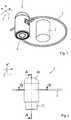
- Figure 1shows a schematic perspective view of a device 2 for arranging an electronic data carrier 4 on a component 6.
- the component 6is part of a fluid power system and, for example, a pipe section, a valve body, a drive body or an intermediate piece between a valve body and a drive body.
- a rope 8is guided circumferentially around the component 6 and is fixed in the present case with both ends in the device 2. Of course, the rope 8 can only be guided around a section of the component 6. Subsequent removal of the device is possible by cutting the rope 8.
- FIG 2shows a side view of the device 2 without the in Figure 1 Component 6 shown.
- the device 2comprises a base body 10, in which an insert 12 is initially arranged displaceably.
- the base body 10 and the insert 12are made of stainless steel.
- the insert 12is in Figure 2 out of the base body 10 and is thus arranged in a first position relative to the base body 10. In the first position, the rope sections of the rope 8 are in the device 2 along their longitudinal axis slidable. If you push the insert 12 into the base body 10, it is shifted into a second position. In the second position, the insert 12 latches in the main body 10 and thus fixes itself and the rope sections of the rope 8 to the base body 10 in a manner that prevents them from being pulled out.
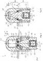
- Figure 3shows the device 2 in a schematic longitudinal section AA Figure 2 , wherein the insert 12 is in relation to the base body 10 in the first position.
- the insert 12has a cylindrical first guide section 14 and a second guide section 16 spaced therefrom.
- the first guide section 14guides the insert 12 axially in an inner cylinder 18 of the base body 10.
- the second guide section 16guides the insert 12 axially in an inner cylinder 20 of the base body 10.
- an annular surface of the insert 12, which lies between the guide section 16 and a release section 37is arranged such that one of the cable sections 32 or 34 penetrates into the space of the inner cylinder 20.
- the base body 10has a distal inner annular groove 22 and a proximal inner annular groove 24 in the region of the first inner cylinder 18.
- the insert 12has an outer annular groove in which an O-ring 26 is received. With the outer ring groove of the insert 12 and the inner ring groove 22, the O-ring 26 defines the first position of the insert 12 relative to the base body 10 in the sense of a first latching position. Of Furthermore, the O-ring 26 with the outer annular groove of the insert 12 and the inner annular groove 24 defines the second position of the insert 12 relative to the base body 10 in the sense of a second latching position.
- the base body 10has through openings 28 and 30, through which cable sections 32 and 34 are guided from an outer space of the base body 10 into and through an inner release space 35 in the interior of the base body 10.
- the release section 37 of the insert 12releases the release space 35 for the cable sections 32 and 34.
- An inner cavity of the base body 2is designed in several stages. So the inner cylinder 18 and the release space 15 are limited by a jump in diameter. The release space 35 and the inner cylinder 20 are also limited by a jump in diameter.
- one of the cable sectionscan also be firmly connected to the base body 10 and only the other cable section is guided around the component 6 in order to then be guided through the base body 10 and to be fixed by pressing in the insert 12 .
- the insert 2has a diameter increase 36 on the side facing away from the guide section 16, which increases into a fixing section 40.
- the diameter increase 36is frustoconical. If the insert 12 is pushed into the base body 10, the diameter increase 36 engages the cable sections 32 and 34 and moves them in the direction of an inner cylinder surface 42.
- the inner cylinder surface 42 and the fixing section 40delimit a fixing channel for the respective cable section 32 mentioned below, 34.
- the fixing section 40forces the cable sections 32, 34 into the respective fixing channel and fixes the cable sections 32, 34 to the device 2 so that they cannot be pulled out.
- the electronic data carrier 4is arranged in a pot-shaped container 44, wherein a closure element 46 in the form of a ball clamps the electronic data carrier 4 between the floor and itself. At the same time, the closure element 46 exerts a force on the wall of the container 44 in a surface perpendicular to the longitudinal axis 50.
- the container 44is preferably made of PTFE, polytetrafluoroethylene and is arranged in a recess 48 of the insert 12 in the sense of an interference fit. An outwardly facing surface 52 of the container 44 is flush with a distal annular surface 54 of the insert 12.
- Figure 4shows the device 2 in a schematic longitudinal sectional view, the insert 12 being located in the second position relative to the base body 10.
- the insert 12In the second position of the insert 12 relative to the base body 10 define an outer cylinder surface of the fixing section 40 and the cylinder inner surface 42 the two fixing channels 56 and 58 for the respective cable sections 32 and 34.
- a distal lateral surface as part of the guide section 14is accommodated in the base body 10 in the second position and the base body 10 covers this peripheral surface.
- the surface 54is flush with a distal surface 55 of the base body 10.
- the surfaces 52, 54 and 55lie in an imaginary common plane. A distance D1 between the ring grooves 22 and 24 and a distance D2 between the release section 37 and the fixing section 40 match.
- the data carrier 4is flat and in particular disc-shaped and lies with the plane spanned by it essentially parallel to at least one of the surfaces 52, 54 and 55.
- the electronic data carrier 4is in particular an RFID chip which has a transponder by means of the data can be read from the data carrier 4 with the aid of a reading device arranged in the vicinity of the data carrier 4 and, if appropriate, can also be written into the data carrier 4.
- Figure 5shows the device 2 in a section BB Figure 2 , wherein the insert 12 is in the first position relative to the base body 10.
- the cable sections 32 and 34can be in the release space 35, which is released in the first position of the insert 12 is easily inserted and moved in it.
- Figure 6shows a schematic section similar to Figure 5 , wherein the insert 12 is located in relation to the base body 10 in the second position. In the second position, the insert 12 forms the fixing channels together with the base body 10, the fixing channel 56 comprising kinks 59 and 60.
- the fixing channel 58comprises kinks 62 and 64.
- a respective kink 59, 60, 62, 64causes the cable sections 32 and 34 to be deflected by at least 40 °, in particular by at least 45 °. The cable sections 32 and 34 are thus positively fixed to the device 2.
- Figure 7shows a schematic flow diagram for the assembly of the device 2.
- the rope 8is placed at least in sections around the component 6.
- a step 104at least one of the cable sections 32, 34 is inserted into the device 2.
- a step 106the insert 12 is pressed into the base body 10. The pull-out secure fixing of the rope 8 results in a fixed loop of the rope 8 around the component 6.
Landscapes
- Engineering & Computer Science (AREA)
- Physics & Mathematics (AREA)
- General Physics & Mathematics (AREA)
- Theoretical Computer Science (AREA)
- Computer Security & Cryptography (AREA)
- Computer Hardware Design (AREA)
- Microelectronics & Electronic Packaging (AREA)
- General Engineering & Computer Science (AREA)
- Computer Networks & Wireless Communication (AREA)
- Mechanical Engineering (AREA)
- Insertion, Bundling And Securing Of Wires For Electric Apparatuses (AREA)
- Quick-Acting Or Multi-Walled Pipe Joints (AREA)
- Infusion, Injection, And Reservoir Apparatuses (AREA)
- Instruments For Viewing The Inside Of Hollow Bodies (AREA)
- Media Introduction/Drainage Providing Device (AREA)
Description
Translated fromGermanDie Erfindung betrifft eine Vorrichtung zur Anordnung eines elektronischen Datenträgers an einer Komponente einer fluttechnischen Anlage nach dem Oberbegriff des Anspruchs 1.The invention relates to a device for arranging an electronic data carrier on a component of a flood control system according to the preamble of claim 1.
Es sind Membranventile bekannt, bei denen eine Ventilmembran mit einem RFID-Chip ausgestattet ist. Hierdurch wird es möglich, dass nicht nur Daten betreffend die Materialien, die Abmessungen, die Herstellung oder ähnliche Kenngrößen der Membran in dem Datenträger abgespeichert und/oder digital im System referenziert werden, sondern auch Daten betreffend den Kunden bzw. die Lieferung. Somit erhöht das Vorsehen eines RFID-Chips die Nachverfolgbarkeit einer Ventilmembran. Beispielhaft wird auf die
Die
Mithin besteht die Aufgabe der Erfindung darin, eine Nachverfolgbarkeit für weitere oder noch nicht mit einem RFID-Chip versehene Komponenten einer fluidtechnischen Anlage bereitzustellen.The object of the invention is therefore to provide traceability for further components of a fluid power system or those not yet provided with an RFID chip.
Diese Aufgabe wird durch eine Vorrichtung nach dem Anspruch 1 gelöst. Vorteilhafte Weiterbildungen der Erfindung sind in den Unteransprüchen angegeben. Für die Erfindung wichtige Merkmale finden sich weitergehend in der nachfolgenden Beschreibung sowie in der beiliegenden Zeichnung.This object is achieved by a device according to claim 1. Advantageous developments of the invention are specified in the subclaims. Features important for the invention can be found further in the following description and in the accompanying drawing.
Es wird vorgeschlagen, dass die Vorrichtung den elektronischen Datenträger umfasst, und dass ein in einen Grundkörper einschiebbarer Einsatz vorgesehen ist. Der Einsatz gibt in einer ersten Position zu dem Grundkörper einen Freigaberaum zu einer Einführung zumindest eines Seilabschnitts eines Seiles frei. Der Einsatz legt in einer zweiten Position zu dem Grundkörper sich selbst und den zumindest einen Seilabschnitt ausziehsicher zu dem Grundkörper fest.It is proposed that the device comprises the electronic data carrier and that an insert which can be inserted into a base body is provided. In a first position to the base body, the insert clears a release space for the introduction of at least one rope section of a rope. In a second position, the insert fixes itself to the base body and the at least one rope section to the base body in a pull-out manner.
Diese Vorrichtung erlaubt die einmalige und ausziehsichere Anordnung des um die Komponente geführten Seiles und damit die einmalige Anordnung des Datenträgers an der jeweiligen fluidtechnischen Komponente. Die ausziehsichere Festlegung sowohl des Einsatzes als auch des Seilabschnitts verhindert vorteilhaft eine nachträgliche Entfernung des Seiles aus der Vorrichtung. Sollte es doch zu einer Durchtrennung des Seiles oder zu einer Entfernung des Seiles aus der Vorrichtung kommen, so kann die gleiche Vorrichtung durch die ausziehsichere Festlegung des Einsatzes nicht erneut an der Komponente angeordnet werden.This device permits the unique and pull-out-safe arrangement of the rope guided around the component and thus the unique arrangement of the data carrier on the respective fluid technology component. The pull-out secure fixing of both the insert and the rope section advantageously prevents the rope from being subsequently removed from the device. If the rope is cut or the rope is removed from the device, the same device cannot be arranged again on the component due to the pull-out fixing of the insert.
Es wird also eine vor beabsichtigter oder unbeabsichtigter Manipulation geschützte Vorrichtung bereitgestellt, mittels derer die zugeordnete technische Komponente elektronisch eindeutig identifizierbar ist. Dies ist insbesondere bei bereits vorhandenen fluidtechnischen Anlagen vorteilhaft, da eine einfache und sichere Nachrüstung eines elektronischen Datenträgers möglich ist.A device is thus provided which is protected against intentional or unintentional manipulation and by means of which the assigned technical component can be clearly identified electronically. This is particularly advantageous in the case of already existing fluid power systems, since simple and safe retrofitting of an electronic data carrier is possible.
Des Weiteren zeichnet sich die bereitgestellte Vorrichtung dadurch aus, dass der Einsatz einen Festlegeabschnitt umfasst, welcher in der zweiten Position gemeinsam mit dem Grundkörper einen Fixierkanal für den Seilabschnitt begrenzt, wobei der Fixierkanal in seinem Verlauf einen Knick aufweist. Hierdurch wird der Seilabschnitt in den Knick gezwungen und dadurch formschlüssig zu der Vorrichtung festgelegt.Furthermore, the device provided is characterized in that the insert comprises a fixing section, which in the second position, together with the base body, delimits a fixing channel for the cable section, the fixing channel having a kink in its course. As a result, the rope section is forced into the kink and thereby positively fixed to the device.
In einer ersten Weiterbildung der Vorrichtung wird vorgeschlagen, dass der elektronische Datenträger in einem distalen Bereich des Einsatzes angeordnet ist. Vorteilhaft kann auf diese Art und Weise eine Bauraum-optimierte und kompakte Vorrichtung bereitgestellt werden.In a first development of the device, it is proposed that the electronic data carrier be arranged in a distal area of the insert. In this way, a space-optimized and compact device can advantageously be provided.
Darüber hinaus ist es insbesondere vorteilhaft, wenn der elektronische Datenträger an einem Boden eines Behälters angeordnet ist, wobei der Behälter mit seinem Boden nach außen zeigend in einer Ausnehmung der Vorrichtung angeordnet ist. Hierdurch wird der elektronische Datenträger vor Umwelteinflüssen geschützt und gleichzeitig auslesbar an einer exponierten Stelle der Vorrichtung angeordnet.In addition, it is particularly advantageous if the electronic data carrier is arranged on a base of a container, the container being arranged with its base facing outward in a recess in the device. As a result, the electronic data carrier is protected from environmental influences and, at the same time, can be read out at an exposed point on the device.
In einer Weiterbildung ist Behälter aus PTFE hergestellt. Hierdurch wird die Abreinigbarkeit der Vorrichtung verbessert.In a further development, containers are made of PTFE. This improves the cleanability of the device.
Eine weitere vorteilhafte Ausführungsform zeichnet sich dadurch aus, dass der Einsatz und der Grundkörper zur Einführung und Festlegung zweier Seilabschnitte ausgebildet sind. Dies ermöglicht eine flexible Montage, bei der das zu verwendende Seil den Anforderungen entsprechend abgelängt wird.A further advantageous embodiment is characterized in that the insert and the base body are designed to insert and fix two cable sections. This enables flexible assembly, in which the rope to be used is cut to length as required.
In einer alternativen Ausführungsform ist ein Seil, welches den Seilabschnitt umfasst, mit dem Grundkörper fest verbunden. Durch das Bereitstellen des Seils an der Vorrichtung vereinfacht sich die Montage.In an alternative embodiment, a rope, which comprises the rope section, is firmly connected to the base body. The provision of the rope on the device simplifies the assembly.
Der Einsatz ist in der zweiten Position vorteilhaft derart in dem Hauptkörper aufgenommen, sodass eine distale Mantelfläche des Einsatzes vom Hauptkörper verdeckt ist. Damit kann keine seitliche Klemmkraft auf den Einsatz ausgeübt werden. Ein nachträgliches Entfernen des Einsatzes wird somit verhindert.In the second position, the insert is advantageously received in the main body such that a distal lateral surface of the insert is covered by the main body. This means that no lateral clamping force can be exerted on the insert. Subsequent removal of the insert is thus prevented.
In der zweiten Position des Einsatzes zu dem Grundkörper ist eine distale Abschlussfläche des Einsatzes bündig mit einer Abschlussfläche des Hauptkörpers. Durch diesen bündigen Abschluss wird ein Entfernen des Einsatzes aus dem Hauptkörper verhindert. Des Weiteren ergeben sich Vorteile beim kontaktlosen Auslesen des elektronischen Datenträgers und bei der Abreinigbarkeit der Vorrichtung.In the second position of the insert relative to the base body, a distal end face of the insert is flush with an end face of the main body. This flush finish prevents the insert from being removed from the main body. Furthermore, there are advantages in the contactless reading of the electronic data carrier and in the cleanability of the device.
Eine vorteilhafte Ausführungsform zeichnet sich dadurch aus, dass eine Ringnut, welche für die Festlegung des Einsatzes in der zweiten Position vorgesehen ist, zwischen einem ersten und einem zweiten Innenzylinder des Hauptkörpers angeordnet ist, wobei ein erster Führungsabschnitt des Einsatzes in dem ersten Innenzylinder axial geführt ist, und wobei ein zweiter Führungsabschnitt des Einsatzes in dem zweiten Innenzylinder axial geführt ist. Hierdurch wird die axiale Führung des Einsatzes in dem Hauptkörper. Dies wirkt sich wiederum positiv auf die sichere Einrastung in der zweiten Position aus.An advantageous embodiment is characterized in that an annular groove, which is provided for fixing the insert in the second position, between a first and a second inner cylinder of the main body is arranged, a first guide section of the insert being guided axially in the first inner cylinder, and a second guide section of the insert being axially guided in the second inner cylinder. This will guide the insert axially in the main body. This in turn has a positive effect on the secure locking in the second position.
Ein weiterer Aspekt der Bearbeitung betrifft ein Verfahren zur Anordnung der Vorrichtung an einer Komponente einer fluidtechnischen Anlage, insbesondere an einem Rohrleitungsstück, einem Ventilkörper, an einem Antriebskörper oder an einem Zwischenstück. Das Verfahren umfasst: Anordnen des Seiles um die Komponente; Einführen des zumindest einen Seilabschnitts in die Vorrichtung; und Eindrücken des Einsatzes in den Grundkörper. Somit kann die Vorrichtung auf einfache Art und Weise montiert werden und es ergibt sich die vorteilhafte ausziehsichere Festlegung des Seiles zu der Vorrichtung.Another aspect of the processing relates to a method for arranging the device on a component of a fluid power system, in particular on a pipe section, a valve body, on a drive body or on an intermediate piece. The method includes: placing the rope around the component; Inserting the at least one rope section into the device; and pressing the insert into the base body. Thus, the device can be assembled in a simple manner and the result is the advantageous pull-out fixing of the rope to the device.
Nachfolgend wird eine Ausführungsform der vorliegenden Erfindung beispielhaft unter Bezugnahme auf die beiliegende Zeichnung erläutert. In der Zeichnung zeigen:
Figur 1 eine schematische perspektivische Ansicht einer Vorrichtung;Figur 2Figuren 3 und 4 jeweils eine schematische Längsschnittansicht der Vorrichtung;Figuren 5 und 6 jeweils eine schematische Querschnittansicht der Vorrichtung; undFigur 7 zeigt ein schematisches Ablaufdiagramm.
Figure 1 a schematic perspective view of a device;Figure 2 a side view of the device;Figures 3 and 4 each a schematic longitudinal sectional view of the device;Figures 5 and 6 each a schematic cross-sectional view of the device; andFigure 7 shows a schematic flow diagram.
Der Grundkörper 10 weist im Bereich des ersten Innenzylinders 18 eine distale innere Ringnut 22 und eine proximale innere Ringnut 24 auf. Hierzu korrespondierend weist der Einsatz 12 eine äußere Ringnut auf, in welcher ein O-Ring 26 aufgenommen ist. Der O-Ring 26 definiert mit der äußeren Ringnut des Einsatzes 12 und der inneren Ringnut 22 die erste Position des Einsatzes 12 zu dem Grundkörper 10 im Sinne einer ersten Rastposition. Des Weiteren definiert der O-Ring 26 mit der äußeren Ringnut des Einsatzes 12 und der inneren Ringnut 24 die zweite Position des Einsatzes 12 zu dem Grundkörper 10 im Sinne einer zweiten Rastposition.The
Der Grundkörper 10 weist Durchgangsöffnungen 28 und 30 auf, durch welche von einem Außenraum des Grundkörpers 10 Seilabschnitte 32 und 34 in und durch einen inneren Freigaberaum 35 im Inneren des Grundkörpers 10 geführt werden. In der ersten Position des Einsatzes 12 gibt der Freigabeabschnitt 37 des Einsatzes 12 den Freigaberaum 35 für die Seilabschnitte 32 und 34 frei.The
Ein innerer Hohlraum des Grundkörpers 2 ist mehrstufig ausgeführt. So sind der Innenzylinder 18 und der Freigaberaum 15 durch einen Durchmessersprung begrenzt. Der Freigaberaum 35 und der Innenzylinder 20 sind ebenfalls durch einen Durchmessersprung begrenzt.An inner cavity of the
Alternativ zu der Ein- und Durchführung zweier Seilabschnitte kann auch einer der Seilabschnitte mit dem Grundkörper 10 fest verbunden sein und es wird nur der andere Seilabschnitt um die Komponente 6 geführt um anschließend durch den Grundkörper 10 geführt und mittels des Eindrückens des Einsatzes 12 festgelegt zu werden.As an alternative to the introduction and implementation of two cable sections, one of the cable sections can also be firmly connected to the
Ausgehend von dem Freigabeabschnitt 37 weist der Einsatz 2 auf der dem Führungsabschnitt 16 abgewandten Seite eine Durchmesserzunahme 36 auf, welche in einen Festlegeabschnitt 40 übergeht. Die Durchmesserzunahme 36 ist kegelstumpfförmig ausgebildet. Schiebt man den Einsatz 12 in den Grundkörper 10 ein, so greift die Durchmesserzunahme 36 an den Seilabschnitten 32 und 34 an und bewegt diese in Richtung einer Zylinderinnenfläche 42. Die Zylinderinnenfläche 42 und der Festlegeabschnitt 40 begrenzen einen nachfolgend genannten Fixierkanal für den jeweiligen Seilabschnitt 32, 34. Der Festlegeabschnitt 40 zwingt die Seilabschnitte 32, 34 in den jeweiligen Fixierkanal und legt die Seilabschnitte 32, 34 ausziehsicher zu der Vorrichtung 2 fest.Starting from the
Der elektronische Datenträger 4 ist in einem topfförmigen Behälter 44 angeordnet, wobei ein Verschlusselement 46 in Form einer Kugel den elektronischen Datenträger 4 zwischen dem Boden und sich selbst einklemmt. Gleichzeitig bewirkt das Verschlusselement 46 in einer Fläche lotrecht zur Längsachse 50 eine Kraft auf die Wandung des Behälters 44. Der Behälter 44 ist bevorzugt aus PTFE, Polytetrafluorethylen, gefertigt und in einer Ausnehmung 48 des Einsatzes 12 im Sinne einer Presspassung angeordnet. Eine nach außen gewandte Oberfläche 52 des Behälters 44 schließt bündig mit einer distalen kreisringförmig ausgebildeten Oberfläche 54 des Einsatzes 12 ab.The
Eine distale Mantelfläche als Teil des Führungsabschnitts 14 ist in der zweiten Position im Grundkörper 10 aufgenommen und der Grundkörper 10 verdeckt diese Mantelfläche. Darüber hinaus ist die Oberfläche 54 bündig zu einer distalen Oberfläche 55 des Grundkörpers 10. Insbesondere liegen die Oberflächen 52, 54 und 55 in einer gedachten gemeinsamen Ebene. Eine Distanz D1 zwischen den Ringnuten 22 und 24 sowie eine Distanz D2 zwischen dem Freigabeabschnitt 37 und dem Festlegeabschnitt 40 stimmen überein.A distal lateral surface as part of the
Der Datenträger 4 ist flächig und insbesondere Scheibenförmig ausgebildet und liegt mit der von ihm aufgespannt Ebene im Wesentlichen parallel zu mindestens einer der Oberflächen 52, 54 und 55. Der elektronische Datenträger 4 ist insbesondere ein RFID-Chip, der einen Transponder aufweist, mittels dem Daten unter Zuhilfenahme eines in der Nähe des Datenträgers 4 angeordneten Lesegeräts von dem Datenträger 4 ausgelesen und gegebenenfalls auch in den Datenträger 4 eingeschrieben werden können.The
Claims (11)
- A device (2) for arranging an electronic data carrier (4) on a component (6) of a fluidic system, the device (2) comprising the electronic data carrier (4), an insert (12), in a first position relative to a main body (10), opening a release chamber (35) for the introduction of at least one cord portion (32; 34) of a cord (8),characterized in that- the insert can be inserted into the main body (10),- in a second position relative to the main body (10), the insert (12) fastens itself and the at least one cord portion (32; 34) to the main body (10) so as to be secured against pulling out,- the insert (12) comprises a fastening portion (40) which, in the second position, defines a fixing channel (56; 58) for the cord portion (32; 34) together with the main body (10), and- the fixing channel (56; 58) for the cord portion (32; 34) has a bend (59; 60; 62; 64) in the path thereof.
- The device (2) according to claim 1, wherein the electronic data carrier (4) is arranged in a distal region of the insert (12).
- The device (2) according to claim 1 or claim 2, wherein the electronic data carrier (4) is arranged on a base of a container (44), and wherein the container (44) is arranged in a recess (48) of the device (2), with the base thereof pointing outward.
- The device according to claim 3, wherein the container (44) is made of PTFE.
- The device (2) according to any of the preceding claims, wherein the insert (12) and the main body (10) are designed for the introduction and fastening of two cord portions (32, 34).
- The device (2) according to any of claims 1 to 4, wherein a cord which comprises the cord portion (32; 34) is fixedly connected to the main body (10).
- The device (2) according to any of the preceding claims, wherein, in the second position, the insert (12) is received in the main body (10) such that a distal lateral outer surface of the insert (12) is covered by the main body (10).
- The device (2) according to any of the preceding claims, wherein, in the second position of the insert (12) relative to the main body (10), a distal end face (54) of the insert (12) is flush with an end face (55) of the main body (10).
- The device (2) according to any of the preceding claims, wherein an annular groove (24) which is provided for fastening the insert (12) in the second position is arranged between a first and a second inner cylinder (18, 20) of the main body (10), wherein a first guide portion (14) of the insert (12) is axially guided in the first inner cylinder (18), and wherein a second guide portion (16) of the insert (12) is axially guided in the second inner cylinder (20).
- A component (6) of a fluidic system, in particular a piece of pipe, a valve body, a drive body or an intermediate piece, to which the device (2) according to any of the preceding claims is fastened.
- A method for arranging the device (2) according to any of claims 1 to 9 on a component (6) of a fluidic system, in particular on a piece of pipeline, on a valve body, on a drive body, or on an intermediate piece, said method comprising:- arranging (102) the cord (8) around the component (6);- introducing (104) the at least one cord portion (32; 34) into the device (2); and- pressing (106) the insert (12) into the main body (10).
Applications Claiming Priority (1)
| Application Number | Priority Date | Filing Date | Title |
|---|---|---|---|
| DE102017107705.7ADE102017107705A1 (en) | 2017-04-10 | 2017-04-10 | Device for arranging an electronic data carrier on a component of a fluid power system |
Publications (2)
| Publication Number | Publication Date |
|---|---|
| EP3389032A1 EP3389032A1 (en) | 2018-10-17 |
| EP3389032B1true EP3389032B1 (en) | 2020-06-10 |
Family
ID=61628116
Family Applications (1)
| Application Number | Title | Priority Date | Filing Date |
|---|---|---|---|
| EP18160439.8AActiveEP3389032B1 (en) | 2017-04-10 | 2018-03-07 | Device for mounting an electronic data carrier to a component of a fluid installation |
Country Status (4)
| Country | Link |
|---|---|
| US (1) | US11106962B2 (en) |
| EP (1) | EP3389032B1 (en) |
| CN (1) | CN108692161B (en) |
| DE (1) | DE102017107705A1 (en) |
Families Citing this family (2)
| Publication number | Priority date | Publication date | Assignee | Title |
|---|---|---|---|---|
| DE102017107705A1 (en)* | 2017-04-10 | 2018-10-11 | Gemü Gebr. Müller Apparatebau Gmbh & Co. Kommanditgesellschaft | Device for arranging an electronic data carrier on a component of a fluid power system |
| DE102020115205A1 (en) | 2020-06-08 | 2021-12-09 | Bürkert Werke GmbH & Co. KG | Device for controlling or measuring a fluid |
Family Cites Families (85)
| Publication number | Priority date | Publication date | Assignee | Title |
|---|---|---|---|---|
| FR1023017A (en)* | 1950-08-04 | 1953-03-12 | Dejoie & Cie | Improvement in warranty seals |
| AU575465B2 (en)* | 1985-02-05 | 1988-07-28 | Encrypta Electronics Limited | Apparatus for recording the opening or closing of a closure member |
| US5042181A (en)* | 1990-01-17 | 1991-08-27 | Thomas & Betts Corporation | Cable tie identification tag |
| US5120097A (en)* | 1990-07-30 | 1992-06-09 | The Rel Corporation | Security seal |
| US5167626A (en)* | 1990-10-02 | 1992-12-01 | Glaxo Inc. | Medical capsule device actuated by radio-frequency (RF) signal |
| ATE136674T1 (en)* | 1991-12-19 | 1996-04-15 | Ake Gustafson | SAFETY LOCKING DEVICE |
| IT1296683B1 (en)* | 1997-11-06 | 1999-07-14 | Mainetti Tecnologie Spa | ANTI-SHOPPING SEAL |
| DE19837163C1 (en) | 1998-08-17 | 2000-03-16 | Deere & Co | Hand control lever |
| US6200341B1 (en)* | 1998-09-25 | 2001-03-13 | Sulzer Carbomedics Inc. | Mechanical heart valve assembly with super-elastic lock wire |
| GB9914711D0 (en)* | 1999-06-23 | 1999-08-25 | Leck Michael J | Electronic seal,methods and security system |
| PT1087334E (en)* | 1999-09-15 | 2008-03-10 | Europ Economic Community | Multi-use electronic seal with passive transponder |
| US6390519B1 (en)* | 2000-06-08 | 2002-05-21 | E. J. Brooks Company | Rotatable seal |
| US6588812B1 (en)* | 2001-02-22 | 2003-07-08 | The Regents Of The University Of California | Enhanced tamper indicator |
| JP3831629B2 (en)* | 2001-05-16 | 2006-10-11 | 三洋電機株式会社 | Tag device |
| US7429927B2 (en)* | 2001-07-10 | 2008-09-30 | American Express Travel Related Services Company, Inc. | System and method for providing and RFID transaction device |
| EP1540632B1 (en)* | 2002-08-05 | 2009-03-25 | Holo-Point Ltd. | Means and method for marking products |
| US8378841B2 (en)* | 2003-04-09 | 2013-02-19 | Visible Assets, Inc | Tracking of oil drilling pipes and other objects |
| WO2005043494A1 (en)* | 2003-10-29 | 2005-05-12 | Display Technologies, Inc. | Anti-theft tag |
| US6933847B2 (en)* | 2003-10-29 | 2005-08-23 | A&H Manufacturing, Co. | Anti-theft tag |
| US7518521B2 (en)* | 2003-10-29 | 2009-04-14 | Display Technologies, Inc. | Rotating anti-theft tag |
| US7239238B2 (en)* | 2004-03-30 | 2007-07-03 | E. J. Brooks Company | Electronic security seal |
| US7202788B2 (en)* | 2004-10-21 | 2007-04-10 | Yeng-Bao Shieh | RFID electronic seal and system using the RFID electronic seal |
| US20060109118A1 (en)* | 2004-11-22 | 2006-05-25 | Sdgi Holdings, Inc. | Twist-tie RFID tag |
| US7474209B2 (en)* | 2005-01-14 | 2009-01-06 | Checkpoint Systems, Inc. | Cable alarm security device |
| US7183914B2 (en)* | 2005-02-28 | 2007-02-27 | B & G Plastics, Inc. | Hang tag with swivel attachment |
| US7292149B2 (en)* | 2005-03-16 | 2007-11-06 | Elpas Electro-Optic Systems, Ltd. | Electronic monitoring device |
| US20070012772A1 (en)* | 2005-07-18 | 2007-01-18 | Cooper William J | Plastic case for an EAS tag |
| US7828342B2 (en)* | 2005-07-29 | 2010-11-09 | Terahop Networks, Inc. | Reusable locking body, of bolt-type seal lock, having open-ended passageway and U-shaped bolt |
| US20070057788A1 (en)* | 2005-09-12 | 2007-03-15 | Ke-Hsiao Wu | Seal |
| US7178841B1 (en)* | 2005-10-20 | 2007-02-20 | Moreno Jose M | Locking tether assembly for shipping container doors |
| US7616116B2 (en)* | 2005-11-15 | 2009-11-10 | E. J. Brooks Company | Electronic tamper evident seal |
| AT503044B1 (en)* | 2006-03-03 | 2007-07-15 | Pollmann Austria Ohg | Fixing component for electrical wires, has plate-shaped, prefabricated carrier body formed with receptacles for assembly of individual electrical wires, in which electrical wires are press-fitted into receptacles of carrier body |
| US7448411B2 (en)* | 2006-04-03 | 2008-11-11 | Humphrey Products Company | Actuator and valve assembly |
| US7602296B2 (en)* | 2006-06-02 | 2009-10-13 | Ulibarri Giovanni M | System and method for transport security control and tracking |
| ATE461337T1 (en)* | 2006-06-21 | 2010-04-15 | Mw Security Ab | SAFETY PACKAGING |
| US20080045069A1 (en)* | 2006-08-08 | 2008-02-21 | Edgar Diego Haren | Security system for portable electronic devices |
| US20080072633A1 (en)* | 2006-09-25 | 2008-03-27 | Elsamma Samuel | Security device |
| EP1970510A1 (en)* | 2007-03-13 | 2008-09-17 | MW Security AB | Security device |
| US8122744B2 (en)* | 2007-03-28 | 2012-02-28 | Checkpoint Systems, Inc. | Cable wrap security device |
| EP2222928B1 (en)* | 2007-11-23 | 2014-01-22 | Tyco Fire & Security GmbH | Electronic article surveillance tag |
| ATE541270T1 (en)* | 2007-11-28 | 2012-01-15 | Fujitsu Ltd | METAL TUBE MANAGED BY WIRELESS IC LABEL AND WIRELESS IC LABEL |
| JP5070076B2 (en)* | 2008-02-08 | 2012-11-07 | 富士通株式会社 | Non-contact type storage medium mounting structure and non-contact type storage medium holder mounting structure |
| US8373566B2 (en)* | 2008-02-22 | 2013-02-12 | Xiao Hui Yang | Security apparatus with tether |
| DE102008025061B4 (en)* | 2008-05-26 | 2013-09-05 | Alfa-Siltec Ltd. | Indikatorplombe |
| US8228192B2 (en)* | 2008-05-30 | 2012-07-24 | Checkpoint Systems, Inc. | Cable lock closure with defeat prevention |
| US20100326219A1 (en)* | 2009-05-12 | 2010-12-30 | Band-It-Idex, Inc. | Band Clamp With Embedded Electronics |
| EP2496781A2 (en)* | 2009-11-02 | 2012-09-12 | Checkpoint Systems, Inc. | Adjustable dual loop cable security device |
| NO335278B1 (en)* | 2009-11-12 | 2014-11-03 | Trac Id Systems As | Attachment of ID mark to cylindrical object |
| EP2348461B1 (en)* | 2010-01-15 | 2012-06-06 | Assa Abloy AB | RFID tag for high temperature environment |
| US8640509B2 (en)* | 2010-04-30 | 2014-02-04 | Checkpoint Systems, Inc. | Security assembly for attachment to an object |
| US8267326B2 (en)* | 2010-07-09 | 2012-09-18 | B&G Plastics, Inc. | Tag for bottle neck having integral locking ring |
| US8528371B2 (en)* | 2010-08-06 | 2013-09-10 | Evan Scott Spiegel | Everyday safe |
| WO2012047884A1 (en)* | 2010-10-04 | 2012-04-12 | Checkpoint Systems, Inc. | Adjustable cable securty device |
| US9105168B2 (en)* | 2011-03-09 | 2015-08-11 | Checkpoint Systems, Inc. | Method and apparatus for securing related products |
| WO2012125360A2 (en)* | 2011-03-17 | 2012-09-20 | A. Raymond Et Cie | Smart material actuated fasteners |
| US20150108223A1 (en)* | 2011-05-12 | 2015-04-23 | Petratec International Ltd. | Rfid collar |
| CN202126800U (en)* | 2011-06-22 | 2012-01-25 | 于兵 | Electronic sealing buckle capable of being used both way |
| US8733805B2 (en)* | 2011-07-27 | 2014-05-27 | Nic Products Inc. | Security seal assembly |
| US8813528B2 (en)* | 2011-09-20 | 2014-08-26 | Jordan A. Olear | Theft prevention apparatus for a personal electronic device |
| US9076095B2 (en)* | 2011-12-01 | 2015-07-07 | Vallourec Oil And Gas France, S.A.S. | Extendable identification tag |
| US20150287299A1 (en)* | 2012-01-31 | 2015-10-08 | Checkpoint Systems, Inc. | Security device with flexible strip |
| US9013301B2 (en)* | 2012-07-02 | 2015-04-21 | Donald S. Williams | Mobile lock with retractable cable |
| US9032766B2 (en)* | 2012-11-14 | 2015-05-19 | Ingamar Co. Ltd. | Anti-theft mechanism for electronic devices |
| US10186176B2 (en)* | 2013-05-14 | 2019-01-22 | Nic Products, Inc. | Rotary security seal |
| DE102013214304A1 (en) | 2013-07-22 | 2015-01-22 | Gemü Gebr. Müller Apparatebau Gmbh & Co. Kommanditgesellschaft | Membrane and process for its production |
| US20150154891A1 (en)* | 2013-12-01 | 2015-06-04 | Robert Baschnagel | Whiteboard With A Unique Attaching/Looping Device |
| US9299232B2 (en)* | 2013-12-20 | 2016-03-29 | Checkpoint Systems, Inc. | Security device with dual use transformer |
| US20150243146A1 (en)* | 2014-01-03 | 2015-08-27 | USS Technologies, LLC | Anti-theft tag |
| KR102442538B1 (en)* | 2014-01-17 | 2022-09-08 | 알피니티, 엘엘씨 | Fluid monitoring assembly with sensor functionality |
| CN203882548U (en)* | 2014-02-20 | 2014-10-15 | 福州信通捷通信技术有限公司 | Shielding electronic lead seal |
| US9679235B2 (en)* | 2014-04-16 | 2017-06-13 | Emanate Wireless, Inc. | Active RFID asset tracking tag with current-sensing cable clamp |
| US10126334B2 (en)* | 2014-04-16 | 2018-11-13 | Emanate Wireless, Inc. | Active RFID asset tracking tag with current-sensing cable clamp |
| US9818273B2 (en)* | 2014-04-27 | 2017-11-14 | Dirac Solutions, Inc. | Secure passive RFID tag with seal |
| US9355545B2 (en)* | 2014-05-20 | 2016-05-31 | Dirac Solutions, Inc. | Secure optionally passive RFID tag or sensor with external power source and data logging |
| CN204596328U (en)* | 2015-04-20 | 2015-08-26 | 福州信通捷通信技术有限公司 | A kind of active electronic lead sealing |
| KR102419334B1 (en)* | 2015-09-24 | 2022-07-08 | 렌록 홀딩스, 엘엘씨 | Pipe fitting including sensor |
| EP3183708A1 (en)* | 2015-11-09 | 2017-06-28 | Ascent Solutions Pte Ltd. | Location tracking system |
| EP3384736B1 (en)* | 2015-11-30 | 2019-10-09 | Heraeus Noblelight America LLC | Lamps and light sources including rfid tags, and methods of assembling and operating the same |
| US9805563B2 (en)* | 2015-12-03 | 2017-10-31 | Checkpoint Systems, Inc. | Security device |
| US10446002B2 (en)* | 2016-02-09 | 2019-10-15 | Noccela Oy | Electronic article surveillance tag |
| ITUA20162059A1 (en)* | 2016-03-07 | 2017-09-07 | Luciano Grapsa | SELF-LOCKING SAFETY SEAL |
| US10066422B2 (en)* | 2016-12-12 | 2018-09-04 | Xiao Hui Yang | EAS device with wrapping splitter for objects with wrapping |
| DE102017107705A1 (en)* | 2017-04-10 | 2018-10-11 | Gemü Gebr. Müller Apparatebau Gmbh & Co. Kommanditgesellschaft | Device for arranging an electronic data carrier on a component of a fluid power system |
| JP2020527206A (en)* | 2017-07-14 | 2020-09-03 | カブー・インコーポレイテッド | Lock device with tracking function |
| US20210172202A1 (en)* | 2019-12-04 | 2021-06-10 | Brandon Linz | Electronic locking apparatus |
- 2017
- 2017-04-10DEDE102017107705.7Apatent/DE102017107705A1/ennot_activeWithdrawn
- 2018
- 2018-03-07EPEP18160439.8Apatent/EP3389032B1/enactiveActive
- 2018-04-05USUS15/946,050patent/US11106962B2/enactiveActive
- 2018-04-08CNCN201810306961.3Apatent/CN108692161B/enactiveActive
Non-Patent Citations (1)
| Title |
|---|
| None* |
Also Published As
| Publication number | Publication date |
|---|---|
| CN108692161A (en) | 2018-10-23 |
| US20180293482A1 (en) | 2018-10-11 |
| EP3389032A1 (en) | 2018-10-17 |
| CN108692161B (en) | 2021-05-04 |
| US11106962B2 (en) | 2021-08-31 |
| DE102017107705A1 (en) | 2018-10-11 |
Similar Documents
| Publication | Publication Date | Title |
|---|---|---|
| DE102006015555B3 (en) | Sealing arrangement for hydraulic plug connection includes casing and sealing element with profile parts for positive connection together; casing part is crosswise recess around casing, the other a fastening body guided into casing recess | |
| DE102010000901B4 (en) | Solenoid valve and driver assistance device | |
| EP2240943A2 (en) | Actuating magnet | |
| DE102008056853A1 (en) | closure device | |
| EP3389032B1 (en) | Device for mounting an electronic data carrier to a component of a fluid installation | |
| DE102007013694A1 (en) | Self-centering clutch release bearing | |
| EP0280180B1 (en) | Detachable plug-in connection for pipes | |
| DE102019120225A1 (en) | Valve and device for regulating pressures of a fluid with the valve and device for securing the valve in the transmission component | |
| DE102014210353A1 (en) | Adapter for a shut-off device | |
| DE19941794B4 (en) | Arrangement of a pressure piece in a synchronizer | |
| WO2019185783A1 (en) | Connecting device for media lines | |
| DE112016004702B4 (en) | Fluid pressure device and method for its manufacture | |
| EP1328747B1 (en) | Closure device | |
| DE102014215589A1 (en) | Residual air gap disk for a magnetic assembly of a solenoid valve and method for producing a residual air gap disk | |
| EP2281136B1 (en) | Plug connection for fluid conduits | |
| DE102019211004A1 (en) | Valve | |
| DE102015213688A1 (en) | catheter fixation | |
| DE10237166B4 (en) | Pump, in particular vacuum pump | |
| DE10108775A1 (en) | master cylinder | |
| DE20300666U1 (en) | Sealing unit for connector part of hydraulic supply system, designed as drawer to be inserted horizontally into matching slot | |
| DE112008002584T5 (en) | Anchoring device for the sheath closure of a Bowden cable | |
| DE102015226536A1 (en) | Cable gland | |
| DE102015104889A1 (en) | Connector for media cables with secondary locking | |
| DE102017129324B4 (en) | Connection device for media lines and method for assembling a connection device | |
| DE102019120227A1 (en) | Valve and device for regulating pressures of a fluid with the valve and device for securing the valve in the transmission component |
Legal Events
| Date | Code | Title | Description |
|---|---|---|---|
| PUAI | Public reference made under article 153(3) epc to a published international application that has entered the european phase | Free format text:ORIGINAL CODE: 0009012 | |
| STAA | Information on the status of an ep patent application or granted ep patent | Free format text:STATUS: THE APPLICATION HAS BEEN PUBLISHED | |
| AK | Designated contracting states | Kind code of ref document:A1 Designated state(s):AL AT BE BG CH CY CZ DE DK EE ES FI FR GB GR HR HU IE IS IT LI LT LU LV MC MK MT NL NO PL PT RO RS SE SI SK SM TR | |
| AX | Request for extension of the european patent | Extension state:BA ME | |
| STAA | Information on the status of an ep patent application or granted ep patent | Free format text:STATUS: REQUEST FOR EXAMINATION WAS MADE | |
| 17P | Request for examination filed | Effective date:20190125 | |
| RBV | Designated contracting states (corrected) | Designated state(s):AL AT BE BG CH CY CZ DE DK EE ES FI FR GB GR HR HU IE IS IT LI LT LU LV MC MK MT NL NO PL PT RO RS SE SI SK SM TR | |
| GRAP | Despatch of communication of intention to grant a patent | Free format text:ORIGINAL CODE: EPIDOSNIGR1 | |
| STAA | Information on the status of an ep patent application or granted ep patent | Free format text:STATUS: GRANT OF PATENT IS INTENDED | |
| INTG | Intention to grant announced | Effective date:20200226 | |
| GRAS | Grant fee paid | Free format text:ORIGINAL CODE: EPIDOSNIGR3 | |
| GRAA | (expected) grant | Free format text:ORIGINAL CODE: 0009210 | |
| STAA | Information on the status of an ep patent application or granted ep patent | Free format text:STATUS: THE PATENT HAS BEEN GRANTED | |
| RAP1 | Party data changed (applicant data changed or rights of an application transferred) | Owner name:GEMUE GEBR. MUELLER APPARATEBAU GMBH & CO. KOMMANDITGESELLSCHAFT | |
| AK | Designated contracting states | Kind code of ref document:B1 Designated state(s):AL AT BE BG CH CY CZ DE DK EE ES FI FR GB GR HR HU IE IS IT LI LT LU LV MC MK MT NL NO PL PT RO RS SE SI SK SM TR | |
| REG | Reference to a national code | Ref country code:GB Ref legal event code:FG4D Free format text:NOT ENGLISH | |
| REG | Reference to a national code | Ref country code:CH Ref legal event code:EP Ref country code:AT Ref legal event code:REF Ref document number:1279803 Country of ref document:AT Kind code of ref document:T Effective date:20200615 | |
| REG | Reference to a national code | Ref country code:DE Ref legal event code:R096 Ref document number:502018001613 Country of ref document:DE | |
| REG | Reference to a national code | Ref country code:IE Ref legal event code:FG4D Free format text:LANGUAGE OF EP DOCUMENT: GERMAN | |
| REG | Reference to a national code | Ref country code:LT Ref legal event code:MG4D | |
| PG25 | Lapsed in a contracting state [announced via postgrant information from national office to epo] | Ref country code:LT Free format text:LAPSE BECAUSE OF FAILURE TO SUBMIT A TRANSLATION OF THE DESCRIPTION OR TO PAY THE FEE WITHIN THE PRESCRIBED TIME-LIMIT Effective date:20200610 Ref country code:FI Free format text:LAPSE BECAUSE OF FAILURE TO SUBMIT A TRANSLATION OF THE DESCRIPTION OR TO PAY THE FEE WITHIN THE PRESCRIBED TIME-LIMIT Effective date:20200610 Ref country code:GR Free format text:LAPSE BECAUSE OF FAILURE TO SUBMIT A TRANSLATION OF THE DESCRIPTION OR TO PAY THE FEE WITHIN THE PRESCRIBED TIME-LIMIT Effective date:20200911 Ref country code:NO Free format text:LAPSE BECAUSE OF FAILURE TO SUBMIT A TRANSLATION OF THE DESCRIPTION OR TO PAY THE FEE WITHIN THE PRESCRIBED TIME-LIMIT Effective date:20200910 Ref country code:SE Free format text:LAPSE BECAUSE OF FAILURE TO SUBMIT A TRANSLATION OF THE DESCRIPTION OR TO PAY THE FEE WITHIN THE PRESCRIBED TIME-LIMIT Effective date:20200610 | |
| REG | Reference to a national code | Ref country code:NL Ref legal event code:MP Effective date:20200610 | |
| PG25 | Lapsed in a contracting state [announced via postgrant information from national office to epo] | Ref country code:LV Free format text:LAPSE BECAUSE OF FAILURE TO SUBMIT A TRANSLATION OF THE DESCRIPTION OR TO PAY THE FEE WITHIN THE PRESCRIBED TIME-LIMIT Effective date:20200610 Ref country code:RS Free format text:LAPSE BECAUSE OF FAILURE TO SUBMIT A TRANSLATION OF THE DESCRIPTION OR TO PAY THE FEE WITHIN THE PRESCRIBED TIME-LIMIT Effective date:20200610 Ref country code:HR Free format text:LAPSE BECAUSE OF FAILURE TO SUBMIT A TRANSLATION OF THE DESCRIPTION OR TO PAY THE FEE WITHIN THE PRESCRIBED TIME-LIMIT Effective date:20200610 Ref country code:BG Free format text:LAPSE BECAUSE OF FAILURE TO SUBMIT A TRANSLATION OF THE DESCRIPTION OR TO PAY THE FEE WITHIN THE PRESCRIBED TIME-LIMIT Effective date:20200910 | |
| PG25 | Lapsed in a contracting state [announced via postgrant information from national office to epo] | Ref country code:AL Free format text:LAPSE BECAUSE OF FAILURE TO SUBMIT A TRANSLATION OF THE DESCRIPTION OR TO PAY THE FEE WITHIN THE PRESCRIBED TIME-LIMIT Effective date:20200610 Ref country code:NL Free format text:LAPSE BECAUSE OF FAILURE TO SUBMIT A TRANSLATION OF THE DESCRIPTION OR TO PAY THE FEE WITHIN THE PRESCRIBED TIME-LIMIT Effective date:20200610 | |
| PG25 | Lapsed in a contracting state [announced via postgrant information from national office to epo] | Ref country code:PT Free format text:LAPSE BECAUSE OF FAILURE TO SUBMIT A TRANSLATION OF THE DESCRIPTION OR TO PAY THE FEE WITHIN THE PRESCRIBED TIME-LIMIT Effective date:20201012 Ref country code:ES Free format text:LAPSE BECAUSE OF FAILURE TO SUBMIT A TRANSLATION OF THE DESCRIPTION OR TO PAY THE FEE WITHIN THE PRESCRIBED TIME-LIMIT Effective date:20200610 Ref country code:RO Free format text:LAPSE BECAUSE OF FAILURE TO SUBMIT A TRANSLATION OF THE DESCRIPTION OR TO PAY THE FEE WITHIN THE PRESCRIBED TIME-LIMIT Effective date:20200610 Ref country code:CZ Free format text:LAPSE BECAUSE OF FAILURE TO SUBMIT A TRANSLATION OF THE DESCRIPTION OR TO PAY THE FEE WITHIN THE PRESCRIBED TIME-LIMIT Effective date:20200610 Ref country code:SM Free format text:LAPSE BECAUSE OF FAILURE TO SUBMIT A TRANSLATION OF THE DESCRIPTION OR TO PAY THE FEE WITHIN THE PRESCRIBED TIME-LIMIT Effective date:20200610 Ref country code:EE Free format text:LAPSE BECAUSE OF FAILURE TO SUBMIT A TRANSLATION OF THE DESCRIPTION OR TO PAY THE FEE WITHIN THE PRESCRIBED TIME-LIMIT Effective date:20200610 | |
| PG25 | Lapsed in a contracting state [announced via postgrant information from national office to epo] | Ref country code:SK Free format text:LAPSE BECAUSE OF FAILURE TO SUBMIT A TRANSLATION OF THE DESCRIPTION OR TO PAY THE FEE WITHIN THE PRESCRIBED TIME-LIMIT Effective date:20200610 Ref country code:PL Free format text:LAPSE BECAUSE OF FAILURE TO SUBMIT A TRANSLATION OF THE DESCRIPTION OR TO PAY THE FEE WITHIN THE PRESCRIBED TIME-LIMIT Effective date:20200610 Ref country code:IS Free format text:LAPSE BECAUSE OF FAILURE TO SUBMIT A TRANSLATION OF THE DESCRIPTION OR TO PAY THE FEE WITHIN THE PRESCRIBED TIME-LIMIT Effective date:20201010 | |
| REG | Reference to a national code | Ref country code:DE Ref legal event code:R097 Ref document number:502018001613 Country of ref document:DE | |
| PLBE | No opposition filed within time limit | Free format text:ORIGINAL CODE: 0009261 | |
| STAA | Information on the status of an ep patent application or granted ep patent | Free format text:STATUS: NO OPPOSITION FILED WITHIN TIME LIMIT | |
| PG25 | Lapsed in a contracting state [announced via postgrant information from national office to epo] | Ref country code:DK Free format text:LAPSE BECAUSE OF FAILURE TO SUBMIT A TRANSLATION OF THE DESCRIPTION OR TO PAY THE FEE WITHIN THE PRESCRIBED TIME-LIMIT Effective date:20200610 | |
| 26N | No opposition filed | Effective date:20210311 | |
| PG25 | Lapsed in a contracting state [announced via postgrant information from national office to epo] | Ref country code:SI Free format text:LAPSE BECAUSE OF FAILURE TO SUBMIT A TRANSLATION OF THE DESCRIPTION OR TO PAY THE FEE WITHIN THE PRESCRIBED TIME-LIMIT Effective date:20200610 | |
| PG25 | Lapsed in a contracting state [announced via postgrant information from national office to epo] | Ref country code:MC Free format text:LAPSE BECAUSE OF FAILURE TO SUBMIT A TRANSLATION OF THE DESCRIPTION OR TO PAY THE FEE WITHIN THE PRESCRIBED TIME-LIMIT Effective date:20200610 | |
| REG | Reference to a national code | Ref country code:CH Ref legal event code:PL | |
| REG | Reference to a national code | Ref country code:BE Ref legal event code:MM Effective date:20210331 | |
| PG25 | Lapsed in a contracting state [announced via postgrant information from national office to epo] | Ref country code:LI Free format text:LAPSE BECAUSE OF NON-PAYMENT OF DUE FEES Effective date:20210331 Ref country code:CH Free format text:LAPSE BECAUSE OF NON-PAYMENT OF DUE FEES Effective date:20210331 Ref country code:IE Free format text:LAPSE BECAUSE OF NON-PAYMENT OF DUE FEES Effective date:20210307 | |
| PG25 | Lapsed in a contracting state [announced via postgrant information from national office to epo] | Ref country code:BE Free format text:LAPSE BECAUSE OF NON-PAYMENT OF DUE FEES Effective date:20210331 | |
| P01 | Opt-out of the competence of the unified patent court (upc) registered | Effective date:20230524 | |
| PG25 | Lapsed in a contracting state [announced via postgrant information from national office to epo] | Ref country code:CY Free format text:LAPSE BECAUSE OF FAILURE TO SUBMIT A TRANSLATION OF THE DESCRIPTION OR TO PAY THE FEE WITHIN THE PRESCRIBED TIME-LIMIT Effective date:20200610 | |
| PG25 | Lapsed in a contracting state [announced via postgrant information from national office to epo] | Ref country code:HU Free format text:LAPSE BECAUSE OF FAILURE TO SUBMIT A TRANSLATION OF THE DESCRIPTION OR TO PAY THE FEE WITHIN THE PRESCRIBED TIME-LIMIT; INVALID AB INITIO Effective date:20180307 | |
| PG25 | Lapsed in a contracting state [announced via postgrant information from national office to epo] | Ref country code:MK Free format text:LAPSE BECAUSE OF FAILURE TO SUBMIT A TRANSLATION OF THE DESCRIPTION OR TO PAY THE FEE WITHIN THE PRESCRIBED TIME-LIMIT Effective date:20200610 | |
| REG | Reference to a national code | Ref country code:AT Ref legal event code:MM01 Ref document number:1279803 Country of ref document:AT Kind code of ref document:T Effective date:20230307 | |
| PG25 | Lapsed in a contracting state [announced via postgrant information from national office to epo] | Ref country code:TR Free format text:LAPSE BECAUSE OF FAILURE TO SUBMIT A TRANSLATION OF THE DESCRIPTION OR TO PAY THE FEE WITHIN THE PRESCRIBED TIME-LIMIT Effective date:20200610 | |
| PG25 | Lapsed in a contracting state [announced via postgrant information from national office to epo] | Ref country code:AT Free format text:LAPSE BECAUSE OF NON-PAYMENT OF DUE FEES Effective date:20230307 | |
| PG25 | Lapsed in a contracting state [announced via postgrant information from national office to epo] | Ref country code:AT Free format text:LAPSE BECAUSE OF NON-PAYMENT OF DUE FEES Effective date:20230307 | |
| PG25 | Lapsed in a contracting state [announced via postgrant information from national office to epo] | Ref country code:MT Free format text:LAPSE BECAUSE OF FAILURE TO SUBMIT A TRANSLATION OF THE DESCRIPTION OR TO PAY THE FEE WITHIN THE PRESCRIBED TIME-LIMIT Effective date:20200610 | |
| PGFP | Annual fee paid to national office [announced via postgrant information from national office to epo] | Ref country code:LU Payment date:20250320 Year of fee payment:8 | |
| PGFP | Annual fee paid to national office [announced via postgrant information from national office to epo] | Ref country code:FR Payment date:20250324 Year of fee payment:8 | |
| PGFP | Annual fee paid to national office [announced via postgrant information from national office to epo] | Ref country code:GB Payment date:20250318 Year of fee payment:8 | |
| PGFP | Annual fee paid to national office [announced via postgrant information from national office to epo] | Ref country code:DE Payment date:20250512 Year of fee payment:8 | |
| PGFP | Annual fee paid to national office [announced via postgrant information from national office to epo] | Ref country code:IT Payment date:20250331 Year of fee payment:8 |