EP3388760B1 - Regulation method for inverter compressors in refrigeration facilities - Google Patents
Regulation method for inverter compressors in refrigeration facilitiesDownload PDFInfo
- Publication number
- EP3388760B1 EP3388760B1EP18162445.3AEP18162445AEP3388760B1EP 3388760 B1EP3388760 B1EP 3388760B1EP 18162445 AEP18162445 AEP 18162445AEP 3388760 B1EP3388760 B1EP 3388760B1
- Authority
- EP
- European Patent Office
- Prior art keywords
- compressor
- temperature
- working
- established
- maximum
- Prior art date
- Legal status (The legal status is an assumption and is not a legal conclusion. Google has not performed a legal analysis and makes no representation as to the accuracy of the status listed.)
- Revoked
Links
- 238000005057refrigerationMethods0.000titleclaimsdescription29
- 238000000034methodMethods0.000titleclaimsdescription21
- 230000033228biological regulationEffects0.000titleclaimsdescription10
- 230000008020evaporationEffects0.000claimsdescription43
- 238000001704evaporationMethods0.000claimsdescription43
- 230000005494condensationEffects0.000claimsdescription38
- 238000009833condensationMethods0.000claimsdescription38
- 230000006835compressionEffects0.000claimsdescription19
- 238000007906compressionMethods0.000claimsdescription19
- 239000002826coolantSubstances0.000description30
- XLYOFNOQVPJJNP-UHFFFAOYSA-NwaterSubstancesOXLYOFNOQVPJJNP-UHFFFAOYSA-N0.000description19
- 230000009471actionEffects0.000description14
- 239000000523sampleSubstances0.000description13
- 239000007788liquidSubstances0.000description10
- 239000007789gasSubstances0.000description6
- 230000007423decreaseEffects0.000description4
- 239000007792gaseous phaseSubstances0.000description4
- 230000008569processEffects0.000description4
- 238000010257thawingMethods0.000description4
- 238000010586diagramMethods0.000description3
- 230000006872improvementEffects0.000description3
- 238000009434installationMethods0.000description3
- 239000007791liquid phaseSubstances0.000description3
- 230000001105regulatory effectEffects0.000description3
- QGZKDVFQNNGYKY-UHFFFAOYSA-NAmmoniaChemical compoundNQGZKDVFQNNGYKY-UHFFFAOYSA-N0.000description2
- ATUOYWHBWRKTHZ-UHFFFAOYSA-NPropaneChemical compoundCCCATUOYWHBWRKTHZ-UHFFFAOYSA-N0.000description2
- 230000002159abnormal effectEffects0.000description2
- 230000001133accelerationEffects0.000description2
- 230000008859changeEffects0.000description2
- 238000007429general methodMethods0.000description2
- 230000017525heat dissipationEffects0.000description2
- 238000010438heat treatmentMethods0.000description2
- 238000013021overheatingMethods0.000description2
- 230000005856abnormalityEffects0.000description1
- 230000032683agingEffects0.000description1
- 229910021529ammoniaInorganic materials0.000description1
- 230000015556catabolic processEffects0.000description1
- 238000004891communicationMethods0.000description1
- 230000000295complement effectEffects0.000description1
- 230000001276controlling effectEffects0.000description1
- 238000001816coolingMethods0.000description1
- 239000000110cooling liquidSubstances0.000description1
- 238000006731degradation reactionMethods0.000description1
- 238000013461designMethods0.000description1
- 230000000694effectsEffects0.000description1
- 238000005516engineering processMethods0.000description1
- ILEDWLMCKZNDJK-UHFFFAOYSA-NesculetinChemical compoundC1=CC(=O)OC2=C1C=C(O)C(O)=C2ILEDWLMCKZNDJK-UHFFFAOYSA-N0.000description1
- 238000007710freezingMethods0.000description1
- 230000008014freezingEffects0.000description1
- 238000010348incorporationMethods0.000description1
- 238000004519manufacturing processMethods0.000description1
- 239000001294propaneSubstances0.000description1
- 239000000126substanceSubstances0.000description1
- 238000012546transferMethods0.000description1
Images


Classifications
- F—MECHANICAL ENGINEERING; LIGHTING; HEATING; WEAPONS; BLASTING
- F25—REFRIGERATION OR COOLING; COMBINED HEATING AND REFRIGERATION SYSTEMS; HEAT PUMP SYSTEMS; MANUFACTURE OR STORAGE OF ICE; LIQUEFACTION SOLIDIFICATION OF GASES
- F25B—REFRIGERATION MACHINES, PLANTS OR SYSTEMS; COMBINED HEATING AND REFRIGERATION SYSTEMS; HEAT PUMP SYSTEMS
- F25B49/00—Arrangement or mounting of control or safety devices
- F25B49/005—Arrangement or mounting of control or safety devices of safety devices
- F—MECHANICAL ENGINEERING; LIGHTING; HEATING; WEAPONS; BLASTING
- F25—REFRIGERATION OR COOLING; COMBINED HEATING AND REFRIGERATION SYSTEMS; HEAT PUMP SYSTEMS; MANUFACTURE OR STORAGE OF ICE; LIQUEFACTION SOLIDIFICATION OF GASES
- F25B—REFRIGERATION MACHINES, PLANTS OR SYSTEMS; COMBINED HEATING AND REFRIGERATION SYSTEMS; HEAT PUMP SYSTEMS
- F25B49/00—Arrangement or mounting of control or safety devices
- F25B49/02—Arrangement or mounting of control or safety devices for compression type machines, plants or systems
- F25B49/025—Motor control arrangements
- F—MECHANICAL ENGINEERING; LIGHTING; HEATING; WEAPONS; BLASTING
- F25—REFRIGERATION OR COOLING; COMBINED HEATING AND REFRIGERATION SYSTEMS; HEAT PUMP SYSTEMS; MANUFACTURE OR STORAGE OF ICE; LIQUEFACTION SOLIDIFICATION OF GASES
- F25B—REFRIGERATION MACHINES, PLANTS OR SYSTEMS; COMBINED HEATING AND REFRIGERATION SYSTEMS; HEAT PUMP SYSTEMS
- F25B49/00—Arrangement or mounting of control or safety devices
- F25B49/04—Arrangement or mounting of control or safety devices for sorption type machines, plants or systems
- F25B49/043—Operating continuously
- F—MECHANICAL ENGINEERING; LIGHTING; HEATING; WEAPONS; BLASTING
- F25—REFRIGERATION OR COOLING; COMBINED HEATING AND REFRIGERATION SYSTEMS; HEAT PUMP SYSTEMS; MANUFACTURE OR STORAGE OF ICE; LIQUEFACTION SOLIDIFICATION OF GASES
- F25B—REFRIGERATION MACHINES, PLANTS OR SYSTEMS; COMBINED HEATING AND REFRIGERATION SYSTEMS; HEAT PUMP SYSTEMS
- F25B2341/00—Details of ejectors not being used as compression device; Details of flow restrictors or expansion valves
- F25B2341/06—Details of flow restrictors or expansion valves
- F—MECHANICAL ENGINEERING; LIGHTING; HEATING; WEAPONS; BLASTING
- F25—REFRIGERATION OR COOLING; COMBINED HEATING AND REFRIGERATION SYSTEMS; HEAT PUMP SYSTEMS; MANUFACTURE OR STORAGE OF ICE; LIQUEFACTION SOLIDIFICATION OF GASES
- F25B—REFRIGERATION MACHINES, PLANTS OR SYSTEMS; COMBINED HEATING AND REFRIGERATION SYSTEMS; HEAT PUMP SYSTEMS
- F25B2500/00—Problems to be solved
- F25B2500/19—Calculation of parameters
- F—MECHANICAL ENGINEERING; LIGHTING; HEATING; WEAPONS; BLASTING
- F25—REFRIGERATION OR COOLING; COMBINED HEATING AND REFRIGERATION SYSTEMS; HEAT PUMP SYSTEMS; MANUFACTURE OR STORAGE OF ICE; LIQUEFACTION SOLIDIFICATION OF GASES
- F25B—REFRIGERATION MACHINES, PLANTS OR SYSTEMS; COMBINED HEATING AND REFRIGERATION SYSTEMS; HEAT PUMP SYSTEMS
- F25B2600/00—Control issues
- F25B2600/02—Compressor control
- F25B2600/021—Inverters therefor
- F—MECHANICAL ENGINEERING; LIGHTING; HEATING; WEAPONS; BLASTING
- F25—REFRIGERATION OR COOLING; COMBINED HEATING AND REFRIGERATION SYSTEMS; HEAT PUMP SYSTEMS; MANUFACTURE OR STORAGE OF ICE; LIQUEFACTION SOLIDIFICATION OF GASES
- F25B—REFRIGERATION MACHINES, PLANTS OR SYSTEMS; COMBINED HEATING AND REFRIGERATION SYSTEMS; HEAT PUMP SYSTEMS
- F25B2600/00—Control issues
- F25B2600/02—Compressor control
- F25B2600/025—Compressor control by controlling speed
- F25B2600/0251—Compressor control by controlling speed with on-off operation
- F—MECHANICAL ENGINEERING; LIGHTING; HEATING; WEAPONS; BLASTING
- F25—REFRIGERATION OR COOLING; COMBINED HEATING AND REFRIGERATION SYSTEMS; HEAT PUMP SYSTEMS; MANUFACTURE OR STORAGE OF ICE; LIQUEFACTION SOLIDIFICATION OF GASES
- F25B—REFRIGERATION MACHINES, PLANTS OR SYSTEMS; COMBINED HEATING AND REFRIGERATION SYSTEMS; HEAT PUMP SYSTEMS
- F25B2600/00—Control issues
- F25B2600/02—Compressor control
- F25B2600/025—Compressor control by controlling speed
- F25B2600/0253—Compressor control by controlling speed with variable speed
- F—MECHANICAL ENGINEERING; LIGHTING; HEATING; WEAPONS; BLASTING
- F25—REFRIGERATION OR COOLING; COMBINED HEATING AND REFRIGERATION SYSTEMS; HEAT PUMP SYSTEMS; MANUFACTURE OR STORAGE OF ICE; LIQUEFACTION SOLIDIFICATION OF GASES
- F25B—REFRIGERATION MACHINES, PLANTS OR SYSTEMS; COMBINED HEATING AND REFRIGERATION SYSTEMS; HEAT PUMP SYSTEMS
- F25B2600/00—Control issues
- F25B2600/19—Refrigerant outlet condenser temperature
- F—MECHANICAL ENGINEERING; LIGHTING; HEATING; WEAPONS; BLASTING
- F25—REFRIGERATION OR COOLING; COMBINED HEATING AND REFRIGERATION SYSTEMS; HEAT PUMP SYSTEMS; MANUFACTURE OR STORAGE OF ICE; LIQUEFACTION SOLIDIFICATION OF GASES
- F25B—REFRIGERATION MACHINES, PLANTS OR SYSTEMS; COMBINED HEATING AND REFRIGERATION SYSTEMS; HEAT PUMP SYSTEMS
- F25B2600/00—Control issues
- F25B2600/21—Refrigerant outlet evaporator temperature
- F—MECHANICAL ENGINEERING; LIGHTING; HEATING; WEAPONS; BLASTING
- F25—REFRIGERATION OR COOLING; COMBINED HEATING AND REFRIGERATION SYSTEMS; HEAT PUMP SYSTEMS; MANUFACTURE OR STORAGE OF ICE; LIQUEFACTION SOLIDIFICATION OF GASES
- F25B—REFRIGERATION MACHINES, PLANTS OR SYSTEMS; COMBINED HEATING AND REFRIGERATION SYSTEMS; HEAT PUMP SYSTEMS
- F25B2600/00—Control issues
- F25B2600/25—Control of valves
- F25B2600/2513—Expansion valves
- F—MECHANICAL ENGINEERING; LIGHTING; HEATING; WEAPONS; BLASTING
- F25—REFRIGERATION OR COOLING; COMBINED HEATING AND REFRIGERATION SYSTEMS; HEAT PUMP SYSTEMS; MANUFACTURE OR STORAGE OF ICE; LIQUEFACTION SOLIDIFICATION OF GASES
- F25B—REFRIGERATION MACHINES, PLANTS OR SYSTEMS; COMBINED HEATING AND REFRIGERATION SYSTEMS; HEAT PUMP SYSTEMS
- F25B2700/00—Sensing or detecting of parameters; Sensors therefor
- F25B2700/19—Pressures
- F25B2700/193—Pressures of the compressor
- F25B2700/1931—Discharge pressures
- F—MECHANICAL ENGINEERING; LIGHTING; HEATING; WEAPONS; BLASTING
- F25—REFRIGERATION OR COOLING; COMBINED HEATING AND REFRIGERATION SYSTEMS; HEAT PUMP SYSTEMS; MANUFACTURE OR STORAGE OF ICE; LIQUEFACTION SOLIDIFICATION OF GASES
- F25B—REFRIGERATION MACHINES, PLANTS OR SYSTEMS; COMBINED HEATING AND REFRIGERATION SYSTEMS; HEAT PUMP SYSTEMS
- F25B2700/00—Sensing or detecting of parameters; Sensors therefor
- F25B2700/21—Temperatures
- F25B2700/2115—Temperatures of a compressor or the drive means therefor
- F25B2700/21152—Temperatures of a compressor or the drive means therefor at the discharge side of the compressor
- F—MECHANICAL ENGINEERING; LIGHTING; HEATING; WEAPONS; BLASTING
- F25—REFRIGERATION OR COOLING; COMBINED HEATING AND REFRIGERATION SYSTEMS; HEAT PUMP SYSTEMS; MANUFACTURE OR STORAGE OF ICE; LIQUEFACTION SOLIDIFICATION OF GASES
- F25B—REFRIGERATION MACHINES, PLANTS OR SYSTEMS; COMBINED HEATING AND REFRIGERATION SYSTEMS; HEAT PUMP SYSTEMS
- F25B2700/00—Sensing or detecting of parameters; Sensors therefor
- F25B2700/21—Temperatures
- F25B2700/2117—Temperatures of an evaporator
- F25B2700/21174—Temperatures of an evaporator of the refrigerant at the inlet of the evaporator
- F—MECHANICAL ENGINEERING; LIGHTING; HEATING; WEAPONS; BLASTING
- F25—REFRIGERATION OR COOLING; COMBINED HEATING AND REFRIGERATION SYSTEMS; HEAT PUMP SYSTEMS; MANUFACTURE OR STORAGE OF ICE; LIQUEFACTION SOLIDIFICATION OF GASES
- F25B—REFRIGERATION MACHINES, PLANTS OR SYSTEMS; COMBINED HEATING AND REFRIGERATION SYSTEMS; HEAT PUMP SYSTEMS
- F25B2700/00—Sensing or detecting of parameters; Sensors therefor
- F25B2700/21—Temperatures
- F25B2700/2117—Temperatures of an evaporator
- F25B2700/21175—Temperatures of an evaporator of the refrigerant at the outlet of the evaporator
- Y—GENERAL TAGGING OF NEW TECHNOLOGICAL DEVELOPMENTS; GENERAL TAGGING OF CROSS-SECTIONAL TECHNOLOGIES SPANNING OVER SEVERAL SECTIONS OF THE IPC; TECHNICAL SUBJECTS COVERED BY FORMER USPC CROSS-REFERENCE ART COLLECTIONS [XRACs] AND DIGESTS
- Y02—TECHNOLOGIES OR APPLICATIONS FOR MITIGATION OR ADAPTATION AGAINST CLIMATE CHANGE
- Y02B—CLIMATE CHANGE MITIGATION TECHNOLOGIES RELATED TO BUILDINGS, e.g. HOUSING, HOUSE APPLIANCES OR RELATED END-USER APPLICATIONS
- Y02B30/00—Energy efficient heating, ventilation or air conditioning [HVAC]
- Y02B30/70—Efficient control or regulation technologies, e.g. for control of refrigerant flow, motor or heating
Definitions
- the present inventionconsists of a method for controlling the refrigerating unit in refrigeration equipment by regulating the inverter compressor, both on an individual basis and for the system as a whole.
- Improvementsaffect the regulation of the efficiency and operation of the inverter compressor in the refrigerating unit, the management of the production of refrigerating power, and the management of the defrosting of the refrigerating unit. All of this without introducing new components into the system.
- the firstis a refrigeration system consisting of a central unit from which the entire refrigeration cycle is carried out. These systems have a series of centralised compressors and condensers that are of the appropriate size to be able to generate the amount of refrigeration needed to reach the working conditions in the specified area.
- the other systemconsists of having a centralised area and the required individual refrigerating units arranged in the specific area in which a certain temperature is required.
- the problem with this modelis that the cooling liquid flows through the entire circuit, thus causing loses in the system due to joins in the communications.
- Document ES2538306relates to an industrial refrigeration system consisting of various independent refrigerating units aimed at both conservation and freezing, wherein each refrigerating unit is installed in a thermally and acoustically insulated piece of furniture.
- the refrigeration systemcomprises a single heat dissipation unit connected by a pipeline by means of a water ring from which branches extend to each of the refrigerating units.
- Each of the refrigerating units and the heat dissipation unitare provided with individual electronic control devices.
- the refrigerating unitscomprise two compressors, which operate alternately and never simultaneously, such that it may continue refrigerating via one of the compressors even if the other compressor breaks down.
- the individual electronic control devices of each of the componentsare connected to each other and to a control centre that receives information on the state of all the components of the installation and that is capable of detecting notifications and alarms.
- JP 2014 159893 Adiscloses a method in which the compression ratio is controlled by means of a compressor degradation determination which calculates a temperature difference of the discharge temperature and the suction temperature which is then compared to a reference value. The value of the compressor efficiency is hereby determined with respect to the reference value. When the determination of the compressor efficiency has degraded a fixed number of times repeatingly, abnormality of the compressor is reported.
- the present inventiongoes one step further in the management of the efficiency of a refrigerating unit with an inverter compressor or of the entire system through the programming of a control management system.
- the present inventiondescribes a method for regulating an inverter compressor of a refrigeration system comprising an expansion valve defined by an evaporation temperature T e , a condensation temperature T c , a compressor speed v c and a compression ratio r c .
- the method according to claim 1comprises the following steps:
- step c)consists of lowering the compressor speed v c to the established minimum. Furthermore, if the situation in which the working condensation temperature T c of the compressor is higher than the established maximum condensation temperature T c persists, the method comprises the following additional step: d) opening the expansion valve until the predetermined maximum reheat value is reached.
- step c)consists of closing the expansion valve.
- step c)consists of increasing the compressor speed v c , to the established minimum. Furthermore, if the situation in which the working evaporation temperature T e of the compressor is lower than the established minimum evaporation temperature T e , the general method comprises the following additional step: d) opening the expansion valve until the predetermined maximum reheat value is reached.
- step c)consists of lowering the compressor speed v c to the established minimum.
- step c)consists of lowering the compressor speed v c to the established minimum.
- the systemis mainly made up of a water ring (5) connected to a heat dissipater (6). Branches extend from the water ring (5) to the heat exchangers (8) of the condensers of the different refrigerating units (4) that make up the respective refrigeration equipment of the system, where the water receives the heat from the coolant.
- the refrigerating units (4)are connected to the evaporators (1) through the expansion valves (3).
- the systemcan use any of the substances known in the state of the art such as, for example, HFC, ammonia, propane, or even CO2, as coolant.
- Figure 2shows how the water from the closed ring (5) comes in and out of the heat exchanger (8) of each of the refrigerating units (4) controlled by both water temperature probes (21), as shown in Figure 1 .
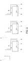
- Figure 1represents the refrigerator diagram of a refrigerating unit (4) using an inverter compressor (7).
- the inverter compressors (7)do not stop operating as the target temperatures are reached for the area to be cooled, as takes place with the traditional compressors, but rather the speed of the compressor (7) is reduced by a frequency converter as the target temperature is reached, such that the focus is on maintaining that target temperature by adapting the refrigerating power delivered as needed at all times.
- the inverter compressor (7)does not start-up and shut-down, it does not suffer as much and the incorporation of a redundant system to prevent failures is not needed, leaving the system free to focus on energy efficiency.
- this figureshows how the coolant, which comes from the evaporator (1) and after passing through a suction pressure probe (16) and through a temperature probe (17), arrives at the gas/liquid heat exchanger (20) in order to be directed to the inverter compressor (7) and continue in order to enter in the heat exchanger (8). Similar to coming out of the evaporator (1), at the outlet of the inverter compressor (7), the coolant passes through a discharge pressure probe (23) and through a discharge temperature probe (24).
- the coolantpasses through an oil exchanger (22) that is responsible for collecting part of the oil included in the coolant and taking it to a capillary liquid cooler (25) in which it condenses.
- the coolantBefore entering the expansion valve (3), the coolant passes through a gas/liquid heat exchanger (20) incorporated for the purpose of providing greater efficiency to the system.
- the compressor (7)When the compressor (7) starts up, it increases the pressure and temperature of the coolant in gaseous phase, sending it to the heat exchanger (8) of the condenser.
- the coolantcondenses passing energy to the water, reducing the simple temperature and enthalpy but maintaining the pressure constant.
- the coolantleaves the heat exchanger (8) of the condenser in liquid phase at a condensing temperature situated between 35°C and 50°C and being sent to the evaporator (1) through the expansion valve (3).
- the liquid coolantreduces the pressure thereof until it reaches a certain evaporation temperature which is variable depending on the type of product to be cooled.
- the liquid coolantevaporates by capturing the energy of the product to be cooled, leaving the evaporator (1) in gaseous phase.
- the systemcollects all the water from the different refrigerating units (4) that are operating, sending it to the water ring (5) by means of the water recirculation pumps until reaching the heat dissipater (6).
- the recirculation pumpsregulate the flow rate they produce, which is necessary for the operation of the system, via a frequency converter controlled either by a water differential pressure probe that maintains the pressure difference between the suction and impulsion of the pump constant or by the modulating outlet that the control plate of the unit has in order to manage the flow of water.
- the waterpasses through a water-air heat exchanger, via which the heat captured is released in the end refrigerating units (4) into the outside air.
- the compressor (7)is the component of the system where most of the consumption of energy is done. Therefore, its correct management and control will guarantee the maximum savings in the consumption of electric power by the system and therefore greater energy efficiency.
- the consumption of energyis regulated directly by means of frequency converters, which control compressor (7) speed depending on demand.
- One of the limitations of the systemis, in any case, based on the limitation of the minimum compressor (7) speed. This is due to the fact that speed has a direct influence on the correct refrigeration of the compressor (7) to the extent it limits the circulation of the coolant. In this way, regardless of the compressor (7) speed required by the temperature demands, even though that demand can be very low, the minimum compressor (7) speed is limited to a minimum that cannot be exceeded.
- the graphshows an OPTIMAL area where the compressor (7) should be operating. There is also a NON-OPTIMAL area, where the compressor (7) should be prevented from operating, and if it does operate therein, it should only do so for a short period of time.
- An important control to be carried outis related to the the compressor (7) to be prevented from operating outside the OPTIMAL area indicated in the graph because it would be operating under undesirable pressure, temperature, speed or consumption conditions due to poor system performance and exposure to damage that could lead to failures in the compressor (7).
- condensation and evaporation temperature values that define the areas of the graph marked as OPTIMAL and NON-OPTIMALdepend on the compressor (7) model in particular and are specified by the manufacturer.
- the position in the graph in which a compressor (7) is operatingmay be due to the demand of certain conditions by the area to be cooled and can be affected by water and coolant temperatures, but may also be due to a failure in the refrigerating unit (4). For this reason, controls are established to determine if this situation is temporary or if, on the contrary, it can continue due to a failure in the refrigerating unit (4).
- the systemwill consider that the refrigerating unit (4) is operating in an abnormal manner, it will stop operating and trigger an alarm.
- the graph of Figure 4is based on the graph of Figure 3 which represents the areas considered dangerous for the operation of the compressor (7) more precisely, differentiating them to determine the type of corrective action to be adopted in case the compressor (7) operates within any of these areas.
- AREA 1the condensation temperature and, therefore, the condensation pressure, are very high.
- the condensation pressuremust be reduced, for which the compressor (7) speed is reduced to the extent it is directly proportional, to the established lower limit.
- the electronic expansion valve (3) of the refrigeration equipmentis opened to try to reduce the high pressure and position the compressor in the OPTIMAL area.
- the opening of this valve (3)is limited by the reheat value, which must always be positive to ensure that the coolant liquid does not return to the compressor (7).
- the reheat valueis the difference between the temperature at the evaporator outlet and the evaporation temperature at the evaporator inlet. It can be considered as the excess from the evaporation temperature, which provides a margin to ensure that the steam does not return to the liquid phase once again.
- AREA 2the condensation temperature and, therefore, the condensation pressure, are very low.
- the first actionis to close the electronic expansion valve (3) of the refrigeration equipment to create an obstruction that increases the condensation pressure. This action limited by the existing routine in the expansion valve (3) and is conditional upon the maximum reheat value.
- the expansion valve (3)remains closed until the maximum reheat value is reached, at which point it is opened as necessary to avoid exceeding the maximum value.
- the compressor (7) speedincreases such that, when the condensation pressure increases, the expansion valve (3) is reopened to reach a certain condensation pressure and, consequently, a certain condensation temperature within the OPTIMAL area.
- AREA 3the evaporation temperature and, therefore, the evaporation pressure, are very low.
- the compressor (7) speedmust be increased to the established upper limit to reduce the evaporation pressure and, therefore, the evaporation temperature.
- the expansion valve (3)needs to be opened with the positive reheat value as a limit. This way, by passing more coolant to the evaporator (1), the evaporation pressure, as well as the evaporation temperature, increase until the compressor (7) is found within the OPTIMAL operating area.
- AREA 4the evaporation temperature and, therefore, the evaporation pressure, are very high.
- the compressor (7) speedmust be reduced to increase the evaporation pressure and, therefore, the evaporation temperature until the compressor is found within the OPTIMAL operating area.
- the expansion valve (3)is closed, using the maximum reheat value as the limit to reduce the evaporation pressure and, therefore, the evaporation temperature.
- AREA 5the compression ratio is very low. Therefore, the compressor (7) speed must be increased to likewise increase the compression ratio. This way, the evaporation temperature decreases and the condensation temperature increases.
- Control functionsare carried out by electronic systems known in the state of the art and therefore not described here.
- control systemestablishes a programmable parameter based on the data on the demand for refrigerating power increased by an adjustment factor to take into account the losses of the system, especially due to the fouling and aging of the system.
- the working point in which the compressor (7) is foundmust be compensated between the target temperature or set point, which is preestablished by the user, and the temperature identified by the temperature probe of the refrigerating unit (4), or the actual temperature of said refrigerating unit (4), for which a series of parameters must be established such as the dead area or temperature range as of the target temperature within which the refrigerating unit (4) does not adopt any action, and the differential, the temperature that marks the working point at which the compressor (7) should operate within the maximum limits allowed by reaching an operating speed that is 100% within the limit.
- the dead areais established so that the compressor (7) does not have to change its operating conditions due to small and insignificant temperature variations. This value is usually set at 0.5 degrees.
- the differentialis used as the maximum temperature increase permitted when a rapid decrease in temperature is required, and is normally set to 1 degree.
- the minimum operating limit of the compressor (7)is taken into account in a compressor operation curve (7). This is the limit below which the compressor (7) begins to suffer and which should not be exceeded.
- the compressorstarts up at a low speed to compensate for the temperature increase. If the temperature continues to rise, the compressor increases its speed so that, if it reaches the differential, the compressor (7) reaches the maximum operating limit at 100% of the admissible value. When the temperature lowers, the compressor (7) speed decreases as well. The compressor (7) stops when it reaches the set point. It should be noted that the compressor (7) could also stop if it reaches the minimum limit before reaching the set point, without the circuit having to change much.
- the refrigerating power demandedis limited by the sum of the different refrigerating powers demanded by each one of the areas to be cooled such that the total power demanded by the compressor (7) at each instant is the sum of the instantaneous powers demanded by each of the areas to be cooled connected to the refrigerating unit (4).
- the demand for refrigerating power of each of the areas to be cooledis based on the same criteria described above.
- Each of the parameters defined for the working conditionsi.e., set, differential and dead area, can be different in each of the refrigeration services to the extent that is the way in which the service will be provided under actual operating conditions.
- valve (3)In terms of the electronic expansion valve (3), variations in compressor (7) speed also influence the opening or closing of said valve (3), inasmuch as it controls the distribution of the volume of coolant circulating through the compressor (7) in the different areas to be cooled. It should also be noted that, due to the installation of the refrigeration pipeline, it is necessary to ensure that the coolant is distributed correctly. Thus, depending on the demand for refrigerating power, the valve (3) is closed and, as demand increases, it opens.
- the expansion valves (3)are closed. Prior to start-up, the expansion valve (3) is opened to a certain percentage that can be programmed as to value and time, regardless of the working curves and limitations described above.
- the operation of the expansion valve (3)is always limited to the extent it focuses on maintaining a positive reheat value and due to the protection measures for the compressor (7) based on its working conditions.
- the last improvement implemented in the present inventionconsists of the treatment of defrosting.
- the defrosting programming parameterscan vary from one refrigerated area to another.
- the expansion valve (3)always remains closed.
Landscapes
- Engineering & Computer Science (AREA)
- Physics & Mathematics (AREA)
- Mechanical Engineering (AREA)
- Thermal Sciences (AREA)
- General Engineering & Computer Science (AREA)
- Devices That Are Associated With Refrigeration Equipment (AREA)
- Air Conditioning Control Device (AREA)
- Control Of Positive-Displacement Pumps (AREA)
Description
- The present invention, as expressed in the text of this specification, consists of a method for controlling the refrigerating unit in refrigeration equipment by regulating the inverter compressor, both on an individual basis and for the system as a whole.
- Improvements affect the regulation of the efficiency and operation of the inverter compressor in the refrigerating unit, the management of the production of refrigerating power, and the management of the defrosting of the refrigerating unit. All of this without introducing new components into the system.
- In most of the existing systems there are two situations that divide the current technology.
- The first is a refrigeration system consisting of a central unit from which the entire refrigeration cycle is carried out. These systems have a series of centralised compressors and condensers that are of the appropriate size to be able to generate the amount of refrigeration needed to reach the working conditions in the specified area.
- The other system consists of having a centralised area and the required individual refrigerating units arranged in the specific area in which a certain temperature is required. The problem with this model is that the cooling liquid flows through the entire circuit, thus causing loses in the system due to joins in the communications.
- In both systems, the problem comes from the heat generated in the condensers, which heat the same area that is to be cooled.
- Document
ES2538306 - The refrigerating units comprise two compressors, which operate alternately and never simultaneously, such that it may continue refrigerating via one of the compressors even if the other compressor breaks down.
- The individual electronic control devices of each of the components are connected to each other and to a control centre that receives information on the state of all the components of the installation and that is capable of detecting notifications and alarms.
- In this invention, functionality has been considered as the main factor to be taken into account, while energy efficiency comes in second.
- Document
ES2558026 P201331679 JP 2014 159893 A - The present invention goes one step further in the management of the efficiency of a refrigerating unit with an inverter compressor or of the entire system through the programming of a control management system.
- The present invention, as defined by
claim 1, describes a method for regulating an inverter compressor of a refrigeration system comprising an expansion valve defined by an evaporation temperature Te, a condensation temperature Tc, a compressor speed vc and a compression ratio rc. - The method according to
claim 1 comprises the following steps: - a) establishing a working area with predetermined values for:
- minimum and maximum evaporation temperatures Te,
- minimum and maximum condensation temperatures Tc,
- minimum and maximum compressor speeds vc,
- a maximum compression ratio rc, which defines the relationship between a specific evaporation temperature Te and a specific condensation temperature Tc,
- a maximum reheat value,
- b) measuring the working values of the compressor in terms of:
- the evaporation temperature Te,
- the condensation temperature Tc, and
- the compression ratio rc,
if the compressor is operating on values outside the established working area, the method includes the additional step of: - c) modifying the working parameters of the compressor acting on elements to be selected between:
- the compressor speed vc,
- the opening angle of the expansion valve,
- a combination of the above,
- Even though this is the general method, there can be a series of variations and alternatives as indicated below.
- In the event where the working condensation temperature Tc of the compressor is higher than the established maximum condensation temperature Tc, step c) consists of lowering the compressor speed vc to the established minimum. Furthermore, if the situation in which the working condensation temperature Tc of the compressor is higher than the established maximum condensation temperature Tc persists, the method comprises the following additional step:
d) opening the expansion valve until the predetermined maximum reheat value is reached. - Alternatively, if the working condensation temperature Tc of the compressor is lower than the established minimum condensation temperature Tc, step c) consists of closing the expansion valve.
- Alternatively, if the working evaporation temperature Te of the compressor is lower than the established minimum evaporation temperature, step c) consists of increasing the compressor speed vc, to the established minimum. Furthermore, if the situation in which the working evaporation temperature Te of the compressor is lower than the established minimum evaporation temperature Te, the general method comprises the following additional step:
d) opening the expansion valve until the predetermined maximum reheat value is reached. - Alternatively, if the working evaporation temperature Te of the compressor is higher than the established maximum evaporation temperature Te, step c) consists of lowering the compressor speed vc to the established minimum.
- Alternatively, if the working compression ratio rc of the compressor is lower than the established minimum compression ratio rc, step c) consists of lowering the compressor speed vc to the established minimum.
- As a complement to the description provided below, and for the purpose of helping to make the characteristics of the invention more readily understandable, in accordance with a preferred practical embodiment thereof, said description is accompanied by a set of figures, which by way of illustration and not limitation represent the following:
Figure 1 represents a refrigerator and hydraulic diagram of a refrigerating unit.Figure 2 represents a refrigerator and hydraulic diagram of the refrigeration system.Figure 3 represents an Evaporation temperature - Condensation temperature graph showing the optimal and non-optimal working areas of a compressor.Figure 4 represents the graph ofFigure 3 showing the danger working areas of a compressor.Figure 5 represents a Discharge pressure versus compressor speed and compressor power graph, which are directly related.Figure 6 represents a graph showing product temperature as a function of compressor speed.Figure 7 represents the graph ofFigure 5 applied to several areas to be cooled by the same compressor.- Below is a list of the references used in the figures:
- 1.
- Evaporator.
- 2.
- Fan.
- 3.
- Expansion valve.
- 4.
- Refrigerating unit.
- 5.
- Water ring.
- 6.
- Dissipater.
- 7.
- Compressor.
- 8.
- Heat exchanger.
- 15.
- Pressure valves.
- 16.
- Suction pressure probe.
- 17.
- Suction temperature probe.
- 18.
- Coolant tank.
- 19.
- Liquid temperature probe.
- 20.
- Gas/liquid heat exchanger.
- 21.
- Water temperature probes.
- 22.
- Oil exchanger.
- 23.
- Discharge pressure probe.
- 24.
- Discharge temperature probe.
- 25.
- Capillary liquid cooler.
- 26.
- Suction container.
- In a preferred embodiment and as shown in
Figure 2 , the system is mainly made up of a water ring (5) connected to a heat dissipater (6). Branches extend from the water ring (5) to the heat exchangers (8) of the condensers of the different refrigerating units (4) that make up the respective refrigeration equipment of the system, where the water receives the heat from the coolant. As for the coolant, the refrigerating units (4) are connected to the evaporators (1) through the expansion valves (3). - The system can use any of the substances known in the state of the art such as, for example, HFC, ammonia, propane, or even CO2, as coolant.
Figure 2 shows how the water from the closed ring (5) comes in and out of the heat exchanger (8) of each of the refrigerating units (4) controlled by both water temperature probes (21), as shown inFigure 1 .Figure 1 represents the refrigerator diagram of a refrigerating unit (4) using an inverter compressor (7). The inverter compressors (7) do not stop operating as the target temperatures are reached for the area to be cooled, as takes place with the traditional compressors, but rather the speed of the compressor (7) is reduced by a frequency converter as the target temperature is reached, such that the focus is on maintaining that target temperature by adapting the refrigerating power delivered as needed at all times. As the inverter compressor (7) does not start-up and shut-down, it does not suffer as much and the incorporation of a redundant system to prevent failures is not needed, leaving the system free to focus on energy efficiency.- It should be clarified that, for reasons of simplicity, when reference is made throughout the specification to a compressor, such references should be understood as references to an inverter compressor (7).
- Thus, this figure shows how the coolant, which comes from the evaporator (1) and after passing through a suction pressure probe (16) and through a temperature probe (17), arrives at the gas/liquid heat exchanger (20) in order to be directed to the inverter compressor (7) and continue in order to enter in the heat exchanger (8). Similar to coming out of the evaporator (1), at the outlet of the inverter compressor (7), the coolant passes through a discharge pressure probe (23) and through a discharge temperature probe (24).
- At the outlet of the inverter compressor (7), the coolant passes through an oil exchanger (22) that is responsible for collecting part of the oil included in the coolant and taking it to a capillary liquid cooler (25) in which it condenses.
- Subsequently, the coolant leaves the heat exchanger (8) after having released the heat into the water ring (5) in order to move to the expansion valve (3) and the evaporator (1), both represented in
Figure 2 . - Before entering the expansion valve (3), the coolant passes through a gas/liquid heat exchanger (20) incorporated for the purpose of providing greater efficiency to the system.
- There is also a coolant tank (18) in the refrigerating circuit such that the circuit is over-supplied and from which coolant is absorbed according the amounts required.
- The circuit operation is as described below.
- When the compressor (7) starts up, it increases the pressure and temperature of the coolant in gaseous phase, sending it to the heat exchanger (8) of the condenser.
- In the heat exchanger (8) the coolant condenses passing energy to the water, reducing the simple temperature and enthalpy but maintaining the pressure constant.
- The coolant leaves the heat exchanger (8) of the condenser in liquid phase at a condensing temperature situated between 35°C and 50°C and being sent to the evaporator (1) through the expansion valve (3).
- In the expansion process, the liquid coolant reduces the pressure thereof until it reaches a certain evaporation temperature which is variable depending on the type of product to be cooled.
- In the evaporator (1), the liquid coolant evaporates by capturing the energy of the product to be cooled, leaving the evaporator (1) in gaseous phase.
- When the coolant in gaseous phase leaves the evaporator (1), it returns to the suction of the compressor (7) in order to repeat the process.
- This process is repeated until the temperature of the product lowers to the desired set point.
- Since the energy efficiency is improved, energy transfer takes place in a gas/liquid heat exchanger (20) between the coolant in liquid phase at the outlet of the heat exchanger (8) of the condenser and the coolant in gaseous phase when it returns from the evaporator (1) to the refrigerating unit (4) towards the inverter compressor (7).
- The heat dissipated in the heat exchanger (8) of the condenser, which comes from the products, is released into a volume of water that is kept in circulation in a closed ring system (5) by means of water recirculation pumps that are located in the heat dissipater (6).
- The system collects all the water from the different refrigerating units (4) that are operating, sending it to the water ring (5) by means of the water recirculation pumps until reaching the heat dissipater (6).
- The recirculation pumps regulate the flow rate they produce, which is necessary for the operation of the system, via a frequency converter controlled either by a water differential pressure probe that maintains the pressure difference between the suction and impulsion of the pump constant or by the modulating outlet that the control plate of the unit has in order to manage the flow of water.
- In the heat dissipater (6), the water passes through a water-air heat exchanger, via which the heat captured is released in the end refrigerating units (4) into the outside air.
- Once the operation and configuration of a refrigeration system with a compressor (7) has been explained in detail, the improvements introduced in the system are described below.
- The compressor (7) is the component of the system where most of the consumption of energy is done. Therefore, its correct management and control will guarantee the maximum savings in the consumption of electric power by the system and therefore greater energy efficiency.
- By using the compressors (7) as mentioned above, the consumption of energy is regulated directly by means of frequency converters, which control compressor (7) speed depending on demand.
- However, not only it is necessary to reach the target temperature of the area to be cooled, but also protecting compressor (7) against out of range operations that could damage it. For this reason, not only the adjustment of the compressor (7) according to demand must be improved, but that its operation remains within the appropriate range must be also ensured, combining both functions.
- One of the limitations of the system is, in any case, based on the limitation of the minimum compressor (7) speed. This is due to the fact that speed has a direct influence on the correct refrigeration of the compressor (7) to the extent it limits the circulation of the coolant. In this way, regardless of the compressor (7) speed required by the temperature demands, even though that demand can be very low, the minimum compressor (7) speed is limited to a minimum that cannot be exceeded.
- This lower limit applicable to compressor speed (7) is given by the high-pressure and low-pressure working position in the graph, as reflected in
Figure 3 , where the abscissa represents the evaporation temperature and the ordinate represents the condensation temperature. - The graph shows an OPTIMAL area where the compressor (7) should be operating. There is also a NON-OPTIMAL area, where the compressor (7) should be prevented from operating, and if it does operate therein, it should only do so for a short period of time.
- Finally, there is a cropped area in the graph where the compressor (7) does not operate. To understand this area of the graph, we must first take into account the ideal gas law applied to a constant volume, together with the definition of compression ratio:


- Thus, it can be seen from the graph that when the compression ratio increases, the lower limit of the low pressure or, of the condensation temperature, can only increase.
- This limitation is caused by the fact that high compression factors imply greater heating of the compressor (7), which can damage the compressor (7) and reduce its useful life. For this reason, they need to be avoided if possible.
- In addition, it must be taken into consideration that there could be a situation wherein the compressor (7) is operating at high compression factors and at a low rotation speed when the area to be cooled has a temperature close to the target temperature. This would damage the compressor (7) due to overheating caused by the high compression ratio, on the one hand, and a lack of refrigeration due to the non-circulation of the coolant, on the other.
- To avoid overheating, it is essential to increase the volume of coolant in circulation, since this is the only way to refrigerate the compressor (7) and, above all, not allow it to exceed the minimum levels.
- An important control to be carried out is related to the the compressor (7) to be prevented from operating outside the OPTIMAL area indicated in the graph because it would be operating under undesirable pressure, temperature, speed or consumption conditions due to poor system performance and exposure to damage that could lead to failures in the compressor (7).
- It should be noted that the condensation and evaporation temperature values that define the areas of the graph marked as OPTIMAL and NON-OPTIMAL depend on the compressor (7) model in particular and are specified by the manufacturer.
- In any case, the position in the graph in which a compressor (7) is operating may be due to the demand of certain conditions by the area to be cooled and can be affected by water and coolant temperatures, but may also be due to a failure in the refrigerating unit (4). For this reason, controls are established to determine if this situation is temporary or if, on the contrary, it can continue due to a failure in the refrigerating unit (4).
- Thus, if the operation of the compressor (7) falls within an undesirable area, a time range is established during which actions aimed at returning the compressor (7) to the OPTIMAL area will be performed.
- In the event that a certain time elapses during which the unit has tried to go back to its OPTIMAL working area but has not managed to leave the undesirable area, the system will consider that the refrigerating unit (4) is operating in an abnormal manner, it will stop operating and trigger an alarm.
- Thus, depending on the position in which the compressor (7) is operating as regards the deviation from the OPTIMAL working area, certain corrective actions are adopted.
- The graph of
Figure 4 is based on the graph ofFigure 3 which represents the areas considered dangerous for the operation of the compressor (7) more precisely, differentiating them to determine the type of corrective action to be adopted in case the compressor (7) operates within any of these areas. - The effects of the compressor (7) operating within each of the marked areas and the corrective actions to be adopted to prevent the compressor (7) from operating in areas where it can be damaged are described below.
- In the graph of
Figure 4 it is necessary to take into consideration that, based on the ideal gas law for a constant volume and as has been shown above, the pressure-temperature ratio needs to remain constant. This way, high-temperature or low-temperature areas imply high-pressure or low-pressure areas, respectively. It should also be taken into consideration that an increase in compressor (7) speed implies an increase in condensation pressure and a decrease in evaporation pressure, which would also imply an increase in the compression ratio. - AREA 1: the condensation temperature and, therefore, the condensation pressure, are very high. To avoid triggering the high-pressure alarm, the condensation pressure must be reduced, for which the compressor (7) speed is reduced to the extent it is directly proportional, to the established lower limit.
- If this lower limit of the minimum speed is reached and the compressor (7) is still within
area 1, the electronic expansion valve (3) of the refrigeration equipment is opened to try to reduce the high pressure and position the compressor in the OPTIMAL area. The opening of this valve (3) is limited by the reheat value, which must always be positive to ensure that the coolant liquid does not return to the compressor (7). The reheat value is the difference between the temperature at the evaporator outlet and the evaporation temperature at the evaporator inlet. It can be considered as the excess from the evaporation temperature, which provides a margin to ensure that the steam does not return to the liquid phase once again. - If these actions do not return the compressor (7) to the OPTIMAL area within a certain time, the compressor (7) stops operating and triggers an alarm.
- AREA 2: the condensation temperature and, therefore, the condensation pressure, are very low. To avoid triggering the low-pressure alarm, the first action is to close the electronic expansion valve (3) of the refrigeration equipment to create an obstruction that increases the condensation pressure. This action limited by the existing routine in the expansion valve (3) and is conditional upon the maximum reheat value.
- The operation of this routine is as described below. When the expansion valve (3) is closed, less coolant passes through the evaporator (1), due to which the reheat value increases.
- The expansion valve (3) remains closed until the maximum reheat value is reached, at which point it is opened as necessary to avoid exceeding the maximum value.
- This needs to be controlled since maintaining reheat values higher than the maximum reheat value can imply an excessive heating of the compressor given that the compressor (7) is cooled by the coolant passing through.
- If, after closing the expansion valve (3), it is not possible to increase the condensation pressure within a certain period of time, the compressor (7) speed increases such that, when the condensation pressure increases, the expansion valve (3) is reopened to reach a certain condensation pressure and, consequently, a certain condensation temperature within the OPTIMAL area.
- If these actions do not return the compressor (7) to the OPTIMAL area within a certain time, the compressor (7) stops operating and triggers an alarm.
- AREA 3: the evaporation temperature and, therefore, the evaporation pressure, are very low. Thus, the compressor (7) speed must be increased to the established upper limit to reduce the evaporation pressure and, therefore, the evaporation temperature.
- If this action does not lead to an increase in the evaporation temperature, the expansion valve (3) needs to be opened with the positive reheat value as a limit. This way, by passing more coolant to the evaporator (1), the evaporation pressure, as well as the evaporation temperature, increase until the compressor (7) is found within the OPTIMAL operating area.
- If these actions do not return the compressor (7) to the OPTIMAL area within a certain time, the compressor (7) stops operating and triggers an alarm.
- AREA 4: the evaporation temperature and, therefore, the evaporation pressure, are very high. Thus, the compressor (7) speed must be reduced to increase the evaporation pressure and, therefore, the evaporation temperature until the compressor is found within the OPTIMAL operating area.
- If the compressor cannot return to the OPTIMAL area with this action, the expansion valve (3) is closed, using the maximum reheat value as the limit to reduce the evaporation pressure and, therefore, the evaporation temperature.
- If these actions do not return the compressor (7) to the OPTIMAL area within a certain time, the compressor (7) stops operating and triggers an alarm.
- AREA 5: the compression ratio is very low. Therefore, the compressor (7) speed must be increased to likewise increase the compression ratio. This way, the evaporation temperature decreases and the condensation temperature increases.
- If this action does not return the compressor (7) to the OPTIMAL area within a certain time, the compressor (7) stops operating and triggers an alarm.
- Control functions are carried out by electronic systems known in the state of the art and therefore not described here.
- Establishing the above safety routines, which are activated in the event that the compressor (7) enters any of the
danger operating areas 1 to 5 described above with the operating limits imposed by the operation of the compressor (7) and, based on the data of demand for refrigerating power, the refrigeration equipment is configured to work at a point located in the OPTIMAL area of the graph shown inFigure 4 , based on the fact that the actual demand for refrigerating power is directly proportional to compressor (7) speed and, therefore, to compressor (7) power as reflected inFigure 5 where the abscissa reflects demanded power PD and the ordinate reflects compressor power Pc and compressor speed Vc. - Thus, the control system establishes a programmable parameter based on the data on the demand for refrigerating power increased by an adjustment factor to take into account the losses of the system, especially due to the fouling and aging of the system.
- It should be noted that the limits on compressor (7) speed are not considered when the compressor (7) operates outside the OPTIMAL area established in
Figure 4 , so as not to discriminate any of the tools to go back to the OPTIMAL area in the shortest possible time. - The working point in which the compressor (7) is found must be compensated between the target temperature or set point, which is preestablished by the user, and the temperature identified by the temperature probe of the refrigerating unit (4), or the actual temperature of said refrigerating unit (4), for which a series of parameters must be established such as the dead area or temperature range as of the target temperature within which the refrigerating unit (4) does not adopt any action, and the differential, the temperature that marks the working point at which the compressor (7) should operate within the maximum limits allowed by reaching an operating speed that is 100% within the limit. The dead area is established so that the compressor (7) does not have to change its operating conditions due to small and insignificant temperature variations. This value is usually set at 0.5 degrees. The differential is used as the maximum temperature increase permitted when a rapid decrease in temperature is required, and is normally set to 1 degree.
- In addition, the minimum operating limit of the compressor (7), already established as mentioned above, is taken into account in a compressor operation curve (7). This is the limit below which the compressor (7) begins to suffer and which should not be exceeded.
- This situation is represented in
Figure 6 . - When the temperature of the product increases above the set point value increased with the dead area value, the compressor starts up at a low speed to compensate for the temperature increase. If the temperature continues to rise, the compressor increases its speed so that, if it reaches the differential, the compressor (7) reaches the maximum operating limit at 100% of the admissible value. When the temperature lowers, the compressor (7) speed decreases as well. The compressor (7) stops when it reaches the set point. It should be noted that the compressor (7) could also stop if it reaches the minimum limit before reaching the set point, without the circuit having to change much.
- In addition to the positive and negative acceleration of the compressor (7), the speed at which that acceleration occurs, that is, the overspeed, is also taken into consideration.
- It should be noted that the situation described above is valid for refrigeration equipment that focuses on cooling a single area and also for several areas. In the latter case, the unit could focus on the variation in compressor (7) speed or in the opening and closing of the electronic expansion valve (3).
- In terms of compressor (7) speed, and as shown in
Figure 7 based onFigure 5 , the refrigerating power demanded is limited by the sum of the different refrigerating powers demanded by each one of the areas to be cooled such that the total power demanded by the compressor (7) at each instant is the sum of the instantaneous powers demanded by each of the areas to be cooled connected to the refrigerating unit (4). - The demand for refrigerating power of each of the areas to be cooled is based on the same criteria described above. Each of the parameters defined for the working conditions, i.e., set, differential and dead area, can be different in each of the refrigeration services to the extent that is the way in which the service will be provided under actual operating conditions.
- In terms of the electronic expansion valve (3), variations in compressor (7) speed also influence the opening or closing of said valve (3), inasmuch as it controls the distribution of the volume of coolant circulating through the compressor (7) in the different areas to be cooled. It should also be noted that, due to the installation of the refrigeration pipeline, it is necessary to ensure that the coolant is distributed correctly. Thus, depending on the demand for refrigerating power, the valve (3) is closed and, as demand increases, it opens.
- When the compressor (7) stops operating, the expansion valves (3) are closed. Prior to start-up, the expansion valve (3) is opened to a certain percentage that can be programmed as to value and time, regardless of the working curves and limitations described above.
- The operation of the expansion valve (3) is always limited to the extent it focuses on maintaining a positive reheat value and due to the protection measures for the compressor (7) based on its working conditions.
- The last improvement implemented in the present invention consists of the treatment of defrosting.
- The defrosting programming parameters can vary from one refrigerated area to another.
- To avoid abnormal operations, when one of the services is in the process of defrosting, the expansion valve (3) always remains closed.
- The present invention must not be limited to the embodiment described herein. Other configurations may be made by a person skilled in the art in view of the present description. Consequently, the scope of the invention is defined by the following claims.


Claims (8)
- A regulation method for an inverter compressor (7) in a refrigeration system comprising an expansion valve (3) defined by an evaporation temperature Te, a condensation temperature Tc, a compressor (7) speed vc and a compression ratio rc, said method comprising the following steps:a) establishing a working area with predetermined values for:- minimum and maximum evaporation temperatures Te,- minimum and maximum condensation temperatures Tc,- minimum and maximum compressor (7) speeds vc,- a maximum compression ratio rc, which defines the relationship between an evaporation temperature Te and a condensation temperature Tc,- a maximum reheat value,b) measuring the working values of the compressor (7) in terms of:- the evaporation temperature Te,- the condensation temperature Tc, and- the compression ratio rc,where,
if the compressor (7) is operating on values outside the established working area, the method includes the additional step of:c) modifying the working parameters of the compressor (7) acting on elements to be selected between:such that, if the compressor (7) does not go back to operating on values in the established working area within a certain time, the compressor (7) stops operating and triggers an alarm.- the compressor (7) speed vc,- the opening angle of the expansion valve (3), and- a combination of the above, - The regulation method for an inverter compressor (7) in a refrigeration system according to claim 1, wherein the working condensation temperature Tc of the compressor (7) is higher than the established maximum condensation temperature Tc, step c) consists of lowering the compressor speed vc to the established minimum.
- The regulation method for an inverter compressor (7) in a refrigeration system according to claim 2, wherein the working condensation temperature Tc of the compressor (7) is higher than the established maximum condensation temperature Tc, claim 1 comprises the following additional step:
d) opening the expansion valve (3) until the predetermined maximum reheat value is reached. - The regulation method for an inverter compressor (7) in a refrigeration system according to claim 1, wherein the working condensation temperature Tc of the compressor (7) is lower than the established minimum condensation temperature Tc, step c) consists of closing the expansion valve (3).
- The regulation method for an inverter compressor (7) in a refrigeration system according to claim 1, wherein the working evaporation temperature Te of the compressor (7) is lower than the established minimum evaporation temperature Te, step c) consists of increasing the compressor speed vc, to the established minimum.
- The regulation method for an inverter compressor (7) in a refrigeration system according to claim 5, wherein the working evaporation temperature Te of the compressor (7) is lower than the established minimum evaporation temperature Te, claim 1 comprises the following additional step:
d) opening the expansion valve (3) until the predetermined maximum reheat value is reached. - The regulation method for an inverter compressor (7) in a refrigeration system according to claim 1, wherein the working evaporation temperature Te of the compressor (7) is higher than the established maximum evaporation temperature Te, step c) consists of lowering the compressor speed vc to the established minimum.
- The regulation method for an inverter compressor (7) in a refrigeration system according to claim 1, wherein the working compression ratio rc of the compressor (7) is lower than the established minimum compression ratio rc, step c) consists of lowering the compressor speed vc to the established minimum.
Priority Applications (1)
| Application Number | Priority Date | Filing Date | Title |
|---|---|---|---|
| PL18162445TPL3388760T3 (en) | 2017-03-29 | 2018-03-19 | Regulation method for inverter compressors in refrigeration facilities |
Applications Claiming Priority (1)
| Application Number | Priority Date | Filing Date | Title |
|---|---|---|---|
| ES201700309AES2692207B1 (en) | 2017-03-29 | 2017-03-29 | Regulation procedure for inverter compressors in refrigeration installations |
Publications (2)
| Publication Number | Publication Date |
|---|---|
| EP3388760A1 EP3388760A1 (en) | 2018-10-17 |
| EP3388760B1true EP3388760B1 (en) | 2019-08-28 |
Family
ID=61691719
Family Applications (1)
| Application Number | Title | Priority Date | Filing Date |
|---|---|---|---|
| EP18162445.3ARevokedEP3388760B1 (en) | 2017-03-29 | 2018-03-19 | Regulation method for inverter compressors in refrigeration facilities |
Country Status (8)
| Country | Link |
|---|---|
| US (1) | US10955178B2 (en) |
| EP (1) | EP3388760B1 (en) |
| ES (2) | ES2692207B1 (en) |
| MA (1) | MA45351B1 (en) |
| MX (1) | MX384533B (en) |
| PL (1) | PL3388760T3 (en) |
| PT (1) | PT3388760T (en) |
| WO (1) | WO2018178485A1 (en) |
Families Citing this family (7)
| Publication number | Priority date | Publication date | Assignee | Title |
|---|---|---|---|---|
| ES2692207B1 (en) | 2017-03-29 | 2019-09-16 | Chillida Vicente Avila | Regulation procedure for inverter compressors in refrigeration installations |
| US11022334B2 (en)* | 2018-04-25 | 2021-06-01 | Johnson Controls Technology Company | Operational envelope control of an HVAC compressor |
| CN109855252B (en)* | 2019-02-14 | 2022-02-22 | 青岛海尔空调电子有限公司 | Refrigerant control method of multi-line air conditioning system |
| EP3882524B1 (en)* | 2020-03-16 | 2023-11-08 | Mitsubishi Electric Corporation | Air conditioning system |
| CN113432353B (en)* | 2021-06-15 | 2022-08-23 | 广东芬尼克兹节能设备有限公司 | Compression ratio adjusting method, compression ratio adjusting device, compression ratio adjusting equipment and storage medium |
| CN114110953B (en)* | 2021-11-29 | 2023-05-16 | 海信空调有限公司 | Self-cleaning control method for air conditioner, air conditioner and computer storage medium |
| IT202200016839A1 (en)* | 2022-08-05 | 2024-02-05 | Carel Ind Spa | REFRIGERATING SYSTEM AND METHOD OF OPERATION |
Citations (21)
| Publication number | Priority date | Publication date | Assignee | Title |
|---|---|---|---|---|
| EP0146486A2 (en) | 1983-12-19 | 1985-06-26 | Carrier Corporation | Method and apparatus for controlling a refrigerant expansion valve in a refrigeration system |
| JPS6484055A (en) | 1987-09-25 | 1989-03-29 | Matsushita Refrigeration | Multiple chamber type air conditioner |
| US5209076A (en) | 1992-06-05 | 1993-05-11 | Izon, Inc. | Control system for preventing compressor damage in a refrigeration system |
| US5570585A (en) | 1994-10-03 | 1996-11-05 | Vaynberg; Mikhail | Universal cooling system automatically configured to operate in compound or single compressor mode |
| US5857348A (en) | 1993-06-15 | 1999-01-12 | Multistack International Limited | Compressor |
| EP1039252A2 (en) | 1999-03-26 | 2000-09-27 | Carrier Corporation | High engine coolant temperature control |
| US6318100B1 (en) | 2000-04-14 | 2001-11-20 | Carrier Corporation | Integrated electronic refrigerant management system |
| US6430951B1 (en) | 1991-04-26 | 2002-08-13 | Denso Corporation | Automotive airconditioner having condenser and evaporator provided within air duct |
| US20070028639A1 (en) | 2003-05-27 | 2007-02-08 | Daikin Industries, Ltd. | Humidity controller |
| WO2009048578A1 (en) | 2007-10-08 | 2009-04-16 | Emerson Climate Technologies, Inc. | Variable speed compressor protection system and method |
| WO2009048566A2 (en) | 2007-10-08 | 2009-04-16 | Emerson Climate Technologies, Inc. | System and method for monitoring overheat of a compressor |
| US20100170273A1 (en) | 2007-09-20 | 2010-07-08 | Mitsubishi Electric Corporation | Refrigerating and air conditioning apparatus |
| JP2011174702A (en) | 2011-04-27 | 2011-09-08 | Mitsubishi Electric Corp | Air conditioning system and remote monitoring device |
| US20120010753A1 (en) | 2009-04-03 | 2012-01-12 | Carrier Corporation | Systems and Methods Involving Heating and Cooling System Control |
| JP2013130160A (en) | 2011-12-22 | 2013-07-04 | Mitsubishi Electric Corp | Air conditioner |
| US20130186118A1 (en) | 2012-01-20 | 2013-07-25 | Douglas G. Ohs | Dehumidification system |
| AU2013101085A4 (en) | 2013-08-14 | 2013-09-26 | Actron Engineering Pty Ltd | System and method for over heat protection of an air conditioning system |
| US20140174114A1 (en) | 2012-12-20 | 2014-06-26 | Mitsubishi Electric Corporation | Refrigerant charge assisting device, air-conditioning apparatus, and refrigerant charge assisting program |
| EP2835602A1 (en) | 2012-03-27 | 2015-02-11 | Mitsubishi Electric Corporation | Air conditioning device |
| US20150075766A1 (en) | 2013-09-18 | 2015-03-19 | Alaska Structures, Inc. | Environment control system and devices |
| EP2876385A2 (en) | 2013-11-26 | 2015-05-27 | Mitsubishi Heavy Industries, Ltd. | Air conditioner |
Family Cites Families (8)
| Publication number | Priority date | Publication date | Assignee | Title |
|---|---|---|---|---|
| CN101809372B (en)* | 2007-09-28 | 2013-12-18 | 大金工业株式会社 | Compressor operation control device and air conditioner using same |
| US20140343733A1 (en)* | 2011-09-13 | 2014-11-20 | Lynn A. Turner | Systems And Methods For Compressor Overspeed Control |
| JP5370560B2 (en)* | 2011-09-30 | 2013-12-18 | ダイキン工業株式会社 | Refrigerant cycle system |
| JP5744081B2 (en)* | 2013-02-19 | 2015-07-01 | 三菱電機株式会社 | Air conditioner |
| US9816742B2 (en)* | 2013-03-13 | 2017-11-14 | Trane International Inc. | Variable frequency drive apparatuses, systems, and methods and controls for same |
| ES2558026B1 (en) | 2014-06-30 | 2016-11-16 | Vicente AVILA CHILLIDA | INDUSTRIAL REFRIGERATION SYSTEM, IMPROVED |
| ES2538306B1 (en) | 2013-11-18 | 2016-04-20 | Vicente AVILA CHILLIDA | INDUSTRIAL REFRIGERATION SYSTEM |
| ES2692207B1 (en) | 2017-03-29 | 2019-09-16 | Chillida Vicente Avila | Regulation procedure for inverter compressors in refrigeration installations |
- 2017
- 2017-03-29ESES201700309Apatent/ES2692207B1/enactiveActive
- 2017-09-25MXMX2017012109Apatent/MX384533B/enunknown
- 2018
- 2018-03-19PTPT181624453Tpatent/PT3388760T/enunknown
- 2018-03-19ESES18162445Tpatent/ES2751086T3/enactiveActive
- 2018-03-19EPEP18162445.3Apatent/EP3388760B1/ennot_activeRevoked
- 2018-03-19MAMA45351Apatent/MA45351B1/enunknown
- 2018-03-19PLPL18162445Tpatent/PL3388760T3/enunknown
- 2018-03-27USUS15/936,816patent/US10955178B2/enactiveActive
- 2018-03-28WOPCT/ES2018/070274patent/WO2018178485A1/ennot_activeCeased
Patent Citations (21)
| Publication number | Priority date | Publication date | Assignee | Title |
|---|---|---|---|---|
| EP0146486A2 (en) | 1983-12-19 | 1985-06-26 | Carrier Corporation | Method and apparatus for controlling a refrigerant expansion valve in a refrigeration system |
| JPS6484055A (en) | 1987-09-25 | 1989-03-29 | Matsushita Refrigeration | Multiple chamber type air conditioner |
| US6430951B1 (en) | 1991-04-26 | 2002-08-13 | Denso Corporation | Automotive airconditioner having condenser and evaporator provided within air duct |
| US5209076A (en) | 1992-06-05 | 1993-05-11 | Izon, Inc. | Control system for preventing compressor damage in a refrigeration system |
| US5857348A (en) | 1993-06-15 | 1999-01-12 | Multistack International Limited | Compressor |
| US5570585A (en) | 1994-10-03 | 1996-11-05 | Vaynberg; Mikhail | Universal cooling system automatically configured to operate in compound or single compressor mode |
| EP1039252A2 (en) | 1999-03-26 | 2000-09-27 | Carrier Corporation | High engine coolant temperature control |
| US6318100B1 (en) | 2000-04-14 | 2001-11-20 | Carrier Corporation | Integrated electronic refrigerant management system |
| US20070028639A1 (en) | 2003-05-27 | 2007-02-08 | Daikin Industries, Ltd. | Humidity controller |
| US20100170273A1 (en) | 2007-09-20 | 2010-07-08 | Mitsubishi Electric Corporation | Refrigerating and air conditioning apparatus |
| WO2009048566A2 (en) | 2007-10-08 | 2009-04-16 | Emerson Climate Technologies, Inc. | System and method for monitoring overheat of a compressor |
| WO2009048578A1 (en) | 2007-10-08 | 2009-04-16 | Emerson Climate Technologies, Inc. | Variable speed compressor protection system and method |
| US20120010753A1 (en) | 2009-04-03 | 2012-01-12 | Carrier Corporation | Systems and Methods Involving Heating and Cooling System Control |
| JP2011174702A (en) | 2011-04-27 | 2011-09-08 | Mitsubishi Electric Corp | Air conditioning system and remote monitoring device |
| JP2013130160A (en) | 2011-12-22 | 2013-07-04 | Mitsubishi Electric Corp | Air conditioner |
| US20130186118A1 (en) | 2012-01-20 | 2013-07-25 | Douglas G. Ohs | Dehumidification system |
| EP2835602A1 (en) | 2012-03-27 | 2015-02-11 | Mitsubishi Electric Corporation | Air conditioning device |
| US20140174114A1 (en) | 2012-12-20 | 2014-06-26 | Mitsubishi Electric Corporation | Refrigerant charge assisting device, air-conditioning apparatus, and refrigerant charge assisting program |
| AU2013101085A4 (en) | 2013-08-14 | 2013-09-26 | Actron Engineering Pty Ltd | System and method for over heat protection of an air conditioning system |
| US20150075766A1 (en) | 2013-09-18 | 2015-03-19 | Alaska Structures, Inc. | Environment control system and devices |
| EP2876385A2 (en) | 2013-11-26 | 2015-05-27 | Mitsubishi Heavy Industries, Ltd. | Air conditioner |
Non-Patent Citations (3)
| Title |
|---|
| CAREL: "Technical user Manual", HOES HIGH EFFICIENCY SHOWCASE CONTROLLER, 30 October 2014 (2014-10-30), pages 1 - 52, XP055641341 |
| MAXSON: "Superheat", HEATCRAFT TECH-TOPICS, vol. 1, no. 2, June 1993 (1993-06-01), XP055641343 |
| MUVEGI W. ET AL: "integrated CONTROL SYSTEM WITH DC INVERTER TECHNOLOGY for healt pumps", CAREL INDUSTRIES, 5 April 2011 (2011-04-05), pages 216 - 223, XP055641347 |
Also Published As
| Publication number | Publication date |
|---|---|
| ES2751086T3 (en) | 2020-03-30 |
| PT3388760T (en) | 2019-10-29 |
| US20180283756A1 (en) | 2018-10-04 |
| MX2017012109A (en) | 2018-11-12 |
| WO2018178485A1 (en) | 2018-10-04 |
| ES2692207A1 (en) | 2018-11-30 |
| US10955178B2 (en) | 2021-03-23 |
| MX384533B (en) | 2025-03-14 |
| MA45351B1 (en) | 2019-11-29 |
| EP3388760A1 (en) | 2018-10-17 |
| PL3388760T3 (en) | 2020-02-28 |
| MA45351A (en) | 2019-08-28 |
| ES2692207B1 (en) | 2019-09-16 |
Similar Documents
| Publication | Publication Date | Title |
|---|---|---|
| EP3388760B1 (en) | Regulation method for inverter compressors in refrigeration facilities | |
| US11493246B2 (en) | Demand flow for air cooled chillers | |
| EP3798538B1 (en) | Cooling system and control method therefor | |
| CA2844242C (en) | User control interface for heat transfer system | |
| KR101471813B1 (en) | Heat source system | |
| US20130274948A1 (en) | Heat source system and method for controlling the number of operated devices in heat source system | |
| RU2426957C1 (en) | Procedure for control of vapour-compressor system | |
| RU2680447C1 (en) | Steam compression system with at least two external installations | |
| US20140374497A1 (en) | Heat source system, control device thereof, and control method thereof | |
| EP3115707A1 (en) | Heat source device | |
| WO2016091418A1 (en) | A method for controlling a valve arrangement in a vapour compression system | |
| JP2007064546A (en) | Waste heat recovery equipment | |
| JP4167190B2 (en) | Refrigeration system and operation method thereof | |
| KR20230066017A (en) | Temperature control device using multi-stage refrigeration cycle and temperature control method using the same | |
| JP5913066B2 (en) | Heat source system | |
| WO2016062430A1 (en) | Selecting control strategy for an expansion valve | |
| US20210285704A1 (en) | Refrigeration apparatus | |
| JP2007232249A (en) | Heat source machine, its control method, and heat source system | |
| JP5604228B2 (en) | Chiller | |
| US20050210893A1 (en) | Control logic for maintaining proper solution concentration in an absorption chiller in co-generation applications | |
| CN116914318B (en) | Refrigeration method, air conditioning system and storage medium | |
| JPH0455677A (en) | Cooling system | |
| WO2015090481A1 (en) | A heat pump system | |
| LIPTÁK | 8.13 Chiller Optimization |
Legal Events
| Date | Code | Title | Description |
|---|---|---|---|
| PUAI | Public reference made under article 153(3) epc to a published international application that has entered the european phase | Free format text:ORIGINAL CODE: 0009012 | |
| STAA | Information on the status of an ep patent application or granted ep patent | Free format text:STATUS: THE APPLICATION HAS BEEN PUBLISHED | |
| AK | Designated contracting states | Kind code of ref document:A1 Designated state(s):AL AT BE BG CH CY CZ DE DK EE ES FI FR GB GR HR HU IE IS IT LI LT LU LV MC MK MT NL NO PL PT RO RS SE SI SK SM TR | |
| AX | Request for extension of the european patent | Extension state:BA ME | |
| STAA | Information on the status of an ep patent application or granted ep patent | Free format text:STATUS: REQUEST FOR EXAMINATION WAS MADE | |
| 17P | Request for examination filed | Effective date:20190116 | |
| RAV | Requested validation state of the european patent: fee paid | Extension state:MA Effective date:20190116 | |
| RBV | Designated contracting states (corrected) | Designated state(s):AL AT BE BG CH CY CZ DE DK EE ES FI FR GB GR HR HU IE IS IT LI LT LU LV MC MK MT NL NO PL PT RO RS SE SI SK SM TR | |
| GRAP | Despatch of communication of intention to grant a patent | Free format text:ORIGINAL CODE: EPIDOSNIGR1 | |
| STAA | Information on the status of an ep patent application or granted ep patent | Free format text:STATUS: GRANT OF PATENT IS INTENDED | |
| INTG | Intention to grant announced | Effective date:20190320 | |
| GRAS | Grant fee paid | Free format text:ORIGINAL CODE: EPIDOSNIGR3 | |
| GRAA | (expected) grant | Free format text:ORIGINAL CODE: 0009210 | |
| STAA | Information on the status of an ep patent application or granted ep patent | Free format text:STATUS: THE PATENT HAS BEEN GRANTED | |
| RAP1 | Party data changed (applicant data changed or rights of an application transferred) | Owner name:NONWATIO TECHNOLOGY SOLUTIONS, S.L. | |
| RIN1 | Information on inventor provided before grant (corrected) | Inventor name:AVILA CHILLIDA, VICENTE | |
| AK | Designated contracting states | Kind code of ref document:B1 Designated state(s):AL AT BE BG CH CY CZ DE DK EE ES FI FR GB GR HR HU IE IS IT LI LT LU LV MC MK MT NL NO PL PT RO RS SE SI SK SM TR | |
| REG | Reference to a national code | Ref country code:GB Ref legal event code:FG4D | |
| REG | Reference to a national code | Ref country code:CH Ref legal event code:EP | |
| REG | Reference to a national code | Ref country code:DE Ref legal event code:R026 Ref document number:602018000497 Country of ref document:DE | |
| REG | Reference to a national code | Ref country code:AT Ref legal event code:REF Ref document number:1172915 Country of ref document:AT Kind code of ref document:T Effective date:20190915 | |
| REG | Reference to a national code | Ref country code:IE Ref legal event code:FG4D | |
| REG | Reference to a national code | Ref country code:DE Ref legal event code:R096 Ref document number:602018000497 Country of ref document:DE | |
| PLBI | Opposition filed | Free format text:ORIGINAL CODE: 0009260 | |
| 26 | Opposition filed | Opponent name:CAREL INDUSTRIES S.P.A. Effective date:20190912 | |
| REG | Reference to a national code | Ref country code:PT Ref legal event code:SC4A Ref document number:3388760 Country of ref document:PT Date of ref document:20191029 Kind code of ref document:T Free format text:AVAILABILITY OF NATIONAL TRANSLATION Effective date:20191015 | |
| REG | Reference to a national code | Ref country code:NL Ref legal event code:FP | |
| REG | Reference to a national code | Ref country code:RO Ref legal event code:EPE | |
| REG | Reference to a national code | Ref country code:CH Ref legal event code:NV Representative=s name:ISLER AND PEDRAZZINI AG, CH | |
| REG | Reference to a national code | Ref country code:MA Ref legal event code:VAGR Ref document number:45351 Country of ref document:MA Kind code of ref document:B1 | |
| REG | Reference to a national code | Ref country code:LT Ref legal event code:MG4D | |
| PG25 | Lapsed in a contracting state [announced via postgrant information from national office to epo] | Ref country code:SE Free format text:LAPSE BECAUSE OF FAILURE TO SUBMIT A TRANSLATION OF THE DESCRIPTION OR TO PAY THE FEE WITHIN THE PRESCRIBED TIME-LIMIT Effective date:20190828 Ref country code:BG Free format text:LAPSE BECAUSE OF FAILURE TO SUBMIT A TRANSLATION OF THE DESCRIPTION OR TO PAY THE FEE WITHIN THE PRESCRIBED TIME-LIMIT Effective date:20191128 Ref country code:NO Free format text:LAPSE BECAUSE OF FAILURE TO SUBMIT A TRANSLATION OF THE DESCRIPTION OR TO PAY THE FEE WITHIN THE PRESCRIBED TIME-LIMIT Effective date:20191128 Ref country code:FI Free format text:LAPSE BECAUSE OF FAILURE TO SUBMIT A TRANSLATION OF THE DESCRIPTION OR TO PAY THE FEE WITHIN THE PRESCRIBED TIME-LIMIT Effective date:20190828 Ref country code:LT Free format text:LAPSE BECAUSE OF FAILURE TO SUBMIT A TRANSLATION OF THE DESCRIPTION OR TO PAY THE FEE WITHIN THE PRESCRIBED TIME-LIMIT Effective date:20190828 Ref country code:HR Free format text:LAPSE BECAUSE OF FAILURE TO SUBMIT A TRANSLATION OF THE DESCRIPTION OR TO PAY THE FEE WITHIN THE PRESCRIBED TIME-LIMIT Effective date:20190828 | |
| PG25 | Lapsed in a contracting state [announced via postgrant information from national office to epo] | Ref country code:LV Free format text:LAPSE BECAUSE OF FAILURE TO SUBMIT A TRANSLATION OF THE DESCRIPTION OR TO PAY THE FEE WITHIN THE PRESCRIBED TIME-LIMIT Effective date:20190828 Ref country code:IS Free format text:LAPSE BECAUSE OF FAILURE TO SUBMIT A TRANSLATION OF THE DESCRIPTION OR TO PAY THE FEE WITHIN THE PRESCRIBED TIME-LIMIT Effective date:20191228 Ref country code:AL Free format text:LAPSE BECAUSE OF FAILURE TO SUBMIT A TRANSLATION OF THE DESCRIPTION OR TO PAY THE FEE WITHIN THE PRESCRIBED TIME-LIMIT Effective date:20190828 Ref country code:RS Free format text:LAPSE BECAUSE OF FAILURE TO SUBMIT A TRANSLATION OF THE DESCRIPTION OR TO PAY THE FEE WITHIN THE PRESCRIBED TIME-LIMIT Effective date:20190828 | |
| REG | Reference to a national code | Ref country code:GR Ref legal event code:EP Ref document number:20190403584 Country of ref document:GR Effective date:20200213 | |
| REG | Reference to a national code | Ref country code:AT Ref legal event code:MK05 Ref document number:1172915 Country of ref document:AT Kind code of ref document:T Effective date:20190828 | |
| REG | Reference to a national code | Ref country code:ES Ref legal event code:FG2A Ref document number:2751086 Country of ref document:ES Kind code of ref document:T3 Effective date:20200330 | |
| PG25 | Lapsed in a contracting state [announced via postgrant information from national office to epo] | Ref country code:DK Free format text:LAPSE BECAUSE OF FAILURE TO SUBMIT A TRANSLATION OF THE DESCRIPTION OR TO PAY THE FEE WITHIN THE PRESCRIBED TIME-LIMIT Effective date:20190828 Ref country code:EE Free format text:LAPSE BECAUSE OF FAILURE TO SUBMIT A TRANSLATION OF THE DESCRIPTION OR TO PAY THE FEE WITHIN THE PRESCRIBED TIME-LIMIT Effective date:20190828 Ref country code:AT Free format text:LAPSE BECAUSE OF FAILURE TO SUBMIT A TRANSLATION OF THE DESCRIPTION OR TO PAY THE FEE WITHIN THE PRESCRIBED TIME-LIMIT Effective date:20190828 | |
| PG25 | Lapsed in a contracting state [announced via postgrant information from national office to epo] | Ref country code:SK Free format text:LAPSE BECAUSE OF FAILURE TO SUBMIT A TRANSLATION OF THE DESCRIPTION OR TO PAY THE FEE WITHIN THE PRESCRIBED TIME-LIMIT Effective date:20190828 Ref country code:SM Free format text:LAPSE BECAUSE OF FAILURE TO SUBMIT A TRANSLATION OF THE DESCRIPTION OR TO PAY THE FEE WITHIN THE PRESCRIBED TIME-LIMIT Effective date:20190828 Ref country code:CZ Free format text:LAPSE BECAUSE OF FAILURE TO SUBMIT A TRANSLATION OF THE DESCRIPTION OR TO PAY THE FEE WITHIN THE PRESCRIBED TIME-LIMIT Effective date:20190828 Ref country code:IS Free format text:LAPSE BECAUSE OF FAILURE TO SUBMIT A TRANSLATION OF THE DESCRIPTION OR TO PAY THE FEE WITHIN THE PRESCRIBED TIME-LIMIT Effective date:20200224 | |
| PLAX | Notice of opposition and request to file observation + time limit sent | Free format text:ORIGINAL CODE: EPIDOSNOBS2 | |
| PG2D | Information on lapse in contracting state deleted | Ref country code:IS | |
| PG25 | Lapsed in a contracting state [announced via postgrant information from national office to epo] | Ref country code:SI Free format text:LAPSE BECAUSE OF FAILURE TO SUBMIT A TRANSLATION OF THE DESCRIPTION OR TO PAY THE FEE WITHIN THE PRESCRIBED TIME-LIMIT Effective date:20190828 | |
| PLBB | Reply of patent proprietor to notice(s) of opposition received | Free format text:ORIGINAL CODE: EPIDOSNOBS3 | |
| PG25 | Lapsed in a contracting state [announced via postgrant information from national office to epo] | Ref country code:MC Free format text:LAPSE BECAUSE OF FAILURE TO SUBMIT A TRANSLATION OF THE DESCRIPTION OR TO PAY THE FEE WITHIN THE PRESCRIBED TIME-LIMIT Effective date:20190828 | |
| PG25 | Lapsed in a contracting state [announced via postgrant information from national office to epo] | Ref country code:LU Free format text:LAPSE BECAUSE OF NON-PAYMENT OF DUE FEES Effective date:20200319 | |
| PLCK | Communication despatched that opposition was rejected | Free format text:ORIGINAL CODE: EPIDOSNREJ1 | |
| APBM | Appeal reference recorded | Free format text:ORIGINAL CODE: EPIDOSNREFNO | |
| APBP | Date of receipt of notice of appeal recorded | Free format text:ORIGINAL CODE: EPIDOSNNOA2O | |
| APAH | Appeal reference modified | Free format text:ORIGINAL CODE: EPIDOSCREFNO | |
| APBQ | Date of receipt of statement of grounds of appeal recorded | Free format text:ORIGINAL CODE: EPIDOSNNOA3O | |
| PG25 | Lapsed in a contracting state [announced via postgrant information from national office to epo] | Ref country code:MT Free format text:LAPSE BECAUSE OF FAILURE TO SUBMIT A TRANSLATION OF THE DESCRIPTION OR TO PAY THE FEE WITHIN THE PRESCRIBED TIME-LIMIT Effective date:20190828 Ref country code:CY Free format text:LAPSE BECAUSE OF FAILURE TO SUBMIT A TRANSLATION OF THE DESCRIPTION OR TO PAY THE FEE WITHIN THE PRESCRIBED TIME-LIMIT Effective date:20190828 | |
| PG25 | Lapsed in a contracting state [announced via postgrant information from national office to epo] | Ref country code:MK Free format text:LAPSE BECAUSE OF FAILURE TO SUBMIT A TRANSLATION OF THE DESCRIPTION OR TO PAY THE FEE WITHIN THE PRESCRIBED TIME-LIMIT Effective date:20190828 | |
| P01 | Opt-out of the competence of the unified patent court (upc) registered | Effective date:20230523 | |
| PGFP | Annual fee paid to national office [announced via postgrant information from national office to epo] | Ref country code:GR Payment date:20240307 Year of fee payment:7 | |
| PGFP | Annual fee paid to national office [announced via postgrant information from national office to epo] | Ref country code:NL Payment date:20240306 Year of fee payment:7 Ref country code:IE Payment date:20240320 Year of fee payment:7 | |
| PGFP | Annual fee paid to national office [announced via postgrant information from national office to epo] | Ref country code:RO Payment date:20240319 Year of fee payment:7 Ref country code:DE Payment date:20240327 Year of fee payment:7 Ref country code:PT Payment date:20240306 Year of fee payment:7 Ref country code:GB Payment date:20240315 Year of fee payment:7 | |
| PGFP | Annual fee paid to national office [announced via postgrant information from national office to epo] | Ref country code:TR Payment date:20240313 Year of fee payment:7 Ref country code:PL Payment date:20240307 Year of fee payment:7 Ref country code:IT Payment date:20240311 Year of fee payment:7 Ref country code:FR Payment date:20240306 Year of fee payment:7 Ref country code:BE Payment date:20240329 Year of fee payment:7 | |
| PGFP | Annual fee paid to national office [announced via postgrant information from national office to epo] | Ref country code:CH Payment date:20240401 Year of fee payment:7 | |
| PGFP | Annual fee paid to national office [announced via postgrant information from national office to epo] | Ref country code:ES Payment date:20240401 Year of fee payment:7 | |
| REG | Reference to a national code | Ref country code:DE Ref legal event code:R103 Ref document number:602018000497 Country of ref document:DE Ref country code:DE Ref legal event code:R064 Ref document number:602018000497 Country of ref document:DE | |
| APBU | Appeal procedure closed | Free format text:ORIGINAL CODE: EPIDOSNNOA9O | |
| RDAF | Communication despatched that patent is revoked | Free format text:ORIGINAL CODE: EPIDOSNREV1 | |
| STAA | Information on the status of an ep patent application or granted ep patent | Free format text:STATUS: PATENT REVOKED | |
| RDAG | Patent revoked | Free format text:ORIGINAL CODE: 0009271 | |
| REG | Reference to a national code | Ref country code:CH Ref legal event code:PL | |
| 27W | Patent revoked | Effective date:20241218 | |
| GBPR | Gb: patent revoked under art. 102 of the ep convention designating the uk as contracting state | Effective date:20241218 |