EP3385039B1 - Synthetic representation of a surgical robot - Google Patents
Synthetic representation of a surgical robotDownload PDFInfo
- Publication number
- EP3385039B1 EP3385039B1EP18173423.7AEP18173423AEP3385039B1EP 3385039 B1EP3385039 B1EP 3385039B1EP 18173423 AEP18173423 AEP 18173423AEP 3385039 B1EP3385039 B1EP 3385039B1
- Authority
- EP
- European Patent Office
- Prior art keywords
- view
- tool
- component
- surgeon
- image
- Prior art date
- Legal status (The legal status is an assumption and is not a legal conclusion. Google has not performed a legal analysis and makes no representation as to the accuracy of the status listed.)
- Active
Links
- 239000012636effectorSubstances0.000claimsdescription45
- 238000000034methodMethods0.000claimsdescription36
- 230000033001locomotionEffects0.000claimsdescription32
- 230000000712assemblyEffects0.000claimsdescription19
- 238000000429assemblyMethods0.000claimsdescription19
- 230000008569processEffects0.000description21
- 230000008859changeEffects0.000description10
- 230000000007visual effectEffects0.000description10
- 238000001356surgical procedureMethods0.000description9
- 230000006870functionEffects0.000description6
- 238000001514detection methodMethods0.000description5
- 238000009877renderingMethods0.000description5
- 238000012937correctionMethods0.000description4
- 238000002324minimally invasive surgeryMethods0.000description4
- 238000011084recoveryMethods0.000description3
- 238000002432robotic surgeryMethods0.000description3
- 230000008901benefitEffects0.000description2
- 238000010586diagramMethods0.000description2
- 238000005516engineering processMethods0.000description2
- 210000000245forearmAnatomy0.000description2
- 238000003384imaging methodMethods0.000description2
- 239000007787solidSubstances0.000description2
- 235000004443Ricinus communisNutrition0.000description1
- 240000000528Ricinus communisSpecies0.000description1
- 210000003484anatomyAnatomy0.000description1
- 239000008280bloodSubstances0.000description1
- 210000004369bloodAnatomy0.000description1
- 239000002775capsuleSubstances0.000description1
- 239000003086colorantSubstances0.000description1
- 238000004891communicationMethods0.000description1
- 238000010276constructionMethods0.000description1
- 230000008878couplingEffects0.000description1
- 238000010168coupling processMethods0.000description1
- 238000005859coupling reactionMethods0.000description1
- 238000001839endoscopyMethods0.000description1
- 210000004247handAnatomy0.000description1
- 230000002452interceptive effectEffects0.000description1
- 238000013507mappingMethods0.000description1
- 238000005259measurementMethods0.000description1
- 239000002184metalSubstances0.000description1
- 230000003278mimic effectEffects0.000description1
- 238000012986modificationMethods0.000description1
- 230000004048modificationEffects0.000description1
- 239000013307optical fiberSubstances0.000description1
- 210000000056organAnatomy0.000description1
- 230000008447perceptionEffects0.000description1
- 238000012545processingMethods0.000description1
- 230000000284resting effectEffects0.000description1
- 230000002441reversible effectEffects0.000description1
- 238000000926separation methodMethods0.000description1
- 239000000779smokeSubstances0.000description1
- 238000000547structure dataMethods0.000description1
- 230000001360synchronised effectEffects0.000description1
- 230000007704transitionEffects0.000description1
- 230000001960triggered effectEffects0.000description1
- 238000013024troubleshootingMethods0.000description1
- 210000000707wristAnatomy0.000description1
Images


Classifications
- B—PERFORMING OPERATIONS; TRANSPORTING
- B25—HAND TOOLS; PORTABLE POWER-DRIVEN TOOLS; MANIPULATORS
- B25J—MANIPULATORS; CHAMBERS PROVIDED WITH MANIPULATION DEVICES
- B25J9/00—Programme-controlled manipulators
- B25J9/16—Programme controls
- B25J9/1694—Programme controls characterised by use of sensors other than normal servo-feedback from position, speed or acceleration sensors, perception control, multi-sensor controlled systems, sensor fusion
- B25J9/1697—Vision controlled systems
- G—PHYSICS
- G16—INFORMATION AND COMMUNICATION TECHNOLOGY [ICT] SPECIALLY ADAPTED FOR SPECIFIC APPLICATION FIELDS
- G16H—HEALTHCARE INFORMATICS, i.e. INFORMATION AND COMMUNICATION TECHNOLOGY [ICT] SPECIALLY ADAPTED FOR THE HANDLING OR PROCESSING OF MEDICAL OR HEALTHCARE DATA
- G16H20/00—ICT specially adapted for therapies or health-improving plans, e.g. for handling prescriptions, for steering therapy or for monitoring patient compliance
- G16H20/40—ICT specially adapted for therapies or health-improving plans, e.g. for handling prescriptions, for steering therapy or for monitoring patient compliance relating to mechanical, radiation or invasive therapies, e.g. surgery, laser therapy, dialysis or acupuncture
- A—HUMAN NECESSITIES
- A61—MEDICAL OR VETERINARY SCIENCE; HYGIENE
- A61B—DIAGNOSIS; SURGERY; IDENTIFICATION
- A61B34/00—Computer-aided surgery; Manipulators or robots specially adapted for use in surgery
- A61B34/30—Surgical robots
- A—HUMAN NECESSITIES
- A61—MEDICAL OR VETERINARY SCIENCE; HYGIENE
- A61B—DIAGNOSIS; SURGERY; IDENTIFICATION
- A61B34/00—Computer-aided surgery; Manipulators or robots specially adapted for use in surgery
- A61B34/25—User interfaces for surgical systems
- A—HUMAN NECESSITIES
- A61—MEDICAL OR VETERINARY SCIENCE; HYGIENE
- A61B—DIAGNOSIS; SURGERY; IDENTIFICATION
- A61B34/00—Computer-aided surgery; Manipulators or robots specially adapted for use in surgery
- A61B34/30—Surgical robots
- A61B34/37—Leader-follower robots
- A—HUMAN NECESSITIES
- A61—MEDICAL OR VETERINARY SCIENCE; HYGIENE
- A61B—DIAGNOSIS; SURGERY; IDENTIFICATION
- A61B90/00—Instruments, implements or accessories specially adapted for surgery or diagnosis and not covered by any of the groups A61B1/00 - A61B50/00, e.g. for luxation treatment or for protecting wound edges
- A61B90/36—Image-producing devices or illumination devices not otherwise provided for
- A61B90/361—Image-producing devices, e.g. surgical cameras
- A—HUMAN NECESSITIES
- A61—MEDICAL OR VETERINARY SCIENCE; HYGIENE
- A61B—DIAGNOSIS; SURGERY; IDENTIFICATION
- A61B90/00—Instruments, implements or accessories specially adapted for surgery or diagnosis and not covered by any of the groups A61B1/00 - A61B50/00, e.g. for luxation treatment or for protecting wound edges
- A61B90/36—Image-producing devices or illumination devices not otherwise provided for
- A61B90/37—Surgical systems with images on a monitor during operation
- B—PERFORMING OPERATIONS; TRANSPORTING
- B25—HAND TOOLS; PORTABLE POWER-DRIVEN TOOLS; MANIPULATORS
- B25J—MANIPULATORS; CHAMBERS PROVIDED WITH MANIPULATION DEVICES
- B25J9/00—Programme-controlled manipulators
- B25J9/16—Programme controls
- B25J9/1656—Programme controls characterised by programming, planning systems for manipulators
- B25J9/1664—Programme controls characterised by programming, planning systems for manipulators characterised by motion, path, trajectory planning
- B25J9/1666—Avoiding collision or forbidden zones
- B—PERFORMING OPERATIONS; TRANSPORTING
- B25—HAND TOOLS; PORTABLE POWER-DRIVEN TOOLS; MANIPULATORS
- B25J—MANIPULATORS; CHAMBERS PROVIDED WITH MANIPULATION DEVICES
- B25J9/00—Programme-controlled manipulators
- B25J9/16—Programme controls
- B25J9/1656—Programme controls characterised by programming, planning systems for manipulators
- B25J9/1671—Programme controls characterised by programming, planning systems for manipulators characterised by simulation, either to verify existing program or to create and verify new program, CAD/CAM oriented, graphic oriented programming systems
- B—PERFORMING OPERATIONS; TRANSPORTING
- B25—HAND TOOLS; PORTABLE POWER-DRIVEN TOOLS; MANIPULATORS
- B25J—MANIPULATORS; CHAMBERS PROVIDED WITH MANIPULATION DEVICES
- B25J9/00—Programme-controlled manipulators
- B25J9/16—Programme controls
- B25J9/1679—Programme controls characterised by the tasks executed
- B25J9/1689—Teleoperation
- B—PERFORMING OPERATIONS; TRANSPORTING
- B25—HAND TOOLS; PORTABLE POWER-DRIVEN TOOLS; MANIPULATORS
- B25J—MANIPULATORS; CHAMBERS PROVIDED WITH MANIPULATION DEVICES
- B25J9/00—Programme-controlled manipulators
- B25J9/16—Programme controls
- B25J9/1679—Programme controls characterised by the tasks executed
- B25J9/1692—Calibration of manipulator
- G—PHYSICS
- G05—CONTROLLING; REGULATING
- G05B—CONTROL OR REGULATING SYSTEMS IN GENERAL; FUNCTIONAL ELEMENTS OF SUCH SYSTEMS; MONITORING OR TESTING ARRANGEMENTS FOR SUCH SYSTEMS OR ELEMENTS
- G05B19/00—Programme-control systems
- G05B19/02—Programme-control systems electric
- G05B19/42—Recording and playback systems, i.e. in which the programme is recorded from a cycle of operations, e.g. the cycle of operations being manually controlled, after which this record is played back on the same machine
- G05B19/4202—Recording and playback systems, i.e. in which the programme is recorded from a cycle of operations, e.g. the cycle of operations being manually controlled, after which this record is played back on the same machine preparation of the programme medium using a drawing, a model
- A—HUMAN NECESSITIES
- A61—MEDICAL OR VETERINARY SCIENCE; HYGIENE
- A61B—DIAGNOSIS; SURGERY; IDENTIFICATION
- A61B34/00—Computer-aided surgery; Manipulators or robots specially adapted for use in surgery
- A61B34/20—Surgical navigation systems; Devices for tracking or guiding surgical instruments, e.g. for frameless stereotaxis
- A61B2034/2046—Tracking techniques
- A61B2034/2059—Mechanical position encoders
- A—HUMAN NECESSITIES
- A61—MEDICAL OR VETERINARY SCIENCE; HYGIENE
- A61B—DIAGNOSIS; SURGERY; IDENTIFICATION
- A61B34/00—Computer-aided surgery; Manipulators or robots specially adapted for use in surgery
- A61B34/20—Surgical navigation systems; Devices for tracking or guiding surgical instruments, e.g. for frameless stereotaxis
- A61B2034/2046—Tracking techniques
- A61B2034/2061—Tracking techniques using shape-sensors, e.g. fiber shape sensors with Bragg gratings
- A—HUMAN NECESSITIES
- A61—MEDICAL OR VETERINARY SCIENCE; HYGIENE
- A61B—DIAGNOSIS; SURGERY; IDENTIFICATION
- A61B90/00—Instruments, implements or accessories specially adapted for surgery or diagnosis and not covered by any of the groups A61B1/00 - A61B50/00, e.g. for luxation treatment or for protecting wound edges
- A61B90/36—Image-producing devices or illumination devices not otherwise provided for
- A61B90/37—Surgical systems with images on a monitor during operation
- A61B2090/371—Surgical systems with images on a monitor during operation with simultaneous use of two cameras
- A—HUMAN NECESSITIES
- A61—MEDICAL OR VETERINARY SCIENCE; HYGIENE
- A61B—DIAGNOSIS; SURGERY; IDENTIFICATION
- A61B34/00—Computer-aided surgery; Manipulators or robots specially adapted for use in surgery
- A61B34/20—Surgical navigation systems; Devices for tracking or guiding surgical instruments, e.g. for frameless stereotaxis
- G—PHYSICS
- G05—CONTROLLING; REGULATING
- G05B—CONTROL OR REGULATING SYSTEMS IN GENERAL; FUNCTIONAL ELEMENTS OF SUCH SYSTEMS; MONITORING OR TESTING ARRANGEMENTS FOR SUCH SYSTEMS OR ELEMENTS
- G05B2219/00—Program-control systems
- G05B2219/30—Nc systems
- G05B2219/36—Nc in input of data, input key till input tape
- G05B2219/36432—By putting some constraints on some DOF, move within limited volumes, areas, planes, limits motion in x, y or z planes, virtual reality constraints
- G—PHYSICS
- G05—CONTROLLING; REGULATING
- G05B—CONTROL OR REGULATING SYSTEMS IN GENERAL; FUNCTIONAL ELEMENTS OF SUCH SYSTEMS; MONITORING OR TESTING ARRANGEMENTS FOR SUCH SYSTEMS OR ELEMENTS
- G05B2219/00—Program-control systems
- G05B2219/30—Nc systems
- G05B2219/39—Robotics, robotics to robotics hand
- G05B2219/39083—Robot interference, between two robot arms
- G—PHYSICS
- G05—CONTROLLING; REGULATING
- G05B—CONTROL OR REGULATING SYSTEMS IN GENERAL; FUNCTIONAL ELEMENTS OF SUCH SYSTEMS; MONITORING OR TESTING ARRANGEMENTS FOR SUCH SYSTEMS OR ELEMENTS
- G05B2219/00—Program-control systems
- G05B2219/30—Nc systems
- G05B2219/39—Robotics, robotics to robotics hand
- G05B2219/39096—Self-collision, internal collison, collision between links of one robot
- G—PHYSICS
- G05—CONTROLLING; REGULATING
- G05B—CONTROL OR REGULATING SYSTEMS IN GENERAL; FUNCTIONAL ELEMENTS OF SUCH SYSTEMS; MONITORING OR TESTING ARRANGEMENTS FOR SUCH SYSTEMS OR ELEMENTS
- G05B2219/00—Program-control systems
- G05B2219/30—Nc systems
- G05B2219/39—Robotics, robotics to robotics hand
- G05B2219/39449—Pendant, pda displaying camera images overlayed with graphics, augmented reality
- G—PHYSICS
- G05—CONTROLLING; REGULATING
- G05B—CONTROL OR REGULATING SYSTEMS IN GENERAL; FUNCTIONAL ELEMENTS OF SUCH SYSTEMS; MONITORING OR TESTING ARRANGEMENTS FOR SUCH SYSTEMS OR ELEMENTS
- G05B2219/00—Program-control systems
- G05B2219/30—Nc systems
- G05B2219/40—Robotics, robotics mapping to robotics vision
- G05B2219/40607—Fixed camera to observe workspace, object, workpiece, global
- G—PHYSICS
- G05—CONTROLLING; REGULATING
- G05B—CONTROL OR REGULATING SYSTEMS IN GENERAL; FUNCTIONAL ELEMENTS OF SUCH SYSTEMS; MONITORING OR TESTING ARRANGEMENTS FOR SUCH SYSTEMS OR ELEMENTS
- G05B2219/00—Program-control systems
- G05B2219/30—Nc systems
- G05B2219/45—Nc applications
- G05B2219/45117—Medical, radio surgery manipulator
- G—PHYSICS
- G05—CONTROLLING; REGULATING
- G05B—CONTROL OR REGULATING SYSTEMS IN GENERAL; FUNCTIONAL ELEMENTS OF SUCH SYSTEMS; MONITORING OR TESTING ARRANGEMENTS FOR SUCH SYSTEMS OR ELEMENTS
- G05B2219/00—Program-control systems
- G05B2219/30—Nc systems
- G05B2219/45—Nc applications
- G05B2219/45123—Electrogoniometer, neuronavigator, medical robot used by surgeon to operate
- G—PHYSICS
- G16—INFORMATION AND COMMUNICATION TECHNOLOGY [ICT] SPECIALLY ADAPTED FOR SPECIFIC APPLICATION FIELDS
- G16H—HEALTHCARE INFORMATICS, i.e. INFORMATION AND COMMUNICATION TECHNOLOGY [ICT] SPECIALLY ADAPTED FOR THE HANDLING OR PROCESSING OF MEDICAL OR HEALTHCARE DATA
- G16H40/00—ICT specially adapted for the management or administration of healthcare resources or facilities; ICT specially adapted for the management or operation of medical equipment or devices
- G16H40/60—ICT specially adapted for the management or administration of healthcare resources or facilities; ICT specially adapted for the management or operation of medical equipment or devices for the operation of medical equipment or devices
- G16H40/67—ICT specially adapted for the management or administration of healthcare resources or facilities; ICT specially adapted for the management or operation of medical equipment or devices for the operation of medical equipment or devices for remote operation
Definitions
- Minimally invasive surgeries performed by robotic surgical systemsare known and commonly used in remote or in other environments where it is advantageous for a human not to perform surgery.
- One example of such a telerobotic surgical systemis the minimally invasive robotic surgery system described in commonly owned U.S. Patent No. 7,155,315 .
- the da Vinci® Surgical Systems manufactured by Intuitive Surgical, Inc. of Sunnyvale, Californiaare illustrative implementations of minimally invasive robotic surgical systems (e.g., teleoperated; telesurgical).
- Endoscopic surgical instruments in minimally invasive medical techniquesgenerally include an endoscope for viewing the surgical field, and working tools that include end effectors.
- Typical surgical end effectorsinclude clamps, graspers, scissors, staplers, or needle holders, as examples.
- the working toolsare similar to those used in conventional (open) surgery, except that the end effector of each tool is supported on the end of, for example, an approximately 12-inch-long extension tube.
- a human operatormanipulates or otherwise commands a locally-provided master manipulator. Commands from the master manipulator are translated as appropriate and sent to a remotely-deployed slave manipulator. The slave manipulator then manipulates the end effectors according to the operator's commands.
- Force feedbackmay be included in minimally invasive robotic surgical systems.
- the remote slave manipulatorstypically provide force information to the master manipulator, and that force information is utilized to provide force feedback to the surgeon so that the surgeon is given the perception of feeling forces acting on a slave manipulator.
- haptic feedbackmay provide an artificial feel to the surgeon of tissue reactive forces on a working tool and its end effector.
- the master controlswhich are typically located at a surgeon console, will include a clutch or other device for releasing one of the work tools at the patient site.
- This featuremay be used, for example, in a system where there are more than two working tools. In such a system, the surgeon may release control of one working tool by one master and establish control over another working tool with that master.
- the surgeontypically views an image of only the distal ends of the working tools that are within the endoscope's field of view.
- the surgeoncannot see portions of a tool, or an entire tool, that is outside the field of view. Accordingly, the surgeon cannot see if two or more tools are interfering with each other outside the field of view.
- the endoscopemay be manipulated to be at various positions and orientations with reference to a surgical site and to the surgeon's body frame of reference, the surgeon may become confused about the general location of the tools. Consequently, the surgeon may not understand how to best move the master manipulators to avoid an inter-tool interference or to reorient one or more tools with reference to the surgical site.
- US 2007/293734 A1discloses methods and apparatus which provide enhanced planning of entry port placement and/or robot position for laparoscopic, robotic, and other minimally invasive surgery.
- Various embodimentsmay be used in robotic surgery systems to identify advantageous entry ports for multiple robotic surgical tools into a patient to access a surgical site.
- datasuch as imaging data is processed and used to create a model of a surgical site, which can then be used to select advantageous entry port sites for two or more surgical tools based on multiple criteria.
- US 2005/187432 A1discloses a graphical model which provides a dynamic representation of the endoscopic view and viewing direction relative to a virtual world.
- the modelcan be oriented and adjusted to approximate a real world situation.
- Angular image navigation coordinatesare also provided.
- WO 99/00052 A1discloses a surgical navigation system which has a computer with a memory and a display connected to a surgical instrument or pointer and a position tracking system, so that the location and orientation of the pointer are tracked in real time, and conveyed to the computer.
- the computer memoryis loaded with data from an MRI, CT, or other volumetric scan of a patient, and this data is utilized to dynamically display 3-dimensional perspective images in real time of the patient's anatomy from the viewpoint of the pointer.
- US 2005/054895discloses a method for a variable direction of view endoscope used in combination with an image guided surgical system to provide diagnostic and surgical capabilities.
- the present inventionprovides a robotic surgical system, comprising: a robot having a first robotic arm assembly and a second robotic arm assembly, wherein the first robotic arm assembly is detachably coupled to a tool, and wherein the second robotic arm assembly is arranged to hold an image capture device having a field of view that is positionable to capture an image of an end effector of the tool; modeling data for providing a synthetic representation of at least a portion of the robot, the tool, and the image capture device; a display; and a first component coupled to the modeling data, encoders in the first and second robotic arm assemblies, and the display, wherein the first component is configured to: generate the synthetic representation so that actual movements of the robot, the tool, and the image capture device are mimicked in the synthetic image while a medical procedure is being performed on a patient, generate a three-dimensional representation of a projection of boundaries of the field of view of the image capture device so that the three-dimensional representation is properly positioned relative to a viewing end of the image capture device in the synthetic image while the medical procedure is being performed on the
- the systemincludes a robot including a linkage supporting at least one tool for performing surgery on a patient; a kinematic component coupled to the robot so as to obtain joint state information from the linkage; a display; and a first component coupling the display with the kinematic component so as to display a synthetic representation of the robot including a graphical representation of at least a portion of the linkage based upon linkage structure data regarding the linkage; and the joint state information.
- the systemincludes a robot including an image capture device having a field of view and a linkage supporting at least one tool for performing surgery on a patient; a kinematic component coupled to the linkage so as to obtain joint states information regarding the linkage; data regarding structure of the first linkage and said at least one tool; and a collision detection component coupled to the data and to the kinematic component so as to generate a warning.
- Fig. 1shows a minimally invasive telesurgical system 20 having an operator station or surgeon console 30 in accordance with an embodiment.
- the surgeon console 30includes a viewer 32 where an image of a surgical site is displayed to a surgeon S.
- a support(not shown) is provided on which the surgeon S can rest his or her forearms while gripping two master controls 700 ( Fig. 5 ), one in each hand. More controls may be provided if more end effectors are available, but typically a surgeon manipulates only two controls at a time and, if multiple tools are used, the surgeon releases one tool with a master control 700 and grasps another with same master control.
- the surgeon console 30the surgeon S typically sits in a chair in front of the surgeon console, positions his or her eyes in front of the viewer 32, and grips the master controls 700, one in each hand, while resting his or her forearms on the support.
- a patient side cart 40 of the telesurgical system 20is positioned adjacent to a patient P.
- the patient side cart 40is positioned close to the patient P requiring surgery.
- the patient side cart 40typically is stationary during a surgical procedure, and includes wheels or castors to render it mobile.
- the surgeon console 30is typically positioned remote from the patient side cart 40, and it may be separated from the patient side cart by a great distance-even miles away-but will typically be used within the same operating room as the patient side cart.
- the patient side cart 40typically includes two or more robotic arm assemblies.
- the patient side cart 40includes four robotic arm assemblies 42, 44, 46, 48, but more or less may be provided.
- Each robotic arm assembly 42, 44, 46, 48is normally operatively connected to one of the master controls of the surgeon console 30. Thus, movement of the manipulator portion of the robotic arm assemblies 44, 46 48 is controlled by manipulation of the master controls.
- One of the robotic arm assembliesis arranged to hold an image capture device 50, e.g., an endoscope, or the like.
- the endoscope or image capture device 50includes a viewing end 56 at a remote end of an elongated shaft 54.
- the elongated shaft 54permits the viewing end 56 to be inserted through a surgery entry port of the patient P.
- the image capture device 50is operatively connected to the viewer 32 of the surgeon console 30 to display an image captured at its viewing end 56.
- Each of the other robotic arm assemblies 44, 46, 48is a linkage that supports and includes a removable surgical instrument or tool 60, 62, 64, respectively.
- the tools 60, 62, 64 of the robotic arm assemblies 44, 46, 48include end effectors 66, 68, 70, respectively.
- the end effectors 66, 68, 70are mounted on wrist members which are mounted on distal ends of elongated shafts of the tools, as is known in the art.
- the tools 60, 62, 64have elongated shafts to permit the end effectors 66, 68, 70 to be inserted through surgical entry ports of the patient P. Movement of the end effectors 66, 68, 70 relative to the ends of the shafts of the tools 60, 62, 64 is controlled by the master controls of the surgeon console 30.
- the depicted telesurgical system 20includes a vision cart 80, which contains equipment associated with the image capture device.
- the vision cart 80can be combined with other equipment that includes most of the computer equipment or other controls (the "core" data processing equipment) for operating the telesurgical system 20.
- signals sent by the master controllers of the surgeon console 30may be sent to the vision/core cart 80, which in turn may interpret the signals and generate commands for the end effectors 66, 68, 70 and/or robotic arm assemblies 44, 46, 48.
- video sent from the image capture device 50 to the viewer 34may be processed by, or simply transferred by, the vision cart 80.
- Fig. 3is a diagrammatic representation of the telesurgical system 20.
- the systemincludes the surgeon console 30, the patient side cart 40, and the vision cart 80.
- an additional computer 82 and display 84are provided. These components may be incorporated in one or more of the surgeon console 30, the patient side cart 40, and/or the vision cart 80.
- the features of the computer 82may be incorporated into the vision cart 80.
- the features of the display 84may be incorporated into the surgeon console 30, for example, in the viewer 32, or maybe provided by a completely separate display at the surgeon console or on another location.
- the computer 82may generate information that may be utilized without a display, such as the display 84.
- the computer 82may be a component of a computer system or any other software or hardware that is capable of performing the functions described herein. Moreover, as described above, functions and features of the computer 82 may be distributed over several devices or software components. Thus, the computer 82 shown in the drawings is for the convenience of discussion, and it may be replaced by a controller or its functions may be provided by one or more other components.
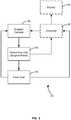
- Fig. 4shows components of the computer 82 in accordance with an embodiment.
- a positional componentis included in or is otherwise associated with the computer 82.
- the positional componentprovides information about a position of an end effector, such as one of the end effectors 66, 68, 70.
- a tool tracking component 90is used for the positional component and provides information about a position of an end effector, such as the end effectors 66, 68, 70.
- positionmeans at least one of the location and/or the orientation of the end effector.
- a variety of different technologiesmay be used to provide information about a position of an end effector, and such technologies may or may not be considered tool tracking devices.
- the positional componentutilizes video feed from the image capture device 50 to provide information about the position of an end effector, but other information may be used instead of, or in addition to, this visual information, including sensor information, kinematic information, any combination of these, or additional information that may provide the position and/or orientation of the end effectors 66, 68, 70.
- Examples of systems that may be used for the tool tracking component 90are disclosed in , U.S. Pat. No. 5,950,629 (filed Apr. 28, 1994 ), U.S. Pat. No. 6,468,265 (filed Nov. 9, 1999 ), U.S. Pat. App. Pub. No. US 2006/0258938 A1 (filed May 16,2005 ), and U.S. Pat. App.
- the tool tracking component 90utilizes the systems and methods described in commonly owned U.S. Pat. App. No. 61/204,084 (filed Dec. 31, 2008 ).
- the positional componentmaintains information about the actual position and orientation of end effectors. This information is updated depending upon when the information is available, and may be, for example, asynchronous information.
- the kinematic component 92is generally any device that estimates a position, herein a "kinematic position," of an end effector utilizing information available through the telesurgical system 20.
- the kinematic component 92utilizes kinematic position information from joint states of a linkage to the end effector.
- the kinematic component 92may utilize the master/slave architecture for the telesurgical system 20 to calculate intended Cartesian positions of the end effectors 66, 68, 70 based upon encoder signals for the joints in the linkage for each of the tools 60, 62, 64.
- the kinematic componentmay utilize slave encoders 102 and/or master manipulator encoders to estimate the position of tool.
- Kinematic position information for the end effector or any portion of the linkage and/or toolmay also be provided in other ways, such as the use of optical fiber shape sensing, sensing the positions of components (e.g., electromagnetic components) embedded at various places along the linkage, tool, or end effector, various video tool tracking methods, etc.
- componentse.g., electromagnetic components
- an error correction component 94is provided.
- the error correction componentcalculates a difference between a location and/or orientation of a tool as provided by the tool tracking component 90 compared to the location and/or orientation of the tool as provided by the kinematic component 92.
- the error correction componentcalculates a difference between a location and/or orientation of a tool as provided by the tool tracking component 90 compared to the location and/or orientation of the tool as provided by the kinematic component 92.
- an offsetmay be generated by the error correction component 94. This offset provides information regarding the difference between the kinematic information provided by the kinematic component and the actual position information provided by the tool tracking component. Utilizing the offset, the kinematic information and the actual position information may be registered to the same location and/or orientation.
- a modeling component 108is provided for generating a synthetic image 120 ( Fig. 6 ) of a patient side cart, such as the patient side cart 40, or any portion thereof.
- the synthetic image 120is of a different patient side cart configuration than the patient side cart 40 (an illustrative model of a da Vinci® Surgical System Model IS2000 patient side cart with three arms is shown), but the basic components of the two patient side carts are the same, except that the patient side cart 40 includes an additional robotic arm assembly and tool.
- the synthetic image 120may be displayed on the display 84 or the viewer 32.
- modeling data 104( Fig.
- the modeling data 104may be, for example, a two-dimensional (2-D) or three-dimensional (3-D) representation, such as an image, of the patient side cart 40, or any portion thereof.
- a representationis a 3-D model of the patient side cart 40, or any portion thereof, and thus may represent an actual solid model of the patient side cart 40, or any portion thereof.
- the modeling data 104may be, for example, CAD data or other 3-D solid model data representing components of the patient side cart 40.
- the 3-D modelis manipulatable at each joint of the patient side cart 40, so that movements of the patient side cart may be mimicked by the synthetic image 120 of the patient side cart 40.
- the modeling datamay represent the entire patient side cart or any portion thereof, such as only the tools for the patient side cart.
- Joint locations and orientationsare generally known from kinematic data provided, for example, by the kinematic component 92. Utilizing this information, each component of the patient side cart may be rendered in location so as to generate a image of the patient side cart that appears in 3-D to the surgeon.
- the modeling data 104includes individualized information for each component or link of the patient side cart robot.
- the modeling component 108constantly updates the location and/or orientation of the components of the synthetic image 120 in accordance with information provided by the tool tracking component 90 and/or the kinematic component 92.
- an initial state of the kinematic component 92may be determined including a position of one or more end effectors for the patient side cart. These positions may be compared with position information provided by the tool tracking component 90. As described above, the difference between the actual position as determined by the tool tracking component 90 and the estimated position of the end effectors provided by the kinematic component 92 may result in an offset, which may be stored in or otherwise used by the error correction component 94. This offset may be used to register the position and orientation of an end effector as determined by the tool tracking component 90 to the position and orientation as estimated by the kinematic component 92.
- the actual position of the end effectormay be tracked and registered with information provided by the kinematic component 92.
- an assumptionmay be made that any change in kinematic information provided by the kinematic component 92 is an indication of actual movement by the end effector. That is, when tool tracking is not available, the position of an end effector may be accurately determined by the change in coordinate positions between the current position and the last known position, as calculated by the kinematic component 92.
- the assumption hereis that the change in position may be accurately calculated using only kinematic data, without tool tracking information.
- asynchronous datamay be provided by the tool tracking component 90, and synchronous data may be provided by the kinematic component 92.
- the combination of this informationprovides data regarding the positions and orientations of the components of the patient side cart 40.
- the positions of the components of a robotic arm assemblymay be determined by utilizing the joint states provided by the kinematic component. These joint states arc calculated backwards from the end effector, the position of which is known, as described above.
- the slave encoders 102 at the joints of robotic arm assemblies 122 for the patient side cartprovide change in state information for each joint, the relative position of each section of the robotic arm assemblies may be accurately estimated and tracked.
- informationcan be provided to the modeling component 108 that is sufficient so that modeling component 108 may generate the synthetic image 120 by utilizing the modeling data 104, with the position of each of the segments of the robotic arm assemblies 122, including tools 124 at the end of the robotic arm assemblies, or an endoscope 126 at the end of one of the robotic arm assemblies.
- a view volume 130 for the endoscopein addition to the synthetic image 120 for the patient side cart, a view volume 130 for the endoscope is provided.
- the view volume 130represents a projection of the field of view of the endoscope 126.
- the field of viewis the view visible by the endoscope
- the view volumeis a projection of the boundaries of the field of view. That is, the view volume 130 represents a 3-D space that is visible by the endoscope 126.
- camera information 132may be provided to the modeling component 108.
- the camera informationincludes a calibrated set of intrinsic and extrinsic parameters about the camera.
- the intrinsic parametersinclude, e.g., focal length and principle point, which model the perspective mapping of the optics.
- the intrinsic parametersmay account for lens distortion.
- the extrinsic parametersmay account for, e.g., relative position and orientation between the stereo endoscopic views. As can be understood, changing the parameters, such as zoom, of the endoscope will change the view volume for the endoscope, such as making the view volume narrower or wider. In addition, as the endoscope 126 is moved, the view volume 130 will move accordingly.
- the camera informationpermits the creation of a 3-D stereo rendering that may be superimposed on the stereo view of the end effector from the image capture device, as described below.
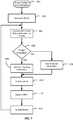
- Fig. 7is a flowchart representing a process for updating a rendering of a synthetic image 120 in accordance with an embodiment. Beginning at 401, the position and orientation of the patient side cart, or any portion thereof, is sensed. This sensing may occur, for example, via the tool tracking component 90 and/or the kinematic component 92, as described above.
- the position and orientation information from 401is used to generate a model (e.g., the synthetic image 120).
- the modeling component 108uses the modeling data 104 to generate the model.
- the position and orientation information provided from 401is utilized to correctly arrange the position and orientation of the synthetic model to match that of the patient side cart.
- the movementmay be, for example, movement of one of the robotic arm assemblies, movement of the endoscope, change in the focus of the endoscope, or movement by one of the end effectors.
- the movement of the end effectormay be a change in location or orientation, including, for example, closing of pinchers or other operational movement of the end effectors.
- the determinationis whether an image is available so that the actual position of the end effector or any portion of the tool that is in a field of view (e.g., the view volume 130) of the endoscope 126 may be found using the tool tracking component 90.
- 406branches to 408 where the tool tracking information is utilized to update information about the position and orientation of the tool and/or end effector.
- the kinematic informationis used to update information about the location and orientation of the joints of each linkage of the robot for the patient side cart.
- the offsetis updated, if desired.
- the display of the synthetic image 120is updated, and the process branches back to 404.
- the processbranches to 416, where the kinematic information provided by the kinematic component 92 is utilized to determine the position of the end effector.
- the processthen proceeds to 410, and then on through the process, although since the tool tracking information was not available on this loop, the offset will likely not be updated, skipping 412.
- a 3-D rendering of the synthetic image 120is generated, and the synthetic image accurately represents the physical configuration of the patient side cart at any point in time throughout a surgical procedure.
- This informationcan be utilized and viewed by the surgeon S, or by someone else, to evaluate the state of the patient side cart.
- the viewer 34 or the display 82may show the synthetic image 120, either from a point of view that is the same as the point of view from the endoscope, or from another angle or distance.
- the synthetic image 120enables observation of all parts of the patient view cart via the viewer 32, thus permitting the surgeon S to monitor movements of the robot and tools.
- viewing of these componentsis available in connection with the view volume 130, permitting a surgeon to have a good perspective of where the endoscope's field of view is with respect to space.
- the view volume 130provides a three dimensional representation of what is being seen by the surgeon S when looking in the viewer 32.
- a single displaymay be provided for showing both the field of view of the endoscope and the synthetic image 120.
- a view 200 provided by the viewer 32 or the display 84provides both an actual field of view image 202 for the endoscope 126 and the synthetic image 120.
- the synthetic image 120is shown in a separate tile window 204.
- the tile 204is approximately the same size as the field of view 202, but if desired, the tile window may be smaller or larger than the field of view 202.
- a toggle or other featuremay be provided so that the surgeon may switch back and forth between a larger presentation of the synthetic image 120 or the field of view 202.
- the synthetic image 120 and/or the tile window 204may be partially superimposed over a portion of the field of view, either on a continuous basis or upon request.
- a camera controlmay be provided that is connected to the master manipulators. For example, a user may start looking at the endoscopic view and may pull the endoscope back by pulling the his hands towards himself while in a camera control mode. At some point, the endoscope cannot be pulled back any farther, and the field of view encompasses a maximum area.
- the master controlswith or without a haptic detent or other indication
- Pulling back even farther on the master controlsmay provide a view where the image captured in field of view 202 is only the middle section of the screen. Pulling back still farther on the controls (with or without haptic detent or other indication) may provide the entire synthetic image 120. Reversing the master control direction can be used to reverse such a real-to-synthetic zoom out function and control a synthetic-to-real zoom in function.
- the systemmay be configured to use another control input (e.g., a foot pedal, a finger button on a manipulator, the roll of the master manipulator grip, and the like) to control the zoom functions.
- Fig. 9shows a tile window 208 displaying an alternate angle for viewing a portion of the synthetic image 120.
- the view volume 130is slightly tilted from the actual field of view of the endoscope, but the particular angle of view of the view volume 130 shows relevant information regarding the configuration of the tools 124 with respect to the view volume.
- the features of the synthetic image 120provide another number of benefits to a user of the minimally invasive telesurgical system 20. Some of these advantages are set forth below.
- the synthetic image 120 and/or the information generated by the modeling component 128may be utilized for collision detection.
- a surgeon viewing the viewer 32, or another individual viewing the display 84may view the synthetic image 120 to see an indication of an imminent or actual collision.
- Collision detectionmay involve more than just a visual image of a collision.
- Information about relative locations of robot linkages and toolsis maintained by the modeling component 128, and this information may be used to generate a signal if two components are sensed to be too close to one another.
- each toolmay be treated like a capsule or cylinder, having a particular radius or buffer zone outside the tool's surface.
- the modeling component 108may predict or warn of a collision.
- the modeling component 108may assume that a collision has occurred.
- a separate signalmay be generated if the two tools arc calculated to be close, but not in contact, with each other. For the above example, this distance may be, e.g., a center line distance between the tools of 1.20 inches.
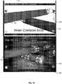
- Fig. 10shows at the bottom a display tile window in which a real field of view image 250 shows two tools 252, 254 colliding.
- the collision in Fig. 10is within the field of view 250, as described above, the collision may take place outside the field of view or even outside the body of the patient. Even if inside the field of view, the tools 252, 254 are not necessarily visible, because they may be blocked by cauterization smoke, blood, or an organ, as examples.
- the inner collisionis seen in the field of view 250, but it is also detected by the modeling component 108.
- a display tile window 260representing the synthetic image 120.
- the tile window 260is taken from the same point of view as the field of view 250, but a different point of view may be provided as described above.
- outer collisions, as well as inner collisionsmay be detected.
- Fig. 11is a flowchart showing an illustrative process for providing collision information in accordance with an embodiment.
- the processbegins at 1100.
- a modelsuch as the synthetic image 120, is generated. This generation process is described with reference to Fig. 7 .
- the robot for the patient side cartis moved.
- the proximity of linkages and/or tools of the robotic arm assemblies 122are computed.
- a determinationis made whether the proximities are within a high threshold.
- the high thresholdrepresents spacing between tools or linkages at which a warning of a collision is given. For example, as described above, if two tools are assumed to have a radius of a half an inch, the high threshold may be a centerline separation of 1.2 inches. If the components of the patient side cart are not within the high threshold, 1106 branches back to 1104, and the robot continues to move.
- a warningis generated.
- This warningmay be an audible warning, a visual warning (e.g., provided within the viewer 32 or on the display 84), or another suitable indication of collision proximity.
- the warningmay be presented, for example, in the field of view 250 ( Fig. 10 ). In the embodiment shown in Fig. 10 , the words "inner collision error" are shown, indicating an actual collision.
- a warning messagea message stating that tools are too close or similar may be provided.
- the color of the tools 124may change to provide the warning, such as changing from a metal color to yellow for a warning.
- a surgeonmay or may not elect to rearrange the robot after the warning is generated at 1108. In either event, the process proceeds to 1110, where the robot has moved again. At 1112, a determination is made whether the robot is within a low threshold.
- the low thresholdrepresents a distance, such as a center line distance, at which a collision is assumed. If the low threshold is not met, the process branches back to 1104 and continues to loop, likely continuing to generate the warning message unless the components of the patient side cart are moved to outside the high threshold in 1106.
- 1112branches to 1114, where collision information is generated, such as a collision warning or message.
- collision informationis generated, such as a collision warning or message.
- the collision error warningis provided in the field of view 250. (Both near and actual collision warnings may use the same or different indications.)
- a similar collision error warningmay be provided in the tile window 260, and the tools 124 may change colors, such as to red, to show a collision error. The process then loops back to 1104.
- the componentsneed not be in the field of view of the viewer 32.
- informationmay be provided, either in visual form or in the form of a warning or error message.
- the warningmay be particularly helpful where a user is not familiar with operation of the robot and may put the tools or robotic arm assemblies in an awkward position.
- the person viewing the viewer 32may select a different synthetic view angle and distance of the robot so as to determine the near collision or actual collision point between two robotic manipulators.
- the operatormay adjust one or more of the robot's kinematic arms (either the passive, "set up” portions or the actively controlled, manipulator portions) to cure the actual or near collision condition and avoid further collisions.
- the synthetic viewmay be automatically changed to show a collision point if a collision warning or actual collision is occurring.
- the location of a patient and/or portions of the patient's tissue structuresmay be provided to the system, and registered patient location data may be to detect, warn, and display actual or potential collisions between the robot and the patient or designated tissue structures in the patient. Collisions may be detected as described above.
- a visual, audio, or other indicatormay be provided to assist in reducing or correcting a collision state.
- informationmay be provided to a surgeon to aid the surgeon in avoiding a collision.
- a visual indicatormay provide information about a movement direction in which a collision might occur, or may indicate a movement direction for the surgeon to make in order to avoid or cure a collision.
- the synthetic image 120provides a solution to this problem by presenting the surgeon with a broader view of the endoscope's view volume 130, along with an accurate depiction of the position of each tool 124.
- a broader view and tool depictionmay be provided from various points of view.
- the broad view and tool depictionsare provided from the same point of view or direction as the endoscope field of view. By providing a broad view in this direction, the surgeon will be able to retain the intuitive tool control movement he or she normally experiences when viewing the real endoscopic image while moving tools into the proper position so that the tool is back in the view volume 130.
- the view volume 130may be viewed from other angles, allowing a surgeon to have a different perspective of what the endoscope 126 is viewing.
- Figs. 8 and 9show three different views, taken at different angles and pans, of views that may be shown for the synthetic image 120.
- the lower part of Fig. 8shows an actual image
- a synthetic image 120may be provided from the same direction, and would look similar except that synthetic tools would be shown instead of video feed of the actual tools.
- the view established by the field of viewis shown in the lower part of Fig. 8 , and a view taken from a front side of the synthetic image-zoomed outward to show much of the patient side cart-is shown in the top of Fig. 8 .
- a view taken slightly rearward and upward of the direction of the field of view of the endoscope, and zoomed outward to show the view volume 130,is shown in Fig. 9 .
- This slight variation in viewprovides a good perspective of where the tools 124 are with respect to the view volume 130.
- a surgeonmay toggle between a view consistent with the field of view and one just off from the field of view, such as shown in Fig. 9 .
- a controller or other devicemay be provided for allowing a surgeon to toggle between different views of the synthetic image 120.
- a separate controller or the master controllermay be utilized to allow infinite positioning (e.g., various pan, tilt, roll, dolly, truck, crane, and zoom image movements) of the synthetic image 120.
- Fig. 12is a flow chart representing a process for lost tool recovery in accordance with an embodiment.
- the processbegins at 1200.
- the synthetic image 120is generated as described above.
- the patient side cart, or the robotis moved.
- the synthetic imagemay or may not be automatically shown; the synthetic image display may be selected by a surgeon.
- 1208may be done as a result of a request by the surgeon or another operator, and may or may not be triggered by a tool being out of the field of view.
- a synthetic imagemay be automatically shown as a result of a loss of an image of the tool. In such an embodiment, however, it may be desirable to show the synthetic image in a tile window in addition to the field of view, instead of taking the field of view away from the surgeon.
- the synthetic view 120may be requested or otherwise provided in 1208.
- the synthetic image provided in 1208may be, as described above, substantially the same as the field of view of the endoscope 126 or any number of perspectives of the modeled system. If a desired angle is not shown, then a surgeon may elect at 1210 to show a different view. If the surgeon elects to show a different view, then 1210 branches to 1212, where the synthetic image 120 is, e.g., rotated to show a different view. If desired, as part of this movement, the synthetic image may rotate in space so that the surgeon may get an idea of the position from which the view started relative to the position where the view is going.
- a warning message or other indicatormay be provided to the surgeon so that the surgeon may understand that he or she is looking at the view volume 130 from a direction that is different than the direction of the field of view.
- the synthetic image 120provides an image of the patient side cart that is larger than and outside of the view volume 130.
- the surgeonmay zoom outward so that tools that are just outside the view volume 130 may be seen. The surgeon may then move these tools or the endoscope to the desired position so that they are within the field of view.
- a first optiondescribed with respect to Fig. 8 , includes a tile window 204 showing a synthetic view above the field of view image 202, with both shown at the same time.
- Another optionshown in Fig. 9 , shows only the synthetic image 120.
- a third optionis provided in which a video display from an endoscope is superimposed over the synthetic image 120, with the positions matched, so that the video image is rendered in the context of the synthetic image 120 of the entire patient side cart.
- This viewprovides relative positions of the components of the patient cart for the surgeon, and allows the surgeon to understand where the surgeon is with respect to space.
- the viewis also well suited when transitioning between a pure video display and a pure synthetic image 120. During the transition, the surgeon can relate respective positions of the robot and the video image from the endoscope.
- FIG. 13A simplified version of this feature is shown in Fig. 13 , where an image within the field of view 300 is projected over a window tile 306 that includes the synthetic image 120.
- the field of view image 300includes two tools 302, 304 performing an operation.
- the window tile 306extends the view provided by the field of view 300, and additional sections of the tools 302,304-indicated by the reference numerals 308,310, respectively-are provided.
- the surgeonmay zoom in and out to provide additional information about the location of the tools with respect to other parts of the patient side cart.
- the features described with respect to the embodiment shown in Fig. 13may be utilized to find the lost tool that is just outside the field of view, for example, in the window tile 306, but not in the field of view 300.
- the modeling data 104may be utilized to project a image other than a visual representation of portions of the patient side cart.
- the modeling component 108may display a portion of the synthetic image 120 in a different color, or it may display text on a portion of the synthetic image or instead of the synthetic image.
- the textmay be superimposed over the actual tools in a field of view so as to focus attention on that tool or to provide other information.
- the modeling component 108may be utilized to display a text message "closed" 320 collocated over the video image of the tool 304 to indicate that the clamp for the tool is closed.
- the camera informationdescribed above, permits the creation of a 3-D stereo rendering that may be superimposed on the stereo view of the tool 304 from the image capture device. Error messages may also be provided.
- Fig. 14is a flow chart representing a process for displaying information utilizing the modeling component 108 in accordance with an embodiment.
- the location of the components of the patient side cartis determined, for example, the location of the tools 124.
- the modeling component 108is aligned with the tool as described above.
- the desired informationis displayed over the tool. For example, as described above, words may be displayed over the tool. In addition, if desired, information may be displayed around or adjacent to a tool or other feature.
- the modeling data 104need only include information about the outer perimeter of the tools.
- the other components of the patient side cartare not needed for this embodiment.
- the synthetic image 120may be useful in providing a remote image of the operation of the patient side cart.
- an individual remote from the patient side cartmay desire to view operation of the patient side cart.
- the synthetic image 120may be rendered at both the viewer 32 and a remote display (e.g., the display 84).
- the modeling datamay be maintained all at one location, with the synthetic image 120 sent to a remote location for display at the remote location.
- position and orientation information provided by the tool tracking component 90 and/or the kinematic component 92may be sent to a remote computer.
- the remote computerincludes a modeling component 108 and the modeling data 104.
- the synthetic image 120is generated at the remote location in a separate operation from producing the synthetic image 120 for the viewer 32.
- a remote user or proctormay have controls for movement of a synthetic image, such as a synthetic image 120.
- the movement of the synthetic imagemay be watched by a surgeon or student at the surgeon console, permitting the user to learn surgical procedures and motions, and to mimic those motions with the surgeon or student's controls (and thus the tools).
- the linkages for the robotic arm assemblies of the patient side carthave a limited range of movement, limiting the movement of the tools supported by each arm or linkage.
- range of motion limitsWhen the robot for a patient encounters range of motion limits, it is not always obvious to a surgeon (new or experienced) why the robot is not able to continue moving.
- the modeling component 108generates a signal to indicate that a limit of the range of movement for a tool is approaching.
- the signalmay be used, for example, to generate a visual cue to the surgeon, such as color coding of the part(s) that have reached a limit.
- the limitmay be represented with synthetic geometry as a virtual wall 340 ( Fig. 6 ), which may be shown with the synthetic model 120, or may alternately be superimposed over the field of view.
- the virtual wall 340is for the right-most tool 124, and it may be shown as concave, flat, or otherwise shaped to match the curvature of a range of motion.
- the virtual wall 340is displayed in a position and direction that is perpendicular to the impeded motion direction of the instrument tip.
Landscapes
- Engineering & Computer Science (AREA)
- Health & Medical Sciences (AREA)
- Surgery (AREA)
- Life Sciences & Earth Sciences (AREA)
- Robotics (AREA)
- Nuclear Medicine, Radiotherapy & Molecular Imaging (AREA)
- General Health & Medical Sciences (AREA)
- Medical Informatics (AREA)
- Public Health (AREA)
- Biomedical Technology (AREA)
- Heart & Thoracic Surgery (AREA)
- Molecular Biology (AREA)
- Animal Behavior & Ethology (AREA)
- Veterinary Medicine (AREA)
- Mechanical Engineering (AREA)
- Pathology (AREA)
- Oral & Maxillofacial Surgery (AREA)
- Human Computer Interaction (AREA)
- Automation & Control Theory (AREA)
- General Physics & Mathematics (AREA)
- Physics & Mathematics (AREA)
- Gynecology & Obstetrics (AREA)
- Radiology & Medical Imaging (AREA)
- Urology & Nephrology (AREA)
- Epidemiology (AREA)
- Primary Health Care (AREA)
- Manipulator (AREA)
- Surgical Instruments (AREA)
- Image Analysis (AREA)
- Image Processing (AREA)
- Endoscopes (AREA)
Description
- Minimally invasive surgeries performed by robotic surgical systems are known and commonly used in remote or in other environments where it is advantageous for a human not to perform surgery. One example of such a telerobotic surgical system is the minimally invasive robotic surgery system described in commonly owned
U.S. Patent No. 7,155,315 . The da Vinci® Surgical Systems manufactured by Intuitive Surgical, Inc. of Sunnyvale, California are illustrative implementations of minimally invasive robotic surgical systems (e.g., teleoperated; telesurgical). - A common form of minimally invasive surgery is endoscopy. Endoscopic surgical instruments in minimally invasive medical techniques generally include an endoscope for viewing the surgical field, and working tools that include end effectors. Typical surgical end effectors include clamps, graspers, scissors, staplers, or needle holders, as examples. The working tools are similar to those used in conventional (open) surgery, except that the end effector of each tool is supported on the end of, for example, an approximately 12-inch-long extension tube.
- To manipulate end effectors, a human operator, typically a surgeon, manipulates or otherwise commands a locally-provided master manipulator. Commands from the master manipulator are translated as appropriate and sent to a remotely-deployed slave manipulator. The slave manipulator then manipulates the end effectors according to the operator's commands.
- Force feedback may be included in minimally invasive robotic surgical systems. To provide such feedback, the remote slave manipulators typically provide force information to the master manipulator, and that force information is utilized to provide force feedback to the surgeon so that the surgeon is given the perception of feeling forces acting on a slave manipulator. In some force feedback implementations, haptic feedback may provide an artificial feel to the surgeon of tissue reactive forces on a working tool and its end effector.
- Often, the master controls, which are typically located at a surgeon console, will include a clutch or other device for releasing one of the work tools at the patient site. This feature may be used, for example, in a system where there are more than two working tools. In such a system, the surgeon may release control of one working tool by one master and establish control over another working tool with that master.
- The surgeon typically views an image of only the distal ends of the working tools that are within the endoscope's field of view. The surgeon cannot see portions of a tool, or an entire tool, that is outside the field of view. Accordingly, the surgeon cannot see if two or more tools are interfering with each other outside the field of view. Further, since the endoscope may be manipulated to be at various positions and orientations with reference to a surgical site and to the surgeon's body frame of reference, the surgeon may become confused about the general location of the tools. Consequently, the surgeon may not understand how to best move the master manipulators to avoid an inter-tool interference or to reorient one or more tools with reference to the surgical site.
US 2007/293734 A1 discloses methods and apparatus which provide enhanced planning of entry port placement and/or robot position for laparoscopic, robotic, and other minimally invasive surgery. Various embodiments may be used in robotic surgery systems to identify advantageous entry ports for multiple robotic surgical tools into a patient to access a surgical site. Generally, data such as imaging data is processed and used to create a model of a surgical site, which can then be used to select advantageous entry port sites for two or more surgical tools based on multiple criteria.US 2005/187432 A1 discloses a graphical model which provides a dynamic representation of the endoscopic view and viewing direction relative to a virtual world. The model can be oriented and adjusted to approximate a real world situation. Angular image navigation coordinates are also provided.WO 99/00052 A1 US 2005/054895 discloses a method for a variable direction of view endoscope used in combination with an image guided surgical system to provide diagnostic and surgical capabilities.- The following presents a simplified summary of some aspects and embodiments of the invention in order to provide a basic understanding of the invention. This summary is not an extensive overview of the invention. It is not intended to identify key/critical elements of the invention or to delineate the scope of the invention. Its sole purpose is to present some aspects and embodiments of the invention in a simplified form as a prelude to the more detailed description that is presented later.
- The present invention provides a robotic surgical system, comprising: a robot having a first robotic arm assembly and a second robotic arm assembly, wherein the first robotic arm assembly is detachably coupled to a tool, and wherein the second robotic arm assembly is arranged to hold an image capture device having a field of view that is positionable to capture an image of an end effector of the tool; modeling data for providing a synthetic representation of at least a portion of the robot, the tool, and the image capture device; a display; and a first component coupled to the modeling data, encoders in the first and second robotic arm assemblies, and the display, wherein the first component is configured to: generate the synthetic representation so that actual movements of the robot, the tool, and the image capture device are mimicked in the synthetic image while a medical procedure is being performed on a patient, generate a three-dimensional representation of a projection of boundaries of the field of view of the image capture device so that the three-dimensional representation is properly positioned relative to a viewing end of the image capture device in the synthetic image while the medical procedure is being performed on the patient, and cause the synthetic representation and the three-dimensional representation of the projection of boundaries of the field of view of the image capture device to be displayed on the display while the medical procedure is being performed on the patient.
- Also described is a robotic surgical system. The system includes a robot including a linkage supporting at least one tool for performing surgery on a patient; a kinematic component coupled to the robot so as to obtain joint state information from the linkage; a display; and a first component coupling the display with the kinematic component so as to display a synthetic representation of the robot including a graphical representation of at least a portion of the linkage based upon linkage structure data regarding the linkage; and the joint state information.
- Also described is a robotic surgical system. The system includes a robot including an image capture device having a field of view and a linkage supporting at least one tool for performing surgery on a patient; a kinematic component coupled to the linkage so as to obtain joint states information regarding the linkage; data regarding structure of the first linkage and said at least one tool; and a collision detection component coupled to the data and to the kinematic component so as to generate a warning.
Fig. 1 shows a top view of an operating room which includes a minimally invasive telesurgical system;Fig. 2 is front view of a patient cart for the minimally invasive telesurgical system ofFig. 1 ;Fig. 3 is a block diagram representing components of the minimally invasive telesurgical system ofFig. 1 ;Fig. 4 is a block diagram representing components for a computer for use in the minimally invasive telesurgical system ofFig. 1 ;Fig. 5 is a side perspective view of a master controller;Fig. 6 is a view of a synthetic image of a robot;Fig. 7 is a flowchart representing a process for updating a rendering of a synthetic image;Fig. 8 is a view provided by a display that provides both a field of view for an endoscope and a synthetic image of a robot supporting the endoscope;Fig. 9 shows a tile window displaying an alternate angle for viewing a portion of the synthetic image of a robot;Fig. 10 shows a field of view in which two tools are colliding;Fig. 11 is a flowchart showing a process for providing collision information;Fig. 12 is a flow chart representing a process for lost tool recovery;Fig. 13 shows a field of view projected over a window tile that includes a synthetic image of a robot; andFig. 14 is a flow chart representing a process for displaying information utilizing a modeling component.- In the following description, various aspects and embodiments of the present invention will be described. For purposes of explanation, specific configurations and details are set forth in order to provide a thorough understanding of the embodiments. However, it will also be apparent to one skilled in the art that the present invention may be practiced without the specific details. Furthermore, well-known features may be omitted from this description or simplified in order not to obscure the embodiment being described.
- Referring now to the drawings, in which like reference numerals represent like parts throughout several views,
Fig. 1 shows a minimally invasivetelesurgical system 20 having an operator station orsurgeon console 30 in accordance with an embodiment. Thesurgeon console 30 includes aviewer 32 where an image of a surgical site is displayed to a surgeon S. As is known, a support (not shown) is provided on which the surgeon S can rest his or her forearms while gripping two master controls 700 (Fig. 5 ), one in each hand. More controls may be provided if more end effectors are available, but typically a surgeon manipulates only two controls at a time and, if multiple tools are used, the surgeon releases one tool with amaster control 700 and grasps another with same master control. When using thesurgeon console 30, the surgeon S typically sits in a chair in front of the surgeon console, positions his or her eyes in front of theviewer 32, and grips the master controls 700, one in each hand, while resting his or her forearms on the support. - A
patient side cart 40 of thetelesurgical system 20 is positioned adjacent to a patient P. In use, thepatient side cart 40 is positioned close to the patient P requiring surgery. Thepatient side cart 40 typically is stationary during a surgical procedure, and includes wheels or castors to render it mobile. Thesurgeon console 30 is typically positioned remote from thepatient side cart 40, and it may be separated from the patient side cart by a great distance-even miles away-but will typically be used within the same operating room as the patient side cart. - The
patient side cart 40, shown in more detail inFig. 2 , typically includes two or more robotic arm assemblies. In the embodiment shown inFig. 2 , thepatient side cart 40 includes fourrobotic arm assemblies robotic arm assembly surgeon console 30. Thus, movement of the manipulator portion of therobotic arm assemblies - One of the robotic arm assemblies, indicated by the
reference numeral 42, is arranged to hold animage capture device 50, e.g., an endoscope, or the like. The endoscope orimage capture device 50 includes aviewing end 56 at a remote end of anelongated shaft 54. Theelongated shaft 54 permits theviewing end 56 to be inserted through a surgery entry port of the patient P. Theimage capture device 50 is operatively connected to theviewer 32 of thesurgeon console 30 to display an image captured at itsviewing end 56. - Each of the other
robotic arm assemblies tool tools robotic arm assemblies end effectors tools end effectors end effectors tools surgeon console 30. - The depicted
telesurgical system 20 includes avision cart 80, which contains equipment associated with the image capture device. In another embodiment, thevision cart 80 can be combined with other equipment that includes most of the computer equipment or other controls (the "core" data processing equipment) for operating thetelesurgical system 20. As an example, signals sent by the master controllers of thesurgeon console 30 may be sent to the vision/core cart 80, which in turn may interpret the signals and generate commands for theend effectors robotic arm assemblies image capture device 50 to the viewer 34 may be processed by, or simply transferred by, thevision cart 80. Fig. 3 is a diagrammatic representation of thetelesurgical system 20. As can be seen, the system includes thesurgeon console 30, thepatient side cart 40, and thevision cart 80. In addition, in accordance with an embodiment, anadditional computer 82 anddisplay 84 are provided. These components may be incorporated in one or more of thesurgeon console 30, thepatient side cart 40, and/or thevision cart 80. For example, the features of thecomputer 82 may be incorporated into thevision cart 80. In addition, the features of thedisplay 84 may be incorporated into thesurgeon console 30, for example, in theviewer 32, or maybe provided by a completely separate display at the surgeon console or on another location. In addition, in accordance with an embodiment, thecomputer 82 may generate information that may be utilized without a display, such as thedisplay 84.- Although described as a "computer," the
computer 82 may be a component of a computer system or any other software or hardware that is capable of performing the functions described herein. Moreover, as described above, functions and features of thecomputer 82 may be distributed over several devices or software components. Thus, thecomputer 82 shown in the drawings is for the convenience of discussion, and it may be replaced by a controller or its functions may be provided by one or more other components. Fig. 4 shows components of thecomputer 82 in accordance with an embodiment. A positional component is included in or is otherwise associated with thecomputer 82. The positional component provides information about a position of an end effector, such as one of theend effectors tool tracking component 90 is used for the positional component and provides information about a position of an end effector, such as theend effectors image capture device 50 to provide information about the position of an end effector, but other information may be used instead of, or in addition to, this visual information, including sensor information, kinematic information, any combination of these, or additional information that may provide the position and/or orientation of theend effectors tool tracking component 90 are disclosed in ,U.S. Pat. No. 5,950,629 (filed Apr. 28, 1994 ),U.S. Pat. No. 6,468,265 (filed Nov. 9, 1999 ), U.S. Pat. App. Pub. No.US 2006/0258938 A1 (filed May 16,2005 ), and U.S. Pat. App. Pub. No.US 2008/0004603 A1 (filed Jun. 29, 2006 ). In accordance with an embodiment, thetool tracking component 90 utilizes the systems and methods described in commonly ownedU.S. Pat. App. No. 61/204,084 (filed Dec. 31, 2008 - The
kinematic component 92 is generally any device that estimates a position, herein a "kinematic position," of an end effector utilizing information available through thetelesurgical system 20. In an embodiment, thekinematic component 92 utilizes kinematic position information from joint states of a linkage to the end effector. For example, thekinematic component 92 may utilize the master/slave architecture for thetelesurgical system 20 to calculate intended Cartesian positions of theend effectors tools slave encoders 102 and/or master manipulator encoders to estimate the position of tool. An example of system utilizing an embodiment of a kinematic component is described inU.S. Pat. No. 7,155,315 , although others may be utilized. Kinematic position information for the end effector or any portion of the linkage and/or tool may also be provided in other ways, such as the use of optical fiber shape sensing, sensing the positions of components (e.g., electromagnetic components) embedded at various places along the linkage, tool, or end effector, various video tool tracking methods, etc. - In the embodiment shown in the drawings, an
error correction component 94 is provided. In general, the error correction component calculates a difference between a location and/or orientation of a tool as provided by thetool tracking component 90 compared to the location and/or orientation of the tool as provided by thekinematic component 92. Because of the large number of joints and movable parts, current kinematics measurement typically does not provide exact information for the location of a surgical end effector in space. A system with sufficient rigidity and sensing could theoretically provide near-exact kinetic information. In current minimally invasive robotic surgery systems, however, often the kinematic information may be inaccurate by up to an inch in any direction when taken in space. Thus, in accordance with an embodiment, an offset may be generated by theerror correction component 94. This offset provides information regarding the difference between the kinematic information provided by the kinematic component and the actual position information provided by the tool tracking component. Utilizing the offset, the kinematic information and the actual position information may be registered to the same location and/or orientation. - In accordance with an embodiment, a
modeling component 108 is provided for generating a synthetic image 120 (Fig. 6 ) of a patient side cart, such as thepatient side cart 40, or any portion thereof. In the embodiment shown in the drawings, thesynthetic image 120 is of a different patient side cart configuration than the patient side cart 40 (an illustrative model of a da Vinci® Surgical System Model IS2000 patient side cart with three arms is shown), but the basic components of the two patient side carts are the same, except that thepatient side cart 40 includes an additional robotic arm assembly and tool. In accordance with an embodiment, thesynthetic image 120 may be displayed on thedisplay 84 or theviewer 32. To this end, modeling data 104 (Fig. 3 ) may be provided that is associated with thevision cart 80 and/or thecomputer 82. Themodeling data 104 may be, for example, a two-dimensional (2-D) or three-dimensional (3-D) representation, such as an image, of thepatient side cart 40, or any portion thereof. In an embodiment, such a representation is a 3-D model of thepatient side cart 40, or any portion thereof, and thus may represent an actual solid model of thepatient side cart 40, or any portion thereof. Themodeling data 104 may be, for example, CAD data or other 3-D solid model data representing components of thepatient side cart 40. In an embodiment, the 3-D model is manipulatable at each joint of thepatient side cart 40, so that movements of the patient side cart may be mimicked by thesynthetic image 120 of thepatient side cart 40. The modeling data may represent the entire patient side cart or any portion thereof, such as only the tools for the patient side cart. - Joint locations and orientations are generally known from kinematic data provided, for example, by the
kinematic component 92. Utilizing this information, each component of the patient side cart may be rendered in location so as to generate a image of the patient side cart that appears in 3-D to the surgeon. Thus, in an embodiment, themodeling data 104 includes individualized information for each component or link of the patient side cart robot. - In accordance with an embodiment, the
modeling component 108 constantly updates the location and/or orientation of the components of thesynthetic image 120 in accordance with information provided by thetool tracking component 90 and/or thekinematic component 92. For example, an initial state of thekinematic component 92 may be determined including a position of one or more end effectors for the patient side cart. These positions may be compared with position information provided by thetool tracking component 90. As described above, the difference between the actual position as determined by thetool tracking component 90 and the estimated position of the end effectors provided by thekinematic component 92 may result in an offset, which may be stored in or otherwise used by theerror correction component 94. This offset may be used to register the position and orientation of an end effector as determined by thetool tracking component 90 to the position and orientation as estimated by thekinematic component 92. - As data is available from the
tool tracking component 90, the actual position of the end effector may be tracked and registered with information provided by thekinematic component 92. When tool tracking information is not available from thetool tracking component 90, an assumption may be made that any change in kinematic information provided by thekinematic component 92 is an indication of actual movement by the end effector. That is, when tool tracking is not available, the position of an end effector may be accurately determined by the change in coordinate positions between the current position and the last known position, as calculated by thekinematic component 92. The assumption here is that the change in position may be accurately calculated using only kinematic data, without tool tracking information. This assumption is reasonable, because although kinematic information is often not accurate for calculating a position of an end effector in space, it is typically accurate for calculating a change of position once a position is known, especially over a short period of time or for a small amount of movement. Thus, asynchronous data may be provided by thetool tracking component 90, and synchronous data may be provided by thekinematic component 92. The combination of this information provides data regarding the positions and orientations of the components of thepatient side cart 40. - The positions of the components of a robotic arm assembly may be determined by utilizing the joint states provided by the kinematic component. These joint states arc calculated backwards from the end effector, the position of which is known, as described above. In addition, because the
slave encoders 102 at the joints ofrobotic arm assemblies 122 for the patient side cart provide change in state information for each joint, the relative position of each section of the robotic arm assemblies may be accurately estimated and tracked. Thus, information can be provided to themodeling component 108 that is sufficient so thatmodeling component 108 may generate thesynthetic image 120 by utilizing themodeling data 104, with the position of each of the segments of therobotic arm assemblies 122, includingtools 124 at the end of the robotic arm assemblies, or anendoscope 126 at the end of one of the robotic arm assemblies. - Referring again to
Fig. 6 , in an embodiment, in addition to thesynthetic image 120 for the patient side cart, aview volume 130 for the endoscope is provided. Theview volume 130 represents a projection of the field of view of theendoscope 126. The field of view is the view visible by the endoscope, and the view volume is a projection of the boundaries of the field of view. That is, theview volume 130 represents a 3-D space that is visible by theendoscope 126. If desired, as shown inFig. 4 ,camera information 132 may be provided to themodeling component 108. The camera information includes a calibrated set of intrinsic and extrinsic parameters about the camera. The intrinsic parameters include, e.g., focal length and principle point, which model the perspective mapping of the optics. Additionally, the intrinsic parameters may account for lens distortion. The extrinsic parameters may account for, e.g., relative position and orientation between the stereo endoscopic views. As can be understood, changing the parameters, such as zoom, of the endoscope will change the view volume for the endoscope, such as making the view volume narrower or wider. In addition, as theendoscope 126 is moved, theview volume 130 will move accordingly. The camera information permits the creation of a 3-D stereo rendering that may be superimposed on the stereo view of the end effector from the image capture device, as described below. Fig. 7 is a flowchart representing a process for updating a rendering of asynthetic image 120 in accordance with an embodiment. Beginning at 401, the position and orientation of the patient side cart, or any portion thereof, is sensed. This sensing may occur, for example, via thetool tracking component 90 and/or thekinematic component 92, as described above.- At 402, the position and orientation information from 401 is used to generate a model (e.g., the synthetic image 120). As described above, the
modeling component 108 uses themodeling data 104 to generate the model. The position and orientation information provided from 401 is utilized to correctly arrange the position and orientation of the synthetic model to match that of the patient side cart. - At 404, as a result of the patient side cart moving, information is received. The movement may be, for example, movement of one of the robotic arm assemblies, movement of the endoscope, change in the focus of the endoscope, or movement by one of the end effectors. The movement of the end effector may be a change in location or orientation, including, for example, closing of pinchers or other operational movement of the end effectors.
- At 406, a determination is made whether tool tracking information is available. In the embodiment show in
Fig. 4 , the determination is whether an image is available so that the actual position of the end effector or any portion of the tool that is in a field of view (e.g., the view volume 130) of theendoscope 126 may be found using thetool tracking component 90. In one aspect, if tool tracking is available, then 406 branches to 408 where the tool tracking information is utilized to update information about the position and orientation of the tool and/or end effector. - At 410, the kinematic information is used to update information about the location and orientation of the joints of each linkage of the robot for the patient side cart. At 412, the offset is updated, if desired. At 414, the display of the
synthetic image 120 is updated, and the process branches back to 404. - At 406, if the tool tracking information is not available, then the process branches to 416, where the kinematic information provided by the
kinematic component 92 is utilized to determine the position of the end effector. The process then proceeds to 410, and then on through the process, although since the tool tracking information was not available on this loop, the offset will likely not be updated, skipping 412. - Utilizing the method shown in
Fig. 7 , a 3-D rendering of thesynthetic image 120 is generated, and the synthetic image accurately represents the physical configuration of the patient side cart at any point in time throughout a surgical procedure. This information can be utilized and viewed by the surgeon S, or by someone else, to evaluate the state of the patient side cart. As described below, the viewer 34 or thedisplay 82 may show thesynthetic image 120, either from a point of view that is the same as the point of view from the endoscope, or from another angle or distance. Thesynthetic image 120 enables observation of all parts of the patient view cart via theviewer 32, thus permitting the surgeon S to monitor movements of the robot and tools. In addition, in accordance with an embodiment, viewing of these components is available in connection with theview volume 130, permitting a surgeon to have a good perspective of where the endoscope's field of view is with respect to space. Theview volume 130 provides a three dimensional representation of what is being seen by the surgeon S when looking in theviewer 32. - If desired, a single display may be provided for showing both the field of view of the endoscope and the
synthetic image 120. For example, as shown inFig. 8 , aview 200 provided by theviewer 32 or thedisplay 84 provides both an actual field ofview image 202 for theendoscope 126 and thesynthetic image 120. Thesynthetic image 120 is shown in aseparate tile window 204. In the embodiment shown inFig. 8 , thetile 204 is approximately the same size as the field ofview 202, but if desired, the tile window may be smaller or larger than the field ofview 202. Also, if desired, a toggle or other feature may be provided so that the surgeon may switch back and forth between a larger presentation of thesynthetic image 120 or the field ofview 202. In addition, thesynthetic image 120 and/or thetile window 204 may be partially superimposed over a portion of the field of view, either on a continuous basis or upon request. - As an example of toggling back and forth between a larger presentation of the
synthetic image 120 or the field ofview 202, a camera control may be provided that is connected to the master manipulators. For example, a user may start looking at the endoscopic view and may pull the endoscope back by pulling the his hands towards himself while in a camera control mode. At some point, the endoscope cannot be pulled back any farther, and the field of view encompasses a maximum area. Continuing to pull back on the master controls (with or without a haptic detent or other indication) can expose a view showing sections of asynthetic image 120 along the borders of the real image (e.g., the image captured in field of view 202). Pulling back even farther on the master controls (with or without haptic detent or other indication) may provide a view where the image captured in field ofview 202 is only the middle section of the screen. Pulling back still farther on the controls (with or without haptic detent or other indication) may provide the entiresynthetic image 120. Reversing the master control direction can be used to reverse such a real-to-synthetic zoom out function and control a synthetic-to-real zoom in function. As an alternative to camera control using master manipulator movement, the system may be configured to use another control input (e.g., a foot pedal, a finger button on a manipulator, the roll of the master manipulator grip, and the like) to control the zoom functions. Fig. 9 shows atile window 208 displaying an alternate angle for viewing a portion of thesynthetic image 120. In the embodiment shown, theview volume 130 is slightly tilted from the actual field of view of the endoscope, but the particular angle of view of theview volume 130 shows relevant information regarding the configuration of thetools 124 with respect to the view volume.- The features of the
synthetic image 120 provide another number of benefits to a user of the minimally invasivetelesurgical system 20. Some of these advantages are set forth below. - Typically, in a minimally invasive telesurgical system, only the most distal portions of the surgical tools, such as the
tools 124, may be visible to the surgeon in the field of view of theendoscope 126 at any time. Depending upon the configuration of the patient side cart, it is possible that collisions between moving parts of the robot assembly may occur which are not visible to the surgeon in the field of view. Some of these collisions ("outer collisions" because they are outside of the field of view for the endoscope 126) may occur between the linkages of robotic arm assemblies leading to the tools, the collisions may occur between two tools, or may occur between a tool and a linkage. Such outer collisions may occur outside the body or inside the body but not within the field of view. In addition, an outer collision may occur between one tool that is in the field of view and another tool that is slightly outside the field of view. Collisions occurring inside the body and in the field of view of the endoscope are "inner collisions". - In accordance with an embodiment, the
synthetic image 120 and/or the information generated by the modeling component 128 may be utilized for collision detection. As an example, a surgeon viewing theviewer 32, or another individual viewing thedisplay 84, may view thesynthetic image 120 to see an indication of an imminent or actual collision. - Collision detection may involve more than just a visual image of a collision. Information about relative locations of robot linkages and tools is maintained by the modeling component 128, and this information may be used to generate a signal if two components are sensed to be too close to one another. For example, each tool may be treated like a capsule or cylinder, having a particular radius or buffer zone outside the tool's surface. Using the actual position information from the tool tracking component and/or the kinematic information from the
kinematic component 92, themodeling component 108 may predict or warn of a collision. For example, if twotools 124 are presumed to have a radius of one half inch each, then if the center line for one of the tools comes within an inch of the center line for a second tool, then themodeling component 108 may assume that a collision has occurred. A separate signal may be generated if the two tools arc calculated to be close, but not in contact, with each other. For the above example, this distance may be, e.g., a center line distance between the tools of 1.20 inches. Fig. 10 shows at the bottom a display tile window in which a real field ofview image 250 shows twotools Fig. 10 is within the field ofview 250, as described above, the collision may take place outside the field of view or even outside the body of the patient. Even if inside the field of view, thetools Fig. 10 , the inner collision is seen in the field ofview 250, but it is also detected by themodeling component 108.- At the top of
Fig. 10 is adisplay tile window 260 representing thesynthetic image 120. In the embodiment shown inFig. 10 , thetile window 260 is taken from the same point of view as the field ofview 250, but a different point of view may be provided as described above. In addition, as described above, outer collisions, as well as inner collisions, may be detected. Fig. 11 is a flowchart showing an illustrative process for providing collision information in accordance with an embodiment. The process begins at 1100. At 1102, a model, such as thesynthetic image 120, is generated. This generation process is described with reference toFig. 7 . At 1104, the robot for the patient side cart is moved. At 1105, the proximity of linkages and/or tools of therobotic arm assemblies 122 are computed. At 1106, a determination is made whether the proximities are within a high threshold. The high threshold represents spacing between tools or linkages at which a warning of a collision is given. For example, as described above, if two tools are assumed to have a radius of a half an inch, the high threshold may be a centerline separation of 1.2 inches. If the components of the patient side cart are not within the high threshold, 1106 branches back to 1104, and the robot continues to move.- If two components of the patient side cart are within the high threshold, then 1106 branches to 1108, where a warning is generated. This warning may be an audible warning, a visual warning (e.g., provided within the
viewer 32 or on the display 84), or another suitable indication of collision proximity. If visual, the warning may be presented, for example, in the field of view 250 (Fig. 10 ). In the embodiment shown inFig. 10 , the words "inner collision error" are shown, indicating an actual collision. Alternatively, for a warning message, a message stating that tools are too close or similar may be provided. In addition, for the view of thesynthetic image 120, the color of thetools 124 may change to provide the warning, such as changing from a metal color to yellow for a warning. - A surgeon may or may not elect to rearrange the robot after the warning is generated at 1108. In either event, the process proceeds to 1110, where the robot has moved again. At 1112, a determination is made whether the robot is within a low threshold. In an embodiment, the low threshold represents a distance, such as a center line distance, at which a collision is assumed. If the low threshold is not met, the process branches back to 1104 and continues to loop, likely continuing to generate the warning message unless the components of the patient side cart are moved to outside the high threshold in 1106.
- If the components are within the low threshold, then 1112 branches to 1114, where collision information is generated, such as a collision warning or message. As an example, in
Fig. 10 , the collision error warning is provided in the field ofview 250. (Both near and actual collision warnings may use the same or different indications.) A similar collision error warning may be provided in thetile window 260, and thetools 124 may change colors, such as to red, to show a collision error. The process then loops back to 1104. - As stated above, for collision detection, the components need not be in the field of view of the
viewer 32. Thus, when components of the patient side cart are improperly aligned and are approaching a collision or actually have a collision, information may be provided, either in visual form or in the form of a warning or error message. The warning may be particularly helpful where a user is not familiar with operation of the robot and may put the tools or robotic arm assemblies in an awkward position. The person viewing theviewer 32 may select a different synthetic view angle and distance of the robot so as to determine the near collision or actual collision point between two robotic manipulators. Once the operator views the collision point, he or she may adjust one or more of the robot's kinematic arms (either the passive, "set up" portions or the actively controlled, manipulator portions) to cure the actual or near collision condition and avoid further collisions. In one aspect, if the operator is viewing a synthetic view that corresponds to the endoscope's field of view, the synthetic view may be automatically changed to show a collision point if a collision warning or actual collision is occurring. - In an embodiment, the location of a patient and/or portions of the patient's tissue structures (e.g., from preoperative imaging or by other suitable method of registering tissue structure locations) may be provided to the system, and registered patient location data may be to detect, warn, and display actual or potential collisions between the robot and the patient or designated tissue structures in the patient. Collisions may be detected as described above.
- Also, in an embodiment, a visual, audio, or other indicator may be provided to assist in reducing or correcting a collision state. For example, for the warning situation described above, information may be provided to a surgeon to aid the surgeon in avoiding a collision. For example, a visual indicator may provide information about a movement direction in which a collision might occur, or may indicate a movement direction for the surgeon to make in order to avoid or cure a collision.
- In minimally invasive surgery, it is possible for instruments to be positioned outside the endoscopic camera's view volume. This possibility can result in situations where the tool is effectively lost, since the surgeon does not necessarily know how to move the endoscope to bring the instrument back into view, or how to move the instrument into the endoscope's field of view. Moreover, the situation may compromise patient safety, since the surgeon is able to move an instrument which cannot be observed.
- The
synthetic image 120 provides a solution to this problem by presenting the surgeon with a broader view of the endoscope'sview volume 130, along with an accurate depiction of the position of eachtool 124. Such a broader view and tool depiction may be provided from various points of view. In an embodiment, the broad view and tool depictions are provided from the same point of view or direction as the endoscope field of view. By providing a broad view in this direction, the surgeon will be able to retain the intuitive tool control movement he or she normally experiences when viewing the real endoscopic image while moving tools into the proper position so that the tool is back in theview volume 130. Alternatively, theview volume 130 may be viewed from other angles, allowing a surgeon to have a different perspective of what theendoscope 126 is viewing. As examples,Figs. 8 and9 show three different views, taken at different angles and pans, of views that may be shown for thesynthetic image 120. Although the lower part ofFig. 8 shows an actual image, asynthetic image 120 may be provided from the same direction, and would look similar except that synthetic tools would be shown instead of video feed of the actual tools. The view established by the field of view is shown in the lower part ofFig. 8 , and a view taken from a front side of the synthetic image-zoomed outward to show much of the patient side cart-is shown in the top ofFig. 8 . A view taken slightly rearward and upward of the direction of the field of view of the endoscope, and zoomed outward to show theview volume 130, is shown inFig. 9 . This slight variation in view provides a good perspective of where thetools 124 are with respect to theview volume 130. A surgeon may toggle between a view consistent with the field of view and one just off from the field of view, such as shown inFig. 9 . To this end, a controller or other device may be provided for allowing a surgeon to toggle between different views of thesynthetic image 120. Alternatively, a separate controller or the master controller may be utilized to allow infinite positioning (e.g., various pan, tilt, roll, dolly, truck, crane, and zoom image movements) of thesynthetic image 120. Fig. 12 is a flow chart representing a process for lost tool recovery in accordance with an embodiment. The process begins at 1200. At 1202, thesynthetic image 120 is generated as described above. At 1204, the patient side cart, or the robot, is moved.- At 1206, a determination is made whether one or more of the tools is outside of the field of view. If not, the process loops back to 1204. If one or more of the tools is outside of the field of view, then the process may move to 1208, where a synthetic image is shown. The synthetic image may or may not be automatically shown; the synthetic image display may be selected by a surgeon. To this end, 1208 may be done as a result of a request by the surgeon or another operator, and may or may not be triggered by a tool being out of the field of view. If desired, however, a synthetic image may be automatically shown as a result of a loss of an image of the tool. In such an embodiment, however, it may be desirable to show the synthetic image in a tile window in addition to the field of view, instead of taking the field of view away from the surgeon.
- If the missing tool display option is available, the
synthetic view 120 may be requested or otherwise provided in 1208. The synthetic image provided in 1208 may be, as described above, substantially the same as the field of view of theendoscope 126 or any number of perspectives of the modeled system. If a desired angle is not shown, then a surgeon may elect at 1210 to show a different view. If the surgeon elects to show a different view, then 1210 branches to 1212, where thesynthetic image 120 is, e.g., rotated to show a different view. If desired, as part of this movement, the synthetic image may rotate in space so that the surgeon may get an idea of the position from which the view started relative to the position where the view is going. In addition, in accordance with an embodiment, when a view of thesynthetic image 120 is inconsistent with the same point of view as the field of view, a warning message or other indicator may be provided to the surgeon so that the surgeon may understand that he or she is looking at theview volume 130 from a direction that is different than the direction of the field of view. - If the surgeon did not request a different view in 1210, then the process loops back to 1204.
- As described above, the
synthetic image 120 provides an image of the patient side cart that is larger than and outside of theview volume 130. Thus, even if taken along the same point of view as the field of the view of theendoscope 126, the surgeon may zoom outward so that tools that are just outside theview volume 130 may be seen. The surgeon may then move these tools or the endoscope to the desired position so that they are within the field of view. - As described above, there are a number of ways in which the system may present the
synthetic image 120 of the robot to the surgeon. A first option, described with respect toFig. 8 , includes atile window 204 showing a synthetic view above the field ofview image 202, with both shown at the same time. Another option, shown inFig. 9 , shows only thesynthetic image 120. - In accordance with an embodiment, a third option is provided in which a video display from an endoscope is superimposed over the
synthetic image 120, with the positions matched, so that the video image is rendered in the context of thesynthetic image 120 of the entire patient side cart. This view provides relative positions of the components of the patient cart for the surgeon, and allows the surgeon to understand where the surgeon is with respect to space. The view is also well suited when transitioning between a pure video display and a puresynthetic image 120. During the transition, the surgeon can relate respective positions of the robot and the video image from the endoscope. - A simplified version of this feature is shown in
Fig. 13 , where an image within the field ofview 300 is projected over awindow tile 306 that includes thesynthetic image 120. The field ofview image 300 includes twotools window tile 306 extends the view provided by the field ofview 300, and additional sections of the tools 302,304-indicated by the reference numerals 308,310, respectively-are provided. The surgeon may zoom in and out to provide additional information about the location of the tools with respect to other parts of the patient side cart. In addition, the features described with respect to the embodiment shown inFig. 13 may be utilized to find the lost tool that is just outside the field of view, for example, in thewindow tile 306, but not in the field ofview 300. - In accordance with an embodiment, instead of or in addition to the
synthetic image 120, themodeling data 104 may be utilized to project a image other than a visual representation of portions of the patient side cart. For example, using the position information provided by thetool tracking component 90 and/or thekinematic component 92, themodeling component 108 may display a portion of thesynthetic image 120 in a different color, or it may display text on a portion of the synthetic image or instead of the synthetic image. In such an embodiment, the text may be superimposed over the actual tools in a field of view so as to focus attention on that tool or to provide other information. As an example, for thetool 304 inFig. 13 , themodeling component 108 may be utilized to display a text message "closed" 320 collocated over the video image of thetool 304 to indicate that the clamp for the tool is closed. The camera information, described above, permits the creation of a 3-D stereo rendering that may be superimposed on the stereo view of thetool 304 from the image capture device. Error messages may also be provided. Fig. 14 is a flow chart representing a process for displaying information utilizing themodeling component 108 in accordance with an embodiment. Beginning at 1400, the location of the components of the patient side cart is determined, for example, the location of thetools 124. At 1402, themodeling component 108 is aligned with the tool as described above. At 1404, the desired information is displayed over the tool. For example, as described above, words may be displayed over the tool. In addition, if desired, information may be displayed around or adjacent to a tool or other feature.- As can be understood, to superimpose a message over actual tools in the field of view, the
modeling data 104 need only include information about the outer perimeter of the tools. The other components of the patient side cart are not needed for this embodiment. - The
synthetic image 120 may be useful in providing a remote image of the operation of the patient side cart. For example, in some situations, an individual remote from the patient side cart may desire to view operation of the patient side cart. In such a situation, thesynthetic image 120 may be rendered at both theviewer 32 and a remote display (e.g., the display 84). In such a situation, in accordance with one embodiment, the modeling data may be maintained all at one location, with thesynthetic image 120 sent to a remote location for display at the remote location. - In an alternate embodiment, position and orientation information provided by the
tool tracking component 90 and/or thekinematic component 92 may be sent to a remote computer. The remote computer, in turn, includes amodeling component 108 and themodeling data 104. In this embodiment, thesynthetic image 120 is generated at the remote location in a separate operation from producing thesynthetic image 120 for theviewer 32. - Being able to provide a
synthetic image 120 in remote locations permits an operating surgeon viewing the surgeon's console to communicate with a surgical assistant viewing an assistant monitor. In addition, a student surgeon at one surgeon console may communicate with a remote proctor at another surgeon console. - In accordance with another embodiment, a remote user or proctor may have controls for movement of a synthetic image, such as a
synthetic image 120. The movement of the synthetic image may be watched by a surgeon or student at the surgeon console, permitting the user to learn surgical procedures and motions, and to mimic those motions with the surgeon or student's controls (and thus the tools). - The linkages for the robotic arm assemblies of the patient side cart have a limited range of movement, limiting the movement of the tools supported by each arm or linkage. When the robot for a patient encounters range of motion limits, it is not always obvious to a surgeon (new or experienced) why the robot is not able to continue moving. In a telesurgical system, there are typically two sources of range of motion limits: joint limits of the master manipulator and joint limits of the slave manipulator.
- In accordance with an embodiment, the
modeling component 108 generates a signal to indicate that a limit of the range of movement for a tool is approaching. The signal may be used, for example, to generate a visual cue to the surgeon, such as color coding of the part(s) that have reached a limit. Alternatively, the limit may be represented with synthetic geometry as a virtual wall 340 (Fig. 6 ), which may be shown with thesynthetic model 120, or may alternately be superimposed over the field of view. Thevirtual wall 340 is for theright-most tool 124, and it may be shown as concave, flat, or otherwise shaped to match the curvature of a range of motion. Thevirtual wall 340 is displayed in a position and direction that is perpendicular to the impeded motion direction of the instrument tip. - Thus, while the invention is susceptible to various modifications and alternative constructions, a certain illustrated embodiment thereof is shown in the drawings and has been described above in detail.
- The use of the terms "a" and "an" and "the" and similar referents in the context of describing the invention (especially in the context of the following claims) are to be construed to cover both the singular and the plural, unless otherwise indicated herein or clearly contradicted by context. The terms "comprising," "having," "including," and "containing" are to be construed as open-ended terms (i.e., meaning "including, but not limited to,") unless otherwise noted. The term "connected" is to be construed as partly or wholly contained within, attached to, or joined together, even if there is something intervening. Recitation of ranges of values herein are merely intended to serve as a shorthand method of referring individually to each separate value falling within the range, unless otherwise indicated herein, and each separate value is incorporated into the specification as if it were individually recited herein. All methods described herein can be performed in any suitable order unless otherwise indicated herein or otherwise clearly contradicted by context. The use of any and all examples, or exemplary language (e.g., "such as") provided herein, is intended merely to better illuminate embodiments of the invention and does not pose a limitation on the scope of the invention unless otherwise claimed. No language in the specification should be construed as indicating any non-claimed element as essential to the practice of the invention.
- Preferred embodiments of this invention are described herein, including the best mode known to the inventors for carrying out the invention. Variations of those preferred embodiments may become apparent to those of ordinary skill in the art upon reading the foregoing description. The inventors expect skilled artisans to employ such variations as appropriate, and the inventors intend for the invention to be practiced otherwise than as specifically described herein.
Claims (4)
- A robotic surgical system (20), comprising:a robot (40) having a first robotic arm assembly (46) and a second robotic arm assembly (42), wherein the first robotic arm assembly (46) is detachably coupled to a tool (62), and wherein the second robotic arm assembly (42) is arranged to hold an image capture device (50) having a field of view that is positionable to capture an image of an end effector (68) of the tool (62);modeling data (104) for providing a synthetic representation (120) of at least a portion of the robot (40), the tool (62), and the image capture device (50);a display (32, 84); anda first component (108, 90, 92) coupled to the modeling data (104), encoders (102) in the first and second robotic arm assemblies (46, 42), and the display (32, 84), wherein the first component (108, 90, 92) is configured to:generate the synthetic representation (120) so that actual movements of the robot (40), the tool (62), and the image capture device (50) are mimicked in the synthetic image (120) while a medical procedure is being performed on a patient,generate a three-dimensional representation (130) of a projection of boundaries of the field of view of the image capture device (50) so that the three-dimensional representation (130) is properly positioned relative to a viewing end (56) of the image capture device (50) in the synthetic image (120) while the medical procedure is being performed on the patient, andcause the synthetic representation (120) and the three-dimensional representation (130) of the projection of boundaries of the field of view of the image capture device (50) to be displayed on the display (32, 84) while the medical procedure is being performed on the patient.
- The system (20) of claim 1, wherein the display comprises a viewer (32) of a surgeon console (30) of the robotic surgical system (20).
- The system (20) of claim 1, wherein the synthetic representation (120) comprises a three-dimensional representation of the displayed portion of the robot (40), the tool (62), and the image capture device (50).
- The system (20) of claim 1, wherein the first component (108, 90, 92) comprises:a tool tracking component (90) for providing information about a position of the end effector (68);a kinematic component (92) for estimating a kinematic position of the tool (62) using information provided by the encoders (102); anda modeling component (108) for generating the synthetic representation (120) using information provided by the tool tracking component (90), the kinematic component (92), and the modeling data (104).
Priority Applications (2)
| Application Number | Priority Date | Filing Date | Title |
|---|---|---|---|
| EP19201566.7AEP3613547B1 (en) | 2009-03-31 | 2010-03-26 | Synthetic representation of a surgical robot |
| EP21158299.4AEP3842190B1 (en) | 2009-03-31 | 2010-03-26 | Synthetic representation of a surgical robot |
Applications Claiming Priority (4)
| Application Number | Priority Date | Filing Date | Title |
|---|---|---|---|
| US12/415,354US9789608B2 (en) | 2006-06-29 | 2009-03-31 | Synthetic representation of a surgical robot |
| EP10717330.4AEP2414137B1 (en) | 2009-03-31 | 2010-03-26 | Synthetic representation of a surgical robot |
| EP17175195.1AEP3246135A1 (en) | 2009-03-31 | 2010-03-26 | Synthetic representation of a surgical robot |
| PCT/US2010/028897WO2010117685A2 (en) | 2009-03-31 | 2010-03-26 | Synthetic representation of a surgical robot |
Related Parent Applications (2)
| Application Number | Title | Priority Date | Filing Date |
|---|---|---|---|
| EP17175195.1ADivisionEP3246135A1 (en) | 2009-03-31 | 2010-03-26 | Synthetic representation of a surgical robot |
| EP10717330.4ADivisionEP2414137B1 (en) | 2009-03-31 | 2010-03-26 | Synthetic representation of a surgical robot |
Related Child Applications (2)
| Application Number | Title | Priority Date | Filing Date |
|---|---|---|---|
| EP19201566.7ADivisionEP3613547B1 (en) | 2009-03-31 | 2010-03-26 | Synthetic representation of a surgical robot |
| EP21158299.4ADivisionEP3842190B1 (en) | 2009-03-31 | 2010-03-26 | Synthetic representation of a surgical robot |
Publications (2)
| Publication Number | Publication Date |
|---|---|
| EP3385039A1 EP3385039A1 (en) | 2018-10-10 |
| EP3385039B1true EP3385039B1 (en) | 2019-11-06 |
Family
ID=42261901
Family Applications (5)
| Application Number | Title | Priority Date | Filing Date |
|---|---|---|---|
| EP19201566.7AActiveEP3613547B1 (en) | 2009-03-31 | 2010-03-26 | Synthetic representation of a surgical robot |
| EP10717330.4AActiveEP2414137B1 (en) | 2009-03-31 | 2010-03-26 | Synthetic representation of a surgical robot |
| EP21158299.4AActiveEP3842190B1 (en) | 2009-03-31 | 2010-03-26 | Synthetic representation of a surgical robot |
| EP18173423.7AActiveEP3385039B1 (en) | 2009-03-31 | 2010-03-26 | Synthetic representation of a surgical robot |
| EP17175195.1AWithdrawnEP3246135A1 (en) | 2009-03-31 | 2010-03-26 | Synthetic representation of a surgical robot |
Family Applications Before (3)
| Application Number | Title | Priority Date | Filing Date |
|---|---|---|---|
| EP19201566.7AActiveEP3613547B1 (en) | 2009-03-31 | 2010-03-26 | Synthetic representation of a surgical robot |
| EP10717330.4AActiveEP2414137B1 (en) | 2009-03-31 | 2010-03-26 | Synthetic representation of a surgical robot |
| EP21158299.4AActiveEP3842190B1 (en) | 2009-03-31 | 2010-03-26 | Synthetic representation of a surgical robot |
Family Applications After (1)
| Application Number | Title | Priority Date | Filing Date |
|---|---|---|---|
| EP17175195.1AWithdrawnEP3246135A1 (en) | 2009-03-31 | 2010-03-26 | Synthetic representation of a surgical robot |
Country Status (6)
| Country | Link |
|---|---|
| US (4) | US9789608B2 (en) |
| EP (5) | EP3613547B1 (en) |
| JP (8) | JP5840121B2 (en) |
| KR (1) | KR101705921B1 (en) |
| CN (1) | CN102448680B (en) |
| WO (1) | WO2010117685A2 (en) |
Families Citing this family (253)
| Publication number | Priority date | Publication date | Assignee | Title |
|---|---|---|---|---|
| US8944070B2 (en)* | 1999-04-07 | 2015-02-03 | Intuitive Surgical Operations, Inc. | Non-force reflecting method for providing tool force information to a user of a telesurgical system |
| US20060041252A1 (en)* | 2004-08-17 | 2006-02-23 | Odell Roger C | System and method for monitoring electrosurgical instruments |
| US9789608B2 (en) | 2006-06-29 | 2017-10-17 | Intuitive Surgical Operations, Inc. | Synthetic representation of a surgical robot |
| US9492240B2 (en) | 2009-06-16 | 2016-11-15 | Intuitive Surgical Operations, Inc. | Virtual measurement tool for minimally invasive surgery |
| US8073528B2 (en) | 2007-09-30 | 2011-12-06 | Intuitive Surgical Operations, Inc. | Tool tracking systems, methods and computer products for image guided surgery |
| US10555775B2 (en) | 2005-05-16 | 2020-02-11 | Intuitive Surgical Operations, Inc. | Methods and system for performing 3-D tool tracking by fusion of sensor and/or camera derived data during minimally invasive robotic surgery |
| US8971597B2 (en)* | 2005-05-16 | 2015-03-03 | Intuitive Surgical Operations, Inc. | Efficient vision and kinematic data fusion for robotic surgical instruments and other applications |
| US9962066B2 (en) | 2005-12-30 | 2018-05-08 | Intuitive Surgical Operations, Inc. | Methods and apparatus to shape flexible entry guides for minimally invasive surgery |
| US7930065B2 (en) | 2005-12-30 | 2011-04-19 | Intuitive Surgical Operations, Inc. | Robotic surgery system including position sensors using fiber bragg gratings |
| US7907166B2 (en)* | 2005-12-30 | 2011-03-15 | Intuitive Surgical Operations, Inc. | Stereo telestration for robotic surgery |
| KR101477133B1 (en) | 2006-06-13 | 2014-12-29 | 인튜어티브 서지컬 인코포레이티드 | Minimally invasive surgical system |
| US10258425B2 (en) | 2008-06-27 | 2019-04-16 | Intuitive Surgical Operations, Inc. | Medical robotic system providing an auxiliary view of articulatable instruments extending out of a distal end of an entry guide |
| US12357400B2 (en) | 2006-06-29 | 2025-07-15 | Intuitive Surgical Operations, Inc. | Synthetic representation of a surgical robot |
| US9718190B2 (en)* | 2006-06-29 | 2017-08-01 | Intuitive Surgical Operations, Inc. | Tool position and identification indicator displayed in a boundary area of a computer display screen |
| US10008017B2 (en) | 2006-06-29 | 2018-06-26 | Intuitive Surgical Operations, Inc. | Rendering tool information as graphic overlays on displayed images of tools |
| US20090192523A1 (en) | 2006-06-29 | 2009-07-30 | Intuitive Surgical, Inc. | Synthetic representation of a surgical instrument |
| US8903546B2 (en)* | 2009-08-15 | 2014-12-02 | Intuitive Surgical Operations, Inc. | Smooth control of an articulated instrument across areas with different work space conditions |
| US9138129B2 (en) | 2007-06-13 | 2015-09-22 | Intuitive Surgical Operations, Inc. | Method and system for moving a plurality of articulated instruments in tandem back towards an entry guide |
| US9469034B2 (en) | 2007-06-13 | 2016-10-18 | Intuitive Surgical Operations, Inc. | Method and system for switching modes of a robotic system |
| US9089256B2 (en) | 2008-06-27 | 2015-07-28 | Intuitive Surgical Operations, Inc. | Medical robotic system providing an auxiliary view including range of motion limitations for articulatable instruments extending out of a distal end of an entry guide |
| US9084623B2 (en) | 2009-08-15 | 2015-07-21 | Intuitive Surgical Operations, Inc. | Controller assisted reconfiguration of an articulated instrument during movement into and out of an entry guide |
| US9096033B2 (en) | 2007-06-13 | 2015-08-04 | Intuitive Surgical Operations, Inc. | Surgical system instrument sterile adapter |
| US8620473B2 (en)* | 2007-06-13 | 2013-12-31 | Intuitive Surgical Operations, Inc. | Medical robotic system with coupled control modes |
| JP4912993B2 (en)* | 2007-09-12 | 2012-04-11 | オリンパスメディカルシステムズ株式会社 | Medical equipment system |
| US12239396B2 (en) | 2008-06-27 | 2025-03-04 | Intuitive Surgical Operations, Inc. | Medical robotic system providing an auxiliary view including range of motion limitations for articulatable instruments extending out of a distal end of an entry guide |
| US8864652B2 (en)* | 2008-06-27 | 2014-10-21 | Intuitive Surgical Operations, Inc. | Medical robotic system providing computer generated auxiliary views of a camera instrument for controlling the positioning and orienting of its tip |
| US9833281B2 (en) | 2008-08-18 | 2017-12-05 | Encision Inc. | Enhanced control systems including flexible shielding and support systems for electrosurgical applications |
| US8500728B2 (en) | 2008-08-18 | 2013-08-06 | Encision, Inc. | Enhanced control systems including flexible shielding and support systems for electrosurgical applications |
| US8184880B2 (en) | 2008-12-31 | 2012-05-22 | Intuitive Surgical Operations, Inc. | Robust sparse image matching for robotic surgery |
| US8594841B2 (en)* | 2008-12-31 | 2013-11-26 | Intuitive Surgical Operations, Inc. | Visual force feedback in a minimally invasive surgical procedure |
| US8830224B2 (en) | 2008-12-31 | 2014-09-09 | Intuitive Surgical Operations, Inc. | Efficient 3-D telestration for local robotic proctoring |
| US8374723B2 (en)* | 2008-12-31 | 2013-02-12 | Intuitive Surgical Operations, Inc. | Obtaining force information in a minimally invasive surgical procedure |
| KR100961661B1 (en)* | 2009-02-12 | 2010-06-09 | 주식회사 래보 | Apparatus and method of operating a medical navigation system |
| US8337397B2 (en) | 2009-03-26 | 2012-12-25 | Intuitive Surgical Operations, Inc. | Method and system for providing visual guidance to an operator for steering a tip of an endoscopic device toward one or more landmarks in a patient |
| US10004387B2 (en)* | 2009-03-26 | 2018-06-26 | Intuitive Surgical Operations, Inc. | Method and system for assisting an operator in endoscopic navigation |
| US12266040B2 (en) | 2009-03-31 | 2025-04-01 | Intuitive Surgical Operations, Inc. | Rendering tool information as graphic overlays on displayed images of tools |
| US9155592B2 (en)* | 2009-06-16 | 2015-10-13 | Intuitive Surgical Operations, Inc. | Virtual measurement tool for minimally invasive surgery |
| US8423186B2 (en)* | 2009-06-30 | 2013-04-16 | Intuitive Surgical Operations, Inc. | Ratcheting for master alignment of a teleoperated minimally-invasive surgical instrument |
| US9492927B2 (en) | 2009-08-15 | 2016-11-15 | Intuitive Surgical Operations, Inc. | Application of force feedback on an input device to urge its operator to command an articulated instrument to a preferred pose |
| US8918211B2 (en) | 2010-02-12 | 2014-12-23 | Intuitive Surgical Operations, Inc. | Medical robotic system providing sensory feedback indicating a difference between a commanded state and a preferred pose of an articulated instrument |
| KR101620831B1 (en)* | 2009-10-26 | 2016-05-13 | (주)미래컴퍼니 | Surgical instrument |
| NO330598B1 (en)* | 2010-03-10 | 2011-05-23 | Seabed Rig As | Method and apparatus for ensuring the operation of automatic or autonomous equipment |
| US9486189B2 (en) | 2010-12-02 | 2016-11-08 | Hitachi Aloka Medical, Ltd. | Assembly for use with surgery system |
| US9119655B2 (en) | 2012-08-03 | 2015-09-01 | Stryker Corporation | Surgical manipulator capable of controlling a surgical instrument in multiple modes |
| KR102143818B1 (en)* | 2011-02-15 | 2020-08-13 | 인튜어티브 서지컬 오퍼레이션즈 인코포레이티드 | Indicator for knife location in a stapling or vessel sealing instrument |
| US10350431B2 (en) | 2011-04-28 | 2019-07-16 | Gt Medical Technologies, Inc. | Customizable radioactive carriers and loading system |
| WO2013009887A1 (en) | 2011-07-11 | 2013-01-17 | Board Of Regents Of The University Of Nebraska | Robotic surgical devices, systems and related methods |
| ITFI20110186A1 (en)* | 2011-08-26 | 2013-02-27 | Scuola Superiore Di Studi Universit Arie Di Perfe | ROBOTIC DEVICE FOR NEURAL INTERFACE PLANT IN THE PERIPHERAL NERVOUS SYSTEM |
| FR2980683B1 (en)* | 2011-09-30 | 2014-11-21 | Univ Paris Curie | DEVICE FOR GUIDING A MEDICAL INSTRUMENT INSERTED IN A NATURAL PATH OR AN ARTIFICIAL PATH OF A PATIENT |
| WO2013052137A2 (en) | 2011-10-03 | 2013-04-11 | Board Of Regents Of The University Of Nebraska | Robotic surgical devices, systems and related methods |
| US9452276B2 (en) | 2011-10-14 | 2016-09-27 | Intuitive Surgical Operations, Inc. | Catheter with removable vision probe |
| US9387048B2 (en) | 2011-10-14 | 2016-07-12 | Intuitive Surgical Operations, Inc. | Catheter sensor systems |
| US20130303944A1 (en) | 2012-05-14 | 2013-11-14 | Intuitive Surgical Operations, Inc. | Off-axis electromagnetic sensor |
| US10238837B2 (en) | 2011-10-14 | 2019-03-26 | Intuitive Surgical Operations, Inc. | Catheters with control modes for interchangeable probes |
| EP2797657B1 (en)* | 2011-12-30 | 2019-03-13 | St. Jude Medical, Atrial Fibrillation Division, Inc. | System and method for detection and avoidance of collisions of robotically-controlled medical devices |
| DE102012206350A1 (en)* | 2012-04-18 | 2013-10-24 | Deutsches Zentrum für Luft- und Raumfahrt e.V. | Method for operating a robot |
| EP2844181B1 (en) | 2012-05-01 | 2021-03-10 | Board of Regents of the University of Nebraska | Single site robotic device and related systems |
| CN107595392B (en)* | 2012-06-01 | 2020-11-27 | 直观外科手术操作公司 | Avoidance of manipulator arm collisions with patient using null space |
| US11857266B2 (en) | 2012-06-21 | 2024-01-02 | Globus Medical, Inc. | System for a surveillance marker in robotic-assisted surgery |
| US11298196B2 (en) | 2012-06-21 | 2022-04-12 | Globus Medical Inc. | Surgical robotic automation with tracking markers and controlled tool advancement |
| US12004905B2 (en) | 2012-06-21 | 2024-06-11 | Globus Medical, Inc. | Medical imaging systems using robotic actuators and related methods |
| US11896446B2 (en) | 2012-06-21 | 2024-02-13 | Globus Medical, Inc | Surgical robotic automation with tracking markers |
| US11864745B2 (en) | 2012-06-21 | 2024-01-09 | Globus Medical, Inc. | Surgical robotic system with retractor |
| US11317971B2 (en) | 2012-06-21 | 2022-05-03 | Globus Medical, Inc. | Systems and methods related to robotic guidance in surgery |
| US10799298B2 (en) | 2012-06-21 | 2020-10-13 | Globus Medical Inc. | Robotic fluoroscopic navigation |
| US11045267B2 (en) | 2012-06-21 | 2021-06-29 | Globus Medical, Inc. | Surgical robotic automation with tracking markers |
| US11963755B2 (en) | 2012-06-21 | 2024-04-23 | Globus Medical Inc. | Apparatus for recording probe movement |
| US11857149B2 (en) | 2012-06-21 | 2024-01-02 | Globus Medical, Inc. | Surgical robotic systems with target trajectory deviation monitoring and related methods |
| US11399900B2 (en) | 2012-06-21 | 2022-08-02 | Globus Medical, Inc. | Robotic systems providing co-registration using natural fiducials and related methods |
| US10624710B2 (en) | 2012-06-21 | 2020-04-21 | Globus Medical, Inc. | System and method for measuring depth of instrumentation |
| US11793570B2 (en) | 2012-06-21 | 2023-10-24 | Globus Medical Inc. | Surgical robotic automation with tracking markers |
| US11786324B2 (en) | 2012-06-21 | 2023-10-17 | Globus Medical, Inc. | Surgical robotic automation with tracking markers |
| US11864839B2 (en) | 2012-06-21 | 2024-01-09 | Globus Medical Inc. | Methods of adjusting a virtual implant and related surgical navigation systems |
| US11974822B2 (en) | 2012-06-21 | 2024-05-07 | Globus Medical Inc. | Method for a surveillance marker in robotic-assisted surgery |
| US11589771B2 (en) | 2012-06-21 | 2023-02-28 | Globus Medical Inc. | Method for recording probe movement and determining an extent of matter removed |
| US11253327B2 (en) | 2012-06-21 | 2022-02-22 | Globus Medical, Inc. | Systems and methods for automatically changing an end-effector on a surgical robot |
| CN107198567B (en) | 2012-08-03 | 2021-02-09 | 史赛克公司 | Systems and methods for robotic surgery |
| US9226796B2 (en) | 2012-08-03 | 2016-01-05 | Stryker Corporation | Method for detecting a disturbance as an energy applicator of a surgical instrument traverses a cutting path |
| US9770305B2 (en) | 2012-08-08 | 2017-09-26 | Board Of Regents Of The University Of Nebraska | Robotic surgical devices, systems, and related methods |
| EP2882331A4 (en) | 2012-08-08 | 2016-03-23 | Univ Nebraska | ROBOTIC SURGICAL SYSTEMS AND DEVICES, AND ASSOCIATED METHODS |
| US12295680B2 (en) | 2012-08-08 | 2025-05-13 | Board Of Regents Of The University Of Nebraska | Robotic surgical devices, systems and related methods |
| US20140051049A1 (en) | 2012-08-17 | 2014-02-20 | Intuitive Surgical Operations, Inc. | Anatomical model and method for surgical training |
| US20150238276A1 (en)* | 2012-09-30 | 2015-08-27 | M.S.T. Medical Surgery Technologies Ltd. | Device and method for assisting laparoscopic surgery - directing and maneuvering articulating tool |
| US20140148673A1 (en) | 2012-11-28 | 2014-05-29 | Hansen Medical, Inc. | Method of anchoring pullwire directly articulatable region in catheter |
| CN105188590B (en) | 2012-12-10 | 2019-04-26 | 直观外科手术操作公司 | Collision avoidance during controlled movement of an image capture device and an actuatable device movable arm |
| WO2014104088A1 (en)* | 2012-12-25 | 2014-07-03 | 川崎重工業株式会社 | Surgical robot |
| US10507066B2 (en) | 2013-02-15 | 2019-12-17 | Intuitive Surgical Operations, Inc. | Providing information of tools by filtering image areas adjacent to or on displayed images of the tools |
| CA2906672C (en) | 2013-03-14 | 2022-03-15 | Board Of Regents Of The University Of Nebraska | Methods, systems, and devices relating to force control surgical systems |
| US11747895B2 (en)* | 2013-03-15 | 2023-09-05 | Intuitive Surgical Operations, Inc. | Robotic system providing user selectable actions associated with gaze tracking |
| US9492683B2 (en) | 2013-03-15 | 2016-11-15 | Gammatile Llc | Dosimetrically customizable brachytherapy carriers and methods thereof in the treatment of tumors |
| CA2906772C (en) | 2013-03-15 | 2021-09-21 | Board Of Regents Of The University Of Nebraska | Robotic surgical devices, systems and related methods |
| US10092165B2 (en) | 2013-03-20 | 2018-10-09 | Covidien Lp | System and method for enhancing picture-in-picture display for imaging devices used for surgical procedures |
| JP6265630B2 (en)* | 2013-06-13 | 2018-01-24 | オリンパス株式会社 | Endoscope apparatus and method for operating endoscope apparatus |
| US10966700B2 (en) | 2013-07-17 | 2021-04-06 | Virtual Incision Corporation | Robotic surgical devices, systems and related methods |
| DE102013012839B4 (en)* | 2013-08-02 | 2019-05-09 | Abb Schweiz Ag | robot system |
| US9724493B2 (en)* | 2013-08-27 | 2017-08-08 | Catheter Precision, Inc. | Components and methods for balancing a catheter controller system with a counterweight |
| WO2015031777A1 (en) | 2013-08-29 | 2015-03-05 | Wayne State University | Camera control system and method |
| WO2015095715A1 (en) | 2013-12-20 | 2015-06-25 | Intuitive Surgical Operations, Inc. | Simulator system for medical procedure training |
| JP5785284B2 (en)* | 2014-02-17 | 2015-09-24 | ファナック株式会社 | Robot system that prevents accidents of transported objects falling |
| KR102363661B1 (en)* | 2014-03-17 | 2022-02-17 | 인튜어티브 서지컬 오퍼레이션즈 인코포레이티드 | Systems and methods for offscreen indication of instruments in a teleoperational medical system |
| KR102470468B1 (en)* | 2014-03-17 | 2022-11-25 | 인튜어티브 서지컬 오퍼레이션즈 인코포레이티드 | System and method for aligning with a reference target |
| KR102300251B1 (en)* | 2014-03-17 | 2021-09-09 | 인튜어티브 서지컬 오퍼레이션즈 인코포레이티드 | Automatic push-out to avoid range of motion limits |
| WO2015142953A1 (en)* | 2014-03-17 | 2015-09-24 | Intuitive Surgical Operations, Inc. | System and method for recentering imaging devices and input controls |
| EP3243476B1 (en) | 2014-03-24 | 2019-11-06 | Auris Health, Inc. | Systems and devices for catheter driving instinctiveness |
| KR102373714B1 (en) | 2014-03-28 | 2022-03-15 | 인튜어티브 서지컬 오퍼레이션즈 인코포레이티드 | Quantitative three-dimensional imaging of surgical scenes from multiport perspectives |
| WO2015149043A1 (en) | 2014-03-28 | 2015-10-01 | Dorin Panescu | Quantitative three-dimensional imaging and printing of surgical implants |
| WO2015149044A1 (en) | 2014-03-28 | 2015-10-01 | Dorin Panescu | Surgical system with haptic feedback based upon quantitative three-dimensional imaging |
| CN106456267B (en)* | 2014-03-28 | 2020-04-03 | 直观外科手术操作公司 | Quantitative 3D visualization of instruments in the field of view |
| WO2015149040A1 (en) | 2014-03-28 | 2015-10-01 | Dorin Panescu | Quantitative three-dimensional imaging of surgical scenes |
| KR20150128049A (en)* | 2014-05-08 | 2015-11-18 | 삼성전자주식회사 | Surgical robot and control method thereof |
| DE102014210116A1 (en)* | 2014-05-27 | 2015-12-03 | Carl Zeiss Meditec Ag | Device for controlling an observation device |
| EP3200718A4 (en) | 2014-09-30 | 2018-04-25 | Auris Surgical Robotics, Inc | Configurable robotic surgical system with virtual rail and flexible endoscope |
| US10314463B2 (en) | 2014-10-24 | 2019-06-11 | Auris Health, Inc. | Automated endoscope calibration |
| EP3217890B1 (en) | 2014-11-11 | 2020-04-08 | Board of Regents of the University of Nebraska | Robotic device with compact joint design |
| US9821174B1 (en) | 2015-02-06 | 2017-11-21 | Gammatile Llc | Radioactive implant planning system and placement guide system |
| CN114795471A (en)* | 2015-04-06 | 2022-07-29 | 直观外科手术操作公司 | System and method for registration compensation in image-guided surgery |
| EP3288720A4 (en) | 2015-05-01 | 2018-04-25 | Titan Medical Inc. | Instrument collision detection and feedback |
| WO2016181781A1 (en) | 2015-05-14 | 2016-11-17 | オリンパス株式会社 | Endoscope device |
| CN111803215B (en) | 2015-05-15 | 2025-01-24 | 直观外科手术操作公司 | System and method for reducing blade exposure |
| JP6147459B2 (en)* | 2015-05-29 | 2017-06-14 | オリンパス株式会社 | Medical manipulator system |
| WO2017014517A1 (en)* | 2015-07-17 | 2017-01-26 | 주식회사 레이언스 | Medical x-ray imaging system, and operation control method for medical x-ray imaging device using same |
| WO2017024081A1 (en) | 2015-08-03 | 2017-02-09 | Board Of Regents Of The University Of Nebraska | Robotic surgical devices systems and related methods |
| US10973595B2 (en) | 2015-08-13 | 2021-04-13 | Siemens Healthcare Gmbh | Device and method for controlling a system comprising an imaging modality |
| WO2017033365A1 (en)* | 2015-08-25 | 2017-03-02 | 川崎重工業株式会社 | Remote control robot system |
| WO2017037705A1 (en)* | 2015-08-30 | 2017-03-09 | M.S.T. Medical Surgery Technologies Ltd | An intelligent surgical tool control system for laparoscopic surgeries |
| JP6824967B2 (en) | 2015-09-18 | 2021-02-03 | オーリス ヘルス インコーポレイテッド | Tubular net navigation |
| US9949749B2 (en) | 2015-10-30 | 2018-04-24 | Auris Surgical Robotics, Inc. | Object capture with a basket |
| CN108348303B (en)* | 2015-10-30 | 2021-03-05 | 柯惠Lp公司 | Input handle for robotic surgical system with visual feedback |
| US9955986B2 (en) | 2015-10-30 | 2018-05-01 | Auris Surgical Robotics, Inc. | Basket apparatus |
| US10231793B2 (en) | 2015-10-30 | 2019-03-19 | Auris Health, Inc. | Object removal through a percutaneous suction tube |
| US10143526B2 (en) | 2015-11-30 | 2018-12-04 | Auris Health, Inc. | Robot-assisted driving systems and methods |
| WO2017103984A1 (en)* | 2015-12-15 | 2017-06-22 | オリンパス株式会社 | Medical manipulator system and operation method therefor |
| JP6619456B2 (en) | 2016-01-14 | 2019-12-11 | オリンパス株式会社 | Medical manipulator system and method for operating medical manipulator system |
| WO2017124177A1 (en) | 2016-01-19 | 2017-07-27 | Titan Medical Inc. | Graphical user interface for a robotic surgical system |
| CN107427328B (en)* | 2016-01-22 | 2020-03-20 | 奥林巴斯株式会社 | Medical manipulator system |
| US11883217B2 (en) | 2016-02-03 | 2024-01-30 | Globus Medical, Inc. | Portable medical imaging system and method |
| JP6733239B2 (en)* | 2016-03-18 | 2020-07-29 | セイコーエプソン株式会社 | Controller and robot system |
| JP6857649B2 (en)* | 2016-04-15 | 2021-04-14 | 川崎重工業株式会社 | Surgical system control method and surgical system |
| JP6831642B2 (en)* | 2016-04-15 | 2021-02-17 | 川崎重工業株式会社 | Surgical system |
| CA3024623A1 (en) | 2016-05-18 | 2017-11-23 | Virtual Incision Corporation | Robotic surgical devices, systems and related methods |
| SG10201903589VA (en)* | 2016-06-01 | 2019-05-30 | Endomaster Pte Ltd | Endoscopy system components |
| CN206063225U (en)* | 2016-06-04 | 2017-04-05 | 深圳市前海康启源科技有限公司 | For para-operative medical robot |
| KR102764208B1 (en) | 2016-07-14 | 2025-02-07 | 인튜어티브 서지컬 오퍼레이션즈 인코포레이티드 | Secondary instrument control in a computer-assisted teleoperated system |
| WO2018013198A1 (en)* | 2016-07-14 | 2018-01-18 | Intuitive Surgical Operations, Inc. | Systems and methods for displaying an instrument navigator in a teleoperational system |
| JP6918844B2 (en)* | 2016-07-14 | 2021-08-11 | インテュイティブ サージカル オペレーションズ, インコーポレイテッド | Systems and methods for on-screen menus in remote-controlled medical systems |
| US20180036086A1 (en)* | 2016-08-03 | 2018-02-08 | Amith Derek Mendonca | Novel robotic surgical device |
| US10413373B2 (en) | 2016-08-16 | 2019-09-17 | Ethicon, Llc | Robotic visualization and collision avoidance |
| US10182875B2 (en) | 2016-08-16 | 2019-01-22 | Ethicon Llc | Robotic visualization and collision avoidance |
| EP3503834B1 (en)* | 2016-08-23 | 2024-06-12 | Intuitive Surgical Operations, Inc. | Systems for monitoring patient motion during a medical procedure |
| WO2018045036A1 (en) | 2016-08-30 | 2018-03-08 | Board Of Regents Of The University Of Nebraska | Robotic device with compact joint design and an additional degree of freedom and related systems and methods |
| CN109310473B (en)* | 2016-09-19 | 2023-02-17 | 直观外科手术操作公司 | Base positioning system for a steerable arm and related methods |
| US9931025B1 (en)* | 2016-09-30 | 2018-04-03 | Auris Surgical Robotics, Inc. | Automated calibration of endoscopes with pull wires |
| US10888710B1 (en) | 2016-11-29 | 2021-01-12 | Gt Medical Technologies, Inc. | Transparent loading apparatus |
| DE102016223841A1 (en)* | 2016-11-30 | 2018-05-30 | Siemens Healthcare Gmbh | Calculate a calibration parameter of a robot tool |
| WO2018122946A1 (en) | 2016-12-27 | 2018-07-05 | オリンパス株式会社 | Shape acquisition method and control method for medical manipulator |
| US10244926B2 (en) | 2016-12-28 | 2019-04-02 | Auris Health, Inc. | Detecting endolumenal buckling of flexible instruments |
| JP6699583B2 (en)* | 2017-02-14 | 2020-05-27 | 信越化学工業株式会社 | Addition-curable silicone composition |
| JP6858593B2 (en)* | 2017-03-02 | 2021-04-14 | ソニー・オリンパスメディカルソリューションズ株式会社 | Medical observation device and control method |
| US20200038125A1 (en)* | 2017-03-15 | 2020-02-06 | Covidien Lp | Robotic surgical systems, instruments, and controls |
| USD849953S1 (en)* | 2017-04-21 | 2019-05-28 | Intuitive Surgical Operations, Inc. | Surgical apparatus |
| KR102643758B1 (en) | 2017-05-12 | 2024-03-08 | 아우리스 헬스, 인코포레이티드 | Biopsy devices and systems |
| CN107049492B (en) | 2017-05-26 | 2020-02-21 | 微创(上海)医疗机器人有限公司 | Surgical robot system and method for displaying position of surgical instrument |
| US10022192B1 (en) | 2017-06-23 | 2018-07-17 | Auris Health, Inc. | Automatically-initialized robotic systems for navigation of luminal networks |
| US10299870B2 (en) | 2017-06-28 | 2019-05-28 | Auris Health, Inc. | Instrument insertion compensation |
| US10610303B2 (en) | 2017-06-29 | 2020-04-07 | Verb Surgical Inc. | Virtual reality laparoscopic tools |
| US11284955B2 (en) | 2017-06-29 | 2022-03-29 | Verb Surgical Inc. | Emulation of robotic arms and control thereof in a virtual reality environment |
| US11011077B2 (en) | 2017-06-29 | 2021-05-18 | Verb Surgical Inc. | Virtual reality training, simulation, and collaboration in a robotic surgical system |
| US11270601B2 (en) | 2017-06-29 | 2022-03-08 | Verb Surgical Inc. | Virtual reality system for simulating a robotic surgical environment |
| USD840542S1 (en)* | 2017-06-29 | 2019-02-12 | Intuitive Surgical Operations, Inc. | Surgical system base |
| US10426559B2 (en) | 2017-06-30 | 2019-10-01 | Auris Health, Inc. | Systems and methods for medical instrument compression compensation |
| WO2019032450A1 (en)* | 2017-08-08 | 2019-02-14 | Intuitive Surgical Operations, Inc. | Systems and methods for rendering alerts in a display of a teleoperational system |
| WO2019050829A1 (en)* | 2017-09-05 | 2019-03-14 | Covidien Lp | Collision handling algorithms for robotic surgical systems |
| CN117017492A (en)* | 2017-09-27 | 2023-11-10 | 虚拟切割有限公司 | Robotic surgical device with tracking camera technology and related systems and methods |
| US10145747B1 (en) | 2017-10-10 | 2018-12-04 | Auris Health, Inc. | Detection of undesirable forces on a surgical robotic arm |
| WO2019083886A1 (en) | 2017-10-25 | 2019-05-02 | Intuitive Surgical Operations, Inc. | System and method for repositioning input control devices |
| US11589939B2 (en) | 2017-10-30 | 2023-02-28 | Intuitive Surgical Operations, Inc. | Systems and methods for guided port placement selection |
| EP3684282B1 (en) | 2017-12-06 | 2024-02-21 | Auris Health, Inc. | Systems to correct for uncommanded instrument roll |
| US11071595B2 (en)* | 2017-12-14 | 2021-07-27 | Verb Surgical Inc. | Multi-panel graphical user interface for a robotic surgical system |
| US11510736B2 (en) | 2017-12-14 | 2022-11-29 | Auris Health, Inc. | System and method for estimating instrument location |
| CA3087672A1 (en) | 2018-01-05 | 2019-07-11 | Board Of Regents Of The University Of Nebraska | Single-arm robotic device with compact joint design and related systems and methods |
| KR20240118200A (en) | 2018-02-13 | 2024-08-02 | 아우리스 헬스, 인코포레이티드 | System and method for driving medical instrument |
| WO2019159361A1 (en) | 2018-02-19 | 2019-08-22 | オリンパス株式会社 | Medical care system |
| JP7225259B2 (en) | 2018-03-28 | 2023-02-20 | オーリス ヘルス インコーポレイテッド | Systems and methods for indicating probable location of instruments |
| CN108777001A (en)* | 2018-06-26 | 2018-11-09 | 宁波极呈光电有限公司 | Surgical simulation method and device |
| EP3586782A1 (en)* | 2018-06-28 | 2020-01-01 | Globus Medical, Inc. | Controlling a surgical robot to avoid robotic arm collision |
| CN112672710A (en) | 2018-09-05 | 2021-04-16 | 纽文思公司 | Systems and methods for spinal surgery |
| CN112804959B (en) | 2018-09-28 | 2025-01-28 | 奥瑞斯健康公司 | Robotic systems and methods for accompanying endoscopic and percutaneous medical procedures |
| KR102852843B1 (en) | 2018-09-28 | 2025-09-03 | 아우리스 헬스, 인코포레이티드 | System and method for docking medical devices |
| GB2608751B (en) | 2018-10-03 | 2023-06-14 | Cmr Surgical Ltd | Methods and systems for providing assistance to a user of a surgical robot system |
| CN119770189A (en)* | 2018-10-04 | 2025-04-08 | 直观外科手术操作公司 | System and method for motion control of a steerable device |
| EP3870021B1 (en)* | 2018-10-26 | 2022-05-25 | Intuitive Surgical Operations, Inc. | Mixed reality systems and methods for indicating an extent of a field of view of an imaging device |
| US10926416B2 (en)* | 2018-11-21 | 2021-02-23 | Ford Global Technologies, Llc | Robotic manipulation using an independently actuated vision system, an adversarial control scheme, and a multi-tasking deep learning architecture |
| CN109620410B (en)* | 2018-12-04 | 2021-01-26 | 微创(上海)医疗机器人有限公司 | Method and system for preventing collision of mechanical arm and medical robot |
| CN109288591B (en)* | 2018-12-07 | 2021-12-03 | 上海微创医疗机器人(集团)股份有限公司 | Surgical robot system |
| WO2020146348A1 (en) | 2019-01-07 | 2020-07-16 | Virtual Incision Corporation | Robotically assisted surgical system and related devices and methods |
| US10981018B2 (en) | 2019-02-14 | 2021-04-20 | Gt Medical Technologies, Inc. | Radioactive seed loading apparatus |
| CN113453642B (en) | 2019-02-22 | 2025-06-03 | 奥瑞斯健康公司 | Surgical platform with motorized arm for adjustable arm support |
| EP3962396B1 (en)* | 2019-04-29 | 2025-10-15 | Smith&Nephew, Inc. | Multi-level positional tracking |
| EP3973540A1 (en)* | 2019-05-23 | 2022-03-30 | Intuitive Surgical Operations, Inc. | Systems and methods for generating workspace volumes and identifying reachable workspaces of surgical instruments |
| CN114126529A (en) | 2019-06-25 | 2022-03-01 | 奥瑞斯健康公司 | Medical instrument including a wrist with hybrid redirecting surfaces |
| WO2020263629A1 (en) | 2019-06-27 | 2020-12-30 | Auris Health, Inc. | Systems and methods for a medical clip applier |
| WO2020264418A1 (en) | 2019-06-28 | 2020-12-30 | Auris Health, Inc. | Console overlay and methods of using same |
| WO2020263949A1 (en) | 2019-06-28 | 2020-12-30 | Auris Health, Inc. | Medical instruments including wrists with hybrid redirect surfaces |
| US12207886B2 (en)* | 2019-07-29 | 2025-01-28 | Verily Life Sciences Llc | Surgery tool segmentation with robot kinematics |
| CN114269279A (en)* | 2019-08-02 | 2022-04-01 | 奥瑞斯健康公司 | System and method for adjusting remote center distance in medical procedures |
| US11896330B2 (en) | 2019-08-15 | 2024-02-13 | Auris Health, Inc. | Robotic medical system having multiple medical instruments |
| US11548140B2 (en)* | 2019-08-15 | 2023-01-10 | Covidien Lp | System and method for radio based location of modular arm carts in a surgical robotic system |
| WO2021059100A1 (en)* | 2019-09-26 | 2021-04-01 | Auris Health, Inc. | Systems and methods for collision avoidance using object models |
| US10959792B1 (en)* | 2019-09-26 | 2021-03-30 | Auris Health, Inc. | Systems and methods for collision detection and avoidance |
| US11737845B2 (en) | 2019-09-30 | 2023-08-29 | Auris Inc. | Medical instrument with a capstan |
| US11737835B2 (en) | 2019-10-29 | 2023-08-29 | Auris Health, Inc. | Braid-reinforced insulation sheath |
| EP4021686A1 (en)* | 2019-11-19 | 2022-07-06 | Google LLC | Methods and systems for graphical user interfaces to control remotely located robots |
| CN114727850A (en) | 2019-11-21 | 2022-07-08 | 奥瑞斯健康公司 | Systems and methods for draping surgical systems |
| CN114786611A (en) | 2019-12-19 | 2022-07-22 | 柯惠Lp公司 | Systems and methods for mitigation of collisions in robotic systems |
| EP4084724A4 (en) | 2019-12-31 | 2023-12-27 | Auris Health, Inc. | ADVANCED BASKET DRIVE MODE |
| WO2021137109A1 (en) | 2019-12-31 | 2021-07-08 | Auris Health, Inc. | Alignment techniques for percutaneous access |
| CN114901188A (en) | 2019-12-31 | 2022-08-12 | 奥瑞斯健康公司 | Dynamic pulley system |
| WO2021137108A1 (en) | 2019-12-31 | 2021-07-08 | Auris Health, Inc. | Alignment interfaces for percutaneous access |
| EP4084721B1 (en) | 2019-12-31 | 2025-10-01 | Auris Health, Inc. | Anatomical feature identification and targeting |
| US12251185B2 (en)* | 2020-02-18 | 2025-03-18 | Verb Surgical Inc. | Robotic surgical system and method for providing a stadium view with arm set-up guidance |
| GB2593473B (en)* | 2020-03-23 | 2024-09-04 | Cmr Surgical Ltd | Virtual console for controlling a surgical robot |
| JP7439602B2 (en)* | 2020-03-23 | 2024-02-28 | Toppanホールディングス株式会社 | Visualization device, visualization method, and program |
| US12370002B2 (en)* | 2020-03-30 | 2025-07-29 | Auris Health, Inc. | Workspace optimization for robotic surgery |
| US11737663B2 (en) | 2020-03-30 | 2023-08-29 | Auris Health, Inc. | Target anatomical feature localization |
| DE112021002550T5 (en) | 2020-04-27 | 2023-03-02 | Fanuc Corporation | Display device for industrial machine |
| WO2021231293A1 (en) | 2020-05-11 | 2021-11-18 | Intuitive Surgical Operations, Inc. | Systems and methods for region-based presentation of augmented content |
| CN115802975A (en) | 2020-06-29 | 2023-03-14 | 奥瑞斯健康公司 | System and method for detecting contact between a connecting rod and an external object |
| CN115734765A (en)* | 2020-06-30 | 2023-03-03 | 奥瑞斯健康公司 | Robotic medical system with crash proximity indicator |
| US11357586B2 (en) | 2020-06-30 | 2022-06-14 | Auris Health, Inc. | Systems and methods for saturated robotic movement |
| JP7397879B2 (en)* | 2020-08-03 | 2023-12-13 | 三菱電機株式会社 | remote control device |
| US12029522B2 (en)* | 2020-09-23 | 2024-07-09 | Verb Surgical Inc. | Deep disengagement detection during telesurgery |
| CN112043396B (en)* | 2020-10-08 | 2022-03-04 | 深圳市精锋医疗科技股份有限公司 | Surgical robot, graphical control device thereof and graphical display method |
| CN111991084B (en)* | 2020-10-08 | 2022-04-26 | 深圳市精锋医疗科技股份有限公司 | Surgical robot, virtual imaging control method thereof and virtual imaging control device thereof |
| KR102430468B1 (en)* | 2020-10-13 | 2022-08-09 | 서울대학교 산학협력단 | Surgical robot system based on Headset using voice recognition Microphone |
| JP7566601B2 (en) | 2020-12-03 | 2024-10-15 | 株式会社メディカロイド | Robotic surgery system and display method |
| CN112587244A (en)* | 2020-12-15 | 2021-04-02 | 深圳市精锋医疗科技有限公司 | Surgical robot and control method and control device thereof |
| WO2022204010A1 (en)* | 2021-03-26 | 2022-09-29 | Think Surgical, Inc. | System and method for detecting a potential collision between a bone and an end-effector |
| US12150728B2 (en) | 2021-04-14 | 2024-11-26 | Globus Medical, Inc. | End effector for a surgical robot |
| US20220331051A1 (en) | 2021-04-14 | 2022-10-20 | Cilag Gmbh International | Utilizing contextual parameters of one or more surgical devices to predict a frequency interval for displaying surgical information |
| US11948226B2 (en) | 2021-05-28 | 2024-04-02 | Covidien Lp | Systems and methods for clinical workspace simulation |
| CN118411417A (en)* | 2021-07-29 | 2024-07-30 | 武汉联影智融医疗科技有限公司 | Instrument space prediction method, apparatus, computer device and storage medium |
| CN113648066B (en)* | 2021-08-20 | 2022-10-11 | 苏州康多机器人有限公司 | A collision detection method, electronic device and master-slave surgical robot |
| US12376910B2 (en)* | 2021-09-29 | 2025-08-05 | Cilag Gmbh International | Methods for controlling cooperative surgical instruments |
| WO2023065988A1 (en)* | 2021-10-21 | 2023-04-27 | 上海微创医疗机器人(集团)股份有限公司 | Collision detection method and apparatus, device, and readable storage medium |
| WO2023126770A1 (en)* | 2021-12-28 | 2023-07-06 | Auris Health, Inc. | Offscreen indicator viewer user interface |
| US12053644B2 (en) | 2021-12-30 | 2024-08-06 | Gt Medical Technologies, Inc. | Radiation shielding apparatus for implantable radioactive seeds |
| US20230355324A1 (en)* | 2022-05-05 | 2023-11-09 | Meditrina, Inc. | Medical robotic system |
| WO2024013651A1 (en)* | 2022-07-13 | 2024-01-18 | Auris Health, Inc. | Dynamic flexible scope drive and methods of using same |
| JP2024036816A (en)* | 2022-09-06 | 2024-03-18 | 川崎重工業株式会社 | Control method for surgical support system and operating device |
| KR20240100959A (en)* | 2022-12-23 | 2024-07-02 | (주)미래컴퍼니 | Method for allocating an auxiliary input device to the control of surgical instruments in a robotic surgical system and the robotic surgical system |
| WO2024201216A1 (en)* | 2023-03-31 | 2024-10-03 | Covidien Lp | Surgical robotic system and method for preventing instrument collision |
| WO2025027463A1 (en)* | 2023-08-01 | 2025-02-06 | Covidien Lp | System and method for processing combined data streams of surgical robots |
| CN117562674A (en)* | 2024-01-11 | 2024-02-20 | 科弛医疗科技(北京)有限公司 | Surgical robots and methods performed by them |
Family Cites Families (439)
| Publication number | Priority date | Publication date | Assignee | Title |
|---|---|---|---|---|
| US3628535A (en) | 1969-11-12 | 1971-12-21 | Nibot Corp | Surgical instrument for implanting a prosthetic heart valve or the like |
| US3818284A (en) | 1972-12-07 | 1974-06-18 | Marotta Scientific Controls | Valve control with pulse width modulation |
| US3890552A (en) | 1972-12-29 | 1975-06-17 | George C Devol | Dual-armed multi-axes program controlled manipulators |
| US3923166A (en) | 1973-10-11 | 1975-12-02 | Nasa | Remote manipulator system |
| US3905215A (en) | 1974-06-26 | 1975-09-16 | John R Wright | Ultrasensitive force measuring instrument employing torsion balance |
| US4150326A (en) | 1977-09-19 | 1979-04-17 | Unimation, Inc. | Trajectory correlation and error detection method and apparatus |
| US4349837A (en) | 1979-07-03 | 1982-09-14 | Spar Aerospace Limited | Satellite servicing |
| US5493595A (en) | 1982-02-24 | 1996-02-20 | Schoolman Scientific Corp. | Stereoscopically displayed three dimensional medical imaging |
| US4588348A (en) | 1983-05-27 | 1986-05-13 | At&T Bell Laboratories | Robotic system utilizing a tactile sensor array |
| US4577621A (en) | 1984-12-03 | 1986-03-25 | Patel Jayendrakumar I | Endoscope having novel proximate and distal portions |
| JPS61230895A (en) | 1985-04-04 | 1986-10-15 | 三菱重工業株式会社 | Manipulator interference preventive device |
| US4673988A (en) | 1985-04-22 | 1987-06-16 | E.I. Du Pont De Nemours And Company | Electronic mosaic imaging process |
| US4672963A (en) | 1985-06-07 | 1987-06-16 | Israel Barken | Apparatus and method for computer controlled laser surgery |
| US4644237A (en)* | 1985-10-17 | 1987-02-17 | International Business Machines Corp. | Collision avoidance system |
| US4722056A (en) | 1986-02-18 | 1988-01-26 | Trustees Of Dartmouth College | Reference display systems for superimposing a tomagraphic image onto the focal plane of an operating microscope |
| JPH085018B2 (en) | 1986-02-26 | 1996-01-24 | 株式会社日立製作所 | Remote manipulation method and apparatus |
| US4762456A (en) | 1986-06-11 | 1988-08-09 | Nelson Arthur J | Accommodations to exchange containers between vessels |
| JPH0766290B2 (en) | 1986-06-26 | 1995-07-19 | 東芝機械株式会社 | Tool path generation method |
| US4791934A (en) | 1986-08-07 | 1988-12-20 | Picker International, Inc. | Computer tomography assisted stereotactic surgery system and method |
| GB2194656B (en) | 1986-09-03 | 1991-10-09 | Ibm | Method and system for solid modelling |
| US4759074A (en) | 1986-10-28 | 1988-07-19 | General Motors Corporation | Method for automatically inspecting parts utilizing machine vision and system utilizing same |
| JPH0829509B2 (en) | 1986-12-12 | 1996-03-27 | 株式会社日立製作所 | Control device for manipulator |
| US4839838A (en) | 1987-03-30 | 1989-06-13 | Labiche Mitchell | Spatial input apparatus |
| US4860215A (en) | 1987-04-06 | 1989-08-22 | California Institute Of Technology | Method and apparatus for adaptive force and position control of manipulators |
| US4863133A (en) | 1987-05-26 | 1989-09-05 | Leonard Medical | Arm device for adjustable positioning of a medical instrument or the like |
| US4762455A (en) | 1987-06-01 | 1988-08-09 | Remote Technology Corporation | Remote manipulator |
| US4831549A (en) | 1987-07-28 | 1989-05-16 | Brigham Young University | Device and method for correction of robot inaccuracy |
| US4833383A (en) | 1987-08-13 | 1989-05-23 | Iowa State University Research Foundation, Inc. | Means and method of camera space manipulation |
| US5079699A (en) | 1987-11-27 | 1992-01-07 | Picker International, Inc. | Quick three-dimensional display |
| US5170347A (en) | 1987-11-27 | 1992-12-08 | Picker International, Inc. | System to reformat images for three-dimensional display using unique spatial encoding and non-planar bisectioning |
| US4815450A (en) | 1988-02-01 | 1989-03-28 | Patel Jayendra I | Endoscope having variable flexibility |
| EP0326768A3 (en) | 1988-02-01 | 1991-01-23 | Faro Medical Technologies Inc. | Computer-aided surgery apparatus |
| US5251127A (en) | 1988-02-01 | 1993-10-05 | Faro Medical Technologies Inc. | Computer-aided surgery apparatus |
| US5046022A (en) | 1988-03-10 | 1991-09-03 | The Regents Of The University Of Michigan | Tele-autonomous system and method employing time/position synchrony/desynchrony |
| US5187796A (en) | 1988-03-29 | 1993-02-16 | Computer Motion, Inc. | Three-dimensional vector co-processor having I, J, and K register files and I, J, and K execution units |
| US4989253A (en) | 1988-04-15 | 1991-01-29 | The Montefiore Hospital Association Of Western Pennsylvania | Voice activated microscope |
| US4979949A (en) | 1988-04-26 | 1990-12-25 | The Board Of Regents Of The University Of Washington | Robot-aided system for surgery |
| US4891767A (en)* | 1988-06-02 | 1990-01-02 | Combustion Engineering, Inc. | Machine vision system for position sensing |
| JPH01310875A (en) | 1988-06-07 | 1989-12-14 | Fujitsu Ltd | Remote control method for dual-arm manipulator |
| US4984157A (en) | 1988-09-21 | 1991-01-08 | General Electric Company | System and method for displaying oblique planar cross sections of a solid body using tri-linear interpolation to determine pixel position dataes |
| GB2226245A (en) | 1988-11-18 | 1990-06-27 | Alan Crockard | Endoscope, remote actuator and aneurysm clip applicator. |
| US4942539A (en) | 1988-12-21 | 1990-07-17 | Gmf Robotics Corporation | Method and system for automatically determining the position and orientation of an object in 3-D space |
| US5099846A (en) | 1988-12-23 | 1992-03-31 | Hardy Tyrone L | Method and apparatus for video presentation from a variety of scanner imaging sources |
| US5098426A (en) | 1989-02-06 | 1992-03-24 | Phoenix Laser Systems, Inc. | Method and apparatus for precision laser surgery |
| US5184009A (en) | 1989-04-10 | 1993-02-02 | Wright Scott M | Optical attenuator movement detection system |
| US5053976A (en) | 1989-05-22 | 1991-10-01 | Honda Giken Kogyo Kabushiki Kaisha | Method of teaching a robot |
| US5257203A (en) | 1989-06-09 | 1993-10-26 | Regents Of The University Of Minnesota | Method and apparatus for manipulating computer-based representations of objects of complex and unique geometry |
| DE3935256C1 (en) | 1989-10-23 | 1991-01-03 | Bauerfeind, Peter, Dr., 8264 Waldkraiburg, De | |
| US5181823A (en) | 1989-10-27 | 1993-01-26 | Grumman Aerospace Corporation | Apparatus and method for producing a video display |
| DE69026196T2 (en) | 1989-11-08 | 1996-09-05 | George S Allen | Mechanical arm for an interactive, image-controlled, surgical system |
| US5086401A (en) | 1990-05-11 | 1992-02-04 | International Business Machines Corporation | Image-directed robotic system for precise robotic surgery including redundant consistency checking |
| JP3083606B2 (en) | 1990-11-22 | 2000-09-04 | 株式会社東芝 | Medical diagnosis support system |
| US5217003A (en) | 1991-03-18 | 1993-06-08 | Wilk Peter J | Automated surgical system and apparatus |
| US5217453A (en) | 1991-03-18 | 1993-06-08 | Wilk Peter J | Automated surgical system and apparatus |
| US5176702A (en) | 1991-04-04 | 1993-01-05 | Symbiosis Corporation | Ratchet locking mechanism for surgical instruments |
| US5251611A (en) | 1991-05-07 | 1993-10-12 | Zehel Wendell E | Method and apparatus for conducting exploratory procedures |
| US5313306A (en) | 1991-05-13 | 1994-05-17 | Telerobotics International, Inc. | Omniview motionless camera endoscopy system |
| US5181514A (en) | 1991-05-21 | 1993-01-26 | Hewlett-Packard Company | Transducer positioning system |
| US5266875A (en) | 1991-05-23 | 1993-11-30 | Massachusetts Institute Of Technology | Telerobotic system |
| US5417210A (en) | 1992-05-27 | 1995-05-23 | International Business Machines Corporation | System and method for augmentation of endoscopic surgery |
| US5279309A (en) | 1991-06-13 | 1994-01-18 | International Business Machines Corporation | Signaling device and method for monitoring positions in a surgical operation |
| US5182641A (en) | 1991-06-17 | 1993-01-26 | The United States Of America As Represented By The Administrator Of The National Aeronautics And Space Administration | Composite video and graphics display for camera viewing systems in robotics and teleoperation |
| US5261404A (en) | 1991-07-08 | 1993-11-16 | Mick Peter R | Three-dimensional mammal anatomy imaging system and method |
| US5184601A (en) | 1991-08-05 | 1993-02-09 | Putman John M | Endoscope stabilizer |
| US5889670A (en) | 1991-10-24 | 1999-03-30 | Immersion Corporation | Method and apparatus for tactilely responsive user interface |
| US5230623A (en) | 1991-12-10 | 1993-07-27 | Radionics, Inc. | Operating pointer with interactive computergraphics |
| US5531742A (en) | 1992-01-15 | 1996-07-02 | Barken; Israel | Apparatus and method for computer controlled cryosurgery |
| US5631973A (en) | 1994-05-05 | 1997-05-20 | Sri International | Method for telemanipulation with telepresence |
| US6963792B1 (en) | 1992-01-21 | 2005-11-08 | Sri International | Surgical method |
| CA2128606C (en) | 1992-01-21 | 2008-07-22 | Philip S. Green | Teleoperator system and method with telepresence |
| DE4204397C2 (en) | 1992-02-14 | 2001-08-30 | Sinz Dirk Peter | Shipping container |
| US5737500A (en) | 1992-03-11 | 1998-04-07 | California Institute Of Technology | Mobile dexterous siren degree of freedom robot arm with real-time control system |
| US5430643A (en) | 1992-03-11 | 1995-07-04 | The United States Of America As Represented By The Administrator Of The National Aeronautics And Space Administration | Configuration control of seven degree of freedom arms |
| US5321353A (en) | 1992-05-13 | 1994-06-14 | Storage Technolgy Corporation | System and method for precisely positioning a robotic tool |
| US5482029A (en) | 1992-06-26 | 1996-01-09 | Kabushiki Kaisha Toshiba | Variable flexibility endoscope system |
| US5361768A (en) | 1992-06-30 | 1994-11-08 | Cardiovascular Imaging Systems, Inc. | Automated longitudinal position translator for ultrasonic imaging probes, and methods of using same |
| US5239246A (en) | 1992-07-08 | 1993-08-24 | The United States Of America As Represented By The Administrator Of The National Aeronautics And Space Administration | Force reflection with compliance control |
| AT399647B (en) | 1992-07-31 | 1995-06-26 | Truppe Michael | ARRANGEMENT FOR DISPLAYING THE INTERIOR OF BODIES |
| US5524180A (en) | 1992-08-10 | 1996-06-04 | Computer Motion, Inc. | Automated endoscope system for optimal positioning |
| US5762458A (en) | 1996-02-20 | 1998-06-09 | Computer Motion, Inc. | Method and apparatus for performing minimally invasive cardiac procedures |
| US5657429A (en) | 1992-08-10 | 1997-08-12 | Computer Motion, Inc. | Automated endoscope system optimal positioning |
| US5754741A (en) | 1992-08-10 | 1998-05-19 | Computer Motion, Inc. | Automated endoscope for optimal positioning |
| US5515478A (en) | 1992-08-10 | 1996-05-07 | Computer Motion, Inc. | Automated endoscope system for optimal positioning |
| US5397323A (en) | 1992-10-30 | 1995-03-14 | International Business Machines Corporation | Remote center-of-motion robot for surgery |
| US5788688A (en) | 1992-11-05 | 1998-08-04 | Bauer Laboratories, Inc. | Surgeon's command and control |
| US5629594A (en) | 1992-12-02 | 1997-05-13 | Cybernet Systems Corporation | Force feedback system |
| DE9302650U1 (en) | 1993-02-24 | 1993-04-15 | Karl Storz GmbH & Co, 7200 Tuttlingen | Medical forceps |
| DE69431518D1 (en) | 1993-03-31 | 2002-11-14 | Luma Corp | INFORMATION MANAGEMENT IN AN ENDOSCOPY SYSTEM |
| EP0699053B1 (en) | 1993-05-14 | 1999-03-17 | Sri International | Surgical apparatus |
| US5791231A (en) | 1993-05-17 | 1998-08-11 | Endorobotics Corporation | Surgical robotic system and hydraulic actuator therefor |
| AU7468494A (en) | 1993-07-07 | 1995-02-06 | Cornelius Borst | Robotic system for close inspection and remote treatment of moving parts |
| CA2103626A1 (en) | 1993-08-09 | 1995-02-10 | Septimiu Edmund Salcudean | Motion scaling tele-operating system with force feedback suitable for microsurgery |
| US5343385A (en) | 1993-08-17 | 1994-08-30 | International Business Machines Corporation | Interference-free insertion of a solid body into a cavity |
| US5503320A (en) | 1993-08-19 | 1996-04-02 | United States Surgical Corporation | Surgical apparatus with indicator |
| FR2709656B1 (en) | 1993-09-07 | 1995-12-01 | Deemed Int Sa | Installation for computer-assisted microsurgery operation and methods implemented by said installation. |
| SE9303253D0 (en) | 1993-10-05 | 1993-10-05 | Siemens Elema Ab | Instruments for peephole surgery |
| JPH08107875A (en) | 1994-08-18 | 1996-04-30 | Olympus Optical Co Ltd | Endoscope shape detector |
| US6059718A (en) | 1993-10-18 | 2000-05-09 | Olympus Optical Co., Ltd. | Endoscope form detecting apparatus in which coil is fixedly mounted by insulating member so that form is not deformed within endoscope |
| US5876325A (en) | 1993-11-02 | 1999-03-02 | Olympus Optical Co., Ltd. | Surgical manipulation system |
| US5842473A (en) | 1993-11-29 | 1998-12-01 | Life Imaging Systems | Three-dimensional imaging system |
| AU7601094A (en) | 1993-12-15 | 1995-07-03 | Computer Motion, Inc. | Automated endoscope system for optimal positioning |
| US6241725B1 (en) | 1993-12-15 | 2001-06-05 | Sherwood Services Ag | High frequency thermal ablation of cancerous tumors and functional targets with image data assistance |
| JPH07184923A (en) | 1993-12-28 | 1995-07-25 | Hitachi Ltd | Remote microsurgery support device |
| US5454827A (en) | 1994-05-24 | 1995-10-03 | Aust; Gilbert M. | Surgical instrument |
| US5835693A (en) | 1994-07-22 | 1998-11-10 | Lynch; James D. | Interactive system for simulation and display of multi-body systems in three dimensions |
| US6115053A (en) | 1994-08-02 | 2000-09-05 | New York University | Computer animation method and system for synthesizing human-like gestures and actions |
| NO300407B1 (en) | 1994-08-30 | 1997-05-26 | Vingmed Sound As | Apparatus for endoscope or gastroscope examination of patients |
| US6120433A (en) | 1994-09-01 | 2000-09-19 | Olympus Optical Co., Ltd. | Surgical manipulator system |
| US5528955A (en) | 1994-09-08 | 1996-06-25 | Hannaford; Blake | Five axis direct-drive mini-robot having fifth actuator located at non-adjacent joint |
| JP3695779B2 (en) | 1994-09-27 | 2005-09-14 | オリンパス株式会社 | Manipulator system |
| US5765561A (en) | 1994-10-07 | 1998-06-16 | Medical Media Systems | Video-based surgical targeting system |
| JPH08132372A (en)* | 1994-11-08 | 1996-05-28 | Toshiba Corp | Robot control method |
| US5649032A (en) | 1994-11-14 | 1997-07-15 | David Sarnoff Research Center, Inc. | System for automatically aligning images to form a mosaic image |
| JP3642812B2 (en) | 1994-11-17 | 2005-04-27 | 株式会社町田製作所 | Medical observation device |
| JP3640087B2 (en) | 1994-11-29 | 2005-04-20 | 豊田工機株式会社 | Machine Tools |
| JPH08154321A (en) | 1994-11-29 | 1996-06-11 | Tokyo Electric Power Co Inc:The | Remote controlled robot |
| JPH08164148A (en) | 1994-12-13 | 1996-06-25 | Olympus Optical Co Ltd | Surgical operation device under endoscope |
| US5575764A (en) | 1994-12-14 | 1996-11-19 | Van Dyne; Leonard A. | Prosthetic joint with dynamic torque compensator |
| JP3539645B2 (en) | 1995-02-16 | 2004-07-07 | 株式会社日立製作所 | Remote surgery support device |
| JPH08224241A (en) | 1995-02-22 | 1996-09-03 | Olympus Optical Co Ltd | Medical manipulator |
| US6019724A (en) | 1995-02-22 | 2000-02-01 | Gronningsaeter; Aage | Method for ultrasound guidance during clinical procedures |
| US5836880A (en) | 1995-02-27 | 1998-11-17 | Micro Chemical, Inc. | Automated system for measuring internal tissue characteristics in feed animals |
| US5797849A (en) | 1995-03-28 | 1998-08-25 | Sonometrics Corporation | Method for carrying out a medical procedure using a three-dimensional tracking and imaging system |
| US5817022A (en) | 1995-03-28 | 1998-10-06 | Sonometrics Corporation | System for displaying a 2-D ultrasound image within a 3-D viewing environment |
| JPH08275958A (en) | 1995-04-07 | 1996-10-22 | Olympus Optical Co Ltd | Manipulator device for operation |
| US5887121A (en) | 1995-04-21 | 1999-03-23 | International Business Machines Corporation | Method of constrained Cartesian control of robotic mechanisms with active and passive joints |
| JP3986099B2 (en) | 1995-05-02 | 2007-10-03 | オリンパス株式会社 | Surgical manipulator system |
| US5814038A (en) | 1995-06-07 | 1998-09-29 | Sri International | Surgical manipulator for a telerobotic system |
| US5759151A (en) | 1995-06-07 | 1998-06-02 | Carnegie Mellon University | Flexible steerable device for conducting exploratory procedures |
| US5649956A (en) | 1995-06-07 | 1997-07-22 | Sri International | System and method for releasably holding a surgical instrument |
| US5551432A (en) | 1995-06-19 | 1996-09-03 | New York Eye & Ear Infirmary | Scanning control system for ultrasound biomicroscopy |
| JPH10505286A (en) | 1995-06-20 | 1998-05-26 | シン ング、ワン | Articulated arm for medical procedures |
| US6702736B2 (en) | 1995-07-24 | 2004-03-09 | David T. Chen | Anatomical visualization system |
| US6256529B1 (en) | 1995-07-26 | 2001-07-03 | Burdette Medical Systems, Inc. | Virtual reality 3D visualization for surgical procedures |
| DE19529950C1 (en) | 1995-08-14 | 1996-11-14 | Deutsche Forsch Luft Raumfahrt | Guiding method for stereo laparoscope in minimal invasive surgery |
| US5638819A (en) | 1995-08-29 | 1997-06-17 | Manwaring; Kim H. | Method and apparatus for guiding an instrument to a target |
| US5784542A (en) | 1995-09-07 | 1998-07-21 | California Institute Of Technology | Decoupled six degree-of-freedom teleoperated robot system |
| US5825982A (en) | 1995-09-15 | 1998-10-20 | Wright; James | Head cursor control interface for an automated endoscope system for optimal positioning |
| US5601085A (en) | 1995-10-02 | 1997-02-11 | Nycomed Imaging As | Ultrasound imaging |
| JPH09141580A (en) | 1995-11-22 | 1997-06-03 | Yaskawa Electric Corp | Direct teaching robot movement range limiting device |
| DE69637413T2 (en) | 1995-12-27 | 2009-01-22 | Fanuc Ltd. | COMPOSITE DETECTION SYSTEM FOR ROBOTS |
| US5624398A (en) | 1996-02-08 | 1997-04-29 | Symbiosis Corporation | Endoscopic robotic surgical tools and methods |
| US5971976A (en) | 1996-02-20 | 1999-10-26 | Computer Motion, Inc. | Motion minimization and compensation system for use in surgical procedures |
| US5855583A (en) | 1996-02-20 | 1999-01-05 | Computer Motion, Inc. | Method and apparatus for performing minimally invasive cardiac procedures |
| US6063095A (en) | 1996-02-20 | 2000-05-16 | Computer Motion, Inc. | Method and apparatus for performing minimally invasive surgical procedures |
| US6436107B1 (en) | 1996-02-20 | 2002-08-20 | Computer Motion, Inc. | Method and apparatus for performing minimally invasive surgical procedures |
| US6699177B1 (en) | 1996-02-20 | 2004-03-02 | Computer Motion, Inc. | Method and apparatus for performing minimally invasive surgical procedures |
| WO1997044089A1 (en) | 1996-05-17 | 1997-11-27 | Biosense Inc. | Self-aligning catheter |
| US5792135A (en) | 1996-05-20 | 1998-08-11 | Intuitive Surgical, Inc. | Articulated surgical instrument for performing minimally invasive surgery with enhanced dexterity and sensitivity |
| US5797900A (en) | 1996-05-20 | 1998-08-25 | Intuitive Surgical, Inc. | Wrist mechanism for surgical instrument for performing minimally invasive surgery with enhanced dexterity and sensitivity |
| US5807377A (en) | 1996-05-20 | 1998-09-15 | Intuitive Surgical, Inc. | Force-reflecting surgical instrument and positioning mechanism for performing minimally invasive surgery with enhanced dexterity and sensitivity |
| US6167296A (en) | 1996-06-28 | 2000-12-26 | The Board Of Trustees Of The Leland Stanford Junior University | Method for volumetric image navigation |
| GB9616261D0 (en) | 1996-08-02 | 1996-09-11 | Philips Electronics Nv | Virtual environment manipulation device modelling and control |
| US6642836B1 (en) | 1996-08-06 | 2003-11-04 | Computer Motion, Inc. | General purpose distributed operating room control system |
| JP3550966B2 (en) | 1996-09-18 | 2004-08-04 | 株式会社日立製作所 | Surgical equipment |
| US7302288B1 (en) | 1996-11-25 | 2007-11-27 | Z-Kat, Inc. | Tool position indicator |
| DE19649082C1 (en) | 1996-11-27 | 1998-01-08 | Fraunhofer Ges Forschung | Remote control unit for implement with holder and two hexapods |
| US5810008A (en) | 1996-12-03 | 1998-09-22 | Isg Technologies Inc. | Apparatus and method for visualizing ultrasonic images |
| US6331181B1 (en) | 1998-12-08 | 2001-12-18 | Intuitive Surgical, Inc. | Surgical robotic tools, data architecture, and use |
| US7666191B2 (en) | 1996-12-12 | 2010-02-23 | Intuitive Surgical, Inc. | Robotic surgical system with sterile surgical adaptor |
| US5853367A (en) | 1997-03-17 | 1998-12-29 | General Electric Company | Task-interface and communications system and method for ultrasound imager control |
| DE19880445D2 (en) | 1997-04-16 | 2002-08-14 | Storz Karl Gmbh & Co Kg | Endoscopic system |
| KR100223601B1 (en) | 1997-05-29 | 1999-10-15 | 윤종용 | Lcd device |
| US5938678A (en) | 1997-06-11 | 1999-08-17 | Endius Incorporated | Surgical instrument |
| JPH11309A (en) | 1997-06-12 | 1999-01-06 | Hitachi Ltd | Image processing device |
| US6231565B1 (en) | 1997-06-18 | 2001-05-15 | United States Surgical Corporation | Robotic arm DLUs for performing surgical tasks |
| EP0999785A4 (en)* | 1997-06-27 | 2007-04-25 | Univ Leland Stanford Junior | METHOD AND APPARATUS FOR GENERATING THREE-DIMENSIONAL IMAGES FOR "NAVIGATION" PURPOSES |
| AU9036098A (en) | 1997-08-28 | 1999-03-16 | Microdexterity Systems | Parallel mechanism |
| US6002184A (en) | 1997-09-17 | 1999-12-14 | Coactive Drive Corporation | Actuator with opposing repulsive magnetic forces |
| EP2362286B1 (en) | 1997-09-19 | 2015-09-02 | Massachusetts Institute Of Technology | Robotic apparatus |
| US6714839B2 (en) | 1998-12-08 | 2004-03-30 | Intuitive Surgical, Inc. | Master having redundant degrees of freedom |
| US5993391A (en) | 1997-09-25 | 1999-11-30 | Kabushiki Kaisha Toshiba | Ultrasound diagnostic apparatus |
| EP1028683B1 (en) | 1997-11-07 | 2003-07-16 | Hill-Rom, Inc. | Mobile surgical support apparatus |
| US6129670A (en) | 1997-11-24 | 2000-10-10 | Burdette Medical Systems | Real time brachytherapy spatial registration and visualization system |
| US6358749B1 (en) | 1997-12-02 | 2002-03-19 | Ozo Diversified Automation, Inc. | Automated system for chromosome microdissection and method of using same |
| US5842993A (en) | 1997-12-10 | 1998-12-01 | The Whitaker Corporation | Navigable ultrasonic imaging probe assembly |
| US6292712B1 (en) | 1998-01-29 | 2001-09-18 | Northrop Grumman Corporation | Computer interface system for a robotic system |
| EP1053071A1 (en) | 1998-02-03 | 2000-11-22 | Hexel Corporation | Systems and methods employing a rotary track for machining and manufacturing |
| EP1056388B1 (en) | 1998-02-19 | 2004-12-22 | California Institute Of Technology | Apparatus for providing spherical viewing during endoscopic procedures |
| US6810281B2 (en) | 2000-12-21 | 2004-10-26 | Endovia Medical, Inc. | Medical mapping system |
| US7297142B2 (en) | 1998-02-24 | 2007-11-20 | Hansen Medical, Inc. | Interchangeable surgical instrument |
| JP3582348B2 (en) | 1998-03-19 | 2004-10-27 | 株式会社日立製作所 | Surgical equipment |
| US5980461A (en) | 1998-05-01 | 1999-11-09 | Rajan; Subramaniam D. | Ultrasound imaging apparatus for medical diagnostics |
| EP2289423A1 (en) | 1998-05-14 | 2011-03-02 | David N. Krag | System for bracketing tissue |
| US6425865B1 (en) | 1998-06-12 | 2002-07-30 | The University Of British Columbia | Robotically assisted medical ultrasound |
| US6184868B1 (en) | 1998-09-17 | 2001-02-06 | Immersion Corp. | Haptic feedback control devices |
| WO2000007503A1 (en) | 1998-08-04 | 2000-02-17 | Intuitive Surgical, Inc. | Manipulator positioning linkage for robotic surgery |
| US6383951B1 (en) | 1998-09-03 | 2002-05-07 | Micron Technology, Inc. | Low dielectric constant material for integrated circuit fabrication |
| US5993390A (en) | 1998-09-18 | 1999-11-30 | Hewlett- Packard Company | Segmented 3-D cardiac ultrasound imaging method and apparatus |
| JP4101951B2 (en) | 1998-11-10 | 2008-06-18 | オリンパス株式会社 | Surgical microscope |
| AU1525400A (en) | 1998-11-18 | 2000-06-05 | Microdexterity Systems, Inc. | Medical manipulator for use with an imaging device |
| US6398726B1 (en) | 1998-11-20 | 2002-06-04 | Intuitive Surgical, Inc. | Stabilizer for robotic beating-heart surgery |
| US8527094B2 (en) | 1998-11-20 | 2013-09-03 | Intuitive Surgical Operations, Inc. | Multi-user medical robotic system for collaboration or training in minimally invasive surgical procedures |
| US6659939B2 (en) | 1998-11-20 | 2003-12-09 | Intuitive Surgical, Inc. | Cooperative minimally invasive telesurgical system |
| US6852107B2 (en) | 2002-01-16 | 2005-02-08 | Computer Motion, Inc. | Minimally invasive surgical training using robotics and tele-collaboration |
| US6951535B2 (en) | 2002-01-16 | 2005-10-04 | Intuitive Surgical, Inc. | Tele-medicine system that transmits an entire state of a subsystem |
| US6468265B1 (en) | 1998-11-20 | 2002-10-22 | Intuitive Surgical, Inc. | Performing cardiac surgery without cardioplegia |
| US6459926B1 (en) | 1998-11-20 | 2002-10-01 | Intuitive Surgical, Inc. | Repositioning and reorientation of master/slave relationship in minimally invasive telesurgery |
| US6342889B1 (en) | 1998-11-27 | 2002-01-29 | Dicomit Dicom Information Technologies Corp. | Method and system for selecting at least one optimal view of a three dimensional image |
| US6522906B1 (en) | 1998-12-08 | 2003-02-18 | Intuitive Surgical, Inc. | Devices and methods for presenting and regulating auxiliary information on an image display of a telesurgical system to assist an operator in performing a surgical procedure |
| US6325808B1 (en) | 1998-12-08 | 2001-12-04 | Advanced Realtime Control Systems, Inc. | Robotic system, docking station, and surgical tool for collaborative control in minimally invasive surgery |
| US6620173B2 (en) | 1998-12-08 | 2003-09-16 | Intuitive Surgical, Inc. | Method for introducing an end effector to a surgical site in minimally invasive surgery |
| US6770081B1 (en) | 2000-01-07 | 2004-08-03 | Intuitive Surgical, Inc. | In vivo accessories for minimally invasive robotic surgery and methods |
| US6493608B1 (en) | 1999-04-07 | 2002-12-10 | Intuitive Surgical, Inc. | Aspects of a control system of a minimally invasive surgical apparatus |
| US6799065B1 (en) | 1998-12-08 | 2004-09-28 | Intuitive Surgical, Inc. | Image shifting apparatus and method for a telerobotic system |
| JP2000193893A (en) | 1998-12-28 | 2000-07-14 | Suzuki Motor Corp | Bending device of insertion tube for inspection |
| US6224542B1 (en) | 1999-01-04 | 2001-05-01 | Stryker Corporation | Endoscopic camera system with non-mechanical zoom |
| US6394998B1 (en) | 1999-01-22 | 2002-05-28 | Intuitive Surgical, Inc. | Surgical tools for use in minimally invasive telesurgical applications |
| US6602185B1 (en) | 1999-02-18 | 2003-08-05 | Olympus Optical Co., Ltd. | Remote surgery support system |
| US6084371A (en) | 1999-02-19 | 2000-07-04 | Lockheed Martin Energy Research Corporation | Apparatus and methods for a human de-amplifier system |
| KR100555391B1 (en) | 1999-02-25 | 2006-03-03 | 테쯔야 코레나가 | Electrotherapy |
| US7324081B2 (en) | 1999-03-02 | 2008-01-29 | Siemens Aktiengesellschaft | Augmented-reality system for situation-related support of the interaction between a user and an engineering apparatus |
| US6243624B1 (en) | 1999-03-19 | 2001-06-05 | Northwestern University | Non-Linear muscle-like compliant controller |
| US6569084B1 (en) | 1999-03-31 | 2003-05-27 | Olympus Optical Co., Ltd. | Endoscope holder and endoscope device |
| US6424885B1 (en) | 1999-04-07 | 2002-07-23 | Intuitive Surgical, Inc. | Camera referenced control in a minimally invasive surgical apparatus |
| US6594552B1 (en) | 1999-04-07 | 2003-07-15 | Intuitive Surgical, Inc. | Grip strength with tactile feedback for robotic surgery |
| US8944070B2 (en) | 1999-04-07 | 2015-02-03 | Intuitive Surgical Operations, Inc. | Non-force reflecting method for providing tool force information to a user of a telesurgical system |
| JP2000300579A (en) | 1999-04-26 | 2000-10-31 | Olympus Optical Co Ltd | Multifunctional manipulator |
| JP3668865B2 (en) | 1999-06-21 | 2005-07-06 | 株式会社日立製作所 | Surgical device |
| US7744613B2 (en) | 1999-06-25 | 2010-06-29 | Usgi Medical, Inc. | Apparatus and methods for forming and securing gastrointestinal tissue folds |
| US7637905B2 (en) | 2003-01-15 | 2009-12-29 | Usgi Medical, Inc. | Endoluminal tool deployment system |
| JP4302246B2 (en) | 1999-08-25 | 2009-07-22 | 住友ベークライト株式会社 | Medical treatment instrument insertion tool |
| US8004229B2 (en) | 2005-05-19 | 2011-08-23 | Intuitive Surgical Operations, Inc. | Software center and highly configurable robotic systems for surgery and other uses |
| US7594912B2 (en) | 2004-09-30 | 2009-09-29 | Intuitive Surgical, Inc. | Offset remote center manipulator for robotic surgery |
| US8768516B2 (en) | 2009-06-30 | 2014-07-01 | Intuitive Surgical Operations, Inc. | Control of medical robotic system manipulator about kinematic singularities |
| JP3454235B2 (en) | 1999-10-06 | 2003-10-06 | 株式会社日立製作所 | Biomagnetic field measurement device |
| JP2001104333A (en) | 1999-10-07 | 2001-04-17 | Hitachi Ltd | Surgery support device |
| US6312435B1 (en) | 1999-10-08 | 2001-11-06 | Intuitive Surgical, Inc. | Surgical instrument with extended reach for use in minimally invasive surgery |
| JP2001202531A (en) | 1999-10-15 | 2001-07-27 | Hitachi Kokusai Electric Inc | Moving image editing method |
| US6654031B1 (en) | 1999-10-15 | 2003-11-25 | Hitachi Kokusai Electric Inc. | Method of editing a video program with variable view point of picked-up image and computer program product for displaying video program |
| US6442417B1 (en) | 1999-11-29 | 2002-08-27 | The Board Of Trustees Of The Leland Stanford Junior University | Method and apparatus for transforming view orientations in image-guided surgery |
| US6204620B1 (en) | 1999-12-10 | 2001-03-20 | Fanuc Robotics North America | Method of controlling an intelligent assist device |
| US20190090967A1 (en) | 1999-12-14 | 2019-03-28 | Intuitive Surgical Operations, Inc. | Display of computer generated image of an out-of-view portion of a medical device adjacent a real-time image of an in-view portion of the medical device |
| DE19961971B4 (en) | 1999-12-22 | 2009-10-22 | Forschungszentrum Karlsruhe Gmbh | Device for safely automatically tracking an endoscope and tracking an instrument |
| US6847922B1 (en) | 2000-01-06 | 2005-01-25 | General Motors Corporation | Method for computer-aided layout of manufacturing cells |
| JP2001287183A (en) | 2000-01-31 | 2001-10-16 | Matsushita Electric Works Ltd | Automatic conveyance robot |
| DE10004264C2 (en) | 2000-02-01 | 2002-06-13 | Storz Karl Gmbh & Co Kg | Device for the intracorporeal, minimally invasive treatment of a patient |
| US7819799B2 (en) | 2000-03-16 | 2010-10-26 | Immersion Medical, Inc. | System and method for controlling force applied to and manipulation of medical instruments |
| US6817973B2 (en) | 2000-03-16 | 2004-11-16 | Immersion Medical, Inc. | Apparatus for controlling force for manipulation of medical instruments |
| DE10015826A1 (en) | 2000-03-30 | 2001-10-11 | Siemens Ag | Image generating system for medical surgery |
| US6984203B2 (en) | 2000-04-03 | 2006-01-10 | Neoguide Systems, Inc. | Endoscope with adjacently positioned guiding apparatus |
| US20010055062A1 (en) | 2000-04-20 | 2001-12-27 | Keiji Shioda | Operation microscope |
| DE10025285A1 (en) | 2000-05-22 | 2001-12-06 | Siemens Ag | Fully automatic, robot-assisted camera guidance using position sensors for laparoscopic interventions |
| US6645196B1 (en) | 2000-06-16 | 2003-11-11 | Intuitive Surgical, Inc. | Guided tool change |
| US6599247B1 (en) | 2000-07-07 | 2003-07-29 | University Of Pittsburgh | System and method for location-merging of real-time tomographic slice images with human vision |
| EP1182541A3 (en) | 2000-08-22 | 2005-11-30 | Siemens Aktiengesellschaft | System and method for combined use of different display/apparatus types with system controlled context dependant information representation |
| JP4765155B2 (en) | 2000-09-28 | 2011-09-07 | ソニー株式会社 | Authoring system, authoring method, and storage medium |
| US7194118B1 (en) | 2000-11-10 | 2007-03-20 | Lucid, Inc. | System for optically sectioning and mapping surgically excised tissue |
| US6718194B2 (en) | 2000-11-17 | 2004-04-06 | Ge Medical Systems Global Technology Company, Llc | Computer assisted intramedullary rod surgery system with enhanced features |
| DE10063089C1 (en) | 2000-12-18 | 2002-07-25 | Siemens Ag | User-controlled linking of information within an augmented reality system |
| US6676669B2 (en) | 2001-01-16 | 2004-01-13 | Microdexterity Systems, Inc. | Surgical manipulator |
| US7766894B2 (en) | 2001-02-15 | 2010-08-03 | Hansen Medical, Inc. | Coaxial catheter system |
| US6765569B2 (en) | 2001-03-07 | 2004-07-20 | University Of Southern California | Augmented-reality tool employing scene-feature autocalibration during camera motion |
| JP3769469B2 (en) | 2001-03-28 | 2006-04-26 | 株式会社東芝 | Operation training equipment |
| US6456901B1 (en) | 2001-04-20 | 2002-09-24 | Univ Michigan | Hybrid robot motion task level control system |
| US6862561B2 (en) | 2001-05-29 | 2005-03-01 | Entelos, Inc. | Method and apparatus for computer modeling a joint |
| US7607440B2 (en) | 2001-06-07 | 2009-10-27 | Intuitive Surgical, Inc. | Methods and apparatus for surgical planning |
| US6887245B2 (en) | 2001-06-11 | 2005-05-03 | Ge Medical Systems Global Technology Company, Llc | Surgical drill for use with a computer assisted surgery system |
| US20040254454A1 (en) | 2001-06-13 | 2004-12-16 | Kockro Ralf Alfons | Guide system and a probe therefor |
| ES2292593T3 (en) | 2001-06-13 | 2008-03-16 | Volume Interactions Pte. Ltd. | GUIDING SYSTEM |
| US6817974B2 (en) | 2001-06-29 | 2004-11-16 | Intuitive Surgical, Inc. | Surgical tool having positively positionable tendon-actuated multi-disk wrist joint |
| US20040243147A1 (en) | 2001-07-03 | 2004-12-02 | Lipow Kenneth I. | Surgical robot and robotic controller |
| WO2003007129A2 (en) | 2001-07-13 | 2003-01-23 | Broks Automation, Inc. | Trajectory planning and motion control strategies for a planar three-degree-of-freedom robotic arm |
| US6550757B2 (en) | 2001-08-07 | 2003-04-22 | Hewlett-Packard Company | Stapler having selectable staple size |
| JP3579379B2 (en) | 2001-08-10 | 2004-10-20 | 株式会社東芝 | Medical manipulator system |
| US6587750B2 (en) | 2001-09-25 | 2003-07-01 | Intuitive Surgical, Inc. | Removable infinite roll master grip handle and touch sensor for robotic surgery |
| AU2002361572A1 (en) | 2001-10-19 | 2003-04-28 | University Of North Carolina At Chape Hill | Methods and systems for dynamic virtual convergence and head mountable display |
| JP3529373B2 (en) | 2001-11-09 | 2004-05-24 | ファナック株式会社 | Work machine simulation equipment |
| US6663559B2 (en) | 2001-12-14 | 2003-12-16 | Endactive, Inc. | Interface for a variable direction of view endoscope |
| US6941192B2 (en) | 2002-01-31 | 2005-09-06 | Abb Research Ltd. | Robot machining tool position and orientation calibration |
| US8010180B2 (en)* | 2002-03-06 | 2011-08-30 | Mako Surgical Corp. | Haptic guidance system and method |
| TW200304608A (en) | 2002-03-06 | 2003-10-01 | Z Kat Inc | System and method for using a haptic device in combination with a computer-assisted surgery system |
| US7831292B2 (en) | 2002-03-06 | 2010-11-09 | Mako Surgical Corp. | Guidance system and method for surgical procedures with improved feedback |
| JP2003300444A (en) | 2002-04-11 | 2003-10-21 | Hitachi Ltd | Driving support system for moving objects |
| JP4056791B2 (en) | 2002-05-22 | 2008-03-05 | 策雄 米延 | Fracture reduction guidance device |
| US6678582B2 (en) | 2002-05-30 | 2004-01-13 | Kuka Roboter Gmbh | Method and control device for avoiding collisions between cooperating robots |
| US6790173B2 (en) | 2002-06-13 | 2004-09-14 | Usgi Medical, Inc. | Shape lockable apparatus and method for advancing an instrument through unsupported anatomy |
| AU2003257309A1 (en) | 2002-08-13 | 2004-02-25 | Microbotics Corporation | Microsurgical robot system |
| US20040176751A1 (en) | 2002-08-14 | 2004-09-09 | Endovia Medical, Inc. | Robotic medical instrument system |
| US20040044295A1 (en)* | 2002-08-19 | 2004-03-04 | Orthosoft Inc. | Graphical user interface for computer-assisted surgery |
| JP4169549B2 (en) | 2002-09-06 | 2008-10-22 | オリンパス株式会社 | Endoscope |
| US7331967B2 (en) | 2002-09-09 | 2008-02-19 | Hansen Medical, Inc. | Surgical instrument coupling mechanism |
| JP2004105638A (en) | 2002-09-20 | 2004-04-08 | Shimadzu Corp | Ultrasound diagnostic equipment |
| US20040077940A1 (en) | 2002-10-11 | 2004-04-22 | Kienzle Thomas C. | Instrument guide for use with a tracking system |
| US6899672B2 (en) | 2002-11-08 | 2005-05-31 | Scimed Life Systems, Inc. | Endoscopic imaging system including removable deflection device |
| JP2004174662A (en) | 2002-11-27 | 2004-06-24 | Fanuc Ltd | Operation state analysis device for robot |
| KR101087996B1 (en) | 2002-12-06 | 2011-12-01 | 인튜어티브 서지컬 인코포레이티드 | Minimally invasive surgical instruments |
| SE0203908D0 (en) | 2002-12-30 | 2002-12-30 | Abb Research Ltd | An augmented reality system and method |
| JP2004223128A (en) | 2003-01-27 | 2004-08-12 | Hitachi Ltd | Medical practice support apparatus and method |
| FR2850775B1 (en) | 2003-01-30 | 2005-07-22 | Ge Med Sys Global Tech Co Llc | MEDICAL IMAGING DEVICE WITH SEMIAUTOMATIC REORIENTATION OF RADIOLOGICAL OBJECT |
| JP3972854B2 (en) | 2003-04-10 | 2007-09-05 | ソニー株式会社 | Robot motion control device |
| US7381183B2 (en) | 2003-04-21 | 2008-06-03 | Karl Storz Development Corp. | Method for capturing and displaying endoscopic maps |
| JP3975959B2 (en) | 2003-04-23 | 2007-09-12 | トヨタ自動車株式会社 | Robot operation regulating method and apparatus, and robot equipped with the same |
| CA2522097C (en) | 2003-04-28 | 2012-09-25 | Stephen James Crampton | Cmm arm with exoskeleton |
| CA2523727A1 (en) | 2003-04-28 | 2005-01-06 | Bracco Imaging Spa | Surgical navigation imaging system |
| EP2591820B1 (en) | 2003-05-21 | 2015-02-18 | The Johns Hopkins University | Devices and systems for minimally invasive surgery of the throat and other portions of mammalian body |
| JP2007523757A (en) | 2003-06-20 | 2007-08-23 | ファナック ロボティクス アメリカ,インコーポレイティド | Tracking and mirroring of multiple robot arms |
| US8753262B2 (en) | 2003-07-29 | 2014-06-17 | Hoya Corporation | Internal treatment apparatus having circumferential side holes |
| US20050054895A1 (en) | 2003-09-09 | 2005-03-10 | Hoeg Hans David | Method for using variable direction of view endoscopy in conjunction with image guided surgical systems |
| DE202004014857U1 (en) | 2003-09-29 | 2005-04-21 | Fraunhofer-Gesellschaft zur Förderung der angewandten Forschung e.V. | Device for the virtual situation analysis of at least one intracorporeally introduced into a body medical instrument |
| JP2005110878A (en) | 2003-10-06 | 2005-04-28 | Olympus Corp | Operation supporting system |
| JP3708097B2 (en) | 2003-10-08 | 2005-10-19 | ファナック株式会社 | Robot manual feeder |
| WO2005039391A2 (en) | 2003-10-21 | 2005-05-06 | The Board Of Trustees Of The Leland Stanford Junior University | Systems and methods for intraoperative targetting |
| US20050096502A1 (en) | 2003-10-29 | 2005-05-05 | Khalili Theodore M. | Robotic surgical device |
| JP3732494B2 (en) | 2003-10-31 | 2006-01-05 | ファナック株式会社 | Simulation device |
| US20050107680A1 (en) | 2003-11-18 | 2005-05-19 | Kopf J. D. | Stereotaxic instrument with linear coordinate scales coupled to split-image microscopic image display system |
| US7774044B2 (en) | 2004-02-17 | 2010-08-10 | Siemens Medical Solutions Usa, Inc. | System and method for augmented reality navigation in a medical intervention procedure |
| US9615772B2 (en)* | 2004-02-20 | 2017-04-11 | Karl Storz Imaging, Inc. | Global endoscopic viewing indicator |
| US20050267359A1 (en) | 2004-05-27 | 2005-12-01 | General Electric Company | System, method, and article of manufacture for guiding an end effector to a target position within a person |
| DE102004026813A1 (en) | 2004-06-02 | 2005-12-29 | Kuka Roboter Gmbh | Method and device for controlling handling devices |
| US20060013523A1 (en) | 2004-07-16 | 2006-01-19 | Luna Innovations Incorporated | Fiber optic position and shape sensing device and method relating thereto |
| CA2513202C (en)* | 2004-07-23 | 2015-03-31 | Mehran Anvari | Multi-purpose robotic operating system and method |
| US8480566B2 (en) | 2004-09-24 | 2013-07-09 | Vivid Medical, Inc. | Solid state illumination for endoscopy |
| US7238056B2 (en) | 2004-10-12 | 2007-07-03 | Dekko Technologies, Inc. | Electrical connector |
| US7904202B2 (en) | 2004-10-25 | 2011-03-08 | University Of Dayton | Method and system to provide improved accuracies in multi-jointed robots through kinematic robot model parameters determination |
| US20060149129A1 (en) | 2005-01-05 | 2006-07-06 | Watts H D | Catheter with multiple visual elements |
| US8872906B2 (en) | 2005-01-05 | 2014-10-28 | Avantis Medical Systems, Inc. | Endoscope assembly with a polarizing filter |
| US7763015B2 (en) | 2005-01-24 | 2010-07-27 | Intuitive Surgical Operations, Inc. | Modular manipulator support for robotic surgery |
| US7837674B2 (en) | 2005-01-24 | 2010-11-23 | Intuitive Surgical Operations, Inc. | Compact counter balance for robotic surgical systems |
| WO2006091494A1 (en) | 2005-02-22 | 2006-08-31 | Mako Surgical Corp. | Haptic guidance system and method |
| EP1876942A4 (en) | 2005-04-18 | 2009-04-08 | M S T Medical Surgery Technolo | Means and methods of improving laparoscopic surgery |
| US8208988B2 (en) | 2005-05-13 | 2012-06-26 | General Electric Company | System and method for controlling a medical imaging device |
| US9789608B2 (en) | 2006-06-29 | 2017-10-17 | Intuitive Surgical Operations, Inc. | Synthetic representation of a surgical robot |
| US8971597B2 (en) | 2005-05-16 | 2015-03-03 | Intuitive Surgical Operations, Inc. | Efficient vision and kinematic data fusion for robotic surgical instruments and other applications |
| US8108072B2 (en) | 2007-09-30 | 2012-01-31 | Intuitive Surgical Operations, Inc. | Methods and systems for robotic instrument tool tracking with adaptive fusion of kinematics information and image information |
| US9492240B2 (en) | 2009-06-16 | 2016-11-15 | Intuitive Surgical Operations, Inc. | Virtual measurement tool for minimally invasive surgery |
| US8073528B2 (en) | 2007-09-30 | 2011-12-06 | Intuitive Surgical Operations, Inc. | Tool tracking systems, methods and computer products for image guided surgery |
| US10555775B2 (en)* | 2005-05-16 | 2020-02-11 | Intuitive Surgical Operations, Inc. | Methods and system for performing 3-D tool tracking by fusion of sensor and/or camera derived data during minimally invasive robotic surgery |
| JP2006321027A (en) | 2005-05-20 | 2006-11-30 | Hitachi Ltd | Master / slave manipulator system and its operation input device |
| US8398541B2 (en) | 2006-06-06 | 2013-03-19 | Intuitive Surgical Operations, Inc. | Interactive user interfaces for robotic minimally invasive surgical systems |
| JP4999012B2 (en)* | 2005-06-06 | 2012-08-15 | インチュイティブ サージカル,インコーポレイテッド | Laparoscopic ultrasonic robotic surgical system |
| EP1901884B1 (en) | 2005-06-30 | 2019-02-13 | Intuitive Surgical Operations Inc. | Indicator for tool state communication in multi-arm telesurgery |
| US20070005002A1 (en) | 2005-06-30 | 2007-01-04 | Intuitive Surgical Inc. | Robotic surgical instruments for irrigation, aspiration, and blowing |
| JP2007029232A (en) | 2005-07-25 | 2007-02-08 | Hitachi Medical Corp | System for supporting endoscopic operation |
| EP1909904B1 (en) | 2005-07-25 | 2013-09-04 | Karl Otto | Methods and apparatus for the planning of radiation treatments |
| JP2009507617A (en) | 2005-09-14 | 2009-02-26 | ネオガイド システムズ, インコーポレイテッド | Method and apparatus for performing transluminal and other operations |
| JP4728075B2 (en) | 2005-09-28 | 2011-07-20 | オリンパスメディカルシステムズ株式会社 | Endoscope system |
| JP2007090481A (en) | 2005-09-28 | 2007-04-12 | Fanuc Ltd | Robot simulation device |
| US20070106307A1 (en) | 2005-09-30 | 2007-05-10 | Restoration Robotics, Inc. | Methods for implanting follicular units using an automated system |
| US8111904B2 (en) | 2005-10-07 | 2012-02-07 | Cognex Technology And Investment Corp. | Methods and apparatus for practical 3D vision system |
| WO2007047782A2 (en) | 2005-10-20 | 2007-04-26 | Intuitive Surgical, Inc | Auxiliary image display and manipulation on a computer display in a medical robotic system |
| US8303505B2 (en) | 2005-12-02 | 2012-11-06 | Abbott Cardiovascular Systems Inc. | Methods and apparatuses for image guided medical procedures |
| US8190238B2 (en) | 2005-12-09 | 2012-05-29 | Hansen Medical, Inc. | Robotic catheter system and methods |
| US9241767B2 (en) | 2005-12-20 | 2016-01-26 | Intuitive Surgical Operations, Inc. | Method for handling an operator command exceeding a medical device state limitation in a medical robotic system |
| US7819859B2 (en) | 2005-12-20 | 2010-10-26 | Intuitive Surgical Operations, Inc. | Control system for reducing internally generated frictional and inertial resistance to manual positioning of a surgical manipulator |
| US7741802B2 (en) | 2005-12-20 | 2010-06-22 | Intuitive Surgical Operations, Inc. | Medical robotic system with programmably controlled constraints on error dynamics |
| KR101337278B1 (en) | 2005-12-20 | 2013-12-09 | 인튜어티브 서지컬 인코포레이티드 | Instrument interface of a robotic surgical system |
| US7689320B2 (en) | 2005-12-20 | 2010-03-30 | Intuitive Surgical Operations, Inc. | Robotic surgical system with joint motion controller adapted to reduce instrument tip vibrations |
| US7453227B2 (en) | 2005-12-20 | 2008-11-18 | Intuitive Surgical, Inc. | Medical robotic system with sliding mode control |
| US9266239B2 (en) | 2005-12-27 | 2016-02-23 | Intuitive Surgical Operations, Inc. | Constraint based control in a minimally invasive surgical apparatus |
| US9962066B2 (en) | 2005-12-30 | 2018-05-08 | Intuitive Surgical Operations, Inc. | Methods and apparatus to shape flexible entry guides for minimally invasive surgery |
| US7930065B2 (en) | 2005-12-30 | 2011-04-19 | Intuitive Surgical Operations, Inc. | Robotic surgery system including position sensors using fiber bragg gratings |
| US7835823B2 (en) | 2006-01-05 | 2010-11-16 | Intuitive Surgical Operations, Inc. | Method for tracking and reporting usage events to determine when preventive maintenance is due for a medical robotic system |
| US20110295295A1 (en) | 2006-01-31 | 2011-12-01 | Ethicon Endo-Surgery, Inc. | Robotically-controlled surgical instrument having recording capabilities |
| EP1815949A1 (en) | 2006-02-03 | 2007-08-08 | The European Atomic Energy Community (EURATOM), represented by the European Commission | Medical robotic system with manipulator arm of the cylindrical coordinate type |
| EP1815950A1 (en)* | 2006-02-03 | 2007-08-08 | The European Atomic Energy Community (EURATOM), represented by the European Commission | Robotic surgical system for performing minimally invasive medical procedures |
| US8167823B2 (en) | 2009-03-24 | 2012-05-01 | Biomet Manufacturing Corp. | Method and apparatus for aligning and securing an implant relative to a patient |
| ITMI20060443A1 (en) | 2006-03-13 | 2007-09-14 | Ethicon Endo Surgery Inc | DEVICE FOR THE MANIPULATION OF BODY TEXTILE |
| US8016749B2 (en) | 2006-03-21 | 2011-09-13 | Boston Scientific Scimed, Inc. | Vision catheter having electromechanical navigation |
| JP4382052B2 (en) | 2006-03-28 | 2009-12-09 | 川崎重工業株式会社 | Drive body control device and control method |
| US8518024B2 (en) | 2006-04-24 | 2013-08-27 | Transenterix, Inc. | System and method for multi-instrument surgical access using a single access port |
| US8924021B2 (en) | 2006-04-27 | 2014-12-30 | Honda Motor Co., Ltd. | Control of robots from human motion descriptors |
| JP4883563B2 (en) | 2006-04-27 | 2012-02-22 | 学校法人慶應義塾 | Manipulator device |
| ATE472980T1 (en) | 2006-05-17 | 2010-07-15 | Hansen Medical Inc | ROBOTIC INSTRUMENT SYSTEM |
| US8568299B2 (en) | 2006-05-19 | 2013-10-29 | Intuitive Surgical Operations, Inc. | Methods and apparatus for displaying three-dimensional orientation of a steerable distal tip of an endoscope |
| WO2007136769A2 (en) | 2006-05-19 | 2007-11-29 | Mako Surgical Corp. | Method and apparatus for controlling a haptic device |
| WO2007136739A2 (en) | 2006-05-19 | 2007-11-29 | Mako Surgical Corp. | A method and apparatus for controlling a haptic device |
| US8029516B2 (en) | 2006-06-13 | 2011-10-04 | Intuitive Surgical Operations, Inc. | Bracing of bundled medical devices for single port entry, robotically assisted medical procedures |
| WO2007146984A2 (en) | 2006-06-13 | 2007-12-21 | Intuitive Surgical, Inc. | Control system configured to compensate for non-ideal actuator-to-joint linkage characteristics in a medical robotic system |
| US8377045B2 (en) | 2006-06-13 | 2013-02-19 | Intuitive Surgical Operations, Inc. | Extendable suction surface for bracing medial devices during robotically assisted medical procedures |
| KR101477133B1 (en) | 2006-06-13 | 2014-12-29 | 인튜어티브 서지컬 인코포레이티드 | Minimally invasive surgical system |
| US8517933B2 (en) | 2006-06-13 | 2013-08-27 | Intuitive Surgical Operations, Inc. | Retraction of tissue for single port entry, robotically assisted medical procedures |
| US8597280B2 (en) | 2006-06-13 | 2013-12-03 | Intuitive Surgical Operations, Inc. | Surgical instrument actuator |
| US9718190B2 (en) | 2006-06-29 | 2017-08-01 | Intuitive Surgical Operations, Inc. | Tool position and identification indicator displayed in a boundary area of a computer display screen |
| US20090192523A1 (en) | 2006-06-29 | 2009-07-30 | Intuitive Surgical, Inc. | Synthetic representation of a surgical instrument |
| US10258425B2 (en) | 2008-06-27 | 2019-04-16 | Intuitive Surgical Operations, Inc. | Medical robotic system providing an auxiliary view of articulatable instruments extending out of a distal end of an entry guide |
| US10008017B2 (en) | 2006-06-29 | 2018-06-26 | Intuitive Surgical Operations, Inc. | Rendering tool information as graphic overlays on displayed images of tools |
| DE102006046689A1 (en)* | 2006-09-29 | 2008-04-10 | Siemens Ag | Medical technical treatment system |
| US7831096B2 (en) | 2006-11-17 | 2010-11-09 | General Electric Company | Medical navigation system with tool and/or implant integration into fluoroscopic image projections and method of use |
| ATE548987T1 (en) | 2006-11-28 | 2012-03-15 | Koninkl Philips Electronics Nv | DEVICE FOR DETERMINING A POSITION OF A FIRST OBJECT WITHIN A SECOND OBJECT |
| US9456877B2 (en) | 2006-12-01 | 2016-10-04 | Boston Scientific Scimed, Inc. | Direct drive instruments and methods of use |
| US8814779B2 (en) | 2006-12-21 | 2014-08-26 | Intuitive Surgical Operations, Inc. | Stereoscopic endoscope |
| DE102006061178A1 (en)* | 2006-12-22 | 2008-06-26 | Siemens Ag | Medical system for carrying out and monitoring a minimal invasive intrusion, especially for treating electro-physiological diseases, has X-ray equipment and a control/evaluation unit |
| WO2008103383A1 (en) | 2007-02-20 | 2008-08-28 | Gildenberg Philip L | Videotactic and audiotactic assisted surgical methods and procedures |
| JP4891823B2 (en) | 2007-03-29 | 2012-03-07 | オリンパスメディカルシステムズ株式会社 | Endoscope device |
| JP5030639B2 (en) | 2007-03-29 | 2012-09-19 | オリンパスメディカルシステムズ株式会社 | Endoscope device treatment instrument position control device |
| EP2148629B1 (en) | 2007-04-16 | 2012-06-06 | NeuroArm Surgical, Ltd. | Frame mapping and force feedback methods, devices and systems |
| JP5543331B2 (en) | 2007-04-16 | 2014-07-09 | ニューロアーム サージカル リミテッド | Method, apparatus, and system for non-mechanically limiting and / or programming movement along one axis of a manipulator tool |
| WO2009044287A2 (en) | 2007-04-16 | 2009-04-09 | The Governors Of The University Of Calgary | Methods, devices, and systems for automated movements involving medical robots |
| US8931682B2 (en) | 2007-06-04 | 2015-01-13 | Ethicon Endo-Surgery, Inc. | Robotically-controlled shaft based rotary drive systems for surgical instruments |
| US8903546B2 (en) | 2009-08-15 | 2014-12-02 | Intuitive Surgical Operations, Inc. | Smooth control of an articulated instrument across areas with different work space conditions |
| US9089256B2 (en) | 2008-06-27 | 2015-07-28 | Intuitive Surgical Operations, Inc. | Medical robotic system providing an auxiliary view including range of motion limitations for articulatable instruments extending out of a distal end of an entry guide |
| US9084623B2 (en) | 2009-08-15 | 2015-07-21 | Intuitive Surgical Operations, Inc. | Controller assisted reconfiguration of an articulated instrument during movement into and out of an entry guide |
| US9138129B2 (en) | 2007-06-13 | 2015-09-22 | Intuitive Surgical Operations, Inc. | Method and system for moving a plurality of articulated instruments in tandem back towards an entry guide |
| US9469034B2 (en) | 2007-06-13 | 2016-10-18 | Intuitive Surgical Operations, Inc. | Method and system for switching modes of a robotic system |
| US8620473B2 (en) | 2007-06-13 | 2013-12-31 | Intuitive Surgical Operations, Inc. | Medical robotic system with coupled control modes |
| JP2009006410A (en) | 2007-06-26 | 2009-01-15 | Fuji Electric Systems Co Ltd | Remote operation support device and remote operation support program |
| DE102007029884A1 (en) | 2007-06-28 | 2009-01-15 | Siemens Ag | A method and apparatus for generating an overall image composed of a plurality of endoscopic frames from an interior surface of a body cavity |
| JP2009012106A (en) | 2007-07-03 | 2009-01-22 | Fuji Electric Systems Co Ltd | Remote operation support device and remote operation support program |
| JP2009039814A (en) | 2007-08-08 | 2009-02-26 | Toyota Motor Corp | Power assist device and control method thereof |
| EP2217157A2 (en) | 2007-10-05 | 2010-08-18 | Ethicon Endo-Surgery, Inc. | Ergonomic surgical instruments |
| US9037295B2 (en) | 2008-03-07 | 2015-05-19 | Perception Raisonnement Action En Medecine | Dynamic physical constraint for hard surface emulation |
| GB0804633D0 (en) | 2008-03-12 | 2008-04-16 | Prosurgics Ltd | a telescopic support |
| US8155479B2 (en) | 2008-03-28 | 2012-04-10 | Intuitive Surgical Operations Inc. | Automated panning and digital zooming for robotic surgical systems |
| US8808164B2 (en) | 2008-03-28 | 2014-08-19 | Intuitive Surgical Operations, Inc. | Controlling a robotic surgical tool with a display monitor |
| US20090259105A1 (en) | 2008-04-10 | 2009-10-15 | Miyano Hiromichi | Medical treatment system and suturing method |
| JP5384178B2 (en) | 2008-04-21 | 2014-01-08 | 株式会社森精機製作所 | Machining simulation method and machining simulation apparatus |
| US8315738B2 (en) | 2008-05-21 | 2012-11-20 | Fanuc Robotics America, Inc. | Multi-arm robot system interference check via three dimensional automatic zones |
| EP2138366B1 (en) | 2008-06-26 | 2013-03-20 | Kawasaki Jukogyo Kabushiki Kaisha | Slip suppression control system for vehicle |
| US9179832B2 (en) | 2008-06-27 | 2015-11-10 | Intuitive Surgical Operations, Inc. | Medical robotic system with image referenced camera control using partitionable orientational and translational modes |
| US8414469B2 (en) | 2008-06-27 | 2013-04-09 | Intuitive Surgical Operations, Inc. | Medical robotic system having entry guide controller with instrument tip velocity limiting |
| US8864652B2 (en) | 2008-06-27 | 2014-10-21 | Intuitive Surgical Operations, Inc. | Medical robotic system providing computer generated auxiliary views of a camera instrument for controlling the positioning and orienting of its tip |
| WO2010030397A1 (en) | 2008-09-12 | 2010-03-18 | Accuray Incorporated | Controlling x-ray imaging based on target motion |
| US8315720B2 (en) | 2008-09-26 | 2012-11-20 | Intuitive Surgical Operations, Inc. | Method for graphically providing continuous change of state directions to a user of a medical robotic system |
| US8126642B2 (en) | 2008-10-24 | 2012-02-28 | Gray & Company, Inc. | Control and systems for autonomously driven vehicles |
| US20100331856A1 (en) | 2008-12-12 | 2010-12-30 | Hansen Medical Inc. | Multiple flexible and steerable elongate instruments for minimally invasive operations |
| EP2212753B1 (en) | 2008-12-17 | 2011-05-04 | KUKA Laboratories GmbH | Method for allowing a manipulator to cover a predetermined trajectory, and control device for carrying out said method |
| US8335590B2 (en) | 2008-12-23 | 2012-12-18 | Intuitive Surgical Operations, Inc. | System and method for adjusting an image capturing device attribute using an unused degree-of-freedom of a master control device |
| US8594841B2 (en) | 2008-12-31 | 2013-11-26 | Intuitive Surgical Operations, Inc. | Visual force feedback in a minimally invasive surgical procedure |
| US8306656B1 (en) | 2009-01-12 | 2012-11-06 | Titan Medical Inc. | Method and system for performing medical procedure |
| US8120301B2 (en) | 2009-03-09 | 2012-02-21 | Intuitive Surgical Operations, Inc. | Ergonomic surgeon control console in robotic surgical systems |
| US8423182B2 (en) | 2009-03-09 | 2013-04-16 | Intuitive Surgical Operations, Inc. | Adaptable integrated energy control system for electrosurgical tools in robotic surgical systems |
| US8337397B2 (en) | 2009-03-26 | 2012-12-25 | Intuitive Surgical Operations, Inc. | Method and system for providing visual guidance to an operator for steering a tip of an endoscopic device toward one or more landmarks in a patient |
| JP2011013294A (en) | 2009-06-30 | 2011-01-20 | Toshiba Corp | Information processing apparatus and luminance control method |
| US9492927B2 (en) | 2009-08-15 | 2016-11-15 | Intuitive Surgical Operations, Inc. | Application of force feedback on an input device to urge its operator to command an articulated instrument to a preferred pose |
| US8918211B2 (en) | 2010-02-12 | 2014-12-23 | Intuitive Surgical Operations, Inc. | Medical robotic system providing sensory feedback indicating a difference between a commanded state and a preferred pose of an articulated instrument |
| US8244402B2 (en) | 2009-09-22 | 2012-08-14 | GM Global Technology Operations LLC | Visual perception system and method for a humanoid robot |
| CN102711586B (en) | 2010-02-11 | 2015-06-17 | 直观外科手术操作公司 | Method and system for automatically maintaining an operator selected roll orientation at a distal tip of a robotic endoscope |
| US8589814B2 (en) | 2010-04-16 | 2013-11-19 | Honeywell International Inc. | System and method for visual presentation of information in a process control system |
| EP2600813B1 (en) | 2010-08-02 | 2021-01-20 | The Johns Hopkins University | Surgical system using cooperativ manual/robot-control and audio feedback |
| CN103607971B (en) | 2011-07-07 | 2016-08-31 | 奥林巴斯株式会社 | Medical master-slave operator |
| US9387048B2 (en) | 2011-10-14 | 2016-07-12 | Intuitive Surgical Operations, Inc. | Catheter sensor systems |
| KR20130080909A (en) | 2012-01-06 | 2013-07-16 | 삼성전자주식회사 | Surgical robot and method for controlling the same |
| US8891924B2 (en) | 2012-04-26 | 2014-11-18 | Bio-Medical Engineering (HK) Limited | Magnetic-anchored robotic system |
| KR101800189B1 (en) | 2012-04-30 | 2017-11-23 | 삼성전자주식회사 | Apparatus and method for controlling power of surgical robot |
| US10507066B2 (en) | 2013-02-15 | 2019-12-17 | Intuitive Surgical Operations, Inc. | Providing information of tools by filtering image areas adjacent to or on displayed images of the tools |
| KR102115447B1 (en) | 2013-03-27 | 2020-05-27 | 한양대학교 에리카산학협력단 | Endoscope apparatus |
| US9949798B2 (en) | 2016-01-06 | 2018-04-24 | Ethicon Endo-Surgery, Llc | Methods, systems, and devices for controlling movement of a robotic surgical system |
| CA3087094A1 (en) | 2017-12-28 | 2019-07-04 | Orbsurgical Ltd. | Microsurgery-specific haptic hand controller |
- 2009
- 2009-03-31USUS12/415,354patent/US9789608B2/enactiveActive
- 2010
- 2010-03-26WOPCT/US2010/028897patent/WO2010117685A2/enactiveApplication Filing
- 2010-03-26KRKR1020117025321Apatent/KR101705921B1/enactiveActive
- 2010-03-26EPEP19201566.7Apatent/EP3613547B1/enactiveActive
- 2010-03-26CNCN201080023529.5Apatent/CN102448680B/enactiveActive
- 2010-03-26EPEP10717330.4Apatent/EP2414137B1/enactiveActive
- 2010-03-26EPEP21158299.4Apatent/EP3842190B1/enactiveActive
- 2010-03-26EPEP18173423.7Apatent/EP3385039B1/enactiveActive
- 2010-03-26EPEP17175195.1Apatent/EP3246135A1/ennot_activeWithdrawn
- 2010-03-26JPJP2012503535Apatent/JP5840121B2/enactiveActive
- 2014
- 2014-02-28JPJP2014038429Apatent/JP2014097431A/enactivePending
- 2015
- 2015-10-14JPJP2015202607Apatent/JP2016052521A/enactivePending
- 2015-12-11JPJP2015242062Apatent/JP6576002B2/enactiveActive
- 2015-12-11JPJP2015242064Apatent/JP6058111B2/enactiveActive
- 2015-12-11JPJP2015242063Apatent/JP2016064155A/enactivePending
- 2017
- 2017-05-16JPJP2017097171Apatent/JP2017176848A/ennot_activeWithdrawn
- 2017-06-21USUS15/629,533patent/US10137575B2/enactiveActive
- 2018
- 2018-10-16USUS16/161,204patent/US10737394B2/enactiveActive
- 2019
- 2019-07-03JPJP2019124321Apatent/JP2019202158A/ennot_activeWithdrawn
- 2020
- 2020-07-17USUS16/932,373patent/US11638999B2/enactiveActive
Non-Patent Citations (1)
| Title |
|---|
| None* |
Also Published As
| Publication number | Publication date |
|---|---|
| JP2014097431A (en) | 2014-05-29 |
| JP2016073686A (en) | 2016-05-12 |
| CN102448680B (en) | 2016-04-27 |
| US20090192524A1 (en) | 2009-07-30 |
| CN102448680A (en) | 2012-05-09 |
| US9789608B2 (en) | 2017-10-17 |
| JP5840121B2 (en) | 2016-01-06 |
| US20180126559A9 (en) | 2018-05-10 |
| EP3613547B1 (en) | 2021-05-05 |
| EP3246135A1 (en) | 2017-11-22 |
| EP3613547A1 (en) | 2020-02-26 |
| JP2016101506A (en) | 2016-06-02 |
| JP2016052521A (en) | 2016-04-14 |
| US20190047154A1 (en) | 2019-02-14 |
| WO2010117685A3 (en) | 2011-02-24 |
| EP2414137A2 (en) | 2012-02-08 |
| US20200368915A1 (en) | 2020-11-26 |
| EP2414137B1 (en) | 2017-06-21 |
| KR20120004479A (en) | 2012-01-12 |
| JP2012521855A (en) | 2012-09-20 |
| JP2016064155A (en) | 2016-04-28 |
| US10737394B2 (en) | 2020-08-11 |
| JP6058111B2 (en) | 2017-01-11 |
| JP6576002B2 (en) | 2019-09-18 |
| JP2019202158A (en) | 2019-11-28 |
| JP2017176848A (en) | 2017-10-05 |
| US20170282372A1 (en) | 2017-10-05 |
| EP3842190A1 (en) | 2021-06-30 |
| EP3385039A1 (en) | 2018-10-10 |
| EP3842190B1 (en) | 2024-11-27 |
| WO2010117685A2 (en) | 2010-10-14 |
| US11638999B2 (en) | 2023-05-02 |
| KR101705921B1 (en) | 2017-02-10 |
| US10137575B2 (en) | 2018-11-27 |
Similar Documents
| Publication | Publication Date | Title |
|---|---|---|
| US11638999B2 (en) | Synthetic representation of a surgical robot | |
| US12251184B2 (en) | Systems and methods for onscreen identification of instruments in a teleoperational medical system | |
| US9801690B2 (en) | Synthetic representation of a surgical instrument | |
| US12357400B2 (en) | Synthetic representation of a surgical robot | |
| CN107530138B (en) | System and method for presenting on-screen identification of instruments in a teleoperated medical system |
Legal Events
| Date | Code | Title | Description |
|---|---|---|---|
| PUAI | Public reference made under article 153(3) epc to a published international application that has entered the european phase | Free format text:ORIGINAL CODE: 0009012 | |
| STAA | Information on the status of an ep patent application or granted ep patent | Free format text:STATUS: THE APPLICATION HAS BEEN PUBLISHED | |
| AC | Divisional application: reference to earlier application | Ref document number:2414137 Country of ref document:EP Kind code of ref document:P Ref document number:3246135 Country of ref document:EP Kind code of ref document:P | |
| AK | Designated contracting states | Kind code of ref document:A1 Designated state(s):AT BE BG CH CY CZ DE DK EE ES FI FR GB GR HR HU IE IS IT LI LT LU LV MC MK MT NL NO PL PT RO SE SI SK SM TR | |
| STAA | Information on the status of an ep patent application or granted ep patent | Free format text:STATUS: REQUEST FOR EXAMINATION WAS MADE | |
| 17P | Request for examination filed | Effective date:20190410 | |
| RBV | Designated contracting states (corrected) | Designated state(s):AT BE BG CH CY CZ DE DK EE ES FI FR GB GR HR HU IE IS IT LI LT LU LV MC MK MT NL NO PL PT RO SE SI SK SM TR | |
| GRAP | Despatch of communication of intention to grant a patent | Free format text:ORIGINAL CODE: EPIDOSNIGR1 | |
| STAA | Information on the status of an ep patent application or granted ep patent | Free format text:STATUS: GRANT OF PATENT IS INTENDED | |
| RIC1 | Information provided on ipc code assigned before grant | Ipc:B25J 9/16 20060101AFI20190514BHEP Ipc:G05B 19/42 20060101ALI20190514BHEP | |
| INTG | Intention to grant announced | Effective date:20190531 | |
| GRAS | Grant fee paid | Free format text:ORIGINAL CODE: EPIDOSNIGR3 | |
| GRAA | (expected) grant | Free format text:ORIGINAL CODE: 0009210 | |
| STAA | Information on the status of an ep patent application or granted ep patent | Free format text:STATUS: THE PATENT HAS BEEN GRANTED | |
| AC | Divisional application: reference to earlier application | Ref document number:2414137 Country of ref document:EP Kind code of ref document:P Ref document number:3246135 Country of ref document:EP Kind code of ref document:P | |
| AK | Designated contracting states | Kind code of ref document:B1 Designated state(s):AT BE BG CH CY CZ DE DK EE ES FI FR GB GR HR HU IE IS IT LI LT LU LV MC MK MT NL NO PL PT RO SE SI SK SM TR | |
| REG | Reference to a national code | Ref country code:GB Ref legal event code:FG4D | |
| REG | Reference to a national code | Ref country code:CH Ref legal event code:EP Ref country code:AT Ref legal event code:REF Ref document number:1198125 Country of ref document:AT Kind code of ref document:T Effective date:20191115 | |
| REG | Reference to a national code | Ref country code:IE Ref legal event code:FG4D | |
| REG | Reference to a national code | Ref country code:DE Ref legal event code:R096 Ref document number:602010061910 Country of ref document:DE | |
| REG | Reference to a national code | Ref country code:NL Ref legal event code:MP Effective date:20191106 | |
| REG | Reference to a national code | Ref country code:LT Ref legal event code:MG4D | |
| PG25 | Lapsed in a contracting state [announced via postgrant information from national office to epo] | Ref country code:LT Free format text:LAPSE BECAUSE OF FAILURE TO SUBMIT A TRANSLATION OF THE DESCRIPTION OR TO PAY THE FEE WITHIN THE PRESCRIBED TIME-LIMIT Effective date:20191106 Ref country code:GR Free format text:LAPSE BECAUSE OF FAILURE TO SUBMIT A TRANSLATION OF THE DESCRIPTION OR TO PAY THE FEE WITHIN THE PRESCRIBED TIME-LIMIT Effective date:20200207 Ref country code:PL Free format text:LAPSE BECAUSE OF FAILURE TO SUBMIT A TRANSLATION OF THE DESCRIPTION OR TO PAY THE FEE WITHIN THE PRESCRIBED TIME-LIMIT Effective date:20191106 Ref country code:SE Free format text:LAPSE BECAUSE OF FAILURE TO SUBMIT A TRANSLATION OF THE DESCRIPTION OR TO PAY THE FEE WITHIN THE PRESCRIBED TIME-LIMIT Effective date:20191106 Ref country code:LV Free format text:LAPSE BECAUSE OF FAILURE TO SUBMIT A TRANSLATION OF THE DESCRIPTION OR TO PAY THE FEE WITHIN THE PRESCRIBED TIME-LIMIT Effective date:20191106 Ref country code:NO Free format text:LAPSE BECAUSE OF FAILURE TO SUBMIT A TRANSLATION OF THE DESCRIPTION OR TO PAY THE FEE WITHIN THE PRESCRIBED TIME-LIMIT Effective date:20200206 Ref country code:NL Free format text:LAPSE BECAUSE OF FAILURE TO SUBMIT A TRANSLATION OF THE DESCRIPTION OR TO PAY THE FEE WITHIN THE PRESCRIBED TIME-LIMIT Effective date:20191106 Ref country code:PT Free format text:LAPSE BECAUSE OF FAILURE TO SUBMIT A TRANSLATION OF THE DESCRIPTION OR TO PAY THE FEE WITHIN THE PRESCRIBED TIME-LIMIT Effective date:20200306 Ref country code:FI Free format text:LAPSE BECAUSE OF FAILURE TO SUBMIT A TRANSLATION OF THE DESCRIPTION OR TO PAY THE FEE WITHIN THE PRESCRIBED TIME-LIMIT Effective date:20191106 Ref country code:BG Free format text:LAPSE BECAUSE OF FAILURE TO SUBMIT A TRANSLATION OF THE DESCRIPTION OR TO PAY THE FEE WITHIN THE PRESCRIBED TIME-LIMIT Effective date:20200206 | |
| PG25 | Lapsed in a contracting state [announced via postgrant information from national office to epo] | Ref country code:IS Free format text:LAPSE BECAUSE OF FAILURE TO SUBMIT A TRANSLATION OF THE DESCRIPTION OR TO PAY THE FEE WITHIN THE PRESCRIBED TIME-LIMIT Effective date:20200306 Ref country code:HR Free format text:LAPSE BECAUSE OF FAILURE TO SUBMIT A TRANSLATION OF THE DESCRIPTION OR TO PAY THE FEE WITHIN THE PRESCRIBED TIME-LIMIT Effective date:20191106 | |
| PG25 | Lapsed in a contracting state [announced via postgrant information from national office to epo] | Ref country code:EE Free format text:LAPSE BECAUSE OF FAILURE TO SUBMIT A TRANSLATION OF THE DESCRIPTION OR TO PAY THE FEE WITHIN THE PRESCRIBED TIME-LIMIT Effective date:20191106 Ref country code:DK Free format text:LAPSE BECAUSE OF FAILURE TO SUBMIT A TRANSLATION OF THE DESCRIPTION OR TO PAY THE FEE WITHIN THE PRESCRIBED TIME-LIMIT Effective date:20191106 Ref country code:RO Free format text:LAPSE BECAUSE OF FAILURE TO SUBMIT A TRANSLATION OF THE DESCRIPTION OR TO PAY THE FEE WITHIN THE PRESCRIBED TIME-LIMIT Effective date:20191106 Ref country code:ES Free format text:LAPSE BECAUSE OF FAILURE TO SUBMIT A TRANSLATION OF THE DESCRIPTION OR TO PAY THE FEE WITHIN THE PRESCRIBED TIME-LIMIT Effective date:20191106 Ref country code:CZ Free format text:LAPSE BECAUSE OF FAILURE TO SUBMIT A TRANSLATION OF THE DESCRIPTION OR TO PAY THE FEE WITHIN THE PRESCRIBED TIME-LIMIT Effective date:20191106 | |
| REG | Reference to a national code | Ref country code:DE Ref legal event code:R097 Ref document number:602010061910 Country of ref document:DE | |
| REG | Reference to a national code | Ref country code:AT Ref legal event code:MK05 Ref document number:1198125 Country of ref document:AT Kind code of ref document:T Effective date:20191106 | |
| PG25 | Lapsed in a contracting state [announced via postgrant information from national office to epo] | Ref country code:SK Free format text:LAPSE BECAUSE OF FAILURE TO SUBMIT A TRANSLATION OF THE DESCRIPTION OR TO PAY THE FEE WITHIN THE PRESCRIBED TIME-LIMIT Effective date:20191106 Ref country code:SM Free format text:LAPSE BECAUSE OF FAILURE TO SUBMIT A TRANSLATION OF THE DESCRIPTION OR TO PAY THE FEE WITHIN THE PRESCRIBED TIME-LIMIT Effective date:20191106 | |
| PLBE | No opposition filed within time limit | Free format text:ORIGINAL CODE: 0009261 | |
| STAA | Information on the status of an ep patent application or granted ep patent | Free format text:STATUS: NO OPPOSITION FILED WITHIN TIME LIMIT | |
| 26N | No opposition filed | Effective date:20200807 | |
| PG25 | Lapsed in a contracting state [announced via postgrant information from national office to epo] | Ref country code:MC Free format text:LAPSE BECAUSE OF FAILURE TO SUBMIT A TRANSLATION OF THE DESCRIPTION OR TO PAY THE FEE WITHIN THE PRESCRIBED TIME-LIMIT Effective date:20191106 | |
| REG | Reference to a national code | Ref country code:CH Ref legal event code:PL | |
| PG25 | Lapsed in a contracting state [announced via postgrant information from national office to epo] | Ref country code:SI Free format text:LAPSE BECAUSE OF FAILURE TO SUBMIT A TRANSLATION OF THE DESCRIPTION OR TO PAY THE FEE WITHIN THE PRESCRIBED TIME-LIMIT Effective date:20191106 Ref country code:AT Free format text:LAPSE BECAUSE OF FAILURE TO SUBMIT A TRANSLATION OF THE DESCRIPTION OR TO PAY THE FEE WITHIN THE PRESCRIBED TIME-LIMIT Effective date:20191106 | |
| REG | Reference to a national code | Ref country code:BE Ref legal event code:MM Effective date:20200331 | |
| PG25 | Lapsed in a contracting state [announced via postgrant information from national office to epo] | Ref country code:LU Free format text:LAPSE BECAUSE OF NON-PAYMENT OF DUE FEES Effective date:20200326 | |
| PG25 | Lapsed in a contracting state [announced via postgrant information from national office to epo] | Ref country code:IT Free format text:LAPSE BECAUSE OF FAILURE TO SUBMIT A TRANSLATION OF THE DESCRIPTION OR TO PAY THE FEE WITHIN THE PRESCRIBED TIME-LIMIT Effective date:20191106 Ref country code:FR Free format text:LAPSE BECAUSE OF NON-PAYMENT OF DUE FEES Effective date:20200331 Ref country code:LI Free format text:LAPSE BECAUSE OF NON-PAYMENT OF DUE FEES Effective date:20200331 Ref country code:IE Free format text:LAPSE BECAUSE OF NON-PAYMENT OF DUE FEES Effective date:20200326 Ref country code:CH Free format text:LAPSE BECAUSE OF NON-PAYMENT OF DUE FEES Effective date:20200331 | |
| PG25 | Lapsed in a contracting state [announced via postgrant information from national office to epo] | Ref country code:BE Free format text:LAPSE BECAUSE OF NON-PAYMENT OF DUE FEES Effective date:20200331 | |
| GBPC | Gb: european patent ceased through non-payment of renewal fee | Effective date:20200326 | |
| PG25 | Lapsed in a contracting state [announced via postgrant information from national office to epo] | Ref country code:GB Free format text:LAPSE BECAUSE OF NON-PAYMENT OF DUE FEES Effective date:20200326 | |
| PG25 | Lapsed in a contracting state [announced via postgrant information from national office to epo] | Ref country code:TR Free format text:LAPSE BECAUSE OF FAILURE TO SUBMIT A TRANSLATION OF THE DESCRIPTION OR TO PAY THE FEE WITHIN THE PRESCRIBED TIME-LIMIT Effective date:20191106 Ref country code:MT Free format text:LAPSE BECAUSE OF FAILURE TO SUBMIT A TRANSLATION OF THE DESCRIPTION OR TO PAY THE FEE WITHIN THE PRESCRIBED TIME-LIMIT Effective date:20191106 Ref country code:CY Free format text:LAPSE BECAUSE OF FAILURE TO SUBMIT A TRANSLATION OF THE DESCRIPTION OR TO PAY THE FEE WITHIN THE PRESCRIBED TIME-LIMIT Effective date:20191106 | |
| PG25 | Lapsed in a contracting state [announced via postgrant information from national office to epo] | Ref country code:MK Free format text:LAPSE BECAUSE OF FAILURE TO SUBMIT A TRANSLATION OF THE DESCRIPTION OR TO PAY THE FEE WITHIN THE PRESCRIBED TIME-LIMIT Effective date:20191106 | |
| P01 | Opt-out of the competence of the unified patent court (upc) registered | Effective date:20230510 | |
| PGFP | Annual fee paid to national office [announced via postgrant information from national office to epo] | Ref country code:DE Payment date:20250327 Year of fee payment:16 |