EP3383284B1 - Alignment device - Google Patents
Alignment deviceDownload PDFInfo
- Publication number
- EP3383284B1 EP3383284B1EP16812788.4AEP16812788AEP3383284B1EP 3383284 B1EP3383284 B1EP 3383284B1EP 16812788 AEP16812788 AEP 16812788AEP 3383284 B1EP3383284 B1EP 3383284B1
- Authority
- EP
- European Patent Office
- Prior art keywords
- sensor
- femoral
- tibial
- alignment device
- alignment
- Prior art date
- Legal status (The legal status is an assumption and is not a legal conclusion. Google has not performed a legal analysis and makes no representation as to the accuracy of the status listed.)
- Active
Links
- 210000000988bone and boneAnatomy0.000claimsdescription27
- 210000000629knee jointAnatomy0.000claimsdescription12
- 239000000463materialSubstances0.000claimsdescription5
- 230000008878couplingEffects0.000claimsdescription2
- 238000010168coupling processMethods0.000claimsdescription2
- 238000005859coupling reactionMethods0.000claimsdescription2
- 210000000689upper legAnatomy0.000description30
- 210000002303tibiaAnatomy0.000description22
- 210000003127kneeAnatomy0.000description20
- 238000013150knee replacementMethods0.000description20
- 238000001356surgical procedureMethods0.000description20
- 210000002414legAnatomy0.000description19
- 238000000034methodMethods0.000description14
- 239000007943implantSubstances0.000description12
- 241001227561ValgusSpecies0.000description10
- 241000469816VarusSpecies0.000description10
- 238000005259measurementMethods0.000description6
- 208000014674injuryDiseases0.000description4
- 238000003780insertionMethods0.000description4
- 230000037431insertionEffects0.000description4
- 230000008733traumaEffects0.000description4
- 210000003423ankleAnatomy0.000description3
- 238000012937correctionMethods0.000description3
- 210000002683footAnatomy0.000description3
- 238000011161developmentMethods0.000description2
- 238000011065in-situ storageMethods0.000description2
- 239000002184metalSubstances0.000description2
- 208000005137Joint instabilityDiseases0.000description1
- 206010033372Pain and discomfortDiseases0.000description1
- 230000009692acute damageEffects0.000description1
- 238000011882arthroplastyMethods0.000description1
- 239000004568cementSubstances0.000description1
- 230000006378damageEffects0.000description1
- 230000003412degenerative effectEffects0.000description1
- 238000000605extractionMethods0.000description1
- 210000003414extremityAnatomy0.000description1
- 210000000245forearmAnatomy0.000description1
- 210000002758humerusAnatomy0.000description1
- 238000002513implantationMethods0.000description1
- 230000003993interactionEffects0.000description1
- 210000003041ligamentAnatomy0.000description1
- 210000003141lower extremityAnatomy0.000description1
- 201000008482osteoarthritisDiseases0.000description1
- 238000002360preparation methodMethods0.000description1
- 238000012545processingMethods0.000description1
- 210000004872soft tissueAnatomy0.000description1
- 230000006641stabilisationEffects0.000description1
- 238000011105stabilizationMethods0.000description1
- 238000010561standard procedureMethods0.000description1
- 238000003860storageMethods0.000description1
- 238000011541total hip replacementMethods0.000description1
Images


Classifications
- A—HUMAN NECESSITIES
- A61—MEDICAL OR VETERINARY SCIENCE; HYGIENE
- A61B—DIAGNOSIS; SURGERY; IDENTIFICATION
- A61B5/00—Measuring for diagnostic purposes; Identification of persons
- A61B5/103—Measuring devices for testing the shape, pattern, colour, size or movement of the body or parts thereof, for diagnostic purposes
- A61B5/107—Measuring physical dimensions, e.g. size of the entire body or parts thereof
- A61B5/1071—Measuring physical dimensions, e.g. size of the entire body or parts thereof measuring angles, e.g. using goniometers
- A—HUMAN NECESSITIES
- A61—MEDICAL OR VETERINARY SCIENCE; HYGIENE
- A61F—FILTERS IMPLANTABLE INTO BLOOD VESSELS; PROSTHESES; DEVICES PROVIDING PATENCY TO, OR PREVENTING COLLAPSING OF, TUBULAR STRUCTURES OF THE BODY, e.g. STENTS; ORTHOPAEDIC, NURSING OR CONTRACEPTIVE DEVICES; FOMENTATION; TREATMENT OR PROTECTION OF EYES OR EARS; BANDAGES, DRESSINGS OR ABSORBENT PADS; FIRST-AID KITS
- A61F2/00—Filters implantable into blood vessels; Prostheses, i.e. artificial substitutes or replacements for parts of the body; Appliances for connecting them with the body; Devices providing patency to, or preventing collapsing of, tubular structures of the body, e.g. stents
- A61F2/02—Prostheses implantable into the body
- A61F2/30—Joints
- A61F2/46—Special tools for implanting artificial joints
- A61F2/4657—Measuring instruments used for implanting artificial joints
- A—HUMAN NECESSITIES
- A61—MEDICAL OR VETERINARY SCIENCE; HYGIENE
- A61B—DIAGNOSIS; SURGERY; IDENTIFICATION
- A61B17/00—Surgical instruments, devices or methods
- A61B17/14—Surgical saws
- A61B17/15—Guides therefor
- A61B17/154—Guides therefor for preparing bone for knee prosthesis
- A—HUMAN NECESSITIES
- A61—MEDICAL OR VETERINARY SCIENCE; HYGIENE
- A61B—DIAGNOSIS; SURGERY; IDENTIFICATION
- A61B17/00—Surgical instruments, devices or methods
- A61B17/14—Surgical saws
- A61B17/15—Guides therefor
- A61B17/154—Guides therefor for preparing bone for knee prosthesis
- A61B17/155—Cutting femur
- A—HUMAN NECESSITIES
- A61—MEDICAL OR VETERINARY SCIENCE; HYGIENE
- A61B—DIAGNOSIS; SURGERY; IDENTIFICATION
- A61B17/00—Surgical instruments, devices or methods
- A61B17/14—Surgical saws
- A61B17/15—Guides therefor
- A61B17/154—Guides therefor for preparing bone for knee prosthesis
- A61B17/157—Cutting tibia
- A—HUMAN NECESSITIES
- A61—MEDICAL OR VETERINARY SCIENCE; HYGIENE
- A61B—DIAGNOSIS; SURGERY; IDENTIFICATION
- A61B17/00—Surgical instruments, devices or methods
- A61B17/16—Instruments for performing osteoclasis; Drills or chisels for bones; Trepans
- A61B17/17—Guides or aligning means for drills, mills, pins or wires
- A61B17/1739—Guides or aligning means for drills, mills, pins or wires specially adapted for particular parts of the body
- A61B17/1764—Guides or aligning means for drills, mills, pins or wires specially adapted for particular parts of the body for the knee
- A—HUMAN NECESSITIES
- A61—MEDICAL OR VETERINARY SCIENCE; HYGIENE
- A61B—DIAGNOSIS; SURGERY; IDENTIFICATION
- A61B5/00—Measuring for diagnostic purposes; Identification of persons
- A61B5/103—Measuring devices for testing the shape, pattern, colour, size or movement of the body or parts thereof, for diagnostic purposes
- A61B5/11—Measuring movement of the entire body or parts thereof, e.g. head or hand tremor or mobility of a limb
- A61B5/1121—Determining geometric values, e.g. centre of rotation or angular range of movement
- A—HUMAN NECESSITIES
- A61—MEDICAL OR VETERINARY SCIENCE; HYGIENE
- A61B—DIAGNOSIS; SURGERY; IDENTIFICATION
- A61B5/00—Measuring for diagnostic purposes; Identification of persons
- A61B5/45—For evaluating or diagnosing the musculoskeletal system or teeth
- A61B5/4538—Evaluating a particular part of the muscoloskeletal system or a particular medical condition
- A61B5/4585—Evaluating the knee
- A—HUMAN NECESSITIES
- A61—MEDICAL OR VETERINARY SCIENCE; HYGIENE
- A61B—DIAGNOSIS; SURGERY; IDENTIFICATION
- A61B5/00—Measuring for diagnostic purposes; Identification of persons
- A61B5/48—Other medical applications
- A61B5/4851—Prosthesis assessment or monitoring
- A—HUMAN NECESSITIES
- A61—MEDICAL OR VETERINARY SCIENCE; HYGIENE
- A61B—DIAGNOSIS; SURGERY; IDENTIFICATION
- A61B17/00—Surgical instruments, devices or methods
- A61B17/56—Surgical instruments or methods for treatment of bones or joints; Devices specially adapted therefor
- A61B17/58—Surgical instruments or methods for treatment of bones or joints; Devices specially adapted therefor for osteosynthesis, e.g. bone plates, screws or setting implements
- A61B17/68—Internal fixation devices, including fasteners and spinal fixators, even if a part thereof projects from the skin
- A61B17/72—Intramedullary devices, e.g. pins or nails
- A—HUMAN NECESSITIES
- A61—MEDICAL OR VETERINARY SCIENCE; HYGIENE
- A61B—DIAGNOSIS; SURGERY; IDENTIFICATION
- A61B17/00—Surgical instruments, devices or methods
- A61B17/56—Surgical instruments or methods for treatment of bones or joints; Devices specially adapted therefor
- A61B2017/564—Methods for bone or joint treatment
- A61B2017/565—Methods for bone or joint treatment for surgical correction of axial deviation, e.g. hallux valgus or genu valgus
- A—HUMAN NECESSITIES
- A61—MEDICAL OR VETERINARY SCIENCE; HYGIENE
- A61B—DIAGNOSIS; SURGERY; IDENTIFICATION
- A61B5/00—Measuring for diagnostic purposes; Identification of persons
- A61B5/103—Measuring devices for testing the shape, pattern, colour, size or movement of the body or parts thereof, for diagnostic purposes
- A61B5/107—Measuring physical dimensions, e.g. size of the entire body or parts thereof
- A61B5/1072—Measuring physical dimensions, e.g. size of the entire body or parts thereof measuring distances on the body, e.g. measuring length, height or thickness
- A—HUMAN NECESSITIES
- A61—MEDICAL OR VETERINARY SCIENCE; HYGIENE
- A61B—DIAGNOSIS; SURGERY; IDENTIFICATION
- A61B5/00—Measuring for diagnostic purposes; Identification of persons
- A61B5/45—For evaluating or diagnosing the musculoskeletal system or teeth
- A61B5/4528—Joints
- A—HUMAN NECESSITIES
- A61—MEDICAL OR VETERINARY SCIENCE; HYGIENE
- A61B—DIAGNOSIS; SURGERY; IDENTIFICATION
- A61B5/00—Measuring for diagnostic purposes; Identification of persons
- A61B5/74—Details of notification to user or communication with user or patient; User input means
- A61B5/742—Details of notification to user or communication with user or patient; User input means using visual displays
- A61B5/743—Displaying an image simultaneously with additional graphical information, e.g. symbols, charts, function plots
- A—HUMAN NECESSITIES
- A61—MEDICAL OR VETERINARY SCIENCE; HYGIENE
- A61F—FILTERS IMPLANTABLE INTO BLOOD VESSELS; PROSTHESES; DEVICES PROVIDING PATENCY TO, OR PREVENTING COLLAPSING OF, TUBULAR STRUCTURES OF THE BODY, e.g. STENTS; ORTHOPAEDIC, NURSING OR CONTRACEPTIVE DEVICES; FOMENTATION; TREATMENT OR PROTECTION OF EYES OR EARS; BANDAGES, DRESSINGS OR ABSORBENT PADS; FIRST-AID KITS
- A61F2/00—Filters implantable into blood vessels; Prostheses, i.e. artificial substitutes or replacements for parts of the body; Appliances for connecting them with the body; Devices providing patency to, or preventing collapsing of, tubular structures of the body, e.g. stents
- A61F2/02—Prostheses implantable into the body
- A61F2/30—Joints
- A61F2/46—Special tools for implanting artificial joints
- A61F2/4684—Trial or dummy prostheses
Definitions
- the present inventionrelates generally to the field of orthopaedics, specifically, knee replacement surgery and alignment devices for knee replacement surgery.
- the kneeis a large and complex joint in the human body which permits flexion, extension, rotation, as well as sliding between the femur and tibia.
- the kneecan be subject to forces many times the weight of the body, and is therefore vulnerable to both acute injury and the development of degenerative conditions such as osteoarthritis.
- Knee replacementor knee arthroplasty, is a surgical procedure to replace the weight-bearing surfaces of the knee joint. Knee replacement surgery is performed in order to relieve pain and disability associated with conditions such as those mentioned above.
- Knee replacement surgerycan be performed as a partial or a total knee replacement.
- the surgeryinvolves the replacement of unhealthy or damaged joint surfaces of the knee with metal and plastic components, which provide pain relief and are designed to allow continued motion of the knee after surgery.
- ensuring that any components used in a partial or total replacement knee are properly alignedis critical. Part of this includes ensuring that the femur and tibia are aligned correctly when the replacement components are in situ since a small variation from the mechanical or anatomical axes of the leg can result in early failure of the prosthesis.
- the present disclosurerelates to an alignment device as defined in claim 1.
- the disclosed alignment deviceis designed for aligning the femur and tibia at the knee joint, the device includes a femoral part, a tibial part, and optionally a freehand sensor.
- the femoral partmay have two components.
- the two componentsmay be an intramedullary sensor and an extramedullary sensor.
- the femoral sensorcan either be inserted into the canal or fixed on the exposed femur at the time of knee replacement.
- the intramedullary componentis used where the femoral canal is available and accessible to the surgeon.
- the extramedullary sensoris used where the femoral canal is not available for instrumentation due to presence of metalwork or deformity.
- the tibial partis mounted on the leg parallel to the tibia.
- the tibial partwill communicate with the femoral sensor, and help the operator to ensure accurate alignment of the tibia and femur.
- the relative alignmentis displayed on the screen attached to the tibial component, or on a remote computer.
- the freehand sensoris also connected wirelessly to the tibial and femoral components. This can be used to check the alignment of the trial in relation to the femoral axis and the tibial axis. This can provide both varus - valgus, sagittal and rotational alignment information.
- the methodmay include obtaining an alignment device as claimed and coupling the alignment device to the femur and tibia and determining a first range of motion.
- the methodmay further include performing a knee replacement operation and determining a second range of motion
- an embodiment of an alignment guideis disclosed herein. Further, a method (not claimed) for using the alignment guide is discussed.
- proximal, distal, anterior, posterior, medial, lateral, superior, inferior, dorsal and plantarare defined by their standard usage for indicating a particular part of a bone or implant according to the relative disposition of the natural bone or directional terms of reference.
- proximalmeans the portion of the guide or bone nearest the torso
- distalindicates the portion of the guide or bone farthest from the torso.
- anterioris a direction towards the front side of the body
- posteriormeans a direction towards the back side of the body
- medialmeans towards the midline of the body
- lateralis a direction towards the sides or away from the midline of the body
- superiormeans a direction above
- inferiormeans a direction below another object or structure.
- the term “dorsal”refers to the top of the foot and the term “plantar” refers to the bottom of the foot.
- the alignment of the knee with respect to the hip and the ankleis determined by measuring the angle between the mechanical axis of the femur and the mechanical axis of the tibia.
- the mechanical axis of femurmakes an angle of 5 to 7 degrees with the anatomical axis of the femur.
- the mechanical axis of tibiais considered to be collinear with the anatomical axis.
- the knee replacement operationshould restore the mechanical axis of the lower limb, such that the line drawn from the centre of the hip to the centre of the ankle should pass through the centre of the knee. While this is the goal of knee replacement surgery, it is important to note that there are wide variations in the mechanical axis of different individuals.
- knee replacement surgeryinvolves exposure of the front of the knee allowing exposure of the distal (lower) end of the femur and the proximal (upper) end of the tibia.
- the ends of these bonesare then accurately cut to shape using cutting guides oriented to the long axis of the bones.
- Metal componentsare then impacted onto the bone using a suitable cement or cementless technique.
- Conventional knee replacement instrumentsallow accurate measurement of positioning of the cutting jigs in relation to the anatomical axis of the femur and tibia. However, they do not allow checking of alignment once bone cuts have been made. In addition, alignment of the knee in side profile should demonstrate that the knee is able to fully straighten (extend) after an operation. Conventional mechanical instruments do not have a system to measure this, or to measure the range of flexion achieved.
- Alignmentis thus an important surgeon-controlled factor in determining the durability of a knee replacement since any significant variation from normal alignment will usually result in pain and discomfort for the patient as well as a tendency for components of the joint replacement to wear more quickly than otherwise.
- alignment devices 20 , 30for aligning a femoral bone 1 and a tibial bone 2 at a knee joint 3.
- the alignment devices 20, 30permit various translational, angulation and rotational aspects to be measured. If desired alignment has not been achieved, further bone and soft tissue procedures can be undertaken to achieve the correct alignment.
- the devices 20, 30will allow rechecking of the alignment and the accuracy of the bone cuts. It will also allow for checking of the alignment once the trial components, or the actual implant is in position.
- the devices 20, 30include a femoral portion 22 , 32 , a tibial portion 24 , and a freehand sensor 12.
- the femoral portion 22, 32can be of two types, and each can be used individually or both femoral parts can be used in conjunction with each other.
- the two typesare a sensor rod 4 , as described in greater detail below with reference to FIGS. 1 and 2 , and a flat sensor device 10 , as described in greater detail below with reference to FIGS. 3 and 4 .
- FIGS. 1-7show portions of example alignment devices 20, 30 according to one embodiment.
- the device 20includes a femoral portion 22, a tibial portion 24, and a freehand sensor 12, as shown in FIGS. 5-7 .
- the femoral portion 22 of the device 20includes a sensor rod 4.
- the sensor rod 4may be, for example, a rod which acts as a housing for a sensor (not shown).
- the sensor (not shown)may be positioned inside the rod 4.
- the sensor (not shown)may also be collinear with the rod 4, such that the position of the rod 4 matches the alignment of the sensor.
- the rod 4can be inserted retrograde (from the lower end of femur) into the femoral intramedullary canal.
- the rod 4has a tape or chord 7 at one end which can be used to aid its removal from the canal.
- the rod 4is henceforth called femoral intramedullary sensor ("FIS") 4.
- FIS 4femoral intramedullary sensor
- the device 30includes a femoral portion 32 and a tibial portion 24.
- the femoral portion 32 of the device 30includes a flat sensor device 10.
- the flat sensor device 10may include, for example, a housing and a sensor (not shown) positioned within the housing.
- the sensor 10 within the housingwill have at least one of a three-axis accelerometer and a three-axis gyroscope.
- At least one of the sensors 4, 10may be configured to monitor the orientation in the three-dimensional coordinate reference system and to generate orientation data corresponding to the orientation of sensor 4 or sensor 10.
- the flat sensor device 10may attach on the front of the patient's femur to position the sensor (not shown) for extramedullary alignment.
- the flat device 10can be fixed to the surface of the femur 1. Typically, this would be the anterior (front) aspect, but it can be on any side or part of the femur 1.
- the flat device 10has a fixation mechanism 11 to fix the flat device 10 to the femur 1.
- the clamp 11 on the housing of the extramedullary sensor 10may be, for example, designed to include screws, clamps, pegs or any other suitable method of fixation. This is henceforth referred to as femoral extramedullary sensor ("FES”) 10.
- Each of the sensor rod 4 and sensor device 10may have at least one of a three-axis accelerometer and a three-axis gyroscope. At least one of the sensor rod 4 and sensor device 10 may be configured to monitor the orientation in a three dimensional coordinate reference system and to generate orientation data corresponding to the orientation of the rod 4 and/or device 10.
- the rod 4may be a housing to hold a sensor.
- the sensormay be collinear with the rod 4, thereby, allowing for the position of the rod 4 to match the alignment of the sensor.
- the attachment on the front of the femur 1is the housing for the sensor 4, 10 for extramedullary alignment.
- the alignment devices 20, 30may include both a sensor rod 4, as described in greater detail above with reference to FIGS. 1 and 2 , and a flat sensor device 10, as described in greater detail above with reference to FIGS. 3 and 4 .
- the tibial portion 24 of the devices 20, 30include a sensor rod 5 mounted on two clamps 8.
- the sensor rod 5may include, for example, a housing and a sensor (not shown).
- the sensor (not shown)may be included in the housing of the sensor rod 5.
- the axis of the sensor (not shown) and the housingmay be positioned collinear to allow the axis of the sensor (not shown) to be matched to the anatomic axis of the tibia when the rod 5 is aligned to the anatomic tibial axis.
- the sensor rod 5 within the housingmay have, for example, at least one of a three-axis accelerometer and a three-axis gyroscope.
- the sensor rod 5may be, for example, configured to monitor orientation in the three dimensional coordinate reference system and to generate orientation data corresponding to the orientation of the sensor rod 5.
- the axis of the sensor 5 and the housingmay be, for example, collinear. In one embodiment, the axis of the sensor 5 can be matched to the tibial axis if the rod 5 is matched to the tibial axis.
- the housing of the sensor rod 5may be attached to the patient's leg by, for example, clamps 8 including pegs, screws or other fasteners.
- the clamps 8allow adjustment of the position of the sensor rod 5, so that it can be aligned in relation to the tibia 2, or the mechanical axis of the patient's leg.
- the clamps 8may include, for example, spring loaded arms that may be opened and closed around the patient's leg. It is also contemplated that the clamps 8 may be, for example, two separate arms that may be attached together around the patient's leg to position and secure the sensor rod 5 to the patient. Further, it is also contemplated that the clamps may be, for example, an elastic band or strap that extends around the patient's leg and fastened together at each end by, for example, a hook, clasp, or other fastener, or any other method for attachment to allow for stable contact.
- the clamps 8also may include a movable joint positioned between the clamps 8 and the housing of the sensor rod 5.
- the movable jointallows the sensor rod 5 to be pulled forward or backwards, on either side (medially and laterally) or proximally / distally (up or down) while the clamps 8 remain fixed to the patient's leg.
- the clamps 8are attached to two curved arms 9 , which help to secure the tibial portion 24 to the leg. It is intended that, once the curved arms 9 and clamps 8 are mounted, the tibial sensor 5 is parallel to the shaft of the tibia 2.
- the sensor rod 5is connected to a screen 6 by any known means.
- the screen 6displays the relationship of the femoral sensors 4 and/or 10 to the tibial sensor 5.
- the screen 6may display, for example, an image showing the position of the sensors 4 and/or 10 and the patient's leg, as well as numbers indicating the angle, in degrees, between the two sensors.
- connectioncan be articulated to allow convenient positioning of the sensor rod 5, so that it can be visualised by the operator. It may be equipped with auditory signals which indicate when the femoral sensors 4 and/or 10 are aligned with the tibial sensor 5. The auditory signals would be broadcast through a speaker (not shown) that may be contained within the housing of the display 6.
- the display unit 6may be directly incorporated into the sensor 5 so as to make it a combined unit.
- the sensor rod 4, flat sensor device 10, and the sensor rod 5may each communicate wirelessly, be wired, or a combination of wired and wirelessly with the display 6.
- the femoral intramedullary sensor 4has a tape 7 fixed at one end. This can be either a single strand or more than one strand and the tape 7 may be useful in extraction of the rod 4 before final implantation of the femoral component.
- the shape of the femoral intramedullary sensor 4is intended to be, for example, cylindrical, although any other shape which can be accommodated in the femoral canal may also be used.
- the sensor 4may be expansible to contour itself to the shape of the medullary canal.
- the entire alignment instrument 20, 30can be made of material which can be sterilised for use during surgery. In addition, portions of the alignment instruments 20, 30 may be made of a sterilisable or disposable material.
- the femoral intramedullary sensor 4can be removed and reinserted into the medullary canal multiple times during a knee replacement procedure in order to permit adjustments to bone cuts or prostheses positioning. Insertion and removal can be effected whilst the knee joint under consideration is bent at an angle, such as 90° for example, thereby exposing the canal for insertion/removal.
- a channelis made into the femur as part of the standard technique in knee replacement and the same channel can be used for the femoral intramedullary sensor 4.
- the alignment devices 20, 30may also include a freehand sensor 12, as shown in FIGS. 5-7 .
- the freehand sensor 12may include a housing and a sensor.
- the sensor 12may have at least one of a three-axis accelerometer and a three axis gyroscope.
- the sensor 12may be, for example, configured to monitor orientation in the three dimensional coordinate reference system and to generate orientation data corresponding to the orientation of the rod 12.
- the freehand sensor 12includes two blocks 13 , 14 which are used to place it against the surface whose alignment is being measured.
- Block 13may have a fixed attachment to the rod 12.
- the freehand sensor 12includes a rod for housing for the sensor (not shown).
- the blocks 13, 14allow for placement of the freehand sensor rod 12 along the axis of the blocks 13, 14.
- Each block 13, 14may be held apposed to the femoral or tibial trial, for example, one block 13, 14 may contact the medial side and the other block 13, 14 may contact the lateral side.
- block 13may be fixed and block 14 may be mobile as femoral and tibial trial components of different sizes are tried in the patient's bones.
- Block 14may be mobile side to side to allow placement against the femoral and tibial trial components of different sizes.
- Block 14may move within, for example, a track in the rod 12 which is aligned for side to side motion of the block 14.
- the blocks 13, 14may contact, for example, the distal most point on the femoral trial on the medial and lateral sides to allow for a determination of the varus or valgus angle of the femoral trial prosthesis in relation to the intramedullary rod sensor 4.
- the blocks 13, 14may also be apposed to the most anterior point on the femoral condyles of the trial. The positioning of the blocks 13, 14 allow for the rotation of the femoral component to be compared to the tibial rotation.
- the blocks 13, 14can be placed such that one is in contact with the cut surface of the tibia on the medial side and the other is on the lateral side to enable the varus and valgus alignment of the tibial trial prosthesis to be obtained. If the rod 12 is placed in an anterior-posterior direction on the cut surface of tibia, the posterior slope on the tibia can be determined in relation to the tibial axis given by rod 12.
- the freehand sensor 12can be placed against the distal (lower) end of the femoral component and this will allow measurement of the varus and valgus angle of femoral trial component 15 in relation to the intramedullary sensor 4.
- the senor 12can also be placed on the anterior surface of femoral trial component 15 to show the rotation of the femoral trial 15.
- the sensor 12may be held against the femoral trial component 15 while measurements are taken.
- the tibial trialcan be matched to femoral trial 15 on the basis of this measurement.
- the freehand sensor 12may also be placed on the cut surface of tibia 1, and this allows checking the varus or valgus alignment of the tibial cut in relation to the tibial axis. Additionally, the tibial trial 16 can be placed on the tibial surface and alignment checked.
- the deviceallows checking of a range of alignment indices in knee replacement surgery. If the desired alignment is not achieved, further surgical procedures using traditional instruments are carried out to correct the alignment and the devices 20, 30 reused to demonstrate the final result.
- a method of using an alignment device 20, 30is shown in FIG. 8 and described in greater detail below.
- the methodmay include, for example, performing a clinical assessment on a patient's leg 100 , surgical exposure of the knee joint 110 , selecting and attaching at least one femoral sensor to the patient's femur 120 , selecting and attaching to tibial sensor to the patient's tibia 130 , recording measurements of the relative position of the sensors 140 , removing at least one femoral sensor and tibial sensor 150 , preparing the patient's femur and tibia 160 , reinserting the femoral and tibial sensors 170 , placement of trial implants and checking the relative alignment of sensors 180 , using the handheld sensor to check the alignment of trial implants 190 , removal of trial implants and sensors for making any further adjustments using standard instruments to achieve the desired collection of deformities 200 , reinsertion of sensors and trial implants to ensure desired correction and alignment has been achieved 210 , using the handheld sensor to again check alignment
- a clinical assessmentis made to check for limb alignment, any fixed flexion deformities, range of flexion and various other parameters prior to the knee replacement operation.
- the initial stepis exposure of the knee.
- the preparation of the femur 1can be done in various ways.
- Traditional femoral jigsinvolve making a hole in the distal femur to gain entry into the medullary canal.
- the femoral intramedullary sensor 4may be employed.
- a femoral canal entryis not required, and in that situation the extramedullary sensor 10 may be used.
- an extramedullary sensor 10may be used.
- Such trauma or surgery situationsmay include, but are not limited to, femoral intramedullary rods, previous trauma, femoral stems from an existing knee replacement, long stem femoral components from the hip, or metalwork used in fracture stabilization.
- the femoral sensor 4is selected, then the appropriate sized femoral sensor 4 is inserted into the patient.
- the tibial sensor 5is mounted on the leg and the relative position of the two sensors 4 and 5 is checked. This should be done in full extension (with the leg as straight as possible) and in flexion (with the knee bent fully).
- informationsuch as, (1) range of movement of the knee (flexion and extension range); and (2) varus and valgus stability on stressing the knee in full extension and in different degrees of flexion, may be recorded.
- the relative position information or datamay be recorded either electronically or printed in hard copy.
- the femoral extramedullary sensor 10can be calibrated with regards to the intramedullary sensor 4. Once the extramedullary sensor 10 is calibrated, the intramedullary sensor 4 may be removed. The extramedullary sensor 10 may be used along with the tibial sensor 5, without the need for intramedullary sensor 4. This would be useful in situations where the femoral canal is obstructed or occupied.
- the extramedullary sensor 10may be used as a reference, without calibration by placing the sensor 10 along the anterior surface of femur.
- the sensor 10may be used in computer navigation surgery to find the centre of the femoral head. The centre of the femoral head may be found by placing the sensor 10 on the patient's femur and moving the femur in different planes. The data obtained from the sensor 10 while the patient's femur is moved may then be used to deduce the centre of the femoral head.
- the relative position of the extramedullary sensor 10 and the tibial sensor 5may be checked.
- the relative positionsmay be checked by moving the leg from full extension to flexion. As the leg is moved, the relative position of sensors 10, 5 may be used to obtain the range of movement of the knee and the varus/valgus stability on stressing the knee.
- the clamp 11 on the femoral extramedullary sensor 10allows adjustment in position such that the extramedullary sensor 10 can be aligned with the intramedullary sensor 4 when both sensors 4, 10 are used.
- Each sensor 4, 10can be detected individually, or in combination, by the tibial sensor 5.
- the femoral sensor(s) 4, 10 and tibial sensor 5are removed and the knee replacement operation proceeds with standard instruments. Appropriate bone cuts are made to the femur 1 and tibia 2. Once the cuts are made in the bones 1, 2, trial implants 15, 16, as shown in FIGS. 6-7 , may be placed to check balancing clinically. At this stage, the femoral sensor(s) 4, 10 and tibial sensor 5 are again mounted with the trial implants 15, 16 in situ, another check is made for the parameters which were recorded initially. This includes range of movement and stability of the knee in varus and valgus stressing. The information gained from the device helps confirm clinical assessment. This information from the device is also recorded.
- the trials 15, 16are mounted with the device 20, 30 and alignment is rechecked using the femoral and tibial sensors 4 and/or 10, 5.
- the freehand sensor 12may be used to check the alignment of the femoral and tibial trial components 15, 16, as well as the actual femoral and tibial joint replacement components.
- the freehand sensor 12may be used after the implant components have been inserted into the patient's leg to determine whether the final alignment of the components matches the desired alignment.
- the sensor 12may be placed at the distal end of the femoral component to determine the varus or valgus alignment of the femoral component.
- the sensor 12may be placed on the tibial component to determine the varus or valgus alignment and to measure the posterior slope of the tibia.
- This applicationcomprises the principle of detecting the position of one sensor in relation to another.
- the devices disclosed hereincan be applied to any areas of surgery whereby the surgeon wishes to align, or determine the relative alignment of two instruments or bones, or a combination thereof.
- the alignment devicescan be used for insertion of femoral stem in total hip replacement, where one sensor is mounted on the femur and the other is mounted on the handle which is used to insert the femoral stem. It can also be used in elbow surgery to determine the relationship between the humerus and forearm, and to objectively document the range of movement. It can also be used in trauma surgery, where documentation of range of movement is required, with one sensor mounted on either side of the joint to be tested.
- a method or device that "comprises,” “has,” “includes,” or “contains” one or more steps or elementspossesses those one or more steps or elements, but is not limited to possessing only those one or more steps or elements.
- a step of a method or an element of a device that "comprises,” “has,” “includes,” or “contains” one or more featurespossesses those one or more features, but is not limited to possessing only those one or more features.
- a device or structure that is configured in a certain wayis configured in at least that way, but may also be configured in ways that are not listed.
Landscapes
- Health & Medical Sciences (AREA)
- Life Sciences & Earth Sciences (AREA)
- Surgery (AREA)
- Engineering & Computer Science (AREA)
- Veterinary Medicine (AREA)
- Public Health (AREA)
- General Health & Medical Sciences (AREA)
- Animal Behavior & Ethology (AREA)
- Heart & Thoracic Surgery (AREA)
- Biomedical Technology (AREA)
- Molecular Biology (AREA)
- Medical Informatics (AREA)
- Oral & Maxillofacial Surgery (AREA)
- Orthopedic Medicine & Surgery (AREA)
- Dentistry (AREA)
- Transplantation (AREA)
- Physics & Mathematics (AREA)
- Biophysics (AREA)
- Physical Education & Sports Medicine (AREA)
- Nuclear Medicine, Radiotherapy & Molecular Imaging (AREA)
- Pathology (AREA)
- Rheumatology (AREA)
- Geometry (AREA)
- Physiology (AREA)
- Cardiology (AREA)
- Vascular Medicine (AREA)
- Prostheses (AREA)
- Surgical Instruments (AREA)
Description
- The present invention relates generally to the field of orthopaedics, specifically, knee replacement surgery and alignment devices for knee replacement surgery.
- The knee is a large and complex joint in the human body which permits flexion, extension, rotation, as well as sliding between the femur and tibia. The knee can be subject to forces many times the weight of the body, and is therefore vulnerable to both acute injury and the development of degenerative conditions such as osteoarthritis.
- Knee replacement, or knee arthroplasty, is a surgical procedure to replace the weight-bearing surfaces of the knee joint. Knee replacement surgery is performed in order to relieve pain and disability associated with conditions such as those mentioned above.
- Knee replacement surgery can be performed as a partial or a total knee replacement. Typically, the surgery involves the replacement of unhealthy or damaged joint surfaces of the knee with metal and plastic components, which provide pain relief and are designed to allow continued motion of the knee after surgery.
- Due to its complex nature and the interplay between the various elements of the knee joint, ensuring that any components used in a partial or total replacement knee are properly aligned is critical. Part of this includes ensuring that the femur and tibia are aligned correctly when the replacement components arein situ since a small variation from the mechanical or anatomical axes of the leg can result in early failure of the prosthesis.
- Document
US2011/213221 A1 discloses an exemplary alignment device for aligning femoral and tibial bones at a knee joint. - The present disclosure relates to an alignment device as defined in
claim 1. - The disclosed alignment device is designed for aligning the femur and tibia at the knee joint, the device includes a femoral part, a tibial part, and optionally a freehand sensor. The femoral part may have two components. The two components may be an intramedullary sensor and an extramedullary sensor. The femoral sensor can either be inserted into the canal or fixed on the exposed femur at the time of knee replacement. The intramedullary component is used where the femoral canal is available and accessible to the surgeon.
- The extramedullary sensor is used where the femoral canal is not available for instrumentation due to presence of metalwork or deformity.
- The tibial part is mounted on the leg parallel to the tibia. The tibial part will communicate with the femoral sensor, and help the operator to ensure accurate alignment of the tibia and femur. The relative alignment is displayed on the screen attached to the tibial component, or on a remote computer.
- The freehand sensor is also connected wirelessly to the tibial and femoral components. This can be used to check the alignment of the trial in relation to the femoral axis and the tibial axis. This can provide both varus - valgus, sagittal and rotational alignment information.
- There is disclosed herein a method for measuring alignment characteristics of a prosthetic knee joint arranged between a femur and tibia. The method may include obtaining an alignment device as claimed and coupling the alignment device to the femur and tibia and determining a first range of motion. The method may further include performing a knee replacement operation and determining a second range of motion
- These features and advantages of this invention will become apparent from the following detailed description taken in conjunction with the accompanying drawings.
- The accompanying drawings, which are incorporated in and constitute a part of the specification, illustrate embodiments of the invention and together with the detailed description herein, serve to explain the principles of the invention. It is emphasized that, in accordance with the standard practice in the industry, various features are not drawn to scale. In fact, the dimensions of the various features may be arbitrarily increased or reduced for clarity of discussion. The drawings are only for purposes of illustrating preferred embodiments and are not to be construed as limiting the invention.
- An embodiment will now be described, by way of example only, and with reference to the accompanying drawings, in which:
FIG. 1 is a side view of the alignment device, using an intramedullary sensor and positioned on a portion of a patient's leg, in accordance with an aspect of the present invention;FIG. 2 is a frontal view of the alignment device ofFIG. 1 , in accordance with an aspect of the present invention;FIG. 3 is a side view of the alignment device, using an extramedullary sensor and positioned on a portion of a patient's leg, in accordance with an aspect of the present invention;FIG. 4 is a frontal view of the alignment device ofFIG. 3 , in accordance with an aspect of the present invention;FIG. 5 shows the freehand sensor and its application to the distal end of trial femoral component, in the frontal view, in accordance with an aspect of the present invention;FIG. 6 shows a side view of the freehand sensor and its application to the femoral trial component, in accordance with an aspect of the present invention;FIG. 7 shows the application of the freehand sensor to the tibial cut surface and, on the surface of the trial tibial component, in accordance with an aspect of the present invention; andFIG. 8 depicts one example of a method for using an alignment device according to the present invention.- Generally stated, disclosed herein is an embodiment of an alignment guide. Further, a method (not claimed) for using the alignment guide is discussed.
- In this detailed description and the following claims, the words proximal, distal, anterior, posterior, medial, lateral, superior, inferior, dorsal and plantar are defined by their standard usage for indicating a particular part of a bone or implant according to the relative disposition of the natural bone or directional terms of reference. For example, "proximal" means the portion of the guide or bone nearest the torso, while "distal" indicates the portion of the guide or bone farthest from the torso. As for directional terms, "anterior" is a direction towards the front side of the body, "posterior" means a direction towards the back side of the body, "medial" means towards the midline of the body, "lateral" is a direction towards the sides or away from the midline of the body, "superior" means a direction above and "inferior" means a direction below another object or structure. Further, specifically in regards to the foot, the term "dorsal" refers to the top of the foot and the term "plantar" refers to the bottom of the foot.
- The alignment of the knee with respect to the hip and the ankle is determined by measuring the angle between the mechanical axis of the femur and the mechanical axis of the tibia. The mechanical axis of femur makes an angle of 5 to 7 degrees with the anatomical axis of the femur. The mechanical axis of tibia is considered to be collinear with the anatomical axis. When the natural alignment and orientation of the knee joint is disrupted, subsequent joint instability, imbalance and stress at fixation interfaces can occur. Correction of this type of damage can require surgical replacement of some, or all, of the affected knee joint.
- Ideally, the knee replacement operation should restore the mechanical axis of the lower limb, such that the line drawn from the centre of the hip to the centre of the ankle should pass through the centre of the knee. While this is the goal of knee replacement surgery, it is important to note that there are wide variations in the mechanical axis of different individuals.
- Typically, knee replacement surgery involves exposure of the front of the knee allowing exposure of the distal (lower) end of the femur and the proximal (upper) end of the tibia. The ends of these bones are then accurately cut to shape using cutting guides oriented to the long axis of the bones. Metal components are then impacted onto the bone using a suitable cement or cementless technique.
- Conventional knee replacement instruments allow accurate measurement of positioning of the cutting jigs in relation to the anatomical axis of the femur and tibia. However, they do not allow checking of alignment once bone cuts have been made. In addition, alignment of the knee in side profile should demonstrate that the knee is able to fully straighten (extend) after an operation. Conventional mechanical instruments do not have a system to measure this, or to measure the range of flexion achieved.
- It is desirable that rotation of the femoral component and the tibial component should be closely matched. Errors of tibial rotation can lead to early failure and a high revision rate of a prosthesis.
- Alignment is thus an important surgeon-controlled factor in determining the durability of a knee replacement since any significant variation from normal alignment will usually result in pain and discomfort for the patient as well as a tendency for components of the joint replacement to wear more quickly than otherwise.
- In order to achieve acceptable alignment, the accurate placement of the components and the relative positioning of the knee joint with respect to the hips and ankle is key. According to an example and as shown in
FIGS. 1-7 , there is providedalignment devices femoral bone 1 and atibial bone 2 at aknee joint 3. Thealignment devices devices - The
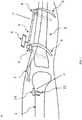
devices femoral portion tibial portion 24, and afreehand sensor 12. Thefemoral portion sensor rod 4, as described in greater detail below with reference toFIGS. 1 and2 , and aflat sensor device 10, as described in greater detail below with reference toFIGS. 3 and4 . FIGS. 1-7 show portions ofexample alignment devices FIGS. 1 and2 , thedevice 20 includes afemoral portion 22, atibial portion 24, and afreehand sensor 12, as shown inFIGS. 5-7 . Thefemoral portion 22 of thedevice 20 includes asensor rod 4. Thesensor rod 4 may be, for example, a rod which acts as a housing for a sensor (not shown). The sensor (not shown) may be positioned inside therod 4. The sensor (not shown) may also be collinear with therod 4, such that the position of therod 4 matches the alignment of the sensor. Therod 4 can be inserted retrograde (from the lower end of femur) into the femoral intramedullary canal. Therod 4 has a tape orchord 7 at one end which can be used to aid its removal from the canal. Therod 4 is henceforth called femoral intramedullary sensor ("FIS") 4. Once inserted into thefemur 1, theFIS 4 acts as a reference for the anatomical axis of the femoral shaft.- As shown in
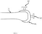
FIGS. 3 and4 , thedevice 30 includes afemoral portion 32 and atibial portion 24. Thefemoral portion 32 of thedevice 30 includes aflat sensor device 10. Theflat sensor device 10 may include, for example, a housing and a sensor (not shown) positioned within the housing. Thesensor 10 within the housing will have at least one of a three-axis accelerometer and a three-axis gyroscope. At least one of thesensors sensor 4 orsensor 10. Theflat sensor device 10 may attach on the front of the patient's femur to position the sensor (not shown) for extramedullary alignment. - The
flat device 10 can be fixed to the surface of thefemur 1. Typically, this would be the anterior (front) aspect, but it can be on any side or part of thefemur 1. Theflat device 10 has afixation mechanism 11 to fix theflat device 10 to thefemur 1. Theclamp 11 on the housing of theextramedullary sensor 10 may be, for example, designed to include screws, clamps, pegs or any other suitable method of fixation. This is henceforth referred to as femoral extramedullary sensor ("FES") 10. - Each of the
sensor rod 4 andsensor device 10 may have at least one of a three-axis accelerometer and a three-axis gyroscope. At least one of thesensor rod 4 andsensor device 10 may be configured to monitor the orientation in a three dimensional coordinate reference system and to generate orientation data corresponding to the orientation of therod 4 and/ordevice 10. Therod 4 may be a housing to hold a sensor. The sensor may be collinear with therod 4, thereby, allowing for the position of therod 4 to match the alignment of the sensor. Similarly for theextramedullary sensor 10, the attachment on the front of thefemur 1 is the housing for thesensor - Although not shown, it is also contemplated that the
alignment devices sensor rod 4, as described in greater detail above with reference toFIGS. 1 and2 , and aflat sensor device 10, as described in greater detail above with reference toFIGS. 3 and4 . - The
tibial portion 24 of thedevices sensor rod 5 mounted on twoclamps 8. Thesensor rod 5 may include, for example, a housing and a sensor (not shown). The sensor (not shown) may be included in the housing of thesensor rod 5. The axis of the sensor (not shown) and the housing may be positioned collinear to allow the axis of the sensor (not shown) to be matched to the anatomic axis of the tibia when therod 5 is aligned to the anatomic tibial axis. Thesensor rod 5 within the housing may have, for example, at least one of a three-axis accelerometer and a three-axis gyroscope. Thesensor rod 5 may be, for example, configured to monitor orientation in the three dimensional coordinate reference system and to generate orientation data corresponding to the orientation of thesensor rod 5. The axis of thesensor 5 and the housing may be, for example, collinear. In one embodiment, the axis of thesensor 5 can be matched to the tibial axis if therod 5 is matched to the tibial axis. The housing of thesensor rod 5 may be attached to the patient's leg by, for example, clamps8 including pegs, screws or other fasteners. - The
clamps 8 allow adjustment of the position of thesensor rod 5, so that it can be aligned in relation to thetibia 2, or the mechanical axis of the patient's leg. Theclamps 8 may include, for example, spring loaded arms that may be opened and closed around the patient's leg. It is also contemplated that theclamps 8 may be, for example, two separate arms that may be attached together around the patient's leg to position and secure thesensor rod 5 to the patient. Further, it is also contemplated that the clamps may be, for example, an elastic band or strap that extends around the patient's leg and fastened together at each end by, for example, a hook, clasp, or other fastener, or any other method for attachment to allow for stable contact. - The
clamps 8 also may include a movable joint positioned between theclamps 8 and the housing of thesensor rod 5. The movable joint allows thesensor rod 5 to be pulled forward or backwards, on either side (medially and laterally) or proximally / distally (up or down) while theclamps 8 remain fixed to the patient's leg. - The
clamps 8 are attached to twocurved arms 9, which help to secure thetibial portion 24 to the leg. It is intended that, once thecurved arms 9 and clamps 8 are mounted, thetibial sensor 5 is parallel to the shaft of thetibia 2. - The
sensor rod 5 is connected to ascreen 6 by any known means. Thescreen 6 displays the relationship of thefemoral sensors 4 and/or 10 to thetibial sensor 5. Thescreen 6 may display, for example, an image showing the position of thesensors 4 and/or 10 and the patient's leg, as well as numbers indicating the angle, in degrees, between the two sensors. - The connection can be articulated to allow convenient positioning of the
sensor rod 5, so that it can be visualised by the operator. It may be equipped with auditory signals which indicate when thefemoral sensors 4 and/or 10 are aligned with thetibial sensor 5. The auditory signals would be broadcast through a speaker (not shown) that may be contained within the housing of thedisplay 6. - It would be possible to connect the
display 6 to an external computer for the purpose of storage, processing, display or printing of information. Thedisplay unit 6 may be directly incorporated into thesensor 5 so as to make it a combined unit. Thesensor rod 4,flat sensor device 10, and thesensor rod 5 may each communicate wirelessly, be wired, or a combination of wired and wirelessly with thedisplay 6. - In
FIGS. 1 and2 , the femoralintramedullary sensor 4 has atape 7 fixed at one end. This can be either a single strand or more than one strand and thetape 7 may be useful in extraction of therod 4 before final implantation of the femoral component. - The shape of the femoral
intramedullary sensor 4 is intended to be, for example, cylindrical, although any other shape which can be accommodated in the femoral canal may also be used. Thesensor 4 may be expansible to contour itself to the shape of the medullary canal. Theentire alignment instrument alignment instruments intramedullary sensor 4 can be removed and reinserted into the medullary canal multiple times during a knee replacement procedure in order to permit adjustments to bone cuts or prostheses positioning. Insertion and removal can be effected whilst the knee joint under consideration is bent at an angle, such as 90° for example, thereby exposing the canal for insertion/removal. - A channel is made into the femur as part of the standard technique in knee replacement and the same channel can be used for the femoral
intramedullary sensor 4. - The
alignment devices freehand sensor 12, as shown inFIGS. 5-7 . Thefreehand sensor 12 may include a housing and a sensor. Thesensor 12 may have at least one of a three-axis accelerometer and a three axis gyroscope. Thesensor 12 may be, for example, configured to monitor orientation in the three dimensional coordinate reference system and to generate orientation data corresponding to the orientation of therod 12. - As shown in
FIG. 5 , thefreehand sensor 12 includes twoblocks Block 13 may have a fixed attachment to therod 12. Thefreehand sensor 12 includes a rod for housing for the sensor (not shown). Theblocks freehand sensor rod 12 along the axis of theblocks block block other block Block 14 may be mobile side to side to allow placement against the femoral and tibial trial components of different sizes.Block 14 may move within, for example, a track in therod 12 which is aligned for side to side motion of theblock 14. Theblocks intramedullary rod sensor 4. Theblocks blocks blocks rod 12 is placed in an anterior-posterior direction on the cut surface of tibia, the posterior slope on the tibia can be determined in relation to the tibial axis given byrod 12. - The
freehand sensor 12 can be placed against the distal (lower) end of the femoral component and this will allow measurement of the varus and valgus angle offemoral trial component 15 in relation to theintramedullary sensor 4. - Referring now to
FIG. 6 , thesensor 12 can also be placed on the anterior surface offemoral trial component 15 to show the rotation of thefemoral trial 15. Thesensor 12 may be held against thefemoral trial component 15 while measurements are taken. - The tibial trial can be matched to
femoral trial 15 on the basis of this measurement. - As shown in
FIG. 7 , thefreehand sensor 12 may also be placed on the cut surface oftibia 1, and this allows checking the varus or valgus alignment of the tibial cut in relation to the tibial axis. Additionally, thetibial trial 16 can be placed on the tibial surface and alignment checked. - The device, with its various components, allows checking of a range of alignment indices in knee replacement surgery. If the desired alignment is not achieved, further surgical procedures using traditional instruments are carried out to correct the alignment and the
devices - A method of using an
alignment device FIG. 8 and described in greater detail below. The method may include, for example, performing a clinical assessment on a patient'sleg 100, surgical exposure of the knee joint110, selecting and attaching at least one femoral sensor to the patient'sfemur 120, selecting and attaching to tibial sensor to the patient'stibia 130, recording measurements of the relative position of thesensors 140, removing at least one femoral sensor andtibial sensor 150, preparing the patient's femur andtibia 160, reinserting the femoral andtibial sensors 170, placement of trial implants and checking the relative alignment ofsensors 180, using the handheld sensor to check the alignment oftrial implants 190, removal of trial implants and sensors for making any further adjustments using standard instruments to achieve the desired collection ofdeformities 200, reinsertion of sensors and trial implants to ensure desired correction and alignment has been achieved210, using the handheld sensor to again check alignment oftrial implants 220, recording accurate correction of deformities and restoration ofalignment 230, removing the femoral and tibial sensors to complete insertion ofdefinitive implant 240, using the hand held sensor to check the final alignment of implants and record themeasurements 250, and using the femoral and tibial sensors to measure and record thefinal leg alignment 260. - With continued reference to
FIG. 8 , a clinical assessment is made to check for limb alignment, any fixed flexion deformities, range of flexion and various other parameters prior to the knee replacement operation. - At the time of the knee replacement operation, the initial step is exposure of the knee. The preparation of the
femur 1 can be done in various ways. Traditional femoral jigs involve making a hole in the distal femur to gain entry into the medullary canal. In this situation, the femoralintramedullary sensor 4 may be employed. With the development of patient specific instruments, a femoral canal entry is not required, and in that situation theextramedullary sensor 10 may be used. In addition, with patients that have an obstructed or occupied femoral canal from, for example, previous trauma or surgery, anextramedullary sensor 10 may be used. Such trauma or surgery situations may include, but are not limited to, femoral intramedullary rods, previous trauma, femoral stems from an existing knee replacement, long stem femoral components from the hip, or metalwork used in fracture stabilization. - If the
femoral sensor 4 is selected, then the appropriate sizedfemoral sensor 4 is inserted into the patient. Next, thetibial sensor 5 is mounted on the leg and the relative position of the twosensors sensors - If the
femoral extramedullary sensor 10 is selected, then thefemoral extramedullary sensor 10 can be calibrated with regards to theintramedullary sensor 4. Once theextramedullary sensor 10 is calibrated, theintramedullary sensor 4 may be removed. Theextramedullary sensor 10 may be used along with thetibial sensor 5, without the need forintramedullary sensor 4. This would be useful in situations where the femoral canal is obstructed or occupied. - When the femoral canal is obstructed or occupied, the
extramedullary sensor 10 may be used as a reference, without calibration by placing thesensor 10 along the anterior surface of femur. Alternatively, thesensor 10 may be used in computer navigation surgery to find the centre of the femoral head. The centre of the femoral head may be found by placing thesensor 10 on the patient's femur and moving the femur in different planes. The data obtained from thesensor 10 while the patient's femur is moved may then be used to deduce the centre of the femoral head. - An example of when the femoral canal may be obstructed is revision knee surgery using femoral stems. The relative position of the
extramedullary sensor 10 and thetibial sensor 5 may be checked. The relative positions may be checked by moving the leg from full extension to flexion. As the leg is moved, the relative position ofsensors - The
clamp 11 on thefemoral extramedullary sensor 10 allows adjustment in position such that theextramedullary sensor 10 can be aligned with theintramedullary sensor 4 when bothsensors sensor tibial sensor 5. - After this, the femoral sensor(s) 4, 10 and
tibial sensor 5 are removed and the knee replacement operation proceeds with standard instruments. Appropriate bone cuts are made to thefemur 1 andtibia 2. Once the cuts are made in thebones trial implants FIGS. 6-7 , may be placed to check balancing clinically. At this stage, the femoral sensor(s) 4, 10 andtibial sensor 5 are again mounted with thetrial implants trials device tibial sensors 4 and/or 10, 5. - The
freehand sensor 12 may be used to check the alignment of the femoral andtibial trial components freehand sensor 12 may be used after the implant components have been inserted into the patient's leg to determine whether the final alignment of the components matches the desired alignment. For example, thesensor 12 may be placed at the distal end of the femoral component to determine the varus or valgus alignment of the femoral component. Similarly, thesensor 12 may be placed on the tibial component to determine the varus or valgus alignment and to measure the posterior slope of the tibia. - This application comprises the principle of detecting the position of one sensor in relation to another. In alternative embodiments, the devices disclosed herein can be applied to any areas of surgery whereby the surgeon wishes to align, or determine the relative alignment of two instruments or bones, or a combination thereof.
- For instance, the alignment devices can be used for insertion of femoral stem in total hip replacement, where one sensor is mounted on the femur and the other is mounted on the handle which is used to insert the femoral stem. It can also be used in elbow surgery to determine the relationship between the humerus and forearm, and to objectively document the range of movement. It can also be used in trauma surgery, where documentation of range of movement is required, with one sensor mounted on either side of the joint to be tested.
- The terminology used herein is for the purpose of describing particular embodiments only and is not intended to be limiting of the invention. As used herein, the singular forms "a", "an" and "the" are intended to include the plural forms as well, unless the context clearly indicates otherwise. It will be further understood that the terms "comprise" (and any form of comprise, such as "comprises" and "comprising"), "have" (and any form of have, such as "has", and "having"), "include" (and any form of include, such as "includes" and "including"), and "contain" (and any form of contain, such as "contains" and "containing") are open-ended linking verbs. As a result, a method or device that "comprises," "has," "includes," or "contains" one or more steps or elements possesses those one or more steps or elements, but is not limited to possessing only those one or more steps or elements. Likewise, a step of a method or an element of a device that "comprises," "has," "includes," or "contains" one or more features possesses those one or more features, but is not limited to possessing only those one or more features. Furthermore, a device or structure that is configured in a certain way is configured in at least that way, but may also be configured in ways that are not listed.
- The invention has been described with reference to the preferred embodiments. It will be understood that the architectural and operational embodiments described herein are exemplary of a plurality of possible arrangements to provide the same general features, characteristics, and general system operation. Attention is directed to the claims hereinafter appearing which define the scope of the invention.
Claims (16)
- An alignment device (20; 30) for aligning femoral and tibial bones (1, 2) at a knee joint (3), the device comprising:a femoral portion (22; 32) to be coupled to the femoral bone (1), and comprising either an intramedullary rod sensor (4) or a flat device comprising an extramedullary sensor (10); anda tibial portion (24) to be mounted on the tibial bone(2), and comprising a sensor rod (5) mounted on two clamps (8) and including a sensor on the tibial portion (24) to enable determination of femoral and tibial axis in relation to each other.
- The alignment device of claim 1, wherein the femoral portion (22; 32) and the tibial portion (24) are connectable through wires.
- The alignment device of claim 1, wherein the femoral portion (22; 32) and the tibial portion (24) are connectable wirelessly.
- The alignment device of claim 1, wherein a long axis of the femoral portion (22; 32) is parallel to the plane of the long axis of the femoral shaft.
- The alignment device of claim 1, wherein a long axis of the tibial portion (24) is parallel to the plane of the long axis of the tibial shaft.
- The alignment device of claim 1, wherein the femoral (22; 32) and tibial (24) portions are made from a material selected from a sterilisable material and a disposable material.
- The alignment device of claim 1, wherein the sensor on the tibial portion (24) comprises:
at least one of a three-axis accelerometer and a three-axis gyroscope. - The alignment device of claim 1, wherein the alignment device (20; 30) further comprises:
a display (6) and wherein the display (6) is wirelessly coupled to the sensor. - The alignment device of claim 1, wherein at least one of the sensors (4, 10) is configured to monitor orientation in a three-dimensional coordinate reference system and to generate orientation data corresponding to the orientation of sensor (4) or sensor 10), and sensor rod (5) is configured to monitor orientation in the three dimensional coordinate reference system and to generate orientation data corresponding to the orientation of the sensor rod (5), whereby the relative alignment of a femoral and tibial axis is recordable.
- The alignment device of claim 1, wherein at least one sensor (4; 10) comprises:
at least one of a three-axis accelerometer and a three-axis gyroscope. - The alignment device of claim 1, wherein the at least one sensor (4; 10) comprises:
a housing for holding the sensor. - The alignment device of claim 1, wherein at least one additional sensor (12) is provided as a freehand sensor (12).
- The alignment device of claim 12, wherein at least one additional sensor (12) comprises:
at least one of a three-axis accelerometer and a three-axis gyroscope. - The alignment device of claim 9, wherein the at least one sensor (10) is a femoral extramedullary flat sensor (10) which is provided with a clamp (11) for coupling the flat sensor (10) to the femoral bone.
- The alignment device of claim 14, comprising both an intramedullary rod sensor (4) and a femoral extramedullary sensor (10) positioned such that the extramedullary sensor (10) is alignable with the intramedullary sensor (4) and each of the intramedullary rod sensor (4) and a femoral extramedullary sensor (10) is detectable individually, or in combination, by the tibial rod sensor (5).
- An alignment device (20; 30) for aligning first and second bones (1, 2) at a joint (3), the device comprising:a first portion (22; 32) to be coupled to the first bone (1), and comprising either an intramedullary rod sensor (4) or a flat device comprising an extramedullary sensor (10); anda second portion (24) to be mounted on the second bone (2), and comprising a sensor rod (5) mounted on two clamps (8) and including a sensor on the second portion (24) to enable determination of first bone and second bone axis in relation to each other.
Applications Claiming Priority (2)
| Application Number | Priority Date | Filing Date | Title |
|---|---|---|---|
| US201562262695P | 2015-12-03 | 2015-12-03 | |
| PCT/GB2016/053832WO2017093769A1 (en) | 2015-12-03 | 2016-12-05 | Alignment device |
Publications (2)
| Publication Number | Publication Date |
|---|---|
| EP3383284A1 EP3383284A1 (en) | 2018-10-10 |
| EP3383284B1true EP3383284B1 (en) | 2020-10-28 |
Family
ID=57570084
Family Applications (1)
| Application Number | Title | Priority Date | Filing Date |
|---|---|---|---|
| EP16812788.4AActiveEP3383284B1 (en) | 2015-12-03 | 2016-12-05 | Alignment device |
Country Status (4)
| Country | Link |
|---|---|
| US (1) | US20180289286A1 (en) |
| EP (1) | EP3383284B1 (en) |
| CN (1) | CN108495591A (en) |
| WO (1) | WO2017093769A1 (en) |
Families Citing this family (14)
| Publication number | Priority date | Publication date | Assignee | Title |
|---|---|---|---|---|
| US7559931B2 (en) | 2003-06-09 | 2009-07-14 | OrthAlign, Inc. | Surgical orientation system and method |
| AU2009273863B2 (en) | 2008-07-24 | 2014-12-18 | OrthAlign, Inc. | Systems and methods for joint replacement |
| AU2009291743B2 (en) | 2008-09-10 | 2015-02-05 | Orthalign, Inc | Hip surgery systems and methods |
| US10869771B2 (en) | 2009-07-24 | 2020-12-22 | OrthAlign, Inc. | Systems and methods for joint replacement |
| US9649160B2 (en) | 2012-08-14 | 2017-05-16 | OrthAlign, Inc. | Hip replacement navigation system and method |
| US10363149B2 (en) | 2015-02-20 | 2019-07-30 | OrthAlign, Inc. | Hip replacement navigation system and method |
| CA3056495A1 (en) | 2017-03-14 | 2018-09-20 | OrthAlign, Inc. | Soft tissue measurement & balancing systems and methods |
| CN109009582B (en)* | 2018-08-29 | 2020-07-28 | 中山市中医院 | Knee joint replacement measuring device and measuring system |
| AU2021238350A1 (en)* | 2020-03-20 | 2022-09-29 | OrthAlign, Inc. | Systems and methods for limb alignment |
| CN111956296A (en)* | 2020-07-10 | 2020-11-20 | 嘉思特华剑医疗器材(天津)有限公司 | Internal and external ankle positioning module for tibial high-position osteotomy surgical guide plate |
| CN112754665A (en)* | 2021-01-22 | 2021-05-07 | 吉林大学 | A orthopedics intelligent robot for high-order osteotomy of shin bone |
| CN114053003B (en)* | 2021-11-16 | 2023-06-27 | 陕西麟德惯性电气有限公司 | E-TKA replacement system |
| WO2024187245A1 (en)* | 2023-03-16 | 2024-09-19 | Viortec Pty Ltd | Surgical clamp |
| CN116712066B (en)* | 2023-06-08 | 2025-09-05 | 江苏泰科博曼医疗器械有限公司 | A leg positioning clamping structure and clamping method thereof |
Family Cites Families (5)
| Publication number | Priority date | Publication date | Assignee | Title |
|---|---|---|---|---|
| US20050113846A1 (en)* | 2001-02-27 | 2005-05-26 | Carson Christopher P. | Surgical navigation systems and processes for unicompartmental knee arthroplasty |
| US7048741B2 (en)* | 2002-05-10 | 2006-05-23 | Swanson Todd V | Method and apparatus for minimally invasive knee arthroplasty |
| US20110213221A1 (en)* | 2005-03-29 | 2011-09-01 | Roche Martin W | Method for Detecting Body Parameters |
| US9549742B2 (en)* | 2012-05-18 | 2017-01-24 | OrthAlign, Inc. | Devices and methods for knee arthroplasty |
| WO2015038979A1 (en)* | 2013-09-13 | 2015-03-19 | Orthosensor, Inc. | Kinetic assessment and alignment of the muscular-skeletal system and method therefor |
- 2016
- 2016-12-05WOPCT/GB2016/053832patent/WO2017093769A1/ennot_activeCeased
- 2016-12-05CNCN201680078853.4Apatent/CN108495591A/enactivePending
- 2016-12-05EPEP16812788.4Apatent/EP3383284B1/enactiveActive
- 2018
- 2018-06-01USUS15/995,324patent/US20180289286A1/ennot_activeAbandoned
Non-Patent Citations (1)
| Title |
|---|
| None* |
Also Published As
| Publication number | Publication date |
|---|---|
| EP3383284A1 (en) | 2018-10-10 |
| WO2017093769A1 (en) | 2017-06-08 |
| US20180289286A1 (en) | 2018-10-11 |
| CN108495591A (en) | 2018-09-04 |
Similar Documents
| Publication | Publication Date | Title |
|---|---|---|
| EP3383284B1 (en) | Alignment device | |
| AU680267B2 (en) | Method and apparatus for locating functional structures of the lower leg during knee surgery | |
| EP1226788B1 (en) | Computer-assisted knee arthroplasty system | |
| US5376093A (en) | Tibiofemoral alignment guide | |
| US9730712B2 (en) | Alignment devices and methods | |
| US6991655B2 (en) | Computer assisted insertion of an artificial hip joint | |
| AU2008323521B2 (en) | Leg alignment and length measurement in hip replacement surgery | |
| CN111329584B (en) | Surgical planning and method | |
| JP2018149403A (en) | Device and method for knee arthroplasty | |
| US20130184713A1 (en) | Anatomical Alignment Systems and Methods | |
| US20090076519A1 (en) | System, method and tool for ensuring correct insertion of an artificial hip joint | |
| KR20170089878A (en) | A method and apparatus for joint reconstruction | |
| JP2018509208A (en) | Surgical aids for joints | |
| US10582982B2 (en) | Disposable multi-purpose tool for total knee arthroplasty | |
| JP2007202950A (en) | Leg holding tool for surgery robot | |
| WO2010125474A2 (en) | Device and method of determination of the knee flexion axis in computer assisted surgery | |
| Konermann et al. | CT-free navigation including soft-tissue balancing: LCS-TKA and VectorVision systems | |
| US12383342B2 (en) | Pinless navigation system | |
| US20240164914A1 (en) | Systems and Methods for Selecting Artificial Femoral Components | |
| US20200337865A1 (en) | Systems and Methods for Selecting Artificial Femoral Components | |
| Strauss et al. | Navigation and soft-tissue balancing of LCS total knee arthroplasty | |
| CN120304910A (en) | Intraoperatively adjustable knee joint surgical guide device and method of use thereof | |
| CN119770239A (en) | A load and gap balancing system for knee replacement surgery | |
| Strauss et al. | Navigation and Soft-Tissue Balancing of LCS TKA | |
| GB2492339A (en) | Alignment device for the knee |
Legal Events
| Date | Code | Title | Description |
|---|---|---|---|
| STAA | Information on the status of an ep patent application or granted ep patent | Free format text:STATUS: UNKNOWN | |
| STAA | Information on the status of an ep patent application or granted ep patent | Free format text:STATUS: THE INTERNATIONAL PUBLICATION HAS BEEN MADE | |
| PUAI | Public reference made under article 153(3) epc to a published international application that has entered the european phase | Free format text:ORIGINAL CODE: 0009012 | |
| STAA | Information on the status of an ep patent application or granted ep patent | Free format text:STATUS: REQUEST FOR EXAMINATION WAS MADE | |
| 17P | Request for examination filed | Effective date:20180629 | |
| AK | Designated contracting states | Kind code of ref document:A1 Designated state(s):AL AT BE BG CH CY CZ DE DK EE ES FI FR GB GR HR HU IE IS IT LI LT LU LV MC MK MT NL NO PL PT RO RS SE SI SK SM TR | |
| AX | Request for extension of the european patent | Extension state:BA ME | |
| DAV | Request for validation of the european patent (deleted) | ||
| DAX | Request for extension of the european patent (deleted) | ||
| GRAP | Despatch of communication of intention to grant a patent | Free format text:ORIGINAL CODE: EPIDOSNIGR1 | |
| STAA | Information on the status of an ep patent application or granted ep patent | Free format text:STATUS: GRANT OF PATENT IS INTENDED | |
| INTG | Intention to grant announced | Effective date:20191210 | |
| GRAJ | Information related to disapproval of communication of intention to grant by the applicant or resumption of examination proceedings by the epo deleted | Free format text:ORIGINAL CODE: EPIDOSDIGR1 | |
| STAA | Information on the status of an ep patent application or granted ep patent | Free format text:STATUS: REQUEST FOR EXAMINATION WAS MADE | |
| GRAP | Despatch of communication of intention to grant a patent | Free format text:ORIGINAL CODE: EPIDOSNIGR1 | |
| STAA | Information on the status of an ep patent application or granted ep patent | Free format text:STATUS: GRANT OF PATENT IS INTENDED | |
| INTC | Intention to grant announced (deleted) | ||
| RAP1 | Party data changed (applicant data changed or rights of an application transferred) | Owner name:AGARWAL, RAJIV Owner name:AGARWAL, SANJEEV | |
| RIN1 | Information on inventor provided before grant (corrected) | Inventor name:AGARWAL, RAJIV Inventor name:AGARWAL, SANJEEV | |
| INTG | Intention to grant announced | Effective date:20200507 | |
| GRAS | Grant fee paid | Free format text:ORIGINAL CODE: EPIDOSNIGR3 | |
| GRAA | (expected) grant | Free format text:ORIGINAL CODE: 0009210 | |
| STAA | Information on the status of an ep patent application or granted ep patent | Free format text:STATUS: THE PATENT HAS BEEN GRANTED | |
| AK | Designated contracting states | Kind code of ref document:B1 Designated state(s):AL AT BE BG CH CY CZ DE DK EE ES FI FR GB GR HR HU IE IS IT LI LT LU LV MC MK MT NL NO PL PT RO RS SE SI SK SM TR | |
| REG | Reference to a national code | Ref country code:GB Ref legal event code:FG4D | |
| REG | Reference to a national code | Ref country code:CH Ref legal event code:EP | |
| REG | Reference to a national code | Ref country code:AT Ref legal event code:REF Ref document number:1327389 Country of ref document:AT Kind code of ref document:T Effective date:20201115 | |
| REG | Reference to a national code | Ref country code:DE Ref legal event code:R096 Ref document number:602016046810 Country of ref document:DE | |
| REG | Reference to a national code | Ref country code:IE Ref legal event code:FG4D | |
| REG | Reference to a national code | Ref country code:AT Ref legal event code:MK05 Ref document number:1327389 Country of ref document:AT Kind code of ref document:T Effective date:20201028 | |
| REG | Reference to a national code | Ref country code:NL Ref legal event code:MP Effective date:20201028 | |
| PG25 | Lapsed in a contracting state [announced via postgrant information from national office to epo] | Ref country code:NO Free format text:LAPSE BECAUSE OF FAILURE TO SUBMIT A TRANSLATION OF THE DESCRIPTION OR TO PAY THE FEE WITHIN THE PRESCRIBED TIME-LIMIT Effective date:20210128 Ref country code:PT Free format text:LAPSE BECAUSE OF FAILURE TO SUBMIT A TRANSLATION OF THE DESCRIPTION OR TO PAY THE FEE WITHIN THE PRESCRIBED TIME-LIMIT Effective date:20210301 Ref country code:RS Free format text:LAPSE BECAUSE OF FAILURE TO SUBMIT A TRANSLATION OF THE DESCRIPTION OR TO PAY THE FEE WITHIN THE PRESCRIBED TIME-LIMIT Effective date:20201028 Ref country code:FI Free format text:LAPSE BECAUSE OF FAILURE TO SUBMIT A TRANSLATION OF THE DESCRIPTION OR TO PAY THE FEE WITHIN THE PRESCRIBED TIME-LIMIT Effective date:20201028 Ref country code:GR Free format text:LAPSE BECAUSE OF FAILURE TO SUBMIT A TRANSLATION OF THE DESCRIPTION OR TO PAY THE FEE WITHIN THE PRESCRIBED TIME-LIMIT Effective date:20210129 | |
| REG | Reference to a national code | Ref country code:LT Ref legal event code:MG4D | |
| PG25 | Lapsed in a contracting state [announced via postgrant information from national office to epo] | Ref country code:BG Free format text:LAPSE BECAUSE OF FAILURE TO SUBMIT A TRANSLATION OF THE DESCRIPTION OR TO PAY THE FEE WITHIN THE PRESCRIBED TIME-LIMIT Effective date:20210128 Ref country code:LV Free format text:LAPSE BECAUSE OF FAILURE TO SUBMIT A TRANSLATION OF THE DESCRIPTION OR TO PAY THE FEE WITHIN THE PRESCRIBED TIME-LIMIT Effective date:20201028 Ref country code:PL Free format text:LAPSE BECAUSE OF FAILURE TO SUBMIT A TRANSLATION OF THE DESCRIPTION OR TO PAY THE FEE WITHIN THE PRESCRIBED TIME-LIMIT Effective date:20201028 Ref country code:IS Free format text:LAPSE BECAUSE OF FAILURE TO SUBMIT A TRANSLATION OF THE DESCRIPTION OR TO PAY THE FEE WITHIN THE PRESCRIBED TIME-LIMIT Effective date:20210228 Ref country code:AT Free format text:LAPSE BECAUSE OF FAILURE TO SUBMIT A TRANSLATION OF THE DESCRIPTION OR TO PAY THE FEE WITHIN THE PRESCRIBED TIME-LIMIT Effective date:20201028 Ref country code:ES Free format text:LAPSE BECAUSE OF FAILURE TO SUBMIT A TRANSLATION OF THE DESCRIPTION OR TO PAY THE FEE WITHIN THE PRESCRIBED TIME-LIMIT Effective date:20201028 Ref country code:SE Free format text:LAPSE BECAUSE OF FAILURE TO SUBMIT A TRANSLATION OF THE DESCRIPTION OR TO PAY THE FEE WITHIN THE PRESCRIBED TIME-LIMIT Effective date:20201028 | |
| PG25 | Lapsed in a contracting state [announced via postgrant information from national office to epo] | Ref country code:NL Free format text:LAPSE BECAUSE OF FAILURE TO SUBMIT A TRANSLATION OF THE DESCRIPTION OR TO PAY THE FEE WITHIN THE PRESCRIBED TIME-LIMIT Effective date:20201028 Ref country code:HR Free format text:LAPSE BECAUSE OF FAILURE TO SUBMIT A TRANSLATION OF THE DESCRIPTION OR TO PAY THE FEE WITHIN THE PRESCRIBED TIME-LIMIT Effective date:20201028 | |
| REG | Reference to a national code | Ref country code:DE Ref legal event code:R119 Ref document number:602016046810 Country of ref document:DE | |
| PG25 | Lapsed in a contracting state [announced via postgrant information from national office to epo] | Ref country code:SM Free format text:LAPSE BECAUSE OF FAILURE TO SUBMIT A TRANSLATION OF THE DESCRIPTION OR TO PAY THE FEE WITHIN THE PRESCRIBED TIME-LIMIT Effective date:20201028 Ref country code:LT Free format text:LAPSE BECAUSE OF FAILURE TO SUBMIT A TRANSLATION OF THE DESCRIPTION OR TO PAY THE FEE WITHIN THE PRESCRIBED TIME-LIMIT Effective date:20201028 Ref country code:CZ Free format text:LAPSE BECAUSE OF FAILURE TO SUBMIT A TRANSLATION OF THE DESCRIPTION OR TO PAY THE FEE WITHIN THE PRESCRIBED TIME-LIMIT Effective date:20201028 Ref country code:EE Free format text:LAPSE BECAUSE OF FAILURE TO SUBMIT A TRANSLATION OF THE DESCRIPTION OR TO PAY THE FEE WITHIN THE PRESCRIBED TIME-LIMIT Effective date:20201028 Ref country code:SK Free format text:LAPSE BECAUSE OF FAILURE TO SUBMIT A TRANSLATION OF THE DESCRIPTION OR TO PAY THE FEE WITHIN THE PRESCRIBED TIME-LIMIT Effective date:20201028 Ref country code:RO Free format text:LAPSE BECAUSE OF FAILURE TO SUBMIT A TRANSLATION OF THE DESCRIPTION OR TO PAY THE FEE WITHIN THE PRESCRIBED TIME-LIMIT Effective date:20201028 | |
| REG | Reference to a national code | Ref country code:CH Ref legal event code:PL | |
| PG25 | Lapsed in a contracting state [announced via postgrant information from national office to epo] | Ref country code:DK Free format text:LAPSE BECAUSE OF FAILURE TO SUBMIT A TRANSLATION OF THE DESCRIPTION OR TO PAY THE FEE WITHIN THE PRESCRIBED TIME-LIMIT Effective date:20201028 Ref country code:MC Free format text:LAPSE BECAUSE OF FAILURE TO SUBMIT A TRANSLATION OF THE DESCRIPTION OR TO PAY THE FEE WITHIN THE PRESCRIBED TIME-LIMIT Effective date:20201028 | |
| PLBE | No opposition filed within time limit | Free format text:ORIGINAL CODE: 0009261 | |
| REG | Reference to a national code | Ref country code:BE Ref legal event code:MM Effective date:20201231 | |
| STAA | Information on the status of an ep patent application or granted ep patent | Free format text:STATUS: NO OPPOSITION FILED WITHIN TIME LIMIT | |
| GBPC | Gb: european patent ceased through non-payment of renewal fee | Effective date:20210128 | |
| 26N | No opposition filed | Effective date:20210729 | |
| PG25 | Lapsed in a contracting state [announced via postgrant information from national office to epo] | Ref country code:LU Free format text:LAPSE BECAUSE OF NON-PAYMENT OF DUE FEES Effective date:20201205 Ref country code:IT Free format text:LAPSE BECAUSE OF FAILURE TO SUBMIT A TRANSLATION OF THE DESCRIPTION OR TO PAY THE FEE WITHIN THE PRESCRIBED TIME-LIMIT Effective date:20201028 Ref country code:FR Free format text:LAPSE BECAUSE OF NON-PAYMENT OF DUE FEES Effective date:20201228 Ref country code:IE Free format text:LAPSE BECAUSE OF NON-PAYMENT OF DUE FEES Effective date:20201205 Ref country code:AL Free format text:LAPSE BECAUSE OF FAILURE TO SUBMIT A TRANSLATION OF THE DESCRIPTION OR TO PAY THE FEE WITHIN THE PRESCRIBED TIME-LIMIT Effective date:20201028 | |
| PG25 | Lapsed in a contracting state [announced via postgrant information from national office to epo] | Ref country code:LI Free format text:LAPSE BECAUSE OF NON-PAYMENT OF DUE FEES Effective date:20201231 Ref country code:GB Free format text:LAPSE BECAUSE OF NON-PAYMENT OF DUE FEES Effective date:20210128 Ref country code:CH Free format text:LAPSE BECAUSE OF NON-PAYMENT OF DUE FEES Effective date:20201231 Ref country code:DE Free format text:LAPSE BECAUSE OF NON-PAYMENT OF DUE FEES Effective date:20210701 Ref country code:SI Free format text:LAPSE BECAUSE OF FAILURE TO SUBMIT A TRANSLATION OF THE DESCRIPTION OR TO PAY THE FEE WITHIN THE PRESCRIBED TIME-LIMIT Effective date:20201028 | |
| PG25 | Lapsed in a contracting state [announced via postgrant information from national office to epo] | Ref country code:IS Free format text:LAPSE BECAUSE OF FAILURE TO SUBMIT A TRANSLATION OF THE DESCRIPTION OR TO PAY THE FEE WITHIN THE PRESCRIBED TIME-LIMIT Effective date:20210228 Ref country code:TR Free format text:LAPSE BECAUSE OF FAILURE TO SUBMIT A TRANSLATION OF THE DESCRIPTION OR TO PAY THE FEE WITHIN THE PRESCRIBED TIME-LIMIT Effective date:20201028 Ref country code:MT Free format text:LAPSE BECAUSE OF FAILURE TO SUBMIT A TRANSLATION OF THE DESCRIPTION OR TO PAY THE FEE WITHIN THE PRESCRIBED TIME-LIMIT Effective date:20201028 Ref country code:CY Free format text:LAPSE BECAUSE OF FAILURE TO SUBMIT A TRANSLATION OF THE DESCRIPTION OR TO PAY THE FEE WITHIN THE PRESCRIBED TIME-LIMIT Effective date:20201028 | |
| PG25 | Lapsed in a contracting state [announced via postgrant information from national office to epo] | Ref country code:MK Free format text:LAPSE BECAUSE OF FAILURE TO SUBMIT A TRANSLATION OF THE DESCRIPTION OR TO PAY THE FEE WITHIN THE PRESCRIBED TIME-LIMIT Effective date:20201028 | |
| PG25 | Lapsed in a contracting state [announced via postgrant information from national office to epo] | Ref country code:BE Free format text:LAPSE BECAUSE OF NON-PAYMENT OF DUE FEES Effective date:20201231 |