EP3382714B1 - Method to project a two dimensional image/photo onto a 3d reconstruction, such as an epicardial view of heart - Google Patents
Method to project a two dimensional image/photo onto a 3d reconstruction, such as an epicardial view of heartDownload PDFInfo
- Publication number
- EP3382714B1 EP3382714B1EP18164954.2AEP18164954AEP3382714B1EP 3382714 B1EP3382714 B1EP 3382714B1EP 18164954 AEP18164954 AEP 18164954AEP 3382714 B1EP3382714 B1EP 3382714B1
- Authority
- EP
- European Patent Office
- Prior art keywords
- images
- cardiac
- catheter
- cardiac structure
- processing device
- Prior art date
- Legal status (The legal status is an assumption and is not a legal conclusion. Google has not performed a legal analysis and makes no representation as to the accuracy of the status listed.)
- Active
Links
Images


Classifications
- G—PHYSICS
- G06—COMPUTING OR CALCULATING; COUNTING
- G06T—IMAGE DATA PROCESSING OR GENERATION, IN GENERAL
- G06T17/00—Three dimensional [3D] modelling, e.g. data description of 3D objects
- A—HUMAN NECESSITIES
- A61—MEDICAL OR VETERINARY SCIENCE; HYGIENE
- A61B—DIAGNOSIS; SURGERY; IDENTIFICATION
- A61B5/00—Measuring for diagnostic purposes; Identification of persons
- A61B5/68—Arrangements of detecting, measuring or recording means, e.g. sensors, in relation to patient
- A61B5/6846—Arrangements of detecting, measuring or recording means, e.g. sensors, in relation to patient specially adapted to be brought in contact with an internal body part, i.e. invasive
- A61B5/6847—Arrangements of detecting, measuring or recording means, e.g. sensors, in relation to patient specially adapted to be brought in contact with an internal body part, i.e. invasive mounted on an invasive device
- A61B5/6852—Catheters
- G—PHYSICS
- G16—INFORMATION AND COMMUNICATION TECHNOLOGY [ICT] SPECIALLY ADAPTED FOR SPECIFIC APPLICATION FIELDS
- G16H—HEALTHCARE INFORMATICS, i.e. INFORMATION AND COMMUNICATION TECHNOLOGY [ICT] SPECIALLY ADAPTED FOR THE HANDLING OR PROCESSING OF MEDICAL OR HEALTHCARE DATA
- G16H30/00—ICT specially adapted for the handling or processing of medical images
- G16H30/40—ICT specially adapted for the handling or processing of medical images for processing medical images, e.g. editing
- A—HUMAN NECESSITIES
- A61—MEDICAL OR VETERINARY SCIENCE; HYGIENE
- A61B—DIAGNOSIS; SURGERY; IDENTIFICATION
- A61B18/00—Surgical instruments, devices or methods for transferring non-mechanical forms of energy to or from the body
- A61B18/04—Surgical instruments, devices or methods for transferring non-mechanical forms of energy to or from the body by heating
- A61B18/12—Surgical instruments, devices or methods for transferring non-mechanical forms of energy to or from the body by heating by passing a current through the tissue to be heated, e.g. high-frequency current
- A61B18/14—Probes or electrodes therefor
- A61B18/1482—Probes or electrodes therefor having a long rigid shaft for accessing the inner body transcutaneously in minimal invasive surgery, e.g. laparoscopy
- A—HUMAN NECESSITIES
- A61—MEDICAL OR VETERINARY SCIENCE; HYGIENE
- A61B—DIAGNOSIS; SURGERY; IDENTIFICATION
- A61B5/00—Measuring for diagnostic purposes; Identification of persons
- A61B5/0059—Measuring for diagnostic purposes; Identification of persons using light, e.g. diagnosis by transillumination, diascopy, fluorescence
- A61B5/0082—Measuring for diagnostic purposes; Identification of persons using light, e.g. diagnosis by transillumination, diascopy, fluorescence adapted for particular medical purposes
- A61B5/0084—Measuring for diagnostic purposes; Identification of persons using light, e.g. diagnosis by transillumination, diascopy, fluorescence adapted for particular medical purposes for introduction into the body, e.g. by catheters
- A—HUMAN NECESSITIES
- A61—MEDICAL OR VETERINARY SCIENCE; HYGIENE
- A61B—DIAGNOSIS; SURGERY; IDENTIFICATION
- A61B5/00—Measuring for diagnostic purposes; Identification of persons
- A61B5/06—Devices, other than using radiation, for detecting or locating foreign bodies ; Determining position of diagnostic devices within or on the body of the patient
- A61B5/065—Determining position of the probe employing exclusively positioning means located on or in the probe, e.g. using position sensors arranged on the probe
- A—HUMAN NECESSITIES
- A61—MEDICAL OR VETERINARY SCIENCE; HYGIENE
- A61B—DIAGNOSIS; SURGERY; IDENTIFICATION
- A61B5/00—Measuring for diagnostic purposes; Identification of persons
- A61B5/24—Detecting, measuring or recording bioelectric or biomagnetic signals of the body or parts thereof
- A61B5/25—Bioelectric electrodes therefor
- A—HUMAN NECESSITIES
- A61—MEDICAL OR VETERINARY SCIENCE; HYGIENE
- A61B—DIAGNOSIS; SURGERY; IDENTIFICATION
- A61B5/00—Measuring for diagnostic purposes; Identification of persons
- A61B5/24—Detecting, measuring or recording bioelectric or biomagnetic signals of the body or parts thereof
- A61B5/316—Modalities, i.e. specific diagnostic methods
- A61B5/318—Heart-related electrical modalities, e.g. electrocardiography [ECG]
- A61B5/346—Analysis of electrocardiograms
- A61B5/349—Detecting specific parameters of the electrocardiograph cycle
- A61B5/363—Detecting tachycardia or bradycardia
- G—PHYSICS
- G16—INFORMATION AND COMMUNICATION TECHNOLOGY [ICT] SPECIALLY ADAPTED FOR SPECIFIC APPLICATION FIELDS
- G16H—HEALTHCARE INFORMATICS, i.e. INFORMATION AND COMMUNICATION TECHNOLOGY [ICT] SPECIALLY ADAPTED FOR THE HANDLING OR PROCESSING OF MEDICAL OR HEALTHCARE DATA
- G16H50/00—ICT specially adapted for medical diagnosis, medical simulation or medical data mining; ICT specially adapted for detecting, monitoring or modelling epidemics or pandemics
- G16H50/50—ICT specially adapted for medical diagnosis, medical simulation or medical data mining; ICT specially adapted for detecting, monitoring or modelling epidemics or pandemics for simulation or modelling of medical disorders
- A—HUMAN NECESSITIES
- A61—MEDICAL OR VETERINARY SCIENCE; HYGIENE
- A61B—DIAGNOSIS; SURGERY; IDENTIFICATION
- A61B18/00—Surgical instruments, devices or methods for transferring non-mechanical forms of energy to or from the body
- A61B2018/00315—Surgical instruments, devices or methods for transferring non-mechanical forms of energy to or from the body for treatment of particular body parts
- A61B2018/00345—Vascular system
- A61B2018/00351—Heart
- A—HUMAN NECESSITIES
- A61—MEDICAL OR VETERINARY SCIENCE; HYGIENE
- A61B—DIAGNOSIS; SURGERY; IDENTIFICATION
- A61B18/00—Surgical instruments, devices or methods for transferring non-mechanical forms of energy to or from the body
- A61B2018/00571—Surgical instruments, devices or methods for transferring non-mechanical forms of energy to or from the body for achieving a particular surgical effect
- A61B2018/00577—Ablation
- A—HUMAN NECESSITIES
- A61—MEDICAL OR VETERINARY SCIENCE; HYGIENE
- A61B—DIAGNOSIS; SURGERY; IDENTIFICATION
- A61B18/00—Surgical instruments, devices or methods for transferring non-mechanical forms of energy to or from the body
- A61B2018/00636—Sensing and controlling the application of energy
- A61B2018/00642—Sensing and controlling the application of energy with feedback, i.e. closed loop control
- A—HUMAN NECESSITIES
- A61—MEDICAL OR VETERINARY SCIENCE; HYGIENE
- A61B—DIAGNOSIS; SURGERY; IDENTIFICATION
- A61B2576/00—Medical imaging apparatus involving image processing or analysis
- A61B2576/02—Medical imaging apparatus involving image processing or analysis specially adapted for a particular organ or body part
- A61B2576/023—Medical imaging apparatus involving image processing or analysis specially adapted for a particular organ or body part for the heart
Definitions
- a three-dimensional (3D) electrical mapping systemmay be used to generate a 3D image of the epicardial surface of a heart by integrating one or more epicardial images with a 3D image of the heart that may be generated by real-time 3D location and mapping system for cardiac mapping and ablation.
- the visual representation of the epicardial surface of the heartmay be reconstructed using, for example, an image sensor or camera-based catheter to collect images of the epicardial surface including textural details.
- the systemmay store the image data along with the corresponding catheter location, orientation and/or distance information relative to the heart.
- the location, orientation, and/or distance informationmay be used to reconstruct a 3D textural model of the epicardial surface of the heart.
- WO 2013/044182discloses a system and method for ablation and data visualisation which includes a catheter with a fiber optic waveguide, so that an image can be taken with a camera located outside of the catheter.
- WO 2013/044182neither discloses a camera on the tip of the catheter nor the specific location, orientation and distance sensor claimed herein. Thus WO 2013/044182 represents the closest prior art.
- Cardiac ablationis a medical procedure performed by electrophysiologists that may be used to correct heart rhythm defects, known as arrhythmias, by creating lesions to destroy tissue in the heart that contributes to the rhythm defects.
- arrhythmiathat can be treated using cardiac ablation is atrial fibrillation (AF), which is an abnormal heart rhythm that originates in the atria of the heart.
- AFatrial fibrillation
- Cardiac ablationmay employ long, flexible catheters that may be inserted through a small incision in the groin and through the blood vessels to the heart, and may be used to apply energy (e.g., radio frequency (RF) energy, or extreme cold) to produce small scars or lesions on the tissue to block faulty electrical impulses that may cause the heart rhythm disorders.
- energye.g., radio frequency (RF) energy, or extreme cold
- Real-time three-dimensional (3D) location and mapping technologymay be employed to visualize the exact position and orientation of a catheter within the heart and act as an advanced navigation system to enable the electrophysiologist to visualize and carefully guide the catheter to administer the RF energy in the appropriate locations.
- Goals of cardiac ablationare to remove the arrhythmia to return the patient's heart to a normal heart rhythm or reduce the frequency of arrhythmia and the severity of symptoms in the patient.
- An example of a real-time 3D location and mapping system for cardiac ablationis the CARTO ® 3 System, produced by Biosense Webster ® , Inc., a subsidiary of Johnson & Johnson.
- the CARTO ® 3 Systemuses electromagnetic technology to create 3D maps of a patient's cardiac structure and to display the exact location and orientation of the catheters (or other objects) in the heart.
- the CARTO ® 3 Systemcompensates for patient and cardiac motion to ensure accurate, real-time visualization of the cardiac structures.
- FIG. 1shows an example 3D cardiac map of the heart 100 of a patient generated by a CARTO ® 3 System.
- the location and orientation of a catheter 102is illustrated within the 3D visualization of the heart 100 of the patient.
- the catheter 102may be a therapeutic and/or diagnostic catheter.
- Other objects and images, although not shown,may be included in the 3D visualization shown in FIG. 1 such as, but not limited to, the following: the location and orientation of additional catheters and devices; a 3D synthetic heart model used for orientation within the mapped heart 100; a two-dimensional (2D) image to assist in directional (e.g., up, down, back, forward) orientation; and fluoroscopy images or other background images.
- 2Dtwo-dimensional
- FIG. 2Ais a schematic diagram of an example cardiac mapping and ablation system 200 with integrated real-time 3D location and mapping technology (e.g., CARTO ® 3 System or other 3D location and mapping technology), in accordance with the disclosures herein.
- the cardiac mapping and ablation system 200may include, but is not limited to include, any of the following components: a console system 201; extra-cardiac sensors 214; reference device constellation 215; energy source 219; and/or catheter(s) 220.
- the console system 201may include, but is not limited to include, any of the following components: processing device(s) 202; local storage 208; visual display device 216; and/or operator interface(s) 218.
- Certain elements of the cardiac mapping and ablation system 200may be used directly on, in, and/or in proximity to the patient 205 in order to gather information to be used for visualization, diagnostics, and to perform ablation therapy. This information may be provided to the console system 201 for processing, visualization and operator control and direction, some of which is described below.
- the reference device constellation 215may include a ring of computer-controlled (e.g., controlled by processing device(s) 202) magnets positioned beneath the patient 205.
- the magnetsmay have known and fixed strength and position values that may be used as point of origin references for the magnetic fields in the surrounding space and may provide the reference information to the processing device(s) 202 to be used in producing accurate 3D images of the heart.
- the extra-cardiac sensor(s) 214may be electrodes on the skin of a patient 205, for example.
- the extra-cardiac sensor(s) 214may detect electrical activity of the heart via detection of electrical changes on the skin due to the electrophysiologic pattern of the heart, and provide information on the electrical activity to the processing device(s) 202 to be used in diagnosing arrhythmias and determining a therapeutic course of action.
- Processed versions of the extra-cardiac signals detected by the extra-cardiac sensor(s) 214may be displayed on visual display device 216.
- One or more devicesmay be used on the patient 205 for therapeutic and diagnostic purposes.
- catheter(s) 220are shown and described for these purposes; however, other devices may be used for diagnostics and/or therapeutic treatment.
- One or more catheter(s) 220may be percutaneously inserted by a physician through the patient's 205 vascular system into the heart of the patient 205.
- the catheter(s) 220may be equipped with location and/or electrical sensors for the purpose of gathering information for diagnostic mapping and/or delivering therapeutic treatment (e.g., performing ablation).
- therapeutic treatmente.g., performing ablation
- Different types of catheter(s) 220may be used including, but not limited to, the following example types: fixed catheter; deflectable catheter; bi-directional catheter; uni-directional catheter; tricuspid mapping catheter; halo-shaped tip catheter; basket catheter; and/or lasso-shaped catheter.
- the catheter(s) 220When the catheter(s) 220 is used for performing ablation on a target location (e.g., one or more locations along a path), for example by applying RF energy, the catheter(s) 220 may receive the RF energy from the energy source 219, as may be instructed by the processing device(s) 202. In an example, the catheter(s) 220 may request the RF energy directly from the energy source 219.
- a target locatione.g., one or more locations along a path
- the catheter(s) 220may receive the RF energy from the energy source 219, as may be instructed by the processing device(s) 202.
- the catheter(s) 220may request the RF energy directly from the energy source 219.
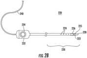
- a catheter 220is shown in greater detail in FIG. 2B , showing some, but not all, of the elements that may be included in the catheter 220.
- a catheter 220may include, but is not limited to include, any one or more of the following components: electrode(s) 222; non-contact electrodes 224; image sensor(s) 225; positioning sensor(s) 226; distal tip 228; distal end 230; handle 232; and/or cable 240.
- the distal end 230 of the catheter 220may include an electrode(s) 222 at the distal tip 228 that may be used to measure electrical properties of the cardiac tissue.
- the electrode(s) 222may also be used to send electrical signals to the heart for diagnostic purposes.
- the electrode(s) 222may also perform ablation on defective cardiac tissue by applying energy (e.g., RF energy) directly to the cardiac tissue at the desired location of ablation.
- energye.g., RF energy
- the distal end 230may include non-contact electrodes 224 arranged in an array, which may be used to simultaneously receive and measure far-field electrical signals from the walls of the heart chamber of the patient 205.
- the electrode(s) 222 and non-contact electrodes 224provide information regarding the electrical properties of the heart to the processing device(s) 202 for processing.
- the catheter(s) 220may be equipped with one or more image sensor(s) 225, such as a charge coupled device (CCD) image sensor, and/or a camera for capturing endoscopic images when inserted in a body cavity.
- image sensor(s) 225may be located at the distal end 230.
- the distal end 230may include positioning sensor(s) 226 (also called location sensors) in the distal tip 228 of the catheter 220 that may generate signals used to determine the position and orientation (and/or distance) of the catheter 220 in the body.
- the relative position and orientation of the positioning sensor(s) 226, the electrode(s) 222, and the distal tipare fixed and known in order to facilitate accurate positioning information of the distal tip.
- the position of the positioning sensor(s) 226may be determined in part based on the relative position to known positions outside the heart (e.g., based on extra-cardiac sensors 214).
- the use of positioning sensor(s) 226may provide improved location accuracy within the magnetic fields in the surrounding space and provide location information that is adaptable to patient movement because the position information of the catheter 220 is relative to the anatomy of the patient 205.
- the handle 232 of the catheter 220may be operated by the physician and may include controls 234 to enable the physician to effectively steer the distal tip 228 in the desired direction.
- the electrodes 222, 224, and sensors 226may be connected to the processing device(s) 202 via wires that may pass through handle 232 and cable 240, in order to provide electrical and position information to the console system 201, which may be used to operate and display the function of the catheter 220 within the heart in real-time.
- the processing device(s) 202may include one or more signal processing circuits that may be contained inside a computer, for example.
- the processing device(s) 202may be implemented in hardware and/or programmed in software to carry out the functions of the cardiac mapping and ablation system 200.
- This softwaremay be downloaded to the processing device(s) 202 in electronic form, over a network, for example, and/or it may be provided on tangible media, such as magnetic or optical media or other nonvolatile memory.
- enhancementmay be made to the cardiac visualization and diagnostic capabilities of the cardiac mapping and ablation system 200 by downloading and installing software modules to the processing device(s) 202.
- processing device(s) 202may comprise a general-purpose computer.
- the processing device(s) 202may receive, amplify, filter and/or digitize signals (carrying information or data) from catheter 220, including signals generated by positioning sensor(s) 226, tip electrode(s) 222 and/or non-contact electrodes 224. The signals are received and used by the processing device(s) 202 to compute the position and orientation of the catheter 220 as well as the electrical characteristics of the heart chamber. In an example, appropriate circuitry may be associated with the catheter 220 itself so that processing device(s) 202 receive signals that are already amplified, filtered and/or digitized.
- the processing device(s) 202may also be used to generate and send signals, containing information or instructions, to other elements in the cardiac mapping and ablation system 200.
- the processing device(s) 202may generate and send real-time 3D cardiac map information for display on the visual display device 216.
- the processing device(s) 202may send/receive information to/from the local storage 208.
- the processing device(s) 202may send signals to the catheter(s) 220 to apply RF energy provided by the energy source 219 to an ablation target.
- processing device(s) 202may implement specific functions, which may be represented (e.g., illustratively or physically) as separate units within the processing device(s) 202.
- the processing device(s) 202may include a decoder unit 204 (e.g., implemented in hardware as a processing circuit and/or software as a software module) that may be configured to receive the position signals from the positioning sensor(s) 226 in the catheter 220, and may use the position signals to calculate position, orientation, distance, temperature and/or electrocardiogram (ECG) values for the catheter distal tip 228.
- a decoder unit 204e.g., implemented in hardware as a processing circuit and/or software as a software module
- ECGelectrocardiogram
- the processing device(s) 202may include a controller unit 207 for sending instructions to other devices in the system 200.
- the controller unit 207may send instructions to the energy source 219 to provide RF energy to the catheter(s) 220 for ablation, and may send instructions to the catheter(s) 220 to apply the RF energy to an ablation target (e.g., one or more locations along a path).
- the processing device(s) 202may include a 3D image reconstruction unit 206 (e.g., implemented in hardware as processing circuits and/or software as a software module) that may be configured to collect image data from a medical imaging system (not shown), such as a magnetic resonance imaging (MRI) system and/or a computed tomography (CT) system, as well as image data from the catheter(s) 220 (e.g., from image sensor(s) 225 in FIG. 2B ).
- 3D image reconstruction unit 206may use the image data to construct a simulated surface of the patient's 205 cardiac chamber and provide it to the visual display device 216 for display, as described further below.
- processing units 204, 206 and 207are examples, and do not comprise all the possible functions that may be implemented in processing device(s) 202. Other functionality and/or processing units may be included in processing device(s) 202 but are not shown.
- Visual display device 216may be used to display 2D and/or 3D visual representations and/or maps of the heart and show the exact location and orientation of the catheter 220 within the heart, based on information processing done in the processing device(s) 202.
- mapsmay be displayed as anatomical maps, cardiac electrical activation maps, cardiac electrical propagation maps, cardiac electrical potential maps, impedance maps, cardiac chamber geometry, and ECG fragmentation maps.
- cardiac representations/maps and catheter(s)In addition to the cardiac representations/maps and catheter(s), other objects in view and/or information (e.g., labels, diagnostics etc.) relevant to the mapping, diagnostic and therapeutic procedures may also be displayed on visual display device 216.
- the 3D visual representation of the cardiac mappingis a critical tool used by the physician to provide an accurate and real-time visual guide for performing diagnostic and therapeutic cardiac procedures, such as cardiac ablation.
- the operator interface(s) 218may be used by one or more operators to interact with and control the cardiac mapping and ablation system 200.
- the operator interface(s) 218may include, but are not limited to include, the following devices: a keyboard; and/or a mouse.
- the operator interface(s) 218may allow operators to access and manipulate visual information, and may provide them with the ability to tag, or label, lesions to keep track of treatment strategies for individual patients.
- Operators of the cardiac mapping and ablation system 200may include, but are not limited to include, the following: a physician (e.g., an electrophysiologist) who may, for example, control the catheter, gather and interpret diagnostics, and perform the ablation procedure; and a Clinical Application Specialist (CAS) who functions as the physician's assistant during the procedures.
- a physiciane.g., an electrophysiologist
- CASClinical Application Specialist
- Ventricular tachycardiais a type of arrhythmia that arises from improper electrical activity in the ventricles, which are the lower pumping chambers of the heart.
- a normal heartmay beat between 60-100 beats per minute (bpm), with the atria of the heart contracting first, followed by the ventricles in a synchronized fashion.
- the ventriclesbeat at a rapid rate, for example 120 - 300 bpm, and are no longer coordinated with the atria.
- There are varying degrees of severity of VTwith more severe cases potentially leading to ventricular fibrillation or cardiac arrest.
- VTmay be treated using ablation treatment, for example using the tools and procedures described herein.
- a physicianmay determine that the VT originates from an electrical circuit on the outer surface of the heart, or on the epicardium (i.e., the connective tissue and fat layer immediately surrounding the heart muscle).
- cardiac ablationmay be applied to the epicardium to treat the VT.
- a puncture into the sac (epicardium) around the heartmay be made just beneath the sternum to insert a catheter (e.g., catheter 220 in FIG. 2A ).
- the cathetermay be maneuvered within the epicardium to determine whether the VT originates there. If VT is located on the epicardium, then ablation treatment may be applied to the epicardium as part of VT treatment.
- Existing cardiac mapping and ablation systemslack visualization of the details and texture of the epicardial surface for diagnosing and treating heart conditions on the epicardium, such as VT.
- knowledge of the coronary arteries, small vessels, adipose tissue, and/or scar areas on the epicardial surfacemay be needed to perform safe and effective ablation treatment.
- a large number of photosmay be needed to effectively display and visually reconstruct a 3D object such as the exterior view of the heart including the details of the surface and texture of the epicardium.
- a video-assisted 3D electrical mapping systemmay be used to generate a gross 3D image of the epicardial surface of a heart by integrating one or more 2D epicardial images with a 3D map of the cardiac structure that may be generated by real-time 3D location and mapping system for cardiac ablation (e.g. a CARTO ® 3 System).
- the 3D visual representation of the epicardial surface of the heartmay be reconstructed using, for example, an image sensor or camera-based catheter to collect a stream of images of the epicardial surface.
- An example of an image sensormay be a charge-coupled device (CCD) image sensor, which collects pixels stored as electrical charges in a photo-sensor array to provide high quality and high-resolution images.
- CCDcharge-coupled device
- the systemmay store the image data along with the corresponding catheter location, orientation and/or distance.
- the catheter location, orientation and/or distancemay be defined relative to external sensors (e.g., a location pad and/or reference device constellation 215 in FIG. 2A ) that are also used for all images to ensure a consistent relative location, orientation and/or distance information and enable accurate stitching together or combining of multiple images of aspects of the cardiac structure.
- the location, orientation, and/or distance of the catheter image sensor (or camera)may be used to register and reconstruct a 3D object using the 2D photos (images) by adding photos, at the known location/orientation/distance, to the 3D map of the heart.
- FIGS. 3A, 3B and 3Cshow drawn depictions of example 2D images 300A, 300B, and 300C of a pericardial space (including the epicardium) of a cardiac structure, in accordance with the disclosures herein.
- the example 2D images 300A, 300B, and/or 300Cmay be captured by an image sensor mounted catheter 302 (e.g., catheter 220 in FIGs. 2A and 2B ) inserted into the pericardial space through a puncture site.
- an image sensor mounted catheter 302e.g., catheter 220 in FIGs. 2A and 2B
- the example images 300A, 300B, and 300Ccapture textural details of the epicardial surface, including, but not limited to, the following: coronary artery 304; small vessels 306; adipose tissue 308; and/or scar lesions (not shown) (not all components of the epicardial surface are labeled or shown).
- Example, unclaimed, procedure 400 in FIG. 4may be used to integrate multiple 2D images of the pericardial surface (e.g., images 300A-300C in FIGs. 3A-3C ) with a 3D geometric image or map of the heart (e.g., FIG. 1 ) to generate a 3D reconstruction image of the epicardial surface of the heart including textural details.
- a 3D geometric image or map of the hearte.g., FIG. 1
- FIG. 4is a flow diagram of an example procedure 400 for generating a 3D textural reconstruction image of the epicardial surface of the heart.
- anatomical data of the cardiac structuremay be acquired and used to generate a 3D model (or map or image) of the cardiac structure.
- the 3D model of the cardiac structuremay be generated using a real-time 3D cardiac location and mapping system such as the CARTO ® 3 System.
- the 3D model of the cardiac structurelacks textural details of the surface of the epicardium.
- an image-sensor (or camera) based cathetermay be inserted into the epicardium to collect 2D images of the epicardial surface showing textural details of the epicardium.
- the imagesmay be generated, for example, using a CCD image sensor (e.g., mounted on a catheter or endoscope) and may show full details of the surface of the epicardium including, but not limited to: small vessels; coronary arteries; adipose tissue; and/or scar areas.
- the following datamay be stored: image data; associated location data; associated orientation data; and/or associated distance data.
- the image information collected in step 404may be stored in storage device in a table including the location/orientation/distance information associated with each the image.
- location/orientation/distance information for a 2D epicardial imagemay be based on a relative position of the image-sensor mounted catheter relative to an external reference (e.g., external sensors or external location pad).
- location/orientation/distance information associated with each 2D epicardial imagemay be used to combine the 2D images, in the appropriate locations, with the 3D model of the cardiac structure to generate a 3D texture map of the epicardial surface.
- any algorithm for multi-view 3D reconstruction from 2D imagesmay be used, that may involve stitching the 2D images to the 3D model at the appropriate locations using the location/orientation/distance information.
- 2D imagesmay be captured (during step 404) and/or selected during step 408 to minimize the amount of overlapping and redundant image information and thus reduce the number of photos required for 3D image reconstruction of the epicardium.
- the 3D texture map of the epicardial surface of the cardiac structuremay be displayed on a visual display device (e.g., visual display device 216 in FIG. 2A ) for use by a physician or operator during diagnostics and/or treatment of cardiac conditions (e.g., ablation treatment for VT).
- a visual display devicee.g., visual display device 216 in FIG. 2A
- a physician or operatorduring diagnostics and/or treatment of cardiac conditions (e.g., ablation treatment for VT).
- the use of the location, orientation and/or distance information from the cathetermay be used to map to the epicardial space images to register and construct an accurate 3D model of the heart to visualize not only the surface on the heart chamber, but also the texture of the surface of the heart chamber (epicardium).
- the use of the location, orientation and/or distance information from the catheter image sensor (camera)may also enable the use of fewer 2D photos of the epicardial surface by minimizing the amount of overlapping information in the photos used, and enabling the discarding of redundant photos.
- an approach for generating a 3D reconstruction image of a cardiac structuremay use a non-contact geometry construction (e.g., using non-contact sensors) and thus may provide more effective and safer ablation by providing visualization of the cardiac structure.
- FIG. 5shows an example high-level procedure 500 for generating a 3D geometric reconstruction image 510 of a non-contact 3D mapping of a cardiac structure (without texture).
- the 2D images 502 and 504 of the cardiac structuremay be taken at different angles and provided to algorithm 506 to be create the 3D geometric cardiac image 510.
- Cardiac images 502 and 504may be, for example, images obtained by inserting an endoscope/catheter into the cardiac structure and/or by imaging systems (MRI, CT), and algorithm 506 may be any multi-view 3D reconstruction algorithm.
- the procedure 500may be used to obtain the 3D model of the cardiac structure in step 402 of procedure 400 shown in FIG. 4 .
- the embodiments and procedures described hereinmay be implemented in hardware, and/or software.
- a computer system for performing ablationmay be capable of running software modules that introduce additional features including the procedures described herein.
- the procedures described hereinmay enable advanced cardiac visualization, and diagnostic capabilities to enhance clinicians' ability to diagnose and treat heart rhythm disorders. Although the procedures disclosed herein are describe with respect to ablation procedures within the heart, the procedures may be similarly used for ablation in other parts of the body.
- processorsinclude, by way of example, a general purpose processor, a special purpose processor, a conventional processor, a digital signal processor (DSP), a plurality of microprocessors, one or more microprocessors in association with a DSP core, a controller, a microcontroller, Application Specific Integrated Circuits (ASICs), Field Programmable Gate Arrays (FPGAs) circuits, any other type of integrated circuit (IC), and/or a state machine.
- DSPdigital signal processor
- ASICsApplication Specific Integrated Circuits
- FPGAsField Programmable Gate Arrays
- Such processorscan be manufactured by configuring a manufacturing process using the results of processed hardware description language (HDL) instructions and other intermediary data including netlists (such instructions capable of being stored on a computer readable media). The results of such processing can be mask works that are then used in a semiconductor manufacturing process to manufacture a processor which implements the methods described herein.
- HDLhardware description language
- non-transitory computer-readable storage mediumsinclude a ROM, a random access memory (RAM), a register, cache memory, semiconductor memory devices, magnetic media such as internal hard disks and removable disks, magneto-optical media, and optical media such as CD-ROM disks, and digital versatile disks (DVDs).
Landscapes
- Health & Medical Sciences (AREA)
- Life Sciences & Earth Sciences (AREA)
- Engineering & Computer Science (AREA)
- Medical Informatics (AREA)
- Public Health (AREA)
- General Health & Medical Sciences (AREA)
- Biomedical Technology (AREA)
- Surgery (AREA)
- Physics & Mathematics (AREA)
- Pathology (AREA)
- Heart & Thoracic Surgery (AREA)
- Molecular Biology (AREA)
- Animal Behavior & Ethology (AREA)
- Veterinary Medicine (AREA)
- Biophysics (AREA)
- Primary Health Care (AREA)
- Epidemiology (AREA)
- Nuclear Medicine, Radiotherapy & Molecular Imaging (AREA)
- Radiology & Medical Imaging (AREA)
- Databases & Information Systems (AREA)
- Data Mining & Analysis (AREA)
- Cardiology (AREA)
- Human Computer Interaction (AREA)
- Otolaryngology (AREA)
- Plasma & Fusion (AREA)
- Theoretical Computer Science (AREA)
- Geometry (AREA)
- Software Systems (AREA)
- General Physics & Mathematics (AREA)
- Computer Graphics (AREA)
- Measurement And Recording Of Electrical Phenomena And Electrical Characteristics Of The Living Body (AREA)
- Surgical Instruments (AREA)
- Measuring And Recording Apparatus For Diagnosis (AREA)
- Image Generation (AREA)
- Magnetic Resonance Imaging Apparatus (AREA)
- Endoscopes (AREA)
Description
- A three-dimensional (3D) electrical mapping system may be used to generate a 3D image of the epicardial surface of a heart by integrating one or more epicardial images with a 3D image of the heart that may be generated by real-
time 3D location and mapping system for cardiac mapping and ablation. The visual representation of the epicardial surface of the heart may be reconstructed using, for example, an image sensor or camera-based catheter to collect images of the epicardial surface including textural details. For each image that is captured, the system may store the image data along with the corresponding catheter location, orientation and/or distance information relative to the heart. The location, orientation, and/or distance information may be used to reconstruct a 3D textural model of the epicardial surface of the heart. WO 2013/044182 discloses a system and method for ablation and data visualisation which includes a catheter with a fiber optic waveguide, so that an image can be taken with a camera located outside of the catheter.WO 2013/044182 neither discloses a camera on the tip of the catheter nor the specific location, orientation and distance sensor claimed herein. ThusWO 2013/044182 represents the closest prior art.FIG. 1 shows a drawn depiction of an example three-dimensional (3D) cardiac map of a patient's heart generated by a CARTO® 3 System, in accordance with the disclosures herein;FIG. 2A is a schematic diagram of an example cardiac mapping and ablation system, in accordance with the disclosures herein;FIG. 2B is a schematic diagram of an example catheter that may be included in the example cardiac mapping and ablation system ofFIG. 2A , in accordance with the disclosures herein;FIGS. 3A, 3B , and3C show drawn depictions of example 2D images of a pericardial space of a cardiac structure, in accordance with the disclosures herein;FIG. 4 is a flow diagram of an example procedure for generating a 3D textural reconstruction image of the epicardial surface of the heart; andFIG. 5 shows an example high-level procedure for generating a 3D geometric reconstruction image of a non-contact 3D mapping of a cardiac structure.- Cardiac ablation is a medical procedure performed by electrophysiologists that may be used to correct heart rhythm defects, known as arrhythmias, by creating lesions to destroy tissue in the heart that contributes to the rhythm defects. An example arrhythmia that can be treated using cardiac ablation is atrial fibrillation (AF), which is an abnormal heart rhythm that originates in the atria of the heart.
- Cardiac ablation may employ long, flexible catheters that may be inserted through a small incision in the groin and through the blood vessels to the heart, and may be used to apply energy (e.g., radio frequency (RF) energy, or extreme cold) to produce small scars or lesions on the tissue to block faulty electrical impulses that may cause the heart rhythm disorders. Real-time three-dimensional (3D) location and mapping technology may be employed to visualize the exact position and orientation of a catheter within the heart and act as an advanced navigation system to enable the electrophysiologist to visualize and carefully guide the catheter to administer the RF energy in the appropriate locations. Goals of cardiac ablation are to remove the arrhythmia to return the patient's heart to a normal heart rhythm or reduce the frequency of arrhythmia and the severity of symptoms in the patient.
- An example of a real-
time 3D location and mapping system for cardiac ablation is the CARTO® 3 System, produced by Biosense Webster®, Inc., a subsidiary of Johnson & Johnson. The CARTO® 3 System uses electromagnetic technology to create 3D maps of a patient's cardiac structure and to display the exact location and orientation of the catheters (or other objects) in the heart. The CARTO® 3 System compensates for patient and cardiac motion to ensure accurate, real-time visualization of the cardiac structures. FIG. 1 shows an example 3D cardiac map of theheart 100 of a patient generated by a CARTO® 3 System. The location and orientation of acatheter 102 is illustrated within the 3D visualization of theheart 100 of the patient. Thecatheter 102 may be a therapeutic and/or diagnostic catheter. Other objects and images, although not shown, may be included in the 3D visualization shown inFIG. 1 such as, but not limited to, the following: the location and orientation of additional catheters and devices; a 3D synthetic heart model used for orientation within the mappedheart 100; a two-dimensional (2D) image to assist in directional (e.g., up, down, back, forward) orientation; and fluoroscopy images or other background images.FIG. 2A is a schematic diagram of an example cardiac mapping andablation system 200 with integrated real-time 3D location and mapping technology (e.g., CARTO® 3 System or other 3D location and mapping technology), in accordance with the disclosures herein. The cardiac mapping andablation system 200 may include, but is not limited to include, any of the following components: aconsole system 201;extra-cardiac sensors 214;reference device constellation 215;energy source 219; and/or catheter(s) 220. Theconsole system 201 may include, but is not limited to include, any of the following components: processing device(s) 202;local storage 208;visual display device 216; and/or operator interface(s) 218. Certain elements of the cardiac mapping andablation system 200 may be used directly on, in, and/or in proximity to thepatient 205 in order to gather information to be used for visualization, diagnostics, and to perform ablation therapy. This information may be provided to theconsole system 201 for processing, visualization and operator control and direction, some of which is described below.- The reference device constellation 215 (e.g., may be referred to as a location pad) may include a ring of computer-controlled (e.g., controlled by processing device(s) 202) magnets positioned beneath the
patient 205. The magnets may have known and fixed strength and position values that may be used as point of origin references for the magnetic fields in the surrounding space and may provide the reference information to the processing device(s) 202 to be used in producing accurate 3D images of the heart. - The extra-cardiac sensor(s) 214 may be electrodes on the skin of a
patient 205, for example. The extra-cardiac sensor(s) 214 may detect electrical activity of the heart via detection of electrical changes on the skin due to the electrophysiologic pattern of the heart, and provide information on the electrical activity to the processing device(s) 202 to be used in diagnosing arrhythmias and determining a therapeutic course of action. Processed versions of the extra-cardiac signals detected by the extra-cardiac sensor(s) 214 may be displayed onvisual display device 216. - One or more devices may be used on the
patient 205 for therapeutic and diagnostic purposes. In the example cardiac mapping andablation system 200, catheter(s) 220 are shown and described for these purposes; however, other devices may be used for diagnostics and/or therapeutic treatment. - One or more catheter(s) 220 may be percutaneously inserted by a physician through the patient's 205 vascular system into the heart of the
patient 205. The catheter(s) 220 may be equipped with location and/or electrical sensors for the purpose of gathering information for diagnostic mapping and/or delivering therapeutic treatment (e.g., performing ablation). Different types of catheter(s) 220 may be used including, but not limited to, the following example types: fixed catheter; deflectable catheter; bi-directional catheter; uni-directional catheter; tricuspid mapping catheter; halo-shaped tip catheter; basket catheter; and/or lasso-shaped catheter. When the catheter(s) 220 is used for performing ablation on a target location (e.g., one or more locations along a path), for example by applying RF energy, the catheter(s) 220 may receive the RF energy from theenergy source 219, as may be instructed by the processing device(s) 202. In an example, the catheter(s) 220 may request the RF energy directly from theenergy source 219. - An
example catheter 220 is shown in greater detail inFIG. 2B , showing some, but not all, of the elements that may be included in thecatheter 220. Acatheter 220 may include, but is not limited to include, any one or more of the following components: electrode(s) 222; non-contactelectrodes 224; image sensor(s) 225; positioning sensor(s) 226;distal tip 228;distal end 230;handle 232; and/orcable 240. - The
distal end 230 of thecatheter 220 may include an electrode(s) 222 at thedistal tip 228 that may be used to measure electrical properties of the cardiac tissue. The electrode(s) 222 may also be used to send electrical signals to the heart for diagnostic purposes. The electrode(s) 222 may also perform ablation on defective cardiac tissue by applying energy (e.g., RF energy) directly to the cardiac tissue at the desired location of ablation. - The
distal end 230 may includenon-contact electrodes 224 arranged in an array, which may be used to simultaneously receive and measure far-field electrical signals from the walls of the heart chamber of thepatient 205. The electrode(s) 222 andnon-contact electrodes 224 provide information regarding the electrical properties of the heart to the processing device(s) 202 for processing. - The catheter(s) 220 may be equipped with one or more image sensor(s) 225, such as a charge coupled device (CCD) image sensor, and/or a camera for capturing endoscopic images when inserted in a body cavity. The image sensor(s) 225 may be located at the
distal end 230. - The
distal end 230 may include positioning sensor(s) 226 (also called location sensors) in thedistal tip 228 of thecatheter 220 that may generate signals used to determine the position and orientation (and/or distance) of thecatheter 220 in the body. In an example, the relative position and orientation of the positioning sensor(s) 226, the electrode(s) 222, and the distal tip are fixed and known in order to facilitate accurate positioning information of the distal tip. For example, the position of the positioning sensor(s) 226 may be determined in part based on the relative position to known positions outside the heart (e.g., based on extra-cardiac sensors 214). The use of positioning sensor(s) 226 may provide improved location accuracy within the magnetic fields in the surrounding space and provide location information that is adaptable to patient movement because the position information of thecatheter 220 is relative to the anatomy of thepatient 205. - The
handle 232 of thecatheter 220 may be operated by the physician and may includecontrols 234 to enable the physician to effectively steer thedistal tip 228 in the desired direction. - The
electrodes sensors 226 may be connected to the processing device(s) 202 via wires that may pass throughhandle 232 andcable 240, in order to provide electrical and position information to theconsole system 201, which may be used to operate and display the function of thecatheter 220 within the heart in real-time. - With reference to
FIG. 2A , within theconsole system 201, the processing device(s) 202 may include one or more signal processing circuits that may be contained inside a computer, for example. The processing device(s) 202 may be implemented in hardware and/or programmed in software to carry out the functions of the cardiac mapping andablation system 200. This software may be downloaded to the processing device(s) 202 in electronic form, over a network, for example, and/or it may be provided on tangible media, such as magnetic or optical media or other nonvolatile memory. For example, enhancement may be made to the cardiac visualization and diagnostic capabilities of the cardiac mapping andablation system 200 by downloading and installing software modules to the processing device(s) 202. In an example, processing device(s) 202 may comprise a general-purpose computer. - The processing device(s) 202 may receive, amplify, filter and/or digitize signals (carrying information or data) from
catheter 220, including signals generated by positioning sensor(s) 226, tip electrode(s) 222 and/ornon-contact electrodes 224. The signals are received and used by the processing device(s) 202 to compute the position and orientation of thecatheter 220 as well as the electrical characteristics of the heart chamber. In an example, appropriate circuitry may be associated with thecatheter 220 itself so that processing device(s) 202 receive signals that are already amplified, filtered and/or digitized. - The processing device(s) 202 may also be used to generate and send signals, containing information or instructions, to other elements in the cardiac mapping and
ablation system 200. For example, the processing device(s) 202 may generate and send real-time 3D cardiac map information for display on thevisual display device 216. In another example, the processing device(s) 202 may send/receive information to/from thelocal storage 208. In another example, the processing device(s) 202 may send signals to the catheter(s) 220 to apply RF energy provided by theenergy source 219 to an ablation target. - As explained above, processing device(s) 202 may implement specific functions, which may be represented (e.g., illustratively or physically) as separate units within the processing device(s) 202. For example, the processing device(s) 202 may include a decoder unit 204 (e.g., implemented in hardware as a processing circuit and/or software as a software module) that may be configured to receive the position signals from the positioning sensor(s) 226 in the
catheter 220, and may use the position signals to calculate position, orientation, distance, temperature and/or electrocardiogram (ECG) values for the catheterdistal tip 228. - In another example, the processing device(s) 202 may include a
controller unit 207 for sending instructions to other devices in thesystem 200. For example, thecontroller unit 207 may send instructions to theenergy source 219 to provide RF energy to the catheter(s) 220 for ablation, and may send instructions to the catheter(s) 220 to apply the RF energy to an ablation target (e.g., one or more locations along a path). - In another example, the processing device(s) 202 may include a 3D image reconstruction unit 206 (e.g., implemented in hardware as processing circuits and/or software as a software module) that may be configured to collect image data from a medical imaging system (not shown), such as a magnetic resonance imaging (MRI) system and/or a computed tomography (CT) system, as well as image data from the catheter(s) 220 (e.g., from image sensor(s) 225 in
FIG. 2B ). 3Dimage reconstruction unit 206 may use the image data to construct a simulated surface of the patient's 205 cardiac chamber and provide it to thevisual display device 216 for display, as described further below. - The
processing units Visual display device 216 may be used to display 2D and/or 3D visual representations and/or maps of the heart and show the exact location and orientation of thecatheter 220 within the heart, based on information processing done in the processing device(s) 202. For example, maps may be displayed as anatomical maps, cardiac electrical activation maps, cardiac electrical propagation maps, cardiac electrical potential maps, impedance maps, cardiac chamber geometry, and ECG fragmentation maps.- In addition to the cardiac representations/maps and catheter(s), other objects in view and/or information (e.g., labels, diagnostics etc.) relevant to the mapping, diagnostic and therapeutic procedures may also be displayed on
visual display device 216. The 3D visual representation of the cardiac mapping is a critical tool used by the physician to provide an accurate and real-time visual guide for performing diagnostic and therapeutic cardiac procedures, such as cardiac ablation. - The operator interface(s) 218 may be used by one or more operators to interact with and control the cardiac mapping and
ablation system 200. The operator interface(s) 218 may include, but are not limited to include, the following devices: a keyboard; and/or a mouse. The operator interface(s) 218 may allow operators to access and manipulate visual information, and may provide them with the ability to tag, or label, lesions to keep track of treatment strategies for individual patients. - Operators of the cardiac mapping and
ablation system 200 may include, but are not limited to include, the following: a physician (e.g., an electrophysiologist) who may, for example, control the catheter, gather and interpret diagnostics, and perform the ablation procedure; and a Clinical Application Specialist (CAS) who functions as the physician's assistant during the procedures. - Ventricular tachycardia (VT or V-tach) is a type of arrhythmia that arises from improper electrical activity in the ventricles, which are the lower pumping chambers of the heart. For example, a normal heart may beat between 60-100 beats per minute (bpm), with the atria of the heart contracting first, followed by the ventricles in a synchronized fashion. In VT, the ventricles beat at a rapid rate, for example 120 - 300 bpm, and are no longer coordinated with the atria. There are varying degrees of severity of VT, with more severe cases potentially leading to ventricular fibrillation or cardiac arrest.
- VT may be treated using ablation treatment, for example using the tools and procedures described herein. In some cases, a physician may determine that the VT originates from an electrical circuit on the outer surface of the heart, or on the epicardium (i.e., the connective tissue and fat layer immediately surrounding the heart muscle). For VT that may occur on the epicardium, cardiac ablation may be applied to the epicardium to treat the VT. For example, a puncture into the sac (epicardium) around the heart may be made just beneath the sternum to insert a catheter (e.g.,
catheter 220 inFIG. 2A ). The catheter may be maneuvered within the epicardium to determine whether the VT originates there. If VT is located on the epicardium, then ablation treatment may be applied to the epicardium as part of VT treatment. - Existing cardiac mapping and ablation systems lack visualization of the details and texture of the epicardial surface for diagnosing and treating heart conditions on the epicardium, such as VT. For example, knowledge of the coronary arteries, small vessels, adipose tissue, and/or scar areas on the epicardial surface may be needed to perform safe and effective ablation treatment. A large number of photos may be needed to effectively display and visually reconstruct a 3D object such as the exterior view of the heart including the details of the surface and texture of the epicardium.
- According to an embodiment, a video-assisted 3D electrical mapping system may be used to generate a gross 3D image of the epicardial surface of a heart by integrating one or more 2D epicardial images with a 3D map of the cardiac structure that may be generated by real-
time 3D location and mapping system for cardiac ablation (e.g. a CARTO® 3 System). The 3D visual representation of the epicardial surface of the heart may be reconstructed using, for example, an image sensor or camera-based catheter to collect a stream of images of the epicardial surface. An example of an image sensor may be a charge-coupled device (CCD) image sensor, which collects pixels stored as electrical charges in a photo-sensor array to provide high quality and high-resolution images. - For each 2D epicardial image that is captured, the system may store the image data along with the corresponding catheter location, orientation and/or distance. In an example, the catheter location, orientation and/or distance may be defined relative to external sensors (e.g., a location pad and/or
reference device constellation 215 inFIG. 2A ) that are also used for all images to ensure a consistent relative location, orientation and/or distance information and enable accurate stitching together or combining of multiple images of aspects of the cardiac structure. Thus, the location, orientation, and/or distance of the catheter image sensor (or camera) may be used to register and reconstruct a 3D object using the 2D photos (images) by adding photos, at the known location/orientation/distance, to the 3D map of the heart. FIGS. 3A, 3B and3C show drawn depictions ofexample 2D images example 2D images catheter 220 inFIGs. 2A and2B ) inserted into the pericardial space through a puncture site. Theexample images coronary artery 304;small vessels 306;adipose tissue 308; and/or scar lesions (not shown) (not all components of the epicardial surface are labeled or shown).- Example, unclaimed,
procedure 400 inFIG. 4 may be used to integrate multiple 2D images of the pericardial surface (e.g.,images 300A-300C inFIGs. 3A-3C ) with a 3D geometric image or map of the heart (e.g.,FIG. 1 ) to generate a 3D reconstruction image of the epicardial surface of the heart including textural details. FIG. 4 is a flow diagram of anexample procedure 400 for generating a 3D textural reconstruction image of the epicardial surface of the heart. At 402, anatomical data of the cardiac structure may be acquired and used to generate a 3D model (or map or image) of the cardiac structure. For example, the 3D model of the cardiac structure may be generated using a real-time 3D cardiac location and mapping system such as the CARTO® 3 System. The 3D model of the cardiac structure lacks textural details of the surface of the epicardium.- To remedy the lack of detail for the epicardium, at 404, an image-sensor (or camera) based catheter may be inserted into the epicardium to collect 2D images of the epicardial surface showing textural details of the epicardium. The images may be generated, for example, using a CCD image sensor (e.g., mounted on a catheter or endoscope) and may show full details of the surface of the epicardium including, but not limited to: small vessels; coronary arteries; adipose tissue; and/or scar areas. At 406, for each epicardial image, the following data may be stored: image data; associated location data; associated orientation data; and/or associated distance data. For example, the image information collected in
step 404 may be stored in storage device in a table including the location/orientation/distance information associated with each the image. For example location/orientation/distance information for a 2D epicardial image may be based on a relative position of the image-sensor mounted catheter relative to an external reference (e.g., external sensors or external location pad). - At 408, location/orientation/distance information associated with each 2D epicardial image may be used to combine the 2D images, in the appropriate locations, with the 3D model of the cardiac structure to generate a 3D texture map of the epicardial surface. For example, any algorithm for multi-view 3D reconstruction from 2D images may be used, that may involve stitching the 2D images to the 3D model at the appropriate locations using the location/orientation/distance information. 2D images may be captured (during step 404) and/or selected during
step 408 to minimize the amount of overlapping and redundant image information and thus reduce the number of photos required for 3D image reconstruction of the epicardium. At 410, the 3D texture map of the epicardial surface of the cardiac structure may be displayed on a visual display device (e.g.,visual display device 216 inFIG. 2A ) for use by a physician or operator during diagnostics and/or treatment of cardiac conditions (e.g., ablation treatment for VT). - Thus, according to the
example procedure 400, the use of the location, orientation and/or distance information from the catheter may be used to map to the epicardial space images to register and construct an accurate 3D model of the heart to visualize not only the surface on the heart chamber, but also the texture of the surface of the heart chamber (epicardium). The use of the location, orientation and/or distance information from the catheter image sensor (camera) may also enable the use of fewer 2D photos of the epicardial surface by minimizing the amount of overlapping information in the photos used, and enabling the discarding of redundant photos. - According to an example that is not claimed, an approach for generating a 3D reconstruction image of a cardiac structure may use a non-contact geometry construction (e.g., using non-contact sensors) and thus may provide more effective and safer ablation by providing visualization of the cardiac structure.
FIG. 5 shows an example high-level procedure 500 for generating a 3Dgeometric reconstruction image 510 of a non-contact 3D mapping of a cardiac structure (without texture). In the example ofFIG. 5 , the2D images algorithm 506 to be create the 3D geometriccardiac image 510.Cardiac images algorithm 506 may be any multi-view 3D reconstruction algorithm. In an example, theprocedure 500 may be used to obtain the 3D model of the cardiac structure instep 402 ofprocedure 400 shown inFIG. 4 . - The embodiments and procedures described herein may be implemented in hardware, and/or software. A computer system for performing ablation may be capable of running software modules that introduce additional features including the procedures described herein. The procedures described herein may enable advanced cardiac visualization, and diagnostic capabilities to enhance clinicians' ability to diagnose and treat heart rhythm disorders. Although the procedures disclosed herein are describe with respect to ablation procedures within the heart, the procedures may be similarly used for ablation in other parts of the body.
- The methods provided include implementation in a general purpose computer, a processor, or a processor core. Suitable processors include, by way of example, a general purpose processor, a special purpose processor, a conventional processor, a digital signal processor (DSP), a plurality of microprocessors, one or more microprocessors in association with a DSP core, a controller, a microcontroller, Application Specific Integrated Circuits (ASICs), Field Programmable Gate Arrays (FPGAs) circuits, any other type of integrated circuit (IC), and/or a state machine. Such processors can be manufactured by configuring a manufacturing process using the results of processed hardware description language (HDL) instructions and other intermediary data including netlists (such instructions capable of being stored on a computer readable media). The results of such processing can be mask works that are then used in a semiconductor manufacturing process to manufacture a processor which implements the methods described herein.
- The methods or flow charts provided herein may be implemented in a computer program, software, or firmware incorporated in a non-transitory computer-readable storage medium for execution by a general purpose computer or a processor. Examples of non-transitory computer-readable storage mediums include a ROM, a random access memory (RAM), a register, cache memory, semiconductor memory devices, magnetic media such as internal hard disks and removable disks, magneto-optical media, and optical media such as CD-ROM disks, and digital versatile disks (DVDs).
Claims (8)
- A system (200) configured to generate a three-dimensional (3D) reconstruction image of an epicardial surface of a cardiac structure (100), the system comprising:a processing device (202) configured to acquire anatomical data of the cardiac structure and generate a 3D model of the cardiac structure;a catheter (220) inserted into an epicardium of the cardiac structure, the catheter comprising:an image sensor (225) configured to capture a plurality of images of the epicardial surface of the cardiac structure and provide the plurality of images to the processing device, wherein the plurality of images include texture of the epicardial surface;at least one location sensor (226) configured to generate, for each of the plurality images, corresponding location, orientation and distance information and provide the corresponding location, orientation and distance information to the processing device;the processing device further configured to generate a 3D texture map of the epicardial surface of the cardiac structure by stitching the plurality of images to the 3D model of the cardiac structure using the corresponding location, orientation and distance information;the processing device configured to provide the 3D texture map of the epicardial surface of the cardiac structure to a visual display device (216); andthe visual display device configured to visually display the 3D texture map of the epicardial surface of the cardiac structure.
- The system of claim 1, wherein the processing device is further configured to store the plurality of images and the corresponding location, orientation and distance information in a local storage (208).
- The system of claim 1, wherein:
the processing device is configured to generate the 3D model of the cardiac structure using a multi-view 3D reconstruction algorithm. - The system of claim 1, wherein the image sensor is a charge-coupled device (CCD) image sensor.
- The system of claim 1, wherein the processing device is configured to generate the 3D texture map of the epicardial surface of the cardiac structure by selecting a subset of images from the plurality of images of the epicardial surface of the cardiac structure based on the corresponding location, orientation and distance information to minimize redundant information in the subset of images.
- The system of claim 1 configured to use non-contact sensors (224).
- The system of claim 1, wherein the 3D texture map of the epicardial surface of the cardiac structure shows at least one of a coronary artery (304), small vessels (306), adipose tissue (308), or a scar lesion.
- The system of claim 1, wherein the corresponding location, orientation and distance information is relative to an external reference (215).
Applications Claiming Priority (1)
| Application Number | Priority Date | Filing Date | Title |
|---|---|---|---|
| US15/476,097US10765371B2 (en) | 2017-03-31 | 2017-03-31 | Method to project a two dimensional image/photo onto a 3D reconstruction, such as an epicardial view of heart |
Publications (2)
| Publication Number | Publication Date |
|---|---|
| EP3382714A1 EP3382714A1 (en) | 2018-10-03 |
| EP3382714B1true EP3382714B1 (en) | 2023-02-15 |
Family
ID=62001944
Family Applications (1)
| Application Number | Title | Priority Date | Filing Date |
|---|---|---|---|
| EP18164954.2AActiveEP3382714B1 (en) | 2017-03-31 | 2018-03-29 | Method to project a two dimensional image/photo onto a 3d reconstruction, such as an epicardial view of heart |
Country Status (6)
| Country | Link |
|---|---|
| US (1) | US10765371B2 (en) |
| EP (1) | EP3382714B1 (en) |
| JP (1) | JP7123602B2 (en) |
| CN (1) | CN108694743B (en) |
| CA (1) | CA2999633A1 (en) |
| IL (1) | IL258199B (en) |
Families Citing this family (34)
| Publication number | Priority date | Publication date | Assignee | Title |
|---|---|---|---|---|
| US10905329B2 (en) | 2016-06-09 | 2021-02-02 | Biosense Webster (Israel) Ltd. | Multi-function conducting elements for a catheter |
| US12029545B2 (en) | 2017-05-30 | 2024-07-09 | Biosense Webster (Israel) Ltd. | Catheter splines as location sensors |
| WO2019157219A1 (en)* | 2018-02-07 | 2019-08-15 | Boston Scientific Scimed Inc. | System and method for mapping and characterizing the coronary vasculature for epicardial ablations |
| US20190314083A1 (en) | 2018-04-11 | 2019-10-17 | Biosense Webster (Israel) Ltd. | Flexible Multi-Arm Catheter with Diametrically Opposed Sensing Electrodes |
| US11045628B2 (en) | 2018-12-11 | 2021-06-29 | Biosense Webster (Israel) Ltd. | Balloon catheter with high articulation |
| US11207016B2 (en) | 2018-12-28 | 2021-12-28 | Biosense Webster (Israel) Ltd. | Mapping ECG signals using a multipole electrode assembly |
| CN109745037B (en)* | 2019-02-14 | 2022-06-24 | 广州视源电子科技股份有限公司 | An image processing method, apparatus, device and storage medium |
| US12292564B2 (en) | 2019-04-08 | 2025-05-06 | Activ Surgical, Inc. | Systems and methods for medical imaging |
| US11850051B2 (en) | 2019-04-30 | 2023-12-26 | Biosense Webster (Israel) Ltd. | Mapping grid with high density electrode array |
| US11712172B2 (en) | 2019-07-18 | 2023-08-01 | Biosense Webster (Israel) Ltd. | Visual guidance for positioning a distal end of a medical probe |
| WO2021035094A1 (en)* | 2019-08-21 | 2021-02-25 | Activ Surgical, Inc. | Systems and methods for medical imaging |
| CN110782994A (en)* | 2019-10-29 | 2020-02-11 | 上海交通大学医学院附属新华医院 | A novel method for measuring epicardial fat using mimics software |
| US11950930B2 (en) | 2019-12-12 | 2024-04-09 | Biosense Webster (Israel) Ltd. | Multi-dimensional acquisition of bipolar signals from a catheter |
| US11517218B2 (en) | 2019-12-20 | 2022-12-06 | Biosense Webster (Israel) Ltd. | Selective graphical presentation of electrophysiological parameters |
| US12232874B2 (en) | 2020-05-29 | 2025-02-25 | Biosense Webster (Israel) Ltd. | Electrode apparatus for diagnosis of arrhythmias |
| US11987017B2 (en) | 2020-06-08 | 2024-05-21 | Biosense Webster (Israel) Ltd. | Features to assist in assembly and testing of devices |
| US12048479B2 (en) | 2020-09-10 | 2024-07-30 | Biosense Webster (Israel) Ltd. | Surface mounted electrode catheter |
| US20220079462A1 (en)* | 2020-09-16 | 2022-03-17 | Biosense Webster (Israel) Ltd. | Systems and methods for cardiac chamber visualization |
| US11950841B2 (en) | 2020-09-22 | 2024-04-09 | Biosense Webster (Israel) Ltd. | Basket catheter having insulated ablation electrodes and diagnostic electrodes |
| US11950840B2 (en) | 2020-09-22 | 2024-04-09 | Biosense Webster (Israel) Ltd. | Basket catheter having insulated ablation electrodes |
| US12082875B2 (en) | 2020-09-24 | 2024-09-10 | Biosense Webster (Israel) Ltd | Balloon catheter having a coil for sensing tissue temperature and position of the balloon |
| US11974803B2 (en) | 2020-10-12 | 2024-05-07 | Biosense Webster (Israel) Ltd. | Basket catheter with balloon |
| US12201786B2 (en) | 2020-12-17 | 2025-01-21 | Biosense Webster (Israel) Ltd. | Measurement of distal end dimension of catheters using magnetic fields |
| CN112767530B (en)* | 2020-12-17 | 2022-09-09 | 中南民族大学 | Heart image three-dimensional reconstruction method, device, equipment and storage medium |
| US11918383B2 (en) | 2020-12-21 | 2024-03-05 | Biosense Webster (Israel) Ltd. | Visualizing performance of catheter electrodes |
| WO2022147253A1 (en)* | 2021-01-04 | 2022-07-07 | The Trustees Of The University Of Pennsylvania | Device for cardiac imaging and epicardial ablation and methods of use thereof |
| US12064170B2 (en) | 2021-05-13 | 2024-08-20 | Biosense Webster (Israel) Ltd. | Distal assembly for catheter with lumens running along spines |
| US12364426B2 (en) | 2021-08-12 | 2025-07-22 | Biosense Webster (Israel) Ltd. | Electro-anatomical mapping and annotation presented in electrophysiological procedures |
| US12004804B2 (en) | 2021-09-09 | 2024-06-11 | Biosense Webster (Israel) Ltd. | Basket catheter with mushroom shape distal tip |
| US12011280B2 (en) | 2021-10-04 | 2024-06-18 | Biosense Webster (Israel) Ltd. | Electrophysiological mapping in the presence of injury current |
| US12419683B2 (en) | 2021-12-22 | 2025-09-23 | Biosense Webster (Israel) Ltd. | Irreversible electroporation with shorted electrodes |
| WO2023147544A2 (en)* | 2022-01-28 | 2023-08-03 | Shifamed Holdings, Llc | Systems and methods for imaging and anatomical modeling |
| CN116712104B (en)* | 2023-07-05 | 2024-11-15 | 天津市鹰泰利安康医疗科技有限责任公司 | A method and system for reconstructing three-dimensional cardiac mapping data |
| CN116965915B (en)* | 2023-08-03 | 2024-11-19 | 天津市鹰泰利安康医疗科技有限责任公司 | Heart three-dimensional mapping method and system based on ultrasonic ranging |
Family Cites Families (23)
| Publication number | Priority date | Publication date | Assignee | Title |
|---|---|---|---|---|
| US5435310A (en) | 1993-06-23 | 1995-07-25 | University Of Washington | Determining cardiac wall thickness and motion by imaging and three-dimensional modeling |
| US6650927B1 (en) | 2000-08-18 | 2003-11-18 | Biosense, Inc. | Rendering of diagnostic imaging data on a three-dimensional map |
| US20050163357A1 (en) | 2002-05-22 | 2005-07-28 | Sherif Makram-Ebeid | Medical viewing system and image processing for integrated visualisation of medical data |
| US7599730B2 (en)* | 2002-11-19 | 2009-10-06 | Medtronic Navigation, Inc. | Navigation system for cardiac therapies |
| IL170404A (en)* | 2004-08-26 | 2012-03-29 | C2Cure Inc | Wireless determination of endoscope orientation |
| CA2620196A1 (en)* | 2005-08-24 | 2007-03-01 | Traxtal Inc. | System, method and devices for navigated flexible endoscopy |
| US7515954B2 (en) | 2006-06-13 | 2009-04-07 | Rhythmia Medical, Inc. | Non-contact cardiac mapping, including moving catheter and multi-beat integration |
| EP2203894B1 (en) | 2007-09-03 | 2011-03-02 | Koninklijke Philips Electronics N.V. | Visualization of voxel data |
| US8177835B2 (en)* | 2009-08-21 | 2012-05-15 | Siemens Aktiengesellschaft | Method of imaging for heart valve implant procedure |
| US8634896B2 (en) | 2010-09-20 | 2014-01-21 | Apn Health, Llc | 3D model creation of anatomic structures using single-plane fluoroscopy |
| CN102411795B (en)* | 2011-08-16 | 2014-12-10 | 中国人民解放军第三军医大学第一附属医院 | Combined display method of multimode image of coronary artery |
| AU2012312066C1 (en)* | 2011-09-22 | 2016-06-16 | 460Medical, Inc. | Systems and methods for visualizing ablated tissue |
| CN103202727B (en)* | 2012-01-12 | 2015-11-25 | 通用电气公司 | Non-invasive arrhythmia treatment system |
| WO2014046214A1 (en)* | 2012-09-20 | 2014-03-27 | 株式会社東芝 | Image processing system, x-ray diagnostic device, and image processing method |
| US20140088457A1 (en) | 2012-09-26 | 2014-03-27 | Covidien Lp | Bleeding containment device |
| US9775578B2 (en)* | 2013-08-12 | 2017-10-03 | Biosense Webster (Israel) Ltd. | Unmapped region visualization |
| JP6737705B2 (en)* | 2013-11-14 | 2020-08-12 | ザ・ジョージ・ワシントン・ユニバーシティThe George Washingtonuniversity | Method of operating system for determining depth of injury site and system for generating images of heart tissue |
| WO2015153832A1 (en)* | 2014-04-02 | 2015-10-08 | Siemens Aktiengesellschaft | System and method for characterization of electrical properties of the heart from medical images and body surface potentials |
| US20150313445A1 (en)* | 2014-05-01 | 2015-11-05 | Endochoice, Inc. | System and Method of Scanning a Body Cavity Using a Multiple Viewing Elements Endoscope |
| US9757182B2 (en)* | 2014-06-02 | 2017-09-12 | Biosense Webster (Israel) Ltd. | Identification and visualization of gaps between cardiac ablation sites |
| US20160128553A1 (en)* | 2014-11-07 | 2016-05-12 | Zheng Jason Geng | Intra- Abdominal Lightfield 3D Endoscope and Method of Making the Same |
| US10105117B2 (en) | 2015-02-13 | 2018-10-23 | Biosense Webster (Israel) Ltd. | Compensation for heart movement using coronary sinus catheter images |
| EP3292490A1 (en)* | 2015-05-07 | 2018-03-14 | Siemens Aktiengesellschaft | System and method for guidance of laparoscopic surgical procedures through anatomical model augmentation |
- 2017
- 2017-03-31USUS15/476,097patent/US10765371B2/enactiveActive
- 2018
- 2018-03-18ILIL258199Apatent/IL258199B/enactiveIP Right Grant
- 2018-03-29CNCN201810269815.8Apatent/CN108694743B/enactiveActive
- 2018-03-29CACA2999633Apatent/CA2999633A1/ennot_activeAbandoned
- 2018-03-29EPEP18164954.2Apatent/EP3382714B1/enactiveActive
- 2018-03-30JPJP2018067241Apatent/JP7123602B2/enactiveActive
Also Published As
| Publication number | Publication date |
|---|---|
| US20180279954A1 (en) | 2018-10-04 |
| JP7123602B2 (en) | 2022-08-23 |
| CA2999633A1 (en) | 2018-09-30 |
| US10765371B2 (en) | 2020-09-08 |
| EP3382714A1 (en) | 2018-10-03 |
| CN108694743A (en) | 2018-10-23 |
| CN108694743B (en) | 2023-10-03 |
| JP2018171445A (en) | 2018-11-08 |
| IL258199A (en) | 2018-05-31 |
| IL258199B (en) | 2021-04-29 |
Similar Documents
| Publication | Publication Date | Title |
|---|---|---|
| EP3382714B1 (en) | Method to project a two dimensional image/photo onto a 3d reconstruction, such as an epicardial view of heart | |
| US8515527B2 (en) | Method and apparatus for registering 3D models of anatomical regions of a heart and a tracking system with projection images of an interventional fluoroscopic system | |
| KR100700904B1 (en) | Methods and devices for measuring the condition of the ventricles within the heart | |
| US8195271B2 (en) | Method and system for performing ablation to treat ventricular tachycardia | |
| US7327872B2 (en) | Method and system for registering 3D models of anatomical regions with projection images of the same | |
| US20190164633A1 (en) | System and method for interactive event timeline | |
| EP3092944A1 (en) | Combined electrophysiological mapping and cardiac ablation methods, systems, components and devices | |
| US20090076373A1 (en) | Medical imaging facility, in particular for producing image recordings in the context of a treatment of cardiac arrhythmias, and associated method | |
| US20090105579A1 (en) | Method and apparatus for remotely controlled navigation using diagnostically enhanced intra-operative three-dimensional image data | |
| US20050137661A1 (en) | Method and system of treatment of cardiac arrhythmias using 4D imaging | |
| US20100217116A1 (en) | System and method for visualizing heart morphology during electrophysiology mapping and treatment | |
| EP3432780A1 (en) | Virtual reality or augmented reality visualization of 3d medical images | |
| US20050143777A1 (en) | Method and system of treatment of heart failure using 4D imaging | |
| WO2006060421A2 (en) | System for registering an image with a navigational reference catheter | |
| GB2510452A (en) | Method of mapping the heart with a trackable electrode catheter | |
| JP2017217474A (en) | Medical image diagnostic apparatus and medical image processing system | |
| JP2022049687A (en) | Systems and methods for ventricular visualization | |
| JP6727936B2 (en) | Registration of coronary sinus catheter images | |
| EP3669758A1 (en) | Electrocardiographic imaging system | |
| JP2025502629A (en) | Cardiac venous ablation visualization system and catheter | |
| Kanagkinis et al. | Multi‐modality and Multi‐dimensional Mapping: How Far Do We Need To Go? |
Legal Events
| Date | Code | Title | Description |
|---|---|---|---|
| PUAI | Public reference made under article 153(3) epc to a published international application that has entered the european phase | Free format text:ORIGINAL CODE: 0009012 | |
| STAA | Information on the status of an ep patent application or granted ep patent | Free format text:STATUS: THE APPLICATION HAS BEEN PUBLISHED | |
| AK | Designated contracting states | Kind code of ref document:A1 Designated state(s):AL AT BE BG CH CY CZ DE DK EE ES FI FR GB GR HR HU IE IS IT LI LT LU LV MC MK MT NL NO PL PT RO RS SE SI SK SM TR | |
| AX | Request for extension of the european patent | Extension state:BA ME | |
| STAA | Information on the status of an ep patent application or granted ep patent | Free format text:STATUS: REQUEST FOR EXAMINATION WAS MADE | |
| 17P | Request for examination filed | Effective date:20190318 | |
| RBV | Designated contracting states (corrected) | Designated state(s):AL AT BE BG CH CY CZ DE DK EE ES FI FR GB GR HR HU IE IS IT LI LT LU LV MC MK MT NL NO PL PT RO RS SE SI SK SM TR | |
| STAA | Information on the status of an ep patent application or granted ep patent | Free format text:STATUS: EXAMINATION IS IN PROGRESS | |
| 17Q | First examination report despatched | Effective date:20200213 | |
| GRAP | Despatch of communication of intention to grant a patent | Free format text:ORIGINAL CODE: EPIDOSNIGR1 | |
| STAA | Information on the status of an ep patent application or granted ep patent | Free format text:STATUS: GRANT OF PATENT IS INTENDED | |
| INTG | Intention to grant announced | Effective date:20220915 | |
| GRAS | Grant fee paid | Free format text:ORIGINAL CODE: EPIDOSNIGR3 | |
| GRAA | (expected) grant | Free format text:ORIGINAL CODE: 0009210 | |
| STAA | Information on the status of an ep patent application or granted ep patent | Free format text:STATUS: THE PATENT HAS BEEN GRANTED | |
| AK | Designated contracting states | Kind code of ref document:B1 Designated state(s):AL AT BE BG CH CY CZ DE DK EE ES FI FR GB GR HR HU IE IS IT LI LT LU LV MC MK MT NL NO PL PT RO RS SE SI SK SM TR | |
| REG | Reference to a national code | Ref country code:CH Ref legal event code:EP Ref country code:GB Ref legal event code:FG4D | |
| REG | Reference to a national code | Ref country code:DE Ref legal event code:R096 Ref document number:602018046084 Country of ref document:DE | |
| REG | Reference to a national code | Ref country code:AT Ref legal event code:REF Ref document number:1548650 Country of ref document:AT Kind code of ref document:T Effective date:20230315 Ref country code:IE Ref legal event code:FG4D | |
| PGFP | Annual fee paid to national office [announced via postgrant information from national office to epo] | Ref country code:NL Payment date:20230215 Year of fee payment:6 | |
| PGFP | Annual fee paid to national office [announced via postgrant information from national office to epo] | Ref country code:BE Payment date:20230216 Year of fee payment:6 | |
| REG | Reference to a national code | Ref country code:LT Ref legal event code:MG9D | |
| REG | Reference to a national code | Ref country code:NL Ref legal event code:MP Effective date:20230215 | |
| REG | Reference to a national code | Ref country code:AT Ref legal event code:MK05 Ref document number:1548650 Country of ref document:AT Kind code of ref document:T Effective date:20230215 | |
| PG25 | Lapsed in a contracting state [announced via postgrant information from national office to epo] | Ref country code:RS Free format text:LAPSE BECAUSE OF FAILURE TO SUBMIT A TRANSLATION OF THE DESCRIPTION OR TO PAY THE FEE WITHIN THE PRESCRIBED TIME-LIMIT Effective date:20230215 Ref country code:PT Free format text:LAPSE BECAUSE OF FAILURE TO SUBMIT A TRANSLATION OF THE DESCRIPTION OR TO PAY THE FEE WITHIN THE PRESCRIBED TIME-LIMIT Effective date:20230615 Ref country code:NO Free format text:LAPSE BECAUSE OF FAILURE TO SUBMIT A TRANSLATION OF THE DESCRIPTION OR TO PAY THE FEE WITHIN THE PRESCRIBED TIME-LIMIT Effective date:20230515 Ref country code:NL Free format text:LAPSE BECAUSE OF FAILURE TO SUBMIT A TRANSLATION OF THE DESCRIPTION OR TO PAY THE FEE WITHIN THE PRESCRIBED TIME-LIMIT Effective date:20230215 Ref country code:LV Free format text:LAPSE BECAUSE OF FAILURE TO SUBMIT A TRANSLATION OF THE DESCRIPTION OR TO PAY THE FEE WITHIN THE PRESCRIBED TIME-LIMIT Effective date:20230215 Ref country code:LT Free format text:LAPSE BECAUSE OF FAILURE TO SUBMIT A TRANSLATION OF THE DESCRIPTION OR TO PAY THE FEE WITHIN THE PRESCRIBED TIME-LIMIT Effective date:20230215 Ref country code:HR Free format text:LAPSE BECAUSE OF FAILURE TO SUBMIT A TRANSLATION OF THE DESCRIPTION OR TO PAY THE FEE WITHIN THE PRESCRIBED TIME-LIMIT Effective date:20230215 Ref country code:ES Free format text:LAPSE BECAUSE OF FAILURE TO SUBMIT A TRANSLATION OF THE DESCRIPTION OR TO PAY THE FEE WITHIN THE PRESCRIBED TIME-LIMIT Effective date:20230215 Ref country code:AT Free format text:LAPSE BECAUSE OF FAILURE TO SUBMIT A TRANSLATION OF THE DESCRIPTION OR TO PAY THE FEE WITHIN THE PRESCRIBED TIME-LIMIT Effective date:20230215 | |
| PG25 | Lapsed in a contracting state [announced via postgrant information from national office to epo] | Ref country code:SE Free format text:LAPSE BECAUSE OF FAILURE TO SUBMIT A TRANSLATION OF THE DESCRIPTION OR TO PAY THE FEE WITHIN THE PRESCRIBED TIME-LIMIT Effective date:20230215 Ref country code:PL Free format text:LAPSE BECAUSE OF FAILURE TO SUBMIT A TRANSLATION OF THE DESCRIPTION OR TO PAY THE FEE WITHIN THE PRESCRIBED TIME-LIMIT Effective date:20230215 Ref country code:IS Free format text:LAPSE BECAUSE OF FAILURE TO SUBMIT A TRANSLATION OF THE DESCRIPTION OR TO PAY THE FEE WITHIN THE PRESCRIBED TIME-LIMIT Effective date:20230615 Ref country code:GR Free format text:LAPSE BECAUSE OF FAILURE TO SUBMIT A TRANSLATION OF THE DESCRIPTION OR TO PAY THE FEE WITHIN THE PRESCRIBED TIME-LIMIT Effective date:20230516 Ref country code:FI Free format text:LAPSE BECAUSE OF FAILURE TO SUBMIT A TRANSLATION OF THE DESCRIPTION OR TO PAY THE FEE WITHIN THE PRESCRIBED TIME-LIMIT Effective date:20230215 | |
| PG25 | Lapsed in a contracting state [announced via postgrant information from national office to epo] | Ref country code:SM Free format text:LAPSE BECAUSE OF FAILURE TO SUBMIT A TRANSLATION OF THE DESCRIPTION OR TO PAY THE FEE WITHIN THE PRESCRIBED TIME-LIMIT Effective date:20230215 Ref country code:RO Free format text:LAPSE BECAUSE OF FAILURE TO SUBMIT A TRANSLATION OF THE DESCRIPTION OR TO PAY THE FEE WITHIN THE PRESCRIBED TIME-LIMIT Effective date:20230215 Ref country code:EE Free format text:LAPSE BECAUSE OF FAILURE TO SUBMIT A TRANSLATION OF THE DESCRIPTION OR TO PAY THE FEE WITHIN THE PRESCRIBED TIME-LIMIT Effective date:20230215 Ref country code:DK Free format text:LAPSE BECAUSE OF FAILURE TO SUBMIT A TRANSLATION OF THE DESCRIPTION OR TO PAY THE FEE WITHIN THE PRESCRIBED TIME-LIMIT Effective date:20230215 Ref country code:CZ Free format text:LAPSE BECAUSE OF FAILURE TO SUBMIT A TRANSLATION OF THE DESCRIPTION OR TO PAY THE FEE WITHIN THE PRESCRIBED TIME-LIMIT Effective date:20230215 | |
| REG | Reference to a national code | Ref country code:CH Ref legal event code:PL | |
| REG | Reference to a national code | Ref country code:DE Ref legal event code:R097 Ref document number:602018046084 Country of ref document:DE | |
| PG25 | Lapsed in a contracting state [announced via postgrant information from national office to epo] | Ref country code:SK Free format text:LAPSE BECAUSE OF FAILURE TO SUBMIT A TRANSLATION OF THE DESCRIPTION OR TO PAY THE FEE WITHIN THE PRESCRIBED TIME-LIMIT Effective date:20230215 | |
| PLBE | No opposition filed within time limit | Free format text:ORIGINAL CODE: 0009261 | |
| STAA | Information on the status of an ep patent application or granted ep patent | Free format text:STATUS: NO OPPOSITION FILED WITHIN TIME LIMIT | |
| PG25 | Lapsed in a contracting state [announced via postgrant information from national office to epo] | Ref country code:LU Free format text:LAPSE BECAUSE OF NON-PAYMENT OF DUE FEES Effective date:20230329 | |
| PG25 | Lapsed in a contracting state [announced via postgrant information from national office to epo] | Ref country code:MC Free format text:LAPSE BECAUSE OF FAILURE TO SUBMIT A TRANSLATION OF THE DESCRIPTION OR TO PAY THE FEE WITHIN THE PRESCRIBED TIME-LIMIT Effective date:20230215 | |
| REG | Reference to a national code | Ref country code:IE Ref legal event code:MM4A | |
| 26N | No opposition filed | Effective date:20231116 | |
| PG25 | Lapsed in a contracting state [announced via postgrant information from national office to epo] | Ref country code:SI Free format text:LAPSE BECAUSE OF FAILURE TO SUBMIT A TRANSLATION OF THE DESCRIPTION OR TO PAY THE FEE WITHIN THE PRESCRIBED TIME-LIMIT Effective date:20230215 Ref country code:MC Free format text:LAPSE BECAUSE OF FAILURE TO SUBMIT A TRANSLATION OF THE DESCRIPTION OR TO PAY THE FEE WITHIN THE PRESCRIBED TIME-LIMIT Effective date:20230215 Ref country code:LI Free format text:LAPSE BECAUSE OF NON-PAYMENT OF DUE FEES Effective date:20230331 Ref country code:IE Free format text:LAPSE BECAUSE OF NON-PAYMENT OF DUE FEES Effective date:20230329 Ref country code:CH Free format text:LAPSE BECAUSE OF NON-PAYMENT OF DUE FEES Effective date:20230331 | |
| PG25 | Lapsed in a contracting state [announced via postgrant information from national office to epo] | Ref country code:BG Free format text:LAPSE BECAUSE OF FAILURE TO SUBMIT A TRANSLATION OF THE DESCRIPTION OR TO PAY THE FEE WITHIN THE PRESCRIBED TIME-LIMIT Effective date:20230215 | |
| PG25 | Lapsed in a contracting state [announced via postgrant information from national office to epo] | Ref country code:BG Free format text:LAPSE BECAUSE OF FAILURE TO SUBMIT A TRANSLATION OF THE DESCRIPTION OR TO PAY THE FEE WITHIN THE PRESCRIBED TIME-LIMIT Effective date:20230215 | |
| REG | Reference to a national code | Ref country code:BE Ref legal event code:MM Effective date:20240331 | |
| PG25 | Lapsed in a contracting state [announced via postgrant information from national office to epo] | Ref country code:BE Free format text:LAPSE BECAUSE OF NON-PAYMENT OF DUE FEES Effective date:20240331 | |
| PG25 | Lapsed in a contracting state [announced via postgrant information from national office to epo] | Ref country code:BE Free format text:LAPSE BECAUSE OF NON-PAYMENT OF DUE FEES Effective date:20240331 | |
| PGFP | Annual fee paid to national office [announced via postgrant information from national office to epo] | Ref country code:DE Payment date:20250204 Year of fee payment:8 | |
| PGFP | Annual fee paid to national office [announced via postgrant information from national office to epo] | Ref country code:FR Payment date:20250210 Year of fee payment:8 | |
| PGFP | Annual fee paid to national office [announced via postgrant information from national office to epo] | Ref country code:IT Payment date:20250211 Year of fee payment:8 Ref country code:GB Payment date:20250206 Year of fee payment:8 | |
| PG25 | Lapsed in a contracting state [announced via postgrant information from national office to epo] | Ref country code:CY Free format text:LAPSE BECAUSE OF FAILURE TO SUBMIT A TRANSLATION OF THE DESCRIPTION OR TO PAY THE FEE WITHIN THE PRESCRIBED TIME-LIMIT; INVALID AB INITIO Effective date:20180329 | |
| PG25 | Lapsed in a contracting state [announced via postgrant information from national office to epo] | Ref country code:HU Free format text:LAPSE BECAUSE OF FAILURE TO SUBMIT A TRANSLATION OF THE DESCRIPTION OR TO PAY THE FEE WITHIN THE PRESCRIBED TIME-LIMIT; INVALID AB INITIO Effective date:20180329 |