EP3381396A1 - Balloon catheter with large area electrodes - Google Patents
Balloon catheter with large area electrodesDownload PDFInfo
- Publication number
- EP3381396A1 EP3381396A1EP18164943.5AEP18164943AEP3381396A1EP 3381396 A1EP3381396 A1EP 3381396A1EP 18164943 AEP18164943 AEP 18164943AEP 3381396 A1EP3381396 A1EP 3381396A1
- Authority
- EP
- European Patent Office
- Prior art keywords
- balloon
- distal
- lumen
- electrode
- pole
- Prior art date
- Legal status (The legal status is an assumption and is not a legal conclusion. Google has not performed a legal analysis and makes no representation as to the accuracy of the status listed.)
- Withdrawn
Links
Images


Classifications
- A—HUMAN NECESSITIES
- A61—MEDICAL OR VETERINARY SCIENCE; HYGIENE
- A61B—DIAGNOSIS; SURGERY; IDENTIFICATION
- A61B18/00—Surgical instruments, devices or methods for transferring non-mechanical forms of energy to or from the body
- A61B18/04—Surgical instruments, devices or methods for transferring non-mechanical forms of energy to or from the body by heating
- A61B18/12—Surgical instruments, devices or methods for transferring non-mechanical forms of energy to or from the body by heating by passing a current through the tissue to be heated, e.g. high-frequency current
- A61B18/14—Probes or electrodes therefor
- A61B18/1492—Probes or electrodes therefor having a flexible, catheter-like structure, e.g. for heart ablation
- A—HUMAN NECESSITIES
- A61—MEDICAL OR VETERINARY SCIENCE; HYGIENE
- A61B—DIAGNOSIS; SURGERY; IDENTIFICATION
- A61B18/00—Surgical instruments, devices or methods for transferring non-mechanical forms of energy to or from the body
- A61B18/04—Surgical instruments, devices or methods for transferring non-mechanical forms of energy to or from the body by heating
- A61B18/12—Surgical instruments, devices or methods for transferring non-mechanical forms of energy to or from the body by heating by passing a current through the tissue to be heated, e.g. high-frequency current
- A61B18/14—Probes or electrodes therefor
- A—HUMAN NECESSITIES
- A61—MEDICAL OR VETERINARY SCIENCE; HYGIENE
- A61B—DIAGNOSIS; SURGERY; IDENTIFICATION
- A61B18/00—Surgical instruments, devices or methods for transferring non-mechanical forms of energy to or from the body
- A61B2018/00005—Cooling or heating of the probe or tissue immediately surrounding the probe
- A61B2018/00011—Cooling or heating of the probe or tissue immediately surrounding the probe with fluids
- A61B2018/00029—Cooling or heating of the probe or tissue immediately surrounding the probe with fluids open
- A—HUMAN NECESSITIES
- A61—MEDICAL OR VETERINARY SCIENCE; HYGIENE
- A61B—DIAGNOSIS; SURGERY; IDENTIFICATION
- A61B18/00—Surgical instruments, devices or methods for transferring non-mechanical forms of energy to or from the body
- A61B2018/00053—Mechanical features of the instrument of device
- A61B2018/00214—Expandable means emitting energy, e.g. by elements carried thereon
- A61B2018/0022—Balloons
- A—HUMAN NECESSITIES
- A61—MEDICAL OR VETERINARY SCIENCE; HYGIENE
- A61B—DIAGNOSIS; SURGERY; IDENTIFICATION
- A61B18/00—Surgical instruments, devices or methods for transferring non-mechanical forms of energy to or from the body
- A61B2018/00315—Surgical instruments, devices or methods for transferring non-mechanical forms of energy to or from the body for treatment of particular body parts
- A61B2018/00345—Vascular system
- A61B2018/00351—Heart
- A61B2018/00357—Endocardium
- A—HUMAN NECESSITIES
- A61—MEDICAL OR VETERINARY SCIENCE; HYGIENE
- A61B—DIAGNOSIS; SURGERY; IDENTIFICATION
- A61B18/00—Surgical instruments, devices or methods for transferring non-mechanical forms of energy to or from the body
- A61B2018/00571—Surgical instruments, devices or methods for transferring non-mechanical forms of energy to or from the body for achieving a particular surgical effect
- A61B2018/00577—Ablation
- A—HUMAN NECESSITIES
- A61—MEDICAL OR VETERINARY SCIENCE; HYGIENE
- A61B—DIAGNOSIS; SURGERY; IDENTIFICATION
- A61B18/00—Surgical instruments, devices or methods for transferring non-mechanical forms of energy to or from the body
- A61B2018/00636—Sensing and controlling the application of energy
- A61B2018/00642—Sensing and controlling the application of energy with feedback, i.e. closed loop control
- A—HUMAN NECESSITIES
- A61—MEDICAL OR VETERINARY SCIENCE; HYGIENE
- A61B—DIAGNOSIS; SURGERY; IDENTIFICATION
- A61B18/00—Surgical instruments, devices or methods for transferring non-mechanical forms of energy to or from the body
- A61B2018/00636—Sensing and controlling the application of energy
- A61B2018/00696—Controlled or regulated parameters
- A61B2018/00702—Power or energy
- A—HUMAN NECESSITIES
- A61—MEDICAL OR VETERINARY SCIENCE; HYGIENE
- A61B—DIAGNOSIS; SURGERY; IDENTIFICATION
- A61B18/00—Surgical instruments, devices or methods for transferring non-mechanical forms of energy to or from the body
- A61B2018/00636—Sensing and controlling the application of energy
- A61B2018/00696—Controlled or regulated parameters
- A61B2018/00744—Fluid flow
- A—HUMAN NECESSITIES
- A61—MEDICAL OR VETERINARY SCIENCE; HYGIENE
- A61B—DIAGNOSIS; SURGERY; IDENTIFICATION
- A61B18/00—Surgical instruments, devices or methods for transferring non-mechanical forms of energy to or from the body
- A61B2018/00636—Sensing and controlling the application of energy
- A61B2018/00696—Controlled or regulated parameters
- A61B2018/00761—Duration
- A—HUMAN NECESSITIES
- A61—MEDICAL OR VETERINARY SCIENCE; HYGIENE
- A61B—DIAGNOSIS; SURGERY; IDENTIFICATION
- A61B18/00—Surgical instruments, devices or methods for transferring non-mechanical forms of energy to or from the body
- A61B2018/00636—Sensing and controlling the application of energy
- A61B2018/00773—Sensed parameters
- A61B2018/00839—Bioelectrical parameters, e.g. ECG, EEG
- A—HUMAN NECESSITIES
- A61—MEDICAL OR VETERINARY SCIENCE; HYGIENE
- A61B—DIAGNOSIS; SURGERY; IDENTIFICATION
- A61B18/00—Surgical instruments, devices or methods for transferring non-mechanical forms of energy to or from the body
- A61B2018/00636—Sensing and controlling the application of energy
- A61B2018/00773—Sensed parameters
- A61B2018/00875—Resistance or impedance
- A—HUMAN NECESSITIES
- A61—MEDICAL OR VETERINARY SCIENCE; HYGIENE
- A61B—DIAGNOSIS; SURGERY; IDENTIFICATION
- A61B18/00—Surgical instruments, devices or methods for transferring non-mechanical forms of energy to or from the body
- A61B2018/00988—Means for storing information, e.g. calibration constants, or for preventing excessive use, e.g. usage, service life counter
- A—HUMAN NECESSITIES
- A61—MEDICAL OR VETERINARY SCIENCE; HYGIENE
- A61B—DIAGNOSIS; SURGERY; IDENTIFICATION
- A61B18/00—Surgical instruments, devices or methods for transferring non-mechanical forms of energy to or from the body
- A61B18/04—Surgical instruments, devices or methods for transferring non-mechanical forms of energy to or from the body by heating
- A61B18/12—Surgical instruments, devices or methods for transferring non-mechanical forms of energy to or from the body by heating by passing a current through the tissue to be heated, e.g. high-frequency current
- A61B18/14—Probes or electrodes therefor
- A61B2018/1465—Deformable electrodes
- A—HUMAN NECESSITIES
- A61—MEDICAL OR VETERINARY SCIENCE; HYGIENE
- A61B—DIAGNOSIS; SURGERY; IDENTIFICATION
- A61B18/00—Surgical instruments, devices or methods for transferring non-mechanical forms of energy to or from the body
- A61B18/04—Surgical instruments, devices or methods for transferring non-mechanical forms of energy to or from the body by heating
- A61B18/12—Surgical instruments, devices or methods for transferring non-mechanical forms of energy to or from the body by heating by passing a current through the tissue to be heated, e.g. high-frequency current
- A61B18/14—Probes or electrodes therefor
- A61B2018/1467—Probes or electrodes therefor using more than two electrodes on a single probe
- A—HUMAN NECESSITIES
- A61—MEDICAL OR VETERINARY SCIENCE; HYGIENE
- A61B—DIAGNOSIS; SURGERY; IDENTIFICATION
- A61B18/00—Surgical instruments, devices or methods for transferring non-mechanical forms of energy to or from the body
- A61B18/04—Surgical instruments, devices or methods for transferring non-mechanical forms of energy to or from the body by heating
- A61B18/12—Surgical instruments, devices or methods for transferring non-mechanical forms of energy to or from the body by heating by passing a current through the tissue to be heated, e.g. high-frequency current
- A61B18/14—Probes or electrodes therefor
- A61B2018/1475—Electrodes retractable in or deployable from a housing
- A—HUMAN NECESSITIES
- A61—MEDICAL OR VETERINARY SCIENCE; HYGIENE
- A61B—DIAGNOSIS; SURGERY; IDENTIFICATION
- A61B18/00—Surgical instruments, devices or methods for transferring non-mechanical forms of energy to or from the body
- A61B18/04—Surgical instruments, devices or methods for transferring non-mechanical forms of energy to or from the body by heating
- A61B18/12—Surgical instruments, devices or methods for transferring non-mechanical forms of energy to or from the body by heating by passing a current through the tissue to be heated, e.g. high-frequency current
- A61B18/14—Probes or electrodes therefor
- A61B18/16—Indifferent or passive electrodes for grounding
- A61B2018/167—Passive electrodes capacitively coupled to the skin
- A—HUMAN NECESSITIES
- A61—MEDICAL OR VETERINARY SCIENCE; HYGIENE
- A61B—DIAGNOSIS; SURGERY; IDENTIFICATION
- A61B90/00—Instruments, implements or accessories specially adapted for surgery or diagnosis and not covered by any of the groups A61B1/00 - A61B50/00, e.g. for luxation treatment or for protecting wound edges
- A61B90/39—Markers, e.g. radio-opaque or breast lesions markers
- A61B2090/3954—Markers, e.g. radio-opaque or breast lesions markers magnetic, e.g. NMR or MRI
- A—HUMAN NECESSITIES
- A61—MEDICAL OR VETERINARY SCIENCE; HYGIENE
- A61B—DIAGNOSIS; SURGERY; IDENTIFICATION
- A61B2218/00—Details of surgical instruments, devices or methods for transferring non-mechanical forms of energy to or from the body
- A61B2218/001—Details of surgical instruments, devices or methods for transferring non-mechanical forms of energy to or from the body having means for irrigation and/or aspiration of substances to and/or from the surgical site
- A61B2218/002—Irrigation
- A—HUMAN NECESSITIES
- A61—MEDICAL OR VETERINARY SCIENCE; HYGIENE
- A61B—DIAGNOSIS; SURGERY; IDENTIFICATION
- A61B5/00—Measuring for diagnostic purposes; Identification of persons
- A61B5/06—Devices, other than using radiation, for detecting or locating foreign bodies ; Determining position of diagnostic devices within or on the body of the patient
- A61B5/061—Determining position of a probe within the body employing means separate from the probe, e.g. sensing internal probe position employing impedance electrodes on the surface of the body
- A61B5/063—Determining position of a probe within the body employing means separate from the probe, e.g. sensing internal probe position employing impedance electrodes on the surface of the body using impedance measurements
- A—HUMAN NECESSITIES
- A61—MEDICAL OR VETERINARY SCIENCE; HYGIENE
- A61B—DIAGNOSIS; SURGERY; IDENTIFICATION
- A61B5/00—Measuring for diagnostic purposes; Identification of persons
- A61B5/68—Arrangements of detecting, measuring or recording means, e.g. sensors, in relation to patient
- A61B5/6801—Arrangements of detecting, measuring or recording means, e.g. sensors, in relation to patient specially adapted to be attached to or worn on the body surface
- A61B5/683—Means for maintaining contact with the body
- A61B5/6832—Means for maintaining contact with the body using adhesives
- A61B5/6833—Adhesive patches
- A—HUMAN NECESSITIES
- A61—MEDICAL OR VETERINARY SCIENCE; HYGIENE
- A61B—DIAGNOSIS; SURGERY; IDENTIFICATION
- A61B5/00—Measuring for diagnostic purposes; Identification of persons
- A61B5/68—Arrangements of detecting, measuring or recording means, e.g. sensors, in relation to patient
- A61B5/6846—Arrangements of detecting, measuring or recording means, e.g. sensors, in relation to patient specially adapted to be brought in contact with an internal body part, i.e. invasive
- A61B5/6847—Arrangements of detecting, measuring or recording means, e.g. sensors, in relation to patient specially adapted to be brought in contact with an internal body part, i.e. invasive mounted on an invasive device
- A61B5/6852—Catheters
- A61B5/6853—Catheters with a balloon
Definitions
- the present inventionrelates generally to invasive medical probes, and specifically to a balloon catheter comprising one or more large area electrodes.
- a balloon cathetercomprises an inflatable balloon at its distal end that can be inflated and deflated as necessary.
- the balloonis typically deflated while the catheter is inserted into a body cavity (e.g., a heart) of a patient, inflated in order to perform the necessary procedure, and deflated again upon completing the procedure.
- EP 2,923,666 to Govari et al.whose disclosure is incorporated herein by reference, describes a catheter with a balloon having one or more ablation electrodes and multiple microelectrodes that are configured to measure temperature.
- the microelectrodesare disposed circumferentially about a longitudinal axis of an exterior wall of the balloon.
- the microelectrodesare disposed on a flexible circuit substrate and adhered to the exterior wall of the balloon.
- Electrodesmay comprise microelectrodes, stimulation electrodes, and ablation electrodes.
- the catheter systemmay include an inflatable balloon having a plurality of mapping electrodes arranged in an array at the distal end of the balloon.
- a medical apparatusincluding a probe having a distal end configured for insertion into a body cavity and containing a lumen that opens through the distal end, an inflatable balloon deployable through the lumen into the body cavity such that when the balloon is deployed through the lumen and inflated, a distal pole on a distal side of the balloon is located opposite the lumen, and an electrode attached to the distal side of the inflatable balloon and extending over at least 50% of an area of the distal side of the balloon that is within 30° of arc from the distal pole.
- the electrodehas a non-polygonal shape. In additional embodiments, the electrode is symmetrical around the distal pole. In further embodiments, the balloon has a non-elongated spherical shape when inflated.
- the distal side of the balloonhas a continuously smooth surface.
- the electrodemay include multiple sub-electrodes.
- the electrodemay include a first electrode that does not cover the distal pole and having a first size, and the medical apparatus may include a second electrode having a second size smaller than the first size and attached to the distal pole of the inflatable balloon.
- the medical apparatusmay include additional electrodes attached to the distal side of the inflatable balloon.
- the balloonis not inflated when deployed through the lumen, the balloon has a balloon diameter less than or equal to eight millimeters when inflated, and the lumen has a lumen diameter of 2.5 millimeters.
- the electrode extending over at least 50% of an area of the distal side of the balloon that is within 30° of arc from the distal poleincludes the electrode extending over at least 75% of the area of the distal side of the balloon that is within 30° of arc from the distal pole.
- a methodincluding providing a probe having a distal end configured for insertion into a body cavity and containing a lumen that opens through the distal end, providing an inflatable balloon that is deployable through the lumen into the body cavity such that when the balloon is deployed through the lumen and inflated, a distal pole on a distal side of the balloon is located opposite the lumen, and attaching, to the distal side of the inflatable balloon, an electrode that extends over at least 50% of an area of the distal side of the balloon that is within 30° of arc from the distal pole.
- a methodincluding inserting a distal end of a medical probe into a body cavity of a patient, the medical probe including a lumen that opens through the distal end, an inflatable balloon deployable through the lumen into the body cavity such that when the balloon is deployed through the lumen and inflated, a distal pole on a distal side of the balloon is located opposite the lumen, and an electrode attached to the distal side of the inflatable balloon and extending over at least 50% of an area of the distal side of the balloon that is within 30° of arc from the distal pole.
- the methodalso includes selecting, in the body cavity, an area of tissue to ablate in a region distal to the catheter, controlling an inflation pressure of the balloon responsively to a size of the area, pressing the distal side of the balloon against the selected area of the tissue, and ablating the selected area of the tissue.
- controlling the inflation pressureincludes controlling an irrigation flow rate.
- a medical probein this case a balloon catheter, comprises a distal end configured for insertion into a body cavity, and the probe contains a lumen that opens through the distal end.
- the medical probealso comprises an inflatable balloon that is deployable through the lumen into the body cavity such that when the balloon is deployed through the lumen and inflated, a distal pole on a distal side of the balloon is located opposite the lumen.
- the medical probefurther comprises an electrode that is attached to the distal side of the inflatable balloon and extends over at least 50% of an area of the distal side of the balloon that is within 30° of arc from the distal pole.
- Balloon catheters implementing embodiments of the present inventionenable ablation of tissue in contact with the distal pole of the balloon.
- varying the inflation pressure in the balloonimpacts the compliance and size of the balloon, which therefore impacts the percentage of surface area of the electrode that is in contact with tissue in a body cavity. Therefore, as described hereinbelow, during a cardiac ablation procedure, a medical professional can control the size of the ablation area by controlling the inflation pressure in the balloon.
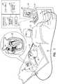
- FIG. 1is a schematic, pictorial illustration of a medical system 20 comprising a medical probe 22 and a control console 24, and Figure 2 is a schematic pictorial illustration of a distal end 26 of the medical probe, in accordance with an embodiment of the present invention.
- Medical system 20may be based, for example, on the CARTO® system, produced by Biosense Webster Inc. (Diamond Bar, California, U.S.A.).
- medical probe 22comprises a balloon catheter that is used for diagnostic or therapeutic treatment, such as for performing ablation procedures in a heart 28 of a patient 30.
- medical probe 22may be used, mutatis mutandis, for other therapeutic and/or diagnostic purposes in the heart or in other body organs.
- a medical professional 32inserts medical probe 22 into a biocompatible sheath (not shown) that has been pre-positioned in a body cavity (e.g., a chamber of heart 28) of the patient so that an inflatable balloon 36 ( Figure 2 ) affixed to distal end 26 of the medical probe enters the body cavity.
- Balloon 36is typically formed from bio-compatible material such as polyethylene terephthalate (PET), polyurethane, Nylon, or Pebax.
- Control console 24is connected, by a cable 38, to body surface electrodes, which typically comprise adhesive skin patches 40 that are affixed to patient 30.
- Control console 24comprises a processor 42 that determines position coordinates of distal end 26 inside heart 28 based on impedances measured between adhesive skin patches 40 and one or more electrodes 44 (also referred to herein as microelectrodes 44) that are attached to an exterior wall of balloon 36. While embodiments herein describe using microelectrodes 44 as location sensors, using the microelectrodes to perform other tasks (e.g., measuring electrical activity of heart 28) during a medical procedure is considered to be within the spirit and scope of the present invention.
- Processor 42typically comprises a general-purpose computer, with suitable front end and interface circuits for receiving signals from elements of medical probe 22 (e.g., microelectrodes 44) and controlling the other components of control console 24.
- Processor 42may be programmed in software to carry out the functions that are described herein.
- the softwaremay be downloaded to control console 24 in electronic form, over a network, for example, or it may be provided on non-transitory tangible media, such as optical, magnetic or electronic memory media.
- some or all of the functions of processor 42may be carried out by dedicated or programmable digital hardware components.
- Impedance-based position tracking techniquesare described, for example, in U.S. Patents 5,983,126 , 6,456,864 and 5,944,022 , whose disclosures are incorporated herein by reference.
- Magnetic position tracking techniquesare described, for example, in U.S. Patents 5,391,199 , 5,443,489 , 6,788,967 , 6,690,963 , 5,558,091 , 6,172,499 6,177,792 , whose disclosures are incorporated herein by reference.
- the methods of position sensing described hereinaboveare implemented in the above-mentioned CARTO® system and are described in detail in the patents cited above.
- Control console 24also comprises an input/output (I/O) communications interface 46 that enables the control console to transfer signals from, and/or transfer signals to electrodes 44 in medical probe 22 and adhesive skin patches 40.
- processor 42can generate a map 48 that shows the position of balloon 36 in the patient's body.
- processor 42can present map 48 to medical professional 32 on a display 50, and store data representing the map in a memory 52.
- Memory 52may comprise any suitable volatile and/or non-volatile memory, such as random access memory or a hard disk drive.
- medical professional 32can manipulate map 48 using one or more input devices 54.
- display 50may comprise a touchscreen that can be configured to accept inputs from medical professional 32, in addition to presenting image 48.
- distal end 26comprises one or more electrodes 56, that are typically used for ablation and so are also referred to herein as ablation electrodes 56, attached to the exterior wall of balloon 36.
- ablation electrodes 56have non-polygonal shapes, and microelectrodes 44 are positioned in "islands" within the ablation electrodes. Electrodes 44 and 56 can be fabricated with the balloon and typically comprise gold overlaying the exterior wall of balloon 36.
- Control console 24also comprises an ablation module 58, and an inflation module 59.
- Ablation module 58is configured to monitor and control ablation parameters such as the level and the duration of ablation power (e.g., radio-frequency energy) conveyed to ablation electrodes 56.
- Inflation module 59is configured to monitor and control the inflation pressure in balloon 36. As described in the description referencing Figures 5 and 6 hereinbelow, medical professional 32 can control the inflation pressure in the balloon in order to adjust the amount of cardiac tissue that is in contact with electrode(s) 56 during an ablation procedure.
- inflation module 59can use irrigation fluid to inflate balloon 36, and control the inflation pressure in the balloon by controlling a flow rate of the irrigation fluid into the balloon.
- balloon 36comprises multiple small fenestrations (not shown) that allow the irrigation fluid to exit the balloon. These fenestrations are typically 0.025-0.500 millimeters (mm) (e.g., 0.089mm) in diameter.
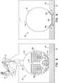
- FIG. 3is a schematic cutaway view of distal end 26, in accordance with an embodiment of the present invention.
- Balloon 36is affixed to a tubular shaft 60 that is configured to extend from a distal end of a lumen 62 of medical probe 22, and the balloon is configured to be deployed through the lumen into a body cavity such as heart 28.
- Balloon 36comprises a proximal pole region 64 and a distal pole 66 that lie on a longitudinal equator 68 of the balloon. Balloon 36 also comprises a proximal side 70 and a distal side 72 that are separated by a latitudinal equator 74 of the balloon. Proximal side 70 comprises a first hemisphere terminated by latitudinal equator 74 that includes proximal pole region 64, and distal side 72 comprises a second hemisphere terminated by the latitudinal equator that includes distal pole 66.
- balloon 36does not comprise any structural elements (e.g., an extender shaft) within the balloon. Additionally, balloon 36 comprises a main aperture 78 at proximal pole region 64 that connects the balloon to tubular shaft 60 (i.e., for inflation/deflation). In other words, unlike other balloons used for ablation known in the art, balloon 36 does not comprise a through extender shaft.
- distal side 72has a continuously smooth surface (i.e., there are no large apertures on the distal side) and balloon 36 has a non-elongated spherical shape when inflated.
- medical probe 22has a diameter of 2.5 millimeters
- balloon 36can have a diameter of up to eight millimeters when inflated. In a non-inflated state, balloon 36 can be retracted into the medical probe. The inventors have found that using these dimensions, the balloon can form its non-elongated spherical shape when inflated, yet retract to fit within probe 22 when deflated.
- Ablation electrodes 56are differentiated herein by appending a letter to the identifying numeral, so that the ablation electrodes comprise ablation electrodes 56A and 56B.
- ablation electrode 56Ais attached to balloon 36 (i.e., as indicated by arrows 76) so that ablation electrode 56A extends over at least 50% of an area on distal side 72 that is within 30° of arc from distal pole 66.
- ablation electrode 56Acan extend over at least 75% of the area on distal side 72 that is within 30° of arc from distal pole 66.
- the shape of ablation electrode 56Ais symmetrical around distal pole 66.
- ablation electrodes 56Bare attached to balloon 36 and encompass both proximal side 70 and distal side 72.
- distal end 72may not include any microelectrodes 44.
- electrodes 56can be used as position sensors (i.e., in addition to being used to ablate tissue).
- ablation electrode 56Amay comprise multiple "sub-electrodes" that extend over at least 50% of an area on distal side 72 that is within 30° of arc from distal pole 66.
- connections of electrodes 56 and microelectrodes 44 to interface 46 and module 58are not shown.
- the connectionsare made by wires (not shown) running from the inside of the balloon to the outer surface of the balloon.
- the electrical connectionscan be formed with conductive epoxy or welding.
- Figure 4is a flow diagram that schematically illustrates a method of using medical probe 22 to perform an ablation procedure
- Figures 5 and 6are schematic detail views of distal end 26 while the medical probe performs the ablation procedure on tissue in heart 28, in accordance with an embodiment of the present invention.
- Figure 5illustrates distal end when balloon 36 is under low pressure (0.5-5.0 P.S.I.)
- Figure 6illustrates the distal end when the balloon is under high pressure.
- high pressuree.g., >5.0 P.S.I.
- the diameter of the balloonincreases. This increase comes preferentially from enlargement of gaps 102 between electrodes 56.
- more electrode surfacecomes into contact with the tissue. This allows for the creation of a larger and deeper lesion.
- balloon 36In low pressure, balloon 36 inflates to a first diameter (e.g., 2.5mm), and under high pressure, the balloon inflates to a second diameter (e.g., 8.0mm) that is greater than the first diameter.
- a first diametere.g. 2.5mm
- a second diametere.g. 8.0mm
- FIG. 5while pressing distal side 72 against tissue 100 during an ablation procedure, only a small portion of electrode 56A is in contact with the tissue when balloon 36 is inflated to the first diameter. However, as shown in Figure 6 , while pressing distal side 72 against tissue 100 during an ablation procedure, almost all (or all) of electrodes 56A and 56B are in contact with the tissue when balloon 36 is inflated to the second diameter.
- inflating balloon 36 using higher pressurestretches the elastic biocompatible material in the balloon (i.e., electrodes 56 typically do not stretch), thereby increasing the surface area of gaps 102, and "pushing" electrodes 56B forward (i.e., towards tissue 100).
- a selection step 80medical professional 32 selects, e.g., from a previously generated map of heart 28, an area of tissue 100 in heart 28 that is in a region of the tissue distal to medical probe 22, and in a first determination step 82, processor 42 determines dimensions (and therefore a size) of the selected area.
- processor 42determines, based on impedances measured by microelectrodes 44, a current location of balloon 36 in a second determination step 86.
- a control step 88in response to the determined size of the selected area, medical professional 32 can control, using inflation module 59, the inflation pressure (and therefore the size) of balloon 36.
- one or more electrodes 56conform to and cover the selected area in response to the exerted force.
- the processorupon processor 42 determining the size of the selected area, can determine the inflation pressure responsively to the size of the area (i.e., in order to ensure that one or more ablation electrodes cover the selected area when distal side 72 of balloon 36 presses against tissue 100).
- a first positioning step 90medical professional 32 positions medical probe 22 so that distal side 72 of balloon 36 presses against the selected area of tissue 100, and in an ablation step 92, one or more ablation electrodes 56 deliver ablation energy received from ablation module 58 to the tissue in order to perform the ablation.
- the inflation pressure in balloon 36influences the compliancy of the balloon. Therefore, the number of ablation electrodes 56 used, and the size of the area being ablated by the ablation electrodes, are dependent on the inflation pressure in the balloon.
- balloon 36is inflated using a high inflation pressure thereby expanding the balloon and placing more electrodes into contact with the tissue.
- the balloonis inflated using a low inflation pressure, thereby making the balloon smaller and presenting less electrodes towards the distal face of the balloon (i.e., less electrodes make contact with the tissue).
- ablation electrode 56Aonly a portion of ablation electrode 56A is in contact (and can therefore ablate) with the tissue during the ablation procedure when balloon 36 is inflated using a low inflation pressure.
- balloon 36comprises a given microelectrode 44 that encompasses distal pole 66 (i.e., as shown in Figure 2 )
- heat generated in response to ablation energy delivered by ablation electrode 56Ai.e., that surrounds the given microelectrode
- the increased size of balloon 36enables almost all of ablation electrode 56A and portions of ablation electrodes 56B to be in contact with tissue 100.
- the area of ablation electrodes 56 that can deliver radio-frequency energy to tissue 100 for ablationis related to the inflation pressure in balloon 36, so that as the pressure increases, the area increases (and vice versa ) .
- the area of ablation electrodes 56 that can deliver radio-frequency energy to tissue 100 for ablationis related to the inflation pressure in balloon 36, so that as the pressure increases, the area increases (and vice versa ) .
- ablation electrodes 56can create deeper lesions and ablate larger areas of tissue.
- ablation electrodes 56While ablation electrodes 56 are in contact with tissue 100, there are gaps (i.e., open space) 102 on balloon 36 that is not covered by the ablation electrodes. In operation, heat in the tissue that is generated in response to ablation energy delivered by ablation electrodes 56 (i.e., that surround the open space) can conduct to nearby tissue (and therefore ablate) the tissue that is in contact with any gaps 102 that are in contact with tissue 100.
- step 94if there is any additional tissue that needs to be ablated, then the method continues with step 80.
- step 96if there is no further tissue 100 that needs to be ablated, then the ablation procedure is complete and the method ends.
Landscapes
- Health & Medical Sciences (AREA)
- Life Sciences & Earth Sciences (AREA)
- Engineering & Computer Science (AREA)
- Surgery (AREA)
- General Health & Medical Sciences (AREA)
- Public Health (AREA)
- Biomedical Technology (AREA)
- Heart & Thoracic Surgery (AREA)
- Medical Informatics (AREA)
- Molecular Biology (AREA)
- Physics & Mathematics (AREA)
- Animal Behavior & Ethology (AREA)
- Veterinary Medicine (AREA)
- Plasma & Fusion (AREA)
- Nuclear Medicine, Radiotherapy & Molecular Imaging (AREA)
- Otolaryngology (AREA)
- Cardiology (AREA)
- Biophysics (AREA)
- Pathology (AREA)
- Human Computer Interaction (AREA)
- Surgical Instruments (AREA)
Abstract
Description
- The present invention relates generally to invasive medical probes, and specifically to a balloon catheter comprising one or more large area electrodes.
- A balloon catheter comprises an inflatable balloon at its distal end that can be inflated and deflated as necessary. In operation, the balloon is typically deflated while the catheter is inserted into a body cavity (e.g., a heart) of a patient, inflated in order to perform the necessary procedure, and deflated again upon completing the procedure.
U.S. Patent Application 2012/0310233 to Dimmer et al. , whose disclosure is incorporated herein by reference, describes a balloon catheter comprising electrodes that can have different shapes and configurations. The electrodes are attached to an inflatable balloon having a diameter between five and twenty five millimeters.U.S. Patent 8,295,902 to Salahieh et al. , whose disclosure is incorporated herein by reference, describes a tissue electrode assembly that includes electrodes that can have different shapes, sizes and patterns. The configuration of the electrodes influences the amount and ablation lines of energy delivered by the electrodes to body tissue.- European Patent Application
EP 2,923,666 to Govari et al. , whose disclosure is incorporated herein by reference, describes a catheter with a balloon having one or more ablation electrodes and multiple microelectrodes that are configured to measure temperature. In some embodiments, the microelectrodes are disposed circumferentially about a longitudinal axis of an exterior wall of the balloon. In alternative embodiments, the microelectrodes are disposed on a flexible circuit substrate and adhered to the exterior wall of the balloon. - International Patent Application
WO 2014/070999 to Toth et al. , whose disclosure is incorporated herein by reference, describes a probe that can be used for micro-ablation procedures and includes a plurality of electrodes. The electrodes may comprise microelectrodes, stimulation electrodes, and ablation electrodes. - United States Patent Application
2009/0076498 to Vahid et al. , whose disclosure is incorporated herein by reference, describes a visualization and ablation system that includes a visualization balloon having ablation electrodes on a distal front surface of the balloon. - United States Patent Application
2008/0319350 to Wallace et al. , whose disclosure is incorporated herein by reference, describes a device configured to measure a size of a body lumen and to ablate tissue that uses the measurement to normalize delivery of ablation energy from a balloon to a luminal target of varying circumference. The ablation energy is delivered by an energy delivery element such as a radio-frequency electrode, an array of electrodes, or solid-state circuitry that can be arranged directly on the expandable balloon, or arranged on an electrode support that is itself engaged around the balloon. - United States Patent
6,771,996 to Bowe et al. , whose disclosure is incorporated herein by reference, describes an ablation and high-resolution mapping catheter system for pulmonary vein foci elimination. The catheter system may include an inflatable balloon having a plurality of mapping electrodes arranged in an array at the distal end of the balloon. - Documents incorporated by reference in the present patent application are to be considered an integral part of the application except that to the extent any terms are defined in these incorporated documents in a manner that conflicts with the definitions made explicitly or implicitly in the present specification, only the definitions in the present specification should be considered.
- The description above is presented as a general overview of related art in this field and should not be construed as an admission that any of the information it contains constitutes prior art against the present patent application.
- There is provided, in accordance with an embodiment of the present invention, a medical apparatus, including a probe having a distal end configured for insertion into a body cavity and containing a lumen that opens through the distal end, an inflatable balloon deployable through the lumen into the body cavity such that when the balloon is deployed through the lumen and inflated, a distal pole on a distal side of the balloon is located opposite the lumen, and an electrode attached to the distal side of the inflatable balloon and extending over at least 50% of an area of the distal side of the balloon that is within 30° of arc from the distal pole.
- In some embodiments, the electrode has a non-polygonal shape. In additional embodiments, the electrode is symmetrical around the distal pole. In further embodiments, the balloon has a non-elongated spherical shape when inflated.
- In some embodiments, the distal side of the balloon has a continuously smooth surface. In additional embodiments where the distal side of the balloon has a continuously smooth surface, the electrode may include multiple sub-electrodes. In further embodiments where the distal side of the balloon has a continuously smooth surface, the electrode may include a first electrode that does not cover the distal pole and having a first size, and the medical apparatus may include a second electrode having a second size smaller than the first size and attached to the distal pole of the inflatable balloon.
- In supplemental embodiments, the medical apparatus may include additional electrodes attached to the distal side of the inflatable balloon. In some embodiments, the balloon is not inflated when deployed through the lumen, the balloon has a balloon diameter less than or equal to eight millimeters when inflated, and the lumen has a lumen diameter of 2.5 millimeters. In additional embodiments, the electrode extending over at least 50% of an area of the distal side of the balloon that is within 30° of arc from the distal pole includes the electrode extending over at least 75% of the area of the distal side of the balloon that is within 30° of arc from the distal pole.
- There is also provided, in accordance with an embodiment of the present invention, a method, including providing a probe having a distal end configured for insertion into a body cavity and containing a lumen that opens through the distal end, providing an inflatable balloon that is deployable through the lumen into the body cavity such that when the balloon is deployed through the lumen and inflated, a distal pole on a distal side of the balloon is located opposite the lumen, and attaching, to the distal side of the inflatable balloon, an electrode that extends over at least 50% of an area of the distal side of the balloon that is within 30° of arc from the distal pole.
- There is additionally provided, in accordance with an embodiment of the present invention, a method, including inserting a distal end of a medical probe into a body cavity of a patient, the medical probe including a lumen that opens through the distal end, an inflatable balloon deployable through the lumen into the body cavity such that when the balloon is deployed through the lumen and inflated, a distal pole on a distal side of the balloon is located opposite the lumen, and an electrode attached to the distal side of the inflatable balloon and extending over at least 50% of an area of the distal side of the balloon that is within 30° of arc from the distal pole. The method also includes selecting, in the body cavity, an area of tissue to ablate in a region distal to the catheter, controlling an inflation pressure of the balloon responsively to a size of the area, pressing the distal side of the balloon against the selected area of the tissue, and ablating the selected area of the tissue.
- In some embodiments, controlling the inflation pressure includes controlling an irrigation flow rate.
- The disclosure is herein described, by way of example only, with reference to the accompanying drawings, wherein:
Figure 1 is a schematic, pictorial illustration of a medical system comprising a medical probe whose distal end comprises a balloon, in accordance with an embodiment of the present invention;Figure 2 is a schematic pictorial illustration of the distal end comprising multiple ablation electrodes and multiple microelectrodes attached to the balloon, in accordance with an embodiment of the present invention;Figure 3 is a schematic cutaway view of the distal end of the medical probe, in accordance with an embodiment of the present invention;Figure 4 is a flow diagram that schematically illustrates a method of using the medical probe to perform an ablation procedure on endocardial tissue, in accordance with an embodiment of the present invention;Figure 5 is a schematic detail view of the distal end of the medical probe performing the ablation procedure on the endocardial tissue while the balloon is fully inflated, in accordance with an embodiment of the present invention; andFigure 6 is a schematic detail view of the distal end of the medical probe performing the ablation procedure on the endocardial tissue while the balloon is partially inflated, in accordance with an embodiment of the present invention.- In embodiments of the present invention, a medical probe, in this case a balloon catheter, comprises a distal end configured for insertion into a body cavity, and the probe contains a lumen that opens through the distal end. The medical probe also comprises an inflatable balloon that is deployable through the lumen into the body cavity such that when the balloon is deployed through the lumen and inflated, a distal pole on a distal side of the balloon is located opposite the lumen. The medical probe further comprises an electrode that is attached to the distal side of the inflatable balloon and extends over at least 50% of an area of the distal side of the balloon that is within 30° of arc from the distal pole.
- Balloon catheters implementing embodiments of the present invention enable ablation of tissue in contact with the distal pole of the balloon. In embodiments of the present invention, varying the inflation pressure in the balloon impacts the compliance and size of the balloon, which therefore impacts the percentage of surface area of the electrode that is in contact with tissue in a body cavity. Therefore, as described hereinbelow, during a cardiac ablation procedure, a medical professional can control the size of the ablation area by controlling the inflation pressure in the balloon.
Figure 1 is a schematic, pictorial illustration of amedical system 20 comprising amedical probe 22 and acontrol console 24, andFigure 2 is a schematic pictorial illustration of adistal end 26 of the medical probe, in accordance with an embodiment of the present invention.Medical system 20 may be based, for example, on the CARTO® system, produced by Biosense Webster Inc. (Diamond Bar, California, U.S.A.). In embodiments described hereinbelow,medical probe 22 comprises a balloon catheter that is used for diagnostic or therapeutic treatment, such as for performing ablation procedures in aheart 28 of apatient 30. Alternatively,medical probe 22 may be used,mutatis mutandis, for other therapeutic and/or diagnostic purposes in the heart or in other body organs.- During a medical procedure, a
medical professional 32 insertsmedical probe 22 into a biocompatible sheath (not shown) that has been pre-positioned in a body cavity (e.g., a chamber of heart 28) of the patient so that an inflatable balloon 36 (Figure 2 ) affixed todistal end 26 of the medical probe enters the body cavity.Balloon 36 is typically formed from bio-compatible material such as polyethylene terephthalate (PET), polyurethane, Nylon, or Pebax. Control console 24 is connected, by acable 38, to body surface electrodes, which typically compriseadhesive skin patches 40 that are affixed topatient 30.Control console 24 comprises aprocessor 42 that determines position coordinates ofdistal end 26 insideheart 28 based on impedances measured betweenadhesive skin patches 40 and one or more electrodes 44 (also referred to herein as microelectrodes 44) that are attached to an exterior wall ofballoon 36. While embodiments herein describe usingmicroelectrodes 44 as location sensors, using the microelectrodes to perform other tasks (e.g., measuring electrical activity of heart 28) during a medical procedure is considered to be within the spirit and scope of the present invention.Processor 42 typically comprises a general-purpose computer, with suitable front end and interface circuits for receiving signals from elements of medical probe 22 (e.g., microelectrodes 44) and controlling the other components ofcontrol console 24.Processor 42 may be programmed in software to carry out the functions that are described herein. The software may be downloaded to controlconsole 24 in electronic form, over a network, for example, or it may be provided on non-transitory tangible media, such as optical, magnetic or electronic memory media. Alternatively, some or all of the functions ofprocessor 42 may be carried out by dedicated or programmable digital hardware components.- Although the medical system shown in
Figures 1 and2 uses impedance-based sensing to measure a location ofdistal end 26, other position tracking techniques may be used (e.g., techniques using magnetic-based sensors). Impedance-based position tracking techniques are described, for example, inU.S. Patents 5,983,126 ,6,456,864 and5,944,022 , whose disclosures are incorporated herein by reference. Magnetic position tracking techniques are described, for example, inU.S. Patents 5,391,199 ,5,443,489 ,6,788,967 ,6,690,963 ,5,558,091 ,6,172,499 6,177,792 , whose disclosures are incorporated herein by reference. The methods of position sensing described hereinabove are implemented in the above-mentioned CARTO® system and are described in detail in the patents cited above. Control console 24 also comprises an input/output (I/O)communications interface 46 that enables the control console to transfer signals from, and/or transfer signals toelectrodes 44 inmedical probe 22 andadhesive skin patches 40. Based on signals received frommicroelectrodes 44 andadhesive skin patches 40,processor 42 can generate amap 48 that shows the position ofballoon 36 in the patient's body. During the procedure,processor 42 can presentmap 48 to medical professional 32 on adisplay 50, and store data representing the map in amemory 52.Memory 52 may comprise any suitable volatile and/or non-volatile memory, such as random access memory or a hard disk drive. In some embodiments, medical professional 32 can manipulate map 48 using one ormore input devices 54. In alternative embodiments,display 50 may comprise a touchscreen that can be configured to accept inputs from medical professional 32, in addition to presentingimage 48.- In embodiments of the present invention,
distal end 26 comprises one ormore electrodes 56, that are typically used for ablation and so are also referred to herein asablation electrodes 56, attached to the exterior wall ofballoon 36. In the configuration shown inFigure 2 ,ablation electrodes 56 have non-polygonal shapes, andmicroelectrodes 44 are positioned in "islands" within the ablation electrodes.Electrodes balloon 36. Control console 24 also comprises anablation module 58, and aninflation module 59.Ablation module 58 is configured to monitor and control ablation parameters such as the level and the duration of ablation power (e.g., radio-frequency energy) conveyed toablation electrodes 56.Inflation module 59 is configured to monitor and control the inflation pressure inballoon 36. As described in the description referencingFigures 5 and 6 hereinbelow, medical professional 32 can control the inflation pressure in the balloon in order to adjust the amount of cardiac tissue that is in contact with electrode(s) 56 during an ablation procedure.- In some embodiments,
inflation module 59 can use irrigation fluid to inflateballoon 36, and control the inflation pressure in the balloon by controlling a flow rate of the irrigation fluid into the balloon. In theseembodiments balloon 36 comprises multiple small fenestrations (not shown) that allow the irrigation fluid to exit the balloon. These fenestrations are typically 0.025-0.500 millimeters (mm) (e.g., 0.089mm) in diameter. Figure 3 is a schematic cutaway view ofdistal end 26, in accordance with an embodiment of the present invention.Balloon 36 is affixed to atubular shaft 60 that is configured to extend from a distal end of alumen 62 ofmedical probe 22, and the balloon is configured to be deployed through the lumen into a body cavity such asheart 28.Balloon 36 comprises aproximal pole region 64 and adistal pole 66 that lie on alongitudinal equator 68 of the balloon.Balloon 36 also comprises aproximal side 70 and adistal side 72 that are separated by alatitudinal equator 74 of the balloon.Proximal side 70 comprises a first hemisphere terminated bylatitudinal equator 74 that includesproximal pole region 64, anddistal side 72 comprises a second hemisphere terminated by the latitudinal equator that includesdistal pole 66.- In embodiments of the present invention,
balloon 36 does not comprise any structural elements (e.g., an extender shaft) within the balloon. Additionally,balloon 36 comprises amain aperture 78 atproximal pole region 64 that connects the balloon to tubular shaft 60 (i.e., for inflation/deflation). In other words, unlike other balloons used for ablation known in the art,balloon 36 does not comprise a through extender shaft. - Furthermore,
distal side 72 has a continuously smooth surface (i.e., there are no large apertures on the distal side) andballoon 36 has a non-elongated spherical shape when inflated. In some embodiments,medical probe 22 has a diameter of 2.5 millimeters, andballoon 36 can have a diameter of up to eight millimeters when inflated. In a non-inflated state,balloon 36 can be retracted into the medical probe. The inventors have found that using these dimensions, the balloon can form its non-elongated spherical shape when inflated, yet retract to fit withinprobe 22 when deflated. Ablation electrodes 56 are differentiated herein by appending a letter to the identifying numeral, so that the ablation electrodes compriseablation electrodes ablation electrode 56A is attached to balloon 36 (i.e., as indicated by arrows 76) so thatablation electrode 56A extends over at least 50% of an area ondistal side 72 that is within 30° of arc fromdistal pole 66. In some embodiments,ablation electrode 56A can extend over at least 75% of the area ondistal side 72 that is within 30° of arc fromdistal pole 66. In additional embodiments, the shape ofablation electrode 56A is symmetrical arounddistal pole 66. In the example shown inFigure 3 ,ablation electrodes 56B are attached to balloon 36 and encompass bothproximal side 70 anddistal side 72.- In further embodiments, as shown in
Figure 3 ,distal end 72 may not include anymicroelectrodes 44. In these embodiments,electrodes 56 can be used as position sensors (i.e., in addition to being used to ablate tissue). In additional embodiments,ablation electrode 56A may comprise multiple "sub-electrodes" that extend over at least 50% of an area ondistal side 72 that is within 30° of arc fromdistal pole 66. For simplicity, connections ofelectrodes 56 andmicroelectrodes 44 to interface 46 andmodule 58 are not shown. In some embodiments, the connections are made by wires (not shown) running from the inside of the balloon to the outer surface of the balloon. The electrical connections can be formed with conductive epoxy or welding. Figure 4 is a flow diagram that schematically illustrates a method of usingmedical probe 22 to perform an ablation procedure, andFigures 5 and 6 (drawn to different scales) are schematic detail views ofdistal end 26 while the medical probe performs the ablation procedure on tissue inheart 28, in accordance with an embodiment of the present invention.Figure 5 illustrates distal end whenballoon 36 is under low pressure (0.5-5.0 P.S.I.), andFigure 6 illustrates the distal end when the balloon is under high pressure. When under high pressure (e.g., >5.0 P.S.I.) the diameter of the balloon increases. This increase comes preferentially from enlargement ofgaps 102 betweenelectrodes 56. When enlarged, more electrode surface comes into contact with the tissue. This allows for the creation of a larger and deeper lesion.- Under low pressure,
balloon 36 inflates to a first diameter (e.g., 2.5mm), and under high pressure, the balloon inflates to a second diameter (e.g., 8.0mm) that is greater than the first diameter. As shown inFigure 5 , while pressingdistal side 72 againsttissue 100 during an ablation procedure, only a small portion ofelectrode 56A is in contact with the tissue whenballoon 36 is inflated to the first diameter. However, as shown inFigure 6 , while pressingdistal side 72 againsttissue 100 during an ablation procedure, almost all (or all) ofelectrodes balloon 36 is inflated to the second diameter. In balloon catheters implementing embodiments of the present invention, inflatingballoon 36 using higher pressure stretches the elastic biocompatible material in the balloon (i.e.,electrodes 56 typically do not stretch), thereby increasing the surface area ofgaps 102, and "pushing"electrodes 56B forward (i.e., towards tissue 100). - In a
selection step 80, medical professional 32 selects, e.g., from a previously generated map ofheart 28, an area oftissue 100 inheart 28 that is in a region of the tissue distal tomedical probe 22, and in afirst determination step 82,processor 42 determines dimensions (and therefore a size) of the selected area. In aninsertion step 84, medical professional 32 manipulatesmedical probe 22 so thatdistal end 26 enters a chamber ofheart 28, and while maneuvering the medical probe in the cardiac chamber,processor 42 determines, based on impedances measured bymicroelectrodes 44, a current location ofballoon 36 in asecond determination step 86. - In a
control step 88, in response to the determined size of the selected area, medical professional 32 can control, usinginflation module 59, the inflation pressure (and therefore the size) ofballoon 36. In some embodiments, as shown inFigure 6 , one ormore electrodes 56 conform to and cover the selected area in response to the exerted force. In some embodiments, uponprocessor 42 determining the size of the selected area, the processor can determine the inflation pressure responsively to the size of the area (i.e., in order to ensure that one or more ablation electrodes cover the selected area whendistal side 72 ofballoon 36 presses against tissue 100). - In a
first positioning step 90, medical professional 32 positionsmedical probe 22 so thatdistal side 72 ofballoon 36 presses against the selected area oftissue 100, and in anablation step 92, one ormore ablation electrodes 56 deliver ablation energy received fromablation module 58 to the tissue in order to perform the ablation. - In embodiments of the present invention, the inflation pressure in
balloon 36 influences the compliancy of the balloon. Therefore, the number ofablation electrodes 56 used, and the size of the area being ablated by the ablation electrodes, are dependent on the inflation pressure in the balloon. In the example shown inFigure 6 ,balloon 36 is inflated using a high inflation pressure thereby expanding the balloon and placing more electrodes into contact with the tissue. InFigure 5 , the balloon is inflated using a low inflation pressure, thereby making the balloon smaller and presenting less electrodes towards the distal face of the balloon (i.e., less electrodes make contact with the tissue). - As shown in
Figure 5 , only a portion ofablation electrode 56A is in contact (and can therefore ablate) with the tissue during the ablation procedure whenballoon 36 is inflated using a low inflation pressure. In embodiments whereballoon 36 comprises a givenmicroelectrode 44 that encompasses distal pole 66 (i.e., as shown inFigure 2 ), heat generated in response to ablation energy delivered byablation electrode 56A (i.e., that surrounds the given microelectrode) can conduct to nearby tissue (and therefore ablate) the tissue that is in contact with the given microelectrode (i.e., the portion the exterior wall ofballoon 36 surroundingdistal pole 66 that is not covered byablation electrode 56A). - As shown in
Figure 6 , the increased size ofballoon 36 enables almost all ofablation electrode 56A and portions ofablation electrodes 56B to be in contact withtissue 100. In other words, the area ofablation electrodes 56 that can deliver radio-frequency energy totissue 100 for ablation is related to the inflation pressure inballoon 36, so that as the pressure increases, the area increases (andvice versa). Additionally, in the high pressure state, whiledistal side 72 is pressed against the tissue, there is less interference from surrounding blood, so thatablation electrodes 56 can create deeper lesions and ablate larger areas of tissue. - While
ablation electrodes 56 are in contact withtissue 100, there are gaps (i.e., open space) 102 onballoon 36 that is not covered by the ablation electrodes. In operation, heat in the tissue that is generated in response to ablation energy delivered by ablation electrodes 56 (i.e., that surround the open space) can conduct to nearby tissue (and therefore ablate) the tissue that is in contact with anygaps 102 that are in contact withtissue 100. - Returning to the flow diagram, in a
comparison step 94, if there is any additional tissue that needs to be ablated, then the method continues withstep 80. Returning to step 96, if there is nofurther tissue 100 that needs to be ablated, then the ablation procedure is complete and the method ends. - It will be appreciated that the embodiments described above are cited by way of example, and that the present invention is not limited to what has been particularly shown and described hereinabove. Rather, the scope of the present invention includes both combinations and subcombinations of the various features described hereinabove, as well as variations and modifications thereof which would occur to persons skilled in the art upon reading the foregoing description and which are not disclosed in the prior art.
- 1. A method, comprising:
inserting a distal end of a medical probe into a body cavity of a patient, the medical probe comprising:- a lumen that opens through the distal end,
- an inflatable balloon deployable through the lumen into the body cavity such that when the balloon is deployed through the lumen and inflated, a distal pole on a distal side of the balloon is located opposite the lumen, and
- an electrode attached to the distal side of the inflatable balloon and extending over at least 50% of an area of the distal side of the balloon that is within 30° of arc from the distal pole;
- selecting, in the body cavity, an area of tissue to ablate in a region distal to the catheter;
- controlling an inflation pressure of the balloon responsively to a size of the area;
- pressing the distal side of the balloon against the selected area of the tissue; and
- ablating the selected area of the tissue.
- 2. The method according to aspect 1, wherein controlling the inflation pressure comprises controlling an irrigation flow rate.
Claims (15)
- A medical apparatus, comprising:a probe having a distal end configured for insertion into a body cavity and containing a lumen that opens through the distal end;an inflatable balloon deployable through the lumen into the body cavity such that when the balloon is deployed through the lumen and inflated, a distal pole on a distal side of the balloon is located opposite the lumen; andan electrode attached to the distal side of the inflatable balloon and extending over at least 50% of an area of the distal side of the balloon that is within 30° of arc from the distal pole.
- The medical apparatus according to claim 1, and comprising additional electrodes attached to the distal side of the inflatable balloon.
- The medical apparatus according to claim 1, wherein the balloon is not inflated when deployed through the lumen, wherein the balloon has a balloon diameter less than or equal to eight millimeters when inflated, and wherein the lumen has a lumen diameter of 2.5 millimeters.
- The medical apparatus according to claim 1, wherein the electrode extending over at least 50% of an area of the distal side of the balloon that is within 30° of arc from the distal pole comprises the electrode extending over at least 75% of the area of the distal side of the balloon that is within 30° of arc from the distal pole.
- A method, comprising:providing a probe having a distal end configured for insertion into a body cavity and containing a lumen that opens through the distal end;providing an inflatable balloon that is deployable through the lumen into the body cavity such that when the balloon is deployed through the lumen and inflated, a distal pole on a distal side of the balloon is located opposite the lumen; andattaching, to the distal side of the inflatable balloon, an electrode that extends over at least 50% of an area of the distal side of the balloon that is within 30° of arc from the distal pole.
- The medical apparatus according to claim 1 or the method according to claim 5, wherein the electrode has a non-polygonal shape.
- The medical apparatus according to claim 1 or the method according to claim 5, wherein the electrode is symmetrical around the distal pole.
- The medical apparatus according to claim 1 or the method according to claim 5, wherein the balloon has a non-elongated spherical shape when inflated.
- The medical apparatus according to claim 1 or the method according to claim 5, wherein the distal side of the balloon has a continuously smooth surface.
- The medical apparatus or the method according to claim 9, wherein the electrode comprises multiple sub-electrodes.
- The medical apparatus according to claim 9, wherein the electrode comprises a first electrode that does not cover the distal pole and having a first size, and comprising a second electrode having a second size smaller than the first size and attached to the distal pole of the inflatable balloon.
- The method according to claim 9, wherein the electrode comprises a first electrode that does not cover the distal pole and having a first size, and comprising attaching, to the distal pole of the inflatable balloon, a second electrode having a second size smaller than the first size.
- The method according to claim 5, and comprising attaching additional electrodes to the distal side of the inflatable balloon.
- The method according to claim 5, wherein the balloon is not inflated when deployed through the lumen, wherein the balloon has a balloon diameter less than or equal to eight millimeters when inflated, and wherein the lumen has a lumen diameter of 2.5 millimeters.
- The method according to claim 14, wherein the electrode that extends over at least 50% of an area of the distal side of the balloon that is within 30° of arc from the distal pole comprises the electrode extending over at least 75% of the area of the distal side of the balloon that is within 30° of arc from the distal pole.
Applications Claiming Priority (1)
| Application Number | Priority Date | Filing Date | Title |
|---|---|---|---|
| US15/476,191US20180280080A1 (en) | 2017-03-31 | 2017-03-31 | Balloon catheter with large area electrodes |
Publications (1)
| Publication Number | Publication Date |
|---|---|
| EP3381396A1true EP3381396A1 (en) | 2018-10-03 |
Family
ID=61837687
Family Applications (1)
| Application Number | Title | Priority Date | Filing Date |
|---|---|---|---|
| EP18164943.5AWithdrawnEP3381396A1 (en) | 2017-03-31 | 2018-03-29 | Balloon catheter with large area electrodes |
Country Status (7)
| Country | Link |
|---|---|
| US (1) | US20180280080A1 (en) |
| EP (1) | EP3381396A1 (en) |
| JP (1) | JP7046676B2 (en) |
| CN (1) | CN108852506B (en) |
| AU (1) | AU2018202091A1 (en) |
| CA (1) | CA2999610A1 (en) |
| IL (1) | IL258111B2 (en) |
Cited By (3)
| Publication number | Priority date | Publication date | Assignee | Title |
|---|---|---|---|---|
| EP3834764A1 (en)* | 2019-12-11 | 2021-06-16 | Biosense Webster (Israel) Ltd | Balloon catheter with position sensors |
| EP3900659A1 (en)* | 2020-04-22 | 2021-10-27 | Biosense Webster (Israel) Ltd | Ablation of a hard-to-access region |
| EP3991682A1 (en)* | 2020-10-30 | 2022-05-04 | Biosense Webster (Israel) Ltd | Balloon catheter with split electrodes |
Families Citing this family (37)
| Publication number | Priority date | Publication date | Assignee | Title |
|---|---|---|---|---|
| WO2015192018A1 (en) | 2014-06-12 | 2015-12-17 | Iowa Approach Inc. | Method and apparatus for rapid and selective tissue ablation with cooling |
| EP3154463B1 (en) | 2014-06-12 | 2019-03-27 | Farapulse, Inc. | Apparatus for rapid and selective transurethral tissue ablation |
| EP3206613B1 (en) | 2014-10-14 | 2019-07-03 | Farapulse, Inc. | Apparatus for rapid and safe pulmonary vein cardiac ablation |
| US11534239B2 (en) | 2014-12-22 | 2022-12-27 | Biosense Webster (Israel) Ltd. | Systems and method or uses of ablating cardiac tissue |
| US10172673B2 (en) | 2016-01-05 | 2019-01-08 | Farapulse, Inc. | Systems devices, and methods for delivery of pulsed electric field ablative energy to endocardial tissue |
| US20170189097A1 (en) | 2016-01-05 | 2017-07-06 | Iowa Approach Inc. | Systems, apparatuses and methods for delivery of ablative energy to tissue |
| US10130423B1 (en) | 2017-07-06 | 2018-11-20 | Farapulse, Inc. | Systems, devices, and methods for focal ablation |
| US12144541B2 (en) | 2016-01-05 | 2024-11-19 | Boston Scientific Scimed, Inc. | Systems, apparatuses and methods for delivery of ablative energy to tissue |
| US10660702B2 (en) | 2016-01-05 | 2020-05-26 | Farapulse, Inc. | Systems, devices, and methods for focal ablation |
| US10905329B2 (en) | 2016-06-09 | 2021-02-02 | Biosense Webster (Israel) Ltd. | Multi-function conducting elements for a catheter |
| US11400205B2 (en) | 2016-11-23 | 2022-08-02 | Biosense Webster (Israel) Ltd. | Balloon-in-balloon irrigation balloon catheter |
| US9987081B1 (en) | 2017-04-27 | 2018-06-05 | Iowa Approach, Inc. | Systems, devices, and methods for signal generation |
| US12029545B2 (en) | 2017-05-30 | 2024-07-09 | Biosense Webster (Israel) Ltd. | Catheter splines as location sensors |
| WO2019023259A2 (en) | 2017-07-25 | 2019-01-31 | Affera, Inc. | Ablation catheters and related systems and methods |
| EP3658050B1 (en)* | 2017-07-25 | 2023-09-06 | Affera, Inc. | Ablation catheters |
| JP7586706B2 (en) | 2017-09-12 | 2024-11-19 | ボストン サイエンティフィック サイムド,インコーポレイテッド | Systems, devices and methods for focal ventricular ablation - Patents.com |
| WO2019217433A1 (en) | 2018-05-07 | 2019-11-14 | Farapulse, Inc. | Systems, apparatuses and methods for delivery of ablative energy to tissue |
| US11071585B2 (en) | 2018-09-14 | 2021-07-27 | Biosense Webster (Israel) Ltd. | Systems and methods of ablating cardiac tissue |
| WO2020053831A1 (en) | 2018-09-14 | 2020-03-19 | Biosense Webster (Israel) Ltd. | Systems for ablating cardiac tissue |
| US10687892B2 (en) | 2018-09-20 | 2020-06-23 | Farapulse, Inc. | Systems, apparatuses, and methods for delivery of pulsed electric field ablative energy to endocardial tissue |
| US11751936B2 (en)* | 2018-11-21 | 2023-09-12 | Biosense Webster (Israel) Ltd. | Configuring perimeter of balloon electrode as location sensor |
| US11457995B2 (en)* | 2018-12-27 | 2022-10-04 | Biosense Webster (Israel) Ltd. | Accurate balloon computation and visualization |
| US12369975B2 (en) | 2019-09-12 | 2025-07-29 | Biosense Webster (Israel) Ltd. | Balloon catheter with force sensor |
| US11633228B2 (en) | 2019-10-04 | 2023-04-25 | Biosense Webster (Israel) Ltd. | Identifying pulmonary vein occlusion by dimension deformations of balloon catheter |
| US12369974B2 (en) | 2019-10-10 | 2025-07-29 | Biosense Webster (Israel) Ltd. | Touch indication of balloon-catheter ablation electrode via balloon surface temperature measurement |
| US12137967B2 (en) | 2019-11-12 | 2024-11-12 | Biosense Webster (Israel) Ltd. | Accurate positioning and shape visualization of balloon catheter ablation tags |
| US20210378734A1 (en) | 2020-06-04 | 2021-12-09 | Biosense Webster (Israel) Ltd. | Smooth-edge and equidistantly spaced electrodes on an expandable frame of a catheter for irreversible-electroporation (ire) |
| US12310652B2 (en) | 2020-07-24 | 2025-05-27 | Boston Scientific Scimed, Inc. | Hybrid electroporation ablation catheter |
| WO2022020478A1 (en) | 2020-07-24 | 2022-01-27 | Boston Scientific Scimed Inc | Electric field application for single shot cardiac ablation by irreversible electroporation |
| US12239364B2 (en) | 2020-10-07 | 2025-03-04 | Biosense Webster (Israel) Ltd. | Printed proximal electrodes of an expandable catheter for use as a common electrode |
| US11974803B2 (en) | 2020-10-12 | 2024-05-07 | Biosense Webster (Israel) Ltd. | Basket catheter with balloon |
| US20220117577A1 (en)* | 2020-10-15 | 2022-04-21 | Elliot C. Schmidt | Stabilizing transnasal balloon sheath |
| US11957852B2 (en) | 2021-01-14 | 2024-04-16 | Biosense Webster (Israel) Ltd. | Intravascular balloon with slidable central irrigation tube |
| JP2024504184A (en) | 2021-01-27 | 2024-01-30 | ボストン サイエンティフィック サイムド,インコーポレイテッド | Voltage-controlled pulse sequence for irreversible electroporation ablation |
| US11849995B2 (en) | 2021-02-18 | 2023-12-26 | Biosense Webster (Israel) Ltd. | Detection of balloon catheter tissue contact using optical measurement |
| CN112932651B (en)* | 2021-03-24 | 2025-02-21 | 上海微创旋律医疗科技有限公司 | Electrode components and electrode balloon catheters |
| US12194260B2 (en)* | 2021-07-27 | 2025-01-14 | Biosense Webster (Israel) Ltd. | Identifying the state of a balloon catheter |
Citations (19)
| Publication number | Priority date | Publication date | Assignee | Title |
|---|---|---|---|---|
| WO1994023794A1 (en)* | 1993-04-14 | 1994-10-27 | Vesta Medical, Inc. | Method and apparatus for endometrial ablation |
| US5391199A (en) | 1993-07-20 | 1995-02-21 | Biosense, Inc. | Apparatus and method for treating cardiac arrhythmias |
| US5558091A (en) | 1993-10-06 | 1996-09-24 | Biosense, Inc. | Magnetic determination of position and orientation |
| US5944022A (en) | 1997-04-28 | 1999-08-31 | American Cardiac Ablation Co. Inc. | Catheter positioning system |
| US5983126A (en) | 1995-11-22 | 1999-11-09 | Medtronic, Inc. | Catheter location system and method |
| US6172499B1 (en) | 1999-10-29 | 2001-01-09 | Ascension Technology Corporation | Eddy current error-reduced AC magnetic position measurement system |
| US6177792B1 (en) | 1996-03-26 | 2001-01-23 | Bisense, Inc. | Mutual induction correction for radiator coils of an objects tracking system |
| US6456864B1 (en) | 1994-10-11 | 2002-09-24 | Ep Technologies, Inc. | Systems and methods for guiding movable electrode elements within multiple-electrode structures |
| US6690963B2 (en) | 1995-01-24 | 2004-02-10 | Biosense, Inc. | System for determining the location and orientation of an invasive medical instrument |
| US6771996B2 (en) | 2001-05-24 | 2004-08-03 | Cardiac Pacemakers, Inc. | Ablation and high-resolution mapping catheter system for pulmonary vein foci elimination |
| US20080319350A1 (en) | 2007-06-22 | 2008-12-25 | Wallace Michael P | Electrical means to normalize ablational energy transmission to a luminal tissue surface of varying size |
| US20090076498A1 (en) | 2007-08-31 | 2009-03-19 | Voyage Medical, Inc. | Visualization and ablation system variations |
| WO2010056771A1 (en)* | 2008-11-11 | 2010-05-20 | Shifamed Llc | Low profile electrode assembly |
| US20120310233A1 (en) | 2009-11-11 | 2012-12-06 | Innovative Pulmonary Solutions, Inc | Systems, apparatuses, and methods for treating tissue and controlling stenosis |
| US20140031810A1 (en)* | 2012-07-30 | 2014-01-30 | Northwestern University | Radiofrequency Probe for Circumferential Ablation of a Hollow Cavity |
| WO2014070999A2 (en) | 2012-11-05 | 2014-05-08 | Landy Toth | Systems, methods, and devices for monitoring and treatment of tissues within and/or through a lumen wall |
| EP2848225A1 (en)* | 2013-09-13 | 2015-03-18 | Covidien LP | A pleated or folded catheter-mounted balloon |
| EP2923666A2 (en) | 2014-03-27 | 2015-09-30 | Biosense Webster (Israel), Ltd. | Temperature measurement in catheter |
| WO2015163846A1 (en)* | 2014-04-21 | 2015-10-29 | Empire Technology Development Llc | Thermally treating torn tissue |
Family Cites Families (3)
| Publication number | Priority date | Publication date | Assignee | Title |
|---|---|---|---|---|
| US6142993A (en)* | 1998-02-27 | 2000-11-07 | Ep Technologies, Inc. | Collapsible spline structure using a balloon as an expanding actuator |
| US20070287994A1 (en)* | 2006-06-12 | 2007-12-13 | Pankaj Amrit Patel | Endoscopically Introducible Expandable Bipolar Probe |
| JP6265434B2 (en)* | 2015-03-27 | 2018-01-24 | 日本ライフライン株式会社 | Balloon type ablation catheter and ablation catheter device |
- 2017
- 2017-03-31USUS15/476,191patent/US20180280080A1/ennot_activeAbandoned
- 2018
- 2018-03-14ILIL258111Apatent/IL258111B2/enunknown
- 2018-03-23AUAU2018202091Apatent/AU2018202091A1/ennot_activeAbandoned
- 2018-03-29CACA2999610Apatent/CA2999610A1/ennot_activeAbandoned
- 2018-03-29EPEP18164943.5Apatent/EP3381396A1/ennot_activeWithdrawn
- 2018-03-29CNCN201810268769.XApatent/CN108852506B/enactiveActive
- 2018-03-30JPJP2018067204Apatent/JP7046676B2/enactiveActive
Patent Citations (23)
| Publication number | Priority date | Publication date | Assignee | Title |
|---|---|---|---|---|
| WO1994023794A1 (en)* | 1993-04-14 | 1994-10-27 | Vesta Medical, Inc. | Method and apparatus for endometrial ablation |
| US5391199A (en) | 1993-07-20 | 1995-02-21 | Biosense, Inc. | Apparatus and method for treating cardiac arrhythmias |
| US5443489A (en) | 1993-07-20 | 1995-08-22 | Biosense, Inc. | Apparatus and method for ablation |
| US5558091A (en) | 1993-10-06 | 1996-09-24 | Biosense, Inc. | Magnetic determination of position and orientation |
| US6456864B1 (en) | 1994-10-11 | 2002-09-24 | Ep Technologies, Inc. | Systems and methods for guiding movable electrode elements within multiple-electrode structures |
| US6690963B2 (en) | 1995-01-24 | 2004-02-10 | Biosense, Inc. | System for determining the location and orientation of an invasive medical instrument |
| US5983126A (en) | 1995-11-22 | 1999-11-09 | Medtronic, Inc. | Catheter location system and method |
| US6177792B1 (en) | 1996-03-26 | 2001-01-23 | Bisense, Inc. | Mutual induction correction for radiator coils of an objects tracking system |
| US5944022A (en) | 1997-04-28 | 1999-08-31 | American Cardiac Ablation Co. Inc. | Catheter positioning system |
| US6788967B2 (en) | 1997-05-14 | 2004-09-07 | Biosense, Inc. | Medical diagnosis, treatment and imaging systems |
| US6172499B1 (en) | 1999-10-29 | 2001-01-09 | Ascension Technology Corporation | Eddy current error-reduced AC magnetic position measurement system |
| US6771996B2 (en) | 2001-05-24 | 2004-08-03 | Cardiac Pacemakers, Inc. | Ablation and high-resolution mapping catheter system for pulmonary vein foci elimination |
| US20080319350A1 (en) | 2007-06-22 | 2008-12-25 | Wallace Michael P | Electrical means to normalize ablational energy transmission to a luminal tissue surface of varying size |
| US20090076498A1 (en) | 2007-08-31 | 2009-03-19 | Voyage Medical, Inc. | Visualization and ablation system variations |
| WO2010056771A1 (en)* | 2008-11-11 | 2010-05-20 | Shifamed Llc | Low profile electrode assembly |
| EP2370015A1 (en)* | 2008-11-11 | 2011-10-05 | Shifamed, Llc | Low profile electrode assembly |
| US8295902B2 (en) | 2008-11-11 | 2012-10-23 | Shifamed Holdings, Llc | Low profile electrode assembly |
| US20120310233A1 (en) | 2009-11-11 | 2012-12-06 | Innovative Pulmonary Solutions, Inc | Systems, apparatuses, and methods for treating tissue and controlling stenosis |
| US20140031810A1 (en)* | 2012-07-30 | 2014-01-30 | Northwestern University | Radiofrequency Probe for Circumferential Ablation of a Hollow Cavity |
| WO2014070999A2 (en) | 2012-11-05 | 2014-05-08 | Landy Toth | Systems, methods, and devices for monitoring and treatment of tissues within and/or through a lumen wall |
| EP2848225A1 (en)* | 2013-09-13 | 2015-03-18 | Covidien LP | A pleated or folded catheter-mounted balloon |
| EP2923666A2 (en) | 2014-03-27 | 2015-09-30 | Biosense Webster (Israel), Ltd. | Temperature measurement in catheter |
| WO2015163846A1 (en)* | 2014-04-21 | 2015-10-29 | Empire Technology Development Llc | Thermally treating torn tissue |
Cited By (4)
| Publication number | Priority date | Publication date | Assignee | Title |
|---|---|---|---|---|
| EP3834764A1 (en)* | 2019-12-11 | 2021-06-16 | Biosense Webster (Israel) Ltd | Balloon catheter with position sensors |
| CN113041481A (en)* | 2019-12-11 | 2021-06-29 | 伯恩森斯韦伯斯特(以色列)有限责任公司 | Balloon catheter with position sensor |
| EP3900659A1 (en)* | 2020-04-22 | 2021-10-27 | Biosense Webster (Israel) Ltd | Ablation of a hard-to-access region |
| EP3991682A1 (en)* | 2020-10-30 | 2022-05-04 | Biosense Webster (Israel) Ltd | Balloon catheter with split electrodes |
Also Published As
| Publication number | Publication date |
|---|---|
| IL258111A (en) | 2018-04-30 |
| CN108852506B (en) | 2023-03-07 |
| JP7046676B2 (en) | 2022-04-04 |
| IL258111B2 (en) | 2025-05-01 |
| AU2018202091A1 (en) | 2018-10-18 |
| JP2018171444A (en) | 2018-11-08 |
| US20180280080A1 (en) | 2018-10-04 |
| CA2999610A1 (en) | 2018-09-30 |
| IL258111B1 (en) | 2025-01-01 |
| CN108852506A (en) | 2018-11-23 |
Similar Documents
| Publication | Publication Date | Title |
|---|---|---|
| EP3381396A1 (en) | Balloon catheter with large area electrodes | |
| JP7374618B2 (en) | Reinforced large diameter balloon catheter | |
| CN110313987B (en) | Irrigation electrophysiology catheter with distinguishable electrodes for multi-electrode identification and orientation | |
| AU2018204229B2 (en) | Lasso catheter with tip electrode | |
| CN106852708B (en) | Ablation catheter with light-based contact sensor | |
| EP3766415A1 (en) | Visual guidance for positioning a distal end of a medical probe | |
| EP3461400A1 (en) | Highlighting a target region for re-ablation | |
| EP3231384A1 (en) | Pulmonary-vein cork device with ablation guiding trench | |
| EP3821838B1 (en) | Accurate positioning and shape visualization of balloon catheter ablation tags | |
| EP3841998A1 (en) | Lasso catheter with balloon | |
| CN111887973B (en) | Pulmonary vein isolation for patients with atrial fibrillation | |
| EP3954313A1 (en) | Balloon probe for irreversible electroporation | |
| EP4520284A1 (en) | Expandable electrode assembly comprising extended distal end for a medical catheter |
Legal Events
| Date | Code | Title | Description |
|---|---|---|---|
| PUAI | Public reference made under article 153(3) epc to a published international application that has entered the european phase | Free format text:ORIGINAL CODE: 0009012 | |
| STAA | Information on the status of an ep patent application or granted ep patent | Free format text:STATUS: THE APPLICATION HAS BEEN PUBLISHED | |
| AK | Designated contracting states | Kind code of ref document:A1 Designated state(s):AL AT BE BG CH CY CZ DE DK EE ES FI FR GB GR HR HU IE IS IT LI LT LU LV MC MK MT NL NO PL PT RO RS SE SI SK SM TR | |
| AX | Request for extension of the european patent | Extension state:BA ME | |
| STAA | Information on the status of an ep patent application or granted ep patent | Free format text:STATUS: REQUEST FOR EXAMINATION WAS MADE | |
| 17P | Request for examination filed | Effective date:20190403 | |
| RBV | Designated contracting states (corrected) | Designated state(s):AL AT BE BG CH CY CZ DE DK EE ES FI FR GB GR HR HU IE IS IT LI LT LU LV MC MK MT NL NO PL PT RO RS SE SI SK SM TR | |
| STAA | Information on the status of an ep patent application or granted ep patent | Free format text:STATUS: EXAMINATION IS IN PROGRESS | |
| 17Q | First examination report despatched | Effective date:20200303 | |
| GRAP | Despatch of communication of intention to grant a patent | Free format text:ORIGINAL CODE: EPIDOSNIGR1 | |
| STAA | Information on the status of an ep patent application or granted ep patent | Free format text:STATUS: GRANT OF PATENT IS INTENDED | |
| INTG | Intention to grant announced | Effective date:20241216 | |
| STAA | Information on the status of an ep patent application or granted ep patent | Free format text:STATUS: THE APPLICATION IS DEEMED TO BE WITHDRAWN | |
| 18D | Application deemed to be withdrawn | Effective date:20250417 |