EP3381173B1 - A device for identifying a person and a method thereof - Google Patents
A device for identifying a person and a method thereofDownload PDFInfo
- Publication number
- EP3381173B1 EP3381173B1EP18700444.5AEP18700444AEP3381173B1EP 3381173 B1EP3381173 B1EP 3381173B1EP 18700444 AEP18700444 AEP 18700444AEP 3381173 B1EP3381173 B1EP 3381173B1
- Authority
- EP
- European Patent Office
- Prior art keywords
- person
- physiological
- biometric
- monitor
- information
- Prior art date
- Legal status (The legal status is an assumption and is not a legal conclusion. Google has not performed a legal analysis and makes no representation as to the accuracy of the status listed.)
- Active
Links
Images


Classifications
- H—ELECTRICITY
- H04—ELECTRIC COMMUNICATION TECHNIQUE
- H04L—TRANSMISSION OF DIGITAL INFORMATION, e.g. TELEGRAPHIC COMMUNICATION
- H04L63/00—Network architectures or network communication protocols for network security
- H04L63/08—Network architectures or network communication protocols for network security for authentication of entities
- H04L63/0861—Network architectures or network communication protocols for network security for authentication of entities using biometrical features, e.g. fingerprint, retina-scan
- A—HUMAN NECESSITIES
- A61—MEDICAL OR VETERINARY SCIENCE; HYGIENE
- A61B—DIAGNOSIS; SURGERY; IDENTIFICATION
- A61B5/00—Measuring for diagnostic purposes; Identification of persons
- A61B5/0002—Remote monitoring of patients using telemetry, e.g. transmission of vital signals via a communication network
- A61B5/0015—Remote monitoring of patients using telemetry, e.g. transmission of vital signals via a communication network characterised by features of the telemetry system
- A61B5/0022—Monitoring a patient using a global network, e.g. telephone networks, internet
- A—HUMAN NECESSITIES
- A61—MEDICAL OR VETERINARY SCIENCE; HYGIENE
- A61B—DIAGNOSIS; SURGERY; IDENTIFICATION
- A61B5/00—Measuring for diagnostic purposes; Identification of persons
- A61B5/02—Detecting, measuring or recording for evaluating the cardiovascular system, e.g. pulse, heart rate, blood pressure or blood flow
- A61B5/024—Measuring pulse rate or heart rate
- A61B5/02438—Measuring pulse rate or heart rate with portable devices, e.g. worn by the patient
- A—HUMAN NECESSITIES
- A61—MEDICAL OR VETERINARY SCIENCE; HYGIENE
- A61B—DIAGNOSIS; SURGERY; IDENTIFICATION
- A61B5/00—Measuring for diagnostic purposes; Identification of persons
- A61B5/103—Measuring devices for testing the shape, pattern, colour, size or movement of the body or parts thereof, for diagnostic purposes
- A61B5/11—Measuring movement of the entire body or parts thereof, e.g. head or hand tremor or mobility of a limb
- A61B5/1118—Determining activity level
- A—HUMAN NECESSITIES
- A61—MEDICAL OR VETERINARY SCIENCE; HYGIENE
- A61B—DIAGNOSIS; SURGERY; IDENTIFICATION
- A61B5/00—Measuring for diagnostic purposes; Identification of persons
- A61B5/117—Identification of persons
- A61B5/1171—Identification of persons based on the shapes or appearances of their bodies or parts thereof
- A61B5/1172—Identification of persons based on the shapes or appearances of their bodies or parts thereof using fingerprinting
- A—HUMAN NECESSITIES
- A61—MEDICAL OR VETERINARY SCIENCE; HYGIENE
- A61B—DIAGNOSIS; SURGERY; IDENTIFICATION
- A61B5/00—Measuring for diagnostic purposes; Identification of persons
- A61B5/24—Detecting, measuring or recording bioelectric or biomagnetic signals of the body or parts thereof
- A61B5/316—Modalities, i.e. specific diagnostic methods
- A61B5/318—Heart-related electrical modalities, e.g. electrocardiography [ECG]
- A61B5/346—Analysis of electrocardiograms
- A61B5/349—Detecting specific parameters of the electrocardiograph cycle
- A—HUMAN NECESSITIES
- A61—MEDICAL OR VETERINARY SCIENCE; HYGIENE
- A61B—DIAGNOSIS; SURGERY; IDENTIFICATION
- A61B5/00—Measuring for diagnostic purposes; Identification of persons
- A61B5/68—Arrangements of detecting, measuring or recording means, e.g. sensors, in relation to patient
- A61B5/6801—Arrangements of detecting, measuring or recording means, e.g. sensors, in relation to patient specially adapted to be attached to or worn on the body surface
- A61B5/6802—Sensor mounted on worn items
- A61B5/6803—Head-worn items, e.g. helmets, masks, headphones or goggles
- A—HUMAN NECESSITIES
- A61—MEDICAL OR VETERINARY SCIENCE; HYGIENE
- A61B—DIAGNOSIS; SURGERY; IDENTIFICATION
- A61B5/00—Measuring for diagnostic purposes; Identification of persons
- A61B5/68—Arrangements of detecting, measuring or recording means, e.g. sensors, in relation to patient
- A61B5/6801—Arrangements of detecting, measuring or recording means, e.g. sensors, in relation to patient specially adapted to be attached to or worn on the body surface
- A61B5/6802—Sensor mounted on worn items
- A61B5/681—Wristwatch-type devices
- A—HUMAN NECESSITIES
- A61—MEDICAL OR VETERINARY SCIENCE; HYGIENE
- A61B—DIAGNOSIS; SURGERY; IDENTIFICATION
- A61B5/00—Measuring for diagnostic purposes; Identification of persons
- A61B5/68—Arrangements of detecting, measuring or recording means, e.g. sensors, in relation to patient
- A61B5/6801—Arrangements of detecting, measuring or recording means, e.g. sensors, in relation to patient specially adapted to be attached to or worn on the body surface
- A61B5/6813—Specially adapted to be attached to a specific body part
- A61B5/6824—Arm or wrist
- A—HUMAN NECESSITIES
- A61—MEDICAL OR VETERINARY SCIENCE; HYGIENE
- A61B—DIAGNOSIS; SURGERY; IDENTIFICATION
- A61B5/00—Measuring for diagnostic purposes; Identification of persons
- A61B5/72—Signal processing specially adapted for physiological signals or for diagnostic purposes
- A61B5/7235—Details of waveform analysis
- A61B5/7246—Details of waveform analysis using correlation, e.g. template matching or determination of similarity
- A—HUMAN NECESSITIES
- A61—MEDICAL OR VETERINARY SCIENCE; HYGIENE
- A61B—DIAGNOSIS; SURGERY; IDENTIFICATION
- A61B5/00—Measuring for diagnostic purposes; Identification of persons
- A61B5/72—Signal processing specially adapted for physiological signals or for diagnostic purposes
- A61B5/7271—Specific aspects of physiological measurement analysis
- A61B5/7282—Event detection, e.g. detecting unique waveforms indicative of a medical condition
- G—PHYSICS
- G06—COMPUTING OR CALCULATING; COUNTING
- G06F—ELECTRIC DIGITAL DATA PROCESSING
- G06F1/00—Details not covered by groups G06F3/00 - G06F13/00 and G06F21/00
- G06F1/16—Constructional details or arrangements
- G06F1/1613—Constructional details or arrangements for portable computers
- G06F1/163—Wearable computers, e.g. on a belt
- G—PHYSICS
- G06—COMPUTING OR CALCULATING; COUNTING
- G06F—ELECTRIC DIGITAL DATA PROCESSING
- G06F1/00—Details not covered by groups G06F3/00 - G06F13/00 and G06F21/00
- G06F1/16—Constructional details or arrangements
- G06F1/1613—Constructional details or arrangements for portable computers
- G06F1/1633—Constructional details or arrangements of portable computers not specific to the type of enclosures covered by groups G06F1/1615 - G06F1/1626
- G06F1/1684—Constructional details or arrangements related to integrated I/O peripherals not covered by groups G06F1/1635 - G06F1/1675
- G06F1/1686—Constructional details or arrangements related to integrated I/O peripherals not covered by groups G06F1/1635 - G06F1/1675 the I/O peripheral being an integrated camera
- G—PHYSICS
- G06—COMPUTING OR CALCULATING; COUNTING
- G06F—ELECTRIC DIGITAL DATA PROCESSING
- G06F1/00—Details not covered by groups G06F3/00 - G06F13/00 and G06F21/00
- G06F1/16—Constructional details or arrangements
- G06F1/1613—Constructional details or arrangements for portable computers
- G06F1/1633—Constructional details or arrangements of portable computers not specific to the type of enclosures covered by groups G06F1/1615 - G06F1/1626
- G06F1/1684—Constructional details or arrangements related to integrated I/O peripherals not covered by groups G06F1/1635 - G06F1/1675
- G06F1/1696—Constructional details or arrangements related to integrated I/O peripherals not covered by groups G06F1/1635 - G06F1/1675 the I/O peripheral being a printing or scanning device
- G—PHYSICS
- G06—COMPUTING OR CALCULATING; COUNTING
- G06F—ELECTRIC DIGITAL DATA PROCESSING
- G06F3/00—Input arrangements for transferring data to be processed into a form capable of being handled by the computer; Output arrangements for transferring data from processing unit to output unit, e.g. interface arrangements
- G06F3/01—Input arrangements or combined input and output arrangements for interaction between user and computer
- G06F3/011—Arrangements for interaction with the human body, e.g. for user immersion in virtual reality
- G06F3/015—Input arrangements based on nervous system activity detection, e.g. brain waves [EEG] detection, electromyograms [EMG] detection, electrodermal response detection
- G—PHYSICS
- G06—COMPUTING OR CALCULATING; COUNTING
- G06F—ELECTRIC DIGITAL DATA PROCESSING
- G06F3/00—Input arrangements for transferring data to be processed into a form capable of being handled by the computer; Output arrangements for transferring data from processing unit to output unit, e.g. interface arrangements
- G06F3/01—Input arrangements or combined input and output arrangements for interaction between user and computer
- G06F3/017—Gesture based interaction, e.g. based on a set of recognized hand gestures
- G—PHYSICS
- G06—COMPUTING OR CALCULATING; COUNTING
- G06V—IMAGE OR VIDEO RECOGNITION OR UNDERSTANDING
- G06V40/00—Recognition of biometric, human-related or animal-related patterns in image or video data
- G06V40/10—Human or animal bodies, e.g. vehicle occupants or pedestrians; Body parts, e.g. hands
- G06V40/12—Fingerprints or palmprints
- G06V40/1365—Matching; Classification
- G—PHYSICS
- G06—COMPUTING OR CALCULATING; COUNTING
- G06V—IMAGE OR VIDEO RECOGNITION OR UNDERSTANDING
- G06V40/00—Recognition of biometric, human-related or animal-related patterns in image or video data
- G06V40/70—Multimodal biometrics, e.g. combining information from different biometric modalities
- G—PHYSICS
- G16—INFORMATION AND COMMUNICATION TECHNOLOGY [ICT] SPECIALLY ADAPTED FOR SPECIFIC APPLICATION FIELDS
- G16H—HEALTHCARE INFORMATICS, i.e. INFORMATION AND COMMUNICATION TECHNOLOGY [ICT] SPECIALLY ADAPTED FOR THE HANDLING OR PROCESSING OF MEDICAL OR HEALTHCARE DATA
- G16H40/00—ICT specially adapted for the management or administration of healthcare resources or facilities; ICT specially adapted for the management or operation of medical equipment or devices
- G16H40/60—ICT specially adapted for the management or administration of healthcare resources or facilities; ICT specially adapted for the management or operation of medical equipment or devices for the operation of medical equipment or devices
- G16H40/67—ICT specially adapted for the management or administration of healthcare resources or facilities; ICT specially adapted for the management or operation of medical equipment or devices for the operation of medical equipment or devices for remote operation
- H—ELECTRICITY
- H04—ELECTRIC COMMUNICATION TECHNIQUE
- H04R—LOUDSPEAKERS, MICROPHONES, GRAMOPHONE PICK-UPS OR LIKE ACOUSTIC ELECTROMECHANICAL TRANSDUCERS; DEAF-AID SETS; PUBLIC ADDRESS SYSTEMS
- H04R1/00—Details of transducers, loudspeakers or microphones
- H04R1/10—Earpieces; Attachments therefor ; Earphones; Monophonic headphones
- H04R1/1016—Earpieces of the intra-aural type
- H—ELECTRICITY
- H04—ELECTRIC COMMUNICATION TECHNIQUE
- H04R—LOUDSPEAKERS, MICROPHONES, GRAMOPHONE PICK-UPS OR LIKE ACOUSTIC ELECTROMECHANICAL TRANSDUCERS; DEAF-AID SETS; PUBLIC ADDRESS SYSTEMS
- H04R1/00—Details of transducers, loudspeakers or microphones
- H04R1/10—Earpieces; Attachments therefor ; Earphones; Monophonic headphones
- H04R1/1041—Mechanical or electronic switches, or control elements
- H—ELECTRICITY
- H04—ELECTRIC COMMUNICATION TECHNIQUE
- H04W—WIRELESS COMMUNICATION NETWORKS
- H04W12/00—Security arrangements; Authentication; Protecting privacy or anonymity
- H04W12/02—Protecting privacy or anonymity, e.g. protecting personally identifiable information [PII]
- H—ELECTRICITY
- H04—ELECTRIC COMMUNICATION TECHNIQUE
- H04W—WIRELESS COMMUNICATION NETWORKS
- H04W12/00—Security arrangements; Authentication; Protecting privacy or anonymity
- H04W12/03—Protecting confidentiality, e.g. by encryption
- H—ELECTRICITY
- H04—ELECTRIC COMMUNICATION TECHNIQUE
- H04W—WIRELESS COMMUNICATION NETWORKS
- H04W12/00—Security arrangements; Authentication; Protecting privacy or anonymity
- H04W12/06—Authentication
- H04W12/065—Continuous authentication
- H—ELECTRICITY
- H04—ELECTRIC COMMUNICATION TECHNIQUE
- H04W—WIRELESS COMMUNICATION NETWORKS
- H04W12/00—Security arrangements; Authentication; Protecting privacy or anonymity
- H04W12/30—Security of mobile devices; Security of mobile applications
- H04W12/33—Security of mobile devices; Security of mobile applications using wearable devices, e.g. using a smartwatch or smart-glasses
- A—HUMAN NECESSITIES
- A61—MEDICAL OR VETERINARY SCIENCE; HYGIENE
- A61B—DIAGNOSIS; SURGERY; IDENTIFICATION
- A61B2562/00—Details of sensors; Constructional details of sensor housings or probes; Accessories for sensors
- A61B2562/02—Details of sensors specially adapted for in-vivo measurements
- A61B2562/0219—Inertial sensors, e.g. accelerometers, gyroscopes, tilt switches
- A—HUMAN NECESSITIES
- A61—MEDICAL OR VETERINARY SCIENCE; HYGIENE
- A61B—DIAGNOSIS; SURGERY; IDENTIFICATION
- A61B5/00—Measuring for diagnostic purposes; Identification of persons
- A61B5/02—Detecting, measuring or recording for evaluating the cardiovascular system, e.g. pulse, heart rate, blood pressure or blood flow
- A61B5/024—Measuring pulse rate or heart rate
- G—PHYSICS
- G06—COMPUTING OR CALCULATING; COUNTING
- G06F—ELECTRIC DIGITAL DATA PROCESSING
- G06F21/00—Security arrangements for protecting computers, components thereof, programs or data against unauthorised activity
- G06F21/30—Authentication, i.e. establishing the identity or authorisation of security principals
- G06F21/31—User authentication
- G06F21/32—User authentication using biometric data, e.g. fingerprints, iris scans or voiceprints
- G—PHYSICS
- G06—COMPUTING OR CALCULATING; COUNTING
- G06F—ELECTRIC DIGITAL DATA PROCESSING
- G06F2203/00—Indexing scheme relating to G06F3/00 - G06F3/048
- G06F2203/01—Indexing scheme relating to G06F3/01
- G06F2203/011—Emotion or mood input determined on the basis of sensed human body parameters such as pulse, heart rate or beat, temperature of skin, facial expressions, iris, voice pitch, brain activity patterns
- G—PHYSICS
- G06—COMPUTING OR CALCULATING; COUNTING
- G06V—IMAGE OR VIDEO RECOGNITION OR UNDERSTANDING
- G06V40/00—Recognition of biometric, human-related or animal-related patterns in image or video data
- G06V40/10—Human or animal bodies, e.g. vehicle occupants or pedestrians; Body parts, e.g. hands
- G06V40/12—Fingerprints or palmprints
- G06V40/1382—Detecting the live character of the finger, i.e. distinguishing from a fake or cadaver finger
- G06V40/1394—Detecting the live character of the finger, i.e. distinguishing from a fake or cadaver finger using acquisition arrangements
- G—PHYSICS
- G06—COMPUTING OR CALCULATING; COUNTING
- G06V—IMAGE OR VIDEO RECOGNITION OR UNDERSTANDING
- G06V40/00—Recognition of biometric, human-related or animal-related patterns in image or video data
- G06V40/10—Human or animal bodies, e.g. vehicle occupants or pedestrians; Body parts, e.g. hands
- G06V40/15—Biometric patterns based on physiological signals, e.g. heartbeat, blood flow
Definitions
- the present inventionrelates to a person authentication device and method.
- the inventionrelates to a device which can be used to ascertain that the person wearing of using the device is indeed the person as authenticated.
- Wearable deviceshave been proposed for monitoring physical performance of people in exercise or sport. People using such a device normally just wear the device on their wrist, waist, chest and so on. Some of these devices contain an accelerometer to count the number of steps the person has taken in a cross-country run or the number of stokes he has executed in a swim, or to observe the height to which he has jumped. Some of these devices are able to monitor the heart rate or temperature of the person, and may raise an alarm when the person appears to be at the end of his endurance or performance tolerance. Furthermore, these devices may contain a GPS respondent to observe the distance the person has covered in a long distance sport.
- These devicesmay be used to record competition between persons who are physically remote from each other.
- the performance of the personsmay be recorded in real time and displayed on the wearable device worn by each person. In this way, the persons are able to tell many steps each of them has taken and the distance each has covered.
- the problem with such wearable devicesis that they can be taken off and worn by someone else instead of the intended person. Someone else may wear the device for a person to take part in a competition in place of the person.
- Biometrics authentication methodshave been proposed to authenticate the person wearing such a device.
- the devicecomprises a fingerprint reader which is used to authenticate the person.
- Document WO2015051253discloses a user-wearable device that can sense biometric information of a user wearing the device.
- An authentication moduleperforms or receives results of an authentication determination that compares the sensed biometric information to baseline biometric information to determine whether they match and a user is authenticated.
- the inventionproposes a device for identifying a person comprising: a physiological monitor; a biometric identity reader; wherein the biometric identity reader and the physiological monitor are configured such that the biometric identity reader reads biometric information of the person and the physiological monitor reads physiological information of the person at the same time.
- Reading biometric information at the same time as reading physiological data using the same deviceprovides the possibility that the physiological data be verified as belonging to the person identified by the biometric information.
- the physiological monitoris adjacent the biometric identity reader; such that the physical distance between physiological monitor and the biometric identity reader prevents the physiological monitor and the biometric identity reader from being applied separately to more than one person at the same time.
- the physiological monitor and the biometric identity readerare in the same device housing which is sized to be placed on the same part of the body of the person. A smaller housing ensures that embodiments of the invention are used at the same time and on the same person; the physiological monitor cannot be physically applied on one person while the biometric identity reader is applied on another person.
- the physiological monitormonitors the heart beat pattern of the person.
- the term 'heart beat pattern'is used to include heart rate but may also refer other kinds of physiological observations made on the heart.
- the 'heart beat pattern'may be a peak to peak magnitude.
- the deviceis in communication with a second physiological monitor; the biometric identity reader and the physiological monitor of the device, and the second physiological monitor are configured such that the biometric identity reader reads biometric information of the person, the physiological monitor reads physiological information of the person and the second physiological monitor reads physiological information of the person at the same time.
- any number of 'second' physiological monitors worn by the identified personmay be verified cascadingly as being worn by the same person, provided that the same physiological data read of all these devices match. Once these other 'second' physiological monitors are verified as being worn by the same person, different functions of these 'second' physiological monitors may be employed with confidence that they are applied on the identified person.
- the deviceis in communication with the second physiological monitor wirelessly.
- the deviceis a smart phone having a fingerprint scanner which can read the heart rate pattern from a person's fingertip
- the second physiological monitoris a device worn by the person.
- the personmay wear the second physiological monitor on his wrist, ankle, ear, head, chest or even internally in his body (such as a swallowed device in his intestines).
- the wireless communication protocolcan be Wi-Fi, Bluetooth TM , infrared and so on.
- the deviceis physically integral with the second physiological monitor, the integrated device having a dimension which prevents the physiological monitor, the biometric identity reader and the second physiological monitor from being applied onto different persons. This helps to ensure the integrity of embodiment physically in the sense that the embodiments have to be applied onto the same person who may be identified by the biometric identity reader.
- the biometric identity readeris a fingerprint reader.
- the biometric identity readeris a biometric heartbeat pattern reader, such as a biometric ECG monitor.
- the biometric identity reader and the a physiological monitorare both provided as one, in the form of a camera, the camera positioned to be capable of being looked into by the eye of the person
- the devicefurther comprises a belt for strapping to the wrist of the person.
- the deviceis an earphone or ear bud which can be inserted into a person's ear canal, in which case the second physiological monitor may be a light based blood flow monitor installed in the ear phone or ear bud.
- the second physiological monitoris a light based blood flow monitor installed in an ear phone.
- the biometric identity readeris an accelerometer, for monitoring characteristic mannerism of the person using the device, the characteristic mannerism of the person being useable as a behavioural biometric identification.
- the inventionproposes a physiological monitor, which is capable of obtaining a first set of physiological data read from a person; supplying the first set of physiological data to be matched to a second set of physiological data read from the same person; the first set of physiological data and the second set of physiological data read from the same person at the same time.
- devices containing the physiological monitormay be used for monitoring the performance of a person wearing such a device, and the person may be authenticating by matching the first set of physiological data and the second set of physiological data.
- the first set of physiological datais read from the person in real time. Therefore, the second set of physiological data is also read from the person in real time. This allows improved identity security in that the second set of physiological data is not pre-recorded.
- the physiological monitoris a light based blood flow monitor installed in an ear phone.
- the physiological monitoris capable of encrypting physiological data in real time using biometric data of the person.
- biometric data of the personDifferent persons may use the same device, but each of them separately and independent authenticated as they use the device in turn.
- the inventionproposes a method of authenticating physiological information of person comprising the steps of: providing a first physiological monitor; providing a biometric identity reader; the biometric identity reader reading biometric information of the person and the first physiological monitor reading physiological information of the person at the same time; authenticating the biometric information of the person in order to accept the physiological information as belonging to the person.
- the biometric identity reader and the first physiological monitorare physically constrained preventing from being applied separately to more than one person at the same time.
- the biometric information of the personis keystroke patterns characteristic of the person typing on a keyboard.
- the methodcomprises the further steps of: providing a second physiological monitor; the second physiological monitor reading physiological information of the person; if the physiological information read by the first physiological monitor correlates to the physiological information read by the second physiological monitor; accepting yet further physiological information read by the second physiological monitor as belonging to the person.
- the methodcomprises the further step of encrypting the further physiological information read by the second physiological monitor using the biometric information of the person.
- the inventionproposes a physiological monitor and a biometric identity reader co-located to read from the same part of a living body.
- the part of the bodymay be a fingertip or the eye.
- the physiological monitoris a pulse reader
- the biometric identity readeris a fingerprint reader if the part of the body is the fingertip or biometric identity reader is an iris scanner if the part of the body is the eye.
- Being co-locatedpreferably in the same physical housing to prevent the physiological monitor and the biometric identity reader from be separated, ensures that the information is read from the same person. In this way, both the readings from the physiological monitor and the biometric identity reader can be said to originate from the same person with certainty.
- Figure 1 to Figure 4show a first embodiment 100, which is a device that may be worn on the wrist of a person.
- the top face 101 of the deviceis shown in Figure 1 , i.e. it faces away from the wrist when worn.
- the underside 201is shown in Figure 2 , i.e. the face which is in contact with the wrist of the person if worn.
- Figure 3shows the embodiment 100 in perspective view.
- Figure 4shows the embodiment 100 when worn by the person.
- Both the top face 101 and the bottom face 201are each provided with a light-based heart rate monitor.
- the preferred type of light base heart rate monitoris the PPG sensor (photoplethysmography).
- the top PPG sensor 103 in Figure 1i.e. the PPG sensor on the top face 101 of the embodiment 100, is superimposed with a fingerprint reader 105 such that the tip of a finger is able to cover the top PPG sensor 103 and the fingerprint reader 105 at the same time.
- 'Superimposition'means the top PPG sensor 103 and the fingerprint reader 105 are laid one over the other.
- the meaning of 'superimposition'also includes any configuration in which the top PPG sensor 103 and the fingerprint reader 105 are placed in such close proximity such that a person's fingertip is able to cover over both the top PPG sensor and the finger print reader at once.
- the top PPG sensor 103 and the fingerprint reader 105may also be adjacent or next to one another.
- the fingerprint reader 105Next to the fingerprint reader 105 is a screen 107 for displaying information.
- the fingerprint reader 105, the top PPG sensor 103 and the display screen 107are laid one over the other in order to maximise the size of the screen 107 over the top face 101 of the device.
- the embodiment 100is provided with wrist straps 109.
- the personwears the embodiment 100 by strapping it over his wrist so that the bottom PPG sensor 211 is placed snugly against the person's skin.
- a typical PPG sensorcomprises at least one light source 203 such as an LED (light emitting diode), which is illustrated by a circle in Figure 2 , and at least one corresponding optical sensor 205 normally placed next to the light source 203, which is illustrated by a square in Figure 2 .
- a rectangular dashed line in Figure 2 around the optical sensor 205 and a light source 203represents the bottom PPG sensor 211 as a whole.
- the light frequency of the light source 203is such that blood in the wrist skin and wrist tissue is able to absorb the light.
- Light from the light source 203 which has transmitted through the skin and tissue of a personis normally pulsating.
- the pulsationis cyclical and virtually periodic, corresponding to the flushing of blood into the skin and tissue as it is pumped by the heart.
- Figure 2aschematically illustrates the pulsating pattern of PPG sensor light propagation through a person's skin and tissue.
- the peaks 207 in the signalare moments when the heart is relaxed and wrist tissue is relatively depleted of blood, such that more light propagates through the wrist to reach the optical sensor.
- the troughs 209 in the signalare moments when the heart has contracted and wrist tissue is relatively full of blood, such that less light propagates through the wrist to reach the optical sensor 205 because most of the light has been absorbed by blood.
- the optical sensor 205monitors this pulsation, which can be used to determine the pattern of the heart beat of the person against whose skin is the PPG sensor placed.
- FIG. 1does not illustrate the top PPG in its components of an optical sensor and a light source, but the skilled reader should understand that these components make up the top PPG nevertheless.
- the fingerprint reader 105 superimposed with the top PPG sensor 103provides the possibility that the person to identified himself as the person who is indeed wearing the embodiment 100.
- the personplaces his index finger over the fingerprint reader 105 and the top PPG sensor 103 at the same time. This is illustrated in Figure 3 and Figure 4 .
- the top PPG sensor 103is practically in the same location as the fingerprint reader 105, while the fingerprint of the person's index finger is being scanned, the top PPG sensor 103 is also reading the person's heart beat pattern from the index finger. At the same time, the bottom PPG sensor also monitors the person's heart beat pattern from the person's wrist.
- the heart beat patternis the same throughout the person's body. Therefore, the heart beat pattern read by the top PPG sensor 103 and heart beat pattern read by the bottom PPG sensor 211 should be identical if the person wearing the embodiment 100 is the same person who has placed this finger onto the fingerprint reader 105. Accordingly, if the heart beat patterns observed by each of the two PPG sensors in the embodiment 100 correlate, it is deemed that the person who is wearing the embodiment 100 is also the person whose fingerprint has been scanned. In this case, the scanned fingerprint is deemed acceptable for verifying the identity of the person. The embodiment 100 then transmits the scanned fingerprint to a server wirelessly for verification. A copy of the person's fingerprint has been scanned and recorded in the server in advance, which may therefore be used as a template for matching the scanned fingerprint transmitted from the embodiment 100 for verifying the person's identity.
- the fingerprint scanned by the embodiment 100is matched with a copy of the person's fingerprint which has been pre-stored inside a memory within the embodiment 100 for verifying the person's identity.
- the heart beat patterns observed by each of the two PPG sensors in the embodiment 100do not correlate, it is deemed that the person who is wearing the embodiment 100 is not the person whose fingerprint has been scanned. Therefore, the fingerprint scanned by the embodiment 100 is not accepted for verifying the identity of the person.
- the person identityis assumed to be verified and the embodiment worn by the person as long as the bottom PPG sensor 211 has not detected itself being moved away from the person.
- the embodiment 100will assume that the embodiment 100 has been taken off the person's wrist.
- the embodiment 100detects that the heart rate of the person has ceased to be detectable for a period of time, the embodiment 100 will also assume that the embodiment 100 has been taken off the person's wrist. In these cases, the person's identify needs to be verified again using the aforementioned procedure.
- the personcan begin exercising and his heart rate and exercise performance can be recorded by the embodiment 100. If the embodiment contains an accelerator, the person's steps can be counted. If the embodiment contains a GPS, the person's location can be monitored. This data can be transmitted to the server which the embodiment 100 is in wireless communication with to be stored under the person's profile.
- the embodimentis useable to monitor the performance of different people in different parts of the world all wearing an embodiment 100.
- the performance of these different people performancecan be recorded and compared in real time by the server to facilitate a remote competition.
- the embodiment 100provides a possibility of ensuring that the identity of the person who is actually wearing the embodiment is authenticated.
- PPG sensorbased on infrared light, electrodes to monitor electrical signals and so on. These do not require elaboration here.
- the biometric datais used to encrypt any data which is sent over to the server by the embodiment.
- the serverhas a copy of the biometric data of the person, the server is able to decrypt the data.
- different personsmay use the same device, but each of them may be separately and independent authenticated as they use the device in turn.
- Their physiological data and other information which is collected by the devicemay be securely released to the server without fear of being intercepted wirelessly and used. This allows the same embodiment to be used by multiple users to obtain very sensitive and personal physiological data for medical record and yet retain security of information from each other and unknown third parties.
- the encryption of each packet of data of physiological datais done in real time.
- the embodiment 100includes a method of performing real time data encryption using a person's biometric data.
- the biometric datahas been first verified as described.
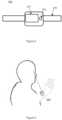
- Figure 5illustrates another embodiment 500.
- the person's authenticationis obtained by his fingerprint but by biometric eye recognition.
- biometric eye recognitionThis may be Iris recognition.
- the irishas a complex pattern which is unique to every person. The pattern is stable and can be seen from some distance. Iris recognition can be done using a video camera to capture the iris pattern in near infrared illumination.
- the biometric eye recognitionis retinal blood vessel pattern recognition.
- thisnot the preferred method as the retina requires a more in-depth scan of the eye.
- This embodiment 500is also a wrist worn device and a bottom PPG sensor 211 is still used to monitor the blood flow in the person's wrist.
- Figure 5shows the embodiment 100 comprising a camera 501 in place of the fingerprint reader 105 and the top PPG sensor 103 in the first embodiment. This is because the camera 501 is able to capture an image of the iris for identification of the person, as well as observe the pulsations of blood vessel in the retina to monitor the heart beat pattern of the person.
- the personwears the embodiment on this wrist, such that the bottom PPG sensor 211 is able to monitor heart beat pattern from the person's wrist.
- the personlooks into the camera 501, as illustrated in Figure 6 , in order that his iris pattern may be scanned and also that the heart beat pattern may be observed from the pulsating flow of blood in the blood vessels inside his eye.
- the light frequency used for monitoring blood flow in the eyeis preferably selected to be near infrared for better sensitivity.
- the heart beat pattern observed by the camera 501 from the pulsating blood flow in the person's eye and the heart beat pattern as observed by the bottom PPG sensor 211 from the person's wristshould be identical if the person wearing the embodiment 100 on his wrist is indeed the same person who has looked into the camera 501. If the two heart beat patterns are identical, it is deemed that the person who is wearing the embodiment is indeed the person whose iris pattern has been scanned. Therefore, the iris pattern is deemed accepted for verifying the identity of the person.
- the embodiment 100then transmits the iris pattern to a server wirelessly for verification.
- a copy of the person's iris patternhas been scanned and recorded in the server in advance, which may therefore be used as a template for matching the scanned iris pattern transmitted from the embodiment 100 for verifying the person's identity.
- the iris pattern scanned by the embodiment 100is matched with a copy of the person's iris pattern which has been pre-stored inside a memory within the embodiment 100 for verifying the person's identity.
- the heart rate patternsare not identical, it is deemed that the person who is wearing the embodiment is not the person whose iris pattern has been scanned. Therefore, the iris pattern is rejected for verifying the identity of the person.
- the person identityis assumed to be verified and the embodiment worn by the person as long as the bottom PPG sensor 211 has not detected itself being moved away from the person.
- the embodiment 100will assume that the embodiment 100 has been taken off the person's wrist.
- the embodiment 100detects that the heart rate of the person has ceased to be detectable for a period of time, the embodiment 100 will also assume that the embodiment 100 has been taken off the person's wrist. In these cases, the person's identify needs to be verified again using the aforementioned procedure.
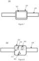
- FIG. 7 and Figure 8shows another embodiment 700 comprising a miniature ECG (electrocardiogram) sensor instead of the fingerprint reader 105 of the first embodiment.
- the pattern of a heart beat signal obtained in an ECGhas specific characteristics which are biometrically unique to every person.
- the fingerprint reader 105 and the top PPG sensor 103 in the first embodiment 100are not required. Only the bottom PPG sensor 211 is needed for monitoring the heart beat pattern of the person from the person's wrist. As the ECG sensor is able to obtain heart beat signals, the ECG sensor fulfils both the role of a biometric authentication device, as well as that of a heart beat pattern monitor.
- the ECG sensor 801is shown in Figure 8 placed on the bottom face 201 of the embodiment 700 in Figure 8 . That is, the ECG sensor 801 is located on the same side of the embodiment 700 as the bottom PPG sensor 211.
- top face 101 of the embodiment as shown in Figure 7can be fully occupied by a display, as a top PPG sensor no longer occupies the top face 101.
- Figure 9shows a standard cardiogram having several peaks which can be detected as electric signals from the different heart chambers, represented by PQRST.
- An ECGcan identify a person using heartbeat sub-patterns (in particular the P, QRS, T,PQRS and QRST subsets of the standard ECG of a person), or even the full heartbeat waveform ( Exploring Heartbeat Sub-patterns for Person Identication, Carreiras et. al., Portuguese Conference on Pattern Recognition 2013 ). Details of the technology used in an ECG sensor are not within the scope of this invention and therefore detailed elaboration of it is not necessary.
- the personwears the embodiment 700 on his wrist, such that the bottom PPG sensor 211 is able to monitor his heart beat pattern the wrist.
- the ECG sensor 801is also on the underside of the embodiment and therefore observes the ECG of the person from virtually the same part of the wrist.
- the heart beat pattern observed by the bottom PPG sensor 211 and the heart rate observed by the ECG sensor 801should correlate, since they are read from the person.
- the bottom PPG sensor 211is unable to collect fine details for biometric recognition like the ECG sensor 801.
- the bottom PPG sensor 211on the other hand, is more rugged and robust, and is useable to monitor the heart beat pattern of the person over long period of time while he is engaging in strenuous activities.
- a wearable ECG sensoris more delicate and may be obtaining too much information after the person has been verified or authenticated, which requires more intensive processing power. Furthermore, in most situations, there is no need for continual biometric identification.
- both the bottom PPG sensor 211 and the ECG sensor 801in the same embedment even though the ECG sensor may well by itself monitor the heart beat pattern of the person.
- the personmerely needs to interact with the display screen 107 trigger an authentication process.
- the bottom PPG sensor 211is practically in the same location as the ECG sensor 801, while the ECG-biometric identity of the person is being scanned, the bottom PPG sensor 211 is also reading the person's heart beat pattern from the wrist.
- the ECG-biometric identity of the personnaturally contains the person's heart beat pattern.
- the heart beat pattern read by the bottom PPG sensor 211 and heart beat pattern embodied in the ECG-biometric identityshould be the same. Accordingly, the ECG-biometric identity is used for verifying the identity of the person.
- the embodiment 700transmits the ECG-biometric identity 'to a server wirelessly for verification of the person. A copy of the person's ECG-biometric identity has been scanned and recorded in the server in advance, which may therefore be used as a template for matching the ECG-biometric identity transmitted from the embodiment 700 for verifying the person's identity.
- the ECG-biometric identity scanned by the embodiment 100is matched with a copy of the person's ECG-biometric identity which has been pre-stored inside a memory within the embodiment 700 for verifying the person's identity.
- the person identityis assumed to be verified and the embodiment worn by the person as long as the bottom PPG sensor 211 has not detected itself being moved away from the person.
- Figure 10shows yet another embodiment 1000, which is a smart earphone 1000 containing physiological sensors.
- Figure 11shows a close up of the ear bud 1501 of the smart earphone 1000 which is intended for insertion in the ear canal, stripped of the typical foam covering.
- Figure 12shows the same ear bud 1501 in a cross sectional side view.
- the earphone 1000comprises a light source 203 and an optical sensor 205 arranged in the ear bud 1501.
- the ear bud 1501is made of a deformable resilient outer part 1701 sized to fit within the ear canal of a person.
- a speaker 1703Within the ear bud 1501 is a speaker 1703, a hollow inner core 1601 for sound conduction from the speaker in to the ear, an resilient inner foam structure 1603 for softness and flexibility, thin wirings (not illustrated) for connection to the light source 203 and optical sensor 205.
- the resilient outer part 1701provides increased comfort and protection of the light source 203 and optical sensors 205.
- the resilient inner foam 1603may be compressed during insertion of the ear bud 1501 into the ear to provide further support in the ear canal.
- the light source 203transmit a light into the skin and tissue of the ear canal. As light propagates into the skin and tissue, some of the light is scattered and is diverted towards the optical sensor 205. Blood content in the ear canal affects the transmission of light. When there is more blood in the ear, more light is absorbed and less light is scattered towards the optical sensor 205. When there is less blood in the ear, more light is absorbed and less light is scattered towards the optical sensor 205. Therefore, the pumping of the heart is detectable by monitoring the transmission of light from the light source 203 through the skin and tissue, and to the optical sensor 205.
- the earphone 1000is capable of communicating with a server wirelessly to send physiological data of the person, the identity of the person and the GPS location of the earphone to the server.
- FIG 10shows that along the wire leading up to the earphone 1000 is a housing which contains a fingerprint reader 105, which is co-located with a top PPG sensor 103, both arranged in a similar manner as that in the embodiment of Figure 1 .
- the underside of the housingdoes not have a PPG sensor, as the function of collecting heart beat pattern of the bottom PPG sensor is now provided in the ear bud 1501.
- the personTo identifying himself to the server which the smart earphone is in communication with, the person simply places his fingertip onto the fingerprint reader 105 and the PPG sensor 103 at once. The scanning of the person's fingerprint is done at the same time and from the same part of the finger as the PPG sensor 103 reads the person's heart beat pattern.
- the sensors in the earphoneare triggered to read the heart beat pattern of the person at the same time.
- the heart beat pattern read from the finger and in the ear canalshould be identical if the person wearing the ear bud is the same person who has placed this finger onto the fingerprint reader. Therefore, if the heart beat patterns observed by the PPG sensor 103 and the sensors in the earphone correlate, it is deemed that the person who is wearing the ear bud is actually the person whose fingerprint has been scanned. The scanned fingerprint is therefore deemed acceptable for use in verifying the identity of the person.
- the scanned fingerprintis rejected for verifying the identity of the person.
- the person identifyis assumed to be the same as long as the sensors in the ear bud do not detected that the ear bud has been taken out of the ear canal. For example, if the optical sensors in the ear bud detect bright ambient light, the smart earphone will determine that that indicates that the embodiment has been taken off the person's ear canal. in such a case, the person's identify needs to be verified again.
- Figure 13illustrates yet another embodiment 1300.
- the embodiment 1300is a wrist worn device containing the bottom PPG sensor (not visible in Figure 13 ) to read the person's heart beat pattern from his wrist, similar to the embodiment 100 of Figure 1 , except that the embodiment 1300 now includes an accelerometer (not illustrated) to monitor movements of the wrist.
- the biometric authentication of the person in this embodimentis behavioural instead of a physical attribute.
- the manner in which the person types a passwordhas unique keystroke rhythm. That is, the accentuation of different strokes on different keys, the time period between typing on every two letters in the password and which of his hands does the person use for typing certain characters in the password and so on.
- the typing manner of a passwordhas been found to be unique to every person.
- the person using this embodiment 1300When the person using this embodiment 1300 is about to type his password on the keyboard, the person triggers the embodiment 1300 to detect movements caused by the typing. At the same time, the embodiment 1300 is reading the heart beat pattern using the bottom PPG sensor at the person's wrist.
- the computeralso monitors the person's typing characteristics as the person enters his password, monitoring the keystroke rhythm, that is, the accentuation of different strokes on different keys (e.g. keyboards can detect accentuations as staccato and non-staccato typing), the time period between typing on every two letters in the password and so on.
- the computeris able to communicate with the device on the person's wrist wirelessly, such as by WiFi or Bluetooth TM . Either the computer or the device, or both, are able to match the typing characteristics detected by the embodiment 1300 from the person's hand when he was entering the password with the typing characteristics sensed by the computer from the keyboard.
- the embodiment 1300If the typing characteristics of those characters entered by that hand wearing the embodiment 1300 match the typing characteristics of those characters received by the computer (entered by that same hand), it shall be deemed that the embodiment is being worn by the person who has been identified the password. Subsequently, heart beat pattern obtained by the PPG sensor and any other physiological data, or movement data as provided by the embodiment 1300 are deemed as belonging the person as verified.
- the personuses a smart phone instead of a computer to enter his password.
- the personenters his password into the smart phone using the hand wearing the embodiment 1300. If the typing characteristics of those characters entered by that hand wearing the embodiment 1300 match the typing characteristics of those characters received by the smart phone (entered by that same hand), it shall be deemed that the embodiment 1300 is being worn by the person who has been identified the password.
- Figure 14shows another embodiment.
- the sports monitoring device 1401is similar to the embodiment of Figure 1 in that it comprises a bottom PPG sensor 211 which may be used to monitor the blood flow in the person's wrist.
- the sports monitoring device 1401does not have the fingerprint reader 105 superimposed with the top PPG sensor 103 of Figure 1 for authenticating the person. Instead, the sports monitoring device 1401 relies on a remote biometric authentication device 1400.
- the remote biometric authentication device 1400is provided for reading the person's fingerprint and heart beat pattern.
- the remote biometric authentication device 1400is a smart phone which comprises a fingerprint reader 1405 for unlocking the smart phone for user access.
- the fingerprint reader 1405is superimposed with a PPG sensor such that a finger placed on the fingerprint reader 1405 to be scanned for fingerprint is also monitored for heart beat pattern at the same time by the PPG sensor.
- the personplaces his index finger on the fingerprint reader 1405 of the remote biometric authentication device 1400.
- the remote biometric authentication deviceis in wireless communication, such as by WiFi or Bluetooth TM , with the sports monitoring device 1401.
- the heart beat pattern read by fingerprint reader 1405 of the remote biometric authentication device 1400 from the person's finger and the heart beat pattern read by the bottom PPG sensor 211 in the sports monitoring device 1401 from the person's wristshould be identical or very similar, provided that the person wearing the sports monitoring device 1401 is indeed the same person who has placed this finger onto the fingerprint reader 1405. Accordingly, if the heart beat patterns matches, it is deemed that the person who is wearing the sports monitoring device 1401 is also the person whose fingerprint has been scanned by the remote biometric authentication device 1400. In this case, the scanned fingerprint is deemed acceptable for verifying the identity of the person.
- the personcan begin exercising and his heart rate and exercise performance can be recorded by the sports monitoring device 1401 and communicated to a server which is in wireless communication with the sports monitoring device 1401.
- the remote biometric authentication device 1400can be linked to the sports monitoring device 1401 by a physical wire for providing a communication channel between them.
- Figure 15illustrates a variation of the embodiment of Figure 14 , in which the fingerprint reader is replaced with a camera for iris biometric recognition.
- the device 1401is similar to the embodiment of Figure 1 in that the device comprises a bottom PPG sensor 211 which may be used to monitor the blood flow in the person's wrist.
- the sports monitoring device 1401does not have the fingerprint reader 105 superimposed with the top PPG sensor 103 of Figure 1 . Instead, the sports monitoring device 1401 relies on a remote biometric authentication device 1500.
- the remote biometric authentication device 1500is provided for reading the person's iris and also the person's heart beat pattern from blood vessels in his eye.
- the remote biometric authentication device 1500is a camera 1505 in a smart phone 1500.
- the remote biometric authentication device 1500is in wireless communication, such as by WiFi or Bluetooth TM , with the sports monitoring device 1401.
- the heart beat pattern read by the remote biometric authentication device 1500 from the person's eye and the heart beat pattern read by the bottom PPG sensor 211 in the sports monitoring device 1401 from the person's wristshould be identical or very similar, provided that the person wearing the sports monitoring device 1401 is indeed the same person who looks into the camera 1505. Accordingly, if the heart beat patterns matches, it is deemed that the person who is wearing the sports monitoring device 1401 is also the person whose iris has been scanned by the remote biometric authentication device 1500. In this case, the scanned iris is deemed acceptable for verifying the identity of the person.
- the embodimentsillustrate how, by reading biometric information at the same time as physiological data such as heart rate pattern, may the physiological data be verified as belonging to the identified person. From one set of physiological data, any number of other devices worn by the same person may be verified in turn as being worn by the identified person if the physiological data of all these devices match. This allows remotely conducted sports or competition to be held without fear that the athlete or competitor has be replaced by someone else secretly.
- 'heart beat pattern'is used to include heart rate but may also refer other kinds of physiological observations made on the heart.
- the 'heart beat pattern'may be a peak to peak magnitude.
- a camerais provided within the ear bud for recording and identifying unique ear canal blood vessels for biometrically identifying the person, and for also for observing light transmission into the ear canal for physiological data such as heart rate.
- the embodimentsinclude a device in which a physiological monitor and a biometric identity reader are co-located to read from the same part of a living body.
Landscapes
- Engineering & Computer Science (AREA)
- Health & Medical Sciences (AREA)
- Life Sciences & Earth Sciences (AREA)
- Physics & Mathematics (AREA)
- Theoretical Computer Science (AREA)
- General Engineering & Computer Science (AREA)
- Biomedical Technology (AREA)
- General Health & Medical Sciences (AREA)
- General Physics & Mathematics (AREA)
- Human Computer Interaction (AREA)
- Computer Security & Cryptography (AREA)
- Signal Processing (AREA)
- Computer Hardware Design (AREA)
- Public Health (AREA)
- Medical Informatics (AREA)
- Surgery (AREA)
- Veterinary Medicine (AREA)
- Animal Behavior & Ethology (AREA)
- Molecular Biology (AREA)
- Heart & Thoracic Surgery (AREA)
- Pathology (AREA)
- Biophysics (AREA)
- Computer Networks & Wireless Communication (AREA)
- Cardiology (AREA)
- Physiology (AREA)
- Multimedia (AREA)
- Computing Systems (AREA)
- Psychiatry (AREA)
- Computer Vision & Pattern Recognition (AREA)
- Artificial Intelligence (AREA)
- Acoustics & Sound (AREA)
- Software Systems (AREA)
- Oral & Maxillofacial Surgery (AREA)
- Primary Health Care (AREA)
- Business, Economics & Management (AREA)
- General Business, Economics & Management (AREA)
- Dentistry (AREA)
- Dermatology (AREA)
- Neurology (AREA)
- Neurosurgery (AREA)
Description
- The present invention relates to a person authentication device and method. In particular, the invention relates to a device which can be used to ascertain that the person wearing of using the device is indeed the person as authenticated.
- Wearable devices have been proposed for monitoring physical performance of people in exercise or sport. People using such a device normally just wear the device on their wrist, waist, chest and so on. Some of these devices contain an accelerometer to count the number of steps the person has taken in a cross-country run or the number of stokes he has executed in a swim, or to observe the height to which he has jumped. Some of these devices are able to monitor the heart rate or temperature of the person, and may raise an alarm when the person appears to be at the end of his endurance or performance tolerance. Furthermore, these devices may contain a GPS respondent to observe the distance the person has covered in a long distance sport.
- These devices may be used to record competition between persons who are physically remote from each other. The performance of the persons may be recorded in real time and displayed on the wearable device worn by each person. In this way, the persons are able to tell many steps each of them has taken and the distance each has covered. The problem with such wearable devices is that they can be taken off and worn by someone else instead of the intended person. Someone else may wear the device for a person to take part in a competition in place of the person.
- Biometrics authentication methods have been proposed to authenticate the person wearing such a device. For example, the device comprises a fingerprint reader which is used to authenticate the person.
- Document
WO2015051253 discloses a user-wearable device that can sense biometric information of a user wearing the device. An authentication module performs or receives results of an authentication determination that compares the sensed biometric information to baseline biometric information to determine whether they match and a user is authenticated. - However, this method is not fool proof. Someone who is taking part in a competition in place of a person may wear the device while the person provide the fingerprint to be read.
- Therefore, it is desirable to provide an authentication method for verifying the identity of the actual person wearing such wearable devices.
- The present invention is defined by the appended independent claims. In a first aspect, the invention proposes a device for identifying a person comprising: a physiological monitor; a biometric identity reader; wherein the biometric identity reader and the physiological monitor are configured such that the biometric identity reader reads biometric information of the person and the physiological monitor reads physiological information of the person at the same time.
- Reading biometric information at the same time as reading physiological data using the same device provides the possibility that the physiological data be verified as belonging to the person identified by the biometric information.
- Preferably, the physiological monitor is adjacent the biometric identity reader; such that the physical distance between physiological monitor and the biometric identity reader prevents the physiological monitor and the biometric identity reader from being applied separately to more than one person at the same time. For example the physiological monitor and the biometric identity reader are in the same device housing which is sized to be placed on the same part of the body of the person. A smaller housing ensures that embodiments of the invention are used at the same time and on the same person; the physiological monitor cannot be physically applied on one person while the biometric identity reader is applied on another person.
- Preferably, the physiological monitor monitors the heart beat pattern of the person. The term 'heart beat pattern' is used to include heart rate but may also refer other kinds of physiological observations made on the heart. For example, instead of heart rate, the 'heart beat pattern' may be a peak to peak magnitude.
- Optionally, the device is in communication with a second physiological monitor; the biometric identity reader and the physiological monitor of the device, and the second physiological monitor are configured such that the biometric identity reader reads biometric information of the person, the physiological monitor reads physiological information of the person and the second physiological monitor reads physiological information of the person at the same time.
- This provides the possibility that, from one set of physiological data, any number of 'second' physiological monitors worn by the identified person may be verified cascadingly as being worn by the same person, provided that the same physiological data read of all these devices match. Once these other 'second' physiological monitors are verified as being worn by the same person, different functions of these 'second' physiological monitors may be employed with confidence that they are applied on the identified person.
- Optionally, the device is in communication with the second physiological monitor wirelessly. In such embodiments, the device is a smart phone having a fingerprint scanner which can read the heart rate pattern from a person's fingertip, and the second physiological monitor is a device worn by the person. The person may wear the second physiological monitor on his wrist, ankle, ear, head, chest or even internally in his body (such as a swallowed device in his intestines). The wireless communication protocol can be Wi-Fi, Bluetooth™, infrared and so on.
- Preferably, however, the device is physically integral with the second physiological monitor, the integrated device having a dimension which prevents the physiological monitor, the biometric identity reader and the second physiological monitor from being applied onto different persons. This helps to ensure the integrity of embodiment physically in the sense that the embodiments have to be applied onto the same person who may be identified by the biometric identity reader.
- Preferably, the biometric identity reader is a fingerprint reader. Alternatively, the biometric identity reader is a biometric heartbeat pattern reader, such as a biometric ECG monitor. In some embodiments, the biometric identity reader and the a physiological monitor are both provided as one, in the form of a camera, the camera positioned to be capable of being looked into by the eye of the person
- Preferably, the device further comprises a belt for strapping to the wrist of the person. Alternatively, the device is an earphone or ear bud which can be inserted into a person's ear canal, in which case the second physiological monitor may be a light based blood flow monitor installed in the ear phone or ear bud.
- Preferably, the second physiological monitor is a light based blood flow monitor installed in an ear phone.
- Optionally, the biometric identity reader is an accelerometer, for monitoring characteristic mannerism of the person using the device, the characteristic mannerism of the person being useable as a behavioural biometric identification.
- In a second aspect, the invention proposes a physiological monitor, which is capable of obtaining a first set of physiological data read from a person; supplying the first set of physiological data to be matched to a second set of physiological data read from the same person; the first set of physiological data and the second set of physiological data read from the same person at the same time.
- Typically, the person from whom the second set of physiological data is read has been authenticated. Therefore, devices containing the physiological monitor may be used for monitoring the performance of a person wearing such a device, and the person may be authenticating by matching the first set of physiological data and the second set of physiological data.
- This provides the advantage that different physiological monitors may be provided or sold to the person separately and yet benefit from being able to obtain the second set of physiological data for matching to the first set of physiological data. In this way, as long as the second set of physiological data has been verified as having been obtained from an authenticated person, the first set of physiological data may be relied upon as having been read from the authenticated person
- Preferably, the first set of physiological data is read from the person in real time. Therefore, the second set of physiological data is also read from the person in real time. This allows improved identity security in that the second set of physiological data is not pre-recorded.
- Optionally, the physiological monitor is a light based blood flow monitor installed in an ear phone.
- Preferably, the physiological monitor is capable of encrypting physiological data in real time using biometric data of the person. Different persons may use the same device, but each of them separately and independent authenticated as they use the device in turn.
- In yet a further aspect, the invention proposes a method of authenticating physiological information of person comprising the steps of: providing a first physiological monitor; providing a biometric identity reader; the biometric identity reader reading biometric information of the person and the first physiological monitor reading physiological information of the person at the same time; authenticating the biometric information of the person in order to accept the physiological information as belonging to the person.
- Preferably, the biometric identity reader and the first physiological monitor are physically constrained preventing from being applied separately to more than one person at the same time.
- Preferably, the biometric information of the person is keystroke patterns characteristic of the person typing on a keyboard.
- Preferably, the method comprises the further steps of: providing a second physiological monitor; the second physiological monitor reading physiological information of the person; if the physiological information read by the first physiological monitor correlates to the physiological information read by the second physiological monitor; accepting yet further physiological information read by the second physiological monitor as belonging to the person.
- Preferably, the method comprises the further step of encrypting the further physiological information read by the second physiological monitor using the biometric information of the person.
- In a further aspect, the invention proposes a physiological monitor and a biometric identity reader co-located to read from the same part of a living body. The part of the body may be a fingertip or the eye. Typically, but not necessarily, the physiological monitor is a pulse reader, and the biometric identity reader is a fingerprint reader if the part of the body is the fingertip or biometric identity reader is an iris scanner if the part of the body is the eye. Being co-located, preferably in the same physical housing to prevent the physiological monitor and the biometric identity reader from be separated, ensures that the information is read from the same person. In this way, both the readings from the physiological monitor and the biometric identity reader can be said to originate from the same person with certainty.
- It will be convenient to further describe the present invention with respect to the accompanying drawings that illustrate possible arrangements of the invention, in which like integers refer to like parts. Other arrangements of the invention are possible, and consequently the particularity of the accompanying drawings is not to be understood as superseding the generality of the preceding description of the invention.
Figure 1 is an illustrate of a first embodiment;Figure 2 is an illustration of the embodiment ofFigure 1 in a different view;Figure 2a illustrates a heart rate signal observable by the embodiment ofFigure 1 ;Figure 3 illustrates the embodiment ofFigure 1 in perspective view;Figure 4 illustrates the embodiment ofFigure 1 in use;Figure 5 is an illustrate of a second embodiment;Figure 6 is an illustrate of the embodiment ofFigure 5 in use;Figure 7 is an illustrate of a third embodiment;Figure 8 is an illustration of the embodiment ofFigure 7 in a different view;Figure 9 illustrates a heart rate signal observable by the embodiment ofFigure 7 ;Figure 10 is an illustrate of a fourth embodiment;Figure 11 is another illustration of the embodiment ofFigure 10 ;Figure 12 is a different view of the embodiment ofFigure 11 ;Figure 13 illustrates yet another embodiment;Figure 14 illustrates yet another embodiment; andFigure 15 illustrates yet another embodiment.Figure 1 to Figure 4 show afirst embodiment 100, which is a device that may be worn on the wrist of a person. Thetop face 101 of the device is shown inFigure 1 , i.e. it faces away from the wrist when worn. Theunderside 201 is shown inFigure 2 , i.e. the face which is in contact with the wrist of the person if worn.Figure 3 shows theembodiment 100 in perspective view.Figure 4 shows theembodiment 100 when worn by the person.- Both the
top face 101 and thebottom face 201 are each provided with a light-based heart rate monitor. The preferred type of light base heart rate monitor is the PPG sensor (photoplethysmography). - The
top PPG sensor 103 inFigure 1 , i.e. the PPG sensor on thetop face 101 of theembodiment 100, is superimposed with afingerprint reader 105 such that the tip of a finger is able to cover thetop PPG sensor 103 and thefingerprint reader 105 at the same time. - 'Superimposition' means the
top PPG sensor 103 and thefingerprint reader 105 are laid one over the other. However, the meaning of 'superimposition' also includes any configuration in which thetop PPG sensor 103 and thefingerprint reader 105 are placed in such close proximity such that a person's fingertip is able to cover over both the top PPG sensor and the finger print reader at once. In other words, thetop PPG sensor 103 and thefingerprint reader 105 may also be adjacent or next to one another. - Next to the
fingerprint reader 105 is ascreen 107 for displaying information. However, in other embodiments, thefingerprint reader 105, thetop PPG sensor 103 and thedisplay screen 107 are laid one over the other in order to maximise the size of thescreen 107 over thetop face 101 of the device. - The
embodiment 100 is provided with wrist straps 109. The person wears theembodiment 100 by strapping it over his wrist so that thebottom PPG sensor 211 is placed snugly against the person's skin. A typical PPG sensor comprises at least onelight source 203 such as an LED (light emitting diode), which is illustrated by a circle inFigure 2 , and at least one correspondingoptical sensor 205 normally placed next to thelight source 203, which is illustrated by a square inFigure 2 . A rectangular dashed line inFigure 2 around theoptical sensor 205 and alight source 203 represents thebottom PPG sensor 211 as a whole. - The light frequency of the
light source 203 is such that blood in the wrist skin and wrist tissue is able to absorb the light. Light from thelight source 203 which has transmitted through the skin and tissue of a person is normally pulsating. The pulsation is cyclical and virtually periodic, corresponding to the flushing of blood into the skin and tissue as it is pumped by the heart.Figure 2a schematically illustrates the pulsating pattern of PPG sensor light propagation through a person's skin and tissue. Thepeaks 207 in the signal are moments when the heart is relaxed and wrist tissue is relatively depleted of blood, such that more light propagates through the wrist to reach the optical sensor. Thetroughs 209 in the signal are moments when the heart has contracted and wrist tissue is relatively full of blood, such that less light propagates through the wrist to reach theoptical sensor 205 because most of the light has been absorbed by blood. Theoptical sensor 205 monitors this pulsation, which can be used to determine the pattern of the heart beat of the person against whose skin is the PPG sensor placed. Figure 1 does not illustrate the top PPG in its components of an optical sensor and a light source, but the skilled reader should understand that these components make up the top PPG nevertheless.- The
fingerprint reader 105 superimposed with thetop PPG sensor 103 provides the possibility that the person to identified himself as the person who is indeed wearing theembodiment 100. - To authenticate himself as the person wearing the
embodiment 100, the person places his index finger over thefingerprint reader 105 and thetop PPG sensor 103 at the same time. This is illustrated inFigure 3 andFigure 4 . - As the
top PPG sensor 103 is practically in the same location as thefingerprint reader 105, while the fingerprint of the person's index finger is being scanned, thetop PPG sensor 103 is also reading the person's heart beat pattern from the index finger. At the same time, the bottom PPG sensor also monitors the person's heart beat pattern from the person's wrist. - The heart beat pattern is the same throughout the person's body. Therefore, the heart beat pattern read by the
top PPG sensor 103 and heart beat pattern read by thebottom PPG sensor 211 should be identical if the person wearing theembodiment 100 is the same person who has placed this finger onto thefingerprint reader 105. Accordingly, if the heart beat patterns observed by each of the two PPG sensors in theembodiment 100 correlate, it is deemed that the person who is wearing theembodiment 100 is also the person whose fingerprint has been scanned. In this case, the scanned fingerprint is deemed acceptable for verifying the identity of the person. Theembodiment 100 then transmits the scanned fingerprint to a server wirelessly for verification. A copy of the person's fingerprint has been scanned and recorded in the server in advance, which may therefore be used as a template for matching the scanned fingerprint transmitted from theembodiment 100 for verifying the person's identity. - Alternatively, the fingerprint scanned by the
embodiment 100 is matched with a copy of the person's fingerprint which has been pre-stored inside a memory within theembodiment 100 for verifying the person's identity. - If the heart beat patterns observed by each of the two PPG sensors in the
embodiment 100 do not correlate, it is deemed that the person who is wearing theembodiment 100 is not the person whose fingerprint has been scanned. Therefore, the fingerprint scanned by theembodiment 100 is not accepted for verifying the identity of the person. - Typically, the person identity is assumed to be verified and the embodiment worn by the person as long as the
bottom PPG sensor 211 has not detected itself being moved away from the person. For example, if theoptical sensor 205 ofbottom PPG sensor 211 detects bright ambient light, theembodiment 100 will assume that theembodiment 100 has been taken off the person's wrist. Alternatively, if theembodiment 100 detects that the heart rate of the person has ceased to be detectable for a period of time, theembodiment 100 will also assume that theembodiment 100 has been taken off the person's wrist. In these cases, the person's identify needs to be verified again using the aforementioned procedure. - Subsequently, the person can begin exercising and his heart rate and exercise performance can be recorded by the
embodiment 100. If the embodiment contains an accelerator, the person's steps can be counted. If the embodiment contains a GPS, the person's location can be monitored. This data can be transmitted to the server which theembodiment 100 is in wireless communication with to be stored under the person's profile. - The embodiment is useable to monitor the performance of different people in different parts of the world all wearing an
embodiment 100. The performance of these different people performance can be recorded and compared in real time by the server to facilitate a remote competition. - Accordingly, the
embodiment 100 provides a possibility of ensuring that the identity of the person who is actually wearing the embodiment is authenticated. - Other technologies may be used instead of that of the PPG sensor such as those based on infrared light, electrodes to monitor electrical signals and so on. These do not require elaboration here.
- In a variation of the
embodiment 100, once the person has been authenticated, the biometric data is used to encrypt any data which is sent over to the server by the embodiment. Where the server has a copy of the biometric data of the person, the server is able to decrypt the data. In this way, different persons may use the same device, but each of them may be separately and independent authenticated as they use the device in turn. Their physiological data and other information which is collected by the device may be securely released to the server without fear of being intercepted wirelessly and used. This allows the same embodiment to be used by multiple users to obtain very sensitive and personal physiological data for medical record and yet retain security of information from each other and unknown third parties. Virtually, as the physiological data is obtained continually from the person wearing the embodiment, the encryption of each packet of data of physiological data is done in real time. - Accordingly, the
embodiment 100 includes a method of performing real time data encryption using a person's biometric data. Preferably, the biometric data has been first verified as described. Figure 5 illustrates anotherembodiment 500. In this embodiment, the person's authentication is obtained by his fingerprint but by biometric eye recognition. This may beIris recognition. The iris has a complex pattern which is unique to every person. The pattern is stable and can be seen from some distance. Iris recognition can be done using a video camera to capture the iris pattern in near infrared illumination.- In a variation of this embodiment, the biometric eye recognition is retinal blood vessel pattern recognition. However, this not the preferred method as the retina requires a more in-depth scan of the eye.
- This
embodiment 500 is also a wrist worn device and abottom PPG sensor 211 is still used to monitor the blood flow in the person's wrist. However,Figure 5 shows theembodiment 100 comprising acamera 501 in place of thefingerprint reader 105 and thetop PPG sensor 103 in the first embodiment. This is because thecamera 501 is able to capture an image of the iris for identification of the person, as well as observe the pulsations of blood vessel in the retina to monitor the heart beat pattern of the person. - In use, the person wears the embodiment on this wrist, such that the
bottom PPG sensor 211 is able to monitor heart beat pattern from the person's wrist. The person then looks into thecamera 501, as illustrated inFigure 6 , in order that his iris pattern may be scanned and also that the heart beat pattern may be observed from the pulsating flow of blood in the blood vessels inside his eye. The light frequency used for monitoring blood flow in the eye is preferably selected to be near infrared for better sensitivity. - The heart beat pattern observed by the
camera 501 from the pulsating blood flow in the person's eye and the heart beat pattern as observed by thebottom PPG sensor 211 from the person's wrist should be identical if the person wearing theembodiment 100 on his wrist is indeed the same person who has looked into thecamera 501. If the two heart beat patterns are identical, it is deemed that the person who is wearing the embodiment is indeed the person whose iris pattern has been scanned. Therefore, the iris pattern is deemed accepted for verifying the identity of the person. - The
embodiment 100 then transmits the iris pattern to a server wirelessly for verification. A copy of the person's iris pattern has been scanned and recorded in the server in advance, which may therefore be used as a template for matching the scanned iris pattern transmitted from theembodiment 100 for verifying the person's identity. - Alternatively, the iris pattern scanned by the
embodiment 100 is matched with a copy of the person's iris pattern which has been pre-stored inside a memory within theembodiment 100 for verifying the person's identity. - Conversely, if the heart rate patterns are not identical, it is deemed that the person who is wearing the embodiment is not the person whose iris pattern has been scanned. Therefore, the iris pattern is rejected for verifying the identity of the person.
- Typically, the person identity is assumed to be verified and the embodiment worn by the person as long as the
bottom PPG sensor 211 has not detected itself being moved away from the person. For example, if theoptical sensor 205 ofbottom PPG sensor 211 detects bright ambient light, theembodiment 100 will assume that theembodiment 100 has been taken off the person's wrist. Alternatively, if theembodiment 100 detects that the heart rate of the person has ceased to be detectable for a period of time, theembodiment 100 will also assume that theembodiment 100 has been taken off the person's wrist. In these cases, the person's identify needs to be verified again using the aforementioned procedure. Figure 7 and Figure 8 shows anotherembodiment 700 comprising a miniature ECG (electrocardiogram) sensor instead of thefingerprint reader 105 of the first embodiment. The pattern of a heart beat signal obtained in an ECG has specific characteristics which are biometrically unique to every person.- In this
embodiment 700, thefingerprint reader 105 and thetop PPG sensor 103 in thefirst embodiment 100 are not required. Only thebottom PPG sensor 211 is needed for monitoring the heart beat pattern of the person from the person's wrist. As the ECG sensor is able to obtain heart beat signals, the ECG sensor fulfils both the role of a biometric authentication device, as well as that of a heart beat pattern monitor. - The
ECG sensor 801 is shown inFigure 8 placed on thebottom face 201 of theembodiment 700 inFigure 8 . That is, theECG sensor 801 is located on the same side of theembodiment 700 as thebottom PPG sensor 211. - Accordingly, the
top face 101 of the embodiment as shown inFigure 7 can be fully occupied by a display, as a top PPG sensor no longer occupies thetop face 101. Figure 9 shows a standard cardiogram having several peaks which can be detected as electric signals from the different heart chambers, represented by PQRST. An ECG can identify a person using heartbeat sub-patterns (in particular the P, QRS, T,PQRS and QRST subsets of the standard ECG of a person), or even the full heartbeat waveform (Exploring Heartbeat Sub-patterns for Person Identication, Carreiras et. al., Portuguese Conference on Pattern Recognition 2013). Details of the technology used in an ECG sensor are not within the scope of this invention and therefore detailed elaboration of it is not necessary.- In use, the person wears the
embodiment 700 on his wrist, such that thebottom PPG sensor 211 is able to monitor his heart beat pattern the wrist. TheECG sensor 801 is also on the underside of the embodiment and therefore observes the ECG of the person from virtually the same part of the wrist. The heart beat pattern observed by thebottom PPG sensor 211 and the heart rate observed by theECG sensor 801 should correlate, since they are read from the person. However, thebottom PPG sensor 211 is unable to collect fine details for biometric recognition like theECG sensor 801. Thebottom PPG sensor 211, on the other hand, is more rugged and robust, and is useable to monitor the heart beat pattern of the person over long period of time while he is engaging in strenuous activities. In contrast, a wearable ECG sensor is more delicate and may be obtaining too much information after the person has been verified or authenticated, which requires more intensive processing power. Furthermore, in most situations, there is no need for continual biometric identification. - Therefore, it is preferred to have both the
bottom PPG sensor 211 and theECG sensor 801 in the same embedment even though the ECG sensor may well by itself monitor the heart beat pattern of the person. - To authenticate himself as the person wearing the
embodiment 700, the person merely needs to interact with thedisplay screen 107 trigger an authentication process. - As the
bottom PPG sensor 211 is practically in the same location as theECG sensor 801, while the ECG-biometric identity of the person is being scanned, thebottom PPG sensor 211 is also reading the person's heart beat pattern from the wrist. The ECG-biometric identity of the person naturally contains the person's heart beat pattern. - The heart beat pattern read by the
bottom PPG sensor 211 and heart beat pattern embodied in the ECG-biometric identity should be the same. Accordingly, the ECG-biometric identity is used for verifying the identity of the person. Theembodiment 700 transmits the ECG-biometric identity 'to a server wirelessly for verification of the person. A copy of the person's ECG-biometric identity has been scanned and recorded in the server in advance, which may therefore be used as a template for matching the ECG-biometric identity transmitted from theembodiment 700 for verifying the person's identity. - Alternatively, the ECG-biometric identity scanned by the
embodiment 100 is matched with a copy of the person's ECG-biometric identity which has been pre-stored inside a memory within theembodiment 700 for verifying the person's identity. - As with the earlier embodiments, the person identity is assumed to be verified and the embodiment worn by the person as long as the
bottom PPG sensor 211 has not detected itself being moved away from the person. Figure 10 shows yet anotherembodiment 1000, which is asmart earphone 1000 containing physiological sensors.Figure 11 shows a close up of theear bud 1501 of thesmart earphone 1000 which is intended for insertion in the ear canal, stripped of the typical foam covering.Figure 12 shows thesame ear bud 1501 in a cross sectional side view.- The
earphone 1000 comprises alight source 203 and anoptical sensor 205 arranged in theear bud 1501. Typically, theear bud 1501 is made of a deformable resilientouter part 1701 sized to fit within the ear canal of a person. Within theear bud 1501 is aspeaker 1703, a hollowinner core 1601 for sound conduction from the speaker in to the ear, an resilientinner foam structure 1603 for softness and flexibility, thin wirings (not illustrated) for connection to thelight source 203 andoptical sensor 205. The resilientouter part 1701 provides increased comfort and protection of thelight source 203 andoptical sensors 205. The resilientinner foam 1603 may be compressed during insertion of theear bud 1501 into the ear to provide further support in the ear canal. There are threesets 1605 oflight source 203 andoptical sensor 205 pairs, spaced 120 degree around the ear bud. One set is facing the reader showing clearly thelight source 203 andoptical sensor 205, while the other sets face away from the reader. - To monitor the heart beat pattern of the person wearing the
earphone 100, thelight source 203 transmit a light into the skin and tissue of the ear canal. As light propagates into the skin and tissue, some of the light is scattered and is diverted towards theoptical sensor 205. Blood content in the ear canal affects the transmission of light. When there is more blood in the ear, more light is absorbed and less light is scattered towards theoptical sensor 205. When there is less blood in the ear, more light is absorbed and less light is scattered towards theoptical sensor 205. Therefore, the pumping of the heart is detectable by monitoring the transmission of light from thelight source 203 through the skin and tissue, and to theoptical sensor 205. - The
earphone 1000 is capable of communicating with a server wirelessly to send physiological data of the person, the identity of the person and the GPS location of the earphone to the server. Figure 10 shows that along the wire leading up to theearphone 1000 is a housing which contains afingerprint reader 105, which is co-located with atop PPG sensor 103, both arranged in a similar manner as that in the embodiment ofFigure 1 . The underside of the housing does not have a PPG sensor, as the function of collecting heart beat pattern of the bottom PPG sensor is now provided in theear bud 1501.- To identifying himself to the server which the smart earphone is in communication with, the person simply places his fingertip onto the
fingerprint reader 105 and thePPG sensor 103 at once. The scanning of the person's fingerprint is done at the same time and from the same part of the finger as thePPG sensor 103 reads the person's heart beat pattern. - When the
fingerprint reader 105 begins scanning the person's fingerprint, the sensors in the earphone are triggered to read the heart beat pattern of the person at the same time. - The heart beat pattern read from the finger and in the ear canal should be identical if the person wearing the ear bud is the same person who has placed this finger onto the fingerprint reader. Therefore, if the heart beat patterns observed by the
PPG sensor 103 and the sensors in the earphone correlate, it is deemed that the person who is wearing the ear bud is actually the person whose fingerprint has been scanned. The scanned fingerprint is therefore deemed acceptable for use in verifying the identity of the person. - Conversely, if the heart rates as observed by the
PPG sensor 103 and the sensors in the earphone do not correlate, it is deemed that the person who is wearing the ear bud is not the person whose fingerprint has been scanned. Therefore, the scanned fingerprint is rejected for verifying the identity of the person. - Typically, the person identify is assumed to be the same as long as the sensors in the ear bud do not detected that the ear bud has been taken out of the ear canal. For example, if the optical sensors in the ear bud detect bright ambient light, the smart earphone will determine that that indicates that the embodiment has been taken off the person's ear canal. in such a case, the person's identify needs to be verified again.
Figure 13 illustrates yet anotherembodiment 1300. Theembodiment 1300 is a wrist worn device containing the bottom PPG sensor (not visible inFigure 13 ) to read the person's heart beat pattern from his wrist, similar to theembodiment 100 ofFigure 1 , except that theembodiment 1300 now includes an accelerometer (not illustrated) to monitor movements of the wrist.- The biometric authentication of the person in this embodiment is behavioural instead of a physical attribute. In particular, the manner in which the person types a password has unique keystroke rhythm. That is, the accentuation of different strokes on different keys, the time period between typing on every two letters in the password and which of his hands does the person use for typing certain characters in the password and so on. The typing manner of a password has been found to be unique to every person.
- When the person using this
embodiment 1300 is about to type his password on the keyboard, the person triggers theembodiment 1300 to detect movements caused by the typing. At the same time, theembodiment 1300 is reading the heart beat pattern using the bottom PPG sensor at the person's wrist. - The computer also monitors the person's typing characteristics as the person enters his password, monitoring the keystroke rhythm, that is, the accentuation of different strokes on different keys (e.g. keyboards can detect accentuations as staccato and non-staccato typing), the time period between typing on every two letters in the password and so on. The computer is able to communicate with the device on the person's wrist wirelessly, such as by WiFi or Bluetooth™. Either the computer or the device, or both, are able to match the typing characteristics detected by the
embodiment 1300 from the person's hand when he was entering the password with the typing characteristics sensed by the computer from the keyboard. - If the typing characteristics of those characters entered by that hand wearing the
embodiment 1300 match the typing characteristics of those characters received by the computer (entered by that same hand), it shall be deemed that the embodiment is being worn by the person who has been identified the password. Subsequently, heart beat pattern obtained by the PPG sensor and any other physiological data, or movement data as provided by theembodiment 1300 are deemed as belonging the person as verified. - Alternatively, the person uses a smart phone instead of a computer to enter his password. The person enters his password into the smart phone using the hand wearing the
embodiment 1300. If the typing characteristics of those characters entered by that hand wearing theembodiment 1300 match the typing characteristics of those characters received by the smart phone (entered by that same hand), it shall be deemed that theembodiment 1300 is being worn by the person who has been identified the password. Figure 14 shows another embodiment.- A person wears a
sports monitoring device 1401 on this wrist. Thesports monitoring device 1401 is similar to the embodiment ofFigure 1 in that it comprises abottom PPG sensor 211 which may be used to monitor the blood flow in the person's wrist. However, thesports monitoring device 1401 does not have thefingerprint reader 105 superimposed with thetop PPG sensor 103 ofFigure 1 for authenticating the person. Instead, thesports monitoring device 1401 relies on a remotebiometric authentication device 1400. - The remote
biometric authentication device 1400 is provided for reading the person's fingerprint and heart beat pattern. Preferably, the remotebiometric authentication device 1400 is a smart phone which comprises afingerprint reader 1405 for unlocking the smart phone for user access. Thefingerprint reader 1405 is superimposed with a PPG sensor such that a finger placed on thefingerprint reader 1405 to be scanned for fingerprint is also monitored for heart beat pattern at the same time by the PPG sensor. - Therefore, to use the
sports monitoring device 1401, the person places his index finger on thefingerprint reader 1405 of the remotebiometric authentication device 1400. The remote biometric authentication device is in wireless communication, such as by WiFi or Bluetooth™, with thesports monitoring device 1401. - The heart beat pattern read by
fingerprint reader 1405 of the remotebiometric authentication device 1400 from the person's finger and the heart beat pattern read by thebottom PPG sensor 211 in thesports monitoring device 1401 from the person's wrist should be identical or very similar, provided that the person wearing thesports monitoring device 1401 is indeed the same person who has placed this finger onto thefingerprint reader 1405. Accordingly, if the heart beat patterns matches, it is deemed that the person who is wearing thesports monitoring device 1401 is also the person whose fingerprint has been scanned by the remotebiometric authentication device 1400. In this case, the scanned fingerprint is deemed acceptable for verifying the identity of the person. - Subsequently, the person can begin exercising and his heart rate and exercise performance can be recorded by the
sports monitoring device 1401 and communicated to a server which is in wireless communication with thesports monitoring device 1401. - This embodiment illustrates how the biometric authentication device does not need to be physically integrated with the PPG sensor on the person's wrist. In variations of this embodiment, the remote
biometric authentication device 1400 can be linked to thesports monitoring device 1401 by a physical wire for providing a communication channel between them. Figure 15 illustrates a variation of the embodiment ofFigure 14 , in which the fingerprint reader is replaced with a camera for iris biometric recognition.- A person wears a
sports monitoring device 1401 on this wrist. Thedevice 1401 is similar to the embodiment ofFigure 1 in that the device comprises abottom PPG sensor 211 which may be used to monitor the blood flow in the person's wrist. However, thesports monitoring device 1401 does not have thefingerprint reader 105 superimposed with thetop PPG sensor 103 ofFigure 1 . Instead, thesports monitoring device 1401 relies on a remotebiometric authentication device 1500. - The remote
biometric authentication device 1500 is provided for reading the person's iris and also the person's heart beat pattern from blood vessels in his eye. Preferably, the remotebiometric authentication device 1500 is acamera 1505 in asmart phone 1500. - Therefore, to use the
sports monitoring device 1401, the person looks into thecamera 1505. The remotebiometric authentication device 1500 is in wireless communication, such as by WiFi or Bluetooth™, with thesports monitoring device 1401. - The heart beat pattern read by the remote
biometric authentication device 1500 from the person's eye and the heart beat pattern read by thebottom PPG sensor 211 in thesports monitoring device 1401 from the person's wrist should be identical or very similar, provided that the person wearing thesports monitoring device 1401 is indeed the same person who looks into thecamera 1505. Accordingly, if the heart beat patterns matches, it is deemed that the person who is wearing thesports monitoring device 1401 is also the person whose iris has been scanned by the remotebiometric authentication device 1500. In this case, the scanned iris is deemed acceptable for verifying the identity of the person. - The embodiments illustrate how, by reading biometric information at the same time as physiological data such as heart rate pattern, may the physiological data be verified as belonging to the identified person. From one set of physiological data, any number of other devices worn by the same person may be verified in turn as being worn by the identified person if the physiological data of all these devices match. This allows remotely conducted sports or competition to be held without fear that the athlete or competitor has be replaced by someone else secretly.
- The term 'heart beat pattern' is used to include heart rate but may also refer other kinds of physiological observations made on the heart. For example, instead of heart rate, the 'heart beat pattern' may be a peak to peak magnitude.
- While there has been described in the foregoing description preferred embodiments of the present invention, it will be understood by those skilled in the technology concerned that many variations or modifications in details of design, construction or operation may be made without departing from the scope of the present invention as claimed. For example, It is within the contemplation of this invention that a camera is provided within the ear bud for recording and identifying unique ear canal blood vessels for biometrically identifying the person, and for also for observing light transmission into the ear canal for physiological data such as heart rate.
- In other words, the embodiments include a device in which a physiological monitor and a biometric identity reader are co-located to read from the same part of a living body.
Claims (6)
- A device (100) for monitoring physiological information of and identifying a person comprising:a physiological monitor (103, 211);a biometric identity reader (105); whereinthe biometric identity reader (105) and the physiological monitor (103, 211) are configured such that the biometric identity reader (105) reads biometric information of the person and the physiological monitor (103, 211) reads physiological information of the person at the same time;wherein the physiological monitor (103) is adjacent the biometric identity reader (105), such that the physical distance between physiological monitor (103, 211) and the biometric identity reader (105) prevents the physiological monitor (103, 211) and the biometric identity reader (105) from being applied separately to more than one person at the same time;such thatwhen the physiological information is authenticated as being of the person, the physiological monitor (103, 211) continues reading physiological information of the person; andif the physiological monitor (103, 211) is detected to have been moved away from the person, the device (100) is configured to require the biometric identity reader (105) to read the biometric information of the person and the physiological monitor (103, 211) to read the physiological information of the person at the same time again to re-authenticate the physiological information as being of the person.
- A device (100) for monitoring physiological information of and identifying a person as claimed in claim 1, wherein
the physiological monitor (103, 211) monitors the heart beat pattern of the person. - A device (100) for monitoring physiological information of and identifying a person as claimed in claim 1 or claim 2, wherein
the biometric identity reader (105) is a fingerprint reader. - A device (100) for monitoring physiological information of and identifying a person as claimed in claim 1 or claim 2, wherein
the biometric identity reader is a biometric heartbeat pattern reader. - A method of authenticating physiological information of and identifying a person comprising the steps of:a) providing a device having a physiological monitor (103, 211);b) providing the device having a biometric identity reader (105);
the biometric identity reader (105) reading biometric information of the person and the physiological monitor (103, 211) reading physiological information of the person at the same time, and from the same body part of the person;c) authenticating the biometric information of the person in order to accept the physiological information as belonging to the person; andd) when the physiological information is authenticated as being of the person, continuing the reading of physiological information of the person by the physiological monitor (103, 211); ande) when the physiological monitor (103, 211) is detected to have been moved away from the body part, requiring, by the device, the biometric identity reader to read the biometric information of the person and the physiological monitor to read the physiological information of the person at the same time again to re-authenticate the physiological information as being of the person. - A method of authenticating physiological information of a person as claimed in claim 5, wherein
the biometric identity reader (105) and the physiological monitor (103, 211) are physically constrained preventing them from being applied separately to more than one person at the same time.
Applications Claiming Priority (2)
| Application Number | Priority Date | Filing Date | Title |
|---|---|---|---|
| HK17101077.5AHK1236738A2 (en) | 2017-01-28 | A device for identifying a person and a method thereof | |
| PCT/CN2018/074022WO2018137662A1 (en) | 2017-01-28 | 2018-01-24 | A device for identifying a person and a method thereof |
Publications (3)
| Publication Number | Publication Date |
|---|---|
| EP3381173A1 EP3381173A1 (en) | 2018-10-03 |
| EP3381173A4 EP3381173A4 (en) | 2019-05-01 |
| EP3381173B1true EP3381173B1 (en) | 2023-05-10 |
Family
ID=62979087
Family Applications (1)
| Application Number | Title | Priority Date | Filing Date |
|---|---|---|---|
| EP18700444.5AActiveEP3381173B1 (en) | 2017-01-28 | 2018-01-24 | A device for identifying a person and a method thereof |
Country Status (5)
| Country | Link |
|---|---|
| US (2) | US11070550B2 (en) |
| EP (1) | EP3381173B1 (en) |
| CN (1) | CN108781221B (en) |
| SG (1) | SG11201906342VA (en) |
| WO (1) | WO2018137662A1 (en) |
Families Citing this family (16)
| Publication number | Priority date | Publication date | Assignee | Title |
|---|---|---|---|---|
| CN109426713B (en) | 2017-08-28 | 2022-05-24 | 关楗股份有限公司 | Fake biometric filtering device for use in identity verification systems |
| WO2019134965A1 (en)* | 2018-01-04 | 2019-07-11 | Sony Corporation | Methods and apparatuses for signal detection |
| CA2992333C (en) | 2018-01-19 | 2020-06-02 | Nymi Inc. | User access authorization system and method, and physiological user sensor and authentication device therefor |
| US11488590B2 (en)* | 2018-05-09 | 2022-11-01 | Staton Techiya Llc | Methods and systems for processing, storing, and publishing data collected by an in-ear device |
| CA3042361A1 (en)* | 2019-05-06 | 2020-11-06 | Nymi Inc. | Live user authentication device, system and method and fraud or collusion prevention using same |
| US11115764B2 (en)* | 2019-09-30 | 2021-09-07 | Sonova Ag | Hearing systems, sensor systems, and methods for detecting a physiological attribute of a user |
| USD933454S1 (en)* | 2019-09-30 | 2021-10-19 | Dezhao Xiang | Handle with fingerprint identifying device |
| US11809536B2 (en) | 2020-03-06 | 2023-11-07 | Kyndryl, Inc. | Headphone biometric authentication |
| CN111627549A (en)* | 2020-05-26 | 2020-09-04 | 遵义医科大学 | Auxiliary system for infectious disease investigation |
| US20220004658A1 (en)* | 2020-07-01 | 2022-01-06 | Johanna Paola Contreras | Cardiac monitoring system |
| US11241173B2 (en)* | 2020-07-09 | 2022-02-08 | Mediatek Inc. | Physiological monitoring systems and methods of estimating vital-sign data |
| CN113436359A (en)* | 2021-01-11 | 2021-09-24 | 安徽中屏科技有限公司 | Official working attendance system based on wrist-watch is dressed to intelligence |
| CN117241727A (en)* | 2021-04-30 | 2023-12-15 | 株式会社村田制作所 | Biological data measurement system |
| CN113625539A (en)* | 2021-08-10 | 2021-11-09 | 宁波芯然科技有限公司 | Intelligent wearable electronic device based on superlens vein imaging biometric identification |
| CN119678429A (en)* | 2021-12-30 | 2025-03-21 | 欧拉健康公司 | User authentication by wearable device |
| US12271459B2 (en) | 2021-12-30 | 2025-04-08 | Oura Health Oy | User authentication by a wearable device |
Citations (1)
| Publication number | Priority date | Publication date | Assignee | Title |
|---|---|---|---|---|
| WO2015051253A2 (en)* | 2013-10-04 | 2015-04-09 | Salutron, Inc. | Persistent authentication using sensors of a user-wearable device |
Family Cites Families (28)
| Publication number | Priority date | Publication date | Assignee | Title |
|---|---|---|---|---|
| GB9725571D0 (en)* | 1997-12-04 | 1998-02-04 | Philips Electronics Nv | Electronic apparatus comprising fingerprint sensing devices |
| JP3838141B2 (en) | 2002-04-09 | 2006-10-25 | オムロンヘルスケア株式会社 | Blood pressure measuring device and exercise equipment |
| JP4366921B2 (en)* | 2002-07-12 | 2009-11-18 | セイコーエプソン株式会社 | Personal verification device, card-type information recording medium, and information processing system using the same |
| US7230519B2 (en)* | 2003-06-19 | 2007-06-12 | Scriptpro Llc | RFID tag and method of user verification |
| US7683759B2 (en) | 2004-10-06 | 2010-03-23 | Martis Ip Holdings, Llc | Patient identification system |
| CN101442933A (en) | 2005-10-07 | 2009-05-27 | 皇家飞利浦电子股份有限公司 | Ear-thermometer with ear identification |
| JP4823985B2 (en) | 2007-08-07 | 2011-11-24 | 株式会社日立製作所 | Biometric authentication device and information terminal |
| GB2469606C (en) | 2008-03-25 | 2012-12-26 | Oneempower Pte Ltd | Health monitoring system with biometric identification |
| US8190544B2 (en)* | 2008-12-12 | 2012-05-29 | International Business Machines Corporation | Identifying and generating biometric cohorts based on biometric sensor input |
| EP3127476A1 (en)* | 2009-02-25 | 2017-02-08 | Valencell, Inc. | Light-guiding devices and monitoring devices incorporating same |
| US8190129B2 (en)* | 2009-06-22 | 2012-05-29 | Mourad Ben Ayed | Systems for three factor authentication |
| US8938787B2 (en)* | 2010-11-29 | 2015-01-20 | Biocatch Ltd. | System, device, and method of detecting identity of a user of a mobile electronic device |
| US9436816B2 (en)* | 2010-12-16 | 2016-09-06 | Microsoft Technology Licensing, Llc | Supplementing biometric identification with device identification |
| US8475367B1 (en)* | 2011-01-09 | 2013-07-02 | Fitbit, Inc. | Biometric monitoring device having a body weight sensor, and methods of operating same |
| US10390733B2 (en)* | 2011-11-07 | 2019-08-27 | Lifelens Technologies, Llc | Metabolic and cardiopulmonary monitor |
| US9152869B2 (en) | 2013-02-26 | 2015-10-06 | Qtech Systems Inc. | Biometric authentication systems and methods |
| US9974468B2 (en)* | 2013-03-15 | 2018-05-22 | Covidien Lp | Systems and methods for identifying a medically monitored patient |
| CN107193382B (en)* | 2014-02-24 | 2020-08-07 | 索尼公司 | Smart wearable devices and methods for automatically utilizing sensors to configure capabilities |
| US9721409B2 (en)* | 2014-05-02 | 2017-08-01 | Qualcomm Incorporated | Biometrics for user identification in mobile health systems |
| US10154818B2 (en)* | 2014-12-24 | 2018-12-18 | Samsung Electronics Co., Ltd. | Biometric authentication method and apparatus |
| US20180011973A1 (en)* | 2015-01-28 | 2018-01-11 | Os - New Horizons Personal Computing Solutions Ltd. | An integrated mobile personal electronic device and a system to securely store, measure and manage users health data |
| US20170346635A1 (en)* | 2015-02-20 | 2017-11-30 | Hewlett-Packard Development Company, L.P. | User authentication device |
| CN204633806U (en)* | 2015-05-08 | 2015-09-09 | 浙江师范大学 | A Wearable Remote Authentication System Based on Pulse Signature |
| US20170035328A1 (en)* | 2015-08-07 | 2017-02-09 | Fitbit, Inc. | User identification via data collected from sensors of a wearable fitness monitor |
| US20170098040A1 (en)* | 2015-10-06 | 2017-04-06 | Scale Down | Weight management system and method |
| WO2017089189A1 (en)* | 2015-11-24 | 2017-06-01 | Koninklijke Philips N.V. | Two-factor authentication in a pulse oximetry system |
| CN106067243A (en)* | 2016-05-19 | 2016-11-02 | 合肥工业大学 | A kind of smart machine anti-loss method based on kinestate data analysis |
| CN106037706A (en)* | 2016-07-11 | 2016-10-26 | 天津大学 | Wearable device capable of monitoring heart rate based on photoplethysmography and monitoring method |
- 2018
- 2018-01-24EPEP18700444.5Apatent/EP3381173B1/enactiveActive
- 2018-01-24CNCN201880000114.2Apatent/CN108781221B/enactiveActive
- 2018-01-24USUS15/755,491patent/US11070550B2/enactiveActive
- 2018-01-24WOPCT/CN2018/074022patent/WO2018137662A1/ennot_activeCeased
- 2018-01-24SGSG11201906342VApatent/SG11201906342VA/enunknown
- 2021
- 2021-06-28USUS17/361,173patent/US20210328984A1/enactivePending
Patent Citations (1)
| Publication number | Priority date | Publication date | Assignee | Title |
|---|---|---|---|---|
| WO2015051253A2 (en)* | 2013-10-04 | 2015-04-09 | Salutron, Inc. | Persistent authentication using sensors of a user-wearable device |
Also Published As
| Publication number | Publication date |
|---|---|
| WO2018137662A1 (en) | 2018-08-02 |
| SG11201906342VA (en) | 2019-08-27 |
| EP3381173A1 (en) | 2018-10-03 |
| US20190347386A1 (en) | 2019-11-14 |
| CN108781221A (en) | 2018-11-09 |
| US20210328984A1 (en) | 2021-10-21 |
| US11070550B2 (en) | 2021-07-20 |
| CN108781221B (en) | 2021-10-22 |
| EP3381173A4 (en) | 2019-05-01 |
Similar Documents
| Publication | Publication Date | Title |
|---|---|---|
| US20210328984A1 (en) | Device for identifying a person and a method thereof | |
| EP3679516B1 (en) | Wearable authentication device | |
| US9558336B2 (en) | Persistent authentication using sensors of a user-wearable device | |
| US20070191691A1 (en) | Identification of guilty knowledge and malicious intent | |
| US20140196131A1 (en) | User authentication based on a wrist vein pattern | |
| EP3534371B1 (en) | System and method for identifying and authenticating a user of a medical device, and controlling access to patient data generated by the medical device | |
| Hashizume et al. | Auth ‘n’scan: Opportunistic photoplethysmography in mobile fingerprint authentication | |
| JP6392188B2 (en) | Authenticity assurance device and authenticity assurance system | |
| US20210022679A1 (en) | Sensor Devices and Methods for Detecting when a Sensor Device is Worn | |
| CN109195520B (en) | Biological information measuring device, biological information validity judging method, and storage medium | |
| JP7598674B2 (en) | Biological information acquisition device and biological condition warning system using the same | |
| US11748464B2 (en) | Virtual reality system with high security | |
| KR20230078415A (en) | Electronic apparatus and controlling method thereof | |
| US20210029537A1 (en) | Devices and Methods for Providing Safe Data Transfer via a Non-Secure Communication Protocol | |
| JP2012529331A (en) | System and method for biometric authentication | |
| Zhang et al. | PressHeart: A Two-Factor Authentication Mechanism via PPG Signals for Wearable Devices | |
| Cornelius et al. | A SURVEY OF BIOMETRICS FOR WEARABLE DEVICES. | |
| US20240412874A1 (en) | Measurement authenticating wellness devices | |
| DK180493B1 (en) | Device and Method for Providing Safe Data Transfer Via a Non-Secure Communication Protocol | |
| EP4361964A1 (en) | Muscle, skin or brain based authentication & identification | |
| US20250209145A1 (en) | Wearable device charger with fingerprint reader | |
| DK180464B1 (en) | Sensor device and method for detecting while wearing sensor device | |
| WO2019134965A1 (en) | Methods and apparatuses for signal detection | |
| MADDULURI et al. | ELECTROCARDIOGRAM PLETHYSMOGRAPHIC ELECTROMYOGRAMS BASED BIOMETRIC AUTHENTICATION MODELS | |
| KR101661118B1 (en) | User authentication method and system via the recognizing the inserted metal in the bio-electrical signal measurement environment using wearable sensors |
Legal Events
| Date | Code | Title | Description |
|---|---|---|---|
| STAA | Information on the status of an ep patent application or granted ep patent | Free format text:STATUS: UNKNOWN | |
| STAA | Information on the status of an ep patent application or granted ep patent | Free format text:STATUS: THE INTERNATIONAL PUBLICATION HAS BEEN MADE | |
| PUAI | Public reference made under article 153(3) epc to a published international application that has entered the european phase | Free format text:ORIGINAL CODE: 0009012 | |
| STAA | Information on the status of an ep patent application or granted ep patent | Free format text:STATUS: REQUEST FOR EXAMINATION WAS MADE | |
| 17P | Request for examination filed | Effective date:20180226 | |
| AK | Designated contracting states | Kind code of ref document:A1 Designated state(s):AL AT BE BG CH CY CZ DE DK EE ES FI FR GB GR HR HU IE IS IT LI LT LU LV MC MK MT NL NO PL PT RO RS SE SI SK SM TR | |
| AX | Request for extension of the european patent | Extension state:BA ME | |
| A4 | Supplementary search report drawn up and despatched | Effective date:20190329 | |
| RIC1 | Information provided on ipc code assigned before grant | Ipc:H04W 12/06 20090101ALN20190325BHEP Ipc:H04L 29/06 20060101AFI20190325BHEP Ipc:A61B 5/024 20060101ALN20190325BHEP Ipc:G06K 9/00 20060101ALN20190325BHEP Ipc:G06F 21/32 20130101ALN20190325BHEP Ipc:G06F 1/16 20060101ALI20190325BHEP | |
| DAV | Request for validation of the european patent (deleted) | ||
| DAX | Request for extension of the european patent (deleted) | ||
| STAA | Information on the status of an ep patent application or granted ep patent | Free format text:STATUS: EXAMINATION IS IN PROGRESS | |
| 17Q | First examination report despatched | Effective date:20201007 | |
| RIN1 | Information on inventor provided before grant (corrected) | Inventor name:RAHMEL, JUERGEN HARALD Inventor name:WONG, MING YIP WALLACE | |
| REG | Reference to a national code | Ref country code:DE Ref legal event code:R079 Ref document number:602018049543 Country of ref document:DE Free format text:PREVIOUS MAIN CLASS: H04L0029060000 Ipc:H04L0009400000 | |
| RAP3 | Party data changed (applicant data changed or rights of an application transferred) | Owner name:WELL BEING DIGITAL LIMITED | |
| GRAP | Despatch of communication of intention to grant a patent | Free format text:ORIGINAL CODE: EPIDOSNIGR1 | |
| STAA | Information on the status of an ep patent application or granted ep patent | Free format text:STATUS: GRANT OF PATENT IS INTENDED | |
| RIC1 | Information provided on ipc code assigned before grant | Ipc:G06V 40/10 20220101ALN20221021BHEP Ipc:G06F 21/32 20130101ALN20221021BHEP Ipc:H04W 12/33 20210101ALI20221021BHEP Ipc:H04W 12/065 20210101ALI20221021BHEP Ipc:H04R 1/10 20060101ALI20221021BHEP Ipc:G16H 40/67 20180101ALI20221021BHEP Ipc:G06V 40/70 20220101ALI20221021BHEP Ipc:G06V 40/12 20220101ALI20221021BHEP Ipc:G06F 3/01 20060101ALI20221021BHEP Ipc:A61B 5/349 20210101ALI20221021BHEP Ipc:A61B 5/11 20060101ALI20221021BHEP Ipc:A61B 5/024 20060101ALI20221021BHEP Ipc:A61B 5/00 20060101ALI20221021BHEP Ipc:G06F 1/16 20060101ALI20221021BHEP Ipc:H04L 9/40 20220101AFI20221021BHEP | |
| INTG | Intention to grant announced | Effective date:20221125 | |
| GRAS | Grant fee paid | Free format text:ORIGINAL CODE: EPIDOSNIGR3 | |
| GRAA | (expected) grant | Free format text:ORIGINAL CODE: 0009210 | |
| STAA | Information on the status of an ep patent application or granted ep patent | Free format text:STATUS: THE PATENT HAS BEEN GRANTED | |
| AK | Designated contracting states | Kind code of ref document:B1 Designated state(s):AL AT BE BG CH CY CZ DE DK EE ES FI FR GB GR HR HU IE IS IT LI LT LU LV MC MK MT NL NO PL PT RO RS SE SI SK SM TR | |
| REG | Reference to a national code | Ref country code:GB Ref legal event code:FG4D | |
| REG | Reference to a national code | Ref country code:AT Ref legal event code:REF Ref document number:1567815 Country of ref document:AT Kind code of ref document:T Effective date:20230515 Ref country code:CH Ref legal event code:EP | |
| REG | Reference to a national code | Ref country code:DE Ref legal event code:R096 Ref document number:602018049543 Country of ref document:DE | |
| REG | Reference to a national code | Ref country code:IE Ref legal event code:FG4D | |
| P01 | Opt-out of the competence of the unified patent court (upc) registered | Effective date:20230514 | |
| REG | Reference to a national code | Ref country code:LT Ref legal event code:MG9D | |
| REG | Reference to a national code | Ref country code:NL Ref legal event code:MP Effective date:20230510 | |
| REG | Reference to a national code | Ref country code:AT Ref legal event code:MK05 Ref document number:1567815 Country of ref document:AT Kind code of ref document:T Effective date:20230510 | |
| PG25 | Lapsed in a contracting state [announced via postgrant information from national office to epo] | Ref country code:SE Free format text:LAPSE BECAUSE OF FAILURE TO SUBMIT A TRANSLATION OF THE DESCRIPTION OR TO PAY THE FEE WITHIN THE PRESCRIBED TIME-LIMIT Effective date:20230510 Ref country code:PT Free format text:LAPSE BECAUSE OF FAILURE TO SUBMIT A TRANSLATION OF THE DESCRIPTION OR TO PAY THE FEE WITHIN THE PRESCRIBED TIME-LIMIT Effective date:20230911 Ref country code:NO Free format text:LAPSE BECAUSE OF FAILURE TO SUBMIT A TRANSLATION OF THE DESCRIPTION OR TO PAY THE FEE WITHIN THE PRESCRIBED TIME-LIMIT Effective date:20230810 Ref country code:NL Free format text:LAPSE BECAUSE OF FAILURE TO SUBMIT A TRANSLATION OF THE DESCRIPTION OR TO PAY THE FEE WITHIN THE PRESCRIBED TIME-LIMIT Effective date:20230510 Ref country code:ES Free format text:LAPSE BECAUSE OF FAILURE TO SUBMIT A TRANSLATION OF THE DESCRIPTION OR TO PAY THE FEE WITHIN THE PRESCRIBED TIME-LIMIT Effective date:20230510 Ref country code:AT Free format text:LAPSE BECAUSE OF FAILURE TO SUBMIT A TRANSLATION OF THE DESCRIPTION OR TO PAY THE FEE WITHIN THE PRESCRIBED TIME-LIMIT Effective date:20230510 | |
| PG25 | Lapsed in a contracting state [announced via postgrant information from national office to epo] | Ref country code:RS Free format text:LAPSE BECAUSE OF FAILURE TO SUBMIT A TRANSLATION OF THE DESCRIPTION OR TO PAY THE FEE WITHIN THE PRESCRIBED TIME-LIMIT Effective date:20230510 Ref country code:PL Free format text:LAPSE BECAUSE OF FAILURE TO SUBMIT A TRANSLATION OF THE DESCRIPTION OR TO PAY THE FEE WITHIN THE PRESCRIBED TIME-LIMIT Effective date:20230510 Ref country code:LV Free format text:LAPSE BECAUSE OF FAILURE TO SUBMIT A TRANSLATION OF THE DESCRIPTION OR TO PAY THE FEE WITHIN THE PRESCRIBED TIME-LIMIT Effective date:20230510 Ref country code:LT Free format text:LAPSE BECAUSE OF FAILURE TO SUBMIT A TRANSLATION OF THE DESCRIPTION OR TO PAY THE FEE WITHIN THE PRESCRIBED TIME-LIMIT Effective date:20230510 Ref country code:IS Free format text:LAPSE BECAUSE OF FAILURE TO SUBMIT A TRANSLATION OF THE DESCRIPTION OR TO PAY THE FEE WITHIN THE PRESCRIBED TIME-LIMIT Effective date:20230910 Ref country code:HR Free format text:LAPSE BECAUSE OF FAILURE TO SUBMIT A TRANSLATION OF THE DESCRIPTION OR TO PAY THE FEE WITHIN THE PRESCRIBED TIME-LIMIT Effective date:20230510 Ref country code:GR Free format text:LAPSE BECAUSE OF FAILURE TO SUBMIT A TRANSLATION OF THE DESCRIPTION OR TO PAY THE FEE WITHIN THE PRESCRIBED TIME-LIMIT Effective date:20230811 | |
| PG25 | Lapsed in a contracting state [announced via postgrant information from national office to epo] | Ref country code:FI Free format text:LAPSE BECAUSE OF FAILURE TO SUBMIT A TRANSLATION OF THE DESCRIPTION OR TO PAY THE FEE WITHIN THE PRESCRIBED TIME-LIMIT Effective date:20230510 | |
| PG25 | Lapsed in a contracting state [announced via postgrant information from national office to epo] | Ref country code:SK Free format text:LAPSE BECAUSE OF FAILURE TO SUBMIT A TRANSLATION OF THE DESCRIPTION OR TO PAY THE FEE WITHIN THE PRESCRIBED TIME-LIMIT Effective date:20230510 | |
| PG25 | Lapsed in a contracting state [announced via postgrant information from national office to epo] | Ref country code:SM Free format text:LAPSE BECAUSE OF FAILURE TO SUBMIT A TRANSLATION OF THE DESCRIPTION OR TO PAY THE FEE WITHIN THE PRESCRIBED TIME-LIMIT Effective date:20230510 Ref country code:SK Free format text:LAPSE BECAUSE OF FAILURE TO SUBMIT A TRANSLATION OF THE DESCRIPTION OR TO PAY THE FEE WITHIN THE PRESCRIBED TIME-LIMIT Effective date:20230510 Ref country code:RO Free format text:LAPSE BECAUSE OF FAILURE TO SUBMIT A TRANSLATION OF THE DESCRIPTION OR TO PAY THE FEE WITHIN THE PRESCRIBED TIME-LIMIT Effective date:20230510 Ref country code:EE Free format text:LAPSE BECAUSE OF FAILURE TO SUBMIT A TRANSLATION OF THE DESCRIPTION OR TO PAY THE FEE WITHIN THE PRESCRIBED TIME-LIMIT Effective date:20230510 Ref country code:DK Free format text:LAPSE BECAUSE OF FAILURE TO SUBMIT A TRANSLATION OF THE DESCRIPTION OR TO PAY THE FEE WITHIN THE PRESCRIBED TIME-LIMIT Effective date:20230510 Ref country code:CZ Free format text:LAPSE BECAUSE OF FAILURE TO SUBMIT A TRANSLATION OF THE DESCRIPTION OR TO PAY THE FEE WITHIN THE PRESCRIBED TIME-LIMIT Effective date:20230510 | |
| REG | Reference to a national code | Ref country code:DE Ref legal event code:R097 Ref document number:602018049543 Country of ref document:DE | |
| PLBE | No opposition filed within time limit | Free format text:ORIGINAL CODE: 0009261 | |
| STAA | Information on the status of an ep patent application or granted ep patent | Free format text:STATUS: NO OPPOSITION FILED WITHIN TIME LIMIT | |
| 26N | No opposition filed | Effective date:20240213 | |
| PG25 | Lapsed in a contracting state [announced via postgrant information from national office to epo] | Ref country code:SI Free format text:LAPSE BECAUSE OF FAILURE TO SUBMIT A TRANSLATION OF THE DESCRIPTION OR TO PAY THE FEE WITHIN THE PRESCRIBED TIME-LIMIT Effective date:20230510 | |
| PG25 | Lapsed in a contracting state [announced via postgrant information from national office to epo] | Ref country code:SI Free format text:LAPSE BECAUSE OF FAILURE TO SUBMIT A TRANSLATION OF THE DESCRIPTION OR TO PAY THE FEE WITHIN THE PRESCRIBED TIME-LIMIT Effective date:20230510 Ref country code:IT Free format text:LAPSE BECAUSE OF FAILURE TO SUBMIT A TRANSLATION OF THE DESCRIPTION OR TO PAY THE FEE WITHIN THE PRESCRIBED TIME-LIMIT Effective date:20230510 | |
| PG25 | Lapsed in a contracting state [announced via postgrant information from national office to epo] | Ref country code:MC Free format text:LAPSE BECAUSE OF FAILURE TO SUBMIT A TRANSLATION OF THE DESCRIPTION OR TO PAY THE FEE WITHIN THE PRESCRIBED TIME-LIMIT Effective date:20230510 | |
| PG25 | Lapsed in a contracting state [announced via postgrant information from national office to epo] | Ref country code:MC Free format text:LAPSE BECAUSE OF FAILURE TO SUBMIT A TRANSLATION OF THE DESCRIPTION OR TO PAY THE FEE WITHIN THE PRESCRIBED TIME-LIMIT Effective date:20230510 | |
| REG | Reference to a national code | Ref country code:CH Ref legal event code:PL | |
| PG25 | Lapsed in a contracting state [announced via postgrant information from national office to epo] | Ref country code:LU Free format text:LAPSE BECAUSE OF NON-PAYMENT OF DUE FEES Effective date:20240124 | |
| PG25 | Lapsed in a contracting state [announced via postgrant information from national office to epo] | Ref country code:LU Free format text:LAPSE BECAUSE OF NON-PAYMENT OF DUE FEES Effective date:20240124 | |
| PG25 | Lapsed in a contracting state [announced via postgrant information from national office to epo] | Ref country code:BE Free format text:LAPSE BECAUSE OF NON-PAYMENT OF DUE FEES Effective date:20240131 | |
| PG25 | Lapsed in a contracting state [announced via postgrant information from national office to epo] | Ref country code:CH Free format text:LAPSE BECAUSE OF NON-PAYMENT OF DUE FEES Effective date:20240131 | |
| PG25 | Lapsed in a contracting state [announced via postgrant information from national office to epo] | Ref country code:CH Free format text:LAPSE BECAUSE OF NON-PAYMENT OF DUE FEES Effective date:20240131 Ref country code:BE Free format text:LAPSE BECAUSE OF NON-PAYMENT OF DUE FEES Effective date:20240131 | |
| REG | Reference to a national code | Ref country code:BE Ref legal event code:MM Effective date:20240131 | |
| PG25 | Lapsed in a contracting state [announced via postgrant information from national office to epo] | Ref country code:BG Free format text:LAPSE BECAUSE OF FAILURE TO SUBMIT A TRANSLATION OF THE DESCRIPTION OR TO PAY THE FEE WITHIN THE PRESCRIBED TIME-LIMIT Effective date:20230510 | |
| PG25 | Lapsed in a contracting state [announced via postgrant information from national office to epo] | Ref country code:BG Free format text:LAPSE BECAUSE OF FAILURE TO SUBMIT A TRANSLATION OF THE DESCRIPTION OR TO PAY THE FEE WITHIN THE PRESCRIBED TIME-LIMIT Effective date:20230510 | |
| PG25 | Lapsed in a contracting state [announced via postgrant information from national office to epo] | Ref country code:IE Free format text:LAPSE BECAUSE OF NON-PAYMENT OF DUE FEES Effective date:20240124 | |
| PG25 | Lapsed in a contracting state [announced via postgrant information from national office to epo] | Ref country code:IE Free format text:LAPSE BECAUSE OF NON-PAYMENT OF DUE FEES Effective date:20240124 | |
| PGFP | Annual fee paid to national office [announced via postgrant information from national office to epo] | Ref country code:DE Payment date:20250115 Year of fee payment:8 | |
| PGFP | Annual fee paid to national office [announced via postgrant information from national office to epo] | Ref country code:FR Payment date:20250110 Year of fee payment:8 | |
| PGFP | Annual fee paid to national office [announced via postgrant information from national office to epo] | Ref country code:GB Payment date:20250102 Year of fee payment:8 | |
| PG25 | Lapsed in a contracting state [announced via postgrant information from national office to epo] | Ref country code:CY Free format text:LAPSE BECAUSE OF FAILURE TO SUBMIT A TRANSLATION OF THE DESCRIPTION OR TO PAY THE FEE WITHIN THE PRESCRIBED TIME-LIMIT; INVALID AB INITIO Effective date:20180124 | |
| PG25 | Lapsed in a contracting state [announced via postgrant information from national office to epo] | Ref country code:HU Free format text:LAPSE BECAUSE OF FAILURE TO SUBMIT A TRANSLATION OF THE DESCRIPTION OR TO PAY THE FEE WITHIN THE PRESCRIBED TIME-LIMIT; INVALID AB INITIO Effective date:20180124 |