EP3380368B1 - Object detection system and method thereof - Google Patents
Object detection system and method thereofDownload PDFInfo
- Publication number
- EP3380368B1 EP3380368B1EP16798500.1AEP16798500AEP3380368B1EP 3380368 B1EP3380368 B1EP 3380368B1EP 16798500 AEP16798500 AEP 16798500AEP 3380368 B1EP3380368 B1EP 3380368B1
- Authority
- EP
- European Patent Office
- Prior art keywords
- interest
- vehicle
- fov
- detection system
- images
- Prior art date
- Legal status (The legal status is an assumption and is not a legal conclusion. Google has not performed a legal analysis and makes no representation as to the accuracy of the status listed.)
- Active
Links
Images


Classifications
- B—PERFORMING OPERATIONS; TRANSPORTING
- B60—VEHICLES IN GENERAL
- B60R—VEHICLES, VEHICLE FITTINGS, OR VEHICLE PARTS, NOT OTHERWISE PROVIDED FOR
- B60R21/00—Arrangements or fittings on vehicles for protecting or preventing injuries to occupants or pedestrians in case of accidents or other traffic risks
- B60R21/34—Protecting non-occupants of a vehicle, e.g. pedestrians
- B60R21/38—Protecting non-occupants of a vehicle, e.g. pedestrians using means for lifting bonnets
- G—PHYSICS
- G06—COMPUTING OR CALCULATING; COUNTING
- G06T—IMAGE DATA PROCESSING OR GENERATION, IN GENERAL
- G06T7/00—Image analysis
- G06T7/90—Determination of colour characteristics
- G—PHYSICS
- G06—COMPUTING OR CALCULATING; COUNTING
- G06V—IMAGE OR VIDEO RECOGNITION OR UNDERSTANDING
- G06V20/00—Scenes; Scene-specific elements
- G06V20/50—Context or environment of the image
- G06V20/56—Context or environment of the image exterior to a vehicle by using sensors mounted on the vehicle
- G06V20/58—Recognition of moving objects or obstacles, e.g. vehicles or pedestrians; Recognition of traffic objects, e.g. traffic signs, traffic lights or roads
- G—PHYSICS
- G06—COMPUTING OR CALCULATING; COUNTING
- G06T—IMAGE DATA PROCESSING OR GENERATION, IN GENERAL
- G06T2210/00—Indexing scheme for image generation or computer graphics
- G06T2210/12—Bounding box
Definitions
- the patentrelates generally to an object detection system for used in a vehicle.
- Fisheye camera imagesalso have extremely wide field of view and image magnification decrease with distance from optical axis. This creates non-uniform sampling of pixels in the image.
- An example of a fisheye image 10 with radial distortionis shown in FIG.1 .
- SIFTScale-Invariant Feature Transform
- Threshold levelscan be varied for distance sensors and horizontal and vertical detection areas can be changed.
- Document DE 10 2011 005 368 A1describes a car assistance system which displays a video image. The data from the video image and from a sensor device can be combined.
- a vehiclecomprising a vehicle body having at least four sides, one or more of a fisheye lens cameras is mounted to the vehicle body, the fisheye lens cameras generates one or more of field of view (FOV) images, and an object detection system communicatively coupled to at least one or more of the fisheye lens cameras, the object detection system configured to classify object of interest appeared on one or more of the FOV images, estimate distance of object of interest either between the vehicle and the object of interest or between two or more of the object of interest, apply bounding boxes around the classified object of interest.
- FOVfield of view
- a display unitis further provided and is communicatively coupled to the object detection system for displaying the FOV image in the form of at least one or more of a narrow FOV, a wide FOV, an ultra-wide FOV, and an ultra-narrow FOV.
- the object of interestcomprising pedestrians, vehicles, traffic lights, and signages.
- a processoris further communicatively coupled to one of the object detection system or the fisheye lens cameras.
- the processorcomprises a sequence of instruction or object code and is configured to process the FOV images incorporating applied bounding boxes around the classified object of interest and transmit the FOV images to the display unit for display in a human readable format.
- the processoris also configured to control the vehicle of an event detected by the object detector
- a transducer mounted on the vehicleis provided and connected to the processor. The transducer is triggered to generate sound-based warning of an event.
- the bounding boxescomprises at least one or more color coding to distinguish the classified object of interest.
- One or more FOV images having one or more object of interest
- an object detection system for used in a vehicleincludes an object detector.
- One or more fisheye lens cameras coupled to an object detection systemare positioned at various location of the vehicle for capturing a field of view (FOV) into an image.
- the imageis split into multiple different set of perspective images.
- Each perspective imagesmay include a portion of overlap having common or identical object of interest.
- the object detectorclassifies various objects of interest in the perspective images, estimates distance of objects of interest from the vehicle using camera calibration information stored in one of the camera, and transmits the sensed information that corresponds to the distance of interest to a processor.
- the processorincludes sequence of instruction or object code either located in one of the object detection system, in-vehicle network, and an electronic device processes the sensed information and applies bounding boxes around objects of interest the vehicle or in the electronic device.
- One or more images incorporated the colored bounding boxesare transmitted to a display unit or screen for display as human readable format.
- An object detection system for a vehiclecomprises a fisheye lens cameras generates a field of view image (FOV) and an object detector coupled to the fisheye lens cameras, the object detector is configured to classify object of interest appeared on one or more of the FOV images, estimate distance of object of interest either between the vehicle and the object of interest or between two or more of the object of interest, apply bounding boxes around the classified object of interest.
- the field of view imageis at least one or more of a narrow FOV, a wide FOV, an ultra-wide FOV, and an ultra-narrow FOV.
- a display unit communicatively coupled to the object detector for displaying the FOV imageis provided.
- the display unitis at least one or more of a tablet, a desktop, a personal digital assistant (PDA), an entertainment unit, a monitor, a cellular phone, a hand-held computer, and a wearable device.
- the object of interestcomprises pedestrians, vehicles, traffic lights, and signages.
- a processora sequence of instruction or object code is provided and is configured to process the FOV images incorporating applied bounding boxes around the classified object of interest and transmit the FOV images to the display unit for display in a human readable format. Further, the processor is configured to control the vehicle of an event detected by the object detector.
- a transducer mounted on the vehicle, the transducer connected to the processoris triggered to generate sound-based warning of an event.
- the bounding boxescomprises at least one or more color coding to distinguish the classified object of interest.
- One or more FOV images having one or more object of interestare partially or wholly overlap to each other.
- the term "metadata”refers to properties of objects that are identified in video or other image data. For example, if an object is captured in a field of view (FOV) of a camera, the metadata corresponding to the object include the two dimensional position of the object in the frames of video or image data, velocity of the object, a direction of movement of the object, a size of the object, and a duration of time that the object is present in the FOV of the camera. As described below, events are identified with reference to be observed metadata of an object. The metadata do not require that an object be identified with particularity. In one embodiment, the metadata do not identify that an object is a particular person, or even a human being.
- Metadatacorrespond to a human if the event is similar to an expected human action, such metadata of an object moving at a direction and speed that correspond to a human walking past a camera.
- metadataof an object moving at a direction and speed that correspond to a human walking past a camera.
- individual objectsare only tracked for a short time and the metadata do not identify the same object over prolonged time periods.
- the stored metadata and identification of high-interest events due to metadatado not require the collection and storage of Personally Identifiable Information (PII) beyond storage of video or image data footage for later retrieval.
- PIIPersonally Identifiable Information
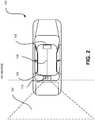
- a vehicle 100is depicted and comprises an object detection system 102 that views an area 104 at a rear of the vehicle 100.
- the object detection system 102comprises a camera 110 such as a fisheye lens camera and is capable of capturing a field of view (FOV) in a single video image.
- the video image captured by the cameraincludes a narrow FOV, a wide FOV, an ultra-wide FIV, an ultra-narrow FOV, or combination thereof.
- the object detection system 102is positioned at the rear of the vehicle 100, the system 102 may be positioned at any location of the vehicle 100.
- More than one camera 110may be incorporated in the object detection system 102 for capturing other FOV to a left side, right side, or forward of the vehicle 100.
- the camera 110may be either communicatively coupled to the object detection system 102 via wired or wirelessly. More than one camera may be mounted to various locations of the vehicle 100, depending on the application.
- the camera 110 and the object detection system 102may be located in different portion of the vehicle 100. For example, the camera 100 is positioned at the rear of the vehicle 100 whereas the object detection system 102 is located inside the vehicle.
- the object detection system 102is coupled to a display unit 106 located at a front of the vehicle 100 via a bus or in-vehicle network 108.
- the bus 108may be CAN bus or the like.
- the image captured by the camera 110is processed by the object detection system 102 before the processed image is displayed at the display unit 106 as a human readable format.
- the processed imageis transmitted to an electronic device for display as a human readable format.
- the electronic devicemay be for example a mobile phone, a computer monitor, a laptop, a tablet, a personal digital assistant (PDA), a hand-held computer, a wearable device, and the like.
- PDApersonal digital assistant
- each of the fisheye imagecan is either split or transform into at least two perspective images, but can be more than two perspective images, depending on the application.
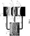
- a fisheye image 202 of an area 104is captured by the camera 110 of FIG. 2 .
- the fisheye image 202is split into three different set of fisheye or perspective images.
- left, center, and right perspective images 204, 206, 208are transmitted to at least one object detector 102 of FIG. 2 for processing.
- more than one object detector 102may be provided to process the perspective images 204, 206, 208 independently.
- the perspective images 204, 206, 208include a portion of overlap having common or identical objects of interest.
- perspective image 204includes a person or pedestrian P and two vehicles VI, V2.
- Perspective image 206includes the same person P and vehicle VI, V2.
- Perspective image 208includes only vehicle V2.
- the common or identical objects of interest found on these images 204, 206, 208is vehicle V2.
- Each of the object detector 102classifies various objects of interest such as P, VI, V2 in the split images 204, 206, 208.
- the objects of interestmay be for example pedestrians, vehicles, bikes, shopping carts, and so forth. Based on the multiple common or identical overlaps found on the perspective images 204, 206, 208, the object detector 102 corresponds to each perspective image therefore achieve better accuracy of classifying the objects of interest. Once the objects of interest is identified and classified, the object detector 102 continues to perform other functions.
- the object detector 102is capable of estimate distance of objects of interest from the vehicle using camera calibration information stored in one of the camera, object detector, memory, database, a processor, or the like. The object detector 102 then applies bounding boxes around objects of interest illustrated in the perspective images 204, 206, 208 in different colors depending on the distance of objects from the vehicle. Alternatively, the object detector 102 transmits the sensed information that corresponds to the distance of interest to the processor and in turn, the processor includes sequence of instruction or object code and processes the sensed information and applies bounding boxes around objects of interest illustrated in the perspective images 204, 206, 208 in different colors depending on the distance of objects from the vehicle. The processor for performing the above described processes may be either integrated in the vehicle or in the electronic device.
- the object of interest located a distance further from the vehicleis drawn with a green color bounded box while the object of interest located a distance close to the vehicle is drawn with a color different from green bounded box.
- One or more images incorporated the colored bounding boxesare transmitted to a display unit or screen for display as human readable format.
- the display unit or screenmay be integrated in the vehicle. In other embodiment, the display unit or screen is part of the electronic device.
- the object detector 102transmits the classified information corresponds to the object of interest to the processor via a bus or in-vehicle network 108.
- the processorincludes an instruction of object code for controlling a transducer (not shown) to generate sound-based warning to the vehicle driver of an event.
- the sound-based warningis triggered only when the object of interest is located a predefined distance closer to the vehicle. Alternatively, the sound-based warning is triggered when the predefined distance is below a threshold.
- the processormay perform other controls. For example, the processor controls the brake of the vehicle for emergency stop or brake if objects of interest too close to the vehicle are detected. In yet another embodiment, the processor controls the speed of the vehicle if objects of interest too close to the vehicle are detected.
- FIG. 4illustrate a fisheye image 202 of an area 104 captured by the camera 110 of FIG. 2 .
- the fisheye image 202is identical to the fisheye image 202 illustrated in FIG. 3 .
- the fisheye image 202is split into various views.
- the viewsinclude a ground plain view 304, a vertical plain view 306, and a sky estimation view 308.
- a devicesuch as an object detector 102 of FIG. 2 is provided for calibrating parameter and view point information.
- the object detector 102communicatively coupled to the fisheye camera 104.
- the calibration parameter and view point informationincludes height of camera from ground plane, position of camera on the rear side of vehicle, and so forth.
- the object detector 102scans or detects objects of interest within a predefined threshold and any objects outside the threshold will not be processed. For example, a drone depicted in the sky estimation view 308 that falls outside the threshold will not be scanned or detected by the object detector thus eliminates the processing time of computation non-objects of interest. Only objects of interest falls within the threshold will be scanned and detected. For example, all the three views 304, 306, and 308 depict vehicles V1 and V2. One or more object detectors scan and detect possible objects of interest, in this case V1 and V2, and discard other objects outside the threshold. In one embodiment, the object detector is capable of estimating one or more regions where V1 and V2 are detected in the vertical plain view 306.
- the object detectoris capable of detecting possible objects such as V1 and V2 from the ground plane in the ground plain view 304.
- the object detector for use to detect the objects of interest in the vertical plain view 306may be a different object detector for use to detect the objects of interest in the ground plain view 304.
- the information detected by one or more object detectorsare collected and combined together for processing.
- the object detector 102is also capable of estimate distance of objects from vehicle using camera calibration information based on the sensed information described above and applies bounding boxes around objects illustrated in the perspective images 304, 306, 308 in different colors depending on the distance of objects from the vehicles.
- the object of interest located a distance further from the vehicleis drawn with a green color bounded box while the object of interest located a distance closer to the vehicle is drawn with a color different from green bounded box.
- the object detector 102transmits the classified information corresponds to the object of interest to a processor (not shown) via a bus or in-vehicle network 108.
- the processorincludes an instruction of object code for execution control a transducer (not shown) to generate early sound-based warning to the vehicle driver.
- the sound-based warningis triggered only when the object of interest is located a distance closer to the vehicle.
- the processorcontrols the brake of the vehicle for emergency stop or brake if objects of interest too close to the vehicle are detected.
- the processormay control the speed of the vehicle if objects of interest too close to the vehicle are detected.
Landscapes
- Engineering & Computer Science (AREA)
- Physics & Mathematics (AREA)
- General Physics & Mathematics (AREA)
- Theoretical Computer Science (AREA)
- Mechanical Engineering (AREA)
- Computer Vision & Pattern Recognition (AREA)
- Multimedia (AREA)
- Traffic Control Systems (AREA)
- Image Analysis (AREA)
- Closed-Circuit Television Systems (AREA)
Description
- The patent relates generally to an object detection system for used in a vehicle.
- Unless otherwise indicated herein, the materials described in this section are not prior art to the claims in this application and are not admitted to the prior art by inclusion in this section.
- Use of forward looking, side view, and rear view cameras are becoming a common feature in latest automotives. Uses of cameras for automotives have also accelerated the development of applications improving vehicle, driver, passenger, and pedestrian safety. Especially, lack of rear visibility technology contribute to high injuries/deaths. These injuries/deaths take place while reversing a car in parking lots, backing up a car from drive ways, and so forth. According to National Highway Traffic Safety Administration (NHTSA), about 210 fatalities and 15000 injuries per year are caused in back-over accidents in the U.S. alone. 31 percent of the incidents involve children under age 5. The U.S. Department of Transportation's National Highway Traffic Safety Administration (NHTSA) recently issued a final rule requiring rear visibility technology in all new vehicles under 10,000 pounds by May 2018.
- There is an extensive studies available on object and people detections. The limitation of the conventional detectors is that it is not invariant to Radial distortion which is present inherently in the fisheye images and videos.
- Fisheye camera images also have extremely wide field of view and image magnification decrease with distance from optical axis. This creates non-uniform sampling of pixels in the image. An example of a
fisheye image 10 with radial distortion is shown inFIG.1 . - Due to these reasons, conventional detectors cannot be applied directly on the fisheye images. There has been some work done on modifying Scale-Invariant Feature Transform (SIFT) descriptors to make them invariant to Radial distortion, however, SIFT features are not suitable for object detection and there has been no effort to develop efficient object detectors for radial distorted fisheye images using SIFT descriptors. Therefore, there is a need to develop efficient techniques which can be used to detect and recognize objects using fisheye camera installed in automotive.
- Document
US 2012/0327239 A1 describes a vehicle rear view monitoring device. Threshold levels can be varied for distance sensors and horizontal and vertical detection areas can be changed. Document DE 10 2011 005 368 A1 describes a car assistance system which displays a video image. The data from the video image and from a sensor device can be combined.- A summary of certain embodiments disclosed herein is set forth below. It should be understood that these aspects are presented merely to provide the reader with a brief summary of these certain embodiments and that these aspects are not intended to limit the scope of this disclosure. Indeed, this disclosure may encompass a variety of aspects that may not be set forth below.
- In one aspect, a vehicle comprising a vehicle body having at least four sides, one or more of a fisheye lens cameras is mounted to the vehicle body, the fisheye lens cameras generates one or more of field of view (FOV) images, and an object detection system communicatively coupled to at least one or more of the fisheye lens cameras, the object detection system configured to classify object of interest appeared on one or more of the FOV images, estimate distance of object of interest either between the vehicle and the object of interest or between two or more of the object of interest, apply bounding boxes around the classified object of interest. A display unit is further provided and is communicatively coupled to the object detection system for displaying the FOV image in the form of at least one or more of a narrow FOV, a wide FOV, an ultra-wide FOV, and an ultra-narrow FOV. The object of interest comprising pedestrians, vehicles, traffic lights, and signages. A processor is further communicatively coupled to one of the object detection system or the fisheye lens cameras. The processor comprises a sequence of instruction or object code and is configured to process the FOV images incorporating applied bounding boxes around the classified object of interest and transmit the FOV images to the display unit for display in a human readable format. The processor is also configured to control the vehicle of an event detected by the object detector A transducer mounted on the vehicle is provided and connected to the processor. The transducer is triggered to generate sound-based warning of an event. The bounding boxes comprises at least one or more color coding to distinguish the classified object of interest. One or more FOV images having one or more object of interest are partially or wholly overlap to each other.
- In another aspect, an object detection system for used in a vehicle includes an object detector is provided. One or more fisheye lens cameras coupled to an object detection system are positioned at various location of the vehicle for capturing a field of view (FOV) into an image. The image is split into multiple different set of perspective images. Each perspective images may include a portion of overlap having common or identical object of interest. The object detector classifies various objects of interest in the perspective images, estimates distance of objects of interest from the vehicle using camera calibration information stored in one of the camera, and transmits the sensed information that corresponds to the distance of interest to a processor. The processor includes sequence of instruction or object code either located in one of the object detection system, in-vehicle network, and an electronic device processes the sensed information and applies bounding boxes around objects of interest the vehicle or in the electronic device. One or more images incorporated the colored bounding boxes are transmitted to a display unit or screen for display as human readable format.
- In yet another aspect, An object detection system for a vehicle comprises a fisheye lens cameras generates a field of view image (FOV) and an object detector coupled to the fisheye lens cameras, the object detector is configured to classify object of interest appeared on one or more of the FOV images, estimate distance of object of interest either between the vehicle and the object of interest or between two or more of the object of interest, apply bounding boxes around the classified object of interest. The field of view image is at least one or more of a narrow FOV, a wide FOV, an ultra-wide FOV, and an ultra-narrow FOV. A display unit communicatively coupled to the object detector for displaying the FOV image is provided. The display unit is at least one or more of a tablet, a desktop, a personal digital assistant (PDA), an entertainment unit, a monitor, a cellular phone, a hand-held computer, and a wearable device. In one embodiment, the object of interest comprises pedestrians, vehicles, traffic lights, and signages. A processor a sequence of instruction or object code is provided and is configured to process the FOV images incorporating applied bounding boxes around the classified object of interest and transmit the FOV images to the display unit for display in a human readable format. Further, the processor is configured to control the vehicle of an event detected by the object detector. A transducer mounted on the vehicle, the transducer connected to the processor is triggered to generate sound-based warning of an event. The bounding boxes comprises at least one or more color coding to distinguish the classified object of interest. One or more FOV images having one or more object of interest are partially or wholly overlap to each other.
- These and other features and aspects of this patent will become better understood when the following detailed description of certain exemplary embodiments is read with reference to the accompanying drawings in which like characters represent like arts throughout the drawings, wherein:
FIG. 1 is an illustration of an exemplary fisheye image with radial distortion;FIG. 2 is an illustration of a vehicle including an object detection system in accordance with a described embodiment;FIG. 3 is an illustration of a fisheye image split into multiple images using a splitter in accordance with a described embodiment; andFIG. 4 is an illustration of a fisheye image split into multiple images using a splitter in accordance with another described embodiment.- One or more specific embodiments will be described below. In an effort to provide a concise description of these embodiments, not all features of an actual implementation are described in the specification. It should be appreciated that in the development of any such actual implementation, as in any engineering or design project, numerous implementation-specific decisions must be made to achieve the developers' specific goals, such as compliance with system-related and business-related constraints, which may vary from one implementation to another. Moreover, it should be appreciated that such development effort might be complex and time consuming, but would nevertheless be a routine undertaking of design, fabrication, and manufacture for those of ordinary skill having the benefit of this disclosure.
- As used herein, the term "metadata" refers to properties of objects that are identified in video or other image data. For example, if an object is captured in a field of view (FOV) of a camera, the metadata corresponding to the object include the two dimensional position of the object in the frames of video or image data, velocity of the object, a direction of movement of the object, a size of the object, and a duration of time that the object is present in the FOV of the camera. As described below, events are identified with reference to be observed metadata of an object. The metadata do not require that an object be identified with particularity. In one embodiment, the metadata do not identify that an object is a particular person, or even a human being. Alternative embodiments, however, infer that metadata correspond to a human if the event is similar to an expected human action, such metadata of an object moving at a direction and speed that correspond to a human walking past a camera. Additionally, individual objects are only tracked for a short time and the metadata do not identify the same object over prolonged time periods. Thus, the stored metadata and identification of high-interest events due to metadata do not require the collection and storage of Personally Identifiable Information (PII) beyond storage of video or image data footage for later retrieval.
- The following description is presented to enable any person skilled in the art to make and use the described embodiments, and is provided in the context of a particular application and its requirements.
- With reference to
FIG. 2 , avehicle 100 is depicted and comprises anobject detection system 102 that views anarea 104 at a rear of thevehicle 100. In one embodiment, theobject detection system 102 comprises acamera 110 such as a fisheye lens camera and is capable of capturing a field of view (FOV) in a single video image. The video image captured by the camera includes a narrow FOV, a wide FOV, an ultra-wide FIV, an ultra-narrow FOV, or combination thereof. Although theobject detection system 102 is positioned at the rear of thevehicle 100, thesystem 102 may be positioned at any location of thevehicle 100. More than onecamera 110 may be incorporated in theobject detection system 102 for capturing other FOV to a left side, right side, or forward of thevehicle 100. In one embodiment, thecamera 110 may be either communicatively coupled to theobject detection system 102 via wired or wirelessly. More than one camera may be mounted to various locations of thevehicle 100, depending on the application. In another embodiment, thecamera 110 and theobject detection system 102 may be located in different portion of thevehicle 100. For example, thecamera 100 is positioned at the rear of thevehicle 100 whereas theobject detection system 102 is located inside the vehicle. Theobject detection system 102 is coupled to adisplay unit 106 located at a front of thevehicle 100 via a bus or in-vehicle network 108. Thebus 108 may be CAN bus or the like. The image captured by thecamera 110 is processed by theobject detection system 102 before the processed image is displayed at thedisplay unit 106 as a human readable format. In one embodiment, the processed image is transmitted to an electronic device for display as a human readable format. The electronic device may be for example a mobile phone, a computer monitor, a laptop, a tablet, a personal digital assistant (PDA), a hand-held computer, a wearable device, and the like. - Going back to the images captured by the
fisheye camera 100, each of the fisheye image can is either split or transform into at least two perspective images, but can be more than two perspective images, depending on the application. - Now referring to
FIG. 3 , afisheye image 202 of anarea 104 is captured by thecamera 110 ofFIG. 2 . Thefisheye image 202 is split into three different set of fisheye or perspective images. As illustrated, left, center, andright perspective images object detector 102 ofFIG. 2 for processing. Although more than oneobject detector 102 may be provided to process theperspective images perspective images perspective image 204 includes a person or pedestrian P and two vehicles VI, V2.Perspective image 206, on the other hand, includes the same person P and vehicle VI, V2. Perspective image 208, however, includes only vehicle V2. The common or identical objects of interest found on theseimages object detector 102 classifies various objects of interest such as P, VI, V2 in thesplit images perspective images object detector 102 corresponds to each perspective image therefore achieve better accuracy of classifying the objects of interest. Once the objects of interest is identified and classified, theobject detector 102 continues to perform other functions. In one embodiment, theobject detector 102 is capable of estimate distance of objects of interest from the vehicle using camera calibration information stored in one of the camera, object detector, memory, database, a processor, or the like. Theobject detector 102 then applies bounding boxes around objects of interest illustrated in theperspective images
distance of objects from the vehicle. Alternatively, theobject detector 102 transmits the sensed information that corresponds to the distance of interest to the processor and in turn, the processor includes sequence of instruction or object code and processes the sensed information and applies bounding boxes around objects of interest illustrated in theperspective images - The
object detector 102 transmits the classified information corresponds to the object of interest to the processor via a bus or in-vehicle network 108. The processor includes an instruction of object code for controlling a transducer (not shown) to generate sound-based warning to the vehicle driver of an event. The sound-based warning is triggered only when the object of interest is located a predefined distance closer to the vehicle. Alternatively, the sound-based warning is triggered when the predefined distance is below a threshold. The processor may perform other controls. For example, the processor controls the brake of the vehicle for emergency stop or brake if objects of interest too close to the vehicle are detected. In yet another embodiment, the processor controls the speed of the vehicle if objects of interest too close to the vehicle are detected. FIG. 4 illustrate afisheye image 202 of anarea 104 captured by thecamera 110 ofFIG. 2 . As can be seen, thefisheye image 202 is identical to thefisheye image 202 illustrated inFIG. 3 . Thefisheye image 202 is split into various views. The views include a groundplain view 304, a verticalplain view 306, and asky estimation view 308. A device such as anobject detector 102 ofFIG. 2 is provided for calibrating parameter and view point information. As mentioned earlier, theobject detector 102 communicatively coupled to thefisheye camera 104. In one embodiment, the calibration parameter and view point information includes height of camera from ground plane, position of camera on the rear side of vehicle, and so forth. Theobject detector 102 scans or detects objects of interest within a predefined threshold and any objects outside the threshold will not be processed. For example, a drone depicted in thesky estimation view 308 that falls outside the threshold will not be scanned or detected by the object detector thus eliminates the processing time of computation non-objects of interest. Only objects of interest falls within the threshold will be scanned and detected. For example, all the threeviews plain view 306. In another embodiment, the object detector is capable of detecting possible objects such as V1 and V2 from the ground plane in the groundplain view 304. The object detector for use to detect the objects of interest in the verticalplain view 306 may be a different object detector for use to detect the objects of interest in the groundplain view 304. The information detected by one or more object detectors are collected and combined together for processing.- The
object detector 102 is also capable of estimate distance of objects from vehicle using camera calibration information based on the sensed information described above and applies bounding boxes around objects illustrated in theperspective images object detector 102 transmits the classified information corresponds to the object of interest to a processor (not shown) via a bus or in-vehicle network 108. The processor includes an instruction of object code for execution control a transducer (not shown) to generate early sound-based warning to the vehicle driver. The sound-based warning is triggered only when the object of interest is located a distance closer to the vehicle. In another embodiment, the processor controls the brake of the vehicle for emergency stop or brake if objects of interest too close to the vehicle are detected. In yet embodiment, the processor may control the speed of the vehicle if objects of interest too close to the vehicle are detected. - The embodiments described above have been shown by way of example, and it should be understood that these embodiments may be susceptible to various modifications and alternative forms. It should be further understood that the claims are not intended to be limited to the particular forms disclosed, but rather to cover all modifications, equivalents, and alternatives falling with the sprit and scope of this disclosure.
- It is believed that the patent and many of its attendant advantages will be understood by the foregoing description, and it will be apparent that various changes may be made in the form, construction and arrangement of the components without departing from the disclosed subject matter or without sacrificing all of its material advantages. The form described is merely explanatory, and it is the intention of the following claims to encompass and include such changes.
Claims (19)
- A vehicle comprising:a vehicle body having at least four sides;one or more of a fisheye lens cameras is mounted to the vehicle body, the fisheye lens cameras generates one or more of field of view (FOV) images; andan object detection system communicatively coupled to at least one or more of the fisheye lens cameras, the object detection system configured to classify object of interest appeared on one or more of the FOV images, estimate distance of object of interest either between the vehicle and the object of interest or between two or more of the object of interest, apply bounding boxes around the classified object of interest,characterized in that the at least one field of view (FOV) image is split or transformed into at least two perspective images (204, 206, 208) which include a portion of overlap having common or identical objects of interest and wherein the object detection system comprises at least one object detector which is configured to identify and classify common or identical objects of interest in the overlap of the perspective images.
- The vehicle of claim 1, further comprising a display unit communicatively coupled to the object detection system for displaying the FOV image.
- The vehicle of claim 2, wherein the field of view image is at least one or more of a narrow FOV, a wide FOV, an ultra-wide FOV, and an ultra-narrow FOV.
- The vehicle of claim 1, wherein the object of interest comprising pedestrians, vehicles, traffic lights, and signages.
- The vehicle of claim 2, further comprising a processor communicatively coupled to one of the object detection system or the fisheye lens cameras, the processor comprises a sequence of instruction or object code and is configured to process the FOV images incorporating applied bounding boxes around the classified object of interest and transmit the FOV images to the display unit for display in a human readable format.
- The vehicle of claim 5, further comprising a transducer mounted on the vehicle, the transducer connected to the processor is triggered to generate sound-based warning of an event.
- The vehicle of claim 5, wherein the processor is configured to control the vehicle of an event detected by the object detector.
- The vehicle of claim 1, wherein the bounding boxes comprises at least one or more color coding to distinguish the classified object of interest.
- The vehicle of claim 5, wherein one or more FOV images having one or more object of interest are partially or wholly overlap to each other.
- An object detection system for a vehicle comprising:a fisheye lens cameras generates a field of view image (FOV); andan object detector coupled to the fisheye lens cameras, the object detector is configured to classify object of interest appeared on one or more of the FOV images, estimate distance of object of interest either between the vehicle and the object of interest or between two or more of the object of interest, apply bounding boxes around the classified object of interest,characterized in that the at least one field of view (FOV) image is split or transformed into at least two perspective images (204, 206, 208) which include a portion of overlap having common or identical objects of interest and wherein the object detector is configured to identify and classify common or identical objects of interest in the overlap of the perspective images.
- The object detection system of claim 10, wherein the field of view image is at least one or more of a narrow FOV, a wide FOV, an ultra-wide FOV, and an ultra-narrow FOV.
- The object detection system of claim 10, further comprising a display unit communicatively coupled to the object detector for displaying the FOV image.
- The object detection system of claim 12, wherein the display unit is at least one or more of a tablet, a desktop, a personal digital assistant (PDA), an entertainment unit, a monitor, a cellular phone, a hand-held computer, and a wearable device.
- The object detection system of claim 10, wherein the object of interest comprising pedestrians, vehicles, traffic lights, and signages.
- The object detection system of claim 12, further comprising a processor, the processor comprises a sequence of instruction or object code and is configured to process the FOV images incorporating applied bounding boxes around the classified object of interest and transmit the FOV images to the display unit for display in a human readable format.
- The object detection system of claim 15, further comprising a transducer mounted on the vehicle, the transducer connected to the processor is triggered to generate sound-based warning of an event.
- The object detection system of claim 15, wherein the processor is configured to control the vehicle of an event detected by the object detector.
- The object detection system of claim 10, wherein the bounding boxes comprises at least one or more color coding to distinguish the classified object of interest.
- The object detection system of claim 10, wherein one or more FOV images having one or more object of interest are partially or wholly overlap to each other.
Applications Claiming Priority (2)
| Application Number | Priority Date | Filing Date | Title |
|---|---|---|---|
| US201562258942P | 2015-11-23 | 2015-11-23 | |
| PCT/EP2016/078291WO2017089294A1 (en) | 2015-11-23 | 2016-11-21 | Object detection system and method thereof |
Publications (2)
| Publication Number | Publication Date |
|---|---|
| EP3380368A1 EP3380368A1 (en) | 2018-10-03 |
| EP3380368B1true EP3380368B1 (en) | 2019-09-25 |
Family
ID=57354372
Family Applications (1)
| Application Number | Title | Priority Date | Filing Date |
|---|---|---|---|
| EP16798500.1AActiveEP3380368B1 (en) | 2015-11-23 | 2016-11-21 | Object detection system and method thereof |
Country Status (3)
| Country | Link |
|---|---|
| US (1) | US10607093B2 (en) |
| EP (1) | EP3380368B1 (en) |
| WO (1) | WO2017089294A1 (en) |
Families Citing this family (3)
| Publication number | Priority date | Publication date | Assignee | Title |
|---|---|---|---|---|
| US11579629B2 (en)* | 2019-03-15 | 2023-02-14 | Nvidia Corporation | Temporal information prediction in autonomous machine applications |
| KR20220123865A (en) | 2021-03-02 | 2022-09-13 | 주식회사 에이치엘클레무브 | Apparatus for assisting driving and method thereof |
| US12014520B2 (en) | 2021-08-26 | 2024-06-18 | Toyota Motor Engineering & Manufacturing North America, Inc. | Systems and methods for detecting objects within an image in a wide-view format |
Family Cites Families (7)
| Publication number | Priority date | Publication date | Assignee | Title |
|---|---|---|---|---|
| US7359782B2 (en)* | 1994-05-23 | 2008-04-15 | Automotive Technologies International, Inc. | Vehicular impact reactive system and method |
| JP5501452B2 (en)* | 2010-05-19 | 2014-05-21 | 三菱電機株式会社 | Vehicle rear monitoring device |
| US20120013742A1 (en)* | 2010-07-16 | 2012-01-19 | Delphi Technologies, Inc. | Vision system and method for displaying a field of view dependent upon detecting an object |
| DE102011005368A1 (en)* | 2011-03-10 | 2012-09-13 | Robert Bosch Gmbh | Driver assistance system for vehicle, particularly designed as assistance system for shunters or for parking vehicle, has video camera, by which video image of surrounding area of vehicle is recorded with objects |
| US8982180B2 (en) | 2011-03-31 | 2015-03-17 | Fotonation Limited | Face and other object detection and tracking in off-center peripheral regions for nonlinear lens geometries |
| JPWO2013001941A1 (en) | 2011-06-27 | 2015-02-23 | 日本電気株式会社 | Object detection apparatus, object detection method, and object detection program |
| WO2016164118A2 (en)* | 2015-04-10 | 2016-10-13 | Robert Bosch Gmbh | Object position measurement with automotive camera using vehicle motion data |
- 2016
- 2016-11-21WOPCT/EP2016/078291patent/WO2017089294A1/ennot_activeCeased
- 2016-11-21USUS15/776,387patent/US10607093B2/enactiveActive
- 2016-11-21EPEP16798500.1Apatent/EP3380368B1/enactiveActive
Non-Patent Citations (1)
| Title |
|---|
| None* |
Also Published As
| Publication number | Publication date |
|---|---|
| US20180330176A1 (en) | 2018-11-15 |
| EP3380368A1 (en) | 2018-10-03 |
| US10607093B2 (en) | 2020-03-31 |
| WO2017089294A1 (en) | 2017-06-01 |
Similar Documents
| Publication | Publication Date | Title |
|---|---|---|
| US11301698B2 (en) | Multi-camera vision system and method of monitoring | |
| US12304475B1 (en) | Automatic collision detection, warning, avoidance and prevention in parked cars | |
| CN107807632B (en) | Perceiving road conditions from fused sensor data | |
| US11615566B2 (en) | Multi-camera vehicle vision system and method | |
| JP4173901B2 (en) | Vehicle periphery monitoring device | |
| US10331960B2 (en) | Methods for detecting, identifying and displaying object information with a multi-camera vision system | |
| EP2352136B1 (en) | System for monitoring the area around a vehicle | |
| EP1671216B1 (en) | Moving object detection using low illumination depth capable computer vision | |
| JP4173902B2 (en) | Vehicle periphery monitoring device | |
| US9862318B2 (en) | Method to determine distance of an object from an automated vehicle with a monocular device | |
| US20180150704A1 (en) | Method of detecting pedestrian and vehicle based on convolutional neural network by using stereo camera | |
| Loce et al. | Computer vision in roadway transportation systems: a survey | |
| TWI532620B (en) | Vehicle occupancy number monitor and vehicle occupancy monitoring method and computer readable record media | |
| JP4171501B2 (en) | Vehicle periphery monitoring device | |
| US10442438B2 (en) | Method and apparatus for detecting and assessing road reflections | |
| US12299987B2 (en) | Image processing device and image processing method | |
| KR101264282B1 (en) | detection method vehicle in road using Region of Interest | |
| JP2013057992A (en) | Inter-vehicle distance calculation device and vehicle control system using the same | |
| JP6756908B2 (en) | Methods and devices for detecting pedestrians around the vehicle | |
| EP3380368B1 (en) | Object detection system and method thereof | |
| JP4644273B2 (en) | Vehicle periphery monitoring device | |
| Tang et al. | Real-time lane detection and rear-end collision warning system on a mobile computing platform | |
| CN101685014B (en) | Object position detection device and method | |
| JP2018088237A (en) | Information processing device, imaging device, apparatus control system, movable body, information processing method, and information processing program | |
| JP5720380B2 (en) | Object detection method, object detection apparatus, and object detection program |
Legal Events
| Date | Code | Title | Description |
|---|---|---|---|
| STAA | Information on the status of an ep patent application or granted ep patent | Free format text:STATUS: UNKNOWN | |
| STAA | Information on the status of an ep patent application or granted ep patent | Free format text:STATUS: THE INTERNATIONAL PUBLICATION HAS BEEN MADE | |
| PUAI | Public reference made under article 153(3) epc to a published international application that has entered the european phase | Free format text:ORIGINAL CODE: 0009012 | |
| STAA | Information on the status of an ep patent application or granted ep patent | Free format text:STATUS: REQUEST FOR EXAMINATION WAS MADE | |
| 17P | Request for examination filed | Effective date:20180625 | |
| AK | Designated contracting states | Kind code of ref document:A1 Designated state(s):AL AT BE BG CH CY CZ DE DK EE ES FI FR GB GR HR HU IE IS IT LI LT LU LV MC MK MT NL NO PL PT RO RS SE SI SK SM TR | |
| AX | Request for extension of the european patent | Extension state:BA ME | |
| DAV | Request for validation of the european patent (deleted) | ||
| DAX | Request for extension of the european patent (deleted) | ||
| GRAP | Despatch of communication of intention to grant a patent | Free format text:ORIGINAL CODE: EPIDOSNIGR1 | |
| STAA | Information on the status of an ep patent application or granted ep patent | Free format text:STATUS: GRANT OF PATENT IS INTENDED | |
| INTG | Intention to grant announced | Effective date:20190415 | |
| GRAS | Grant fee paid | Free format text:ORIGINAL CODE: EPIDOSNIGR3 | |
| GRAA | (expected) grant | Free format text:ORIGINAL CODE: 0009210 | |
| STAA | Information on the status of an ep patent application or granted ep patent | Free format text:STATUS: THE PATENT HAS BEEN GRANTED | |
| AK | Designated contracting states | Kind code of ref document:B1 Designated state(s):AL AT BE BG CH CY CZ DE DK EE ES FI FR GB GR HR HU IE IS IT LI LT LU LV MC MK MT NL NO PL PT RO RS SE SI SK SM TR | |
| REG | Reference to a national code | Ref country code:GB Ref legal event code:FG4D | |
| REG | Reference to a national code | Ref country code:CH Ref legal event code:EP | |
| REG | Reference to a national code | Ref country code:AT Ref legal event code:REF Ref document number:1183515 Country of ref document:AT Kind code of ref document:T Effective date:20191015 | |
| REG | Reference to a national code | Ref country code:IE Ref legal event code:FG4D | |
| REG | Reference to a national code | Ref country code:DE Ref legal event code:R096 Ref document number:602016021373 Country of ref document:DE | |
| REG | Reference to a national code | Ref country code:NL Ref legal event code:MP Effective date:20190925 | |
| PG25 | Lapsed in a contracting state [announced via postgrant information from national office to epo] | Ref country code:FI Free format text:LAPSE BECAUSE OF FAILURE TO SUBMIT A TRANSLATION OF THE DESCRIPTION OR TO PAY THE FEE WITHIN THE PRESCRIBED TIME-LIMIT Effective date:20190925 Ref country code:LT Free format text:LAPSE BECAUSE OF FAILURE TO SUBMIT A TRANSLATION OF THE DESCRIPTION OR TO PAY THE FEE WITHIN THE PRESCRIBED TIME-LIMIT Effective date:20190925 Ref country code:HR Free format text:LAPSE BECAUSE OF FAILURE TO SUBMIT A TRANSLATION OF THE DESCRIPTION OR TO PAY THE FEE WITHIN THE PRESCRIBED TIME-LIMIT Effective date:20190925 Ref country code:SE Free format text:LAPSE BECAUSE OF FAILURE TO SUBMIT A TRANSLATION OF THE DESCRIPTION OR TO PAY THE FEE WITHIN THE PRESCRIBED TIME-LIMIT Effective date:20190925 Ref country code:BG Free format text:LAPSE BECAUSE OF FAILURE TO SUBMIT A TRANSLATION OF THE DESCRIPTION OR TO PAY THE FEE WITHIN THE PRESCRIBED TIME-LIMIT Effective date:20191225 Ref country code:NO Free format text:LAPSE BECAUSE OF FAILURE TO SUBMIT A TRANSLATION OF THE DESCRIPTION OR TO PAY THE FEE WITHIN THE PRESCRIBED TIME-LIMIT Effective date:20191225 | |
| REG | Reference to a national code | Ref country code:LT Ref legal event code:MG4D | |
| PG25 | Lapsed in a contracting state [announced via postgrant information from national office to epo] | Ref country code:GR Free format text:LAPSE BECAUSE OF FAILURE TO SUBMIT A TRANSLATION OF THE DESCRIPTION OR TO PAY THE FEE WITHIN THE PRESCRIBED TIME-LIMIT Effective date:20191226 Ref country code:LV Free format text:LAPSE BECAUSE OF FAILURE TO SUBMIT A TRANSLATION OF THE DESCRIPTION OR TO PAY THE FEE WITHIN THE PRESCRIBED TIME-LIMIT Effective date:20190925 Ref country code:RS Free format text:LAPSE BECAUSE OF FAILURE TO SUBMIT A TRANSLATION OF THE DESCRIPTION OR TO PAY THE FEE WITHIN THE PRESCRIBED TIME-LIMIT Effective date:20190925 | |
| REG | Reference to a national code | Ref country code:AT Ref legal event code:MK05 Ref document number:1183515 Country of ref document:AT Kind code of ref document:T Effective date:20190925 | |
| RAP2 | Party data changed (patent owner data changed or rights of a patent transferred) | Owner name:ROBERT BOSCH GMBH | |
| PG25 | Lapsed in a contracting state [announced via postgrant information from national office to epo] | Ref country code:EE Free format text:LAPSE BECAUSE OF FAILURE TO SUBMIT A TRANSLATION OF THE DESCRIPTION OR TO PAY THE FEE WITHIN THE PRESCRIBED TIME-LIMIT Effective date:20190925 Ref country code:PL Free format text:LAPSE BECAUSE OF FAILURE TO SUBMIT A TRANSLATION OF THE DESCRIPTION OR TO PAY THE FEE WITHIN THE PRESCRIBED TIME-LIMIT Effective date:20190925 Ref country code:NL Free format text:LAPSE BECAUSE OF FAILURE TO SUBMIT A TRANSLATION OF THE DESCRIPTION OR TO PAY THE FEE WITHIN THE PRESCRIBED TIME-LIMIT Effective date:20190925 Ref country code:RO Free format text:LAPSE BECAUSE OF FAILURE TO SUBMIT A TRANSLATION OF THE DESCRIPTION OR TO PAY THE FEE WITHIN THE PRESCRIBED TIME-LIMIT Effective date:20190925 Ref country code:IT Free format text:LAPSE BECAUSE OF FAILURE TO SUBMIT A TRANSLATION OF THE DESCRIPTION OR TO PAY THE FEE WITHIN THE PRESCRIBED TIME-LIMIT Effective date:20190925 Ref country code:AT Free format text:LAPSE BECAUSE OF FAILURE TO SUBMIT A TRANSLATION OF THE DESCRIPTION OR TO PAY THE FEE WITHIN THE PRESCRIBED TIME-LIMIT Effective date:20190925 Ref country code:AL Free format text:LAPSE BECAUSE OF FAILURE TO SUBMIT A TRANSLATION OF THE DESCRIPTION OR TO PAY THE FEE WITHIN THE PRESCRIBED TIME-LIMIT Effective date:20190925 Ref country code:ES Free format text:LAPSE BECAUSE OF FAILURE TO SUBMIT A TRANSLATION OF THE DESCRIPTION OR TO PAY THE FEE WITHIN THE PRESCRIBED TIME-LIMIT Effective date:20190925 Ref country code:PT Free format text:LAPSE BECAUSE OF FAILURE TO SUBMIT A TRANSLATION OF THE DESCRIPTION OR TO PAY THE FEE WITHIN THE PRESCRIBED TIME-LIMIT Effective date:20200127 | |
| PG25 | Lapsed in a contracting state [announced via postgrant information from national office to epo] | Ref country code:SK Free format text:LAPSE BECAUSE OF FAILURE TO SUBMIT A TRANSLATION OF THE DESCRIPTION OR TO PAY THE FEE WITHIN THE PRESCRIBED TIME-LIMIT Effective date:20190925 Ref country code:SM Free format text:LAPSE BECAUSE OF FAILURE TO SUBMIT A TRANSLATION OF THE DESCRIPTION OR TO PAY THE FEE WITHIN THE PRESCRIBED TIME-LIMIT Effective date:20190925 Ref country code:IS Free format text:LAPSE BECAUSE OF FAILURE TO SUBMIT A TRANSLATION OF THE DESCRIPTION OR TO PAY THE FEE WITHIN THE PRESCRIBED TIME-LIMIT Effective date:20200224 Ref country code:CZ Free format text:LAPSE BECAUSE OF FAILURE TO SUBMIT A TRANSLATION OF THE DESCRIPTION OR TO PAY THE FEE WITHIN THE PRESCRIBED TIME-LIMIT Effective date:20190925 | |
| REG | Reference to a national code | Ref country code:DE Ref legal event code:R097 Ref document number:602016021373 Country of ref document:DE | |
| REG | Reference to a national code | Ref country code:CH Ref legal event code:PL | |
| PG2D | Information on lapse in contracting state deleted | Ref country code:IS | |
| PG25 | Lapsed in a contracting state [announced via postgrant information from national office to epo] | Ref country code:MC Free format text:LAPSE BECAUSE OF FAILURE TO SUBMIT A TRANSLATION OF THE DESCRIPTION OR TO PAY THE FEE WITHIN THE PRESCRIBED TIME-LIMIT Effective date:20190925 Ref country code:CH Free format text:LAPSE BECAUSE OF NON-PAYMENT OF DUE FEES Effective date:20191130 Ref country code:LI Free format text:LAPSE BECAUSE OF NON-PAYMENT OF DUE FEES Effective date:20191130 Ref country code:DK Free format text:LAPSE BECAUSE OF FAILURE TO SUBMIT A TRANSLATION OF THE DESCRIPTION OR TO PAY THE FEE WITHIN THE PRESCRIBED TIME-LIMIT Effective date:20190925 Ref country code:LU Free format text:LAPSE BECAUSE OF NON-PAYMENT OF DUE FEES Effective date:20191121 Ref country code:IS Free format text:LAPSE BECAUSE OF FAILURE TO SUBMIT A TRANSLATION OF THE DESCRIPTION OR TO PAY THE FEE WITHIN THE PRESCRIBED TIME-LIMIT Effective date:20200126 | |
| PLBE | No opposition filed within time limit | Free format text:ORIGINAL CODE: 0009261 | |
| STAA | Information on the status of an ep patent application or granted ep patent | Free format text:STATUS: NO OPPOSITION FILED WITHIN TIME LIMIT | |
| REG | Reference to a national code | Ref country code:BE Ref legal event code:MM Effective date:20191130 | |
| 26N | No opposition filed | Effective date:20200626 | |
| PG25 | Lapsed in a contracting state [announced via postgrant information from national office to epo] | Ref country code:IE Free format text:LAPSE BECAUSE OF NON-PAYMENT OF DUE FEES Effective date:20191121 | |
| PG25 | Lapsed in a contracting state [announced via postgrant information from national office to epo] | Ref country code:BE Free format text:LAPSE BECAUSE OF NON-PAYMENT OF DUE FEES Effective date:20191130 Ref country code:SI Free format text:LAPSE BECAUSE OF FAILURE TO SUBMIT A TRANSLATION OF THE DESCRIPTION OR TO PAY THE FEE WITHIN THE PRESCRIBED TIME-LIMIT Effective date:20190925 | |
| PG25 | Lapsed in a contracting state [announced via postgrant information from national office to epo] | Ref country code:CY Free format text:LAPSE BECAUSE OF FAILURE TO SUBMIT A TRANSLATION OF THE DESCRIPTION OR TO PAY THE FEE WITHIN THE PRESCRIBED TIME-LIMIT Effective date:20190925 | |
| PG25 | Lapsed in a contracting state [announced via postgrant information from national office to epo] | Ref country code:HU Free format text:LAPSE BECAUSE OF FAILURE TO SUBMIT A TRANSLATION OF THE DESCRIPTION OR TO PAY THE FEE WITHIN THE PRESCRIBED TIME-LIMIT; INVALID AB INITIO Effective date:20161121 Ref country code:MT Free format text:LAPSE BECAUSE OF FAILURE TO SUBMIT A TRANSLATION OF THE DESCRIPTION OR TO PAY THE FEE WITHIN THE PRESCRIBED TIME-LIMIT Effective date:20190925 | |
| PG25 | Lapsed in a contracting state [announced via postgrant information from national office to epo] | Ref country code:TR Free format text:LAPSE BECAUSE OF FAILURE TO SUBMIT A TRANSLATION OF THE DESCRIPTION OR TO PAY THE FEE WITHIN THE PRESCRIBED TIME-LIMIT Effective date:20190925 | |
| PG25 | Lapsed in a contracting state [announced via postgrant information from national office to epo] | Ref country code:MK Free format text:LAPSE BECAUSE OF FAILURE TO SUBMIT A TRANSLATION OF THE DESCRIPTION OR TO PAY THE FEE WITHIN THE PRESCRIBED TIME-LIMIT Effective date:20190925 | |
| PGFP | Annual fee paid to national office [announced via postgrant information from national office to epo] | Ref country code:GB Payment date:20241121 Year of fee payment:9 | |
| PGFP | Annual fee paid to national office [announced via postgrant information from national office to epo] | Ref country code:FR Payment date:20241122 Year of fee payment:9 | |
| PGFP | Annual fee paid to national office [announced via postgrant information from national office to epo] | Ref country code:DE Payment date:20250122 Year of fee payment:9 |