EP3379222B1 - Magnetoelastic based sensor assembly - Google Patents
Magnetoelastic based sensor assemblyDownload PDFInfo
- Publication number
- EP3379222B1 EP3379222B1EP17162429.9AEP17162429AEP3379222B1EP 3379222 B1EP3379222 B1EP 3379222B1EP 17162429 AEP17162429 AEP 17162429AEP 3379222 B1EP3379222 B1EP 3379222B1
- Authority
- EP
- European Patent Office
- Prior art keywords
- pin
- magnetic field
- magneto
- field sensor
- active region
- Prior art date
- Legal status (The legal status is an assumption and is not a legal conclusion. Google has not performed a legal analysis and makes no representation as to the accuracy of the status listed.)
- Active
Links
Images


Classifications
- B—PERFORMING OPERATIONS; TRANSPORTING
- B60—VEHICLES IN GENERAL
- B60D—VEHICLE CONNECTIONS
- B60D1/00—Traction couplings; Hitches; Draw-gear; Towing devices
- B60D1/24—Traction couplings; Hitches; Draw-gear; Towing devices characterised by arrangements for particular functions
- B60D1/248—Traction couplings; Hitches; Draw-gear; Towing devices characterised by arrangements for particular functions for measuring, indicating or displaying the weight
- B—PERFORMING OPERATIONS; TRANSPORTING
- B60—VEHICLES IN GENERAL
- B60D—VEHICLE CONNECTIONS
- B60D1/00—Traction couplings; Hitches; Draw-gear; Towing devices
- B60D1/58—Auxiliary devices
- B60D1/62—Auxiliary devices involving supply lines, electric circuits, or the like
- B—PERFORMING OPERATIONS; TRANSPORTING
- B60—VEHICLES IN GENERAL
- B60D—VEHICLE CONNECTIONS
- B60D1/00—Traction couplings; Hitches; Draw-gear; Towing devices
- B60D1/58—Auxiliary devices
- B60D1/62—Auxiliary devices involving supply lines, electric circuits, or the like
- B60D1/64—Couplings or joints therefor
- G—PHYSICS
- G01—MEASURING; TESTING
- G01L—MEASURING FORCE, STRESS, TORQUE, WORK, MECHANICAL POWER, MECHANICAL EFFICIENCY, OR FLUID PRESSURE
- G01L1/00—Measuring force or stress, in general
- G01L1/12—Measuring force or stress, in general by measuring variations in the magnetic properties of materials resulting from the application of stress
- G01L1/125—Measuring force or stress, in general by measuring variations in the magnetic properties of materials resulting from the application of stress by using magnetostrictive means
- G—PHYSICS
- G01—MEASURING; TESTING
- G01L—MEASURING FORCE, STRESS, TORQUE, WORK, MECHANICAL POWER, MECHANICAL EFFICIENCY, OR FLUID PRESSURE
- G01L5/00—Apparatus for, or methods of, measuring force, work, mechanical power, or torque, specially adapted for specific purposes
- G01L5/0004—Force transducers adapted for mounting in a bore of the force receiving structure
- G—PHYSICS
- G01—MEASURING; TESTING
- G01L—MEASURING FORCE, STRESS, TORQUE, WORK, MECHANICAL POWER, MECHANICAL EFFICIENCY, OR FLUID PRESSURE
- G01L5/00—Apparatus for, or methods of, measuring force, work, mechanical power, or torque, specially adapted for specific purposes
- G01L5/13—Apparatus for, or methods of, measuring force, work, mechanical power, or torque, specially adapted for specific purposes for measuring the tractive or propulsive power of vehicles
- G01L5/136—Force sensors associated with a vehicle traction coupling
- G—PHYSICS
- G01—MEASURING; TESTING
- G01L—MEASURING FORCE, STRESS, TORQUE, WORK, MECHANICAL POWER, MECHANICAL EFFICIENCY, OR FLUID PRESSURE
- G01L5/00—Apparatus for, or methods of, measuring force, work, mechanical power, or torque, specially adapted for specific purposes
- G01L5/16—Apparatus for, or methods of, measuring force, work, mechanical power, or torque, specially adapted for specific purposes for measuring several components of force
- G01L5/169—Apparatus for, or methods of, measuring force, work, mechanical power, or torque, specially adapted for specific purposes for measuring several components of force using magnetic means
- B—PERFORMING OPERATIONS; TRANSPORTING
- B60—VEHICLES IN GENERAL
- B60D—VEHICLE CONNECTIONS
- B60D1/00—Traction couplings; Hitches; Draw-gear; Towing devices
- B60D1/01—Traction couplings or hitches characterised by their type
- B60D1/04—Hook or hook-and-hasp couplings
- B—PERFORMING OPERATIONS; TRANSPORTING
- B60—VEHICLES IN GENERAL
- B60D—VEHICLE CONNECTIONS
- B60D1/00—Traction couplings; Hitches; Draw-gear; Towing devices
- B60D1/48—Traction couplings; Hitches; Draw-gear; Towing devices characterised by the mounting
- B60D1/52—Traction couplings; Hitches; Draw-gear; Towing devices characterised by the mounting removably mounted
- F—MECHANICAL ENGINEERING; LIGHTING; HEATING; WEAPONS; BLASTING
- F16—ENGINEERING ELEMENTS AND UNITS; GENERAL MEASURES FOR PRODUCING AND MAINTAINING EFFECTIVE FUNCTIONING OF MACHINES OR INSTALLATIONS; THERMAL INSULATION IN GENERAL
- F16C—SHAFTS; FLEXIBLE SHAFTS; ELEMENTS OR CRANKSHAFT MECHANISMS; ROTARY BODIES OTHER THAN GEARING ELEMENTS; BEARINGS
- F16C11/00—Pivots; Pivotal connections
- F16C11/04—Pivotal connections
- F16C11/06—Ball-joints; Other joints having more than one degree of angular freedom, i.e. universal joints
Definitions
- strain gaugesare used for sensing a load.
- strain gaugesoften require a structural weakening of the load conducting elements. Often, there is a need for load measurements without compromising on structural stability.
- EP 0 341 459 A2discloses a tractor with an implement attached, in which the function of active oscillation damping in the digging position can be performed more effectively and more reliably when cornering with the aid of the electrohydraulic lifting-mechanism control device. Forces transmitted to the tractor housing by lateral guide members when cornering lead to brief signal droops in the force-measuring bolts that support the lower connecting rods and measure horizontal forces.
- a low-pass filterwhich serves for the determination of the dynamic force component and the time constant of which is charged as a function of the actual position value in such a way that, at the end of the corner, relatively small deviations of the force and hence relatively small amplitudes of the lifting mechanism about the mean digging position occur, with the result that active oscillation damping is virtually unimpaired when cornering.
- a sensor assembly for force sensingcomprises a first portion having a first and a second through hole.
- the sensor assemblyfurther comprises comprise a second portion having a third and a fourth through hole.
- the third and the fourth through holesare positioned in correspondence to the first and the second through holes.
- the sensor assemblyfurther comprises a first pin and a second pin. The first pin is arranged such that it extends through the first and the third through holes and the second pin is arranged such that it extends through the second and the fourth through holes, so as to couple the first portion to the second portion.
- the first and the second pinscomprise at least one magneto-elastically active region that is directly or indirectly attached to or form a part of the pin in such a manner that mechanic stress on the pin is transmitted to the magneto-elastically active region.
- the magneto-elastically active regioncomprises at least one magnetically polarized region such that a polarization of the magnetically polarized region becomes increasingly helically shaped as the applied stress increases.
- the sensor assemblyfurther comprises a magnetic field sensor means which is arranged approximate the at least one magneto-elastically active region. The magnetic field sensor means is configured to output a signal corresponding to a stress-induced magnetic flux which emanates from the magnetically polarized region.
- the magnetic field sensor meanscomprises at least one direction sensitive magnetic field sensor which is configured to determine a shear force in at least one direction.
- the at least one direction sensitive magnetic field sensoris arranged to have a predetermined and fixed spatial coordination with the pin, wherein this pin is at least partially hollow.
- At least one out of the first and the second pin of the sensor assemblycomprises at least one X-direction sensitive magnetic field sensor, which is configured to detect a force component Fx1 in a longitudinal direction X, and at least one Z-direction sensitive magnetic field sensor, which is configured to detect a force component Fz1 in a vertical direction Z.
- the longitudinal direction Xis defined by a direction of longitudinal extension of the second portion.
- the vertical direction Zis substantially perpendicular to the longitudinal direction X and substantially perpendicular to the transversal direction Y of longitudinal extension of the at least one pin.
- the first through hole and the third through hole of the sensor assemblycan be configured such that they encompass the first pin in a positive-fitting manner.
- a positive-fitting manner of the fittingallows the pin to be substantially rigidly fixed to the first portion and the second portion by the first and the third through hole. This means that the pin has almost no play inside the first and third through hole and that the accuracy of the force measurement is advantageously increased compared to a configuration in which the first pin has play inside the first and the third through hole.
- the additional degree of freedom of movementmay extend in the longitudinal direction X. Since the additional degree of freedom of movement corresponds to the longitudinal direction X, the determination of the shear force along this direction can advantageously be simplified.
- the first and/or the second pin of the sensor assemblycan comprise a first magneto-elastically active region and a second magneto-elastically active region.
- the first and the second magneto-elastically active regionsmay be directly or indirectly attached to or form parts of the pin in such a manner that mechanic stress may be transmitted to the magneto-elastically active regions.
- Each magneto-elastically active regioncan comprise a magnetically polarized region.
- the magnetic polarization of the first magneto-elastically active region and the magnetic polarization of the second magneto-elastically active regionmay be substantially opposite to each other.
- the magnetic field sensor meanscan comprise at least one first direction sensitive magnetic field sensor which may be arranged approximate the first magneto-elastically active region.
- the magnetic field sensor meansmay be configured to output a first signal corresponding to a stress-induced magnetic flux which may emanate from the first magneto-elastically active region.
- the magnetic field sensor meansmay comprise at least one second direction sensitive magnetic field sensor which may be arranged approximate the second magneto-elastically active region.
- the magnetic field sensor meansmay be configured to output a second signal corresponding to a stress-induced magnetic flux which may emanate from the second magneto-elastically active region.
- the differential evaluation of the signalsadvantageously doubles the signal, which is correlated with the applied stress. Because the polarization of the first and second magneto-elastically active region is opposite to each other, theoretically possible external fields may be compensated.
- the sensor assembly according to this embodimentmay be more sensitive and less susceptible to errors.
- the first and/or the second pin of the sensor assemblycan comprise at least one first X-direction sensitive magnetic field sensor and/or at least one second X-direction sensitive magnetic field sensor and/or at least one Z-direction sensitive magnetic field sensor and/or at least one second Z-direction sensitive magnetic field sensor.
- the at least one X-direction sensitive magnetic field sensormay be configured to detect a force component Fx1 in the first magneto-elastically active region in the longitudinal direction X of the second portion.
- the at least one second X-direction sensitive magnetic field sensormay be configured to detect a force component Fx2 in the second magneto-elastically active region in the longitudinal direction X of the second portion.
- the at least one Z-direction sensitive magnetic field sensormay be configured to detect a force component Fz1 in the first magneto-elastically active region in the vertical direction Z.
- the at least one second Z-direction sensitive magnetic field sensormay be configured to detect a force component Fz2 in the second magneto-elastically active region in the vertical direction Z.
- the shear forcecan be determined in different directions being perpendicularly aligned with respect to each other.
- the first pin of the sensor assemblycan comprise the at least one Z-direction sensitive magnetic field sensor and the at least one second Z-direction sensitive magnetic field sensor.
- the first pincan be configured to exclusively react on a shear force acting along the Z-direction.
- the first pin of the sensor assemblycan comprise the at least one first X-direction sensitive magnetic field sensor, the at least one second X-direction sensitive magnetic field sensor, the at least one first Z-direction sensitive magnetic field sensor and the at least one second Z-direction sensitive magnetic field sensor and the second pin of the sensor assembly can comprise the at least one first X-direction sensitive magnetic field sensor, the at least one second X-direction sensitive magnetic field sensor, the at least one first Z-direction sensitive magnetic field sensor and the at least one second Z-direction sensitive magnetic field sensor.
- both pinsare sensitive to all shear forces along the vertical Z-direction as well as along the longitudinal X-direction.
- the first and the second pinadvantageously can detect the different components of the shear force at different positions of the system.
- the magnetic field sensor meansmay be configured for determination of a first component and a second component of the load, which is applied to the pin.
- the at least one first X-direction sensitive magnetic field sensor and the at least one second X-direction sensitive magnetic field sensorcan form a first group of sensors and the at least one first Z-direction sensitive magnetic field sensor and the at least one second Z-direction sensitive magnetic field sensor can form a second group of sensors.
- the first group of sensorsis suitable for determination of a load component, which is directed along the X-axis.
- the second group of sensorssenses a component of the load, which is substantially perpendicular to the first component along the Z-direction. Consequently, the direction and the value of the stress or force, which is applied to the pins, may be determined from said components in this coordinate system.
- the second portion of the sensor assemblycan comprise a center wall which may extend in the longitudinal direction X and the vertical direction Z.
- the third and the fourth through holemay also extend through the center wall.
- the center wallallows the first portion to be effectively affected by the shear force at an additional point of action.
- first and/or the second pin of the sensor assemblymay be fixedly attached in a predetermined manner to the first portion.
- the first and/or the second pincan advantageously be fixedly attached in all six degrees of freedom. This way, the determination of the shear forces is effectively possible since the pins do not have play inside the through holes of the first portion.
- the first portion of the sensor assemblycan have a yoke-like shape.
- the yoke legs of the first portioncan comprise the first and the second through holes.
- the second portion of the sensor assemblycan have a tubular shape.
- the side walls of the second portioncan comprise the third and fourth through holes.
- the direction sensitive magnetic field sensor(s)may be configured to detect force components of shear forces introduced into the pins by the first portion and the second portion.
- a yoke-like shape of the first portion and a tubular shape of the second portionallow the sensor assembly to be implemented in an elongated joint connection of two objects, whereas the pins are arranged in the through holes and connect both objects.
- the first portion of the sensor assemblycan have a yoke-like shape.
- the yoke legs of the first portioncan comprise the first and the second through holes.
- the center wallcan comprise the third and fourth through holes.
- the direction sensitive magnetic field sensor(s)may be configured to detect force components of shear forces introduced into the pins by the first portion and the second portion.
- the side walls of the second portioncan comprise through holes which may be larger than the third and the fourth through holes such that the shear forces may be introduced into the pins by abutment surfaces of the first and the second through holes in the yoke legs and abutment surfaces of the third and the fourth through holes in the center wall.
- the abutment surfacesallow the transmission of power between the first portion and the second portion to be configured in an advantageous manner.
- the first portion of the sensor assemblymay be a supporting yoke having two yoke legs.
- the yoke legsmay comprise recesses which are aligned in correspondence to each other and which represent the first and the second through holes of the first portion.
- the first portion of the sensor assemblymay be a supporting yoke having two or four yoke legs.
- the yoke legsmay comprise recesses which are aligned in correspondence to each other and which represent the first and the second through holes of the first portion.
- the sensor assemblydispenses with a mechanical linkage or connection between the magnetic field sensor means and the second portion. This eliminates sources of error, which result from mechanic failure of this connection.
- the sensor assemblyreliably operates even under extreme operating conditions. The drift of the measurement values during long term measurement is reduced.
- the sensor assembly according to aspects of the inventionis versatile in that it may be applied to or integrated in nearly every tubular shaped portion, which may be for example a part of a hydraulic unit of a land-, marine-, rail- or air transport vehicle.
- the forces which are detectable by the sensor assemblyare not exclusively restricted to shear forces which originate from shear stress but may also originate due to tensile or compressive stress acting on the magneto-elastically active region(s) of the first pin and/or the second pin of the sensor assembly.
- shear stress and normal stressmay both induce a variation of the polarization of the magnetically polarized region emanating from the magneto-elastically active region(s).
- This polarizationmay be detectable by the magnetic field sensor means which may output a signal corresponding to a stress-induced magnetic flux towards the polarization direction sensitive magnetic field sensor that may be configured to determine the acting force. Consequently, the magneto-elastically active region may be sensitive to all stress types.
- the embodimentmay particularly be suitable, if the pin is exposed to only one single type of stress.
- the direction sensitive magnetic field sensorsmay be one of a Hall-effect, magneto-resistance, magneto-transistor, magneto-diode, MAGFET field sensors or fluxgate magnetometer.
- any hydraulic piston, crane application, car and other various applications incorporating bolts and pins, where shear forces may be appliedmay be equipped with the sensor assembly according to aspects of the invention.
- shear force sensors using strain-gaugesare designed in that they get intentionally weaken to provide enough deformation so as to allow a measurement of the applied loads.
- the magneto-elastically active region of the sensor assemblyprovides the possibility to design the bolt without weaken locations and significantly higher overload capability.
- the load pin having the integrated magneto-elastically active regionprovides the possibility to detect shear forces in pins, screws, bolts etc.
- a method of determining a direction of a load vectoris provided.
- a sensor assemblyaccording to aspects of the invention is provided.
- a sensor assemblywhich can comprise a first portion having a first and a second through hole.
- the sensor assemblycan further comprise a second portion having a third and a fourth through hole.
- the third and the fourth through holecan be positioned in correspondence to the first and the second through hole.
- the sensor assemblycan further comprise a first pin and a second pin.
- the first pincan be arranged such that it extends through the first and the third through hole and the second pin can be arranged such that it extends through the second and the fourth through hole, so as to couple the first portion to the second portion.
- At least one out of the first and the second pincan comprise at least one magneto-elastically active region that may directly or indirectly be attached to or form a part of the pin in such a manner that mechanic stress on the pin is transmitted to the magneto-elastically active region.
- the magneto-elastically active regioncan comprise at least one magnetically polarized region such that a polarization of the magnetically polarized region may become increasingly helically shaped as the applied stress increases.
- the sensor assemblycan further comprise a magnetic field sensor means which may be arranged approximate the at least one magneto-elastically active region.
- the magnetic field sensor meansmay be configured to output a signal corresponding to a stress-induced magnetic flux which may emanate from the magnetically polarized region.
- the magnetic field sensor meansmay comprise at least one direction sensitive magnetic field sensor which may be configured to determine a shear force in at least one direction.
- the at least one direction sensitive magnetic field sensormay in particular be arranged to have a predetermined and fixed spatial coordination with the pin, wherein this pin may at least be partially hollow.
- the at least one direction sensitive magnetic field sensormay be arranged inside an interior of this pin.
- the first pin and the second pinmay be exposed to a load.
- Measurement data of the at least one direction sensitive magnetic field sensormay be processed so as to determine a shear stress and/or a tensile or compressive stress that is applied by the second portion and the first portion to the first and/or second pin 8, 9.
- a direction of a force Fmay be determined from the measurement data on the one hand and the predetermined and known spatial coordination between the direction sensitive magnetic field sensor(s), the first pin, the second pin and the point of load.
- the force Fis applied to the sensor assembly via the second portion 5.
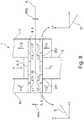
- FIG. 1is a simplified perspective view of a tow coupling comprising a sensor assembly 1 for force sensing according to aspects of the invention
- FIG. 2is a simplified exploded view of the tow coupling.
- the sensor assembly 1 for force sensingcomprises a first portion 2 (supporting yoke) having a first through hole 3 and a second through hole 4, a second portion 5 (receiving tube) having a third through hole 6 and fourth through hole 7.
- the third and fourth through holes 6, 7are positioned in correspondence to the first and second through holes 3, 4.
- the second portiondefines a Cartesian coordinate system having a longitudinal direction X, a transversal direction Y and a vertical direction Z.
- the longitudinal direction Xextends in the direction of longitudinal extension of the second portion.
- the transversal direction Yextends in a direction perpendicular to the longitudinal direction X and in a horizontal plane.
- the vertical direction Zextends in a direction that perpendicular to the longitudinal direction X and the transversal direction Y.
- the sensor assembly 1further comprises a first pin 8 and a second pin 9.
- the first pin 8is arranged such that it extends through the first and third through holes 3, 6.
- the second pin 9is arranged such that it extends through the second and fourth through holes 4, 7.
- the first portion 2is coupled to the second portion 5 via the first and second pins 8, 9.
- At least one out of the first and the second pin 8, 9comprises at least one magneto-elastically active region 10 (see FIG. 4 ) that is directly or indirectly attached to or forms a part of the pin 8, 9 in such a manner that mechanic stress of the pin 8, 9 is transmitted to the magneto-elastically active region.
- the magneto-elastically active region 10comprises at least one magnetically polarized region such that a polarization of the polarized region becomes increasingly helically shaped as the applied stress increases.
- the at least one pin 8, 9further comprises a magnetic field sensor means arranged approximate the at least one magneto-elastically active region 10 for outputting a signal corresponding to a stress-induced magnetic flux emanating from the magnetically polarized region.
- the magnetic field sensor meanscomprises at least one direction sensitive magnetic field sensor L.
- the at least one direction sensitive magnetic field sensoris configured for determination of a shear force in at least one direction.
- the at least one direction sensitive magnetic field sensor Lis in particular arranged to have a predetermined and fixed spatial coordination with the respective pin 8, 9.
- the first through hole 3 and the third through hole 6are configured such that they encompass the first pin 8 in a positive-fitting manner.
- the first pin 8extends through the first and third through holes 3, 6, and the first pin 8 is supported in at least two rotational degrees of freedom and at least two translational degrees of freedom by abutting surfaces of the through holes.
- the second pin 9is encompassed by the second through hole 4 in a positive-fitted manner.
- the second pin 9extends through the second through hole 4, and the second pin 9 is supported in at least two rotational degrees of freedom and at least two translational degrees of freedom by abutting surfaces of the second through hole 4.
- the fourth through hole 7is configured such that the second pin 9 has one additional degree of freedom of movement (compared to the first pin 8 in the third through hole 6) within the fourth through hole 7.
- the second pin 9extends through fourth through hole 7, and the second pin 9 is supported in at least two rotational degrees of freedom and at least one translational degree of freedom by abutting surfaces of the through holes.
- the number of translational degrees of freedom of the second pin 9 in the fourth through hole 7is one more than the number of translational degrees of freedom of the first pin 8 the third through hole 6.
- the additional degree of freedomis a translational degree of freedom that extends in the longitudinal direction X.
- the first portion 2has a yoke-like shape, wherein yoke legs 11 of the first portion comprise the first through hole 3 and second through hole 4.
- the second portion 5has a tubular shape, wherein side walls and/or a center wall of the second portion 5 comprise the third through hole 6 and the fourth through hole 7.
- the direction sensitive magnetic field sensoris (or the direction sensitive magnetic field sensors are) configured to detect force components of shear forces introduced into the pins 8, 9 by the first portion 2 and the second portion 5.
- the first and/or second pin 8, 9is fixedly attached (in all six degrees of freedom in a predetermined manner to the first portion 2.
- Bolts 12screw the pins 8, 9 (via attachment flanges of the pins) to yoke legs 11 of the first portion 2.
- the second portion 5comprises a center wall 13 extending in the longitudinal direction X and the vertical direction Z, the third through hole 6 and fourth through hole 7 extend through the center wall 13.
- the first portion 2has a yoke-like shape, wherein the yoke legs 11 of the first portion 2 comprise the first and second through holes 3, 4, and wherein the center wall comprises the third and fourth through holes 6, 7.
- Direction sensitive magnetic field sensor(s) Lis/are configured to detect force components of shear forces introduced into the pins 8, 9 by the first portion 2 and the second portion 5.
- Side walls 14 of the second portion 5comprise through holes in side walls that are larger than the third and fourth through holes 6, 7, such that the shear forces are introduced into the pins 8, 9 by abutment surfaces of the first and second through holes 3, 4 in the yoke legs 11 and abutment surfaces of the third and fourth through holes 6, 7 in the center wall 13.
- the tow coupling 100comprises the sensor assembly 1.
- the first portion 2is a hitch assembly that is attached to the chassis 101 of a car.
- the second portion 5is a receiving tube that is configured to receive a draw bar 102 (hitch bar, ball mount) of the tow coupling 100.
- the draw bar 102can be partially inserted into the second portion 5.
- a pin 103secures the draw bar 102 to the second portion 5.
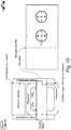
- FIG. 3is a simplified exploded view of a second portion.
- the second portion 5is of tubular (extruded) shape comprising a vertical center wall extending along the longitudinal direction X.
- the center wall 13comprises the third through hole 6 and the fourth through hole 7.
- the center wall 13can be welded into a corresponding slit in the second portion 5.
- the center wall 14thereby forms a part of the second portion 5.
- the second portion 5further comprises a draw bar barrier 99.
- the draw bar barriercan be formed by an abutment surface of the center wall 13.
- the draw bar barriercan be formed by an abutment edge or a bolt/pin extending (in a substantially radial direction) into the inside of the tubular second portion.
- the draw bar barrier 99hinders a draw bar from contacting the first and second pins 8, 9.
- FIG. 4is a simplified cross-sectional view of a sensor assembly.
- the first and second pins 8, 9extend through the first through hole 3 and the second through hole 4 in the first portion 2 and through the third through hole 6 and the fourth through hole 7 in the second portion 5.
- the first and/or second pin 8, 9is an at least partially hollow pin.
- the hollow pincan be sealed by a front cover 15 and a rear cover 17.
- the rear cover 17can provide a cable bushing to provide access for supply and/or signal lines 17.
- the pins 8, 9can comprise one or more collars 19 of comparatively low magnetic permeability (compared to the hollow shaft of the pins 8, 9) arranged such that the positions of the one or more collars 19 substantially correspond to one or more of the positions of the through holes 3, 4, 6, 7 in the first and/or second portion.
- one or more of the through holes 3, 4, 6, 7can comprise a collar/bushing 19 of comparatively low magnetic permeability (compared to the hollow shaft of the pins 8, 9).
- FIGs. 5a, 5bare simplified cross-sectional simplified views of a first and/or second pin 8, 9.
- the first and/or second pin 8, 9comprises a first magneto-elastically active region 21 and a second magneto-elastically active region 22.
- the first magneto-elastically active region 21is directly or indirectly attached to or form parts of the pin 8, 9, in such a manner that mechanic (shear) stress applied to the pin 8, 9 is at least partially transmitted to the first magneto-elastically active region 21.
- the second magneto-elastically active region 22is directly or indirectly attached to or form parts of the pin 8, 9, in such a manner that mechanic (shear) stress applied to the pin 8, 9 is at least partially transmitted to the second magneto-elastically active region 22.
- Each magneto-elastically active regioncomprises a magnetically polarized region.
- the magnetic polarization of the first magneto-elastically active region 21 and the magnetic polarization of the second magneto-elastically active region 22can be substantially opposite to each other.
- the magnetic field sensor meanscomprises at least one first direction sensitive magnetic field sensor Lx1, Lz1 being arranged approximate the first magneto-elastically active region 21 for outputting a first signal corresponding to a stress-induced magnetic flux emanating from the first magnetically polarized region 21.
- the magnetic sensor meanscomprises at least one second direction sensitive magnetic field sensor Lx2, Lz2 being arranged approximate the second magneto-elastically active region 22 for outputting a second signal corresponding to a stress-induced magnetic flux emanating from the second magnetically polarized region 22.
- the at least one out of the first and the second pin 8, 9comprises at least one X-direction sensitive magnetic field sensor Lx configured to detect a force component Fx1 in a longitudinal direction X that is defined by a direction of longitudinal extension of the second portion 5.
- the at least one out of the first and the second pin 8, 9comprises at least one Z-direction sensitive magnetic field sensor Lz configured to detect a force component Fz1 in a vertical direction Z, that is substantially perpendicular to the longitudinal direction X and perpendicular to the transversal direction Y of longitudinal extension of the at least one out of the first and second pin 8, 9.
- the first and/or the second pin 8, 9comprises a first magneto-elastically active region 21 and a second magneto-elastically active region 22, which are directly or indirectly attached to or form parts of the respective pin 8, 9 in such a manner that mechanic stress that is applied to the pin 8, 9 is transmitted to the magneto-elastically active regions.
- Each magneto-elastically active region 21, 22comprises a magnetically polarized region.
- the magnetic polarization of the first magneto-elastically active region 21 and the magnetic polarization of the second magneto-elastically active region 22can be substantially opposite to each other.
- the magnetic field sensor meanscomprises at least one first direction sensitive magnetic field sensor L1 being arranged approximate the first magneto-elastically active region for outputting a first signal corresponding to a stress-induced magnetic flux emanating from the first magnetically polarized region 21.
- the magnetic sensor meanscomprises at least one second direction sensitive magnetic field sensor L2 being arranged approximate the second magneto-elastically active region 22 for outputting a second signal corresponding to a stress-induced magnetic flux emanating from the second magnetically polarized region 22.
- the first and/or the second pin 8, 9comprises at least one respective first X-direction sensitive magnetic field sensor Lx11, Lx12 configured to detect a force component Fx1 in the first magneto-elastically active region 21 in the longitudinal direction X.
- the first and/or the second pin 8, 9comprises at least one respective second X-direction sensitive magnetic field sensor Lx21, Lx22 configured to detect a force component Fx2 in the second magneto-elastically active region 22 in the longitudinal direction X.
- the first and/or the second pin 8, 9comprises at least one respective first Z-direction sensitive magnetic field sensor Lz11, Lz12 configured to detect a force component Fz1 in the first magneto-elastically active region 21 in the vertical direction Z.
- the first and/or the second pin 8, 9comprises at least one second Z-direction sensitive magnetic field sensor Lz21, Lz22 configured to detect a force component Fz2 in the second magneto-elastically active region in the vertical direction Z.
- the sensor meanscomprises at least four magnetic field sensors L having a first to fourth sensing direction, wherein the sensing directions S and a shaft axis A (compare FIGs. 6 and 7 ) are at least substantially parallel to each other.
- the first to fourth magnetic field sensorsare arranged along the circumference of the pin having substantially equal distances in circumferential direction between each other.
- the at least one magneto-elastically active regionprojects along a circumference of the respective pin, and wherein said region is magnetized in that the domain magnetizations in the magnetically polarized region are in a circumferential direction of the member.
- FIG. 6is a simplified cross section of a sensor assembly 1 according to an embodiment of the invention.
- the sensor assembly 1comprises a first portion 2, which is coupled to a second portion 5 via the pin 8, 9.
- the first portion 2is subject to a first shear force FS1 pointing to the left.
- the second portion 5is exposed to a second and opposite shear force FS2, pointing to the right.
- the pin 8, 9comprises a magneto-elastically active region 21, which is arranged at the transition between the first and the second portion 2, 5. Consequently, the active region 21 is subject to shear forces causing the magnetic flux emanating from the magnetically polarized region of said active region 21 to become increasingly helically shaped, when the shear forces FS1, FS2 increase.
- the sensor means of the pin 8, 9comprises four direction sensitive magnetic field sensors Lx1, Lx2, Lz1, Lz2 being arranged along the inner circumference of the pin 8, 9.
- the configuration of the direction sensitive magnetic field sensors Lx1, Lx2, Lz1, Lz2is explained in more detail by making reference to the simplified cross section of the sensor assembly 1, which is shown in FIG. 7 .
- the cross sectional planeis arranged to be substantially perpendicular to the shaft axis A.
- the first direction sensitive sensor Lx1 and the third direction sensitive sensor Lx2form a first group of magnetic field sensors.
- the second group of sensorsconsists of the second direction sensitive sensor Lz1 and the fourth direction sensitive sensor Lz2.
- the sensing direction Sx1 of the first sensor Lx1is 180° opposite to the third sensing direction Sx2 of the third sensor Lx2. This is indicated in the figure using the conventional signs.
- the first sensing direction Sx1points out of the paper plane
- the third sensing direction Sx2points into the paper plane.
- the second sensing direction Sz1 and the fourth sensing direction Sz2are 180° opposite to each other.
- the second and fourth sensor Lz1, Lz2are arranged accordingly. As it is indicated using the commonly known direction signs, the second sensing direction Sz1 points out of the paper plane while the fourth sensing direction Sz2 is directed into the paper plane.
- the second sensor Lz1(having the second sensing direction Sz1) and the fourth sensor Lz2 (having the fourth sensing direction Sz2) are shown in the simplified cross section of FIG. 7 .
- the first sensor Lx1 and the first sensing direction Sx1are added to the simplified cross section of FIG. 7 solely for clarification of the configuration of the sensors.
- the first sensor Lx1is not arranged in a common plane with the second and fourth sensor Sz1, Sz2, as it is shown in the cross section of FIG. 7 .
- the signals of the first group of sensors(comprising the first and the third sensor Lx1, Lx2) is analyzed so as to determine a first component of a force F inducing the respective shear stress forces FS1, FS2.
- this first componentmay be indentified with the X-component Fx of the applied force F.
- the evaluation of the measurement values of the sensors of the second groupi. e. the second sensor Lz1 and the fourth sensor Lz2 results in a value for a second component of the force F.
- this second forceis identified with the Z-component of the force F, i. e. the force component Fz.
- FIG. 8is a cross section of a magneto-elastic sensor assembly 2 according to another embodiment of the invention.
- the first portion 2surrounds the second portion 5, which is exposed to a force F.
- the pin 8, 9intersects the first and the second portions 2, 5 along the shaft axis A.
- the pin 8, 9comprises a first magneto-elastically active region 261 and a second magneto-elastically active region 262. Similar to the other embodiments of the invention, these are directly or indirectly attached to or form a part of the pin 8, 9 in such a manner that the mechanic stress is transmitted to the active regions 261, 262.
- the active regions 261, 262are magnetically polarized in opposite direction.
- the magnetic polarizations P61, P62are substantially 180° opposite to each other. Furthermore, they are substantially perpendicular to the shaft axis A.
- a first pair of magnetic field sensorscomprising a first sensor L1 and a second sensor L2 is arranged inside the pin 8, 9 in that this pair of sensors cooperates with the first active region 261.
- a second pair of magnetic field sensorscomprising a first and a second sensor L1* and L2* is arranged inside the pin 8, 9 so as to interact with the second active region 262.
- the sensors L1, L2 of the first pair and the sensors L1*, L2* of the second pairare arranged approximate the first and the second magneto-elastically active region 261, 262, respectively.
- the first sensor pair L1, L2outputs a first signal S, which is illustrated as a voltage V varying with the applied force F in the lower left of FIG. 8 .
- the signal Scorresponds to a stress-induced magnetic flux emanating from the first magnetically polarized region 261.
- the second pair of magnetic sensors L1*, L2*outputs a second signal S* corresponding to a stress-induced magnetic flux emanating from the second magnetically polarized region 262.
- This signal S*is also a voltage V* varying with the applied F (see lower right of FIG. 8 ).
- the slope of the second signal S*is opposite to that of the first signal S.
- a control unit (not shown) of the magneto-elastic sensor assemblyis configured for determination of the force F inducing a stress in the pin(s) 8, 9.
- the control unitperforms a differential evaluation of the signals S and S* of the first pair of sensors L1, L2 and the second pair of sensors L1*, L2*.
- This differential evaluationadvantageously doubles the sensitivity of the signal, which is correlated with the applied stress. Because the polarization P61 and P62 of the first and second magnetically active region 261, 262 is opposite to each other, theoretically possible external fields are compensated.
- the magneto-elastic sensor assembly according to this embodimentis more sensitive and less susceptible to errors.
- all embodiments of the inventionmay be equipped with the sensor configuration of FIG. 8 having separate, oppositely polarized active regions 261, 262 and two corresponding sets i.e. pairs of sensors L1, L2 and L1*, L2*.
- FIG. 9is a simplified side view of a sensor assembly 1 detecting a simplified first load case.
- the force Fhas a vertical force component Fz in the vertical direction Z.
- the force Fis applied to the sensor assembly via the second portion 5, and more precisely via the ball coupling 104 of the draw bar 102.
- Fz * d 1Fz 1 * d 2
- Fz * d 3Fz 2 * d 2
- FzFz 1 + Fz 2
- F1is a reaction force on the first pin 8
- F2is a reaction force on the second pin 9.
- D2is the distance between (the axes of) the first and the second pin 8
- D1is the distance between the point of load (the ball coupling) and (the axis of) the second pin.
- D3is the distance between the point of load and (the axis of) the first pin.
- FIG. 10is a simplified top view of a sensor assembly detecting a simplified second load case.
- the forcehas a transversal force component Fy in the transversal direction Y applied to the sensor assembly 1 via the second portion 5, and more precisely via the ball coupling 104 of the draw bar 102.
- the fourth through hole 7provides a degree of freedom in the longitudinal direction X.
- the transversal force component Fycreates a first reactive force Fx2 acting in the longitudinal direction X on the first magneto-elastically active region 21 of the first pin 8, and a second reactive force Fx1 acting in the longitudinal direction X on the second magneto-elastically active region 22 of the first pin 8.
- FIG. 11is a simplified top view of a sensor assembly detecting a simplified third load case.
- the forcehas a longitudinal force component Fx in the longitudinal direction X applied to the to the sensor assembly 1 via the second portion 5, and more precisely via the ball coupling 104 of the draw bar 102.
- the fourth through hole 7provides a degree of freedom in the longitudinal direction X.
- FIG. 12is a simplified cross-sectional view of a sensor assembly configured to detect a vertical load component Fz of a load F.
- the first pin 8comprises a first magneto-elastically active region 21 and a second magneto-elastically active region 22, which are directly or indirectly attached to or form parts of the first pin 8 in such a manner that mechanic stress that is applied to the first pin 8 is transmitted to the magneto-elastically active regions 21, 22.
- Each magneto-elastically active region 21, 22comprises a magnetically polarized region.
- the magnetic polarization of the first magneto-elastically active region 21 and the magnetic polarization of the second magneto-elastically active region 22can be substantially opposite to each other.
- the magnetic field sensor meanscomprises at least one first direction sensitive magnetic field sensor Lz11 being arranged approximate the first magneto-elastically active region for outputting a first signal corresponding to a stress-induced magnetic flux emanating from the first magnetically polarized region 21.
- the first pin 8comprises a first and a third Z-direction sensitive magnetic field sensor Lz11, Lz12 configured to detect a force component Fz1 in the first magneto-elastically active region 21 in the vertical direction Z.
- the first pin 8further comprises a second and a fourth Z-direction sensitive magnetic field sensor Lz21, Lz22 configured to detect a force component Fz2 in the second magneto-elastically active region in the vertical direction Z.
- the second pin 9is a naked pin, i.e. the second pin comprises no magneto-elastically active region and no direction sensitive magnetic field sensors.
- the first pin 8comprises at least one first Z-direction sensitive magnetic field sensor Lz11 and at least one second Z-direction sensitive magnetic field sensor Lz21.
- the first and second pins 8, 9are rigidly fixed within the first and second through holes 3, 4 of the first portion 2.
- FIG. 13is a simplified cross-sectional view of a sensor assembly configured to detect a vertical load component Fz, a transversal load component Fy, and a longitudinal load component Fx of a load F.
- the first pin 8comprises a first magneto-elastically active region 21 and a second magneto-elastically active region 22, which are directly or indirectly attached to or form parts of the first pin 8 in such a manner that mechanic stress that is applied to the first pin 8 is transmitted to the magneto-elastically active regions 21, 22.
- Each magneto-elastically active region 21, 22comprises a magnetically polarized region.
- the magnetic polarization of the first magneto-elastically active region 21 and the magnetic polarization of the second magneto-elastically active region 22can be substantially opposite to each other.
- the magnetic field sensor meanscomprises at least one first and third direction sensitive magnetic field sensor Lx11, Lz11 being arranged approximate the first magneto-elastically active region for outputting a first signal and a third signal corresponding to a stress-induced magnetic flux emanating from the first magnetically polarized region 21.
- the magnetic sensor meansfurther comprises at least one second and fourth direction sensitive magnetic field sensor Lx21, Lz21 being arranged approximate the second magneto-elastically active region 22 for outputting a second signal and a fourth signal corresponding to a stress-induced magnetic flux emanating from the second magnetically polarized region 22.
- the first pin 8comprises a first and a third Z-direction sensitive magnetic field sensor Lz11, Lz12 configured to detect a vertical force component Fz11 in the first magneto-elastically active region 21 in the vertical direction Z.
- the first pin 8further comprises a second and a fourth Z-direction sensitive magnetic field sensor Lz21, Lz22 configured to detect a vertical force component Fz12 in the second magneto-elastically active region in the vertical direction Z.
- the first pin 8comprises a first and a third X-direction sensitive magnetic field sensor Lx11, L12 configured to detect a longitudinal force component Fx2 in the first magneto-elastically active region 21 in the longitudinal direction X.
- the second pin 9comprises a first and a third Z-direction sensitive magnetic field sensor Lz11, Lz12 configured to detect a vertical force component Fz21 in the first magneto-elastically active region 21 in the vertical direction Z.
- the second pin 9further comprises a second and a fourth Z-direction sensitive magnetic field sensor Lz21, Lz22 configured to detect a vertical force component Fz22 in the second magneto-elastically active region in the vertical direction Z.
- the first pin 8comprises at least one first X-direction sensitive magnetic field sensor Lx11, at least one second X-direction sensitive magnetic field sensor Lx21, at least one first Z-direction sensitive magnetic field sensor Lz11, and the at least one second Z-direction sensitive magnetic field sensor Lz21.
- the second pin 9comprises at least one first Z-direction sensitive magnetic field sensor Lz11 and at least one second Z-direction sensitive magnetic field sensor Lz21.
- the first and second pins 8, 9are rigidly fixed within the first and second through holes 3, 4 of the first portion 2.
- the third and the fourth through holes 6, 7can provide a minimal gap between the abutment surfaces of the second portion 5 and the first and second pins 8, 9.
- FIG. 14is a simplified cross-sectional view of a sensor assembly configured to detect a vertical load component Fz, a transversal load component Fy, and a longitudinal load component Fx of a load F.
- the first pin 8comprises a first magneto-elastically active region 21 and a second magneto-elastically active region 22, which are directly or indirectly attached to or form parts of the first pin 8 in such a manner that mechanic stress that is applied to the first pin 8 is transmitted to the magneto-elastically active regions 21, 22.
- Each magneto-elastically active region 21, 22comprises a magnetically polarized region.
- the magnetic polarization of the first magneto-elastically active region 21 and the magnetic polarization of the second magneto-elastically active region 22can be substantially opposite to each other.
- the magnetic field sensor meanscomprises at least one first and third direction sensitive magnetic field sensor Lx11, Lz11 being arranged approximate the first magneto-elastically active region for outputting a first signal and a third signal corresponding to a stress-induced magnetic flux emanating from the first magnetically polarized region 21.
- the magnetic sensor meansfurther comprises at least one second and fourth direction sensitive magnetic field sensor Lx21, Lz21 being arranged approximate the second magneto-elastically active region 22 for outputting a second signal and a fourth signal corresponding to a stress-induced magnetic flux emanating from the second magnetically polarized region 22.
- the first pin 8comprises a first and a third Z-direction sensitive magnetic field sensor Lz11, Lz12 configured to detect a vertical force component Fz11 in the first magneto-elastically active region 21 in the vertical direction Z.
- the first pin 8further comprises a second and a fourth Z-direction sensitive magnetic field sensor Lz21, Lz22 configured to detect a vertical force component Fz12 in the second magneto-elastically active region in the vertical direction Z.
- the first pin 8comprises a first and a third X-direction sensitive magnetic field sensor Lx11, L12 configured to detect a longitudinal force component Fx2 in the first magneto-elastically active region 21 in the longitudinal direction X.
- the first pin 8further comprises a second and a fourth X-direction sensitive magnetic field sensor Lx21, Lx22 configured to detect a longitudinal force component Fx1 in the second magneto-elastically active region in the longitudinal direction X.
- the second pin 9comprises a first and a third Z-direction sensitive magnetic field sensor Lz11, Lz12 configured to detect a vertical force component Fz21 in the first magneto-elastically active region 21 in the vertical direction Z.
- the second pin 9further comprises a second and a fourth Z-direction sensitive magnetic field sensor Lz21, Lz22 configured to detect a vertical force component Fz22 in the second magneto-elastically active region 22 in the vertical direction Z.
- the second pin 9comprises a first and a third X-direction sensitive magnetic field sensor Lx11, L12 configured to detect a longitudinal force component Fx10 in the first magneto-elastically active region 21 in the longitudinal direction X.
- the second pin 9further comprises a second and a fourth X-direction sensitive magnetic field sensor Lx21, Lx22 configured to detect a longitudinal force component Fx20 in the second magneto-elastically active region 22 in the longitudinal direction X.
- the configuration of the second pin 9is substantially similar to the configuration of the first pin 8.
- the first pin 8comprises at least one first X-direction sensitive magnetic field sensor Lx11, at least one the second X-direction sensitive magnetic field sensor Lx21, at least one first Z-direction magnetic field sensor Lz11, and at least one second Z-direction magnetic field sensor Lz21.
- the second pincomprises at least one first X-direction sensitive magnetic field sensor Lx11, at least one second X-direction sensitive magnetic field sensor Lx21, at least one first Z-direction magnetic field sensor Lz11, and at least one second Z-direction magnetic field sensor Lz21.
- first and the second longitudinal force components Fx10, Fx20are comparatively small (for example, resulting from friction between the abutment surface of the fourth through hole 7 and the second pin 9) or substantially zero. This is a direct result of the additional translational degree of freedom in the longitudinal direction X, which degree of freedom is provided by the fourth through hole 7 in the second portion 5.
- the first and second pins 8, 9are rigidly fixed within the first and second through holes 3, 4 of the first portion 2.
- the third and the fourth through holes 6, 7can provide a minimal gap between the abutment surfaces of the second portion 5 and the first and second pins 8, 9.
- the first pin 8comprises a first magneto-elastically active region 21 and a second magneto-elastically active region 22, which are directly or indirectly attached to or form parts of the first pin 8 in such a manner that mechanic stress that is applied to the first pin 8 is transmitted to the magneto-elastically active regions 21, 22.
- Each magneto-elastically active region 21, 22comprises a magnetically polarized region.
- the magnetic polarization of the first magneto-elastically active region 21 and the magnetic polarization of the second magneto-elastically active region 22can be substantially opposite to each other.
- the magnetic field sensor meanscomprises at least one first and third direction sensitive magnetic field sensor Lx11, Lz11 being arranged approximate the first magneto-elastically active region for outputting a first signal and a third signal corresponding to a stress-induced magnetic flux emanating from the first magnetically polarized region 21.
- the magnetic sensor meansfurther comprises at least one second and fourth direction sensitive magnetic field sensor Lx21, Lz21 being arranged approximate the second magneto-elastically active region 22 for outputting a second signal and a fourth signal corresponding to a stress-induced magnetic flux emanating from the second magnetically polarized region 22.
- the first pin 8comprises a first and a third Z-direction sensitive magnetic field sensor Lz11, Lz12 configured to detect a vertical force component Fz11 in the first magneto-elastically active region 21 in the vertical direction Z.
- the first pin 8further comprises a second and a fourth Z-direction sensitive magnetic field sensor Lz21, Lz22 configured to detect a vertical force component Fz12 in the second magneto-elastically active region in the vertical direction Z.
- the first pin 8comprises a first and a third X-direction sensitive magnetic field sensor Lx11, L12 configured to detect a longitudinal force component Fx2 in the first magneto-elastically active region 21 in the longitudinal direction X.
- the first pin 8further comprises a second and a fourth X-direction sensitive magnetic field sensor Lx21, Lx22 configured to detect a longitudinal force component Fx1 in the second magneto-elastically active region in the longitudinal direction X.
- the second pin 9comprises a first and a third Z-direction sensitive magnetic field sensor Lz11, Lz12 configured to detect a vertical force component Fz21 in the first magneto-elastically active region 21 in the vertical direction Z.
- the second pin 9further comprises a second and a fourth Z-direction sensitive magnetic field sensor Lz21, Lz22 configured to detect a vertical force component Fz22 in the second magneto-elastically active region 22 in the vertical direction Z.
- the second pin 9comprises a first and a third X-direction sensitive magnetic field sensor Lx11, L12 configured to detect a longitudinal force component Fx22 in the first magneto-elastically active region 21 in the longitudinal direction X.
- the second pin 9further comprises a second and a fourth X-direction sensitive magnetic field sensor Lx21, Lx22 configured to detect a longitudinal force component Fx21 in the second magneto-elastically active region 22 in the longitudinal direction X.
- the general configuration of the first pin 8is substantially similar to the configuration of the first pin depicted in FIG. 14 .
- the general configuration of the second pin 9is substantially similar to the configuration of the first pin 8.
- the first and second pins 8, 9are rigidly fixed within the first and second through holes 3, 4 of the first portion 2.
- the third and the fourth through holes 6, 7can provide a minimal gap between the abutment surfaces of the second portion 5 and the first and second pins 8, 9.
- the fourth through hole 7can provide no minimal gap, such that the second pin 9 is rigidly fixed within the third and the fourth through hole 7.
- FIG. 16is a simplified cross-sectional view of a sensor assembly configured to detect the first load case, the second load case, and the third load case.
- the first pin 8comprises a first magneto-elastically active region 21 and a second magneto-elastically active region 22, which are directly or indirectly attached to or form parts of the first pin 8 in such a manner that mechanic stress that is applied to the first pin 8 is transmitted to the magneto-elastically active regions 21, 22.
- Each magneto-elastically active region 21, 22comprises a magnetically polarized region.
- the magnetic polarization of the first magneto-elastically active region 21 and the magnetic polarization of the second magneto-elastically active region 22can be substantially opposite to each other.
- the magnetic field sensor meanscomprises at least one first direction sensitive magnetic field sensor Lz11 being arranged approximate the first magneto-elastically active region for outputting a first signal corresponding to a stress-induced magnetic flux emanating from the first magnetically polarized region 21.
- the magnetic sensor meansfurther comprises at least one second direction sensitive magnetic field sensor Lz21 being arranged approximate the second magneto-elastically active region 22 for outputting a second signal and a fourth signal corresponding to a stress-induced magnetic flux emanating from the second magnetically polarized region 22.
- the first pin 8comprises a first and a third Z-direction sensitive magnetic field sensor Lz11, Lz12 configured to detect a vertical force component Fz11 in the first magneto-elastically active region 21 of the first pin 8 in the vertical direction Z.
- the first pin 8further comprises a second and a fourth Z-direction sensitive magnetic field sensor Lz21, Lz22 configured to detect a vertical force component Fz12 in the second magneto-elastically active region of the first pin 8 in the vertical direction Z.
- the first pin 8comprises no X-direction sensitive magnetic field sensors.
- the general configuration of the first pin 8is substantially similar to the general configuration of the first pin 8 depicted in FIG. 12 .
- the second pin 9comprises a first and a third Z-direction sensitive magnetic field sensor Lz11, Lz12 configured to detect a vertical force component Fz21 in the first magneto-elastically active region 21 in the vertical direction Z.
- the second pin 9further comprises a second and a fourth Z-direction sensitive magnetic field sensor Lz21, Lz22 configured to detect a vertical force component Fz22 in the second magneto-elastically active region 22 in the vertical direction Z.
- the second pin 9comprises a first and a third X-direction sensitive magnetic field sensor Lx11, L12 configured to detect a longitudinal force component Fx22 in the first magneto-elastically active region 21 in the longitudinal direction X.
- the second pin 9further comprises a second and a fourth X-direction sensitive magnetic field sensor Lx21, Lx22 configured to detect a longitudinal force component Fx21 in the second magneto-elastically active region 22 in the longitudinal direction X.
- the second pin 9generally comprises a configuration that is substantially similar to the general configuration of the second pin 9 depicted in FIG. 15 .
- the first and second pins 8, 9are rigidly fixed within the first and second through holes 3, 4 of the first portion 2.
- the third and the fourth through hole 6, 7can provide a minimal gap between the abutment surfaces of the second portion 5 and the first and second pins 8, 9.
- the fourth through hole 7can provide no minimal gap, such that the second pin 9 is rigidly fixed within the third and the fourth through hole 7.
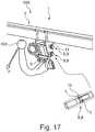
- FIG. 17is a simplified perspective view of a tow coupling comprising a sensor assembly for sensing (components) of a force F.
- the sensor assembly 1 for sensing a force Fcomprises a first portion 2 (attachment assembly, supporting yoke) having a first and a second through hole 3, 4.
- the sensor assembly 1further comprises a second portion 5 (trailer hitch, towing hook) having a third and fourth through hole 6, 7.
- the third and fourth through holes 6, 7are positioned in correspondence to the first and second through holes 3, 4.
- the sensor assembly 1further comprises a first pin 8 and a second pin 9.
- the first pin 8is arranged such that it extends through the first and third through holes 3, 6.
- the second pin 9is arranged such that it extends through the second and fourth through holes 4, 7.
- At least one out of the first and the second pin 8, 9comprises at least one magneto-elastically active region 10 that is directly or indirectly attached to or forms a part of the pin 8, 9 in such a manner that mechanic stress on the pin is transmitted to the magneto-elastically active region.
- the magneto-elastically active region 10comprises at least one magnetically polarized region such that a polarization of the polarized region becomes increasingly helically shaped as the applied stress increases.
- the magnetic field sensor meanscomprise at least one direction sensitive magnetic field sensor L, which is configured for determination of a shear force in at least one direction.
- the at least one direction sensitive magnetic field sensor Lis arranged to have a predetermined and fixed spatial coordination with the pin 8, 9.
- the at least one direction sensitive magnetic field sensor Lis arranged inside the interior of the pin 8, 9.
- the first and second pins 8, 9are substantially arranged along the vertical direction Z.
- the pins 8, 9extend in the transversal direction Y.
- the longitudinal directionis perpendicular to the vertical direction Z and the transversal direction Y to define the Cartesian coordinate system.
- the system of equations that has to be solved in order to determine the respective load components,has to be altered accordingly.
- the sensor assembly 1is part of a tow coupling 100.
- the first part 2is configured to be attached to the chassis of an automobile.
- the second part 5provides a ball head 104 that is configured to couple to a trailer.
- the direction sensitive sensors Lmay be vector sensors.
- Hall-effect, magneto-resistance, magneto-transistor, magneto-diode, MAGFET field sensor or fluxgate magneto-meter sensorscan be applied. This advantageously applies to all embodiments of the invention.
- the sensor assembly for force sensing according to aspects of the inventionis advantageously applicable for load detection tow couplings, for load detection in farming equipment, and/or for load detection in construction equipment.
Landscapes
- Engineering & Computer Science (AREA)
- Physics & Mathematics (AREA)
- General Physics & Mathematics (AREA)
- Transportation (AREA)
- Mechanical Engineering (AREA)
- Chemical & Material Sciences (AREA)
- Analytical Chemistry (AREA)
- Combustion & Propulsion (AREA)
- Force Measurement Appropriate To Specific Purposes (AREA)
Description
- The invention is related in general to systems and methods involving the use of magnetic field sensors for measuring a load. In particular, the invention relates to a magnetoelastic based sensor assembly, i.e. a sensor assembly comprising a magneto-elastically active region and a tow coupling incorporating this sensor assembly. Furthermore, the invention relates to a method of determining a direction of a load vector.
- In many use cases strain gauges are used for sensing a load. However, strain gauges often require a structural weakening of the load conducting elements. Often, there is a need for load measurements without compromising on structural stability.
- This is especially true for tow couplings. Conventional trailer hitch couplings are known from
US 5,593,171 andUS 2011/0221164 A1 . Furthermore, there is a strong demand for smart tow couplings, e.g. for systems providing a load weight gauge (measuring the tongue load of a tow coupling), a tow load weight shift alert, an unsafe trailer load distribution alert, a vehicle limit notification, an automated trailer brake control (closed loop), a low/flat trailer tire notification, and a check trailer brake notification, closed loop braking control, vehicle shift control, engine control, and stability control. The above discussed functions require the measurement of tow loads and/or tongue loads of the tow coupling. - Prior art load measurement devices for tow couplings have significant shortcomings, e.g. the complexity of the measurement and control devices, and the costs of the sensor assembly.
EP 0 341 459 A2 - As an alternative to the widely used strain-gauges, non-contact type sensors exploiting the magnetoelastic effect were developed. These are frequently applied to torque measurements of rotating shafts in various mechanic systems.
US 9,347,845 US 2014/0360282 A1 disclose such a magnetoelastic sensor. - It is an object of the invention to provide an improved magnetoelastic based sensor assembly according to
claim 1 to effectively measure stress and strain in systems having a portion which is subject to a mechanic load. - According to the invention, a sensor assembly for force sensing comprises a first portion having a first and a second through hole. The sensor assembly further comprises comprise a second portion having a third and a fourth through hole. The third and the fourth through holes are positioned in correspondence to the first and the second through holes. The sensor assembly further comprises a first pin and a second pin. The first pin is arranged such that it extends through the first and the third through holes and the second pin is arranged such that it extends through the second and the fourth through holes, so as to couple the first portion to the second portion. The first and the second pins comprise at least one magneto-elastically active region that is directly or indirectly attached to or form a part of the pin in such a manner that mechanic stress on the pin is transmitted to the magneto-elastically active region. The magneto-elastically active region comprises at least one magnetically polarized region such that a polarization of the magnetically polarized region becomes increasingly helically shaped as the applied stress increases. The sensor assembly further comprises a magnetic field sensor means which is arranged approximate the at least one magneto-elastically active region. The magnetic field sensor means is configured to output a signal corresponding to a stress-induced magnetic flux which emanates from the magnetically polarized region. The magnetic field sensor means comprises at least one direction sensitive magnetic field sensor which is configured to determine a shear force in at least one direction. The at least one direction sensitive magnetic field sensor is arranged to have a predetermined and fixed spatial coordination with the pin, wherein this pin is at least partially hollow.
- The at least one direction sensitive magnetic field sensor is arranged inside an interior of this pin. By means of the sensor assembly stress which is applied to a pin caused by a mechanic load is effectively measured. The sensor assembly according to aspects of the invention overcomes the drawback of the prior art solutions. In particular, the sensor assembly does not tend to drift with respect to the measurement values and is less error-prone.
- According to the invention, at least one out of the first and the second pin of the sensor assembly comprises at least one X-direction sensitive magnetic field sensor, which is configured to detect a force component Fx1 in a longitudinal direction X, and at least one Z-direction sensitive magnetic field sensor, which is configured to detect a force component Fz1 in a vertical direction Z. The longitudinal direction X is defined by a direction of longitudinal extension of the second portion. The vertical direction Z is substantially perpendicular to the longitudinal direction X and substantially perpendicular to the transversal direction Y of longitudinal extension of the at least one pin.
- According to another aspect, the first through hole and the third through hole of the sensor assembly can be configured such that they encompass the first pin in a positive-fitting manner. A positive-fitting manner of the fitting allows the pin to be substantially rigidly fixed to the first portion and the second portion by the first and the third through hole. This means that the pin has almost no play inside the first and third through hole and that the accuracy of the force measurement is advantageously increased compared to a configuration in which the first pin has play inside the first and the third through hole.
- According to another aspect, the second pin of the sensor assembly may be encompassed by the second through hole in a positive-fitting manner and the fourth through hole may be configured such that the second pin may have one additional degree of freedom of movement within the fourth through hole. The additional degree of freedom of movement allows the second pin to be insensitive with respect to shear forces acting in the direction of the additional degree of freedom of movement. This means that the determination of the shear force along this direction can advantageously be simplified since the shear effect occurs exclusively on the first pin.
- According to another aspect, the additional degree of freedom of movement may extend in the longitudinal direction X. Since the additional degree of freedom of movement corresponds to the longitudinal direction X, the determination of the shear force along this direction can advantageously be simplified.
- According to another aspect, the first and/or the second pin of the sensor assembly can comprise a first magneto-elastically active region and a second magneto-elastically active region. The first and the second magneto-elastically active regions may be directly or indirectly attached to or form parts of the pin in such a manner that mechanic stress may be transmitted to the magneto-elastically active regions. Each magneto-elastically active region can comprise a magnetically polarized region. Particularly, the magnetic polarization of the first magneto-elastically active region and the magnetic polarization of the second magneto-elastically active region may be substantially opposite to each other. The magnetic field sensor means can comprise at least one first direction sensitive magnetic field sensor which may be arranged approximate the first magneto-elastically active region. The magnetic field sensor means may be configured to output a first signal corresponding to a stress-induced magnetic flux which may emanate from the first magneto-elastically active region. The magnetic field sensor means may comprise at least one second direction sensitive magnetic field sensor which may be arranged approximate the second magneto-elastically active region. The magnetic field sensor means may be configured to output a second signal corresponding to a stress-induced magnetic flux which may emanate from the second magneto-elastically active region. This way, the shear force can advantageously be determined in two opposing directions thereby improving the quality of the determination of the shear force. This "vice versa" configuration of the magnetic field sensors enables the shear directions to be determined by the magneto-elastically active regions. For example, the directions may be distinguishable, if the measurement data, which is acquired from the first direction sensitive magnetic field sensor and the second direction sensitive magnetic field sensor, is differentially processed.
- The differential evaluation of the signals advantageously doubles the signal, which is correlated with the applied stress. Because the polarization of the first and second magneto-elastically active region is opposite to each other, theoretically possible external fields may be compensated. The sensor assembly according to this embodiment may be more sensitive and less susceptible to errors.
- According to another aspect, the first and/or the second pin of the sensor assembly can comprise at least one first X-direction sensitive magnetic field sensor and/or at least one second X-direction sensitive magnetic field sensor and/or at least one Z-direction sensitive magnetic field sensor and/or at least one second Z-direction sensitive magnetic field sensor. The at least one X-direction sensitive magnetic field sensor may be configured to detect a force component Fx1 in the first magneto-elastically active region in the longitudinal direction X of the second portion. The at least one second X-direction sensitive magnetic field sensor may be configured to detect a force component Fx2 in the second magneto-elastically active region in the longitudinal direction X of the second portion. The at least one Z-direction sensitive magnetic field sensor may be configured to detect a force component Fz1 in the first magneto-elastically active region in the vertical direction Z. The at least one second Z-direction sensitive magnetic field sensor may be configured to detect a force component Fz2 in the second magneto-elastically active region in the vertical direction Z. Advantageously, the shear force can be determined in different directions being perpendicularly aligned with respect to each other.
- According to another aspect, the first pin of the sensor assembly can comprise the at least one Z-direction sensitive magnetic field sensor and the at least one second Z-direction sensitive magnetic field sensor. Advantageously, the first pin can be configured to exclusively react on a shear force acting along the Z-direction.
- According to another aspect, the first pin of the sensor assembly can comprise the at least one first X-direction sensitive magnetic field sensor, the at least one second X-direction sensitive magnetic field sensor, the at least one first Z-direction sensitive magnetic field sensor and the at least one second Z-direction sensitive magnetic field sensor and the second pin of the sensor assembly can comprise the at least one Z-direction sensitive magnetic field sensor and the at least one second Z-direction magnetic field sensor. Advantageously, the first pin can be configured to exclusively react on the shear effect along the X-direction which simplifies the shear force evaluation, wherein the shear force along the vertical Z-direction is acting on both pins.
- According to another aspect the first pin of the sensor assembly can comprise the at least one first X-direction sensitive magnetic field sensor, the at least one second X-direction sensitive magnetic field sensor, the at least one first Z-direction sensitive magnetic field sensor and the at least one second Z-direction sensitive magnetic field sensor and the second pin of the sensor assembly can comprise the at least one first X-direction sensitive magnetic field sensor, the at least one second X-direction sensitive magnetic field sensor, the at least one first Z-direction sensitive magnetic field sensor and the at least one second Z-direction sensitive magnetic field sensor. This way, both pins are sensitive to all shear forces along the vertical Z-direction as well as along the longitudinal X-direction. The first and the second pin advantageously can detect the different components of the shear force at different positions of the system.
- The magnetic field sensor means may be configured for determination of a first component and a second component of the load, which is applied to the pin. In particular, the at least one first X-direction sensitive magnetic field sensor and the at least one second X-direction sensitive magnetic field sensor can form a first group of sensors and the at least one first Z-direction sensitive magnetic field sensor and the at least one second Z-direction sensitive magnetic field sensor can form a second group of sensors. The first group of sensors is suitable for determination of a load component, which is directed along the X-axis. The second group of sensors senses a component of the load, which is substantially perpendicular to the first component along the Z-direction. Consequently, the direction and the value of the stress or force, which is applied to the pins, may be determined from said components in this coordinate system.
- According to another aspect, the second portion of the sensor assembly can comprise a center wall which may extend in the longitudinal direction X and the vertical direction Z. The third and the fourth through hole may also extend through the center wall. Advantageously, the center wall allows the first portion to be effectively affected by the shear force at an additional point of action.
- According to another aspect, the first and/or the second pin of the sensor assembly may be fixedly attached in a predetermined manner to the first portion. The first and/or the second pin can advantageously be fixedly attached in all six degrees of freedom. This way, the determination of the shear forces is effectively possible since the pins do not have play inside the through holes of the first portion.
- According to another aspect, the first portion of the sensor assembly can have a yoke-like shape. The yoke legs of the first portion can comprise the first and the second through holes. The second portion of the sensor assembly can have a tubular shape. The side walls of the second portion can comprise the third and fourth through holes. The direction sensitive magnetic field sensor(s) may be configured to detect force components of shear forces introduced into the pins by the first portion and the second portion. Advantageously, a yoke-like shape of the first portion and a tubular shape of the second portion allow the sensor assembly to be implemented in an elongated joint connection of two objects, whereas the pins are arranged in the through holes and connect both objects.
- According to another aspect, the first portion of the sensor assembly can have a yoke-like shape. The yoke legs of the first portion can comprise the first and the second through holes. The center wall can comprise the third and fourth through holes. The direction sensitive magnetic field sensor(s) may be configured to detect force components of shear forces introduced into the pins by the first portion and the second portion. In particular, the side walls of the second portion can comprise through holes which may be larger than the third and the fourth through holes such that the shear forces may be introduced into the pins by abutment surfaces of the first and the second through holes in the yoke legs and abutment surfaces of the third and the fourth through holes in the center wall. The abutment surfaces allow the transmission of power between the first portion and the second portion to be configured in an advantageous manner.
- According to another aspect, a tow coupling can comprise a sensor assembly wherein the first portion is a hitch assembly that may be configured to be attached to a car chassis and wherein the second portion may be a receiving tube which may be configured to receive a draw bar, alternatively a hitch bar or a ball mount of the tow coupling. Advantageously, the sensor assembly is configured to detect the forces of a tow coupling of an automobile, which may be part of a land based on-road or off-road vehicle.
- According to another aspect, the first portion of the sensor assembly may be a supporting yoke having two yoke legs. The yoke legs may comprise recesses which are aligned in correspondence to each other and which represent the first and the second through holes of the first portion.
- According to another aspect, the first portion of the sensor assembly may be a supporting yoke having two or four yoke legs. The yoke legs may comprise recesses which are aligned in correspondence to each other and which represent the first and the second through holes of the first portion.
- According to another aspect, the sensor assembly dispenses with a mechanical linkage or connection between the magnetic field sensor means and the second portion. This eliminates sources of error, which result from mechanic failure of this connection. The sensor assembly reliably operates even under extreme operating conditions. The drift of the measurement values during long term measurement is reduced. The sensor assembly according to aspects of the invention is versatile in that it may be applied to or integrated in nearly every tubular shaped portion, which may be for example a part of a hydraulic unit of a land-, marine-, rail- or air transport vehicle.
- According to another aspect the forces which are detectable by the sensor assembly are not exclusively restricted to shear forces which originate from shear stress but may also originate due to tensile or compressive stress acting on the magneto-elastically active region(s) of the first pin and/or the second pin of the sensor assembly. In other words, shear stress and normal stress may both induce a variation of the polarization of the magnetically polarized region emanating from the magneto-elastically active region(s). This polarization may be detectable by the magnetic field sensor means which may output a signal corresponding to a stress-induced magnetic flux towards the polarization direction sensitive magnetic field sensor that may be configured to determine the acting force. Consequently, the magneto-elastically active region may be sensitive to all stress types. The embodiment may particularly be suitable, if the pin is exposed to only one single type of stress.
- According to another aspect, the direction sensitive magnetic field sensors may be one of a Hall-effect, magneto-resistance, magneto-transistor, magneto-diode, MAGFET field sensors or fluxgate magnetometer. These aspects advantageously apply to all embodiments of the invention.
- According to another aspect, any hydraulic piston, crane application, car and other various applications incorporating bolts and pins, where shear forces may be applied, may be equipped with the sensor assembly according to aspects of the invention. Traditionally, shear force sensors using strain-gauges are designed in that they get intentionally weaken to provide enough deformation so as to allow a measurement of the applied loads. The magneto-elastically active region of the sensor assembly, however, provides the possibility to design the bolt without weaken locations and significantly higher overload capability. The load pin having the integrated magneto-elastically active region provides the possibility to detect shear forces in pins, screws, bolts etc.
- According to another aspect, a method of determining a direction of a load vector is provided. Within said method, a sensor assembly according to aspects of the invention is provided. In other words, a sensor assembly is provided which can comprise a first portion having a first and a second through hole. The sensor assembly can further comprise a second portion having a third and a fourth through hole. The third and the fourth through hole can be positioned in correspondence to the first and the second through hole. The sensor assembly can further comprise a first pin and a second pin. The first pin can be arranged such that it extends through the first and the third through hole and the second pin can be arranged such that it extends through the second and the fourth through hole, so as to couple the first portion to the second portion. At least one out of the first and the second pin can comprise at least one magneto-elastically active region that may directly or indirectly be attached to or form a part of the pin in such a manner that mechanic stress on the pin is transmitted to the magneto-elastically active region. The magneto-elastically active region can comprise at least one magnetically polarized region such that a polarization of the magnetically polarized region may become increasingly helically shaped as the applied stress increases. The sensor assembly can further comprise a magnetic field sensor means which may be arranged approximate the at least one magneto-elastically active region. The magnetic field sensor means may be configured to output a signal corresponding to a stress-induced magnetic flux which may emanate from the magnetically polarized region. The magnetic field sensor means may comprise at least one direction sensitive magnetic field sensor which may be configured to determine a shear force in at least one direction. The at least one direction sensitive magnetic field sensor may in particular be arranged to have a predetermined and fixed spatial coordination with the pin, wherein this pin may at least be partially hollow. The at least one direction sensitive magnetic field sensor may be arranged inside an interior of this pin.
- Furthermore, within the method according to another aspect, the first pin and the second pin may be exposed to a load. Measurement data of the at least one direction sensitive magnetic field sensor may be processed so as to determine a shear stress and/or a tensile or compressive stress that is applied by the second portion and the first portion to the first and/or
second pin - In particular, a direction of a force F may be determined from the measurement data on the one hand and the predetermined and known spatial coordination between the direction sensitive magnetic field sensor(s), the first pin, the second pin and the point of load.
- The force F is applied to the sensor assembly via the
second portion 5. - Same or similar advantages which have been already mentioned with respect to the sensor assembly comprising a magneto-elastically active region according to aspects of the invention apply in a same or similar way to the method of determining a direction of the load vector and will be not repeated.
- Further aspects and characteristics of the invention ensue from the following description of the preferred embodiments of the invention with reference to the accompanying drawings, wherein
FIG. 1 is a simplified perspective view of a tow coupling comprising a sensor assembly for force sensing,FIG. 2 is a simplified exploded view of the tow coupling,FIG. 3 is a simplified exploded perspective view of a second portion,FIG. 4 is a simplified cross-sectional view of a sensor assembly,FIG. 5a is a simplified cross-sectional view of a pin,FIG. 5b is another simplified cross-sectional view of the pin,FIG. 6 is a simplified cross-sectional view of a sensor assembly for force sensing,FIG. 7 is another simplified cross-sectional view of the sensor assembly,FIG. 8 is a simplified cross-sectional view of a sensor assembly for force sensing,FIG. 9 is a simplified side view of a sensor assembly detecting a first simplified load case,FIG. 10 is a simplified top view of a sensor assembly detecting a second simplified load case,FIG. 11 is a simplified top view of a sensor assembly detecting a third simplified load case,FIG. 12 is a simplified cross-sectional view of a sensor assembly configured to detect a vertical load component Fz of a load F,FIG. 13 is a simplified cross-sectional view of a sensor assembly configured to detect a vertical load component Fz, a transversal load component Fy, and a longitudinal load component Fx of a load F,FIG. 14 is a simplified cross-sectional view of a sensor assembly configured to detect a vertical load component Fz, a transversal load component Fy, and a longitudinal load component Fx of a load F,FIG. 15 is a simplified cross-sectional view of a sensor assembly configured to detect a vertical load component Fz, a transversal load component Fy, and a longitudinal load component Fx of a load F, andFIG. 16 is a simplified cross-sectional view of a sensor assembly configured to detect a vertical load component Fz, a transversal load component Fy, and a longitudinal load component Fx of a load F.FIG. 17 is a simplified perspective view of a tow coupling comprising a sensor assembly for force sensing.FIG. 1 is a simplified perspective view of a tow coupling comprising asensor assembly 1 for force sensing according to aspects of the invention;FIG. 2 is a simplified exploded view of the tow coupling.- The
sensor assembly 1 for force sensing comprises a first portion 2 (supporting yoke) having a first throughhole 3 and a second throughhole 4, a second portion 5 (receiving tube) having a third through hole 6 and fourth throughhole 7. The third and fourth throughholes 6, 7 are positioned in correspondence to the first and second throughholes - The second portion defines a Cartesian coordinate system having a longitudinal direction X, a transversal direction Y and a vertical direction Z. The longitudinal direction X extends in the direction of longitudinal extension of the second portion. The transversal direction Y extends in a direction perpendicular to the longitudinal direction X and in a horizontal plane. The vertical direction Z extends in a direction that perpendicular to the longitudinal direction X and the transversal direction Y.
- The
sensor assembly 1 further comprises afirst pin 8 and a second pin 9.Thefirst pin 8 is arranged such that it extends through the first and third throughholes 3, 6. Thesecond pin 9 is arranged such that it extends through the second and fourth throughholes first portion 2 is coupled to thesecond portion 5 via the first andsecond pins - At least one out of the first and the
second pin FIG. 4 ) that is directly or indirectly attached to or forms a part of thepin pin - The magneto-elastically
active region 10 comprises at least one magnetically polarized region such that a polarization of the polarized region becomes increasingly helically shaped as the applied stress increases. - The at least one
pin active region 10 for outputting a signal corresponding to a stress-induced magnetic flux emanating from the magnetically polarized region. - The magnetic field sensor means comprises at least one direction sensitive magnetic field sensor L. The at least one direction sensitive magnetic field sensor is configured for determination of a shear force in at least one direction.
- The at least one direction sensitive magnetic field sensor L is in particular arranged to have a predetermined and fixed spatial coordination with the
respective pin - The
pin pin - The first through
hole 3 and the third through hole 6 are configured such that they encompass thefirst pin 8 in a positive-fitting manner. In other words, thefirst pin 8 extends through the first and third throughholes 3, 6, and thefirst pin 8 is supported in at least two rotational degrees of freedom and at least two translational degrees of freedom by abutting surfaces of the through holes. - The
second pin 9 is encompassed by the second throughhole 4 in a positive-fitted manner. In other words, thesecond pin 9 extends through the second throughhole 4, and thesecond pin 9 is supported in at least two rotational degrees of freedom and at least two translational degrees of freedom by abutting surfaces of the second throughhole 4. - The fourth through
hole 7 is configured such that thesecond pin 9 has one additional degree of freedom of movement (compared to thefirst pin 8 in the third through hole 6) within the fourth throughhole 7. Differently stated, thesecond pin 9 extends through fourth throughhole 7, and thesecond pin 9 is supported in at least two rotational degrees of freedom and at least one translational degree of freedom by abutting surfaces of the through holes. The number of translational degrees of freedom of thesecond pin 9 in the fourth throughhole 7 is one more than the number of translational degrees of freedom of thefirst pin 8 the third through hole 6. - The additional degree of freedom is a translational degree of freedom that extends in the longitudinal direction X.
- The
first portion 2 has a yoke-like shape, whereinyoke legs 11 of the first portion comprise the first throughhole 3 and second throughhole 4. - The
second portion 5 has a tubular shape, wherein side walls and/or a center wall of thesecond portion 5 comprise the third through hole 6 and the fourth throughhole 7. - The direction sensitive magnetic field sensor is (or the direction sensitive magnetic field sensors are) configured to detect force components of shear forces introduced into the
pins first portion 2 and thesecond portion 5. - The first and/or
second pin first portion 2.Bolts 12 screw thepins 8, 9 (via attachment flanges of the pins) toyoke legs 11 of thefirst portion 2. - The
second portion 5 comprises acenter wall 13 extending in the longitudinal direction X and the vertical direction Z, the third through hole 6 and fourth throughhole 7 extend through thecenter wall 13. - The
first portion 2 has a yoke-like shape, wherein theyoke legs 11 of thefirst portion 2 comprise the first and second throughholes holes 6, 7. - Direction sensitive magnetic field sensor(s) L is/are configured to detect force components of shear forces introduced into the
pins first portion 2 and thesecond portion 5. Side walls 14 of thesecond portion 5 comprise through holes in side walls that are larger than the third and fourth throughholes 6, 7, such that the shear forces are introduced into thepins holes yoke legs 11 and abutment surfaces of the third and fourth throughholes 6, 7 in thecenter wall 13.- The
tow coupling 100 comprises thesensor assembly 1. Thefirst portion 2 is a hitch assembly that is attached to thechassis 101 of a car. - The
second portion 5 is a receiving tube that is configured to receive a draw bar 102 (hitch bar, ball mount) of thetow coupling 100. Thedraw bar 102 can be partially inserted into thesecond portion 5. Apin 103 secures thedraw bar 102 to thesecond portion 5. FIG. 3 is a simplified exploded view of a second portion. Thesecond portion 5 is of tubular (extruded) shape comprising a vertical center wall extending along the longitudinal direction X.- The
center wall 13 comprises the third through hole 6 and the fourth throughhole 7. - The
center wall 13 can be welded into a corresponding slit in thesecond portion 5. Thecenter wall 14 thereby forms a part of thesecond portion 5. - The
second portion 5 further comprises adraw bar barrier 99. The draw bar barrier can be formed by an abutment surface of thecenter wall 13. Alternatively, the draw bar barrier can be formed by an abutment edge or a bolt/pin extending (in a substantially radial direction) into the inside of the tubular second portion. Thedraw bar barrier 99 hinders a draw bar from contacting the first andsecond pins FIG. 4 is a simplified cross-sectional view of a sensor assembly. The first andsecond pins hole 3 and the second throughhole 4 in thefirst portion 2 and through the third through hole 6 and the fourth throughhole 7 in thesecond portion 5.- The first and/or
second pin front cover 15 and arear cover 17. Therear cover 17 can provide a cable bushing to provide access for supply and/or signal lines 17. - The
pins circuit board 18 supports the direction sensitive field sensors L. - The
pins more collars 19 of comparatively low magnetic permeability (compared to the hollow shaft of thepins 8, 9) arranged such that the positions of the one ormore collars 19 substantially correspond to one or more of the positions of the throughholes - Alternatively, one or more of the through
holes bushing 19 of comparatively low magnetic permeability (compared to the hollow shaft of thepins 8, 9). - The
first portion 2 and thesecond portion 5 can be configured to provide a gap between thefirst portion 2 and thesecond portion 5. The gap can comprise a material of low magnetic permeability (compared to the hollow shaft of thepins 8, 9). FIGs. 5a, 5b are simplified cross-sectional simplified views of a first and/orsecond pin - The first and/or
second pin active region 21 and a second magneto-elasticallyactive region 22. - The first magneto-elastically
active region 21 is directly or indirectly attached to or form parts of thepin pin active region 21. - The second magneto-elastically
active region 22 is directly or indirectly attached to or form parts of thepin pin active region 22. - Each magneto-elastically active region comprises a magnetically polarized region.
- The magnetic polarization of the first magneto-elastically
active region 21 and the magnetic polarization of the second magneto-elasticallyactive region 22 can be substantially opposite to each other. - The magnetic field sensor means comprises at least one first direction sensitive magnetic field sensor Lx1, Lz1 being arranged approximate the first magneto-elastically
active region 21 for outputting a first signal corresponding to a stress-induced magnetic flux emanating from the first magnetically polarizedregion 21. - The magnetic sensor means comprises at least one second direction sensitive magnetic field sensor Lx2, Lz2 being arranged approximate the second magneto-elastically
active region 22 for outputting a second signal corresponding to a stress-induced magnetic flux emanating from the second magnetically polarizedregion 22. - The at least one out of the first and the
second pin second portion 5. - The at least one out of the first and the
second pin second pin - Advantageously, the first and/or the
second pin active region 21 and a second magneto-elasticallyactive region 22, which are directly or indirectly attached to or form parts of therespective pin pin - Each magneto-elastically
active region - The magnetic polarization of the first magneto-elastically
active region 21 and the magnetic polarization of the second magneto-elasticallyactive region 22 can be substantially opposite to each other. - The magnetic field sensor means comprises at least one first direction sensitive magnetic field sensor L1 being arranged approximate the first magneto-elastically active region for outputting a first signal corresponding to a stress-induced magnetic flux emanating from the first magnetically polarized
region 21. - The magnetic sensor means comprises at least one second direction sensitive magnetic field sensor L2 being arranged approximate the second magneto-elastically
active region 22 for outputting a second signal corresponding to a stress-induced magnetic flux emanating from the second magnetically polarizedregion 22. - The first and/or the
second pin active region 21 in the longitudinal direction X. - The first and/or the
second pin active region 22 in the longitudinal direction X. - The first and/or the
second pin active region 21 in the vertical direction Z. - The first and/or the
second pin - The sensor means comprises at least four magnetic field sensors L having a first to fourth sensing direction, wherein the sensing directions S and a shaft axis A (compare
FIGs. 6 and 7 ) are at least substantially parallel to each other. The first to fourth magnetic field sensors are arranged along the circumference of the pin having substantially equal distances in circumferential direction between each other. - The at least one magneto-elastically active region projects along a circumference of the respective pin, and wherein said region is magnetized in that the domain magnetizations in the magnetically polarized region are in a circumferential direction of the member.
FIG. 6 is a simplified cross section of asensor assembly 1 according to an embodiment of the invention. Thesensor assembly 1 comprises afirst portion 2, which is coupled to asecond portion 5 via thepin first portion 2 is subject to a first shear force FS1 pointing to the left. Thesecond portion 5 is exposed to a second and opposite shear force FS2, pointing to the right. Thepin active region 21, which is arranged at the transition between the first and thesecond portion active region 21 is subject to shear forces causing the magnetic flux emanating from the magnetically polarized region of saidactive region 21 to become increasingly helically shaped, when the shear forces FS1, FS2 increase. The sensor means of thepin pin - The configuration of the direction sensitive magnetic field sensors Lx1, Lx2, Lz1, Lz2 is explained in more detail by making reference to the simplified cross section of the
sensor assembly 1, which is shown inFIG. 7 . The cross sectional plane is arranged to be substantially perpendicular to the shaft axis A. The first direction sensitive sensor Lx1 and the third direction sensitive sensor Lx2 form a first group of magnetic field sensors. The second group of sensors consists of the second direction sensitive sensor Lz1 and the fourth direction sensitive sensor Lz2. The sensing direction Sx1 of the first sensor Lx1 is 180° opposite to the third sensing direction Sx2 of the third sensor Lx2. This is indicated in the figure using the conventional signs. The first sensing direction Sx1 points out of the paper plane, the third sensing direction Sx2 points into the paper plane. Similar to the first group of sensors Lx1, Lx2, the second sensing direction Sz1 and the fourth sensing direction Sz2 are 180° opposite to each other. The second and fourth sensor Lz1, Lz2 are arranged accordingly. As it is indicated using the commonly known direction signs, the second sensing direction Sz1 points out of the paper plane while the fourth sensing direction Sz2 is directed into the paper plane. - The second sensor Lz1 (having the second sensing direction Sz1) and the fourth sensor Lz2 (having the fourth sensing direction Sz2) are shown in the simplified cross section of
FIG. 7 . The first sensor Lx1 and the first sensing direction Sx1 are added to the simplified cross section ofFIG. 7 solely for clarification of the configuration of the sensors. Naturally, the first sensor Lx1 is not arranged in a common plane with the second and fourth sensor Sz1, Sz2, as it is shown in the cross section ofFIG. 7 . - When the
pin FIG. 8 is a cross section of a magneto-elastic sensor assembly 2 according to another embodiment of the invention. Thefirst portion 2 surrounds thesecond portion 5, which is exposed to a force F. Thepin second portions pin active region 261 and a second magneto-elasticallyactive region 262. Similar to the other embodiments of the invention, these are directly or indirectly attached to or form a part of thepin active regions active regions active region 261 and the second polarization P62 of the secondactive region 262. The magnetic polarizations P61, P62 are substantially 180° opposite to each other. Furthermore, they are substantially perpendicular to the shaft axis A.- A first pair of magnetic field sensors comprising a first sensor L1 and a second sensor L2 is arranged inside the
pin active region 261. Similar, a second pair of magnetic field sensors comprising a first and a second sensor L1* and L2* is arranged inside thepin active region 262. The sensors L1, L2 of the first pair and the sensors L1*, L2* of the second pair are arranged approximate the first and the second magneto-elasticallyactive region FIG. 8 . The signal S corresponds to a stress-induced magnetic flux emanating from the first magnetically polarizedregion 261. - Similarly, the second pair of magnetic sensors L1*, L2* outputs a second signal S* corresponding to a stress-induced magnetic flux emanating from the second magnetically polarized
region 262. This signal S* is also a voltage V* varying with the applied F (see lower right ofFIG. 8 ). However, the slope of the second signal S* is opposite to that of the first signal S. A control unit (not shown) of the magneto-elastic sensor assembly is configured for determination of the force F inducing a stress in the pin(s) 8, 9. The control unit performs a differential evaluation of the signals S and S* of the first pair of sensors L1, L2 and the second pair of sensors L1*, L2*. This differential evaluation advantageously doubles the sensitivity of the signal, which is correlated with the applied stress. Because the polarization P61 and P62 of the first and second magneticallyactive region - Advantageously, all embodiments of the invention may be equipped with the sensor configuration of
FIG. 8 having separate, oppositely polarizedactive regions - Furthermore, the embodiment of
FIG. 8 may be equipped with the sensor configuration, which is known from the load pin inFIGs. 6 or 7 . In other words, the sensor pairs L1, L2 and L1*, L2* may be replaced by a sensor configuration having four sensor pairs Lx11/Lx12, Lx21/Lx22, Lz11/Lz12, Lz21/Lz22, which is exemplarily shown inFIG. 5 . According to this particular embodiment of the invention, additional force vectors may be determined. FIG. 9 is a simplified side view of asensor assembly 1 detecting a simplified first load case. The force F has a vertical force component Fz in the vertical direction Z. The force F is applied to the sensor assembly via thesecond portion 5, and more precisely via the ball coupling 104 of thedraw bar 102.- For determining the force component Fz the following set of equations have to be solved.


- F1 is a reaction force on the
first pin 8, F2 is a reaction force on thesecond pin 9. D2 is the distance between (the axes of) the first and thesecond pin FIG. 10 is a simplified top view of a sensor assembly detecting a simplified second load case. The force has a transversal force component Fy in the transversal direction Y applied to thesensor assembly 1 via thesecond portion 5, and more precisely via the ball coupling 104 of thedraw bar 102.- The fourth through
hole 7 provides a degree of freedom in the longitudinal direction X. - The transversal force component Fy creates a first reactive force Fx2 acting in the longitudinal direction X on the first magneto-elastically
active region 21 of thefirst pin 8, and a second reactive force Fx1 acting in the longitudinal direction X on the second magneto-elasticallyactive region 22 of thefirst pin 8. - For determining the force component Fy the following set of equations have to be solved.


FIG. 11 is a simplified top view of a sensor assembly detecting a simplified third load case. The force has a longitudinal force component Fx in the longitudinal direction X applied to the to thesensor assembly 1 via thesecond portion 5, and more precisely via the ball coupling 104 of thedraw bar 102.- The fourth through
hole 7 provides a degree of freedom in the longitudinal direction X. - The longitudinal force component Fx creates a first reactive force Fx2 acting in the longitudinal direction X on the first magneto-elastically
active region 21 of thefirst pin 8, and a second reactive force Fx1 acting in the longitudinal direction X on the second magneto-elasticallyactive region 22 of thefirst pin 8. - For determining the force component Fx the following equation has to be solved.

FIG. 12 is a simplified cross-sectional view of a sensor assembly configured to detect a vertical load component Fz of a load F.- The
first pin 8 comprises a first magneto-elasticallyactive region 21 and a second magneto-elasticallyactive region 22, which are directly or indirectly attached to or form parts of thefirst pin 8 in such a manner that mechanic stress that is applied to thefirst pin 8 is transmitted to the magneto-elasticallyactive regions - Each magneto-elastically
active region - The magnetic polarization of the first magneto-elastically
active region 21 and the magnetic polarization of the second magneto-elasticallyactive region 22 can be substantially opposite to each other. - The magnetic field sensor means comprises at least one first direction sensitive magnetic field sensor Lz11 being arranged approximate the first magneto-elastically active region for outputting a first signal corresponding to a stress-induced magnetic flux emanating from the first magnetically polarized
region 21. - The magnetic sensor means further comprises at least one second direction sensitive magnetic field sensor Lz21 being arranged approximate the second magneto-elastically
active region 22 for outputting a second signal corresponding to a stress-induced magnetic flux emanating from the second magnetically polarizedregion 22. - The
first pin 8 comprises a first and a third Z-direction sensitive magnetic field sensor Lz11, Lz12 configured to detect a force component Fz1 in the first magneto-elasticallyactive region 21 in the vertical direction Z. - The
first pin 8 further comprises a second and a fourth Z-direction sensitive magnetic field sensor Lz21, Lz22 configured to detect a force component Fz2 in the second magneto-elastically active region in the vertical direction Z. - The
second pin 9 is a naked pin, i.e. the second pin comprises no magneto-elastically active region and no direction sensitive magnetic field sensors. - Differently stated, the
first pin 8 comprises at least one first Z-direction sensitive magnetic field sensor Lz11 and at least one second Z-direction sensitive magnetic field sensor Lz21. - The first and
second pins holes first portion 2. - The third and the fourth through
holes 6, 7 can provide a minimal gap between the abutment surfaces of thesecond portion 5 and the first andsecond pins FIG. 13 is a simplified cross-sectional view of a sensor assembly configured to detect a vertical load component Fz, a transversal load component Fy, and a longitudinal load component Fx of a load F.- The
first pin 8 comprises a first magneto-elasticallyactive region 21 and a second magneto-elasticallyactive region 22, which are directly or indirectly attached to or form parts of thefirst pin 8 in such a manner that mechanic stress that is applied to thefirst pin 8 is transmitted to the magneto-elasticallyactive regions - Each magneto-elastically
active region - The magnetic polarization of the first magneto-elastically
active region 21 and the magnetic polarization of the second magneto-elasticallyactive region 22 can be substantially opposite to each other. - The magnetic field sensor means comprises at least one first and third direction sensitive magnetic field sensor Lx11, Lz11 being arranged approximate the first magneto-elastically active region for outputting a first signal and a third signal corresponding to a stress-induced magnetic flux emanating from the first magnetically polarized
region 21. - The magnetic sensor means further comprises at least one second and fourth direction sensitive magnetic field sensor Lx21, Lz21 being arranged approximate the second magneto-elastically
active region 22 for outputting a second signal and a fourth signal corresponding to a stress-induced magnetic flux emanating from the second magnetically polarizedregion 22. - The
first pin 8 comprises a first and a third Z-direction sensitive magnetic field sensor Lz11, Lz12 configured to detect a vertical force component Fz11 in the first magneto-elasticallyactive region 21 in the vertical direction Z. - The
first pin 8 further comprises a second and a fourth Z-direction sensitive magnetic field sensor Lz21, Lz22 configured to detect a vertical force component Fz12 in the second magneto-elastically active region in the vertical direction Z. - The
first pin 8 comprises a first and a third X-direction sensitive magnetic field sensor Lx11, L12 configured to detect a longitudinal force component Fx2 in the first magneto-elasticallyactive region 21 in the longitudinal direction X. - The
first pin 8 further comprises a second and a fourth X-direction sensitive magnetic field sensor Lx21, Lx22 configured to detect a longitudinal force component Fx1 in the second magneto-elastically active region in the longitudinal direction X. - The
second pin 9 comprises a first and a third Z-direction sensitive magnetic field sensor Lz11, Lz12 configured to detect a vertical force component Fz21 in the first magneto-elasticallyactive region 21 in the vertical direction Z. - The
second pin 9 further comprises a second and a fourth Z-direction sensitive magnetic field sensor Lz21, Lz22 configured to detect a vertical force component Fz22 in the second magneto-elastically active region in the vertical direction Z. - Differently stated, the
first pin 8 comprises at least one first X-direction sensitive magnetic field sensor Lx11, at least one second X-direction sensitive magnetic field sensor Lx21, at least one first Z-direction sensitive magnetic field sensor Lz11, and the at least one second Z-direction sensitive magnetic field sensor Lz21. Thesecond pin 9 comprises at least one first Z-direction sensitive magnetic field sensor Lz11 and at least one second Z-direction sensitive magnetic field sensor Lz21. - The first and
second pins holes first portion 2. - The third and the fourth through
holes 6, 7 can provide a minimal gap between the abutment surfaces of thesecond portion 5 and the first andsecond pins FIG. 14 is a simplified cross-sectional view of a sensor assembly configured to detect a vertical load component Fz, a transversal load component Fy, and a longitudinal load component Fx of a load F.- The
first pin 8 comprises a first magneto-elasticallyactive region 21 and a second magneto-elasticallyactive region 22, which are directly or indirectly attached to or form parts of thefirst pin 8 in such a manner that mechanic stress that is applied to thefirst pin 8 is transmitted to the magneto-elasticallyactive regions - Each magneto-elastically
active region - The magnetic polarization of the first magneto-elastically
active region 21 and the magnetic polarization of the second magneto-elasticallyactive region 22 can be substantially opposite to each other. - The magnetic field sensor means comprises at least one first and third direction sensitive magnetic field sensor Lx11, Lz11 being arranged approximate the first magneto-elastically active region for outputting a first signal and a third signal corresponding to a stress-induced magnetic flux emanating from the first magnetically polarized
region 21. - The magnetic sensor means further comprises at least one second and fourth direction sensitive magnetic field sensor Lx21, Lz21 being arranged approximate the second magneto-elastically
active region 22 for outputting a second signal and a fourth signal corresponding to a stress-induced magnetic flux emanating from the second magnetically polarizedregion 22. - The
first pin 8 comprises a first and a third Z-direction sensitive magnetic field sensor Lz11, Lz12 configured to detect a vertical force component Fz11 in the first magneto-elasticallyactive region 21 in the vertical direction Z. - The
first pin 8 further comprises a second and a fourth Z-direction sensitive magnetic field sensor Lz21, Lz22 configured to detect a vertical force component Fz12 in the second magneto-elastically active region in the vertical direction Z. - The
first pin 8 comprises a first and a third X-direction sensitive magnetic field sensor Lx11, L12 configured to detect a longitudinal force component Fx2 in the first magneto-elasticallyactive region 21 in the longitudinal direction X. - The
first pin 8 further comprises a second and a fourth X-direction sensitive magnetic field sensor Lx21, Lx22 configured to detect a longitudinal force component Fx1 in the second magneto-elastically active region in the longitudinal direction X. - The
second pin 9 comprises a first and a third Z-direction sensitive magnetic field sensor Lz11, Lz12 configured to detect a vertical force component Fz21 in the first magneto-elasticallyactive region 21 in the vertical direction Z. - The
second pin 9 further comprises a second and a fourth Z-direction sensitive magnetic field sensor Lz21, Lz22 configured to detect a vertical force component Fz22 in the second magneto-elasticallyactive region 22 in the vertical direction Z. - The
second pin 9 comprises a first and a third X-direction sensitive magnetic field sensor Lx11, L12 configured to detect a longitudinal force component Fx10 in the first magneto-elasticallyactive region 21 in the longitudinal direction X. - The
second pin 9 further comprises a second and a fourth X-direction sensitive magnetic field sensor Lx21, Lx22 configured to detect a longitudinal force component Fx20 in the second magneto-elasticallyactive region 22 in the longitudinal direction X. - Therefore, the configuration of the
second pin 9 is substantially similar to the configuration of thefirst pin 8. - Differently stated, the
first pin 8 comprises at least one first X-direction sensitive magnetic field sensor Lx11, at least one the second X-direction sensitive magnetic field sensor Lx21, at least one first Z-direction magnetic field sensor Lz11, and at least one second Z-direction magnetic field sensor Lz21. The second pin comprises at least one first X-direction sensitive magnetic field sensor Lx11, at least one second X-direction sensitive magnetic field sensor Lx21, at least one first Z-direction magnetic field sensor Lz11, and at least one second Z-direction magnetic field sensor Lz21. - However, the first and the second longitudinal force components Fx10, Fx20 are comparatively small (for example, resulting from friction between the abutment surface of the fourth through
hole 7 and the second pin 9) or substantially zero. This is a direct result of the additional translational degree of freedom in the longitudinal direction X, which degree of freedom is provided by the fourth throughhole 7 in thesecond portion 5. - The first and
second pins holes first portion 2. - The third and the fourth through
holes 6, 7 can provide a minimal gap between the abutment surfaces of thesecond portion 5 and the first andsecond pins FIG. 15 is a simplified cross-sectional view of a sensor assembly configured to detect a vertical load component Fz, a transversal load component Fy, and a longitudinal load component Fx of a load F.- The
first pin 8 comprises a first magneto-elasticallyactive region 21 and a second magneto-elasticallyactive region 22, which are directly or indirectly attached to or form parts of thefirst pin 8 in such a manner that mechanic stress that is applied to thefirst pin 8 is transmitted to the magneto-elasticallyactive regions - Each magneto-elastically
active region - The magnetic polarization of the first magneto-elastically
active region 21 and the magnetic polarization of the second magneto-elasticallyactive region 22 can be substantially opposite to each other. - The magnetic field sensor means comprises at least one first and third direction sensitive magnetic field sensor Lx11, Lz11 being arranged approximate the first magneto-elastically active region for outputting a first signal and a third signal corresponding to a stress-induced magnetic flux emanating from the first magnetically polarized
region 21. - The magnetic sensor means further comprises at least one second and fourth direction sensitive magnetic field sensor Lx21, Lz21 being arranged approximate the second magneto-elastically
active region 22 for outputting a second signal and a fourth signal corresponding to a stress-induced magnetic flux emanating from the second magnetically polarizedregion 22. - The
first pin 8 comprises a first and a third Z-direction sensitive magnetic field sensor Lz11, Lz12 configured to detect a vertical force component Fz11 in the first magneto-elasticallyactive region 21 in the vertical direction Z. - The
first pin 8 further comprises a second and a fourth Z-direction sensitive magnetic field sensor Lz21, Lz22 configured to detect a vertical force component Fz12 in the second magneto-elastically active region in the vertical direction Z. - The
first pin 8 comprises a first and a third X-direction sensitive magnetic field sensor Lx11, L12 configured to detect a longitudinal force component Fx2 in the first magneto-elasticallyactive region 21 in the longitudinal direction X. - The
first pin 8 further comprises a second and a fourth X-direction sensitive magnetic field sensor Lx21, Lx22 configured to detect a longitudinal force component Fx1 in the second magneto-elastically active region in the longitudinal direction X. - The
second pin 9 comprises a first and a third Z-direction sensitive magnetic field sensor Lz11, Lz12 configured to detect a vertical force component Fz21 in the first magneto-elasticallyactive region 21 in the vertical direction Z. - The
second pin 9 further comprises a second and a fourth Z-direction sensitive magnetic field sensor Lz21, Lz22 configured to detect a vertical force component Fz22 in the second magneto-elasticallyactive region 22 in the vertical direction Z. - The
second pin 9 comprises a first and a third X-direction sensitive magnetic field sensor Lx11, L12 configured to detect a longitudinal force component Fx22 in the first magneto-elasticallyactive region 21 in the longitudinal direction X. - The
second pin 9 further comprises a second and a fourth X-direction sensitive magnetic field sensor Lx21, Lx22 configured to detect a longitudinal force component Fx21 in the second magneto-elasticallyactive region 22 in the longitudinal direction X. - Therefore the general configuration of the
first pin 8 is substantially similar to the configuration of the first pin depicted inFIG. 14 . - The general configuration of the
second pin 9 is substantially similar to the configuration of thefirst pin 8. - The first and
second pins holes first portion 2. - The third and the fourth through
holes 6, 7 can provide a minimal gap between the abutment surfaces of thesecond portion 5 and the first andsecond pins hole 7 can provide no minimal gap, such that thesecond pin 9 is rigidly fixed within the third and the fourth throughhole 7. FIG. 16 is a simplified cross-sectional view of a sensor assembly configured to detect the first load case, the second load case, and the third load case.- The
first pin 8 comprises a first magneto-elasticallyactive region 21 and a second magneto-elasticallyactive region 22, which are directly or indirectly attached to or form parts of thefirst pin 8 in such a manner that mechanic stress that is applied to thefirst pin 8 is transmitted to the magneto-elasticallyactive regions - Each magneto-elastically
active region - The magnetic polarization of the first magneto-elastically
active region 21 and the magnetic polarization of the second magneto-elasticallyactive region 22 can be substantially opposite to each other. - The magnetic field sensor means comprises at least one first direction sensitive magnetic field sensor Lz11 being arranged approximate the first magneto-elastically active region for outputting a first signal corresponding to a stress-induced magnetic flux emanating from the first magnetically polarized
region 21. - The magnetic sensor means further comprises at least one second direction sensitive magnetic field sensor Lz21 being arranged approximate the second magneto-elastically
active region 22 for outputting a second signal and a fourth signal corresponding to a stress-induced magnetic flux emanating from the second magnetically polarizedregion 22. - The
first pin 8 comprises a first and a third Z-direction sensitive magnetic field sensor Lz11, Lz12 configured to detect a vertical force component Fz11 in the first magneto-elasticallyactive region 21 of thefirst pin 8 in the vertical direction Z. - The
first pin 8 further comprises a second and a fourth Z-direction sensitive magnetic field sensor Lz21, Lz22 configured to detect a vertical force component Fz12 in the second magneto-elastically active region of thefirst pin 8 in the vertical direction Z. - The
first pin 8 comprises no X-direction sensitive magnetic field sensors. - Therefore, the general configuration of the
first pin 8 is substantially similar to the general configuration of thefirst pin 8 depicted inFIG. 12 . - The
second pin 9 comprises a first and a third Z-direction sensitive magnetic field sensor Lz11, Lz12 configured to detect a vertical force component Fz21 in the first magneto-elasticallyactive region 21 in the vertical direction Z. - The
second pin 9 further comprises a second and a fourth Z-direction sensitive magnetic field sensor Lz21, Lz22 configured to detect a vertical force component Fz22 in the second magneto-elasticallyactive region 22 in the vertical direction Z. - The
second pin 9 comprises a first and a third X-direction sensitive magnetic field sensor Lx11, L12 configured to detect a longitudinal force component Fx22 in the first magneto-elasticallyactive region 21 in the longitudinal direction X. - The
second pin 9 further comprises a second and a fourth X-direction sensitive magnetic field sensor Lx21, Lx22 configured to detect a longitudinal force component Fx21 in the second magneto-elasticallyactive region 22 in the longitudinal direction X. - Therefore, the
second pin 9 generally comprises a configuration that is substantially similar to the general configuration of thesecond pin 9 depicted inFIG. 15 . - The first and
second pins holes first portion 2. - The third and the fourth through
hole 6, 7 can provide a minimal gap between the abutment surfaces of thesecond portion 5 and the first andsecond pins hole 7 can provide no minimal gap, such that thesecond pin 9 is rigidly fixed within the third and the fourth throughhole 7. FIG. 17 is a simplified perspective view of a tow coupling comprising a sensor assembly for sensing (components) of a force F. Thesensor assembly 1 for sensing a force F comprises a first portion 2 (attachment assembly, supporting yoke) having a first and a second throughhole - The
sensor assembly 1 further comprises a second portion 5 (trailer hitch, towing hook) having a third and fourth throughhole 6, 7. The third and fourth throughholes 6, 7 are positioned in correspondence to the first and second throughholes - The
sensor assembly 1 further comprises afirst pin 8 and asecond pin 9. Thefirst pin 8 is arranged such that it extends through the first and third throughholes 3, 6. Thesecond pin 9 is arranged such that it extends through the second and fourth throughholes - The
first portion 2 is coupled to thesecond portion 5 via the first andsecond pins - At least one out of the first and the
second pin active region 10 that is directly or indirectly attached to or forms a part of thepin - The magneto-elastically
active region 10 comprises at least one magnetically polarized region such that a polarization of the polarized region becomes increasingly helically shaped as the applied stress increases. - The at least one
pin active region 10 for outputting a signal corresponding to a stress-induced magnetic flux emanating from the magnetically polarized region. - The magnetic field sensor means comprise at least one direction sensitive magnetic field sensor L, which is configured for determination of a shear force in at least one direction.
- The at least one direction sensitive magnetic field sensor L is arranged to have a predetermined and fixed spatial coordination with the
pin - The
pin - The at least one direction sensitive magnetic field sensor L is arranged inside the interior of the
pin - The first and
second pins pins - Further features and aspects of the invention (which have been described with respect to the preceding embodiments) may also apply to this embodiment.
- The
sensor assembly 1 is part of atow coupling 100. Thefirst part 2 is configured to be attached to the chassis of an automobile. Thesecond part 5 provides aball head 104 that is configured to couple to a trailer. - The direction sensitive sensors L may be vector sensors. In particular, Hall-effect, magneto-resistance, magneto-transistor, magneto-diode, MAGFET field sensor or fluxgate magneto-meter sensors can be applied. This advantageously applies to all embodiments of the invention.
- The sensor assembly for force sensing according to aspects of the invention is advantageously applicable for load detection tow couplings, for load detection in farming equipment, and/or for load detection in construction equipment.
- Although certain presently preferred embodiments of the disclosed invention have been specifically described herein, it will be apparent to those skilled in the art to which the invention pertains that variations and modifications of the various embodiments shown and described herein may be made without departing from the scope of the invention. Accordingly, it is intended that the invention be limited only to the extent required by the appended claims and the applicable rules of law.


Claims (14)
- A sensor assembly (1) for force sensing comprising: a first portion (2) having a first (3) and a second through hole (4), a second portion (5) having a third (6) and fourth through hole (7), the third and fourth through holes (6, 7) being positioned in correspondence to the first and second through holes (3, 4), the sensor assembly (1) further comprising a first pin (8) and a second pin (9), wherein the first pin (8) is arranged such that it extends through the first and third through holes (3, 6) and the second pin (9) is arranged such that it extends through the second and fourth through holes (4, 7), so as to couple the first portion (2) to the second portion (5), wherein the first and the second pin (8, 9) comprises at least one magneto-elastically active region (10) that is directly or indirectly attached to or forms a part of the pin (8, 9) in such a manner that mechanical stress on the pin is transmitted to the magneto-elastically active region (10), the magneto-elastically active region comprising at least one magnetically polarized region such that a polarization of the polarized region becomes increasingly helically shaped as the applied stress increases; and a magnetic field sensor means arranged approximate the at least one magneto-elastically active region (10) for outputting a signal corresponding to a stress-induced magnetic flux emanating from the magnetically polarized region, the magnetic field sensor means comprising at least one direction sensitive magnetic field sensor (L), which is configured for determination of a shear force in at least one direction, wherein the at least one direction sensitive magnetic field sensor (L) is configured to detect force components of shear forces introduced into the pins (8, 9) by the first portion (2) and the second portion (5), wherein the at least one direction sensitive magnetic field sensor (L) is in particular arranged to have a predetermined and fixed spatial coordination with the pin (8, 9), and wherein the pin (8, 9) comprising the at least one direction sensitive magnetic field sensor (L) is at least partially hollow and the at least one direction sensitive magnetic field sensor (L) is arranged inside the interior of the pin (8, 9);
wherein at least one out of the first and the second pin (8, 9) comprises: at least one X-direction sensitive magnetic field sensor (L) configured to detect a force component Fx1 in a longitudinal direction X that is defined by a direction of longitudinal extension of the second portion (5), and at least one Z-direction sensitive magnetic field sensor (L) configured to detect a force component Fz1 in a vertical direction Z, that is substantially perpendicular to the longitudinal direction X and perpendicular to the transversal direction Y of longitudinal extension of the at least one out of the first and second pin (8, 9). - The sensor assembly of claim 1, wherein the first through hole (3) and the third through hole (6) are configured such that they encompass the first pin (8) in a positive-fitting manner.
- The sensor assembly of anyone of the preceding claims, wherein the second pin (9) is encompassed by the second through hole (4) in a positive-fitted manner and the fourth through hole (7) is configured such that the second pin (9) has one additional degree of freedom of movement within the fourth through hole (7).
- The sensor assembly of claim 3, wherein the at least one additional degree of freedom comprises a translational degree of freedom that extends in the longitudinal direction X.
- The sensor assembly of any one of the preceding claims, wherein the first and/or the second pin (8, 9) comprises a first magneto-elastically active region (21) and a second magneto-elastically active region (22), which are directly or indirectly attached to or form parts of the pin (8, 9) in such a manner that the mechanic stress is transmitted to the magneto-elastically active regions, each magneto-elastically active region comprising a magnetically polarized region, particularly wherein the magnetic polarization of the first magneto-elastically active region and the magnetic polarization of the second magneto-elastically active region are substantially opposite to each other, and wherein the magnetic field sensor means comprises at least one first direction sensitive magnetic field sensor (Lx1, Lz1) being arranged approximate the first magneto-elastically active region (21) for outputting a first signal corresponding to a stress-induced magnetic flux emanating from the first magnetically polarized region and the magnetic sensor means comprises at least one second direction sensitive magnetic field sensor (Lx2, Lz2) being arranged approximate the second magneto-elastically active region (22) for outputting a second signal corresponding to a stress-induced magnetic flux emanating from the second magnetically polarized region.
- The sensor assembly of claim 5, wherein the first and/or the second pin (8, 9) comprises:at least one first X-direction sensitive magnetic field sensor (Lx11, Lx12) configured to detect a force component Fx1 in the first magneto-elastically active region in the longitudinal direction X, and/orat least one second X-direction sensitive magnetic field sensor (Lx21, Lx22) configured to detect a force component Fx2 in the second magneto-elastically active region in the longitudinal direction X and/orat least one first Z-direction sensitive magnetic field sensor (Lz11, Lz12) configured to detect a force component Fz1 in the first magneto-elastically active region in the vertical direction Z, and/orat least one second Z-direction sensitive magnetic field sensor (Lz21, Lz22) configured to detect a force component Fz2 in the second magneto-elastically active region in the vertical direction Z.
- The sensor assembly of claim 6, wherein the first pin (8) comprises the at least one first Z-direction sensitive magnetic field sensor (Lz11) and the at least one second Z-direction sensitive magnetic field sensor (Lz21).
- The sensor assembly of claim 7, wherein the first pin (8) comprises the at least one first X-direction sensitive magnetic field sensor (Lx11), the at least one second X-direction sensitive magnetic field sensor (Lx21), and wherein the second pin (9) comprises the at least one first Z-direction sensitive magnetic field sensor (Lz12) and the at least one second Z-direction sensitive magnetic field sensor (Lz22).
- The sensor assembly of claim 8, wherein the second pin (9) comprises the at least one first X-direction sensitive magnetic field sensor (Lx12), and the at least one second X-direction sensitive magnetic field sensor (Lx22).
- The sensor assembly of any one of the preceding claims, wherein the second portion (5) comprises a center wall (13) extending in the longitudinal direction X and the vertical direction Z, the third and fourth through hole (6, 7) extending through the center wall (13).
- The sensor assembly of any one of the preceding claims, wherein the first and/or second pin (8, 9) is fixedly attached in a predetermined position to the first portion (2).
- The sensor assembly of any one of the preceding claims, wherein the first portion (2) has a yoke-like shape, wherein yoke legs (11) of the first portion (2) comprise the first and second through holes (3, 4), and wherein the second portion (5) has a tubular shape, wherein side walls of the second portion (5) comprise the third and fourth through holes (6,7),.
- The sensor assembly of claim 10, wherein the first portion (2) has a yoke-like shape, wherein the yoke legs (11) of the first portion (2) comprise the first and second through holes (3, 4), and wherein the center wall (13) comprises the third and fourth through holes (6, 7), particularly wherein side walls (14) of the second portion (5) comprise through holes in side walls that are larger than the third and fourth through holes (6, 7), such that the shear forces are introduced into the pins (8, 9) by abutment surfaces of the first and second through holes (3, 4) in the yoke legs (11) and abutment surfaces of the third and fourth through holes (6, 7) in the center wall (13).
- A tow coupling (100) comprising the sensor assembly (1) of any one of the preceding claims, wherein the first portion is a hitch assembly configured to be attached to a car chassis (101), and wherein the second portion (5) is a towing hook or a receiving tube configured to receive a draw bar (102) of the tow coupling.
Priority Applications (8)
| Application Number | Priority Date | Filing Date | Title |
|---|---|---|---|
| EP17162429.9AEP3379222B1 (en) | 2017-03-22 | 2017-03-22 | Magnetoelastic based sensor assembly |
| DE112018001492.4TDE112018001492B4 (en) | 2017-03-22 | 2018-03-22 | Sensor arrangement based on magnetoelasticity |
| EP18716502.2AEP3601977B1 (en) | 2017-03-22 | 2018-03-22 | Magnetoelastic based sensor assembly |
| PCT/EP2018/000105WO2018171937A1 (en) | 2017-03-22 | 2018-03-22 | Magnetoelastic based sensor assembly |
| JP2019552126AJP6827558B2 (en) | 2017-03-22 | 2018-03-22 | Magnetically elastic sensor assembly |
| CN201880020450.3ACN110494727B (en) | 2017-03-22 | 2018-03-22 | Magnetoelastic-based sensor assembly |
| US16/523,418US10696109B2 (en) | 2017-03-22 | 2019-07-26 | Magnetolastic based sensor assembly |
| US16/893,988US10940726B2 (en) | 2017-03-22 | 2020-06-05 | Magnetoelastic based sensor assembly |
Applications Claiming Priority (1)
| Application Number | Priority Date | Filing Date | Title |
|---|---|---|---|
| EP17162429.9AEP3379222B1 (en) | 2017-03-22 | 2017-03-22 | Magnetoelastic based sensor assembly |
Publications (2)
| Publication Number | Publication Date |
|---|---|
| EP3379222A1 EP3379222A1 (en) | 2018-09-26 |
| EP3379222B1true EP3379222B1 (en) | 2020-12-30 |
Family
ID=58401507
Family Applications (2)
| Application Number | Title | Priority Date | Filing Date |
|---|---|---|---|
| EP17162429.9AActiveEP3379222B1 (en) | 2017-03-22 | 2017-03-22 | Magnetoelastic based sensor assembly |
| EP18716502.2AActiveEP3601977B1 (en) | 2017-03-22 | 2018-03-22 | Magnetoelastic based sensor assembly |
Family Applications After (1)
| Application Number | Title | Priority Date | Filing Date |
|---|---|---|---|
| EP18716502.2AActiveEP3601977B1 (en) | 2017-03-22 | 2018-03-22 | Magnetoelastic based sensor assembly |
Country Status (6)
| Country | Link |
|---|---|
| US (2) | US10696109B2 (en) |
| EP (2) | EP3379222B1 (en) |
| JP (1) | JP6827558B2 (en) |
| CN (1) | CN110494727B (en) |
| DE (1) | DE112018001492B4 (en) |
| WO (1) | WO2018171937A1 (en) |
Cited By (1)
| Publication number | Priority date | Publication date | Assignee | Title |
|---|---|---|---|---|
| EP3858646A1 (en)* | 2020-01-31 | 2021-08-04 | Methode Electronics, Inc. | Towing systems and methods using magnetic field sensing |
Families Citing this family (32)
| Publication number | Priority date | Publication date | Assignee | Title |
|---|---|---|---|---|
| DE102016110460A1 (en)* | 2016-03-23 | 2017-09-28 | Westfalia-Automotive Gmbh | Support element with a sensor |
| US11428589B2 (en) | 2017-10-16 | 2022-08-30 | Saf-Holland, Inc. | Displacement sensor utilizing ronchi grating interference |
| US10589583B2 (en)* | 2017-11-16 | 2020-03-17 | Ford Global Technologies, Llc | Systems and methods for magnetoelastic hitch receiver force detection |
| DE18907724T1 (en)* | 2018-02-27 | 2021-03-25 | Methode Electronics, Inc. | Towing systems and methods using magnetic field measurement |
| US11491832B2 (en) | 2018-02-27 | 2022-11-08 | Methode Electronics, Inc. | Towing systems and methods using magnetic field sensing |
| US11014417B2 (en)* | 2018-02-27 | 2021-05-25 | Methode Electronics, Inc. | Towing systems and methods using magnetic field sensing |
| US11221262B2 (en) | 2018-02-27 | 2022-01-11 | Methode Electronics, Inc. | Towing systems and methods using magnetic field sensing |
| US11084342B2 (en) | 2018-02-27 | 2021-08-10 | Methode Electronics, Inc. | Towing systems and methods using magnetic field sensing |
| US11135882B2 (en) | 2018-02-27 | 2021-10-05 | Methode Electronics, Inc. | Towing systems and methods using magnetic field sensing |
| US11008014B2 (en) | 2018-08-14 | 2021-05-18 | Ford Global Technologies, Llc | Methods and apparatus to determine vehicle weight information based on ride height |
| US10589700B2 (en) | 2018-08-17 | 2020-03-17 | Ford Global Technologies, Llc | Methods and apparatus for categorization of vehicle loading and display thereof |
| CN109100057B (en)* | 2018-10-25 | 2020-06-23 | 安徽江淮汽车集团股份有限公司 | Tractor load sensor and tractor assembly |
| DE102018131737A1 (en)* | 2018-12-11 | 2020-06-18 | ACPS Automotive GmbH | Clutch unit |
| US11097580B2 (en) | 2018-12-21 | 2021-08-24 | Ford Global Technologies, Llc | Methods and apparatus for a modular double pin load sensor coupled to a hitch receiver |
| WO2020243703A1 (en)* | 2019-05-30 | 2020-12-03 | Ford Global Technologies, Llc | Modular double pin load sensing hitches including two-piece pin mounts |
| US11560028B2 (en)* | 2019-06-07 | 2023-01-24 | Ford Global Technologies, Llc | Methods and apparatus for payload estimation and hitch condition detection using integrated sensors |
| US11607919B2 (en) | 2019-08-09 | 2023-03-21 | Ford Global Technologies, Llc | Methods and apparatus for a dual reacting, single load sensing element coupled to a hitch receiver |
| DE102020121043A1 (en) | 2019-08-09 | 2021-02-11 | Ford Global Technologies, Llc | METHOD AND DEVICE FOR A DOUBLE REACTIVE SINGLE LOAD SENSOR ELEMENT COUPLED TO A RECEPTION DEVICE OF A TRAILER HITCH |
| EP3854613A1 (en)* | 2019-08-19 | 2021-07-28 | Methode Electronics, Inc. | Towing systems and methods using magnetic field sensing |
| US11685205B2 (en)* | 2019-08-22 | 2023-06-27 | Ford Global Technologies, Llc | Methods and apparatus for a hitch including multiple pins coupled to an outboard frame |
| DE102020122048A1 (en) | 2019-08-22 | 2021-02-25 | Ford Global Technologies, Llc | METHOD AND DEVICE FOR A TRAILER HITCH WITH SEVERAL PINS COUPLED TO AN OUTER FRAME |
| CN120588677A (en)* | 2020-01-21 | 2025-09-05 | Acps汽车有限公司 | Device for connecting a trailer |
| DE102020117528A1 (en)* | 2020-01-21 | 2021-07-22 | ACPS Automotive GmbH | Device for coupling a trailer |
| US11524534B2 (en) | 2020-04-14 | 2022-12-13 | Ford Global Technologies, Llc | Methods and apparatus for a load-sensing hitch utilizing a system of strain gauges |
| CA3182223A1 (en)* | 2020-06-10 | 2021-12-16 | Andrew Huett | Force and position sensing system for a towed vehicle |
| EP4297556A4 (en)* | 2021-02-25 | 2024-12-25 | Hustler Equipment Limited | AGRICULTURAL WAGON |
| US12022757B2 (en) | 2021-03-29 | 2024-07-02 | Cnh Industrial America Llc | Systems and methods for detecting changes in the operating condition of a frame assembly of an agricultural implement based on load imbalances |
| DE102021109068A1 (en) | 2021-04-12 | 2022-10-13 | Rühlicke GmbH | Coupling device for a towing vehicle of a vehicle combination |
| DE102021110293A1 (en) | 2021-04-22 | 2022-10-27 | Brüggli | Towing hitch and trailer for a two or three wheeled vehicle |
| US20230160981A1 (en)* | 2021-11-22 | 2023-05-25 | Saf-Holland, Inc. | Non-contact sensor arrangement for fifth wheel assembly |
| DE102022114907A1 (en) | 2022-06-14 | 2023-12-14 | Ledlenser GmbH & Co. KG | Ball joint |
| CN115389062B (en)* | 2022-08-30 | 2024-07-26 | 国家石油天然气管网集团有限公司 | Non-contact type pipe body stress determining method and device, electronic equipment and medium |
Family Cites Families (1503)
| Publication number | Priority date | Publication date | Assignee | Title |
|---|---|---|---|---|
| US2317718A (en) | 1938-06-06 | 1943-04-27 | Walter C Barnes | Method and apparatus for detecting flaws in magnetizable bodies |
| US3520184A (en) | 1968-11-21 | 1970-07-14 | Bell Aerospace Corp | Directional pressure probe |
| US3514997A (en) | 1968-12-23 | 1970-06-02 | Teledyne Inc | Airstream direction detector |
| US3593263A (en) | 1969-12-04 | 1971-07-13 | Blh Electronics | Apparatus for vehicle direction sensing |
| US3737233A (en) | 1971-02-22 | 1973-06-05 | Singer Co | Vector velocimeter |
| US3972231A (en) | 1975-11-19 | 1976-08-03 | The United States Of America As Represented By The Secretary Of The Navy | Method for measuring velocity and direction of currents in a body of water |
| GB1535252A (en) | 1976-04-09 | 1978-12-13 | British Gas Corp | Pipeline inspection vehicles |
| JPS5682660U (en) | 1979-11-30 | 1981-07-03 | ||
| DE3004592A1 (en) | 1980-02-08 | 1981-08-13 | Robert Bosch Gmbh, 7000 Stuttgart | ELECTROHYDRAULIC CONTROL DEVICE FOR OPERATING A HOIST OF AGRICULTURAL WORK VEHICLES |
| JPS57168033U (en)* | 1981-04-15 | 1982-10-22 | ||
| DE3208315A1 (en) | 1982-03-08 | 1983-09-15 | Robert Bosch Gmbh, 7000 Stuttgart | MULTI-AXLE TRACTOR |
| US6039139A (en) | 1992-05-05 | 2000-03-21 | Automotive Technologies International, Inc. | Method and system for optimizing comfort of an occupant |
| US4604789A (en) | 1985-01-31 | 1986-08-12 | Inmos Corporation | Process for fabricating polysilicon resistor in polycide line |
| US4814743A (en) | 1986-07-14 | 1989-03-21 | Kabushiki Kaisha Tokai Rika Denki Seisakusho | Rotary direction detecting sensor |
| US4836019A (en) | 1987-08-27 | 1989-06-06 | Rosemount Inc. | Compact air data sensor |
| DE3816166C2 (en)* | 1988-05-11 | 1996-06-20 | Bosch Gmbh Robert | Agricultural tractor with attached implement |
| US5149176A (en) | 1989-08-07 | 1992-09-22 | Tekonsha Engineering Company | Controller for electric braking systems |
| EP0504478B1 (en) | 1991-03-19 | 1996-07-31 | Luc Riedo | Load indicating device for vehicles |
| DE69204749T2 (en) | 1991-06-03 | 1996-04-04 | Ford New Holland Ltd | Control system for trailer coupling with decoupling safety device. |
| GB2257788A (en) | 1991-07-19 | 1993-01-20 | British Gas Plc | Pipeline inspection vehicle |
| SE9102278D0 (en) | 1991-08-02 | 1991-08-02 | towing equipment | |
| US5205169A (en) | 1991-08-08 | 1993-04-27 | Rosemount Inc. | Angle of attack sensor using inverted ratio of pressure differentials |
| JP2722937B2 (en) | 1992-04-07 | 1998-03-09 | トヨタ自動車株式会社 | Wrinkle press load measuring device for press machine |
| GB9209259D0 (en)* | 1992-04-29 | 1992-06-17 | Bloxwich Eng | Fifth wheel coupling |
| US6242701B1 (en) | 1995-06-07 | 2001-06-05 | Automotive Technologies International, Inc. | Apparatus and method for measuring weight of an occupying item of a seat |
| DE9214574U1 (en) | 1992-10-28 | 1992-12-10 | Wegener GmbH, 5100 Aachen | Welding equipment |
| DE69309610T2 (en) | 1992-11-05 | 1997-09-11 | Toyota Motor Co Ltd | Method and device for measuring and adjusting the press forces on a press |
| US6142959A (en) | 1992-12-21 | 2000-11-07 | Armed L.L.C. | Device for palpation and mechanical imaging of the prostate |
| DE4303815A1 (en) | 1993-02-10 | 1994-08-11 | Bosch Gmbh Robert | Reversing and coupling auxiliary device for motor vehicles |
| JP3231536B2 (en) | 1993-02-25 | 2001-11-26 | トヨタ自動車株式会社 | Diagnosis method of press machine abnormality |
| JPH06261603A (en)* | 1993-03-10 | 1994-09-20 | Kubota Corp | Traction load detection device for tractor |
| GB9305934D0 (en) | 1993-03-22 | 1993-05-12 | Solaria Ind Inc | Automatic hitching system |
| US5478974A (en) | 1993-05-17 | 1995-12-26 | Hi-Tech Scales, Inc. | On-board vehicle weighing system |
| NL9300861A (en) | 1993-05-18 | 1994-12-16 | Trioliet Mullos | Method and system for weighing a device attached to a tractor. |
| DE4422664A1 (en) | 1993-07-03 | 1995-03-09 | Peter Luepges | Braking device |
| AU680671B2 (en) | 1993-09-16 | 1997-08-07 | Owens-Brockway Glass Container Inc. | Inspection of translucent containers |
| JP2520848B2 (en) | 1993-10-25 | 1996-07-31 | 株式会社エニックス | Magnetic surface pressure input panel |
| US5411289A (en) | 1993-10-29 | 1995-05-02 | Morton International, Inc. | Air bag system for a motor vehicle |
| SE504099C2 (en) | 1994-01-11 | 1996-11-11 | Stefan Andersson | Puppet arranged to record blows to the doll |
| IT1273798B (en) | 1994-02-09 | 1997-07-10 | Cbm Spa | QUICK ADJUSTMENT DEVICE FOR THE POSITION IN HEIGHT OF TOW HOOKS TRAILER OF VEHICLES TO BE CONNECTED TO AGRICULTURAL TRACTORS |
| DE9405344U1 (en) | 1994-03-30 | 1994-05-26 | Fischer, Friedrich, 21037 Hamburg | Holding device |
| EP0688687B1 (en) | 1994-03-30 | 2000-05-31 | FISCHER, Friedrich | Lifting device |
| US5485797A (en) | 1994-04-29 | 1996-01-23 | Deere & Company | Trailing cart for agricultural toolbar |
| FR2721089B1 (en) | 1994-06-08 | 1996-09-06 | Christophe Kermabon | Mobile intervention device inside small diameter pipes. |
| FR2721279B1 (en) | 1994-06-16 | 1996-08-02 | Lohr Ind | Connection with angular corrector between two road modules linked together by a self-supporting intermediate module. |
| US5716071A (en) | 1994-06-17 | 1998-02-10 | Patrick L. Stanley | Electrically operated slider release |
| GB9414688D0 (en) | 1994-07-21 | 1994-09-07 | Massey Ferguson Mfg | Implement linkage draft force sensing arrangement |
| EP0695655B1 (en) | 1994-08-03 | 1998-04-01 | Deere & Company | Towing connection and lock device |
| DE4429231C1 (en) | 1994-08-18 | 1995-08-31 | Daimler Benz Ag | Regulating process for load-dependent brake pressure system in agricultural vehicles |
| DE4431698C1 (en) | 1994-09-06 | 1995-09-21 | Daimler Benz Ag | Angle limiting device for 2-part omnibus |
| US5620236A (en) | 1994-09-27 | 1997-04-15 | Hayes Wheels International, Inc. | Electronic trailer brake controller |
| US5617025A (en) | 1994-10-19 | 1997-04-01 | Syron Engineering & Manufacturing Corporation | Side part sensor for determining the presence or absence of a nut and a hole disposed adjacent the nut |
| EP0738200B1 (en) | 1994-11-09 | 2003-02-12 | Amada Company Limited | Shear force sensing system |
| FR2727073B1 (en) | 1994-11-18 | 1997-01-17 | Renault Vehicules Ind | METHOD AND DEVICE FOR CONTROLLING THE BRAKING OF A TRAILER |
| EP0713637B1 (en) | 1994-11-24 | 2000-12-20 | NEW HOLLAND ITALIA S.p.A. | Draft force sensor apparatus |
| NL1001492C1 (en) | 1994-11-25 | 1996-05-28 | Maasland Nv | Weighing system. |
| US5824771A (en) | 1994-12-12 | 1998-10-20 | The Salk Institute For Biological Studies | Cyclic CRF agonists |
| US5803502A (en) | 1994-12-23 | 1998-09-08 | Noll; Virginia | Method and structure for properly positioning freight in a trailer, container or other freight receptacle |
| US5773722A (en) | 1995-01-03 | 1998-06-30 | Helderman; James F. | Torque actuated tensile tester |
| US5980048A (en) | 1995-01-13 | 1999-11-09 | Rannells & Bomar, Inc. | Vehicle safety system |
| US5912616A (en) | 1995-02-08 | 1999-06-15 | Valentino; Joseph A. | Jackknife warning system for trailered vehicle |
| US5780782A (en) | 1995-02-15 | 1998-07-14 | Hi-Tech Transport Electronics, Inc. | On-board scale with remote sensor processing |
| FR2730953B1 (en) | 1995-02-24 | 1997-04-18 | Frans Pateer Bv | LIFTING HOOK DEVICE FOR TOWING VEHICLES |
| DE19513509C2 (en) | 1995-04-10 | 2000-07-13 | Daimler Chrysler Ag | Method for determining the relationship between the mass of a train and the mass of the tractor |
| US5947225A (en) | 1995-04-14 | 1999-09-07 | Minolta Co., Ltd. | Automatic vehicle |
| DE19515316C1 (en) | 1995-04-19 | 1996-08-29 | Mannesmann Ag | Method for operating a mold |
| DE19516256C1 (en) | 1995-04-26 | 1996-10-02 | Fraunhofer Ges Forschung | Device for the in-situ measurement of mechanical stresses in layers |
| US5593171A (en)* | 1995-05-09 | 1997-01-14 | Shields; Samuel | Trailer hitch |
| US7900736B2 (en) | 1995-06-07 | 2011-03-08 | Automotive Technologies International, Inc. | Vehicular seats with fluid-containing weight sensing system |
| US5616861A (en) | 1995-06-07 | 1997-04-01 | Rosemount Aerospace Inc. | Three pressure pseudo -Δ-P sensor for use with three pressure air data probe |
| US5985666A (en) | 1995-06-07 | 1999-11-16 | Pioneer Hi-Bred International, Inc. | Forages |
| US7387183B2 (en) | 1995-06-07 | 2008-06-17 | Automotive Technologies International, Inc. | Weight measuring systems and methods for vehicles |
| US6044915A (en) | 1995-07-11 | 2000-04-04 | Case Corporation | Hitch rocker for a work vehicle |
| WO1997003871A1 (en) | 1995-07-14 | 1997-02-06 | Knorr-Bremse Systeme für Nutzfahrzeuge GmbH | Brake control device for composite vehicles |
| US5592171A (en) | 1995-08-17 | 1997-01-07 | The United States Of America As Represented By The Secretary Of Commerce | Wind profiling radar |
| US5777240A (en) | 1995-08-25 | 1998-07-07 | The Montalvo Corporation | Load cell and load cell beam assembly |
| GB9518473D0 (en) | 1995-09-09 | 1995-11-08 | Massey Ferguson Sa | Vehicle with weight sensing |
| FI105721B (en) | 1995-09-15 | 2000-09-29 | Vesa Koivisto | Sensors for measuring loads |
| US5780783A (en) | 1995-09-19 | 1998-07-14 | Heider; Leon J. | Vehicle load weighing system |
| JP3163965B2 (en) | 1995-09-27 | 2001-05-08 | 三菱自動車工業株式会社 | Structure of magnetostrictive sensor |
| US5618999A (en) | 1995-09-28 | 1997-04-08 | The Goodyear Tire & Rubber Company | Apparatus and method for monitoring condition of objects |
| JP3066950B2 (en) | 1995-10-12 | 2000-07-17 | 本田技研工業株式会社 | Hitch structure of work machine |
| US6127939A (en) | 1996-10-14 | 2000-10-03 | Vehicle Enhancement Systems, Inc. | Systems and methods for monitoring and controlling tractor/trailer vehicle systems |
| GB9524048D0 (en) | 1995-11-24 | 1996-01-24 | Lucas Ind Plc | Electronic braking system for road vehicles operating with a trailer |
| DE69618337T2 (en) | 1996-02-27 | 2003-02-13 | Knorr-Bremse Systeme Fuer Nutzfahrzeuge Gmbh | Procedure for increasing driving stability |
| US5957476A (en) | 1996-02-28 | 1999-09-28 | Simpson; William A. | Anti-jackknife system for tractor-trailers |
| NZ314186A (en) | 1996-03-04 | 1998-02-26 | Holland Hitch Co | Electronic trailer hitch coupling control system |
| DE19706982C2 (en) | 1996-03-06 | 2002-10-24 | Knorr Bremse Systeme | Brake system for controlling the braking of a trailer vehicle |
| US5947637A (en) | 1997-08-18 | 1999-09-07 | Neuling; William V. | Automatic tracking around curved patterns for paint stripers |
| DE19612962A1 (en) | 1996-04-01 | 1997-10-02 | Oris Fahrzeugteile Riehle H | Trailer coupling |
| DE19612961A1 (en) | 1996-04-01 | 1997-10-02 | Oris Fahrzeugteile Riehle H | Trailer coupling |
| DE19612960A1 (en) | 1996-04-01 | 1997-10-02 | Oris Fahrzeugteile Riehle H | Trailer coupling |
| DE19612959A1 (en) | 1996-04-01 | 1997-10-02 | Oris Fahrzeugteile Riehle H | Trailer coupling |
| FR2747075B1 (en) | 1996-04-04 | 1998-05-15 | Peugeot | TOWING SYSTEM FOR AT LEAST ONE TRACTOR VEHICLE AND A TRACTOR VEHICLE AND MOTOR VEHICLE THAT CAN BE USED IN THIS SYSTEM |
| US6012780A (en) | 1996-04-05 | 2000-01-11 | Reese Products, Inc. | Brake controller for trailer brakes |
| US5822876A (en) | 1996-04-25 | 1998-10-20 | Northrop Grumman Corporation | Surface displacement measurement gauge |
| US5863057A (en) | 1996-05-01 | 1999-01-26 | Wessels; Larry L. | Semitrailer load balancing system |
| US5806937A (en) | 1996-05-28 | 1998-09-15 | Trailer Component Innovations, Llc. | Trailer braking system |
| JPH1019646A (en) | 1996-06-28 | 1998-01-23 | Yazaki Corp | Mounting structure of sensing element for vehicle load measurement |
| EP0823368A1 (en) | 1996-08-07 | 1998-02-11 | Menci & C. S.p.A. | An integrated structure for vehicles, in particular for industrial vehicles, such as trailers, semitrailers and similar |
| IT1286196B1 (en) | 1996-08-08 | 1998-07-08 | C B M Spa | ELECTRONICALLY MANAGED CONTROL AND SAFETY SYSTEM FOR CONNECTION BETWEEN A TRACTOR AND A TOWED VEHICLE |
| US5791676A (en) | 1996-08-16 | 1998-08-11 | Jones; Rodney D. | Trailer hook-up gauge for vertical hitch alignment |
| DE19633224A1 (en) | 1996-08-17 | 1998-02-19 | Bosch Gmbh Robert | Air-brake system e.g. for tractor-trailer combination vehicle |
| US6068352A (en) | 1996-08-20 | 2000-05-30 | Tekonsha Engineering Company | Microprocessor-based control for trailer brakes |
| DE29614444U1 (en) | 1996-08-20 | 1997-12-18 | Rumpp, Gerhard, 82266 Inning | Coupling arrangement for a vehicle |
| DE69732183T3 (en) | 1996-09-13 | 2009-07-16 | The Timken Co., Canton | BEARING WITH A SENSOR MODULE |
| US6126246A (en) | 1996-09-13 | 2000-10-03 | Decker, Sr.; Dan | Towed vehicle braking system |
| DE19640685A1 (en) | 1996-10-02 | 1998-04-09 | Willi Lebold | Rotating device |
| JP3245631B2 (en) | 1996-10-15 | 2002-01-15 | 現代自動車株式会社 | Apparatus and method for measuring interference between intake and exhaust valves and pistons |
| US5876100A (en) | 1996-11-01 | 1999-03-02 | Raymond A. Breckner | Trailer braking system |
| US5851021A (en) | 1996-11-04 | 1998-12-22 | Dethmers Manufacturing Company, Inc. | Shock absorbing trailer hitch |
| US5811738A (en) | 1996-11-08 | 1998-09-22 | Larry D. Santi | Trunnion-mounted weight measurement apparatus |
| JP2001503657A (en) | 1996-11-08 | 2001-03-21 | ハウザー,ラッセル,エイ. | Transcutaneous bypass graft and fixation system |
| US6118083A (en) | 1996-11-08 | 2000-09-12 | Creative Microsystems | Weight measurement apparatus for vehicles |
| IT1287175B1 (en) | 1996-11-15 | 1998-08-04 | Meccaniche G Grassi Di Luigi G | TOWING DEVICE FOR A TRACTOR AND SIMILAR |
| US5880409A (en) | 1996-11-20 | 1999-03-09 | Weighst Systems, Inc. | Onboard weighing system for truck having single point suspension |
| US5741981A (en) | 1996-11-22 | 1998-04-21 | Industrial Technology Research Institute | Device and method of measuring the draw-in force for stationary and rotating spindle |
| US5729194A (en) | 1996-11-26 | 1998-03-17 | Spears; Dan E. | Backup system to position vehicle relative to stationary trailer during backing procedure |
| US6250650B1 (en) | 1996-12-17 | 2001-06-26 | Leland H. Douglas | Automatic fifth wheel loading and unloading system |
| US5731525A (en) | 1996-12-18 | 1998-03-24 | Micron Electronics, Inc. | Extraction force tester |
| DE19653427A1 (en) | 1996-12-20 | 1998-07-02 | Siemens Ag | Force sensor |
| FI107249B (en) | 1996-12-20 | 2001-06-29 | Kone Corp | Method and apparatus for measuring the load on an elevator |
| US5783751A (en) | 1996-12-31 | 1998-07-21 | Industrial Technology Research Institute | Cutting force sensor in the form of a turret locking screw |
| US5865593A (en) | 1996-12-31 | 1999-02-02 | Lift-U, Division Of Hogan Mfg., Inc. | Wheelchair lift with wheelchair barrier platform interlock mechanism |
| US6039410A (en) | 1997-01-10 | 2000-03-21 | Hayes Lemmerz International, Inc. | Electronic trailer brake controller |
| JP3834803B2 (en) | 1997-01-30 | 2006-10-18 | マツダ株式会社 | Vehicle airbag system and vehicle occupant restraint system |
| US5971432A (en) | 1997-02-15 | 1999-10-26 | Breed Automotive Technology, Inc. | Seat occupant sensing system |
| GB9703356D0 (en) | 1997-02-18 | 1997-04-09 | Lucas Ind Plc | Trailer brake control |
| JP3570145B2 (en) | 1997-02-25 | 2004-09-29 | トヨタ自動車株式会社 | Trailer brake control device for articulated vehicles |
| US5951035A (en) | 1997-03-11 | 1999-09-14 | Phillips, Jr.; Robert E. | Trailer hitch alignment system |
| US6050649A (en) | 1997-03-13 | 2000-04-18 | James Hensley Revocable Trust A | Brake controller |
| US5823637A (en) | 1997-03-14 | 1998-10-20 | Blue; W. Scott | Universal vacuum pump apparatus and method |
| SE9701443L (en) | 1997-04-18 | 1998-02-23 | Scania Cv Ab | Device for a vehicle |
| EP0876929B1 (en) | 1997-05-09 | 2002-09-11 | Paul Ledon, Société à Responsabilité Limitée | Two point integral connecting device between trailer and vehicle provided with adjusting means |
| US6112589A (en) | 1997-05-14 | 2000-09-05 | The Penn State Research Foundation | Fiber tester |
| US5821852A (en) | 1997-05-20 | 1998-10-13 | Fairchild; O. Dean | Trailer hitch alignment device |
| DE69803240T2 (en) | 1997-05-28 | 2002-07-25 | Techmo Car S.P.A., Limena | Vehicle for moving material or machines in halls, airports, warehouses or the like |
| US5941560A (en) | 1997-06-05 | 1999-08-24 | Siemens Automotive Corporation | Method and system for protecting child seat passengers |
| US5831173A (en) | 1997-06-06 | 1998-11-03 | Westinghouse Air Brake Company | Coupler hook force gage |
| DE19724092B4 (en) | 1997-06-07 | 2006-02-16 | Robert Bosch Gmbh | Method and device for determining the vehicle mass |
| US6013880A (en) | 1997-06-09 | 2000-01-11 | Knight Manufacturing Corp. | Material supporting apparatus |
| SE509538C2 (en) | 1997-06-19 | 1999-02-08 | Volvo Ab | Towbar device for motor vehicles |
| JP3837207B2 (en) | 1997-07-03 | 2006-10-25 | 本田技研工業株式会社 | Piezoelectric load sensor |
| US6044916A (en) | 1997-07-10 | 2000-04-04 | Flexi-Coil Ltd. | Agricultural implement with down-force control |
| US5988666A (en) | 1997-07-18 | 1999-11-23 | Holland Hitch Company | Fifth wheel hitch release |
| GB2327763B (en) | 1997-08-01 | 1999-06-23 | Rotork Controls | Improved thrust sensors |
| US6003614A (en) | 1997-08-12 | 1999-12-21 | Caterpillar Inc. | Hitch assembly providing articulation and oscillation |
| US20040084876A1 (en) | 1997-08-22 | 2004-05-06 | Losee Jerry Lee | Docking guidance indicator |
| DE19738620C1 (en) | 1997-09-04 | 1998-12-10 | Daimler Benz Ag | Electric vehicle battery carrier |
| GB9718891D0 (en) | 1997-09-06 | 1997-11-12 | British Gas Plc | Pipeline inspection device |
| US6037550A (en) | 1997-09-30 | 2000-03-14 | Weigh-Tronix, Inc. | On-board vehicle weighing apparatus and method |
| US6025563A (en) | 1997-10-01 | 2000-02-15 | Vehicle Enhancement Systems, Inc. | Apparatus and method for indicating load weight of a vehicle |
| US5915281A (en) | 1997-10-03 | 1999-06-22 | Delco Electronics Corporation | Silicon force and displacement sensor |
| JPH11113643A (en) | 1997-10-15 | 1999-04-27 | Hitoshi Karashima | Merchandise display method and merchandise display carriage in supermarket |
| US6285278B1 (en) | 2000-01-28 | 2001-09-04 | Holland Hitch Company | Electronic system for monitoring a fifth wheel hitch |
| US6592230B2 (en) | 1997-10-16 | 2003-07-15 | Holland Hitch Company | Truck rearview mirror assembly having a display for displaying trailer coupling status information |
| US6252497B1 (en) | 1997-10-16 | 2001-06-26 | Holland Hitch Company | Coupling alignment warning system |
| DE19747949C2 (en) | 1997-10-30 | 2001-06-28 | Walterscheid Gmbh Gkn | Device for adjusting the length of a top link of an attachment of a tractor |
| US6168181B1 (en) | 1997-12-03 | 2001-01-02 | Ben R. Gadd | Trailer alignment backing aid for vehicles |
| US6629701B1 (en) | 1998-01-12 | 2003-10-07 | Colibert Enterprises | Load leveling weight distributing hitch |
| US7506885B2 (en) | 1998-01-12 | 2009-03-24 | Colibert Enterprises | Load-leveling, weight-distributing hitch system |
| US6120052A (en) | 1998-01-15 | 2000-09-19 | Capik; Dan | Optically guided trailer hitching system |
| US5877455A (en) | 1998-01-21 | 1999-03-02 | Meritor Heavy Vehicle Systems, Llc | Payload monitoring for a tractor-trailer |
| SE513543C2 (en) | 1998-01-28 | 2000-09-25 | Hamworthy Kse Ab | Device for train systems |
| US5910217A (en) | 1998-02-18 | 1999-06-08 | Sargent; Frank T. | Cam actuated apparatus for frictionally controlling trailer sway |
| US6568285B1 (en) | 1998-02-19 | 2003-05-27 | Stowe Woodward Llc | Nip width sensing system and method |
| US5876055A (en) | 1998-03-04 | 1999-03-02 | Fontaine; John P. K. | Automatic tolerance reducing greaseless fifth wheel using a wedge and jaw locking system that eliminates squirting |
| DE19810642B4 (en) | 1998-03-12 | 2008-10-02 | Daimler Ag | Brake device for teams |
| US6053521A (en) | 1998-04-16 | 2000-04-25 | Schertler; Stephen James | Load sensing trailer ball-hitch drawbar |
| ATE208295T1 (en) | 1998-04-17 | 2001-11-15 | Ellebi S R L | VEHICLE TOWING DEVICE WITH DETACHABLE BALL HEAD COUPLING, AUTOMATIC DEVICE AND POWER SOCKET |
| SE512829C2 (en) | 1998-04-30 | 2000-05-22 | Scania Cv Ab | Device for preventing incipient tipping forward motion of a vehicle |
| US5861814A (en) | 1998-05-21 | 1999-01-19 | Clayton; Melvin | Trailer hitch with sensor system |
| US6035943A (en) | 1998-05-28 | 2000-03-14 | Flexi-Coil Ltd | Frame leveling system for tillage implements |
| GB2338304A (en) | 1998-06-12 | 1999-12-15 | Mark Spikings | Tractor load weighing device |
| US5988000A (en) | 1998-06-23 | 1999-11-23 | Case Corporation | Multi dimensional strain sensor |
| GB9813473D0 (en) | 1998-06-24 | 1998-08-19 | Bradley Doublelock Ltd | Coupling device |
| US5983729A (en) | 1998-06-25 | 1999-11-16 | Taylor; Julian S. | Slender column force transducer |
| US6685281B2 (en) | 1998-07-01 | 2004-02-03 | 55 Brake Company | Parking brake control system |
| DE19831286A1 (en) | 1998-07-13 | 2000-01-20 | Bosch Gmbh Robert | Device for recording measured quantities of a front end and / or of measured quantities of a trailer or semi-trailer that is operatively connected to a front end |
| US6525276B1 (en) | 1998-08-07 | 2003-02-25 | The University Of Georgia Research Foundation, Inc. | Crop yield monitoring system |
| DE19840007B4 (en) | 1998-09-02 | 2009-03-19 | Rockinger Spezialfabrik für Anhängerkupplungen GmbH & Co | tow |
| NL1010023C2 (en) | 1998-09-08 | 2000-03-09 | Trioliet Mullos | Mobile device for mixing feed. |
| LU90286B1 (en) | 1998-09-11 | 2000-03-13 | Iee Sarl | Force transducer |
| US6240346B1 (en) | 1998-09-29 | 2001-05-29 | Gary D. Pignato | System with light display and data recorder for monitoring vehicle in relation to adjacent vehicle |
| GB9821363D0 (en) | 1998-10-02 | 1998-11-25 | Vbg Limited | Fifth wheel coupler |
| AUPP648798A0 (en) | 1998-10-14 | 1998-11-05 | Gulf Transport Co Pty Ltd | Multi-combination vehicle incorporating an electronically coupled power dolly |
| US6892839B2 (en) | 1998-10-14 | 2005-05-17 | James W. Cooper | Multi-combination vehicle incorporating a power trailer |
| DE19848487A1 (en) | 1998-10-21 | 2000-05-04 | Oris Fahrzeugteile Riehle H | Trailer coupling |
| US6203049B1 (en) | 1998-11-05 | 2001-03-20 | David A. Gibson | Terrain following hitch |
| US6606913B1 (en) | 1998-11-06 | 2003-08-19 | Wisconsin Alumni Research Foundation | Micromachined strain sensor |
| US6308578B1 (en) | 1998-11-18 | 2001-10-30 | Derose Dayne | Forge protection device and method |
| US6203045B1 (en) | 1998-11-23 | 2001-03-20 | Meritor Heavy Vehicle Systems, Llc | System for automatically controlling weight distribution among truck axles |
| DE29821005U1 (en) | 1998-11-24 | 1999-04-01 | Busse, Rüdiger, 57072 Siegen | Protective cover for towbars |
| US6082467A (en) | 1998-12-02 | 2000-07-04 | Friesen; Milford E. | Tool bar |
| US6851504B2 (en) | 1998-12-14 | 2005-02-08 | Trw Vehicle Safety Systems Inc. | Method and apparatus for anticipating a vehicle crash event |
| DE19859953A1 (en) | 1998-12-28 | 2000-06-29 | Bosch Gmbh Robert | Device and method for stabilizing a vehicle combination consisting of a towing vehicle and a trailer or semitrailer |
| DE19901953B4 (en) | 1999-01-20 | 2014-02-06 | Robert Bosch Gmbh | Device and method for stabilizing a vehicle combination |
| DE19902355A1 (en) | 1999-01-21 | 2000-08-03 | Oris Fahrzeugteile Riehle H | Trailer coupling |
| ATE252989T1 (en) | 1999-01-25 | 2003-11-15 | Scambia Ind Dev Ag | HITCH AND COUPLING HOOK |
| DE19906611A1 (en) | 1999-02-17 | 2000-08-24 | Lely Welger Maschinenfabrik Gm | Agricultural baler with a weighing device |
| US6100794A (en) | 1999-02-18 | 2000-08-08 | Hillier; Terrence E. | Fifth wheel coupling safety system |
| US20010007234A1 (en) | 1999-02-19 | 2001-07-12 | Scheetz Technology, Inc. | Apparatus and method for real time adjustment of a fifth wheel associated with an agricultural machine |
| US6240339B1 (en) | 1999-02-26 | 2001-05-29 | Freightliner Llc | Vehicle rear axle load relief method and system |
| US6105230A (en) | 1999-02-27 | 2000-08-22 | Bracco Research Usa | Method and apparatus for syringe barrel closure removal and measurement of breakaway and running forces of a plunger in a syringe barrel |
| US6189644B1 (en) | 1999-03-11 | 2001-02-20 | Nelson's Bus Service, Inc. | Emergency brake lock assembly |
| US6100795A (en) | 1999-03-12 | 2000-08-08 | Otterbacher; Curtis W. | Trailer hitch alignment system |
| US5964476A (en) | 1999-03-16 | 1999-10-12 | Maines; Ben C. | Shock absorbing fifth wheel |
| ATE228950T1 (en) | 1999-03-24 | 2002-12-15 | Johannes Dipl-Ing Fh Gubernath | ROLL DAMPER |
| US6363802B1 (en) | 1999-03-25 | 2002-04-02 | Coulter International Corp. | Apparatus for aspirating liquid from a vessel |
| US6349959B2 (en) | 1999-05-07 | 2002-02-26 | Case Corporation | Warning device and method |
| US6299191B1 (en) | 1999-05-26 | 2001-10-09 | Frank T. Sargent | Double acting trailer hitch |
| SE514297C2 (en) | 1999-06-02 | 2001-02-05 | Scania Cv Ab | Device for a towing vehicle |
| US6152475A (en) | 1999-06-22 | 2000-11-28 | Poole; James E. | Truck trailer steering apparatus |
| BR0012453A (en) | 1999-06-24 | 2002-05-21 | Jeffrey John Sharp | Improvements to a tow brake system |
| DE19964048A1 (en) | 1999-06-30 | 2001-01-04 | Bosch Gmbh Robert | Method and device for stabilizing a road vehicle |
| EP1107893B1 (en) | 1999-06-30 | 2010-02-24 | Robert Bosch Gmbh | Method and device for stabilizing a vehicle |
| US6178650B1 (en) | 1999-07-14 | 2001-01-30 | Joseph I. Thibodeaux | Trailer hitch positioning system |
| FR2796887B1 (en) | 1999-07-27 | 2002-11-15 | Lohr Ind | DEVICE FOR DAMPING THE LACETY MOVEMENTS OF A ROAD TRAILER TRACTED BY A MOTOR VEHICLE |
| US6230817B1 (en) | 1999-08-10 | 2001-05-15 | Case Corporation | Hitch assembly for a work vehicle |
| US6250671B1 (en) | 1999-08-16 | 2001-06-26 | Cts Corporation | Vehicle occupant position detector and airbag control system |
| GB2353340B (en) | 1999-08-20 | 2003-11-05 | Vincent Roy Garvey | Trailer safety |
| US7388370B2 (en) | 2005-07-29 | 2008-06-17 | Automotive Systems Laboratory Systems, Inc. | Magnetic crash sensor |
| US7514917B2 (en) | 2003-09-19 | 2009-04-07 | Automotive Systems Laboratory, Inc. | Magnetic crash sensor |
| US6234508B1 (en) | 1999-09-03 | 2001-05-22 | Case Corporation | Upper link sensing |
| DE19944082A1 (en) | 1999-09-15 | 2001-03-29 | Jaeger Cartronix Gmbh | Swiveling towbar with automatic locking |
| DE19944264A1 (en) | 1999-09-15 | 2001-03-22 | Jaeger Cartronix Gmbh | Trailer coupling with axial travel |
| DE19944100A1 (en) | 1999-09-15 | 2001-03-22 | Jaeger Cartronix Gmbh | Swiveling towbar with control |
| US6157889A (en) | 1999-09-16 | 2000-12-05 | Modular Mining Systems, Inc. | Load distribution system for haulage trucks |
| US6262573B1 (en) | 1999-09-17 | 2001-07-17 | General Electric Company | Electromagnetic system for railroad track crack detection and traction enhancement |
| ATE280050T1 (en) | 1999-09-22 | 2004-11-15 | Hans Sauermann | TRAILER HITCH |
| US6626504B2 (en) | 1999-09-23 | 2003-09-30 | Tekonsha Engineering Company | Brake actuation system for towed vehicles |
| US6490935B1 (en) | 1999-09-28 | 2002-12-10 | The Timken Company | System for monitoring the operating conditions of a bearing |
| JP2001110857A (en) | 1999-10-06 | 2001-04-20 | Tokyo Electron Ltd | Probing method and device |
| US6222457B1 (en) | 1999-10-12 | 2001-04-24 | Stephen Scott Keneally | Electronic trailer hitching system |
| US6407353B1 (en) | 1999-11-04 | 2002-06-18 | Daniel D. Fritzinger | Trailer breakaway switch assembly and pull-pin actuator therefor |
| JP4513190B2 (en) | 1999-11-09 | 2010-07-28 | 株式会社デンソー | Seat occupant determination device for vehicle seat |
| FR2800676B1 (en) | 1999-11-09 | 2002-01-18 | Valeo Thermique Moteur Sa | HITCHING DEVICE FOR HANDLING TROLLEY |
| DE19953833A1 (en) | 1999-11-09 | 2001-05-10 | Hans Sauermann | Coupling device for a motor vehicle |
| US20020004418A1 (en) | 1999-11-18 | 2002-01-10 | Rota Industria De Maquinas Agricolas Ltda. | Grain harvesting device |
| US6450523B1 (en) | 1999-11-23 | 2002-09-17 | Nathan E. Masters | Steering method for a trailing section of an articulated vehicle |
| US6216072B1 (en) | 1999-11-23 | 2001-04-10 | Deere & Company | Hitch control system with adjustable slip response |
| CA2392215A1 (en) | 1999-11-24 | 2001-05-31 | William Lunceford Barnett | Hydraulic brake system for vehicles |
| US6351697B1 (en) | 1999-12-03 | 2002-02-26 | Modular Mining Systems, Inc. | Autonomous-dispatch system linked to mine development plan |
| US6364432B1 (en) | 1999-12-03 | 2002-04-02 | Claude W. Mixon | Brake control system, self contained electronic brake control device therefor and methods of making and using the scene |
| US6302424B1 (en) | 1999-12-09 | 2001-10-16 | Holland Hitch Company | Force-sensing fifth wheel |
| BE1013185A3 (en) | 1999-12-21 | 2001-10-02 | Vliet Ronny Van De | DOUBLE BENDING BAR WEIGHING ELEMENT composed of two single beam LOAD CELLS. |
| US6259357B1 (en) | 1999-12-30 | 2001-07-10 | Joseph Heider | Trailer hitch positioning apparatus |
| DE19964059A1 (en) | 1999-12-30 | 2001-07-05 | Bosch Gmbh Robert | Relative angle detection method for vehicle tractor-trailer combination, uses electronic direction sensors associated with tractor and trailer |
| ES1045643Y (en) | 2000-01-03 | 2001-04-01 | Ingenieria Y Montajes Monzon S | FEED SUPPLY VEHICLE. |
| US20010038239A1 (en) | 2000-01-11 | 2001-11-08 | Ehrlich Donald J. | Braking system with wireless communication capability and trailer including same |
| US6599079B1 (en) | 2000-01-12 | 2003-07-29 | The Braun Corporation | Apparatus for locking a wheelchair lift in the stowed position |
| US6371217B1 (en) | 2000-01-12 | 2002-04-16 | Deere & Company | Sway bumper for tractor hitch |
| US6452485B1 (en) | 2000-01-28 | 2002-09-17 | The Holland Group, Inc. | Electronic system for monitoring a fifth wheel hitch |
| DE10003607A1 (en) | 2000-01-28 | 2001-08-02 | Volkswagen Ag | Method of folding in / out an electrically operated trailer coupling and electrically operated trailer coupling |
| NO310980B1 (en) | 2000-01-31 | 2001-09-24 | Elkem Materials | Process for grain refining of steel, grain refining alloy for steel and process for the production of grain refining alloy |
| DE10009054C2 (en) | 2000-02-28 | 2002-01-17 | Zf Lemfoerder Metallwaren Ag | ball joint |
| IT1321142B1 (en) | 2000-02-29 | 2003-12-30 | New Holland Italia Spa | APPARATUS, AND RELATED METHOD, FOR THE CONTROL OF THE STRUCTURE OF A TOOL PULLED BY AN AGRICULTURAL MACHINE. |
| US6435535B1 (en) | 2000-03-01 | 2002-08-20 | Deka Products Limited Partnership | Trailer for balancing vehicle |
| US6384716B1 (en) | 2000-03-06 | 2002-05-07 | Meritor Heavy Vehicle Systems, Llc | Trailer slider repositioning alarm |
| KR100326302B1 (en) | 2000-03-13 | 2002-03-08 | 윤종용 | Apparatus and method for measuring residual stress and photoelastic effect of optical fiber |
| DE10013965A1 (en) | 2000-03-21 | 2001-10-11 | Hayes Lemmerz Holding Gmbh | Controlling two-axis wheel test bench for simulating driving loads involves setting horizontal/vertical forces, camber angle depending on test run forces |
| US6334746B1 (en) | 2000-03-31 | 2002-01-01 | General Electric Company | Transport system for a power generation unit |
| JP2001280466A (en) | 2000-03-31 | 2001-10-10 | Isuzu Motors Ltd | Transmission for vehicle |
| DE10017013A1 (en) | 2000-04-05 | 2001-10-18 | Oris Fahrzeugteile Riehle H | Towing |
| JP2003530565A (en) | 2000-04-10 | 2003-10-14 | ザ テイムケン コンパニー | Bearing assembly with sensor for monitoring load |
| US6250863B1 (en) | 2000-04-17 | 2001-06-26 | Boris Kamentser | Washer having stressed and unstressed strain gauges |
| US6587041B1 (en) | 2000-04-20 | 2003-07-01 | Wabash Technology Corporation | Semi-tractor fifth wheel sensor and rail car stanchion sensor for a trailer |
| US6222443B1 (en) | 2000-04-24 | 2001-04-24 | Robert D. Beeson | Quick reliable power and/or data transfer system between tow vehicle and trailer via hitch and hitch receiver coupling |
| US6268800B1 (en) | 2000-04-28 | 2001-07-31 | Donald Howard | Trailer jack-knife alarm device |
| SE515965C2 (en) | 2000-05-02 | 2001-11-05 | Mattias Liljeberg | salvage Trolley |
| DE10023326A1 (en) | 2000-05-12 | 2001-11-15 | Bosch Gmbh Robert | Method and device for recognizing a trailer or semi-trailer of a motor vehicle |
| DE10023640C2 (en) | 2000-05-13 | 2003-05-08 | Fac Frank Abels Consult & Tech | trailer hitch |
| US6494476B2 (en) | 2000-05-16 | 2002-12-17 | Nathan Eugene Masters | Robotic vehicle that tracks the path of a lead vehicle |
| DE10024468A1 (en) | 2000-05-18 | 2001-11-22 | Schopf Maschb Gmbh | Coupling in particular for a towing bar for connecting a towing vehicle to an aircraft |
| US6375211B1 (en) | 2000-05-31 | 2002-04-23 | Charles J. Mackarvich | Trailer hitch with surge braking/dampening apparatus |
| DE10027573A1 (en) | 2000-06-02 | 2001-12-06 | Oris Fahrzeugteile Riehle H | Hitch |
| DE10028234A1 (en) | 2000-06-07 | 2001-12-20 | Guido Kuebler Gmbh | Detachable interlinking device for vehicle elements in tandem has at least three connecting devices, all or all except one of which are adjustable in length |
| DE10028303A1 (en) | 2000-06-07 | 2001-12-13 | Rockinger Spezial Fab Joh | Coupling device and towing vehicle with coupling device |
| US6196328B1 (en) | 2000-06-07 | 2001-03-06 | Caterpillar Inc. | Position sensor drive arrangement |
| US6793233B2 (en) | 2000-06-15 | 2004-09-21 | Meritor Heavy Technology, Llc | Trailer slider pin control system |
| DE10029332B4 (en) | 2000-06-20 | 2007-05-24 | Continental Aktiengesellschaft | Measurement of the load condition of a motor vehicle |
| IT1314900B1 (en) | 2000-06-27 | 2003-01-16 | Sangiacomo Spa | CONTINUOUS MEASUREMENT AND CONTROL METHOD OF THE VOLTAGE AND / OR SLIDING OF THE THREADS SUPPLIED IN MACHINES FOR KNITTING. |
| EP1170155A3 (en) | 2000-06-30 | 2002-08-28 | Flotec UK Limited | Method and means for facilitating reversing of a towing vehicle |
| US7390008B1 (en) | 2000-07-05 | 2008-06-24 | Barry Hall | Trailer coupler |
| WO2002004238A1 (en) | 2000-07-07 | 2002-01-17 | Ivan Boaler Slatten | Self-aligning hitch |
| US6401855B1 (en) | 2000-07-13 | 2002-06-11 | Trw Inc. | Seat load sensing apparatus |
| US6419037B1 (en) | 2000-07-19 | 2002-07-16 | Meritor Heavy Vehicle Systems, Llc | Multi-unit articulated road train propulsion system |
| US6631916B1 (en) | 2000-07-28 | 2003-10-14 | Merle E. Miller | Guidance system for pull-type equipment |
| WO2002010000A1 (en) | 2000-07-31 | 2002-02-07 | Hammonds Technical Services, Inc. | Omni direction vehicle |
| FR2812940B1 (en) | 2000-08-11 | 2002-10-31 | Freyssinet Int Stup | METHOD OF MEASURING STRESS IN A CONSTRUCTION ELEMENT |
| US6439545B1 (en) | 2000-08-14 | 2002-08-27 | Fredrick M. Hansen | Motorized jack for trailers |
| DE10044034A1 (en) | 2000-09-06 | 2002-04-11 | Wabco Gmbh & Co Ohg | Procedure for data exchange between towing vehicle and trailer |
| US20020030347A1 (en) | 2000-09-12 | 2002-03-14 | Nick Korneff | Self hitch vehicle positioning system |
| FR2814237B1 (en) | 2000-09-15 | 2002-11-15 | Bosch Gmbh Robert | WIRELESS MEASUREMENT OF THE EFFORT EXERCISED IN A MOBILE AXIS |
| US6494478B1 (en) | 2000-09-19 | 2002-12-17 | Charles J. Mackarvich | Force responsive trailer hitch |
| CA2320455A1 (en) | 2000-09-22 | 2002-03-22 | Ewmc International Inc. | Medical waste unit |
| US6516925B1 (en) | 2000-09-28 | 2003-02-11 | Ford Global Technologies, Inc. | System and method for braking a towed conveyance |
| ATE301046T1 (en) | 2000-10-12 | 2005-08-15 | Oris Fahrzeugteile Riehle H | TOWING DEVICE |
| US6595062B1 (en) | 2000-10-16 | 2003-07-22 | Lockheed Martin Corporation | High temperature rake for suspersonic flow |
| EP1199547A3 (en) | 2000-10-18 | 2002-07-10 | Diessel Mobile Electronics A/S | Force-sensing fifth wheel |
| GB0025512D0 (en) | 2000-10-18 | 2000-11-29 | Morgan David | Coupling system |
| US6640646B2 (en) | 2001-10-19 | 2003-11-04 | Honeywell International, Inc. | Force measurement of bimetallic thermal disc |
| US6644761B2 (en) | 2000-10-28 | 2003-11-11 | John Robert Schuck | Towed vehicle brake actuation system |
| US6430908B1 (en) | 2000-11-08 | 2002-08-13 | Deere & Company | Self-leveling hitch and clevis assembly |
| US6860030B1 (en) | 2000-11-15 | 2005-03-01 | Voith Paper, Inc. | Control system for gap measuring |
| US6445993B1 (en) | 2000-11-22 | 2002-09-03 | Larry Eccleston | Brake control unit |
| US7072763B2 (en) | 2000-11-28 | 2006-07-04 | Arvinmeritor Technology, Llc | Intelligent load distribution system |
| US20020107627A1 (en) | 2000-11-29 | 2002-08-08 | Visteon Global Technologies, Inc. | Trailer and simulator |
| US6668225B2 (en) | 2000-11-29 | 2003-12-23 | Visteon Global Technologies, Inc. | Trailer control system |
| AUPR184400A0 (en) | 2000-12-01 | 2001-01-04 | Gayat Pty Ltd | Articulated vehicle wheel tracking mechanism |
| CA2332684C (en) | 2000-12-08 | 2005-04-12 | Mcleod Harvest Inc. | Hydraulic drive line and hitching assembly for pull-type implements |
| US6397953B1 (en) | 2000-12-19 | 2002-06-04 | Krause Plow Corporation | Floating hitch for agricultural implement |
| DE10065161A1 (en) | 2000-12-23 | 2002-07-04 | Deere & Co | Trailer hitch for a work vehicle |
| DE10100881B4 (en) | 2001-01-11 | 2006-05-11 | Robert Bosch Gmbh | Device for detecting side impact in a motor vehicle |
| JP4141134B2 (en) | 2001-01-19 | 2008-08-27 | タカタ株式会社 | Rotating structure, bearing structure and seat weight measuring device |
| AU2002251807A1 (en) | 2001-01-23 | 2002-08-19 | Donnelly Corporation | Improved vehicular lighting system for a mirror assembly |
| DE10104180A1 (en) | 2001-01-23 | 2002-07-25 | Fac Frank Abels Consult & Tech | Trailer coupling with trailer identification |
| DE10104185A1 (en) | 2001-01-23 | 2002-07-25 | Fac Frank Abels Consult & Tech | trailer hitch |
| DE10104188A1 (en) | 2001-01-23 | 2002-07-25 | Fac Frank Abels Consult & Tech | Drive control for a drive motor arrangement of a trailer coupling |
| DE60122585T2 (en) | 2001-02-09 | 2007-09-13 | Mitsubishi Denki K.K. | WEIGHT SENSOR FOR ELEVATOR |
| DE10108382A1 (en) | 2001-02-21 | 2002-09-12 | Daimler Chrysler Ag | Movable trailer hitch to avoid pendulum movements in vehicle combinations |
| US7000352B2 (en) | 2001-02-22 | 2006-02-21 | Asmo Co., Ltd. | Backdoor system of vehicle having pressure sensor for detecting object pinched by backdoor |
| DE10111529A1 (en) | 2001-03-10 | 2002-09-12 | Deere & Co | Device for coupling a device to a work vehicle |
| GB0106326D0 (en) | 2001-03-15 | 2001-05-02 | Henderson Stephen C | Improved articulated vehicle |
| DE10211278A1 (en) | 2001-03-15 | 2002-10-24 | Bosch Gmbh Robert | Component actuating method for distributed safety-relevant system e.g. automobile braking system, using redundant microcomputer systems performing monitoring function for one another |
| JP3483143B2 (en) | 2001-04-09 | 2004-01-06 | 松下電器産業株式会社 | Driving support device |
| US6722684B1 (en) | 2001-04-09 | 2004-04-20 | Mcallister Kevin L. | Trailer hitch and associated methods |
| JP4739569B2 (en) | 2001-04-09 | 2011-08-03 | パナソニック株式会社 | Driving assistance device |
| US6668231B2 (en) | 2001-04-12 | 2003-12-23 | George Stylios | Sheet parameter measurement |
| US6714124B2 (en) | 2001-04-19 | 2004-03-30 | Cloy F. Meyer | Truck trailer impact warning system |
| US6480104B1 (en) | 2001-04-23 | 2002-11-12 | Darby S. Wall | Trailer alignment method and apparatus |
| EP1253027A1 (en) | 2001-04-27 | 2002-10-30 | V. Orlandi S.p.A. | A device for opening trailer couplings |
| DE10120732A1 (en) | 2001-04-27 | 2002-10-31 | Deere & Co | Interface between work vehicle and work equipment and control device |
| DE10121386C1 (en) | 2001-05-02 | 2002-08-29 | Daimler Chrysler Ag | Method for controlling a reversible occupant protection device in a motor vehicle |
| US6502654B2 (en) | 2001-05-18 | 2003-01-07 | Deere & Company | Utility transport tractor |
| US20020195870A1 (en) | 2001-05-21 | 2002-12-26 | Brunson Thomas L. | Trailer braking system |
| US6679181B2 (en) | 2001-05-24 | 2004-01-20 | Richard B. Fox | Dual mode transportation system and method |
| US6666527B2 (en) | 2001-06-04 | 2003-12-23 | Dura Global Technologies Inc. | Electro-hydraulic brake actuating device for a trailer |
| DE10134259A1 (en) | 2001-07-18 | 2003-02-06 | Zf Lemfoerder Metallwaren Ag | Ball joint with integrated angle sensor |
| DE60227296D1 (en) | 2001-07-25 | 2008-08-07 | Decoma Int Inc | PEDESTRIAN PROTECTION SYSTEM WITH DEEP BARE IMPACT POINT |
| US6624363B2 (en) | 2001-08-02 | 2003-09-23 | Franklin P. Orlando | Bulk material trailer |
| DE102010034745A1 (en) | 2009-12-18 | 2011-06-22 | WABCO GmbH, 30453 | A method for signaling a braking operation on a trailer, control device therefor and lighting system, trailer brake system and trailer with this control device |
| AT4801U3 (en) | 2001-08-22 | 2002-06-25 | Avl List Gmbh | METHOD AND DEVICE FOR PROVIDING A CRANK ANGLE-BASED SIGNAL PROCESS |
| US20030037981A1 (en) | 2001-08-24 | 2003-02-27 | Scholer Richard Allen | Method and apparatus for maintaining a connection between a vehicle and fuel source |
| DE10144254A1 (en) | 2001-09-03 | 2003-04-03 | Oris Fahrzeugteile Riehle H | Towing |
| DE10144299B4 (en) | 2001-09-10 | 2005-07-14 | Knorr-Bremse Systeme für Nutzfahrzeuge GmbH | Method for driving state stabilization of a commercial vehicle association |
| DE10144822A1 (en) | 2001-09-12 | 2003-03-27 | Fac Frank Abels Consult & Tech | Warning device for a trailer hitch |
| CA2457007C (en) | 2001-09-12 | 2006-03-21 | The Boler Company | Direction/distance sensing vehicle function control system |
| CA2428448C (en) | 2001-09-13 | 2007-01-09 | Gulf Transport Co. Pty. Ltd. | Multi-combination vehicle incorporating a power trailer |
| US6694741B2 (en) | 2001-09-17 | 2004-02-24 | Cummins, Inc. | Electronic engine synchronizer |
| FR2829984B1 (en) | 2001-09-26 | 2003-12-12 | Coutier Ind | TOW HITCH AND MANEUVER OF A TROLLEY |
| SE523069C2 (en) | 2001-10-04 | 2004-03-23 | Mattias Liljeberg | Device for activating and deactivating the braking system for a trailer |
| DE10149090A1 (en) | 2001-10-05 | 2003-04-17 | Bosch Gmbh Robert | Speed regulator for a motor vehicle cruise control system, has a tachometer display that makes clear to the driver the vehicle's current operating mode and its selected limiting speed |
| JP3930288B2 (en) | 2001-10-30 | 2007-06-13 | 株式会社東海理化電機製作所 | In-vehicle device control system |
| WO2003038474A2 (en) | 2001-10-31 | 2003-05-08 | Automotive Systems Laboratory, Inc. | Transaction verification systems and method |
| DE20117647U1 (en) | 2001-11-01 | 2003-01-09 | Knott GmbH, 83125 Eggstätt | Reversing system for trailer overrun brake systems with hydraulic brake force transmission device |
| US20030085562A1 (en) | 2001-11-02 | 2003-05-08 | Sparling James Douglas | Modular passenger semi-trailer with pneumatic unipoint suspension |
| GB2381915B (en) | 2001-11-07 | 2005-06-01 | Tmc Consultancy Ltd | An identification unit for a tractor unit |
| US20030090083A1 (en) | 2001-11-13 | 2003-05-15 | Williams Ronald G. | Supplemental trailer hitch for backing |
| DE60120716D1 (en) | 2001-11-16 | 2006-07-27 | Orlandi S P A V | Coupling device for tractors or the like |
| CA2467698C (en) | 2001-11-19 | 2011-04-26 | Volvo Trucks North America, Inc. | Remote locking fifth wheel |
| US6873909B2 (en) | 2001-11-19 | 2005-03-29 | Volvo Trucks North America, Inc. | System for preventing unauthorized trailer uncoupling |
| US7182362B2 (en) | 2001-11-19 | 2007-02-27 | Volvo Trucks North America Inc. | Remote locking fifth wheel |
| US6619759B2 (en) | 2001-11-27 | 2003-09-16 | Hidden Hitch Of Canada | Brake controller |
| GB0128528D0 (en) | 2001-11-29 | 2002-01-23 | Koninkl Philips Electronics Nv | Shoe based force sensor and equipment for use with the same |
| DE20119469U1 (en) | 2001-11-29 | 2003-04-10 | AL-KO Kober AG, 89359 Kötz | Electric braking device for vehicle trailers |
| US6652038B1 (en) | 2001-12-04 | 2003-11-25 | Titan International, Inc. | Towing and towed vehicle braking system |
| FR2832914B1 (en) | 2001-12-05 | 2004-05-28 | Seb Sa | IMPROVED ELECTRIC TOASTER |
| DE10159977A1 (en) | 2001-12-06 | 2003-06-18 | Bpw Bergische Achsen Kg | Trailer vehicle for connection to a towing vehicle, in particular a heavy-duty truck |
| ITUD20010206A1 (en) | 2001-12-12 | 2003-06-12 | Univ Degli Studi Udine | ELECTROSTIMULATOR DEVICE FOR USERS OF TRANSPORT VEHICLES |
| FI117795B (en) | 2001-12-21 | 2007-02-28 | John Deere Forestry Oy | Articulated vehicle stabilization |
| GB0130598D0 (en) | 2001-12-21 | 2002-02-06 | Fullwood David | Support leg assembly for vehicle trailer |
| US20030117011A1 (en) | 2001-12-21 | 2003-06-26 | Delphi Technologies Inc. | Trailer brake control in a tow vehicle |
| DE10163308C1 (en) | 2001-12-21 | 2003-06-12 | Sartorius Gmbh | System, in particular, for measuring a weight acting on a vehicle seat comprises a force measuring unit and a force transfer element joined respectively to a vehicle structure and to a vehicle seat |
| US6666097B2 (en) | 2001-12-27 | 2003-12-23 | Honda Giken Kogyo Kabushiki Kaisha | Method and device for measuring pushing and pulling forces |
| CA2366382C (en) | 2001-12-28 | 2010-03-09 | Wheel Monitor Inc | Axle weight adjustment system |
| US20030137126A1 (en) | 2002-01-16 | 2003-07-24 | Reuter Gerald Louis | Driver controlled side-to-side movable vehicle hitch for trailer backing |
| ATE304950T1 (en) | 2002-02-11 | 2005-10-15 | Teun Johan Hugo Leende Sanders | STABILIZER TOWING COUPLING |
| EP1788363B1 (en) | 2002-02-15 | 2015-04-08 | Ford Global Technologies, LLC | Weight monitoring system for a motor vehicle |
| AU2003205471A1 (en) | 2002-02-21 | 2003-09-09 | Intelligent Mechatronic Systems, Inc. | (preloaded) load cell for vehicle seat with lateral and angular aligment |
| US6655710B2 (en) | 2002-02-27 | 2003-12-02 | General Motors Corporation | System for detecting trailer instability |
| US20030178811A1 (en) | 2002-03-07 | 2003-09-25 | Buckner Lynn Allan | Torsion trailer hitch |
| US6769315B2 (en) | 2002-03-13 | 2004-08-03 | David L. Stevenson | Shackle pin with internal signal conditioner |
| US6753780B2 (en) | 2002-03-15 | 2004-06-22 | Delphi Technologies, Inc. | Vehicle occupant detection system and method using radar motion sensor |
| DE10247076A1 (en) | 2002-03-15 | 2003-10-16 | Soehnle Waagen Gmbh & Co Kg | Force measuring element for a balance and balance |
| GB0206149D0 (en) | 2002-03-15 | 2002-04-24 | Trailtek Ltd | Coupling system and method of use thereof |
| DE20204423U1 (en) | 2002-03-20 | 2002-07-04 | Erich Jaeger GmbH & Co. KG, 61169 Friedberg | Socket for electrical plug connections |
| DE10213148C1 (en) | 2002-03-23 | 2003-07-03 | Jost Werke Gmbh & Co Kg | Saddle coupling between tractor vehicle and boom has bearing trunnion bolted to vehicle frame beam and with bearing surface |
| JP4206741B2 (en) | 2002-04-03 | 2009-01-14 | タカタ株式会社 | Collision detection device and safety device |
| JP4306229B2 (en) | 2002-04-03 | 2009-07-29 | タカタ株式会社 | Collision detection device and safety device |
| AU2003203469A1 (en) | 2002-04-17 | 2003-11-06 | Lance Albert Lunson | Mounting Apparatus |
| US7046158B2 (en) | 2002-04-17 | 2006-05-16 | Darrel Saunders | Method and apparatus for sensing seat occupancy |
| US7026946B2 (en) | 2002-04-17 | 2006-04-11 | Darrel Saunders | Method and apparatus for sensing seat occupancy |
| US6983883B2 (en) | 2002-04-29 | 2006-01-10 | Speed Trac Technologies, Inc. | System and method for weighing and tracking freight |
| DE10219281A1 (en) | 2002-04-30 | 2003-11-13 | Bpw Bergische Achsen Kg | Method for activating the axle lift device of a semi-trailer motor vehicle |
| DE10219708A1 (en) | 2002-05-02 | 2003-11-13 | Zf Lemfoerder Metallwaren Ag | wishbone |
| CA2426711C (en) | 2002-05-02 | 2009-11-17 | General Electric Company | Wind power plant, control arrangement for a wind power plant, and method for operating a wind power plant |
| US7073603B2 (en) | 2002-05-11 | 2006-07-11 | Deere & Company | Device for coupling two units to each other |
| DE10223366A1 (en) | 2002-05-25 | 2003-12-04 | Bosch Gmbh Robert | Device for detecting motorized two-wheeler seat occupants, has vehicle occupant detection arrangement; at least one vehicle component can be controlled depending on signal from detection arrangement |
| JP4019801B2 (en) | 2002-06-05 | 2007-12-12 | タカタ株式会社 | Failure diagnosis device for seat belt retractor |
| JP3676321B2 (en) | 2002-06-18 | 2005-07-27 | 本田技研工業株式会社 | Thrust measurement device for small planing boat |
| DE10227616B4 (en) | 2002-06-20 | 2004-07-22 | Knott Gmbh | Device for reducing the rolling movements of a trailer with an overrun brake |
| US20020189881A1 (en) | 2002-06-27 | 2002-12-19 | Larry Mathias | System and method for enhancing vision in a vehicle |
| DE10229815B4 (en) | 2002-06-28 | 2006-12-14 | Bos Gmbh & Co. Kg | Vehicle compartment protection system |
| SE523794C2 (en) | 2002-07-10 | 2004-05-18 | Monoflex Sweden Ab | Tow bar structure |
| DE10231222A1 (en) | 2002-07-11 | 2004-01-22 | Dr.Ing.H.C. F. Porsche Ag | Electrically controllable trailer coupling |
| US6851697B2 (en) | 2002-07-11 | 2005-02-08 | Max E. Kinnard | Trailer alignment system and method |
| US6729194B2 (en) | 2002-07-25 | 2004-05-04 | Cts Corporation | Hall effect seat belt tension sensor |
| WO2004012051A2 (en) | 2002-07-26 | 2004-02-05 | Zielinski Reuben Q | Computer controlled positioning device |
| ATE322998T1 (en) | 2002-07-30 | 2006-04-15 | Rockinger Gmbh | HEIGHT-ADJUSTABLE TRAILER Hitch |
| US6966613B2 (en) | 2002-08-06 | 2005-11-22 | Ford Global Technologies, Llc | Integrated passenger vehicle trailer brake controller |
| US20040032323A1 (en) | 2002-08-08 | 2004-02-19 | Daniel Nommensen | Detection apparatus |
| GB2391522B (en) | 2002-08-09 | 2005-11-02 | Autoliv Dev | Improvements in or relating to a safety arrangememnt for a motor vehicle |
| DE10237170C1 (en) | 2002-08-14 | 2003-10-23 | Bosch Gmbh Robert | Automobile passenger restraint system, has seat springs used as integral part of sensors detecting seating position of passenger |
| DE10237615C1 (en) | 2002-08-16 | 2003-10-30 | Blankenheim Karl Heinz | Relative positioning method for enabling coupling of truck tractor and trailer using transmitter directing signal along trailer axis and receiver elements on truck, allowing alignment of alignment of vehicle longitudinal axes |
| FR2843563B1 (en) | 2002-08-19 | 2005-03-25 | Coutier Ind | COUPLING DEVICE FOR CARRIAGE AND CARRIAGE EQUIPPED WITH SAID DEVICE |
| JP3934016B2 (en) | 2002-09-06 | 2007-06-20 | 株式会社デンソー | Vehicle occupant detection device |
| DE10241904B9 (en) | 2002-09-06 | 2008-12-18 | Jost-Werke Gmbh | Sensor for kingpin |
| GB0221410D0 (en) | 2002-09-14 | 2002-10-23 | Bomford Turner Ltd | Shock absorber assembly |
| DE10243433A1 (en) | 2002-09-18 | 2004-04-01 | Jaeger Cartronix Gmbh | trailer hitch |
| DE10243399B4 (en) | 2002-09-18 | 2006-10-05 | ZF Lemförder Metallwaren AG | Turning and / or tilt angle detection device for a ball joint |
| ATE292033T1 (en) | 2002-09-18 | 2005-04-15 | Zbinden Posieux Sa | METHOD FOR CONTROLLING A BRAKE DEVICE OF A TRAILER AND BRAKE DEVICE FOR IMPLEMENTING THIS METHOD |
| US6663132B1 (en) | 2002-09-23 | 2003-12-16 | The United States Of America As Represented By The Secretary Of The Army | Remotely controlled electro-hydraulic towing assembly |
| NO322341B1 (en) | 2002-09-25 | 2006-09-18 | Kongsberg Automotive Asa | System for reading level change in vehicle |
| ITBO20020612A1 (en) | 2002-09-27 | 2004-03-28 | Cnh Italia Spa | ATTACHMENT DEVICE FOR AGRICULTURAL TOOLS TO A TRACTOR. |
| FR2845561B1 (en) | 2002-10-09 | 2005-06-24 | Gregoire & Cie Besson | CONTROL DEVICE FOR SEMI-DOOR EQUIPMENT AND SEMI-DOOR EQUIPMENT, SUCH AS RUNNING, EQUIPPED WITH SUCH A DEVICE |
| DE10247273C1 (en) | 2002-10-10 | 2003-12-04 | Walterscheid Gmbh Gkn | Tractor tool position regulation device uses height adjustment of carrier element supporting tool and mounted on tractor |
| DE20216068U1 (en) | 2002-10-18 | 2003-03-06 | TRW Automotive Safety Systems GmbH, 63743 Aschaffenburg | Vehicle steering device and safety system |
| US7126237B2 (en) | 2002-11-06 | 2006-10-24 | Husqvarna Outdoor Products Inc. | Mow-in reverse control |
| WO2004041614A1 (en) | 2002-11-08 | 2004-05-21 | Continental Teves Ag & Co. Ohg | Method and system for stabilizing a vehicle combination |
| EP1562811B1 (en) | 2002-11-08 | 2011-01-12 | Continental Teves AG & Co. oHG | Method and system for stabilizing a vehicle combination |
| DE10320302A1 (en) | 2003-05-07 | 2004-12-09 | Westfalia-Automotive Gmbh & Co. Kg | Trailer coupling for motor vehicles |
| US6863286B2 (en) | 2002-11-18 | 2005-03-08 | Evenflo Company, Inc. | Infant carrier-receiving component with indicator |
| DE10393615B4 (en) | 2002-11-22 | 2012-12-06 | Daimler Ag | Method and device for stabilizing a vehicle combination |
| GB2390348B (en) | 2002-11-22 | 2004-10-20 | Denby Transp Ltd | Articulated vehicle |
| DE10254708A1 (en) | 2002-11-23 | 2004-06-03 | Adam Opel Ag | Method for remote opening and closing of a rear flap of a motor vehicle and device therefor |
| US20040162658A1 (en) | 2002-11-25 | 2004-08-19 | Newman Frederic M | Crown out-floor out device for a well service rig |
| DK175929B1 (en) | 2002-12-02 | 2005-07-11 | Hardi Int As | Trailer for towing after a towing vehicle, a system comprising a trailer and a towing vehicle, and a method of controlling a trailer around a turning point |
| US7162348B2 (en) | 2002-12-11 | 2007-01-09 | Hemisphere Gps Llc | Articulated equipment position control system and method |
| DE10261513B4 (en) | 2002-12-23 | 2013-02-07 | Wabco Gmbh | Method for Zuspannenergieregelung a vehicle combination |
| JP3693053B2 (en) | 2003-01-07 | 2005-09-07 | 日産自動車株式会社 | Vehicle collision state detection device |
| US6877364B2 (en) | 2003-01-17 | 2005-04-12 | Karsten Manufacturing Corp. | Digital swing weight scale |
| US6948387B2 (en) | 2003-01-17 | 2005-09-27 | Asm Technology Singapore Pte Ltd | Clamp calibration apparatus and method |
| US7210209B2 (en) | 2003-01-21 | 2007-05-01 | Seagate Technology Llc | System and method for ballizing and measuring a workpiece bore hole |
| CA2456608C (en) | 2003-01-31 | 2009-01-06 | Universidad Tecnica Federico Santa Maria | A system to determine and analyze the dynamic internal load in revolving mills, for mineral grinding |
| US7287947B2 (en) | 2003-02-05 | 2007-10-30 | Francis V Smith | Front loading trailer and method of use |
| ATE482383T1 (en) | 2003-02-05 | 2010-10-15 | Kistler Holding Ag | MEASURING SENSOR WITH PRETENSION DEVICE |
| US6808098B1 (en) | 2003-02-11 | 2004-10-26 | Earl H. Bickett, III | Multi-hitch flag mast support system |
| DE10305761B3 (en) | 2003-02-11 | 2004-09-30 | Continental Aktiengesellschaft | System for a motor vehicle for transmitting a signal from the trailer to the tractor of the motor vehicle |
| AT412630B (en) | 2003-02-12 | 2005-05-25 | Josef Ing Scharmueller | CLUTCH DEVICE AND METHOD FOR CLOSING A CLUTCH DEVICE |
| US7273260B2 (en) | 2003-02-13 | 2007-09-25 | Hopkins Manufacturing Corporation | Electronic breakaway device |
| JP2004257913A (en) | 2003-02-27 | 2004-09-16 | Aisin Seiki Co Ltd | Seating detection device |
| JP4141284B2 (en) | 2003-02-28 | 2008-08-27 | トヨタ自動車株式会社 | Vehicle occupant protection device |
| DE10310134B3 (en) | 2003-03-07 | 2004-09-30 | Era-Contact Gmbh | Optical signal coupling |
| DE10310148B4 (en) | 2003-03-07 | 2005-03-03 | Era-Contact Gmbh | Optical fiber coupling |
| GB2399467B (en) | 2003-03-08 | 2005-11-23 | Tmc Consultancy Ltd | An electrical connection sensor |
| US6803530B2 (en) | 2003-03-15 | 2004-10-12 | International Truck Intellectual Property Company, Llc | System and method for vehicle axle load measurement with hysteresis compensation and acceleration filter |
| DE10311838A1 (en) | 2003-03-18 | 2004-10-21 | Wabco Gmbh & Co. Ohg | Method for preventing a vehicle train from tipping over |
| DE10312548B3 (en) | 2003-03-21 | 2004-05-19 | Audi Ag | Vehicle with two symmetrical parking and reversing sensors at rear, employs them when trailer is attached, to detect its relative angle |
| DE10314239A1 (en) | 2003-03-29 | 2004-10-07 | Schmitz Gotha Fahrzeugwerke Gmbh | Length adjustable drawbar assembly |
| JP2004301761A (en) | 2003-03-31 | 2004-10-28 | Toyota Industries Corp | Tension-detecting device for wrapping transmission member and torque-detecting device |
| DE20305794U1 (en) | 2003-04-10 | 2003-07-10 | Fahrzeugwerk Bernard Krone GmbH, 49757 Werlte | Dolly axle with steerable wheelset |
| DE10317302A1 (en) | 2003-04-14 | 2004-10-28 | Dtu Deutsche Traktoren Union Gmbh | Agricultural tractor with articulated frame steering |
| US6997279B2 (en) | 2003-04-30 | 2006-02-14 | General Motors Corporation | Adjustable seat with lock-out feature |
| DE20306787U1 (en) | 2003-05-02 | 2004-09-16 | Georg Fischer Verkehrstechnik Gmbh | Device for detecting the angle between a semitrailer tractor and a semitrailer |
| DE20307086U1 (en) | 2003-05-08 | 2004-09-16 | Haver & Boecker | Device for loading vehicles with bulk and / or flowable goods |
| US7009118B2 (en) | 2003-05-13 | 2006-03-07 | Dynamic Datum Llc | Vehicle load weighing system and load cells for such systems |
| ITVR20030061A1 (en) | 2003-05-19 | 2004-11-20 | H T S Hydro Tech Systems S R L | PNEUMATIC CYLINDER DEVICE FOR ARTICULATED VEHICLES THAT, ACCORDING TO THE RELATIVE ROTATION ANGLE BETWEEN TRACTOR AND SEMI-TRAILER OR BETWEEN TRACTOR AND TRAILER, ASSUMES A CORRESPONDENT ANGULAR POSITION THAT TRANSMITS THE COMMAND OF A CORRESPOND |
| DE10322828B4 (en) | 2003-05-19 | 2007-12-20 | Daimlerchrysler Ag | Control system for a vehicle |
| AU2004243264A1 (en) | 2003-05-21 | 2004-12-09 | Cequent Towing Products, Inc. | Fifth wheel hitch assembly incorporating king pin detection system |
| US7077015B2 (en) | 2003-05-29 | 2006-07-18 | Vincent Hayward | Apparatus to reproduce tactile sensations |
| JP2004359216A (en) | 2003-06-03 | 2004-12-24 | Robert Bosch Gmbh | Method and device for stabilizing connected vehicles |
| US20040252019A1 (en) | 2003-06-10 | 2004-12-16 | Paull George Emil | Trailer eye |
| US6827363B1 (en) | 2003-06-11 | 2004-12-07 | James Amerson | Trailer hitch alignment apparatus |
| DE10327075A1 (en) | 2003-06-13 | 2004-12-30 | Schmitz Gotha Fahrzeugwerke Gmbh | Length adjustable container chassis |
| DE10327564A1 (en) | 2003-06-18 | 2005-01-05 | Robert Bosch Gmbh | Method for brake control of a motor vehicle trailer |
| US20040262883A1 (en) | 2003-06-24 | 2004-12-30 | Kerins James A. | Vertical flex trailer hitch |
| FR2856636B1 (en) | 2003-06-27 | 2005-10-21 | Lohr Ind | IMPROVED COUPLING JOINT ASSEMBLY WITH LATCH MOVEMENT OF A ROAD TRAILER TRACTED BY A MOTOR VEHICLE |
| US20070065060A1 (en) | 2003-07-04 | 2007-03-22 | Ntn Corporation | Wheel support bearing assembly with built-in load sensor |
| DE10331042A1 (en) | 2003-07-09 | 2005-01-27 | Schnabl, Peter | Towing |
| US7228932B2 (en) | 2003-07-17 | 2007-06-12 | Arvinmeritor Technology, Llc | Wheel end condition detection system |
| US7152848B2 (en) | 2003-07-18 | 2006-12-26 | The Holland Group, Inc. | Telescoping leg assembly for semitrailers |
| US20050023050A1 (en) | 2003-07-30 | 2005-02-03 | Craig Chidlow | Portable motorized trailer dolly |
| US7261487B2 (en) | 2003-07-31 | 2007-08-28 | Trw Automotive U.S. Llc | Composite ball joint bearing for a ball joint assembly |
| US20050212256A1 (en) | 2003-08-01 | 2005-09-29 | Cole William R | Anti-jackknifing semi-trailer attachment |
| US6854557B1 (en) | 2003-08-21 | 2005-02-15 | General Motors Corporation | Anti-jackknife control for vehicle-trailer backing up using rear-wheel steer control |
| DE10339126B4 (en) | 2003-08-22 | 2009-04-02 | Zf Friedrichshafen Ag | Ball joint with angle sensor |
| JP4075741B2 (en) | 2003-08-29 | 2008-04-16 | 三菱自動車工業株式会社 | Seat belt non-wear warning device |
| WO2005022104A1 (en) | 2003-08-29 | 2005-03-10 | Jtekt Corporation | Hub unit with sensor |
| US7522986B2 (en) | 2003-09-02 | 2009-04-21 | Kitapini N Ton | Ride control system for articulated vehicles |
| US20050087955A1 (en) | 2003-09-02 | 2005-04-28 | Charles Kellogg | Trailer hitching aid |
| US6769709B1 (en) | 2003-09-03 | 2004-08-03 | Alan L. Piper | Trailer hitch alignment system and method |
| JP4543643B2 (en) | 2003-09-12 | 2010-09-15 | 日本精工株式会社 | Load measuring device for rolling bearing units |
| US7097192B2 (en) | 2003-09-17 | 2006-08-29 | Arvinmeritor Technology, Llc | Trailer slider locking pin interlock with parking brake |
| US7839142B2 (en) | 2003-09-19 | 2010-11-23 | Tk Holdings, Inc. | Magnetic crash sensor |
| US7839143B2 (en) | 2003-09-19 | 2010-11-23 | Tk Holdings Inc. | Eddy current magnetic crash sensor |
| US7772839B2 (en) | 2003-09-19 | 2010-08-10 | Tk Holdings, Inc. | Eddy current magnetic crash sensor |
| US6969809B2 (en) | 2003-09-22 | 2005-11-29 | Cts Corporation | Vehicle seat weight sensor |
| US7311364B2 (en) | 2003-10-09 | 2007-12-25 | Hayes Brake Controller Company, Llc | Electric trailer brake controller |
| CA2484317C (en) | 2003-10-09 | 2013-07-02 | Hayes Lemmerz International, Inc. | Electric trailer brake controller |
| DE10347561B3 (en) | 2003-10-14 | 2005-01-27 | Daimlerchrysler Ag | Articulated train for a truck has a towing vehicle, a surface-mounted unit and a fifth wheel with coupling halves for a mechanical link between the vehicle and the surface-mounted unit |
| JP4449409B2 (en) | 2003-10-27 | 2010-04-14 | 日産自動車株式会社 | Vehicle occupant protection device |
| CA2447019A1 (en) | 2003-10-27 | 2005-04-27 | Alistair Jenkins | Motorized towing apparatus |
| DE10350640B4 (en) | 2003-10-29 | 2005-11-17 | Zf Friedrichshafen Ag | Ball joint for a motor vehicle |
| JP4148473B2 (en) | 2003-10-29 | 2008-09-10 | 株式会社デンソー | Vehicle collision object discrimination device |
| CA2486287C (en) | 2003-10-30 | 2009-01-13 | Mark K. Swannie | Trailer hitch mounted reverse sensing system |
| US20070222283A1 (en) | 2003-10-31 | 2007-09-27 | Robert Skinner | Brake monitoring system |
| US20050098371A1 (en) | 2003-11-07 | 2005-05-12 | Zabtcioglu Fikret M. | Automotive post accident anti-entrapment system |
| US7546324B2 (en) | 2003-11-13 | 2009-06-09 | Commvault Systems, Inc. | Systems and methods for performing storage operations using network attached storage |
| KR20050046245A (en) | 2003-11-13 | 2005-05-18 | 주식회사 만도 | Torque sensor for vehicle |
| US6779616B1 (en) | 2003-11-17 | 2004-08-24 | Clifford Brown | Motorized directionally steerable trailer tongue jack |
| US7290783B2 (en) | 2003-11-21 | 2007-11-06 | Shape Corporation | Towing apparatus with energy absorber |
| US7224264B2 (en) | 2003-11-24 | 2007-05-29 | Honan Iii James W | Radar hitch |
| DE10355490A1 (en) | 2003-11-27 | 2005-08-11 | Westfalia-Automotive Gmbh & Co. Kg | trailer hitch |
| DE10355955A1 (en) | 2003-12-01 | 2005-06-30 | Bosch Rexroth Ag | Hydraulic trailer brake device |
| US7568710B2 (en) | 2003-12-10 | 2009-08-04 | Hendrickson Usa, L.L.C. | Steerable axle automatic lift sensor system |
| DE10358152A1 (en) | 2003-12-10 | 2005-07-21 | Schmitz Gotha Fahrzeugwerke Gmbh | Semitrailer arrangement, in particular tipper semitrailer arrangement |
| ATE335622T1 (en) | 2003-12-13 | 2006-09-15 | Westfalia Automotive Gmbh & Co | TRAILER COUPLING FOR MOTOR VEHICLES |
| US20050128059A1 (en) | 2003-12-16 | 2005-06-16 | Douglas Vause | Apparatus method and system for docking a trailer to a towing vehicle |
| ITVR20030141A1 (en) | 2003-12-19 | 2005-06-20 | H T S Hydro Tech Systems S R L | MAGNETIC WEDGE DEVICE APPLIED TO THE RALLA DEI |
| JP2005186759A (en) | 2003-12-25 | 2005-07-14 | Koyo Seiko Co Ltd | Electric power steering apparatus |
| IL159651A0 (en) | 2003-12-30 | 2004-06-01 | Nexense Ltd | Method and apparatus for measuring torque |
| DE202004000387U1 (en) | 2004-01-12 | 2004-04-01 | Erich Jaeger Gmbh & Co. Kg | Plug connector device |
| US7057498B1 (en) | 2004-01-13 | 2006-06-06 | Cook Robert A | Apparatus for vehicle/trailer hitch guidance device |
| JP3718211B2 (en) | 2004-01-16 | 2005-11-24 | コナミスポーツライフ株式会社 | measuring device |
| US6845851B1 (en) | 2004-01-21 | 2005-01-25 | Automatic Equipment Manufacturing Co. | Braking control system for a vehicle being towed by another vehicle |
| DE102004004501B4 (en) | 2004-01-22 | 2021-07-01 | ACPS Automotive GmbH | Trailer coupling |
| DE102004004504A1 (en) | 2004-01-22 | 2005-08-18 | Oris Fahrzeugteile Hans Riehle Gmbh | Towing |
| DE102004004151B4 (en) | 2004-01-28 | 2014-11-27 | Robert Bosch Gmbh | Method and device for detecting and stabilizing a rolling trailer by means of wheel forces |
| AT413026B (en) | 2004-01-30 | 2005-10-15 | Josef Ing Scharmueller | FORCED STEERING MODULE |
| DE102004006371B4 (en) | 2004-02-09 | 2014-07-10 | Westfalia-Automotive Gmbh | Towbar for motor vehicles |
| US7021157B2 (en) | 2004-02-12 | 2006-04-04 | Electronic Data Systems Corporation | System and method for testing a clamping force |
| US7171769B2 (en) | 2004-02-12 | 2007-02-06 | Sno-Way International, Inc. | Hitch system using a video camera to facilitate hitch alignment |
| DE102004008928A1 (en) | 2004-02-24 | 2005-09-08 | Bayerische Motoren Werke Ag | Method for coupling a trailer using a vehicle level control |
| JP4524197B2 (en) | 2004-03-02 | 2010-08-11 | 株式会社サンノハシ | Axial force detection fastening tool, bolt, bolt manufacturing method |
| DE102004010561B4 (en) | 2004-03-04 | 2022-09-08 | Zf Cv Systems Hannover Gmbh | Procedure for traction help control |
| JP2005249598A (en) | 2004-03-04 | 2005-09-15 | Denso Corp | Load detecting device |
| CA2460262C (en) | 2004-03-05 | 2006-10-31 | Kenneth L. Macdougall | Multiple use adjustable security trailer for transportation, storage and housing |
| JP4124812B2 (en) | 2004-03-10 | 2008-07-23 | 株式会社デンソー | Load detection device |
| DE102004011591A1 (en) | 2004-03-10 | 2005-09-29 | Robert Bosch Gmbh | connecting element |
| MXPA06010230A (en) | 2004-03-11 | 2007-03-07 | Richard Weber | Adjustable trailer coupling system. |
| US7344311B2 (en) | 2004-03-16 | 2008-03-18 | Federal-Mogul World Wide, Inc. | Suspension joint bearing |
| US7401871B2 (en) | 2004-03-18 | 2008-07-22 | Ford Global Technologies, Llc | Method of controlling an automotive vehicle having a trailer using rear axle slip angle |
| DE102004014497A1 (en) | 2004-03-25 | 2005-11-17 | Deere & Company, Moline | Combination of towing vehicle and trailer device |
| ES2246132B1 (en) | 2004-03-31 | 2007-04-01 | Francisco Betancor Bethencourt | DIAGNOSTIC MACHINE FOR HITCHING TO A VEHICLE TRACTOR OF A SEMIRREMOLQUE. |
| US6990745B1 (en) | 2004-04-05 | 2006-01-31 | Schoenenberger Dennis W | Trailer hitch alignment system |
| DE202004005807U1 (en) | 2004-04-08 | 2004-07-08 | Fac Gmbh | trailer hitch |
| US20050224271A1 (en) | 2004-04-08 | 2005-10-13 | Volvo Trucks North America, Inc. | Vehicle traction improvement system |
| US20050248125A1 (en) | 2004-05-04 | 2005-11-10 | Flynn Errol W | Vehicle attachment device |
| DE102004022113A1 (en) | 2004-05-05 | 2005-11-24 | Robert Bosch Gmbh | Monitoring a car trailer with a reversing camera |
| US20050248123A1 (en) | 2004-05-10 | 2005-11-10 | Symington Owen D | Automatic swinging drawbar system |
| US7429073B2 (en) | 2004-05-10 | 2008-09-30 | Mitsui Mining & Smelting Co., Ltd. | Door operating apparatus, electromagnetic clutch, and coupling mechanism |
| SE527134C2 (en) | 2004-05-12 | 2005-12-27 | Scania Cv Abp | Safety system and procedure for tractors for semi-trailers when decoupling the tractor from the semi-trailer |
| DE202004008160U1 (en) | 2004-05-19 | 2005-09-29 | Al-Ko Kober Ag | Rolling brake for vehicle trailers |
| US6932374B1 (en) | 2004-05-21 | 2005-08-23 | Tamara Timms | Trailer hitch coupling kit |
| US20060289580A1 (en) | 2004-05-24 | 2006-12-28 | Glf Innovations, L.L.C. | Receiver hitch rack system |
| WO2005116602A1 (en) | 2004-05-26 | 2005-12-08 | Nsk Ltd. | Rolling bearing unit with load measuring unit |
| US7455139B2 (en) | 2004-05-28 | 2008-11-25 | Richard Cheng Lee | Vehicle safety lighting & signaling system |
| JP4680532B2 (en) | 2004-06-02 | 2011-05-11 | 株式会社ブリヂストン | Method and apparatus for estimating dynamic state of tire |
| US7171289B1 (en) | 2004-06-02 | 2007-01-30 | Cesar Tamez | Trailer tandem adjustment indication apparatus |
| US6966388B1 (en) | 2004-06-07 | 2005-11-22 | Cnh America Llc | Offset hitch |
| DE102004029130A1 (en) | 2004-06-17 | 2005-12-29 | Daimlerchrysler Ag | Method for coupling a trailer to a motor vehicle |
| DE102004029129B4 (en) | 2004-06-17 | 2008-08-28 | Daimler Ag | Method and device for coupling a trailer to a motor vehicle |
| DE102004029295A1 (en) | 2004-06-17 | 2006-02-02 | Deere & Company, Moline | Device for detecting a vertical load |
| DE102004029577A1 (en) | 2004-06-18 | 2005-12-29 | Deere & Company, Moline | Telescopic power transmission device |
| GB2415354A (en) | 2004-06-22 | 2005-12-28 | Agco Sa | Tractor front hitch |
| US7309075B2 (en) | 2004-06-23 | 2007-12-18 | Ramsey J Edward | Trailer alignment device |
| ITMO20040161A1 (en) | 2004-06-25 | 2004-09-25 | Cbm Spa | 'TOW HOOK TOWING DEVICE'. |
| DE102004031467B4 (en) | 2004-06-30 | 2016-09-22 | Westfalia-Automotive Gmbh | Method and device for operating a motor vehicle with a trailer coupling |
| US7195267B1 (en) | 2004-07-07 | 2007-03-27 | Thompson Curtis C | Trailer hitch video alignment system |
| DE102004033474A1 (en) | 2004-07-10 | 2006-01-26 | Robert Bosch Gmbh | Method for assisting the driver of a vehicle with a lurching trailer |
| JP4558395B2 (en) | 2004-07-12 | 2010-10-06 | 富士重工業株式会社 | Wheel contact state determination device, wheel contact state determination method, and vehicle motion control device |
| US8366135B2 (en) | 2004-07-19 | 2013-02-05 | Mattel, Inc. | Children's ride-on vehicles having detection systems |
| US7207588B2 (en) | 2004-07-19 | 2007-04-24 | Mattel, Inc. | Children's ride-on vehicle assemblies having trailing vehicle detection systems |
| JP4695358B2 (en) | 2004-07-30 | 2011-06-08 | テイ・エス テック株式会社 | Vehicle seat occupant weight measurement device |
| WO2006011598A1 (en) | 2004-07-30 | 2006-02-02 | Ts Tech Co., Ltd. | Seat for vehicle and occupant weight measuring device of the same |
| US7142968B2 (en) | 2004-08-03 | 2006-11-28 | Deere & Company | Hitch raise rate calibration method |
| FR2873978B1 (en) | 2004-08-06 | 2007-12-21 | Cochet Sa Sa | TRAILER FOR TRANSPORT OF GEAR |
| US20060032679A1 (en) | 2004-08-13 | 2006-02-16 | Wilson William E | Trailer tongue scale |
| DE102004039781B4 (en) | 2004-08-16 | 2007-03-29 | Zf Friedrichshafen Ag | Ball joint for a motor vehicle |
| US7127340B2 (en) | 2004-08-17 | 2006-10-24 | Deere & Company | Variable gain logic for a GPS based automatic steering system |
| EP1627803A1 (en) | 2004-08-19 | 2006-02-22 | Bradley Doublelock Limited | Trailers |
| US20060044121A1 (en) | 2004-08-25 | 2006-03-02 | Jarnagin Jack R | Device and method to facilitate coupling of a hitch |
| US7507917B2 (en) | 2004-08-25 | 2009-03-24 | Kaltenheuser Steven R | Apparatus and method for weighing crop on board a harvester |
| US7151443B2 (en) | 2004-08-26 | 2006-12-19 | Dialinakis Theodoros N | Optical trailer hitch locator |
| DE102004044295A1 (en) | 2004-09-10 | 2006-03-16 | Jaeger Cartronix Gmbh | Control for driving a trailer hitch |
| US7125033B2 (en) | 2004-09-14 | 2006-10-24 | Forrister John J | Towing apparatuses |
| DE102004044991B4 (en) | 2004-09-16 | 2009-02-12 | Jost-Werke Gmbh | connector bracket |
| DE102004045662B4 (en) | 2004-09-18 | 2008-10-30 | Jost-Werke Gmbh | Adjustment device, control device and device for reducing the air resistance of a semitrailer |
| DE102004045663B4 (en) | 2004-09-18 | 2008-08-28 | Jost-Werke Gmbh | Displacement device for a fifth wheel |
| DE102004045869A1 (en) | 2004-09-20 | 2006-03-23 | Jaeger Cartronix Gmbh | trailer hitch |
| DE102004047492B4 (en) | 2004-09-23 | 2006-07-20 | Jost-Werke Gmbh & Co. Kg | Method for transmitting electrical, pneumatic or hydraulic energy and a power transmission system |
| US20060071549A1 (en) | 2004-09-24 | 2006-04-06 | Ronald Chesnut | Electronic controlled vacuum powered brake system for towed trailers |
| DE202004017016U1 (en) | 2004-10-01 | 2005-04-07 | Wiest Michael | Folding trailer for automobile which folds into a compact pack and is supported behind the vehicle on the towing hitch without contact with the ground |
| US7159890B2 (en)* | 2004-10-06 | 2007-01-09 | ZF Lemförder Metallwaren AG | Trailer hitch for a motor vehicle |
| US8789896B2 (en) | 2004-10-08 | 2014-07-29 | Cequent Electrical Products | Brake control unit |
| US8746812B2 (en) | 2004-10-08 | 2014-06-10 | Marcia Albright | Brake control unit |
| US7402018B2 (en) | 2004-10-14 | 2008-07-22 | Kiva Systems, Inc. | Inventory system with mobile drive unit and inventory holder |
| US7463139B2 (en) | 2004-10-18 | 2008-12-09 | Stmicroelectronics, Inc. | Method and system for driving a vehicle trailer tow connector |
| US6968744B1 (en) | 2004-10-18 | 2005-11-29 | Silverbrook Research Pty Ltd | Capacitative pressure sensor with close electrodes |
| US7404448B2 (en) | 2004-10-20 | 2008-07-29 | Cnh America Llc | Coupler with self-latching and self-locking latching mechanism for a quick hitch |
| JP2006118982A (en) | 2004-10-21 | 2006-05-11 | Denso Corp | Forward collision load detection device for vehicle |
| US7190258B2 (en) | 2004-10-21 | 2007-03-13 | Richard Lee | Alarm for a livestock trailer and method of use thereof |
| EP1650095A1 (en) | 2004-10-22 | 2006-04-26 | Groenewold's Carrosseriefabriek B.V. | Brake control for a vehicle system configurable as a tractor with an articulatable semi-trailer or as a tractor with a non-articulable semi-trailer |
| DE102004051954B4 (en) | 2004-10-22 | 2008-10-02 | Markus Göppel GmbH & Co. | Trailer coupling device for a self-supporting body skeleton and self-supporting body skeleton |
| SE0402633L (en) | 2004-10-29 | 2006-04-04 | Volvo Lastvagnar Ab | Method and system for determining the load transferred from a trailer to a first axle of a tow vehicle |
| US20080257656A1 (en) | 2004-11-01 | 2008-10-23 | Robert Skinner | Brake monitoring system |
| US7762361B2 (en) | 2004-11-15 | 2010-07-27 | Hammonds Technical Services, Inc. | Omni-directional aircraft and ordinance handling vehicle |
| US20060108771A1 (en) | 2004-11-19 | 2006-05-25 | Mike Elkins | Easy alignment apparatus for a vehicle and trailer |
| FR2878191B1 (en) | 2004-11-22 | 2006-12-29 | Renault Sas | FIXING BOX FOR A MEANS FOR TOWING A MOTOR VEHICLE |
| DE102004057220B4 (en) | 2004-11-26 | 2011-07-21 | Audi Ag, 85057 | Method and device for distinguishing a trailer from a carrier device at the rear of a vehicle |
| CA2489068C (en) | 2004-12-03 | 2009-02-10 | Kenneth L. Macdougall | Hitch pin |
| DE102004058738A1 (en) | 2004-12-06 | 2006-06-08 | Truma Gerätetechnik GmbH & Co. KG | Auxiliary drive for a trailer |
| JP4237799B2 (en) | 2004-12-13 | 2009-03-11 | 日本電信電話株式会社 | Haptic presentation method, apparatus and program |
| WO2006066217A2 (en) | 2004-12-16 | 2006-06-22 | Alcoa Inc. | Weight redistribution in freight trucks |
| JP2006168606A (en) | 2004-12-17 | 2006-06-29 | Matsushita Electric Ind Co Ltd | Bumper collision sensor |
| US7158017B2 (en) | 2004-12-22 | 2007-01-02 | Bayerische Motoren Werke Aktiengesellschaft | Method for controlling a safety system in a vehicle |
| DE202004019858U1 (en) | 2004-12-23 | 2005-05-04 | Knott Gmbh | Electro-hydraulic brake system for overrun vehicle trailers |
| ATE432180T1 (en) | 2004-12-24 | 2009-06-15 | Thule Towing Systems B V | RETRACTABLE TOW HITCH |
| JP4577013B2 (en) | 2004-12-28 | 2010-11-10 | 日産自動車株式会社 | Lane departure prevention device |
| US7338062B1 (en) | 2005-01-05 | 2008-03-04 | Richard Violette | Swivelling extender tow hitch and method of centering and locking same |
| FR2881095B1 (en) | 2005-01-21 | 2008-09-19 | Eric Vignes | BRAKING SYSTEM FOR A TRAILER |
| US7156410B1 (en) | 2005-01-27 | 2007-01-02 | Gus Maskaleris | Automated stabilizing system for fifth wheel plate assemblies |
| US20060207822A1 (en) | 2005-01-27 | 2006-09-21 | Taylor Kermit O | Differential steering application for trailer spotter vehicles |
| DE102005004060A1 (en) | 2005-01-28 | 2006-08-03 | Bosch Rexroth Aktiengesellschaft | Bolt shaped dynamometer device for use with agricultural tractor, has sensor transforming deformation of stick into electrical parameters, where measuring range of device and overload resistance are dimensioned separately from each other |
| KR101287927B1 (en) | 2005-02-01 | 2013-07-19 | 더 팀켄 컴퍼니 | Bearing with Cage Mounted Sensors |
| DE102005005354A1 (en) | 2005-02-05 | 2006-08-10 | Bosch Rexroth Aktiengesellschaft | Force measuring device and strain gauge |
| US7548155B2 (en) | 2005-02-18 | 2009-06-16 | Saf-Holland, Inc. | Fifth wheel sensor assembly |
| JP4892494B2 (en)* | 2005-02-28 | 2012-03-07 | アイディーバイク ベスローテン フエンノートシャップ | Method and apparatus for measuring the chain force of a bicycle |
| US7431319B2 (en) | 2005-03-10 | 2008-10-07 | Arnol Staggs | Hitch locking mechanism |
| US7530590B2 (en) | 2005-03-10 | 2009-05-12 | Arnol Staggs | Hitch locking and alarm mechanism |
| JP4276197B2 (en) | 2005-03-15 | 2009-06-10 | 株式会社デンソー | Vehicle collision detection device |
| US7104340B1 (en) | 2005-03-22 | 2006-09-12 | Deere & Company | Towed implement draft force sensor |
| DE102005014977B4 (en) | 2005-03-24 | 2008-08-21 | Jost-Werke Gmbh | Device for detecting and displaying the position of components of vehicle clutches |
| US20060220345A1 (en) | 2005-03-30 | 2006-10-05 | Robert Schmidt | Trailer hitch alignment system and method |
| JP4410138B2 (en) | 2005-03-31 | 2010-02-03 | 株式会社デンソー | Vehicle collision object discrimination device |
| GB0506610D0 (en) | 2005-04-01 | 2005-05-11 | Emilen Ltd | Trailer vehicle coupling safety aids |
| JP4237159B2 (en) | 2005-04-04 | 2009-03-11 | 株式会社デンソー | Inspection method for collision load sensor for vehicle |
| DE102005015818A1 (en) | 2005-04-06 | 2006-10-12 | Rockinger Anhängerkupplungen GmbH | Heavy duty clutch |
| EP1917161B9 (en) | 2005-04-19 | 2010-08-04 | James M. Baxter | Trailer |
| US7380810B1 (en) | 2005-04-21 | 2008-06-03 | Air Hitch Technology, Llc | Vehicle hitch with multi-directional damping |
| GB2425518B (en) | 2005-04-26 | 2008-03-26 | Fontaine Int Europe Ltd | Fifth wheel safety arrangment |
| DE102005019362A1 (en) | 2005-04-26 | 2006-11-02 | Deere & Company, Moline | Electric interface device for transmitting electric power between vehicle and implement has measuring apparatus that is allocated to vehicle interface or actuator which is assigned to vehicle interface |
| US7415869B2 (en) | 2005-04-28 | 2008-08-26 | Dana Heavy Vehicle Systems Group, Llc | Vehicle brake pressure monitoring system and method |
| US7404466B2 (en) | 2005-04-29 | 2008-07-29 | Arnold Wayne Diehl | Locking pin locator |
| US20100039515A1 (en) | 2005-05-13 | 2010-02-18 | Dietz Dan L | Method and Apparatus for Alignment of a Trailer Hitch |
| US7568716B2 (en) | 2005-05-13 | 2009-08-04 | Dietz Dan L | Method and apparatus for alignment of trailer hitch |
| US20060273549A1 (en) | 2005-06-06 | 2006-12-07 | Dietz Dan L | Method and apparatus for alignment of a trailer hitch |
| DE102005027825A1 (en) | 2005-06-15 | 2007-01-04 | Zf Friedrichshafen Ag | Ball joint with sensor device and method for leak detection |
| DE102005027826B3 (en) | 2005-06-15 | 2007-01-18 | Zf Friedrichshafen Ag | Ball joint with sensor device and method for measuring wear |
| US20060290102A1 (en) | 2005-06-22 | 2006-12-28 | Vanbuskirk William J Jr | Weight Sensing Trailer Ball |
| DE102005031365B4 (en) | 2005-06-30 | 2008-04-30 | Jost-Werke Gmbh | Device for detecting and displaying the position of components of vehicle clutches |
| DE102005032474A1 (en) | 2005-07-07 | 2007-01-11 | Oris Fahrzeugteile Hans Riehle Gmbh | hitch |
| IES20050454A2 (en) | 2005-07-07 | 2006-12-29 | James Kelly | A horse-drawn carriage |
| DE102005032222A1 (en) | 2005-07-09 | 2007-01-25 | Schaeffler Kg | Bearing arrangement for supporting at least one machine element on a support |
| SE533870C2 (en) | 2005-07-11 | 2011-02-15 | Volvo Lastvagnar Ab | System and method for stabilizing a vehicle combination |
| DE202005010964U1 (en) | 2005-07-12 | 2006-11-23 | Jacob Composite Gmbh | Hybrid fastener |
| US7141746B1 (en) | 2005-07-18 | 2006-11-28 | Scott Dale W | Device for determining on board weight of tractor-trailers and method |
| US20070017715A1 (en) | 2005-07-20 | 2007-01-25 | Mccann Gerard O | Bogie slider control system and method utilizing trailer weight information |
| US7770909B2 (en) | 2005-07-21 | 2010-08-10 | Deere & Company | Articulated vehicle stabilization system |
| WO2007015283A1 (en) | 2005-08-04 | 2007-02-08 | Studio Tecnico Piazzi Di Piazzi Geometra Roberto E C. S.A.S. | Load shifting device for an articulated vehicle |
| US20070039401A1 (en) | 2005-08-05 | 2007-02-22 | Toyota Jidosha Kabushiki Kaisha | Torque detection apparatus and acting force detection apparatus |
| US20070040353A1 (en) | 2005-08-16 | 2007-02-22 | Jolain Dallaire | Off-road dolly for displacement of a trailer in an off-road environment |
| DE102005039110A1 (en) | 2005-08-18 | 2007-02-22 | Robert Bosch Gmbh | Windshield wiper device |
| GB0517351D0 (en) | 2005-08-24 | 2005-10-05 | Airbus Uk Ltd | Landing load monitor for aircraft landing gear |
| US7619506B2 (en) | 2005-08-25 | 2009-11-17 | Qualcomm Incorporated | Device for sensing tractor trailer connection |
| DE102005040181A1 (en) | 2005-08-25 | 2007-03-01 | Westfalia-Automotive Gmbh | Towbar for motor vehicles |
| US7419027B2 (en) | 2005-08-30 | 2008-09-02 | Motorola, Inc. | System and method of increasing safety to occupants in a vehicle |
| US20100222706A1 (en) | 2005-08-31 | 2010-09-02 | Jms Co., Ltd | Probe for measuring oral pressure, device for measuring oral pressure using the same, and training tool for restoring oral function |
| US7267020B2 (en) | 2005-08-31 | 2007-09-11 | Honeywell International, Inc. | Apparatus for structural testing |
| JP2007108159A (en) | 2005-09-15 | 2007-04-26 | Auto Network Gijutsu Kenkyusho:Kk | Driving assistance device |
| US7735574B2 (en) | 2005-09-23 | 2010-06-15 | Volvo Road Machinery, Ltd. | Motor grader with adjustable front wheel structure |
| DE102005046575A1 (en) | 2005-09-29 | 2007-10-31 | Deere & Company, Moline | Clutch system for making a separable connection between a vehicle and a work implement |
| JP4949256B2 (en) | 2005-09-30 | 2012-06-06 | テイ・エス テック株式会社 | Vehicle seat occupant weight measuring device and load sensor mounting structure |
| US7430491B2 (en) | 2005-10-11 | 2008-09-30 | International Truck Intecllectual Property Company, Llc | Tractor-trailer having self-contained apparatus on-board tractor for estimating trailer weight |
| US20070114756A1 (en) | 2005-10-19 | 2007-05-24 | Armen Shagbazyan | System & method to improve the fuel efficiency and engine life of a vehicle |
| JP2007114001A (en) | 2005-10-19 | 2007-05-10 | Denso Corp | Pressure sensor |
| DE602006015217D1 (en) | 2005-10-24 | 2010-08-12 | Sentinel Systems Ltd | REVERSE BRAKE SYSTEM |
| SE530237C2 (en) | 2005-10-27 | 2008-04-08 | Volvo Lastvagnar Ab | Turntable arrangement for coupling a trailer with a tractor and method for operating said arrangement |
| DE102005053177A1 (en) | 2005-11-03 | 2007-05-10 | Scambia Industrial Developments Aktiengesellschaft | actuator |
| SE0502459L (en) | 2005-11-07 | 2007-04-17 | Volvo Lastvagnar Ab | A towing device intended for coupling a trailer |
| CA2566766A1 (en) | 2005-11-07 | 2007-05-07 | Gerry Cayer | Air brake safety device |
| JP2007125313A (en) | 2005-11-07 | 2007-05-24 | Nitta Ind Corp | Air mat device and method of using the same |
| US7598845B2 (en) | 2005-11-09 | 2009-10-06 | Chrysler Group Llc | Towing load detection system |
| JP2007137336A (en) | 2005-11-21 | 2007-06-07 | Denso Corp | Collision detection device and protection device |
| US8430458B2 (en) | 2005-11-23 | 2013-04-30 | Hopkins Manufacturing Corp. | Towed vehicle braking apparatus |
| JP4311744B2 (en) | 2005-12-02 | 2009-08-12 | 株式会社デンソー | Collision detection device |
| US7549667B2 (en) | 2005-12-06 | 2009-06-23 | Bil-Jax, Inc. | Trailer personnel lift with retractable axles |
| US20070132560A1 (en) | 2005-12-09 | 2007-06-14 | Nystrom Mark W | Coupling alignment system |
| DE102005060124B4 (en) | 2005-12-16 | 2011-05-05 | Jost-Werke Gmbh | Displacement device for a fifth wheel arranged on a towing vehicle |
| US20070152424A1 (en) | 2005-12-20 | 2007-07-05 | Weiwen Deng | Vehicle-trailer low-speed offtracking control |
| WO2007075165A2 (en) | 2005-12-27 | 2007-07-05 | Mack Trucks, Inc. | Fifth wheel slide interlock |
| JP2007192577A (en) | 2006-01-17 | 2007-08-02 | Denso Corp | Collision object discriminating device |
| EP1810561B1 (en) | 2006-01-18 | 2010-06-09 | Josef Scharmüller | Towing device |
| US7452038B2 (en) | 2006-01-20 | 2008-11-18 | Towhaul Corporation | System and method for remotely releasing a parking brake on a disabled vehicle |
| US20070194557A1 (en) | 2006-01-27 | 2007-08-23 | Lockheed Martin, Corporation | Intelligent tow bar |
| ITBS20060016A1 (en) | 2006-01-31 | 2007-08-01 | Denis Vallini | CORRECTION SYSTEM OF SPEED OF AXLES |
| US7458428B2 (en) | 2006-02-07 | 2008-12-02 | Deere & Company | Towed scraper blade control method |
| US20070181350A1 (en) | 2006-02-09 | 2007-08-09 | Stemco Lp | On-board truck scale |
| US7793965B2 (en) | 2006-02-10 | 2010-09-14 | Padula Santo A | Trailer steering system for a tractor/trailer combination |
| DE502006009387D1 (en) | 2006-02-14 | 2011-06-09 | Paul Forrer Ag | Trailer and method for driving a trailer |
| DE102006007385A1 (en) | 2006-02-17 | 2007-08-30 | Robert Bosch Gmbh | Force sensor and manufacturing method for a force sensor |
| DE102006007575A1 (en) | 2006-02-18 | 2007-08-23 | Deere & Company, Moline | Hydraulic arrangement |
| DE102006008837A1 (en) | 2006-02-27 | 2007-09-06 | Westfalia-Automotive Gmbh | Towbar for motor vehicles |
| US20070205580A1 (en) | 2006-03-01 | 2007-09-06 | Hamilton Marine Llc | Trailer hitch |
| US7731216B2 (en) | 2006-03-03 | 2010-06-08 | Keith Cornish | Rollover prevention device |
| EP1995580A4 (en) | 2006-03-10 | 2011-10-05 | Nsk Ltd | Preload measuring device for double row rolling bearing unit |
| DE102006012800B4 (en) | 2006-03-15 | 2008-06-05 | Jost-Werke Gmbh | connector bracket |
| US20070216136A1 (en) | 2006-03-15 | 2007-09-20 | Dietz Dan L | Single camera apparatus and methods for alignment of a trailer hitch |
| NL1031394C2 (en) | 2006-03-17 | 2007-09-18 | Reich Kg | Brake control. |
| US7497458B2 (en) | 2006-03-24 | 2009-03-03 | Nissan Technical Center North America, Inc. | Power retractable trailer hitch |
| US7607677B1 (en) | 2006-03-27 | 2009-10-27 | Bosak Kenneth J | Water and compressed air storage trailer hitch |
| GB2436916B (en) | 2006-03-29 | 2008-09-24 | John Turnbull | Warning System |
| US20070228814A1 (en) | 2006-03-31 | 2007-10-04 | Mr. Steven Miller | Trailer brake steering system |
| US7336159B2 (en) | 2006-04-12 | 2008-02-26 | Swift Transportation Co., Inc. | System, method and device for retrofitting tractor-trailer communications systems |
| ITTO20060287A1 (en) | 2006-04-18 | 2007-10-19 | Cometto Ind | TRAILER WITH VARIABLE LENGTH FOR WHEELED DRIVERS |
| WO2007127967A2 (en) | 2006-04-27 | 2007-11-08 | Wishart Randell J | Apparatus, system, and method for back up control of a towed vehicle |
| US7703790B2 (en) | 2006-04-28 | 2010-04-27 | Don Cunefare | Anti-jackknifing tractor trailer system |
| US7731302B2 (en) | 2006-05-03 | 2010-06-08 | Tandy Engineering & Associates, Inc. | Stability enhancing system for tow-vehicle towing trailer assembly |
| US7798263B2 (en) | 2006-05-03 | 2010-09-21 | Tandy Engineering & Associates, Inc. | Stability enhancing system for tow-vehicle and trailer assembly combination with two processors |
| FI120870B (en) | 2006-05-16 | 2010-04-15 | Lh Lift Oy | Towbar arrangement and method for attaching a towed object to a work machine |
| FR2901233B1 (en) | 2006-05-17 | 2009-02-27 | Eurolum Soc Par Actions Simpli | WHEEL VEHICLE, COUPLING METHOD, DAMAGING METHOD, METHOD OF MANAGING THE VEHICLE AND TRAIN OF RESULTING VEHICLES |
| FR2901548B1 (en) | 2006-05-24 | 2008-07-25 | Lemantec Internat Sarl | LIFTING MEMBER WITH MEANS OF MEASURING LOAD AND / OR CONSTRAINTS |
| US7633020B2 (en) | 2006-05-31 | 2009-12-15 | Larry D. Santi | Vehicle load lift and weighing system and method |
| DE102006025698A1 (en) | 2006-06-01 | 2007-12-06 | Alois Pöttinger Maschinenfabrik Gmbh | Method and device for controlling the tightening of an agricultural machine to a tractor |
| US7584982B2 (en) | 2006-06-05 | 2009-09-08 | Curt Manufacturing, Inc. | Moveable hitch with stress-free elevated bearing guide |
| WO2007145855A1 (en) | 2006-06-05 | 2007-12-21 | Daniel Krones | Automated recreational vehicles support leg adjustment system |
| GB0612364D0 (en) | 2006-06-22 | 2006-08-02 | Cnh Belgium Nv | |
| US7949492B2 (en) | 2006-06-23 | 2011-05-24 | Southern Methodist University | Measuring mechanical propulsive power by energy conversion |
| FR2903068B1 (en) | 2006-06-29 | 2008-09-26 | Renault Sas | TROLLEY COMPRISING MEANS FOR LIMITING THE ROTATION OF WHEELS |
| US7472599B2 (en) | 2006-06-30 | 2009-01-06 | Caterpillar Inc. | Strain sensing device |
| US8490999B2 (en) | 2006-07-10 | 2013-07-23 | Progress Mfg. Inc | Trailer hitch system |
| US7757803B2 (en) | 2006-07-14 | 2010-07-20 | Richard Fiske | Motor vehicle operator identification and maximum speed limiter |
| DE102006035261A1 (en) | 2006-07-29 | 2008-01-31 | Scambia Industrial Developments Aktiengesellschaft | Trailer coupling for vehicle, has rotating block device with rotating block body, which is movable in guidance direction with component in radial direction to swiveling axis and drive is actuator |
| DE102006035918B3 (en) | 2006-07-31 | 2007-11-22 | Haacon Hebetechnik Gmbh | Foot support, for a prop or lifting jack, has a body inserted into the support tube with a lifting spindle and two spaced swing straps to take up the support forces |
| DE102006036748A1 (en) | 2006-08-05 | 2008-02-07 | Wabco Gmbh | Electrically controlled brake system |
| GB2440710B (en) | 2006-08-09 | 2010-07-28 | Agco Gmbh | Trailer coupling for tractive vehicles,in particular agricultural tractors |
| US7285735B1 (en) | 2006-08-22 | 2007-10-23 | Praxair Technology, Inc. | Method of measuring the weight of bulk liquid material within a trailer |
| FI120935B (en) | 2006-08-30 | 2010-05-14 | Ponsse Oyj | The locking arrangement |
| JP2008056390A (en) | 2006-08-30 | 2008-03-13 | Komori Corp | Belt-like body threading method and apparatus |
| JP4878526B2 (en) | 2006-09-05 | 2012-02-15 | 国立大学法人 名古屋工業大学 | Apparatus for measuring compressive force of flexible linear body |
| DE102006044202A1 (en) | 2006-09-15 | 2008-05-21 | Fahrzeugwerk Bernard Krone Gmbh | Dolly axle |
| DE102006044206A1 (en) | 2006-09-15 | 2008-03-27 | Fahrzeugwerk Bernard Krone Gmbh | Dolly axle |
| EP1902870B1 (en) | 2006-09-18 | 2009-11-11 | WESTFALIA - Automotive GmbH | Towing device for a towing vehicle |
| US8039769B2 (en) | 2006-09-19 | 2011-10-18 | Deere & Company | Joystick deactivation |
| US7971942B2 (en) | 2006-09-19 | 2011-07-05 | Wabco Gmbh | Trailer brake system |
| US7514639B2 (en) | 2006-09-21 | 2009-04-07 | Technical Weighing Services, Inc. | Apparatus, system and method for weighing loads in motion |
| US7513521B2 (en) | 2006-09-26 | 2009-04-07 | Cnh America Llc | Suspended drawbar control with selectable operating modes |
| DE102006045979A1 (en) | 2006-09-27 | 2008-04-03 | Fac Frank Abels Consulting & Technology Gesellschaft Mbh | trailer hitch |
| US7603918B2 (en) | 2006-09-28 | 2009-10-20 | Taylor Blackwood | Apparatus and method for measuring torque and power |
| US7454304B2 (en) | 2006-09-29 | 2008-11-18 | Digi-Star, Llc | Peak weight detector and method |
| US20080079237A1 (en) | 2006-10-03 | 2008-04-03 | David Rubin | Methods and apparatus for stabilizing tractor-trailers against jackknifing |
| US7401527B2 (en) | 2006-10-11 | 2008-07-22 | Toyota Motor Engineering & Manufacturing North America, Inc. | Windshield wiper pressure sensor |
| JP5016889B2 (en) | 2006-10-11 | 2012-09-05 | 日立オートモティブシステムズ株式会社 | Preventive safety device |
| SE530440C2 (en) | 2006-10-13 | 2008-06-10 | Volvo Lastvagnar Ab | Method and arrangement for measuring and estimating a braking factor in a vehicle's braking system |
| GB0620996D0 (en) | 2006-10-21 | 2006-11-29 | Agco Sa | Tractor hitch |
| US7588089B2 (en) | 2006-10-26 | 2009-09-15 | Cnh America Llc | Implement weight and center of gravity determination based on hitch cylinder pressure |
| US7878030B2 (en) | 2006-10-27 | 2011-02-01 | Textronics, Inc. | Wearable article with band portion adapted to include textile-based electrodes and method of making such article |
| DE102006051466A1 (en) | 2006-10-31 | 2008-05-08 | MULAG FAHRZEUGWERK Heinz Wössner GmbH & Co. KG | Airport tug with air suspension |
| US7408123B2 (en) | 2006-11-16 | 2008-08-05 | Delphi Technologies, Inc. | Occupant sensing apparatus with load dispersion limiting |
| US7559270B2 (en) | 2006-11-22 | 2009-07-14 | Westendorf Manufacturing Co., Inc. | Hydraulic cylinder system |
| WO2008062867A1 (en) | 2006-11-22 | 2008-05-29 | National University Corporation Tokyo University Of Marine Science And Technology | Device for detecting gravity center, device for predicting critical speed for lateral overturn, and device for predicting cargo weight |
| GB0623802D0 (en) | 2006-11-29 | 2007-01-10 | Brown Duncan | An arrangement of interconnected devices or system to indicate loading state or overload of the axles on a vehicle |
| FR2909313B1 (en) | 2006-12-01 | 2009-02-27 | Fimopart Sa | HITCHING TIMON FOR HANDLING TROLLEY, SUCH TROLLEY AND METHOD OF MOUNTING THE TIMON ON THIS TROLLEY. |
| ITRM20060657A1 (en) | 2006-12-06 | 2008-06-07 | Gavarini S R L | SELF-PROPELLED WAGON FOR THE MOVEMENT OF TRAILERS AND SIMILAR STATIC MACHINES |
| DE102006058439A1 (en)* | 2006-12-12 | 2008-06-19 | Robert Bosch Gmbh | Force bolt at a machine joint has stress strings, linked to sensors, with oscillations to indicate distortion at the bolt through excessive force |
| DE102006058437A1 (en) | 2006-12-12 | 2008-06-19 | Robert Bosch Gmbh | Force measuring bolt for measuring mechanical stresses |
| SE530628C3 (en) | 2006-12-12 | 2008-08-19 | Scania Cv Ab | articulation control |
| US7690439B2 (en) | 2006-12-14 | 2010-04-06 | Cnh America Llc | Automatic latch for three point hitch quick coupler and PTO connection module |
| US20080143179A1 (en) | 2006-12-19 | 2008-06-19 | Thomas Mcdaniel | Brake controller for a towed vehicle |
| US8098145B2 (en) | 2006-12-29 | 2012-01-17 | Volvo Group North America, Llc | Trailer detection apparatus and method |
| WO2008086283A2 (en) | 2007-01-08 | 2008-07-17 | Precision Planting Inc. | Load sensing pin |
| US7690664B2 (en) | 2007-01-09 | 2010-04-06 | Arvinmeritor Technology, Llc | Pneumatic slider suspension locking pin system |
| US9834187B2 (en) | 2007-01-11 | 2017-12-05 | Ford Global Technologies, Llc | Trailer sway control with trailer brake intervention |
| TW200846637A (en) | 2007-01-16 | 2008-12-01 | Rohm & Haas | System and method for making paints from prepaints |
| WO2008087858A1 (en) | 2007-01-17 | 2008-07-24 | Ntn Corporation | Sensor-equipped bearing for wheel |
| US8888121B2 (en) | 2007-01-25 | 2014-11-18 | Target Hitch Llc | Towing vehicle guidance for trailer hitch connection |
| US8888120B2 (en) | 2007-01-25 | 2014-11-18 | Target Hitch Llc | Towing vehicle guidance for trailer hitch connection |
| US7786849B2 (en) | 2007-02-02 | 2010-08-31 | Chrysler Group Llc | Trailer detection system |
| CA2843295C (en) | 2007-02-08 | 2016-06-21 | Prairie Machine & Parts Mfg. (1978) Ltd. | Conveyor machine having pivot connector comprising curved track and rollers engaging track |
| FR2913264B1 (en) | 2007-03-01 | 2009-05-01 | Rouben Hovaguimian | DEMINING EQUIPMENT IN PARTICULAR FOR ANTI-PERSONNEL MINES. |
| US20080217093A1 (en) | 2007-03-05 | 2008-09-11 | William John Foxwell | Adjustable track tractor for zero compaction farming |
| NL2000521C1 (en) | 2007-03-05 | 2008-09-08 | Bart Veldhuizen B V | Binary G-sensor controlled braking system for a trailer. |
| DE102007014423A1 (en) | 2007-03-22 | 2008-09-25 | Knorr-Bremse Systeme für Nutzfahrzeuge GmbH | Parking brake system for commercial vehicles and operating method for a parking brake system |
| GB2450468B (en) | 2007-03-22 | 2011-06-01 | Knorr Bremse Systeme F R Nutzfahrzeuge Gmbh | Trailer electronic braking system |
| GB2447689B (en) | 2007-03-22 | 2011-08-24 | Knorr Bremse Systeme | Trailer electronic braking system |
| US20080238638A1 (en) | 2007-03-30 | 2008-10-02 | Tansil Phillips | Trailer hitch positioning system |
| DE102007015356A1 (en) | 2007-03-30 | 2008-10-02 | Zf Friedrichshafen Ag | Determination of the mass of an aircraft |
| CA2682500A1 (en) | 2007-04-03 | 2008-10-16 | Thule Towing Systems, Llc | Towed equipment brake controller |
| US8013759B1 (en) | 2007-04-12 | 2011-09-06 | Aid James D | Towing monitor system |
| JP4884360B2 (en)* | 2007-04-13 | 2012-02-29 | 豊田鉄工株式会社 | Vehicle operation pedal device with load sensor and operation device with load sensor |
| US8297713B2 (en) | 2007-04-18 | 2012-10-30 | Meritor Wabco Vehicle Control Systems | Full function tractor protection valve |
| US8096173B2 (en) | 2007-04-25 | 2012-01-17 | Toyota Jidosha Kabushiki Kaisha | Tire action force detecting device |
| EP1987967B1 (en) | 2007-04-30 | 2010-02-17 | ARIES S.r.l. | Sliding tow hook for farming machines |
| DE102007020770A1 (en) | 2007-05-03 | 2008-11-13 | Bubenzer Bremsen Gerhard Bubenzer Ing. Gmbh | coupling device |
| US7815212B2 (en) | 2007-05-03 | 2010-10-19 | Beall Corporation | Air-operated coupling assembly |
| DE102007023345B4 (en) | 2007-05-16 | 2013-09-12 | Knorr-Bremse Systeme für Nutzfahrzeuge GmbH | Brake system for a pneumatically coupled with a trailer commercial vehicle and method for operating such a brake system |
| EP2157996B1 (en) | 2007-05-21 | 2019-07-24 | Smart Medical Systems Ltd. | Catheter including a bendable portion |
| AT504906B1 (en) | 2007-05-22 | 2008-09-15 | Christine Scharmueller | DOWN_DEVICE DEVICE |
| DE102007024645A1 (en) | 2007-05-24 | 2008-11-27 | Deere & Company, Moline | Device for the electrical supply of an agricultural work vehicle and / or an attachment which can be coupled to the work vehicle |
| US20080303647A1 (en) | 2007-06-06 | 2008-12-11 | Andre Pare | Accessory for a locking assembly |
| US20080309156A1 (en) | 2007-06-15 | 2008-12-18 | Kds Controls | Brake control system and method |
| US7904222B2 (en) | 2007-06-27 | 2011-03-08 | GM Global Technology Operations LLC | Trailer articulation angle estimation |
| CN101681740B (en) | 2007-06-29 | 2013-01-23 | 国际商业机器公司 | Indicator, detector, and detection method |
| US7864066B2 (en) | 2007-06-29 | 2011-01-04 | Caterpillar Inc | Automated lost load response system |
| JP5123584B2 (en) | 2007-06-29 | 2013-01-23 | 本田技研工業株式会社 | Motion stabilization device for articulated vehicles |
| US20100324770A1 (en) | 2007-07-03 | 2010-12-23 | J. Edward Ramsey | Trailer hitch alignment device and method |
| SE531340C2 (en) | 2007-07-06 | 2009-03-03 | Sandvik Intellectual Property | Measuring instrument for a gyratory crusher, as well as ways to indicate the function of such a crusher |
| JP4403518B2 (en) | 2007-07-13 | 2010-01-27 | 株式会社デンソー | Vehicle collision detection device |
| JP4375451B2 (en) | 2007-07-13 | 2009-12-02 | 株式会社デンソー | Vehicle collision detection device |
| FR2918840B1 (en) | 2007-07-16 | 2012-07-27 | Michelin Soc Tech | CONNECTION DEVICE BETWEEN A HEAVY VEHICLE AND A TRACT VEHICLE AND TRACTION METHOD. |
| CA2592108A1 (en) | 2007-07-18 | 2009-01-18 | Kenneth L. Macdougall | Highway message board sign trailer |
| DE102007034167A1 (en) | 2007-07-23 | 2009-01-29 | Alois Pöttinger Maschinenfabrik Gmbh | agricultural machinery |
| ITPI20070085A1 (en) | 2007-07-23 | 2009-01-24 | Scuola Superiore Di Studi Univ | FLEXIBLE TACTILE SENSOR AND METHOD TO OBTAIN IT |
| WO2009018165A2 (en) | 2007-07-27 | 2009-02-05 | Container Stuffers, Llc | Cargo loader |
| US8434947B2 (en) | 2007-07-31 | 2013-05-07 | Ntn Corporation | Sensor-equipped bearing for wheel |
| GB0715142D0 (en) | 2007-08-03 | 2007-09-12 | Cambridge Entpr Ltd | Active steering controller |
| ITVI20070217A1 (en) | 2007-08-03 | 2009-02-04 | Triveneto Rocciatori Consorzio | MEASUREMENT DEVICE FOR DETECTING STRESS ON A PROTECTION BARRIER AND PROTECTIVE BARRIER PROVIDED WITH THIS MEASUREMENT DEVICE. |
| US20100187489A1 (en) | 2007-08-03 | 2010-07-29 | Michael Hebert | Connector assembly for a trailer |
| EP2022654B1 (en) | 2007-08-06 | 2010-11-24 | BPW Fahrzeugtechnik GmbH & Co. KG | Additional braking system and method for actuating vehicle brakes |
| DE102007038665A1 (en) | 2007-08-15 | 2009-02-19 | Josef Kotte Landtechnik Gmbh & Co. Kg | Trailer with drawbar and angle sensor |
| US7581503B2 (en) | 2007-09-04 | 2009-09-01 | Deere & Company | Fertilizer opener/closer arrangement for an agricultural machine |
| GB2452938B (en) | 2007-09-19 | 2011-08-10 | Messier Dowty Ltd | Load indicator |
| JP5060884B2 (en) | 2007-09-21 | 2012-10-31 | 富士重工業株式会社 | Traction equipment |
| DE102007046677A1 (en) | 2007-09-27 | 2009-04-09 | Claas Selbstfahrende Erntemaschinen Gmbh | Device and method for coupling a trailer to an agricultural towing vehicle |
| US8010252B2 (en) | 2007-10-05 | 2011-08-30 | Ford Global Technologies | Trailer oscillation detection and compensation method for a vehicle and trailer combination |
| DE102007047691A1 (en) | 2007-10-05 | 2009-04-09 | Wabco Gmbh | Electro-pneumatic parking brake modulator for controlling a parking brake function of brakes of a trailer in a vehicle train |
| US7958614B2 (en) | 2007-10-09 | 2011-06-14 | Popenoe Charles H | Method of making a fastening device for visually indicating tension |
| DE102007048697A1 (en) | 2007-10-11 | 2009-04-16 | Deere & Company, Moline | Hydraulic lifting device |
| GB0720446D0 (en) | 2007-10-18 | 2007-11-28 | Pll Ltd | Pipeline geometry sensor |
| US20100218619A1 (en) | 2007-10-22 | 2010-09-02 | The Timken Company | Drive torque sensing wheel end |
| US20090189369A1 (en) | 2007-10-29 | 2009-07-30 | Donald Thomas Llc | Hitch ball mount assembly having a biometric engagement mechanism |
| US7960659B2 (en) | 2007-10-30 | 2011-06-14 | Cleary Michael M | Trailer tongue weight measurement system |
| DE102007052521A1 (en) | 2007-10-31 | 2009-05-28 | Knorr-Bremse Systeme für Nutzfahrzeuge GmbH | Pressure-medium-operated braking device of a tractor with an opposite pressures for trailer brakes generating parking brake module |
| US7858888B2 (en) | 2007-10-31 | 2010-12-28 | Halliburton Energy Services, Inc. | Methods and systems for metering and monitoring material usage |
| TWI348663B (en) | 2007-11-02 | 2011-09-11 | Ind Tech Res Inst | Force feedback and interactive system |
| DE102007052759A1 (en) | 2007-11-06 | 2009-05-07 | Robert Bosch Gmbh | Driver assistance system for motor vehicle combination |
| JP2009113650A (en) | 2007-11-07 | 2009-05-28 | Toyota Industries Corp | Unmanned traction vehicle |
| EP2058151A1 (en) | 2007-11-08 | 2009-05-13 | Hnos. Sanchez-Lafuente, S.A. | Detachable tow hitch on vehicle |
| DE102007053764B4 (en) | 2007-11-12 | 2009-08-20 | Haldex Brake Products Gmbh | Brake system for a trailer of a motor vehicle |
| DE102007059900A1 (en) | 2007-12-12 | 2009-06-18 | Robert Bosch Gmbh | Towing device with stabilizing device for avoiding and / or damping rolling movements between a towing vehicle and a trailer coupled thereto |
| FR2925396B1 (en) | 2007-12-19 | 2014-07-04 | Coutier Ind Sarl | DEVICE FOR UNLOCKING A BALL HITCH |
| US8226354B2 (en) | 2007-12-26 | 2012-07-24 | General Electric Company | Magnetostrictive measurement of tensile stress in foundations |
| JP2009163430A (en) | 2007-12-28 | 2009-07-23 | Sony Corp | Security-feature-equipped on-vehicle device and security feature control method of on-vehicle device |
| NZ583475A (en) | 2008-01-04 | 2012-04-27 | Innovare Motion Pty Ltd | A trailer hwere the trailer bed is raised and lowered by an actuating means in the plane of the wheel |
| US7719409B1 (en) | 2008-01-16 | 2010-05-18 | Jones Adam C | Hitch mounting assisting system |
| CA2711648A1 (en) | 2008-01-22 | 2009-07-30 | Magna International Inc. | Use of a single camera for multiple driver assistance services, park aid, hitch aid and liftgate protection |
| US8988220B2 (en) | 2008-01-25 | 2015-03-24 | GM Global Technology Operations LLC | Apparatus and method for detecting an intruder inside a vehicle |
| US7818140B2 (en) | 2008-01-29 | 2010-10-19 | Zf Friedrichshafen Ag | System for estimating a vehicle mass |
| US9616943B2 (en) | 2008-01-30 | 2017-04-11 | Volvo Group North America, Llc | Tractor trailer gap control system |
| US7963547B2 (en) | 2008-02-01 | 2011-06-21 | Deere & Company | Articulated vehicle stabilization system |
| US7891691B2 (en) | 2008-02-05 | 2011-02-22 | Dale Bearey | Trailer hitch alignment guide |
| US8260518B2 (en) | 2008-02-06 | 2012-09-04 | Ford Global Technologies, Llc | Trailer sway control with reverse sensors |
| US8165768B2 (en) | 2008-02-08 | 2012-04-24 | GM Global Technology Operations LLC | Method for determining trailer braking output |
| US7845225B2 (en) | 2008-02-11 | 2010-12-07 | United States Bowling Congress, Inc. | Analyzing grip pressure of a bowler |
| DE102008009043B3 (en) | 2008-02-14 | 2009-05-14 | Knorr-Bremse Systeme für Nutzfahrzeuge GmbH | Electronically controlled braking system with redundant control of the brake actuators |
| DE102008011835B4 (en) | 2008-02-27 | 2010-04-22 | Jost-Werke Gmbh | Anti-theft device for a vehicle clutch |
| JP5151551B2 (en) | 2008-02-27 | 2013-02-27 | 大同特殊鋼株式会社 | Thin film magnetic sensor |
| JP5272448B2 (en) | 2008-03-04 | 2013-08-28 | 日産自動車株式会社 | Vehicle driving support apparatus and vehicle driving support method |
| GB2460814A (en) | 2008-03-12 | 2009-12-16 | Agco Gmbh | A tractor hitch |
| DE102008014573A1 (en) | 2008-03-13 | 2009-10-15 | Jost-Werke Gmbh | Method and system for detecting the contacting state of plugs |
| WO2009114781A2 (en) | 2008-03-14 | 2009-09-17 | Magneto-Elastic Devices, Inc. | Magnetoelastic torque sensor with ambient field rejection |
| GB2458478A (en) | 2008-03-18 | 2009-09-23 | Bill Bennett Engineering Ltd | Agricultural tractor hitch |
| US7777615B2 (en) | 2008-03-20 | 2010-08-17 | Toyota Motor Engineering & Manufacturing North America, Inc. | System for assisting the attachment of a trailer to a vehicle |
| US20090236578A1 (en) | 2008-03-24 | 2009-09-24 | Unified Marine, Inc. | Trailer support post with spring scale |
| DE102008018470B4 (en) | 2008-04-11 | 2019-08-14 | Knorr-Bremse Systeme für Nutzfahrzeuge GmbH | Parking brake with test function and method for performing a test function |
| DE102008019713A1 (en) | 2008-04-18 | 2009-10-29 | Westfalia-Automotive Gmbh | Towing |
| DE102008045695A1 (en) | 2008-04-18 | 2009-10-29 | Westfalia-Automotive Gmbh | Towing |
| CA2664253C (en) | 2008-04-28 | 2015-09-15 | One Pass Implements Inc. | Method and apparatus for calibrating seeders |
| DE102008022026A1 (en) | 2008-05-02 | 2009-11-05 | Wabco Gmbh | EBS system for drawbar trailers |
| PL2116400T3 (en) | 2008-05-06 | 2019-12-31 | Deere & Company | Process of controlling the correct connection of at least one power driven user to various power outlets |
| US7690670B1 (en) | 2008-05-15 | 2010-04-06 | Brigitte Lincul | Trailer hitch alignment aid |
| DE102008029525A1 (en) | 2008-06-21 | 2009-12-24 | Rohmann, Jürgen | Device for detecting damage to a specimen made of ferromagnetic material |
| DE102008054044A1 (en) | 2008-06-27 | 2009-12-31 | Wabco Gmbh | articulated lorry |
| DE102008002724A1 (en) | 2008-06-27 | 2009-12-31 | Robert Bosch Gmbh | Method for detecting the angle of rotation and a reversing position of a transmission drive unit |
| US7946644B1 (en) | 2008-07-08 | 2011-05-24 | Target Brands, Inc. | Sting trailer |
| US8256526B2 (en) | 2008-07-08 | 2012-09-04 | A.I.L., Inc. | Apparatus and a system for providing guidance control for pull type tongued implements |
| US7572988B1 (en) | 2008-07-10 | 2009-08-11 | Morton Gregory D | Method for onboard vehicle weight measurement |
| US8256851B2 (en) | 2008-07-10 | 2012-09-04 | Robert Bosch Gmbh | Deceleration control for a vehicle |
| US8308182B2 (en) | 2008-07-16 | 2012-11-13 | Ford Global Technologies, Llc | Trailer connection assist system |
| GB2462072B (en) | 2008-07-19 | 2013-02-13 | Haldex Brake Products Ltd | Vehicle braking system |
| DE102008035885A1 (en) | 2008-08-01 | 2010-02-04 | Aspöck Systems GmbH | Method and device for detecting a trailer or trailer on a motor vehicle |
| FR2934835B1 (en) | 2008-08-08 | 2011-04-15 | Le Goff | COUPLING DEVICE FOR A ROAD ASSEMBLY |
| US8038166B1 (en) | 2008-08-11 | 2011-10-18 | Gregory Hubert Piesinger | Trailer hitching and backing precision guidance system method and apparatus |
| US7909355B2 (en) | 2008-08-13 | 2011-03-22 | United Hydraulics, LLC. | Drive-on multipurpose trailer configurable for semi-vertical storage |
| GB2462864B (en) | 2008-08-23 | 2012-05-23 | Haldex Brake Products Ltd | Method of and apparatus for monitoring the performance of a vehicle braking system |
| US7857331B2 (en) | 2008-08-28 | 2010-12-28 | Globe Trailer Manufacturing, Inc. | Mechanically-driven flip axle assembly and method of making |
| US8240270B2 (en) | 2008-09-01 | 2012-08-14 | Ricoh Company, Limited | Impact detecting apparatus and package device |
| NL2001986C (en) | 2008-09-16 | 2010-03-17 | Wagenbouw Bolle B V | G-SENSOR REGULATED BRAKE SYSTEM WITH BRAKE FORCE RECEPTION. |
| DE102008048208B4 (en) | 2008-09-20 | 2010-07-01 | Haldex Brake Products Gmbh | Braking device for a hydraulically braked towing vehicle with pneumatically braked trailer |
| US8160806B2 (en) | 2008-09-23 | 2012-04-17 | Ford Global Technologies, Llc | Load-sensing systems for light-duty trucks |
| ATE533192T1 (en) | 2008-09-25 | 2011-11-15 | Abb Ab | SENSOR FOR MEASURING MECHANICAL LOADS WITH A LAYER OF MAGNETOELASTIC MATERIAL |
| US8100426B2 (en) | 2008-09-29 | 2012-01-24 | David Kronenberg | Systems for positioning and linking motor vehicles to reduce aerodynamic drag |
| US20100082179A1 (en) | 2008-09-29 | 2010-04-01 | David Kronenberg | Methods for Linking Motor Vehicles to Reduce Aerodynamic Drag and Improve Fuel Economy |
| EP2168820A1 (en) | 2008-09-29 | 2010-03-31 | IEE INTERNATIONAL ELECTRONICS & ENGINEERING S.A. | Upholstery item comprising occupancy sensor mat |
| US7896383B2 (en) | 2008-10-02 | 2011-03-01 | The Coast Distribution System, Inc. | Fifth wheel hitch |
| US8191915B2 (en) | 2008-10-17 | 2012-06-05 | GM Global Technology Operations LLC | Vehicle docking assistance system |
| US8182193B2 (en) | 2008-10-28 | 2012-05-22 | Max-Atlas | Trailer for transporting freight containers and method of use |
| US8016314B2 (en) | 2008-11-03 | 2011-09-13 | Dirk Visser | Electronically controlled tow hitch assembly |
| DE102009020594A1 (en) | 2008-11-08 | 2010-05-20 | Wabco Gmbh | Method for determining a direction of travel and control device for a vehicle system |
| JP5227139B2 (en) | 2008-11-12 | 2013-07-03 | 株式会社トプコン | Construction machinery |
| DE102008057027A1 (en) | 2008-11-12 | 2010-05-20 | Beyo Gmbh | Method and system for determining a position and / or orientation of a movable load |
| GB2465397C (en) | 2008-11-17 | 2013-04-10 | Messier Dowty Ltd | Load indicator |
| US8258413B2 (en) | 2008-11-19 | 2012-09-04 | Aisin Seiki Kabushiki Kaisha | Vehicle seat load detection device having interspace to receive projecting portion scraped off from press-fitted shaft member |
| US9150201B2 (en) | 2008-11-25 | 2015-10-06 | Cequent Performance Products, Inc. | Universal trailer mounted proportional brake controller |
| AT507594B1 (en) | 2008-11-26 | 2011-03-15 | Josef Ing Scharmueller | FORCED STEERING |
| AT507606B1 (en) | 2008-11-28 | 2010-11-15 | Josef Ing Scharmueller | FIFTH WHEEL |
| SE533257C2 (en) | 2008-12-02 | 2010-08-03 | Scania Cv Ab | Method and system for controlling the offset position of a turntable |
| JP2010139364A (en) | 2008-12-11 | 2010-06-24 | Calsonic Kansei Corp | Load sensor for vehicle seat |
| JP5420889B2 (en) | 2008-12-16 | 2014-02-19 | トヨタ自動車株式会社 | Collision detection device |
| EP2199166A1 (en) | 2008-12-19 | 2010-06-23 | Safe-Tec ApS | A brake control system for a towed vehicle and method of calibrating the brake control system |
| US9086104B2 (en) | 2008-12-22 | 2015-07-21 | Caterpillar Inc. | System and method for controlling wheel spin and wheel slip on a machine having differentially driven wheels |
| US8515627B2 (en) | 2008-12-23 | 2013-08-20 | Caterpillar Inc. | Method and apparatus for calculating payload weight |
| JP5134527B2 (en) | 2008-12-25 | 2013-01-30 | 川崎重工業株式会社 | Motorcycle bank angle detector and headlamp device |
| DE102009008546A1 (en) | 2009-02-11 | 2010-08-12 | Battenberg, Günther | Method and device for testing the design of a seat comprising a seat, a backrest and a headrest |
| US8930114B1 (en) | 2009-02-17 | 2015-01-06 | Brian Reid | Electronic anti-lock trailer braking system |
| US20100206091A1 (en) | 2009-02-19 | 2010-08-19 | Nexense Ltd. | Apparatus for measuring components of a point force |
| CA2708181C (en) | 2009-02-26 | 2011-04-05 | Roger Mercure | Safety brake system for trailers |
| US8180546B2 (en) | 2009-02-27 | 2012-05-15 | Hayes Brake Controller Company, Llc | Electronic brake controller |
| JP4720918B2 (en) | 2009-03-06 | 2011-07-13 | 株式会社デンソー | Occupant protection device starter |
| US9389328B2 (en) | 2009-03-09 | 2016-07-12 | Ion Geophysical Corporation | Marine seismic surveying with towed components below water's surface |
| US8197015B2 (en) | 2009-03-13 | 2012-06-12 | Hyundai Translead | Cargo carrying vehicle with safety system for shore power connection |
| US20120000715A1 (en) | 2009-03-20 | 2012-01-05 | Fathi Saigh | Weighing apparatus and method for weighing vehicles |
| US8060288B2 (en) | 2009-03-20 | 2011-11-15 | Toyota Motor Engineering & Manufacturing North America, Inc. | Control system and method to inhibit automatic transmission downshifting during trailer sway |
| EP2236346B1 (en) | 2009-04-02 | 2014-03-05 | Grammer Ag | Recognition device and method for recognising the occupation of a seat |
| WO2010116203A1 (en) | 2009-04-06 | 2010-10-14 | Aktiebolaget Skf | Detection system, joint system provided with such a detection system and automotive vehicle equipped with such a joint system |
| RU2009113008A (en) | 2009-04-08 | 2010-10-20 | Михаил Юрьевич Воробьев (RU) | METHOD FOR DETERMINING THE POSITION AND ORIENTATION OF THE VEHICLE TRAILER AND THE DEVICE FOR ITS IMPLEMENTATION |
| US20100262368A1 (en) | 2009-04-08 | 2010-10-14 | Hopkins Manufacturing Corporation | Brake Controller Utilizing a Global Positioning System |
| DE102009002334B4 (en) | 2009-04-09 | 2012-09-27 | Jost-Werke Gmbh | Control system with a displacement device for a fifth wheel arranged on a towing vehicle |
| DE102009002335B3 (en) | 2009-04-09 | 2010-08-19 | Jost-Werke Gmbh | Method and control system for a distance measuring displacement device for detecting obstacles |
| US8505949B2 (en) | 2009-04-10 | 2013-08-13 | Saf-Holland, Inc. | Automatic pneumatic/electrical coupler system for tractor-trailer combination vehicles |
| CN102365537A (en) | 2009-04-17 | 2012-02-29 | 本田技研工业株式会社 | Magnetostrictive torque sensor and electric power steering |
| FR2944534B1 (en) | 2009-04-20 | 2016-09-23 | Morin | BLOCK MODULE FOR A FAST ATTACHING ASSEMBLY OF A TOOL ON A PUBLIC WORKS MACHINE. |
| WO2010124287A2 (en) | 2009-04-24 | 2010-10-28 | Michael Leonard | Modular transport apparatus |
| US8262120B1 (en) | 2009-04-27 | 2012-09-11 | Pitts John G | Trailer coupler |
| JP5376223B2 (en) | 2009-05-18 | 2013-12-25 | アイシン精機株式会社 | Driving assistance device |
| EP2432672A4 (en) | 2009-05-19 | 2013-01-16 | Ev Ip Llc | Methods and apparatus for utilizing electrically powered vehicles |
| JP5565614B2 (en) | 2009-05-26 | 2014-08-06 | 株式会社リコー | Impact detection device and packing device |
| DE102009024107B4 (en) | 2009-06-06 | 2012-03-15 | Manfred Bermes | Tractor |
| AT507665B1 (en) | 2009-06-16 | 2010-07-15 | Scharmueller Josef Ing | TRAILER HITCH |
| DE102009027036A1 (en) | 2009-06-19 | 2010-12-23 | Zf Friedrichshafen Ag | Clutch lock for a trailer hitch |
| US8380390B2 (en)* | 2009-06-24 | 2013-02-19 | Robert Bosch Gmbh | Method and system of determining load characteristics of a trailer |
| US8138899B2 (en) | 2009-07-01 | 2012-03-20 | Ford Global Technologies, Llc | Rear camera backup assistance with touchscreen display using two points of interest |
| DE102009031851B4 (en) | 2009-07-03 | 2021-02-11 | Dipl. Ing. Tietjen Gmbh | Method for braking a tractor-trailer combination and device |
| DE102009032024A1 (en) | 2009-07-07 | 2011-01-13 | Valeo Schalter Und Sensoren Gmbh | A method for determining a position of a trailer attached to a vehicle relative to the vehicle and driver assistance system for a vehicle |
| BE1018826A3 (en) | 2009-07-16 | 2011-09-06 | Cnh Isterreich Gmbh | AN IMPROVED UNIVERSAL COUPLING. |
| DE102009033450A1 (en) | 2009-07-16 | 2011-01-20 | Alois Pöttinger Maschinenfabrik Gmbh | agricultural machinery |
| DE102009033911A1 (en) | 2009-07-20 | 2011-01-27 | Westfalia-Automotive Gmbh | Towing |
| US8838353B2 (en) | 2009-07-24 | 2014-09-16 | Robert Bosch Gmbh | Trailer sway mitigation using measured distance between a trailer and a tow vehicle |
| DE102009028000A1 (en) | 2009-07-24 | 2011-01-27 | Zf Friedrichshafen Ag | Steering device for a trailer vehicle |
| DE102010004336A1 (en) | 2009-07-30 | 2011-03-03 | Diemer, Andreas | Support load measuring device and retrofit method for a vehicle hitch |
| US8365849B2 (en) | 2009-08-19 | 2013-02-05 | Brian Daniel Bartel | System and method for towing a trailer |
| DE202009005185U1 (en) | 2009-08-26 | 2011-01-20 | Al-Ko Kober Ag | auxiliary drive |
| FR2949422B1 (en) | 2009-08-27 | 2011-09-09 | Maxicargo | SLIDING TIMBER TRAILER EQUIPPED WITH A SAFETY DEVICE AGAINST OVERLOADING THE SLIDING TIMON |
| FR2949419B1 (en) | 2009-08-27 | 2011-09-09 | Maxicargo | ROAD ASSEMBLY COMPRISING A TRACTOR VEHICLE, A SLIDING TIMON TRAILER AND AN AXIAL GUIDE DEVICE, AND CORRESPONDING TRAILER |
| US8424892B2 (en) | 2009-08-31 | 2013-04-23 | Andriy Hapyuk | System and method for determining whether the weight of a vehicle equipped with an air-ride suspension exceeds predetermined roadway weight limitations |
| US20110155888A1 (en) | 2009-08-31 | 2011-06-30 | Justin Jordahl | Mobile power unit with pto |
| JP5522434B2 (en) | 2009-09-01 | 2014-06-18 | アイシン精機株式会社 | Driving assistance device |
| US20110071736A1 (en) | 2009-09-22 | 2011-03-24 | International Truck Intellectual Property Company, Llc | Slidably adjustable fifth wheel hitch assembly for a vehicle and control system for the same |
| SE534881C2 (en) | 2009-09-24 | 2012-01-31 | Bae Systems Haegglunds Ab | Protective device for articulated vehicles and a method for controlling a stiffening agent for such a protective device |
| DE102009045044B4 (en) | 2009-09-25 | 2024-12-19 | Deere & Company | Combination of an agricultural implement and a carrier or towing vehicle with a sensor for detecting a dangerous situation and automatically switching off the power take-off shaft |
| SE535049C2 (en) | 2009-09-25 | 2012-03-27 | Bae Systems Haegglunds Ab | Wrist guards for vehicles |
| US20110087413A1 (en) | 2009-10-13 | 2011-04-14 | D-Brake, Llc | Tow brake |
| DE202009013359U1 (en) | 2009-10-15 | 2009-12-03 | M.W.B. Gmbh | Trailer for a trailer train |
| FR2951428B1 (en) | 2009-10-21 | 2011-11-18 | Maxicargo | ROAD ASSEMBLY COMPRISING A TRACTOR VEHICLE, A SLIDING TIMON TRAILER AND AN AXIAL GUIDING DEVICE WITH A RETRACTABLE SWIVEL ARM |
| DE102009050793A1 (en) | 2009-10-27 | 2011-04-28 | Robert Bosch Gmbh | Adaptive braking system for load trailers |
| DE102009046113A1 (en) | 2009-10-28 | 2011-05-12 | Zf Friedrichshafen Ag | Towing device for a towing vehicle |
| US8753032B2 (en) | 2009-10-28 | 2014-06-17 | Honda Motor Co., Ltd. | Friction controlled ball joint |
| DE102009046179A1 (en) | 2009-10-29 | 2011-05-05 | Scambia Industrial Developments Aktiengesellschaft | Towing |
| DE102009046180A1 (en) | 2009-10-29 | 2011-05-05 | Scambia Industrial Developments Aktiengesellschaft | Towing |
| US20110101646A1 (en) | 2009-10-30 | 2011-05-05 | Masami Sakita | Vehicle equipped with coupler |
| US8421611B1 (en) | 2009-11-04 | 2013-04-16 | Albert Coshow | Trailer axle adjustment sensor and indication system and method |
| US9114832B2 (en) | 2009-11-24 | 2015-08-25 | Cnh Industrial America Llc | Auto-steerable farming system |
| CN201540182U (en)* | 2009-11-25 | 2010-08-04 | 中国人民解放军总后勤部军事交通运输研究所 | Static detection device for impact braking system of full trailer |
| US8527151B2 (en) | 2009-12-07 | 2013-09-03 | Ford Global Technologies, Llc | Side impact safety system with blind-spot detection radar data fusion |
| US8511150B2 (en) | 2009-12-10 | 2013-08-20 | Halliburton Energy Services, Inc. | Methods and systems for determining process variables using location of center of gravity |
| EP2335952B1 (en) | 2009-12-18 | 2012-11-28 | Lusaro BV | Drawbar for a trailer |
| JP4989714B2 (en) | 2009-12-22 | 2012-08-01 | トヨタ自動車株式会社 | Operation amount detection device |
| GB0922696D0 (en) | 2009-12-31 | 2010-02-17 | Agco Gmbh | Linkage attachment means for a vehicle |
| US9395233B2 (en) | 2010-01-08 | 2016-07-19 | Fca Us Llc | Mass, drag coefficient and inclination determination using accelerometer sensor |
| US8997587B2 (en) | 2010-01-11 | 2015-04-07 | Waters Technologies Corporation | Needle seal force sensor |
| DE102010000786A1 (en) | 2010-01-11 | 2011-07-14 | Jost-Werke GmbH, 63263 | Towing |
| DE102010000825A1 (en) | 2010-01-12 | 2011-07-14 | Robert Bosch GmbH, 70469 | Method for coupling control of a trailer which can be coupled with a towing vehicle and corresponding electronic device unit |
| US8528929B2 (en) | 2010-01-21 | 2013-09-10 | Midwest Industrial Door, Inc. | Trailer docking repositionable support |
| US20110189640A1 (en) | 2010-02-03 | 2011-08-04 | William David Hurd | System, Method, and Apparatus for Detecting Body Fillers Used to Repair Damaged Automotive Sheet Metal |
| JP5327091B2 (en) | 2010-02-10 | 2013-10-30 | 株式会社デンソー | In-vehicle emergency call device |
| US8335607B2 (en) | 2010-02-12 | 2012-12-18 | Ronald A. Gatten | Method and apparatus for linking electric drive vehicles |
| US9268061B2 (en) | 2010-02-22 | 2016-02-23 | Vaisala Oyj | Method for calibrating or testing a detector surface of a device for detecting hydrometeors and a calibration and testing device |
| EP2362201B1 (en) | 2010-02-25 | 2016-02-10 | Brosa AG | Power measurement sleeve and power measurement device |
| US20110210529A1 (en) | 2010-02-26 | 2011-09-01 | Daimler Trucks North America LLC. | Method and apparatus for adjusting the gap of a fifth wheel of a vehicle |
| SE534666C2 (en) | 2010-03-01 | 2011-11-08 | Scania Cv Ab | System and method for monitoring oil level in a damping unit in a vehicle |
| DE102010009986A1 (en) | 2010-03-02 | 2011-09-08 | Westfalia-Automotive Gmbh | Trailer coupling with a force sensor |
| US9255858B2 (en) | 2010-03-03 | 2016-02-09 | The Gillette Company | Method for measuring fiber cutting force |
| JP5261419B2 (en) | 2010-03-05 | 2013-08-14 | 株式会社小松製作所 | Work vehicle and control method of work vehicle |
| US8925954B2 (en)* | 2010-03-09 | 2015-01-06 | Teleswivel, Llc | Hitch apparatus for vehicles |
| CA2699365A1 (en) | 2010-04-08 | 2011-10-08 | Mobil Grain Ltd. | Drive over bulkweigher transload system |
| BE1019279A3 (en) | 2010-04-08 | 2012-05-08 | Rutten Leon | SCRATCHING METHOD AND CONTROL DEVICE FOR SUCH A METHOD. |
| US10232832B2 (en) | 2010-04-12 | 2019-03-19 | Paul Wolf | Emergency breakaway system having an integral electrical testing system |
| WO2011127605A1 (en) | 2010-04-14 | 2011-10-20 | Roger Mercure | Trailer tongue connection unit |
| PL216956B1 (en) | 2010-04-14 | 2014-05-30 | Przemysłowy Inst Masz Rolniczych | Electro-pneumatic system for controlling the pneumatic-hydraulic operation system and hydraulic brakes, especially light and medium-size trailers and semitrailers |
| US8841566B2 (en) | 2010-04-15 | 2014-09-23 | Stress-Tek, Inc. | Load cell assemblies for measuring off-center loads |
| CN101846566B (en)* | 2010-04-27 | 2011-08-10 | 潍坊威度电子科技有限公司 | Device for measuring longitudinal force of lower pull rod for plowing machine |
| KR101081152B1 (en) | 2010-05-03 | 2011-11-07 | 현대모비스 주식회사 | Passenger Identification Method |
| DE102010019433A1 (en) | 2010-05-05 | 2011-11-10 | Robert Bosch Gmbh | Method for braking and braking system of a power-braked device |
| WO2011140993A1 (en) | 2010-05-12 | 2011-11-17 | 北京星河易达科技有限公司 | Intelligent traffic safety system based on comprehensive state detection and decision method thereof |
| MX2012013357A (en) | 2010-05-19 | 2013-04-22 | Midwest Ind Door Inc | Trailer stabilizer. |
| US9393593B2 (en) | 2010-05-25 | 2016-07-19 | Valmet Technologies, Inc. | Method and apparatus for controlling a coating head, and a coating head |
| DE102010029410A1 (en) | 2010-05-27 | 2011-12-01 | Bayerische Motoren Werke Aktiengesellschaft | Spring and damper assembly |
| DE102010021687B4 (en) | 2010-05-27 | 2022-09-08 | Stabilus Gmbh | Gas spring and hood assembly with the gas spring |
| DE102010021909A1 (en) | 2010-05-28 | 2011-12-01 | Knorr-Bremse Systeme für Nutzfahrzeuge GmbH | Method for controlling a brake system of a vehicle with electronically controlled Hinterachsbremskreis and pneumatically controlled Vorderachsbremskreis |
| WO2011150653A1 (en) | 2010-06-02 | 2011-12-08 | Hao Yun | Chassis articulated system for large articulated vehicle |
| EP2394890B1 (en) | 2010-06-10 | 2018-05-30 | Iveco S.p.A. | Vehicle trailer equipped with an additional traction system, vehicle with said trailer, and method for managing the additional traction system |
| US8333116B2 (en) | 2010-06-30 | 2012-12-18 | Westinghouse Electric Company Llc | Inspection vehicle for a turbine disk |
| DE102010026411A1 (en) | 2010-07-07 | 2012-01-12 | Man Truck & Bus Ag | Method and device for carrying out a brake test on trailer and / or semitrailer vehicles |
| GB2481832B (en) | 2010-07-08 | 2014-07-09 | Aber Instr Ltd | Analysis of a dielectric medium |
| DE202010008058U1 (en) | 2010-07-13 | 2011-10-19 | Kht Fahrzeugteile Gmbh | Linkage between a suspension and a rotation angle sensor connected to a control unit |
| US20120024081A1 (en) | 2010-07-29 | 2012-02-02 | Douglas Baker | Trailer hitch monitoring apparatus and method |
| DE102011014882A1 (en) | 2011-03-23 | 2012-09-27 | Westfalia-Automotive Gmbh | Towing |
| EP2905155B1 (en) | 2010-08-06 | 2021-07-28 | WESTFALIA - Automotive GmbH | Trailer coupling with a sensor |
| US8571777B2 (en) | 2010-08-13 | 2013-10-29 | Robert Bosch Gmbh | Independent trailer sway controller |
| GB201014235D0 (en) | 2010-08-26 | 2010-10-13 | Agco Sa | Tractor rear hitch |
| US8167329B2 (en) | 2010-08-26 | 2012-05-01 | Garry Wayne Lee | Fifth-wheel trailer with an adjustable floor and a method for its use |
| JP5455851B2 (en) | 2010-09-07 | 2014-03-26 | 豊田鉄工株式会社 | Pedal operation amount detection device |
| US8463486B2 (en) | 2010-09-27 | 2013-06-11 | Robert Bosch Gmbh | Impact sensing and identification system for pedestrian protection device |
| US8322482B2 (en) | 2010-09-27 | 2012-12-04 | Deere & Company | Tractor ground positioning system |
| US8794656B2 (en) | 2010-09-30 | 2014-08-05 | Silver Eagle Manufacturing Company | Trailer towing system with adjustable drawbar |
| FR2965514B1 (en) | 2010-10-04 | 2013-03-22 | Jtekt Europe Sas | ASSEMBLY FOR DETERMINING THE ANGULAR POSITION OF A VEHICLE TO BE TRACTED IN RELATION TO A TRACTOR VEHICLE |
| GB2484582B (en) | 2010-10-11 | 2012-10-24 | William Mark Adams | Lifting apparatus and a method of using the same to indicate a load weight |
| DE102010049086A1 (en) | 2010-10-21 | 2012-04-26 | Gm Global Technology Operations Llc (N.D.Ges.D. Staates Delaware) | Method for assessing driver attention |
| US8573627B2 (en) | 2010-11-04 | 2013-11-05 | Saf-Holland, Inc. | Fifth wheel support assembly |
| DE102010050474B4 (en) | 2010-11-04 | 2013-05-08 | Audi Ag | Method for determining the drawbar length of a trailer of a towing vehicle and use of this method |
| DE102010043964A1 (en) | 2010-11-16 | 2012-05-16 | Scambia Industrial Developments Aktiengesellschaft | support device |
| US8414010B2 (en) | 2010-11-19 | 2013-04-09 | Cnh America Llc | System and method for drawbar support |
| KR101241525B1 (en) | 2010-11-30 | 2013-03-11 | 현대자동차주식회사 | Apparatus for controlling engine restarting of vehicle based on Idle Stop and Go and method thereof |
| DE202010016051U1 (en) | 2010-12-02 | 2012-03-05 | Hans Sauermann | Coupling hook for a lower link of a tractor |
| JP5689296B2 (en) | 2010-12-06 | 2015-03-25 | カルソニックカンセイ株式会社 | Occupant detection system |
| DE102010053818A1 (en) | 2010-12-08 | 2012-06-14 | Audi Ag | Method and device for detecting a trailer of a motor vehicle |
| GB2486474A (en) | 2010-12-16 | 2012-06-20 | Gkn Autostructures Ltd | Combination of a tractor and a trailer having an electric motor-generator |
| GB201021941D0 (en) | 2010-12-24 | 2011-02-02 | Agco Sa | Tractor rear hitch |
| US9108598B2 (en) | 2011-01-13 | 2015-08-18 | Continental Automotive Systems, Inc. | System and method for maneuvering a vehicle-trailer unit in reverse travel |
| FR2970461B1 (en) | 2011-01-13 | 2013-08-02 | Ensmse | ROLLING MACHINE THAT CAN BE TRACTED BY TRACTOR MEANS |
| JP5440718B2 (en) | 2011-01-14 | 2014-03-12 | 株式会社村田製作所 | Gas transfer device and vehicle |
| WO2012099569A1 (en) | 2011-01-17 | 2012-07-26 | Volvo Group North America, Llc | Tractor trailer gap control system |
| US8638203B2 (en) | 2011-01-18 | 2014-01-28 | Howard Beuter Inc. | Fifth wheel alarm system |
| US8798842B2 (en) | 2011-01-25 | 2014-08-05 | Teleswivel, Llc | Trailer hitch alignment systems and methods |
| US9085261B2 (en) | 2011-01-26 | 2015-07-21 | Magna Electronics Inc. | Rear vision system with trailer angle detection |
| US8749628B2 (en) | 2011-02-08 | 2014-06-10 | Trimble Navigation Limited | Dry agricultural materials management |
| DE102011003791B4 (en) | 2011-02-08 | 2019-05-02 | Jost-Werke Deutschland Gmbh | A system for automatically adjusting a gap between a towing vehicle and a trailer coupled thereto |
| US8818699B2 (en) | 2011-02-15 | 2014-08-26 | Deere & Company | Weight-based stability detection system |
| DE102011012407A1 (en) | 2011-02-25 | 2012-08-30 | Still Gmbh | Trailer, tractor and tractor train formed therefrom |
| US9516275B2 (en) | 2011-03-02 | 2016-12-06 | Panasonic Intellectual Property Management Co., Ltd. | Driving assistance device and towing vehicle |
| DE202011003521U1 (en) | 2011-03-05 | 2011-06-09 | Zunhammer, Sebastian, Dipl.-Ing. (FH), 83301 | Towing vehicle with trailer |
| US8868356B2 (en) | 2011-03-07 | 2014-10-21 | St. Jude Medical, Inc. | Multi-channel optical coherence tomography for imaging and temperature and force sensing |
| AU2012225142B2 (en) | 2011-03-08 | 2016-01-14 | Al-Ko International Pty Ltd | An electric stability control system and device for controlling sway stability of a caravan or trailer and the like. |
| CN104237557B (en) | 2011-03-10 | 2017-06-23 | 肖克沃奇股份有限公司 | Clash into indicator |
| GB2489663B (en) | 2011-03-21 | 2015-07-08 | Bamford Excavators Ltd | A working machine hitch arrangement |
| KR20120107714A (en) | 2011-03-22 | 2012-10-04 | 삼성테크윈 주식회사 | Multi-linkage and multi-tree structure system and method for controlling the same |
| US8469125B2 (en) | 2011-03-25 | 2013-06-25 | Honda Motor Co., Ltd. | System and method for controlling a trailer connected to a vehicle |
| AR080833A1 (en) | 2011-04-06 | 2012-05-09 | Hasenay Jose Bladimiro | FUEL LOAD CONTROL DEVICE AND APPLICABLE CONTROL PROCEDURE. |
| EP2511109B1 (en) | 2011-04-12 | 2016-03-30 | WESTFALIA - Automotive GmbH | Trailer coupling with an actuator |
| EP2511110B1 (en) | 2011-04-12 | 2019-05-29 | WESTFALIA - Automotive GmbH | Trailer coupling with a sensor |
| US8630753B2 (en) | 2011-04-13 | 2014-01-14 | Bret E. Cahill | Method for dynamic determination of the true mass of a non rigid body subject to low frequency noise |
| US9290203B2 (en) | 2011-04-19 | 2016-03-22 | Ford Global Technologies, Llc | Trailer length estimation in hitch angle applications |
| US9238483B2 (en) | 2011-04-19 | 2016-01-19 | Ford Global Technologies, Llc | Trailer backup assist system with trajectory planner for multiple waypoints |
| US9854209B2 (en) | 2011-04-19 | 2017-12-26 | Ford Global Technologies, Llc | Display system utilizing vehicle and trailer dynamics |
| US9374562B2 (en) | 2011-04-19 | 2016-06-21 | Ford Global Technologies, Llc | System and method for calculating a horizontal camera to target distance |
| US9969428B2 (en) | 2011-04-19 | 2018-05-15 | Ford Global Technologies, Llc | Trailer backup assist system with waypoint selection |
| US9513103B2 (en) | 2011-04-19 | 2016-12-06 | Ford Global Technologies, Llc | Hitch angle sensor assembly |
| US9335163B2 (en) | 2011-04-19 | 2016-05-10 | Ford Global Technologies, Llc | Trailer length estimation in hitch angle applications |
| US9499200B2 (en) | 2011-04-19 | 2016-11-22 | Ford Global Technologies, Llc | Trailer backup assist system with object detection |
| US20140288769A1 (en) | 2013-03-20 | 2014-09-25 | Ford Global Technologies | Hitch angle estimation |
| US9434414B2 (en) | 2011-04-19 | 2016-09-06 | Ford Global Technologies, Llc | System and method for determining a hitch angle offset |
| US9102272B2 (en) | 2011-04-19 | 2015-08-11 | Ford Global Technologies, Llc | Trailer target monitoring system and method |
| US20120283909A1 (en) | 2011-05-03 | 2012-11-08 | Dix Peter J | System and method for positioning a vehicle with a hitch using an automatic steering system |
| EP2708865B1 (en) | 2011-05-09 | 2019-09-04 | NTN Corporation | Sensor-equipped wheel bearing |
| DE102011076392A1 (en) | 2011-05-24 | 2012-11-29 | Robert Bosch Gmbh | Arrangement for connecting a towing vehicle with a trailer |
| ITMO20110134A1 (en) | 2011-05-26 | 2012-11-27 | Cbm Spa | PERFECTED TOWING DEVICE, PARTICULARLY FOR TRAILERS, TOOLS AND MACHINES IN GENERAL. |
| EP2714437B1 (en) | 2011-05-30 | 2016-10-26 | O'Brien, Patrick Timothy | A guide device |
| US8322743B1 (en) | 2011-05-30 | 2012-12-04 | Larry Klein | Gooseneck trailer hitch alignment apparatus |
| CN103561944B (en) | 2011-06-06 | 2016-09-28 | Ev集团E·索尔纳有限责任公司 | Method and apparatus for determining pressure distribution for bonding |
| GB2491639A (en) | 2011-06-10 | 2012-12-12 | Haldex Brake Products Ltd | Vehicle Braking System |
| CN102252786B (en) | 2011-06-13 | 2013-04-03 | 宾伟雄 | Shear force testing device |
| DE102011104431A1 (en) | 2011-06-16 | 2012-12-20 | Man Truck & Bus Ag | Towing device for commercial vehicle with lightweight support structure |
| US9120358B2 (en) | 2011-06-17 | 2015-09-01 | Cequent Performance Products, Inc. | Hitch ball angle sensor |
| EP2540530B1 (en) | 2011-06-27 | 2017-11-29 | Coutier Industrie | Trailer train |
| EP2540531B1 (en) | 2011-06-27 | 2017-05-03 | Coutier Industrie | Trailer train |
| DE102011078329B4 (en)* | 2011-06-29 | 2016-09-01 | Zf Friedrichshafen Ag | Towing device for a towing vehicle |
| GB201111340D0 (en) | 2011-07-04 | 2011-08-17 | Meso Ltd | Load measuring system |
| ITTO20110587A1 (en) | 2011-07-04 | 2013-01-05 | Cnh Italia Spa | METHOD AND APPARATUS FOR BRAKING A TRACTOR EQUIPPED WITH A TRAILER |
| US8505954B1 (en) | 2011-07-05 | 2013-08-13 | Robert Haley | Rotative anti-theft bar lock for tractor trailers |
| NL2007060C2 (en) | 2011-07-06 | 2013-01-08 | Ravas Europ B V | DEVICE, CARRYING BODY AND LIFTING VEHICLE. |
| US8700270B2 (en) | 2011-07-11 | 2014-04-15 | Cnh America Llc | System and method for determining drawbar force magnitude and direction |
| US8678121B2 (en) | 2011-07-18 | 2014-03-25 | The Boeing Company | Adaptive magnetic coupling system |
| EP2548764B1 (en) | 2011-07-22 | 2015-06-24 | Yo Concept | Loading aid device |
| GB201112568D0 (en) | 2011-07-22 | 2011-08-31 | Agco Int Gmbh | Tractor control system |
| DE102011108440B4 (en) | 2011-07-23 | 2017-01-05 | Volkswagen Aktiengesellschaft | Method and device for determining a total length of a trailer |
| US8890670B2 (en) | 2011-08-09 | 2014-11-18 | Continental Automotive Systems, Inc. | Smart trailer |
| FR2978950B1 (en) | 2011-08-09 | 2013-09-20 | Lg Dev | ROAD ASSEMBLY WITH AXIAL GUIDING SYSTEM FITTING IN FRONT OF THE REAR AXLE OF THE TRACTOR VEHICLE |
| US20140224553A1 (en) | 2011-08-10 | 2014-08-14 | Ts Tech Co., Ltd. | Load measurement sensor support structure |
| BR122020005655B1 (en) | 2011-08-10 | 2021-09-28 | Precision Planting Llc | SENSOR FOR MEASURING PRODUCTION HARVESTED BY A HARVESTING MACHINE |
| US9234815B2 (en) | 2011-09-01 | 2016-01-12 | Volvo Lastvagnar Ab | Torque measuring system and a method thereof |
| EP2752650A1 (en) | 2011-09-01 | 2014-07-09 | Kabushiki Kaisha Yaskawa Denki | Force sensor and robot |
| DE102011112258A1 (en) | 2011-09-02 | 2013-03-07 | GM Global Technology Operations LLC (n. d. Gesetzen des Staates Delaware) | Rear attachment unit for a motor vehicle |
| DE102011053505A1 (en)* | 2011-09-12 | 2013-03-14 | Scambia Holdings Cyprus Ltd. | support unit |
| US8716609B2 (en) | 2011-09-13 | 2014-05-06 | Lts Scale Company, Llc | Weighing apparatus and roll-off truck, and associated method |
| EP2570312A1 (en) | 2011-09-16 | 2013-03-20 | Haldex Brake Products Aktiebolag | Method for Controlling a Brake Actuation of a Tractor-Trailer Combination |
| GB2494884B (en) | 2011-09-21 | 2016-01-20 | Palletforce Plc | Apparatus and method for the identification and weighing of cargo |
| US20130079979A1 (en) | 2011-09-23 | 2013-03-28 | Alan D. Sheidler | Towed vehicle arrangement responsive to lateral hitch loading |
| US20130079980A1 (en) | 2011-09-23 | 2013-03-28 | Carl T. Vuk | Towed vehicle arrangement responsive to vehicle acceleration and deceleration |
| US9037346B2 (en) | 2011-09-23 | 2015-05-19 | Deere & Company | Steering control for vehicle trains |
| US20130076007A1 (en) | 2011-09-27 | 2013-03-28 | Joseph Goode | Vehicle backup camera for viewing a mid-chassis mounted trailer hitching structure |
| WO2013046237A1 (en) | 2011-09-27 | 2013-04-04 | C.O.B.O. S.P.A | Identification and recognition device for ancillaries of agricultural vehicles |
| US9464953B2 (en) | 2011-09-28 | 2016-10-11 | Alvin R. Wirthlin | System and method for gauging safe towing parameters |
| US9840277B1 (en) | 2011-09-28 | 2017-12-12 | Geoffrey S. Beech | Tow bar controlled trailer steering system |
| US8909435B2 (en) | 2011-09-29 | 2014-12-09 | Cnh Industrial Canada, Ltd. | Method and apparatus for implement control of tractor hydraulics via isobus connection |
| US9653865B2 (en) | 2011-09-29 | 2017-05-16 | Schleuniger Holding Ag | Method for fitting cables with cable sleeves |
| CN103029039B (en) | 2011-09-30 | 2016-01-06 | 鸿富锦精密工业(深圳)有限公司 | Pressure-detecting device and apply the grinding apparatus of this pressure-detecting device |
| US8917170B2 (en) | 2011-10-04 | 2014-12-23 | Santo A. Padula | Apparatus for measuring articulation angle between a tractor and trailer in an articulated vehicle |
| US9031754B2 (en) | 2011-10-04 | 2015-05-12 | Bendix Commercial Vehicle Systems Llc | Towing vehicle controller providing brake control to a towed vehicle and method |
| GB201117720D0 (en) | 2011-10-13 | 2011-11-23 | Agco Int Gmbh | Method to determine vehicle weight |
| US8635917B2 (en) | 2011-10-18 | 2014-01-28 | Methode Electronics, Inc. | Magnetic torque sensor for transmission converter drive plate |
| US8424393B1 (en) | 2011-10-18 | 2013-04-23 | Methode Electronics, Inc. | Magnetic torque sensor for transmission converter drive plate |
| DE102011085263B4 (en) | 2011-10-26 | 2013-09-12 | Forschungs- und Transferzentrum Leipzig e.V. an der HTWK Leipzig | Sensor element, in particular seat occupancy recognition sensor element |
| AU2011380327B2 (en) | 2011-10-31 | 2017-04-20 | Volvo Lastvagnar Ab | Method and arrangement for vehicle stabilization |
| US9573589B2 (en) | 2011-10-31 | 2017-02-21 | Volvo Lastvagnar Ab | Method and arrangement for vehicle stabilization |
| EP2589504B2 (en) | 2011-11-03 | 2021-03-10 | WESTFALIA - Automotive GmbH | Draw bar with an evaluation device |
| DE102011117519A1 (en) | 2011-11-03 | 2013-05-08 | Westfalia-Automotive Gmbh | Trailer coupling with a force sensor |
| US8794079B2 (en) | 2011-11-04 | 2014-08-05 | International Business Machines Corporation | Determining magnitude of compressive loading |
| FR2982195B1 (en) | 2011-11-04 | 2016-01-01 | Sanef | DEVICE FOR HITCHING / DETACHING A TRAILER TO A TRACTOR VEHICLE AND ASSOCIATED METHOD. |
| US9321440B2 (en) | 2011-11-10 | 2016-04-26 | Ford Global Technologies | Trailer hold assist during standstill |
| DE102011086391A1 (en) | 2011-11-15 | 2013-05-16 | Robert Bosch Gmbh | Apparatus and method for improving the hitching operation of a vehicle with a trailer hitch |
| EP2594534B1 (en) | 2011-11-16 | 2014-09-24 | JFE Advantech Co. Ltd. | Weighing apparatus |
| US8893562B2 (en) | 2011-11-21 | 2014-11-25 | Methode Electronics, Inc. | System and method for detecting magnetic noise by applying a switching function to magnetic field sensing coils |
| CN102519633B (en) | 2011-11-30 | 2014-07-16 | 浙江大学 | Magneto-elastic and magneto-electric effect type stress monitoring device |
| WO2013085444A1 (en) | 2011-12-09 | 2013-06-13 | Autoliv Development Ab | A diagnose arrangement for a vehicle pedestrian impact sensor |
| DE102011120652A1 (en) | 2011-12-09 | 2013-06-13 | Westfalia-Automotive Gmbh | Trailer coupling with a positioning drive arrangement |
| DE102011120649A1 (en) | 2011-12-09 | 2013-06-13 | Westfalia-Automotive Gmbh | Control unit for a trailer hitch and trailer hitch equipped therewith |
| DE102011120651A1 (en) | 2011-12-09 | 2013-06-13 | Westfalia-Automotive Gmbh | Control unit and trailer coupling for communication with an operator panel |
| FR2983954B1 (en) | 2011-12-13 | 2014-09-12 | Renault Sa | SPRING WITH INTEGRATED DEFORMATION SENSOR. |
| US9073524B2 (en) | 2011-12-15 | 2015-07-07 | Robert Bosch Gmbh | Braking system and method for a towed vehicle |
| US9633566B2 (en) | 2011-12-20 | 2017-04-25 | Continental Automotive Systems, Inc. | Trailer backing path prediction using GPS and camera images |
| EP2607159B1 (en) | 2011-12-21 | 2019-01-23 | Astra Veicoli Industriali S.p.A. | Method and device for balancing the loads on the wheels of an industrial vehicle |
| US9340150B2 (en) | 2011-12-28 | 2016-05-17 | Agco Corporation | Articulated machine proximity system |
| US20130173116A1 (en) | 2011-12-28 | 2013-07-04 | Agco Corporation | Automatic transition control of hitch modes |
| US8365422B1 (en) | 2012-01-05 | 2013-02-05 | Charles Lawrence Ott | Tru-hitchin using dual beam technology and triangulation |
| WO2013110195A1 (en) | 2012-01-25 | 2013-08-01 | Prairie Machine & Parts Mfg. (1978) Ltd. | Hitch system for steering vehicle for train |
| US20130192904A1 (en) | 2012-01-26 | 2013-08-01 | Delphi Technologies, Inc. | Occupant detection sensor assembly with integrated fasteners |
| US20150209159A1 (en) | 2012-01-30 | 2015-07-30 | Vanderbilt University | Parallelogram load cell |
| US8496068B1 (en) | 2012-02-01 | 2013-07-30 | Deere & Company | Draft force sensor assembly |
| AU2013200469B2 (en) | 2012-02-07 | 2016-03-24 | Methode Electronics, Inc. | Magnetic torque sensor for transmission converter drive plate |
| GB201202184D0 (en) | 2012-02-08 | 2012-03-21 | Maps Technology Ltd | Material property measurement |
| GB2499459B (en) | 2012-02-20 | 2019-04-03 | Knorr Bremse Systeme Fuer Nutzfahrzeuge Gmbh | Trailer access point pairing |
| GB2499460B (en) | 2012-02-20 | 2019-04-03 | Knorr Bremse Systeme Fuer Nutzfahrzeuge Gmbh | Trailer access point |
| US9513156B2 (en) | 2012-02-22 | 2016-12-06 | The New Zealand Institute For Plant And Food Resea | System and method for determining a property of an object, and a valve |
| US8746084B2 (en) | 2012-02-27 | 2014-06-10 | Ford Global Technologies, Llc | Vehicle impact sensing system |
| US20130226390A1 (en) | 2012-02-29 | 2013-08-29 | Robert Bosch Gmbh | Hitch alignment assistance |
| WO2013131070A2 (en) | 2012-03-02 | 2013-09-06 | East Manufacturing Corporation | Platform trailer with reinforced neck |
| DE102012004290A1 (en) | 2012-03-02 | 2013-09-05 | Wabco Gmbh | Drive axle axle load influence on vehicle trains |
| DE102012004345A1 (en) | 2012-03-07 | 2013-09-12 | Westfalia-Automotive Gmbh | Clutch control device and trailer coupling equipped therewith |
| US20130238205A1 (en) | 2012-03-08 | 2013-09-12 | Jerry A. Edwards | System and method for providing auxiliary braking to a towed vehicle |
| US20130253814A1 (en) | 2012-03-24 | 2013-09-26 | Alvin R. Wirthlin | System and Method for Gauging Safe Towing Parameters |
| US9255909B2 (en) | 2012-03-26 | 2016-02-09 | The Boeing Company | Surface visualization system for indicating inconsistencies |
| US8976246B1 (en) | 2012-04-03 | 2015-03-10 | Michael E. Rappuhn | Gooseneck or fifth wheel trailer hitch alignment and safety system |
| US20150306928A1 (en) | 2012-04-09 | 2015-10-29 | John McCollum | Trailer Lighting and Braking System with Pressure Failure Alarm |
| DE102012206133A1 (en) | 2012-04-16 | 2013-10-17 | Zf Friedrichshafen Ag | trailer hitch |
| US8744694B2 (en) | 2012-04-17 | 2014-06-03 | Bose Corporation | Active suspension seat and vehicle operation interlocks |
| DE102012206537A1 (en) | 2012-04-20 | 2013-10-24 | Zf Friedrichshafen Ag | Ball joint for a vehicle |
| US8827297B2 (en) | 2012-04-27 | 2014-09-09 | Saf-Holland, Inc. | Fifth wheel support assembly with slide limiter |
| NL2008727C2 (en) | 2012-04-27 | 2013-10-29 | Amc Amsterdam | Mammography apparatus and method to adjust or tune the mechanical settings of such a mammography apparatus. |
| DE102012008528A1 (en) | 2012-05-02 | 2013-11-07 | Claas Selbstfahrende Erntemaschinen Gmbh | Vehicle with a hydrostatic drive |
| LU91995B1 (en) | 2012-05-10 | 2013-11-11 | Iee Sarl | The pressure-responsive seat occupancy sensor unit |
| NL2009960C2 (en) | 2012-05-15 | 2013-11-06 | Martinus Theodorus Wetering | TRACTOR-TRAILER COMBINATION. |
| FI124565B (en) | 2012-05-31 | 2014-10-15 | Ponsse Oyj | Stabilization of forestry work unit |
| US9604613B2 (en) | 2012-06-01 | 2017-03-28 | The Kyle Group, Llc | Brake controller |
| DE102012105316A1 (en)* | 2012-06-19 | 2013-12-19 | Scambia Holdings Cyprus Ltd. | Towing |
| US8814198B2 (en) | 2012-06-26 | 2014-08-26 | Pat Wolfe | Adjustable trailer hitch |
| US9227474B2 (en) | 2012-06-29 | 2016-01-05 | Deere & Company | Method and system for estimating a trailer position of a trailer associated with a vehicle |
| DE102012013327A1 (en) | 2012-07-06 | 2014-01-09 | Volkswagen Aktiengesellschaft | Pedestrian protection system for a vehicle |
| DE102012014408A1 (en) | 2012-07-19 | 2014-01-23 | Wabco Gmbh | A method of braking a combination of a plurality of coupled vehicles |
| US8857825B1 (en) | 2012-07-27 | 2014-10-14 | Richard A Johnson | Ice fish house base and expansion lever |
| CN103586772B (en) | 2012-08-16 | 2016-01-06 | 鸿富锦精密工业(深圳)有限公司 | Pressure-detecting device |
| US9254828B2 (en) | 2012-08-17 | 2016-02-09 | Edwin Bernard Simpson | Safety valve for trailer |
| NL2010026C2 (en) | 2012-08-22 | 2014-02-25 | Lely Patent Nv | Feeding apparatus for supplying feed to a trough and a method of monitoring the funtioning of such a feeding apparatus. |
| FI125560B (en) | 2012-08-29 | 2015-11-30 | Ponsse Oyj | Detector device in connection with a mobile work machine |
| DE102012017532A1 (en) | 2012-09-05 | 2014-05-15 | Wabco Gmbh | Method of operating a trailer or a truck with the system |
| GB2506344A (en) | 2012-09-05 | 2014-04-02 | Patrick Mccormick | A suspension system for a towing hitch of a vehicle |
| CN103661337A (en) | 2012-09-05 | 2014-03-26 | 卡特彼勒公司 | Method and system for releasing break-down machine parking brake and machine comprising system |
| US9080931B2 (en) | 2012-09-05 | 2015-07-14 | Nike, Inc. | Method of impact testing using mount assembly with deformable member |
| GB2505666B (en) | 2012-09-06 | 2015-07-01 | Jaguar Land Rover Ltd | Method and system for preventing instability in a vehicle-trailer combination |
| US8892270B2 (en) | 2012-11-05 | 2014-11-18 | Phaedrus, Llc | System and method for obtaining, transmitting and/or providing freight transportation information |
| GB2505948C (en) | 2012-09-17 | 2020-10-21 | Knorr Bremse Systems For Commercial Vehicles Ltd | Trailer access point pairing |
| DE202012008848U1 (en) | 2012-09-17 | 2013-12-18 | Hans Sauermann | Coupling device for a motor vehicle |
| GB2505939B (en) | 2012-09-17 | 2019-04-03 | Knorr Bremse Systems For Commercial Vehicles Ltd | Trailer control system that communicates with a remote device and can determine the proximity of the remote device |
| GB2505949B (en) | 2012-09-17 | 2018-08-22 | Knorr Bremse Systems For Commercial Vehicles Ltd | Trailer access point pairing |
| DE102012216798A1 (en) | 2012-09-19 | 2014-03-20 | Zf Friedrichshafen Ag | Ball swivel module |
| WO2014045685A1 (en) | 2012-09-21 | 2014-03-27 | 株式会社安川電機 | Force sensor and robot having force sensor |
| AU2013327386A1 (en) | 2012-10-01 | 2015-05-14 | Deconcepts Pty Ltd | Brake actuation device |
| US8678421B1 (en) | 2012-10-05 | 2014-03-25 | Teleswivel, Llc | Articulating hitch apparatus for vehicles |
| DE102012110586A1 (en) | 2012-10-15 | 2014-04-17 | Continental Safety Engineering International Gmbh | Connecting device and test arrangement |
| DE202012010042U1 (en) | 2012-10-22 | 2012-12-12 | Truma Gerätetechnik GmbH & Co. KG | Rangler drive with monitoring module |
| US20140110918A1 (en) | 2012-10-24 | 2014-04-24 | Cequent Performance Products, Inc. | Overload indicator |
| EP2724876B1 (en) | 2012-10-25 | 2019-11-27 | Brink Towing Systems B.V. | Towing hook arrangement and method for detecting a load applied to a towing hook |
| DE102012021353A1 (en) | 2012-11-02 | 2014-05-08 | Westfalia-Automotive Gmbh | Trailer coupling with an evaluation device |
| GB201219737D0 (en) | 2012-11-02 | 2012-12-12 | Weigh Point Inc | Weigh-scale for fork-lift using water-jet |
| AU2013201057B2 (en) | 2012-11-06 | 2014-11-20 | SINGH, Kalvin Jit MR | Improvements in and Relating to Load Transfer |
| EP2918469B1 (en) | 2012-11-07 | 2020-02-19 | Volvo Truck Corporation | Trailer coupling determination device and trailer coupling determination method |
| SE537511C2 (en) | 2012-11-20 | 2015-05-26 | Komatsu Forest Ab | Weighing system for loads handled with a lifting device, and load sensing conductive connection |
| US10564029B2 (en) | 2012-11-30 | 2020-02-18 | Bace, Llc | Waste container with weight-measurement system |
| US9315173B1 (en) | 2012-11-30 | 2016-04-19 | Hopkins Manufacturing Corporation | Towed vehicle brake controls |
| US20140151979A1 (en) | 2012-12-03 | 2014-06-05 | Fontaine Fifth Wheel | Fifth Wheel Backup Camera System and Method |
| DE102012023974A1 (en) | 2012-12-07 | 2014-06-12 | Wabco Gmbh | Method, system and control device for operating an immobilizer for trailer vehicles |
| DE102012222862A1 (en) | 2012-12-12 | 2014-06-12 | Robert Bosch Gmbh | Method and device for stabilizing a vehicle combination consisting of a towing vehicle and a trailer |
| GB2508885A (en) | 2012-12-14 | 2014-06-18 | Haldex Brake Products Ltd | Trailer control system where power may be provided to the EBS from an on-board power source |
| ITMO20120320A1 (en) | 2012-12-21 | 2014-06-21 | Cnh Italia Spa | METHOD AND APPARATUS FOR CHECKING THE BRAKING OF A TRAILER TRAILER COMBINATION. |
| US9550399B2 (en) | 2012-12-21 | 2017-01-24 | Intelli-Hitch, Llc | Tow hitch with brake sensor system and method of use |
| US20140183841A1 (en) | 2012-12-21 | 2014-07-03 | Dustin Jones | Tow Hitch System with Brake Sensor |
| ITMO20120323A1 (en) | 2012-12-21 | 2014-06-22 | Cnh Italia Spa | CONTROL SYSTEM TO CONTROL A BRAKE OF A VEHICLE DRIVE UNIT. |
| US20140190275A1 (en) | 2013-01-05 | 2014-07-10 | Concept Torque Solutions Inc. | Load Cell for Screw Pililng Power Head |
| DE102013000275A1 (en) | 2013-01-09 | 2014-07-10 | Wabco Gmbh | Method and device for controlling a compressed air brake system of a vehicle combination |
| US20140216169A1 (en) | 2013-02-04 | 2014-08-07 | Safeworks, Llc | Guide wire tension loss sensor |
| US9303627B2 (en) | 2013-02-04 | 2016-04-05 | Safeworks, Llc | Guide wire tension loss sensor |
| US8987615B2 (en) | 2013-02-27 | 2015-03-24 | American Axle & Manufacturing, Inc. | Axle load monitoring system (ALMS) |
| US20140237868A1 (en) | 2013-02-28 | 2014-08-28 | Caterpillar Inc. | Load estimator for scraper |
| FR3002799B1 (en) | 2013-03-01 | 2015-07-31 | Haulotte Group | EFFORT MEASUREMENT CELL FOR AN ELEVATOR BOOM AND AN ELEVATOR NACELLE COMPRISING SUCH A CELL |
| US9061629B2 (en) | 2013-03-08 | 2015-06-23 | Ford Global Technologies, Llc | Apparatus and method for automatically validating a trailer connection |
| US9432492B2 (en) | 2013-03-11 | 2016-08-30 | Apple Inc. | Drop countermeasures for electronic device |
| US9740828B2 (en) | 2013-03-13 | 2017-08-22 | SMRxT Inc. | Medicine container with an orientation sensor |
| US9026311B1 (en) | 2013-03-13 | 2015-05-05 | Tuson Rv Brakes, Llc | Trailer sway detection and method for reducing trailer sway utilizing trailer brakes |
| US9464930B2 (en) | 2013-03-15 | 2016-10-11 | Larry D. Santi | Load cell for a forklift with a first bridge arrangement consisting of strain gages mounted on the top and bottom external surfaces, and a second bridge arrangement consisting of strain gages mounted internal to a central aperture |
| DE102013004561B4 (en) | 2013-03-15 | 2017-05-04 | Infineon Technologies Ag | A DEVICE FOR RECOGNIZING A POWDER EFFECT AND A METHOD FOR RECOGNIZING A POWDER IMPACT |
| WO2014144560A1 (en) | 2013-03-15 | 2014-09-18 | Santi Larry D | Waste bin scale, load cell and method of measuring a waste bin load |
| DE102013102796A1 (en) | 2013-03-19 | 2014-09-25 | Schmitz Cargobull Gotha GmbH | Apparatus and method for determining a kink angle of a semitrailer |
| JP5781117B2 (en) | 2013-03-29 | 2015-09-16 | 京セラドキュメントソリューションズ株式会社 | Impact detection device |
| EP2789998B1 (en) | 2013-04-08 | 2015-06-10 | Bayern Engineering GmbH & Co. KG | Transport rail system with weighing means |
| EP2789997B1 (en) | 2013-04-08 | 2021-03-31 | Vishay Advanced Technologies Ltd. | Load detecting device |
| EP2793009B1 (en)* | 2013-04-15 | 2021-03-17 | Methode Electronics Malta Ltd. | Magneto-elastic sensor, load pin, ball-joint and tow coupling comprising this sensor, method of determining a direction of a load vector |
| GB2513392B (en) | 2013-04-26 | 2016-06-08 | Jaguar Land Rover Ltd | System for a towing vehicle |
| GB2513393B (en) | 2013-04-26 | 2016-02-03 | Jaguar Land Rover Ltd | Vehicle hitch assistance system |
| CN103195855B (en) | 2013-04-28 | 2015-05-20 | 伊卡路斯(苏州)车辆系统有限公司 | Hydraulic buffer system for rotary dampers |
| EP2799827B1 (en)* | 2013-04-30 | 2017-12-06 | Methode Electronics Malta Ltd. | Magnetoelastic torque sensor and method |
| US9004523B2 (en) | 2013-05-02 | 2015-04-14 | Roger W. Scharf | Tongue weight donut scale |
| EP2799327B1 (en)* | 2013-05-03 | 2016-05-25 | Methode Electronics Malta Ltd. | A freewheel hub comprising a magneto-elastic sensor and bicycle, pedelec, fast pedelec or e-bike comprising the freewheel hub |
| DE102013007535B3 (en) | 2013-05-03 | 2014-06-26 | Uniflex-Hydraulik Gmbh | Force-measuring device |
| DE102013007727A1 (en) | 2013-05-07 | 2014-11-13 | Westfalia-Automotive Gmbh | Trailer coupling with an evaluation device |
| DE102013007881A1 (en) | 2013-05-08 | 2014-11-13 | Knorr-Bremse Systeme für Nutzfahrzeuge GmbH | Method for braking a tractor-trailer combination with reduced trailer braking force depending on the response of the towing vehicle ABS |
| US9862413B2 (en) | 2013-05-15 | 2018-01-09 | Volvo Truck Company | Method for assisting the reversal of an articulated vehicle |
| DE102013008705A1 (en) | 2013-05-18 | 2014-11-20 | Jungheinrich Aktiengesellschaft | Industrial truck with trailer hitch |
| SE538134C2 (en) | 2013-05-20 | 2016-03-15 | BAE Systems Hägglunds Aktiebolag | Articulated vehicle |
| US10106002B2 (en) | 2013-05-22 | 2018-10-23 | Kevin McAllister | Hitch receiver |
| US9327566B2 (en) | 2013-05-22 | 2016-05-03 | Landecor LLC | Ball mount for measuring tongue weight of a trailer |
| US9211772B2 (en) | 2013-05-31 | 2015-12-15 | Ford Global Technologies, Llc | Vehicle towing apparatus and method of towing a vehicle in a test |
| AU2014202922A1 (en) | 2013-06-02 | 2014-12-18 | Turntable Safety Devices Australia Pty Ltd | A safety enhanced turntable or fifth wheel for coupling a semi-trailer to a prime mover |
| ITMO20130162A1 (en) | 2013-06-04 | 2014-12-05 | Cnh Italia Spa | EQUIPMENT AND METHODS FOR BRAKING A TRACTOR-TRAILER COMBINATION. |
| SE537173C2 (en) | 2013-06-12 | 2015-02-24 | Scania Cv Ab | System and method of communication between vehicle units in a vehicle system |
| JP6163900B2 (en) | 2013-06-13 | 2017-07-19 | セイコーエプソン株式会社 | Force detection device and robot |
| AT514448B1 (en) | 2013-06-18 | 2015-03-15 | Scharmüller Josef Ing | fifth wheel |
| US9757793B2 (en) | 2013-06-20 | 2017-09-12 | Goodrich Corporation | Reinforced electromechanical actuator housing |
| US20150009010A1 (en) | 2013-07-03 | 2015-01-08 | Magna Electronics Inc. | Vehicle vision system with driver detection |
| NO20130966A1 (en) | 2013-07-11 | 2015-01-12 | Smart Patents As | System and procedure for automatically connecting a trailer to a vehicle |
| CA2821182A1 (en) | 2013-07-17 | 2015-01-17 | Sheldon Affleck | Method and apparatus for loading railcars with crop material |
| US20150030423A1 (en) | 2013-07-24 | 2015-01-29 | Reid Inventions Limited | Vehicle Trailer |
| JP6188471B2 (en) | 2013-07-26 | 2017-08-30 | アルパイン株式会社 | Vehicle rear side warning device, vehicle rear side warning method, and three-dimensional object detection device |
| US8727364B2 (en) | 2013-07-29 | 2014-05-20 | Macneil Ip Llc | Injection-molded plastic hitch step |
| US9056535B2 (en) | 2013-07-30 | 2015-06-16 | GM Global Technology Operations LLC | Hitch detecting system |
| US9868328B2 (en) | 2013-08-20 | 2018-01-16 | Sleipner Finland Oy | Method and a transfer trailer for transferring a heavy transferable work machine |
| US9037312B2 (en) | 2013-08-26 | 2015-05-19 | Ford Global Technologies | Trailer heading angle using vehicle wheel speed sensors |
| US9278673B2 (en) | 2013-09-03 | 2016-03-08 | Nissan North America, Inc. | Vehicle body assembly |
| US10595573B2 (en) | 2013-09-03 | 2020-03-24 | Kaydon A. Stanzione | Methods, systems, and devices for protection from impact forces |
| US9834184B2 (en) | 2013-09-13 | 2017-12-05 | Vision Works Ip Corporation | Trailer braking system and controller |
| US9880560B2 (en) | 2013-09-16 | 2018-01-30 | Deere & Company | Vehicle auto-motion control system |
| DE102013110211A1 (en) | 2013-09-17 | 2015-03-19 | Still Gmbh | Tugger train and control method for tugger train |
| DE102013110311A1 (en) | 2013-09-19 | 2015-03-19 | Claas Tractor Sas | Sensor arrangement for detecting a mechanical stress of a component of an agricultural vehicle |
| JP6069148B2 (en) | 2013-09-19 | 2017-02-01 | 日立オートモティブシステムズ株式会社 | Vehicle control device |
| DE102013015590A1 (en) | 2013-09-19 | 2015-04-02 | Wabco Gmbh | Method and system for controlling functions in a vehicle |
| US9696229B2 (en) | 2013-10-07 | 2017-07-04 | Mts Systems Corporation | Precision force applicator for force transducer calibration |
| ITMO20130286A1 (en) | 2013-10-11 | 2015-04-11 | Cnh Italia Spa | BRAKING METHODS FOR A VEHICLE AND ITS APPARATUS. |
| WO2015057638A1 (en) | 2013-10-14 | 2015-04-23 | Kinze Manufacturing, Inc. | Autonomous systems, methods, and apparatus for ag based operations |
| US9027949B2 (en) | 2013-10-15 | 2015-05-12 | Edward P. Reimer | Fifth wheel fluid lock safety system and method |
| ITBO20130562A1 (en) | 2013-10-15 | 2015-04-16 | Pei Protezioni Elaborazioni | DEVICE AND METHOD OF CONNECTION OF A FIRST AND A SECOND UNIT OF AN ARTICULATED VEHICLE. |
| US10035540B2 (en) | 2013-10-16 | 2018-07-31 | Aleees Eco Ark (Cayman) Co. Ltd. | Anti-jackknife steering system for articulated bus |
| US20150105975A1 (en) | 2013-10-16 | 2015-04-16 | Alexander Russell Dunn | Electropneumatic Towing Stabilizer System |
| JP5835300B2 (en) | 2013-10-21 | 2015-12-24 | トヨタ自動車株式会社 | Axial force measurement method |
| EP2865585B1 (en) | 2013-10-26 | 2015-10-14 | WAMECH Producent Wozkow Przemyslowych Piotr i Albina Wasik Spolka Jawna | Transport set |
| DE102013017890A1 (en) | 2013-10-28 | 2015-04-30 | Sebastian Zunhammer | Agricultural vehicle team |
| US9383270B1 (en) | 2013-10-28 | 2016-07-05 | Sandia Corporation | Silicon force sensor |
| US9061686B2 (en) | 2013-10-29 | 2015-06-23 | Ford Global Technologies, Llc | Road grade estimation for a trailered vehicle |
| AT515156B1 (en) | 2013-11-04 | 2015-11-15 | Scharmüller Josef Ing | drawbar |
| BR102013028578A2 (en) | 2013-11-06 | 2016-02-02 | Naira Hosana Silvestrini Maschio | fifth wheel handle lever remote lock |
| CN105722699B (en) | 2013-11-15 | 2019-03-29 | 米其林集团总公司 | By contact block measurement of the piezo-electric device during slip event |
| US20150137482A1 (en) | 2013-11-18 | 2015-05-21 | Teleswivel, Llc | Intelligent hitch apparatus for vehicles |
| DE112014004384B4 (en) | 2013-11-18 | 2024-01-11 | Robert Bosch Gmbh | Vector-based driver assistance for towing vehicles |
| US9464886B2 (en) | 2013-11-21 | 2016-10-11 | Ford Global Technologies, Llc | Luminescent hitch angle detection component |
| US9464887B2 (en) | 2013-11-21 | 2016-10-11 | Ford Global Technologies, Llc | Illuminated hitch angle detection component |
| US9638595B2 (en) | 2013-11-21 | 2017-05-02 | Nsk Ltd. | Torque measuring unit for electric power steering device and method of assembling the same |
| US9302557B2 (en) | 2013-12-09 | 2016-04-05 | Fontaine Fifth Wheel | Fifth wheel locking mechanism |
| US9120359B2 (en) | 2013-12-13 | 2015-09-01 | Honda Motor Co., Ltd. | Method and system for stability control |
| US9228882B2 (en) | 2013-12-17 | 2016-01-05 | Delphi Technologies, Inc. | Vehicle seat occupant detection device with an adjustable threshold |
| US9282690B2 (en) | 2013-12-19 | 2016-03-15 | Deere & Company | Three point hitch draft sensing system |
| US9347844B2 (en) | 2013-12-19 | 2016-05-24 | Deere & Company | Three point hitch draft sensing system |
| GB201322771D0 (en) | 2013-12-20 | 2014-02-05 | Agco Int Gmbh | Agricultural implement mounting |
| CH709049A1 (en) | 2013-12-20 | 2015-06-30 | Kistler Holding Ag | Force sensor for hand-operated or pneumatic presses. |
| JP6237222B2 (en) | 2013-12-26 | 2017-11-29 | アイシン精機株式会社 | Load detection sensor cover and load detection device |
| US9186942B1 (en) | 2013-12-26 | 2015-11-17 | Camco Manufacturing, Inc. | Fifth wheel slideable hitch assembly |
| KR101596699B1 (en) | 2013-12-31 | 2016-02-24 | 현대자동차주식회사 | Method for awaring a trailer use for a tractor |
| EP2891586B1 (en) | 2014-01-07 | 2017-06-21 | Unsinn Fahrzeugtechnik GmbH | Trailer with autonomous compressed air braking system |
| DE102014100069A1 (en) | 2014-01-07 | 2015-07-09 | Knorr-Bremse Systeme für Nutzfahrzeuge GmbH | Method for controlling a braking device of a tractor-trailer combination and braking device controlled by the method |
| PL2899101T3 (en) | 2014-01-22 | 2018-10-31 | Helmut Fliegl | King pin with sensor device |
| US9857255B2 (en) | 2014-01-22 | 2018-01-02 | Ford Global Technologies, Llc | Traction-battery vehicle test trailer |
| US9631969B1 (en) | 2014-01-27 | 2017-04-25 | Denny Whalen | High visibility on board digital, semi-trailer scale |
| US9258869B2 (en) | 2014-01-27 | 2016-02-09 | Charles E. Tarr | Trailer tail light adapter/converter |
| US9370977B2 (en) | 2014-01-28 | 2016-06-21 | Daniel Virgil Sallis, Sr. | Trailer steering apparatus and method |
| SE539991C2 (en) | 2014-01-31 | 2018-02-20 | Logevo Ab | Freight storage arrangement in several floors |
| DE102014101201A1 (en) | 2014-01-31 | 2015-08-06 | Huf Hülsbeck & Fürst Gmbh & Co. Kg | Assembly module for a motor vehicle |
| US9738333B2 (en) | 2014-02-07 | 2017-08-22 | Fontaine Fifth Wheel Company | Fifth wheel locking mechanism |
| DE102014101869A1 (en)* | 2014-02-14 | 2015-08-20 | Scambia Holdings Cyprus Ltd. | clutch unit |
| NZ631286A (en) | 2014-02-17 | 2015-01-30 | Redarc Technologies Pty Ltd | Brake controller for towed vehicle braking system and method |
| DE102014002677A1 (en) | 2014-02-28 | 2015-09-03 | Westfalia-Automotive Gmbh | Trailer coupling with an evaluation device, evaluation and evaluation |
| EP3114440B1 (en) | 2014-03-05 | 2019-09-11 | McAllister, Kevin | Ball mount for measuring tongue weight of a trailer |
| AU2015227084B2 (en) | 2014-03-05 | 2019-10-31 | Kevin Mcallister | Ball mount for measuring tongue weight of a trailer |
| US9945744B2 (en) | 2014-03-10 | 2018-04-17 | Iveco S.P.A. | Safety system for an electric power line for interconnecting a tractor and a respective trailer |
| US20160318493A1 (en) | 2014-03-10 | 2016-11-03 | Dean Drako | Anti-jackknifing apparatus for articulated vehicles |
| JP6313848B2 (en) | 2014-03-14 | 2018-04-18 | 株式会社トラスト | Fixing load confirmation tester |
| DE102014004182A1 (en) | 2014-03-22 | 2015-09-24 | Wabco Gmbh | Method for establishing a wireless connection |
| US9975588B2 (en) | 2014-03-24 | 2018-05-22 | Saf-Holland, Inc. | Fifth wheel coupler safety control system |
| US9346439B2 (en) | 2014-04-08 | 2016-05-24 | Ford Global Technologies, Llc | Steering wheel mounted trailer brake controllers and systems |
| JP6256168B2 (en) | 2014-04-14 | 2018-01-10 | 日本精工株式会社 | Bearing device with load sensor |
| JP6413905B2 (en) | 2014-04-21 | 2018-10-31 | トヨタ自動車株式会社 | Control device for power conversion device for vehicle |
| CN106233829B (en) | 2014-04-22 | 2019-04-09 | 株式会社富士 | Load measurement method and recovery method |
| US20150314818A1 (en) | 2014-04-30 | 2015-11-05 | Dwight Gaston | Trailer alignment guide device |
| CN105082910B (en) | 2014-05-07 | 2018-01-26 | 通用汽车环球科技运作有限责任公司 | Aid in the system and method that delivery vehicle is attached to trailer |
| US9522582B2 (en) | 2014-05-09 | 2016-12-20 | Ford Global Technologies, Llc | Systems and methods for setting front axle load restoration |
| DE102014209696A1 (en) | 2014-05-21 | 2015-11-26 | Deere & Company | Method for calibrating a force measuring device |
| US9623904B2 (en) | 2014-06-03 | 2017-04-18 | Ford Global Technologies, Llc | Trailer curvature control with adaptive trailer length estimation |
| US9718503B2 (en) | 2014-06-06 | 2017-08-01 | Gavin Ursich | Counter-torque rollover prevention architecture |
| US20150353063A1 (en) | 2014-06-09 | 2015-12-10 | Continental Automotive Systems, Inc. | Trailer brake system having trailer gain optimization |
| US20150374558A1 (en) | 2014-06-26 | 2015-12-31 | The Procter & Gamble Company | Method of cutting a thread between two substrates |
| WO2016002321A1 (en) | 2014-06-30 | 2016-01-07 | 株式会社日立製作所 | Wind-powered electricity generating apparatus, system for monitoring wind-powered electricity generating apparatus, and method for monitoring wind-powered electricity generating apparatus |
| DE102014009746B4 (en) | 2014-07-01 | 2023-01-12 | Brüggli | trailer for a bicycle |
| US9656637B2 (en) | 2014-07-01 | 2017-05-23 | Stabilock, LLC | Trailer stabilization and restraint |
| GB201411715D0 (en) | 2014-07-01 | 2014-08-13 | Ftl Subsea Ltd | Sensing device |
| US9926009B2 (en) | 2014-07-03 | 2018-03-27 | Daniel Robert Shepard | Portable trailer guidance system |
| SI3166825T1 (en) | 2014-07-08 | 2021-04-30 | Lippert Components Inc. | Adaptive trailer oscillation detection and stability control |
| US9834140B2 (en) | 2014-07-22 | 2017-12-05 | Fca Us Llc | Trailer hitch guidance method |
| US9517668B2 (en) | 2014-07-28 | 2016-12-13 | Ford Global Technologies, Llc | Hitch angle warning system and method |
| US9963004B2 (en) | 2014-07-28 | 2018-05-08 | Ford Global Technologies, Llc | Trailer sway warning system and method |
| ES2916832T3 (en) | 2014-07-30 | 2022-07-06 | Integrity Eng Solutions Pty Ltd | bras |
| GB201413547D0 (en) | 2014-07-31 | 2014-09-17 | Agco Int Gmbh | Vehicle control system |
| GB201413545D0 (en) | 2014-07-31 | 2014-09-17 | Agco Int Gmbh | Vehicle control system |
| US9731743B2 (en) | 2014-08-04 | 2017-08-15 | Chad Collins | Utility cart and docking apparatus there for |
| US20160039480A1 (en) | 2014-08-05 | 2016-02-11 | Agco International Gmbh | Tractor control system |
| MX386939B (en) | 2014-08-05 | 2025-03-19 | Saf Holland Inc | ACTIVE FIFTH WHEEL REPOSITIONING SLIDER. |
| SE538921C2 (en) | 2014-08-13 | 2017-02-14 | Scania Cv Ab | System and method for adapting coupling force when braking an equipage comprising a towing vehicle and a towing vehicle |
| DE102014012549A1 (en) | 2014-08-19 | 2016-02-25 | Wabco Gmbh | Method for controlling brakes in a vehicle |
| US9873300B1 (en) | 2014-08-22 | 2018-01-23 | Richard Gramlow | Trailer hitch apparatus with lateral shift capability |
| JP6129424B2 (en) | 2014-08-26 | 2017-05-17 | 深▲せん▼紐迪瑞科技開発有限公司Shenzhen New Degree Technology Co.,Ltd. | Separable pressure sensor and electronic device |
| US9227607B1 (en) | 2014-08-27 | 2016-01-05 | Bendix Commercial Vehicle Systems, Llc | Apparatus, method and system for monitoring towed vehicles in a tractor-trailer vehicle |
| US10363909B2 (en) | 2014-08-27 | 2019-07-30 | Bendix Commercial Vehicle Systems Llc | Apparatus, method and system for monitoring towed vehicles in a tractor-trailer vehicle |
| US9702797B2 (en) | 2014-09-01 | 2017-07-11 | ScienBiziP Consulting(Shenzhen)Co., Ltd. | Supporting apparatus and torsion test measuring device using same |
| DE102014217801A1 (en) | 2014-09-05 | 2016-03-10 | Bayerische Motoren Werke Aktiengesellschaft | Towing device for a towing vehicle |
| DE202014007403U1 (en) | 2014-09-11 | 2015-08-06 | Knott Gmbh | Overrunning brake system for motor vehicle trailers |
| DE102014013812A1 (en) | 2014-09-23 | 2016-03-24 | Westfalia-Automotive Gmbh | Trailer coupling with a sensor |
| JP5957053B2 (en) | 2014-09-24 | 2016-07-27 | 本田技研工業株式会社 | Sensor arrangement structure |
| CN204188320U (en)* | 2014-09-30 | 2015-03-04 | 浙江吉利控股集团有限公司 | Switching mechanism in a kind of retracting power test unit of automobile safety belt retractor |
| US10151655B2 (en) | 2014-10-02 | 2018-12-11 | Mersen Benelux Bv | Pressure sensor containing mechanically deforming elements |
| US20170246521A1 (en) | 2014-10-04 | 2017-08-31 | Jules Anthony deGreef | Sport sensing system |
| GB2530995B (en) | 2014-10-06 | 2018-10-03 | Jaguar Land Rover Ltd | System for detection of trailer attachment dependent on vehicle pitch |
| DE102014220269A1 (en) | 2014-10-07 | 2016-04-07 | Continental Automotive Gmbh | System and method for warning of an impending collision between towing vehicle and trailer when reversing a towing vehicle with trailer |
| KR20160041445A (en) | 2014-10-07 | 2016-04-18 | 현대모비스 주식회사 | Trailer Track Estimation Method and System by Image Recognition |
| EP3008985B1 (en) | 2014-10-15 | 2017-08-09 | Kverneland Group Ravenna S.r.l. | Towing apparatus for agricultural machines, of the type of balers, round balers and the like |
| EP3012180B1 (en) | 2014-10-21 | 2017-03-22 | Bhbikes Europe, S.L. | Device for measuring the chain force in a bicycle |
| EP3209509B1 (en) | 2014-10-23 | 2019-09-04 | Carrier Corporation | Coupling assist system for a tractor trailer |
| US20160114844A1 (en) | 2014-10-28 | 2016-04-28 | Ronald D. Harris | Retractable trailer apparatus |
| US9914392B2 (en) | 2014-10-30 | 2018-03-13 | Cross Road Centers, Llc | Methods, apparatuses, and systems for monitoring state of a transportation system |
| US9677592B2 (en) | 2014-11-03 | 2017-06-13 | The Boeing Company | Witness enabled fasteners and related systems and methods |
| US9550481B2 (en) | 2014-11-11 | 2017-01-24 | Tuson (Jiaxing) Corporation | Trailer with a trailer brake control device therein |
| KR101693938B1 (en) | 2014-11-25 | 2017-01-09 | 현대자동차주식회사 | Electronic docking vehicle |
| KR101783923B1 (en) | 2014-11-26 | 2017-10-10 | 주식회사 엘지화학 | Apparatus and Method of Measuring Thickness of Secondary Battery Cell |
| US9987893B2 (en) | 2014-11-28 | 2018-06-05 | Sharmel Wilson | Dolly stabilizer |
| DE102014117712A1 (en)* | 2014-12-01 | 2016-06-02 | Westfalia-Automotive Gmbh | Trailer coupling with a sensor |
| US9623849B2 (en) | 2014-12-01 | 2017-04-18 | Bendix Commercial Vehicle Systems Llc | Method, system and controller for determining whether to brake a trailer |
| US9663079B2 (en) | 2014-12-02 | 2017-05-30 | Toyota Motor Engineering & Manufacturing North America, Inc. | Systems for controlling trailer brake output circuits and systems for monitoring manual trailer brake activation slider circuits |
| DE202014009525U1 (en) | 2014-12-03 | 2016-03-04 | Franz Sauermann | Height-adjustable trailer hitch for a vehicle |
| ITPI20140091A1 (en) | 2014-12-03 | 2016-06-03 | Movincar S P A | VEHICLE TO TRANSPORT PALLETIZED MATERIALS |
| US9841312B2 (en) | 2014-12-03 | 2017-12-12 | Caterpillar Inc. | System and method for estimating quantity of payload |
| US20160159176A1 (en) | 2014-12-04 | 2016-06-09 | Bryan McCormick | Hitch directing system |
| EP3036986B1 (en) | 2014-12-24 | 2019-10-16 | CNH Industrial Belgium nv | Weighing round bales |
| US9796226B2 (en) | 2014-12-30 | 2017-10-24 | GM Global Technology Operations LLC | Systems and methods for movable hitch receiver |
| WO2016113867A1 (en) | 2015-01-14 | 2016-07-21 | 日本メクトロン株式会社 | Pressure-sensitive element, pressure sensor, and method for manufacturing pressure-sensitive element |
| US20180000114A1 (en) | 2015-01-16 | 2018-01-04 | S.P.M. Drink Systems S.P.A. | Mechanical seal device |
| RU182550U1 (en) | 2015-01-20 | 2018-08-22 | Голдвер Тек Системз Ко.Лтд | VEHICLE LOAD MEASUREMENT DEVICE |
| US9340197B1 (en) | 2015-01-23 | 2016-05-17 | Robert Bosch Gmbh | Vehicle and method of controlling |
| DE102015201184A1 (en) | 2015-01-23 | 2016-07-28 | Jost-Werke Gmbh | clutch sensor |
| US9499109B2 (en) | 2015-01-27 | 2016-11-22 | Peterson Manufacturing Company | Trailer communication system |
| ES1136555Y (en) | 2015-02-02 | 2015-05-18 | Hernández Daniel Villalba | TRAILING MACHINE FOR THE LEVEL OF SOILS AND ROADS |
| WO2016127058A1 (en) | 2015-02-05 | 2016-08-11 | Fredrickson Douglas | Weight sensing vehicle hitch |
| DE102015202240B3 (en) | 2015-02-09 | 2016-02-25 | Schaeffler Technologies AG & Co. KG | Arrangement for measuring a force or a moment with at least three magnetic field sensors |
| US10046613B2 (en) | 2015-02-17 | 2018-08-14 | Daniel Robert Shepard | Dual purpose hitch sensor |
| US20160243908A1 (en) | 2015-02-20 | 2016-08-25 | GM Global Technology Operations LLC | Semi-autonomous trailer hitch |
| GB2535527B (en) | 2015-02-23 | 2021-08-11 | Knorr Bremse Systems For Commercial Vehicles Ltd | Trailer brake system |
| GB201502980D0 (en) | 2015-02-23 | 2015-04-08 | Knorr Bremse Systeme | Brake valve arrangement |
| EP3265330B1 (en) | 2015-03-05 | 2021-05-05 | Landecor LLC | Ball assembly for measuring tongue weight of a trailer |
| DE102015204892A1 (en) | 2015-03-18 | 2016-09-22 | Deere & Company | Device for steering assistance of a vehicle combination |
| US9551788B2 (en) | 2015-03-24 | 2017-01-24 | Jim Epler | Fleet pan to provide measurement and location of a stored transport item while maximizing space in an interior cavity of a trailer |
| US9804022B2 (en) | 2015-03-24 | 2017-10-31 | Ford Global Technologies, Llc | System and method for hitch angle detection |
| EP3072710B1 (en) | 2015-03-24 | 2018-03-28 | LG Electronics Inc. | Vehicle, mobile terminal and method for controlling the same |
| EP3072709B1 (en) | 2015-03-25 | 2018-06-13 | Volvo Car Corporation | Tow bar control system |
| US9649879B2 (en) | 2015-03-30 | 2017-05-16 | Caterpillar Inc. | High load capacity wheel force transducer |
| FI126576B (en) | 2015-04-01 | 2017-02-28 | Agronic Oy | Pullable device and control system for a pullable device |
| US9499018B2 (en) | 2015-04-01 | 2016-11-22 | Robert Bosch Gmbh | Trailer coupling assistance system with vehicle video camera |
| US20160297361A1 (en) | 2015-04-08 | 2016-10-13 | Jeffrey M. Drazan | Camera array system and method to detect a load status of a semi- trailer truck |
| US9744972B2 (en) | 2015-04-09 | 2017-08-29 | Ford Global Technologies, Llc | Trailer backup aid speed limiting via braking |
| US9840240B2 (en) | 2015-04-09 | 2017-12-12 | Ford Global Technologies, Llc | Trailer backup aid speed limiting via braking |
| US10259453B2 (en) | 2015-04-10 | 2019-04-16 | Continental Automotive Systems, Inc. | Collision avoidance based on front wheel off tracking during reverse operation |
| US10150505B2 (en) | 2015-04-14 | 2018-12-11 | Continental Automotive Systems, Inc. | Automated hitching assist system |
| US20160303933A1 (en) | 2015-04-17 | 2016-10-20 | General Electric Company | System, method and apparatus for increasing the tractive effort of a vehicle |
| DE102015105862A1 (en) | 2015-04-17 | 2016-10-20 | Knorr-Bremse Systeme für Nutzfahrzeuge GmbH | Method for increasing the operational reliability of thermally loaded functional parts of a disc brake |
| US9716968B2 (en) | 2015-04-20 | 2017-07-25 | Refridgerated Transport Technologies Llc | Intermodal asset identification and association system |
| CA2889117C (en) | 2015-04-22 | 2017-01-03 | Bourgault Industries Ltd. | Braking system for towed vehicles |
| JP2016206064A (en) | 2015-04-24 | 2016-12-08 | アイシン精機株式会社 | Load detection device |
| KR101679972B1 (en) | 2015-05-18 | 2016-11-25 | 현대자동차주식회사 | Apparatus for controlling brake of tractor and method thereof |
| US9723692B2 (en) | 2015-05-20 | 2017-08-01 | Saf-Holland, Inc | Fifth wheel coupling detection system with inspection and indication lighting arrangement |
| KR101745093B1 (en) | 2015-05-29 | 2017-06-08 | 현대자동차주식회사 | Apparatus and method for monitoring tire pressure of vehicle |
| DE102015109008B4 (en) | 2015-06-08 | 2020-01-23 | Infineon Technologies Ag | Probe pads qualifiers |
| US9457632B1 (en) | 2015-06-11 | 2016-10-04 | Fca Us Llc | Collision avoidance method including determining height of an object fixed to a vehicle |
| US9676377B2 (en) | 2015-06-17 | 2017-06-13 | Ford Global Technologies, Llc | Speed limiting comfort enhancement |
| US20160375831A1 (en) | 2015-06-23 | 2016-12-29 | GM Global Technology Operations LLC | Hitching assist with pan/zoom and virtual top-view |
| US9696723B2 (en) | 2015-06-23 | 2017-07-04 | GM Global Technology Operations LLC | Smart trailer hitch control using HMI assisted visual servoing |
| US9593992B2 (en) | 2015-06-29 | 2017-03-14 | Mu-Chuan Wu | Torque detecting system |
| US20170016757A1 (en) | 2015-07-18 | 2017-01-19 | Brooks Strong | Axle Load Monitoring System |
| US9760748B2 (en) | 2015-08-07 | 2017-09-12 | General Electric Company | Calibration circuit and method of use |
| DE102015113033A1 (en) | 2015-08-07 | 2017-02-09 | Truma Gerätetechnik GmbH & Co. KG | Drive system for trailers with integrated weighing function |
| US20170043807A1 (en) | 2015-08-11 | 2017-02-16 | Daniel Robert Shepard | Trailer backing up system display |
| US10112647B2 (en) | 2015-08-11 | 2018-10-30 | Continental Automotive Systems, Inc. | Gesture control from a remote position for reversing a vehicle and a vehicle-trailer system |
| JP6265186B2 (en) | 2015-09-03 | 2018-01-24 | トヨタ自動車株式会社 | Automatic driving device |
| DE102015115357A1 (en) | 2015-09-11 | 2017-03-16 | Scambia Holdings Cyprus Limited | Towing |
| CN105300584B (en)* | 2015-09-18 | 2017-12-08 | 北汽福田汽车股份有限公司 | Tractor saddle impacts force test system |
| US9886057B2 (en) | 2015-09-22 | 2018-02-06 | Apple Inc. | Electronic device with enhanced pressure resistant features |
| JP6530687B2 (en) | 2015-09-24 | 2019-06-12 | 日本メクトロン株式会社 | Pressure sensitive element and pressure sensor |
| US9856698B2 (en) | 2015-09-25 | 2018-01-02 | Utilicor Technologies Inc. | Self-propelled, towable coring apparatus |
| US9907221B2 (en) | 2015-09-30 | 2018-03-06 | Deere & Company | Hitch module |
| EP3155886A1 (en) | 2015-10-09 | 2017-04-19 | Agco Corporation | Hitch system |
| WO2017066794A1 (en) | 2015-10-15 | 2017-04-20 | Focus Designs Inc. | Self-balancing electric vehicle with strain-based controls |
| US9981662B2 (en) | 2015-10-15 | 2018-05-29 | Ford Global Technologies, Llc | Speed limiting comfort enhancement |
| US9694816B2 (en) | 2015-10-20 | 2017-07-04 | Chantal Farah | Vehicle management system |
| US20170113745A1 (en) | 2015-10-21 | 2017-04-27 | International Truck Intellectual Property Company, Llc | Map-based vehicle ride height control |
| EP3162665A1 (en) | 2015-10-26 | 2017-05-03 | Alves Batista, Igor Augusto | Magnetic angular measuring system for a fifth wheel joint with a king pin |
| US9505281B1 (en) | 2015-11-03 | 2016-11-29 | Carl Borkholder | Adjustable torsion hitch receiver |
| FR3042943B1 (en) | 2015-11-03 | 2017-11-10 | Kuhn Sa | AGRICULTURAL COUPLING WITH A MANEUVERS MANAGEMENT AND GUIDANCE SYSTEM AND METHOD IMPLEMENTED THROUGH THIS COUPLING |
| EP3165974B1 (en) | 2015-11-05 | 2021-12-15 | Deere & Company | Apparatuses, methods and computer programs for controlling a machine via a mobile communication device |
| US9656699B1 (en) | 2015-11-06 | 2017-05-23 | Heil Trailer International, Co. | Trailer fairing access panel |
| US9821779B2 (en) | 2015-11-18 | 2017-11-21 | Bendix Commercial Vehicle Systems Llc | Controller and method for monitoring trailer brake applications |
| US10118597B2 (en) | 2015-11-18 | 2018-11-06 | Bendix Commercial Vehicle Systems Llc | Parking brake controller an method to maintain a trailer air supply |
| US9731568B2 (en) | 2015-12-01 | 2017-08-15 | GM Global Technology Operations LLC | Guided tow hitch control system and method |
| US9908377B2 (en) | 2015-12-01 | 2018-03-06 | Hayes Towing Electronics LLC | Apparatus and method for sway control |
| US10220878B2 (en) | 2015-12-04 | 2019-03-05 | Continental Automotive Systems, Inc. | Maximum hitch angle control for reversing a vehicle and trailer system |
| US9688111B1 (en) | 2015-12-11 | 2017-06-27 | Ford Global Technologies, Llc | Trailer safety chain attachment monitoring system |
| US9758140B2 (en) | 2015-12-16 | 2017-09-12 | Bendix Commercial Vehicle Systems Llc | System and method for controlling pneumatic control signal |
| US9827818B2 (en) | 2015-12-17 | 2017-11-28 | Ford Global Technologies, Llc | Multi-stage solution for trailer hitch angle initialization |
| US9610975B1 (en) | 2015-12-17 | 2017-04-04 | Ford Global Technologies, Llc | Hitch angle detection for trailer backup assist system |
| US9827819B2 (en) | 2015-12-19 | 2017-11-28 | James Howard Luker | Electronic backing/hitching system |
| US9862242B2 (en) | 2015-12-21 | 2018-01-09 | Jason P. Lurie | Coupling system |
| US20170197598A1 (en) | 2016-01-12 | 2017-07-13 | Bendix Commercial Vehicle Systems Llc | Determining Vehicle Length in a Road Train |
| US9870653B1 (en) | 2016-02-03 | 2018-01-16 | Larron FRITZ | Vehicle and trailer weight balance and force indication system and method of use |
| US9987892B2 (en) | 2016-02-10 | 2018-06-05 | Ford Global Technologies, Llc | Trailer safety chain attachment monitoring system |
| US10609854B2 (en) | 2016-02-12 | 2020-04-07 | Deere & Company | Parallel hitching for modular power units |
| US9649899B1 (en) | 2016-02-16 | 2017-05-16 | Albert Berry | Trailer hitch alignment guide |
| US10337908B2 (en) | 2016-02-19 | 2019-07-02 | Vishay Transducers, Ltd. | Load cell assembly for a towing vehicle |
| AU2017201065A1 (en) | 2016-03-04 | 2017-09-21 | Toigo Importadora E Distribuidora De Sistemas Automotivos Ltda | Onboard load weight measurement system for vehicles, with a multipoint automatic and semi-automatic calibration system. |
| US9884529B2 (en) | 2016-03-15 | 2018-02-06 | Turn & Burn Welding, Inc. | Trailer lock system |
| ITUA20162001A1 (en) | 2016-03-24 | 2017-09-24 | Cbm Spa | TOWING DEVICE FOR AN AGRICULTURAL OR INDUSTRIAL VEHICLE |
| US20170282658A1 (en) | 2016-04-02 | 2017-10-05 | Daniel Robert Shepard | Trailer coupling system |
| US9805623B1 (en) | 2016-04-08 | 2017-10-31 | I.M.Lab Inc. | CPR training system and method |
| US20170297391A1 (en) | 2016-04-14 | 2017-10-19 | Joe Pilliod | Wireless sensor system for trailer communication |
| US10166826B2 (en) | 2016-04-20 | 2019-01-01 | Roderick James Gray | Universal hitch adapter and system |
| US10094703B2 (en) | 2016-04-29 | 2018-10-09 | Air Ops, LLC | Onboard trailer weighing system above a kingpin |
| NL2016703B1 (en) | 2016-04-29 | 2017-11-20 | V O F H J Busscher En Zn | Towed vehicle braking system. |
| US10040327B2 (en) | 2016-05-10 | 2018-08-07 | Deere & Company | Oscillation control system and method |
| US9738125B1 (en) | 2016-05-17 | 2017-08-22 | Horizon Global Americas Inc. | Communication device, system, and method for active control of external vehicle components |
| US10479665B2 (en) | 2016-05-26 | 2019-11-19 | William Mark Adams | Goods movement apparatus |
| JP6524971B2 (en) | 2016-06-14 | 2019-06-05 | 株式会社デンソー | Load fluctuation detection device |
| US9980422B2 (en) | 2016-06-15 | 2018-05-29 | Cnh Industrial America Llc | System and method for leveling an agricultural implement |
| US10105035B2 (en) | 2016-06-15 | 2018-10-23 | President And Fellows Of Harvard College | Modular, millimeter-scale, light-intensity-based force sensing system |
| JP6756166B2 (en) | 2016-06-21 | 2020-09-16 | セイコーエプソン株式会社 | Force sensor unit and robot |
| EP3260832B1 (en) | 2016-06-24 | 2021-05-26 | The Gillette Company LLC | Method for measuring fiber cutter force |
| JP7166175B2 (en) | 2016-06-27 | 2022-11-07 | フォームラブス,インコーポレーテッド | Position Sensing Technology and Related Systems and Methods for Additive Manufacturing |
| EP3263370B1 (en) | 2016-06-29 | 2021-01-20 | Volkswagen Aktiengesellschaft | Assistance method and coupling assistant for coupling a motor vehicle to a trailer |
| FR3053209B1 (en) | 2016-06-30 | 2018-07-13 | Kuhn-Audureau Sa | AGRICULTURAL VEHICLE PROVIDED WITH IMPROVED WEIGHTING |
| US10106193B2 (en) | 2016-07-01 | 2018-10-23 | Ford Global Technologies, Llc | Enhanced yaw rate trailer angle detection initialization |
| DE102016122172B4 (en) | 2016-07-25 | 2018-02-01 | Trafag Ag | Sensor head for a force or torque sensor |
| US10864787B2 (en) | 2016-07-28 | 2020-12-15 | Robert Bosch Gmbh | Systems and methods for a human machine interface for a trailer hitch system |
| US10639739B2 (en) | 2016-07-29 | 2020-05-05 | Fanuc America Corporation | Sensorless pressure change detection for servo gun |
| US10073451B2 (en) | 2016-08-02 | 2018-09-11 | Denso International America, Inc. | Safety verifying system and method for verifying tractor-trailer combination |
| DE102016214597B4 (en) | 2016-08-05 | 2023-10-05 | Volkswagen Aktiengesellschaft | Method for supporting a coupling process of a vehicle and support system |
| US9840119B1 (en) | 2016-08-30 | 2017-12-12 | Gm Global Technology Operations, Llc | Method and apparatus for detecting a status of an electrical connection with an object |
| US9868327B1 (en) | 2016-10-05 | 2018-01-16 | Carl Borkholder | Torsion hitch receiver |
| US10589583B2 (en)* | 2017-11-16 | 2020-03-17 | Ford Global Technologies, Llc | Systems and methods for magnetoelastic hitch receiver force detection |
| US10703345B2 (en) | 2018-01-23 | 2020-07-07 | Ford Global Technologies, Llc | Methods and apparatus to automatically calibrate electronic trailer brake gain |
| DE18907724T1 (en)* | 2018-02-27 | 2021-03-25 | Methode Electronics, Inc. | Towing systems and methods using magnetic field measurement |
| US20190315169A1 (en) | 2018-04-17 | 2019-10-17 | Ford Global Technologies, Llc | Indicator apparatus and related methods for use with vehicles |
| US11548334B2 (en) | 2018-06-19 | 2023-01-10 | Ford Global Technologies, Llc | Methods and apparatus for a single pin load sensor coupled to a hitch receiver |
| US11385651B2 (en) | 2018-06-26 | 2022-07-12 | Ford Global Technologies, Llc | System and methods for detection and response to interference between trailer coupler and hitch ball |
| US10723383B2 (en) | 2018-10-02 | 2020-07-28 | Ford Global Technologies, Llc | Methods and apparatus to determine a vehicle backup position for launching or loading a boat using trailer hitch load |
| US11097580B2 (en) | 2018-12-21 | 2021-08-24 | Ford Global Technologies, Llc | Methods and apparatus for a modular double pin load sensor coupled to a hitch receiver |
- 2017
- 2017-03-22EPEP17162429.9Apatent/EP3379222B1/enactiveActive
- 2018
- 2018-03-22DEDE112018001492.4Tpatent/DE112018001492B4/enactiveActive
- 2018-03-22CNCN201880020450.3Apatent/CN110494727B/enactiveActive
- 2018-03-22JPJP2019552126Apatent/JP6827558B2/enactiveActive
- 2018-03-22EPEP18716502.2Apatent/EP3601977B1/enactiveActive
- 2018-03-22WOPCT/EP2018/000105patent/WO2018171937A1/ennot_activeCeased
- 2019
- 2019-07-26USUS16/523,418patent/US10696109B2/enactiveActive
- 2020
- 2020-06-05USUS16/893,988patent/US10940726B2/enactiveActive
Non-Patent Citations (1)
| Title |
|---|
| None* |
Cited By (1)
| Publication number | Priority date | Publication date | Assignee | Title |
|---|---|---|---|---|
| EP3858646A1 (en)* | 2020-01-31 | 2021-08-04 | Methode Electronics, Inc. | Towing systems and methods using magnetic field sensing |
Also Published As
| Publication number | Publication date |
|---|---|
| JP6827558B2 (en) | 2021-02-10 |
| JP2020511664A (en) | 2020-04-16 |
| WO2018171937A1 (en) | 2018-09-27 |
| DE112018001492B4 (en) | 2023-03-16 |
| EP3379222A1 (en) | 2018-09-26 |
| US20200298638A1 (en) | 2020-09-24 |
| US20190344631A1 (en) | 2019-11-14 |
| US10696109B2 (en) | 2020-06-30 |
| CN110494727B (en) | 2021-08-10 |
| CN110494727A (en) | 2019-11-22 |
| EP3601977A1 (en) | 2020-02-05 |
| DE112018001492T5 (en) | 2019-12-12 |
| EP3601977B1 (en) | 2023-05-03 |
| US10940726B2 (en) | 2021-03-09 |
Similar Documents
| Publication | Publication Date | Title |
|---|---|---|
| EP3601977B1 (en) | Magnetoelastic based sensor assembly | |
| EP2793009B1 (en) | Magneto-elastic sensor, load pin, ball-joint and tow coupling comprising this sensor, method of determining a direction of a load vector | |
| US10670479B2 (en) | Towing systems and methods using magnetic field sensing | |
| EP3758961B1 (en) | Towing systems and methods using magnetic field sensing | |
| US11221262B2 (en) | Towing systems and methods using magnetic field sensing | |
| US11135882B2 (en) | Towing systems and methods using magnetic field sensing | |
| US11084342B2 (en) | Towing systems and methods using magnetic field sensing | |
| US7552653B2 (en) | Load-sensing system with at least one ball and socket joint | |
| US11491832B2 (en) | Towing systems and methods using magnetic field sensing | |
| US10627299B2 (en) | Magnetoelastic shear force sensor with interference field compensation and method | |
| CN219914705U (en) | Measuring device for measuring forces and/or moments between a tractor and a trailer of a vehicle combination, and vehicle combination | |
| EP3900960B1 (en) | Towing systems and methods using magnetic field sensing | |
| EP3858647A1 (en) | Towing systems and methods using magnetic field sensing | |
| EP3858646A1 (en) | Towing systems and methods using magnetic field sensing | |
| EP3854613A1 (en) | Towing systems and methods using magnetic field sensing |
Legal Events
| Date | Code | Title | Description |
|---|---|---|---|
| PUAI | Public reference made under article 153(3) epc to a published international application that has entered the european phase | Free format text:ORIGINAL CODE: 0009012 | |
| STAA | Information on the status of an ep patent application or granted ep patent | Free format text:STATUS: THE APPLICATION HAS BEEN PUBLISHED | |
| AK | Designated contracting states | Kind code of ref document:A1 Designated state(s):AL AT BE BG CH CY CZ DE DK EE ES FI FR GB GR HR HU IE IS IT LI LT LU LV MC MK MT NL NO PL PT RO RS SE SI SK SM TR | |
| AX | Request for extension of the european patent | Extension state:BA ME | |
| STAA | Information on the status of an ep patent application or granted ep patent | Free format text:STATUS: REQUEST FOR EXAMINATION WAS MADE | |
| 17P | Request for examination filed | Effective date:20190326 | |
| RBV | Designated contracting states (corrected) | Designated state(s):AL AT BE BG CH CY CZ DE DK EE ES FI FR GB GR HR HU IE IS IT LI LT LU LV MC MK MT NL NO PL PT RO RS SE SI SK SM TR | |
| RAP1 | Party data changed (applicant data changed or rights of an application transferred) | Owner name:METHODE ELECTRONICS MALTA LTD. | |
| REG | Reference to a national code | Ref country code:DE Ref legal event code:R079 Ref document number:602017030298 Country of ref document:DE Free format text:PREVIOUS MAIN CLASS: G01L0005000000 Ipc:G01L0001120000 | |
| RIC1 | Information provided on ipc code assigned before grant | Ipc:G01L 1/12 20060101AFI20200714BHEP Ipc:B60D 1/62 20060101ALI20200714BHEP Ipc:G01L 5/13 20060101ALI20200714BHEP Ipc:G01L 5/169 20200101ALI20200714BHEP Ipc:G01L 5/00 20060101ALI20200714BHEP Ipc:G01L 5/16 20200101ALI20200714BHEP Ipc:B60D 1/24 20060101ALI20200714BHEP Ipc:B60D 1/52 20060101ALI20200714BHEP | |
| GRAP | Despatch of communication of intention to grant a patent | Free format text:ORIGINAL CODE: EPIDOSNIGR1 | |
| STAA | Information on the status of an ep patent application or granted ep patent | Free format text:STATUS: GRANT OF PATENT IS INTENDED | |
| INTG | Intention to grant announced | Effective date:20200928 | |
| GRAS | Grant fee paid | Free format text:ORIGINAL CODE: EPIDOSNIGR3 | |
| GRAA | (expected) grant | Free format text:ORIGINAL CODE: 0009210 | |
| STAA | Information on the status of an ep patent application or granted ep patent | Free format text:STATUS: THE PATENT HAS BEEN GRANTED | |
| AK | Designated contracting states | Kind code of ref document:B1 Designated state(s):AL AT BE BG CH CY CZ DE DK EE ES FI FR GB GR HR HU IE IS IT LI LT LU LV MC MK MT NL NO PL PT RO RS SE SI SK SM TR | |
| REG | Reference to a national code | Ref country code:GB Ref legal event code:FG4D | |
| REG | Reference to a national code | Ref country code:DE Ref legal event code:R096 Ref document number:602017030298 Country of ref document:DE | |
| REG | Reference to a national code | Ref country code:AT Ref legal event code:REF Ref document number:1350399 Country of ref document:AT Kind code of ref document:T Effective date:20210115 | |
| REG | Reference to a national code | Ref country code:IE Ref legal event code:FG4D | |
| PG25 | Lapsed in a contracting state [announced via postgrant information from national office to epo] | Ref country code:NO Free format text:LAPSE BECAUSE OF FAILURE TO SUBMIT A TRANSLATION OF THE DESCRIPTION OR TO PAY THE FEE WITHIN THE PRESCRIBED TIME-LIMIT Effective date:20210330 Ref country code:RS Free format text:LAPSE BECAUSE OF FAILURE TO SUBMIT A TRANSLATION OF THE DESCRIPTION OR TO PAY THE FEE WITHIN THE PRESCRIBED TIME-LIMIT Effective date:20201230 Ref country code:GR Free format text:LAPSE BECAUSE OF FAILURE TO SUBMIT A TRANSLATION OF THE DESCRIPTION OR TO PAY THE FEE WITHIN THE PRESCRIBED TIME-LIMIT Effective date:20210331 Ref country code:FI Free format text:LAPSE BECAUSE OF FAILURE TO SUBMIT A TRANSLATION OF THE DESCRIPTION OR TO PAY THE FEE WITHIN THE PRESCRIBED TIME-LIMIT Effective date:20201230 | |
| REG | Reference to a national code | Ref country code:AT Ref legal event code:MK05 Ref document number:1350399 Country of ref document:AT Kind code of ref document:T Effective date:20201230 | |
| PG25 | Lapsed in a contracting state [announced via postgrant information from national office to epo] | Ref country code:BG Free format text:LAPSE BECAUSE OF FAILURE TO SUBMIT A TRANSLATION OF THE DESCRIPTION OR TO PAY THE FEE WITHIN THE PRESCRIBED TIME-LIMIT Effective date:20210330 Ref country code:LV Free format text:LAPSE BECAUSE OF FAILURE TO SUBMIT A TRANSLATION OF THE DESCRIPTION OR TO PAY THE FEE WITHIN THE PRESCRIBED TIME-LIMIT Effective date:20201230 Ref country code:SE Free format text:LAPSE BECAUSE OF FAILURE TO SUBMIT A TRANSLATION OF THE DESCRIPTION OR TO PAY THE FEE WITHIN THE PRESCRIBED TIME-LIMIT Effective date:20201230 | |
| REG | Reference to a national code | Ref country code:NL Ref legal event code:MP Effective date:20201230 | |
| PG25 | Lapsed in a contracting state [announced via postgrant information from national office to epo] | Ref country code:HR Free format text:LAPSE BECAUSE OF FAILURE TO SUBMIT A TRANSLATION OF THE DESCRIPTION OR TO PAY THE FEE WITHIN THE PRESCRIBED TIME-LIMIT Effective date:20201230 | |
| REG | Reference to a national code | Ref country code:LT Ref legal event code:MG9D | |
| PG25 | Lapsed in a contracting state [announced via postgrant information from national office to epo] | Ref country code:RO Free format text:LAPSE BECAUSE OF FAILURE TO SUBMIT A TRANSLATION OF THE DESCRIPTION OR TO PAY THE FEE WITHIN THE PRESCRIBED TIME-LIMIT Effective date:20201230 Ref country code:SK Free format text:LAPSE BECAUSE OF FAILURE TO SUBMIT A TRANSLATION OF THE DESCRIPTION OR TO PAY THE FEE WITHIN THE PRESCRIBED TIME-LIMIT Effective date:20201230 Ref country code:PT Free format text:LAPSE BECAUSE OF FAILURE TO SUBMIT A TRANSLATION OF THE DESCRIPTION OR TO PAY THE FEE WITHIN THE PRESCRIBED TIME-LIMIT Effective date:20210430 Ref country code:EE Free format text:LAPSE BECAUSE OF FAILURE TO SUBMIT A TRANSLATION OF THE DESCRIPTION OR TO PAY THE FEE WITHIN THE PRESCRIBED TIME-LIMIT Effective date:20201230 Ref country code:CZ Free format text:LAPSE BECAUSE OF FAILURE TO SUBMIT A TRANSLATION OF THE DESCRIPTION OR TO PAY THE FEE WITHIN THE PRESCRIBED TIME-LIMIT Effective date:20201230 Ref country code:LT Free format text:LAPSE BECAUSE OF FAILURE TO SUBMIT A TRANSLATION OF THE DESCRIPTION OR TO PAY THE FEE WITHIN THE PRESCRIBED TIME-LIMIT Effective date:20201230 | |
| PG25 | Lapsed in a contracting state [announced via postgrant information from national office to epo] | Ref country code:AT Free format text:LAPSE BECAUSE OF FAILURE TO SUBMIT A TRANSLATION OF THE DESCRIPTION OR TO PAY THE FEE WITHIN THE PRESCRIBED TIME-LIMIT Effective date:20201230 Ref country code:PL Free format text:LAPSE BECAUSE OF FAILURE TO SUBMIT A TRANSLATION OF THE DESCRIPTION OR TO PAY THE FEE WITHIN THE PRESCRIBED TIME-LIMIT Effective date:20201230 | |
| PG25 | Lapsed in a contracting state [announced via postgrant information from national office to epo] | Ref country code:IS Free format text:LAPSE BECAUSE OF FAILURE TO SUBMIT A TRANSLATION OF THE DESCRIPTION OR TO PAY THE FEE WITHIN THE PRESCRIBED TIME-LIMIT Effective date:20210430 | |
| REG | Reference to a national code | Ref country code:DE Ref legal event code:R119 Ref document number:602017030298 Country of ref document:DE | |
| PG25 | Lapsed in a contracting state [announced via postgrant information from national office to epo] | Ref country code:MC Free format text:LAPSE BECAUSE OF FAILURE TO SUBMIT A TRANSLATION OF THE DESCRIPTION OR TO PAY THE FEE WITHIN THE PRESCRIBED TIME-LIMIT Effective date:20201230 Ref country code:IT Free format text:LAPSE BECAUSE OF FAILURE TO SUBMIT A TRANSLATION OF THE DESCRIPTION OR TO PAY THE FEE WITHIN THE PRESCRIBED TIME-LIMIT Effective date:20201230 Ref country code:AL Free format text:LAPSE BECAUSE OF FAILURE TO SUBMIT A TRANSLATION OF THE DESCRIPTION OR TO PAY THE FEE WITHIN THE PRESCRIBED TIME-LIMIT Effective date:20201230 | |
| REG | Reference to a national code | Ref country code:CH Ref legal event code:PL | |
| PLBE | No opposition filed within time limit | Free format text:ORIGINAL CODE: 0009261 | |
| STAA | Information on the status of an ep patent application or granted ep patent | Free format text:STATUS: NO OPPOSITION FILED WITHIN TIME LIMIT | |
| GBPC | Gb: european patent ceased through non-payment of renewal fee | Effective date:20210330 | |
| PG25 | Lapsed in a contracting state [announced via postgrant information from national office to epo] | Ref country code:DK Free format text:LAPSE BECAUSE OF FAILURE TO SUBMIT A TRANSLATION OF THE DESCRIPTION OR TO PAY THE FEE WITHIN THE PRESCRIBED TIME-LIMIT Effective date:20201230 | |
| 26N | No opposition filed | Effective date:20211001 | |
| REG | Reference to a national code | Ref country code:BE Ref legal event code:MM Effective date:20210331 | |
| PG25 | Lapsed in a contracting state [announced via postgrant information from national office to epo] | Ref country code:DE Free format text:LAPSE BECAUSE OF NON-PAYMENT OF DUE FEES Effective date:20211001 Ref country code:CH Free format text:LAPSE BECAUSE OF NON-PAYMENT OF DUE FEES Effective date:20210331 Ref country code:LU Free format text:LAPSE BECAUSE OF NON-PAYMENT OF DUE FEES Effective date:20210322 Ref country code:LI Free format text:LAPSE BECAUSE OF NON-PAYMENT OF DUE FEES Effective date:20210331 Ref country code:ES Free format text:LAPSE BECAUSE OF FAILURE TO SUBMIT A TRANSLATION OF THE DESCRIPTION OR TO PAY THE FEE WITHIN THE PRESCRIBED TIME-LIMIT Effective date:20201230 Ref country code:IE Free format text:LAPSE BECAUSE OF NON-PAYMENT OF DUE FEES Effective date:20210322 Ref country code:GB Free format text:LAPSE BECAUSE OF NON-PAYMENT OF DUE FEES Effective date:20210330 | |
| PG25 | Lapsed in a contracting state [announced via postgrant information from national office to epo] | Ref country code:SI Free format text:LAPSE BECAUSE OF FAILURE TO SUBMIT A TRANSLATION OF THE DESCRIPTION OR TO PAY THE FEE WITHIN THE PRESCRIBED TIME-LIMIT Effective date:20201230 | |
| PG25 | Lapsed in a contracting state [announced via postgrant information from national office to epo] | Ref country code:IS Free format text:LAPSE BECAUSE OF FAILURE TO SUBMIT A TRANSLATION OF THE DESCRIPTION OR TO PAY THE FEE WITHIN THE PRESCRIBED TIME-LIMIT Effective date:20210430 | |
| PG25 | Lapsed in a contracting state [announced via postgrant information from national office to epo] | Ref country code:BE Free format text:LAPSE BECAUSE OF NON-PAYMENT OF DUE FEES Effective date:20210331 | |
| PG25 | Lapsed in a contracting state [announced via postgrant information from national office to epo] | Ref country code:NL Free format text:LAPSE BECAUSE OF NON-PAYMENT OF DUE FEES Effective date:20201230 Ref country code:CY Free format text:LAPSE BECAUSE OF FAILURE TO SUBMIT A TRANSLATION OF THE DESCRIPTION OR TO PAY THE FEE WITHIN THE PRESCRIBED TIME-LIMIT Effective date:20201230 | |
| PG25 | Lapsed in a contracting state [announced via postgrant information from national office to epo] | Ref country code:SM Free format text:LAPSE BECAUSE OF FAILURE TO SUBMIT A TRANSLATION OF THE DESCRIPTION OR TO PAY THE FEE WITHIN THE PRESCRIBED TIME-LIMIT Effective date:20201230 Ref country code:HU Free format text:LAPSE BECAUSE OF FAILURE TO SUBMIT A TRANSLATION OF THE DESCRIPTION OR TO PAY THE FEE WITHIN THE PRESCRIBED TIME-LIMIT; INVALID AB INITIO Effective date:20170322 | |
| P01 | Opt-out of the competence of the unified patent court (upc) registered | Effective date:20230629 | |
| PG25 | Lapsed in a contracting state [announced via postgrant information from national office to epo] | Ref country code:MK Free format text:LAPSE BECAUSE OF FAILURE TO SUBMIT A TRANSLATION OF THE DESCRIPTION OR TO PAY THE FEE WITHIN THE PRESCRIBED TIME-LIMIT Effective date:20201230 | |
| PG25 | Lapsed in a contracting state [announced via postgrant information from national office to epo] | Ref country code:MT Free format text:LAPSE BECAUSE OF FAILURE TO SUBMIT A TRANSLATION OF THE DESCRIPTION OR TO PAY THE FEE WITHIN THE PRESCRIBED TIME-LIMIT Effective date:20201230 | |
| PGFP | Annual fee paid to national office [announced via postgrant information from national office to epo] | Ref country code:FR Payment date:20250324 Year of fee payment:9 |