EP3378427B1 - Catheter with deformable distal electrode - Google Patents
Catheter with deformable distal electrodeDownload PDFInfo
- Publication number
- EP3378427B1 EP3378427B1EP18161827.3AEP18161827AEP3378427B1EP 3378427 B1EP3378427 B1EP 3378427B1EP 18161827 AEP18161827 AEP 18161827AEP 3378427 B1EP3378427 B1EP 3378427B1
- Authority
- EP
- European Patent Office
- Prior art keywords
- tube
- distal
- electrode
- catheter probe
- configuration
- Prior art date
- Legal status (The legal status is an assumption and is not a legal conclusion. Google has not performed a legal analysis and makes no representation as to the accuracy of the status listed.)
- Active
Links
- 239000000523sampleSubstances0.000claimsdescription38
- 238000002679ablationMethods0.000claimsdescription13
- 230000007935neutral effectEffects0.000claimsdescription13
- 239000000835fiberSubstances0.000claimsdescription11
- 239000000463materialSubstances0.000claimsdescription9
- 239000013536elastomeric materialSubstances0.000claimsdescription3
- 238000004544sputter depositionMethods0.000claimsdescription2
- 230000008878couplingEffects0.000description20
- 238000010168coupling processMethods0.000description20
- 238000005859coupling reactionMethods0.000description20
- 239000012530fluidSubstances0.000description16
- 230000002262irrigationEffects0.000description16
- 238000003973irrigationMethods0.000description16
- 238000000034methodMethods0.000description12
- 239000000758substrateSubstances0.000description10
- 238000006073displacement reactionMethods0.000description9
- 239000004020conductorSubstances0.000description7
- 239000011148porous materialSubstances0.000description6
- 238000012545processingMethods0.000description6
- 208000008883Patent Foramen OvaleDiseases0.000description5
- FAPWRFPIFSIZLT-UHFFFAOYSA-MSodium chlorideChemical compound[Na+].[Cl-]FAPWRFPIFSIZLT-UHFFFAOYSA-M0.000description5
- 230000003902lesionEffects0.000description5
- WHRVRSCEWKLAHX-LQDWTQKMSA-Nbenzylpenicillin procaineChemical compound[H+].CCN(CC)CCOC(=O)C1=CC=C(N)C=C1.N([C@H]1[C@H]2SC([C@@H](N2C1=O)C([O-])=O)(C)C)C(=O)CC1=CC=CC=C1WHRVRSCEWKLAHX-LQDWTQKMSA-N0.000description4
- 238000003780insertionMethods0.000description4
- 230000037431insertionEffects0.000description4
- WABPQHHGFIMREM-UHFFFAOYSA-Nlead(0)Chemical compound[Pb]WABPQHHGFIMREM-UHFFFAOYSA-N0.000description4
- 229910052751metalInorganic materials0.000description4
- 239000002184metalSubstances0.000description4
- BASFCYQUMIYNBI-UHFFFAOYSA-NplatinumChemical compound[Pt]BASFCYQUMIYNBI-UHFFFAOYSA-N0.000description4
- 230000000747cardiac effectEffects0.000description3
- 229910001000nickel titaniumInorganic materials0.000description3
- 230000008569processEffects0.000description3
- 238000007674radiofrequency ablationMethods0.000description3
- 230000004044responseEffects0.000description3
- 239000011780sodium chlorideSubstances0.000description3
- 238000004891communicationMethods0.000description2
- 229920001940conductive polymerPolymers0.000description2
- 238000010276constructionMethods0.000description2
- 239000012636effectorSubstances0.000description2
- 230000000694effectsEffects0.000description2
- 239000003792electrolyteSubstances0.000description2
- 238000005516engineering processMethods0.000description2
- 238000013507mappingMethods0.000description2
- 238000005259measurementMethods0.000description2
- HLXZNVUGXRDIFK-UHFFFAOYSA-Nnickel titaniumChemical compound[Ti].[Ti].[Ti].[Ti].[Ti].[Ti].[Ti].[Ti].[Ti].[Ti].[Ti].[Ni].[Ni].[Ni].[Ni].[Ni].[Ni].[Ni].[Ni].[Ni].[Ni].[Ni].[Ni].[Ni].[Ni]HLXZNVUGXRDIFK-UHFFFAOYSA-N0.000description2
- 229910052697platinumInorganic materials0.000description2
- 229920002635polyurethanePolymers0.000description2
- 239000004814polyurethaneSubstances0.000description2
- 238000007639printingMethods0.000description2
- 238000007789sealingMethods0.000description2
- 229910000679solderInorganic materials0.000description2
- 230000007704transitionEffects0.000description2
- 210000005166vasculatureAnatomy0.000description2
- 235000001674Agaricus brunnescensNutrition0.000description1
- 229920005123Celcon®Polymers0.000description1
- 229910000566Platinum-iridium alloyInorganic materials0.000description1
- 239000004809TeflonSubstances0.000description1
- 229920006362Teflon®Polymers0.000description1
- 208000007536ThrombosisDiseases0.000description1
- HZEWFHLRYVTOIW-UHFFFAOYSA-N[Ti].[Ni]Chemical compound[Ti].[Ni]HZEWFHLRYVTOIW-UHFFFAOYSA-N0.000description1
- 230000001594aberrant effectEffects0.000description1
- 239000000853adhesiveSubstances0.000description1
- 230000001070adhesive effectEffects0.000description1
- 239000000443aerosolSubstances0.000description1
- 229910045601alloyInorganic materials0.000description1
- 239000000956alloySubstances0.000description1
- 230000006793arrhythmiaEffects0.000description1
- 206010003119arrhythmiaDiseases0.000description1
- 210000001367arteryAnatomy0.000description1
- 239000000560biocompatible materialSubstances0.000description1
- 230000015572biosynthetic processEffects0.000description1
- 238000013153catheter ablationMethods0.000description1
- 230000008859changeEffects0.000description1
- 238000001816coolingMethods0.000description1
- 230000006378damageEffects0.000description1
- 238000000151depositionMethods0.000description1
- 230000008021depositionEffects0.000description1
- 229910003460diamondInorganic materials0.000description1
- 239000010432diamondSubstances0.000description1
- 235000012489doughnutsNutrition0.000description1
- 239000004744fabricSubstances0.000description1
- 210000003191femoral veinAnatomy0.000description1
- 229920002457flexible plasticPolymers0.000description1
- -1for exampleSubstances0.000description1
- 230000006870functionEffects0.000description1
- PCHJSUWPFVWCPO-UHFFFAOYSA-NgoldChemical compound[Au]PCHJSUWPFVWCPO-UHFFFAOYSA-N0.000description1
- 239000010931goldSubstances0.000description1
- 229910052737goldInorganic materials0.000description1
- 238000010438heat treatmentMethods0.000description1
- 229910052741iridiumInorganic materials0.000description1
- GKOZUEZYRPOHIO-UHFFFAOYSA-Niridium atomChemical compound[Ir]GKOZUEZYRPOHIO-UHFFFAOYSA-N0.000description1
- 239000011344liquid materialSubstances0.000description1
- 238000012544monitoring processMethods0.000description1
- 210000004165myocardiumAnatomy0.000description1
- 230000003287optical effectEffects0.000description1
- 230000002093peripheral effectEffects0.000description1
- 239000004033plasticSubstances0.000description1
- 229920003023plasticPolymers0.000description1
- HWLDNSXPUQTBOD-UHFFFAOYSA-Nplatinum-iridium alloyChemical class[Ir].[Pt]HWLDNSXPUQTBOD-UHFFFAOYSA-N0.000description1
- 238000003825pressingMethods0.000description1
- 230000001681protective effectEffects0.000description1
- 239000012056semi-solid materialSubstances0.000description1
- 230000035945sensitivityEffects0.000description1
- 229910001220stainless steelInorganic materials0.000description1
- 239000010935stainless steelSubstances0.000description1
- 238000003860storageMethods0.000description1
- 238000010408sweepingMethods0.000description1
- BFKJFAAPBSQJPD-UHFFFAOYSA-NtetrafluoroetheneChemical compoundFC(F)=C(F)FBFKJFAAPBSQJPD-UHFFFAOYSA-N0.000description1
- 238000002560therapeutic procedureMethods0.000description1
- 230000000451tissue damageEffects0.000description1
- 231100000827tissue damageToxicity0.000description1
- 210000003462veinAnatomy0.000description1
- 239000002759woven fabricSubstances0.000description1
Images


Classifications
- A—HUMAN NECESSITIES
- A61—MEDICAL OR VETERINARY SCIENCE; HYGIENE
- A61B—DIAGNOSIS; SURGERY; IDENTIFICATION
- A61B18/00—Surgical instruments, devices or methods for transferring non-mechanical forms of energy to or from the body
- A61B18/04—Surgical instruments, devices or methods for transferring non-mechanical forms of energy to or from the body by heating
- A61B18/12—Surgical instruments, devices or methods for transferring non-mechanical forms of energy to or from the body by heating by passing a current through the tissue to be heated, e.g. high-frequency current
- A61B18/14—Probes or electrodes therefor
- A61B18/1492—Probes or electrodes therefor having a flexible, catheter-like structure, e.g. for heart ablation
- A—HUMAN NECESSITIES
- A61—MEDICAL OR VETERINARY SCIENCE; HYGIENE
- A61B—DIAGNOSIS; SURGERY; IDENTIFICATION
- A61B5/00—Measuring for diagnostic purposes; Identification of persons
- A61B5/24—Detecting, measuring or recording bioelectric or biomagnetic signals of the body or parts thereof
- A61B5/25—Bioelectric electrodes therefor
- A61B5/279—Bioelectric electrodes therefor specially adapted for particular uses
- A61B5/28—Bioelectric electrodes therefor specially adapted for particular uses for electrocardiography [ECG]
- A61B5/283—Invasive
- A61B5/287—Holders for multiple electrodes, e.g. electrode catheters for electrophysiological study [EPS]
- A—HUMAN NECESSITIES
- A61—MEDICAL OR VETERINARY SCIENCE; HYGIENE
- A61B—DIAGNOSIS; SURGERY; IDENTIFICATION
- A61B5/00—Measuring for diagnostic purposes; Identification of persons
- A61B5/24—Detecting, measuring or recording bioelectric or biomagnetic signals of the body or parts thereof
- A61B5/316—Modalities, i.e. specific diagnostic methods
- A61B5/318—Heart-related electrical modalities, e.g. electrocardiography [ECG]
- A61B5/367—Electrophysiological study [EPS], e.g. electrical activation mapping or electro-anatomical mapping
- A—HUMAN NECESSITIES
- A61—MEDICAL OR VETERINARY SCIENCE; HYGIENE
- A61B—DIAGNOSIS; SURGERY; IDENTIFICATION
- A61B5/00—Measuring for diagnostic purposes; Identification of persons
- A61B5/48—Other medical applications
- A61B5/4836—Diagnosis combined with treatment in closed-loop systems or methods
- A—HUMAN NECESSITIES
- A61—MEDICAL OR VETERINARY SCIENCE; HYGIENE
- A61B—DIAGNOSIS; SURGERY; IDENTIFICATION
- A61B5/00—Measuring for diagnostic purposes; Identification of persons
- A61B5/68—Arrangements of detecting, measuring or recording means, e.g. sensors, in relation to patient
- A61B5/6846—Arrangements of detecting, measuring or recording means, e.g. sensors, in relation to patient specially adapted to be brought in contact with an internal body part, i.e. invasive
- A61B5/6847—Arrangements of detecting, measuring or recording means, e.g. sensors, in relation to patient specially adapted to be brought in contact with an internal body part, i.e. invasive mounted on an invasive device
- A61B5/6852—Catheters
- A61B5/6859—Catheters with multiple distal splines
- A—HUMAN NECESSITIES
- A61—MEDICAL OR VETERINARY SCIENCE; HYGIENE
- A61B—DIAGNOSIS; SURGERY; IDENTIFICATION
- A61B5/00—Measuring for diagnostic purposes; Identification of persons
- A61B5/68—Arrangements of detecting, measuring or recording means, e.g. sensors, in relation to patient
- A61B5/6846—Arrangements of detecting, measuring or recording means, e.g. sensors, in relation to patient specially adapted to be brought in contact with an internal body part, i.e. invasive
- A61B5/6867—Arrangements of detecting, measuring or recording means, e.g. sensors, in relation to patient specially adapted to be brought in contact with an internal body part, i.e. invasive specially adapted to be attached or implanted in a specific body part
- A61B5/6869—Heart
- A—HUMAN NECESSITIES
- A61—MEDICAL OR VETERINARY SCIENCE; HYGIENE
- A61B—DIAGNOSIS; SURGERY; IDENTIFICATION
- A61B90/00—Instruments, implements or accessories specially adapted for surgery or diagnosis and not covered by any of the groups A61B1/00 - A61B50/00, e.g. for luxation treatment or for protecting wound edges
- A61B90/36—Image-producing devices or illumination devices not otherwise provided for
- A61B90/37—Surgical systems with images on a monitor during operation
- A—HUMAN NECESSITIES
- A61—MEDICAL OR VETERINARY SCIENCE; HYGIENE
- A61M—DEVICES FOR INTRODUCING MEDIA INTO, OR ONTO, THE BODY; DEVICES FOR TRANSDUCING BODY MEDIA OR FOR TAKING MEDIA FROM THE BODY; DEVICES FOR PRODUCING OR ENDING SLEEP OR STUPOR
- A61M25/00—Catheters; Hollow probes
- A61M25/0043—Catheters; Hollow probes characterised by structural features
- A—HUMAN NECESSITIES
- A61—MEDICAL OR VETERINARY SCIENCE; HYGIENE
- A61M—DEVICES FOR INTRODUCING MEDIA INTO, OR ONTO, THE BODY; DEVICES FOR TRANSDUCING BODY MEDIA OR FOR TAKING MEDIA FROM THE BODY; DEVICES FOR PRODUCING OR ENDING SLEEP OR STUPOR
- A61M25/00—Catheters; Hollow probes
- A61M25/0067—Catheters; Hollow probes characterised by the distal end, e.g. tips
- A61M25/0068—Static characteristics of the catheter tip, e.g. shape, atraumatic tip, curved tip or tip structure
- A61M25/0069—Tip not integral with tube
- A—HUMAN NECESSITIES
- A61—MEDICAL OR VETERINARY SCIENCE; HYGIENE
- A61M—DEVICES FOR INTRODUCING MEDIA INTO, OR ONTO, THE BODY; DEVICES FOR TRANSDUCING BODY MEDIA OR FOR TAKING MEDIA FROM THE BODY; DEVICES FOR PRODUCING OR ENDING SLEEP OR STUPOR
- A61M25/00—Catheters; Hollow probes
- A61M25/0067—Catheters; Hollow probes characterised by the distal end, e.g. tips
- A61M25/008—Strength or flexibility characteristics of the catheter tip
- A—HUMAN NECESSITIES
- A61—MEDICAL OR VETERINARY SCIENCE; HYGIENE
- A61B—DIAGNOSIS; SURGERY; IDENTIFICATION
- A61B18/00—Surgical instruments, devices or methods for transferring non-mechanical forms of energy to or from the body
- A61B2018/00005—Cooling or heating of the probe or tissue immediately surrounding the probe
- A61B2018/00011—Cooling or heating of the probe or tissue immediately surrounding the probe with fluids
- A61B2018/00023—Cooling or heating of the probe or tissue immediately surrounding the probe with fluids closed, i.e. without wound contact by the fluid
- A—HUMAN NECESSITIES
- A61—MEDICAL OR VETERINARY SCIENCE; HYGIENE
- A61B—DIAGNOSIS; SURGERY; IDENTIFICATION
- A61B18/00—Surgical instruments, devices or methods for transferring non-mechanical forms of energy to or from the body
- A61B2018/00053—Mechanical features of the instrument of device
- A61B2018/00059—Material properties
- A61B2018/00065—Material properties porous
- A—HUMAN NECESSITIES
- A61—MEDICAL OR VETERINARY SCIENCE; HYGIENE
- A61B—DIAGNOSIS; SURGERY; IDENTIFICATION
- A61B18/00—Surgical instruments, devices or methods for transferring non-mechanical forms of energy to or from the body
- A61B2018/00053—Mechanical features of the instrument of device
- A61B2018/00059—Material properties
- A61B2018/00071—Electrical conductivity
- A61B2018/00077—Electrical conductivity high, i.e. electrically conducting
- A—HUMAN NECESSITIES
- A61—MEDICAL OR VETERINARY SCIENCE; HYGIENE
- A61B—DIAGNOSIS; SURGERY; IDENTIFICATION
- A61B18/00—Surgical instruments, devices or methods for transferring non-mechanical forms of energy to or from the body
- A61B2018/00053—Mechanical features of the instrument of device
- A61B2018/00214—Expandable means emitting energy, e.g. by elements carried thereon
- A61B2018/0022—Balloons
- A—HUMAN NECESSITIES
- A61—MEDICAL OR VETERINARY SCIENCE; HYGIENE
- A61B—DIAGNOSIS; SURGERY; IDENTIFICATION
- A61B18/00—Surgical instruments, devices or methods for transferring non-mechanical forms of energy to or from the body
- A61B2018/00053—Mechanical features of the instrument of device
- A61B2018/00214—Expandable means emitting energy, e.g. by elements carried thereon
- A61B2018/00267—Expandable means emitting energy, e.g. by elements carried thereon having a basket shaped structure
- A—HUMAN NECESSITIES
- A61—MEDICAL OR VETERINARY SCIENCE; HYGIENE
- A61B—DIAGNOSIS; SURGERY; IDENTIFICATION
- A61B18/00—Surgical instruments, devices or methods for transferring non-mechanical forms of energy to or from the body
- A61B2018/00315—Surgical instruments, devices or methods for transferring non-mechanical forms of energy to or from the body for treatment of particular body parts
- A61B2018/00345—Vascular system
- A61B2018/00351—Heart
- A61B2018/00357—Endocardium
- A—HUMAN NECESSITIES
- A61—MEDICAL OR VETERINARY SCIENCE; HYGIENE
- A61B—DIAGNOSIS; SURGERY; IDENTIFICATION
- A61B18/00—Surgical instruments, devices or methods for transferring non-mechanical forms of energy to or from the body
- A61B2018/00315—Surgical instruments, devices or methods for transferring non-mechanical forms of energy to or from the body for treatment of particular body parts
- A61B2018/00345—Vascular system
- A61B2018/00351—Heart
- A61B2018/00375—Ostium, e.g. ostium of pulmonary vein or artery
- A—HUMAN NECESSITIES
- A61—MEDICAL OR VETERINARY SCIENCE; HYGIENE
- A61B—DIAGNOSIS; SURGERY; IDENTIFICATION
- A61B18/00—Surgical instruments, devices or methods for transferring non-mechanical forms of energy to or from the body
- A61B2018/00571—Surgical instruments, devices or methods for transferring non-mechanical forms of energy to or from the body for achieving a particular surgical effect
- A61B2018/00577—Ablation
- A—HUMAN NECESSITIES
- A61—MEDICAL OR VETERINARY SCIENCE; HYGIENE
- A61B—DIAGNOSIS; SURGERY; IDENTIFICATION
- A61B18/00—Surgical instruments, devices or methods for transferring non-mechanical forms of energy to or from the body
- A61B2018/00636—Sensing and controlling the application of energy
- A61B2018/00696—Controlled or regulated parameters
- A61B2018/00714—Temperature
- A—HUMAN NECESSITIES
- A61—MEDICAL OR VETERINARY SCIENCE; HYGIENE
- A61B—DIAGNOSIS; SURGERY; IDENTIFICATION
- A61B18/00—Surgical instruments, devices or methods for transferring non-mechanical forms of energy to or from the body
- A61B2018/00636—Sensing and controlling the application of energy
- A61B2018/00696—Controlled or regulated parameters
- A61B2018/00744—Fluid flow
- A—HUMAN NECESSITIES
- A61—MEDICAL OR VETERINARY SCIENCE; HYGIENE
- A61B—DIAGNOSIS; SURGERY; IDENTIFICATION
- A61B18/00—Surgical instruments, devices or methods for transferring non-mechanical forms of energy to or from the body
- A61B2018/00636—Sensing and controlling the application of energy
- A61B2018/00773—Sensed parameters
- A61B2018/00839—Bioelectrical parameters, e.g. ECG, EEG
- A—HUMAN NECESSITIES
- A61—MEDICAL OR VETERINARY SCIENCE; HYGIENE
- A61B—DIAGNOSIS; SURGERY; IDENTIFICATION
- A61B18/00—Surgical instruments, devices or methods for transferring non-mechanical forms of energy to or from the body
- A61B2018/00988—Means for storing information, e.g. calibration constants, or for preventing excessive use, e.g. usage, service life counter
- A—HUMAN NECESSITIES
- A61—MEDICAL OR VETERINARY SCIENCE; HYGIENE
- A61B—DIAGNOSIS; SURGERY; IDENTIFICATION
- A61B18/00—Surgical instruments, devices or methods for transferring non-mechanical forms of energy to or from the body
- A61B18/04—Surgical instruments, devices or methods for transferring non-mechanical forms of energy to or from the body by heating
- A61B18/12—Surgical instruments, devices or methods for transferring non-mechanical forms of energy to or from the body by heating by passing a current through the tissue to be heated, e.g. high-frequency current
- A61B18/14—Probes or electrodes therefor
- A61B2018/1465—Deformable electrodes
- A—HUMAN NECESSITIES
- A61—MEDICAL OR VETERINARY SCIENCE; HYGIENE
- A61B—DIAGNOSIS; SURGERY; IDENTIFICATION
- A61B34/00—Computer-aided surgery; Manipulators or robots specially adapted for use in surgery
- A61B34/20—Surgical navigation systems; Devices for tracking or guiding surgical instruments, e.g. for frameless stereotaxis
- A61B2034/2046—Tracking techniques
- A61B2034/2051—Electromagnetic tracking systems
- A—HUMAN NECESSITIES
- A61—MEDICAL OR VETERINARY SCIENCE; HYGIENE
- A61B—DIAGNOSIS; SURGERY; IDENTIFICATION
- A61B90/00—Instruments, implements or accessories specially adapted for surgery or diagnosis and not covered by any of the groups A61B1/00 - A61B50/00, e.g. for luxation treatment or for protecting wound edges
- A61B90/06—Measuring instruments not otherwise provided for
- A61B2090/064—Measuring instruments not otherwise provided for for measuring force, pressure or mechanical tension
- A—HUMAN NECESSITIES
- A61—MEDICAL OR VETERINARY SCIENCE; HYGIENE
- A61B—DIAGNOSIS; SURGERY; IDENTIFICATION
- A61B90/00—Instruments, implements or accessories specially adapted for surgery or diagnosis and not covered by any of the groups A61B1/00 - A61B50/00, e.g. for luxation treatment or for protecting wound edges
- A61B90/06—Measuring instruments not otherwise provided for
- A61B2090/067—Measuring instruments not otherwise provided for for measuring angles
- A—HUMAN NECESSITIES
- A61—MEDICAL OR VETERINARY SCIENCE; HYGIENE
- A61B—DIAGNOSIS; SURGERY; IDENTIFICATION
- A61B90/00—Instruments, implements or accessories specially adapted for surgery or diagnosis and not covered by any of the groups A61B1/00 - A61B50/00, e.g. for luxation treatment or for protecting wound edges
- A61B90/39—Markers, e.g. radio-opaque or breast lesions markers
- A61B2090/3954—Markers, e.g. radio-opaque or breast lesions markers magnetic, e.g. NMR or MRI
- A61B2090/3958—Markers, e.g. radio-opaque or breast lesions markers magnetic, e.g. NMR or MRI emitting a signal
- A—HUMAN NECESSITIES
- A61—MEDICAL OR VETERINARY SCIENCE; HYGIENE
- A61B—DIAGNOSIS; SURGERY; IDENTIFICATION
- A61B2218/00—Details of surgical instruments, devices or methods for transferring non-mechanical forms of energy to or from the body
- A61B2218/001—Details of surgical instruments, devices or methods for transferring non-mechanical forms of energy to or from the body having means for irrigation and/or aspiration of substances to and/or from the surgical site
- A61B2218/002—Irrigation
- A—HUMAN NECESSITIES
- A61—MEDICAL OR VETERINARY SCIENCE; HYGIENE
- A61M—DEVICES FOR INTRODUCING MEDIA INTO, OR ONTO, THE BODY; DEVICES FOR TRANSDUCING BODY MEDIA OR FOR TAKING MEDIA FROM THE BODY; DEVICES FOR PRODUCING OR ENDING SLEEP OR STUPOR
- A61M25/00—Catheters; Hollow probes
- A61M25/0067—Catheters; Hollow probes characterised by the distal end, e.g. tips
- A61M25/008—Strength or flexibility characteristics of the catheter tip
- A61M2025/0081—Soft tip
- A—HUMAN NECESSITIES
- A61—MEDICAL OR VETERINARY SCIENCE; HYGIENE
- A61M—DEVICES FOR INTRODUCING MEDIA INTO, OR ONTO, THE BODY; DEVICES FOR TRANSDUCING BODY MEDIA OR FOR TAKING MEDIA FROM THE BODY; DEVICES FOR PRODUCING OR ENDING SLEEP OR STUPOR
- A61M2205/00—General characteristics of the apparatus
- A61M2205/02—General characteristics of the apparatus characterised by a particular materials
- A61M2205/0216—Materials providing elastic properties, e.g. for facilitating deformation and avoid breaking
- A—HUMAN NECESSITIES
- A61—MEDICAL OR VETERINARY SCIENCE; HYGIENE
- A61M—DEVICES FOR INTRODUCING MEDIA INTO, OR ONTO, THE BODY; DEVICES FOR TRANSDUCING BODY MEDIA OR FOR TAKING MEDIA FROM THE BODY; DEVICES FOR PRODUCING OR ENDING SLEEP OR STUPOR
- A61M2205/00—General characteristics of the apparatus
- A61M2205/02—General characteristics of the apparatus characterised by a particular materials
- A61M2205/0233—Conductive materials, e.g. antistatic coatings for spark prevention
Definitions
- This inventionrelates to electrophysiologic (EP) catheters, in particular, deflectable EP catheters for RF ablation.
- EPelectrophysiologic
- Electrode cathetershave been in common use in medical practice for many years. They are used to stimulate and map electrical activity in the heart and to ablate sites of aberrant electrical activity.
- the electrode catheteris inserted into a major vein or artery, e.g., femoral vein, and then guided into the chamber of the heart which is of concern.
- energyis imparted to body tissue locally, in a concentrated dose, and it is desirable to cool the treatment area in order to reduce collateral tissue damage.
- cardiac ablation therapyis used to treat arrhythmias by heating tissue with radio-frequency (RF) electrical energy to create non-conducting lesions in the myocardium. It has been found that cooling the area of the ablation site reduces tissue charring and thrombus formation. Catheters with irrigated distal tips are known as part of integrated ablation system.
- a metal catheter tipwhich is energized with RF current to ablate the tissue, has a number of irrigation holes, distributed circumferentially around the tip, for irrigation of the treatment site.
- a pump coupled to the catheterdelivers saline solution to the catheter tip, and the solution flows out through the holes during the procedure in order to cool the catheter tip and the tissue.
- transmural lesionscan be challenging. Deep lesions typically require higher RF energy but higher RF energy can lead to undesirable steam pops. Thus, there is a desire to create deeper lesions by increasing electrode/tissue contact area but without increasing the size of the catheter itself.
- U.S. Patent No. 5,720,719describes a catheter having a probe end that includes a malleable tube and a flexible tube.
- U.S. Patent Publication No. 2014/0121657describes a medical probe having a deformable distal end that includes a flexible and porous material.
- the flexible and porous materialmay include a conductive material.
- An electrical conductorcan be coupled to the flexible and porous material so as to convey RF energy to the deformable distal end, and the RF energy can be conveyed to tissue by the deformable distal end conveying the RF energy to the tissue.
- the medical probemay include means for inflating the deformable end which may include conveying a fluid that irrigates the tissue through pores of the deformable distal end.
- the means for inflating the deformable distal endmay include conveying the fluid the fluid so as to generate a mechanical force sufficient to inflate the deformable distal end.
- a contact area between the deformable distal and the tissuecan increase upon pressing the deformable distal end against the tissue.
- U.S. Patent No. 8,249,685is directed to an apparatus for mapping and/or ablating tissue that includes a braided conductive member that may be inverted to provide a ring shaped surface.
- a distal tip of the braided conductive memberis retracted within the braided conducive member, the lack of protrusion allows the ring-shaped surface to contact a tissue wall such as a cardiac wall.
- the braided conductive memberIn an undeployed configuration, the braided conductive member is longitudinally extended, and in a deployed configuration, the distal end of the braided conductive member is retracted to invert the braided conductive member.
- WO 2007/055783 A1describes an apparatus and method for closing the tunnel of a patent foramen ovale (PFO) including the steps of advancing a device, including an energy delivery element, in the lumen of the tunnel of the PFO, energizing the energy delivery element, and withdrawing the energized energy delivery element from the second end of the lumen of the tunnel toward the first end of the lumen of the PFO tunnel, thereby substantially sealing the tissues in the tunnel of the PFO.
- PFOpatent foramen ovale
- US 2014/121657 A1describes a medical probe, including a flexible insertion tube having a deformable distal end for insertion into a body cavity of a patient, the deformable distal end including a flexible and porous material configured to be brought into contact with tissue in the body cavity.
- the medical probealso includes a means for inflating the deformable distal end, and a channel contained within the insertion tube and configured to convey a fluid generating a mechanical force sufficient to inflate the deformable distal end and that irrigates the tissue through pores of the deformable distal end.
- the medical probefurther includes an electrical conductor passing through the flexible insertion tube and terminating in the deformable distal end and configured to convey radio frequency (RF) energy to the tissue via the deformable distal end.
- RFradio frequency
- WO 2015/038317 A2describes an electrosurgical device.
- the electrosurgical deviceincludes a handle, a shaft extending distally from the handle, and an end effector coupled to a distal end of the shaft.
- US 2014/163541 A1describes an apparatus configured to operate on tissue.
- the apparatusincludes an end effector with an upper jaw and a lower jaw.
- the upper jawis configured to pivot relative to the lower jaw.
- the apparatusalso includes an electrode cap coupled to either the upper or lower jaw.
- the electrode capincludes a first electrode surface configured at a first polarity and a second electrode surface configured at a second polarity. The second polarity is opposite to the first polarity.
- US 6923805describes an apparatus for ablating body tissue using radiofrequency (RF) energy.
- a catheter having a lumen for delivering fluidcan be inserted into a patient's body.
- a porous memberwhich may be expandable, is attached to the distal portion of the catheter.
- the porous memberdefines an interior region in communication with the lumen, such that the interior region is capable of receiving electrolyte fluid delivered from the proximal portion of the catheter.
- An RF electrodeis disposed in the interior region and is configured for coupling to a source of RF energy, whereby RF energy may be transferred from the electrode to selected tissue areas in a patient's body via electrolyte fluid delivered through the lumen and into the interior region of the porous member.
- US 8249685describes an apparatus for mapping and/or ablating tissue including a braided conductive member that may be inverted to provide a ring-shaped surface.
- a distal tip of the braided conductive memberWhen a distal tip of the braided conductive member is retracted within the braided conductive member, the lack of protrusion allows the ring-shaped surface to contact a tissue wall such as a cardiac wall.
- the braided conductive memberIn an undeployed configuration, the braided conductive member is longitudinally extended, and in a deployed configuration, the distal end of the braided conductive member is retracted to invert the braided conductive member.
- the present inventionis directed to a catheter probe configured with a capability to present a larger tissue contact area or "footprint" for larger, deeper lesions, without increasing the french size of the catheter, especially its distal section.
- the catheter probeincludes a flexible elongated shaft and a distal section having a distal tip end, and an elastically deformable electrode configured to adopt a neutral configuration and a tissue contact configuration.
- the deformable electrodecomprising a hollow porous tube with a distal portion having a closed distal end, and a proximal portion defining an opening to an interior of the tube, where the distal tip end is received in the tube through the opening and the distal section is generally surrounded by tube, with the proximal portion being affixed to an outer surface of the distal section.
- the closed distal end of the tubeis spaced apart from the distal tip end so as to allow the distal portion to deform and expand to provide a larger tissue contact area.
- the distal portionhas a preshaped bulbous configuration.
- the preshaped bulbous configurationhas a continuous curvature.
- distal portion of the tubehas a greater width that is at least about 1.5 times to 3 times or more greater than the width of the proximal portion.
- the tubeis porous.
- the tubeis constructed of a woven material.
- the tubeis constructed of woven, electrically conducting fibers.
- the tubeis constructed of a biocompatible elastomeric material.
- the tubeis constructed of an electrically-conductive material in conductive connection with an RF tip electrode.
- the catheter probeincludes a coupling member between the distal section and the elongated shaft.
- the coupling memberincludes a tubular member configured as a spring joint, wherein the spring joint is configured to be responsive to axial and angular forces acting on the distal section.
- a catheter probe of the present inventionincludes a flexible elongated shaft and a distal section having a distal tip electrode, and an elastically deformable tube of woven fibers, wherein the deformable tube is configured to adopt (i) a neutral configuration having a preformed bulbous portion with a first width and (ii) a tissue contact configuration wherein the bulbous portion deforms into a second width greater than the first width.
- the bulbous portionis free from contact with the distal tip electrode when the deformable tube is in the neutral configuration, and the bulbous portion is in contact with the distal tip electrode when the deformable tube is in the tissue contact configuration,
- the deformable tubehas a closed distal end comprising converging fibers and an open end defining an opening receiving the distal tip electrode, and
- the deformable tubeis electrically connected to an ablation energy source
- the bulbous portionhas a continuous curvature when the deformable tube is in the neutral configuration and the tissue contact configuration.
- the catheter probeincludes a coupling member between the distal section and the elongated shaft, where the coupling member is configured to be responsive to axial and angular forces acting on the distal section.
- FIG. 1is a schematic, pictorial illustration of a catheter probe ablating system 10, and to FIG. 2A which illustrates a distal section 12 of a catheter probe 14 used in the system, according to embodiments of the present invention.
- probe 14comprises an elongated shaft 15 supporting the distal section 12 and the distal section 12 and a portion of the shaft 15 are inserted into a vasculature of a subject 22, for example, a chamber of a heart 20.
- the probeis used by an operator 24 of system 10, during a procedure which typically includes performing ablation of body tissue 26.
- the distal section 12advantageously includes a deformable electrode 40.
- the shaft 15 and the distal section 12have a very small outer diameter, typically of the order of 2-3 mm. Therefore, all of the internal components of catheter probe 14, are also made as small and thin as possible and are arranged so as to, as much as possible, avoid damage due to small mechanical strains.
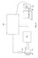
- system controller 30comprising a processing unit 32 communicating with a memory 34, wherein is stored software for operation of system 10.
- the controller 30is a computer comprising a processing unit, and at least some of the functions of the controller may be performed using custom-designed hardware and software, such as an application specific integrated circuit (ASIC) or a field programmable gate array (FPGA).
- ASICapplication specific integrated circuit
- FPGAfield programmable gate array
- Controller 30is typically managed by operator 24 using a pointing device 36 and a graphic user interface (GUI) 38, which enable the operator to set parameters of system 10.
- GUI 38typically also displays results of the procedure to the operator.
- the software in memory 34may be downloaded to the controller 30 in electronic form, over a network, for example.
- the softwaremay be provided on non-transitory tangible media, such as optical, magnetic, or electronic storage media.
- the controller 30comprises a force module 48, an RF ablation module 50, an irrigation module 52, and a position module 54.
- Processing unit 32uses the force module to generate and measure signals supplied to, and received from, a force sensor 58 in distal end 12 in order to measure the magnitude and direction of the force on the distal end. The operation and construction of force sensor 58 is described in more detail below.
- Processing unit 32uses the RF ablation module 50 to monitor and control ablation parameters such as the level of ablation power applied via electrode(s) on the distal section 12.
- the ablation modulealso monitors and controls the duration of the ablation that is provided.
- system 10supplies irrigation fluid to distal end 12.
- System 10uses irrigation module 52 to monitor and control irrigation parameters, such as the rate of flow and the temperature of the irrigation fluid, as is described in more detail below.
- Processing unit 32uses position module 54 to monitor the location and orientation of the distal section relative to patient 22.
- the monitoringmay be implemented by any tracking method known in the art, such as one provided in the Carto3.RTM. system available from Biosense Webster of Diamond Bar, Calif.
- RFradio-frequency
- the position and trackingmay be implemented by measuring impedances between one or more sensing electrodes 17 on the catheter probe 14, and patch electrodes 18 attached to the skin of patient 22, such as is also provided in the Carto3.RTM. system.
- distal section 12is connected to the elongated shaft 15.
- the distal sectionincludes the force sensor 58.
- Aspects of a force sensor similar to force sensor 58are described in U.S. Patent No. 8,357,152, issued on January 22, 2013 to Govari et al. , entitled CATHETER WITH PRESSURE SENSING, and in U.S. Patent Publication No. 2011/0130648, to Beeckler et al., filed Nov. 30, 2009 , entitled CATHETER WITH PRESSURE MEASURING TIP.
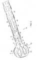
- FIG. 2Ashows a side view of force sensor 58.
- Sensor 58comprises a resilient coupling member 60, which forms a spring joint 62.
- the coupling member 60has a hollow tubular form with a central lumen 68 therethough.
- coupling member 60is formed of a superelastic alloy, such as nickel titanium (Nitinol).
- Coupling member 60typically has one or more helices cut or otherwise formed in the member, so that the member behaves as a spring.
- helicesare formed as two intertwined helices, a first cut helix 72 and a second cut helix 74, which are also referred to herein as a double helix.
- coupling member 60may have any positive integral number of helices, and those having ordinary skill in the art will be able to adapt the present description without undue experimentation to encompass numbers of helices other than two.
- the coupling membermay comprise a coil spring or any other suitable sort of resilient component with similar flexibility and strength characteristics to those generated by the one or more tubular helical cuts, referred to above.
- Coupling member 60is mounted within and covered by sheath 46 (shown as transparent), which is typically formed from flexible plastic material.
- Coupling member 60typically has an outer diameter that is approximately equal to the inner diameter of sheath 46.
- Such a configurationhaving the outer diameter of the coupling member to be as large as possible, increases the sensitivity of force sensor 58.
- the relatively large diameter of the tubular coupling member, and its relatively thin wallsprovide a more spacious lumen 68 enclosed within the coupling member which is used by other elements, described below, in the distal end.
- the sheath 46extends the length of the coupling member 60 to provide a fluid tight seal around the hollow tubular form.
- the sheath 46may be constructed of any suitable biocompatible material that is flexible and insulating, including CELCON, TEFLON or heat-resistant polyurethane.
- sheath 46comprises a heat-resistant plastic material, such as polyurethane, whose shape and elasticity are not substantially affected by exposure to the heat.
- a joint sensing assemblycomprising coils 76, 78, 80 and 82, provides accurate reading of any dimensional change in joint 62, including axial displacement and angular deflection of the joint, such was when the distal section 12 is advanced into contact with tissue.
- These coilsare one type of magnetic transducer that may be used in embodiments of the present invention.
- a "magnetic transducer,” in the context of the present patent application and in the claims,means a device that generates a magnetic field in response to an applied electrical current and/or outputs an electrical signal in response to an applied magnetic field.
- the coils in the sensing assemblyare divided between two subassemblies on opposite axial sides of joint 62.
- One subassemblycomprises coil 82, which is driven by a current, via a cable (not shown) from controller 30 and force module 48, to generate a magnetic field.
- This fieldis received by a second subassembly, comprising coils 76, 78 and 80, which are located in a section of the distal section 12 that is spaced axially apart from coil 82 across the spring joint 62.
- Coil 82typically has an axis of symmetry generally parallel to and coincident with axis 84.
- Coils 76, 78 and 80are fixed in distal end 12 at different radial locations.
- the term "radial”refers to coordinates relative to the axis 84.
- coils 76, 78 and 80are all located in the same axial plane at different azimuthal angles about the catheter axis, and have respective axes of symmetry generally parallel to axis 84.
- the three coilsmay be spaced azimuthally 120 degrees apart at the same radial distance from the axis.
- Coils 76, 78 and 80generate electrical signals in response to the magnetic field transmitted by coil 82. These signals are conveyed by a cable 57 ( FIG. 2A ) extending from the distal section 12, and through the shaft 15 and a control handle 16 to controller 30 which uses force module 48 to process the signals in order to measure the displacement of joint 62 parallel to axis 84, as well as to measure the angular deflection of the joint from the axis. From the measured displacement and deflection, controller 30 is able to evaluate, typically using a previously determined calibration table stored in force module 48, a magnitude and a direction of the force on joint 62.
- Controller 30uses position module 54 to measure the location and orientation of distal end 12.
- the method of measurementmay be by any convenient process known in the art.
- magnetic fields generated external to patient 22create electric signals in elements in the distal section 12, and controller 30 uses the electric signal levels to determine the distal section location and orientation.
- the magnetic fieldsmay be generated in the distal section 12, and the electrical signals created by the fields may be measured external to patient 22.
- the elements in distal section 12 that are used to locate the distal section 12include coils 85 and 86 ( FIG. 3 ) and one of the coil 76, 78 and 80 (in addition to their use as elements of force sensor 58) as orthogonal (x, y, z) position elements housed in the distal section 12.
- a ring electrode 17is mounted on an outer surface of the sheath 46.
- a distal tip member or electrode 21has a shell wall 23 and a plug member 28, as shown in FIG. 4 .
- the shell wall 23has an opening 25 and an interior cavity 27.
- the plug member 28has an interference fit with the shell wall in the opening 25 thus sealing the interior cavity 27.
- the plug member 28has at least one axial through-hole 29 receiving a distal end of an irrigation tubing 31 for transporting fluid (e.g., saline) from a remote source via a luer hub 33 ( FIG.
- Fluid that is delivered into the interior cavity 27 of the distal tip electrode 21can cool the electrode 21 before exiting the interior cavity 27 via irrigation apertures 35 formed in the shell wall 23 to outside of the electrode 21 to flush and/or cool surrounding tissue.
- the distal tip shell wall 23 and the plug member 28are constructed of electrically conducting material, for example, platinum, gold, or stainless steel and, in some embodiments, is preferably made of a platinum-iridium alloy (90% platinum/10% iridium).
- the plug member 28may be configured with one or more blind holes on its proximal face for receiving one or more components, for example, a distal end of a lead wire 37 for energizing the plug member 28.
- Proximal of the plug member 28 and distal of the spring joint 62, the coil 82 ( FIG. 3 ) of the force sensing subassemblymay be housed in the sheath 46, within the lumen 68 of the coupling member 60.
- the lead wire 37 and the irrigation tubing 31pass through a protective tubing 65 that extends through the lumen 68 and further through a lumen of the catheter shaft 15.
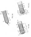
- FIG. 5Aillustrates a woven material suitable for construction of the deformable electrode 40 of the distal section 12.
- a resilient, woven fabric or woven meshmay be advantageous.
- the woven materialmay be woven at least partially from elastic metal fibers, such as strands of Nitinol.
- the use of a metal-based fabricis also helpful in conducting electrical energy to the intracardiac tissue.
- the materialincludes interwoven fibers 41 that are formed as a hollow tube 42, as shown in FIG. 5A , with an outer surface 51 and an inner surface 52 defining a passage 43 between a proximal open end 44, a distal closed end 45 where distal free ends of the fibers 41 are gathered to converge and bunched together into a nub 47, for example, by other fibers, a fastener, and/or adhesive, to close off the passage 43.
- a nub 47for example, by other fibers, a fastener, and/or adhesive
- the tube 42is turned inside out and inverted such that the nub 47 is brought in the passage 43 and points proximally, and the inner surface 52 faces outwardly to present a smooth and atraumatic distal end surface, as shown in FIG. 5B .
- the tube 42is then slipped onto or otherwise mounted over the distal section 12 with a distal tip end 13 being inserted through the proximal open end 44.
- the distal section 12is advanced to a location X that is proximal of the distal closed end 45 of the tube 42 such that there is volume space gap S between the distal closed end 45 of the tube 42 and distal tip end 13 of the distal section 12, when the tube 42 is in its neutral configuration free from external deformation force.
- the tube 42 in its neutral configurationhas a first or distal portion D free from contact with the distal tip electrode 21, and a second or proximal portion P generally in circumferential contact with the distal tip electrode 21.
- the proximal open end 44 of the tube 42extends around the proximal end of shell wall 23 of the distal tip electrode 21 and is wrapped around and secured to the shell wall 23 by one or more bands 49 (see FIG. 2A ). Affixed in this manner, the tube 42 is in direct, electrically-conductive contact with shell wall 23 such that energization of the shell wall 23 also energizes the tube 42.
- the tube 42is resilient, its distal portion D readily compresses down to a size not greater than the width or french size of the distal tip electrode 21 and distal tip section 12 when the catheter is inserted into the patient's vasculature, for example, via a guiding sheath (not shown), and readily resumes its neutral configuration when deployed from the guiding sheath.
- the tube 42may have a uniformly cylindrical configuration, as shown in FIG. 5A and FIG. 5B .
- the tube 42in its neutral configuration, has a generally uniform width W1 along its length, the width W1 being equal to or greater than the width of the distal tip electrode 21 such that the electrode 21 may be readily inserted into the tube 42 without significantly stretching the weave of the underlying material.
- the distal portion D of the tube 42expands and bulges radially from its neutral configuration to a width W2 >W1 when distal face F of the tube 42 comes in contact with tissue upon advancement of the distal section 12 and further when the distal tip electrode 21 abuts or contacts tissue surface T. With such radial expansion, the distal portion D of the tube 42 enables the deformable electrode 40 to provide a larger contact surface area or footprint F by which the tissue can be ablated compared to that of the distal tip electrode 21 alone.
- the tube 42may have a neutral configuration having a mushroom shape, as shown in FIG. 2B , with a distal cap portion DC and a proximal stem portion PS.
- the proximal stem portion PSis generally straight, with a generally uniform width W3 along its length where the width W3 may be generally equal to or less than the width of the distal tip electrode 21.
- the distal cap portion DC of the tube 42has a distal face DF that is generally flat or having a lesser curvature C1, and a bulbous portion B having a greater curvature C2 that is continuous and thus free of any corners or sharp transitions.
- a width W4 of the bulbous portion Bis at least about 1.5 times the width W3 of the stem portion PS.
- the distal cap DC including the bulbous portion Bbecomes more flattened and spreads out, expanding radially for a significantly enlarged contact surface area or footprint F compared to that of the distal tip electrode 21.
- the distal cap DC and its bulbous portion Bhaving a continuous curvature with no sharp angles or corners, the distal cap DC and bulbous portion B can readily keep its overall shape during expansion without any kinking or undesirable deformation.
- the tissue contact surface area Fcan be increased by pivoting the distal section 12 about an axis perpendicular to the contact surface area (in sweeping out a conical volume). In this manner, peripheral portions PY of the bulbous portion B can also be brought into contact with additional tissue surface F'.
- the distal portion D of the tube 42 of the embodiments hereincan be inflated and irrigated by fluid, e.g., a saline solution or any other type of suitable irrigation fluid), which the irrigation module 52 pumps through the irrigation tubing 31 to deliver the saline to the distal tip electrode 21 where it exits through the irrigation apertures 35, thereby generating a mechanical force sufficient to inflate distal portion D of the tube 42.
- fluide.g., a saline solution or any other type of suitable irrigation fluid
- the irrigation module 52pumps through the irrigation tubing 31 to deliver the saline to the distal tip electrode 21 where it exits through the irrigation apertures 35, thereby generating a mechanical force sufficient to inflate distal portion D of the tube 42.
- the distal portion D of the tube 42is inflated and pressed against endocardial tissue T, the distal portion may better conform to the endocardial tissue T, as shown in FIG. 2C .
- ablation module 50can convey RF energy to the deformable electrode 40 via the lead wire 37, and the deformable electrode 40 conducts the energy to the tissue.
- the lead wire 37may apply the RF energy to conductive fluid (e.g., saline) delivered into the distal tip electrode 21, in which case the conductive solution may conduct the RF energy through deformable electrode 40 to the endocardial tissue.
- conductive fluide.g., saline
- the deformable electrode 40may comprise an irrigated balloon tube 90 comprising a biocompatible flexible and elastomeric substrate 91 having an outer surface 92 on which one or more conductive members or surface electrodes 93 are painted or otherwise applied, for example, as printed circuits, sputter coatings, etc. It is understood that the substrate 91 and balloon member 90 may assume any one or more of the applicable characteristics described above and/or illustrated herein for the tube 42. Where the substrate 91 is not woven or otherwise porous, irrigation ports 94 may be formed in the substrate 91 for fluid transported into the interior cavity of the 27 of the balloon member 90 to exit the balloon member 90.
- a conductive material forming the surface electrodes 93is applied by a micropen or positive displacement dispensing system, as understood by one of ordinary skill in the art.
- a micropencan dispense a controllable volume of paste per time, which enables control of thickness by varying print volume, paste concentration, and write speed.
- a positive displacement dispensing system 160includes a pen tip 164 that is kept substantially perpendicular to the surface of the substrate or underlying material. Such a system is disclosed in U.S. Patent No.
- the balloon member 90is at least partially inflated prior to printing the electrodes 93 on its outer surface 92.
- a processing systemsuch as a computer 162 generates a contour image map showing the contours of the balloon member 90.
- Information from the contour map obtained aboveis provided to the positive displacement dispensing system 160 capable of responding to the contour map by altering one or more printing dimensions.
- the positive displacement dispensing system 160contains a writing head 164 (such as a pen tip) and a substrate stage 166 capable of moving the balloon member 93 in at least three independent dimensions.
- the writing headis 164 capable of movement relative to the substrate stage 166.
- the writing head 164applies to the substrate any liquid or semi-solid materials, and the conductive material used to form the electrode(s) 93.
- the writing head 164is mounted on an axis capable of moving in one dimension only, shown in FIG. 7 as the y-axis.
- the substrate stage 166capable of moving in at least three independent dimensions: the x-axis, .phi. (clockwise or counter-clockwise rotation along the z-axis, and .theta. (clockwise or counter-clockwise rotation along the x-axis).
- the substrate stage 166is capable of moving in a fourth independent direction, shown in FIG. 7 as the y-axis.
- the surface electrodes 93may assume any variety of patterns on the balloon member 90.
- One or more solder pads 69FIG. 6 ) may be provided to electrically connect internal lead wires 37 and the surface electrodes 93.
- One or more lead wires 37may transition from inside the sheath 46 to outside via aperture(s) 71 formed in the sheath 46 to connect with the solder pad(s) 69.
- the electrodes 93are connected to the tip electrode 21 by lead wires to conduct RF energy.
- the lead wiresmay run along the outer surface of the balloon member 90 to reach the tip electrode 21, or they may run through the interior of the balloon member to reach the tip electrode 21.
- the balloon member 90is constructed of a conductive polymer.
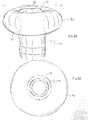
- the balloon member 90has a bulbous or donut shape, defined as a toroidal configuration having a generally circular cross-section, and a center opening through which the distal tip electrode 21 extends, as shown in FIG. 8A and FIG. 8B .
- the balloon member 90has a width W ranging between about 4.0 mm and 5.1 mm. As shown in FIG. 8B , the balloon member 90, when inflated, presents a distal surface in the shape of a ring for contact with tissue surface.
Landscapes
- Health & Medical Sciences (AREA)
- Life Sciences & Earth Sciences (AREA)
- Engineering & Computer Science (AREA)
- Biomedical Technology (AREA)
- Veterinary Medicine (AREA)
- Public Health (AREA)
- General Health & Medical Sciences (AREA)
- Animal Behavior & Ethology (AREA)
- Heart & Thoracic Surgery (AREA)
- Surgery (AREA)
- Biophysics (AREA)
- Medical Informatics (AREA)
- Molecular Biology (AREA)
- Physics & Mathematics (AREA)
- Cardiology (AREA)
- Nuclear Medicine, Radiotherapy & Molecular Imaging (AREA)
- Pathology (AREA)
- Hematology (AREA)
- Pulmonology (AREA)
- Anesthesiology (AREA)
- Plasma & Fusion (AREA)
- Otolaryngology (AREA)
- Physiology (AREA)
- Gynecology & Obstetrics (AREA)
- Radiology & Medical Imaging (AREA)
- Oral & Maxillofacial Surgery (AREA)
- Surgical Instruments (AREA)
- Measurement And Recording Of Electrical Phenomena And Electrical Characteristics Of The Living Body (AREA)
- Media Introduction/Drainage Providing Device (AREA)
Description
- This invention relates to electrophysiologic (EP) catheters, in particular, deflectable EP catheters for RF ablation.
- Electrode catheters have been in common use in medical practice for many years. They are used to stimulate and map electrical activity in the heart and to ablate sites of aberrant electrical activity.
- In use, the electrode catheter is inserted into a major vein or artery, e.g., femoral vein, and then guided into the chamber of the heart which is of concern. In some medical procedures, energy is imparted to body tissue locally, in a concentrated dose, and it is desirable to cool the treatment area in order to reduce collateral tissue damage. For example, cardiac ablation therapy is used to treat arrhythmias by heating tissue with radio-frequency (RF) electrical energy to create non-conducting lesions in the myocardium. It has been found that cooling the area of the ablation site reduces tissue charring and thrombus formation. Catheters with irrigated distal tips are known as part of integrated ablation system. Typically, a metal catheter tip, which is energized with RF current to ablate the tissue, has a number of irrigation holes, distributed circumferentially around the tip, for irrigation of the treatment site. A pump coupled to the catheter delivers saline solution to the catheter tip, and the solution flows out through the holes during the procedure in order to cool the catheter tip and the tissue.
- In certain regions of the heart, for example, in the ventricles where tissue is thicker, the creation of transmural lesions can be challenging. Deep lesions typically require higher RF energy but higher RF energy can lead to undesirable steam pops. Thus, there is a desire to create deeper lesions by increasing electrode/tissue contact area but without increasing the size of the catheter itself.
- Catheters with flexible tips are known.
U.S. Patent No. 5,720,719 describes a catheter having a probe end that includes a malleable tube and a flexible tube.U.S. Patent Publication No. 2014/0121657 , describes a medical probe having a deformable distal end that includes a flexible and porous material. The flexible and porous material may include a conductive material. An electrical conductor can be coupled to the flexible and porous material so as to convey RF energy to the deformable distal end, and the RF energy can be conveyed to tissue by the deformable distal end conveying the RF energy to the tissue. The medical probe may include means for inflating the deformable end which may include conveying a fluid that irrigates the tissue through pores of the deformable distal end. The means for inflating the deformable distal end may include conveying the fluid the fluid so as to generate a mechanical force sufficient to inflate the deformable distal end. A contact area between the deformable distal and the tissue can increase upon pressing the deformable distal end against the tissue. U.S. Patent No. 8,249,685 is directed to an apparatus for mapping and/or ablating tissue that includes a braided conductive member that may be inverted to provide a ring shaped surface. When a distal tip of the braided conductive member is retracted within the braided conducive member, the lack of protrusion allows the ring-shaped surface to contact a tissue wall such as a cardiac wall. In an undeployed configuration, the braided conductive member is longitudinally extended, and in a deployed configuration, the distal end of the braided conductive member is retracted to invert the braided conductive member.WO 2007/055783 A1 describes an apparatus and method for closing the tunnel of a patent foramen ovale (PFO) including the steps of advancing a device, including an energy delivery element, in the lumen of the tunnel of the PFO, energizing the energy delivery element, and withdrawing the energized energy delivery element from the second end of the lumen of the tunnel toward the first end of the lumen of the PFO tunnel, thereby substantially sealing the tissues in the tunnel of the PFO.US 2014/121657 A1 describes a medical probe, including a flexible insertion tube having a deformable distal end for insertion into a body cavity of a patient, the deformable distal end including a flexible and porous material configured to be brought into contact with tissue in the body cavity. The medical probe also includes a means for inflating the deformable distal end, and a channel contained within the insertion tube and configured to convey a fluid generating a mechanical force sufficient to inflate the deformable distal end and that irrigates the tissue through pores of the deformable distal end. The medical probe further includes an electrical conductor passing through the flexible insertion tube and terminating in the deformable distal end and configured to convey radio frequency (RF) energy to the tissue via the deformable distal end.WO 2015/038317 A2 describes an electrosurgical device. The electrosurgical device includes a handle, a shaft extending distally from the handle, and an end effector coupled to a distal end of the shaft.US 2014/163541 A1 describes an apparatus configured to operate on tissue. The apparatus includes an end effector with an upper jaw and a lower jaw. The upper jaw is configured to pivot relative to the lower jaw. The apparatus also includes an electrode cap coupled to either the upper or lower jaw. The electrode cap includes a first electrode surface configured at a first polarity and a second electrode surface configured at a second polarity. The second polarity is opposite to the first polarity.US 6923805 describes an apparatus for ablating body tissue using radiofrequency (RF) energy. A catheter having a lumen for delivering fluid can be inserted into a patient's body. A porous member, which may be expandable, is attached to the distal portion of the catheter. The porous member defines an interior region in communication with the lumen, such that the interior region is capable of receiving electrolyte fluid delivered from the proximal portion of the catheter. An RF electrode is disposed in the interior region and is configured for coupling to a source of RF energy, whereby RF energy may be transferred from the electrode to selected tissue areas in a patient's body via electrolyte fluid delivered through the lumen and into the interior region of the porous member.US 8249685 describes an apparatus for mapping and/or ablating tissue including a braided conductive member that may be inverted to provide a ring-shaped surface. When a distal tip of the braided conductive member is retracted within the braided conductive member, the lack of protrusion allows the ring-shaped surface to contact a tissue wall such as a cardiac wall. In an undeployed configuration, the braided conductive member is longitudinally extended, and in a deployed configuration, the distal end of the braided conductive member is retracted to invert the braided conductive member.- The present invention is directed to a catheter probe configured with a capability to present a larger tissue contact area or "footprint" for larger, deeper lesions, without increasing the french size of the catheter, especially its distal section. In some embodiments, the catheter probe includes a flexible elongated shaft and a distal section having a distal tip end, and an elastically deformable electrode configured to adopt a neutral configuration and a tissue contact configuration. The deformable electrode comprising a hollow porous tube with a distal portion having a closed distal end, and a proximal portion defining an opening to an interior of the tube, where the distal tip end is received in the tube through the opening and the distal section is generally surrounded by tube, with the proximal portion being affixed to an outer surface of the distal section. Advantageously, the closed distal end of the tube is spaced apart from the distal tip end so as to allow the distal portion to deform and expand to provide a larger tissue contact area.
- In some embodiments, the distal portion has a preshaped bulbous configuration.
- In some embodiments, the preshaped bulbous configuration has a continuous curvature.
- In some embodiments, distal portion of the tube has a greater width that is at least about 1.5 times to 3 times or more greater than the width of the proximal portion.
- In some embodiments, the tube is porous.
- In some embodiments, the tube is constructed of a woven material.
- In some embodiments, the tube is constructed of woven, electrically conducting fibers.
- In some embodiments, the tube is constructed of a biocompatible elastomeric material.
- In some embodiments, the tube is constructed of an electrically-conductive material in conductive connection with an RF tip electrode.
- In some embodiments, the catheter probe includes a coupling member between the distal section and the elongated shaft. In more detailed embodiments, the coupling member includes a tubular member configured as a spring joint, wherein the spring joint is configured to be responsive to axial and angular forces acting on the distal section.
- In other embodiments, a catheter probe of the present invention includes a flexible elongated shaft and a distal section having a distal tip electrode, and an elastically deformable tube of woven fibers, wherein the deformable tube is configured to adopt (i) a neutral configuration having a preformed bulbous portion with a first width and (ii) a tissue contact configuration wherein the bulbous portion deforms into a second width greater than the first width.
- In some embodiments, the bulbous portion is free from contact with the distal tip electrode when the deformable tube is in the neutral configuration, and the bulbous portion is in contact with the distal tip electrode when the deformable tube is in the tissue contact configuration,
- In some embodiments, the deformable tube has a closed distal end comprising converging fibers and an open end defining an opening receiving the distal tip electrode, and
- In some embodiments, the deformable tube is electrically connected to an ablation energy source
- In some embodiments, the bulbous portion has a continuous curvature when the deformable tube is in the neutral configuration and the tissue contact configuration.
- In some embodiments, the catheter probe includes a coupling member between the distal section and the elongated shaft, where the coupling member is configured to be responsive to axial and angular forces acting on the distal section.
- These and other features and advantages of the present invention will be better understood by reference to the following detailed description when considered in conjunction with the accompanying drawings wherein:
FIG. 1 is a schematic, pictorial illustration of a catheter probe ablating system, according to an embodiment of the present invention.FIG. 2A is a side view of a catheter probe, including a distal section with a deformable electrode, according an embodiment of the present invention.FIG. 2B is a side view of a distal section with a tube and distal tip electrode during assembly.FIG. 2C is a side view of the catheter probe ofFIG. 2A , wherein the deformable electrode is in contact with tissue.FIG. 3 is a schematic illustration of a force sensing subsystem and a position sensing subsystem, according to an embodiment of the present invention.FIG. 4 is a side cross-sectional view of a distal tip electrode, according to an embodiment of the present invention.FIG. 5A is a side view of a tube for constructing a deformable electrode, according to an embodiment of the present invention.FIG. 5B is a side view of the tube ofFIG. 5A , having been inverted, and being assembled with a distal tip electrode.FIG. 5C is a side view of the assembled tube and distal tip electrode ofFIG. 5B , wherein the deformable electrode is in contact with tissue.FIG. 6 is a side view of a catheter probe, including a distal section with a deformable electrode, according to another embodiment of the present invention.FIG. 7 is a schematic illustration of a positive displacement dispensing system, as used in the present invention, according to one embodiment.FIG. 8A is a side view of a catheter probe, including a balloon member, according to another embodiment of the present invention.FIG. 8B is an end view of the catheter probe ofFIG. 8A .- Reference is now made to
FIG. 1 , which is a schematic, pictorial illustration of a catheterprobe ablating system 10, and toFIG. 2A which illustrates adistal section 12 of acatheter probe 14 used in the system, according to embodiments of the present invention. Insystem 10,probe 14 comprises anelongated shaft 15 supporting thedistal section 12 and thedistal section 12 and a portion of theshaft 15 are inserted into a vasculature of a subject 22, for example, a chamber of aheart 20. The probe is used by an operator 24 ofsystem 10, during a procedure which typically includes performing ablation ofbody tissue 26. Thedistal section 12 advantageously includes adeformable electrode 40. - In some embodiments, for example, for intracardiac procedure, the
shaft 15 and thedistal section 12 have a very small outer diameter, typically of the order of 2-3 mm. Therefore, all of the internal components ofcatheter probe 14, are also made as small and thin as possible and are arranged so as to, as much as possible, avoid damage due to small mechanical strains. - As shown in
FIG. 1 , the functioning ofsystem 10 is managed by asystem controller 30, comprising aprocessing unit 32 communicating with amemory 34, wherein is stored software for operation ofsystem 10. In some embodiments, thecontroller 30 is a computer comprising a processing unit, and at least some of the functions of the controller may be performed using custom-designed hardware and software, such as an application specific integrated circuit (ASIC) or a field programmable gate array (FPGA).Controller 30 is typically managed by operator 24 using apointing device 36 and a graphic user interface (GUI) 38, which enable the operator to set parameters ofsystem 10.GUI 38 typically also displays results of the procedure to the operator. - The software in
memory 34 may be downloaded to thecontroller 30 in electronic form, over a network, for example. Alternatively or additionally, the software may be provided on non-transitory tangible media, such as optical, magnetic, or electronic storage media. - In some embodiments, the
controller 30 comprises aforce module 48, an RF ablation module 50, anirrigation module 52, and aposition module 54. Processingunit 32 uses the force module to generate and measure signals supplied to, and received from, aforce sensor 58 indistal end 12 in order to measure the magnitude and direction of the force on the distal end. The operation and construction offorce sensor 58 is described in more detail below. - Processing
unit 32 uses the RF ablation module 50 to monitor and control ablation parameters such as the level of ablation power applied via electrode(s) on thedistal section 12. The ablation module also monitors and controls the duration of the ablation that is provided. - Typically, during ablation, heat is generated in ablation electrodes, as well as in the surrounding region. In order to dissipate the heat and to improve the efficiency of the ablation process,
system 10 supplies irrigation fluid todistal end 12.System 10 usesirrigation module 52 to monitor and control irrigation parameters, such as the rate of flow and the temperature of the irrigation fluid, as is described in more detail below. - Processing
unit 32 usesposition module 54 to monitor the location and orientation of the distal section relative topatient 22. The monitoring may be implemented by any tracking method known in the art, such as one provided in the Carto3.RTM. system available from Biosense Webster of Diamond Bar, Calif. Such a system uses radio-frequency (RF) magnetic transmitter and receiver elements external topatient 22 and withindistal end 12. Alternatively or additionally, the position and tracking may be implemented by measuring impedances between one ormore sensing electrodes 17 on thecatheter probe 14, andpatch electrodes 18 attached to the skin ofpatient 22, such as is also provided in the Carto3.RTM. system. - As shown in
FIG. 2A ,distal section 12 is connected to theelongated shaft 15. The distal section includes theforce sensor 58. Aspects of a force sensor similar to forcesensor 58 are described inU.S. Patent No. 8,357,152, issued on January 22, 2013 to Govari et al. , entitled CATHETER WITH PRESSURE SENSING, and inU.S. Patent Publication No. 2011/0130648, to Beeckler et al., filed Nov. 30, 2009 , entitled CATHETER WITH PRESSURE MEASURING TIP. FIG. 2A shows a side view offorce sensor 58.Sensor 58 comprises aresilient coupling member 60, which forms aspring joint 62. In some embodiments, thecoupling member 60 has a hollow tubular form with acentral lumen 68 therethough. Although there is no necessity that couplingmember 60 be formed of two parts or longitudinal halves, the two part implementation simplifies assembly of elements comprised in the force sensor, as well as of other elements mounted in thedistal section 12, into themember 60. Typically,coupling member 60 is formed of a superelastic alloy, such as nickel titanium (Nitinol).- Coupling
member 60 typically has one or more helices cut or otherwise formed in the member, so that the member behaves as a spring. In an embodiment described herein, and illustrated inFIG. 2 , helices are formed as two intertwined helices, afirst cut helix 72 and asecond cut helix 74, which are also referred to herein as a double helix. However,coupling member 60 may have any positive integral number of helices, and those having ordinary skill in the art will be able to adapt the present description without undue experimentation to encompass numbers of helices other than two. Alternatively, the coupling member may comprise a coil spring or any other suitable sort of resilient component with similar flexibility and strength characteristics to those generated by the one or more tubular helical cuts, referred to above. - Coupling
member 60 is mounted within and covered by sheath 46 (shown as transparent), which is typically formed from flexible plastic material. Couplingmember 60 typically has an outer diameter that is approximately equal to the inner diameter ofsheath 46. Such a configuration, having the outer diameter of the coupling member to be as large as possible, increases the sensitivity offorce sensor 58. In addition, and as explained below, the relatively large diameter of the tubular coupling member, and its relatively thin walls, provide a morespacious lumen 68 enclosed within the coupling member which is used by other elements, described below, in the distal end. Thesheath 46 extends the length of thecoupling member 60 to provide a fluid tight seal around the hollow tubular form. Thesheath 46 may be constructed of any suitable biocompatible material that is flexible and insulating, including CELCON, TEFLON or heat-resistant polyurethane. - When
catheter probe 14 is used, for example, in ablating endocardial tissue by delivering RF electrical energy through electrode(s) on thedistal section 12, considerable heat is generated in the area ofdistal end 12. For this reason, it is desirable thatsheath 46 comprises a heat-resistant plastic material, such as polyurethane, whose shape and elasticity are not substantially affected by exposure to the heat. - As shown in
FIG. 2A andFIG. 3 , withinforce sensor 58, typically within thecentral lumen 68 of thecoupling member 60, a joint sensing assembly, comprising coils 76, 78, 80 and 82, provides accurate reading of any dimensional change in joint 62, including axial displacement and angular deflection of the joint, such was when thedistal section 12 is advanced into contact with tissue. These coils are one type of magnetic transducer that may be used in embodiments of the present invention. A "magnetic transducer," in the context of the present patent application and in the claims, means a device that generates a magnetic field in response to an applied electrical current and/or outputs an electrical signal in response to an applied magnetic field. Although the embodiments described herein use coils as magnetic transducers, other types of magnetic transducers may be used in alternative embodiments, as will be apparent to those skilled in the art. - The coils in the sensing assembly are divided between two subassemblies on opposite axial sides of joint 62. One subassembly comprises
coil 82, which is driven by a current, via a cable (not shown) fromcontroller 30 andforce module 48, to generate a magnetic field. This field is received by a second subassembly, comprising coils 76, 78 and 80, which are located in a section of thedistal section 12 that is spaced axially apart fromcoil 82 across thespring joint 62. The term "axial," as used in the context of the present patent application and in the claims, refers to the direction of a longitudinal axis ofsymmetry 84 ofdistal end 12. An axial plane is a plane perpendicular to this longitudinal axis, and an axial section is a portion of the catheter contained between two axial planes.Coil 82 typically has an axis of symmetry generally parallel to and coincident withaxis 84. Coils distal end 12 at different radial locations. (The term "radial" refers to coordinates relative to theaxis 84.) Specifically, in this embodiment, coils 76, 78 and 80 are all located in the same axial plane at different azimuthal angles about the catheter axis, and have respective axes of symmetry generally parallel toaxis 84. For example, the three coils may be spaced azimuthally 120 degrees apart at the same radial distance from the axis.Coils coil 82. These signals are conveyed by a cable 57 (FIG. 2A ) extending from thedistal section 12, and through theshaft 15 and a control handle 16 tocontroller 30 which usesforce module 48 to process the signals in order to measure the displacement of joint 62 parallel toaxis 84, as well as to measure the angular deflection of the joint from the axis. From the measured displacement and deflection,controller 30 is able to evaluate, typically using a previously determined calibration table stored inforce module 48, a magnitude and a direction of the force on joint 62.Controller 30 usesposition module 54 to measure the location and orientation ofdistal end 12. The method of measurement may be by any convenient process known in the art. In one embodiment, magnetic fields generated external topatient 22 create electric signals in elements in thedistal section 12, andcontroller 30 uses the electric signal levels to determine the distal section location and orientation. Alternatively, the magnetic fields may be generated in thedistal section 12, and the electrical signals created by the fields may be measured external topatient 22. The elements indistal section 12 that are used to locate thedistal section 12 includecoils 85 and 86 (FIG. 3 ) and one of thecoil distal section 12.- As shown in
FIG. 2A , at or near a distal end of thesheath 46, aring electrode 17 is mounted on an outer surface of thesheath 46. At or near a distal end of thesheath 46, a distal tip member orelectrode 21 has ashell wall 23 and aplug member 28, as shown inFIG. 4 . Theshell wall 23 has anopening 25 and aninterior cavity 27. Theplug member 28 has an interference fit with the shell wall in theopening 25 thus sealing theinterior cavity 27. Theplug member 28 has at least one axial through-hole 29 receiving a distal end of anirrigation tubing 31 for transporting fluid (e.g., saline) from a remote source via a luer hub 33 (FIG. 1 ) that is in communication with a proximal end of theirrigation tubing 31 at or near the control handle 16. Fluid that is delivered into theinterior cavity 27 of thedistal tip electrode 21 can cool theelectrode 21 before exiting theinterior cavity 27 viairrigation apertures 35 formed in theshell wall 23 to outside of theelectrode 21 to flush and/or cool surrounding tissue. - The distal
tip shell wall 23 and theplug member 28 are constructed of electrically conducting material, for example, platinum, gold, or stainless steel and, in some embodiments, is preferably made of a platinum-iridium alloy (90% platinum/10% iridium). Theplug member 28 may be configured with one or more blind holes on its proximal face for receiving one or more components, for example, a distal end of alead wire 37 for energizing theplug member 28. Proximal of theplug member 28 and distal of the spring joint 62, the coil 82 (FIG. 3 ) of the force sensing subassembly may be housed in thesheath 46, within thelumen 68 of thecoupling member 60. Thelead wire 37 and theirrigation tubing 31 pass through aprotective tubing 65 that extends through thelumen 68 and further through a lumen of thecatheter shaft 15. FIG. 5A illustrates a woven material suitable for construction of thedeformable electrode 40 of thedistal section 12. For some applications, a resilient, woven fabric or woven mesh may be advantageous. For enhanced mechanical strength and resilience, the woven material may be woven at least partially from elastic metal fibers, such as strands of Nitinol. The use of a metal-based fabric is also helpful in conducting electrical energy to the intracardiac tissue.- In embodiments according to the invention, the material includes interwoven
fibers 41 that are formed as ahollow tube 42, as shown inFIG. 5A , with anouter surface 51 and aninner surface 52 defining apassage 43 between a proximalopen end 44, a distalclosed end 45 where distal free ends of thefibers 41 are gathered to converge and bunched together into anub 47, for example, by other fibers, a fastener, and/or adhesive, to close off thepassage 43. With thenub 47 being outside of thepassage 43 and pointing distally, as shown inFIG. 5A , thetube 42 is turned inside out and inverted such that thenub 47 is brought in thepassage 43 and points proximally, and theinner surface 52 faces outwardly to present a smooth and atraumatic distal end surface, as shown inFIG. 5B . Thetube 42 is then slipped onto or otherwise mounted over thedistal section 12 with adistal tip end 13 being inserted through the proximalopen end 44. Thedistal section 12 is advanced to a location X that is proximal of the distalclosed end 45 of thetube 42 such that there is volume space gap S between the distalclosed end 45 of thetube 42 anddistal tip end 13 of thedistal section 12, when thetube 42 is in its neutral configuration free from external deformation force. As such, thetube 42 in its neutral configuration has a first or distal portion D free from contact with thedistal tip electrode 21, and a second or proximal portion P generally in circumferential contact with thedistal tip electrode 21. The proximalopen end 44 of thetube 42 extends around the proximal end ofshell wall 23 of thedistal tip electrode 21 and is wrapped around and secured to theshell wall 23 by one or more bands 49 (seeFIG. 2A ). Affixed in this manner, thetube 42 is in direct, electrically-conductive contact withshell wall 23 such that energization of theshell wall 23 also energizes thetube 42. Moreover, because thetube 42 is resilient, its distal portion D readily compresses down to a size not greater than the width or french size of thedistal tip electrode 21 anddistal tip section 12 when the catheter is inserted into the patient's vasculature, for example, via a guiding sheath (not shown), and readily resumes its neutral configuration when deployed from the guiding sheath. - In some embodiments, the
tube 42 may have a uniformly cylindrical configuration, as shown inFIG. 5A and FIG. 5B . Thetube 42, in its neutral configuration, has a generally uniform width W1 along its length, the width W1 being equal to or greater than the width of thedistal tip electrode 21 such that theelectrode 21 may be readily inserted into thetube 42 without significantly stretching the weave of the underlying material. Moreover, as shown inFIG. 5C , the distal portion D of thetube 42 expands and bulges radially from its neutral configuration to a width W2 >W1 when distal face F of thetube 42 comes in contact with tissue upon advancement of thedistal section 12 and further when thedistal tip electrode 21 abuts or contacts tissue surface T. With such radial expansion, the distal portion D of thetube 42 enables thedeformable electrode 40 to provide a larger contact surface area or footprint F by which the tissue can be ablated compared to that of thedistal tip electrode 21 alone. - In other embodiments, the
tube 42 may have a neutral configuration having a mushroom shape, as shown inFIG. 2B , with a distal cap portion DC and a proximal stem portion PS. The proximal stem portion PS is generally straight, with a generally uniform width W3 along its length where the width W3 may be generally equal to or less than the width of thedistal tip electrode 21. The distal cap portion DC of thetube 42 has a distal face DF that is generally flat or having a lesser curvature C1, and a bulbous portion B having a greater curvature C2 that is continuous and thus free of any corners or sharp transitions. A width W4 of the bulbous portion B is at least about 1.5 times the width W3 of the stem portion PS. When mounted on thedistal section 12, the proximal stem portion PS is generally in circumferential contact with thedistal tip electrode 21 and the distal cap portion DC is free from contact with thedistal tip electrode 21, as shown inFIG. 2A . - When the distal face DF of the
tube 42 comes in contact with tissue T upon advancement of thedistal section 12 toward the tissue, as shown inFIG. 2C , the distal cap DC including the bulbous portion B becomes more flattened and spreads out, expanding radially for a significantly enlarged contact surface area or footprint F compared to that of thedistal tip electrode 21. With the distal cap DC and its bulbous portion B having a continuous curvature with no sharp angles or corners, the distal cap DC and bulbous portion B can readily keep its overall shape during expansion without any kinking or undesirable deformation. - For any embodiments of the present invention, the tissue contact surface area F can be increased by pivoting the
distal section 12 about an axis perpendicular to the contact surface area (in sweeping out a conical volume). In this manner, peripheral portions PY of the bulbous portion B can also be brought into contact with additional tissue surface F'. - In operation, the distal portion D of the
tube 42 of the embodiments herein can be inflated and irrigated by fluid, e.g., a saline solution or any other type of suitable irrigation fluid), which theirrigation module 52 pumps through theirrigation tubing 31 to deliver the saline to thedistal tip electrode 21 where it exits through theirrigation apertures 35, thereby generating a mechanical force sufficient to inflate distal portion D of thetube 42. While the distal portion D of thetube 42 is inflated and pressed against endocardial tissue T, the distal portion may better conform to the endocardial tissue T, as shown inFIG. 2C . - When
deformable electrode 40 is conductive, e.g., by comprising suitable metal strands or a conductive polymer, ablation module 50 can convey RF energy to thedeformable electrode 40 via thelead wire 37, and thedeformable electrode 40 conducts the energy to the tissue. Alternatively or additionally, thelead wire 37 may apply the RF energy to conductive fluid (e.g., saline) delivered into thedistal tip electrode 21, in which case the conductive solution may conduct the RF energy throughdeformable electrode 40 to the endocardial tissue. - In other embodiments, as shown in
FIG. 6 , thedeformable electrode 40 may comprise an irrigatedballoon tube 90 comprising a biocompatible flexible andelastomeric substrate 91 having anouter surface 92 on which one or more conductive members orsurface electrodes 93 are painted or otherwise applied, for example, as printed circuits, sputter coatings, etc. It is understood that thesubstrate 91 andballoon member 90 may assume any one or more of the applicable characteristics described above and/or illustrated herein for thetube 42. Where thesubstrate 91 is not woven or otherwise porous,irrigation ports 94 may be formed in thesubstrate 91 for fluid transported into the interior cavity of the 27 of theballoon member 90 to exit theballoon member 90. - In certain embodiments, a conductive material forming the
surface electrodes 93 is applied by a micropen or positive displacement dispensing system, as understood by one of ordinary skill in the art. A micropen can dispense a controllable volume of paste per time, which enables control of thickness by varying print volume, paste concentration, and write speed. As shown inFIG. 7 , a positivedisplacement dispensing system 160 includes apen tip 164 that is kept substantially perpendicular to the surface of the substrate or underlying material. Such a system is disclosed inU.S. Patent No. 9,289,141 - As shown in
FIG. 7 , theballoon member 90 is at least partially inflated prior to printing theelectrodes 93 on itsouter surface 92. A processing system, such as acomputer 162, generates a contour image map showing the contours of theballoon member 90. Information from the contour map obtained above is provided to the positivedisplacement dispensing system 160 capable of responding to the contour map by altering one or more printing dimensions. In some embodiments, the positivedisplacement dispensing system 160 contains a writing head 164 (such as a pen tip) and asubstrate stage 166 capable of moving theballoon member 93 in at least three independent dimensions. The writing head is 164 capable of movement relative to thesubstrate stage 166. The writinghead 164 applies to the substrate any liquid or semi-solid materials, and the conductive material used to form the electrode(s) 93. - The writing
head 164 is mounted on an axis capable of moving in one dimension only, shown inFIG. 7 as the y-axis. In contrast, thesubstrate stage 166 capable of moving in at least three independent dimensions: the x-axis, .phi. (clockwise or counter-clockwise rotation along the z-axis, and .theta. (clockwise or counter-clockwise rotation along the x-axis). In certain embodiments, thesubstrate stage 166 is capable of moving in a fourth independent direction, shown inFIG. 7 as the y-axis. - The
surface electrodes 93 may assume any variety of patterns on theballoon member 90. One or more solder pads 69 (FIG. 6 ) may be provided to electrically connect internallead wires 37 and thesurface electrodes 93. One or morelead wires 37 may transition from inside thesheath 46 to outside via aperture(s) 71 formed in thesheath 46 to connect with the solder pad(s) 69. In other embodiments, theelectrodes 93 are connected to thetip electrode 21 by lead wires to conduct RF energy. The lead wires may run along the outer surface of theballoon member 90 to reach thetip electrode 21, or they may run through the interior of the balloon member to reach thetip electrode 21. - In some embodiments, the
balloon member 90 is constructed of a conductive polymer. In some embodiments, theballoon member 90 has a bulbous or donut shape, defined as a toroidal configuration having a generally circular cross-section, and a center opening through which thedistal tip electrode 21 extends, as shown inFIG. 8A and FIG. 8B . In some embodiments, theballoon member 90 has a width W ranging between about 4.0 mm and 5.1 mm. As shown inFIG. 8B , theballoon member 90, when inflated, presents a distal surface in the shape of a ring for contact with tissue surface.
Claims (14)
- A catheter probe, comprising:a flexible elongated shaft (15);a distal section (12) of the flexible elongated shaft having a distal tip end (21), and an elastically deformable electrode (40) configured to adopt a neutral configuration and a tissue contact configuration, the deformable electrode comprising a hollow porous tube (42) with a distal portion having a closed distal end, and a proximal portion defining an opening to an interior of the tube, wherein the distal tip end is received in the tube through the opening and the distal section of the flexible elongated shaft is generally surrounded by the tube,wherein the hollow porous tube (42) comprises interwoven fibers (41), wherein distal free ends of the fibers are gathered to converge into a nub (47) at the closed distal end of the hollow porous tube, and wherein the nub is positioned within the interior of the tube and points proximally;wherein the closed distal end of the tube is spaced apart from the distal tip end and the distal portion of the tube has a lesser width W1 when the deformable electrode is in the neutral configuration, andwherein the distal portion of the tube has a greater width W2 when the deformable electrode is in the tissue contact configuration.
- The catheter probe of claim 1, wherein the distal portion has a preshaped bulbous configuration.
- The catheter probe of claim 2, wherein the preshaped bulbous configuration has a continuous curvature.
- The catheter probe of claim 1, wherein the greater width W2 is at least about 1.5 times greater than the lesser width W1.
- The catheter probe of claim 1, wherein the tube (42) includes biocompatible elastomeric material.
- The catheter probe of claim 1, wherein the tube (42) includes conductive elastomeric material.
- The catheter probe of claim 1, wherein the elastically deformable electrode (40) includes a surface electrode (93).
- The catheter probe of claim 7, wherein the surface electrode (93) includes (i) conductive ink electrode, (ii) printed circuit electrode, or (iii) sputter coating electrode.
- The catheter probe of claim 1, wherein:the distal tip end (21) comprises a distal tip electrode,the tube (42) is formed of woven fibers (41),the tube has a preformed bulbous portion,the distal portion is in contact with the distal tip electrode when the tube is in the tissue contact configuration, andthe tube is electrically connected to an ablation energy source.
- The catheter probe of claim 9, wherein the bulbous portion has a continuous curvature when the deformable tube (42) is in the neutral configuration and the tissue contact configuration.
- The catheter probe of claim 1 or claim 9, wherein the tube (42) includes woven material.
- The catheter probe of claim 1 or claim 9, wherein the tube (42) includes woven, electrically conducting fibers (41).
- The catheter probe of claim 9, wherein the tube (42) has a toroidal configuration.
- The catheter probe of claim 9, wherein the tube (42) includes a surface electrode (93).
Applications Claiming Priority (1)
| Application Number | Priority Date | Filing Date | Title |
|---|---|---|---|
| US15/469,252US10631928B2 (en) | 2017-03-24 | 2017-03-24 | Catheter with deformable distal electrode |
Publications (3)
| Publication Number | Publication Date |
|---|---|
| EP3378427A2 EP3378427A2 (en) | 2018-09-26 |
| EP3378427A3 EP3378427A3 (en) | 2018-11-28 |
| EP3378427B1true EP3378427B1 (en) | 2020-09-23 |
Family
ID=61655689
Family Applications (1)
| Application Number | Title | Priority Date | Filing Date |
|---|---|---|---|
| EP18161827.3AActiveEP3378427B1 (en) | 2017-03-24 | 2018-03-14 | Catheter with deformable distal electrode |
Country Status (7)
| Country | Link |
|---|---|
| US (3) | US10631928B2 (en) |
| EP (1) | EP3378427B1 (en) |
| JP (1) | JP7130399B2 (en) |
| CN (2) | CN108618841B (en) |
| AU (1) | AU2018202079A1 (en) |
| CA (1) | CA2999126A1 (en) |
| IL (1) | IL258047B (en) |
Cited By (4)
| Publication number | Priority date | Publication date | Assignee | Title |
|---|---|---|---|---|
| US11786300B2 (en) | 2021-04-07 | 2023-10-17 | Btl Medical Technologies S.R.O. | Pulsed field ablation device and method |
| US11896298B2 (en) | 2021-07-06 | 2024-02-13 | Btl Medical Development A.S. | Pulsed field ablation device and method |
| US12076067B2 (en) | 2022-10-05 | 2024-09-03 | Btl Medical Development A.S. | Pulsed field ablation device and method |
| EP3791816B1 (en)* | 2019-09-12 | 2025-04-09 | Biosense Webster (Israel) Ltd. | Balloon catheter with force sensor |
Families Citing this family (25)
| Publication number | Priority date | Publication date | Assignee | Title |
|---|---|---|---|---|
| US11090104B2 (en) | 2009-10-09 | 2021-08-17 | Cilag Gmbh International | Surgical generator for ultrasonic and electrosurgical devices |
| US11051840B2 (en) | 2016-01-15 | 2021-07-06 | Ethicon Llc | Modular battery powered handheld surgical instrument with reusable asymmetric handle housing |
| US11129670B2 (en) | 2016-01-15 | 2021-09-28 | Cilag Gmbh International | Modular battery powered handheld surgical instrument with selective application of energy based on button displacement, intensity, or local tissue characterization |
| US11266430B2 (en) | 2016-11-29 | 2022-03-08 | Cilag Gmbh International | End effector control and calibration |
| US11395906B2 (en)* | 2018-12-12 | 2022-07-26 | Acclarent, Inc. | Combined sinuplasty and seeker instrument with navigation and illumination modalities |
| US12390620B2 (en)* | 2019-12-24 | 2025-08-19 | Biosense Webster (Israel) Ltd. | Contact force spring with mechanical stops |
| US11944366B2 (en) | 2019-12-30 | 2024-04-02 | Cilag Gmbh International | Asymmetric segmented ultrasonic support pad for cooperative engagement with a movable RF electrode |
| US20210196352A1 (en) | 2019-12-30 | 2021-07-01 | Ethicon Llc | Partially conductive clamp arm pad to enable electrode wear through and minimize short circuiting |
| US12114912B2 (en) | 2019-12-30 | 2024-10-15 | Cilag Gmbh International | Non-biased deflectable electrode to minimize contact between ultrasonic blade and electrode |
| US11779387B2 (en) | 2019-12-30 | 2023-10-10 | Cilag Gmbh International | Clamp arm jaw to minimize tissue sticking and improve tissue control |
| US11911063B2 (en) | 2019-12-30 | 2024-02-27 | Cilag Gmbh International | Techniques for detecting ultrasonic blade to electrode contact and reducing power to ultrasonic blade |
| US12262937B2 (en) | 2019-12-30 | 2025-04-01 | Cilag Gmbh International | User interface for surgical instrument with combination energy modality end-effector |
| US11937863B2 (en) | 2019-12-30 | 2024-03-26 | Cilag Gmbh International | Deflectable electrode with variable compression bias along the length of the deflectable electrode |
| US12053224B2 (en) | 2019-12-30 | 2024-08-06 | Cilag Gmbh International | Variation in electrode parameters and deflectable electrode to modify energy density and tissue interaction |
| US11786294B2 (en) | 2019-12-30 | 2023-10-17 | Cilag Gmbh International | Control program for modular combination energy device |
| US12336747B2 (en) | 2019-12-30 | 2025-06-24 | Cilag Gmbh International | Method of operating a combination ultrasonic / bipolar RF surgical device with a combination energy modality end-effector |
| US12343063B2 (en) | 2019-12-30 | 2025-07-01 | Cilag Gmbh International | Multi-layer clamp arm pad for enhanced versatility and performance of a surgical device |
| US12023086B2 (en) | 2019-12-30 | 2024-07-02 | Cilag Gmbh International | Electrosurgical instrument for delivering blended energy modalities to tissue |
| US20210196357A1 (en) | 2019-12-30 | 2021-07-01 | Ethicon Llc | Electrosurgical instrument with asynchronous energizing electrodes |
| US12076006B2 (en) | 2019-12-30 | 2024-09-03 | Cilag Gmbh International | Surgical instrument comprising an orientation detection system |
| US11950797B2 (en) | 2019-12-30 | 2024-04-09 | Cilag Gmbh International | Deflectable electrode with higher distal bias relative to proximal bias |
| US11786291B2 (en) | 2019-12-30 | 2023-10-17 | Cilag Gmbh International | Deflectable support of RF energy electrode with respect to opposing ultrasonic blade |
| EP4173581A4 (en)* | 2020-06-28 | 2024-07-24 | Hangzhou Dinova EP Technology Co., Ltd. | ABLATION DEVICE AND ABLATION SYSTEM |
| AU2022234310A1 (en)* | 2021-03-10 | 2023-09-28 | Cardiofocus, Inc. | Devices for the delivery of pulsed electric fields in the treatment of cardiac tissue |
| CN115363745B (en)* | 2022-10-27 | 2023-03-24 | 杭州德诺电生理医疗科技有限公司 | Ablation Catheter |
Citations (2)
| Publication number | Priority date | Publication date | Assignee | Title |
|---|---|---|---|---|
| US5797903A (en)* | 1996-04-12 | 1998-08-25 | Ep Technologies, Inc. | Tissue heating and ablation systems and methods using porous electrode structures with electrically conductive surfaces |
| US6923805B1 (en)* | 1992-11-13 | 2005-08-02 | Scimed Life Systems, Inc. | Electrophysiology energy treatment devices and methods of use |
Family Cites Families (46)
| Publication number | Priority date | Publication date | Assignee | Title |
|---|---|---|---|---|
| US5341807A (en) | 1992-06-30 | 1994-08-30 | American Cardiac Ablation Co., Inc. | Ablation catheter positioning system |
| US5720719A (en) | 1992-08-12 | 1998-02-24 | Vidamed, Inc. | Ablative catheter with conformable body |
| US5471982A (en) | 1992-09-29 | 1995-12-05 | Ep Technologies, Inc. | Cardiac mapping and ablation systems |
| US5391199A (en) | 1993-07-20 | 1995-02-21 | Biosense, Inc. | Apparatus and method for treating cardiac arrhythmias |
| US5558091A (en) | 1993-10-06 | 1996-09-24 | Biosense, Inc. | Magnetic determination of position and orientation |
| US5462521A (en) | 1993-12-21 | 1995-10-31 | Angeion Corporation | Fluid cooled and perfused tip for a catheter |
| JPH0859386A (en) | 1994-08-22 | 1996-03-05 | Mitsubishi Materials Corp | Semiconductor single crystal growing device |
| US5876336A (en) | 1994-10-11 | 1999-03-02 | Ep Technologies, Inc. | Systems and methods for guiding movable electrode elements within multiple-electrode structure |
| US6690963B2 (en) | 1995-01-24 | 2004-02-10 | Biosense, Inc. | System for determining the location and orientation of an invasive medical instrument |
| US5595183A (en) | 1995-02-17 | 1997-01-21 | Ep Technologies, Inc. | Systems and methods for examining heart tissue employing multiple electrode structures and roving electrodes |
| US5697377A (en) | 1995-11-22 | 1997-12-16 | Medtronic, Inc. | Catheter mapping system and method |
| US5846238A (en) | 1996-01-19 | 1998-12-08 | Ep Technologies, Inc. | Expandable-collapsible electrode structures with distal end steering or manipulation |
| WO1997025917A1 (en) | 1996-01-19 | 1997-07-24 | Ep Technologies, Inc. | Multi-function electrode structures for electrically analyzing and heating body tissue |
| US6177792B1 (en) | 1996-03-26 | 2001-01-23 | Bisense, Inc. | Mutual induction correction for radiator coils of an objects tracking system |
| US5944022A (en) | 1997-04-28 | 1999-08-31 | American Cardiac Ablation Co. Inc. | Catheter positioning system |
| US6172499B1 (en) | 1999-10-29 | 2001-01-09 | Ascension Technology Corporation | Eddy current error-reduced AC magnetic position measurement system |
| DE202004021953U1 (en) | 2003-09-12 | 2013-06-19 | Vessix Vascular, Inc. | Selectable eccentric remodeling and / or ablation of atherosclerotic material |
| WO2005079688A1 (en) | 2004-02-25 | 2005-09-01 | Erbe Elektromedizin Gmbh | Device for the interstitial coagulation of tissue |
| KR101193709B1 (en)* | 2004-04-19 | 2012-10-23 | 프로리듬, 인크. | Ablation devices with sensor structures |
| US8249685B2 (en) | 2004-05-17 | 2012-08-21 | C.R. Bard, Inc. | Method and apparatus for mapping and/or ablation of cardiac tissue |
| US7481808B2 (en) | 2004-06-30 | 2009-01-27 | Ethicon, Inc. | Flexible electrode device and surgical apparatus equipped with same |
| US7869865B2 (en) | 2005-01-07 | 2011-01-11 | Biosense Webster, Inc. | Current-based position sensing |
| US7612147B2 (en)* | 2005-07-07 | 2009-11-03 | The Goodyear Tire & Rubber Company | Dendrimers of rubbery polymers |
| US20070106290A1 (en) | 2005-11-08 | 2007-05-10 | Turano Thomas A | Conformable electrode catheter and method of use |
| US20090043301A1 (en) | 2007-08-09 | 2009-02-12 | Asthmatx, Inc. | Monopolar energy delivery devices and methods for controlling current density in tissue |
| US8357152B2 (en) | 2007-10-08 | 2013-01-22 | Biosense Webster (Israel), Ltd. | Catheter with pressure sensing |
| US9289141B2 (en) | 2007-10-12 | 2016-03-22 | Micropen Technologies Corporation | Apparatus and methods for the measurement of cardiac output |
| US8235988B2 (en)* | 2008-01-24 | 2012-08-07 | Coherex Medical, Inc. | Systems and methods for reduction of atrial fibrillation |
| US8712550B2 (en) | 2008-12-30 | 2014-04-29 | Biosense Webster, Inc. | Catheter with multiple electrode assemblies for use at or near tubular regions of the heart |
| US10688278B2 (en) | 2009-11-30 | 2020-06-23 | Biosense Webster (Israel), Ltd. | Catheter with pressure measuring tip |
| AU2011252976A1 (en)* | 2010-05-12 | 2012-11-08 | Shifamed Holdings, Llc | Low profile electrode assembly |
| US9539046B2 (en)* | 2010-08-03 | 2017-01-10 | Medtronic Cryocath Lp | Cryogenic medical mapping and treatment device |
| US8380276B2 (en) | 2010-08-16 | 2013-02-19 | Biosense Webster, Inc. | Catheter with thin film pressure sensing distal tip |
| US10517667B2 (en) | 2014-05-16 | 2019-12-31 | Biosense Webster (Israel) Ltd. | Catheter tip with microelectrodes |
| US8864762B2 (en)* | 2011-05-13 | 2014-10-21 | Sanovas, Inc. | Balloon catheter mesh |
| WO2013037805A1 (en)* | 2011-09-12 | 2013-03-21 | Highlife Sas | Treatment catheter system |
| US9125668B2 (en)* | 2011-09-14 | 2015-09-08 | Boston Scientific Scimed Inc. | Ablation device with multiple ablation modes |
| US9131980B2 (en)* | 2011-12-19 | 2015-09-15 | Medtronic Advanced Energy Llc | Electrosurgical devices |
| US20140012165A1 (en)* | 2012-07-06 | 2014-01-09 | Thomas D. Cockley | System of a Magnetic Attachment Handle and Attachment devices |
| US20140121657A1 (en) | 2012-10-26 | 2014-05-01 | Biosense Webster (Israel) Ltd. | Irrrigated ablation catheter with deformable head |
| US9572622B2 (en)* | 2012-12-10 | 2017-02-21 | Ethicon Endo-Surgery, Llc | Bipolar electrosurgical features for targeted hemostasis |
| EP2769695A1 (en)* | 2013-02-20 | 2014-08-27 | Cook Medical Technologies LLC | Expandable mesh platform for large area ablation |
| US9814514B2 (en)* | 2013-09-13 | 2017-11-14 | Ethicon Llc | Electrosurgical (RF) medical instruments for cutting and coagulating tissue |
| US10568686B2 (en)* | 2013-11-21 | 2020-02-25 | Biosense Webster (Israel) Ltd. | Multi-electrode balloon catheter with circumferential and point electrodes |
| US9848795B2 (en)* | 2014-06-04 | 2017-12-26 | Boston Scientific Scimed Inc. | Electrode assembly |
| EP4302713A3 (en)* | 2015-11-16 | 2024-03-13 | Boston Scientific Scimed, Inc. | Energy delivery devices |
- 2017
- 2017-03-24USUS15/469,252patent/US10631928B2/enactiveActive
- 2018
- 2018-03-12ILIL258047Apatent/IL258047B/enactiveIP Right Grant
- 2018-03-14EPEP18161827.3Apatent/EP3378427B1/enactiveActive
- 2018-03-23CNCN201810244302.1Apatent/CN108618841B/enactiveActive
- 2018-03-23AUAU2018202079Apatent/AU2018202079A1/ennot_activeAbandoned
- 2018-03-23CNCN202310817334.7Apatent/CN117017303A/enactivePending
- 2018-03-23CACA2999126Apatent/CA2999126A1/ennot_activeAbandoned
- 2018-03-23JPJP2018055742Apatent/JP7130399B2/enactiveActive
- 2020
- 2020-04-27USUS16/859,843patent/US11766292B2/enactiveActive
- 2023
- 2023-09-25USUS18/372,539patent/US20240016541A1/enactivePending
Patent Citations (2)
| Publication number | Priority date | Publication date | Assignee | Title |
|---|---|---|---|---|
| US6923805B1 (en)* | 1992-11-13 | 2005-08-02 | Scimed Life Systems, Inc. | Electrophysiology energy treatment devices and methods of use |
| US5797903A (en)* | 1996-04-12 | 1998-08-25 | Ep Technologies, Inc. | Tissue heating and ablation systems and methods using porous electrode structures with electrically conductive surfaces |
Cited By (6)
| Publication number | Priority date | Publication date | Assignee | Title |
|---|---|---|---|---|
| EP3791816B1 (en)* | 2019-09-12 | 2025-04-09 | Biosense Webster (Israel) Ltd. | Balloon catheter with force sensor |
| US11786300B2 (en) | 2021-04-07 | 2023-10-17 | Btl Medical Technologies S.R.O. | Pulsed field ablation device and method |
| US11832785B2 (en) | 2021-04-07 | 2023-12-05 | Btl Medical Development A.S. | Pulsed field ablation device and method |
| US11896298B2 (en) | 2021-07-06 | 2024-02-13 | Btl Medical Development A.S. | Pulsed field ablation device and method |
| US12076067B2 (en) | 2022-10-05 | 2024-09-03 | Btl Medical Development A.S. | Pulsed field ablation device and method |
| US12279801B2 (en) | 2022-10-05 | 2025-04-22 | Btl Medical Development A.S. | Pulsed field ablation device and method |
Also Published As
| Publication number | Publication date |
|---|---|
| US20200253663A1 (en) | 2020-08-13 |
| EP3378427A2 (en) | 2018-09-26 |
| US20180271590A1 (en) | 2018-09-27 |
| AU2018202079A1 (en) | 2018-10-11 |
| JP2018161471A (en) | 2018-10-18 |
| CN108618841A (en) | 2018-10-09 |
| US10631928B2 (en) | 2020-04-28 |
| IL258047A (en) | 2018-04-30 |
| IL258047B (en) | 2021-04-29 |
| US11766292B2 (en) | 2023-09-26 |
| CA2999126A1 (en) | 2018-09-24 |
| CN108618841B (en) | 2023-07-28 |
| JP7130399B2 (en) | 2022-09-05 |
| EP3378427A3 (en) | 2018-11-28 |
| US20240016541A1 (en) | 2024-01-18 |
| CN117017303A (en) | 2023-11-10 |
Similar Documents
| Publication | Publication Date | Title |
|---|---|---|
| EP3378427B1 (en) | Catheter with deformable distal electrode | |
| US5876399A (en) | Catheter system and methods thereof | |
| US5891137A (en) | Catheter system having a tip with fixation means | |
| US10893904B2 (en) | Temperature controlled short duration ablation | |
| US10813689B2 (en) | Ablation catheter with radial force detection | |
| US10973574B2 (en) | Temperature controlled short duration ablation | |
| EP3494915B1 (en) | Irrigated ablation catheter with deformable head | |
| US10507058B2 (en) | Temperature controlled short duration ablation | |
| US20130253503A1 (en) | Catheter with mulitple irrigated electrodes and a force sensor | |
| EP2977021B1 (en) | Catheter with multiple irrigated electrodes and a force sensor | |
| EP4088676A1 (en) | Distal assembly for catheter with lumens running along spines | |
| JP2023025694A (en) | Method for renal sympathetic nerve ablation | |
| CN113081233A (en) | Lasso catheter with balloon | |
| EP4104783A1 (en) | Catheter for high-power focal ablation |
Legal Events
| Date | Code | Title | Description |
|---|---|---|---|
| PUAI | Public reference made under article 153(3) epc to a published international application that has entered the european phase | Free format text:ORIGINAL CODE: 0009012 | |
| STAA | Information on the status of an ep patent application or granted ep patent | Free format text:STATUS: THE APPLICATION HAS BEEN PUBLISHED | |
| AK | Designated contracting states | Kind code of ref document:A2 Designated state(s):AL AT BE BG CH CY CZ DE DK EE ES FI FR GB GR HR HU IE IS IT LI LT LU LV MC MK MT NL NO PL PT RO RS SE SI SK SM TR | |
| AX | Request for extension of the european patent | Extension state:BA ME | |
| PUAL | Search report despatched | Free format text:ORIGINAL CODE: 0009013 | |
| AK | Designated contracting states | Kind code of ref document:A3 Designated state(s):AL AT BE BG CH CY CZ DE DK EE ES FI FR GB GR HR HU IE IS IT LI LT LU LV MC MK MT NL NO PL PT RO RS SE SI SK SM TR | |
| AX | Request for extension of the european patent | Extension state:BA ME | |
| RIC1 | Information provided on ipc code assigned before grant | Ipc:A61M 25/00 20060101ALI20181022BHEP Ipc:A61B 18/14 20060101AFI20181022BHEP Ipc:A61B 90/00 20160101ALI20181022BHEP Ipc:A61B 18/00 20060101ALN20181022BHEP | |
| STAA | Information on the status of an ep patent application or granted ep patent | Free format text:STATUS: REQUEST FOR EXAMINATION WAS MADE | |
| 17P | Request for examination filed | Effective date:20190520 | |
| RBV | Designated contracting states (corrected) | Designated state(s):AL AT BE BG CH CY CZ DE DK EE ES FI FR GB GR HR HU IE IS IT LI LT LU LV MC MK MT NL NO PL PT RO RS SE SI SK SM TR | |
| STAA | Information on the status of an ep patent application or granted ep patent | Free format text:STATUS: EXAMINATION IS IN PROGRESS | |
| 17Q | First examination report despatched | Effective date:20191004 | |
| GRAP | Despatch of communication of intention to grant a patent | Free format text:ORIGINAL CODE: EPIDOSNIGR1 | |
| STAA | Information on the status of an ep patent application or granted ep patent | Free format text:STATUS: GRANT OF PATENT IS INTENDED | |
| RIC1 | Information provided on ipc code assigned before grant | Ipc:A61B 18/14 20060101AFI20191206BHEP Ipc:A61B 90/00 20160101ALI20191206BHEP Ipc:A61M 25/00 20060101ALI20191206BHEP Ipc:A61B 18/00 20060101ALN20191206BHEP | |
| INTG | Intention to grant announced | Effective date:20200108 | |
| GRAJ | Information related to disapproval of communication of intention to grant by the applicant or resumption of examination proceedings by the epo deleted | Free format text:ORIGINAL CODE: EPIDOSDIGR1 | |
| STAA | Information on the status of an ep patent application or granted ep patent | Free format text:STATUS: EXAMINATION IS IN PROGRESS | |
| GRAP | Despatch of communication of intention to grant a patent | Free format text:ORIGINAL CODE: EPIDOSNIGR1 | |
| STAA | Information on the status of an ep patent application or granted ep patent | Free format text:STATUS: GRANT OF PATENT IS INTENDED | |
| INTC | Intention to grant announced (deleted) | ||
| RIC1 | Information provided on ipc code assigned before grant | Ipc:A61B 18/14 20060101AFI20200604BHEP Ipc:A61B 90/00 20160101ALI20200604BHEP Ipc:A61B 18/00 20060101ALN20200604BHEP Ipc:A61M 25/00 20060101ALI20200604BHEP | |
| INTG | Intention to grant announced | Effective date:20200619 | |
| GRAS | Grant fee paid | Free format text:ORIGINAL CODE: EPIDOSNIGR3 | |
| GRAA | (expected) grant | Free format text:ORIGINAL CODE: 0009210 | |
| STAA | Information on the status of an ep patent application or granted ep patent | Free format text:STATUS: THE PATENT HAS BEEN GRANTED | |
| AK | Designated contracting states | Kind code of ref document:B1 Designated state(s):AL AT BE BG CH CY CZ DE DK EE ES FI FR GB GR HR HU IE IS IT LI LT LU LV MC MK MT NL NO PL PT RO RS SE SI SK SM TR | |
| REG | Reference to a national code | Ref country code:GB Ref legal event code:FG4D | |
| REG | Reference to a national code | Ref country code:CH Ref legal event code:EP | |
| REG | Reference to a national code | Ref country code:DE Ref legal event code:R096 Ref document number:602018007969 Country of ref document:DE | |
| REG | Reference to a national code | Ref country code:IE Ref legal event code:FG4D | |
| REG | Reference to a national code | Ref country code:AT Ref legal event code:REF Ref document number:1315588 Country of ref document:AT Kind code of ref document:T Effective date:20201015 | |
| REG | Reference to a national code | Ref country code:NL Ref legal event code:FP | |
| PG25 | Lapsed in a contracting state [announced via postgrant information from national office to epo] | Ref country code:FI Free format text:LAPSE BECAUSE OF FAILURE TO SUBMIT A TRANSLATION OF THE DESCRIPTION OR TO PAY THE FEE WITHIN THE PRESCRIBED TIME-LIMIT Effective date:20200923 Ref country code:HR Free format text:LAPSE BECAUSE OF FAILURE TO SUBMIT A TRANSLATION OF THE DESCRIPTION OR TO PAY THE FEE WITHIN THE PRESCRIBED TIME-LIMIT Effective date:20200923 Ref country code:BG Free format text:LAPSE BECAUSE OF FAILURE TO SUBMIT A TRANSLATION OF THE DESCRIPTION OR TO PAY THE FEE WITHIN THE PRESCRIBED TIME-LIMIT Effective date:20201223 Ref country code:NO Free format text:LAPSE BECAUSE OF FAILURE TO SUBMIT A TRANSLATION OF THE DESCRIPTION OR TO PAY THE FEE WITHIN THE PRESCRIBED TIME-LIMIT Effective date:20201223 Ref country code:GR Free format text:LAPSE BECAUSE OF FAILURE TO SUBMIT A TRANSLATION OF THE DESCRIPTION OR TO PAY THE FEE WITHIN THE PRESCRIBED TIME-LIMIT Effective date:20201224 Ref country code:SE Free format text:LAPSE BECAUSE OF FAILURE TO SUBMIT A TRANSLATION OF THE DESCRIPTION OR TO PAY THE FEE WITHIN THE PRESCRIBED TIME-LIMIT Effective date:20200923 | |
| REG | Reference to a national code | Ref country code:AT Ref legal event code:MK05 Ref document number:1315588 Country of ref document:AT Kind code of ref document:T Effective date:20200923 | |
| PG25 | Lapsed in a contracting state [announced via postgrant information from national office to epo] | Ref country code:RS Free format text:LAPSE BECAUSE OF FAILURE TO SUBMIT A TRANSLATION OF THE DESCRIPTION OR TO PAY THE FEE WITHIN THE PRESCRIBED TIME-LIMIT Effective date:20200923 Ref country code:LV Free format text:LAPSE BECAUSE OF FAILURE TO SUBMIT A TRANSLATION OF THE DESCRIPTION OR TO PAY THE FEE WITHIN THE PRESCRIBED TIME-LIMIT Effective date:20200923 | |
| REG | Reference to a national code | Ref country code:LT Ref legal event code:MG4D | |
| PG25 | Lapsed in a contracting state [announced via postgrant information from national office to epo] | Ref country code:SM Free format text:LAPSE BECAUSE OF FAILURE TO SUBMIT A TRANSLATION OF THE DESCRIPTION OR TO PAY THE FEE WITHIN THE PRESCRIBED TIME-LIMIT Effective date:20200923 Ref country code:LT Free format text:LAPSE BECAUSE OF FAILURE TO SUBMIT A TRANSLATION OF THE DESCRIPTION OR TO PAY THE FEE WITHIN THE PRESCRIBED TIME-LIMIT Effective date:20200923 Ref country code:EE Free format text:LAPSE BECAUSE OF FAILURE TO SUBMIT A TRANSLATION OF THE DESCRIPTION OR TO PAY THE FEE WITHIN THE PRESCRIBED TIME-LIMIT Effective date:20200923 Ref country code:RO Free format text:LAPSE BECAUSE OF FAILURE TO SUBMIT A TRANSLATION OF THE DESCRIPTION OR TO PAY THE FEE WITHIN THE PRESCRIBED TIME-LIMIT Effective date:20200923 Ref country code:PT Free format text:LAPSE BECAUSE OF FAILURE TO SUBMIT A TRANSLATION OF THE DESCRIPTION OR TO PAY THE FEE WITHIN THE PRESCRIBED TIME-LIMIT Effective date:20210125 Ref country code:CZ Free format text:LAPSE BECAUSE OF FAILURE TO SUBMIT A TRANSLATION OF THE DESCRIPTION OR TO PAY THE FEE WITHIN THE PRESCRIBED TIME-LIMIT Effective date:20200923 | |
| PG25 | Lapsed in a contracting state [announced via postgrant information from national office to epo] | Ref country code:PL Free format text:LAPSE BECAUSE OF FAILURE TO SUBMIT A TRANSLATION OF THE DESCRIPTION OR TO PAY THE FEE WITHIN THE PRESCRIBED TIME-LIMIT Effective date:20200923 Ref country code:IS Free format text:LAPSE BECAUSE OF FAILURE TO SUBMIT A TRANSLATION OF THE DESCRIPTION OR TO PAY THE FEE WITHIN THE PRESCRIBED TIME-LIMIT Effective date:20210123 Ref country code:AL Free format text:LAPSE BECAUSE OF FAILURE TO SUBMIT A TRANSLATION OF THE DESCRIPTION OR TO PAY THE FEE WITHIN THE PRESCRIBED TIME-LIMIT Effective date:20200923 Ref country code:AT Free format text:LAPSE BECAUSE OF FAILURE TO SUBMIT A TRANSLATION OF THE DESCRIPTION OR TO PAY THE FEE WITHIN THE PRESCRIBED TIME-LIMIT Effective date:20200923 Ref country code:ES Free format text:LAPSE BECAUSE OF FAILURE TO SUBMIT A TRANSLATION OF THE DESCRIPTION OR TO PAY THE FEE WITHIN THE PRESCRIBED TIME-LIMIT Effective date:20200923 | |
| REG | Reference to a national code | Ref country code:DE Ref legal event code:R097 Ref document number:602018007969 Country of ref document:DE | |
| PG25 | Lapsed in a contracting state [announced via postgrant information from national office to epo] | Ref country code:SK Free format text:LAPSE BECAUSE OF FAILURE TO SUBMIT A TRANSLATION OF THE DESCRIPTION OR TO PAY THE FEE WITHIN THE PRESCRIBED TIME-LIMIT Effective date:20200923 | |
| PLBE | No opposition filed within time limit | Free format text:ORIGINAL CODE: 0009261 | |
| STAA | Information on the status of an ep patent application or granted ep patent | Free format text:STATUS: NO OPPOSITION FILED WITHIN TIME LIMIT | |
| PG25 | Lapsed in a contracting state [announced via postgrant information from national office to epo] | Ref country code:DK Free format text:LAPSE BECAUSE OF FAILURE TO SUBMIT A TRANSLATION OF THE DESCRIPTION OR TO PAY THE FEE WITHIN THE PRESCRIBED TIME-LIMIT Effective date:20200923 Ref country code:SI Free format text:LAPSE BECAUSE OF FAILURE TO SUBMIT A TRANSLATION OF THE DESCRIPTION OR TO PAY THE FEE WITHIN THE PRESCRIBED TIME-LIMIT Effective date:20200923 | |
| 26N | No opposition filed | Effective date:20210624 | |
| PG25 | Lapsed in a contracting state [announced via postgrant information from national office to epo] | Ref country code:MC Free format text:LAPSE BECAUSE OF FAILURE TO SUBMIT A TRANSLATION OF THE DESCRIPTION OR TO PAY THE FEE WITHIN THE PRESCRIBED TIME-LIMIT Effective date:20200923 | |
| REG | Reference to a national code | Ref country code:CH Ref legal event code:PL | |
| REG | Reference to a national code | Ref country code:BE Ref legal event code:MM Effective date:20210331 | |
| PG25 | Lapsed in a contracting state [announced via postgrant information from national office to epo] | Ref country code:CH Free format text:LAPSE BECAUSE OF NON-PAYMENT OF DUE FEES Effective date:20210331 Ref country code:LI Free format text:LAPSE BECAUSE OF NON-PAYMENT OF DUE FEES Effective date:20210331 Ref country code:IE Free format text:LAPSE BECAUSE OF NON-PAYMENT OF DUE FEES Effective date:20210314 Ref country code:LU Free format text:LAPSE BECAUSE OF NON-PAYMENT OF DUE FEES Effective date:20210314 | |
| PGFP | Annual fee paid to national office [announced via postgrant information from national office to epo] | Ref country code:NL Payment date:20220215 Year of fee payment:5 | |
| PG25 | Lapsed in a contracting state [announced via postgrant information from national office to epo] | Ref country code:BE Free format text:LAPSE BECAUSE OF NON-PAYMENT OF DUE FEES Effective date:20210331 | |
| PG25 | Lapsed in a contracting state [announced via postgrant information from national office to epo] | Ref country code:CY Free format text:LAPSE BECAUSE OF FAILURE TO SUBMIT A TRANSLATION OF THE DESCRIPTION OR TO PAY THE FEE WITHIN THE PRESCRIBED TIME-LIMIT Effective date:20200923 | |
| PG25 | Lapsed in a contracting state [announced via postgrant information from national office to epo] | Ref country code:HU Free format text:LAPSE BECAUSE OF FAILURE TO SUBMIT A TRANSLATION OF THE DESCRIPTION OR TO PAY THE FEE WITHIN THE PRESCRIBED TIME-LIMIT; INVALID AB INITIO Effective date:20180314 | |
| REG | Reference to a national code | Ref country code:NL Ref legal event code:MM Effective date:20230401 | |
| PG25 | Lapsed in a contracting state [announced via postgrant information from national office to epo] | Ref country code:NL Free format text:LAPSE BECAUSE OF NON-PAYMENT OF DUE FEES Effective date:20230401 | |
| PG25 | Lapsed in a contracting state [announced via postgrant information from national office to epo] | Ref country code:MK Free format text:LAPSE BECAUSE OF FAILURE TO SUBMIT A TRANSLATION OF THE DESCRIPTION OR TO PAY THE FEE WITHIN THE PRESCRIBED TIME-LIMIT Effective date:20200923 | |
| PG25 | Lapsed in a contracting state [announced via postgrant information from national office to epo] | Ref country code:TR Free format text:LAPSE BECAUSE OF FAILURE TO SUBMIT A TRANSLATION OF THE DESCRIPTION OR TO PAY THE FEE WITHIN THE PRESCRIBED TIME-LIMIT Effective date:20200923 | |
| PG25 | Lapsed in a contracting state [announced via postgrant information from national office to epo] | Ref country code:MT Free format text:LAPSE BECAUSE OF FAILURE TO SUBMIT A TRANSLATION OF THE DESCRIPTION OR TO PAY THE FEE WITHIN THE PRESCRIBED TIME-LIMIT Effective date:20200923 | |
| PGFP | Annual fee paid to national office [announced via postgrant information from national office to epo] | Ref country code:DE Payment date:20250128 Year of fee payment:8 | |
| PGFP | Annual fee paid to national office [announced via postgrant information from national office to epo] | Ref country code:FR Payment date:20250210 Year of fee payment:8 | |
| PGFP | Annual fee paid to national office [announced via postgrant information from national office to epo] | Ref country code:GB Payment date:20250130 Year of fee payment:8 Ref country code:IT Payment date:20250211 Year of fee payment:8 |