EP3378412B1 - Surgical staple cartridge staple drivers with support features - Google Patents
Surgical staple cartridge staple drivers with support featuresDownload PDFInfo
- Publication number
- EP3378412B1 EP3378412B1EP18165035.9AEP18165035AEP3378412B1EP 3378412 B1EP3378412 B1EP 3378412B1EP 18165035 AEP18165035 AEP 18165035AEP 3378412 B1EP3378412 B1EP 3378412B1
- Authority
- EP
- European Patent Office
- Prior art keywords
- staple
- driver
- staples
- proximal
- distal
- Prior art date
- Legal status (The legal status is an assumption and is not a legal conclusion. Google has not performed a legal analysis and makes no representation as to the accuracy of the status listed.)
- Active
Links
- 238000010304firingMethods0.000description80
- 239000012636effectorSubstances0.000description46
- 238000003491arrayMethods0.000description30
- 239000000463materialSubstances0.000description27
- 239000004677NylonSubstances0.000description24
- 229920004738ULTEM®Polymers0.000description24
- 239000011521glassSubstances0.000description24
- 229920001778nylonPolymers0.000description24
- 238000005520cutting processMethods0.000description18
- 230000033001locomotionEffects0.000description15
- 239000000853adhesiveSubstances0.000description13
- 230000001070adhesive effectEffects0.000description13
- 229910052500inorganic mineralInorganic materials0.000description12
- 239000011707mineralSubstances0.000description12
- 229910000679solderInorganic materials0.000description12
- 238000000034methodMethods0.000description9
- 230000000712assemblyEffects0.000description7
- 238000000429assemblyMethods0.000description7
- 230000005355Hall effectEffects0.000description4
- 239000004020conductorSubstances0.000description4
- RVZRBWKZFJCCIB-UHFFFAOYSA-NperfluorotributylamineChemical compoundFC(F)(F)C(F)(F)C(F)(F)C(F)(F)N(C(F)(F)C(F)(F)C(F)(F)C(F)(F)F)C(F)(F)C(F)(F)C(F)(F)C(F)(F)FRVZRBWKZFJCCIB-UHFFFAOYSA-N0.000description4
- 230000005855radiationEffects0.000description4
- 238000004140cleaningMethods0.000description3
- 210000004072lungAnatomy0.000description3
- 230000000717retained effectEffects0.000description3
- 238000001356surgical procedureMethods0.000description3
- 230000000740bleeding effectEffects0.000description2
- 239000003638chemical reducing agentSubstances0.000description2
- 238000004891communicationMethods0.000description2
- 238000012986modificationMethods0.000description2
- 230000004048modificationEffects0.000description2
- 238000002271resectionMethods0.000description2
- 241000894006BacteriaSpecies0.000description1
- 208000013641Cerebrofacial arteriovenous metameric syndromeDiseases0.000description1
- IAYPIBMASNFSPL-UHFFFAOYSA-NEthylene oxideChemical compoundC1CO1IAYPIBMASNFSPL-UHFFFAOYSA-N0.000description1
- HBBGRARXTFLTSG-UHFFFAOYSA-NLithium ionChemical compound[Li+]HBBGRARXTFLTSG-UHFFFAOYSA-N0.000description1
- 239000004775TyvekSubstances0.000description1
- 229920000690TyvekPolymers0.000description1
- 230000015572biosynthetic processEffects0.000description1
- 239000008280bloodSubstances0.000description1
- 210000004369bloodAnatomy0.000description1
- 238000010276constructionMethods0.000description1
- 230000000994depressogenic effectEffects0.000description1
- 230000000694effectsEffects0.000description1
- 238000003780insertionMethods0.000description1
- 230000037431insertionEffects0.000description1
- 238000012830laparoscopic surgical procedureMethods0.000description1
- 229910001416lithium ionInorganic materials0.000description1
- 238000004519manufacturing processMethods0.000description1
- 238000012978minimally invasive surgical procedureMethods0.000description1
- 238000002355open surgical procedureMethods0.000description1
- 150000002978peroxidesChemical class0.000description1
- 239000004033plasticSubstances0.000description1
- 229920003023plasticPolymers0.000description1
- 239000002861polymer materialSubstances0.000description1
- 230000002441reversible effectEffects0.000description1
- 230000001954sterilising effectEffects0.000description1
- 238000004659sterilization and disinfectionMethods0.000description1
- 210000002784stomachAnatomy0.000description1
- 230000001360synchronised effectEffects0.000description1
- 238000013519translationMethods0.000description1
Images


Classifications
- A—HUMAN NECESSITIES
- A61—MEDICAL OR VETERINARY SCIENCE; HYGIENE
- A61B—DIAGNOSIS; SURGERY; IDENTIFICATION
- A61B17/00—Surgical instruments, devices or methods
- A61B17/10—Surgical instruments, devices or methods for applying or removing wound clamps, e.g. containing only one clamp or staple; Wound clamp magazines
- A61B17/105—Wound clamp magazines
- A—HUMAN NECESSITIES
- A61—MEDICAL OR VETERINARY SCIENCE; HYGIENE
- A61B—DIAGNOSIS; SURGERY; IDENTIFICATION
- A61B17/00—Surgical instruments, devices or methods
- A61B17/068—Surgical staplers, e.g. containing multiple staples or clamps
- A61B17/072—Surgical staplers, e.g. containing multiple staples or clamps for applying a row of staples in a single action, e.g. the staples being applied simultaneously
- A61B17/07207—Surgical staplers, e.g. containing multiple staples or clamps for applying a row of staples in a single action, e.g. the staples being applied simultaneously the staples being applied sequentially
- A—HUMAN NECESSITIES
- A61—MEDICAL OR VETERINARY SCIENCE; HYGIENE
- A61B—DIAGNOSIS; SURGERY; IDENTIFICATION
- A61B17/00—Surgical instruments, devices or methods
- A61B17/068—Surgical staplers, e.g. containing multiple staples or clamps
- A—HUMAN NECESSITIES
- A61—MEDICAL OR VETERINARY SCIENCE; HYGIENE
- A61B—DIAGNOSIS; SURGERY; IDENTIFICATION
- A61B17/00—Surgical instruments, devices or methods
- A61B2017/00017—Electrical control of surgical instruments
- A—HUMAN NECESSITIES
- A61—MEDICAL OR VETERINARY SCIENCE; HYGIENE
- A61B—DIAGNOSIS; SURGERY; IDENTIFICATION
- A61B17/00—Surgical instruments, devices or methods
- A61B2017/00367—Details of actuation of instruments, e.g. relations between pushing buttons, or the like, and activation of the tool, working tip, or the like
- A61B2017/00398—Details of actuation of instruments, e.g. relations between pushing buttons, or the like, and activation of the tool, working tip, or the like using powered actuators, e.g. stepper motors, solenoids
- A—HUMAN NECESSITIES
- A61—MEDICAL OR VETERINARY SCIENCE; HYGIENE
- A61B—DIAGNOSIS; SURGERY; IDENTIFICATION
- A61B17/00—Surgical instruments, devices or methods
- A61B2017/0046—Surgical instruments, devices or methods with a releasable handle; with handle and operating part separable
- A—HUMAN NECESSITIES
- A61—MEDICAL OR VETERINARY SCIENCE; HYGIENE
- A61B—DIAGNOSIS; SURGERY; IDENTIFICATION
- A61B17/00—Surgical instruments, devices or methods
- A61B17/068—Surgical staplers, e.g. containing multiple staples or clamps
- A61B17/072—Surgical staplers, e.g. containing multiple staples or clamps for applying a row of staples in a single action, e.g. the staples being applied simultaneously
- A61B2017/07214—Stapler heads
- A61B2017/07228—Arrangement of the staples
- A—HUMAN NECESSITIES
- A61—MEDICAL OR VETERINARY SCIENCE; HYGIENE
- A61B—DIAGNOSIS; SURGERY; IDENTIFICATION
- A61B17/00—Surgical instruments, devices or methods
- A61B17/068—Surgical staplers, e.g. containing multiple staples or clamps
- A61B17/072—Surgical staplers, e.g. containing multiple staples or clamps for applying a row of staples in a single action, e.g. the staples being applied simultaneously
- A61B2017/07214—Stapler heads
- A61B2017/07235—Stapler heads containing different staples, e.g. staples of different shapes, sizes or materials
- A—HUMAN NECESSITIES
- A61—MEDICAL OR VETERINARY SCIENCE; HYGIENE
- A61B—DIAGNOSIS; SURGERY; IDENTIFICATION
- A61B17/00—Surgical instruments, devices or methods
- A61B17/068—Surgical staplers, e.g. containing multiple staples or clamps
- A61B17/072—Surgical staplers, e.g. containing multiple staples or clamps for applying a row of staples in a single action, e.g. the staples being applied simultaneously
- A61B2017/07214—Stapler heads
- A61B2017/07242—Stapler heads achieving different staple heights during the same shot, e.g. using an anvil anvil having different heights or staples of different sizes
- A—HUMAN NECESSITIES
- A61—MEDICAL OR VETERINARY SCIENCE; HYGIENE
- A61B—DIAGNOSIS; SURGERY; IDENTIFICATION
- A61B17/00—Surgical instruments, devices or methods
- A61B17/068—Surgical staplers, e.g. containing multiple staples or clamps
- A61B17/072—Surgical staplers, e.g. containing multiple staples or clamps for applying a row of staples in a single action, e.g. the staples being applied simultaneously
- A61B2017/07214—Stapler heads
- A61B2017/07271—Stapler heads characterised by its cartridge
- A—HUMAN NECESSITIES
- A61—MEDICAL OR VETERINARY SCIENCE; HYGIENE
- A61B—DIAGNOSIS; SURGERY; IDENTIFICATION
- A61B17/00—Surgical instruments, devices or methods
- A61B17/068—Surgical staplers, e.g. containing multiple staples or clamps
- A61B17/072—Surgical staplers, e.g. containing multiple staples or clamps for applying a row of staples in a single action, e.g. the staples being applied simultaneously
- A61B2017/07214—Stapler heads
- A61B2017/07278—Stapler heads characterised by its sled or its staple holder
- A—HUMAN NECESSITIES
- A61—MEDICAL OR VETERINARY SCIENCE; HYGIENE
- A61B—DIAGNOSIS; SURGERY; IDENTIFICATION
- A61B17/00—Surgical instruments, devices or methods
- A61B17/28—Surgical forceps
- A61B17/29—Forceps for use in minimally invasive surgery
- A61B2017/2926—Details of heads or jaws
- A61B2017/2927—Details of heads or jaws the angular position of the head being adjustable with respect to the shaft
Definitions
- the present inventionrelates to surgical instruments and, in various embodiments, to surgical stapling and cutting instruments and staple cartridges for use therewith.
- a stapling instrumentcan include a pair of cooperating elongate jaw members, wherein each jaw member can be adapted to be inserted into a patient and positioned relative to tissue that is to be stapled and/or incised.
- one of the jaw memberscan support a staple cartridge with at least two laterally spaced rows of staples contained therein, and the other jaw member can support an anvil with staple-forming pockets aligned with the rows of staples in the staple cartridge.
- the stapling instrumentcan further include a pusher bar and a knife blade which are slidable relative to the jaw members to sequentially eject the staples from the staple cartridge via camming surfaces on the pusher bar and/or camming surfaces on a wedge sled that is pushed by the pusher bar.
- the camming surfacescan be configured to activate a plurality of staple drivers carried by the cartridge and associated with the staples in order to push the staples against the anvil and form laterally spaced rows of deformed staples in the tissue gripped between the jaw members.
- the knife bladecan trail the camming surfaces and cut the tissue along a line between the staple rows.
- the present inventionprovides a surgical staple cartridge and surgical instrument as recited in the claims.
- proximal and distalare used herein with reference to a clinician manipulating the handle portion of the surgical instrument.
- proximalrefers to the portion closest to the clinician and the term “distal” refers to the portion located away from the clinician.
- distalrefers to the portion located away from the clinician.
- spatial termssuch as “vertical”, “horizontal”, “up”, and “down” may be used herein with respect to the drawings.
- surgical instrumentsare used in many orientations and positions, and these terms are not intended to be limiting and/or absolute.
- Various exemplary devices and methodsare provided for performing laparoscopic and minimally invasive surgical procedures.
- the various methods and devices disclosed hereincan be used in numerous surgical procedures and applications including, for example, in connection with open surgical procedures.
- the various instruments disclosed hereincan be inserted into a body in any way, such as through a natural orifice, through an incision or puncture hole formed in tissue, etc.
- the working portions or end effector portions of the instrumentscan be inserted directly into a patient's body or can be inserted through an access device that has a working channel through which the end effector and elongate shaft of a surgical instrument can be advanced.
- a surgical stapling systemcan comprise a shaft and an end effector extending from the shaft.
- the end effectorcomprises a first jaw and a second jaw.
- the first jawcomprises a staple cartridge.
- the staple cartridgeis insertable into and removable from the first jaw; however, other embodiments are envisioned in which a staple cartridge is not removable from, or at least readily replaceable from, the first jaw.
- the second jawcomprises an anvil configured to deform staples ejected from the staple cartridge.
- the second jawis pivotable relative to the first jaw about a closure axis; however, other embodiments are envisioned in which first jaw is pivotable relative to the second jaw.
- the surgical stapling systemfurther comprises an articulation joint configured to permit the end effector to be rotated, or articulated, relative to the shaft.
- the end effectoris rotatable about an articulation axis extending through the articulation joint. Other embodiments are envisioned which do not include an articulation joint.
- the staple cartridgecomprises a cartridge body.
- the cartridge bodyincludes a proximal end, a distal end, and a deck extending between the proximal end and the distal end.
- the staple cartridgeis positioned on a first side of the tissue to be stapled and the anvil is positioned on a second side of the tissue.
- the anvilis moved toward the staple cartridge to compress and clamp the tissue against the deck.
- staples removably stored in the cartridge bodycan be deployed into the tissue.
- the cartridge bodyincludes staple cavities defined therein wherein staples are removably stored in the staple cavities.
- the staple cavitiesare arranged in six longitudinal rows. Three rows of staple cavities are positioned on a first side of a longitudinal slot and three rows of staple cavities are positioned on a second side of the longitudinal slot. Other arrangements of staple cavities and staples may be possible.
- the staplesare supported by staple drivers in the cartridge body.
- the driversare movable between a first, or unfired position, and a second, or fired, position to eject the staples from the staple cavities.
- the driversare retained in the cartridge body by a retainer which extends around the bottom of the cartridge body and includes resilient members configured to grip the cartridge body and hold the retainer to the cartridge body.
- the driversare movable between their unfired positions and their fired positions by a sled.
- the sledis movable between a proximal position adjacent the proximal end and a distal position adjacent the distal end.
- the sledcomprises a plurality of ramped surfaces configured to slide under the drivers and lift the drivers, and the staples supported thereon, toward the anvil.
- the sledis moved distally by a firing member.
- the firing memberis configured to contact the sled and push the sled toward the distal end.
- the longitudinal slot defined in the cartridge bodyis configured to receive the firing member.
- the anvilalso includes a slot configured to receive the firing member.
- the firing memberfurther comprises a first cam which engages the first jaw and a second cam which engages the second jaw. As the firing member is advanced distally, the first cam and the second cam can control the distance, or tissue gap, between the deck of the staple cartridge and the anvil.
- the firing memberalso comprises a knife configured to incise the tissue captured intermediate the staple cartridge and the anvil. It is desirable for the knife to be positioned at least partially proximal to the ramped surfaces such that the staples are ejected ahead of the knife.
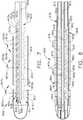
- a surgical fastening instrument 10is depicted in FIG. 1 .
- the surgical fastening instrument 100is configured to deploy an "elastic" or “expandable” staple line.
- Various elastic staple linesare disclosed herein and the surgical fastening instrument 10 is capable of deploying any one of these elastic staple lines.
- surgical instruments other than the surgical fastening instrument 100are capable of deploying any one of the expandable staple lines disclosed herein.
- the surgical fastening instrument 10includes a housing 12 that comprises a handle 14 that is configured to be grasped, manipulated and actuated by the clinician.
- the housing 12is configured for operable attachment to an elongate shaft assembly 200 that has a surgical end effector 700 operably coupled thereto that is configured to perform one or more surgical tasks or procedures.
- the elongate shaft assembly 200may be interchangeable with other shaft assemblies in the various manners disclosed, for example, in U.S. Patent Application Serial No. 14/226,075 , entitled MODULAR POWERED SURGICAL INSTRUMENT WITH DETACHABLE SHAFT ASSEMBLIES.
- the elongate shaft assemblymay not be interchangeable with other shaft assemblies and essentially comprise a dedicated non-removable portion of the instrument.
- the various forms of shaft assemblies and end effectors disclosed hereinmay also be effectively employed in connection with robotically-controlled surgical systems.
- the term "housing”may also encompass a housing or similar portion of a robotic system that houses or otherwise operably supports at least one drive system that is configured to generate and apply at least one control motion which could be used to actuate the elongate shaft assemblies disclosed herein and their respective equivalents.
- the term “frame”may refer to a portion of a handheld surgical instrument.
- framemay also represent a portion of a robotically controlled surgical instrument and/or a portion of the robotic system that may be used to operably control a surgical instrument.
- the shaft assemblies and end effector arrangements disclosed hereinmay be employed with various robotic systems, instruments, components and methods disclosed in U.S. Patent Application Serial No. 13/118,241 , entitled SURGICAL STAPLING INSTRUMENTS WITH ROTATABLE STAPLE DEPLOYMENT ARRANGEMENTS, now U.S. Patent No. 9,072,535 .
- FIG. 1illustrates the housing 12 or handle 14 of the surgical instrument 10 with an interchangeable elongate shaft assembly 200 operably coupled thereto.
- the handle 14may comprise a pair of interconnectable handle housing segments 16 and 18 that may be interconnected by screws, snap features, adhesive, etc.
- the handle housing segments 16, 18cooperate to form a pistol grip portion 19 that can be gripped and manipulated by the clinician.
- the handle 14operably supports a plurality of drive systems therein that are configured to generate and apply various control motions to corresponding portions of the interchangeable shaft assembly that is operably attached thereto.
- the handle 14may further include a frame 20 that operably supports a plurality of drive systems.
- the frame 20can operably support a "first" or closure drive system, generally designated as 30, which may be employed to apply closing and opening motions to the elongate shaft assembly 200 that is operably attached or coupled thereto.
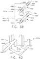
- the closure drive system 30may include an actuator in the form of a closure trigger 32 that is pivotally supported by the frame 20. More specifically, as illustrated in FIG. 2 , the closure trigger 32 is pivotally coupled to the housing 14 by a pin 33.
- the closure drive system 30further includes a closure linkage assembly 34 that is pivotally coupled to the closure trigger 32.
- the closure linkage assembly 34may include a first closure link 36 and a second closure link 38 that are pivotally coupled to the closure trigger 32 by a pin 35.
- the second closure link 38may also be referred to herein as an "attachment member” and include a transverse attachment pin 37.
- the first closure link 36may have a locking wall or end 39 thereon that is configured to cooperate with a closure release assembly 60 that is pivotally coupled to the frame 20.
- the closure release assembly 60may comprise a release button assembly 62 that has a distally protruding locking pawl 64 formed thereon.
- the release button assembly 62may be pivoted in a counterclockwise direction by a release spring (not shown).
- the closure release assembly 60serves to lock the closure trigger 32 in the fully actuated position.
- the cliniciandesires to unlock the closure trigger 32 to permit it to be biased to the unactuated position, the clinician simply pivots the closure release button assembly 62 such that the locking pawl 64 is moved out of engagement with the locking wall 39 on the first closure link 36.
- the closure trigger 32may pivot back to the unactuated position.
- Other closure trigger locking and release arrangementsmay also be employed.
- the closure release button 62When the closure trigger 32 is moved from its unactuated position to its actuated position, the closure release button 62 is pivoted between a first position and a second position.
- the rotation of the closure release button 62can be referred to as being an upward rotation; however, at least a portion of the closure release button 62 is being rotated toward the circuit board 100.
- the closure release button 62can include an arm 61 extending therefrom and a magnetic element 63, such as a permanent magnet, for example, mounted to the arm 61.
- the magnetic element 63When the closure release button 62 is rotated from its first position to its second position, the magnetic element 63 can move toward the circuit board 100.
- the circuit board 100can include at least one sensor that is configured to detect the movement of the magnetic element 63.
- a "Hall effect” sensorcan be mounted to the bottom surface of the circuit board 100.
- the Hall effect sensorcan be configured to detect changes in a magnetic field surrounding the Hall effect sensor that are caused by the movement of the magnetic element 63.
- the Hall effect sensorcan be in signal communication with a microcontroller, for example, which can determine whether the closure release button 62 is in its first position, which is associated with the unactuated position of the closure trigger 32 and the open configuration of the end effector, its second position, which is associated with the actuated position of the closure trigger 32 and the closed configuration of the end effector, and/or any position between the first position and the second position.
- the handle 14 and the frame 20operably support another drive system referred to herein as a firing drive system 80 that is configured to apply firing motions to corresponding portions of the interchangeable shaft assembly attached thereto.
- the firing drive systemmay 80 also be referred to herein as a "second drive system”.
- the firing drive system 80may employ an electric motor 82, located in the pistol grip portion 19 of the handle 14.
- the motor 82may be a DC brushed driving motor having a maximum rotation of, approximately, 25,000 RPM, for example.
- the motormay include a brushless motor, a cordless motor, a synchronous motor, a stepper motor, or any other suitable electric motor.
- the motor 82may be powered by a power source 90 that in one form may comprise a removable power pack 92.
- the power pack 92may comprise a proximal housing portion 94 that is configured for attachment to a distal housing portion 96.
- the proximal housing portion 94 and the distal housing portion 96are configured to operably support a plurality of batteries 98 therein.
- Batteries 98may each comprise, for example, a Lithium Ion ("LI”) or other suitable battery.
- the distal housing portion 96is configured for removable operable attachment to a control circuit board assembly 100 which is also operably coupled to the motor 82.
- a number of batteries 98may be connected in series may be used as the power source for the surgical instrument 10.
- the power source 90may be replaceable and/or rechargeable.
- the electric motor 82includes a rotatable shaft (not shown) that operably interfaces with a gear reducer assembly 84 that is mounted in meshing engagement with a with a set, or rack, of drive teeth 122 on a longitudinally-movable drive member 120.
- a voltage polarity provided by the power source 90can operate the electric motor 82 in a clockwise direction wherein the voltage polarity applied to the electric motor by the battery can be reversed in order to operate the electric motor 82 in a counter-clockwise direction.
- the drive member 120will be axially driven in the distal direction "DD".
- the handle 14can include a switch which can be configured to reverse the polarity applied to the electric motor 82 by the power source 90. As with the other forms described herein, the handle 14 can also include a sensor that is configured to detect the position of the drive member 120 and/or the direction in which the drive member 120 is being moved.
- Actuation of the motor 82is controlled by a firing trigger 130 that is pivotally supported on the handle 14.
- the firing trigger 130may be pivoted between an unactuated position and an actuated position.
- the firing trigger 130may be biased into the unactuated position by a spring 132 or other biasing arrangement such that when the clinician releases the firing trigger 130, it may be pivoted or otherwise returned to the unactuated position by the spring 132 or biasing arrangement.
- the firing trigger 130can be positioned "outboard" of the closure trigger 32 as was discussed above.
- a firing trigger safety button 134may be pivotally mounted to the closure trigger 32 by pin 35.
- the safety button 134may be positioned between the firing trigger 130 and the closure trigger 32 and have a pivot arm 136 protruding therefrom. See FIG. 2 .
- the safety button 134When the closure trigger 32 is in the unactuated position, the safety button 134 is contained in the handle 14 where the clinician cannot readily access it and move it between a safety position preventing actuation of the firing trigger 130 and a firing position wherein the firing trigger 130 may be fired. As the clinician depresses the closure trigger 32, the safety button 134 and the firing trigger 130 pivot down wherein they can then be manipulated by the clinician.
- the handle 14includes a closure trigger 32 and a firing trigger 130.
- the firing trigger 130can be pivotably mounted to the closure trigger 32.
- the closure trigger 32When the closure trigger 32 is moved from its unactuated position to its actuated position, the firing trigger 130 can descend downwardly, as outlined above.
- the safety button 134After the safety button 134 has been moved to its firing position, the firing trigger 130 can be depressed to operate the motor of the surgical instrument firing system.
- the handle 14can include a tracking system configured to determine the position of the closure trigger 32 and/or the position of the firing trigger 130.
- the longitudinally movable drive member 120has a rack of drive teeth 122 formed thereon for meshing engagement with a corresponding drive gear 86 of the gear reducer assembly 84.
- At least one formalso includes a manually-actuatable "bailout” assembly 140 that is configured to enable the clinician to manually retract the longitudinally movable drive member 120 should the motor 82 become disabled.
- the bailout assembly 140may include a lever or bailout handle assembly 142 that is configured to be manually pivoted into ratcheting engagement with teeth 124 also provided in the drive member 120.
- the cliniciancan manually retract the drive member 120 by using the bailout handle assembly 142 to ratchet the drive member 120 in the proximal direction "PD".
- the elongate shaft assembly 200includes a surgical end effector 700 that comprises an elongate channel 702 that is configured to operably support a staple cartridge 800 therein.
- the end effector 700may further include an anvil 710 that is pivotally supported relative to the elongate channel 702.
- the surgical end effector 700may be articulated relative to the elongate shaft assembly about an articulation joint 270.
- the shaft assembly 200can further include a proximal housing or nozzle 201 comprised of nozzle portions 202 and 203.
- the shaft assembly 200further includes a closure tube 260 which can be utilized to close and/or open an anvil 310 of the end effector 700.
- the shaft assembly 200includes a spine 210 which can be configured to fixably support a shaft frame portion 212 of and articulation lock 350. Details regarding the construction and operation of the articulation lock 350 are set forth in U.S. Patent Application Serial No. 13/803,086 , entitled ARTICULATABLE SURGICAL INSTRUMENT COMPRISING AN ARTICULATION LOCK, now U.S. Patent Application Publication No. 2014/0263541 .
- the spine 210is configured to, one, slidably support a firing member 220 therein and, two, slidably support the closure tube 260 which extends around the spine 210.
- the spine 210also slidably supports a proximal articulation driver 230.
- the proximal articulation driver 230has a distal end 301 that is configured to operably engage the articulation lock 350.
- the articulation lock 350interfaces with an articulation frame 352 that is adapted to operably engage a drive pin (not shown) on the end effector frame (not shown).
- the spine 210comprises a proximal end 211 which is rotatably supported in a chassis 240.
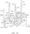
- the proximal end 211 of the spine 210has a thread 214 formed thereon for threaded attachment to a spine bearing 216 configured to be supported within the chassis 240. See FIG. 3 .
- Such arrangementfacilitates rotatable attachment of the spine 210 to the chassis 240 such that the spine 210 may be selectively rotated about a shaft axis SA-SA relative to the chassis 240.
- the shaft assembly 200also includes a closure shuttle 250 that is slidably supported within the chassis 240 such that it may be axially moved relative thereto. As can be seen in FIG.
- the closure shuttle 250includes a pair of proximally-protruding hooks 252 that are configured for attachment to the attachment pin 37 that is attached to the second closure link 38 as will be discussed in further detail below. See FIG. 2 .
- a proximal end 261 of the closure tube 260is coupled to the closure shuttle 250 for relative rotation thereto.
- a U-shaped connector 263is inserted into an annular slot 262 in the proximal end 261 of the closure tube 260 and is retained within vertical slots 253 in the closure shuttle 250. See FIG. 3 .
- Such arrangementserves to attach the closure tube 260 to the closure shuttle 250 for axial travel therewith while enabling the closure tube 260 to rotate relative to the closure shuttle 250 about the shaft axis SA-SA.
- a closure spring 268is journaled on the closure tube 260 and serves to bias the closure tube 260 in the proximal direction "PD" which can serve to pivot the closure trigger into the unactuated position when the shaft assembly 200 is operably coupled to the handle 14.
- the elongate shaft assembly 200further includes a firing member 220 that is supported for axial travel within the shaft spine 210.
- the firing member 220includes an intermediate firing shaft portion 222 that is configured for attachment to a distal cutting portion or firing beam 280.
- the firing member 220may also be referred to herein as a "second shaft” and/or a "second shaft assembly”.
- the intermediate firing shaft portion 222may include a longitudinal slot 223 in the distal end thereof which can be configured to receive a tab 284 on the proximal end 282 of the distal firing beam 280.
- the longitudinal slot 223 and the proximal end 282can be sized and configured to permit relative movement therebetween and can comprise a slip joint 286.
- the slip joint 286can permit the intermediate firing shaft portion 222 of the firing drive 220 to be moved to articulate the surgical end effector 700 without moving, or at least substantially moving, the firing beam 280.
- the intermediate firing shaft portion 222can be advanced distally until a proximal sidewall of the longitudinal slot 223 comes into contact with the tab 284 in order to advance the firing beam 280 and fire a staple cartridge that may be supported in the end effector 700.
- the shaft spine 210has an elongate opening or window 213 therein to facilitate assembly and insertion of the intermediate firing shaft portion 222 into the shaft frame 210.
- a top frame segment 215may be engaged with the shaft frame 212 to enclose the intermediate firing shaft portion 222 and firing beam 280 therein. Further description of the operation of the firing member 220 may be found in U.S. Patent Application Serial No. 13/803,086 , now U.S. Patent Application Publication No. 2014/0263541 .
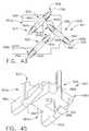
- the illustrated shaft assembly 200includes a clutch assembly 400 which can be configured to selectively and releasably couple the articulation driver 230 to the firing member 220.
- the clutch assembly 400includes a lock collar, or sleeve 402, positioned around the firing member 220 wherein the lock sleeve 402 can be rotated between an engaged position in which the lock sleeve 402 couples the articulation driver 230 to the firing member 220 and a disengaged position in which the articulation driver 230 is not operably coupled to the firing member 200.
- proximal articulation driver 230can be held in position by the articulation lock 350 when the proximal articulation driver 230 is not being moved in the proximal or distal directions by the firing member 220.
- the lock sleeve 402can comprise a cylindrical, or an at least substantially cylindrical, body including a longitudinal aperture 403 defined therein configured to receive the firing member 220.
- the lock sleeve 402can comprise diametrically-opposed, inwardly-facing lock protrusions 404 and an outwardly-facing lock member 406.
- the lock protrusions 404can be configured to be selectively engaged with the firing member 220.
- the lock protrusions 404are positioned within a drive notch 224 defined in the firing member 220 such that a distal pushing force and/or a proximal pulling force can be transmitted from the firing member 220 to the lock sleeve 402.
- a second lock member 406is received within a drive notch 232 defined in the proximal articulation driver 230 such that the distal pushing force and/or the proximal pulling force applied to the lock sleeve 402 can be transmitted to the proximal articulation driver 230.
- the firing member 220, the lock sleeve 402, and the proximal articulation driver 230will move together when the lock sleeve 402 is in its engaged position.
- the lock protrusions 404may not be positioned within the drive notch 224 of the firing member 220 and, as a result, a distal pushing force and/or a proximal pulling force may not be transmitted from the firing member 220 to the lock sleeve 402.
- the distal pushing force and/or the proximal pulling forcemay not be transmitted to the proximal articulation driver 230.
- the firing member 220can be slid proximally and/or distally relative to the lock sleeve 402 and the proximal articulation driver 230.
- the elongate shaft assembly 200further includes a switch drum 500 that is rotatably received on the closure tube 260.
- the switch drum 500comprises a hollow shaft segment 502 that has a shaft boss 504 formed thereon for receive an outwardly protruding actuation pin 410 therein.
- the actuation pin 410extends through a slot 267 into a longitudinal slot 408 provided in the lock sleeve 402 to facilitate axial movement of the lock sleeve 402 when it is engaged with the proximal articulation driver 230.
- a rotary torsion spring 420is configured to engage the shaft boss 504 on the switch drum 500 and a portion of the nozzle housing 203 to apply a biasing force to the switch drum 500.
- the switch drum 500can further comprise at least partially circumferential openings 506 defined therein which, referring to FIGS. 5 and 6 , can be configured to receive circumferential mounts extending from the nozzle portions 202, 203 and permit relative rotation, but not translation, between the switch drum 500 and the proximal nozzle 201.
- the mountsalso extend through openings 266 in the closure tube 260 to be seated in recesses in the shaft spine 210.
- the nozzle 201may be employed to operably engage and disengage the articulation drive system with the firing drive system in the various manners described in further detail in U.S. Patent Application Serial No. 13/803,086 , now U.S. Patent Application Publication No. 2014/0263541 .
- the elongate shaft assembly 200can comprise a slip ring assembly 600 which can be configured to conduct electrical power to and/or from the end effector 700 and/or communicate signals to and/or from the surgical end effector 700, for example.
- the slip ring assembly 600can comprise a proximal connector flange 604 mounted to a chassis flange 242 extending from the chassis 240 and a distal connector flange 601 positioned within a slot defined in the shaft housings 202, 203.
- the proximal connector flange 604can comprise a first face and the distal connector flange 601 can comprise a second face which is positioned adjacent to and movable relative to the first face.
- the distal connector flange 601can rotate relative to the proximal connector flange 604 about the shaft axis SA-SA.
- the proximal connector flange 604can comprise a plurality of concentric, or at least substantially concentric, conductors 602 defined in the first face thereof.
- a connector 607can be mounted on the proximal side of the distal connector flange 601 and may have a plurality of contacts (not shown) wherein each contact corresponds to and is in electrical contact with one of the conductors 602. Such arrangement permits relative rotation between the proximal connector flange 604 and the distal connector flange 601 while maintaining electrical contact therebetween.
- the proximal connector flange 604can include an electrical connector 606 which can place the conductors 602 in signal communication with a shaft circuit board 610 mounted to the shaft chassis 240, for example.
- a wiring harnesscomprising a plurality of conductors can extend between the electrical connector 606 and the shaft circuit board 610. Further details regarding slip ring assembly 600 may be found in U.S. Patent Application Serial No. 13/803,086 , now U.S. Patent Application Publication No. 2014/0263541 .
- the elongate shaft assembly 200can include a proximal portion which is fixably mounted to the handle 14 and a distal portion which is rotatable about a longitudinal shaft axis SA-SA.
- the rotatable distal shaft portioncan be rotated relative to the proximal portion about the slip ring assembly 600, as discussed above.
- the distal connector flange 601 of the slip ring assembly 600can be positioned within the rotatable distal shaft portion.
- the switch drum 500can also be positioned within the rotatable distal shaft portion. When the rotatable distal shaft portion is rotated, the distal connector flange 601 and the switch drum 500 can be rotated synchronously with one another.
- the switch drum 500can be rotated between a first position and a second position relative to the distal connector flange 601.
- the articulation drive systemi.e., the proximal articulation driver 230
- the switch drum 500is in its first position, the articulation drive system (i.e., the proximal articulation driver 230) may be operably disengaged from the firing drive system and, thus, the operation of the firing drive system may not articulate the end effector 700 of the shaft assembly 200.
- the articulation drive systemi.e., the proximal articulation driver 230
- the switch drum 500is moved between its first position and its second position
- the switch drum 500is moved relative to distal connector flange 601.
- the shaft assembly 200can comprise at least one sensor that is configured to detect the position of the switch drum 500.
- the closure tube assembly 260includes a double pivot closure sleeve assembly 271.
- the double pivot closure sleeve assembly 271includes an end effector closure sleeve 272 that includes upper and lower distally projecting tangs 273, 274.
- An upper double pivot link 277includes upwardly projecting distal and proximal pivot pins that engage respectively an upper distal pin hole in the upper proximally projecting tang 273 and an upper proximal pin hole in an upper distally projecting tang 264 on the closure tube 260.
- a lower double pivot link 278includes upwardly projecting distal and proximal pivot pins that engage respectively a lower distal pin hole in the lower proximally projecting tang 274 and a lower proximal pin hole in the lower distally projecting tang 265.
- the surgical end effector 700includes an elongate channel 702 that is configured to operably support a surgical staple cartridge 800 therein.
- the elongate channel 702has a proximal end portion 704 that includes two upstanding lateral walls 706.
- the surgical end effector 700further includes an anvil 710 that has an anvil body 712 that has a staple-forming undersurface 714 formed thereon.
- the proximal end 716 of the anvil body 712includes a laterally protruding anvil trunnion 718.
- a trunnion slot 708is provided in each lateral wall 706 of the elongate channel 702 for receiving a corresponding one of the anvil trunnions 718 therein.
- Such arrangementserves to movably affix the anvil 710 to the elongate channel 702 for selective pivotable travel between open and closed or clamped positions.
- the anvil 710includes a tab 720 that is engageable with a horseshoe-shaped slot 722 in the end effector closure sleeve 272. When the closure tube 260 and, more particularly, the end effector closure sleeve 272, is moved distally, a side wall of the slot 722 can engage the tab 720 to rotate the anvil 710 toward the elongate channel 702.
- an exemplary staple cartridge 800comprises a cartridge body 802 that may be molded for example, from a polymer material and be configured to be removably retained within the elongate channel 702.
- the staple cartridge body 802includes a centrally disposed elongate slot 804 that is configured to receive a tissue cutting member 750 therein.
- a plurality of staple cavities 810a, 810b, 810care arranged in the cartridge body 802 on each side of the elongate slot 804.
- the staple cavities 810a, 810b, 810care generally oriented in a "herringbone-like" pattern.
- Each staple cavity 810a, 810b, 810cis configured to removably store a staple therein, although it is possible that some staple cavities 810a, 810b, 810c may not contain a staple stored therein.
- the staple cartridge 800further comprises a plurality of staple drivers 900a, 900b that are movably positioned within the cartridge body 802 in conjunction with corresponding staple cavities.
- Each staple driver 900a, 900bis configured to support one or more staples thereon and/or lift the staples out of their respective staple cavities 810a, 810b, 810c at the same time, or concurrently when contacted by a sled or camming actuator 760.
- the end effector 700can include a tissue cutting member 750 that is configured to incise tissue captured between the staple cartridge 800 and the anvil 710.
- the tissue cutting member 750is coupled to or integrally formed on a distal end of the firing beam 280 and is oriented for movement within the elongate slot 804. Distal advancement of the firing beam 280 will therefore result in the distal advancement of the tissue cutting member 750 within the elongate slot 804 in the staple cartridge body 802.
- the anvil 710also includes a longitudinal slot configured to at least partially receive a portion of the tissue cutting member 750; however, embodiments are envisioned in which only one of the cartridge 800 and the anvil 710 includes a slot configured to receive a tissue cutting member.
- the tissue cutting member 750comprises at least one first projection 752 extending therefrom which is configured to engage the anvil 710 and at least one second projection 754 that is configured to engage the elongate channel 702. The projections 752 and 754 can position the anvil 710 and the staple cartridge 800 relative to one another.
- the projections 752 and 754can position the anvil 710 and set the tissue gap between the staple forming undersurface 714 of the anvil 710 and the deck surface 816 of the staple cartridge 800 supported in the elongate channel 702.
- the sled or camming actuator 760is configured to be engaged by the tissue cutting member 750 as the tissue cutting member 750 is distally driven through the staple cartridge 800 by the firing beam 280.
- the sled 760 and tissue cutting member 750may be formed as a single component.
- the firing beammay contact the sled or camming member or be integrally formed therewith.
- the sled 760comprises one or more ramp or camming surfaces which are configured to drivingly contact or slide under the staple drivers 900a, 900b and lift the staple drivers 900a, 900b upwardly toward the deck surface 816 of the staple cartridge 800.
- the sled 760comprises four ramp or camming surfaces or camming members 762, 764, 766 and 768.
- the sled 760is movable from a proximal end 803 of the staple cartridge 800 toward a distal end 811 of the cartridge 800 to sequentially lift the staple drivers 900a, 900b in their respective "driver arrays" on each side of the elongate slot 804.
- the staple drivers 900a, 900blift the staples supported thereon toward the staple forming undersurface 714 of the anvil 710.
- the staple cartridge 800can further comprise a support pan 780 attached thereto which extends around the bottom of the staple cartridge body 802 and retains the staple drivers 900a, 900b, the staples, and/or the sled 760 within the cartridge 800.
- the surgical instrument 10includes an articulation drive system 500, which when actuated can articulate the end effector 700 about an articulation joint 270.
- the end effector 700can be rotated in a first direction and, when the proximal articulation driver 230 is pushed in a second direction, the end effector 700 can be rotated in a second, or opposite, direction.
- the end effectoris not capable of articulation.
- the illustrated end effector 700includes an end effector mounting assembly 790 that is adapted to be pivotally mounted to, for example, a portion of the articulation lock 350 ( FIG.
- the end effector mounting assembly 790is mounted to the elongate channel 702 via a spring pin 796 which extends through apertures 705 defined in the elongate channel 702 and the end effector mounting assembly 790.
- the articulation lock 350may be movable between a first, locked or engaged, position in which the lock is engaged with the end effector mounting assembly 790 and a second, or unlocked or disengaged, position.
- the staple cavities 810a, 810b, 810c of the staple cartridge 800open through the deck surface 816 and can be positioned and arranged such that the staples stored in the staple cavities 810a, 810b, 810c are deployed as part of an extensible or "flexible” or “elastic” staple line.
- the staple cavities 810a, 810b, 810care arranged in a "staple cavity array" generally designated as 806.
- the staple cavity array 806comprises a first row 807 of staple cavities 810a which removably stores a first row of staples.
- the first row 807 of staple cavities 810aextends along a first longitudinal axis 812a adjacent the elongate slot 804.
- the staple cavity array 806also comprises a second row 808 of staple cavities 810b which removably stores a second row of staples.
- the second row 808 of staple cavities 810bextends along a second longitudinal axis 812b adjacent the first row 807 of staple cavities 810a.
- the staple cavity array 806further comprises a third row 809 of staple cavities 810c which removably store a third row of staples.
- the third row 809 of staple cavities 810cextends along a third longitudinal axis 812c adjacent the second row 808 of staple cavities 810b.
- the first longitudinal axis 812ais parallel, or at least substantially parallel, to the second longitudinal axis 812b; however, other arrangements are possible in which the first longitudinal axis 812a is not parallel to the second longitudinal axis 812b.
- the second longitudinal axis 812bis parallel, or at least substantially parallel, to the third longitudinal axis 812c; however, other arrangements are possible in which the second longitudinal axis 812b is not parallel to the third longitudinal axis 812c.
- the first longitudinal axis 812ais parallel, or at least substantially parallel, to the third longitudinal axis 812c; however, other arrangements are possible in which the first longitudinal axis 812a is not parallel to the third longitudinal axis 812c. Referring again to FIGS.
- the staple cartridge 800comprises a first portion of the staple cavity array 806 including a first row 807 of staple cavities 810a, a second row 808 of second staple cavities 810b, and a third row 809 of third staple cavities 810c on a first side 805 of the longitudinal slot 804 and a second portion of the cavity array 806 including a first row 810a, a second row 810b, and a third row 810c on a second side 801 of the longitudinal slot 804.
- the first cavity array portionis a mirror image of the second cavity array portion with respect to the longitudinal slot; however, other arrangements may be utilized.
- each of the first staple cavities 810ais oriented at a first angle 824a with respect a first reference axis 997a that is perpendicular to the first longitudinal axis 812a.
- each of the second staple cavities 810bis oriented at a second angle 824b with respect to a second reference axis 997b that is perpendicular to the second longitudinal axis 812b.
- each of the third staple cavities 810cis oriented at a third angle 824c with respect to a third reference axis 997c that is perpendicular to the third longitudinal axis 812c.
- the first angle 824ais different than the second angle 824b; however, in other embodiments, the first angle 824a and the second angle 824b can be the same.
- the third angle 824cis different than the second angle 824b; however, in other embodiments, the third angle 824c and the second angle 824b can be the same.
- the first angle 824ais the same as the third angle 824c; however, in other embodiments, the first angle 824a and the third angle 824c can be different.
- angle 824amay be approximately forty-five (45) degrees (with a range of ⁇ thirty (30) degrees for example); angle 824b may be approximately fifty (50) degrees (with a range of ⁇ thirty (30) degrees, for example); and angle 824c may be approximately forty-five (45) degrees with a range of ⁇ thirty (30) degrees, for example).
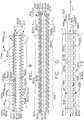
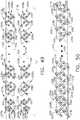
- the staple cartridge 800is configured to deploy the staple pattern 813 depicted in FIG. 9 .
- the staple cartridge 800is configured to deploy a first row 817 of staples 820a along a first longitudinal axis 822a, a second row 818 of staples 820b along a second longitudinal axis 822b, and a third row 819 of staples 820c along a third longitudinal axis 822c.
- the staple cartridge 800is configured to deploy a first row 817 of staples 820a, a second row 818 of staples 820b, and a third row 819 of staples 820c on a first side of a longitudinal incision 826 and a first row 817 of staples 820a, a second row 818 of staples 820b, and a third row 819 of staples 820c on a second side of the longitudinal incision 826.
- the first rows 817 of staples 820acan be positioned adjacent the longitudinal incision 826 and the third row 819 of staples 820c can be positioned furthest away from the longitudinal incision 826.
- Each second row 818 of staples 820bcan be positioned intermediate a first row 817 of staples 820a and a third row 819 of staples 820c.
- first staples 820aare removably stored in the first staple cavities 810a
- the second staples 820bare removably stored in the second staple cavities 810b
- the third staples 820care removably stored in the third staple cavities 810c.
- the staple cavities 810a-810care configured and arranged to deploy the staples 820a-820c in the arrangement depicted in FIGS. 9 and 10 .
- the first staples 820aare oriented at the first angle 824a with respect to a first reference axis 999a that is perpendicular to the first longitudinal axis 822a.
- the second staples 820bare oriented at the second angle 824b with respect to a second reference axis 999b that is perpendicular to the second longitudinal axis 822b.
- the third staples 820care oriented at the third angle 824c with respect to a third reference axis 999c that is perpendicular to the third longitudinal axis 822c.
- the first staples 820a, the second staples 820b, and the third staples 820ccan be positioned and arranged such that they provide "laterally-overlapping" staple lines. More particularly, referring again to FIG. 9 , the second longitudinal row 818 of second staples 820b is positioned laterally with respect to the first longitudinal row 817 of first staples 820a such that the second staples 820b are aligned with the gaps between the first staples 820a and, similarly, the third longitudinal row 819 of third staples 820c is positioned laterally with respect to the second longitudinal row 818 of second staples 820b such that the third staples 820c are aligned with the gaps between the second staples 820b.
- Such an arrangementcan limit the flow of blood from the tissue T to the longitudinal incision 826.
- the staple pattern disclosed in FIG. 9comprises six longitudinal rows of staples.
- Other embodimentsare envisioned which comprise less than six rows of staples, such as four rows of staples, for example, or more than six rows of staples, such as eight rows of staples, for example.
- the first staples 820a, the second staples 820b, and the third staples 820ccan comprise any suitable configuration such as, for example, a V-shaped configuration or a U-shaped configuration.
- a staple comprising a V-shaped configurationcan include a base or crown, a first leg extending from a first end of the base or crown, and a second leg extending from a second end of the base or crown, wherein the first leg and the second leg extend in directions which are non-parallel to one another.
- a staple comprising a U-shaped configurationcan include a base or crown, a first leg extending from a first end of the base or crown, and a second leg extending from a second end of the base or crown, wherein the first leg and the second leg extend in directions which are parallel to one another.
- each first staple 820acomprises a first staple base or crown 827a ( FIG. 12 ) that has a first proximal staple leg 825a and a first distal staple leg 823a protruding therefrom.
- a staple cartridge 800 configured to deploy the staple pattern 813 disclosed in FIG. 9can include a proximal end 803 and a distal end 811.
- the first proximal staple leg 825acan be closer to the proximal end 803 of the staple cartridge 800 than the first distal staple leg 823a and, similarly, the first distal staple leg 823a can be closer to the distal end 811 of the staple cartridge 800 than the first proximal staple leg 825a.
- each first staple 820acan define a first base axis "FBA".
- Each of the first proximal staple leg 825a and the first distal staple leg 823acan extend from the first base axis FBA.
- the first staples 820acan be positioned and arranged such that the first base axes FBA's extend toward the longitudinal cut line 826 and toward the distal end of the staple cartridge 800. Stated another way, the first base axis FBA may be transverse to the elongate slot 804.
- each second staple 820bcomprises a second staple base or crown 827b ( FIG. 12 ) that has a second proximal staple leg 825b and a second distal staple leg 823b protruding therefrom.
- the second proximal staple leg 825bcan be closer to the proximal end 803 of the staple cartridge 800 than the second distal staple leg 823b and, similarly, the second distal staple leg 823b can be closer to the distal end 811 of the staple cartridge 800 than the second proximal staple leg 825b.
- the base second crown 827b of each second staple 820bcan define a second base axis "SBA".
- the second proximal staple leg 825b and the second distal staple leg 823bcan extend from the second base axis SBA.
- the second staples 820bcan be positioned and arranged such that the second base axes SBA's extend toward the longitudinal incision 826 and toward the proximal end 803 of the staple cartridge 800.
- the second base axes SBAare transverse to the first base axes as well as to the elongate slot 804.
- each third staple 820ccomprises a third base or crown 827c ( FIG. 12 ) that has a third proximal staple leg 825c and a third distal staple leg 823c protruding therefrom.
- the third proximal staple leg 825ccan be closer to the proximal end 803 of the staple cartridge 800 than the third distal staple leg 823c and, similarly, the third distal staple leg 823c can be closer to the distal end 811 of the staple cartridge 800 than the third proximal staple leg 825c.
- the third crown 827c of each third staple 820ccan define a third base axis "TBA".
- the third proximal staple leg 825c and the third distal staple leg 823ccan extend from the third base axis TBA.
- the third staples 820ccan be positioned and arranged such that the third base axes TBA's extend toward the longitudinal cut line 826 and toward the distal end of the staple cartridge.
- the third base axes TBAare parallel to the first base axes FBA and are transverse to the second base axes SBA as well as to the elongate slot 804. This is but one exemplary embodiment and any suitable arrangement could be utilized.
- first staples 820astraddle the first longitudinal axis 822a. See FIG. 9 .
- the first distal legs 823a of the first staples 820aare positioned on one side of the first longitudinal axis 822a and the first proximal legs 825a are positioned on the other side of the first longitudinal axis 822a.
- the legs of the first staples 820aare offset with respect to the first longitudinal axis 822a.
- Alternative embodimentsare envisioned in which the first staples 820a are aligned with or collinear with the first longitudinal axis 822a.
- the second staples 820bstraddle the second longitudinal axis 822b.
- the second distal legs 823b of the second staples 820bare positioned on one side of the second longitudinal axis 822b and the second proximal legs 825b are positioned on the other side of the second longitudinal axis 822b. Stated another way, the legs of the second staples 820b are offset with respect to the second longitudinal axis 822b. Alternative embodiments are envisioned in which the second staples 820b are aligned with or collinear with the second longitudinal axis 822b.
- the third staples 820cstraddle the third longitudinal axis 820c.
- the third distal legs 823c of the third staples 820care positioned on one side of the third longitudinal axis 820c and the third proximal legs 825c are positioned on the other side of the third longitudinal axis 822c.
- the legs of the third staples 820care offset with respect to the third longitudinal axis 822c.
- Alternative embodimentsare envisioned in which the third staples 820c are aligned with or collinear with the third longitudinal axis 822c.
- a first staple 820acan comprise a first proximal leg 825a which is aligned with the second distal leg 823b of an adjacent second staple 820b.
- a third staple 820ccan comprise a third proximal leg 825c which is aligned with the second distal leg 823b of an adjacent second staple 820b.
- a first staple 820acan comprise a first proximal leg 825a which is positioned distally with respect to the second distal leg 823b of an adjacent second staple 820b.
- a third staple 820ccan comprise a third proximal leg 825c which is positioned distally with respect to the second distal leg 823b of an adjacent second staple 820b.
- the row of second staples 820bis bounded by the row of first staples 820a and the row of third staples 820c.
- a second staple 820bis bounded on one side by a first staple 820a and on the other side by a third staple 820c.
- a first staple 820ais positioned laterally inwardly with respect to the second proximal leg 825b of a second staple 820b and, similarly, a third staple 820c is positioned laterally outwardly with respect to the second distal leg 823b of the second staple 820b.
- the first staples 820acan provide a boundary on one side of the second staples 820b and the third staples 820b can provide a boundary on the other side of the second staples 820b.
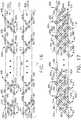
- FIG. 11A traditional staple pattern 829 is illustrated in FIG. 11 .
- This staple pattern 829comprises a first row 836 of first staples 830a positioned along a first longitudinal axis 832a, a second row 838 of second staples 830b positioned along a second longitudinal axis 832b, and a third row 840 of third staples 830c positioned along a third longitudinal axis 832c positioned on a first side of a longitudinal incision 835 in the tissue T.
- the first staples 830aare aligned, or at least substantially aligned, with the first longitudinal axis 832a; the second staples 830b are aligned, or at least substantially aligned, with the second longitudinal axis 832b; and the third staples 830c are aligned, or at least substantially aligned, with the third longitudinal axis 832c.
- the first staples 830aare not oriented at an angle with respect to the first longitudinal axis 832a
- the second staples 830bare not oriented at an angle with respect to the second longitudinal axis 832b
- the third staples 830care not oriented at an angle with respect to the third longitudinal axis 832c.
- This traditional staple patternalso comprises a first row 836 of staples 830a positioned along a first longitudinal axis 832a, a second row 838 of staples 830b positioned along a second longitudinal axis 832b, and a third row 840 of staples 830c positioned along a third longitudinal axis 832c positioned on a second, or opposite, side of the longitudinal incision 835.
- the tissue TWhen a longitudinal tensile force is applied to the tissue T stapled by the staple pattern 829 illustrated in FIG. 11 , the tissue T will stretch longitudinally. Moreover, in various instances, the staples 830a, 830b and 830c can translate longitudinally as the tissue T is stretched longitudinally. Such an arrangement can be suitable in many circumstances; however, the staples 830a, 830b and 830c can restrict the stretching and/or movement of the tissue T. In some instances, the tissue T that has been stapled by the staples 830a, 830b and 830c may be far less flexible than the adjacent tissue that has not been stapled.
- the staple pattern 829comprising the staples 830a, 830b, and 830c can create a sudden change in the material properties of the tissue.
- a large strain gradientcan be created within the tissue T as a result of the staple pattern which, in turn, can create a large stress gradient within the tissue T.
- the legs of the staplescan puncture the tissue T.
- the staple legscreate holes in the tissue.
- Various types of tissuesare resilient and can stretch around the staple legs as the staple legs pass through the tissue.
- the resiliency of the tissuecan permit the tissue to stretch and resiliently return toward the staple legs to reduce or eliminate gaps present between the tissue and the staple legs.
- Such resiliency or elasticitycan also permit the tissue to stretch when a stretching force is applied to the tissue; however, such resiliency can be inhibited by certain staple patterns.
- the staple pattern 829 depicted in FIG. 11can inhibit the longitudinal stretching of the tissue.
- the tissue stapled by the staple pattern of FIG. 11When a longitudinal stretching force is applied to the tissue stapled by the staple pattern of FIG. 11 , the tissue may begin to pull away from the staple legs and create gaps therebetween. In some instances, especially in bariatric resection applications, such gaps can result in increased bleeding from the stomach tissue. In certain instances, especially in lung resection applications, air leaks can result in the lung tissue, for example.
- the staple pattern 813 depicted FIGS. 9 and 10is more flexible or elastic than "traditional" staple pattern 829 arrangements of the type depicted in FIG. 11 .
- the staples 820a, 820b, and 820ccan, one, translate longitudinally as the tissue is stretched longitudinally and/or, two, rotate as the tissue is stretched longitudinally.
- the compliant staple pattern 813 depicted in FIG. 9can reduce or eliminate the gaps between the staple legs and the tissue T when a longitudinal stretching force is applied to the tissue and, as a result, reduce the bleeding and/or air leaks between the staple legs and the tissue.
- FIG. 9is depicted in an unstretched condition.
- the staplescan move longitudinally with the tissue and/or rotate within the tissue, as illustrated in FIG. 10 .
- U.S. Patent Application Serial No. 14/498,121entitled FASTENER CARTRIDGE FOR CREATING A FLEXIBLE STAPLE LINE, filed September 26, 2014 discloses various advantages as well as other variations of the elastic or compliant staple lines described above.
- the staples 820a, 820b, 820care supported on corresponding drivers 900a, 900b that are movably supported in cavities formed in the cartridge body 802.
- each of the staplesmay exit out of their respective cavity so that the staple legs thereof are generally perpendicular to the corresponding portion of the staple forming undersurface 714 of the anvil 710.
- the staple drivers on which the staples are supportedare driven upwardly when they are drivingly contacted by the corresponding ramps or camming members of the distally-moving sled or camming member 760.
- the driving motion applied by the sled ramps to the driverscould, at times, skew a staple driver within its respective cavity as it is driven upward therein.
- Such skewing of the staple driver(s)may undesirably result in one, an increase in the force required to drive the firing beam and/or two result in the skewing of the staples as they are ejected from the cartridge body which could ultimately lead to inconsistently formed staples or even malformed staples.
- FIGS. 12-14illustrate a staple driver 900a according to at least one embodiment of the present invention.
- the staple drivers 900bmay be mirror images of staple drivers 900a.
- one staple driver 900acan support three staples 820a, 820b, 820c thereon.
- the staple driver 900aincludes a first or innermost staple support portion 910 that is configured to support a first staple 820a thereon, a second or central staple support portion 930 that is configured to support a second staple 820b thereon and a third or outermost staple support portion 950 that is configured to support a third staple 820c thereon.
- the term “innermost”refers to the staple support portion that is closest to the elongate slot 804 in the cartridge body 802 and the term “outermost” refers to the staple support portion that is the farthest away from the elongate slot 804.
- the first staple support portion 910comprises a first distal support column 914 and a first proximal support column 918.
- the first staple support portion 910further includes a first distal support cradle 916 and a first proximal support cradle 920 for supporting portions of the first staple crown 827a.
- the first staple crown 827a of the first staple 820ais supported on the support cradles 916 and 920, the first distal leg 823a is essentially axially aligned with the first distal support column 914 and the first proximal leg 825a is essentially axially aligned with the first proximal support column 918.
- the driver 900afurther comprises second staple support portion 930 that comprises a second distal support column 934 and a second proximal support column 938.
- the second staple support portion 930further includes a second distal support cradle 936 and a second proximal support cradle 940 for supporting portions of the second staple crown 827b therein.
- FIG. 12shows that the driver 900a has a second staple support portion 930 that comprises a second distal support column 934 and a second proximal support column 938.
- the second staple support portion 930further includes a second distal support cradle 936 and a second proximal support cradle 940 for supporting portions of the second staple crown 827b therein.
- the driver 900acomprises a third staple support portion 950 that includes a third distal support column 954 and a third proximal support column 958.
- the third staple support portion 950further includes a third distal support cradle 956 and a third proximal support cradle 960 that are configured to support portions of the third staple crown 827c of the third staple 820c therein.
- FIG. 12illustrates a third staple support portion 950 that includes a third distal support column 954 and a third proximal support column 958.
- the third staple support portion 950further includes a third distal support cradle 956 and a third proximal support cradle 960 that are configured to support portions of the third staple crown 827c of the third staple 820c therein.
- the first staple support portion 910is coupled to the second staple support portion 930 by a first or distal connection member 970.
- the first connection member 970includes a first cam portion that has a first camming surface or ramp 974 formed on the underside thereof.
- the second staple support portion 930is likewise connected to the third staple support portion 950 by a second or proximal connection member 980.
- a second cam member 982protrudes from or is attached to the third staple support portion 950 and has a second camming surface or ramp 984 formed thereon.
- the first and second camming surfaces 974, 984are formed with the same angle and are essentially parallel to each other.
- the first and second camming surfaces 974, 984may differ from each other.
- the camming angle of the first and second camming surface 974, 984may relate to the cam angles of the corresponding ramp or camming surfaces of the sled 760.
- the staple driver 900a (and 900b)is integrally formed from or molded from, for example, Ultem®, with no fill.
- Ultem®with a glass or mineral fill or Nylon or Nylon with a glass file
- the various portions of the staple driver 900a (and 900b)may be separately fabricated from other materials and be attached together by adhesive, solder, etc.
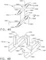
- FIG. 15is a bottom perspective view of a portion of one form of the surgical staple cartridge body 802.
- the cartridge body 802includes an elongate slot 804 that may be centrally disposed in the body 802.
- the elongate slot 804bifurcates the cartridge body 802 into two body portions 850, 870 and extends along the centrally-disposed cartridge axis "CA".
- the first body portion 850includes a first cartridge wall portion 852 that includes first support grooves or slots 854 that are each arranged on a corresponding first slot axis "FSA" that is transverse to the cartridge axis CA.
- the first body portion 850further includes a second cartridge wall portion 856 that contains second support grooves or slots 858 therein that are each arranged on a corresponding second slot axis "SSA" that is transverse to the cartridge axis CA.
- a plurality of spaced, staple driver guides 860Located between the first cartridge wall portion 852 and the second cartridge wall portion 856 are a plurality of spaced, staple driver guides 860.
- the staple driver guides 860are integrally formed with one or both of the cartridge wall portions 852, 856 in the cartridge body 802.
- the staple driver guides 860are attached to the wall portions of the cartridge body 802.
- Each staple driver guide 860may be configured to slidably interlock with or, stated another way, slidably support two adjacent staple drivers 900a. See FIG. 17 .
- each of the staple drivers 900aincludes opposed, hooked shaped slots 901, 903 that are configured to be “hookingly engaged” by corresponding opposed hook-shaped portions 862, 864, respectively of the staple driver guide 860.
- the hook-shaped portions 862are configured to slidably support the first proximal support column 918 of a corresponding staple driver 900a and the hook-shaped portions 864 are configured to slidably support a third distal support column 954 of a corresponding staple driver 900a.
- the staple driver guide 860further includes a proximal slot 863 that is configured to slidably support the second distal support column 934 of a corresponding staple driver 900a as well as a distal slot 868 that is configured to slidably support the second proximal support column 938 of the corresponding staple driver 900a.
- each staple driver 900a that is in sliding engagement with a corresponding staple driver guide 860is slidably movable relative to the staple driver guide 860 when the staple driver 900a is drivingly contacted by the sled ramps or camming surfaces 762, 764.
- the second body portion 870includes a primary cartridge wall portion 872 that includes primary staple leg grooves or slots 874 therein that are each arranged on a corresponding primary slot axis "PSA" that is transverse to the cartridge axis CA.
- the second body portionfurther includes a secondary cartridge wall portion 876 that contains second support grooves or slots 878 therein that are each oriented on a corresponding secondary slot axis SDSA that is transverse to the cartridge axis CA.
- Located between the primary cartridge wall portion 872 and the secondary cartridge wall portion 876are a plurality of other spaced driver guides 860 that are each configured to slidably interlock with two adjacent staple drivers 900b which may be mirror images of staple drivers 900a in the manner described above.
- each staple driver 900b that is in slidable engagement with a corresponding driver guide 860is slidably movable relative to the driver guide 860 when the staple driver 900b is drivingly contacted by the sled ramps or camming members 766, 768. See FIG. 6 .
- staple drivers 900aare arranged in first "staple driver array" generally designated as 905a as shown in FIGS. 16 and 17 .
- first "staple driver array”generally designated as 905a as shown in FIGS. 16 and 17 .
- each staple driver 900amay be in slidable engagement with two corresponding staple guides 860. See FIG. 17 .
- the first distal support column 914 of each staple driver 900amay be slidably received within a corresponding first support groove or slots 854 in the first cartridge wall portion 852. See FIGS. 8 and 15 .
- the third proximal support column 958 of each staple driver 900amay be slidably received within a corresponding second support groove or slot 858 in the second cartridge wall portion 856.
- each of the support columns of the staple driver 900aare slidably supported by a corresponding staple driver guide 860 or they are supported by the corresponding cartridge wall portion. Such arrangement may serve to prevent any skewing of the support columns when the staple driver is driven upward within the cartridge body.
- each of the first cam portions 972 of the staple drivers 900aare aligned along a first cam axis "FCA”.
- each of the first camming surfaces 974is axially aligned on the first cam axis FCA.
- each of the second cam members 982 of the staple drivers 900ais axially aligned along a second cam axis "SCA”.
- each of the second camming surfaces 984 of the staple drivers 900ais axially aligned along the second cam axis SCA.
- the cam axes FCA and SCAare parallel to each other as well as to the elongate slot 804 (represented in segmented lines in FIG. 16 ) in the staple cartridge.
- each of the first cam members 972 of the staple drivers 900bare aligned along a primary first cam axis "PCA”.
- each of the first camming surfaces 974 of the staple drivers 900bare axially aligned on the primary cam axis PCA.
- each of the second cam members 982 of the staple drivers 900bare all axially aligned along a secondary cam axis "SDCA”.
- each of the second camming surfaces 984 of the staple drivers 900bare axially aligned along the secondary cam axis SDCA.
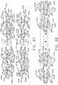
- FIGS. 18 and 19illustrate the position of the sled or camming actuator 760 relative to the staple drivers 900a, 900b.
- the ramp or camming member 764is aligned with the second cam axis SCA.
- the ramp surface or camming member 762is aligned with the first cam axis FCA.
- the ramp or camming member 766is aligned on the primary cam axis PCA and the ramp or camming member 768 is aligned with the secondary cam axis SDCA.
- the ramp or camming member 764is situated to proceed under a portion of each of the crowns 827c of staples 820c that are supported on the drivers 900a.
- the ramp or camming surface 762is situated to proceed under a portion of each of the crowns 827c of staples 820a that are supported on the drivers 900a.
- the ramp or camming member 766is situated to proceed under a portion of the crowns 827a of each of the staples 820a supported on the drivers 900b.
- the ramp or camming member 768is situated to proceed under a portion of the crown 827c of each of the staples 820c supported on the drivers 900b.
- none of the ramps or camming members 764, 762, 766, 768are aligned with any of the staple legs of the staples 820a, 820b, 820c that are supported on the drivers 900a, 900b.
- Such arrangementtherefore enables the third proximal support columns 958 of each of the staple drivers 900a to be slidably received within corresponding second support grooves or slots 858 in the second cartridge wall portion 856 of the cartridge body 802.
- the first distal support columns 914 of each of the staple drivers 900aare slidably received within corresponding first support grooves or slots 854 in the first cartridge wall portion 852 of the cartridge 800.
- each of the support columns 918, 934, 938, 954is also slidably supported in corresponding driver guides 860 that are formed in or attached to the cartridge body 802.
- Each of the driver guides 860may have the same height or similar height as the heights of the wall portions 852, 856.
- the first and second cartridge wall portions 852, 856(not shown in FIG. 19 ) have a height represented by "H".
- the staple driver guides 860may have the same or similar heights "H". This height may also essentially comprise the height of the cartridge body 802 in at least some embodiments.
- Other embodimentsmay employ a "stepped deck” which is a deck surface that has more than one planar portion that have different heights which may be measured from the bottom of the cartridge body for example.
- element 816may represent the staple deck surface (or at least one staple deck surface in embodiments employing a stepped deck) and 781 may represent a surface upon which the staple drivers 900a, 900b sit when they are in an unactuated orientation within the cartridge body.
- element number 781may represent the upper surface of the support pan 780. See FIG. 6 .
- the driver guides 860may also have a height that is equal to or nearly equal to height "H" of the cartridge wall portions 852, 856.
- the support columns of each driver 900a, 900bare essentially slidably supported throughout their entire path of travel (distance "H") when they are driven upward in the cartridge body when contacted by the ramps or camming members on the sled 760.
- each driver 900a, 900bare each supported for a distance or height that is at least 3.40mm (0.134 inch) staple + at least 1.68mm (0.066 inch) driver (5.08mm (0.2 inches) total) for a staple cartridge that may be used to staple lung tissue for example).
- the drivercan be advanced a distance that is at least as long as the height of the staple (e.g., height of 820).
- the staple crownis "ejected" from the staple pocket in the cartridge to prevent tissue from being stuck between the driver and the cartridge deck in its fully advanced state.
- Such featuremay help to avoid the staple drivers 900a, 900b from skewing during actuation which may reduce the likelihood of the formation of malformed staples.
- the tissue cutting member 750contacts the sled or camming member 760 and drives the camming member 760 distally through the staple cartridge 800.
- the camming members 982 of the staple driver 900aare located “inboard” (i.e., closer to the elongate slot 804) from the support columns 958 (and the staple legs 825c supported thereon).
- the camming members 982 of the staple drivers 900bare located inboard of the support columns 958 of those staple drivers 900b and the staple legs 825c supported thereon.
- Such arrangementspermit those support columns 958 to be completely slidably supported through their entire range of upward travel by the corresponding wall portions 856, 876 of the staple cartridge.
- the support columns 934, 938, 918, 954are supported through their entire range of upward travel by the corresponding staple driver guides 860 formed in the cartridge body 802.
- the support column 914 of each of the staple drivers 900a, 900bare slidably supported in the corresponding wall portions 852, 872 of the cartridge body 802 through their entire range of upward travel.
- the driver array 905acomprises a plurality of staple drivers 900a that are each configured to support three staples 820a, 820b, 820c thereon.
- each driver 900amay actually support one, two or all three of such staples.
- staple 820alies along axis FBA.
- the staple crown 827a of staple 820alies along axis FBA.
- Staple 820clies along axis TBA.
- the staple crown 827c of staple 820clies along the third base axis TBA.
- axes FBA and TBAare parallel to each other.
- Staple 820bis centrally supported between staples 820a and 820c and lies along an axis SBA. Stated more precisely, the staple crown of 827b lies along the second base axis SBA. In the illustrated arrangement, SBA is transverse to axes FBA and TBA. Stated another way, the staple driver 900a is configured to support two surgical staples that are parallel to each other or extend in the same direction and one staple that is transverse to the other two staples or extends in another direction that differs from the directions in which the other two staples extend. In the illustrated arrangement, when the staple drivers 900a, 900b are all operably supported in the staple cartridge 800, all of the axes FBA, SBA, TBA are each transverse to the elongate slot 804.
- the staple drivers 900awhen the staple drivers 900a are all operably supported in the staple cartridge in the staple driver array 905a, the staple drivers 900a form a first longitudinal row 1200a of staples 820a that is adjacent to elongate slot 804 in the cartridge body 802. Each of the staples 820a in the first longitudinal row 1200a extend in a first direction as was described above. Likewise, the staple drivers 900a form a second longitudinal row 1202a of staples 820b that are adjacent the first longitudinal row 1200a. The staples 820b in the second longitudinal row 1202a extend in a second direction that is different from the first direction of the staples 820a in the first longitudinal row 1200a.
- the staple drivers 900aform a third longitudinal row 1204a of staples 820c that are oriented in a third direction which may or may not be in the same direction as staples 820a.
- the first and third directionsare the same.
- the third longitudinal row 1204ais adjacent to the second longitudinal row 1202a.
- the staple drivers 900bwhen the staple drivers 900b are all operably supported in the staple cartridge in the staple driver array 905b, the staple drivers 900b form a first longitudinal row 1200b of staples 820a that is adjacent to elongate slot 804 in the cartridge body 802. Each of the staples 820a in the first longitudinal row 1200b extend in a first direction as was described above. Likewise, the staple drivers 900b form a second longitudinal row 1202b of staples 820b that are adjacent the first longitudinal row 1200b. The staples 820b in the second longitudinal row 1202a extend in a second direction that is different from the first direction of the staples 820a in the first longitudinal row 1200a.
- the staple drivers 900bform a third longitudinal row 1204b of staples 820c that are oriented in a third direction which may or may not be in the same direction as staples 820a.
- the first and third directionsare the same.
- the third longitudinal row 1204bis adjacent to the second longitudinal row 1202b.
- FIGS. 20 and 21Other staple driver arrays 990a, 990b are illustrated in FIGS. 20 and 21 .
- the staple driver array 990aemploys a distal staple driver 1000a and a proximal staple driver 1100a in addition to a plurality of the staple drivers 900a.
- the staple driver array 990bincludes a distal staple driver 1000b and a proximal staple driver 1100b.
- Distal staple driver 1000bmay essentially be a mirror image of distal staple driver 1000a and proximal staple driver 1100b may essentially be a mirror image of proximal staple driver 1100a.
- each distal staple driver 1000a, 1000bincludes a distal staple support portion 1010 that is configured to support a corresponding distal most staple 820cd thereon.
- the distal staple support portion 1010comprises a distal support column 1014 and a proximal support column 1018.
- the distal staple support portion 1010further includes a distal support cradle 1016 and a proximal support cradle 1020 for supporting portions of the staple crown 827c of the corresponding distal staple 820cd.
- the first distal leg 823c of the staple 820cdis essentially axially aligned with the first distal support column 1016 and the first proximal leg 825c is essentially axially aligned with the first proximal support column 1018.
- the distal staple drivers 1000a, 1000binclude a distal connection member 1070.
- the distal connection member 1070is configured to slidably engage the corresponding distal-most driver guide (designated as 860D in FIG. 21 ).
- the distal connection member 1070includes a hook-shaped distal slot 1072 that is configured to be "hookingly engaged” by the hook-shaped portion 864 on the corresponding distal-most driver guide 860D.
- the distal connection member 1070may include a projection 1074 that is configured to be slidably received within a corresponding slot 868 in the distal most driver guide 860D. See FIG. 21 .
- each distal staple driver 1000a, 1000bis slidably engaged with a corresponding driver guide 860.
- the proximal support column 1018 of the distal staple driver 1000amay be slidably received within a corresponding second support groove or slot 858 in the second cartridge wall portion 856.
- the proximal support column 1018 of the distal staple driver 1100bmay be slidably received within a corresponding second support groove or slot 878 in the secondary cartridge wall portion 876.
- a first cam member 1022protrudes from or is attached to the distal staple support portion 1010 and has a first camming surface or ramp 1024 formed thereon.
- the distal connection member 1070further includes a second distal cam portion 1026 that has a second or distal camming surface or ramp 1028 formed thereon as shown in FIGS. 23 and 24 .
- the camming surfaces 1024have the same slope or angle as the slope/angle of camming surfaces 984.
- the camming surfaces 1028have the same slope/angle as the slope/angle of camming surfaces 974.
- each distal staple driver 1000a, 1000bis integrally formed from or molded from, for example, Ultem®, with no fill. However, other materials such as, for example, Ultem® with a glass or mineral fill or Nylon or Nylon with a glass file could be used.
- the various portions of the distal staple drivers 1000a, 1000bmay be separately fabricated from other materials and be attached together by adhesive, solder, etc.
- FIGS. 25-27illustrate an exemplary proximal staple driver 1100a.
- Proximal staple driver 1100bmay essentially be a mirror image of proximal staple driver 1100a.
- Each proximal staple driver 1100a, 1100bincludes .a proximal staple support portion 1110 that is configured to support a corresponding proximal most staple 820ap thereon.
- the proximal staple support portion 1110comprises a distal support column 1114 and a proximal support column 1118.
- the proximal staple support portion 1110further includes a distal support cradle 1116 and a proximal support cradle 1120 for supporting portions of the staple crown 827a of the corresponding proximal staple 820ap.
- the proximal staple drivers 1100a, 1100binclude a body member 1170.
- the body member 1170is configured to slidably engage the corresponding proximal-most driver guide (designated as 860P in FIG. 21 ).
- the body member1170includes a hook-shaped distal slot 1172 that is configured to be "hookingly engaged” by the hook-shaped portion 862 of the proximal-most driver guide 860P.
- the body member 1170may include a projection 1174 that is configured to be slidably received within a corresponding slot 869 in the proximal most staple driver guide 860P.
- each proximal staple driver 1100a, 1100bis slidably engaged with a corresponding driver guide 860P.
- the distal support column 1114 of the proximal staple driver 1100amay be slidably received within a corresponding first staple leg groove 854 in the first cartridge wall portion 852.
- the distal support column 1114 of the proximal staple driver 1110bmay be slidably received within a corresponding primary staple leg groove 874 in the primary cartridge wall portion 872.
- a first proximal cam portion 1122protrudes from or is attached to the body member 1170 and has a first proximal camming surface or ramp 1124 formed thereon.
- the body member 1170also includes a second distal cam portion or ramp 1126 that has a second distal camming surface 1128 formed thereon.
- the camming surfaces 1124have the same slope or angle as the slopes/angles of the camming surfaces or ramps 984, 1024.
- the camming surfaces 1128may have the same slope/angle as the slope/angle of camming surface 974 and 1028.
- each proximal staple driver 1100a, 1100bis integrally formed from or molded from, for example, Ultem®, with no fill. However, other materials such as, for example, Ultem® with a glass or mineral fill or Nylon or Nylon with a glass file could be used.
- the various portions of the proximal staple drivers 1100a, 1100bmay be separately fabricated from other materials and be attached together by adhesive, solder, etc.
- each of the first distal camming surfaces 1028, 1128 as well as each of the first camming surfaces 974is axially aligned on the first cam axis FCA.
- the second proximal cam portion 1122 of the proximal staple driver 1100a and the proximal cam portion 1022 of the distal staple driver 1000a, as well as each of the second cam members 982 of the staple drivers 900ais all axially aligned along a second cam axis SCA.
- the proximal camming surfaces 1024, 1124 and the second camming surfaces 984 of the staple drivers 900aare axially aligned along the second cam axis SCA.
- the distal cam portion 1126 of the proximal staple driver 1100b as well as the distal cam portion 1026 of the distal staple driver 1000b as well as each of the cam members 972 of the staple drivers 900bare all aligned along a primary cam axis PCA.
- the distal camming surfaces 1128, 1028, as well as each of the first camming surfaces 974 in the staple driver array 990bare axially aligned on the primary cam axis PCA.
- the staple driver array 990b in the illustrated arrangement, the first distal cam portion 1126 of the proximal staple driver 1100b as well as each of the first cam members 972 of the staple drivers 900b as well as the first distal cam portion 1026 of the distal staple driver 1000bare all aligned along a primary cam axis PCA.
- each of the first distal camming surfaces 1028, 1128 as well as each of the first camming surfaces 974 in the staple driver array 990bis axially aligned on the primary cam axis PCA.
- the second proximal cam portion 1122 of the proximal staple driver 1100b and second proximal cam portion 1022 of the distal staple driver 1000b, as well as each of the second cam members 982 of the staple drivers 900bare all axially aligned along a secondary cam axis SDCA.
- each of the proximal camming surfaces 1024, 1124 and the second camming surfaces 984 of the staple drivers 900bare axially aligned along the second cam axis SDCA.
- the ramp or camming surface 764 of the sled or camming member 760is aligned with the second cam axis SCA.
- the ramp or camming surface 762is aligned with the first cam axis FCA.
- the ramp or camming surface 766is aligned on the primary cam axis PCA and the ramp or camming surface 768 is aligned with the secondary cam axis SDCA.
- the ramp surface 764is aligned with a portion of each of the crowns 827c of staples 820c.
- the ramp surface 762is aligned with a portion of each of the crowns 827c of staples 820a as well as the crowns 827c of the staples 820cd.
- the ramp surface 766is aligned with a portion of the crowns 827a of each of the staples 820a as well as a portion of the crown 827a of the proximal most staple 820ap.
- the ramp surface 768is aligned with a portion of the crown 827c of each of the staples 820c as well as a portion of the crown 827c of the distal most staple 820cd.
- none of the ramps 764, 762, 766, 768are aligned with any of the staple legs of the staples 820a, 820b, 820c, 820cd and 820ap.
- Such arrangementtherefore enables the third proximal support columns 958 of each of the staple drivers 900a to be slidably received within corresponding second support grooves or slots 858 in the second cartridge wall portion 856 of the cartridge body 802.
- the proximal support column 1018 of the distal staple driver 1000ato be slidably received within a corresponding support groove or slot 858 in the cartridge wall portion 856.
- first distal support columns 914 of each of the staple drivers 900aare slidably received within corresponding first support grooves or slots 854 in the first cartridge wall portion 852 of the cartridge 800.
- distal support column 1114 of the proximal staple driver 1100ais slidably received within a support groove or slot 854.
- each of the support columns 1014, 918, 934, 938, 954, 1118are also slidably supported in corresponding driver guides 860D, 860, 860P that are formed in the cartridge body 802 and may have the same heights or similar heights as the heights of the wall portions 852, 856.
- the tissue cutting member 750contacts the sled or camming member 760 and drives the camming member 760 distally through the staple cartridge 800.
- the camming members 982 of the staple driver 900aare located “inboard” from the support columns 958 (and the staple legs 825c supported thereon).
- the camming member 1022 of the distal staple driver 1000ais located inboard of the proximal support column 1018 (and the staple leg 825c of the distal most staple 820cd supported thereon).
- the camming members 972are all located inboard of the proximal support columns 914 (and the staple legs 823a of the staples 820a supported thereon). Also, the camming member 1126 of the proximal staple driver 1100a is located inboard of the support column 1114 (and the staple leg 823a of the proximal most staple 820ap supported thereon).
- the drivers 1000b, 900b, 1100b in driver array 990bare similarly configured. Such arrangements permit the support columns to either be slidably supported in corresponding slots in the cartridge wall portions or in slots in corresponding driver guides formed within the cartridge body through their entire range of upward travel.
- the staple drivers 900a, 1000a and 1100awhen the staple drivers 900a, 1000a and 1100a are all operably supported in the staple cartridge in the staple driver array 990a, the staple drivers 900a, 1000a, 1100a form a first longitudinal row 1210a of staples 820a that is adjacent to elongate slot 804 in the cartridge body 802. Each of the staples 820a in the first longitudinal row 1210a extend in a first direction as was described above. Likewise, the staple drivers 900a form a second longitudinal row 1212a of staples 820b that are adjacent the first longitudinal row 1210a.
- the staples 820b in the second longitudinal row 1212aextend in a second direction that is different from the first direction of the staples 820a in the first longitudinal row 1210a.
- the staple drivers 900aform a third longitudinal row 1214a of staples 820c that are oriented in a third direction which may or may not be in the same direction as staples 820a.
- the first and third directionsare the same.
- the third longitudinal row 1214ais adjacent to the second longitudinal row 1212a.
- the staple drivers 900bwhen the staple drivers 900b are all operably supported in the staple cartridge in the staple driver array 990b, the staple drivers 900b form a first longitudinal row 1210b of staples 820a that is adjacent to elongate slot 804 in the cartridge body 802. Each of the staples 820a in the first longitudinal row 1201b extend in a first direction as was described above. Likewise, the staple drivers 900b form a second longitudinal row 1212b of staples 820b that are adjacent the first longitudinal row 1210b. The staples 820b in the second longitudinal row 1210b extend in a second direction that is different from the first direction of the staples 820a in the first longitudinal row 1210b.
- the staple drivers 900bform a third longitudinal row 1214b of staples 820c that are oriented in a third direction which may or may not be in the same direction as staples 820a.
- the first and third directionsare the same.
- the staple crown of the staples 820amay lie along an axis and the staples 820c may lie along another axis that is parallel to the axis along which the staple crowns of the staples 820a lie as will be discussed in further detail below.
- the third longitudinal row 1214bis adjacent to the second longitudinal row 1212b.
- the staple driver arrays 990a, 990bthere are two staples extending side by side in the same direction or along parallel axes along both ends of each of the staple lines.
- the distal driver 1000asupports a distal most staple 820cd in the longitudinal row of staples 1214a that is extending in the same direction and essentially beside the distal most staple 820a in the longitudinal row 1210a.
- the proximal driver 1100asupports a proximal most staple 820ap in the longitudinal row 1210a of staples that extends in the same direction and is essentially beside the proximal most staple 820c in the longitudinal row 1214a.
- distal driver 1000bsupports a distal most staple 820cd in the longitudinal row of staples 1214b that is extending in the same direction and essentially beside the distal most staple 820a in the longitudinal row 1210b.
- proximal driver 1100bsupports a proximal most staple 820ap in the longitudinal row 1210b of staples that extends in the same direction and is essentially beside the proximal most staple 820c in the longitudinal row 1214b.
- Such staple patternmay provide a redundant seal arrangement at both ends of each line of staples.
- the term "line of staples"collectively refers to the longitudinal rows of staples on one side of the elongate slot 804 in the staple cartridge body 802.
- line of staplesgenerally designated as 1220a, collectively refers to the longitudinal rows 1200a, 1202a, 1204a.
- Line of staples 1220bcollectively refers to the longitudinal rows 1200b, 1202b, 1204b.
- FIGS. 28 and 29Other staple driver arrays 1300a, 1300b are illustrated in FIGS. 28 and 29 .
- the staple driver array 1300aemploys a distal staple driver 1000a and a plurality of staple drivers 900a in the manners described above.
- This arrayalso employs a proximal staple driver 1310a that operably supports a total of four staples.
- FIGS. 30-32illustrate one exemplary form of a proximal staple driver 1310a with it being understood that, in at least one arrangement, the proximal staple driver 1310b essentially contains the same features as a proximal staple driver 1310a and may be a mirror image thereof.
- Each proximal staple driver 1310a, 1310bcomprises a driver body 1311.
- the driver body 1311includes a first or innermost staple support portion 1320 that is configured to support a staple 820a thereon, a second or central staple support portion 1350 that is configured to support a staple 820b thereon, third support portion 1370 that is configured to support a staple 820c thereon and a fourth or proximal most staple support portion 1390 that is configured to support a proximal most staple 820cp thereon.
- the first staple support portion 1320comprises a first distal support column 1324 and a first proximal support column 1328.
- the first staple support portion 1320further includes a first distal support cradle 1326 and a first proximal support cradle 1330 for supporting portions of the first staple crown 827a.
- the first staple crown 827a of the first staple 820ais supported on the support cradles 1326 and 1330, the first distal leg 823a is essentially axially aligned with the first distal support column 1324 and the first proximal leg 825a is essentially axially aligned with the first proximal support column 1328.
- the staple crown 827ais supported or oriented along a first base axis FBA.
- the proximal staple driver 1310afurther comprises second staple support portion 1350 that comprises a second distal support column 1354 and a second proximal support column 1358.
- the second staple support portion 1350further includes a second distal support cradle 1356 and a second proximal support cradle 1360 for supporting portions of the second staple crown 827b therein. As can be seen in FIG.
- the staple crown 827b of the second staple 820bis supported in the cradles 1356, 1360, the second distal leg 823b is essentially axially aligned with the second distal support column 1354 and the second proximal leg 825b is essentially axially aligned with the second proximal support column 1358.
- the staple crown 827bis supported or oriented along a second base axis SBA that, in at least one arrangement, is transverse to the first base axis FBA.
- the proximal staple driver 1310acomprises a third staple support portion 1370 that includes a third distal support column 1374 and a third proximal support column 1378.
- the third staple support portion 1370further includes a third distal support cradle 1376 and a third proximal support cradle 1380 configured to support portions of the third staple crown 827c of the third staple 820c therein.
- the staple crown 827cis supported or oriented along a third base axis TBA that is, in at least one arrangement, parallel with the first base axis FBA and transverse to the second base axis SBA.
- the proximal staple driver 1310acomprises a fourth staple support portion 1390 that includes a fourth distal support column 1394 and a fourth proximal support column 1398.
- the fourth staple support portion 1390further includes a fourth distal support cradle 1396 and a third proximal support cradle 1400 configured to support portions of the fourth staple crown 827cp of the proximal most or fourth staple 820cp therein. As can be seen in FIG.
- the staple crown 827cpis supported or oriented along a proximal base axis PBA that is, in at least one arrangement, parallel with the first base axis and the third base axis TBA and transverse to the second base axis SBA.
- the first staple support portion1320, the second staple support portion 1350, the third staple support portion 1370 and the fourth staple support portion 1390are all coupled together by a connector portion 1410.
- the connector portion 1410is formed with a centrally disposed opening or aperture 1412 that is configured to slidably receive the proximal most driver guide 860P therein. See FIG. 29 .
- the connector portion 1410is formed with a first hook-shaped slot 1414 that is adapted to be hookingly engaged by a hooked shaped portion 862P and a second hook shaped slot 1416 that is adapted to be hookingly engaged by a hook shaped portion 864P on the proximal most driver guide 860P that is formed in the cartridge body.
- a third slot 1418is formed in the connector portion 1410 for slidably engaging a correspondingly shaped portion 866P of the driver guide 860P.
- a fourth slot 1420is formed in the connector portion 1410 for slidably engaging a hook shaped portion 862 of the adjacent driver guide 860. See FIG. 29 .
- the connector portion 1410includes a fifth slot 1422 for slidably receiving a correspondingly shaped portion 868P of the proximal most driver guide 860P.
- the support columns 1324, 1394 of the proximal staple driver 1310amay be slidably received within a corresponding first support groove or slot 854 in the first cartridge wall portion 852 in the manner described above.
- the support column 1378may be slidably supported in a corresponding support groove or slot 858 in the second cartridge wall portion 856.
- the support columns 1324, 1394 of the proximal staple driver 1310bmay be slidably received within a corresponding primary support groove or slot 874 in the primary cartridge wall portion 872 in the manner described above.
- the support column 1378 of the proximal staple driver 1310bmay be slidably supported in a corresponding support groove or slot 878 in the secondary cartridge wall portion 876.
- the connector portion 1410includes a first cam portion 1430 that has a first camming surface or ramp 1432 formed thereon.
- the connector portion 1410also includes a second cam portion 1434 that has a second a second camming surface 1436 formed thereon.
- the camming surfaces 1432, 1436have the same slope or angle which may be the same or different from the slope(s) and/or angles(s) of the camming surfaces or ramps 974, 984.
- each proximal staple driver 1310a, 1310bis integrally formed from or molded from, for example, Ultem®, with no fill.
- proximal staple drivers 1310a, 1310bmay be separately fabricated from other materials and be attached together by adhesive, solder, etc.
- the first cam portion 1430 of the proximal staple driver 1310a and the distal cam portion 1026 of the distal staple driver 1000a, as well as each of the first cam members 972 of the staple drivers 900aare all axially aligned along a first cam axis FCA.
- the proximal camming surface 1028, the second camming surfaces 974 of the staple drivers 900a and the camming surface 1432are all axially aligned along the first cam axis FCA.
- the second cam portion 1434 of the proximal staple driver 1310a, as well as each of the second cam members 982 of the staple drivers 900a, as well as the cam member 1022 of the distal staple driver 1000aare all aligned along a second cam axis SCA.
- the camming surface 1436, as well as each of the camming surfaces 984 and camming surface 1024are all axially aligned on the second cam axis SCA.
- the cam portion 1430 of the proximal staple driver 1310b, as well as each of the cam members 972 of the staple drivers 900b, as well as the cam portion 1026 of the distal staple driver 1000bare all aligned along a primary cam axis PCA.
- the second camming surface 1432 of the proximal staple driver 1310b, the second camming surfaces 974 of the staple drivers 900b and the camming surface 1028 of the distal staple driver 1000bare all axially aligned along the second primary cam axis PCA. Still referring to FIG.
- the second cam portion 1434 of the proximal staple driver 1310b, as well as each of the cam members 982 of the staple drivers 900b as well as the first proximal cam portion 1022 of the distal staple driver 1000bare all aligned along a secondary cam axis SDCA.
- each of the camming surfaces 1436 as well as each of the camming surfaces 984 and camming surface 1024are axially aligned on the secondary cam axis SDCA.
- the staple drivers 900a, 1000a and 1310awhen the staple drivers 900a, 1000a and 1310a are all operably supported in the staple cartridge in the staple driver array 1300a, the staple drivers 900a, 1000a, 1310a form a first longitudinal row 1450a of staples 820a that is adjacent to elongate slot 804 in the cartridge body 802. Each of the staples 820a in the first longitudinal row 1450a extend in a first direction as was described above. Likewise, the staple drivers 900a and the proximal staple driver 1310a form a second longitudinal row 1460a of staples 820b that are adjacent the first longitudinal row 1450a.
- the staples 820b in the second longitudinal row 1460aextend in a second direction that is different from the first direction of the staples 820a in the first longitudinal row 1450a.
- the staple drivers 1000a, 900a and 1310aform a third longitudinal row 1470a of staples 820c that are oriented in a third direction which may or may not be in the same direction as staples 820a.
- the first and third directionsare the same.
- the third longitudinal row 1470ais adjacent to the second longitudinal row 1460a.
- the staple drivers 1000b, 900b and 1310bwhen the staple drivers 1000b, 900b and 1310b are all operably supported in the staple cartridge in the staple driver array 1300b, the staple drivers 1000b, 900b and 1310b form a primary longitudinal row 1450b of staples 820a that is adjacent to elongate slot 804 in the cartridge body 802. Each of the staples 820a in the primary longitudinal row 1450b extend in a first direction as was described above. Likewise, the staple drivers 900b and 1310b form a secondary longitudinal row 1460b of staples 820b that are adjacent the primary longitudinal row 1450b.
- the staples 820b in the secondary longitudinal row 1460bextend in a second direction that is different from the first direction of the staples 820a in the primary longitudinal row 1450b.
- the staple drivers 1000b, 900b and 1310bform a tertiary longitudinal row 1470b of staples 820c that are oriented in a third direction which may or may not be in the same direction as staples 820a.
- the first and third directionsare the same.
- the tertiary longitudinal row 1470bis adjacent to the secondary longitudinal row 1460b.
- the staple driver arrays 1300a, 1300bthere are two staples extending side by side in the same direction or along parallel axes along both ends of each of the staple lines.
- the distal driver 1000asupports a distal most staple 820cd in the longitudinal row of staples 1470a that is extending in the same direction and essentially beside the distal most staple in the longitudinal row 1450a.
- the proximal driver 1310asupports two proximal most staples 820c and 820cp in the longitudinal rows 1450a and 1470a, respectively, of staples that extend in the same direction as the proximal most staple in the longitudinal row 1470a.
- distal driver 1000bsupports a distal most staple 820cd in the longitudinal row of staples 1470b that is extending in the same direction and essentially beside the distal most staple in the longitudinal row 1450b.
- proximal driver 1310bsupports a proximal most staple in the longitudinal row 1450b of staples that extends in the same direction and is essentially beside the proximal most staple in the longitudinal row 1470b.
- Such staple patternmay provide a redundant seal arrangement at both ends of each line of staples.
- the term "line of staples"collectively refers to the longitudinal rows of staples on one side of the elongate slot 804 in the staple cartridge body 802.
- line of staplescollectively refers to the longitudinal rows 1450a, 1460a, 1470a of staples.
- Line of staples 1480bcollectively refers to the longitudinal rows 1450b, 1460b, 1470b of staples.
- the ramp or camming member 764 of the sled or camming actuator 760is aligned with the second cam axis SCA.
- the ramp or camming member 762is aligned with the first cam axis FCA.
- the ramp or camming member 766is aligned on the primary cam axis PCA and the ramp or camming member 768 is aligned with the secondary cam axis SDCA.
- the ramp or camming member 764is aligned with a portion of each of the crowns 827c of staples 820c and 820cd.
- the ramp or camming member 762is aligned with a portion of each of the crowns 827a of staples 820a as well as the crown 827c of the proximal most staple 820cp.
- the ramp or camming member 766is aligned with a portion of the crowns 827a of each of the staples 820a as well as a portion of the crown 827c of the proximal most staple 820cp.
- the ramp or camming member 768is aligned with a portion of the crown 827c of each of the staples 820c as well as a portion of the crown 827c of the distal most staple 820cd.
- none of the ramps or camming members 764, 762, 766, 768are aligned with any of the staple legs of the staples 820a, 820b, 820c, 820cd and 820cp.
- Such arrangementtherefore enables the third proximal support columns 958 of each of the staple drivers 900a, as well as the proximal support column 1018 of the distal staple driver 1000a, as well as the support column 1378 of the proximal staple driver 1310 a to be slidably received within corresponding second support grooves or slots 858 in the second cartridge wall portion 856 of the cartridge body 802.
- first distal support columns 914 of each of the staple drivers 900a, as well as the support columns 1324, 1394 of the proximal staple driver 1310aare all slidably received within corresponding first support grooves or slots 854 in the first cartridge wall portion 852 of the cartridge 800.
- each of the support columns 1014, 918, 934, 938, 954, 1328, 1354, 1358, 1374, 1398are also slidably supported in corresponding driver guides 860D, 860, 860P that are formed in the cartridge body 802 and may have the same heights or similar heights as the heights of the wall portions 852, 856.
- staple driver array 1500aemploys a plurality of staple drivers 1510a that operably supports three staples.
- the staple driver array 1500aalso includes a distal staple driver 1610a that operably supports two staples.
- staple driver array 1500bincludes a plurality of staple drivers 1510b and a distal staple driver 1610b.
- Staple drivers 1510bmay be mirror images of staple drivers 1510a and include the same features.
- Distal staple drivers 1610bmay be mirror images of staple drivers 1610a and include the same features.
- FIGS. 35-37illustrate one exemplary form of a staple driver 1510a with it being understood that, in at least one arrangement, a staple driver 1510b essentially contains the same features as a staple driver 1510a and may be a mirror image thereof.
- Each staple driver 1510a, 1510bcomprises a staple driver body 1511.
- the driver body 1511includes a first or innermost staple support portion 1520 that is configured to support a staple 820a thereon, a second or central staple support portion 1550 that is configured to support a staple 820b thereon and a third support portion 1570 that is configured to support a staple 820c thereon.
- FIG. 35-37illustrate one exemplary form of a staple driver 1510a with it being understood that, in at least one arrangement, a staple driver 1510b essentially contains the same features as a staple driver 1510a and may be a mirror image thereof.
- Each staple driver 1510a, 1510bcomprises a staple driver body 1511.
- the driver body 1511includes a first or inner
- the first staple support portion 1520comprises a first distal support column 1524 and a first proximal support column 1528.
- the first staple support portion 1520further includes a first distal support cradle 1526 and a first proximal support cradle 1530 for supporting portions of the staple crown 827a of a staple 820a.
- the distal leg 823ais essentially axially aligned with the first distal support column 1524 and the first proximal leg 825a is essentially axially aligned with the first proximal support column 1528.
- the staple crown 827ais aligned on a first base axis FBA.
- the proximal staple driver 1510afurther comprises second staple support portion 1550 that comprises a second distal support column 1554 and a second proximal support column 1558.
- the second staple support portion 1550further includes a second distal support cradle 1556 and a second proximal support cradle 1560 for supporting portions of a staple crown 827b of a staple 820b therein. As can be seen in FIG.
- the staple crown 827b of the staple 820bis supported in the cradles 1556, 1560, the distal leg 823b is essentially axially aligned with the second distal support column 1554 and the proximal leg 825b is essentially axially aligned with the second proximal support column 1558.
- the staple crown 827bis aligned on a second base axis SBA.
- the second base axis SBAis transverse to the first base axis FBA.
- the proximal staple driver 1510acomprises a third staple support portion 1570 that includes a third distal support column 1574 and a third proximal support column 1578.
- the third staple support portion 1570further includes a third distal support cradle 1576 and a third proximal support cradle 1580 configured to support portions of a staple crown 827c of a third staple 820c therein.
- FIG. 35illustrates a third staple support portion 1570 that includes a third distal support column 1574 and a third proximal support column 1578.
- the third staple support portion 1570further includes a third distal support cradle 1576 and a third proximal support cradle 1580 configured to support portions of a staple crown 827c of a third staple 820c therein.
- the distal leg 823cis essentially axially aligned with the distal support column 1574 and the proximal leg 825c is essentially axially aligned with the third proximal support column 1578.
- the staple crown 827cis aligned on a third base axis TBA.
- the third base axis TBAis parallel to the first base axis FBA and transverse to the second base axis SBA.
- the first staple support portion 1520, the second staple support portion 1550 and the third staple support portion 1570are all coupled together by a connector portion 1590.
- the connector portion 1590is formed with a centrally disposed opening or aperture 1592 that is configured to slidably receive a corresponding first driver guide 1700 therein. See FIG. 34 .
- the connector portion 1590is formed with a first hook-shaped slot 1594 that is adapted to be hookingly engage by a hooked shaped portion 1702 on the first driver guide 1700.
- the hook shaped portion 1702is adapted to slidably support the support column 1574 therein.
- each first driver guide 1700includes a slot 1704 that is configured to slidably receive the second proximal support column 1558 of the corresponding staple driver 1510a therein.
- Each staple driver 1510ais also configured to slidably engage a second driver guide 1720 as shown in FIG. 34 .
- Each second driver guide 1720includes a first slot 1722 that is configured to slidably receive therein a first proximal support column 1528 of a corresponding staple driver 1510a.
- each second driver guide 1720further has a second slot 1724 that is configured to slidably receive therein a second distal support column 1554 of the corresponding staple driver 1510a therein.
- the connector portion 1590includes a first cam portion 1596 that has a first camming surface or ramp 1598 formed thereon.
- the connector portion 1590also includes a second cam portion 1600 that has a second a second camming surface 1602 formed thereon.
- the camming surfaces 1598, 1602have the same slope or angle or they may have different slopes/angles.
- each staple driver 1510a, 1510bis integrally formed from or molded from, for example, Ultem®, with no fill. However, other materials such as, for example, Ultem® with a glass or mineral fill or Nylon or Nylon with a glass file could be used.
- the various portions of the proximal staple drivers 1510a, 1510bmay be separately fabricated from other materials and be attached together by adhesive, solder, etc.
- the staple driver array 1500a in the illustrated embodimentalso comprises a distal staple driver 1610a that is configured to operably support two staples.
- FIGS. 38-40illustrate one exemplary form of a distal staple driver 1610a with it being understood that, in at least one arrangement, a staple driver 1610b essentially contains the same features as a staple driver 1610a and may be a mirror image thereof.
- Each staple driver 1610a, 1610bincludes a driver body 1611.
- each driver body 1611includes a first staple support portion 1620 that is configured to support a staple 820a thereon and a second staple support portion 1650 that is configured to support a staple 820c thereon.
- FIG. 38-40illustrate one exemplary form of a distal staple driver 1610a with it being understood that, in at least one arrangement, a staple driver 1610b essentially contains the same features as a staple driver 1610a and may be a mirror image thereof.
- Each staple driver 1610a, 1610bincludes a driver body 1611.
- the first staple support portion 1620comprises a first distal support column 1624 and a first proximal support column 1628.
- the first staple support portion 1620further includes a first distal support cradle 1626 and a first proximal support cradle 1630 for supporting portions of the first staple crown 827a.
- the distal leg 823ais essentially axially aligned with the first distal support column 1624 and the proximal leg 825a is essentially axially aligned with the first proximal support column 1628.
- the staple crown 827ais aligned on a first base axis FBA.
- the distal staple driver 1610afurther comprises second staple support portion 1650 that comprises a second distal support column 1654 and a second proximal support column 1658.
- the second staple support portion 1650further includes a second distal support cradle 1656 and a second proximal support cradle 1660 for supporting portions of the staple crown 827c of a staple 820c therein. As can be seen in FIG.
- the staple crown 827c of the staple 820cis supported in the cradles 1656, 1660, the distal leg 823c is essentially axially aligned with the second distal support column 1654 and the proximal leg 825c is essentially axially aligned with the second proximal support column 1658.
- the staple 820cis supported on the second staple support portion 1650, the staple crown 827c is aligned on a second base axis SBA.
- the second base axis SBAis parallel to the first base axis FBA.
- the first staple support portion 1620 and the second staple support portion 1650 of the distal staple driver 1610aare coupled together by a connector portion 1690.
- the driver body portion 1690is formed with a centrally disposed opening or aperture 1692 that is configured to slidably receive a corresponding distal driver guide 1730d therein. See FIG. 34 .
- the distal driver guide 1730dincludes a slot 1732 that is configured to slidably receive the first distal support column 1624 of the distal staple driver 1610a therein.
- the distal staple driver 1610ais also configured to slidably engage the distal most second driver guide 1720d as shown in FIG. 34 .
- the distal most second staple driver guide 1720dincludes a first slot 1722d that is configured to slidably receive therein the first proximal support column 1628 of the distal staple driver 1610a.
- the distal most second staple driver guide 1720dfurther has a second slot 1724d that is configured to slidably receive therein a second distal support column 1554 of the corresponding staple driver 1510a therein.
- the connector portion 1690includes a first cam portion 1694 that has a first camming surface or ramp 1696 formed thereon.
- the connector portion 1690also includes a second cam portion 1698 that has a second camming surface 1700 formed thereon.
- the camming surfaces 1696, 1700have the same slope or angle or they may have different slopes/angles.
- each distal driver 1610a, 1610bis integrally formed from or molded from, for example, Ultem®, with no fill. However, other materials such as, for example, Ultem® with a glass or mineral fill or Nylon or Nylon with a glass file could be used.
- the various portions of the distal drivers 1610a, 1610bmay be separately fabricated from other materials and be attached together by adhesive, solder, etc.
- the first cam portion 1596 of each of the staple drivers 1510a and the cam portion 1694 of the distal staple driver 1610aare all axially aligned along a first cam axis FCA.
- the camming surface 1598 of each of the drivers 1510a and the camming surface 1696 of the distal driver 1610aare axially aligned along the first cam axis FCA.
- the second cam portion 1600 of each of the drivers 1510a and the cam portion 1698 of the distal staple driver 1610aare all aligned along a second cam axis SCA.
- the camming surface 1602 of each of the drivers 1510a and the camming surface 1700 of the distal driver 1610aare axially aligned on the second cam axis SCA.
- the cam portion 1596 of each of the drivers 1510b and the cam portion 1694 of the distal driver 1610bare all aligned along a primary cam axis PCA.
- the camming surface 1598 of each of the drivers 1510b and the camming surface 1696 of the distal driver 1610bare axially aligned along the primary cam axis PCA. Still referring to FIG.
- the cam portion 1600 of each of the drivers 1510b and the cam portion 1698 of the distal driver 1610bare all aligned along a secondary cam axis SDCA.
- the camming surface 1602 of each of the drivers 1510b and the camming surface 1700 of the distal driver 1610bare axially aligned on the secondary cam axis SDCA.
- the staple drivers 1510a, 1610aform a first longitudinal row 1750a of staples 820a that is adjacent to elongate slot 804 in the cartridge body 802.
- Each of the staples 820a in the first longitudinal row 1750aextend in a first direction as was described above.
- the drivers 1510aform a second longitudinal row 1760a of staples 820b that are adjacent the first longitudinal row 1750a.
- the staples 820b in the second longitudinal row 1760aextend in a second direction that is different from the first direction of the staples 820a in the first longitudinal row 1750a.
- the drivers 1510a and 1610aform a third longitudinal row 1770a of staples 820c that are oriented in a third direction which may or may not be in the same direction as staples 820a.
- the first and third directionsare the same.
- the third longitudinal row 1770ais adjacent to the second longitudinal row 1760a.
- the staple drivers 1510b and 1610bwhen the staple drivers 1510b and 1610b are all operably supported in the staple cartridge in the staple driver array 1500b, the staple drivers 1510b and 1610b form a primary longitudinal row 1750b of staples 820a that is adjacent to elongate slot 804 in the cartridge body 802.
- Each of the staples 820a in the primary longitudinal row 1750bextend in a first direction as was described above.
- the staple drivers 1510bform a secondary longitudinal row 1760b of staples 820b that are adjacent the primary longitudinal row 1750b.
- the staples 820b in the secondary longitudinal row 1760bextend in a second direction that is different from the first direction of the staples 820a in the primary longitudinal row 1750b.
- the staple drivers 1510b and 1610bform a tertiary longitudinal row 1770b of staples 820c that are oriented in a third direction which may or may not be in the same direction as staples 820a.
- the first and third directionsare the same.
- the tertiary longitudinal row 1770bis adjacent to the secondary longitudinal row 1760b.
- the staple driver arrays 1500a, 1500bthere are two staples extending side by side in the same direction or along parallel axes along both ends of each of the staple lines.
- the distal driver 1610asupports two distal most staples in the longitudinal rows 1750a, 1770a that each extend in the same direction.
- the proximal most driver 1510asupports two proximal most staples in the longitudinal rows 1550a and 1570a of staples that extend in the same direction.
- distal driver 1610bsupports two distal most staples in the longitudinal rows 1750b, 1770b of staples that extend in the same direction.
- Such staple patternmay provide a redundant seal arrangement at both ends of each line of staples.
- line of staplescollectively refers to the longitudinal rows of staples on one side of the elongate slot 804 in the staple cartridge body 802.
- line of staplesgenerally designated as 1780a
- line of staples 1780bcollectively refers to the longitudinal rows 1750b, 1760b, 1770b of staples.
- the ramp or camming surface 764 of the sled or camming actuator 760is aligned with the second cam axis SCA.
- the ramp or camming member 762is aligned with the first cam axis FCA.
- the ramp or camming member 766is aligned on the primary cam axis PCA and the ramp or camming member 768 is aligned with the secondary cam axis SDCA.
- the ramp or camming member 764is aligned with a portion of each of the crowns 827c of staples 820c.
- the ramp or camming member 762is aligned with a portion of each of the crowns 827a of staples 820a.
- the ramp or camming member 766is aligned with a portion of the crowns 827a of each of the staples 820a.
- the ramp or camming member 768is aligned with a portion of the crown 827c of each of the staples 820c.
- none of the ramps or camming members 764, 762, 766, 768are aligned with any of the staple legs of the staples 820a, 820c.
- Such arrangementtherefore enables the third proximal support columns 1578 of each of the staple drivers 1510a, as well as the proximal support column 1658 of the distal staple driver 1610a to be slidably received within corresponding second support grooves or slots 858 in the second cartridge wall portion 856 of the cartridge body 802.
- the first distal support columns 1524 of each of the staple drivers 1510a, as well as the support column 1624 of the distal staple driver 1610aare all slidably received within corresponding first support grooves or slots 854 in the first cartridge wall portion 852 of the cartridge 800.
- each of the support columns 1654, 1628, 1554, 1558, 1574, 1528are also slidably supported in corresponding driver guides 1700, 1720, 1730d that are formed in the cartridge body 802 and may have the same heights or similar heights as the heights of the cartridge wall portions 852, 856.
- staple driver array 1800aemploys a plurality of staple drivers 1810a that operably supports three staples.
- the staple driver array 1800aalso includes a proximal staple driver 1910a that operably supports two staples.
- staple driver array 1800bincludes a plurality of staple drivers 1810b and a proximal staple driver 1910b.
- Staple drivers 1810bmay be mirror images of staple drivers 1810a and include the same features.
- Proximal staple drivers 1910bmay be mirror images of staple drivers 1910a and include the same features.
- FIGS. 43-45illustrate one exemplary form of a staple driver 1810a with it being understood that, in at least one arrangement, a staple driver 1810b essentially contains the same features as a staple driver 1810a and may be a mirror image thereof.
- Each staple driver 1810a, 1810bcomprises a staple driver body 1811.
- the driver body 1811includes a first or innermost staple support portion 1820 that is configured to support a staple 820a thereon, a second or central staple support portion 1850 that is configured to support a staple 820b thereon and a third support portion 1870 that is configured to support a staple 820c thereon.
- FIG. 43-45illustrate one exemplary form of a staple driver 1810a with it being understood that, in at least one arrangement, a staple driver 1810b essentially contains the same features as a staple driver 1810a and may be a mirror image thereof.
- Each staple driver 1810a, 1810bcomprises a staple driver body 1811.
- the driver body 1811includes a first or inner
- the first staple support portion 1820comprises a first distal support column 1824 and a first proximal support column 1828.
- the first staple support portion 1820further includes a first distal support cradle 1826 and a first proximal support cradle 1830 for supporting portions of the staple crown 827a of a staple 820a.
- the distal leg 823ais essentially axially aligned with the first distal support column 1824 and the first proximal leg 825a is essentially axially aligned with the first proximal support column 1828.
- the staple crown 827ais aligned on a first base axis FBA.
- the staple driver 1810afurther comprises second staple support portion 1850 that comprises a second distal support column 1854 and a second proximal support column 1858.
- the second staple support portion 1850further includes a second distal support cradle 1856 and a second proximal support cradle 1860 for supporting portions of a staple crown 827b of a staple 820b therein. As can be seen in FIG.
- the staple crown 827b of the staple 820bis supported in the cradles 1856, 1860, the distal leg 823b is essentially axially aligned with the second distal support column 1854 and the proximal leg 825b is essentially axially aligned with the second proximal support column 1858.
- the staple 820bis supported on the second staple support portion 1850, the staple crown 827b is aligned on a second base axis SBA.
- the second base axis SBAis transverse to the first base axis FBA. See FIG. 43 .
- the staple driver 1810acomprises a third staple support portion 1870 that includes a third distal support column 1874 and a third proximal support column 1878.
- the third staple support portion 1870further includes a third distal support cradle 1876 and a third proximal support cradle 1880 configured to support portions of a staple crown 827c of a third staple 820c therein.
- FIG. 43illustrates a third staple support portion 1870 that includes a third distal support column 1874 and a third proximal support column 1878.
- the third staple support portion 1870further includes a third distal support cradle 1876 and a third proximal support cradle 1880 configured to support portions of a staple crown 827c of a third staple 820c therein.
- the distal leg 823cis essentially axially aligned with the distal support column 1874 and the proximal leg 825c is essentially axially aligned with the third proximal support column 1878.
- the staple crown 827cis aligned on a third base axis TBA.
- the third base axis TBAis parallel to the first base axis FBA and transverse to the second base axis SBA. See FIG. 43 .
- the first staple support portion 1820, the second staple support portion 1850 and the third staple support portion 1870are all coupled together by a connector portion 1890.
- the connector portion 1890is formed with a centrally disposed opening or aperture 1892 that is configured to slidably receive a corresponding first driver guide 2000 therein. See FIG. 42 .
- the connector portion 1890is formed with a first hook-shaped slot 1894 that is adapted to be hookingly engaged by a hooked shaped portion 2002 on the first driver guide 2000.
- the hook shaped portion 2002is adapted to slidably support the support column 1828 therein.
- each first driver guide 2000includes a slot 2004 that is configured to slidably receive the support column 1878 of the corresponding staple driver 1810a therein.
- Each staple driver 1810ais also configured to slidably engage a second driver guide 2020 as shown in FIG. 42 .
- Each second driver guide 2020includes a first slot 2022 that is configured to slidably receive therein a support column 1858 of a corresponding staple driver 1810a.
- each second driver guide 2020further has a second slot 2024 that is configured to slidably receive therein a support column 1874 of the corresponding staple driver 1810a therein.
- the connector portion 1890includes a first cam portion 1896 that has a first camming surface or ramp 1898 formed thereon.
- the connector portion 1890also includes a second cam portion 1900 that has a second a second camming surface 1902 formed thereon.
- the camming surfaces 1898, 1902have the same slope or angle or they may have different slopes/angles.
- each staple driver 1810a, 1810bis integrally formed from or molded from, for example, Ultem®, with no fill. However, other materials such as, for example, Ultem® with a glass or mineral fill or Nylon or Nylon with a glass file could be used.
- the various portions of the proximal staple drivers 1810a, 1810bmay be separately fabricated from other materials and be attached together by adhesive, solder, etc.
- the staple driver array 1800a in the illustrated embodimentalso comprises a proximal staple driver 1910a that is configured to operably support two staples.
- FIGS. 46-48illustrate one exemplary form of a distal staple driver 1910a with it being understood that, in at least one arrangement, a staple driver 1910b essentially contains the same features as a staple driver 1910a and may be a mirror image thereof.
- Each staple driver 1910a, 1910bincludes a driver body 1911.
- each driver body 1911includes a first staple support portion 1920 that is configured to support a staple 820a thereon and a second staple support portion 1950 that is configured to support a staple 820c thereon. As can be seen in FIG.
- the first staple support portion 1920comprises a first distal support column 1924 and a first proximal support column 1928.
- the first staple support portion 1920further includes a first distal support cradle 1926 and a first proximal support cradle 1930 for supporting portions of the first staple crown 827a.
- the staple crown 827a of the staple 820ais supported on the support cradles 1926 and 1930, the distal leg 823a is essentially axially aligned with the first distal support column 1924 and the proximal leg 825a is essentially axially aligned with the first proximal support column 1928.
- the staple crown 827ais aligned on a first base axis FBA. See FIG. 47 .
- the distal staple driver 1910afurther comprises second staple support portion 1950 that comprises a second distal support column 1954 and a second proximal support column 1958.
- the second staple support portion 1950further includes a second distal support cradle 1956 and a second proximal support cradle 1960 for supporting portions of the staple crown 827c of a staple 820c therein.
- the staple crown 827c of the staple 820cis supported in the cradles 1956, 1960
- the distal leg 823cis essentially axially aligned with the second distal support column 1954 and the proximal leg 825c is essentially axially aligned with the second proximal support column 1958.
- the staple crown 827cis aligned on a second base axis SBA.
- the second base axis SBAis parallel to the first base axis FBA.
- the first staple support portion 1920 and the second staple support portion 1950 of the proximal staple driver 1910aare coupled together by a connector portion 1990.
- the connector portion 1990is formed to slidably mate with a proximal most second driver guide 2020P. See FIG. 42 .
- the support column 1954 of the proximal driver 1910ais configured to be slidably supported in the slot 2024 in the proximal most second driver guide 2020P.
- the connector portion 1990includes a first cam portion 1992 that has a first camming surface or ramp 1994 formed thereon.
- the connector portion 1990also includes a second cam portion 1996 that has a second camming surface 1998 formed thereon.
- the camming surfaces 1994, 1998have the same slope or angle or they may have different slopes/angles.
- each proximal driver 1910a, 1910bis integrally formed from or molded from, for example, Ultem®, with no fill. However, other materials such as, for example, Ultem® with a glass or mineral fill or Nylon or Nylon with a glass file could be used.
- the various portions of the distal drivers 1910a, 1910bmay be separately fabricated from other materials and be attached together by adhesive, solder, etc.
- the cam portion 1896 of each of the staple drivers 1810a and the cam portion 1992 of the proximal staple driver 1910aare all axially aligned along a first cam axis FCA.
- the camming surface 1994 of each of the drivers 1910a and the camming surface 1994 of the proximal driver 1910aare axially aligned along the first cam axis FCA.
- the second cam portion 1900 of each of the drivers 1910a and the cam portion 1996 of the proximal staple driver 1910aare all aligned along a second cam axis SCA.
- the camming surface 1902 of each of the drivers 1910a and the camming surface 1998 of the proximal driver 1910aare axially aligned on the second cam axis SCA.
- the cam portion 1896 of each of the drivers 1810b and the cam portion 1992 of the proximal driver 1910bare all aligned along a primary cam axis PCA.
- the camming surface 1898 of each of the drivers 1810b and the camming surface 1994 of the proximal driver 1910bare axially aligned along the primary cam axis PCA. Still referring to FIG.
- the cam portion 1900 of each of the drivers 1810b and the cam portion 1996 of the proximal driver 1910bare all aligned along a secondary cam axis SDCA.
- the camming surface 1902 of each of the drivers 1810b and the camming surface 1998 of the proximal driver 1910bare axially aligned on the secondary cam axis SDCA.
- the staple drivers 1810a, 1910aform a first longitudinal row 2050a of staples 820a that is adjacent to elongate slot 804 in the cartridge body 802.
- Each of the staples 820a in the first longitudinal row 2050aextend in a first direction as was described above.
- the drivers 1810aform a second longitudinal row 2060a of staples 820b that are adjacent the first longitudinal row 2050a.
- the staples 820b in the second longitudinal row 2060aextend in a second direction that is different from the first direction of the staples 820a in the first longitudinal row 2050a.
- the drivers 1810a and 1910aform a third longitudinal row 2070a of staples 820c that are oriented in a third direction which may or may not be in the same direction as staples 820a.
- the first and third directionsare the same.
- the third longitudinal row 2070ais adjacent to the second longitudinal row 2070a.
- the staple drivers 1810b and 1910bwhen the staple drivers 1810b and 1910b are all operably supported in the staple cartridge in the staple driver array 1800b, the staple drivers 1810b and 1910b form a primary longitudinal row 2050b of staples 820a that is adjacent to elongate slot 804 in the cartridge body 802.
- Each of the staples 820a in the primary longitudinal row 2050bextend in a first direction as was described above.
- the staple drivers 1810bform a secondary longitudinal row 2060b of staples 820b that are adjacent the primary longitudinal row 2050b.
- the staples 820b in the secondary longitudinal row 2060bextend in a second direction that is different from the first direction of the staples 820a in the primary longitudinal row 2050b.
- the staple drivers 1810b and 1910bform a tertiary longitudinal row 2070b of staples 820c that are oriented in a third direction which may or may not be in the same direction as staples 820a.
- the first and third directionsare the same.
- the tertiary longitudinal row 2070bis adjacent to the secondary longitudinal row 2060b.
- the staple driver arrays 1800a, 1800bthere are two staples extending side by side in the same direction or along parallel axes along both ends of each of the staple lines.
- the proximal driver 1910asupports two distal most staples in the longitudinal rows 2050a, 2070a that each extend in the same direction.
- the distal most driver 1810asupports two proximal most staples in the longitudinal rows 2050a and 2070a of staples that extend in the same direction.
- Such staple patternmay provide a redundant seal arrangement at both ends of each line of staples.
- the term "line of staples"collectively refers to the longitudinal rows of staples on one side of the elongate slot 804 in the staple cartridge body 802.
- line of staplescollectively refers to the longitudinal rows 2050a, 2060a, 2070a of staples.
- Line of staples 2080bcollectively refers to the longitudinal rows 2050b, 2060b, 2070b of staples.
- the ramp or camming member 764 of the sled or camming actuator 760is aligned with the second cam axis SCA.
- the ramp or camming member 762is aligned with the first cam axis FCA.
- the ramp or camming member 766is aligned on the primary cam axis PCA and the ramp or camming member 768 is aligned with the secondary cam axis SDCA.
- the ramp or camming member 764is aligned with a portion of each of the crowns 827c of staples 820c.
- the ramp or camming member 762is aligned with a portion of each of the crowns 827a of staples 820a.
- the ramp or camming member 766is aligned with a portion of the crowns 827a of each of the staples 820a.
- the ramp or camming member 768is aligned with a portion of the crown 827c of each of the staples 820c.
- none of the ramps or camming members 764, 762, 766, 768are aligned with any of the staple legs of the staples 820a, 820c.
- each of the support columns 1874, 1828, 1854, 1858, 1954, 1928are also slidably supported in corresponding driver guides 2000, 2020, 2020P that are formed in the cartridge body 802.
- staple driver arrays 2100a, 2100bare illustrated in FIGS. 49 and 50 .
- the staple driver array 2100aemploys a plurality of staple drivers 2110a that operably support five staples and a plurality of drivers 2310a that operably support four staples.
- staple driver array 2100bincludes a plurality of staple drivers 2310b and a distal staple driver 2310b.
- Staple drivers 2110bmay be mirror images of staple drivers 2110a and include the same features.
- Staple drivers 2310bmay be mirror images of staple drivers 2310a and include the same features.
- FIGS. 51-53illustrate one exemplary form of a staple driver 2110a with it being understood that, in at least one arrangement, a staple driver 2110b essentially contains the same features as a staple driver 2110a and may be a mirror image thereof.
- Each staple driver 2110a, 2110bcomprises a staple driver body 2111.
- the driver body 2111includes a first staple support portion 2120 that is configured to support a staple 820a thereon.
- the first staple support portion 2120comprises a first distal support column 2124 and a first proximal support column 2128.
- the first staple support portion 2120further includes a first distal support cradle 2126 and a first proximal support cradle 2130 for supporting portions of the staple crown 827a of a corresponding staple 820a thereon.
- the distal leg 823ais essentially axially aligned with the first distal support column 2124 and the first proximal leg 825a is essentially axially aligned with the first proximal support column 2128.
- the staple crown 827ais aligned on a first base axis FBA.
- the staple driver 2110afurther comprises a primary staple support portion 2140 that comprises a second distal support column 2142 and a second proximal support column 2146.
- the second staple support portion 2140further includes a second distal support cradle 2144 and a second proximal support cradle 2148 for supporting portions of a staple crown 827c of a staple 820c therein. As can be seen in FIG.
- the staple crown 827c of the staple 820cwhen the staple crown 827c of the staple 820c is supported in the cradles 2144, 2148, the distal leg 823c is essentially axially aligned with the second distal support column 2142 and the proximal leg 825c is essentially axially aligned with the second proximal support column 2146.
- the staple 820cis supported on the primary staple support portion 2140
- the staple crown 827cis aligned on a primary base axis PBA.
- the primary base axis PBAis parallel to the first base axis FBA. See FIG. 51 .
- the staple driver 2110afurther comprises second staple support portion 2150 that comprises a second distal support column 2154 and a second proximal support column 2158.
- the second staple support portion 2150further includes a second distal support cradle 2156 and a second proximal support cradle 2160 for supporting portions of a staple crown 827b of a staple 820b therein.
- the distal leg 823bis essentially axially aligned with the second distal support column 2154 and the proximal leg 825b is essentially axially aligned with the second proximal support column 2158.
- the staple crown 827bis aligned on a second base axis SBA.
- the second base axis SBAis transverse to the first base axis FBA and the primary base axis PBA. See FIG. 51 .
- the staple driver 2110acomprises a third staple support portion 2160 that includes a third distal support column 2162 and a third proximal support column 2166.
- the third staple support portion 2160further includes a third distal support cradle 2164 and a third proximal support cradle 2168 configured to support portions of a staple crown 827a of a staple 820a therein.
- the third staple support portion 2160further includes a third distal support cradle 2164 and a third proximal support cradle 2168 configured to support portions of a staple crown 827a of a staple 820a therein.
- the staple crown 827a of the staple 820ais supported in the cradles 2164, 2168, the distal leg 823a is essentially axially aligned with the distal support column 2162 and the proximal leg 825a is essentially axially aligned with the third proximal support column 2166.
- the staple 820ais supported on the third staple support portion 2160, the staple crown 827a is aligned on a third base axis TBA.
- the third base axis TBAis parallel to the first base axis FBA and the primary base axis PBA and transverse to the second base axis SBA. See FIG. 51 .
- the staple driver 2110acomprises a fourth staple support portion 2170 that includes a fourth distal support column 2172 and a fourth proximal support column 2176.
- the fourth staple support portion 2170further includes a fourth distal support cradle 2174 and a fourth proximal support cradle 2178 configured to support portions of a staple crown 827c of a staple 820c therein.
- the fourth staple support portion 2170further includes a fourth distal support cradle 2174 and a fourth proximal support cradle 2178 configured to support portions of a staple crown 827c of a staple 820c therein.
- the staple crown 827ais aligned on a fourth base axis FTBA.
- the fourth base axis FTBAis parallel to the first base axis FBA, the primary base axis PBA and the third base axis TBA and is transverse to the second base axis SBA. See FIG. 51 .
- the first staple support portion 2120, the primary staple support portion 2140, the second staple support portion 2150, the third staple support portion 2160 and the fourth staple support portion 2170are all coupled together by a connector portion 2190.
- the connector portion 2190is formed with a first opening or aperture 2191 that is configured to slidably receive a corresponding first driver guide 2200 therein as will be further discussed below. See FIGS. 50 and 50A .
- the connector portion 2190is formed with a first hook-shaped slot 2192 that is adapted to hookingly engage a hooked shaped portion 2202 on the first driver guide 2200.
- the hook shaped portion 2202has a slot 2204 that is adapted to slidably support a corresponding support column 2172 therein. See FIG. 50A .
- the slot 2204is configured to receive a corresponding support portion 2144 therein as shown in FIG. 50A .
- each first driver guide 2200includes a slot 2206 that is configured to slidably receive the support column 2156 of the corresponding staple driver 2110a therein.
- the connector portion 2190further has a second opening 2194 therethrough that is configured to slidably engage a second driver guide 2220.
- Each second driver guide 2220includes a first hook shaped portion 2222 that has a slot 2224 therein.
- the slot 2224is configured to slidably receive therein a support column 2128 of a corresponding staple driver 2110a.
- each second driver guide 2220further has a second slot 2226 that is configured, in one instance, to slidably receive therein a support column 2152 of the corresponding staple driver 2110a therein.
- the connector portion 2190includes a first cam portion 2195 that has a first camming surface or ramp 2196 formed thereon.
- the connector portion 2190also includes a second cam portion 2197 that has a second a second camming surface 2198 formed thereon.
- the camming surfaces 2196, 2198have the same slope or angle or they may have different slopes/angles.
- each staple driver 2110a, 2110bis integrally formed from or molded from, for example, Ultem®, with no fill. However, other materials such as, for example, Ultem® with a glass or mineral fill or Nylon or Nylon with a glass file could be used.
- the various portions of the proximal staple drivers 2110a, 2110bmay be separately fabricated from other materials and be attached together by adhesive, solder, etc.
- the staple driver array 2100a in the illustrated embodimentalso comprises a second staple driver 2310a that is configured to operably support four staples.
- FIGS. 54-56illustrate one exemplary form of a distal staple driver 2310a with it being understood that, in at least one arrangement, a staple driver 2310b essentially contains the same features as a staple driver 2310a and may be a mirror image thereof.
- Each staple driver 2310a, 2310bincludes a driver body 2311.
- each driver body 2311includes a first staple support portion 2320 that is configured to support a staple 820a thereon, a second staple support portion 2330 that is configured to support a staple 820b thereon, a third staple support portion 2340 that is configured to operably support another staple 820b thereon and a fourth staple support portion 2350 that is configured to operably support a staple 820c thereon.
- the first staple support portion 2320comprises a first distal support column 2322 and a first proximal support column 2326.
- the first staple support portion 2320further includes a first distal support cradle 2324 and a first proximal support cradle 2328 for supporting portions of the first staple crown 827a.
- the staple crown 827a of the staple 820ais supported on the support cradles 2324 and 2328, the distal leg 823a is essentially axially aligned with the first distal support column 2322 and the proximal leg 825a is essentially axially aligned with the first proximal support column 2326.
- the staple 820ais supported on the first staple support portion 1620, the staple crown 827a is aligned on a first base axis FBA. See FIG. 54 .
- the second staple driver 2310afurther comprises second staple support portion 2330 that comprises a second distal support column 2332 and a second proximal support column 2326.
- the second staple support portion 2330further includes a second distal support cradle 2334 and a second proximal support cradle 2338 for supporting portions of the staple crown 827b of a staple 820b therein. As can be seen in FIG.
- the distal leg 823bis essentially axially aligned with the second distal support column 2332 and the proximal leg 825b is essentially axially aligned with the second proximal support column 2336.
- the staple crown 827bis aligned on a second base axis SBA.
- the second base axis SBAis transverse to the first base axis FBA.
- the second staple driver 2310afurther comprises a third staple support portion 2340 that comprises a third distal support column 2342 and a third proximal support column 2346.
- the third staple support portion 2340further includes a third distal support cradle 2344 and a third proximal support cradle 2348 for supporting portions of the staple crown 827b of another staple 820b therein. As can be seen in FIG.
- the staple crown 827b of the other staple 820bis supported in the cradles 2344, 2348, the distal leg 823b is essentially axially aligned with the third distal support column 2342 and the proximal leg 825b is essentially axially aligned with the third proximal support column 2346.
- the staple crown 827bis aligned on a third base axis TBA.
- the third base axis TBAis parallel with the second base axis SBA and transverse to the first base axis FBA.
- the second staple driver 2310afurther comprises fourth staple support portion 2350 that comprises a fourth distal support column 2352 and a second proximal support column 2356.
- the fourth staple support portion 2350further includes a fourth distal support cradle 2354 and a fourth proximal support cradle 2358 for supporting portions of the staple crown 827c of a staple 820c therein. As can be seen in FIG.
- the staple crown 827c of the staple 820cis supported in the cradles 2354, 2358, the distal leg 823c is essentially axially aligned with the fourth distal support column 2352 and the proximal leg 825c is essentially axially aligned with the fourth proximal support column 2356.
- the staple crown 827cis aligned on a fourth base axis FTBA.
- the fourth base axis FTBAis parallel to the first base axis FBA and transverse to the second base axis SBA and the third base axis TBA.
- the first staple support portion 2320, the second staple support portion 2330, the third staple support portion 2340 and the fourth staple support portion 2350 of the second staple driver 2310aare coupled together by a connector portion 2390.
- the connector portion 2390is formed to slidably mate with a corresponding first staple guide 2200 and a second staple guide 2220.
- the connector portion 2390has a first opening 2391 therein that is configured to slidably receive therein a corresponding first staple guide 2200 therein.
- the column 2336is slidably received in the slot 2206 of another first driver guide 2200.
- an inverted first driver guide 2200linterfaces between the first and second drivers 2110a and 2310a.
- the support column 2166 of the first driver guide 2110ais slidably received within the slot 2004 in the inverted first driver guide 2200l and the support column 2332 of the corresponding second driver guide 2310a is slidably received within the slot 2206 of the inverted first driver guide 2200l.
- the support column 2342 of the second driver guide 2310ais slidably received within a slot 2226 in a corresponding second driver guide 2220 and the support column 2326 is slidably received within the slot 2224 in the corresponding second driver guide 2220.
- the connector portion 2390includes a first cam portion 2392 that has a first camming surface or ramp 2394 formed thereon.
- the connector portion 2390also includes a second cam portion 2396 that has a second camming surface 2398 formed thereon.
- the camming surfaces 2394, 2398have the same slope or angle or they may have different slopes/angles.
- each second driver 2310a, 2310bis integrally formed from or molded from, for example, Ultem®, with no fill. However, other materials such as, for example, Ultem® with a glass or mineral fill or Nylon or Nylon with a glass file could be used.
- the various portions of the second drivers 2310a, 2310bmay be separately fabricated from other materials and be attached together by adhesive, solder, etc.
- the cam portion 2195 of each of the first staple drivers 2110a and the cam portion 2392 of each of the second staple drivers 2310aare all axially aligned along a first cam axis FCA.
- the camming surface 2196 of each of the first drivers 2110a and the camming surface 2394 of each of the second drivers 2310aare axially aligned along the first cam axis FCA.
- the second cam portion 2197 of each of the first drivers 2110a and the cam portion 2396 of each of the second staple drivers 2310aare all aligned along a second cam axis SCA.
- the camming surface 2198 of each of the first drivers 2110a and the camming surface 2398 of each of the second drivers 2310aare axially aligned on the second cam axis SCA.
- the cam portion 2195 of each of the first drivers 2110b and the cam portion 2392 of each of the second drivers 2310bare all aligned along a primary cam axis PCA.
- the camming surface 2196 of each of the first drivers 2110b and the camming surface 2394 of the each of the second drivers 2310bare axially aligned along the primary cam axis PCA. Still referring to FIG.
- the cam portion 2197 of each of the first drivers 2110b and the cam portion 2396 of each of the second drivers 2310bare all aligned along a secondary cam axis SDCA.
- the camming surface 2198 of each of the first drivers 2110b and the camming surface 2398 of each of the second drivers 2310bare axially aligned on the secondary cam axis SDCA.
- the staple drivers 2110a, 2310aform a first longitudinal row 2450a of staples that is adjacent to elongate slot 804 in the cartridge body 802.
- Each of the staples in the first longitudinal row 2450aextends in a first direction as was described above.
- the drivers 2110a and 2310aform a second longitudinal row 2460a of staples that are adjacent the first longitudinal row 2450a.
- the staples in the second longitudinal row 2460aextend in a second direction that is different from the first direction of the staples in the first longitudinal row 2450a.
- the drivers 2110a and 2310aform a third longitudinal row 2470a of staples that are oriented in a third direction which may or may not be in the same direction as staples in the first longitudinal row 2450a.
- the first and third directionsare the same.
- the third longitudinal row 2470ais adjacent to the second longitudinal row 2060a.
- the staple drivers 2110b and 2310bwhen the staple drivers 2110b and 2310b are all operably supported in the staple cartridge in the staple driver array 2100b, the staple drivers 2110b and 2310b form a primary longitudinal row 2450b of staples that is adjacent to elongate slot 804 in the cartridge body 802.
- Each of the staples in the primary longitudinal row 2050bextend in a first direction as was described above.
- the staple drivers 2110b and 2310bform a secondary longitudinal row 2460b of staples that are adjacent the primary longitudinal row 2450b.
- the staples in the secondary longitudinal row 2460bextend in a second direction that is different from the first direction of the staples in the primary longitudinal row 2450b.
- the staple drivers 2110b and 2310bform a tertiary longitudinal row 2470b of staples that are oriented in a third direction which may or may not be in the same direction as staples in the primary longitudinal row 2450b.
- the first and third directionsare the same.
- the tertiary longitudinal row 2470bis adjacent to the secondary longitudinal row 2460b.
- the staple driver arrays 2100a, 2100bthere are two staples extending side by side in the same direction or along parallel axes along both ends of each of the staple lines.
- the proximal most first driver 2110asupports two proximal most staples in the longitudinal rows 2450a, 2470a that each extending in the same direction.
- the distal most first driver 2110asupports two proximal most staples in the longitudinal rows 2450a and 2470a of staples that extend in the same direction.
- the same staple patternsare also established in the staple driver array 2100b. Such staple patterns may provide a redundant seal arrangement at both ends of each line of staples.
- line of staplescollectively refers to the longitudinal rows of staples on one side of the elongate slot 804 in the staple cartridge body 802.
- line of staplesgenerally designated as 2480a
- line of staples 2480bcollectively refers to the longitudinal rows 2450b, 2460b, 2470b of staples.
- the ramp or camming member 764 of the sled or camming actuator 760is aligned with the second cam axis SCA.
- the ramp or camming member 762is aligned with the first cam axis FCA.
- the ramp or camming member 766is aligned on the primary cam axis PCA and the ramp or camming member 768 is aligned with the secondary cam axis SDCA.
- the ramp or camming member 764is aligned with a portion of each of the crowns of staples in the longitudinal row 2470a of staples.
- the ramp or camming member 762is aligned with a portion of each of the crowns of the staples in longitudinal row 2450a.
- the ramp or camming member 766is aligned with a portion of the crowns of each of the staples in the longitudinal row 2450b of staples.
- the ramp or camming member 768is aligned with a portion of the crown of each of the staples in longitudinal row 2470b of staples.
- none of the ramps or camming members 764, 762, 766, 768are aligned with any of the staple legs of the staples in longitudinal rows 2470a, 2450a, 2450b, 2470b.
- Such arrangementtherefore enables the support columns 2176 and 2146 of each of the first drivers 2110a as well as the support column 2356 of each of the second drivers 2310a to be slidably received within corresponding second support grooves or slots 858 in the second cartridge wall portion 856 of the cartridge body 802.
- the columns 2162 and 2124 of each of the first drivers 2110a as well as the support column 2322 of each of the second drivers 2310aare all slidably received within corresponding first support grooves or slots 854 in the first cartridge wall portion 852 of the cartridge 800.
- the remaining support columns of each of the first and second drivers 2110a, 2310aare all slidably received within corresponding driver guides 2200, 2220, 2200l. The same arrangement is achieved in the staple driver array 2100b.
- staple driver arrays 2500a, 2500bare illustrated in FIGS. 57 and 58 .
- the staple driver array 2500ais similar to the staple driver array 2100a described above, except that the distal most driver in the array is a distal staple driver 2610a that is adjacent to a second staple driver 2310a.
- the first staple driver 2110ais the distal most driver.
- the distal staple driver 2610aoperably supports two staples.
- staple driver array 2500bincludes a plurality of first staple drivers 2110b and a plurality of second staple driver 2310b as well as a distal staple driver 2610b.
- Staple driver 2610bmay be mirror images of staple driver2610a and include the same features.
- FIGS. 59-61illustrate one exemplary form of a distal staple driver 2610a with it being understood that, in at least one arrangement, a distal staple driver 2610b essentially contains the same features as a distal staple driver 2610a and may be a mirror image thereof.
- Each staple driver 2610a, 2610bcomprises a staple driver body 2611.
- the driver body 2611includes a first or innermost staple support portion 2620 that is configured to support a staple 820a thereon and a second or central staple support portion 2650 that is configured to support a staple 820c thereon.
- the first staple support portion 2620comprises a first distal support column 2622 and a first proximal support column 2626.
- the first staple support portion 2620further includes a first distal support cradle 2624 and a first proximal support cradle 2628 for supporting portions of the staple crown 827a of a staple 820a.
- a first distal support cradle 2624 and a first proximal support cradle 2628for supporting portions of the staple crown 827a of a staple 820a.
- the distal leg 823ais essentially axially aligned with the first distal support column 2622
- the first proximal leg 825ais essentially axially aligned with the first proximal support column 2626.
- the staple crown 827ais aligned on a first base axis FBA.
- the distal staple driver 2610afurther comprises second staple support portion 2650 that comprises a second distal support column 2652 and a second proximal support column 2656.
- the second staple support portion 2650further includes a second distal support cradle 2654 and a second proximal support cradle 2658 for supporting portions of a staple crown 827c of a staple 820c therein. As can be seen in FIG.
- the staple crown 827c of the staple 820cis supported in the cradles 2654, 2658
- the distal leg 823cis essentially axially aligned with the second distal support column 2652
- the proximal leg 825cis essentially axially aligned with the second proximal support column 2656.
- the staple crown 827cis aligned on a second base axis SBA.
- the second base axis SBAis parallel with the first base axis FBA.
- the first staple support portion 2620 and the second staple support portion 2650are coupled together by a connector portion 2690 that is configured to slidably interface with the inverted driver guide 2200l.
- a connector portion 2690that is configured to slidably interface with the inverted driver guide 2200l.
- the support column 2626 of the distal driver 2610ais slidably received within the slot 2204 in the inverted driver guide 2200l.
- the connector portion 2690includes a first cam portion 2692 that has a first camming surface or ramp 2694 formed thereon.
- the connector portion 2690also includes a second cam portion 2696 that has a second a second camming surface 2698 formed thereon.
- each staple driver 2610a, 2610bis integrally formed from or molded from, for example, Ultem®, with no fill.
- Ultem®with a glass or mineral fill or Nylon or Nylon with a glass file
- the various portions of the distal staple drivers 2610a, 2610bmay be separately fabricated from other materials and be attached together by adhesive, solder, etc.
- the cam portion 2195 of each of the first staple drivers 2110a and the cam portion 2392 of each of the second drivers 2310a, as well as the cam portion 2692 of the distal driver 2610aare all axially aligned along a first cam axis FCA.
- the camming surface 2196 of each of the first drivers 2110a and the camming surface 2394 of each of the second drivers 2310a, as well as the camming surface 2694 of the distal driver 2610aare axially aligned along the first cam axis FCA.
- the cam portion 2197 of each of the first drivers 2110a and the cam portion 2396 of each of the second drivers 2310a, as well as the cam portion 2696 of the distal driver 2610aare all aligned along a second cam axis SCA.
- the camming surface 2198 of each of the first drivers 2110a and the camming surface 2398 of each of the second drivers 2310a, as well as the camming surface of the distal driver 2610aare axially aligned on the second cam axis SCA.
- the cam portion 2195 of each of the first drivers 2110b and the cam portion 2392 of each of the second drivers 2310b, as well as the cam portion 2692 of the distal driver 2610bare all aligned along a primary cam axis PCA.
- the camming surface 2196 of each of the first drivers 2110b and the camming surface 2394 of each of the second drivers 2310b, as well as the camming surface 2694 of the distal driver 2610bare axially aligned along the primary cam axis PCA. Still referring to FIG.
- the cam portion 2197 of each of the first drivers 2110b and the cam portion 2396 of each of the second drivers 2310b as well as the cam portion 2696 of the distal driver 2610bare all aligned along a secondary cam axis SDCA.
- the camming surface 2198 of each of the first drivers 2110b and the camming surface 2398 of each of the second drivers 2310b as well as the camming surface 2698 of the distal driver 2610bare axially aligned on the secondary cam axis SDCA.
- the staple drivers 2110a, 2310a and 2610awhen the drivers 2110a, 2310a and 2610a are all operably supported in the staple cartridge in the staple driver array 2500a, the staple drivers 2110a, 2310a, 2610a form a first longitudinal row 2750a of staples 820a that is adjacent to elongate slot 804 in the cartridge body 802. Each of the staples 820a in the first longitudinal row 2750a extend in a first direction as was described above. Likewise, the drivers 2110a and 2310a form a second longitudinal row 2760a of staples 820b that are adjacent the first longitudinal row 2750a.
- the staples 820b in the second longitudinal row 2760aextend in a second direction that is different from the first direction of the staples 820a in the first longitudinal row 2750a.
- the drivers 2110a, 2310a, 2610aform a third longitudinal row 2770a of staples 820c that are oriented in a third direction which may or may not be in the same direction as staples 820a.
- the first and third directionsare the same.
- the third longitudinal row 2770ais adjacent to the second longitudinal row 2760a.
- the staple drivers 2110b, 2310b, 2610bwhen the staple drivers 2110b, 2310b, 2610b are all operably supported in the staple cartridge in the staple driver array 2500b, the staple drivers 2110b and 2310b and 2610b form a primary longitudinal row 2750b of staples 820a that is adjacent to elongate slot 804 in the cartridge body 802. Each of the staples 820a in the primary longitudinal row 2750b extend in a first direction as was described above. Likewise, the staple drivers 2110b and 2310b form a secondary longitudinal row 2760b of staples 820b that are adjacent the primary longitudinal row 2750b.
- the staples 820b in the secondary longitudinal row 2760bextend in a second direction that is different from the first direction of the staples 820a in the primary longitudinal row 1750b.
- the staple drivers 2110b, 2310b and 2610bform a tertiary longitudinal row 2770b of staples 820c that are oriented in a third direction which may or may not be in the same direction as staples 820a.
- the first and third directionsare the same.
- the tertiary longitudinal row 2770bis adjacent to the secondary longitudinal row 2760b.
- the staple driver arrays 2500a, 2500bthere are two staples extending side by side in the same direction or along parallel axes along both ends of each of the staple lines.
- the distal driver 2610asupports two distal most staples in the longitudinal rows 2750a, 2770a that each extending in the same direction.
- the proximal most first driver 2110asupports two proximal most staples in the longitudinal rows 2750a and 2770a of staples that extend in the same direction.
- Such staple patternmay provide a redundant seal arrangement at both ends of each line of staples.
- FIGS. 62 and 63Other staple driver arrays 2800a, 2800b are illustrated in FIGS. 62 and 63 .
- the staple driver array 2800aemploys a plurality of staple drivers 2610a that were described above.
- a staple driver 2610acomprises a proximal most driver and another staple driver 2610a forms a distal most driver in the driver array 2800a.
- Additional staple drivers 2610aalternate with staple drivers 2910a that are each configured to operably support a single staple 820b thereon.
- FIGS. 64-66illustrate one exemplary form of a staple driver 2910a with it being understood that, in at least one arrangement, a distal staple driver 2910b essentially contains the same features as a distal staple driver 2910a and may be a mirror image thereof.
- Each staple driver 2910a, 2910bcomprises a staple driver body 2911.
- the driver body 2911includes a first staple support portion 2920 that is configured to support a staple 820b thereon.
- the first staple support portion 2920comprises a first distal support column 2922 and a first proximal support column 2926.
- the first staple support portion 2920further includes a first distal support cradle 2924 and a first proximal support cradle 2928 for supporting portions of the staple crown 827b of a staple 820b.
- the distal leg 823bis essentially axially aligned with the first distal support column 2922 and the first proximal leg 825b is essentially axially aligned with the first proximal support column 2926.
- the staple crown 827bis aligned on a primary base axis PBA that is transverse to the first and second base axes of the drivers 2610a.
- the staple driver 2910afurther comprises a connector portion 2990 that is configured to slidably interface with first and second driver guides 3000, 3100 that are formed in the staple cartridge.
- a first driver guide 3000includes a first hook-shaped portion 3002 that has a slot 3004 therein that is configured to slidably engage a support column 2652 of a corresponding staple driver 2610a.
- the first driver guide 3000includes a second hook shaped portion 3006 that has a slot 3008 that is configured to slidably engage a support column 2926 of a corresponding staple driver 2910a.
- the second driver guide 3100essentially comprises an inverted driver guide 3000.
- the second driver guide 3100includes a first hook shaped portion 3102 that has a slot 3104 that is configured to slidably engage a support column 2926 of a corresponding driver 2910a.
- the second driver guide 3100further has a second hook shaped portion 3106 that has a slot 3108 that is configured to slidably engage the support column 2922 of the corresponding driver 2910a.
- the connector portion 2990includes a first cam portion 2992 that has a first camming surface or ramp 2994 formed thereon.
- the connector portion 2990also includes a second cam portion 2996 that has a second a second camming surface 2998 formed thereon.
- each staple driver 2910ais integrally formed from or molded from, for example, Ultem®, with no fill.
- Ultem®with a glass or mineral fill or Nylon or Nylon with a glass file
- the various portions of the staple drivers 2910a, 2910bmay be separately fabricated from other materials and be attached together by adhesive, solder, etc.
- the cam portion 2692 of each of the staple drivers 2610a and the cam portion 2992 of each of the drivers 2910aare all axially aligned along a first cam axis FCA.
- the camming surface 2694 of each of the drivers 2610a and the camming surface 2994 of each of the drivers 2910aare axially aligned along the first cam axis FCA.
- the cam portion 2696 of each of the drivers 2610a and the cam portion 2996 of each of the drivers 2910aare all aligned along a second cam axis SCA.
- the camming surface 2698 of each of the drivers 2610a and the camming surface 2998 of each of the drivers 2910aare axially aligned on the second cam axis SCA.
- the cam portion 2692 of each of the drivers 2610b and the cam portion 2992 of each of the drivers 2910bare aligned along a primary cam axis PCA.
- the camming surface 2694 of each of the drivers 2610b and the camming surface 2994 of each of the drivers 2910bare axially aligned along the primary cam axis PCA. Still referring to FIG.
- the cam portion 2696 of each of the drivers 2610b and the cam portion 2996 of each of the drivers 2910bare all aligned along a secondary cam axis SDCA.
- the camming surface 2698 of each of the drivers 2610b and the camming surface 2998 of each of the drivers 2910bare axially aligned on the secondary cam axis SDCA.
- the staple drivers 2610aform a first longitudinal row 3050a of staples 820a that is adjacent to elongate slot 804 in the cartridge body 802.
- Each of the staples 820a in the first longitudinal row 3050aextend in a first direction as was described above.
- the drivers 2910aform a second longitudinal row 3060a of staples 820b that are adjacent the first longitudinal row 3050a.
- the staples 820b in the second longitudinal row 3060aextend in a second direction that is different from the first direction of the staples 820a in the first longitudinal row 3050a.
- the drivers 2610aform a third longitudinal row 3070a of staples 820c that are oriented in a third direction which may or may not be in the same direction as staples 820a.
- the first and third directionsare the same.
- the third longitudinal row 3070ais adjacent to the second longitudinal row 3060a.
- the staple drivers 2610b and 2910bwhen the staple drivers 2610b and 2910b are all operably supported in the staple cartridge in the staple driver array 2800b, the staple drivers 2610b form a primary longitudinal row 3050b of staples 820a that is adjacent to elongate slot 804 in the cartridge body 802. Each of the staples 820a in the primary longitudinal row 3050b extend in a first direction as was described above.
- the staple drivers 2910bform a secondary longitudinal row 3060b of staples 820b that are adjacent the primary longitudinal row 3050b.
- the staples 820b in the secondary longitudinal row 3060bextend in a second direction that is different from the first direction of the staples 820a in the primary longitudinal row 3050b.
- the staple drivers 2610bform a tertiary longitudinal row 3070b of staples 820c that are oriented in a third direction which may or may not be in the same direction as staples 820a.
- the first and third directionsare the same.
- the tertiary longitudinal row 3070bis adjacent to the secondary longitudinal row 3060b.
- the staple driver arrays 2800a, 2800bthere are two staples extending side by side in the same direction or along parallel axes along both ends of each of the staple lines.
- the distal driver 2610asupports two distal most staples in the longitudinal rows 3050a, 3070a that each extend in the same direction.
- the proximal most driver 2610asupports two proximal most staples in the longitudinal rows 3050a and 3070a of staples that extend in the same direction.
- Such staple patternmay provide a redundant seal arrangement at both ends of each line of staples.
- staple driver arrays 3100a, 3100bare illustrated in FIGS. 67 and 68 .
- the staple driver array 3100aemploys a plurality of staple drivers 3210a, 3310a, 3410a that each support a single staple thereon.
- staple driver array 3100bincludes a plurality of staple drivers 3210b, 3310b, 3410b.
- Staple drivers 3210amay be mirror images of staple drivers 3210b and include the same features.
- Staple drivers 3310amay be mirror images of staple drivers 3310b and include the same features.
- Staple drivers 3410amay be mirror images of staple drivers 3410b and include the same features.
- a first driver 3210bincludes a first staple supporting portion 3220 that has a distal cradle 3222 and a proximal cradle 3224 formed therein.
- the first staple supporting portion 3220is configured to operably support a first staple (not shown) therein.
- a second driver 3310bincludes a second staple supporting portion 3320 that has a distal cradle 3322 and a proximal cradle 3324 formed therein.
- the second staple supporting portion 3320is configured to operably support a second staple (not shown) thereon.
- the illustrated staple driver array 3100balso includes a third staple driver 3410b that has a third staple supporting portion 3420.
- the third staple supporting portion 3420includes a proximal cradle 3422 and a distal cradle 3424 formed therein and is configured to operably support a third staple (not shown) thereon.
- the crown of the third stapleis supported along a third base axis TBA that is parallel to the first base axis FBA and transverse to the second base axis SBA.
- each of the drivers 3210b, 3310b, 3410bhas a pair of cam portions protruding therefrom that each have a cam or ramp surface formed thereon.
- a first driver 3210bincludes a first cam portion 3230 that has a ramp or camming surface 3232 formed thereon and a second cam portion 3234 that has a ramp or camming surface 3236 formed thereon.
- the proximal end 3237 of the second cam portion 3234has an angle 3238 formed thereon as shown in FIG. 69 .
- a second driver 3310bincludes a first cam portion 3330 that has a ramp or camming surface 3332 formed thereon and a second cam portion 3334 that has a ramp or camming surface 3336 formed thereon.
- the proximal end of 3331 of the first cam portion 3330has a first angle 3333 formed thereon and the proximal end 3335 of the second cam portion 3334 has an angle 3337 formed thereon as shown in FIG. 69 .
- a third driver 3410bincludes a first cam portion 3430 that has a ramp or camming surface 3432 formed thereon and a second cam portion 3434 that has a ramp or camming surface 3436 formed thereon.
- FIGS. 70 and 71illustrate a second driver 3310b to show the ramps or camming surfaces 3332, 3336 with it being understood that the first and third drivers 3210a, 3410a are similarly constructed.
- each of the drivers 3210b, 3310b, 3410bhas two cam portions with ramps or camming surfaces that are parallel to each other.
- each of the drivers 3210b, 3310b, 3410bis actuated by two ramps or camming members on the sled or cam actuator.
- the sled or cam actuatoris formed with a total of eight ramps (four on each side of the elongate slot 804).
- the camming surfaces on each of the drivers 3210b, 3310b, 3410bare configured at an angle that cooperates with the angle of the corresponding sled ramp or camming member to drive the respective driver upward within the staple cartridge as the sled or cam actuator is driven distally through the staple cartridge.
- FIG. 72illustrates an exemplary staple cartridge 4800 that has a cartridge body 4802 that includes an elongate slot 4804 for accommodating the tissue cutting member in the manner described herein.
- the elongate slot 4804is centrally disposed along the cartridge axis CA and s bifurcates the cartridge body 4802 into two body portions 4810 and 4910.
- FIG. 73illustrates a bottom perspective view of a portion of one form of the surgical staple cartridge body 802'.
- the first body portion 4810includes a first cartridge wall portion 4812 that includes first support grooves or slots 4814 therein that are each oriented on a corresponding first slot axis FSA that is transverse to the cartridge axis CA.
- the second body portion 4810further includes a second cartridge wall portion 4820 that contains second support grooves or slots 4822 therein that are each oriented on a corresponding second slot axis SSA that is transverse to the cartridge axis CA.
- Located between the first cartridge wall portion 4812 and the second cartridge wall portion 4820are four spaced slots 4830, 4832, 4834, 4836 for receiving corresponding ramps or camming members of the sled or cam actuator.
- Slots 4830 and 4832define a plurality of segmented guide rails 4840 that each has a slot 4842 therein.
- slots 4832 and 4834define another plurality of segmented guide rails 4850 that each has two slots 4852 and 4854 therein.
- slots 4834 and 4836define another plurality of segment guide rails 4860 that each has a slot 4862 therein.
- the segmented guide rails 4840are segmented by slots 4844 that are oriented to accommodate a staple supporting portion 3220 of a corresponding first staple driver 3210a.
- the ends of the staple supporting portion 3220are received in corresponding slots 4814 and 4852 so that each of the first drivers 3210a is completely slidably supported in the cartridge body 4802 through its range of upward travel therein.
- the segmented guide rails 4850are segmented by second slots 4856 that are oriented to accommodate a staple supporting portion 3320 of a corresponding second staple driver 3310a.
- the ends of the staple supporting portion 3320are received in corresponding slots 4842 and 4862 so that each of the second staple drivers 3310a is completely slidably supported in the cartridge body 4802 through its range of upward travel therein.
- the segmented guide rails 4860are segmented by third slots 4864 that are oriented to accommodate a staple supporting portion 3420 of a corresponding second staple driver 3410a.
- the ends of the staple supporting portion 3420are received in corresponding slots 4822 and 4854 so that each of the third staple drivers 3410a is completely slidably supported in the cartridge body 4802 through its range of upward travel therein.
- slots 4844, 4856 and 4864extend through a deck surface 4805 of the cartridge body 4802 to enable the staples to exit the cartridge body 4802.
- the slots 4844, 4856, 4864may also be referred to as "staple cavities”. See FIG. 72 .
- the second body portion 4910includes a first cartridge wall portion 4912 that includes first support grooves or slots 4914 therein that each lie along a corresponding primary slot axis PSA that is transverse to the cartridge axis CA.
- the second body portion 4910further includes a second cartridge wall portion 4920 that contains second support grooves or slots 4922 therein that each lie along a corresponding secondary slot axis SDSA that is transverse to the cartridge axis CA.
- Slots 4930 and 4932define a plurality of segmented guide rails 4940 that each has a slot 4942 therein.
- slots 4932 and 4934define another plurality of segmented guide rails 4950 that each has two slots 4952 and 4954 therein.
- slots 4934 and 4936define another plurality of segment guide rails 4960 that each has a slot 4962 therein.
- the segmented guide rails 4940are segmented by slots 4944 that are oriented to accommodate a staple supporting portion 3220 of a corresponding first staple driver 3210b.
- the ends of the staple supporting portion 3220are received in corresponding slots 4914 and 4952 so that each of the first drivers 3210b is completely slidably supported in the cartridge body 4802 through its range of upward travel therein.
- the segmented guide rails 4950are segmented by second slots 4956 that are oriented to accommodate a staple supporting portion 3320 of a corresponding second staple driver 3310b.
- the ends of the staple supporting portion 3320are received in corresponding slots 4942 and 4962 so that each of the second staple drivers 3310b is completely slidably supported in the cartridge body 4802 through its range of upward travel therein.
- the segmented guide rails 4960are segmented by third slots 4964 that are oriented to accommodate a staple supporting portion 3420 of a corresponding second staple driver 3410b.
- the ends of the staple supporting portion 3420are received in corresponding slots 4922 and 4954 so that each of the third staple drivers 3410b is completely slidably supported in the cartridge body 4802 through its range of upward travel therein.
- slots 4944, 4956 and 4964extend through the deck surface 4805 of the cartridge body 4802 to enable the staples to exit the cartridge body 4802.
- the slots 4944, 4956, 4964may also be referred to as "staple cavities”. See FIG. 72 .
- the cam portion 3230 of each of the first drivers 3210aare axially aligned on a first cam axis FCA defined by the first slot 4830.
- the camming surfaces 3232are also axially aligned on the first cam axis FCA for camming contact with a corresponding camming member or ramp on the sled or camming actuator.
- the camming portion 3234 of each first driver 3210a as well as each of the camming portions 3330 of the second drivers 3310aare axially aligned on a second cam axis SCA defined by the slot 4832.
- the camming surfaces 3236 and 3332are also axially aligned on the second cam axis SCA for camming contact with a corresponding camming member or ramp on the sled or camming actuator.
- the camming portion 3430 of each third driver 3410a as well as each of the camming portions 3334 of each of the second drivers 3310aare axially aligned on a third cam axis TCA defined by the slot 4834.
- the camming surfaces 3432 and 3336are also axially aligned on the third cam axis TCA for camming contact with a corresponding camming member or ramp on the sled or camming actuator.
- each third driver 3410ais axially aligned on a fourth axis FTCA defined by the slot 4836.
- the camming surfaces 3436are also axially aligned on the fourth cam axis FTCA for camming contact with a corresponding camming member or ramp on the sled or camming actuator.
- the cam portion 3230 of each of the first drivers 3210bare axially aligned on a primary cam axis PCA defined by the first slot 4930.
- the camming surfaces 3232are also axially aligned on the first cam axis PCA for camming contact with a corresponding camming member or ramp on the sled or camming actuator.
- the camming portion 3234 of each first driver 3210b as well as each of the camming portions 3330 of the second drivers 3310bare axially aligned on a secondary cam axis SDCA defined by the slot 4932.
- the camming surfaces 3236 and 3332are also axially aligned on the secondary cam axis SDCA for camming contact with a corresponding camming member or ramp on the sled or camming actuator.
- the camming portion 3430 of each third driver 3410b as well as each of the camming portions 3334 of each of the second drivers 3310bare axially aligned on a tertiary cam axis TRCA defined by the slot 4934.
- the camming surfaces 3432 and 3336are also axially aligned on the tertiary cam axis TRCA for camming contact with a corresponding camming member or ramp on the sled or camming actuator.
- each third driver 3410ais axially aligned on another fourth axis FRCA defined by the slot 4936.
- the camming surfaces 3436are also axially aligned on the another fourth cam axis FRCA for camming contact with a corresponding camming member or ramp on the sled or camming actuator.
- the camming surfaces 3232, 3236, 3332, 3336, 3432, 3436may be formed with identical slopes or angles or they may have different slopes.
- the camming surfaces 3232are oriented or otherwise configured to operably match the angle/orientation of the camming member or ramp of the sled or camming actuator.
- the camming surfaces 3236 and 3332are formed with the same slope or angle and/or are otherwise configured to operably match the angle/orientation of the corresponding camming member or ramp of the sled or camming actuator.
- the angle or slope of the camming surfaces 3236, 3332are not the same as the angle or slope of the camming surfaces 3232.
- the camming surfaces 3432 and 3336are formed with the same slope or angle and/or are otherwise configured to operably match the angle/orientation of the corresponding camming member or ramp of the sled or camming actuator.
- the angle or slope of the camming surfaces 3432, 3336are not the same as the angle or slope of the camming surfaces 3232, 3234, 3332.
- the camming surfaces 3436are formed with the same slope or angle and/or are otherwise configured to operably match the angle/orientation of the corresponding camming member or ramp of the sled or camming actuator.
- the angle or slope of the camming surfaces 3436is not the same as the angle or slope of the camming surfaces 3232, 3234, 3332, 3432, 3336.
- the staple drivers 3210a, 3310a, 3410awhen the staple drivers 3210a, 3310a, 3410a are all operably supported in the staple cartridge in the staple driver array 3100a, the staple drivers 3210a form a first longitudinal row 5000a of staples that is adjacent to elongate slot 804 in the cartridge body 4802. Each of the staples in the first longitudinal row 5000a extend in a first direction as was described above. Likewise, the staple drivers 3310a form a second longitudinal row 5010a of staples that are adjacent the first longitudinal row 5000a. The staples in the second longitudinal row 5010a extend in a second direction that is different from the first direction of the staples in the first longitudinal row 5000a.
- the staple drivers 3410aform a third longitudinal row 5020a of staples that are oriented in a third direction which may or may not be in the same direction as the staples in the second longitudinal row 5010a.
- the first and third directionsare the same.
- the third longitudinal row 5020ais adjacent to the second longitudinal row 5010a.
- the staple drivers 3210b, 3310b, 3410bwhen the staple drivers 3210b, 3310b, 3410b are all operably supported in the staple cartridge in the staple driver array 3100b, the staple drivers 3210b form a primary longitudinal row 5000b of staples that is adjacent to elongate slot 804 in the cartridge body 4802. Each of the staples in the primary longitudinal row 5000b extend in a first direction as was described above. Likewise, the staple drivers 3310b form a secondary longitudinal row 5010b of staples that are adjacent the primary longitudinal row 5000b. The staples in the secondary longitudinal row 5010b extend in a second direction that is different from the first direction of the staples in the primary longitudinal row 5000b.
- the staple drivers 3410bform a tertiary longitudinal row 5020b of staples that are oriented in a third direction which may or may not be in the same direction as staples in the secondary longitudinal row 5010b.
- the first and third directionsare the same.
- the tertiary longitudinal row 5020bis adjacent to the secondary longitudinal row 5010b.
- FIG. 74illustrates a portion of another surgical staple cartridge 6000 that is configured to achieve lines of staples that each have different formed heights and that may employ various staple driver array arrangements disclosed herein.
- the surgical staple cartridge 6000includes a cartridge body 6002 that has an elongate slot 6004 that divides the cartridge body into a first cartridge portion 6010 and a second cartridge portion 6110.
- the first cartridge portion 6010includes a "stepped deck” 6012. In the illustrated example, the lowest deck surface or "first" deck portion is designated as 6020.
- a series of slots or first staple pockets 6022 that are configured to support a first longitudinal line 6030 of first surgical staples 7000are provided in the first deck portion 6020.
- the first staple pockets 6022 in the line 6030are parallel to each other and are each oriented on a corresponding first axis FA.
- the stepped deck 6012further includes a second deck portion 6040 that has a height or thickness "T1". Stated another way, the second deck portion 6040 extends above the first deck portion 6020 the thickness T1.
- T1may be approximately 0.254mm (0.01 inches). However, other thicknesses or height differences may be employed. For example, T1 may range from 0.127 mm (0.005 inches) - 0.635 mm (0.025 inches).
- a second series of slots or second staple pockets 6042are oriented in the second deck portion 6040 to support a second line 6050 of second staples 7020 therein.
- the second staple pockets 6042are parallel to each other and are each aligned on a second axis SA.
- the second axesmay be transverse to the first axes FA.
- the first stepped deck 6012further includes a third deck portion 6060 that has a height or thickness "T2". Stated another way, the third deck portion 6060 extends above the first deck portion 6020 the thickness T2.
- T2may be approximately 0.508 mm (0.02 inches). However, other thicknesses or height differences may be employed.
- T1may range from 0.127 mm (0.005 inches) - 0.762 mm (0.030 inches).
- a third series of slots or second staple pockets 6062are oriented in the third deck portion 6060 to support a third line 6070 of third staples 7020 therein.
- the third staple pockets 6062are parallel to each other and are each aligned on a third axis TA.
- the third axesmay be parallel to the first axes FA and transverse to the second axes SA, for example.
- the third deck portion 6070will be closer to the undersurface of the anvil than the second deck portion 6040 and the first deck portion 6020.
- the second deck portion 6040is closer to the staple forming undersurface of the anvil than the first deck portion 6020.
- the third staples 7030 supported in the third staple pockets 6062will have a third forming height "TFH” that is less than the second forming height "SFH” of the second staples 7020 supported in the second staple pockets 6042 and second forming height SFH of the second staples 7020 is less than the first forming height "FFH” of the staples supported in the first staple pockets 6022.
- the line 6070 of third staples 7030may be adjacent to the elongate slot 6004.
- the staples 7030 that are the closest to the cut line in the tissuewill have the shortest formed height.
- the second cartridge portion 6110includes a primary deck portion 6120 that is the lowest deck surface.
- a series of slots or primary staple pockets 6122 that are configured to support a primary longitudinal line 6130 of first surgical staples 7000are provided in the primary deck portion 6120.
- the primary staple pockets 6122 in the primary line 6130are parallel to each other and are each oriented on a corresponding primary axis PA.
- the stepped deck 6012further includes a secondary deck portion 6140 that has a height or thickness "T1"'. Stated another way, the secondary deck portion 6140 extends above the primary deck portion 6120 the thickness T1'. In the illustrated arrangement T1' is equal to T1.
- a second series of slots or second staple pockets 6142are oriented in the secondary deck portion 6140 to support a secondary line 6150 of second staples 7020 therein.
- the secondary staple pockets 6142are parallel to each other and are each aligned on a secondary axis SDA.
- the secondary axes SDAmay be transverse to the primary axes PA.
- the stepped deck 6012further includes a tertiary deck portion 6160 that has a height or thickness "T2"'. Stated another way, the tertiary deck portion 6160 extends above the primary deck portion 6120 the thickness T2'. In the illustrated arrangement, T2' is equal to T2. However, other arrangements are contemplated wherein T2' does not equal T2.
- a tertiary series of slots or tertiary staple pockets 6162are oriented in the tertiary deck portion 6160 to support a tertiary line 6170 of third staples 7030 therein.
- the tertiary staple pockets 6162are parallel to each other and are each aligned on a tertiary axis TRA.
- the tertiary axes TRAmay be parallel to the primary axes PA and transverse to the secondary axes SDA, for example.
- the tertiary deck portion 6160will be closer to the undersurface than the second deck portion 6040 and the first deck portion 6020.
- the secondary deck portion 6140is closer to the staple forming undersurface of the anvil than the primary deck portion 6120.
- the third staples 7030 supported in the third staple pockets 6062will have a third forming height "TFH” that is less than the second forming height "SFH” of the second staples 7020 supported in the secondary staple pockets 6142 and second forming height SFH of the second staples 7020 is less than the first forming height "FFH” of the staples supported in the primary staple pockets 6122.
- the line 6170 of third staples 7030may be adjacent to the elongate slot 6004.
- the staples 7030 that are the closest to the cut line in the tissuewill have the shortest formed height.
- Various staple driver arrangements disclosed hereinmay be effectively employed with the above-described stepped deck arrangement to achieve staples having different formed heights. All of the various driver combinations and stepped deck configurations are contemplated herein.
- the various staples employedmay start with different unformed heights. For example, all of the staples in one line of staples may have the same height, but have a different height than all of the staples in another line or other lines of staples in the cartridge.
- the staplesmay be U-shaped or be V-shaped.
- the staplesmay have different wire diameters. Further details regarding staple configurations, cartridge and driver arrangements for forming staples with different formed heights are disclosed in U.S. Patent No.
- housingmay also encompass a housing or similar portion of a robotic system that houses or otherwise operably supports at least one drive system that is configured to generate and apply at least one control motion which could be used to actuate the elongate shaft assemblies disclosed herein and their respective equivalents.
- framemay refer to a portion of a handheld surgical instrument.
- framemay also represent a portion of a robotically controlled surgical instrument and/or a portion of the robotic system that may be used to operably control a surgical instrument.
- shaft assemblies disclosed hereinmay be employed with various robotic systems, instruments, components and methods disclosed in U.S. Patent Application Serial No. 13/118,241 , entitled SURGICAL STAPLING INSTRUMENTS WITH ROTATABLE STAPLE DEPLOYMENT ARRANGEMENTS, now U.S. Patent No. 9,072,535 .
- the surgical instrument systems described hereinare motivated by an electric motor; however, the surgical instrument systems described herein can be motivated in any suitable manner. In various instances, the surgical instrument systems described herein can be motivated by a manually-operated trigger, for example.
- the motor or motor(s)may comprise a portion or portions of a robotically controlled system.
- the surgical instrument systems described hereinare motivated by one or more electric motors; however, the surgical instrument systems described herein can be motivated in any suitable manner. In various instances, the surgical instrument systems described herein can be motivated by a manually-operated trigger, for example.
- the devices disclosed hereincan be designed to be disposed of after a single use, or they can be designed to be used multiple times. In either case, however, the device can be reconditioned for reuse after at least one use. Reconditioning can include any combination of the steps of disassembly of the device, followed by cleaning or replacement of particular pieces, and subsequent reassembly. In particular, the device can be disassembled, and any number of the particular pieces or parts of the device can be selectively replaced or removed in any combination. Upon cleaning and/or replacement of particular parts, the device can be reassembled for subsequent use either at a reconditioning facility, or by a surgical team immediately prior to a surgical procedure.
- reconditioning of a devicecan utilize a variety of techniques for disassembly, cleaning/replacement, and reassembly. Use of such techniques, and the resulting reconditioned device, are all within the scope of the present application.
- a new or used instrumentmay be obtained and when necessary cleaned.
- the instrumentmay then be sterilized.
- the instrumentis placed in a closed and sealed container, such as a plastic or TYVEK bag.
- the container and instrumentmay then be placed in a field of radiation that can penetrate the container, such as gamma radiation, x-rays, or high-energy electrons.
- the radiationmay kill bacteria on the instrument and in the container.
- the sterilized instrumentmay then be stored in the sterile container.
- the sealed containermay keep the instrument sterile until it is opened in a medical facility.
- a devicealso may be sterilized using any other technique known in the art, including but not limited to beta or gamma radiation, ethylene oxide, plasma peroxide, or steam.
Landscapes
- Health & Medical Sciences (AREA)
- Life Sciences & Earth Sciences (AREA)
- Surgery (AREA)
- Heart & Thoracic Surgery (AREA)
- Engineering & Computer Science (AREA)
- Biomedical Technology (AREA)
- Nuclear Medicine, Radiotherapy & Molecular Imaging (AREA)
- Medical Informatics (AREA)
- Molecular Biology (AREA)
- Animal Behavior & Ethology (AREA)
- General Health & Medical Sciences (AREA)
- Public Health (AREA)
- Veterinary Medicine (AREA)
- Surgical Instruments (AREA)
- Portable Nailing Machines And Staplers (AREA)
Description
- The present invention relates to surgical instruments and, in various embodiments, to surgical stapling and cutting instruments and staple cartridges for use therewith.
- A stapling instrument can include a pair of cooperating elongate jaw members, wherein each jaw member can be adapted to be inserted into a patient and positioned relative to tissue that is to be stapled and/or incised. In various embodiments, one of the jaw members can support a staple cartridge with at least two laterally spaced rows of staples contained therein, and the other jaw member can support an anvil with staple-forming pockets aligned with the rows of staples in the staple cartridge. Generally, the stapling instrument can further include a pusher bar and a knife blade which are slidable relative to the jaw members to sequentially eject the staples from the staple cartridge via camming surfaces on the pusher bar and/or camming surfaces on a wedge sled that is pushed by the pusher bar. In at least one embodiment, the camming surfaces can be configured to activate a plurality of staple drivers carried by the cartridge and associated with the staples in order to push the staples against the anvil and form laterally spaced rows of deformed staples in the tissue gripped between the jaw members. In at least one embodiment, the knife blade can trail the camming surfaces and cut the tissue along a line between the staple rows.
- The foregoing discussion is intended only to illustrate various aspects of the related art in the field of the invention at the time, and should not be taken as a disavowal of claim scope.
US 6,010,054 ,EP 0 623 312 A2 ,US 5,738,474 A ,EP 0 399 699 A1 , andEP 2 397 079 A1- The present invention provides a surgical staple cartridge and surgical instrument as recited in the claims.
- Various features of the embodiments described herein, together with advantages thereof, may be understood in accordance with the following description taken in conjunction with the accompanying drawings as follows:
FIG. 1 is a perspective view of a surgical instrument and an elongate shaft assembly embodiment;FIG. 2 is an exploded assembly view of the handle or housing portion of the surgical instrument ofFIG. 1 ;FIG. 3 is an exploded assembly view of a portion of an elongate shaft assembly;FIG. 4 is another exploded assembly view of another portion of the elongate shaft assembly ofFIG. 3 ;FIG. 5 is a perspective view of a portion of a surgical end effector embodiment;FIG. 6 is an exploded assembly view of the surgical end effector ofFIG. 5 ;FIG. 7 is a top view of a surgical staple cartridge embodiment;FIG. 8 is a bottom view of the surgical staple cartridge embodiment ofFIG. 7 ;FIG. 9 depicts the staple pattern deployed by the cartridge ofFIGS. 7 and 8 ;FIG. 10 depicts the staple pattern ofFIG. 9 in a stretched condition;FIG. 11 depicts a previous staple pattern implanted in tissue;FIG. 12 is a perspective view of a staple driver embodiment;FIG. 13 is a top view of the staple driver embodiment ofFIG. 12 ;FIG. 14 is a bottom perspective view of the staple driver ofFIGS. 12 and13 ;FIG. 15 is a bottom perspective view of a portion of a surgical staple cartridge embodiment;FIG. 16 is a top view of corresponding driver arrays employed in the surgical staple cartridge ofFIG. 15 ;FIG. 17 is another top view of one of the driver arrays ofFIG. 16 supported in corresponding portions of a staple cartridge embodiment;FIG. 18 is a top view of portions of the driver arrays ofFIGS. 16 and 17 in connection with a sled or camming actuator of a surgical instrument;FIG. 19 is a front elevational view of the driver array and sled/cam actuator depicted inFIG. 18 ;FIG. 20 is a top view of corresponding portions of other driver array embodiments;FIG. 21 is another top view of one of the driver arrays ofFIG. 20 ;FIG. 22 is a top view of a distal driver of the driver array illustrated inFIG. 20 ;FIG. 23 is a perspective view of the distal driver ofFIG. 22 supporting a staple thereon;FIG. 24 is a bottom perspective view of the distal driver ofFIGS. 22 and 23 ;FIG. 25 is a top view of a proximal driver of the driver array depicted inFIG. 20 ;FIG. 26 is a perspective view of the proximal driver ofFIG. 25 supporting a staple thereon;FIG. 27 is a bottom perspective view of the proximal driver ofFIGS. 25 and 26 ;FIG. 28 is a top view of corresponding portions of other driver array embodiments;FIG. 29 is a top view of one of the driver arrays ofFIG. 28 ;FIG. 30 is a top view of one of the drivers of the driver array ofFIG. 29 ;FIG. 31 is a perspective view of the driver ofFIG. 30 supporting four staples thereon;FIG. 32 is a bottom perspective view of the driver ofFIGS. 30 and31 ;FIG. 33 is a top view of corresponding portions of other driver array embodiments;FIG. 34 is a top view of one of the driver arrays ofFIG. 33 ;FIG. 35 is a top view of a proximal driver of the driver array ofFIG. 34 ;FIG. 36 is a perspective view of the driver ofFIG. 35 supporting three staples thereon;FIG. 37 is a bottom perspective view of driver ofFIGS. 35 and36 ;FIG. 38 is a top view of a distal driver of the driver array ofFIG. 34 ;FIG. 39 is a perspective view of the driver ofFIG. 38 supporting two staples thereon;FIG. 40 is a bottom perspective view of the driver ofFIGS. 38 and39 ;FIG. 41 is a top view of corresponding portions of other driver array embodiments;FIG. 42 is a top view of one of the driver arrays ofFIG. 41 ;FIG. 43 is a top view of a distal driver of the driver array ofFIG. 42 ;FIG. 44 is a perspective view of the driver ofFIG. 43 supporting three staples thereon;FIG. 45 is a bottom perspective view of the driver ofFIGS. 43 and44 ;FIG. 46 is a top view of a proximal staple driver of the driver array ofFIG. 42 ;FIG. 47 is a perspective view the driver ofFIG. 46 supporting two staples thereon;FIG. 48 is a bottom perspective view of the driver ofFIGS. 46 and47 ;FIG. 49 is a top view of corresponding portions of other driver array embodiments;FIG. 50 is a top view of one of the driver arrays ofFIG. 49 ;FIG. 50A is an enlarged view of a portion of the driver array ofFIG. 50 ;FIG. 50B is an enlarged view of another portion of the driver array ofFIG. 50 ;FIG. 51 is a top view of one of the drivers of the driver array depicted inFIG. 50 ;FIG. 52 is a perspective view of the driver ofFIG. 51 supporting a total of five staples thereon;FIG. 53 is a bottom perspective view of the driver ofFIGS. 51 and52 ;FIG. 54 is a top view of another driver of the driver array ofFIG. 50 ;FIG. 55 is a perspective view of the driver ofFIG. 54 supporting four staples thereon;FIG. 56 is a bottom perspective view of the driver ofFIG. 55 ;FIG. 57 is a top view of corresponding portions of other driver array embodiments;FIG. 58 is a top view of one of the driver arrays ofFIG. 57 ;FIG. 59 is a top view of a distal driver of the driver array depicted inFIG. 58 ;FIG. 60 is a perspective view of the distal driver ofFIG. 59 supporting two staples thereon;FIG. 61 is a bottom perspective view of the driver ofFIGS. 59 and60 ;FIG. 62 is a top view of corresponding portions of other driver array embodiments;FIG. 63 is a top view of one of the driver arrays ofFIG. 62 in connection with a portion of a surgical staple cartridge;FIG. 64 is a top view of one of the drivers of the driver arrays ofFIGS. 62 and 63 ;FIG. 65 is a perspective view of the driver ofFIG. 64 supporting a staple thereon;FIG. 66 is a bottom perspective view of the driver ofFIGS. 64 and65 ;FIG. 67 is a top view of corresponding portions of other driver array embodiments;FIG. 68 is an enlarged top view of one of the driver arrays ofFIG. 67 ;FIG. 69 is a top view of first, second and third staple driver embodiments of the staple driver arrays ofFIGS. 67 and 68 ;FIG. 70 is a perspective view of one of the staple drivers ofFIG. 69 ;FIG. 71 is a bottom perspective view of the driver ofFIG. 70 ;FIG. 72 is a perspective view of a surgical staple cartridge that employs the staple driver arrays ofFIGS. 67 and 68 ;FIG. 73 is a partial bottom perspective view of the surgical staple cartridge ofFIG. 72 ;FIG. 74 is a perspective view of a portion of another surgical staple cartridge embodiment; andFIG. 75 is a view of three formed surgical staples that were formed using the surgical staple cartridge ofFIG. 74 .- Corresponding reference characters indicate corresponding parts throughout the several views. The exemplifications set out herein illustrate various embodiments of the invention, in one form, and such exemplifications are not to be construed as limiting the scope of the invention in any manner.
- Numerous specific details are set forth to provide a thorough understanding of the overall structure, function, manufacture, and use of the embodiments as described in the specification and illustrated in the accompanying drawings. Well-known operations, components, and elements have not been described in detail so as not to obscure the embodiments described in the specification. The reader will understand that the embodiments described and illustrated herein are non-limiting examples, and thus it can be appreciated that the specific structural and functional details disclosed herein may be representative and illustrative. Variations and changes thereto may be made without departing from the scope of the claims.
- The terms "comprise" (and any form of comprise, such as "comprises" and "comprising"), "have" (and any form of have, such as "has" and "having"), "include" (and any form of include, such as "includes" and "including") and "contain" (and any form of contain, such as "contains" and "containing") are open-ended linking verbs. As a result, a surgical system, device, or apparatus that "comprises," "has," "includes" or "contains" one or more elements possesses those one or more elements, but is not limited to possessing only those one or more elements. Likewise, an element of a system, device, or apparatus that "comprises," "has," "includes" or "contains" one or more features possesses those one or more features, but is not limited to possessing only those one or more features.
- The terms "proximal" and "distal" are used herein with reference to a clinician manipulating the handle portion of the surgical instrument. The term "proximal" refers to the portion closest to the clinician and the term "distal" refers to the portion located away from the clinician. It will be further appreciated that, for convenience and clarity, spatial terms such as "vertical", "horizontal", "up", and "down" may be used herein with respect to the drawings. However, surgical instruments are used in many orientations and positions, and these terms are not intended to be limiting and/or absolute.
- Various exemplary devices and methods are provided for performing laparoscopic and minimally invasive surgical procedures. However, the reader will readily appreciate that the various methods and devices disclosed herein can be used in numerous surgical procedures and applications including, for example, in connection with open surgical procedures. As the present Detailed Description proceeds, the reader will further appreciate that the various instruments disclosed herein can be inserted into a body in any way, such as through a natural orifice, through an incision or puncture hole formed in tissue, etc. The working portions or end effector portions of the instruments can be inserted directly into a patient's body or can be inserted through an access device that has a working channel through which the end effector and elongate shaft of a surgical instrument can be advanced.
- A surgical stapling system can comprise a shaft and an end effector extending from the shaft. The end effector comprises a first jaw and a second jaw. The first jaw comprises a staple cartridge. The staple cartridge is insertable into and removable from the first jaw; however, other embodiments are envisioned in which a staple cartridge is not removable from, or at least readily replaceable from, the first jaw. The second jaw comprises an anvil configured to deform staples ejected from the staple cartridge. The second jaw is pivotable relative to the first jaw about a closure axis; however, other embodiments are envisioned in which first jaw is pivotable relative to the second jaw. The surgical stapling system further comprises an articulation joint configured to permit the end effector to be rotated, or articulated, relative to the shaft. The end effector is rotatable about an articulation axis extending through the articulation joint. Other embodiments are envisioned which do not include an articulation joint.
- The staple cartridge comprises a cartridge body. The cartridge body includes a proximal end, a distal end, and a deck extending between the proximal end and the distal end. In use, the staple cartridge is positioned on a first side of the tissue to be stapled and the anvil is positioned on a second side of the tissue. The anvil is moved toward the staple cartridge to compress and clamp the tissue against the deck. Thereafter, staples removably stored in the cartridge body can be deployed into the tissue. The cartridge body includes staple cavities defined therein wherein staples are removably stored in the staple cavities. The staple cavities are arranged in six longitudinal rows. Three rows of staple cavities are positioned on a first side of a longitudinal slot and three rows of staple cavities are positioned on a second side of the longitudinal slot. Other arrangements of staple cavities and staples may be possible.
- The staples are supported by staple drivers in the cartridge body. The drivers are movable between a first, or unfired position, and a second, or fired, position to eject the staples from the staple cavities. The drivers are retained in the cartridge body by a retainer which extends around the bottom of the cartridge body and includes resilient members configured to grip the cartridge body and hold the retainer to the cartridge body. The drivers are movable between their unfired positions and their fired positions by a sled. The sled is movable between a proximal position adjacent the proximal end and a distal position adjacent the distal end. The sled comprises a plurality of ramped surfaces configured to slide under the drivers and lift the drivers, and the staples supported thereon, toward the anvil.
- Further to the above, the sled is moved distally by a firing member. The firing member is configured to contact the sled and push the sled toward the distal end. The longitudinal slot defined in the cartridge body is configured to receive the firing member. The anvil also includes a slot configured to receive the firing member. The firing member further comprises a first cam which engages the first jaw and a second cam which engages the second jaw. As the firing member is advanced distally, the first cam and the second cam can control the distance, or tissue gap, between the deck of the staple cartridge and the anvil. The firing member also comprises a knife configured to incise the tissue captured intermediate the staple cartridge and the anvil. It is desirable for the knife to be positioned at least partially proximal to the ramped surfaces such that the staples are ejected ahead of the knife.
- A
surgical fastening instrument 10 is depicted inFIG. 1 . Thesurgical fastening instrument 100 is configured to deploy an "elastic" or "expandable" staple line. Various elastic staple lines are disclosed herein and thesurgical fastening instrument 10 is capable of deploying any one of these elastic staple lines. Moreover, surgical instruments other than thesurgical fastening instrument 100 are capable of deploying any one of the expandable staple lines disclosed herein. - As can be seen in
FIGS. 1-4 , thesurgical fastening instrument 10 includes ahousing 12 that comprises ahandle 14 that is configured to be grasped, manipulated and actuated by the clinician. Thehousing 12 is configured for operable attachment to anelongate shaft assembly 200 that has asurgical end effector 700 operably coupled thereto that is configured to perform one or more surgical tasks or procedures. Theelongate shaft assembly 200 may be interchangeable with other shaft assemblies in the various manners disclosed, for example, inU.S. Patent Application Serial No. 14/226,075 , entitled MODULAR POWERED SURGICAL INSTRUMENT WITH DETACHABLE SHAFT ASSEMBLIES. In other arrangements, the elongate shaft assembly may not be interchangeable with other shaft assemblies and essentially comprise a dedicated non-removable portion of the instrument. It will be further understood that the various forms of shaft assemblies and end effectors disclosed herein may also be effectively employed in connection with robotically-controlled surgical systems. Thus, the term "housing" may also encompass a housing or similar portion of a robotic system that houses or otherwise operably supports at least one drive system that is configured to generate and apply at least one control motion which could be used to actuate the elongate shaft assemblies disclosed herein and their respective equivalents. The term "frame" may refer to a portion of a handheld surgical instrument. The term "frame" may also represent a portion of a robotically controlled surgical instrument and/or a portion of the robotic system that may be used to operably control a surgical instrument. For example, the shaft assemblies and end effector arrangements disclosed herein may be employed with various robotic systems, instruments, components and methods disclosed inU.S. Patent Application Serial No. 13/118,241 , entitled SURGICAL STAPLING INSTRUMENTS WITH ROTATABLE STAPLE DEPLOYMENT ARRANGEMENTS, nowU.S. Patent No. 9,072,535 FIG. 1 illustrates thehousing 12 or handle 14 of thesurgical instrument 10 with an interchangeableelongate shaft assembly 200 operably coupled thereto. As can be seen inFIG. 1 , thehandle 14 may comprise a pair of interconnectable handlehousing segments handle housing segments pistol grip portion 19 that can be gripped and manipulated by the clinician. As will be discussed in further detail below, thehandle 14 operably supports a plurality of drive systems therein that are configured to generate and apply various control motions to corresponding portions of the interchangeable shaft assembly that is operably attached thereto.- Referring now to
FIG. 2 , thehandle 14 may further include aframe 20 that operably supports a plurality of drive systems. For example, theframe 20 can operably support a "first" or closure drive system, generally designated as 30, which may be employed to apply closing and opening motions to theelongate shaft assembly 200 that is operably attached or coupled thereto. In at least one form, theclosure drive system 30 may include an actuator in the form of aclosure trigger 32 that is pivotally supported by theframe 20. More specifically, as illustrated inFIG. 2 , theclosure trigger 32 is pivotally coupled to thehousing 14 by apin 33. Such arrangement enables theclosure trigger 32 to be manipulated by a clinician such that when the clinician grips thepistol grip portion 19 of thehandle 14, theclosure trigger 32 may be easily pivoted from a starting or "unactuated" position to an "actuated" position and more particularly to a fully compressed or fully actuated position. Theclosure trigger 32 may be biased into the unactuated position by spring or other biasing arrangement (not shown). In various forms, theclosure drive system 30 further includes aclosure linkage assembly 34 that is pivotally coupled to theclosure trigger 32. As can be seen inFIG. 2 , theclosure linkage assembly 34 may include afirst closure link 36 and asecond closure link 38 that are pivotally coupled to theclosure trigger 32 by apin 35. Thesecond closure link 38 may also be referred to herein as an "attachment member" and include atransverse attachment pin 37. - Still referring to
FIG. 2 , it can be observed that thefirst closure link 36 may have a locking wall or end 39 thereon that is configured to cooperate with aclosure release assembly 60 that is pivotally coupled to theframe 20. In at least one form, theclosure release assembly 60 may comprise arelease button assembly 62 that has a distally protruding lockingpawl 64 formed thereon. Therelease button assembly 62 may be pivoted in a counterclockwise direction by a release spring (not shown). As the clinician depresses theclosure trigger 32 from its unactuated position towards thepistol grip portion 19 of thehandle 14, thefirst closure link 36 pivots upward to a point wherein the lockingpawl 64 drops into retaining engagement with the lockingwall 39 on thefirst closure link 36 thereby preventing theclosure trigger 32 from returning to the unactuated position. Thus, theclosure release assembly 60 serves to lock theclosure trigger 32 in the fully actuated position. When the clinician desires to unlock theclosure trigger 32 to permit it to be biased to the unactuated position, the clinician simply pivots the closurerelease button assembly 62 such that the lockingpawl 64 is moved out of engagement with the lockingwall 39 on thefirst closure link 36. When the lockingpawl 64 has been moved out of engagement with thefirst closure link 36, theclosure trigger 32 may pivot back to the unactuated position. Other closure trigger locking and release arrangements may also be employed. - When the
closure trigger 32 is moved from its unactuated position to its actuated position, theclosure release button 62 is pivoted between a first position and a second position. The rotation of theclosure release button 62 can be referred to as being an upward rotation; however, at least a portion of theclosure release button 62 is being rotated toward thecircuit board 100. Still referring toFIG. 2 , theclosure release button 62 can include anarm 61 extending therefrom and amagnetic element 63, such as a permanent magnet, for example, mounted to thearm 61. When theclosure release button 62 is rotated from its first position to its second position, themagnetic element 63 can move toward thecircuit board 100. Thecircuit board 100 can include at least one sensor that is configured to detect the movement of themagnetic element 63. In at least one embodiment, a "Hall effect" sensor can be mounted to the bottom surface of thecircuit board 100. The Hall effect sensor can be configured to detect changes in a magnetic field surrounding the Hall effect sensor that are caused by the movement of themagnetic element 63. The Hall effect sensor can be in signal communication with a microcontroller, for example, which can determine whether theclosure release button 62 is in its first position, which is associated with the unactuated position of theclosure trigger 32 and the open configuration of the end effector, its second position, which is associated with the actuated position of theclosure trigger 32 and the closed configuration of the end effector, and/or any position between the first position and the second position. - Also in the illustrated arrangement, the
handle 14 and theframe 20 operably support another drive system referred to herein as afiring drive system 80 that is configured to apply firing motions to corresponding portions of the interchangeable shaft assembly attached thereto. The firing drive system may 80 also be referred to herein as a "second drive system". The firingdrive system 80 may employ anelectric motor 82, located in thepistol grip portion 19 of thehandle 14. In various forms, themotor 82 may be a DC brushed driving motor having a maximum rotation of, approximately, 25,000 RPM, for example. In other arrangements, the motor may include a brushless motor, a cordless motor, a synchronous motor, a stepper motor, or any other suitable electric motor. Themotor 82 may be powered by apower source 90 that in one form may comprise aremovable power pack 92. As can be seen inFIG. 2 , for example, thepower pack 92 may comprise aproximal housing portion 94 that is configured for attachment to adistal housing portion 96. Theproximal housing portion 94 and thedistal housing portion 96 are configured to operably support a plurality ofbatteries 98 therein.Batteries 98 may each comprise, for example, a Lithium Ion ("LI") or other suitable battery. Thedistal housing portion 96 is configured for removable operable attachment to a controlcircuit board assembly 100 which is also operably coupled to themotor 82. A number ofbatteries 98 may be connected in series may be used as the power source for thesurgical instrument 10. In addition, thepower source 90 may be replaceable and/or rechargeable. - As outlined above with respect to other various forms, the
electric motor 82 includes a rotatable shaft (not shown) that operably interfaces with agear reducer assembly 84 that is mounted in meshing engagement with a with a set, or rack, ofdrive teeth 122 on a longitudinally-movable drive member 120. In use, a voltage polarity provided by thepower source 90 can operate theelectric motor 82 in a clockwise direction wherein the voltage polarity applied to the electric motor by the battery can be reversed in order to operate theelectric motor 82 in a counter-clockwise direction. When theelectric motor 82 is rotated in one direction, thedrive member 120 will be axially driven in the distal direction "DD". When themotor 82 is driven in the opposite rotary direction, thedrive member 120 will be axially driven in a proximal direction "PD". Thehandle 14 can include a switch which can be configured to reverse the polarity applied to theelectric motor 82 by thepower source 90. As with the other forms described herein, thehandle 14 can also include a sensor that is configured to detect the position of thedrive member 120 and/or the direction in which thedrive member 120 is being moved. - Actuation of the
motor 82 is controlled by a firingtrigger 130 that is pivotally supported on thehandle 14. The firingtrigger 130 may be pivoted between an unactuated position and an actuated position. The firingtrigger 130 may be biased into the unactuated position by aspring 132 or other biasing arrangement such that when the clinician releases the firingtrigger 130, it may be pivoted or otherwise returned to the unactuated position by thespring 132 or biasing arrangement. In at least one form, the firingtrigger 130 can be positioned "outboard" of theclosure trigger 32 as was discussed above. In at least one form, a firingtrigger safety button 134 may be pivotally mounted to theclosure trigger 32 bypin 35. Thesafety button 134 may be positioned between the firingtrigger 130 and theclosure trigger 32 and have apivot arm 136 protruding therefrom. SeeFIG. 2 . When theclosure trigger 32 is in the unactuated position, thesafety button 134 is contained in thehandle 14 where the clinician cannot readily access it and move it between a safety position preventing actuation of the firingtrigger 130 and a firing position wherein the firingtrigger 130 may be fired. As the clinician depresses theclosure trigger 32, thesafety button 134 and the firingtrigger 130 pivot down wherein they can then be manipulated by the clinician. - As discussed above, the
handle 14 includes aclosure trigger 32 and afiring trigger 130. The firingtrigger 130 can be pivotably mounted to theclosure trigger 32. When theclosure trigger 32 is moved from its unactuated position to its actuated position, the firingtrigger 130 can descend downwardly, as outlined above. After thesafety button 134 has been moved to its firing position, the firingtrigger 130 can be depressed to operate the motor of the surgical instrument firing system. In various instances, thehandle 14 can include a tracking system configured to determine the position of theclosure trigger 32 and/or the position of the firingtrigger 130. - As indicated above, in at least one form, the longitudinally
movable drive member 120 has a rack ofdrive teeth 122 formed thereon for meshing engagement with acorresponding drive gear 86 of thegear reducer assembly 84. At least one form also includes a manually-actuatable "bailout"assembly 140 that is configured to enable the clinician to manually retract the longitudinallymovable drive member 120 should themotor 82 become disabled. Thebailout assembly 140 may include a lever orbailout handle assembly 142 that is configured to be manually pivoted into ratcheting engagement withteeth 124 also provided in thedrive member 120. Thus, the clinician can manually retract thedrive member 120 by using thebailout handle assembly 142 to ratchet thedrive member 120 in the proximal direction "PD".U.S. Patent No. 8,608,045 , entitled POWERED SURGICAL CUTTING AND STAPLING APPARATUS WITH MANUALLY RETRACTABLE FIRING SYSTEM, discloses bailout arrangements and other components, arrangements and systems that may also be employed with the various instruments disclosed herein. - Turning now to
FIGS. 1 and3 , theelongate shaft assembly 200 includes asurgical end effector 700 that comprises anelongate channel 702 that is configured to operably support astaple cartridge 800 therein. Theend effector 700 may further include ananvil 710 that is pivotally supported relative to theelongate channel 702. As will be discussed in further detail below, thesurgical end effector 700 may be articulated relative to the elongate shaft assembly about an articulation joint 270. Various embodiments are also envisioned wherein the end effector is not articulatable. As can be seen inFIGS. 3 and4 , theshaft assembly 200 can further include a proximal housing ornozzle 201 comprised ofnozzle portions shaft assembly 200 further includes aclosure tube 260 which can be utilized to close and/or open ananvil 310 of theend effector 700. As can be seen inFIG. 4 , theshaft assembly 200 includes aspine 210 which can be configured to fixably support ashaft frame portion 212 of andarticulation lock 350. Details regarding the construction and operation of thearticulation lock 350 are set forth inU.S. Patent Application Serial No. 13/803,086 , entitled ARTICULATABLE SURGICAL INSTRUMENT COMPRISING AN ARTICULATION LOCK, nowU.S. Patent Application Publication No. 2014/0263541 . Thespine 210 is configured to, one, slidably support a firingmember 220 therein and, two, slidably support theclosure tube 260 which extends around thespine 210. Thespine 210 also slidably supports aproximal articulation driver 230. Theproximal articulation driver 230 has adistal end 301 that is configured to operably engage thearticulation lock 350. In one arrangement, thearticulation lock 350 interfaces with anarticulation frame 352 that is adapted to operably engage a drive pin (not shown) on the end effector frame (not shown). - In the illustrated arrangement, the
spine 210 comprises aproximal end 211 which is rotatably supported in achassis 240. In one arrangement, for example, theproximal end 211 of thespine 210 has athread 214 formed thereon for threaded attachment to a spine bearing 216 configured to be supported within thechassis 240. SeeFIG. 3 . Such arrangement facilitates rotatable attachment of thespine 210 to thechassis 240 such that thespine 210 may be selectively rotated about a shaft axis SA-SA relative to thechassis 240. Theshaft assembly 200 also includes aclosure shuttle 250 that is slidably supported within thechassis 240 such that it may be axially moved relative thereto. As can be seen inFIG. 3 , theclosure shuttle 250 includes a pair of proximally-protrudinghooks 252 that are configured for attachment to theattachment pin 37 that is attached to thesecond closure link 38 as will be discussed in further detail below. SeeFIG. 2 . Aproximal end 261 of theclosure tube 260 is coupled to theclosure shuttle 250 for relative rotation thereto. For example, aU-shaped connector 263 is inserted into anannular slot 262 in theproximal end 261 of theclosure tube 260 and is retained withinvertical slots 253 in theclosure shuttle 250. SeeFIG. 3 . Such arrangement serves to attach theclosure tube 260 to theclosure shuttle 250 for axial travel therewith while enabling theclosure tube 260 to rotate relative to theclosure shuttle 250 about the shaft axis SA-SA. Aclosure spring 268 is journaled on theclosure tube 260 and serves to bias theclosure tube 260 in the proximal direction "PD" which can serve to pivot the closure trigger into the unactuated position when theshaft assembly 200 is operably coupled to thehandle 14. - As was also indicated above, the
elongate shaft assembly 200 further includes a firingmember 220 that is supported for axial travel within theshaft spine 210. The firingmember 220 includes an intermediatefiring shaft portion 222 that is configured for attachment to a distal cutting portion orfiring beam 280. The firingmember 220 may also be referred to herein as a "second shaft" and/or a "second shaft assembly". As can be seen inFIG. 4 , the intermediatefiring shaft portion 222 may include alongitudinal slot 223 in the distal end thereof which can be configured to receive atab 284 on theproximal end 282 of thedistal firing beam 280. Thelongitudinal slot 223 and theproximal end 282 can be sized and configured to permit relative movement therebetween and can comprise a slip joint 286. The slip joint 286 can permit the intermediatefiring shaft portion 222 of thefiring drive 220 to be moved to articulate thesurgical end effector 700 without moving, or at least substantially moving, thefiring beam 280. Once thesurgical end effector 700 has been suitably oriented, the intermediatefiring shaft portion 222 can be advanced distally until a proximal sidewall of thelongitudinal slot 223 comes into contact with thetab 284 in order to advance thefiring beam 280 and fire a staple cartridge that may be supported in theend effector 700. As can be further seen inFIG. 4 , theshaft spine 210 has an elongate opening orwindow 213 therein to facilitate assembly and insertion of the intermediatefiring shaft portion 222 into theshaft frame 210. Once the intermediatefiring shaft portion 222 has been inserted therein, a top frame segment 215 may be engaged with theshaft frame 212 to enclose the intermediatefiring shaft portion 222 andfiring beam 280 therein. Further description of the operation of the firingmember 220 may be found inU.S. Patent Application Serial No. 13/803,086 , nowU.S. Patent Application Publication No. 2014/0263541 . - Further to the above, the illustrated
shaft assembly 200 includes aclutch assembly 400 which can be configured to selectively and releasably couple thearticulation driver 230 to the firingmember 220. In one form, theclutch assembly 400 includes a lock collar, orsleeve 402, positioned around the firingmember 220 wherein thelock sleeve 402 can be rotated between an engaged position in which thelock sleeve 402 couples thearticulation driver 230 to the firingmember 220 and a disengaged position in which thearticulation driver 230 is not operably coupled to the firingmember 200. Whenlock sleeve 402 is in its engaged position, distal movement of the firingmember 220 can move thearticulation driver 230 distally and, correspondingly, proximal movement of the firingmember 220 can move theproximal articulation driver 230 proximally. Whenlock sleeve 402 is in its disengaged position, movement of the firingmember 220 is not transmitted to theproximal articulation driver 230 and, as a result, the firingmember 220 can move independently of theproximal articulation driver 230. In various circumstances, theproximal articulation driver 230 can be held in position by thearticulation lock 350 when theproximal articulation driver 230 is not being moved in the proximal or distal directions by the firingmember 220. - As can be further seen in
FIG. 4 , thelock sleeve 402 can comprise a cylindrical, or an at least substantially cylindrical, body including alongitudinal aperture 403 defined therein configured to receive the firingmember 220. Thelock sleeve 402 can comprise diametrically-opposed, inwardly-facinglock protrusions 404 and an outwardly-facinglock member 406. The lock protrusions 404 can be configured to be selectively engaged with the firingmember 220. More particularly, when thelock sleeve 402 is in its engaged position, thelock protrusions 404 are positioned within adrive notch 224 defined in the firingmember 220 such that a distal pushing force and/or a proximal pulling force can be transmitted from the firingmember 220 to thelock sleeve 402. When thelock sleeve 402 is in its engaged position, asecond lock member 406 is received within adrive notch 232 defined in theproximal articulation driver 230 such that the distal pushing force and/or the proximal pulling force applied to thelock sleeve 402 can be transmitted to theproximal articulation driver 230. In effect, the firingmember 220, thelock sleeve 402, and theproximal articulation driver 230 will move together when thelock sleeve 402 is in its engaged position. On the other hand, when thelock sleeve 402 is in its disengaged position, thelock protrusions 404 may not be positioned within thedrive notch 224 of the firingmember 220 and, as a result, a distal pushing force and/or a proximal pulling force may not be transmitted from the firingmember 220 to thelock sleeve 402. Correspondingly, the distal pushing force and/or the proximal pulling force may not be transmitted to theproximal articulation driver 230. In such circumstances, the firingmember 220 can be slid proximally and/or distally relative to thelock sleeve 402 and theproximal articulation driver 230. - As can also be seen in
FIG. 4 , theelongate shaft assembly 200 further includes aswitch drum 500 that is rotatably received on theclosure tube 260. Theswitch drum 500 comprises ahollow shaft segment 502 that has ashaft boss 504 formed thereon for receive an outwardlyprotruding actuation pin 410 therein. In various circumstances, theactuation pin 410 extends through aslot 267 into alongitudinal slot 408 provided in thelock sleeve 402 to facilitate axial movement of thelock sleeve 402 when it is engaged with theproximal articulation driver 230. Arotary torsion spring 420 is configured to engage theshaft boss 504 on theswitch drum 500 and a portion of thenozzle housing 203 to apply a biasing force to theswitch drum 500. Theswitch drum 500 can further comprise at least partiallycircumferential openings 506 defined therein which, referring toFIGS. 5 and6 , can be configured to receive circumferential mounts extending from thenozzle portions switch drum 500 and theproximal nozzle 201. The mounts also extend throughopenings 266 in theclosure tube 260 to be seated in recesses in theshaft spine 210. However, rotation of thenozzle 201 to a point where the mounts reach the end of theirrespective slots 506 in theswitch drum 500 will result in rotation of theswitch drum 500 about the shaft axis SA-SA. Rotation of theswitch drum 500 will ultimately result in the rotation of theactuation pin 410 and thelock sleeve 402 between its engaged and disengaged positions. Thus, in essence, thenozzle 201 may be employed to operably engage and disengage the articulation drive system with the firing drive system in the various manners described in further detail inU.S. Patent Application Serial No. 13/803,086 , nowU.S. Patent Application Publication No. 2014/0263541 . - As also illustrated in
FIGS. 3 and4 , theelongate shaft assembly 200 can comprise aslip ring assembly 600 which can be configured to conduct electrical power to and/or from theend effector 700 and/or communicate signals to and/or from thesurgical end effector 700, for example. Theslip ring assembly 600 can comprise aproximal connector flange 604 mounted to achassis flange 242 extending from thechassis 240 and adistal connector flange 601 positioned within a slot defined in theshaft housings proximal connector flange 604 can comprise a first face and thedistal connector flange 601 can comprise a second face which is positioned adjacent to and movable relative to the first face. Thedistal connector flange 601 can rotate relative to theproximal connector flange 604 about the shaft axis SA-SA. Theproximal connector flange 604 can comprise a plurality of concentric, or at least substantially concentric,conductors 602 defined in the first face thereof. Aconnector 607 can be mounted on the proximal side of thedistal connector flange 601 and may have a plurality of contacts (not shown) wherein each contact corresponds to and is in electrical contact with one of theconductors 602. Such arrangement permits relative rotation between theproximal connector flange 604 and thedistal connector flange 601 while maintaining electrical contact therebetween. Theproximal connector flange 604 can include anelectrical connector 606 which can place theconductors 602 in signal communication with ashaft circuit board 610 mounted to theshaft chassis 240, for example. In at least one instance, a wiring harness comprising a plurality of conductors can extend between theelectrical connector 606 and theshaft circuit board 610. Further details regardingslip ring assembly 600 may be found inU.S. Patent Application Serial No. 13/803,086 , nowU.S. Patent Application Publication No. 2014/0263541 . - As discussed above, the
elongate shaft assembly 200 can include a proximal portion which is fixably mounted to thehandle 14 and a distal portion which is rotatable about a longitudinal shaft axis SA-SA. The rotatable distal shaft portion can be rotated relative to the proximal portion about theslip ring assembly 600, as discussed above. Thedistal connector flange 601 of theslip ring assembly 600 can be positioned within the rotatable distal shaft portion. Moreover, further to the above, theswitch drum 500 can also be positioned within the rotatable distal shaft portion. When the rotatable distal shaft portion is rotated, thedistal connector flange 601 and theswitch drum 500 can be rotated synchronously with one another. In addition, theswitch drum 500 can be rotated between a first position and a second position relative to thedistal connector flange 601. When theswitch drum 500 is in its first position, the articulation drive system (i.e., the proximal articulation driver 230) may be operably disengaged from the firing drive system and, thus, the operation of the firing drive system may not articulate theend effector 700 of theshaft assembly 200. When theswitch drum 500 is in its second position, the articulation drive system (i.e., the proximal articulation driver 230) may be operably engaged with the firing drive system and, thus, the operation of the firing drive system may articulate theend effector 700 of theshaft assembly 200. When theswitch drum 500 is moved between its first position and its second position, theswitch drum 500 is moved relative todistal connector flange 601. In various instances, theshaft assembly 200 can comprise at least one sensor that is configured to detect the position of theswitch drum 500. - Referring again to
FIG. 4 , theclosure tube assembly 260 includes a double pivotclosure sleeve assembly 271. According to various forms, the double pivotclosure sleeve assembly 271 includes an endeffector closure sleeve 272 that includes upper and lower distally projectingtangs double pivot link 277 includes upwardly projecting distal and proximal pivot pins that engage respectively an upper distal pin hole in the upperproximally projecting tang 273 and an upper proximal pin hole in an upperdistally projecting tang 264 on theclosure tube 260. A lowerdouble pivot link 278 includes upwardly projecting distal and proximal pivot pins that engage respectively a lower distal pin hole in the lower proximally projectingtang 274 and a lower proximal pin hole in the lower distally projectingtang 265. - As can be seen in
FIGS. 5 and6 , thesurgical end effector 700 includes anelongate channel 702 that is configured to operably support a surgicalstaple cartridge 800 therein. Theelongate channel 702 has aproximal end portion 704 that includes two upstandinglateral walls 706. Thesurgical end effector 700 further includes ananvil 710 that has ananvil body 712 that has a staple-formingundersurface 714 formed thereon. Theproximal end 716 of theanvil body 712 includes a laterally protrudinganvil trunnion 718. Atrunnion slot 708 is provided in eachlateral wall 706 of theelongate channel 702 for receiving a corresponding one of theanvil trunnions 718 therein. Such arrangement serves to movably affix theanvil 710 to theelongate channel 702 for selective pivotable travel between open and closed or clamped positions. Theanvil 710 includes atab 720 that is engageable with a horseshoe-shapedslot 722 in the endeffector closure sleeve 272. When theclosure tube 260 and, more particularly, the endeffector closure sleeve 272, is moved distally, a side wall of theslot 722 can engage thetab 720 to rotate theanvil 710 toward theelongate channel 702. To open theanvil 710, theclosure tube 260 and, more particularly, the endeffector closure sleeve 272 is moved in the proximal direction. In doing so, a central tab portion defined by the horseshoe shapedslot 722 cooperates with thetab 720 on theanvil 710 to pivot theanvil 710 to an open position. Other anvil and closure arrangements are disclosed inU.S. Patent Application Serial No. 14/742,914 - Referring now to
FIGS. 6-8 , anexemplary staple cartridge 800 comprises acartridge body 802 that may be molded for example, from a polymer material and be configured to be removably retained within theelongate channel 702. Thestaple cartridge body 802 includes a centrally disposedelongate slot 804 that is configured to receive atissue cutting member 750 therein. A plurality ofstaple cavities cartridge body 802 on each side of theelongate slot 804. In the embodiment depicted inFIGS. 6-8 , thestaple cavities staple cavity staple cavities staple cartridge 800 further comprises a plurality ofstaple drivers cartridge body 802 in conjunction with corresponding staple cavities. Eachstaple driver respective staple cavities camming actuator 760. - Referring to
FIG. 6 , as indicated above, theend effector 700 can include atissue cutting member 750 that is configured to incise tissue captured between thestaple cartridge 800 and theanvil 710. In the illustrated example, thetissue cutting member 750 is coupled to or integrally formed on a distal end of thefiring beam 280 and is oriented for movement within theelongate slot 804. Distal advancement of thefiring beam 280 will therefore result in the distal advancement of thetissue cutting member 750 within theelongate slot 804 in thestaple cartridge body 802. Theanvil 710 also includes a longitudinal slot configured to at least partially receive a portion of thetissue cutting member 750; however, embodiments are envisioned in which only one of thecartridge 800 and theanvil 710 includes a slot configured to receive a tissue cutting member. In the illustrated embodiment, thetissue cutting member 750 comprises at least onefirst projection 752 extending therefrom which is configured to engage theanvil 710 and at least onesecond projection 754 that is configured to engage theelongate channel 702. Theprojections anvil 710 and thestaple cartridge 800 relative to one another. As thetissue cutting member 750 is advanced distally, theprojections anvil 710 and set the tissue gap between thestaple forming undersurface 714 of theanvil 710 and thedeck surface 816 of thestaple cartridge 800 supported in theelongate channel 702. - As can be seen in
FIG. 6 , for example, the sled orcamming actuator 760 is configured to be engaged by thetissue cutting member 750 as thetissue cutting member 750 is distally driven through thestaple cartridge 800 by thefiring beam 280. In other arrangements, however, thesled 760 andtissue cutting member 750 may be formed as a single component. In still other arrangements that do not employ a tissue cutting member, the firing beam may contact the sled or camming member or be integrally formed therewith. Thesled 760 comprises one or more ramp or camming surfaces which are configured to drivingly contact or slide under thestaple drivers staple drivers deck surface 816 of thestaple cartridge 800. In the illustrated embodiment, thesled 760 comprises four ramp or camming surfaces orcamming members sled 760 is movable from aproximal end 803 of thestaple cartridge 800 toward adistal end 811 of thecartridge 800 to sequentially lift thestaple drivers elongate slot 804. When thedrivers deck surface 816 by thesled 760, thestaple drivers staple forming undersurface 714 of theanvil 710. As thesled 760 is progressed distally, the staples are driven against the staple-formingundersurface 714 of theanvil 710 and are ejected from thestaple cavities staple drivers staple cartridge 800 can further comprise asupport pan 780 attached thereto which extends around the bottom of thestaple cartridge body 802 and retains thestaple drivers sled 760 within thecartridge 800. - As indicated above, in the illustrated exemplary embodiment, the
surgical instrument 10 includes anarticulation drive system 500, which when actuated can articulate theend effector 700 about an articulation joint 270. When theproximal articulation driver 230 is pushed in a first direction, theend effector 700 can be rotated in a first direction and, when theproximal articulation driver 230 is pushed in a second direction, theend effector 700 can be rotated in a second, or opposite, direction. In other embodiments, the end effector is not capable of articulation. Referring now toFIG. 6 , theillustrated end effector 700 includes an endeffector mounting assembly 790 that is adapted to be pivotally mounted to, for example, a portion of the articulation lock 350 (FIG. 4 ) that is configured to be rotatably received within the mountinghole 792 in the endeffector mounting assembly 790. In the illustrated embodiment, the endeffector mounting assembly 790 is mounted to theelongate channel 702 via aspring pin 796 which extends throughapertures 705 defined in theelongate channel 702 and the endeffector mounting assembly 790. As described in further detail inU.S. Patent Application Publication No. 2014/0263541 , which has been herein incorporated by reference in its entirety, thearticulation lock 350 may be movable between a first, locked or engaged, position in which the lock is engaged with the endeffector mounting assembly 790 and a second, or unlocked or disengaged, position. When thearticulation lock 350 is in its engaged or locked position, thearticulation lock 350 can hold theend effector 700 in position. When thearticulation lock 350 is in its disengaged position, theend effector 700 can be rotated about the articulation joint 270. Other articulation arrangements are disclosed inU.S. Patent Application Serial No. 14/314,788 U.S. Patent Application Publication No. 2014/0305993 . Still other articulation arrangements are disclosed inU.S. Patent Application Publication No. 2013/0168435 , entitled SURGICAL STAPLING INSTRUMENT WITH AN ARTICULATABLE END EFFECTOR, which was filed on February 26, 2013. - Turning now to
FIGS. 7 and 8 , thestaple cavities staple cartridge 800 open through thedeck surface 816 and can be positioned and arranged such that the staples stored in thestaple cavities staple cavities staple cavity array 806 comprises afirst row 807 ofstaple cavities 810a which removably stores a first row of staples. Thefirst row 807 ofstaple cavities 810a extends along a firstlongitudinal axis 812a adjacent theelongate slot 804. Thestaple cavity array 806 also comprises asecond row 808 ofstaple cavities 810b which removably stores a second row of staples. Thesecond row 808 ofstaple cavities 810b extends along a secondlongitudinal axis 812b adjacent thefirst row 807 ofstaple cavities 810a. Thestaple cavity array 806 further comprises athird row 809 ofstaple cavities 810c which removably store a third row of staples. Thethird row 809 ofstaple cavities 810c extends along a thirdlongitudinal axis 812c adjacent thesecond row 808 ofstaple cavities 810b. The firstlongitudinal axis 812a is parallel, or at least substantially parallel, to the secondlongitudinal axis 812b; however, other arrangements are possible in which the firstlongitudinal axis 812a is not parallel to the secondlongitudinal axis 812b. The secondlongitudinal axis 812b is parallel, or at least substantially parallel, to the thirdlongitudinal axis 812c; however, other arrangements are possible in which the secondlongitudinal axis 812b is not parallel to the thirdlongitudinal axis 812c. The firstlongitudinal axis 812a is parallel, or at least substantially parallel, to the thirdlongitudinal axis 812c; however, other arrangements are possible in which the firstlongitudinal axis 812a is not parallel to the thirdlongitudinal axis 812c. Referring again toFIGS. 7 and 8 , thestaple cartridge 800 comprises a first portion of thestaple cavity array 806 including afirst row 807 of staple cavities 810a, asecond row 808 of secondstaple cavities 810b, and athird row 809 of thirdstaple cavities 810c on afirst side 805 of thelongitudinal slot 804 and a second portion of thecavity array 806 including afirst row 810a, asecond row 810b, and athird row 810c on asecond side 801 of thelongitudinal slot 804. The first cavity array portion is a mirror image of the second cavity array portion with respect to the longitudinal slot; however, other arrangements may be utilized. - Still referring to
FIG. 7 , each of thefirst staple cavities 810a is oriented at afirst angle 824a with respect afirst reference axis 997a that is perpendicular to the firstlongitudinal axis 812a. Also in the illustrated arrangement, each of thesecond staple cavities 810b is oriented at asecond angle 824b with respect to asecond reference axis 997b that is perpendicular to the secondlongitudinal axis 812b. In addition, each of the thirdstaple cavities 810c is oriented at athird angle 824c with respect to athird reference axis 997c that is perpendicular to the thirdlongitudinal axis 812c. Thefirst angle 824a is different than thesecond angle 824b; however, in other embodiments, thefirst angle 824a and thesecond angle 824b can be the same. Thethird angle 824c is different than thesecond angle 824b; however, in other embodiments, thethird angle 824c and thesecond angle 824b can be the same. Thefirst angle 824a is the same as thethird angle 824c; however, in other embodiments, thefirst angle 824a and thethird angle 824c can be different. In at least one embodiment,angle 824a may be approximately forty-five (45) degrees (with a range of ± thirty (30) degrees for example);angle 824b may be approximately fifty (50) degrees (with a range of ± thirty (30) degrees, for example); andangle 824c may be approximately forty-five (45) degrees with a range of ± thirty (30) degrees, for example). - The
staple cartridge 800 is configured to deploy thestaple pattern 813 depicted inFIG. 9 . Thestaple cartridge 800 is configured to deploy afirst row 817 ofstaples 820a along a firstlongitudinal axis 822a, asecond row 818 ofstaples 820b along a secondlongitudinal axis 822b, and athird row 819 ofstaples 820c along a thirdlongitudinal axis 822c. In various instances, thestaple cartridge 800 is configured to deploy afirst row 817 ofstaples 820a, asecond row 818 ofstaples 820b, and athird row 819 ofstaples 820c on a first side of alongitudinal incision 826 and afirst row 817 ofstaples 820a, asecond row 818 ofstaples 820b, and athird row 819 ofstaples 820c on a second side of thelongitudinal incision 826. Thefirst rows 817 ofstaples 820a can be positioned adjacent thelongitudinal incision 826 and thethird row 819 ofstaples 820c can be positioned furthest away from thelongitudinal incision 826. Eachsecond row 818 ofstaples 820b can be positioned intermediate afirst row 817 ofstaples 820a and athird row 819 ofstaples 820c. - Further to the above, the
first staples 820a are removably stored in thefirst staple cavities 810a, thesecond staples 820b are removably stored in thesecond staple cavities 810b, and thethird staples 820c are removably stored in the thirdstaple cavities 810c. Thestaple cavities 810a-810c are configured and arranged to deploy thestaples 820a-820c in the arrangement depicted inFIGS. 9 and 10 . For example, thefirst staples 820a are oriented at thefirst angle 824a with respect to a first reference axis 999a that is perpendicular to the firstlongitudinal axis 822a. Thesecond staples 820b are oriented at thesecond angle 824b with respect to asecond reference axis 999b that is perpendicular to the secondlongitudinal axis 822b. Thethird staples 820c are oriented at thethird angle 824c with respect to athird reference axis 999c that is perpendicular to the thirdlongitudinal axis 822c. - The
first staples 820a, thesecond staples 820b, and thethird staples 820c can be positioned and arranged such that they provide "laterally-overlapping" staple lines. More particularly, referring again toFIG. 9 , the secondlongitudinal row 818 ofsecond staples 820b is positioned laterally with respect to the firstlongitudinal row 817 offirst staples 820a such that thesecond staples 820b are aligned with the gaps between thefirst staples 820a and, similarly, the thirdlongitudinal row 819 ofthird staples 820c is positioned laterally with respect to the secondlongitudinal row 818 ofsecond staples 820b such that thethird staples 820c are aligned with the gaps between thesecond staples 820b. Such an arrangement can limit the flow of blood from the tissue T to thelongitudinal incision 826. - Further to the above, the staple pattern disclosed in
FIG. 9 comprises six longitudinal rows of staples. Other embodiments are envisioned which comprise less than six rows of staples, such as four rows of staples, for example, or more than six rows of staples, such as eight rows of staples, for example. Thefirst staples 820a, thesecond staples 820b, and thethird staples 820c can comprise any suitable configuration such as, for example, a V-shaped configuration or a U-shaped configuration. A staple comprising a V-shaped configuration can include a base or crown, a first leg extending from a first end of the base or crown, and a second leg extending from a second end of the base or crown, wherein the first leg and the second leg extend in directions which are non-parallel to one another. A staple comprising a U-shaped configuration can include a base or crown, a first leg extending from a first end of the base or crown, and a second leg extending from a second end of the base or crown, wherein the first leg and the second leg extend in directions which are parallel to one another. - With regard to the staple pattern disclosed in
FIG. 9 , for example, eachfirst staple 820a comprises a first staple base orcrown 827a (FIG. 12 ) that has a first proximalstaple leg 825a and a first distalstaple leg 823a protruding therefrom. Astaple cartridge 800 configured to deploy thestaple pattern 813 disclosed inFIG. 9 can include aproximal end 803 and adistal end 811. The first proximalstaple leg 825a can be closer to theproximal end 803 of thestaple cartridge 800 than the first distalstaple leg 823a and, similarly, the first distalstaple leg 823a can be closer to thedistal end 811 of thestaple cartridge 800 than the first proximalstaple leg 825a. Thefirst crown 827a of eachfirst staple 820a can define a first base axis "FBA". Each of the first proximalstaple leg 825a and the first distalstaple leg 823a can extend from the first base axis FBA. Thefirst staples 820a can be positioned and arranged such that the first base axes FBA's extend toward thelongitudinal cut line 826 and toward the distal end of thestaple cartridge 800. Stated another way, the first base axis FBA may be transverse to theelongate slot 804. - With regard to the
staple pattern 813 disclosed inFIG. 9 , for example, eachsecond staple 820b comprises a second staple base orcrown 827b (FIG. 12 ) that has a second proximalstaple leg 825b and a second distalstaple leg 823b protruding therefrom. The second proximalstaple leg 825b can be closer to theproximal end 803 of thestaple cartridge 800 than the second distalstaple leg 823b and, similarly, the second distalstaple leg 823b can be closer to thedistal end 811 of thestaple cartridge 800 than the second proximalstaple leg 825b. The basesecond crown 827b of eachsecond staple 820b can define a second base axis "SBA". The second proximalstaple leg 825b and the second distalstaple leg 823b can extend from the second base axis SBA. Thesecond staples 820b can be positioned and arranged such that the second base axes SBA's extend toward thelongitudinal incision 826 and toward theproximal end 803 of thestaple cartridge 800. In the illustrated example, the second base axes SBA are transverse to the first base axes as well as to theelongate slot 804. - With regard to the
staple pattern 813 disclosed inFIG. 9 , for example, eachthird staple 820c comprises a third base orcrown 827c (FIG. 12 ) that has a third proximalstaple leg 825c and a third distalstaple leg 823c protruding therefrom. The third proximalstaple leg 825c can be closer to theproximal end 803 of thestaple cartridge 800 than the third distalstaple leg 823c and, similarly, the third distalstaple leg 823c can be closer to thedistal end 811 of thestaple cartridge 800 than the third proximalstaple leg 825c. Thethird crown 827c of eachthird staple 820c can define a third base axis "TBA". The third proximalstaple leg 825c and the third distalstaple leg 823c can extend from the third base axis TBA. Thethird staples 820c can be positioned and arranged such that the third base axes TBA's extend toward thelongitudinal cut line 826 and toward the distal end of the staple cartridge. In the illustrated example, the third base axes TBA are parallel to the first base axes FBA and are transverse to the second base axes SBA as well as to theelongate slot 804. This is but one exemplary embodiment and any suitable arrangement could be utilized. - Further to the above, the
first staples 820a straddle the firstlongitudinal axis 822a. SeeFIG. 9 . The firstdistal legs 823a of thefirst staples 820a are positioned on one side of the firstlongitudinal axis 822a and the firstproximal legs 825a are positioned on the other side of the firstlongitudinal axis 822a. Stated another way, the legs of thefirst staples 820a are offset with respect to the firstlongitudinal axis 822a. Alternative embodiments are envisioned in which thefirst staples 820a are aligned with or collinear with the firstlongitudinal axis 822a. Thesecond staples 820b straddle the secondlongitudinal axis 822b. The seconddistal legs 823b of thesecond staples 820b are positioned on one side of the secondlongitudinal axis 822b and the secondproximal legs 825b are positioned on the other side of the secondlongitudinal axis 822b. Stated another way, the legs of thesecond staples 820b are offset with respect to the secondlongitudinal axis 822b. Alternative embodiments are envisioned in which thesecond staples 820b are aligned with or collinear with the secondlongitudinal axis 822b. - In the illustrated example, the
third staples 820c straddle the thirdlongitudinal axis 820c. The thirddistal legs 823c of thethird staples 820c are positioned on one side of the thirdlongitudinal axis 820c and the thirdproximal legs 825c are positioned on the other side of the thirdlongitudinal axis 822c. Stated another way, the legs of thethird staples 820c are offset with respect to the thirdlongitudinal axis 822c. Alternative embodiments are envisioned in which thethird staples 820c are aligned with or collinear with the thirdlongitudinal axis 822c. In certain embodiments, afirst staple 820a can comprise a firstproximal leg 825a which is aligned with the seconddistal leg 823b of an adjacentsecond staple 820b. Similarly, athird staple 820c can comprise a thirdproximal leg 825c which is aligned with the seconddistal leg 823b of an adjacentsecond staple 820b. In various embodiments, afirst staple 820a can comprise a firstproximal leg 825a which is positioned distally with respect to the seconddistal leg 823b of an adjacentsecond staple 820b. Similarly, athird staple 820c can comprise a thirdproximal leg 825c which is positioned distally with respect to the seconddistal leg 823b of an adjacentsecond staple 820b. The row ofsecond staples 820b is bounded by the row offirst staples 820a and the row ofthird staples 820c. Asecond staple 820b is bounded on one side by afirst staple 820a and on the other side by athird staple 820c. More particularly, afirst staple 820a is positioned laterally inwardly with respect to the secondproximal leg 825b of asecond staple 820b and, similarly, athird staple 820c is positioned laterally outwardly with respect to the seconddistal leg 823b of thesecond staple 820b. As a result, thefirst staples 820a can provide a boundary on one side of thesecond staples 820b and thethird staples 820b can provide a boundary on the other side of thesecond staples 820b. - A
traditional staple pattern 829 is illustrated inFIG. 11 . Thisstaple pattern 829 comprises afirst row 836 offirst staples 830a positioned along a firstlongitudinal axis 832a, asecond row 838 ofsecond staples 830b positioned along a secondlongitudinal axis 832b, and athird row 840 ofthird staples 830c positioned along a thirdlongitudinal axis 832c positioned on a first side of a longitudinal incision 835 in the tissue T. Thefirst staples 830a are aligned, or at least substantially aligned, with the firstlongitudinal axis 832a; thesecond staples 830b are aligned, or at least substantially aligned, with the secondlongitudinal axis 832b; and thethird staples 830c are aligned, or at least substantially aligned, with the thirdlongitudinal axis 832c. Stated another way, thefirst staples 830a are not oriented at an angle with respect to the firstlongitudinal axis 832a, thesecond staples 830b are not oriented at an angle with respect to the secondlongitudinal axis 832b, and thethird staples 830c are not oriented at an angle with respect to the thirdlongitudinal axis 832c. This traditional staple pattern also comprises afirst row 836 ofstaples 830a positioned along a firstlongitudinal axis 832a, asecond row 838 ofstaples 830b positioned along a secondlongitudinal axis 832b, and athird row 840 ofstaples 830c positioned along a thirdlongitudinal axis 832c positioned on a second, or opposite, side of the longitudinal incision 835. - When a longitudinal tensile force is applied to the tissue T stapled by the
staple pattern 829 illustrated inFIG. 11 , the tissue T will stretch longitudinally. Moreover, in various instances, thestaples staples staples staple pattern 829 comprising thestaples - When the
staples 830a-830c are ejected from a staple cartridge, the legs of the staples can puncture the tissue T. As a result, the staple legs create holes in the tissue. Various types of tissues are resilient and can stretch around the staple legs as the staple legs pass through the tissue. In various instances, the resiliency of the tissue can permit the tissue to stretch and resiliently return toward the staple legs to reduce or eliminate gaps present between the tissue and the staple legs. Such resiliency or elasticity can also permit the tissue to stretch when a stretching force is applied to the tissue; however, such resiliency can be inhibited by certain staple patterns. In at least one instance, thestaple pattern 829 depicted inFIG. 11 can inhibit the longitudinal stretching of the tissue. When a longitudinal stretching force is applied to the tissue stapled by the staple pattern ofFIG. 11 , the tissue may begin to pull away from the staple legs and create gaps therebetween. In some instances, especially in bariatric resection applications, such gaps can result in increased bleeding from the stomach tissue. In certain instances, especially in lung resection applications, air leaks can result in the lung tissue, for example. - The
staple pattern 813 depictedFIGS. 9 and 10 is more flexible or elastic than "traditional"staple pattern 829 arrangements of the type depicted inFIG. 11 . For example, when a longitudinal tensile force is applied to the tissue T, referring now toFIG. 10 , thestaples compliant staple pattern 813 depicted inFIG. 9 can reduce or eliminate the gaps between the staple legs and the tissue T when a longitudinal stretching force is applied to the tissue and, as a result, reduce the bleeding and/or air leaks between the staple legs and the tissue. Thestaple pattern 813 depicted inFIG. 9 is depicted in an unstretched condition. When the tissue stapled by the staple pattern depicted inFIG. 9 is stretched longitudinally, the staples can move longitudinally with the tissue and/or rotate within the tissue, as illustrated inFIG. 10 .U.S. Patent Application Serial No. 14/498,121 - As indicated above, the
staples drivers cartridge body 802. To achieve staples with consistent "formed" shapes, it may be desirable for each of the staples to exit out of their respective cavity so that the staple legs thereof are generally perpendicular to the corresponding portion of thestaple forming undersurface 714 of theanvil 710. As indicated above, the staple drivers on which the staples are supported are driven upwardly when they are drivingly contacted by the corresponding ramps or camming members of the distally-moving sled orcamming member 760. Because the sled ramps are moving in directions that are essentially transverse to the direction in which the drivers are moving, the driving motion applied by the sled ramps to the drivers could, at times, skew a staple driver within its respective cavity as it is driven upward therein. Such skewing of the staple driver(s) may undesirably result in one, an increase in the force required to drive the firing beam and/or two result in the skewing of the staples as they are ejected from the cartridge body which could ultimately lead to inconsistently formed staples or even malformed staples. Thus, it may be desirable to employ staple driver arrangements and corresponding cartridge body arrangements that afford sufficient amounts of support to the staple drivers as they are drivingly contacted by the sled ramps. FIGS. 12-14 illustrate astaple driver 900a according to at least one embodiment of the present invention. In at least one arrangement, thestaple drivers 900b may be mirror images ofstaple drivers 900a. As can be seen inFIG. 12 , onestaple driver 900a can support threestaples staple driver 900a includes a first or innermoststaple support portion 910 that is configured to support afirst staple 820a thereon, a second or centralstaple support portion 930 that is configured to support asecond staple 820b thereon and a third or outermoststaple support portion 950 that is configured to support athird staple 820c thereon. As used in this context, the term "innermost" refers to the staple support portion that is closest to theelongate slot 804 in thecartridge body 802 and the term "outermost" refers to the staple support portion that is the farthest away from theelongate slot 804.- As can be seen in
FIG. 12 , the firststaple support portion 910 comprises a firstdistal support column 914 and a firstproximal support column 918. The firststaple support portion 910 further includes a firstdistal support cradle 916 and a firstproximal support cradle 920 for supporting portions of thefirst staple crown 827a. As can be further seen inFIG. 12 , when thefirst staple crown 827a of thefirst staple 820a is supported on the support cradles 916 and 920, the firstdistal leg 823a is essentially axially aligned with the firstdistal support column 914 and the firstproximal leg 825a is essentially axially aligned with the firstproximal support column 918. - Still referring to
FIG. 12 , thedriver 900a further comprises secondstaple support portion 930 that comprises a seconddistal support column 934 and a secondproximal support column 938. The secondstaple support portion 930 further includes a seconddistal support cradle 936 and a secondproximal support cradle 940 for supporting portions of thesecond staple crown 827b therein. As can also be seen inFIG. 12 , when thesecond staple crown 827b of thesecond staple 820b is supported in thesecond cradles distal leg 823b is essentially axially aligned with the seconddistal support column 934 and the secondproximal leg 825b is essentially axially aligned with the secondproximal support column 938. - As can also be seen in
FIG. 12 , thedriver 900a comprises a thirdstaple support portion 950 that includes a thirddistal support column 954 and a thirdproximal support column 958. The thirdstaple support portion 950 further includes a thirddistal support cradle 956 and a thirdproximal support cradle 960 that are configured to support portions of thethird staple crown 827c of thethird staple 820c therein. As can be seen inFIG. 12 , when thethird crown 827c of thethird staple 820c is supported in thethird cradles distal leg 823c is essentially axially aligned with the thirddistal support column 954 and the thirdproximal leg 825c is essentially axially aligned with the thirdproximal support column 958. - Still referring to
FIGS. 12-14 , in at least one arrangement the firststaple support portion 910 is coupled to the secondstaple support portion 930 by a first ordistal connection member 970. Thefirst connection member 970 includes a first cam portion that has a first camming surface or ramp 974 formed on the underside thereof. The secondstaple support portion 930 is likewise connected to the thirdstaple support portion 950 by a second orproximal connection member 980. Asecond cam member 982 protrudes from or is attached to the thirdstaple support portion 950 and has a second camming surface or ramp 984 formed thereon. In the illustrated arrangement, the first and second camming surfaces 974, 984 are formed with the same angle and are essentially parallel to each other. In other arrangements, however, the first and second camming surfaces 974, 984 may differ from each other. The camming angle of the first andsecond camming surface sled 760. In at least one embodiment, thestaple driver 900a (and 900b) is integrally formed from or molded from, for example, Ultem®, with no fill. However, other materials such as, for example, Ultem® with a glass or mineral fill or Nylon or Nylon with a glass file could be used. In other arrangements, the various portions of thestaple driver 900a (and 900b) may be separately fabricated from other materials and be attached together by adhesive, solder, etc. FIG. 15 is a bottom perspective view of a portion of one form of the surgicalstaple cartridge body 802. As indicated above, in at least one embodiment, thecartridge body 802 includes anelongate slot 804 that may be centrally disposed in thebody 802. In the embodiment depicted inFIG. 15 , for example, theelongate slot 804 bifurcates thecartridge body 802 into twobody portions first body portion 850 includes a firstcartridge wall portion 852 that includes first support grooves orslots 854 that are each arranged on a corresponding first slot axis "FSA" that is transverse to the cartridge axis CA. Thefirst body portion 850 further includes a secondcartridge wall portion 856 that contains second support grooves orslots 858 therein that are each arranged on a corresponding second slot axis "SSA" that is transverse to the cartridge axis CA. Located between the firstcartridge wall portion 852 and the secondcartridge wall portion 856 are a plurality of spaced, staple driver guides 860. In at least one arrangement, the staple driver guides 860 are integrally formed with one or both of thecartridge wall portions cartridge body 802. In other arrangements, the staple driver guides 860 are attached to the wall portions of thecartridge body 802. Eachstaple driver guide 860 may be configured to slidably interlock with or, stated another way, slidably support twoadjacent staple drivers 900a. SeeFIG. 17 .- Referring now to
FIGS. 16 and 17 , in at least one arrangement, each of thestaple drivers 900a includes opposed, hooked shapedslots portions staple driver guide 860. The hook-shapedportions 862 are configured to slidably support the firstproximal support column 918 of acorresponding staple driver 900a and the hook-shapedportions 864 are configured to slidably support a thirddistal support column 954 of acorresponding staple driver 900a. In addition, thestaple driver guide 860 further includes aproximal slot 863 that is configured to slidably support the seconddistal support column 934 of acorresponding staple driver 900a as well as adistal slot 868 that is configured to slidably support the secondproximal support column 938 of thecorresponding staple driver 900a. Thus, eachstaple driver 900a that is in sliding engagement with a correspondingstaple driver guide 860 is slidably movable relative to thestaple driver guide 860 when thestaple driver 900a is drivingly contacted by the sled ramps or camming surfaces 762, 764. - Referring again to
FIG. 15 , thesecond body portion 870 includes a primarycartridge wall portion 872 that includes primary staple leg grooves orslots 874 therein that are each arranged on a corresponding primary slot axis "PSA" that is transverse to the cartridge axis CA. The second body portion further includes a secondarycartridge wall portion 876 that contains second support grooves orslots 878 therein that are each oriented on a corresponding secondary slot axis SDSA that is transverse to the cartridge axis CA. Located between the primarycartridge wall portion 872 and the secondarycartridge wall portion 876 are a plurality of other spaced driver guides 860 that are each configured to slidably interlock with twoadjacent staple drivers 900b which may be mirror images ofstaple drivers 900a in the manner described above. Thus, eachstaple driver 900b that is in slidable engagement with a correspondingdriver guide 860 is slidably movable relative to thedriver guide 860 when thestaple driver 900b is drivingly contacted by the sled ramps orcamming members FIG. 6 . - In the illustrated embodiment,
staple drivers 900a are arranged in first "staple driver array" generally designated as 905a as shown inFIGS. 16 and 17 . When thestaple drivers 900a are arranged as shown inFIGS. 16 and 17 , eachstaple driver 900a may be in slidable engagement with two corresponding staple guides 860. SeeFIG. 17 . In addition, the firstdistal support column 914 of eachstaple driver 900a may be slidably received within a corresponding first support groove orslots 854 in the firstcartridge wall portion 852. SeeFIGS. 8 and15 . Likewise, the thirdproximal support column 958 of eachstaple driver 900a may be slidably received within a corresponding second support groove orslot 858 in the secondcartridge wall portion 856. Thus, each of the support columns of thestaple driver 900a are slidably supported by a correspondingstaple driver guide 860 or they are supported by the corresponding cartridge wall portion. Such arrangement may serve to prevent any skewing of the support columns when the staple driver is driven upward within the cartridge body. - Referring again to
FIG. 16 , it can be seen that each of thefirst cam portions 972 of thestaple drivers 900a are aligned along a first cam axis "FCA". Thus, in at least one embodiment, each of the first camming surfaces 974 is axially aligned on the first cam axis FCA. Also, each of thesecond cam members 982 of thestaple drivers 900a is axially aligned along a second cam axis "SCA". Thus, each of the second camming surfaces 984 of thestaple drivers 900a is axially aligned along the second cam axis SCA. In at least one arrangement, for example, the cam axes FCA and SCA are parallel to each other as well as to the elongate slot 804 (represented in segmented lines inFIG. 16 ) in the staple cartridge. Also in the illustratedstaple driver array 905b, each of thefirst cam members 972 of thestaple drivers 900b are aligned along a primary first cam axis "PCA". Thus, in at least one embodiment, each of the first camming surfaces 974 of thestaple drivers 900b are axially aligned on the primary cam axis PCA. Also, each of thesecond cam members 982 of thestaple drivers 900b are all axially aligned along a secondary cam axis "SDCA". Thus, each of the second camming surfaces 984 of thestaple drivers 900b are axially aligned along the secondary cam axis SDCA. FIGS. 18 and 19 illustrate the position of the sled orcamming actuator 760 relative to thestaple drivers FIG. 18 , in thearray 905a ofstaple drivers 900a, the ramp orcamming member 764 is aligned with the second cam axis SCA. The ramp surface orcamming member 762 is aligned with the first cam axis FCA. The ramp orcamming member 766 is aligned on the primary cam axis PCA and the ramp orcamming member 768 is aligned with the secondary cam axis SDCA. Thus, the ramp orcamming member 764 is situated to proceed under a portion of each of thecrowns 827c ofstaples 820c that are supported on thedrivers 900a. The ramp orcamming surface 762 is situated to proceed under a portion of each of thecrowns 827c ofstaples 820a that are supported on thedrivers 900a. Likewise, in thearray 905b of thestaple drivers 900b, the ramp orcamming member 766 is situated to proceed under a portion of thecrowns 827a of each of thestaples 820a supported on thedrivers 900b. The ramp orcamming member 768 is situated to proceed under a portion of thecrown 827c of each of thestaples 820c supported on thedrivers 900b. Stated another way, none of the ramps orcamming members staples drivers proximal support columns 958 of each of thestaple drivers 900a to be slidably received within corresponding second support grooves orslots 858 in the secondcartridge wall portion 856 of thecartridge body 802. In addition, the firstdistal support columns 914 of each of thestaple drivers 900a are slidably received within corresponding first support grooves orslots 854 in the firstcartridge wall portion 852 of thecartridge 800. Likewise, each of thesupport columns cartridge body 802. Each of the driver guides 860 may have the same height or similar height as the heights of thewall portions - Referring to
FIG. 19 for example, the first and secondcartridge wall portions 852, 856 (not shown inFIG. 19 ) have a height represented by "H". The staple driver guides 860 may have the same or similar heights "H". This height may also essentially comprise the height of thecartridge body 802 in at least some embodiments. Other embodiments may employ a "stepped deck" which is a deck surface that has more than one planar portion that have different heights which may be measured from the bottom of the cartridge body for example. InFIG. 19 ,element 816 may represent the staple deck surface (or at least one staple deck surface in embodiments employing a stepped deck) and 781 may represent a surface upon which thestaple drivers element number 781 may represent the upper surface of thesupport pan 780. SeeFIG. 6 . In at least one arrangement, the driver guides 860 may also have a height that is equal to or nearly equal to height "H" of thecartridge wall portions driver sled 760. In other embodiments, the support columns of eachdriver staple drivers - When the surgical instrument is "fired" or, stated another way, when the
firing drive system 80 is actuated to drive thefiring beam 280 distally, thetissue cutting member 750 contacts the sled orcamming member 760 and drives thecamming member 760 distally through thestaple cartridge 800. As can be seen inFIG. 16 , thecamming members 982 of thestaple driver 900a are located "inboard" (i.e., closer to the elongate slot 804) from the support columns 958 (and thestaple legs 825c supported thereon). Likewise, thecamming members 982 of thestaple drivers 900b are located inboard of thesupport columns 958 of thosestaple drivers 900b and thestaple legs 825c supported thereon. Such arrangements permit thosesupport columns 958 to be completely slidably supported through their entire range of upward travel by thecorresponding wall portions support columns cartridge body 802. Likewise thesupport column 914 of each of thestaple drivers corresponding wall portions cartridge body 802 through their entire range of upward travel. - Still referring to
FIGS. 16 and 17 , thedriver array 905a comprises a plurality ofstaple drivers 900a that are each configured to support threestaples driver 900a may actually support one, two or all three of such staples. On eachstaple driver 900a, staple 820a lies along axis FBA. Stated more precisely, thestaple crown 827a of staple 820a lies along axis FBA.Staple 820c lies along axis TBA. Stated more precisely, thestaple crown 827c ofstaple 820c lies along the third base axis TBA. In at least one arrangement axes FBA and TBA are parallel to each other.Staple 820b is centrally supported betweenstaples staple driver 900a is configured to support two surgical staples that are parallel to each other or extend in the same direction and one staple that is transverse to the other two staples or extends in another direction that differs from the directions in which the other two staples extend. In the illustrated arrangement, when thestaple drivers staple cartridge 800, all of the axes FBA, SBA, TBA are each transverse to theelongate slot 804. - As can be appreciated from reference to
FIG. 16 , when thestaple drivers 900a are all operably supported in the staple cartridge in thestaple driver array 905a, thestaple drivers 900a form a firstlongitudinal row 1200a ofstaples 820a that is adjacent to elongateslot 804 in thecartridge body 802. Each of thestaples 820a in the firstlongitudinal row 1200a extend in a first direction as was described above. Likewise, thestaple drivers 900a form a second longitudinal row 1202a ofstaples 820b that are adjacent the firstlongitudinal row 1200a. Thestaples 820b in the second longitudinal row 1202a extend in a second direction that is different from the first direction of thestaples 820a in the firstlongitudinal row 1200a. In addition, thestaple drivers 900a form a thirdlongitudinal row 1204a ofstaples 820c that are oriented in a third direction which may or may not be in the same direction asstaples 820a. For example, in the illustrated embodiment, the first and third directions are the same. The thirdlongitudinal row 1204a is adjacent to the second longitudinal row 1202a. - Still referring to
FIG. 16 , when thestaple drivers 900b are all operably supported in the staple cartridge in thestaple driver array 905b, thestaple drivers 900b form a firstlongitudinal row 1200b ofstaples 820a that is adjacent to elongateslot 804 in thecartridge body 802. Each of thestaples 820a in the firstlongitudinal row 1200b extend in a first direction as was described above. Likewise, thestaple drivers 900b form a secondlongitudinal row 1202b ofstaples 820b that are adjacent the firstlongitudinal row 1200b. Thestaples 820b in the second longitudinal row 1202a extend in a second direction that is different from the first direction of thestaples 820a in the firstlongitudinal row 1200a. In addition, thestaple drivers 900b form a third longitudinal row 1204b ofstaples 820c that are oriented in a third direction which may or may not be in the same direction asstaples 820a. For example, in the illustrated embodiment, the first and third directions are the same. The third longitudinal row 1204b is adjacent to the secondlongitudinal row 1202b. - Other
staple driver arrays FIGS. 20 and 21 . As can be seen in those Figures, thestaple driver array 990a employs adistal staple driver 1000a and aproximal staple driver 1100a in addition to a plurality of thestaple drivers 900a. Likewise, thestaple driver array 990b includes adistal staple driver 1000b and aproximal staple driver 1100b.Distal staple driver 1000b may essentially be a mirror image ofdistal staple driver 1000a andproximal staple driver 1100b may essentially be a mirror image ofproximal staple driver 1100a.FIGS. 22-24 illustrate one exemplary form of adistal staple driver 1000a with it being understood that, in at least one arrangement, thedistal staple driver 1000b essentially contains the same features as adistal staple driver 1000a, but is a mirror image thereof. Eachdistal staple driver staple support portion 1010 that is configured to support a corresponding distal most staple 820cd thereon. As can be seen inFIGS. 22-24 , the distalstaple support portion 1010 comprises adistal support column 1014 and aproximal support column 1018. The distalstaple support portion 1010 further includes adistal support cradle 1016 and aproximal support cradle 1020 for supporting portions of thestaple crown 827c of the corresponding distal staple 820cd. When thestaple crown 827c of the distal staple 820cd is supported on the support cradles 1016 and 1020, the firstdistal leg 823c of the staple 820cd is essentially axially aligned with the firstdistal support column 1016 and the firstproximal leg 825c is essentially axially aligned with the firstproximal support column 1018. In at least one arrangement, thedistal staple drivers distal connection member 1070. Thedistal connection member 1070 is configured to slidably engage the corresponding distal-most driver guide (designated as 860D inFIG. 21 ). - In at least one arrangement, the
distal connection member 1070 includes a hook-shapeddistal slot 1072 that is configured to be "hookingly engaged" by the hook-shapedportion 864 on the correspondingdistal-most driver guide 860D. In addition, thedistal connection member 1070 may include aprojection 1074 that is configured to be slidably received within acorresponding slot 868 in the distalmost driver guide 860D. SeeFIG. 21 . Thus, eachdistal staple driver driver guide 860. In addition, in thearray 990a ofstaple drivers proximal support column 1018 of thedistal staple driver 1000a may be slidably received within a corresponding second support groove orslot 858 in the secondcartridge wall portion 856. Likewise, theproximal support column 1018 of thedistal staple driver 1100b may be slidably received within a corresponding second support groove orslot 878 in the secondarycartridge wall portion 876. As can also be seen inFIGS. 23 and 24 , afirst cam member 1022 protrudes from or is attached to the distalstaple support portion 1010 and has a first camming surface orramp 1024 formed thereon. Thedistal connection member 1070 further includes a seconddistal cam portion 1026 that has a second or distal camming surface orramp 1028 formed thereon as shown inFIGS. 23 and 24 . In at least one arrangement, the camming surfaces 1024 have the same slope or angle as the slope/angle of camming surfaces 984. Likewise, the camming surfaces 1028 have the same slope/angle as the slope/angle of camming surfaces 974. In at least one embodiment, eachdistal staple driver distal staple drivers FIGS. 25-27 illustrate an exemplary proximalstaple driver 1100a.Proximal staple driver 1100b may essentially be a mirror image ofproximal staple driver 1100a. Eachproximal staple driver staple support portion 1110 that is configured to support a corresponding proximal most staple 820ap thereon. As can be seen inFIGS. 25-27 , the proximalstaple support portion 1110 comprises adistal support column 1114 and aproximal support column 1118. The proximalstaple support portion 1110 further includes adistal support cradle 1116 and aproximal support cradle 1120 for supporting portions of thestaple crown 827a of the corresponding proximal staple 820ap. When thestaple crown 827a of the proximal staple 820ap is supported on the support cradles 1116 and 1120, thedistal leg 823a of the staple 820ap is essentially axially aligned with thedistal support column 1116 and theproximal leg 825a is essentially axially aligned with theproximal support column 1118. In at least one arrangement, theproximal staple drivers body member 1170. Thebody member 1170 is configured to slidably engage the corresponding proximal-most driver guide (designated as 860P inFIG. 21 ).- In at least one arrangement, the body member1170 includes a hook-shaped
distal slot 1172 that is configured to be "hookingly engaged" by the hook-shapedportion 862 of theproximal-most driver guide 860P. In addition, thebody member 1170 may include aprojection 1174 that is configured to be slidably received within acorresponding slot 869 in the proximal moststaple driver guide 860P. Thus, eachproximal staple driver driver guide 860P. In addition, in thearray 990a ofstaple drivers distal support column 1114 of theproximal staple driver 1100a may be slidably received within a corresponding firststaple leg groove 854 in the firstcartridge wall portion 852. Likewise, thedistal support column 1114 of the proximal staple driver 1110b may be slidably received within a corresponding primarystaple leg groove 874 in the primarycartridge wall portion 872. As can also be seen inFIGS. 26 and 27 , a firstproximal cam portion 1122 protrudes from or is attached to thebody member 1170 and has a first proximal camming surface orramp 1124 formed thereon. Thebody member 1170 also includes a second distal cam portion orramp 1126 that has a seconddistal camming surface 1128 formed thereon. In at least one arrangement, the camming surfaces 1124 have the same slope or angle as the slopes/angles of the camming surfaces orramps camming surface proximal staple driver proximal staple drivers - Referring again to
FIG. 20 , it can be seen that in thestaple driver array 990a in the illustrated arrangement, thedistal cam portion 1126 of theproximal staple driver 1100a as well as each of thefirst cam members 972 of thestaple drivers 900a, as well as thedistal cam portion 1026 of thedistal staple driver 1000a are all aligned along a first cam axis FCA. Thus, in at least one embodiment, each of the firstdistal camming surfaces proximal cam portion 1122 of theproximal staple driver 1100a and theproximal cam portion 1022 of thedistal staple driver 1000a, as well as each of thesecond cam members 982 of thestaple drivers 900a is all axially aligned along a second cam axis SCA. Thus, theproximal camming surfaces staple drivers 900a are axially aligned along the second cam axis SCA. Also in the illustratedstaple driver array 990b, thedistal cam portion 1126 of theproximal staple driver 1100b as well as thedistal cam portion 1026 of thedistal staple driver 1000b as well as each of thecam members 972 of thestaple drivers 900b are all aligned along a primary cam axis PCA. Thus, in at least one embodiment, thedistal camming surfaces staple driver array 990b are axially aligned on the primary cam axis PCA. - Still referring to
FIG. 20 , thestaple driver array 990b in the illustrated arrangement, the firstdistal cam portion 1126 of theproximal staple driver 1100b as well as each of thefirst cam members 972 of thestaple drivers 900b as well as the firstdistal cam portion 1026 of thedistal staple driver 1000b are all aligned along a primary cam axis PCA. Thus, in at least one embodiment, each of the firstdistal camming surfaces staple driver array 990b is axially aligned on the primary cam axis PCA. Also, the secondproximal cam portion 1122 of theproximal staple driver 1100b and secondproximal cam portion 1022 of thedistal staple driver 1000b, as well as each of thesecond cam members 982 of thestaple drivers 900b are all axially aligned along a secondary cam axis SDCA. Thus each of theproximal camming surfaces staple drivers 900b are axially aligned along the second cam axis SDCA. - As was discussed above, in the
array 990a, the ramp orcamming surface 764 of the sled orcamming member 760 is aligned with the second cam axis SCA. Likewise, the ramp orcamming surface 762 is aligned with the first cam axis FCA. The ramp orcamming surface 766 is aligned on the primary cam axis PCA and the ramp orcamming surface 768 is aligned with the secondary cam axis SDCA. Thus, theramp surface 764 is aligned with a portion of each of thecrowns 827c ofstaples 820c. Theramp surface 762 is aligned with a portion of each of thecrowns 827c ofstaples 820a as well as thecrowns 827c of the staples 820cd. Likewise, in thearray 990b of thestaple drivers ramp surface 766 is aligned with a portion of thecrowns 827a of each of thestaples 820a as well as a portion of thecrown 827a of the proximal most staple 820ap. Theramp surface 768 is aligned with a portion of thecrown 827c of each of thestaples 820c as well as a portion of thecrown 827c of the distal most staple 820cd. Stated another way, none of theramps staples proximal support columns 958 of each of thestaple drivers 900a to be slidably received within corresponding second support grooves orslots 858 in the secondcartridge wall portion 856 of thecartridge body 802. As well as theproximal support column 1018 of thedistal staple driver 1000a to be slidably received within a corresponding support groove orslot 858 in thecartridge wall portion 856. In addition, the firstdistal support columns 914 of each of thestaple drivers 900a are slidably received within corresponding first support grooves orslots 854 in the firstcartridge wall portion 852 of thecartridge 800. In addition, thedistal support column 1114 of theproximal staple driver 1100a is slidably received within a support groove orslot 854. In thestaple driver array 990a, each of thesupport columns cartridge body 802 and may have the same heights or similar heights as the heights of thewall portions - When the surgical instrument is "fired" or stated another way, when the
firing drive system 80 is actuated to drive thefiring beam 280 distally, thetissue cutting member 750 contacts the sled orcamming member 760 and drives thecamming member 760 distally through thestaple cartridge 800. As can be seen inFIG. 20 , thecamming members 982 of thestaple driver 900a are located "inboard" from the support columns 958 (and thestaple legs 825c supported thereon). Likewise, thecamming member 1022 of thedistal staple driver 1000a is located inboard of the proximal support column 1018 (and thestaple leg 825c of the distal most staple 820cd supported thereon). In addition, thecamming members 972 are all located inboard of the proximal support columns 914 (and thestaple legs 823a of thestaples 820a supported thereon). Also, thecamming member 1126 of theproximal staple driver 1100a is located inboard of the support column 1114 (and thestaple leg 823a of the proximal most staple 820ap supported thereon). Thedrivers driver array 990b are similarly configured. Such arrangements permit the support columns to either be slidably supported in corresponding slots in the cartridge wall portions or in slots in corresponding driver guides formed within the cartridge body through their entire range of upward travel. - As can be appreciated from reference to
FIG. 20 , when thestaple drivers staple driver array 990a, thestaple drivers staples 820a that is adjacent to elongateslot 804 in thecartridge body 802. Each of thestaples 820a in the first longitudinal row 1210a extend in a first direction as was described above. Likewise, thestaple drivers 900a form a secondlongitudinal row 1212a ofstaples 820b that are adjacent the first longitudinal row 1210a. Thestaples 820b in the secondlongitudinal row 1212a extend in a second direction that is different from the first direction of thestaples 820a in the first longitudinal row 1210a. In addition, thestaple drivers 900a form a thirdlongitudinal row 1214a ofstaples 820c that are oriented in a third direction which may or may not be in the same direction asstaples 820a. For example, in the illustrated embodiment, the first and third directions are the same. The thirdlongitudinal row 1214a is adjacent to the secondlongitudinal row 1212a. - Still referring to
FIG. 20 , when thestaple drivers 900b are all operably supported in the staple cartridge in thestaple driver array 990b, thestaple drivers 900b form a firstlongitudinal row 1210b ofstaples 820a that is adjacent to elongateslot 804 in thecartridge body 802. Each of thestaples 820a in the first longitudinal row 1201b extend in a first direction as was described above. Likewise, thestaple drivers 900b form a secondlongitudinal row 1212b ofstaples 820b that are adjacent the firstlongitudinal row 1210b. Thestaples 820b in the secondlongitudinal row 1210b extend in a second direction that is different from the first direction of thestaples 820a in the firstlongitudinal row 1210b. In addition, thestaple drivers 900b form a thirdlongitudinal row 1214b ofstaples 820c that are oriented in a third direction which may or may not be in the same direction asstaples 820a. For example, in the illustrated embodiment, the first and third directions are the same. Stated another way, the staple crown of thestaples 820a may lie along an axis and thestaples 820c may lie along another axis that is parallel to the axis along which the staple crowns of thestaples 820a lie as will be discussed in further detail below. The thirdlongitudinal row 1214b is adjacent to the secondlongitudinal row 1212b. - Thus, when employing the
staple driver arrays distal driver 1000a supports a distal most staple 820cd in the longitudinal row ofstaples 1214a that is extending in the same direction and essentially beside the distal most staple 820a in the longitudinal row 1210a. Similarly, theproximal driver 1100a supports a proximal most staple 820ap in the longitudinal row 1210a of staples that extends in the same direction and is essentially beside the proximal most staple 820c in thelongitudinal row 1214a. Likewise,distal driver 1000b supports a distal most staple 820cd in the longitudinal row ofstaples 1214b that is extending in the same direction and essentially beside the distal most staple 820a in thelongitudinal row 1210b. Similarly, theproximal driver 1100b supports a proximal most staple 820ap in thelongitudinal row 1210b of staples that extends in the same direction and is essentially beside the proximal most staple 820c in thelongitudinal row 1214b. Such staple pattern may provide a redundant seal arrangement at both ends of each line of staples. As used in this context, the term "line of staples" collectively refers to the longitudinal rows of staples on one side of theelongate slot 804 in thestaple cartridge body 802. For example, line of staples, generally designated as 1220a, collectively refers to thelongitudinal rows staples 1220b collectively refers to thelongitudinal rows - Other
staple driver arrays FIGS. 28 and 29 . As can be seen in those Figures, thestaple driver array 1300a employs adistal staple driver 1000a and a plurality ofstaple drivers 900a in the manners described above. This array also employs aproximal staple driver 1310a that operably supports a total of four staples.FIGS. 30-32 illustrate one exemplary form of aproximal staple driver 1310a with it being understood that, in at least one arrangement, theproximal staple driver 1310b essentially contains the same features as aproximal staple driver 1310a and may be a mirror image thereof. Eachproximal staple driver driver body 1311. In at least one form, thedriver body 1311 includes a first or innermoststaple support portion 1320 that is configured to support a staple 820a thereon, a second or centralstaple support portion 1350 that is configured to support a staple 820b thereon,third support portion 1370 that is configured to support a staple 820c thereon and a fourth or proximal moststaple support portion 1390 that is configured to support a proximal most staple 820cp thereon. - As can be seen in
FIGS. 30 and31 , the firststaple support portion 1320 comprises a firstdistal support column 1324 and a firstproximal support column 1328. The firststaple support portion 1320 further includes a firstdistal support cradle 1326 and a firstproximal support cradle 1330 for supporting portions of thefirst staple crown 827a. As can be seen inFIG. 31 , when thefirst staple crown 827a of thefirst staple 820a is supported on the support cradles 1326 and 1330, the firstdistal leg 823a is essentially axially aligned with the firstdistal support column 1324 and the firstproximal leg 825a is essentially axially aligned with the firstproximal support column 1328. In addition, thestaple crown 827a is supported or oriented along a first base axis FBA. - Still referring to
FIGS. 30 and31 , theproximal staple driver 1310a further comprises secondstaple support portion 1350 that comprises a seconddistal support column 1354 and a secondproximal support column 1358. The secondstaple support portion 1350 further includes a seconddistal support cradle 1356 and a secondproximal support cradle 1360 for supporting portions of thesecond staple crown 827b therein. As can be seen inFIG. 31 , when thesecond staple crown 827b of thesecond staple 820b is supported in thecradles distal leg 823b is essentially axially aligned with the seconddistal support column 1354 and the secondproximal leg 825b is essentially axially aligned with the secondproximal support column 1358. In addition, thestaple crown 827b is supported or oriented along a second base axis SBA that, in at least one arrangement, is transverse to the first base axis FBA. - As can also be seen in
FIGS. 30 and31 , theproximal staple driver 1310a comprises a thirdstaple support portion 1370 that includes a third distal support column 1374 and a thirdproximal support column 1378. The thirdstaple support portion 1370 further includes a thirddistal support cradle 1376 and a thirdproximal support cradle 1380 configured to support portions of thethird staple crown 827c of thethird staple 820c therein. As can be seen inFIG. 31 , when thethird crown 827c of thethird staple 820c is supported in thecradles distal leg 823c is essentially axially aligned with the third distal support column 1374 and the thirdproximal leg 825c is essentially axially aligned with the thirdproximal support column 1378. In addition, thestaple crown 827c is supported or oriented along a third base axis TBA that is, in at least one arrangement, parallel with the first base axis FBA and transverse to the second base axis SBA. - Still referring to
FIGS. 30 and31 , theproximal staple driver 1310a comprises a fourthstaple support portion 1390 that includes a fourthdistal support column 1394 and a fourthproximal support column 1398. The fourthstaple support portion 1390 further includes a fourthdistal support cradle 1396 and a thirdproximal support cradle 1400 configured to support portions of the fourth staple crown 827cp of the proximal most or fourth staple 820cp therein. As can be seen inFIG. 31 , when the fourth crown 827cp of the fourth staple 820cp is supported in thecradles distal support column 1394 and the fourth proximal leg 825cp is essentially axially aligned with the fourthproximal support column 1398. In addition, the staple crown 827cp is supported or oriented along a proximal base axis PBA that is, in at least one arrangement, parallel with the first base axis and the third base axis TBA and transverse to the second base axis SBA. - In at least one arrangement, the first staple support portion1320, the second
staple support portion 1350, the thirdstaple support portion 1370 and the fourthstaple support portion 1390 are all coupled together by aconnector portion 1410. In at least one arrangement, theconnector portion 1410 is formed with a centrally disposed opening oraperture 1412 that is configured to slidably receive the proximalmost driver guide 860P therein. SeeFIG. 29 . Theconnector portion 1410 is formed with a first hook-shapedslot 1414 that is adapted to be hookingly engaged by a hooked shapedportion 862P and a second hook shapedslot 1416 that is adapted to be hookingly engaged by a hook shapedportion 864P on the proximalmost driver guide 860P that is formed in the cartridge body. In addition, athird slot 1418 is formed in theconnector portion 1410 for slidably engaging a correspondingly shapedportion 866P of thedriver guide 860P. Afourth slot 1420 is formed in theconnector portion 1410 for slidably engaging a hook shapedportion 862 of theadjacent driver guide 860. SeeFIG. 29 . Also in the illustrated embodiment, theconnector portion 1410 includes afifth slot 1422 for slidably receiving a correspondingly shapedportion 868P of the proximalmost driver guide 860P. In addition, in thearray 1300a ofstaple drivers support columns proximal staple driver 1310a may be slidably received within a corresponding first support groove orslot 854 in the firstcartridge wall portion 852 in the manner described above. In addition, thesupport column 1378 may be slidably supported in a corresponding support groove orslot 858 in the secondcartridge wall portion 856. Likewise, thesupport columns proximal staple driver 1310b may be slidably received within a corresponding primary support groove orslot 874 in the primarycartridge wall portion 872 in the manner described above. In addition, thesupport column 1378 of theproximal staple driver 1310b may be slidably supported in a corresponding support groove orslot 878 in the secondarycartridge wall portion 876. - As can also be seen in
FIGS. 31 and32 , theconnector portion 1410 includes afirst cam portion 1430 that has a first camming surface orramp 1432 formed thereon. Theconnector portion 1410 also includes asecond cam portion 1434 that has a second asecond camming surface 1436 formed thereon. In at least one arrangement, the camming surfaces 1432, 1436 have the same slope or angle which may be the same or different from the slope(s) and/or angles(s) of the camming surfaces orramps proximal staple driver proximal staple drivers - Referring again to
FIG. 28 , it can be seen that in thestaple driver array 1300a in the illustrated arrangement, thefirst cam portion 1430 of theproximal staple driver 1310a and thedistal cam portion 1026 of thedistal staple driver 1000a, as well as each of thefirst cam members 972 of thestaple drivers 900a are all axially aligned along a first cam axis FCA. Thus theproximal camming surface 1028, the second camming surfaces 974 of thestaple drivers 900a and thecamming surface 1432 are all axially aligned along the first cam axis FCA. Thesecond cam portion 1434 of theproximal staple driver 1310a, as well as each of thesecond cam members 982 of thestaple drivers 900a, as well as thecam member 1022 of thedistal staple driver 1000a are all aligned along a second cam axis SCA. Thus, in at least one embodiment, thecamming surface 1436, as well as each of the camming surfaces 984 andcamming surface 1024 are all axially aligned on the second cam axis SCA. Also in the illustratedstaple driver array 1300b, thecam portion 1430 of theproximal staple driver 1310b, as well as each of thecam members 972 of thestaple drivers 900b, as well as thecam portion 1026 of thedistal staple driver 1000b are all aligned along a primary cam axis PCA. Thus, thesecond camming surface 1432 of theproximal staple driver 1310b, the second camming surfaces 974 of thestaple drivers 900b and thecamming surface 1028 of thedistal staple driver 1000b are all axially aligned along the second primary cam axis PCA. Still referring toFIG. 28 , in thestaple driver array 1300b of the illustrated arrangement, thesecond cam portion 1434 of theproximal staple driver 1310b, as well as each of thecam members 982 of thestaple drivers 900b as well as the firstproximal cam portion 1022 of thedistal staple driver 1000b are all aligned along a secondary cam axis SDCA. Thus, in at least one embodiment, each of the camming surfaces 1436 as well as each of the camming surfaces 984 andcamming surface 1024 are axially aligned on the secondary cam axis SDCA. - As can be appreciated from reference to
FIG. 28 , when thestaple drivers staple driver array 1300a, thestaple drivers longitudinal row 1450a ofstaples 820a that is adjacent to elongateslot 804 in thecartridge body 802. Each of thestaples 820a in the firstlongitudinal row 1450a extend in a first direction as was described above. Likewise, thestaple drivers 900a and theproximal staple driver 1310a form a second longitudinal row 1460a ofstaples 820b that are adjacent the firstlongitudinal row 1450a. Thestaples 820b in the second longitudinal row 1460a extend in a second direction that is different from the first direction of thestaples 820a in the firstlongitudinal row 1450a. In addition, thestaple drivers staples 820c that are oriented in a third direction which may or may not be in the same direction asstaples 820a. For example, in the illustrated embodiment, the first and third directions are the same. The third longitudinal row 1470a is adjacent to the second longitudinal row 1460a. - Still referring to
FIG. 28 , when thestaple drivers staple driver array 1300b, thestaple drivers longitudinal row 1450b ofstaples 820a that is adjacent to elongateslot 804 in thecartridge body 802. Each of thestaples 820a in the primarylongitudinal row 1450b extend in a first direction as was described above. Likewise, thestaple drivers longitudinal row 1460b ofstaples 820b that are adjacent the primarylongitudinal row 1450b. Thestaples 820b in the secondarylongitudinal row 1460b extend in a second direction that is different from the first direction of thestaples 820a in the primarylongitudinal row 1450b. In addition, thestaple drivers staples 820c that are oriented in a third direction which may or may not be in the same direction asstaples 820a. For example, in the illustrated embodiment, the first and third directions are the same. The tertiary longitudinal row 1470b is adjacent to the secondarylongitudinal row 1460b. - Thus, when employing the
staple driver arrays distal driver 1000a supports a distal most staple 820cd in the longitudinal row of staples 1470a that is extending in the same direction and essentially beside the distal most staple in thelongitudinal row 1450a. Similarly, theproximal driver 1310a supports two proximalmost staples 820c and 820cp in thelongitudinal rows 1450a and 1470a, respectively, of staples that extend in the same direction as the proximal most staple in the longitudinal row 1470a. Likewise,distal driver 1000b supports a distal most staple 820cd in the longitudinal row of staples 1470b that is extending in the same direction and essentially beside the distal most staple in thelongitudinal row 1450b. Similarly, theproximal driver 1310b supports a proximal most staple in thelongitudinal row 1450b of staples that extends in the same direction and is essentially beside the proximal most staple in the longitudinal row 1470b. Such staple pattern may provide a redundant seal arrangement at both ends of each line of staples. As used in this context, the term "line of staples" collectively refers to the longitudinal rows of staples on one side of theelongate slot 804 in thestaple cartridge body 802. For example, line of staples, generally designated as 1480a, collectively refers to thelongitudinal rows 1450a, 1460a, 1470a of staples. Line ofstaples 1480b collectively refers to thelongitudinal rows - As was discussed above, in the
array 1300a, the ramp orcamming member 764 of the sled orcamming actuator 760 is aligned with the second cam axis SCA. Likewise, the ramp orcamming member 762 is aligned with the first cam axis FCA. The ramp orcamming member 766 is aligned on the primary cam axis PCA and the ramp orcamming member 768 is aligned with the secondary cam axis SDCA. Thus, the ramp orcamming member 764 is aligned with a portion of each of thecrowns 827c ofstaples 820c and 820cd. The ramp orcamming member 762 is aligned with a portion of each of thecrowns 827a ofstaples 820a as well as thecrown 827c of the proximal most staple 820cp. Likewise, in thearray 1300b of thestaple drivers camming member 766 is aligned with a portion of thecrowns 827a of each of thestaples 820a as well as a portion of thecrown 827c of the proximal most staple 820cp. The ramp orcamming member 768 is aligned with a portion of thecrown 827c of each of thestaples 820c as well as a portion of thecrown 827c of the distal most staple 820cd. Stated another way, none of the ramps orcamming members staples proximal support columns 958 of each of thestaple drivers 900a, as well as theproximal support column 1018 of thedistal staple driver 1000a, as well as thesupport column 1378 of theproximal staple driver 1310 a to be slidably received within corresponding second support grooves orslots 858 in the secondcartridge wall portion 856 of thecartridge body 802. Likewise, the firstdistal support columns 914 of each of thestaple drivers 900a, as well as thesupport columns proximal staple driver 1310a are all slidably received within corresponding first support grooves orslots 854 in the firstcartridge wall portion 852 of thecartridge 800. In thestaple driver array 1300a, each of thesupport columns cartridge body 802 and may have the same heights or similar heights as the heights of thewall portions - Other
staple driver arrays FIGS. 33 and 34 . As can be seen in those Figures, thestaple driver array 1500a employs a plurality ofstaple drivers 1510a that operably supports three staples. Thestaple driver array 1500a also includes adistal staple driver 1610a that operably supports two staples. Likewise,staple driver array 1500b includes a plurality ofstaple drivers 1510b and adistal staple driver 1610b.Staple drivers 1510b may be mirror images ofstaple drivers 1510a and include the same features.Distal staple drivers 1610b may be mirror images ofstaple drivers 1610a and include the same features. FIGS. 35-37 illustrate one exemplary form of astaple driver 1510a with it being understood that, in at least one arrangement, astaple driver 1510b essentially contains the same features as astaple driver 1510a and may be a mirror image thereof. Eachstaple driver staple driver body 1511. In the illustrated arrangement, thedriver body 1511 includes a first or innermoststaple support portion 1520 that is configured to support a staple 820a thereon, a second or centralstaple support portion 1550 that is configured to support a staple 820b thereon and athird support portion 1570 that is configured to support a staple 820c thereon. As can be seen inFIG. 35 , the firststaple support portion 1520 comprises a firstdistal support column 1524 and a firstproximal support column 1528. The firststaple support portion 1520 further includes a firstdistal support cradle 1526 and a firstproximal support cradle 1530 for supporting portions of thestaple crown 827a of a staple 820a. As can be seen inFIG. 31 , when thestaple crown 827a of the staple 820a is supported on the support cradles 1526 and 1530, thedistal leg 823a is essentially axially aligned with the firstdistal support column 1524 and the firstproximal leg 825a is essentially axially aligned with the firstproximal support column 1528. When the staple 820a is supported on the firststaple support portion 1520, thestaple crown 827a is aligned on a first base axis FBA.- Still referring to
FIGS. 35 and36 , theproximal staple driver 1510a further comprises secondstaple support portion 1550 that comprises a seconddistal support column 1554 and a secondproximal support column 1558. The secondstaple support portion 1550 further includes a seconddistal support cradle 1556 and a secondproximal support cradle 1560 for supporting portions of astaple crown 827b of a staple 820b therein. As can be seen inFIG. 36 , when thestaple crown 827b of the staple 820b is supported in thecradles distal leg 823b is essentially axially aligned with the seconddistal support column 1554 and theproximal leg 825b is essentially axially aligned with the secondproximal support column 1558. When the staple 820b is supported on the secondstaple support portion 1550, thestaple crown 827b is aligned on a second base axis SBA. In the illustrated arrangement, the second base axis SBA is transverse to the first base axis FBA. - As can also be seen in
FIGS. 35 and36 , theproximal staple driver 1510a comprises a thirdstaple support portion 1570 that includes a thirddistal support column 1574 and a thirdproximal support column 1578. The thirdstaple support portion 1570 further includes a thirddistal support cradle 1576 and a thirdproximal support cradle 1580 configured to support portions of astaple crown 827c of athird staple 820c therein. As can be seen inFIG. 31 , when thecrown 827c of the staple 820c is supported in thecradles distal leg 823c is essentially axially aligned with thedistal support column 1574 and theproximal leg 825c is essentially axially aligned with the thirdproximal support column 1578. When the staple 820c is supported on the thirdstaple support portion 1570, thestaple crown 827c is aligned on a third base axis TBA. In the illustrated arrangement, the third base axis TBA is parallel to the first base axis FBA and transverse to the second base axis SBA. - Still referring to
FIGS. 35-37 , in at least one arrangement, the firststaple support portion 1520, the secondstaple support portion 1550 and the thirdstaple support portion 1570 are all coupled together by aconnector portion 1590. In at least one arrangement, theconnector portion 1590 is formed with a centrally disposed opening oraperture 1592 that is configured to slidably receive a correspondingfirst driver guide 1700 therein. SeeFIG. 34 . Theconnector portion 1590 is formed with a first hook-shapedslot 1594 that is adapted to be hookingly engage by a hooked shapedportion 1702 on thefirst driver guide 1700. The hook shapedportion 1702 is adapted to slidably support thesupport column 1574 therein. In addition, as can be further seen inFIG. 34 , eachfirst driver guide 1700 includes aslot 1704 that is configured to slidably receive the secondproximal support column 1558 of thecorresponding staple driver 1510a therein. Eachstaple driver 1510a is also configured to slidably engage asecond driver guide 1720 as shown inFIG. 34 . Eachsecond driver guide 1720 includes afirst slot 1722 that is configured to slidably receive therein a firstproximal support column 1528 of acorresponding staple driver 1510a. In addition, eachsecond driver guide 1720 further has asecond slot 1724 that is configured to slidably receive therein a seconddistal support column 1554 of thecorresponding staple driver 1510a therein. - As can also be seen in
FIGS. 35 and36 , theconnector portion 1590 includes afirst cam portion 1596 that has a first camming surface orramp 1598 formed thereon. Theconnector portion 1590 also includes asecond cam portion 1600 that has a second asecond camming surface 1602 formed thereon. In at least one arrangement, the camming surfaces 1598, 1602 have the same slope or angle or they may have different slopes/angles. In at least one embodiment, eachstaple driver proximal staple drivers - The
staple driver array 1500a in the illustrated embodiment also comprises adistal staple driver 1610a that is configured to operably support two staples.FIGS. 38-40 illustrate one exemplary form of adistal staple driver 1610a with it being understood that, in at least one arrangement, astaple driver 1610b essentially contains the same features as astaple driver 1610a and may be a mirror image thereof. Eachstaple driver driver body 1611. In the illustrated arrangement, eachdriver body 1611 includes a firststaple support portion 1620 that is configured to support a staple 820a thereon and a secondstaple support portion 1650 that is configured to support a staple 820c thereon. As can be seen inFIG. 30 , the firststaple support portion 1620 comprises a firstdistal support column 1624 and a firstproximal support column 1628. The firststaple support portion 1620 further includes a firstdistal support cradle 1626 and a firstproximal support cradle 1630 for supporting portions of thefirst staple crown 827a. As can be seen inFIG. 39 , when thestaple crown 827a of the staple 820a is supported on the support cradles 1626 and 1630, thedistal leg 823a is essentially axially aligned with the firstdistal support column 1624 and theproximal leg 825a is essentially axially aligned with the firstproximal support column 1628. When the staple 820a is supported on the firststaple support portion 1620, thestaple crown 827a is aligned on a first base axis FBA. - Still referring to
FIGS. 38 and39 , thedistal staple driver 1610a further comprises secondstaple support portion 1650 that comprises a seconddistal support column 1654 and a secondproximal support column 1658. The secondstaple support portion 1650 further includes a seconddistal support cradle 1656 and a secondproximal support cradle 1660 for supporting portions of thestaple crown 827c of a staple 820c therein. As can be seen inFIG. 39 , when thestaple crown 827c of the staple 820c is supported in thecradles distal leg 823c is essentially axially aligned with the seconddistal support column 1654 and theproximal leg 825c is essentially axially aligned with the secondproximal support column 1658. When the staple 820c is supported on the secondstaple support portion 1650, thestaple crown 827c is aligned on a second base axis SBA. In the illustrated arrangement, the second base axis SBA is parallel to the first base axis FBA. - In at least one arrangement, the first
staple support portion 1620 and the secondstaple support portion 1650 of thedistal staple driver 1610a are coupled together by aconnector portion 1690. In at least one arrangement, thedriver body portion 1690 is formed with a centrally disposed opening oraperture 1692 that is configured to slidably receive a correspondingdistal driver guide 1730d therein. SeeFIG. 34 . Thedistal driver guide 1730d includes aslot 1732 that is configured to slidably receive the firstdistal support column 1624 of thedistal staple driver 1610a therein. Thedistal staple driver 1610a is also configured to slidably engage the distal mostsecond driver guide 1720d as shown inFIG. 34 . The distal most secondstaple driver guide 1720d includes a first slot 1722d that is configured to slidably receive therein the firstproximal support column 1628 of thedistal staple driver 1610a. In addition, the distal most secondstaple driver guide 1720d further has a second slot 1724d that is configured to slidably receive therein a seconddistal support column 1554 of thecorresponding staple driver 1510a therein. - As can also be seen in
FIGS. 39 and40 , theconnector portion 1690 includes afirst cam portion 1694 that has a first camming surface orramp 1696 formed thereon. Theconnector portion 1690 also includes asecond cam portion 1698 that has asecond camming surface 1700 formed thereon. In at least one arrangement, the camming surfaces 1696, 1700 have the same slope or angle or they may have different slopes/angles. In at least one embodiment, eachdistal driver distal drivers - Referring again to
FIG. 33 , it can be seen that in thestaple driver array 1500a in the illustrated arrangement, thefirst cam portion 1596 of each of thestaple drivers 1510a and thecam portion 1694 of thedistal staple driver 1610a are all axially aligned along a first cam axis FCA. Thus thecamming surface 1598 of each of thedrivers 1510a and thecamming surface 1696 of thedistal driver 1610a are axially aligned along the first cam axis FCA. Thesecond cam portion 1600 of each of thedrivers 1510a and thecam portion 1698 of thedistal staple driver 1610a are all aligned along a second cam axis SCA. Thus, in at least one embodiment, thecamming surface 1602 of each of thedrivers 1510a and thecamming surface 1700 of thedistal driver 1610a are axially aligned on the second cam axis SCA. Also in the illustratedstaple driver array 1500b, thecam portion 1596 of each of thedrivers 1510b and thecam portion 1694 of thedistal driver 1610b are all aligned along a primary cam axis PCA. Thus, thecamming surface 1598 of each of thedrivers 1510b and thecamming surface 1696 of thedistal driver 1610b are axially aligned along the primary cam axis PCA. Still referring toFIG. 33 , in thestaple driver array 1500b of the illustrated arrangement, thecam portion 1600 of each of thedrivers 1510b and thecam portion 1698 of thedistal driver 1610b are all aligned along a secondary cam axis SDCA. Thus, in at least one embodiment, thecamming surface 1602 of each of thedrivers 1510b and thecamming surface 1700 of thedistal driver 1610b are axially aligned on the secondary cam axis SDCA. - As can be appreciated from reference to
FIG. 33 , when thedrivers staple driver array 1500a, thestaple drivers staples 820a that is adjacent to elongateslot 804 in thecartridge body 802. Each of thestaples 820a in the first longitudinal row 1750a extend in a first direction as was described above. Likewise, thedrivers 1510a form a second longitudinal row 1760a ofstaples 820b that are adjacent the first longitudinal row 1750a. Thestaples 820b in the second longitudinal row 1760a extend in a second direction that is different from the first direction of thestaples 820a in the first longitudinal row 1750a. In addition, thedrivers longitudinal row 1770a ofstaples 820c that are oriented in a third direction which may or may not be in the same direction asstaples 820a. For example, in the illustrated embodiment, the first and third directions are the same. The thirdlongitudinal row 1770a is adjacent to the second longitudinal row 1760a. - Still referring to
FIG. 33 , when thestaple drivers staple driver array 1500b, thestaple drivers longitudinal row 1750b ofstaples 820a that is adjacent to elongateslot 804 in thecartridge body 802. Each of thestaples 820a in the primarylongitudinal row 1750b extend in a first direction as was described above. Likewise, thestaple drivers 1510b form a secondarylongitudinal row 1760b ofstaples 820b that are adjacent the primarylongitudinal row 1750b. Thestaples 820b in the secondarylongitudinal row 1760b extend in a second direction that is different from the first direction of thestaples 820a in the primarylongitudinal row 1750b. In addition, thestaple drivers longitudinal row 1770b ofstaples 820c that are oriented in a third direction which may or may not be in the same direction asstaples 820a. For example, in the illustrated embodiment, the first and third directions are the same. The tertiarylongitudinal row 1770b is adjacent to the secondarylongitudinal row 1760b. - Thus, when employing the
staple driver arrays distal driver 1610a supports two distal most staples in thelongitudinal rows 1750a, 1770a that each extend in the same direction. Similarly, the proximalmost driver 1510a supports two proximal most staples in the longitudinal rows 1550a and 1570a of staples that extend in the same direction. Likewise,distal driver 1610b supports two distal most staples in thelongitudinal rows elongate slot 804 in thestaple cartridge body 802. For example, line of staples, generally designated as 1780a, collectively refers to thelongitudinal rows 1750a, 1760a, 1770a of staples. Line ofstaples 1780b collectively refers to thelongitudinal rows - As was discussed above, in the
array 1500a, the ramp orcamming surface 764 of the sled orcamming actuator 760 is aligned with the second cam axis SCA. Likewise, the ramp orcamming member 762 is aligned with the first cam axis FCA. The ramp orcamming member 766 is aligned on the primary cam axis PCA and the ramp orcamming member 768 is aligned with the secondary cam axis SDCA. Thus, the ramp orcamming member 764 is aligned with a portion of each of thecrowns 827c ofstaples 820c. The ramp orcamming member 762 is aligned with a portion of each of thecrowns 827a ofstaples 820a. Likewise, in thearray 1500b of thestaple drivers camming member 766 is aligned with a portion of thecrowns 827a of each of thestaples 820a. The ramp orcamming member 768 is aligned with a portion of thecrown 827c of each of thestaples 820c. Stated another way, none of the ramps orcamming members staples proximal support columns 1578 of each of thestaple drivers 1510a, as well as theproximal support column 1658 of thedistal staple driver 1610a to be slidably received within corresponding second support grooves orslots 858 in the secondcartridge wall portion 856 of thecartridge body 802. Likewise, the firstdistal support columns 1524 of each of thestaple drivers 1510a, as well as thesupport column 1624 of thedistal staple driver 1610a are all slidably received within corresponding first support grooves orslots 854 in the firstcartridge wall portion 852 of thecartridge 800. In thestaple driver array 1500a, each of thesupport columns cartridge body 802 and may have the same heights or similar heights as the heights of thecartridge wall portions - Other
staple driver arrays FIGS. 41 and 42 . As can be seen in those Figures, thestaple driver array 1800a employs a plurality ofstaple drivers 1810a that operably supports three staples. Thestaple driver array 1800a also includes aproximal staple driver 1910a that operably supports two staples. Likewise,staple driver array 1800b includes a plurality ofstaple drivers 1810b and aproximal staple driver 1910b.Staple drivers 1810b may be mirror images ofstaple drivers 1810a and include the same features.Proximal staple drivers 1910b may be mirror images ofstaple drivers 1910a and include the same features. FIGS. 43-45 illustrate one exemplary form of astaple driver 1810a with it being understood that, in at least one arrangement, astaple driver 1810b essentially contains the same features as astaple driver 1810a and may be a mirror image thereof. Eachstaple driver staple driver body 1811. In the illustrated arrangement, thedriver body 1811 includes a first or innermoststaple support portion 1820 that is configured to support a staple 820a thereon, a second or centralstaple support portion 1850 that is configured to support a staple 820b thereon and athird support portion 1870 that is configured to support a staple 820c thereon. As can be seen inFIG. 43 , the firststaple support portion 1820 comprises a firstdistal support column 1824 and a firstproximal support column 1828. The firststaple support portion 1820 further includes a firstdistal support cradle 1826 and a firstproximal support cradle 1830 for supporting portions of thestaple crown 827a of a staple 820a. As can be seen inFIG. 44 , when thestaple crown 827a of the staple 820a is supported on the support cradles 1826 and 1830, thedistal leg 823a is essentially axially aligned with the firstdistal support column 1824 and the firstproximal leg 825a is essentially axially aligned with the firstproximal support column 1828. When the staple 820a is supported on the firststaple support portion 1820, thestaple crown 827a is aligned on a first base axis FBA.- Still referring to
FIGS. 43 and44 , thestaple driver 1810a further comprises secondstaple support portion 1850 that comprises a seconddistal support column 1854 and a secondproximal support column 1858. The secondstaple support portion 1850 further includes a seconddistal support cradle 1856 and a secondproximal support cradle 1860 for supporting portions of astaple crown 827b of a staple 820b therein. As can be seen inFIG. 44 , when thestaple crown 827b of the staple 820b is supported in thecradles distal leg 823b is essentially axially aligned with the seconddistal support column 1854 and theproximal leg 825b is essentially axially aligned with the secondproximal support column 1858. When the staple 820b is supported on the secondstaple support portion 1850, thestaple crown 827b is aligned on a second base axis SBA. In the illustrated arrangement, the second base axis SBA is transverse to the first base axis FBA. SeeFIG. 43 . - As can also be seen in
FIGS. 43 and44 , thestaple driver 1810a comprises a thirdstaple support portion 1870 that includes a thirddistal support column 1874 and a thirdproximal support column 1878. The thirdstaple support portion 1870 further includes a thirddistal support cradle 1876 and a thirdproximal support cradle 1880 configured to support portions of astaple crown 827c of athird staple 820c therein. As can be seen inFIG. 44 , when thecrown 827c of the staple 820c is supported in thecradles distal leg 823c is essentially axially aligned with thedistal support column 1874 and theproximal leg 825c is essentially axially aligned with the thirdproximal support column 1878. When the staple 820c is supported on the thirdstaple support portion 1870, thestaple crown 827c is aligned on a third base axis TBA. In the illustrated arrangement, the third base axis TBA is parallel to the first base axis FBA and transverse to the second base axis SBA. SeeFIG. 43 . - Still referring to
FIGS. 43-45 , in at least one arrangement, the firststaple support portion 1820, the secondstaple support portion 1850 and the thirdstaple support portion 1870 are all coupled together by aconnector portion 1890. In at least one arrangement, theconnector portion 1890 is formed with a centrally disposed opening oraperture 1892 that is configured to slidably receive a correspondingfirst driver guide 2000 therein. SeeFIG. 42 . Theconnector portion 1890 is formed with a first hook-shapedslot 1894 that is adapted to be hookingly engaged by a hooked shapedportion 2002 on thefirst driver guide 2000. The hook shapedportion 2002 is adapted to slidably support thesupport column 1828 therein. In addition, as can be further seen inFIG. 42 , eachfirst driver guide 2000 includes aslot 2004 that is configured to slidably receive thesupport column 1878 of thecorresponding staple driver 1810a therein. Eachstaple driver 1810a is also configured to slidably engage asecond driver guide 2020 as shown inFIG. 42 . Eachsecond driver guide 2020 includes afirst slot 2022 that is configured to slidably receive therein asupport column 1858 of acorresponding staple driver 1810a. In addition, eachsecond driver guide 2020 further has asecond slot 2024 that is configured to slidably receive therein asupport column 1874 of thecorresponding staple driver 1810a therein. - As can also be seen in
FIGS. 44 and45 , theconnector portion 1890 includes afirst cam portion 1896 that has a first camming surface orramp 1898 formed thereon. Theconnector portion 1890 also includes asecond cam portion 1900 that has a second asecond camming surface 1902 formed thereon. In at least one arrangement, the camming surfaces 1898, 1902 have the same slope or angle or they may have different slopes/angles. In at least one embodiment, eachstaple driver proximal staple drivers - The
staple driver array 1800a in the illustrated embodiment also comprises aproximal staple driver 1910a that is configured to operably support two staples.FIGS. 46-48 illustrate one exemplary form of adistal staple driver 1910a with it being understood that, in at least one arrangement, astaple driver 1910b essentially contains the same features as astaple driver 1910a and may be a mirror image thereof. Eachstaple driver driver body 1911. In the illustrated arrangement, eachdriver body 1911 includes a firststaple support portion 1920 that is configured to support a staple 820a thereon and a secondstaple support portion 1950 that is configured to support a staple 820c thereon. As can be seen inFIG. 46 , the firststaple support portion 1920 comprises a firstdistal support column 1924 and a firstproximal support column 1928. The firststaple support portion 1920 further includes a firstdistal support cradle 1926 and a firstproximal support cradle 1930 for supporting portions of thefirst staple crown 827a. As can be seen inFIG. 47 , when thestaple crown 827a of the staple 820a is supported on the support cradles 1926 and 1930, thedistal leg 823a is essentially axially aligned with the firstdistal support column 1924 and theproximal leg 825a is essentially axially aligned with the firstproximal support column 1928. When the staple 820a is supported on the firststaple support portion 1920, thestaple crown 827a is aligned on a first base axis FBA. SeeFIG. 47 . - Still referring to
FIGS. 46 and47 , thedistal staple driver 1910a further comprises secondstaple support portion 1950 that comprises a seconddistal support column 1954 and a secondproximal support column 1958. The secondstaple support portion 1950 further includes a seconddistal support cradle 1956 and a secondproximal support cradle 1960 for supporting portions of thestaple crown 827c of a staple 820c therein. As can be seen inFIG. 47 , when thestaple crown 827c of the staple 820c is supported in thecradles distal leg 823c is essentially axially aligned with the seconddistal support column 1954 and theproximal leg 825c is essentially axially aligned with the secondproximal support column 1958. When the staple 820c is supported on the secondstaple support portion 1950, thestaple crown 827c is aligned on a second base axis SBA. In the illustrated arrangement, the second base axis SBA is parallel to the first base axis FBA. - Still referring to
FIGS. 46-48 , in at least one arrangement, the firststaple support portion 1920 and the secondstaple support portion 1950 of theproximal staple driver 1910a are coupled together by aconnector portion 1990. In at least one arrangement, theconnector portion 1990 is formed to slidably mate with a proximal mostsecond driver guide 2020P. SeeFIG. 42 . Thesupport column 1954 of theproximal driver 1910a is configured to be slidably supported in theslot 2024 in the proximal mostsecond driver guide 2020P. - As can also be seen in
FIGS. 47 and48 , theconnector portion 1990 includes afirst cam portion 1992 that has a first camming surface orramp 1994 formed thereon. Theconnector portion 1990 also includes asecond cam portion 1996 that has asecond camming surface 1998 formed thereon. In at least one arrangement, the camming surfaces 1994, 1998 have the same slope or angle or they may have different slopes/angles. In at least one embodiment, eachproximal driver distal drivers - Referring again to
FIG. 41 , it can be seen that in thestaple driver array 1800a in the illustrated arrangement, thecam portion 1896 of each of thestaple drivers 1810a and thecam portion 1992 of theproximal staple driver 1910a are all axially aligned along a first cam axis FCA. Thus thecamming surface 1994 of each of thedrivers 1910a and thecamming surface 1994 of theproximal driver 1910a are axially aligned along the first cam axis FCA. Thesecond cam portion 1900 of each of thedrivers 1910a and thecam portion 1996 of theproximal staple driver 1910a are all aligned along a second cam axis SCA. Thus, in at least one embodiment, thecamming surface 1902 of each of thedrivers 1910a and thecamming surface 1998 of theproximal driver 1910a are axially aligned on the second cam axis SCA. Also in the illustratedstaple driver array 1900b, thecam portion 1896 of each of thedrivers 1810b and thecam portion 1992 of theproximal driver 1910b are all aligned along a primary cam axis PCA. Thus, thecamming surface 1898 of each of thedrivers 1810b and thecamming surface 1994 of theproximal driver 1910b are axially aligned along the primary cam axis PCA. Still referring toFIG. 41 , in thestaple driver array 1800b of the illustrated arrangement, thecam portion 1900 of each of thedrivers 1810b and thecam portion 1996 of theproximal driver 1910b are all aligned along a secondary cam axis SDCA. Thus, in at least one embodiment, thecamming surface 1902 of each of thedrivers 1810b and thecamming surface 1998 of theproximal driver 1910b are axially aligned on the secondary cam axis SDCA. - As can be appreciated from reference to
FIG. 41 , when thedrivers staple driver array 1800a, thestaple drivers staples 820a that is adjacent to elongateslot 804 in thecartridge body 802. Each of thestaples 820a in the first longitudinal row 2050a extend in a first direction as was described above. Likewise, thedrivers 1810a form a secondlongitudinal row 2060a ofstaples 820b that are adjacent the first longitudinal row 2050a. Thestaples 820b in the secondlongitudinal row 2060a extend in a second direction that is different from the first direction of thestaples 820a in the first longitudinal row 2050a. In addition, thedrivers longitudinal row 2070a ofstaples 820c that are oriented in a third direction which may or may not be in the same direction asstaples 820a. For example, in the illustrated embodiment, the first and third directions are the same. The thirdlongitudinal row 2070a is adjacent to the secondlongitudinal row 2070a. - Still referring to
FIG. 41 , when thestaple drivers staple driver array 1800b, thestaple drivers longitudinal row 2050b ofstaples 820a that is adjacent to elongateslot 804 in thecartridge body 802. Each of thestaples 820a in the primarylongitudinal row 2050b extend in a first direction as was described above. Likewise, thestaple drivers 1810b form a secondarylongitudinal row 2060b ofstaples 820b that are adjacent the primarylongitudinal row 2050b. Thestaples 820b in the secondarylongitudinal row 2060b extend in a second direction that is different from the first direction of thestaples 820a in the primarylongitudinal row 2050b. In addition, thestaple drivers longitudinal row 2070b ofstaples 820c that are oriented in a third direction which may or may not be in the same direction asstaples 820a. For example, in the illustrated embodiment, the first and third directions are the same. The tertiarylongitudinal row 2070b is adjacent to the secondarylongitudinal row 2060b. - Thus, when employing the
staple driver arrays proximal driver 1910a supports two distal most staples in thelongitudinal rows 2050a, 2070a that each extend in the same direction. Similarly, the distalmost driver 1810a supports two proximal most staples in thelongitudinal rows 2050a and 2070a of staples that extend in the same direction. Such staple pattern may provide a redundant seal arrangement at both ends of each line of staples. As used in this context, the term "line of staples" collectively refers to the longitudinal rows of staples on one side of theelongate slot 804 in thestaple cartridge body 802. For example, line of staples, generally designated as 2080a, collectively refers to thelongitudinal rows staples 2080b collectively refers to thelongitudinal rows - As was discussed above, in the
array 1800a, the ramp orcamming member 764 of the sled orcamming actuator 760 is aligned with the second cam axis SCA. Likewise, the ramp orcamming member 762 is aligned with the first cam axis FCA. The ramp orcamming member 766 is aligned on the primary cam axis PCA and the ramp orcamming member 768 is aligned with the secondary cam axis SDCA. Thus, the ramp orcamming member 764 is aligned with a portion of each of thecrowns 827c ofstaples 820c. The ramp orcamming member 762 is aligned with a portion of each of thecrowns 827a ofstaples 820a. Likewise, in thearray 1800b of thestaple drivers camming member 766 is aligned with a portion of thecrowns 827a of each of thestaples 820a. The ramp orcamming member 768 is aligned with a portion of thecrown 827c of each of thestaples 820c. Stated another way, none of the ramps orcamming members staples proximal support columns 1878 of each of thestaple drivers 1810a, as well as theproximal support column 1958 of theproximal staple driver 1910a to be slidably received within corresponding second support grooves orslots 858 in the secondcartridge wall portion 856 of thecartridge body 802. Likewise, the firstdistal support columns 1824 of each of thestaple drivers 1810a, as well as thesupport column 1924 of theproximal staple driver 1910a are all slidably received within corresponding first support grooves orslots 854 in the firstcartridge wall portion 852 of thecartridge 800. In thestaple driver array 1800a, each of thesupport columns cartridge body 802. - Other
staple driver arrays FIGS. 49 and 50 . As can be seen in those Figures, thestaple driver array 2100a employs a plurality ofstaple drivers 2110a that operably support five staples and a plurality ofdrivers 2310a that operably support four staples. Likewise,staple driver array 2100b includes a plurality ofstaple drivers 2310b and adistal staple driver 2310b.Staple drivers 2110b may be mirror images ofstaple drivers 2110a and include the same features.Staple drivers 2310b may be mirror images ofstaple drivers 2310a and include the same features. FIGS. 51-53 illustrate one exemplary form of astaple driver 2110a with it being understood that, in at least one arrangement, astaple driver 2110b essentially contains the same features as astaple driver 2110a and may be a mirror image thereof. Eachstaple driver staple driver body 2111. In the illustrated arrangement, thedriver body 2111 includes a firststaple support portion 2120 that is configured to support a staple 820a thereon. As can be seen inFIG. 51 , the firststaple support portion 2120 comprises a firstdistal support column 2124 and a firstproximal support column 2128. The firststaple support portion 2120 further includes a firstdistal support cradle 2126 and a firstproximal support cradle 2130 for supporting portions of thestaple crown 827a of acorresponding staple 820a thereon. As can be seen inFIG. 52 , when thestaple crown 827a of the staple 820a is supported on the support cradles 2126 and 2130, thedistal leg 823a is essentially axially aligned with the firstdistal support column 2124 and the firstproximal leg 825a is essentially axially aligned with the firstproximal support column 2128. When the staple 820a is supported on the firststaple support portion 2120, thestaple crown 827a is aligned on a first base axis FBA.- Still referring to
FIGS. 51 and52 , thestaple driver 2110a further comprises a primarystaple support portion 2140 that comprises a seconddistal support column 2142 and a secondproximal support column 2146. The secondstaple support portion 2140 further includes a seconddistal support cradle 2144 and a secondproximal support cradle 2148 for supporting portions of astaple crown 827c of a staple 820c therein. As can be seen inFIG. 52 , when thestaple crown 827c of the staple 820c is supported in thecradles distal leg 823c is essentially axially aligned with the seconddistal support column 2142 and theproximal leg 825c is essentially axially aligned with the secondproximal support column 2146. When the staple 820c is supported on the primarystaple support portion 2140, thestaple crown 827c is aligned on a primary base axis PBA. In the illustrated arrangement, the primary base axis PBA is parallel to the first base axis FBA. SeeFIG. 51 . - The
staple driver 2110a further comprises secondstaple support portion 2150 that comprises a seconddistal support column 2154 and a secondproximal support column 2158. The secondstaple support portion 2150 further includes a seconddistal support cradle 2156 and a secondproximal support cradle 2160 for supporting portions of astaple crown 827b of a staple 820b therein. As can be seen inFIG. 52 , when thestaple crown 827b of the staple 820b is supported in thecradles distal leg 823b is essentially axially aligned with the seconddistal support column 2154 and theproximal leg 825b is essentially axially aligned with the secondproximal support column 2158. When the staple 820b is supported on the secondstaple support portion 2150, thestaple crown 827b is aligned on a second base axis SBA. In the illustrated arrangement, the second base axis SBA is transverse to the first base axis FBA and the primary base axis PBA. SeeFIG. 51 . - As can also be seen in
FIGS. 51 and52 , thestaple driver 2110a comprises a thirdstaple support portion 2160 that includes a thirddistal support column 2162 and a thirdproximal support column 2166. The thirdstaple support portion 2160 further includes a thirddistal support cradle 2164 and a thirdproximal support cradle 2168 configured to support portions of astaple crown 827a of a staple 820a therein. As can be seen inFIG. 52 , when thecrown 827a of the staple 820a is supported in thecradles distal leg 823a is essentially axially aligned with thedistal support column 2162 and theproximal leg 825a is essentially axially aligned with the thirdproximal support column 2166. When the staple 820a is supported on the thirdstaple support portion 2160, thestaple crown 827a is aligned on a third base axis TBA. In the illustrated arrangement, the third base axis TBA is parallel to the first base axis FBA and the primary base axis PBA and transverse to the second base axis SBA. SeeFIG. 51 . - As can be further seen in
FIGS. 51 and52 , thestaple driver 2110a comprises a fourthstaple support portion 2170 that includes a fourthdistal support column 2172 and a fourthproximal support column 2176. The fourthstaple support portion 2170 further includes a fourthdistal support cradle 2174 and a fourthproximal support cradle 2178 configured to support portions of astaple crown 827c of a staple 820c therein. As can be seen inFIG. 52 , when thecrown 827c of the staple 820c is supported in thecradles distal leg 823c is essentially axially aligned with thedistal support column 2172 and theproximal leg 825c is essentially axially aligned with the fourthproximal support column 2176. When the staple 820c is supported on the fourthstaple support portion 2160, thestaple crown 827a is aligned on a fourth base axis FTBA. In the illustrated arrangement, the fourth base axis FTBA is parallel to the first base axis FBA, the primary base axis PBA and the third base axis TBA and is transverse to the second base axis SBA. SeeFIG. 51 . - Still referring to
FIGS. 51-53 , in at least one arrangement, the firststaple support portion 2120, the primarystaple support portion 2140, the secondstaple support portion 2150, the thirdstaple support portion 2160 and the fourthstaple support portion 2170 are all coupled together by aconnector portion 2190. In at least one arrangement, theconnector portion 2190 is formed with a first opening oraperture 2191 that is configured to slidably receive a correspondingfirst driver guide 2200 therein as will be further discussed below. SeeFIGS. 50 and50A . Theconnector portion 2190 is formed with a first hook-shapedslot 2192 that is adapted to hookingly engage a hooked shapedportion 2202 on thefirst driver guide 2200. In one instance, the hook shapedportion 2202 has aslot 2204 that is adapted to slidably support acorresponding support column 2172 therein. SeeFIG. 50A . In another instance, theslot 2204 is configured to receive acorresponding support portion 2144 therein as shown inFIG. 50A . In addition, as can be further seen inFIG. 50A , eachfirst driver guide 2200 includes aslot 2206 that is configured to slidably receive thesupport column 2156 of thecorresponding staple driver 2110a therein. As can be seen inFIGS. 50A and51 , theconnector portion 2190 further has asecond opening 2194 therethrough that is configured to slidably engage asecond driver guide 2220. Eachsecond driver guide 2220 includes a first hook shapedportion 2222 that has aslot 2224 therein. In one instance, theslot 2224 is configured to slidably receive therein asupport column 2128 of acorresponding staple driver 2110a. In addition, eachsecond driver guide 2220 further has asecond slot 2226 that is configured, in one instance, to slidably receive therein asupport column 2152 of thecorresponding staple driver 2110a therein. - As can also be seen in
FIGS. 52 and53 , theconnector portion 2190 includes afirst cam portion 2195 that has a first camming surface orramp 2196 formed thereon. Theconnector portion 2190 also includes asecond cam portion 2197 that has a second asecond camming surface 2198 formed thereon. In at least one arrangement, the camming surfaces 2196, 2198 have the same slope or angle or they may have different slopes/angles. In at least one embodiment, eachstaple driver proximal staple drivers - The
staple driver array 2100a in the illustrated embodiment also comprises asecond staple driver 2310a that is configured to operably support four staples.FIGS. 54-56 illustrate one exemplary form of adistal staple driver 2310a with it being understood that, in at least one arrangement, astaple driver 2310b essentially contains the same features as astaple driver 2310a and may be a mirror image thereof. Eachstaple driver driver body 2311. In the illustrated arrangement, eachdriver body 2311 includes a firststaple support portion 2320 that is configured to support a staple 820a thereon, a secondstaple support portion 2330 that is configured to support a staple 820b thereon, a thirdstaple support portion 2340 that is configured to operably support another staple 820b thereon and a fourthstaple support portion 2350 that is configured to operably support a staple 820c thereon. As can be seen inFIG. 54 , the firststaple support portion 2320 comprises a firstdistal support column 2322 and a firstproximal support column 2326. The firststaple support portion 2320 further includes a firstdistal support cradle 2324 and a firstproximal support cradle 2328 for supporting portions of thefirst staple crown 827a. As can be seen inFIG. 55 , when thestaple crown 827a of the staple 820a is supported on the support cradles 2324 and 2328, thedistal leg 823a is essentially axially aligned with the firstdistal support column 2322 and theproximal leg 825a is essentially axially aligned with the firstproximal support column 2326. When the staple 820a is supported on the firststaple support portion 1620, thestaple crown 827a is aligned on a first base axis FBA. SeeFIG. 54 . - Still referring to
FIGS. 54 and55 , thesecond staple driver 2310a further comprises secondstaple support portion 2330 that comprises a seconddistal support column 2332 and a secondproximal support column 2326. The secondstaple support portion 2330 further includes a seconddistal support cradle 2334 and a secondproximal support cradle 2338 for supporting portions of thestaple crown 827b of a staple 820b therein. As can be seen inFIG. 55 , when thestaple crown 827b of the staple 820b is supported in thecradles distal leg 823b is essentially axially aligned with the seconddistal support column 2332 and theproximal leg 825b is essentially axially aligned with the secondproximal support column 2336. When the staple 820b is supported on the secondstaple support portion 2330, thestaple crown 827b is aligned on a second base axis SBA. In the illustrated arrangement, the second base axis SBA is transverse to the first base axis FBA. - Also in the illustrated embodiment, the
second staple driver 2310a further comprises a thirdstaple support portion 2340 that comprises a thirddistal support column 2342 and a thirdproximal support column 2346. The thirdstaple support portion 2340 further includes a thirddistal support cradle 2344 and a thirdproximal support cradle 2348 for supporting portions of thestaple crown 827b of another staple 820b therein. As can be seen inFIG. 55 , when thestaple crown 827b of theother staple 820b is supported in thecradles distal leg 823b is essentially axially aligned with the thirddistal support column 2342 and theproximal leg 825b is essentially axially aligned with the thirdproximal support column 2346. When theother staple 820b is supported on the thirdstaple support portion 2340, thestaple crown 827b is aligned on a third base axis TBA. In the illustrated arrangement, the third base axis TBA is parallel with the second base axis SBA and transverse to the first base axis FBA. - Still referring to
FIGS. 54 and55 , thesecond staple driver 2310a further comprises fourthstaple support portion 2350 that comprises a fourthdistal support column 2352 and a secondproximal support column 2356. The fourthstaple support portion 2350 further includes a fourthdistal support cradle 2354 and a fourthproximal support cradle 2358 for supporting portions of thestaple crown 827c of a staple 820c therein. As can be seen inFIG. 55 , when thestaple crown 827c of the staple 820c is supported in thecradles distal leg 823c is essentially axially aligned with the fourthdistal support column 2352 and theproximal leg 825c is essentially axially aligned with the fourthproximal support column 2356. When the staple 820c is supported on the fourthstaple support portion 2350, thestaple crown 827c is aligned on a fourth base axis FTBA. In the illustrated arrangement, the fourth base axis FTBA is parallel to the first base axis FBA and transverse to the second base axis SBA and the third base axis TBA. - In at least one arrangement, the first
staple support portion 2320, the secondstaple support portion 2330, the thirdstaple support portion 2340 and the fourthstaple support portion 2350 of thesecond staple driver 2310a are coupled together by aconnector portion 2390. In the illustrated example, theconnector portion 2390 is formed to slidably mate with a correspondingfirst staple guide 2200 and asecond staple guide 2220. In particular, theconnector portion 2390 has afirst opening 2391 therein that is configured to slidably receive therein a correspondingfirst staple guide 2200 therein. When thestaple driver 2310a slidably interfaces with the corresponding first staple guides 2200, thesupport column 2346 is slidably received in theslot 2206 in the correspondingfirst driver guide 2200. Likewise, thecolumn 2336 is slidably received in theslot 2206 of anotherfirst driver guide 2200. In addition, an inverted first driver guide 2200l interfaces between the first andsecond drivers FIG. 50 , thesupport column 2166 of thefirst driver guide 2110a is slidably received within theslot 2004 in the inverted first driver guide 2200l and thesupport column 2332 of the correspondingsecond driver guide 2310a is slidably received within theslot 2206 of the inverted first driver guide 2200l. In addition, thesupport column 2342 of thesecond driver guide 2310a is slidably received within aslot 2226 in a correspondingsecond driver guide 2220 and thesupport column 2326 is slidably received within theslot 2224 in the correspondingsecond driver guide 2220. - As can also be seen in
FIGS. 55 and56 , theconnector portion 2390 includes afirst cam portion 2392 that has a first camming surface orramp 2394 formed thereon. Theconnector portion 2390 also includes asecond cam portion 2396 that has asecond camming surface 2398 formed thereon. In at least one arrangement, the camming surfaces 2394, 2398 have the same slope or angle or they may have different slopes/angles. In at least one embodiment, eachsecond driver second drivers - Referring again to
FIG. 49 , it can be seen that in thestaple driver array 2100a in the illustrated arrangement, thecam portion 2195 of each of thefirst staple drivers 2110a and thecam portion 2392 of each of thesecond staple drivers 2310a are all axially aligned along a first cam axis FCA. Thus, thecamming surface 2196 of each of thefirst drivers 2110a and thecamming surface 2394 of each of thesecond drivers 2310a are axially aligned along the first cam axis FCA. As can also be seen inFIG. 49 , thesecond cam portion 2197 of each of thefirst drivers 2110a and thecam portion 2396 of each of thesecond staple drivers 2310a are all aligned along a second cam axis SCA. Thus, in at least one embodiment, thecamming surface 2198 of each of thefirst drivers 2110a and thecamming surface 2398 of each of thesecond drivers 2310a are axially aligned on the second cam axis SCA. Also in the illustratedstaple driver array 2100b, thecam portion 2195 of each of thefirst drivers 2110b and thecam portion 2392 of each of thesecond drivers 2310b are all aligned along a primary cam axis PCA. Thus, thecamming surface 2196 of each of thefirst drivers 2110b and thecamming surface 2394 of the each of thesecond drivers 2310b are axially aligned along the primary cam axis PCA. Still referring toFIG. 49 , in thestaple driver array 2100b of the illustrated arrangement, thecam portion 2197 of each of thefirst drivers 2110b and thecam portion 2396 of each of thesecond drivers 2310b are all aligned along a secondary cam axis SDCA. Thus, in at least one embodiment, thecamming surface 2198 of each of thefirst drivers 2110b and thecamming surface 2398 of each of thesecond drivers 2310b are axially aligned on the secondary cam axis SDCA. - As can be appreciated from reference to
FIG. 49 , when thefirst drivers 2110a and thesecond drivers 2310a are all operably supported in the staple cartridge in thestaple driver array 2100a, thestaple drivers longitudinal row 2450a of staples that is adjacent to elongateslot 804 in thecartridge body 802. Each of the staples in the firstlongitudinal row 2450a extends in a first direction as was described above. Likewise, thedrivers longitudinal row 2460a of staples that are adjacent the firstlongitudinal row 2450a. The staples in the secondlongitudinal row 2460a extend in a second direction that is different from the first direction of the staples in the firstlongitudinal row 2450a. In addition, thedrivers longitudinal row 2470a of staples that are oriented in a third direction which may or may not be in the same direction as staples in the firstlongitudinal row 2450a. For example, in the illustrated embodiment, the first and third directions are the same. The thirdlongitudinal row 2470a is adjacent to the secondlongitudinal row 2060a. - Still referring to
FIG. 49 , when thestaple drivers staple driver array 2100b, thestaple drivers longitudinal row 2450b of staples that is adjacent to elongateslot 804 in thecartridge body 802. Each of the staples in the primarylongitudinal row 2050b extend in a first direction as was described above. Likewise, thestaple drivers longitudinal row 2460b of staples that are adjacent the primarylongitudinal row 2450b. The staples in the secondarylongitudinal row 2460b extend in a second direction that is different from the first direction of the staples in the primarylongitudinal row 2450b. In addition, thestaple drivers longitudinal row 2450b. For example, in the illustrated embodiment, the first and third directions are the same. The tertiary longitudinal row 2470b is adjacent to the secondarylongitudinal row 2460b. - Thus, when employing the
staple driver arrays first driver 2110a supports two proximal most staples in thelongitudinal rows first driver 2110a supports two proximal most staples in thelongitudinal rows staple driver array 2100b. Such staple patterns may provide a redundant seal arrangement at both ends of each line of staples. As used in this context, the term "line of staples" collectively refers to the longitudinal rows of staples on one side of theelongate slot 804 in thestaple cartridge body 802. For example, line of staples, generally designated as 2480a, collectively refers to thelongitudinal rows staples 2480b collectively refers to thelongitudinal rows - As was discussed above, in the
array 2100a, the ramp orcamming member 764 of the sled orcamming actuator 760 is aligned with the second cam axis SCA. Likewise, the ramp orcamming member 762 is aligned with the first cam axis FCA. The ramp orcamming member 766 is aligned on the primary cam axis PCA and the ramp orcamming member 768 is aligned with the secondary cam axis SDCA. Thus, the ramp orcamming member 764 is aligned with a portion of each of the crowns of staples in thelongitudinal row 2470a of staples. The ramp orcamming member 762 is aligned with a portion of each of the crowns of the staples inlongitudinal row 2450a. Likewise, in thearray 2100b of thestaple drivers camming member 766 is aligned with a portion of the crowns of each of the staples in thelongitudinal row 2450b of staples. The ramp orcamming member 768 is aligned with a portion of the crown of each of the staples in longitudinal row 2470b of staples. Stated another way, none of the ramps orcamming members longitudinal rows support columns first drivers 2110a as well as thesupport column 2356 of each of thesecond drivers 2310a to be slidably received within corresponding second support grooves orslots 858 in the secondcartridge wall portion 856 of thecartridge body 802. Likewise, thecolumns first drivers 2110a as well as thesupport column 2322 of each of thesecond drivers 2310a are all slidably received within corresponding first support grooves orslots 854 in the firstcartridge wall portion 852 of thecartridge 800. The remaining support columns of each of the first andsecond drivers staple driver array 2100b. - Other
staple driver arrays FIGS. 57 and 58 . As can be seen in those Figures, thestaple driver array 2500a is similar to thestaple driver array 2100a described above, except that the distal most driver in the array is adistal staple driver 2610a that is adjacent to asecond staple driver 2310a. Whereas, in thestaple driver array 2100a, thefirst staple driver 2110a is the distal most driver. Thedistal staple driver 2610a operably supports two staples. Likewise,staple driver array 2500b includes a plurality offirst staple drivers 2110b and a plurality ofsecond staple driver 2310b as well as adistal staple driver 2610b.Staple driver 2610b may be mirror images of staple driver2610a and include the same features. FIGS. 59-61 illustrate one exemplary form of adistal staple driver 2610a with it being understood that, in at least one arrangement, adistal staple driver 2610b essentially contains the same features as adistal staple driver 2610a and may be a mirror image thereof. Eachstaple driver staple driver body 2611. In the illustrated arrangement, thedriver body 2611 includes a first or innermoststaple support portion 2620 that is configured to support a staple 820a thereon and a second or centralstaple support portion 2650 that is configured to support a staple 820c thereon. As can be seen inFIG. 59 , the firststaple support portion 2620 comprises a firstdistal support column 2622 and a firstproximal support column 2626. The firststaple support portion 2620 further includes a firstdistal support cradle 2624 and a firstproximal support cradle 2628 for supporting portions of thestaple crown 827a of a staple 820a. As can be seen inFIG. 60 , when thestaple crown 827a of the staple 820a is supported on the support cradles 2624 and 2628, thedistal leg 823a is essentially axially aligned with the firstdistal support column 2622 and the firstproximal leg 825a is essentially axially aligned with the firstproximal support column 2626. When the staple 820a is supported on the firststaple support portion 2620, thestaple crown 827a is aligned on a first base axis FBA.- Still referring to
FIGS. 59 and60 , thedistal staple driver 2610a further comprises secondstaple support portion 2650 that comprises a seconddistal support column 2652 and a secondproximal support column 2656. The secondstaple support portion 2650 further includes a seconddistal support cradle 2654 and a secondproximal support cradle 2658 for supporting portions of astaple crown 827c of a staple 820c therein. As can be seen inFIG. 60 , when thestaple crown 827c of the staple 820c is supported in thecradles distal leg 823c is essentially axially aligned with the seconddistal support column 2652 and theproximal leg 825c is essentially axially aligned with the secondproximal support column 2656. When the staple 820c is supported on the secondstaple support portion 2650, thestaple crown 827c is aligned on a second base axis SBA. In the illustrated arrangement, the second base axis SBA is parallel with the first base axis FBA. - In at least one arrangement, the first
staple support portion 2620 and the secondstaple support portion 2650 are coupled together by aconnector portion 2690 that is configured to slidably interface with the inverted driver guide 2200l. As can be seen inFIG. 58 , for example, thesupport column 2626 of thedistal driver 2610a is slidably received within theslot 2204 in the inverted driver guide 2200l. As can also be seen inFIGS. 59-61 , theconnector portion 2690 includes afirst cam portion 2692 that has a first camming surface orramp 2694 formed thereon. Theconnector portion 2690 also includes asecond cam portion 2696 that has a second asecond camming surface 2698 formed thereon. In at least one arrangement, the camming surfaces 2694, 2698 have the same slope or angle or as the corresponding camming surfaces on the first andsecond drivers staple driver distal staple drivers - Referring again to
FIG. 57 , it can be seen that in thestaple driver array 2500a in the illustrated arrangement, thecam portion 2195 of each of thefirst staple drivers 2110a and thecam portion 2392 of each of thesecond drivers 2310a, as well as thecam portion 2692 of thedistal driver 2610a are all axially aligned along a first cam axis FCA. Thus thecamming surface 2196 of each of thefirst drivers 2110a and thecamming surface 2394 of each of thesecond drivers 2310a, as well as thecamming surface 2694 of thedistal driver 2610a are axially aligned along the first cam axis FCA. Thecam portion 2197 of each of thefirst drivers 2110a and thecam portion 2396 of each of thesecond drivers 2310a, as well as thecam portion 2696 of thedistal driver 2610a are all aligned along a second cam axis SCA. Thus, in at least one embodiment, thecamming surface 2198 of each of thefirst drivers 2110a and thecamming surface 2398 of each of thesecond drivers 2310a, as well as the camming surface of thedistal driver 2610a are axially aligned on the second cam axis SCA. Also in the illustratedstaple driver array 2500b, thecam portion 2195 of each of thefirst drivers 2110b and thecam portion 2392 of each of thesecond drivers 2310b, as well as thecam portion 2692 of thedistal driver 2610b are all aligned along a primary cam axis PCA. Thus, thecamming surface 2196 of each of thefirst drivers 2110b and thecamming surface 2394 of each of thesecond drivers 2310b, as well as thecamming surface 2694 of thedistal driver 2610b are axially aligned along the primary cam axis PCA. Still referring toFIG. 57 , in thestaple driver array 2500b of the illustrated arrangement, thecam portion 2197 of each of thefirst drivers 2110b and thecam portion 2396 of each of thesecond drivers 2310b as well as thecam portion 2696 of thedistal driver 2610b are all aligned along a secondary cam axis SDCA. Thus, in at least one embodiment, thecamming surface 2198 of each of thefirst drivers 2110b and thecamming surface 2398 of each of thesecond drivers 2310b as well as thecamming surface 2698 of thedistal driver 2610b are axially aligned on the secondary cam axis SDCA. - As can be appreciated from reference to
FIG. 57 , when thedrivers staple driver array 2500a, thestaple drivers longitudinal row 2750a ofstaples 820a that is adjacent to elongateslot 804 in thecartridge body 802. Each of thestaples 820a in the firstlongitudinal row 2750a extend in a first direction as was described above. Likewise, thedrivers longitudinal row 2760a ofstaples 820b that are adjacent the firstlongitudinal row 2750a. Thestaples 820b in the secondlongitudinal row 2760a extend in a second direction that is different from the first direction of thestaples 820a in the firstlongitudinal row 2750a. In addition, thedrivers longitudinal row 2770a ofstaples 820c that are oriented in a third direction which may or may not be in the same direction asstaples 820a. For example, in the illustrated embodiment, the first and third directions are the same. The thirdlongitudinal row 2770a is adjacent to the secondlongitudinal row 2760a. - Still referring to
FIG. 57 , when thestaple drivers staple driver array 2500b, thestaple drivers longitudinal row 2750b ofstaples 820a that is adjacent to elongateslot 804 in thecartridge body 802. Each of thestaples 820a in the primarylongitudinal row 2750b extend in a first direction as was described above. Likewise, thestaple drivers longitudinal row 2760b ofstaples 820b that are adjacent the primarylongitudinal row 2750b. Thestaples 820b in the secondarylongitudinal row 2760b extend in a second direction that is different from the first direction of thestaples 820a in the primarylongitudinal row 1750b. In addition, thestaple drivers longitudinal row 2770b ofstaples 820c that are oriented in a third direction which may or may not be in the same direction asstaples 820a. For example, in the illustrated embodiment, the first and third directions are the same. The tertiarylongitudinal row 2770b is adjacent to the secondarylongitudinal row 2760b. - Thus, when employing the
staple driver arrays distal driver 2610a supports two distal most staples in thelongitudinal rows first driver 2110a supports two proximal most staples in thelongitudinal rows - Other
staple driver arrays FIGS. 62 and 63 . As can be seen in those Figures, thestaple driver array 2800a employs a plurality ofstaple drivers 2610a that were described above. Astaple driver 2610a comprises a proximal most driver and anotherstaple driver 2610a forms a distal most driver in thedriver array 2800a.Additional staple drivers 2610a alternate withstaple drivers 2910a that are each configured to operably support asingle staple 820b thereon. FIGS. 64-66 illustrate one exemplary form of astaple driver 2910a with it being understood that, in at least one arrangement, adistal staple driver 2910b essentially contains the same features as adistal staple driver 2910a and may be a mirror image thereof. Eachstaple driver staple driver body 2911. In the illustrated arrangement, thedriver body 2911 includes a firststaple support portion 2920 that is configured to support a staple 820b thereon. As can be seen inFIG. 64 , the firststaple support portion 2920 comprises a firstdistal support column 2922 and a firstproximal support column 2926. The firststaple support portion 2920 further includes a firstdistal support cradle 2924 and a firstproximal support cradle 2928 for supporting portions of thestaple crown 827b of a staple 820b. As can be seen inFIG. 65 , when thestaple crown 827b of the staple 820b is supported on the support cradles 2924 and 2928, thedistal leg 823b is essentially axially aligned with the firstdistal support column 2922 and the firstproximal leg 825b is essentially axially aligned with the firstproximal support column 2926. When the staple 820b is supported on the firststaple support portion 2920, thestaple crown 827b is aligned on a primary base axis PBA that is transverse to the first and second base axes of thedrivers 2610a.- In the illustrated embodiment, the
staple driver 2910a further comprises aconnector portion 2990 that is configured to slidably interface with first and second driver guides 3000, 3100 that are formed in the staple cartridge. Referring toFIG. 63 , afirst driver guide 3000 includes a first hook-shapedportion 3002 that has aslot 3004 therein that is configured to slidably engage asupport column 2652 of acorresponding staple driver 2610a. In addition, thefirst driver guide 3000 includes a second hook shapedportion 3006 that has aslot 3008 that is configured to slidably engage asupport column 2926 of acorresponding staple driver 2910a. Thesecond driver guide 3100 essentially comprises aninverted driver guide 3000. As can be seen inFIG.63 , thesecond driver guide 3100 includes a first hook shapedportion 3102 that has aslot 3104 that is configured to slidably engage asupport column 2926 of acorresponding driver 2910a. Thesecond driver guide 3100 further has a second hook shapedportion 3106 that has aslot 3108 that is configured to slidably engage thesupport column 2922 of the correspondingdriver 2910a. As can also be seen inFIGS. 64-66 , theconnector portion 2990 includes afirst cam portion 2992 that has a first camming surface orramp 2994 formed thereon. Theconnector portion 2990 also includes asecond cam portion 2996 that has a second asecond camming surface 2998 formed thereon. In at least one arrangement, the camming surfaces 2994, 2998 have the same slope or angle as the corresponding camming surfaces on thedrivers 2610a. In at least one embodiment, eachstaple driver 2910a, is integrally formed from or molded from, for example, Ultem®, with no fill. However, other materials such as, for example, Ultem® with a glass or mineral fill or Nylon or Nylon with a glass file could be used. In other arrangements, the various portions of thestaple drivers - Referring again to
FIG. 62 , it can be seen that in thestaple driver array 2800a in the illustrated arrangement, thecam portion 2692 of each of thestaple drivers 2610a and thecam portion 2992 of each of thedrivers 2910a are all axially aligned along a first cam axis FCA. Thus thecamming surface 2694 of each of thedrivers 2610a and thecamming surface 2994 of each of thedrivers 2910a are axially aligned along the first cam axis FCA. Thecam portion 2696 of each of thedrivers 2610a and thecam portion 2996 of each of thedrivers 2910a are all aligned along a second cam axis SCA. Thus, in at least one embodiment, thecamming surface 2698 of each of thedrivers 2610a and thecamming surface 2998 of each of thedrivers 2910a are axially aligned on the second cam axis SCA. Also in the illustratedstaple driver array 2800b, thecam portion 2692 of each of thedrivers 2610b and thecam portion 2992 of each of thedrivers 2910b are aligned along a primary cam axis PCA. Thus, thecamming surface 2694 of each of thedrivers 2610b and thecamming surface 2994 of each of thedrivers 2910b are axially aligned along the primary cam axis PCA. Still referring toFIG. 62 , in thestaple driver array 2800b of the illustrated arrangement, thecam portion 2696 of each of thedrivers 2610b and thecam portion 2996 of each of thedrivers 2910b are all aligned along a secondary cam axis SDCA. Thus, in at least one embodiment, thecamming surface 2698 of each of thedrivers 2610b and thecamming surface 2998 of each of thedrivers 2910b are axially aligned on the secondary cam axis SDCA. - As can be appreciated from reference to
FIG. 62 , when thedrivers staple driver array 2800a, thestaple drivers 2610a form a firstlongitudinal row 3050a ofstaples 820a that is adjacent to elongateslot 804 in thecartridge body 802. Each of thestaples 820a in the firstlongitudinal row 3050a extend in a first direction as was described above. Likewise, thedrivers 2910a form a secondlongitudinal row 3060a ofstaples 820b that are adjacent the firstlongitudinal row 3050a. Thestaples 820b in the secondlongitudinal row 3060a extend in a second direction that is different from the first direction of thestaples 820a in the firstlongitudinal row 3050a. In addition, thedrivers 2610a form a thirdlongitudinal row 3070a ofstaples 820c that are oriented in a third direction which may or may not be in the same direction asstaples 820a. For example, in the illustrated embodiment, the first and third directions are the same. The thirdlongitudinal row 3070a is adjacent to the secondlongitudinal row 3060a. - Still referring to
FIG. 62 , when thestaple drivers staple driver array 2800b, thestaple drivers 2610b form a primarylongitudinal row 3050b ofstaples 820a that is adjacent to elongateslot 804 in thecartridge body 802. Each of thestaples 820a in the primarylongitudinal row 3050b extend in a first direction as was described above. Likewise, thestaple drivers 2910b form a secondarylongitudinal row 3060b ofstaples 820b that are adjacent the primarylongitudinal row 3050b. Thestaples 820b in the secondarylongitudinal row 3060b extend in a second direction that is different from the first direction of thestaples 820a in the primarylongitudinal row 3050b. In addition, thestaple drivers 2610b form a tertiarylongitudinal row 3070b ofstaples 820c that are oriented in a third direction which may or may not be in the same direction asstaples 820a. For example, in the illustrated embodiment, the first and third directions are the same. The tertiarylongitudinal row 3070b is adjacent to the secondarylongitudinal row 3060b. - Thus, when employing the
staple driver arrays distal driver 2610a supports two distal most staples in thelongitudinal rows most driver 2610a supports two proximal most staples in thelongitudinal rows - Other
staple driver arrays FIGS. 67 and 68 . As can be seen in those Figures, thestaple driver array 3100a employs a plurality ofstaple drivers staple driver array 3100b includes a plurality ofstaple drivers Staple drivers 3210a may be mirror images ofstaple drivers 3210b and include the same features.Staple drivers 3310a may be mirror images ofstaple drivers 3310b and include the same features.Staple drivers 3410a may be mirror images ofstaple drivers 3410b and include the same features. - As can be seen in
FIG. 69 , afirst driver 3210b includes a firststaple supporting portion 3220 that has adistal cradle 3222 and aproximal cradle 3224 formed therein. The firststaple supporting portion 3220 is configured to operably support a first staple (not shown) therein. When the first staple is supported in the firststaple supporting portion 3220, the staple crown of the first staple is supported along a first base axis FBA. Also in the illustrated arrangement, asecond driver 3310b includes a secondstaple supporting portion 3320 that has adistal cradle 3322 and aproximal cradle 3324 formed therein. The secondstaple supporting portion 3320 is configured to operably support a second staple (not shown) thereon. When the second staple is supported in the secondstaple supporting portion 3320, the staple crown of the second staple is supported along a second base axis SBA that is transverse to the first base axis FBA. The illustratedstaple driver array 3100b also includes athird staple driver 3410b that has a thirdstaple supporting portion 3420. The thirdstaple supporting portion 3420 includes aproximal cradle 3422 and adistal cradle 3424 formed therein and is configured to operably support a third staple (not shown) thereon. When the third staple is supported on the thirdstaple supporting portion 3420, the crown of the third staple is supported along a third base axis TBA that is parallel to the first base axis FBA and transverse to the second base axis SBA. - Still referring to
FIG. 69 , each of thedrivers first driver 3210b includes afirst cam portion 3230 that has a ramp orcamming surface 3232 formed thereon and asecond cam portion 3234 that has a ramp orcamming surface 3236 formed thereon. To provide clearance for the adjacent proximalsecond driver 3310b, theproximal end 3237 of thesecond cam portion 3234 has anangle 3238 formed thereon as shown inFIG. 69 . Asecond driver 3310b includes afirst cam portion 3330 that has a ramp orcamming surface 3332 formed thereon and asecond cam portion 3334 that has a ramp orcamming surface 3336 formed thereon. To provide clearance for the adjacent proximalfirst driver 3210b and adjacent proximalthird driver 3410b, the proximal end of 3331 of thefirst cam portion 3330 has afirst angle 3333 formed thereon and theproximal end 3335 of thesecond cam portion 3334 has anangle 3337 formed thereon as shown inFIG. 69 . Athird driver 3410b includes afirst cam portion 3430 that has a ramp orcamming surface 3432 formed thereon and asecond cam portion 3434 that has a ramp orcamming surface 3436 formed thereon. To provide clearance for the adjacent proximalsecond driver 3310b, theproximal end 3431 of thefirst cam portion 3430 has anangle 3433 formed thereon.FIGS. 70 and 71 illustrate asecond driver 3310b to show the ramps orcamming surfaces third drivers - In the illustrated embodiment, each of the
drivers drivers drivers FIG. 72 illustrates anexemplary staple cartridge 4800 that has acartridge body 4802 that includes anelongate slot 4804 for accommodating the tissue cutting member in the manner described herein. Theelongate slot 4804 is centrally disposed along the cartridge axis CA and s bifurcates thecartridge body 4802 into twobody portions FIG. 73 illustrates a bottom perspective view of a portion of one form of the surgical staple cartridge body 802'. As can be seen in that Figure, thefirst body portion 4810 includes a firstcartridge wall portion 4812 that includes first support grooves orslots 4814 therein that are each oriented on a corresponding first slot axis FSA that is transverse to the cartridge axis CA. Thesecond body portion 4810 further includes a secondcartridge wall portion 4820 that contains second support grooves orslots 4822 therein that are each oriented on a corresponding second slot axis SSA that is transverse to the cartridge axis CA. Located between the firstcartridge wall portion 4812 and the secondcartridge wall portion 4820 are four spacedslots Slots segmented guide rails 4840 that each has aslot 4842 therein. Likewise,slots segmented guide rails 4850 that each has twoslots slots segment guide rails 4860 that each has aslot 4862 therein.- Still referring to
FIG. 73 , thesegmented guide rails 4840 are segmented byslots 4844 that are oriented to accommodate astaple supporting portion 3220 of a correspondingfirst staple driver 3210a. In addition, the ends of thestaple supporting portion 3220 are received in correspondingslots first drivers 3210a is completely slidably supported in thecartridge body 4802 through its range of upward travel therein. Similarly, thesegmented guide rails 4850 are segmented bysecond slots 4856 that are oriented to accommodate astaple supporting portion 3320 of a correspondingsecond staple driver 3310a. In addition, the ends of thestaple supporting portion 3320 are received in correspondingslots second staple drivers 3310a is completely slidably supported in thecartridge body 4802 through its range of upward travel therein. Further, thesegmented guide rails 4860 are segmented bythird slots 4864 that are oriented to accommodate astaple supporting portion 3420 of a correspondingsecond staple driver 3410a. In addition, the ends of thestaple supporting portion 3420 are received in correspondingslots third staple drivers 3410a is completely slidably supported in thecartridge body 4802 through its range of upward travel therein. It will be appreciated that theslots deck surface 4805 of thecartridge body 4802 to enable the staples to exit thecartridge body 4802. Theslots FIG. 72 . - Likewise, the
second body portion 4910 includes a firstcartridge wall portion 4912 that includes first support grooves orslots 4914 therein that each lie along a corresponding primary slot axis PSA that is transverse to the cartridge axis CA. Thesecond body portion 4910 further includes a secondcartridge wall portion 4920 that contains second support grooves orslots 4922 therein that each lie along a corresponding secondary slot axis SDSA that is transverse to the cartridge axis CA. Located between the firstcartridge wall portion 4912 and the secondcartridge wall portion 4920 are four spacedslots Slots segmented guide rails 4940 that each has aslot 4942 therein. Likewise,slots segmented guide rails 4950 that each has twoslots slots segment guide rails 4960 that each has aslot 4962 therein. - Still referring to
FIG.73 , thesegmented guide rails 4940 are segmented byslots 4944 that are oriented to accommodate astaple supporting portion 3220 of a correspondingfirst staple driver 3210b. In addition, the ends of thestaple supporting portion 3220 are received in correspondingslots first drivers 3210b is completely slidably supported in thecartridge body 4802 through its range of upward travel therein. Similarly, thesegmented guide rails 4950 are segmented bysecond slots 4956 that are oriented to accommodate astaple supporting portion 3320 of a correspondingsecond staple driver 3310b. In addition, the ends of thestaple supporting portion 3320 are received in correspondingslots second staple drivers 3310b is completely slidably supported in thecartridge body 4802 through its range of upward travel therein. Further, thesegmented guide rails 4960 are segmented bythird slots 4964 that are oriented to accommodate astaple supporting portion 3420 of a correspondingsecond staple driver 3410b. In addition, the ends of thestaple supporting portion 3420 are received in correspondingslots third staple drivers 3410b is completely slidably supported in thecartridge body 4802 through its range of upward travel therein. It will be appreciated that theslots deck surface 4805 of thecartridge body 4802 to enable the staples to exit thecartridge body 4802. Theslots FIG. 72 . - In the illustrated arrangement, when the
drivers cartridge body 4802 to form thestaple driver array 3100a, thecam portion 3230 of each of thefirst drivers 3210a are axially aligned on a first cam axis FCA defined by thefirst slot 4830. Thus, the camming surfaces 3232 are also axially aligned on the first cam axis FCA for camming contact with a corresponding camming member or ramp on the sled or camming actuator. Likewise, thecamming portion 3234 of eachfirst driver 3210a as well as each of thecamming portions 3330 of thesecond drivers 3310a are axially aligned on a second cam axis SCA defined by theslot 4832. Thus, the camming surfaces 3236 and 3332 are also axially aligned on the second cam axis SCA for camming contact with a corresponding camming member or ramp on the sled or camming actuator. In addition, thecamming portion 3430 of eachthird driver 3410a as well as each of thecamming portions 3334 of each of thesecond drivers 3310a are axially aligned on a third cam axis TCA defined by theslot 4834. Thus, the camming surfaces 3432 and 3336 are also axially aligned on the third cam axis TCA for camming contact with a corresponding camming member or ramp on the sled or camming actuator. Also, thecamming portion 3434 of eachthird driver 3410a is axially aligned on a fourth axis FTCA defined by theslot 4836. Thus, the camming surfaces 3436 are also axially aligned on the fourth cam axis FTCA for camming contact with a corresponding camming member or ramp on the sled or camming actuator. - Also in the illustrated
staple driver array 3100b, thecam portion 3230 of each of thefirst drivers 3210b are axially aligned on a primary cam axis PCA defined by thefirst slot 4930. Thus, the camming surfaces 3232 are also axially aligned on the first cam axis PCA for camming contact with a corresponding camming member or ramp on the sled or camming actuator. Likewise, thecamming portion 3234 of eachfirst driver 3210b as well as each of thecamming portions 3330 of thesecond drivers 3310b are axially aligned on a secondary cam axis SDCA defined by theslot 4932. Thus, the camming surfaces 3236 and 3332 are also axially aligned on the secondary cam axis SDCA for camming contact with a corresponding camming member or ramp on the sled or camming actuator. In addition, thecamming portion 3430 of eachthird driver 3410b as well as each of thecamming portions 3334 of each of thesecond drivers 3310b are axially aligned on a tertiary cam axis TRCA defined by theslot 4934. Thus, the camming surfaces 3432 and 3336 are also axially aligned on the tertiary cam axis TRCA for camming contact with a corresponding camming member or ramp on the sled or camming actuator. Also, thecamming portion 3434 of eachthird driver 3410a is axially aligned on another fourth axis FRCA defined by theslot 4936. Thus, the camming surfaces 3436 are also axially aligned on the another fourth cam axis FRCA for camming contact with a corresponding camming member or ramp on the sled or camming actuator. - In at least one arrangement, the camming surfaces 3232, 3236, 3332, 3336, 3432, 3436 may be formed with identical slopes or angles or they may have different slopes. However, in the illustrated arrangement, for example, the camming surfaces 3232 are oriented or otherwise configured to operably match the angle/orientation of the camming member or ramp of the sled or camming actuator. Also in the illustrated arrangement, the camming surfaces 3236 and 3332 are formed with the same slope or angle and/or are otherwise configured to operably match the angle/orientation of the corresponding camming member or ramp of the sled or camming actuator. However, it is conceivable that the angle or slope of the camming surfaces 3236, 3332 are not the same as the angle or slope of the camming surfaces 3232. Likewise, the camming surfaces 3432 and 3336 are formed with the same slope or angle and/or are otherwise configured to operably match the angle/orientation of the corresponding camming member or ramp of the sled or camming actuator. However, it is conceivable that the angle or slope of the camming surfaces 3432, 3336 are not the same as the angle or slope of the camming surfaces 3232, 3234, 3332. Also in the illustrated arrangement, the camming surfaces 3436 are formed with the same slope or angle and/or are otherwise configured to operably match the angle/orientation of the corresponding camming member or ramp of the sled or camming actuator. However, it is conceivable that the angle or slope of the camming surfaces 3436 is not the same as the angle or slope of the camming surfaces 3232, 3234, 3332, 3432, 3336.
- Still referring to
FIG. 67 , when thestaple drivers staple driver array 3100a, thestaple drivers 3210a form a firstlongitudinal row 5000a of staples that is adjacent to elongateslot 804 in thecartridge body 4802. Each of the staples in the firstlongitudinal row 5000a extend in a first direction as was described above. Likewise, thestaple drivers 3310a form a secondlongitudinal row 5010a of staples that are adjacent the firstlongitudinal row 5000a. The staples in the secondlongitudinal row 5010a extend in a second direction that is different from the first direction of the staples in the firstlongitudinal row 5000a. In addition, thestaple drivers 3410a form a third longitudinal row 5020a of staples that are oriented in a third direction which may or may not be in the same direction as the staples in the secondlongitudinal row 5010a. For example, in the illustrated embodiment, the first and third directions are the same. The third longitudinal row 5020a is adjacent to the secondlongitudinal row 5010a. - In the illustrated arrangement, when the
staple drivers staple driver array 3100b, thestaple drivers 3210b form a primarylongitudinal row 5000b of staples that is adjacent to elongateslot 804 in thecartridge body 4802. Each of the staples in the primarylongitudinal row 5000b extend in a first direction as was described above. Likewise, thestaple drivers 3310b form a secondary longitudinal row 5010b of staples that are adjacent the primarylongitudinal row 5000b. The staples in the secondary longitudinal row 5010b extend in a second direction that is different from the first direction of the staples in the primarylongitudinal row 5000b. In addition, thestaple drivers 3410b form a tertiarylongitudinal row 5020b of staples that are oriented in a third direction which may or may not be in the same direction as staples in the secondary longitudinal row 5010b. For example, in the illustrated embodiment, the first and third directions are the same. The tertiarylongitudinal row 5020b is adjacent to the secondary longitudinal row 5010b. FIG. 74 illustrates a portion of anothersurgical staple cartridge 6000 that is configured to achieve lines of staples that each have different formed heights and that may employ various staple driver array arrangements disclosed herein. Thesurgical staple cartridge 6000 includes acartridge body 6002 that has anelongate slot 6004 that divides the cartridge body into afirst cartridge portion 6010 and asecond cartridge portion 6110. Thefirst cartridge portion 6010 includes a "stepped deck" 6012. In the illustrated example, the lowest deck surface or "first" deck portion is designated as 6020. A series of slots or firststaple pockets 6022 that are configured to support a firstlongitudinal line 6030 of firstsurgical staples 7000 are provided in thefirst deck portion 6020. In the illustrated embodiment, the firststaple pockets 6022 in theline 6030 are parallel to each other and are each oriented on a corresponding first axis FA.- As can be further seen in
FIG. 74 , the steppeddeck 6012 further includes asecond deck portion 6040 that has a height or thickness "T1". Stated another way, thesecond deck portion 6040 extends above thefirst deck portion 6020 the thickness T1. In one example, T1 may be approximately 0.254mm (0.01 inches). However, other thicknesses or height differences may be employed. For example, T1 may range from 0.127 mm (0.005 inches) - 0.635 mm (0.025 inches). A second series of slots or secondstaple pockets 6042 are oriented in thesecond deck portion 6040 to support asecond line 6050 ofsecond staples 7020 therein. The second staple pockets 6042 are parallel to each other and are each aligned on a second axis SA. The second axes may be transverse to the first axes FA. - Still referring to
FIG. 74 , the first steppeddeck 6012 further includes athird deck portion 6060 that has a height or thickness "T2". Stated another way, thethird deck portion 6060 extends above thefirst deck portion 6020 the thickness T2. In one example, T2 may be approximately 0.508 mm (0.02 inches). However, other thicknesses or height differences may be employed. For example, T1 may range from 0.127 mm (0.005 inches) - 0.762 mm (0.030 inches). A third series of slots or secondstaple pockets 6062 are oriented in thethird deck portion 6060 to support athird line 6070 ofthird staples 7020 therein. The thirdstaple pockets 6062 are parallel to each other and are each aligned on a third axis TA. The third axes may be parallel to the first axes FA and transverse to the second axes SA, for example. - In use, when the anvil of the surgical instrument is locked in a closed position wherein the staple forming undersurface of the anvil is positioned in confronting relationship with the deck of the
staple cartridge 6000, thethird deck portion 6070 will be closer to the undersurface of the anvil than thesecond deck portion 6040 and thefirst deck portion 6020. Likewise, thesecond deck portion 6040 is closer to the staple forming undersurface of the anvil than thefirst deck portion 6020. Thus, as illustrated inFIG. 75 , thethird staples 7030 supported in the thirdstaple pockets 6062 will have a third forming height "TFH" that is less than the second forming height "SFH" of thesecond staples 7020 supported in the second staple pockets 6042 and second forming height SFH of thesecond staples 7020 is less than the first forming height "FFH" of the staples supported in the first staple pockets 6022. As shown inFIG. 74 , theline 6070 ofthird staples 7030 may be adjacent to theelongate slot 6004. Thus, thestaples 7030 that are the closest to the cut line in the tissue will have the shortest formed height. - The
second cartridge portion 6110 includes aprimary deck portion 6120 that is the lowest deck surface. A series of slots or primary staple pockets 6122 that are configured to support a primarylongitudinal line 6130 of firstsurgical staples 7000 are provided in theprimary deck portion 6120. In the illustrated embodiment, the primary staple pockets 6122 in theprimary line 6130 are parallel to each other and are each oriented on a corresponding primary axis PA. As can be further seen inFIG. 74 , the steppeddeck 6012 further includes asecondary deck portion 6140 that has a height or thickness "T1"'. Stated another way, thesecondary deck portion 6140 extends above theprimary deck portion 6120 the thickness T1'. In the illustrated arrangement T1' is equal to T1. However, other arrangements are contemplated wherein T1' does not equal T1. A second series of slots or secondstaple pockets 6142 are oriented in thesecondary deck portion 6140 to support asecondary line 6150 ofsecond staples 7020 therein. The secondary staple pockets 6142 are parallel to each other and are each aligned on a secondary axis SDA. The secondary axes SDA may be transverse to the primary axes PA. - Still referring to
FIG. 74 , the steppeddeck 6012 further includes atertiary deck portion 6160 that has a height or thickness "T2"'. Stated another way, thetertiary deck portion 6160 extends above theprimary deck portion 6120 the thickness T2'. In the illustrated arrangement, T2' is equal to T2. However, other arrangements are contemplated wherein T2' does not equal T2. A tertiary series of slots or tertiary staple pockets 6162 are oriented in thetertiary deck portion 6160 to support atertiary line 6170 ofthird staples 7030 therein. The tertiary staple pockets 6162 are parallel to each other and are each aligned on a tertiary axis TRA. The tertiary axes TRA may be parallel to the primary axes PA and transverse to the secondary axes SDA, for example. - In use, when the anvil of the surgical instrument is locked in a closed position wherein the staple forming undersurface of the anvil is positioned in confronting relationship with the deck of the
staple cartridge 6000, thetertiary deck portion 6160 will be closer to the undersurface than thesecond deck portion 6040 and thefirst deck portion 6020. Likewise, thesecondary deck portion 6140 is closer to the staple forming undersurface of the anvil than theprimary deck portion 6120. Thus, as illustrated inFIG. 75 , thethird staples 7030 supported in the thirdstaple pockets 6062 will have a third forming height "TFH" that is less than the second forming height "SFH" of thesecond staples 7020 supported in the secondary staple pockets 6142 and second forming height SFH of thesecond staples 7020 is less than the first forming height "FFH" of the staples supported in the primary staple pockets 6122. As shown inFIG. 74 , theline 6170 ofthird staples 7030 may be adjacent to theelongate slot 6004. Thus, thestaples 7030 that are the closest to the cut line in the tissue will have the shortest formed height. - Various staple driver arrangements disclosed herein may be effectively employed with the above-described stepped deck arrangement to achieve staples having different formed heights. All of the various driver combinations and stepped deck configurations are contemplated herein. The various staples employed may start with different unformed heights. For example, all of the staples in one line of staples may have the same height, but have a different height than all of the staples in another line or other lines of staples in the cartridge. The staples may be U-shaped or be V-shaped. The staples may have different wire diameters. Further details regarding staple configurations, cartridge and driver arrangements for forming staples with different formed heights are disclosed in
U.S. Patent No. 7,669,746 , entitled STAPLE CARTRIDGES FOR FORMING STAPLES HAVING DIFFERENT FORMED HEIGHTS;U.S. Patent No. 7,500,979 , entitled SURGICAL STAPLING DEVICE WITH MULTIPLE STACKED ACTUATOR WEDGE CAMS FOR DRIVING STAPLE DRIVERS;U.S. Patent No. 7,673,781 , entitled SURGICAL STAPLING DEVICE WITH STAPLE DRIVER THAT SUPPORTS MULTIPLE WIRE DIAMETER STAPLES;U.S. Patent No. 8,636,187 , entitled SURGICAL STAPLING SYSTEMS THAT PRODUCE FORMED STAPLES HAVING DIFFERENT LENGTHS;U.S. Patent No. 7,934,630 , entitled STAPLE CARTRIDGES FOR FORMING STAPLES HAVING DIFFERENT FORMED HEIGHTS;U.S. Patent No. 8,567,656 , entitled STAPLE CARTRIDGES FOR FORMING STAPLES HAVING DIFFERENT FORMED HEIGHTS;U.S. Patent No. 8,464,923 , entitled STAPLE CARTRIDGES FOR FORMING STAPLES HAVING DIFFERENT FORMED HEIGHTS. - As the present Detailed Description proceeds, it will be understood that the various forms of surgical staple cartridges disclosed herein may also be effectively employed in connection with robotically-controlled surgical systems. Thus, the term "housing" may also encompass a housing or similar portion of a robotic system that houses or otherwise operably supports at least one drive system that is configured to generate and apply at least one control motion which could be used to actuate the elongate shaft assemblies disclosed herein and their respective equivalents. The term "frame" may refer to a portion of a handheld surgical instrument. The term "frame" may also represent a portion of a robotically controlled surgical instrument and/or a portion of the robotic system that may be used to operably control a surgical instrument. For example, the shaft assemblies disclosed herein may be employed with various robotic systems, instruments, components and methods disclosed in
U.S. Patent Application Serial No. 13/118,241 , entitled SURGICAL STAPLING INSTRUMENTS WITH ROTATABLE STAPLE DEPLOYMENT ARRANGEMENTS, nowU.S. Patent No. 9,072,535 - The surgical instrument systems described herein are motivated by an electric motor; however, the surgical instrument systems described herein can be motivated in any suitable manner. In various instances, the surgical instrument systems described herein can be motivated by a manually-operated trigger, for example. The motor or motor(s) may comprise a portion or portions of a robotically controlled system.
- The surgical instrument systems described herein are motivated by one or more electric motors; however, the surgical instrument systems described herein can be motivated in any suitable manner. In various instances, the surgical instrument systems described herein can be motivated by a manually-operated trigger, for example.
- Although the various embodiments of the devices have been described herein in connection with certain disclosed embodiments, many modifications and variations to those embodiments may be implemented. Also, where materials are disclosed for certain components, other materials may be used. Furthermore, according to various embodiments, a single component may be replaced by multiple components, and multiple components may be replaced by a single component, to perform a given function or functions. The foregoing description is intended to cover all such modification and variations.
- The devices disclosed herein can be designed to be disposed of after a single use, or they can be designed to be used multiple times. In either case, however, the device can be reconditioned for reuse after at least one use. Reconditioning can include any combination of the steps of disassembly of the device, followed by cleaning or replacement of particular pieces, and subsequent reassembly. In particular, the device can be disassembled, and any number of the particular pieces or parts of the device can be selectively replaced or removed in any combination. Upon cleaning and/or replacement of particular parts, the device can be reassembled for subsequent use either at a reconditioning facility, or by a surgical team immediately prior to a surgical procedure. Those skilled in the art will appreciate that reconditioning of a device can utilize a variety of techniques for disassembly, cleaning/replacement, and reassembly. Use of such techniques, and the resulting reconditioned device, are all within the scope of the present application.
- By way of example only, aspects described herein may be processed before surgery. First, a new or used instrument may be obtained and when necessary cleaned. The instrument may then be sterilized. In one sterilization technique, the instrument is placed in a closed and sealed container, such as a plastic or TYVEK bag. The container and instrument may then be placed in a field of radiation that can penetrate the container, such as gamma radiation, x-rays, or high-energy electrons. The radiation may kill bacteria on the instrument and in the container. The sterilized instrument may then be stored in the sterile container. The sealed container may keep the instrument sterile until it is opened in a medical facility. A device also may be sterilized using any other technique known in the art, including but not limited to beta or gamma radiation, ethylene oxide, plasma peroxide, or steam.
- While this invention has been described as having exemplary designs, the present invention may be further modified within the scope of the claims.
Claims (7)
- A surgical staple cartridge (800), comprising:a cartridge body (802) defining a cartridge axis (CA) in a proximal-to-distal direction and comprising a first cartridge wall (852) and a second cartridge wall (856) spaced from said first cartridge wall (852), said first and second cartridge walls (852, 856) arranged in first and second planes respectively which are parallel to the cartridge axis (CA) and on a first side of said cartridge axis (CA), the first and second planes being parallel to each other, said cartridge body (802) further comprising at least two driver guides (860) upstanding in a first direction parallel to the first and second planes (852, 856) and perpendicular to the cartridge axis (CA) and located between said first cartridge wall (852) and said second cartridge wall (856), the at least two driver guides comprising a proximal driver guide (860) arranged proximally to a distal driver guide (860);at least one surgical staple driver (900a), comprising:a driver body comprising a proximal end configured to slidably engage said proximal driver guide (860) in said first direction and a distal end configured to slidably engage said distal driver guide (860) in said first direction; andat least one staple support member (910, 930, 950), each staple support member (910, 930, 950) configured to operably support a surgical staple (820a-c) thereon,characterized in that:the driver body of said at least one surgical staple driver (900a) comprises a proximal hooked-shaped slot (901) when viewed in the first direction that is configured to be engaged by a corresponding hook-shaped portion (862) of the proximal driver guide (860), and a distal hooked-shaped slot (903) when viewed in the first direction that is opposed to the proximal hooked-shaped slot (901) and that is configured to be engaged by a corresponding hook-shaped portion (864) of the distal driver guide (860)
- The surgical staple cartridge (800) of Claim 1, wherein said at least one staple support member comprises:a first staple support member (910) configured to support a first surgical staple (820a) thereon; anda second staple support member (950) configured to support a second surgical (820c) staple thereon and wherein a portion of said first staple support member (910) is slidably supported in a corresponding slot (854) in said first cartridge wall (852) and wherein another portion of said second staple support member (950) is slidably supported in another corresponding slot (858) in said second cartridge wall (856).
- The surgical staple cartridge (800) of Claim 2, wherein said corresponding slot (854) and said another corresponding slot (858) are each transverse to the cartridge axis (CA).
- The surgical staple cartridge of Claim 2, and further comprising the first surgical staple (820a) and the second surgical staple (820c), wherein the first surgical staple (820a) comprises a first crown (827a) supported on a first base axis (FBA) and wherein the second surgical staple (820c) comprises a second crown (827c) on a second base axis (TBA) that is parallel with said first base axis (FBA).
- The surgical staple cartridge of Claim 2, and further comprising the first surgical staple (820a) and the second surgical staple (820b), wherein the first surgical staple (820a) comprises a first crown (827a) supported on a first base axis (FBA) and wherein the second surgical staple (820b) comprises a second crown (827b) on a second base axis (SBA) that is transverse to said first base axis (FBA).
- A surgical instrument, comprising:an axially movable sled (760), comprising:a first camming member (762) configured to move along a first cam axis (FCA); anda second camming member (764) configured to move along a second cam axis (SCA) and wherein said surgical instrument further comprises:the surgical staple cartridge (800) of any preceding claim.
- The surgical instrument of Claim 6, wherein said driver body further comprises:a first camming surface (974) in axial alignment with said first cam axis (FCA) and oriented on a first side of each of said at least two upstanding driver guides (860) which is closest to said first cartridge wall; anda second camming surface (984) in axial alignment with said second cam axis and oriented on a second side of each of said at least two upstanding driver guides (860) which is closest to said second cartridge wall.
Applications Claiming Priority (6)
| Application Number | Priority Date | Filing Date | Title |
|---|---|---|---|
| US14/843,196US10172619B2 (en) | 2015-09-02 | 2015-09-02 | Surgical staple driver arrays |
| US14/843,216US10251648B2 (en) | 2015-09-02 | 2015-09-02 | Surgical staple cartridge staple drivers with central support features |
| US14/843,168US10314587B2 (en) | 2015-09-02 | 2015-09-02 | Surgical staple cartridge with improved staple driver configurations |
| US14/843,243US10357252B2 (en) | 2015-09-02 | 2015-09-02 | Surgical staple configurations with camming surfaces located between portions supporting surgical staples |
| US14/843,267US10238390B2 (en) | 2015-09-02 | 2015-09-02 | Surgical staple cartridges with driver arrangements for establishing herringbone staple patterns |
| EP16186789.0AEP3138512B8 (en) | 2015-09-02 | 2016-09-01 | Surgical staple cartridge staple drivers with central support features |
Related Parent Applications (2)
| Application Number | Title | Priority Date | Filing Date |
|---|---|---|---|
| EP16186789.0ADivisionEP3138512B8 (en) | 2015-09-02 | 2016-09-01 | Surgical staple cartridge staple drivers with central support features |
| EP16186789.0ADivision-IntoEP3138512B8 (en) | 2015-09-02 | 2016-09-01 | Surgical staple cartridge staple drivers with central support features |
Publications (2)
| Publication Number | Publication Date |
|---|---|
| EP3378412A1 EP3378412A1 (en) | 2018-09-26 |
| EP3378412B1true EP3378412B1 (en) | 2021-06-23 |
Family
ID=65894713
Family Applications (6)
| Application Number | Title | Priority Date | Filing Date |
|---|---|---|---|
| EP16186877.3AActiveEP3138515B1 (en) | 2015-09-02 | 2016-09-01 | Surgical staple cartridges with driver arrangements for establishing herringbone staple patterns |
| EP16186861.7AActiveEP3138514B1 (en) | 2015-09-02 | 2016-09-01 | Surgical staple driver arrays |
| EP16186843.5AActiveEP3138513B1 (en) | 2015-09-02 | 2016-09-01 | Surgical staple cartridge with improved staple driver configurations |
| EP16186739.5AActiveEP3138510B1 (en) | 2015-09-02 | 2016-09-01 | Surgical staple configurations with camming surfaces located between portions supporting surgical staples |
| EP18165035.9AActiveEP3378412B1 (en) | 2015-09-02 | 2016-09-01 | Surgical staple cartridge staple drivers with support features |
| EP16186789.0AActiveEP3138512B8 (en) | 2015-09-02 | 2016-09-01 | Surgical staple cartridge staple drivers with central support features |
Family Applications Before (4)
| Application Number | Title | Priority Date | Filing Date |
|---|---|---|---|
| EP16186877.3AActiveEP3138515B1 (en) | 2015-09-02 | 2016-09-01 | Surgical staple cartridges with driver arrangements for establishing herringbone staple patterns |
| EP16186861.7AActiveEP3138514B1 (en) | 2015-09-02 | 2016-09-01 | Surgical staple driver arrays |
| EP16186843.5AActiveEP3138513B1 (en) | 2015-09-02 | 2016-09-01 | Surgical staple cartridge with improved staple driver configurations |
| EP16186739.5AActiveEP3138510B1 (en) | 2015-09-02 | 2016-09-01 | Surgical staple configurations with camming surfaces located between portions supporting surgical staples |
Family Applications After (1)
| Application Number | Title | Priority Date | Filing Date |
|---|---|---|---|
| EP16186789.0AActiveEP3138512B8 (en) | 2015-09-02 | 2016-09-01 | Surgical staple cartridge staple drivers with central support features |
Country Status (8)
| Country | Link |
|---|---|
| US (7) | US10238390B2 (en) |
| EP (6) | EP3138515B1 (en) |
| JP (5) | JP6816120B2 (en) |
| CN (5) | CN108348246B (en) |
| BR (1) | BR112018003947B1 (en) |
| MX (3) | MX382415B (en) |
| RU (2) | RU2732964C2 (en) |
| WO (5) | WO2017040597A1 (en) |
Families Citing this family (442)
| Publication number | Priority date | Publication date | Assignee | Title |
|---|---|---|---|---|
| US9060770B2 (en) | 2003-05-20 | 2015-06-23 | Ethicon Endo-Surgery, Inc. | Robotically-driven surgical instrument with E-beam driver |
| US20070084897A1 (en) | 2003-05-20 | 2007-04-19 | Shelton Frederick E Iv | Articulating surgical stapling instrument incorporating a two-piece e-beam firing mechanism |
| US11890012B2 (en) | 2004-07-28 | 2024-02-06 | Cilag Gmbh International | Staple cartridge comprising cartridge body and attached support |
| US8215531B2 (en) | 2004-07-28 | 2012-07-10 | Ethicon Endo-Surgery, Inc. | Surgical stapling instrument having a medical substance dispenser |
| US11998198B2 (en) | 2004-07-28 | 2024-06-04 | Cilag Gmbh International | Surgical stapling instrument incorporating a two-piece E-beam firing mechanism |
| US9072535B2 (en) | 2011-05-27 | 2015-07-07 | Ethicon Endo-Surgery, Inc. | Surgical stapling instruments with rotatable staple deployment arrangements |
| US11246590B2 (en) | 2005-08-31 | 2022-02-15 | Cilag Gmbh International | Staple cartridge including staple drivers having different unfired heights |
| US10159482B2 (en) | 2005-08-31 | 2018-12-25 | Ethicon Llc | Fastener cartridge assembly comprising a fixed anvil and different staple heights |
| US7934630B2 (en) | 2005-08-31 | 2011-05-03 | Ethicon Endo-Surgery, Inc. | Staple cartridges for forming staples having differing formed staple heights |
| US7669746B2 (en) | 2005-08-31 | 2010-03-02 | Ethicon Endo-Surgery, Inc. | Staple cartridges for forming staples having differing formed staple heights |
| US11484312B2 (en) | 2005-08-31 | 2022-11-01 | Cilag Gmbh International | Staple cartridge comprising a staple driver arrangement |
| US9237891B2 (en) | 2005-08-31 | 2016-01-19 | Ethicon Endo-Surgery, Inc. | Robotically-controlled surgical stapling devices that produce formed staples having different lengths |
| US20070106317A1 (en) | 2005-11-09 | 2007-05-10 | Shelton Frederick E Iv | Hydraulically and electrically actuated articulation joints for surgical instruments |
| US11793518B2 (en) | 2006-01-31 | 2023-10-24 | Cilag Gmbh International | Powered surgical instruments with firing system lockout arrangements |
| US8708213B2 (en) | 2006-01-31 | 2014-04-29 | Ethicon Endo-Surgery, Inc. | Surgical instrument having a feedback system |
| US7753904B2 (en) | 2006-01-31 | 2010-07-13 | Ethicon Endo-Surgery, Inc. | Endoscopic surgical instrument with a handle that can articulate with respect to the shaft |
| US20110295295A1 (en) | 2006-01-31 | 2011-12-01 | Ethicon Endo-Surgery, Inc. | Robotically-controlled surgical instrument having recording capabilities |
| US8820603B2 (en) | 2006-01-31 | 2014-09-02 | Ethicon Endo-Surgery, Inc. | Accessing data stored in a memory of a surgical instrument |
| US8186555B2 (en) | 2006-01-31 | 2012-05-29 | Ethicon Endo-Surgery, Inc. | Motor-driven surgical cutting and fastening instrument with mechanical closure system |
| US11278279B2 (en) | 2006-01-31 | 2022-03-22 | Cilag Gmbh International | Surgical instrument assembly |
| US20120292367A1 (en) | 2006-01-31 | 2012-11-22 | Ethicon Endo-Surgery, Inc. | Robotically-controlled end effector |
| US7845537B2 (en) | 2006-01-31 | 2010-12-07 | Ethicon Endo-Surgery, Inc. | Surgical instrument having recording capabilities |
| US20110024477A1 (en) | 2009-02-06 | 2011-02-03 | Hall Steven G | Driven Surgical Stapler Improvements |
| US11224427B2 (en) | 2006-01-31 | 2022-01-18 | Cilag Gmbh International | Surgical stapling system including a console and retraction assembly |
| US8992422B2 (en) | 2006-03-23 | 2015-03-31 | Ethicon Endo-Surgery, Inc. | Robotically-controlled endoscopic accessory channel |
| US8322455B2 (en) | 2006-06-27 | 2012-12-04 | Ethicon Endo-Surgery, Inc. | Manually driven surgical cutting and fastening instrument |
| US7506791B2 (en) | 2006-09-29 | 2009-03-24 | Ethicon Endo-Surgery, Inc. | Surgical stapling instrument with mechanical mechanism for limiting maximum tissue compression |
| US10568652B2 (en) | 2006-09-29 | 2020-02-25 | Ethicon Llc | Surgical staples having attached drivers of different heights and stapling instruments for deploying the same |
| US11980366B2 (en) | 2006-10-03 | 2024-05-14 | Cilag Gmbh International | Surgical instrument |
| US11291441B2 (en) | 2007-01-10 | 2022-04-05 | Cilag Gmbh International | Surgical instrument with wireless communication between control unit and remote sensor |
| US8684253B2 (en) | 2007-01-10 | 2014-04-01 | Ethicon Endo-Surgery, Inc. | Surgical instrument with wireless communication between a control unit of a robotic system and remote sensor |
| US8632535B2 (en) | 2007-01-10 | 2014-01-21 | Ethicon Endo-Surgery, Inc. | Interlock and surgical instrument including same |
| US8652120B2 (en) | 2007-01-10 | 2014-02-18 | Ethicon Endo-Surgery, Inc. | Surgical instrument with wireless communication between control unit and sensor transponders |
| US11039836B2 (en) | 2007-01-11 | 2021-06-22 | Cilag Gmbh International | Staple cartridge for use with a surgical stapling instrument |
| US20080169333A1 (en) | 2007-01-11 | 2008-07-17 | Shelton Frederick E | Surgical stapler end effector with tapered distal end |
| US7673782B2 (en) | 2007-03-15 | 2010-03-09 | Ethicon Endo-Surgery, Inc. | Surgical stapling instrument having a releasable buttress material |
| US8931682B2 (en) | 2007-06-04 | 2015-01-13 | Ethicon Endo-Surgery, Inc. | Robotically-controlled shaft based rotary drive systems for surgical instruments |
| US11564682B2 (en) | 2007-06-04 | 2023-01-31 | Cilag Gmbh International | Surgical stapler device |
| US7753245B2 (en) | 2007-06-22 | 2010-07-13 | Ethicon Endo-Surgery, Inc. | Surgical stapling instruments |
| US11849941B2 (en) | 2007-06-29 | 2023-12-26 | Cilag Gmbh International | Staple cartridge having staple cavities extending at a transverse angle relative to a longitudinal cartridge axis |
| US8636736B2 (en) | 2008-02-14 | 2014-01-28 | Ethicon Endo-Surgery, Inc. | Motorized surgical cutting and fastening instrument |
| US8573465B2 (en) | 2008-02-14 | 2013-11-05 | Ethicon Endo-Surgery, Inc. | Robotically-controlled surgical end effector system with rotary actuated closure systems |
| JP5410110B2 (en) | 2008-02-14 | 2014-02-05 | エシコン・エンド−サージェリィ・インコーポレイテッド | Surgical cutting / fixing instrument with RF electrode |
| US11986183B2 (en) | 2008-02-14 | 2024-05-21 | Cilag Gmbh International | Surgical cutting and fastening instrument comprising a plurality of sensors to measure an electrical parameter |
| US9179912B2 (en) | 2008-02-14 | 2015-11-10 | Ethicon Endo-Surgery, Inc. | Robotically-controlled motorized surgical cutting and fastening instrument |
| US7866527B2 (en) | 2008-02-14 | 2011-01-11 | Ethicon Endo-Surgery, Inc. | Surgical stapling apparatus with interlockable firing system |
| US7819298B2 (en) | 2008-02-14 | 2010-10-26 | Ethicon Endo-Surgery, Inc. | Surgical stapling apparatus with control features operable with one hand |
| US8758391B2 (en) | 2008-02-14 | 2014-06-24 | Ethicon Endo-Surgery, Inc. | Interchangeable tools for surgical instruments |
| US9585657B2 (en) | 2008-02-15 | 2017-03-07 | Ethicon Endo-Surgery, Llc | Actuator for releasing a layer of material from a surgical end effector |
| US11648005B2 (en) | 2008-09-23 | 2023-05-16 | Cilag Gmbh International | Robotically-controlled motorized surgical instrument with an end effector |
| US9005230B2 (en) | 2008-09-23 | 2015-04-14 | Ethicon Endo-Surgery, Inc. | Motorized surgical instrument |
| US8210411B2 (en) | 2008-09-23 | 2012-07-03 | Ethicon Endo-Surgery, Inc. | Motor-driven surgical cutting instrument |
| US9386983B2 (en) | 2008-09-23 | 2016-07-12 | Ethicon Endo-Surgery, Llc | Robotically-controlled motorized surgical instrument |
| US8608045B2 (en) | 2008-10-10 | 2013-12-17 | Ethicon Endo-Sugery, Inc. | Powered surgical cutting and stapling apparatus with manually retractable firing system |
| US8517239B2 (en) | 2009-02-05 | 2013-08-27 | Ethicon Endo-Surgery, Inc. | Surgical stapling instrument comprising a magnetic element driver |
| RU2525225C2 (en) | 2009-02-06 | 2014-08-10 | Этикон Эндо-Серджери, Инк. | Improvement of drive surgical suturing instrument |
| US8220688B2 (en) | 2009-12-24 | 2012-07-17 | Ethicon Endo-Surgery, Inc. | Motor-driven surgical cutting instrument with electric actuator directional control assembly |
| US8851354B2 (en) | 2009-12-24 | 2014-10-07 | Ethicon Endo-Surgery, Inc. | Surgical cutting instrument that analyzes tissue thickness |
| US8783543B2 (en) | 2010-07-30 | 2014-07-22 | Ethicon Endo-Surgery, Inc. | Tissue acquisition arrangements and methods for surgical stapling devices |
| US11298125B2 (en) | 2010-09-30 | 2022-04-12 | Cilag Gmbh International | Tissue stapler having a thickness compensator |
| US9788834B2 (en) | 2010-09-30 | 2017-10-17 | Ethicon Llc | Layer comprising deployable attachment members |
| US10945731B2 (en) | 2010-09-30 | 2021-03-16 | Ethicon Llc | Tissue thickness compensator comprising controlled release and expansion |
| US11812965B2 (en) | 2010-09-30 | 2023-11-14 | Cilag Gmbh International | Layer of material for a surgical end effector |
| US12213666B2 (en) | 2010-09-30 | 2025-02-04 | Cilag Gmbh International | Tissue thickness compensator comprising layers |
| US9016542B2 (en) | 2010-09-30 | 2015-04-28 | Ethicon Endo-Surgery, Inc. | Staple cartridge comprising compressible distortion resistant components |
| US9386988B2 (en) | 2010-09-30 | 2016-07-12 | Ethicon End-Surgery, LLC | Retainer assembly including a tissue thickness compensator |
| US9351730B2 (en) | 2011-04-29 | 2016-05-31 | Ethicon Endo-Surgery, Llc | Tissue thickness compensator comprising channels |
| US9629814B2 (en) | 2010-09-30 | 2017-04-25 | Ethicon Endo-Surgery, Llc | Tissue thickness compensator configured to redistribute compressive forces |
| US11925354B2 (en) | 2010-09-30 | 2024-03-12 | Cilag Gmbh International | Staple cartridge comprising staples positioned within a compressible portion thereof |
| US8695866B2 (en) | 2010-10-01 | 2014-04-15 | Ethicon Endo-Surgery, Inc. | Surgical instrument having a power control circuit |
| AU2012250197B2 (en) | 2011-04-29 | 2017-08-10 | Ethicon Endo-Surgery, Inc. | Staple cartridge comprising staples positioned within a compressible portion thereof |
| US11207064B2 (en) | 2011-05-27 | 2021-12-28 | Cilag Gmbh International | Automated end effector component reloading system for use with a robotic system |
| US9044230B2 (en) | 2012-02-13 | 2015-06-02 | Ethicon Endo-Surgery, Inc. | Surgical cutting and fastening instrument with apparatus for determining cartridge and firing motion status |
| BR112014024098B1 (en) | 2012-03-28 | 2021-05-25 | Ethicon Endo-Surgery, Inc. | staple cartridge |
| JP6224070B2 (en) | 2012-03-28 | 2017-11-01 | エシコン・エンド−サージェリィ・インコーポレイテッドEthicon Endo−Surgery,Inc. | Retainer assembly including tissue thickness compensator |
| MX358135B (en) | 2012-03-28 | 2018-08-06 | Ethicon Endo Surgery Inc | Tissue thickness compensator comprising a plurality of layers. |
| US9101358B2 (en) | 2012-06-15 | 2015-08-11 | Ethicon Endo-Surgery, Inc. | Articulatable surgical instrument comprising a firing drive |
| US9282974B2 (en) | 2012-06-28 | 2016-03-15 | Ethicon Endo-Surgery, Llc | Empty clip cartridge lockout |
| BR112014032776B1 (en) | 2012-06-28 | 2021-09-08 | Ethicon Endo-Surgery, Inc | SURGICAL INSTRUMENT SYSTEM AND SURGICAL KIT FOR USE WITH A SURGICAL INSTRUMENT SYSTEM |
| US20140001231A1 (en) | 2012-06-28 | 2014-01-02 | Ethicon Endo-Surgery, Inc. | Firing system lockout arrangements for surgical instruments |
| US9289256B2 (en) | 2012-06-28 | 2016-03-22 | Ethicon Endo-Surgery, Llc | Surgical end effectors having angled tissue-contacting surfaces |
| US12383267B2 (en) | 2012-06-28 | 2025-08-12 | Cilag Gmbh International | Robotically powered surgical device with manually-actuatable reversing system |
| US11278284B2 (en) | 2012-06-28 | 2022-03-22 | Cilag Gmbh International | Rotary drive arrangements for surgical instruments |
| JP6290201B2 (en) | 2012-06-28 | 2018-03-07 | エシコン・エンド−サージェリィ・インコーポレイテッドEthicon Endo−Surgery,Inc. | Lockout for empty clip cartridge |
| US20140005718A1 (en) | 2012-06-28 | 2014-01-02 | Ethicon Endo-Surgery, Inc. | Multi-functional powered surgical device with external dissection features |
| US9408606B2 (en) | 2012-06-28 | 2016-08-09 | Ethicon Endo-Surgery, Llc | Robotically powered surgical device with manually-actuatable reversing system |
| BR112015021082B1 (en) | 2013-03-01 | 2022-05-10 | Ethicon Endo-Surgery, Inc | surgical instrument |
| RU2672520C2 (en) | 2013-03-01 | 2018-11-15 | Этикон Эндо-Серджери, Инк. | Hingedly turnable surgical instruments with conducting ways for signal transfer |
| US9629629B2 (en) | 2013-03-14 | 2017-04-25 | Ethicon Endo-Surgey, LLC | Control systems for surgical instruments |
| US9808244B2 (en) | 2013-03-14 | 2017-11-07 | Ethicon Llc | Sensor arrangements for absolute positioning system for surgical instruments |
| BR112015026109B1 (en) | 2013-04-16 | 2022-02-22 | Ethicon Endo-Surgery, Inc | surgical instrument |
| US9826976B2 (en) | 2013-04-16 | 2017-11-28 | Ethicon Llc | Motor driven surgical instruments with lockable dual drive shafts |
| MX369362B (en) | 2013-08-23 | 2019-11-06 | Ethicon Endo Surgery Llc | Firing member retraction devices for powered surgical instruments. |
| US9775609B2 (en) | 2013-08-23 | 2017-10-03 | Ethicon Llc | Tamper proof circuit for surgical instrument battery pack |
| US20150173749A1 (en) | 2013-12-23 | 2015-06-25 | Ethicon Endo-Surgery, Inc. | Surgical staples and staple cartridges |
| US9839428B2 (en) | 2013-12-23 | 2017-12-12 | Ethicon Llc | Surgical cutting and stapling instruments with independent jaw control features |
| US20150173756A1 (en) | 2013-12-23 | 2015-06-25 | Ethicon Endo-Surgery, Inc. | Surgical cutting and stapling methods |
| US9724092B2 (en) | 2013-12-23 | 2017-08-08 | Ethicon Llc | Modular surgical instruments |
| US9962161B2 (en) | 2014-02-12 | 2018-05-08 | Ethicon Llc | Deliverable surgical instrument |
| US12232723B2 (en) | 2014-03-26 | 2025-02-25 | Cilag Gmbh International | Systems and methods for controlling a segmented circuit |
| US10004497B2 (en) | 2014-03-26 | 2018-06-26 | Ethicon Llc | Interface systems for use with surgical instruments |
| US10013049B2 (en) | 2014-03-26 | 2018-07-03 | Ethicon Llc | Power management through sleep options of segmented circuit and wake up control |
| BR112016021943B1 (en) | 2014-03-26 | 2022-06-14 | Ethicon Endo-Surgery, Llc | SURGICAL INSTRUMENT FOR USE BY AN OPERATOR IN A SURGICAL PROCEDURE |
| US20150272580A1 (en) | 2014-03-26 | 2015-10-01 | Ethicon Endo-Surgery, Inc. | Verification of number of battery exchanges/procedure count |
| US10470768B2 (en) | 2014-04-16 | 2019-11-12 | Ethicon Llc | Fastener cartridge including a layer attached thereto |
| BR112016023825B1 (en) | 2014-04-16 | 2022-08-02 | Ethicon Endo-Surgery, Llc | STAPLE CARTRIDGE FOR USE WITH A SURGICAL STAPLER AND STAPLE CARTRIDGE FOR USE WITH A SURGICAL INSTRUMENT |
| US20150297225A1 (en) | 2014-04-16 | 2015-10-22 | Ethicon Endo-Surgery, Inc. | Fastener cartridges including extensions having different configurations |
| CN106456159B (en) | 2014-04-16 | 2019-03-08 | 伊西康内外科有限责任公司 | Fastener Cartridge Assembly and Nail Retainer Cover Arrangement |
| CN106456176B (en) | 2014-04-16 | 2019-06-28 | 伊西康内外科有限责任公司 | Fastener Cartridge Including Extensions With Different Configurations |
| US10327764B2 (en) | 2014-09-26 | 2019-06-25 | Ethicon Llc | Method for creating a flexible staple line |
| US9730694B2 (en)* | 2014-07-01 | 2017-08-15 | Covidien Lp | Loading unit including shipping assembly |
| BR112017004361B1 (en) | 2014-09-05 | 2023-04-11 | Ethicon Llc | ELECTRONIC SYSTEM FOR A SURGICAL INSTRUMENT |
| US11311294B2 (en) | 2014-09-05 | 2022-04-26 | Cilag Gmbh International | Powered medical device including measurement of closure state of jaws |
| US10135242B2 (en) | 2014-09-05 | 2018-11-20 | Ethicon Llc | Smart cartridge wake up operation and data retention |
| US10105142B2 (en) | 2014-09-18 | 2018-10-23 | Ethicon Llc | Surgical stapler with plurality of cutting elements |
| CN107427300B (en) | 2014-09-26 | 2020-12-04 | 伊西康有限责任公司 | Surgical suture buttresses and auxiliary materials |
| US11523821B2 (en) | 2014-09-26 | 2022-12-13 | Cilag Gmbh International | Method for creating a flexible staple line |
| US10076325B2 (en) | 2014-10-13 | 2018-09-18 | Ethicon Llc | Surgical stapling apparatus comprising a tissue stop |
| US9924944B2 (en) | 2014-10-16 | 2018-03-27 | Ethicon Llc | Staple cartridge comprising an adjunct material |
| US10517594B2 (en) | 2014-10-29 | 2019-12-31 | Ethicon Llc | Cartridge assemblies for surgical staplers |
| US11141153B2 (en) | 2014-10-29 | 2021-10-12 | Cilag Gmbh International | Staple cartridges comprising driver arrangements |
| US9844376B2 (en) | 2014-11-06 | 2017-12-19 | Ethicon Llc | Staple cartridge comprising a releasable adjunct material |
| US10736636B2 (en) | 2014-12-10 | 2020-08-11 | Ethicon Llc | Articulatable surgical instrument system |
| US9987000B2 (en) | 2014-12-18 | 2018-06-05 | Ethicon Llc | Surgical instrument assembly comprising a flexible articulation system |
| US10085748B2 (en) | 2014-12-18 | 2018-10-02 | Ethicon Llc | Locking arrangements for detachable shaft assemblies with articulatable surgical end effectors |
| US9844374B2 (en) | 2014-12-18 | 2017-12-19 | Ethicon Llc | Surgical instrument systems comprising an articulatable end effector and means for adjusting the firing stroke of a firing member |
| MX389118B (en) | 2014-12-18 | 2025-03-20 | Ethicon Llc | SURGICAL INSTRUMENT WITH AN ANVIL THAT CAN BE SELECTIVELY MOVED ON A DISCRETE, NON-MOBILE AXIS RELATIVE TO A STAPLE CARTRIDGE. |
| US9844375B2 (en) | 2014-12-18 | 2017-12-19 | Ethicon Llc | Drive arrangements for articulatable surgical instruments |
| US9943309B2 (en) | 2014-12-18 | 2018-04-17 | Ethicon Llc | Surgical instruments with articulatable end effectors and movable firing beam support arrangements |
| US11154301B2 (en) | 2015-02-27 | 2021-10-26 | Cilag Gmbh International | Modular stapling assembly |
| US10687806B2 (en) | 2015-03-06 | 2020-06-23 | Ethicon Llc | Adaptive tissue compression techniques to adjust closure rates for multiple tissue types |
| US10617412B2 (en) | 2015-03-06 | 2020-04-14 | Ethicon Llc | System for detecting the mis-insertion of a staple cartridge into a surgical stapler |
| US9993248B2 (en) | 2015-03-06 | 2018-06-12 | Ethicon Endo-Surgery, Llc | Smart sensors with local signal processing |
| US10548504B2 (en) | 2015-03-06 | 2020-02-04 | Ethicon Llc | Overlaid multi sensor radio frequency (RF) electrode system to measure tissue compression |
| US9901342B2 (en) | 2015-03-06 | 2018-02-27 | Ethicon Endo-Surgery, Llc | Signal and power communication system positioned on a rotatable shaft |
| JP2020121162A (en) | 2015-03-06 | 2020-08-13 | エシコン エルエルシーEthicon LLC | Time dependent evaluation of sensor data to determine stability element, creep element and viscoelastic element of measurement |
| US9924961B2 (en) | 2015-03-06 | 2018-03-27 | Ethicon Endo-Surgery, Llc | Interactive feedback system for powered surgical instruments |
| US10245033B2 (en) | 2015-03-06 | 2019-04-02 | Ethicon Llc | Surgical instrument comprising a lockable battery housing |
| US10441279B2 (en) | 2015-03-06 | 2019-10-15 | Ethicon Llc | Multiple level thresholds to modify operation of powered surgical instruments |
| US9808246B2 (en) | 2015-03-06 | 2017-11-07 | Ethicon Endo-Surgery, Llc | Method of operating a powered surgical instrument |
| US10433844B2 (en) | 2015-03-31 | 2019-10-08 | Ethicon Llc | Surgical instrument with selectively disengageable threaded drive systems |
| US9987012B2 (en)* | 2015-07-21 | 2018-06-05 | Covidien Lp | Small diameter cartridge design for a surgical stapling instrument |
| US10835249B2 (en) | 2015-08-17 | 2020-11-17 | Ethicon Llc | Implantable layers for a surgical instrument |
| MX2018002392A (en) | 2015-08-26 | 2018-08-01 | Ethicon Llc | Staple cartridge assembly comprising various tissue compression gaps and staple forming gaps. |
| RU2725081C2 (en) | 2015-08-26 | 2020-06-29 | ЭТИКОН ЭлЭлСи | Strips with surgical staples allowing the presence of staples with variable properties and providing simple loading of the cartridge |
| US10980538B2 (en) | 2015-08-26 | 2021-04-20 | Ethicon Llc | Surgical stapling configurations for curved and circular stapling instruments |
| MX2022009705A (en) | 2015-08-26 | 2022-11-07 | Ethicon Llc | Surgical staples comprising hardness variations for improved fastening of tissue. |
| US10238390B2 (en) | 2015-09-02 | 2019-03-26 | Ethicon Llc | Surgical staple cartridges with driver arrangements for establishing herringbone staple patterns |
| MX2022006189A (en) | 2015-09-02 | 2022-06-16 | Ethicon Llc | Surgical staple configurations with camming surfaces located between portions supporting surgical staples. |
| US10238386B2 (en) | 2015-09-23 | 2019-03-26 | Ethicon Llc | Surgical stapler having motor control based on an electrical parameter related to a motor current |
| US10105139B2 (en) | 2015-09-23 | 2018-10-23 | Ethicon Llc | Surgical stapler having downstream current-based motor control |
| US10299878B2 (en) | 2015-09-25 | 2019-05-28 | Ethicon Llc | Implantable adjunct systems for determining adjunct skew |
| US10478188B2 (en) | 2015-09-30 | 2019-11-19 | Ethicon Llc | Implantable layer comprising a constricted configuration |
| US10980539B2 (en) | 2015-09-30 | 2021-04-20 | Ethicon Llc | Implantable adjunct comprising bonded layers |
| US10433846B2 (en) | 2015-09-30 | 2019-10-08 | Ethicon Llc | Compressible adjunct with crossing spacer fibers |
| US11890015B2 (en) | 2015-09-30 | 2024-02-06 | Cilag Gmbh International | Compressible adjunct with crossing spacer fibers |
| US10265068B2 (en) | 2015-12-30 | 2019-04-23 | Ethicon Llc | Surgical instruments with separable motors and motor control circuits |
| US10292704B2 (en) | 2015-12-30 | 2019-05-21 | Ethicon Llc | Mechanisms for compensating for battery pack failure in powered surgical instruments |
| US10368865B2 (en) | 2015-12-30 | 2019-08-06 | Ethicon Llc | Mechanisms for compensating for drivetrain failure in powered surgical instruments |
| US10413291B2 (en) | 2016-02-09 | 2019-09-17 | Ethicon Llc | Surgical instrument articulation mechanism with slotted secondary constraint |
| US11213293B2 (en) | 2016-02-09 | 2022-01-04 | Cilag Gmbh International | Articulatable surgical instruments with single articulation link arrangements |
| BR112018016098B1 (en) | 2016-02-09 | 2023-02-23 | Ethicon Llc | SURGICAL INSTRUMENT |
| US11224426B2 (en) | 2016-02-12 | 2022-01-18 | Cilag Gmbh International | Mechanisms for compensating for drivetrain failure in powered surgical instruments |
| US10448948B2 (en) | 2016-02-12 | 2019-10-22 | Ethicon Llc | Mechanisms for compensating for drivetrain failure in powered surgical instruments |
| US10617413B2 (en) | 2016-04-01 | 2020-04-14 | Ethicon Llc | Closure system arrangements for surgical cutting and stapling devices with separate and distinct firing shafts |
| US11179150B2 (en) | 2016-04-15 | 2021-11-23 | Cilag Gmbh International | Systems and methods for controlling a surgical stapling and cutting instrument |
| US10357247B2 (en) | 2016-04-15 | 2019-07-23 | Ethicon Llc | Surgical instrument with multiple program responses during a firing motion |
| US10492783B2 (en) | 2016-04-15 | 2019-12-03 | Ethicon, Llc | Surgical instrument with improved stop/start control during a firing motion |
| US11607239B2 (en) | 2016-04-15 | 2023-03-21 | Cilag Gmbh International | Systems and methods for controlling a surgical stapling and cutting instrument |
| US10828028B2 (en) | 2016-04-15 | 2020-11-10 | Ethicon Llc | Surgical instrument with multiple program responses during a firing motion |
| US10456137B2 (en) | 2016-04-15 | 2019-10-29 | Ethicon Llc | Staple formation detection mechanisms |
| US10426467B2 (en) | 2016-04-15 | 2019-10-01 | Ethicon Llc | Surgical instrument with detection sensors |
| US10335145B2 (en) | 2016-04-15 | 2019-07-02 | Ethicon Llc | Modular surgical instrument with configurable operating mode |
| US11317917B2 (en) | 2016-04-18 | 2022-05-03 | Cilag Gmbh International | Surgical stapling system comprising a lockable firing assembly |
| US20170296173A1 (en) | 2016-04-18 | 2017-10-19 | Ethicon Endo-Surgery, Llc | Method for operating a surgical instrument |
| US10363037B2 (en) | 2016-04-18 | 2019-07-30 | Ethicon Llc | Surgical instrument system comprising a magnetic lockout |
| JP6957532B2 (en) | 2016-06-24 | 2021-11-02 | エシコン エルエルシーEthicon LLC | Staple cartridges including wire staples and punched staples |
| JP6980705B2 (en) | 2016-06-24 | 2021-12-15 | エシコン エルエルシーEthicon LLC | Stapling system for use with wire staples and punched staples |
| US10893863B2 (en) | 2016-06-24 | 2021-01-19 | Ethicon Llc | Staple cartridge comprising offset longitudinal staple rows |
| USD850617S1 (en) | 2016-06-24 | 2019-06-04 | Ethicon Llc | Surgical fastener cartridge |
| USD847989S1 (en) | 2016-06-24 | 2019-05-07 | Ethicon Llc | Surgical fastener cartridge |
| USD826405S1 (en) | 2016-06-24 | 2018-08-21 | Ethicon Llc | Surgical fastener |
| US10500000B2 (en) | 2016-08-16 | 2019-12-10 | Ethicon Llc | Surgical tool with manual control of end effector jaws |
| US10631857B2 (en) | 2016-11-04 | 2020-04-28 | Covidien Lp | Loading unit for surgical instruments with low profile pushers |
| US20180168625A1 (en) | 2016-12-21 | 2018-06-21 | Ethicon Endo-Surgery, Llc | Surgical stapling instruments with smart staple cartridges |
| US10542982B2 (en) | 2016-12-21 | 2020-01-28 | Ethicon Llc | Shaft assembly comprising first and second articulation lockouts |
| US11419606B2 (en) | 2016-12-21 | 2022-08-23 | Cilag Gmbh International | Shaft assembly comprising a clutch configured to adapt the output of a rotary firing member to two different systems |
| US11134942B2 (en) | 2016-12-21 | 2021-10-05 | Cilag Gmbh International | Surgical stapling instruments and staple-forming anvils |
| JP7010957B2 (en) | 2016-12-21 | 2022-01-26 | エシコン エルエルシー | Shaft assembly with lockout |
| US10813638B2 (en) | 2016-12-21 | 2020-10-27 | Ethicon Llc | Surgical end effectors with expandable tissue stop arrangements |
| US10695055B2 (en) | 2016-12-21 | 2020-06-30 | Ethicon Llc | Firing assembly comprising a lockout |
| US20180168615A1 (en) | 2016-12-21 | 2018-06-21 | Ethicon Endo-Surgery, Llc | Method of deforming staples from two different types of staple cartridges with the same surgical stapling instrument |
| US10758229B2 (en) | 2016-12-21 | 2020-09-01 | Ethicon Llc | Surgical instrument comprising improved jaw control |
| US10980536B2 (en) | 2016-12-21 | 2021-04-20 | Ethicon Llc | No-cartridge and spent cartridge lockout arrangements for surgical staplers |
| US10945727B2 (en) | 2016-12-21 | 2021-03-16 | Ethicon Llc | Staple cartridge with deformable driver retention features |
| US10687810B2 (en) | 2016-12-21 | 2020-06-23 | Ethicon Llc | Stepped staple cartridge with tissue retention and gap setting features |
| US10485543B2 (en) | 2016-12-21 | 2019-11-26 | Ethicon Llc | Anvil having a knife slot width |
| US10568625B2 (en) | 2016-12-21 | 2020-02-25 | Ethicon Llc | Staple cartridges and arrangements of staples and staple cavities therein |
| US10898186B2 (en) | 2016-12-21 | 2021-01-26 | Ethicon Llc | Staple forming pocket arrangements comprising primary sidewalls and pocket sidewalls |
| JP2020501815A (en) | 2016-12-21 | 2020-01-23 | エシコン エルエルシーEthicon LLC | Surgical stapling system |
| JP6983893B2 (en) | 2016-12-21 | 2021-12-17 | エシコン エルエルシーEthicon LLC | Lockout configuration for surgical end effectors and replaceable tool assemblies |
| US10582928B2 (en) | 2016-12-21 | 2020-03-10 | Ethicon Llc | Articulation lock arrangements for locking an end effector in an articulated position in response to actuation of a jaw closure system |
| US10973516B2 (en) | 2016-12-21 | 2021-04-13 | Ethicon Llc | Surgical end effectors and adaptable firing members therefor |
| US20180168648A1 (en) | 2016-12-21 | 2018-06-21 | Ethicon Endo-Surgery, Llc | Durability features for end effectors and firing assemblies of surgical stapling instruments |
| US11684367B2 (en) | 2016-12-21 | 2023-06-27 | Cilag Gmbh International | Stepped assembly having and end-of-life indicator |
| US11090048B2 (en) | 2016-12-21 | 2021-08-17 | Cilag Gmbh International | Method for resetting a fuse of a surgical instrument shaft |
| JP7010956B2 (en) | 2016-12-21 | 2022-01-26 | エシコン エルエルシー | How to staple tissue |
| CN110087565A (en) | 2016-12-21 | 2019-08-02 | 爱惜康有限责任公司 | Surgical stapling system |
| MX2019007295A (en) | 2016-12-21 | 2019-10-15 | Ethicon Llc | Surgical instrument system comprising an end effector lockout and a firing assembly lockout. |
| US10993715B2 (en) | 2016-12-21 | 2021-05-04 | Ethicon Llc | Staple cartridge comprising staples with different clamping breadths |
| US20180235618A1 (en) | 2017-02-22 | 2018-08-23 | Covidien Lp | Loading unit for surgical instruments with low profile pushers |
| US11382638B2 (en) | 2017-06-20 | 2022-07-12 | Cilag Gmbh International | Closed loop feedback control of motor velocity of a surgical stapling and cutting instrument based on measured time over a specified displacement distance |
| US11071554B2 (en) | 2017-06-20 | 2021-07-27 | Cilag Gmbh International | Closed loop feedback control of motor velocity of a surgical stapling and cutting instrument based on magnitude of velocity error measurements |
| USD890784S1 (en) | 2017-06-20 | 2020-07-21 | Ethicon Llc | Display panel with changeable graphical user interface |
| USD879808S1 (en) | 2017-06-20 | 2020-03-31 | Ethicon Llc | Display panel with graphical user interface |
| US10888321B2 (en) | 2017-06-20 | 2021-01-12 | Ethicon Llc | Systems and methods for controlling velocity of a displacement member of a surgical stapling and cutting instrument |
| US10980537B2 (en) | 2017-06-20 | 2021-04-20 | Ethicon Llc | Closed loop feedback control of motor velocity of a surgical stapling and cutting instrument based on measured time over a specified number of shaft rotations |
| US10646220B2 (en) | 2017-06-20 | 2020-05-12 | Ethicon Llc | Systems and methods for controlling displacement member velocity for a surgical instrument |
| US11090046B2 (en) | 2017-06-20 | 2021-08-17 | Cilag Gmbh International | Systems and methods for controlling displacement member motion of a surgical stapling and cutting instrument |
| US11653914B2 (en) | 2017-06-20 | 2023-05-23 | Cilag Gmbh International | Systems and methods for controlling motor velocity of a surgical stapling and cutting instrument according to articulation angle of end effector |
| US10813639B2 (en) | 2017-06-20 | 2020-10-27 | Ethicon Llc | Closed loop feedback control of motor velocity of a surgical stapling and cutting instrument based on system conditions |
| US10881399B2 (en) | 2017-06-20 | 2021-01-05 | Ethicon Llc | Techniques for adaptive control of motor velocity of a surgical stapling and cutting instrument |
| US10307170B2 (en) | 2017-06-20 | 2019-06-04 | Ethicon Llc | Method for closed loop control of motor velocity of a surgical stapling and cutting instrument |
| US11517325B2 (en) | 2017-06-20 | 2022-12-06 | Cilag Gmbh International | Closed loop feedback control of motor velocity of a surgical stapling and cutting instrument based on measured displacement distance traveled over a specified time interval |
| US10624633B2 (en) | 2017-06-20 | 2020-04-21 | Ethicon Llc | Systems and methods for controlling motor velocity of a surgical stapling and cutting instrument |
| US10881396B2 (en) | 2017-06-20 | 2021-01-05 | Ethicon Llc | Surgical instrument with variable duration trigger arrangement |
| US10779820B2 (en) | 2017-06-20 | 2020-09-22 | Ethicon Llc | Systems and methods for controlling motor speed according to user input for a surgical instrument |
| USD879809S1 (en) | 2017-06-20 | 2020-03-31 | Ethicon Llc | Display panel with changeable graphical user interface |
| US11090049B2 (en) | 2017-06-27 | 2021-08-17 | Cilag Gmbh International | Staple forming pocket arrangements |
| US10856869B2 (en) | 2017-06-27 | 2020-12-08 | Ethicon Llc | Surgical anvil arrangements |
| USD835785S1 (en) | 2017-06-27 | 2018-12-11 | Ethicon Llc | Handle for surgical stapler |
| US11324503B2 (en) | 2017-06-27 | 2022-05-10 | Cilag Gmbh International | Surgical firing member arrangements |
| US11266405B2 (en) | 2017-06-27 | 2022-03-08 | Cilag Gmbh International | Surgical anvil manufacturing methods |
| US10993716B2 (en) | 2017-06-27 | 2021-05-04 | Ethicon Llc | Surgical anvil arrangements |
| US10772629B2 (en) | 2017-06-27 | 2020-09-15 | Ethicon Llc | Surgical anvil arrangements |
| US11246592B2 (en) | 2017-06-28 | 2022-02-15 | Cilag Gmbh International | Surgical instrument comprising an articulation system lockable to a frame |
| US10758232B2 (en) | 2017-06-28 | 2020-09-01 | Ethicon Llc | Surgical instrument with positive jaw opening features |
| USD906355S1 (en) | 2017-06-28 | 2020-12-29 | Ethicon Llc | Display screen or portion thereof with a graphical user interface for a surgical instrument |
| US10765427B2 (en) | 2017-06-28 | 2020-09-08 | Ethicon Llc | Method for articulating a surgical instrument |
| US11484310B2 (en) | 2017-06-28 | 2022-11-01 | Cilag Gmbh International | Surgical instrument comprising a shaft including a closure tube profile |
| US10903685B2 (en) | 2017-06-28 | 2021-01-26 | Ethicon Llc | Surgical shaft assemblies with slip ring assemblies forming capacitive channels |
| USD869655S1 (en) | 2017-06-28 | 2019-12-10 | Ethicon Llc | Surgical fastener cartridge |
| US11259805B2 (en) | 2017-06-28 | 2022-03-01 | Cilag Gmbh International | Surgical instrument comprising firing member supports |
| EP3420947B1 (en) | 2017-06-28 | 2022-05-25 | Cilag GmbH International | Surgical instrument comprising selectively actuatable rotatable couplers |
| US10716614B2 (en) | 2017-06-28 | 2020-07-21 | Ethicon Llc | Surgical shaft assemblies with slip ring assemblies with increased contact pressure |
| US11564686B2 (en) | 2017-06-28 | 2023-01-31 | Cilag Gmbh International | Surgical shaft assemblies with flexible interfaces |
| US11007022B2 (en) | 2017-06-29 | 2021-05-18 | Ethicon Llc | Closed loop velocity control techniques based on sensed tissue parameters for robotic surgical instrument |
| US10898183B2 (en) | 2017-06-29 | 2021-01-26 | Ethicon Llc | Robotic surgical instrument with closed loop feedback techniques for advancement of closure member during firing |
| US10932772B2 (en) | 2017-06-29 | 2021-03-02 | Ethicon Llc | Methods for closed loop velocity control for robotic surgical instrument |
| US11974742B2 (en) | 2017-08-03 | 2024-05-07 | Cilag Gmbh International | Surgical system comprising an articulation bailout |
| US11471155B2 (en) | 2017-08-03 | 2022-10-18 | Cilag Gmbh International | Surgical system bailout |
| US11944300B2 (en) | 2017-08-03 | 2024-04-02 | Cilag Gmbh International | Method for operating a surgical system bailout |
| US11304695B2 (en) | 2017-08-03 | 2022-04-19 | Cilag Gmbh International | Surgical system shaft interconnection |
| US10765429B2 (en) | 2017-09-29 | 2020-09-08 | Ethicon Llc | Systems and methods for providing alerts according to the operational state of a surgical instrument |
| US11399829B2 (en) | 2017-09-29 | 2022-08-02 | Cilag Gmbh International | Systems and methods of initiating a power shutdown mode for a surgical instrument |
| USD907648S1 (en) | 2017-09-29 | 2021-01-12 | Ethicon Llc | Display screen or portion thereof with animated graphical user interface |
| USD907647S1 (en) | 2017-09-29 | 2021-01-12 | Ethicon Llc | Display screen or portion thereof with animated graphical user interface |
| US10743872B2 (en) | 2017-09-29 | 2020-08-18 | Ethicon Llc | System and methods for controlling a display of a surgical instrument |
| USD917500S1 (en) | 2017-09-29 | 2021-04-27 | Ethicon Llc | Display screen or portion thereof with graphical user interface |
| US10729501B2 (en) | 2017-09-29 | 2020-08-04 | Ethicon Llc | Systems and methods for language selection of a surgical instrument |
| US11134944B2 (en) | 2017-10-30 | 2021-10-05 | Cilag Gmbh International | Surgical stapler knife motion controls |
| US11090075B2 (en) | 2017-10-30 | 2021-08-17 | Cilag Gmbh International | Articulation features for surgical end effector |
| US10842490B2 (en) | 2017-10-31 | 2020-11-24 | Ethicon Llc | Cartridge body design with force reduction based on firing completion |
| US10779903B2 (en) | 2017-10-31 | 2020-09-22 | Ethicon Llc | Positive shaft rotation lock activated by jaw closure |
| US10779825B2 (en) | 2017-12-15 | 2020-09-22 | Ethicon Llc | Adapters with end effector position sensing and control arrangements for use in connection with electromechanical surgical instruments |
| US11197670B2 (en) | 2017-12-15 | 2021-12-14 | Cilag Gmbh International | Surgical end effectors with pivotal jaws configured to touch at their respective distal ends when fully closed |
| US10966718B2 (en) | 2017-12-15 | 2021-04-06 | Ethicon Llc | Dynamic clamping assemblies with improved wear characteristics for use in connection with electromechanical surgical instruments |
| US10743874B2 (en) | 2017-12-15 | 2020-08-18 | Ethicon Llc | Sealed adapters for use with electromechanical surgical instruments |
| US11071543B2 (en) | 2017-12-15 | 2021-07-27 | Cilag Gmbh International | Surgical end effectors with clamping assemblies configured to increase jaw aperture ranges |
| US10828033B2 (en) | 2017-12-15 | 2020-11-10 | Ethicon Llc | Handheld electromechanical surgical instruments with improved motor control arrangements for positioning components of an adapter coupled thereto |
| US10779826B2 (en) | 2017-12-15 | 2020-09-22 | Ethicon Llc | Methods of operating surgical end effectors |
| US11006955B2 (en) | 2017-12-15 | 2021-05-18 | Ethicon Llc | End effectors with positive jaw opening features for use with adapters for electromechanical surgical instruments |
| US11033267B2 (en) | 2017-12-15 | 2021-06-15 | Ethicon Llc | Systems and methods of controlling a clamping member firing rate of a surgical instrument |
| US10687813B2 (en) | 2017-12-15 | 2020-06-23 | Ethicon Llc | Adapters with firing stroke sensing arrangements for use in connection with electromechanical surgical instruments |
| US10743875B2 (en) | 2017-12-15 | 2020-08-18 | Ethicon Llc | Surgical end effectors with jaw stiffener arrangements configured to permit monitoring of firing member |
| US10869666B2 (en) | 2017-12-15 | 2020-12-22 | Ethicon Llc | Adapters with control systems for controlling multiple motors of an electromechanical surgical instrument |
| US10835330B2 (en) | 2017-12-19 | 2020-11-17 | Ethicon Llc | Method for determining the position of a rotatable jaw of a surgical instrument attachment assembly |
| USD910847S1 (en) | 2017-12-19 | 2021-02-16 | Ethicon Llc | Surgical instrument assembly |
| US11045270B2 (en) | 2017-12-19 | 2021-06-29 | Cilag Gmbh International | Robotic attachment comprising exterior drive actuator |
| US11020112B2 (en) | 2017-12-19 | 2021-06-01 | Ethicon Llc | Surgical tools configured for interchangeable use with different controller interfaces |
| US10716565B2 (en) | 2017-12-19 | 2020-07-21 | Ethicon Llc | Surgical instruments with dual articulation drivers |
| US10729509B2 (en) | 2017-12-19 | 2020-08-04 | Ethicon Llc | Surgical instrument comprising closure and firing locking mechanism |
| US11076853B2 (en) | 2017-12-21 | 2021-08-03 | Cilag Gmbh International | Systems and methods of displaying a knife position during transection for a surgical instrument |
| US12336705B2 (en) | 2017-12-21 | 2025-06-24 | Cilag Gmbh International | Continuous use self-propelled stapling instrument |
| US11179151B2 (en) | 2017-12-21 | 2021-11-23 | Cilag Gmbh International | Surgical instrument comprising a display |
| US11129680B2 (en) | 2017-12-21 | 2021-09-28 | Cilag Gmbh International | Surgical instrument comprising a projector |
| US11311290B2 (en) | 2017-12-21 | 2022-04-26 | Cilag Gmbh International | Surgical instrument comprising an end effector dampener |
| US10912559B2 (en) | 2018-08-20 | 2021-02-09 | Ethicon Llc | Reinforced deformable anvil tip for surgical stapler anvil |
| US10842492B2 (en) | 2018-08-20 | 2020-11-24 | Ethicon Llc | Powered articulatable surgical instruments with clutching and locking arrangements for linking an articulation drive system to a firing drive system |
| US11207065B2 (en) | 2018-08-20 | 2021-12-28 | Cilag Gmbh International | Method for fabricating surgical stapler anvils |
| US11291440B2 (en) | 2018-08-20 | 2022-04-05 | Cilag Gmbh International | Method for operating a powered articulatable surgical instrument |
| US20200054321A1 (en) | 2018-08-20 | 2020-02-20 | Ethicon Llc | Surgical instruments with progressive jaw closure arrangements |
| US10779821B2 (en) | 2018-08-20 | 2020-09-22 | Ethicon Llc | Surgical stapler anvils with tissue stop features configured to avoid tissue pinch |
| US11045192B2 (en) | 2018-08-20 | 2021-06-29 | Cilag Gmbh International | Fabricating techniques for surgical stapler anvils |
| US10856870B2 (en) | 2018-08-20 | 2020-12-08 | Ethicon Llc | Switching arrangements for motor powered articulatable surgical instruments |
| US11083458B2 (en) | 2018-08-20 | 2021-08-10 | Cilag Gmbh International | Powered surgical instruments with clutching arrangements to convert linear drive motions to rotary drive motions |
| US11253256B2 (en) | 2018-08-20 | 2022-02-22 | Cilag Gmbh International | Articulatable motor powered surgical instruments with dedicated articulation motor arrangements |
| USD914878S1 (en) | 2018-08-20 | 2021-03-30 | Ethicon Llc | Surgical instrument anvil |
| US11039834B2 (en) | 2018-08-20 | 2021-06-22 | Cilag Gmbh International | Surgical stapler anvils with staple directing protrusions and tissue stability features |
| US11324501B2 (en) | 2018-08-20 | 2022-05-10 | Cilag Gmbh International | Surgical stapling devices with improved closure members |
| US11464511B2 (en)* | 2019-02-19 | 2022-10-11 | Cilag Gmbh International | Surgical staple cartridges with movable authentication key arrangements |
| US11696761B2 (en) | 2019-03-25 | 2023-07-11 | Cilag Gmbh International | Firing drive arrangements for surgical systems |
| US11147551B2 (en) | 2019-03-25 | 2021-10-19 | Cilag Gmbh International | Firing drive arrangements for surgical systems |
| US11172929B2 (en) | 2019-03-25 | 2021-11-16 | Cilag Gmbh International | Articulation drive arrangements for surgical systems |
| US11147553B2 (en) | 2019-03-25 | 2021-10-19 | Cilag Gmbh International | Firing drive arrangements for surgical systems |
| US11432816B2 (en) | 2019-04-30 | 2022-09-06 | Cilag Gmbh International | Articulation pin for a surgical instrument |
| US11471157B2 (en) | 2019-04-30 | 2022-10-18 | Cilag Gmbh International | Articulation control mapping for a surgical instrument |
| US11426251B2 (en) | 2019-04-30 | 2022-08-30 | Cilag Gmbh International | Articulation directional lights on a surgical instrument |
| US11903581B2 (en) | 2019-04-30 | 2024-02-20 | Cilag Gmbh International | Methods for stapling tissue using a surgical instrument |
| US11648009B2 (en) | 2019-04-30 | 2023-05-16 | Cilag Gmbh International | Rotatable jaw tip for a surgical instrument |
| US11452528B2 (en) | 2019-04-30 | 2022-09-27 | Cilag Gmbh International | Articulation actuators for a surgical instrument |
| US11253254B2 (en) | 2019-04-30 | 2022-02-22 | Cilag Gmbh International | Shaft rotation actuator on a surgical instrument |
| US12376934B2 (en) | 2019-05-22 | 2025-08-05 | Covidien Lp | Surgical robotic arm storage assemblies and methods of replacing surgical robotic arms using the storage assemblies |
| US11478241B2 (en) | 2019-06-28 | 2022-10-25 | Cilag Gmbh International | Staple cartridge including projections |
| US11426167B2 (en) | 2019-06-28 | 2022-08-30 | Cilag Gmbh International | Mechanisms for proper anvil attachment surgical stapling head assembly |
| US12004740B2 (en) | 2019-06-28 | 2024-06-11 | Cilag Gmbh International | Surgical stapling system having an information decryption protocol |
| US11298132B2 (en) | 2019-06-28 | 2022-04-12 | Cilag GmbH Inlernational | Staple cartridge including a honeycomb extension |
| US11638587B2 (en) | 2019-06-28 | 2023-05-02 | Cilag Gmbh International | RFID identification systems for surgical instruments |
| US11497492B2 (en) | 2019-06-28 | 2022-11-15 | Cilag Gmbh International | Surgical instrument including an articulation lock |
| US11553971B2 (en) | 2019-06-28 | 2023-01-17 | Cilag Gmbh International | Surgical RFID assemblies for display and communication |
| US11224497B2 (en) | 2019-06-28 | 2022-01-18 | Cilag Gmbh International | Surgical systems with multiple RFID tags |
| US11627959B2 (en) | 2019-06-28 | 2023-04-18 | Cilag Gmbh International | Surgical instruments including manual and powered system lockouts |
| US11399837B2 (en) | 2019-06-28 | 2022-08-02 | Cilag Gmbh International | Mechanisms for motor control adjustments of a motorized surgical instrument |
| US11523822B2 (en) | 2019-06-28 | 2022-12-13 | Cilag Gmbh International | Battery pack including a circuit interrupter |
| US11660163B2 (en) | 2019-06-28 | 2023-05-30 | Cilag Gmbh International | Surgical system with RFID tags for updating motor assembly parameters |
| US11219455B2 (en) | 2019-06-28 | 2022-01-11 | Cilag Gmbh International | Surgical instrument including a lockout key |
| US11684434B2 (en) | 2019-06-28 | 2023-06-27 | Cilag Gmbh International | Surgical RFID assemblies for instrument operational setting control |
| US11241235B2 (en) | 2019-06-28 | 2022-02-08 | Cilag Gmbh International | Method of using multiple RFID chips with a surgical assembly |
| US11771419B2 (en) | 2019-06-28 | 2023-10-03 | Cilag Gmbh International | Packaging for a replaceable component of a surgical stapling system |
| US11376098B2 (en) | 2019-06-28 | 2022-07-05 | Cilag Gmbh International | Surgical instrument system comprising an RFID system |
| US11464601B2 (en) | 2019-06-28 | 2022-10-11 | Cilag Gmbh International | Surgical instrument comprising an RFID system for tracking a movable component |
| US11051807B2 (en) | 2019-06-28 | 2021-07-06 | Cilag Gmbh International | Packaging assembly including a particulate trap |
| US11298127B2 (en) | 2019-06-28 | 2022-04-12 | Cilag GmbH Interational | Surgical stapling system having a lockout mechanism for an incompatible cartridge |
| US11246678B2 (en) | 2019-06-28 | 2022-02-15 | Cilag Gmbh International | Surgical stapling system having a frangible RFID tag |
| US11259803B2 (en) | 2019-06-28 | 2022-03-01 | Cilag Gmbh International | Surgical stapling system having an information encryption protocol |
| US11291451B2 (en) | 2019-06-28 | 2022-04-05 | Cilag Gmbh International | Surgical instrument with battery compatibility verification functionality |
| BR112022002665A2 (en)* | 2019-08-29 | 2022-08-09 | Touchstone International Medical Science Co Ltd | CLOSING DRIVE MECHANISM AND SURGICAL STAPLER |
| US11925347B2 (en) | 2019-12-13 | 2024-03-12 | Dinesh Vyas | Stapler apparatus and methods for use |
| US12290258B2 (en)* | 2019-12-13 | 2025-05-06 | Dinesh Vyas | Stapler apparatus and methods for use |
| US20230056943A1 (en)* | 2019-12-13 | 2023-02-23 | Dinesh Vyas | Stapler apparatus and methods for use |
| US11304696B2 (en) | 2019-12-19 | 2022-04-19 | Cilag Gmbh International | Surgical instrument comprising a powered articulation system |
| US11701111B2 (en) | 2019-12-19 | 2023-07-18 | Cilag Gmbh International | Method for operating a surgical stapling instrument |
| US11911032B2 (en) | 2019-12-19 | 2024-02-27 | Cilag Gmbh International | Staple cartridge comprising a seating cam |
| US11559304B2 (en) | 2019-12-19 | 2023-01-24 | Cilag Gmbh International | Surgical instrument comprising a rapid closure mechanism |
| US11234698B2 (en) | 2019-12-19 | 2022-02-01 | Cilag Gmbh International | Stapling system comprising a clamp lockout and a firing lockout |
| US12035913B2 (en) | 2019-12-19 | 2024-07-16 | Cilag Gmbh International | Staple cartridge comprising a deployable knife |
| US11529139B2 (en) | 2019-12-19 | 2022-12-20 | Cilag Gmbh International | Motor driven surgical instrument |
| US11576672B2 (en) | 2019-12-19 | 2023-02-14 | Cilag Gmbh International | Surgical instrument comprising a closure system including a closure member and an opening member driven by a drive screw |
| US11607219B2 (en) | 2019-12-19 | 2023-03-21 | Cilag Gmbh International | Staple cartridge comprising a detachable tissue cutting knife |
| US11504122B2 (en) | 2019-12-19 | 2022-11-22 | Cilag Gmbh International | Surgical instrument comprising a nested firing member |
| US11464512B2 (en) | 2019-12-19 | 2022-10-11 | Cilag Gmbh International | Staple cartridge comprising a curved deck surface |
| US11446029B2 (en) | 2019-12-19 | 2022-09-20 | Cilag Gmbh International | Staple cartridge comprising projections extending from a curved deck surface |
| US11529137B2 (en) | 2019-12-19 | 2022-12-20 | Cilag Gmbh International | Staple cartridge comprising driver retention members |
| US11291447B2 (en) | 2019-12-19 | 2022-04-05 | Cilag Gmbh International | Stapling instrument comprising independent jaw closing and staple firing systems |
| US11844520B2 (en) | 2019-12-19 | 2023-12-19 | Cilag Gmbh International | Staple cartridge comprising driver retention members |
| US11931033B2 (en) | 2019-12-19 | 2024-03-19 | Cilag Gmbh International | Staple cartridge comprising a latch lockout |
| US11844519B2 (en)* | 2020-03-03 | 2023-12-19 | Boston Scientific Scimed, Inc. | Systems, devices, and related methods for fastening tissue |
| USD974560S1 (en) | 2020-06-02 | 2023-01-03 | Cilag Gmbh International | Staple cartridge |
| USD975851S1 (en) | 2020-06-02 | 2023-01-17 | Cilag Gmbh International | Staple cartridge |
| USD976401S1 (en) | 2020-06-02 | 2023-01-24 | Cilag Gmbh International | Staple cartridge |
| USD966512S1 (en) | 2020-06-02 | 2022-10-11 | Cilag Gmbh International | Staple cartridge |
| USD967421S1 (en) | 2020-06-02 | 2022-10-18 | Cilag Gmbh International | Staple cartridge |
| USD975850S1 (en) | 2020-06-02 | 2023-01-17 | Cilag Gmbh International | Staple cartridge |
| USD975278S1 (en) | 2020-06-02 | 2023-01-10 | Cilag Gmbh International | Staple cartridge |
| US11871925B2 (en) | 2020-07-28 | 2024-01-16 | Cilag Gmbh International | Surgical instruments with dual spherical articulation joint arrangements |
| US11517390B2 (en) | 2020-10-29 | 2022-12-06 | Cilag Gmbh International | Surgical instrument comprising a limited travel switch |
| US11931025B2 (en) | 2020-10-29 | 2024-03-19 | Cilag Gmbh International | Surgical instrument comprising a releasable closure drive lock |
| US11896217B2 (en) | 2020-10-29 | 2024-02-13 | Cilag Gmbh International | Surgical instrument comprising an articulation lock |
| US11717289B2 (en) | 2020-10-29 | 2023-08-08 | Cilag Gmbh International | Surgical instrument comprising an indicator which indicates that an articulation drive is actuatable |
| US11452526B2 (en) | 2020-10-29 | 2022-09-27 | Cilag Gmbh International | Surgical instrument comprising a staged voltage regulation start-up system |
| US12053175B2 (en) | 2020-10-29 | 2024-08-06 | Cilag Gmbh International | Surgical instrument comprising a stowed closure actuator stop |
| US11844518B2 (en) | 2020-10-29 | 2023-12-19 | Cilag Gmbh International | Method for operating a surgical instrument |
| USD1013170S1 (en) | 2020-10-29 | 2024-01-30 | Cilag Gmbh International | Surgical instrument assembly |
| US11617577B2 (en) | 2020-10-29 | 2023-04-04 | Cilag Gmbh International | Surgical instrument comprising a sensor configured to sense whether an articulation drive of the surgical instrument is actuatable |
| USD980425S1 (en) | 2020-10-29 | 2023-03-07 | Cilag Gmbh International | Surgical instrument assembly |
| US11779330B2 (en) | 2020-10-29 | 2023-10-10 | Cilag Gmbh International | Surgical instrument comprising a jaw alignment system |
| US11534259B2 (en) | 2020-10-29 | 2022-12-27 | Cilag Gmbh International | Surgical instrument comprising an articulation indicator |
| US11890010B2 (en) | 2020-12-02 | 2024-02-06 | Cllag GmbH International | Dual-sided reinforced reload for surgical instruments |
| US11737751B2 (en) | 2020-12-02 | 2023-08-29 | Cilag Gmbh International | Devices and methods of managing energy dissipated within sterile barriers of surgical instrument housings |
| US11678882B2 (en) | 2020-12-02 | 2023-06-20 | Cilag Gmbh International | Surgical instruments with interactive features to remedy incidental sled movements |
| US11744581B2 (en) | 2020-12-02 | 2023-09-05 | Cilag Gmbh International | Powered surgical instruments with multi-phase tissue treatment |
| US11849943B2 (en) | 2020-12-02 | 2023-12-26 | Cilag Gmbh International | Surgical instrument with cartridge release mechanisms |
| US11653920B2 (en) | 2020-12-02 | 2023-05-23 | Cilag Gmbh International | Powered surgical instruments with communication interfaces through sterile barrier |
| US11627960B2 (en) | 2020-12-02 | 2023-04-18 | Cilag Gmbh International | Powered surgical instruments with smart reload with separately attachable exteriorly mounted wiring connections |
| US11653915B2 (en) | 2020-12-02 | 2023-05-23 | Cilag Gmbh International | Surgical instruments with sled location detection and adjustment features |
| US11944296B2 (en) | 2020-12-02 | 2024-04-02 | Cilag Gmbh International | Powered surgical instruments with external connectors |
| US11749877B2 (en) | 2021-02-26 | 2023-09-05 | Cilag Gmbh International | Stapling instrument comprising a signal antenna |
| US11950779B2 (en) | 2021-02-26 | 2024-04-09 | Cilag Gmbh International | Method of powering and communicating with a staple cartridge |
| US11812964B2 (en) | 2021-02-26 | 2023-11-14 | Cilag Gmbh International | Staple cartridge comprising a power management circuit |
| US11980362B2 (en) | 2021-02-26 | 2024-05-14 | Cilag Gmbh International | Surgical instrument system comprising a power transfer coil |
| US11751869B2 (en) | 2021-02-26 | 2023-09-12 | Cilag Gmbh International | Monitoring of multiple sensors over time to detect moving characteristics of tissue |
| US11701113B2 (en) | 2021-02-26 | 2023-07-18 | Cilag Gmbh International | Stapling instrument comprising a separate power antenna and a data transfer antenna |
| US11730473B2 (en) | 2021-02-26 | 2023-08-22 | Cilag Gmbh International | Monitoring of manufacturing life-cycle |
| US11925349B2 (en) | 2021-02-26 | 2024-03-12 | Cilag Gmbh International | Adjustment to transfer parameters to improve available power |
| US11696757B2 (en) | 2021-02-26 | 2023-07-11 | Cilag Gmbh International | Monitoring of internal systems to detect and track cartridge motion status |
| US11950777B2 (en) | 2021-02-26 | 2024-04-09 | Cilag Gmbh International | Staple cartridge comprising an information access control system |
| US12324580B2 (en) | 2021-02-26 | 2025-06-10 | Cilag Gmbh International | Method of powering and communicating with a staple cartridge |
| US12108951B2 (en) | 2021-02-26 | 2024-10-08 | Cilag Gmbh International | Staple cartridge comprising a sensing array and a temperature control system |
| US11744583B2 (en) | 2021-02-26 | 2023-09-05 | Cilag Gmbh International | Distal communication array to tune frequency of RF systems |
| US11723657B2 (en) | 2021-02-26 | 2023-08-15 | Cilag Gmbh International | Adjustable communication based on available bandwidth and power capacity |
| US11793514B2 (en) | 2021-02-26 | 2023-10-24 | Cilag Gmbh International | Staple cartridge comprising sensor array which may be embedded in cartridge body |
| US11826012B2 (en) | 2021-03-22 | 2023-11-28 | Cilag Gmbh International | Stapling instrument comprising a pulsed motor-driven firing rack |
| US11737749B2 (en) | 2021-03-22 | 2023-08-29 | Cilag Gmbh International | Surgical stapling instrument comprising a retraction system |
| US11723658B2 (en) | 2021-03-22 | 2023-08-15 | Cilag Gmbh International | Staple cartridge comprising a firing lockout |
| US11806011B2 (en) | 2021-03-22 | 2023-11-07 | Cilag Gmbh International | Stapling instrument comprising tissue compression systems |
| US11826042B2 (en) | 2021-03-22 | 2023-11-28 | Cilag Gmbh International | Surgical instrument comprising a firing drive including a selectable leverage mechanism |
| US11759202B2 (en) | 2021-03-22 | 2023-09-19 | Cilag Gmbh International | Staple cartridge comprising an implantable layer |
| US11717291B2 (en) | 2021-03-22 | 2023-08-08 | Cilag Gmbh International | Staple cartridge comprising staples configured to apply different tissue compression |
| US11793516B2 (en) | 2021-03-24 | 2023-10-24 | Cilag Gmbh International | Surgical staple cartridge comprising longitudinal support beam |
| US11786239B2 (en) | 2021-03-24 | 2023-10-17 | Cilag Gmbh International | Surgical instrument articulation joint arrangements comprising multiple moving linkage features |
| US11744603B2 (en) | 2021-03-24 | 2023-09-05 | Cilag Gmbh International | Multi-axis pivot joints for surgical instruments and methods for manufacturing same |
| US11896218B2 (en) | 2021-03-24 | 2024-02-13 | Cilag Gmbh International | Method of using a powered stapling device |
| US11896219B2 (en) | 2021-03-24 | 2024-02-13 | Cilag Gmbh International | Mating features between drivers and underside of a cartridge deck |
| US11903582B2 (en) | 2021-03-24 | 2024-02-20 | Cilag Gmbh International | Leveraging surfaces for cartridge installation |
| US11849945B2 (en) | 2021-03-24 | 2023-12-26 | Cilag Gmbh International | Rotary-driven surgical stapling assembly comprising eccentrically driven firing member |
| US12102323B2 (en) | 2021-03-24 | 2024-10-01 | Cilag Gmbh International | Rotary-driven surgical stapling assembly comprising a floatable component |
| US11832816B2 (en) | 2021-03-24 | 2023-12-05 | Cilag Gmbh International | Surgical stapling assembly comprising nonplanar staples and planar staples |
| US11786243B2 (en) | 2021-03-24 | 2023-10-17 | Cilag Gmbh International | Firing members having flexible portions for adapting to a load during a surgical firing stroke |
| US11944336B2 (en) | 2021-03-24 | 2024-04-02 | Cilag Gmbh International | Joint arrangements for multi-planar alignment and support of operational drive shafts in articulatable surgical instruments |
| US11849944B2 (en) | 2021-03-24 | 2023-12-26 | Cilag Gmbh International | Drivers for fastener cartridge assemblies having rotary drive screws |
| US11857183B2 (en) | 2021-03-24 | 2024-01-02 | Cilag Gmbh International | Stapling assembly components having metal substrates and plastic bodies |
| US11826047B2 (en) | 2021-05-28 | 2023-11-28 | Cilag Gmbh International | Stapling instrument comprising jaw mounts |
| US12213668B2 (en)* | 2021-08-16 | 2025-02-04 | Cilag Gmbh International | Firing system features for surgical stapler |
| US11980363B2 (en) | 2021-10-18 | 2024-05-14 | Cilag Gmbh International | Row-to-row staple array variations |
| US11957337B2 (en) | 2021-10-18 | 2024-04-16 | Cilag Gmbh International | Surgical stapling assembly with offset ramped drive surfaces |
| US11877745B2 (en) | 2021-10-18 | 2024-01-23 | Cilag Gmbh International | Surgical stapling assembly having longitudinally-repeating staple leg clusters |
| US12239317B2 (en) | 2021-10-18 | 2025-03-04 | Cilag Gmbh International | Anvil comprising an arrangement of forming pockets proximal to tissue stop |
| US12089841B2 (en) | 2021-10-28 | 2024-09-17 | Cilag CmbH International | Staple cartridge identification systems |
| US12432790B2 (en) | 2021-10-28 | 2025-09-30 | Cilag Gmbh International | Method and device for transmitting UART communications over a security short range wireless communication |
| US11937816B2 (en) | 2021-10-28 | 2024-03-26 | Cilag Gmbh International | Electrical lead arrangements for surgical instruments |
| CN115363658A (en)* | 2022-08-29 | 2022-11-22 | 宝玛医疗科技(无锡)有限公司 | Combined nail, nail pusher, nail bin assembly applying combined nail and detection method |
| USD1077222S1 (en)* | 2023-02-27 | 2025-05-27 | Ezisurg Medical Co., Ltd. | Surgical stapler |
| US12426880B2 (en) | 2023-05-19 | 2025-09-30 | Cilag Gmbh International | Surgical stapler cartridge having intermediate raised tissue engagement protrusions |
| USD1087995S1 (en) | 2023-08-02 | 2025-08-12 | Covidien Lp | Surgeon display screen with a transitional graphical user interface having staple firing icon |
| USD1087135S1 (en) | 2023-08-02 | 2025-08-05 | Covidien Lp | Surgeon display screen with a graphical user interface having spent staple icon |
| US12295576B2 (en) | 2023-10-13 | 2025-05-13 | Cilag Gmbh International | Zoned algorithm adaptive changes based on correlation of cooperative compression contributions of tissue |
| US12279769B1 (en) | 2023-10-13 | 2025-04-22 | Cilag Gmbh International | Staple cartridge comprising a sled having a driver lift cam |
| US12310583B2 (en) | 2023-10-13 | 2025-05-27 | Cilag Gmbh International | Staple cartridges comprising trace retention features |
| US12295578B2 (en) | 2023-10-13 | 2025-05-13 | Cilag Gmbh International | Adjuncts for use with surgical stapling instruments |
| US12357308B2 (en) | 2023-10-13 | 2025-07-15 | Cilag Gmbh International | Pan-less staple cartridge assembly comprising retention features for holding staple drivers and sled |
| US12357302B2 (en) | 2023-10-13 | 2025-07-15 | Cilag Gmbh International | Integral cartridge stiffening features to reduce cartridge deflection |
| US12349904B2 (en) | 2023-10-13 | 2025-07-08 | Cilag Gmbh International | Staple cartridges comprising staple retention features |
Family Cites Families (2938)
| Publication number | Priority date | Publication date | Assignee | Title |
|---|---|---|---|---|
| US1306107A (en) | 1919-06-10 | Assigotob to amebxcak | ||
| DE273689C (en) | 1913-08-07 | 1914-05-08 | ||
| US66052A (en) | 1867-06-25 | smith | ||
| US1314601A (en) | 1919-09-02 | Flexible shaft | ||
| US662587A (en) | 1900-05-18 | 1900-11-27 | Charles Chandler Blake | Insulated support for electric conductors. |
| US670748A (en) | 1900-10-25 | 1901-03-26 | Paul Weddeler | Flexible shafting. |
| US951393A (en) | 1909-04-06 | 1910-03-08 | John N Hahn | Staple. |
| FR459743A (en) | 1912-09-14 | 1913-11-12 | Bariquant Et Marre Des Atel | Flexible transmission |
| US1677337A (en) | 1924-09-27 | 1928-07-17 | Thomas E Grove | Antrum drill |
| US1794907A (en) | 1929-07-19 | 1931-03-03 | Joseph N Kelly | Worm and gear |
| US2037727A (en) | 1934-12-27 | 1936-04-21 | United Shoe Machinery Corp | Fastening |
| US2132295A (en) | 1937-05-05 | 1938-10-04 | Hawkins Earl | Stapling device |
| US2211117A (en) | 1937-09-06 | 1940-08-13 | Rieter Joh Jacob & Cie Ag | Device for drawing rovings in speeders and spinning machines |
| US2161632A (en) | 1937-12-20 | 1939-06-06 | Martin L Nattenheimer | Fastening device |
| US2214870A (en) | 1938-08-10 | 1940-09-17 | William J West | Siding cutter |
| US2318379A (en) | 1941-04-17 | 1943-05-04 | Walter S Davis | Suture package |
| US2441096A (en) | 1944-09-04 | 1948-05-04 | Singer Mfg Co | Control means for portable electric tools |
| US2578686A (en) | 1945-04-27 | 1951-12-18 | Tubing Appliance Co Inc | Open-sided-socket ratchet wrench |
| US2475322A (en) | 1946-05-10 | 1949-07-05 | Richard J Horton | Coupling device for flexible conduits |
| US2526902A (en) | 1947-07-31 | 1950-10-24 | Norman C Rublee | Insulating staple |
| FR999646A (en) | 1949-11-16 | 1952-02-04 | Cable clamp device | |
| US2674149A (en) | 1952-03-01 | 1954-04-06 | Jerry S Benson | Multiple pronged fastener device with spreading means |
| DE1026134B (en) | 1953-01-12 | 1958-03-13 | Fritz Ungerer Dipl Ing | Device for releasable securing of wheels against axial displacement |
| US2711461A (en) | 1953-12-24 | 1955-06-21 | Singer Mfg Co | Portable electric tool handle assemblies |
| US2804848A (en) | 1954-09-30 | 1957-09-03 | Chicago Pneumatic Tool Co | Drilling apparatus |
| FR1112936A (en) | 1954-10-20 | 1956-03-20 | Electric motor and three-speed control enclosed in a sheath | |
| US2808482A (en) | 1956-04-12 | 1957-10-01 | Miniature Switch Corp | Toggle switch construction |
| US2853074A (en) | 1956-06-15 | 1958-09-23 | Edward A Olson | Stapling instrument for surgical purposes |
| US3060972A (en) | 1957-08-22 | 1962-10-30 | Bausch & Lomb | Flexible tube structures |
| US2959974A (en) | 1958-05-28 | 1960-11-15 | Melvin H Emrick | Forward and reverse friction drive tapping attachment |
| US3032769A (en) | 1959-08-18 | 1962-05-08 | John R Palmer | Method of making a bracket |
| US3078465A (en) | 1959-09-09 | 1963-02-26 | Bobrov Boris Sergueevitch | Instrument for stitching gastric stump |
| GB939929A (en) | 1959-10-30 | 1963-10-16 | Vasilii Fedotovich Goodov | Instrument for stitching blood vessels, intestines, bronchi and other soft tissues |
| US3079606A (en) | 1960-01-04 | 1963-03-05 | Bobrov Boris Sergeevich | Instrument for placing lateral gastrointestinal anastomoses |
| US3075062A (en) | 1960-02-02 | 1963-01-22 | J B T Instr Inc | Toggle switch |
| SU143738A1 (en) | 1960-06-15 | 1960-11-30 | А.А. Стрекопытов | Method of suturing lung tissue by double-sided immersion sutures |
| US3204731A (en) | 1961-05-26 | 1965-09-07 | Gardner Denver Co | Positive engaging jaw clutch or brake |
| US3157308A (en) | 1961-09-05 | 1964-11-17 | Clark Mfg Co J L | Canister type container and method of making the same |
| US3196869A (en) | 1962-06-13 | 1965-07-27 | William M Scholl | Buttress pad and method of making the same |
| US3166072A (en) | 1962-10-22 | 1965-01-19 | Jr John T Sullivan | Barbed clips |
| US3266494A (en) | 1963-08-26 | 1966-08-16 | Possis Machine Corp | Powered forceps |
| US3269630A (en) | 1964-04-30 | 1966-08-30 | Fleischer Harry | Stapling instrument |
| US3317103A (en) | 1965-05-03 | 1967-05-02 | Cullen | Apparatus for handling hose or similar elongate members |
| US3275211A (en) | 1965-05-10 | 1966-09-27 | United States Surgical Corp | Surgical stapler with replaceable cartridge |
| GB1210522A (en) | 1966-10-10 | 1970-10-28 | United States Surgical Corp | Instrument for placing lateral gastro-intestinal anastomoses |
| US3499591A (en) | 1967-06-23 | 1970-03-10 | United States Surgical Corp | Instrument for placing lateral gastro-intestinal anastomoses |
| GB1217159A (en) | 1967-12-05 | 1970-12-31 | Coventry Gauge & Tool Co Ltd | Torque limiting device |
| US3583393A (en) | 1967-12-26 | 1971-06-08 | Olympus Optical Co | Bendable tube assembly |
| JPS4711908Y1 (en) | 1968-01-18 | 1972-05-02 | ||
| DE1775926A1 (en) | 1968-08-28 | 1972-01-27 | Ver Deutsche Metallwerke Ag | Verfaerkungen for plastic Bowden cable guide hoses without wire reinforcement |
| US3551987A (en) | 1968-09-12 | 1971-01-05 | Jack E Wilkinson | Stapling clamp for gastrointestinal surgery |
| US3662939A (en) | 1970-02-26 | 1972-05-16 | United States Surgical Corp | Surgical stapler for skin and fascia |
| US3717294A (en) | 1970-12-14 | 1973-02-20 | Surgical Corp | Cartridge and powering instrument for stapling skin and fascia |
| US3799151A (en) | 1970-12-21 | 1974-03-26 | Olympus Optical Co | Controllably bendable tube of an endoscope |
| US3940844A (en) | 1972-02-22 | 1976-03-02 | Pci Group, Inc. | Method of installing an insulating sleeve on a staple |
| US4198734A (en) | 1972-04-04 | 1980-04-22 | Brumlik George C | Self-gripping devices with flexible self-gripping means and method |
| GB1339394A (en) | 1972-04-06 | 1973-12-05 | Vnii Khirurgicheskoi Apparatur | Dies for surgical stapling instruments |
| USRE28932E (en) | 1972-09-29 | 1976-08-17 | United States Surgical Corporation | Surgical stapling instrument |
| JPS5033988U (en) | 1973-07-21 | 1975-04-11 | ||
| JPS543B2 (en) | 1974-02-28 | 1979-01-05 | ||
| US4169990A (en) | 1974-06-24 | 1979-10-02 | General Electric Company | Electronically commutated motor |
| US4129059A (en) | 1974-11-07 | 1978-12-12 | Eck William F Van | Staple-type fastener |
| US4108211A (en) | 1975-04-28 | 1978-08-22 | Fuji Photo Optical Co., Ltd. | Articulated, four-way bendable tube structure |
| SU566574A1 (en) | 1975-05-04 | 1977-07-30 | Всесоюзный научно-исследовательский и испытательный институт медицинской техники | Apparatus for applying linear agraffe suture on organs and tissue |
| US4060089A (en) | 1975-09-03 | 1977-11-29 | United States Surgical Corporation | Surgical fastening method and device therefor |
| US4014244A (en) | 1975-10-22 | 1977-03-29 | Charles O. Larson Co. | Flattened round end staple |
| US4226242A (en) | 1977-09-13 | 1980-10-07 | United States Surgical Corporation | Repeating hemostatic clip applying instruments and multi-clip cartridges therefor |
| SU674747A1 (en) | 1976-11-24 | 1979-07-25 | Всесоюзный научно-исследовательский и испытательный институт медицинской техники | Apparatus for mechanical suturing of tissues |
| FR2446509A1 (en) | 1977-04-29 | 1980-08-08 | Garret Roger | PROGRAMMER |
| US4573468A (en) | 1977-05-26 | 1986-03-04 | United States Surgical Corporation | Hollow body organ stapling instrument and disposable cartridge employing relief vents |
| US4304236A (en) | 1977-05-26 | 1981-12-08 | United States Surgical Corporation | Stapling instrument having an anvil-carrying part of particular geometric shape |
| CA1124605A (en) | 1977-08-05 | 1982-06-01 | Charles H. Klieman | Surgical stapler |
| US4241861A (en) | 1977-12-20 | 1980-12-30 | Fleischer Harry N | Scissor-type surgical stapler |
| US4900303A (en) | 1978-03-10 | 1990-02-13 | Lemelson Jerome H | Dispensing catheter and method |
| US4207898A (en) | 1978-03-27 | 1980-06-17 | Senco Products, Inc. | Intralumenal anastomosis surgical stapling instrument |
| US4321002A (en) | 1978-03-27 | 1982-03-23 | Minnesota Mining And Manufacturing Company | Medical stapling device |
| US4274304A (en) | 1978-03-29 | 1981-06-23 | Cooper Industries, Inc. | In-line reversing mechanism |
| US4198982A (en) | 1978-03-31 | 1980-04-22 | Memorial Hospital For Cancer And Allied Diseases | Surgical stapling instrument and method |
| SU1036324A1 (en) | 1978-03-31 | 1983-08-23 | Всесоюзный научно-исследовательский и испытательный институт медицинской техники | Surgical suturing device |
| GB2024012B (en) | 1978-04-10 | 1982-07-28 | Johnson & Johnson | Oxygen-generating surgical dressing |
| US4180285A (en) | 1978-05-11 | 1979-12-25 | Reneau Bobby J | Articulated ball connector for use with pipeline |
| DE2839990C2 (en) | 1978-09-14 | 1980-05-14 | Audi Nsu Auto Union Ag, 7107 Neckarsulm | Method for remelt hardening the surface of a workpiece rotating about its axis of rotation, which surface is at a different distance from the axis of rotation |
| SE419421B (en) | 1979-03-16 | 1981-08-03 | Ove Larson | RESIDENTIAL ARM IN SPECIAL ROBOT ARM |
| US4340331A (en) | 1979-03-26 | 1982-07-20 | Savino Dominick J | Staple and anviless stapling apparatus therefor |
| SU886900A1 (en) | 1979-03-26 | 1981-12-07 | Всесоюзный научно-исследовательский и испытательный институт медицинской техники | Surgical apparatus for applying line sutures |
| US4261244A (en) | 1979-05-14 | 1981-04-14 | Senco Products, Inc. | Surgical staple |
| US4272662A (en) | 1979-05-21 | 1981-06-09 | C & K Components, Inc. | Toggle switch with shaped wire spring contact |
| US4275813A (en) | 1979-06-04 | 1981-06-30 | United States Surgical Corporation | Coherent surgical staple array |
| US4272002A (en) | 1979-07-23 | 1981-06-09 | Lawrence M. Smith | Internal surgical stapler |
| US4296654A (en) | 1979-08-20 | 1981-10-27 | Mercer Albert E | Adjustable angled socket wrench extension |
| US4250436A (en) | 1979-09-24 | 1981-02-10 | The Singer Company | Motor braking arrangement and method |
| SU1022703A1 (en) | 1979-12-20 | 1983-06-15 | Всесоюзный научно-исследовательский и испытательный институт медицинской техники | Device for correcting and fixing vertebral column of patients ill with scoliosis surgical apparatus for applying compression sutures |
| AU534210B2 (en) | 1980-02-05 | 1984-01-12 | United States Surgical Corporation | Surgical staples |
| US4429695A (en) | 1980-02-05 | 1984-02-07 | United States Surgical Corporation | Surgical instruments |
| JPS56112235A (en) | 1980-02-07 | 1981-09-04 | Vnii Ispytatel Med Tech | Surgical suturing implement for suturing staple |
| US4396139A (en) | 1980-02-15 | 1983-08-02 | Technalytics, Inc. | Surgical stapling system, apparatus and staple |
| US4317451A (en) | 1980-02-19 | 1982-03-02 | Ethicon, Inc. | Plastic surgical staple |
| US4319576A (en) | 1980-02-26 | 1982-03-16 | Senco Products, Inc. | Intralumenal anastomosis surgical stapling instrument |
| US4289133A (en) | 1980-02-28 | 1981-09-15 | Senco Products, Inc. | Cut-through backup washer for the scalpel of an intraluminal surgical stapling instrument |
| US4428376A (en) | 1980-05-02 | 1984-01-31 | Ethicon Inc. | Plastic surgical staple |
| US4331277A (en) | 1980-05-23 | 1982-05-25 | United States Surgical Corporation | Self-contained gas powered surgical stapler |
| US4380312A (en) | 1980-07-17 | 1983-04-19 | Minnesota Mining And Manufacturing Company | Stapling tool |
| US4606343A (en) | 1980-08-18 | 1986-08-19 | United States Surgical Corporation | Self-powered surgical fastening instrument |
| US4328839A (en) | 1980-09-19 | 1982-05-11 | Drilling Development, Inc. | Flexible drill pipe |
| US4353371A (en) | 1980-09-24 | 1982-10-12 | Cosman Eric R | Longitudinally, side-biting, bipolar coagulating, surgical instrument |
| DE3036217C2 (en) | 1980-09-25 | 1986-12-18 | Siemens AG, 1000 Berlin und 8000 München | Remote-controlled medical device |
| US4349028A (en) | 1980-10-03 | 1982-09-14 | United States Surgical Corporation | Surgical stapling apparatus having self-contained pneumatic system for completing manually initiated motion sequence |
| AU542936B2 (en) | 1980-10-17 | 1985-03-28 | United States Surgical Corporation | Self centering staple |
| US4500024A (en) | 1980-11-19 | 1985-02-19 | Ethicon, Inc. | Multiple clip applier |
| US4347450A (en) | 1980-12-10 | 1982-08-31 | Colligan Wallace M | Portable power tool |
| US4451743A (en) | 1980-12-29 | 1984-05-29 | Citizen Watch Company Limited | DC-to-DC Voltage converter |
| US4409057A (en) | 1981-01-19 | 1983-10-11 | Minnesota Mining & Manufacturing Company | Staple supporting and removing strip |
| US4382326A (en) | 1981-01-19 | 1983-05-10 | Minnesota Mining & Manufacturing Company | Staple supporting and staple removing strip |
| US4379457A (en) | 1981-02-17 | 1983-04-12 | United States Surgical Corporation | Indicator for surgical stapler |
| SU1009439A1 (en) | 1981-03-24 | 1983-04-07 | Предприятие П/Я Р-6094 | Surgical suturing device for application of anastomosis on digestive tract |
| US4526174A (en) | 1981-03-27 | 1985-07-02 | Minnesota Mining And Manufacturing Company | Staple and cartridge for use in a tissue stapling device and a tissue closing method |
| SU982676A1 (en) | 1981-04-07 | 1982-12-23 | Всесоюзный научно-исследовательский и испытательный институт медицинской техники | Surgical cramp |
| DE3115192C2 (en) | 1981-04-15 | 1983-05-19 | Christian Prof. Dr.med. 2400 Lübeck Krüger | Medical instrument |
| US4383634A (en) | 1981-05-26 | 1983-05-17 | United States Surgical Corporation | Surgical stapler apparatus with pivotally mounted actuator assemblies |
| US4485816A (en) | 1981-06-25 | 1984-12-04 | Alchemia | Shape-memory surgical staple apparatus and method for use in surgical suturing |
| US4486928A (en) | 1981-07-09 | 1984-12-11 | Magnavox Government And Industrial Electronics Company | Apparatus for tool storage and selection |
| FR2509490B1 (en) | 1981-07-09 | 1985-02-22 | Tractel Sa | RELEASE MECHANISM FOR TRACTION EQUIPMENT ACTING ON A CABLE THROUGH IT |
| US4475679A (en) | 1981-08-07 | 1984-10-09 | Fleury Jr George J | Multi-staple cartridge for surgical staplers |
| US4632290A (en) | 1981-08-17 | 1986-12-30 | United States Surgical Corporation | Surgical stapler apparatus |
| US4576167A (en) | 1981-09-03 | 1986-03-18 | United States Surgical Corporation | Surgical stapler apparatus with curved shaft |
| JPS5844033A (en) | 1981-09-11 | 1983-03-14 | 富士写真光機株式会社 | Adaptor type treating tool introducing apparatus for endoscope |
| JPS5861747A (en) | 1981-10-08 | 1983-04-12 | 馬渕 健一 | Beauty tool |
| US4402445A (en) | 1981-10-09 | 1983-09-06 | United States Surgical Corporation | Surgical fastener and means for applying same |
| EP0077526B1 (en) | 1981-10-15 | 1987-09-16 | Olympus Optical Co., Ltd. | Endoscope system with an electric bending mechanism |
| US4809695A (en) | 1981-10-21 | 1989-03-07 | Owen M. Gwathmey | Suturing assembly and method |
| US4416276A (en) | 1981-10-26 | 1983-11-22 | Valleylab, Inc. | Adaptive, return electrode monitoring system |
| US4415112A (en) | 1981-10-27 | 1983-11-15 | United States Surgical Corporation | Surgical stapling assembly having resiliently mounted anvil |
| US4442964A (en) | 1981-12-07 | 1984-04-17 | Senco Products, Inc. | Pressure sensitive and working-gap controlled surgical stapling instrument |
| US4448194A (en) | 1982-02-03 | 1984-05-15 | Ethicon, Inc. | Full stroke compelling mechanism for surgical instrument with drum drive |
| DE3204532C2 (en) | 1982-02-10 | 1983-12-08 | B. Braun Melsungen Ag, 3508 Melsungen | Surgical skin staple |
| SU1114405A1 (en) | 1982-02-23 | 1984-09-23 | Всесоюзный научно-исследовательский и испытательный институт медицинской техники | Surgical suturing apparatus for placing compression anastomoses on the organs of digestive tract |
| US4802478A (en) | 1982-03-04 | 1989-02-07 | Minnesota Mining And Manufacturing Company | Medical staple and removal method |
| DE3210466A1 (en) | 1982-03-22 | 1983-09-29 | Peter Dipl.-Kfm. Dr. 6230 Frankfurt Gschaider | Method and device for carrying out handling processes |
| US4408692A (en) | 1982-04-12 | 1983-10-11 | The Kendall Company | Sterile cover for instrument |
| US4664305A (en) | 1982-05-04 | 1987-05-12 | Blake Joseph W Iii | Surgical stapler |
| US4473077A (en) | 1982-05-28 | 1984-09-25 | United States Surgical Corporation | Surgical stapler apparatus with flexible shaft |
| US4467805A (en) | 1982-08-25 | 1984-08-28 | Mamoru Fukuda | Skin closure stapling device for surgical procedures |
| US4488523A (en) | 1982-09-24 | 1984-12-18 | United States Surgical Corporation | Flexible, hydraulically actuated device for applying surgical fasteners |
| US4604786A (en) | 1982-11-05 | 1986-08-12 | The Grigoleit Company | Method of making a composite article including a body having a decorative metal plate attached thereto |
| US4790225A (en) | 1982-11-24 | 1988-12-13 | Panduit Corp. | Dispenser of discrete cable ties provided on a continuous ribbon of cable ties |
| US4676245A (en) | 1983-02-09 | 1987-06-30 | Mamoru Fukuda | Interlocking surgical staple assembly |
| JPS59163608A (en) | 1983-03-08 | 1984-09-14 | Hitachi Koki Co Ltd | jigsaw |
| JPS59168848A (en) | 1983-03-11 | 1984-09-22 | エチコン・インコ−ポレ−テツド | Antiseptic surgical apparatus made of nonmetal having affinity to organism |
| US4652820A (en) | 1983-03-23 | 1987-03-24 | North American Philips Corporation | Combined position sensor and magnetic motor or bearing |
| US4506671A (en) | 1983-03-30 | 1985-03-26 | United States Surgical Corporation | Apparatus for applying two-part surgical fasteners |
| GB2138298B (en) | 1983-04-21 | 1986-11-05 | Hundon Forge Ltd | Pellet implanter |
| US4522327A (en) | 1983-05-18 | 1985-06-11 | United States Surgical Corporation | Surgical fastener applying apparatus |
| US4527724A (en) | 1983-06-10 | 1985-07-09 | Senmed, Inc. | Disposable linear surgical stapling instrument |
| US4532927A (en) | 1983-06-20 | 1985-08-06 | Ethicon, Inc. | Two-piece tissue fastener with non-reentry bent leg staple and retaining receiver |
| GR81919B (en) | 1983-06-20 | 1984-12-12 | Ethicon Inc | |
| US4573469A (en) | 1983-06-20 | 1986-03-04 | Ethicon, Inc. | Two-piece tissue fastener with coinable leg staple and retaining receiver and method and instrument for applying same |
| US4531522A (en) | 1983-06-20 | 1985-07-30 | Ethicon, Inc. | Two-piece tissue fastener with locking top and method for applying same |
| US4693248A (en) | 1983-06-20 | 1987-09-15 | Ethicon, Inc. | Two-piece tissue fastener with deformable retaining receiver |
| US4548202A (en) | 1983-06-20 | 1985-10-22 | Ethicon, Inc. | Mesh tissue fasteners |
| SU1175891A1 (en) | 1983-08-16 | 1985-08-30 | Предприятие П/Я А-7840 | Device for moulding articles |
| US4944443A (en) | 1988-04-22 | 1990-07-31 | Innovative Surgical Devices, Inc. | Surgical suturing instrument and method |
| US4669647A (en) | 1983-08-26 | 1987-06-02 | Technalytics, Inc. | Surgical stapler |
| US4667674A (en) | 1983-10-04 | 1987-05-26 | United States Surgical Corporation | Surgical fastener exhibiting improved hemostasis |
| US4530453A (en) | 1983-10-04 | 1985-07-23 | United States Surgical Corporation | Surgical fastener applying apparatus |
| US4589416A (en) | 1983-10-04 | 1986-05-20 | United States Surgical Corporation | Surgical fastener retainer member assembly |
| US4505414A (en) | 1983-10-12 | 1985-03-19 | Filipi Charles J | Expandable anvil surgical stapler |
| US4610383A (en) | 1983-10-14 | 1986-09-09 | Senmed, Inc. | Disposable linear surgical stapler |
| US4571213A (en) | 1983-11-17 | 1986-02-18 | Nikko Co., Ltd. | Direction-converting device for a toy car |
| US4565109A (en) | 1983-12-27 | 1986-01-21 | Tsay Chi Chour | Instantaneous direction changing rotation mechanism |
| JPS60137406U (en) | 1984-02-24 | 1985-09-11 | シ−アイ化成株式会社 | magnetic sheet |
| US4600037A (en) | 1984-03-19 | 1986-07-15 | Texas Eastern Drilling Systems, Inc. | Flexible drill pipe |
| US4612933A (en) | 1984-03-30 | 1986-09-23 | Senmed, Inc. | Multiple-load cartridge assembly for a linear surgical stapling instrument |
| US4619391A (en) | 1984-04-18 | 1986-10-28 | Acme United Corporation | Surgical stapling instrument |
| US4607638A (en) | 1984-04-20 | 1986-08-26 | Design Standards Corporation | Surgical staples |
| EP0185026A1 (en) | 1984-05-07 | 1986-06-25 | PUCHY, David Peter William | Surgical stapler providing variable degree of staple closure |
| US4894051A (en) | 1984-05-14 | 1990-01-16 | Surgical Systems & Instruments, Inc. | Atherectomy system with a biasing sleeve and method of using the same |
| US5002553A (en) | 1984-05-14 | 1991-03-26 | Surgical Systems & Instruments, Inc. | Atherectomy system with a clutch |
| US5464013A (en) | 1984-05-25 | 1995-11-07 | Lemelson; Jerome H. | Medical scanning and treatment system and method |
| US4781186A (en) | 1984-05-30 | 1988-11-01 | Devices For Vascular Intervention, Inc. | Atherectomy device having a flexible housing |
| GB8417562D0 (en) | 1984-07-10 | 1984-08-15 | Surgical Design Services | Fasteners |
| US4585153A (en) | 1984-07-16 | 1986-04-29 | Ethicon, Inc. | Surgical instrument for applying two-piece fasteners comprising frictionally held U-shaped staples and receivers (Case III) |
| US4591085A (en) | 1984-07-16 | 1986-05-27 | Ethicon, Inc. | Surgical instrument for applying fasteners, said instrument having an improved trigger interlocking mechanism (Case VI) |
| US4605004A (en) | 1984-07-16 | 1986-08-12 | Ethicon, Inc. | Surgical instrument for applying fasteners said instrument including force supporting means (case IV) |
| IN165375B (en) | 1984-07-16 | 1989-10-07 | Ethicon Inc | |
| US4741336A (en) | 1984-07-16 | 1988-05-03 | Ethicon, Inc. | Shaped staples and slotted receivers (case VII) |
| US4655222A (en) | 1984-07-30 | 1987-04-07 | Ethicon, Inc. | Coated surgical staple |
| US4671445A (en) | 1984-08-09 | 1987-06-09 | Baxter Travenol Laboratories, Inc. | Flexible surgical stapler assembly |
| US4754909A (en) | 1984-08-09 | 1988-07-05 | Barker John M | Flexible stapler |
| IL73079A (en) | 1984-09-26 | 1989-01-31 | Porat Michael | Gripper means for medical instruments |
| USD286441S (en) | 1984-10-16 | 1986-10-28 | United States Surgical Corporation | Surgical fastener |
| USD286180S (en) | 1984-10-16 | 1986-10-14 | United States Surgical Corporation | Surgical fastener |
| US4605001A (en) | 1984-10-19 | 1986-08-12 | Senmed, Inc. | Surgical stapling instrument with dual staple height mechanism |
| US4633874A (en) | 1984-10-19 | 1987-01-06 | Senmed, Inc. | Surgical stapling instrument with jaw latching mechanism and disposable staple cartridge |
| US4580712A (en) | 1984-10-19 | 1986-04-08 | United States Surgical Corporation | Surgical fastener applying apparatus with progressive application of fastener |
| US4566620A (en) | 1984-10-19 | 1986-01-28 | United States Surgical Corporation | Articulated surgical fastener applying apparatus |
| US4573622A (en) | 1984-10-19 | 1986-03-04 | United States Surgical Corporation | Surgical fastener applying apparatus with variable fastener arrays |
| US4767044A (en) | 1984-10-19 | 1988-08-30 | United States Surgical Corporation | Surgical fastener applying apparatus |
| US4608981A (en) | 1984-10-19 | 1986-09-02 | Senmed, Inc. | Surgical stapling instrument with staple height adjusting mechanism |
| US4787387A (en) | 1984-11-08 | 1988-11-29 | American Cyanamid Company | Surgical closure element |
| US4646722A (en) | 1984-12-10 | 1987-03-03 | Opielab, Inc. | Protective endoscope sheath and method of installing same |
| US4641076A (en) | 1985-01-23 | 1987-02-03 | Hall Surgical-Division Of Zimmer, Inc. | Method and apparatus for sterilizing and charging batteries |
| US4569469A (en) | 1985-02-15 | 1986-02-11 | Minnesota Mining And Manufacturing Company | Bone stapler cartridge |
| JPS635697Y2 (en) | 1985-04-04 | 1988-02-17 | ||
| US4665916A (en) | 1985-08-09 | 1987-05-19 | United States Surgical Corporation | Surgical stapler apparatus |
| US4643731A (en) | 1985-08-16 | 1987-02-17 | Alza Corporation | Means for providing instant agent from agent dispensing system |
| US4750902A (en) | 1985-08-28 | 1988-06-14 | Sonomed Technology, Inc. | Endoscopic ultrasonic aspirators |
| US4750488A (en) | 1986-05-19 | 1988-06-14 | Sonomed Technology, Inc. | Vibration apparatus preferably for endoscopic ultrasonic aspirator |
| US4728020A (en) | 1985-08-30 | 1988-03-01 | United States Surgical Corporation | Articulated surgical fastener applying apparatus |
| CH670753A5 (en) | 1985-09-10 | 1989-07-14 | Vnii Ispytatel Med Tech | |
| SU1377053A1 (en) | 1985-10-02 | 1988-02-28 | В. Г. Сахаутдинов, Р. А. Талипов, Р. М. Халиков и 3. X. Гарифуллин | Surgical suturing apparatus |
| US4610250A (en) | 1985-10-08 | 1986-09-09 | United States Surgical Corporation | Two-part surgical fastener for fascia wound approximation |
| US4715520A (en) | 1985-10-10 | 1987-12-29 | United States Surgical Corporation | Surgical fastener applying apparatus with tissue edge control |
| US4729260A (en) | 1985-12-06 | 1988-03-08 | Desoutter Limited | Two speed gearbox |
| SU1333319A2 (en) | 1985-12-10 | 1987-08-30 | Петрозаводский государственный университет им.О.В.Куусинена | Suture appliance for hollow organs |
| US4634419A (en) | 1985-12-13 | 1987-01-06 | Cooper Lasersonics, Inc. | Angulated ultrasonic surgical handpieces and method for their production |
| USD297764S (en) | 1985-12-18 | 1988-09-20 | Ethicon, Inc. | Surgical staple cartridge |
| USD286442S (en) | 1985-12-31 | 1986-10-28 | United States Surgical Corporation | Surgical fastener |
| US4728876A (en) | 1986-02-19 | 1988-03-01 | Minnesota Mining And Manufacturing Company | Orthopedic drive assembly |
| US4662555A (en) | 1986-03-11 | 1987-05-05 | Edward Weck & Company, Inc. | Surgical stapler |
| US4903697A (en) | 1986-03-27 | 1990-02-27 | Semion Resnick | Cartridge assembly for a surgical stapling instrument |
| US4700703A (en) | 1986-03-27 | 1987-10-20 | Semion Resnick | Cartridge assembly for a surgical stapling instrument |
| US4827911A (en) | 1986-04-02 | 1989-05-09 | Cooper Lasersonics, Inc. | Method and apparatus for ultrasonic surgical fragmentation and removal of tissue |
| US4747820A (en) | 1986-04-09 | 1988-05-31 | Cooper Lasersonics, Inc. | Irrigation/aspiration manifold and fittings for ultrasonic surgical aspiration system |
| US4988334A (en) | 1986-04-09 | 1991-01-29 | Valleylab, Inc. | Ultrasonic surgical system with aspiration tubulation connector |
| JPS62170011U (en) | 1986-04-16 | 1987-10-28 | ||
| US4817847A (en) | 1986-04-21 | 1989-04-04 | Finanzaktiengesellschaft Globe Control | Instrument and a procedure for performing an anastomosis |
| SU1561964A1 (en) | 1986-04-24 | 1990-05-07 | Благовещенский государственный медицинский институт | Surgical suturing apparatus |
| FR2598905B1 (en) | 1986-05-22 | 1993-08-13 | Chevalier Jean Michel | DEVICE FOR INTERRUPTING THE CIRCULATION OF A FLUID IN A FLEXIBLE WALL CONDUIT, IN PARTICULAR A HOLLOW VISCERE AND CLIP ASSEMBLY COMPRISING THIS DEVICE |
| US4709120A (en) | 1986-06-06 | 1987-11-24 | Pearson Dean C | Underground utility equipment vault |
| US5190544A (en) | 1986-06-23 | 1993-03-02 | Pfizer Hospital Products Group, Inc. | Modular femoral fixation system |
| US4874122A (en) | 1986-07-14 | 1989-10-17 | Minnesota Mining And Manufacturing Company | Bent back box staple and staple closing mechanism with split actuator |
| US4727308A (en) | 1986-08-28 | 1988-02-23 | International Business Machines Corporation | FET power converter with reduced switching loss |
| US4743214A (en) | 1986-09-03 | 1988-05-10 | Tai Cheng Yang | Steering control for toy electric vehicles |
| US4890613A (en) | 1986-09-19 | 1990-01-02 | Ethicon, Inc. | Two piece internal organ fastener |
| US4893622A (en) | 1986-10-17 | 1990-01-16 | United States Surgical Corporation | Method of stapling tubular body organs |
| US4752024A (en) | 1986-10-17 | 1988-06-21 | Green David T | Surgical fastener and surgical stapling apparatus |
| JPH0755222B2 (en) | 1986-12-12 | 1995-06-14 | オリンパス光学工業株式会社 | Treatment tool |
| US4865030A (en) | 1987-01-21 | 1989-09-12 | American Medical Systems, Inc. | Apparatus for removal of objects from body passages |
| CA1322314C (en) | 1987-02-10 | 1993-09-21 | Paul Mulhauser | Venous cuff applicator |
| US4873977A (en) | 1987-02-11 | 1989-10-17 | Odis L. Avant | Stapling method and apparatus for vesicle-urethral re-anastomosis following retropubic prostatectomy and other tubular anastomosis |
| US4719917A (en) | 1987-02-17 | 1988-01-19 | Minnesota Mining And Manufacturing Company | Surgical staple |
| US5217478A (en) | 1987-02-18 | 1993-06-08 | Linvatec Corporation | Arthroscopic surgical instrument drive system |
| DE3709067A1 (en) | 1987-03-19 | 1988-09-29 | Ewald Hensler | Medical, especially surgical, instrument |
| US4777780A (en) | 1987-04-21 | 1988-10-18 | United States Surgical Corporation | Method for forming a sealed sterile package |
| US4730726A (en) | 1987-04-21 | 1988-03-15 | United States Surgical Corporation | Sealed sterile package |
| US4941623A (en) | 1987-05-12 | 1990-07-17 | United States Surgical Corporation | Stapling process and device for use on the mesentery of the abdomen |
| US5542949A (en) | 1987-05-14 | 1996-08-06 | Yoon; Inbae | Multifunctional clip applier instrument |
| US5285944A (en) | 1987-05-26 | 1994-02-15 | United States Surgical Corporation | Surgical stapler apparatus |
| US4844068A (en) | 1987-06-05 | 1989-07-04 | Ethicon, Inc. | Bariatric surgical instrument |
| US4848637A (en) | 1987-06-11 | 1989-07-18 | Pruitt J Crayton | Staple device for use on the mesenteries of the abdomen |
| US4930503A (en) | 1987-06-11 | 1990-06-05 | Pruitt J Crayton | Stapling process and device for use on the mesenteries of the abdomen |
| US5027834A (en) | 1987-06-11 | 1991-07-02 | United States Surgical Corporation | Stapling process for use on the mesenteries of the abdomen |
| US4773420A (en) | 1987-06-22 | 1988-09-27 | U.S. Surgical Corporation | Purse string applicator |
| DE3723310A1 (en) | 1987-07-15 | 1989-01-26 | John Urquhart | PHARMACEUTICAL PREPARATION AND METHOD FOR THE PRODUCTION THEREOF |
| US4821939A (en) | 1987-09-02 | 1989-04-18 | United States Surgical Corporation | Staple cartridge and an anvilless surgical stapler |
| US5158567A (en) | 1987-09-02 | 1992-10-27 | United States Surgical Corporation | One-piece surgical staple |
| SU1509051A1 (en) | 1987-09-14 | 1989-09-23 | Институт прикладной физики АН СССР | Appliance for suturing organs |
| US5015227A (en) | 1987-09-30 | 1991-05-14 | Valleylab Inc. | Apparatus for providing enhanced tissue fragmentation and/or hemostasis |
| US4931047A (en) | 1987-09-30 | 1990-06-05 | Cavitron, Inc. | Method and apparatus for providing enhanced tissue fragmentation and/or hemostasis |
| US4805617A (en) | 1987-11-05 | 1989-02-21 | Ethicon, Inc. | Surgical fastening systems made from polymeric materials |
| US4887601A (en) | 1987-11-06 | 1989-12-19 | Ophthalmic Ventures Limited Partnership | Adjustable surgical staple and method of using the same |
| US4830855A (en) | 1987-11-13 | 1989-05-16 | Landec Labs, Inc. | Temperature-controlled active agent dispenser |
| US5106627A (en) | 1987-11-17 | 1992-04-21 | Brown University Research Foundation | Neurological therapy devices |
| US5018515A (en) | 1987-12-14 | 1991-05-28 | The Kendall Company | See through absorbent dressing |
| US4834720A (en) | 1987-12-24 | 1989-05-30 | Becton, Dickinson And Company | Implantable port septum |
| US4951860A (en) | 1987-12-28 | 1990-08-28 | Edward Weck & Co. | Method and apparatus for storing, dispensing and applying surgical staples |
| US4819853A (en) | 1987-12-31 | 1989-04-11 | United States Surgical Corporation | Surgical fastener cartridge |
| US5383881A (en) | 1989-07-18 | 1995-01-24 | United States Surgical Corporation | Safety device for use with endoscopic instrumentation |
| US5100420A (en) | 1989-07-18 | 1992-03-31 | United States Surgical Corporation | Apparatus and method for applying surgical clips in laparoscopic or endoscopic procedures |
| GB8800909D0 (en) | 1988-01-15 | 1988-02-17 | Ethicon Inc | Gas powered surgical stapler |
| US5084057A (en) | 1989-07-18 | 1992-01-28 | United States Surgical Corporation | Apparatus and method for applying surgical clips in laparoscopic or endoscopic procedures |
| JPH01182196A (en) | 1988-01-18 | 1989-07-20 | Sanshin Ind Co Ltd | Auxiliary shift device |
| US4805823A (en) | 1988-03-18 | 1989-02-21 | Ethicon, Inc. | Pocket configuration for internal organ staplers |
| US4880015A (en) | 1988-06-03 | 1989-11-14 | Nierman David M | Biopsy forceps |
| US5444113A (en) | 1988-08-08 | 1995-08-22 | Ecopol, Llc | End use applications of biodegradable polymers |
| US5024671A (en) | 1988-09-19 | 1991-06-18 | Baxter International Inc. | Microporous vascular graft |
| US5071052A (en) | 1988-09-22 | 1991-12-10 | United States Surgical Corporation | Surgical fastening apparatus with activation lockout |
| US4869415A (en) | 1988-09-26 | 1989-09-26 | Ethicon, Inc. | Energy storage means for a surgical stapler |
| CA1308782C (en) | 1988-10-13 | 1992-10-13 | Gyrus Medical Limited | Screening and monitoring instrument |
| JPH02121645A (en) | 1988-10-31 | 1990-05-09 | Matsutani Seisakusho Co Ltd | Medical staples and their manufacturing method |
| US4892244A (en) | 1988-11-07 | 1990-01-09 | Ethicon, Inc. | Surgical stapler cartridge lockout device |
| DE68924692T2 (en) | 1988-11-11 | 1996-04-25 | United States Surgical Corp | Surgical instrument. |
| US5197648A (en) | 1988-11-29 | 1993-03-30 | Gingold Bruce S | Surgical stapling apparatus |
| US4915100A (en) | 1988-12-19 | 1990-04-10 | United States Surgical Corporation | Surgical stapler apparatus with tissue shield |
| US4978333A (en) | 1988-12-20 | 1990-12-18 | Valleylab, Inc. | Resonator for surgical handpiece |
| US4986808A (en) | 1988-12-20 | 1991-01-22 | Valleylab, Inc. | Magnetostrictive transducer |
| US5098360A (en) | 1988-12-26 | 1992-03-24 | Tochigifujisangyo Kabushiki Kaisha | Differential gear with limited slip and locking mechanism |
| US5108368A (en) | 1990-01-04 | 1992-04-28 | Pilot Cardiovascular System, Inc. | Steerable medical device |
| US5111987A (en) | 1989-01-23 | 1992-05-12 | Moeinzadeh Manssour H | Semi-disposable surgical stapler |
| US5061269A (en) | 1989-02-07 | 1991-10-29 | Joseph J. Berke | Surgical rongeur power grip structure and method |
| EP0389102B1 (en) | 1989-02-22 | 1995-05-10 | United States Surgical Corporation | Skin fastener |
| US5089009A (en) | 1989-06-27 | 1992-02-18 | United States Surgical Corporation | Inwardly biased skin fastener |
| US4930674A (en) | 1989-02-24 | 1990-06-05 | Abiomed, Inc. | Surgical stapler |
| US5186711A (en) | 1989-03-07 | 1993-02-16 | Albert Einstein College Of Medicine Of Yeshiva University | Hemostasis apparatus and method |
| US5522817A (en) | 1989-03-31 | 1996-06-04 | United States Surgical Corporation | Absorbable surgical fastener with bone penetrating elements |
| US5062563A (en) | 1989-04-10 | 1991-11-05 | United States Surgical Corporation | Fascia stapler |
| US5104397A (en) | 1989-04-14 | 1992-04-14 | Codman & Shurtleff, Inc. | Multi-position latching mechanism for forceps |
| US5009661A (en) | 1989-04-24 | 1991-04-23 | Michelson Gary K | Protective mechanism for surgical rongeurs |
| US5053047A (en) | 1989-05-16 | 1991-10-01 | Inbae Yoon | Suture devices particularly useful in endoscopic surgery and methods of suturing |
| US5222976A (en) | 1989-05-16 | 1993-06-29 | Inbae Yoon | Suture devices particularly useful in endoscopic surgery |
| SU1708312A1 (en) | 1989-05-16 | 1992-01-30 | Всесоюзный научно-исследовательский и испытательный институт медицинской техники | Surgical apparatus for suturing bone tissue |
| US5318221A (en) | 1989-05-26 | 1994-06-07 | United States Surgical Corporation | Apparatus and method for placing staples in laparoscopic or endoscopic procedures |
| US4978049A (en)* | 1989-05-26 | 1990-12-18 | United States Surgical Corporation | Three staple drive member |
| US5505363A (en) | 1989-05-26 | 1996-04-09 | United States Surgical Corporation | Surgical staples with plated anvils |
| US5106008A (en) | 1989-05-26 | 1992-04-21 | United States Surgical Corporation | Locking mechanism for a surgical fastening apparatus |
| US5031814A (en) | 1989-05-26 | 1991-07-16 | United States Surgical Corporation | Locking mechanism for surgical fastening apparatus |
| US5040715B1 (en) | 1989-05-26 | 1994-04-05 | United States Surgical Corp | Apparatus and method for placing staples in laparoscopic or endoscopic procedures |
| US4955959A (en) | 1989-05-26 | 1990-09-11 | United States Surgical Corporation | Locking mechanism for a surgical fastening apparatus |
| US5413268A (en) | 1989-05-26 | 1995-05-09 | United States Surgical Corporation | Apparatus and method for placing stables in laparoscopic or endoscopic procedures |
| US5035040A (en) | 1989-05-30 | 1991-07-30 | Duo-Fast Corporation | Hog ring fastener, tool and methods |
| USD327323S (en) | 1989-08-02 | 1992-06-23 | Ethicon,Inc. | Combination skin stapler and rotating head |
| US4932960A (en) | 1989-09-01 | 1990-06-12 | United States Surgical Corporation | Absorbable surgical fastener |
| US5155941A (en) | 1989-09-18 | 1992-10-20 | Olympus Optical Co., Ltd. | Industrial endoscope system having a rotary treatment member |
| US4965709A (en) | 1989-09-25 | 1990-10-23 | General Electric Company | Switching converter with pseudo-resonant DC link |
| CH677728A5 (en) | 1989-10-17 | 1991-06-28 | Bieffe Medital Sa | |
| US5264218A (en) | 1989-10-25 | 1993-11-23 | C. R. Bard, Inc. | Modifiable, semi-permeable, wound dressing |
| US5239981A (en) | 1989-11-16 | 1993-08-31 | Effner Biomet Gmbh | Film covering to protect a surgical instrument and an endoscope to be used with the film covering |
| US5797958A (en) | 1989-12-05 | 1998-08-25 | Yoon; Inbae | Endoscopic grasping instrument with scissors |
| US5893863A (en) | 1989-12-05 | 1999-04-13 | Yoon; Inbae | Surgical instrument with jaws and movable internal hook member for use thereof |
| US5919202A (en) | 1989-12-05 | 1999-07-06 | Yoon; Inbae | Surgical instrument with jaws and movable internal needle and method for use thereof |
| US5665100A (en) | 1989-12-05 | 1997-09-09 | Yoon; Inbae | Multifunctional instrument with interchangeable operating units for performing endoscopic procedures |
| US5156609A (en) | 1989-12-26 | 1992-10-20 | Nakao Naomi L | Endoscopic stapling device and method |
| US6033378A (en) | 1990-02-02 | 2000-03-07 | Ep Technologies, Inc. | Catheter steering mechanism |
| US5195968A (en) | 1990-02-02 | 1993-03-23 | Ingemar Lundquist | Catheter steering mechanism |
| AU7082091A (en) | 1990-02-13 | 1991-08-15 | Ethicon Inc. | Rotating head skin stapler |
| US5100042A (en) | 1990-03-05 | 1992-03-31 | United States Surgical Corporation | Surgical fastener apparatus |
| US5088997A (en) | 1990-03-15 | 1992-02-18 | Valleylab, Inc. | Gas coagulation device |
| US5244462A (en) | 1990-03-15 | 1993-09-14 | Valleylab Inc. | Electrosurgical apparatus |
| US5217457A (en) | 1990-03-15 | 1993-06-08 | Valleylab Inc. | Enhanced electrosurgical apparatus |
| US5014899A (en) | 1990-03-30 | 1991-05-14 | United States Surgical Corporation | Surgical stapling apparatus |
| SU1722476A1 (en) | 1990-04-02 | 1992-03-30 | Свердловский Филиал Научно-Производственного Объединения "Фтизиопульмонология" | Appliance for temporary occlusion of tubular organs |
| US5005754A (en) | 1990-04-04 | 1991-04-09 | Ethicon, Inc. | Bladder and mandrel for use with surgical stapler |
| US5002543A (en) | 1990-04-09 | 1991-03-26 | Bradshaw Anthony J | Steerable intramedullary fracture reduction device |
| US5454378A (en) | 1993-02-11 | 1995-10-03 | Symbiosis Corporation | Biopsy forceps having a detachable proximal handle and distal jaws |
| US5290271A (en) | 1990-05-14 | 1994-03-01 | Jernberg Gary R | Surgical implant and method for controlled release of chemotherapeutic agents |
| US5116349A (en) | 1990-05-23 | 1992-05-26 | United States Surgical Corporation | Surgical fastener apparatus |
| US5074454A (en) | 1990-06-04 | 1991-12-24 | Peters Ronald L | Surgical stapler |
| US5342395A (en) | 1990-07-06 | 1994-08-30 | American Cyanamid Co. | Absorbable surgical repair devices |
| SU1752361A1 (en) | 1990-07-10 | 1992-08-07 | Производственное Объединение "Челябинский Тракторный Завод Им.В.И.Ленина" | Surgical sutural material |
| RU2008830C1 (en) | 1990-07-13 | 1994-03-15 | Константин Алексеевич Додонов | Electrosurgical apparatus |
| US5163598A (en) | 1990-07-23 | 1992-11-17 | Rudolph Peters | Sternum stapling apparatus |
| US5234447A (en) | 1990-08-28 | 1993-08-10 | Robert L. Kaster | Side-to-end vascular anastomotic staple apparatus |
| US5094247A (en) | 1990-08-31 | 1992-03-10 | Cordis Corporation | Biopsy forceps with handle having a flexible coupling |
| US5389102A (en) | 1990-09-13 | 1995-02-14 | United States Surgical Corporation | Apparatus and method for subcuticular stapling of body tissue |
| US5653373A (en) | 1990-09-17 | 1997-08-05 | United States Surgical Corporation | Arcuate apparatus for applying two-part surgical fasteners |
| US5156315A (en) | 1990-09-17 | 1992-10-20 | United States Surgical Corporation | Arcuate apparatus for applying two-part surgical fasteners |
| US5253793A (en) | 1990-09-17 | 1993-10-19 | United States Surgical Corporation | Apparatus for applying two-part surgical fasteners |
| US5156614A (en) | 1990-09-17 | 1992-10-20 | United States Surgical Corporation | Apparatus for applying two-part surgical fasteners |
| US5104025A (en) | 1990-09-28 | 1992-04-14 | Ethicon, Inc. | Intraluminal anastomotic surgical stapler with detached anvil |
| US5080556A (en) | 1990-09-28 | 1992-01-14 | General Electric Company | Thermal seal for a gas turbine spacer disc |
| EP0484677B2 (en) | 1990-10-05 | 2000-07-05 | United States Surgical Corporation | Apparatus for placing staples in laparoscopic or endoscopic procedures |
| US5088979A (en) | 1990-10-11 | 1992-02-18 | Wilson-Cook Medical Inc. | Method for esophageal invagination and devices useful therein |
| US5042707A (en) | 1990-10-16 | 1991-08-27 | Taheri Syde A | Intravascular stapler, and method of operating same |
| USD330699S (en) | 1990-10-19 | 1992-11-03 | W. W. Cross, Inc. | Insulated staple |
| FR2668361A1 (en) | 1990-10-30 | 1992-04-30 | Mai Christian | OSTEOSYNTHESIS CLIP AND PLATE WITH SELF-RETENTIVE DYNAMIC COMPRESSION. |
| US5344454A (en) | 1991-07-24 | 1994-09-06 | Baxter International Inc. | Closed porous chambers for implanting tissue in a host |
| US5658307A (en) | 1990-11-07 | 1997-08-19 | Exconde; Primo D. | Method of using a surgical dissector instrument |
| GB9025131D0 (en) | 1990-11-19 | 1991-01-02 | Ofrex Group Holdings Plc | Improvements in or relating to a stapling machine |
| US5129570A (en) | 1990-11-30 | 1992-07-14 | Ethicon, Inc. | Surgical stapler |
| CA2055943C (en) | 1990-12-06 | 2003-09-23 | Daniel P. Rodak | Surgical fastening apparatus with locking mechanism |
| US5470009A (en) | 1990-12-06 | 1995-11-28 | United States Surgical Corporation | Surgical fastening apparatus with locking mechanism |
| US5209747A (en) | 1990-12-13 | 1993-05-11 | Knoepfler Dennis J | Adjustable angle medical forceps |
| USRE36720E (en) | 1990-12-13 | 2000-05-30 | United States Surgical Corporation | Apparatus and method for applying latchless surgical clips |
| US5122156A (en) | 1990-12-14 | 1992-06-16 | United States Surgical Corporation | Apparatus for securement and attachment of body organs |
| US7384417B2 (en) | 1990-12-14 | 2008-06-10 | Cucin Robert L | Air-powered tissue-aspiration instrument system employing curved bipolar-type electro-cauterizing dual cannula assembly |
| BR9107241A (en) | 1990-12-18 | 1994-02-16 | Minnesota Mining & Mfg | CLAMP CARTRIDGE SET ADAPTED FOR USE IN A SURGICAL STAPLER |
| US5083695A (en) | 1990-12-18 | 1992-01-28 | Minnesota Mining And Manufacturing Company | Stapler and firing device |
| US5141144A (en) | 1990-12-18 | 1992-08-25 | Minnesota Mining And Manufacturing Company | Stapler and firing device |
| CA2055985A1 (en) | 1990-12-20 | 1992-06-21 | Daniel Shichman | Fascia clip |
| US5354303A (en) | 1991-01-09 | 1994-10-11 | Endomedix Corporation | Devices for enclosing, manipulating, debulking and removing tissue through minimal incisions |
| US5222963A (en) | 1991-01-17 | 1993-06-29 | Ethicon, Inc. | Pull-through circular anastomosic intraluminal stapler with absorbable fastener means |
| US5188111A (en) | 1991-01-18 | 1993-02-23 | Catheter Research, Inc. | Device for seeking an area of interest within a body |
| CA2060040A1 (en) | 1991-02-08 | 1992-08-10 | Miguel A. Velez | Surgical staple and endoscopic stapler |
| CA2060635A1 (en) | 1991-02-12 | 1992-08-13 | Keith D'alessio | Bioabsorbable medical implants |
| US5329923A (en) | 1991-02-15 | 1994-07-19 | Lundquist Ingemar H | Torquable catheter |
| DE4104755A1 (en) | 1991-02-15 | 1992-08-20 | Heidmueller Harald | SURGICAL INSTRUMENT |
| AU1102192A (en) | 1991-02-19 | 1992-08-27 | Ethicon Inc. | Surgical staple for insertion into tissue |
| US5571285A (en) | 1991-02-19 | 1996-11-05 | Ethicon, Inc. | Surgical staple for insertion into tissue |
| US5219111A (en) | 1991-03-11 | 1993-06-15 | Ethicon, Inc. | Pneumatically actuated linear stapling device |
| US5445155A (en) | 1991-03-13 | 1995-08-29 | Scimed Life Systems Incorporated | Intravascular imaging apparatus and methods for use and manufacture |
| CA2061885A1 (en) | 1991-03-14 | 1992-09-15 | David T. Green | Approximating apparatus for surgical jaw structure |
| US5336232A (en) | 1991-03-14 | 1994-08-09 | United States Surgical Corporation | Approximating apparatus for surgical jaw structure and method of using the same |
| US5217453A (en) | 1991-03-18 | 1993-06-08 | Wilk Peter J | Automated surgical system and apparatus |
| US5170925A (en) | 1991-03-18 | 1992-12-15 | Ethicon, Inc. | Laparoscopic stapler with knife means |
| SU1814161A1 (en) | 1991-03-19 | 1993-05-07 | Penzen Nii Elektronno Mekh Pri | Electric motor |
| US5171253A (en) | 1991-03-22 | 1992-12-15 | Klieman Charles H | Velcro-like closure system with absorbable suture materials for absorbable hemostatic clips and surgical strips |
| USD338729S (en) | 1991-03-22 | 1993-08-24 | Ethicon, Inc. | Linear surgical stapler |
| US5065929A (en) | 1991-04-01 | 1991-11-19 | Ethicon, Inc. | Surgical stapler with locking means |
| US5246156A (en) | 1991-09-12 | 1993-09-21 | Ethicon, Inc. | Multiple fire endoscopic stapling mechanism |
| US5171249A (en) | 1991-04-04 | 1992-12-15 | Ethicon, Inc. | Endoscopic multiple ligating clip applier |
| US5470010A (en) | 1991-04-04 | 1995-11-28 | Ethicon, Inc. | Multiple fire endoscopic stapling mechanism |
| US5171247A (en) | 1991-04-04 | 1992-12-15 | Ethicon, Inc. | Endoscopic multiple ligating clip applier with rotating shaft |
| JPH05208014A (en) | 1991-04-10 | 1993-08-20 | Olympus Optical Co Ltd | Treating tool |
| US5297714A (en) | 1991-04-17 | 1994-03-29 | Ethicon, Inc. | Surgical staple with modified "B" shaped configuration |
| US5339799A (en) | 1991-04-23 | 1994-08-23 | Olympus Optical Co., Ltd. | Medical system for reproducing a state of contact of the treatment section in the operation unit |
| US5257713A (en) | 1991-05-07 | 1993-11-02 | United States Surgical Corporation | Surgical fastening device |
| US5413267A (en) | 1991-05-14 | 1995-05-09 | United States Surgical Corporation | Surgical stapler with spent cartridge sensing and lockout means |
| US5137198A (en) | 1991-05-16 | 1992-08-11 | Ethicon, Inc. | Fast closure device for linear surgical stapling instrument |
| DE4116343A1 (en) | 1991-05-18 | 1992-11-19 | Bosch Gmbh Robert | HAND-MADE ELECTRIC TOOL, ESPECIALLY DRILLING MACHINE |
| JP2581082Y2 (en) | 1991-05-24 | 1998-09-17 | 三洋電機株式会社 | Battery device |
| FI93607C (en) | 1991-05-24 | 1995-05-10 | John Koivukangas | Cutting Remedy |
| US5190517A (en) | 1991-06-06 | 1993-03-02 | Valleylab Inc. | Electrosurgical and ultrasonic surgical system |
| US5221036A (en) | 1991-06-11 | 1993-06-22 | Haruo Takase | Surgical stapler |
| US5190560A (en) | 1991-06-20 | 1993-03-02 | Woods John B | Instrument for ligation and castration |
| US5262678A (en) | 1991-06-21 | 1993-11-16 | Lutron Electronics Co., Inc. | Wallbox-mountable switch and dimmer |
| US5207697A (en) | 1991-06-27 | 1993-05-04 | Stryker Corporation | Battery powered surgical handpiece |
| US5268622A (en) | 1991-06-27 | 1993-12-07 | Stryker Corporation | DC powered surgical handpiece having a motor control circuit |
| US5735290A (en) | 1993-02-22 | 1998-04-07 | Heartport, Inc. | Methods and systems for performing thoracoscopic coronary bypass and other procedures |
| US5391180A (en) | 1991-08-05 | 1995-02-21 | United States Surgical Corporation | Articulating endoscopic surgical apparatus |
| US5383888A (en) | 1992-02-12 | 1995-01-24 | United States Surgical Corporation | Articulating endoscopic surgical apparatus |
| AU2063592A (en) | 1991-08-09 | 1993-02-11 | Emerson Electric Co. | Cordless power tool |
| US5282829A (en) | 1991-08-15 | 1994-02-01 | United States Surgical Corporation | Hollow body implants |
| US5333773A (en) | 1991-08-23 | 1994-08-02 | Ethicon, Inc. | Sealing means for endoscopic surgical anastomosis stapling instrument |
| GR920100358A (en) | 1991-08-23 | 1993-06-07 | Ethicon Inc | Surgical anastomosis stapling instrument. |
| US5350104A (en) | 1991-08-23 | 1994-09-27 | Ethicon, Inc. | Sealing means for endoscopic surgical anastomosis stapling instrument |
| US5263973A (en) | 1991-08-30 | 1993-11-23 | Cook Melvin S | Surgical stapling method |
| US5142932A (en) | 1991-09-04 | 1992-09-01 | The United States Of America As Represented By The Administrator Of The National Aeronautics And Space Administration | Flexible robotic arm |
| US5200280A (en) | 1991-09-05 | 1993-04-06 | Black & Decker Inc. | Terminal cover for a battery pack |
| IT1251206B (en) | 1991-09-18 | 1995-05-04 | Magneti Marelli Spa | ELECTRICAL SYSTEM OF A MOTOR VEHICLE, INCLUDING AT LEAST A SUPER CAPACITOR. |
| US5476479A (en) | 1991-09-26 | 1995-12-19 | United States Surgical Corporation | Handle for endoscopic surgical instruments and jaw structure |
| US5431654A (en) | 1991-09-30 | 1995-07-11 | Stryker Corporation | Bone cement injector |
| US5697909A (en) | 1992-01-07 | 1997-12-16 | Arthrocare Corporation | Methods and apparatus for surgical cutting |
| USD348930S (en) | 1991-10-11 | 1994-07-19 | Ethicon, Inc. | Endoscopic stapler |
| USD347474S (en) | 1991-10-11 | 1994-05-31 | Ethicon, Inc. | Endoscopic stapler |
| US5275608A (en) | 1991-10-16 | 1994-01-04 | Implemed, Inc. | Generic endoscopic instrument |
| US5201746A (en) | 1991-10-16 | 1993-04-13 | United States Surgical Corporation | Surgical hemostatic clip |
| CA2075141C (en) | 1991-10-17 | 1998-06-30 | Donald A. Morin | Anvil for surgical staplers |
| US5443198A (en) | 1991-10-18 | 1995-08-22 | United States Surgical Corporation | Surgical fastener applying apparatus |
| US6250532B1 (en) | 1991-10-18 | 2001-06-26 | United States Surgical Corporation | Surgical stapling apparatus |
| US5326013A (en) | 1991-10-18 | 1994-07-05 | United States Surgical Corporation | Self contained gas powered surgical apparatus |
| US5308576A (en) | 1991-10-18 | 1994-05-03 | United States Surgical Corporation | Injection molded anvils |
| US5289963A (en) | 1991-10-18 | 1994-03-01 | United States Surgical Corporation | Apparatus and method for applying surgical staples to attach an object to body tissue |
| US5332142A (en) | 1991-10-18 | 1994-07-26 | Ethicon, Inc. | Linear stapling mechanism with cutting means |
| AU657364B2 (en) | 1991-10-18 | 1995-03-09 | United States Surgical Corporation | Self contained gas powered surgical apparatus |
| US5397046A (en) | 1991-10-18 | 1995-03-14 | United States Surgical Corporation | Lockout mechanism for surgical apparatus |
| US5312023A (en) | 1991-10-18 | 1994-05-17 | United States Surgical Corporation | Self contained gas powered surgical apparatus |
| US5478003A (en) | 1991-10-18 | 1995-12-26 | United States Surgical Corporation | Surgical apparatus |
| CA2078794C (en) | 1991-10-18 | 1998-10-06 | Frank J. Viola | Locking device for an apparatus for applying surgical fasteners |
| US5431322A (en) | 1991-10-18 | 1995-07-11 | United States Surgical Corporation | Self contained gas powered surgical apparatus |
| AU660712B2 (en) | 1991-10-18 | 1995-07-06 | United States Surgical Corporation | Apparatus for applying surgical fasteners |
| US5497933A (en) | 1991-10-18 | 1996-03-12 | United States Surgical Corporation | Apparatus and method for applying surgical staples to attach an object to body tissue |
| CA2075227C (en) | 1991-10-18 | 2004-02-10 | Robert J. Geiste | Surgical fastening apparatus with shipping interlock |
| US5579978A (en) | 1991-10-18 | 1996-12-03 | United States Surgical Corporation | Apparatus for applying surgical fasteners |
| US5474223A (en) | 1991-10-18 | 1995-12-12 | United States Surgical Corporation | Surgical fastener applying apparatus |
| US5711472A (en) | 1991-10-18 | 1998-01-27 | United States Surgical Corporation | Self contained gas powered surgical apparatus |
| US5366134A (en) | 1991-10-18 | 1994-11-22 | United States Surgical Corporation | Surgical fastening apparatus |
| US5364001A (en) | 1991-10-18 | 1994-11-15 | United States Surgical Corporation | Self contained gas powered surgical apparatus |
| US5307976A (en) | 1991-10-18 | 1994-05-03 | Ethicon, Inc. | Linear stapling mechanism with cutting means |
| CA2079756A1 (en) | 1991-10-18 | 1993-04-19 | David T. Green | Apparatus for applying surgical fasteners |
| US5395312A (en) | 1991-10-18 | 1995-03-07 | Desai; Ashvin | Surgical tool |
| US5197649A (en) | 1991-10-29 | 1993-03-30 | The Trustees Of Columbia University In The City Of New York | Gastrointestinal endoscoptic stapler |
| EP0540461A1 (en) | 1991-10-29 | 1993-05-05 | SULZER Medizinaltechnik AG | Sterile puncturing apparatus for blood vessels with non-sterile ultrasound probe and device for preparing the apparatus |
| US5240163A (en) | 1991-10-30 | 1993-08-31 | American Cyanamid Company | Linear surgical stapling instrument |
| US5350400A (en) | 1991-10-30 | 1994-09-27 | American Cyanamid Company | Malleable, bioabsorbable, plastic staple; and method and apparatus for deforming such staple |
| EP0541950B1 (en) | 1991-10-30 | 2004-03-10 | Sherwood Services AG | Stapling device comprising malleable, bioabsorbable, plastic staples |
| US5665085A (en) | 1991-11-01 | 1997-09-09 | Medical Scientific, Inc. | Electrosurgical cutting tool |
| JPH05123325A (en) | 1991-11-01 | 1993-05-21 | Olympus Optical Co Ltd | Treating tool |
| US5531744A (en) | 1991-11-01 | 1996-07-02 | Medical Scientific, Inc. | Alternative current pathways for bipolar surgical cutting tool |
| US5713896A (en) | 1991-11-01 | 1998-02-03 | Medical Scientific, Inc. | Impedance feedback electrosurgical system |
| US5395034A (en) | 1991-11-07 | 1995-03-07 | American Cyanamid Co. | Linear surgical stapling instrument |
| CA2106410C (en) | 1991-11-08 | 2004-07-06 | Stuart D. Edwards | Ablation electrode with insulated temperature sensing elements |
| US5439467A (en) | 1991-12-03 | 1995-08-08 | Vesica Medical, Inc. | Suture passer |
| CA2085556A1 (en) | 1991-12-18 | 1993-06-19 | Marc J. Smet | Quick connect pipe coupling |
| US5458579A (en) | 1991-12-31 | 1995-10-17 | Technalytics, Inc. | Mechanical trocar insertion apparatus |
| WO1993013704A1 (en) | 1992-01-09 | 1993-07-22 | Endomedix Corporation | Bi-directional miniscope |
| US5383880A (en) | 1992-01-17 | 1995-01-24 | Ethicon, Inc. | Endoscopic surgical system with sensing means |
| US5433721A (en) | 1992-01-17 | 1995-07-18 | Ethicon, Inc. | Endoscopic instrument having a torsionally stiff drive shaft for applying fasteners to tissue |
| US6963792B1 (en) | 1992-01-21 | 2005-11-08 | Sri International | Surgical method |
| CA2128606C (en) | 1992-01-21 | 2008-07-22 | Philip S. Green | Teleoperator system and method with telepresence |
| DE9290164U1 (en) | 1992-01-21 | 1994-09-15 | Valleylab, Inc., Boulder, Col. | Electrosurgical control for a trocar |
| US5284128A (en) | 1992-01-24 | 1994-02-08 | Applied Medical Resources Corporation | Surgical manipulator |
| US5271543A (en) | 1992-02-07 | 1993-12-21 | Ethicon, Inc. | Surgical anastomosis stapling instrument with flexible support shaft and anvil adjusting mechanism |
| WO1993015648A1 (en) | 1992-02-07 | 1993-08-19 | Wilk Peter J | Endoscope with disposable insertion member |
| DE9290173U1 (en) | 1992-02-07 | 1994-10-27 | Valleylab, Inc., Boulder, Col. | Ultrasonic surgical device |
| US5348259A (en) | 1992-02-10 | 1994-09-20 | Massachusetts Institute Of Technology | Flexible, articulable column |
| US5514157A (en) | 1992-02-12 | 1996-05-07 | United States Surgical Corporation | Articulating endoscopic surgical apparatus |
| US5626595A (en) | 1992-02-14 | 1997-05-06 | Automated Medical Instruments, Inc. | Automated surgical instrument |
| US5282806A (en) | 1992-08-21 | 1994-02-01 | Habley Medical Technology Corporation | Endoscopic surgical instrument having a removable, rotatable, end effector assembly |
| CA2089999A1 (en) | 1992-02-24 | 1993-08-25 | H. Jonathan Tovey | Resilient arm mesh deployer |
| US5658238A (en) | 1992-02-25 | 1997-08-19 | Olympus Optical Co., Ltd. | Endoscope apparatus capable of being switched to a mode in which a curvature operating lever is returned and to a mode in which the curvature operating lever is not returned |
| US5352235A (en) | 1992-03-16 | 1994-10-04 | Tibor Koros | Laparoscopic grasper and cutter |
| GR1002537B (en) | 1992-03-30 | 1997-01-27 | Ethicon Inc. | Surgical staple for insertion into tissue. |
| US5281216A (en) | 1992-03-31 | 1994-01-25 | Valleylab, Inc. | Electrosurgical bipolar treating apparatus |
| US5484095A (en) | 1992-03-31 | 1996-01-16 | United States Surgical Corporation | Apparatus for endoscopically applying staples individually to body tissue |
| US5223675A (en) | 1992-04-02 | 1993-06-29 | Taft Anthony W | Cable fastener |
| US5314424A (en) | 1992-04-06 | 1994-05-24 | United States Surgical Corporation | Surgical instrument locking mechanism |
| US5411481A (en) | 1992-04-08 | 1995-05-02 | American Cyanamid Co. | Surgical purse string suturing instrument and method |
| US5314466A (en) | 1992-04-13 | 1994-05-24 | Ep Technologies, Inc. | Articulated unidirectional microwave antenna systems for cardiac ablation |
| WO1993020886A1 (en) | 1992-04-13 | 1993-10-28 | Ep Technologies, Inc. | Articulated systems for cardiac ablation |
| US5236440A (en) | 1992-04-14 | 1993-08-17 | American Cyanamid Company | Surgical fastener |
| US5355897A (en) | 1992-04-16 | 1994-10-18 | Ethicon, Inc. | Method of performing a pyloroplasty/pylorectomy using a stapler having a shield |
| US5417203A (en) | 1992-04-23 | 1995-05-23 | United States Surgical Corporation | Articulating endoscopic surgical apparatus |
| US20050096605A1 (en) | 1992-04-24 | 2005-05-05 | Green David T. | Valve assembly for introducing instruments into body cavities |
| GR1002336B (en) | 1992-05-06 | 1996-05-21 | Ethicon Inc. | Endoscopic surgical apparatus capable of ligation and division. |
| US5211655A (en) | 1992-05-08 | 1993-05-18 | Hasson Harrith M | Multiple use forceps for endoscopy |
| US5484451A (en) | 1992-05-08 | 1996-01-16 | Ethicon, Inc. | Endoscopic surgical instrument and staples for applying purse string sutures |
| US5242457A (en) | 1992-05-08 | 1993-09-07 | Ethicon, Inc. | Surgical instrument and staples for applying purse string sutures |
| US5344059A (en) | 1992-05-19 | 1994-09-06 | United States Surgical Corporation | Surgical apparatus and anvil delivery system therefor |
| JPH0630945A (en) | 1992-05-19 | 1994-02-08 | Olympus Optical Co Ltd | Suturing apparatus |
| US5389098A (en) | 1992-05-19 | 1995-02-14 | Olympus Optical Co., Ltd. | Surgical device for stapling and/or fastening body tissues |
| US5197966A (en) | 1992-05-22 | 1993-03-30 | Sommerkamp T Greg | Radiodorsal buttress blade plate implant for repairing distal radius fractures |
| US5192288A (en) | 1992-05-26 | 1993-03-09 | Origin Medsystems, Inc. | Surgical clip applier |
| JPH0647050A (en) | 1992-06-04 | 1994-02-22 | Olympus Optical Co Ltd | Tissue suture and ligature device |
| US5658300A (en) | 1992-06-04 | 1997-08-19 | Olympus Optical Co., Ltd. | Tissue fixing surgical instrument, tissue-fixing device, and method of fixing tissues |
| US5906625A (en) | 1992-06-04 | 1999-05-25 | Olympus Optical Co., Ltd. | Tissue-fixing surgical instrument, tissue-fixing device, and method of fixing tissue |
| US5279416A (en) | 1992-06-05 | 1994-01-18 | Edward Weck Incorporated | Ligating device cartridge with separable retainer |
| US7928281B2 (en) | 1992-06-19 | 2011-04-19 | Arizant Technologies Llc | Wound covering |
| US5263629A (en) | 1992-06-29 | 1993-11-23 | Ethicon, Inc. | Method and apparatus for achieving hemostasis along a staple line |
| US5258009A (en) | 1992-06-30 | 1993-11-02 | American Cyanamid Company | Malleable, bioabsorbable,plastic staple having a knotted configuration; and method and apparatus for deforming such staple |
| US5258012A (en) | 1992-06-30 | 1993-11-02 | Ethicon, Inc. | Surgical fasteners |
| US5221281A (en) | 1992-06-30 | 1993-06-22 | Valleylab Inc. | Electrosurgical tubular trocar |
| US5368606A (en) | 1992-07-02 | 1994-11-29 | Marlow Surgical Technologies, Inc. | Endoscopic instrument system |
| US5222975A (en) | 1992-07-13 | 1993-06-29 | Lawrence Crainich | Surgical staples |
| US5360428A (en) | 1992-07-22 | 1994-11-01 | Hutchinson Jr William B | Laparoscopic instrument with electrical cutting wires |
| US5511564A (en) | 1992-07-29 | 1996-04-30 | Valleylab Inc. | Laparoscopic stretching instrument and associated method |
| US5762458A (en) | 1996-02-20 | 1998-06-09 | Computer Motion, Inc. | Method and apparatus for performing minimally invasive cardiac procedures |
| US5657429A (en) | 1992-08-10 | 1997-08-12 | Computer Motion, Inc. | Automated endoscope system optimal positioning |
| DE4228909C2 (en) | 1992-08-28 | 1994-06-09 | Ethicon Gmbh | Endoscopic instrument for the application of ligature binders and ligature binders |
| JP3421038B2 (en) | 1992-09-01 | 2003-06-30 | エドウィン エル アデアー, | Sterilizable endoscope having a detachable disposable tube assembly |
| US5630782A (en) | 1992-09-01 | 1997-05-20 | Adair; Edwin L. | Sterilizable endoscope with separable auxiliary assembly |
| CA2104345A1 (en) | 1992-09-02 | 1994-03-03 | David T. Green | Surgical clamp apparatus |
| US5368215A (en) | 1992-09-08 | 1994-11-29 | United States Surgical Corporation | Surgical apparatus and detachable anvil rod therefor |
| US5485952A (en) | 1992-09-23 | 1996-01-23 | United States Surgical Corporation | Apparatus for applying surgical fasteners |
| US5465819A (en) | 1992-09-29 | 1995-11-14 | Borg-Warner Automotive, Inc. | Power transmitting assembly |
| US5423471A (en) | 1992-10-02 | 1995-06-13 | United States Surgical Corporation | Apparatus for applying two-part surgical fasteners in laparoscopic or endoscopic procedures |
| US5569161A (en) | 1992-10-08 | 1996-10-29 | Wendell V. Ebling | Endoscope with sterile sleeve |
| US5601224A (en) | 1992-10-09 | 1997-02-11 | Ethicon, Inc. | Surgical instrument |
| US5381943A (en) | 1992-10-09 | 1995-01-17 | Ethicon, Inc. | Endoscopic surgical stapling instrument with pivotable and rotatable staple cartridge |
| US5374277A (en) | 1992-10-09 | 1994-12-20 | Ethicon, Inc. | Surgical instrument |
| US5431323A (en) | 1992-10-09 | 1995-07-11 | Ethicon, Inc. | Endoscopic surgical instrument with pivotable and rotatable staple cartridge |
| US5626587A (en) | 1992-10-09 | 1997-05-06 | Ethicon Endo-Surgery, Inc. | Method for operating a surgical instrument |
| US5662662A (en) | 1992-10-09 | 1997-09-02 | Ethicon Endo-Surgery, Inc. | Surgical instrument and method |
| US5330502A (en) | 1992-10-09 | 1994-07-19 | Ethicon, Inc. | Rotational endoscopic mechanism with jointed drive mechanism |
| US5350391A (en) | 1992-10-19 | 1994-09-27 | Benedetto Iacovelli | Laparoscopic instruments |
| US5718548A (en) | 1992-10-20 | 1998-02-17 | Clipmaster Corporation Pty Ltd | Staple assembly |
| CA2108605A1 (en) | 1992-10-21 | 1994-04-22 | Nagabhushanam Totakura | Bioabsorbable foam pledget |
| US5309927A (en) | 1992-10-22 | 1994-05-10 | Ethicon, Inc. | Circular stapler tissue retention spring method |
| US5259366A (en) | 1992-11-03 | 1993-11-09 | Boris Reydel | Method of using a catheter-sleeve assembly for an endoscope |
| US5409498A (en) | 1992-11-05 | 1995-04-25 | Ethicon, Inc. | Rotatable articulating endoscopic fastening instrument |
| GB2272159A (en) | 1992-11-10 | 1994-05-11 | Andreas G Constantinides | Surgical/diagnostic aid |
| IL103737A (en) | 1992-11-13 | 1997-02-18 | Technion Res & Dev Foundation | Stapler device particularly useful in medical suturing |
| US5441483A (en) | 1992-11-16 | 1995-08-15 | Avitall; Boaz | Catheter deflection control |
| US5389104A (en) | 1992-11-18 | 1995-02-14 | Symbiosis Corporation | Arthroscopic surgical instruments |
| US5346504A (en) | 1992-11-19 | 1994-09-13 | Ethicon, Inc. | Intraluminal manipulator with a head having articulating links |
| AU672227B2 (en) | 1992-11-30 | 1996-09-26 | Sherwood Services Ag | An ultrasonic surgical handpiece and an energy initiator to maintain the vibration and linear dynamics |
| US5372602A (en) | 1992-11-30 | 1994-12-13 | Device For Vascular Intervention, Inc. | Method of removing plaque using catheter cutter with torque control |
| US5333422A (en) | 1992-12-02 | 1994-08-02 | The United States Of America As Represented By The United States Department Of Energy | Lightweight extendable and retractable pole |
| US5356006A (en) | 1992-12-16 | 1994-10-18 | Ethicon, Inc. | Sterile package for surgical devices |
| US5330487A (en) | 1992-12-17 | 1994-07-19 | Tfi Acquistion Corp. | Drive mechanism for surgical instruments |
| US5807393A (en) | 1992-12-22 | 1998-09-15 | Ethicon Endo-Surgery, Inc. | Surgical tissue treating device with locking mechanism |
| US5403312A (en) | 1993-07-22 | 1995-04-04 | Ethicon, Inc. | Electrosurgical hemostatic device |
| US5558671A (en) | 1993-07-22 | 1996-09-24 | Yates; David C. | Impedance feedback monitor for electrosurgical instrument |
| FR2699806B1 (en) | 1992-12-30 | 1995-03-24 | Duthoit Francois | Instrument, intended in particular to allow the extraction of pathological venous sections such as varicose veins. |
| EP0604789A1 (en) | 1992-12-31 | 1994-07-06 | K. Widmann Ag | Surgical clamping element for making a purse string |
| US5468253A (en) | 1993-01-21 | 1995-11-21 | Ethicon, Inc. | Elastomeric medical device |
| US5358510A (en) | 1993-01-26 | 1994-10-25 | Ethicon, Inc. | Two part surgical fastener |
| CA2114282A1 (en) | 1993-01-28 | 1994-07-29 | Lothar Schilder | Multi-layered implant |
| US5303539A (en) | 1993-01-29 | 1994-04-19 | The Gillette Company | Staple forming |
| US5336229A (en) | 1993-02-09 | 1994-08-09 | Laparomed Corporation | Dual ligating and dividing apparatus |
| US5304204A (en) | 1993-02-09 | 1994-04-19 | Ethicon, Inc. | Receiverless surgical fasteners |
| US5383895A (en) | 1993-02-10 | 1995-01-24 | Unisurge, Inc. | Endoscopic surgical grasper and method |
| US5342381A (en) | 1993-02-11 | 1994-08-30 | Everest Medical Corporation | Combination bipolar scissors and forceps instrument |
| JPH06237937A (en) | 1993-02-12 | 1994-08-30 | Olympus Optical Co Ltd | Suturing device for surgery |
| JPH08502438A (en) | 1993-02-22 | 1996-03-19 | ヴァリーラブ・インコーポレーテッド | Laparoscopic distraction tension retractor device and method |
| JP2672713B2 (en) | 1993-03-02 | 1997-11-05 | ホロビーム インコーポレイティド | Surgical equipment |
| US5342396A (en) | 1993-03-02 | 1994-08-30 | Cook Melvin S | Staples |
| DE4306786C1 (en) | 1993-03-04 | 1994-02-10 | Wolfgang Daum | Hand-type surgical manipulator for areas hard to reach - has distal components actuated by fingers via Bowden cables |
| US5397324A (en) | 1993-03-10 | 1995-03-14 | Carroll; Brendan J. | Surgical stapler instrument and method for vascular hemostasis |
| US5360305A (en) | 1993-03-19 | 1994-11-01 | Duo-Fast Corporation | Clinch staples and method of manufacturing and applying clinch staples |
| US5312329A (en) | 1993-04-07 | 1994-05-17 | Valleylab Inc. | Piezo ultrasonic and electrosurgical handpiece |
| USD352780S (en) | 1993-04-19 | 1994-11-22 | Valleylab Inc. | Combined suction, irrigation and electrosurgical handle |
| US5370645A (en) | 1993-04-19 | 1994-12-06 | Valleylab Inc. | Electrosurgical processor and method of use |
| DE69406845T2 (en) | 1993-04-20 | 1998-04-09 | United States Surgical Corp | Surgical stapling instrument |
| US5540375A (en) | 1993-04-20 | 1996-07-30 | United States Surgical Corporation | Endoscopic stapler |
| DE69403271T2 (en) | 1993-04-27 | 1997-09-18 | American Cyanamid Co | Automatic laparoscopic applicator for ligation clips |
| US5467911A (en) | 1993-04-27 | 1995-11-21 | Olympus Optical Co., Ltd. | Surgical device for stapling and fastening body tissues |
| US5431668A (en) | 1993-04-29 | 1995-07-11 | Ethicon, Inc. | Ligating clip applier |
| US5407293A (en) | 1993-04-29 | 1995-04-18 | Crainich; Lawrence | Coupling apparatus for medical instrument |
| US5464300A (en) | 1993-04-29 | 1995-11-07 | Crainich; Lawrence | Medical instrument and coupling apparatus for same |
| US6716232B1 (en) | 1993-04-30 | 2004-04-06 | United States Surgical Corporation | Surgical instrument having an articulated jaw structure and a detachable knife |
| US5447265A (en) | 1993-04-30 | 1995-09-05 | Minnesota Mining And Manufacturing Company | Laparoscopic surgical instrument with a mechanism for preventing its entry into the abdominal cavity once it is depleted and removed from the abdominal cavity |
| ES2122282T3 (en) | 1993-04-30 | 1998-12-16 | United States Surgical Corp | SURGICAL INSTRUMENT THAT HAS AN ARTICULATED JAW STRUCTURE. |
| GB9309142D0 (en) | 1993-05-04 | 1993-06-16 | Gyrus Medical Ltd | Laparoscopic instrument |
| US5364003A (en) | 1993-05-05 | 1994-11-15 | Ethicon Endo-Surgery | Staple cartridge for a surgical stapler |
| US5415334A (en)* | 1993-05-05 | 1995-05-16 | Ethicon Endo-Surgery | Surgical stapler and staple cartridge |
| US5449370A (en) | 1993-05-12 | 1995-09-12 | Ethicon, Inc. | Blunt tipped ultrasonic trocar |
| US5352229A (en) | 1993-05-12 | 1994-10-04 | Marlowe Goble E | Arbor press staple and washer and method for its use |
| EP0699053B1 (en) | 1993-05-14 | 1999-03-17 | Sri International | Surgical apparatus |
| US6406472B1 (en) | 1993-05-14 | 2002-06-18 | Sri International, Inc. | Remote center positioner |
| US5549621A (en) | 1993-05-14 | 1996-08-27 | Byron C. Sutherland | Apparatus and method for performing vertical banded gastroplasty |
| JPH06327684A (en) | 1993-05-19 | 1994-11-29 | Olympus Optical Co Ltd | Surgical suture instrument |
| CA2124109A1 (en) | 1993-05-24 | 1994-11-25 | Mark T. Byrne | Endoscopic surgical instrument with electromagnetic sensor |
| US5381649A (en) | 1993-06-04 | 1995-01-17 | Webb; Stephen A. | Medical staple forming die and punch |
| ES2185651T3 (en) | 1993-06-04 | 2003-05-01 | Smith & Nephew Inc | SURGICAL SCREW AND WASHER. |
| US5341724A (en) | 1993-06-28 | 1994-08-30 | Bronislav Vatel | Pneumatic telescoping cylinder and method |
| GB9314391D0 (en) | 1993-07-12 | 1993-08-25 | Gyrus Medical Ltd | A radio frequency oscillator and an electrosurgical generator incorporating such an oscillator |
| US5478354A (en) | 1993-07-14 | 1995-12-26 | United States Surgical Corporation | Wound closing apparatus and method |
| US5501654A (en) | 1993-07-15 | 1996-03-26 | Ethicon, Inc. | Endoscopic instrument having articulating element |
| DE9310601U1 (en) | 1993-07-15 | 1993-09-02 | Siemens AG, 80333 München | Cassette for holding medical, in particular dental, instruments |
| US5792165A (en) | 1993-07-21 | 1998-08-11 | Charles H. Klieman | Endoscopic instrument with detachable end effector |
| US5582617A (en) | 1993-07-21 | 1996-12-10 | Charles H. Klieman | Surgical instrument for endoscopic and general surgery |
| ATE209875T1 (en) | 1993-07-21 | 2001-12-15 | Charles H Klieman | SURGICAL INSTRUMENT FOR ENDOSCOPIC AND GENERAL OPERATIONS |
| US5817093A (en) | 1993-07-22 | 1998-10-06 | Ethicon Endo-Surgery, Inc. | Impedance feedback monitor with query electrode for electrosurgical instrument |
| US5693051A (en) | 1993-07-22 | 1997-12-02 | Ethicon Endo-Surgery, Inc. | Electrosurgical hemostatic device with adaptive electrodes |
| US5810811A (en) | 1993-07-22 | 1998-09-22 | Ethicon Endo-Surgery, Inc. | Electrosurgical hemostatic device |
| US5709680A (en) | 1993-07-22 | 1998-01-20 | Ethicon Endo-Surgery, Inc. | Electrosurgical hemostatic device |
| US5688270A (en) | 1993-07-22 | 1997-11-18 | Ethicon Endo-Surgery,Inc. | Electrosurgical hemostatic device with recessed and/or offset electrodes |
| GR940100335A (en) | 1993-07-22 | 1996-05-22 | Ethicon Inc. | Electrosurgical device for placing staples. |
| US5372596A (en) | 1993-07-27 | 1994-12-13 | Valleylab Inc. | Apparatus for leakage control and method for its use |
| JPH079622U (en) | 1993-07-27 | 1995-02-10 | 和光化成工業株式会社 | Vehicle sun visor holder structure |
| US5441494A (en) | 1993-07-29 | 1995-08-15 | Ethicon, Inc. | Manipulable hand for laparoscopy |
| US5503320A (en) | 1993-08-19 | 1996-04-02 | United States Surgical Corporation | Surgical apparatus with indicator |
| US5447417A (en) | 1993-08-31 | 1995-09-05 | Valleylab Inc. | Self-adjusting pump head and safety manifold cartridge for a peristaltic pump |
| USD357981S (en) | 1993-09-01 | 1995-05-02 | United States Surgical Corporation | Surgical stapler |
| US5441193A (en) | 1993-09-23 | 1995-08-15 | United States Surgical Corporation | Surgical fastener applying apparatus with resilient film |
| US5405344A (en) | 1993-09-30 | 1995-04-11 | Ethicon, Inc. | Articulable socket joint assembly for an endoscopic instrument for surgical fastner track therefor |
| CA2133159A1 (en) | 1993-09-30 | 1995-03-31 | Eric J. Butterfield | Surgical instrument having improved manipulating means |
| US5542594A (en) | 1993-10-06 | 1996-08-06 | United States Surgical Corporation | Surgical stapling apparatus with biocompatible surgical fabric |
| CA2132917C (en) | 1993-10-07 | 2004-12-14 | John Charles Robertson | Circular anastomosis device |
| US5439155A (en) | 1993-10-07 | 1995-08-08 | United States Surgical Corporation | Cartridge for surgical fastener applying apparatus |
| US5496312A (en) | 1993-10-07 | 1996-03-05 | Valleylab Inc. | Impedance and temperature generator control |
| US6210403B1 (en) | 1993-10-07 | 2001-04-03 | Sherwood Services Ag | Automatic control for energy from an electrosurgical generator |
| US5560532A (en) | 1993-10-08 | 1996-10-01 | United States Surgical Corporation | Apparatus and method for applying surgical staples to body tissue |
| US5487499A (en) | 1993-10-08 | 1996-01-30 | United States Surgical Corporation | Surgical apparatus for applying surgical fasteners including a counter |
| US5562682A (en) | 1993-10-08 | 1996-10-08 | Richard-Allan Medical Industries, Inc. | Surgical Instrument with adjustable arms |
| US5725554A (en) | 1993-10-08 | 1998-03-10 | Richard-Allan Medical Industries, Inc. | Surgical staple and stapler |
| RU2098025C1 (en) | 1993-10-11 | 1997-12-10 | Аркадий Вениаминович Дубровский | Rotary device |
| US5556416A (en) | 1993-10-12 | 1996-09-17 | Valleylab, Inc. | Endoscopic instrument |
| US5571100B1 (en) | 1993-11-01 | 1998-01-06 | Gyrus Medical Ltd | Electrosurgical apparatus |
| GB9322464D0 (en) | 1993-11-01 | 1993-12-22 | Gyrus Medical Ltd | Electrosurgical apparatus |
| JP3414455B2 (en) | 1993-11-02 | 2003-06-09 | オリンパス光学工業株式会社 | Suture device |
| US5376095A (en) | 1993-11-04 | 1994-12-27 | Ethicon Endo-Surgery | Endoscopic multi-fire flat stapler with low profile |
| US5531305A (en) | 1993-11-05 | 1996-07-02 | Borg-Warner Automotive, Inc. | Synchronizer clutch assembly for multiple ratio gearing |
| US5562690A (en) | 1993-11-12 | 1996-10-08 | United States Surgical Corporation | Apparatus and method for performing compressional anastomoses |
| US5503635A (en) | 1993-11-12 | 1996-04-02 | United States Surgical Corporation | Apparatus and method for performing compressional anastomoses |
| US5449355A (en) | 1993-11-24 | 1995-09-12 | Valleylab Inc. | Retrograde tissue splitter and method |
| DE4340707C2 (en) | 1993-11-30 | 1997-03-27 | Wolf Gmbh Richard | manipulator |
| US5514129A (en) | 1993-12-03 | 1996-05-07 | Valleylab Inc. | Automatic bipolar control for an electrosurgical generator |
| US5405073A (en) | 1993-12-06 | 1995-04-11 | Ethicon, Inc. | Flexible support shaft assembly |
| US5465894A (en) | 1993-12-06 | 1995-11-14 | Ethicon, Inc. | Surgical stapling instrument with articulated stapling head assembly on rotatable and flexible support shaft |
| US5743456A (en) | 1993-12-16 | 1998-04-28 | Stryker Corporation | Hand actuable surgical handpiece |
| US5422567A (en) | 1993-12-27 | 1995-06-06 | Valleylab Inc. | High frequency power measurement |
| WO1995017855A1 (en) | 1993-12-30 | 1995-07-06 | Valleylab, Inc. | Bipolar ultrasonic surgery |
| US5441191A (en) | 1993-12-30 | 1995-08-15 | Linden; Gerald E. | Indicating "staples low" in a paper stapler |
| US5782397A (en) | 1994-01-04 | 1998-07-21 | Alpha Surgical Technologies, Inc. | Stapling device |
| US5437681A (en) | 1994-01-13 | 1995-08-01 | Suturtek Inc. | Suturing instrument with thread management |
| US5382247A (en) | 1994-01-21 | 1995-01-17 | Valleylab Inc. | Technique for electrosurgical tips and method of manufacture and use |
| US5452837A (en) | 1994-01-21 | 1995-09-26 | Ethicon Endo-Surgery, Inc. | Surgical stapler with tissue gripping ridge |
| JP2925036B2 (en) | 1994-01-31 | 1999-07-26 | ヴァリーラブ・インコーポレーテッド | Telescopic telescopic bipolar electrode for non-invasive therapy |
| US5465895A (en) | 1994-02-03 | 1995-11-14 | Ethicon Endo-Surgery, Inc. | Surgical stapler instrument |
| US5597107A (en) | 1994-02-03 | 1997-01-28 | Ethicon Endo-Surgery, Inc. | Surgical stapler instrument |
| US5487500A (en) | 1994-02-03 | 1996-01-30 | Ethicon Endo-Surgery, Inc. | Surgical stapler instrument |
| US5452836A (en) | 1994-02-07 | 1995-09-26 | Ethicon Endo-Surgery, Inc. | Surgical stapling instrument with improved jaw closure and staple firing actuator mechanism |
| US5503638A (en) | 1994-02-10 | 1996-04-02 | Bio-Vascular, Inc. | Soft tissue stapling buttress |
| US5527320A (en) | 1994-02-10 | 1996-06-18 | Pilling Weck Inc. | Surgical clip applying instrument |
| US5413107A (en) | 1994-02-16 | 1995-05-09 | Tetrad Corporation | Ultrasonic probe having articulated structure and rotatable transducer head |
| US5507773A (en) | 1994-02-18 | 1996-04-16 | Ethicon Endo-Surgery | Cable-actuated jaw assembly for surgical instruments |
| JPH0833642A (en) | 1994-02-25 | 1996-02-06 | Ethicon Endo Surgery Inc | Improved anvil receiving port for surgical stapler |
| WO1995023557A1 (en) | 1994-03-01 | 1995-09-08 | United States Surgical Corporation | Surgical stapler with anvil sensor and lockout |
| CA2144211C (en) | 1994-03-16 | 2005-05-24 | David T. Green | Surgical instruments useful for endoscopic spinal procedures |
| DE9404459U1 (en) | 1994-03-16 | 1994-07-14 | Chr. Renz GmbH & Co, 73540 Heubach | Device for packaging binding elements |
| US5484398A (en) | 1994-03-17 | 1996-01-16 | Valleylab Inc. | Methods of making and using ultrasonic handpiece |
| JP3421117B2 (en) | 1994-03-17 | 2003-06-30 | テルモ株式会社 | Surgical instruments |
| RU2052979C1 (en) | 1994-03-22 | 1996-01-27 | Товарищество с ограниченной ответственностью "Дипы" ЛТД | Apparatus for application of clamping clips and magazine for suturing staples or clamping clips |
| US5472442A (en) | 1994-03-23 | 1995-12-05 | Valleylab Inc. | Moveable switchable electrosurgical handpiece |
| US5860581A (en) | 1994-03-24 | 1999-01-19 | United States Surgical Corporation | Anvil for circular stapler |
| US5541376A (en) | 1994-03-28 | 1996-07-30 | Valleylab Inc | Switch and connector |
| CA2145723A1 (en) | 1994-03-30 | 1995-10-01 | Steven W. Hamblin | Surgical stapling instrument with remotely articulated stapling head assembly on rotatable support shaft |
| US5715987A (en) | 1994-04-05 | 1998-02-10 | Tracor Incorporated | Constant width, adjustable grip, staple apparatus and method |
| US5695524A (en) | 1994-04-05 | 1997-12-09 | Tracor Aerospace, Inc. | Constant width, adjustable grip, staple apparatus and method |
| US5415335A (en) | 1994-04-07 | 1995-05-16 | Ethicon Endo-Surgery | Surgical stapler cartridge containing lockout mechanism |
| CA2144818C (en) | 1994-04-07 | 2006-07-11 | Henry Bolanos | Graduated anvil for surgical stapling instruments |
| US5653677A (en) | 1994-04-12 | 1997-08-05 | Fuji Photo Optical Co. Ltd | Electronic endoscope apparatus with imaging unit separable therefrom |
| JPH07285089A (en) | 1994-04-14 | 1995-10-31 | Mitsubishi Heavy Ind Ltd | Pentadactylic hand arm mechanism |
| RU2063710C1 (en) | 1994-04-19 | 1996-07-20 | Сергей Владимирович Колядин | Surgical suture appliance for endoscopic operations and agraffe |
| US5529235A (en) | 1994-04-28 | 1996-06-25 | Ethicon Endo-Surgery, Inc. | Identification device for surgical instrument |
| US5489058A (en) | 1994-05-02 | 1996-02-06 | Minnesota Mining And Manufacturing Company | Surgical stapler with mechanisms for reducing the firing force |
| US5470007A (en) | 1994-05-02 | 1995-11-28 | Minnesota Mining And Manufacturing Company | Laparoscopic stapler with overload sensor and interlock |
| US5474566A (en) | 1994-05-05 | 1995-12-12 | United States Surgical Corporation | Self-contained powered surgical apparatus |
| US5628446A (en) | 1994-05-05 | 1997-05-13 | United States Surgical Corporation | Self-contained powered surgical apparatus |
| CA2148667A1 (en) | 1994-05-05 | 1995-11-06 | Carlo A. Mililli | Self-contained powered surgical apparatus |
| US5843021A (en) | 1994-05-09 | 1998-12-01 | Somnus Medical Technologies, Inc. | Cell necrosis apparatus |
| US5782749A (en) | 1994-05-10 | 1998-07-21 | Riza; Erol D. | Laparoscopic surgical instrument with adjustable grip |
| US5480409A (en) | 1994-05-10 | 1996-01-02 | Riza; Erol D. | Laparoscopic surgical instrument |
| US6704210B1 (en) | 1994-05-20 | 2004-03-09 | Medtronic, Inc. | Bioprothesis film strip for surgical stapler and method of attaching the same |
| US5454827A (en) | 1994-05-24 | 1995-10-03 | Aust; Gilbert M. | Surgical instrument |
| USRE38335E1 (en) | 1994-05-24 | 2003-11-25 | Endius Incorporated | Surgical instrument |
| ES2135012T3 (en) | 1994-05-30 | 1999-10-16 | Canon Kk | RECHARGEABLE BATTERIES. |
| US5814057A (en) | 1994-06-03 | 1998-09-29 | Gunze Limited | Supporting element for staple region |
| GB9411429D0 (en) | 1994-06-08 | 1994-07-27 | Seton Healthcare Group Plc | Wound dressings |
| US5553675A (en) | 1994-06-10 | 1996-09-10 | Minnesota Mining And Manufacturing Company | Orthopedic surgical device |
| US5522831A (en) | 1994-06-13 | 1996-06-04 | Dennis R. Sleister | Incising trocar and cannula assembly |
| US5473204A (en) | 1994-06-16 | 1995-12-05 | Temple; Thomas D. | Time delay switch |
| US5732872A (en) | 1994-06-17 | 1998-03-31 | Heartport, Inc. | Surgical stapling instrument |
| WO1995035065A1 (en) | 1994-06-17 | 1995-12-28 | Heartport, Inc. | Surgical stapling instrument and method thereof |
| US5746224A (en) | 1994-06-24 | 1998-05-05 | Somnus Medical Technologies, Inc. | Method for ablating turbinates |
| US5558665A (en) | 1994-06-24 | 1996-09-24 | Archimedes Surgical, Inc. | Surgical instrument and method for intraluminal retraction of an anatomic structure |
| US5807376A (en) | 1994-06-24 | 1998-09-15 | United States Surgical Corporation | Apparatus and method for performing surgical tasks during laparoscopic procedures |
| DE4422621C1 (en) | 1994-06-28 | 1995-08-31 | Aesculap Ag | Surgical instrument for gripping, transporting or fixing objects |
| GB9413070D0 (en) | 1994-06-29 | 1994-08-17 | Gyrus Medical Ltd | Electrosurgical apparatus |
| US5551622A (en) | 1994-07-13 | 1996-09-03 | Yoon; Inbae | Surgical stapler |
| US5833695A (en) | 1994-07-13 | 1998-11-10 | Yoon; Inbae | Surgical stapling system and method of applying staples from multiple staple cartridges |
| RU2112436C1 (en) | 1994-07-14 | 1998-06-10 | Горшков Вячеслав Юрьевич | Surgical suture appliance |
| US5629577A (en) | 1994-07-15 | 1997-05-13 | Micro Medical Devices | Miniature linear motion actuator |
| US5533521A (en) | 1994-07-15 | 1996-07-09 | United States Surgical Corporation | Interchangeable tissue measuring device |
| DE9412228U1 (en) | 1994-07-28 | 1994-09-22 | Loctite Europa E.E.I.G. (E.W.I.V.), 85748 Garching | Peristaltic pump for precise dosing of small amounts of liquid |
| AU694225B2 (en) | 1994-08-02 | 1998-07-16 | Ethicon Endo-Surgery, Inc. | Ultrasonic hemostatic and cutting instrument |
| US5507426A (en) | 1994-08-05 | 1996-04-16 | United States Surgical Corporation | Apparatus for applying surgical fasteners |
| EP0699418A1 (en) | 1994-08-05 | 1996-03-06 | United States Surgical Corporation | Self-contained powered surgical apparatus |
| US5779130A (en) | 1994-08-05 | 1998-07-14 | United States Surgical Corporation | Self-contained powered surgical apparatus |
| US5509916A (en) | 1994-08-12 | 1996-04-23 | Valleylab Inc. | Laser-assisted electrosurgery system |
| US5480089A (en) | 1994-08-19 | 1996-01-02 | United States Surgical Corporation | Surgical stapler apparatus with improved staple pockets |
| CA2146508C (en) | 1994-08-25 | 2006-11-14 | Robert H. Schnut | Anvil for circular stapler |
| US6120433A (en) | 1994-09-01 | 2000-09-19 | Olympus Optical Co., Ltd. | Surgical manipulator system |
| US5569284A (en) | 1994-09-23 | 1996-10-29 | United States Surgical Corporation | Morcellator |
| US5609601A (en) | 1994-09-23 | 1997-03-11 | United States Surgical Corporation | Endoscopic surgical apparatus with rotation lock |
| US5916225A (en) | 1994-09-29 | 1999-06-29 | Surgical Sense, Inc. | Hernia mesh patch |
| DE4434864C2 (en) | 1994-09-29 | 1997-06-19 | United States Surgical Corp | Surgical staple applicator with interchangeable staple magazine |
| US5571116A (en) | 1994-10-02 | 1996-11-05 | United States Surgical Corporation | Non-invasive treatment of gastroesophageal reflux disease |
| US5685474A (en) | 1994-10-04 | 1997-11-11 | United States Surgical Corporation | Tactile indicator for surgical instrument |
| US5901895A (en) | 1994-10-05 | 1999-05-11 | United States Surgical Corporation | Articulating apparatus for applying surgical fasteners to body tissue |
| US5797538A (en) | 1994-10-05 | 1998-08-25 | United States Surgical Corporation | Articulating apparatus for applying surgical fasteners to body tissue |
| US5540374A (en) | 1994-10-06 | 1996-07-30 | Minnesota Mining And Manufacturing Company | Bone stapler cartridge |
| US5571090A (en) | 1994-10-07 | 1996-11-05 | United States Surgical Corporation | Vascular suturing apparatus |
| EP0705571A1 (en) | 1994-10-07 | 1996-04-10 | United States Surgical Corporation | Self-contained powered surgical apparatus |
| US5575805A (en) | 1994-10-07 | 1996-11-19 | Li Medical Technologies, Inc. | Variable tip-pressure surgical grasper |
| CN1163558A (en) | 1994-10-11 | 1997-10-29 | 查尔斯·H·克利曼 | Endoscopic instrument with detachable end effector |
| US5591170A (en) | 1994-10-14 | 1997-01-07 | Genesis Orthopedics | Intramedullary bone cutting saw |
| US5549627A (en) | 1994-10-21 | 1996-08-27 | Kieturakis; Maciej J. | Surgical instruments and method for applying progressive intracorporeal traction |
| US5599852A (en) | 1994-10-18 | 1997-02-04 | Ethicon, Inc. | Injectable microdispersions for soft tissue repair and augmentation |
| USD381077S (en) | 1994-10-25 | 1997-07-15 | Ethicon Endo-Surgery | Multifunctional surgical stapling instrument |
| US5575789A (en) | 1994-10-27 | 1996-11-19 | Valleylab Inc. | Energizable surgical tool safety device and method |
| US5549637A (en) | 1994-11-10 | 1996-08-27 | Crainich; Lawrence | Articulated medical instrument |
| US5891558A (en) | 1994-11-22 | 1999-04-06 | Tissue Engineering, Inc. | Biopolymer foams for use in tissue repair and reconstruction |
| US6206897B1 (en) | 1994-12-02 | 2001-03-27 | Ethicon, Inc. | Enhanced visualization of the latching mechanism of latching surgical devices |
| US5868760A (en) | 1994-12-07 | 1999-02-09 | Mcguckin, Jr.; James F. | Method and apparatus for endolumenally resectioning tissue |
| US7235089B1 (en) | 1994-12-07 | 2007-06-26 | Boston Scientific Corporation | Surgical apparatus and method |
| JP2973842B2 (en) | 1994-12-09 | 1999-11-08 | マックス株式会社 | Staple |
| US5988479A (en) | 1994-12-13 | 1999-11-23 | United States Surgical Corporation | Apparatus for applying surgical fasteners |
| JPH08164141A (en) | 1994-12-13 | 1996-06-25 | Olympus Optical Co Ltd | Treating tool |
| US5569270A (en) | 1994-12-13 | 1996-10-29 | Weng; Edward E. | Laparoscopic surgical instrument |
| US5636779A (en) | 1994-12-13 | 1997-06-10 | United States Surgical Corporation | Apparatus for applying surgical fasteners |
| US5704534A (en) | 1994-12-19 | 1998-01-06 | Ethicon Endo-Surgery, Inc. | Articulation assembly for surgical instruments |
| US5713505A (en) | 1996-05-13 | 1998-02-03 | Ethicon Endo-Surgery, Inc. | Articulation transmission mechanism for surgical instruments |
| US5632432A (en) | 1994-12-19 | 1997-05-27 | Ethicon Endo-Surgery, Inc. | Surgical instrument |
| US5613966A (en) | 1994-12-21 | 1997-03-25 | Valleylab Inc | System and method for accessory rate control |
| GB9425781D0 (en) | 1994-12-21 | 1995-02-22 | Gyrus Medical Ltd | Electrosurgical instrument |
| US5628743A (en) | 1994-12-21 | 1997-05-13 | Valleylab Inc. | Dual mode ultrasonic surgical apparatus |
| AU701320B2 (en) | 1994-12-22 | 1999-01-28 | Ethicon Endo-Surgery, Inc. | Impedance feedback monitor with query electrode for electrosurgical instrument |
| US5695494A (en) | 1994-12-22 | 1997-12-09 | Valleylab Inc | Rem output stage topology |
| US5620452A (en) | 1994-12-22 | 1997-04-15 | Yoon; Inbae | Surgical clip with ductile tissue penetrating members |
| US5466020A (en) | 1994-12-30 | 1995-11-14 | Valleylab Inc. | Bayonet connector for surgical handpiece |
| US5713895A (en) | 1994-12-30 | 1998-02-03 | Valleylab Inc | Partially coated electrodes |
| CA2210517A1 (en) | 1995-02-03 | 1996-08-08 | Valleylab, Inc. | Electrosurgical aspirator combined with a pencil |
| USD372086S (en) | 1995-02-03 | 1996-07-23 | Valleylab Inc. | Aspirator attachment for a surgical device |
| US5669907A (en) | 1995-02-10 | 1997-09-23 | Valleylab Inc. | Plasma enhanced bipolar electrosurgical system |
| US5695504A (en) | 1995-02-24 | 1997-12-09 | Heartport, Inc. | Devices and methods for performing a vascular anastomosis |
| US6213999B1 (en) | 1995-03-07 | 2001-04-10 | Sherwood Services Ag | Surgical gas plasma ignition apparatus and method |
| US5735445A (en) | 1995-03-07 | 1998-04-07 | United States Surgical Corporation | Surgical stapler |
| US5669904A (en) | 1995-03-07 | 1997-09-23 | Valleylab Inc. | Surgical gas plasma ignition apparatus and method |
| DE19509116C2 (en) | 1995-03-16 | 2000-01-05 | Deutsch Zentr Luft & Raumfahrt | Flexible structure |
| DE19509115C2 (en) | 1995-03-16 | 1997-11-27 | Deutsche Forsch Luft Raumfahrt | Surgical device for preparing an anastomosis using minimally invasive surgical techniques |
| US5575799A (en) | 1995-03-30 | 1996-11-19 | United States Surgical Corporation | Articulating surgical apparatus |
| US5599350A (en) | 1995-04-03 | 1997-02-04 | Ethicon Endo-Surgery, Inc. | Electrosurgical clamping device with coagulation feedback |
| US5618307A (en) | 1995-04-03 | 1997-04-08 | Heartport, Inc. | Clamp assembly and method of use |
| US5619992A (en) | 1995-04-06 | 1997-04-15 | Guthrie; Robert B. | Methods and apparatus for inhibiting contamination of reusable pulse oximetry sensors |
| US6056735A (en) | 1996-04-04 | 2000-05-02 | Olympus Optical Co., Ltd. | Ultrasound treatment system |
| US5624452A (en) | 1995-04-07 | 1997-04-29 | Ethicon Endo-Surgery, Inc. | Hemostatic surgical cutting or stapling instrument |
| JPH10513390A (en) | 1995-04-21 | 1998-12-22 | ダブリュ.エル.ゴア アンド アソシエイツ,インコーポレイティド | Surgical pledget dispensing and feeding system |
| US5553765A (en) | 1995-04-28 | 1996-09-10 | Ethicon Endo-Surgery, Inc. | Surgical stapler with improved operating lever mounting arrangement |
| JP3526487B2 (en) | 1995-05-08 | 2004-05-17 | 株式会社伊垣医療設計 | Medical sutures |
| JP3795100B2 (en) | 1995-05-08 | 2006-07-12 | 株式会社伊垣医療設計 | Medical suture material |
| AU5741296A (en) | 1995-05-12 | 1996-11-29 | Rodney C. Perkins | Translumenal circumferential injector |
| US6123241A (en) | 1995-05-23 | 2000-09-26 | Applied Tool Development Corporation | Internal combustion powered tool |
| US5678748A (en) | 1995-05-24 | 1997-10-21 | Vir Engineering | Surgical stapler with improved safety mechanism |
| US5630540A (en) | 1995-05-24 | 1997-05-20 | United States Surgical Corporation | Surgical staple and staple drive member |
| US5628745A (en) | 1995-06-06 | 1997-05-13 | Bek; Robin B. | Exit spark control for an electrosurgical generator |
| US5720744A (en) | 1995-06-06 | 1998-02-24 | Valleylab Inc | Control system for neurosurgery |
| WO1996039086A1 (en) | 1995-06-06 | 1996-12-12 | Valleylab Inc. | Power control for an electrosurgical generator |
| US5599344A (en) | 1995-06-06 | 1997-02-04 | Valleylab Inc. | Control apparatus for electrosurgical generator power output |
| JPH10506564A (en) | 1995-06-06 | 1998-06-30 | ヴァリーラブ・インコーポレーテッド | Digital waveform generation for electrosurgical generators |
| US5814038A (en) | 1995-06-07 | 1998-09-29 | Sri International | Surgical manipulator for a telerobotic system |
| US5649956A (en) | 1995-06-07 | 1997-07-22 | Sri International | System and method for releasably holding a surgical instrument |
| FR2735350B1 (en) | 1995-06-15 | 1997-12-26 | Maurice Lanzoni | DEVICE FOR DEVELOPING EFFORTS OF A CUTTER |
| US5849011A (en) | 1995-06-19 | 1998-12-15 | Vidamed, Inc. | Medical device with trigger actuation assembly |
| GB9600377D0 (en) | 1996-01-09 | 1996-03-13 | Gyrus Medical Ltd | Electrosurgical instrument |
| US6780180B1 (en) | 1995-06-23 | 2004-08-24 | Gyrus Medical Limited | Electrosurgical instrument |
| KR19990028365A (en) | 1995-06-23 | 1999-04-15 | 니겔 마크 고블 | Electrosurgical surgical instruments |
| US6293942B1 (en) | 1995-06-23 | 2001-09-25 | Gyrus Medical Limited | Electrosurgical generator method |
| EP1025807B1 (en) | 1995-06-23 | 2004-12-08 | Gyrus Medical Limited | An electrosurgical instrument |
| US6015406A (en) | 1996-01-09 | 2000-01-18 | Gyrus Medical Limited | Electrosurgical instrument |
| GB9526627D0 (en) | 1995-12-29 | 1996-02-28 | Gyrus Medical Ltd | An electrosurgical instrument and an electrosurgical electrode assembly |
| GB9604770D0 (en) | 1995-06-23 | 1996-05-08 | Gyrus Medical Ltd | An electrosurgical generator and system |
| US5902312A (en) | 1995-07-03 | 1999-05-11 | Frater; Dirk A. | System for mounting bolster material on tissue staplers |
| USRE38708E1 (en) | 1995-07-11 | 2005-03-01 | United States Surgical Corporation | Disposable loading unit for surgical stapler |
| US5752644A (en) | 1995-07-11 | 1998-05-19 | United States Surgical Corporation | Disposable loading unit for surgical stapler |
| US5591187A (en) | 1995-07-14 | 1997-01-07 | Dekel; Moshe | Laparoscopic tissue retrieval device and method |
| US5706998A (en) | 1995-07-17 | 1998-01-13 | United States Surgical Corporation | Surgical stapler with alignment pin locking mechanism |
| US6447518B1 (en) | 1995-07-18 | 2002-09-10 | William R. Krause | Flexible shaft components |
| AU6499596A (en) | 1995-07-18 | 1997-02-18 | Edwards, Garland U. | Flexible shaft |
| US5702409A (en) | 1995-07-21 | 1997-12-30 | W. L. Gore & Associates, Inc. | Device and method for reinforcing surgical staples |
| US5810855A (en) | 1995-07-21 | 1998-09-22 | Gore Enterprise Holdings, Inc. | Endoscopic device and method for reinforcing surgical staples |
| US6023638A (en) | 1995-07-28 | 2000-02-08 | Scimed Life Systems, Inc. | System and method for conducting electrophysiological testing using high-voltage energy pulses to stun tissue |
| US5810846A (en) | 1995-08-03 | 1998-09-22 | United States Surgical Corporation | Vascular hole closure |
| US5611709A (en) | 1995-08-10 | 1997-03-18 | Valleylab Inc | Method and assembly of member and terminal |
| US5715988A (en) | 1995-08-14 | 1998-02-10 | United States Surgical Corporation | Surgical stapler with lockout mechanism |
| US5718359A (en) | 1995-08-14 | 1998-02-17 | United States Of America Surgical Corporation | Surgical stapler with lockout mechanism |
| US5839639A (en) | 1995-08-17 | 1998-11-24 | Lasersurge, Inc. | Collapsible anvil assembly and applicator instrument |
| US5931853A (en) | 1995-08-25 | 1999-08-03 | Mcewen; James A. | Physiologic tourniquet with safety circuit |
| US5762256A (en) | 1995-08-28 | 1998-06-09 | United States Surgical Corporation | Surgical stapler |
| US6032849A (en) | 1995-08-28 | 2000-03-07 | United States Surgical | Surgical stapler |
| US5782396A (en) | 1995-08-28 | 1998-07-21 | United States Surgical Corporation | Surgical stapler |
| US5574431A (en) | 1995-08-29 | 1996-11-12 | Checkpoint Systems, Inc. | Deactivateable security tag |
| US5667526A (en) | 1995-09-07 | 1997-09-16 | Levin; John M. | Tissue retaining clamp |
| DE19534112A1 (en) | 1995-09-14 | 1997-03-20 | Wolf Gmbh Richard | Endoscopic instrument with steerable distal end |
| US5704087A (en) | 1995-09-19 | 1998-01-06 | Strub; Richard | Dental care apparatus and technique |
| US5827271A (en) | 1995-09-19 | 1998-10-27 | Valleylab | Energy delivery system for vessel sealing |
| US5814055A (en) | 1995-09-19 | 1998-09-29 | Ethicon Endo-Surgery, Inc. | Surgical clamping mechanism |
| US5776130A (en) | 1995-09-19 | 1998-07-07 | Valleylab, Inc. | Vascular tissue sealing pressure control |
| US5797959A (en) | 1995-09-21 | 1998-08-25 | United States Surgical Corporation | Surgical apparatus with articulating jaw structure |
| US5772659A (en) | 1995-09-26 | 1998-06-30 | Valleylab Inc. | Electrosurgical generator power control circuit and method |
| US5702387A (en) | 1995-09-27 | 1997-12-30 | Valleylab Inc | Coated electrosurgical electrode |
| US5732821A (en) | 1995-09-28 | 1998-03-31 | Biomet, Inc. | System for sterilizing medical devices |
| US5707392A (en) | 1995-09-29 | 1998-01-13 | Symbiosis Corporation | Hermaphroditic stamped forceps jaw for disposable endoscopic biopsy forceps and method of making the same |
| US5796188A (en) | 1995-10-05 | 1998-08-18 | Xomed Surgical Products, Inc. | Battery-powered medical instrument with power booster |
| US5697542A (en) | 1995-10-19 | 1997-12-16 | Ethicon Endo-Surgery, Inc. | Endoscopic surgical stapler with compact profile |
| US5809441A (en) | 1995-10-19 | 1998-09-15 | Case Corporation | Apparatus and method of neutral start control of a power transmission |
| US5653721A (en) | 1995-10-19 | 1997-08-05 | Ethicon Endo-Surgery, Inc. | Override mechanism for an actuator on a surgical instrument |
| US5700270A (en) | 1995-10-20 | 1997-12-23 | United States Surgical Corporation | Surgical clip applier |
| US5997552A (en) | 1995-10-20 | 1999-12-07 | United States Surgical Corporation | Meniscal fastener applying device |
| GB9521772D0 (en) | 1995-10-24 | 1996-01-03 | Gyrus Medical Ltd | An electrosurgical instrument |
| US5651491A (en) | 1995-10-27 | 1997-07-29 | United States Surgical Corporation | Surgical stapler having interchangeable loading units |
| US5941442A (en) | 1995-10-27 | 1999-08-24 | United States Surgical | Surgical stapler |
| CA2188738A1 (en) | 1995-10-27 | 1997-04-28 | Lisa W. Heaton | Surgical stapler having interchangeable loading units |
| US5827298A (en) | 1995-11-17 | 1998-10-27 | Innovasive Devices, Inc. | Surgical fastening system and method for using the same |
| US5860953A (en) | 1995-11-21 | 1999-01-19 | Catheter Imaging Systems, Inc. | Steerable catheter having disposable module and sterilizable handle and method of connecting same |
| US5658281A (en) | 1995-12-04 | 1997-08-19 | Valleylab Inc | Bipolar electrosurgical scissors and method of manufacture |
| US5971916A (en) | 1995-12-27 | 1999-10-26 | Koren; Arie | Video camera cover |
| BR9612395A (en) | 1995-12-29 | 1999-07-13 | Gyrus Medical Ltd | Electrosurgical instrument and an electrosurgical electrode set |
| GB9600354D0 (en) | 1996-01-09 | 1996-03-13 | Gyrus Medical Ltd | Electrosurgical instrument |
| US6090106A (en) | 1996-01-09 | 2000-07-18 | Gyrus Medical Limited | Electrosurgical instrument |
| US6013076A (en) | 1996-01-09 | 2000-01-11 | Gyrus Medical Limited | Electrosurgical instrument |
| US5755717A (en) | 1996-01-16 | 1998-05-26 | Ethicon Endo-Surgery, Inc. | Electrosurgical clamping device with improved coagulation feedback |
| US5738648A (en) | 1996-01-23 | 1998-04-14 | Valleylab Inc | Method and apparatus for a valve and irrigator |
| US6015417A (en) | 1996-01-25 | 2000-01-18 | Reynolds, Jr.; Walker | Surgical fastener |
| DE19603889C2 (en) | 1996-02-03 | 1999-05-06 | Aesculap Ag & Co Kg | Surgical application device |
| GB9602580D0 (en) | 1996-02-08 | 1996-04-10 | Dual Voltage Ltd | Plastics flexible core |
| US5624398A (en) | 1996-02-08 | 1997-04-29 | Symbiosis Corporation | Endoscopic robotic surgical tools and methods |
| US5620289A (en) | 1996-02-09 | 1997-04-15 | Curry; Rinda M. | Colored staples |
| WO1997029680A1 (en) | 1996-02-13 | 1997-08-21 | Imagyn Medical, Inc. | Surgical access device and method of constructing same |
| US5749889A (en) | 1996-02-13 | 1998-05-12 | Imagyn Medical, Inc. | Method and apparatus for performing biopsy |
| US5713128A (en) | 1996-02-16 | 1998-02-03 | Valleylab Inc | Electrosurgical pad apparatus and method of manufacture |
| US6010054A (en) | 1996-02-20 | 2000-01-04 | Imagyn Medical Technologies | Linear stapling instrument with improved staple cartridge |
| US5797537A (en) | 1996-02-20 | 1998-08-25 | Richard-Allan Medical Industries, Inc. | Articulated surgical instrument with improved firing mechanism |
| US5820009A (en) | 1996-02-20 | 1998-10-13 | Richard-Allan Medical Industries, Inc. | Articulated surgical instrument with improved jaw closure mechanism |
| US5855583A (en) | 1996-02-20 | 1999-01-05 | Computer Motion, Inc. | Method and apparatus for performing minimally invasive cardiac procedures |
| US5725536A (en) | 1996-02-20 | 1998-03-10 | Richard-Allen Medical Industries, Inc. | Articulated surgical instrument with improved articulation control mechanism |
| US6436107B1 (en) | 1996-02-20 | 2002-08-20 | Computer Motion, Inc. | Method and apparatus for performing minimally invasive surgical procedures |
| US5762255A (en) | 1996-02-20 | 1998-06-09 | Richard-Allan Medical Industries, Inc. | Surgical instrument with improvement safety lockout mechanisms |
| US5894843A (en) | 1996-02-20 | 1999-04-20 | Cardiothoracic Systems, Inc. | Surgical method for stabilizing the beating heart during coronary artery bypass graft surgery |
| US5800379A (en) | 1996-02-23 | 1998-09-01 | Sommus Medical Technologies, Inc. | Method for ablating interior sections of the tongue |
| US5891160A (en) | 1996-02-23 | 1999-04-06 | Cardiovascular Technologies, Llc | Fastener delivery and deployment mechanism and method for placing the fastener in minimally invasive surgery |
| US6099537A (en) | 1996-02-26 | 2000-08-08 | Olympus Optical Co., Ltd. | Medical treatment instrument |
| US5810721A (en) | 1996-03-04 | 1998-09-22 | Heartport, Inc. | Soft tissue retractor and method for providing surgical access |
| US5673842A (en) | 1996-03-05 | 1997-10-07 | Ethicon Endo-Surgery | Surgical stapler with locking mechanism |
| US5605272A (en) | 1996-03-12 | 1997-02-25 | Ethicon Endo-Surgery, Inc. | Trigger mechanism for surgical instruments |
| US5697543A (en) | 1996-03-12 | 1997-12-16 | Ethicon Endo-Surgery, Inc. | Linear stapler with improved firing stroke |
| US5810240A (en) | 1996-03-15 | 1998-09-22 | United States Surgical Corporation | Surgical fastener applying device |
| IL117607A0 (en) | 1996-03-21 | 1996-07-23 | Dev Of Advanced Medical Produc | Surgical stapler and method of surgical fastening |
| WO1997035533A1 (en) | 1996-03-25 | 1997-10-02 | Enrico Nicolo | Surgical mesh prosthetic material and methods of use |
| US5747953A (en) | 1996-03-29 | 1998-05-05 | Stryker Corporation | Cordless, battery operated surical tool |
| USD416089S (en) | 1996-04-08 | 1999-11-02 | Richard-Allan Medical Industries, Inc. | Endoscopic linear stapling and dividing surgical instrument |
| US5785232A (en) | 1996-04-17 | 1998-07-28 | Vir Engineering | Surgical stapler |
| US5728121A (en) | 1996-04-17 | 1998-03-17 | Teleflex Medical, Inc. | Surgical grasper devices |
| US6149660A (en) | 1996-04-22 | 2000-11-21 | Vnus Medical Technologies, Inc. | Method and apparatus for delivery of an appliance in a vessel |
| US5836503A (en) | 1996-04-22 | 1998-11-17 | United States Surgical Corporation | Insertion device for surgical apparatus |
| US6050472A (en) | 1996-04-26 | 2000-04-18 | Olympus Optical Co., Ltd. | Surgical anastomosis stapler |
| US5741305A (en) | 1996-05-06 | 1998-04-21 | Physio-Control Corporation | Keyed self-latching battery pack for a portable defibrillator |
| DE19618291A1 (en) | 1996-05-07 | 1998-01-29 | Storz Karl Gmbh & Co | Instrument with a bendable handle |
| US5823066A (en) | 1996-05-13 | 1998-10-20 | Ethicon Endo-Surgery, Inc. | Articulation transmission mechanism for surgical instruments |
| US5792135A (en) | 1996-05-20 | 1998-08-11 | Intuitive Surgical, Inc. | Articulated surgical instrument for performing minimally invasive surgery with enhanced dexterity and sensitivity |
| US5772379A (en) | 1996-05-24 | 1998-06-30 | Evensen; Kenneth | Self-filling staple fastener |
| US6119913A (en) | 1996-06-14 | 2000-09-19 | Boston Scientific Corporation | Endoscopic stapler |
| GB2314274A (en) | 1996-06-20 | 1997-12-24 | Gyrus Medical Ltd | Electrode construction for an electrosurgical instrument |
| US5735874A (en) | 1996-06-21 | 1998-04-07 | Ethicon Endo-Surgery, Inc. | Variable position handle locking mechanism |
| US5782748A (en) | 1996-07-10 | 1998-07-21 | Symbiosis Corporation | Endoscopic surgical instruments having detachable proximal and distal portions |
| US5702408A (en) | 1996-07-17 | 1997-12-30 | Ethicon Endo-Surgery, Inc. | Articulating surgical instrument |
| US6083234A (en) | 1996-07-23 | 2000-07-04 | Surgical Dynamics, Inc. | Anastomosis instrument and method |
| US6440146B2 (en) | 1996-07-23 | 2002-08-27 | United States Surgical Corporation | Anastomosis instrument and method |
| US6024748A (en) | 1996-07-23 | 2000-02-15 | United States Surgical Corporation | Singleshot anastomosis instrument with detachable loading unit and method |
| US5785647A (en) | 1996-07-31 | 1998-07-28 | United States Surgical Corporation | Surgical instruments useful for spinal surgery |
| US6017354A (en) | 1996-08-15 | 2000-01-25 | Stryker Corporation | Integrated system for powered surgical tools |
| US5830598A (en) | 1996-08-15 | 1998-11-03 | Ericsson Inc. | Battery pack incorporating battery pack contact assembly and method |
| USD393067S (en) | 1996-08-27 | 1998-03-31 | Valleylab Inc. | Electrosurgical pencil |
| US5997528A (en) | 1996-08-29 | 1999-12-07 | Bausch & Lomb Surgical, Inc. | Surgical system providing automatic reconfiguration |
| US5873885A (en) | 1996-08-29 | 1999-02-23 | Storz Instrument Company | Surgical handpiece |
| US6364888B1 (en) | 1996-09-09 | 2002-04-02 | Intuitive Surgical, Inc. | Alignment of master and slave in a minimally invasive surgical apparatus |
| US5730758A (en) | 1996-09-12 | 1998-03-24 | Allgeyer; Dean O. | Staple and staple applicator for use in skin fixation of catheters |
| US20050143769A1 (en) | 2002-08-19 | 2005-06-30 | White Jeffrey S. | Ultrasonic dissector |
| US5833696A (en) | 1996-10-03 | 1998-11-10 | United States Surgical Corporation | Apparatus for applying surgical clips |
| US6109500A (en) | 1996-10-04 | 2000-08-29 | United States Surgical Corporation | Lockout mechanism for a surgical stapler |
| US5843132A (en) | 1996-10-07 | 1998-12-01 | Ilvento; Joseph P. | Self-contained, self-powered temporary intravenous pacing catheter assembly |
| US5904647A (en) | 1996-10-08 | 1999-05-18 | Asahi Kogyo Kabushiki Kaisha | Treatment accessories for an endoscope |
| JP3091420B2 (en) | 1996-10-18 | 2000-09-25 | 株式会社貝印刃物開発センター | Endoscope treatment tool |
| US5752965A (en) | 1996-10-21 | 1998-05-19 | Bio-Vascular, Inc. | Apparatus and method for producing a reinforced surgical fastener suture line |
| US5769892A (en) | 1996-10-22 | 1998-06-23 | Mitroflow International Inc. | Surgical stapler sleeve for reinforcing staple lines |
| US6165184A (en) | 1996-11-18 | 2000-12-26 | Smith & Nephew, Inc. | Systems methods and instruments for minimally invasive surgery |
| BR9714740A (en) | 1996-11-18 | 2002-01-02 | Univ Massachusetts | Systems, methods and instruments for minimized penetration surgery |
| US6159224A (en) | 1996-11-27 | 2000-12-12 | Yoon; Inbae | Multiple needle suturing instrument and method |
| US5899915A (en) | 1996-12-02 | 1999-05-04 | Angiotrax, Inc. | Apparatus and method for intraoperatively performing surgery |
| US6165188A (en) | 1996-12-02 | 2000-12-26 | Angiotrax, Inc. | Apparatus for percutaneously performing myocardial revascularization having controlled cutting depth and methods of use |
| US6162211A (en) | 1996-12-05 | 2000-12-19 | Thermolase Corporation | Skin enhancement using laser light |
| CA2224366C (en) | 1996-12-11 | 2006-10-31 | Ethicon, Inc. | Meniscal repair device |
| US6132368A (en) | 1996-12-12 | 2000-10-17 | Intuitive Surgical, Inc. | Multi-component telepresence system and method |
| US6331181B1 (en) | 1998-12-08 | 2001-12-18 | Intuitive Surgical, Inc. | Surgical robotic tools, data architecture, and use |
| GB9626512D0 (en) | 1996-12-20 | 1997-02-05 | Gyrus Medical Ltd | An improved electrosurgical generator and system |
| US6063098A (en) | 1996-12-23 | 2000-05-16 | Houser; Kevin | Articulable ultrasonic surgical apparatus |
| US5849023A (en) | 1996-12-27 | 1998-12-15 | Mericle; Robert William | Disposable remote flexible drive cutting apparatus |
| US5931847A (en) | 1997-01-09 | 1999-08-03 | Ethicon Endo-Surgery, Inc. | Surgical cutting instrument with improved cutting edge |
| US6074401A (en) | 1997-01-09 | 2000-06-13 | Coalescent Surgical, Inc. | Pinned retainer surgical fasteners, instruments and methods for minimally invasive vascular and endoscopic surgery |
| US6485667B1 (en) | 1997-01-17 | 2002-11-26 | Rayonier Products And Financial Services Company | Process for making a soft, strong, absorbent material for use in absorbent articles |
| US5784934A (en) | 1997-01-30 | 1998-07-28 | Shinano Pneumatic Industries, Inc. | Ratchet wrench with pivotable head |
| US5908402A (en) | 1997-02-03 | 1999-06-01 | Valleylab | Method and apparatus for detecting tube occlusion in argon electrosurgery system |
| US6376971B1 (en) | 1997-02-07 | 2002-04-23 | Sri International | Electroactive polymer electrodes |
| US6545384B1 (en) | 1997-02-07 | 2003-04-08 | Sri International | Electroactive polymer devices |
| DE19707373C1 (en) | 1997-02-25 | 1998-02-05 | Storz Karl Gmbh & Co | Releasable connection of two tube shaft instruments or instrument parts |
| CA2283392C (en) | 1997-03-05 | 2009-06-30 | The Trustees Of Columbia University In The City Of New York | Electrothermal device for sealing and joining or cutting tissue |
| US5810821A (en) | 1997-03-28 | 1998-09-22 | Biomet Inc. | Bone fixation screw system |
| WO1998043543A1 (en) | 1997-03-31 | 1998-10-08 | Kabushikikaisha Igaki Iryo Sekkei | Suture retaining member for use in medical treatment |
| US6050172A (en) | 1997-04-04 | 2000-04-18 | Emhart Glass S.A. | Pneumatically operated mechanism |
| US5846254A (en) | 1997-04-08 | 1998-12-08 | Ethicon Endo-Surgery, Inc. | Surgical instrument for forming a knot |
| US5843169A (en) | 1997-04-08 | 1998-12-01 | Taheri; Syde A. | Apparatus and method for stapling graft material to a blood vessel wall while preserving the patency of orifices |
| US6033399A (en) | 1997-04-09 | 2000-03-07 | Valleylab, Inc. | Electrosurgical generator with adaptive power control |
| RU2144791C1 (en) | 1997-04-14 | 2000-01-27 | Дубровский Аркадий Вениаминович | Gently sloping turning device |
| TW473600B (en) | 1997-04-15 | 2002-01-21 | Swagelok Co | Tube fitting, rear ferrule for a two ferrule tube fitting and ferrule for a tube fitting and a non-flared tube fitting |
| US5919198A (en) | 1997-04-17 | 1999-07-06 | Ethicon Endo-Surgery, Inc. | Disposable cartridge with drivers |
| US5893878A (en) | 1997-04-24 | 1999-04-13 | Pierce; Javin | Micro traumatic tissue manipulator apparatus |
| GB9708268D0 (en) | 1997-04-24 | 1997-06-18 | Gyrus Medical Ltd | An electrosurgical instrument |
| US6017358A (en) | 1997-05-01 | 2000-01-25 | Inbae Yoon | Surgical instrument with multiple rotatably mounted offset end effectors |
| US6037724A (en) | 1997-05-01 | 2000-03-14 | Osteomed Corporation | Electronic controlled surgical power tool |
| US6867248B1 (en) | 1997-05-12 | 2005-03-15 | Metabolix, Inc. | Polyhydroxyalkanoate compositions having controlled degradation rates |
| USH1904H (en) | 1997-05-14 | 2000-10-03 | Ethicon Endo-Surgery, Inc. | Electrosurgical hemostatic method and device |
| USH2037H1 (en) | 1997-05-14 | 2002-07-02 | David C. Yates | Electrosurgical hemostatic device including an anvil |
| DE19721076A1 (en) | 1997-05-20 | 1998-11-26 | Trw Repa Gmbh | Method for producing a rope section with a fastening element for a vehicle occupant restraint system, and rope section produced with this method |
| US5817091A (en) | 1997-05-20 | 1998-10-06 | Medical Scientific, Inc. | Electrosurgical device having a visible indicator |
| US5899914A (en) | 1997-06-11 | 1999-05-04 | Endius Incorporated | Surgical instrument |
| US6231565B1 (en) | 1997-06-18 | 2001-05-15 | United States Surgical Corporation | Robotic arm DLUs for performing surgical tasks |
| US5947996A (en) | 1997-06-23 | 1999-09-07 | Medicor Corporation | Yoke for surgical instrument |
| US5951552A (en) | 1997-06-30 | 1999-09-14 | Ethicon Endo-Surgery, Inc. | Capacitively coupled cordless electrosurgical instrument |
| US7021878B1 (en) | 1997-07-03 | 2006-04-04 | Trackers Company | Categorizing fasteners and construction connectors using visual identifiers |
| FR2765794B1 (en) | 1997-07-11 | 1999-09-03 | Joel Bardeau | DRAINAGE DEVICE, PARTICULARLY FOR COVERING |
| US6338737B1 (en) | 1997-07-17 | 2002-01-15 | Haviv Toledano | Flexible annular stapler for closed surgery of hollow organs |
| US7278994B2 (en) | 1997-07-18 | 2007-10-09 | Gyrus Medical Limited | Electrosurgical instrument |
| US6923803B2 (en) | 1999-01-15 | 2005-08-02 | Gyrus Medical Limited | Electrosurgical system and method |
| GB2327352A (en) | 1997-07-18 | 1999-01-27 | Gyrus Medical Ltd | Electrosurgical instrument |
| GB9900964D0 (en) | 1999-01-15 | 1999-03-10 | Gyrus Medical Ltd | An electrosurgical system |
| US5937951A (en) | 1997-07-18 | 1999-08-17 | Ethicon Endo-Surgery, Inc. | Skin stapler with rack and pinion staple feed mechanism |
| WO1999003408A1 (en) | 1997-07-18 | 1999-01-28 | Gyrus Medical Limited | An electrosurgical instrument |
| AU731398B2 (en) | 1997-07-18 | 2001-03-29 | Gyrus Medical Limited | An electrosurgical instrument |
| WO1999003409A1 (en) | 1997-07-18 | 1999-01-28 | Gyrus Medical Limited | An electrosurgical instrument |
| AU8586298A (en) | 1997-07-25 | 1999-02-16 | University Of Massachusetts | Designed protein pores as components for biosensors |
| US5948030A (en) | 1997-07-25 | 1999-09-07 | General Motors Corporation | Steering angle determaination method and apparatus |
| DE69824545T2 (en) | 1997-07-29 | 2005-06-16 | Thomas & Betts International, Inc., Wilmington | DEVICE FOR DISTRIBUTING CABLE TIES |
| JP3811291B2 (en) | 1998-07-02 | 2006-08-16 | オリンパス株式会社 | Endoscope system |
| US5878938A (en) | 1997-08-11 | 1999-03-09 | Ethicon Endo-Surgery, Inc. | Surgical stapler with improved locking mechanism |
| US5904702A (en) | 1997-08-14 | 1999-05-18 | University Of Massachusetts | Instrument for thoracic surgical procedures |
| AUPO889497A0 (en) | 1997-09-01 | 1997-09-25 | N.J. Phillips Pty. Limited | An applicator |
| US6267761B1 (en) | 1997-09-09 | 2001-07-31 | Sherwood Services Ag | Apparatus and method for sealing and cutting tissue |
| WO1999012488A1 (en) | 1997-09-10 | 1999-03-18 | Sherwood Services Ag | Bipolar instrument for vessel fusion |
| AU9478498A (en) | 1997-09-11 | 1999-03-29 | Genzyme Corporation | Articulating endoscopic implant rotator surgical apparatus and method for using same |
| EP2362286B1 (en) | 1997-09-19 | 2015-09-02 | Massachusetts Institute Of Technology | Robotic apparatus |
| US6017356A (en) | 1997-09-19 | 2000-01-25 | Ethicon Endo-Surgery Inc. | Method for using a trocar for penetration and skin incision |
| US20040236352A1 (en) | 1997-09-22 | 2004-11-25 | Yulun Wang | Method and apparatus for performing minimally invasive cardiac procedures |
| US5865361A (en) | 1997-09-23 | 1999-02-02 | United States Surgical Corporation | Surgical stapling apparatus |
| US5921956A (en) | 1997-09-24 | 1999-07-13 | Smith & Nephew, Inc. | Surgical instrument |
| GB2329840C (en) | 1997-10-03 | 2007-10-05 | Johnson & Johnson Medical | Biopolymer sponge tubes |
| US5984949A (en) | 1997-10-06 | 1999-11-16 | Levin; John M. | Tissue hooks and tools for applying same |
| US6293941B1 (en) | 1997-10-06 | 2001-09-25 | Somnus Medical Technologies, Inc. | Method and apparatus for impedance measurement in a multi-channel electro-surgical generator |
| US5944172A (en) | 1997-10-06 | 1999-08-31 | Allen-Bradley Company, Llc | Biasing assembly for a switching device |
| US5893835A (en) | 1997-10-10 | 1999-04-13 | Ethicon Endo-Surgery, Inc. | Ultrasonic clamp coagulator apparatus having dual rotational positioning |
| US5947984A (en) | 1997-10-10 | 1999-09-07 | Ethicon Endo-Surger, Inc. | Ultrasonic clamp coagulator apparatus having force limiting clamping mechanism |
| US6171316B1 (en) | 1997-10-10 | 2001-01-09 | Origin Medsystems, Inc. | Endoscopic surgical instrument for rotational manipulation |
| US6241723B1 (en) | 1997-10-15 | 2001-06-05 | Team Medical Llc | Electrosurgical system |
| US6224617B1 (en) | 1997-10-17 | 2001-05-01 | Angiotrax, Inc. | Methods and apparatus for defibrillating a heart refractory to electrical stimuli |
| US6511468B1 (en) | 1997-10-17 | 2003-01-28 | Micro Therapeutics, Inc. | Device and method for controlling injection of liquid embolic composition |
| US6117148A (en) | 1997-10-17 | 2000-09-12 | Ravo; Biagio | Intraluminal anastomotic device |
| JP4121615B2 (en) | 1997-10-31 | 2008-07-23 | オリンパス株式会社 | Endoscope |
| US6086600A (en) | 1997-11-03 | 2000-07-11 | Symbiosis Corporation | Flexible endoscopic surgical instrument for invagination and fundoplication |
| US6187003B1 (en) | 1997-11-12 | 2001-02-13 | Sherwood Services Ag | Bipolar electrosurgical instrument for sealing vessels |
| US6050996A (en) | 1997-11-12 | 2000-04-18 | Sherwood Services Ag | Bipolar electrosurgical instrument with replaceable electrodes |
| US6228083B1 (en) | 1997-11-14 | 2001-05-08 | Sherwood Services Ag | Laparoscopic bipolar electrosurgical instrument |
| US6010513A (en) | 1997-11-26 | 2000-01-04 | Bionx Implants Oy | Device for installing a tissue fastener |
| US6273876B1 (en) | 1997-12-05 | 2001-08-14 | Intratherapeutics, Inc. | Catheter segments having circumferential supports with axial projection |
| US6068627A (en) | 1997-12-10 | 2000-05-30 | Valleylab, Inc. | Smart recognition apparatus and method |
| US6171330B1 (en) | 1997-12-15 | 2001-01-09 | Sofradim Production | Pneumatic surgical instrument for the distribution and placement of connecting or fastening means |
| US6472784B2 (en) | 1997-12-16 | 2002-10-29 | Fred N. Miekka | Methods and apparatus for increasing power of permanent magnet motors |
| EP0923907A1 (en) | 1997-12-19 | 1999-06-23 | Gyrus Medical Limited | An electrosurgical instrument |
| US6033427A (en) | 1998-01-07 | 2000-03-07 | Lee; Benjamin I. | Method and device for percutaneous sealing of internal puncture sites |
| US6620166B1 (en) | 1998-01-09 | 2003-09-16 | Ethicon, Inc. | Suture buttress system |
| US6245081B1 (en) | 1998-01-09 | 2001-06-12 | Steven M. Bowman | Suture buttress |
| US6156056A (en) | 1998-01-09 | 2000-12-05 | Ethicon, Inc. | Suture buttress |
| GB2336214A (en) | 1998-01-16 | 1999-10-13 | David William Taylor | Preventionof multiple use of limited use devices |
| US6096074A (en) | 1998-01-27 | 2000-08-01 | United States Surgical | Stapling apparatus and method for heart valve replacement |
| US6228454B1 (en) | 1998-02-02 | 2001-05-08 | Fort James Corporation | Sheet material having weakness zones and a system for dispensing the material |
| US6165175A (en) | 1999-02-02 | 2000-12-26 | Ethicon Endo-Surgery, Inc. | RF bipolar mesentery takedown device including improved bipolar end effector |
| US6296640B1 (en) | 1998-02-06 | 2001-10-02 | Ethicon Endo-Surgery, Inc. | RF bipolar end effector for use in electrosurgical instruments |
| US7052499B2 (en) | 1998-02-18 | 2006-05-30 | Walter Lorenz Surgical, Inc. | Method and apparatus for bone fracture fixation |
| US6645201B1 (en) | 1998-02-19 | 2003-11-11 | Curon Medical, Inc. | Systems and methods for treating dysfunctions in the intestines and rectum |
| US7090683B2 (en) | 1998-02-24 | 2006-08-15 | Hansen Medical, Inc. | Flexible instrument |
| US20020095175A1 (en) | 1998-02-24 | 2002-07-18 | Brock David L. | Flexible instrument |
| US20020128661A1 (en) | 1998-02-24 | 2002-09-12 | Brock David L. | Surgical instrument |
| US7789875B2 (en) | 1998-02-24 | 2010-09-07 | Hansen Medical, Inc. | Surgical instruments |
| RU2141279C1 (en) | 1998-03-11 | 1999-11-20 | Кондратюк Георгий Константинович | Multipurpose attachment |
| US6099551A (en) | 1998-03-12 | 2000-08-08 | Shelhigh, Inc. | Pericardial strip and stapler assembly for dividing and sealing visceral tissues and method of use thereof |
| US6042601A (en) | 1998-03-18 | 2000-03-28 | United States Surgical Corporation | Apparatus for vascular hole closure |
| US6592538B1 (en) | 1998-03-20 | 2003-07-15 | New York Society For The Ruptured And Crippled Maintaining The Hospital For Special Surgery | Dynamic orthopedic braces |
| GB9807303D0 (en) | 1998-04-03 | 1998-06-03 | Gyrus Medical Ltd | An electrode assembly for an electrosurgical instrument |
| AU3157599A (en) | 1998-03-26 | 1999-10-18 | Gyrus Medical Limited | An electrosurgical instrument |
| GB2335858A (en) | 1998-04-03 | 1999-10-06 | Gyrus Medical Ltd | Resectoscope having pivoting electrode assembly |
| US6249076B1 (en) | 1998-04-14 | 2001-06-19 | Massachusetts Institute Of Technology | Conducting polymer actuator |
| US6047861A (en) | 1998-04-15 | 2000-04-11 | Vir Engineering, Inc. | Two component fluid dispenser |
| US6450989B2 (en) | 1998-04-27 | 2002-09-17 | Artemis Medical, Inc. | Dilating and support apparatus with disease inhibitors and methods for use |
| US6003517A (en) | 1998-04-30 | 1999-12-21 | Ethicon Endo-Surgery, Inc. | Method for using an electrosurgical device on lung tissue |
| US6558378B2 (en) | 1998-05-05 | 2003-05-06 | Cardiac Pacemakers, Inc. | RF ablation system and method having automatic temperature control |
| US6171305B1 (en) | 1998-05-05 | 2001-01-09 | Cardiac Pacemakers, Inc. | RF ablation apparatus and method having high output impedance drivers |
| US6517566B1 (en) | 1998-05-11 | 2003-02-11 | Surgical Connections, Inc. | Devices and methods for treating e.g. urinary stress incontinence |
| US6062360A (en) | 1998-05-13 | 2000-05-16 | Brunswick Corporation | Synchronizer for a gear shift mechanism for a marine propulsion system |
| US6165929A (en) | 1998-05-18 | 2000-12-26 | Phillips Petroleum Company | Compositions that can produce polymers |
| US20050283188A1 (en) | 1998-05-29 | 2005-12-22 | By-Pass, Inc. | Vascular closure device |
| US6309403B1 (en) | 1998-06-01 | 2001-10-30 | Board Of Trustees Operating Michigan State University | Dexterous articulated linkage for surgical applications |
| JP3331172B2 (en) | 1998-06-12 | 2002-10-07 | 旭光学工業株式会社 | Endoscope foreign matter collection tool |
| US6629630B2 (en) | 1998-06-19 | 2003-10-07 | Scimed Life Systems, Inc. | Non-circular resection device and endoscope |
| US6126058A (en) | 1998-06-19 | 2000-10-03 | Scimed Life Systems, Inc. | Method and device for full thickness resectioning of an organ |
| US6585144B2 (en) | 1998-06-19 | 2003-07-01 | Acimed Life Systems, Inc. | Integrated surgical staple retainer for a full thickness resectioning device |
| US6601749B2 (en) | 1998-06-19 | 2003-08-05 | Scimed Life Systems, Inc. | Multi fire full thickness resectioning device |
| US6478210B2 (en) | 2000-10-25 | 2002-11-12 | Scimed Life Systems, Inc. | Method and device for full thickness resectioning of an organ |
| US6018227A (en) | 1998-06-22 | 2000-01-25 | Stryker Corporation | Battery charger especially useful with sterilizable, rechargeable battery packs |
| US5941890A (en) | 1998-06-26 | 1999-08-24 | Ethicon Endo-Surgery, Inc. | Implantable surgical marker |
| US6066132A (en) | 1998-06-30 | 2000-05-23 | Ethicon, Inc. | Articulating endometrial ablation device |
| US6228098B1 (en) | 1998-07-10 | 2001-05-08 | General Surgical Innovations, Inc. | Apparatus and method for surgical fastening |
| JP3806518B2 (en) | 1998-07-17 | 2006-08-09 | オリンパス株式会社 | Endoscopic treatment device |
| US6352503B1 (en) | 1998-07-17 | 2002-03-05 | Olympus Optical Co., Ltd. | Endoscopic surgery apparatus |
| FR2781259B1 (en) | 1998-07-20 | 2000-09-08 | Valeo | HYDRAULIC CYLINDER |
| US6818018B1 (en) | 1998-08-14 | 2004-11-16 | Incept Llc | In situ polymerizable hydrogels |
| DE19836950B4 (en) | 1998-08-17 | 2004-09-02 | Deutsches Zentrum für Luft- und Raumfahrt e.V. | Surgical instrument in the form of a suturing device |
| US6554798B1 (en) | 1998-08-18 | 2003-04-29 | Medtronic Minimed, Inc. | External infusion device with remote programming, bolus estimator and/or vibration alarm capabilities |
| US6131790A (en) | 1998-09-02 | 2000-10-17 | Piraka; Hadi A. | Surgical stapler and cartridge |
| FR2783429B1 (en) | 1998-09-18 | 2002-04-12 | Imedex Biomateriaux | BICOMPOSITE COLLAGENIC MATERIAL, ITS OBTAINING PROCESS AND ITS THERAPEUTIC APPLICATIONS |
| JP3766552B2 (en) | 1998-10-01 | 2006-04-12 | 富士写真フイルム株式会社 | Film unit with lens with data imprinting device |
| US6245084B1 (en) | 1998-10-20 | 2001-06-12 | Promex, Inc. | System for controlling a motor driven surgical cutting instrument |
| AU756626B2 (en) | 1998-10-23 | 2003-01-16 | Covidien Ag | Open vessel sealing forceps with disposable electrodes |
| JP4164235B2 (en) | 1998-10-23 | 2008-10-15 | コビディエン アクチェンゲゼルシャフト | Endoscopic bipolar electrosurgical forceps |
| WO2000024322A1 (en) | 1998-10-23 | 2000-05-04 | Applied Medical Resources Corporation | Surgical grasper with inserts and method of using same |
| US5951574A (en) | 1998-10-23 | 1999-09-14 | Ethicon Endo-Surgery, Inc. | Multiple clip applier having a split feeding mechanism |
| US6270508B1 (en) | 1998-10-26 | 2001-08-07 | Charles H. Klieman | End effector and instrument for endoscopic and general surgery needle control |
| DE19851291A1 (en) | 1998-11-06 | 2000-01-05 | Siemens Ag | Data input unit suitable for use in operating theatre |
| US6459926B1 (en) | 1998-11-20 | 2002-10-01 | Intuitive Surgical, Inc. | Repositioning and reorientation of master/slave relationship in minimally invasive telesurgery |
| US6102271A (en) | 1998-11-23 | 2000-08-15 | Ethicon Endo-Surgery, Inc. | Circular stapler for hemorrhoidal surgery |
| US6200330B1 (en) | 1998-11-23 | 2001-03-13 | Theodore V. Benderev | Systems for securing sutures, grafts and soft tissue to bone and periosteum |
| JP2000171730A (en) | 1998-12-08 | 2000-06-23 | Olympus Optical Co Ltd | Battery type portable endoscopic device |
| JP4233656B2 (en) | 1998-12-11 | 2009-03-04 | ジョンソン・エンド・ジョンソン株式会社 | Automatic anastomosis instrument and guide balloon attachable to the anastomosis instrument |
| US6828902B2 (en) | 1998-12-14 | 2004-12-07 | Soundcraft, Inc. | Wireless data input to RFID reader |
| US6126670A (en) | 1998-12-16 | 2000-10-03 | Medtronic, Inc. | Cordless surgical handpiece with disposable battery; and method |
| DE19858512C1 (en) | 1998-12-18 | 2000-05-25 | Storz Karl Gmbh & Co Kg | Bipolar medical instrument for minimally invasive surgery for endoscopic operations; has mutually insulated leads passing through tubular shaft to conductor elements on linked jaw parts |
| US20040030333A1 (en) | 1999-01-15 | 2004-02-12 | Gyrus Medical Ltd. | Electrosurgical system and method |
| US7001380B2 (en) | 1999-01-15 | 2006-02-21 | Gyrus Medical Limited | Electrosurgical system and method |
| US6554861B2 (en) | 1999-01-19 | 2003-04-29 | Gyrus Ent L.L.C. | Otologic prosthesis |
| US6394998B1 (en) | 1999-01-22 | 2002-05-28 | Intuitive Surgical, Inc. | Surgical tools for use in minimally invasive telesurgical applications |
| US8529588B2 (en) | 1999-01-25 | 2013-09-10 | Applied Medical Resources Corporation | Multiple clip applier apparatus and method |
| DE19905085A1 (en) | 1999-01-29 | 2000-08-03 | Black & Decker Inc N D Ges D S | Battery operated, hand-held power tool |
| US6387113B1 (en) | 1999-02-02 | 2002-05-14 | Biomet, Inc. | Method and apparatus for repairing a torn meniscus |
| US6174309B1 (en) | 1999-02-11 | 2001-01-16 | Medical Scientific, Inc. | Seal & cut electrosurgical instrument |
| DE19906191A1 (en) | 1999-02-15 | 2000-08-17 | Ingo F Herrmann | Mouldable endoscope for transmitting light and images with supplementary device has non-round cross section along longitudinal section for inserting in human or animal body opening |
| US6295888B1 (en) | 1999-02-16 | 2001-10-02 | Shimano Inc. | Gear indicator for a bicycle |
| US6083242A (en) | 1999-02-17 | 2000-07-04 | Holobeam, Inc. | Surgical staples with deformation zones of non-uniform cross section |
| US6065919A (en) | 1999-02-18 | 2000-05-23 | Peck; Philip D. | Self-tapping screw with an improved thread design |
| US6806808B1 (en) | 1999-02-26 | 2004-10-19 | Sri International | Wireless event-recording device with identification codes |
| GB9905211D0 (en) | 1999-03-05 | 1999-04-28 | Gyrus Medical Ltd | Electrosurgery system and instrument |
| GB9905209D0 (en) | 1999-03-05 | 1999-04-28 | Gyrus Medical Ltd | Electrosurgery system |
| US6398781B1 (en) | 1999-03-05 | 2002-06-04 | Gyrus Medical Limited | Electrosurgery system |
| GB9905210D0 (en) | 1999-03-05 | 1999-04-28 | Gyrus Medical Ltd | Electrosurgical system |
| US6666875B1 (en) | 1999-03-05 | 2003-12-23 | Olympus Optical Co., Ltd. | Surgical apparatus permitting recharge of battery-driven surgical instrument in noncontact state |
| US20020022836A1 (en) | 1999-03-05 | 2002-02-21 | Gyrus Medical Limited | Electrosurgery system |
| US6582427B1 (en) | 1999-03-05 | 2003-06-24 | Gyrus Medical Limited | Electrosurgery system |
| US6190386B1 (en) | 1999-03-09 | 2001-02-20 | Everest Medical Corporation | Electrosurgical forceps with needle electrodes |
| US6159146A (en) | 1999-03-12 | 2000-12-12 | El Gazayerli; Mohamed Mounir | Method and apparatus for minimally-invasive fundoplication |
| US6179776B1 (en) | 1999-03-12 | 2001-01-30 | Scimed Life Systems, Inc. | Controllable endoscopic sheath apparatus and related method of use |
| US6512360B1 (en) | 1999-03-15 | 2003-01-28 | Amiteq Co., Ltd | Self-induction-type stroke sensor |
| DE19912038C1 (en) | 1999-03-17 | 2001-01-25 | Storz Karl Gmbh & Co Kg | Handle for a medical instrument |
| CA2368470C (en) | 1999-03-25 | 2011-05-17 | Metabolix, Inc. | Medical devices and applications of polyhydroxyalkanoate polymers |
| AU4187800A (en) | 1999-03-31 | 2000-10-16 | Peter L. Rosenblatt | Systems and methods for soft tissue reconstruction |
| US6416486B1 (en) | 1999-03-31 | 2002-07-09 | Ethicon Endo-Surgery, Inc. | Ultrasonic surgical device having an embedding surface and a coagulating surface |
| US6086544A (en) | 1999-03-31 | 2000-07-11 | Ethicon Endo-Surgery, Inc. | Control apparatus for an automated surgical biopsy device |
| US6981983B1 (en) | 1999-03-31 | 2006-01-03 | Rosenblatt Peter L | System and methods for soft tissue reconstruction |
| JP2000287987A (en) | 1999-04-01 | 2000-10-17 | Olympus Optical Co Ltd | Chargeable battery type medical treatment apparatus |
| US6228084B1 (en) | 1999-04-06 | 2001-05-08 | Kirwan Surgical Products, Inc. | Electro-surgical forceps having recessed irrigation channel |
| US6182673B1 (en) | 1999-04-12 | 2001-02-06 | Mike Kindermann Marketing/Vertriebs Gmbh | Dump facility for cassette sewage tanks |
| US6308089B1 (en) | 1999-04-14 | 2001-10-23 | O.B. Scientific, Inc. | Limited use medical probe |
| US6248117B1 (en) | 1999-04-16 | 2001-06-19 | Vital Access Corp | Anastomosis apparatus for use in intraluminally directed vascular anastomosis |
| US6689153B1 (en) | 1999-04-16 | 2004-02-10 | Orthopaedic Biosystems Ltd, Inc. | Methods and apparatus for a coated anchoring device and/or suture |
| US6325805B1 (en) | 1999-04-23 | 2001-12-04 | Sdgi Holdings, Inc. | Shape memory alloy staple |
| US6181105B1 (en) | 1999-04-26 | 2001-01-30 | Exonix Corporation | Self contained transportable power source maintenance and charge |
| US6383201B1 (en) | 1999-05-14 | 2002-05-07 | Tennison S. Dong | Surgical prosthesis for repairing a hernia |
| JP4503725B2 (en) | 1999-05-17 | 2010-07-14 | オリンパス株式会社 | Endoscopic treatment device |
| US6921412B1 (en) | 1999-05-18 | 2005-07-26 | Cryolife, Inc. | Self-supporting, shaped, three-dimensional biopolymeric materials and methods |
| US6547786B1 (en) | 1999-05-21 | 2003-04-15 | Gyrus Medical | Electrosurgery system and instrument |
| GB9911954D0 (en) | 1999-05-21 | 1999-07-21 | Gyrus Medical Ltd | Electrosurgery system and instrument |
| GB9911956D0 (en) | 1999-05-21 | 1999-07-21 | Gyrus Medical Ltd | Electrosurgery system and method |
| US6762339B1 (en) | 1999-05-21 | 2004-07-13 | 3M Innovative Properties Company | Hydrophilic polypropylene fibers having antimicrobial activity |
| US6454781B1 (en) | 1999-05-26 | 2002-09-24 | Ethicon Endo-Surgery, Inc. | Feedback control in an ultrasonic surgical instrument for improved tissue effects |
| DE19924311A1 (en) | 1999-05-27 | 2000-11-30 | Walter A Rau | Clip cutting device to cut body tissue and place staple on at least one side of cut line; has clamp head with staples and pressure plate part, with collagen and fibrin fleece underlay covering staples |
| GB9912627D0 (en) | 1999-05-28 | 1999-07-28 | Gyrus Medical Ltd | An electrosurgical instrument |
| GB9912625D0 (en) | 1999-05-28 | 1999-07-28 | Gyrus Medical Ltd | An electrosurgical generator and system |
| US6409724B1 (en) | 1999-05-28 | 2002-06-25 | Gyrus Medical Limited | Electrosurgical instrument |
| US6517565B1 (en) | 1999-06-02 | 2003-02-11 | Power Medical Interventions, Inc. | Carriage assembly for controlling a steering wire steering mechanism within a flexible shaft |
| US6981941B2 (en) | 1999-06-02 | 2006-01-03 | Power Medical Interventions | Electro-mechanical surgical device |
| US6264087B1 (en) | 1999-07-12 | 2001-07-24 | Powermed, Inc. | Expanding parallel jaw device for use with an electromechanical driver device |
| US8241322B2 (en) | 2005-07-27 | 2012-08-14 | Tyco Healthcare Group Lp | Surgical device |
| US6793652B1 (en) | 1999-06-02 | 2004-09-21 | Power Medical Interventions, Inc. | Electro-mechanical surgical device |
| US7032798B2 (en) | 1999-06-02 | 2006-04-25 | Power Medical Interventions, Inc. | Electro-mechanical surgical device |
| US6315184B1 (en) | 1999-06-02 | 2001-11-13 | Powermed, Inc. | Stapling device for use with an electromechanical driver device for use with anastomosing, stapling, and resecting instruments |
| US6491201B1 (en) | 2000-02-22 | 2002-12-10 | Power Medical Interventions, Inc. | Fluid delivery mechanism for use with anastomosing, stapling, and resecting instruments |
| US7695485B2 (en) | 2001-11-30 | 2010-04-13 | Power Medical Interventions, Llc | Surgical device |
| US8025199B2 (en) | 2004-02-23 | 2011-09-27 | Tyco Healthcare Group Lp | Surgical cutting and stapling device |
| US6716233B1 (en) | 1999-06-02 | 2004-04-06 | Power Medical Interventions, Inc. | Electromechanical driver and remote surgical instrument attachment having computer assisted control capabilities |
| US7951071B2 (en) | 1999-06-02 | 2011-05-31 | Tyco Healthcare Group Lp | Moisture-detecting shaft for use with an electro-mechanical surgical device |
| US6443973B1 (en) | 1999-06-02 | 2002-09-03 | Power Medical Interventions, Inc. | Electromechanical driver device for use with anastomosing, stapling, and resecting instruments |
| US6223833B1 (en) | 1999-06-03 | 2001-05-01 | One World Technologies, Inc. | Spindle lock and chipping mechanism for hammer drill |
| EP1058177A1 (en) | 1999-06-04 | 2000-12-06 | Alps Electric Co., Ltd. | Input device for game machine |
| US6179849B1 (en) | 1999-06-10 | 2001-01-30 | Vascular Innovations, Inc. | Sutureless closure for connecting a bypass graft to a target vessel |
| GB9913652D0 (en) | 1999-06-11 | 1999-08-11 | Gyrus Medical Ltd | An electrosurgical generator |
| EP1194495B1 (en) | 1999-06-18 | 2006-08-23 | 3M Innovative Properties Company | Nonwoven sheets, adhesive articles, and methods for making the same |
| SE519023C2 (en) | 1999-06-21 | 2002-12-23 | Micromuscle Ab | Catheter-borne microsurgical tool kit |
| US7637905B2 (en) | 2003-01-15 | 2009-12-29 | Usgi Medical, Inc. | Endoluminal tool deployment system |
| FR2795301B1 (en) | 1999-06-25 | 2001-08-31 | Prec | ENDOSCOPIC SURGERY INSTRUMENT |
| US6257351B1 (en) | 1999-06-29 | 2001-07-10 | Microaire Surgical Instruments, Inc. | Powered surgical instrument having locking systems and a clutch mechanism |
| US6333029B1 (en) | 1999-06-30 | 2001-12-25 | Ethicon, Inc. | Porous tissue scaffoldings for the repair of regeneration of tissue |
| US6355699B1 (en) | 1999-06-30 | 2002-03-12 | Ethicon, Inc. | Process for manufacturing biomedical foams |
| US6325810B1 (en) | 1999-06-30 | 2001-12-04 | Ethicon, Inc. | Foam buttress for stapling apparatus |
| US6488196B1 (en) | 1999-06-30 | 2002-12-03 | Axya Medical, Inc. | Surgical stapler and method of applying plastic staples to body tissue |
| US6117158A (en) | 1999-07-07 | 2000-09-12 | Ethicon Endo-Surgery, Inc. | Ratchet release mechanism for hand held instruments |
| JP3293802B2 (en) | 1999-07-07 | 2002-06-17 | エスエムシー株式会社 | Chuck with position detection function |
| US6168605B1 (en) | 1999-07-08 | 2001-01-02 | Ethicon Endo-Surgery, Inc. | Curved laparoscopic scissor having arcs of curvature |
| JP2001035827A (en) | 1999-07-16 | 2001-02-09 | Memc Kk | High concentration ozone water, preparation method thereof and cleaning method using the same |
| RU2161450C1 (en) | 1999-07-22 | 2001-01-10 | Каншин Николай Николаевич | Surgical suturing device |
| US7214232B2 (en) | 1999-07-23 | 2007-05-08 | Ethicon, Inc. | Graft fixation device |
| US6436110B2 (en) | 1999-07-23 | 2002-08-20 | Ethicon, Inc. | Method of securing a graft using a graft fixation device |
| US6402766B2 (en) | 1999-07-23 | 2002-06-11 | Ethicon, Inc. | Graft fixation device combination |
| US7303570B2 (en) | 1999-07-28 | 2007-12-04 | Cardica, Inc. | Anastomosis tool having a connector holder |
| US7766924B1 (en) | 1999-07-28 | 2010-08-03 | Cardica, Inc. | System for performing anastomosis |
| US7063712B2 (en) | 2001-04-27 | 2006-06-20 | Cardica, Inc. | Anastomosis method |
| US7682368B1 (en) | 1999-07-28 | 2010-03-23 | Cardica, Inc. | Anastomosis tool actuated with stored energy |
| US7285131B1 (en) | 1999-07-28 | 2007-10-23 | Cardica, Inc. | System for performing anastomosis |
| US6391038B2 (en) | 1999-07-28 | 2002-05-21 | Cardica, Inc. | Anastomosis system and method for controlling a tissue site |
| DE19935904C1 (en) | 1999-07-30 | 2001-07-12 | Karlsruhe Forschzent | Applicator tip of a surgical applicator for placing clips / clips for the connection of tissue |
| US6527785B2 (en) | 1999-08-03 | 2003-03-04 | Onux Medical, Inc. | Surgical suturing instrument and method of use |
| CA2380111A1 (en) | 1999-08-03 | 2001-02-08 | Smith & Nephew, Inc. | Controlled release implantable devices |
| IT1307263B1 (en) | 1999-08-05 | 2001-10-30 | Sorin Biomedica Cardio Spa | ANGIOPLASTIC STENT WITH RESTENOSIS ANTAGONIST ACTION, RELATED KIT AND COMPONENTS. |
| AU6519100A (en) | 1999-08-05 | 2001-03-05 | Biocardia, Inc. | A system and method for delivering thermally sensitive and reverse-thermal gelation matrials |
| EP1206254A1 (en) | 1999-08-06 | 2002-05-22 | The Board Of Regents, The University Of Texas System | Drug releasing biodegradable fiber implant |
| DE50014373D1 (en) | 1999-09-09 | 2007-07-12 | Tuebingen Scient Medical Gmbh | SURGICAL INSTRUMENT FOR MINIMALLY INVASIVE INTERVENTIONS |
| US7662161B2 (en) | 1999-09-13 | 2010-02-16 | Rex Medical, L.P | Vascular hole closure device |
| US7267679B2 (en) | 1999-09-13 | 2007-09-11 | Rex Medical, L.P | Vascular hole closure device |
| US6636412B2 (en) | 1999-09-17 | 2003-10-21 | Taser International, Inc. | Hand-held stun gun for incapacitating a human target |
| US7075770B1 (en) | 1999-09-17 | 2006-07-11 | Taser International, Inc. | Less lethal weapons and methods for halting locomotion |
| US6356072B1 (en) | 1999-09-24 | 2002-03-12 | Jacob Chass | Hall effect sensor of displacement of magnetic core |
| US6358224B1 (en) | 1999-09-24 | 2002-03-19 | Tyco Healthcare Group Lp | Irrigation system for endoscopic surgery |
| JP2001087272A (en) | 1999-09-24 | 2001-04-03 | Motoko Iwabuchi | Automatic suturing unit for excising living body tissue |
| CA2322061A1 (en) | 1999-10-05 | 2001-04-05 | Anil K. Nalagatla | Stapling instrument having two staple forming surfaces |
| RU2152756C1 (en) | 1999-10-11 | 2000-07-20 | Открытое акционерное общество Научно-производственное объединение "Экран" | Surgical clamp for connecting tissues |
| US7887535B2 (en) | 1999-10-18 | 2011-02-15 | Covidien Ag | Vessel sealing wave jaw |
| US6320123B1 (en) | 1999-10-20 | 2001-11-20 | Steven S. Reimers | System and method for shielding electrical components from electromagnetic waves |
| US6179194B1 (en) | 1999-10-22 | 2001-01-30 | Mack R. Morton | Cartridge fed stapler |
| US6780151B2 (en) | 1999-10-26 | 2004-08-24 | Acmi Corporation | Flexible ureteropyeloscope |
| US6749560B1 (en) | 1999-10-26 | 2004-06-15 | Circon Corporation | Endoscope shaft with slotted tube |
| EP1095627A1 (en) | 1999-10-27 | 2001-05-02 | Everest Medical Corporation | Electrosurgical probe for surface treatment |
| DE19951940C2 (en) | 1999-10-28 | 2001-11-29 | Karlsruhe Forschzent | Clamping device that can be used endoscopically |
| DE19954497C1 (en) | 1999-11-11 | 2001-04-19 | Norbert Lemke | Electrical apparatus operating device for use in sterile area uses magnetic field device within sterile device cooperating with magnetic field sensor outside sterile area |
| US6666846B1 (en) | 1999-11-12 | 2003-12-23 | Edwards Lifesciences Corporation | Medical device introducer and obturator and methods of use |
| GB9927338D0 (en) | 1999-11-18 | 2000-01-12 | Gyrus Medical Ltd | Electrosurgical system |
| US6324339B1 (en) | 1999-11-29 | 2001-11-27 | Eveready Battery Company, Inc. | Battery pack including input and output waveform modification capability |
| US6494896B1 (en) | 1999-11-30 | 2002-12-17 | Closure Medical Corporation | Applicator for laparoscopic or endoscopic surgery |
| US6184655B1 (en) | 1999-12-10 | 2001-02-06 | Stryker Corporation | Battery charging system with internal power manager |
| US6736825B2 (en) | 1999-12-14 | 2004-05-18 | Integrated Vascular Interventional Technologies, L C (Ivit Lc) | Paired expandable anastomosis devices and related methods |
| US6352532B1 (en) | 1999-12-14 | 2002-03-05 | Ethicon Endo-Surgery, Inc. | Active load control of ultrasonic surgical instruments |
| TW429637B (en) | 1999-12-17 | 2001-04-11 | Synergy Scientech Corp | Electrical energy storage device |
| US6428487B1 (en) | 1999-12-17 | 2002-08-06 | Ethicon Endo-Surgery, Inc. | Surgical biopsy system with remote control for selecting an operational mode |
| US6942674B2 (en) | 2000-01-05 | 2005-09-13 | Integrated Vascular Systems, Inc. | Apparatus and methods for delivering a closure device |
| US6197042B1 (en) | 2000-01-05 | 2001-03-06 | Medical Technology Group, Inc. | Vascular sheath with puncture site closure apparatus and methods of use |
| RU2181566C2 (en) | 2000-01-10 | 2002-04-27 | Дубровский Аркадий Вениаминович | Controllable pivoting mechanism |
| US20030205029A1 (en) | 2000-01-20 | 2003-11-06 | Chapolini Robert J. | Method and apparatus for introducing a non-sterile component into a sterile device |
| US6193129B1 (en) | 2000-01-24 | 2001-02-27 | Ethicon Endo-Surgery, Inc. | Cutting blade for a surgical anastomosis stapling instrument |
| HU225908B1 (en) | 2000-01-24 | 2007-12-28 | Ethicon Endo Surgery Europe | Surgical circular stapling head |
| US6429611B1 (en) | 2000-01-28 | 2002-08-06 | Hui Li | Rotary and linear motor |
| DE10004264C2 (en) | 2000-02-01 | 2002-06-13 | Storz Karl Gmbh & Co Kg | Device for the intracorporeal, minimally invasive treatment of a patient |
| GB0002849D0 (en) | 2000-02-08 | 2000-03-29 | Gyrus Medical Ltd | An electrosurgical instrument and an electosurgery system including such an instrument |
| US6758846B2 (en) | 2000-02-08 | 2004-07-06 | Gyrus Medical Limited | Electrosurgical instrument and an electrosurgery system including such an instrument |
| US20040181219A1 (en) | 2000-02-08 | 2004-09-16 | Gyrus Medical Limited | Electrosurgical instrument and an electrosugery system including such an instrument |
| GB0223348D0 (en) | 2002-10-08 | 2002-11-13 | Gyrus Medical Ltd | A surgical instrument |
| US20040068307A1 (en) | 2000-02-08 | 2004-04-08 | Gyrus Medical Limited | Surgical instrument |
| US7963964B2 (en) | 2000-02-10 | 2011-06-21 | Santilli Albert N | Surgical clamp assembly with electrodes |
| US6306149B1 (en) | 2000-02-15 | 2001-10-23 | Microline, Inc. | Medical clip device with cyclical pusher mechanism |
| US6569171B2 (en) | 2001-02-28 | 2003-05-27 | Microline, Inc. | Safety locking mechanism for a medical clip device |
| US6911033B2 (en) | 2001-08-21 | 2005-06-28 | Microline Pentax Inc. | Medical clip applying device |
| US6589164B1 (en) | 2000-02-15 | 2003-07-08 | Transvascular, Inc. | Sterility barriers for insertion of non-sterile apparatus into catheters or other medical devices |
| DE10007919C2 (en) | 2000-02-21 | 2003-07-17 | Wolf Gmbh Richard | Forceps for free preparation of tissue in a body cavity |
| US6629974B2 (en) | 2000-02-22 | 2003-10-07 | Gyrus Medical Limited | Tissue treatment method |
| GB0004179D0 (en) | 2000-02-22 | 2000-04-12 | Gyrus Medical Ltd | Tissue resurfacing |
| US7335199B2 (en) | 2000-02-22 | 2008-02-26 | Rhytec Limited | Tissue resurfacing |
| US6723091B2 (en) | 2000-02-22 | 2004-04-20 | Gyrus Medical Limited | Tissue resurfacing |
| US6348061B1 (en) | 2000-02-22 | 2002-02-19 | Powermed, Inc. | Vessel and lumen expander attachment for use with an electromechanical driver device |
| US7770773B2 (en) | 2005-07-27 | 2010-08-10 | Power Medical Interventions, Llc | Surgical device |
| US8016855B2 (en)* | 2002-01-08 | 2011-09-13 | Tyco Healthcare Group Lp | Surgical device |
| US6533157B1 (en) | 2000-02-22 | 2003-03-18 | Power Medical Interventions, Inc. | Tissue stapling attachment for use with an electromechanical driver device |
| US6488197B1 (en) | 2000-02-22 | 2002-12-03 | Power Medical Interventions, Inc. | Fluid delivery device for use with anastomosing resecting and stapling instruments |
| JP4447196B2 (en) | 2000-02-22 | 2010-04-07 | パワー メディカル インターベンションズ, エルエルシー | Telesurgical instrument attachment with electromechanical driver and computer control capability |
| US6582441B1 (en) | 2000-02-24 | 2003-06-24 | Advanced Bionics Corporation | Surgical insertion tool |
| US20010025183A1 (en) | 2000-02-25 | 2001-09-27 | Ramin Shahidi | Methods and apparatuses for maintaining a trajectory in sterotaxi for tracking a target inside a body |
| US6273897B1 (en) | 2000-02-29 | 2001-08-14 | Ethicon, Inc. | Surgical bettress and surgical stapling apparatus |
| DE60136862D1 (en) | 2000-03-06 | 2009-01-15 | Tyco Healthcare | DEVICE FOR IMPLEMENTING A BYPASS IN THE DIGESTING SYSTEM |
| US6423079B1 (en) | 2000-03-07 | 2002-07-23 | Blake, Iii Joseph W | Repeating multi-clip applier |
| US6663623B1 (en) | 2000-03-13 | 2003-12-16 | Olympus Optical Co., Ltd. | Electric surgical operation apparatus |
| US6510854B2 (en) | 2000-03-16 | 2003-01-28 | Gyrus Medical Limited | Method of treatment of prostatic adenoma |
| IL139788A (en) | 2000-11-20 | 2006-10-05 | Minelu Zonnenschein | Stapler for endoscopes |
| JP4477280B2 (en) | 2000-03-16 | 2010-06-09 | メディガス リミテッド | Gastric fistula wall forming device |
| JP2001276091A (en) | 2000-03-29 | 2001-10-09 | Toshiba Corp | Medical manipulator |
| US6837846B2 (en) | 2000-04-03 | 2005-01-04 | Neo Guide Systems, Inc. | Endoscope having a guide tube |
| US6858005B2 (en) | 2000-04-03 | 2005-02-22 | Neo Guide Systems, Inc. | Tendon-driven endoscope and methods of insertion |
| US6984203B2 (en) | 2000-04-03 | 2006-01-10 | Neoguide Systems, Inc. | Endoscope with adjacently positioned guiding apparatus |
| WO2005018428A2 (en) | 2000-04-03 | 2005-03-03 | Neoguide Systems, Inc. | Activated polymer articulated instruments and methods of insertion |
| US6517528B1 (en) | 2000-04-13 | 2003-02-11 | Scimed Life Systems, Inc. | Magnetic catheter drive shaft clutch |
| DE60111517T2 (en) | 2000-04-27 | 2006-05-11 | Medtronic, Inc., Minneapolis | VIBRATION-SENSITIVE ABLATION DEVICE |
| RU2187249C2 (en) | 2000-04-27 | 2002-08-20 | Общество с ограниченной ответственностью "ЭНДОМЕДИУМ+" | Surgical instrument |
| US6387114B2 (en) | 2000-04-28 | 2002-05-14 | Scimed Life Systems, Inc. | Gastrointestinal compression clips |
| US6305891B1 (en) | 2000-05-15 | 2001-10-23 | Mark S. Burlingame | Fastening device and a spacer, and a method of using the same |
| US7510566B2 (en) | 2000-05-19 | 2009-03-31 | Coapt Systems, Inc. | Multi-point tissue tension distribution device and method, a chin lift variation |
| US6485503B2 (en) | 2000-05-19 | 2002-11-26 | Coapt Systems, Inc. | Multi-point tissue tension distribution device, a brow and face lift variation, and a method of tissue approximation using the device |
| US6419695B1 (en) | 2000-05-22 | 2002-07-16 | Shlomo Gabbay | Cardiac prosthesis for helping improve operation of a heart valve |
| DE10026683C2 (en) | 2000-05-30 | 2003-07-10 | Ethicon Endo Surgery Europe | Surgical stapling device |
| US6805273B2 (en) | 2002-11-04 | 2004-10-19 | Federico Bilotti | Surgical stapling instrument |
| US6602262B2 (en) | 2000-06-02 | 2003-08-05 | Scimed Life Systems, Inc. | Medical device having linear to rotation control |
| AU2001275511A1 (en) | 2000-06-07 | 2001-12-17 | Stereotaxis, Inc. | Guide for medical devices |
| US6492785B1 (en) | 2000-06-27 | 2002-12-10 | Deere & Company | Variable current limit control for vehicle electric drive system |
| DE10031436A1 (en) | 2000-06-28 | 2002-01-10 | Alexander Von Fuchs | Anti-slip protection for a housing head of medical instruments |
| US6863694B1 (en) | 2000-07-03 | 2005-03-08 | Osteotech, Inc. | Osteogenic implants derived from bone |
| JP3789733B2 (en) | 2000-07-06 | 2006-06-28 | アルプス電気株式会社 | Compound operation switch |
| JP3897962B2 (en) | 2000-07-19 | 2007-03-28 | 株式会社モリタ製作所 | Identification-type instrument body, identification-type adapter, identification-type tube, and medical device using these |
| EP2005914B1 (en) | 2000-07-20 | 2012-04-04 | CareFusion 2200, Inc. | Hand-actuated articulating surgical tool |
| EP1303222A1 (en) | 2000-07-21 | 2003-04-23 | Atropos Limited | A cannula |
| US6494882B1 (en) | 2000-07-25 | 2002-12-17 | Verimetra, Inc. | Cutting instrument having integrated sensors |
| US8366787B2 (en) | 2000-08-04 | 2013-02-05 | Depuy Products, Inc. | Hybrid biologic-synthetic bioabsorbable scaffolds |
| JP2002051974A (en) | 2000-08-14 | 2002-02-19 | Fuji Photo Optical Co Ltd | Endoscope manipulator |
| AU2001288462A1 (en) | 2000-08-30 | 2002-03-13 | Cerebral Vascular Applications Inc. | Medical instrument |
| US20040093024A1 (en) | 2000-09-01 | 2004-05-13 | James Lousararian | Advanced wound site management systems and methods |
| US6767356B2 (en) | 2000-09-01 | 2004-07-27 | Angiolink Corporation | Advanced wound site management systems and methods |
| GB0021799D0 (en) | 2000-09-05 | 2000-10-18 | Gyrus Medical Ltd | Electrosurgery system |
| JP2002078674A (en) | 2000-09-08 | 2002-03-19 | Fuji Photo Optical Co Ltd | Curved surface structure of endoscope |
| DE60144328D1 (en) | 2000-09-08 | 2011-05-12 | Abbott Vascular Inc | Surgical clamp |
| US6712773B1 (en) | 2000-09-11 | 2004-03-30 | Tyco Healthcare Group Lp | Biopsy system |
| FR2814198A1 (en) | 2000-09-18 | 2002-03-22 | Renault Vehicules Ind | METHOD AND DEVICE FOR RECIRCULATION OF BURNED GASES FROM A COMBUSTION ENGINE |
| JP4297603B2 (en) | 2000-09-19 | 2009-07-15 | 株式会社トップ | Surgical stapler |
| WO2002026143A1 (en) | 2000-09-27 | 2002-04-04 | Applied Medical Resources | Surgical apparatus with detachable handle assembly |
| JP4014792B2 (en) | 2000-09-29 | 2007-11-28 | 株式会社東芝 | manipulator |
| BR0017336B1 (en) | 2000-10-04 | 2008-11-18 | device for supplying electric power to an electric pen, electric pen for use with such a device as well as device with such an electric pen. | |
| US6817508B1 (en) | 2000-10-13 | 2004-11-16 | Tyco Healthcare Group, Lp | Surgical stapling device |
| WO2003079909A2 (en) | 2002-03-19 | 2003-10-02 | Tyco Healthcare Group, Lp | Surgical fastener applying apparatus |
| US7334717B2 (en) | 2001-10-05 | 2008-02-26 | Tyco Healthcare Group Lp | Surgical fastener applying apparatus |
| US7407076B2 (en) | 2000-10-13 | 2008-08-05 | Tyco Healthcare Group Lp | Surgical stapling device |
| US7055730B2 (en) | 2000-10-13 | 2006-06-06 | Tyco Healthcare Group Lp | Surgical fastener applying apparatus |
| US6551333B2 (en) | 2000-10-19 | 2003-04-22 | Ethicon Endo-Surgery, Inc. | Method for attaching hernia mesh |
| US7485124B2 (en) | 2000-10-19 | 2009-02-03 | Ethicon Endo-Surgery, Inc. | Surgical instrument having a fastener delivery mechanism |
| US6773438B1 (en) | 2000-10-19 | 2004-08-10 | Ethicon Endo-Surgery | Surgical instrument having a rotary lockout mechanism |
| US6908472B2 (en) | 2000-10-20 | 2005-06-21 | Ethicon Endo-Surgery, Inc. | Apparatus and method for altering generator functions in an ultrasonic surgical system |
| US6945981B2 (en) | 2000-10-20 | 2005-09-20 | Ethicon-Endo Surgery, Inc. | Finger operated switch for controlling a surgical handpiece |
| US7273483B2 (en) | 2000-10-20 | 2007-09-25 | Ethicon Endo-Surgery, Inc. | Apparatus and method for alerting generator functions in an ultrasonic surgical system |
| AU2002234140A1 (en) | 2000-10-20 | 2002-05-06 | Onux Medical, Inc. | Surgical suturing instrument and method of use |
| US20040267310A1 (en) | 2000-10-20 | 2004-12-30 | Racenet David C | Directionally biased staple and anvil assembly for forming the staple |
| US6913608B2 (en) | 2000-10-23 | 2005-07-05 | Viacor, Inc. | Automated annular plication for mitral valve repair |
| US6656177B2 (en) | 2000-10-23 | 2003-12-02 | Csaba Truckai | Electrosurgical systems and techniques for sealing tissue |
| US6500176B1 (en) | 2000-10-23 | 2002-12-31 | Csaba Truckai | Electrosurgical systems and techniques for sealing tissue |
| US6605090B1 (en) | 2000-10-25 | 2003-08-12 | Sdgi Holdings, Inc. | Non-metallic implant devices and intra-operative methods for assembly and fixation |
| US6793661B2 (en) | 2000-10-30 | 2004-09-21 | Vision Sciences, Inc. | Endoscopic sheath assemblies having longitudinal expansion inhibiting mechanisms |
| GB0026586D0 (en) | 2000-10-31 | 2000-12-13 | Gyrus Medical Ltd | An electrosurgical system |
| FR2815842B1 (en) | 2000-10-31 | 2003-05-09 | Assist Publ Hopitaux De Paris | MECHANICAL STAPLER FOR RECTUM SURGERY |
| US6893435B2 (en) | 2000-10-31 | 2005-05-17 | Gyrus Medical Limited | Electrosurgical system |
| US20030139741A1 (en) | 2000-10-31 | 2003-07-24 | Gyrus Medical Limited | Surgical instrument |
| US6843789B2 (en) | 2000-10-31 | 2005-01-18 | Gyrus Medical Limited | Electrosurgical system |
| JP2002143078A (en) | 2000-11-08 | 2002-05-21 | Olympus Optical Co Ltd | Outside tube for endoscope |
| US6821282B2 (en) | 2000-11-27 | 2004-11-23 | Scimed Life Systems, Inc. | Full thickness resection device control handle |
| US8286845B2 (en) | 2000-11-27 | 2012-10-16 | Boston Scientific Scimed, Inc. | Full thickness resection device control handle |
| JP2002159500A (en) | 2000-11-28 | 2002-06-04 | Koseki Ika Kk | Ligament fixing system |
| US7081114B2 (en) | 2000-11-29 | 2006-07-25 | St. Jude Medical, Atrial Fibrillation Division, Inc. | Electrophysiology/ablation catheter having lariat configuration of variable radius |
| JP2002170622A (en) | 2000-11-30 | 2002-06-14 | Sumitomo Wiring Syst Ltd | Connector |
| US6398795B1 (en) | 2000-11-30 | 2002-06-04 | Scimed Life Systems, Inc. | Stapling and cutting in resectioning for full thickness resection devices |
| US6439446B1 (en) | 2000-12-01 | 2002-08-27 | Stephen J. Perry | Safety lockout for actuator shaft |
| US6569085B2 (en) | 2001-08-16 | 2003-05-27 | Syntheon, Llc | Methods and apparatus for delivering a medical instrument over an endoscope while the endoscope is in a body lumen |
| ES2326467T3 (en) | 2000-12-08 | 2009-10-13 | Osteotech, Inc. | IMPLANT FOR ORTHOPEDIC APPLICATIONS. |
| US20020127265A1 (en) | 2000-12-21 | 2002-09-12 | Bowman Steven M. | Use of reinforced foam implants with enhanced integrity for soft tissue repair and regeneration |
| US6406440B1 (en) | 2000-12-21 | 2002-06-18 | Ethicon Endo-Surgery, Inc. | Specimen retrieval bag |
| US6503259B2 (en) | 2000-12-27 | 2003-01-07 | Ethicon, Inc. | Expandable anastomotic device |
| US7041868B2 (en) | 2000-12-29 | 2006-05-09 | Kimberly-Clark Worldwide, Inc. | Bioabsorbable wound dressing |
| US6840938B1 (en) | 2000-12-29 | 2005-01-11 | Intuitive Surgical, Inc. | Bipolar cauterizing instrument |
| DE60218814T2 (en) | 2001-01-03 | 2007-12-06 | Santa Fe Science and Technology, Inc., Santa Fe | STABLE, CONJUGATED POLYMER-CONTAINING ELECTROCHROMIC DEVICES WITH IONIC LIQUIDS |
| US6482200B2 (en) | 2001-01-03 | 2002-11-19 | Ronald D. Shippert | Cautery apparatus and method |
| US20020133131A1 (en) | 2001-01-09 | 2002-09-19 | Krishnakumar Rangachari | Absorbent material incorporating synthetic fibers and process for making the material |
| IL156876A0 (en) | 2001-01-11 | 2004-02-08 | Given Imaging Ltd | Device and system for in-vivo procedures |
| US6439439B1 (en) | 2001-01-12 | 2002-08-27 | Telios Orthopedic Systems, Inc. | Bone cement delivery apparatus and hand-held fluent material dispensing apparatus |
| JP4121730B2 (en) | 2001-01-19 | 2008-07-23 | 富士通コンポーネント株式会社 | Pointing device and portable information device |
| EP1357844B1 (en) | 2001-01-24 | 2008-06-25 | Tyco Healthcare Group Lp | Anastomosis instrument and method for performing same |
| US6626834B2 (en) | 2001-01-25 | 2003-09-30 | Shane Dunne | Spiral scanner with electronic control |
| US20020134811A1 (en) | 2001-01-29 | 2002-09-26 | Senco Products, Inc. | Multi-mode power tool utilizing attachment |
| US20020103494A1 (en) | 2001-01-31 | 2002-08-01 | Pacey John Allen | Percutaneous cannula delvery system for hernia patch |
| US6835199B2 (en) | 2001-01-31 | 2004-12-28 | Rex Medical, L.P. | Apparatus and method for resectioning gastro-esophageal tissue |
| US6997931B2 (en) | 2001-02-02 | 2006-02-14 | Lsi Solutions, Inc. | System for endoscopic suturing |
| US8313496B2 (en) | 2001-02-02 | 2012-11-20 | Lsi Solutions, Inc. | System for endoscopic suturing |
| JP3939158B2 (en) | 2001-02-06 | 2007-07-04 | オリンパス株式会社 | Endoscope device |
| US6723109B2 (en) | 2001-02-07 | 2004-04-20 | Karl Storz Endoscopy-America, Inc. | Deployable surgical clamp with delivery/retrieval device and actuator |
| AU2002251958A1 (en) | 2001-02-15 | 2002-09-04 | Brock Rogers Surgical, Inc. | Surgical master/slave system |
| US7766894B2 (en) | 2001-02-15 | 2010-08-03 | Hansen Medical, Inc. | Coaxial catheter system |
| US20030135204A1 (en) | 2001-02-15 | 2003-07-17 | Endo Via Medical, Inc. | Robotically controlled medical instrument with a flexible section |
| US7699835B2 (en) | 2001-02-15 | 2010-04-20 | Hansen Medical, Inc. | Robotically controlled surgical instruments |
| DE10108732A1 (en) | 2001-02-23 | 2002-09-05 | Philips Corp Intellectual Pty | Device with a magnetic position sensor |
| US6533784B2 (en) | 2001-02-24 | 2003-03-18 | Csaba Truckai | Electrosurgical working end for transecting and sealing tissue |
| DE60224990T2 (en) | 2001-02-27 | 2009-02-05 | Tyco Healthcare Group Lp, Norwalk | EXTERNAL MIXING ARRANGEMENT |
| US6682527B2 (en) | 2001-03-13 | 2004-01-27 | Perfect Surgical Techniques, Inc. | Method and system for heating tissue with a bipolar instrument |
| JP2002282269A (en) | 2001-03-28 | 2002-10-02 | Gc Corp | Pin for fixing dental tissue regenerated membrane |
| US20030181900A1 (en) | 2002-03-25 | 2003-09-25 | Long Gary L. | Endoscopic ablation system with a plurality of electrodes |
| US7097644B2 (en) | 2001-03-30 | 2006-08-29 | Ethicon Endo-Surgery, Inc. | Medical device with improved wall construction |
| US6769590B2 (en) | 2001-04-02 | 2004-08-03 | Susan E. Vresh | Luminal anastomotic device and method |
| US6605669B2 (en) | 2001-04-03 | 2003-08-12 | E. I. Du Pont De Nemours And Company | Radiation-curable coating compounds |
| EP2397080B1 (en) | 2001-04-03 | 2018-08-01 | Covidien LP | Surgical stapling device |
| ES2262639T3 (en) | 2001-04-06 | 2006-12-01 | Sherwood Services Ag | SHUTTER AND DIVIDER OF GLASSES WITH BUMPER MEMBERS N OCONDUCTIVES. |
| US7090673B2 (en) | 2001-04-06 | 2006-08-15 | Sherwood Services Ag | Vessel sealer and divider |
| US6638285B2 (en) | 2001-04-16 | 2003-10-28 | Shlomo Gabbay | Biological tissue strip and system and method to seal tissue |
| JP2002314298A (en) | 2001-04-18 | 2002-10-25 | Matsushita Electric Ind Co Ltd | Electronic component mounting equipment |
| US7824401B2 (en) | 2004-10-08 | 2010-11-02 | Intuitive Surgical Operations, Inc. | Robotic tool with wristed monopolar electrosurgical end effectors |
| US6783524B2 (en) | 2001-04-19 | 2004-08-31 | Intuitive Surgical, Inc. | Robotic surgical tool with ultrasound cauterizing and cutting instrument |
| US7367973B2 (en) | 2003-06-30 | 2008-05-06 | Intuitive Surgical, Inc. | Electro-surgical instrument with replaceable end-effectors and inhibited surface conduction |
| US6994708B2 (en) | 2001-04-19 | 2006-02-07 | Intuitive Surgical | Robotic tool with monopolar electro-surgical scissors |
| WO2002085254A1 (en) | 2001-04-20 | 2002-10-31 | The Research Foundation Of State University Of Newyork | Apparatus and method for fixation of vascular grafts |
| US20040110439A1 (en) | 2001-04-20 | 2004-06-10 | Chaikof Elliot L | Native protein mimetic fibers, fiber networks and fabrics for medical use |
| ATE551955T1 (en) | 2001-04-20 | 2012-04-15 | Tyco Healthcare | SURGICAL DEVICE HAVING BIPOLAR OR ULTRASONIC FEATURES |
| IL158527A0 (en) | 2001-04-26 | 2004-05-12 | Control Delivery Sys Inc | Sustained release drug delivery system containing codrugs |
| US6913579B2 (en) | 2001-05-01 | 2005-07-05 | Surgrx, Inc. | Electrosurgical working end and method for obtaining tissue samples for biopsy |
| US6535764B2 (en) | 2001-05-01 | 2003-03-18 | Intrapace, Inc. | Gastric treatment and diagnosis device and method |
| DE10121305A1 (en) | 2001-05-02 | 2002-12-12 | Ethicon Endo Surgery Europe | Surgical instrument |
| US6656193B2 (en) | 2001-05-07 | 2003-12-02 | Ethicon Endo-Surgery, Inc. | Device for attachment of buttress material to a surgical fastening device |
| US6503257B2 (en) | 2001-05-07 | 2003-01-07 | Ethicon Endo-Surgery, Inc. | Method for releasing buttress material attached to a surgical fastening device |
| US6827725B2 (en) | 2001-05-10 | 2004-12-07 | Gyrus Medical Limited | Surgical instrument |
| US6630047B2 (en) | 2001-05-21 | 2003-10-07 | 3M Innovative Properties Company | Fluoropolymer bonding composition and method |
| IES20010547A2 (en) | 2001-06-07 | 2002-12-11 | Christy Cummins | Surgical Staple |
| DE50214070D1 (en) | 2001-06-07 | 2010-01-21 | Kaltenbach & Voigt | MEDICAL OR DENTAL MEDICINE INSTRUMENT AND / OR SUPPLY APPARATUS AND / OR CARE INSTRUMENT FOR THE MEDICAL OR DENTAL MEDICINE INSTRUMENT |
| DE20121753U1 (en) | 2001-06-15 | 2003-04-17 | BEMA GmbH + Co. KG Endochirurgische Instrumente, 78576 Emmingen-Liptingen | Handle for a surgical instrument comprises a locking device having a sliding element attached to one handle part and axially moving in a clamping housing attached to the other handle part |
| AU2002315397A1 (en) | 2001-06-20 | 2003-01-08 | Power Medical Interventions, Inc. | A method and system for integrated medical tracking |
| CA2814279C (en) | 2001-06-22 | 2015-12-29 | Tyco Healthcare Group Lp | Electro-mechanical surgical device with data memory unit |
| US6817974B2 (en) | 2001-06-29 | 2004-11-16 | Intuitive Surgical, Inc. | Surgical tool having positively positionable tendon-actuated multi-disk wrist joint |
| AU2002322374B2 (en) | 2001-06-29 | 2006-10-26 | Intuitive Surgical, Inc. | Platform link wrist mechanism |
| US20050182298A1 (en) | 2002-12-06 | 2005-08-18 | Intuitive Surgical Inc. | Cardiac tissue ablation instrument with flexible wrist |
| US20040243147A1 (en) | 2001-07-03 | 2004-12-02 | Lipow Kenneth I. | Surgical robot and robotic controller |
| CN2488482Y (en) | 2001-07-05 | 2002-05-01 | 天津市华志计算机应用有限公司 | Joint locking mechanism for mechanical arm |
| CA2451102C (en) | 2001-07-09 | 2009-09-15 | Tyco Healthcare Group Lp | Right angle clip applier apparatus and method |
| AU2002313694B2 (en) | 2001-07-16 | 2007-08-30 | Depuy Products, Inc. | Cartilage repair apparatus and method |
| DE50109817D1 (en) | 2001-07-19 | 2006-06-22 | Hilti Ag | Bolt setting tool with setting depth control |
| IL144446A0 (en) | 2001-07-19 | 2002-05-23 | Prochon Biotech Ltd | Plasma protein matrices and methods for their preparation |
| DE20112837U1 (en) | 2001-08-02 | 2001-10-04 | Aesculap AG & Co. KG, 78532 Tuttlingen | Forceps or tweezers shaped surgical instrument |
| WO2003013374A1 (en) | 2001-08-06 | 2003-02-20 | Penn State Research Foundation | Multifunctional tool and method for minimally invasive surgery |
| DE60216676T2 (en) | 2001-08-07 | 2007-10-04 | Universitair Medisch Centrum Utrecht | Device for connecting a surgical device with a stable base |
| EP2314233B1 (en) | 2001-08-08 | 2013-06-12 | Stryker Corporation | A surgical tool system with an intermediate attachment located between the handpiece and an accessory or an implant, the attachment able to transmit energy from the handpiece to the accessory or the implant and the transmission of data signals from the accessory or implant to the handpiece |
| IES20010748A2 (en) | 2001-08-09 | 2003-02-19 | Christy Cummins | Surgical Stapling Device and Method |
| US6592608B2 (en) | 2001-12-07 | 2003-07-15 | Biopsy Sciences, Llc | Bioabsorbable sealant |
| DE10139153A1 (en) | 2001-08-09 | 2003-02-27 | Ingo F Herrmann | Disposable endoscope sheath |
| US6705503B1 (en) | 2001-08-20 | 2004-03-16 | Tricord Solutions, Inc. | Electrical motor driven nail gun |
| US6692507B2 (en) | 2001-08-23 | 2004-02-17 | Scimed Life Systems, Inc. | Impermanent biocompatible fastener |
| US7563862B2 (en) | 2001-08-24 | 2009-07-21 | Neuren Pharmaceuticals Limited | Neural regeneration peptides and methods for their use in treatment of brain damage |
| US6966907B2 (en) | 2001-08-27 | 2005-11-22 | Gyrus Medical Limited | Electrosurgical generator and system |
| US7344532B2 (en) | 2001-08-27 | 2008-03-18 | Gyrus Medical Limited | Electrosurgical generator and system |
| EP1287788B1 (en) | 2001-08-27 | 2011-04-20 | Gyrus Medical Limited | Electrosurgical system |
| US6808525B2 (en) | 2001-08-27 | 2004-10-26 | Gyrus Medical, Inc. | Bipolar electrosurgical hook probe for cutting and coagulating tissue |
| US6929641B2 (en) | 2001-08-27 | 2005-08-16 | Gyrus Medical Limited | Electrosurgical system |
| US7282048B2 (en) | 2001-08-27 | 2007-10-16 | Gyrus Medical Limited | Electrosurgical generator and system |
| GB0425051D0 (en) | 2004-11-12 | 2004-12-15 | Gyrus Medical Ltd | Electrosurgical generator and system |
| WO2004078051A2 (en) | 2001-08-27 | 2004-09-16 | Gyrus Medial Limited | Electrosurgical system |
| US6629988B2 (en) | 2001-08-28 | 2003-10-07 | Ethicon, Inc. | Composite staple for completing an anastomosis |
| US6755338B2 (en) | 2001-08-29 | 2004-06-29 | Cerebral Vascular Applications, Inc. | Medical instrument |
| NL1018874C2 (en) | 2001-09-03 | 2003-03-05 | Michel Petronella Hub Vleugels | Surgical instrument. |
| US6747121B2 (en) | 2001-09-05 | 2004-06-08 | Synthes (Usa) | Poly(L-lactide-co-glycolide) copolymers, methods for making and using same, and devices containing same |
| JP2003070804A (en) | 2001-09-05 | 2003-03-11 | Olympus Optical Co Ltd | Remote medical support system |
| US20050267495A1 (en) | 2004-05-17 | 2005-12-01 | Gateway Medical, Inc. | Systems and methods for closing internal tissue defects |
| US6802843B2 (en) | 2001-09-13 | 2004-10-12 | Csaba Truckai | Electrosurgical working end with resistive gradient electrodes |
| US6773409B2 (en) | 2001-09-19 | 2004-08-10 | Surgrx Llc | Surgical system for applying ultrasonic energy to tissue |
| GB2379878B (en) | 2001-09-21 | 2004-11-10 | Gyrus Medical Ltd | Electrosurgical system and method |
| DE10147145C2 (en) | 2001-09-25 | 2003-12-18 | Kunz Reiner | Multi-function instrument for micro-invasive surgery |
| US6578751B2 (en) | 2001-09-26 | 2003-06-17 | Scimed Life Systems, Inc. | Method of sequentially firing staples using springs and a rotary or linear shutter |
| JP3557186B2 (en) | 2001-09-26 | 2004-08-25 | 三洋電機株式会社 | DC-DC converter |
| JP4450622B2 (en) | 2001-09-28 | 2010-04-14 | アンジオ ダイナミクス インコーポレイテッド | Impedance-controlled tissue peeling device and method |
| US7108701B2 (en) | 2001-09-28 | 2006-09-19 | Ethicon, Inc. | Drug releasing anastomosis devices and methods for treating anastomotic sites |
| US6835173B2 (en) | 2001-10-05 | 2004-12-28 | Scimed Life Systems, Inc. | Robotic endoscope |
| US6770027B2 (en) | 2001-10-05 | 2004-08-03 | Scimed Life Systems, Inc. | Robotic endoscope with wireless interface |
| EP1432358B1 (en) | 2001-10-05 | 2015-08-12 | Covidien LP | Surgical stapling device |
| EP1434571B1 (en) | 2001-10-05 | 2005-05-11 | SurModics, Inc. | Particle immobilized coatings and uses thereof |
| JP4245480B2 (en) | 2001-10-05 | 2009-03-25 | タイコ ヘルスケア グループ エルピー | Surgical stapling apparatus and method |
| US6929644B2 (en) | 2001-10-22 | 2005-08-16 | Surgrx Inc. | Electrosurgical jaw structure for controlled energy delivery |
| US7070597B2 (en) | 2001-10-18 | 2006-07-04 | Surgrx, Inc. | Electrosurgical working end for controlled energy delivery |
| US7464847B2 (en) | 2005-06-03 | 2008-12-16 | Tyco Healthcare Group Lp | Surgical stapler with timer and feedback display |
| US7041102B2 (en) | 2001-10-22 | 2006-05-09 | Surgrx, Inc. | Electrosurgical working end with replaceable cartridges |
| US7011657B2 (en) | 2001-10-22 | 2006-03-14 | Surgrx, Inc. | Jaw structure for electrosurgical instrument and method of use |
| US20030216732A1 (en) | 2002-05-20 | 2003-11-20 | Csaba Truckai | Medical instrument with thermochromic or piezochromic surface indicators |
| US6770072B1 (en) | 2001-10-22 | 2004-08-03 | Surgrx, Inc. | Electrosurgical jaw structure for controlled energy delivery |
| US6905497B2 (en) | 2001-10-22 | 2005-06-14 | Surgrx, Inc. | Jaw structure for electrosurgical instrument |
| US7083619B2 (en) | 2001-10-22 | 2006-08-01 | Surgrx, Inc. | Electrosurgical instrument and method of use |
| US6926716B2 (en) | 2001-11-09 | 2005-08-09 | Surgrx Inc. | Electrosurgical instrument |
| US7125409B2 (en) | 2001-10-22 | 2006-10-24 | Surgrx, Inc. | Electrosurgical working end for controlled energy delivery |
| US20060020336A1 (en) | 2001-10-23 | 2006-01-26 | Liddicoat John R | Automated annular plication for mitral valve repair |
| FR2831417B1 (en) | 2001-10-30 | 2004-08-06 | Eurosurgical | SURGICAL INSTRUMENT |
| JP2003135473A (en) | 2001-11-01 | 2003-05-13 | Mizuho Co Ltd | Active forceps for endoscopic surgery |
| US6716223B2 (en) | 2001-11-09 | 2004-04-06 | Micrus Corporation | Reloadable sheath for catheter system for deploying vasoocclusive devices |
| US6471106B1 (en) | 2001-11-15 | 2002-10-29 | Intellectual Property Llc | Apparatus and method for restricting the discharge of fasteners from a tool |
| JP2003164066A (en) | 2001-11-21 | 2003-06-06 | Hitachi Koki Co Ltd | Battery pack |
| US6605078B2 (en) | 2001-11-26 | 2003-08-12 | Scimed Life Systems, Inc. | Full thickness resection device |
| DE10158246C1 (en) | 2001-11-28 | 2003-08-21 | Ethicon Endo Surgery Europe | Surgical stapling instrument |
| US6671185B2 (en) | 2001-11-28 | 2003-12-30 | Landon Duval | Intelligent fasteners |
| DE60238362D1 (en) | 2001-11-29 | 2010-12-30 | Max Co Ltd | Electric stapler |
| EP1453432B1 (en) | 2001-12-04 | 2012-08-01 | Tyco Healthcare Group LP | System and method for calibrating a surgical instrument |
| US7331968B2 (en) | 2004-06-14 | 2008-02-19 | Ethicon Endo-Surgery, Inc. | Endoscopic clip applier with threaded clip |
| US8211123B2 (en) | 2001-12-21 | 2012-07-03 | Abbott Laboratories | Suture trimmer |
| US7918867B2 (en) | 2001-12-07 | 2011-04-05 | Abbott Laboratories | Suture trimmer |
| GB2383006A (en) | 2001-12-13 | 2003-06-18 | Black & Decker Inc | Mechanism for use in a power tool and a power tool including such a mechanism |
| US6723087B2 (en) | 2001-12-14 | 2004-04-20 | Medtronic, Inc. | Apparatus and method for performing surgery on a patient |
| US6974462B2 (en) | 2001-12-19 | 2005-12-13 | Boston Scientific Scimed, Inc. | Surgical anchor implantation device |
| US7122028B2 (en) | 2001-12-19 | 2006-10-17 | Allegiance Corporation | Reconfiguration surgical apparatus |
| US6939358B2 (en) | 2001-12-20 | 2005-09-06 | Gore Enterprise Holdings, Inc. | Apparatus and method for applying reinforcement material to a surgical stapler |
| EP1465555B1 (en) | 2001-12-21 | 2015-05-06 | QuickRing Medical Technologies Ltd. | Implantation system for annuloplasty rings |
| US7729742B2 (en) | 2001-12-21 | 2010-06-01 | Biosense, Inc. | Wireless position sensor |
| RU2225170C2 (en) | 2001-12-25 | 2004-03-10 | Дубровский Аркадий Вениаминович | Instrument having rotation device |
| JP4313205B2 (en) | 2001-12-27 | 2009-08-12 | ジラス メディカル リミティド | Surgical instruments |
| US6942662B2 (en) | 2001-12-27 | 2005-09-13 | Gyrus Group Plc | Surgical Instrument |
| GB0130975D0 (en) | 2001-12-27 | 2002-02-13 | Gyrus Group Plc | A surgical instrument |
| GB0425842D0 (en) | 2004-11-24 | 2004-12-29 | Gyrus Group Plc | An electrosurgical instrument |
| US6729119B2 (en) | 2001-12-28 | 2004-05-04 | The Schnipke Family Limited Liability Company | Robotic loader for surgical stapling cartridge |
| US6913594B2 (en) | 2001-12-31 | 2005-07-05 | Biosense Webster, Inc. | Dual-function catheter handle |
| US6602252B2 (en) | 2002-01-03 | 2003-08-05 | Starion Instruments Corporation | Combined dissecting, cauterizing, and stapling device |
| US6740030B2 (en) | 2002-01-04 | 2004-05-25 | Vision Sciences, Inc. | Endoscope assemblies having working channels with reduced bending and stretching resistance |
| DE60335080D1 (en) | 2002-01-16 | 2011-01-05 | Toyota Motor Co Ltd | TESTING PROCEDURE, STORAGE MEDIUM, PROGRAM, DRIVE |
| AU2003205148A1 (en) | 2002-01-16 | 2003-09-02 | Eva Corporation | Catheter hand-piece apparatus and method of using the same |
| US6869435B2 (en) | 2002-01-17 | 2005-03-22 | Blake, Iii John W | Repeating multi-clip applier |
| US6676660B2 (en) | 2002-01-23 | 2004-01-13 | Ethicon Endo-Surgery, Inc. | Feedback light apparatus and method for use with an electrosurgical instrument |
| DE10203282A1 (en) | 2002-01-29 | 2003-08-21 | Behrens Ag Friedrich Joh | Fasteners and process for its manufacture |
| US7530985B2 (en) | 2002-01-30 | 2009-05-12 | Olympus Corporation | Endoscopic suturing system |
| EP1478263B1 (en) | 2002-01-30 | 2011-03-09 | Tyco Healthcare Group LP | Surgical imaging device |
| US7501198B2 (en) | 2002-02-07 | 2009-03-10 | Linvatec Corporation | Sterile transfer battery container |
| JP2005516714A (en) | 2002-02-13 | 2005-06-09 | アプライド メディカル リソーシーズ コーポレイション | Tissue melting / welding apparatus and method |
| US7494499B2 (en) | 2002-02-15 | 2009-02-24 | Olympus Corporation | Surgical therapeutic instrument |
| US7427607B2 (en) | 2002-02-20 | 2008-09-23 | Next21 K.K. | Drug administration method |
| US7400752B2 (en) | 2002-02-21 | 2008-07-15 | Alcon Manufacturing, Ltd. | Video overlay system for surgical apparatus |
| US6646307B1 (en) | 2002-02-21 | 2003-11-11 | Advanced Micro Devices, Inc. | MOSFET having a double gate |
| US7289139B2 (en) | 2002-03-12 | 2007-10-30 | Karl Storz Imaging, Inc. | Endoscope reader |
| GB0206208D0 (en) | 2002-03-15 | 2002-05-01 | Gyrus Medical Ltd | A surgical instrument |
| US7247161B2 (en) | 2002-03-22 | 2007-07-24 | Gyrus Ent L.L.C. | Powered surgical apparatus, method of manufacturing powered surgical apparatus, and method of using powered surgical apparatus |
| USD484595S1 (en) | 2002-03-22 | 2003-12-30 | Gyrus Ent L.L.C. | Surgical tool blade holder |
| USD478986S1 (en) | 2002-03-22 | 2003-08-26 | Gyrus Ent L.L.C. | Surgical tool |
| USD484977S1 (en) | 2002-03-22 | 2004-01-06 | Gyrus Ent L.L.C. | Surgical tool blade holder |
| USD484243S1 (en) | 2002-03-22 | 2003-12-23 | Gyrus Ent L.L.C. | Surgical tool blade holder |
| USD478665S1 (en) | 2002-03-22 | 2003-08-19 | Gyrus Ent L.L.C. | Disposable trigger |
| USD484596S1 (en) | 2002-03-22 | 2003-12-30 | Gyrus Ent L.L.C. | Surgical tool blade holder |
| JP4071642B2 (en) | 2002-03-25 | 2008-04-02 | 株式会社リコー | Paper processing apparatus and image forming system |
| US7137981B2 (en) | 2002-03-25 | 2006-11-21 | Ethicon Endo-Surgery, Inc. | Endoscopic ablation system with a distally mounted image sensor |
| US7128748B2 (en) | 2002-03-26 | 2006-10-31 | Synovis Life Technologies, Inc. | Circular stapler buttress combination |
| JP2003300416A (en) | 2002-04-10 | 2003-10-21 | Kyowa Sangyo Kk | Sun visor for vehicles |
| US7070083B2 (en) | 2002-04-11 | 2006-07-04 | Tyco Healthcare Group Lp | Surgical stapling apparatus including an anvil and cartridge each having cooperating mating surfaces |
| WO2003088854A1 (en) | 2002-04-15 | 2003-10-30 | Tyco Healthcare Group, Lp | Instrument introducer |
| CA2479765C (en) | 2002-04-15 | 2009-01-27 | Cook Biotech Incorporated | Apparatus and method for producing a reinforced surgical staple line |
| EP2298187B1 (en) | 2002-04-16 | 2017-06-07 | Covidien LP | Surgical stapler and method |
| US8241308B2 (en) | 2002-04-24 | 2012-08-14 | Boston Scientific Scimed, Inc. | Tissue fastening devices and processes that promote tissue adhesion |
| WO2003090630A2 (en) | 2002-04-25 | 2003-11-06 | Tyco Healthcare Group, Lp | Surgical instruments including micro-electromechanical systems (mems) |
| US7674270B2 (en) | 2002-05-02 | 2010-03-09 | Laparocision, Inc | Apparatus for positioning a medical instrument |
| AU2003224567A1 (en) | 2002-05-08 | 2003-11-11 | Radi Medical Systems Ab | Dissolvable medical sealing device |
| AU2003230359B2 (en) | 2002-05-10 | 2008-11-13 | Covidien Lp | Electrosurgical stapling apparatus |
| EP2292151B1 (en) | 2002-05-10 | 2014-08-27 | Covidien LP | Surgical stapling apparatus having a wound closure material applicator assembly |
| US6736854B2 (en) | 2002-05-10 | 2004-05-18 | C. R. Bard, Inc. | Prosthetic repair fabric with erosion resistant edge |
| JP4316491B2 (en) | 2002-05-10 | 2009-08-19 | タイコ ヘルスケア グループ エルピー | Wound closure material applicator and stapler |
| AU2003234551A1 (en) | 2002-05-13 | 2003-11-11 | Tyco Healthcare Group, Lp | Surgical stapler and disposable loading unit having different size staples |
| US7967839B2 (en) | 2002-05-20 | 2011-06-28 | Rocky Mountain Biosystems, Inc. | Electromagnetic treatment of tissues and cells |
| US6638297B1 (en) | 2002-05-30 | 2003-10-28 | Ethicon Endo-Surgery, Inc. | Surgical staple |
| US7056330B2 (en) | 2002-05-31 | 2006-06-06 | Ethicon Endo-Surgery, Inc. | Method for applying tissue fastener |
| US6543456B1 (en) | 2002-05-31 | 2003-04-08 | Ethicon Endo-Surgery, Inc. | Method for minimally invasive surgery in the digestive system |
| US7004174B2 (en) | 2002-05-31 | 2006-02-28 | Neothermia Corporation | Electrosurgery with infiltration anesthesia |
| US6769594B2 (en) | 2002-05-31 | 2004-08-03 | Tyco Healthcare Group, Lp | End-to-end anastomosis instrument and method for performing same |
| US6861142B1 (en) | 2002-06-06 | 2005-03-01 | Hills, Inc. | Controlling the dissolution of dissolvable polymer components in plural component fibers |
| US6790173B2 (en) | 2002-06-13 | 2004-09-14 | Usgi Medical, Inc. | Shape lockable apparatus and method for advancing an instrument through unsupported anatomy |
| US20050137454A1 (en) | 2002-06-13 | 2005-06-23 | Usgi Medical Corp. | Shape lockable apparatus and method for advancing an instrument through unsupported anatomy |
| CA2489727C (en) | 2002-06-14 | 2011-04-26 | Power Medical Interventions, Inc. | Surgical device |
| EP1515645B1 (en) | 2002-06-17 | 2006-08-16 | Tyco Healthcare Group Lp | Annular support structures |
| EP1719461B1 (en) | 2002-06-17 | 2009-06-03 | Tyco Healthcare Group Lp | Annular support structures |
| US7063671B2 (en) | 2002-06-21 | 2006-06-20 | Boston Scientific Scimed, Inc. | Electronically activated capture device |
| US7112214B2 (en) | 2002-06-25 | 2006-09-26 | Incisive Surgical, Inc. | Dynamic bioabsorbable fastener for use in wound closure |
| GB2390024B (en) | 2002-06-27 | 2005-09-21 | Gyrus Medical Ltd | Electrosurgical system |
| US7699856B2 (en) | 2002-06-27 | 2010-04-20 | Van Wyk Robert A | Method, apparatus, and kit for thermal suture cutting |
| US7220260B2 (en) | 2002-06-27 | 2007-05-22 | Gyrus Medical Limited | Electrosurgical system |
| US8287561B2 (en) | 2002-06-28 | 2012-10-16 | Boston Scientific Scimed, Inc. | Balloon-type actuator for surgical applications |
| AUPS322702A0 (en) | 2002-06-28 | 2002-07-18 | Cochlear Limited | Cochlear implant electrode array |
| US20040006340A1 (en) | 2002-07-02 | 2004-01-08 | Gyrus Medical, Inc. | Bipolar electrosurgical instrument for cutting, desiccating and sealing tissue |
| US7033356B2 (en) | 2002-07-02 | 2006-04-25 | Gyrus Medical, Inc. | Bipolar electrosurgical instrument for cutting desiccating and sealing tissue |
| US6932218B2 (en) | 2002-07-03 | 2005-08-23 | Monica Rich Kosann Photography Llc | Folding photo case |
| EP1646320B1 (en) | 2002-07-03 | 2009-02-25 | Abbott Vascular Inc | Surgical stapling device |
| US20040006335A1 (en) | 2002-07-08 | 2004-01-08 | Garrison Lawrence L. | Cauterizing surgical saw |
| US20060089535A1 (en) | 2002-07-11 | 2006-04-27 | Dan Raz | Piston-actuated endoscopic steering system |
| US20040006860A1 (en) | 2002-07-15 | 2004-01-15 | Haytayan Harry M. | Method and apparatus for attaching structural components with fasteners |
| US7074880B2 (en) | 2002-07-22 | 2006-07-11 | Aspen Aerogels, Inc. | Polyimide aerogels, carbon aerogels, and metal carbide aerogels and methods of making same |
| IL150853A0 (en) | 2002-07-22 | 2003-02-12 | Niti Medical Technologies Ltd | Imppoved intussusception and anastomosis apparatus |
| JP4046569B2 (en) | 2002-07-30 | 2008-02-13 | オリンパス株式会社 | Surgical instrument |
| WO2004011037A2 (en) | 2002-07-31 | 2004-02-05 | Tyco Heathcare Group, Lp | Tool member cover and cover deployment device |
| US8016881B2 (en) | 2002-07-31 | 2011-09-13 | Icon Interventional Systems, Inc. | Sutures and surgical staples for anastamoses, wound closures, and surgical closures |
| US7179223B2 (en) | 2002-08-06 | 2007-02-20 | Olympus Optical Co., Ltd. | Endoscope apparatus having an internal channel |
| US6969395B2 (en) | 2002-08-07 | 2005-11-29 | Boston Scientific Scimed, Inc. | Electroactive polymer actuated medical devices |
| US9271753B2 (en) | 2002-08-08 | 2016-03-01 | Atropos Limited | Surgical device |
| US6863668B2 (en) | 2002-08-16 | 2005-03-08 | Edwards Lifesciences Corporation | Articulation mechanism for medical devices |
| EP1531750B1 (en) | 2002-08-28 | 2014-08-27 | Heribert Schmid | Dental treatment system |
| US20040044364A1 (en) | 2002-08-29 | 2004-03-04 | Devries Robert | Tissue fasteners and related deployment systems and methods |
| US6981978B2 (en) | 2002-08-30 | 2006-01-03 | Satiety, Inc. | Methods and devices for maintaining a space occupying device in a relatively fixed location within a stomach |
| US7223230B2 (en) | 2002-09-06 | 2007-05-29 | C. R. Bard, Inc. | External endoscopic accessory control system |
| US8298161B2 (en) | 2002-09-12 | 2012-10-30 | Intuitive Surgical Operations, Inc. | Shape-transferring cannula system and method of use |
| GB0221707D0 (en) | 2002-09-18 | 2002-10-30 | Gyrus Medical Ltd | Electrical system |
| US7001408B2 (en) | 2002-09-20 | 2006-02-21 | Ethicon Endo-Surgery,Inc. | Surgical device with expandable member |
| US8454628B2 (en) | 2002-09-20 | 2013-06-04 | Syntheon, Llc | Surgical fastener aligning instrument particularly for transoral treatment of gastroesophageal reflux disease |
| US7256695B2 (en) | 2002-09-23 | 2007-08-14 | Microstrain, Inc. | Remotely powered and remotely interrogated wireless digital sensor telemetry system |
| AU2002368279A1 (en) | 2002-09-27 | 2004-05-04 | Aesculap Ag And Co. Kg | Set of instruments for performing a surgical operation |
| WO2004028585A2 (en) | 2002-09-30 | 2004-04-08 | Sightline Technologies Ltd. | Piston-actuated endoscopic tool |
| US7326203B2 (en) | 2002-09-30 | 2008-02-05 | Depuy Acromed, Inc. | Device for advancing a functional element through tissue |
| US7087054B2 (en) | 2002-10-01 | 2006-08-08 | Surgrx, Inc. | Electrosurgical instrument and method of use |
| JP4049217B2 (en) | 2002-10-02 | 2008-02-20 | イーメックス株式会社 | Conductive polymer molded article and apparatus using laminate |
| US20040068161A1 (en) | 2002-10-02 | 2004-04-08 | Couvillon Lucien Alfred | Thrombolysis catheter |
| US20040068224A1 (en) | 2002-10-02 | 2004-04-08 | Couvillon Lucien Alfred | Electroactive polymer actuated medication infusion pumps |
| ES2289334T3 (en) | 2002-10-04 | 2008-02-01 | Tyco Healthcare Group Lp | TOOL ASSEMBLY FOR SURGICAL STAPLING DEVICE. |
| ES2730694T3 (en) | 2002-10-04 | 2019-11-12 | Covidien Lp | Surgical stapler with universal joint and prior tissue support |
| JP4422027B2 (en) | 2002-10-04 | 2010-02-24 | タイコ ヘルスケア グループ エルピー | Surgical stapling device |
| CA2500785C (en) | 2002-10-04 | 2011-04-26 | Philip C. Roy | Pneumatic powered surgical stapling device |
| AU2003279854B2 (en) | 2002-10-04 | 2008-12-18 | Covidien Lp | Tool assembly for a surgical stapling device |
| US20040070369A1 (en) | 2002-10-11 | 2004-04-15 | Makita Corporation | Adapters for battery chargers |
| RU2242183C2 (en) | 2002-10-14 | 2004-12-20 | Пронин Василий Михайлович | Organ and tissue stitching-stapling apparatus |
| US6958035B2 (en) | 2002-10-15 | 2005-10-25 | Dusa Pharmaceuticals, Inc | Medical device sheath apparatus and method of making and using same |
| US7023159B2 (en) | 2002-10-18 | 2006-04-04 | Black & Decker Inc. | Method and device for braking a motor |
| US8100872B2 (en) | 2002-10-23 | 2012-01-24 | Tyco Healthcare Group Lp | Medical dressing containing antimicrobial agent |
| JP4086621B2 (en) | 2002-10-28 | 2008-05-14 | 株式会社トップ | Surgical instrument handle structure |
| US6923093B2 (en) | 2002-10-29 | 2005-08-02 | Rizwan Ullah | Tool drive system |
| US7083620B2 (en) | 2002-10-30 | 2006-08-01 | Medtronic, Inc. | Electrosurgical hemostat |
| US7037344B2 (en) | 2002-11-01 | 2006-05-02 | Valentx, Inc. | Apparatus and methods for treatment of morbid obesity |
| US8070743B2 (en) | 2002-11-01 | 2011-12-06 | Valentx, Inc. | Devices and methods for attaching an endolumenal gastrointestinal implant |
| US20090149871A9 (en) | 2002-11-01 | 2009-06-11 | Jonathan Kagan | Devices and methods for treating morbid obesity |
| US20050256452A1 (en) | 2002-11-15 | 2005-11-17 | Demarchi Thomas | Steerable vascular sheath |
| DE10253572A1 (en) | 2002-11-15 | 2004-07-29 | Vega Grieshaber Kg | Wireless communication |
| US7211092B2 (en) | 2002-11-19 | 2007-05-01 | Pilling Weck Incorporated | Automated-feed surgical clip applier and related methods |
| CN1486667A (en) | 2002-11-22 | 2004-04-07 | Endoscope system with disposable sheath | |
| DE10257760A1 (en) | 2002-11-26 | 2004-06-17 | Stefan Koscher | Surgical instrument |
| US20040101822A1 (en) | 2002-11-26 | 2004-05-27 | Ulrich Wiesner | Fluorescent silica-based nanoparticles |
| US20040102783A1 (en) | 2002-11-27 | 2004-05-27 | Sutterlin Chester E. | Powered Kerrison-like Rongeur system |
| CA2507803C (en) | 2002-11-29 | 2012-12-04 | John R. Liddicoat | Apparatus and method for manipulating tissue |
| US7267682B1 (en) | 2002-12-04 | 2007-09-11 | Cardica, Inc. | Anastomosis staple |
| KR100803798B1 (en) | 2002-12-16 | 2008-02-14 | 군제 가부시키가이샤 | Medical film |
| EP1572009A2 (en) | 2002-12-17 | 2005-09-14 | Applied Medical Resources Corporation | Surgical staple-clip and applier |
| US7119534B2 (en) | 2002-12-18 | 2006-10-10 | Koninklijke Philips Electronics N.V. | Magnetic position sensor |
| US7348763B1 (en) | 2002-12-20 | 2008-03-25 | Linvatec Corporation | Method for utilizing temperature to determine a battery state |
| US7343920B2 (en) | 2002-12-20 | 2008-03-18 | Toby E Bruce | Connective tissue repair system |
| US20040147909A1 (en) | 2002-12-20 | 2004-07-29 | Gyrus Ent L.L.C. | Surgical instrument |
| US7131445B2 (en) | 2002-12-23 | 2006-11-07 | Gyrus Medical Limited | Electrosurgical method and apparatus |
| US6931830B2 (en) | 2002-12-23 | 2005-08-23 | Chase Liao | Method of forming a wire package |
| GB0230055D0 (en) | 2002-12-23 | 2003-01-29 | Gyrus Medical Ltd | Electrosurgical method and apparatus |
| CN1323649C (en) | 2003-01-09 | 2007-07-04 | 盖拉斯医疗有限公司 | electrosurgical generator |
| US7195627B2 (en) | 2003-01-09 | 2007-03-27 | Gyrus Medical Limited | Electrosurgical generator |
| GB0426648D0 (en) | 2004-12-03 | 2005-01-05 | Gyrus Medical Ltd | An electrosurgical generator |
| US7287682B1 (en) | 2003-01-20 | 2007-10-30 | Hazem Ezzat | Surgical device and method |
| US6821284B2 (en) | 2003-01-22 | 2004-11-23 | Novare Surgical Systems, Inc. | Surgical clamp inserts with micro-tractive surfaces |
| US6960220B2 (en) | 2003-01-22 | 2005-11-01 | Cardia, Inc. | Hoop design for occlusion device |
| US20040225186A1 (en) | 2003-01-29 | 2004-11-11 | Horne Guy E. | Composite flexible endoscope insertion shaft with tubular substructure |
| US7341591B2 (en) | 2003-01-30 | 2008-03-11 | Depuy Spine, Inc. | Anterior buttress staple |
| JP2004229976A (en) | 2003-01-31 | 2004-08-19 | Nippon Zeon Co Ltd | Forceps type electric treatment instrument |
| EP1442720A1 (en) | 2003-01-31 | 2004-08-04 | Tre Esse Progettazione Biomedica S.r.l | Apparatus for the maneuvering of flexible catheters in the human cardiovascular system |
| US7041196B2 (en) | 2003-02-06 | 2006-05-09 | The Procter & Gamble Company | Process for making a fibrous structure comprising cellulosic and synthetic fibers |
| US7067038B2 (en) | 2003-02-06 | 2006-06-27 | The Procter & Gamble Company | Process for making unitary fibrous structure comprising randomly distributed cellulosic fibers and non-randomly distributed synthetic fibers |
| EP2196288B1 (en) | 2003-02-07 | 2011-11-23 | MAX Kabushiki Kaisha | Staple Refill, Stapler |
| DE602004015729D1 (en) | 2003-02-11 | 2008-09-25 | Olympus Corp | ABOUT TUBE |
| CN100442622C (en) | 2003-02-18 | 2008-12-10 | 美商波特-凯博公司 | Over current protective amperage control for battery of electric tool |
| US20040167572A1 (en) | 2003-02-20 | 2004-08-26 | Roth Noah M. | Coated medical devices |
| US7083615B2 (en) | 2003-02-24 | 2006-08-01 | Intuitive Surgical Inc | Surgical tool having electrocautery energy supply conductor with inhibited current leakage |
| US7476237B2 (en) | 2003-02-27 | 2009-01-13 | Olympus Corporation | Surgical instrument |
| WO2004078236A2 (en) | 2003-03-04 | 2004-09-16 | Norton Healthcare Limited | Medicament dispensing device with a display indicative of the state of an internal medicament reservoir |
| AU2004216886B9 (en) | 2003-03-05 | 2010-02-25 | Gyrus Medical Limited | Electrosurgical generator and system |
| IL154814A0 (en) | 2003-03-09 | 2003-10-31 | Edward G Shifrin | Sternal closure system, method and apparatus therefor |
| US20060064086A1 (en) | 2003-03-13 | 2006-03-23 | Darren Odom | Bipolar forceps with multiple electrode array end effector assembly |
| EP1603452B1 (en) | 2003-03-17 | 2017-05-17 | Covidien LP | Endoscopic tissue removal apparatus |
| US20060041188A1 (en) | 2003-03-25 | 2006-02-23 | Dirusso Carlo A | Flexible endoscope |
| US20040193189A1 (en) | 2003-03-25 | 2004-09-30 | Kortenbach Juergen A. | Passive surgical clip |
| US7559449B2 (en) | 2003-03-26 | 2009-07-14 | Tyco Healthcare Group Lp | Energy stored in spring with controlled release |
| DE10314072B4 (en) | 2003-03-28 | 2009-01-15 | Aesculap Ag | Surgical instrument |
| JP3944108B2 (en) | 2003-03-31 | 2007-07-11 | 株式会社東芝 | Power transmission mechanism and manipulator for medical manipulator |
| DE10330604A1 (en) | 2003-04-01 | 2004-10-28 | Tuebingen Scientific Surgical Products Gmbh | Surgical instrument |
| DE10324844A1 (en) | 2003-04-01 | 2004-12-23 | Tuebingen Scientific Surgical Products Gmbh | Surgical instrument with instrument handle and zero point adjustment |
| US7591783B2 (en) | 2003-04-01 | 2009-09-22 | Boston Scientific Scimed, Inc. | Articulation joint for video endoscope |
| DE10314827B3 (en) | 2003-04-01 | 2004-04-22 | Tuebingen Scientific Surgical Products Gmbh | Surgical instrument used in minimal invasive surgery comprises an effector-operating gear train having a push bar displaceably arranged in a tubular shaft and lying in contact with a push bolt interacting with an engaging element |
| US20040243163A1 (en) | 2003-04-02 | 2004-12-02 | Gyrus Ent L.L.C | Surgical instrument |
| US20040199181A1 (en) | 2003-04-02 | 2004-10-07 | Knodel Bryan D. | Surgical device for anastomosis |
| US8377029B2 (en) | 2003-04-23 | 2013-02-19 | Otsuka Pharmaceutical Factory, Inc. | Drug solution filling plastic ampoule and process for producing the same |
| CA2523270A1 (en) | 2003-04-25 | 2004-11-11 | Applied Medical Resources Corporation | Steerable kink-resistant sheath |
| US20040243151A1 (en) | 2003-04-29 | 2004-12-02 | Demmy Todd L. | Surgical stapling device with dissecting tip |
| US8714429B2 (en) | 2003-04-29 | 2014-05-06 | Covidien Lp | Dissecting tip for surgical stapler |
| RU32984U1 (en) | 2003-04-30 | 2003-10-10 | Институт экспериментальной ветеринарии Сибири и Дальнего Востока СО РАСХН | CUTIMETER |
| US7160299B2 (en) | 2003-05-01 | 2007-01-09 | Sherwood Services Ag | Method of fusing biomaterials with radiofrequency energy |
| US8128624B2 (en) | 2003-05-01 | 2012-03-06 | Covidien Ag | Electrosurgical instrument that directs energy delivery and protects adjacent tissue |
| JP4391762B2 (en) | 2003-05-08 | 2009-12-24 | オリンパス株式会社 | Surgical instrument |
| AU2003243219B2 (en) | 2003-05-09 | 2009-10-29 | Covidien Lp | Anastomotic staple with fluid dispensing capillary |
| US7815565B2 (en) | 2003-05-16 | 2010-10-19 | Ethicon Endo-Surgery, Inc. | Endcap for use with an endoscope |
| US7431694B2 (en) | 2003-05-16 | 2008-10-07 | Ethicon Endo-Surgery, Inc. | Method of guiding medical devices |
| US7615003B2 (en) | 2005-05-13 | 2009-11-10 | Ethicon Endo-Surgery, Inc. | Track for medical devices |
| US7140528B2 (en) | 2003-05-20 | 2006-11-28 | Ethicon Endo-Surgery, Inc. | Surgical stapling instrument having an electroactive polymer actuated single lockout mechanism for prevention of firing |
| US7044352B2 (en) | 2003-05-20 | 2006-05-16 | Ethicon Endo-Surgery, Inc. | Surgical stapling instrument having a single lockout mechanism for prevention of firing |
| US7286850B2 (en) | 2003-05-20 | 2007-10-23 | Agere Systems Inc. | Wireless communication module system and method for performing a wireless communication |
| US6978921B2 (en) | 2003-05-20 | 2005-12-27 | Ethicon Endo-Surgery, Inc. | Surgical stapling instrument incorporating an E-beam firing mechanism |
| US20070084897A1 (en) | 2003-05-20 | 2007-04-19 | Shelton Frederick E Iv | Articulating surgical stapling instrument incorporating a two-piece e-beam firing mechanism |
| US20070010838A1 (en) | 2003-05-20 | 2007-01-11 | Shelton Frederick E Iv | Surgical stapling instrument having a firing lockout for an unclosed anvil |
| US9060770B2 (en) | 2003-05-20 | 2015-06-23 | Ethicon Endo-Surgery, Inc. | Robotically-driven surgical instrument with E-beam driver |
| US7143923B2 (en) | 2003-05-20 | 2006-12-05 | Ethicon Endo-Surgery, Inc. | Surgical stapling instrument having a firing lockout for an unclosed anvil |
| US7380695B2 (en) | 2003-05-20 | 2008-06-03 | Ethicon Endo-Surgery, Inc. | Surgical stapling instrument having a single lockout mechanism for prevention of firing |
| US7380696B2 (en) | 2003-05-20 | 2008-06-03 | Ethicon Endo-Surgery, Inc. | Articulating surgical stapling instrument incorporating a two-piece E-beam firing mechanism |
| US6988649B2 (en) | 2003-05-20 | 2006-01-24 | Ethicon Endo-Surgery, Inc. | Surgical stapling instrument having a spent cartridge lockout |
| USD502994S1 (en) | 2003-05-21 | 2005-03-15 | Blake, Iii Joseph W | Repeating multi-clip applier |
| US7090637B2 (en) | 2003-05-23 | 2006-08-15 | Novare Surgical Systems, Inc. | Articulating mechanism for remote manipulation of a surgical or diagnostic tool |
| US8100824B2 (en) | 2003-05-23 | 2012-01-24 | Intuitive Surgical Operations, Inc. | Tool with articulation lock |
| US7413563B2 (en) | 2003-05-27 | 2008-08-19 | Cardia, Inc. | Flexible medical device |
| US6921397B2 (en) | 2003-05-27 | 2005-07-26 | Cardia, Inc. | Flexible delivery device |
| DE10325393B3 (en) | 2003-05-28 | 2005-01-05 | Karl Storz Gmbh & Co. Kg | retractor |
| JP3521910B1 (en) | 2003-05-29 | 2004-04-26 | 清輝 司馬 | External forceps channel device for endoscope |
| US20040247415A1 (en) | 2003-06-04 | 2004-12-09 | Mangone Peter G. | Slotted fastener and fastening method |
| US8007511B2 (en) | 2003-06-06 | 2011-08-30 | Hansen Medical, Inc. | Surgical instrument design |
| US7043852B2 (en) | 2003-06-09 | 2006-05-16 | Mitutoyo Corporation | Measuring instrument |
| DE10326677A1 (en) | 2003-06-13 | 2005-01-20 | Zf Friedrichshafen Ag | planetary gear |
| US20060052825A1 (en) | 2003-06-16 | 2006-03-09 | Ransick Mark H | Surgical implant alloy |
| US20040254590A1 (en) | 2003-06-16 | 2004-12-16 | Hoffman Gary H. | Method and instrument for the performance of stapled anastamoses |
| US20060052824A1 (en) | 2003-06-16 | 2006-03-09 | Ransick Mark H | Surgical implant |
| US7905902B2 (en) | 2003-06-16 | 2011-03-15 | Ethicon Endo-Surgery, Inc. | Surgical implant with preferential corrosion zone |
| US20040260315A1 (en) | 2003-06-17 | 2004-12-23 | Dell Jeffrey R. | Expandable tissue support member and method of forming the support member |
| US7494039B2 (en) | 2003-06-17 | 2009-02-24 | Tyco Healthcare Group Lp | Surgical stapling device |
| EP2474272B1 (en) | 2003-06-17 | 2020-11-04 | Covidien LP | Surgical stapling device |
| EP1635712B1 (en) | 2003-06-20 | 2015-09-30 | Covidien LP | Surgical stapling device |
| WO2004112652A2 (en) | 2003-06-20 | 2004-12-29 | Medtronic Vascular, Inc. | Device, system, and method for contracting tissue in a mammalian body |
| SE526852C2 (en) | 2003-06-26 | 2005-11-08 | Kongsberg Automotive Ab | Method and arrangement for controlling DC motor |
| JP2005013573A (en) | 2003-06-27 | 2005-01-20 | Olympus Corp | Electronic endoscope system |
| DE10328934B4 (en) | 2003-06-27 | 2005-06-02 | Christoph Zepf | Motor drive for surgical instruments |
| US8226715B2 (en) | 2003-06-30 | 2012-07-24 | Depuy Mitek, Inc. | Scaffold for connective tissue repair |
| US7126303B2 (en) | 2003-07-08 | 2006-10-24 | Board Of Regents Of The University Of Nebraska | Robot for surgical applications |
| RU46916U1 (en)* | 2003-07-08 | 2005-08-10 | Общество с ограниченной ответственностью Научно-производственное предприятие "УНИКОН" | SURGICAL BINDING MACHINE |
| US20050010213A1 (en) | 2003-07-08 | 2005-01-13 | Depuy Spine, Inc. | Attachment mechanism for surgical instrument |
| US6786382B1 (en) | 2003-07-09 | 2004-09-07 | Ethicon Endo-Surgery, Inc. | Surgical stapling instrument incorporating an articulation joint for a firing bar track |
| US6981628B2 (en) | 2003-07-09 | 2006-01-03 | Ethicon Endo-Surgery, Inc. | Surgical instrument with a lateral-moving articulation control |
| US6964363B2 (en) | 2003-07-09 | 2005-11-15 | Ethicon Endo-Surgery, Inc. | Surgical stapling instrument having articulation joint support plates for supporting a firing bar |
| US7213736B2 (en) | 2003-07-09 | 2007-05-08 | Ethicon Endo-Surgery, Inc. | Surgical stapling instrument incorporating an electroactive polymer actuated firing bar track through an articulation joint |
| US7055731B2 (en) | 2003-07-09 | 2006-06-06 | Ethicon Endo-Surgery Inc. | Surgical stapling instrument incorporating a tapered firing bar for increased flexibility around the articulation joint |
| US7111769B2 (en) | 2003-07-09 | 2006-09-26 | Ethicon Endo-Surgery, Inc. | Surgical instrument incorporating an articulation mechanism having rotation about the longitudinal axis |
| US7066879B2 (en) | 2003-07-15 | 2006-06-27 | The Trustees Of Columbia University In The City Of New York | Insertable device and system for minimal access procedure |
| US7931695B2 (en) | 2003-07-15 | 2011-04-26 | Kensey Nash Corporation | Compliant osteosynthesis fixation plate |
| CA2531909C (en) | 2003-07-16 | 2011-02-15 | Tyco Healthcare Group Lp | Surgical stapling device with tissue tensioner |
| ATE482656T1 (en) | 2003-07-17 | 2010-10-15 | Gunze Kk | SEAM REINFORCEMENT MATERIAL FOR AN AUTOMATIC SEWING DEVICE |
| US7183737B2 (en) | 2003-07-17 | 2007-02-27 | Asmo Co., Ltd. | Motor control device and motor control method |
| US20050032511A1 (en) | 2003-08-07 | 2005-02-10 | Cardiac Pacemakers, Inc. | Wireless firmware download to an external device |
| US7686201B2 (en) | 2003-09-01 | 2010-03-30 | Tyco Healthcare Group Lp | Circular stapler for hemorrhoid operations |
| CA2439536A1 (en) | 2003-09-04 | 2005-03-04 | Jacek Krzyzanowski | Variations of biopsy jaw and clevis and method of manufacture |
| JP4190983B2 (en) | 2003-09-04 | 2008-12-03 | ジョンソン・エンド・ジョンソン株式会社 | Staple device |
| US20050059997A1 (en) | 2003-09-17 | 2005-03-17 | Bauman Ann M. | Circular stapler buttress |
| US7547312B2 (en) | 2003-09-17 | 2009-06-16 | Gore Enterprise Holdings, Inc. | Circular stapler buttress |
| US7000819B2 (en) | 2003-09-29 | 2006-02-21 | Ethicon Endo-Surgery, Inc. | Surgical stapling instrument having multistroke firing incorporating a traction-biased ratcheting mechanism |
| US7303108B2 (en) | 2003-09-29 | 2007-12-04 | Ethicon Endo-Surgery, Inc. | Surgical stapling instrument incorporating a multi-stroke firing mechanism with a flexible rack |
| US6959852B2 (en) | 2003-09-29 | 2005-11-01 | Ethicon Endo-Surgery, Inc. | Surgical stapling instrument with multistroke firing incorporating an anti-backup mechanism |
| US7083075B2 (en) | 2003-09-29 | 2006-08-01 | Ethicon Endo-Surgery, Inc. | Multi-stroke mechanism with automatic end of stroke retraction |
| US7434715B2 (en) | 2003-09-29 | 2008-10-14 | Ethicon Endo-Surgery, Inc. | Surgical stapling instrument having multistroke firing with opening lockout |
| US6905057B2 (en) | 2003-09-29 | 2005-06-14 | Ethicon Endo-Surgery, Inc. | Surgical stapling instrument incorporating a firing mechanism having a linked rack transmission |
| US7364061B2 (en) | 2003-09-29 | 2008-04-29 | Ethicon Endo-Surgery, Inc. | Surgical stapling instrument incorporating a multistroke firing position indicator and retraction mechanism |
| US7094202B2 (en) | 2003-09-29 | 2006-08-22 | Ethicon Endo-Surgery, Inc. | Method of operating an endoscopic device with one hand |
| US20050070929A1 (en) | 2003-09-30 | 2005-03-31 | Dalessandro David A. | Apparatus and method for attaching a surgical buttress to a stapling apparatus |
| US20050075561A1 (en) | 2003-10-01 | 2005-04-07 | Lucent Medical Systems, Inc. | Method and apparatus for indicating an encountered obstacle during insertion of a medical device |
| US7556647B2 (en) | 2003-10-08 | 2009-07-07 | Arbor Surgical Technologies, Inc. | Attachment device and methods of using the same |
| US7914543B2 (en) | 2003-10-14 | 2011-03-29 | Satiety, Inc. | Single fold device for tissue fixation |
| US7533906B2 (en) | 2003-10-14 | 2009-05-19 | Water Pik, Inc. | Rotatable and pivotable connector |
| US7097650B2 (en) | 2003-10-14 | 2006-08-29 | Satiety, Inc. | System for tissue approximation and fixation |
| US7029435B2 (en) | 2003-10-16 | 2006-04-18 | Granit Medical Innovation, Llc | Endoscope having multiple working segments |
| US8806973B2 (en) | 2009-12-02 | 2014-08-19 | Covidien Lp | Adapters for use between surgical handle assembly and surgical end effector |
| EP1680028B1 (en) | 2003-10-17 | 2012-01-25 | Tyco Healthcare Group LP | Surgical stapling device |
| US20090090763A1 (en) | 2007-10-05 | 2009-04-09 | Tyco Healthcare Group Lp | Powered surgical stapling device |
| US8770459B2 (en) | 2003-10-17 | 2014-07-08 | Covidien Lp | Surgical stapling device with independent tip rotation |
| US8968276B2 (en) | 2007-09-21 | 2015-03-03 | Covidien Lp | Hand held surgical handle assembly, surgical adapters for use between surgical handle assembly and surgical end effectors, and methods of use |
| US9113880B2 (en) | 2007-10-05 | 2015-08-25 | Covidien Lp | Internal backbone structural chassis for a surgical device |
| US10588629B2 (en) | 2009-11-20 | 2020-03-17 | Covidien Lp | Surgical console and hand-held surgical device |
| USD509297S1 (en) | 2003-10-17 | 2005-09-06 | Tyco Healthcare Group, Lp | Surgical instrument |
| USD509589S1 (en) | 2003-10-17 | 2005-09-13 | Tyco Healthcare Group, Lp | Handle for surgical instrument |
| US9055943B2 (en) | 2007-09-21 | 2015-06-16 | Covidien Lp | Hand held surgical handle assembly, surgical adapters for use between surgical handle assembly and surgical end effectors, and methods of use |
| US7296722B2 (en) | 2003-10-17 | 2007-11-20 | Tyco Healthcare Group Lp | Surgical fastener applying apparatus with controlled beam deflection |
| US20050090817A1 (en) | 2003-10-22 | 2005-04-28 | Scimed Life Systems, Inc. | Bendable endoscopic bipolar device |
| US20050214318A1 (en) | 2003-10-23 | 2005-09-29 | Nmk Research, Llc | Immunogenic composition and method of developing a vaccine based on fusion protein |
| DE602004015134D1 (en) | 2003-10-30 | 2008-08-28 | Mcneil Ppc Inc | VACUUM ARTICLES WITH METAL-LOADED NANOTEILES |
| US7686826B2 (en) | 2003-10-30 | 2010-03-30 | Cambridge Endoscopic Devices, Inc. | Surgical instrument |
| US7147650B2 (en) | 2003-10-30 | 2006-12-12 | Woojin Lee | Surgical instrument |
| US7842028B2 (en) | 2005-04-14 | 2010-11-30 | Cambridge Endoscopic Devices, Inc. | Surgical instrument guide device |
| US7338513B2 (en) | 2003-10-30 | 2008-03-04 | Cambridge Endoscopic Devices, Inc. | Surgical instrument |
| JP2005131164A (en) | 2003-10-31 | 2005-05-26 | Olympus Corp | External channel for endoscope |
| JP2005131173A (en) | 2003-10-31 | 2005-05-26 | Olympus Corp | Externally mounted channel for endoscope |
| JP2005131163A (en) | 2003-10-31 | 2005-05-26 | Olympus Corp | External channel for endoscope |
| JP2005131212A (en) | 2003-10-31 | 2005-05-26 | Olympus Corp | External channel for endoscope and endoscope device |
| JP2005131211A (en) | 2003-10-31 | 2005-05-26 | Olympus Corp | Externally mounted channel for endoscope |
| US20050096683A1 (en) | 2003-11-01 | 2005-05-05 | Medtronic, Inc. | Using thinner laminations to reduce operating temperature in a high speed hand-held surgical power tool |
| JP2005137423A (en) | 2003-11-04 | 2005-06-02 | Olympus Corp | External channel for endoscope and branch member for external channel |
| US7397364B2 (en) | 2003-11-11 | 2008-07-08 | Biosense Webster, Inc. | Digital wireless position sensor |
| JP4614965B2 (en) | 2003-11-12 | 2011-01-19 | アプライド メディカル リソーシーズ コーポレイション | Overmold gripping jaw |
| DE10353846A1 (en) | 2003-11-18 | 2005-06-16 | Maquet Gmbh & Co. Kg | Method of preparation of equipment intended for the performance of medical or surgical procedures |
| JP4594612B2 (en) | 2003-11-27 | 2010-12-08 | オリンパス株式会社 | Insertion aid |
| GB0327904D0 (en) | 2003-12-02 | 2004-01-07 | Qinetiq Ltd | Gear change mechanism |
| GB2408936B (en) | 2003-12-09 | 2007-07-18 | Gyrus Group Plc | A surgical instrument |
| US7439354B2 (en) | 2003-12-11 | 2008-10-21 | E.I. Du Pont De Nemours And Company | Process for preparing amide acetals |
| MXPA06006362A (en) | 2003-12-12 | 2006-08-23 | Automated Merchandising System | Adjustable storage rack for a vending machine. |
| US20050131457A1 (en) | 2003-12-15 | 2005-06-16 | Ethicon, Inc. | Variable stiffness shaft |
| US8221424B2 (en) | 2004-12-20 | 2012-07-17 | Spinascope, Inc. | Surgical instrument for orthopedic surgery |
| JP4552435B2 (en) | 2003-12-22 | 2010-09-29 | 住友化学株式会社 | Oxime production method |
| US8590764B2 (en) | 2003-12-24 | 2013-11-26 | Boston Scientific Scimed, Inc. | Circumferential full thickness resectioning device |
| CN1634601A (en) | 2003-12-26 | 2005-07-06 | 吉林省中立实业有限公司 | Method for sterilizing medical appliance |
| US7134587B2 (en) | 2003-12-30 | 2006-11-14 | Ethicon Endo-Surgery, Inc. | Knife retraction arm for a curved cutter stapler |
| US7549563B2 (en) | 2003-12-30 | 2009-06-23 | Ethicon Endo-Surgery, Inc. | Rotating curved cutter stapler |
| US20050143759A1 (en) | 2003-12-30 | 2005-06-30 | Kelly William D. | Curved cutter stapler shaped for male pelvis |
| US6988650B2 (en) | 2003-12-30 | 2006-01-24 | Ethicon Endo-Surgery, Inc. | Retaining pin lever advancement mechanism for a curved cutter stapler |
| US7766207B2 (en) | 2003-12-30 | 2010-08-03 | Ethicon Endo-Surgery, Inc. | Articulating curved cutter stapler |
| US7207472B2 (en) | 2003-12-30 | 2007-04-24 | Ethicon Endo-Surgery, Inc. | Cartridge with locking knife for a curved cutter stapler |
| US7147139B2 (en) | 2003-12-30 | 2006-12-12 | Ethicon Endo-Surgery, Inc | Closure plate lockout for a curved cutter stapler |
| US7204404B2 (en) | 2003-12-30 | 2007-04-17 | Ethicon Endo-Surgery, Inc. | Slotted pins guiding knife in a curved cutter stapler |
| US7147140B2 (en) | 2003-12-30 | 2006-12-12 | Ethicon Endo - Surgery, Inc. | Cartridge retainer for a curved cutter stapler |
| US20050139636A1 (en) | 2003-12-30 | 2005-06-30 | Schwemberger Richard F. | Replaceable cartridge module for a surgical stapling and cutting instrument |
| US6995729B2 (en) | 2004-01-09 | 2006-02-07 | Biosense Webster, Inc. | Transponder with overlapping coil antennas on a common core |
| TWI228850B (en) | 2004-01-14 | 2005-03-01 | Asia Optical Co Inc | Laser driver circuit for burst mode and making method thereof |
| US7219980B2 (en) | 2004-01-21 | 2007-05-22 | Silverbrook Research Pty Ltd | Printhead assembly with removable cover |
| US20050171522A1 (en) | 2004-01-30 | 2005-08-04 | Christopherson Mark A. | Transurethral needle ablation system with needle position indicator |
| US7204835B2 (en) | 2004-02-02 | 2007-04-17 | Gyrus Medical, Inc. | Surgical instrument |
| DE102004005709A1 (en) | 2004-02-05 | 2005-08-25 | Polydiagnost Gmbh | Endoscope with a flexible probe |
| GB0403020D0 (en) | 2004-02-11 | 2004-03-17 | Pa Consulting Services | Portable charging device |
| ES2285586T3 (en) | 2004-02-17 | 2007-11-16 | Tyco Healthcare Group Lp | SURGICAL ENGRAVING DEVICE WITH LOCKING MECHANISM. |
| GB2429651C (en) | 2004-02-17 | 2009-03-25 | Cook Biotech Inc | Medical devices and methods useful for applying bolster material |
| US7886952B2 (en) | 2004-02-17 | 2011-02-15 | Tyco Healthcare Group Lp | Surgical stapling apparatus with locking mechanism |
| US7097089B2 (en) | 2004-02-17 | 2006-08-29 | Tyco Healthcare Group Lp | Surgical stapling apparatus with locking mechanism |
| ES2285587T3 (en) | 2004-02-17 | 2007-11-16 | Tyco Healthcare Group Lp | SURGICAL ENGRAVING DEVICE WITH LOCKING MECHANISM. |
| DE602005001328T2 (en) | 2004-02-17 | 2008-02-14 | Tyco Healthcare Group Lp, Norwalk | Surgical stapler |
| US6953138B1 (en) | 2004-02-18 | 2005-10-11 | Frank W. Dworak | Surgical stapler anvil with nested staple forming pockets |
| US20050187545A1 (en) | 2004-02-20 | 2005-08-25 | Hooven Michael D. | Magnetic catheter ablation device and method |
| US8046049B2 (en) | 2004-02-23 | 2011-10-25 | Biosense Webster, Inc. | Robotically guided catheter |
| JP2005279253A (en) | 2004-03-02 | 2005-10-13 | Olympus Corp | Endoscope |
| US20060100610A1 (en) | 2004-03-05 | 2006-05-11 | Wallace Daniel T | Methods using a robotic catheter system |
| WO2005087128A1 (en) | 2004-03-05 | 2005-09-22 | Hansen Medical, Inc. | Robotic catheter system |
| JP4610934B2 (en) | 2004-06-03 | 2011-01-12 | オリンパス株式会社 | Surgical instrument |
| US7066944B2 (en) | 2004-03-11 | 2006-06-27 | Laufer Michael D | Surgical fastening system |
| GB2412232A (en) | 2004-03-15 | 2005-09-21 | Ims Nanofabrication Gmbh | Particle-optical projection system |
| US8181840B2 (en) | 2004-03-19 | 2012-05-22 | Tyco Healthcare Group Lp | Tissue tensioner assembly and approximation mechanism for surgical stapling device |
| ES2400050T3 (en) | 2004-03-19 | 2013-04-05 | Covidien Lp | Anvil set with improved cutting ring |
| JP4727158B2 (en) | 2004-03-23 | 2011-07-20 | オリンパス株式会社 | Endoscope system |
| TWI234339B (en) | 2004-03-25 | 2005-06-11 | Richtek Techohnology Corp | High-efficiency voltage transformer |
| US7036680B1 (en) | 2004-04-07 | 2006-05-02 | Avery Dennison Corporation | Device for dispensing plastic fasteners |
| JP2005296412A (en) | 2004-04-13 | 2005-10-27 | Olympus Corp | Endoscopic treatment apparatus |
| WO2006033671A2 (en) | 2004-04-15 | 2006-03-30 | Wilson-Cook Medical Inc. | Endoscopic surgical access devices and methods of articulating an external accessory channel |
| US6960107B1 (en) | 2004-04-16 | 2005-11-01 | Brunswick Corporation | Marine transmission with a cone clutch used for direct transfer of torque |
| US7758612B2 (en) | 2004-04-27 | 2010-07-20 | Tyco Healthcare Group Lp | Surgery delivery device and mesh anchor |
| US7377918B2 (en) | 2004-04-28 | 2008-05-27 | Gyrus Medical Limited | Electrosurgical method and apparatus |
| US7098794B2 (en) | 2004-04-30 | 2006-08-29 | Kimberly-Clark Worldwide, Inc. | Deactivating a data tag for user privacy or tamper-evident packaging |
| CA2562096A1 (en) | 2004-05-03 | 2005-11-24 | Ams Research Corporation | Surgical implants and related methods |
| CA2563426C (en) | 2004-05-05 | 2013-12-24 | Direct Flow Medical, Inc. | Unstented heart valve with formed in place support structure |
| US7736374B2 (en) | 2004-05-07 | 2010-06-15 | Usgi Medical, Inc. | Tissue manipulation and securement system |
| US8333764B2 (en) | 2004-05-12 | 2012-12-18 | Medtronic, Inc. | Device and method for determining tissue thickness and creating cardiac ablation lesions |
| JP2005328882A (en) | 2004-05-18 | 2005-12-02 | Olympus Corp | Treatment instrument for endoscope, and endoscopic system |
| GB2414185A (en) | 2004-05-20 | 2005-11-23 | Gyrus Medical Ltd | Morcellating device using cutting electrodes on end-face of tube |
| US7260431B2 (en) | 2004-05-20 | 2007-08-21 | Cardiac Pacemakers, Inc. | Combined remodeling control therapy and anti-remodeling therapy by implantable cardiac device |
| JP2005335432A (en) | 2004-05-24 | 2005-12-08 | Nissan Motor Co Ltd | Rear wheel steering control device |
| IES20040368A2 (en) | 2004-05-25 | 2005-11-30 | James E Coleman | Surgical stapler |
| US7828808B2 (en) | 2004-06-07 | 2010-11-09 | Novare Surgical Systems, Inc. | Link systems and articulation mechanisms for remote manipulation of surgical or diagnostic tools |
| DE102004027850A1 (en) | 2004-06-08 | 2006-01-05 | Henke-Sass Wolf Gmbh | Bendable section of an introducer tube of an endoscope and method for its manufacture |
| GB2415140A (en) | 2004-06-18 | 2005-12-21 | Gyrus Medical Ltd | A surgical instrument |
| US7059508B2 (en) | 2004-06-30 | 2006-06-13 | Ethicon Endo-Surgery, Inc. | Surgical stapling instrument incorporating an uneven multistroke firing mechanism having a rotary transmission |
| EP1614394A3 (en) | 2004-07-02 | 2006-11-02 | Discus Dental Impressions Inc. | Support system for dentistry |
| US7485133B2 (en) | 2004-07-14 | 2009-02-03 | Warsaw Orthopedic, Inc. | Force diffusion spinal hook |
| US20060020258A1 (en) | 2004-07-20 | 2006-01-26 | Medtronic, Inc. | Surgical apparatus with a manually actuatable assembly and a method of operating same |
| RU42750U1 (en) | 2004-07-26 | 2004-12-20 | Альбертин Сергей Викторович | DEVICE FOR DOSED SUBMISSION OF SUBSTANCES |
| US20090078736A1 (en) | 2004-07-26 | 2009-03-26 | Van Lue Stephen J | Surgical stapler with magnetically secured components |
| US8905977B2 (en) | 2004-07-28 | 2014-12-09 | Ethicon Endo-Surgery, Inc. | Surgical stapling instrument having an electroactive polymer actuated medical substance dispenser |
| US7407074B2 (en) | 2004-07-28 | 2008-08-05 | Ethicon Endo-Surgery, Inc. | Electroactive polymer-based actuation mechanism for multi-fire surgical fastening instrument |
| US8215531B2 (en) | 2004-07-28 | 2012-07-10 | Ethicon Endo-Surgery, Inc. | Surgical stapling instrument having a medical substance dispenser |
| US7857183B2 (en) | 2004-07-28 | 2010-12-28 | Ethicon Endo-Surgery, Inc. | Surgical instrument incorporating an electrically actuated articulation mechanism |
| US7147138B2 (en) | 2004-07-28 | 2006-12-12 | Ethicon Endo-Surgery, Inc. | Surgical stapling instrument having an electroactive polymer actuated buttress deployment mechanism |
| US7410086B2 (en) | 2004-07-28 | 2008-08-12 | Ethicon Endo-Surgery, Inc. | Electroactive polymer-based actuation mechanism for circular stapler |
| CA2512948C (en) | 2004-07-28 | 2013-10-01 | Ethicon Endo-Surgery, Inc. | Surgical stapling instrument having an electroactive polymer actuated medical substance dispenser |
| US7879070B2 (en) | 2004-07-28 | 2011-02-01 | Ethicon Endo-Surgery, Inc. | Electroactive polymer-based actuation mechanism for grasper |
| AU2005203215B2 (en) | 2004-07-28 | 2011-06-09 | Ethicon Endo-Surgery, Inc. | Surgical instrument incorporating an electrically actuated pivoting articulation mechanism |
| US7354447B2 (en) | 2005-11-10 | 2008-04-08 | Ethicon Endo-Surgery, Inc. | Disposable loading unit and surgical instruments including same |
| US7143925B2 (en) | 2004-07-28 | 2006-12-05 | Ethicon Endo-Surgery, Inc. | Surgical instrument incorporating EAP blocking lockout mechanism |
| US7487899B2 (en) | 2004-07-28 | 2009-02-10 | Ethicon Endo-Surgery, Inc. | Surgical instrument incorporating EAP complete firing system lockout mechanism |
| US8057508B2 (en) | 2004-07-28 | 2011-11-15 | Ethicon Endo-Surgery, Inc. | Surgical instrument incorporating an electrically actuated articulation locking mechanism |
| US7506790B2 (en) | 2004-07-28 | 2009-03-24 | Ethicon Endo-Surgery, Inc. | Surgical instrument incorporating an electrically actuated articulation mechanism |
| US7407077B2 (en) | 2004-07-28 | 2008-08-05 | Ethicon Endo-Surgery, Inc. | Electroactive polymer-based actuation mechanism for linear surgical stapler |
| US20060025812A1 (en) | 2004-07-28 | 2006-02-02 | Ethicon Endo-Surgery, Inc. | Surgical instrument incorporating an electrically actuated pivoting articulation mechanism |
| US9072535B2 (en) | 2011-05-27 | 2015-07-07 | Ethicon Endo-Surgery, Inc. | Surgical stapling instruments with rotatable staple deployment arrangements |
| US7513408B2 (en) | 2004-07-28 | 2009-04-07 | Ethicon Endo-Surgery, Inc. | Multiple firing stroke surgical instrument incorporating electroactive polymer anti-backup mechanism |
| US7143926B2 (en) | 2005-02-07 | 2006-12-05 | Ethicon Endo-Surgery, Inc. | Surgical stapling instrument incorporating a multi-stroke firing mechanism with return spring rotary manual retraction system |
| US7210609B2 (en) | 2004-07-30 | 2007-05-01 | Tools For Surgery, Llc | Stapling apparatus having a curved anvil and driver |
| DE202004012389U1 (en) | 2004-07-30 | 2004-09-30 | Aesculap Ag & Co. Kg | Surgical machine has brushless electric motor with space vector pulse width modulation control using rotor position sensing by reverse EMF during coil disconnection |
| EP1774037B1 (en) | 2004-08-06 | 2011-05-11 | Genentech, Inc. | Assays and methods using biomarkers |
| CN2716900Y (en) | 2004-08-09 | 2005-08-10 | 陈永 | Novel feeling mouse |
| AU2005277448B2 (en) | 2004-08-17 | 2011-04-21 | Covidien Lp | Stapling support structures |
| EP1778752B1 (en) | 2004-08-19 | 2012-02-15 | Tyco Healthcare Group LP | Water-swellable copolymers and articles and coating made therefrom |
| US7182239B1 (en) | 2004-08-27 | 2007-02-27 | Myers Stephan R | Segmented introducer device for a circular surgical stapler |
| DE102004042886A1 (en) | 2004-09-04 | 2006-03-30 | Roche Diagnostics Gmbh | Lancet device for creating a puncture wound |
| US7128254B2 (en) | 2004-09-07 | 2006-10-31 | Ethicon Endo-Surgery, Inc. | Surgical stapling instrument incorporating a multistroke firing mechanism having a rotary slip-clutch transmission |
| KR100646762B1 (en) | 2004-09-10 | 2006-11-23 | 인하대학교 산학협력단 | Surgical staples and surgical anastomosis device having the same |
| CA2579606C (en) | 2004-09-10 | 2012-04-17 | Ethicon Endo-Surgery, Inc. | Surgical stapling instrument |
| JP2006081687A (en) | 2004-09-15 | 2006-03-30 | Max Co Ltd | Medical stapler |
| US7336184B2 (en) | 2004-09-24 | 2008-02-26 | Intel Corporation | Inertially controlled switch and RFID tag |
| JP5047797B2 (en) | 2004-09-30 | 2012-10-10 | コヴァロン・テクノロジーズ・インコーポレーテッド | Non-adhesive elastic gelatin matrix |
| FR2876020B1 (en) | 2004-10-06 | 2007-03-09 | Sofradim Production Sa | APPARATUS FOR STORAGE, DISTRIBUTION AND INSTALLATION OF SURGICAL ATTACHES |
| CA2809110A1 (en) | 2004-10-08 | 2006-04-20 | Tyco Healthcare Group Lp | Apparatus for applying surgical clips |
| US7819886B2 (en) | 2004-10-08 | 2010-10-26 | Tyco Healthcare Group Lp | Endoscopic surgical clip applier |
| US8409222B2 (en) | 2004-10-08 | 2013-04-02 | Covidien Lp | Endoscopic surgical clip applier |
| WO2006044581A2 (en) | 2004-10-13 | 2006-04-27 | Medtronic, Inc. | Single-use transurethral needle ablation device |
| US8257356B2 (en) | 2004-10-15 | 2012-09-04 | Baxano, Inc. | Guidewire exchange systems to treat spinal stenosis |
| US8372094B2 (en) | 2004-10-15 | 2013-02-12 | Covidien Lp | Seal element for anastomosis |
| US7857813B2 (en) | 2006-08-29 | 2010-12-28 | Baxano, Inc. | Tissue access guidewire system and method |
| US7823592B2 (en) | 2004-10-18 | 2010-11-02 | Tyco Healthcare Group Lp | Annular adhesive structure |
| CN201515238U (en) | 2004-10-18 | 2010-06-23 | 布莱克和戴克公司 | Cordless power tool system and battery pack for cordless power tool system |
| US7938307B2 (en) | 2004-10-18 | 2011-05-10 | Tyco Healthcare Group Lp | Support structures and methods of using the same |
| US7845536B2 (en) | 2004-10-18 | 2010-12-07 | Tyco Healthcare Group Lp | Annular adhesive structure |
| US7922743B2 (en) | 2004-10-18 | 2011-04-12 | Tyco Healthcare Group Lp | Structure for applying sprayable wound treatment material |
| US7455682B2 (en) | 2004-10-18 | 2008-11-25 | Tyco Healthcare Group Lp | Structure containing wound treatment material |
| US7717313B2 (en) | 2004-10-18 | 2010-05-18 | Tyco Healthcare Group Lp | Surgical apparatus and structure for applying sprayable wound treatment material |
| ES2748926T3 (en) | 2004-10-18 | 2020-03-18 | Covidien Lp | Surgical fixings coated with wound treatment materials |
| WO2006044799A2 (en) | 2004-10-18 | 2006-04-27 | Tyco Healthcare Group, Lp | Extraluminal sealant applicator and method |
| CA2583800C (en) | 2004-10-18 | 2013-12-10 | Tyco Healthcare Group Lp | Apparatus for applying wound treatment material using tissue-penetrating needles |
| CN101137402B (en) | 2004-10-20 | 2012-01-11 | 伊西康公司 | Reinforced absorbable multilayered fabric for use in medical devices and its preparation thereof |
| US20060087746A1 (en) | 2004-10-22 | 2006-04-27 | Kenneth Lipow | Remote augmented motor-sensory interface for surgery |
| US20060086032A1 (en) | 2004-10-27 | 2006-04-27 | Joseph Valencic | Weapon and input device to record information |
| CN2738962Y (en) | 2004-11-15 | 2005-11-09 | 胡建坤 | Electric shaver and electric shaver with charger |
| US7182763B2 (en) | 2004-11-23 | 2007-02-27 | Instrasurgical, Llc | Wound closure device |
| GB0425843D0 (en) | 2004-11-24 | 2004-12-29 | Gyrus Group Plc | An electrosurgical instrument |
| CA2526541C (en) | 2004-12-01 | 2013-09-03 | Tyco Healthcare Group Lp | Novel biomaterial drug delivery and surface modification compositions |
| US7328829B2 (en) | 2004-12-13 | 2008-02-12 | Niti Medical Technologies Ltd. | Palm size surgical stapler for single hand operation |
| US7121446B2 (en) | 2004-12-13 | 2006-10-17 | Niti Medical Technologies Ltd. | Palm-size surgical stapler for single hand operation |
| US7568619B2 (en) | 2004-12-15 | 2009-08-04 | Alcon, Inc. | System and method for identifying and controlling ophthalmic surgical devices and components |
| US7611474B2 (en) | 2004-12-29 | 2009-11-03 | Ethicon Endo-Surgery, Inc. | Core sampling biopsy device with short coupled MRI-compatible driver |
| US7419321B2 (en) | 2005-01-05 | 2008-09-02 | Misha Tereschouk | Hand applicator of encapsulated liquids |
| EP1847225B1 (en) | 2005-01-26 | 2011-12-21 | Suzhou Touchstone International Medical Science Co., Ltd. | Surgical stapler having a stapling head with a rotatable cutter |
| US20060173470A1 (en) | 2005-01-31 | 2006-08-03 | Oray B N | Surgical fastener buttress material |
| WO2006085389A1 (en) | 2005-02-09 | 2006-08-17 | Johnson & Johnson Kabushiki Kaisha | Stapling instrument |
| EP1690638A1 (en) | 2005-02-09 | 2006-08-16 | BLACK & DECKER INC. | Power tool gear-train and torque overload clutch therefor |
| GB2423199B (en) | 2005-02-11 | 2009-05-13 | Pa Consulting Services | Power supply systems for electrical devices |
| US7559452B2 (en) | 2005-02-18 | 2009-07-14 | Ethicon Endo-Surgery, Inc. | Surgical instrument having fluid actuated opposing jaws |
| US7559450B2 (en) | 2005-02-18 | 2009-07-14 | Ethicon Endo-Surgery, Inc. | Surgical instrument incorporating a fluid transfer controlled articulation mechanism |
| US7784662B2 (en) | 2005-02-18 | 2010-08-31 | Ethicon Endo-Surgery, Inc. | Surgical instrument with articulating shaft with single pivot closure and double pivot frame ground |
| US7654431B2 (en) | 2005-02-18 | 2010-02-02 | Ethicon Endo-Surgery, Inc. | Surgical instrument with guided laterally moving articulation member |
| US20060289602A1 (en) | 2005-06-23 | 2006-12-28 | Ethicon Endo-Surgery, Inc. | Surgical instrument with articulating shaft with double pivot closure and single pivot frame ground |
| US7780054B2 (en) | 2005-02-18 | 2010-08-24 | Ethicon Endo-Surgery, Inc. | Surgical instrument with laterally moved shaft actuator coupled to pivoting articulation joint |
| US7699846B2 (en) | 2005-03-04 | 2010-04-20 | Gyrus Ent L.L.C. | Surgical instrument and method |
| US7674263B2 (en) | 2005-03-04 | 2010-03-09 | Gyrus Ent, L.L.C. | Surgical instrument and method |
| US20060201989A1 (en) | 2005-03-11 | 2006-09-14 | Ojeda Herminio F | Surgical anvil and system for deploying the same |
| AU2012200178B2 (en) | 2005-03-15 | 2013-07-11 | Covidien Lp | Anastomosis composite gasket |
| US20070203510A1 (en) | 2006-02-28 | 2007-08-30 | Bettuchi Michael J | Annular disk for reduction of anastomotic tension and methods of using the same |
| US7942890B2 (en) | 2005-03-15 | 2011-05-17 | Tyco Healthcare Group Lp | Anastomosis composite gasket |
| US9364229B2 (en) | 2005-03-15 | 2016-06-14 | Covidien Lp | Circular anastomosis structures |
| US7784663B2 (en) | 2005-03-17 | 2010-08-31 | Ethicon Endo-Surgery, Inc. | Surgical stapling instrument having load sensing control circuitry |
| WO2006100658A2 (en) | 2005-03-22 | 2006-09-28 | Atropos Limited | A surgical instrument |
| US20060252993A1 (en) | 2005-03-23 | 2006-11-09 | Freed David I | Medical devices and systems |
| US7918848B2 (en) | 2005-03-25 | 2011-04-05 | Maquet Cardiovascular, Llc | Tissue welding and cutting apparatus and method |
| US9138226B2 (en) | 2005-03-30 | 2015-09-22 | Covidien Lp | Cartridge assembly for a surgical stapling device |
| JP4857585B2 (en) | 2005-04-04 | 2012-01-18 | 日立工機株式会社 | Cordless power tool |
| US7780055B2 (en) | 2005-04-06 | 2010-08-24 | Tyco Healthcare Group Lp | Loading unit having drive assembly locking mechanism |
| US7297149B2 (en) | 2005-04-14 | 2007-11-20 | Ethicon Endo-Surgery, Inc. | Surgical clip applier methods |
| US7731724B2 (en) | 2005-04-14 | 2010-06-08 | Ethicon Endo-Surgery, Inc. | Surgical clip advancement and alignment mechanism |
| US7699860B2 (en) | 2005-04-14 | 2010-04-20 | Ethicon Endo-Surgery, Inc. | Surgical clip |
| US8038686B2 (en) | 2005-04-14 | 2011-10-18 | Ethicon Endo-Surgery, Inc. | Clip applier configured to prevent clip fallout |
| US9204830B2 (en) | 2005-04-15 | 2015-12-08 | Surgisense Corporation | Surgical instruments with sensors for detecting tissue properties, and system using such instruments |
| US7837694B2 (en) | 2005-04-28 | 2010-11-23 | Warsaw Orthopedic, Inc. | Method and apparatus for surgical instrument identification |
| US8084001B2 (en) | 2005-05-02 | 2011-12-27 | Cornell Research Foundation, Inc. | Photoluminescent silica-based sensors and methods of use |
| DE102005020377B4 (en) | 2005-05-02 | 2021-08-12 | Robert Bosch Gmbh | Method for operating an electric machine tool |
| US20100016888A1 (en) | 2005-05-05 | 2010-01-21 | Allison Calabrese | Surgical Gasket |
| US20100100124A1 (en) | 2005-05-05 | 2010-04-22 | Tyco Healthcare Group Lp | Bioabsorbable surgical composition |
| US20090177226A1 (en) | 2005-05-05 | 2009-07-09 | Jon Reinprecht | Bioabsorbable Surgical Compositions |
| US7418078B2 (en) | 2005-05-06 | 2008-08-26 | Siemens Medical Solutions Usa, Inc. | Spot-size effect reduction |
| US7806871B2 (en) | 2005-05-09 | 2010-10-05 | Boston Scientific Scimed, Inc. | Method and device for tissue removal and for delivery of a therapeutic agent or bulking agent |
| US7648457B2 (en) | 2005-05-13 | 2010-01-19 | Ethicon Endo-Surgery, Inc. | Method of positioning a device on an endoscope |
| US8108072B2 (en) | 2007-09-30 | 2012-01-31 | Intuitive Surgical Operations, Inc. | Methods and systems for robotic instrument tool tracking with adaptive fusion of kinematics information and image information |
| SG127831A1 (en) | 2005-05-17 | 2006-12-29 | Ethicon Endo Surgery Inc | Surgical stapler having a plastic closure plate |
| US8157815B2 (en) | 2005-05-20 | 2012-04-17 | Neotract, Inc. | Integrated handle assembly for anchor delivery system |
| EP1883358B1 (en) | 2005-05-25 | 2009-12-02 | Gyrus Medical, Inc. | A surgical instrument |
| US20060291981A1 (en) | 2005-06-02 | 2006-12-28 | Viola Frank J | Expandable backspan staple |
| CA2549209C (en) | 2005-06-02 | 2014-03-25 | Tyco Healthcare Group Lp | Multiple coil staple and staple applier |
| US7909191B2 (en) | 2005-06-03 | 2011-03-22 | Greatbatch Ltd. | Connectable instrument trays for creating a modular case |
| AU2006344427B2 (en) | 2005-06-03 | 2012-03-01 | Covidien Lp | Surgical stapler with timer and feedback display |
| US7717312B2 (en) | 2005-06-03 | 2010-05-18 | Tyco Healthcare Group Lp | Surgical instruments employing sensors |
| CA2609970C (en) | 2005-06-03 | 2014-08-12 | Tyco Healthcare Group Lp | Battery powered surgical instrument |
| MX2007015387A (en) | 2005-06-06 | 2008-02-19 | Lutron Electronics Co | Method and apparatus for quiet variable motor speed control. |
| US7265374B2 (en) | 2005-06-10 | 2007-09-04 | Arima Computer Corporation | Light emitting semiconductor device |
| US7295907B2 (en) | 2005-06-14 | 2007-11-13 | Trw Automotive U.S. Llc | Recovery of calibrated center steering position after loss of battery power |
| EP2241270B1 (en) | 2005-06-28 | 2012-10-10 | Stryker Corporation | Control assembly for a motorized surgical tool that contains a sensor that monitors the state of the motor rotor |
| US20070005002A1 (en) | 2005-06-30 | 2007-01-04 | Intuitive Surgical Inc. | Robotic surgical instruments for irrigation, aspiration, and blowing |
| JP4336386B2 (en) | 2005-07-26 | 2009-09-30 | エシコン エンド−サージェリー,インク. | Surgical stapling and cutting device and method of using the device |
| US7479608B2 (en) | 2006-05-19 | 2009-01-20 | Ethicon Endo-Surgery, Inc. | Force switch |
| US8579176B2 (en) | 2005-07-26 | 2013-11-12 | Ethicon Endo-Surgery, Inc. | Surgical stapling and cutting device and method for using the device |
| US8573462B2 (en) | 2006-05-19 | 2013-11-05 | Ethicon Endo-Surgery, Inc. | Electrical surgical instrument with optimized power supply and drive |
| US8679154B2 (en) | 2007-01-12 | 2014-03-25 | Ethicon Endo-Surgery, Inc. | Adjustable compression staple and method for stapling with adjustable compression |
| US8627993B2 (en) | 2007-02-12 | 2014-01-14 | Ethicon Endo-Surgery, Inc. | Active braking electrical surgical instrument and method for braking such an instrument |
| US8627995B2 (en) | 2006-05-19 | 2014-01-14 | Ethicon Endo-Sugery, Inc. | Electrically self-powered surgical instrument with cryptographic identification of interchangeable part |
| US7959050B2 (en) | 2005-07-26 | 2011-06-14 | Ethicon Endo-Surgery, Inc | Electrically self-powered surgical instrument with manual release |
| WO2007014354A2 (en) | 2005-07-27 | 2007-02-01 | Power Medical Interventions, Inc. | Staple pocket arrangement for surgical stapler |
| CN101495046B (en) | 2005-07-27 | 2012-12-12 | Tyco医疗健康集团 | e.g. shafts for electromechanical surgical equipment |
| US8048503B2 (en) | 2005-07-29 | 2011-11-01 | Gore Enterprise Holdings, Inc. | Highly porous self-cohered web materials |
| US7655584B2 (en) | 2005-07-29 | 2010-02-02 | Gore Enterprise Holdings, Inc. | Highly porous self-cohered web materials |
| US20070155010A1 (en) | 2005-07-29 | 2007-07-05 | Farnsworth Ted R | Highly porous self-cohered fibrous tissue engineering scaffold |
| US20070026040A1 (en) | 2005-07-29 | 2007-02-01 | Crawley Jerald M | Composite self-cohered web materials |
| US20070026039A1 (en) | 2005-07-29 | 2007-02-01 | Drumheller Paul D | Composite self-cohered web materials |
| US7655288B2 (en) | 2005-07-29 | 2010-02-02 | Gore Enterprise Holdings, Inc. | Composite self-cohered web materials |
| US20070027551A1 (en) | 2005-07-29 | 2007-02-01 | Farnsworth Ted R | Composite self-cohered web materials |
| US20070027468A1 (en) | 2005-08-01 | 2007-02-01 | Wales Kenneth S | Surgical instrument with an articulating shaft locking mechanism |
| US7641092B2 (en) | 2005-08-05 | 2010-01-05 | Ethicon Endo - Surgery, Inc. | Swing gate for device lockout in a curved cutter stapler |
| US7559937B2 (en) | 2005-08-09 | 2009-07-14 | Towertech Research Group | Surgical fastener apparatus and reinforcing material |
| US7407075B2 (en) | 2005-08-15 | 2008-08-05 | Tyco Healthcare Group Lp | Staple cartridge having multiple staple sizes for a surgical stapling instrument |
| US8579178B2 (en) | 2005-08-15 | 2013-11-12 | Covidien Lp | Surgical stapling instruments including a cartridge having multiple staples sizes |
| US7398908B2 (en) | 2005-08-15 | 2008-07-15 | Tyco Healthcare Group Lp | Surgical stapling instruments including a cartridge having multiple staple sizes |
| US7401721B2 (en) | 2005-08-15 | 2008-07-22 | Tyco Healthcare Group Lp | Surgical stapling instruments including a cartridge having multiple staple sizes |
| DE102005038919A1 (en) | 2005-08-17 | 2007-03-15 | BSH Bosch und Siemens Hausgeräte GmbH | Electric motor kitchen appliance with electrical or electronic interlock |
| RU2290884C1 (en) | 2005-08-18 | 2007-01-10 | Общество С Ограниченной Ответственностью "Производство Точной Медицинской Техники" (Ооо "Тмт-Ворсма") | Surgical apparatus for putting seams on |
| US8657814B2 (en) | 2005-08-22 | 2014-02-25 | Medtronic Ablation Frontiers Llc | User interface for tissue ablation system |
| US20070049950A1 (en) | 2005-08-25 | 2007-03-01 | Microline Pentax Inc. | Medical clip applying device |
| US7828794B2 (en) | 2005-08-25 | 2010-11-09 | Covidien Ag | Handheld electrosurgical apparatus for controlling operating room equipment |
| US7669746B2 (en) | 2005-08-31 | 2010-03-02 | Ethicon Endo-Surgery, Inc. | Staple cartridges for forming staples having differing formed staple heights |
| US8800838B2 (en) | 2005-08-31 | 2014-08-12 | Ethicon Endo-Surgery, Inc. | Robotically-controlled cable-based surgical end effectors |
| US10159482B2 (en) | 2005-08-31 | 2018-12-25 | Ethicon Llc | Fastener cartridge assembly comprising a fixed anvil and different staple heights |
| US7673781B2 (en) | 2005-08-31 | 2010-03-09 | Ethicon Endo-Surgery, Inc. | Surgical stapling device with staple driver that supports multiple wire diameter staples |
| US7934630B2 (en) | 2005-08-31 | 2011-05-03 | Ethicon Endo-Surgery, Inc. | Staple cartridges for forming staples having differing formed staple heights |
| US7500979B2 (en) | 2005-08-31 | 2009-03-10 | Ethicon Endo-Surgery, Inc. | Surgical stapling device with multiple stacked actuator wedge cams for driving staple drivers |
| US9237891B2 (en) | 2005-08-31 | 2016-01-19 | Ethicon Endo-Surgery, Inc. | Robotically-controlled surgical stapling devices that produce formed staples having different lengths |
| US20070051375A1 (en) | 2005-09-06 | 2007-03-08 | Milliman Keith L | Instrument introducer |
| US7778004B2 (en) | 2005-09-13 | 2010-08-17 | Taser International, Inc. | Systems and methods for modular electronic weaponry |
| JP2009507617A (en) | 2005-09-14 | 2009-02-26 | ネオガイド システムズ, インコーポレイテッド | Method and apparatus for performing transluminal and other operations |
| US7467740B2 (en) | 2005-09-21 | 2008-12-23 | Ethicon Endo-Surgery, Inc. | Surgical stapling instruments having flexible channel and anvil features for adjustable staple heights |
| US7407078B2 (en) | 2005-09-21 | 2008-08-05 | Ehthicon Endo-Surgery, Inc. | Surgical stapling instrument having force controlled spacing end effector |
| EP1767163A1 (en) | 2005-09-22 | 2007-03-28 | Sherwood Services AG | Bipolar forceps with multiple electrode array end effector assembly |
| US7691106B2 (en) | 2005-09-23 | 2010-04-06 | Synvasive Technology, Inc. | Transverse acting surgical saw blade |
| US7451904B2 (en) | 2005-09-26 | 2008-11-18 | Ethicon Endo-Surgery, Inc. | Surgical stapling instrument having end effector gripping surfaces |
| US7357287B2 (en) | 2005-09-29 | 2008-04-15 | Ethicon Endo-Surgery, Inc. | Surgical stapling instrument having preloaded firing assistance mechanism |
| AU2006222753B2 (en) | 2005-09-30 | 2012-09-27 | Ethicon Endo-Surgery, Inc. | Electroactive polymer-based actuation mechanism for linear surgical stapler |
| US7722607B2 (en) | 2005-09-30 | 2010-05-25 | Covidien Ag | In-line vessel sealer and divider |
| US20080190989A1 (en) | 2005-10-03 | 2008-08-14 | Crews Samuel T | Endoscopic plication device and method |
| US20070078484A1 (en) | 2005-10-03 | 2007-04-05 | Joseph Talarico | Gentle touch surgical instrument and method of using same |
| US9055942B2 (en) | 2005-10-03 | 2015-06-16 | Boston Scienctific Scimed, Inc. | Endoscopic plication devices and methods |
| US7635074B2 (en)* | 2005-10-04 | 2009-12-22 | Tyco Healthcare Group Lp | Staple drive assembly |
| US7641091B2 (en) | 2005-10-04 | 2010-01-05 | Tyco Healthcare Group Lp | Staple drive assembly |
| US8096459B2 (en) | 2005-10-11 | 2012-01-17 | Ethicon Endo-Surgery, Inc. | Surgical stapler with an end effector support |
| CA2563147C (en) | 2005-10-14 | 2014-09-23 | Tyco Healthcare Group Lp | Surgical stapling device |
| US20070244471A1 (en) | 2005-10-21 | 2007-10-18 | Don Malackowski | System and method for managing the operation of a battery powered surgical tool and the battery used to power the tool |
| US7850623B2 (en) | 2005-10-27 | 2010-12-14 | Boston Scientific Scimed, Inc. | Elongate medical device with continuous reinforcement member |
| US7656131B2 (en) | 2005-10-31 | 2010-02-02 | Black & Decker Inc. | Methods of charging battery packs for cordless power tool systems |
| EP2919295B1 (en) | 2005-10-31 | 2018-08-29 | Black & Decker, Inc. | Method of arranging the components of a battery pack |
| CN101030709A (en) | 2005-11-01 | 2007-09-05 | 布莱克和戴克公司 | Recharging battery group and operation system |
| US20070102472A1 (en) | 2005-11-04 | 2007-05-10 | Ethicon Endo-Surgery, Inc. | Electrosurgical stapling instrument with disposable severing / stapling unit |
| US7673783B2 (en) | 2005-11-04 | 2010-03-09 | Ethicon Endo-Surgery, Inc. | Surgical stapling instruments structured for delivery of medical agents |
| US7328828B2 (en) | 2005-11-04 | 2008-02-12 | Ethicon Endo-Surgery, Inc, | Lockout mechanisms and surgical instruments including same |
| US7607557B2 (en) | 2005-11-04 | 2009-10-27 | Ethicon Endo-Surgery, Inc. | Surgical stapling instruments structured for pump-assisted delivery of medical agents |
| US20070106113A1 (en) | 2005-11-07 | 2007-05-10 | Biagio Ravo | Combination endoscopic operative delivery system |
| US7799039B2 (en) | 2005-11-09 | 2010-09-21 | Ethicon Endo-Surgery, Inc. | Surgical instrument having a hydraulically actuated end effector |
| US20070106317A1 (en) | 2005-11-09 | 2007-05-10 | Shelton Frederick E Iv | Hydraulically and electrically actuated articulation joints for surgical instruments |
| US7673780B2 (en) | 2005-11-09 | 2010-03-09 | Ethicon Endo-Surgery, Inc. | Articulation joint with improved moment arm extension for articulating an end effector of a surgical instrument |
| CN2868212Y (en) | 2005-11-11 | 2007-02-14 | 钟李宽 | Random-replaceable laparoscope surgical forceps |
| CN101351236B (en) | 2005-11-15 | 2013-05-29 | 约翰霍普金斯大学 | An active sleeve for biosensing and surgery |
| US7651017B2 (en) | 2005-11-23 | 2010-01-26 | Ethicon Endo-Surgery, Inc. | Surgical stapler with a bendable end effector |
| US7896895B2 (en) | 2005-11-23 | 2011-03-01 | Ethicon Endo-Surgery, Inc. | Surgical clip and applier device and method of use |
| US7246734B2 (en) | 2005-12-05 | 2007-07-24 | Ethicon Endo-Surgery, Inc. | Rotary hydraulic pump actuated multi-stroke surgical instrument |
| US20070135686A1 (en) | 2005-12-14 | 2007-06-14 | Pruitt John C Jr | Tools and methods for epicardial access |
| RU61114U1 (en) | 2005-12-23 | 2007-02-27 | Мирзакарим Санакулович Норбеков | DEVICE FOR THE DEVELOPMENT OF BRAIN ACTIVITY |
| US20100145146A1 (en) | 2005-12-28 | 2010-06-10 | Envisionier Medical Technologies, Inc. | Endoscopic digital recording system with removable screen and storage device |
| WO2007074430A1 (en) | 2005-12-28 | 2007-07-05 | Given Imaging Ltd. | Device, system and method for activation of an in vivo device |
| US7481824B2 (en) | 2005-12-30 | 2009-01-27 | Ethicon Endo-Surgery, Inc. | Surgical instrument with bending articulation controlled articulation pivot joint |
| US8628518B2 (en) | 2005-12-30 | 2014-01-14 | Intuitive Surgical Operations, Inc. | Wireless force sensor on a distal portion of a surgical instrument and method |
| US7955257B2 (en) | 2006-01-05 | 2011-06-07 | Depuy Spine, Inc. | Non-rigid surgical retractor |
| US7670334B2 (en) | 2006-01-10 | 2010-03-02 | Ethicon Endo-Surgery, Inc. | Surgical instrument having an articulating end effector |
| US20070173813A1 (en) | 2006-01-24 | 2007-07-26 | Sherwood Services Ag | System and method for tissue sealing |
| US8147485B2 (en) | 2006-01-24 | 2012-04-03 | Covidien Ag | System and method for tissue sealing |
| CA2574934C (en) | 2006-01-24 | 2015-12-29 | Sherwood Services Ag | System and method for closed loop monitoring of monopolar electrosurgical apparatus |
| CA2854625C (en) | 2006-01-27 | 2017-01-24 | Suturtek Incorporated | Apparatus and method for tissue closure |
| US8161977B2 (en) | 2006-01-31 | 2012-04-24 | Ethicon Endo-Surgery, Inc. | Accessing data stored in a memory of a surgical instrument |
| US8186555B2 (en) | 2006-01-31 | 2012-05-29 | Ethicon Endo-Surgery, Inc. | Motor-driven surgical cutting and fastening instrument with mechanical closure system |
| US7644848B2 (en) | 2006-01-31 | 2010-01-12 | Ethicon Endo-Surgery, Inc. | Electronic lockouts and surgical instrument including same |
| US20070175955A1 (en) | 2006-01-31 | 2007-08-02 | Shelton Frederick E Iv | Surgical cutting and fastening instrument with closure trigger locking mechanism |
| US7845537B2 (en) | 2006-01-31 | 2010-12-07 | Ethicon Endo-Surgery, Inc. | Surgical instrument having recording capabilities |
| US20110024477A1 (en) | 2009-02-06 | 2011-02-03 | Hall Steven G | Driven Surgical Stapler Improvements |
| US7891531B1 (en) | 2006-01-31 | 2011-02-22 | Ward Gary L | Sub-miniature surgical staple cartridge |
| US7422139B2 (en) | 2006-01-31 | 2008-09-09 | Ethicon Endo-Surgery, Inc. | Motor-driven surgical cutting fastening instrument with tactile position feedback |
| US7568603B2 (en) | 2006-01-31 | 2009-08-04 | Ethicon Endo-Surgery, Inc. | Motor-driven surgical cutting and fastening instrument with articulatable end effector |
| US20120292367A1 (en) | 2006-01-31 | 2012-11-22 | Ethicon Endo-Surgery, Inc. | Robotically-controlled end effector |
| US7770775B2 (en) | 2006-01-31 | 2010-08-10 | Ethicon Endo-Surgery, Inc. | Motor-driven surgical cutting and fastening instrument with adaptive user feedback |
| US8820603B2 (en) | 2006-01-31 | 2014-09-02 | Ethicon Endo-Surgery, Inc. | Accessing data stored in a memory of a surgical instrument |
| US20070175950A1 (en) | 2006-01-31 | 2007-08-02 | Shelton Frederick E Iv | Disposable staple cartridge having an anvil with tissue locator for use with a surgical cutting and fastening instrument and modular end effector system therefor |
| US20070175951A1 (en) | 2006-01-31 | 2007-08-02 | Shelton Frederick E Iv | Gearing selector for a powered surgical cutting and fastening instrument |
| US9861359B2 (en) | 2006-01-31 | 2018-01-09 | Ethicon Llc | Powered surgical instruments with firing system lockout arrangements |
| US8708213B2 (en) | 2006-01-31 | 2014-04-29 | Ethicon Endo-Surgery, Inc. | Surgical instrument having a feedback system |
| US7464846B2 (en) | 2006-01-31 | 2008-12-16 | Ethicon Endo-Surgery, Inc. | Surgical instrument having a removable battery |
| US7753904B2 (en) | 2006-01-31 | 2010-07-13 | Ethicon Endo-Surgery, Inc. | Endoscopic surgical instrument with a handle that can articulate with respect to the shaft |
| US7464849B2 (en) | 2006-01-31 | 2008-12-16 | Ethicon Endo-Surgery, Inc. | Electro-mechanical surgical instrument with closure system and anvil alignment components |
| US20110295295A1 (en) | 2006-01-31 | 2011-12-01 | Ethicon Endo-Surgery, Inc. | Robotically-controlled surgical instrument having recording capabilities |
| US7575144B2 (en) | 2006-01-31 | 2009-08-18 | Ethicon Endo-Surgery, Inc. | Surgical fastener and cutter with single cable actuator |
| US7416101B2 (en) | 2006-01-31 | 2008-08-26 | Ethicon Endo-Surgery, Inc. | Motor-driven surgical cutting and fastening instrument with loading force feedback |
| US7766210B2 (en) | 2006-01-31 | 2010-08-03 | Ethicon Endo-Surgery, Inc. | Motor-driven surgical cutting and fastening instrument with user feedback system |
| US8763879B2 (en) | 2006-01-31 | 2014-07-01 | Ethicon Endo-Surgery, Inc. | Accessing data stored in a memory of surgical instrument |
| US7422138B2 (en) | 2006-02-01 | 2008-09-09 | Ethicon Endo-Surgery, Inc. | Elliptical intraluminal surgical stapler for anastomosis |
| US9629626B2 (en) | 2006-02-02 | 2017-04-25 | Covidien Lp | Mechanically tuned buttress material to assist with proper formation of surgical element in diseased tissue |
| EP1837041A1 (en) | 2006-03-20 | 2007-09-26 | Tissuemed Limited | Tissue-adhesive materials |
| EP1815950A1 (en) | 2006-02-03 | 2007-08-08 | The European Atomic Energy Community (EURATOM), represented by the European Commission | Robotic surgical system for performing minimally invasive medical procedures |
| WO2007095005A1 (en) | 2006-02-10 | 2007-08-23 | Z-Medica Corporation | Agents and devices for providing blood clotting functions to wounds |
| CN201263101Y (en) | 2006-02-20 | 2009-06-24 | 布莱克和戴克公司 | DC motor with double commutator strip set and selectable series/parallel connection adjacent coil |
| US20070208359A1 (en) | 2006-03-01 | 2007-09-06 | Hoffman Douglas B | Method for stapling tissue |
| US7771396B2 (en) | 2006-03-22 | 2010-08-10 | Ethicon Endo-Surgery, Inc. | Intubation device for enteral feeding |
| US8992422B2 (en) | 2006-03-23 | 2015-03-31 | Ethicon Endo-Surgery, Inc. | Robotically-controlled endoscopic accessory channel |
| US20110163146A1 (en) | 2006-03-23 | 2011-07-07 | Ortiz Mark S | Surgical Stapling And Cuttting Device |
| US8721630B2 (en) | 2006-03-23 | 2014-05-13 | Ethicon Endo-Surgery, Inc. | Methods and devices for controlling articulation |
| US8236010B2 (en) | 2006-03-23 | 2012-08-07 | Ethicon Endo-Surgery, Inc. | Surgical fastener and cutter with mimicking end effector |
| US9675375B2 (en) | 2006-03-29 | 2017-06-13 | Ethicon Llc | Ultrasonic surgical system and method |
| US20090020958A1 (en) | 2006-03-31 | 2009-01-22 | Soul David F | Methods and apparatus for operating an internal combustion engine |
| US7836400B2 (en) | 2006-03-31 | 2010-11-16 | Research In Motion Limited | Snooze support for event reminders |
| EP2007466A4 (en) | 2006-03-31 | 2012-01-18 | Automated Medical Instr Inc | System and method for advancing, orienting, and immobilizing on internal body tissue a catheter or other therapeutic device |
| JP4102409B2 (en) | 2006-04-03 | 2008-06-18 | オリンパス株式会社 | Suture and ligature applier |
| MX2008012555A (en) | 2006-04-11 | 2008-10-14 | Tyco Healthcare | Wound dressings with anti-microbial and zinc-containing agents. |
| US7741273B2 (en) | 2006-04-13 | 2010-06-22 | Warsaw Orthopedic, Inc. | Drug depot implant designs |
| US20070243227A1 (en) | 2006-04-14 | 2007-10-18 | Michael Gertner | Coatings for surgical staplers |
| US20070246505A1 (en) | 2006-04-24 | 2007-10-25 | Medical Ventures Inc. | Surgical buttress assemblies and methods of uses thereof |
| US7278563B1 (en) | 2006-04-25 | 2007-10-09 | Green David T | Surgical instrument for progressively stapling and incising tissue |
| JP4566943B2 (en) | 2006-04-26 | 2010-10-20 | 株式会社マキタ | Charger |
| CN101484599A (en) | 2006-04-28 | 2009-07-15 | 生物镁系统有限公司 | Biodegradable magnesium alloys and uses thereof |
| EP2015681B1 (en) | 2006-05-03 | 2018-03-28 | Datascope Corp. | Tissue closure device |
| WO2007129121A1 (en) | 2006-05-08 | 2007-11-15 | Tayside Health Board | Device and method for improved surgical suturing |
| JP4829005B2 (en) | 2006-05-12 | 2011-11-30 | テルモ株式会社 | manipulator |
| EP2018248B1 (en) | 2006-05-19 | 2015-11-04 | Applied Medical Resources Corporation | Surgical stapler |
| EP2486862B1 (en) | 2006-05-19 | 2019-03-27 | Ethicon Endo-Surgery, Inc. | Electrical surgical instrument |
| US8105350B2 (en) | 2006-05-23 | 2012-01-31 | Cambridge Endoscopic Devices, Inc. | Surgical instrument |
| US20070275035A1 (en) | 2006-05-24 | 2007-11-29 | Microchips, Inc. | Minimally Invasive Medical Implant Devices for Controlled Drug Delivery |
| US20070276409A1 (en) | 2006-05-25 | 2007-11-29 | Ethicon Endo-Surgery, Inc. | Endoscopic gastric restriction methods and devices |
| WO2007138571A2 (en) | 2006-06-01 | 2007-12-06 | Mor Research Applications Ltd. | Membrane augmentation, such as of for treatment of cardiac valves, and fastening devices for membrane augmentation |
| IL176133A0 (en) | 2006-06-05 | 2006-10-05 | Medigus Ltd | Stapler |
| US7615067B2 (en) | 2006-06-05 | 2009-11-10 | Cambridge Endoscopic Devices, Inc. | Surgical instrument |
| US7530984B2 (en) | 2006-06-05 | 2009-05-12 | Medigus Ltd. | Transgastric method for carrying out a partial fundoplication |
| DE202007003114U1 (en) | 2006-06-13 | 2007-06-21 | Olympus Winter & Ibe Gmbh | Medical forceps has a removable tool that fits into a retaining sleeve that has a snap action element that prevents rotation |
| US9561045B2 (en) | 2006-06-13 | 2017-02-07 | Intuitive Surgical Operations, Inc. | Tool with rotation lock |
| US20070286892A1 (en) | 2006-06-13 | 2007-12-13 | Uri Herzberg | Compositions and methods for preventing or reducing postoperative ileus and gastric stasis in mammals |
| US8551076B2 (en) | 2006-06-13 | 2013-10-08 | Intuitive Surgical Operations, Inc. | Retrograde instrument |
| KR101477133B1 (en) | 2006-06-13 | 2014-12-29 | 인튜어티브 서지컬 인코포레이티드 | Minimally invasive surgical system |
| EP2040635A1 (en) | 2006-06-14 | 2009-04-01 | MacDonald Dettwiler & Associates Inc. | Surgical manipulator with right-angle pulley drive mechanisms |
| EP2035723A4 (en) | 2006-06-20 | 2011-11-30 | Aortx Inc | Torque shaft and torque drive |
| DE502006006482C5 (en) | 2006-06-21 | 2017-08-17 | Steffpa Gmbh | DEVICE FOR INTRODUCING AND POSITIONING SURGICAL INSTRUMENTS |
| US8322455B2 (en) | 2006-06-27 | 2012-12-04 | Ethicon Endo-Surgery, Inc. | Manually driven surgical cutting and fastening instrument |
| US20080003196A1 (en) | 2006-06-30 | 2008-01-03 | Jonn Jerry Y | Absorbable cyanoacrylate compositions |
| US7391173B2 (en) | 2006-06-30 | 2008-06-24 | Intuitive Surgical, Inc | Mechanically decoupled capstan drive |
| US20080200835A1 (en) | 2006-06-30 | 2008-08-21 | Monson Gavin M | Energy Biopsy Device for Tissue Penetration and Hemostasis |
| DE602006017990D1 (en) | 2006-07-07 | 2010-12-16 | Ethicon Endo Surgery Inc | Surgical stapling applicator and stapling cartridge and staple for such a device |
| US7776037B2 (en) | 2006-07-07 | 2010-08-17 | Covidien Ag | System and method for controlling electrode gap during tissue sealing |
| DE602006010845D1 (en) | 2006-07-07 | 2010-01-14 | Ethicon Endo Surgery Inc | Surgical stapling device |
| CA2592221C (en) | 2006-07-11 | 2014-10-07 | Tyco Healthcare Group Lp | Skin staples with thermal properties |
| US7993360B2 (en) | 2006-07-11 | 2011-08-09 | Arthrex, Inc. | Rotary shaver with improved connection between flexible and rigid rotatable tubes |
| DE102006031971A1 (en) | 2006-07-11 | 2008-01-17 | Karl Storz Gmbh & Co. Kg | Medical instrument |
| IL176889A0 (en) | 2006-07-16 | 2006-10-31 | Medigus Ltd | Devices and methods for treating morbid obesity |
| US20080021278A1 (en) | 2006-07-24 | 2008-01-24 | Leonard Robert F | Surgical device with removable end effector |
| US7431189B2 (en) | 2006-08-02 | 2008-10-07 | Ethicon Endo-Surgery, Inc. | Pneumatically powered surgical cutting and fastening instrument with mechanical linkage coupling end effector and trigger motion |
| US7740159B2 (en) | 2006-08-02 | 2010-06-22 | Ethicon Endo-Surgery, Inc. | Pneumatically powered surgical cutting and fastening instrument with a variable control of the actuating rate of firing with mechanical power assist |
| US20080029574A1 (en) | 2006-08-02 | 2008-02-07 | Shelton Frederick E | Pneumatically powered surgical cutting and fastening instrument with actuator at distal end |
| US20080030170A1 (en) | 2006-08-03 | 2008-02-07 | Bruno Dacquay | Safety charging system for surgical hand piece |
| WO2008021969A2 (en) | 2006-08-09 | 2008-02-21 | Coherex Medical, Inc. | Methods, systems and devices for reducing the size of an internal tissue opening |
| US20080039880A1 (en) | 2006-08-10 | 2008-02-14 | Nohilly Martin J | Cutting blade for morcellator |
| US7708758B2 (en) | 2006-08-16 | 2010-05-04 | Cambridge Endoscopic Devices, Inc. | Surgical instrument |
| US7674253B2 (en) | 2006-08-18 | 2010-03-09 | Kensey Nash Corporation | Catheter for conducting a procedure within a lumen, duct or organ of a living being |
| US20080051833A1 (en) | 2006-08-25 | 2008-02-28 | Vincent Gramuglia | Suture passer and method of passing suture material |
| DE102006041951B4 (en) | 2006-08-30 | 2022-05-05 | Deltatech Controls Usa, Llc | Switch |
| US8323789B2 (en) | 2006-08-31 | 2012-12-04 | Cambridge Enterprise Limited | Nanomaterial polymer compositions and uses thereof |
| US8982195B2 (en) | 2006-09-07 | 2015-03-17 | Abbott Medical Optics Inc. | Digital video capture system and method with customizable graphical overlay |
| US20080065153A1 (en) | 2006-09-08 | 2008-03-13 | Warsaw Orthopedic, Inc. | Surgical staple |
| US8794496B2 (en) | 2006-09-11 | 2014-08-05 | Covidien Lp | Rotating knob locking mechanism for surgical stapling device |
| US7648519B2 (en) | 2006-09-13 | 2010-01-19 | Cambridge Endoscopic Devices, Inc. | Surgical instrument |
| US7780663B2 (en) | 2006-09-22 | 2010-08-24 | Ethicon Endo-Surgery, Inc. | End effector coatings for electrosurgical instruments |
| US20190269402A1 (en) | 2006-09-29 | 2019-09-05 | Ethicon Llc | Surgical staple having a deformable member with a non-circular cross-sectional geometry |
| US10130359B2 (en) | 2006-09-29 | 2018-11-20 | Ethicon Llc | Method for forming a staple |
| US20080082114A1 (en) | 2006-09-29 | 2008-04-03 | Mckenna Robert H | Adhesive Mechanical Fastener for Lumen Creation Utilizing Tissue Necrosing Means |
| US20200038018A1 (en) | 2006-09-29 | 2020-02-06 | Ethicon Llc | End effector for use with a surgical fastening instrument |
| US20100133317A1 (en) | 2006-09-29 | 2010-06-03 | Shelton Iv Frederick E | Motor-Driven Surgical Cutting And Fastening Instrument with Tactile Position Feedback |
| US7506791B2 (en) | 2006-09-29 | 2009-03-24 | Ethicon Endo-Surgery, Inc. | Surgical stapling instrument with mechanical mechanism for limiting maximum tissue compression |
| US20110087276A1 (en) | 2009-10-09 | 2011-04-14 | Ethicon Endo-Surgery, Inc. | Method for forming a staple |
| US10568652B2 (en) | 2006-09-29 | 2020-02-25 | Ethicon Llc | Surgical staples having attached drivers of different heights and stapling instruments for deploying the same |
| US8708210B2 (en) | 2006-10-05 | 2014-04-29 | Covidien Lp | Method and force-limiting handle mechanism for a surgical instrument |
| JP5481194B2 (en) | 2006-10-05 | 2014-04-23 | コヴィディエン リミテッド パートナーシップ | Flexible endoscopic suturing device |
| US7481348B2 (en) | 2006-10-06 | 2009-01-27 | Tyco Healthcare Group Lp | Surgical instrument with articulating tool assembly |
| JP5225996B2 (en) | 2006-10-06 | 2013-07-03 | タイコ ヘルスケア グループ リミテッド パートナーシップ | Endoscopic vessel sealer and divider with flexible articulation shaft |
| US7866525B2 (en) | 2006-10-06 | 2011-01-11 | Tyco Healthcare Group Lp | Surgical instrument having a plastic surface |
| US7967178B2 (en) | 2006-10-06 | 2011-06-28 | Tyco Healthcare Group Lp | Grasping jaw mechanism |
| US8475453B2 (en) | 2006-10-06 | 2013-07-02 | Covidien Lp | Endoscopic vessel sealer and divider having a flexible articulating shaft |
| EP1908422B1 (en) | 2006-10-06 | 2009-07-08 | Ethicon Endo-Surgery, Inc. | Improvements relating to an anastomotic ring applier |
| US8733614B2 (en) | 2006-10-06 | 2014-05-27 | Covidien Lp | End effector identification by mechanical features |
| US20080086078A1 (en) | 2006-10-06 | 2008-04-10 | Powell Darrel M | Devices for reduction of post operative ileus |
| US20080085296A1 (en) | 2006-10-06 | 2008-04-10 | Powell Darrel M | Methods for reduction of post operative ileus. |
| US8584921B2 (en) | 2006-10-06 | 2013-11-19 | Covidien Lp | Surgical instrument with articulating tool assembly |
| US8721646B2 (en) | 2006-10-10 | 2014-05-13 | William Casey Fox | Methods and apparatus for a staple |
| ATE470399T1 (en) | 2006-10-13 | 2010-06-15 | Terumo Corp | MANIPULATOR |
| CA2605135C (en) | 2006-10-17 | 2014-12-30 | Tyco Healthcare Group Lp | Apparatus for applying surgical clips |
| JP5198014B2 (en) | 2006-10-25 | 2013-05-15 | テルモ株式会社 | Medical manipulator |
| JP5085996B2 (en) | 2006-10-25 | 2012-11-28 | テルモ株式会社 | Manipulator system |
| US8157793B2 (en) | 2006-10-25 | 2012-04-17 | Terumo Kabushiki Kaisha | Manipulator for medical use |
| US7845533B2 (en) | 2007-06-22 | 2010-12-07 | Tyco Healthcare Group Lp | Detachable buttress material retention systems for use with a surgical stapling device |
| US8028883B2 (en) | 2006-10-26 | 2011-10-04 | Tyco Healthcare Group Lp | Methods of using shape memory alloys for buttress attachment |
| US7828854B2 (en) | 2006-10-31 | 2010-11-09 | Ethicon, Inc. | Implantable repair device |
| US20080129253A1 (en) | 2006-11-03 | 2008-06-05 | Advanced Desalination Inc. | Battery energy reclamation apparatus and method thereby |
| JP2008114339A (en) | 2006-11-06 | 2008-05-22 | Terumo Corp | manipulator |
| US7780685B2 (en) | 2006-11-09 | 2010-08-24 | Ethicon Endo-Surgery, Inc. | Adhesive and mechanical fastener |
| US7946453B2 (en) | 2006-11-09 | 2011-05-24 | Ethicon Endo-Surgery, Inc. | Surgical band fluid media dispenser |
| US7708180B2 (en) | 2006-11-09 | 2010-05-04 | Ethicon Endo-Surgery, Inc. | Surgical fastening device with initiator impregnation of a matrix or buttress to improve adhesive application |
| US8834498B2 (en) | 2006-11-10 | 2014-09-16 | Ethicon Endo-Surgery, Inc. | Method and device for effecting anastomosis of hollow organ structures using adhesive and fasteners |
| US7721930B2 (en) | 2006-11-10 | 2010-05-25 | Thicon Endo-Surgery, Inc. | Disposable cartridge with adhesive for use with a stapling device |
| US8114100B2 (en) | 2006-12-06 | 2012-02-14 | Ethicon Endo-Surgery, Inc. | Safety fastener for tissue apposition |
| WO2008073362A2 (en) | 2006-12-08 | 2008-06-19 | Bovie Medical | Forceps for performing endoscopic surgery |
| US7434716B2 (en) | 2006-12-21 | 2008-10-14 | Tyco Healthcare Group Lp | Staple driver for articulating surgical stapler |
| ITPD20060463A1 (en) | 2006-12-21 | 2008-06-22 | Ln 2 S R L | SEALING CONNECTION SYSTEM OF TUBULAR SECTIONS FOR AIR CONDITIONING OF AIR-FORMS, IN PARTICULAR FOR THE CONVEYANCE AND DISCHARGE OF FUMES OR STEAMS |
| US8684253B2 (en) | 2007-01-10 | 2014-04-01 | Ethicon Endo-Surgery, Inc. | Surgical instrument with wireless communication between a control unit of a robotic system and remote sensor |
| US7721936B2 (en) | 2007-01-10 | 2010-05-25 | Ethicon Endo-Surgery, Inc. | Interlock and surgical instrument including same |
| US8652120B2 (en) | 2007-01-10 | 2014-02-18 | Ethicon Endo-Surgery, Inc. | Surgical instrument with wireless communication between control unit and sensor transponders |
| US7721931B2 (en) | 2007-01-10 | 2010-05-25 | Ethicon Endo-Surgery, Inc. | Prevention of cartridge reuse in a surgical instrument |
| US7738971B2 (en) | 2007-01-10 | 2010-06-15 | Ethicon Endo-Surgery, Inc. | Post-sterilization programming of surgical instruments |
| US8459520B2 (en) | 2007-01-10 | 2013-06-11 | Ethicon Endo-Surgery, Inc. | Surgical instrument with wireless communication between control unit and remote sensor |
| US20110174861A1 (en) | 2007-01-10 | 2011-07-21 | Shelton Iv Frederick E | Surgical Instrument With Wireless Communication Between Control Unit and Remote Sensor |
| US8632535B2 (en) | 2007-01-10 | 2014-01-21 | Ethicon Endo-Surgery, Inc. | Interlock and surgical instrument including same |
| US7900805B2 (en) | 2007-01-10 | 2011-03-08 | Ethicon Endo-Surgery, Inc. | Surgical instrument with enhanced battery performance |
| US7954682B2 (en) | 2007-01-10 | 2011-06-07 | Ethicon Endo-Surgery, Inc. | Surgical instrument with elements to communicate between control unit and end effector |
| US20080169333A1 (en) | 2007-01-11 | 2008-07-17 | Shelton Frederick E | Surgical stapler end effector with tapered distal end |
| US20080169328A1 (en) | 2007-01-11 | 2008-07-17 | Shelton Frederick E | Buttress material for use with a surgical stapler |
| AU2011218702B2 (en) | 2007-01-12 | 2013-06-06 | Ethicon Endo-Surgery, Inc | Adjustable compression staple and method for stapling with adjustable compression |
| WO2008089404A2 (en) | 2007-01-19 | 2008-07-24 | Synovis Life Technologies, Inc. | Circular stapler anvil introducer |
| US7789883B2 (en) | 2007-02-14 | 2010-09-07 | Olympus Medical Systems Corp. | Curative treatment system, curative treatment device, and treatment method for living tissue using energy |
| US20080200933A1 (en) | 2007-02-15 | 2008-08-21 | Bakos Gregory J | Surgical devices and methods for forming an anastomosis between organs by gaining access thereto through a natural orifice in the body |
| US20080249536A1 (en) | 2007-02-15 | 2008-10-09 | Hansen Medical, Inc. | Interface assembly for controlling orientation of robotically controlled medical instrument |
| US20080200762A1 (en) | 2007-02-16 | 2008-08-21 | Stokes Michael J | Flexible endoscope shapelock |
| US7682367B2 (en) | 2007-02-28 | 2010-03-23 | Tyco Healthcare Group Lp | Surgical stapling apparatus |
| US20100076489A1 (en) | 2007-03-06 | 2010-03-25 | Joshua Stopek | Wound closure material |
| US8011550B2 (en) | 2009-03-31 | 2011-09-06 | Tyco Healthcare Group Lp | Surgical stapling apparatus |
| US8011555B2 (en) | 2007-03-06 | 2011-09-06 | Tyco Healthcare Group Lp | Surgical stapling apparatus |
| EP3087929B1 (en) | 2007-03-06 | 2020-04-29 | Covidien LP | Surgical stapling apparatus |
| CA2678889A1 (en) | 2007-03-06 | 2008-09-12 | Tyco Healthcare Group Lp | Wound closure material |
| US9888924B2 (en) | 2007-03-06 | 2018-02-13 | Covidien Lp | Wound closure material |
| US20100318085A1 (en) | 2007-03-13 | 2010-12-16 | Smith & Nephew, Inc. | Internal fixation devices |
| US7431188B1 (en) | 2007-03-15 | 2008-10-07 | Tyco Healthcare Group Lp | Surgical stapling apparatus with powered articulation |
| US7673782B2 (en) | 2007-03-15 | 2010-03-09 | Ethicon Endo-Surgery, Inc. | Surgical stapling instrument having a releasable buttress material |
| US7422136B1 (en) | 2007-03-15 | 2008-09-09 | Tyco Healthcare Group Lp | Powered surgical stapling device |
| CA2681186C (en) | 2007-03-22 | 2015-07-21 | Tyco Healthcare Group Lp | Apparatus for forming variable height surgical fasteners |
| US8608745B2 (en) | 2007-03-26 | 2013-12-17 | DePuy Synthes Products, LLC | System, apparatus, and method for cutting bone during an orthopaedic surgical procedure |
| US8893946B2 (en) | 2007-03-28 | 2014-11-25 | Ethicon Endo-Surgery, Inc. | Laparoscopic tissue thickness and clamp load measuring devices |
| US7490749B2 (en) | 2007-03-28 | 2009-02-17 | Ethicon Endo-Surgery, Inc. | Surgical stapling and cutting instrument with manually retractable firing member |
| US8056787B2 (en) | 2007-03-28 | 2011-11-15 | Ethicon Endo-Surgery, Inc. | Surgical stapling and cutting instrument with travel-indicating retraction member |
| US8496153B2 (en) | 2007-03-29 | 2013-07-30 | Covidien Lp | Anvil-mounted dissecting tip for surgical stapling device |
| US8377044B2 (en) | 2007-03-30 | 2013-02-19 | Ethicon Endo-Surgery, Inc. | Detachable end effectors |
| US8951274B2 (en) | 2007-04-06 | 2015-02-10 | Hologic, Inc. | Methods of high rate, low profile tissue removal |
| US8006885B2 (en) | 2007-04-09 | 2011-08-30 | Tyco Healthcare Group Lp | Surgical stapling apparatus with powered retraction |
| EP2144660A4 (en) | 2007-04-09 | 2016-05-04 | Creative Surgical Llc | FRAME DEVICE |
| CN102327136B (en) | 2007-04-11 | 2014-04-23 | 柯惠Lp公司 | Surgical clip applier |
| US20080255413A1 (en) | 2007-04-13 | 2008-10-16 | Michael Zemlok | Powered surgical instrument |
| US7950560B2 (en) | 2007-04-13 | 2011-05-31 | Tyco Healthcare Group Lp | Powered surgical instrument |
| US8800837B2 (en) | 2007-04-13 | 2014-08-12 | Covidien Lp | Powered surgical instrument |
| US7708182B2 (en) | 2007-04-17 | 2010-05-04 | Tyco Healthcare Group Lp | Flexible endoluminal surgical instrument |
| US7823760B2 (en) | 2007-05-01 | 2010-11-02 | Tyco Healthcare Group Lp | Powered surgical stapling device platform |
| JP4348714B2 (en) | 2007-05-10 | 2009-10-21 | シャープ株式会社 | Data transmission system and data transmission method |
| US7931660B2 (en) | 2007-05-10 | 2011-04-26 | Tyco Healthcare Group Lp | Powered tacker instrument |
| CA2691269C (en) | 2007-05-12 | 2016-04-12 | Barosense, Inc. | Devices and methods for stomach partitioning |
| US7823761B2 (en) | 2007-05-16 | 2010-11-02 | The Invention Science Fund I, Llc | Maneuverable surgical stapler |
| US7832611B2 (en) | 2007-05-16 | 2010-11-16 | The Invention Science Fund I, Llc | Steerable surgical stapler |
| US7810691B2 (en) | 2007-05-16 | 2010-10-12 | The Invention Science Fund I, Llc | Gentle touch surgical stapler |
| US9545258B2 (en) | 2007-05-17 | 2017-01-17 | Boston Scientific Scimed, Inc. | Tissue aperture securing and sealing apparatuses and related methods of use |
| US8038045B2 (en) | 2007-05-25 | 2011-10-18 | Tyco Healthcare Group Lp | Staple buttress retention system |
| US20080297287A1 (en) | 2007-05-30 | 2008-12-04 | Magnetecs, Inc. | Magnetic linear actuator for deployable catheter tools |
| US7798386B2 (en) | 2007-05-30 | 2010-09-21 | Ethicon Endo-Surgery, Inc. | Surgical instrument articulation joint cover |
| US7549564B2 (en) | 2007-06-22 | 2009-06-23 | Ethicon Endo-Surgery, Inc. | Surgical stapling instrument with an articulating end effector |
| US7810693B2 (en) | 2007-05-30 | 2010-10-12 | Ethicon Endo-Surgery, Inc. | Surgical stapling and cutting instrument with articulatable end effector |
| US20080296346A1 (en) | 2007-05-31 | 2008-12-04 | Shelton Iv Frederick E | Pneumatically powered surgical cutting and fastening instrument with electrical control and recording mechanisms |
| US8157145B2 (en) | 2007-05-31 | 2012-04-17 | Ethicon Endo-Surgery, Inc. | Pneumatically powered surgical cutting and fastening instrument with electrical feedback |
| US7819299B2 (en) | 2007-06-04 | 2010-10-26 | Ethicon Endo-Surgery, Inc. | Surgical instrument having a common trigger for actuating an end effector closing system and a staple firing system |
| US8534528B2 (en) | 2007-06-04 | 2013-09-17 | Ethicon Endo-Surgery, Inc. | Surgical instrument having a multiple rate directional switching mechanism |
| US7832408B2 (en) | 2007-06-04 | 2010-11-16 | Ethicon Endo-Surgery, Inc. | Surgical instrument having a directional switching mechanism |
| US7905380B2 (en) | 2007-06-04 | 2011-03-15 | Ethicon Endo-Surgery, Inc. | Surgical instrument having a multiple rate directional switching mechanism |
| US8931682B2 (en) | 2007-06-04 | 2015-01-13 | Ethicon Endo-Surgery, Inc. | Robotically-controlled shaft based rotary drive systems for surgical instruments |
| JP2008307383A (en) | 2007-06-12 | 2008-12-25 | Tyco Healthcare Group Lp | Surgical fastener |
| US9096033B2 (en) | 2007-06-13 | 2015-08-04 | Intuitive Surgical Operations, Inc. | Surgical system instrument sterile adapter |
| US7731072B2 (en) | 2007-06-18 | 2010-06-08 | Ethicon Endo-Surgery, Inc. | Surgical stapling and cutting instrument with improved anvil opening features |
| US7950561B2 (en) | 2007-06-18 | 2011-05-31 | Tyco Healthcare Group Lp | Structure for attachment of buttress material to anvils and cartridges of surgical staplers |
| US7665646B2 (en) | 2007-06-18 | 2010-02-23 | Tyco Healthcare Group Lp | Interlocking buttress material retention system |
| US7658311B2 (en) | 2007-06-22 | 2010-02-09 | Ethicon Endo-Surgery, Inc. | Surgical stapling instrument with a geared return mechanism |
| US7604150B2 (en) | 2007-06-22 | 2009-10-20 | Ethicon Endo-Surgery, Inc. | Surgical stapling instrument with an anti-back up mechanism |
| US8408439B2 (en) | 2007-06-22 | 2013-04-02 | Ethicon Endo-Surgery, Inc. | Surgical stapling instrument with an articulatable end effector |
| US7597229B2 (en) | 2007-06-22 | 2009-10-06 | Ethicon Endo-Surgery, Inc. | End effector closure system for a surgical stapling instrument |
| US7753245B2 (en) | 2007-06-22 | 2010-07-13 | Ethicon Endo-Surgery, Inc. | Surgical stapling instruments |
| US7441685B1 (en) | 2007-06-22 | 2008-10-28 | Ethicon Endo-Surgery, Inc. | Surgical stapling instrument with a return mechanism |
| US20090004455A1 (en) | 2007-06-27 | 2009-01-01 | Philippe Gravagna | Reinforced composite implant |
| US8062330B2 (en) | 2007-06-27 | 2011-11-22 | Tyco Healthcare Group Lp | Buttress and surgical stapling apparatus |
| CN101873834B (en)* | 2007-06-29 | 2012-12-05 | 伊西康内外科公司 | Washer for use with a surgical stapling instrument |
| US7600663B2 (en) | 2007-07-05 | 2009-10-13 | Green David T | Apparatus for stapling and incising tissue |
| US8758366B2 (en) | 2007-07-09 | 2014-06-24 | Neotract, Inc. | Multi-actuating trigger anchor delivery system |
| US9492278B2 (en) | 2007-07-10 | 2016-11-15 | Warsaw Orthopedic, Inc. | Delivery system |
| US8348972B2 (en) | 2007-07-11 | 2013-01-08 | Covidien Lp | Surgical staple with augmented compression area |
| USD605762S1 (en) | 2007-07-16 | 2009-12-08 | Ethicon Endo-Surgery, Inc. | Surgical stapler cartridge |
| JP2009028157A (en) | 2007-07-25 | 2009-02-12 | Terumo Corp | Medical manipulator system |
| US8430898B2 (en) | 2007-07-31 | 2013-04-30 | Ethicon Endo-Surgery, Inc. | Ultrasonic surgical instruments |
| EP2626030A3 (en) | 2007-08-14 | 2017-03-08 | Koninklijke Philips N.V. | Robotic instrument systems and methods utilizing optical fiber sensors |
| US20090048589A1 (en) | 2007-08-14 | 2009-02-19 | Tomoyuki Takashino | Treatment device and treatment method for living tissue |
| WO2009023745A1 (en) | 2007-08-14 | 2009-02-19 | The Regents Of The University Of California | Mesocellular oxide foams as hemostatic compositions and methods of use |
| US7556185B2 (en) | 2007-08-15 | 2009-07-07 | Tyco Healthcare Group Lp | Surgical instrument with flexible drive mechanism |
| CA2695619C (en) | 2007-08-15 | 2015-11-24 | Board Of Regents Of The University Of Nebraska | Modular and cooperative medical devices and related systems and methods |
| US9005238B2 (en) | 2007-08-23 | 2015-04-14 | Covidien Lp | Endoscopic surgical devices |
| US7967181B2 (en) | 2007-08-29 | 2011-06-28 | Tyco Healthcare Group Lp | Rotary knife cutting systems |
| US8382761B2 (en) | 2007-08-29 | 2013-02-26 | Covidien Lp | Surgical staple with adjustable width backspan |
| US7624902B2 (en) | 2007-08-31 | 2009-12-01 | Tyco Healthcare Group Lp | Surgical stapling apparatus |
| US8262655B2 (en) | 2007-11-21 | 2012-09-11 | Ethicon Endo-Surgery, Inc. | Bipolar forceps |
| US8061576B2 (en) | 2007-08-31 | 2011-11-22 | Tyco Healthcare Group Lp | Surgical instrument |
| US9168039B1 (en) | 2007-09-06 | 2015-10-27 | Cardica, Inc. | Surgical stapler with staples of different sizes |
| US7988026B2 (en) | 2007-09-06 | 2011-08-02 | Cardica, Inc. | Endocutter with staple feed |
| US8070036B1 (en) | 2007-09-06 | 2011-12-06 | Cardica, Inc | True multi-fire surgical stapler configured to fire staples of different sizes |
| US8556151B2 (en) | 2007-09-11 | 2013-10-15 | Covidien Lp | Articulating joint for surgical instruments |
| US8317790B2 (en) | 2007-09-14 | 2012-11-27 | W. L. Gore & Associates, Inc. | Surgical staple line reinforcements |
| US20090076506A1 (en) | 2007-09-18 | 2009-03-19 | Surgrx, Inc. | Electrosurgical instrument and method |
| EP2039302A3 (en) | 2007-09-18 | 2009-06-10 | Ethicon Endo-Surgery, Inc. | Devices for reduction of post operative ileus |
| CN102793571B (en) | 2007-09-21 | 2014-12-17 | 柯惠Lp公司 | Surgical device |
| AU2008302043B2 (en) | 2007-09-21 | 2013-06-27 | Covidien Lp | Surgical device |
| US9023014B2 (en) | 2007-09-21 | 2015-05-05 | Covidien Lp | Quick connect assembly for use between surgical handle assembly and surgical accessories |
| US9597080B2 (en) | 2007-09-24 | 2017-03-21 | Covidien Lp | Insertion shroud for surgical instrument |
| US8678263B2 (en) | 2007-09-24 | 2014-03-25 | Covidien Lp | Materials delivery system for stapling device |
| US8721666B2 (en) | 2007-09-26 | 2014-05-13 | Ethicon, Inc. | Method of facial reconstructive surgery using a self-anchoring tissue lifting device |
| US7703653B2 (en) | 2007-09-28 | 2010-04-27 | Tyco Healthcare Group Lp | Articulation mechanism for surgical instrument |
| US9050120B2 (en) | 2007-09-30 | 2015-06-09 | Intuitive Surgical Operations, Inc. | Apparatus and method of user interface with alternate tool mode for robotic surgical tools |
| US8285367B2 (en) | 2007-10-05 | 2012-10-09 | The Invention Science Fund I, Llc | Vasculature and lymphatic system imaging and ablation associated with a reservoir |
| US8960520B2 (en) | 2007-10-05 | 2015-02-24 | Covidien Lp | Method and apparatus for determining parameters of linear motion in a surgical instrument |
| EP2044888B1 (en) | 2007-10-05 | 2016-12-07 | Covidien LP | Articulation mechanism for a surgical instrument |
| US8967443B2 (en) | 2007-10-05 | 2015-03-03 | Covidien Lp | Method and apparatus for determining parameters of linear motion in a surgical instrument |
| US8012170B2 (en) | 2009-04-27 | 2011-09-06 | Tyco Healthcare Group Lp | Device and method for controlling compression of tissue |
| US10779818B2 (en) | 2007-10-05 | 2020-09-22 | Covidien Lp | Powered surgical stapling device |
| US10500309B2 (en) | 2007-10-05 | 2019-12-10 | Cook Biotech Incorporated | Absorbable adhesives and their formulation for use in medical applications |
| US20110022032A1 (en) | 2007-10-05 | 2011-01-27 | Tyco Healthcare Group Lp | Battery ejection design for a surgical device |
| US8517241B2 (en) | 2010-04-16 | 2013-08-27 | Covidien Lp | Hand-held surgical devices |
| US20130214025A1 (en) | 2007-10-05 | 2013-08-22 | Covidien Lp | Powered surgical stapling device |
| AU2008311321B2 (en) | 2007-10-08 | 2012-11-08 | W. L. Gore & Associates, Inc. | Apparatus for supplying surgical staple line reinforcement |
| US20120289979A1 (en) | 2007-10-08 | 2012-11-15 | Sherif Eskaros | Apparatus for Supplying Surgical Staple Line Reinforcement |
| US20090099579A1 (en) | 2007-10-16 | 2009-04-16 | Tyco Healthcare Group Lp | Self-adherent implants and methods of preparation |
| EP2995276B1 (en) | 2007-10-17 | 2017-07-05 | Davol, Inc. | Fixating means between a mesh and mesh deployment means especially useful for hernia repair surgeries |
| JP5364255B2 (en) | 2007-10-31 | 2013-12-11 | テルモ株式会社 | Medical manipulator |
| US7922063B2 (en) | 2007-10-31 | 2011-04-12 | Tyco Healthcare Group, Lp | Powered surgical instrument |
| AU2008318560B2 (en) | 2007-10-31 | 2014-12-04 | Cardinal Health 529, Llc | Method of making a vascular closure device |
| US8771312B1 (en) | 2007-11-05 | 2014-07-08 | Cardica, Inc. | Anastomosis fasteners |
| US7954687B2 (en) | 2007-11-06 | 2011-06-07 | Tyco Healthcare Group Lp | Coated surgical staples and an illuminated staple cartridge for a surgical stapling instrument |
| JP2009115640A (en) | 2007-11-07 | 2009-05-28 | Honda Motor Co Ltd | Navigation device |
| RU2010123052A (en) | 2007-11-08 | 2011-12-20 | Сеапро Инк. (Ca) | AVENANTRAMID COMPOSITIONS |
| US8425600B2 (en) | 2007-11-14 | 2013-04-23 | G. Patrick Maxwell | Interfaced medical implant assembly |
| US20090177201A1 (en) | 2007-11-14 | 2009-07-09 | Michael Soltz | Staple with Multiple Cross Sectional Shapes |
| WO2009067649A2 (en) | 2007-11-21 | 2009-05-28 | Ethicon Endo-Surgery, Inc. | Bipolar forceps having a cutting element |
| US8457757B2 (en) | 2007-11-26 | 2013-06-04 | Micro Transponder, Inc. | Implantable transponder systems and methods |
| US20090143855A1 (en) | 2007-11-29 | 2009-06-04 | Boston Scientific Scimed, Inc. | Medical Device Including Drug-Loaded Fibers |
| JP5377944B2 (en) | 2007-11-30 | 2013-12-25 | 住友ベークライト株式会社 | Gastrostomy sheath, sheathed dilator, gastrostomy sheath with insertion aid, gastrostomy catheter kit |
| US20090143800A1 (en) | 2007-12-03 | 2009-06-04 | Derek Dee Deville | Cordless Hand-Held Ultrasonic Cautery Cutting Device |
| US7772720B2 (en) | 2007-12-03 | 2010-08-10 | Spx Corporation | Supercapacitor and charger for secondary power |
| US8319002B2 (en) | 2007-12-06 | 2012-11-27 | Nanosys, Inc. | Nanostructure-enhanced platelet binding and hemostatic structures |
| JP5235394B2 (en) | 2007-12-06 | 2013-07-10 | 株式会社ハーモニック・エイディ | Switchable rotary drive |
| US8180458B2 (en) | 2007-12-17 | 2012-05-15 | Thermage, Inc. | Method and apparatus for digital signal processing for radio frequency surgery measurements |
| US20090171147A1 (en) | 2007-12-31 | 2009-07-02 | Woojin Lee | Surgical instrument |
| TWI348086B (en) | 2008-01-02 | 2011-09-01 | Mstar Semiconductor Inc | Dc power converter and mode-switching method |
| US8727199B2 (en) | 2008-01-03 | 2014-05-20 | Covidien Lp | Surgical stapler |
| US8647258B2 (en) | 2008-01-10 | 2014-02-11 | Covidien Lp | Apparatus for endoscopic procedures |
| EP2240083B8 (en) | 2008-01-10 | 2015-08-19 | Covidien LP | Imaging system for a surgical device |
| WO2009091497A2 (en) | 2008-01-16 | 2009-07-23 | John Hyoung Kim | Minimally invasive surgical instrument |
| WO2009097468A2 (en) | 2008-01-29 | 2009-08-06 | Kliman Gilbert H | Drug delivery devices, kits and methods therefor |
| US8006365B2 (en) | 2008-01-30 | 2011-08-30 | Easylap Ltd. | Device and method for applying rotary tacks |
| US20090198272A1 (en) | 2008-02-06 | 2009-08-06 | Lawrence Kerver | Method and apparatus for articulating the wrist of a laparoscopic grasping instrument |
| US8540133B2 (en) | 2008-09-19 | 2013-09-24 | Ethicon Endo-Surgery, Inc. | Staple cartridge |
| US8561870B2 (en) | 2008-02-13 | 2013-10-22 | Ethicon Endo-Surgery, Inc. | Surgical stapling instrument |
| US8453908B2 (en) | 2008-02-13 | 2013-06-04 | Ethicon Endo-Surgery, Inc. | Surgical stapling instrument with improved firing trigger arrangement |
| US7766209B2 (en) | 2008-02-13 | 2010-08-03 | Ethicon Endo-Surgery, Inc. | Surgical stapling instrument with improved firing trigger arrangement |
| JP5410110B2 (en) | 2008-02-14 | 2014-02-05 | エシコン・エンド−サージェリィ・インコーポレイテッド | Surgical cutting / fixing instrument with RF electrode |
| US7819298B2 (en) | 2008-02-14 | 2010-10-26 | Ethicon Endo-Surgery, Inc. | Surgical stapling apparatus with control features operable with one hand |
| US8752749B2 (en) | 2008-02-14 | 2014-06-17 | Ethicon Endo-Surgery, Inc. | Robotically-controlled disposable motor-driven loading unit |
| US8657174B2 (en) | 2008-02-14 | 2014-02-25 | Ethicon Endo-Surgery, Inc. | Motorized surgical cutting and fastening instrument having handle based power source |
| US20090206133A1 (en) | 2008-02-14 | 2009-08-20 | Ethicon Endo-Surgery, Inc. | Articulatable loading units for surgical stapling and cutting instruments |
| US7793812B2 (en) | 2008-02-14 | 2010-09-14 | Ethicon Endo-Surgery, Inc. | Disposable motor-driven loading unit for use with a surgical cutting and stapling apparatus |
| US7913891B2 (en) | 2008-02-14 | 2011-03-29 | Ethicon Endo-Surgery, Inc. | Disposable loading unit with user feedback features and surgical instrument for use therewith |
| US7819297B2 (en) | 2008-02-14 | 2010-10-26 | Ethicon Endo-Surgery, Inc. | Surgical stapling apparatus with reprocessible handle assembly |
| US7819296B2 (en) | 2008-02-14 | 2010-10-26 | Ethicon Endo-Surgery, Inc. | Surgical stapling apparatus with retractable firing systems |
| US9179912B2 (en) | 2008-02-14 | 2015-11-10 | Ethicon Endo-Surgery, Inc. | Robotically-controlled motorized surgical cutting and fastening instrument |
| US8459525B2 (en) | 2008-02-14 | 2013-06-11 | Ethicon Endo-Sugery, Inc. | Motorized surgical cutting and fastening instrument having a magnetic drive train torque limiting device |
| US8758391B2 (en) | 2008-02-14 | 2014-06-24 | Ethicon Endo-Surgery, Inc. | Interchangeable tools for surgical instruments |
| US7857185B2 (en) | 2008-02-14 | 2010-12-28 | Ethicon Endo-Surgery, Inc. | Disposable loading unit for surgical stapling apparatus |
| US7866527B2 (en) | 2008-02-14 | 2011-01-11 | Ethicon Endo-Surgery, Inc. | Surgical stapling apparatus with interlockable firing system |
| US8584919B2 (en) | 2008-02-14 | 2013-11-19 | Ethicon Endo-Sugery, Inc. | Surgical stapling apparatus with load-sensitive firing mechanism |
| US8622274B2 (en) | 2008-02-14 | 2014-01-07 | Ethicon Endo-Surgery, Inc. | Motorized cutting and fastening instrument having control circuit for optimizing battery usage |
| US7810692B2 (en) | 2008-02-14 | 2010-10-12 | Ethicon Endo-Surgery, Inc. | Disposable loading unit with firing indicator |
| US8636736B2 (en) | 2008-02-14 | 2014-01-28 | Ethicon Endo-Surgery, Inc. | Motorized surgical cutting and fastening instrument |
| US8573465B2 (en) | 2008-02-14 | 2013-11-05 | Ethicon Endo-Surgery, Inc. | Robotically-controlled surgical end effector system with rotary actuated closure systems |
| JP5496520B2 (en) | 2008-02-14 | 2014-05-21 | エシコン・エンド−サージェリィ・インコーポレイテッド | Motorized cutting and fastening device with control circuit to optimize battery use |
| US7861906B2 (en) | 2008-02-14 | 2011-01-04 | Ethicon Endo-Surgery, Inc. | Surgical stapling apparatus with articulatable components |
| US7980443B2 (en) | 2008-02-15 | 2011-07-19 | Ethicon Endo-Surgery, Inc. | End effectors for a surgical cutting and stapling instrument |
| US20090206141A1 (en) | 2008-02-15 | 2009-08-20 | Ethicon Endo-Surgery, Inc. | Buttress material having an activatable adhesive |
| US20090206131A1 (en) | 2008-02-15 | 2009-08-20 | Ethicon Endo-Surgery, Inc. | End effector coupling arrangements for a surgical cutting and stapling instrument |
| US11272927B2 (en) | 2008-02-15 | 2022-03-15 | Cilag Gmbh International | Layer arrangements for surgical staple cartridges |
| US7959051B2 (en) | 2008-02-15 | 2011-06-14 | Ethicon Endo-Surgery, Inc. | Closure systems for a surgical cutting and stapling instrument |
| US20090206137A1 (en) | 2008-02-15 | 2009-08-20 | Ethicon Endo-Surgery, Inc. | Disposable loading units for a surgical cutting and stapling instrument |
| US9585657B2 (en) | 2008-02-15 | 2017-03-07 | Ethicon Endo-Surgery, Llc | Actuator for releasing a layer of material from a surgical end effector |
| US8398673B2 (en) | 2008-02-15 | 2013-03-19 | Surgical Innovations V.O.F. | Surgical instrument for grasping and cutting tissue |
| US8608044B2 (en) | 2008-02-15 | 2013-12-17 | Ethicon Endo-Surgery, Inc. | Feedback and lockout mechanism for surgical instrument |
| US8870049B2 (en) | 2008-03-14 | 2014-10-28 | Transenterix, Inc. | Hernia stapler |
| US8020741B2 (en) | 2008-03-18 | 2011-09-20 | Barosense, Inc. | Endoscopic stapling devices and methods |
| US8328802B2 (en) | 2008-03-19 | 2012-12-11 | Covidien Ag | Cordless medical cauterization and cutting device |
| US8136713B2 (en) | 2008-03-25 | 2012-03-20 | Tyco Healthcare Group Lp | Surgical stapling instrument having transducer effecting vibrations |
| US20090247901A1 (en) | 2008-03-25 | 2009-10-01 | Brian Zimmer | Latching side removal spacer |
| US20090242610A1 (en) | 2008-03-26 | 2009-10-01 | Shelton Iv Frederick E | Disposable loading unit and surgical instruments including same |
| US8317744B2 (en) | 2008-03-27 | 2012-11-27 | St. Jude Medical, Atrial Fibrillation Division, Inc. | Robotic catheter manipulator assembly |
| WO2009120953A2 (en) | 2008-03-27 | 2009-10-01 | Mayo Foundation For Medical Education And Research | Navigation and tissue capture systems and methods |
| US9895813B2 (en) | 2008-03-31 | 2018-02-20 | Intuitive Surgical Operations, Inc. | Force and torque sensing in a surgical robot setup arm |
| US7886743B2 (en) | 2008-03-31 | 2011-02-15 | Intuitive Surgical Operations, Inc. | Sterile drape interface for robotic surgical instrument |
| DE102008018158A1 (en) | 2008-04-10 | 2009-10-15 | Aesculap Ag | Ligature clip magazine and bearing body for use in this |
| US7926691B2 (en)* | 2008-04-14 | 2011-04-19 | Tyco Healthcare Group, L.P. | Variable compression surgical fastener cartridge |
| US8231041B2 (en) | 2008-04-14 | 2012-07-31 | Tyco Healthcare Group Lp | Variable compression surgical fastener cartridge |
| US8100310B2 (en) | 2008-04-14 | 2012-01-24 | Tyco Healthcare Group Lp | Variable compression surgical fastener apparatus |
| US20090255974A1 (en) | 2008-04-14 | 2009-10-15 | Tyco Healthcare Group Lp | Single loop surgical fastener apparatus for applying variable compression |
| US8231040B2 (en) | 2008-04-14 | 2012-07-31 | Tyco Healthcare Group Lp | Variable compression surgical fastener cartridge |
| US8170241B2 (en) | 2008-04-17 | 2012-05-01 | Intouch Technologies, Inc. | Mobile tele-presence system with a microphone system |
| US7942301B2 (en) | 2008-04-17 | 2011-05-17 | Medtronic Vascular, Inc. | Vascular puncture stapling system |
| US8021375B2 (en) | 2008-04-21 | 2011-09-20 | Conmed Corporation | Surgical clip applicator |
| WO2009130631A2 (en) | 2008-04-21 | 2009-10-29 | Simcha Milo | Surgical stapling systems |
| US8028884B2 (en) | 2008-04-22 | 2011-10-04 | Tyco Healthcare Group Lp | Cartridge for applying varying amounts of tissue compression |
| US20090275957A1 (en) | 2008-05-01 | 2009-11-05 | Harris Jason L | Clip and delivery assembly used in forming a tissue fold |
| US7997468B2 (en) | 2008-05-05 | 2011-08-16 | Tyco Healthcare Group Lp | Surgical instrument with clamp |
| CA2665017A1 (en) | 2008-05-05 | 2009-11-05 | Tyco Healthcare Group Lp | Surgical instrument with sequential clamping and cutting |
| EP2502595B1 (en) | 2008-05-05 | 2014-10-01 | Stryker Corporation | Control console for a surgical tool, the console capable of reading data from a memory integral with the tool from the console terminals over which power is sourced to the tool |
| US8967446B2 (en) | 2008-05-09 | 2015-03-03 | Covidien Lp | Variable compression surgical fastener cartridge |
| US9016541B2 (en) | 2008-05-09 | 2015-04-28 | Covidien Lp | Varying tissue compression with an anvil configuration |
| US8091756B2 (en) | 2008-05-09 | 2012-01-10 | Tyco Healthcare Group Lp | Varying tissue compression using take-up component |
| US8464922B2 (en) | 2008-05-09 | 2013-06-18 | Covidien Lp | Variable compression surgical fastener cartridge |
| US8795308B2 (en) | 2008-05-09 | 2014-08-05 | Elmer Valin | Laparoscopic gastric and intestinal trocar |
| US8186556B2 (en) | 2008-05-09 | 2012-05-29 | Tyco Healthcare Group Lp | Variable compression surgical fastener apparatus |
| US8308659B2 (en) | 2008-05-09 | 2012-11-13 | Greatbatch Ltd. | Bi-directional sheath deflection mechanism |
| US8409079B2 (en) | 2008-05-14 | 2013-04-02 | Olympus Medical Systems Corp. | Electric bending operation device and medical treatment system including electric bending operation device |
| US8273404B2 (en) | 2008-05-19 | 2012-09-25 | Cordis Corporation | Extraction of solvents from drug containing polymer reservoirs |
| DE112009001239T5 (en) | 2008-05-21 | 2011-04-07 | Cook Biotech, Inc., West Lafayette | Apparatus and methods for attaching reinforcing materials to surgical fasteners |
| US7922061B2 (en) | 2008-05-21 | 2011-04-12 | Ethicon Endo-Surgery, Inc. | Surgical instrument with automatically reconfigurable articulating end effector |
| US8016176B2 (en) | 2008-06-04 | 2011-09-13 | Tyco Healthcare Group, Lp | Surgical stapling instrument with independent sequential firing |
| US7942303B2 (en) | 2008-06-06 | 2011-05-17 | Tyco Healthcare Group Lp | Knife lockout mechanisms for surgical instrument |
| US8701959B2 (en) | 2008-06-06 | 2014-04-22 | Covidien Lp | Mechanically pivoting cartridge channel for surgical instrument |
| US8007513B2 (en) | 2008-06-12 | 2011-08-30 | Ethicon Endo-Surgery, Inc. | Partially reusable surgical stapler |
| BRPI0915375B8 (en) | 2008-06-12 | 2021-06-22 | Ethicon Endo Surgery Inc | surgical stapler for installing staples in fabrics |
| US8267951B2 (en) | 2008-06-12 | 2012-09-18 | Ncontact Surgical, Inc. | Dissecting cannula and methods of use thereof |
| EP2303353B1 (en) | 2008-06-12 | 2018-01-10 | Ramot at Tel-Aviv University Ltd. | Drug-eluting medical devices |
| US7543730B1 (en) | 2008-06-24 | 2009-06-09 | Tyco Healthcare Group Lp | Segmented drive member for surgical instruments |
| US8011551B2 (en) | 2008-07-01 | 2011-09-06 | Tyco Healthcare Group Lp | Retraction mechanism with clutch-less drive for use with a surgical apparatus |
| US8888792B2 (en) | 2008-07-14 | 2014-11-18 | Ethicon Endo-Surgery, Inc. | Tissue apposition clip application devices and methods |
| US9204923B2 (en) | 2008-07-16 | 2015-12-08 | Intuitive Surgical Operations, Inc. | Medical instrument electronically energized using drive cables |
| US20100023052A1 (en) | 2008-07-23 | 2010-01-28 | Tyco Healthcare Group Lp | Staple for use in surgical procedures |
| US20100023024A1 (en) | 2008-07-25 | 2010-01-28 | Zeiner Mark S | Reloadable laparoscopic fastener deploying device with disposable cartridge for use in a gastric volume reduction procedure |
| US8801752B2 (en) | 2008-08-04 | 2014-08-12 | Covidien Lp | Articulating surgical device |
| US8968355B2 (en) | 2008-08-04 | 2015-03-03 | Covidien Lp | Articulating surgical device |
| US8058771B2 (en) | 2008-08-06 | 2011-11-15 | Ethicon Endo-Surgery, Inc. | Ultrasonic device for cutting and coagulating with stepped output |
| US20100036370A1 (en) | 2008-08-07 | 2010-02-11 | Al Mirel | Electrosurgical instrument jaw structure with cutting tip |
| US8109426B2 (en) | 2008-08-12 | 2012-02-07 | Tyco Healthcare Group Lp | Surgical tilt anvil assembly |
| US8211125B2 (en) | 2008-08-15 | 2012-07-03 | Ethicon Endo-Surgery, Inc. | Sterile appliance delivery device for endoscopic procedures |
| US8532747B2 (en) | 2008-08-22 | 2013-09-10 | Devicor Medical Products, Inc. | Biopsy marker delivery device |
| US7954688B2 (en) | 2008-08-22 | 2011-06-07 | Medtronic, Inc. | Endovascular stapling apparatus and methods of use |
| US8465502B2 (en) | 2008-08-25 | 2013-06-18 | Covidien Lp | Surgical clip applier and method of assembly |
| US9358015B2 (en) | 2008-08-29 | 2016-06-07 | Covidien Lp | Endoscopic surgical clip applier with wedge plate |
| US8409223B2 (en) | 2008-08-29 | 2013-04-02 | Covidien Lp | Endoscopic surgical clip applier with clip retention |
| US8113405B2 (en) | 2008-09-03 | 2012-02-14 | Tyco Healthcare Group, Lp | Surgical instrument with indicator |
| US20100051668A1 (en) | 2008-09-03 | 2010-03-04 | Milliman Keith L | Surgical instrument with indicator |
| WO2010028332A2 (en) | 2008-09-08 | 2010-03-11 | Mayo Foundation For Medical Education And Research | Devices, kits and methods for surgical fastening |
| US8808294B2 (en) | 2008-09-09 | 2014-08-19 | William Casey Fox | Method and apparatus for a multiple transition temperature implant |
| US8047236B2 (en) | 2008-09-12 | 2011-11-01 | Boston Scientific Scimed, Inc. | Flexible conduit with locking element |
| US8083120B2 (en) | 2008-09-18 | 2011-12-27 | Ethicon Endo-Surgery, Inc. | End effector for use with a surgical cutting and stapling instrument |
| US20100069942A1 (en) | 2008-09-18 | 2010-03-18 | Ethicon Endo-Surgery, Inc. | Surgical instrument with apparatus for measuring elapsed time between actions |
| US7837080B2 (en) | 2008-09-18 | 2010-11-23 | Ethicon Endo-Surgery, Inc. | Surgical stapling instrument with device for indicating when the instrument has cut through tissue |
| BRPI0903919B8 (en) | 2008-09-19 | 2021-06-22 | Ethicon Endo Surgery Inc | staple cartridge and surgical stapler |
| US7954686B2 (en) | 2008-09-19 | 2011-06-07 | Ethicon Endo-Surgery, Inc. | Surgical stapler with apparatus for adjusting staple height |
| US8628544B2 (en) | 2008-09-23 | 2014-01-14 | Covidien Lp | Knife bar for surgical instrument |
| US9386983B2 (en) | 2008-09-23 | 2016-07-12 | Ethicon Endo-Surgery, Llc | Robotically-controlled motorized surgical instrument |
| US8360298B2 (en) | 2008-09-23 | 2013-01-29 | Covidien Lp | Surgical instrument and loading unit for use therewith |
| US7988028B2 (en)* | 2008-09-23 | 2011-08-02 | Tyco Healthcare Group Lp | Surgical instrument having an asymmetric dynamic clamping member |
| US9005230B2 (en) | 2008-09-23 | 2015-04-14 | Ethicon Endo-Surgery, Inc. | Motorized surgical instrument |
| US8210411B2 (en) | 2008-09-23 | 2012-07-03 | Ethicon Endo-Surgery, Inc. | Motor-driven surgical cutting instrument |
| US9050083B2 (en) | 2008-09-23 | 2015-06-09 | Ethicon Endo-Surgery, Inc. | Motorized surgical instrument |
| US7896214B2 (en) | 2008-09-23 | 2011-03-01 | Tyco Healthcare Group Lp | Tissue stop for surgical instrument |
| JP2010075242A (en) | 2008-09-24 | 2010-04-08 | Terumo Corp | Medical manipulator |
| US8608045B2 (en) | 2008-10-10 | 2013-12-17 | Ethicon Endo-Sugery, Inc. | Powered surgical cutting and stapling apparatus with manually retractable firing system |
| US8020743B2 (en) | 2008-10-15 | 2011-09-20 | Ethicon Endo-Surgery, Inc. | Powered articulatable surgical cutting and fastening instrument with flexible drive member |
| JP2010098844A (en) | 2008-10-16 | 2010-04-30 | Toyota Motor Corp | Power supply system of vehicle |
| US7918377B2 (en) | 2008-10-16 | 2011-04-05 | Ethicon Endo-Surgery, Inc. | Surgical stapling instrument with apparatus for providing anvil position feedback |
| US9889230B2 (en) | 2008-10-17 | 2018-02-13 | Covidien Lp | Hemostatic implant |
| US8996165B2 (en) | 2008-10-21 | 2015-03-31 | Intouch Technologies, Inc. | Telepresence robot with a camera boom |
| US9370341B2 (en) | 2008-10-23 | 2016-06-21 | Covidien Lp | Surgical retrieval apparatus |
| KR101075363B1 (en) | 2008-10-31 | 2011-10-19 | 정창욱 | Surgical Robot System Having Tool for Minimally Invasive Surgery |
| US8231042B2 (en) | 2008-11-06 | 2012-07-31 | Tyco Healthcare Group Lp | Surgical stapler |
| US9119898B2 (en) | 2008-11-07 | 2015-09-01 | Sofradim Production | Medical implant including a 3D mesh of oxidized cellulose and a collagen sponge |
| US7934631B2 (en) | 2008-11-10 | 2011-05-03 | Barosense, Inc. | Multi-fire stapling systems and methods for delivering arrays of staples |
| US8657821B2 (en) | 2008-11-14 | 2014-02-25 | Revascular Therapeutics Inc. | Method and system for reversibly controlled drilling of luminal occlusions |
| US7886951B2 (en) | 2008-11-24 | 2011-02-15 | Tyco Healthcare Group Lp | Pouch used to deliver medication when ruptured |
| FR2939021B1 (en) | 2008-11-28 | 2011-09-02 | Tornier Sa | ANCILLARY FOR THE INSTALLATION OF COMPRESSION STAPLES AND COMPRESSION STAPLER INSTALLATION ASSEMBLY. |
| GB0822110D0 (en) | 2008-12-03 | 2009-01-07 | Angiomed Ag | Catheter sheath for implant delivery |
| US8034363B2 (en) | 2008-12-11 | 2011-10-11 | Advanced Technologies And Regenerative Medicine, Llc. | Sustained release systems of ascorbic acid phosphate |
| US20100331856A1 (en) | 2008-12-12 | 2010-12-30 | Hansen Medical Inc. | Multiple flexible and steerable elongate instruments for minimally invasive operations |
| US20100147921A1 (en) | 2008-12-16 | 2010-06-17 | Lee Olson | Surgical Apparatus Including Surgical Buttress |
| US8770460B2 (en) | 2008-12-23 | 2014-07-08 | George E. Belzer | Shield for surgical stapler and method of use |
| US8245594B2 (en) | 2008-12-23 | 2012-08-21 | Intuitive Surgical Operations, Inc. | Roll joint and method for a surgical apparatus |
| US8281974B2 (en) | 2009-01-14 | 2012-10-09 | Tyco Healthcare, Group LP | Surgical stapler with suture locator |
| US8801732B2 (en) | 2009-01-26 | 2014-08-12 | Ethicon Endo-Surgery, Inc. | Surgical stapler to secure a tissue fold |
| US20100191262A1 (en) | 2009-01-26 | 2010-07-29 | Harris Jason L | Surgical stapler for applying a large staple through small delivery port and a method of using the stapler to secure a tissue fold |
| US20110278343A1 (en) | 2009-01-29 | 2011-11-17 | Cardica, Inc. | Clamping of Hybrid Surgical Instrument |
| US8037591B2 (en) | 2009-02-02 | 2011-10-18 | Ethicon Endo-Surgery, Inc. | Surgical scissors |
| US8523900B2 (en) | 2009-02-03 | 2013-09-03 | Terumo Kabushiki Kaisha | Medical manipulator |
| US8397971B2 (en) | 2009-02-05 | 2013-03-19 | Ethicon Endo-Surgery, Inc. | Sterilizable surgical instrument |
| US8517239B2 (en) | 2009-02-05 | 2013-08-27 | Ethicon Endo-Surgery, Inc. | Surgical stapling instrument comprising a magnetic element driver |
| US8414577B2 (en) | 2009-02-05 | 2013-04-09 | Ethicon Endo-Surgery, Inc. | Surgical instruments and components for use in sterile environments |
| US8485413B2 (en) | 2009-02-05 | 2013-07-16 | Ethicon Endo-Surgery, Inc. | Surgical stapling instrument comprising an articulation joint |
| US20100193566A1 (en) | 2009-02-05 | 2010-08-05 | Ethicon Endo-Surgery, Inc. | Surgical stapling instrument |
| US8245899B2 (en) | 2009-02-06 | 2012-08-21 | Ethicon Endo-Surgery, Inc. | Driven surgical stapler improvements |
| US8453907B2 (en) | 2009-02-06 | 2013-06-04 | Ethicon Endo-Surgery, Inc. | Motor driven surgical fastener device with cutting member reversing mechanism |
| RU2525225C2 (en) | 2009-02-06 | 2014-08-10 | Этикон Эндо-Серджери, Инк. | Improvement of drive surgical suturing instrument |
| US8444036B2 (en) | 2009-02-06 | 2013-05-21 | Ethicon Endo-Surgery, Inc. | Motor driven surgical fastener device with mechanisms for adjusting a tissue gap within the end effector |
| US20110024478A1 (en) | 2009-02-06 | 2011-02-03 | Shelton Iv Frederick E | Driven Surgical Stapler Improvements |
| EP2395941B1 (en) | 2009-02-11 | 2017-01-11 | Nanyang Technological University | Multi-layered surgical prosthesis |
| US8708211B2 (en) | 2009-02-12 | 2014-04-29 | Covidien Lp | Powered surgical instrument with secondary circuit board |
| US20100204717A1 (en) | 2009-02-12 | 2010-08-12 | Cardica, Inc. | Surgical Device for Multiple Clip Application |
| US20100298636A1 (en) | 2009-02-19 | 2010-11-25 | Salvatore Castro | Flexible rigidizing instruments |
| US8393516B2 (en) | 2009-02-26 | 2013-03-12 | Covidien Lp | Surgical stapling apparatus with curved cartridge and anvil assemblies |
| US20130066304A1 (en) | 2009-02-27 | 2013-03-14 | Modular Surgical, Inc. | Apparatus and methods for hybrid endoscopic and laparoscopic surgery |
| US7918376B1 (en) | 2009-03-09 | 2011-04-05 | Cardica, Inc. | Articulated surgical instrument |
| US8317071B1 (en) | 2009-03-09 | 2012-11-27 | Cardica, Inc. | Endocutter with auto-feed buttress |
| US8356740B1 (en) | 2009-03-09 | 2013-01-22 | Cardica, Inc. | Controlling compression applied to tissue by surgical tool |
| US8397973B1 (en) | 2009-03-09 | 2013-03-19 | Cardica, Inc. | Wide handle for true multi-fire surgical stapler |
| US8066167B2 (en) | 2009-03-23 | 2011-11-29 | Ethicon Endo-Surgery, Inc. | Circular surgical stapling instrument with anvil locking system |
| US8505227B2 (en) | 2009-03-24 | 2013-08-13 | Sturm, Ruger & Company, Inc. | Firearm with quick coupling barrel interlock system |
| US8206291B2 (en) | 2009-03-27 | 2012-06-26 | Tyco Healthcare Group Lp | Portal device |
| US20100249497A1 (en) | 2009-03-30 | 2010-09-30 | Peine William J | Surgical instrument |
| US8110208B1 (en) | 2009-03-30 | 2012-02-07 | Biolife, L.L.C. | Hemostatic compositions for arresting blood flow from an open wound or surgical site |
| US8092443B2 (en) | 2009-03-30 | 2012-01-10 | Medtronic, Inc. | Element for implantation with medical device |
| US8348126B2 (en) | 2009-03-31 | 2013-01-08 | Covidien Lp | Crimp and release of suture holding buttress material |
| US8016178B2 (en) | 2009-03-31 | 2011-09-13 | Tyco Healthcare Group Lp | Surgical stapling apparatus |
| US8365972B2 (en) | 2009-03-31 | 2013-02-05 | Covidien Lp | Surgical stapling apparatus |
| US7967179B2 (en) | 2009-03-31 | 2011-06-28 | Tyco Healthcare Group Lp | Center cinch and release of buttress material |
| US7988027B2 (en) | 2009-03-31 | 2011-08-02 | Tyco Healthcare Group Lp | Crimp and release of suture holding buttress material |
| US8945163B2 (en) | 2009-04-01 | 2015-02-03 | Ethicon Endo-Surgery, Inc. | Methods and devices for cutting and fastening tissue |
| US8257251B2 (en) | 2009-04-08 | 2012-09-04 | Ethicon Endo-Surgery, Inc. | Methods and devices for providing access into a body cavity |
| US8444549B2 (en) | 2009-04-16 | 2013-05-21 | Covidien Lp | Self-steering endoscopic device |
| US20100274160A1 (en) | 2009-04-22 | 2010-10-28 | Chie Yachi | Switching structure and surgical equipment |
| EP2424448A4 (en) | 2009-04-27 | 2015-03-04 | Intersect Ent Inc | Devices and methods for treating pain associated with tonsillectomies |
| US8631992B1 (en) | 2009-05-03 | 2014-01-21 | Cardica, Inc. | Feeder belt with padded staples for true multi-fire surgical stapler |
| US8365975B1 (en) | 2009-05-05 | 2013-02-05 | Cardica, Inc. | Cam-controlled knife for surgical instrument |
| US8167898B1 (en) | 2009-05-05 | 2012-05-01 | Cardica, Inc. | Flexible cutter for surgical stapler |
| US9038881B1 (en) | 2009-05-05 | 2015-05-26 | Cardica, Inc. | Feeder belt actuation mechanism for true multi-fire surgical stapler |
| US8328064B2 (en) | 2009-05-06 | 2012-12-11 | Covidien Lp | Pin locking mechanism for a surgical instrument |
| US8523881B2 (en) | 2010-07-26 | 2013-09-03 | Valtech Cardio, Ltd. | Multiple anchor delivery tool |
| US8127976B2 (en) | 2009-05-08 | 2012-03-06 | Tyco Healthcare Group Lp | Stapler cartridge and channel interlock |
| US20100292540A1 (en) | 2009-05-12 | 2010-11-18 | Hess Christopher J | Surgical retractor and method |
| US8894669B2 (en) | 2009-05-12 | 2014-11-25 | Ethicon, Inc. | Surgical fasteners, applicator instruments, and methods for deploying surgical fasteners |
| US8308043B2 (en) | 2009-05-19 | 2012-11-13 | Covidien Lp | Recognition of interchangeable component of a device |
| US9004339B1 (en) | 2009-05-26 | 2015-04-14 | Cardica, Inc. | Cartridgizable feeder belt for surgical stapler |
| US8070034B1 (en) | 2009-05-29 | 2011-12-06 | Cardica, Inc. | Surgical stapler with angled staple bays |
| US9192377B1 (en) | 2009-06-02 | 2015-11-24 | Cardica, Inc. | Work hardening of staples within surgical stapler |
| US8225980B1 (en) | 2009-06-02 | 2012-07-24 | Cardica, Inc. | True multi-fire surgical stapler with buttress strip |
| US8418909B2 (en) | 2009-06-02 | 2013-04-16 | Covidien Lp | Surgical instrument and method for performing a resection |
| US8056789B1 (en) | 2009-06-03 | 2011-11-15 | Cardica, Inc. | Staple and feeder belt configurations for surgical stapler |
| JP5198361B2 (en) | 2009-06-04 | 2013-05-15 | トヨタ自動車株式会社 | Retainer structure |
| US8132706B2 (en) | 2009-06-05 | 2012-03-13 | Tyco Healthcare Group Lp | Surgical stapling apparatus having articulation mechanism |
| US8827134B2 (en) | 2009-06-19 | 2014-09-09 | Covidien Lp | Flexible surgical stapler with motor in the head |
| US8701960B1 (en) | 2009-06-22 | 2014-04-22 | Cardica, Inc. | Surgical stapler with reduced clamp gap for insertion |
| US8784404B2 (en) | 2009-06-29 | 2014-07-22 | Carefusion 2200, Inc. | Flexible wrist-type element and methods of manufacture and use thereof |
| US9463260B2 (en) | 2009-06-29 | 2016-10-11 | Covidien Lp | Self-sealing compositions |
| KR101180665B1 (en) | 2009-07-03 | 2012-09-07 | 주식회사 이턴 | Hybrid surgical robot system and control method thereof |
| CN101940844A (en) | 2009-07-03 | 2011-01-12 | 林翠琼 | Analog dog tail oscillator |
| US8146790B2 (en) | 2009-07-11 | 2012-04-03 | Tyco Healthcare Group Lp | Surgical instrument with safety mechanism |
| US8276802B2 (en) | 2009-07-11 | 2012-10-02 | Tyco Healthcare Group Lp | Surgical instrument with double cartridge and anvil assemblies |
| CN102497827B (en) | 2009-07-15 | 2016-06-01 | 伊西康内外科公司 | Electrosurgical generator for ultrasonic surgical instrument |
| US20110011916A1 (en) | 2009-07-16 | 2011-01-20 | New York University | Anastomosis device |
| US8328062B2 (en) | 2009-07-21 | 2012-12-11 | Covidien Lp | Surgical instrument with curvilinear tissue-contacting surfaces |
| US8205779B2 (en) | 2009-07-23 | 2012-06-26 | Tyco Healthcare Group Lp | Surgical stapler with tactile feedback system |
| FR2948594B1 (en) | 2009-07-31 | 2012-07-20 | Dexterite Surgical | ERGONOMIC AND SEMI-AUTOMATIC MANIPULATOR AND INSTRUMENT APPLICATIONS FOR MINI-INVASIVE SURGERY |
| US8968358B2 (en) | 2009-08-05 | 2015-03-03 | Covidien Lp | Blunt tissue dissection surgical instrument jaw designs |
| US10383629B2 (en) | 2009-08-10 | 2019-08-20 | Covidien Lp | System and method for preventing reprocessing of a powered surgical instrument |
| US20110036891A1 (en) | 2009-08-11 | 2011-02-17 | Tyco Healthcare Group Lp | Surgical stapler with visual positional indicator |
| US8360299B2 (en) | 2009-08-11 | 2013-01-29 | Covidien Lp | Surgical stapling apparatus |
| US8955732B2 (en) | 2009-08-11 | 2015-02-17 | Covidien Lp | Surgical stapling apparatus |
| US8647350B2 (en) | 2009-08-11 | 2014-02-11 | Raptor Ridge, Llc | Delivery device and method for compliant tissue fasteners |
| US8276801B2 (en) | 2011-02-01 | 2012-10-02 | Tyco Healthcare Group Lp | Surgical stapling apparatus |
| US8342378B2 (en) | 2009-08-17 | 2013-01-01 | Covidien Lp | One handed stapler |
| US8733612B2 (en) | 2009-08-17 | 2014-05-27 | Covidien Lp | Safety method for powered surgical instruments |
| US20110046667A1 (en) | 2009-08-17 | 2011-02-24 | Patrick John Culligan | Apparatus for housing a plurality of needles and method of use therefor |
| US9265500B2 (en) | 2009-08-19 | 2016-02-23 | Covidien Lp | Surgical staple |
| US8387848B2 (en) | 2009-08-20 | 2013-03-05 | Covidien Lp | Surgical staple |
| US8470355B2 (en) | 2009-10-01 | 2013-06-25 | Covidien Lp | Mesh implant |
| WO2011041571A2 (en) | 2009-10-01 | 2011-04-07 | Kardium Inc. | Medical device, kit and method for constricting tissue or a bodily orifice, for example, a mitral valve |
| US8430892B2 (en) | 2009-10-06 | 2013-04-30 | Covidien Lp | Surgical clip applier having a wireless clip counter |
| US8257634B2 (en) | 2009-10-06 | 2012-09-04 | Tyco Healthcare Group Lp | Actuation sled having a curved guide member and method |
| US8496154B2 (en) | 2009-10-08 | 2013-07-30 | Covidien Lp | Pair of double staple pusher in triple row stapler |
| US9295463B2 (en) | 2009-10-08 | 2016-03-29 | Covidien Lp | Shape memory fasteners and method of use |
| US8939974B2 (en) | 2009-10-09 | 2015-01-27 | Ethicon Endo-Surgery, Inc. | Surgical instrument comprising first and second drive systems actuatable by a common trigger mechanism |
| WO2011044343A2 (en) | 2009-10-09 | 2011-04-14 | Ethicon Endo-Surgery, Inc. | Surgical instrument |
| US8152041B2 (en) | 2009-10-14 | 2012-04-10 | Tyco Healthcare Group Lp | Varying tissue compression aided by elastic members |
| US9693772B2 (en) | 2009-10-15 | 2017-07-04 | Covidien Lp | Staple line reinforcement for anvil and cartridge |
| US9610080B2 (en) | 2009-10-15 | 2017-04-04 | Covidien Lp | Staple line reinforcement for anvil and cartridge |
| US8157151B2 (en) | 2009-10-15 | 2012-04-17 | Tyco Healthcare Group Lp | Staple line reinforcement for anvil and cartridge |
| US20150231409A1 (en) | 2009-10-15 | 2015-08-20 | Covidien Lp | Buttress brachytherapy and integrated staple line markers for margin identification |
| US8523042B2 (en) | 2009-10-21 | 2013-09-03 | The General Hospital Corporation | Apparatus and method for preserving a tissue margin |
| US8413872B2 (en) | 2009-10-28 | 2013-04-09 | Covidien Lp | Surgical fastening apparatus |
| US8430292B2 (en) | 2009-10-28 | 2013-04-30 | Covidien Lp | Surgical fastening apparatus |
| US8322590B2 (en) | 2009-10-28 | 2012-12-04 | Covidien Lp | Surgical stapling instrument |
| US8398633B2 (en) | 2009-10-30 | 2013-03-19 | Covidien Lp | Jaw roll joint |
| US8162138B2 (en) | 2009-11-09 | 2012-04-24 | Containmed, Inc. | Universal surgical fastener sterilization caddy |
| EP2498710B1 (en) | 2009-11-13 | 2018-05-16 | Intuitive Surgical Operations, Inc. | Motor interface for parallel drive shafts within an independently rotating member |
| CN201617885U (en) | 2009-11-13 | 2010-11-03 | 常州新区佳森医用支架器械有限公司 | Absorbable magnesium alloy staple used for anastomat |
| EP2467065B1 (en) | 2009-11-13 | 2020-01-08 | Intuitive Surgical Operations, Inc. | End effector with redundant closing mechanisms |
| US20110114697A1 (en) | 2009-11-19 | 2011-05-19 | Ethicon Endo-Surgery, Inc. | Circular stapler introducer with multi-lumen sheath |
| US8136712B2 (en) | 2009-12-10 | 2012-03-20 | Ethicon Endo-Surgery, Inc. | Surgical stapler with discrete staple height adjustment and tactile feedback |
| GB2476461A (en) | 2009-12-22 | 2011-06-29 | Neosurgical Ltd | Laparoscopic surgical device with jaws biased closed |
| US8220688B2 (en) | 2009-12-24 | 2012-07-17 | Ethicon Endo-Surgery, Inc. | Motor-driven surgical cutting instrument with electric actuator directional control assembly |
| US8851354B2 (en) | 2009-12-24 | 2014-10-07 | Ethicon Endo-Surgery, Inc. | Surgical cutting instrument that analyzes tissue thickness |
| US8267300B2 (en) | 2009-12-30 | 2012-09-18 | Ethicon Endo-Surgery, Inc. | Dampening device for endoscopic surgical stapler |
| US8714430B2 (en) | 2009-12-31 | 2014-05-06 | Covidien Lp | Indicator for surgical stapler |
| US8261958B1 (en) | 2010-01-06 | 2012-09-11 | Cardica, Inc. | Stapler cartridge with staples frangibly affixed thereto |
| US8608046B2 (en) | 2010-01-07 | 2013-12-17 | Ethicon Endo-Surgery, Inc. | Test device for a surgical tool |
| US8313509B2 (en) | 2010-01-19 | 2012-11-20 | Covidien Lp | Suture and retainer assembly and SULU |
| US8469254B2 (en) | 2010-01-22 | 2013-06-25 | Covidien Lp | Surgical instrument having a drive assembly |
| CN102811675B (en) | 2010-01-22 | 2016-01-20 | 奥林巴斯株式会社 | Treatment instrument for treatment, treatment device for treatment, and treatment method for treatment |
| ES2662543T3 (en) | 2010-01-26 | 2018-04-06 | Artack Medical (2013) Ltd. | Articulated medical instrument |
| US9510925B2 (en) | 2010-02-02 | 2016-12-06 | Covidien Lp | Surgical meshes |
| US8328061B2 (en) | 2010-02-02 | 2012-12-11 | Covidien Lp | Surgical instrument for joining tissue |
| ES2436516T3 (en) | 2010-02-04 | 2014-01-02 | Aesculap Ag | Laparoscopic radiofrequency surgical device |
| WO2011097634A1 (en) | 2010-02-08 | 2011-08-11 | On Demand Therapeutics, Inc. | Low-permeability, laser-activated drug delivery device |
| US8403945B2 (en) | 2010-02-25 | 2013-03-26 | Covidien Lp | Articulating endoscopic surgical clip applier |
| CN101779977B (en) | 2010-02-25 | 2011-12-14 | 上海创亿医疗器械技术有限公司 | Nail bin for surgical linear cut stapler |
| US8696665B2 (en) | 2010-03-26 | 2014-04-15 | Ethicon Endo-Surgery, Inc. | Surgical cutting and sealing instrument with reduced firing force |
| US8348127B2 (en) | 2010-04-07 | 2013-01-08 | Covidien Lp | Surgical fastener applying apparatus |
| US8662370B2 (en) | 2010-04-08 | 2014-03-04 | Hidehisa Thomas Takei | Introducer system and assembly for surgical staplers |
| US8834518B2 (en) | 2010-04-12 | 2014-09-16 | Ethicon Endo-Surgery, Inc. | Electrosurgical cutting and sealing instruments with cam-actuated jaws |
| EP2377477B1 (en) | 2010-04-14 | 2012-05-30 | Tuebingen Scientific Medical GmbH | Surgical instrument with elastically moveable instrument head |
| US20110276083A1 (en) | 2010-05-07 | 2011-11-10 | Ethicon Endo-Surgery, Inc. | Bendable shaft for handle positioning |
| US20110275901A1 (en) | 2010-05-07 | 2011-11-10 | Ethicon Endo-Surgery, Inc. | Laparoscopic devices with articulating end effectors |
| US8464925B2 (en) | 2010-05-11 | 2013-06-18 | Ethicon Endo-Surgery, Inc. | Methods and apparatus for delivering tissue treatment compositions to stapled tissue |
| US8646674B2 (en) | 2010-05-11 | 2014-02-11 | Ethicon Endo-Surgery, Inc. | Methods and apparatus for delivering tissue treatment compositions to stapled tissue |
| US8685020B2 (en) | 2010-05-17 | 2014-04-01 | Ethicon Endo-Surgery, Inc. | Surgical instruments and end effectors therefor |
| US20110293690A1 (en) | 2010-05-27 | 2011-12-01 | Tyco Healthcare Group Lp | Biodegradable Polymer Encapsulated Microsphere Particulate Film and Method of Making Thereof |
| KR101095099B1 (en) | 2010-06-07 | 2011-12-16 | 삼성전기주식회사 | Flat vibration motor |
| US8795276B2 (en) | 2010-06-09 | 2014-08-05 | Ethicon Endo-Surgery, Inc. | Electrosurgical instrument employing a plurality of electrodes |
| WO2011160124A1 (en) | 2010-06-18 | 2011-12-22 | The Curators Of The University Of Missouri | Ratcheting staple for surgical applications |
| US8596515B2 (en) | 2010-06-18 | 2013-12-03 | Covidien Lp | Staple position sensor system |
| US20110313894A1 (en) | 2010-06-18 | 2011-12-22 | Dye Alan W | System and Method for Surgical Pack Manufacture, Monitoring, and Tracking |
| KR20110139127A (en) | 2010-06-21 | 2011-12-28 | 엔비전 에너지 (덴마크) 에이피에스 | Wind turbines and shafts for wind turbines |
| US8302323B2 (en) | 2010-06-21 | 2012-11-06 | Confluent Surgical, Inc. | Hemostatic patch |
| US8366559B2 (en) | 2010-06-23 | 2013-02-05 | Lenkbar, Llc | Cannulated flexible drive shaft |
| US9028495B2 (en) | 2010-06-23 | 2015-05-12 | Covidien Lp | Surgical instrument with a separable coaxial joint |
| US20110315413A1 (en) | 2010-06-25 | 2011-12-29 | Mako Surgical Corp. | Kit-Of Parts for Multi-Functional Tool, Drive Unit, and Operating Members |
| US20120004636A1 (en) | 2010-07-02 | 2012-01-05 | Denny Lo | Hemostatic fibrous material |
| WO2012006306A2 (en) | 2010-07-08 | 2012-01-12 | Ethicon Endo-Surgery, Inc. | Surgical instrument comprising an articulatable end effector |
| US9149324B2 (en) | 2010-07-08 | 2015-10-06 | Ethicon Endo-Surgery, Inc. | Surgical instrument comprising an articulatable end effector |
| US20120016413A1 (en) | 2010-07-14 | 2012-01-19 | Ethicon Endo-Surgery, Inc. | Surgical fastening devices comprising rivets |
| US8453906B2 (en) | 2010-07-14 | 2013-06-04 | Ethicon Endo-Surgery, Inc. | Surgical instruments with electrodes |
| US8439246B1 (en) | 2010-07-20 | 2013-05-14 | Cardica, Inc. | Surgical stapler with cartridge-adjustable clamp gap |
| US8840609B2 (en) | 2010-07-23 | 2014-09-23 | Conmed Corporation | Tissue fusion system and method of performing a functional verification test |
| WO2012013577A1 (en) | 2010-07-26 | 2012-02-02 | Laboratorios Miret, S.A. | Composition for coating medical devices containing lae and a polycationic amphoteric polymer |
| US8968337B2 (en) | 2010-07-28 | 2015-03-03 | Covidien Lp | Articulating clip applier |
| US8801734B2 (en) | 2010-07-30 | 2014-08-12 | Ethicon Endo-Surgery, Inc. | Circular stapling instruments with secondary cutting arrangements and methods of using same |
| US8789740B2 (en) | 2010-07-30 | 2014-07-29 | Ethicon Endo-Surgery, Inc. | Linear cutting and stapling device with selectively disengageable cutting member |
| US8783543B2 (en) | 2010-07-30 | 2014-07-22 | Ethicon Endo-Surgery, Inc. | Tissue acquisition arrangements and methods for surgical stapling devices |
| WO2012019063A2 (en) | 2010-08-05 | 2012-02-09 | William Beaumont Hospital | Surgical stapling and cutting system |
| US8852199B2 (en) | 2010-08-06 | 2014-10-07 | Abyrx, Inc. | Method and device for handling bone adhesives |
| US8360296B2 (en) | 2010-09-09 | 2013-01-29 | Ethicon Endo-Surgery, Inc. | Surgical stapling head assembly with firing lockout for a surgical stapler |
| WO2012033836A1 (en) | 2010-09-09 | 2012-03-15 | Synthes Usa, Llc | Surgical nail |
| US8632525B2 (en) | 2010-09-17 | 2014-01-21 | Ethicon Endo-Surgery, Inc. | Power control arrangements for surgical instruments and batteries |
| US9289212B2 (en) | 2010-09-17 | 2016-03-22 | Ethicon Endo-Surgery, Inc. | Surgical instruments and batteries for surgical instruments |
| US20120078244A1 (en) | 2010-09-24 | 2012-03-29 | Worrell Barry C | Control features for articulating surgical device |
| US9220559B2 (en) | 2010-09-24 | 2015-12-29 | Ethicon Endo-Surgery, Inc. | Articulation joint features for articulating surgical device |
| US20130131651A1 (en) | 2010-09-24 | 2013-05-23 | Ethicon Endo-Surgery, Inc. | Features providing linear actuation through articulation joint in surgical instrument |
| US8733613B2 (en) | 2010-09-29 | 2014-05-27 | Ethicon Endo-Surgery, Inc. | Staple cartridge |
| RU2586246C2 (en) | 2010-09-30 | 2016-06-10 | Этикон Эндо-Серджери, Инк. | Compressible fastener cartridge |
| US9055941B2 (en) | 2011-09-23 | 2015-06-16 | Ethicon Endo-Surgery, Inc. | Staple cartridge including collapsible deck |
| US9351730B2 (en) | 2011-04-29 | 2016-05-31 | Ethicon Endo-Surgery, Llc | Tissue thickness compensator comprising channels |
| RU2013119928A (en) | 2010-09-30 | 2014-11-10 | Этикон Эндо-Серджери, Инк. | A STAPLING SYSTEM CONTAINING A RETAINING MATRIX AND A LEVELING MATRIX |
| US9301753B2 (en) | 2010-09-30 | 2016-04-05 | Ethicon Endo-Surgery, Llc | Expandable tissue thickness compensator |
| US9277919B2 (en) | 2010-09-30 | 2016-03-08 | Ethicon Endo-Surgery, Llc | Tissue thickness compensator comprising fibers to produce a resilient load |
| US9629814B2 (en) | 2010-09-30 | 2017-04-25 | Ethicon Endo-Surgery, Llc | Tissue thickness compensator configured to redistribute compressive forces |
| US9220501B2 (en) | 2010-09-30 | 2015-12-29 | Ethicon Endo-Surgery, Inc. | Tissue thickness compensators |
| JP5902177B2 (en) | 2010-09-30 | 2016-04-13 | エシコン・エンド−サージェリィ・インコーポレイテッドEthicon Endo−Surgery,Inc. | Implantable fastener cartridge including support retainer |
| US9788834B2 (en) | 2010-09-30 | 2017-10-17 | Ethicon Llc | Layer comprising deployable attachment members |
| US9232941B2 (en) | 2010-09-30 | 2016-01-12 | Ethicon Endo-Surgery, Inc. | Tissue thickness compensator comprising a reservoir |
| US9386988B2 (en) | 2010-09-30 | 2016-07-12 | Ethicon End-Surgery, LLC | Retainer assembly including a tissue thickness compensator |
| US9332974B2 (en) | 2010-09-30 | 2016-05-10 | Ethicon Endo-Surgery, Llc | Layered tissue thickness compensator |
| US9016542B2 (en) | 2010-09-30 | 2015-04-28 | Ethicon Endo-Surgery, Inc. | Staple cartridge comprising compressible distortion resistant components |
| US9113862B2 (en) | 2010-09-30 | 2015-08-25 | Ethicon Endo-Surgery, Inc. | Surgical stapling instrument with a variable staple forming system |
| US20120248169A1 (en) | 2010-09-30 | 2012-10-04 | Ethicon Endo-Surgery, Inc. | Methods for forming tissue thickness compensator arrangements for surgical staplers |
| US9314246B2 (en) | 2010-09-30 | 2016-04-19 | Ethicon Endo-Surgery, Llc | Tissue stapler having a thickness compensator incorporating an anti-inflammatory agent |
| US9307989B2 (en) | 2012-03-28 | 2016-04-12 | Ethicon Endo-Surgery, Llc | Tissue stapler having a thickness compensator incorportating a hydrophobic agent |
| US9364233B2 (en) | 2010-09-30 | 2016-06-14 | Ethicon Endo-Surgery, Llc | Tissue thickness compensators for circular surgical staplers |
| BR112013007618B1 (en)* | 2010-09-30 | 2021-03-02 | Ethicon Endo-Surgery, Inc. | staple cartridge |
| US9301752B2 (en) | 2010-09-30 | 2016-04-05 | Ethicon Endo-Surgery, Llc | Tissue thickness compensator comprising a plurality of capsules |
| CN102440813B (en) | 2010-09-30 | 2013-05-08 | 上海创亿医疗器械技术有限公司 | Endoscopic surgical cutting anastomat with chain joints |
| US8893949B2 (en) | 2010-09-30 | 2014-11-25 | Ethicon Endo-Surgery, Inc. | Surgical stapler with floating anvil |
| US8979890B2 (en) | 2010-10-01 | 2015-03-17 | Ethicon Endo-Surgery, Inc. | Surgical instrument with jaw member |
| USD650074S1 (en) | 2010-10-01 | 2011-12-06 | Ethicon Endo-Surgery, Inc. | Surgical instrument |
| US9750502B2 (en) | 2010-10-01 | 2017-09-05 | Covidien Lp | Surgical stapling device for performing circular anastomosis and surgical staples for use therewith |
| US8695866B2 (en) | 2010-10-01 | 2014-04-15 | Ethicon Endo-Surgery, Inc. | Surgical instrument having a power control circuit |
| US8998061B2 (en) | 2010-10-01 | 2015-04-07 | Covidien Lp | Surgical fastener applying apparatus |
| EP2621390A2 (en) | 2010-10-01 | 2013-08-07 | Ethicon Endo-Surgery, Inc. | Surgical instrument with jaw member |
| US20120109186A1 (en) | 2010-10-29 | 2012-05-03 | Parrott David A | Articulating laparoscopic surgical instruments |
| US8568425B2 (en) | 2010-11-01 | 2013-10-29 | Covidien Lp | Wire spool for passing of wire through a rotational coupling |
| US8292150B2 (en) | 2010-11-02 | 2012-10-23 | Tyco Healthcare Group Lp | Adapter for powered surgical devices |
| US9510895B2 (en) | 2010-11-05 | 2016-12-06 | Ethicon Endo-Surgery, Llc | Surgical instrument with modular shaft and end effector |
| US9072523B2 (en) | 2010-11-05 | 2015-07-07 | Ethicon Endo-Surgery, Inc. | Medical device with feature for sterile acceptance of non-sterile reusable component |
| EP2640301B1 (en) | 2010-11-15 | 2016-03-30 | Intuitive Surgical Operations, Inc. | Decoupling instrument shaft roll and end effector actuation in a surgical instrument |
| US8480703B2 (en) | 2010-11-19 | 2013-07-09 | Covidien Lp | Surgical device |
| US20120175398A1 (en) | 2010-11-22 | 2012-07-12 | Mayo Foundation For Medical Education And Research | Stapling apparatus and methods of assembling or operating the same |
| US8679093B2 (en) | 2010-11-23 | 2014-03-25 | Microchips, Inc. | Multi-dose drug delivery device and method |
| US8523043B2 (en) | 2010-12-07 | 2013-09-03 | Immersion Corporation | Surgical stapler having haptic feedback |
| US8348130B2 (en) | 2010-12-10 | 2013-01-08 | Covidien Lp | Surgical apparatus including surgical buttress |
| CN201949071U (en) | 2010-12-10 | 2011-08-31 | 苏州天臣国际医疗科技有限公司 | Linear type cutting suturing device |
| US8714352B2 (en) | 2010-12-10 | 2014-05-06 | Covidien Lp | Cartridge shipping aid |
| US8540735B2 (en) | 2010-12-16 | 2013-09-24 | Apollo Endosurgery, Inc. | Endoscopic suture cinch system |
| US8936614B2 (en) | 2010-12-30 | 2015-01-20 | Covidien Lp | Combined unilateral/bilateral jaws on a surgical instrument |
| DE102012100086A1 (en) | 2011-01-07 | 2012-08-02 | Z-Medical Gmbh & Co. Kg | Surgical instrument |
| WO2012097342A1 (en) | 2011-01-14 | 2012-07-19 | Transenterix, Inc. | Surgical stapling device and method |
| US9084602B2 (en) | 2011-01-26 | 2015-07-21 | Covidien Lp | Buttress film with hemostatic action for surgical stapling apparatus |
| US8336754B2 (en) | 2011-02-04 | 2012-12-25 | Covidien Lp | Locking articulation mechanism for surgical stapler |
| US8348124B2 (en) | 2011-02-08 | 2013-01-08 | Covidien Lp | Knife bar with geared overdrive |
| US9216062B2 (en) | 2011-02-15 | 2015-12-22 | Intuitive Surgical Operations, Inc. | Seals and sealing methods for a surgical instrument having an articulated end effector actuated by a drive shaft |
| US8479968B2 (en) | 2011-03-10 | 2013-07-09 | Covidien Lp | Surgical instrument buttress attachment |
| US9211122B2 (en) | 2011-03-14 | 2015-12-15 | Ethicon Endo-Surgery, Inc. | Surgical access devices with anvil introduction and specimen retrieval structures |
| US8800841B2 (en) | 2011-03-15 | 2014-08-12 | Ethicon Endo-Surgery, Inc. | Surgical staple cartridges |
| US8926598B2 (en) | 2011-03-15 | 2015-01-06 | Ethicon Endo-Surgery, Inc. | Surgical instruments with articulatable and rotatable end effector |
| US20120234895A1 (en) | 2011-03-15 | 2012-09-20 | Ethicon Endo-Surgery, Inc. | Surgical staple cartridges and end effectors with vessel measurement arrangements |
| US8556935B1 (en) | 2011-03-15 | 2013-10-15 | Cardica, Inc. | Method of manufacturing surgical staples |
| US8857693B2 (en) | 2011-03-15 | 2014-10-14 | Ethicon Endo-Surgery, Inc. | Surgical instruments with lockable articulating end effector |
| US8540131B2 (en) | 2011-03-15 | 2013-09-24 | Ethicon Endo-Surgery, Inc. | Surgical staple cartridges with tissue tethers for manipulating divided tissue and methods of using same |
| US9044229B2 (en) | 2011-03-15 | 2015-06-02 | Ethicon Endo-Surgery, Inc. | Surgical fastener instruments |
| WO2012127462A1 (en) | 2011-03-22 | 2012-09-27 | Human Extensions Ltd. | Motorized surgical instruments |
| US10729458B2 (en) | 2011-03-30 | 2020-08-04 | Covidien Lp | Ultrasonic surgical instruments |
| US9655615B2 (en) | 2011-04-19 | 2017-05-23 | Dextera Surgical Inc. | Active wedge and I-beam for surgical stapler |
| US20140039549A1 (en) | 2011-04-21 | 2014-02-06 | Novogate Medical Ltd | Tissue closure device and method of deliver and uses thereof |
| US9155536B1 (en) | 2011-04-26 | 2015-10-13 | Cardica, Inc. | Circular stapler |
| US8789737B2 (en) | 2011-04-27 | 2014-07-29 | Covidien Lp | Circular stapler and staple line reinforcement material |
| CN103717151B (en) | 2011-04-29 | 2016-05-04 | 伊西康内外科公司 | Comprise the nail bin of compressible resistance to deformation parts |
| AU2012201645B2 (en) | 2011-04-29 | 2015-04-16 | Covidien Lp | Surgical stapling apparatus |
| AU2012250194B2 (en) | 2011-04-29 | 2017-08-03 | Ethicon Endo-Surgery, Inc. | Surgical stapler anvil comprising a plurality of forming pockets |
| AU2012250197B2 (en) | 2011-04-29 | 2017-08-10 | Ethicon Endo-Surgery, Inc. | Staple cartridge comprising staples positioned within a compressible portion thereof |
| US9820741B2 (en) | 2011-05-12 | 2017-11-21 | Covidien Lp | Replaceable staple cartridge |
| US8852185B2 (en) | 2011-05-19 | 2014-10-07 | Covidien Lp | Apparatus for performing an electrosurgical procedure |
| WO2012160163A1 (en) | 2011-05-25 | 2012-11-29 | Sanofi-Aventis Deutschland Gmbh | Medicament delivery device with cap |
| US10542978B2 (en) | 2011-05-27 | 2020-01-28 | Covidien Lp | Method of internally potting or sealing a handheld medical device |
| US9913694B2 (en) | 2011-05-31 | 2018-03-13 | Intuitive Surgical Operations, Inc. | Grip force control in a robotic surgical instrument |
| WO2012166817A2 (en) | 2011-05-31 | 2012-12-06 | Intuitive Surgical Operations, Inc. | Surgical instrument with single drive input for two end effector mechanisms |
| US20130012983A1 (en) | 2011-07-08 | 2013-01-10 | Tyco Healthcare Group Lp | Surgical Instrument with Flexible Shaft |
| EP2734121A2 (en) | 2011-07-11 | 2014-05-28 | Agile Endosurgery, Inc. | Articulated surgical tool |
| US8758235B2 (en) | 2011-07-13 | 2014-06-24 | Cook Medical Technologies Llc | Foldable surgical retractor |
| US8960521B2 (en) | 2011-07-15 | 2015-02-24 | Covidien Lp | Loose staples removal system |
| US8574263B2 (en) | 2011-07-20 | 2013-11-05 | Covidien Lp | Coaxial coil lock |
| US8603135B2 (en) | 2011-07-20 | 2013-12-10 | Covidien Lp | Articulating surgical apparatus |
| US10512459B2 (en) | 2011-07-27 | 2019-12-24 | William Casey Fox | Bone staple, instrument and method of use and manufacturing |
| US8998059B2 (en) | 2011-08-01 | 2015-04-07 | Ethicon Endo-Surgery, Inc. | Adjunct therapy device having driver with cavity for hemostatic agent |
| US9492170B2 (en) | 2011-08-10 | 2016-11-15 | Ethicon Endo-Surgery, Inc. | Device for applying adjunct in endoscopic procedure |
| US20130041406A1 (en) | 2011-08-10 | 2013-02-14 | Brian W. Bear | Surgical staple with localized adjunct coating |
| US8844424B2 (en) | 2011-08-17 | 2014-09-30 | Lwrc International Llc | Bolt carrier and bolt for gas operated firearms |
| US9707043B2 (en) | 2011-09-02 | 2017-07-18 | Stryker Corporation | Surgical instrument including housing, a cutting accessory that extends from the housing and actuators that establish the position of the cutting accessory relative to the housing |
| US8833632B2 (en) | 2011-09-06 | 2014-09-16 | Ethicon Endo-Surgery, Inc. | Firing member displacement system for a stapling instrument |
| US9999408B2 (en) | 2011-09-14 | 2018-06-19 | Ethicon Endo-Surgery, Inc. | Surgical instrument with fluid fillable buttress |
| US8814025B2 (en) | 2011-09-15 | 2014-08-26 | Ethicon Endo-Surgery, Inc. | Fibrin pad matrix with suspended heat activated beads of adhesive |
| US9125649B2 (en) | 2011-09-15 | 2015-09-08 | Ethicon Endo-Surgery, Inc. | Surgical instrument with filled staple |
| US9393018B2 (en) | 2011-09-22 | 2016-07-19 | Ethicon Endo-Surgery, Inc. | Surgical staple assembly with hemostatic feature |
| US9050084B2 (en) | 2011-09-23 | 2015-06-09 | Ethicon Endo-Surgery, Inc. | Staple cartridge including collapsible deck arrangement |
| US8899464B2 (en) | 2011-10-03 | 2014-12-02 | Ethicon Endo-Surgery, Inc. | Attachment of surgical staple buttress to cartridge |
| US9089326B2 (en)* | 2011-10-07 | 2015-07-28 | Ethicon Endo-Surgery, Inc. | Dual staple cartridge for surgical stapler |
| US8585721B2 (en) | 2011-10-12 | 2013-11-19 | Covidien Lp | Mesh fixation system |
| US9333025B2 (en) | 2011-10-24 | 2016-05-10 | Ethicon Endo-Surgery, Llc | Battery initialization clip |
| US8657177B2 (en) | 2011-10-25 | 2014-02-25 | Covidien Lp | Surgical apparatus and method for endoscopic surgery |
| US8899462B2 (en) | 2011-10-25 | 2014-12-02 | Covidien Lp | Apparatus for endoscopic procedures |
| US9016539B2 (en) | 2011-10-25 | 2015-04-28 | Covidien Lp | Multi-use loading unit |
| US9492146B2 (en) | 2011-10-25 | 2016-11-15 | Covidien Lp | Apparatus for endoscopic procedures |
| US20130098970A1 (en) | 2011-10-25 | 2013-04-25 | David Racenet | Surgical Apparatus and Method for Endoluminal Surgery |
| US8672206B2 (en) | 2011-10-25 | 2014-03-18 | Covidien Lp | Apparatus for endoscopic procedures |
| US9480492B2 (en) | 2011-10-25 | 2016-11-01 | Covidien Lp | Apparatus for endoscopic procedures |
| US9675351B2 (en) | 2011-10-26 | 2017-06-13 | Covidien Lp | Buttress release from surgical stapler by knife pushing |
| US8418908B1 (en) | 2011-10-26 | 2013-04-16 | Covidien Lp | Staple feeding and forming apparatus |
| US8584920B2 (en) | 2011-11-04 | 2013-11-19 | Covidien Lp | Surgical stapling apparatus including releasable buttress |
| US9486213B2 (en) | 2011-11-14 | 2016-11-08 | Thd Lap Ltd. | Drive mechanism for articulating tacker |
| CN111281457B (en) | 2011-11-15 | 2023-10-20 | 直观外科手术操作公司 | Surgical instrument with retracting blade |
| EP2787898B1 (en) | 2011-12-08 | 2019-05-01 | O3 Optix LLC | Fasteners, deployment systems, and methods for ophthalmic tissue closure and fixation of ophthalmic prosthesis and other uses |
| US8967448B2 (en) | 2011-12-14 | 2015-03-03 | Covidien Lp | Surgical stapling apparatus including buttress attachment via tabs |
| US9113885B2 (en) | 2011-12-14 | 2015-08-25 | Covidien Lp | Buttress assembly for use with surgical stapling device |
| US9237892B2 (en) | 2011-12-14 | 2016-01-19 | Covidien Lp | Buttress attachment to the cartridge surface |
| US9351731B2 (en) | 2011-12-14 | 2016-05-31 | Covidien Lp | Surgical stapling apparatus including releasable surgical buttress |
| US9010608B2 (en) | 2011-12-14 | 2015-04-21 | Covidien Lp | Releasable buttress retention on a surgical stapler |
| JP5361983B2 (en) | 2011-12-27 | 2013-12-04 | 株式会社東芝 | Information processing apparatus and control method |
| US9220502B2 (en) | 2011-12-28 | 2015-12-29 | Covidien Lp | Staple formation recognition for a surgical device |
| CN202397539U (en) | 2011-12-29 | 2012-08-29 | 瑞奇外科器械(中国)有限公司 | Surgical suturing machine and suturing nail drive thereof |
| US8894647B2 (en) | 2012-01-13 | 2014-11-25 | Covidien Lp | System and method for performing surgical procedures with a reusable instrument module |
| US10064618B2 (en) | 2012-01-20 | 2018-09-04 | Zimmer, Inc. | Compression bone staple |
| US9044230B2 (en) | 2012-02-13 | 2015-06-02 | Ethicon Endo-Surgery, Inc. | Surgical cutting and fastening instrument with apparatus for determining cartridge and firing motion status |
| CN202526242U (en) | 2012-02-22 | 2012-11-14 | 吴伟敏 | Anastomat and butting stud seat thereof for procedure for prolapsed and hemorrhoids |
| US8820606B2 (en) | 2012-02-24 | 2014-09-02 | Covidien Lp | Buttress retention system for linear endostaplers |
| US20130231661A1 (en) | 2012-03-01 | 2013-09-05 | Hasan M. Sh. Sh. Alshemari | Electrosurgical midline clamping scissors |
| KR101965892B1 (en) | 2012-03-05 | 2019-04-08 | 삼성디스플레이 주식회사 | DC-DC Converter and Organic Light Emitting Display Device Using the same |
| US8752264B2 (en) | 2012-03-06 | 2014-06-17 | Covidien Lp | Surgical tissue sealer |
| US9113881B2 (en) | 2012-03-16 | 2015-08-25 | Covidien Lp | Travel clip for surgical staple cartridge |
| US9078653B2 (en) | 2012-03-26 | 2015-07-14 | Ethicon Endo-Surgery, Inc. | Surgical stapling device with lockout system for preventing actuation in the absence of an installed staple cartridge |
| BR112014024098B1 (en) | 2012-03-28 | 2021-05-25 | Ethicon Endo-Surgery, Inc. | staple cartridge |
| US9198662B2 (en) | 2012-03-28 | 2015-12-01 | Ethicon Endo-Surgery, Inc. | Tissue thickness compensator having improved visibility |
| US20130256373A1 (en) | 2012-03-28 | 2013-10-03 | Ethicon Endo-Surgery, Inc. | Devices and methods for attaching tissue thickness compensating materials to surgical stapling instruments |
| JP6224070B2 (en) | 2012-03-28 | 2017-11-01 | エシコン・エンド−サージェリィ・インコーポレイテッドEthicon Endo−Surgery,Inc. | Retainer assembly including tissue thickness compensator |
| EP2833802A4 (en) | 2012-04-04 | 2015-11-18 | Cardica Inc | Surgical staple cartridge with bendable tip |
| CA2809613C (en) | 2012-04-09 | 2019-11-12 | Covidien Lp | Surgical fastener applying apparatus |
| AU2013201994B2 (en) | 2012-04-11 | 2017-09-07 | Covidien Lp | Apparatus for endoscopic procedures |
| DE102012207707A1 (en) | 2012-05-09 | 2013-11-28 | Deutsches Zentrum für Luft- und Raumfahrt e.V. | Minimally invasive instrument for robotic surgery |
| US20130317305A1 (en) | 2012-05-25 | 2013-11-28 | Cook Medical Technologies Llc | Removable medical retractor tip |
| US8973805B2 (en) | 2012-05-25 | 2015-03-10 | Covidien Lp | Surgical fastener applying apparatus including a knife guard |
| US9597104B2 (en) | 2012-06-01 | 2017-03-21 | Covidien Lp | Handheld surgical handle assembly, surgical adapters for use between surgical handle assembly and surgical end effectors, and methods of use |
| US9868198B2 (en) | 2012-06-01 | 2018-01-16 | Covidien Lp | Hand held surgical handle assembly, surgical adapters for use between surgical handle assembly and surgical loading units, and methods of use |
| US20130334280A1 (en) | 2012-06-14 | 2013-12-19 | Covidien Lp | Sliding Anvil/Retracting Cartridge Reload |
| US9101358B2 (en) | 2012-06-15 | 2015-08-11 | Ethicon Endo-Surgery, Inc. | Articulatable surgical instrument comprising a firing drive |
| US9364220B2 (en) | 2012-06-19 | 2016-06-14 | Covidien Lp | Apparatus for endoscopic procedures |
| US8747238B2 (en) | 2012-06-28 | 2014-06-10 | Ethicon Endo-Surgery, Inc. | Rotary drive shaft assemblies for surgical instruments with articulatable end effectors |
| US9289256B2 (en) | 2012-06-28 | 2016-03-22 | Ethicon Endo-Surgery, Llc | Surgical end effectors having angled tissue-contacting surfaces |
| US20140001231A1 (en) | 2012-06-28 | 2014-01-02 | Ethicon Endo-Surgery, Inc. | Firing system lockout arrangements for surgical instruments |
| US20140005718A1 (en) | 2012-06-28 | 2014-01-02 | Ethicon Endo-Surgery, Inc. | Multi-functional powered surgical device with external dissection features |
| US9119657B2 (en) | 2012-06-28 | 2015-09-01 | Ethicon Endo-Surgery, Inc. | Rotary actuatable closure arrangement for surgical end effector |
| US9282974B2 (en) | 2012-06-28 | 2016-03-15 | Ethicon Endo-Surgery, Llc | Empty clip cartridge lockout |
| US9561038B2 (en) | 2012-06-28 | 2017-02-07 | Ethicon Endo-Surgery, Llc | Interchangeable clip applier |
| US9408606B2 (en) | 2012-06-28 | 2016-08-09 | Ethicon Endo-Surgery, Llc | Robotically powered surgical device with manually-actuatable reversing system |
| US9125662B2 (en) | 2012-06-28 | 2015-09-08 | Ethicon Endo-Surgery, Inc. | Multi-axis articulating and rotating surgical tools |
| US9101385B2 (en) | 2012-06-28 | 2015-08-11 | Ethicon Endo-Surgery, Inc. | Electrode connections for rotary driven surgical tools |
| US9072536B2 (en) | 2012-06-28 | 2015-07-07 | Ethicon Endo-Surgery, Inc. | Differential locking arrangements for rotary powered surgical instruments |
| US20140005640A1 (en) | 2012-06-28 | 2014-01-02 | Ethicon Endo-Surgery, Inc. | Surgical end effector jaw and electrode configurations |
| US9028494B2 (en) | 2012-06-28 | 2015-05-12 | Ethicon Endo-Surgery, Inc. | Interchangeable end effector coupling arrangement |
| US20140005702A1 (en) | 2012-06-29 | 2014-01-02 | Ethicon Endo-Surgery, Inc. | Ultrasonic surgical instruments with distally positioned transducers |
| US9408622B2 (en) | 2012-06-29 | 2016-08-09 | Ethicon Endo-Surgery, Llc | Surgical instruments with articulating shafts |
| US9839480B2 (en) | 2012-07-09 | 2017-12-12 | Covidien Lp | Surgical adapter assemblies for use between surgical handle assembly and surgical end effectors |
| WO2014010998A1 (en) | 2012-07-13 | 2014-01-16 | Samsung Electronics Co., Ltd. | Method for transmitting and receiving data between memo layer and application and electronic device using the same |
| US9554796B2 (en) | 2012-07-18 | 2017-01-31 | Covidien Lp | Multi-fire surgical stapling apparatus including safety lockout and visual indicator |
| US9402604B2 (en) | 2012-07-20 | 2016-08-02 | Covidien Lp | Apparatus for endoscopic procedures |
| US10058317B2 (en) | 2012-07-26 | 2018-08-28 | Smith & Nephew, Inc. | Knotless anchor for instability repair |
| US20140048580A1 (en) | 2012-08-20 | 2014-02-20 | Covidien Lp | Buttress attachment features for surgical stapling apparatus |
| US9526564B2 (en)* | 2012-10-08 | 2016-12-27 | Covidien Lp | Electric stapler device |
| KR101376888B1 (en) | 2012-10-11 | 2014-03-20 | 삼성전기주식회사 | Mask for bumping solder ball on circuit board and solder ball bumping method using the same |
| US9386985B2 (en) | 2012-10-15 | 2016-07-12 | Ethicon Endo-Surgery, Llc | Surgical cutting instrument |
| US9364217B2 (en) | 2012-10-16 | 2016-06-14 | Covidien Lp | In-situ loaded stapler |
| US9421014B2 (en) | 2012-10-18 | 2016-08-23 | Covidien Lp | Loading unit velocity and position feedback |
| CA2795323C (en) | 2012-11-09 | 2019-09-24 | Covidien Lp | Multi-use loading unit |
| US9192384B2 (en) | 2012-11-09 | 2015-11-24 | Covidien Lp | Recessed groove for better suture retention |
| WO2014080862A1 (en) | 2012-11-20 | 2014-05-30 | オリンパスメディカルシステムズ株式会社 | Tissue ablation apparatus |
| US9289207B2 (en) | 2012-11-29 | 2016-03-22 | Ethicon Endo-Surgery, Llc | Surgical staple with integral pledget for tip deflection |
| US9295466B2 (en) | 2012-11-30 | 2016-03-29 | Covidien Lp | Surgical apparatus including surgical buttress |
| US20140158747A1 (en) | 2012-12-06 | 2014-06-12 | Ethicon Endo-Surgery, Inc. | Surgical stapler with varying staple widths along different circumferences |
| US9445808B2 (en) | 2012-12-11 | 2016-09-20 | Ethicon Endo-Surgery, Llc | Electrosurgical end effector with tissue tacking features |
| CN103156660B (en) | 2012-12-26 | 2015-05-06 | 苏州天臣国际医疗科技有限公司 | Circular tube type anastomat |
| CN202982106U (en) | 2012-12-29 | 2013-06-12 | 苏州天臣国际医疗科技有限公司 | Surgical operating instrument |
| JP6297060B2 (en) | 2012-12-31 | 2018-03-20 | インテュイティブ サージカル オペレーションズ, インコーポレイテッド | Surgical staple cartridge with enhanced knife clearance |
| US9433420B2 (en) | 2013-01-23 | 2016-09-06 | Covidien Lp | Surgical apparatus including surgical buttress |
| US9241758B2 (en) | 2013-01-25 | 2016-01-26 | Ethicon Endo-Surgery, Inc. | Surgical instrument with blade compliant along vertical cutting edge plane |
| US9149325B2 (en) | 2013-01-25 | 2015-10-06 | Ethicon Endo-Surgery, Inc. | End effector with compliant clamping jaw |
| US9386984B2 (en) | 2013-02-08 | 2016-07-12 | Ethicon Endo-Surgery, Llc | Staple cartridge comprising a releasable cover |
| US20140224857A1 (en) | 2013-02-08 | 2014-08-14 | Ethicon Endo-Surgery, Inc. | Staple cartridge comprising a compressible portion |
| US9839421B2 (en) | 2013-02-28 | 2017-12-12 | Ethicon Llc | Jaw closure feature for end effector of surgical instrument |
| US9795379B2 (en) | 2013-02-28 | 2017-10-24 | Ethicon Llc | Surgical instrument with multi-diameter shaft |
| US10092292B2 (en) | 2013-02-28 | 2018-10-09 | Ethicon Llc | Staple forming features for surgical stapling instrument |
| BR112015021082B1 (en) | 2013-03-01 | 2022-05-10 | Ethicon Endo-Surgery, Inc | surgical instrument |
| JP2014194211A (en) | 2013-03-01 | 2014-10-09 | Aisan Ind Co Ltd | Electric vacuum pump |
| US9468438B2 (en) | 2013-03-01 | 2016-10-18 | Eticon Endo-Surgery, LLC | Sensor straightened end effector during removal through trocar |
| US9483095B2 (en) | 2013-03-04 | 2016-11-01 | Abbott Medical Optics Inc. | Apparatus and method for providing a modular power supply with multiple adjustable output voltages |
| US9706993B2 (en) | 2013-03-08 | 2017-07-18 | Covidien Lp | Staple cartridge with shipping wedge |
| US9492189B2 (en) | 2013-03-13 | 2016-11-15 | Covidien Lp | Apparatus for endoscopic procedures |
| US9345481B2 (en) | 2013-03-13 | 2016-05-24 | Ethicon Endo-Surgery, Llc | Staple cartridge tissue thickness sensor system |
| US9668729B2 (en) | 2013-03-13 | 2017-06-06 | Covidien Lp | Surgical stapling apparatus |
| US9655613B2 (en) | 2013-03-14 | 2017-05-23 | Dextera Surgical Inc. | Beltless staple chain for cartridge and cartridgeless surgical staplers |
| EP2967564B1 (en) | 2013-03-14 | 2018-09-12 | Applied Medical Resources Corporation | Surgical stapler with partial pockets |
| US9629629B2 (en) | 2013-03-14 | 2017-04-25 | Ethicon Endo-Surgey, LLC | Control systems for surgical instruments |
| US9808244B2 (en) | 2013-03-14 | 2017-11-07 | Ethicon Llc | Sensor arrangements for absolute positioning system for surgical instruments |
| KR102526549B1 (en) | 2013-03-15 | 2023-04-27 | 어플라이드 메디컬 리소시스 코포레이션 | Surgical stapler having actuation mechanism with rotatable shaft |
| US20140263558A1 (en) | 2013-03-15 | 2014-09-18 | Cardica, Inc. | Extended curved tip for surgical apparatus |
| US9510827B2 (en) | 2013-03-25 | 2016-12-06 | Covidien Lp | Micro surgical instrument and loading unit for use therewith |
| US9795384B2 (en) | 2013-03-27 | 2017-10-24 | Ethicon Llc | Fastener cartridge comprising a tissue thickness compensator and a gap setting element |
| US9572577B2 (en) | 2013-03-27 | 2017-02-21 | Ethicon Endo-Surgery, Llc | Fastener cartridge comprising a tissue thickness compensator including openings therein |
| US20140291379A1 (en) | 2013-03-27 | 2014-10-02 | Ethicon Endo-Surgery, Inc. | Tissue thickness compensator comprising a cutting member path |
| US9332984B2 (en) | 2013-03-27 | 2016-05-10 | Ethicon Endo-Surgery, Llc | Fastener cartridge assemblies |
| US9826976B2 (en) | 2013-04-16 | 2017-11-28 | Ethicon Llc | Motor driven surgical instruments with lockable dual drive shafts |
| ES2799580T3 (en) | 2013-05-15 | 2020-12-18 | Aesculap Ag | Stapling and cutting surgical apparatus |
| US9574644B2 (en) | 2013-05-30 | 2017-02-21 | Ethicon Endo-Surgery, Llc | Power module for use with a surgical instrument |
| USD706927S1 (en) | 2013-06-12 | 2014-06-10 | Biomedical Enterprises, Inc. | Orthopedic staple |
| US9597074B2 (en)* | 2013-08-15 | 2017-03-21 | Ethicon Endo-Surgery, Llc | Endoluminal stapler with rotating wheel cam for multi-staple firing |
| US9775609B2 (en) | 2013-08-23 | 2017-10-03 | Ethicon Llc | Tamper proof circuit for surgical instrument battery pack |
| US20140018832A1 (en) | 2013-09-13 | 2014-01-16 | Ethicon Endo-Surgery, Inc. | Method For Applying A Surgical Clip Having A Compliant Portion |
| US20140175150A1 (en) | 2013-10-01 | 2014-06-26 | Ethicon Endo-Surgery, Inc. | Providing Near Real Time Feedback To A User of A Surgical Instrument |
| CN105682567B (en) | 2013-11-04 | 2021-09-10 | 柯惠Lp公司 | Surgical fastener applying apparatus |
| US9427232B2 (en) | 2013-11-08 | 2016-08-30 | C.R. Bard, Inc. | Surgical fastener |
| US9918713B2 (en) | 2013-12-09 | 2018-03-20 | Covidien Lp | Adapter assembly for interconnecting electromechanical surgical devices and surgical loading units, and surgical systems thereof |
| US9867613B2 (en) | 2013-12-19 | 2018-01-16 | Covidien Lp | Surgical staples and end effectors for deploying the same |
| US9724092B2 (en) | 2013-12-23 | 2017-08-08 | Ethicon Llc | Modular surgical instruments |
| US20150173756A1 (en) | 2013-12-23 | 2015-06-25 | Ethicon Endo-Surgery, Inc. | Surgical cutting and stapling methods |
| US9839428B2 (en) | 2013-12-23 | 2017-12-12 | Ethicon Llc | Surgical cutting and stapling instruments with independent jaw control features |
| US9642620B2 (en) | 2013-12-23 | 2017-05-09 | Ethicon Endo-Surgery, Llc | Surgical cutting and stapling instruments with articulatable end effectors |
| US20150173749A1 (en) | 2013-12-23 | 2015-06-25 | Ethicon Endo-Surgery, Inc. | Surgical staples and staple cartridges |
| US20150173789A1 (en) | 2013-12-23 | 2015-06-25 | Ethicon Endo-Surgery, Inc. | Surgical instruments with articulatable shaft arrangements |
| USD775336S1 (en) | 2013-12-23 | 2016-12-27 | Ethicon Endo-Surgery, Llc | Surgical fastener |
| US9681870B2 (en) | 2013-12-23 | 2017-06-20 | Ethicon Llc | Articulatable surgical instruments with separate and distinct closing and firing systems |
| US9539020B2 (en) | 2013-12-27 | 2017-01-10 | Ethicon Endo-Surgery, Llc | Coupling features for ultrasonic surgical instrument |
| CN104739488A (en) | 2013-12-30 | 2015-07-01 | 温州冠美医疗科技有限公司 | Nail plate of prepuce loop cutting suturing instrument |
| US9629627B2 (en)* | 2014-01-28 | 2017-04-25 | Coviden Lp | Surgical apparatus |
| US9700312B2 (en) | 2014-01-28 | 2017-07-11 | Covidien Lp | Surgical apparatus |
| US9962161B2 (en) | 2014-02-12 | 2018-05-08 | Ethicon Llc | Deliverable surgical instrument |
| US20140166724A1 (en) | 2014-02-24 | 2014-06-19 | Ethicon Endo-Surgery, Inc. | Staple cartridge including a barbed staple |
| WO2015134682A1 (en) | 2014-03-04 | 2015-09-11 | Maquet Cardiovascular Llc | Surgical implant and method and instrument for installing the same |
| US10499908B2 (en) | 2014-03-04 | 2019-12-10 | Maquet Cardiovascular Llc | Surgical implant and method and instrument for installing the same |
| US9913642B2 (en) | 2014-03-26 | 2018-03-13 | Ethicon Llc | Surgical instrument comprising a sensor system |
| US20150272580A1 (en) | 2014-03-26 | 2015-10-01 | Ethicon Endo-Surgery, Inc. | Verification of number of battery exchanges/procedure count |
| US10004497B2 (en) | 2014-03-26 | 2018-06-26 | Ethicon Llc | Interface systems for use with surgical instruments |
| US10013049B2 (en) | 2014-03-26 | 2018-07-03 | Ethicon Llc | Power management through sleep options of segmented circuit and wake up control |
| AU2015241193B2 (en) | 2014-03-29 | 2020-01-02 | Standard Bariatrics, Inc. | End effectors surgical stapling devices, and methods of using same |
| US9757126B2 (en) | 2014-03-31 | 2017-09-12 | Covidien Lp | Surgical stapling apparatus with firing lockout mechanism |
| US10327764B2 (en) | 2014-09-26 | 2019-06-25 | Ethicon Llc | Method for creating a flexible staple line |
| US10470768B2 (en) | 2014-04-16 | 2019-11-12 | Ethicon Llc | Fastener cartridge including a layer attached thereto |
| US20150297225A1 (en) | 2014-04-16 | 2015-10-22 | Ethicon Endo-Surgery, Inc. | Fastener cartridges including extensions having different configurations |
| US10080552B2 (en) | 2014-04-21 | 2018-09-25 | Covidien Lp | Adapter assembly with gimbal for interconnecting electromechanical surgical devices and surgical loading units, and surgical systems thereof |
| EP3137249B1 (en) | 2014-04-30 | 2020-06-03 | Gyrus Acmi, Inc., D.B.A. Olympus Surgical | Rotary tool with improved coupling assembly |
| US20150324317A1 (en) | 2014-05-07 | 2015-11-12 | Covidien Lp | Authentication and information system for reusable surgical instruments |
| US9848871B2 (en) | 2014-06-10 | 2017-12-26 | Ethicon Llc | Woven and fibrous materials for reinforcing a staple line |
| ES2861258T3 (en) | 2014-06-11 | 2021-10-06 | Applied Med Resources | Circumferential Shot Surgical Stapler |
| US10045781B2 (en) | 2014-06-13 | 2018-08-14 | Ethicon Llc | Closure lockout systems for surgical instruments |
| US9987099B2 (en) | 2014-06-18 | 2018-06-05 | Covidien Lp | Disposable housings for encasing handle assemblies |
| US10456132B2 (en) | 2014-06-25 | 2019-10-29 | Ethicon Llc | Jaw opening feature for surgical stapler |
| US9839425B2 (en) | 2014-06-26 | 2017-12-12 | Covidien Lp | Adapter assembly for interconnecting electromechanical surgical devices and surgical loading units, and surgical systems thereof |
| US9987095B2 (en) | 2014-06-26 | 2018-06-05 | Covidien Lp | Adapter assemblies for interconnecting electromechanical handle assemblies and surgical loading units |
| US9795380B2 (en) | 2014-09-02 | 2017-10-24 | Ethicon Llc | Devices and methods for facilitating closing and clamping of an end effector of a surgical device |
| US9848877B2 (en) | 2014-09-02 | 2017-12-26 | Ethicon Llc | Methods and devices for adjusting a tissue gap of an end effector of a surgical device |
| US10135242B2 (en) | 2014-09-05 | 2018-11-20 | Ethicon Llc | Smart cartridge wake up operation and data retention |
| KR102773368B1 (en) | 2014-09-15 | 2025-02-27 | 어플라이드 메디컬 리소시스 코포레이션 | Surgical stapler with self-adjusting staple height |
| US10105142B2 (en) | 2014-09-18 | 2018-10-23 | Ethicon Llc | Surgical stapler with plurality of cutting elements |
| US11523821B2 (en) | 2014-09-26 | 2022-12-13 | Cilag Gmbh International | Method for creating a flexible staple line |
| US10603128B2 (en) | 2014-10-07 | 2020-03-31 | Covidien Lp | Handheld electromechanical surgical system |
| US10076325B2 (en) | 2014-10-13 | 2018-09-18 | Ethicon Llc | Surgical stapling apparatus comprising a tissue stop |
| US9924944B2 (en) | 2014-10-16 | 2018-03-27 | Ethicon Llc | Staple cartridge comprising an adjunct material |
| US11141153B2 (en) | 2014-10-29 | 2021-10-12 | Cilag Gmbh International | Staple cartridges comprising driver arrangements |
| US10517594B2 (en) | 2014-10-29 | 2019-12-31 | Ethicon Llc | Cartridge assemblies for surgical staplers |
| US9844376B2 (en) | 2014-11-06 | 2017-12-19 | Ethicon Llc | Staple cartridge comprising a releasable adjunct material |
| USD754855S1 (en) | 2014-11-24 | 2016-04-26 | Ethicon, Inc. | Curved tissue fastening device |
| US10736636B2 (en) | 2014-12-10 | 2020-08-11 | Ethicon Llc | Articulatable surgical instrument system |
| US10085748B2 (en) | 2014-12-18 | 2018-10-02 | Ethicon Llc | Locking arrangements for detachable shaft assemblies with articulatable surgical end effectors |
| US9844375B2 (en) | 2014-12-18 | 2017-12-19 | Ethicon Llc | Drive arrangements for articulatable surgical instruments |
| US10117649B2 (en) | 2014-12-18 | 2018-11-06 | Ethicon Llc | Surgical instrument assembly comprising a lockable articulation system |
| US9943309B2 (en) | 2014-12-18 | 2018-04-17 | Ethicon Llc | Surgical instruments with articulatable end effectors and movable firing beam support arrangements |
| US10188385B2 (en) | 2014-12-18 | 2019-01-29 | Ethicon Llc | Surgical instrument system comprising lockable systems |
| US9844374B2 (en) | 2014-12-18 | 2017-12-19 | Ethicon Llc | Surgical instrument systems comprising an articulatable end effector and means for adjusting the firing stroke of a firing member |
| US9987000B2 (en) | 2014-12-18 | 2018-06-05 | Ethicon Llc | Surgical instrument assembly comprising a flexible articulation system |
| CN104490438B (en)* | 2014-12-31 | 2016-09-14 | 苏州天臣国际医疗科技有限公司 | Nail cartridge assembly and medical stapler using the same |
| US10085749B2 (en) | 2015-02-26 | 2018-10-02 | Covidien Lp | Surgical apparatus with conductor strain relief |
| US10180463B2 (en) | 2015-02-27 | 2019-01-15 | Ethicon Llc | Surgical apparatus configured to assess whether a performance parameter of the surgical apparatus is within an acceptable performance band |
| US10159483B2 (en) | 2015-02-27 | 2018-12-25 | Ethicon Llc | Surgical apparatus configured to track an end-of-life parameter |
| US9993258B2 (en) | 2015-02-27 | 2018-06-12 | Ethicon Llc | Adaptable surgical instrument handle |
| US9855040B2 (en) | 2015-03-04 | 2018-01-02 | Covidien Lp | Surgical stapling loading unit having articulating jaws |
| US9993248B2 (en) | 2015-03-06 | 2018-06-12 | Ethicon Endo-Surgery, Llc | Smart sensors with local signal processing |
| US10441279B2 (en) | 2015-03-06 | 2019-10-15 | Ethicon Llc | Multiple level thresholds to modify operation of powered surgical instruments |
| US10548504B2 (en) | 2015-03-06 | 2020-02-04 | Ethicon Llc | Overlaid multi sensor radio frequency (RF) electrode system to measure tissue compression |
| US9808246B2 (en) | 2015-03-06 | 2017-11-07 | Ethicon Endo-Surgery, Llc | Method of operating a powered surgical instrument |
| US10687806B2 (en) | 2015-03-06 | 2020-06-23 | Ethicon Llc | Adaptive tissue compression techniques to adjust closure rates for multiple tissue types |
| US9924961B2 (en) | 2015-03-06 | 2018-03-27 | Ethicon Endo-Surgery, Llc | Interactive feedback system for powered surgical instruments |
| US10045776B2 (en) | 2015-03-06 | 2018-08-14 | Ethicon Llc | Control techniques and sub-processor contained within modular shaft with select control processing from handle |
| US9901342B2 (en) | 2015-03-06 | 2018-02-27 | Ethicon Endo-Surgery, Llc | Signal and power communication system positioned on a rotatable shaft |
| US10245033B2 (en) | 2015-03-06 | 2019-04-02 | Ethicon Llc | Surgical instrument comprising a lockable battery housing |
| US10617412B2 (en) | 2015-03-06 | 2020-04-14 | Ethicon Llc | System for detecting the mis-insertion of a staple cartridge into a surgical stapler |
| US9895148B2 (en) | 2015-03-06 | 2018-02-20 | Ethicon Endo-Surgery, Llc | Monitoring speed control and precision incrementing of motor for powered surgical instruments |
| US9918717B2 (en) | 2015-03-18 | 2018-03-20 | Covidien Lp | Pivot mechanism for surgical device |
| US10433844B2 (en) | 2015-03-31 | 2019-10-08 | Ethicon Llc | Surgical instrument with selectively disengageable threaded drive systems |
| JP6344674B2 (en) | 2015-04-20 | 2018-06-20 | メディ チューリップ カンパニー,リミテッド | Surgical linear stapling device |
| US10349941B2 (en) | 2015-05-27 | 2019-07-16 | Covidien Lp | Multi-fire lead screw stapling device |
| US10154841B2 (en) | 2015-06-18 | 2018-12-18 | Ethicon Llc | Surgical stapling instruments with lockout arrangements for preventing firing system actuation when a cartridge is spent or missing |
| US10548599B2 (en) | 2015-07-20 | 2020-02-04 | Covidien Lp | Endoscopic stapler and staple |
| US9987012B2 (en) | 2015-07-21 | 2018-06-05 | Covidien Lp | Small diameter cartridge design for a surgical stapling instrument |
| US11154300B2 (en) | 2015-07-30 | 2021-10-26 | Cilag Gmbh International | Surgical instrument comprising separate tissue securing and tissue cutting systems |
| US10194913B2 (en) | 2015-07-30 | 2019-02-05 | Ethicon Llc | Surgical instrument comprising systems for assuring the proper sequential operation of the surgical instrument |
| US10980538B2 (en) | 2015-08-26 | 2021-04-20 | Ethicon Llc | Surgical stapling configurations for curved and circular stapling instruments |
| RU2725081C2 (en) | 2015-08-26 | 2020-06-29 | ЭТИКОН ЭлЭлСи | Strips with surgical staples allowing the presence of staples with variable properties and providing simple loading of the cartridge |
| MX2022006189A (en) | 2015-09-02 | 2022-06-16 | Ethicon Llc | Surgical staple configurations with camming surfaces located between portions supporting surgical staples. |
| US10238390B2 (en)* | 2015-09-02 | 2019-03-26 | Ethicon Llc | Surgical staple cartridges with driver arrangements for establishing herringbone staple patterns |
| US10213204B2 (en) | 2015-10-02 | 2019-02-26 | Covidien Lp | Micro surgical instrument and loading unit for use therewith |
| US10265073B2 (en) | 2015-10-15 | 2019-04-23 | Ethicon Llc | Surgical stapler with terminal staple orientation crossing center line |
| US10952730B2 (en) | 2015-10-15 | 2021-03-23 | Ethicon Llc | End effector for surgical stapler with varying curve and taper |
| US10226251B2 (en) | 2015-10-15 | 2019-03-12 | Ethicon Llc | Surgical staple actuating sled with actuation stroke having minimized distance relative to distal staple |
| US20170105727A1 (en) | 2015-10-15 | 2017-04-20 | Ethicon Endo-Surgery, Llc | Surgical stapler with progressively driven asymmetric alternating staple drivers |
| US10342535B2 (en) | 2015-10-15 | 2019-07-09 | Ethicon Llc | Method of applying staples to liver and other organs |
| US11141159B2 (en) | 2015-10-15 | 2021-10-12 | Cilag Gmbh International | Surgical stapler end effector with multi-staple driver crossing center line |
| US10772632B2 (en) | 2015-10-28 | 2020-09-15 | Covidien Lp | Surgical stapling device with triple leg staples |
| US10292702B2 (en) | 2015-11-17 | 2019-05-21 | Ethicon, Inc. | Applicator instruments for dispensing surgical fasteners having articulating shafts and articulation control elements |
| US10368865B2 (en) | 2015-12-30 | 2019-08-06 | Ethicon Llc | Mechanisms for compensating for drivetrain failure in powered surgical instruments |
| US10265068B2 (en) | 2015-12-30 | 2019-04-23 | Ethicon Llc | Surgical instruments with separable motors and motor control circuits |
| US10292704B2 (en) | 2015-12-30 | 2019-05-21 | Ethicon Llc | Mechanisms for compensating for battery pack failure in powered surgical instruments |
| US10610219B2 (en) | 2015-12-31 | 2020-04-07 | Ethicon Llc | Surgical stapler with curved outer surface on anvil |
| US11213293B2 (en) | 2016-02-09 | 2022-01-04 | Cilag Gmbh International | Articulatable surgical instruments with single articulation link arrangements |
| US10413291B2 (en) | 2016-02-09 | 2019-09-17 | Ethicon Llc | Surgical instrument articulation mechanism with slotted secondary constraint |
| US10420559B2 (en) | 2016-02-11 | 2019-09-24 | Covidien Lp | Surgical stapler with small diameter endoscopic portion |
| US11224426B2 (en) | 2016-02-12 | 2022-01-18 | Cilag Gmbh International | Mechanisms for compensating for drivetrain failure in powered surgical instruments |
| US10258331B2 (en) | 2016-02-12 | 2019-04-16 | Ethicon Llc | Mechanisms for compensating for drivetrain failure in powered surgical instruments |
| US10448948B2 (en) | 2016-02-12 | 2019-10-22 | Ethicon Llc | Mechanisms for compensating for drivetrain failure in powered surgical instruments |
| US20170231628A1 (en) | 2016-02-12 | 2017-08-17 | Ethicon Endo-Surgery, Llc | Mechanisms for compensating for drivetrain failure in powered surgical instruments |
| US11284890B2 (en) | 2016-04-01 | 2022-03-29 | Cilag Gmbh International | Circular stapling system comprising an incisable tissue support |
| US10420552B2 (en) | 2016-04-01 | 2019-09-24 | Ethicon Llc | Surgical stapling system configured to provide selective cutting of tissue |
| US10413297B2 (en) | 2016-04-01 | 2019-09-17 | Ethicon Llc | Surgical stapling system configured to apply annular rows of staples having different heights |
| US10531874B2 (en) | 2016-04-01 | 2020-01-14 | Ethicon Llc | Surgical cutting and stapling end effector with anvil concentric drive member |
| US10363032B2 (en) | 2016-04-20 | 2019-07-30 | Ethicon Llc | Surgical stapler with hydraulic deck control |
| US10285700B2 (en) | 2016-04-20 | 2019-05-14 | Ethicon Llc | Surgical staple cartridge with hydraulic staple deployment |
| USD847989S1 (en) | 2016-06-24 | 2019-05-07 | Ethicon Llc | Surgical fastener cartridge |
| US10893863B2 (en) | 2016-06-24 | 2021-01-19 | Ethicon Llc | Staple cartridge comprising offset longitudinal staple rows |
| USD850617S1 (en) | 2016-06-24 | 2019-06-04 | Ethicon Llc | Surgical fastener cartridge |
| JP6957532B2 (en) | 2016-06-24 | 2021-11-02 | エシコン エルエルシーEthicon LLC | Staple cartridges including wire staples and punched staples |
| USD826405S1 (en) | 2016-06-24 | 2018-08-21 | Ethicon Llc | Surgical fastener |
| USD822206S1 (en) | 2016-06-24 | 2018-07-03 | Ethicon Llc | Surgical fastener |
| US10215318B2 (en) | 2016-07-27 | 2019-02-26 | Gates Corporation | Breech lock coupling |
| US10631857B2 (en) | 2016-11-04 | 2020-04-28 | Covidien Lp | Loading unit for surgical instruments with low profile pushers |
| US10582928B2 (en) | 2016-12-21 | 2020-03-10 | Ethicon Llc | Articulation lock arrangements for locking an end effector in an articulated position in response to actuation of a jaw closure system |
| US10813638B2 (en) | 2016-12-21 | 2020-10-27 | Ethicon Llc | Surgical end effectors with expandable tissue stop arrangements |
| US10993715B2 (en) | 2016-12-21 | 2021-05-04 | Ethicon Llc | Staple cartridge comprising staples with different clamping breadths |
| US10542982B2 (en) | 2016-12-21 | 2020-01-28 | Ethicon Llc | Shaft assembly comprising first and second articulation lockouts |
| US11090048B2 (en) | 2016-12-21 | 2021-08-17 | Cilag Gmbh International | Method for resetting a fuse of a surgical instrument shaft |
| US11134942B2 (en) | 2016-12-21 | 2021-10-05 | Cilag Gmbh International | Surgical stapling instruments and staple-forming anvils |
| US20180168615A1 (en) | 2016-12-21 | 2018-06-21 | Ethicon Endo-Surgery, Llc | Method of deforming staples from two different types of staple cartridges with the same surgical stapling instrument |
| US10980536B2 (en) | 2016-12-21 | 2021-04-20 | Ethicon Llc | No-cartridge and spent cartridge lockout arrangements for surgical staplers |
| US10485543B2 (en) | 2016-12-21 | 2019-11-26 | Ethicon Llc | Anvil having a knife slot width |
| US20180168648A1 (en) | 2016-12-21 | 2018-06-21 | Ethicon Endo-Surgery, Llc | Durability features for end effectors and firing assemblies of surgical stapling instruments |
| US10687810B2 (en) | 2016-12-21 | 2020-06-23 | Ethicon Llc | Stepped staple cartridge with tissue retention and gap setting features |
| US10568625B2 (en) | 2016-12-21 | 2020-02-25 | Ethicon Llc | Staple cartridges and arrangements of staples and staple cavities therein |
| US10945727B2 (en) | 2016-12-21 | 2021-03-16 | Ethicon Llc | Staple cartridge with deformable driver retention features |
| US11684367B2 (en) | 2016-12-21 | 2023-06-27 | Cilag Gmbh International | Stepped assembly having and end-of-life indicator |
| US10973516B2 (en) | 2016-12-21 | 2021-04-13 | Ethicon Llc | Surgical end effectors and adaptable firing members therefor |
| US10898186B2 (en) | 2016-12-21 | 2021-01-26 | Ethicon Llc | Staple forming pocket arrangements comprising primary sidewalls and pocket sidewalls |
| US20180168625A1 (en) | 2016-12-21 | 2018-06-21 | Ethicon Endo-Surgery, Llc | Surgical stapling instruments with smart staple cartridges |
| US10758229B2 (en) | 2016-12-21 | 2020-09-01 | Ethicon Llc | Surgical instrument comprising improved jaw control |
| US11419606B2 (en) | 2016-12-21 | 2022-08-23 | Cilag Gmbh International | Shaft assembly comprising a clutch configured to adapt the output of a rotary firing member to two different systems |
| US10426471B2 (en) | 2016-12-21 | 2019-10-01 | Ethicon Llc | Surgical instrument with multiple failure response modes |
| US10695055B2 (en) | 2016-12-21 | 2020-06-30 | Ethicon Llc | Firing assembly comprising a lockout |
| USD836198S1 (en) | 2017-02-17 | 2018-12-18 | Ethicon Llc | Staple cartridge for a surgical stapler |
| US10765442B2 (en) | 2017-04-14 | 2020-09-08 | Ethicon Llc | Surgical devices and methods for biasing an end effector to a closed configuration |
| USD869655S1 (en) | 2017-06-28 | 2019-12-10 | Ethicon Llc | Surgical fastener cartridge |
| US10624636B2 (en) | 2017-08-23 | 2020-04-21 | Covidien Lp | Surgical stapling device with floating staple cartridge |
| USD831209S1 (en) | 2017-09-14 | 2018-10-16 | Ethicon Llc | Surgical stapler cartridge |
| US10842490B2 (en) | 2017-10-31 | 2020-11-24 | Ethicon Llc | Cartridge body design with force reduction based on firing completion |
| US10779826B2 (en) | 2017-12-15 | 2020-09-22 | Ethicon Llc | Methods of operating surgical end effectors |
- 2015
- 2015-09-02USUS14/843,267patent/US10238390B2/enactiveActive
- 2015-09-02USUS14/843,216patent/US10251648B2/enactiveActive
- 2015-09-02USUS14/843,168patent/US10314587B2/enactiveActive
- 2015-09-02USUS14/843,243patent/US10357252B2/enactiveActive
- 2015-09-02USUS14/843,196patent/US10172619B2/enactiveActive
- 2016
- 2016-08-31WOPCT/US2016/049602patent/WO2017040597A1/ennot_activeCeased
- 2016-08-31WOPCT/US2016/049609patent/WO2017040600A1/ennot_activeCeased
- 2016-08-31CNCN201680063720.XApatent/CN108348246B/enactiveActive
- 2016-08-31WOPCT/US2016/049601patent/WO2017040596A1/ennot_activeCeased
- 2016-08-31MXMX2018002630Apatent/MX382415B/enunknown
- 2016-08-31JPJP2018511479Apatent/JP6816120B2/enactiveActive
- 2016-08-31CNCN201680063768.0Apatent/CN108348248B/enactiveActive
- 2016-08-31MXMX2018002636Apatent/MX2018002636A/enunknown
- 2016-08-31JPJP2018511474Apatent/JP6896707B2/enactiveActive
- 2016-08-31CNCN201680063846.7Apatent/CN108260343B/enactiveActive
- 2016-08-31RURU2018111440Apatent/RU2732964C2/enactive
- 2016-08-31WOPCT/US2016/049599patent/WO2017040595A1/ennot_activeCeased
- 2016-08-31JPJP2018511439Apatent/JP6855453B2/enactiveActive
- 2016-08-31CNCN201680063733.7Apatent/CN108348247B/enactiveActive
- 2016-08-31JPJP2018511472Apatent/JP6855455B2/enactiveActive
- 2016-08-31RURU2018111243Apatent/RU2727247C2/enactive
- 2016-08-31BRBR112018003947-0Apatent/BR112018003947B1/enactiveIP Right Grant
- 2016-08-31JPJP2018511466Apatent/JP6855454B2/enactiveActive
- 2016-08-31MXMX2018002634Apatent/MX383550B/enunknown
- 2016-08-31WOPCT/US2016/049607patent/WO2017040599A1/ennot_activeCeased
- 2016-08-31CNCN201680063812.8Apatent/CN108348249B/enactiveActive
- 2016-09-01EPEP16186877.3Apatent/EP3138515B1/enactiveActive
- 2016-09-01EPEP16186861.7Apatent/EP3138514B1/enactiveActive
- 2016-09-01EPEP16186843.5Apatent/EP3138513B1/enactiveActive
- 2016-09-01EPEP16186739.5Apatent/EP3138510B1/enactiveActive
- 2016-09-01EPEP18165035.9Apatent/EP3378412B1/enactiveActive
- 2016-09-01EPEP16186789.0Apatent/EP3138512B8/enactiveActive
- 2019
- 2019-03-29USUS16/369,399patent/US11382624B2/enactiveActive
- 2019-06-06USUS16/433,333patent/US11589868B2/enactiveActive
Non-Patent Citations (1)
| Title |
|---|
| None* |
Also Published As
Similar Documents
| Publication | Publication Date | Title |
|---|---|---|
| EP3378412B1 (en) | Surgical staple cartridge staple drivers with support features | |
| US12156656B2 (en) | Surgical staple configurations with camming surfaces located between portions supporting surgical staples | |
| RU2727248C2 (en) | Cassettes with surgical staples with ejectors arrangement to form staple herringbone patterns | |
| RU2732119C2 (en) | Staple extractors for cartridge with surgical staples, having central supporting elements |
Legal Events
| Date | Code | Title | Description |
|---|---|---|---|
| PUAI | Public reference made under article 153(3) epc to a published international application that has entered the european phase | Free format text:ORIGINAL CODE: 0009012 | |
| STAA | Information on the status of an ep patent application or granted ep patent | Free format text:STATUS: THE APPLICATION HAS BEEN PUBLISHED | |
| AC | Divisional application: reference to earlier application | Ref document number:3138512 Country of ref document:EP Kind code of ref document:P | |
| AK | Designated contracting states | Kind code of ref document:A1 Designated state(s):AL AT BE BG CH CY CZ DE DK EE ES FI FR GB GR HR HU IE IS IT LI LT LU LV MC MK MT NL NO PL PT RO RS SE SI SK SM TR | |
| STAA | Information on the status of an ep patent application or granted ep patent | Free format text:STATUS: REQUEST FOR EXAMINATION WAS MADE | |
| 17P | Request for examination filed | Effective date:20190322 | |
| RBV | Designated contracting states (corrected) | Designated state(s):AL AT BE BG CH CY CZ DE DK EE ES FI FR GB GR HR HU IE IS IT LI LT LU LV MC MK MT NL NO PL PT RO RS SE SI SK SM TR | |
| STAA | Information on the status of an ep patent application or granted ep patent | Free format text:STATUS: EXAMINATION IS IN PROGRESS | |
| 17Q | First examination report despatched | Effective date:20191014 | |
| RIC1 | Information provided on ipc code assigned before grant | Ipc:A61B 17/10 20060101ALI20201204BHEP Ipc:A61B 17/29 20060101ALN20201204BHEP Ipc:A61B 17/00 20060101ALN20201204BHEP Ipc:A61B 17/072 20060101AFI20201204BHEP Ipc:A61B 17/068 20060101ALI20201204BHEP | |
| GRAP | Despatch of communication of intention to grant a patent | Free format text:ORIGINAL CODE: EPIDOSNIGR1 | |
| STAA | Information on the status of an ep patent application or granted ep patent | Free format text:STATUS: GRANT OF PATENT IS INTENDED | |
| RIC1 | Information provided on ipc code assigned before grant | Ipc:A61B 17/072 20060101AFI20201214BHEP Ipc:A61B 17/00 20060101ALN20201214BHEP Ipc:A61B 17/068 20060101ALI20201214BHEP Ipc:A61B 17/29 20060101ALN20201214BHEP Ipc:A61B 17/10 20060101ALI20201214BHEP | |
| INTG | Intention to grant announced | Effective date:20210120 | |
| RAP3 | Party data changed (applicant data changed or rights of an application transferred) | Owner name:ETHICON LLC | |
| GRAS | Grant fee paid | Free format text:ORIGINAL CODE: EPIDOSNIGR3 | |
| GRAA | (expected) grant | Free format text:ORIGINAL CODE: 0009210 | |
| STAA | Information on the status of an ep patent application or granted ep patent | Free format text:STATUS: THE PATENT HAS BEEN GRANTED | |
| AC | Divisional application: reference to earlier application | Ref document number:3138512 Country of ref document:EP Kind code of ref document:P | |
| AK | Designated contracting states | Kind code of ref document:B1 Designated state(s):AL AT BE BG CH CY CZ DE DK EE ES FI FR GB GR HR HU IE IS IT LI LT LU LV MC MK MT NL NO PL PT RO RS SE SI SK SM TR | |
| REG | Reference to a national code | Ref country code:GB Ref legal event code:FG4D | |
| REG | Reference to a national code | Ref country code:CH Ref legal event code:EP | |
| REG | Reference to a national code | Ref country code:DE Ref legal event code:R096 Ref document number:602016059842 Country of ref document:DE Ref country code:AT Ref legal event code:REF Ref document number:1403588 Country of ref document:AT Kind code of ref document:T Effective date:20210715 | |
| REG | Reference to a national code | Ref country code:IE Ref legal event code:FG4D | |
| REG | Reference to a national code | Ref country code:LT Ref legal event code:MG9D | |
| PG25 | Lapsed in a contracting state [announced via postgrant information from national office to epo] | Ref country code:BG Free format text:LAPSE BECAUSE OF FAILURE TO SUBMIT A TRANSLATION OF THE DESCRIPTION OR TO PAY THE FEE WITHIN THE PRESCRIBED TIME-LIMIT Effective date:20210923 Ref country code:FI Free format text:LAPSE BECAUSE OF FAILURE TO SUBMIT A TRANSLATION OF THE DESCRIPTION OR TO PAY THE FEE WITHIN THE PRESCRIBED TIME-LIMIT Effective date:20210623 Ref country code:LT Free format text:LAPSE BECAUSE OF FAILURE TO SUBMIT A TRANSLATION OF THE DESCRIPTION OR TO PAY THE FEE WITHIN THE PRESCRIBED TIME-LIMIT Effective date:20210623 Ref country code:HR Free format text:LAPSE BECAUSE OF FAILURE TO SUBMIT A TRANSLATION OF THE DESCRIPTION OR TO PAY THE FEE WITHIN THE PRESCRIBED TIME-LIMIT Effective date:20210623 | |
| REG | Reference to a national code | Ref country code:AT Ref legal event code:MK05 Ref document number:1403588 Country of ref document:AT Kind code of ref document:T Effective date:20210623 | |
| PG25 | Lapsed in a contracting state [announced via postgrant information from national office to epo] | Ref country code:GR Free format text:LAPSE BECAUSE OF FAILURE TO SUBMIT A TRANSLATION OF THE DESCRIPTION OR TO PAY THE FEE WITHIN THE PRESCRIBED TIME-LIMIT Effective date:20210924 Ref country code:RS Free format text:LAPSE BECAUSE OF FAILURE TO SUBMIT A TRANSLATION OF THE DESCRIPTION OR TO PAY THE FEE WITHIN THE PRESCRIBED TIME-LIMIT Effective date:20210623 Ref country code:SE Free format text:LAPSE BECAUSE OF FAILURE TO SUBMIT A TRANSLATION OF THE DESCRIPTION OR TO PAY THE FEE WITHIN THE PRESCRIBED TIME-LIMIT Effective date:20210623 Ref country code:LV Free format text:LAPSE BECAUSE OF FAILURE TO SUBMIT A TRANSLATION OF THE DESCRIPTION OR TO PAY THE FEE WITHIN THE PRESCRIBED TIME-LIMIT Effective date:20210623 Ref country code:NO Free format text:LAPSE BECAUSE OF FAILURE TO SUBMIT A TRANSLATION OF THE DESCRIPTION OR TO PAY THE FEE WITHIN THE PRESCRIBED TIME-LIMIT Effective date:20210923 | |
| REG | Reference to a national code | Ref country code:NL Ref legal event code:MP Effective date:20210623 | |
| PG25 | Lapsed in a contracting state [announced via postgrant information from national office to epo] | Ref country code:AT Free format text:LAPSE BECAUSE OF FAILURE TO SUBMIT A TRANSLATION OF THE DESCRIPTION OR TO PAY THE FEE WITHIN THE PRESCRIBED TIME-LIMIT Effective date:20210623 Ref country code:CZ Free format text:LAPSE BECAUSE OF FAILURE TO SUBMIT A TRANSLATION OF THE DESCRIPTION OR TO PAY THE FEE WITHIN THE PRESCRIBED TIME-LIMIT Effective date:20210623 Ref country code:RO Free format text:LAPSE BECAUSE OF FAILURE TO SUBMIT A TRANSLATION OF THE DESCRIPTION OR TO PAY THE FEE WITHIN THE PRESCRIBED TIME-LIMIT Effective date:20210623 Ref country code:PT Free format text:LAPSE BECAUSE OF FAILURE TO SUBMIT A TRANSLATION OF THE DESCRIPTION OR TO PAY THE FEE WITHIN THE PRESCRIBED TIME-LIMIT Effective date:20211025 Ref country code:NL Free format text:LAPSE BECAUSE OF FAILURE TO SUBMIT A TRANSLATION OF THE DESCRIPTION OR TO PAY THE FEE WITHIN THE PRESCRIBED TIME-LIMIT Effective date:20210623 Ref country code:SK Free format text:LAPSE BECAUSE OF FAILURE TO SUBMIT A TRANSLATION OF THE DESCRIPTION OR TO PAY THE FEE WITHIN THE PRESCRIBED TIME-LIMIT Effective date:20210623 Ref country code:SM Free format text:LAPSE BECAUSE OF FAILURE TO SUBMIT A TRANSLATION OF THE DESCRIPTION OR TO PAY THE FEE WITHIN THE PRESCRIBED TIME-LIMIT Effective date:20210623 Ref country code:ES Free format text:LAPSE BECAUSE OF FAILURE TO SUBMIT A TRANSLATION OF THE DESCRIPTION OR TO PAY THE FEE WITHIN THE PRESCRIBED TIME-LIMIT Effective date:20210623 Ref country code:EE Free format text:LAPSE BECAUSE OF FAILURE TO SUBMIT A TRANSLATION OF THE DESCRIPTION OR TO PAY THE FEE WITHIN THE PRESCRIBED TIME-LIMIT Effective date:20210623 | |
| PG25 | Lapsed in a contracting state [announced via postgrant information from national office to epo] | Ref country code:PL Free format text:LAPSE BECAUSE OF FAILURE TO SUBMIT A TRANSLATION OF THE DESCRIPTION OR TO PAY THE FEE WITHIN THE PRESCRIBED TIME-LIMIT Effective date:20210623 | |
| REG | Reference to a national code | Ref country code:DE Ref legal event code:R097 Ref document number:602016059842 Country of ref document:DE | |
| PG25 | Lapsed in a contracting state [announced via postgrant information from national office to epo] | Ref country code:DK Free format text:LAPSE BECAUSE OF FAILURE TO SUBMIT A TRANSLATION OF THE DESCRIPTION OR TO PAY THE FEE WITHIN THE PRESCRIBED TIME-LIMIT Effective date:20210623 | |
| PLBE | No opposition filed within time limit | Free format text:ORIGINAL CODE: 0009261 | |
| STAA | Information on the status of an ep patent application or granted ep patent | Free format text:STATUS: NO OPPOSITION FILED WITHIN TIME LIMIT | |
| REG | Reference to a national code | Ref country code:CH Ref legal event code:PL | |
| REG | Reference to a national code | Ref country code:BE Ref legal event code:MM Effective date:20210930 | |
| 26N | No opposition filed | Effective date:20220324 | |
| PG25 | Lapsed in a contracting state [announced via postgrant information from national office to epo] | Ref country code:MC Free format text:LAPSE BECAUSE OF FAILURE TO SUBMIT A TRANSLATION OF THE DESCRIPTION OR TO PAY THE FEE WITHIN THE PRESCRIBED TIME-LIMIT Effective date:20210623 Ref country code:AL Free format text:LAPSE BECAUSE OF FAILURE TO SUBMIT A TRANSLATION OF THE DESCRIPTION OR TO PAY THE FEE WITHIN THE PRESCRIBED TIME-LIMIT Effective date:20210623 | |
| PG25 | Lapsed in a contracting state [announced via postgrant information from national office to epo] | Ref country code:LU Free format text:LAPSE BECAUSE OF NON-PAYMENT OF DUE FEES Effective date:20210901 Ref country code:IE Free format text:LAPSE BECAUSE OF NON-PAYMENT OF DUE FEES Effective date:20210901 Ref country code:BE Free format text:LAPSE BECAUSE OF NON-PAYMENT OF DUE FEES Effective date:20210930 | |
| PG25 | Lapsed in a contracting state [announced via postgrant information from national office to epo] | Ref country code:LI Free format text:LAPSE BECAUSE OF NON-PAYMENT OF DUE FEES Effective date:20210930 Ref country code:CH Free format text:LAPSE BECAUSE OF NON-PAYMENT OF DUE FEES Effective date:20210930 | |
| PG25 | Lapsed in a contracting state [announced via postgrant information from national office to epo] | Ref country code:CY Free format text:LAPSE BECAUSE OF FAILURE TO SUBMIT A TRANSLATION OF THE DESCRIPTION OR TO PAY THE FEE WITHIN THE PRESCRIBED TIME-LIMIT Effective date:20210623 | |
| PG25 | Lapsed in a contracting state [announced via postgrant information from national office to epo] | Ref country code:HU Free format text:LAPSE BECAUSE OF FAILURE TO SUBMIT A TRANSLATION OF THE DESCRIPTION OR TO PAY THE FEE WITHIN THE PRESCRIBED TIME-LIMIT; INVALID AB INITIO Effective date:20160901 | |
| PG25 | Lapsed in a contracting state [announced via postgrant information from national office to epo] | Ref country code:MK Free format text:LAPSE BECAUSE OF FAILURE TO SUBMIT A TRANSLATION OF THE DESCRIPTION OR TO PAY THE FEE WITHIN THE PRESCRIBED TIME-LIMIT Effective date:20210623 | |
| PG25 | Lapsed in a contracting state [announced via postgrant information from national office to epo] | Ref country code:MT Free format text:LAPSE BECAUSE OF FAILURE TO SUBMIT A TRANSLATION OF THE DESCRIPTION OR TO PAY THE FEE WITHIN THE PRESCRIBED TIME-LIMIT Effective date:20210623 | |
| PGFP | Annual fee paid to national office [announced via postgrant information from national office to epo] | Ref country code:DE Payment date:20240730 Year of fee payment:9 | |
| PGFP | Annual fee paid to national office [announced via postgrant information from national office to epo] | Ref country code:GB Payment date:20240801 Year of fee payment:9 | |
| PGFP | Annual fee paid to national office [announced via postgrant information from national office to epo] | Ref country code:FR Payment date:20240808 Year of fee payment:9 | |
| PGFP | Annual fee paid to national office [announced via postgrant information from national office to epo] | Ref country code:IT Payment date:20240812 Year of fee payment:9 |