EP3372201B1 - Tibial bearing component for a knee prosthesis with improved articular characteristics - Google Patents
Tibial bearing component for a knee prosthesis with improved articular characteristicsDownload PDFInfo
- Publication number
- EP3372201B1 EP3372201B1EP17163440.5AEP17163440AEP3372201B1EP 3372201 B1EP3372201 B1EP 3372201B1EP 17163440 AEP17163440 AEP 17163440AEP 3372201 B1EP3372201 B1EP 3372201B1
- Authority
- EP
- European Patent Office
- Prior art keywords
- bearing component
- tibial bearing
- articular
- lateral
- posterior
- Prior art date
- Legal status (The legal status is an assumption and is not a legal conclusion. Google has not performed a legal analysis and makes no representation as to the accuracy of the status listed.)
- Active
Links
Images


Classifications
- A—HUMAN NECESSITIES
- A61—MEDICAL OR VETERINARY SCIENCE; HYGIENE
- A61F—FILTERS IMPLANTABLE INTO BLOOD VESSELS; PROSTHESES; DEVICES PROVIDING PATENCY TO, OR PREVENTING COLLAPSING OF, TUBULAR STRUCTURES OF THE BODY, e.g. STENTS; ORTHOPAEDIC, NURSING OR CONTRACEPTIVE DEVICES; FOMENTATION; TREATMENT OR PROTECTION OF EYES OR EARS; BANDAGES, DRESSINGS OR ABSORBENT PADS; FIRST-AID KITS
- A61F2/00—Filters implantable into blood vessels; Prostheses, i.e. artificial substitutes or replacements for parts of the body; Appliances for connecting them with the body; Devices providing patency to, or preventing collapsing of, tubular structures of the body, e.g. stents
- A61F2/02—Prostheses implantable into the body
- A61F2/30—Joints
- A61F2/38—Joints for elbows or knees
- A61F2/3868—Joints for elbows or knees with sliding tibial bearing
- A—HUMAN NECESSITIES
- A61—MEDICAL OR VETERINARY SCIENCE; HYGIENE
- A61F—FILTERS IMPLANTABLE INTO BLOOD VESSELS; PROSTHESES; DEVICES PROVIDING PATENCY TO, OR PREVENTING COLLAPSING OF, TUBULAR STRUCTURES OF THE BODY, e.g. STENTS; ORTHOPAEDIC, NURSING OR CONTRACEPTIVE DEVICES; FOMENTATION; TREATMENT OR PROTECTION OF EYES OR EARS; BANDAGES, DRESSINGS OR ABSORBENT PADS; FIRST-AID KITS
- A61F2/00—Filters implantable into blood vessels; Prostheses, i.e. artificial substitutes or replacements for parts of the body; Appliances for connecting them with the body; Devices providing patency to, or preventing collapsing of, tubular structures of the body, e.g. stents
- A61F2/02—Prostheses implantable into the body
- A61F2/30—Joints
- A61F2/38—Joints for elbows or knees
- A61F2/3886—Joints for elbows or knees for stabilising knees against anterior or lateral dislocations
- A—HUMAN NECESSITIES
- A61—MEDICAL OR VETERINARY SCIENCE; HYGIENE
- A61F—FILTERS IMPLANTABLE INTO BLOOD VESSELS; PROSTHESES; DEVICES PROVIDING PATENCY TO, OR PREVENTING COLLAPSING OF, TUBULAR STRUCTURES OF THE BODY, e.g. STENTS; ORTHOPAEDIC, NURSING OR CONTRACEPTIVE DEVICES; FOMENTATION; TREATMENT OR PROTECTION OF EYES OR EARS; BANDAGES, DRESSINGS OR ABSORBENT PADS; FIRST-AID KITS
- A61F2/00—Filters implantable into blood vessels; Prostheses, i.e. artificial substitutes or replacements for parts of the body; Appliances for connecting them with the body; Devices providing patency to, or preventing collapsing of, tubular structures of the body, e.g. stents
- A61F2/02—Prostheses implantable into the body
- A61F2/30—Joints
- A61F2/38—Joints for elbows or knees
- A61F2/389—Tibial components
- A—HUMAN NECESSITIES
- A61—MEDICAL OR VETERINARY SCIENCE; HYGIENE
- A61F—FILTERS IMPLANTABLE INTO BLOOD VESSELS; PROSTHESES; DEVICES PROVIDING PATENCY TO, OR PREVENTING COLLAPSING OF, TUBULAR STRUCTURES OF THE BODY, e.g. STENTS; ORTHOPAEDIC, NURSING OR CONTRACEPTIVE DEVICES; FOMENTATION; TREATMENT OR PROTECTION OF EYES OR EARS; BANDAGES, DRESSINGS OR ABSORBENT PADS; FIRST-AID KITS
- A61F2/00—Filters implantable into blood vessels; Prostheses, i.e. artificial substitutes or replacements for parts of the body; Appliances for connecting them with the body; Devices providing patency to, or preventing collapsing of, tubular structures of the body, e.g. stents
- A61F2/02—Prostheses implantable into the body
- A61F2/30—Joints
- A61F2002/30001—Additional features of subject-matter classified in A61F2/28, A61F2/30 and subgroups thereof
- A61F2002/30316—The prosthesis having different structural features at different locations within the same prosthesis; Connections between prosthetic parts; Special structural features of bone or joint prostheses not otherwise provided for
- A61F2002/30535—Special structural features of bone or joint prostheses not otherwise provided for
- A61F2002/30604—Special structural features of bone or joint prostheses not otherwise provided for modular
- A61F2002/30616—Sets comprising a plurality of prosthetic parts of different sizes or orientations
Definitions
- the present disclosurerelates to orthopaedic prostheses and, specifically, to articular tibial components in a knee prosthesis.
- a knee prosthesismay be implanted using a tibial baseplate, a tibial bearing component, and a distal femoral component.
- the tibial baseplateis affixed to a proximal end of the patient's tibia, which is typically resected to accept the baseplate.
- the femoral componentis implanted on a distal end of the patient's femur, which is also typically resected to accept the femoral component.
- the tibial bearing componentis placed between the tibial baseplate and femoral component, and may be fixed upon or slidably coupled to the tibial baseplate.
- the tibial bearing componentwhich may also be referred to as a tibial insert or meniscal component, provides an articular surface which interacts with the adjacent femur or femoral component during extension and flexion of the knee.
- the features and geometry of the articular surfaceinfluences the articular characteristics of the knee, such as by defining maximum knee flexion, internal/external rotation, femoral rollback, and behavior of the knee prosthesis in hyperextension, for example. Accordingly, substantial design efforts have previously focused on providing knee prosthesis components which preserve flexion range and promote a desired kinematic motion profile for the widest possible range of prospective knee replacement patients.
- US4963152discloses an Asymmetric prosthetic tibial component
- US2011082558discloses an artificial knee joint
- US2011190898discloses a cruciate-retaining knee prosthesis
- US 2010292804discloses systems and methods for providing deeper knee flexion capabilities for knee prosthesis patients.
- the present disclosuredescribes an orthopaedic knee prosthesis including a tibial bearing component with articular features which operate to protect adjacent soft tissues of the natural knee, promote and/or accommodate desired articulation with an abutting femoral component, and facilitate expedient and effective implantation by a surgeon.
- features which accommodate and protect soft tissues of the kneeinclude 1) a relief or scallop formed in the proximal peripheral edge of the bearing component near an anterior/lateral corner thereof; and 2) a bulbous, convex flare protruding from the tibial bearing component sidewall at an anterior/medial portion thereof.
- features which facilitate and/or promote improved articular characteristicsinclude: 1) medial and lateral articular tracks, defined by respective dished articular compartments of the tibial bearing component, which are angled or "clocked" with respect to the posterior edge of the tibial bearing component; 2) a lateral articular compartment which defines a low conformity with the corresponding condyle of the abutting femoral component, and a medial articular compartment which defines a high conformity with the corresponding medial condyle of the femoral component; 3) medial and lateral articular tracks which, when viewed in respective sagittal planes, define a distal-most point which is anteriorly shifted with respect to predicate devices; 4) a lateral articular track which transitions from an early- and mid-flexion path that is generally linear along an anterior/posterior path as viewed in a transverse plane, to an arcuate path at the deep-flexion, posterior end of the articular track; 5)
- tibial bearing componentsfrom which the surgeon may choose intraoperatively. These families may include a range of component sizes, multiple components within a given size, and different component designs. For example, within a range of sizes, different components may feature varying clocking angles and/or levels of posterior "flattening" in the lateral articular compartment, as noted above. Within a given size, multiple components may feature differing thickness profiles, as viewed from a sagittal and/or coronal perspective, in order to selectively tilt or cant the articular surface. Moreover, various combinations of the design features described herein may be provided across several tibial bearing component designs, such as posterior-stabilized, ultra-congruent and cruciate-retaining designs.
- the present disclosuredescribes a tibial bearing component for articulation with a medial femoral condyle and a lateral femoral condyle, the tibial bearing component defining a tibial bearing component coordinate system comprising: a bearing component transverse plane extending along a medial/lateral direction and an anterior/posterior direction; a bearing component coronal plane extending along a proximal/distal direction and the medial/lateral direction, the bearing component coronal plane perpendicular to the bearing component transverse plane; and a bearing component sagittal plane extending along the anterior/posterior direction and the proximal/distal direction, the bearing component sagittal plane perpendicular to the bearing component transverse plane and the bearing component coronal plane, the tibial bearing component comprising: an articular surface and an opposing distal surface, the distal surface parallel to the bearing component transverse plane, the articular surface including medial and lateral dished articul
- the present disclosuredescribes a tibial bearing component for articulation with a medial femoral condyle and a lateral femoral condyle, the tibial bearing component defining a tibial bearing component coordinate system comprising: a bearing component transverse plane extending along a medial/lateral direction and an anterior/posterior direction; a bearing component coronal plane extending along a proximal/distal direction and the medial/lateral direction, the bearing component coronal plane perpendicular to the bearing component transverse plane; and a bearing component sagittal plane extending along the anterior/posterior direction and the proximal/distal direction, the bearing component sagittal plane perpendicular to the bearing component transverse plane and the bearing component coronal plane, the tibial bearing component comprising: an articular surface and an opposing distal surface, the distal surface parallel to the bearing component transverse plane, the articular surface including medial and lateral dished articul
- the present inventionis defined in claim 1 and provides a family of tibial bearing components for articulation with femoral condyles, each of the family of tibial bearing components defining a tibial bearing component coordinate system comprising: a bearing component transverse plane extending along a medial/lateral direction and an anterior/posterior direction; a bearing component coronal plane extending along a proximal/distal direction and the medial/lateral direction, the bearing component coronal plane perpendicular to the bearing component transverse plane; and a bearing component sagittal plane extending along the anterior/posterior direction and the proximal/distal direction, the bearing component sagittal plane perpendicular to the bearing component transverse plane and the bearing component coronal plane, the family of tibial bearing components comprising a small tibial bearing component and a large tibial bearing component, the small and large tibial bearing components each comprising: an articular surface and an opposing distal surface, the distal surface
- the present disclosuredescribes a tibial bearing component for articulation with a medial femoral condyle and a lateral femoral condyle, the tibial bearing component defining a tibial bearing component coordinate system comprising: a bearing component transverse plane extending along a medial/lateral direction and an anterior/posterior direction; a bearing component coronal plane extending along a proximal/distal direction and the medial/lateral direction, the bearing component coronal plane perpendicular to the bearing component transverse plane; and a bearing component sagittal plane extending along the anterior/posterior direction and the proximal/distal direction, the bearing component sagittal plane perpendicular to the bearing component transverse plane and the bearing component coronal plane, the tibial bearing component comprising: an articular surface and an opposing distal surface, the distal surface parallel to the bearing component transverse plane, the articular surface including medial and lateral dished
- the present disclosureprovides tibial bearing components for a knee prosthesis in which the bearing components have various features which enhance articular characteristics throughout a range of motion while also protecting the soft tissues of the knee after implantation.
- any suitable methods or apparatuses for preparation of the knee jointmay be used.
- Exemplary surgical procedures and associated surgical instrumentsare disclosed in "Zimmer LPS-Flex Fixed Bearing Knee, Surgical Technique", “NEXGEN COMPLETE KNEE SOLUTION, Surgical Technique for the CR-Flex Fixed Bearing Knee” and “Zimmer NexGen Complete Knee Solution Extramedullary/Intramedullary Tibial Resector, Surgical Technique” (collectively, the “Zimmer Surgical Techniques ").
- proximalrefers to a direction generally toward the torso of a patient
- distalrefers to the opposite direction of proximal, i.e., away from the torso of a patient
- anteriorrefers to a direction generally toward the front of a patient or knee
- posteriorrefers to the opposite direction of anterior, i.e., toward the back of the patient or knee.
- such directionscorrespond to the orientation of the prosthesis after implantation, such that a proximal portion of the prosthesis is that portion which will ordinarily be closest to the torso of the patient, the anterior portion closest to the front of the patient's knee, etc.
- knee prostheses in accordance with the present disclosuremay be referred to in the context of a coordinate system including transverse, coronal and sagittal planes of the component.
- a transverse plane of the knee prosthesisis generally parallel to an anatomic transverse plane, i.e., the transverse plane of the knee prosthesis is inclusive of imaginary vectors extending along medial/lateral and anterior/posterior directions.
- the bearing component transverse planemay be slightly angled with respect to the anatomic transverse plane, such as when the proximal surface of the resected tibia T ( Figs.
- anteroposterior slope S(described in detail below).
- tibia Tis shown with a positive anteroposterior slope, in that the proximal resected surface of tibia T is not normal to anatomic axis A T of tibia T.
- anteroposterior slope Sis non-zero, the bearing component transverse plane will be angled with respect to the anatomic transverse plane, with the magnitude of such angle being approximately equal to the magnitude of the anteroposterior slope S.
- Coronal and sagittal planes of the knee prosthesisare also generally parallel to the coronal and sagittal anatomic planes in a similar fashion.
- a coronal plane of the prosthesisis inclusive of vectors extending along proximal/distal and medial/lateral directions
- a sagittal planeis inclusive of vectors extending along anterior/posterior and proximal/distal directions.
- small anglesmay be formed between the bearing component sagittal and coronal planes and the corresponding anatomic sagittal and coronal planes depending upon the surgical implantation method. For example, creation of anteroposterior slope S ( Figs.
- the sagittal, coronal and transverse planes defined by the knee prosthesisare mutually perpendicular to one another.
- reference to sagittal, coronal and transverse planesis with respect to the present knee prosthesis unless otherwise specified.
- a tibial bearing component made in accordance with the present disclosureprovides an articular surface with features and geometry which promote and accommodate an articular profile similar to a healthy natural knee. As described in detail below, features incorporated into the tibial bearing component articular surface advantageously provide an optimal level of constraint and motion guidance throughout a wide range of knee flexion.
- Prosthesis designs in accordance with the present disclosuremay include posterior stabilized (PS) prostheses and mid level constraint (MLC) prostheses, each of which includes spine 38 ( Fig. 1A ) and femoral cam 40 ( Fig. 2 ) designed to cooperate with one another to stabilize femoral component 20 with respect to tibial bearing component 12 in lieu of a resected posterior cruciate ligament (PCL).
- PS and MLC prosthesesare both of a "posterior-stabilized" design, which includes spine 38 extending proximally from the articular surface, in which the spine is spaced posteriorly from an anterior edge of the periphery of tibial bearing component 12 ( Fig. 1A ).
- Spine 38is disposed between medial and lateral dished articular compartments 16, 18.
- CRcruciate retaining
- CR designsomit spine 38 and femoral cam 40, such that femoral component 220 defines an intercondylar space between medial and lateral condyles 222, 224 that is entirely open and uninterrupted by femoral cam 40.
- CR tibial componentsare generally used in surgical procedures which retain the PCL.
- Cruciate-retaining (CR) type tibial bearing component 212is illustrated in Figs. 7A and 7B .
- Tibial bearing component 212 and femoral component 220are substantially similar to tibial bearing component 12 and femoral component 20 described herein,, respectively, with reference numerals of components 212, 220 analogous to the reference numerals used in component 12, 20 except with 200 added thereto. Structures of tibial bearing component 212 and femoral component 220 correspond to similar structures denoted by corresponding reference numerals of tibial bearing component 12 and femoral component 20, except as otherwise noted.
- posterior cutout 236is sized and positioned to accommodate a posterior cruciate ligament upon implantation of tibial bearing component 212.
- Intercompartmental eminence 238comprises an intercondylar ridge disposed between medial and lateral articular compartments 216, 218 and extending anteroposteriorly from posterior 236 cutout to anterior relief space 261.
- the intercondylar ridge defined by intercompartmental eminence 238is disposed between the medial and lateral dished articular compartments and occupies the available anterior/posterior space therebetween.
- Anterior relief space 261is also disposed generally between medial and lateral articular compartments 216, 218, anterior of intercondylar eminence 238, and extending posteriorly from an anterior edge of the periphery of tibial bearing component 212.
- An exemplary embodiment of relief space 261is described in U.S. Provisional Patent Application Serial No. 61/621,361 (Attorney Docket No. ZIM0912-03), entitled TIBIAL BEARING COMPONENT FOR A KNEE PROSTHESIS WITH IMPROVED ARTICULAR CHARACTERISTICS and filed on April 6, 2012, and in U.S. Patent Application (Attorney Docket No.
- ultra-congruent tibial bearing component 112which includes posterior eminence 138.
- Posterior eminence 138extends proximally from the articular surface of tibial bearing component 112, by a distance more than intercondylar eminence 238 and less than spine 38.
- Posterior eminence 138also extends anteriorly from a posterior edge of the tibial bearing periphery, in the area normally occupied by posterior cutout 36 ( Fig. 1A ).
- posterior eminence 138is distinguished from spine 38 in that posterior eminence 138 resides at the posterior edge of tibial bearing component 112, and in that it defines an intermediate height above the surrounding articular surface.
- posterior eminence 138is disposed between the medial and lateral dished articular compartments 116, 118.
- Congruencein the context of knee prostheses, refers to the similarity of curvature between the convex femoral condyles and the correspondingly concave tibial articular compartments. A detailed discussion of congruence appears below.
- UC designsutilize very high congruence between the tibial bearing compartments and femoral condyles to provide prosthesis stability, particularly with respect to anterior/posterior relative motion.
- tibial bearing components 12, 112, 212are each adapted to fixedly attach to tibial baseplate 14, such that the resulting tibial prosthesis is a "fixed-bearing" design.
- tibial bearing component 212is shown in Fig. 11 .
- distal surface 260 of tibial bearing component 212includes a two-pronged recess 280 which cooperates with a correspondingly shaped two-prong boss 80 protruding proximally from tray 84 of tibial baseplate 14.
- a peripheral undercut 282 formed around the periphery of distal surface 260 of tibial bearing component 212is sized and shaped to receive peripheral wall 82.
- tibial bearing component 212is advanced along path P, such that tibial bearing component moves along a generally anterior-to-posterior path as recess 280 begins to engage with boss 80. Further posterior movement of tibial bearing component 212 causes a tight interfitting engagement between recess 280 and boss 80, and eventually aligns peripheral undercut 282 with peripheral wall 82. When so aligned, tibial bearing component 212 "snaps" into fixed engagement with tibial baseplate 14. Posterior-stabilized tibial bearing component 12 and ultra-congruent tibial bearing component 112 may fixedly engage with tibial baseplate in a similar fashion.
- tibial bearing component 212(or components 12 or 112) is immovable with respect to tibial baseplate 14.
- a "fixed bearing" tibial prosthesisis a prosthesis in which a bearing component is seated atop a tibial baseplate in a final, locked position such as the arrangement described above. In this locked position, lift-off of bearing components 12, 112, 212 from tibial baseplate 14, as well as transverse movement of bearing components 12, 112, 212 relative to tibial baseplate 14, is prevented during natural articulation of the knee. While some very small amount of motion (sometimes referred to as micromotion) may occur between tibial bearing components 12, 112, 212 and tibial baseplate 14 in a fixed bearing prosthesis, no such motion occurs by design along a designated path.
- Exemplary fixed-bearing securement designsare described in U.S. Patent Application Publication No. 2012/0035737, filed July 22, 2011 and entitled TIBIAL PROSTHESIS (Attorney Docket No. ZIM0806-02), and in U.S. Patent Application No. 2012/0035735, filed July 22, 2011 and entitled TIBIAL PROSTHESIS (Attorney Docket No. ZIM0806-03).
- Other types of fixed bearing prosthesesinclude "monoblock" type designs, in which the tibial bearing component is permanently molded over the tibial baseplate to create a unitary tibial prosthesis.
- the features of a tibial bearing component described hereinmay be used on a "mobile bearing" prosthesis design in which the tibial bearing component is allowed to move relative to the tibial baseplate during articulation.
- Fig. 1Aillustrates tibial prosthesis 10 having tibial bearing component 12 and tibial baseplate 14.
- the perspective of Fig. 1Ais a transverse-plane view of tibial prosthesis 10, looking down upon the proximally facing articular surface of bearing component 12, such that distal surface 60 ( Fig. 3A ) is substantially parallel to the transverse plane.
- Bearing component 12includes medial articular compartment 16 and lateral articular compartment 18, each defining concave dished articular surfaces sized and shaped to articulate with femoral condyles, e.g., prosthetic condyles such as medial and lateral condyles 22, 24 of femoral component 20 ( Fig. 2 ).
- a central sagittal planemay be said to bisect tibial prosthesis 10 into a medial portion including medial articular compartment 16 and a lateral portion including lateral compartment 18.
- any given coronal cross-section of articular compartments 16, 18defines medial and lateral distal-most points in medial and lateral articular compartments 16, 18, respectively. These distal-most points are each coincident with medial and lateral articular tracks 26, 28, respectively.
- the set of distal-most pointsform lines which define medial and lateral articular tracks 26, 28 respectively.
- the location of distal-most points 42, 44 of articular compartments 16, 18may be determined accounting for or ignoring the anteroposterior tibial slope S ( Figs. 3A and 3B ), it being understood that the magnitude of slope S influences the anterior/posterior positions of distal-most points 42, 44.
- both methods of determining the locations of distal-most points 42, 44may be appropriate in some instances, while in other instances a particular method is appropriate.
- both methods of determining the anterior/posterior positions of distal-most points 42, 44may be used except where otherwise specified.
- each potential point or line of contacti.e., any of the points along one of articular tracks 26, 28
- an area of contactmay be relatively larger or smaller depending on various factors, such as prosthesis materials, the amount of pressure applied at the interface between tibial bearing component 12 and femoral component 20, and the like.
- a "contact point”may be taken as the point at the geometric center of the area of contact.
- the "geometric center”refers to the intersection of all straight lines that divide a given area into two parts of equal moment about each respective line. Stated another way, a geometric center may be said to be the "average” (i.e., arithmetic mean) of all points of the given area.
- a "contact line”is the central line of contact passing through and bisecting an elongate area of contact.
- medial articular track 26defines a generally straight line extending along an anterior/posterior direction when viewed from above (i.e., when projected onto the transverse plane) as shown in Fig. 1A .
- medial condyle 22 of femoral component 20articulates with medial compartment 16 of tibial bearing component 12
- the point of contact therebetweenfollows a generally straight anterior/posterior path as projected onto the transverse plane.
- a "straight" line or path defined by a component of a knee prosthesisrefers to a nominally straight line or path, it being appreciated that manufacturing tolerances and circumstances of in vivo use may cause such straight lines or paths to deviate slightly from the nominal path.
- a "nominal" quantity or featurerefers to a feature as designed, notwithstanding variabilities arising from manufacturing and/or use.
- lateral articular track 28includes arcuate portion 30 near the posterior edge of lateral articular compartment 18.
- the contact point between lateral condyle 24 and lateral articular compartment 18follows a generally straight-line anteroposterior path throughout early and mid flexion, such that an anterior portion of lateral articular track 28 is linear in a similar fashion to medial articular track 26.
- the corresponding posterior portion of articular track 28curves or arcs inwardly to define a curved line forming arcuate portion 30.
- arcuate portion 30 of articular track 28defines an arc having a radius R T defining radius center C T , which is spaced medially from lateral articular track 28.
- this medial spacingis equal to the medial/lateral separation distance D T ( Fig. 1A ) between the parallel linear portions of medial and lateral articular tracks 26, 28, such that radius center C T of radius R T is coincident with medial articular track 26.
- Radius R Tmay be between as little as 30 mm, 34 mm or 36 mm and as large as 48 mm, 52 mm or 60 mm, or may be any size within any range defined by any of the foregoing values.
- the magnitude of Radius R Tgenerally grows larger as the size of tibial bearing component 12 increases across a range of prosthesis sizes.
- each of medial and lateral articular tracks 26, 28include an arcuate sagittal profile (shown in Figs. 3A and 3B and described below) defining sagittal distal-most points 42, 44 respectively.
- the anterior/posterior position of radius center C Tis, in an exemplary embodiment, coincident with distal-most point 42 thereof as viewed in the transverse plane perspective of Fig. 1A . Further discussion of distal-most point 42 appears below within the context of an implanted knee prosthesis.
- distal-most point 42may be taken to be the point in lateral compartment 18 which is closest to distal surface 60 of tibial bearing component 12 (see Fig. 4B ).
- arcuate portion 30defines a point of tangency with the linear anterior remainder of articular track 28 at transition point 31, such that transition point 31 represents the posterior terminus of such linear anterior portion and the anterior terminus of arcuate portion 30 of articular track 28.
- radius center C T and transition point 31 of lateral articular track 28lie in a common coronal plane.
- the linear/arcuate transition point 31 of lateral articular track 28 and radius center C T of medial articular track 26share a common anteroposterior location along their respective articular tracks 26, 28.
- setting the magnitude of radius R T equal to bearing spacing distance D Taccommodates external rotation of the femur, which causes femoral component 20 ( Fig. 2 ) to pivot in deep flexion about the contact point between medial condyle 22 and medial articular compartment 16.
- This contact pointis coincident with radius center C T , such that lateral condyle 24 follows the path of least resistance upon lateral articular compartment 18 even as external rotation and the associated femoral rollback occurs.
- arcuate portion 30 of lateral articular track 28occupies as little as 20% or 25% and as much as 28%, 35% or 50% of the overall anterior/posterior extent of lateral articular compartment 18, or may occupy any percentage within any range defined by any of the foregoing values.
- transition point 31cooperates with the articular surface geometry of lateral articular compartment 18 and the articular surface geometry of lateral condyle 24 of femoral component 20 to set the initial level of flexion for engagement of condyle 24 with arcuate portion 30 of articular track 28 at approximately 90 degrees of flexion, though it is appreciated that the actual initial engagement may vary substantially depending on, for example, unique patient anatomy and the particular conditions of articulation during prosthesis use.
- articular tracks 26, 28 as described hereinmay be incorporated into ultra-congruent, posterior-stabilized and cruciate-retaining designs, and that the benefits and advantages conferred by the disclosed arrangement of articular tracks 26, 28 may be realized in any knee prosthesis design.
- Articular TracksRotational Orientation with Respect to Posterior Edge of the Tibial Prosthesis.
- Articular tracks 26, 28are angled with respect to the posterior edges of tibial bearing component 12 and tibial baseplate 14, which promotes a similarly angled orientation of articular track 26, 28 upon implantation to facilitate enhanced prosthesis articulation. Such angling may be defined in the context of tibial bearing component 12 alone, as described below, and/or when tibial bearing component 12 is attached to tibial baseplate 14.
- tibial bearing component 12defines an acute angle ⁇ between posterior line 32 (described in detail below) and medial articular track 26. Because medial articular track 26 and the linear anterior portion of lateral articular track 28 are parallel to one another (as noted above), angle ⁇ is also defined between the linear anterior portion of lateral articular track 28 and posterior line 32.
- angle ⁇is defined between posterior line 34 of tibial baseplate 14 and articular tracks 26, 28.
- the medial compartment of tibial baseplate 14extends further posteriorly compared to the posterior/medial edge of tibial bearing component 12, but tibial bearing component 12 and tibial baseplate 14 define similar anteroposterior extents in their respective lateral sides. Therefore, as shown in Fig. 1A , angle ⁇ is less than angle ⁇ .
- posterior lines 32, 34as shown in Fig. 1A , medial articular track 26 and the linear anterior portion of lateral articular track 28 are first extrapolated posteriorly to intersect with the outer peripheries defined by tibial bearing component 12 and tibial baseplate 14, respectively.
- Posterior line 32 of tibial bearing component 12is then defined as the line which joins medial and lateral intersection points P TM , P TL between medial and lateral articular tracks 26, 28 and the periphery of tibial bearing component 12.
- Posterior line 34 of tibial baseplate 14is the line which joins intersection points P BM , P BL between medial and lateral articular tracks 26, 28 and the periphery of tibial baseplate 14.
- angle ⁇ defined by tibial bearing component 12 alonemay be only slightly less than 90 degrees, such as by 0.5 degrees. In other embodiments and across various prosthesis sizes, angle ⁇ may be less than 90 degrees by as much as 9 degrees or more.
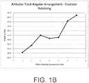
- angle ⁇ for various sizes of cruciate-retaining prosthesis designsare illustrated, with sizes 1 and 7 (on the horizontal axis) being the smallest and largest component sizes, respectively, and the intermediate sizes 2-6 growing progressively in size. For such cruciate-retaining designs, angle ⁇ ranges from 81 degrees to 89.5 degrees across the seven cruciate-retaining component sizes.
- angle ⁇ for seven sizesis illustrated for an ultra-congruent prosthesis design.
- Angle ⁇as shown on the vertical axis, ranges from 82 degrees to 88.7 degrees across the seven ultra-congruent component sizes.
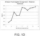
- angle ⁇ for eleven sizes of posterior-stabilized prosthesis designsare illustrated, with sizes 1 and 11 (on the horizontal axis) being the smallest and largest component sizes, respectively, and the intermediate sizes 2-10 growing progressively in size.
- Angle ⁇again on the vertical axis, ranges from 81.7 degrees to 86.7 degrees across the eleven posterior-stabilized component sizes.
- Figs. 1B-1Dall illustrate a family of tibial bearing components within a given design class (i.e., posterior-stabilized, ultra-congruent or cruciate-retaining), in which each family exhibits an upward trend in angle ⁇ as the prosthesis size grows larger.
- angle ⁇experiences a minimum value for the smallest component size and a largest value for the largest component size, with angle ⁇ in intermediate component sizes following an upward trend from smallest-to-largest.
- the next-largest sizewill define a decreased angle ⁇ as compared to the next-smallest size, as illustrated in Figs. IB-ID.
- Angle ⁇is less than angle ⁇ , and deviates from angle ⁇ by any amount greater than 0 degrees.
- angle ⁇is less than angle ⁇ by as little as 0.01 degrees, 0.4 degrees or 1 degree and as large as 6 degrees, 8.8 degrees or 15 degrees, or may be any value within any range defined by any of the foregoing values.
- the difference between angle ⁇ and angle ⁇generally smaller for small prosthesis sizes and larger for large prosthesis sizes.
- the rotation of articular tracks 26, 28 with respect to posterior lines 32, 34rotates or "clocks" tibial bearing component 12 into a counterclockwise orientation, as viewed from above, as compared to a non-rotated or centered orientation (in which angles ⁇ and/or ⁇ would be 90-degrees).
- clockingcan be thought of as rotation of the proximal, articular surface of a tibial bearing component while leaving the distal, baseplate-contacting surface non-rotated.
- Clocking in accordance with the present disclosureis therefore analogous to disconnecting articular compartments 16, 18 from distal surface 60, rotating articular compartments 16, 18 in a counterclockwise direction (as viewed from above), and reconnecting articular compartments 16, 18 to distal surface 60 in the new, rotated orientation.
- the structure and arrangement of tibial bearing component 12provides means for clocking articular tracks 26, 28.
- tibial bearing component 12promotes clinically successful prosthesis function by providing a correct orientation and position of the tibiofemoral "bearing couple" with respect to one another.
- the bearing coupleis comprised of femoral component 20 and tibial bearing component 12.
- articular compartments 16, 18are fixed to tibial baseplate 14 and therefore the tibial component defines the articular surface orientation with respect to tibia T (see, e.g., Fig. 3A ).
- Femoral component 20which is mounted to the distal end of the femur F, is not mechanically coupled to tibial bearing component 12, but instead articulates therewith along an articular profile influenced by the mating articular surfaces of tibial bearing component 12 and femoral component 20.
- the placement and articular geometry of tibial bearing component 12helps establish the lower (distal) half of the bearing couple.
- tibial bearing component 12provides smooth cooperation with the knee's soft tissues during in vivo knee articulation by ensuring that the articular bearing motion is properly oriented relative to the femur to deliver desired knee kinematics, range of motion (ROM) and stability.
- this cooperationpromotes decreased material wear in tibial bearing component 12, enhanced prosthesis stability, proper knee balance, and high ROM.
- tibial baseplate 14substantial coverage provided by tibial baseplate 14 and the clocked orientation of articular tracks 26, 28 with respect thereto encourages proper rotation of tibial bearing component 12 upon implantation.
- a bone-contacting surface of a properly sized tibial baseplate 14is mated with a resected tibia, the asymmetric periphery thereof results in substantial coverage of the resected proximal surface and largely controls the rotational orientation thereof.
- a detailed description of the periphery of tibial baseplate 14 and the attendant substantial coverage of a resected proximal tibiais described in U.S. Patent Application Publication No.
- the amount of rotation or "clocking" of articular tracks 26, 28may vary depending on prosthesis design and/or prosthesis size (as described above).
- a second tibial bearing component 12may be provided which defines a different magnitude of clocking but is otherwise identical to the first tibial bearing component 12.
- two tibial bearing components 12 useable with a common tibial baseplate 14 and femoral component 20 - but each with different levels of clocking -may be provided and chosen by a surgeon preoperatively or intraoperatively.
- a set of three or more tibial bearing components 12may be provided, each sharing a common size and prosthesis design, but all having different levels of clocking.
- medial and lateral articular compartments 16, 18define distal-most points 42, 44, respectively.
- Distal-most points 42, 44are coincident with medial and lateral articular tracks 26, 28, respectively, and represent the distal-most points from a sagittal perspective on articular tracks 26, 28 when tibial bearing component 12 is implanted upon tibia T with an anteroposterior slope S of 5 degrees.
- Anteroposterior slope Sreferences a zero degree slope line 46, which is defined by a generally transverse reference plane normal to anatomic axis A T of tibia T.
- proximal and distal directionsare directions normal to the reference plane (and, therefore, parallel to anatomic axis A T after implantation of tibial prosthesis 10).
- Tibial bearing component 12is a "high-flexion" prosthetic component, in that the geometry and configuration of articular compartments 16, 18 cooperate with a femoral component (e.g., femoral component 20 of Figs. 4A and 4B ) to allow a large total range of motion.
- a high-flexion knee prosthesismay enable a flexion range of as little as 130 degrees, 135 degrees, or 140 degrees and as large as 150 degrees, 155 degrees or 170 degrees, or may enable any level of flexion within any range defined by any of the foregoing values.
- enablement of high flexionrefers to the ability of a prosthesis to reach a given level of flexion by articulation of condyles 22, 24 with articular compartments 16, 18 and without impingement of any prosthesis structures with non-articular prosthesis surfaces.
- tibial bearing component 12enables high prosthesis flexion as described below, it is of course appreciated that the actual level of flexion achievable for any given patient is also dependent upon various anatomical and surgical factors.
- tibial bearing component 12high flexion may be enabled by one or both of two features.
- tibial bearing component 12includes differential heights H L , H M , with H L less than H M to facilitate posterior rollback of lateral condyle 24 in deep flexion (as described in detail below).
- heights H L , H Mare measured normal to slope line 46.
- the medial/posterior periphery of tibial bearing component 12includes posterior chamfer surface 27 (disposed at the posterior periphery of medial articular compartment 16, as shown in Fig. 3A ), which slopes in a posterior direction from proximal-to-distal.
- Chamfer 27creates an absence of a vertical peripheral wall immediately posterior of medial articular compartment 16, thereby creating a corresponding space the adjacent femoral bone and/or adjacent soft tissues in deep flexion.
- An exemplary embodiment of posterior/medial chamfer 27is described in detail in U.S. Patent Application Publication No. 2012/0101585, filed September 9, 2011 and entitled MOTION FACILITATING TIBIAL COMPONENT FOR A KNEE PROSTHESIS (Attorney Docket No. ZIM0815-04).
- High flexionis also accommodated by a differential in curvature between medial and lateral condyles 22, 24.
- lateral condyle 24 of femoral component 20may have a larger radius of curvature than medial condyle 22 thereof.
- An exemplary femoral componentis described in U.S. Patent No. 6,770,099, filed November 19, 2002 , titled FEMORAL PROSTHESIS.
- the larger lateral condyle 24 of femoral component 20tends to travel a greater distance along lateral articular track 28 of tibial bearing component 12 as compared to the smaller medial condyle 22 of femoral component 20.
- This difference in distance traveled over a given range of knee flexionmay be described as "big wheel / little wheel” movement, and is a feature which enables high flexion of the knee prosthesis by encouraging advancement of lateral condyle 24 toward the posterior edge of lateral articular compartment 18 at high levels of flexion.
- distal-most points 42, 44are shifted anteriorly with respect to predicate prostheses which enable comparably high levels of flexion, as described below.
- the relative anterior/posterior location of distal-most points 42, 44are measured by the distances AP DM , AP DL of distal-most points 42, 44 from the anterior edge of the tibial prosthesis ( Figs. 3A and 3B ).
- distances AP DM , AP DLmay each be expressed as a percentage of the overall anteroposterior extent AP M , AP L of medial and lateral prosthesis portions, which is inclusive of tibial bearing component 12 and tibial baseplate 14 ( Figs. 1A , 3A and 3B ) and is measured along the extrapolated articular tracks 26, 28 (as shown in Fig. 1A and described herein). For example, if distal-most point 42 were located in the middle of overall anteroposterior extent AP M of medial articular compartment 16, then distal-most point 42 would be considered to be disposed at an anteroposterior location of approximately 50%.
- distal-most point 42were located near the posterior edge of articular compartment 16, then distal-most point would be near a 100% anteroposterior location. Conversely, if distal-most point 42 were located near the anterior edge of articular compartment 16, the distal-most point 42 would be near a 0% anteroposterior location.
- medial anterior/posterior extent AP M ( Fig. 1A ) of the medial portion of tibial baseplate 14is found by extrapolating medial articular track 26 anteriorly and posteriorly to intersect the periphery of baseplate 14 (in similar fashion to the intersection points used to define posterior line 34 described above), then measuring the distance between the resulting medial posterior and anterior intersection points.
- lateral anterior/posterior extent AP L ( Fig. 1A ) of the lateral portion of tibial baseplate 14is found by extrapolating the linear anterior portion of lateral articular track 28 anteriorly and posteriorly to intersect the periphery of baseplate 14, then measuring the distance between the resulting lateral posterior and anterior intersection points.
- a graphical representation of the anterior/posterior position of medial distal-most point 42( Fig. 3A ) is illustrated as compared to predicate high-flexion and non-high-flexion prostheses.
- the anterior/posterior position of medial distal-most point 42( Fig. 3A ) is in the range of 59% to 63% when implanted at an anterior/posterior slope S equal to 5 degrees.
- one prior art high-flexion deviceis the Zimmer Natural Knee Flex Ultracongruent Tibial Bearing Component, which places its corresponding medial distal-most point in the range of 67% and 70% when implanted at a slope angle S of 5 degrees.
- the prior art Zimmer Natural Knee Flex Ultracongruent Tibial Bearing Componentdefines medial low points which are consistently posterior of medial distal-most point 42.
- the prior art Zimmer Natural Knee II Ultracongruent Tibial Bearing Componentplaces its corresponding medial distal-most point between 63% and 68% when implanted at a slope angle S of 5 degrees, but the Zimmer Natural Knee II Ultracongruent Tibial Bearing Component does not enable high flexion at least up to 130 degrees.
- distal-most point 44has an anterior/posterior position of between 68% and 74%.
- the prior art high-flexion designplaces such lateral distal-most points at between 70% and 73% when implanted at a slope angle S of 5 degrees.
- the non-high-flexion prior art designplaces its distal-most point at between 66% and 70.5% when implanted at a slope angle S of 5 degrees.
- the present ultracongruent prosthesisblends a high-flexion design enabling at least 130 degrees of knee flexion with low points that are relatively further anterior as compared to prior art ultracongruent prostheses.
- this anterior low-point shiftdiscourages "paradoxical movement," or movement between the femur and tibia in an opposite pattern from normal articulation.
- the anterior shift of distal-most points 42, 44inhibits anterior sliding of femoral component 20 with respect to tibial bearing component 12 when the knee is articulating from extension toward early flexion.
- Such early-flexion articulationis normally accompanied by a slight posterior shift in the contact points between condyles 22, 24 of femoral component 20 and articular compartments 16, 18 of tibial bearing component 12. This posterior shift is facilitated - and a paradoxical anterior shift is inhibited - by the relative anterior positioning of distal-most points 42, 44. Meanwhile, the potential of high-flexion articulation is preserved by the high-flexion features incorporated into tibial bearing component 12, as described in detail herein.
- anterior shift of articular surface low pointsrefers to exemplary ultracongruent (UC) type tibial bearing components.
- UCultracongruent
- PSposterior-stabilized
- femoral component 220 and tibial bearing component 212are shown.
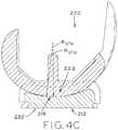
- femoral component 20 and tibial bearing component 12will be described in the context of Figs. 4A-4C , it being appreciated that any potential prosthesis design (e.g., PS, UC and CR type femoral components) may each include the present described features as noted above.
- Femoral component 20cooperates with tibial bearing component 12 to provide relatively low conformity between lateral condyle 24 and lateral articular compartment 18, and relatively high conformity between medial condyle 22 and medial articular compartment 16.
- a convex surfacemay be considered to be highly conforming with a corresponding concave surface where the two surfaces have similar or identical convex and concave geometries, such that the convex surface "nests" or tightly interfits with the concave surface.
- the hemispherewould have no conformity with an adjacent flat or convex surface.
- Femoral condyles 22, 24define a coronal conformity with tibial articular compartments 16, 18, respectively, as shown in Fig. 4A .
- femoral condyles 22, 24define sagittal conformity with the corresponding articular compartments 16, 18, respectively, as shown in Fig. 4B .
- medial condyle 22cooperates with medial articular compartment 16 to define a medial conformity comprised of both a medial sagittal conformity and a medial coronal conformity.
- lateral femoral condyle 24cooperates with lateral articular compartment 18 to define a lateral conformity comprised of the lateral sagittal conformity and lateral coronal conformity.
- any given component of conformityis defined as a ratio of two radii.
- a lateral coronal conformityis defined by the ratio of the coronal radius of lateral articular compartment 18 of tibial bearing component 12 along lateral articular track 28, which is illustrated as radius R CTL (where CTL stands for coronal, tibial, lateral) to the corresponding coronal radius of lateral condyle 24 of femoral component 20, illustrated as radius R CFL (where CFL denotes coronal, femoral, lateral).
- R CTLwhere CTL stands for coronal, tibial, lateral
- R CFLwhere CFL denotes coronal, femoral, lateral
- medial coronal conformityis defined by the ratio R CTM :R CFM (where M denotes medial).
- Sagittal conformity between lateral condyle 24 and lateral articular compartment 18is defined as the ratio R STL :R SFL ( Fig. 4B , where S denotes sagittal, F denotes femoral, T denotes tibia, and L denotes lateral).
- Medial condyle 22defines sagittal conformity with medial articular compartment 16 in a similar fashion, as R STM :R SFM ( Fig. 4C ).
- lateral sagittal conformity ratio R STL :R SFLmay be between 1.0 and 1.7
- medial sagittal conformity ratio R STM :R SFMmay be between 1.0 and 1.9
- lateral ratio R STL :R SFLgreater than medial ratio R STM :R SFM by at least 0.2 through at least a portion of the flexion range.
- lateral sagittal conformity ratio R STL :R SFLmay be between 1.4 and 1.8
- medial sagittal conformity ratio R STM :R SFMmay be between 1.0 and 1.8
- lateral ratio R STL :R SFLgreater than medial ratio R STM :R SFM by at least 0.4 through at least a portion of the flexion range.
- lateral sagittal conformity ratio R STL :R SFLmay be between 1.1 and 2.6
- medial sagittal conformity ratio R STM :R SFMmay be between 1.1 and 2.2
- lateral ratio R STL :R SFLgreater than medial ratio R STM :R SFM by at least 0.5 through at least a portion of the flexion range.
- Predicate deviceshave defined varying levels of medial and lateral conformity between the femoral condyles thereof and the corresponding tibial articular compartments.
- the lateral conformity(defined by ratios R STL :R SFL and R CTL : R CFL ) is approximately equal to the lowest lateral conformity defined by the predicate devices, while the medial conformity (defined by ratios R STM :R SFM and R CTM :R CFM ) is approximately equal to the highest medial conformity defined by predicate devices.
- jump heightrefers to the proximal/distal distance that a portion of femoral component 20 must traverse to sublux from the tibial bearing component 12.
- medial and lateral articular compartments 16, 18 of tibial bearing component 12are shown in cross-section to illustrate the location of distal-most points 42, 44.
- the vertical distance between respective distal-most points 42, 44 ( Figs. 3A, 3B ) on the articular surface of tibial bearing component 12 to the highest point at the edge of such articular surfaceis the jump height of tibial bearing component 12.
- medial femoral condyle 22Fig.
- such "highest point”is the point at which a posterior extrapolation of medial articular track 26 reaches its proximal peak as the extrapolated line advances toward the posterior edge of the tibial bearing periphery.
- H Mmay be referred to as the posterior jump height established by the particular curvature and geometry of medial articular compartment 16.
- Jump height H Mis designed to provide an appropriately low barrier to desired posterior translation of the contact point between medial condyle 22 and medial compartment 16 along medial articular track 26, while also being sufficiently high to ensure that condyle 22 remains safely engaged with articular compartment 16 throughout the range of flexion provided by the knee prosthesis.
- lateral jump height H Lis lower than medial jump height H M .
- setting H L lower than H Mfacilitates femoral rollback by presenting a relatively lower barrier to lateral condyle 24 to traverse the posterior arcuate portion 30 of lateral articular track 28 when the knee prosthesis is in deep flexion.
- the height differential between lateral and medial jump heights H L , H Mare between 0.4 mm and 2.3 mm, which has been found to be an ideal range in order to facilitate femoral rollback while maintaining appropriate barrier to subluxation in both medial and lateral compartments 16, 18.
- Fig. 3Cillustrates the height differential between jump heights H L , H M for eleven sizes of a posterior-stabilized tibial component design in accordance with the present disclosure, when such posterior-stabilized components are implanted with a tibial slope angle S ( Figs. 3A and 3B ) of 3 degrees.
- the jump height differentialranges from 1.15 mm in the smallest prosthesis size, then trends generally downwardly to a minimum of 0.45 mm for the seventh of 11 sizes.
- the jump height differentialmay be as large as 2.68 mm. It is contemplated that a jump height differential up to 3 mm may be used with prostheses according to the present disclosure.
- Fig. 3Dgraphically depicts the jump height differentials between jump heights H L , H M for seven sizes of an ultra-congruent tibial component design in accordance with the present disclosure, when such ultra-congruent components are implanted with a tibial slope angle S ( Figs. 3A and 3B ) of 5 degrees.
- the jump height differentialranges from 2.25 mm in the smallest prosthesis size, then trends generally downwardly to a minimum of 0.56 mm for the largest of the seven sizes.
- jump height differential for the above-mentioned prior art high-flexion prosthesisi.e., the Zimmer Natural Knee Flex Ultracongruent Tibial Bearing Component discussed above, range from 0.09 mm to 0.39 mm.
- the jump height differentialranges from 0.22 mm to 0.88 mm.
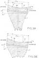
- spine 38 of tibial bearing component 12defines posterior articular surface 48, which is designed to articulate with femoral cam 40 ( Fig. 2 ) of femoral component 20 during prosthesis articulation, and particularly in mid- and deep flexion.
- posterior articular surface 48defines a progressively angled surface from a proximal, symmetric beginning to an angled distal end. This progressive angling accommodates external rotation of femoral component 20 in deep flexion.
- initial contact line 50represents the line of contact between femoral cam 40 and posterior surface 48 when femoral cam 40 initially contacts spine 38 during flexion
- deep flexion contact line 52represents the line of contact therebetween when femoral cam 40 has moved posteriorly down posterior surface 48 to a deep flexion orientation.
- the total distance traversed by femoral cam 40 along posterior surface 48is referred to as the articular extent of posterior surface 48 as measured along a proximal/distal direction. In Fig. 5A , this articular extent may be represented as the distance from initial contact line 50 to deep-flexion contact line 52.
- the articular extent of posterior surface 48may be as little as 2 mm, 3 mm or 5 mm and as large as 10 mm, 15 mm or 20 mm, or may be any value within any range defined by any of the foregoing values.
- spine 38is considered to be bisected by a sagittal plane into medial and lateral halves, such that a posterior spine centerline is formed along the intersection between the bisecting sagittal plane and posterior surface 48.
- Posterior surface 48defines a series of medial/lateral tangent lines, each of which is tangent to posterior surface 48 at the spine centerline.
- a medial/lateral tangent line at the proximal end of posterior articular surface 48is illustrated as initial contact line 50 in Fig. 5A
- a medial/lateral tangent line at the distal end thereofis illustrated as deep flexion contact line 52.
- initial contact line 50will be coincident with the proximal-most medial/lateral tangent line and deep-flexion contact line 52 will be coincident with the distal-most medial/lateral tangent line, as shown in Fig. 5A and described herein.
- the actual lines of contact between femoral cam 40 and posterior surface 48 during prosthesis usemay deviate slightly from the intended medial/lateral tangent lines.
- prosthesis characteristicssuch as contact lines 50, 52 are described solely in terms of the designed articular profile of the prosthesis when tibial and femoral components 12, 20 are articulated through their nominal range of motion.
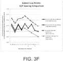
- contact lines 50 and 52are not parallel, with contact line 50 running medially/laterally along a direction parallel to a coronal plane, and contact line 52 oblique to the coronal plane such that line 52 advances posteriorly as it extends laterally (and, concomitantly, also advances anteriorly as it extends medially). Both of lines 50, 52 are parallel to the transverse plane, such that the angle formed between lines 50, 52 is solely with respect to the coronal plane.
- the angle formed between initial contact line 50 and deep-flexion contact line 52may be as large as 3 degrees. However, it is contemplated that other exemplary embodiments may form such angle at 7 degrees, and that an angle up to 10 degrees may be used in some instances.
- Posterior articular surface 48defines medial surface line 48A, extending between initial contact line 50 and deep flexion contact line 52. As described in detail below, if posterior articular surface 48 defined articular surface line 48A across the medial/lateral extent of spine 38, spine 38 would be symmetric and external femoral rotation in deep flexion would not be accommodated in the manner provided by the asymmetric spine 38 of the present disclosure.
- FIG. 5Ca cross-section medially/laterally bisecting spine 38 is shown.
- Articular surface line 48Bis defined by posterior articular surface 48 at this cross-section, and is shown juxtaposed against a hidden line representing articular surface line 48A from Fig. 5B .
- lines 48A and 48Bboth extend from a common proximal point along initial contact line 50. However, the distal point of line 48B (along deep flexion contact line 52) has moved posteriorly with respect to the distal end of line 48A.
- This posterior movementreflects a progressively increasing material buildup along the base or distal end of posterior articular surface 48, such that this base is increasingly "augmented” by additional spine material as the deep flexion contact line 52 traverses from medial to lateral.
- spine 38is effectively thicker in the region of contact line 52 at the bisecting cross-section of Fig. 5C as compared to the medially-biased cross-section of Fig. 5B .
- Fig. 5Dit can be seen that the process of material thickening or augmentation described above with respect to Fig. 5C has grown and further intensified.
- line 48Cstill originates from a common proximal point with lines 48A, 48B along initial contact line 50, the distal end of line 48C along deep flexion contact line 52 has moved further posteriorly with respect to line 48A.
- the base of spine 38is thicker still.
- the changing geometry of posterior articular surface 48 of spine 38 from medial to lateralhas the effect of imparting an angled appearance to the distal, deep-flexion portion of posterior articular surface 48.
- the remainder of spine 38is generally symmetrical about the sagittal plane, as illustrated in Fig. 5A .
- the angle of the surface encountered by femoral cam 40changes, thereby changing the angle of the medial/lateral tangent lines described above with respect to the coronal plane.
- the initial transition from non-angled contact lines (e.g., initial contact line 50) to angled contact lines (e.g., deep-flexion contact line 52)is spaced from a proximal terminus of posterior surface 48 by a distance of between 0% and 100% of the total proximal/distal extent of posterior articular surface 48 (i.e., the transition may occur immediately or at the very end of the flexion range, or anywhere in between).
- the proximal/distal extent of posterior articular surface 48is the total distance traversed by femoral cam 40 throughout the range of flexion motion. In the illustrative embodiment of Fig.
- this total proximal/distal articular extent of posterior articular surface 48(i.e., the distance between a proximal start point and a distal end point) may be as little as 2 mm, 3 mm or 4 mm and as large as 17 mm, 18.5 mm or 20 mm, or may be any value within any range defined by any of the foregoing values.
- the proximal end pointcoincides with an initial contact between cam 40 and posterior articular surface 48 at a prosthesis flexion of between 75 degrees flexion and 93 degrees flexion, while the distal end point is at a final contact between cam 40 and posterior articular surface 48 at a prosthesis flexion of 155 degrees.
- the extent of the angling of posterior articular surface 48changes with changing levels of flexion. More particularly, the angle grows by an amount corresponding to the expected increase in external rotation of femoral component 20 as flexion progresses, thereby ensuring that line contact is made between femoral cam 40 and posterior articular surface 48 throughout the range of flexion of prosthesis 10.
- a maximum external rotation of femoral component 20occurs between 120 degrees flexion and 155 degrees flexion.
- femoral cam 40would transition from line contact along initial contact line 50 to an increasingly point-like contact near the medial edge of posterior articular surface 48.
- femoral cam 40is symmetrical in nature, such that accommodation of deep flexion external rotation without diminishment of cam/spine contact area is accomplished solely through the above described lateral augmentation of posterior articular surface 48 at the distal base of spine 38.
- Femoral cam 40is described in detail in: U.S. Provisional Patent Application Serial No. 61/561,658, filed on November 18, 2011 and entitled FEMORAL COMPONENT FOR A KNEE PROSTHESIS WITH IMPROVED ARTICULAR CHARACTERISTICS (Attorney Docket: ZIM0915); U.S. Provisional Patent Application Serial No.
- Patent Application filed on even date herewith and entitled FEMORAL COMPONENT FOR A KNEE PROSTHESIS WITH IMPROVED ARTICULAR CHARACTERISTICS(Attorney Docket: ZIM0915-07); U.S. Patent Application filed on even date herewith and entitled FEMORAL COMPONENT FOR A KNEE PROSTHESIS WITH IMPROVED ARTICULAR CHARACTERISTICS (Attorney Docket: ZIM0915-08); and in U.S. Patent Application filed on even date herewith and entitled FEMORAL COMPONENT FOR A KNEE PROSTHESIS WITH IMPROVED ARTICULAR CHARACTERISTICS (Attorney Docket: ZIM0915-09).
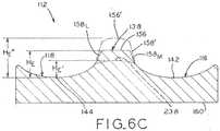
- Figs. 6A and 6Billustrate an ultra congruent (UC) type tibial bearing component 112 designed for use with femoral component 120 lacking the femoral cam 40 found on femoral component 20 ( Fig. 2 ).
- ultra congruent tibial bearing componentssuch as component 112 lack spine 38 found on bearing component 12.
- Tibial bearing component 112 and femoral component 120are otherwise substantially similar to tibial bearing component 12 and femoral component 20 described above, with reference numerals of components 112 and 120 analogous to the reference numerals used in components 12 and 20 respectively, except with 100 added thereto.
- tibial bearing component 112 and femoral component 120correspond to similar structures denoted by corresponding reference numerals of tibial bearing component 12 and femoral component 20, except as otherwise noted.
- femoral component 120is similar or identical to cruciate-retaining (CR) femoral component 220 ( Figs. 4A and 4B ).
- posterior eminence 138may be provided.
- femoral component 120includes intercondylar notch 154 which, when in an extension orientation as shown, defines a width which provides minimal medial lateral clearance with posterior eminence 138.
- any forces tending to urge femoral component 120 medially or laterally upon the proximal articular surface of tibial bearing component 112encounter resistance as the inwardly facing lateral and medial sidewalls 155 L , 155 M of intercondylar notch 154 engage the lateral and medial sidewall portions 158 L , 158 M of sidewall 158 of posterior eminence 138.
- anterior portion 158 A of sidewall 158 of posterior eminence 138is generally arcuate and defines radius R EA , thereby corresponding in shape to the inwardly facing anterior wall 155 A defining radius R NA which joins lateral and medial sidewalls 155 L , 155 M to form intercondylar notch 154.
- radius R EAis defined at the outer periphery of proximal surface 156, i.e., at the point where the planarity of proximal surface 156 gives way to the distally sloping profile of sidewall 158.
- radius R NA of anterior wall 155 Ais measured at that portion of anterior wall 155 A which is complimentary to radius R EA when femoral component 120 is seated upon tibial bearing component 112 in an extension orientation.
- radius R EAmay be 4 mm and radius R NA may be 6 mm, such that a minimal clearance is provided between posterior eminence 138 and intercondylar notch 154 in the fully extended position of Fig. 6A .
- proximal surface 156 to sidewall 158is gradual and sloped, such that every potentially articular portion of posterior eminence defines a radius of at least 1 mm, including the sagittal/coronal radii R SC1 , R SC2 defined by sidewall 158.
- Radii R SC1 , R SC2are shown denoted only in the sagittal perspective in Fig. 6D , it being understood that radii R SC1 , R SC2 also extend around lateral and medial sidewall portions 158 L , 158 M .
- radii R SC1 , R SC2extend around the medial, anterior and lateral portions of sidewall 158, thereby forming the gradual rounded transition between proximal surface 156 to the surrounding articular surfaces of ultracongruent tibial bearing component 112.
- any section plane perpendicular to a transverse planee.g., the transverse and coronal planes
- any of lateral, medial and anterior sidewall portions 158 L , 158 M , 158 A of sidewall 158will define radii greater than 1 mm at such sidewall portions 158 L , 158 M , 158 A , such as radii R SC1 , R SC2 .
- posterior face of posterior eminence 138which forms a portion of peripheral sidewall 172 of tibial bearing component 112, is not designed for articulation with any structure as femoral component 120 lacks any structure bridging the gap between medial and lateral condyles 122, 124 (such as, for example, femoral cam 40 of posterior-stabilized femoral component 20).
- intercondylar notch 154ascends the anterior portion of sidewall 158, gradually “beaching” or transitioning into contact between the patello-femoral groove adjacent intercondylar notch 154 and the medial and lateral portions of sidewall 158 over proximal surface 156.
- such transitionis designed to occur at 3.5 degrees of hyperextension (i.e., minus-3.5 degrees flexion), though other exemplary embodiments may experience the transition as high as 7 or 10 degrees of hyperextension. As shown in Fig.
- the level of hyperextensionis controlled by the distance between anterior wall 155 A of intercondylar notch 134 and anterior portion 158 A of sidewall 158 in extension (as shown in Fig. 6D ). This distance can be made smaller for an earlier engagement and larger for a later engagement.
- Fig. 6Aillustrates that angles ⁇ F , ⁇ T are formed by sidewalls 155 L , 155 M and 158 L , 158 M of intercondylar notch 154 and posterior eminence 138, respectively, and are both arranged to converge anterior of posterior eminence 138 as shown.
- Fig. 6Aillustrates that angles ⁇ F , ⁇ T are formed by sidewalls 155 L , 155 M and 158 L , 158 M of intercondylar notch 154 and posterior eminence 138, respectively, and are both arranged to converge anterior of posterior eminence 138 as shown.
- angles ⁇ F , ⁇ Tare measured in a transverse plane with femoral component 120 seated upon tibial bearing component 112 in an extension orientation. Angles ⁇ F , ⁇ T are large enough to guide and center femoral component 120 into engagement with posterior eminence 138 during hyperextension, but are small enough so that interaction between intercondylar notch 154 and posterior eminence 138 provides effective medial/lateral stability in extension and early flexion. In an exemplary embodiment, angle ⁇ T , is 21.5 degrees and angle ⁇ F ranges from 21 degrees to 23 degrees through a range of prosthesis sizes. However, it is contemplated that angles ⁇ F , ⁇ T would accomplish their dual roles of medial/lateral stability and hyperextension accommodation at any angle between 15 degrees and 30 degrees.
- the distal portion of the patellofemoral groove or sulcuswhich coincides with and gradually transitions into the anterior terminus of intercondylar notch 154, also has a shape which matches the profile of lateral and medial portions 158 L , 158 M of sidewall 158.
- this matching shape and volume between intercondylar notch 154 and posterior eminence 138cooperates with the gently sloped sidewall 158 to accommodate hyperextension by minimizing the abruptness of impact therebetween.
- the prior art Zimmer Natural Knee Flex Ultracongruent knee prosthesisavailable from Zimmer, Inc. of Warsaw, Indiana includes prior art tibial bearing component 112A having posterior eminence 138A having areas which define a radius of less than 1 mm, as shown in Fig. 6E .
- the angle formed between lateral and medial sidewall portions 158A L , 158A M of posterior eminence 138Ais substantially less than angle ⁇ T defined by posterior eminence 138. More particularly, the prior art angle is 9-12 degrees, while angle ⁇ T is between 21 and 23 degrees as noted above.
- intercondylar walls of the prior art femoral component designed for use with prior art tibial bearing component 112Ahas parallel intercondylar walls, i.e., no angle is formed between the intercondylar walls.
- the distance between posterior eminence 138A and the anterior edge of the intercondylar notch of the prior art femoral componentis larger than the corresponding distance defined by eminence 138 and anterior wall 155 A of the intercondylar notch of femoral component 120 ( Fig. 6D ), such that the prior art Zimmer Natural Knee Flex Ultracongruent knee prosthesis lacks the capability for hyperextension "beaching" as described above.
- medial/lateral stabilityis provided by the sloped surface provided by sidewall 158, and more particularly the height H E of proximal surface 156 over distal-most points 142, 144, of medial and lateral articular compartments 116, 118.
- posterior eminence 138is sized and shaped to cooperate with intercondylar notch 154 to provide steadily decreasing levels of medial/lateral constraint starting from a maximum at full extension and transition to a minimum at 90 degrees flexion, after which such constraint is no longer needed.
- lateral and medial sidewalls 155 L , 155 M of intercondylar notch 154diverge posteriorly from the anterior terminus of notch 154 (at anterior wall 155 A ), such that the effective width between lateral and medial sidewalls 155 L , 155 M becomes steadily greater than posterior eminence 138 as flexion progresses.
- additional medial/lateral space between posterior eminence 138 and intercondylar notchbecomes available as prosthesis 110 is transitioned into deeper flexion.
- An exemplary femoral component with such a divergent intercondylar notchis described in: U.S. Provisional Patent Application Serial No.
- Patent Application filed on even date herewith and entitled FEMORAL COMPONENT FOR A KNEE PROSTHESIS WITH IMPROVED ARTICULAR CHARACTERISTICS(Attorney Docket: ZIM0915-08); and in U.S. Patent Application filed on even date herewith and entitled FEMORAL COMPONENT FOR A KNEE PROSTHESIS WITH IMPROVED ARTICULAR CHARACTERISTICS (Attorney Docket: ZIM0915-09).
- Posterior eminence 138has a limited anterior/posterior extent which also operates to effect disengagement of posterior eminence 138 from intercondylar notch 154 at a desired level of prosthesis flexion, as described in detail below.
- posterior eminence 138is shaped to cooperate with intercondylar notch 154 to be functional only where its medial/lateral stability function is desired, and to avoid interaction with intercondylar notch 154 where such function is no longer required.
- posterior eminence 138accomplishes this balance by having a rounded shape that is complementary to intercondylar notch 154 of femoral component 120 as described above.
- the prior art Natural Knee Flex Ultracongruent knee prosthesisavailable from Zimmer, Inc. of Warsaw, Indiana, includes a tibial bearing component 112A ( Fig. 6E ) having a posterior eminence 138A which does not "interfit" with the corresponding femoral component in the manner described above.
- proximal surface 156is substantially flat and/or planar and rises above distal-most points 144, 142 by a height H E .
- height H Eis between 3.8 mm and 5.5 mm.
- height H Emay be as high as 10 mm, provided that anterior wall 155 A is appropriately angled so as to prevent presentation of a non-ramped surface to anterior portion 158 A of sidewall 158 of femoral intercondylar notch 154 during hyperextension.
- a traditional "cruciate retaining" tibial bearing component 212(Figs. 7A and 7B , described herein) includes intercompartmental eminence 238 which defines a reduced height H E ' and is not flat or planar in its proximal surface.
- height H E ' of intercompartmental eminenceis between 3.7 mm and 5.2 mm across a family of prosthesis sizes, but may have an alternative range of 2.0 mm - 5.5 mm in some embodiments.
- posterior eminence 138is distinguished from spine 38 of posterior-stabilized tibial bearing component ( Fig. 5A ) in that posterior eminence 138 is substantially shorter and defines a posterior surface that is non-articular.
- spine 38protrudes proximally from the surrounding articular surface by at least 21 mm.
- posterior eminence 138may define an increased height H E ", and may include a rounded proximal surface 156' within the scope of the present disclosure. More particularly, increased height H E " and rounded proximal surface 156' may be sized and shaped to match the distal end of the patellofemoral groove of femoral component 120, such that sidewalls 158' and proximal surface 156' make continuous contact around the adjacent periphery of the patellofemoral groove in hyperextension. Advantageously, this full-area contact may further reduce the contact pressures and impact magnitude experienced by posterior eminence 138 when femoral component 120 is hyperextended.
- Posterior eminence 138defines an anterior/posterior extent AP PE , which may be expressed in absolute terms or as a percentage of the corresponding overall anterior/posterior extent AP UC of ultracongruent tibial bearing component 112.
- anterior/posterior extent AP UCis measured at the same medial/lateral position as a sagittal plane bisecting posterior eminence 138.
- anterior/posterior extent AP PE of posterior eminence 138may be as little as 5 mm, 6 mm or 7 mm, and as much as 11 mm, 13 mm or 15 mm, or may be any value within any range defined by any of the foregoing values.
- This range of anterior/posterior extents AP PEcorrespond to a range of percentages of overall anterior/posterior extent AP UC for the respective sizes of tibial bearing component 112 that is as little as 10% or 18.7% and as much as 20.5% or 30%, or any percentage within any range defined by any of the foregoing values.
- an anterior/lateral corner of tibial bearing component 212may have material removed near the proximal edge thereof to create scallop 268.
- Scallop 268creates extra space for the adjacent iliotibial (IT) band, which could potentially impinge upon tibial bearing component 212 in some patients.
- scallop 268extends around the entirety of the anterior/lateral corner of tibial bearing component 212.
- scallop 268may be used in lieu of or in addition to an anterior/lateral pullback to avoid or minimize the impact of potential impingement of the iliotibial band on such corner.
- Scallop 268extends inwardly into the area of lateral articular compartment 218, and downwardly toward the distal, baseplate-contacting surface of tibial bearing component 212.
- scallop 268is a chamfer or fillet-like void in the periphery of tibial bearing component 212 which creates a space that may be occupied by nearby soft tissues that would otherwise impinge upon such periphery.
- Scallop 268may extend distally almost to the distal baseplate-contacting surface, or may extend a lesser amount distally.
- the inward (i.e., medial and posterior) extent of scallop into lateral articular compartment 218may be approximately equal to the distal extent, or may deviate from the distal extent.
- scallop 268occupies a 10-degree angular sweep around the anterior/lateral portion of the periphery of lateral articular compartment 218.
- scallops or relief spacesmay be provided around the periphery of tibial bearing component 212 to accommodate other adjacent soft tissues, such as the medial collateral ligament (MCL) and the lateral collateral ligament (LCL).
- Scallop 268 and any other scallops positioned for relief around other soft tissuesare sufficiently sized and shaped to provide relief space for the intended soft tissue throughout a full range of flexion, and for a wide variety of patients.
- Soft Tissue AccommodationAnterior/Medial Bulbous Flare.
- ultra-congruent type tibial bearing component 112is illustrated with a convex, bulbous flare 170 extending outwardly from peripheral sidewall 172.
- flare 170provides additional strength to medial compartment 116 at the anterior end thereof and protects adjacent soft tissues from abrasion, particularly the patellar tendon.
- sidewall 172extends generally vertically (i.e., in a proximal-distal direction) between the distal, baseplate-contacting surface 160 ( Fig. 8B ) and the proximal articular surfaces of tibial bearing component 112. Accordingly, a majority of the periphery of baseplate contacting surface 160 substantially fits within the proximal periphery of the associated tibial baseplate (i.e., baseplate 14 shown in Fig. 1A ).
- a detailed discussion of matching peripheries between a tibial baseplate and associated tibial bearing componentmay be found in U.S. Patent Application Publication No. 2012/0022659 filed July 22, 2011 and entitled "ASYMMETRIC TIBIAL COMPONENTS FOR A KNEE PROSTHESIS" (Attorney Docket ZIM0815-01).
- bulbous flare 170extends beyond the anterior/medial periphery of baseplate contacting surface 160, and therefore also extends beyond the corresponding periphery of the associated tibial baseplate when tibial bearing component 112 is fixed thereto (such as is shown in Fig. 1A in the context of tibial bearing component 12). Bulbous flare 170 thereby enables medial articular compartment 116 to "overhang" or extend anteriorly and medially beyond the periphery of tibial baseplate 14.
- this overhangallows an expanded anterior/medial and proximal reach of medial articular compartment 116, while obviating the need for a larger tibial baseplate.
- Avoiding the use of a larger baseplate sizeadvantageously prevents overhang of tibial baseplate 14 over a small patient bone, while the bulbous flare 170 of tibial bearing component 112 preserves a relatively large articular surface.
- tibial components incorporating bulbous flare 170are particularly suited to tibial prostheses for use in small stature patients, whose tibias commonly present a small proximal tibial resected surface which necessitates the use of a correspondingly small tibial baseplate 14.
- bulbous flare 170includes a convex curvature which extends up and around the proximal edge of medial articular compartment 116.
- this convex profile and associated soft proximal edgepresents only large-radius, "soft" edges to the patellar tendon, particularly in deep flexion prosthesis configurations.
- the convex curvature defined by bulbous flare 170defines a flare radius R BF ( Fig. 8B ) of at least 10 mm, which extends around a partially spherical surface.
- bulbous flare 170may also be formed as a complex shape incorporating multiple radii, such that bulbous flare 170 may be defined by any surface with convexity in transverse and sagittal planes.
- proximal/distal extent PD Ois the portion of peripheral sidewall 172 of tibial bearing component not covered by tibial baseplate 14 when tibial bearing component 12 is assembled thereto, and proximal/distal extent PD F of the convexity of flare 170 occupies at least 80% of a proximal/distal extent PD O .
- bulbous flare 170 at the anterior/medial portion of sidewall 172provides a buttress for the anterior edge of medial articular compartment 116, thereby enabling tibial bearing component 112 to readily absorb substantial anteriorly-directed forces applied by the femur during prosthesis use.
- a larger femoral component 120may be used in conjunction with a given size of tibial prosthesis.
- this larger femoral/smaller tibial prosthesis arrangementmay provide a closer match to a healthy natural knee configuration, and/or enhanced articulation characteristics.
- convex, bulbous shape of flare 170is that the soft, rounded appearance thereof minimizes the visual impact of an increased proximal height of medial articular compartment 116 and the increased anterior extent thereof past the periphery of baseplate contacting surface 160. This minimized visual impact allows sufficient levels of buttressing material to be added to the anterior/medial portion of sidewall 172 while preserving surgeon confidence that the overhang of flare 170 past baseplate contacting surface 160 is appropriate.
- medial and lateral articular compartments 16, 18 of tibial bearing component 12define substantially equal material thicknesses between their respective superior, dished articular surfaces and opposing distal (i.e. inferior) surface 60.
- the coronal "thickness profiles" of medial and lateral articular compartments 16, 18are substantial mirror images of one another about a sagittal plane bisecting tibial bearing component 12.
- a thickness profile of tibial bearing component 12may be defined as the changing material thicknesses of medial and/or lateral articular compartments 16, 18 across a defined cross-sectional extent, such as an anterior/posterior extent in a sagittal cross-section ( Figs. 9A-9D ) or a medial/lateral extent in a coronal cross-section ( Figs. 10A-10C ).
- medial and lateral articular compartments 16, 18 of tibial bearing component 12define sagittal thickness profiles ( Figs. 3A and 3B , respectively) between the superior dished articular surfaces of medial and lateral articular compartments 16, 18 and distal surface 60.
- These sagittal thickness profilescooperate with anterior/posterior slope S defined by the proximal respective surface of tibia T (described in detail above) to define the anterior/posterior locations of medial and lateral distal-most points 42, 44, respectively.
- distal-most points 42, 44may shift anteriorly or posteriorly in response to a change in the sagittal thickness profile or tibial slope S, or both.
- tibial bearing component 12shown generally in Figs. 9A-10C , the orientation of distal surface 60 with respect to the superior articular surfaces of medial and lateral articular compartments 16, 18 may be reconfigured. This reconfiguration alters the spatial relationship of distal surface 60 to the articular surfaces, thereby effecting a change in the orientation of such articular surfaces with respect to the proximal resected surface of tibia T. As described below, this spatial alteration may be used to offer alternative bearing component designs tailored to the specific needs of some patients, while avoiding the need to recut or otherwise alter the geometry of the proximal tibia.
- tibial bearing component 12is alteration of the sagittal thickness profile to increase or decrease the anterior/posterior "tilt" of the proximal articular surfaces of medial and lateral articular compartments 16, 18.
- tiltanterior/posterior "tilt" of the proximal articular surfaces of medial and lateral articular compartments 16, 18.
- lateral articular compartment 18is shown in Figs. 9A-9D and described detail below, it being understood that a similar geometric reconfiguration can be applied to medial compartment 16 in a similar fashion.
- tibial bearing component 12may tilt forward (such as to shift distal-most points 42, 44 anteriorly), he or she may recut the proximal tibia to reduce tibial slope S.
- increasing tibial slope Stilts tibial bearing component 12 backward and posteriorly shifts distal-most points 42, 44.
- a similar "tilting" of the tibial articular surface and shifting of sagittal distal-most pointsmay be accomplished without altering tibial slope S by using alternative tibial bearing components in accordance with the present disclosure, as described below.
- alternative tibial bearing componentsin accordance with the present disclosure, as described below.
- differing sagittal thickness profiles in the alternative componenteffects the same articular changes normally achieved by a change in tibial slope S.
- Tibial bearing component 312is shown superimposed over tibial bearing component 12, with distal surfaces 60 aligned such that changes to the articular surface of lateral articular compartment 18 are illustrated.
- Tibial bearing component 312features a sagittal radius R STL ' defining radius center C STL ' which is anteriorly shifted along direction A with respect to sagittal radius R STL and radius center C STL of tibial bearing component 12. This anterior shift reconfigures the spatial relationship of the articular surface of lateral articular compartment 18 with respect to distal surface 60.
- this anterior shiftmimics a reduction in tibial slope S, because alternative lateral articular compartment 18' defines an articular surface which is "anteriorly tilted" so as to shift distal-most point 44 anteriorly to the alternative distal-most point 44', as shown in the dashed-line articular surface profile of Fig. 9D .
- center C STL of radius R STLcould be shifted posteriorly to mimic an increase in posterior slope S by causing a posterior shift of distal-most point 44.
- a family of tibial bearing componentsmay be provided in which one component in the family has an anteriorly shifted center C STL as compared to the other component in the family.
- the surgeonmay intraoperatively choose from the family of components to accommodate the chosen slope S and place the distal-most points of articular compartments 16, 18 at a desired anterior/posterior location.
- components within the familymay have identical distal surfaces 60 such that each component in the family can be mounted to a common tibial baseplate 14.
- tibial bearing components 312A, 312Pare shown superimposed over tibial bearing component 12, with articular compartment 18 aligned such that changes in distal surfaces 60, 60A, 60P are illustrated.
- bearing component 312Aselectively thickens portions of the sagittal thickness profile of lateral articular compartment 18, thereby angling the distal surface thereof with respect to the superior articular surfaces.
- Alternative distal surface 60Adefines angle ⁇ A with respect to distal surface 60 of tibial bearing component 12.
- bearing component 312Aprogressively adds material to distal surface 60 along a posterior-to-anterior direction, such a minimum amount of added material is present at the posterior-most portion of distal surface 60 and a maximum amount of added material is present at the anterior-most portion of distal surface 60.
- alternative distal surface 60Ais otherwise identical to distal surface 60, such that either of distal surfaces 60, 60A can be mounted to the same tibial baseplate.
- the added material which defines distal surface 60A of tibial bearing component 312Aoperates in the manner of a wedge-shaped shim placed between distal surface 60 and the adjacent superior surface 62 of tibial baseplate 14, except that the added material of component 312A is unitarily or monolithically formed therewith.
- this wedge-shaped added materialtilts the articular surface of lateral articular compartment 18 posteriorly (i.e., the posterior portion of component 312A shifts distally relative to the anterior portion), thereby shifting distal-most point 44 posteriorly to alternative distal-most point 44A.
- the magnitude of the posterior tiltis controlled by increasing or decreasing angle ⁇ A ( Fig. 9A ).
- tibial bearing component 312P( Fig. 9B ) progressively adds material along an anterior-to-posterior direction, thereby adding a wedge-shaped portion of extra material to component 312P to define distal surface 60P.
- Distal surface 60Pis also identical to distal surface 60, such that component 312P can be attached to tibial baseplate 14.
- the superior articular surface of lateral articular compartment 18is anteriorly tilted (i.e., the anterior portion of component 312P shifts distally relative to the posterior portion).
- distal-most point 44is shifted anteriorly to alternative distal-most point 44P.
- the magnitude of the anterior tilt(and therefore, of the anterior low-point shift) is controlled by increasing or decreasing angle ⁇ P ( Fig. 9A ).
- tibial bearing component 12A similar selective thickening of tibial bearing component 12 may be employed to provide alternative bearing components which allow a surgeon to intraoperatively correct for varus/valgus deformities.
- alternative tibial bearing components 412L, 412Mdefine distal surfaces 60L, 60M which progressively add material along medial-to-lateral and lateral-to-medial directions, respectively, as compared to distal surface 60 of tibial bearing component 12.
- distal surfaces 60L, 60Mare otherwise identical to distal surface 60 such that any of components 12, 412M, 412L can be mounted to a common tibial baseplate 14.
- Distal surface 60Ldefines angle ⁇ L with distal surface 60, effectively placing the thickest part of a wedge-shaped shim of additional material underneath lateral articular compartment 18.
- distal surface 60Mdefines angle ⁇ M with distal surface 60, such that the increased thickness of the coronal cross-sectional profile is concentrated underneath the medial articular compartment 16.
- Fig. 10Billustrates tibial prosthesis 410L, which includes alternative tibial bearing component 412L having distal surface 60L mounted to superior surface 62 of tibial baseplate 14.
- Bearing component 412Lis juxtaposed the profile of tibial bearing component 12, which is shown in dashed lines.
- the superior articular surfaces of medial and lateral articular compartments 16, 18are tilted medially with respect to the resected surface of tibia T (i.e., the medial portion of component 412L shifts distally relative to the lateral portion) when tibial bearing component 412L is attached to tibial baseplate 14.
- Bearing component 412L defining such a medial tiltmay be employed, for example, to intraoperatively correct for a varus deformity in the knee of the patient without altering the geometry of the proximal tibial cut surface or replacing tibial baseplate 14.
- the magnitude of the medial tiltis controlled by increasing or decreasing angle ⁇ L ( Fig. 10A ).
- tibial bearing component 412Mis shown juxtaposed against the dashed line profile of tibial bearing component 12.
- Bearing component 412Mis similar to component 412L discussed above, except that distal surface 60M features a lateral tilt (i.e., the lateral portion of component 412M shifts distally relative to the medial portion) when tibial bearing component 412M is attached to tibial baseplate 14.
- Bearing component 412M defining such a lateral tiltmay be employed, for example, to intraoperatively correct for a valgus deformity in the knee of the patient without altering the geometry of the proximal tibial cut surface or replacing tibial baseplate 14.
- the magnitude of the lateral tiltis controlled by increasing or decreasing angle ⁇ M ( Fig. 10A ).
- a set or family of tibial bearing componentsmay be provided which includes any combination of tibial bearing components 12, 312A, 312P, 412M, and 412L. Further, multiple versions of components 312A, 312P, 412L, 412M may be provided, in which each version defines a unique value for angles ⁇ A , ⁇ P , ⁇ L , ⁇ M respectively.
- a surgeonmay intraoperatively select a tibial bearing component which positions distal-most points 42, 44 at a desired location, and/or corrects for varus or valgus deformities, without having to alter tibial slope S or change tibial baseplate 14.
- the geometry and curvature of the superior dished articular surfaces of medial and lateral articular compartments 16, 18will be identical for all components provided in the kit, such that no other changes to the articular characteristics of the tibial bearing component intermingle with the changes brought on by altering the thickness profile as described above.
- tibial baseplates described abovehave either reconfigured sagittal thickness profiles or reconfigured coronal thickness profiles, it is contemplated that tibial bearing components may be provided which incorporate reconfigurations to both the sagittal and coronal thickness profiles within a single tibial bearing component. Moreover, it is contemplated that any appropriate thickness profile or set of thickness profiles may be provided as required or desired for a particular application.
- a family of tibial bearing componentsobviates any need for a surgeon to recut the proximal surface of tibia T, and allows the surgeon to permanently implant tibial baseplate 14 while also preserving the intraoperative option to 1) alter the anterior/posterior tilt of the articular surfaces of medial and lateral articular compartments 16, 18, and/or 2) alter the medial/lateral tilt or the articular surfaces, such as for correction of a varus/valgus deformity.
- a tibial bearing component in accordance with the present disclosuremay be provided in a single-component design, i.e., not part of a kit, while still being designed to "alter" the tilt of the superior articular surface.
- the articular surface of an alternative bearing componentmay be designed to may mimic the articular surface of a "regular" tibial bearing component (such as component 12, described above), even though the two components are designed to cooperate with differing anteroposterior tibial slopes.
- tibial bearing componente.g., ultracongruent and posterior-stabilized
- differing classes of tibial bearing componentare designed to be used with differing tibial slopes.
- a surgeonmay wish to intraoperatively select between these differing component classes, which in turn may necessitate recutting of tibia T.
- ultracongruent tibial bearing component 112Figs.
- distal surface 160which defines an anterior/posterior slope with respect to medial and lateral articular compartments 116, 118 which effectively "tilts" the articular surfaces thereof forward sufficiently to render ultracongruent tibial bearing component 112 compatible with tibial slope S (shown in Figs. 3A and 3B and described in detail above) used for posterior-stabilized tibial bearing component 12.
- an ultracongruent-type tibial bearing componentmay be typically designed for use with a tibial slope S equal to 3 degrees, while other bearing component designs (e.g., posterior-stabilized designs) may use a 5 degree tibial slope S.
- ultracongruent tibial bearing component 112may be effectively "tilted anteriorly" by 2 degrees in the manner described above, such that the articular characteristics designed into the articular surfaces of tibial bearing component 112 are achievable with a 5-degree tibial slope S.
- a surgeonmay make a proximal cut of tibia T to create an anteroposterior slope S of 5 degrees, for example, while achieving articular characteristics normally associated with a tibial slope of 3 degrees by implanting tibial bearing component 112 on tibial baseplate 14.
- a surgeonmay have the freedom to choose intraoperatively between ultracongruent tibial bearing component 112 and posterior stabilized tibial bearing component 12 without having to alter tibial slope S or tibial baseplate 14.
- changing thickness profiles or the moving the center of sagittal curvature of an articular surface as described abovemay be accomplished with any combination of cruciate-retaining, ultracongruent and/or posterior-stabilized designs.
Landscapes
- Health & Medical Sciences (AREA)
- Orthopedic Medicine & Surgery (AREA)
- Physical Education & Sports Medicine (AREA)
- Cardiology (AREA)
- Oral & Maxillofacial Surgery (AREA)
- Transplantation (AREA)
- Engineering & Computer Science (AREA)
- Biomedical Technology (AREA)
- Heart & Thoracic Surgery (AREA)
- Vascular Medicine (AREA)
- Life Sciences & Earth Sciences (AREA)
- Animal Behavior & Ethology (AREA)
- General Health & Medical Sciences (AREA)
- Public Health (AREA)
- Veterinary Medicine (AREA)
- Prostheses (AREA)
Description
- The present disclosure relates to orthopaedic prostheses and, specifically, to articular tibial components in a knee prosthesis.
- Orthopaedic prostheses are commonly utilized to repair and/or replace damaged bone and tissue in the human body. For a damaged knee, a knee prosthesis may be implanted using a tibial baseplate, a tibial bearing component, and a distal femoral component. The tibial baseplate is affixed to a proximal end of the patient's tibia, which is typically resected to accept the baseplate. The femoral component is implanted on a distal end of the patient's femur, which is also typically resected to accept the femoral component. The tibial bearing component is placed between the tibial baseplate and femoral component, and may be fixed upon or slidably coupled to the tibial baseplate.
- The tibial bearing component, which may also be referred to as a tibial insert or meniscal component, provides an articular surface which interacts with the adjacent femur or femoral component during extension and flexion of the knee. The features and geometry of the articular surface influences the articular characteristics of the knee, such as by defining maximum knee flexion, internal/external rotation, femoral rollback, and behavior of the knee prosthesis in hyperextension, for example. Accordingly, substantial design efforts have previously focused on providing knee prosthesis components which preserve flexion range and promote a desired kinematic motion profile for the widest possible range of prospective knee replacement patients.
US4963152 discloses an Asymmetric prosthetic tibial component,US2011082558 discloses an artificial knee joint,US2011190898 discloses a cruciate-retaining knee prosthesis, andUS 2010292804 discloses systems and methods for providing deeper knee flexion capabilities for knee prosthesis patients. - The present disclosure describes an orthopaedic knee prosthesis including a tibial bearing component with articular features which operate to protect adjacent soft tissues of the natural knee, promote and/or accommodate desired articulation with an abutting femoral component, and facilitate expedient and effective implantation by a surgeon.
- Features which accommodate and protect soft tissues of the knee include 1) a relief or scallop formed in the proximal peripheral edge of the bearing component near an anterior/lateral corner thereof; and 2) a bulbous, convex flare protruding from the tibial bearing component sidewall at an anterior/medial portion thereof.
- Features which facilitate and/or promote improved articular characteristics include: 1) medial and lateral articular tracks, defined by respective dished articular compartments of the tibial bearing component, which are angled or "clocked" with respect to the posterior edge of the tibial bearing component; 2) a lateral articular compartment which defines a low conformity with the corresponding condyle of the abutting femoral component, and a medial articular compartment which defines a high conformity with the corresponding medial condyle of the femoral component; 3) medial and lateral articular tracks which, when viewed in respective sagittal planes, define a distal-most point which is anteriorly shifted with respect to predicate devices; 4) a lateral articular track which transitions from an early- and mid-flexion path that is generally linear along an anterior/posterior path as viewed in a transverse plane, to an arcuate path at the deep-flexion, posterior end of the articular track; 5) a lateral articular compartment which defines a relatively "flattened" posterior edge profile as compared to the posterior edge profile of the medial articular compartment to define a differential "jump height" therebetween; 6) for posterior-stabilized (PS) prostheses, a spine defining a posterior face which transitions from symmetrical in a proximal portion (i.e., a portion contacted by a femoral cam in early flexion) to an angled configuration in a distal portion (i.e., a portion contacted by the femoral cam in mid- to deep flexion); and 7) for ultra-congruent (UC) knee prostheses, a posterior eminence disposed between medial and lateral articular compartments that is sized and shaped to smoothly transition into a position within the intercondylar notch of an abutting femoral component when the knee prosthesis is hyperextended.
- Features which facilitate surgical implantation include provision of families of tibial bearing components from which the surgeon may choose intraoperatively. These families may include a range of component sizes, multiple components within a given size, and different component designs. For example, within a range of sizes, different components may feature varying clocking angles and/or levels of posterior "flattening" in the lateral articular compartment, as noted above. Within a given size, multiple components may feature differing thickness profiles, as viewed from a sagittal and/or coronal perspective, in order to selectively tilt or cant the articular surface. Moreover, various combinations of the design features described herein may be provided across several tibial bearing component designs, such as posterior-stabilized, ultra-congruent and cruciate-retaining designs.
- According to one example thereof, the present disclosure describes a tibial bearing component for articulation with a medial femoral condyle and a lateral femoral condyle, the tibial bearing component defining a tibial bearing component coordinate system comprising: a bearing component transverse plane extending along a medial/lateral direction and an anterior/posterior direction; a bearing component coronal plane extending along a proximal/distal direction and the medial/lateral direction, the bearing component coronal plane perpendicular to the bearing component transverse plane; and a bearing component sagittal plane extending along the anterior/posterior direction and the proximal/distal direction, the bearing component sagittal plane perpendicular to the bearing component transverse plane and the bearing component coronal plane, the tibial bearing component comprising: an articular surface and an opposing distal surface, the distal surface parallel to the bearing component transverse plane, the articular surface including medial and lateral dished articular compartments sized and shaped for articulation with the medial and lateral femoral condyles respectively, the medial and lateral dished articular compartments separated from one another by the bearing component sagittal plane, the lateral articular compartment comprising a plurality of coronal cross-sectional profiles defining a lateral set of coronal distal-most points spanning a lateral anterior/posterior extent, the lateral set of coronal distal-most points defining a lateral articular track, the lateral articular track having an anterior portion and a posterior portion, the anterior portion defining a nominally straight line when projected onto the bearing component transverse plane, the posterior portion defining a curved line when projected onto the bearing component transverse plane.
- According to another example thereof, the present disclosure describes a tibial bearing component for articulation with a medial femoral condyle and a lateral femoral condyle, the tibial bearing component defining a tibial bearing component coordinate system comprising: a bearing component transverse plane extending along a medial/lateral direction and an anterior/posterior direction; a bearing component coronal plane extending along a proximal/distal direction and the medial/lateral direction, the bearing component coronal plane perpendicular to the bearing component transverse plane; and a bearing component sagittal plane extending along the anterior/posterior direction and the proximal/distal direction, the bearing component sagittal plane perpendicular to the bearing component transverse plane and the bearing component coronal plane, the tibial bearing component comprising: an articular surface and an opposing distal surface, the distal surface parallel to the bearing component transverse plane, the articular surface including medial and lateral dished articular compartments sized and shaped for articulation with the medial and lateral femoral condyles respectively, the medial and lateral dished articular compartments separated from one another by the bearing component sagittal plane, the articular and distal surfaces bounded by a tibial bearing periphery, the lateral articular compartment comprising a plurality of coronal cross-sectional profiles defining a lateral set of coronal distal-most points spanning a lateral anterior/posterior extent, the lateral set of coronal distal-most points defining a lateral articular track having an anterior portion and a posterior portion, the anterior portion defining a nominally straight line when projected onto the bearing component transverse plane, the anterior portion of the lateral articular track extrapolated posteriorly to define a lateral intersection point with the tibial bearing periphery, the medial articular compartment comprising a plurality of coronal cross-sectional profiles defining a medial set of coronal distal-most points spanning a medial anterior/posterior extent, the medial set of coronal distal-most points defining a medial articular track, the medial articular track defining a nominally straight line when projected onto the bearing component transverse plane, the medial articular track extrapolated posteriorly to define a medial intersection point with the tibial bearing periphery, the lateral and medial intersection points joined by a posterior line of the tibial bearing component, at least one of the lateral articular track and the medial articular track defining an acute angle with the posterior line.
- The present invention is defined in
claim 1 and provides a family of tibial bearing components for articulation with femoral condyles, each of the family of tibial bearing components defining a tibial bearing component coordinate system comprising: a bearing component transverse plane extending along a medial/lateral direction and an anterior/posterior direction; a bearing component coronal plane extending along a proximal/distal direction and the medial/lateral direction, the bearing component coronal plane perpendicular to the bearing component transverse plane; and a bearing component sagittal plane extending along the anterior/posterior direction and the proximal/distal direction, the bearing component sagittal plane perpendicular to the bearing component transverse plane and the bearing component coronal plane, the family of tibial bearing components comprising a small tibial bearing component and a large tibial bearing component, the small and large tibial bearing components each comprising: an articular surface and an opposing distal surface, the distal surface parallel to the bearing component transverse plane, the articular surface including medial and lateral dished articular compartments sized and shaped for articulation with the femoral condyles, the medial and lateral dished articular compartments separated from one another by the bearing component sagittal plane, the articular and distal surfaces bounded by a tibial bearing periphery, the lateral articular compartment comprising a plurality of coronal cross-sectional profiles defining a lateral set of coronal distal-most points spanning a lateral anterior/posterior extent, the lateral set of coronal distal-most points defining a lateral articular track having an anterior portion and a posterior portion, the anterior portion defining a nominally straight line when projected onto the bearing component transverse plane, the anterior portion of the lateral articular track extrapolated posteriorly to define a lateral intersection point with the tibial bearing periphery, the medial articular compartment comprising a plurality of coronal cross-sectional profiles defining a medial set of coronal distal-most points spanning a medial anterior/posterior extent, the medial set of coronal distal-most points defining a medial articular track, the medial articular track defining a nominally straight line when projected onto the bearing component transverse plane, the medial articular track extrapolated posteriorly to define a medial intersection point with the tibial bearing periphery, the lateral and medial intersection points joined by a posterior line, at least one of the lateral articular track and the medial articular track defining an acute angle with the posterior line; and the acute angle of the small tibial bearing component less than the acute angle of the large tibial bearing component. - According to still another example thereof, the present disclosure describes a tibial bearing component for articulation with a medial femoral condyle and a lateral femoral condyle, the tibial bearing component defining a tibial bearing component coordinate system comprising: a bearing component transverse plane extending along a medial/lateral direction and an anterior/posterior direction; a bearing component coronal plane extending along a proximal/distal direction and the medial/lateral direction, the bearing component coronal plane perpendicular to the bearing component transverse plane; and a bearing component sagittal plane extending along the anterior/posterior direction and the proximal/distal direction, the bearing component sagittal plane perpendicular to the bearing component transverse plane and the bearing component coronal plane, the tibial bearing component comprising: an articular surface and an opposing distal surface, the distal surface parallel to the bearing component transverse plane, the articular surface including medial and lateral dished articular compartments sized and shaped for articulation with the medial and lateral femoral condyles respectively, the medial and lateral dished articular compartments separated from one another by the bearing component sagittal plane, the articular and distal surfaces bounded by a tibial bearing periphery, the lateral articular compartment comprising a plurality of coronal cross-sectional profiles defining a lateral set of coronal distal-most points spanning a lateral anterior/posterior extent, the lateral set of coronal distal-most points defining a lateral articular track having an anterior portion and a posterior portion, the medial articular compartment comprising a plurality of coronal cross-sectional profiles defining a medial set of coronal distal-most points spanning a medial anterior/posterior extent, the medial set of coronal distal-most points defining a medial articular track; and means for clocking the medial articular track and the lateral articular track into a counterclockwise clocked rotation.
- The above mentioned and other features and advantages of this disclosure, and the manner of attaining them, will become more apparent and the invention itself will be better understood by reference to the following description of embodiments of the invention taken in conjunction with the accompanying drawings, wherein:
Fig. 1A is a top plan view of a posterior stabilized (PS) tibial bearing component and baseplate in accordance with the present disclosure;Fig. 1B is a graph plotting the angular arrangement of articular tracks of various sizes of ultra-congruent tibial bearing components in accordance with the present disclosure;Fig. 1C is a graph plotting the angular arrangement of articular tracks of various sizes of posterior-stabilized tibial bearing components in accordance with the present disclosure;Fig. 1D is a graph plotting the angular arrangement of articular tracks of various sizes of cruciate-retaining tibial bearing components in accordance with the present disclosure;Fig. 2 is a perspective view of a femoral component in accordance with the present disclosure;Fig. 3A is a sagittal, cross-sectional view of a tibial bearing component in accordance with the present disclosure, taken through a medial articular compartment alongline 3A-3A ofFig. 1A ;Fig. 3B is a sagittal, cross-sectional view of a tibial bearing component in accordance with the present disclosure, taken through a lateral articular compartment along line 3B-3B ofFig. 1A ;Fig. 3C is a graph plotting the height differential between medial and lateral posterior compartment edges for various sizes of posterior-stabilized tibial bearing components in accordance with the present disclosure;Fig. 3D is a graph plotting the height differential between medial and lateral posterior compartment edges for various sizes of ultra-congruent tibial bearing components in accordance with the present disclosure;Fig. 3E is a graph plotting the anterior/posterior position of medial distal-most points of an articular surface for tibial bearing components in accordance with the present disclosure and prior art tibial bearing components (where prior art devices are listed as "predicate");Fig. 3F is a graph plotting the anterior/posterior position of lateral distal-most points of an articular surface for tibial bearing components in accordance with the present disclosure and prior art tibial bearing components(where prior art devices are listed as "predicate");Fig. 4A is an elevation, cross-sectional view of the tibial bearing shown inFig. 1A , together with a femoral component made in accordance with the present disclosure, taken in a coronal plane;Fig. 4B is an elevation, cross-sectional view of the tibial bearing and femoral components shown inFig. 4A , taken in a sagittal plane through the lateral articular condyle and articular compartment thereof;Fig. 4C is an elevation, cross-sectional view of the tibial bearing and femoral components shown inFig. 4A , taken in a sagittal plane through the medial articular condyle and articular compartment thereof;Fig. 5A is a top perspective view of the tibial bearing component shown inFig. 1A ;Fig. 5B is a sagittal, cross-sectional view of the tibial bearing component shown inFig. 5A , taken along theline 5B-5B ofFig. 5A ;Fig. 5C is another sagittal, cross-sectional view of the tibial bearing component shown inFig. 5A , taken along the line 5C-5C ofFig. 5A ;Fig. 5D is another sagittal, cross-sectional view of the tibial bearing component shown inFig. 5A , taken along the line 5D-5D ofFig. 5A ;Fig. 6A is a top plan view of an ultracongruent (UC) tibial bearing component made in accordance with the present disclosure;Fig. 6B is a perspective view of the tibial bearing component shown inFig. 6A , shown positioned atop a tibial baseplate;Fig. 6C is an elevation, cross-sectional view of the tibial bearing component shown inFig. 6A , taken in a coronal plane;Fig. 6D is a sagittal, elevation, cross-sectional view of the tibial bearing component ofFig. 6A , in combination with a femoral component;Fig. 6E is a fragmentary, anterior perspective view of a prior art ultracongruent (UC) tibial bearing component, illustrating a posterior eminence thereof (where prior art devices are listed as "predicate");Fig. 7A is a top, perspective view of a cruciate-retaining (CR) tibial bearing component made in accordance with the present disclosure;Fig. 7B is a top plan view of the tibial bearing component shown inFig. 7A ;Fig. 8A is a side, elevation view of another ultracongruent (UC) tibial bearing component in accordance with the present disclosure, illustrating an anterior medial bulbous flare;Fig. 8B is a bottom plan view of the tibial bearing component show inFig. 8A ;Fig. 9A is a sagittal, cross-sectional view of a tibial bearing component in accordance with the present disclosure, illustrating geometric changes to the distal surface of the tibial bearing component which affect the anterior/posterior orientation of the tibial articular surfaces with respect to the tibia;Fig. 9B is a sagittal, cross-sectional view of the tibial bearing component ofFig. 9A , in which the geometric changes to the tibial bearing component replicate a decrease in the anteroposterior slope defined by the resected surface of the tibia;Fig. 9C is a sagittal, cross-sectional view of the tibial bearing component ofFig. 9A , in which the geometric changes to the tibial bearing component replicate an increase in the anteroposterior slope defined by the resected surface of the tibia;Fig. 9D is a sagittal, cross-sectional view of a tibial bearing component in accordance with the present disclosure, illustrating geometric changes to the articular surface of the tibial bearing component which affect the anterior/posterior orientation of the tibial articular surfaces with respect to the tibia;Fig. 10A is a coronal, cross-sectional view of a tibial bearing component in accordance with the present disclosure, illustrating potential geometric changes to the distal surface of the tibial bearing component which affect the medial/lateral orientation of the tibial articular surfaces with respect to the tibia;Fig. 10B is a coronal, cross-sectional view of an alternative tibial bearing component, in which one of the potential geometric changes to the bearing component shown inFig. 10A is effected to compensate for a valgus deformity;Fig. 10C is a coronal, cross-sectional view of an alternative tibial bearing component, in which one of the potential geometric changes to the bearing component shown inFig. 10A is effected to compensate for a varus deformity; andFig. 11 is a perspective, exploded view illustrating assembly of a tibial bearing component and tibial baseplate made in accordance with the present disclosure.- Corresponding reference characters indicate corresponding parts throughout the several views. The exemplifications set out herein illustrate exemplary embodiments of the invention, and such exemplifications are not to be construed as limiting the scope of the invention in any manner.
- The present disclosure provides tibial bearing components for a knee prosthesis in which the bearing components have various features which enhance articular characteristics throughout a range of motion while also protecting the soft tissues of the knee after implantation.
- In order to prepare the tibia and femur for receipt of a knee joint prosthesis of the present disclosure, any suitable methods or apparatuses for preparation of the knee joint may be used. Exemplary surgical procedures and associated surgical instruments are disclosed in "Zimmer LPS-Flex Fixed Bearing Knee, Surgical Technique", "NEXGEN COMPLETE KNEE SOLUTION, Surgical Technique for the CR-Flex Fixed Bearing Knee" and "Zimmer NexGen Complete Knee Solution Extramedullary/Intramedullary Tibial Resector, Surgical Technique" (collectively, the "Zimmer Surgical Techniques ").
- As used herein, "proximal" refers to a direction generally toward the torso of a patient, and "distal" refers to the opposite direction of proximal, i.e., away from the torso of a patient. "Anterior" refers to a direction generally toward the front of a patient or knee, and "posterior" refers to the opposite direction of anterior, i.e., toward the back of the patient or knee. In the context of a prosthesis alone, such directions correspond to the orientation of the prosthesis after implantation, such that a proximal portion of the prosthesis is that portion which will ordinarily be closest to the torso of the patient, the anterior portion closest to the front of the patient's knee, etc.
- Similarly, knee prostheses in accordance with the present disclosure may be referred to in the context of a coordinate system including transverse, coronal and sagittal planes of the component. Upon implantation of the prosthesis and with a patient in a standing position, a transverse plane of the knee prosthesis is generally parallel to an anatomic transverse plane, i.e., the transverse plane of the knee prosthesis is inclusive of imaginary vectors extending along medial/lateral and anterior/posterior directions. However, in some instances the bearing component transverse plane may be slightly angled with respect to the anatomic transverse plane, such as when the proximal surface of the resected tibia T (
Figs. 3A and 3B ) defines anteroposterior slope S (described in detail below). InFigs. 3A and 3B , tibia T is shown with a positive anteroposterior slope, in that the proximal resected surface of tibia T is not normal to anatomic axis AT of tibia T. Where such anteroposterior slope S is non-zero, the bearing component transverse plane will be angled with respect to the anatomic transverse plane, with the magnitude of such angle being approximately equal to the magnitude of the anteroposterior slope S. - Coronal and sagittal planes of the knee prosthesis are also generally parallel to the coronal and sagittal anatomic planes in a similar fashion. Thus, a coronal plane of the prosthesis is inclusive of vectors extending along proximal/distal and medial/lateral directions, and a sagittal plane is inclusive of vectors extending along anterior/posterior and proximal/distal directions. As with the relationship between the anatomic and bearing component transverse planes discussed above, it is appreciated that small angles may be formed between the bearing component sagittal and coronal planes and the corresponding anatomic sagittal and coronal planes depending upon the surgical implantation method. For example, creation of anteroposterior slope S (
Figs. 3A and 3B ) will angle the bearing component coronal plane with respect to the anatomic coronal plane, while alteration of the resected surface S for correction of a varus or valgus deformity will angle the bearing component sagittal plane with respect to the anatomic sagittal plane. - As with anatomic planes, the sagittal, coronal and transverse planes defined by the knee prosthesis are mutually perpendicular to one another. For purposes of the present disclosure, reference to sagittal, coronal and transverse planes is with respect to the present knee prosthesis unless otherwise specified.
- The embodiments shown and described herein illustrate components for a left knee prosthesis. Right and left knee prosthesis configurations are mirror images of one another about a sagittal plane. Thus, it will be appreciated that the aspects of the prosthesis described herein are equally applicable to a left or right knee configuration.
- A tibial bearing component made in accordance with the present disclosure provides an articular surface with features and geometry which promote and accommodate an articular profile similar to a healthy natural knee. As described in detail below, features incorporated into the tibial bearing component articular surface advantageously provide an optimal level of constraint and motion guidance throughout a wide range of knee flexion.
- Prosthesis designs in accordance with the present disclosure may include posterior stabilized (PS) prostheses and mid level constraint (MLC) prostheses, each of which includes spine 38 (
Fig. 1A ) and femoral cam 40 (Fig. 2 ) designed to cooperate with one another to stabilizefemoral component 20 with respect totibial bearing component 12 in lieu of a resected posterior cruciate ligament (PCL). For purposes of the present disclosure, PS and MLC prostheses are both of a "posterior-stabilized" design, which includesspine 38 extending proximally from the articular surface, in which the spine is spaced posteriorly from an anterior edge of the periphery of tibial bearing component 12 (Fig. 1A ).Spine 38 is disposed between medial and lateral dishedarticular compartments - Another contemplated design includes "cruciate retaining" (CR) prostheses, such as those using components configured as shown in
Figs. 4A and 4B . CR designs omitspine 38 andfemoral cam 40, such thatfemoral component 220 defines an intercondylar space between medial andlateral condyles femoral cam 40. CR tibial components are generally used in surgical procedures which retain the PCL. Cruciate-retaining (CR) typetibial bearing component 212 is illustrated inFigs. 7A and7B .Tibial bearing component 212 andfemoral component 220 are substantially similar totibial bearing component 12 andfemoral component 20 described herein,, respectively, with reference numerals ofcomponents component tibial bearing component 212 andfemoral component 220 correspond to similar structures denoted by corresponding reference numerals oftibial bearing component 12 andfemoral component 20, except as otherwise noted. - Referring to
Fig. 7A ,posterior cutout 236 is sized and positioned to accommodate a posterior cruciate ligament upon implantation oftibial bearing component 212.Intercompartmental eminence 238 comprises an intercondylar ridge disposed between medial and lateralarticular compartments posterior 236 cutout toanterior relief space 261. Thus, the intercondylar ridge defined byintercompartmental eminence 238 is disposed between the medial and lateral dished articular compartments and occupies the available anterior/posterior space therebetween. Anterior relief space 261 is also disposed generally between medial and lateralarticular compartments intercondylar eminence 238, and extending posteriorly from an anterior edge of the periphery oftibial bearing component 212. An exemplary embodiment ofrelief space 261 is described inU.S. Provisional Patent Application Serial No. 61/621,361 - Yet another design includes "ultra congruent" (UC) prostheses, shown in
Figs. 6A, 6B ,8A and 8B , which also omitsspine 38 andfemoral cam 40 but is designed for use with a patient whose PCL is resected. Referring toFigs. 6A and 6B , for example, ultra-congruenttibial bearing component 112 is illustrated which includesposterior eminence 138.Posterior eminence 138 extends proximally from the articular surface oftibial bearing component 112, by a distance more thanintercondylar eminence 238 and less thanspine 38.Posterior eminence 138 also extends anteriorly from a posterior edge of the tibial bearing periphery, in the area normally occupied by posterior cutout 36 (Fig. 1A ). Thus,posterior eminence 138 is distinguished fromspine 38 in thatposterior eminence 138 resides at the posterior edge oftibial bearing component 112, and in that it defines an intermediate height above the surrounding articular surface. Likespine 38 andintercompartmental eminence 238,posterior eminence 138 is disposed between the medial and lateral dishedarticular compartments - "Congruence," in the context of knee prostheses, refers to the similarity of curvature between the convex femoral condyles and the correspondingly concave tibial articular compartments. A detailed discussion of congruence appears below. UC designs utilize very high congruence between the tibial bearing compartments and femoral condyles to provide prosthesis stability, particularly with respect to anterior/posterior relative motion.
- In the exemplary embodiments described below,
tibial bearing components tibial baseplate 14, such that the resulting tibial prosthesis is a "fixed-bearing" design. For purposes of illustration,tibial bearing component 212 is shown inFig. 11 . As shown inFig. 11 ,distal surface 260 oftibial bearing component 212 includes a two-pronged recess 280 which cooperates with a correspondingly shaped two-prong boss 80 protruding proximally fromtray 84 oftibial baseplate 14. Further, a peripheral undercut 282 formed around the periphery ofdistal surface 260 oftibial bearing component 212 is sized and shaped to receiveperipheral wall 82. Upon assembly,tibial bearing component 212 is advanced along path P, such that tibial bearing component moves along a generally anterior-to-posterior path asrecess 280 begins to engage withboss 80. Further posterior movement oftibial bearing component 212 causes a tight interfitting engagement betweenrecess 280 andboss 80, and eventually aligns peripheral undercut 282 withperipheral wall 82. When so aligned,tibial bearing component 212 "snaps" into fixed engagement withtibial baseplate 14. Posterior-stabilizedtibial bearing component 12 and ultra-congruenttibial bearing component 112 may fixedly engage with tibial baseplate in a similar fashion. - Once such fixed engagement takes place, tibial bearing component 212 (or
components 12 or 112) is immovable with respect totibial baseplate 14. As used herein, a "fixed bearing" tibial prosthesis is a prosthesis in which a bearing component is seated atop a tibial baseplate in a final, locked position such as the arrangement described above. In this locked position, lift-off of bearingcomponents tibial baseplate 14, as well as transverse movement of bearingcomponents tibial baseplate 14, is prevented during natural articulation of the knee. While some very small amount of motion (sometimes referred to as micromotion) may occur betweentibial bearing components tibial baseplate 14 in a fixed bearing prosthesis, no such motion occurs by design along a designated path. - Exemplary fixed-bearing securement designs are described in
U.S. Patent Application Publication No. 2012/0035737, filed July 22, 2011 and entitled TIBIAL PROSTHESIS (Attorney Docket No. ZIM0806-02), and inU.S. Patent Application No. 2012/0035735, filed July 22, 2011 and entitled TIBIAL PROSTHESIS (Attorney Docket No. ZIM0806-03). Other types of fixed bearing prostheses include "monoblock" type designs, in which the tibial bearing component is permanently molded over the tibial baseplate to create a unitary tibial prosthesis. However, it is also contemplated that the features of a tibial bearing component described herein may be used on a "mobile bearing" prosthesis design in which the tibial bearing component is allowed to move relative to the tibial baseplate during articulation. - Except as otherwise specified herein, all features described below may be used with any potential prosthesis design. While a particular design may potentially include all the features described herein, it is contemplated that some prosthesis designs may include selected features described herein but omit other such features, as required or desired for a particular application.
Fig. 1A illustratestibial prosthesis 10 havingtibial bearing component 12 andtibial baseplate 14. The perspective ofFig. 1A is a transverse-plane view oftibial prosthesis 10, looking down upon the proximally facing articular surface of bearingcomponent 12, such that distal surface 60 (Fig. 3A ) is substantially parallel to the transverse plane.Bearing component 12 includes medialarticular compartment 16 and lateralarticular compartment 18, each defining concave dished articular surfaces sized and shaped to articulate with femoral condyles, e.g., prosthetic condyles such as medial andlateral condyles Fig. 2 ). For purposes of the present disclosure, a central sagittal plane may be said to bisecttibial prosthesis 10 into a medial portion including medialarticular compartment 16 and a lateral portion includinglateral compartment 18.- During articulation from knee extension to flexion, the contact point between
condyles articular compartments articular track 26 and lateralarticular track 28, respectively.Articular tracks articular compartments articular compartments 16, 18 (such as, for example, the coronal cross-section shown inFig. 4A ) defines medial and lateral distal-most points in medial and lateralarticular compartments articular tracks articular compartments 16, 18) are aggregated, the set of distal-most points form lines which define medial and lateralarticular tracks distal-most points articular compartments Figs. 3A and 3B ), it being understood that the magnitude of slope S influences the anterior/posterior positions ofdistal-most points distal-most points distal-most points - For convenience, the present discussion refers to "points" or "lines" of contact between
tibial bearing component 12 andfemoral component 20 alongarticular tracks articular tracks 26, 28) is not truly a point or line, but rather an area of contact. These areas of contact may be relatively larger or smaller depending on various factors, such as prosthesis materials, the amount of pressure applied at the interface betweentibial bearing component 12 andfemoral component 20, and the like. Moreover, it is appreciated that some of the factors affecting the size of the contact area may change dynamically during prosthesis use, such as the amount of applied pressure at the femoral/tibial interface during walking, climbing stairs or crouching, for example. For purposes of the present discussion, a "contact point" may be taken as the point at the geometric center of the area of contact. The "geometric center", in turn, refers to the intersection of all straight lines that divide a given area into two parts of equal moment about each respective line. Stated another way, a geometric center may be said to be the "average" (i.e., arithmetic mean) of all points of the given area. Similarly, a "contact line" is the central line of contact passing through and bisecting an elongate area of contact. - Referring still to
Fig. 1A , medialarticular track 26 defines a generally straight line extending along an anterior/posterior direction when viewed from above (i.e., when projected onto the transverse plane) as shown inFig. 1A . Thus, asmedial condyle 22 offemoral component 20 articulates withmedial compartment 16 oftibial bearing component 12, the point of contact therebetween follows a generally straight anterior/posterior path as projected onto the transverse plane. For purposes of the present disclosure, a "straight" line or path defined by a component of a knee prosthesis refers to a nominally straight line or path, it being appreciated that manufacturing tolerances and circumstances of in vivo use may cause such straight lines or paths to deviate slightly from the nominal path. As used herein, a "nominal" quantity or feature refers to a feature as designed, notwithstanding variabilities arising from manufacturing and/or use. - On the other hand, lateral
articular track 28 includesarcuate portion 30 near the posterior edge of lateralarticular compartment 18. The contact point betweenlateral condyle 24 and lateralarticular compartment 18 follows a generally straight-line anteroposterior path throughout early and mid flexion, such that an anterior portion of lateralarticular track 28 is linear in a similar fashion to medialarticular track 26. However, whenprosthesis 10 reaches a deep flexion configuration and the contact point betweenlateral condyle 24 and lateralarticular compartment 18 advances toward the posterior portion oflateral compartment 18, the corresponding posterior portion ofarticular track 28 curves or arcs inwardly to define a curved line formingarcuate portion 30. - In the exemplary embodiment of
Fig. 1A ,arcuate portion 30 ofarticular track 28 defines an arc having a radius RT defining radius center CT, which is spaced medially from lateralarticular track 28. In the illustrative embodiment ofFig. 1A , this medial spacing is equal to the medial/lateral separation distance DT (Fig. 1A ) between the parallel linear portions of medial and lateralarticular tracks articular track 26. Radius RT may be between as little as 30 mm, 34 mm or 36 mm and as large as 48 mm, 52 mm or 60 mm, or may be any size within any range defined by any of the foregoing values. The magnitude of Radius RT generally grows larger as the size oftibial bearing component 12 increases across a range of prosthesis sizes. - In addition to the coronal distal-most points described above, each of medial and lateral
articular tracks Figs. 3A and 3B and described below) defining sagittaldistal-most points Fig. 1A , the anterior/posterior position of radius center CT is, in an exemplary embodiment, coincident withdistal-most point 42 thereof as viewed in the transverse plane perspective ofFig. 1A . Further discussion ofdistal-most point 42 appears below within the context of an implanted knee prosthesis. For purposes of the illustration ofFig. 1A , however,distal-most point 42 may be taken to be the point inlateral compartment 18 which is closest todistal surface 60 of tibial bearing component 12 (seeFig. 4B ). - In addition,
arcuate portion 30 defines a point of tangency with the linear anterior remainder ofarticular track 28 attransition point 31, such thattransition point 31 represents the posterior terminus of such linear anterior portion and the anterior terminus ofarcuate portion 30 ofarticular track 28. In the exemplary embodiment ofFig. 1A , radius center CT andtransition point 31 of lateralarticular track 28 lie in a common coronal plane. Stated another way, the linear/arcuate transition point 31 of lateralarticular track 28 and radius center CT of medialarticular track 26 share a common anteroposterior location along their respectivearticular tracks - Advantageously, setting the magnitude of radius RT equal to bearing spacing distance DT accommodates external rotation of the femur, which causes femoral component 20 (
Fig. 2 ) to pivot in deep flexion about the contact point betweenmedial condyle 22 and medialarticular compartment 16. This contact point is coincident with radius center CT, such thatlateral condyle 24 follows the path of least resistance upon lateralarticular compartment 18 even as external rotation and the associated femoral rollback occurs. - In an exemplary embodiment,
arcuate portion 30 of lateralarticular track 28 occupies as little as 20% or 25% and as much as 28%, 35% or 50% of the overall anterior/posterior extent of lateralarticular compartment 18, or may occupy any percentage within any range defined by any of the foregoing values. This anterior/posterior location oftransition point 31 cooperates with the articular surface geometry of lateralarticular compartment 18 and the articular surface geometry oflateral condyle 24 offemoral component 20 to set the initial level of flexion for engagement ofcondyle 24 witharcuate portion 30 ofarticular track 28 at approximately 90 degrees of flexion, though it is appreciated that the actual initial engagement may vary substantially depending on, for example, unique patient anatomy and the particular conditions of articulation during prosthesis use. - As noted above, it is contemplated that
articular tracks articular tracks Articular tracks tibial bearing component 12 andtibial baseplate 14, which promotes a similarly angled orientation ofarticular track tibial bearing component 12 alone, as described below, and/or whentibial bearing component 12 is attached totibial baseplate 14.- Referring still to
Fig. 1A ,tibial bearing component 12 defines an acute angle α between posterior line 32 (described in detail below) and medialarticular track 26. Because medialarticular track 26 and the linear anterior portion of lateralarticular track 28 are parallel to one another (as noted above), angle α is also defined between the linear anterior portion of lateralarticular track 28 andposterior line 32. - Similarly, angle θ is defined between
posterior line 34 oftibial baseplate 14 andarticular tracks tibial baseplate 14 extends further posteriorly compared to the posterior/medial edge oftibial bearing component 12, buttibial bearing component 12 andtibial baseplate 14 define similar anteroposterior extents in their respective lateral sides. Therefore, as shown inFig. 1A , angle θ is less than angle α. - To form
posterior lines Fig. 1A , medialarticular track 26 and the linear anterior portion of lateralarticular track 28 are first extrapolated posteriorly to intersect with the outer peripheries defined bytibial bearing component 12 andtibial baseplate 14, respectively.Posterior line 32 oftibial bearing component 12 is then defined as the line which joins medial and lateral intersection points PTM, PTL between medial and lateralarticular tracks tibial bearing component 12.Posterior line 34 oftibial baseplate 14 is the line which joins intersection points PBM, PBL between medial and lateralarticular tracks tibial baseplate 14. - In an exemplary embodiment, angle α defined by
tibial bearing component 12 alone may be only slightly less than 90 degrees, such as by 0.5 degrees. In other embodiments and across various prosthesis sizes, angle α may be less than 90 degrees by as much as 9 degrees or more. For example, referring toFig. 1B , angle α for various sizes of cruciate-retaining prosthesis designs are illustrated, withsizes 1 and 7 (on the horizontal axis) being the smallest and largest component sizes, respectively, and the intermediate sizes 2-6 growing progressively in size. For such cruciate-retaining designs, angle α ranges from 81 degrees to 89.5 degrees across the seven cruciate-retaining component sizes. - Referring to
Fig. 1C , angle α for seven sizes (again shown on the horizontal axis) is illustrated for an ultra-congruent prosthesis design. Angle α, as shown on the vertical axis, ranges from 82 degrees to 88.7 degrees across the seven ultra-congruent component sizes. - Referring to
Fig. 1D , angle α for eleven sizes of posterior-stabilized prosthesis designs are illustrated, withsizes 1 and 11 (on the horizontal axis) being the smallest and largest component sizes, respectively, and the intermediate sizes 2-10 growing progressively in size. Angle α, again on the vertical axis, ranges from 81.7 degrees to 86.7 degrees across the eleven posterior-stabilized component sizes. Figs. 1B-1D all illustrate a family of tibial bearing components within a given design class (i.e., posterior-stabilized, ultra-congruent or cruciate-retaining), in which each family exhibits an upward trend in angle α as the prosthesis size grows larger. Generally speaking, angle α experiences a minimum value for the smallest component size and a largest value for the largest component size, with angle α in intermediate component sizes following an upward trend from smallest-to-largest. In some instances, the next-largest size will define a decreased angle α as compared to the next-smallest size, as illustrated in Figs. IB-ID. However, a substantial majority of sizes experience an increase in angle α from smaller to larger sizes, as well as the overall substantial increase exhibited by the overall change from the smallest to largest size. Therefore, it may be said that the trend in angle α is generally upward across the range of sizes.- Angle θ is less than angle α, and deviates from angle α by any amount greater than 0 degrees. In an exemplary embodiment, angle θ is less than angle α by as little as 0.01 degrees, 0.4 degrees or 1 degree and as large as 6 degrees, 8.8 degrees or 15 degrees, or may be any value within any range defined by any of the foregoing values. The difference between angle θ and angle α generally smaller for small prosthesis sizes and larger for large prosthesis sizes.
- Advantageously, the rotation of
articular tracks posterior lines tibial bearing component 12 into a counterclockwise orientation, as viewed from above, as compared to a non-rotated or centered orientation (in which angles α and/or θ would be 90-degrees). Stated another way, such "clocking" can be thought of as rotation of the proximal, articular surface of a tibial bearing component while leaving the distal, baseplate-contacting surface non-rotated. Clocking in accordance with the present disclosure is therefore analogous to disconnectingarticular compartments distal surface 60, rotatingarticular compartments articular compartments distal surface 60 in the new, rotated orientation. In this regard, the structure and arrangement oftibial bearing component 12 provides means for clockingarticular tracks - Such clocking yields an improved articular profile which more closely mimics natural motion of the knee, reduces wear of the prosthesis components, and enhances prosthesis longevity. More particularly,
tibial bearing component 12 promotes clinically successful prosthesis function by providing a correct orientation and position of the tibiofemoral "bearing couple" with respect to one another. The bearing couple is comprised offemoral component 20 andtibial bearing component 12. Inprosthesis 10,articular compartments tibial baseplate 14 and therefore the tibial component defines the articular surface orientation with respect to tibia T (see, e.g.,Fig. 3A ).Femoral component 20, which is mounted to the distal end of the femur F, is not mechanically coupled totibial bearing component 12, but instead articulates therewith along an articular profile influenced by the mating articular surfaces oftibial bearing component 12 andfemoral component 20. Thus, the placement and articular geometry oftibial bearing component 12 helps establish the lower (distal) half of the bearing couple. - The clocking of tibial
articular tracks tibial baseplate 14, discourages implantation oftibial bearing component 12 such that tracks 26, 28 are relatively internally rotated. By preventing such internal rotation oftracks tibial bearing component 12 provides smooth cooperation with the knee's soft tissues during in vivo knee articulation by ensuring that the articular bearing motion is properly oriented relative to the femur to deliver desired knee kinematics, range of motion (ROM) and stability. Advantageously, this cooperation promotes decreased material wear intibial bearing component 12, enhanced prosthesis stability, proper knee balance, and high ROM. - Further, the substantial coverage provided by
tibial baseplate 14 and the clocked orientation ofarticular tracks tibial bearing component 12 upon implantation. When a bone-contacting surface of a properlysized tibial baseplate 14 is mated with a resected tibia, the asymmetric periphery thereof results in substantial coverage of the resected proximal surface and largely controls the rotational orientation thereof. A detailed description of the periphery oftibial baseplate 14 and the attendant substantial coverage of a resected proximal tibia is described inU.S. Patent Application Publication No. 2012/0022659 filed July 22, 2011 and entitled "ASYMMETRIC TIBIAL COMPONENTS FOR A KNEE PROSTHESIS" (Attorney Docket No. ZIM0815-01). Withtibial baseplate 14 properly oriented, fixingtibial bearing component 12 thereto will set the location and orientation of bearingcomponent 12, which will then be automatically "clocked" in the advantageous manner described above. - The amount of rotation or "clocking" of
articular tracks tibial bearing component 12 may be provided which defines a different magnitude of clocking but is otherwise identical to the firsttibial bearing component 12. Thus, twotibial bearing components 12 useable with acommon tibial baseplate 14 and femoral component 20 - but each with different levels of clocking - may be provided and chosen by a surgeon preoperatively or intraoperatively. Similarly, a set of three or moretibial bearing components 12 may be provided, each sharing a common size and prosthesis design, but all having different levels of clocking. - Referring now to
Figs. 3A and 3B , medial and lateralarticular compartments distal-most points articular tracks articular tracks tibial bearing component 12 is implanted upon tibia T with an anteroposterior slope S of 5 degrees.Tibial baseplate 14, having a constant thickness across its anterior/posterior extent, does not affect the value of anteroposterior slope S. Anteroposterior slope S references a zerodegree slope line 46, which is defined by a generally transverse reference plane normal to anatomic axis AT of tibia T. For purposes of the present disclosure, proximal and distal directions are directions normal to the reference plane (and, therefore, parallel to anatomic axis AT after implantation of tibial prosthesis 10). Tibial bearing component 12 is a "high-flexion" prosthetic component, in that the geometry and configuration ofarticular compartments femoral component 20 ofFigs. 4A and 4B ) to allow a large total range of motion. For example, a high-flexion knee prosthesis may enable a flexion range of as little as 130 degrees, 135 degrees, or 140 degrees and as large as 150 degrees, 155 degrees or 170 degrees, or may enable any level of flexion within any range defined by any of the foregoing values. In the context of high-flexion components, enablement of high flexion refers to the ability of a prosthesis to reach a given level of flexion by articulation ofcondyles articular compartments tibial bearing component 12 enables high prosthesis flexion as described below, it is of course appreciated that the actual level of flexion achievable for any given patient is also dependent upon various anatomical and surgical factors.- For
tibial bearing component 12, high flexion may be enabled by one or both of two features. First,tibial bearing component 12 includes differential heights HL, HM, with HL less than HM to facilitate posterior rollback oflateral condyle 24 in deep flexion (as described in detail below). For purposes of the present disclosure, heights HL, HM are measured normal toslope line 46. Whenlateral condyle 24 is allowed to roll back in this manner, potential impingement between the articular surface ofcondyle 24 and/or the adjacent femoral bone against the posterior/lateral periphery oftibial bearing component 12 is avoided. Second, the medial/posterior periphery oftibial bearing component 12 includes posterior chamfer surface 27 (disposed at the posterior periphery of medialarticular compartment 16, as shown inFig. 3A ), which slopes in a posterior direction from proximal-to-distal.Chamfer 27 creates an absence of a vertical peripheral wall immediately posterior of medialarticular compartment 16, thereby creating a corresponding space the adjacent femoral bone and/or adjacent soft tissues in deep flexion. An exemplary embodiment of posterior/medial chamfer 27 is described in detail inU.S. Patent Application Publication No. 2012/0101585, filed September 9, 2011 and entitled MOTION FACILITATING TIBIAL COMPONENT FOR A KNEE PROSTHESIS (Attorney Docket No. ZIM0815-04). - High flexion is also accommodated by a differential in curvature between medial and
lateral condyles lateral condyle 24 offemoral component 20 may have a larger radius of curvature thanmedial condyle 22 thereof. An exemplary femoral component is described inU.S. Patent No. 6,770,099, filed November 19, 2002 , titled FEMORAL PROSTHESIS. During flexion and extension, the largerlateral condyle 24 offemoral component 20 tends to travel a greater distance along lateralarticular track 28 oftibial bearing component 12 as compared to the smallermedial condyle 22 offemoral component 20. This difference in distance traveled over a given range of knee flexion may be described as "big wheel / little wheel" movement, and is a feature which enables high flexion of the knee prosthesis by encouraging advancement oflateral condyle 24 toward the posterior edge of lateralarticular compartment 18 at high levels of flexion. - In
tibial bearing component 12, medial and lateraldistal-most points distal-most points distal-most points Figs. 3A and 3B ). For purposes of comparison, distances APDM, APDL may each be expressed as a percentage of the overall anteroposterior extent APM, APL of medial and lateral prosthesis portions, which is inclusive oftibial bearing component 12 and tibial baseplate 14 (Figs. 1A ,3A and 3B ) and is measured along the extrapolatedarticular tracks 26, 28 (as shown inFig. 1A and described herein). For example, ifdistal-most point 42 were located in the middle of overall anteroposterior extent APM of medialarticular compartment 16, thendistal-most point 42 would be considered to be disposed at an anteroposterior location of approximately 50%. Ifdistal-most point 42 were located near the posterior edge ofarticular compartment 16, then distal-most point would be near a 100% anteroposterior location. Conversely, ifdistal-most point 42 were located near the anterior edge ofarticular compartment 16, thedistal-most point 42 would be near a 0% anteroposterior location. - For purposes of the present disclosure, medial anterior/posterior extent APM (
Fig. 1A ) of the medial portion oftibial baseplate 14 is found by extrapolating medialarticular track 26 anteriorly and posteriorly to intersect the periphery of baseplate 14 (in similar fashion to the intersection points used to defineposterior line 34 described above), then measuring the distance between the resulting medial posterior and anterior intersection points. Similarly, lateral anterior/posterior extent APL (Fig. 1A ) of the lateral portion oftibial baseplate 14 is found by extrapolating the linear anterior portion of lateralarticular track 28 anteriorly and posteriorly to intersect the periphery ofbaseplate 14, then measuring the distance between the resulting lateral posterior and anterior intersection points. - Turning to
Fig. 3E , a graphical representation of the anterior/posterior position of medial distal-most point 42 (Fig. 3A ) is illustrated as compared to predicate high-flexion and non-high-flexion prostheses. Intibial bearing component 12, the anterior/posterior position of medial distal-most point 42 (Fig. 3A ) is in the range of 59% to 63% when implanted at an anterior/posterior slope S equal to 5 degrees. By comparison, one prior art high-flexion device is the Zimmer Natural Knee Flex Ultracongruent Tibial Bearing Component, which places its corresponding medial distal-most point in the range of 67% and 70% when implanted at a slope angle S of 5 degrees. Thus, the prior art Zimmer Natural Knee Flex Ultracongruent Tibial Bearing Component defines medial low points which are consistently posterior of medialdistal-most point 42. On the other hand, the prior art Zimmer Natural Knee II Ultracongruent Tibial Bearing Component places its corresponding medial distal-most point between 63% and 68% when implanted at a slope angle S of 5 degrees, but the Zimmer Natural Knee II Ultracongruent Tibial Bearing Component does not enable high flexion at least up to 130 degrees. - As for lateral compartment 18 (
Figs. 3B and3F ) oftibial bearing component 12,distal-most point 44 has an anterior/posterior position of between 68% and 74%. The prior art high-flexion design, the Zimmer Natural Knee Flex Ultracongruent Tibial Bearing Component mentioned above, places such lateral distal-most points at between 70% and 73% when implanted at a slope angle S of 5 degrees. The non-high-flexion prior art design, the Zimmer Natural Knee II Ultracongruent Tibial Bearing Component mentioned above, places its distal-most point at between 66% and 70.5% when implanted at a slope angle S of 5 degrees. - Thus, the present ultracongruent prosthesis, as exemplified by
tibial bearing component 12, blends a high-flexion design enabling at least 130 degrees of knee flexion with low points that are relatively further anterior as compared to prior art ultracongruent prostheses. Advantageously, this anterior low-point shift discourages "paradoxical movement," or movement between the femur and tibia in an opposite pattern from normal articulation. For example, the anterior shift ofdistal-most points femoral component 20 with respect totibial bearing component 12 when the knee is articulating from extension toward early flexion. Such early-flexion articulation is normally accompanied by a slight posterior shift in the contact points betweencondyles femoral component 20 andarticular compartments tibial bearing component 12. This posterior shift is facilitated - and a paradoxical anterior shift is inhibited - by the relative anterior positioning ofdistal-most points tibial bearing component 12, as described in detail herein. - The above discussion regarding anterior shift of articular surface low points refers to exemplary ultracongruent (UC) type tibial bearing components. However, such anterior shift may be applied to tibial bearing components of other designs, such as cruciate-retaining (CR) and posterior-stabilized (PS) designs.
- Referring now to
Figs. 4A-4C ,femoral component 220 andtibial bearing component 212 are shown. For purposes of the following discussion,femoral component 20 andtibial bearing component 12 will be described in the context ofFigs. 4A-4C , it being appreciated that any potential prosthesis design (e.g., PS, UC and CR type femoral components) may each include the present described features as noted above. Femoral component 20 cooperates withtibial bearing component 12 to provide relatively low conformity betweenlateral condyle 24 and lateralarticular compartment 18, and relatively high conformity betweenmedial condyle 22 and medialarticular compartment 16.- A convex surface may be considered to be highly conforming with a corresponding concave surface where the two surfaces have similar or identical convex and concave geometries, such that the convex surface "nests" or tightly interfits with the concave surface. For example, a hemisphere having a radius perfectly conforms (i.e., defines high conformity) with a corresponding hemispherical cavity having the same radius. Conversely, the hemisphere would have no conformity with an adjacent flat or convex surface.
Femoral condyles articular compartments Fig. 4A . Similarly,femoral condyles articular compartments Fig. 4B . Thus,medial condyle 22 cooperates with medialarticular compartment 16 to define a medial conformity comprised of both a medial sagittal conformity and a medial coronal conformity. Similarly, lateralfemoral condyle 24 cooperates with lateralarticular compartment 18 to define a lateral conformity comprised of the lateral sagittal conformity and lateral coronal conformity. Although only a single prosthesis is shown inFigs. 4A-4C , it is contemplated that conformity may be similarly defined across a range of prosthesis sizes within a particular prosthesis design.- For purposes of the present disclosure, any given component of conformity is defined as a ratio of two radii. Referring to
Fig. 4A , a lateral coronal conformity is defined by the ratio of the coronal radius of lateralarticular compartment 18 oftibial bearing component 12 along lateralarticular track 28, which is illustrated as radius RCTL (where CTL stands for coronal, tibial, lateral) to the corresponding coronal radius oflateral condyle 24 offemoral component 20, illustrated as radius RCFL (where CFL denotes coronal, femoral, lateral). The conformity defined by RCTL: RCFL is a number greater than 1, becausefemoral condyle 24 is designed to fit within lateralarticular compartment 18 to define point contact therewith, as described in detail above. - Similarly, medial coronal conformity is defined by the ratio RCTM:RCFM (where M denotes medial). Sagittal conformity between
lateral condyle 24 and lateralarticular compartment 18 is defined as the ratio RSTL:RSFL (Fig. 4B , where S denotes sagittal, F denotes femoral, T denotes tibia, and L denotes lateral).Medial condyle 22 defines sagittal conformity with medialarticular compartment 16 in a similar fashion, as RSTM:RSFM (Fig. 4C ). In exemplary embodiments ultra-congruent type prostheses, lateral sagittal conformity ratio RSTL:RSFL may be between 1.0 and 1.7, and medial sagittal conformity ratio RSTM:RSFM may be between 1.0 and 1.9, with lateral ratio RSTL:RSFL greater than medial ratio RSTM:RSFM by at least 0.2 through at least a portion of the flexion range. In exemplary embodiments of posterior-stabilized type prostheses, lateral sagittal conformity ratio RSTL:RSFL may be between 1.4 and 1.8, and medial sagittal conformity ratio RSTM:RSFM may be between 1.0 and 1.8, with lateral ratio RSTL:RSFL greater than medial ratio RSTM:RSFM by at least 0.4 through at least a portion of the flexion range. In exemplary embodiments of cruciate-retaining type prostheses, lateral sagittal conformity ratio RSTL:RSFL may be between 1.1 and 2.6, and medial sagittal conformity ratio RSTM:RSFM may be between 1.1 and 2.2, with lateral ratio RSTL:RSFL greater than medial ratio RSTM:RSFM by at least 0.5 through at least a portion of the flexion range. - Predicate devices have defined varying levels of medial and lateral conformity between the femoral condyles thereof and the corresponding tibial articular compartments. Generally speaking, in the case of
tibial bearing component 12 andfemoral component 20, the lateral conformity (defined by ratios RSTL:RSFL and RCTL: RCFL) is approximately equal to the lowest lateral conformity defined by the predicate devices, while the medial conformity (defined by ratios RSTM:RSFM and RCTM:RCFM) is approximately equal to the highest medial conformity defined by predicate devices. - As used herein, "jump height" refers to the proximal/distal distance that a portion of
femoral component 20 must traverse to sublux from thetibial bearing component 12. Referring toFigs. 3A and 3B , medial and lateralarticular compartments tibial bearing component 12 are shown in cross-section to illustrate the location ofdistal-most points distal-most points 42, 44 (Figs. 3A, 3B ) on the articular surface oftibial bearing component 12 to the highest point at the edge of such articular surface is the jump height oftibial bearing component 12. Referring toFig. 3A , medial femoral condyle 22 (Fig. 2 ) would have to move proximally by a distance HM to move the contact point betweencondyle 22 andmedial compartment 16 fromdistal-most point 42 to the highest point along the posterior edge ofmedial compartment 16. For purposes of the present disclosure, such "highest point" is the point at which a posterior extrapolation of medialarticular track 26 reaches its proximal peak as the extrapolated line advances toward the posterior edge of the tibial bearing periphery. - Thus, HM may be referred to as the posterior jump height established by the particular curvature and geometry of medial
articular compartment 16. Jump height HM is designed to provide an appropriately low barrier to desired posterior translation of the contact point betweenmedial condyle 22 andmedial compartment 16 along medialarticular track 26, while also being sufficiently high to ensure thatcondyle 22 remains safely engaged witharticular compartment 16 throughout the range of flexion provided by the knee prosthesis. - Referring to
Fig. 3B , lateral jump height HL is lower than medial jump height HM. Advantageously, setting HL lower than HM facilitates femoral rollback by presenting a relatively lower barrier tolateral condyle 24 to traverse the posteriorarcuate portion 30 of lateralarticular track 28 when the knee prosthesis is in deep flexion. In an exemplary embodiment, the height differential between lateral and medial jump heights HL, HM are between 0.4 mm and 2.3 mm, which has been found to be an ideal range in order to facilitate femoral rollback while maintaining appropriate barrier to subluxation in both medial andlateral compartments - For example,
Fig. 3C illustrates the height differential between jump heights HL, HM for eleven sizes of a posterior-stabilized tibial component design in accordance with the present disclosure, when such posterior-stabilized components are implanted with a tibial slope angle S (Figs. 3A and 3B ) of 3 degrees. As shown inFig. 3C , the jump height differential ranges from 1.15 mm in the smallest prosthesis size, then trends generally downwardly to a minimum of 0.45 mm for the seventh of 11 sizes. In other exemplary embodiments, the jump height differential may be as large as 2.68 mm. It is contemplated that a jump height differential up to 3 mm may be used with prostheses according to the present disclosure. Fig. 3D graphically depicts the jump height differentials between jump heights HL, HM for seven sizes of an ultra-congruent tibial component design in accordance with the present disclosure, when such ultra-congruent components are implanted with a tibial slope angle S (Figs. 3A and 3B ) of 5 degrees. As illustrated, the jump height differential ranges from 2.25 mm in the smallest prosthesis size, then trends generally downwardly to a minimum of 0.56 mm for the largest of the seven sizes. By comparison, jump height differential for the above-mentioned prior art high-flexion prosthesis, i.e., the Zimmer Natural Knee Flex Ultracongruent Tibial Bearing Component discussed above, range from 0.09 mm to 0.39 mm. For non-high-flexion prior art designs, such as the Zimmer Natural Knee II Ultracongruent Tibial Bearing Component discussed above, the jump height differential ranges from 0.22 mm to 0.88 mm.- Similar to the trending of clocking angle α (
Fig. 1A ) described in detail above, a majority of prosthesis sizes represented byFigs. 3C and3D experience a decrease in jump height differential from smaller to larger sizes, and an overall substantial decrease is exhibited in the difference between the smallest and largest sizes. Therefore, it may be said that the trend in jump height differential for posterior-stabilized and ultra-congruent tibial bearing components made in accordance with the present disclosure is generally downward across the range of sizes. - Turning now to
Fig. 5A ,spine 38 oftibial bearing component 12 defines posteriorarticular surface 48, which is designed to articulate with femoral cam 40 (Fig. 2 ) offemoral component 20 during prosthesis articulation, and particularly in mid- and deep flexion. As described in detail below, posteriorarticular surface 48 defines a progressively angled surface from a proximal, symmetric beginning to an angled distal end. This progressive angling accommodates external rotation offemoral component 20 in deep flexion. - In use,
initial contact line 50 represents the line of contact betweenfemoral cam 40 andposterior surface 48 whenfemoral cam 40 initiallycontacts spine 38 during flexion, while deepflexion contact line 52 represents the line of contact therebetween whenfemoral cam 40 has moved posteriorly downposterior surface 48 to a deep flexion orientation. The total distance traversed byfemoral cam 40 alongposterior surface 48 is referred to as the articular extent ofposterior surface 48 as measured along a proximal/distal direction. InFig. 5A , this articular extent may be represented as the distance frominitial contact line 50 to deep-flexion contact line 52. In an exemplary embodiment, the articular extent ofposterior surface 48 may be as little as 2 mm, 3 mm or 5 mm and as large as 10 mm, 15 mm or 20 mm, or may be any value within any range defined by any of the foregoing values. - For purposes of the present disclosure,
spine 38 is considered to be bisected by a sagittal plane into medial and lateral halves, such that a posterior spine centerline is formed along the intersection between the bisecting sagittal plane andposterior surface 48.Posterior surface 48 defines a series of medial/lateral tangent lines, each of which is tangent toposterior surface 48 at the spine centerline. For purposes of illustration, a medial/lateral tangent line at the proximal end of posteriorarticular surface 48 is illustrated asinitial contact line 50 inFig. 5A , while a medial/lateral tangent line at the distal end thereof is illustrated as deepflexion contact line 52. In normal articulation,initial contact line 50 will be coincident with the proximal-most medial/lateral tangent line and deep-flexion contact line 52 will be coincident with the distal-most medial/lateral tangent line, as shown inFig. 5A and described herein. However, it is appreciated that a certain amount of variation from the designed articular profile of a prosthesis is normal for in vivo prosthesis articulation. Therefore, the actual lines of contact betweenfemoral cam 40 andposterior surface 48 during prosthesis use may deviate slightly from the intended medial/lateral tangent lines. For purposes of the present disclosure, prosthesis characteristics such ascontact lines femoral components - As illustrated in
Fig. 5A ,contact lines contact line 50 running medially/laterally along a direction parallel to a coronal plane, andcontact line 52 oblique to the coronal plane such thatline 52 advances posteriorly as it extends laterally (and, concomitantly, also advances anteriorly as it extends medially). Both oflines lines initial contact line 50 and deep-flexion contact line 52 may be as large as 3 degrees. However, it is contemplated that other exemplary embodiments may form such angle at 7 degrees, and that an angle up to 10 degrees may be used in some instances. - Turning to
Fig. 5B , a cross-section of the medial portion ofspine 38 is shown. Posteriorarticular surface 48 definesmedial surface line 48A, extending betweeninitial contact line 50 and deepflexion contact line 52. As described in detail below, if posteriorarticular surface 48 definedarticular surface line 48A across the medial/lateral extent ofspine 38,spine 38 would be symmetric and external femoral rotation in deep flexion would not be accommodated in the manner provided by theasymmetric spine 38 of the present disclosure. - Turning to
Fig. 5C , a cross-section medially/laterally bisectingspine 38 is shown.Articular surface line 48B is defined by posteriorarticular surface 48 at this cross-section, and is shown juxtaposed against a hidden line representingarticular surface line 48A fromFig. 5B . As illustrated inFig. 5C ,lines initial contact line 50. However, the distal point ofline 48B (along deep flexion contact line 52) has moved posteriorly with respect to the distal end ofline 48A. This posterior movement reflects a progressively increasing material buildup along the base or distal end of posteriorarticular surface 48, such that this base is increasingly "augmented" by additional spine material as the deepflexion contact line 52 traverses from medial to lateral. Stated another way,spine 38 is effectively thicker in the region ofcontact line 52 at the bisecting cross-section ofFig. 5C as compared to the medially-biased cross-section ofFig. 5B . - Turning to
Fig. 5D , it can be seen that the process of material thickening or augmentation described above with respect toFig. 5C has grown and further intensified. Thus, while line 48C still originates from a common proximal point withlines initial contact line 50, the distal end of line 48C along deepflexion contact line 52 has moved further posteriorly with respect toline 48A. Thus, at the lateral edge of posteriorarticular surface 48, the base ofspine 38 is thicker still. - In effect, the changing geometry of posterior
articular surface 48 ofspine 38 from medial to lateral has the effect of imparting an angled appearance to the distal, deep-flexion portion of posteriorarticular surface 48. The remainder ofspine 38 is generally symmetrical about the sagittal plane, as illustrated inFig. 5A . Asfemoral cam 40 traverses posteriorarticular surface 48 from theinitial contact line 50 in mid flexion to the deepflexion contact line 52 in deep flexion, the angle of the surface encountered byfemoral cam 40 changes, thereby changing the angle of the medial/lateral tangent lines described above with respect to the coronal plane. In an exemplary embodiment, the initial transition from non-angled contact lines (e.g., initial contact line 50) to angled contact lines (e.g., deep-flexion contact line 52) is spaced from a proximal terminus ofposterior surface 48 by a distance of between 0% and 100% of the total proximal/distal extent of posterior articular surface 48 (i.e., the transition may occur immediately or at the very end of the flexion range, or anywhere in between). For purposes of the present disclosure, the proximal/distal extent of posteriorarticular surface 48 is the total distance traversed byfemoral cam 40 throughout the range of flexion motion. In the illustrative embodiment ofFig. 5A , this total proximal/distal articular extent of posterior articular surface 48 (i.e., the distance between a proximal start point and a distal end point) may be as little as 2 mm, 3 mm or 4 mm and as large as 17 mm, 18.5 mm or 20 mm, or may be any value within any range defined by any of the foregoing values. The proximal end point coincides with an initial contact betweencam 40 and posteriorarticular surface 48 at a prosthesis flexion of between 75 degrees flexion and 93 degrees flexion, while the distal end point is at a final contact betweencam 40 and posteriorarticular surface 48 at a prosthesis flexion of 155 degrees. - Advantageously, the extent of the angling of posterior
articular surface 48 changes with changing levels of flexion. More particularly, the angle grows by an amount corresponding to the expected increase in external rotation offemoral component 20 as flexion progresses, thereby ensuring that line contact is made betweenfemoral cam 40 and posteriorarticular surface 48 throughout the range of flexion ofprosthesis 10. In an exemplary embodiment, a maximum external rotation offemoral component 20 occurs between 120 degrees flexion and 155 degrees flexion. - In contrast, if the
posterior surface 48 ofspine 38 had no angled surface portions (i.e., ifinitial contact line 50 were parallel to deep flexion contact line 52)femoral cam 40 would transition from line contact alonginitial contact line 50 to an increasingly point-like contact near the medial edge of posteriorarticular surface 48. - In the exemplary embodiment illustrated in the figures,
femoral cam 40 is symmetrical in nature, such that accommodation of deep flexion external rotation without diminishment of cam/spine contact area is accomplished solely through the above described lateral augmentation of posteriorarticular surface 48 at the distal base ofspine 38. Femoral cam 40 is described in detail in: U.S. Provisional Patent Application Serial No.61/561,658, filed on November 18, 2011 61/579,873, filed on December 23, 2011 61/592,575 filed on January 30, 2012 61/594,113 filed on February 2, 2012 61/621,370 filed on April 6, 2012 61/621,372, filed on April 6, 2012 61/621,373, filed on April 6, 2012 - As noted above,
Figs. 6A and 6B illustrate an ultra congruent (UC) typetibial bearing component 112 designed for use withfemoral component 120 lacking thefemoral cam 40 found on femoral component 20 (Fig. 2 ). As also noted above, ultra congruent tibial bearing components such ascomponent 112lack spine 38 found on bearingcomponent 12.Tibial bearing component 112 andfemoral component 120 are otherwise substantially similar totibial bearing component 12 andfemoral component 20 described above, with reference numerals ofcomponents components tibial bearing component 112 andfemoral component 120 correspond to similar structures denoted by corresponding reference numerals oftibial bearing component 12 andfemoral component 20, except as otherwise noted. In one exemplary embodiment,femoral component 120 is similar or identical to cruciate-retaining (CR) femoral component 220 (Figs. 4A and 4B ). - In order to provide some medial/lateral constraint of
femoral component 20, particularly in extension and early flexion configurations,posterior eminence 138 may be provided. As shown inFig. 6A ,femoral component 120 includesintercondylar notch 154 which, when in an extension orientation as shown, defines a width which provides minimal medial lateral clearance withposterior eminence 138. Thus, any forces tending to urgefemoral component 120 medially or laterally upon the proximal articular surface oftibial bearing component 112 encounter resistance as the inwardly facing lateral and medial sidewalls 155L, 155M ofintercondylar notch 154 engage the lateral andmedial sidewall portions sidewall 158 ofposterior eminence 138. - As best seen in
Fig. 6A ,anterior portion 158A ofsidewall 158 ofposterior eminence 138 is generally arcuate and defines radius REA, thereby corresponding in shape to the inwardly facing anterior wall 155A defining radius RNA which joins lateral and medial sidewalls 155L, 155M to formintercondylar notch 154. In an exemplary embodiment, radius REA is defined at the outer periphery ofproximal surface 156, i.e., at the point where the planarity ofproximal surface 156 gives way to the distally sloping profile ofsidewall 158. Similarly, radius RNA of anterior wall 155A is measured at that portion of anterior wall 155A which is complimentary to radius REA whenfemoral component 120 is seated upontibial bearing component 112 in an extension orientation. - Thus,
posterior eminence 138 andintercondylar notch 154 interfit with one another whenfemoral component 120 is in the extension orientation as shown. In an exemplary embodiment, radius REA may be 4 mm and radius RNA may be 6 mm, such that a minimal clearance is provided betweenposterior eminence 138 andintercondylar notch 154 in the fully extended position ofFig. 6A . - Further, as best seen in
Fig. 6B , the transition fromproximal surface 156 tosidewall 158 is gradual and sloped, such that every potentially articular portion of posterior eminence defines a radius of at least 1 mm, including the sagittal/coronal radii RSC1, RSC2 defined bysidewall 158. Radii RSC1, RSC2 are shown denoted only in the sagittal perspective inFig. 6D , it being understood that radii RSC1, RSC2 also extend around lateral andmedial sidewall portions sidewall 158, thereby forming the gradual rounded transition betweenproximal surface 156 to the surrounding articular surfaces of ultracongruenttibial bearing component 112. Stated another way, any section plane perpendicular to a transverse plane (e.g., the transverse and coronal planes) taken through any of lateral, medial andanterior sidewall portions sidewall 158 will define radii greater than 1 mm atsuch sidewall portions posterior eminence 138, which forms a portion ofperipheral sidewall 172 oftibial bearing component 112, is not designed for articulation with any structure asfemoral component 120 lacks any structure bridging the gap between medial and lateral condyles 122, 124 (such as, for example,femoral cam 40 of posterior-stabilized femoral component 20). - When
femoral component 120 enters a hyperextension configuration (i.e., whenknee prosthesis 110 is articulated beyond full extension to a "backwards bend" of the knee),intercondylar notch 154 ascends the anterior portion ofsidewall 158, gradually "beaching" or transitioning into contact between the patello-femoral groove adjacentintercondylar notch 154 and the medial and lateral portions ofsidewall 158 overproximal surface 156. In an exemplary embodiment, such transition is designed to occur at 3.5 degrees of hyperextension (i.e., minus-3.5 degrees flexion), though other exemplary embodiments may experience the transition as high as 7 or 10 degrees of hyperextension. As shown inFig. 6D , the level of hyperextension is controlled by the distance between anterior wall 155A of intercondylar notch 134 andanterior portion 158A ofsidewall 158 in extension (as shown inFig. 6D ). This distance can be made smaller for an earlier engagement and larger for a later engagement. - The hyperextension "beaching" transition is further aided by the complementary angular arrangement of lateral and medial sidewalls 155L, 155M of
intercondylar notch 154 as compared to lateral andmedial sidewall portions posterior eminence 138. More particularly,Fig. 6A illustrates that angles µF, µT are formed bysidewalls intercondylar notch 154 andposterior eminence 138, respectively, and are both arranged to converge anterior ofposterior eminence 138 as shown. In the illustrative embodiment ofFig. 6A , angles µF, µT are measured in a transverse plane withfemoral component 120 seated upontibial bearing component 112 in an extension orientation. Angles µF, µT are large enough to guide and centerfemoral component 120 into engagement withposterior eminence 138 during hyperextension, but are small enough so that interaction betweenintercondylar notch 154 andposterior eminence 138 provides effective medial/lateral stability in extension and early flexion. In an exemplary embodiment, angle µT, is 21.5 degrees and angle µF ranges from 21 degrees to 23 degrees through a range of prosthesis sizes. However, it is contemplated that angles µF, µT would accomplish their dual roles of medial/lateral stability and hyperextension accommodation at any angle between 15 degrees and 30 degrees. - The distal portion of the patellofemoral groove or sulcus, which coincides with and gradually transitions into the anterior terminus of
intercondylar notch 154, also has a shape which matches the profile of lateral andmedial portions sidewall 158. Advantageously, this matching shape and volume betweenintercondylar notch 154 andposterior eminence 138 cooperates with the gently slopedsidewall 158 to accommodate hyperextension by minimizing the abruptness of impact therebetween. Because hyperextension interaction is spread over a large area, potential abrasion ofposterior eminence 138 by such interaction is also minimized, thereby potentially extending the service life ofposterior eminence 138 and, ultimately, oftibial bearing component 112 in patients with hyperextending knees. - By contrast, the prior art Zimmer Natural Knee Flex Ultracongruent knee prosthesis, available from Zimmer, Inc. of Warsaw, Indiana includes prior art tibial bearing component 112A having
posterior eminence 138A having areas which define a radius of less than 1 mm, as shown inFig. 6E . The angle formed between lateral andmedial sidewall portions posterior eminence 138A is substantially less than angle µT defined byposterior eminence 138. More particularly, the prior art angle is 9-12 degrees, while angle µT is between 21 and 23 degrees as noted above. Further, the intercondylar walls of the prior art femoral component designed for use with prior art tibial bearing component 112A (not shown) has parallel intercondylar walls, i.e., no angle is formed between the intercondylar walls. Moreover, the distance betweenposterior eminence 138A and the anterior edge of the intercondylar notch of the prior art femoral component is larger than the corresponding distance defined byeminence 138 and anterior wall 155A of the intercondylar notch of femoral component 120 (Fig. 6D ), such that the prior art Zimmer Natural Knee Flex Ultracongruent knee prosthesis lacks the capability for hyperextension "beaching" as described above. - Turning back to
Fig. 6C , medial/lateral stability is provided by the sloped surface provided bysidewall 158, and more particularly the height HE ofproximal surface 156 overdistal-most points articular compartments posterior eminence 138 is sized and shaped to cooperate withintercondylar notch 154 to provide steadily decreasing levels of medial/lateral constraint starting from a maximum at full extension and transition to a minimum at 90 degrees flexion, after which such constraint is no longer needed. - More particularly, as illustrated in
Fig. 6A , lateral and medial sidewalls 155L, 155M ofintercondylar notch 154 diverge posteriorly from the anterior terminus of notch 154 (at anterior wall 155A), such that the effective width between lateral and medial sidewalls 155L, 155M becomes steadily greater thanposterior eminence 138 as flexion progresses. Thus, additional medial/lateral space betweenposterior eminence 138 and intercondylar notch becomes available asprosthesis 110 is transitioned into deeper flexion. An exemplary femoral component with such a divergent intercondylar notch is described in: U.S. Provisional Patent Application Serial No.61/561,658, filed on November 18, 2011 61/579,873, filed on December 23, 2011 61/592,575 filed on January 30, 2012 61/594,113 filed on February 2, 2012 61/621,370 filed on April 6, 2012 61/621,372, filed on April 6, 2012 61/621,373, filed on April 6, 2012 Posterior eminence 138 has a limited anterior/posterior extent which also operates to effect disengagement ofposterior eminence 138 fromintercondylar notch 154 at a desired level of prosthesis flexion, as described in detail below.- Thus, advantageously,
posterior eminence 138 is shaped to cooperate withintercondylar notch 154 to be functional only where its medial/lateral stability function is desired, and to avoid interaction withintercondylar notch 154 where such function is no longer required. As compared to predicate posterior eminences,posterior eminence 138 accomplishes this balance by having a rounded shape that is complementary tointercondylar notch 154 offemoral component 120 as described above. For example, the prior art Natural Knee Flex Ultracongruent knee prosthesis, available from Zimmer, Inc. of Warsaw, Indiana, includes a tibial bearing component 112A (Fig. 6E ) having aposterior eminence 138A which does not "interfit" with the corresponding femoral component in the manner described above. - In the illustrated embodiment of
Fig. 6C ,proximal surface 156 is substantially flat and/or planar and rises abovedistal-most points anterior portion 158A ofsidewall 158 of femoralintercondylar notch 154 during hyperextension. - By contrast, a traditional "cruciate retaining" tibial bearing component 212 (
Figs. 7A and7B , described herein) includesintercompartmental eminence 238 which defines a reduced height HE' and is not flat or planar in its proximal surface. In an exemplary embodiment, height HE' of intercompartmental eminence is between 3.7 mm and 5.2 mm across a family of prosthesis sizes, but may have an alternative range of 2.0 mm - 5.5 mm in some embodiments. - Further,
posterior eminence 138 is distinguished fromspine 38 of posterior-stabilized tibial bearing component (Fig. 5A ) in thatposterior eminence 138 is substantially shorter and defines a posterior surface that is non-articular. In an exemplary embodiment, for example,spine 38 protrudes proximally from the surrounding articular surface by at least 21 mm. - It is contemplated that
posterior eminence 138 may define an increased height HE", and may include a rounded proximal surface 156' within the scope of the present disclosure. More particularly, increased height HE" and rounded proximal surface 156' may be sized and shaped to match the distal end of the patellofemoral groove offemoral component 120, such that sidewalls 158' and proximal surface 156' make continuous contact around the adjacent periphery of the patellofemoral groove in hyperextension. Advantageously, this full-area contact may further reduce the contact pressures and impact magnitude experienced byposterior eminence 138 whenfemoral component 120 is hyperextended. Posterior eminence 138 defines an anterior/posterior extent APPE, which may be expressed in absolute terms or as a percentage of the corresponding overall anterior/posterior extent APUC of ultracongruenttibial bearing component 112. For purposes of the present disclosure, anterior/posterior extent APUC is measured at the same medial/lateral position as a sagittal plane bisectingposterior eminence 138. Across an exemplary range of sizes oftibial bearing component 112, anterior/posterior extent APPE ofposterior eminence 138 may be as little as 5 mm, 6 mm or 7 mm, and as much as 11 mm, 13 mm or 15 mm, or may be any value within any range defined by any of the foregoing values. This range of anterior/posterior extents APPE correspond to a range of percentages of overall anterior/posterior extent APUC for the respective sizes oftibial bearing component 112 that is as little as 10% or 18.7% and as much as 20.5% or 30%, or any percentage within any range defined by any of the foregoing values.- Referring back to
Fig. 7B , an anterior/lateral corner oftibial bearing component 212 may have material removed near the proximal edge thereof to createscallop 268.Scallop 268 creates extra space for the adjacent iliotibial (IT) band, which could potentially impinge upontibial bearing component 212 in some patients. In an exemplary embodiment,scallop 268 extends around the entirety of the anterior/lateral corner oftibial bearing component 212. A detailed discussion of how the anterior/lateral corner of tibial prosthesis components are defined, and the advantages of pulling such corners away from the bone periphery, may be found in U.S. Patent Application Publication No.2012/0022659 filed July 22, 2011 and entitled "ASYMMETRIC TIBIAL COMPONENTS FOR A KNEE PROSTHESIS" (Attorney Docket No. ZIM0815-01). Advantageously,scallop 268 may be used in lieu of or in addition to an anterior/lateral pullback to avoid or minimize the impact of potential impingement of the iliotibial band on such corner. Scallop 268 extends inwardly into the area of lateralarticular compartment 218, and downwardly toward the distal, baseplate-contacting surface oftibial bearing component 212. Thus,scallop 268 is a chamfer or fillet-like void in the periphery oftibial bearing component 212 which creates a space that may be occupied by nearby soft tissues that would otherwise impinge upon such periphery.Scallop 268 may extend distally almost to the distal baseplate-contacting surface, or may extend a lesser amount distally. The inward (i.e., medial and posterior) extent of scallop into lateralarticular compartment 218 may be approximately equal to the distal extent, or may deviate from the distal extent. In an exemplary embodiment,scallop 268 occupies a 10-degree angular sweep around the anterior/lateral portion of the periphery of lateralarticular compartment 218.- It is also contemplated that similar scallops or relief spaces may be provided around the periphery of
tibial bearing component 212 to accommodate other adjacent soft tissues, such as the medial collateral ligament (MCL) and the lateral collateral ligament (LCL).Scallop 268 and any other scallops positioned for relief around other soft tissues are sufficiently sized and shaped to provide relief space for the intended soft tissue throughout a full range of flexion, and for a wide variety of patients. - Referring now to
Figs. 8A and 8B , ultra-congruent typetibial bearing component 112 is illustrated with a convex,bulbous flare 170 extending outwardly fromperipheral sidewall 172. As described in detail below, flare 170 provides additional strength tomedial compartment 116 at the anterior end thereof and protects adjacent soft tissues from abrasion, particularly the patellar tendon. - Most of
sidewall 172 extends generally vertically (i.e., in a proximal-distal direction) between the distal, baseplate-contacting surface 160 (Fig. 8B ) and the proximal articular surfaces oftibial bearing component 112. Accordingly, a majority of the periphery ofbaseplate contacting surface 160 substantially fits within the proximal periphery of the associated tibial baseplate (i.e.,baseplate 14 shown inFig. 1A ). A detailed discussion of matching peripheries between a tibial baseplate and associated tibial bearing component may be found in U.S. Patent Application Publication No.2012/0022659 filed July 22, 2011 and entitled "ASYMMETRIC TIBIAL COMPONENTS FOR A KNEE PROSTHESIS" (Attorney Docket ZIM0815-01). - Additionally, most of the outer periphery of the proximal articular surfaces of
tibial bearing component 112 substantially matches the corresponding outer periphery of the distal (i.e., baseplate contacting)surface 160. However,bulbous flare 170 extends beyond the anterior/medial periphery ofbaseplate contacting surface 160, and therefore also extends beyond the corresponding periphery of the associated tibial baseplate whentibial bearing component 112 is fixed thereto (such as is shown inFig. 1A in the context of tibial bearing component 12).Bulbous flare 170 thereby enables medialarticular compartment 116 to "overhang" or extend anteriorly and medially beyond the periphery oftibial baseplate 14. Advantageously, this overhang allows an expanded anterior/medial and proximal reach of medialarticular compartment 116, while obviating the need for a larger tibial baseplate. Avoiding the use of a larger baseplate size advantageously prevents overhang oftibial baseplate 14 over a small patient bone, while thebulbous flare 170 oftibial bearing component 112 preserves a relatively large articular surface. Accordingly, tibial components incorporatingbulbous flare 170 are particularly suited to tibial prostheses for use in small stature patients, whose tibias commonly present a small proximal tibial resected surface which necessitates the use of a correspondinglysmall tibial baseplate 14. - As shown in
Fig. 8A ,bulbous flare 170 includes a convex curvature which extends up and around the proximal edge of medialarticular compartment 116. Advantageously, this convex profile and associated soft proximal edge presents only large-radius, "soft" edges to the patellar tendon, particularly in deep flexion prosthesis configurations. In one exemplary embodiment, the convex curvature defined bybulbous flare 170 defines a flare radius RBF (Fig. 8B ) of at least 10 mm, which extends around a partially spherical surface. However, it is contemplated thatbulbous flare 170 may also be formed as a complex shape incorporating multiple radii, such thatbulbous flare 170 may be defined by any surface with convexity in transverse and sagittal planes. - Referring now to
Fig. 8A , another quantification for the broadly convex, soft-tissue friendly nature offlare 170 is the portion of proximal/distal extent PDO of the adjacent portion ofsidewall 172 that is occupied by proximal/distal extent PDF offlare 170. In an exemplary embodiment, proximal/distal extent PDO is the portion ofperipheral sidewall 172 of tibial bearing component not covered bytibial baseplate 14 whentibial bearing component 12 is assembled thereto, and proximal/distal extent PDF of the convexity offlare 170 occupies at least 80% of a proximal/distal extent PDO. - Also advantageously, the additional material afforded by
bulbous flare 170 at the anterior/medial portion ofsidewall 172 provides a buttress for the anterior edge of medialarticular compartment 116, thereby enablingtibial bearing component 112 to readily absorb substantial anteriorly-directed forces applied by the femur during prosthesis use. - Yet another advantage provided by the increased size of medial
articular compartments 116 through use offlare 170 is that a largerfemoral component 120 may be used in conjunction with a given size of tibial prosthesis. For some patients, this larger femoral/smaller tibial prosthesis arrangement may provide a closer match to a healthy natural knee configuration, and/or enhanced articulation characteristics. - Still another advantage to the convex, bulbous shape of
flare 170 is that the soft, rounded appearance thereof minimizes the visual impact of an increased proximal height of medialarticular compartment 116 and the increased anterior extent thereof past the periphery ofbaseplate contacting surface 160. This minimized visual impact allows sufficient levels of buttressing material to be added to the anterior/medial portion ofsidewall 172 while preserving surgeon confidence that the overhang offlare 170 pastbaseplate contacting surface 160 is appropriate. - As illustrated in
Fig. 4A , medial and lateralarticular compartments tibial bearing component 12 define substantially equal material thicknesses between their respective superior, dished articular surfaces and opposing distal (i.e. inferior)surface 60. Stated another way, the coronal "thickness profiles" of medial and lateralarticular compartments tibial bearing component 12. - For purposes of the present disclosure, a thickness profile of
tibial bearing component 12 may be defined as the changing material thicknesses of medial and/or lateralarticular compartments Figs. 9A-9D ) or a medial/lateral extent in a coronal cross-section (Figs. 10A-10C ). - Thus, in addition to the coronal thickness profiles shown in
Fig. 4A , medial and lateralarticular compartments tibial bearing component 12 define sagittal thickness profiles (Figs. 3A and 3B , respectively) between the superior dished articular surfaces of medial and lateralarticular compartments distal surface 60. These sagittal thickness profiles cooperate with anterior/posterior slope S defined by the proximal respective surface of tibia T (described in detail above) to define the anterior/posterior locations of medial and lateraldistal-most points distal-most points - In alternative embodiments of
tibial bearing component 12, shown generally inFigs. 9A-10C , the orientation ofdistal surface 60 with respect to the superior articular surfaces of medial and lateralarticular compartments distal surface 60 to the articular surfaces, thereby effecting a change in the orientation of such articular surfaces with respect to the proximal resected surface of tibia T. As described below, this spatial alteration may be used to offer alternative bearing component designs tailored to the specific needs of some patients, while avoiding the need to recut or otherwise alter the geometry of the proximal tibia. - Referring now to
Fig. 9A , one potential geometric reconfiguration oftibial bearing component 12 is alteration of the sagittal thickness profile to increase or decrease the anterior/posterior "tilt" of the proximal articular surfaces of medial and lateralarticular compartments articular compartment 18 is shown inFigs. 9A-9D and described detail below, it being understood that a similar geometric reconfiguration can be applied tomedial compartment 16 in a similar fashion. - For example, if a surgeon wishes to tilt
tibial bearing component 12 forward (such as to shiftdistal-most points tibial bearing component 12 backward and posteriorly shiftsdistal-most points - Referring to
Fig. 9D , one exemplary alternativetibial bearing component 312 is shown superimposed overtibial bearing component 12, withdistal surfaces 60 aligned such that changes to the articular surface of lateralarticular compartment 18 are illustrated.Tibial bearing component 312 features a sagittal radius RSTL' defining radius center CSTL' which is anteriorly shifted along direction A with respect to sagittal radius RSTL and radius center CSTL oftibial bearing component 12. This anterior shift reconfigures the spatial relationship of the articular surface of lateralarticular compartment 18 with respect todistal surface 60. More particularly, this anterior shift mimics a reduction in tibial slope S, because alternative lateral articular compartment 18' defines an articular surface which is "anteriorly tilted" so as to shiftdistal-most point 44 anteriorly to the alternative distal-most point 44', as shown in the dashed-line articular surface profile ofFig. 9D . Conversely, center CSTL of radius RSTL could be shifted posteriorly to mimic an increase in posterior slope S by causing a posterior shift ofdistal-most point 44. - When center CSTL is anteriorly shifted to alternative center CSTL', the resulting articular surface may not be identical to its non-shifted counterpart. However, the articular characteristics of
tibial bearing components distal-most points 44, 44' at the same anterior/posterior position. Thus, a family of tibial bearing components may be provided in which one component in the family has an anteriorly shifted center CSTL as compared to the other component in the family. Depending on a surgeon's choice of anterior slope S, the surgeon may intraoperatively choose from the family of components to accommodate the chosen slope S and place the distal-most points ofarticular compartments distal surfaces 60 such that each component in the family can be mounted to acommon tibial baseplate 14. - Turning back to
Fig. 9A , other alternativetibial bearing components tibial bearing component 12, witharticular compartment 18 aligned such that changes indistal surfaces bearing component 312A selectively thickens portions of the sagittal thickness profile of lateralarticular compartment 18, thereby angling the distal surface thereof with respect to the superior articular surfaces. Alternativedistal surface 60A defines angle βA with respect todistal surface 60 oftibial bearing component 12. As compared with theunaltered bearing component 12,bearing component 312A progressively adds material todistal surface 60 along a posterior-to-anterior direction, such a minimum amount of added material is present at the posterior-most portion ofdistal surface 60 and a maximum amount of added material is present at the anterior-most portion ofdistal surface 60. However, alternativedistal surface 60A is otherwise identical todistal surface 60, such that either ofdistal surfaces - Thus, the added material which defines
distal surface 60A oftibial bearing component 312A operates in the manner of a wedge-shaped shim placed betweendistal surface 60 and the adjacentsuperior surface 62 oftibial baseplate 14, except that the added material ofcomponent 312A is unitarily or monolithically formed therewith. As shown by a comparison ofFigs. 9A and9C , this wedge-shaped added material tilts the articular surface of lateralarticular compartment 18 posteriorly (i.e., the posterior portion ofcomponent 312A shifts distally relative to the anterior portion), thereby shiftingdistal-most point 44 posteriorly to alternativedistal-most point 44A. As compared to bearingcomponent 12, the magnitude of the posterior tilt (and therefore, of the posterior low-point shift) is controlled by increasing or decreasing angle βA (Fig. 9A ). - Conversely,
tibial bearing component 312P (Fig. 9B ) progressively adds material along an anterior-to-posterior direction, thereby adding a wedge-shaped portion of extra material tocomponent 312P to definedistal surface 60P.Distal surface 60P is also identical todistal surface 60, such thatcomponent 312P can be attached totibial baseplate 14. When so attached, the superior articular surface of lateralarticular compartment 18 is anteriorly tilted (i.e., the anterior portion ofcomponent 312P shifts distally relative to the posterior portion). As illustrated by a comparison ofFigs. 9A and9B ,distal-most point 44 is shifted anteriorly to alternativedistal-most point 44P. As compared to bearingcomponent 12, the magnitude of the anterior tilt (and therefore, of the anterior low-point shift) is controlled by increasing or decreasing angle βP (Fig. 9A ). - A similar selective thickening of
tibial bearing component 12 may be employed to provide alternative bearing components which allow a surgeon to intraoperatively correct for varus/valgus deformities. Referring now toFig. 10A , alternativetibial bearing components distal surfaces 60L, 60M which progressively add material along medial-to-lateral and lateral-to-medial directions, respectively, as compared todistal surface 60 oftibial bearing component 12. As withalternative surfaces distal surfaces 60L, 60M are otherwise identical todistal surface 60 such that any ofcomponents common tibial baseplate 14. - Distal surface 60L defines angle βL with
distal surface 60, effectively placing the thickest part of a wedge-shaped shim of additional material underneath lateralarticular compartment 18. Conversely,distal surface 60M defines angle βM withdistal surface 60, such that the increased thickness of the coronal cross-sectional profile is concentrated underneath the medialarticular compartment 16. Fig. 10B illustratestibial prosthesis 410L, which includes alternativetibial bearing component 412L having distal surface 60L mounted tosuperior surface 62 oftibial baseplate 14.Bearing component 412L is juxtaposed the profile oftibial bearing component 12, which is shown in dashed lines. As illustrated, the superior articular surfaces of medial and lateralarticular compartments component 412L shifts distally relative to the lateral portion) whentibial bearing component 412L is attached totibial baseplate 14.Bearing component 412L defining such a medial tilt may be employed, for example, to intraoperatively correct for a varus deformity in the knee of the patient without altering the geometry of the proximal tibial cut surface or replacingtibial baseplate 14. The magnitude of the medial tilt is controlled by increasing or decreasing angle βL (Fig. 10A ).- Turning to
Fig. 10C , another alternativetibial bearing component 412M is shown juxtaposed against the dashed line profile oftibial bearing component 12.Bearing component 412M is similar tocomponent 412L discussed above, except thatdistal surface 60M features a lateral tilt (i.e., the lateral portion ofcomponent 412M shifts distally relative to the medial portion) whentibial bearing component 412M is attached totibial baseplate 14.Bearing component 412M defining such a lateral tilt may be employed, for example, to intraoperatively correct for a valgus deformity in the knee of the patient without altering the geometry of the proximal tibial cut surface or replacingtibial baseplate 14. The magnitude of the lateral tilt is controlled by increasing or decreasing angle βM (Fig. 10A ). - In an exemplary embodiment, a set or family of tibial bearing components may be provided which includes any combination of
tibial bearing components components distal-most points tibial baseplate 14. In an exemplary embodiment, the geometry and curvature of the superior dished articular surfaces of medial and lateralarticular compartments - While the alternative tibial baseplates described above have either reconfigured sagittal thickness profiles or reconfigured coronal thickness profiles, it is contemplated that tibial bearing components may be provided which incorporate reconfigurations to both the sagittal and coronal thickness profiles within a single tibial bearing component. Moreover, it is contemplated that any appropriate thickness profile or set of thickness profiles may be provided as required or desired for a particular application.
- Thus, a family of tibial bearing components provided in accordance with the present disclosure obviates any need for a surgeon to recut the proximal surface of tibia T, and allows the surgeon to permanently implant
tibial baseplate 14 while also preserving the intraoperative option to 1) alter the anterior/posterior tilt of the articular surfaces of medial and lateralarticular compartments - Moreover, it is appreciated that a tibial bearing component in accordance with the present disclosure may be provided in a single-component design, i.e., not part of a kit, while still being designed to "alter" the tilt of the superior articular surface. For example, the articular surface of an alternative bearing component may be designed to may mimic the articular surface of a "regular" tibial bearing component (such as
component 12, described above), even though the two components are designed to cooperate with differing anteroposterior tibial slopes. - In some instances, for example, differing classes of tibial bearing component (e.g., ultracongruent and posterior-stabilized) are designed to be used with differing tibial slopes. However, a surgeon may wish to intraoperatively select between these differing component classes, which in turn may necessitate recutting of tibia T. However, in an exemplary embodiment, ultracongruent tibial bearing component 112 (
Figs. 6A through 6C ) may includedistal surface 160 which defines an anterior/posterior slope with respect to medial and lateralarticular compartments tibial bearing component 112 compatible with tibial slope S (shown inFigs. 3A and 3B and described in detail above) used for posterior-stabilizedtibial bearing component 12. - For example, an ultracongruent-type tibial bearing component may be typically designed for use with a tibial slope S equal to 3 degrees, while other bearing component designs (e.g., posterior-stabilized designs) may use a 5 degree tibial slope S. In this situation, ultracongruent
tibial bearing component 112 may be effectively "tilted anteriorly" by 2 degrees in the manner described above, such that the articular characteristics designed into the articular surfaces oftibial bearing component 112 are achievable with a 5-degree tibial slope S. Thus, a surgeon may make a proximal cut of tibia T to create an anteroposterior slope S of 5 degrees, for example, while achieving articular characteristics normally associated with a tibial slope of 3 degrees by implantingtibial bearing component 112 ontibial baseplate 14. Thus, a surgeon may have the freedom to choose intraoperatively between ultracongruenttibial bearing component 112 and posterior stabilizedtibial bearing component 12 without having to alter tibial slope S ortibial baseplate 14. - Moreover, it is contemplated that changing thickness profiles or the moving the center of sagittal curvature of an articular surface as described above may be accomplished with any combination of cruciate-retaining, ultracongruent and/or posterior-stabilized designs.
- While the present disclosure has been described as having exemplary designs, the present disclosure can be further modified within the scope of the invention as defined by the claims.
Claims (6)
- A family of tibial bearing components (12, 112, 212) for articulation with femoral condyles, each of the family of tibial bearing components defining a tibial bearing component coordinate system comprising:a bearing component transverse plane extending along a medial/lateral direction and an anterior/posterior direction;a bearing component coronal plane extending along a proximal/distal direction and the medial/lateral direction, said bearing component coronal plane perpendicular to said bearing component transverse plane; and;a bearing component sagittal plane extending along the anterior/posterior direction and the proximal/distal direction, said bearing component sagittal plane perpendicular to said bearing component transverse plane and said bearing component coronal plane,said family of tibial bearing components comprising a small tibial bearing component and a large tibial bearing component, said small and large tibial bearing components each comprising:an articular surface and an opposing distal surface (60, 160, 260), said distal surface parallel to the bearing component transverse plane, said articular surface including medial and lateral dished articular compartments sized and shaped for articulation with the femoral condyles, said medial and lateral dished articular compartments (16, 18; 116, 118; 216, 218) separated from one another by the bearing component sagittal plane, said articular and distal surfaces bounded by a tibial bearing periphery,said lateral articular compartment (18, 118, 218) comprising a plurality of coronal cross-sectional profiles defining a lateral set of coronal distal-most points spanning a lateral anterior/posterior extent (APL), said lateral set of coronal distal-most points defining a lateral articular track (28, 128, 228) having an anterior portion and a posterior portion (30), said anterior portion defining a nominally straight line when projected onto the bearing component transverse plane, said anterior portion of said lateral articular track extrapolated posteriorly to define a lateral intersection point (PTL) with said tibial bearing periphery,said medial articular compartment (16, 116, 216) comprising a plurality of coronal cross-sectional profiles defining a medial set of coronal distal-most points spanning a medial anterior/posterior extent (APM), said medial set of coronal distal-most points defining a medial articular track (26, 126, 226), said medial articular track defining a nominally straight line when projected onto the bearing component transverse plane, said medial articular track extrapolated posteriorly to define a medial intersection point (PTM) with said tibial bearing periphery,said lateral and medial intersection points joined by a posterior line (32), at least one of said lateral articular track and said medial articular track defining an acute angle (α) with said posterior line;characterised in thatsaid acute angle of said small tibial bearing component is less than said acute angle of said large tibial bearing component.
- The family of tibial bearing components (12, 112, 212) of claim 1, wherein said small and large tibial bearing components each comprise a posterior-stabilized design including a spine (38) extending proximally from said articular surface, said spine spaced posteriorly from an anterior edge of said tibial bearing periphery, and said spine disposed between said medial and lateral dished articular compartments (16, 18),
said acute angle (α) of said small tibial bearing component as little as 81.7 degrees, said acute angle (α) of said large tibial bearing component as large as 86.7 degrees. - The family of tibial bearing components (12, 112, 212) of claim 1, wherein said small and large tibial bearing components each comprise an ultra-congruent design including a posterior eminence (138) extending proximally from said articular surface, wherein for each of said small and large tibial bearing components:said lateral articular track (28, 128, 228) defining a lateral sagittal distal-most point (44) along said lateral anterior/posterior extent (APL), said posterior eminence defining an eminence height (HE) between 3.8 mm and 10 mm as measured proximally from said lateral sagittal distal-most point,said posterior eminence extending anteriorly from a posterior edge of said tibial bearing periphery to define an anterior/posterior eminence extent (APPE) equal to less than 30% of an overall anterior/posterior extent (APuc) of said tibial bearing component, said posterior eminence disposed between said medial and lateral dished articular compartments (116, 118), said acute angle (α) of said small tibial bearing component as little as 82 degrees, said acute angle (α) of said large tibial bearing component as large as 88.7 degrees.
- The family of tibial bearing components (12, 112, 212) of claim 1, wherein said small and large tibial bearing components each comprise a cruciate-retaining design comprising:a posterior cutout (236) sized and positioned to accommodate a posterior cruciate ligament upon implantation of one of the family of tibial bearing components; and,an intercondylar ridge (238) extending anteroposteriorly from said posterior cutout to an anterior relief space (261) proximate an anterior edge of said tibial bearing periphery, said intercondylar ridge disposed between said medial and lateral dished articular compartments (216, 218),said acute angle (a) of said small tibial bearing component as little as 81 degrees, said acute angle (α) of said large tibial bearing component as large as 89.5 degrees.
- The family of tibial bearing components (12, 112, 212) of claim 1, wherein said small and large tibial bearing components comprise smallest and largest components of a plurality of tibial bearing component sizes, said acute angle (α) trending upward from as little as 81 degrees to as much as 89.5 degrees as tibial bearing component sizes grow larger.
- The family of tibial bearing components (12, 112, 212) of claim 5, wherein said plurality of tibial bearing component sizes comprises at least seven bearing component sizes.
Priority Applications (2)
| Application Number | Priority Date | Filing Date | Title |
|---|---|---|---|
| EP20175535.2AEP3848005B1 (en) | 2011-11-18 | 2012-04-27 | Tibial bearing component for a knee prosthesis with improved articular characteristics |
| EP25163024.0AEP4541323A3 (en) | 2011-11-18 | 2012-04-27 | Tibial bearing component for a knee prosthesis with improved articular characteristics |
Applications Claiming Priority (9)
| Application Number | Priority Date | Filing Date | Title |
|---|---|---|---|
| US201161561657P | 2011-11-18 | 2011-11-18 | |
| US201161577293P | 2011-12-19 | 2011-12-19 | |
| US201261592576P | 2012-01-30 | 2012-01-30 | |
| US201261621363P | 2012-04-06 | 2012-04-06 | |
| US201261621366P | 2012-04-06 | 2012-04-06 | |
| US201261621361P | 2012-04-06 | 2012-04-06 | |
| US201261621364P | 2012-04-06 | 2012-04-06 | |
| EP12718882.9AEP2779947B1 (en) | 2011-11-18 | 2012-04-27 | Tibial bearing component for a knee prosthesis with improved articular characteristics |
| PCT/US2012/035680WO2013074143A1 (en) | 2011-11-18 | 2012-04-27 | Tibial bearing component for a knee prosthesis with improved articular characteristics |
Related Parent Applications (1)
| Application Number | Title | Priority Date | Filing Date |
|---|---|---|---|
| EP12718882.9ADivisionEP2779947B1 (en) | 2011-11-18 | 2012-04-27 | Tibial bearing component for a knee prosthesis with improved articular characteristics |
Related Child Applications (2)
| Application Number | Title | Priority Date | Filing Date |
|---|---|---|---|
| EP25163024.0ADivisionEP4541323A3 (en) | 2011-11-18 | 2012-04-27 | Tibial bearing component for a knee prosthesis with improved articular characteristics |
| EP20175535.2ADivisionEP3848005B1 (en) | 2011-11-18 | 2012-04-27 | Tibial bearing component for a knee prosthesis with improved articular characteristics |
Publications (3)
| Publication Number | Publication Date |
|---|---|
| EP3372201A2 EP3372201A2 (en) | 2018-09-12 |
| EP3372201A3 EP3372201A3 (en) | 2019-01-23 |
| EP3372201B1true EP3372201B1 (en) | 2020-05-20 |
Family
ID=46027010
Family Applications (8)
| Application Number | Title | Priority Date | Filing Date |
|---|---|---|---|
| EP16156228.5AActiveEP3175824B1 (en) | 2011-11-18 | 2012-04-27 | Tibial bearing component for a knee prosthesis with improved articular characteristics |
| EP12718882.9AActiveEP2779947B1 (en) | 2011-11-18 | 2012-04-27 | Tibial bearing component for a knee prosthesis with improved articular characteristics |
| EP12719236.7AActiveEP2779949B1 (en) | 2011-11-18 | 2012-04-27 | Tibial bearing component for a knee prosthesis with improved articular characteristics |
| EP17163440.5AActiveEP3372201B1 (en) | 2011-11-18 | 2012-04-27 | Tibial bearing component for a knee prosthesis with improved articular characteristics |
| EP12720352.9AActiveEP2779950B1 (en) | 2011-11-18 | 2012-04-27 | Tibial bearing component for a knee prosthesis with improved articular characteristics |
| EP20175535.2AActiveEP3848005B1 (en) | 2011-11-18 | 2012-04-27 | Tibial bearing component for a knee prosthesis with improved articular characteristics |
| EP25163024.0APendingEP4541323A3 (en) | 2011-11-18 | 2012-04-27 | Tibial bearing component for a knee prosthesis with improved articular characteristics |
| EP12718883.7AActiveEP2779948B1 (en) | 2011-11-18 | 2012-04-27 | Tibial bearing component for a knee prosthesis with improved articular characteristics |
Family Applications Before (3)
| Application Number | Title | Priority Date | Filing Date |
|---|---|---|---|
| EP16156228.5AActiveEP3175824B1 (en) | 2011-11-18 | 2012-04-27 | Tibial bearing component for a knee prosthesis with improved articular characteristics |
| EP12718882.9AActiveEP2779947B1 (en) | 2011-11-18 | 2012-04-27 | Tibial bearing component for a knee prosthesis with improved articular characteristics |
| EP12719236.7AActiveEP2779949B1 (en) | 2011-11-18 | 2012-04-27 | Tibial bearing component for a knee prosthesis with improved articular characteristics |
Family Applications After (4)
| Application Number | Title | Priority Date | Filing Date |
|---|---|---|---|
| EP12720352.9AActiveEP2779950B1 (en) | 2011-11-18 | 2012-04-27 | Tibial bearing component for a knee prosthesis with improved articular characteristics |
| EP20175535.2AActiveEP3848005B1 (en) | 2011-11-18 | 2012-04-27 | Tibial bearing component for a knee prosthesis with improved articular characteristics |
| EP25163024.0APendingEP4541323A3 (en) | 2011-11-18 | 2012-04-27 | Tibial bearing component for a knee prosthesis with improved articular characteristics |
| EP12718883.7AActiveEP2779948B1 (en) | 2011-11-18 | 2012-04-27 | Tibial bearing component for a knee prosthesis with improved articular characteristics |
Country Status (8)
| Country | Link |
|---|---|
| US (13) | US8764838B2 (en) |
| EP (8) | EP3175824B1 (en) |
| JP (3) | JP5980341B2 (en) |
| CN (1) | CN104066402B (en) |
| AU (3) | AU2012337369B2 (en) |
| CA (1) | CA2856070C (en) |
| ES (1) | ES2623955T3 (en) |
| WO (4) | WO2013074142A1 (en) |
Families Citing this family (61)
| Publication number | Priority date | Publication date | Assignee | Title |
|---|---|---|---|---|
| US8066776B2 (en)* | 2001-12-14 | 2011-11-29 | Btg International Limited | Tibial component |
| US8632600B2 (en)* | 2007-09-25 | 2014-01-21 | Depuy (Ireland) | Prosthesis with modular extensions |
| US9204967B2 (en)* | 2007-09-28 | 2015-12-08 | Depuy (Ireland) | Fixed-bearing knee prosthesis having interchangeable components |
| US8764840B2 (en) | 2010-07-24 | 2014-07-01 | Zimmer, Inc. | Tibial prosthesis |
| ES2632995T3 (en) | 2010-07-24 | 2017-09-18 | Zimmer, Inc. | Asymmetric tibia components for a knee prosthesis |
| US8591594B2 (en) | 2010-09-10 | 2013-11-26 | Zimmer, Inc. | Motion facilitating tibial components for a knee prosthesis |
| US8603101B2 (en) | 2010-12-17 | 2013-12-10 | Zimmer, Inc. | Provisional tibial prosthesis system |
| US8728167B2 (en) | 2011-01-10 | 2014-05-20 | Howmedica Osteonics Corp. | Bicruciate retaining tibial baseplate design and method of implantation |
| EP3308726A3 (en)* | 2011-07-13 | 2018-10-24 | The General Hospital Corporation d/b/a Massachusetts General Hospital | Devices for knee joint replacement with anterior cruciate ligament substitution |
| EP3175824B1 (en) | 2011-11-18 | 2019-01-02 | Zimmer, Inc. | Tibial bearing component for a knee prosthesis with improved articular characteristics |
| ES2585838T3 (en) | 2011-11-21 | 2016-10-10 | Zimmer, Inc. | Tibial base plate with asymmetric placement of fixing structures |
| US8911501B2 (en) | 2011-12-29 | 2014-12-16 | Mako Surgical Corp. | Cruciate-retaining tibial prosthesis |
| IN2014DN07145A (en) | 2012-01-30 | 2015-04-24 | Zimmer Inc | |
| FR2994644B1 (en)* | 2012-08-24 | 2014-08-29 | Anatomic | PROTHETIC TIBIAL PLUG AND TIBIAL PROTHETIC INSERT FOR IMMOBILIZATION ON SUCH PROTHETIC TIBIAL PLUG |
| US9345578B2 (en) | 2013-02-22 | 2016-05-24 | Stryker Corporation | Bicruciate retaining tibial implant system |
| WO2014195969A1 (en)* | 2013-06-01 | 2014-12-11 | Narendra DAMLE | "an implant set having modularity with conformity for total knee replacement" |
| US9925052B2 (en) | 2013-08-30 | 2018-03-27 | Zimmer, Inc. | Method for optimizing implant designs |
| FR3010628B1 (en) | 2013-09-18 | 2015-10-16 | Medicrea International | METHOD FOR REALIZING THE IDEAL CURVATURE OF A ROD OF A VERTEBRAL OSTEOSYNTHESIS EQUIPMENT FOR STRENGTHENING THE VERTEBRAL COLUMN OF A PATIENT |
| FR3012030B1 (en) | 2013-10-18 | 2015-12-25 | Medicrea International | METHOD FOR REALIZING THE IDEAL CURVATURE OF A ROD OF A VERTEBRAL OSTEOSYNTHESIS EQUIPMENT FOR STRENGTHENING THE VERTEBRAL COLUMN OF A PATIENT |
| US9387085B2 (en)* | 2014-05-30 | 2016-07-12 | Stryker Corporation | Stepped tibial baseplate |
| WO2016145025A1 (en) | 2015-03-12 | 2016-09-15 | Zimmer, Inc. | Tibial implant for use in knee arthroplasty |
| KR101748377B1 (en)* | 2015-07-20 | 2017-06-19 | 주식회사 코렌텍 | Asymmetric Knee Prosthesis |
| WO2017053196A1 (en)* | 2015-09-21 | 2017-03-30 | Zimmer, Inc. | Prosthesis system including tibial bearing component |
| CN105147419A (en)* | 2015-10-08 | 2015-12-16 | 北京市春立正达医疗器械股份有限公司 | Knee joint prosthesis capable of being matched with diseased knee joint |
| US10456211B2 (en) | 2015-11-04 | 2019-10-29 | Medicrea International | Methods and apparatus for spinal reconstructive surgery and measuring spinal length and intervertebral spacing, tension and rotation |
| US10231840B2 (en) | 2016-07-27 | 2019-03-19 | Howmedica Osteonics Corp. | Low profile tibial baseplate with fixation members |
| US10179052B2 (en) | 2016-07-28 | 2019-01-15 | Depuy Ireland Unlimited Company | Total knee implant prosthesis assembly and method |
| WO2018109556A1 (en) | 2016-12-12 | 2018-06-21 | Medicrea International | Systems and methods for patient-specific spinal implants |
| US11039938B2 (en) | 2017-07-26 | 2021-06-22 | Optimotion Implants LLC | Modular knee prothesis |
| US11406502B2 (en) | 2017-03-02 | 2022-08-09 | Optimotion Implants LLC | Orthopedic implants and methods |
| US12083027B2 (en) | 2017-03-02 | 2024-09-10 | Optimotion Implants LLC | Universal femoral trial system and methods |
| US10675153B2 (en) | 2017-03-10 | 2020-06-09 | Zimmer, Inc. | Tibial prosthesis with tibial bearing component securing feature |
| EP3612122B1 (en) | 2017-04-21 | 2023-12-20 | Medicrea International | A system for developing one or more patient-specific spinal implants |
| WO2018208612A1 (en) | 2017-05-12 | 2018-11-15 | Zimmer, Inc. | Femoral prostheses with upsizing and downsizing capabilities |
| US11273044B2 (en)* | 2017-06-23 | 2022-03-15 | Forcast Orthopedics, Inc. | Method, system, and apparatus for antibiotic dispensing knee prosthesis |
| CN107802381A (en)* | 2017-10-16 | 2018-03-16 | 刘方 | Knee-joint prosthesis |
| US11426282B2 (en) | 2017-11-16 | 2022-08-30 | Zimmer, Inc. | Implants for adding joint inclination to a knee arthroplasty |
| US10918422B2 (en) | 2017-12-01 | 2021-02-16 | Medicrea International | Method and apparatus for inhibiting proximal junctional failure |
| US10835380B2 (en) | 2018-04-30 | 2020-11-17 | Zimmer, Inc. | Posterior stabilized prosthesis system |
| CN108403264A (en)* | 2018-05-14 | 2018-08-17 | 北京市春立正达医疗器械股份有限公司 | Diversification knee joint tibial platform pads prosthese |
| US11547570B2 (en) | 2018-08-13 | 2023-01-10 | Zimmer, Inc. | Knee prosthesis system and method |
| CN111529137A (en) | 2019-01-22 | 2020-08-14 | 天津正天医疗器械有限公司 | Knee joint prosthesis and knee joint prosthesis assembly |
| EP3698761B1 (en) | 2019-02-22 | 2021-11-17 | Stryker European Operations Limited | Total ankle prosthesis |
| US11278417B2 (en)* | 2019-02-26 | 2022-03-22 | Wm Innovations, Llc | Orthopaedic system with medial pivoting insert |
| JP2022524439A (en) | 2019-03-12 | 2022-05-02 | デピュイ・アイルランド・アンリミテッド・カンパニー | Orthopedic system with medial pivot femoral components and inserts |
| US20220175542A1 (en)* | 2019-03-12 | 2022-06-09 | Depuy Ireland Unlimited Company | Orthopaedic system with insert having a post for medial pivoting of a femoral component |
| US11925417B2 (en) | 2019-04-02 | 2024-03-12 | Medicrea International | Systems, methods, and devices for developing patient-specific spinal implants, treatments, operations, and/or procedures |
| US11877801B2 (en) | 2019-04-02 | 2024-01-23 | Medicrea International | Systems, methods, and devices for developing patient-specific spinal implants, treatments, operations, and/or procedures |
| US11944385B2 (en) | 2019-04-02 | 2024-04-02 | Medicrea International | Systems and methods for medical image analysis |
| AU2020265431B2 (en) | 2019-05-02 | 2025-04-24 | Depuy Ireland Unlimited Company | Orthopaedic implant placement system and method |
| WO2020225676A1 (en) | 2019-05-08 | 2020-11-12 | DePuy Synthes Products, Inc. | Orthopaedic implant system with hinge |
| US12083020B2 (en) | 2019-09-10 | 2024-09-10 | Depuy Ireland Unlimited Company | Orthopaedic knee prosthesis system and methods for using same |
| US11769251B2 (en) | 2019-12-26 | 2023-09-26 | Medicrea International | Systems and methods for medical image analysis |
| US11382757B1 (en)* | 2020-01-15 | 2022-07-12 | Lento Medical, Inc. | Condylar asymmetry knee prosthesis |
| US11357634B1 (en)* | 2020-01-15 | 2022-06-14 | Lento Medical, Inc. | Posterior-stabilized symmetric knee prosthesis |
| EP4545052A3 (en) | 2020-07-10 | 2025-07-09 | DePuy Ireland Unlimited Company | Medial stabilized orthopaedic knee prosthesis |
| KR102608868B1 (en)* | 2021-04-26 | 2023-12-01 | 이장연 | Tibia Bearing component for a Knee Prosthesis With Reverse Slope |
| US12053387B2 (en)* | 2021-05-17 | 2024-08-06 | Optimotion Implants LLC | Knee prosthesis |
| US12318144B2 (en) | 2021-06-23 | 2025-06-03 | Medicrea International SA | Systems and methods for planning a patient-specific spinal correction |
| US11911280B2 (en) | 2022-01-23 | 2024-02-27 | Optimotion Implants LLC | Knee prosthesis |
| WO2025054594A1 (en)* | 2023-09-07 | 2025-03-13 | New York University | Knee prosthesis with anatomic geometry motion and laxity |
Family Cites Families (456)
| Publication number | Priority date | Publication date | Assignee | Title |
|---|---|---|---|---|
| GB225347A (en) | 1923-10-31 | 1924-12-04 | Frederick Henry Royce | Improvements in mounting engines in vehicles |
| US3774244A (en) | 1972-02-08 | 1973-11-27 | Relief Ruptured And Crippled S | Knee-joint prosthesis |
| US4016606A (en) | 1975-07-14 | 1977-04-12 | Research Corporation | Knee joint prosthesis |
| US4301553A (en) | 1975-08-15 | 1981-11-24 | United States Surgical Corporation | Prosthetic knee joint |
| US4257129A (en) | 1979-05-21 | 1981-03-24 | Volz Robert G | Prosthetic knee joint tibial implant |
| US4340978A (en) | 1979-07-02 | 1982-07-27 | Biomedical Engineering Corp. | New Jersey meniscal bearing knee replacement |
| US4309778A (en) | 1979-07-02 | 1982-01-12 | Biomedical Engineering Corp. | New Jersey meniscal bearing knee replacement |
| US4770661A (en) | 1982-01-18 | 1988-09-13 | Indong Oh | Conversion femoral endoprosthesis |
| GB2120943B (en) | 1982-03-13 | 1985-04-11 | Thackray C F Ltd | Knee prosthesis |
| US4501266A (en) | 1983-03-04 | 1985-02-26 | Biomet, Inc. | Knee distraction device |
| EP0135319A3 (en)* | 1983-08-24 | 1985-07-24 | ARTHROPLASTY RESEARCH & DEVELOPMENT (PTY) LTD. | Knee prosthesis |
| DE3433264C2 (en)* | 1984-09-11 | 1986-10-02 | S + G Implants GmbH, 2400 Lübeck | Tibial part for a knee joint endoprosthesis |
| SE450336B (en) | 1984-11-28 | 1987-06-22 | Branemark Per Ingvar | LED PROTES FOR PERMANENT ANCHORING IN THE BONE TISSUE |
| US4714474A (en) | 1986-05-12 | 1987-12-22 | Dow Corning Wright Corporation | Tibial knee joint prosthesis with removable articulating surface insert |
| US4822365A (en) | 1986-05-30 | 1989-04-18 | Walker Peter S | Method of design of human joint prosthesis |
| US4963152A (en)* | 1986-10-27 | 1990-10-16 | Intermedics Orthopedics, Inc. | Asymmetric prosthetic tibial component |
| US4769040A (en) | 1986-11-18 | 1988-09-06 | Queen's University At Kingston | Tibial prosthesis |
| JPS6468255A (en) | 1987-08-10 | 1989-03-14 | Dow Corning Wright Corp | Artificial device for composing thighbone in knee joint |
| US4759767A (en) | 1987-08-10 | 1988-07-26 | Dow Corning Wright Corporation | Prosthesis for tibial component of knee joint |
| DE3730175C1 (en) | 1987-09-09 | 1988-09-15 | S & G Implants Gmbh | Tibial part of a knee joint endoprosthesis |
| US4795468A (en) | 1987-12-23 | 1989-01-03 | Zimmer, Inc. | Mechanism and method for locking a bearing insert to the base of a prosthetic implant |
| US5194066A (en) | 1988-01-11 | 1993-03-16 | Boehringer Mannheim Corporation | Modular joint prosthesis |
| US4959071A (en) | 1988-02-03 | 1990-09-25 | Biomet, Inc. | Partially stabilized knee prosthesis |
| US4944756A (en)* | 1988-02-03 | 1990-07-31 | Pfizer Hospital Products Group | Prosthetic knee joint with improved patellar component tracking |
| EP0327495A3 (en) | 1988-02-05 | 1990-05-09 | GebràDer Sulzer Aktiengesellschaft | Tibial component of a knee joint prosthesis |
| CA1325698C (en) | 1988-04-08 | 1994-01-04 | Jennifer J. Lackey | System of inserts for the tibial component of a knee prosthesis |
| US4950298A (en) | 1988-04-08 | 1990-08-21 | Gustilo Ramon B | Modular knee joint prosthesis |
| US5047058A (en) | 1988-04-08 | 1991-09-10 | Smith & Nephew Richards, Inc. | System of inserts for the tibial component of a knee prosthesis |
| GB8817908D0 (en) | 1988-07-27 | 1988-09-01 | Howmedica | Tibial component for replacement knee prosthesis |
| US4944757A (en) | 1988-11-07 | 1990-07-31 | Martinez David M | Modulator knee prosthesis system |
| US4919667A (en) | 1988-12-02 | 1990-04-24 | Stryker Corporation | Implant |
| US4936853A (en) | 1989-01-11 | 1990-06-26 | Kirschner Medical Corporation | Modular knee prosthesis |
| US5007933A (en) | 1989-01-31 | 1991-04-16 | Osteonics Corp. | Modular knee prosthesis system |
| US5061271A (en) | 1989-02-27 | 1991-10-29 | Boehringer Mannheim Corporation | Tool for separating components of a modular joint prosthesis |
| US5171283A (en) | 1989-07-11 | 1992-12-15 | Biomedical Engineering Trust | Compound shape rotating bearing |
| US5059216A (en) | 1989-09-29 | 1991-10-22 | Winters Thomas F | Knee joint replacement apparatus |
| US5192328A (en) | 1989-09-29 | 1993-03-09 | Winters Thomas F | Knee joint replacement apparatus |
| US5147405A (en)* | 1990-02-07 | 1992-09-15 | Boehringer Mannheim Corporation | Knee prosthesis |
| JPH03267055A (en) | 1990-03-16 | 1991-11-27 | Koshino Nariko | Shank side component of artificial knee joint |
| US5116375A (en) | 1990-08-27 | 1992-05-26 | Hofmann Aaron A | Knee prosthesis |
| US5370701A (en) | 1990-09-28 | 1994-12-06 | Arch Development Corporation | Rotating/sliding contrained prosthetic knee |
| US5071438A (en) | 1990-11-07 | 1991-12-10 | Intermedics Orthopedics, Inc. | Tibial prothesis with pivoting articulating surface |
| CA2078228C (en) | 1990-11-14 | 2000-04-11 | Lawrence Pottenger | Improved floating bearing prosthetic knee |
| EP0495340A1 (en) | 1991-01-18 | 1992-07-22 | Gebrüder Sulzer Aktiengesellschaft | Modular construction kit for the tibial part of a knee joint prosthesis |
| US5609639A (en) | 1991-02-04 | 1997-03-11 | Walker; Peter S. | Prosthesis for knee replacement |
| GB9102633D0 (en) | 1991-02-07 | 1991-03-27 | Finsbury Instr Ltd | Knee prosthesis |
| US5236461A (en) | 1991-03-22 | 1993-08-17 | Forte Mark R | Totally posterior stabilized knee prosthesis |
| US5197488A (en) | 1991-04-05 | 1993-03-30 | N. K. Biotechnical Engineering Co. | Knee joint load measuring instrument and joint prosthesis |
| US5108442A (en) | 1991-05-09 | 1992-04-28 | Boehringer Mannheim Corporation | Prosthetic implant locking assembly |
| US5282868A (en) | 1991-06-17 | 1994-02-01 | Andre Bahler | Prosthetic arrangement for a complex joint, especially knee joint |
| US5395401A (en) | 1991-06-17 | 1995-03-07 | Bahler; Andre | Prosthetic device for a complex joint |
| US5133758A (en) | 1991-09-16 | 1992-07-28 | Research And Education Institute, Inc. Harbor-Ucla Medical Center | Total knee endoprosthesis with fixed flexion-extension axis of rotation |
| ES2097199T3 (en) | 1991-10-11 | 1997-04-01 | Essor Soc Civ | SURGICAL PROSTHESIS FOR THE KNEE JOINT. |
| US5310480A (en) | 1991-10-31 | 1994-05-10 | Uop | Processes for the separation of aromatic hydrocarbons from a hydrocarbon mixture |
| US5470354A (en) | 1991-11-12 | 1995-11-28 | Biomet Inc. | Force sensing apparatus and method for orthopaedic joint reconstruction |
| CH686611A5 (en) | 1992-01-14 | 1996-05-15 | Sulzer Medizinaltechnik Ag | Art Royal knee. |
| DE59209628D1 (en) | 1992-01-14 | 1999-03-11 | Sulzer Orthopaedie Ag | Meniscal platform for artificial knee joint |
| GB9201231D0 (en) | 1992-01-21 | 1992-03-11 | Howmedica | Tibial element for a replacement knee prosthesis |
| US5275603A (en) | 1992-02-20 | 1994-01-04 | Wright Medical Technology, Inc. | Rotationally and angularly adjustable tibial cutting guide and method of use |
| US5246459A (en) | 1992-02-24 | 1993-09-21 | Elias Sarmed G | Modular tibial support pegs for the tibial component of a prosthetic knee replacement system |
| US5282861A (en) | 1992-03-11 | 1994-02-01 | Ultramet | Open cell tantalum structures for cancellous bone implants and cell and tissue receptors |
| US5226915A (en) | 1992-04-03 | 1993-07-13 | Bertin Kim C | Femoral prosthesis component system for knee replacement surgery |
| NZ243181A (en) | 1992-04-23 | 1994-10-26 | Michael John Pappas | Prosthetic joint with guide means to limit articulation of a first element and bearing means to two degrees of freedom |
| US6102954A (en) | 1992-05-18 | 2000-08-15 | Astra Aktiebolag | Joint prosthesis and apparatus for preparing the bone prior to fitting of the prosthesis |
| SE9201557D0 (en) | 1992-05-18 | 1992-05-18 | Astra Ab | JOINT PROSTHESIS AND APPARATUS FOR PREPARING THE BONE PRIOR TO FITTING OF THE PROSTHESIS |
| FR2692475B1 (en) | 1992-06-19 | 2000-04-21 | Montpellier Chirurgie | TOTAL KNEE PROSTHESIS. |
| US5824102A (en) | 1992-06-19 | 1998-10-20 | Buscayret; Christian | Total knee prosthesis |
| US5425775A (en) | 1992-06-23 | 1995-06-20 | N.K. Biotechnical Engineering Company | Method for measuring patellofemoral forces |
| US5445642A (en) | 1992-09-01 | 1995-08-29 | Depuy Inc. | Method for installing a femoral component |
| US5271737A (en) | 1992-09-04 | 1993-12-21 | U.S. Medical Products, Inc. | Tibial prosthetic implant with offset stem |
| US5344460A (en) | 1992-10-30 | 1994-09-06 | Encore Orthopedics, Inc. | Prosthesis system |
| US5658342A (en) | 1992-11-16 | 1997-08-19 | Arch Development | Stabilized prosthetic knee |
| US5290313A (en) | 1992-11-23 | 1994-03-01 | Zimmer, Inc. | Offset prosthetic stem extension |
| AU691162B2 (en) | 1992-12-14 | 1998-05-14 | Biomedical Engineering Trust I | Fixed bearing joint endoprosthesis |
| US5413604A (en) | 1992-12-24 | 1995-05-09 | Osteonics Corp. | Prosthetic knee implant for an anterior cruciate ligament deficient total knee replacement |
| JPH06203576A (en) | 1992-12-28 | 1994-07-22 | Toshiba Corp | Sense-circuit |
| US5370699A (en) | 1993-01-21 | 1994-12-06 | Orthomet, Inc. | Modular knee joint prosthesis |
| US5344461A (en) | 1993-02-12 | 1994-09-06 | Zimmer, Inc. | Modular implant provisional |
| FR2702368B1 (en) | 1993-03-10 | 1995-06-09 | Medinov Sa | Tibial implant for knee prosthesis. |
| US5387239A (en) | 1993-04-19 | 1995-02-07 | Wright Medical Technology, Inc. | Adjustable length prosthetic implant |
| US5405396A (en) | 1993-07-01 | 1995-04-11 | Zimmer, Inc. | Tibial prosthesis |
| GB9314832D0 (en) | 1993-07-16 | 1993-09-01 | Walker Peter S | Prostheses for knee replacement |
| IT1264820B1 (en) | 1993-07-28 | 1996-10-10 | Cremascoli G Srl | TOTAL KNEE PROSTHESIS TOTAL KNEE PROSTHESIS |
| US5364402A (en) | 1993-07-29 | 1994-11-15 | Intermedics Orthopedics, Inc. | Tibial spacer saw guide |
| FR2712799B1 (en) | 1993-11-22 | 1996-07-26 | Landanger Landos | Total knee prosthesis and corresponding modular knee prosthetic set. |
| US5871541A (en) | 1993-11-23 | 1999-02-16 | Plus Endoprothetik, Ag | System for producing a knee-joint endoprosthesis |
| DE59408522D1 (en) | 1993-11-23 | 1999-08-26 | Gerber | SYSTEM FOR TRAINING A KNEE-ENDOPROTHESIS |
| JPH08507245A (en) | 1993-12-30 | 1996-08-06 | プラス エンドプロテティク アーゲー | Artificial knee joint and its preparation instrument |
| US6074425A (en) | 1994-01-14 | 2000-06-13 | Biomedical Engineering Trust I | Fixed bearing joint endoprosthesis |
| US5489311A (en) | 1994-01-21 | 1996-02-06 | Joint Medical Products Corporation | Prosthesis with orientable bearing surface |
| DE59409392D1 (en) | 1994-03-15 | 2000-07-13 | Sulzer Orthopaedie Ag Baar | Tibial plateau for an artificial knee joint |
| CA2190029A1 (en) | 1994-05-09 | 1995-11-16 | Smith & Nephew, Inc. | Orthopedic prosthesis |
| FR2720626B1 (en) | 1994-06-03 | 1996-10-04 | Provis Sa | Prosthetic set of the knee joint. |
| FR2721500B1 (en) | 1994-06-22 | 1996-12-06 | Euros Sa | Femoral implant, in particular for a three-compartment knee prosthesis. |
| GB9415180D0 (en) | 1994-07-28 | 1994-09-21 | Walker Peter S | Stabilised mobile bearing knee |
| US5549688A (en)* | 1994-08-04 | 1996-08-27 | Smith & Nephew Richards Inc. | Asymmetric femoral prosthesis |
| US5755803A (en) | 1994-09-02 | 1998-05-26 | Hudson Surgical Design | Prosthetic implant |
| GB9418492D0 (en) | 1994-09-14 | 1994-11-02 | Goodfellow John W | Prosthetic knee joint device |
| FR2726175B1 (en) | 1994-10-27 | 1997-01-31 | Impact | TIBIAL PROSTHETIC ELEMENT FOR KNEE PROSTHESIS |
| WO1996013233A1 (en) | 1994-10-28 | 1996-05-09 | Intermedics Orthopedics, Inc. | Knee prosthesis with shims |
| US5571194A (en) | 1994-11-14 | 1996-11-05 | Johnson & Johnson Professional, Inc. | Femoral augmentation system for artificial knee joint |
| US5458637A (en) | 1994-11-21 | 1995-10-17 | Zimmer, Inc. | Orthopaedic base component with modular augmentation block |
| US5556433A (en) | 1994-12-01 | 1996-09-17 | Johnson & Johnson Professional, Inc. | Modular knee prosthesis |
| FR2728782B1 (en) | 1994-12-30 | 1998-10-16 | Jbs Sa | KNEE PROSTHESIS |
| US6102955A (en) | 1995-01-19 | 2000-08-15 | Mendes; David | Surgical method, surgical tool and artificial implants for repairing knee joints |
| CN1179709A (en) | 1995-01-31 | 1998-04-22 | 史密夫和内修有限公司 | Tibial prosthesis |
| US5609641A (en) | 1995-01-31 | 1997-03-11 | Smith & Nephew Richards Inc. | Tibial prosthesis |
| US5609642A (en) | 1995-02-15 | 1997-03-11 | Smith & Nephew Richards Inc. | Tibial trial prosthesis and bone preparation system |
| US5609643A (en) | 1995-03-13 | 1997-03-11 | Johnson & Johnson Professional, Inc. | Knee joint prosthesis |
| US5613970A (en) | 1995-07-06 | 1997-03-25 | Zimmer, Inc. | Orthopaedic instrumentation assembly having an offset bushing |
| FR2736819B1 (en) | 1995-07-22 | 1997-09-19 | Bouvet Jean Claude | KNEE PROSTHESIS WITH SLIDING PAD INTERPOSED BETWEEN A FEMALE PIECE AND A TIBIAL ELEMENT |
| US5656785A (en) | 1995-08-07 | 1997-08-12 | The Charles Stark Draper Laboratory, Inc. | Micromechanical contact load force sensor for sensing magnitude and distribution of loads and tool employing micromechanical contact load force sensor |
| US5733292A (en) | 1995-09-15 | 1998-03-31 | Midwest Orthopaedic Research Foundation | Arthroplasty trial prosthesis alignment devices and associated methods |
| US5871546A (en)* | 1995-09-29 | 1999-02-16 | Johnson & Johnson Professional, Inc. | Femoral component condyle design for knee prosthesis |
| US5733290A (en) | 1995-12-21 | 1998-03-31 | Johnson & Johnson Professional, Inc. | Quick-release tibial alignment handle |
| US5658344A (en) | 1995-12-29 | 1997-08-19 | Johnson & Johnson Professional, Inc. | Tibial insert reinforcement pin |
| US5702464A (en) | 1996-02-20 | 1997-12-30 | Smith & Nephew Inc. | Modular trial tibial insert |
| US5702463A (en) | 1996-02-20 | 1997-12-30 | Smith & Nephew Inc. | Tibial prosthesis with polymeric liner and liner insertion/removal instrument |
| US5871543A (en) | 1996-02-23 | 1999-02-16 | Hofmann; Aaron A. | Tibial prosthesis with mobile bearing member |
| FR2747914B3 (en) | 1996-04-30 | 1998-05-15 | Raoult Andre | PARTIAL KNEE PROSTHESIS |
| GB9611059D0 (en) | 1996-05-28 | 1996-07-31 | Howmedica | Tibial element for a replacement knee prosthesis |
| GB9611074D0 (en) | 1996-05-28 | 1996-07-31 | Howmedica | Surgical apparatus |
| DE69716339T2 (en) | 1996-05-28 | 2003-02-20 | Howmedica International S. De R.L., Shannon | Tibial part for a knee prosthesis |
| US5964808A (en) | 1996-07-11 | 1999-10-12 | Wright Medical Technology, Inc. | Knee prosthesis |
| WO1998010721A1 (en) | 1996-09-11 | 1998-03-19 | Plus Endoprothetik Ag | Shinbone element of knee joint prothesis |
| US6004351A (en) | 1996-09-14 | 1999-12-21 | Mizuho Ika Kogyo Kabushiki Kaisha | Prosthetic knee joint |
| US5800832A (en) | 1996-10-18 | 1998-09-01 | Virotex Corporation | Bioerodable film for delivery of pharmaceutical compounds to mucosal surfaces |
| US5824100A (en) | 1996-10-30 | 1998-10-20 | Osteonics Corp. | Knee prosthesis with increased balance and reduced bearing stress |
| GB2336317B (en) | 1996-12-09 | 2001-02-14 | Jacques Afriat | Complete knee joint prosthesis |
| US20090222103A1 (en) | 2001-05-25 | 2009-09-03 | Conformis, Inc. | Articular Implants Providing Lower Adjacent Cartilage Wear |
| US8545569B2 (en) | 2001-05-25 | 2013-10-01 | Conformis, Inc. | Patient selectable knee arthroplasty devices |
| US8083745B2 (en) | 2001-05-25 | 2011-12-27 | Conformis, Inc. | Surgical tools for arthroplasty |
| US8480754B2 (en) | 2001-05-25 | 2013-07-09 | Conformis, Inc. | Patient-adapted and improved articular implants, designs and related guide tools |
| US9603711B2 (en) | 2001-05-25 | 2017-03-28 | Conformis, Inc. | Patient-adapted and improved articular implants, designs and related guide tools |
| US8771365B2 (en) | 2009-02-25 | 2014-07-08 | Conformis, Inc. | Patient-adapted and improved orthopedic implants, designs, and related tools |
| US20070233269A1 (en) | 2001-05-25 | 2007-10-04 | Conformis, Inc. | Interpositional Joint Implant |
| US8882847B2 (en) | 2001-05-25 | 2014-11-11 | Conformis, Inc. | Patient selectable knee joint arthroplasty devices |
| ES2182015T3 (en) | 1997-01-10 | 2003-03-01 | Sulzer Orthopadie Ag | TIBIA PLATFORM FOR AN ARTIFICIAL ARTICLE OF KNEE. |
| CA2226240A1 (en) | 1997-01-17 | 1998-07-17 | Ceramtec Ag | Fixation of a tibial part on a tibial plate of a knee-joint endoprosthesis |
| GB2323034B (en) | 1997-03-13 | 2001-07-25 | Zimmer Ltd | Prosthesis for knee replacement |
| US5824103A (en) | 1997-05-12 | 1998-10-20 | Howmedica Inc. | Tibial prosthesis |
| US5976147A (en) | 1997-07-11 | 1999-11-02 | Johnson & Johnson Professional, Inc | Modular instrumentation for bone preparation and implant trial reduction of orthopedic implants |
| US6039764A (en) | 1997-08-18 | 2000-03-21 | Arch Development Corporation | Prosthetic knee with adjusted center of internal/external rotation |
| US6258126B1 (en) | 1997-09-09 | 2001-07-10 | Depuy Orthopaedics, Inc. | Cushioned joint prosthesis |
| US6123728A (en) | 1997-09-17 | 2000-09-26 | Smith & Nephew, Inc. | Mobile bearing knee prosthesis |
| US6010534A (en) | 1997-09-25 | 2000-01-04 | Johnson & Johnson Professional, Inc. | Rotatable tibial prosthesis with keyed axial securement |
| US5782925A (en) | 1997-11-06 | 1998-07-21 | Howmedica Inc. | Knee implant rotational alignment apparatus |
| US6325828B1 (en) | 1997-12-02 | 2001-12-04 | Rose Biomedical Research | Apparatus for knee prosthesis |
| FR2773059B1 (en) | 1997-12-31 | 2000-06-02 | Philippe Legay | KNEE PROSTHESIS |
| US6123729A (en)* | 1998-03-10 | 2000-09-26 | Bristol-Myers Squibb Company | Four compartment knee |
| FR2777452B1 (en) | 1998-04-15 | 2000-12-15 | Aesculap Sa | KNEE PROSTHESIS |
| FR2778332B1 (en) | 1998-05-07 | 2000-09-22 | Jacques Philippe Laboureau | KNEE PROSTHESIS, UNICOMPARTMENTAL AND ADAPTABLE SKATE |
| US6090144A (en) | 1998-05-12 | 2000-07-18 | Letot; Patrick | Synthetic knee system |
| EP0956836B1 (en) | 1998-05-13 | 2004-07-28 | DePuy Products, Inc. | Tibial tray with adjustable keel |
| US6428577B1 (en) | 1998-05-20 | 2002-08-06 | Smith & Nephew, Inc. | Mobile bearing knee prosthesis |
| US6660039B1 (en) | 1998-05-20 | 2003-12-09 | Smith & Nephew, Inc. | Mobile bearing knee prosthesis |
| US6126692A (en) | 1998-06-25 | 2000-10-03 | New York Society For The Relief Of The Ruptured And Crippled Maintaining The Hospital For Special Surgery | Retaining mechanism for a modular tibial component of a knee prosthesis |
| US6080195A (en) | 1998-07-08 | 2000-06-27 | Johnson & Johnson Professional, Inc. | Rotatable and translatable joint prosthesis with posterior stabilization |
| US6143034A (en) | 1998-07-30 | 2000-11-07 | Sulzer Orthopedics Inc. | Implantable hinged knee prosthesis having tibial baseplate |
| US6500208B1 (en) | 1998-10-16 | 2002-12-31 | Biomet, Inc. | Nonmodular joint prosthesis convertible in vivo to a modular prosthesis |
| US6623526B1 (en) | 1999-01-08 | 2003-09-23 | Corin Limited | Knee prosthesis |
| GB2345446B (en) | 1999-01-08 | 2000-11-22 | Corin Medical Ltd | A knee prosthesis |
| FR2788964B1 (en) | 1999-01-28 | 2001-04-20 | Aesculap Sa | TIBIAL ANTI-TIPPING INSERT |
| US6306172B1 (en) | 1999-01-28 | 2001-10-23 | Johnson & Johnson Professional, Inc. | Modular tibial insert for prosthesis system |
| AU771796B2 (en) | 1999-02-03 | 2004-04-01 | Depuy Orthopaedics, Inc. | Modular joint prosthesis system |
| US6413279B1 (en) | 1999-03-01 | 2002-07-02 | Biomet, Inc. | Floating bearing knee joint prosthesis with a fixed tibial post |
| US6972039B2 (en) | 1999-03-01 | 2005-12-06 | Biomet, Inc. | Floating bearing knee joint prosthesis with a fixed tibial post |
| US6206927B1 (en) | 1999-04-02 | 2001-03-27 | Barry M. Fell | Surgically implantable knee prothesis |
| GB9914074D0 (en) | 1999-06-16 | 1999-08-18 | Btg Int Ltd | Tibial component |
| ATE272372T1 (en) | 1999-09-24 | 2004-08-15 | Ct Pulse Orthopedics Ltd | TIBIAL PART FOR A KNEE JOINT PROSTHESIS AND KIT WITH SUCH A TIBIAL PART |
| US6974481B1 (en) | 1999-10-20 | 2005-12-13 | Smith & Nephew, Inc. | Tibial trial system |
| US6217618B1 (en) | 1999-10-26 | 2001-04-17 | Bristol-Myers Squibb Company | Tibial knee component with a mobile bearing |
| EP1097679B1 (en) | 1999-10-29 | 2004-05-19 | Sulzer Orthopädie AG | Unicompartmental knee prosthesis |
| DE59908476D1 (en) | 1999-11-09 | 2004-03-11 | Link Waldemar Gmbh Co | Knee Prosthesis System |
| US6379388B1 (en) | 1999-12-08 | 2002-04-30 | Ortho Development Corporation | Tibial prosthesis locking system and method of repairing knee joint |
| US6702821B2 (en) | 2000-01-14 | 2004-03-09 | The Bonutti 2003 Trust A | Instrumentation for minimally invasive joint replacement and methods for using same |
| US6770078B2 (en) | 2000-01-14 | 2004-08-03 | Peter M. Bonutti | Movable knee implant and methods therefor |
| US7635390B1 (en) | 2000-01-14 | 2009-12-22 | Marctec, Llc | Joint replacement component having a modular articulating surface |
| US6491726B2 (en) | 2000-03-08 | 2002-12-10 | Biomedical Engineering Trust I | Posterior stabilized prosthetic knee replacement with bearing translation and dislocation prevention features |
| AU2001247476A1 (en) | 2000-03-16 | 2001-09-24 | Eugene M. Wolf M.D. Inc | Facile total shoulder arthroplasty apparatus and method |
| ITVI20000025U1 (en) | 2000-04-07 | 2001-10-07 | Tecres Spa | TEMPORARY SPACER DEVICE FOR SURGICAL TREATMENT OF THE KNEE |
| US6436145B1 (en) | 2000-06-02 | 2002-08-20 | Zimmer, Inc. | Plug for a modular orthopaedic implant and method for assembly |
| JP3679315B2 (en) | 2000-07-19 | 2005-08-03 | 経憲 武井 | Knee prosthesis |
| EP1331904B1 (en) | 2000-07-20 | 2005-06-01 | Hayes Medical Inc. | Bimetal tibial component construct for knee joint prosthesis |
| US6558426B1 (en) | 2000-11-28 | 2003-05-06 | Medidea, Llc | Multiple-cam, posterior-stabilized knee prosthesis |
| US6942670B2 (en) | 2000-12-27 | 2005-09-13 | Depuy Orthopaedics, Inc. | Prosthesis evaluation assembly and associated method |
| US6485519B2 (en) | 2001-01-29 | 2002-11-26 | Bristol-Myers Squibb Company | Constrained prosthetic knee with rotating bearing |
| US6719800B2 (en) | 2001-01-29 | 2004-04-13 | Zimmer Technology, Inc. | Constrained prosthetic knee with rotating bearing |
| US7169182B2 (en) | 2001-07-16 | 2007-01-30 | Spinecore, Inc. | Implanting an artificial intervertebral disc |
| US6607559B2 (en) | 2001-07-16 | 2003-08-19 | Spine Care, Inc. | Trial intervertebral distraction spacers |
| US20020120340A1 (en) | 2001-02-23 | 2002-08-29 | Metzger Robert G. | Knee joint prosthesis |
| US7497874B1 (en) | 2001-02-23 | 2009-03-03 | Biomet Manufacturing Corp. | Knee joint prosthesis |
| US7776085B2 (en) | 2001-05-01 | 2010-08-17 | Amedica Corporation | Knee prosthesis with ceramic tibial component |
| FR2824260B1 (en) | 2001-05-04 | 2004-01-30 | Biomet Merck France | IMPROVED TIBIAL PROSTHETIC ELEMENT FOR KNEE PROSTHESIS |
| US20080140212A1 (en) | 2001-05-15 | 2008-06-12 | Robert Metzger | Elongated femoral component |
| US6632225B2 (en) | 2001-06-20 | 2003-10-14 | Zimmer, Inc. | Method and apparatus for resecting a distal femur and a proximal tibia in preparation for implanting a partial knee prosthesis |
| EP1269938A1 (en) | 2001-06-27 | 2003-01-02 | Waldemar Link (GmbH & Co.) | Coupled knee prothesis with rotational bearing |
| US6953479B2 (en) | 2001-07-16 | 2005-10-11 | Smith & Nephew, Inc. | Orthopedic implant extension |
| AU2002348204A1 (en) | 2001-11-28 | 2003-06-10 | Wright Medical Technology, Inc. | Instrumentation for minimally invasive unicompartmental knee replacement |
| EP1327424B1 (en) | 2002-01-11 | 2012-09-12 | Barry M. Fell | Surgically implantable knee prosthesis having medially shifted tibial surface |
| GB0201149D0 (en) | 2002-01-18 | 2002-03-06 | Finsbury Dev Ltd | Prosthesis |
| US20040034432A1 (en) | 2002-02-11 | 2004-02-19 | Dean Hughes | Mobile bearing tibial base prosthetic devices employing oxidized zirconium surfaces |
| JP3781186B2 (en) | 2002-02-13 | 2006-05-31 | 徹 勝呂 | Knee prosthesis |
| FR2835738B1 (en) | 2002-02-14 | 2004-10-01 | Jacques Afriat | TOTAL KNEE PROSTHESIS |
| US6942475B2 (en) | 2002-03-13 | 2005-09-13 | Ortho Development Corporation | Disposable knee mold |
| EP1487385A2 (en) | 2002-03-19 | 2004-12-22 | The Board of Trustees for the University of Illinois | System and method for prosthetic fitting and balancing in joints |
| US6923832B1 (en) | 2002-03-21 | 2005-08-02 | Trigon Incorporated | Revision tibial component |
| FR2838634B1 (en) | 2002-04-19 | 2004-06-18 | Cabinet Boettcher | TOTAL KNEE PROSTHESIS |
| AU2003237813A1 (en) | 2002-05-09 | 2003-11-11 | Hayes Medical, Inc. | System for establishing the orientation of a modular implant |
| FR2839882B1 (en) | 2002-05-23 | 2004-07-23 | Beguec Pierre Le | FEMALE PROSTHESIS TEST SYSTEM |
| EP1509174A4 (en) | 2002-05-24 | 2011-04-27 | Medicinelodge Inc | Femoral components for knee arthroplasty |
| US7771483B2 (en) | 2003-12-30 | 2010-08-10 | Zimmer, Inc. | Tibial condylar hemiplasty implants, anchor assemblies, and related methods |
| US20040002767A1 (en) | 2002-06-28 | 2004-01-01 | Joseph Wyss | Modular knee joint prosthesis |
| US7329260B2 (en) | 2002-06-28 | 2008-02-12 | Depuy Products, Inc. | Kit, guide and method for locating distal femoral resection plane |
| ES2309350T3 (en) | 2002-07-11 | 2008-12-16 | Advanced Bio Surfaces, Inc. | METHOD AND EQUIPMENT FOR INTERPOSITIONAL ARTROPLASTY. |
| US7291174B2 (en) | 2002-09-09 | 2007-11-06 | Depuy Products, Inc. | Prosthetic tibial component with modular sleeve |
| US7632283B2 (en) | 2002-09-30 | 2009-12-15 | Depuy Products, Inc. | Modified system and method for intraoperative tension assessment during joint arthroplasty |
| US7591854B2 (en) | 2002-09-30 | 2009-09-22 | Depuy Products, Inc. | Apparatus, system and method for intraoperative performance analysis during joint arthroplasty |
| JP2006501977A (en) | 2002-10-07 | 2006-01-19 | コンフォーミス・インコーポレイテッド | Minimally invasive joint implant with a three-dimensional profile that conforms to the joint surface |
| JP2006505366A (en) | 2002-11-07 | 2006-02-16 | コンフォーミス・インコーポレイテッド | Method of determining meniscus size and shape and devised treatment |
| JP4148316B2 (en) | 2002-11-18 | 2008-09-10 | 株式会社神戸製鋼所 | Artificial knee joint |
| US6770099B2 (en) | 2002-11-19 | 2004-08-03 | Zimmer Technology, Inc. | Femoral prosthesis |
| JP4095919B2 (en) | 2002-12-09 | 2008-06-04 | ジンマー株式会社 | Measuring device for total knee replacement surgery |
| ES2465090T3 (en)* | 2002-12-20 | 2014-06-05 | Smith & Nephew, Inc. | High performance knee prostheses |
| US7160330B2 (en) | 2003-01-21 | 2007-01-09 | Howmedica Osteonics Corp. | Emulating natural knee kinematics in a knee prosthesis |
| US20040153066A1 (en) | 2003-02-03 | 2004-08-05 | Coon Thomas M. | Apparatus for knee surgery and method of use |
| US8105386B2 (en) | 2003-02-04 | 2012-01-31 | Zimmer, Inc. | Rotating/non-rotating tibia base plate/insert system |
| US7172597B2 (en) | 2003-02-04 | 2007-02-06 | Zimmer Technology, Inc. | Provisional orthopedic implant and recutting instrument guide |
| JP4045194B2 (en) | 2003-02-25 | 2008-02-13 | 京セラ株式会社 | Artificial knee joint |
| US9259508B2 (en) | 2003-03-07 | 2016-02-16 | Louis A. Serafin, Jr. Trust | Ceramic manufactures |
| FR2852819B1 (en) | 2003-03-28 | 2008-03-07 | Iota | TOTAL POSTERO-STABILIZED KNEE PROSTHESIS |
| US7008454B2 (en) | 2003-04-09 | 2006-03-07 | Biomedical Engineering Trust I | Prosthetic knee with removable stop pin for limiting anterior sliding movement of bearing |
| US6986791B1 (en) | 2003-04-15 | 2006-01-17 | Biomet Manufacturing Corp. | Knee prosthesis with moveable post |
| FR2854059B1 (en) | 2003-04-24 | 2006-01-27 | Aesculap Sa | MODULAR PLOT FOR POSTERO-STABILIZED KNEE PROSTHESIS |
| FR2854792B1 (en) | 2003-05-12 | 2005-09-09 | Tornier Sa | GAME OF PROTHETIC ELEMENTS FOR A TIBIAL PROTHETIC SET |
| US7153326B1 (en) | 2003-06-19 | 2006-12-26 | Biomet Manufacturing Corp. | Method and apparatus for use of an offset stem connection |
| US7081137B1 (en) | 2003-06-23 | 2006-07-25 | Howmedica Osteonics Corp. | Knee prosthesis with extended range of motion |
| US7708782B2 (en) | 2003-07-17 | 2010-05-04 | Exactech, Inc. | Mobile bearing knee prosthesis |
| US7422605B2 (en) | 2003-07-17 | 2008-09-09 | Exactech, Inc. | Mobile bearing knee prosthesis |
| US7547327B2 (en) | 2003-10-03 | 2009-06-16 | Howmedica Osteonics Corp. | Expandable augment trial |
| CA2542619C (en) | 2003-10-17 | 2011-10-11 | Smith & Nephew, Inc. | High flexion articular insert |
| US7261740B2 (en) | 2003-10-29 | 2007-08-28 | Wright Medical Technology, Inc. | Tibial knee prosthesis |
| US7585328B2 (en) | 2003-11-06 | 2009-09-08 | Haas Steven B | Minimally invasive knee arthroplasty |
| US7294149B2 (en) | 2003-12-05 | 2007-11-13 | Howmedica Osteonics Corp. | Orthopedic implant with angled pegs |
| US7364581B2 (en) | 2004-01-14 | 2008-04-29 | Howmedica Osteonics Corp. | Variable angle cutting block |
| AU2005209244A1 (en) | 2004-01-23 | 2005-08-11 | Massachusetts General Hospital | Anterior cruciate ligament substituting knee replacement prosthesis |
| US8758355B2 (en) | 2004-02-06 | 2014-06-24 | Synvasive Technology, Inc. | Dynamic knee balancer with pressure sensing |
| US7442196B2 (en) | 2004-02-06 | 2008-10-28 | Synvasive Technology, Inc. | Dynamic knee balancer |
| DE202004003133U1 (en) | 2004-02-26 | 2004-07-29 | Aap Implantate Ag | Joint replacement tibial plateau |
| US7753960B2 (en) | 2004-02-26 | 2010-07-13 | Omni Life Science, Inc. | Modular knee prosthesis |
| EP1574185B1 (en)* | 2004-03-09 | 2012-05-23 | Zimmer Technology, Inc. | Tibial knee component with a mobile bearing |
| JP3915989B2 (en) | 2004-03-17 | 2007-05-16 | 徹 勝呂 | Artificial knee joint |
| US7175666B2 (en) | 2004-04-30 | 2007-02-13 | Zimmer Technology, Inc. | Modular implant with a micro-motion damper |
| JP4874970B2 (en) | 2004-06-07 | 2012-02-15 | ジンテス ゲゼルシャフト ミット ベシュレンクテル ハフツング | Orthopedic implant with sensor |
| US7731755B2 (en) | 2004-06-11 | 2010-06-08 | Depuy Products, Inc. | Posterior stabilized mobile bearing knee |
| WO2005122899A1 (en) | 2004-06-15 | 2005-12-29 | Synthes Gmbh | Device for measuring tibio-femoral force amplitudes and force locations in total knee arthroplasty |
| FR2871678B1 (en) | 2004-06-17 | 2006-09-01 | Transysteme Sa | TOTAL KNEE PROSTHESIS |
| WO2006004885A2 (en) | 2004-06-28 | 2006-01-12 | Arthrosurface, Inc. | System for articular surface replacement |
| US9237958B2 (en) | 2004-06-30 | 2016-01-19 | Synergy Disc Replacement Inc. | Joint prostheses |
| EP1778559B1 (en) | 2004-07-20 | 2017-11-15 | Cayenne Medical, Inc. | Modular apparatus for sculpting the surface of a joint |
| US8366782B2 (en) | 2004-08-05 | 2013-02-05 | Depuy Products, Inc. | Modular orthopaedic implant system with multi-use stems |
| US20060069436A1 (en) | 2004-09-30 | 2006-03-30 | Depuy Spine, Inc. | Trial disk implant |
| US7309363B2 (en) | 2004-11-24 | 2007-12-18 | Depuy Products, Inc. | Adjustable knee tibial trial insert |
| US20060142869A1 (en) | 2004-12-23 | 2006-06-29 | Gross Thomas P | Knee prosthesis |
| CN2768715Y (en) | 2005-01-11 | 2006-04-05 | 郑诚功 | Improved artificial knee joint |
| US20060161259A1 (en) | 2005-01-18 | 2006-07-20 | Cheng-Kung Cheng | Knee joint prosthesis |
| US20060189864A1 (en) | 2005-01-26 | 2006-08-24 | Francois Paradis | Computer-assisted hip joint resurfacing method and system |
| US7488330B2 (en) | 2005-01-27 | 2009-02-10 | Depuy Spine, Inc. | Modular static intervertebral trial |
| US20060184176A1 (en) | 2005-02-17 | 2006-08-17 | Zimmer Technology, Inc. | Tibial trialing assembly and method of trialing a tibial implant |
| DE102005009496B4 (en) | 2005-03-02 | 2012-12-20 | Mathys Ag Bettlach | Knee joint endoprosthesis with intermediate element with differently designed sliding surfaces |
| US20100100011A1 (en) | 2008-10-22 | 2010-04-22 | Martin Roche | System and Method for Orthopedic Alignment and Measurement |
| US20060224244A1 (en) | 2005-03-31 | 2006-10-05 | Zimmer Technology, Inc. | Hydrogel implant |
| GB0510193D0 (en) | 2005-05-19 | 2005-06-22 | Mcminn Derek J W | Knee prosthesis |
| US7695519B2 (en) | 2005-07-08 | 2010-04-13 | Howmedica Osteonics Corp. | Modular tibial baseplate |
| US7955394B2 (en) | 2005-07-14 | 2011-06-07 | Saga University | Artificial knee joint |
| US20080243258A1 (en) | 2005-08-24 | 2008-10-02 | Kantilal Hastimal Sancheti | Knee Joint Prosthesis |
| US20080288080A1 (en) | 2005-08-24 | 2008-11-20 | Kantilal Hastimal Sancheti | Knee joint prosthesis |
| JP4522343B2 (en) | 2005-08-26 | 2010-08-11 | ナカシマプロペラ株式会社 | Tensor used for joint replacement |
| US7413577B1 (en)* | 2005-09-22 | 2008-08-19 | Howmedica Osteonics Corp. | Total stabilized knee prosthesis with constraint |
| US20090149963A1 (en) | 2005-11-14 | 2009-06-11 | Ronald Sekel | Prosthesis assembly including angle and position adaptors |
| US7766969B2 (en) | 2005-12-05 | 2010-08-03 | Zimmer, Inc. | Modular progressive implant for a joint articulation surface |
| US8211181B2 (en) | 2005-12-14 | 2012-07-03 | New York University | Surface guided knee replacement |
| US20070135924A1 (en) | 2005-12-14 | 2007-06-14 | Verhoogen Alex R | Joint replacement prosthesis, joint replacement mounting stud and method |
| US20080058947A1 (en) | 2005-12-15 | 2008-03-06 | Zimmer, Inc. | Distal femoral knee prostheses |
| CN101404955B (en) | 2006-01-23 | 2013-08-21 | 史密夫和内修有限公司 | patellar component |
| FR2896684B1 (en) | 2006-02-01 | 2008-09-26 | Tornier Soc Par Actions Simplifiee | TIBIAL IMPLANT WITH OFFSET SHAFT |
| CN105030296A (en) | 2006-02-06 | 2015-11-11 | 康复米斯公司 | Patient selectable joint arthroplasty devices and surgical tools |
| US7625407B2 (en) | 2006-02-07 | 2009-12-01 | Howmedica Osteonics Corp. | Tibial prosthesis with asymmetric articular surfaces |
| US7967868B2 (en) | 2007-04-17 | 2011-06-28 | Biomet Manufacturing Corp. | Patient-modified implant and associated method |
| AU2007227678A1 (en)* | 2006-03-13 | 2007-09-27 | Mako Surgical Corp. | Prosthetic device and system and method for implanting prosthetic device |
| JP2009529954A (en) | 2006-03-14 | 2009-08-27 | マコ サージカル コーポレーション | Prosthetic device and system and method for implanting a prosthetic device |
| AU2007226924A1 (en) | 2006-03-21 | 2007-09-27 | Conformis, Inc. | Interpositional joint implant |
| EP1996122B1 (en)* | 2006-03-21 | 2012-11-21 | DePuy (Ireland) | Moment induced total arthroplasty prosthetic |
| US20070239165A1 (en) | 2006-03-29 | 2007-10-11 | Farid Amirouche | Device and method of spacer and trial design during joint arthroplasty |
| US8141437B2 (en) | 2006-03-29 | 2012-03-27 | Ortho Sensing Technologies, Llc | Force monitoring system |
| CA2648444C (en) | 2006-04-04 | 2014-03-18 | Smith & Nephew, Inc. | Trial coupler systems and methods |
| GR1005477B (en) | 2006-04-07 | 2007-03-26 | Total knee arthroplasty consisting in the use of an internal prosthesis composed of a third condylus and a pivoting polyethylene insert | |
| GB0607544D0 (en) | 2006-04-13 | 2006-05-24 | Pinskerova Vera | Knee prothesis |
| US7695520B2 (en) | 2006-05-31 | 2010-04-13 | Biomet Manufacturing Corp. | Prosthesis and implementation system |
| FR2901995B1 (en) | 2006-06-12 | 2008-08-29 | Jean Francois Biegun | PROTHESIS TRICOMPARTIMENT A REINFORCEMENT |
| US7842093B2 (en) | 2006-07-18 | 2010-11-30 | Biomet Manufacturing Corp. | Method and apparatus for a knee implant |
| GB0614468D0 (en) | 2006-07-21 | 2006-08-30 | Depuy Int Ltd | Guide Assembly |
| WO2008024836A2 (en) | 2006-08-22 | 2008-02-28 | Exactech, Inc. | System and method for adjusting the thickness of a prosthesis |
| DE102006042829A1 (en) | 2006-09-08 | 2008-03-27 | Siebel, Thomas, Dr. | knee prosthesis |
| US7740662B2 (en) | 2006-10-13 | 2010-06-22 | Depuy Products, Inc. | Mobile/fixed prosthetic knee systems |
| US20080091271A1 (en) | 2006-10-13 | 2008-04-17 | Bonitati John A | Mobile/fixed prosthetic knee systems |
| US20080091273A1 (en) | 2006-10-13 | 2008-04-17 | Hazebrouck Stephen A | Mobile/fixed prosthetic knee systems |
| US20080091272A1 (en) | 2006-10-13 | 2008-04-17 | Aram Luke J | Mobile/fixed prosthetic knee systems |
| US9278006B2 (en) | 2006-10-26 | 2016-03-08 | European Foot Platform Sc | Ankle prosthesis with neutral position adjustment |
| US9119734B2 (en) | 2006-10-31 | 2015-09-01 | Smith & Nephew, Inc. | Trial femoral prosthesis and its use |
| US7947082B2 (en) | 2006-11-09 | 2011-05-24 | Consensus Orthopedics, Inc. | System and method for joint arthroplasty |
| US20080119938A1 (en) | 2006-11-17 | 2008-05-22 | Sang Soo Oh | Knee joint prosthesis for bi-compartmental knee replacement and surgical devices thereof |
| US8187280B2 (en) | 2007-10-10 | 2012-05-29 | Biomet Manufacturing Corp. | Knee joint prosthesis system and method for implantation |
| US8163028B2 (en) | 2007-01-10 | 2012-04-24 | Biomet Manufacturing Corp. | Knee joint prosthesis system and method for implantation |
| US8562616B2 (en) | 2007-10-10 | 2013-10-22 | Biomet Manufacturing, Llc | Knee joint prosthesis system and method for implantation |
| JP5448842B2 (en) | 2007-01-10 | 2014-03-19 | バイオメト マニファクチャリング コーポレイション | Knee joint prosthesis system and implantation method |
| US8328873B2 (en) | 2007-01-10 | 2012-12-11 | Biomet Manufacturing Corp. | Knee joint prosthesis system and method for implantation |
| CN101347359A (en) | 2007-03-30 | 2009-01-21 | 德普伊产品公司 | Mobile bearing assembly having multiple articulation interfaces |
| US8080064B2 (en) | 2007-06-29 | 2011-12-20 | Depuy Products, Inc. | Tibial tray assembly having a wireless communication device |
| US20090005708A1 (en) | 2007-06-29 | 2009-01-01 | Johanson Norman A | Orthopaedic Implant Load Sensor And Method Of Interpreting The Same |
| MY146046A (en) | 2007-08-10 | 2012-06-15 | Sancheti Kantilal Hastimal | Knee joint prosthesis |
| US8382846B2 (en) | 2007-08-27 | 2013-02-26 | Kent M. Samuelson | Systems and methods for providing deeper knee flexion capabilities for knee prosthesis patients |
| US8273133B2 (en) | 2007-08-27 | 2012-09-25 | Samuelson Kent M | Systems and methods for providing deeper knee flexion capabilities for knee prosthesis patients |
| US8366783B2 (en)* | 2007-08-27 | 2013-02-05 | Samuelson Kent M | Systems and methods for providing deeper knee flexion capabilities for knee prosthesis patients |
| US8470047B2 (en) | 2007-09-25 | 2013-06-25 | Depuy (Ireland) | Fixed-bearing knee prosthesis |
| US8128703B2 (en) | 2007-09-28 | 2012-03-06 | Depuy Products, Inc. | Fixed-bearing knee prosthesis having interchangeable components |
| US7628818B2 (en) | 2007-09-28 | 2009-12-08 | Depuy Products, Inc. | Fixed-bearing knee prosthesis having interchangeable components |
| US20090088862A1 (en) | 2007-09-27 | 2009-04-02 | Kyle Thomas | Stem extension and adaptor for use with a knee orthopaedic implant |
| US8777875B2 (en) | 2008-07-23 | 2014-07-15 | Otismed Corporation | System and method for manufacturing arthroplasty jigs having improved mating accuracy |
| KR100901528B1 (en) | 2008-01-08 | 2009-06-08 | 주식회사 코렌텍 | Artificial knee joint to prevent ligament injury |
| KR100930727B1 (en) | 2008-01-08 | 2009-12-09 | 주식회사 코렌텍 | Artificial knee joint with improved post and improved cam structure |
| KR100904087B1 (en) | 2008-01-08 | 2009-06-23 | 주식회사 코렌텍 | Artificial knee joint with curvature in bearing member |
| CN201175391Y (en) | 2008-01-17 | 2009-01-07 | 四川大学 | knee prosthesis |
| CN101214175B (en) | 2008-01-17 | 2011-03-23 | 四川大学 | Knee joint endoprosthesis |
| FR2926719B1 (en) | 2008-01-30 | 2010-03-26 | Aston Medical Developmemts Ltd | COMPOUND COMPRISING A TIBIAL PLUG AND A TIBIAL AND PROSTHETIC INSERT COMPRISING SUCH AN ASSEMBLY |
| US8292965B2 (en)* | 2008-02-11 | 2012-10-23 | New York University | Knee joint with a ramp |
| CN101977570B (en) | 2008-02-11 | 2013-08-14 | 精密技术公司 | Knee prosthesis system with slope |
| EP2254520B1 (en) | 2008-02-18 | 2016-07-13 | Maxx Orthopedics, Inc. | Total knee replacement prosthesis with high order nurbs surfaces |
| CN102006839B (en) | 2008-02-18 | 2014-07-23 | 麦克斯外科整形公司 | Total knee replacement prosthesis |
| JP2009245619A (en) | 2008-03-28 | 2009-10-22 | Toshiba Corp | Coaxial cable connection / phase adjustment device |
| US7991599B2 (en) | 2008-04-09 | 2011-08-02 | Active Implants Corporation | Meniscus prosthetic device selection and implantation methods |
| US8790411B2 (en) | 2008-04-17 | 2014-07-29 | Steven L. Mandell | Femoral component of an artificial knee joint |
| US8696755B2 (en)* | 2008-04-17 | 2014-04-15 | Steven L. Mandell | Tibial component of an artificial knee joint |
| US8377073B2 (en) | 2008-04-21 | 2013-02-19 | Ray Wasielewski | Method of designing orthopedic implants using in vivo data |
| FR2932079B1 (en) | 2008-06-06 | 2010-07-30 | Michel Bercovy | TOTAL KNEE PROSTHESIS |
| CN100581490C (en) | 2008-06-20 | 2010-01-20 | 周一新 | Knee-joint prosthesis implantation process, osteotomy module thereof and device thereof |
| US8298288B2 (en)* | 2008-06-24 | 2012-10-30 | New York University | Recess-ramp knee joint prosthesis |
| US8236061B2 (en) | 2008-06-30 | 2012-08-07 | Depuy Products, Inc. | Orthopaedic knee prosthesis having controlled condylar curvature |
| US8480752B2 (en) | 2008-06-30 | 2013-07-09 | DePuy Synthes Products, LLC | Tibial bearing having increased axial-rotation |
| US8187335B2 (en) | 2008-06-30 | 2012-05-29 | Depuy Products, Inc. | Posterior stabilized orthopaedic knee prosthesis having controlled condylar curvature |
| US8075626B2 (en) | 2008-06-30 | 2011-12-13 | Depuy Products, Inc. | Orthopaedic knee prosthesis having increased axial-rotation |
| US8206451B2 (en) | 2008-06-30 | 2012-06-26 | Depuy Products, Inc. | Posterior stabilized orthopaedic prosthesis |
| US8414592B2 (en) | 2008-07-11 | 2013-04-09 | Q-Spine, Llc | Spinal measuring device and distractor |
| US7981159B2 (en) | 2008-07-16 | 2011-07-19 | Depuy Products, Inc. | Antero-posterior placement of axis of rotation for a rotating platform |
| US8202323B2 (en)* | 2008-07-16 | 2012-06-19 | Depuy Products, Inc. | Knee prostheses with enhanced kinematics |
| US8715358B2 (en)* | 2008-07-18 | 2014-05-06 | Michael A. Masini | PCL retaining ACL substituting TKA apparatus and method |
| EP2346446B1 (en) | 2008-08-20 | 2017-06-07 | Synvasive Technology, Inc. | Sensing force during partial and total knee replacement surgery |
| EP2158879A1 (en) | 2008-09-01 | 2010-03-03 | MMK Consulting GmbH | Trial Prosthesis for total knee arthroplasty |
| US8078440B2 (en) | 2008-09-19 | 2011-12-13 | Smith & Nephew, Inc. | Operatively tuning implants for increased performance |
| US8187283B2 (en) | 2008-09-30 | 2012-05-29 | Depuy Products, Inc. | Reusable orthopaedic instrument having drain holes |
| US8012216B2 (en) | 2008-10-17 | 2011-09-06 | Biomet Manufacturing Corp. | High flexion tibial tray |
| US20100100191A1 (en) | 2008-10-17 | 2010-04-22 | Biomet Manufacturing Corp. | Tibial Tray Having a Reinforcing Member |
| EP2373235B1 (en) | 2008-10-30 | 2016-05-04 | Synvasive Technology, Inc. | Force sensing distal femoral alignment system |
| WO2010056962A1 (en) | 2008-11-14 | 2010-05-20 | Barker Bretell | Transiently mobile tibial engagement |
| TWM357975U (en) | 2008-12-17 | 2009-06-01 | United Orthopedic Corp | Structure improvement of orthopedic implant |
| US20100161067A1 (en)* | 2008-12-23 | 2010-06-24 | Aesculap Ag | Knee prosthesis |
| US20100191341A1 (en) | 2009-01-28 | 2010-07-29 | Zimmer, Inc. | Lateral condyle posterior inflection for total knee implant |
| US8795282B2 (en) | 2009-01-29 | 2014-08-05 | Zimmer, Inc. | Apparatus and method for the extramedullary location of the mechanical axis of a femur |
| JP5419490B2 (en)* | 2009-02-20 | 2014-02-19 | 京セラメディカル株式会社 | Artificial knee joint |
| US8721568B2 (en) | 2009-03-31 | 2014-05-13 | Depuy (Ireland) | Method for performing an orthopaedic surgical procedure |
| US8597210B2 (en) | 2009-03-31 | 2013-12-03 | Depuy (Ireland) | System and method for displaying joint force data |
| US8556830B2 (en) | 2009-03-31 | 2013-10-15 | Depuy | Device and method for displaying joint force data |
| US8915965B2 (en)* | 2009-05-07 | 2014-12-23 | Depuy (Ireland) | Anterior stabilized knee implant |
| US8152853B2 (en) | 2009-06-05 | 2012-04-10 | Biomet Manufacturing Corp. | Knee prosthesis with rotatable post |
| JP2011004848A (en) | 2009-06-24 | 2011-01-13 | Japan Medical Materials Corp | Surgical instrument for artificial knee joint replacement |
| US8421479B2 (en) | 2009-06-30 | 2013-04-16 | Navisense | Pulsed echo propagation device and method for measuring a parameter |
| CN102497837B (en) | 2009-07-27 | 2015-12-02 | 托马斯·P·安瑞尔基 | Knee joint replacement system |
| US8998997B2 (en) | 2009-08-11 | 2015-04-07 | Michael D. Ries | Implantable mobile bearing prosthetics |
| US8906105B2 (en) | 2009-08-11 | 2014-12-09 | Michael D. Ries | Systems and methods for mobile bearing prosthetic knee |
| US8568485B2 (en) | 2009-08-11 | 2013-10-29 | Imds Corporation | Articulating trials for prosthetic implants |
| US9655731B2 (en) | 2009-08-26 | 2017-05-23 | Zimmer Gmbh | Tibial component with enhanced radial cement fixation |
| US8740984B2 (en)* | 2009-10-06 | 2014-06-03 | Microport Orthopedics Holdings Inc. | Tibial implant base |
| GB2474242B (en) | 2009-10-07 | 2015-08-12 | Otis Biotech Co Ltd | Artificial knee joint |
| WO2011049637A1 (en) | 2009-10-23 | 2011-04-28 | Synvasive Technology, Inc. | Knee balancing for revision procedures |
| US8596068B2 (en) | 2009-10-30 | 2013-12-03 | Gilbert Staffend | High efficiency thermodynamic system |
| EP2316382B1 (en) | 2009-10-30 | 2014-03-05 | DePuy (Ireland) | Prosthesis for cementless fixation |
| EP2319460A1 (en) | 2009-10-30 | 2011-05-11 | DePuy Products, Inc. | Prosthesis with cut-off pegs |
| EP2319462B1 (en) | 2009-10-30 | 2013-04-03 | DePuy Products, Inc. | Prosthesis with composite component |
| WO2011063123A2 (en) | 2009-11-19 | 2011-05-26 | Medicinelodge, Inc. Dba Imds Co-Innovation | Articulating and position adjustable trial systems for prosthetic implants |
| JP5775092B2 (en) | 2009-12-09 | 2015-09-09 | ザ・ジエネラル・ホスピタル・コーポレーシヨン・ドウーイング・ビジネス・アズ・マサチユセツツ・ジエネラル・ホスピタル | Implants that repair the normal range of knee flexion and movement |
| CA2782137A1 (en) | 2009-12-11 | 2011-06-16 | Conformis, Inc. | Patient-specific and patient-engineered orthopedic implants |
| US8357202B2 (en) | 2009-12-22 | 2013-01-22 | Zimmer, Gmbh | J-curve for a femoral prosthesis component |
| US9011547B2 (en) | 2010-01-21 | 2015-04-21 | Depuy (Ireland) | Knee prosthesis system |
| US8900316B2 (en)* | 2010-01-29 | 2014-12-02 | Smith & Nephew, Inc. | Cruciate-retaining knee prosthesis |
| US8206452B2 (en) | 2010-02-18 | 2012-06-26 | Biomet Manufacturing Corp. | Prosthetic device with damper |
| GB201004068D0 (en) | 2010-03-11 | 2010-04-28 | Goodfellow John | Tibial prosthetic component for a partial or unicondylar meniscal bearing knee replacement,method of selecting such a tibial prosthetic component |
| US20130079670A1 (en) | 2011-09-23 | 2013-03-28 | Orthosensor | Self-contained muscular-skeletal parameter measurement system having un-loaded or lightly loaded cavity |
| US9132014B2 (en) | 2010-04-13 | 2015-09-15 | Zimmer, Inc. | Anterior cruciate ligament substituting knee implants |
| US8496704B2 (en) | 2010-04-13 | 2013-07-30 | Smith & Nephew, Inc. | Systems and methods for tensioning ligaments and other soft tissues |
| GB201011448D0 (en) | 2010-07-07 | 2010-08-25 | Depuy Ireland | A surgical instrument |
| CN106073949B (en) | 2010-07-24 | 2018-12-14 | 捷迈有限公司 | tibial prosthesis |
| US8764840B2 (en) | 2010-07-24 | 2014-07-01 | Zimmer, Inc. | Tibial prosthesis |
| ES2632995T3 (en) | 2010-07-24 | 2017-09-18 | Zimmer, Inc. | Asymmetric tibia components for a knee prosthesis |
| WO2012020460A1 (en) | 2010-08-13 | 2012-02-16 | Johnson & Johnson Kabushiki Kaisha | Real time knee balancer |
| CA2993979A1 (en) | 2010-09-10 | 2012-03-15 | Zimmer Gmbh | Femoral prosthesis with medialized patellar groove |
| US8591594B2 (en) | 2010-09-10 | 2013-11-26 | Zimmer, Inc. | Motion facilitating tibial components for a knee prosthesis |
| US8317870B2 (en) | 2010-09-30 | 2012-11-27 | Depuy Products, Inc. | Tibial component of a knee prosthesis having an angled cement pocket |
| US8603101B2 (en) | 2010-12-17 | 2013-12-10 | Zimmer, Inc. | Provisional tibial prosthesis system |
| US9597090B2 (en) | 2010-12-17 | 2017-03-21 | Zimmer, Inc. | Cut guide attachment for use in tibial prosthesis systems |
| US20120185054A1 (en)* | 2011-01-19 | 2012-07-19 | Wright Medical Technology, Inc. | Medial pivot posterior stabilized knee implant system |
| US8403994B2 (en) | 2011-01-19 | 2013-03-26 | Wright Medical Technology, Inc. | Knee implant system |
| WO2012112694A2 (en) | 2011-02-15 | 2012-08-23 | Conformis, Inc. | Medeling, analyzing and using anatomical data for patient-adapted implants. designs, tools and surgical procedures |
| US8900317B2 (en) | 2011-05-20 | 2014-12-02 | Zimmer, Inc. | Stabilizing prosthesis support structure |
| US8979847B2 (en) | 2011-06-06 | 2015-03-17 | Biomet Manufacturing, Llc | Method and apparatus for implanting a knee prosthesis |
| US8932365B2 (en) | 2011-06-16 | 2015-01-13 | Zimmer, Inc. | Femoral component for a knee prosthesis with improved articular characteristics |
| AU2012271243B2 (en) | 2011-06-16 | 2015-05-07 | Zimmer, Inc. | Femoral component for a knee prosthesis with improved articular characteristics |
| US9308095B2 (en) | 2011-06-16 | 2016-04-12 | Zimmer, Inc. | Femoral component for a knee prosthesis with improved articular characteristics |
| US9060868B2 (en) | 2011-06-16 | 2015-06-23 | Zimmer, Inc. | Femoral component for a knee prosthesis with bone compacting ridge |
| US8617250B2 (en) | 2011-06-17 | 2013-12-31 | Biomet Manufacturing, Llc | Revision knee tibial locking mechanism |
| JP6472658B2 (en) | 2011-06-30 | 2019-02-20 | デピュイ・アイルランド・アンリミテッド・カンパニーDepuy Ireland Unlimited Company | Retrostable orthopedic knee prosthesis with controlled condyle curvature |
| WO2013007747A1 (en) | 2011-07-13 | 2013-01-17 | Zimmer Gmbh | Femoral knee prosthesis with diverging lateral condyle |
| JP6055825B2 (en) | 2011-07-19 | 2016-12-27 | ジンマー,インコーポレイティド | Knee arthroplasty instrument |
| EP2775966B1 (en) | 2011-10-24 | 2015-09-16 | Synvasive Technology, Inc. | Knee balancing systems |
| EP3175824B1 (en) | 2011-11-18 | 2019-01-02 | Zimmer, Inc. | Tibial bearing component for a knee prosthesis with improved articular characteristics |
| ES2585838T3 (en) | 2011-11-21 | 2016-10-10 | Zimmer, Inc. | Tibial base plate with asymmetric placement of fixing structures |
| JP5826025B2 (en) | 2011-12-28 | 2015-12-02 | 京セラメディカル株式会社 | Total knee implant |
| US8911501B2 (en) | 2011-12-29 | 2014-12-16 | Mako Surgical Corp. | Cruciate-retaining tibial prosthesis |
| US9649195B2 (en) | 2011-12-29 | 2017-05-16 | Mako Surgical Corp. | Femoral implant for preserving cruciate ligaments |
| US8808387B2 (en) | 2012-01-26 | 2014-08-19 | Epic Ortho, LLC | Prosthetic joint |
| IN2014DN07145A (en) | 2012-01-30 | 2015-04-24 | Zimmer Inc | |
| US20130261759A1 (en) | 2012-03-30 | 2013-10-03 | Zimmer, Inc. | Tibial prosthesis systems, kits, and methods |
| US20130277261A1 (en) | 2012-04-23 | 2013-10-24 | Perfecseal, Inc. | Packaging for a Size Varying Series of Femoral Components for Artificial Knee Joints |
| JP5826113B2 (en) | 2012-05-24 | 2015-12-02 | 京セラ株式会社 | Piezoelectric vibration element storage package, piezoelectric device, and multi-piece wiring board |
| US20150257889A1 (en) | 2012-11-07 | 2015-09-17 | Hyung Wook Kang | Femoral component for a femoral knee implant system |
| US9131945B2 (en) | 2013-03-11 | 2015-09-15 | DePuy Synthes Products, Inc. | Customized patient-specific revision surgical instruments and method |
| US9925052B2 (en) | 2013-08-30 | 2018-03-27 | Zimmer, Inc. | Method for optimizing implant designs |
| US9592133B2 (en) | 2013-09-23 | 2017-03-14 | Zimmer, Inc. | Spacer block |
| EP2918235B1 (en) | 2013-10-25 | 2017-01-04 | Zimmer, Inc. | Cut guide attachment for use in tibial prosthesis systems |
| KR101606694B1 (en) | 2014-02-14 | 2016-03-28 | 주식회사 코렌텍 | Tibia prosthesis trial for total knee arthroplasty |
| US10130375B2 (en) | 2014-07-31 | 2018-11-20 | Zimmer, Inc. | Instruments and methods in performing kinematically-aligned total knee arthroplasty |
| US10463498B2 (en) | 2014-09-23 | 2019-11-05 | Tecres S.P.A. | Constrained prosthesis for the knee joint |
| JP2017528219A (en) | 2014-09-23 | 2017-09-28 | テクレス・ソシエタ・ペル・アチオニTecres S.P.A. | Restraint type spacer device for knee joint |
| WO2017053196A1 (en) | 2015-09-21 | 2017-03-30 | Zimmer, Inc. | Prosthesis system including tibial bearing component |
| GB2543284A (en) | 2015-10-13 | 2017-04-19 | Biomet Uk Healthcare Ltd | An anterior locking clip |
| US10195056B2 (en) | 2015-10-19 | 2019-02-05 | Depuy Ireland Unlimited Company | Method for preparing a patient's tibia to receive an implant |
| US10537445B2 (en) | 2015-10-19 | 2020-01-21 | Depuy Ireland Unlimited Company | Surgical instruments for preparing a patient's tibia to receive an implant |
| TWM521999U (en) | 2016-02-17 | 2016-05-21 | United Orthopedic Corp | Artificial joint |
| WO2017181216A1 (en) | 2016-04-22 | 2017-10-26 | Cabot Jonathan Peter | An arrangement and method used in the preparation of the proximal surface of the tibia for the tibia component of a prosthetic knee joint |
| US10568742B2 (en) | 2016-12-06 | 2020-02-25 | Zimmer, Inc. | Tibial insert |
| US10675153B2 (en) | 2017-03-10 | 2020-06-09 | Zimmer, Inc. | Tibial prosthesis with tibial bearing component securing feature |
| KR101954936B1 (en) | 2017-03-23 | 2019-03-11 | 주식회사 코렌텍 | Detachable Knee Trial |
| WO2018208612A1 (en) | 2017-05-12 | 2018-11-15 | Zimmer, Inc. | Femoral prostheses with upsizing and downsizing capabilities |
| US11426282B2 (en) | 2017-11-16 | 2022-08-30 | Zimmer, Inc. | Implants for adding joint inclination to a knee arthroplasty |
| WO2019210323A1 (en) | 2018-04-27 | 2019-10-31 | Delta Ortho, Llc | Hinge joint system with distal femoral replacement prosthetic knee |
| US10835380B2 (en) | 2018-04-30 | 2020-11-17 | Zimmer, Inc. | Posterior stabilized prosthesis system |
| US11419731B1 (en) | 2021-02-04 | 2022-08-23 | Jonathan P. GARINO | Modular artificial knee system |
- 2012
- 2012-04-27EPEP16156228.5Apatent/EP3175824B1/enactiveActive
- 2012-04-27EPEP12718882.9Apatent/EP2779947B1/enactiveActive
- 2012-04-27JPJP2014542297Apatent/JP5980341B2/enactiveActive
- 2012-04-27WOPCT/US2012/035679patent/WO2013074142A1/enactiveApplication Filing
- 2012-04-27USUS13/459,056patent/US8764838B2/enactiveActive
- 2012-04-27WOPCT/US2012/035684patent/WO2013074145A1/enactiveApplication Filing
- 2012-04-27EPEP12719236.7Apatent/EP2779949B1/enactiveActive
- 2012-04-27USUS13/459,037patent/US8858643B2/enactiveActive
- 2012-04-27WOPCT/US2012/035680patent/WO2013074143A1/enactiveApplication Filing
- 2012-04-27CACA2856070Apatent/CA2856070C/enactiveActive
- 2012-04-27CNCN201280067481.7Apatent/CN104066402B/enactiveActive
- 2012-04-27EPEP17163440.5Apatent/EP3372201B1/enactiveActive
- 2012-04-27USUS13/459,048patent/US8690954B2/enactiveActive
- 2012-04-27ESES12718882.9Tpatent/ES2623955T3/enactiveActive
- 2012-04-27EPEP12720352.9Apatent/EP2779950B1/enactiveActive
- 2012-04-27USUS13/459,041patent/US9072607B2/enactiveActive
- 2012-04-27AUAU2012337369Apatent/AU2012337369B2/enactiveActive
- 2012-04-27WOPCT/US2012/035683patent/WO2013074144A1/enactiveApplication Filing
- 2012-04-27EPEP20175535.2Apatent/EP3848005B1/enactiveActive
- 2012-04-27EPEP25163024.0Apatent/EP4541323A3/enactivePending
- 2012-04-27EPEP12718883.7Apatent/EP2779948B1/enactiveActive
- 2014
- 2014-02-14USUS14/181,033patent/US9186255B2/enactiveActive
- 2014-05-21USUS14/284,028patent/US9295558B2/enactiveActive
- 2014-09-18USUS14/490,153patent/US9204970B2/enactiveActive
- 2015
- 2015-06-16USUS14/740,690patent/US9788954B2/enactiveActive
- 2015-10-07AUAU2015238820Apatent/AU2015238820B2/enactiveActive
- 2015-10-21USUS14/918,721patent/US9655728B2/enactiveActive
- 2015-10-29USUS14/926,281patent/US9925050B2/enactiveActive
- 2016
- 2016-03-07USUS15/062,262patent/US9655729B2/enactiveActive
- 2016-07-25JPJP2016145390Apatent/JP6200559B2/enactiveActive
- 2017
- 2017-08-24JPJP2017161246Apatent/JP2017221732A/enactivePending
- 2017-09-29USUS15/720,866patent/US10898337B2/enactiveActive
- 2017-10-25AUAU2017251736Apatent/AU2017251736B2/enactiveActive
- 2020
- 2020-12-28USUS17/134,885patent/US12383407B2/enactiveActive
Non-Patent Citations (1)
| Title |
|---|
| None* |
Also Published As
Similar Documents
| Publication | Publication Date | Title |
|---|---|---|
| US12383407B2 (en) | Tibial bearing component for a knee prosthesis with improved articular characteristics |
Legal Events
| Date | Code | Title | Description |
|---|---|---|---|
| PUAI | Public reference made under article 153(3) epc to a published international application that has entered the european phase | Free format text:ORIGINAL CODE: 0009012 | |
| STAA | Information on the status of an ep patent application or granted ep patent | Free format text:STATUS: THE APPLICATION HAS BEEN PUBLISHED | |
| AC | Divisional application: reference to earlier application | Ref document number:2779947 Country of ref document:EP Kind code of ref document:P | |
| AK | Designated contracting states | Kind code of ref document:A2 Designated state(s):AL AT BE BG CH CY CZ DE DK EE ES FI FR GB GR HR HU IE IS IT LI LT LU LV MC MK MT NL NO PL PT RO RS SE SI SK SM TR | |
| PUAL | Search report despatched | Free format text:ORIGINAL CODE: 0009013 | |
| AK | Designated contracting states | Kind code of ref document:A3 Designated state(s):AL AT BE BG CH CY CZ DE DK EE ES FI FR GB GR HR HU IE IS IT LI LT LU LV MC MK MT NL NO PL PT RO RS SE SI SK SM TR | |
| RIC1 | Information provided on ipc code assigned before grant | Ipc:A61F 2/38 20060101AFI20181219BHEP | |
| STAA | Information on the status of an ep patent application or granted ep patent | Free format text:STATUS: REQUEST FOR EXAMINATION WAS MADE | |
| 17P | Request for examination filed | Effective date:20190722 | |
| RBV | Designated contracting states (corrected) | Designated state(s):AL AT BE BG CH CY CZ DE DK EE ES FI FR GB GR HR HU IE IS IT LI LT LU LV MC MK MT NL NO PL PT RO RS SE SI SK SM TR | |
| GRAP | Despatch of communication of intention to grant a patent | Free format text:ORIGINAL CODE: EPIDOSNIGR1 | |
| STAA | Information on the status of an ep patent application or granted ep patent | Free format text:STATUS: GRANT OF PATENT IS INTENDED | |
| INTG | Intention to grant announced | Effective date:20191128 | |
| RIN1 | Information on inventor provided before grant (corrected) | Inventor name:HABEGGER, ABRAHAM, P. Inventor name:TODD, DWIGHT, T. Inventor name:BLAYLOCK, JEFF, C. Inventor name:PARISI, RAYMOND, C. | |
| GRAS | Grant fee paid | Free format text:ORIGINAL CODE: EPIDOSNIGR3 | |
| GRAA | (expected) grant | Free format text:ORIGINAL CODE: 0009210 | |
| STAA | Information on the status of an ep patent application or granted ep patent | Free format text:STATUS: THE PATENT HAS BEEN GRANTED | |
| AC | Divisional application: reference to earlier application | Ref document number:2779947 Country of ref document:EP Kind code of ref document:P | |
| AK | Designated contracting states | Kind code of ref document:B1 Designated state(s):AL AT BE BG CH CY CZ DE DK EE ES FI FR GB GR HR HU IE IS IT LI LT LU LV MC MK MT NL NO PL PT RO RS SE SI SK SM TR | |
| REG | Reference to a national code | Ref country code:GB Ref legal event code:FG4D | |
| REG | Reference to a national code | Ref country code:CH Ref legal event code:EP Ref country code:CH Ref legal event code:NV Representative=s name:MICHELI AND CIE SA, CH | |
| REG | Reference to a national code | Ref country code:DE Ref legal event code:R096 Ref document number:602012070281 Country of ref document:DE | |
| REG | Reference to a national code | Ref country code:AT Ref legal event code:REF Ref document number:1272126 Country of ref document:AT Kind code of ref document:T Effective date:20200615 | |
| REG | Reference to a national code | Ref country code:LT Ref legal event code:MG4D | |
| REG | Reference to a national code | Ref country code:DE Ref legal event code:R082 Ref document number:602012070281 Country of ref document:DE Representative=s name:VENNER SHIPLEY GERMANY LLP, DE Ref country code:DE Ref legal event code:R082 Ref document number:602012070281 Country of ref document:DE Representative=s name:VENNER SHIPLEY LLP, DE | |
| REG | Reference to a national code | Ref country code:NL Ref legal event code:MP Effective date:20200520 | |
| PG25 | Lapsed in a contracting state [announced via postgrant information from national office to epo] | Ref country code:LT Free format text:LAPSE BECAUSE OF FAILURE TO SUBMIT A TRANSLATION OF THE DESCRIPTION OR TO PAY THE FEE WITHIN THE PRESCRIBED TIME-LIMIT Effective date:20200520 Ref country code:FI Free format text:LAPSE BECAUSE OF FAILURE TO SUBMIT A TRANSLATION OF THE DESCRIPTION OR TO PAY THE FEE WITHIN THE PRESCRIBED TIME-LIMIT Effective date:20200520 Ref country code:PT Free format text:LAPSE BECAUSE OF FAILURE TO SUBMIT A TRANSLATION OF THE DESCRIPTION OR TO PAY THE FEE WITHIN THE PRESCRIBED TIME-LIMIT Effective date:20200921 Ref country code:IS Free format text:LAPSE BECAUSE OF FAILURE TO SUBMIT A TRANSLATION OF THE DESCRIPTION OR TO PAY THE FEE WITHIN THE PRESCRIBED TIME-LIMIT Effective date:20200920 Ref country code:NO Free format text:LAPSE BECAUSE OF FAILURE TO SUBMIT A TRANSLATION OF THE DESCRIPTION OR TO PAY THE FEE WITHIN THE PRESCRIBED TIME-LIMIT Effective date:20200820 Ref country code:SE Free format text:LAPSE BECAUSE OF FAILURE TO SUBMIT A TRANSLATION OF THE DESCRIPTION OR TO PAY THE FEE WITHIN THE PRESCRIBED TIME-LIMIT Effective date:20200520 Ref country code:GR Free format text:LAPSE BECAUSE OF FAILURE TO SUBMIT A TRANSLATION OF THE DESCRIPTION OR TO PAY THE FEE WITHIN THE PRESCRIBED TIME-LIMIT Effective date:20200821 | |
| PG25 | Lapsed in a contracting state [announced via postgrant information from national office to epo] | Ref country code:RS Free format text:LAPSE BECAUSE OF FAILURE TO SUBMIT A TRANSLATION OF THE DESCRIPTION OR TO PAY THE FEE WITHIN THE PRESCRIBED TIME-LIMIT Effective date:20200520 Ref country code:LV Free format text:LAPSE BECAUSE OF FAILURE TO SUBMIT A TRANSLATION OF THE DESCRIPTION OR TO PAY THE FEE WITHIN THE PRESCRIBED TIME-LIMIT Effective date:20200520 Ref country code:BG Free format text:LAPSE BECAUSE OF FAILURE TO SUBMIT A TRANSLATION OF THE DESCRIPTION OR TO PAY THE FEE WITHIN THE PRESCRIBED TIME-LIMIT Effective date:20200820 Ref country code:HR Free format text:LAPSE BECAUSE OF FAILURE TO SUBMIT A TRANSLATION OF THE DESCRIPTION OR TO PAY THE FEE WITHIN THE PRESCRIBED TIME-LIMIT Effective date:20200520 | |
| REG | Reference to a national code | Ref country code:AT Ref legal event code:MK05 Ref document number:1272126 Country of ref document:AT Kind code of ref document:T Effective date:20200520 | |
| PG25 | Lapsed in a contracting state [announced via postgrant information from national office to epo] | Ref country code:AL Free format text:LAPSE BECAUSE OF FAILURE TO SUBMIT A TRANSLATION OF THE DESCRIPTION OR TO PAY THE FEE WITHIN THE PRESCRIBED TIME-LIMIT Effective date:20200520 Ref country code:NL Free format text:LAPSE BECAUSE OF FAILURE TO SUBMIT A TRANSLATION OF THE DESCRIPTION OR TO PAY THE FEE WITHIN THE PRESCRIBED TIME-LIMIT Effective date:20200520 | |
| PG25 | Lapsed in a contracting state [announced via postgrant information from national office to epo] | Ref country code:CZ Free format text:LAPSE BECAUSE OF FAILURE TO SUBMIT A TRANSLATION OF THE DESCRIPTION OR TO PAY THE FEE WITHIN THE PRESCRIBED TIME-LIMIT Effective date:20200520 Ref country code:ES Free format text:LAPSE BECAUSE OF FAILURE TO SUBMIT A TRANSLATION OF THE DESCRIPTION OR TO PAY THE FEE WITHIN THE PRESCRIBED TIME-LIMIT Effective date:20200520 Ref country code:RO Free format text:LAPSE BECAUSE OF FAILURE TO SUBMIT A TRANSLATION OF THE DESCRIPTION OR TO PAY THE FEE WITHIN THE PRESCRIBED TIME-LIMIT Effective date:20200520 Ref country code:AT Free format text:LAPSE BECAUSE OF FAILURE TO SUBMIT A TRANSLATION OF THE DESCRIPTION OR TO PAY THE FEE WITHIN THE PRESCRIBED TIME-LIMIT Effective date:20200520 Ref country code:EE Free format text:LAPSE BECAUSE OF FAILURE TO SUBMIT A TRANSLATION OF THE DESCRIPTION OR TO PAY THE FEE WITHIN THE PRESCRIBED TIME-LIMIT Effective date:20200520 Ref country code:SM Free format text:LAPSE BECAUSE OF FAILURE TO SUBMIT A TRANSLATION OF THE DESCRIPTION OR TO PAY THE FEE WITHIN THE PRESCRIBED TIME-LIMIT Effective date:20200520 Ref country code:DK Free format text:LAPSE BECAUSE OF FAILURE TO SUBMIT A TRANSLATION OF THE DESCRIPTION OR TO PAY THE FEE WITHIN THE PRESCRIBED TIME-LIMIT Effective date:20200520 | |
| REG | Reference to a national code | Ref country code:DE Ref legal event code:R097 Ref document number:602012070281 Country of ref document:DE | |
| PG25 | Lapsed in a contracting state [announced via postgrant information from national office to epo] | Ref country code:SK Free format text:LAPSE BECAUSE OF FAILURE TO SUBMIT A TRANSLATION OF THE DESCRIPTION OR TO PAY THE FEE WITHIN THE PRESCRIBED TIME-LIMIT Effective date:20200520 Ref country code:PL Free format text:LAPSE BECAUSE OF FAILURE TO SUBMIT A TRANSLATION OF THE DESCRIPTION OR TO PAY THE FEE WITHIN THE PRESCRIBED TIME-LIMIT Effective date:20200520 | |
| PLBE | No opposition filed within time limit | Free format text:ORIGINAL CODE: 0009261 | |
| STAA | Information on the status of an ep patent application or granted ep patent | Free format text:STATUS: NO OPPOSITION FILED WITHIN TIME LIMIT | |
| 26N | No opposition filed | Effective date:20210223 | |
| PG25 | Lapsed in a contracting state [announced via postgrant information from national office to epo] | Ref country code:SI Free format text:LAPSE BECAUSE OF FAILURE TO SUBMIT A TRANSLATION OF THE DESCRIPTION OR TO PAY THE FEE WITHIN THE PRESCRIBED TIME-LIMIT Effective date:20200520 | |
| PG25 | Lapsed in a contracting state [announced via postgrant information from national office to epo] | Ref country code:MC Free format text:LAPSE BECAUSE OF FAILURE TO SUBMIT A TRANSLATION OF THE DESCRIPTION OR TO PAY THE FEE WITHIN THE PRESCRIBED TIME-LIMIT Effective date:20200520 | |
| PG25 | Lapsed in a contracting state [announced via postgrant information from national office to epo] | Ref country code:LU Free format text:LAPSE BECAUSE OF NON-PAYMENT OF DUE FEES Effective date:20210427 | |
| REG | Reference to a national code | Ref country code:BE Ref legal event code:MM Effective date:20210430 | |
| PG25 | Lapsed in a contracting state [announced via postgrant information from national office to epo] | Ref country code:BE Free format text:LAPSE BECAUSE OF NON-PAYMENT OF DUE FEES Effective date:20210430 | |
| PG25 | Lapsed in a contracting state [announced via postgrant information from national office to epo] | Ref country code:CY Free format text:LAPSE BECAUSE OF FAILURE TO SUBMIT A TRANSLATION OF THE DESCRIPTION OR TO PAY THE FEE WITHIN THE PRESCRIBED TIME-LIMIT Effective date:20200520 | |
| P01 | Opt-out of the competence of the unified patent court (upc) registered | Effective date:20230525 | |
| PG25 | Lapsed in a contracting state [announced via postgrant information from national office to epo] | Ref country code:HU Free format text:LAPSE BECAUSE OF FAILURE TO SUBMIT A TRANSLATION OF THE DESCRIPTION OR TO PAY THE FEE WITHIN THE PRESCRIBED TIME-LIMIT; INVALID AB INITIO Effective date:20120427 | |
| PG25 | Lapsed in a contracting state [announced via postgrant information from national office to epo] | Ref country code:MK Free format text:LAPSE BECAUSE OF FAILURE TO SUBMIT A TRANSLATION OF THE DESCRIPTION OR TO PAY THE FEE WITHIN THE PRESCRIBED TIME-LIMIT Effective date:20200520 | |
| PG25 | Lapsed in a contracting state [announced via postgrant information from national office to epo] | Ref country code:MT Free format text:LAPSE BECAUSE OF FAILURE TO SUBMIT A TRANSLATION OF THE DESCRIPTION OR TO PAY THE FEE WITHIN THE PRESCRIBED TIME-LIMIT Effective date:20200520 | |
| PGFP | Annual fee paid to national office [announced via postgrant information from national office to epo] | Ref country code:IE Payment date:20250317 Year of fee payment:14 | |
| PGFP | Annual fee paid to national office [announced via postgrant information from national office to epo] | Ref country code:FR Payment date:20250314 Year of fee payment:14 | |
| PGFP | Annual fee paid to national office [announced via postgrant information from national office to epo] | Ref country code:GB Payment date:20250312 Year of fee payment:14 Ref country code:IT Payment date:20250318 Year of fee payment:14 | |
| PGFP | Annual fee paid to national office [announced via postgrant information from national office to epo] | Ref country code:DE Payment date:20250313 Year of fee payment:14 | |
| PGFP | Annual fee paid to national office [announced via postgrant information from national office to epo] | Ref country code:CH Payment date:20250501 Year of fee payment:14 |