EP3372184B1 - Offset remote center manipulator - Google Patents
Offset remote center manipulatorDownload PDFInfo
- Publication number
- EP3372184B1 EP3372184B1EP18156122.6AEP18156122AEP3372184B1EP 3372184 B1EP3372184 B1EP 3372184B1EP 18156122 AEP18156122 AEP 18156122AEP 3372184 B1EP3372184 B1EP 3372184B1
- Authority
- EP
- European Patent Office
- Prior art keywords
- linkage
- manipulator
- parallelogram
- axis
- shaft
- Prior art date
- Legal status (The legal status is an assumption and is not a legal conclusion. Google has not performed a legal analysis and makes no representation as to the accuracy of the status listed.)
- Expired - Lifetime
Links
- 0CC1*=CCC1C1CC1Chemical compoundCC1*=CCC1C1CC10.000description2
Images


Classifications
- A—HUMAN NECESSITIES
- A61—MEDICAL OR VETERINARY SCIENCE; HYGIENE
- A61B—DIAGNOSIS; SURGERY; IDENTIFICATION
- A61B17/00—Surgical instruments, devices or methods
- A61B17/00234—Surgical instruments, devices or methods for minimally invasive surgery
- A—HUMAN NECESSITIES
- A61—MEDICAL OR VETERINARY SCIENCE; HYGIENE
- A61B—DIAGNOSIS; SURGERY; IDENTIFICATION
- A61B34/00—Computer-aided surgery; Manipulators or robots specially adapted for use in surgery
- A61B34/70—Manipulators specially adapted for use in surgery
- A61B34/71—Manipulators operated by drive cable mechanisms
- A—HUMAN NECESSITIES
- A61—MEDICAL OR VETERINARY SCIENCE; HYGIENE
- A61B—DIAGNOSIS; SURGERY; IDENTIFICATION
- A61B34/00—Computer-aided surgery; Manipulators or robots specially adapted for use in surgery
- A61B34/30—Surgical robots
- A—HUMAN NECESSITIES
- A61—MEDICAL OR VETERINARY SCIENCE; HYGIENE
- A61B—DIAGNOSIS; SURGERY; IDENTIFICATION
- A61B34/00—Computer-aided surgery; Manipulators or robots specially adapted for use in surgery
- A61B34/30—Surgical robots
- A61B34/37—Leader-follower robots
- A—HUMAN NECESSITIES
- A61—MEDICAL OR VETERINARY SCIENCE; HYGIENE
- A61B—DIAGNOSIS; SURGERY; IDENTIFICATION
- A61B17/00—Surgical instruments, devices or methods
- A61B2017/00477—Coupling
- A—HUMAN NECESSITIES
- A61—MEDICAL OR VETERINARY SCIENCE; HYGIENE
- A61B—DIAGNOSIS; SURGERY; IDENTIFICATION
- A61B34/00—Computer-aided surgery; Manipulators or robots specially adapted for use in surgery
- A61B34/30—Surgical robots
- A61B2034/305—Details of wrist mechanisms at distal ends of robotic arms
- A—HUMAN NECESSITIES
- A61—MEDICAL OR VETERINARY SCIENCE; HYGIENE
- A61B—DIAGNOSIS; SURGERY; IDENTIFICATION
- A61B90/00—Instruments, implements or accessories specially adapted for surgery or diagnosis and not covered by any of the groups A61B1/00 - A61B50/00, e.g. for luxation treatment or for protecting wound edges
- A61B90/50—Supports for surgical instruments, e.g. articulated arms
- A61B2090/506—Supports for surgical instruments, e.g. articulated arms using a parallelogram linkage, e.g. panthograph
- A—HUMAN NECESSITIES
- A61—MEDICAL OR VETERINARY SCIENCE; HYGIENE
- A61B—DIAGNOSIS; SURGERY; IDENTIFICATION
- A61B90/00—Instruments, implements or accessories specially adapted for surgery or diagnosis and not covered by any of the groups A61B1/00 - A61B50/00, e.g. for luxation treatment or for protecting wound edges
- A61B90/36—Image-producing devices or illumination devices not otherwise provided for
- A61B90/361—Image-producing devices, e.g. surgical cameras
- Y—GENERAL TAGGING OF NEW TECHNOLOGICAL DEVELOPMENTS; GENERAL TAGGING OF CROSS-SECTIONAL TECHNOLOGIES SPANNING OVER SEVERAL SECTIONS OF THE IPC; TECHNICAL SUBJECTS COVERED BY FORMER USPC CROSS-REFERENCE ART COLLECTIONS [XRACs] AND DIGESTS
- Y10—TECHNICAL SUBJECTS COVERED BY FORMER USPC
- Y10S—TECHNICAL SUBJECTS COVERED BY FORMER USPC CROSS-REFERENCE ART COLLECTIONS [XRACs] AND DIGESTS
- Y10S901/00—Robots
- Y10S901/14—Arm movement, spatial
- Y10S901/15—Jointed arm
- Y—GENERAL TAGGING OF NEW TECHNOLOGICAL DEVELOPMENTS; GENERAL TAGGING OF CROSS-SECTIONAL TECHNOLOGIES SPANNING OVER SEVERAL SECTIONS OF THE IPC; TECHNICAL SUBJECTS COVERED BY FORMER USPC CROSS-REFERENCE ART COLLECTIONS [XRACs] AND DIGESTS
- Y10—TECHNICAL SUBJECTS COVERED BY FORMER USPC
- Y10T—TECHNICAL SUBJECTS COVERED BY FORMER US CLASSIFICATION
- Y10T74/00—Machine element or mechanism
- Y10T74/20—Control lever and linkage systems
- Y10T74/20207—Multiple controlling elements for single controlled element
- Y10T74/20305—Robotic arm
Definitions
- the present inventionis generally related to medical, surgical, and/or robotic devices and systems.
- Minimally invasive medical techniquesare intended to reduce the amount of extraneous tissue which is damaged during diagnostic or surgical procedures, thereby reducing patient recovery time, discomfort, and deleterious side effects.
- One effect of minimally invasive surgeryfor example, is reduced post-operative hospital recovery times. Because the average hospital stay for a standard surgery is typically significantly longer than the average stay for an analogous minimally invasive surgery, increased use of minimally invasive techniques could save millions of dollars in hospital costs each year. While many of the surgeries performed each year in the United States could potentially be performed in a minimally invasive manner, only a portion of the current surgeries use these advantageous techniques due to limitations in minimally invasive surgical instruments and the additional surgical training involved in mastering them.
- Minimally invasive robotic surgical or telesurgical systemshave been developed to increase a surgeon's dexterity and avoid some of the limitations on traditional minimally invasive techniques.
- the surgeonuses some form of remote control, e.g., a servomechanism or the like, to manipulate surgical instrument movements, rather than directly holding and moving the instruments by hand.
- the surgeoncan be provided with an image of the surgical site at the surgical workstation. While viewing a two or three dimensional image of the surgical site on a display, the surgeon performs the surgical procedures on the patient by manipulating master control devices, which in turn control motion of the servomechanically operated instruments.
- the servomechanism used for telesurgerywill often accept input from two master controllers (one for each of the surgeon's hands) and may include two or more robotic arms on each of which a surgical instrument is mounted. Operative communication between master controllers and associated robotic arm and instrument assemblies is typically achieved through a control system.
- the control systemtypically includes at least one processor which relays input commands from the master controllers to the associated robotic arm and instrument assemblies and back from the instrument and arm assemblies to the associated master controllers in the case of, e.g., force feedback or the like.
- One example of a robotic surgical systemis the DA VINCI® system available from Intuitive Surgical, Inc. of Mountain View, CA.
- the driven linkage or "slave”is often called a robotic surgical manipulator, and exemplary linkage arrangements for use as a robotic surgical manipulator during minimally invasive robotic surgery are described in U.S. Patent Nos. 6,758,843 ; 6,246,200 ; and 5,800,423 .
- These linkagesoften make use of a parallelogram arrangement to hold an instrument having a shaft.
- Such a manipulator structurecan constrain movement of the instrument so that the instrument pivots about a center of spherical rotation positioned in space along the length of the rigid shaft.
- an end effector of the surgical instrumentcan be positioned safely by moving the proximal end of the shaft using the manipulator linkage without imposing dangerous forces against the abdominal wall.
- Alternative manipulator structuresare described, for example, in U.S. Patent Nos. 6,702,805 ; 6,676,669 ; 5,855,583 ; 5,808,665 ; 5,445,166 ; and 5,184,601 .
- FR2845889A and US2003/0221504disclose a remote center manipulator according to the preamble of claims 1. While the new telesurgical systems and device have proven highly effective and advantageous, still further improvements would be desirable. In general, it would be desirable to provide improved structures and systems for performing minimally invasive robotic surgery. More specifically, it would be beneficial to enhance the efficiency and ease of use of these systems. For example, it would be particularly beneficial to improve the range of motion provided by the robotic surgical manipulator while at the same time reducing the overall complexity, size, and physical weight of the system.
- the present inventionis generally related to medical, surgical, and/or robotic devices and systems.
- the present inventionis directed to improved remote center manipulators used to support a surgical instrument and provide a center of spherical rotation, remote from any bearings or mechanical supports, at a desired location of the instrument during minimally invasive robotic surgery.
- the remote center manipulatorconstrains the instrument to move around a fixed center of rotation, which is preferably coincident with an entry incision in a patient, such as the patient's abdominal wall.
- the inventionprovides an offset remote center parallelogram manipulator linkage assembly which constrains a position of a surgical instrument during minimally invasive robotic surgery.
- the improved remote center manipulatoradvantageously enhances the range of instrument motion along first and second axes while at the same time reduces the overall complexity, size, and physical weight of the robotic surgical system. Such advantages in turn enhance the efficiency and ease of use of such robotic surgical systems.
- a remote center manipulatorfor constraining a position of a surgical instrument.
- the surgical instrument coupleable to an instrument holder during minimally invasive robotic surgeryincludes an elongate shaft.
- the shafthas a distal working end configured for insertion through an incision in a body wall into a body cavity of a patient.
- the remote center manipulatorcomprises an articulate linkage assembly having a mounting base rotationally coupled to a parallelogram linkage base for rotation about a first axis.
- the parallelogram linkage baseis coupled to the instrument holder by a plurality of links and joints.
- the links and jointsdefine a parallelogram so as to constrain the elongate shaft of the instrument relative to a center of rotation when the instrument is mounted to the instrument holder and the shaft is moved in at least one degree of freedom.
- the first axis and a first side of the parallelogram adjacent the parallelogram linkage baseintersect the shaft at the center of rotation.
- the first side of the parallelogramis angularly offset from the first axis.
- the first side of the parallelogramis angularly offset from the first axis by at least 2 degrees, preferably by 10 degrees. Generally, the first side of the parallelogram is angularly offset from the first axis in a range from about 2 degrees to about 45 degrees, preferably in a range from about 2 degrees to about 35 degrees. The first side of the parallelogram may sometimes extend beneath the first axis, generally at least one side of the parallelogram extends beneath the first axis.
- the manipulatorprovides an improved range of shaft motion that is greater than ⁇ 90 degrees along the first axis, preferably greater than ⁇ 95 degrees along the first axis.
- the cantilevered parallelogram linkage baseprovides shaft motion in a range from ⁇ 168 degrees along the first axis, wherein the first axis is sometimes referred to as a yaw axis.
- the offset articulate linkage assemblyprovides an improved range of shaft motion that is greater than ⁇ 55 degrees along a second axis, preferably greater than ⁇ 60 degrees along the second axis.
- the offset articulate linkage assemblyprovides improved shaft motion in a range from ⁇ 75 degrees along the second axis, wherein the second axis is sometimes referred to as a pitch axis.
- At least one of the linksis bent at an angle so as to provide clearance for another link to rest on the bent link. This clearance prevents inter-linkage collisions so as to further allow for an improved range of pitch motion.
- the linkmay be bent at an angle of about 22 degrees.
- the manipulatormay net be balanced in at least one degree of freedom.
- a brake systemmay be coupled to the articulate linkage assembly. The brake system releasably inhibits articulation of at least one of the joints.
- the plurality of links and jointscomprise at least one pulley and at least one flexible element coupled to the pulley that is configured to constrain shaft motion relative to the center of rotation.
- the plurality of links and jointscomprise a linkage having six pulleys and four belts.
- the plurality of links and jointsare driven by a servomechanism.
- the plurality of links and the parallelogram linkage basemay be offset in different planes so as to reduce the possibility of inter-linkage collisions.
- the plurality of links and the instrument holderhowever may be located in the same plane.
- the articulate linkage assemblyis configured to constrain shaft motion relative to the center of rotation.
- the shaftis maintained substantially aligned through the center of rotation as the shaft is pivotally moved in at least one degree of freedom.
- the center of rotationis aligned with the incision point to the internal surgical site, for example, with a trocar or cannula at an abdominal wall during laparoscopic surgery.
- an end effector of the surgical instrumentcan be positioned safely by moving the proximal end of the shaft using the offset remote center robotic manipulator without imposing dangerous forces against the abdominal wall.
- a remote center manipulatorfor constraining a position of a surgical instrument.
- the surgical instrument coupleable to an instrument holder during minimally invasive robotic surgeryincludes an elongate shaft.
- the shafthas a distal working end configured for insertion through an incision in a body wall into a body cavity of a patient.
- the remote center manipulatorcomprises an articulate linkage assembly having a mounting base rotationally coupled to a parallelogram linkage base for rotation about a first axis.
- the parallelogram linkage baseis coupled to the instrument holder by a plurality of links and pivots.
- the links and pivotsdefine a parallelogram so as to constrain the elongate shaft of the instrument relative to a center of rotation when the instrument is mounted to the instrument holder and the shaft is moved along a plane of the parallelogram.
- the first axis and a first pivot of the parallelogram adjacent the parallelogram linkage baseare angularly offset and at least one of the links is bent.
- the first pivot of the parallelogramis angularly offset from the first axis by at least 2 degrees, preferably by 10 degrees. Generally, the first pivot of the parallelogram is angularly offset from the first axis in a range from about 2 degrees to about 45 degrees, preferably in a range from about 2 degrees to about 35 degrees. The first pivot of the parallelogram may sometimes extend beneath the first axis, generally at least one pivot of the parallelogram extends beneath the first axis.
- the manipulatorprovides shaft motion in a range greater than ⁇ 90 degrees along the first axis, preferably greater than ⁇ 95 degrees along the first axis.
- the cantilevered parallelogram linkage baseprovides improved shaft motion in a range from ⁇ 168 degrees along the first axis, e.g., yaw axis.
- the offset parallelogram and bent link togetherprovide shaft motion in a range greater than ⁇ 55 degrees along a second axis, preferably greater than ⁇ 60 degrees along the second axis.
- the offset parallelogram and bent linkprovide improved shaft motion in a range from ⁇ 75 degrees along the second axis, e.g., pitch axis.
- At least one linkis bent at an angle (e.g., 22 degrees) so as to provide clearance for another link to rest on the bent link.
- At least one of the links and pivotsare not balanced in at least one degree of freedom.
- a brake systemis coupled to the articulate linkage assembly, the brake system releasably inhibiting articulation of at least one of the pivots.
- the plurality of links and pivotscomprise at least one pulley and at least one flexible element coupled to the pulley that is configured to constrain shaft motion relative to the center of rotation.
- the plurality of links and pivotscomprise a linkage having six pulleys and four belts.
- the plurality of links and the parallelogram linkage basemay be offset in different planes, while the plurality of links and the instrument holder however may be located in the same plane.
- a remote center manipulatorfor constraining a position of a surgical instrument.
- the surgical instrument coupleable to an instrument holder during minimally invasive robotic surgeryincludes an elongate shaft.
- the shafthas a distal working end configured for insertion through an incision in a body wall into a body cavity of a patient,
- the remote center manipulatorcomprises an articulate linkage assembly having a mounting base rotationally coupled to a parallelogram linkage base for rotation about a first axis.
- the parallelogram linkage baseis coupled to the instrument holder by a plurality of links and pivots.
- the links and pivotsdefine a parallelogram so as to constrain the elongate shaft of the instrument relative to a center of rotation when the instrument is mounted to the instrument holder and the shaft is moved along a plane of the parallelogram.
- the first axis and the parallelogramintersect the shaft at the center of rotation.
- the parallelogramis angularly offset from the first axis.
- a distal end of the parallelogram extending from a joint adjacent the instrument holder to the center of rotationis angularly offset from the elongate shaft.
- a remote center manipulator for pivotal motion of a surgical instrumentincludes an elongate shaft.
- the shafthas a proximal end and a distal working end configured for insertion through an incision in a body wall into a body cavity of a patient.
- the remote center manipulatorcomprises a linkage base, a first linkage assembly, and a second linkage assembly.
- the first linkage assemblyis pivotally supported by the linkage base and has a first outer housing.
- the second linkage assemblyis cantilevered between a proximal pivotal joint and a distal pivotal joint and defines a second linkage assembly axis therebetween.
- the proximal pivotal jointcouples the second linkage assembly to the first linkage assembly.
- the distal pivotal jointcouples the second linkage assembly to the instrument holder.
- the first and second linkage assembliesconstrain lateral motion of the shaft to pivotal motion about a center of rotation disposed along the shaft.
- the second linkagehas a second outer housing having a recess disposed between and separated from the first joint and the second joint so that the first outer housing of the first linkage assembly can protrude into the recess and across the second linkage axis when the proximal end of the shaft moves toward the linkage base.
- the second linkage assemblymay comprise a flexible member in tension between the proximal pivotal joint and the distal pivotal joint, and at least one guide engaging the flexible member laterally so as to displace the flexible member away from the recess.
- a method for performing minimally invasive robotic surgery within a body cavity of a patient employing a surgical instrumentincludes an elongate shaft.
- the shafthas a distal working end configured for insertion through an incision in a body wall into a body cavity of a patient.
- the methodcomprises providing an offset articulate linkage assembly as described above. At least the distal working end of the instrument shaft is introduced through the incision into the body cavity. At least the shaft of the instrument is pivotally moved in at least one degree of freedom while at least a portion of the distal working end is within the body cavity.
- the offset articulate linkage assemblyconstrains lateral motion of the shaft to pivotal motion about the center of rotation so that the shaft is maintained substantially aligned through the center of rotation.
- Figs. 1 through 4illustrate a robotic surgical system 1 for performing minimally invasive robotic surgery, which is described in more detail in U.S. Patent No. 6,246,200 .
- An operator Ogenerally a surgeon
- a computer processor 4 of console 3directs movement of endoscopic surgical instruments or tools 5, effecting servo-mechanical movement of the instruments via a robotic patient-side system 6 (a cart-mounted system in this example).
- patient side system or cart 6includes at least three robotic manipulator arms.
- Two arms or linkages 7(mounted at the sides of cart 6 in this example) support and position servo-manipulators 8 which drive surgical tools 5; and one arm or linkage 9 (mounted at the center of cart 6 in this example) supports and positions servo-manipulator 10 which controls the motion of an endoscope/camera probe 11, which captures an image (preferably stereoscopic) of the internal surgical site.
- the image of the internal surgical siteis shown to surgeon or operator O by a stereoscopic display viewer 12 in surgeon's console 3, and is simultaneously shown to assistant A by an assistant's display 14.
- Assistant Aassists in pre-positioning the manipulator 8 and 10 relative to patient P using set-up linkage arms 7, 9, in swapping tools 5 in one or more of surgical manipulator 8 (and/or 10) for alternative surgical tools or instruments 5', in operating related non-robotic medical instruments and equipment, and the like.
- the arms or linkages 7, 9comprise a positioning linkage or set-up arm portion of patient-side system 6, typically remaining in a fixed configuration while tissue is manipulated, and the manipulators 8, 10 comprise a driven portion which is actively articulated under the direction of surgeon's console 3.
- the actively driven portionis herein generally referred to as a "manipulator”
- the fixable portion of the positioning linkage of patient-side system linkageis referred to herein as a "set-up arm”
- set-up armsmay optionally have powered and computer controlled joints.
- a manipulatorsuch as 8 actuating tissue affecting surgical tools is generally referred to herein as a PSM (patient-side manipulator), and a manipulator such as 10 controlling an image capture or data acquisition device, such as endoscope 11, is generally referred to herein as a ECM (endoscope-camera manipulator), it being noted that such telesurgical robotic manipulators may optionally actuate, maneuver and control a wide variety of instruments, tools and devices useful in surgery.
- PSMpatient-side manipulator
- ECMendoscope-camera manipulator
- Fig. 2illustrates a perspective view of the cart mounted telesurgical patient-side system 6 of Fig. 1 , including two PSM's 8 and one ECM 10.
- Cart system 6includes a column 15 which in turn mounts three positioning linkages or set-up arms, including two PSM set-up arms 7, each supporting one of the PSM's 8, and one ECM set-up arm 9 supporting ECM 10.
- the PSM set-up arms 7each have six degrees of freedom, and are mounted one on each side of centrally mounted ECM set-up arm 9.
- the ECM set-up arm 9 shownhas less than six degrees of freedom, and ECM 10 may not include all of the tool actuation drive system provided for articulated surgical instruments, such as are typically included in PSM 8.
- Each PSM 8releasably mounts surgical tool 5 (shown in dashed lines) and ECM 10 releasably mounts endoscope probe 11 (shown in dashed lines).
- Figs. 3A and 3Bare side and front views, respectively, of the linkage of the robotic surgical manipulator or PSM 8 of Fig. 2 , having a remote center mechanism.
- PSM 8is one prior art example of a manipulator which may be mounted and supported by a cart mount 6, ceiling mount, or floor/pedestal mount.
- the PSM 8preferably includes a linkage arrangement 20 that constrains movement of tool interface housing 21 and mounted instrument or tool 5.
- linkage 20includes rigid links coupled together by rotational joints in a parallelogram arrangement so that housing 21 and tool 5 rotate around a point in space 22, as more fully described in issued U.S. Patent No. 6,758,843 .
- the parallelogram arrangement of linkage 20constrains rotation to pivoting, as indicated by arrow 22a in Fig. 3A , about an axis, sometimes called the pitch axis, which is perpendicular to the page in that illustration and which passes through pivot point 22.
- the links supporting the parallelogram linkageare pivotally mounted to set-up joints (7 in Fig. 2 ) so that tool 5 further rotates about an axis 22b ( Fig. 3B ), sometimes called the yaw axis.
- the pitch and yaw axesintersect at the remote center 22, which is aligned along a shaft 23 of tool 5.
- Tool 5has still further driven degrees of freedom as supported by manipulator 8, including sliding motion of the tool along insertion axis 22c.
- Tool 5includes proximal housing 24 which mounts to manipulator interface housing 21.
- Interface housing 21both provides for motion of the tool 5 along axis 22c and serves to transfer actuator inputs to tool 5 from the end effector actuator servo-mechanisms of PSM 8.
- the parallelogram arrangement 20is coupled to tool 5 so as to mechanically constrain the tool shaft 23 to rotation about pivot point 22 as the servomechanism actuates tool motion according to the surgeon's control inputs.
- motors 26can be used to actuate an articulatable end effector of the tool for grasping tissues in the jaws of a forceps or the like. Motors 26 may be coupled to at least some of the joints of tool 5 using cables, as more fully described in U.S. Patent No. 5,792,135 .
- the manipulator 8will often include flexible members for transferring motion from the drive components to the surgical tool 5.
- manipulator 8will often include a cannula 27.
- Fig. 4illustrates an exploded perspective view of the articulated surgical tool or instrument 5 and proximal housing 24, that may be employed in the system of Fig. 1 .
- Tool 5includes elongate shaft 23 supporting end effector 28 relative to proximal housing 24.
- Proximal housing 24is adapted for releasably mounting and interfacing instrument 5 to a manipulator (e.g., PSM 8 in Figs. 1 , 2 , 3A, and 3B ), and for transmitting drive signals and/or motion between the manipulator 8 and end effector 28.
- a manipulatore.g., PSM 8 in Figs. 1 , 2 , 3A, and 3B
- An articulated wrist mechanism 29may provide two degrees of freedom of motion between end effector 28 and shaft 23, and the shaft 23 may be rotatable relative to proximal housing 24 so as to provide the end effector 28 with three substantially orientational degrees of freedom within the patient's body.
- the refined manipulator 30provides an offset remote center parallelogram manipulator linkage assembly which constrains a position of a surgical instrument 32 coupled to an instrument holder 34 during minimally invasive robotic surgery.
- the surgical instrument 32includes an elongate shaft 36 having a distal working end 38 configured for insertion through an incision in a body wall into a body cavity of a patient. It will be appreciated that the above depictions are for illustrative purposes only and do not necessarily reflect the actual shape, size, or dimensions of the robotic surgical manipulator 30. This applies to all depictions hereinafter.
- the offset remote center robotic manipulator 30is configured to constrain shaft 36 motion relative to a center of rotation 66.
- the shaft 36is maintained substantially aligned through the center of rotation 66 as the shaft 36 is pivotally moved in at least one degree of freedom.
- the center of rotation 66is aligned with the incision point to the internal surgical site, for example, with a trocar or cannula at an abdominal wall during laparoscopic surgery.
- an end effector of the surgical instrument 32can be positioned safely by moving the proximal end of the shaft 36 using the offset remote center robotic manipulator 30 without imposing dangerous forces against the abdominal wall.
- the refined remote center manipulatorgenerally includes an articulate linkage assembly 30 having a mounting base 40, a parallelogram linkage base 42, and a plurality of links 44, 46 and joints 48, 50, 52, 54.
- the term “joint”is used interchangeably with the term “pivot” herein.
- the mounting base 40is rotationally coupled to the parallelogram linkage base 42 for rotation about a first axis 56, also known as the yaw axis, as indicated by arrow 58.
- the mounting base 40allows for the surgical manipulator 30 to be mounted and supported by set-up arms/joints of a cart mount, ceiling mount, floor/pedestal mount, or other mounting surface.
- the mounting base 40 in this embodimentis fixed to base support 60 by screws or bolts 62, wherein the base support 60 is adapted to be attached to the set-up arms/joints.
- the parallelogram linkage base 42is coupled to the instrument holder 34 by rigid links 44, 46 coupled together by rotational pivot joints 48, 50, 52, 54.
- the links 44, 46 and joints 48, 50, 52, 54define a parallelogram 64 so as to constrain the elongate shaft 36 of the instrument 32 relative to the center of rotation 66 when the instrument 32 is mounted to the instrument holder 34 and the shaft 36 is moved along a plane of the parallelogram 64.
- first axis 56 and the parallelogram 64intersect the shaft 36 at the center of rotation 66, wherein the parallelogram 64 is angularly offset from the first axis 56.
- a first side 68 which originates from the first pivot 48 of the parallelogram 64 adjacent the parallelogram linkage base 40 and the first axis 56intersect the shaft 36 at the center of rotation 66, wherein the first side 68 and the first pivot 48 of the parallelogram 64 are angularly offset from the first axis 56.
- the first side 68 and first pivot 48 of the parallelogram 64are offset from the first axis 56 by an angle ⁇ of at least 2 degrees, preferably by 10 degrees.
- the first side 68 and first pivot 48 of the parallelogram 64are offset from the first axis 56 by angle ⁇ in a range from about 2 degrees to about 45 degrees, preferably in a range from about 2 degrees to about 35 degrees.
- FIGs. 6A and 6Badditional side views of the exemplary robotic manipulator linkage assembly 30 are illustrated showing the instrument holder 34 in an extended position.
- the offset parallelogram 64 arrangementallows for improved rotation of instrument 32 and holder 34 over the prior art example described in Figs. 3A and 3B while the remote center of rotation 66 remains at the same location.
- the offset articulate linkage assembly 30provides an improved range of shaft 36 motion that is greater than ⁇ 55 degrees relative to a second axis (which is perpendicular to the page in these illustrations and which passes through pivot point 66), preferably greater than ⁇ 60 degrees relative to the second axis.
- the offset articulate linkage assembly 30constrains shaft 36 motion about pivot point 66 in a range from ⁇ 75 degrees relative to the second axis as indicated by arrow 72, wherein the second axis is sometimes referred to as a pitch axis.
- the manipulator 30also provides an improved range of shaft 36 motion that is greater than ⁇ 90 degrees relative to the first axis 56, preferably greater than ⁇ 95 degrees relative to the first axis 56, as indicated by arrow 58 in Figs. 9A and 9B .
- the cantilevered parallelogram linkage base 42constrains shaft 36 motion about pivot point 66 in a range from ⁇ 168 degrees relative to the first axis 56.
- the yaw axis 56, the pitch axis (which is perpendicular to the page), and an insertion axis 74all intersect with each other at the remote center 66, which is aligned along a shaft 36 of the instrument 32.
- the instrument 32can be pivotally rotated though desired angles as indicated by arrows 58 and 72 while the remote center of rotation 66 remains fixed in space relative to the mounting base 40 (mounting point to set-up arm) of manipulator 30.
- the entire manipulator 30is generally moved to re-position the remote center 66, It will further be appreciated that the instrument 32 still has further driven degrees of freedom as supported by the offset remote center manipulator 30, including sliding motion of the instrument along the insertion axis 74.
- the new and improved offset articulate linkage assembly 30which decouples the first pivot 48 and first side 68 of the parallelogram 64 from the yaw axis 56 advantageously enhances the range of instrument 32 motion about pivot point 66 relative to the second axis, as indicated by arrow 72.
- the manipulator 30further allows for an enhanced range of motion relative to the first axis 56, as indicated by arrow 58.
- An improved pivot range of motion along pitch and yaw axesin turn enhances the efficiency and ease of use of such robotic surgical systems.
- the overall complexity of the robotic surgical systemmay be reduced due to the improved range of motion of the system.
- the number of degrees of freedom in the set-up joints/armsmay be reduced (e.g., less than six degrees of freedom). This allows for a simpler system platform requiring less pro-configuration of the set-up joints. As such, normal operating room personnel may rapidly arrange and prepare the robotic system for surgery with little or no specialized training.
- the plurality of linkscomprise an offset yaw link 42, a lowered vertical link 44, and a main bent link 46.
- the main link 46is bent at an angle so as to provide clearance for the vertical link 44 to rest on the main bent link 46. This clearance prevents inter-linkage collisions between the vertical link 44 and the main bent link 46,
- the main link 46may be bent at an angle of about 22 degrees to allow clearance over a pitch dive 72 as shown in Figs. 8A, 8B , and 9D .
- the main bent link 46 and the vertical link 44 as well as the instrument holder 34are located in the same plane.
- main link 46 and the vertical link 44may alternatively be offset in different planes (i.e., placed side by side) to reduce inter-linkage collisions in lieu of bending main link 46.
- the vertical link 44 pivot 48is lower relative to the yaw axis 56 so as to provide the offset parallelogram 64 arrangement, as discussed above.
- the yaw link 42is off set from links 44, 46, as best seen in Figs. 9B through 9D .
- Link 42 and links 44, 46are not in the same plane, but are rather offset side by side so as to reduce the possibility of inter-linkage collisions between link 42 and links 44, 46.
- At least one of the rigid links 42, 44, 46 coupled together by rotational pivot joints 48, 50, 52, 54are not completely balanced in at least one degree of freedom.
- a brake systemmay be coupled to the articulate linkage assembly 30.
- the brake systemreleasably inhibits articulation of at least one of the joints 48, 50, 52, 54.
- the offset remote center manipulator 30may comprise a lighter system as the linkage is free of any counter-balancing weights.
- the links 42, 44, 46will preferably comprise sufficiently rigid and stiff structures so as to support any vibration issues associated with the lighter manipulator 30.
- the offset remote center manipulator 30may optionally be balanced by the use of weights, tension springs, gas springs, torsion springs, compression springs, air or hydraulic cylinders, torque motors, or combinations thereof.
- the offset remote center manipulator 30may preferably comprise six pulleys 76, 78a , 78b, 80, 82a, 82b and four flexible elements 84a, 84b, 86a, 86b coupled to the pulleys 76, 78a, 78b, 80, 82a, 82b that are configured to constrain shaft 36 motion relative to the center of rotation 66.
- Links 42 and 46are kept from rotating relative to each other by flexible elements 84a, 84b running -on two pulleys 76, 78a, with one pulley 76 fixed to link 42 and one pulley 78a fixed to link 46.
- Links 44 and 34are likewise kept from rotating relative to each other by a flexible elements 86a, 86b running on the remaining four pulleys 78b, 80, 82a, 82b, with one pulley 78b fixed to link 44, one pulley 80 fixed to link 34, and idler pulleys 82a, 82b to get the flexible elements 86a, 86b around the main bent link 46.
- links 42 and 46can translate but not rotate relative to each other to maintain the parallelogram shape 64.
- links 44 and 34can translate but not rotate relative to each other to maintain the parallelogram shape 64.
- the term pulley 76, 78a, 78b, 80, 82a, 82bcan include wheels, gears, sprockets, and the like.
- the flexible element 84a, 84b, 86a, 86bmay include belts, chains, or cables connected around the pulleys 76, 78a, 78b, 80, 82a, 82b.
- the flexible elementscomprise multi-layer metal belts, such as stainless steel belts having a breaking strength of approximately 363kg (800 lbs) and being about 0.6cm (a quarter inch) wide.
- the beltsare preferably multi-layered utilizing at least 3 plies, preferably 5 plies to be strong enough to carry an adequate tension load yet sufficiently thin enough to not fatigue when repeatedly bent around the pulleys.
- Pulleys 76 and 78ahave approximately the same diameter, e.g., 5.6cm (2.2 inches).
- Smaller pulleys 78b and 80have approximately the same diameter, e.g., 4.6cm (1.8 inches).
- Utilization of non-continuous offset belts 84a, 84b and 86a, 86bprovides for stress reduction, particularly at the attachment points, thus minimizing failures. Further, non-continuous belts allow for convenient tension and position adjustments.
- belts 84a, 84b as well as belts 86a, 86bmay optionally comprise continuous single belts. Additionally, the metal belts may be lightly coupled to flat flex cables that carry electrical signals along the manipulator arm.
- the offset articulate linkage assembly 30is driven by a series of motors.
- Motorsmay be located within the plurality of links to drive the pulley and belt mechanisms. Preferably, a majority of the motors are housed in the lowered vertical link 44.
- the motor which drives the pitch axis 72 rotating link 44 relative to link 42 through spur gears and a harmonic drive as well as the motors that run instrument actuation cables (e.g., wrist drive cables which may be spring tensioned)may be housed in link 44. Placement of the vertical link 44, the main bent link 46, and the instrument holder 34 in the same plane is advantageous as the motors that run the actuation cables are housed in link 44.
- the motor driving the yaw axis 58may be housed in mounting base 40.
Landscapes
- Health & Medical Sciences (AREA)
- Engineering & Computer Science (AREA)
- Life Sciences & Earth Sciences (AREA)
- Surgery (AREA)
- Robotics (AREA)
- Medical Informatics (AREA)
- Biomedical Technology (AREA)
- Heart & Thoracic Surgery (AREA)
- Nuclear Medicine, Radiotherapy & Molecular Imaging (AREA)
- Molecular Biology (AREA)
- Animal Behavior & Ethology (AREA)
- General Health & Medical Sciences (AREA)
- Public Health (AREA)
- Veterinary Medicine (AREA)
- Manipulator (AREA)
- Surgical Instruments (AREA)
Description
- The present invention is generally related to medical, surgical, and/or robotic devices and systems.
- Minimally invasive medical techniques are intended to reduce the amount of extraneous tissue which is damaged during diagnostic or surgical procedures, thereby reducing patient recovery time, discomfort, and deleterious side effects. One effect of minimally invasive surgery, for example, is reduced post-operative hospital recovery times. Because the average hospital stay for a standard surgery is typically significantly longer than the average stay for an analogous minimally invasive surgery, increased use of minimally invasive techniques could save millions of dollars in hospital costs each year. While many of the surgeries performed each year in the United States could potentially be performed in a minimally invasive manner, only a portion of the current surgeries use these advantageous techniques due to limitations in minimally invasive surgical instruments and the additional surgical training involved in mastering them.
- Minimally invasive robotic surgical or telesurgical systems have been developed to increase a surgeon's dexterity and avoid some of the limitations on traditional minimally invasive techniques. In telesurgery, the surgeon uses some form of remote control, e.g., a servomechanism or the like, to manipulate surgical instrument movements, rather than directly holding and moving the instruments by hand. In telesurgery systems, the surgeon can be provided with an image of the surgical site at the surgical workstation. While viewing a two or three dimensional image of the surgical site on a display, the surgeon performs the surgical procedures on the patient by manipulating master control devices, which in turn control motion of the servomechanically operated instruments.
- The servomechanism used for telesurgery will often accept input from two master controllers (one for each of the surgeon's hands) and may include two or more robotic arms on each of which a surgical instrument is mounted. Operative communication between master controllers and associated robotic arm and instrument assemblies is typically achieved through a control system. The control system typically includes at least one processor which relays input commands from the master controllers to the associated robotic arm and instrument assemblies and back from the instrument and arm assemblies to the associated master controllers in the case of, e.g., force feedback or the like. One example of a robotic surgical system is the DA VINCI® system available from Intuitive Surgical, Inc. of Mountain View, CA.
- A variety of structural arrangements can be used to support the surgical instrument at the surgical site during robotic surgery. The driven linkage or "slave" is often called a robotic surgical manipulator, and exemplary linkage arrangements for use as a robotic surgical manipulator during minimally invasive robotic surgery are described in
U.S. Patent Nos. 6,758,843 ;6,246,200 ; and5,800,423 . These linkages often make use of a parallelogram arrangement to hold an instrument having a shaft. Such a manipulator structure can constrain movement of the instrument so that the instrument pivots about a center of spherical rotation positioned in space along the length of the rigid shaft. By aligning this center of rotation with the incision point to the internal surgical site (for example, with a trocar or cannula at an abdominal wall during laparoscopic surgery), an end effector of the surgical instrument can be positioned safely by moving the proximal end of the shaft using the manipulator linkage without imposing dangerous forces against the abdominal wall. Alternative manipulator structures are described, for example, inU.S. Patent Nos. 6,702,805 ;6,676,669 ;5,855,583 ;5,808,665 ;5,445,166 ; and5,184,601 . FR2845889A US2003/0221504 disclose a remote center manipulator according to the preamble ofclaims 1. While the new telesurgical systems and device have proven highly effective and advantageous, still further improvements would be desirable. In general, it would be desirable to provide improved structures and systems for performing minimally invasive robotic surgery. More specifically, it would be beneficial to enhance the efficiency and ease of use of these systems. For example, it would be particularly beneficial to improve the range of motion provided by the robotic surgical manipulator while at the same time reducing the overall complexity, size, and physical weight of the system.- The invention is defined in appended
claim 1, preferred embodiments are described in the dependent claims. The present invention is generally related to medical, surgical, and/or robotic devices and systems. In particular, the present invention is directed to improved remote center manipulators used to support a surgical instrument and provide a center of spherical rotation, remote from any bearings or mechanical supports, at a desired location of the instrument during minimally invasive robotic surgery. The remote center manipulator constrains the instrument to move around a fixed center of rotation, which is preferably coincident with an entry incision in a patient, such as the patient's abdominal wall. In an exemplary embodiment, the invention provides an offset remote center parallelogram manipulator linkage assembly which constrains a position of a surgical instrument during minimally invasive robotic surgery. The improved remote center manipulator advantageously enhances the range of instrument motion along first and second axes while at the same time reduces the overall complexity, size, and physical weight of the robotic surgical system. Such advantages in turn enhance the efficiency and ease of use of such robotic surgical systems. - In a first aspect of the present disclosure, a remote center manipulator for constraining a position of a surgical instrument is provided. The surgical instrument coupleable to an instrument holder during minimally invasive robotic surgery includes an elongate shaft. The shaft has a distal working end configured for insertion through an incision in a body wall into a body cavity of a patient. The remote center manipulator comprises an articulate linkage assembly having a mounting base rotationally coupled to a parallelogram linkage base for rotation about a first axis. The parallelogram linkage base is coupled to the instrument holder by a plurality of links and joints. The links and joints define a parallelogram so as to constrain the elongate shaft of the instrument relative to a center of rotation when the instrument is mounted to the instrument holder and the shaft is moved in at least one degree of freedom. The first axis and a first side of the parallelogram adjacent the parallelogram linkage base intersect the shaft at the center of rotation. Significantly, the first side of the parallelogram is angularly offset from the first axis.
- The first side of the parallelogram is angularly offset from the first axis by at least 2 degrees, preferably by 10 degrees. Generally, the first side of the parallelogram is angularly offset from the first axis in a range from about 2 degrees to about 45 degrees, preferably in a range from about 2 degrees to about 35 degrees. The first side of the parallelogram may sometimes extend beneath the first axis, generally at least one side of the parallelogram extends beneath the first axis. The manipulator provides an improved range of shaft motion that is greater than ± 90 degrees along the first axis, preferably greater than ± 95 degrees along the first axis. In particular, the cantilevered parallelogram linkage base provides shaft motion in a range from ± 168 degrees along the first axis, wherein the first axis is sometimes referred to as a yaw axis. Advantageously, the offset articulate linkage assembly provides an improved range of shaft motion that is greater than ± 55 degrees along a second axis, preferably greater than ± 60 degrees along the second axis. Generally, the offset articulate linkage assembly provides improved shaft motion in a range from ± 75 degrees along the second axis, wherein the second axis is sometimes referred to as a pitch axis.
- Preferably, at least one of the links is bent at an angle so as to provide clearance for another link to rest on the bent link. This clearance prevents inter-linkage collisions so as to further allow for an improved range of pitch motion. For example, the link may be bent at an angle of about 22 degrees. The manipulator may net be balanced in at least one degree of freedom. As such, a brake system may be coupled to the articulate linkage assembly. The brake system releasably inhibits articulation of at least one of the joints. Preferably, the plurality of links and joints comprise at least one pulley and at least one flexible element coupled to the pulley that is configured to constrain shaft motion relative to the center of rotation. In one embodiment, the plurality of links and joints comprise a linkage having six pulleys and four belts. The plurality of links and joints are driven by a servomechanism. The plurality of links and the parallelogram linkage base may be offset in different planes so as to reduce the possibility of inter-linkage collisions. The plurality of links and the instrument holder however may be located in the same plane.
- In general, the articulate linkage assembly is configured to constrain shaft motion relative to the center of rotation. As such, the shaft is maintained substantially aligned through the center of rotation as the shaft is pivotally moved in at least one degree of freedom. Preferably, the center of rotation is aligned with the incision point to the internal surgical site, for example, with a trocar or cannula at an abdominal wall during laparoscopic surgery. As such, an end effector of the surgical instrument can be positioned safely by moving the proximal end of the shaft using the offset remote center robotic manipulator without imposing dangerous forces against the abdominal wall.
- In another aspect of the present disclosure, a remote center manipulator for constraining a position of a surgical instrument is provided. The surgical instrument coupleable to an instrument holder during minimally invasive robotic surgery includes an elongate shaft. The shaft has a distal working end configured for insertion through an incision in a body wall into a body cavity of a patient. The remote center manipulator comprises an articulate linkage assembly having a mounting base rotationally coupled to a parallelogram linkage base for rotation about a first axis. The parallelogram linkage base is coupled to the instrument holder by a plurality of links and pivots. The links and pivots define a parallelogram so as to constrain the elongate shaft of the instrument relative to a center of rotation when the instrument is mounted to the instrument holder and the shaft is moved along a plane of the parallelogram. Significantly, the first axis and a first pivot of the parallelogram adjacent the parallelogram linkage base are angularly offset and at least one of the links is bent.
- The first pivot of the parallelogram is angularly offset from the first axis by at least 2 degrees, preferably by 10 degrees. Generally, the first pivot of the parallelogram is angularly offset from the first axis in a range from about 2 degrees to about 45 degrees, preferably in a range from about 2 degrees to about 35 degrees. The first pivot of the parallelogram may sometimes extend beneath the first axis, generally at least one pivot of the parallelogram extends beneath the first axis. The manipulator provides shaft motion in a range greater than ± 90 degrees along the first axis, preferably greater than ± 95 degrees along the first axis. In particular, the cantilevered parallelogram linkage base provides improved shaft motion in a range from ± 168 degrees along the first axis, e.g., yaw axis. Advantageously, the offset parallelogram and bent link together provide shaft motion in a range greater than ± 55 degrees along a second axis, preferably greater than ± 60 degrees along the second axis. Typically, the offset parallelogram and bent link provide improved shaft motion in a range from ± 75 degrees along the second axis, e.g., pitch axis.
- At least one link is bent at an angle (e.g., 22 degrees) so as to provide clearance for another link to rest on the bent link. At feast one of the links and pivots are not balanced in at least one degree of freedom. Accordingly, a brake system is coupled to the articulate linkage assembly, the brake system releasably inhibiting articulation of at least one of the pivots. Preferably, the plurality of links and pivots comprise at least one pulley and at least one flexible element coupled to the pulley that is configured to constrain shaft motion relative to the center of rotation. In one embodiment, the plurality of links and pivots comprise a linkage having six pulleys and four belts. The plurality of links and the parallelogram linkage base may be offset in different planes, while the plurality of links and the instrument holder however may be located in the same plane.
- In yet another aspect of the present disclosure, a remote center manipulator for constraining a position of a surgical instrument is provided. The surgical instrument coupleable to an instrument holder during minimally invasive robotic surgery includes an elongate shaft. The shaft has a distal working end configured for insertion through an incision in a body wall into a body cavity of a patient, The remote center manipulator comprises an articulate linkage assembly having a mounting base rotationally coupled to a parallelogram linkage base for rotation about a first axis. The parallelogram linkage base is coupled to the instrument holder by a plurality of links and pivots. The links and pivots define a parallelogram so as to constrain the elongate shaft of the instrument relative to a center of rotation when the instrument is mounted to the instrument holder and the shaft is moved along a plane of the parallelogram. The first axis and the parallelogram intersect the shaft at the center of rotation. Significantly, the parallelogram is angularly offset from the first axis. For example, a distal end of the parallelogram extending from a joint adjacent the instrument holder to the center of rotation is angularly offset from the elongate shaft.
- In still another aspect of the present invention, a remote center manipulator for pivotal motion of a surgical instrument is provided. The surgical instrument coupleable to an instrument holder during minimally invasive robotic surgery includes an elongate shaft. The shaft has a proximal end and a distal working end configured for insertion through an incision in a body wall into a body cavity of a patient. The remote center manipulator comprises a linkage base, a first linkage assembly, and a second linkage assembly. The first linkage assembly is pivotally supported by the linkage base and has a first outer housing. The second linkage assembly is cantilevered between a proximal pivotal joint and a distal pivotal joint and defines a second linkage assembly axis therebetween. The proximal pivotal joint couples the second linkage assembly to the first linkage assembly. The distal pivotal joint couples the second linkage assembly to the instrument holder. The first and second linkage assemblies constrain lateral motion of the shaft to pivotal motion about a center of rotation disposed along the shaft. The second linkage has a second outer housing having a recess disposed between and separated from the first joint and the second joint so that the first outer housing of the first linkage assembly can protrude into the recess and across the second linkage axis when the proximal end of the shaft moves toward the linkage base. The second linkage assembly may comprise a flexible member in tension between the proximal pivotal joint and the distal pivotal joint, and at least one guide engaging the flexible member laterally so as to displace the flexible member away from the recess.
- In still another aspect of the present disclosure, a method for performing minimally invasive robotic surgery within a body cavity of a patient employing a surgical instrument is provided. The surgical instrument coupleable to an instrument holder during minimally invasive robotic surgery includes an elongate shaft. The shaft has a distal working end configured for insertion through an incision in a body wall into a body cavity of a patient. The method comprises providing an offset articulate linkage assembly as described above. At least the distal working end of the instrument shaft is introduced through the incision into the body cavity. At least the shaft of the instrument is pivotally moved in at least one degree of freedom while at least a portion of the distal working end is within the body cavity. The offset articulate linkage assembly constrains lateral motion of the shaft to pivotal motion about the center of rotation so that the shaft is maintained substantially aligned through the center of rotation.
- A further understanding of the nature and advantages of the present invention will become apparent by reference to the remaining portions of the specification and drawings.
- The following drawings should be read with reference to the detailed description. Like numbers in different drawings refer to like elements. The drawings, which are not necessarily to scale, illustratively depict embodiments of the present invention and are not intended to limit the scope of the invention.
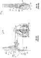
Fig. 1 is a schematic plane view of a portion of an operating theater illustrating a robotic surgical system, including a master surgeon console or workstation for inputting a surgical procedure and a robotic patient side cart for robotically moving surgical instruments having surgical end effectors at a surgical site.Fig. 2 is a perspective view of the robotic patient side cart or stand, including two patient side robotic manipulators and one endoscope/camera robotic manipulator.Figs. 3A and 3B are side and front views, respectively, of the linkage of the robotic manipulators ofFig. 2 .Fig. 4 is a perspective view of an articulated surgical instrument for use in the system ofFig. 1 .Figs. 5A and 5B are side and front views, respectively, of an exemplary robotic manipulator linkage assembly constructed in accordance with the principles of the present invention.Figs. 6A and 6B are additional side views of the exemplary robotic manipulator linkage assembly.Figs. 7A and7B are side views of the exemplary robotic manipulator linkage assembly illustrating an improved range of motion along a pitch axis.Figs. 8A and 8B are side views of the exemplary robotic manipulator linkage assembly illustrating an improved range of motion along a pitch axis.Figs. 9A through 9D are perspective view of the exemplary robotic assembly manipulator linkage illustrating an improved range of motion along both the pitch and yaw axes.Figs. 1 through 4 illustrate a roboticsurgical system 1 for performing minimally invasive robotic surgery, which is described in more detail inU.S. Patent No. 6,246,200 . An operator O (generally a surgeon) performs a minimally invasive surgical procedure on patient P lying on operating table T, the operator O manipulating one or more input devices ormasters 2 at a surgeon'sconsole 3. In response to the surgeon's inputs, a computer processor 4 ofconsole 3 directs movement of endoscopic surgical instruments ortools 5, effecting servo-mechanical movement of the instruments via a robotic patient-side system 6 (a cart-mounted system in this example).- Typically, patient side system or
cart 6 includes at least three robotic manipulator arms. Two arms or linkages 7 (mounted at the sides ofcart 6 in this example) support and position servo-manipulators 8 which drivesurgical tools 5; and one arm or linkage 9 (mounted at the center ofcart 6 in this example) supports and positions servo-manipulator 10 which controls the motion of an endoscope/camera probe 11, which captures an image (preferably stereoscopic) of the internal surgical site. - The image of the internal surgical site is shown to surgeon or operator O by a
stereoscopic display viewer 12 in surgeon'sconsole 3, and is simultaneously shown to assistant A by an assistant'sdisplay 14. Assistant A assists in pre-positioning themanipulator linkage arms swapping tools 5 in one or more of surgical manipulator 8 (and/or 10) for alternative surgical tools or instruments 5', in operating related non-robotic medical instruments and equipment, and the like. - In general terms, the arms or
linkages side system 6, typically remaining in a fixed configuration while tissue is manipulated, and themanipulators console 3. The actively driven portion is herein generally referred to as a "manipulator", and the fixable portion of the positioning linkage of patient-side system linkage is referred to herein as a "set-up arm", it being noted that such set-up arms may optionally have powered and computer controlled joints. - For convenience in terminology, a manipulator such as 8 actuating tissue affecting surgical tools is generally referred to herein as a PSM (patient-side manipulator), and a manipulator such as 10 controlling an image capture or data acquisition device, such as
endoscope 11, is generally referred to herein as a ECM (endoscope-camera manipulator), it being noted that such telesurgical robotic manipulators may optionally actuate, maneuver and control a wide variety of instruments, tools and devices useful in surgery. Fig. 2 illustrates a perspective view of the cart mounted telesurgical patient-side system 6 ofFig. 1 , including two PSM's 8 and oneECM 10.Cart system 6 includes acolumn 15 which in turn mounts three positioning linkages or set-up arms, including two PSM set-uparms 7, each supporting one of the PSM's 8, and one ECM set-uparm 9 supportingECM 10. The PSM set-uparms 7 each have six degrees of freedom, and are mounted one on each side of centrally mounted ECM set-uparm 9. The ECM set-uparm 9 shown has less than six degrees of freedom, andECM 10 may not include all of the tool actuation drive system provided for articulated surgical instruments, such as are typically included inPSM 8. EachPSM 8 releasably mounts surgical tool 5 (shown in dashed lines) andECM 10 releasably mounts endoscope probe 11 (shown in dashed lines).Figs. 3A and 3B are side and front views, respectively, of the linkage of the robotic surgical manipulator orPSM 8 ofFig. 2 , having a remote center mechanism.PSM 8 is one prior art example of a manipulator which may be mounted and supported by acart mount 6, ceiling mount, or floor/pedestal mount. In this example, thePSM 8 preferably includes alinkage arrangement 20 that constrains movement oftool interface housing 21 and mounted instrument ortool 5. More specifically,linkage 20 includes rigid links coupled together by rotational joints in a parallelogram arrangement so thathousing 21 andtool 5 rotate around a point inspace 22, as more fully described in issuedU.S. Patent No. 6,758,843 .- The parallelogram arrangement of
linkage 20 constrains rotation to pivoting, as indicated byarrow 22a inFig. 3A , about an axis, sometimes called the pitch axis, which is perpendicular to the page in that illustration and which passes throughpivot point 22. The links supporting the parallelogram linkage are pivotally mounted to set-up joints (7 inFig. 2 ) so thattool 5 further rotates about anaxis 22b (Fig. 3B ), sometimes called the yaw axis. The pitch and yaw axes intersect at theremote center 22, which is aligned along ashaft 23 oftool 5.Tool 5 has still further driven degrees of freedom as supported bymanipulator 8, including sliding motion of the tool alonginsertion axis 22c.Tool 5 includesproximal housing 24 which mounts tomanipulator interface housing 21.Interface housing 21 both provides for motion of thetool 5 alongaxis 22c and serves to transfer actuator inputs totool 5 from the end effector actuator servo-mechanisms ofPSM 8. In this example of a remote center system, theparallelogram arrangement 20 is coupled totool 5 so as to mechanically constrain thetool shaft 23 to rotation aboutpivot point 22 as the servomechanism actuates tool motion according to the surgeon's control inputs. - As
tool 5 slides alongaxis 22c relative tomanipulator 8,remote center 22 remains fixed relative to mounting base 25 (mounting point to set-up arm 7) ofmanipulator 8. Hence, theentire manipulator 8 is generally moved to re-positionremote center 22.Linkage 20 ofmanipulator 8 is driven by a series of motors 26 (Fig. 3A ). These motors actively movelinkage 20 in response to commands from a processor (4 inFig. 1 ).Motors 26 are further coupled totool 5 so as to rotate the tool aboutaxis 22c, and may articulate a wrist (29 inFig. 4 ) at the distal end of thetool 5 about at least one, and often two, degrees of freedom. Additionally,motors 26 can be used to actuate an articulatable end effector of the tool for grasping tissues in the jaws of a forceps or the like.Motors 26 may be coupled to at least some of the joints oftool 5 using cables, as more fully described inU.S. Patent No. 5,792,135 . As described in that reference, themanipulator 8 will often include flexible members for transferring motion from the drive components to thesurgical tool 5. For endoscopic procedures,manipulator 8 will often include acannula 27.Cannula 27, which may be releasably coupled tomanipulator 8, supportstool 5, preferably allowing the tool to rotate and move axially through the central bore of thecannula 27. Fig. 4 illustrates an exploded perspective view of the articulated surgical tool orinstrument 5 andproximal housing 24, that may be employed in the system ofFig. 1 .Tool 5 includeselongate shaft 23 supportingend effector 28 relative toproximal housing 24.Proximal housing 24 is adapted for releasably mounting and interfacinginstrument 5 to a manipulator (e.g.,PSM 8 inFigs. 1 ,2 ,3A, and 3B ), and for transmitting drive signals and/or motion between themanipulator 8 and endeffector 28. An articulatedwrist mechanism 29 may provide two degrees of freedom of motion betweenend effector 28 andshaft 23, and theshaft 23 may be rotatable relative toproximal housing 24 so as to provide theend effector 28 with three substantially orientational degrees of freedom within the patient's body.- Referring now to
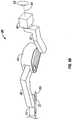
Figs. 5A and 5B , side and front views are illustrated of an exemplary offset remote centerrobotic manipulator 30 constructed in accordance with the principles of the present invention. As described in greater detail below, therefined manipulator 30 provides an offset remote center parallelogram manipulator linkage assembly which constrains a position of asurgical instrument 32 coupled to aninstrument holder 34 during minimally invasive robotic surgery. Thesurgical instrument 32 includes anelongate shaft 36 having a distal workingend 38 configured for insertion through an incision in a body wall into a body cavity of a patient. It will be appreciated that the above depictions are for illustrative purposes only and do not necessarily reflect the actual shape, size, or dimensions of the roboticsurgical manipulator 30. This applies to all depictions hereinafter. - Generally, the offset remote center
robotic manipulator 30 is configured to constrainshaft 36 motion relative to a center ofrotation 66. As such, theshaft 36 is maintained substantially aligned through the center ofrotation 66 as theshaft 36 is pivotally moved in at least one degree of freedom. Preferably, the center ofrotation 66 is aligned with the incision point to the internal surgical site, for example, with a trocar or cannula at an abdominal wall during laparoscopic surgery. As such, an end effector of thesurgical instrument 32 can be positioned safely by moving the proximal end of theshaft 36 using the offset remote centerrobotic manipulator 30 without imposing dangerous forces against the abdominal wall. - Referring back to
Fig. 5A , the refined remote center manipulator generally includes anarticulate linkage assembly 30 having a mountingbase 40, aparallelogram linkage base 42, and a plurality oflinks joints base 40 is rotationally coupled to theparallelogram linkage base 42 for rotation about afirst axis 56, also known as the yaw axis, as indicated byarrow 58. The mountingbase 40 allows for thesurgical manipulator 30 to be mounted and supported by set-up arms/joints of a cart mount, ceiling mount, floor/pedestal mount, or other mounting surface. The mountingbase 40 in this embodiment is fixed tobase support 60 by screws orbolts 62, wherein thebase support 60 is adapted to be attached to the set-up arms/joints. Theparallelogram linkage base 42 is coupled to theinstrument holder 34 byrigid links links joints parallelogram 64 so as to constrain theelongate shaft 36 of theinstrument 32 relative to the center ofrotation 66 when theinstrument 32 is mounted to theinstrument holder 34 and theshaft 36 is moved along a plane of theparallelogram 64. - Significantly, the
first axis 56 and theparallelogram 64 intersect theshaft 36 at the center ofrotation 66, wherein theparallelogram 64 is angularly offset from thefirst axis 56. Specifically, afirst side 68 which originates from thefirst pivot 48 of theparallelogram 64 adjacent theparallelogram linkage base 40 and thefirst axis 56 intersect theshaft 36 at the center ofrotation 66, wherein thefirst side 68 and thefirst pivot 48 of theparallelogram 64 are angularly offset from thefirst axis 56. Thefirst side 68 andfirst pivot 48 of theparallelogram 64 are offset from thefirst axis 56 by an angle α of at least 2 degrees, preferably by 10 degrees. Generally, thefirst side 68 andfirst pivot 48 of theparallelogram 64 are offset from thefirst axis 56 by angle α in a range from about 2 degrees to about 45 degrees, preferably in a range from about 2 degrees to about 35 degrees. - Referring now to
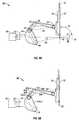
Figs. 6A and 6B , additional side views of the exemplary roboticmanipulator linkage assembly 30 are illustrated showing theinstrument holder 34 in an extended position. The offsetparallelogram 64 arrangement allows for improved rotation ofinstrument 32 andholder 34 over the prior art example described inFigs. 3A and 3B while the remote center ofrotation 66 remains at the same location. Specifically, as shown inFigs. 7A ,7B ,8A, 8B ,9C and9D , the offsetarticulate linkage assembly 30 provides an improved range ofshaft 36 motion that is greater than ± 55 degrees relative to a second axis (which is perpendicular to the page in these illustrations and which passes through pivot point 66), preferably greater than ± 60 degrees relative to the second axis. Generally, the offsetarticulate linkage assembly 30 constrainsshaft 36 motion aboutpivot point 66 in a range from ± 75 degrees relative to the second axis as indicated byarrow 72, wherein the second axis is sometimes referred to as a pitch axis. Themanipulator 30 also provides an improved range ofshaft 36 motion that is greater than ± 90 degrees relative to thefirst axis 56, preferably greater than ± 95 degrees relative to thefirst axis 56, as indicated byarrow 58 inFigs. 9A and9B . Typically, the cantileveredparallelogram linkage base 42 constrainsshaft 36 motion aboutpivot point 66 in a range from ± 168 degrees relative to thefirst axis 56. - Additionally, similar to the discussed prior art, the
yaw axis 56, the pitch axis (which is perpendicular to the page), and aninsertion axis 74 all intersect with each other at theremote center 66, which is aligned along ashaft 36 of theinstrument 32. Thus, theinstrument 32 can be pivotally rotated though desired angles as indicated byarrows rotation 66 remains fixed in space relative to the mounting base 40 (mounting point to set-up arm) ofmanipulator 30. Hence, theentire manipulator 30 is generally moved to re-position theremote center 66, It will further be appreciated that theinstrument 32 still has further driven degrees of freedom as supported by the offsetremote center manipulator 30, including sliding motion of the instrument along theinsertion axis 74. - The new and improved offset
articulate linkage assembly 30 which decouples thefirst pivot 48 andfirst side 68 of theparallelogram 64 from theyaw axis 56 advantageously enhances the range ofinstrument 32 motion aboutpivot point 66 relative to the second axis, as indicated byarrow 72. Themanipulator 30 further allows for an enhanced range of motion relative to thefirst axis 56, as indicated byarrow 58. An improved pivot range of motion along pitch and yaw axes in turn enhances the efficiency and ease of use of such robotic surgical systems. For example, the overall complexity of the robotic surgical system may be reduced due to the improved range of motion of the system. Specifically, the number of degrees of freedom in the set-up joints/arms may be reduced (e.g., less than six degrees of freedom). This allows for a simpler system platform requiring less pro-configuration of the set-up joints. As such, normal operating room personnel may rapidly arrange and prepare the robotic system for surgery with little or no specialized training. - The plurality of links comprise an offset
yaw link 42, a loweredvertical link 44, and a mainbent link 46. Themain link 46 is bent at an angle so as to provide clearance for thevertical link 44 to rest on the mainbent link 46. This clearance prevents inter-linkage collisions between thevertical link 44 and the mainbent link 46, For example, themain link 46 may be bent at an angle of about 22 degrees to allow clearance over apitch dive 72 as shown inFigs. 8A, 8B , and9D . In such an embodiment, the mainbent link 46 and thevertical link 44 as well as theinstrument holder 34 are located in the same plane. It will be appreciated however that themain link 46 and thevertical link 44 may alternatively be offset in different planes (i.e., placed side by side) to reduce inter-linkage collisions in lieu of bendingmain link 46. Thevertical link 44pivot 48 is lower relative to theyaw axis 56 so as to provide the offsetparallelogram 64 arrangement, as discussed above. Theyaw link 42 is off set fromlinks Figs. 9B through 9D .Link 42 andlinks link 42 andlinks - At least one of the
rigid links articulate linkage assembly 30. The brake system releasably inhibits articulation of at least one of thejoints remote center manipulator 30 may comprise a lighter system as the linkage is free of any counter-balancing weights. As such, thelinks lighter manipulator 30. It will further be appreciated that the offsetremote center manipulator 30 may optionally be balanced by the use of weights, tension springs, gas springs, torsion springs, compression springs, air or hydraulic cylinders, torque motors, or combinations thereof. - Referring back to
Figs. 6B ,7B , and8B , the offsetremote center manipulator 30 may preferably comprise sixpulleys flexible elements pulleys shaft 36 motion relative to the center ofrotation 66.Links flexible elements 84a, 84b running -on twopulleys pulley 76 fixed to link 42 and onepulley 78a fixed to link 46.Links flexible elements pulleys pulley 80 fixed to link 34, andidler pulleys 82a, 82b to get theflexible elements bent link 46. Hence, links 42 and 46 can translate but not rotate relative to each other to maintain theparallelogram shape 64. Likewise, links 44 and 34 can translate but not rotate relative to each other to maintain theparallelogram shape 64. It will be appreciated that theterm pulley - The
flexible element pulleys Pulleys idler pulleys 82a, 82b at the bend of themain link 46 to facilitate running ofbelts belts belts 84a, 84b as well asbelts - The offset
articulate linkage assembly 30 is driven by a series of motors. Motors may be located within the plurality of links to drive the pulley and belt mechanisms. Preferably, a majority of the motors are housed in the loweredvertical link 44. In particular, the motor which drives thepitch axis 72rotating link 44 relative to link 42 through spur gears and a harmonic drive as well as the motors that run instrument actuation cables (e.g., wrist drive cables which may be spring tensioned) may be housed inlink 44. Placement of thevertical link 44, the mainbent link 46, and theinstrument holder 34 in the same plane is advantageous as the motors that run the actuation cables are housed inlink 44. Further, having thevertical link 44, the mainbent link 46, and theinstrument holder 34 in the same plane allows for space minimization at the distal end of themanipulator 30, which is of significant importance when performing minimally invasive robotic surgery in a confined operating environment. The motor driving theyaw axis 58 may be housed in mountingbase 40. - Although certain exemplary embodiments and methods have been described in some detail, for clarity of understanding and by way of example, it will be apparent from the foregoing disclosure to those skilled in the art that variations, modifications, changes, and adaptations of such embodiments and methods may be made without departing from the scope of the invention. Therefore, the above description should not be taken as limiting the scope of the invention which is defined by the appended claims.
Claims (6)
- A remote center manipulator (30) for a surgical instrument (32) having a shaft (36), the manipulator comprising:an instrument holder (34) releasably holding the surgical instrument (32);a linkage base (42);a first linkage assembly (44) pivotally supported by the linkage base (42), the first linkage assembly having a first outer housing; anda second linkage assembly (46) comprising a proximal pivotal joint (50) coupling the second linkage assembly to the first linkage assembly (44) and a distal pivotal joint (54) coupling the second linkage assembly to the instrument holder (34), the second linkage assembly having a second outer housing, the first and second linkage assemblies (44, 46) constraining lateral motion of the shaft to pivotal motion about a center of rotation (66) disposed along the shaft (36);characterized in that the second outer housing has a recess to provide clearance for the first outer housing to protrude into the recess and across a second linkage axis provided between the proximal and distal pivotal joints when the proximal end of the shaft (36) pivots towards the linkage base (42).
- The manipulator of claim 1, wherein the second linkage assembly (46) comprises a flexible member (86a, 86b) in tension between the proximal pivotal joint (50) and the distal pivotal joint (54), and at least one guide (82a,82b) engaging the flexible member laterally so as to displace the flexible member away from the recess.
- The manipulator of claim 1, further comprising:
an articulate linkage assembly having a mounting base (40) rotationally coupled to the linkage base (42) for rotation about a first axis (56), the linkage base coupled to the instrument holder (34) by a plurality of links (44, 46) and pivots (48, 50, 54), the links and pivots defining a parallelogram (64), wherein the first axis (56) and a first pivot (48) of the parallelogram adjacent the linkage base (42) are angularly offset, and wherein at least one of the links (44, 46) is bent. - The manipulator of claim 3, wherein the first pivot (48) of the parallelogram is angularly offset from the first axis by at least 2 degrees.
- The manipulator of claim 3, wherein a first pivot (48) of the parallelogram is angularly offset from the first axis (56) in a range from about 2 degrees to about 45 degrees.
- The manipulator of claim 1, wherein a distal end of the parallelogram extends from a joint adjacent the instrument holder (34) to a center of rotation (66) coinciding with a pivot of the parallelogram (64).
Priority Applications (1)
| Application Number | Priority Date | Filing Date | Title |
|---|---|---|---|
| EP20186036.8AEP3753522A1 (en) | 2004-09-30 | 2005-09-09 | Offset remote center manipulator |
Applications Claiming Priority (4)
| Application Number | Priority Date | Filing Date | Title |
|---|---|---|---|
| US10/957,077US7594912B2 (en) | 2004-09-30 | 2004-09-30 | Offset remote center manipulator for robotic surgery |
| EP10175702.9AEP2253288B1 (en) | 2004-09-30 | 2005-09-09 | Offset remote center manipulator |
| EP05795948.8AEP1793761B1 (en) | 2004-09-30 | 2005-09-09 | Offset remote center manipulator |
| PCT/US2005/032488WO2006039092A2 (en) | 2004-09-30 | 2005-09-09 | Offset remote center manipulator |
Related Parent Applications (3)
| Application Number | Title | Priority Date | Filing Date |
|---|---|---|---|
| EP05795948.8ADivisionEP1793761B1 (en) | 2004-09-30 | 2005-09-09 | Offset remote center manipulator |
| EP10175702.9ADivision-IntoEP2253288B1 (en) | 2004-09-30 | 2005-09-09 | Offset remote center manipulator |
| EP10175702.9ADivisionEP2253288B1 (en) | 2004-09-30 | 2005-09-09 | Offset remote center manipulator |
Related Child Applications (1)
| Application Number | Title | Priority Date | Filing Date |
|---|---|---|---|
| EP20186036.8ADivisionEP3753522A1 (en) | 2004-09-30 | 2005-09-09 | Offset remote center manipulator |
Publications (2)
| Publication Number | Publication Date |
|---|---|
| EP3372184A1 EP3372184A1 (en) | 2018-09-12 |
| EP3372184B1true EP3372184B1 (en) | 2020-08-12 |
Family
ID=35482120
Family Applications (6)
| Application Number | Title | Priority Date | Filing Date |
|---|---|---|---|
| EP10175702.9AExpired - LifetimeEP2253288B1 (en) | 2004-09-30 | 2005-09-09 | Offset remote center manipulator |
| EP18156122.6AExpired - LifetimeEP3372184B1 (en) | 2004-09-30 | 2005-09-09 | Offset remote center manipulator |
| EP16179332.8AExpired - LifetimeEP3199120B1 (en) | 2004-09-30 | 2005-09-09 | Offset remote center manipulator |
| EP10175715.1AExpired - LifetimeEP2253289B1 (en) | 2004-09-30 | 2005-09-09 | Offset remote center manipulator |
| EP05795948.8AExpired - LifetimeEP1793761B1 (en) | 2004-09-30 | 2005-09-09 | Offset remote center manipulator |
| EP20186036.8AWithdrawnEP3753522A1 (en) | 2004-09-30 | 2005-09-09 | Offset remote center manipulator |
Family Applications Before (1)
| Application Number | Title | Priority Date | Filing Date |
|---|---|---|---|
| EP10175702.9AExpired - LifetimeEP2253288B1 (en) | 2004-09-30 | 2005-09-09 | Offset remote center manipulator |
Family Applications After (4)
| Application Number | Title | Priority Date | Filing Date |
|---|---|---|---|
| EP16179332.8AExpired - LifetimeEP3199120B1 (en) | 2004-09-30 | 2005-09-09 | Offset remote center manipulator |
| EP10175715.1AExpired - LifetimeEP2253289B1 (en) | 2004-09-30 | 2005-09-09 | Offset remote center manipulator |
| EP05795948.8AExpired - LifetimeEP1793761B1 (en) | 2004-09-30 | 2005-09-09 | Offset remote center manipulator |
| EP20186036.8AWithdrawnEP3753522A1 (en) | 2004-09-30 | 2005-09-09 | Offset remote center manipulator |
Country Status (5)
| Country | Link |
|---|---|
| US (7) | US7594912B2 (en) |
| EP (6) | EP2253288B1 (en) |
| JP (6) | JP4943338B2 (en) |
| CN (5) | CN105852974B (en) |
| WO (1) | WO2006039092A2 (en) |
Families Citing this family (454)
| Publication number | Priority date | Publication date | Assignee | Title |
|---|---|---|---|---|
| US8944070B2 (en) | 1999-04-07 | 2015-02-03 | Intuitive Surgical Operations, Inc. | Non-force reflecting method for providing tool force information to a user of a telesurgical system |
| US9415510B2 (en) | 1999-09-17 | 2016-08-16 | Intuitive Surgical Operations, Inc. | System and methods for positioning a manipulator arm by clutching within a null-perpendicular space concurrent with null-space movement |
| US7594912B2 (en) | 2004-09-30 | 2009-09-29 | Intuitive Surgical, Inc. | Offset remote center manipulator for robotic surgery |
| WO2015142796A1 (en) | 2014-03-17 | 2015-09-24 | Intuitive Surgical Operations, Inc. | Tele-operative surgical systems and methods of control at joint limits using inverse kinematics |
| US8398634B2 (en)* | 2002-04-18 | 2013-03-19 | Intuitive Surgical Operations, Inc. | Wristed robotic surgical tool for pluggable end-effectors |
| US6994708B2 (en)* | 2001-04-19 | 2006-02-07 | Intuitive Surgical | Robotic tool with monopolar electro-surgical scissors |
| US9155544B2 (en)* | 2002-03-20 | 2015-10-13 | P Tech, Llc | Robotic systems and methods |
| US9261172B2 (en)* | 2004-09-30 | 2016-02-16 | Intuitive Surgical Operations, Inc. | Multi-ply strap drive trains for surgical robotic arms |
| US10646292B2 (en)* | 2004-09-30 | 2020-05-12 | Intuitive Surgical Operations, Inc. | Electro-mechanical strap stack in robotic arms |
| US7837674B2 (en) | 2005-01-24 | 2010-11-23 | Intuitive Surgical Operations, Inc. | Compact counter balance for robotic surgical systems |
| US7763015B2 (en) | 2005-01-24 | 2010-07-27 | Intuitive Surgical Operations, Inc. | Modular manipulator support for robotic surgery |
| US9943372B2 (en) | 2005-04-18 | 2018-04-17 | M.S.T. Medical Surgery Technologies Ltd. | Device having a wearable interface for improving laparoscopic surgery and methods for use thereof |
| US20060243085A1 (en)* | 2005-04-25 | 2006-11-02 | Blake Hannaford | Spherical motion mechanism |
| US20110020779A1 (en)* | 2005-04-25 | 2011-01-27 | University Of Washington | Skill evaluation using spherical motion mechanism |
| US9789608B2 (en) | 2006-06-29 | 2017-10-17 | Intuitive Surgical Operations, Inc. | Synthetic representation of a surgical robot |
| GB0521281D0 (en)* | 2005-10-19 | 2005-11-30 | Acrobat Company The Ltd | hybrid constrant mechanism |
| US7930065B2 (en) | 2005-12-30 | 2011-04-19 | Intuitive Surgical Operations, Inc. | Robotic surgery system including position sensors using fiber bragg gratings |
| US9962066B2 (en) | 2005-12-30 | 2018-05-08 | Intuitive Surgical Operations, Inc. | Methods and apparatus to shape flexible entry guides for minimally invasive surgery |
| US8219178B2 (en) | 2007-02-16 | 2012-07-10 | Catholic Healthcare West | Method and system for performing invasive medical procedures using a surgical robot |
| US10653497B2 (en) | 2006-02-16 | 2020-05-19 | Globus Medical, Inc. | Surgical tool systems and methods |
| US10357184B2 (en) | 2012-06-21 | 2019-07-23 | Globus Medical, Inc. | Surgical tool systems and method |
| US10893912B2 (en) | 2006-02-16 | 2021-01-19 | Globus Medical Inc. | Surgical tool systems and methods |
| KR101477133B1 (en) | 2006-06-13 | 2014-12-29 | 인튜어티브 서지컬 인코포레이티드 | Minimally invasive surgical system |
| WO2007147232A1 (en)* | 2006-06-19 | 2007-12-27 | Robarts Research Institute | Apparatus for guiding a medical tool |
| US20090192523A1 (en) | 2006-06-29 | 2009-07-30 | Intuitive Surgical, Inc. | Synthetic representation of a surgical instrument |
| US9718190B2 (en)* | 2006-06-29 | 2017-08-01 | Intuitive Surgical Operations, Inc. | Tool position and identification indicator displayed in a boundary area of a computer display screen |
| US10258425B2 (en) | 2008-06-27 | 2019-04-16 | Intuitive Surgical Operations, Inc. | Medical robotic system providing an auxiliary view of articulatable instruments extending out of a distal end of an entry guide |
| US10008017B2 (en) | 2006-06-29 | 2018-06-26 | Intuitive Surgical Operations, Inc. | Rendering tool information as graphic overlays on displayed images of tools |
| US12357400B2 (en) | 2006-06-29 | 2025-07-15 | Intuitive Surgical Operations, Inc. | Synthetic representation of a surgical robot |
| US7879039B2 (en)* | 2006-12-28 | 2011-02-01 | Mi4Spine, Llc | Minimally invasive interspinous process spacer insertion device |
| US9084623B2 (en) | 2009-08-15 | 2015-07-21 | Intuitive Surgical Operations, Inc. | Controller assisted reconfiguration of an articulated instrument during movement into and out of an entry guide |
| US9096033B2 (en) | 2007-06-13 | 2015-08-04 | Intuitive Surgical Operations, Inc. | Surgical system instrument sterile adapter |
| US8620473B2 (en)* | 2007-06-13 | 2013-12-31 | Intuitive Surgical Operations, Inc. | Medical robotic system with coupled control modes |
| US8903546B2 (en) | 2009-08-15 | 2014-12-02 | Intuitive Surgical Operations, Inc. | Smooth control of an articulated instrument across areas with different work space conditions |
| US9089256B2 (en) | 2008-06-27 | 2015-07-28 | Intuitive Surgical Operations, Inc. | Medical robotic system providing an auxiliary view including range of motion limitations for articulatable instruments extending out of a distal end of an entry guide |
| US9469034B2 (en) | 2007-06-13 | 2016-10-18 | Intuitive Surgical Operations, Inc. | Method and system for switching modes of a robotic system |
| US9138129B2 (en) | 2007-06-13 | 2015-09-22 | Intuitive Surgical Operations, Inc. | Method and system for moving a plurality of articulated instruments in tandem back towards an entry guide |
| US8444631B2 (en)* | 2007-06-14 | 2013-05-21 | Macdonald Dettwiler & Associates Inc | Surgical manipulator |
| US20080314181A1 (en)* | 2007-06-19 | 2008-12-25 | Bruce Schena | Robotic Manipulator with Remote Center of Motion and Compact Drive |
| WO2009004616A2 (en)* | 2007-07-02 | 2009-01-08 | M.S.T. Medical Surgery Technologies Ltd | System for positioning endoscope and surgical instruments |
| US8400094B2 (en) | 2007-12-21 | 2013-03-19 | Intuitive Surgical Operations, Inc. | Robotic surgical system with patient support |
| US8343096B2 (en)* | 2008-03-27 | 2013-01-01 | St. Jude Medical, Atrial Fibrillation Division, Inc. | Robotic catheter system |
| US12239396B2 (en) | 2008-06-27 | 2025-03-04 | Intuitive Surgical Operations, Inc. | Medical robotic system providing an auxiliary view including range of motion limitations for articulatable instruments extending out of a distal end of an entry guide |
| US8864652B2 (en) | 2008-06-27 | 2014-10-21 | Intuitive Surgical Operations, Inc. | Medical robotic system providing computer generated auxiliary views of a camera instrument for controlling the positioning and orienting of its tip |
| US7875039B2 (en)* | 2008-06-30 | 2011-01-25 | Eigen, Inc. | Support assembly for a tracking assembly and mounted transrectal ultrasound probe |
| US8916134B2 (en)* | 2008-07-11 | 2014-12-23 | Industry-Academic Cooperation Foundation, Yonsei University | Metal nanocomposite, preparation method and use thereof |
| US8423182B2 (en)* | 2009-03-09 | 2013-04-16 | Intuitive Surgical Operations, Inc. | Adaptable integrated energy control system for electrosurgical tools in robotic surgical systems |
| US8082673B2 (en)* | 2009-11-06 | 2011-12-27 | Hexagon Metrology Ab | Systems and methods for control and calibration of a CMM |
| US12266040B2 (en) | 2009-03-31 | 2025-04-01 | Intuitive Surgical Operations, Inc. | Rendering tool information as graphic overlays on displayed images of tools |
| KR101030371B1 (en) | 2009-04-27 | 2011-04-20 | 국립암센터 | Endoscopic adjustment device for minimally invasive surgery |
| JP2010260139A (en)* | 2009-05-08 | 2010-11-18 | Ntn Corp | Remote-controlled work robot |
| US8918211B2 (en) | 2010-02-12 | 2014-12-23 | Intuitive Surgical Operations, Inc. | Medical robotic system providing sensory feedback indicating a difference between a commanded state and a preferred pose of an articulated instrument |
| US9492927B2 (en) | 2009-08-15 | 2016-11-15 | Intuitive Surgical Operations, Inc. | Application of force feedback on an input device to urge its operator to command an articulated instrument to a preferred pose |
| EP2480173B1 (en) | 2009-09-22 | 2016-11-23 | Memic Innovative Surgery Ltd. | Mechanical finger |
| US8623028B2 (en) | 2009-09-23 | 2014-01-07 | Intuitive Surgical Operations, Inc. | Surgical port feature |
| US20110071541A1 (en) | 2009-09-23 | 2011-03-24 | Intuitive Surgical, Inc. | Curved cannula |
| US8465476B2 (en)* | 2009-09-23 | 2013-06-18 | Intuitive Surgical Operations, Inc. | Cannula mounting fixture |
| US8545515B2 (en)* | 2009-09-23 | 2013-10-01 | Intuitive Surgical Operations, Inc. | Curved cannula surgical system |
| US8888789B2 (en) | 2009-09-23 | 2014-11-18 | Intuitive Surgical Operations, Inc. | Curved cannula surgical system control |
| KR101680132B1 (en)* | 2009-10-01 | 2016-11-28 | 마코 서지컬 코포레이션 | Tool, kit-of-parts for multi-functional tool, and robotic system for same |
| EP2485652B1 (en)* | 2009-10-09 | 2019-08-21 | Applied Medical Resources Corporation | Single incision laparoscopic tissue retrieval system |
| KR101948703B1 (en)* | 2009-11-13 | 2019-02-15 | 인튜어티브 서지컬 오퍼레이션즈 인코포레이티드 | Curved cannula and robotic manipulator |
| KR20200064161A (en)* | 2009-11-13 | 2020-06-05 | 인튜어티브 서지컬 오퍼레이션즈 인코포레이티드 | Curved cannula surgical system |
| KR101109197B1 (en)* | 2009-12-17 | 2012-01-30 | 국립암센터 | Needle feeder |
| JP2013517898A (en)* | 2010-01-26 | 2013-05-20 | ケアフュージョン2200、インコーポレイテッド | Powered signal control manual joint device and method of use |
| US9033998B1 (en) | 2010-05-13 | 2015-05-19 | Titan Medical Inc. | Independent roll wrist mechanism |
| WO2013014621A2 (en) | 2011-07-27 | 2013-01-31 | Ecole Polytechnique Federale De Lausanne (Epfl) | Mechanical teleoperated device for remote manipulation |
| US12402960B2 (en) | 2010-10-11 | 2025-09-02 | Ecole Polytechnique Federale De Lausanne (Epfl) | Mechanical manipulator for surgical instruments |
| EP2627278B1 (en) | 2010-10-11 | 2015-03-25 | Ecole Polytechnique Fédérale de Lausanne (EPFL) | Mechanical manipulator for surgical instruments |
| US9486189B2 (en) | 2010-12-02 | 2016-11-08 | Hitachi Aloka Medical, Ltd. | Assembly for use with surgery system |
| US9241766B2 (en)* | 2010-12-22 | 2016-01-26 | Intuitive Surgical Operations, Inc. | Alternate instrument removal |
| WO2012127404A2 (en) | 2011-03-18 | 2012-09-27 | Ecole Polytechnique Federale De Lausanne (Epfl) | Ergonomic handle for haptic devices |
| US9308050B2 (en) | 2011-04-01 | 2016-04-12 | Ecole Polytechnique Federale De Lausanne (Epfl) | Robotic system and method for spinal and other surgeries |
| JP5834473B2 (en)* | 2011-04-28 | 2015-12-24 | セイコーエプソン株式会社 | robot |
| JP6005950B2 (en) | 2011-08-04 | 2016-10-12 | オリンパス株式会社 | Surgery support apparatus and control method thereof |
| JP5841451B2 (en) | 2011-08-04 | 2016-01-13 | オリンパス株式会社 | Surgical instrument and control method thereof |
| JP6081061B2 (en) | 2011-08-04 | 2017-02-15 | オリンパス株式会社 | Surgery support device |
| WO2013018861A1 (en) | 2011-08-04 | 2013-02-07 | オリンパス株式会社 | Medical manipulator and method for controlling same |
| JP6009840B2 (en) | 2011-08-04 | 2016-10-19 | オリンパス株式会社 | Medical equipment |
| JP5931497B2 (en)* | 2011-08-04 | 2016-06-08 | オリンパス株式会社 | Surgery support apparatus and assembly method thereof |
| JP6000641B2 (en) | 2011-08-04 | 2016-10-05 | オリンパス株式会社 | Manipulator system |
| JP5953058B2 (en) | 2011-08-04 | 2016-07-13 | オリンパス株式会社 | Surgery support device and method for attaching and detaching the same |
| JP5936914B2 (en) | 2011-08-04 | 2016-06-22 | オリンパス株式会社 | Operation input device and manipulator system including the same |
| JP6021484B2 (en)* | 2011-08-04 | 2016-11-09 | オリンパス株式会社 | Medical manipulator |
| WO2013018908A1 (en) | 2011-08-04 | 2013-02-07 | オリンパス株式会社 | Manipulator for medical use and surgery support device |
| US10866783B2 (en) | 2011-08-21 | 2020-12-15 | Transenterix Europe S.A.R.L. | Vocally activated surgical control system |
| US9757206B2 (en) | 2011-08-21 | 2017-09-12 | M.S.T. Medical Surgery Technologies Ltd | Device and method for assisting laparoscopic surgery—rule based approach |
| US9204939B2 (en) | 2011-08-21 | 2015-12-08 | M.S.T. Medical Surgery Technologies Ltd. | Device and method for assisting laparoscopic surgery—rule based approach |
| US11561762B2 (en)* | 2011-08-21 | 2023-01-24 | Asensus Surgical Europe S.A.R.L. | Vocally actuated surgical control system |
| US9795282B2 (en) | 2011-09-20 | 2017-10-24 | M.S.T. Medical Surgery Technologies Ltd | Device and method for maneuvering endoscope |
| US9387048B2 (en) | 2011-10-14 | 2016-07-12 | Intuitive Surgical Operations, Inc. | Catheter sensor systems |
| US10238837B2 (en) | 2011-10-14 | 2019-03-26 | Intuitive Surgical Operations, Inc. | Catheters with control modes for interchangeable probes |
| US9452276B2 (en) | 2011-10-14 | 2016-09-27 | Intuitive Surgical Operations, Inc. | Catheter with removable vision probe |
| US20130303944A1 (en) | 2012-05-14 | 2013-11-14 | Intuitive Surgical Operations, Inc. | Off-axis electromagnetic sensor |
| JP5893330B2 (en)* | 2011-10-18 | 2016-03-23 | オリンパス株式会社 | Operation input device and method for initializing operation input device |
| SG11201402020XA (en) | 2011-11-04 | 2014-09-26 | Univ Johns Hopkins | Steady hand micromanipulation robot |
| FI20116111A7 (en) | 2011-11-10 | 2013-05-11 | Sensapex Oy | Micromanipulator arrangement |
| KR101901580B1 (en) | 2011-12-23 | 2018-09-28 | 삼성전자주식회사 | Surgical robot and control method thereof |
| CN104334109B (en)* | 2012-06-01 | 2017-06-23 | 直观外科手术操作公司 | Systems and methods for reconfiguration of commands of a surgical manipulator using null space |
| EP4070755A1 (en)* | 2012-06-01 | 2022-10-12 | Intuitive Surgical Operations, Inc. | Multi-port surgical robotic system architecture |
| CN107595392B (en)* | 2012-06-01 | 2020-11-27 | 直观外科手术操作公司 | Avoidance of manipulator arm collisions with patient using null space |
| EP3915504A1 (en)* | 2012-06-01 | 2021-12-01 | Intuitive Surgical Operations, Inc. | Surgical instrument manipulator aspects |
| EP2854687B1 (en)* | 2012-06-01 | 2022-08-24 | Intuitive Surgical Operations, Inc. | Systems for avoiding collisions between manipulator arms using a null-space |
| EP3623120A1 (en) | 2012-06-01 | 2020-03-18 | Intuitive Surgical Operations Inc. | Instrument carriage assembly for surgical system |
| KR102386692B1 (en)* | 2012-06-01 | 2022-04-14 | 인튜어티브 서지컬 오퍼레이션즈 인코포레이티드 | Redundant axis and degree of freedom for hardware-constrained remote center robotic manipulator |
| US11253327B2 (en) | 2012-06-21 | 2022-02-22 | Globus Medical, Inc. | Systems and methods for automatically changing an end-effector on a surgical robot |
| US11607149B2 (en) | 2012-06-21 | 2023-03-21 | Globus Medical Inc. | Surgical tool systems and method |
| US10231791B2 (en) | 2012-06-21 | 2019-03-19 | Globus Medical, Inc. | Infrared signal based position recognition system for use with a robot-assisted surgery |
| US12220120B2 (en) | 2012-06-21 | 2025-02-11 | Globus Medical, Inc. | Surgical robotic system with retractor |
| US10136954B2 (en) | 2012-06-21 | 2018-11-27 | Globus Medical, Inc. | Surgical tool systems and method |
| US20150032164A1 (en) | 2012-06-21 | 2015-01-29 | Globus Medical, Inc. | Methods for Performing Invasive Medical Procedures Using a Surgical Robot |
| US11793570B2 (en) | 2012-06-21 | 2023-10-24 | Globus Medical Inc. | Surgical robotic automation with tracking markers |
| US11317971B2 (en) | 2012-06-21 | 2022-05-03 | Globus Medical, Inc. | Systems and methods related to robotic guidance in surgery |
| US11395706B2 (en) | 2012-06-21 | 2022-07-26 | Globus Medical Inc. | Surgical robot platform |
| US10350013B2 (en) | 2012-06-21 | 2019-07-16 | Globus Medical, Inc. | Surgical tool systems and methods |
| US12329593B2 (en) | 2012-06-21 | 2025-06-17 | Globus Medical, Inc. | Surgical robotic automation with tracking markers |
| US10624710B2 (en) | 2012-06-21 | 2020-04-21 | Globus Medical, Inc. | System and method for measuring depth of instrumentation |
| US12262954B2 (en) | 2012-06-21 | 2025-04-01 | Globus Medical, Inc. | Surgical robotic automation with tracking markers |
| US12004905B2 (en) | 2012-06-21 | 2024-06-11 | Globus Medical, Inc. | Medical imaging systems using robotic actuators and related methods |
| US11864745B2 (en) | 2012-06-21 | 2024-01-09 | Globus Medical, Inc. | Surgical robotic system with retractor |
| US11399900B2 (en) | 2012-06-21 | 2022-08-02 | Globus Medical, Inc. | Robotic systems providing co-registration using natural fiducials and related methods |
| US11298196B2 (en) | 2012-06-21 | 2022-04-12 | Globus Medical Inc. | Surgical robotic automation with tracking markers and controlled tool advancement |
| EP2863827B1 (en) | 2012-06-21 | 2022-11-16 | Globus Medical, Inc. | Surgical robot platform |
| US10758315B2 (en) | 2012-06-21 | 2020-09-01 | Globus Medical Inc. | Method and system for improving 2D-3D registration convergence |
| US11974822B2 (en) | 2012-06-21 | 2024-05-07 | Globus Medical Inc. | Method for a surveillance marker in robotic-assisted surgery |
| US11857149B2 (en) | 2012-06-21 | 2024-01-02 | Globus Medical, Inc. | Surgical robotic systems with target trajectory deviation monitoring and related methods |
| US11045267B2 (en) | 2012-06-21 | 2021-06-29 | Globus Medical, Inc. | Surgical robotic automation with tracking markers |
| US11864839B2 (en) | 2012-06-21 | 2024-01-09 | Globus Medical Inc. | Methods of adjusting a virtual implant and related surgical navigation systems |
| US11116576B2 (en) | 2012-06-21 | 2021-09-14 | Globus Medical Inc. | Dynamic reference arrays and methods of use |
| US11857266B2 (en) | 2012-06-21 | 2024-01-02 | Globus Medical, Inc. | System for a surveillance marker in robotic-assisted surgery |
| US12310683B2 (en) | 2012-06-21 | 2025-05-27 | Globus Medical, Inc. | Surgical tool systems and method |
| EP2883511B1 (en) | 2012-07-03 | 2018-08-22 | KUKA Deutschland GmbH | Surgical instrument arrangement |
| JP6042652B2 (en)* | 2012-07-30 | 2016-12-14 | オリンパス株式会社 | Surgical tools and medical manipulators |
| WO2014028563A1 (en) | 2012-08-15 | 2014-02-20 | Intuitive Surgical Operations, Inc. | Phantom degrees of freedom in joint estimation and control |
| KR102109594B1 (en)* | 2012-08-15 | 2020-05-12 | 인튜어티브 서지컬 오퍼레이션즈 인코포레이티드 | Systems and methods for cancellation of joint motion using the null-space |
| EP2885114B1 (en) | 2012-08-15 | 2021-06-30 | Intuitive Surgical Operations, Inc. | Phantom degrees of freedom for manipulating the movement of mechanical bodies |
| KR102283182B1 (en) | 2012-08-15 | 2021-07-29 | 인튜어티브 서지컬 오퍼레이션즈 인코포레이티드 | User initiated break-away clutching of a surgical mounting platform |
| KR102184960B1 (en) | 2012-08-15 | 2020-12-01 | 인튜어티브 서지컬 오퍼레이션즈 인코포레이티드 | Movable surgical mounting platform controlled by manual motion of robotic arms |
| US20140051049A1 (en) | 2012-08-17 | 2014-02-20 | Intuitive Surgical Operations, Inc. | Anatomical model and method for surgical training |
| CN104640514B (en) | 2012-09-17 | 2019-05-07 | 直观外科手术操作公司 | Method and system for assigning input devices to teleoperated surgical instrument functionality |
| US10631939B2 (en) | 2012-11-02 | 2020-04-28 | Intuitive Surgical Operations, Inc. | Systems and methods for mapping flux supply paths |
| US10864048B2 (en) | 2012-11-02 | 2020-12-15 | Intuitive Surgical Operations, Inc. | Flux disambiguation for teleoperated surgical systems |
| DE102012112712A1 (en)* | 2012-12-20 | 2014-06-26 | MAQUET GmbH | instrument support |
| DE102012112716A1 (en) | 2012-12-20 | 2014-06-26 | MAQUET GmbH | Medical support arm |
| US10507066B2 (en) | 2013-02-15 | 2019-12-17 | Intuitive Surgical Operations, Inc. | Providing information of tools by filtering image areas adjacent to or on displayed images of the tools |
| EP2967623B1 (en) | 2013-03-14 | 2021-07-21 | SRI International | Compact robotic wrist |
| US10561470B2 (en) | 2013-03-15 | 2020-02-18 | Intuitive Surgical Operations, Inc. | Software configurable manipulator degrees of freedom |
| EP2969407B1 (en) | 2013-03-15 | 2022-11-02 | Intuitive Surgical Operations, Inc. | System for managing multiple null-space objectives and sli behaviors |
| KR102214811B1 (en) | 2013-03-15 | 2021-02-10 | 인튜어티브 서지컬 오퍼레이션즈 인코포레이티드 | Systems and methods for using the null space to emphasize manipulator joint motion anisotropically |
| JP6396987B2 (en) | 2013-03-15 | 2018-09-26 | エスアールアイ インターナショナルSRI International | Super elaborate surgical system |
| EP2969409B1 (en) | 2013-03-15 | 2024-05-01 | Intuitive Surgical Operations, Inc. | Inter-operative switching of tools in a robotic surgical system |
| GB201305984D0 (en)* | 2013-04-03 | 2013-05-15 | Moog Bv | Mechanical linkage |
| DE102013005982A1 (en)* | 2013-04-08 | 2014-10-09 | Kuka Laboratories Gmbh | medical robots |
| TWI504492B (en)* | 2013-04-30 | 2015-10-21 | Hiwin Tech Corp | Spherical Linkage Surgical Arm |
| US10076348B2 (en) | 2013-08-15 | 2018-09-18 | Intuitive Surgical Operations, Inc. | Rotary input for lever actuation |
| EP3708105B1 (en) | 2013-08-15 | 2022-02-09 | Intuitive Surgical Operations, Inc. | Preloaded surgical instrument interface |
| CN108784838B (en) | 2013-08-15 | 2021-06-08 | 直观外科手术操作公司 | Instrument sterile adapter drive interface |
| US10016244B2 (en)* | 2013-08-15 | 2018-07-10 | Intuitive Surgical Operations, Inc. | Robotic instrument driven element |
| CN103431913B (en)* | 2013-09-12 | 2015-04-29 | 哈尔滨工业大学 | Robotic surgery micro-device for minimally invasive surgery |
| US9283048B2 (en) | 2013-10-04 | 2016-03-15 | KB Medical SA | Apparatus and systems for precise guidance of surgical tools |
| CN103568003B (en)* | 2013-10-12 | 2016-07-06 | 上海交通大学 | The long-range airborne carrier mechanical arm of vacuum chamber is equipped towards MCF |
| TWI511700B (en)* | 2013-11-19 | 2015-12-11 | Univ Nat Taiwan Science Tech | Surgical holder |
| CN105813582B (en) | 2013-12-11 | 2019-05-28 | 柯惠Lp公司 | Wrist and jaw assemblies for robotic surgical systems |
| WO2015095715A1 (en)* | 2013-12-20 | 2015-06-25 | Intuitive Surgical Operations, Inc. | Simulator system for medical procedure training |
| US9241771B2 (en) | 2014-01-15 | 2016-01-26 | KB Medical SA | Notched apparatus for guidance of an insertable instrument along an axis during spinal surgery |
| CN106659540B (en)* | 2014-02-03 | 2019-03-05 | 迪斯塔莫申股份公司 | Mechanical teleoperated devices including interchangeable distal instruments |
| WO2015121311A1 (en) | 2014-02-11 | 2015-08-20 | KB Medical SA | Sterile handle for controlling a robotic surgical system from a sterile field |
| WO2015120557A1 (en)* | 2014-02-17 | 2015-08-20 | Claronav Inc. | Medical cart |
| KR102327850B1 (en)* | 2014-02-20 | 2021-11-17 | 인튜어티브 서지컬 오퍼레이션즈 인코포레이티드 | Limited movement of a surgical mounting platform controlled by manual motion of robotic arms |
| KR102300251B1 (en) | 2014-03-17 | 2021-09-09 | 인튜어티브 서지컬 오퍼레이션즈 인코포레이티드 | Automatic push-out to avoid range of motion limits |
| CN106102632B (en) | 2014-03-17 | 2019-06-14 | 直观外科手术操作公司 | Fix instrument control input bearing/orientation during in-program restart |
| US10201390B2 (en)* | 2014-03-17 | 2019-02-12 | Intuitive Surgical Operations, Inc. | Command shaping to dampen vibrations in mode transitions |
| USD760387S1 (en)* | 2014-03-17 | 2016-06-28 | Intuitive Surgical Operations, Inc. | Surgical instrument end portion |
| USD767129S1 (en)* | 2014-03-17 | 2016-09-20 | Intuitive Surgical Operations, Inc. | Surgical instrument end portion |
| USD768295S1 (en)* | 2014-03-17 | 2016-10-04 | Intuitive Surgical Operations, Inc. | Surgical instrument end portion |
| USD767130S1 (en)* | 2014-03-17 | 2016-09-20 | Intuitive Surgical Operations, Inc. | Surgical instrument end portion |
| US10258414B2 (en) | 2014-03-17 | 2019-04-16 | Intuitive Surgical Operations, Inc. | Methods and devices for table pose tracking using fudicial markers |
| US10166061B2 (en) | 2014-03-17 | 2019-01-01 | Intuitive Surgical Operations, Inc. | Teleoperated surgical system equipment with user interface |
| CN106163445B (en) | 2014-03-31 | 2019-11-29 | 直观外科手术操作公司 | Surgical instruments with switchable drives |
| CN106163444B (en) | 2014-04-01 | 2019-06-28 | 直观外科手术操作公司 | Control Input Accuracy of Teleoperated Surgical Instruments |
| EP3134022B1 (en) | 2014-04-24 | 2018-01-10 | KB Medical SA | Surgical instrument holder for use with a robotic surgical system |
| JP2017514608A (en) | 2014-05-05 | 2017-06-08 | バイカリアス サージカル インク. | Virtual reality surgical device |
| US9549781B2 (en) | 2014-05-30 | 2017-01-24 | The Johns Hopkins University | Multi-force sensing surgical instrument and method of use for robotic surgical systems |
| US10357257B2 (en) | 2014-07-14 | 2019-07-23 | KB Medical SA | Anti-skid surgical instrument for use in preparing holes in bone tissue |
| US10251717B2 (en) | 2014-08-01 | 2019-04-09 | Intuitive Surgical Operations, Inc. | Damping a telesurgical system |
| US10058395B2 (en) | 2014-08-01 | 2018-08-28 | Intuitive Surgical Operations, Inc. | Active and semi-active damping in a telesurgical system |
| CN106659538B (en) | 2014-08-13 | 2019-05-10 | 柯惠Lp公司 | Robot-controlled gripping with mechanical advantages |
| EP3179952B1 (en) | 2014-08-13 | 2019-03-20 | Covidien LP | Robotically controlled mechanical advantage gripper |
| CN106573373B (en)* | 2014-08-14 | 2019-10-18 | 库卡罗伯特有限公司 | Positioning to robot |
| EP3185808B1 (en) | 2014-08-27 | 2022-02-23 | DistalMotion SA | Surgical system for microsurgical techniques |
| EP3193767B1 (en)* | 2014-09-15 | 2022-04-20 | Covidien LP | Robotically controlling surgical assemblies |
| CN107073707B (en)* | 2014-09-30 | 2021-06-04 | 精工爱普生株式会社 | robot |
| WO2016056339A1 (en) | 2014-10-09 | 2016-04-14 | ソニー株式会社 | Information-processing device, information-processing method, and program |
| EP3212107B1 (en) | 2014-10-27 | 2025-04-09 | Intuitive Surgical Operations, Inc. | Medical device with active brake release control |
| KR102545930B1 (en) | 2014-10-27 | 2023-06-22 | 인튜어티브 서지컬 오퍼레이션즈 인코포레이티드 | System and method for integrated surgical table |
| EP4082466B1 (en) | 2014-10-27 | 2025-07-30 | Intuitive Surgical Operations, Inc. | System for instrument disturbance compensation |
| KR102479287B1 (en) | 2014-10-27 | 2022-12-20 | 인튜어티브 서지컬 오퍼레이션즈 인코포레이티드 | System and method for monitoring control points during reactive motion |
| CN110236853B (en) | 2014-10-27 | 2021-06-04 | 直观外科手术操作公司 | System and method for registration to an operating table |
| WO2016069663A1 (en) | 2014-10-27 | 2016-05-06 | Intuitive Surgical Operations, Inc. | System and method for integrated surgical table motion |
| US10624807B2 (en) | 2014-10-27 | 2020-04-21 | Intuitive Surgical Operations, Inc. | System and method for integrated surgical table icons |
| EP3226781B1 (en) | 2014-12-02 | 2018-08-01 | KB Medical SA | Robot assisted volume removal during surgery |
| KR101965678B1 (en)* | 2014-12-11 | 2019-08-13 | 타이탄 메디칼 아이엔씨. | Actuator and drive for manipulating a tool |
| WO2016097861A1 (en) | 2014-12-19 | 2016-06-23 | Distalmotion Sa | Sterile interface for articulated surgical instruments |
| WO2016097871A1 (en) | 2014-12-19 | 2016-06-23 | Distalmotion Sa | Docking system for mechanical telemanipulator |
| WO2016097873A2 (en) | 2014-12-19 | 2016-06-23 | Distalmotion Sa | Articulated handle for mechanical telemanipulator |
| EP3653145B1 (en) | 2014-12-19 | 2024-01-24 | DistalMotion SA | Reusable surgical instrument for minimally invasive procedures |
| EP3232951B1 (en) | 2014-12-19 | 2023-10-25 | DistalMotion SA | Surgical instrument with articulated end-effector |
| DE102015101018A1 (en)* | 2015-01-23 | 2016-07-28 | MAQUET GmbH | Device for holding and moving a laparoscope during an operation |
| CN104523339B (en)* | 2015-01-23 | 2016-08-24 | 哈尔滨工业大学 | Intraperitoneal magnetic grappling for Minimally Invasive Surgery clamps operating robot |
| US10013808B2 (en) | 2015-02-03 | 2018-07-03 | Globus Medical, Inc. | Surgeon head-mounted display apparatuses |
| WO2016131903A1 (en) | 2015-02-18 | 2016-08-25 | KB Medical SA | Systems and methods for performing minimally invasive spinal surgery with a robotic surgical system using a percutaneous technique |
| WO2016133633A1 (en) | 2015-02-19 | 2016-08-25 | Covidien Lp | Repositioning method of input device for robotic surgical system |
| WO2016144937A1 (en) | 2015-03-10 | 2016-09-15 | Covidien Lp | Measuring health of a connector member of a robotic surgical system |
| EP3280337B1 (en) | 2015-04-09 | 2019-11-13 | DistalMotion SA | Articulated hand-held instrument |
| US10568709B2 (en) | 2015-04-09 | 2020-02-25 | Distalmotion Sa | Mechanical teleoperated device for remote manipulation |
| CN107735044B (en) | 2015-05-11 | 2021-02-05 | 柯惠Lp公司 | Coupling instrument drive unit and robotic surgical instrument |
| US10959788B2 (en) | 2015-06-03 | 2021-03-30 | Covidien Lp | Offset instrument drive unit |
| CA2987637C (en) | 2015-06-16 | 2023-10-03 | Covidien Lp | Robotic surgical system torque transduction sensing |
| JP6771494B2 (en) | 2015-06-19 | 2020-10-21 | コヴィディエン リミテッド パートナーシップ | Control method for robotic surgical instruments with bidirectional connections |
| EP3313315B1 (en) | 2015-06-23 | 2024-04-10 | Covidien LP | Robotic surgical assemblies |
| US10646990B2 (en) | 2015-07-17 | 2020-05-12 | The Johns Hopkins University | Delta mechanism with enhanced torsional stiffness |
| CN108025445A (en)* | 2015-07-23 | 2018-05-11 | 斯里国际 | Robots arm and robotic surgical system |
| US10058394B2 (en) | 2015-07-31 | 2018-08-28 | Globus Medical, Inc. | Robot arm and methods of use |
| US10646298B2 (en) | 2015-07-31 | 2020-05-12 | Globus Medical, Inc. | Robot arm and methods of use |
| US10080615B2 (en) | 2015-08-12 | 2018-09-25 | Globus Medical, Inc. | Devices and methods for temporary mounting of parts to bone |
| WO2017031600A1 (en)* | 2015-08-27 | 2017-03-02 | Focal Healthcare Inc. | Moveable interface between a stepper and a stabilizer |
| WO2017037532A1 (en) | 2015-08-28 | 2017-03-09 | Distalmotion Sa | Surgical instrument with increased actuation force |
| JP6894431B2 (en) | 2015-08-31 | 2021-06-30 | ケービー メディカル エスアー | Robotic surgical system and method |
| US10034716B2 (en) | 2015-09-14 | 2018-07-31 | Globus Medical, Inc. | Surgical robotic systems and methods thereof |
| AU2016326371B2 (en) | 2015-09-25 | 2020-07-23 | Covidien Lp | Robotic surgical assemblies and instrument drive connectors thereof |
| WO2017062370A1 (en)* | 2015-10-07 | 2017-04-13 | Intuitive Surgical Operations, Inc. | Controlling roll for a device in a computer-assisted medical system |
| US9771092B2 (en) | 2015-10-13 | 2017-09-26 | Globus Medical, Inc. | Stabilizer wheel assembly and methods of use |
| EP3878396A1 (en) | 2015-10-23 | 2021-09-15 | Covidien LP | Surgical system for detecting gradual changes in perfusion |
| EP3373838B1 (en) | 2015-11-11 | 2020-10-28 | Intuitive Surgical Operations Inc. | Reconfigurable end effector architecture |
| EP3376988B1 (en) | 2015-11-19 | 2023-08-23 | Covidien LP | Optical force sensor for robotic surgical system |
| JP2017104450A (en)* | 2015-12-11 | 2017-06-15 | 川崎重工業株式会社 | Surgical system |
| JP2017104451A (en)* | 2015-12-11 | 2017-06-15 | 川崎重工業株式会社 | Surgical system |
| CN105832417B (en)* | 2016-01-22 | 2018-10-30 | 中国科学院重庆绿色智能技术研究院 | A kind of micro-wound operation robot mechanical arm RCM mechanisms |
| US10842453B2 (en) | 2016-02-03 | 2020-11-24 | Globus Medical, Inc. | Portable medical imaging system |
| US10117632B2 (en) | 2016-02-03 | 2018-11-06 | Globus Medical, Inc. | Portable medical imaging system with beam scanning collimator |
| US11883217B2 (en) | 2016-02-03 | 2024-01-30 | Globus Medical, Inc. | Portable medical imaging system and method |
| US10448910B2 (en) | 2016-02-03 | 2019-10-22 | Globus Medical, Inc. | Portable medical imaging system |
| US11058378B2 (en) | 2016-02-03 | 2021-07-13 | Globus Medical, Inc. | Portable medical imaging system |
| EP3422990A4 (en) | 2016-03-04 | 2019-11-13 | Covidien LP | REVERSE KINEMATIC CONTROL SYSTEMS FOR SURGICAL ROBOTIC SYSTEM |
| US10866119B2 (en) | 2016-03-14 | 2020-12-15 | Globus Medical, Inc. | Metal detector for detecting insertion of a surgical device into a hollow tube |
| JP6686644B2 (en)* | 2016-04-06 | 2020-04-22 | セイコーエプソン株式会社 | Robots and robot systems |
| US11576562B2 (en) | 2016-04-07 | 2023-02-14 | Titan Medical Inc. | Camera positioning method and apparatus for capturing images during a medical procedure |
| EP3241518B1 (en) | 2016-04-11 | 2024-10-23 | Globus Medical, Inc | Surgical tool systems |
| JP6831642B2 (en)* | 2016-04-15 | 2021-02-17 | 川崎重工業株式会社 | Surgical system |
| CN105748153B (en)* | 2016-05-24 | 2018-03-20 | 山东大学齐鲁医院 | A kind of assisted minimally invasive surgical operation robot mechanical arm |
| EP3463159B1 (en) | 2016-05-26 | 2024-01-03 | Covidien LP | Instrument drive units |
| EP3463143A4 (en) | 2016-05-26 | 2020-01-22 | Covidien LP | ROBOTIC SURGICAL ARRANGEMENTS |
| CN107735040B (en) | 2016-06-03 | 2021-06-18 | 柯惠Lp公司 | Control Arms for Robotic Surgical Systems |
| WO2017210500A1 (en) | 2016-06-03 | 2017-12-07 | Covidien Lp | Robotic surgical system with an embedded imager |
| WO2017210497A1 (en) | 2016-06-03 | 2017-12-07 | Covidien Lp | Systems, methods, and computer-readable program products for controlling a robotically delivered manipulator |
| CN109195543A (en) | 2016-06-03 | 2019-01-11 | 柯惠Lp公司 | Passive Shaft Systems for Robotic Surgical Systems |
| DE102016111737A1 (en)* | 2016-06-27 | 2017-12-28 | avateramedical GmBH | Instrument carrier device for a manipulator of a robotic surgical system |
| CN114052854B (en)* | 2016-07-01 | 2024-11-12 | 直观外科手术操作公司 | Computer-assisted medical system and method |
| USD864386S1 (en) | 2016-07-14 | 2019-10-22 | Intuitive Surgical Operations, Inc. | Surgical instrument actuator end portion |
| USD865164S1 (en) | 2016-07-14 | 2019-10-29 | Intuitive Surgical Operations, Inc. | Surgical instrument actuator end portion |
| USD865163S1 (en) | 2016-07-14 | 2019-10-29 | Intuitive Surgical Operations, Inc. | Surgical instrument actuator end portion |
| KR102764208B1 (en) | 2016-07-14 | 2025-02-07 | 인튜어티브 서지컬 오퍼레이션즈 인코포레이티드 | Secondary instrument control in a computer-assisted teleoperated system |
| BR112019001533B1 (en)* | 2016-07-28 | 2023-02-14 | Tom Thys | INSTRUMENT HOLDER |
| CN106214261B (en)* | 2016-09-21 | 2018-11-09 | 刘秦鹏 | A kind of suspension type operating robot |
| KR101997827B1 (en)* | 2016-10-06 | 2019-07-08 | 사회복지법인 삼성생명공익재단 | Femoral tunnel guide |
| CN110114046B (en) | 2016-11-28 | 2021-07-13 | 威博外科公司 | Robotic surgical system that reduces undesired vibrations |
| CN106584445B (en) | 2016-12-16 | 2018-12-25 | 微创(上海)医疗机器人有限公司 | Fixed point mechanism |
| CN106618736B (en)* | 2016-12-16 | 2019-03-08 | 微创(上海)医疗机器人有限公司 | Mechanical arm and operating robot with double freedom |
| JP7233841B2 (en) | 2017-01-18 | 2023-03-07 | ケービー メディカル エスアー | Robotic Navigation for Robotic Surgical Systems |
| US10799308B2 (en) | 2017-02-09 | 2020-10-13 | Vicarious Surgical Inc. | Virtual reality surgical tools system |
| CN110139619A (en) | 2017-02-15 | 2019-08-16 | 柯惠Lp公司 | Anti-Crush Systems and Devices for Medical Robotics Applications |
| US10820951B2 (en) | 2017-03-14 | 2020-11-03 | Verb Surgical Inc. | Techniques for damping vibration in a robotic surgical system |
| US11071594B2 (en) | 2017-03-16 | 2021-07-27 | KB Medical SA | Robotic navigation of robotic surgical systems |
| US11078945B2 (en) | 2017-03-26 | 2021-08-03 | Verb Surgical Inc. | Coupler to attach robotic arm to surgical table |
| JP2018187749A (en)* | 2017-05-11 | 2018-11-29 | セイコーエプソン株式会社 | robot |
| US11058503B2 (en) | 2017-05-11 | 2021-07-13 | Distalmotion Sa | Translational instrument interface for surgical robot and surgical robot systems comprising the same |
| US10792119B2 (en) | 2017-05-22 | 2020-10-06 | Ethicon Llc | Robotic arm cart and uses therefor |
| EP3629979A4 (en) | 2017-05-24 | 2021-02-17 | Covidien LP | PRESENCE DETECTION FOR ELECTROSURGICAL TOOLS IN A ROBOTIC SYSTEM |
| WO2018217431A1 (en) | 2017-05-25 | 2018-11-29 | Covidien Lp | Robotic surgical system with automated guidance |
| US11510747B2 (en) | 2017-05-25 | 2022-11-29 | Covidien Lp | Robotic surgical systems and drapes for covering components of robotic surgical systems |
| CN107041786A (en)* | 2017-05-25 | 2017-08-15 | 杭州妙手机器人有限公司 | A kind of laparoscopic device |
| JP7130003B2 (en) | 2017-05-25 | 2022-09-02 | コヴィディエン リミテッド パートナーシップ | Systems and methods for detection of objects within the field of view of an image capture device |
| US10856948B2 (en) | 2017-05-31 | 2020-12-08 | Verb Surgical Inc. | Cart for robotic arms and method and apparatus for registering cart to surgical table |
| US10485623B2 (en) | 2017-06-01 | 2019-11-26 | Verb Surgical Inc. | Robotic arm cart with fine position adjustment features and uses therefor |
| US10913145B2 (en) | 2017-06-20 | 2021-02-09 | Verb Surgical Inc. | Cart for robotic arms and method and apparatus for cartridge or magazine loading of arms |
| CN109091230B (en)* | 2017-06-21 | 2020-12-18 | 山东威高手术机器人有限公司 | Main operation arm for minimally invasive surgery |
| CN109091235B (en)* | 2017-06-21 | 2020-11-24 | 山东威高手术机器人有限公司 | Auxiliary operation arm of minimally invasive surgical instrument |
| CN109091236B (en)* | 2017-06-21 | 2020-08-21 | 山东威高手术机器人有限公司 | Minimally invasive surgical instrument auxiliary operation arm |
| US11135015B2 (en) | 2017-07-21 | 2021-10-05 | Globus Medical, Inc. | Robot surgical platform |
| WO2019036418A1 (en) | 2017-08-16 | 2019-02-21 | Covidien Lp | End effector including wrist assembly and monopolar tool for robotic surgical systems |
| WO2019050829A1 (en) | 2017-09-05 | 2019-03-14 | Covidien Lp | Collision handling algorithms for robotic surgical systems |
| US11583358B2 (en) | 2017-09-06 | 2023-02-21 | Covidien Lp | Boundary scaling of surgical robots |
| EP3678579A4 (en) | 2017-09-08 | 2021-06-16 | Covidien LP | Energy disconnect for robotic surgical assemblies |
| WO2019055681A1 (en) | 2017-09-14 | 2019-03-21 | Vicarious Surgical Inc. | Virtual reality surgical camera system |
| CN107510507A (en)* | 2017-09-26 | 2017-12-26 | 广西南宁栩兮科技有限公司 | A kind of surgical Aided Machine arm |
| CN107669337A (en)* | 2017-09-26 | 2018-02-09 | 广西南宁栩兮科技有限公司 | A kind of operation robotic manipulation device |
| CN107569286A (en)* | 2017-10-24 | 2018-01-12 | 广西南宁栩兮科技有限公司 | A kind of high-precision medical manipulator |
| EP3492032B1 (en) | 2017-11-09 | 2023-01-04 | Globus Medical, Inc. | Surgical robotic systems for bending surgical rods |
| US11794338B2 (en) | 2017-11-09 | 2023-10-24 | Globus Medical Inc. | Robotic rod benders and related mechanical and motor housings |
| US11357548B2 (en) | 2017-11-09 | 2022-06-14 | Globus Medical, Inc. | Robotic rod benders and related mechanical and motor housings |
| US11134862B2 (en) | 2017-11-10 | 2021-10-05 | Globus Medical, Inc. | Methods of selecting surgical implants and related devices |
| US12029523B2 (en) | 2017-12-01 | 2024-07-09 | Covidien Lp | Drape management assembly for robotic surgical systems |
| WO2019118336A1 (en) | 2017-12-14 | 2019-06-20 | Intuitive Surgical Operations, Inc. | Medical tools having tension bands |
| CN107951565A (en)* | 2017-12-18 | 2018-04-24 | 苏州康多机器人有限公司 | A kind of laparoscopic surgery robot architecture centered on holding handel |
| CN111556735A (en) | 2018-01-04 | 2020-08-18 | 柯惠Lp公司 | Systems and assemblies for mounting surgical accessories to robotic surgical systems and providing access therethrough |
| WO2019139944A1 (en)* | 2018-01-10 | 2019-07-18 | Covidien Lp | Surgical robotic arms and pulley assemblies thereof |
| CN111587095A (en) | 2018-01-10 | 2020-08-25 | 柯惠Lp公司 | Robotic surgical system and method of controlling a robotic surgical system |
| CN112236269B (en)* | 2018-01-25 | 2024-04-16 | 雷尼公司 | Semi-automatic precision positioning robot device and method |
| US12102403B2 (en) | 2018-02-02 | 2024-10-01 | Coviden Lp | Robotic surgical systems with user engagement monitoring |
| US12376927B2 (en) | 2018-02-07 | 2025-08-05 | Distalmotion Sa | Surgical robot systems comprising robotic telemanipulators and integrated laparoscopy |
| AU2019218707B2 (en) | 2018-02-07 | 2024-10-24 | Distalmotion Sa | Surgical robot systems comprising robotic telemanipulators and integrated laparoscopy |
| US20190254753A1 (en) | 2018-02-19 | 2019-08-22 | Globus Medical, Inc. | Augmented reality navigation systems for use with robotic surgical systems and methods of their use |
| US11189379B2 (en) | 2018-03-06 | 2021-11-30 | Digital Surgery Limited | Methods and systems for using multiple data structures to process surgical data |
| CN111787880A (en) | 2018-03-08 | 2020-10-16 | 柯惠Lp公司 | Surgical robot system |
| US10573023B2 (en) | 2018-04-09 | 2020-02-25 | Globus Medical, Inc. | Predictive visualization of medical imaging scanner component movement |
| US11647888B2 (en) | 2018-04-20 | 2023-05-16 | Covidien Lp | Compensation for observer movement in robotic surgical systems having stereoscopic displays |
| EP3781367B1 (en) | 2018-04-20 | 2025-03-05 | Covidien LP | Methods for surgical robotic cart placement |
| USD884892S1 (en) | 2018-04-20 | 2020-05-19 | Intuitive Surgical Operations, Inc. | Surgical instrument backend housing |
| WO2020009830A1 (en) | 2018-07-03 | 2020-01-09 | Covidien Lp | Systems, methods, and computer-readable media for detecting image degradation during surgical procedures |
| US11311257B2 (en)* | 2018-08-14 | 2022-04-26 | General Electric Company | Systems and methods for a mobile x-ray imaging system |
| CN109223046B (en)* | 2018-09-07 | 2021-04-20 | 通化师范学院 | Mammary gland automated scanning auxiliary system |
| US12178528B2 (en) | 2018-09-14 | 2024-12-31 | Covidien Lp | Surgical robotic systems and methods of tracking usage of surgical instruments thereof |
| US12186040B2 (en) | 2018-09-17 | 2025-01-07 | Covidien Lp | Surgical robotic systems |
| WO2020060790A1 (en) | 2018-09-17 | 2020-03-26 | Covidien Lp | Surgical robotic systems |
| US11109746B2 (en) | 2018-10-10 | 2021-09-07 | Titan Medical Inc. | Instrument insertion system, method, and apparatus for performing medical procedures |
| US11337742B2 (en) | 2018-11-05 | 2022-05-24 | Globus Medical Inc | Compliant orthopedic driver |
| US11707263B2 (en) | 2018-11-16 | 2023-07-25 | Applied Medical Resources Corporation | Tissue retrieval system with retention features |
| US11278360B2 (en) | 2018-11-16 | 2022-03-22 | Globus Medical, Inc. | End-effectors for surgical robotic systems having sealed optical components |
| CN109223182B (en)* | 2018-11-21 | 2021-06-11 | 天津工业大学 | Steel belt transmission mechanism for remote center movement of minimally invasive surgery robot |
| US11744655B2 (en) | 2018-12-04 | 2023-09-05 | Globus Medical, Inc. | Drill guide fixtures, cranial insertion fixtures, and related methods and robotic systems |
| US11602402B2 (en) | 2018-12-04 | 2023-03-14 | Globus Medical, Inc. | Drill guide fixtures, cranial insertion fixtures, and related methods and robotic systems |
| CN109620411B (en)* | 2018-12-18 | 2023-09-05 | 中国科学院苏州生物医学工程技术研究所 | Needle insertion mechanism for puncture robot in minimally invasive surgery |
| EP3897405A4 (en) | 2018-12-21 | 2022-09-14 | Intuitive Surgical Operations, Inc. | ACTUATION MECHANISMS FOR SURGICAL INSTRUMENTS |
| JP7241178B2 (en) | 2018-12-21 | 2023-03-16 | インテュイティブ サージカル オペレーションズ, インコーポレイテッド | Surgical instrument with reinforced staple cartridge |
| WO2020131692A1 (en) | 2018-12-21 | 2020-06-25 | Intuitive Surgical Operations, Inc. | Surgical instruments having mechanisms for identifying and/or deactivating stapler cartridges |
| US11586106B2 (en) | 2018-12-28 | 2023-02-21 | Titan Medical Inc. | Imaging apparatus having configurable stereoscopic perspective |
| US11717355B2 (en) | 2019-01-29 | 2023-08-08 | Covidien Lp | Drive mechanisms for surgical instruments such as for use in robotic surgical systems |
| US11576733B2 (en) | 2019-02-06 | 2023-02-14 | Covidien Lp | Robotic surgical assemblies including electrosurgical instruments having articulatable wrist assemblies |
| US11484372B2 (en) | 2019-02-15 | 2022-11-01 | Covidien Lp | Articulation mechanisms for surgical instruments such as for use in robotic surgical systems |
| CN113453642B (en) | 2019-02-22 | 2025-06-03 | 奥瑞斯健康公司 | Surgical platform with motorized arm for adjustable arm support |
| US11918313B2 (en) | 2019-03-15 | 2024-03-05 | Globus Medical Inc. | Active end effectors for surgical robots |
| US11382549B2 (en) | 2019-03-22 | 2022-07-12 | Globus Medical, Inc. | System for neuronavigation registration and robotic trajectory guidance, and related methods and devices |
| US11806084B2 (en) | 2019-03-22 | 2023-11-07 | Globus Medical, Inc. | System for neuronavigation registration and robotic trajectory guidance, and related methods and devices |
| US11419616B2 (en) | 2019-03-22 | 2022-08-23 | Globus Medical, Inc. | System for neuronavigation registration and robotic trajectory guidance, robotic surgery, and related methods and devices |
| US11571265B2 (en) | 2019-03-22 | 2023-02-07 | Globus Medical Inc. | System for neuronavigation registration and robotic trajectory guidance, robotic surgery, and related methods and devices |
| US11317978B2 (en) | 2019-03-22 | 2022-05-03 | Globus Medical, Inc. | System for neuronavigation registration and robotic trajectory guidance, robotic surgery, and related methods and devices |
| US20200297357A1 (en) | 2019-03-22 | 2020-09-24 | Globus Medical, Inc. | System for neuronavigation registration and robotic trajectory guidance, robotic surgery, and related methods and devices |
| US11944302B2 (en) | 2019-04-15 | 2024-04-02 | Intuitive Surgical Operations, Inc. | Staple cartridge for a surgical instrument |
| US11045179B2 (en) | 2019-05-20 | 2021-06-29 | Global Medical Inc | Robot-mounted retractor system |
| US12376934B2 (en) | 2019-05-22 | 2025-08-05 | Covidien Lp | Surgical robotic arm storage assemblies and methods of replacing surgical robotic arms using the storage assemblies |
| CN113905675B (en) | 2019-05-31 | 2025-01-14 | 直观外科手术操作公司 | Staple cartridge for surgical instruments |
| US11628023B2 (en) | 2019-07-10 | 2023-04-18 | Globus Medical, Inc. | Robotic navigational system for interbody implants |
| US12223629B2 (en) | 2019-09-11 | 2025-02-11 | Covidien Lp | Systems and methods for smoke-reduction in images |
| WO2021046752A1 (en) | 2019-09-11 | 2021-03-18 | Covidien Lp | Systems and methods for neural-network based color restoration |
| US12396692B2 (en) | 2019-09-24 | 2025-08-26 | Globus Medical, Inc. | Compound curve cable chain |
| US11571171B2 (en) | 2019-09-24 | 2023-02-07 | Globus Medical, Inc. | Compound curve cable chain |
| US11426178B2 (en) | 2019-09-27 | 2022-08-30 | Globus Medical Inc. | Systems and methods for navigating a pin guide driver |
| US12329391B2 (en) | 2019-09-27 | 2025-06-17 | Globus Medical, Inc. | Systems and methods for robot-assisted knee arthroplasty surgery |
| US12408929B2 (en) | 2019-09-27 | 2025-09-09 | Globus Medical, Inc. | Systems and methods for navigating a pin guide driver |
| US11890066B2 (en) | 2019-09-30 | 2024-02-06 | Globus Medical, Inc | Surgical robot with passive end effector |
| US11864857B2 (en) | 2019-09-27 | 2024-01-09 | Globus Medical, Inc. | Surgical robot with passive end effector |
| EP4025152A4 (en)* | 2019-10-11 | 2023-09-20 | Endoquest Robotics, Inc. | POSITIONING DEVICE WITH SEVEN DEGREES OF FREEDOM FOR ROBOTIC SURGERY |
| US11510684B2 (en) | 2019-10-14 | 2022-11-29 | Globus Medical, Inc. | Rotary motion passive end effector for surgical robots in orthopedic surgeries |
| CN114502083A (en) | 2019-10-18 | 2022-05-13 | 直观外科手术操作公司 | Surgical instrument with adjustable jaws |
| US11937890B2 (en)* | 2019-11-14 | 2024-03-26 | Intuitive Surgical Operations, Inc. | Direct drive for mechanical arm assembly |
| US12133772B2 (en) | 2019-12-10 | 2024-11-05 | Globus Medical, Inc. | Augmented reality headset for navigated robotic surgery |
| US11992373B2 (en) | 2019-12-10 | 2024-05-28 | Globus Medical, Inc | Augmented reality headset with varied opacity for navigated robotic surgery |
| US12220176B2 (en) | 2019-12-10 | 2025-02-11 | Globus Medical, Inc. | Extended reality instrument interaction zone for navigated robotic |
| US20210177500A1 (en) | 2019-12-12 | 2021-06-17 | Intuitive Surgical Operations, Inc. | Surgical instruments having non-linear cam slots |
| US12064189B2 (en) | 2019-12-13 | 2024-08-20 | Globus Medical, Inc. | Navigated instrument for use in robotic guided surgery |
| US12350828B2 (en) | 2019-12-16 | 2025-07-08 | Covidien Lp | Surgical robotic systems including surgical instruments with articulation |
| EP4081152A1 (en) | 2019-12-23 | 2022-11-02 | Covidien LP | System for guiding surgical procedures |
| CN111166503A (en)* | 2019-12-30 | 2020-05-19 | 深圳迈瑞生物医疗电子股份有限公司 | Support arm for a medical device and medical device |
| US11382699B2 (en) | 2020-02-10 | 2022-07-12 | Globus Medical Inc. | Extended reality visualization of optical tool tracking volume for computer assisted navigation in surgery |
| US12414752B2 (en) | 2020-02-17 | 2025-09-16 | Globus Medical, Inc. | System and method of determining optimal 3-dimensional position and orientation of imaging device for imaging patient bones |
| US11207150B2 (en) | 2020-02-19 | 2021-12-28 | Globus Medical, Inc. | Displaying a virtual model of a planned instrument attachment to ensure correct selection of physical instrument attachment |
| EP4110221A1 (en) | 2020-02-26 | 2023-01-04 | Covidien LP | Robotic surgical instrument including linear encoders for measuring cable displacement |
| CN111407407B (en)* | 2020-03-11 | 2024-11-08 | 杭州唯精医疗机器人有限公司 | A three-degree-of-freedom series-parallel telecentric mechanism |
| US11253216B2 (en) | 2020-04-28 | 2022-02-22 | Globus Medical Inc. | Fixtures for fluoroscopic imaging systems and related navigation systems and methods |
| US11153555B1 (en) | 2020-05-08 | 2021-10-19 | Globus Medical Inc. | Extended reality headset camera system for computer assisted navigation in surgery |
| US11510750B2 (en) | 2020-05-08 | 2022-11-29 | Globus Medical, Inc. | Leveraging two-dimensional digital imaging and communication in medicine imagery in three-dimensional extended reality applications |
| US11382700B2 (en) | 2020-05-08 | 2022-07-12 | Globus Medical Inc. | Extended reality headset tool tracking and control |
| WO2021231508A1 (en) | 2020-05-12 | 2021-11-18 | Covidien Lp | Systems and methods for image mapping and fusion during surgical procedures |
| US12030195B2 (en) | 2020-05-27 | 2024-07-09 | Covidien Lp | Tensioning mechanisms and methods for articulating surgical instruments such as for use in robotic surgical systems |
| US12070276B2 (en) | 2020-06-09 | 2024-08-27 | Globus Medical Inc. | Surgical object tracking in visible light via fiducial seeding and synthetic image registration |
| US11317973B2 (en) | 2020-06-09 | 2022-05-03 | Globus Medical, Inc. | Camera tracking bar for computer assisted navigation during surgery |
| US11382713B2 (en) | 2020-06-16 | 2022-07-12 | Globus Medical, Inc. | Navigated surgical system with eye to XR headset display calibration |
| USD963851S1 (en) | 2020-07-10 | 2022-09-13 | Covidien Lp | Port apparatus |
| US11877807B2 (en) | 2020-07-10 | 2024-01-23 | Globus Medical, Inc | Instruments for navigated orthopedic surgeries |
| US11793588B2 (en) | 2020-07-23 | 2023-10-24 | Globus Medical, Inc. | Sterile draping of robotic arms |
| US11737831B2 (en) | 2020-09-02 | 2023-08-29 | Globus Medical Inc. | Surgical object tracking template generation for computer assisted navigation during surgical procedure |
| US11523785B2 (en) | 2020-09-24 | 2022-12-13 | Globus Medical, Inc. | Increased cone beam computed tomography volume length without requiring stitching or longitudinal C-arm movement |
| CN114305692B (en)* | 2020-09-29 | 2024-12-03 | 北京术锐机器人股份有限公司 | A wire frame support device for a surgical robot system |
| US11911112B2 (en) | 2020-10-27 | 2024-02-27 | Globus Medical, Inc. | Robotic navigational system |
| US12076091B2 (en) | 2020-10-27 | 2024-09-03 | Globus Medical, Inc. | Robotic navigational system |
| US11941814B2 (en) | 2020-11-04 | 2024-03-26 | Globus Medical Inc. | Auto segmentation using 2-D images taken during 3-D imaging spin |
| US11717350B2 (en) | 2020-11-24 | 2023-08-08 | Globus Medical Inc. | Methods for robotic assistance and navigation in spinal surgery and related systems |
| US12402883B2 (en) | 2021-01-08 | 2025-09-02 | Intuitive Surgical Operations, Inc. | Surgical instrument with linear and purse string suture staples |
| US12161433B2 (en) | 2021-01-08 | 2024-12-10 | Globus Medical, Inc. | System and method for ligament balancing with robotic assistance |
| CN116669636A (en) | 2021-01-08 | 2023-08-29 | 直观外科手术操作公司 | Surgical stapling instrument |
| DE202021000992U1 (en) | 2021-03-05 | 2021-06-21 | lNTUITIVE SURGICAL OPERATIONS,INC. | Electrosurgical instruments for sealing and dissection |
| US12150728B2 (en) | 2021-04-14 | 2024-11-26 | Globus Medical, Inc. | End effector for a surgical robot |
| US12178523B2 (en) | 2021-04-19 | 2024-12-31 | Globus Medical, Inc. | Computer assisted surgical navigation system for spine procedures |
| US12409003B2 (en) | 2021-05-14 | 2025-09-09 | Covidien Lp | Instrument cassette assemblies for robotic surgical instruments |
| US12369998B2 (en) | 2021-05-28 | 2025-07-29 | Covidien Lp | Real time monitoring of a robotic drive module |
| US11948226B2 (en) | 2021-05-28 | 2024-04-02 | Covidien Lp | Systems and methods for clinical workspace simulation |
| US11857273B2 (en) | 2021-07-06 | 2024-01-02 | Globus Medical, Inc. | Ultrasonic robotic surgical navigation |
| US11439444B1 (en) | 2021-07-22 | 2022-09-13 | Globus Medical, Inc. | Screw tower and rod reduction tool |
| WO2023014149A1 (en) | 2021-08-06 | 2023-02-09 | 주식회사 리브스메드 | Surgical robot arm |
| WO2023037273A1 (en) | 2021-09-13 | 2023-03-16 | Distalmotion Sa | Instruments for surgical robotic system and interfaces for the same |
| CN114533271B (en)* | 2021-09-13 | 2023-10-31 | 广西大学 | A single-hole minimally invasive surgical control system |
| US12213745B2 (en) | 2021-09-16 | 2025-02-04 | Globus Medical, Inc. | Extended reality systems for visualizing and controlling operating room equipment |
| US12184636B2 (en) | 2021-10-04 | 2024-12-31 | Globus Medical, Inc. | Validating credential keys based on combinations of credential value strings and input order strings |
| US12238087B2 (en) | 2021-10-04 | 2025-02-25 | Globus Medical, Inc. | Validating credential keys based on combinations of credential value strings and input order strings |
| US20230368330A1 (en) | 2021-10-20 | 2023-11-16 | Globus Medical, Inc. | Interpolation of medical images |
| CN114052917A (en)* | 2021-11-16 | 2022-02-18 | 深圳市精锋医疗科技股份有限公司 | Operation arm, slave operation device and surgical robot |
| CN114010326A (en)* | 2021-11-16 | 2022-02-08 | 深圳市精锋医疗科技有限公司 | Operation arm, slave operation device and surgical robot |
| US20230165639A1 (en) | 2021-12-01 | 2023-06-01 | Globus Medical, Inc. | Extended reality systems with three-dimensional visualizations of medical image scan slices |
| US12390294B2 (en) | 2021-12-14 | 2025-08-19 | Covidien Lp | Robotic surgical assemblies including surgical instruments having articulatable wrist assemblies |
| US11911115B2 (en) | 2021-12-20 | 2024-02-27 | Globus Medical Inc. | Flat panel registration fixture and method of using same |
| JP2023103734A (en)* | 2022-01-14 | 2023-07-27 | キヤノン株式会社 | Continuum robot system |
| CN116549125A (en)* | 2022-01-28 | 2023-08-08 | 北京天智航医疗科技股份有限公司 | Surgical robot device and system |
| US12433699B2 (en) | 2022-02-10 | 2025-10-07 | Covidien Lp | Surgical robotic systems and robotic arm carts thereof |
| CN114224496B (en)* | 2022-02-18 | 2022-08-19 | 极限人工智能有限公司 | Instrument bending joint assembly, surgical instrument and split type surgical device |
| US12103480B2 (en) | 2022-03-18 | 2024-10-01 | Globus Medical Inc. | Omni-wheel cable pusher |
| US12048493B2 (en) | 2022-03-31 | 2024-07-30 | Globus Medical, Inc. | Camera tracking system identifying phantom markers during computer assisted surgery navigation |
| US12394086B2 (en) | 2022-05-10 | 2025-08-19 | Globus Medical, Inc. | Accuracy check and automatic calibration of tracked instruments |
| CN114789466B (en)* | 2022-05-16 | 2023-06-30 | 浙江大学 | Skeleton structure for improving bearing capacity of soft mechanical arm |
| US12161427B2 (en) | 2022-06-08 | 2024-12-10 | Globus Medical, Inc. | Surgical navigation system with flat panel registration fixture |
| US12226169B2 (en) | 2022-07-15 | 2025-02-18 | Globus Medical, Inc. | Registration of 3D and 2D images for surgical navigation and robotic guidance without using radiopaque fiducials in the images |
| US20240020840A1 (en) | 2022-07-15 | 2024-01-18 | Globus Medical, Inc. | REGISTRATION OF 3D and 2D IMAGES FOR SURGICAL NAVIGATION AND ROBOTIC GUIDANCE WITHOUT USING RADIOPAQUE FIDUCIALS IN THE IMAGES |
| US12318150B2 (en) | 2022-10-11 | 2025-06-03 | Globus Medical Inc. | Camera tracking system for computer assisted surgery navigation |
| USD1066405S1 (en) | 2023-01-13 | 2025-03-11 | Covidien Lp | Display screen with graphical user interface |
| USD1066380S1 (en) | 2023-01-13 | 2025-03-11 | Covidien Lp | Display screen with graphical user interface |
| USD1066404S1 (en) | 2023-01-13 | 2025-03-11 | Covidien Lp | Display screen with graphical user interface |
| USD1066383S1 (en) | 2023-01-13 | 2025-03-11 | Covidien Lp | Display screen with graphical user interface |
| USD1066381S1 (en) | 2023-01-13 | 2025-03-11 | Covidien Lp | Display screen with graphical user interface |
| USD1066382S1 (en) | 2023-01-13 | 2025-03-11 | Covidien Lp | Display screen with graphical user interface |
| USD1066378S1 (en) | 2023-01-13 | 2025-03-11 | Covidien Lp | Display screen with graphical user interface |
| USD1066379S1 (en) | 2023-01-13 | 2025-03-11 | Covidien Lp | Display screen with graphical user interface |
| US11844585B1 (en) | 2023-02-10 | 2023-12-19 | Distalmotion Sa | Surgical robotics systems and devices having a sterile restart, and methods thereof |
| CN116077197B (en)* | 2023-02-20 | 2025-07-25 | 山东威高手术机器人有限公司 | Instrument mechanical arm with joint adjusting device |
| CN116077144B (en)* | 2023-04-10 | 2023-06-23 | 艺柏湾医疗科技(上海)有限公司 | Transmission device and multi-degree-of-freedom surgical instrument |
| WO2024215716A1 (en) | 2023-04-11 | 2024-10-17 | Intuitive Surgical Operations, Inc. | Surgical stapling instruments and control systems for such instruments |
| WO2024242819A1 (en) | 2023-05-03 | 2024-11-28 | Intuitive Surgical Operations, Inc. | Surgical staple cartridge insertion and protection devices |
| WO2024249991A2 (en) | 2023-06-02 | 2024-12-05 | Intuitive Surgical Operations, Inc. | Devices, system and methods for applying multiple clips to tissue |
| USD1087135S1 (en) | 2023-08-02 | 2025-08-05 | Covidien Lp | Surgeon display screen with a graphical user interface having spent staple icon |
| USD1087995S1 (en) | 2023-08-02 | 2025-08-12 | Covidien Lp | Surgeon display screen with a transitional graphical user interface having staple firing icon |
| WO2025155683A1 (en) | 2024-01-16 | 2025-07-24 | Intuitive Surgical Operations, Inc. | Circular stapling instrument |
| WO2025155653A1 (en) | 2024-01-16 | 2025-07-24 | Intuitive Surgical Operations, Inc. | Collapsible circular staplers |
| WO2025155666A1 (en) | 2024-01-16 | 2025-07-24 | Intuitive Surgical Operations, Inc. | Circular stapling instrument |
| WO2025155694A1 (en) | 2024-01-16 | 2025-07-24 | Intuitive Surgical Operations, Inc. | Circular stapling systems and instruments |
| WO2025198973A1 (en) | 2024-03-18 | 2025-09-25 | Intuitive Surgical Operations, Inc. | Intraoperative control of robotic surgery systems |
| WO2025198972A1 (en) | 2024-03-18 | 2025-09-25 | Intuitive Surgical Operations, Inc. | Control devices for robotic surgery systems |
Family Cites Families (153)
| Publication number | Priority date | Publication date | Assignee | Title |
|---|---|---|---|---|
| US586731A (en) | 1897-07-20 | Churn | ||
| US369023A (en) | 1887-08-30 | Driving-belt fastener | ||
| US590764A (en)* | 1897-09-28 | Filter | ||
| US522409A (en)* | 1894-07-03 | Process of making edible fats | ||
| US669393A (en) | 1900-12-03 | 1901-03-05 | Henry Clay Jent | Churn. |
| US1597152A (en) | 1923-11-05 | 1926-08-24 | Ternstedt Mfg Co | Window regulator |
| US1515335A (en) | 1924-03-03 | 1924-11-11 | George B Bosco | Form clamp |
| US1700468A (en) | 1925-10-12 | 1929-01-29 | Marion Steam Shovel Co | Dipper-tripping device |
| US2027275A (en) | 1934-08-27 | 1936-01-07 | Edwin E Foster | Mechanical movement |
| US2331382A (en) | 1939-11-06 | 1943-10-12 | Francis E Vaughan | Drafting machine brake |
| US2815697A (en) | 1950-06-06 | 1957-12-10 | Saunders-Singer Arthur Edward | Microscope manipulators or dissection manipulators |
| US2845697A (en)* | 1957-03-11 | 1958-08-05 | Zenith Radio Corp | Method of manufacturing a longitudinal mode mechanical vibrator |
| US3011034A (en) | 1957-03-20 | 1961-11-28 | Gen Motors Corp | Linear scale timer |
| US3025647A (en) | 1960-01-12 | 1962-03-20 | Harvey H Moody | Two-way positive cable drive mechanism |
| US3193633A (en) | 1962-07-02 | 1965-07-06 | Gen Electric | Racking mechanism including a differential pulley system |
| US3463329A (en) | 1967-05-18 | 1969-08-26 | Sylvania Electric Prod | Material transfer device with parallel link frame |
| CH482439A (en) | 1968-02-20 | 1969-12-15 | Contraves Ag | Observation device |
| US3500692A (en) | 1968-07-25 | 1970-03-17 | Decitek Inc | Cable actuated device converting rotary to linear motion |
| US3739649A (en) | 1970-10-20 | 1973-06-19 | Csi Liquidating Corp | Linear position converter |
| US3695215A (en) | 1971-10-29 | 1972-10-03 | Gen Motors Corp | Transmission gearshift indicator |
| US3736056A (en) | 1972-01-27 | 1973-05-29 | Dyk Research Corp Van | Apparatus for imparting intermittent rotation to a first member in rotating registry with a second member |
| BE795860A (en) | 1972-02-25 | 1973-08-23 | Xerox Corp | HIGH SPEED PRINTING MACHINES WITH TRAVEL COMPENSATION TROLLEY CABLE |
| US3813843A (en) | 1972-06-09 | 1974-06-04 | Wehr Corp | Method and apparatus for rolling cut filter pad |
| US3855583A (en) | 1973-06-04 | 1974-12-17 | Rockwell International Corp | Conductor-insulator-junction (cij) optical memory device and a memory system dependent thereon |
| US3954282A (en) | 1974-07-15 | 1976-05-04 | Hege Advanced Systems Corporation | Variable speed reciprocating lever drive mechanism |
| FR2303204A1 (en) | 1975-03-06 | 1976-10-01 | Commissariat Energie Atomique | TENSIONING DEVICE FOR RIBBONS OR CABLES FOR TELEMANIPULATOR |
| US3967240A (en) | 1975-07-15 | 1976-06-29 | Kay Melinda Brownlee | Directional signal |
| US3976206A (en) | 1975-07-16 | 1976-08-24 | Flatau Carl R | Articulated master slave manipulator |
| DE2714695C3 (en) | 1977-04-01 | 1979-09-20 | Siemens Ag, 1000 Berlin Und 8000 Muenchen | Fixation device for a patient |
| DE2819976C2 (en) | 1978-05-08 | 1984-03-08 | Fritz 5882 Meinerzhagen Sträter | Articulated arm with wrapped parallelogram function |
| JPS556046A (en) | 1978-06-27 | 1980-01-17 | Hiroshi Sukawa | Swing-linear motion combination type actuator |
| JPS594266B2 (en) | 1978-07-28 | 1984-01-28 | 元田電子工業株式会社 | Advanced control robot |
| FR2460762A1 (en) | 1979-07-12 | 1981-01-30 | Technigaz | Tool orienting control system - effects positioning by deforming articulated parallelogram on carriage supporting tool |
| US4486183A (en) | 1980-06-30 | 1984-12-04 | The Gates Rubber Company | Torsionally elastic power transmitting device and drive |
| US4362525A (en) | 1980-08-08 | 1982-12-07 | Dyneer Corporation | Belt tensioner construction |
| US4396919A (en) | 1981-04-06 | 1983-08-02 | General Dynamics, Pomona Division | Differential drive pedestal gimbal |
| FR2512909B1 (en) | 1981-09-15 | 1987-02-20 | Renault | RECTILINEAR PULLEY AND BELT TRANSMISSION MECHANISM |
| DE3211688C2 (en) | 1982-03-30 | 1986-10-09 | Binder, Karl-Franz, 8077 Reichertshofen | Industrial robots for manufacturing and / or assembly purposes |
| JPH056604Y2 (en) | 1985-03-18 | 1993-02-19 | ||
| FR2593106B1 (en) | 1986-01-22 | 1990-03-30 | Royer Jacques | DEVICE FOR MOVING A TOOL OR THE LIKE OVERHEAD, ESPECIALLY AROUND AN OBJECT. |
| US4696501A (en) | 1986-01-30 | 1987-09-29 | Honeywell Inc. | Robot gripper |
| EP0239409A1 (en) | 1986-03-28 | 1987-09-30 | Life Technology Research Foundation | Robot for surgical operation |
| US4923053A (en) | 1986-04-11 | 1990-05-08 | Ampex Corporation | Flexible member mounting assembly |
| US5078140A (en) | 1986-05-08 | 1992-01-07 | Kwoh Yik S | Imaging device - aided robotic stereotaxis system |
| US4728252A (en) | 1986-08-22 | 1988-03-01 | Lam Research Corporation | Wafer transport mechanism |
| JPS63278674A (en) | 1987-05-11 | 1988-11-16 | Shinko Electric Co Ltd | Offset mechanism for rotating center |
| US4897015A (en) | 1987-05-15 | 1990-01-30 | Ade Corporation | Rotary to linear motion robot arm |
| US4921393A (en) | 1988-03-09 | 1990-05-01 | Sri International | Articulatable structure with adjustable end-point compliance |
| US4903536A (en) | 1988-04-21 | 1990-02-27 | Massachusetts Institute Of Technology | Compact cable transmission with cable differential |
| US5149057A (en) | 1989-03-09 | 1992-09-22 | Baker Hughes Incorporated | Tape drive with self-expanding coils for sludge collector |
| IT1233340B (en) | 1989-05-17 | 1992-03-27 | Oto Mills Spa | LAUNCHING DEVICE FOR OPERATING MACHINES OR TOOLS OPERATING ON CONTINUOUS FLOW LINES IN PARTICULAR FOR THE MANUFACTURE OF STEEL PRODUCTS |
| US5103263A (en) | 1989-05-23 | 1992-04-07 | Delphax Systems | Powder transport, fusing and imaging apparatus |
| US5364832A (en)* | 1990-08-10 | 1994-11-15 | Hoechst Aktiengesellschaft | Water-dispersible granules comprising fenoxaprop-ethyl and/or fenchlorazole |
| US5150937A (en) | 1989-09-07 | 1992-09-29 | Canon Kabushiki Kaisha | Work pickup apparatus |
| US5257998A (en)* | 1989-09-20 | 1993-11-02 | Mitaka Kohki Co., Ltd. | Medical three-dimensional locating apparatus |
| US5273039A (en) | 1989-10-16 | 1993-12-28 | Olympus Optical Co., Ltd. | Surgical microscope apparatus having a function to display coordinates of observation point |
| PT97705A (en) | 1990-07-20 | 1993-07-30 | Ibm | PERSONAL COMPUTER WITH PROTECTION SHIELD OF INPUT / OUTPUT SIGNALS |
| US5060532A (en) | 1990-08-23 | 1991-10-29 | Barker Sidney L | Universal joint boom |
| US5074539A (en) | 1990-09-11 | 1991-12-24 | Ward Holding Company, Inc. | Feeding sheets of corrugated paperboard |
| FR2668359B1 (en) | 1990-10-24 | 1998-02-20 | Gen Electric Cgr | MAMMOGRAPH PROVIDED WITH A PERFECTED NEEDLE HOLDER. |
| US5209747A (en) | 1990-12-13 | 1993-05-11 | Knoepfler Dennis J | Adjustable angle medical forceps |
| US5129911A (en) | 1991-03-11 | 1992-07-14 | Siczek Bernard W | Orbital aiming device |
| US5217003A (en) | 1991-03-18 | 1993-06-08 | Wilk Peter J | Automated surgical system and apparatus |
| US5217453A (en) | 1991-03-18 | 1993-06-08 | Wilk Peter J | Automated surgical system and apparatus |
| US5339799A (en) | 1991-04-23 | 1994-08-23 | Olympus Optical Co., Ltd. | Medical system for reproducing a state of contact of the treatment section in the operation unit |
| US5279309A (en) | 1991-06-13 | 1994-01-18 | International Business Machines Corporation | Signaling device and method for monitoring positions in a surgical operation |
| US5417210A (en) | 1992-05-27 | 1995-05-23 | International Business Machines Corporation | System and method for augmentation of endoscopic surgery |
| JP3030667B2 (en) | 1991-07-29 | 2000-04-10 | 東京エレクトロン株式会社 | Transfer device |
| US5184601A (en) | 1991-08-05 | 1993-02-09 | Putman John M | Endoscope stabilizer |
| US5222409A (en)* | 1991-09-25 | 1993-06-29 | Dalakian Sergei V | Industrial robot arms |
| CA2128606C (en) | 1992-01-21 | 2008-07-22 | Philip S. Green | Teleoperator system and method with telepresence |
| US5203247A (en) | 1992-03-27 | 1993-04-20 | Arcy John W D | Vertical mitering band saw |
| US5524180A (en) | 1992-08-10 | 1996-06-04 | Computer Motion, Inc. | Automated endoscope system for optimal positioning |
| US5657429A (en) | 1992-08-10 | 1997-08-12 | Computer Motion, Inc. | Automated endoscope system optimal positioning |
| US5762458A (en) | 1996-02-20 | 1998-06-09 | Computer Motion, Inc. | Method and apparatus for performing minimally invasive cardiac procedures |
| JP3273084B2 (en)* | 1992-08-20 | 2002-04-08 | オリンパス光学工業株式会社 | Medical device holder device |
| US5397323A (en)* | 1992-10-30 | 1995-03-14 | International Business Machines Corporation | Remote center-of-motion robot for surgery |
| IT1260295B (en) | 1992-11-13 | 1996-04-03 | Moreno Minghetti | HIGH PRODUCTION MACHINE FOR THERMOFORMING BY BLOWING CONTAINERS OR OTHER CABLES, IN THERMOPLASTIC MATERIAL. |
| US5329800A (en) | 1993-02-11 | 1994-07-19 | Service Tool International, Inc. | Conversion system having conveyor slide assembly for multiple belts |
| EP0699053B1 (en) | 1993-05-14 | 1999-03-17 | Sri International | Surgical apparatus |
| US6406472B1 (en)* | 1993-05-14 | 2002-06-18 | Sri International, Inc. | Remote center positioner |
| US5339929A (en) | 1993-07-02 | 1994-08-23 | Tsoung Ren Chern | Brake assembly for a bicycle |
| AU7468494A (en) | 1993-07-07 | 1995-02-06 | Cornelius Borst | Robotic system for close inspection and remote treatment of moving parts |
| US5343385A (en) | 1993-08-17 | 1994-08-30 | International Business Machines Corporation | Interference-free insertion of a solid body into a cavity |
| JPH0759788A (en) | 1993-08-25 | 1995-03-07 | Olympus Optical Co Ltd | Snipping force feedback forceps device |
| US5876325A (en) | 1993-11-02 | 1999-03-02 | Olympus Optical Co., Ltd. | Surgical manipulation system |
| JP3476878B2 (en)* | 1993-11-15 | 2003-12-10 | オリンパス株式会社 | Surgical manipulator |
| DE4340707C2 (en)* | 1993-11-30 | 1997-03-27 | Wolf Gmbh Richard | manipulator |
| JPH0836173A (en) | 1994-05-18 | 1996-02-06 | Toshiba Corp | Liquid crystal display manufacturing method |
| US5479929A (en) | 1994-06-27 | 1996-01-02 | Acuson Corporation | Drive system with a multiturn rotary stop |
| US5599268A (en) | 1994-07-20 | 1997-02-04 | Tetra Laval Holdings & Finance S.A. | Belt driven linear transport apparatus for packaging machine |
| US5645561A (en)* | 1994-07-29 | 1997-07-08 | Utah Medical Products, Inc. | Uterine manipulator |
| US5427581A (en) | 1994-08-12 | 1995-06-27 | Belt Technologies, Inc. | Independently steerable idler pulley |
| EP0737636B1 (en) | 1995-03-31 | 1998-01-14 | TAPEMATIC S.p.A. | Unit for individually feeding brochures to a pick-up station and feeding method carried into effect by said unit |
| US5806246A (en) | 1995-02-28 | 1998-09-15 | Nippon Cable System Inc. | Powered sliding-door system and actuating devices for the same |
| US5808655A (en)* | 1995-05-12 | 1998-09-15 | Eastman Kodak Company | Interleaving thermal printing with discontiguous dye-transfer tracks on an individual multiple-source printhead pass |
| US5682795A (en) | 1995-07-10 | 1997-11-04 | Smart Machines | Robotic joint using metal bands |
| US6428266B1 (en) | 1995-07-10 | 2002-08-06 | Brooks Automation, Inc. | Direct driven robot |
| US5794487A (en) | 1995-07-10 | 1998-08-18 | Smart Machines | Drive system for a robotic arm |
| US5710870A (en) | 1995-09-07 | 1998-01-20 | California Institute Of Technology | Decoupled six degree-of-freedom robot manipulator |
| US5855583A (en) | 1996-02-20 | 1999-01-05 | Computer Motion, Inc. | Method and apparatus for performing minimally invasive cardiac procedures |
| US5792135A (en) | 1996-05-20 | 1998-08-11 | Intuitive Surgical, Inc. | Articulated surgical instrument for performing minimally invasive surgery with enhanced dexterity and sensitivity |
| US5878325A (en)* | 1996-07-12 | 1999-03-02 | At&T Corp | Hybrid fiber-coax system having at least one digital fiber node |
| US9050119B2 (en) | 2005-12-20 | 2015-06-09 | Intuitive Surgical Operations, Inc. | Cable tensioning in a robotic surgical system |
| US6132368A (en)* | 1996-12-12 | 2000-10-17 | Intuitive Surgical, Inc. | Multi-component telepresence system and method |
| US6116197A (en) | 1996-12-19 | 2000-09-12 | Honda Giken Kogyo Kabushiki Kaisha | Vertical internal combustion engine |
| JP3852723B2 (en) | 1997-09-12 | 2006-12-06 | 本田技研工業株式会社 | Vertical internal combustion engine |
| EP2362286B1 (en)* | 1997-09-19 | 2015-09-02 | Massachusetts Institute Of Technology | Robotic apparatus |
| US6086600A (en)* | 1997-11-03 | 2000-07-11 | Symbiosis Corporation | Flexible endoscopic surgical instrument for invagination and fundoplication |
| US6692485B1 (en) | 1998-02-24 | 2004-02-17 | Endovia Medical, Inc. | Articulated apparatus for telemanipulator system |
| JPH11327059A (en) | 1998-05-13 | 1999-11-26 | Fuji Photo Optical Co Ltd | Driving pulley for image reader |
| US6309403B1 (en) | 1998-06-01 | 2001-10-30 | Board Of Trustees Operating Michigan State University | Dexterous articulated linkage for surgical applications |
| WO2000007503A1 (en)* | 1998-08-04 | 2000-02-17 | Intuitive Surgical, Inc. | Manipulator positioning linkage for robotic surgery |
| US6659939B2 (en)* | 1998-11-20 | 2003-12-09 | Intuitive Surgical, Inc. | Cooperative minimally invasive telesurgical system |
| US6451027B1 (en)* | 1998-12-16 | 2002-09-17 | Intuitive Surgical, Inc. | Devices and methods for moving an image capture device in telesurgical systems |
| US6394998B1 (en) | 1999-01-22 | 2002-05-28 | Intuitive Surgical, Inc. | Surgical tools for use in minimally invasive telesurgical applications |
| US6324934B1 (en) | 1999-03-01 | 2001-12-04 | Creative Design Corporation | Robot arm |
| US6594552B1 (en)* | 1999-04-07 | 2003-07-15 | Intuitive Surgical, Inc. | Grip strength with tactile feedback for robotic surgery |
| FR2792626B1 (en) | 1999-04-23 | 2001-06-15 | Mediterranee Const Ind | HANDRAINING DEVICE FOR AN ACCELERATED WALKING SIDEWALK |
| US6167686B1 (en) | 1999-07-30 | 2001-01-02 | Deere & Company | Tensioner for header of a harvester |
| US6788018B1 (en)* | 1999-08-03 | 2004-09-07 | Intuitive Surgical, Inc. | Ceiling and floor mounted surgical robot set-up arms |
| US7594912B2 (en) | 2004-09-30 | 2009-09-29 | Intuitive Surgical, Inc. | Offset remote center manipulator for robotic surgery |
| US6206903B1 (en)* | 1999-10-08 | 2001-03-27 | Intuitive Surgical, Inc. | Surgical tool with mechanical advantage |
| US6702805B1 (en)* | 1999-11-12 | 2004-03-09 | Microdexterity Systems, Inc. | Manipulator |
| JP4222706B2 (en)* | 2000-03-22 | 2009-02-12 | オリンパス株式会社 | Medical instrument holding device |
| US6840938B1 (en) | 2000-12-29 | 2005-01-11 | Intuitive Surgical, Inc. | Bipolar cauterizing instrument |
| US6676669B2 (en) | 2001-01-16 | 2004-01-13 | Microdexterity Systems, Inc. | Surgical manipulator |
| US20030135204A1 (en) | 2001-02-15 | 2003-07-17 | Endo Via Medical, Inc. | Robotically controlled medical instrument with a flexible section |
| CN1145458C (en)* | 2001-04-11 | 2004-04-14 | 郝敏 | Positioner for femur neck guiding needle |
| AU2002322374B2 (en) | 2001-06-29 | 2006-10-26 | Intuitive Surgical, Inc. | Platform link wrist mechanism |
| AU2002327249A1 (en) | 2001-07-13 | 2003-01-29 | Brooks Automation, Inc. | Substrate transport apparatus with multiple independent end effectors |
| AU2003214837B2 (en)* | 2002-02-06 | 2008-06-12 | The Johns Hopkins University | Remote center of motion robotic system and method |
| JP2003230565A (en)* | 2002-02-12 | 2003-08-19 | Univ Tokyo | Active trocar |
| JP3937067B2 (en) | 2002-03-18 | 2007-06-27 | Smc株式会社 | Electric actuator and method of assembling the same |
| US6923612B2 (en) | 2002-03-29 | 2005-08-02 | TGW Transportgeräte GmbH & Co. KG | Load-handling system and telescopic arm therefor |
| US6969385B2 (en) | 2002-05-01 | 2005-11-29 | Manuel Ricardo Moreyra | Wrist with decoupled motion transmission |
| US7350334B2 (en) | 2002-08-20 | 2008-04-01 | Intier Automotive Closures Inc. | Window regulator assembly |
| US7331967B2 (en) | 2002-09-09 | 2008-02-19 | Hansen Medical, Inc. | Surgical instrument coupling mechanism |
| JP3912251B2 (en) | 2002-10-02 | 2007-05-09 | 株式会社日立製作所 | manipulator |
| US6871643B2 (en) | 2002-10-18 | 2005-03-29 | Hoyt Usa, Inc. | Eccentric elements for a compound archery bow |
| FR2845889B1 (en)* | 2002-10-22 | 2005-02-11 | Centre Nat Rech Scient | SURGICAL ROBOT FOR ORIENTATION AND POSITIONING A SURGICAL INSTRUMENT CARRYING A SURGICAL TERMINAL TOOL |
| CA2522097C (en) | 2003-04-28 | 2012-09-25 | Stephen James Crampton | Cmm arm with exoskeleton |
| EP2591820B1 (en) | 2003-05-21 | 2015-02-18 | The Johns Hopkins University | Devices and systems for minimally invasive surgery of the throat and other portions of mammalian body |
| FR2866826B1 (en) | 2004-02-26 | 2006-08-04 | Commissariat Energie Atomique | TELEMANIPULATION ARM IN TWO PARTS |
| US9261172B2 (en)* | 2004-09-30 | 2016-02-16 | Intuitive Surgical Operations, Inc. | Multi-ply strap drive trains for surgical robotic arms |
| US10646292B2 (en) | 2004-09-30 | 2020-05-12 | Intuitive Surgical Operations, Inc. | Electro-mechanical strap stack in robotic arms |
| ATE543455T1 (en) | 2005-03-29 | 2012-02-15 | Toshiba Kk | MANIPULATOR |
| US7736254B2 (en) | 2006-10-12 | 2010-06-15 | Intuitive Surgical Operations, Inc. | Compact cable tension tender device |
| US7935130B2 (en) | 2006-11-16 | 2011-05-03 | Intuitive Surgical Operations, Inc. | Two-piece end-effectors for robotic surgical tools |
| US20090229388A1 (en) | 2008-03-17 | 2009-09-17 | Lee Jeongyeop | Cable connecting apparatus of controller for air conditoner in vehicle |
| US7644906B2 (en) | 2008-03-19 | 2010-01-12 | 9182-9622 Quebec Inc. | Apparatus for winding an elongate strap onto a winch |
| CN102256555B (en) | 2008-12-23 | 2015-09-09 | 马科外科公司 | End effector with release actuator |
| JP5499647B2 (en) | 2009-11-10 | 2014-05-21 | 株式会社安川電機 | Robot and robot system |
- 2004
- 2004-09-30USUS10/957,077patent/US7594912B2/enactiveActive
- 2005
- 2005-09-09JPJP2007534622Apatent/JP4943338B2/ennot_activeExpired - Lifetime
- 2005-09-09CNCN201610206136.7Apatent/CN105852974B/ennot_activeExpired - Lifetime
- 2005-09-09CNCN201010108479.2Apatent/CN101912307B/ennot_activeExpired - Lifetime
- 2005-09-09CNCN201810051355.1Apatent/CN108309458B/ennot_activeExpired - Lifetime
- 2005-09-09EPEP10175702.9Apatent/EP2253288B1/ennot_activeExpired - Lifetime
- 2005-09-09EPEP18156122.6Apatent/EP3372184B1/ennot_activeExpired - Lifetime
- 2005-09-09CNCN201110197855.4Apatent/CN102327152B/ennot_activeExpired - Lifetime
- 2005-09-09CNCN2005800321529Apatent/CN101027010B/ennot_activeExpired - Lifetime
- 2005-09-09EPEP16179332.8Apatent/EP3199120B1/ennot_activeExpired - Lifetime
- 2005-09-09WOPCT/US2005/032488patent/WO2006039092A2/enactiveApplication Filing
- 2005-09-09EPEP10175715.1Apatent/EP2253289B1/ennot_activeExpired - Lifetime
- 2005-09-09EPEP05795948.8Apatent/EP1793761B1/ennot_activeExpired - Lifetime
- 2005-09-09EPEP20186036.8Apatent/EP3753522A1/ennot_activeWithdrawn
- 2009
- 2009-07-08USUS12/499,392patent/US8062288B2/ennot_activeExpired - Lifetime
- 2011
- 2011-05-23JPJP2011115139Apatent/JP5213993B2/ennot_activeExpired - Lifetime
- 2011-05-23JPJP2011115141Apatent/JP5255670B2/ennot_activeExpired - Lifetime
- 2011-05-23JPJP2011115140Apatent/JP5219226B2/ennot_activeExpired - Lifetime
- 2011-10-03USUS13/251,881patent/US8256319B2/ennot_activeExpired - Fee Related
- 2012
- 2012-02-03JPJP2012021597Apatent/JP5458122B2/ennot_activeExpired - Lifetime
- 2012-07-31USUS13/562,547patent/US8562594B2/ennot_activeExpired - Lifetime
- 2013
- 2013-02-05JPJP2013020339Apatent/JP5649143B2/ennot_activeExpired - Lifetime
- 2013-09-24USUS14/035,014patent/US10449011B2/enactiveActive
- 2019
- 2019-09-20USUS16/577,349patent/US11160626B2/ennot_activeExpired - Lifetime
- 2021
- 2021-10-01USUS17/491,803patent/US20220015850A1/ennot_activeAbandoned
Non-Patent Citations (1)
| Title |
|---|
| None* |
Also Published As
Similar Documents
| Publication | Publication Date | Title |
|---|---|---|
| US11160626B2 (en) | Offset remote center manipulator for robotic surgery | |
| US10898281B2 (en) | Modular manipulator support for robotic surgery |
Legal Events
| Date | Code | Title | Description |
|---|---|---|---|
| PUAI | Public reference made under article 153(3) epc to a published international application that has entered the european phase | Free format text:ORIGINAL CODE: 0009012 | |
| STAA | Information on the status of an ep patent application or granted ep patent | Free format text:STATUS: THE APPLICATION HAS BEEN PUBLISHED | |
| AC | Divisional application: reference to earlier application | Ref document number:1793761 Country of ref document:EP Kind code of ref document:P Ref document number:2253288 Country of ref document:EP Kind code of ref document:P | |
| AK | Designated contracting states | Kind code of ref document:A1 Designated state(s):AT BE BG CH CY CZ DE DK EE ES FI FR GB GR HU IE IS IT LI LT LU LV MC NL PL PT RO SE SI SK TR | |
| STAA | Information on the status of an ep patent application or granted ep patent | Free format text:STATUS: REQUEST FOR EXAMINATION WAS MADE | |
| 17P | Request for examination filed | Effective date:20190312 | |
| RBV | Designated contracting states (corrected) | Designated state(s):AT BE BG CH CY CZ DE DK EE ES FI FR GB GR HU IE IS IT LI LT LU LV MC NL PL PT RO SE SI SK TR | |
| STAA | Information on the status of an ep patent application or granted ep patent | Free format text:STATUS: EXAMINATION IS IN PROGRESS | |
| 17Q | First examination report despatched | Effective date:20190520 | |
| GRAP | Despatch of communication of intention to grant a patent | Free format text:ORIGINAL CODE: EPIDOSNIGR1 | |
| STAA | Information on the status of an ep patent application or granted ep patent | Free format text:STATUS: GRANT OF PATENT IS INTENDED | |
| RIC1 | Information provided on ipc code assigned before grant | Ipc:A61B 90/00 20160101ALI20200122BHEP Ipc:A61B 90/50 20160101ALN20200122BHEP Ipc:A61B 34/37 20160101ALN20200122BHEP Ipc:A61B 34/00 20160101AFI20200122BHEP Ipc:A61B 34/30 20160101ALI20200122BHEP | |
| RIC1 | Information provided on ipc code assigned before grant | Ipc:A61B 90/00 20160101ALI20200204BHEP Ipc:A61B 90/50 20160101ALN20200204BHEP Ipc:A61B 34/00 20160101AFI20200204BHEP Ipc:A61B 34/37 20160101ALN20200204BHEP Ipc:A61B 34/30 20160101ALI20200204BHEP | |
| INTG | Intention to grant announced | Effective date:20200221 | |
| GRAS | Grant fee paid | Free format text:ORIGINAL CODE: EPIDOSNIGR3 | |
| GRAA | (expected) grant | Free format text:ORIGINAL CODE: 0009210 | |
| STAA | Information on the status of an ep patent application or granted ep patent | Free format text:STATUS: THE PATENT HAS BEEN GRANTED | |
| AC | Divisional application: reference to earlier application | Ref document number:2253288 Country of ref document:EP Kind code of ref document:P Ref document number:1793761 Country of ref document:EP Kind code of ref document:P | |
| AK | Designated contracting states | Kind code of ref document:B1 Designated state(s):AT BE BG CH CY CZ DE DK EE ES FI FR GB GR HU IE IS IT LI LT LU LV MC NL PL PT RO SE SI SK TR | |
| REG | Reference to a national code | Ref country code:CH Ref legal event code:EP | |
| REG | Reference to a national code | Ref country code:DE Ref legal event code:R096 Ref document number:602005056955 Country of ref document:DE | |
| REG | Reference to a national code | Ref country code:IE Ref legal event code:FG4D | |
| REG | Reference to a national code | Ref country code:AT Ref legal event code:REF Ref document number:1300767 Country of ref document:AT Kind code of ref document:T Effective date:20200915 | |
| REG | Reference to a national code | Ref country code:LT Ref legal event code:MG4D | |
| REG | Reference to a national code | Ref country code:NL Ref legal event code:MP Effective date:20200812 | |
| PG25 | Lapsed in a contracting state [announced via postgrant information from national office to epo] | Ref country code:LT Free format text:LAPSE BECAUSE OF FAILURE TO SUBMIT A TRANSLATION OF THE DESCRIPTION OR TO PAY THE FEE WITHIN THE PRESCRIBED TIME-LIMIT Effective date:20200812 Ref country code:BG Free format text:LAPSE BECAUSE OF FAILURE TO SUBMIT A TRANSLATION OF THE DESCRIPTION OR TO PAY THE FEE WITHIN THE PRESCRIBED TIME-LIMIT Effective date:20201112 Ref country code:SE Free format text:LAPSE BECAUSE OF FAILURE TO SUBMIT A TRANSLATION OF THE DESCRIPTION OR TO PAY THE FEE WITHIN THE PRESCRIBED TIME-LIMIT Effective date:20200812 Ref country code:FI Free format text:LAPSE BECAUSE OF FAILURE TO SUBMIT A TRANSLATION OF THE DESCRIPTION OR TO PAY THE FEE WITHIN THE PRESCRIBED TIME-LIMIT Effective date:20200812 Ref country code:GR Free format text:LAPSE BECAUSE OF FAILURE TO SUBMIT A TRANSLATION OF THE DESCRIPTION OR TO PAY THE FEE WITHIN THE PRESCRIBED TIME-LIMIT Effective date:20201113 | |
| REG | Reference to a national code | Ref country code:AT Ref legal event code:MK05 Ref document number:1300767 Country of ref document:AT Kind code of ref document:T Effective date:20200812 | |
| PG25 | Lapsed in a contracting state [announced via postgrant information from national office to epo] | Ref country code:NL Free format text:LAPSE BECAUSE OF FAILURE TO SUBMIT A TRANSLATION OF THE DESCRIPTION OR TO PAY THE FEE WITHIN THE PRESCRIBED TIME-LIMIT Effective date:20200812 Ref country code:LV Free format text:LAPSE BECAUSE OF FAILURE TO SUBMIT A TRANSLATION OF THE DESCRIPTION OR TO PAY THE FEE WITHIN THE PRESCRIBED TIME-LIMIT Effective date:20200812 Ref country code:PL Free format text:LAPSE BECAUSE OF FAILURE TO SUBMIT A TRANSLATION OF THE DESCRIPTION OR TO PAY THE FEE WITHIN THE PRESCRIBED TIME-LIMIT Effective date:20200812 Ref country code:IS Free format text:LAPSE BECAUSE OF FAILURE TO SUBMIT A TRANSLATION OF THE DESCRIPTION OR TO PAY THE FEE WITHIN THE PRESCRIBED TIME-LIMIT Effective date:20201212 | |
| PG25 | Lapsed in a contracting state [announced via postgrant information from national office to epo] | Ref country code:EE Free format text:LAPSE BECAUSE OF FAILURE TO SUBMIT A TRANSLATION OF THE DESCRIPTION OR TO PAY THE FEE WITHIN THE PRESCRIBED TIME-LIMIT Effective date:20200812 Ref country code:RO Free format text:LAPSE BECAUSE OF FAILURE TO SUBMIT A TRANSLATION OF THE DESCRIPTION OR TO PAY THE FEE WITHIN THE PRESCRIBED TIME-LIMIT Effective date:20200812 Ref country code:DK Free format text:LAPSE BECAUSE OF FAILURE TO SUBMIT A TRANSLATION OF THE DESCRIPTION OR TO PAY THE FEE WITHIN THE PRESCRIBED TIME-LIMIT Effective date:20200812 Ref country code:CZ Free format text:LAPSE BECAUSE OF FAILURE TO SUBMIT A TRANSLATION OF THE DESCRIPTION OR TO PAY THE FEE WITHIN THE PRESCRIBED TIME-LIMIT Effective date:20200812 | |
| REG | Reference to a national code | Ref country code:CH Ref legal event code:PL | |
| REG | Reference to a national code | Ref country code:DE Ref legal event code:R097 Ref document number:602005056955 Country of ref document:DE | |
| PG25 | Lapsed in a contracting state [announced via postgrant information from national office to epo] | Ref country code:MC Free format text:LAPSE BECAUSE OF FAILURE TO SUBMIT A TRANSLATION OF THE DESCRIPTION OR TO PAY THE FEE WITHIN THE PRESCRIBED TIME-LIMIT Effective date:20200812 Ref country code:AT Free format text:LAPSE BECAUSE OF FAILURE TO SUBMIT A TRANSLATION OF THE DESCRIPTION OR TO PAY THE FEE WITHIN THE PRESCRIBED TIME-LIMIT Effective date:20200812 Ref country code:ES Free format text:LAPSE BECAUSE OF FAILURE TO SUBMIT A TRANSLATION OF THE DESCRIPTION OR TO PAY THE FEE WITHIN THE PRESCRIBED TIME-LIMIT Effective date:20200812 | |
| PLBE | No opposition filed within time limit | Free format text:ORIGINAL CODE: 0009261 | |
| REG | Reference to a national code | Ref country code:BE Ref legal event code:MM Effective date:20200930 | |
| STAA | Information on the status of an ep patent application or granted ep patent | Free format text:STATUS: NO OPPOSITION FILED WITHIN TIME LIMIT | |
| PG25 | Lapsed in a contracting state [announced via postgrant information from national office to epo] | Ref country code:SK Free format text:LAPSE BECAUSE OF FAILURE TO SUBMIT A TRANSLATION OF THE DESCRIPTION OR TO PAY THE FEE WITHIN THE PRESCRIBED TIME-LIMIT Effective date:20200812 Ref country code:LU Free format text:LAPSE BECAUSE OF NON-PAYMENT OF DUE FEES Effective date:20200909 | |
| 26N | No opposition filed | Effective date:20210514 | |
| GBPC | Gb: european patent ceased through non-payment of renewal fee | Effective date:20201112 | |
| PG25 | Lapsed in a contracting state [announced via postgrant information from national office to epo] | Ref country code:IT Free format text:LAPSE BECAUSE OF FAILURE TO SUBMIT A TRANSLATION OF THE DESCRIPTION OR TO PAY THE FEE WITHIN THE PRESCRIBED TIME-LIMIT Effective date:20200812 Ref country code:FR Free format text:LAPSE BECAUSE OF NON-PAYMENT OF DUE FEES Effective date:20201012 | |
| PG25 | Lapsed in a contracting state [announced via postgrant information from national office to epo] | Ref country code:BE Free format text:LAPSE BECAUSE OF NON-PAYMENT OF DUE FEES Effective date:20200930 Ref country code:CH Free format text:LAPSE BECAUSE OF NON-PAYMENT OF DUE FEES Effective date:20200930 Ref country code:LI Free format text:LAPSE BECAUSE OF NON-PAYMENT OF DUE FEES Effective date:20200930 Ref country code:SI Free format text:LAPSE BECAUSE OF FAILURE TO SUBMIT A TRANSLATION OF THE DESCRIPTION OR TO PAY THE FEE WITHIN THE PRESCRIBED TIME-LIMIT Effective date:20200812 Ref country code:IE Free format text:LAPSE BECAUSE OF NON-PAYMENT OF DUE FEES Effective date:20200909 | |
| PG25 | Lapsed in a contracting state [announced via postgrant information from national office to epo] | Ref country code:GB Free format text:LAPSE BECAUSE OF NON-PAYMENT OF DUE FEES Effective date:20201112 | |
| PG25 | Lapsed in a contracting state [announced via postgrant information from national office to epo] | Ref country code:IS Free format text:LAPSE BECAUSE OF FAILURE TO SUBMIT A TRANSLATION OF THE DESCRIPTION OR TO PAY THE FEE WITHIN THE PRESCRIBED TIME-LIMIT Effective date:20201212 Ref country code:TR Free format text:LAPSE BECAUSE OF FAILURE TO SUBMIT A TRANSLATION OF THE DESCRIPTION OR TO PAY THE FEE WITHIN THE PRESCRIBED TIME-LIMIT Effective date:20200812 Ref country code:CY Free format text:LAPSE BECAUSE OF FAILURE TO SUBMIT A TRANSLATION OF THE DESCRIPTION OR TO PAY THE FEE WITHIN THE PRESCRIBED TIME-LIMIT Effective date:20200812 | |
| PG25 | Lapsed in a contracting state [announced via postgrant information from national office to epo] | Ref country code:PT Free format text:LAPSE BECAUSE OF FAILURE TO SUBMIT A TRANSLATION OF THE DESCRIPTION OR TO PAY THE FEE WITHIN THE PRESCRIBED TIME-LIMIT Effective date:20200812 | |
| P01 | Opt-out of the competence of the unified patent court (upc) registered | Effective date:20230602 | |
| P02 | Opt-out of the competence of the unified patent court (upc) changed | Effective date:20230616 | |
| PGFP | Annual fee paid to national office [announced via postgrant information from national office to epo] | Ref country code:DE Payment date:20240926 Year of fee payment:20 | |
| REG | Reference to a national code | Ref country code:DE Ref legal event code:R071 Ref document number:602005056955 Country of ref document:DE |