EP3370445A1 - Method and apparatus for creating virtual graffiti in a mobile virtual and augmented reality system - Google Patents
Method and apparatus for creating virtual graffiti in a mobile virtual and augmented reality systemDownload PDFInfo
- Publication number
- EP3370445A1 EP3370445A1EP18182855.9AEP18182855AEP3370445A1EP 3370445 A1EP3370445 A1EP 3370445A1EP 18182855 AEP18182855 AEP 18182855AEP 3370445 A1EP3370445 A1EP 3370445A1
- Authority
- EP
- European Patent Office
- Prior art keywords
- virtual graffiti
- location
- virtual
- user
- graffiti
- Prior art date
- Legal status (The legal status is an assumption and is not a legal conclusion. Google has not performed a legal analysis and makes no representation as to the accuracy of the status listed.)
- Granted
Links
Images


Classifications
- H—ELECTRICITY
- H04—ELECTRIC COMMUNICATION TECHNIQUE
- H04W—WIRELESS COMMUNICATION NETWORKS
- H04W4/00—Services specially adapted for wireless communication networks; Facilities therefor
- H—ELECTRICITY
- H04—ELECTRIC COMMUNICATION TECHNIQUE
- H04W—WIRELESS COMMUNICATION NETWORKS
- H04W4/00—Services specially adapted for wireless communication networks; Facilities therefor
- H04W4/02—Services making use of location information
- H—ELECTRICITY
- H04—ELECTRIC COMMUNICATION TECHNIQUE
- H04W—WIRELESS COMMUNICATION NETWORKS
- H04W4/00—Services specially adapted for wireless communication networks; Facilities therefor
- H04W4/02—Services making use of location information
- H04W4/021—Services related to particular areas, e.g. point of interest [POI] services, venue services or geofences
- H04W4/022—Services related to particular areas, e.g. point of interest [POI] services, venue services or geofences with dynamic range variability
- H—ELECTRICITY
- H04—ELECTRIC COMMUNICATION TECHNIQUE
- H04W—WIRELESS COMMUNICATION NETWORKS
- H04W4/00—Services specially adapted for wireless communication networks; Facilities therefor
- H04W4/02—Services making use of location information
- H04W4/029—Location-based management or tracking services
- H—ELECTRICITY
- H04—ELECTRIC COMMUNICATION TECHNIQUE
- H04W—WIRELESS COMMUNICATION NETWORKS
- H04W4/00—Services specially adapted for wireless communication networks; Facilities therefor
- H04W4/18—Information format or content conversion, e.g. adaptation by the network of the transmitted or received information for the purpose of wireless delivery to users or terminals
- H04W4/185—Information format or content conversion, e.g. adaptation by the network of the transmitted or received information for the purpose of wireless delivery to users or terminals by embedding added-value information into content, e.g. geo-tagging
- H—ELECTRICITY
- H04—ELECTRIC COMMUNICATION TECHNIQUE
- H04W—WIRELESS COMMUNICATION NETWORKS
- H04W64/00—Locating users or terminals or network equipment for network management purposes, e.g. mobility management
Definitions
- the present inventionrelates virtual and augmented reality systems, and in particular, to a method and apparatus for creating virtual graffiti in a mobile virtual and augmented reality system.
- Messaging systemshave been used for years to let users send and receive messages to each other.
- one of the simplest ways to send a message to another individualis to simply send a text message to the individual's cellular phone.
- US6681107B2SYSTEM AND METHOD OF ACCESSING AND RECORDING MESSAGES AT COORDINATE WAY POINTS
- the authorproposes that a subscriber can merely push a button at a specific location causing the Device to save the physical location. Then he can push a "record message" button which allows him to speak a message into his device.
- This messagecould be directions to the subscriber's house from the specific location or any other personal message.
- the messageis then uploaded to the network where it will become available to other network subscribers.
- the person creating the messagecan designate whether the message is available to all subscribers, only the persons stored in the memory of the Subscriber's Device, a subset of the persons stored in memory, or even a single person.
- references to specific implementation embodiments such as “circuitry”may equally be accomplished via replacement with software instruction executions either on general purpose computing apparatus (e.g., CPU) or specialized processing apparatus (e.g., DSP).
- general purpose computing apparatuse.g., CPU
- specialized processing apparatuse.g., DSP
- a method and apparatusfor easily creating virtual graffiti that will be left for a particular device to view.
- a devicewill be placed near a first point that is used to define a boundary for the virtual graffiti.
- the devicewill locate the first point, and use the point to define the boundary.
- the devicewill receive an image that is to be used as virtual graffiti, and will fit the image within the boundary of the virtual graffiti.
- the devicemay be consecutively placed near four points that will define a polygon to be used as the boundary for the virtual graffiti. An image will then be received, and the image will be fit within the polygon.
- the above-described method for creating virtual graffitican be used to easily create virtual graffiti of various sizes and shapes. For example, a user may wish to place a virtual bull's eye around a large area so that it can be easily seen from passing airplanes. With the above technique, the user can simply walk to the edges of the desired boundary and instruct the device to use the locations as a boundary of the virtual graffiti.
- augmented reality systemcomputer generated images, or "virtual images" may be embedded in or merged with the user's view of the real-world environment to enhance the user's interactions with, or perception of the environment.
- the user's augmented reality systemmerges any virtual graffiti messages with the user's view of the real world.
- a first usermay wish to leave a message for a second user to try a particular menu item at a restaurant.
- the messagemay be virtually written on the door of the restaurant, and left for the second user to view.
- the second user visits the restauranthe will receive an indication that virtual graffiti is available for him to view.
- the messagewill then appear to the second user on the door of the restaurant when viewed with the second user's augmented reality system.
- the usermay wish to leave a message for himself.
- the present inventionencompasses a method for a device to create virtual graffiti, the method comprises the steps of being placing near a first point, determining a location of the first point, using the location of the first point to define a boundary for the virtual graffiti, receiving an image to be used as the virtual graffiti, and providing the image and information on the boundary to a server.
- the serverthen provides the virtual graffiti to a user when that user is near a location of the virtual graffiti.
- the present inventionadditionally encompasses a method for a device to create virtual graffiti.
- the methodcomprises the steps of being placing near a first point, determining a location of the first point, being placed near a second point, and determining a location of the second point.
- a boundary for the virtual graffitiis determined by using at least the location of the first point and the location of the second point as vertices for the boundary for the virtual graffiti.
- An imageis then received to be used as virtual graffiti and the virtual graffiti is created by fitting the image within the boundary of the virtual graffiti.
- the present inventionadditionally encompasses an apparatus comprising location circuitry, logic circuitry accessing the location circuitry to determine a location of a point used to define a boundary for virtual graffiti, the logic circuitry then receiving an image to be used as virtual graffiti, and a transmitter providing the image and information on the boundary to a server, wherein the server provides the virtual graffiti to a user when that user is near a location of the virtual graffiti.
- the present inventionadditionally encompasses an apparatus comprising location circuitry being placing near a first point and a second point and determining a location of the first point and a location of the second point.
- the apparatusadditionally comprising logic circuitry receiving an image to be used as virtual graffiti and determining a boundary for the virtual graffiti by using at least the location of the first point and the location of the second point as vertices for the boundary for the virtual graffiti, the logic circuitry creating the virtual graffiti by fitting the image within the boundary for the virtual graffiti.
- FIG. 1is a block diagram of context-aware messaging system 100.
- System 100comprises virtual graffiti server 101, network 103, and user devices 105-109.
- network 103comprises a next-generation cellular network, capable of high data rates.
- Such systemsinclude the enhanced Evolved Universal Terrestrial Radio Access (UTRA) or the Evolved Universal Terrestrial Radio Access Network (UTRAN) (also known as EUTRA and EUTRAN) within 3GPP, along with evolutions of communication systems within other technical specification generating organizations (such as 'Phase 2' within 3GPP2, and evolutions of IEEE 802.11, 802.16, 802.20, and 802.22).
- User devices 105-109comprise devices capable of real-world imaging and providing the user with the real-world image augmented with virtual graffiti.
- a userdetermines that he wishes to send another user virtual graffiti as part of an augmented reality scene.
- User device 105is then utilized to create the virtual graffiti and associate the virtual graffiti with a location.
- the useralso provides device 105 with a list of user(s) (e.g., user 107) that will be allowed to view the virtual graffiti.
- Device 105then utilizes network 103 to provide this information to virtual graffiti server 101.
- Server 101periodically monitors the locations of all devices 105-109 along with their identities, and when a particular device is near a location where it is to be provided with virtual graffiti, server 101 utilizes network 103 to provide this information to the device.
- the deviceWhen a particular device is near a location where virtual graffiti is available for viewing, the device will notify the user, for example, by beeping. The user can then use the device to view the virtual graffiti as part of an augmented reality scene. Particularly, the virtual graffiti will be embedded in or merged with the user's view of the real-world. It should be noted that in alternate embodiments, no notification is sent to the user. It would then be up to the user to find any virtual graffiti in his environment.
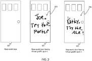
- FIG. 2illustrates an augmented reality scene.
- a userhas created virtual graffiti 203 that states, "Joe, try the porter" and has attached this virtual graffiti to the location of the door.
- the real-world door 201does not have the virtual graffiti existing upon it.
- their augmented reality viewing systemwill show door 201 having virtual graffiti 203 upon it.
- the virtual graffitiis not available to all users of system 100.
- the virtual graffitiis only available to those designated able to view it (preferably by the individual who created the virtual graffiti).
- each device 105-109will provide a unique augmented reality scene to their user.
- a first usermay view a first augmented reality scene, while a second user may view a totally different augmented reality scene.
- a first user, looking at door 201may view virtual graffiti 203, while a second user, looking at the same door 201 may view virtual graffiti 205.
- virtual graffiti 203displayed on a particular object (i.e., door 201)
- virtual graffitimay be displayed not attached to any object.
- virtual graffitimay be displayed as floating in the air, or simply in front of a person's field of view.
- a devicemust be capable of identifying the object's location, and then displaying the virtual graffiti at the object's location.
- a 3-dimensional rendering systemsuch as the Java Mobile 3D Graphics, or M3G, API can produce a view of the virtual scene unique to the user.
- This virtual scenemust be overlaid onto a view of the real world to produce an augmented reality scene.
- One method to overlay the virtual scene onto a view of the real world from the mobile device's camerais to make use of the M3G background object which allows any image to be placed behind the virtual scene as its background.
- M3G backgroundcontinuously updated frames from the camera can be placed behind the virtual scene, thus making the scene appear to be overlaid on the camera output.
- the device's locationis determined and sent to the server.
- the serverdetermines what messages, if any, are in proximity to and available for the user. These messages are then downloaded by the user and processed. The processing involves transforming the physical locations of the virtual messages into virtual coordinates. The messages are then placed at those virtual coordinates.
- the device's position and its orientationare used to define a viewpoint into the virtual world also in virtual coordinates. If the downloaded virtual message is visible from the given viewpoint, it is rendered on a mobile device's display on top of live video of the scene from the device's camera.
- the userwants to place a virtual message on the top of an object, the user must identify the location of the point on top of the object where the message will be left. In the simplest case, the user can place his device on the object and capture the location. He then sends this location with the virtual object and its associated content (i.e., a beer stein with the text message "try the porter" applied to the southward-facing side of the stein) to the server. The user further specifies that the message be available for a particular user. When the particular user arrives at the bar and is within range of the message, he will see the message from his location (and, therefore, his viewpoint).
- the virtual object and its associated contenti.e., a beer stein with the text message "try the porter" applied to the southward-facing side of the stein
- FIG. 3is a block diagram of the server of FIG. 1 .
- server 101comprises a global object manager 301, database 303, and personal object manager 305.
- global object manager 301will receive virtual graffiti from any device 105-109 wishing to store virtual graffiti on server 101. This information is preferably received wirelessly through receiver 307.
- Global object manager 301is responsible for storing all virtual graffiti existing within system 100.
- global object manager 301will also receive a location for the virtual graffiti along with a list of devices that are allowed to display the virtual graffiti. Again, this information is preferably received wirelessly through receiver 307. If the virtual graffiti is to be attached to a particular item, then the information needed for attaching the virtual graffiti to the object will be received as well.
- This informationpreferably comprises a location of a boundary for the virtual graffiti and the image that is to be displayed within the boundary. All of the above information is stored in database 303.
- each subscriberwill have its own personal object manager 305.
- Personal object manager 305is intended to serve as an intermediary between its corresponding subscriber and global object manager 301.
- Personal object manager 305will periodically receive a location for its corresponding subscriber's device. Once personal object manager 305 has determined the location of the device, personal object manager 305 will access global object manager 301 to determine if any virtual graffiti exists for the particular device at, or near the device's location.
- Personal object manager 305filters all available virtual graffiti in order to determine only the virtual graffiti relevant to the particular device and the device's location.
- Personal object manager 305then provides the device with the relevant information needed to display the virtual graffiti based on the location of the device, wherein the relevant virtual graffiti changes based on the identity and location of the device.
- This informationpreferably comprises a location of a boundary for the virtual graffiti and the image that is to be displayed within the boundary. This information will be provided to the device by instructing transmitter 309 to transmit the information wirelessly to the device.
- FIG. 4is a block diagram of a user device of FIG. 1 .
- the user devicecomprises augmented reality system 415, location circuitry 409, database 407, logic circuitry 405, transmitter 411, receiver 413, and user interface 417.
- a user of the devicecreates virtual graffiti via user interface 417.
- user interface 417comprises an electronic tablet capable of receiving and creating handwritten messages and/or pictures.
- pre-defined imagesare stored within database 407 and can be used in the creation of virtual graffiti. The process for creating virtual graffiti will be described in detail below.
- logic circuitry 405accesses location circuitry 409 and determines a location where the virtual graffiti was created. Logic circuitry 405 also receives a list of users with privileges to view the virtual graffiti. This list is also provided to logic circuitry 405 through user interface 417.
- the virtual graffitiis also associated with a physical object.
- logic circuitry 405will also receive information required to attach the virtual graffiti to an object.
- logic circuitry 405receives a location of a boundary for the virtual graffiti and the image that is to be displayed within the boundary.
- the virtual graffitiis provided to virtual graffiti server 101 by logic circuitry 405 instructing transmitter 411 to transmit the virtual graffiti, the location, the list of users able to view the virtual graffiti, and if relevant, the information needed to attach the virtual graffiti to an object.
- server 101periodically monitors the locations of all devices 105-109 along with their identities, and when a particular device is near a location where it is to be provided with virtual graffiti, server 101 utilizes network 103 to provide this information to the device.
- the deviceWhen a particular device is near a location where virtual graffiti is available for viewing, the device will notify the user, for example, by instructing user interface 417 to beep. The user can then use the device to view the virtual graffiti as part of an augmented reality scene.
- receiver 413When the device of FIG. 4 is near a location where virtual graffiti is available for it, receiver 413 will receive the virtual graffiti and the location of the virtual graffiti from server 101. If relevant, receiver 413 will also receive information needed to attach the virtual graffiti to a physical object. This information will be passed to logic circuitry 405 and stored in database 407.
- Logic circuitry 405periodically accesses location circuitry 409 to get updates to its location and provides these updates to server 101. When logic circuitry 405 determines that the virtual graffiti should be displayed, it will notify the user of the fact. The user can then use augmented reality system 415 to display the virtual graffiti. More particularly, imager 403 will image the current background and provide this to display 401. Display 401 will also receive the virtual graffiti from database 407 and provide an image of the current background with the virtual graffiti appropriately displayed. Thus, the virtual graffiti will be embedded in or merged with the user's view of the real-world.
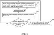
- FIG. 5is a flow chart showing operation of the server of FIG. 1 .
- the logic flowbegins at step 501 where global object manager 301 receives from a first device, information representing virtual graffiti, a location of the virtual graffiti, and a list of users able to view the virtual graffiti. This information is then stored in database 303 (step 503).
- personal object manager 305will periodically receive locations for devices (step 505) and determine if the location of a device is near any stored virtual graffiti (step 507). If, at step 507, personal object manager 305 determines that its corresponding device is near any virtual graffiti that it is able to view, then the logic flow continues to step 509 where the virtual graffiti and the necessary information for viewing the virtual graffiti is wirelessly transmitted to the device. However, if at step 507, it is determined that the device is not near any virtual graffiti, then the logic flow returns to step 501. As discussed above, the virtual graffiti is restricted as to what device can display the virtual graffiti.
- device 105will be placed near a first point that is used to define a boundary for the virtual graffiti.
- the devicewill locate the first point, and use the point to define the boundary.
- the devicewill receive an image that is to be used as virtual graffiti, and will fit the image within the boundary of the virtual graffiti.
- the devicemay be consecutively placed near multiple points that will define a polygon to be used as the boundary for the virtual graffiti.
- An imagewill then be received, and the image will be fit within the polygon. This process is illustrated in FIG 6 through FIG. 8 .
- the devicemay be placed near a single point that defines a center of a circle of a particular radius. The image will then be received and the image will be fit within the circle.
- device 105is placed near vertex 601 of a geometrical shape.
- Device 105is instructed by the user (via user interface 417) to use the particular location of device 105 as vertex 601.
- Logic circuitry 405receives the instruction to capture vertex 601 and accesses location circuitry 409 to determine the location of the vertex. This process repeats until a boundary 701 is created from vertices 601.
- Logic circuitry 405additionally receives image 702 that will be used to create the virtual graffiti.
- Image 702may be a hand-drawn image received from user interface 417, or alternatively may comprise a stored image from memory 407.
- logic circuitrycreates the virtual graffiti by appropriately fitting image 702 within boundary 701.
- server 101may create the virtual graffiti instead of device 105.
- boundary 701 and image 702will be provided to server 101.
- Server 101will create virtual graffiti 801, or may simply provide image 702 and boundary 701 to devices that are capable of viewing virtual graffiti 801. These devices will then create virtual graffiti 801 for viewing.
- a predefined polygonal boundary of arbitrary sizecan be centered on the device's current location and oriented horizontally (parallel to the ground) or vertically (perpendicular to the group) as well as rotated by a specified amount (e.g., 10 degrees from due north).
- a specified amounte.g. 10 degrees from due north.
- Another possibilityis to define a subset of vertices by direct capture of coordinates from the device and to then enter a relative offset for the remaining coordinates. For example, the user could select a rectangular region of a wall of a building by capturing the lower two vertices of the rectangle with the device and then specifying an offset of 100 feet in the vertical direction above each coordinate.
- FIG. 9is a flow chart showing operation of the user device of FIG. 1 .
- the logic flow of FIG. 9shows the steps necessary to create virtual graffiti and store the virtual graffiti on server 101 for others to view.
- the logic flowbegins at step 901 where device 105 device is placed near a first point and a location of the first point is determined by logic circuitry 405 accessing location circuitry 409 (step 903).
- steps 901 and 903may repeat until a sufficient amount of locations are determined for points (i.e., at least a second point) defining the boundary for the virtual graffiti).
- logic circuitry 409uses at least the location of the first point (and possibly the location of other points) to determine the boundary of the virtual graffiti.
- the pointsmay define vertices of the boundary, or alternatively, a single point may define an edge for a predetermined shape.
- an image to be used in the creation of virtual graffitiis received by logic circuitry 409.
- the imagemay be received from database 407, or may be received from user input (interface) 417.
- the logic flowthen continues to optional step 909. (Step 909 is executed whenever the virtual graffiti is to be created within device 105).
- logic circuitry 409creates the virtual graffiti by fitting the image within the boundary of the virtual graffiti.
- step 911logic circuitry 405 accesses location circuitry 409 to determine a location of the virtual graffiti and then receives a list of devices that may view the virtual graffiti (step 913). From this point in the logic flow, one of two paths may be taken.
- the logic flowcontinues to step 915 where the virtual graffiti, its location, and the list are provided to server 101, where the server provides the virtual graffiti to a user on the list when that user is near the location. This is accomplished by logic circuitry 405 utilizing transmitter 411 to wirelessly transmit the information.
- step 917the image, the information on the boundary, the location of the virtual graffiti, and the list are provided to a server 101, where the server creates the virtual graffiti and provides the virtual graffiti to a user when that user is near a location of the virtual graffiti.
- a 3 dimensional virtual objectmay be utilized in the creation of the virtual graffiti.
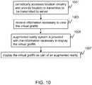
- FIG. 10is a flow chart showing operation of the user device of FIG. 1 .
- the logic flow of FIG. 10shows those steps necessary to display virtual graffiti.
- the logic flowbegins at step 1001 where logic circuitry 405 periodically accesses location circuitry 409 and provides a location to transmitter 411 to be transmitted to server 101.
- receiver 413receives information necessary to view the virtual graffiti.
- this informationmay simply contain a gross location of the virtual graffiti along with a representation of the virtual graffiti.
- this informationmay contain the location of a border for the virtual graffiti along with the image to be displayed within the border.
- the informationmay contain the necessary information to attach the virtual graffiti to an object.
- Such informationmay include a digital representation of the physical object, or a precise location of the virtual graffiti.
- logic circuitry 405accesses augmented reality system 415 and provides system 415 with the information necessary to display the virtual graffiti. For the 3D case, this would include the device's orientation to specify a viewpoint.
- display 401displays the virtual graffiti as part of an augmented reality scene.
- a user who receives virtual graffitimay be able to modify the virtual graffiti and then store the modified virtual graffiti on server 101.
- Multiple usersmay store multiple versions of the modified virtual graffiti on server 101. Users are allowed to modify any version of the virtual graffiti, no matter whether it is the original version, any intermediate versions, or the latest version. Therefore, a hierarchical relationship among all versions of the virtual graffiti can be established, which can be represented as a tree, with each node representing one version of the virtual graffiti and all its children representing the versions that are directly extended from the current version.
- Each version of the virtual graffitiis given a unique version number, may contain different attributes (such as locations), and may be available to different lists of users. Users can view multiple versions of the virtual graffiti at the same time and have the freedom to choose any versions for further modification. Once the modification is performed by the user, a new version of the virtual graffiti is created and sent to the server along with its location and a list of users having the privilege to view the virtual graffiti. The new version is then stored on the server and is available to other users of the system.
- a first usercan create virtual graffiti to be stored on server 101.
- Server 101may, at a later time receive the virtual graffiti from a second device along with a location of the modified virtual graffiti, wherein the modified virtual graffiti is an updated version of the virtual graffiti.
- a first usermay receive virtual graffiti as described above and then modify the virtual graffiti, sending the modified virtual graffiti back to server 101.
Landscapes
- Engineering & Computer Science (AREA)
- Computer Networks & Wireless Communication (AREA)
- Signal Processing (AREA)
- Processing Or Creating Images (AREA)
- Information Transfer Between Computers (AREA)
Abstract
Description
- The present invention relates virtual and augmented reality systems, and in particular, to a method and apparatus for creating virtual graffiti in a mobile virtual and augmented reality system.
- Messaging systems have been used for years to let users send and receive messages to each other. Currently, one of the simplest ways to send a message to another individual is to simply send a text message to the individual's cellular phone. Recently, it has been proposed to expand the capabilities of messaging systems so that subscribers of the network may be given the option of leaving a specific message at a particular coordinate location. For example, in
US6681107B2 , SYSTEM AND METHOD OF ACCESSING AND RECORDING MESSAGES AT COORDINATE WAY POINTS, the author proposes that a subscriber can merely push a button at a specific location causing the Device to save the physical location. Then he can push a "record message" button which allows him to speak a message into his device. This message could be directions to the subscriber's house from the specific location or any other personal message. The message is then uploaded to the network where it will become available to other network subscribers. The person creating the message can designate whether the message is available to all subscribers, only the persons stored in the memory of the Subscriber's Device, a subset of the persons stored in memory, or even a single person. - In order to enhance the user's experience with the above-type of context-aware messaging system, the types of information provided to the users must go beyond simple text, images, and video. With this in mind, United States Patent Application No.
11844538 - While the system of Buhrke does enhance a user's experience, a need exists for a method and apparatus for easily creating the virtual graffiti that will be left for a particular device to view.
FIG. 1 is a block diagram of a context-aware messaging system.FIG. 2 illustrates an augmented reality scene.FIG. 3 is a block diagram of the server ofFIG. 1 .FIG. 4 is a block diagram of the user device ofFIG. 1 .FIG. 5 is a flow chart showing operation of the server ofFIG. 1 .FIG. 6 .illustrates the creation of virtual graffiti.FIG. 7 . illustrates the creation of virtual graffiti.FIG. 8 . illustrates the creation of virtual graffiti.FIG. 9 is a flow chart showing operation of the user device ofFIG. 1 .FIG. 10 is a flow chart showing operation of the user device ofFIG. 1 .- Skilled artisans will appreciate that elements in the figures are illustrated for simplicity and clarity and have not necessarily been drawn to scale. For example, the dimensions and/or relative positioning of some of the elements in the figures may be exaggerated relative to other elements to help to improve understanding of various embodiments of the present invention. Also, common but well-understood elements that are useful or necessary in a commercially feasible embodiment are often not depicted in order to facilitate a less obstructed view of these various embodiments of the present invention. It will further be appreciated that certain actions and/or steps may be described or depicted in a particular order of occurrence while those skilled in the art will understand that such specificity with respect to sequence is not actually required. Those skilled in the art will further recognize that references to specific implementation embodiments such as "circuitry" may equally be accomplished via replacement with software instruction executions either on general purpose computing apparatus (e.g., CPU) or specialized processing apparatus (e.g., DSP). It will also be understood that the terms and expressions used herein have the ordinary technical meaning as is accorded to such terms and expressions by persons skilled in the technical field as set forth above except where different specific meanings have otherwise been set forth herein.
- In order to address the above-mentioned need, a method and apparatus is provided for easily creating virtual graffiti that will be left for a particular device to view. During operation a device will be placed near a first point that is used to define a boundary for the virtual graffiti. The device will locate the first point, and use the point to define the boundary. The device will receive an image that is to be used as virtual graffiti, and will fit the image within the boundary of the virtual graffiti. For example, the device may be consecutively placed near four points that will define a polygon to be used as the boundary for the virtual graffiti. An image will then be received, and the image will be fit within the polygon.
- The above-described method for creating virtual graffiti can be used to easily create virtual graffiti of various sizes and shapes. For example, a user may wish to place a virtual bull's eye around a large area so that it can be easily seen from passing airplanes. With the above technique, the user can simply walk to the edges of the desired boundary and instruct the device to use the locations as a boundary of the virtual graffiti.
- In an augmented reality system, computer generated images, or "virtual images" may be embedded in or merged with the user's view of the real-world environment to enhance the user's interactions with, or perception of the environment. In the present invention, the user's augmented reality system merges any virtual graffiti messages with the user's view of the real world.
- As an example, a first user may wish to leave a message for a second user to try a particular menu item at a restaurant. The message may be virtually written on the door of the restaurant, and left for the second user to view. When the second user visits the restaurant, he will receive an indication that virtual graffiti is available for him to view. The message will then appear to the second user on the door of the restaurant when viewed with the second user's augmented reality system. In a similar manner, the user may wish to leave a message for himself.
- The present invention encompasses a method for a device to create virtual graffiti, the method comprises the steps of being placing near a first point, determining a location of the first point, using the location of the first point to define a boundary for the virtual graffiti, receiving an image to be used as the virtual graffiti, and providing the image and information on the boundary to a server. The server then provides the virtual graffiti to a user when that user is near a location of the virtual graffiti.
- The present invention additionally encompasses a method for a device to create virtual graffiti. The method comprises the steps of being placing near a first point, determining a location of the first point, being placed near a second point, and determining a location of the second point. A boundary for the virtual graffiti is determined by using at least the location of the first point and the location of the second point as vertices for the boundary for the virtual graffiti. An image is then received to be used as virtual graffiti and the virtual graffiti is created by fitting the image within the boundary of the virtual graffiti.
- The present invention additionally encompasses an apparatus comprising location circuitry, logic circuitry accessing the location circuitry to determine a location of a point used to define a boundary for virtual graffiti, the logic circuitry then receiving an image to be used as virtual graffiti, and a transmitter providing the image and information on the boundary to a server, wherein the server provides the virtual graffiti to a user when that user is near a location of the virtual graffiti.
- The present invention additionally encompasses an apparatus comprising location circuitry being placing near a first point and a second point and determining a location of the first point and a location of the second point. The apparatus additionally comprising logic circuitry receiving an image to be used as virtual graffiti and determining a boundary for the virtual graffiti by using at least the location of the first point and the location of the second point as vertices for the boundary for the virtual graffiti, the logic circuitry creating the virtual graffiti by fitting the image within the boundary for the virtual graffiti.
- Turning now to the drawings, wherein like numerals designate like components,
FIG. 1 is a block diagram of context-aware messaging system 100.System 100 comprisesvirtual graffiti server 101,network 103, and user devices 105-109. In one embodiment of the present invention,network 103 comprises a next-generation cellular network, capable of high data rates. Such systems include the enhanced Evolved Universal Terrestrial Radio Access (UTRA) or the Evolved Universal Terrestrial Radio Access Network (UTRAN) (also known as EUTRA and EUTRAN) within 3GPP, along with evolutions of communication systems within other technical specification generating organizations (such as 'Phase 2' within 3GPP2, and evolutions of IEEE 802.11, 802.16, 802.20, and 802.22). User devices 105-109 comprise devices capable of real-world imaging and providing the user with the real-world image augmented with virtual graffiti. - During operation, a user (e.g., a user operating user device 105) determines that he wishes to send another user virtual graffiti as part of an augmented reality scene.
User device 105 is then utilized to create the virtual graffiti and associate the virtual graffiti with a location. The user also providesdevice 105 with a list of user(s) (e.g., user 107) that will be allowed to view the virtual graffiti.Device 105 then utilizesnetwork 103 to provide this information tovirtual graffiti server 101. Server 101 periodically monitors the locations of all devices 105-109 along with their identities, and when a particular device is near a location where it is to be provided with virtual graffiti,server 101 utilizesnetwork 103 to provide this information to the device. When a particular device is near a location where virtual graffiti is available for viewing, the device will notify the user, for example, by beeping. The user can then use the device to view the virtual graffiti as part of an augmented reality scene. Particularly, the virtual graffiti will be embedded in or merged with the user's view of the real-world. It should be noted that in alternate embodiments, no notification is sent to the user. It would then be up to the user to find any virtual graffiti in his environment.FIG. 2 illustrates an augmented reality scene. In this example, a user has createdvirtual graffiti 203 that states, "Joe, try the porter" and has attached this virtual graffiti to the location of the door. As is shown inFIG. 2 , the real-world door 201 does not have the virtual graffiti existing upon it. However, if a user has privileges to view the virtual graffiti, then their augmented reality viewing system will showdoor 201 havingvirtual graffiti 203 upon it. Thus, as is obvious, the virtual graffiti isnot available to all users ofsystem 100. The virtual graffiti is only available to those designated able to view it (preferably by the individual who created the virtual graffiti). Thus, each device 105-109 will provide a unique augmented reality scene to their user. For example, a first user may view a first augmented reality scene, while a second user may view a totally different augmented reality scene. This is illustrated inFIG. 2 withvirtual graffiti 205 being different thanvirtual graffiti 203. Thus, a first user, looking atdoor 201 may viewvirtual graffiti 203, while a second user, looking at thesame door 201 may viewvirtual graffiti 205.- Although the above example was given with
virtual graffiti 203 displayed on a particular object (i.e., door 201), in alternate embodiments of the present invention, virtual graffiti may be displayed not attached to any object. For example, virtual graffiti may be displayed as floating in the air, or simply in front of a person's field of view. As is evident, for any particular device 105-109 to be able to display virtual graffiti attached to a particular object, a device must be capable of identifying the object's location, and then displaying the virtual graffiti at the object's location. - Given a virtual scene containing virtual graffiti (at the specified virtual coordinates) and a viewpoint, a 3-dimensional rendering system such as the Java Mobile 3D Graphics, or M3G, API can produce a view of the virtual scene unique to the user. This virtual scene must be overlaid onto a view of the real world to produce an augmented reality scene. One method to overlay the virtual scene onto a view of the real world from the mobile device's camera is to make use of the M3G background object which allows any image to be placed behind the virtual scene as its background. Using the M3G background, continuously updated frames from the camera can be placed behind the virtual scene, thus making the scene appear to be overlaid on the camera output.
- Given the above information, when a user views virtual graffiti, the device's location is determined and sent to the server. The server determines what messages, if any, are in proximity to and available for the user. These messages are then downloaded by the user and processed. The processing involves transforming the physical locations of the virtual messages into virtual coordinates. The messages are then placed at those virtual coordinates. At the same time, the device's position and its orientation are used to define a viewpoint into the virtual world also in virtual coordinates. If the downloaded virtual message is visible from the given viewpoint, it is rendered on a mobile device's display on top of live video of the scene from the device's camera.
- Thus, if the user wants to place a virtual message on the top of an object, the user must identify the location of the point on top of the object where the message will be left. In the simplest case, the user can place his device on the object and capture the location. He then sends this location with the virtual object and its associated content (i.e., a beer stein with the text message "try the porter" applied to the southward-facing side of the stein) to the server. The user further specifies that the message be available for a particular user. When the particular user arrives at the bar and is within range of the message, he will see the message from his location (and, therefore, his viewpoint). If he is looking toward the eastward-facing side of the message, he will see the stein, but will just be able to tell that there is some text message on the southern side. If a user wishes to read the text message, he will have to move his device (and thus his viewpoint) so that it is facing the southern side of the stein.
FIG. 3 is a block diagram of the server ofFIG. 1 . As is evident,server 101 comprises aglobal object manager 301,database 303, andpersonal object manager 305. During operation,global object manager 301 will receive virtual graffiti from any device 105-109 wishing to store virtual graffiti onserver 101. This information is preferably received wirelessly throughreceiver 307.Global object manager 301 is responsible for storing all virtual graffiti existing withinsystem 100. Along with the virtual graffiti,global object manager 301 will also receive a location for the virtual graffiti along with a list of devices that are allowed to display the virtual graffiti. Again, this information is preferably received wirelessly throughreceiver 307. If the virtual graffiti is to be attached to a particular item, then the information needed for attaching the virtual graffiti to the object will be received as well. This information preferably comprises a location of a boundary for the virtual graffiti and the image that is to be displayed within the boundary. All of the above information is stored indatabase 303.- Although only one
personal object manager 305 is shown inFIG. 3 , it is envisioned that each subscriber will have its ownpersonal object manager 305.Personal object manager 305 is intended to serve as an intermediary between its corresponding subscriber andglobal object manager 301.Personal object manager 305 will periodically receive a location for its corresponding subscriber's device. Oncepersonal object manager 305 has determined the location of the device,personal object manager 305 will accessglobal object manager 301 to determine if any virtual graffiti exists for the particular device at, or near the device's location.Personal object manager 305 filters all available virtual graffiti in order to determine only the virtual graffiti relevant to the particular device and the device's location.Personal object manager 305 then provides the device with the relevant information needed to display the virtual graffiti based on the location of the device, wherein the relevant virtual graffiti changes based on the identity and location of the device. This information preferably comprises a location of a boundary for the virtual graffiti and the image that is to be displayed within the boundary. This information will be provided to the device by instructingtransmitter 309 to transmit the information wirelessly to the device. FIG. 4 is a block diagram of a user device ofFIG. 1 . As shown, the user device comprises augmentedreality system 415,location circuitry 409,database 407,logic circuitry 405,transmitter 411,receiver 413, anduser interface 417. During operation, a user of the device creates virtual graffiti viauser interface 417. In one embodiment of the present invention,user interface 417 comprises an electronic tablet capable of receiving and creating handwritten messages and/or pictures. In another embodiment, pre-defined images are stored withindatabase 407 and can be used in the creation of virtual graffiti. The process for creating virtual graffiti will be described in detail below.- Once
logic circuitry 405 receives the virtual graffiti fromuser interface 417,logic circuitry 405 accesseslocation circuitry 409 and determines a location where the virtual graffiti was created.Logic circuitry 405 also receives a list of users with privileges to view the virtual graffiti. This list is also provided tologic circuitry 405 throughuser interface 417. - In one embodiment of the present invention the virtual graffiti is also associated with a physical object. When this is the case,
logic circuitry 405 will also receive information required to attach the virtual graffiti to an object. In anotherembodiment logic circuitry 405 receives a location of a boundary for the virtual graffiti and the image that is to be displayed within the boundary. Finally, the virtual graffiti is provided tovirtual graffiti server 101 bylogic circuitry 405 instructingtransmitter 411 to transmit the virtual graffiti, the location, the list of users able to view the virtual graffiti, and if relevant, the information needed to attach the virtual graffiti to an object. - As discussed above,
server 101 periodically monitors the locations of all devices 105-109 along with their identities, and when a particular device is near a location where it is to be provided with virtual graffiti,server 101 utilizesnetwork 103 to provide this information to the device. - When a particular device is near a location where virtual graffiti is available for viewing, the device will notify the user, for example, by instructing
user interface 417 to beep. The user can then use the device to view the virtual graffiti as part of an augmented reality scene. Thus, when the device ofFIG. 4 is near a location where virtual graffiti is available for it,receiver 413 will receive the virtual graffiti and the location of the virtual graffiti fromserver 101. If relevant,receiver 413 will also receive information needed to attach the virtual graffiti to a physical object. This information will be passed tologic circuitry 405 and stored indatabase 407. Logic circuitry 405 periodically accesseslocation circuitry 409 to get updates to its location and provides these updates toserver 101. Whenlogic circuitry 405 determines that the virtual graffiti should be displayed, it will notify the user of the fact. The user can then useaugmented reality system 415 to display the virtual graffiti. More particularly,imager 403 will image the current background and provide this to display 401.Display 401 will also receive the virtual graffiti fromdatabase 407 and provide an image of the current background with the virtual graffiti appropriately displayed. Thus, the virtual graffiti will be embedded in or merged with the user's view of the real-world.FIG. 5 is a flow chart showing operation of the server ofFIG. 1 . The logic flow begins atstep 501 whereglobal object manager 301 receives from a first device, information representing virtual graffiti, a location of the virtual graffiti, and a list of users able to view the virtual graffiti. This information is then stored in database 303 (step 503). As discussed above,personal object manager 305 will periodically receive locations for devices (step 505) and determine if the location of a device is near any stored virtual graffiti (step 507). If, atstep 507,personal object manager 305 determines that its corresponding device is near any virtual graffiti that it is able to view, then the logic flow continues to step 509 where the virtual graffiti and the necessary information for viewing the virtual graffiti is wirelessly transmitted to the device. However, if atstep 507, it is determined that the device is not near any virtual graffiti, then the logic flow returns to step 501. As discussed above, the virtual graffiti is restricted as to what device can display the virtual graffiti.- As discussed above, a need exists for a method and apparatus for easily creating the virtual graffiti that will be left for a particular device to view. With this in mind, during the creation of virtual graffiti,
device 105 will be placed near a first point that is used to define a boundary for the virtual graffiti. The device will locate the first point, and use the point to define the boundary. The device will receive an image that is to be used as virtual graffiti, and will fit the image within the boundary of the virtual graffiti. For example, the device may be consecutively placed near multiple points that will define a polygon to be used as the boundary for the virtual graffiti. An image will then be received, and the image will be fit within the polygon. This process is illustrated inFIG 6 through FIG. 8 . In another example, the device may be placed near a single point that defines a center of a circle of a particular radius. The image will then be received and the image will be fit within the circle. - As shown in
FIG. 6 ,device 105 is placed nearvertex 601 of a geometrical shape.Device 105 is instructed by the user (via user interface 417) to use the particular location ofdevice 105 asvertex 601.Logic circuitry 405 receives the instruction to capturevertex 601 and accesseslocation circuitry 409 to determine the location of the vertex. This process repeats until aboundary 701 is created fromvertices 601. Logic circuitry 405 additionally receivesimage 702 that will be used to create the virtual graffiti.Image 702 may be a hand-drawn image received fromuser interface 417, or alternatively may comprise a stored image frommemory 407. Finally, as shown inFIG. 8 , logic circuitry creates the virtual graffiti by appropriatelyfitting image 702 withinboundary 701.- In an alternate embodiment,
server 101 may create the virtual graffiti instead ofdevice 105. In this scenario,boundary 701 andimage 702 will be provided toserver 101.Server 101 will createvirtual graffiti 801, or may simply provideimage 702 andboundary 701 to devices that are capable of viewingvirtual graffiti 801. These devices will then createvirtual graffiti 801 for viewing. - It should be noted that the above example was given with regards to
device 105 creating vertices for defining a boundary for virtual graffiti. However, such a technique for creating virtual graffiti may not needdevice 105 to be placed over a vertex in order to identifyboundary 701. For example, a predefined polygonal boundary of arbitrary size can be centered on the device's current location and oriented horizontally (parallel to the ground) or vertically (perpendicular to the group) as well as rotated by a specified amount (e.g., 10 degrees from due north). Another possibility is to define a subset of vertices by direct capture of coordinates from the device and to then enter a relative offset for the remaining coordinates. For example, the user could select a rectangular region of a wall of a building by capturing the lower two vertices of the rectangle with the device and then specifying an offset of 100 feet in the vertical direction above each coordinate. FIG. 9 is a flow chart showing operation of the user device ofFIG. 1 . In particular, the logic flow ofFIG. 9 shows the steps necessary to create virtual graffiti and store the virtual graffiti onserver 101 for others to view. The logic flow begins atstep 901 wheredevice 105 device is placed near a first point and a location of the first point is determined bylogic circuitry 405 accessing location circuitry 409 (step 903). (It should be noted thatsteps step 905logic circuitry 409 uses at least the location of the first point (and possibly the location of other points) to determine the boundary of the virtual graffiti. As discussed above, the points may define vertices of the boundary, or alternatively, a single point may define an edge for a predetermined shape.- Continuing, at
step 907 an image to be used in the creation of virtual graffiti is received bylogic circuitry 409. As discussed above, the image may be received fromdatabase 407, or may be received from user input (interface) 417. The logic flow then continues tooptional step 909. (Step 909 is executed whenever the virtual graffiti is to be created within device 105). Atoptional step 909logic circuitry 409 creates the virtual graffiti by fitting the image within the boundary of the virtual graffiti. - Continuing, at
step 911logic circuitry 405 accesseslocation circuitry 409 to determine a location of the virtual graffiti and then receives a list of devices that may view the virtual graffiti (step 913). From this point in the logic flow, one of two paths may be taken. When the virtual graffiti is created bydevice 105, the logic flow continues to step 915 where the virtual graffiti, its location, and the list are provided toserver 101, where the server provides the virtual graffiti to a user on the list when that user is near the location. This is accomplished bylogic circuitry 405 utilizingtransmitter 411 to wirelessly transmit the information. - When
server 101 is creating the virtual graffiti, the logic flow continues to step 917 where the image, the information on the boundary, the location of the virtual graffiti, and the list are provided to aserver 101, where the server creates the virtual graffiti and provides the virtual graffiti to a user when that user is near a location of the virtual graffiti. - It should be noted that while the above description was given with regards to using a two-dimensional image in creating virtual graffiti, in alternate embodiments, a 3 dimensional virtual object may be utilized in the creation of the virtual graffiti.
FIG. 10 is a flow chart showing operation of the user device ofFIG. 1 . In particular, the logic flow ofFIG. 10 shows those steps necessary to display virtual graffiti. The logic flow begins atstep 1001 wherelogic circuitry 405 periodically accesseslocation circuitry 409 and provides a location totransmitter 411 to be transmitted toserver 101. Atstep 1003,receiver 413 receives information necessary to view the virtual graffiti. As discussed above, this information may simply contain a gross location of the virtual graffiti along with a representation of the virtual graffiti. In other embodiments, this information may contain the location of a border for the virtual graffiti along with the image to be displayed within the border. In yet another embodiment, the information may contain the necessary information to attach the virtual graffiti to an object. Such information may include a digital representation of the physical object, or a precise location of the virtual graffiti. Atstep 1005,logic circuitry 405 accesses augmentedreality system 415 and providessystem 415 with the information necessary to display the virtual graffiti. For the 3D case, this would include the device's orientation to specify a viewpoint. Finally, atstep 1007,display 401 displays the virtual graffiti as part of an augmented reality scene.- While the invention has been particularly shown and described with reference to particular embodiments, it will be understood by those skilled in the art that various changes in form and details may be made therein without departing from the spirit and scope of the invention. For example, it is envisioned that a user who receives virtual graffiti may be able to modify the virtual graffiti and then store the modified virtual graffiti on
server 101. Multiple users may store multiple versions of the modified virtual graffiti onserver 101. Users are allowed to modify any version of the virtual graffiti, no matter whether it is the original version, any intermediate versions, or the latest version. Therefore, a hierarchical relationship among all versions of the virtual graffiti can be established, which can be represented as a tree, with each node representing one version of the virtual graffiti and all its children representing the versions that are directly extended from the current version. Each version of the virtual graffiti is given a unique version number, may contain different attributes (such as locations), and may be available to different lists of users. Users can view multiple versions of the virtual graffiti at the same time and have the freedom to choose any versions for further modification. Once the modification is performed by the user, a new version of the virtual graffiti is created and sent to the server along with its location and a list of users having the privilege to view the virtual graffiti. The new version is then stored on the server and is available to other users of the system. - With the above in mind, a first user can create virtual graffiti to be stored on
server 101.Server 101 may, at a later time receive the virtual graffiti from a second device along with a location of the modified virtual graffiti, wherein the modified virtual graffiti is an updated version of the virtual graffiti. Similarly, a first user may receive virtual graffiti as described above and then modify the virtual graffiti, sending the modified virtual graffiti back toserver 101. - Further aspects of the invention are provided by the subject matter of the following clauses:
- 1. A method for a device to create virtual graffiti, the method comprising the steps of:
- the device being placing near a first point;
- the device determining a location of the first point;
- the device using the location of the first point to define a boundary for the virtual graffiti;
- the device receiving an image to be used as the virtual graffiti; and
- the device providing the image and information on the boundary to a server, wherein the server provides the virtual graffiti to a user when that user is near a location of the virtual graffiti.
- 2. The method of clause 1 further comprising the step of:
the device creating the virtual graffiti by fitting the image within the boundary for the virtual graffiti. - 3. The method of clause 2 further comprising the steps of:
- the device determining a location of the virtual graffiti;
- the device receiving a list of devices that may view the virtual graffiti;
- the device providing the virtual graffiti, the location of the virtual graffiti, and the list to a server, wherein the server provides the virtual graffiti to a user on the list when that user is near the location.
- 4. The method of clause 1 further comprising the steps of:
- the device determining a location of the virtual graffiti;
- the device receiving a list of devices that may view the virtual graffiti;
- the device additionally providing the location and the list to a server, wherein the server provides the virtual graffiti to a user on the list when that user is near the location.
- 5. The method of clause 1 wherein the step of providing the image and the information on the boundary to a server comprises the step of wirelessly transmitting the image and the information on the boundary to a server.
- 6. A method for a device to create virtual graffiti, the method comprising the steps of:
- the device being placing near a first point;
- the device determining a location of the first point;
- the device being placed near a second point;
- the device determining a location of the second point;
- the device determining a boundary for the virtual graffiti by using at least the location of the first point and the location of the second point as vertices for the boundary for the virtual graffiti;
- the device receiving an image to be used as virtual graffiti; and
- the device creating the virtual graffiti by fitting the image within the boundary of the virtual graffiti.
- 7. The method of clause 6 further comprising the steps of:
- the device determining a location of the virtual graffiti;
- the device receiving a list of devices that may view the virtual graffiti;
- the device providing the virtual graffiti, the location, and the list of devices that may view the virtual graffiti to a server, wherein the server provides the virtual graffiti to a user on the list when that user is near the location.
- 8. The method of clause 7 wherein the step of providing comprises the step of wirelessly transmitting.
- 9. An apparatus comprising:
- location circuitry;
- logic circuitry accessing the location circuitry to determine a location of a point used to define a boundary for virtual graffiti, the logic circuitry then receiving an image to be used as virtual graffiti; and
- a transmitter providing the image and information on the boundary to a server, wherein the server provides the virtual graffiti to a user when that user is near a location of the virtual graffiti.
- 10. An apparatus comprising:
- location circuitry being placing near a first point and a second point and determining a location of the first point and a location of the second point;
- logic circuitry receiving an image to be used as virtual graffiti and determining a boundary for the virtual graffiti by using at least the location of the first point and the location of the second point as vertices for the boundary for the virtual graffiti, the logic circuitry creating the virtual graffiti by fitting the image within the boundary for the virtual graffiti.
Claims (5)
- A method for a device to create virtual graffiti, the method comprising the steps of:the device being placing near a first point;the device determining a location of the first point;the device being placed near a second point;the device determining a location of the second point;the device determining a boundary for the virtual graffiti by using at least the location of the first point and the location of the second point as vertices for the boundary for the virtual graffiti;the device receiving an image to be used as virtual graffiti; andthe device creating the virtual graffiti by fitting the image within the boundary of the virtual graffiti.
- The method of claim 1 further comprising the steps of:the device determining a location of the virtual graffiti;the device receiving a list of devices that may view the virtual graffiti;the device providing the virtual graffiti, the location, and the list of devices that may view the virtual graffiti to a server, wherein the server provides the virtual graffiti to a user on the list when that user is near the location.
- The method of claim 2 wherein the step of providing comprises the step of wirelessly transmitting.
- An apparatus comprising:location circuitry;logic circuitry accessing the location circuitry to determine a location of a point used to define a boundary for virtual graffiti, the logic circuitry then receiving an image to be used as virtual graffiti; anda transmitter providing the image and information on the boundary to a server, wherein the server provides the virtual graffiti to a user when that user is near a location of the virtual graffiti.
- An apparatus comprising:location circuitry being placing near a first point and a second point and determining a location of the first point and a location of the second point;logic circuitry receiving an image to be used as virtual graffiti and determining a boundary for the virtual graffiti by using at least the location of the first point and the location of the second point as vertices for the boundary for the virtual graffiti, the logic circuitry creating the virtual graffiti by fitting the image within the boundary for the virtual graffiti.
Applications Claiming Priority (3)
| Application Number | Priority Date | Filing Date | Title |
|---|---|---|---|
| US12/365,266US8350871B2 (en) | 2009-02-04 | 2009-02-04 | Method and apparatus for creating virtual graffiti in a mobile virtual and augmented reality system |
| EP10738967.8AEP2394448B1 (en) | 2009-02-04 | 2010-01-26 | Method and apparatus for creating virtual graffiti in a mobile virtual and augmented reality system |
| PCT/US2010/022091WO2010090906A2 (en) | 2009-02-04 | 2010-01-26 | Method and apparatus for creating virtual graffiti in a mobile virtual and augmented reality system |
Related Parent Applications (2)
| Application Number | Title | Priority Date | Filing Date |
|---|---|---|---|
| EP10738967.8ADivisionEP2394448B1 (en) | 2009-02-04 | 2010-01-26 | Method and apparatus for creating virtual graffiti in a mobile virtual and augmented reality system |
| EP10738967.8ADivision-IntoEP2394448B1 (en) | 2009-02-04 | 2010-01-26 | Method and apparatus for creating virtual graffiti in a mobile virtual and augmented reality system |
Publications (2)
| Publication Number | Publication Date |
|---|---|
| EP3370445A1true EP3370445A1 (en) | 2018-09-05 |
| EP3370445B1 EP3370445B1 (en) | 2022-06-29 |
Family
ID=42397309
Family Applications (2)
| Application Number | Title | Priority Date | Filing Date |
|---|---|---|---|
| EP10738967.8ANot-in-forceEP2394448B1 (en) | 2009-02-04 | 2010-01-26 | Method and apparatus for creating virtual graffiti in a mobile virtual and augmented reality system |
| EP18182855.9AActiveEP3370445B1 (en) | 2009-02-04 | 2010-01-26 | Method and apparatus for creating virtual graffiti in a mobile virtual and augmented reality system |
Family Applications Before (1)
| Application Number | Title | Priority Date | Filing Date |
|---|---|---|---|
| EP10738967.8ANot-in-forceEP2394448B1 (en) | 2009-02-04 | 2010-01-26 | Method and apparatus for creating virtual graffiti in a mobile virtual and augmented reality system |
Country Status (8)
| Country | Link |
|---|---|
| US (2) | US8350871B2 (en) |
| EP (2) | EP2394448B1 (en) |
| KR (1) | KR101277906B1 (en) |
| CN (1) | CN102308599B (en) |
| BR (1) | BRPI1008515B1 (en) |
| DE (1) | DE202010018456U1 (en) |
| MX (1) | MX2011006955A (en) |
| WO (1) | WO2010090906A2 (en) |
Families Citing this family (63)
| Publication number | Priority date | Publication date | Assignee | Title |
|---|---|---|---|---|
| WO2007076555A2 (en)* | 2005-12-29 | 2007-07-05 | Aechelon Technology, Inc. | A location based wireless collaborative environment with a visual user interface |
| US7853296B2 (en)* | 2007-10-31 | 2010-12-14 | Motorola Mobility, Inc. | Mobile virtual and augmented reality system |
| US20100214111A1 (en)* | 2007-12-21 | 2010-08-26 | Motorola, Inc. | Mobile virtual and augmented reality system |
| US20090237328A1 (en)* | 2008-03-20 | 2009-09-24 | Motorola, Inc. | Mobile virtual and augmented reality system |
| JP5047090B2 (en)* | 2008-07-31 | 2012-10-10 | キヤノン株式会社 | system |
| US8350871B2 (en)* | 2009-02-04 | 2013-01-08 | Motorola Mobility Llc | Method and apparatus for creating virtual graffiti in a mobile virtual and augmented reality system |
| EP2355472B1 (en)* | 2010-01-22 | 2020-03-04 | Samsung Electronics Co., Ltd. | Apparatus and method for transmitting and receiving handwriting animation message |
| US8797353B2 (en)* | 2010-02-12 | 2014-08-05 | Samsung Electronics Co., Ltd. | Augmented media message |
| KR101459175B1 (en)* | 2010-12-23 | 2014-11-07 | 주식회사 케이티 | System and Terminal Device for Sharing Moving Virtual Images and Method Thereof |
| KR101292463B1 (en)* | 2011-01-27 | 2013-07-31 | 주식회사 팬택 | Augmented reality system and method that share augmented reality service to remote |
| WO2012118507A1 (en)* | 2011-03-03 | 2012-09-07 | Research In Motion Limited | Methods and apparatus to generate virtual-world environments |
| US8743244B2 (en) | 2011-03-21 | 2014-06-03 | HJ Laboratories, LLC | Providing augmented reality based on third party information |
| US8810598B2 (en) | 2011-04-08 | 2014-08-19 | Nant Holdings Ip, Llc | Interference based augmented reality hosting platforms |
| US8891772B2 (en) | 2011-06-17 | 2014-11-18 | Microsoft Corporation | Cloud key escrow system |
| US8627508B2 (en)* | 2011-06-17 | 2014-01-07 | Microsoft Corporation | Cloud key directory for federating data exchanges |
| EP3680863B1 (en)* | 2011-08-24 | 2024-01-10 | Sony Group Corporation | Information processing device, information processing method, and program |
| EP2783340A4 (en) | 2011-11-21 | 2015-03-25 | Nant Holdings Ip Llc | Subscription bill service, systems and methods |
| US8521128B1 (en) | 2011-12-09 | 2013-08-27 | Google Inc. | Method, system, and computer program product for obtaining crowd-sourced location information |
| KR101874895B1 (en)* | 2012-01-12 | 2018-07-06 | 삼성전자 주식회사 | Method for providing augmented reality and terminal supporting the same |
| JP5942456B2 (en)* | 2012-02-10 | 2016-06-29 | ソニー株式会社 | Image processing apparatus, image processing method, and program |
| US9430876B1 (en)* | 2012-05-10 | 2016-08-30 | Aurasma Limited | Intelligent method of determining trigger items in augmented reality environments |
| US9064326B1 (en)* | 2012-05-10 | 2015-06-23 | Longsand Limited | Local cache of augmented reality content in a mobile computing device |
| US9066200B1 (en)* | 2012-05-10 | 2015-06-23 | Longsand Limited | User-generated content in a virtual reality environment |
| US10176635B2 (en) | 2012-06-28 | 2019-01-08 | Microsoft Technology Licensing, Llc | Saving augmented realities |
| US20140053944A1 (en)* | 2012-08-21 | 2014-02-27 | Anheuser-Busch Inbev | Refill station using an intelligent beverage container |
| US9270885B2 (en) | 2012-10-26 | 2016-02-23 | Google Inc. | Method, system, and computer program product for gamifying the process of obtaining panoramic images |
| US9325861B1 (en) | 2012-10-26 | 2016-04-26 | Google Inc. | Method, system, and computer program product for providing a target user interface for capturing panoramic images |
| KR101984915B1 (en)* | 2012-12-03 | 2019-09-03 | 삼성전자주식회사 | Supporting Portable Device for operating an Augmented reality contents and system, and Operating Method thereof |
| US9088625B1 (en) | 2012-12-12 | 2015-07-21 | Google Inc. | Obtaining an image for a place of interest |
| CN103049729B (en)* | 2012-12-30 | 2015-12-23 | 成都理想境界科技有限公司 | Based on the augmented reality method of Quick Response Code, system and terminal |
| JP2014203406A (en)* | 2013-04-09 | 2014-10-27 | 富士通株式会社 | Control device, control method, and control program |
| US9443354B2 (en) | 2013-04-29 | 2016-09-13 | Microsoft Technology Licensing, Llc | Mixed reality interactions |
| EP3036923A4 (en) | 2013-08-22 | 2017-05-10 | Inc. Sensoriant | Method and system for addressing the problem of discovering relevant services and applications that are available over the internet or other communcations network |
| US9582516B2 (en) | 2013-10-17 | 2017-02-28 | Nant Holdings Ip, Llc | Wide area augmented reality location-based services |
| CN103716396B (en)* | 2013-12-27 | 2017-01-04 | 北京像素软件科技股份有限公司 | A kind of scribble method |
| US10592929B2 (en) | 2014-02-19 | 2020-03-17 | VP Holdings, Inc. | Systems and methods for delivering content |
| US9196151B2 (en) | 2014-04-04 | 2015-11-24 | Google Inc. | Encoding location-based reminders |
| US10338793B2 (en) | 2014-04-25 | 2019-07-02 | Timothy Isaac FISHER | Messaging with drawn graphic input |
| US20160012453A1 (en) | 2014-07-11 | 2016-01-14 | Shamim A. Naqvi | System and Method for Inferring the Intent of a User While Receiving Signals On a Mobile Communication Device From a Broadcasting Device |
| US10824440B2 (en) | 2014-08-22 | 2020-11-03 | Sensoriant, Inc. | Deriving personalized experiences of smart environments |
| JP2017049762A (en)* | 2015-09-01 | 2017-03-09 | 株式会社東芝 | System and method |
| US10228775B2 (en)* | 2016-01-22 | 2019-03-12 | Microsoft Technology Licensing, Llc | Cross application digital ink repository |
| CN105848286B (en)* | 2016-05-24 | 2019-05-14 | 华中科技大学 | The method and system of virtual scene is accurately positioned and triggered based on mobile terminal |
| CN106888203B (en) | 2016-12-13 | 2020-03-24 | 阿里巴巴集团控股有限公司 | Virtual object distribution method and device based on augmented reality |
| CN106843473B (en)* | 2016-12-30 | 2020-04-10 | 武汉市马里欧网络有限公司 | AR-based children painting system and method |
| US10242503B2 (en) | 2017-01-09 | 2019-03-26 | Snap Inc. | Surface aware lens |
| EP3349099A1 (en) | 2017-01-13 | 2018-07-18 | Kai-Holger Brassel | Immersive information and communication medium for very large user numbers |
| US10712901B2 (en) | 2018-06-27 | 2020-07-14 | Facebook Technologies, Llc | Gesture-based content sharing in artificial reality environments |
| US10635895B2 (en) | 2018-06-27 | 2020-04-28 | Facebook Technologies, Llc | Gesture-based casting and manipulation of virtual content in artificial-reality environments |
| US10783712B2 (en) | 2018-06-27 | 2020-09-22 | Facebook Technologies, Llc | Visual flairs for emphasizing gestures in artificial-reality environments |
| US12067683B2 (en)* | 2018-09-14 | 2024-08-20 | Streem, Llc | Location persistent augmented reality object and annotation placement |
| CA3119609A1 (en) | 2018-11-15 | 2020-05-22 | Edx Technologies, Inc. | Augmented reality (ar) imprinting methods and systems |
| US11176737B2 (en) | 2018-11-27 | 2021-11-16 | Snap Inc. | Textured mesh building |
| CN113330484B (en) | 2018-12-20 | 2025-08-05 | 斯纳普公司 | Virtual surface modification |
| US11189098B2 (en) | 2019-06-28 | 2021-11-30 | Snap Inc. | 3D object camera customization system |
| US11232646B2 (en)* | 2019-09-06 | 2022-01-25 | Snap Inc. | Context-based virtual object rendering |
| JP2021051497A (en)* | 2019-09-24 | 2021-04-01 | 東芝テック株式会社 | Information processing apparatus and program |
| US11263817B1 (en) | 2019-12-19 | 2022-03-01 | Snap Inc. | 3D captions with face tracking |
| US11227442B1 (en) | 2019-12-19 | 2022-01-18 | Snap Inc. | 3D captions with semantic graphical elements |
| US11651029B2 (en)* | 2020-01-09 | 2023-05-16 | Palantir Technologies Inc. | Contextual augmentation of map information using overlays |
| CN111476873B (en)* | 2020-03-12 | 2023-11-10 | 浙江工业大学 | A method of virtual graffiti on mobile phones based on augmented reality |
| CN113778218B (en)* | 2020-06-09 | 2024-07-02 | 上海哔哩哔哩科技有限公司 | Virtual graffiti method and system based on virtual electronic wall |
| EP4304886B1 (en)* | 2021-03-11 | 2025-06-04 | Cariad Se | Method and system for presenting a shared virtual environment to users residing in different vehicles, and server unit, user device, and vehicle |
Citations (3)
| Publication number | Priority date | Publication date | Assignee | Title |
|---|---|---|---|---|
| US6681107B2 (en) | 2000-12-06 | 2004-01-20 | Xybernaut Corporation | System and method of accessing and recording messages at coordinate way points |
| US20080122871A1 (en)* | 2006-11-27 | 2008-05-29 | Microsoft Corporation | Federated Virtual Graffiti |
| US20080225779A1 (en)* | 2006-10-09 | 2008-09-18 | Paul Bragiel | Location-based networking system and method |
Family Cites Families (55)
| Publication number | Priority date | Publication date | Assignee | Title |
|---|---|---|---|---|
| US5659626A (en)* | 1994-10-20 | 1997-08-19 | Calspan Corporation | Fingerprint identification system |
| US6222939B1 (en)* | 1996-06-25 | 2001-04-24 | Eyematic Interfaces, Inc. | Labeled bunch graphs for image analysis |
| US6317127B1 (en) | 1996-10-16 | 2001-11-13 | Hughes Electronics Corporation | Multi-user real-time augmented reality system and method |
| US7073129B1 (en) | 1998-12-18 | 2006-07-04 | Tangis Corporation | Automated selection of appropriate information based on a computer user's context |
| US6825550B2 (en) | 1999-09-02 | 2004-11-30 | Micron Technology, Inc. | Board-on-chip packages with conductive foil on the chip surface |
| US7065253B2 (en)* | 1999-09-03 | 2006-06-20 | Intel Corporation | Wavelet zerotree coding of ordered bits |
| SE522917C2 (en) | 1999-09-10 | 2004-03-16 | Ericsson Telefon Ab L M | Mobile communication system which enables position-associated messages |
| WO2001024067A1 (en) | 1999-09-24 | 2001-04-05 | Discountnet Pty Limited | Interactive system and method for viewing on line advertising |
| US6304898B1 (en)* | 1999-10-13 | 2001-10-16 | Datahouse, Inc. | Method and system for creating and sending graphical email |
| US7127087B2 (en)* | 2000-03-27 | 2006-10-24 | Microsoft Corporation | Pose-invariant face recognition system and process |
| AU2001283004A1 (en)* | 2000-07-24 | 2002-02-05 | Vivcom, Inc. | System and method for indexing, searching, identifying, and editing portions of electronic multimedia files |
| US7224991B1 (en)* | 2000-09-12 | 2007-05-29 | At&T Corp. | Method and system for handwritten electronic messaging |
| US7003308B1 (en)* | 2000-09-12 | 2006-02-21 | At&T Corp. | Method and system for handwritten electronic messaging |
| US7176921B2 (en)* | 2000-10-20 | 2007-02-13 | Sony Corporation | Graphical rewriting system for multimedia descriptions |
| US6377793B1 (en) | 2000-12-06 | 2002-04-23 | Xybernaut Corporation | System and method of accessing and recording messages at coordinate way points |
| US20020144007A1 (en) | 2001-03-30 | 2002-10-03 | Koninklijke Philips Electronics N.V. | Task management system |
| WO2002089408A1 (en) | 2001-05-02 | 2002-11-07 | Symbian Limited | Group communication method for a wireless communication device |
| US7113618B2 (en) | 2001-09-18 | 2006-09-26 | Intel Corporation | Portable virtual reality |
| US6879835B2 (en) | 2001-12-04 | 2005-04-12 | International Business Machines Corporation | Location-specific messaging system |
| JP2003303356A (en) | 2002-04-09 | 2003-10-24 | Canon Inc | Exhibition equipment |
| TW569148B (en)* | 2002-04-09 | 2004-01-01 | Ind Tech Res Inst | Method for locating facial features in an image |
| US6917370B2 (en) | 2002-05-13 | 2005-07-12 | Charles Benton | Interacting augmented reality and virtual reality |
| US7190960B2 (en) | 2002-06-14 | 2007-03-13 | Cingular Wireless Ii, Llc | System for providing location-based services in a wireless network, such as modifying locating privileges among individuals and managing lists of individuals associated with such privileges |
| US7042421B2 (en) | 2002-07-18 | 2006-05-09 | Information Decision Technologies, Llc. | Method for advanced imaging in augmented reality |
| US7050078B2 (en) | 2002-12-19 | 2006-05-23 | Accenture Global Services Gmbh | Arbitrary object tracking augmented reality applications |
| KR100593982B1 (en) | 2003-11-06 | 2006-06-30 | 삼성전자주식회사 | Apparatus and method for providing virtual graffiti and a recording medium thereof |
| KR100593398B1 (en) | 2003-12-08 | 2006-06-28 | 한국전자통신연구원 | Location Information Providing System and Method of Mobile Terminal User Using Augmented Reality |
| US20050131776A1 (en) | 2003-12-15 | 2005-06-16 | Eastman Kodak Company | Virtual shopper device |
| KR100651508B1 (en) | 2004-01-30 | 2006-11-29 | 삼성전자주식회사 | Local information provision method using augmented reality and local information service system for it |
| US20050289590A1 (en) | 2004-05-28 | 2005-12-29 | Cheok Adrian D | Marketing platform |
| JP4677273B2 (en)* | 2004-06-29 | 2011-04-27 | キヤノン株式会社 | Information processing method and information processing apparatus |
| CN102982092B (en) | 2004-10-19 | 2017-06-09 | 飞扬管理有限公司 | For the system and method for location-based social networks |
| US8878851B2 (en)* | 2004-11-12 | 2014-11-04 | Synchronica Plc | Method and system for streaming documents, e-mail attachments and maps to wireless devices |
| KR20060057150A (en) | 2004-11-23 | 2006-05-26 | (주)유비테크놀로지스 | Parking Information Unmanned Guidance System |
| US7450954B2 (en) | 2005-02-07 | 2008-11-11 | Lamoda, Inc. | System and method for location-based interactive content |
| US20060241859A1 (en) | 2005-04-21 | 2006-10-26 | Microsoft Corporation | Virtual earth real-time advertising |
| ES2325374T3 (en) | 2005-05-03 | 2009-09-02 | Seac02 S.R.L. | INCREASED REALITY SYSTEM WITH IDENTIFICATION OF REAL MARKER OBJECT. |
| US8933889B2 (en) | 2005-07-29 | 2015-01-13 | Nokia Corporation | Method and device for augmented reality message hiding and revealing |
| US20070032244A1 (en) | 2005-08-08 | 2007-02-08 | Microsoft Corporation | Group-centric location tagging for mobile devices |
| US20070043828A1 (en) | 2005-08-16 | 2007-02-22 | Toshiba America Research, Inc. | Ghost messaging |
| US20070153731A1 (en)* | 2006-01-05 | 2007-07-05 | Nadav Fine | Varying size coefficients in a wireless local area network return channel |
| KR100754745B1 (en) | 2006-03-16 | 2007-09-03 | 에스케이 텔레콤주식회사 | Mobile Graffiti Space Implementation System and Its Method |
| KR100836481B1 (en) | 2006-09-08 | 2008-06-09 | 주식회사 케이티 | System and method for advertising location and activity information of user's avatar object on 3D virtual map to real world |
| US20080079751A1 (en) | 2006-10-03 | 2008-04-03 | Nokia Corporation | Virtual graffiti |
| US20080154697A1 (en) | 2006-12-22 | 2008-06-26 | Microsoft Corporation | Like-Minded People Proximity Detection and Interest Matching System |
| US8019167B2 (en)* | 2007-01-03 | 2011-09-13 | Human Monitoring Ltd. | Compressing high resolution images in a low resolution video |
| US20080215975A1 (en) | 2007-03-01 | 2008-09-04 | Phil Harrison | Virtual world user opinion & response monitoring |
| US10235429B2 (en)* | 2007-08-20 | 2019-03-19 | Stephen W. Meehan | System and method for organizing data in a dynamic user-customizable interface for search and display |
| US20090054084A1 (en) | 2007-08-24 | 2009-02-26 | Motorola, Inc. | Mobile virtual and augmented reality system |
| US7844229B2 (en) | 2007-09-21 | 2010-11-30 | Motorola Mobility, Inc | Mobile virtual and augmented reality system |
| US7853296B2 (en)* | 2007-10-31 | 2010-12-14 | Motorola Mobility, Inc. | Mobile virtual and augmented reality system |
| US20100214111A1 (en)* | 2007-12-21 | 2010-08-26 | Motorola, Inc. | Mobile virtual and augmented reality system |
| US20090237328A1 (en)* | 2008-03-20 | 2009-09-24 | Motorola, Inc. | Mobile virtual and augmented reality system |
| US20100066750A1 (en)* | 2008-09-16 | 2010-03-18 | Motorola, Inc. | Mobile virtual and augmented reality system |
| US8350871B2 (en)* | 2009-02-04 | 2013-01-08 | Motorola Mobility Llc | Method and apparatus for creating virtual graffiti in a mobile virtual and augmented reality system |
- 2009
- 2009-02-04USUS12/365,266patent/US8350871B2/ennot_activeExpired - Fee Related
- 2010
- 2010-01-26EPEP10738967.8Apatent/EP2394448B1/ennot_activeNot-in-force
- 2010-01-26BRBRPI1008515-7Apatent/BRPI1008515B1/enactiveIP Right Grant
- 2010-01-26DEDE202010018456.8Upatent/DE202010018456U1/ennot_activeExpired - Lifetime
- 2010-01-26CNCN201080006567.XApatent/CN102308599B/enactiveActive
- 2010-01-26EPEP18182855.9Apatent/EP3370445B1/enactiveActive
- 2010-01-26MXMX2011006955Apatent/MX2011006955A/enactiveIP Right Grant
- 2010-01-26KRKR1020117018186Apatent/KR101277906B1/ennot_activeExpired - Fee Related
- 2010-01-26WOPCT/US2010/022091patent/WO2010090906A2/enactiveApplication Filing
- 2012
- 2012-08-30USUS13/598,902patent/US20120327120A1/ennot_activeAbandoned
Patent Citations (3)
| Publication number | Priority date | Publication date | Assignee | Title |
|---|---|---|---|---|
| US6681107B2 (en) | 2000-12-06 | 2004-01-20 | Xybernaut Corporation | System and method of accessing and recording messages at coordinate way points |
| US20080225779A1 (en)* | 2006-10-09 | 2008-09-18 | Paul Bragiel | Location-based networking system and method |
| US20080122871A1 (en)* | 2006-11-27 | 2008-05-29 | Microsoft Corporation | Federated Virtual Graffiti |
Also Published As
| Publication number | Publication date |
|---|---|
| US20120327120A1 (en) | 2012-12-27 |
| WO2010090906A3 (en) | 2010-10-28 |
| KR101277906B1 (en) | 2013-06-21 |
| CN102308599A (en) | 2012-01-04 |
| MX2011006955A (en) | 2011-08-03 |
| CN102308599B (en) | 2015-10-21 |
| EP2394448A4 (en) | 2014-05-07 |
| BRPI1008515A2 (en) | 2016-03-08 |
| KR20110112405A (en) | 2011-10-12 |
| US8350871B2 (en) | 2013-01-08 |
| EP3370445B1 (en) | 2022-06-29 |
| DE202010018456U1 (en) | 2016-10-21 |
| EP2394448A2 (en) | 2011-12-14 |
| US20100194782A1 (en) | 2010-08-05 |
| BRPI1008515B1 (en) | 2021-03-16 |
| EP2394448B1 (en) | 2018-08-22 |
| WO2010090906A2 (en) | 2010-08-12 |
Similar Documents
| Publication | Publication Date | Title |
|---|---|---|
| EP3370445B1 (en) | Method and apparatus for creating virtual graffiti in a mobile virtual and augmented reality system | |
| US7853296B2 (en) | Mobile virtual and augmented reality system | |
| US7844229B2 (en) | Mobile virtual and augmented reality system | |
| US20090054084A1 (en) | Mobile virtual and augmented reality system | |
| US12217374B2 (en) | Surface aware lens | |
| EP2225896B1 (en) | Mobile virtual and augmented reality system | |
| EP3702914B1 (en) | Mobile virtual and augmented reality system | |
| CN115698946A (en) | SDK Engagement Monitor | |
| KR20230104676A (en) | Use of Portrait Images in Augmented Reality Components | |
| US12244569B2 (en) | Per participant end-to-end encrypted metadata | |
| CN116710895A (en) | Body UI for augmented reality components |
Legal Events
| Date | Code | Title | Description |
|---|---|---|---|
| PUAI | Public reference made under article 153(3) epc to a published international application that has entered the european phase | Free format text:ORIGINAL CODE: 0009012 | |
| STAA | Information on the status of an ep patent application or granted ep patent | Free format text:STATUS: THE APPLICATION HAS BEEN PUBLISHED | |
| AC | Divisional application: reference to earlier application | Ref document number:2394448 Country of ref document:EP Kind code of ref document:P | |
| AK | Designated contracting states | Kind code of ref document:A1 Designated state(s):AT BE BG CH CY CZ DE DK EE ES FI FR GB GR HR HU IE IS IT LI LT LU LV MC MK MT NL NO PL PT RO SE SI SK SM TR | |
| STAA | Information on the status of an ep patent application or granted ep patent | Free format text:STATUS: REQUEST FOR EXAMINATION WAS MADE | |
| 17P | Request for examination filed | Effective date:20190222 | |
| RBV | Designated contracting states (corrected) | Designated state(s):AT BE BG CH CY CZ DE DK EE ES FI FR GB GR HR HU IE IS IT LI LT LU LV MC MK MT NL NO PL PT RO SE SI SK SM TR | |
| STAA | Information on the status of an ep patent application or granted ep patent | Free format text:STATUS: EXAMINATION IS IN PROGRESS | |
| 17Q | First examination report despatched | Effective date:20190814 | |
| GRAP | Despatch of communication of intention to grant a patent | Free format text:ORIGINAL CODE: EPIDOSNIGR1 | |
| STAA | Information on the status of an ep patent application or granted ep patent | Free format text:STATUS: GRANT OF PATENT IS INTENDED | |
| INTG | Intention to grant announced | Effective date:20220111 | |
| RIC1 | Information provided on ipc code assigned before grant | Ipc:H04W 4/021 20180101ALI20211218BHEP Ipc:H04W 64/00 20090101ALI20211218BHEP Ipc:H04W 4/00 20180101ALI20211218BHEP Ipc:H04W 4/18 20090101ALI20211218BHEP Ipc:H04W 4/02 20180101AFI20211218BHEP | |
| GRAS | Grant fee paid | Free format text:ORIGINAL CODE: EPIDOSNIGR3 | |
| GRAA | (expected) grant | Free format text:ORIGINAL CODE: 0009210 | |
| STAA | Information on the status of an ep patent application or granted ep patent | Free format text:STATUS: THE PATENT HAS BEEN GRANTED | |
| AC | Divisional application: reference to earlier application | Ref document number:2394448 Country of ref document:EP Kind code of ref document:P | |
| AK | Designated contracting states | Kind code of ref document:B1 Designated state(s):AT BE BG CH CY CZ DE DK EE ES FI FR GB GR HR HU IE IS IT LI LT LU LV MC MK MT NL NO PL PT RO SE SI SK SM TR | |
| REG | Reference to a national code | Ref country code:CH Ref legal event code:EP | |
| REG | Reference to a national code | Ref country code:DE Ref legal event code:R096 Ref document number:602010068330 Country of ref document:DE | |
| REG | Reference to a national code | Ref country code:AT Ref legal event code:REF Ref document number:1502090 Country of ref document:AT Kind code of ref document:T Effective date:20220715 | |
| REG | Reference to a national code | Ref country code:IE Ref legal event code:FG4D | |
| REG | Reference to a national code | Ref country code:LT Ref legal event code:MG9D | |
| PG25 | Lapsed in a contracting state [announced via postgrant information from national office to epo] | Ref country code:SE Free format text:LAPSE BECAUSE OF FAILURE TO SUBMIT A TRANSLATION OF THE DESCRIPTION OR TO PAY THE FEE WITHIN THE PRESCRIBED TIME-LIMIT Effective date:20220629 Ref country code:NO Free format text:LAPSE BECAUSE OF FAILURE TO SUBMIT A TRANSLATION OF THE DESCRIPTION OR TO PAY THE FEE WITHIN THE PRESCRIBED TIME-LIMIT Effective date:20220929 Ref country code:LT Free format text:LAPSE BECAUSE OF FAILURE TO SUBMIT A TRANSLATION OF THE DESCRIPTION OR TO PAY THE FEE WITHIN THE PRESCRIBED TIME-LIMIT Effective date:20220629 Ref country code:HR Free format text:LAPSE BECAUSE OF FAILURE TO SUBMIT A TRANSLATION OF THE DESCRIPTION OR TO PAY THE FEE WITHIN THE PRESCRIBED TIME-LIMIT Effective date:20220629 Ref country code:GR Free format text:LAPSE BECAUSE OF FAILURE TO SUBMIT A TRANSLATION OF THE DESCRIPTION OR TO PAY THE FEE WITHIN THE PRESCRIBED TIME-LIMIT Effective date:20220930 Ref country code:FI Free format text:LAPSE BECAUSE OF FAILURE TO SUBMIT A TRANSLATION OF THE DESCRIPTION OR TO PAY THE FEE WITHIN THE PRESCRIBED TIME-LIMIT Effective date:20220629 Ref country code:BG Free format text:LAPSE BECAUSE OF FAILURE TO SUBMIT A TRANSLATION OF THE DESCRIPTION OR TO PAY THE FEE WITHIN THE PRESCRIBED TIME-LIMIT Effective date:20220929 | |
| REG | Reference to a national code | Ref country code:NL Ref legal event code:MP Effective date:20220629 | |
| REG | Reference to a national code | Ref country code:AT Ref legal event code:MK05 Ref document number:1502090 Country of ref document:AT Kind code of ref document:T Effective date:20220629 | |
| PG25 | Lapsed in a contracting state [announced via postgrant information from national office to epo] | Ref country code:LV Free format text:LAPSE BECAUSE OF FAILURE TO SUBMIT A TRANSLATION OF THE DESCRIPTION OR TO PAY THE FEE WITHIN THE PRESCRIBED TIME-LIMIT Effective date:20220629 | |
| PG25 | Lapsed in a contracting state [announced via postgrant information from national office to epo] | Ref country code:NL Free format text:LAPSE BECAUSE OF FAILURE TO SUBMIT A TRANSLATION OF THE DESCRIPTION OR TO PAY THE FEE WITHIN THE PRESCRIBED TIME-LIMIT Effective date:20220629 | |
| PG25 | Lapsed in a contracting state [announced via postgrant information from national office to epo] | Ref country code:SM Free format text:LAPSE BECAUSE OF FAILURE TO SUBMIT A TRANSLATION OF THE DESCRIPTION OR TO PAY THE FEE WITHIN THE PRESCRIBED TIME-LIMIT Effective date:20220629 Ref country code:SK Free format text:LAPSE BECAUSE OF FAILURE TO SUBMIT A TRANSLATION OF THE DESCRIPTION OR TO PAY THE FEE WITHIN THE PRESCRIBED TIME-LIMIT Effective date:20220629 Ref country code:RO Free format text:LAPSE BECAUSE OF FAILURE TO SUBMIT A TRANSLATION OF THE DESCRIPTION OR TO PAY THE FEE WITHIN THE PRESCRIBED TIME-LIMIT Effective date:20220629 Ref country code:PT Free format text:LAPSE BECAUSE OF FAILURE TO SUBMIT A TRANSLATION OF THE DESCRIPTION OR TO PAY THE FEE WITHIN THE PRESCRIBED TIME-LIMIT Effective date:20221031 Ref country code:ES Free format text:LAPSE BECAUSE OF FAILURE TO SUBMIT A TRANSLATION OF THE DESCRIPTION OR TO PAY THE FEE WITHIN THE PRESCRIBED TIME-LIMIT Effective date:20220629 Ref country code:EE Free format text:LAPSE BECAUSE OF FAILURE TO SUBMIT A TRANSLATION OF THE DESCRIPTION OR TO PAY THE FEE WITHIN THE PRESCRIBED TIME-LIMIT Effective date:20220629 Ref country code:AT Free format text:LAPSE BECAUSE OF FAILURE TO SUBMIT A TRANSLATION OF THE DESCRIPTION OR TO PAY THE FEE WITHIN THE PRESCRIBED TIME-LIMIT Effective date:20220629 | |
| PG25 | Lapsed in a contracting state [announced via postgrant information from national office to epo] | Ref country code:PL Free format text:LAPSE BECAUSE OF FAILURE TO SUBMIT A TRANSLATION OF THE DESCRIPTION OR TO PAY THE FEE WITHIN THE PRESCRIBED TIME-LIMIT Effective date:20220629 Ref country code:IS Free format text:LAPSE BECAUSE OF FAILURE TO SUBMIT A TRANSLATION OF THE DESCRIPTION OR TO PAY THE FEE WITHIN THE PRESCRIBED TIME-LIMIT Effective date:20221029 | |
| REG | Reference to a national code | Ref country code:DE Ref legal event code:R097 Ref document number:602010068330 Country of ref document:DE | |
| PG25 | Lapsed in a contracting state [announced via postgrant information from national office to epo] | Ref country code:DK Free format text:LAPSE BECAUSE OF FAILURE TO SUBMIT A TRANSLATION OF THE DESCRIPTION OR TO PAY THE FEE WITHIN THE PRESCRIBED TIME-LIMIT Effective date:20220629 Ref country code:CZ Free format text:LAPSE BECAUSE OF FAILURE TO SUBMIT A TRANSLATION OF THE DESCRIPTION OR TO PAY THE FEE WITHIN THE PRESCRIBED TIME-LIMIT Effective date:20220629 | |
| PLBE | No opposition filed within time limit | Free format text:ORIGINAL CODE: 0009261 | |
| STAA | Information on the status of an ep patent application or granted ep patent | Free format text:STATUS: NO OPPOSITION FILED WITHIN TIME LIMIT | |
| 26N | No opposition filed | Effective date:20230330 | |
| P01 | Opt-out of the competence of the unified patent court (upc) registered | Effective date:20230510 | |
| PG25 | Lapsed in a contracting state [announced via postgrant information from national office to epo] | Ref country code:SI Free format text:LAPSE BECAUSE OF FAILURE TO SUBMIT A TRANSLATION OF THE DESCRIPTION OR TO PAY THE FEE WITHIN THE PRESCRIBED TIME-LIMIT Effective date:20220629 | |
| REG | Reference to a national code | Ref country code:CH Ref legal event code:PL | |
| PG25 | Lapsed in a contracting state [announced via postgrant information from national office to epo] | Ref country code:LU Free format text:LAPSE BECAUSE OF NON-PAYMENT OF DUE FEES Effective date:20230126 | |
| REG | Reference to a national code | Ref country code:BE Ref legal event code:MM Effective date:20230131 | |
| PG25 | Lapsed in a contracting state [announced via postgrant information from national office to epo] | Ref country code:LI Free format text:LAPSE BECAUSE OF NON-PAYMENT OF DUE FEES Effective date:20230131 Ref country code:CH Free format text:LAPSE BECAUSE OF NON-PAYMENT OF DUE FEES Effective date:20230131 | |
| PG25 | Lapsed in a contracting state [announced via postgrant information from national office to epo] | Ref country code:BE Free format text:LAPSE BECAUSE OF NON-PAYMENT OF DUE FEES Effective date:20230131 | |
| PG25 | Lapsed in a contracting state [announced via postgrant information from national office to epo] | Ref country code:IT Free format text:LAPSE BECAUSE OF FAILURE TO SUBMIT A TRANSLATION OF THE DESCRIPTION OR TO PAY THE FEE WITHIN THE PRESCRIBED TIME-LIMIT Effective date:20220629 Ref country code:IE Free format text:LAPSE BECAUSE OF NON-PAYMENT OF DUE FEES Effective date:20230126 | |
| PGFP | Annual fee paid to national office [announced via postgrant information from national office to epo] | Ref country code:DE Payment date:20240129 Year of fee payment:15 Ref country code:GB Payment date:20240129 Year of fee payment:15 | |
| PGFP | Annual fee paid to national office [announced via postgrant information from national office to epo] | Ref country code:FR Payment date:20240125 Year of fee payment:15 | |
| PG25 | Lapsed in a contracting state [announced via postgrant information from national office to epo] | Ref country code:MC Free format text:LAPSE BECAUSE OF FAILURE TO SUBMIT A TRANSLATION OF THE DESCRIPTION OR TO PAY THE FEE WITHIN THE PRESCRIBED TIME-LIMIT Effective date:20220629 | |
| PG25 | Lapsed in a contracting state [announced via postgrant information from national office to epo] | Ref country code:MC Free format text:LAPSE BECAUSE OF FAILURE TO SUBMIT A TRANSLATION OF THE DESCRIPTION OR TO PAY THE FEE WITHIN THE PRESCRIBED TIME-LIMIT Effective date:20220629 | |
| PG25 | Lapsed in a contracting state [announced via postgrant information from national office to epo] | Ref country code:BG Free format text:LAPSE BECAUSE OF FAILURE TO SUBMIT A TRANSLATION OF THE DESCRIPTION OR TO PAY THE FEE WITHIN THE PRESCRIBED TIME-LIMIT Effective date:20220629 | |
| PG25 | Lapsed in a contracting state [announced via postgrant information from national office to epo] | Ref country code:BG Free format text:LAPSE BECAUSE OF FAILURE TO SUBMIT A TRANSLATION OF THE DESCRIPTION OR TO PAY THE FEE WITHIN THE PRESCRIBED TIME-LIMIT Effective date:20220629 | |
| PG25 | Lapsed in a contracting state [announced via postgrant information from national office to epo] | Ref country code:CY Free format text:LAPSE BECAUSE OF FAILURE TO SUBMIT A TRANSLATION OF THE DESCRIPTION OR TO PAY THE FEE WITHIN THE PRESCRIBED TIME-LIMIT; INVALID AB INITIO Effective date:20100126 | |
| REG | Reference to a national code | Ref country code:DE Ref legal event code:R119 Ref document number:602010068330 Country of ref document:DE | |
| PG25 | Lapsed in a contracting state [announced via postgrant information from national office to epo] | Ref country code:HU Free format text:LAPSE BECAUSE OF FAILURE TO SUBMIT A TRANSLATION OF THE DESCRIPTION OR TO PAY THE FEE WITHIN THE PRESCRIBED TIME-LIMIT; INVALID AB INITIO Effective date:20100126 | |
| GBPC | Gb: european patent ceased through non-payment of renewal fee | Effective date:20250126 |