EP3367711B1 - Machine-to-machine gateway architecture and functionality - Google Patents
Machine-to-machine gateway architecture and functionalityDownload PDFInfo
- Publication number
- EP3367711B1 EP3367711B1EP18161433.0AEP18161433AEP3367711B1EP 3367711 B1EP3367711 B1EP 3367711B1EP 18161433 AEP18161433 AEP 18161433AEP 3367711 B1EP3367711 B1EP 3367711B1
- Authority
- EP
- European Patent Office
- Prior art keywords
- devices
- registration
- network
- management
- rar
- Prior art date
- Legal status (The legal status is an assumption and is not a legal conclusion. Google has not performed a legal analysis and makes no representation as to the accuracy of the status listed.)
- Active
Links
Images


Classifications
- H—ELECTRICITY
- H04—ELECTRIC COMMUNICATION TECHNIQUE
- H04W—WIRELESS COMMUNICATION NETWORKS
- H04W4/00—Services specially adapted for wireless communication networks; Facilities therefor
- H—ELECTRICITY
- H04—ELECTRIC COMMUNICATION TECHNIQUE
- H04L—TRANSMISSION OF DIGITAL INFORMATION, e.g. TELEGRAPHIC COMMUNICATION
- H04L43/00—Arrangements for monitoring or testing data switching networks
- H04L43/10—Active monitoring, e.g. heartbeat, ping or trace-route
- H—ELECTRICITY
- H04—ELECTRIC COMMUNICATION TECHNIQUE
- H04L—TRANSMISSION OF DIGITAL INFORMATION, e.g. TELEGRAPHIC COMMUNICATION
- H04L67/00—Network arrangements or protocols for supporting network services or applications
- H04L67/01—Protocols
- H04L67/12—Protocols specially adapted for proprietary or special-purpose networking environments, e.g. medical networks, sensor networks, networks in vehicles or remote metering networks
- H—ELECTRICITY
- H04—ELECTRIC COMMUNICATION TECHNIQUE
- H04L—TRANSMISSION OF DIGITAL INFORMATION, e.g. TELEGRAPHIC COMMUNICATION
- H04L67/00—Network arrangements or protocols for supporting network services or applications
- H04L67/50—Network services
- H04L67/56—Provisioning of proxy services
- H—ELECTRICITY
- H04—ELECTRIC COMMUNICATION TECHNIQUE
- H04W—WIRELESS COMMUNICATION NETWORKS
- H04W4/00—Services specially adapted for wireless communication networks; Facilities therefor
- H04W4/50—Service provisioning or reconfiguring
- H—ELECTRICITY
- H04—ELECTRIC COMMUNICATION TECHNIQUE
- H04W—WIRELESS COMMUNICATION NETWORKS
- H04W4/00—Services specially adapted for wireless communication networks; Facilities therefor
- H04W4/70—Services for machine-to-machine communication [M2M] or machine type communication [MTC]
Definitions
- This applicationis related to wireless communications.
- Machine-to-machine (M2M) systemsmay include M2M devices that reside behind M2M gateways (GWs). These M2M devices may be remotely accessed through the GWs. Remote access may be imposed either as a result of a physical/hardware/software limitation, or by a choice of the M2M devices, (e.g., in cases where device power conservation may be desired).
- M2M GW functionalitymay include security capability (SC) functionality, generic messaging (GM) capability functionality, M2M device and M2M GW management (MDGM) capability functionality, and support for the GW as network proxy connectivity, as disclosed for example in Draft ETSI TS102 690 V0.1.3 (2010-02 ).
- SCsecurity capability
- GMgeneric messaging
- MDGMM2M GW management
- case 1For M2M devices that reside behind an M2M GW, two connectivity options, known as case 1 and case 2, may be applicable as summarized below.
- case 1 connectivityalso known as direct connectivity
- the M2M devicesmay connect to a network and application (N&A) domain directly via the access network or through an M2M GW.
- the M2M devicemay perform procedures, such as registration, authentication, authorization, management and provisioning with the N&A domain, for example.
- the M2M devicemay have other devices connected to it that may be hidden from the N&A domain.
- the M2M devicemay connect to the N&A domain via an M2M GW.
- M2M devicesmay connect to the M2M GW via an M2M area network, for example.
- the M2M GWmay connect to the N&A domain via an access network and act as a proxy for the M2M N&A domain towards the M2M devices that may be connected to the M2M GW.
- Such an M2M GWmay perform procedures, such as authentication, authorization, registration, management, and provisioning of the M2M devices that may be connected to it, and may also execute applications on behalf of the M2M N&A domain.
- the M2M GWmay decide on routing service layer requests originating from applications on M2M devices locally or to the M2M N&A domain.
- the M2M devices that connect to such an M2M GWmay or may not be addressable by the M2M N&A domain.
- the M2M GW functionalitymay have a number of shortcomings that may lead to inefficiencies if reachability, addressing, and repository functionality resides solely in the N&A domain. For example, in the "case 2" connectivity case, the device registration functionality may be moved to the M2M GW. It may be inefficient for the device to register with the M2M GW, yet have the registration information stored in the N&A domain. Other shortcomings may include access to M2M area addresses, signaling overhead associated with updating device mapping tables, device status synchronization, and device mobility.
- M2Mmachine-to-machine
- RARrepository
- M2M gatewaymay maintain a local mapping table, perform data aggregation, address translation, name translation, maintain a local device application repository, and establish M2M GW reachability and wake-up time based on an underlying M2M device reachability and wake-up time.
- the M2M GWmay communicate with a neighbor M2M GW RAR to facilitate the sharing and synchronization of proxy RAR based information between M2M GWs, base a registration on a registration attribute and request that cached data be used if a device is unreachable.
- the M2M GW RARmay support requests from other capabilities within the M2M GW or from M2M applications within the M2M GW.
- the M2M GW RARmay support requests from a network and application (N&A) domain RAR and the N&A RAR may be notified when certain events occur.
- N&Anetwork and application
- the M2M GWmay include an M2M device and M2M gateway management (MDGM) capability that receives management requests for an M2M device.
- the MDGM in the M2M GWmay function as a network proxy.
- the MDGMmay accept and process the management request from the N&A domain on behalf of the M2M device.
- the MDGMmay perform management functions of the M2M device on behalf of the N&A domain.
- the MDGMmay request the N&A domain for permission to start interacting with the M2M device to perform device management tasks.
- the MDGMmay initiate, as per the policy of the network and application domain provisioned to the M2M gateway, an interaction for device management tasks with the M2M device, and inform the N&A domain the results of the interaction for the device management tasks.
- FIG. 1Ais a diagram of an example communications system 100 in which one or more disclosed embodiments may be implemented.
- the communications system 100may be a multiple access system that provides content, such as voice, data, video, messaging, broadcast, etc., to multiple wireless users.
- the communications system 100may enable multiple wireless users to access such content through the sharing of system resources, including wireless bandwidth.
- the communications systems 100may employ one or more channel access methods, such as code division multiple access (CDMA), time division multiple access (TDMA), frequency division multiple access (FDMA), orthogonal FDMA (OFDMA), single-carrier FDMA (SC-FDMA), and the like.
- CDMAcode division multiple access
- TDMAtime division multiple access
- FDMAfrequency division multiple access
- OFDMAorthogonal FDMA
- SC-FDMAsingle-carrier FDMA
- the communications system 100may include wireless transmit/receive units (WTRUs) 102a, 102b, 102c, 102d, a radio access network (RAN) 104, a core network 106, a public switched telephone network (PSTN) 108, the Internet 110, and other networks 112, though it will be appreciated that the disclosed embodiments contemplate any number of WTRUs, base stations, networks, and/or network elements.
- WTRUs 102a, 102b, 102c, 102dmay be any type of device configured to operate and/or communicate in a wireless environment.
- the WTRUs 102a, 102b, 102c, 102dmay be configured to transmit and/or receive wireless signals and may include user equipment (UE), a mobile station, a fixed or mobile subscriber unit, a pager, a cellular telephone, a personal digital assistant (PDA), a smartphone, a laptop, a netbook, a personal computer, a wireless sensor, consumer electronics, and the like.
- UEuser equipment
- PDApersonal digital assistant
- smartphonea laptop
- netbooka personal computer
- M2Mmachine-to-machine
- the communications systems 100may also include a base station 114a and a base station 114b.
- Each of the base stations 114a, 114bmay be any type of device configured to wirelessly interface with at least one of the WTRUs 102a, 102b, 102c, 102d to facilitate access to one or more communication networks, such as the core network 106, the Internet 110, and/or the networks 112.
- the base stations 114a, 114bmay be a base transceiver station (BTS), a Node-B, an eNode B, a Home Node B, a Home eNode B, a site controller, an access point (AP), a wireless router, and the like. While the base stations 114a, 114b are each depicted as a single element, it will be appreciated that the base stations 114a, 114b may include any number of interconnected base stations and/or network elements.
- the base station 114amay be part of the RAN 104, which may also include other base stations and/or network elements (not shown), such as a base station controller (BSC), a radio network controller (RNC), relay nodes, etc.
- BSCbase station controller
- RNCradio network controller
- the base station 114a and/or the base station 114bmay be configured to transmit and/or receive wireless signals within a particular geographic region, which may be referred to as a cell (not shown).
- the cellmay further be divided into cell sectors.
- the cell associated with the base station 114amay be divided into three sectors.
- the base station 114amay include three transceivers, i.e., one for each sector of the cell.
- the base station 114amay employ multiple-input multiple output (MIMO) technology and, therefore, may utilize multiple transceivers for each sector of the cell.
- MIMOmultiple-input multiple output
- the base stations 114a, 114bmay communicate with one or more of the WTRUs 102a, 102b, 102c, 102d over an air interface 116, which may be any suitable wireless communication link (e.g., radio frequency (RF), microwave, infrared (IR), ultraviolet (UV), visible light, etc.).
- the air interface 116may be established using any suitable radio access technology (RAT).
- RATradio access technology
- the communications system 100may be a multiple access system and may employ one or more channel access schemes, such as CDMA, TDMA, FDMA, OFDMA, SC-FDMA, and the like.
- the base station 114a in the RAN 104 and the WTRUs 102a, 102b, 102cmay implement a radio technology such as Universal Mobile Telecommunications System (UMTS) Terrestrial Radio Access (UTRA), which may establish the air interface 116 using wideband CDMA (WCDMA).
- WCDMAmay include communication protocols such as High-Speed Packet Access (HSPA) and/or Evolved HSPA (HSPA+).
- HSPAmay include High-Speed Downlink Packet Access (HSDPA) and/or High-Speed Uplink Packet Access (HSUPA).
- the base station 114a and the WTRUs 102a, 102b, 102cmay implement a radio technology such as Evolved UMTS Terrestrial Radio Access (E-UTRA), which may establish the air interface 116 using Long Term Evolution (LTE) and/or LTE-Advanced (LTE-A).
- E-UTRAEvolved UMTS Terrestrial Radio Access
- LTELong Term Evolution
- LTE-ALTE-Advanced
- the base station 114a and the WTRUs 102a, 102b, 102cmay implement radio technologies such as IEEE 802.16 (i.e., Worldwide Interoperability for Microwave Access (WiMAX)), CDMA2000, CDMA2000 IX, CDMA2000 EV-DO, Interim Standard 2000 (IS-2000), Interim Standard 95 (IS-95), Interim Standard 856 (IS-856), Global System for Mobile communications (GSM), Enhanced Data rates for GSM Evolution (EDGE), GSM EDGE (GERAN), and the like.
- IEEE 802.16i.e., Worldwide Interoperability for Microwave Access (WiMAX)
- CDMA2000, CDMA2000 IX, CDMA2000 EV-DOCode Division Multiple Access 2000
- IS-95Interim Standard 95
- IS-856Interim Standard 856
- GSMGlobal System for Mobile communications
- GSMGlobal System for Mobile communications
- EDGEEnhanced Data rates for GSM Evolution
- GERANGSM EDGERAN
- the base station 114b in FIG. 1Amay be a wireless router, Home Node B, Home eNode B, or access point, for example, and may utilize any suitable RAT for facilitating wireless connectivity in a localized area, such as a place of business, a home, a vehicle, a campus, and the like.
- the base station 114b and the WTRUs 102c, 102dmay implement a radio technology such as IEEE 802.11 to establish a wireless local area network (WLAN).
- the base station 114b and the WTRUs 102c, 102dmay implement a radio technology such as IEEE 802.15 to establish a wireless personal area network (WPAN).
- WLANwireless local area network
- WPANwireless personal area network
- the base station 114b and the WTRUs 102c, 102dmay utilize a cellular-based RAT (e.g., WCDMA, CDMA2000, GSM, LTE, LTE-A, etc.) to establish a picocell or femtocell.
- a cellular-based RATe.g., WCDMA, CDMA2000, GSM, LTE, LTE-A, etc.
- the base station 114bmay have a direct connection to the Internet 110.
- the base station 114bmay not be required to access the Internet 110 via the core network 106.
- the RAN 104may be in communication with the core network 106, which may be any type of network configured to provide voice, data, applications, and/or voice over internet protocol (VoIP) services to one or more of the WTRUs 102a, 102b, 102c, 102d.
- the core network 106may provide call control, billing services, mobile location-based services, pre-paid calling, Internet connectivity, video distribution, etc., and/or perform high-level security functions, such as user authentication.
- the RAN 104 and/or the core network 106may be in direct or indirect communication with other RANs that employ the same RAT as the RAN 104 or a different RAT.
- the core network 106may also be in communication with another RAN (not shown) employing a GSM radio technology.
- the core network 106may also serve as a gateway for the WTRUs 102a, 102b, 102c, 102d to access the PSTN 108, the Internet 110, and/or other networks 112.
- the PSTN 108may include circuit-switched telephone networks that provide plain old telephone service (POTS).
- POTSplain old telephone service
- the Internet 110may include a global system of interconnected computer networks and devices that use common communication protocols, such as the transmission control protocol (TCP), user datagram protocol (UDP) and the internet protocol (IP) in the TCP/IP internet protocol suite.
- the networks 112may include wired or wireless communications networks owned and/or operated by other service providers.
- the networks 112may include another core network connected to one or more RANs, which may employ the same RAT as the RAN 104 or a different RAT.
- the WTRUs 102a, 102b, 102c, 102d in the communications system 100may include multi-mode capabilities, i.e., the WTRUs 102a, 102b, 102c, 102d may include multiple transceivers for communicating with different wireless networks over different wireless links.
- the WTRU 102c shown in FIG. 1Amay be configured to communicate with the base station 114a, which may employ a cellular-based radio technology, and with the base station 114b, which may employ an IEEE 802 radio technology.
- FIG. 1Bis a system diagram of an example WTRU 102.
- the WTRU 102may include a processor 118, a transceiver 120, a transmit/receive element 122, a speaker/microphone 124, a keypad 126, a display/touchpad 128, non-removable memory 106, removable memory 132, a power source 134, a global positioning system (GPS) chipset 136, and other peripherals 138.
- GPSglobal positioning system
- the processor 118may be a general purpose processor, a special purpose processor, a conventional processor, a digital signal processor (DSP), a plurality of microprocessors, one or more microprocessors in association with a DSP core, a controller, a microcontroller, Application Specific Integrated Circuits (ASICs), Field Programmable Gate Array (FPGAs) circuits, any other type of integrated circuit (IC), a state machine, and the like.
- the processor 118may perform signal coding, data processing, power control, input/output processing, and/or any other functionality that enables the WTRU 102 to operate in a wireless environment.
- the processor 118may be coupled to the transceiver 120, which may be coupled to the transmit/receive element 122. While FIG. 1B depicts the processor 118 and the transceiver 120 as separate components, it will be appreciated that the processor 118 and the transceiver 120 may be integrated together in an electronic package or chip.
- the transmit/receive element 122may be configured to transmit signals to, or receive signals from, a base station (e.g., the base station 114a) over the air interface 116.
- a base statione.g., the base station 114a
- the transmit/receive element 122may be an antenna configured to transmit and/or receive RF signals.
- the transmit/receive element 122may be an emitter/detector configured to transmit and/or receive IR, UV, or visible light signals, for example.
- the transmit/receive element 122may be configured to transmit and receive both RF and light signals. It will be appreciated that the transmit/receive element 122 may be configured to transmit and/or receive any combination of wireless signals.
- the WTRU 102may include any number of transmit/receive elements 122. More specifically, the WTRU 102 may employ MIMO technology. Thus, in one embodiment, the WTRU 102 may include two or more transmit/receive elements 122 (e.g., multiple antennas) for transmitting and receiving wireless signals over the air interface 116.
- the transceiver 120may be configured to modulate the signals that are to be transmitted by the transmit/receive element 122 and to demodulate the signals that are received by the transmit/receive element 122.
- the WTRU 102may have multi-mode capabilities.
- the transceiver 120may include multiple transceivers for enabling the WTRU 102 to communicate via multiple RATs, such as UTRA and IEEE 802.11, for example.
- the processor 118 of the WTRU 102may be coupled to, and may receive user input data from, the speaker/microphone 124, the keypad 126, and/or the display/touchpad 128 (e.g., a liquid crystal display (LCD) display unit or organic light-emitting diode (OLED) display unit).
- the processor 118may also output user data to the speaker/microphone 124, the keypad 126, and/or the display/touchpad 128.
- the processor 118may access information from, and store data in, any type of suitable memory, such as the non-removable memory 106 and/or the removable memory 132.
- the non-removable memory 106may include random-access memory (RAM), read-only memory (ROM), a hard disk, or any other type of memory storage device.
- the removable memory 132may include a subscriber identity module (SIM) card, a memory stick, a secure digital (SD) memory card, and the like.
- SIMsubscriber identity module
- SDsecure digital
- the processor 118may access information from, and store data in, memory that is not physically located on the WTRU 102, such as on a server or a home computer (not shown).
- the processor 118may receive power from the power source 134, and may be configured to distribute and/or control the power to the other components in the WTRU 102.
- the power source 134may be any suitable device for powering the WTRU 102.
- the power source 134may include one or more dry cell batteries (e.g., nickel-cadmium (NiCd), nickel-zinc (NiZn), nickel metal hydride (NiMH), lithium-ion (Li-ion), etc.), solar cells, fuel cells, and the like.
- the processor 118may also be coupled to the GPS chipset 136, which may be configured to provide location information (e.g., longitude and latitude) regarding the current location of the WTRU 102.
- location informatione.g., longitude and latitude
- the WTRU 102may receive location information over the air interface 116 from a base station (e.g., base stations 114a, 114b) and/or determine its location based on the timing of the signals being received from two or more nearby base stations. It will be appreciated that the WTRU 102 may acquire location information by way of any suitable location-determination method while remaining consistent with an embodiment.
- the processor 118may further be coupled to other peripherals 138, which may include one or more software and/or hardware modules that provide additional features, functionality and/or wired or wireless connectivity.
- the peripherals 138may include an accelerometer, an e-compass, a satellite transceiver, a digital camera (for photographs or video), a universal serial bus (USB) port, a vibration device, a television transceiver, a hands free headset, a Bluetooth® module, a frequency modulated (FM) radio unit, a digital music player, a media player, a video game player module, an Internet browser, and the like.
- the peripherals 138may include an accelerometer, an e-compass, a satellite transceiver, a digital camera (for photographs or video), a universal serial bus (USB) port, a vibration device, a television transceiver, a hands free headset, a Bluetooth® module, a frequency modulated (FM) radio unit, a digital music player, a media player, a video game player
- FIG. 1Cis a system diagram of the RAN 104 and the core network 106 according to an embodiment.
- the RAN 104may employ an E-UTRA radio technology to communicate with the WTRUs 102a, 102b, 102c over the air interface 116.
- the RAN 104may also be in communication with the core network 106.
- the RAN 104may include eNode-Bs 140a, 140b, 140c, though it will be appreciated that the RAN 104 may include any number of eNode-Bs while remaining consistent with an embodiment.
- the eNode-Bs 140a, 140b, 140cmay each include one or more transceivers for communicating with the WTRUs 102a, 102b, 102c over the air interface 116.
- the eNode-Bs 140a, 140b, 140cmay implement MIMO technology.
- the eNode-B 140afor example, may use multiple antennas to transmit wireless signals to, and receive wireless signals from, the WTRU 102a.
- Each of the eNode-Bs 140a, 140b, 140cmay be associated with a particular cell (not shown) and may be configured to handle radio resource management decisions, handover decisions, scheduling of users in the uplink and/or downlink, and the like. As shown in FIG. 1C , the eNode-Bs 140a, 140b, 140c may communicate with one another over an X2 interface.
- the core network 106 shown in FIG. 1Cmay include a mobility management gateway (MME) 142, a serving gateway 144, and a packet data network (PDN) gateway 146. While each of the foregoing elements are depicted as part of the core network 106, it will be appreciated that any one of these elements may be owned and/or operated by an entity other than the core network operator.
- MMEmobility management gateway
- PDNpacket data network
- the MME 142may be connected to each of the eNode-Bs 142a, 142b, 142c in the RAN 104 via an S1 interface and may serve as a control node.
- the MME 142may be responsible for authenticating users of the WTRUs 102a, 102b, 102c, bearer activation/deactivation, selecting a particular serving gateway during an initial attach of the WTRUs 102a, 102b, 102c, and the like.
- the MME 142may also provide a control plane function for switching between the RAN 104 and other RANs (not shown) that employ other radio technologies, such as GSM or WCDMA.
- the serving gateway 144may be connected to each of the eNode Bs 140a, 140b, 140c in the RAN 104 via the S1 interface.
- the serving gateway 144may generally route and forward user data packets to/from the WTRUs 102a, 102b, 102c.
- the serving gateway 144may also perform other functions, such as anchoring user planes during inter-eNode B handovers, triggering paging when downlink data is available for the WTRUs 102a, 102b, 102c, managing and storing contexts of the WTRUs 102a, 102b, 102c, and the like.
- the serving gateway 144may also be connected to the PDN gateway 146, which may provide the WTRUs 102a, 102b, 102c with access to packet-switched networks, such as the Internet 110, to facilitate communications between the WTRUs 102a, 102b, 102c and IP-enabled devices.
- the PDN gateway 146may provide the WTRUs 102a, 102b, 102c with access to packet-switched networks, such as the Internet 110, to facilitate communications between the WTRUs 102a, 102b, 102c and IP-enabled devices.
- the core network 106may facilitate communications with other networks.
- the core network 106may provide the WTRUs 102a, 102b, 102c with access to circuit-switched networks, such as the PSTN 108, to facilitate communications between the WTRUs 102a, 102b, 102c and traditional land-line communications devices.
- the core network 106may include, or may communicate with, an IP gateway (e.g., an IP multimedia subsystem (IMS) server) that serves as an interface between the core network 106 and the PSTN 108.
- IMSIP multimedia subsystem
- the core network 106may provide the WTRUs 102a, 102b, 102c with access to the networks 112, which may include other wired or wireless networks that are owned and/or operated by other service providers.
- Device user-plane datamay be data that is generated by M2M devices, for example sensor data.
- Registration attributesmay include characteristics of devices that may be allowed to register. The characteristics may relate to physical characteristics such as, for example, available power, available capacity, device identification (ID), and/or service class.
- Device control-plane informationmay include control information that pertains to a specific device, for example information regarding reachability, wake-up times and durations, registration information, and/or service information.
- End-to-end system requirementsmay be implemented to support M2M communication services.
- An M2M functional architecturemay be designed to deliver M2M services to applications.
- the M2M functional architecturemay present the overall end to end M2M functional entities, the relationships between these entities, as well as the relationship to European Telecommunications Standards Institute (ETSI) telecommunications and Internet converged services and protocols for advanced networks (TISPAN) and 3rd Generation Partnership Project (3GPP) networks.
- ETSIEuropean Telecommunications Standards Institute
- TISPANadvanced networks
- 3GPP3rd Generation Partnership Project
- FIG. 2shows an example overall architecture 200.
- the architecturemay be divided into two “domains”: an M2M device domain 210 and a network and application (N&A) domain 215.
- the M2M device domain 210may include M2M devices 220 that run M2M applications 222 using M2M service capabilities or M2M capabilities 224 (collectively "M2M service capabilities"), and N&A domain 215 functionality.
- M2M applicationsmay refer to applications that run the service logic using the M2M service capabilities.
- M2M service capabilitiesmay be a grouping of functions that may enable end-to-end communications between applications in M2M devices, M2M gateways and the M2M Core Network.
- the M2M device domain 210may further include an M2M area network 225 that may communicate between the M2M devices 220 and an M2M gateway (GW) 230, where the M2M GW may include M2M applications 232 and M2M service capabilities 234.
- the M2M GW 230may be used to communicate with the N&A domain 210.
- M2M GWmay refer to any entity that provides some service capabilities to devices behind it. These devices may be both ETSI and non-ETSI compliant, (e.g., legacy devices not supporting the M2M capabilities). Based on this definition, the M2M GW may be considered to be: 1) an ETSI compliant GW with ETSI compliant devices behind it, all connected through an M2M area network; 2) an ETSI compliant GW with non-ETSI compliant devices behind it, all connected through an M2M area network; 3) an ETSI compliant GW with a mixed device deployment behind it, (ETSI and non-ETSI compliant), all connected through an M2M area network; 4) an ETSI M2M device, connected to non-ETSI compliant devices using some legacy protocol, (e.g., Bluetooth®); 5) an ETSI M2M device, connected to ETSI compliant M2M devices; or 6) an ETSI compliant device with a mixed device deployment behind
- the N&A domain 210may include a transport network 237 for transporting data within the N&A domain 210, and an access network 235 for communicating with the M2M device domain 210.
- the access network 235may communicate with a core network (CN) 240, which in turn may communicate with M2M service capabilities 242.
- the M2M service capabilities 242 and the CN 240may comprise an M2M core 245.
- M2M applications 244operate with M2M service capabilities 242.
- a network management function 250may include functionality to manage the access network 235, transport network 237, and CN 240 and may include an M2M specific management function 252.
- AN M2M management function 255may include functionality to manage M2M service capabilities and M2M applications.
- the M2M devices 220 in the M2M device domain 215may either communicate directly with the N&A domain 210 using an access network 235, or alternatively, they may communicate indirectly through the M2M GW 230.
- the M2M GW 230may use the M2M area network 225 to communicate with the M2M devices 220 and may use the access network 235 to communicate with the N&A domain 210.
- the N&A M2M service capabilitiesmay include a reachability, addressing, and repository (RAR) functionality.
- RARreachability, addressing, and repository
- the M2M GWlacks such functionality and may have a number of shortcomings that may lead to inefficiencies if the RAR functionality resides solely in the N&A domain.
- the device registration functionalitymay be moved to the M2M GW. Therefore, it may be inefficient for the M2M device to register with the M2M GW, yet have the registration information stored in the N&A domain.
- the name resolution task for the M2M GWmay be assigned to a generic message delivery (GM) capability. This approach, however, may not be in line with the approach used for the N&A domain.
- GMgeneric message delivery
- device-to-device communicationsmay be supported through the M2M GW. If an M2M device does not know the M2M area address of a neighboring device, it may need to query the N&A RAR functionality to determine where to route the messages. The message may then use the services of the GM capability in the service provider domain, to route the traffic to the destination. Eliminating this transfer out of the M2M area network 225 may be more efficient. This query functionality may be supported by the GW and therefore be done locally at the GW.
- the N&A RARmay keep the device mapping table up to date.
- an M2M devicemay inform the N&A RAR about any change in address, reachability or sleep cycle, which may result in a potentially high signaling load. This may put a strain on the access and core networks.
- the M2M GW's reachability and wake-up statusmay be out-of-sync with, or independent of, the underlying devices. This may result in the M2M GW potentially having to store and forward traffic that may be destined for sleeping M2M devices. Therefore information about reachability, sleep cycle and addressing may be kept locally in the GW and shared with the N&A domain only on a need basis.
- M2M device mobility from one M2M GW to anothermay require a re-registration with the N&A domain service capabilities.
- Communication to M2M devices through multiple M2M GWsmay not be permitted, for example for mission critical applications or load sharing.
- "Local" access, through a home Node-B, for example,may require that communication go to the N&A domain, even if an application server resides in the M2M GW. If the GW includes the RAR functionality, communication using local access may be facilitated.
- FIG. 3shows a system architecture 300 where an M2M GW 320 may include a RAR entity 360.
- the system architecture 300may include an N&A M2M application entity 305 which may be in communication with an N&A M2M service capabilities entity 310, which in turn may be in communication with a transport and access network entity 315.
- the transport and access network entity 315may be in communication with the M2M GW 320.
- the M2M GW 320may in turn be in communication with M2M devices 330 through M2M area network 325.
- the N&A M2M application entity 305 and the N&A M2M service capabilities entity 310may be implemented using servers or alternatively, may be implemented in the network.
- the N&A domain M2M service capabilities entity 310may include for example reachability, addressing and device application repository (RAR) entity 350 provides capabilities as discussed herein, generic message delivery (GM) entity 352 provides at least session establishment and teardown along with security keys negotiation along with other capabilities, network and communication service selection (NCSS) entity 354 provides at least network selection when the M2M device or M2M GW can be reached through several network via several subscriptions along with other capabilities, M2M device and M2M GW management (MDGM) entity 356 provides capabilities as discussed herein, historization and data retention (HDR) entity (not shown) provides at least hiding of the history and data retention tasks from the M2M Application and the Devices/M2M GW along with other capabilities, generic M2M application enablement (GMAE) entity 358 is the single contact point to the M2M Applications in the N&A domain as well as providing other capabilities, security capability (SC) entity 359 provides at least authentication and service key management along with other capabilities, transaction management (TM) entity (not shown) handles at
- the N&A domain RAR service capabilitymay be tasked with functionality, such as name translation, reachability determination, wake-up determination, maintaining device information, maintaining a device application repository, and/or responding to requests. Converting a device name to a list of network routable addresses may be an example of name translation. For devices behind a GW, the network address may be that of the M2M GW.
- An example of reachability determinationmay be where, upon request, the RAR may provide the reachability status of a device.
- An example of wake-up determinationmay be where, upon request, the RAR may provide an indication of a device wake-up period.
- Other example functionalitiesmay be to maintain a device information mapping table such as device X ⁇ address, reachability, and wake-up times, maintain a device application repository such as registration information of device and its applications, and/or respond to requests from applications and other service capabilities for device registration information.
- a device information mapping tablesuch as device X ⁇ address, reachability, and wake-up times
- a device application repositorysuch as registration information of device and its applications
- the M2M GW 360may include a RAR entity 360, a GM entity 362, a SC entity 364, a MDGM entity 366 and other functionality entity 368.
- the M2M GW RAR entity 360may be a proxy RAR entity.
- the M2M GW RAR entity 360may maintain a local mapping table and store the following M2M device information for the M2M devices residing behind it. For example, the M2M GW RAR entity 360 may store an M2M area network address for each M2M device. AN M2M device may acquire a new address as a result of mobility, topology changes within the M2M area network, its connection point within the M2M area network and the like.
- the M2M GW RAR entity 360may also store a reachability status.
- the reachability statusmay be set to "on” when the M2M device is reachable, and to "off' when the M2M device is not reachable.
- the M2M GW RAR entity 360may also store the next planned wake-up time and wake-up duration, if available.
- the above informationmay be sent from the M2M device to the M2M GW RAR entity 360 using a dedicated control message in the M2M area network, for example.
- the above functionalitiesmay be included in any combination in the M2M GW RAR entity 360.
- the M2M GW RAR entity 360may also support requests from other capabilities within the M2M GW 320 or from the M2M application within the M2M GW 320.
- the other capabilities or M2M applicationsmay be notified upon the occurrence of certain events.
- the generic M2M device application enablement (GMDAE) capabilitymay need knowledge of the accessibility of a specific M2M device after it receives a message from the N&A domain. As a result, when the M2M device may become reachable and/or has its next planned wake-up time or wake-up duration may be sent to the GMDAE.
- the M2M GW RAR entity 360may support requests from the N&A domain RAR entity 350 and other M2M GW RARs.
- the N&A domain RAR 350 and other M2M GW RARsmay be notified for M2M devices behind the M2M GW 320 when certain monitored events occur. These events may, for example, be when a specific M2M device may become reachable, when an M2M device may acquire a new address as a result of mobility, and/or changes may occur on a set of M2M device applications registration information. These events may also include modification of specific data or attributes related to an application repository. For example, for a temperature sensor it could be the event of temperature modification or temperature reaching above or below a specified threshold.
- the above informationmay be provided after a change in status of any of the monitored events.
- the M2M GW 320may decide to send this information periodically, for example every K time units, or based on a predefined policy. For example, if the M2M GW 320 manages address translation, it may determine not to report an M2M device address change. Similarly, if the M2M GW 320 provides store and forward capability, it may determine not to report wake-up time changes. This determination may also be based on the availability of the access network. For example, the access network may be congested, and may request that the M2M GW 320 refrain from sending this information.
- the M2M GW RAR entity 360may support requests from the N&A domain RAR entity 350 and other M2M GW RARs. For example, these requests may be for M2M devices behind the M2M GW 320 and may concern reachability of an M2M device and/or the next planned wake-up time of an M2M device.
- the M2M GW RAR entity 360may perform address translation between area network and core network, if applicable. Examples of address translations may include Internet Protocol version 4 (IPv4), IPv6, and mobile station international integrated service digital network (ISDN) number (MSISDN). Performing an address translation may involve translation between a public GW address and a private device address.
- IPv4Internet Protocol version 4
- IPv6mobile station international integrated service digital network (ISDN) number
- MSISDNmobile station international integrated service digital network
- Performing an address translationmay involve translation between a public GW address and a private device address.
- the M2M GW RAR entity 360may handle name resolution for messages sent from a GMDAE capability in the service provider towards an M2M device. The mapping may be between a network routable GW address and an M2M device specific ID to an M2M area network address.
- the M2M GW RAR entity 360may maintain a local device application repository for M2M devices behind the M2M GW. For example, this may be done by storing device service class properties for M2M devices within the area network and by keeping this information up to date. The M2M GW RAR entity 360 may aggregate/fuse this class information. In another example, it may be done by storing the M2M GW RAR entity 360 in the device application repository the M2M device application registration information of M2M devices and by keeping the information up to date. The M2M GW RAR entity 360 may aggregate/fuse this registration information. In another example, the M2M GW RAR entity 360 may maintain a local device application repository by providing a query interface to properly authenticate and authorize entities residing in the N&A domain for them to be able to retrieve M2M device applications registration information.
- the M2M GW RAR entity 360may maintain a local device application repository by providing, upon request, this information to any entity residing in the N&A domains, assuming the requesting entity is authenticated and authorized to perform such a query.
- the M2M GW RAR entity 360may maintain a local device application repository by providing, upon request, this information to the M2M application residing in the M2M GW 320.
- the M2M GW 320may use this information to assist in service discovery within the M2M area network 325. In one option, it may broadcast this information, for example using beacons. Alternatively, it may include this information in the responses sent to M2M devices, for example, after a registration request.
- the M2M GW RAR entity 360may establish M2M GW 320 reachability and wake-up time based on an underlying M2M device reachability and wake-up time. For example, if all M2M devices are unreachable, the M2M GW 320 may decide to turn off and inform the N&A RAR entity 350 of this action. Alternatively, the M2M GW 320 may synchronize its sleep time to the M2M devices under it. For example, if all M2M devices are asleep between 1:00 PM and 2:00 PM, the M2M GW 320 may decide to also sleep during this time. Alternatively, M2M GWs may base its decisions on a majority of the M2M devices.
- the M2M GW RAR entity 360may communicate with neighbor M2M GW RARs. This may allow inter-networking of multiple M2M GWs and their corresponding proxy RAR capabilities that may facilitate the sharing and synchronization of proxy RAR based information between M2M GWs. Such functionality may be used to support scenarios such as M2M device mobility, (e.g., optimized device handovers between separate M2M area networks serviced by separate M2M GWs), and enhanced reliability, performance and scalability via the use of multiple M2M GWs serving the same M2M area network(s).
- M2M device mobilitye.g., optimized device handovers between separate M2M area networks serviced by separate M2M GWs
- enhanced reliability, performance and scalabilityvia the use of multiple M2M GWs serving the same M2M area network(s).
- the inter-GW communicationmay be through a wired connection, (e.g., all M2M GWs sharing an Ethernet), through a parent GW/router device that may communicate with the multiple M2M GWs, (e.g., a home Node-B or Institute of Electrical and Electronics Engineers (IEEE) 802.11 wireless access point), or through the N&A domain.
- a wired connectione.g., all M2M GWs sharing an Ethernet
- a parent GW/router devicemay communicate with the multiple M2M GWs, (e.g., a home Node-B or Institute of Electrical and Electronics Engineers (IEEE) 802.11 wireless access point), or through the N&A domain.
- IEEEInstitute of Electrical and Electronics Engineers
- the M2M GW RAR entity 360may accept "registration attributes" from the N&A domain RAR 350 that may limit the types of devices allowed for local registration in the "case 2" connectivity scenario.
- the N&A RAR entity 350may notify the M2M GW RAR entity 360 to only allow registration for M2M devices with a specific service class, device ID, physical characteristic, (e.g., available power, available storage and/or the like). This in turn, may be used by the SC entity 364 to either accept or reject registrations. This functionality may also be implemented in the SC entity 364.
- the M2M GW RAR entity 360may request that cached data be used if an M2M device is unreachable. This may apply to the information stored in the M2M GW RAR entity 360 such as reachability, address, registration information, service information and/or the like, as well as device user-plane data that may be stored in the M2M GW RAR entity 360 or in another capability within the M2M GW 320. If an access is attempted to an M2M device that is not reachable, the M2M GW RAR entity 360 may direct that a cached response be issued rather than waiting for the M2M device to become reachable.
- the M2M GW RAR entity 360may perform data aggregation.
- the M2M GW RAR entity 360may keep a list of M2M devices which form a group from which data may be aggregated.
- the M2M GW 320may gather the information from such M2M devices and process it, (aggregate it) and send the aggregated results to the network.
- the M2M GW RAR entity 360may keep track of all groups for M2M devices that belong to that M2M GW 320. This may apply both to the control-plane data stored in the M2M GW RAR entity 360 such as reachability, address, registration information, service information and/or the like, as well as device user-plane data.
- the M2M GW RAR entity 360may communicate with a parent M2M GW RAR, for example, when multiple hierarchical M2M GWs service a single network.
- the master GW RARmay act as a proxy to a slave GW's RAR or standalone M2M devices.
- the M2M GW RAR entity 360may perform device selection.
- Some M2M network applicationsmay not know or not need to know device ID. Instead, an M2M network application, (such as a sensing application), may just submit a task which specifies the spatial area to be sensed and the time window for the sensing. Thus, there is no device ID, (or even group ID), in the application's request.
- a capability in the N&A domain or M2M GW 320may be required to determine the M2M devices to be involved in the application's request.
- Such a function/capabilitymay be referred to as "device selection”. If device selection is needed and is implemented in the M2M GW 320, this function may be integrated into the M2M GW RAR entity 360 or alternatively, as an additional function in the M2M GW 320, such as in the other functionality 368.
- the M2M GW RAR 360may perform device blacklisting. For example, certain M2M devices that fail the integrity verification procedure may be blocked from accessing the N&A domain. If this device integrity verification is handled in the N&A domain, (i.e., in the SC entity 359), the results of the integrity verification may be transferred to the M2M GW 320 and stored locally in the M2M GW RAR entity 360. The M2M GW 320 may query this information when using M2M services.
- the M2M GW RAR entity 360may be configured to act as an event manager and to report on monitored events. For instance, it may be configured to monitor when an M2M device registers with the M2M GW RAR entity 360, and to report this event back to some other entity.
- the event managermay be configured during M2M GW 320 registration, or autonomously by the N&A domain. The details of the configuration may be carried in the registration response message, or in a dedicated configuration message.
- the configuration informationmay include the events to be monitored or measured, and the parameters for triggering the response action.
- the M2M GW RAR entity 360may initiate a message transmission to the recipient, (e.g., the entity that issued the event monitor, or some other configured entity), or it may take some local action within the M2M GW 320, (e.g., block access to an M2M device).
- the recipiente.g., the entity that issued the event monitor, or some other configured entity
- the M2M GW RAR entity 360may initiate a message transmission to the recipient, (e.g., the entity that issued the event monitor, or some other configured entity), or it may take some local action within the M2M GW 320, (e.g., block access to an M2M device).
- additional functionalitymay be included in the N&A domain service capabilities. For example, if the M2M GW RAR entity 360 supports event manager functions, then the N&A domain may need to configure M2M GW RAR 360 for the event manager. In one embodiment, these functions may be included in the N&A RAR entity 350.
- the N&A RAR entity 350may send the registration attribute list to the M2M GW 320. This may be performed during registration of the M2M GW 320, for example, in the registration response message, or upon request from the M2M GW 320. Alternatively, the network may decide to autonomously change this registration attribute list and send this information to the M2M GW 320.
- the N&A domain RAR entity 350may initiate a tunnel between itself and the proxy RAR entity in the M2M GW 320, (the M2M GW RAR entity 360). In such an example, the N&A domain RAR entity 350 may keep track of control plane information pertaining to the M2M GW 320, and not to the M2M devices behind it. The first time the network application attempts to access the M2M device, the N&A domain RAR entity 350 may query the M2M GW RAR entity 360 to determine the device reachability and next wake-up period, if the M2M device is reachable.
- the N&A RAR entity 350may keep track of M2M GW 320 reachability.
- messagesmay be transparently routed to the M2M GW RAR entity 360, which may determine device reachability. If the M2M device is not reachable, the M2M GW 320 may store the message and forward the message at a later time.
- FIGs. 4 , 5 , and 6are example call flows that may be used for a network application to device application message transfer.
- the M2M devicemay lie behind an M2M GW.
- the call flow 400 of FIG. 4illustrates a baseline call flow where the M2M GW 410 lacks a RAR entity.
- the device application 405may communicate a change, such as registration information, reachability information and the like, to a GW 410 (0).
- the GW 410may communicate this change to an N&A RAR entity 415 to keep it up to date with regard to M2M devices behind the GW 410 (00).
- a message transfer request initiated by a network application 420 (2)undergoes an authentication and authorization process with a GMAE 425 (1).
- the GMAE 425may then verify that the request from the network application 420 is valid (3).
- the GMAE 425may query the N&A RAR entity 415 to lookup the address of the M2M device (4).
- the N&A RAR entity 415may find the address and the service class (5) and then may send the device information to the GMAE 425 (6).
- the GMAE 425may then request the NCSS 430 to determine the network for sending the message (7).
- the NCSS 430may select a network (8), negotiate quality of service (QoS) with a core network 435 (9) and confirm the network selection (10).
- QoSquality of service
- the network selectionmay then be sent by the NCSS 430 to the GMAE 425 (11), which then applies policy management procedures to determine if it should store and forward the message, apply an exception and/or schedule the message (12).
- the GMAEmay then send the message to the GM 440 (13), which in turn forwards the message to the M2M GW 410 (14).
- the M2M GW 410may then send the message to the device application 405 (15).
- the call flow of FIG. 5illustrates a call flow 500 where an M2M GW includes a RAR entity 510.
- a message transfer request initiated by a network application 520 (2)undergoes an authentication and authorization process with a GMAE 525 (1).
- the GMAE 525may then verify that the request from the network application 520 is valid (3).
- the GMAE 525may query the N&A RAR entity 515 to lookup the address of the M2M device (4).
- the N&A RAR entity 515may not have the have the address information for the device, and may query the M2M GW RAR to find the address and the service class (5). To accomplish this, it may send the gateway information to the GMAE 525 (6).
- the GMAE 525may then request the NCSS 530 to determine the network for sending the message (7).
- the NCSS 530may select a network (8), negotiate quality of service (QoS) with a core network 535 (9) and confirm the network selection (10).
- the network selectionmay then be sent by the NCSS 530 to the GMAE 525 (11), which may then send a query about the device information to the M2M GW RAR 510 (12).
- the M2M GW RAR 510may then send the device information to the GMAE 525 (13), which in turn may forward the device information to the N&A RAR 515 (14).
- the N&A RAR 515may then send to the GMAE 525 information for sending the message to the device application 505 (15).
- the GMAE 525may then apply policy management procedures to determine if it should store and forward the message, apply an exception and/or schedule the message (16).
- the GMAEmay then send the message to the GM 535 (17), which in turn forwards the message to the device application 505 (18).
- the call flow of FIG. 6illustrates a call flow 500 where an M2M GW includes a RAR entity 510 and a tunnel is set up between an N&A RAR 615 and an M2M GW RAR 610.
- a tunnel(00) may be established between N&A RAR 615 and M2M GW RAR 610 after the first application to device transmission (0).
- a message transfer request initiated by a network application 620 (2)undergoes an authentication and authorization process with a GMAE 625 (1).
- the GMAE 625may then verify that the request from the network application 620 is valid (3).
- the GMAE 625may query the N&A RAR entity 615 to lookup the address of the M2M device (4).
- the N&A RAR entity 615may not have the address information for the device (5). Instead, it may send the gateway information and the indication to use the tunnel to the GMAE 625 (6).
- the GMAE 625may then request the NCSS 630 to determine the network for sending the message (7).
- the NCSS 630may select a network (8), negotiate quality of service (QoS) with a core network 635 (9) and confirm the network selection (10).
- the network selectionmay then be sent by the NCSS 630 to the GMAE 625 (11), which may then apply policy management procedures to determine if it should store and forward the message, apply an exception and/or schedule the message (12).
- the GMAEmay then send the message to the GM 440 (13) using the tunnel.
- the GM 640may then forward the message to the M2M GW RAR 610 (14) using the tunnel.
- the M2M GW 610may then send the message to the device application 605 (15).
- the MDGM capability in the M2M GWhas been identified as an M2M GW management proxy.
- the MDGM in the M2M GWmay support at least the following two aspects of management functionality: (1) accept and process the management requests from the N&A domain on behalf of the M2M devices under its control, and (2) perform management functions of the M2M devices on behalf of the N&A domain.
- the MDGM capability in the M2M GWmay receive the same management requests, (in one or consecutive messages), targeting multiple M2M devices under its control. Such requests may trigger a resource-consuming operation process, (e.g., bulk downloading of firmware and/or software data objects), that may lead to performance deterioration in the N&A domain and the M2M GW.
- the M2M GWmay optimize the operation process by reducing the signaling and data traffic to and from the N&A domain.
- the MDGM capability in the M2M GWmay act as an M2M GW management client.
- the MDGM in the M2M GWmay perform configuration management (CM), performance management (PM), fault management (FM) and software and firmware upgrade functions of the M2M GW.
- CMconfiguration management
- PMperformance management
- FMfault management
- the MDGM in the M2M GWmay act as an M2M gateway management proxy.
- the MDGM in the M2M GWmay accept and process management requests from the N&A domain on behalf of one or more M2M devices.
- the MDGM in the M2M GWmay request the N&A domain for permission to start interacting with one or more M2M devices to perform device management tasks, (e.g., bulk firmware and/or software update, fault and performance diagnostics), and perform such tasks after receiving such permission.
- device management taskse.g., bulk firmware and/or software update, fault and performance diagnostics
- the MDGM in the M2M GWmay initiate, as per the policy of the N&A domain provisioned on the M2M GW, interactions for device management tasks, (e.g., bulk firmware and/or software update, fault and performance diagnostics), with one or multiple M2M devices, and inform the N&A domain of the results of the device management interactions.
- device management taskse.g., bulk firmware and/or software update, fault and performance diagnostics
- the M2M GWmay optimize the operation process, (e.g., bulk downloading of firmware and/or software data objects, fault and performance diagnostics), to reduce the signaling and data traffic to and from the N&A domain.
- the MDGM in the M2M GWmay also act as an M2M GW management proxy to perform management functions of the M2M devices. For that purpose it may need to use scheduling functions when an M2M device is in sleep mode.
- Management proxy functionsmay include, but are not limited to, management protocol translation, protocol encapsulation and decapsulation, and the like.
- MDGMIn conventional call flows, the only functionality performed by MDGM is to provide the default configuration of N&A M2M applications or M2M device applications for their first registration. Call flows for the main functionalities, (e.g., configuration management, performance management, fault management, software and firmware upgrade, etc.), have not been provided.
- the examples and embodiments disclosed hereinprovide a general view regarding the end-to-end device and gateway management procedures so as to validate the main functionalities of the MDGM at a system level and to complete the M2M functional architecture.
- the embodiments belowaddress the case 2 or "Gateway as a Network Proxy" connectivity, where the M2M GW performs device management procedures on behalf of the M2M network and application domain.
- the example call flowsare for M2M network or application-initiated device management (gateway as a network proxy).
- FIG. 7A and 7Bare an example call flow if the M2M device is online (connected) and an immediate interaction is needed
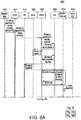
- FIGs. 8A and 8Bare an example call flow if the M2M device is offline or if an immediate interaction with the M2M device is not absolutely required.
- device management requestsmay be initiated from the M2M network application as a typical example. Generally, such requests may be initiated from any trusted entities residing in the M2M N&A domain, as long as they are authenticated and authorized by the GMAE. Alternatively, the MDGM may also initiate the management requests for the purpose of operator administration. In this case, the call flow may be a little different. In another example, the M2M GW MDGM entity may initiate the management request. The intended receivers of the management requests may be M2M device applications. Some management requests, (e.g., firmware update, reboot, connectivity configuration, and the like), may be targeted to the whole M2M device rather than one of its hosted device applications.
- a dedicated M2M device applicationmay exist in the intended M2M device to respond to such management requests.
- M2M service capabilitiese.g., HDR, SC, TM, and the like
- FIGs. 7A and 7B and 8A and 8Bsome M2M service capabilities, (e.g., HDR, SC, TM, and the like), that may not be critical or necessary for the device management operation are not illustrated in FIGs. 7A and 7B and 8A and 8B .
- FIGs. 7A and 7Bshows an example call flow 700 for M2M device management via an M2M GW (M2M GW as a network proxy) when the M2M device is online.
- the call flowmay occur when an M2M network application 705 initiates a device management procedure with one or more online M2M devices 740 via an M2M GW 735.
- the M2M network application 705may contact the GMAE 710 to issue a management request to one or more M2M devices 740 connecting to the network via the same M2M GW 735 (001).
- the management requestmay include parameters such as appID, devID_list, mgmtObjs, serviceClass, authorizationToken, and the like.
- the mgmtObjs parametermay be used to encapsulate the detailed management commands, parameters and data objects for the purpose of device management.
- the devID_list parametermay contain a list of identifiers referring to the intended device applications located on one or more M2M devices managed by the same M2M GW.
- the GMAE 710may contact the N&A MDGM 725 to execute the management request (002).
- the N&A MDGM 725may decide to contact the RAR 730 to deliver the management request to the intended M2M device applications 740 (003).
- the content of mgmtObjs delivered to the M2M device applications 740may be modified from the original mgmtObjs received from the M2M network application 705 at the discretion of the N&A MDGM 725.
- the RAR 730may contact the NCSS 720 to determine which physical interface it may use to access the M2M devices 740 (004).
- the NCSS 720may determine the interface based on, for example but not limited to, device reachability information and/or some policy management, and return the device physical address corresponding to this interface for each intended M2M device application 740 (005).
- the RAR 730may forward the management request to the GM delivery capability 715 (006), which in turn may deliver the management request to the M2M GW 735 that manages the intended M2M devices (007).
- the network for sending the management requestmay be selected based on QoS requirements that may originate from the NCSS 720 entity and forwarded to the GM 715, as well as any other policies that are relevant to the service class which may originate from any other service capability and forwarded to the GM 715.
- the management requestmay be sent as several messages each targeting an intended M2M device application or as an aggregated message for all of the intended M2M device applications.
- the MDGM in the M2M GW 735may need to contact the N&A MDGM 725 for further management operations, (e.g., downloading software and/or firmware packages, configuring parameters, or reporting statistic data, and the like) (008).
- the N&A MDGM 725may send the requested management information to the MDGM in the M2M GW 735 (009).
- the management operations for different M2M device applicationsare the same, such operations may be optimized by, for example, aggregating to reduce the communication overhead between the M2M GW 735 and the M2M N&A domain.
- a broadcast updatemay be warranted under the discretion of the M2M GW 735, (based off of reachability, and the like).
- the MDGM in the M2M GW 735may store the management request and any management objects received from the N&A MDGM 725 (010).
- the M2M GW 735may store all device configurations, perform all MDGM actions directly with the M2M device 740, and aggregate all responses prior to sending a successful update message to the initiator or a list of which device updates were unsuccessful.
- the MDGM in the M2M GW 735may initiate a new management request to each intended M2M device application 740 according to the original request from the M2M network application 705 (011).
- the new management requestmay conform to the original one in the sense of the management operation result, while it may be different in terms of the request initiator or the management data source for the sake of optimization.
- each M2M device application 740may need to contact the MDGM in the M2M GW 735 for further management operations, (e.g., downloading software and/or firmware packages, configuring parameters, or reporting statistic data, etc.) (012 and 013).
- Each M2M device application 740may run a local process to deploy the management objects as requested by the M2M network application 705 (014), and return the status of the management operation to the MDGM in the M2M GW 735 (015).
- the M2M device application 740may store the current configuration as part of running a process to deploy the management objects. If the download or update was unsuccessful, the M2M device application 740 may invalidate and remove the unsuccessful update and signal this fact back to the N&A MDGM 725, (for example in 016 and 017).
- the MDGM in the GW 735may store the configuration information for all M2M devices.
- the MDGM in the M2M GW 735may return the status of the management operation to the GM 715 (016), which in turn passes it to the RAR 730 (017).
- the MDGM in the M2M GW 735may aggregate the status of the managed M2M device applications 740 in a limited time span before returning the status to the GM 715 to optimize the communication overhead.
- the status of the management operation resultmay be returned to the N&A MDGM 725 (018), and later M2M network application 705 (020) through the GMAE 710 (019).
- FIGs. 8A and 8Bshows an example call flow 800 for M2M device management via an M2M GW (M2M GW as a network proxy) when the M2M device is offline.
- the call flowmay occur when an M2M network application 805 initiates a device management procedure with one or more offline (hibernating) M2M devices 840 via an M2M GW 835.
- the M2M network application 805may contact the GMAE 810 to issue a management request to one or more M2M devices 840 managed by the same M2M GW 835 (001).
- the management requestmay include parameters such as appID, devID_list, mgmtObjs, serviceClass, authorizationToken, and the like.
- the mgmtObjs parametermay be used to encapsulate the detailed management commands, parameters and data objects for the purpose of device management.
- the devID_list parametermay contain a list of identifiers referring to the intended device applications located on one or more M2M devices managed by the same M2M GW.
- the GMAE 810may contact the N&A MDGM 825 to execute the management request (002).
- the MDGM 825may decide to contact the RAR 830 to deliver the management request to the intended M2M device applications 840 (003).
- the content of mgmtObjs delivered to the M2M device applications 840may be modified from the original mgmtObjs received from the M2M network application 805 at the discretion of the N&A MDGM 825.
- the RAR 830may contact the NCSS 820 to determine which physical interface it may use to access the M2M GW 835 (004).
- the NCSS 820may determine the interface based on, for example but not limited to, device reachability information and/or some policy management, and return the device physical address corresponding to this interface (005).
- the RAR 830may forward the management request to the GM capability 815 (006), which in turn may deliver the management request to the M2M GW 835 that manages the intended M2M devices (007).
- the network for sending the management requestmay be selected based on QoS that may originate from the NCSS entity 820 and then forwarded to the GM entity 815, as well as any other policies that are relevant to the service class that are from any other service capability entity.
- the MDGM in the M2M GW 835may need to contact the N&A MDGM 825 for further management operations, (e.g., downloading software and/or firmware packages, configuring parameters, or reporting statistic data) (008).
- the N&A MDGM 825may send the requested management information to the MDGM in the M2M GW 835 (009). If the management operations for different M2M device applications 840 are the same, such interactions may be optimized by, for example, aggregating to reduce the communication overhead between the M2M GW 835 and the N&A M2M domain.
- the MDGM in the M2M GW 835may store the management request and any management objects received from the N&A MDGM 825 (010).
- the MDGM in the M2M GW 835may respond to the N&A MDGM 825 via the GM 815 (011) and the N&A RAR 825 (012) that the management request has been accepted on behalf of the M2M device application 840 but will be delivered later since the intended M2M device application 840 is temporarily unreachable (013).
- the management responsemay be returned to the M2M network application 805 (015) through the GMAE 810 (014).
- the MDGM in the M2M GW 835may initiate a new management request to the M2M device application 840 according to the original request from the M2M network application 805 (016).
- the new management requestmay conform to the original one in the sense of the management operation result, while it may be different in terms of the request initiator or the management data source for the sake of optimization.
- the M2M device application 840may need to contact the MDGM in the M2M GW 835 for further management operations, (e.g., downloading software and/or firmware packages, configuring parameters, or reporting statistic data, and the like) (017 and 018).
- the M2M device application 840may run a local process to deploy the management objects as requested by the M2M network application 805 (019), and return the status of the management operation to the MDGM in the M2M GW 835 (020).
- the M2M device application 840may store the current configuration as part of running a local process that deploys the management objects, in order to be able to invalidate and remove any download or update that was unsuccessful. If such removal occurs, such fact may be signaled back to the MDGM in the GW 835, and then forwarded to the N&A MDGM 825 (for example as part of 021-023).
- the MDGM in the GW 835may store the configuration information for all M2M devices.
- the MDGM in the M2M GW 835may return the status of the management operation to the N&A MDGM 825 by a final management confirmation (021).
- the MDGM in the M2M GW 835may aggregate the status in a limited time span to optimize the communication overhead.
- the final management confirmationmay then be forwarded to the M2M network application 805 (023) through the GMAE 810 (022).
Landscapes
- Engineering & Computer Science (AREA)
- Computer Networks & Wireless Communication (AREA)
- Signal Processing (AREA)
- Health & Medical Sciences (AREA)
- General Health & Medical Sciences (AREA)
- Computing Systems (AREA)
- Medical Informatics (AREA)
- Cardiology (AREA)
- Mobile Radio Communication Systems (AREA)
- Small-Scale Networks (AREA)
- Telephonic Communication Services (AREA)
- Stored Programmes (AREA)
Description
- This application claims the benefit of
U.S. provisional application No. 61/309,297 filed March 1, 2010 U.S. provisional application No. 61/311,161 filed March 5, 2010 U.S. provisional application No. 61/326,081 filed April 20, 2010 - This application is related to wireless communications.
- Machine-to-machine (M2M) systems may include M2M devices that reside behind M2M gateways (GWs). These M2M devices may be remotely accessed through the GWs. Remote access may be imposed either as a result of a physical/hardware/software limitation, or by a choice of the M2M devices, (e.g., in cases where device power conservation may be desired). M2M GW functionality may include security capability (SC) functionality, generic messaging (GM) capability functionality, M2M device and M2M GW management (MDGM) capability functionality, and support for the GW as network proxy connectivity, as disclosed for example inDraft ETSI TS102 690 V0.1.3 (2010-02).
- For M2M devices that reside behind an M2M GW, two connectivity options, known as
case 1 andcase 2, may be applicable as summarized below. In thecase 1 connectivity, also known as direct connectivity, the M2M devices may connect to a network and application (N&A) domain directly via the access network or through an M2M GW. The M2M device may perform procedures, such as registration, authentication, authorization, management and provisioning with the N&A domain, for example. The M2M device may have other devices connected to it that may be hidden from the N&A domain. - In the
case 2 connectivity, also known as M2M GW as network proxy connectivity, the M2M device may connect to the N&A domain via an M2M GW. M2M devices may connect to the M2M GW via an M2M area network, for example. The M2M GW may connect to the N&A domain via an access network and act as a proxy for the M2M N&A domain towards the M2M devices that may be connected to the M2M GW. Such an M2M GW may perform procedures, such as authentication, authorization, registration, management, and provisioning of the M2M devices that may be connected to it, and may also execute applications on behalf of the M2M N&A domain. The M2M GW may decide on routing service layer requests originating from applications on M2M devices locally or to the M2M N&A domain. The M2M devices that connect to such an M2M GW may or may not be addressable by the M2M N&A domain. - The M2M GW functionality may have a number of shortcomings that may lead to inefficiencies if reachability, addressing, and repository functionality resides solely in the N&A domain. For example, in the "
case 2" connectivity case, the device registration functionality may be moved to the M2M GW. It may be inefficient for the device to register with the M2M GW, yet have the registration information stored in the N&A domain. Other shortcomings may include access to M2M area addresses, signaling overhead associated with updating device mapping tables, device status synchronization, and device mobility. - A machine-to-machine (M2M) architecture and functionality is described that provides reachability, addressing, and repository (RAR) capability in an M2M gateway (GW). The M2M GW may maintain a local mapping table, perform data aggregation, address translation, name translation, maintain a local device application repository, and establish M2M GW reachability and wake-up time based on an underlying M2M device reachability and wake-up time. The M2M GW may communicate with a neighbor M2M GW RAR to facilitate the sharing and synchronization of proxy RAR based information between M2M GWs, base a registration on a registration attribute and request that cached data be used if a device is unreachable. The M2M GW RAR may support requests from other capabilities within the M2M GW or from M2M applications within the M2M GW. The M2M GW RAR may support requests from a network and application (N&A) domain RAR and the N&A RAR may be notified when certain events occur.
- The M2M GW may include an M2M device and M2M gateway management (MDGM) capability that receives management requests for an M2M device. The MDGM in the M2M GW may function as a network proxy. The MDGM may accept and process the management request from the N&A domain on behalf of the M2M device. The MDGM may perform management functions of the M2M device on behalf of the N&A domain. The MDGM may request the N&A domain for permission to start interacting with the M2M device to perform device management tasks. The MDGM may initiate, as per the policy of the network and application domain provisioned to the M2M gateway, an interaction for device management tasks with the M2M device, and inform the N&A domain the results of the interaction for the device management tasks.
- A more detailed understanding may be had from the following description, given by way of example in conjunction with the accompanying drawings wherein:
FIG. 1A is a system diagram of an example communications system in which one or more disclosed embodiments may be implemented;FIG. 1B is a system diagram of an example wireless transmit/receive unit (WTRU) that may be used within the communications system illustrated inFIG. 1A ;FIG. 1C is a system diagram of an example radio access network and an example core network that may be used within the communications system illustrated inFIG. 1A ;FIG 2 is a high level overview of an example machine-to-machine (M2M) system;FIG. 3 is a block diagram of an example reachability, addressing and repository (RAR) entity in an M2M gateway (GW);FIG. 4 is an example call flow of a network to device communication;FIG. 5 is an example call flow of a network to device communication with a GW RAR;FIG. 6 is an example call flow of a network to device communication with a GW RAR and tunnel;FIGs. 7A and7B are an example call flow for M2M device management via a GW acting as a network proxy when a M2M device is online; andFIGs. 8A and8B are an example call flow for M2M device management via a GW acting as a network proxy when an M2M device is offlineFIG. 1A is a diagram of anexample communications system 100 in which one or more disclosed embodiments may be implemented. Thecommunications system 100 may be a multiple access system that provides content, such as voice, data, video, messaging, broadcast, etc., to multiple wireless users. Thecommunications system 100 may enable multiple wireless users to access such content through the sharing of system resources, including wireless bandwidth. For example, thecommunications systems 100 may employ one or more channel access methods, such as code division multiple access (CDMA), time division multiple access (TDMA), frequency division multiple access (FDMA), orthogonal FDMA (OFDMA), single-carrier FDMA (SC-FDMA), and the like.- As shown in
FIG. 1A , thecommunications system 100 may include wireless transmit/receive units (WTRUs) 102a, 102b, 102c, 102d, a radio access network (RAN) 104, acore network 106, a public switched telephone network (PSTN) 108, the Internet 110, andother networks 112, though it will be appreciated that the disclosed embodiments contemplate any number of WTRUs, base stations, networks, and/or network elements. Each of the WTRUs 102a, 102b, 102c, 102d may be any type of device configured to operate and/or communicate in a wireless environment. By way of example, the WTRUs 102a, 102b, 102c, 102d may be configured to transmit and/or receive wireless signals and may include user equipment (UE), a mobile station, a fixed or mobile subscriber unit, a pager, a cellular telephone, a personal digital assistant (PDA), a smartphone, a laptop, a netbook, a personal computer, a wireless sensor, consumer electronics, and the like. A machine-to-machine (M2M) device may be a WTRU. - The
communications systems 100 may also include abase station 114a and abase station 114b. Each of thebase stations WTRUs core network 106, theInternet 110, and/or thenetworks 112. By way of example, thebase stations base stations base stations - The
base station 114a may be part of theRAN 104, which may also include other base stations and/or network elements (not shown), such as a base station controller (BSC), a radio network controller (RNC), relay nodes, etc. Thebase station 114a and/or thebase station 114b may be configured to transmit and/or receive wireless signals within a particular geographic region, which may be referred to as a cell (not shown). The cell may further be divided into cell sectors. For example, the cell associated with thebase station 114a may be divided into three sectors. Thus, in one embodiment, thebase station 114a may include three transceivers, i.e., one for each sector of the cell. In another embodiment, thebase station 114a may employ multiple-input multiple output (MIMO) technology and, therefore, may utilize multiple transceivers for each sector of the cell. - The
base stations WTRUs air interface 116, which may be any suitable wireless communication link (e.g., radio frequency (RF), microwave, infrared (IR), ultraviolet (UV), visible light, etc.). Theair interface 116 may be established using any suitable radio access technology (RAT). - More specifically, as noted above, the
communications system 100 may be a multiple access system and may employ one or more channel access schemes, such as CDMA, TDMA, FDMA, OFDMA, SC-FDMA, and the like. For example, thebase station 114a in theRAN 104 and theWTRUs air interface 116 using wideband CDMA (WCDMA). WCDMA may include communication protocols such as High-Speed Packet Access (HSPA) and/or Evolved HSPA (HSPA+). HSPA may include High-Speed Downlink Packet Access (HSDPA) and/or High-Speed Uplink Packet Access (HSUPA). - In another embodiment, the
base station 114a and theWTRUs air interface 116 using Long Term Evolution (LTE) and/or LTE-Advanced (LTE-A). - In other embodiments, the
base station 114a and theWTRUs - The
base station 114b inFIG. 1A may be a wireless router, Home Node B, Home eNode B, or access point, for example, and may utilize any suitable RAT for facilitating wireless connectivity in a localized area, such as a place of business, a home, a vehicle, a campus, and the like. In one embodiment, thebase station 114b and theWTRUs base station 114b and theWTRUs base station 114b and theWTRUs FIG. 1A , thebase station 114b may have a direct connection to theInternet 110. Thus, thebase station 114b may not be required to access theInternet 110 via thecore network 106. - The
RAN 104 may be in communication with thecore network 106, which may be any type of network configured to provide voice, data, applications, and/or voice over internet protocol (VoIP) services to one or more of theWTRUs core network 106 may provide call control, billing services, mobile location-based services, pre-paid calling, Internet connectivity, video distribution, etc., and/or perform high-level security functions, such as user authentication. Although not shown inFIG. 1A , it will be appreciated that theRAN 104 and/or thecore network 106 may be in direct or indirect communication with other RANs that employ the same RAT as theRAN 104 or a different RAT. For example, in addition to being connected to theRAN 104, which may be utilizing an E-UTRA radio technology, thecore network 106 may also be in communication with another RAN (not shown) employing a GSM radio technology. - The
core network 106 may also serve as a gateway for theWTRUs PSTN 108, theInternet 110, and/orother networks 112. ThePSTN 108 may include circuit-switched telephone networks that provide plain old telephone service (POTS). TheInternet 110 may include a global system of interconnected computer networks and devices that use common communication protocols, such as the transmission control protocol (TCP), user datagram protocol (UDP) and the internet protocol (IP) in the TCP/IP internet protocol suite. Thenetworks 112 may include wired or wireless communications networks owned and/or operated by other service providers. For example, thenetworks 112 may include another core network connected to one or more RANs, which may employ the same RAT as theRAN 104 or a different RAT. - Some or all of the
WTRUs communications system 100 may include multi-mode capabilities, i.e., theWTRUs WTRU 102c shown inFIG. 1A may be configured to communicate with thebase station 114a, which may employ a cellular-based radio technology, and with thebase station 114b, which may employ an IEEE 802 radio technology. FIG. 1B is a system diagram of anexample WTRU 102. As shown inFIG. 1B , theWTRU 102 may include aprocessor 118, atransceiver 120, a transmit/receiveelement 122, a speaker/microphone 124, akeypad 126, a display/touchpad 128,non-removable memory 106,removable memory 132, apower source 134, a global positioning system (GPS)chipset 136, andother peripherals 138. It will be appreciated that theWTRU 102 may include any sub-combination of the foregoing elements while remaining consistent with an embodiment.- The
processor 118 may be a general purpose processor, a special purpose processor, a conventional processor, a digital signal processor (DSP), a plurality of microprocessors, one or more microprocessors in association with a DSP core, a controller, a microcontroller, Application Specific Integrated Circuits (ASICs), Field Programmable Gate Array (FPGAs) circuits, any other type of integrated circuit (IC), a state machine, and the like. Theprocessor 118 may perform signal coding, data processing, power control, input/output processing, and/or any other functionality that enables theWTRU 102 to operate in a wireless environment. Theprocessor 118 may be coupled to thetransceiver 120, which may be coupled to the transmit/receiveelement 122. WhileFIG. 1B depicts theprocessor 118 and thetransceiver 120 as separate components, it will be appreciated that theprocessor 118 and thetransceiver 120 may be integrated together in an electronic package or chip. - The transmit/receive
element 122 may be configured to transmit signals to, or receive signals from, a base station (e.g., thebase station 114a) over theair interface 116. For example, in one embodiment, the transmit/receiveelement 122 may be an antenna configured to transmit and/or receive RF signals. In another embodiment, the transmit/receiveelement 122 may be an emitter/detector configured to transmit and/or receive IR, UV, or visible light signals, for example. In yet another embodiment, the transmit/receiveelement 122 may be configured to transmit and receive both RF and light signals. It will be appreciated that the transmit/receiveelement 122 may be configured to transmit and/or receive any combination of wireless signals. - In addition, although the transmit/receive
element 122 is depicted inFIG. 1B as a single element, theWTRU 102 may include any number of transmit/receiveelements 122. More specifically, theWTRU 102 may employ MIMO technology. Thus, in one embodiment, theWTRU 102 may include two or more transmit/receive elements 122 (e.g., multiple antennas) for transmitting and receiving wireless signals over theair interface 116. - The
transceiver 120 may be configured to modulate the signals that are to be transmitted by the transmit/receiveelement 122 and to demodulate the signals that are received by the transmit/receiveelement 122. As noted above, theWTRU 102 may have multi-mode capabilities. Thus, thetransceiver 120 may include multiple transceivers for enabling theWTRU 102 to communicate via multiple RATs, such as UTRA and IEEE 802.11, for example. - The
processor 118 of theWTRU 102 may be coupled to, and may receive user input data from, the speaker/microphone 124, thekeypad 126, and/or the display/touchpad 128 (e.g., a liquid crystal display (LCD) display unit or organic light-emitting diode (OLED) display unit). Theprocessor 118 may also output user data to the speaker/microphone 124, thekeypad 126, and/or the display/touchpad 128. In addition, theprocessor 118 may access information from, and store data in, any type of suitable memory, such as thenon-removable memory 106 and/or theremovable memory 132. Thenon-removable memory 106 may include random-access memory (RAM), read-only memory (ROM), a hard disk, or any other type of memory storage device. Theremovable memory 132 may include a subscriber identity module (SIM) card, a memory stick, a secure digital (SD) memory card, and the like. In other embodiments, theprocessor 118 may access information from, and store data in, memory that is not physically located on theWTRU 102, such as on a server or a home computer (not shown). - The
processor 118 may receive power from thepower source 134, and may be configured to distribute and/or control the power to the other components in theWTRU 102. Thepower source 134 may be any suitable device for powering theWTRU 102. For example, thepower source 134 may include one or more dry cell batteries (e.g., nickel-cadmium (NiCd), nickel-zinc (NiZn), nickel metal hydride (NiMH), lithium-ion (Li-ion), etc.), solar cells, fuel cells, and the like. - The
processor 118 may also be coupled to theGPS chipset 136, which may be configured to provide location information (e.g., longitude and latitude) regarding the current location of theWTRU 102. In addition to, or in lieu of, the information from theGPS chipset 136, theWTRU 102 may receive location information over theair interface 116 from a base station (e.g.,base stations WTRU 102 may acquire location information by way of any suitable location-determination method while remaining consistent with an embodiment. - The
processor 118 may further be coupled toother peripherals 138, which may include one or more software and/or hardware modules that provide additional features, functionality and/or wired or wireless connectivity. For example, theperipherals 138 may include an accelerometer, an e-compass, a satellite transceiver, a digital camera (for photographs or video), a universal serial bus (USB) port, a vibration device, a television transceiver, a hands free headset, a Bluetooth® module, a frequency modulated (FM) radio unit, a digital music player, a media player, a video game player module, an Internet browser, and the like. FIG. 1C is a system diagram of theRAN 104 and thecore network 106 according to an embodiment. As noted above, theRAN 104 may employ an E-UTRA radio technology to communicate with theWTRUs air interface 116. TheRAN 104 may also be in communication with thecore network 106.- The
RAN 104 may include eNode-Bs RAN 104 may include any number of eNode-Bs while remaining consistent with an embodiment. The eNode-Bs WTRUs air interface 116. In one embodiment, the eNode-Bs B 140a, for example, may use multiple antennas to transmit wireless signals to, and receive wireless signals from, theWTRU 102a. - Each of the eNode-
Bs FIG. 1C , the eNode-Bs - The
core network 106 shown inFIG. 1C may include a mobility management gateway (MME) 142, a servinggateway 144, and a packet data network (PDN)gateway 146. While each of the foregoing elements are depicted as part of thecore network 106, it will be appreciated that any one of these elements may be owned and/or operated by an entity other than the core network operator. - The
MME 142 may be connected to each of the eNode-Bs 142a, 142b, 142c in theRAN 104 via an S1 interface and may serve as a control node. For example, theMME 142 may be responsible for authenticating users of theWTRUs WTRUs MME 142 may also provide a control plane function for switching between theRAN 104 and other RANs (not shown) that employ other radio technologies, such as GSM or WCDMA. - The serving
gateway 144 may be connected to each of theeNode Bs RAN 104 via the S1 interface. The servinggateway 144 may generally route and forward user data packets to/from theWTRUs gateway 144 may also perform other functions, such as anchoring user planes during inter-eNode B handovers, triggering paging when downlink data is available for theWTRUs WTRUs - The serving
gateway 144 may also be connected to thePDN gateway 146, which may provide theWTRUs Internet 110, to facilitate communications between theWTRUs - The
core network 106 may facilitate communications with other networks. For example, thecore network 106 may provide theWTRUs PSTN 108, to facilitate communications between theWTRUs core network 106 may include, or may communicate with, an IP gateway (e.g., an IP multimedia subsystem (IMS) server) that serves as an interface between thecore network 106 and thePSTN 108. In addition, thecore network 106 may provide theWTRUs networks 112, which may include other wired or wireless networks that are owned and/or operated by other service providers. - Device user-plane data may be data that is generated by M2M devices, for example sensor data. Registration attributes may include characteristics of devices that may be allowed to register. The characteristics may relate to physical characteristics such as, for example, available power, available capacity, device identification (ID), and/or service class. Device control-plane information may include control information that pertains to a specific device, for example information regarding reachability, wake-up times and durations, registration information, and/or service information.
- End-to-end system requirements may be implemented to support M2M communication services. An M2M functional architecture may be designed to deliver M2M services to applications. The M2M functional architecture may present the overall end to end M2M functional entities, the relationships between these entities, as well as the relationship to European Telecommunications Standards Institute (ETSI) telecommunications and Internet converged services and protocols for advanced networks (TISPAN) and 3rd Generation Partnership Project (3GPP) networks.
FIG. 2 shows an exampleoverall architecture 200. The architecture may be divided into two "domains": anM2M device domain 210 and a network and application (N&A)domain 215. TheM2M device domain 210 may includeM2M devices 220 that runM2M applications 222 using M2M service capabilities or M2M capabilities 224 (collectively "M2M service capabilities"), andN&A domain 215 functionality. The term "M2M applications" may refer to applications that run the service logic using the M2M service capabilities. The term "M2M service capabilities" may be a grouping of functions that may enable end-to-end communications between applications in M2M devices, M2M gateways and the M2M Core Network. TheM2M device domain 210 may further include anM2M area network 225 that may communicate between theM2M devices 220 and an M2M gateway (GW) 230, where the M2M GW may includeM2M applications 232 andM2M service capabilities 234. TheM2M GW 230 may be used to communicate with theN&A domain 210.- The term "M2M GW" as used herein may refer to any entity that provides some service capabilities to devices behind it. These devices may be both ETSI and non-ETSI compliant, (e.g., legacy devices not supporting the M2M capabilities). Based on this definition, the M2M GW may be considered to be: 1) an ETSI compliant GW with ETSI compliant devices behind it, all connected through an M2M area network; 2) an ETSI compliant GW with non-ETSI compliant devices behind it, all connected through an M2M area network; 3) an ETSI compliant GW with a mixed device deployment behind it, (ETSI and non-ETSI compliant), all connected through an M2M area network; 4) an ETSI M2M device, connected to non-ETSI compliant devices using some legacy protocol, (e.g., Bluetooth®); 5) an ETSI M2M device, connected to ETSI compliant M2M devices; or 6) an ETSI compliant device with a mixed device deployment behind it, (ETSI and non-ETSI compliant devices).
- The
N&A domain 210 may include atransport network 237 for transporting data within theN&A domain 210, and anaccess network 235 for communicating with theM2M device domain 210. Theaccess network 235 may communicate with a core network (CN) 240, which in turn may communicate withM2M service capabilities 242. TheM2M service capabilities 242 and theCN 240 may comprise an M2M core 245.M2M applications 244 operate withM2M service capabilities 242. Anetwork management function 250 may include functionality to manage theaccess network 235,transport network 237, andCN 240 and may include an M2Mspecific management function 252. AN M2M management function 255 may include functionality to manage M2M service capabilities and M2M applications. - Using the
architecture 200 above, theM2M devices 220 in theM2M device domain 215 may either communicate directly with theN&A domain 210 using anaccess network 235, or alternatively, they may communicate indirectly through theM2M GW 230. For example, theM2M GW 230 may use theM2M area network 225 to communicate with theM2M devices 220 and may use theaccess network 235 to communicate with theN&A domain 210. - The N&A M2M service capabilities may include a reachability, addressing, and repository (RAR) functionality. However, the M2M GW lacks such functionality and may have a number of shortcomings that may lead to inefficiencies if the RAR functionality resides solely in the N&A domain. For example, in the case where the M2M devices connect to the N&A domain via an M2M GW, the device registration functionality may be moved to the M2M GW. Therefore, it may be inefficient for the M2M device to register with the M2M GW, yet have the registration information stored in the N&A domain. Moreover, the name resolution task for the M2M GW may be assigned to a generic message delivery (GM) capability. This approach, however, may not be in line with the approach used for the N&A domain.
- In another example, device-to-device communications may be supported through the M2M GW. If an M2M device does not know the M2M area address of a neighboring device, it may need to query the N&A RAR functionality to determine where to route the messages. The message may then use the services of the GM capability in the service provider domain, to route the traffic to the destination. Eliminating this transfer out of the
M2M area network 225 may be more efficient. This query functionality may be supported by the GW and therefore be done locally at the GW. - In another example, the N&A RAR may keep the device mapping table up to date. For cases where many M2M devices are behind an M2M GW, an M2M device may inform the N&A RAR about any change in address, reachability or sleep cycle, which may result in a potentially high signaling load. This may put a strain on the access and core networks. Moreover, the M2M GW's reachability and wake-up status may be out-of-sync with, or independent of, the underlying devices. This may result in the M2M GW potentially having to store and forward traffic that may be destined for sleeping M2M devices. Therefore information about reachability, sleep cycle and addressing may be kept locally in the GW and shared with the N&A domain only on a need basis.
- In another example, M2M device mobility from one M2M GW to another may require a re-registration with the N&A domain service capabilities. Communication to M2M devices through multiple M2M GWs may not be permitted, for example for mission critical applications or load sharing. "Local" access, through a home Node-B, for example, may require that communication go to the N&A domain, even if an application server resides in the M2M GW. If the GW includes the RAR functionality, communication using local access may be facilitated.
FIG. 3 shows asystem architecture 300 where anM2M GW 320 may include aRAR entity 360. Thesystem architecture 300 may include an N&AM2M application entity 305 which may be in communication with an N&A M2Mservice capabilities entity 310, which in turn may be in communication with a transport andaccess network entity 315. The transport andaccess network entity 315 may be in communication with theM2M GW 320. TheM2M GW 320 may in turn be in communication withM2M devices 330 throughM2M area network 325. The N&AM2M application entity 305 and the N&A M2Mservice capabilities entity 310 may be implemented using servers or alternatively, may be implemented in the network.- The N&A domain M2M
service capabilities entity 310 may include for example reachability, addressing and device application repository (RAR)entity 350 provides capabilities as discussed herein, generic message delivery (GM)entity 352 provides at least session establishment and teardown along with security keys negotiation along with other capabilities, network and communication service selection (NCSS)entity 354 provides at least network selection when the M2M device or M2M GW can be reached through several network via several subscriptions along with other capabilities, M2M device and M2M GW management (MDGM)entity 356 provides capabilities as discussed herein, historization and data retention (HDR) entity (not shown) provides at least hiding of the history and data retention tasks from the M2M Application and the Devices/M2M GW along with other capabilities, generic M2M application enablement (GMAE)entity 358 is the single contact point to the M2M Applications in the N&A domain as well as providing other capabilities, security capability (SC)entity 359 provides at least authentication and service key management along with other capabilities, transaction management (TM) entity (not shown) handles at least the management of transactions along with other capabilities, and/or M2M device and M2M GW proxy (MDGP) entity (not shown) provides at least interworking between MDGM and the device or GW management functions. - The N&A domain RAR service capability may be tasked with functionality, such as name translation, reachability determination, wake-up determination, maintaining device information, maintaining a device application repository, and/or responding to requests. Converting a device name to a list of network routable addresses may be an example of name translation. For devices behind a GW, the network address may be that of the M2M GW. An example of reachability determination may be where, upon request, the RAR may provide the reachability status of a device. An example of wake-up determination may be where, upon request, the RAR may provide an indication of a device wake-up period. Other example functionalities may be to maintain a device information mapping table such as device X → address, reachability, and wake-up times, maintain a device application repository such as registration information of device and its applications, and/or respond to requests from applications and other service capabilities for device registration information.
- The
M2M GW 360 may include aRAR entity 360, aGM entity 362, aSC entity 364, aMDGM entity 366 andother functionality entity 368. The M2MGW RAR entity 360 may be a proxy RAR entity. The M2MGW RAR entity 360 may maintain a local mapping table and store the following M2M device information for the M2M devices residing behind it. For example, the M2MGW RAR entity 360 may store an M2M area network address for each M2M device. AN M2M device may acquire a new address as a result of mobility, topology changes within the M2M area network, its connection point within the M2M area network and the like. The M2MGW RAR entity 360 may also store a reachability status. The reachability status may be set to "on" when the M2M device is reachable, and to "off' when the M2M device is not reachable. The M2MGW RAR entity 360 may also store the next planned wake-up time and wake-up duration, if available. The above information may be sent from the M2M device to the M2MGW RAR entity 360 using a dedicated control message in the M2M area network, for example. The above functionalities may be included in any combination in the M2MGW RAR entity 360. - The M2M
GW RAR entity 360 may also support requests from other capabilities within theM2M GW 320 or from the M2M application within theM2M GW 320. In some examples, the other capabilities or M2M applications may be notified upon the occurrence of certain events. For example, the generic M2M device application enablement (GMDAE) capability may need knowledge of the accessibility of a specific M2M device after it receives a message from the N&A domain. As a result, when the M2M device may become reachable and/or has its next planned wake-up time or wake-up duration may be sent to the GMDAE. - In another example, the M2M
GW RAR entity 360 may support requests from the N&Adomain RAR entity 350 and other M2M GW RARs. For example, theN&A domain RAR 350 and other M2M GW RARs may be notified for M2M devices behind theM2M GW 320 when certain monitored events occur. These events may, for example, be when a specific M2M device may become reachable, when an M2M device may acquire a new address as a result of mobility, and/or changes may occur on a set of M2M device applications registration information. These events may also include modification of specific data or attributes related to an application repository. For example, for a temperature sensor it could be the event of temperature modification or temperature reaching above or below a specified threshold. The above information may be provided after a change in status of any of the monitored events. Alternatively, theM2M GW 320 may decide to send this information periodically, for example every K time units, or based on a predefined policy. For example, if theM2M GW 320 manages address translation, it may determine not to report an M2M device address change. Similarly, if theM2M GW 320 provides store and forward capability, it may determine not to report wake-up time changes. This determination may also be based on the availability of the access network. For example, the access network may be congested, and may request that theM2M GW 320 refrain from sending this information. - In another example, the M2M
GW RAR entity 360 may support requests from the N&Adomain RAR entity 350 and other M2M GW RARs. For example, these requests may be for M2M devices behind theM2M GW 320 and may concern reachability of an M2M device and/or the next planned wake-up time of an M2M device. - In another example, the M2M
GW RAR entity 360 may perform address translation between area network and core network, if applicable. Examples of address translations may include Internet Protocol version 4 (IPv4), IPv6, and mobile station international integrated service digital network (ISDN) number (MSISDN). Performing an address translation may involve translation between a public GW address and a private device address. The M2MGW RAR entity 360 may handle name resolution for messages sent from a GMDAE capability in the service provider towards an M2M device. The mapping may be between a network routable GW address and an M2M device specific ID to an M2M area network address. - In another example, the M2M
GW RAR entity 360 may maintain a local device application repository for M2M devices behind the M2M GW. For example, this may be done by storing device service class properties for M2M devices within the area network and by keeping this information up to date. The M2MGW RAR entity 360 may aggregate/fuse this class information. In another example, it may be done by storing the M2MGW RAR entity 360 in the device application repository the M2M device application registration information of M2M devices and by keeping the information up to date. The M2MGW RAR entity 360 may aggregate/fuse this registration information. In another example, the M2MGW RAR entity 360 may maintain a local device application repository by providing a query interface to properly authenticate and authorize entities residing in the N&A domain for them to be able to retrieve M2M device applications registration information. - In another example, the M2M
GW RAR entity 360 may maintain a local device application repository by providing, upon request, this information to any entity residing in the N&A domains, assuming the requesting entity is authenticated and authorized to perform such a query. Alternatively, the M2MGW RAR entity 360 may maintain a local device application repository by providing, upon request, this information to the M2M application residing in theM2M GW 320. TheM2M GW 320 may use this information to assist in service discovery within theM2M area network 325. In one option, it may broadcast this information, for example using beacons. Alternatively, it may include this information in the responses sent to M2M devices, for example, after a registration request. - In another example, the M2M
GW RAR entity 360 may establishM2M GW 320 reachability and wake-up time based on an underlying M2M device reachability and wake-up time. For example, if all M2M devices are unreachable, theM2M GW 320 may decide to turn off and inform theN&A RAR entity 350 of this action. Alternatively, theM2M GW 320 may synchronize its sleep time to the M2M devices under it. For example, if all M2M devices are asleep between 1:00 PM and 2:00 PM, theM2M GW 320 may decide to also sleep during this time. Alternatively, M2M GWs may base its decisions on a majority of the M2M devices. - In another example, the M2M
GW RAR entity 360 may communicate with neighbor M2M GW RARs. This may allow inter-networking of multiple M2M GWs and their corresponding proxy RAR capabilities that may facilitate the sharing and synchronization of proxy RAR based information between M2M GWs. Such functionality may be used to support scenarios such as M2M device mobility, (e.g., optimized device handovers between separate M2M area networks serviced by separate M2M GWs), and enhanced reliability, performance and scalability via the use of multiple M2M GWs serving the same M2M area network(s). The inter-GW communication may be through a wired connection, (e.g., all M2M GWs sharing an Ethernet), through a parent GW/router device that may communicate with the multiple M2M GWs, (e.g., a home Node-B or Institute of Electrical and Electronics Engineers (IEEE) 802.11 wireless access point), or through the N&A domain. - In another example, the M2M
GW RAR entity 360 may accept "registration attributes" from theN&A domain RAR 350 that may limit the types of devices allowed for local registration in the "case 2" connectivity scenario. For example, theN&A RAR entity 350 may notify the M2MGW RAR entity 360 to only allow registration for M2M devices with a specific service class, device ID, physical characteristic, (e.g., available power, available storage and/or the like). This in turn, may be used by theSC entity 364 to either accept or reject registrations. This functionality may also be implemented in theSC entity 364. - In another example, the M2M
GW RAR entity 360 may request that cached data be used if an M2M device is unreachable. This may apply to the information stored in the M2MGW RAR entity 360 such as reachability, address, registration information, service information and/or the like, as well as device user-plane data that may be stored in the M2MGW RAR entity 360 or in another capability within theM2M GW 320. If an access is attempted to an M2M device that is not reachable, the M2MGW RAR entity 360 may direct that a cached response be issued rather than waiting for the M2M device to become reachable. - In another example, the M2M
GW RAR entity 360 may perform data aggregation. The M2MGW RAR entity 360 may keep a list of M2M devices which form a group from which data may be aggregated. TheM2M GW 320 may gather the information from such M2M devices and process it, (aggregate it) and send the aggregated results to the network. There may be several different groups defined, and an M2M device may belong to more than one group. The groups may also change over time. The M2MGW RAR entity 360 may keep track of all groups for M2M devices that belong to thatM2M GW 320. This may apply both to the control-plane data stored in the M2MGW RAR entity 360 such as reachability, address, registration information, service information and/or the like, as well as device user-plane data. - In another example, the M2M
GW RAR entity 360 may communicate with a parent M2M GW RAR, for example, when multiple hierarchical M2M GWs service a single network. The master GW RAR may act as a proxy to a slave GW's RAR or standalone M2M devices. - In another example, the M2M
GW RAR entity 360 may perform device selection. Some M2M network applications may not know or not need to know device ID. Instead, an M2M network application, (such as a sensing application), may just submit a task which specifies the spatial area to be sensed and the time window for the sensing. Thus, there is no device ID, (or even group ID), in the application's request. For such applications, a capability in the N&A domain orM2M GW 320 may be required to determine the M2M devices to be involved in the application's request. Such a function/capability may be referred to as "device selection". If device selection is needed and is implemented in theM2M GW 320, this function may be integrated into the M2MGW RAR entity 360 or alternatively, as an additional function in theM2M GW 320, such as in theother functionality 368. - In another example, the
M2M GW RAR 360 may perform device blacklisting. For example, certain M2M devices that fail the integrity verification procedure may be blocked from accessing the N&A domain. If this device integrity verification is handled in the N&A domain, (i.e., in the SC entity 359), the results of the integrity verification may be transferred to theM2M GW 320 and stored locally in the M2MGW RAR entity 360. TheM2M GW 320 may query this information when using M2M services. - In another example, the M2M
GW RAR entity 360 may be configured to act as an event manager and to report on monitored events. For instance, it may be configured to monitor when an M2M device registers with the M2MGW RAR entity 360, and to report this event back to some other entity. The event manager may be configured duringM2M GW 320 registration, or autonomously by the N&A domain. The details of the configuration may be carried in the registration response message, or in a dedicated configuration message. The configuration information may include the events to be monitored or measured, and the parameters for triggering the response action. These parameters may include an absolute change in some measured or observed value, the persistence of the trigger conditions, (e.g., time-to-trigger), and hysteresis parameters that may prevent ping-pong like conditions. Once an event is triggered, the M2MGW RAR entity 360 may initiate a message transmission to the recipient, (e.g., the entity that issued the event monitor, or some other configured entity), or it may take some local action within theM2M GW 320, (e.g., block access to an M2M device). - In order to support the functionality described herein for the M2M GW RAR entity, additional functionality may be included in the N&A domain service capabilities. For example, if the M2M
GW RAR entity 360 supports event manager functions, then the N&A domain may need to configureM2M GW RAR 360 for the event manager. In one embodiment, these functions may be included in theN&A RAR entity 350. - In another example, for cases where the M2M GW RAR entity 360may use a form of "Registration Attribute" to filter out M2M device registration requests, the
N&A RAR entity 350, (or possibly some other M2M core network capability), may send the registration attribute list to theM2M GW 320. This may be performed during registration of theM2M GW 320, for example, in the registration response message, or upon request from theM2M GW 320. Alternatively, the network may decide to autonomously change this registration attribute list and send this information to theM2M GW 320. - In another example, in cases where a network application or some other N&A service capability accesses an M2M device behind an
M2M GW 320, the N&Adomain RAR entity 350 may initiate a tunnel between itself and the proxy RAR entity in theM2M GW 320, (the M2M GW RAR entity 360). In such an example, the N&Adomain RAR entity 350 may keep track of control plane information pertaining to theM2M GW 320, and not to the M2M devices behind it. The first time the network application attempts to access the M2M device, the N&Adomain RAR entity 350 may query the M2MGW RAR entity 360 to determine the device reachability and next wake-up period, if the M2M device is reachable. At the same time, it may initiate the setup of a tunnel so that subsequent communications between the network application and M2M device may not need to rely on theN&A domain RAR 350 to determine device reachability. Rather, theN&A RAR entity 350 may keep track ofM2M GW 320 reachability. When theM2M GW 320 is reachable, messages may be transparently routed to the M2MGW RAR entity 360, which may determine device reachability. If the M2M device is not reachable, theM2M GW 320 may store the message and forward the message at a later time. FIGs. 4 ,5 , and6 are example call flows that may be used for a network application to device application message transfer. In each of the three examples, the M2M device may lie behind an M2M GW.- The
call flow 400 ofFIG. 4 illustrates a baseline call flow where the M2M GW 410 lacks a RAR entity. Incall flow 400, the device application 405 may communicate a change, such as registration information, reachability information and the like, to a GW 410 (0). The GW 410 may communicate this change to an N&A RAR entity 415 to keep it up to date with regard to M2M devices behind the GW 410 (00). - A message transfer request initiated by a network application 420 (2) undergoes an authentication and authorization process with a GMAE 425 (1). The GMAE 425 may then verify that the request from the
network application 420 is valid (3). After verification, the GMAE 425 may query the N&A RAR entity 415 to lookup the address of the M2M device (4). The N&A RAR entity 415 may find the address and the service class (5) and then may send the device information to the GMAE 425 (6). The GMAE 425 may then request theNCSS 430 to determine the network for sending the message (7). TheNCSS 430 may select a network (8), negotiate quality of service (QoS) with a core network 435 (9) and confirm the network selection (10). The network selection may then be sent by theNCSS 430 to the GMAE 425 (11), which then applies policy management procedures to determine if it should store and forward the message, apply an exception and/or schedule the message (12). The GMAE may then send the message to the GM 440 (13), which in turn forwards the message to the M2M GW 410 (14). The M2M GW 410 may then send the message to the device application 405 (15). - The call flow of
FIG. 5 illustrates acall flow 500 where an M2M GW includes aRAR entity 510. A message transfer request initiated by a network application 520 (2) undergoes an authentication and authorization process with a GMAE 525 (1). TheGMAE 525 may then verify that the request from thenetwork application 520 is valid (3). After verification, theGMAE 525 may query the N&A RAR entity 515 to lookup the address of the M2M device (4). The N&A RAR entity 515 may not have the have the address information for the device, and may query the M2M GW RAR to find the address and the service class (5). To accomplish this, it may send the gateway information to the GMAE 525 (6). TheGMAE 525 may then request theNCSS 530 to determine the network for sending the message (7). TheNCSS 530 may select a network (8), negotiate quality of service (QoS) with a core network 535 (9) and confirm the network selection (10). The network selection may then be sent by theNCSS 530 to the GMAE 525 (11), which may then send a query about the device information to the M2M GW RAR 510 (12). TheM2M GW RAR 510 may then send the device information to the GMAE 525 (13), which in turn may forward the device information to the N&A RAR 515 (14). The N&A RAR 515 may then send to theGMAE 525 information for sending the message to the device application 505 (15). TheGMAE 525 may then apply policy management procedures to determine if it should store and forward the message, apply an exception and/or schedule the message (16). The GMAE may then send the message to the GM 535 (17), which in turn forwards the message to the device application 505 (18). - The call flow of
FIG. 6 illustrates acall flow 500 where an M2M GW includes aRAR entity 510 and a tunnel is set up between anN&A RAR 615 and anM2M GW RAR 610. Incall flow 600, a tunnel (00) may be established betweenN&A RAR 615 andM2M GW RAR 610 after the first application to device transmission (0). - A message transfer request initiated by a network application 620 (2) undergoes an authentication and authorization process with a GMAE 625 (1). The GMAE 625 may then verify that the request from the network application 620 is valid (3). After verification, the GMAE 625 may query the
N&A RAR entity 615 to lookup the address of the M2M device (4). TheN&A RAR entity 615 may not have the address information for the device (5). Instead, it may send the gateway information and the indication to use the tunnel to the GMAE 625 (6). The GMAE 625 may then request theNCSS 630 to determine the network for sending the message (7). TheNCSS 630 may select a network (8), negotiate quality of service (QoS) with a core network 635 (9) and confirm the network selection (10). The network selection may then be sent by theNCSS 630 to the GMAE 625 (11), which may then apply policy management procedures to determine if it should store and forward the message, apply an exception and/or schedule the message (12). The GMAE may then send the message to the GM 440 (13) using the tunnel. TheGM 640 may then forward the message to the M2M GW RAR 610 (14) using the tunnel. TheM2M GW 610 may then send the message to the device application 605 (15). - Described herein are enhanced functionality and call flows for the MDGM. The MDGM capability in the M2M GW has been identified as an M2M GW management proxy. By performing as an M2M GW management proxy, the MDGM in the M2M GW may support at least the following two aspects of management functionality: (1) accept and process the management requests from the N&A domain on behalf of the M2M devices under its control, and (2) perform management functions of the M2M devices on behalf of the N&A domain.
- When performing as an M2M GW management proxy, the MDGM capability in the M2M GW may receive the same management requests, (in one or consecutive messages), targeting multiple M2M devices under its control. Such requests may trigger a resource-consuming operation process, (e.g., bulk downloading of firmware and/or software data objects), that may lead to performance deterioration in the N&A domain and the M2M GW. In this case, the M2M GW may optimize the operation process by reducing the signaling and data traffic to and from the N&A domain.
- The MDGM capability in the M2M GW may act as an M2M GW management client. The MDGM in the M2M GW may perform configuration management (CM), performance management (PM), fault management (FM) and software and firmware upgrade functions of the M2M GW.
- The MDGM in the M2M GW may act as an M2M gateway management proxy. For example, the MDGM in the M2M GW may accept and process management requests from the N&A domain on behalf of one or more M2M devices. In another example, the MDGM in the M2M GW may request the N&A domain for permission to start interacting with one or more M2M devices to perform device management tasks, (e.g., bulk firmware and/or software update, fault and performance diagnostics), and perform such tasks after receiving such permission.
- In another example, the MDGM in the M2M GW may initiate, as per the policy of the N&A domain provisioned on the M2M GW, interactions for device management tasks, (e.g., bulk firmware and/or software update, fault and performance diagnostics), with one or multiple M2M devices, and inform the N&A domain of the results of the device management interactions. This may be the case where the GW is a true, largely autonomous proxy for the network.
- In another example, in the case of managing multiple M2M devices with the same operations, (e.g., bulk firmware and/or software update, fault and performance diagnostics), the M2M GW may optimize the operation process, (e.g., bulk downloading of firmware and/or software data objects, fault and performance diagnostics), to reduce the signaling and data traffic to and from the N&A domain.
- The MDGM in the M2M GW may also act as an M2M GW management proxy to perform management functions of the M2M devices. For that purpose it may need to use scheduling functions when an M2M device is in sleep mode. Management proxy functions may include, but are not limited to, management protocol translation, protocol encapsulation and decapsulation, and the like.
- In conventional call flows, the only functionality performed by MDGM is to provide the default configuration of N&A M2M applications or M2M device applications for their first registration. Call flows for the main functionalities, (e.g., configuration management, performance management, fault management, software and firmware upgrade, etc.), have not been provided.
- The examples and embodiments disclosed herein provide a general view regarding the end-to-end device and gateway management procedures so as to validate the main functionalities of the MDGM at a system level and to complete the M2M functional architecture. The embodiments below address the
case 2 or "Gateway as a Network Proxy" connectivity, where the M2M GW performs device management procedures on behalf of the M2M network and application domain. In particular, the example call flows are for M2M network or application-initiated device management (gateway as a network proxy). - When an M2M network application issues device management requests to one or more M2M devices via an M2M GW, it may conform to the call flows shown in
FIGs. 7A and7B and8A and8B .FIG. 7A and7B are an example call flow if the M2M device is online (connected) and an immediate interaction is needed, andFIGs. 8A and8B are an example call flow if the M2M device is offline or if an immediate interaction with the M2M device is not absolutely required. - In the call flows discussed herein, device management requests may be initiated from the M2M network application as a typical example. Generally, such requests may be initiated from any trusted entities residing in the M2M N&A domain, as long as they are authenticated and authorized by the GMAE. Alternatively, the MDGM may also initiate the management requests for the purpose of operator administration. In this case, the call flow may be a little different. In another example, the M2M GW MDGM entity may initiate the management request. The intended receivers of the management requests may be M2M device applications. Some management requests, (e.g., firmware update, reboot, connectivity configuration, and the like), may be targeted to the whole M2M device rather than one of its hosted device applications. In this case, a dedicated M2M device application may exist in the intended M2M device to respond to such management requests. For simplicity, some M2M service capabilities, (e.g., HDR, SC, TM, and the like), that may not be critical or necessary for the device management operation are not illustrated in
FIGs. 7A and7B and8A and8B . - As stated above,
FIGs. 7A and7B shows anexample call flow 700 for M2M device management via an M2M GW (M2M GW as a network proxy) when the M2M device is online. In particular, the call flow may occur when anM2M network application 705 initiates a device management procedure with one or moreonline M2M devices 740 via anM2M GW 735. - The
M2M network application 705 may contact theGMAE 710 to issue a management request to one ormore M2M devices 740 connecting to the network via the same M2M GW 735 (001). The management request may include parameters such as appID, devID_list, mgmtObjs, serviceClass, authorizationToken, and the like. The mgmtObjs parameter may be used to encapsulate the detailed management commands, parameters and data objects for the purpose of device management. The devID_list parameter may contain a list of identifiers referring to the intended device applications located on one or more M2M devices managed by the same M2M GW. - After authentication and authorization is completed, to ensure that the
M2M network application 705 is authentic and authorized to issue the request, theGMAE 710 may contact theN&A MDGM 725 to execute the management request (002). According to the detailed information provided in mgmtObjs, theN&A MDGM 725 may decide to contact theRAR 730 to deliver the management request to the intended M2M device applications 740 (003). The content of mgmtObjs delivered to theM2M device applications 740 may be modified from the original mgmtObjs received from theM2M network application 705 at the discretion of theN&A MDGM 725. - The
RAR 730 may contact theNCSS 720 to determine which physical interface it may use to access the M2M devices 740 (004). TheNCSS 720 may determine the interface based on, for example but not limited to, device reachability information and/or some policy management, and return the device physical address corresponding to this interface for each intended M2M device application 740 (005). TheRAR 730 may forward the management request to the GM delivery capability 715 (006), which in turn may deliver the management request to theM2M GW 735 that manages the intended M2M devices (007). The network for sending the management request may be selected based on QoS requirements that may originate from theNCSS 720 entity and forwarded to theGM 715, as well as any other policies that are relevant to the service class which may originate from any other service capability and forwarded to theGM 715. The management request may be sent as several messages each targeting an intended M2M device application or as an aggregated message for all of the intended M2M device applications. - Optionally, according to the received management request, the MDGM in the
M2M GW 735 may need to contact theN&A MDGM 725 for further management operations, (e.g., downloading software and/or firmware packages, configuring parameters, or reporting statistic data, and the like) (008). TheN&A MDGM 725 may send the requested management information to the MDGM in the M2M GW 735 (009). If the management operations for different M2M device applications are the same, such operations may be optimized by, for example, aggregating to reduce the communication overhead between theM2M GW 735 and the M2M N&A domain. A broadcast update may be warranted under the discretion of theM2M GW 735, (based off of reachability, and the like). The MDGM in theM2M GW 735 may store the management request and any management objects received from the N&A MDGM 725 (010). Alternatively, theM2M GW 735 may store all device configurations, perform all MDGM actions directly with theM2M device 740, and aggregate all responses prior to sending a successful update message to the initiator or a list of which device updates were unsuccessful. - The MDGM in the
M2M GW 735 may initiate a new management request to each intendedM2M device application 740 according to the original request from the M2M network application 705 (011). The new management request may conform to the original one in the sense of the management operation result, while it may be different in terms of the request initiator or the management data source for the sake of optimization. Optionally, according to the received management request, eachM2M device application 740 may need to contact the MDGM in theM2M GW 735 for further management operations, (e.g., downloading software and/or firmware packages, configuring parameters, or reporting statistic data, etc.) (012 and 013). - Each
M2M device application 740 may run a local process to deploy the management objects as requested by the M2M network application 705 (014), and return the status of the management operation to the MDGM in the M2M GW 735 (015). Alternatively, theM2M device application 740 may store the current configuration as part of running a process to deploy the management objects. If the download or update was unsuccessful, theM2M device application 740 may invalidate and remove the unsuccessful update and signal this fact back to theN&A MDGM 725, (for example in 016 and 017). Alternatively, the MDGM in theGW 735 may store the configuration information for all M2M devices. - The MDGM in the
M2M GW 735 may return the status of the management operation to the GM 715 (016), which in turn passes it to the RAR 730 (017). The MDGM in theM2M GW 735 may aggregate the status of the managedM2M device applications 740 in a limited time span before returning the status to theGM 715 to optimize the communication overhead. The status of the management operation result may be returned to the N&A MDGM 725 (018), and later M2M network application 705 (020) through the GMAE 710 (019). - As stated above,
FIGs. 8A and8B shows anexample call flow 800 for M2M device management via an M2M GW (M2M GW as a network proxy) when the M2M device is offline. In particular, the call flow may occur when anM2M network application 805 initiates a device management procedure with one or more offline (hibernating)M2M devices 840 via anM2M GW 835. - The
M2M network application 805 may contact theGMAE 810 to issue a management request to one ormore M2M devices 840 managed by the same M2M GW 835 (001). The management request may include parameters such as appID, devID_list, mgmtObjs, serviceClass, authorizationToken, and the like. The mgmtObjs parameter may be used to encapsulate the detailed management commands, parameters and data objects for the purpose of device management. The devID_list parameter may contain a list of identifiers referring to the intended device applications located on one or more M2M devices managed by the same M2M GW. - After authentication and authorization is completed to ensure that the
M2M network application 805 is authentic and authorized to issue the request, theGMAE 810 may contact theN&A MDGM 825 to execute the management request (002). According to the detailed information provided in mgmtObjs, theMDGM 825 may decide to contact theRAR 830 to deliver the management request to the intended M2M device applications 840 (003). The content of mgmtObjs delivered to theM2M device applications 840 may be modified from the original mgmtObjs received from theM2M network application 805 at the discretion of theN&A MDGM 825. - Although the intended
M2M device applications 840 are temporally unreachable, their managingM2M GW 835 is currently registered and available to theRAR 830. Therefore, theRAR 830 may contact theNCSS 820 to determine which physical interface it may use to access the M2M GW 835 (004). TheNCSS 820 may determine the interface based on, for example but not limited to, device reachability information and/or some policy management, and return the device physical address corresponding to this interface (005). TheRAR 830 may forward the management request to the GM capability 815 (006), which in turn may deliver the management request to theM2M GW 835 that manages the intended M2M devices (007). The network for sending the management request may be selected based on QoS that may originate from theNCSS entity 820 and then forwarded to theGM entity 815, as well as any other policies that are relevant to the service class that are from any other service capability entity. - Optionally, according to the received management request, the MDGM in the
M2M GW 835 may need to contact theN&A MDGM 825 for further management operations, (e.g., downloading software and/or firmware packages, configuring parameters, or reporting statistic data) (008). TheN&A MDGM 825 may send the requested management information to the MDGM in the M2M GW 835 (009). If the management operations for differentM2M device applications 840 are the same, such interactions may be optimized by, for example, aggregating to reduce the communication overhead between theM2M GW 835 and the N&A M2M domain. The MDGM in theM2M GW 835 may store the management request and any management objects received from the N&A MDGM 825 (010). - The MDGM in the
M2M GW 835 may respond to theN&A MDGM 825 via the GM 815 (011) and the N&A RAR 825 (012) that the management request has been accepted on behalf of theM2M device application 840 but will be delivered later since the intendedM2M device application 840 is temporarily unreachable (013). The management response may be returned to the M2M network application 805 (015) through the GMAE 810 (014). - When each of the intended
M2M device applications 840 connects back to the network, the following call flow may take place. The MDGM in theM2M GW 835 may initiate a new management request to theM2M device application 840 according to the original request from the M2M network application 805 (016). The new management request may conform to the original one in the sense of the management operation result, while it may be different in terms of the request initiator or the management data source for the sake of optimization. Optionally, according to the received management request, theM2M device application 840 may need to contact the MDGM in theM2M GW 835 for further management operations, (e.g., downloading software and/or firmware packages, configuring parameters, or reporting statistic data, and the like) (017 and 018). - The
M2M device application 840 may run a local process to deploy the management objects as requested by the M2M network application 805 (019), and return the status of the management operation to the MDGM in the M2M GW 835 (020). TheM2M device application 840 may store the current configuration as part of running a local process that deploys the management objects, in order to be able to invalidate and remove any download or update that was unsuccessful. If such removal occurs, such fact may be signaled back to the MDGM in theGW 835, and then forwarded to the N&A MDGM 825 (for example as part of 021-023). Alternatively, the MDGM in theGW 835 may store the configuration information for all M2M devices. - The MDGM in the
M2M GW 835 may return the status of the management operation to theN&A MDGM 825 by a final management confirmation (021). For managing more than one M2M device application, the MDGM in theM2M GW 835 may aggregate the status in a limited time span to optimize the communication overhead. The final management confirmation may then be forwarded to the M2M network application 805 (023) through the GMAE 810 (022).
Claims (15)
- A machine to machine (M2M) gateway (GW), comprising:at least one processor configured to determine registration attributes for a registration service, for a plurality of M2M devices, that comprise an M2M device identification for each of the plurality of M2M devices permitted to register with the M2M GW;the at least one processor configured to receive a registration request from one of the M2M devices to register with the M2M GW;the at least one processor configured to determine, using the registration service, whether to register the requesting M2M device by comparing the registration request to the registration attributes;the at least one processor configured to register the requesting M2M device with the M2M GW; andthe at least one processor configured to communicate with the requesting M2M device to provide the requesting M2M device with an M2M service capability.
- The M2M GW of claim 1, wherein the at least one processor is further configured to receive the registration attributes from a network and application service.
- The M2M GW of claim 1, further comprising a memory configured to store the registration attributes.
- The M2M GW of claim 1, wherein the registration attributes further comprise at least one of a service class, power availability for the plurality of M2M devices, and memory availability for the plurality of M2M devices.
- The M2M GW of claim 1, wherein the at least one processor is further configured to authenticate the plurality of M2M devices to use the M2M service capability.
- The M2M GW of claim 1, wherein the at least one processor is further configured to save the registration attributes in a mapping table that comprises an M2M area network address for each of the plurality of M2M devices.
- The M2M GW of claim 1, wherein the at least one processor is further configured to determine if there is a change in registration information of the requesting M2M device based on the registration attributes.
- The M2M GW of claim 7, wherein the at least one processor is further configured to send a notification message to a network and application service on the condition that there is a change in the registration information of the requesting M2M device.
- A method implemented by a machine to machine (M2M) gateway (GW), comprising:determining registration attributes for a registration service, for a plurality of M2M devices, that comprise an M2M device identification for each of the plurality of M2M devices permitted to register with the M2M GW;receiving a registration request from one of the M2M devices to register with the M2M GW;determining, using the registration service, whether to register the requesting M2M device by comparing the registration request to the registration attributes;registering the requesting M2M device with the M2M GW; andcommunicating with the requesting M2M device to provide the requesting M2M device with an M2M service capability.
- The method of claim 9, further comprising receiving the registration attributes from a network and application service.
- The method of claim 9, wherein the registration attributes further comprise at least one of a service class, power availability for the plurality of M2M devices, and memory availability for the plurality of M2M devices.
- The method of claim 9, further comprising authenticating the plurality of M2M devices to use the M2M service capability.
- The method of claim 9, wherein further comprising saving the registration attributes in a mapping table that comprises an M2M area network address for each of the plurality of M2M devices.
- The method of claim 9, further comprising determining if there is a change in registration information of the requesting M2M device based on the registration attributes.
- The method of claim 14, further comprising sending a notification message to a network and application service on the condition that there is a change in the registration information of the requesting M2M device.
Applications Claiming Priority (5)
| Application Number | Priority Date | Filing Date | Title |
|---|---|---|---|
| US30929710P | 2010-03-01 | 2010-03-01 | |
| US31116110P | 2010-03-05 | 2010-03-05 | |
| US32608110P | 2010-04-20 | 2010-04-20 | |
| EP11708158.8AEP2543175B1 (en) | 2010-03-01 | 2011-03-01 | Machine-to-machine gateway architecture and functionality |
| PCT/US2011/026729WO2011109424A1 (en) | 2010-03-01 | 2011-03-01 | Machine-to-machine gateway architecture and functionality |
Related Parent Applications (2)
| Application Number | Title | Priority Date | Filing Date |
|---|---|---|---|
| EP11708158.8ADivision-IntoEP2543175B1 (en) | 2010-03-01 | 2011-03-01 | Machine-to-machine gateway architecture and functionality |
| EP11708158.8ADivisionEP2543175B1 (en) | 2010-03-01 | 2011-03-01 | Machine-to-machine gateway architecture and functionality |
Publications (2)
| Publication Number | Publication Date |
|---|---|
| EP3367711A1 EP3367711A1 (en) | 2018-08-29 |
| EP3367711B1true EP3367711B1 (en) | 2020-05-13 |
Family
ID=44246476
Family Applications (2)
| Application Number | Title | Priority Date | Filing Date |
|---|---|---|---|
| EP18161433.0AActiveEP3367711B1 (en) | 2010-03-01 | 2011-03-01 | Machine-to-machine gateway architecture and functionality |
| EP11708158.8AActiveEP2543175B1 (en) | 2010-03-01 | 2011-03-01 | Machine-to-machine gateway architecture and functionality |
Family Applications After (1)
| Application Number | Title | Priority Date | Filing Date |
|---|---|---|---|
| EP11708158.8AActiveEP2543175B1 (en) | 2010-03-01 | 2011-03-01 | Machine-to-machine gateway architecture and functionality |
Country Status (9)
| Country | Link |
|---|---|
| US (2) | US10104492B2 (en) |
| EP (2) | EP3367711B1 (en) |
| JP (5) | JP5443625B2 (en) |
| KR (2) | KR101760912B1 (en) |
| CN (2) | CN102804738B (en) |
| BR (1) | BR112012022204B1 (en) |
| RU (1) | RU2589860C2 (en) |
| TW (2) | TWI569615B (en) |
| WO (1) | WO2011109424A1 (en) |
Families Citing this family (120)
| Publication number | Priority date | Publication date | Assignee | Title |
|---|---|---|---|---|
| WO2011109424A1 (en)* | 2010-03-01 | 2011-09-09 | Interdigital Patent Holdings, Inc. | Machine-to-machine gateway architecture and functionality |
| KR101871642B1 (en) | 2010-03-09 | 2018-06-26 | 아이오티 홀딩스, 인크. | Method and apparatus for supporting machine-to-machine communications |
| EP2375849B1 (en)* | 2010-03-29 | 2015-08-12 | Vodafone Holding GmbH | Connection management for M2M device in a mobile communication network |
| WO2011139087A2 (en)* | 2010-05-04 | 2011-11-10 | 엘지전자 주식회사 | M2m device which performs communication during network entry and handover, and corresponding method for performing communication |
| KR101589352B1 (en)* | 2010-08-05 | 2016-01-27 | 닛본 덴끼 가부시끼가이샤 | Communication apparatus, communication system, communication method and computer readable storage medium for storing a communication program |
| US8650619B2 (en)* | 2010-08-19 | 2014-02-11 | Alcatel Lucent | Method and apparatus of automated discovery in a communication network |
| EP4274275A3 (en) | 2010-10-01 | 2024-01-17 | Mitsubishi Electric Corporation | Communication system, base station and radio network controller |
| CN102142980B (en) | 2010-10-27 | 2014-05-07 | 华为技术有限公司 | Method and gateway for remotely managing sensor network topology |
| US8996689B2 (en)* | 2010-11-11 | 2015-03-31 | Telefonaktiebolaget L M Ericsson (Publ) | Methods of operating networks, application servers, and wireless devices supporting machine-to-machine applications |
| KR20120090855A (en)* | 2011-02-08 | 2012-08-17 | 한국전자통신연구원 | Method for transmitting signal in machine to machine comunication |
| EP2676498B1 (en)* | 2011-02-17 | 2021-04-07 | Telefonaktiebolaget LM Ericsson (publ) | Devices and methods for detecting potential displacement of a wireless transceiver |
| KR101923047B1 (en)* | 2011-04-15 | 2018-11-28 | 삼성전자주식회사 | Method and apparatus for providing machine-to-machine service |
| KR101533864B1 (en)* | 2011-05-13 | 2015-07-03 | 주식회사 케이티 | A Method and Apparatus of selecting network connection in M2M communication |
| GB201114079D0 (en)* | 2011-06-13 | 2011-09-28 | Neul Ltd | Mobile base station |
| CN102833742B (en)* | 2011-06-17 | 2016-03-30 | 华为技术有限公司 | The machinery of consultation of equipment for machine type communication group algorithm and equipment |
| EP2727305A4 (en) | 2011-07-01 | 2015-01-07 | Intel Corp | LAYER SHIFTING IN MULTIPLE INPUT COMMUNICATIONS, MULTIPLE OPEN LOOP OUTPUTS |
| US10045175B2 (en)* | 2011-07-14 | 2018-08-07 | Telefonaktiebolaget Lm Ericsson (Publ) | Handling device generated data |
| WO2013008992A1 (en)* | 2011-07-14 | 2013-01-17 | Lg Electronics Inc. | Method and apparatus for transmitting m2m ranging information in a wireless communication system |
| US8989091B2 (en)* | 2011-07-15 | 2015-03-24 | Telefonaktiebolaget L M Ericsson (Publ) | Dynamic enablement of M2M services over 3GPP access networks |
| US9877139B2 (en) | 2011-10-03 | 2018-01-23 | Intel Corporation | Device to device (D2D) communication mechanisms |
| US8761101B1 (en) | 2011-10-13 | 2014-06-24 | Excelfore Corporation | Network based machine-to-machine system for monitoring |
| JP5826090B2 (en)* | 2011-10-13 | 2015-12-02 | Kddi株式会社 | Gateway and program |
| TWI625048B (en)* | 2011-10-24 | 2018-05-21 | 內數位專利控股公司 | Method, system and device for machine-to-machine (M2M) communication between complex service layers |
| US8971885B2 (en) | 2011-11-02 | 2015-03-03 | Qualcomm Incorporated | Methods and devices for facilitating access terminal registrations |
| ES2649980T3 (en) | 2011-11-04 | 2018-01-16 | Intel Corporation | Techniques and configurations for small data in a wireless communications network |
| US9241351B2 (en) | 2011-11-04 | 2016-01-19 | Intel Corporation | Techniques and configurations for triggering a plurality of wireless devices |
| US10271274B2 (en) | 2012-02-03 | 2019-04-23 | Qualcomm Incorporated | Devices and methods for facilitating extended time periods for maintaining PPP sessions |
| US9295020B2 (en)* | 2012-03-26 | 2016-03-22 | Harris Corporation | Systems and methods registration and maintenance of wireless clients via a proxy wireless network service |
| US9113283B2 (en) | 2012-04-03 | 2015-08-18 | Telefonaktiebolaget L M Ericsson (Publ) | Systems and methods for event notification framework in a machine-to-machine (M2M) context |
| KR101438358B1 (en)* | 2012-05-30 | 2014-11-03 | 모다정보통신 주식회사 | Method for Providing Machine to Machine Overlay Network, System, Server And Gateway Therefor |
| CN103491114B (en)* | 2012-06-11 | 2018-12-04 | 南京中兴新软件有限责任公司 | Integrated approach, system and the application proxy of Internet of Things application and third party's service |
| CN103685353A (en)* | 2012-09-05 | 2014-03-26 | 中兴通讯股份有限公司 | Method and device for managing terminal through gateway |
| CN103686769A (en)* | 2012-09-12 | 2014-03-26 | 中兴通讯股份有限公司 | Service control method and device for terminal equipment |
| CN103685210B (en)* | 2012-09-26 | 2018-02-13 | 中兴通讯股份有限公司 | The register method and device of terminal |
| EP2894884B1 (en) | 2012-09-27 | 2018-04-18 | Huawei Technologies Co., Ltd. | Group triggering method, equipment and system |
| CN103716822A (en)* | 2012-10-09 | 2014-04-09 | 中兴通讯股份有限公司 | Monitoring method and apparatus |
| CN103731870B (en)* | 2012-10-12 | 2019-09-10 | 中兴通讯股份有限公司 | The management method and device of monitor task |
| CN103312532B (en) | 2012-10-17 | 2016-03-02 | 中兴通讯股份有限公司 | The automatic method for removing of fault for things-internet gateway and system |
| CN103780663B (en)* | 2012-10-26 | 2019-05-07 | 中兴通讯股份有限公司 | A kind of method for remote management of terminal peripheral hardware, device and system |
| CN103781056A (en)* | 2012-10-26 | 2014-05-07 | 中兴通讯股份有限公司 | Terminal peripheral data management method and M2M gateway |
| CN103781100B (en) | 2012-10-26 | 2019-08-13 | 中兴通讯股份有限公司 | The policy control method and device of terminal peripheral hardware |
| CN103796343B (en)* | 2012-10-30 | 2018-01-02 | 中兴通讯股份有限公司 | M2M gateway devices and its application process |
| US9253081B2 (en)* | 2012-11-15 | 2016-02-02 | Cisco Technology, Inc. | Trigger message routing according to a service class |
| WO2014089778A1 (en)* | 2012-12-12 | 2014-06-19 | 华为技术有限公司 | Method, robot and system for online state information interaction |
| CN103929732B (en) | 2013-01-11 | 2018-07-13 | 中兴通讯股份有限公司 | A kind of method and M2M gateways of management terminal peripheral hardware |
| US10404811B2 (en)* | 2013-02-07 | 2019-09-03 | Iot Holdings, Inc. | Methods and apparatuses for restful batch services |
| US9215549B2 (en) | 2013-02-13 | 2015-12-15 | Aeris Communications, Inc. | Method for delivering machine to machine (M2M) application control data over control plane in LTE/EPS utilizing standard bearer management procedures |
| US10834557B2 (en) | 2013-02-13 | 2020-11-10 | Aeris Communications, Inc. | Layered machine to machine (M2M) service methodology using class-based access point names (APNs) for the internet of things |
| WO2014125780A1 (en) | 2013-02-15 | 2014-08-21 | 日本電気株式会社 | Mobile communication system, service platform, network-parameter control method, and non-transitory computer-readable medium |
| KR101997610B1 (en)* | 2013-02-21 | 2019-07-08 | 주식회사 케이티 | Discovery Method in M2M System using Classification and Priority |
| KR101988477B1 (en)* | 2013-03-08 | 2019-09-30 | 주식회사 케이티 | Method of registration of devices for M2M network using M2M gateway and M2M gateway for it |
| JP6265611B2 (en)* | 2013-03-27 | 2018-01-24 | 株式会社Nttドコモ | COMMUNICATION SYSTEM, RELAY DEVICE, AND COMMUNICATION METHOD |
| US9661441B2 (en)* | 2013-04-17 | 2017-05-23 | Telefonaktiebolaget Lm Ericsson (Publ) | System and method to reduce radio resource management (RRM) related signaling in machine-to-machine (M2M) communications |
| CN104113939A (en)* | 2013-04-17 | 2014-10-22 | 中兴通讯股份有限公司 | Method and device for processing operation on terminal peripheral |
| KR101874514B1 (en)* | 2013-05-06 | 2018-08-02 | 콘비다 와이어리스, 엘엘씨 | Intelligent negotiation service for internet of things |
| WO2014181941A1 (en)* | 2013-05-09 | 2014-11-13 | 전자부품연구원 | Open m2m system, and methods for managing resource of and interfacing with same |
| CN105210344B (en)* | 2013-05-16 | 2018-09-18 | Lg电子株式会社 | Customization and notification method in M2M communication system and apparatus for the method |
| CN104243530A (en)* | 2013-06-20 | 2014-12-24 | 中兴通讯股份有限公司 | Ticket service application method, system and terminal device based on M2M |
| CN104244243B (en)* | 2013-06-24 | 2019-08-23 | 中兴通讯股份有限公司 | Terminal peripheral hardware control method, Machine To Machine gateway and communication system |
| CN105453662B (en)* | 2013-07-12 | 2021-06-11 | 康维达无线有限责任公司 | Neighbor discovery for supporting dormant nodes |
| CN104427457B (en)* | 2013-08-20 | 2019-05-10 | 中兴通讯股份有限公司 | Business platform interface arrangement and method towards M2M application and network |
| KR20180057740A (en)* | 2013-08-29 | 2018-05-30 | 콘비다 와이어리스, 엘엘씨 | Internet of things event management systems and methods |
| KR101890768B1 (en) | 2013-09-20 | 2018-08-23 | 콘비다 와이어리스, 엘엘씨 | Enhanced m2m content management based on interest |
| KR102208119B1 (en)* | 2013-09-27 | 2021-01-27 | 엘지전자 주식회사 | Method for delivering notification message in m2m system and devices for same |
| CN104618312B (en) | 2013-11-04 | 2019-03-29 | 中兴通讯股份有限公司 | A kind of remote login methods, devices and systems of M2M application |
| KR20150069768A (en)* | 2013-12-16 | 2015-06-24 | (주)엔텔스 | M2m network system, m2m gateway and installing method for software module in m2m gateway to communicate with device |
| CN104767783A (en)* | 2014-01-08 | 2015-07-08 | 中国科学院沈阳自动化研究所 | Functional modules based on FPGA-based M2M data interaction |
| CN104796922B (en)* | 2014-01-22 | 2019-07-09 | 中兴通讯股份有限公司 | The triggering management method and device of CSE, CSE, carrying network element |
| CN105940681A (en) | 2014-01-29 | 2016-09-14 | 日本电气株式会社 | Communication system, general service control device, data collection method, and non-transitory computer readable medium |
| CN106165374A (en)* | 2014-02-10 | 2016-11-23 | 中兴通讯股份有限公司 | Enables different device triggers in machine-to-machine communication systems |
| EP3105911B1 (en)* | 2014-02-10 | 2020-01-29 | ZTE Corporation | Extending connectivity in a machine to machine communication system |
| WO2015120484A1 (en)* | 2014-02-10 | 2015-08-13 | Zte Corporation | Techniques for mapping machine to machine communication to different underlying networks |
| WO2015126302A1 (en)* | 2014-02-21 | 2015-08-27 | Telefonaktiebolaget L M Ericsson (Publ) | Selection of capillary network gateway to a cellular network |
| US9684708B2 (en) | 2014-02-21 | 2017-06-20 | International Business Machines Corporation | Representing a machine-to-machine device model based on ontological relationships |
| US10623504B2 (en) | 2014-04-25 | 2020-04-14 | Telefonaktiebolaget Lm Ericsson (Publ) | Apparatus and method for managing client devices |
| EP3148138B1 (en) | 2014-05-23 | 2021-01-06 | Nec Corporation | Communication apparatus, communication method, and communication system |
| US10349248B2 (en)* | 2014-06-02 | 2019-07-09 | Telefonaktiebolaget Lm Ericsson (Publ) | Merging proxy |
| US9713179B2 (en)* | 2014-06-27 | 2017-07-18 | Alcatel Lucent | Configuration of layer-1 destination address for device-to-device communications |
| US10001759B2 (en)* | 2014-08-11 | 2018-06-19 | Qualcomm Incorporated | Method and apparatus for automatically generating an events dictionary in an internet of things (IOT) network |
| JP6155237B2 (en)* | 2014-08-25 | 2017-06-28 | 日本電信電話株式会社 | Network system and terminal registration method |
| JP6473500B2 (en)* | 2014-09-17 | 2019-02-20 | コンヴィーダ ワイヤレス, エルエルシー | System and method enabling access to third party services through a service layer |
| KR101570619B1 (en)* | 2014-10-08 | 2015-11-30 | 한국과학기술원 | Method and service system for improving performance in instance hosting environment |
| US9544395B2 (en) | 2014-10-10 | 2017-01-10 | At&T Intellectual Property I, L.P. | Facilitating quality of service and security via functional classification of devices in networks |
| WO2016061803A1 (en)* | 2014-10-24 | 2016-04-28 | 华为技术有限公司 | M2m terminal control method and related device |
| US10194417B2 (en)* | 2014-10-28 | 2019-01-29 | Lg Electronics Inc. | Method for processing notification message in wireless communication system and apparatus therefor |
| EP3213205A1 (en) | 2014-10-31 | 2017-09-06 | Convida Wireless, LLC | Managing application relationships in machine-to-machine systems |
| WO2016076776A1 (en)* | 2014-11-14 | 2016-05-19 | Telefonaktiebolaget L M Ericsson (Publ) | Coordinating capillary gateways |
| EP3227842A1 (en)* | 2014-12-01 | 2017-10-11 | Convida Wireless, LLC | Method for supporting negotiation service at a service layer |
| US9838258B2 (en)* | 2014-12-04 | 2017-12-05 | At&T Intellectual Property I, L.P. | Network service interface for machine-to-machine applications |
| US10080120B2 (en)* | 2014-12-15 | 2018-09-18 | Huawei Technologies Co., Ltd | System and method for machine type communication |
| WO2016096055A1 (en)* | 2014-12-19 | 2016-06-23 | Telefonaktiebolaget Lm Ericsson (Publ) | Method, network node and terminal device in a communication network |
| CN105992383B (en)* | 2015-01-29 | 2021-06-22 | 中兴通讯股份有限公司 | Random access response message sending method and node |
| US10609182B2 (en) | 2015-03-02 | 2020-03-31 | Convida Wireless, Llc | Network and application management using service layer capabilities |
| EP3286936B1 (en)* | 2015-04-23 | 2021-02-17 | Convida Wireless, LLC | Device and method for adding a service |
| CN106303985B (en)* | 2015-06-09 | 2020-01-24 | 宏碁股份有限公司 | Method, apparatus and communication system based on machine type communication grouping |
| KR101678606B1 (en) | 2015-06-15 | 2016-12-06 | (주)엔텔스 | SERVICE PROVIDING METHOD USING IoT DEVICE AND SERVICE PROVIDING SYSTEM USING IoT DEVICE |
| EP3335401B1 (en)* | 2015-08-13 | 2025-02-12 | Apple Inc. | Lightweight s-1 lite protocol design for cellular internet of things |
| WO2017027071A1 (en)* | 2015-08-13 | 2017-02-16 | Intel IP Corporation | Ciot architecture for efficient data transmission |
| KR20170020290A (en)* | 2015-08-14 | 2017-02-22 | 전자부품연구원 | Method for handling sequential transactions in IoT network, IoT communication node for the same, and IoT network using the same |
| CN106919550B (en)* | 2015-12-25 | 2021-09-07 | 华为技术有限公司 | A method and device for semantic verification |
| US10212232B2 (en) | 2016-06-03 | 2019-02-19 | At&T Intellectual Property I, L.P. | Method and apparatus for managing data communications using communication thresholds |
| CN105933853A (en)* | 2016-06-06 | 2016-09-07 | 海尔优家智能科技(北京)有限公司 | Configuration method and device for wireless resources of mobile device |
| US10999144B2 (en)* | 2016-07-01 | 2021-05-04 | Intel Corporation | Automated configuration of machine-to-machine systems |
| US10298996B2 (en) | 2016-08-18 | 2019-05-21 | At&T Intellectual Property I, L.P. | Satellite TV user community smart device monitoring and management |
| US10298448B2 (en) | 2016-09-20 | 2019-05-21 | At&T Intellectual Property I, L.P. | Method and apparatus for extending service capabilities in a communication network |
| US10798216B2 (en)* | 2016-10-15 | 2020-10-06 | Microsoft Technology Licensing, Llc | Automatic provisioning of IoT devices |
| US10528725B2 (en) | 2016-11-04 | 2020-01-07 | Microsoft Technology Licensing, Llc | IoT security service |
| US10171968B2 (en) | 2016-12-06 | 2019-01-01 | At&T Mobility Ii Llc | Device based network notification of device supported machine-type communication features |
| US10992711B2 (en)* | 2017-04-13 | 2021-04-27 | At&T Intellectual Property I, L.P. | Network aware data driven internet of things service engine |
| US10833923B2 (en) | 2017-10-26 | 2020-11-10 | Skylo Technologies Inc. | Dynamic multiple access for distributed device communication networks with scheduled and unscheduled transmissions |
| US10306442B1 (en) | 2018-01-16 | 2019-05-28 | Skylo Technologies Inc. | Devices and methods for specialized machine-to-machine communication transmission network modes via edge node capabilities |
| US11019668B2 (en) | 2018-04-09 | 2021-05-25 | Ofinno, Llc | PDU session establishment for cellular IoT |
| US20190319815A1 (en)* | 2018-04-17 | 2019-10-17 | Flex Ltd. | Distributed rules engine |
| TWI681648B (en)* | 2018-07-26 | 2020-01-01 | 宇曜智能股份有限公司 | Simulated object, device and management system thereof |
| JP7209854B2 (en)* | 2019-05-17 | 2023-01-20 | テンセント・アメリカ・エルエルシー | Method and apparatus for device-to-device interconnection local area network |
| KR20200135176A (en)* | 2019-05-23 | 2020-12-02 | 현대자동차주식회사 | Method and apparatus for edge transfer based on movement of user equipment |
| CN111741137B (en)* | 2020-08-28 | 2020-12-29 | 北京连山科技股份有限公司 | Point-to-point communication method based on 5G technology |
| WO2022169966A1 (en)* | 2021-02-03 | 2022-08-11 | Interdigital Patent Holdings, Inc. | Methods for blockchain offline operations management |
| CN112804376B (en)* | 2021-03-22 | 2022-02-15 | 北京浩瀚深度信息技术股份有限公司 | Batch command execution method and device in NAT environment and storage medium |
| CN116347591A (en)* | 2021-12-22 | 2023-06-27 | 维沃移动通信有限公司 | Registration method and device of Internet of things equipment, communication equipment, core network equipment, storage medium and system |
Family Cites Families (68)
| Publication number | Priority date | Publication date | Assignee | Title |
|---|---|---|---|---|
| JPS5443625B2 (en) | 1974-03-08 | 1979-12-21 | ||
| US20030140112A1 (en)* | 1999-11-04 | 2003-07-24 | Satish Ramachandran | Electronic messaging system method and apparatus |
| CN1249972C (en)* | 2000-06-05 | 2006-04-05 | 凤凰技术有限公司 | System, methods, and software for remote password authentication using multiple servers |
| US20030018769A1 (en)* | 2000-07-26 | 2003-01-23 | Davis Foulger | Method of backtracing network performance |
| US7570587B1 (en)* | 2000-12-14 | 2009-08-04 | Nortel Networks Limited | Resource allocation for multi-service gateways |
| WO2002067546A1 (en) | 2001-02-20 | 2002-08-29 | Ascom Ag | Method and device for checking a network supporting wap terminals |
| US7068841B2 (en) | 2001-06-29 | 2006-06-27 | Hewlett-Packard Development Company, L.P. | Automatic digital image enhancement |
| FI20030943L (en)* | 2003-06-25 | 2004-12-26 | Nokia Corp | Method for configuring machine-to-machine unit parameters and machine-to-machine unit |
| US7437509B2 (en)* | 2004-09-29 | 2008-10-14 | Sap Ag | Mobile adaptive cache |
| SE0403133D0 (en)* | 2004-12-22 | 2004-12-22 | Ericsson Telefon Ab L M | A method and arrangement for providing communication group information to a client |
| KR100667283B1 (en)* | 2005-02-01 | 2007-01-12 | 삼성전자주식회사 | A gateway connecting the ad hoc network and the infrastructure network, A service provider registration method using the gateway, and a search method. |
| WO2006094291A1 (en)* | 2005-03-03 | 2006-09-08 | Raytheon Company | Incident command system |
| US7941376B2 (en)* | 2005-03-16 | 2011-05-10 | Dt Labs, Llc | System and method for customer authentication of an item |
| DE602005003452T2 (en)* | 2005-04-14 | 2008-03-06 | Agilent Technologies Inc., Santa Clara | Measuring device with measured data buffer |
| CA2603236C (en)* | 2005-04-18 | 2011-09-13 | Research In Motion Limited | System and method of device-to-server registration |
| US7523101B2 (en)* | 2005-05-17 | 2009-04-21 | Cisco Technology, Inc. | Method and system for annotating configuration files |
| US8149849B2 (en) | 2006-08-31 | 2012-04-03 | Sony Ericsson Mobile Communications Ab | Zigbee/IP gateway |
| US7774008B2 (en) | 2006-12-22 | 2010-08-10 | Cellco Partnership | MDN-less SMS messaging (network solution) for wireless M2M application |
| US8780917B2 (en)* | 2007-03-14 | 2014-07-15 | James Roger Hargrave | System, method and computer readable medium for communication on a Zigbee network |
| US20080270548A1 (en)* | 2007-04-24 | 2008-10-30 | Danger, Inc. | Apparatus and method for caching email messages within a wireless data service |
| JP4906594B2 (en) | 2007-05-25 | 2012-03-28 | 株式会社日立国際電気 | Wireless communication system |
| US9332575B2 (en) | 2007-06-27 | 2016-05-03 | Telefonaktiebolaget Lm Ericsson (Publ) | Method and apparatus for enabling connectivity in a communication network |
| US7720098B1 (en)* | 2007-08-08 | 2010-05-18 | At&T Mobility Ii Llc | Wireless bandwidth aggregation |
| US9270552B2 (en)* | 2007-09-07 | 2016-02-23 | Power Measurement Ltd. | Energy monitoring system using network management protocols |
| JP5088062B2 (en) | 2007-09-20 | 2012-12-05 | 横河電機株式会社 | Wireless control system |
| US20090150789A1 (en)* | 2007-12-10 | 2009-06-11 | Alain Regnier | Dynamic multi-platform monitoring client for WSD-enabled devices |
| US8806081B2 (en)* | 2008-02-19 | 2014-08-12 | International Business Machines Corporation | Open host issued statesave to attached storage |
| US8407769B2 (en)* | 2008-02-22 | 2013-03-26 | Telefonaktiebolaget Lm Ericsson (Publ) | Methods and apparatus for wireless device registration |
| US20090217038A1 (en) | 2008-02-22 | 2009-08-27 | Vesa Petteri Lehtovirta | Methods and Apparatus for Locating a Device Registration Server in a Wireless Network |
| GB2459435A (en)* | 2008-04-02 | 2009-10-28 | Vodafone Plc | Telecommunications network |
| GB2471438B (en)* | 2008-04-02 | 2012-10-10 | Vodafone Plc | Telecommunications network |
| JP5146066B2 (en) | 2008-04-14 | 2013-02-20 | 横河電機株式会社 | Wireless control system |
| EP2129095B1 (en) | 2008-05-30 | 2012-07-11 | Koninklijke KPN N.V. | M2M communication using a plurality of SIM-less communication modules |
| WO2010002303A1 (en) | 2008-07-03 | 2010-01-07 | Telefonaktiebolaget L M Ericsson (Publ) | Determining preamble sequences for random access |
| US8737989B2 (en)* | 2008-08-29 | 2014-05-27 | Apple Inc. | Methods and apparatus for machine-to-machine based communication service classes |
| US10122829B2 (en)* | 2008-11-12 | 2018-11-06 | Teloip Inc. | System and method for providing a control plane for quality of service |
| US9426029B2 (en)* | 2008-11-12 | 2016-08-23 | Teloip Inc. | System, apparatus and method for providing improved performance of aggregated/bonded network connections with cloud provisioning |
| US9438448B2 (en)* | 2009-08-18 | 2016-09-06 | Microsoft Technology Licensing, Llc | Maintaining communication connections during temporary network disruptions |
| ES2651669T3 (en)* | 2009-11-03 | 2018-01-29 | Alcatel Lucent | Procedure and equipment for the convergence of plural service data of machine terminal devices |
| US8750145B2 (en)* | 2009-11-23 | 2014-06-10 | Interdigital Patent Holdings, Inc. | Method and apparatus for machine-to-machine communication registration |
| JP5409930B2 (en) | 2009-12-22 | 2014-02-05 | インターデイジタル パテント ホールディングス インコーポレイテッド | Group-based machine-to-machine communication |
| WO2011082150A1 (en) | 2009-12-28 | 2011-07-07 | Interdigital Patent Holdings, Inc. | Machine-to-machine gateway architecture |
| EP2547039B1 (en)* | 2010-01-05 | 2014-11-26 | Alcatel Lucent | Handling of M2M services in a communication system |
| KR101810260B1 (en)* | 2010-02-12 | 2017-12-18 | 인터디지탈 패튼 홀딩스, 인크 | Method and apparatus for optimizing uplink random access channel transmission |
| US9037730B2 (en)* | 2010-02-19 | 2015-05-19 | Telefonaktiebolaget L M Ericsson (Publ) | Apparatuses and methods for handling machine-to-machine communications |
| US8385221B2 (en) | 2010-02-28 | 2013-02-26 | International Business Machines Corporation | System and method for monitoring of user quality-of-experience on a wireless network |
| WO2011109424A1 (en) | 2010-03-01 | 2011-09-09 | Interdigital Patent Holdings, Inc. | Machine-to-machine gateway architecture and functionality |
| KR101871642B1 (en)* | 2010-03-09 | 2018-06-26 | 아이오티 홀딩스, 인크. | Method and apparatus for supporting machine-to-machine communications |
| EP2375849B1 (en)* | 2010-03-29 | 2015-08-12 | Vodafone Holding GmbH | Connection management for M2M device in a mobile communication network |
| CN102238573A (en)* | 2010-04-30 | 2011-11-09 | 中兴通讯股份有限公司 | Machine-to-machine/machine-to-man/man-to-machine (M2M) service structure and M2M service realization method |
| US8942191B2 (en)* | 2010-05-03 | 2015-01-27 | Mformation Software Technologies Llc | Providing dynamic group subscriptions for M2M device communication |
| US9329947B2 (en)* | 2010-06-22 | 2016-05-03 | Red Hat Israel, Ltd. | Resuming a paused virtual machine without restarting the virtual machine |
| US9736873B2 (en)* | 2010-06-25 | 2017-08-15 | Interdigital Patent Holdings, Inc. | Interface of an M2M server with the 3GPP core network |
| WO2012018893A1 (en) | 2010-08-03 | 2012-02-09 | Interdigital Patent Holdings, Inc, | Machine-to-machine (m2m) call flow security |
| US8650619B2 (en)* | 2010-08-19 | 2014-02-11 | Alcatel Lucent | Method and apparatus of automated discovery in a communication network |
| US20120066396A1 (en)* | 2010-09-10 | 2012-03-15 | Samsung Electronics Co. Ltd. | Apparatus and method for supporting periodic multicast transmission in machine to machine communication system |
| US8705352B2 (en)* | 2010-09-10 | 2014-04-22 | Industrial Technology Research Institute | Prioritized random access method |
| EP2617210A1 (en)* | 2010-09-17 | 2013-07-24 | Nokia Siemens Networks Oy | Method for context establishment in telecommunication networks |
| US8797856B1 (en)* | 2010-11-15 | 2014-08-05 | Juniper Networks, Inc. | Feedback for machine to machine devices to account for failure of network elements |
| WO2012068465A1 (en)* | 2010-11-19 | 2012-05-24 | Interdigital Patent Holdings, Inc. | Machine-to-machine (m2m) interface procedures for announce and de-announce of resources |
| KR20120070690A (en)* | 2010-12-22 | 2012-07-02 | 한국전자통신연구원 | Random access apparatus and method for machine type communications |
| US8818946B2 (en)* | 2011-07-08 | 2014-08-26 | Telefonaktiebolaget L M Ericsson (Publ) | Machine to machine (M2M) application server, XDMS server, and methods for M2M applications group management |
| US8965415B2 (en)* | 2011-07-15 | 2015-02-24 | Qualcomm Incorporated | Short packet data service |
| US8989091B2 (en)* | 2011-07-15 | 2015-03-24 | Telefonaktiebolaget L M Ericsson (Publ) | Dynamic enablement of M2M services over 3GPP access networks |
| KR20140043484A (en)* | 2011-08-01 | 2014-04-09 | 인텔 코포레이션 | Method and system for network access control |
| JP5826090B2 (en)* | 2011-10-13 | 2015-12-02 | Kddi株式会社 | Gateway and program |
| US9113283B2 (en)* | 2012-04-03 | 2015-08-18 | Telefonaktiebolaget L M Ericsson (Publ) | Systems and methods for event notification framework in a machine-to-machine (M2M) context |
| WO2014182694A1 (en)* | 2013-05-06 | 2014-11-13 | Convida Wireless LLC | Device triggering |
- 2011
- 2011-03-01WOPCT/US2011/026729patent/WO2011109424A1/enactiveApplication Filing
- 2011-03-01CNCN201180012195.6Apatent/CN102804738B/enactiveActive
- 2011-03-01EPEP18161433.0Apatent/EP3367711B1/enactiveActive
- 2011-03-01CNCN201610839853.3Apatent/CN107070960B/enactiveActive
- 2011-03-01KRKR1020127025092Apatent/KR101760912B1/enactiveActive
- 2011-03-01EPEP11708158.8Apatent/EP2543175B1/enactiveActive
- 2011-03-01KRKR1020177020108Apatent/KR101874273B1/enactiveActive
- 2011-03-01JPJP2012556179Apatent/JP5443625B2/enactiveActive
- 2011-03-01TWTW100106640Apatent/TWI569615B/ennot_activeIP Right Cessation
- 2011-03-01USUS13/037,916patent/US10104492B2/enactiveActive
- 2011-03-01RURU2012141560/08Apatent/RU2589860C2/enactive
- 2011-03-01TWTW105123113Apatent/TWI630811B/enactive
- 2011-03-01BRBR112012022204-0Apatent/BR112012022204B1/enactiveIP Right Grant
- 2013
- 2013-12-19JPJP2013262989Apatent/JP5786015B2/enactiveActive
- 2015
- 2015-07-27JPJP2015147730Apatent/JP6122913B2/enactiveActive
- 2017
- 2017-04-03JPJP2017073892Apatent/JP2017143562A/enactivePending
- 2018
- 2018-10-15USUS16/160,361patent/US10735888B2/enactiveActive
- 2019
- 2019-05-15JPJP2019092413Apatent/JP6709312B2/enactiveActive
Non-Patent Citations (1)
| Title |
|---|
| None* |
Also Published As
| Publication number | Publication date |
|---|---|
| RU2589860C2 (en) | 2016-07-10 |
| JP5443625B2 (en) | 2014-03-19 |
| KR20130037199A (en) | 2013-04-15 |
| US20110213871A1 (en) | 2011-09-01 |
| BR112012022204B1 (en) | 2022-04-19 |
| JP6122913B2 (en) | 2017-04-26 |
| RU2012141560A (en) | 2014-05-27 |
| TWI630811B (en) | 2018-07-21 |
| JP2013521709A (en) | 2013-06-10 |
| EP2543175B1 (en) | 2018-05-02 |
| TW201206132A (en) | 2012-02-01 |
| KR101760912B1 (en) | 2017-07-24 |
| JP5786015B2 (en) | 2015-09-30 |
| EP3367711A1 (en) | 2018-08-29 |
| CN107070960B (en) | 2021-01-29 |
| JP2017143562A (en) | 2017-08-17 |
| CN102804738A (en) | 2012-11-28 |
| KR101874273B1 (en) | 2018-07-03 |
| TW201715871A (en) | 2017-05-01 |
| JP2019154064A (en) | 2019-09-12 |
| KR20170086702A (en) | 2017-07-26 |
| US10104492B2 (en) | 2018-10-16 |
| US20190052993A1 (en) | 2019-02-14 |
| BR112012022204A2 (en) | 2019-05-28 |
| TWI569615B (en) | 2017-02-01 |
| CN107070960A (en) | 2017-08-18 |
| JP2016028473A (en) | 2016-02-25 |
| JP6709312B2 (en) | 2020-06-10 |
| JP2014112843A (en) | 2014-06-19 |
| WO2011109424A1 (en) | 2011-09-09 |
| US10735888B2 (en) | 2020-08-04 |
| EP2543175A1 (en) | 2013-01-09 |
| CN102804738B (en) | 2016-10-19 |
Similar Documents
| Publication | Publication Date | Title |
|---|---|---|
| US10735888B2 (en) | Machine-to-machine (M2M) gateway (GW) and method for M2M registration | |
| US11451633B2 (en) | Methods, systems and apparatuses for application service layer (ASL) inter-networking | |
| EP3032849B1 (en) | Method and apparatus for supporting machine-to-machine communications | |
| CN110771251A (en) | Small data transfer, data buffering and data management as a service in a communication network | |
| WO2018232253A1 (en) | Network exposure function | |
| CN114401533A (en) | Network service exposure for service and session continuity | |
| JP2015522980A (en) | System level procedure and method for enabling data sharing in cellular networks | |
| US20110069676A1 (en) | Information service and event service mechanisms for wireless communications | |
| HK1259838A1 (en) | Machine-to-machine gateway architecture and functionality | |
| HK1259838B (en) | Machine-to-machine gateway architecture and functionality | |
| HK1177997A (en) | Machine-to-machine gateway architecture and functionality |
Legal Events
| Date | Code | Title | Description |
|---|---|---|---|
| PUAI | Public reference made under article 153(3) epc to a published international application that has entered the european phase | Free format text:ORIGINAL CODE: 0009012 | |
| STAA | Information on the status of an ep patent application or granted ep patent | Free format text:STATUS: REQUEST FOR EXAMINATION WAS MADE | |
| 17P | Request for examination filed | Effective date:20180313 | |
| AC | Divisional application: reference to earlier application | Ref document number:2543175 Country of ref document:EP Kind code of ref document:P | |
| AK | Designated contracting states | Kind code of ref document:A1 Designated state(s):AL AT BE BG CH CY CZ DE DK EE ES FI FR GB GR HR HU IE IS IT LI LT LU LV MC MK MT NL NO PL PT RO RS SE SI SK SM TR | |
| RIN1 | Information on inventor provided before grant (corrected) | Inventor name:CHA, INHYOK Inventor name:STARSINIC, MICHAEL F. Inventor name:GAUVREAU, JEAN-LOUIS Inventor name:PINHEIRO, ANA LUCIA Inventor name:WANG, CHONGGANG Inventor name:SEED, DALE N. Inventor name:RUSSELL, JR, PAUL L. Inventor name:DIGIROLAMO, ROCCO Inventor name:PODIAS, NICHOLAS J. | |
| GRAP | Despatch of communication of intention to grant a patent | Free format text:ORIGINAL CODE: EPIDOSNIGR1 | |
| STAA | Information on the status of an ep patent application or granted ep patent | Free format text:STATUS: GRANT OF PATENT IS INTENDED | |
| RIC1 | Information provided on ipc code assigned before grant | Ipc:H04L 29/08 20060101ALI20190913BHEP Ipc:H04W 4/50 20180101ALI20190913BHEP Ipc:H04W 4/70 20180101AFI20190913BHEP | |
| INTG | Intention to grant announced | Effective date:20191001 | |
| REG | Reference to a national code | Ref country code:HK Ref legal event code:DE Ref document number:1259838 Country of ref document:HK | |
| GRAS | Grant fee paid | Free format text:ORIGINAL CODE: EPIDOSNIGR3 | |
| GRAA | (expected) grant | Free format text:ORIGINAL CODE: 0009210 | |
| STAA | Information on the status of an ep patent application or granted ep patent | Free format text:STATUS: THE PATENT HAS BEEN GRANTED | |
| AC | Divisional application: reference to earlier application | Ref document number:2543175 Country of ref document:EP Kind code of ref document:P | |
| AK | Designated contracting states | Kind code of ref document:B1 Designated state(s):AL AT BE BG CH CY CZ DE DK EE ES FI FR GB GR HR HU IE IS IT LI LT LU LV MC MK MT NL NO PL PT RO RS SE SI SK SM TR | |
| REG | Reference to a national code | Ref country code:GB Ref legal event code:FG4D | |
| REG | Reference to a national code | Ref country code:CH Ref legal event code:EP | |
| REG | Reference to a national code | Ref country code:DE Ref legal event code:R096 Ref document number:602011066904 Country of ref document:DE | |
| REG | Reference to a national code | Ref country code:AT Ref legal event code:REF Ref document number:1271826 Country of ref document:AT Kind code of ref document:T Effective date:20200615 | |
| REG | Reference to a national code | Ref country code:NL Ref legal event code:FP | |
| REG | Reference to a national code | Ref country code:LT Ref legal event code:MG4D | |
| PG25 | Lapsed in a contracting state [announced via postgrant information from national office to epo] | Ref country code:SE Free format text:LAPSE BECAUSE OF FAILURE TO SUBMIT A TRANSLATION OF THE DESCRIPTION OR TO PAY THE FEE WITHIN THE PRESCRIBED TIME-LIMIT Effective date:20200513 Ref country code:IS Free format text:LAPSE BECAUSE OF FAILURE TO SUBMIT A TRANSLATION OF THE DESCRIPTION OR TO PAY THE FEE WITHIN THE PRESCRIBED TIME-LIMIT Effective date:20200913 Ref country code:NO Free format text:LAPSE BECAUSE OF FAILURE TO SUBMIT A TRANSLATION OF THE DESCRIPTION OR TO PAY THE FEE WITHIN THE PRESCRIBED TIME-LIMIT Effective date:20200813 Ref country code:GR Free format text:LAPSE BECAUSE OF FAILURE TO SUBMIT A TRANSLATION OF THE DESCRIPTION OR TO PAY THE FEE WITHIN THE PRESCRIBED TIME-LIMIT Effective date:20200814 Ref country code:FI Free format text:LAPSE BECAUSE OF FAILURE TO SUBMIT A TRANSLATION OF THE DESCRIPTION OR TO PAY THE FEE WITHIN THE PRESCRIBED TIME-LIMIT Effective date:20200513 Ref country code:LT Free format text:LAPSE BECAUSE OF FAILURE TO SUBMIT A TRANSLATION OF THE DESCRIPTION OR TO PAY THE FEE WITHIN THE PRESCRIBED TIME-LIMIT Effective date:20200513 Ref country code:PT Free format text:LAPSE BECAUSE OF FAILURE TO SUBMIT A TRANSLATION OF THE DESCRIPTION OR TO PAY THE FEE WITHIN THE PRESCRIBED TIME-LIMIT Effective date:20200914 | |
| PG25 | Lapsed in a contracting state [announced via postgrant information from national office to epo] | Ref country code:LV Free format text:LAPSE BECAUSE OF FAILURE TO SUBMIT A TRANSLATION OF THE DESCRIPTION OR TO PAY THE FEE WITHIN THE PRESCRIBED TIME-LIMIT Effective date:20200513 Ref country code:HR Free format text:LAPSE BECAUSE OF FAILURE TO SUBMIT A TRANSLATION OF THE DESCRIPTION OR TO PAY THE FEE WITHIN THE PRESCRIBED TIME-LIMIT Effective date:20200513 Ref country code:RS Free format text:LAPSE BECAUSE OF FAILURE TO SUBMIT A TRANSLATION OF THE DESCRIPTION OR TO PAY THE FEE WITHIN THE PRESCRIBED TIME-LIMIT Effective date:20200513 Ref country code:BG Free format text:LAPSE BECAUSE OF FAILURE TO SUBMIT A TRANSLATION OF THE DESCRIPTION OR TO PAY THE FEE WITHIN THE PRESCRIBED TIME-LIMIT Effective date:20200813 | |
| REG | Reference to a national code | Ref country code:AT Ref legal event code:MK05 Ref document number:1271826 Country of ref document:AT Kind code of ref document:T Effective date:20200513 | |
| PG25 | Lapsed in a contracting state [announced via postgrant information from national office to epo] | Ref country code:AL Free format text:LAPSE BECAUSE OF FAILURE TO SUBMIT A TRANSLATION OF THE DESCRIPTION OR TO PAY THE FEE WITHIN THE PRESCRIBED TIME-LIMIT Effective date:20200513 | |
| PG25 | Lapsed in a contracting state [announced via postgrant information from national office to epo] | Ref country code:SM Free format text:LAPSE BECAUSE OF FAILURE TO SUBMIT A TRANSLATION OF THE DESCRIPTION OR TO PAY THE FEE WITHIN THE PRESCRIBED TIME-LIMIT Effective date:20200513 Ref country code:EE Free format text:LAPSE BECAUSE OF FAILURE TO SUBMIT A TRANSLATION OF THE DESCRIPTION OR TO PAY THE FEE WITHIN THE PRESCRIBED TIME-LIMIT Effective date:20200513 Ref country code:DK Free format text:LAPSE BECAUSE OF FAILURE TO SUBMIT A TRANSLATION OF THE DESCRIPTION OR TO PAY THE FEE WITHIN THE PRESCRIBED TIME-LIMIT Effective date:20200513 Ref country code:ES Free format text:LAPSE BECAUSE OF FAILURE TO SUBMIT A TRANSLATION OF THE DESCRIPTION OR TO PAY THE FEE WITHIN THE PRESCRIBED TIME-LIMIT Effective date:20200513 Ref country code:RO Free format text:LAPSE BECAUSE OF FAILURE TO SUBMIT A TRANSLATION OF THE DESCRIPTION OR TO PAY THE FEE WITHIN THE PRESCRIBED TIME-LIMIT Effective date:20200513 Ref country code:IT Free format text:LAPSE BECAUSE OF FAILURE TO SUBMIT A TRANSLATION OF THE DESCRIPTION OR TO PAY THE FEE WITHIN THE PRESCRIBED TIME-LIMIT Effective date:20200513 Ref country code:CZ Free format text:LAPSE BECAUSE OF FAILURE TO SUBMIT A TRANSLATION OF THE DESCRIPTION OR TO PAY THE FEE WITHIN THE PRESCRIBED TIME-LIMIT Effective date:20200513 Ref country code:AT Free format text:LAPSE BECAUSE OF FAILURE TO SUBMIT A TRANSLATION OF THE DESCRIPTION OR TO PAY THE FEE WITHIN THE PRESCRIBED TIME-LIMIT Effective date:20200513 | |
| REG | Reference to a national code | Ref country code:DE Ref legal event code:R097 Ref document number:602011066904 Country of ref document:DE | |
| PG25 | Lapsed in a contracting state [announced via postgrant information from national office to epo] | Ref country code:PL Free format text:LAPSE BECAUSE OF FAILURE TO SUBMIT A TRANSLATION OF THE DESCRIPTION OR TO PAY THE FEE WITHIN THE PRESCRIBED TIME-LIMIT Effective date:20200513 Ref country code:SK Free format text:LAPSE BECAUSE OF FAILURE TO SUBMIT A TRANSLATION OF THE DESCRIPTION OR TO PAY THE FEE WITHIN THE PRESCRIBED TIME-LIMIT Effective date:20200513 | |
| PLBE | No opposition filed within time limit | Free format text:ORIGINAL CODE: 0009261 | |
| STAA | Information on the status of an ep patent application or granted ep patent | Free format text:STATUS: NO OPPOSITION FILED WITHIN TIME LIMIT | |
| 26N | No opposition filed | Effective date:20210216 | |
| PG25 | Lapsed in a contracting state [announced via postgrant information from national office to epo] | Ref country code:SI Free format text:LAPSE BECAUSE OF FAILURE TO SUBMIT A TRANSLATION OF THE DESCRIPTION OR TO PAY THE FEE WITHIN THE PRESCRIBED TIME-LIMIT Effective date:20200513 | |
| PG25 | Lapsed in a contracting state [announced via postgrant information from national office to epo] | Ref country code:MC Free format text:LAPSE BECAUSE OF FAILURE TO SUBMIT A TRANSLATION OF THE DESCRIPTION OR TO PAY THE FEE WITHIN THE PRESCRIBED TIME-LIMIT Effective date:20200513 | |
| REG | Reference to a national code | Ref country code:CH Ref legal event code:PL | |
| REG | Reference to a national code | Ref country code:BE Ref legal event code:MM Effective date:20210331 | |
| PG25 | Lapsed in a contracting state [announced via postgrant information from national office to epo] | Ref country code:IE Free format text:LAPSE BECAUSE OF NON-PAYMENT OF DUE FEES Effective date:20210301 Ref country code:LU Free format text:LAPSE BECAUSE OF NON-PAYMENT OF DUE FEES Effective date:20210301 Ref country code:LI Free format text:LAPSE BECAUSE OF NON-PAYMENT OF DUE FEES Effective date:20210331 Ref country code:CH Free format text:LAPSE BECAUSE OF NON-PAYMENT OF DUE FEES Effective date:20210331 | |
| PG25 | Lapsed in a contracting state [announced via postgrant information from national office to epo] | Ref country code:BE Free format text:LAPSE BECAUSE OF NON-PAYMENT OF DUE FEES Effective date:20210331 | |
| PG25 | Lapsed in a contracting state [announced via postgrant information from national office to epo] | Ref country code:CY Free format text:LAPSE BECAUSE OF FAILURE TO SUBMIT A TRANSLATION OF THE DESCRIPTION OR TO PAY THE FEE WITHIN THE PRESCRIBED TIME-LIMIT Effective date:20200513 | |
| P01 | Opt-out of the competence of the unified patent court (upc) registered | Effective date:20230510 | |
| REG | Reference to a national code | Ref country code:DE Ref legal event code:R081 Ref document number:602011066904 Country of ref document:DE Owner name:DRNC HOLDINGS, INC., WILMINGTON, US Free format text:FORMER OWNER: INTERDIGITAL PATENT HOLDINGS, INC., WILMINGTON, DEL., US | |
| PG25 | Lapsed in a contracting state [announced via postgrant information from national office to epo] | Ref country code:HU Free format text:LAPSE BECAUSE OF FAILURE TO SUBMIT A TRANSLATION OF THE DESCRIPTION OR TO PAY THE FEE WITHIN THE PRESCRIBED TIME-LIMIT; INVALID AB INITIO Effective date:20110301 | |
| REG | Reference to a national code | Ref country code:GB Ref legal event code:732E Free format text:REGISTERED BETWEEN 20231012 AND 20231018 | |
| REG | Reference to a national code | Ref country code:GB Ref legal event code:732E Free format text:REGISTERED BETWEEN 20231019 AND 20231025 | |
| PG25 | Lapsed in a contracting state [announced via postgrant information from national office to epo] | Ref country code:MK Free format text:LAPSE BECAUSE OF FAILURE TO SUBMIT A TRANSLATION OF THE DESCRIPTION OR TO PAY THE FEE WITHIN THE PRESCRIBED TIME-LIMIT Effective date:20200513 | |
| PG25 | Lapsed in a contracting state [announced via postgrant information from national office to epo] | Ref country code:TR Free format text:LAPSE BECAUSE OF FAILURE TO SUBMIT A TRANSLATION OF THE DESCRIPTION OR TO PAY THE FEE WITHIN THE PRESCRIBED TIME-LIMIT Effective date:20200513 | |
| PG25 | Lapsed in a contracting state [announced via postgrant information from national office to epo] | Ref country code:MT Free format text:LAPSE BECAUSE OF FAILURE TO SUBMIT A TRANSLATION OF THE DESCRIPTION OR TO PAY THE FEE WITHIN THE PRESCRIBED TIME-LIMIT Effective date:20200513 | |
| PGFP | Annual fee paid to national office [announced via postgrant information from national office to epo] | Ref country code:DE Payment date:20250327 Year of fee payment:15 | |
| PGFP | Annual fee paid to national office [announced via postgrant information from national office to epo] | Ref country code:NL Payment date:20250325 Year of fee payment:15 | |
| PGFP | Annual fee paid to national office [announced via postgrant information from national office to epo] | Ref country code:FR Payment date:20250324 Year of fee payment:15 | |
| PGFP | Annual fee paid to national office [announced via postgrant information from national office to epo] | Ref country code:GB Payment date:20250325 Year of fee payment:15 |