EP3366640A1 - Method and system for partial oxidation - Google Patents
Method and system for partial oxidationDownload PDFInfo
- Publication number
- EP3366640A1 EP3366640A1EP17400010.9AEP17400010AEP3366640A1EP 3366640 A1EP3366640 A1EP 3366640A1EP 17400010 AEP17400010 AEP 17400010AEP 3366640 A1EP3366640 A1EP 3366640A1
- Authority
- EP
- European Patent Office
- Prior art keywords
- gas
- reactor
- mixture
- mixing
- reaction chamber
- Prior art date
- Legal status (The legal status is an assumption and is not a legal conclusion. Google has not performed a legal analysis and makes no representation as to the accuracy of the status listed.)
- Withdrawn
Links
- 238000000034methodMethods0.000titleclaimsabstractdescription48
- 230000003647oxidationEffects0.000titleclaimsabstractdescription18
- 238000007254oxidation reactionMethods0.000titleclaimsabstractdescription18
- 239000007789gasSubstances0.000claimsabstractdescription87
- 230000015572biosynthetic processEffects0.000claimsabstractdescription30
- 238000003786synthesis reactionMethods0.000claimsabstractdescription30
- 230000008569processEffects0.000claimsabstractdescription26
- 229930195733hydrocarbonNatural products0.000claimsabstractdescription12
- 150000002430hydrocarbonsChemical class0.000claimsabstractdescription12
- 239000004215Carbon black (E152)Substances0.000claimsabstractdescription9
- 239000000463materialSubstances0.000claimsabstractdescription8
- UFHFLCQGNIYNRP-UHFFFAOYSA-NHydrogenChemical compound[H][H]UFHFLCQGNIYNRP-UHFFFAOYSA-N0.000claimsabstractdescription6
- 229910052739hydrogenInorganic materials0.000claimsabstractdescription6
- 239000001257hydrogenSubstances0.000claimsabstractdescription6
- UGFAIRIUMAVXCW-UHFFFAOYSA-NCarbon monoxideChemical compound[O+]#[C-]UGFAIRIUMAVXCW-UHFFFAOYSA-N0.000claimsabstractdescription4
- 229910002091carbon monoxideInorganic materials0.000claimsabstractdescription4
- 238000006243chemical reactionMethods0.000claimsdescription38
- 239000000203mixtureSubstances0.000claimsdescription20
- 238000000465mouldingMethods0.000claimsdescription16
- QVGXLLKOCUKJST-UHFFFAOYSA-Natomic oxygenChemical compound[O]QVGXLLKOCUKJST-UHFFFAOYSA-N0.000claimsdescription14
- 229910052760oxygenInorganic materials0.000claimsdescription14
- 239000001301oxygenSubstances0.000claimsdescription14
- 239000000376reactantSubstances0.000claimsdescription8
- OKTJSMMVPCPJKN-UHFFFAOYSA-NCarbonChemical compound[C]OKTJSMMVPCPJKN-UHFFFAOYSA-N0.000claimsdescription6
- 229910052799carbonInorganic materials0.000claimsdescription6
- 230000003068static effectEffects0.000claimsdescription6
- 229910018072Al 2 O 3Inorganic materials0.000claimsdescription4
- 239000000919ceramicSubstances0.000claimsdescription2
- 239000006260foamSubstances0.000claimsdescription2
- 239000000126substanceSubstances0.000claimsdescription2
- 238000007599dischargingMethods0.000claims3
- 239000011819refractory materialSubstances0.000claims1
- 238000006057reforming reactionMethods0.000abstract1
- VNWKTOKETHGBQD-UHFFFAOYSA-NmethaneChemical compoundCVNWKTOKETHGBQD-UHFFFAOYSA-N0.000description14
- 239000000047productSubstances0.000description10
- 238000004364calculation methodMethods0.000description6
- 238000013461designMethods0.000description5
- 230000000694effectsEffects0.000description5
- 238000004088simulationMethods0.000description4
- 241001156002Anthonomus pomorumSpecies0.000description3
- 238000002407reformingMethods0.000description3
- 239000007858starting materialSubstances0.000description3
- 238000012360testing methodMethods0.000description3
- CURLTUGMZLYLDI-UHFFFAOYSA-NCarbon dioxideChemical compoundO=C=OCURLTUGMZLYLDI-UHFFFAOYSA-N0.000description2
- 230000008901benefitEffects0.000description2
- 239000003054catalystSubstances0.000description2
- 238000002309gasificationMethods0.000description2
- 239000003345natural gasSubstances0.000description2
- 238000012856packingMethods0.000description2
- 230000007306turnoverEffects0.000description2
- NINIDFKCEFEMDL-UHFFFAOYSA-NSulfurChemical compound[S]NINIDFKCEFEMDL-UHFFFAOYSA-N0.000description1
- 229910002092carbon dioxideInorganic materials0.000description1
- 239000001569carbon dioxideSubstances0.000description1
- 229910010293ceramic materialInorganic materials0.000description1
- 230000008859changeEffects0.000description1
- 239000003245coalSubstances0.000description1
- 239000013065commercial productSubstances0.000description1
- 238000010276constructionMethods0.000description1
- 208000012839conversion diseaseDiseases0.000description1
- 230000001419dependent effectEffects0.000description1
- 238000011161developmentMethods0.000description1
- 230000018109developmental processEffects0.000description1
- 238000002474experimental methodMethods0.000description1
- 239000000295fuel oilSubstances0.000description1
- 239000012535impuritySubstances0.000description1
- 238000004519manufacturing processMethods0.000description1
- 238000010327methods by industryMethods0.000description1
- 239000003208petroleumSubstances0.000description1
- 238000012545processingMethods0.000description1
- 229910052717sulfurInorganic materials0.000description1
- 239000011593sulfurSubstances0.000description1
- 238000012546transferMethods0.000description1
- 238000009827uniform distributionMethods0.000description1
Images


Classifications
- C—CHEMISTRY; METALLURGY
- C01—INORGANIC CHEMISTRY
- C01B—NON-METALLIC ELEMENTS; COMPOUNDS THEREOF; METALLOIDS OR COMPOUNDS THEREOF NOT COVERED BY SUBCLASS C01C
- C01B3/00—Hydrogen; Gaseous mixtures containing hydrogen; Separation of hydrogen from mixtures containing it; Purification of hydrogen
- C01B3/02—Production of hydrogen or of gaseous mixtures containing a substantial proportion of hydrogen
- C01B3/32—Production of hydrogen or of gaseous mixtures containing a substantial proportion of hydrogen by reaction of gaseous or liquid organic compounds with gasifying agents, e.g. water, carbon dioxide, air
- C01B3/34—Production of hydrogen or of gaseous mixtures containing a substantial proportion of hydrogen by reaction of gaseous or liquid organic compounds with gasifying agents, e.g. water, carbon dioxide, air by reaction of hydrocarbons with gasifying agents
- C01B3/36—Production of hydrogen or of gaseous mixtures containing a substantial proportion of hydrogen by reaction of gaseous or liquid organic compounds with gasifying agents, e.g. water, carbon dioxide, air by reaction of hydrocarbons with gasifying agents using oxygen or mixtures containing oxygen as gasifying agents
- C—CHEMISTRY; METALLURGY
- C01—INORGANIC CHEMISTRY
- C01B—NON-METALLIC ELEMENTS; COMPOUNDS THEREOF; METALLOIDS OR COMPOUNDS THEREOF NOT COVERED BY SUBCLASS C01C
- C01B2203/00—Integrated processes for the production of hydrogen or synthesis gas
- C01B2203/02—Processes for making hydrogen or synthesis gas
- C01B2203/025—Processes for making hydrogen or synthesis gas containing a partial oxidation step
- C01B2203/0255—Processes for making hydrogen or synthesis gas containing a partial oxidation step containing a non-catalytic partial oxidation step
Definitions
- the inventionalso relates to a plant for carrying out the partial oxidation process.
- Partial oxidation processes for the conversion of hydrocarbon-containing gas into a carbon monoxide- and hydrogen-containing synthesis gasare known per se. Practical significance, for example, the procedures of the companies Shell and Texaco, whose main features, for example, in Ullmann's Encyclopedia of Industrial Chemistry, 4th Edition (1973), Volume 3, pages 340-341 are described.
- the converted by partial oxidation, hydrocarbon-containing gascan be obtained from coal, residues from petroleum processing or heavy oil.
- the hydrocarbon-containing gasoptionally mixed with steam, is fed together with oxygen as starting material mixture via a mixer / burner of the reaction chamber of a reactor in which proceed at temperatures between 1200 and 1500 ° C and pressures of 20 to 120 bar, the gasification reactions.
- a portion of the hydrocarbonsis burned to obtain the heat energy necessary for the gasification reactions. This happens in the flame zone forming at the mixer / burner outlet. This is followed by the so-called reforming zone, which fills the rest of the reactor chamber.
- no catalystis used, so that hydrocarbons with a high content of impurities, such as sulfur, can be processed.
- the mixture of educts and products produced in the reaction chamber during the partial oxidation process, the synthesis gas product gas,is alternatively referred to below as the process gas.
- the patent GB 1 342 116describes a reactor for carrying out the partial oxidation. This comprises a standing arranged reactor with a mixer / burner, through which the reactant gases are passed into the refractory lined reactor chamber of the reactor, that it comes to a good mixing of the reacting gases and as far as possible the chemical reactions in the reactor chamber , At the lower end of the reactor, the synthesis gas generated is discharged from the reactor chamber and then fed through a transfer line to a heat exchanger, the heat exchanger is used to use the sensible heat contained in the synthesis gas to generate steam.
- the reaction rates between the gasesare increased, but the increased reaction rates also result in increased oxygen demand of the process and increased vapor and carbon dioxide levels in the product gas.
- the temperatureincreases the load on the materials used to build the reactor.
- the object of the present inventionis therefore to provide a method in which the disadvantages of the prior art occur to a lesser extent.
- the objectis achieved by a method according to the features of claim 1 and by a system according to the features of claim 13.
- the process gasesare passed through the mixing-enhancing or flow-directing internals which act as a static mixing device and / or a layer of shaped bodies also acting as a mixing device, the mixing of the gases is improved.
- the shaped bodiescan have any shape which promotes the mixing of the process gas, in particular increases the turbulence in the gas flow when flowing through the shaped body layer.
- a shaped body layerpreferably comes in the reactor chamber and the mixing-enhancing internals are preferably used in the connecting line between the reactor vessel and the gas cooler.
- the mixingin particular the turbulence in the process gas is increased and thus improves the mixing of the gas components.
- Thisincreases the possibility of reaction-ready gas molecules coming together, thus increasing the speed of the chemical reactions taking place in the reactor.
- Another advantage of the inventionis. in the possibility to lower the process temperature, with constant reaction conversion.
- a preferred embodiment of the inventionis characterized in that the internals which increase the mixing are static mixers.
- Static mixershave long been proven in process engineering and are available in numerous variants.
- a further preferred embodiment of the inventionis characterized in that the internals which increase the mixing are structured packings.
- Structured packingsare easy to install in the reaction space. They deliver a precisely defined flow result that is easily reproducible even when the pack is replaced.
- the shaped bodiesare balls. It is a commercial product. By selecting the appropriate ball diameter, the mixing effect and the pressure loss of the process gas can be adjusted via the bed.
- spheres made of ceramic materialsfor example based on Al 2 O 3 , are preferred because they have the necessary mechanical and thermal stability and are chemically inert.
- a further preferred embodiment of the inventionis characterized in that the static mixing device or the shaped bodies of the bed of foam ceramic consist. These are characterized by a high thermal stability at low specific mass.
- a further preferred embodiment of the inventionis characterized in that the mixing device or the moldings consist of Al 2 O 3 .
- This materialis inert to the chemical reactions occurring in the process gas.
- the materialis thermally stable and commercially available.
- a further preferred embodiment of the inventionis characterized in that the mixing device or the moldings occupy between 1 and 50% by volume, preferably between 20 and 40% by volume, of the reaction chamber. In this area, there is enough free volume for a uniform distribution of the gas in the reactor chamber and at the same time sufficient mixing elements, such as moldings or internals, are present in order to achieve a good mixing effect.
- a further preferred embodiment of the inventionis characterized in that the process is carried out at a pressure between 10 and 100 bar in the reactor chamber. This range allows a reasonable compromise between high throughput with compact dimensions and an equilibrium position that allows sufficient turnover.
- a further preferred embodiment of the inventionis characterized in that the process is carried out at a temperature between 900 and 1500 ° C, preferably between 1200 and 1400 ° C in the reactor chamber. This represents a meaningful compromise between sufficient turnover, limited oxygen demand and thermal stability of the materials.
- a further preferred embodiment of the inventionis characterized in that the method is carried out with a molar ratio of steam / carbon in Eduktgasgemisch between 0 and 0.6. As a result, the hydrogen / carbon monoxide ratio in the synthesis gas can be adjusted.
- a further preferred embodiment of the inventionis characterized in that the process is carried out with a molar ratio of oxygen / carbon in the educt gas mixture between 0.5 and 0.8, to the o. G. Temperature range to achieve.
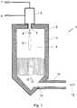
- Fig. 1shows a section through a reactor according to the invention.
- the reactor 1comprises the reactor vessel 2 with the refractory lining 3.
- the reactor chamber 4On the upper opening 5 of the reactor chamber 4 of the mixer / burner 6 is placed.
- the mixer / burner 6generates from the educts hydrocarbon 7 and oxygen / steam 8, the reactant gas mixture 9.
- the reactants 7 and 8are the mixer / burner 6 supplied so that upon exiting the mixer / burner 9 in the reactor chamber 4 a stable Flame zone 10 can form.
- the flame zonemerges in the lower region of the reactor chamber into the reforming zone, in which a layer of moldings 11 is arranged.
- the educt gasesAfter flowing through the reforming zone, the educt gases are largely converted into product gas, ie synthesis gas 12.
- the product gas 12leaves through the lower opening 13, the reactor chamber 4 and is supplied through the connecting line 14 to a non-illustrated gas cooler.
- Fig. 2shows a section through a reactor according to the invention of the same type as in Fig. 1 shown. Unlike in Fig. 1 are here in the reactor chamber 4 and also in the connecting line 14, the mixing-enhancing internals 15 installed.
- Fig. 3shows a section through a reactor according to the invention of the same type, as in Fig. 1 and Fig. 2 shown.
- Fig. 1in the reactor chamber one Layer of moldings 11 and arranged, as in Fig. 2 , are here in the connecting line 14, the mixing-enhancing internals 15 installed.
- a layer of spherical shaped bodieswas used in the reactor chamber.
- the diameter of the layercorresponding to the inner diameter of the reactor chamber, was 500 mm, the thickness of the layer 900 mm and the diameter of the balls 20 mm.
- the ballswere made of Al 2 O 3 .
- the test resultsare summarized in the two following tables. Trial 1 V O2 / V NG V H2 + CO / V NG V H2 + CO. tr CH 4, syngas.
- This first calculationshows that the residual methane content in the synthesis gas is lowered by the mixing device, even with lowered process temperature.
- This second calculationshows that the amount of oxygen used, or the process temperature, can be lowered by the mixing device, whereby the synthesis gas yield nevertheless increases.
- the method according to the inventionit is thus possible to potentially reduce the oxygen demand at the same residual methane content in the synthesis gas by up to 3% in comparison to the operation of the partial oxidation according to the prior art.
- the temperaturecan be lowered significantly by about 70 K.
- the amount of synthesis gas producedis between 1.07 mol% and 1.3 mol% higher in both simulation scenarios.
- the inventionprovides an improved process and apparatus for the production of synthesis gas by partial oxidation and is thus industrially applicable.
Landscapes
- Chemical & Material Sciences (AREA)
- Chemical Kinetics & Catalysis (AREA)
- Organic Chemistry (AREA)
- Health & Medical Sciences (AREA)
- General Health & Medical Sciences (AREA)
- Engineering & Computer Science (AREA)
- Combustion & Propulsion (AREA)
- Inorganic Chemistry (AREA)
- Physical Or Chemical Processes And Apparatus (AREA)
- Hydrogen, Water And Hydrids (AREA)
Abstract
Translated fromGerman
Description
Translated fromGermanDie Erfindung betrifft ein Partialoxidationsverfahren zur Erzeugung eines kohlenmonoxid- und wasserstoffhaltigen Synthesegases aus kohlenwasserstoffhaltigem Eduktmaterial, wobei folgende Verfahrensschritte durchgeführt werden:
- Bereitstellen der Edukte, umfassend einen kohlenwasserstoffhaltigen Stoff, ein sauerstoffhaltiges Gas und optional Dampf,
- Bereitstellen eines Reaktors, umfassend ein stehend angeordnetes, mit feuerfestem Material ausgekleidetes Reaktorgefäß mit einer darin liegenden Reaktionskammer, einer am oberen Ende des Gefäßes liegenden Öffnung für die Einleitung des Eduktgemisches und einer am unteren Ende liegenden Öffnung für die Ausleitung des Synthesegases als Produktgas und eine daran anschließende Verbindungsleitung zu einem Gaskühler und einen Mischer/Brenner zur Erzeugung eines Gemisches aus den Edukten, wobei der Mischer/Brenner so auf die obere Öffnung des Reaktorgefäßes montiert ist, dass über ihn das Eduktgemisch in das Reaktorgefäß eingeleitet werden kann,
- Einleiten der Edukte über den Mischer/Brenner in die Reaktionskammer des Reaktorgefäßes, mit den für die chemischen Umwandlungsreaktionen der Partialoxidation erforderlichen Temperaturen und Drücken,
- Umwandlung des Eduktgemischs in Synthesegas innerhalb der Reaktionskammer,
- Ausleitung des Synthesegases durch die Verbindungsleitung aus dem Reaktorgefäß zur weiteren Behandlung in einem Gaskühler.
- Providing the educts comprising a hydrocarbon-containing substance, an oxygen-containing gas and optionally steam,
- Providing a reactor comprising a standing up, refractory lined reactor vessel having a reaction chamber therein, an upper end of the vessel opening for the introduction of the reactant mixture and a lower end opening for the discharge of the synthesis gas as product gas and one thereon subsequent connection line to a gas cooler and a mixer / burner for generating a mixture of the educts, wherein the mixer / burner is mounted on the upper opening of the reactor vessel so that via it the educt mixture can be introduced into the reactor vessel,
- Introducing the educts via the mixer / burner into the reaction chamber of the reactor vessel, with the temperatures and pressures required for the chemical transformation reactions of the partial oxidation,
- Conversion of the educt mixture into synthesis gas within the reaction chamber,
- Discharge of the synthesis gas through the connecting line from the reactor vessel for further treatment in a gas cooler.
Die Erfindung betrifft ebenso eine Anlage zur Durchführung des Partialoxidationsverfahrens.The invention also relates to a plant for carrying out the partial oxidation process.
Partialoxidationsverfahren zur Umwandlung von kohlenwasserstoffhaltigem Gas in ein kohlenmonoxid- und wasserstoffhaltiges Synthesegas sind an sich bekannt. Praktische Bedeutung haben beispielsweise die Verfahren der Firmen Shell und Texaco, deren Grundzüge beispielsweise in
Das durch Partialoxidation umgewandelte, kohlenwasserstoffhaltige Gas kann aus Kohle, Rückständen aus der Erdölverarbeitung bzw. Schweröl gewonnen werden. Das kohlenwasserstoffhaltige Gas, gegebenenfalls vermischt mit Dampf, wird zusammen mit Sauerstoff als Eduktgemisch über einen Mischer/Brenner der Reaktionskammer eines Reaktors zugeführt, in dem bei Temperaturen zwischen 1200 und 1500 °C und Drücken von 20 bis 120 bar die Vergasungsreaktionen ablaufen. Dabei wird ein Teil der Kohlenwasserstoffe zur Gewinnung der für die Vergasungsreaktionen notwendigen Wärmeenergie verbrannt. Dies geschieht in der sich am Mischer/Brenner-Austritt bildenden Flammenzone. An diese schließt sich die sogenannte Reformierungszone an, die den Rest der Reaktorkammer ausfüllt. Bei der Partialoxidation wird kein Katalysator verwendet, sodass auch Kohlenwasserstoffe mit hohem Gehalt an Verunreinigungen, wie Schwefel, verarbeitet werden können.The converted by partial oxidation, hydrocarbon-containing gas can be obtained from coal, residues from petroleum processing or heavy oil. The hydrocarbon-containing gas, optionally mixed with steam, is fed together with oxygen as starting material mixture via a mixer / burner of the reaction chamber of a reactor in which proceed at temperatures between 1200 and 1500 ° C and pressures of 20 to 120 bar, the gasification reactions. In this case, a portion of the hydrocarbons is burned to obtain the heat energy necessary for the gasification reactions. This happens in the flame zone forming at the mixer / burner outlet. This is followed by the so-called reforming zone, which fills the rest of the reactor chamber. In the partial oxidation, no catalyst is used, so that hydrocarbons with a high content of impurities, such as sulfur, can be processed.
Das beim Ablauf des Partialoxidationsverfahrens in der Reaktionskammer erzeugte Gemisch aus Edukten und Produkten, das Synthesegas-Produktgas, wird im Folgenden alternativ auch als Prozessgas bezeichnet.The mixture of educts and products produced in the reaction chamber during the partial oxidation process, the synthesis gas product gas, is alternatively referred to below as the process gas.
Die Patentschrift
Durch das Fehlen eines Katalysators ist es grundsätzlich schwierig, einen ausreichenden Umsatz der eingesetzten Kohlenwasserstoffe und damit einen niedrigen Restmethangehalt im Produktgas zu erreichen. Zur Optimierung des Umsatzes stehen die Prozessparameter Temperatur, Güte der Gasdurchmischung und die Verweilzeit des Gases in der Reaktorkammer zur Verfügung.Due to the absence of a catalyst, it is fundamentally difficult to achieve a sufficient conversion of the hydrocarbons used and thus a low residual methane content in the product gas. To optimize the conversion, the process parameters temperature, quality of gas mixing and the residence time of the gas in the reactor chamber are available.
Mit zunehmender Temperatur wird eine Zunahme der Reaktionsgeschwindigkeiten zwischen den Gasen erreicht, allerdings führen die erhöhten Reaktionsgeschwindigkeiten auch zu einem erhöhten Sauerstoffbedarf des Prozesses und zu einem erhöhten Dampf- und Kohlendioxidgehalt im Produktgas. Außerdem steigt mit der Temperatur die Belastung für die zum Bau des Reaktionsapparates verwendeten Materialien.As the temperature increases, the reaction rates between the gases are increased, but the increased reaction rates also result in increased oxygen demand of the process and increased vapor and carbon dioxide levels in the product gas. In addition, the temperature increases the load on the materials used to build the reactor.
Durch geeignete Konstruktion des Mischer/Brenners und, abgestimmt damit, durch geeignete Konstruktion der Reaktionskammer kann die Güte der Gasdurchmischung, der Strömungsverlauf und die Verweilzeit des Gases in der Reaktorkammer beeinflusst werden. Dabei sind der Verweilzeit durch die Größe der Reaktionskammer und den davon abhängigen Baukosten enge Grenzen gesetzt. Das geeignete Design für eine optimale Gasdurchmischung und Strömungsführung zu finden, ist sehr aufwendig, insbesondere da sich bei einem Up- oder Downscaling der Apparate die Strömungsverläufe stark ändern können und das Design der Bauteile überarbeitet werden muss.By suitable design of the mixer / burner and, matched with it, by suitable design of the reaction chamber, the quality of the gas mixture, the flow and the residence time of the gas can be influenced in the reactor chamber. The residence time is limited by the size of the reaction chamber and the construction costs dependent thereon. Finding the suitable design for optimum gas mixing and flow guidance is very complicated, especially since the flow patterns can change greatly during an up- or downscaling of the apparatus and the design of the components must be revised.
Die Aufgabe der vorliegenden Erfindung ist es daher, ein Verfahren zur Verfügung zu stellen, bei dem die Nachteile des Stands der Technik in geringerem Umfang auftreten.The object of the present invention is therefore to provide a method in which the disadvantages of the prior art occur to a lesser extent.
Die Aufgabe wird durch ein Verfahren gemäß den Merkmalen des Anspruchs 1 und durch eine Anlage gemäß den Merkmalen des Anspruchs 13 gelöst.The object is achieved by a method according to the features of
Dadurch, dass erfindungsgemäß die Prozessgase durch die Durchmischung erhöhenden oder strömungslenkenden Einbauten, die als statische Mischeinrichtung wirken, und/oder eine ebenfalls als Mischeinrichtung wirkende Schicht aus Formkörpern geleitet werden, wird die Durchmischung der Gase verbessert. Die Formkörper können dabei jede Form haben, die die Durchmischung des Prozessgases fördert, insbesondere die Turbulenz in der Gasströmung beim Durchströmen der Formkörperschicht erhöht. Dabei kommt eine Formkörperschicht bevorzugt in der Reaktorkammer und die die Durchmischung erhöhenden Einbauten kommen bevorzugt in der Verbindungsleitung zwischen dem Reaktorgefäß und dem Gaskühler zum Einsatz.Due to the fact that according to the invention the process gases are passed through the mixing-enhancing or flow-directing internals which act as a static mixing device and / or a layer of shaped bodies also acting as a mixing device, the mixing of the gases is improved. The shaped bodies can have any shape which promotes the mixing of the process gas, in particular increases the turbulence in the gas flow when flowing through the shaped body layer. Here, a shaped body layer preferably comes in the reactor chamber and the mixing-enhancing internals are preferably used in the connecting line between the reactor vessel and the gas cooler.
Durch diese erfindungsgemäßen Maßnahmen wird die Vermischung, insbesondere die Turbulenz im Prozessgas erhöht und damit die Vermischung der Gaskomponenten verbessert. Damit wird die Möglichkeit erhöht, dass reaktionsbereite Gasmoleküle zusammentreffen und damit die Geschwindigkeit der im Reaktor ablaufenden chemischen Reaktionen gesteigert. Dadurch werden die Anforderungen an das Design des Mischer/Brenners oder der Reaktorkammer vereinfacht, um eine optimale Strömungsführung hinsichtlich der Gasdurchmischung oder der Verweilzeit zu erreichen. Ein weiterer Vorteil der Erfindung besteht. in der Möglichkeit die Prozesstemperatur, bei gleichbleibendem Reaktionsumsatz, zu senken.By these measures according to the invention, the mixing, in particular the turbulence in the process gas is increased and thus improves the mixing of the gas components. This increases the possibility of reaction-ready gas molecules coming together, thus increasing the speed of the chemical reactions taking place in the reactor. This simplifies the design requirements of the mixer / burner or reactor chamber in order to achieve optimum flow control in terms of gas mixing or residence time. Another advantage of the invention is. in the possibility to lower the process temperature, with constant reaction conversion.
Eine bevorzugte Ausgestaltung der Erfindung ist dadurch gekennzeichnet, dass es sich bei den die Durchmischung erhöhenden Einbauten um statische Mischer handelt. Statische Mischer sind seit langem in der Verfahrenstechnik bewährt und in zahlreichen Varianten verfügbar.A preferred embodiment of the invention is characterized in that the internals which increase the mixing are static mixers. Static mixers have long been proven in process engineering and are available in numerous variants.
Eine weitere bevorzugte Ausgestaltung der Erfindung ist dadurch gekennzeichnet, dass es sich bei den die Durchmischung erhöhenden Einbauten um strukturierte Packungen handelt. Strukturierte Packungen sind einfach in den Reaktionsraum einzubauen. Sie liefern ein exakt definiertes Strömungsergebnis, das auch bei Austausch der Packung gut reproduzierbar ist.A further preferred embodiment of the invention is characterized in that the internals which increase the mixing are structured packings. Structured packings are easy to install in the reaction space. They deliver a precisely defined flow result that is easily reproducible even when the pack is replaced.
Eine weitere bevorzugte Ausgestaltung der Erfindung ist dadurch gekennzeichnet, dass es sich bei den Formkörpern um Kugeln handelt. Es handelt sich dabei um ein handelsübliches Produkt. Durch Auswahl des geeigneten Kugeldurchmessers kann die Mischwirkung und der Druckverlust des Prozessgases über die Schüttung eingestellt werden. Bevorzugt werden dabei insbesondere Kugeln aus keramischen Materialen, beispielsweise auf Basis von Al2O3, da sie die nötige mechanische und thermische Stabilität aufweisen und chemisch inert sind.Another preferred embodiment of the invention is characterized in that the shaped bodies are balls. It is a commercial product. By selecting the appropriate ball diameter, the mixing effect and the pressure loss of the process gas can be adjusted via the bed. In particular, spheres made of ceramic materials, for example based on Al2 O3 , are preferred because they have the necessary mechanical and thermal stability and are chemically inert.
Eine weitere bevorzugte Ausgestaltung der Erfindung ist dadurch gekennzeichnet, dass die statische Mischeinrichtung oder die Formkörpern der Schüttung aus Schaumkeramik bestehen. Diese sind durch eine hohe thermische Stabilität bei geringet spezifischer Masse gekennzeichnet.A further preferred embodiment of the invention is characterized in that the static mixing device or the shaped bodies of the bed of foam ceramic consist. These are characterized by a high thermal stability at low specific mass.
Eine weitere bevorzugte Ausgestaltung der Erfindung ist dadurch gekennzeichnet, dass die Mischeinrichtung oder die Formkörper aus Al2O3 bestehen. Dieses Material ist inert gegenüber den im Prozessgas ablaufenden chemischen Reaktionen. Außerdem ist das Material thermisch stabil und marktüblich.A further preferred embodiment of the invention is characterized in that the mixing device or the moldings consist of Al2 O3 . This material is inert to the chemical reactions occurring in the process gas. In addition, the material is thermally stable and commercially available.
Eine weitere bevorzugte Ausgestaltung der Erfindung ist dadurch gekennzeichnet, dass die Mischeinrichtung oder die Formkörper zwischen 1 und 50 Vol.-%, bevorzugt zwischen 20 und 40 Vol.-% der Reaktionskammer einnehmen. In diesem Bereich ist genügend freies Volumen für eine gleichmäßige Verteilung des Gases in der Reaktorkammer vorhanden und gleichzeitig sind genügend Mischelemente, wie Formkörper oder Einbauten, vorhanden, um eine gute Mischwirkung zu erzielen.A further preferred embodiment of the invention is characterized in that the mixing device or the moldings occupy between 1 and 50% by volume, preferably between 20 and 40% by volume, of the reaction chamber. In this area, there is enough free volume for a uniform distribution of the gas in the reactor chamber and at the same time sufficient mixing elements, such as moldings or internals, are present in order to achieve a good mixing effect.
Eine weitere bevorzugte Ausgestaltung der Erfindung ist dadurch gekennzeichnet, dass das Verfahren mit einem Druck zwischen 10 und 100 bar in der Reaktorkammer durchgeführt wird. Dieser Bereich ermöglicht einen sinnvollen Kompromiss zwischen hohem Durchsatz bei kompakten Abmessungen und einer Gleichgewichtslage, die ausreichenden Umsatz erlaubt.A further preferred embodiment of the invention is characterized in that the process is carried out at a pressure between 10 and 100 bar in the reactor chamber. This range allows a reasonable compromise between high throughput with compact dimensions and an equilibrium position that allows sufficient turnover.
Eine weitere bevorzugte Ausgestaltung der Erfindung ist dadurch gekennzeichnet, dass das Verfahren mit einer Temperatur zwischen 900 und 1500 °C, vorzugsweise zwischen 1200 und 1400 °C in der Reaktorkammer durchgeführt wird. Dieses stellt einen sinnvol[en Kompromiss zwischen ausreichendem Umsatz, begrenztem Sauerstoffbedarf und thermischer Stabilität der Materialien dar.A further preferred embodiment of the invention is characterized in that the process is carried out at a temperature between 900 and 1500 ° C, preferably between 1200 and 1400 ° C in the reactor chamber. This represents a meaningful compromise between sufficient turnover, limited oxygen demand and thermal stability of the materials.
Eine weitere bevorzugte Ausgestaltung der Erfindung ist dadurch gekennzeichnet, dass das Verfahren mit einem molaren Mengenverhältnis von Dampf / Kohlenstoff im Eduktgasgemisch zwischen 0 und 0,6 durchgeführt wird. Hierdurch kann das Wasserstoff/Kohlenmonoxidverhältnis im Synthesegas eingestellt werden.A further preferred embodiment of the invention is characterized in that the method is carried out with a molar ratio of steam / carbon in Eduktgasgemisch between 0 and 0.6. As a result, the hydrogen / carbon monoxide ratio in the synthesis gas can be adjusted.
Eine weitere bevorzugte Ausgestaltung der Erfindung ist dadurch gekennzeichnet, dass das Verfahren mit einem molaren Mengenverhältnis von Sauerstoff / Kohlenstoff im Eduktgasgemisch zwischen 0,5 und 0,8 durchgeführt wird, um den o. g. Temperaturbereich zu erzielen.A further preferred embodiment of the invention is characterized in that the process is carried out with a molar ratio of oxygen / carbon in the educt gas mixture between 0.5 and 0.8, to the o. G. Temperature range to achieve.
Weiterbildungen, Vorteile und Anwendungsmöglichkeiten der Erfindung ergeben sich auch aus der nachfolgenden Beschreibung von nicht beschränkenden Ausführungs- und Zahlenbeispielen und den Zeichnungen. Dabei bilden alle beschriebenen und/oder bildlich dargestellten Merkmale für sich oder in beliebiger Kombination die Erfindung, unabhängig von ihrer Zusammenfassung in den Ansprüchen oder deren Rückbeziehung.Further developments, advantages and applications of the invention will become apparent from the following description of non-limiting embodiment and numerical examples and the drawings. All described and / or illustrated features alone or in any combination form the invention, regardless of their combination in the claims or their dependency.
Die Erfindung soll im Folgenden anhand der Zeichnung sowie anhand von Versuchsdaten und Ergebnissen von Simulationsrechnungen näher erläutert werden.The invention will be explained in more detail below with reference to the drawing and with reference to experimental data and results of simulation calculations.
Dabei zeigen:
- Fig. 1
- Schnitt durch einen erfindungsgemäßen Reaktor mit einer Schüttung aus Formkörpern in der Reaktionskammer,
- Fig. 2
- Schnitt durch einen erfindungsgemäßen Reaktor mit Einbauten in der Reaktionskammer und in der Verbindungsleitung,
- Fig. 3
- Schnitt durch einen erfindungsgemäßen Reaktor mit einer Schüttung aus Formkörpern in der Reaktionskammer und Einbauten in der Verbindungsleitung.
- Fig. 1
- Section through a reactor according to the invention with a bed of moldings in the reaction chamber,
- Fig. 2
- Section through a reactor according to the invention with internals in the reaction chamber and in the connecting line,
- Fig. 3
- Section through a reactor according to the invention with a bed of moldings in the reaction chamber and internals in the connecting line.
Ebenfalls zu der Erfindung gehören die bildlich nicht dargestellten Ausgestaltungen, bei denen entweder nur die Reaktorkammer, aber nicht die Verbindungsleitung, oder nur die Verbindungsleitung, aber nicht die Reaktorkammer mit die Durchmischung erhöhenden Einbauten ausgestattet sind.Also included in the invention are the embodiments, not shown, in which either only the reactor chamber, but not the connecting line, or only the connecting line, but not the reactor chamber are equipped with the mixing-enhancing internals.
Um die Wirkung einer Schüttung aus Formkörpern in der Reaktorkammer eines Partialoxidationsreaktors zu testen, wurden zwei Versuche, bei 50 und bei 60 bar Druck in der Reaktorkammer oberhalb der Mischeinrichtung, jeweils mit und ohne Mischeinrichtung durchgeführt. In der ersten Phase A wurde die Partialoxidation gemäß dem bisherigen Stand der Technik mit einer leeren Reaktorkammer und dann, in der zweiten Phase B, unter sonst gleichen Bedingungen, mit einer eine Schüttung aus Formkörpern enthaltenden Reaktionskammer durchgeführt.In order to test the effect of a bed of moldings in the reactor chamber of a partial oxidation reactor, two tests were carried out at 50 and at 60 bar pressure in the reactor chamber above the mixing device, each with and without mixing device. In the first phase A, the partial oxidation according to the prior art was carried out with an empty reactor chamber and then, in the second phase B, under otherwise identical conditions, with a reaction chamber containing a bed of moldings.
Als Mischeinrichtung wurde in der Reaktorkammer eine Schicht aus kugelförmigen Formkörpem verwendet. Der Durchmesser der Schicht, entsprechend dem Innendurchmesser der Reaktorkammer, betrug 500 mm, die Dicke der Schicht 900 mm und der Durchmesser der Kugeln 20 mm. Die Kugeln bestanden aus Al2O3. Die Versuchsergebnisse sind in den beiden nachfolgenden Tabellen zusammengestellt.
**) mit Mischeinrichtung
**) with mixing device
Bei diesen Versuchen wurden Erdgas und Sauerstoff als Eduktgase eingesetzt. In Versuchsphase B, in der eine Schüttung aus Formkörpern in der Reaktorkammer vorhanden war, wurde ein erhöhtes Volumenverhältnis von Wasserstoff und Kohlenmonoxid im Produktgas zum eingesetzten Erdgas NG erhalten. Weiterhin wurde ein geringerer Rest-CH4-Gehalt im Synthesegas, tr (trocken) erreicht. Diese positiven Ergebnisse wurden bei geringerer Prozesstemperatur im Reaktor erreicht.In these experiments, natural gas and oxygen were used as educt gases. In experimental phase B, in which a bed of moldings was present in the reactor chamber, an increased volume ratio of hydrogen and carbon monoxide in the product gas to the natural gas used NG was obtained. Furthermore, a lower residual CH4 content was achieved in the synthesis gas, tr (dry). These positive results were achieved at lower process temperature in the reactor.
In einer ersten Rechnung wurde die Wirkung einer Mischeinrichtung in der Reaktorkammer bei in beiden Phasen gleicher Sauerstoffmenge im Eduktgas simuliert. Die Ergebnisse dieser Simulationsrechnungen sind ebenfalls in Tabellenform zusammengestellt.
**) mit Mischeinrichtung
**) with mixing device
Diese erste Rechnung zeigt, dass durch die Mischeinrichtung, sogar mit abgesenkter Prozesstemperatur, der Restmethangehalt im Synthesegas gesenkt wird.This first calculation shows that the residual methane content in the synthesis gas is lowered by the mixing device, even with lowered process temperature.
In einer zweiten Rechnung wurde die Wirkung einer Mischeinrichtung in der Reaktorkammer bei in beiden Phasen gleichem Restmethangehalt im Synthesegas, bezogen auf den trockenen Zustand des Synthesegases, simuliert.
**) mit Mischeinrichtung
**) with mixing device
Diese zweite Rechnung zeigt, dass durch die Mischeinrichtung die Menge an eingesetztem Sauerstoff, bzw. die Prozesstemperatur, gesenkt werden kann, wobei die Synthesegasausbeute dennoch steigt.This second calculation shows that the amount of oxygen used, or the process temperature, can be lowered by the mixing device, whereby the synthesis gas yield nevertheless increases.
Unter Anwendung des erfindungsgemäßen Verfahrens ist es demnach möglich, den Sauerstoffbedarf bei gleichem Restmethangehalt im Synthesegas im Vergleich zum Betrieb der partiellen Oxidation nach dem Stand der Technik potentiell um bis zu 3 % zu reduzieren. Zudem kann die Temperatur deutlich um ca. 70 K gesenkt werden. Bei gleicher Sauerstoffzufuhr lässt sich dementsprechend ein höherer Methanumsatz erzielen. Zudem liegt die produzierte Synthesegasmenge, verglichen mit der partiellen Oxidation nach dem Stand der Technik, in beiden Simulationsszenarien zwischen 1,07 mol-% und 1,3 mol-% höher.Using the method according to the invention, it is thus possible to potentially reduce the oxygen demand at the same residual methane content in the synthesis gas by up to 3% in comparison to the operation of the partial oxidation according to the prior art. In addition, the temperature can be lowered significantly by about 70 K. At the same Oxygen supply can be achieved accordingly a higher methane conversion. In addition, compared to the prior art partial oxidation, the amount of synthesis gas produced is between 1.07 mol% and 1.3 mol% higher in both simulation scenarios.
Die Erfindung stellt ein verbessertes Verfahren und einen verbesserten Apparat für die Erzeugung von Synthesegas durch Partialoxidation zur Verfügung und ist damit gewerblich anwendbar.The invention provides an improved process and apparatus for the production of synthesis gas by partial oxidation and is thus industrially applicable.
- 11
- erfindungsgemäße Anlage zur Partialoxidationinventive system for partial oxidation
- 22
- Reaktorreactor
- 33
- Feuerfeste AuskleidungRefractory lining
- 44
- Reaktionskammerreaction chamber
- 55
- Öffnung für die Einleitung des EduktgasgemischesOpening for the introduction of the educt gas mixture
- 66
- Mischer/BrennerMixer / burner
- 77
- Kohlenwasserstoffhaltiger EduktstromHydrocarbon-containing reactant stream
- 88th
- Sauerstoff- und optional dampfhaltiger EduktstromOxygen and optionally steam-containing reactant stream
- 99
- Eduktgasgemischreactant gas mixture
- 1010
- Flammeflame
- 1111
- Schicht aus FormkörpernLayer of moldings
- 1212
- ProduktsynthesegasProduct synthesis gas
- 1313
- Öffnung zur Ausleitung des ProduktsynthesegasesOpening for the discharge of the product synthesis gas
- 1414
- Verbindungsleitungconnecting line
- 1515
- durchmischungserhöhende Einbautenmixing-enhancing internals
Claims (13)
Translated fromGermanPriority Applications (2)
| Application Number | Priority Date | Filing Date | Title |
|---|---|---|---|
| EP17400010.9AEP3366640A1 (en) | 2017-02-28 | 2017-02-28 | Method and system for partial oxidation |
| PCT/EP2018/025035WO2018157972A1 (en) | 2017-02-28 | 2018-02-09 | Process and plant for partial oxidation |
Applications Claiming Priority (1)
| Application Number | Priority Date | Filing Date | Title |
|---|---|---|---|
| EP17400010.9AEP3366640A1 (en) | 2017-02-28 | 2017-02-28 | Method and system for partial oxidation |
Publications (1)
| Publication Number | Publication Date |
|---|---|
| EP3366640A1true EP3366640A1 (en) | 2018-08-29 |
Family
ID=58410235
Family Applications (1)
| Application Number | Title | Priority Date | Filing Date |
|---|---|---|---|
| EP17400010.9AWithdrawnEP3366640A1 (en) | 2017-02-28 | 2017-02-28 | Method and system for partial oxidation |
Country Status (2)
| Country | Link |
|---|---|
| EP (1) | EP3366640A1 (en) |
| WO (1) | WO2018157972A1 (en) |
Citations (4)
| Publication number | Priority date | Publication date | Assignee | Title |
|---|---|---|---|---|
| GB672165A (en)* | 1949-07-23 | 1952-05-14 | Texaco Development Corp | Improvements in or relating to process for generating synthesis gas |
| GB1342116A (en) | 1970-01-30 | 1973-12-25 | Shell Int Research | Apparatus for the preparation and cooling of synthesis gas |
| US3982910A (en)* | 1974-07-10 | 1976-09-28 | The United States Of America As Represented By The Administrator Of The National Aeronautics And Space Administration | Hydrogen-rich gas generator |
| US20090224209A1 (en)* | 2007-11-19 | 2009-09-10 | Jacobus Eilers | Process to prepare a mixture of hydrogen and carbon monoxide |
- 2017
- 2017-02-28EPEP17400010.9Apatent/EP3366640A1/ennot_activeWithdrawn
- 2018
- 2018-02-09WOPCT/EP2018/025035patent/WO2018157972A1/ennot_activeCeased
Patent Citations (4)
| Publication number | Priority date | Publication date | Assignee | Title |
|---|---|---|---|---|
| GB672165A (en)* | 1949-07-23 | 1952-05-14 | Texaco Development Corp | Improvements in or relating to process for generating synthesis gas |
| GB1342116A (en) | 1970-01-30 | 1973-12-25 | Shell Int Research | Apparatus for the preparation and cooling of synthesis gas |
| US3982910A (en)* | 1974-07-10 | 1976-09-28 | The United States Of America As Represented By The Administrator Of The National Aeronautics And Space Administration | Hydrogen-rich gas generator |
| US20090224209A1 (en)* | 2007-11-19 | 2009-09-10 | Jacobus Eilers | Process to prepare a mixture of hydrogen and carbon monoxide |
Non-Patent Citations (1)
| Title |
|---|
| "Ullmanns Encyklopädie der technischen Chemie", vol. 3, 1973, pages: 340 - 341 |
Also Published As
| Publication number | Publication date |
|---|---|
| WO2018157972A1 (en) | 2018-09-07 |
Similar Documents
| Publication | Publication Date | Title |
|---|---|---|
| DE69701808T2 (en) | METHOD AND APPARATUS FOR DESULFURING FUEL GAS | |
| EP0214432B1 (en) | Apparatus for the production of synthesis gas | |
| DE60025124T2 (en) | Method and apparatus for hydrogen production by reforming | |
| DE1417796C3 (en) | Process for producing a hydrogen-rich gas | |
| EP4363372A1 (en) | Method and apparatus for producing hydrogen from ammonia | |
| DE2758395A1 (en) | METHOD FOR PRODUCING SYNTHESIS GAS | |
| DE3504010A1 (en) | METHOD FOR CONVERTING HEAVY OIL RESIDUES TO HYDROGEN AND GASEOUS AND DISTILLABLE HYDROCARBONS | |
| AT394394B (en) | DEVICE AND METHOD IN PARTICULAR FOR INCREASING THE CARBON CONTENT OF DIRECTLY REDUCED IRON | |
| AT394393B (en) | DEVICE AND METHOD IN PARTICULAR FOR INCREASING THE CARBON CONTENT OF DIRECTLY REDUCED IRON | |
| DE3244252A1 (en) | METHOD AND DEVICE FOR GENERATING PRODUCT GAS WITH HYDROGEN AND CARBON OXYDE CONTENT | |
| DE3033336C2 (en) | Process for the manufacture of sponge iron | |
| DE3606108A1 (en) | METHOD AND DEVICE FOR PRODUCING A GAS CONTAINING MAINLY CO + H (ARROW DOWN) 2 (ARROW DOWN) BY THERMAL REFORMING OF GASEOUS HYDROCARBON | |
| DE60116459T2 (en) | Process for the preparation of a mixture containing hydrogen and carbon monoxide | |
| EP3899057B1 (en) | Method and device for direct reduction with electrically heated reducing gas | |
| EP1717198A2 (en) | Process and apparatus for reforming at high temperature | |
| EP3202922B1 (en) | Method and apparatus for manufacturing sponge iron | |
| EP2758338B1 (en) | Method for producing synthetic gas | |
| EP3366640A1 (en) | Method and system for partial oxidation | |
| DE2805244A1 (en) | METHOD AND DEVICE FOR COOLING DUSTY OR FINE-GRAINED SOLIDS | |
| EP0920352A2 (en) | Apparatus and method for conducting reactions in fluidized particle layers | |
| WO2024041751A1 (en) | Preventing nitriding when operating an ammonia cracker furnace | |
| DE2141875A1 (en) | METHOD FOR PRODUCING A REDUCING GAS | |
| DE3803080A1 (en) | METHOD FOR GENERATING SYNTHESIS GAS FROM HYDROCARBON-CONTAINED SUBSTANCES | |
| WO2016198245A1 (en) | Determining pressure, temperature and s/c ratio for soot-free atr operation | |
| DE60037141T2 (en) | SPOX-SUPPORTED PROCESS FOR THE PRODUCTION OF SYNTHESIS GAS |
Legal Events
| Date | Code | Title | Description |
|---|---|---|---|
| PUAI | Public reference made under article 153(3) epc to a published international application that has entered the european phase | Free format text:ORIGINAL CODE: 0009012 | |
| STAA | Information on the status of an ep patent application or granted ep patent | Free format text:STATUS: THE APPLICATION HAS BEEN PUBLISHED | |
| AK | Designated contracting states | Kind code of ref document:A1 Designated state(s):AL AT BE BG CH CY CZ DE DK EE ES FI FR GB GR HR HU IE IS IT LI LT LU LV MC MK MT NL NO PL PT RO RS SE SI SK SM TR | |
| AX | Request for extension of the european patent | Extension state:BA ME | |
| STAA | Information on the status of an ep patent application or granted ep patent | Free format text:STATUS: REQUEST FOR EXAMINATION WAS MADE | |
| 17P | Request for examination filed | Effective date:20190129 | |
| RBV | Designated contracting states (corrected) | Designated state(s):AL AT BE BG CH CY CZ DE DK EE ES FI FR GB GR HR HU IE IS IT LI LT LU LV MC MK MT NL NO PL PT RO RS SE SI SK SM TR | |
| STAA | Information on the status of an ep patent application or granted ep patent | Free format text:STATUS: EXAMINATION IS IN PROGRESS | |
| 17Q | First examination report despatched | Effective date:20200324 | |
| STAA | Information on the status of an ep patent application or granted ep patent | Free format text:STATUS: THE APPLICATION IS DEEMED TO BE WITHDRAWN | |
| 18D | Application deemed to be withdrawn | Effective date:20200804 |