EP3366603B1 - A pouring spout for a container, a container assembly and a method for producing a pouring spout - Google Patents
A pouring spout for a container, a container assembly and a method for producing a pouring spoutDownload PDFInfo
- Publication number
- EP3366603B1 EP3366603B1EP17157375.1AEP17157375AEP3366603B1EP 3366603 B1EP3366603 B1EP 3366603B1EP 17157375 AEP17157375 AEP 17157375AEP 3366603 B1EP3366603 B1EP 3366603B1
- Authority
- EP
- European Patent Office
- Prior art keywords
- tubular portion
- neck
- spout
- projection
- outer tubular
- Prior art date
- Legal status (The legal status is an assumption and is not a legal conclusion. Google has not performed a legal analysis and makes no representation as to the accuracy of the status listed.)
- Active
Links
- 238000004519manufacturing processMethods0.000titleclaimsdescription5
- 238000000465mouldingMethods0.000claimsdescription16
- 238000000034methodMethods0.000claimsdescription5
- 239000000463materialSubstances0.000description17
- 230000009975flexible effectEffects0.000description9
- 239000007788liquidSubstances0.000description7
- 239000004033plasticSubstances0.000description7
- 229920003023plasticPolymers0.000description7
- 230000002349favourable effectEffects0.000description4
- 238000007789sealingMethods0.000description4
- 239000004698PolyethyleneSubstances0.000description3
- 229920001903high density polyethylenePolymers0.000description3
- 239000004700high-density polyethyleneSubstances0.000description3
- 230000003993interactionEffects0.000description3
- -1polyethylenePolymers0.000description3
- 229920000573polyethylenePolymers0.000description3
- 239000003599detergentSubstances0.000description2
- 238000006073displacement reactionMethods0.000description2
- 238000000605extractionMethods0.000description2
- 239000012530fluidSubstances0.000description2
- 239000000446fuelSubstances0.000description2
- 238000001746injection mouldingMethods0.000description2
- 239000000126substanceSubstances0.000description2
- AFCARXCZXQIEQB-UHFFFAOYSA-NN-[3-oxo-3-(2,4,6,7-tetrahydrotriazolo[4,5-c]pyridin-5-yl)propyl]-2-[[3-(trifluoromethoxy)phenyl]methylamino]pyrimidine-5-carboxamideChemical compoundO=C(CCNC(=O)C=1C=NC(=NC=1)NCC1=CC(=CC=C1)OC(F)(F)F)N1CC2=C(CC1)NN=N2AFCARXCZXQIEQB-UHFFFAOYSA-N0.000description1
- 235000013361beverageNutrition0.000description1
- 238000004891communicationMethods0.000description1
- 230000001419dependent effectEffects0.000description1
- 239000002828fuel tankSubstances0.000description1
- 239000002184metalSubstances0.000description1
- 239000003208petroleumSubstances0.000description1
- 238000004064recyclingMethods0.000description1
- 229920001169thermoplasticPolymers0.000description1
- 239000004416thermosoftening plasticSubstances0.000description1
- 230000007704transitionEffects0.000description1
Images


Classifications
- B—PERFORMING OPERATIONS; TRANSPORTING
- B65—CONVEYING; PACKING; STORING; HANDLING THIN OR FILAMENTARY MATERIAL
- B65D—CONTAINERS FOR STORAGE OR TRANSPORT OF ARTICLES OR MATERIALS, e.g. BAGS, BARRELS, BOTTLES, BOXES, CANS, CARTONS, CRATES, DRUMS, JARS, TANKS, HOPPERS, FORWARDING CONTAINERS; ACCESSORIES, CLOSURES, OR FITTINGS THEREFOR; PACKAGING ELEMENTS; PACKAGES
- B65D47/00—Closures with filling and discharging, or with discharging, devices
- B65D47/04—Closures with discharging devices other than pumps
- B65D47/06—Closures with discharging devices other than pumps with pouring spouts or tubes; with discharge nozzles or passages
- B65D47/065—Closures with discharging devices other than pumps with pouring spouts or tubes; with discharge nozzles or passages with hinged, foldable or pivotable spouts
- B—PERFORMING OPERATIONS; TRANSPORTING
- B65—CONVEYING; PACKING; STORING; HANDLING THIN OR FILAMENTARY MATERIAL
- B65D—CONTAINERS FOR STORAGE OR TRANSPORT OF ARTICLES OR MATERIALS, e.g. BAGS, BARRELS, BOTTLES, BOXES, CANS, CARTONS, CRATES, DRUMS, JARS, TANKS, HOPPERS, FORWARDING CONTAINERS; ACCESSORIES, CLOSURES, OR FITTINGS THEREFOR; PACKAGING ELEMENTS; PACKAGES
- B65D25/00—Details of other kinds or types of rigid or semi-rigid containers
- B65D25/38—Devices for discharging contents
- B65D25/40—Nozzles or spouts
- B65D25/42—Integral or attached nozzles or spouts
- B65D25/46—Hinged, foldable or pivoted nozzles or spouts
Definitions
- the present inventionrelates to a pouring spout for attachment to a container neck, according to the preamble of claim 1.
- This type of containersincludes cans and similar types of containers. Such cans include gas cans, wherein the pouring spout is attached to the neck of the can to facilitate pouring of its content into a fuel tank.
- This type of containersalso includes containers for oil, washer fluids, detergents, chemicals and similar but can include containers for any liquids or semi liquids.
- the present inventionalso includes an assembly comprising a container, such as a can, and such a pouring spout mounted on said container to facilitate extraction of its contents.
- the present inventionalso relates to a method for producing such a pouring spout.
- pouring spouts for containerssuch as gas cans
- One such type of pouring spoutcomprises a threaded portion for connection to a threaded neck of the container, wherein the spout is attached to the neck by screwing.
- Document EP 2 960 173 A1discloses a pouring spout according to the preamble of claim 1.
- An object of the inventionis to avoid the above-mentioned problems of the prior art.
- the inventionresults in pouring spout with favourable sealing properties, which is easy to attach to a container and is easy to use.
- the present inventionrelates to a pouring spout for attachment to a container neck, comprising an outer tubular portion for enclosing an exterior surface of the neck and having a centre axis, and an inward extending projection for engaging an exterior flange of the neck for fastening the spout to the neck, wherein the spout also comprises an inner tubular portion extending in the axial direction for engaging an interior surface of the neck, wherein the inner tubular portion is spaced apart from the outer tubular portion in the radial direction to form a gap between the outer tubular portion and the inner tubular portion, characterised in that a surface of the inner tubular portion facing the outer tubular portion is formed in a plurality of radially displaced steps.
- the combination of the projection for interaction with the flange of the neck together with the steps of the inner tubular portionresult in a spout that can be pushed onto the neck without rotation for a safe and reliable attachment of the spout while providing an excellent seal to prevent leakage from the container.
- the spout and/or neckcan be arranged in a resiliently flexible material, such as plastic materials, wherein at least the projection can be arranged resiliently flexible, and wherein the neck and/or inner tubular portion are resiliently flexible by the inherent properties of the material.
- Both the entire spout and the entire container with the neckcan be arranged in similar material, such as similar plastic material, which is favourable from a recycling perspective.
- both the spout and the containercan be formed in polyethylene, such as HDPE.
- An edge portioncan be arranged between each of the steps. It has been found that the edge portions further improve the sealing properties of the spout.
- the inner tubular portionis tapered downward, such as toward a free end thereof, by means of the steps. This facilitates mounting on the neck while providing favourable sealing properties.
- the outer side of the inner tubular portioncan be formed with a chamfer to guide the inner tubular portion within the neck and thereby guide the spout onto the neck during assembly.
- the inwards extending projectioncan be arranged to extend inward and upward, which will result in a favourable locking of the spout to the neck, which can withstand relatively large forces on the spout axially upward also when the projection and/or a notch between the projection and the outer tubular portion is formed with reduced or relatively small material thickness.
- Such small material thicknesswill provide easier folding of the projection and thereby easier production while providing material savings.
- the outer tubular portioncan be arranged with an inner diameter which is larger in its lower part than in its upper part to form a space for temporarily receiving the projection during mounting on the neck.
- a spaceis provided to facilitate for the projection to be displaced radially when it slides along the neck toward the flange, wherein it returns by its inherent resilient flexible properties when it has reached the flange to engage it and interact with it to attach the spout to the neck.
- the present inventionalso relates to an assembly comprising the spout and a container, wherein the neck of the container is received in the gap between the inner tubular portion and the outer tubular portion, at least an uppermost step of the inner tubular portion engages the interior side of the neck, and the inwards extending projection of the outer tubular portion engages the flange of the neck to attach the spout to the neck.
- the present inventionalso relates to a method for producing a pouring spout for attachment to a container neck, comprising the steps of
- a pouring spout 10 mounted on a neck 11 of a container 12is illustrated schematically according to one embodiment.
- the pouring spout 10is arranged to facilitate extraction of the contents of the container 12.
- the pouring spout 10is arranged in plastic materials, such as a suitable thermoplastic.
- the pouring spout 10is formed in polyethylene, such as HDPE.
- the pouring spoutis, e.g. partially produced by moulding, such as injection moulding, using movable jaws and a tool core interacting with the jaws to form a mould for receiving an amount of plastic material for producing the pouring spout 10.
- the jaws and the tool coreare arranged with a particular form for providing the mould for producing the pouring spout 10 according to the invention, which form is evident by the description of the special features of the pouring spout 10 below.
- the pouring spout 10is also formed partially by means of a mechanical folding machine, which folding is described more in detail below.
- the container 12is, for example, a can, such as a gas can for containing fuel. Alternatively, the container 12 is arranged for containing oil, washer fluids, detergents, chemicals and similar. Alternatively, the container 12 is arranged for containing foodstuff, such as beverages.
- the container 12is, e.g. arranged for containing a volume of at least 1 litre, such as at least 3 litres or at least 5 litres.
- the container 12is arranged in plastic materials or metal.
- the container 12is arranged in the same plastic materials as the spout 10.
- the container 12is arranged in polyethylene, such as HDPE.
- the spout 10is mounted on the neck 11 of the container 12, wherein an interior of the spout 10 is in liquid communication with an interior of the container 12.
- the spout 10comprises an inlet for receiving liquid from the container 12 and an outlet through which the liquid leaves the spout 10.
- the spout 10is arranged to be mounted on top of the container 12.
- the spout 10is provided with a removable cap 13, such as a screw cap, for closing the spout 10 and preventing the contents of the container 12 from being unintentionally extracted through the spout 10.
- the spout 10is illustrated according to one embodiment, wherein the spout 10 has been moulded and removed but is not finished.
- the spout 10 as illustrated in Fig. 2has been removed from the mould for further processing.
- the spout 10comprises a pipe portion 14 and a tubular portion in the form of an outer tubular portion 15, wherein the outer tubular portion 15 is connected to the pipe portion 14.
- the pipe portion 14has a free first end and an opposite second end, wherein a thread 16 is arranged in the area of the free first end and the outer tubular portion 15 is connected to the second end.
- the thread 16is arranged for engaging a corresponding thread of the cap 13.
- the thread 16 of the spout 10is an external thread.
- the pipe portion 14is arranged with a bend 17, so that the outlet of the spout 10 is offset from the inlet.
- the inletis arranged perpendicular to the outlet, wherein a centre axis A of the outer tubular portion 15 is perpendicular to a part of a centre axis B of the pipe portion 14 at the free first end thereof.
- the centre axis A of the outer tubular portion 15is inclined to the part of the centre axis B of the pipe portion 14 at the free first end thereof.
- the pipe portion 14is arranged without the bend 17, wherein the pipe portion 14 is straight and the centre axis A of the outer tubular portion 15 is aligned with the part of the centre axis B of the pipe portion 14 at the free first end thereof.
- the centre axis A of the outer tubular portion 15is straight along the entire outer tubular portion 15.
- the spout 10comprises a projection 18 for fastening of the spout 10 to the neck 11 of the container 12.
- the projection 18is connected to the outer tubular portion 15, such as at the end of the outer tubular portion 15.
- the projection 18is formed at the end of the tubular portion 15 opposite the pipe portion 14.
- the projection 18is formed at the end of the tubular portion 15 opposite the bend 17.
- the projection 18is annular and extend continuously around the outer tubular portion 15.
- the projection 18is cylindrical having a circular cross section.
- the spout 10comprises a plurality of projections 18 distributed around the outer tubular portion 15.
- the spout 10is illustrated after moulding, e.g. by injection moulding, but before finishing thereof.
- the projection 18extends downwards from the outer tubular portion 15, such as away from the outer tubular portion 15 and in a direction away from the pipe portion 14.
- angle between the inner side of the outer tubular portion 15 and the inner side of the projection 18is then larger than 90 degrees and, for example larger than 120 degrees, and optionally less than 180 degrees.
- the projection 18extends obliquely downwards and inwards, so that the projection extends partially axially downwards and partially radially inwards when the spout 10 has been moulded but not finished.
- the outer tubular portion 15then extends substantially in the axial direction and slightly outwards.
- the projection 18is connected to the outer tubular portion 18 through a folding notch 19, along which the projection 18 is foldable after moulding, which is described further below.
- the material thickness at the notch 19is less than 1 mm, such as 0.2-0.5 mm or around 0.3 mm.
- the length of the projection 18 from the notch 19 to its free endis, for example 3-10 mm, such as around 5 mm.
- a material thickness of the projection 18 at its thickest partis, for example 1-2 mm, such as 1.2-1.5 or around 1.4 mm.
- the spout 10comprises an inner tubular portion 20 arranged within the outer tubular portion 15.
- the inner tubular portion 20extends substantially in the axial direction of the outer tubular portion 15.
- the inner tubular portion 20is cylindrical having a circular cross section.
- the outer tubular portion 15is cylindrical having a circular cross section.
- the outer tubular portion 15is, for example arranged conical outwards, wherein the outer tubular portion 15 is somewhat tapered towards the pipe portion 14.
- a lower part of the outer tubular portion 15is angled outwards in relation to an upper part thereof.
- the inner tubular portion 20extends substantially coaxial with the outer tubular portion 15.
- the inner tubular portion 20is arranged for conducting liquid from the container outlet to the pipe portion 14, through the bend 17 if applicable.
- the inner tubular portion 20is spaced apart from the outer tubular portion 15 in the radial direction to form a gap 21 between the outer tubular portion 15 and the inner tubular portion 20.
- the gap 21is tapered in a direction towards the pipe portion 14.
- the inner tubular portion 20is formed with an outer diameter of 20-50 mm, such as around 30-35 mm, 32-33 mm or 32.46 mm at its widest point.
- the inner tubular portion 20is formed with steps 22 on a radially outwards facing surface of the inner tubular portion 20, i.e. the surface facing the gap 21 and the outer tubular portion 15.
- the steps 22are displaced radially in relation to each other.
- a plurality of steps 22are arranged adjacent to each other in the axial direction, wherein the steps 22 are displaced radially outwards in a direction towards the pipe portion 14.
- the inner tubular portion 20is connected to the pipe portion 14 in one end, wherein the opposite end of the inner tubular portion is a free end.
- the radially outwards facing side of the inner tubular portion 20is somewhat conical inward toward its free end due to the steps 22, wherein an outer diameter of the inner tubular portion 20 is larger toward the pipe portion 14 and smaller toward its free end.
- the inner tubular portion 20is tapered towards its free end by means of the steps 22.
- the steps 22are separated by a radially extending edge portion 23.
- the steps 22form axially extending surfaces facing the outer tubular portion 15, wherein the edge portions 23 form radially extending flanges, so that the edge portions 23 form the radial displacements between the steps 22.
- the edge portions 23are distinct and, e.g. connects to the steps 22 in a relatively sharp transition.
- an angle between the steps 22 and an upwards adjacent edge portion 23is at least 90 degrees but less than 150 degrees, such as less than 135 degrees or around 120 degrees or less.
- each edge portion 23is less than 1 mm, less than 0.5 mm or around 0.2-0.3 mm, such as around 0.25 mm or 0.235 mm in the radial direction.
- the inner tubular portion 20is formed with five steps 22.
- the inner tubular portion 20is formed with two or more steps, such as three to ten steps.
- the inner tubular portion 20is terminated with a chamfer 24 at its free end.
- the chamfer 24is arranged radially inward towards the free end of the inner tubular portion 20.
- the chamfer 24is arranged on the outer side of the inner tubular portion 20 to guide the spout 10 during mounting on the container neck 11.
- the spout 10is illustrated after finishing thereof by folding the projection 18 inward and upward.
- a part of the spout 10is illustrated to show the folded projection 18 more in detail.
- the projection 18is folded along the notch 19.
- the moulded spout 10is removed from the mould and transferred to a machine for folding the projection 18.
- said machinealso applies the cap 13 to the outlet end of the pipe portion 14.
- the projection 18is folded in the mould after axial displacement of the tool core, so that the projection 18 can be folded inward.
- the projection 18is folded when the material of at least the notch 19 is warm enough for plastic deformation, so that the folded projection 18 stays in its folded position.
- the projection 18is folded while the material is still warm from the moulding process, i.e. while the material still is plastically deformable by heat from the moulding process.
- the projection 18is folded to a position in which it extends substantially axially upward toward the pipe portion 14.
- the projection 18is folded to a position in which its free end is arranged between the outer tubular portion 15 and the inner tubular portion 20, wherein the free end of the projection 18 is folded into the gap 21.
- the projection 18is folded within the outer tubular portion 15, so that the outer tubular portion 15 at least partially encloses the projection 18 in the radial direction.
- the lower part of the outer tubular portion 15is arranged with greater diameter than the upper part thereof.
- the outwards angled lower part of the outer tubular portion 15is formed into a part with the greater diameter.
- the lower part of the outer tubular portion 15is formed, so that the lower part of the gap 21 has greater diameter than the upper part thereof to form a space for temporarily receiving the projection 18 during mounting on a neck 11.
- the wider lower part of the outer tubular portion 15 and the wider lower part of the gap 21is formed with a length corresponding to or being longer than the projection 18.
- spout 10is illustrated after finishing thereof and mounted on the container neck 11.
- parts of the spout 10 and the neck 11are illustrated more in detail to show the interaction between them.
- the spout 10is mounted on the neck 11 of the container 12 after moulding and after finishing of the spout 10 by folding of the projection 18.
- the spout 10is mounted on the neck 11 by pushing the spout 10 in the axial direction of the outer tubular portion 15 onto the neck 11.
- the outer tubular portion 15is substantially coaxially aligned with the neck 11 and pushed axially onto the neck, optionally without rotation of the spout 10 in relation to the neck 11.
- the neck 11is formed with a flange 25 for engaging the projection 18 to fasten the spout 10 to the neck 11.
- the flange 25is arranged on the exterior side of the neck 11 and projects radially outwards.
- the flange 25is continuous and extends around the neck 11.
- the flange 25extends in the same axial level around the neck 11.
- the neck 11is conical towards its free end, i.e. its upper end.
- the neck 11is tapered towards the free end.
- the outer tubular portion 15is arranged to enclose the neck 11 while the inner tubular portion 20 is arranged within the neck 11.
- the projection 18is pushed radially outward by the neck 11 due to the inherent flexible properties of the spout 10 and, optionally also the neck 11.
- the lower part of the outer tubular portion 15 adjacent the projection 18is formed with a greater diameter than the remaining part of the outer tubular portion 15 toward the pipe portion 14, wherein the lower part with larger diameter is arranged to temporarily accommodate the projection 18 when it is displaced radially outward.
- the neck 11is received in the gap 21 by pushing the outer tubular portion 15 axially onto the neck 11 until the projection 18 reaches the flange 25.
- the projection 18When the projection 18 reaches the flange 25 the projection 18 springs back radially inward due to its inherent resilient flexible properties to engage the flange 25 and prevent removal of the spout 10 from the neck 11. For example, the projection 18 is then in a default unbiased position or biased radially inward due to the inherent resilient flexible properties. Hence, the spout 10 is locked on the neck 11 when the projection 18 engages the flange 25.
- the spout 10is irreversibly attached to the neck 11 and cannot be removed.
- the spout 10 and neck 11are arranged without threads.
- the outer side of the neck 11is smooth and even between its free end and the flange 25.
- the spout 10 and the container 12form an assembly when the spout has been mounted on the neck 11, wherein the neck 11 is arranged in the gap 21 between the outer tubular portion 15 and the inner tubular portion 20, wherein the projection 18 engages the flange 25, and wherein at least one of the steps 22 engages the inner side of the neck 11.
- the neck 11, the outer tubular portion 15 and the inner tubular portion 20are arranged substantially coaxial.
- the inner side of the neck 11is smooth and even, for example along its entire length or at least from its free end to a level corresponding to its flange 25 or to a level corresponding to the free end of the inner tubular portion 20.
- the outer side of the inner tubular portion 20is tapered towards its free end.
- the inner tubular portion 20is formed tapered towards its free during moulding thereof.
- the inner tubular portion 20will be forced against the inner side of the neck 11 during assembly due to the inherent resilient flexible properties of the inner tubular portion 20, possibly in combination with pressure applied thereon by the contents of the container 12.
- a liquid contentsuch as fuel, e.g. in the form of petroleum or similar
- more than one of the steps 22, such as at least two or at least three steps 22,will be in contact with the neck 11 to seal the container 12.
- the pressure in the container 12is increased after assembly, it is believed that additional steps 22, if applicable, will engage the neck 11 to further seal the container 12.
- the inner tubular portion 20 and the neck 11are biased toward each other by means of the inherent resilient flexible properties of at least one of them, so that at least one or at least two steps 22 are forced against the neck 11.
Landscapes
- Engineering & Computer Science (AREA)
- Mechanical Engineering (AREA)
- Closures For Containers (AREA)
Description
- The present invention relates to a pouring spout for attachment to a container neck, according to the preamble of claim 1. This type of containers includes cans and similar types of containers. Such cans include gas cans, wherein the pouring spout is attached to the neck of the can to facilitate pouring of its content into a fuel tank. This type of containers also includes containers for oil, washer fluids, detergents, chemicals and similar but can include containers for any liquids or semi liquids.
- The present invention also includes an assembly comprising a container, such as a can, and such a pouring spout mounted on said container to facilitate extraction of its contents. The present invention also relates to a method for producing such a pouring spout.
- Different types of pouring spouts for containers, such as gas cans, are part of the prior art. One such type of pouring spout comprises a threaded portion for connection to a threaded neck of the container, wherein the spout is attached to the neck by screwing.
- One problem with pouring spouts according to the prior art is that they can be difficult to use.
- Another problem with such prior art pouring spouts is that the sealing properties can be poor.
- Document
EP 2 960 173 A1 discloses a pouring spout according to the preamble of claim 1. - An object of the invention is to avoid the above-mentioned problems of the prior art. The invention results in pouring spout with favourable sealing properties, which is easy to attach to a container and is easy to use.
- The present invention relates to a pouring spout for attachment to a container neck, comprising an outer tubular portion for enclosing an exterior surface of the neck and having a centre axis, and an inward extending projection for engaging an exterior flange of the neck for fastening the spout to the neck, wherein the spout also comprises an inner tubular portion extending in the axial direction for engaging an interior surface of the neck, wherein the inner tubular portion is spaced apart from the outer tubular portion in the radial direction to form a gap between the outer tubular portion and the inner tubular portion, characterised in that a surface of the inner tubular portion facing the outer tubular portion is formed in a plurality of radially displaced steps. The combination of the projection for interaction with the flange of the neck together with the steps of the inner tubular portion result in a spout that can be pushed onto the neck without rotation for a safe and reliable attachment of the spout while providing an excellent seal to prevent leakage from the container. The spout and/or neck can be arranged in a resiliently flexible material, such as plastic materials, wherein at least the projection can be arranged resiliently flexible, and wherein the neck and/or inner tubular portion are resiliently flexible by the inherent properties of the material. Both the entire spout and the entire container with the neck can be arranged in similar material, such as similar plastic material, which is favourable from a recycling perspective. For example, both the spout and the container can be formed in polyethylene, such as HDPE.
- An edge portion can be arranged between each of the steps. It has been found that the edge portions further improve the sealing properties of the spout.
- The inner tubular portion is tapered downward, such as toward a free end thereof, by means of the steps. This facilitates mounting on the neck while providing favourable sealing properties.
- The outer side of the inner tubular portion can be formed with a chamfer to guide the inner tubular portion within the neck and thereby guide the spout onto the neck during assembly.
- The inwards extending projection can be arranged to extend inward and upward, which will result in a favourable locking of the spout to the neck, which can withstand relatively large forces on the spout axially upward also when the projection and/or a notch between the projection and the outer tubular portion is formed with reduced or relatively small material thickness. Such small material thickness will provide easier folding of the projection and thereby easier production while providing material savings.
- The outer tubular portion can be arranged with an inner diameter which is larger in its lower part than in its upper part to form a space for temporarily receiving the projection during mounting on the neck. Hence, a space is provided to facilitate for the projection to be displaced radially when it slides along the neck toward the flange, wherein it returns by its inherent resilient flexible properties when it has reached the flange to engage it and interact with it to attach the spout to the neck.
- The present invention also relates to an assembly comprising the spout and a container, wherein the neck of the container is received in the gap between the inner tubular portion and the outer tubular portion, at least an uppermost step of the inner tubular portion engages the interior side of the neck, and the inwards extending projection of the outer tubular portion engages the flange of the neck to attach the spout to the neck.
- The present invention also relates to a method for producing a pouring spout for attachment to a container neck, comprising the steps of
- a) moulding the spout with an outer tubular portion and an axially extending inner tubular portion spaced apart from the outer tubular portion in the radial direction to form a gap between the outer tubular portion and the inner tubular portion, while moulding a projection in the end of the outer tubular portion and moulding a plurality of radially displaced steps in a surface of the inner tubular portion facing the outer tubular portion, and
- b) after step a) folding the projection inwards.
- Further characteristics and advantages of the present invention will become apparent from the description of the embodiments below, the appended drawings and the dependent claims.
- The invention will now be described more in detail with the aid of embodiment examples and with reference to the appended drawings, in which
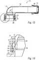
Fig. 1 is a schematic view of a container provided with a pouring spout according to one embodiment,Fig. 2 is a schematic side view of the pouring spout according to one embodiment, illustrating the pouring spout after moulding thereof but before folding of a projection of the pouring spout inwards,Fig. 3 is a schematic rear view of the spout ofFig. 2 ,Fig. 4 is a schematic section view of the spout ofFig. 2 , illustrating an outer tubular portion and an inner tubular portion of the spout according to one embodiment,Fig. 5 is a schematic section view of a part of the spout ofFig. 4 , illustrating the outer and inner tubular portions and the projection prior to folding more in detail,Fig. 6 is a schematic side view of a finished pouring spout according to one embodiment, wherein the projection has been folded inwards,Fig. 7 is a schematic rear view of the spout ofFig. 6 ,Fig. 8 is a schematic section view of the spout ofFig. 6 , illustrating the projection and the outer and inner tubular portions of the spout after folding of the projection,Fig. 9 is a schematic section view of a part of the spout ofFig. 8 , illustrating the outer and inner tubular portions and the projection after folding more in detail,Fig. 10 is a schematic side view of the finished pouring spout arranged on a neck of a container and provided with a cap according to one embodiment,Fig. 11 is a schematic rear view of the spout and the neck ofFig. 10 ,Fig. 12 is a schematic section view of the spout and neck ofFig. 10 , andFig. 13 is a schematic section view of a part of the spout and neck ofFig. 12 , illustrating an interaction of the outer and inner tubular portions with the neck more in detail,- With reference to
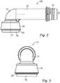
Fig. 1 apouring spout 10 mounted on aneck 11 of acontainer 12 is illustrated schematically according to one embodiment. The pouringspout 10 is arranged to facilitate extraction of the contents of thecontainer 12. For example, thepouring spout 10 is arranged in plastic materials, such as a suitable thermoplastic. For example, thepouring spout 10 is formed in polyethylene, such as HDPE. The pouring spout is, e.g. partially produced by moulding, such as injection moulding, using movable jaws and a tool core interacting with the jaws to form a mould for receiving an amount of plastic material for producing thepouring spout 10. The jaws and the tool core are arranged with a particular form for providing the mould for producing thepouring spout 10 according to the invention, which form is evident by the description of the special features of thepouring spout 10 below. Thepouring spout 10 is also formed partially by means of a mechanical folding machine, which folding is described more in detail below. - The
container 12 is, for example, a can, such as a gas can for containing fuel. Alternatively, thecontainer 12 is arranged for containing oil, washer fluids, detergents, chemicals and similar. Alternatively, thecontainer 12 is arranged for containing foodstuff, such as beverages. Thecontainer 12 is, e.g. arranged for containing a volume of at least 1 litre, such as at least 3 litres or at least 5 litres. For example, thecontainer 12 is arranged in plastic materials or metal. For example, thecontainer 12 is arranged in the same plastic materials as thespout 10. For example, thecontainer 12 is arranged in polyethylene, such as HDPE. - In
Fig.1 , thespout 10 is mounted on theneck 11 of thecontainer 12, wherein an interior of thespout 10 is in liquid communication with an interior of thecontainer 12. Hence, thespout 10 comprises an inlet for receiving liquid from thecontainer 12 and an outlet through which the liquid leaves thespout 10. For example, thespout 10 is arranged to be mounted on top of thecontainer 12. InFig. 1 thespout 10 is provided with aremovable cap 13, such as a screw cap, for closing thespout 10 and preventing the contents of thecontainer 12 from being unintentionally extracted through thespout 10. - With reference to
Figs. 2 and 3 thespout 10 is illustrated according to one embodiment, wherein thespout 10 has been moulded and removed but is not finished. For example, thespout 10 as illustrated inFig. 2 has been removed from the mould for further processing. Thespout 10 comprises apipe portion 14 and a tubular portion in the form of an outertubular portion 15, wherein the outertubular portion 15 is connected to thepipe portion 14. Thepipe portion 14 has a free first end and an opposite second end, wherein athread 16 is arranged in the area of the free first end and the outertubular portion 15 is connected to the second end. Thethread 16 is arranged for engaging a corresponding thread of thecap 13. For example, thethread 16 of thespout 10 is an external thread. - In the illustrated embodiment, the
pipe portion 14 is arranged with abend 17, so that the outlet of thespout 10 is offset from the inlet. For example, the inlet is arranged perpendicular to the outlet, wherein a centre axis A of the outertubular portion 15 is perpendicular to a part of a centre axis B of thepipe portion 14 at the free first end thereof. Alternatively, the centre axis A of the outertubular portion 15 is inclined to the part of the centre axis B of thepipe portion 14 at the free first end thereof. Alternatively, thepipe portion 14 is arranged without thebend 17, wherein thepipe portion 14 is straight and the centre axis A of the outertubular portion 15 is aligned with the part of the centre axis B of thepipe portion 14 at the free first end thereof. For example, the centre axis A of the outertubular portion 15 is straight along the entire outertubular portion 15. - The
spout 10 comprises aprojection 18 for fastening of thespout 10 to theneck 11 of thecontainer 12. Theprojection 18 is connected to the outertubular portion 15, such as at the end of the outertubular portion 15. In the illustrated embodiment, theprojection 18 is formed at the end of thetubular portion 15 opposite thepipe portion 14. For example, theprojection 18 is formed at the end of thetubular portion 15 opposite thebend 17. In the illustrated embodiment, theprojection 18 is annular and extend continuously around the outertubular portion 15. For example, theprojection 18 is cylindrical having a circular cross section. Alternatively, thespout 10 comprises a plurality ofprojections 18 distributed around the outertubular portion 15. - In
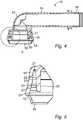
Figs. 2-5 , thespout 10 is illustrated after moulding, e.g. by injection moulding, but before finishing thereof. After moulding and before finishing of thespout 10 theprojection 18 extends downwards from the outertubular portion 15, such as away from the outertubular portion 15 and in a direction away from thepipe portion 14. Hence, and angle between the inner side of the outertubular portion 15 and the inner side of theprojection 18 is then larger than 90 degrees and, for example larger than 120 degrees, and optionally less than 180 degrees. For example, theprojection 18 extends obliquely downwards and inwards, so that the projection extends partially axially downwards and partially radially inwards when thespout 10 has been moulded but not finished. In the illustrated embodiment, the outertubular portion 15 then extends substantially in the axial direction and slightly outwards. In the illustrated embodiment, theprojection 18 is connected to the outertubular portion 18 through afolding notch 19, along which theprojection 18 is foldable after moulding, which is described further below. For example, the material thickness at thenotch 19 is less than 1 mm, such as 0.2-0.5 mm or around 0.3 mm. The length of theprojection 18 from thenotch 19 to its free end is, for example 3-10 mm, such as around 5 mm. A material thickness of theprojection 18 at its thickest part is, for example 1-2 mm, such as 1.2-1.5 or around 1.4 mm. - As illustrated in
Figs. 4 and 5 , thespout 10 comprises an innertubular portion 20 arranged within the outertubular portion 15. The innertubular portion 20 extends substantially in the axial direction of the outertubular portion 15. For example, the innertubular portion 20 is cylindrical having a circular cross section. For example, the outertubular portion 15 is cylindrical having a circular cross section. The outertubular portion 15 is, for example arranged conical outwards, wherein the outertubular portion 15 is somewhat tapered towards thepipe portion 14. InFig. 5 , a lower part of the outertubular portion 15 is angled outwards in relation to an upper part thereof. The innertubular portion 20 extends substantially coaxial with the outertubular portion 15. The innertubular portion 20 is arranged for conducting liquid from the container outlet to thepipe portion 14, through thebend 17 if applicable. The innertubular portion 20 is spaced apart from the outertubular portion 15 in the radial direction to form agap 21 between the outertubular portion 15 and the innertubular portion 20. For example, thegap 21 is tapered in a direction towards thepipe portion 14. For example, the innertubular portion 20 is formed with an outer diameter of 20-50 mm, such as around 30-35 mm, 32-33 mm or 32.46 mm at its widest point. - The inner
tubular portion 20 is formed withsteps 22 on a radially outwards facing surface of the innertubular portion 20, i.e. the surface facing thegap 21 and the outertubular portion 15. Thesteps 22 are displaced radially in relation to each other. Hence, a plurality ofsteps 22 are arranged adjacent to each other in the axial direction, wherein thesteps 22 are displaced radially outwards in a direction towards thepipe portion 14. For example, the innertubular portion 20 is connected to thepipe portion 14 in one end, wherein the opposite end of the inner tubular portion is a free end. Hence, the radially outwards facing side of the innertubular portion 20 is somewhat conical inward toward its free end due to thesteps 22, wherein an outer diameter of the innertubular portion 20 is larger toward thepipe portion 14 and smaller toward its free end. In the illustrated embodiment, the innertubular portion 20 is tapered towards its free end by means of thesteps 22. Thesteps 22 are separated by a radially extending edge portion 23. Hence, thesteps 22 form axially extending surfaces facing the outertubular portion 15, wherein the edge portions 23 form radially extending flanges, so that the edge portions 23 form the radial displacements between thesteps 22. The edge portions 23 are distinct and, e.g. connects to thesteps 22 in a relatively sharp transition. For example, an angle between thesteps 22 and an upwards adjacent edge portion 23 is at least 90 degrees but less than 150 degrees, such as less than 135 degrees or around 120 degrees or less. For example, each edge portion 23 is less than 1 mm, less than 0.5 mm or around 0.2-0.3 mm, such as around 0.25 mm or 0.235 mm in the radial direction. In the illustrated embodiment, the innertubular portion 20 is formed with fivesteps 22. Alternatively, the innertubular portion 20 is formed with two or more steps, such as three to ten steps. - In the illustrated embodiment, the inner
tubular portion 20 is terminated with achamfer 24 at its free end. Thechamfer 24 is arranged radially inward towards the free end of the innertubular portion 20. Thechamfer 24 is arranged on the outer side of the innertubular portion 20 to guide thespout 10 during mounting on thecontainer neck 11. - With reference to
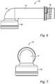
Figs. 6-8 thespout 10 is illustrated after finishing thereof by folding theprojection 18 inward and upward. InFig. 9 a part of thespout 10 is illustrated to show the foldedprojection 18 more in detail. After moulding of thespout 10 theprojection 18 is folded along thenotch 19. For example, the mouldedspout 10 is removed from the mould and transferred to a machine for folding theprojection 18. Optionally, said machine also applies thecap 13 to the outlet end of thepipe portion 14. Alternatively, theprojection 18 is folded in the mould after axial displacement of the tool core, so that theprojection 18 can be folded inward. Theprojection 18 is folded when the material of at least thenotch 19 is warm enough for plastic deformation, so that the foldedprojection 18 stays in its folded position. For example, theprojection 18 is folded while the material is still warm from the moulding process, i.e. while the material still is plastically deformable by heat from the moulding process. For example, theprojection 18 is folded to a position in which it extends substantially axially upward toward thepipe portion 14. For example, theprojection 18 is folded to a position in which its free end is arranged between the outertubular portion 15 and the innertubular portion 20, wherein the free end of theprojection 18 is folded into thegap 21. For example, theprojection 18 is folded within the outertubular portion 15, so that the outertubular portion 15 at least partially encloses theprojection 18 in the radial direction. - As can be seen particularly in
Fig. 9 , the lower part of the outertubular portion 15 is arranged with greater diameter than the upper part thereof. During folding of theprojection 18 the outwards angled lower part of the outertubular portion 15 is formed into a part with the greater diameter. The lower part of the outertubular portion 15 is formed, so that the lower part of thegap 21 has greater diameter than the upper part thereof to form a space for temporarily receiving theprojection 18 during mounting on aneck 11. Hence, the wider lower part of the outertubular portion 15 and the wider lower part of thegap 21 is formed with a length corresponding to or being longer than theprojection 18. - With reference to
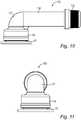
Figs. 10-12 thespout 10 is illustrated after finishing thereof and mounted on thecontainer neck 11. InFig. 13 parts of thespout 10 and theneck 11 are illustrated more in detail to show the interaction between them. Thespout 10 is mounted on theneck 11 of thecontainer 12 after moulding and after finishing of thespout 10 by folding of theprojection 18. Thespout 10 is mounted on theneck 11 by pushing thespout 10 in the axial direction of the outertubular portion 15 onto theneck 11. For example, the outertubular portion 15 is substantially coaxially aligned with theneck 11 and pushed axially onto the neck, optionally without rotation of thespout 10 in relation to theneck 11. - As illustrated in
Figs. 12 and 13 theneck 11 is formed with aflange 25 for engaging theprojection 18 to fasten thespout 10 to theneck 11. Theflange 25 is arranged on the exterior side of theneck 11 and projects radially outwards. For example, theflange 25 is continuous and extends around theneck 11. For example, theflange 25 extends in the same axial level around theneck 11. In the illustrated embodiment, theneck 11 is conical towards its free end, i.e. its upper end. For example, theneck 11 is tapered towards the free end. - To fasten the
spout 10 to theneck 11 the outertubular portion 15 is arranged to enclose theneck 11 while the innertubular portion 20 is arranged within theneck 11. Theprojection 18 is pushed radially outward by theneck 11 due to the inherent flexible properties of thespout 10 and, optionally also theneck 11. In the illustrated embodiment, the lower part of the outertubular portion 15 adjacent theprojection 18 is formed with a greater diameter than the remaining part of the outertubular portion 15 toward thepipe portion 14, wherein the lower part with larger diameter is arranged to temporarily accommodate theprojection 18 when it is displaced radially outward. Theneck 11 is received in thegap 21 by pushing the outertubular portion 15 axially onto theneck 11 until theprojection 18 reaches theflange 25. When theprojection 18 reaches theflange 25 theprojection 18 springs back radially inward due to its inherent resilient flexible properties to engage theflange 25 and prevent removal of thespout 10 from theneck 11. For example, theprojection 18 is then in a default unbiased position or biased radially inward due to the inherent resilient flexible properties. Hence, thespout 10 is locked on theneck 11 when theprojection 18 engages theflange 25. For example, thespout 10 is irreversibly attached to theneck 11 and cannot be removed. In the illustrated embodiment, thespout 10 andneck 11 are arranged without threads. For example, the outer side of theneck 11 is smooth and even between its free end and theflange 25. When thespout 10 is pushed onto theneck 11, the innertubular portion 20 engages the inner side of theneck 11, wherein one or more of thesteps 22 engage theneck 11 to seal the neck opening and prevent the content of thecontainer 12 from leaking. - The
spout 10 and thecontainer 12 form an assembly when the spout has been mounted on theneck 11, wherein theneck 11 is arranged in thegap 21 between the outertubular portion 15 and the innertubular portion 20, wherein theprojection 18 engages theflange 25, and wherein at least one of thesteps 22 engages the inner side of theneck 11. Theneck 11, the outertubular portion 15 and the innertubular portion 20 are arranged substantially coaxial. In the illustrated embodiment, the inner side of theneck 11 is smooth and even, for example along its entire length or at least from its free end to a level corresponding to itsflange 25 or to a level corresponding to the free end of the innertubular portion 20. InFig. 13 it can be seen that the outer side of the innertubular portion 20 is tapered towards its free end. The innertubular portion 20 is formed tapered towards its free during moulding thereof. However, it is believed that the innertubular portion 20 will be forced against the inner side of theneck 11 during assembly due to the inherent resilient flexible properties of the innertubular portion 20, possibly in combination with pressure applied thereon by the contents of thecontainer 12. Hence, after assembly of thespout 10 on theneck 11 of acontainer 12 having a liquid content, such as fuel, e.g. in the form of petroleum or similar, it is believed that more than one of thesteps 22, such as at least two or at least threesteps 22, will be in contact with theneck 11 to seal thecontainer 12. If the pressure in thecontainer 12 is increased after assembly, it is believed thatadditional steps 22, if applicable, will engage theneck 11 to further seal thecontainer 12. For example, the innertubular portion 20 and theneck 11 are biased toward each other by means of the inherent resilient flexible properties of at least one of them, so that at least one or at least twosteps 22 are forced against theneck 11.
Claims (14)
- A pouring spout (10) for attachment to a container neck (11), comprising an outer tubular portion (15) for enclosing an exterior surface of the neck (11) and having a centre axis (A), and an inward extending projection (18) for engaging an exterior flange (25) of the neck (11) for fastening the spout (10) to the neck (11), wherein the spout (10) also comprises an inner tubular portion (20) extending in the axial direction for engaging an interior surface of the neck (11), wherein the inner tubular portion (20) is spaced apart from the outer tubular portion (15) in the radial direction to form a gap (21) between the outer tubular portion (15) and the inner tubular portion (20),
characterised in that
a surface of the inner tubular portion (20) facing the outer tubular portion (15) is formed with a plurality of radially displaced steps (22), such that the inner tubular portion (20) is tapered downward toward a free end thereof. - A pouring spout according to claim 1, wherein the steps (22) are separated by an edge portion (23).
- A pouring spout according to claim 1 or 2, wherein the inner tubular portion (20) is tapered by means of the steps (22).
- A pouring spout according to claim 3, wherein the inner tubular portion (20) has a free end and is tapered towards its free end.
- A pouring spout according to claim 4, wherein the free end of the inner tubular portion is formed with a chamfer (24).
- A pouring spout according to any of the preceding claims, wherein the inwards extending projection (18) is formed in the end of the outer tubular portion (15).
- A pouring spout according to any of the preceding claims, wherein the inwards extending projection (18) extends inwards and upwards.
- A pouring spout according to any of the preceding claims, wherein the outer tubular portion (15) is arranged with an inner diameter which is larger in its lower part to form a space for temporarily receiving the projection (18) during mounting on the neck (11).
- An assembly comprising a container (12) having a neck (11) and a spout (10) according to any of the preceding claims, wherein the neck (11) is received in the gap (21) between the inner tubular portion (20) and the outer tubular portion (15) of the spout, at least one of the steps (22) of the inner tubular portion (20) engages the interior side of the neck (11), and the inwards extending projection (18) of the outer tubular portion (15) engages the flange (25) of the neck to attach the spout to the neck.
- An assembly according to claim 9, wherein at least an uppermost step (22) engages the neck (11).
- A method for producing a pouring spout (10) according to any of the preceding claims, for attachment to a container neck (11), comprising the steps ofa) moulding the spout (10) with an outer tubular portion (15) having a centre axis (A), and an axially extending inner tubular portion (20) spaced apart from the outer tubular portion (15) in the radial direction to form a gap (21) between them, while moulding a foldable projection (18) in the end of the outer tubular portion (15) and moulding a plurality of radially displaced steps (22) in a surface of the inner tubular portion (20) facing the outer tubular portion (15), andb) after step a) folding the projection (18) inwards.
- A method according to claim 11, including, after step a) and before step b), the steps of removing the moulded spout (10) from the mould and transferring the moulded spout to a machine for folding the projection (18).
- A method according to claim 11 or 12, including the step of folding the projection (18) to a position in which it extends inward and upward.
- A method according to any of claims 11-13, including, in step a), the step of forming the outer tubular portion (15) with an inner diameter which is larger in its lower part to form a space for temporarily receiving the projection (18) during mounting on the neck (11).
Priority Applications (2)
| Application Number | Priority Date | Filing Date | Title |
|---|---|---|---|
| EP17157375.1AEP3366603B1 (en) | 2017-02-22 | 2017-02-22 | A pouring spout for a container, a container assembly and a method for producing a pouring spout |
| DK17157375.1TDK3366603T3 (en) | 2017-02-22 | 2017-02-22 | Pouring spout for a container, container assembly and method for making a pouring spout |
Applications Claiming Priority (1)
| Application Number | Priority Date | Filing Date | Title |
|---|---|---|---|
| EP17157375.1AEP3366603B1 (en) | 2017-02-22 | 2017-02-22 | A pouring spout for a container, a container assembly and a method for producing a pouring spout |
Publications (2)
| Publication Number | Publication Date |
|---|---|
| EP3366603A1 EP3366603A1 (en) | 2018-08-29 |
| EP3366603B1true EP3366603B1 (en) | 2019-11-13 |
Family
ID=58158867
Family Applications (1)
| Application Number | Title | Priority Date | Filing Date |
|---|---|---|---|
| EP17157375.1AActiveEP3366603B1 (en) | 2017-02-22 | 2017-02-22 | A pouring spout for a container, a container assembly and a method for producing a pouring spout |
Country Status (2)
| Country | Link |
|---|---|
| EP (1) | EP3366603B1 (en) |
| DK (1) | DK3366603T3 (en) |
Family Cites Families (3)
| Publication number | Priority date | Publication date | Assignee | Title |
|---|---|---|---|---|
| FR1088929A (en)* | 1953-12-23 | 1955-03-11 | Stoppers and capping process | |
| US20130277328A1 (en)* | 2011-08-03 | 2013-10-24 | Obrist Closures Switzerland Gmbh | Container Closure |
| ES2421212B1 (en)* | 2013-02-21 | 2014-04-28 | Bericap, S.A. | Plastic plugs |
- 2017
- 2017-02-22DKDK17157375.1Tpatent/DK3366603T3/enactive
- 2017-02-22EPEP17157375.1Apatent/EP3366603B1/enactiveActive
Non-Patent Citations (1)
| Title |
|---|
| None* |
Also Published As
| Publication number | Publication date |
|---|---|
| EP3366603A1 (en) | 2018-08-29 |
| DK3366603T3 (en) | 2020-02-24 |
Similar Documents
| Publication | Publication Date | Title |
|---|---|---|
| US8365933B2 (en) | Closure system for a container and dispensing closure | |
| EP1772391B1 (en) | Metal beverage container with drinking sleeve | |
| CA2996208C (en) | Closure system for container | |
| US10913579B2 (en) | Fitment for a container neck | |
| EP2663506B1 (en) | Closure | |
| CN102015473A (en) | Closures for plastic containers adapted for automated insert molding | |
| US20170267425A1 (en) | Anti-glug device for liquid containers and pour spouts | |
| US20080302753A1 (en) | Apparatus and method for producing a container closure | |
| US20250091776A1 (en) | Closure with Liner | |
| US9878898B2 (en) | Catch releasing capless fuel-filler bottle | |
| AU2004200440A1 (en) | Closures and containers in combination therewith | |
| EP3366603B1 (en) | A pouring spout for a container, a container assembly and a method for producing a pouring spout | |
| US20130075355A1 (en) | Container having a threaded closure sleeve | |
| KR20230162641A (en) | Method for forming a metal container with a carrier ring and resulting container | |
| EP2408675B1 (en) | Pour spout and method of mounting a pour spout on a spigot | |
| EP1886931A1 (en) | Closure cap for a standard bottleneck ring | |
| EP0641718B1 (en) | Method and device for producing a tubular article having a circumferential accumulation of material | |
| JP6278931B2 (en) | Outlet stopper and packaging container | |
| US20060151423A1 (en) | Closure having tapered sealing plug | |
| WO2007062364A2 (en) | Scallop cap closures | |
| EP4136035B1 (en) | Screw-cap closure | |
| MX2013012477A (en) | DOUBLE WALL CLOSURE. | |
| NZ280558A (en) | Container closure cap with ratchet teeth on skirt having teeth abutment portions at an acute angle to plane of skirt open end | |
| NZ612532B2 (en) | Closure | |
| HK1099893B (en) | Sealing means for a closure, closure and process |
Legal Events
| Date | Code | Title | Description |
|---|---|---|---|
| PUAI | Public reference made under article 153(3) epc to a published international application that has entered the european phase | Free format text:ORIGINAL CODE: 0009012 | |
| STAA | Information on the status of an ep patent application or granted ep patent | Free format text:STATUS: THE APPLICATION HAS BEEN PUBLISHED | |
| AK | Designated contracting states | Kind code of ref document:A1 Designated state(s):AL AT BE BG CH CY CZ DE DK EE ES FI FR GB GR HR HU IE IS IT LI LT LU LV MC MK MT NL NO PL PT RO RS SE SI SK SM TR | |
| AX | Request for extension of the european patent | Extension state:BA ME | |
| STAA | Information on the status of an ep patent application or granted ep patent | Free format text:STATUS: REQUEST FOR EXAMINATION WAS MADE | |
| 17P | Request for examination filed | Effective date:20190213 | |
| RBV | Designated contracting states (corrected) | Designated state(s):AL AT BE BG CH CY CZ DE DK EE ES FI FR GB GR HR HU IE IS IT LI LT LU LV MC MK MT NL NO PL PT RO RS SE SI SK SM TR | |
| RIC1 | Information provided on ipc code assigned before grant | Ipc:B65D 25/46 20060101AFI20190423BHEP Ipc:B65D 47/06 20060101ALI20190423BHEP | |
| GRAP | Despatch of communication of intention to grant a patent | Free format text:ORIGINAL CODE: EPIDOSNIGR1 | |
| STAA | Information on the status of an ep patent application or granted ep patent | Free format text:STATUS: GRANT OF PATENT IS INTENDED | |
| INTG | Intention to grant announced | Effective date:20190613 | |
| GRAS | Grant fee paid | Free format text:ORIGINAL CODE: EPIDOSNIGR3 | |
| GRAA | (expected) grant | Free format text:ORIGINAL CODE: 0009210 | |
| STAA | Information on the status of an ep patent application or granted ep patent | Free format text:STATUS: THE PATENT HAS BEEN GRANTED | |
| AK | Designated contracting states | Kind code of ref document:B1 Designated state(s):AL AT BE BG CH CY CZ DE DK EE ES FI FR GB GR HR HU IE IS IT LI LT LU LV MC MK MT NL NO PL PT RO RS SE SI SK SM TR | |
| REG | Reference to a national code | Ref country code:CH Ref legal event code:EP Ref country code:AT Ref legal event code:REF Ref document number:1201423 Country of ref document:AT Kind code of ref document:T Effective date:20191115 | |
| REG | Reference to a national code | Ref country code:SE Ref legal event code:TRGR | |
| REG | Reference to a national code | Ref country code:DE Ref legal event code:R096 Ref document number:602017008558 Country of ref document:DE | |
| REG | Reference to a national code | Ref country code:IE Ref legal event code:FG4D | |
| REG | Reference to a national code | Ref country code:DK Ref legal event code:T3 Effective date:20200217 | |
| REG | Reference to a national code | Ref country code:NL Ref legal event code:MP Effective date:20191113 | |
| REG | Reference to a national code | Ref country code:LT Ref legal event code:MG4D | |
| PG25 | Lapsed in a contracting state [announced via postgrant information from national office to epo] | Ref country code:PL Free format text:LAPSE BECAUSE OF FAILURE TO SUBMIT A TRANSLATION OF THE DESCRIPTION OR TO PAY THE FEE WITHIN THE PRESCRIBED TIME-LIMIT Effective date:20191113 Ref country code:GR Free format text:LAPSE BECAUSE OF FAILURE TO SUBMIT A TRANSLATION OF THE DESCRIPTION OR TO PAY THE FEE WITHIN THE PRESCRIBED TIME-LIMIT Effective date:20200214 Ref country code:NO Free format text:LAPSE BECAUSE OF FAILURE TO SUBMIT A TRANSLATION OF THE DESCRIPTION OR TO PAY THE FEE WITHIN THE PRESCRIBED TIME-LIMIT Effective date:20200213 Ref country code:NL Free format text:LAPSE BECAUSE OF FAILURE TO SUBMIT A TRANSLATION OF THE DESCRIPTION OR TO PAY THE FEE WITHIN THE PRESCRIBED TIME-LIMIT Effective date:20191113 Ref country code:LT Free format text:LAPSE BECAUSE OF FAILURE TO SUBMIT A TRANSLATION OF THE DESCRIPTION OR TO PAY THE FEE WITHIN THE PRESCRIBED TIME-LIMIT Effective date:20191113 Ref country code:PT Free format text:LAPSE BECAUSE OF FAILURE TO SUBMIT A TRANSLATION OF THE DESCRIPTION OR TO PAY THE FEE WITHIN THE PRESCRIBED TIME-LIMIT Effective date:20200313 Ref country code:LV Free format text:LAPSE BECAUSE OF FAILURE TO SUBMIT A TRANSLATION OF THE DESCRIPTION OR TO PAY THE FEE WITHIN THE PRESCRIBED TIME-LIMIT Effective date:20191113 Ref country code:BG Free format text:LAPSE BECAUSE OF FAILURE TO SUBMIT A TRANSLATION OF THE DESCRIPTION OR TO PAY THE FEE WITHIN THE PRESCRIBED TIME-LIMIT Effective date:20200213 Ref country code:FI Free format text:LAPSE BECAUSE OF FAILURE TO SUBMIT A TRANSLATION OF THE DESCRIPTION OR TO PAY THE FEE WITHIN THE PRESCRIBED TIME-LIMIT Effective date:20191113 | |
| PG25 | Lapsed in a contracting state [announced via postgrant information from national office to epo] | Ref country code:IS Free format text:LAPSE BECAUSE OF FAILURE TO SUBMIT A TRANSLATION OF THE DESCRIPTION OR TO PAY THE FEE WITHIN THE PRESCRIBED TIME-LIMIT Effective date:20200313 Ref country code:RS Free format text:LAPSE BECAUSE OF FAILURE TO SUBMIT A TRANSLATION OF THE DESCRIPTION OR TO PAY THE FEE WITHIN THE PRESCRIBED TIME-LIMIT Effective date:20191113 Ref country code:HR Free format text:LAPSE BECAUSE OF FAILURE TO SUBMIT A TRANSLATION OF THE DESCRIPTION OR TO PAY THE FEE WITHIN THE PRESCRIBED TIME-LIMIT Effective date:20191113 | |
| PG25 | Lapsed in a contracting state [announced via postgrant information from national office to epo] | Ref country code:AL Free format text:LAPSE BECAUSE OF FAILURE TO SUBMIT A TRANSLATION OF THE DESCRIPTION OR TO PAY THE FEE WITHIN THE PRESCRIBED TIME-LIMIT Effective date:20191113 | |
| PG25 | Lapsed in a contracting state [announced via postgrant information from national office to epo] | Ref country code:ES Free format text:LAPSE BECAUSE OF FAILURE TO SUBMIT A TRANSLATION OF THE DESCRIPTION OR TO PAY THE FEE WITHIN THE PRESCRIBED TIME-LIMIT Effective date:20191113 Ref country code:EE Free format text:LAPSE BECAUSE OF FAILURE TO SUBMIT A TRANSLATION OF THE DESCRIPTION OR TO PAY THE FEE WITHIN THE PRESCRIBED TIME-LIMIT Effective date:20191113 Ref country code:CZ Free format text:LAPSE BECAUSE OF FAILURE TO SUBMIT A TRANSLATION OF THE DESCRIPTION OR TO PAY THE FEE WITHIN THE PRESCRIBED TIME-LIMIT Effective date:20191113 Ref country code:RO Free format text:LAPSE BECAUSE OF FAILURE TO SUBMIT A TRANSLATION OF THE DESCRIPTION OR TO PAY THE FEE WITHIN THE PRESCRIBED TIME-LIMIT Effective date:20191113 | |
| REG | Reference to a national code | Ref country code:DE Ref legal event code:R097 Ref document number:602017008558 Country of ref document:DE | |
| REG | Reference to a national code | Ref country code:AT Ref legal event code:MK05 Ref document number:1201423 Country of ref document:AT Kind code of ref document:T Effective date:20191113 | |
| PG25 | Lapsed in a contracting state [announced via postgrant information from national office to epo] | Ref country code:SK Free format text:LAPSE BECAUSE OF FAILURE TO SUBMIT A TRANSLATION OF THE DESCRIPTION OR TO PAY THE FEE WITHIN THE PRESCRIBED TIME-LIMIT Effective date:20191113 Ref country code:SM Free format text:LAPSE BECAUSE OF FAILURE TO SUBMIT A TRANSLATION OF THE DESCRIPTION OR TO PAY THE FEE WITHIN THE PRESCRIBED TIME-LIMIT Effective date:20191113 | |
| REG | Reference to a national code | Ref country code:DE Ref legal event code:R119 Ref document number:602017008558 Country of ref document:DE | |
| PLBE | No opposition filed within time limit | Free format text:ORIGINAL CODE: 0009261 | |
| STAA | Information on the status of an ep patent application or granted ep patent | Free format text:STATUS: NO OPPOSITION FILED WITHIN TIME LIMIT | |
| REG | Reference to a national code | Ref country code:CH Ref legal event code:PL | |
| 26N | No opposition filed | Effective date:20200814 | |
| REG | Reference to a national code | Ref country code:BE Ref legal event code:MM Effective date:20200229 | |
| PG25 | Lapsed in a contracting state [announced via postgrant information from national office to epo] | Ref country code:MC Free format text:LAPSE BECAUSE OF FAILURE TO SUBMIT A TRANSLATION OF THE DESCRIPTION OR TO PAY THE FEE WITHIN THE PRESCRIBED TIME-LIMIT Effective date:20191113 Ref country code:LU Free format text:LAPSE BECAUSE OF NON-PAYMENT OF DUE FEES Effective date:20200222 | |
| PG25 | Lapsed in a contracting state [announced via postgrant information from national office to epo] | Ref country code:LI Free format text:LAPSE BECAUSE OF NON-PAYMENT OF DUE FEES Effective date:20200229 Ref country code:SI Free format text:LAPSE BECAUSE OF FAILURE TO SUBMIT A TRANSLATION OF THE DESCRIPTION OR TO PAY THE FEE WITHIN THE PRESCRIBED TIME-LIMIT Effective date:20191113 Ref country code:CH Free format text:LAPSE BECAUSE OF NON-PAYMENT OF DUE FEES Effective date:20200229 Ref country code:AT Free format text:LAPSE BECAUSE OF FAILURE TO SUBMIT A TRANSLATION OF THE DESCRIPTION OR TO PAY THE FEE WITHIN THE PRESCRIBED TIME-LIMIT Effective date:20191113 | |
| PG25 | Lapsed in a contracting state [announced via postgrant information from national office to epo] | Ref country code:DE Free format text:LAPSE BECAUSE OF NON-PAYMENT OF DUE FEES Effective date:20200901 Ref country code:IE Free format text:LAPSE BECAUSE OF NON-PAYMENT OF DUE FEES Effective date:20200222 Ref country code:FR Free format text:LAPSE BECAUSE OF NON-PAYMENT OF DUE FEES Effective date:20200229 Ref country code:IT Free format text:LAPSE BECAUSE OF FAILURE TO SUBMIT A TRANSLATION OF THE DESCRIPTION OR TO PAY THE FEE WITHIN THE PRESCRIBED TIME-LIMIT Effective date:20191113 | |
| PG25 | Lapsed in a contracting state [announced via postgrant information from national office to epo] | Ref country code:BE Free format text:LAPSE BECAUSE OF NON-PAYMENT OF DUE FEES Effective date:20200229 | |
| GBPC | Gb: european patent ceased through non-payment of renewal fee | Effective date:20210222 | |
| PG25 | Lapsed in a contracting state [announced via postgrant information from national office to epo] | Ref country code:GB Free format text:LAPSE BECAUSE OF NON-PAYMENT OF DUE FEES Effective date:20210222 | |
| PG25 | Lapsed in a contracting state [announced via postgrant information from national office to epo] | Ref country code:TR Free format text:LAPSE BECAUSE OF FAILURE TO SUBMIT A TRANSLATION OF THE DESCRIPTION OR TO PAY THE FEE WITHIN THE PRESCRIBED TIME-LIMIT Effective date:20191113 Ref country code:MT Free format text:LAPSE BECAUSE OF FAILURE TO SUBMIT A TRANSLATION OF THE DESCRIPTION OR TO PAY THE FEE WITHIN THE PRESCRIBED TIME-LIMIT Effective date:20191113 Ref country code:CY Free format text:LAPSE BECAUSE OF FAILURE TO SUBMIT A TRANSLATION OF THE DESCRIPTION OR TO PAY THE FEE WITHIN THE PRESCRIBED TIME-LIMIT Effective date:20191113 | |
| PG25 | Lapsed in a contracting state [announced via postgrant information from national office to epo] | Ref country code:MK Free format text:LAPSE BECAUSE OF FAILURE TO SUBMIT A TRANSLATION OF THE DESCRIPTION OR TO PAY THE FEE WITHIN THE PRESCRIBED TIME-LIMIT Effective date:20191113 | |
| P01 | Opt-out of the competence of the unified patent court (upc) registered | Effective date:20230523 | |
| PGFP | Annual fee paid to national office [announced via postgrant information from national office to epo] | Ref country code:DK Payment date:20250212 Year of fee payment:9 | |
| PGFP | Annual fee paid to national office [announced via postgrant information from national office to epo] | Ref country code:SE Payment date:20250210 Year of fee payment:9 |