EP3360509B1 - Sealable endovascular implants - Google Patents
Sealable endovascular implantsDownload PDFInfo
- Publication number
- EP3360509B1 EP3360509B1EP18164018.6AEP18164018AEP3360509B1EP 3360509 B1EP3360509 B1EP 3360509B1EP 18164018 AEP18164018 AEP 18164018AEP 3360509 B1EP3360509 B1EP 3360509B1
- Authority
- EP
- European Patent Office
- Prior art keywords
- sealer
- implant
- proximal
- locking member
- distal
- Prior art date
- Legal status (The legal status is an assumption and is not a legal conclusion. Google has not performed a legal analysis and makes no representation as to the accuracy of the status listed.)
- Active
Links
Images


Classifications
- A—HUMAN NECESSITIES
- A61—MEDICAL OR VETERINARY SCIENCE; HYGIENE
- A61F—FILTERS IMPLANTABLE INTO BLOOD VESSELS; PROSTHESES; DEVICES PROVIDING PATENCY TO, OR PREVENTING COLLAPSING OF, TUBULAR STRUCTURES OF THE BODY, e.g. STENTS; ORTHOPAEDIC, NURSING OR CONTRACEPTIVE DEVICES; FOMENTATION; TREATMENT OR PROTECTION OF EYES OR EARS; BANDAGES, DRESSINGS OR ABSORBENT PADS; FIRST-AID KITS
- A61F2/00—Filters implantable into blood vessels; Prostheses, i.e. artificial substitutes or replacements for parts of the body; Appliances for connecting them with the body; Devices providing patency to, or preventing collapsing of, tubular structures of the body, e.g. stents
- A61F2/95—Instruments specially adapted for placement or removal of stents or stent-grafts
- A61F2/954—Instruments specially adapted for placement or removal of stents or stent-grafts for placing stents or stent-grafts in a bifurcation
- A—HUMAN NECESSITIES
- A61—MEDICAL OR VETERINARY SCIENCE; HYGIENE
- A61F—FILTERS IMPLANTABLE INTO BLOOD VESSELS; PROSTHESES; DEVICES PROVIDING PATENCY TO, OR PREVENTING COLLAPSING OF, TUBULAR STRUCTURES OF THE BODY, e.g. STENTS; ORTHOPAEDIC, NURSING OR CONTRACEPTIVE DEVICES; FOMENTATION; TREATMENT OR PROTECTION OF EYES OR EARS; BANDAGES, DRESSINGS OR ABSORBENT PADS; FIRST-AID KITS
- A61F2/00—Filters implantable into blood vessels; Prostheses, i.e. artificial substitutes or replacements for parts of the body; Appliances for connecting them with the body; Devices providing patency to, or preventing collapsing of, tubular structures of the body, e.g. stents
- A61F2/02—Prostheses implantable into the body
- A61F2/04—Hollow or tubular parts of organs, e.g. bladders, tracheae, bronchi or bile ducts
- A61F2/06—Blood vessels
- A61F2/07—Stent-grafts
- A—HUMAN NECESSITIES
- A61—MEDICAL OR VETERINARY SCIENCE; HYGIENE
- A61F—FILTERS IMPLANTABLE INTO BLOOD VESSELS; PROSTHESES; DEVICES PROVIDING PATENCY TO, OR PREVENTING COLLAPSING OF, TUBULAR STRUCTURES OF THE BODY, e.g. STENTS; ORTHOPAEDIC, NURSING OR CONTRACEPTIVE DEVICES; FOMENTATION; TREATMENT OR PROTECTION OF EYES OR EARS; BANDAGES, DRESSINGS OR ABSORBENT PADS; FIRST-AID KITS
- A61F2/00—Filters implantable into blood vessels; Prostheses, i.e. artificial substitutes or replacements for parts of the body; Appliances for connecting them with the body; Devices providing patency to, or preventing collapsing of, tubular structures of the body, e.g. stents
- A61F2/02—Prostheses implantable into the body
- A61F2/04—Hollow or tubular parts of organs, e.g. bladders, tracheae, bronchi or bile ducts
- A61F2/06—Blood vessels
- A—HUMAN NECESSITIES
- A61—MEDICAL OR VETERINARY SCIENCE; HYGIENE
- A61F—FILTERS IMPLANTABLE INTO BLOOD VESSELS; PROSTHESES; DEVICES PROVIDING PATENCY TO, OR PREVENTING COLLAPSING OF, TUBULAR STRUCTURES OF THE BODY, e.g. STENTS; ORTHOPAEDIC, NURSING OR CONTRACEPTIVE DEVICES; FOMENTATION; TREATMENT OR PROTECTION OF EYES OR EARS; BANDAGES, DRESSINGS OR ABSORBENT PADS; FIRST-AID KITS
- A61F2/00—Filters implantable into blood vessels; Prostheses, i.e. artificial substitutes or replacements for parts of the body; Appliances for connecting them with the body; Devices providing patency to, or preventing collapsing of, tubular structures of the body, e.g. stents
- A61F2/82—Devices providing patency to, or preventing collapsing of, tubular structures of the body, e.g. stents
- A61F2/856—Single tubular stent with a side portal passage
- A—HUMAN NECESSITIES
- A61—MEDICAL OR VETERINARY SCIENCE; HYGIENE
- A61F—FILTERS IMPLANTABLE INTO BLOOD VESSELS; PROSTHESES; DEVICES PROVIDING PATENCY TO, OR PREVENTING COLLAPSING OF, TUBULAR STRUCTURES OF THE BODY, e.g. STENTS; ORTHOPAEDIC, NURSING OR CONTRACEPTIVE DEVICES; FOMENTATION; TREATMENT OR PROTECTION OF EYES OR EARS; BANDAGES, DRESSINGS OR ABSORBENT PADS; FIRST-AID KITS
- A61F2/00—Filters implantable into blood vessels; Prostheses, i.e. artificial substitutes or replacements for parts of the body; Appliances for connecting them with the body; Devices providing patency to, or preventing collapsing of, tubular structures of the body, e.g. stents
- A61F2/82—Devices providing patency to, or preventing collapsing of, tubular structures of the body, e.g. stents
- A61F2/86—Stents in a form characterised by the wire-like elements; Stents in the form characterised by a net-like or mesh-like structure
- A61F2/90—Stents in a form characterised by the wire-like elements; Stents in the form characterised by a net-like or mesh-like structure characterised by a net-like or mesh-like structure
- A—HUMAN NECESSITIES
- A61—MEDICAL OR VETERINARY SCIENCE; HYGIENE
- A61F—FILTERS IMPLANTABLE INTO BLOOD VESSELS; PROSTHESES; DEVICES PROVIDING PATENCY TO, OR PREVENTING COLLAPSING OF, TUBULAR STRUCTURES OF THE BODY, e.g. STENTS; ORTHOPAEDIC, NURSING OR CONTRACEPTIVE DEVICES; FOMENTATION; TREATMENT OR PROTECTION OF EYES OR EARS; BANDAGES, DRESSINGS OR ABSORBENT PADS; FIRST-AID KITS
- A61F2/00—Filters implantable into blood vessels; Prostheses, i.e. artificial substitutes or replacements for parts of the body; Appliances for connecting them with the body; Devices providing patency to, or preventing collapsing of, tubular structures of the body, e.g. stents
- A61F2/82—Devices providing patency to, or preventing collapsing of, tubular structures of the body, e.g. stents
- A61F2/94—Stents retaining their form, i.e. not being deformable, after placement in the predetermined place
- A—HUMAN NECESSITIES
- A61—MEDICAL OR VETERINARY SCIENCE; HYGIENE
- A61F—FILTERS IMPLANTABLE INTO BLOOD VESSELS; PROSTHESES; DEVICES PROVIDING PATENCY TO, OR PREVENTING COLLAPSING OF, TUBULAR STRUCTURES OF THE BODY, e.g. STENTS; ORTHOPAEDIC, NURSING OR CONTRACEPTIVE DEVICES; FOMENTATION; TREATMENT OR PROTECTION OF EYES OR EARS; BANDAGES, DRESSINGS OR ABSORBENT PADS; FIRST-AID KITS
- A61F2/00—Filters implantable into blood vessels; Prostheses, i.e. artificial substitutes or replacements for parts of the body; Appliances for connecting them with the body; Devices providing patency to, or preventing collapsing of, tubular structures of the body, e.g. stents
- A61F2/95—Instruments specially adapted for placement or removal of stents or stent-grafts
- A—HUMAN NECESSITIES
- A61—MEDICAL OR VETERINARY SCIENCE; HYGIENE
- A61F—FILTERS IMPLANTABLE INTO BLOOD VESSELS; PROSTHESES; DEVICES PROVIDING PATENCY TO, OR PREVENTING COLLAPSING OF, TUBULAR STRUCTURES OF THE BODY, e.g. STENTS; ORTHOPAEDIC, NURSING OR CONTRACEPTIVE DEVICES; FOMENTATION; TREATMENT OR PROTECTION OF EYES OR EARS; BANDAGES, DRESSINGS OR ABSORBENT PADS; FIRST-AID KITS
- A61F2/00—Filters implantable into blood vessels; Prostheses, i.e. artificial substitutes or replacements for parts of the body; Appliances for connecting them with the body; Devices providing patency to, or preventing collapsing of, tubular structures of the body, e.g. stents
- A61F2/02—Prostheses implantable into the body
- A61F2/04—Hollow or tubular parts of organs, e.g. bladders, tracheae, bronchi or bile ducts
- A61F2/06—Blood vessels
- A61F2002/065—Y-shaped blood vessels
- A61F2002/067—Y-shaped blood vessels modular
- A—HUMAN NECESSITIES
- A61—MEDICAL OR VETERINARY SCIENCE; HYGIENE
- A61F—FILTERS IMPLANTABLE INTO BLOOD VESSELS; PROSTHESES; DEVICES PROVIDING PATENCY TO, OR PREVENTING COLLAPSING OF, TUBULAR STRUCTURES OF THE BODY, e.g. STENTS; ORTHOPAEDIC, NURSING OR CONTRACEPTIVE DEVICES; FOMENTATION; TREATMENT OR PROTECTION OF EYES OR EARS; BANDAGES, DRESSINGS OR ABSORBENT PADS; FIRST-AID KITS
- A61F2/00—Filters implantable into blood vessels; Prostheses, i.e. artificial substitutes or replacements for parts of the body; Appliances for connecting them with the body; Devices providing patency to, or preventing collapsing of, tubular structures of the body, e.g. stents
- A61F2/02—Prostheses implantable into the body
- A61F2/04—Hollow or tubular parts of organs, e.g. bladders, tracheae, bronchi or bile ducts
- A61F2/06—Blood vessels
- A61F2/07—Stent-grafts
- A61F2002/075—Stent-grafts the stent being loosely attached to the graft material, e.g. by stitching
- A—HUMAN NECESSITIES
- A61—MEDICAL OR VETERINARY SCIENCE; HYGIENE
- A61F—FILTERS IMPLANTABLE INTO BLOOD VESSELS; PROSTHESES; DEVICES PROVIDING PATENCY TO, OR PREVENTING COLLAPSING OF, TUBULAR STRUCTURES OF THE BODY, e.g. STENTS; ORTHOPAEDIC, NURSING OR CONTRACEPTIVE DEVICES; FOMENTATION; TREATMENT OR PROTECTION OF EYES OR EARS; BANDAGES, DRESSINGS OR ABSORBENT PADS; FIRST-AID KITS
- A61F2/00—Filters implantable into blood vessels; Prostheses, i.e. artificial substitutes or replacements for parts of the body; Appliances for connecting them with the body; Devices providing patency to, or preventing collapsing of, tubular structures of the body, e.g. stents
- A61F2/02—Prostheses implantable into the body
- A61F2/04—Hollow or tubular parts of organs, e.g. bladders, tracheae, bronchi or bile ducts
- A61F2/06—Blood vessels
- A61F2/07—Stent-grafts
- A61F2002/077—Stent-grafts having means to fill the space between stent-graft and aneurysm wall, e.g. a sleeve
- A—HUMAN NECESSITIES
- A61—MEDICAL OR VETERINARY SCIENCE; HYGIENE
- A61F—FILTERS IMPLANTABLE INTO BLOOD VESSELS; PROSTHESES; DEVICES PROVIDING PATENCY TO, OR PREVENTING COLLAPSING OF, TUBULAR STRUCTURES OF THE BODY, e.g. STENTS; ORTHOPAEDIC, NURSING OR CONTRACEPTIVE DEVICES; FOMENTATION; TREATMENT OR PROTECTION OF EYES OR EARS; BANDAGES, DRESSINGS OR ABSORBENT PADS; FIRST-AID KITS
- A61F2/00—Filters implantable into blood vessels; Prostheses, i.e. artificial substitutes or replacements for parts of the body; Appliances for connecting them with the body; Devices providing patency to, or preventing collapsing of, tubular structures of the body, e.g. stents
- A61F2/95—Instruments specially adapted for placement or removal of stents or stent-grafts
- A61F2002/9505—Instruments specially adapted for placement or removal of stents or stent-grafts having retaining means other than an outer sleeve, e.g. male-female connector between stent and instrument
- A61F2002/9511—Instruments specially adapted for placement or removal of stents or stent-grafts having retaining means other than an outer sleeve, e.g. male-female connector between stent and instrument the retaining means being filaments or wires
- A—HUMAN NECESSITIES
- A61—MEDICAL OR VETERINARY SCIENCE; HYGIENE
- A61F—FILTERS IMPLANTABLE INTO BLOOD VESSELS; PROSTHESES; DEVICES PROVIDING PATENCY TO, OR PREVENTING COLLAPSING OF, TUBULAR STRUCTURES OF THE BODY, e.g. STENTS; ORTHOPAEDIC, NURSING OR CONTRACEPTIVE DEVICES; FOMENTATION; TREATMENT OR PROTECTION OF EYES OR EARS; BANDAGES, DRESSINGS OR ABSORBENT PADS; FIRST-AID KITS
- A61F2/00—Filters implantable into blood vessels; Prostheses, i.e. artificial substitutes or replacements for parts of the body; Appliances for connecting them with the body; Devices providing patency to, or preventing collapsing of, tubular structures of the body, e.g. stents
- A61F2/95—Instruments specially adapted for placement or removal of stents or stent-grafts
- A61F2002/9528—Instruments specially adapted for placement or removal of stents or stent-grafts for retrieval of stents
- A—HUMAN NECESSITIES
- A61—MEDICAL OR VETERINARY SCIENCE; HYGIENE
- A61F—FILTERS IMPLANTABLE INTO BLOOD VESSELS; PROSTHESES; DEVICES PROVIDING PATENCY TO, OR PREVENTING COLLAPSING OF, TUBULAR STRUCTURES OF THE BODY, e.g. STENTS; ORTHOPAEDIC, NURSING OR CONTRACEPTIVE DEVICES; FOMENTATION; TREATMENT OR PROTECTION OF EYES OR EARS; BANDAGES, DRESSINGS OR ABSORBENT PADS; FIRST-AID KITS
- A61F2/00—Filters implantable into blood vessels; Prostheses, i.e. artificial substitutes or replacements for parts of the body; Appliances for connecting them with the body; Devices providing patency to, or preventing collapsing of, tubular structures of the body, e.g. stents
- A61F2/95—Instruments specially adapted for placement or removal of stents or stent-grafts
- A61F2002/9534—Instruments specially adapted for placement or removal of stents or stent-grafts for repositioning of stents
- A—HUMAN NECESSITIES
- A61—MEDICAL OR VETERINARY SCIENCE; HYGIENE
- A61F—FILTERS IMPLANTABLE INTO BLOOD VESSELS; PROSTHESES; DEVICES PROVIDING PATENCY TO, OR PREVENTING COLLAPSING OF, TUBULAR STRUCTURES OF THE BODY, e.g. STENTS; ORTHOPAEDIC, NURSING OR CONTRACEPTIVE DEVICES; FOMENTATION; TREATMENT OR PROTECTION OF EYES OR EARS; BANDAGES, DRESSINGS OR ABSORBENT PADS; FIRST-AID KITS
- A61F2250/00—Special features of prostheses classified in groups A61F2/00 - A61F2/26 or A61F2/82 or A61F9/00 or A61F11/00 or subgroups thereof
- A61F2250/0004—Special features of prostheses classified in groups A61F2/00 - A61F2/26 or A61F2/82 or A61F9/00 or A61F11/00 or subgroups thereof adjustable
- A61F2250/001—Special features of prostheses classified in groups A61F2/00 - A61F2/26 or A61F2/82 or A61F9/00 or A61F11/00 or subgroups thereof adjustable for adjusting a diameter
- A—HUMAN NECESSITIES
- A61—MEDICAL OR VETERINARY SCIENCE; HYGIENE
- A61F—FILTERS IMPLANTABLE INTO BLOOD VESSELS; PROSTHESES; DEVICES PROVIDING PATENCY TO, OR PREVENTING COLLAPSING OF, TUBULAR STRUCTURES OF THE BODY, e.g. STENTS; ORTHOPAEDIC, NURSING OR CONTRACEPTIVE DEVICES; FOMENTATION; TREATMENT OR PROTECTION OF EYES OR EARS; BANDAGES, DRESSINGS OR ABSORBENT PADS; FIRST-AID KITS
- A61F2250/00—Special features of prostheses classified in groups A61F2/00 - A61F2/26 or A61F2/82 or A61F9/00 or A61F11/00 or subgroups thereof
- A61F2250/0014—Special features of prostheses classified in groups A61F2/00 - A61F2/26 or A61F2/82 or A61F9/00 or A61F11/00 or subgroups thereof having different values of a given property or geometrical feature, e.g. mechanical property or material property, at different locations within the same prosthesis
- A61F2250/0018—Special features of prostheses classified in groups A61F2/00 - A61F2/26 or A61F2/82 or A61F9/00 or A61F11/00 or subgroups thereof having different values of a given property or geometrical feature, e.g. mechanical property or material property, at different locations within the same prosthesis differing in elasticity, stiffness or compressibility
- A—HUMAN NECESSITIES
- A61—MEDICAL OR VETERINARY SCIENCE; HYGIENE
- A61F—FILTERS IMPLANTABLE INTO BLOOD VESSELS; PROSTHESES; DEVICES PROVIDING PATENCY TO, OR PREVENTING COLLAPSING OF, TUBULAR STRUCTURES OF THE BODY, e.g. STENTS; ORTHOPAEDIC, NURSING OR CONTRACEPTIVE DEVICES; FOMENTATION; TREATMENT OR PROTECTION OF EYES OR EARS; BANDAGES, DRESSINGS OR ABSORBENT PADS; FIRST-AID KITS
- A61F2250/00—Special features of prostheses classified in groups A61F2/00 - A61F2/26 or A61F2/82 or A61F9/00 or A61F11/00 or subgroups thereof
- A61F2250/0014—Special features of prostheses classified in groups A61F2/00 - A61F2/26 or A61F2/82 or A61F9/00 or A61F11/00 or subgroups thereof having different values of a given property or geometrical feature, e.g. mechanical property or material property, at different locations within the same prosthesis
- A61F2250/0039—Special features of prostheses classified in groups A61F2/00 - A61F2/26 or A61F2/82 or A61F9/00 or A61F11/00 or subgroups thereof having different values of a given property or geometrical feature, e.g. mechanical property or material property, at different locations within the same prosthesis differing in diameter
- A—HUMAN NECESSITIES
- A61—MEDICAL OR VETERINARY SCIENCE; HYGIENE
- A61F—FILTERS IMPLANTABLE INTO BLOOD VESSELS; PROSTHESES; DEVICES PROVIDING PATENCY TO, OR PREVENTING COLLAPSING OF, TUBULAR STRUCTURES OF THE BODY, e.g. STENTS; ORTHOPAEDIC, NURSING OR CONTRACEPTIVE DEVICES; FOMENTATION; TREATMENT OR PROTECTION OF EYES OR EARS; BANDAGES, DRESSINGS OR ABSORBENT PADS; FIRST-AID KITS
- A61F2250/00—Special features of prostheses classified in groups A61F2/00 - A61F2/26 or A61F2/82 or A61F9/00 or A61F11/00 or subgroups thereof
- A61F2250/0058—Additional features; Implant or prostheses properties not otherwise provided for
- A61F2250/006—Additional features; Implant or prostheses properties not otherwise provided for modular
- A—HUMAN NECESSITIES
- A61—MEDICAL OR VETERINARY SCIENCE; HYGIENE
- A61F—FILTERS IMPLANTABLE INTO BLOOD VESSELS; PROSTHESES; DEVICES PROVIDING PATENCY TO, OR PREVENTING COLLAPSING OF, TUBULAR STRUCTURES OF THE BODY, e.g. STENTS; ORTHOPAEDIC, NURSING OR CONTRACEPTIVE DEVICES; FOMENTATION; TREATMENT OR PROTECTION OF EYES OR EARS; BANDAGES, DRESSINGS OR ABSORBENT PADS; FIRST-AID KITS
- A61F2250/00—Special features of prostheses classified in groups A61F2/00 - A61F2/26 or A61F2/82 or A61F9/00 or A61F11/00 or subgroups thereof
- A61F2250/0058—Additional features; Implant or prostheses properties not otherwise provided for
- A61F2250/0065—Additional features; Implant or prostheses properties not otherwise provided for telescopic
- A—HUMAN NECESSITIES
- A61—MEDICAL OR VETERINARY SCIENCE; HYGIENE
- A61F—FILTERS IMPLANTABLE INTO BLOOD VESSELS; PROSTHESES; DEVICES PROVIDING PATENCY TO, OR PREVENTING COLLAPSING OF, TUBULAR STRUCTURES OF THE BODY, e.g. STENTS; ORTHOPAEDIC, NURSING OR CONTRACEPTIVE DEVICES; FOMENTATION; TREATMENT OR PROTECTION OF EYES OR EARS; BANDAGES, DRESSINGS OR ABSORBENT PADS; FIRST-AID KITS
- A61F2250/00—Special features of prostheses classified in groups A61F2/00 - A61F2/26 or A61F2/82 or A61F9/00 or A61F11/00 or subgroups thereof
- A61F2250/0058—Additional features; Implant or prostheses properties not otherwise provided for
- A61F2250/0069—Sealing means
Definitions
- the present inventionrelates to the field of vascular surgery and the treatment of aneurysms or other luminal vascular defects. Specifically, the present invention relates to a novel design for sealable endovascular implants. Also disclosed, but not forming part of the present invention, are methods of use for such implants in endovascular procedures for aneurysms of the thoracic or abdominal aorta or other vascular structural defects.
- Aneurysms of the thoracic and abdominal aortarepresent a degenerative process of the aorta that is often attributed to atherosclerosis.
- Aneurysmsare defined as a focal dilatation with at least a 50% increase over normal arterial diameter, usually associated with a degradation of the aortic media, or other structural defect in the aortic wall.
- Abdominal aortic aneurysmsmost commonly begin in the infrarenal aorta, and extend down to the iliac bifurcation. Aneurysms of the thoracic aorta are most commonly located in the descending thoracic aorta, beginning just distal to the origin of the left subclavian artery.
- Aortic aneurysmsgenerally affect elderly Caucasian men. Aortic aneurysms are less commonly reported among persona of African American, Asian, and Hispanic heritage. Abdominal aortic aneurysms are five times more common in men than in women. In men, the aneurysm process appears to begin at approximately age fifty years and reaches peak incidence at approximately age eighty years. Women appear to have a more delayed onset in which the aneurysm process appears to begin at approximately age 60 years. Smoking has been associated as a potential risk factor for the development of aortic aneurysms. Other risk factors include previous aneurysm repair or peripheral aneurysm (such as femoral or popliteal), coronary artery disease, and hypertension.
- aortic aneurysmsThe surgical management of aortic aneurysms dates back to the early twentieth century, and has involved a variety of methods, including ligation, intraluminal wiring, cellophane wrapping, homografts, and grafts using nylon and polytetrafluoroethylene [PTFE] fabrics.
- Small post-implantation leaksmay be repaired with the placement of one or more extension cuffs above the endograft proximally, or below the implant distally to attempt to obtain a better seal with the vessel.
- extension cuffsmay add significantly to the overall cost and morbidity of the procedure.
- Major failures with endograft repairgenerally require emergent open surgery to avert catastrophic rupture of the aneurysm.
- current endovascular systemsrequire accurate size matching of endograft implants, leaving a very small margin for error.
- a proximal neck of at least 15 mm. of normal aortamust exist between the origin of the most inferior renal artery and the origin of the aneurysm in the case of abdominal aneurysms or the left subclavian artery for thoracic aortic aneurysms in order to permit an adequate seal.
- at least 15 mm. of normal vesselmust exist distal to the distal extent of the aneurysm for an adequate seal to be achieved.
- WO 2005/055883describes an aortic annuloplasty ring comprising a controller coupled to an adjustment system such as an electronic fulcrum or gear arrangement.
- the controllermay be an RF receiver that receives commands from an external control. In response to such commands, the controller may instruct the arrangement to open or close the ring.
- the controller and/or arrangementmay also be responsive to magnetic signals.
- the present inventionis directed towards a novel design for endovascular implant grafts. Also disclosed, but not forming part of the present invention, are methods for their use for the treatment of aortic aneurysms and other structural vascular defects.
- An exemplary sealable, repositionable endograft system for placement in a blood vesselis disclosed, in which an embodiment of an endograft implant of the present invention comprises a non-elastic tubular implant body with an elastic proximal ends and an elastic distal end(s).
- Both the elastic proximal and distal ends in an implant according to this embodiment of the present inventionfurther comprise one or more circumferential sealable collars and one or more variable sealing device, capable of controllably varying the expanded diameter of said collar upon deployment to achieve the desired seal between the collar and the vessel's inner wall.
- An embodiment of the endovascular implant according to the present inventionfurther comprises a central lumen and one or more control leads extending distally from releasable connections with each variable sealing device.
- Embodiments of endovascular implants according to the present inventionmay further be provided with retractable retention tines or other retention devices allowing an implant to be repositioned before final deployment.
- An exemplary endograft systemfurther comprises a delivery catheter with an operable tubular sheath, capable of housing a folded or compressed endograft implant prior to deployment and capable of retracting or otherwise opening in at least its proximal end to allow implant deployment, said sheath sized and configured to allow its placement via a peripheral arteriotomy site, and of appropriate length to allow its advancement into the thoracic or abdominal aorta, as required for a specific application.
- an operatorprepares an arteriotomy site in a patient in a suitable peripheral location, such as the femoral arteries.
- a guide wireis placed, and extended under radiographic visualization into the aorta.
- a catheter sheathis inserted, housing a collapsed endovascular graft.
- An injector cannulais inserted, with its proximal tip extending beyond the catheter sheath.
- radio-opaque or other contrast dyeis injected into the injector cannula, and the contrast dye-enhanced view is used to position the proximal edge of the cannula above the beginning of the aneurysm sac.
- the catheter sheathis then partially retracted to expose the proximal portion of the endovascular implant.
- the variable sealing device for the proximal sealis activated, expanding the elastic circumferential sealable collar until firm contact is made with the vessel wall. At this point, additional radio-opaque or other contrast dye is injected, and the seal is assessed.
- variable sealing deviceis again activated to expand the diameter of the circumferential sealable collar for a firmer contact.
- the sealis reassessed and adjusted until there no contrast dye leaks are seen. If the radio-opaque or other contrast dye indicates that the device is placed too proximally and threatens or covers the renal or subclavian junctions, then it is loosened and moved distally.
- the catheter sheathis then retracted beyond the distal extent of the aneurysm exposing the remainder of the graft.
- the variable sealing device for the distal sealis similarly activated, expanding the elastic circumferential sealable collar until firm contact is made with the vessel wall. At this point, additional radio-or other contrast dye is injected, and the distal seal is assessed. If there are leaks, the distal variable sealing device is again activated to expand the diameter of the distal circumferential sealable collar for a firmer contact. The seal is reassessed and adjusted until there no contrast dye leaks are seen.
- an endograft implantcomprises a non-elastic tubular body with an elastic proximal and distal ends and a non-elastic contralateral cuff.
- An operatordeploys and seals the proximal and distal ends of the implant as described above, with the distal end deployed and sealed in the iliac artery on the side of the initial arteriotomy. Then, a second arteriotomy is made on the opposite side. Radio-or other contrast dye injection is again used to allow visualization of the nonelastic contralateral cuff, and a second guide wire is placed from the second arteriotomy site through the non-elastic contralateral cuff.
- a contralateral delivery catheteris then introduced over the second guide wire.
- the contralateral delivery cathetercomprises a slidable or removable sheath housing a folded or compressed endograft segmental implant which further comprises a non-elastic tubular body with an elastic proximal and distal ends.
- Both the elastic proximal and distal ends in an exemplary endograft segmental implant according to the present inventionfurther comprise one or more circumferential sealable collars and one or more variable sealing device, capable of controllable varying the expanded diameter of said collar upon deployment to achieve the desired seal between the collar and the non elastic contralateral cuff proximally and between the collar and the vessel's inner wall distally.
- An exemplary endograft segmental implant according to the present inventionfurther comprises a central lumen and one or more control leads extending distally from releasable connections with each variable sealing device.
- radio-opaque or other contrast dyeis injected into the injector cannula, and the contrast dye-enhanced view is used to position the proximal edge of the contralateral delivery catheter within the lumen of the non-elastic contralateral cuff.
- the contralateral delivery catheter sheathis then partially retracted to expose the proximal portion of the endograft segmental implant.
- the variable sealing device for the proximal sealis activated, expanding the elastic circumferential sealable collar until firm contact is made between the sealable collar and the non elastic cuff.
- additional radio-opaque or other contrast dyeis injected, and the seal is assessed. If there are leaks, the variable sealing device is again activated to expand the diameter of the circumferential sealable collar for a firmer contact. The seal is reassessed and adjusted until there no contrast dye leaks are seen
- the catheter sheathis then retracted beyond the distal extent of the aneurysm, exposing the remainder of the graft.
- the variable sealing device for the distal sealis similarly activated, expanding the elastic circumferential sealable collar until firm contact is made with the vessel wall. At this point, additional radio-opaque or other contrast dye is injected, and the distal seal is assessed. If there are leaks, the distal variable sealing device is again activated to expand the diameter of the distal circumferential sealable collar for a firmer contact. The seal is reassessed and adjusted until there no contrast dye leaks are seen. At this point, the operator may remove the injector cannula and detach the control leads from the variable sealing devices, and remove the control leads and guide wires from their arteriotomy sites and close the wounds.
- the present inventionis directed towards novel designs for sealable and repositionable endovascular implant grafts. Also disclosed but not forming part of the present invention are methods for their use for the treatment of aortic aneurysms and other structural vascular defects.
- a sealable vascular endograft system for placement in a vascular defectcomprising an elongated main implant delivery catheter with an external end and an internal end for placement in a blood vessel with internal walls.
- the main implant delivery catheterfurther comprises a main implant delivery catheter sheath which may be openable or removable at said internal end and a main implant delivery catheter lumen containing within a compressed or folded endovascular implant.
- an endovascular implantcomprises a non-elastic tubular implant body with an elastic proximal end terminating in a proximal sealable circumferential collar controlled by a proximal variable sealing device which is operated by a proximal control lead that traverses said main implant delivery catheter and exits at said external end for interface by an operator, such that said proximal sealable circumferential collar may be expanded or contracted by said operator to achieve a fluid-tight seal between said proximal sealable circumferential collar and the internal walls of said blood vessel proximal to said vascular defect.
- an endovascular implantfurther comprises a non-elastic tubular implant body with an elastic distal end terminating in a distal sealable circumferential collar controlled by a distal variable sealing device which is operated by a distal control lead that exits said main implant delivery catheter at said external end for interface by an operator, such that said distal sealable circumferential collar may be expanded or contracted by said operator to achieve a fluid-tight seal between said distal sealable circumferential collar and the internal walls of said blood vessel distal to the vascular defect.
- FIG. 1Ashows a side perspective view of the proximal tip of a main implant delivery catheter 100 with a main implant delivery catheter lumen 102 containing a disclosed embodiment of compressed or folded endovascular implant 200 housed within a main implant delivery catheter sheath 104.
- the endovascular implant 200 in the embodiment shown in FIG. 1Aincludes a non-elastic tubular implant body 106 with an elastic proximal end 108 and an elastic distal end 110.
- the elastic proximal end 108terminates in a proximal sealable circumferential collar 112, controlled by a proximal variable sealing device 116 which is operated by a proximal control lead 120 that traverses the main implant delivery catheter 100 and exits distally for interface with an operator (not shown in FIG. 1A ).
- the elastic distal end 110terminates in a distal sealable circumferential collar 114, controlled by a distal variable sealing device 118 which is operated by a distal control lead 122 that exits the main implant delivery catheter 100 distally for interface with an operator (not shown in FIG. 1A ).
- an endovascular implant 200 of FIG. 1Ais further shown in FIG. 1B removed from the main implant delivery catheter 100 and in a semi- or partially expanded or non-folded state.
- the endovascular implant 200 in the embodiment shown in FIG. 1Bmay also include a contralateral non-elastic cuff 126.
- FIG. 2AAn alternate embodiment of a sealable endovascular implant according to the present invention is shown in FIG. 2A .
- the endovascular implant 202 in the embodiment shown in FIG. 2Aincludes a non-elastic tubular implant body 106 with an elastic proximal end 108 and an elastic distal end 110.
- the elastic proximal end 108terminates in a proximal sealable circumferential collar 112, controlled by a proximal variable sealing device 116 which is operated by a proximal control lead 120 that traverses the main implant delivery catheter 100 and exits distally for interface with an operator (not shown in FIG. 2A ).
- the elastic distal end 110terminates in a distal sealable circumferential collar 114, controlled by a distal variable sealing device 118 which is operated by a distal control lead 122 that exits the main implant delivery catheter 100 distally for interface with an operator (not shown in FIG. 2A ).
- FIG. 2BThe embodiment of an endovascular implant 202 of FIG. 2A is further shown in FIG. 2B removed from the main implant delivery catheter 100 and in an semi- or partially expanded or non-folded state.
- a straight endovascular implant 202 according to the embodiment shown in FIGS. 2A and 2Bprovides a non-branching conduit between the proximal sealable circumferential collar 112 and the distal sealable circumferential collar 114.
- FIG. 3An embodiment of an endograft segmental implant according to the present invention is shown in FIG. 3 .
- An endograft segmental implant 306sealably interfaces to provide a conduit between a non-elastic vascular graft and a distal blood vessel.
- an endograft segmental implant 306includes a non-elastic tubular segmental implant body 308 with an elastic proximal segmental end 310 and an elastic distal segmental end 312.
- the elastic proximal segmental end 310terminates in a proximal segmental sealable circumferential collar 314, controlled by a proximal segmental variable sealing device 318 which is operated by a proximal segmental control lead 322 that traverses a segmental implant delivery catheter (not shown in FIG. 3 ) and exits distally for interface with an operator (not shown in FIG. 3 ).
- the elastic distal segmental end 312terminates in a distal sealable segmental circumferential collar 316, controlled by a distal segmental variable sealing device 320 which is operated by a distal segmental control lead 324 that exits a segmental implant delivery catheter distally for interface with an operator (not shown in FIG. 3 ).
- endovascular implants 200may be constructed of solid, woven, non-woven, or mesh materials such as, but not limited to, natural or synthetic rubbers, nylon, Goretex, elastomers, polyisoprenes, polyphosphazenes, polyurethanes, vinyl plastisols, acrylic polyesters, polyvinylpyrrolidone-polyurethane interpolymers, butadiene rubbers, styrene-butadiene rubbers, rubber lattices, Dacron, PTFE, malleable metals, other biologically compatible materials or a combination of such biologically compatible materials in a molded, woven, or non-woven configuration, coated, non-coated, and other polymers or materials with suitable resilience and pliability qualities.
- it is desirable for the non-elastic tubular implant body 106 and corresponding structuresto be pliable to allow for folding or compressibility without allowing elasticity.
- the elastic proximal end 108 and the elastic distal end 110 and corresponding structuresare both elastic and compressible or foldable.
- the non-elastic tubular implant body 106, the elastic proximal end 108, the elastic distal end 110 and corresponding structuresmay be constructed of the same material of varying elasticity, or these structures may be constructed of different, but compatible materials.
- FIGS. 4-9illustrate an exemplary embodiment of sealable endovascular implants according to the present invention and an illustrative, examplary method of their use for the treatment of an infrarenal abdominal aortic aneurysm with vascular access through bilateral femoral arteriotomy sites.
- a main implant delivery catheter 100has been placed in a first side through a femoral artery (not shown in FIG. 4 ) and positioned in an abdominal aorta 402 in a location distal to the renal arteries 408, but above the origin of an abdominal aortic aneurysm 410.
- FIG. 5is a continuation of the disclosed exemplary method of FIG. 4 in which an injector cannula 404 with one or more injection ports 406 has been introduced through a main implant delivery lumen 102 of the main implant delivery catheter 100, and protrudes proximal to the tip of the implant delivery catheter 100 to fully expose the injector ports 406 for real-time visualization contrast dye injection therethrough.
- contrast dye injectionmay be performed using radio-opaque or other contrast dyes for fluoroscopy, computerized tomography, or other radiographic techniques.
- Other real-time visualization techniquesmay be used, including but not limited to, ultrasound or nuclear magnetic resonance techniques using appropriate contrast dye materials for injection.
- Such contrast dye injectionallows an operator to assess the distance between the origins of the renal arteries 408, and the origin of the aortic aneurysmal sac 410 for proper implant placement.
- FIG. 6is a continuation of the disclosed exemplary method of FIG. 5 in which the main implant delivery catheter sheath 104 of the main implant delivery catheter 100 has been retracted or partially opened to allow the endovascular implant 200 therein to partially open or unfold from its initially compressed or folded position. Additional contrast dye injection through the injector cannula 404 may be performed by the operator at this point to verify the level of the proximal circumferential sealable collar 112 with respect to the level of the renal arteries 408.
- FIG. 7is a continuation of the disclosed exemplary method of FIG. 6 in which the level of the proximal circumferential sealable collar 112 has been adjusted by the operator with respect to the level of the renal arteries 408 for optimal deployment.
- FIG. 8is a continuation of the disclosed exemplary method of FIG. 7 in which operator action on one or more proximal control leads 120 connected to one or more proximal variable sealing devices 116 has caused the proximal circumferential sealable collar 112 of the elastic proximal end 108 of the endovascular implant 200 to firmly and fully contact the aortic inner wall 124, effecting a vascular seal therein.
- FIG. 9is a continuation of the disclosed exemplary method of FIG. 8 in which operator action has fully retracted or opened and removed the main implant delivery sheath 104 of the main implant delivery catheter 100 allowing the endovascular implant 200 therein to fully decompress or unfold, thus exposing a distal elastic implant end 110 and a non-elastic contralateral cuff 126.
- additional contrast dye injectionwould likely again be performed to ascertain that there is a complete seal at the level of the proximal circumferential sealable collar 112.
- additional operator action on the proximal control lead (s) 120may be used to further expand the proximal circumferential sealable collar 112 to secure an acceptable seal.
- operator actionmay reduce the expanded proximal circumferential sealable collar 112 to allow its reposition and redeployment, again under real-time radiographic or other visualized control.
- FIG. 10is a continuation of the disclosed exemplary method of FIG. 9 once a suitable proximal seal has been achieved.
- Operator action on one or more distal control leads 122 connected to one or more distal variable sealing devices 118has caused the extended distal circumferential sealable collar 114 of the endovascular implant's 200 elastic distal end 110 to firmly and fully contact the inner wall of the common iliac artery 412 above the origin of the internal iliac artery 414, effecting a vascular seal therein and preserving flow through the internal iliac artery 414.
- Additional contrast dye injection through the injector cannula 404would be used by the operator to confirm adequate seals both proximally and distally at this point.
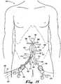
- FIG. 11is a continuation of the disclosed exemplary method of FIG. 10 in which operator action has placed a second guide wire 302 provided with an engagement tip 328 to grasp and stabilize the non-elastic contralateral cuff 126 under radiographic or other imaging control through an access via a second side through a femoral arteriotomy (not shown in FIG. 11 ).
- FIG. 12is a continuation of the disclosed exemplary method of FIG. 11 in which operator action has placed a contralateral delivery catheter 300 over the second guide wire 302.
- the contralateral delivery catheter 300includes a contralateral delivery catheter lumen 304 and a contralateral delivery catheter sheath 340 which may be operably opened or retracted by operator action.
- FIG. 13is a continuation of the disclosed exemplary method of FIG. 12 in which operator action has removed the contralateral delivery catheter sheath 340 of the contralateral delivery catheter 300 allowing the endograft segmental implant 344 therein to fully decompress or unfold to expose a proximal segmental elastic implant end 348, a distal segmental elastic implant end 356, and the full length of a non-elastic segmental tubular implant body 346 connecting said ends 348 and 356.
- FIG. 14is a continuation of the disclosed exemplary method of FIG. 13 in which operator action on one or more proximal segmental control leads 354 connected to one or more proximal segmental variable sealing devices 352 has caused the expansion of proximal segmental circumferential sealable collar 350 of the endograft segmental implant's 344 elastic proximal segmental implant end 348 to firmly and fully contact the inner walls of the non-elastic contralateral cuff 126 effecting a proximal seal, and then similarly caused the distal segmental circumferential sealable collar 358 of the endograft segmental implant's 344 elastic distal segmental implant end 356 to expand to firmly and fully contact the inner wall of the common iliac artery 416 on the second side above the origin of the internal iliac artery 418, effecting a vascular seal therein and preserving flow through the internal iliac artery 418.
- the aortic aneurysmal sac 410is devascularized and collapses.
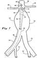
- FIG. 15shows an diagrammatic view of a patient 500 in a dorsal supine position, with a disclosed embodiment of an endovascular implant 200 according to the present invention in sealed position in the patient's abdominal aorta 402 proximally and distally, and with arteriotomy incisions 332, 336 in both femoral arteries with an injector cannula 330 for radiographic contrast dye injection and proximal 120 and distal 122 control leads for operator manipulation in place in the patient's right arteriotomy site 332 and a second guide wire 302 in place in the 'patient's left arteriotomy site 336, corresponding to the procedural stage shown in FIG. 11 .
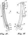
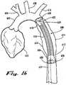
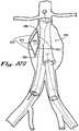
- FIG. 16shows an anatomic view of a disclosed embodiment of a thoracic endovascular implant 600 according to the present invention in sealed position proximally and distally in a patient's descending thoracic aorta 612, traversing a devascularized thoracic aortic aneurysm 614.
- the ascending aorta 604arises from the heart 602 and gives rise to the innominate artery 606, the left common carotid artery 608, and the left subclavian artery 610 before continuing as the descending thoracic aorta 612.
- the thoracic endovascular implant 600includes a non-elastic tubular thoracic implant body 616 with an elastic proximal thoracic end 618 and an elastic distal thoracic end 626.
- the elastic proximal thoracic end 618terminates in a proximal thoracic sealable circumferential collar 620, controlled by a proximal thoracic variable sealing device 622 which is operated by a proximal thoracic control lead 624 that traverses a thoracic implant delivery catheter (not shown in FIG. 16 ) and exits distally for interface with an operator (not shown in FIG. 16 ).
- the elastic distal thoracic end 626terminates in a distal sealable thoracic circumferential collar 628, controlled by a distal thoracic variable sealing device 630 which is operated by a distal thoracic control lead 632 that exits a thoracic implant delivery catheter distally for interface with an operator (not shown in FIG. 6 ).
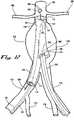
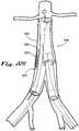
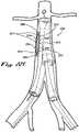
- FIG. 17provides an anatomic view showing an alternate disclosed embodiment of a thoracic endovascular implant 700 in a patient's descending thoracic aorta 612 according to the present invention in which a first thoracic endovascular implant 718 includes a non-elastic distal cuff 730, a proximal first thoracic circumferential sealable collar 724, a proximal first thoracic variable sealing device 726, and a proximal first thoracic control lead 728. As shown in FIG.
- the first thoracic endovascular implant 718has been sealed in position proximally by operator action on the proximal first thoracic variable sealing device 726 using the proximal first thoracic control lead 728, expanding the proximal first thoracic circumferential sealable collar 724 to achieve a proximal seal within the descending thoracic aorta 612, and effectively devascularizing a thoracic aneurysm 614 therein.
- the first thoracic endovascular implant 718has been joined distally by a second thoracic endovascular implant 732, which includes an elastic proximal second thoracic implant end 736, a non-elastic tubular second thoracic implant body 734, and an elastic distal second thoracic implant end 746.
- the elastic proximal second thoracic implant end 736includes a proximal second thoracic circumferential sealable collar 738, a proximal second thoracic variable sealing device 740, and a proximal second thoracic control lead 742
- the elastic distal second thoracic implant end 746includes a distal second thoracic circumferential sealable collar 748, a distal second thoracic variable sealing device 750, and a distal second thoracic control lead 752.
- an operatorwould first secure a seal in the proximal descending thoracic aorta using the first thoracic endovascular implant 718, and then seal the proximal and distal aspects, respectively, of the second thoracic endovascular implant 732, using real-time radiographic or other visualization techniques with injected contrast dye as previously described in this disclosure.
- FIGS. 18A and 18Bshow an embodiment of an endovascular implant according to the present invention similar to the disclosure of FIG. 1B , with the additional inclusion of one of more retention tines 136 attached to the proximal circumferential sealable collar 112 and distal circumferential sealable collar 114.
- a plurality of retention tines 136is used.
- the retention tines 136are oriented to extend radially outward from the proximal circumferential sealable collar 112 and distal circumferential sealable collar 114.
- the retention tines 136may be oriented to extend perpendicularly or at any other desired angle outward from the proximal circumferential sealable collar 112 and distal circumferential sealable collar 114.
- the retention tines 136may be constructed of any biocompatible material including, but not limited to, metals, plastics, or ceramics.
- the retention tines 136 of the proximal circumferential sealable collar 112 and distal circumferential sealable collar 114 covered by a compressible foam sheathing 134 in a pre-deployment positionmay be constructed of any biocompatible material of suitable compressibility to allow the foam to be substantially compressed by the pressure of the proximal circumferential sealable collar 112 and distal circumferential sealable collar 114 against the inner wall of a target artery, upon operator deployment.
- the compressible foam sheathing 134may also be constructed of material of suitable memory characteristics to allow the foam to substantially decompress to its pre-deployment position, covering the retention tines 136, if pressure against the arterial wall is removed, thus allowing repositioning or removal of an endovascular implant according to the present invention at the operator's discretion.
- Compressible foam sheathing 134may be any biocompatible foam material of either an open or closed cell structure with sufficient compressibility and resilience to allow rapid recovery in a non-compressed state.
- foam materialsmay be viscoelastic foam with a compressible cellular material that has both elastic (spring-like) and viscous (time-dependent) properties. Viscoelastic foam differs from regular foam by having time-dependent behaviors such as creep, stress relaxation, and hysteresis.
- FIGS. 19A and 19Bshow the exemplary endovascular implant of FIGS. 18A and 18B in the anatomic context of an endovascular implant 100 being deployed and sealed proximally in an abdominal aorta 402 containing an aneurysm 410, with complete expansion and seal at the level of the proximal circumferential sealable implant collar 112 against the aortic inner wall 124, but incomplete expansion and no seal against the arterial inner wall 144 at the level of the distal circumferential sealable implant collar 114 at this stage of the procedure.
- the retention tines 136 of the proximal circumferential sealable collar 112 and distal circumferential sealable collar 114covered by a compressible foam sheathing 134 in a pre-deployment position.
- FIGS. 20A and 20Bfurther show the exemplary endovascular implant of FIGS. 18A and 18B in the anatomic context of an endovascular implant 100 being deployed and sealed proximally in an abdominal aorta 402 containing an aneurysm 410, now with complete expansion of the distal circumferential sealable implant collar 114 and complete seal against the arterial inner wall 144 at this stage of the procedure.
- compressible foam sheathing 134is compressed between the distal circumferential sealable collar 114 and the arterial inner wall 144, allowing the retention tines 136 to engage the arterial inner wall 144 in their deployed position, thereby serving to retain the deployed position of the endovascular implant 100.
- retention tines 136 and the compressible foam sheathing 134 as described abovemay be used in conjunction with any or all circumferentially sealable elements in this disclosure, including but not limited to, proximal circumferential sealable collars 112, distal circumferential sealable collars 114, proximal segmental circumferential sealable collars 314, distal segmental circumferential sealable collars 316, proximal thoracic circumferential sealable collars 620, distal thoracic circumferential sealable collars 628, proximal first thoracic circumferential sealable collars 724, proximal second thoracic circumferential sealable collars 738, and distal second thoracic circumferential sealable collars 748.
- proximal circumferential sealable collars 112distal circumferential sealable collars 114, proximal segmental circumferential sealable collars 314, distal segmental circumferential sealable collars 316, proximal thoracic circumfer
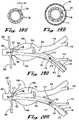
- FIGS. 21A-Dillustrate details of an embodiment of a variable sealing device according to the present invention.
- a variable sealing mechanism assembly 2100comprises a sealing device housing 2102 attached to a sealer belt 2104 with a sealer belt fixed end 2108 attached to said housing 2102 and with a sealer belt moveable end 2110 operably passing through said housing and collecting in a concentric belt receiver channel 2130 as said sealer belt moveable end 2110 exits said housing 2102.
- the sealer belt moveable end 2110contains a plurality of uniformly distributed belt engagement slots 2106.
- the belt engagement slots 2106may be round, oval, square, rectangular, triangular, or any other shape, but are sized, spaced, and configured on said sealer belt moveable end 2110 to engage with sealer gear teeth 2116 of a sealer gear 2114 rotatably located within a housing gear recess 2112 contained within said housing 2102.
- the sealer gear teeth 2116are oriented to present on the outer circumference of said sealer gear 2114.
- On the inner circumference of said sealer gear 2114a plurality of uniformly distributed sealer gear retainment slots 2118 are configured to receive a locking member 2120.
- the locking member 2120in various embodiments according to the present invention may be a simple strip or bar as shown in FIGs.
- the locking member 2120is fabricated of a metal or plastic with resilient spring, like properties, such that, when depressed or pulled in a perpendicular vector with respect to the sealer gear 2114, the ends of said locking member 2120 are withdrawn from the sealer gear retainment slots 2118, thus allowing the sealer gear 2114 to rotate within said housing gear recess 2112, as shown in FIGS. 21 B and C.
- the locking member 2120is further provided with one or more sealer gear drive pins 2126, which are received by gear drive pins 2126said sealer gear 2114 when the locking member 2120 is depressed, as shown in FIG. 21C .
- the gear drive pins 2126 and gear drive pins 2126may be tapered, straight, or otherwise shaped to facilitate their secure engagement and release.
- the locking member 2120is depressed by action of a control lead shaft 2124, which is removably attached to the locking member 2120 at a control lead attachment 2122.
- a control lead shaft 2124which is removably attached to the locking member 2120 at a control lead attachment 2122.
- FIG. 21Dshows an exemplary embodiment according to the present invention, in which a sealable collar 2140 contains a variable sealing mechanism assembly 2100 comprising a sealing device housing 2102 attached to a sealer belt 2104 with a sealer belt fixed end 2108 attached to said housing 2102 and with a sealer belt moveable end 2110 operably passing through said housing and collecting in a concentric belt receiver channel 2130 as said sealer belt moveable end 2110 exits said housing 2102.
- the sealable collar 2140is constructed of a tubular elastic body in a closed loop defining a central collar lumen 2142.
- the sealer belt 2104may pass circumferentially through substantially all of the sealable collar 2140, as shown in FIG.
- variable sealing mechanism assembly 2100may enlarge or constrict, with similar action on the sealable collar 2140, thus allowing a variable seal to be achieved between the sealable collar 2140 and the inner lumen of a vessel wall (not shown in FIG. 21 D) containing the sealable collar 2140.
- an endograftmay also incorporate radio-opaque, echogenic materials and magnetic resonance imaging (MRI) responsive materials (i.e., MRI contrast agents) to aid in visualization of the device under x-ray, ultrasound, fluoroscopy MRI or other imaging modalities.
- MRImagnetic resonance imaging
- various embodiments according to the present inventionmay incorporate markers comprising various radio-opaque, echogenic materials and magnetic resonance imaging (MRI) responsive materials that may be placed on the walls of an aneurysm sac or on other anatomic sites for improved postoperative visualization to monitor for aneurysmal revascu larization.
- MRImagnetic resonance imaging
- various embodiments according to the present inventionmay also be provided with one or more endograft monitoring devices to facilitate diagnosis of postoperative graft failure and aneurysm revascularization.
- endograft monitoring devicesmay be pressure sensors positioned to demonstrate positive pressure within the former aneurysmal sac in some manner that may be identifiable by electronic, radiographic, or other visual or electronic communications.
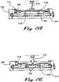
- FIGS 22A-Fillustrate yet other examples of endograft monitoring devices.
- FIGS. 22A-22Bshow an example of a sealable vascular endograft system 2200 which incorporates an endograft monitoring device comprising an radio-opaque graft attachment member 2205 joined at a monitoring pivot 2210 to a radio-opaque aneurysmal attachment 2220 which is affixed by an operator at the time of endograft placement to the inner wall of the aneurysmal sac 2215, which is shown in a collapsed, nonvascularized state in FIG. 22A , but in an expanded, revascularized state in FIG.22B . As further shown in FIG.
- the expansion of the aneurysmal sac 2215has the further effect of increasing the angle between the radio-opaque graft attachment member 2205 and the radio-opaque aneurysmal attachment 2220.
- plain radiographs or other visualization meanscould be employed to evaluate the angle between the attachment members of an endograft monitoring device to detect endograft failure and revascularization of the aneurysm without requiring more invasive and expensive diagnostic studies.
- FIGS. 22C and 22Dillustrate yet another example of a sealable vascular endograft system 2200 which incorporates an endograft monitoring device comprising an radio-opaque graft attachment 2202 pivotably joined by two or more radio-opaque graft frame members 2212 which are in turn joined frame pivots 2204 to radio-opaque aneurysmal frame members 2214 which are joined at an aneurysmal attachment 2216 which is affixed by an operator at the time of endograft placement to the inner wall of the aneurysmal sac 2215, which is shown in a collapsed, nonvascularized state in FIG. 22C , but in an expanded, revascularized state in FIG.22D . As further shown in FIG.
- the expansion of the aneurysmal sac 2215has the further effect of increasing the angles between the radio-opaque graft frame member 2212 and the radio-opaque aneurysmal frame members 2214 to create a square or polygonal shape visible on radiographs.
- plain radiographs or other visualization meanscould again be employed to evaluate the angles between the attachment members of an endograft monitoring device to detect endograft failure and revascularization of the aneurysm without requiring more invasive and expensive diagnostic studies.
- FIGS. 22E and 22Eillustrate still another example of a sealable vascular endograft system 2200.
- an endograft monitoring devicecomprising two or more radio-opaque graft attachment 2202 pivotably joined by two or more radio-opaque graft frame members 2212 which are in turn joined frame pivots 2204 to radio-opaque aneurysmal frame members 2214 which are joined at two or more aneurysmal attachments 2216 which are affixed by an operator at the time of endograft placement to the inner wall of the aneurysmal sac 2215, which is shown in a collapsed, nonvascularized state in FIG. 22E , but in an expanded, revascularized state in FIG.22F .
- FIG. 22Eillustrate still another example of a sealable vascular endograft system 2200.
- an endograft monitoring devicecomprising two or more radio-opaque graft attachment 2202 pivotably joined by two or more radio-opaque graft frame members
- the expansion of the aneurysmal sac 2215has the further effect of increasing the angles between the radio-opaque graft frame member 2212 and the radio-opaque aneurysmal frame members 2214 to create a square or polygonal shape visible on radiographs.
- three-dimensional, cage-like structurescould be formed by the various frame members described, further enhancing the clinical visibility of an indication of aneurysmal revascularization.
Landscapes
- Health & Medical Sciences (AREA)
- Engineering & Computer Science (AREA)
- Biomedical Technology (AREA)
- Cardiology (AREA)
- Oral & Maxillofacial Surgery (AREA)
- Transplantation (AREA)
- Heart & Thoracic Surgery (AREA)
- Vascular Medicine (AREA)
- Life Sciences & Earth Sciences (AREA)
- Animal Behavior & Ethology (AREA)
- General Health & Medical Sciences (AREA)
- Public Health (AREA)
- Veterinary Medicine (AREA)
- Gastroenterology & Hepatology (AREA)
- Pulmonology (AREA)
- Prostheses (AREA)
- Surgical Instruments (AREA)
Description
- The present application claims priority of
U.S. Provisional Patent Application Serial No. 60/834,401, filed July 31, 2006 U.S. Provisional Patent Application Serial No. 60/834,627, filed August 1, 2006 - The present invention relates to the field of vascular surgery and the treatment of aneurysms or other luminal vascular defects. Specifically, the present invention relates to a novel design for sealable endovascular implants. Also disclosed, but not forming part of the present invention, are methods of use for such implants in endovascular procedures for aneurysms of the thoracic or abdominal aorta or other vascular structural defects.
- Aneurysms of the thoracic and abdominal aorta represent a degenerative process of the aorta that is often attributed to atherosclerosis. Aneurysms are defined as a focal dilatation with at least a 50% increase over normal arterial diameter, usually associated with a degradation of the aortic media, or other structural defect in the aortic wall.
- Medical research has suggested that these lesions are prone to occur in areas subjected to significant redirection of blood flow during diastole; however, the exact cause of such aneurysms is not known. A familial tendency to symptomatic aneurysms has been suggested. Degenerative aneurysms account for more than 90% of all infrarenal aneurysms of the abdominal aorta. Other potential causes include infection, cystic medial necrosis, arteritis, trauma, collagen vascular disorders, and anastomotic disruption.
- Abdominal aortic aneurysms most commonly begin in the infrarenal aorta, and extend down to the iliac bifurcation. Aneurysms of the thoracic aorta are most commonly located in the descending thoracic aorta, beginning just distal to the origin of the left subclavian artery.
- Aortic aneurysms generally affect elderly Caucasian men. Aortic aneurysms are less commonly reported among persona of African American, Asian, and Hispanic heritage. Abdominal aortic aneurysms are five times more common in men than in women. In men, the aneurysm process appears to begin at approximately age fifty years and reaches peak incidence at approximately age eighty years. Women appear to have a more delayed onset in which the aneurysm process appears to begin at approximately age 60 years. Smoking has been associated as a potential risk factor for the development of aortic aneurysms. Other risk factors include previous aneurysm repair or peripheral aneurysm (such as femoral or popliteal), coronary artery disease, and hypertension.
- Although the reported findings from autopsy series vary widely, the incidence of aortic aneurysms probably exceeds 3-4% in individuals older than 65 years. Death from aneurysmal rupture remains one of the 15 leading causes of death in the United States. In addition, the overall prevalence of aortic aneurysms has increased significantly in the last 30 years. This is partly due to an increase in diagnosis based on the widespread use of imaging techniques. However, the prevalence of fatal and nonfatal rupture has also increased, suggesting a true increase in incidence. An aging population probably plays a significant role.
- The surgical management of aortic aneurysms dates back to the early twentieth century, and has involved a variety of methods, including ligation, intraluminal wiring, cellophane wrapping, homografts, and grafts using nylon and polytetrafluoroethylene [PTFE] fabrics.
- Prior to the development of endoaneurysmorrhaphy in 1962, postoperative surgical mortality rates were high (>25%). Endovascular repair techniques have reduced the operative mortality to 1.8-5%.
- Existing techniques for endovascular treatment of aneurysms involve placement of a tubular graft with seals to normal aortic walls above and below the aneurysm to create a tubular bridge to carry flow across the aneurysm without allowing flow to fill the aneurismal sac. Using these techniques, grafts may be placed using percutaneous access to the femoral arteries, and delivery/implantation using vascular catheters and fluoroscopic visualization. The deficiencies associated with existing endograft technology relate to leakage at the graft/aortic interface and/or post-implantation migration of the endograft. Small post-implantation leaks may be repaired with the placement of one or more extension cuffs above the endograft proximally, or below the implant distally to attempt to obtain a better seal with the vessel. The required use of such cuffs may add significantly to the overall cost and morbidity of the procedure. Major failures with endograft repair generally require emergent open surgery to avert catastrophic rupture of the aneurysm. Also, current endovascular systems require accurate size matching of endograft implants, leaving a very small margin for error.
- In order for a patient to be a candidate for existing endograft methods and technologies, a proximal neck of at least 15 mm. of normal aorta must exist between the origin of the most inferior renal artery and the origin of the aneurysm in the case of abdominal aneurysms or the left subclavian artery for thoracic aortic aneurysms in order to permit an adequate seal. Similarly, at least 15 mm. of normal vessel must exist distal to the distal extent of the aneurysm for an adequate seal to be achieved.
- Migration of existing endografts has' also been a significant clinical problem, potentially causing leakage and re-vascularization of aneurysms and/or compromising necessary vascular supplies to arteries such as the carotid, subclavian, renal, or internal iliac vessels. This problem has been partially addressed by some existing endograft designs, in which barbs or hooks have been incorporated to help retain the endograft at its intended site. However, these existing endograft designs are not removable and repositionable once they are deployed. Thus, once such an endograft has been placed, open surgery is necessary if there is failure due to leakage or undesired occlusion of other vascular structures.
- Because of the limitations imposed by existing vascular endograft devices and endovascular techniques, approximately eighty percent of abdominal and thoracic aneurysms repaired in the U.S. are still managed though open vascular surgery, instead of the lower morbidity of the endovascular approach.
WO 2005/055883 describes an aortic annuloplasty ring comprising a controller coupled to an adjustment system such as an electronic fulcrum or gear arrangement. The controller may be an RF receiver that receives commands from an external control. In response to such commands, the controller may instruct the arrangement to open or close the ring. The controller and/or arrangement may also be responsive to magnetic signals.- Aspects of the invention are set out in the independent claims. Particular embodiments of these aspects are set out in the dependent claims. Any subject matter contained herein that does not fall within the scope of the appended claims is considered as being useful for understanding the invention.
- The present invention is directed towards a novel design for endovascular implant grafts. Also disclosed, but not forming part of the present invention, are methods for their use for the treatment of aortic aneurysms and other structural vascular defects. An exemplary sealable, repositionable endograft system for placement in a blood vessel is disclosed, in which an embodiment of an endograft implant of the present invention comprises a non-elastic tubular implant body with an elastic proximal ends and an elastic distal end(s). Both the elastic proximal and distal ends in an implant according to this embodiment of the present invention further comprise one or more circumferential sealable collars and one or more variable sealing device, capable of controllably varying the expanded diameter of said collar upon deployment to achieve the desired seal between the collar and the vessel's inner wall. An embodiment of the endovascular implant according to the present invention further comprises a central lumen and one or more control leads extending distally from releasable connections with each variable sealing device. Embodiments of endovascular implants according to the present invention may further be provided with retractable retention tines or other retention devices allowing an implant to be repositioned before final deployment. An exemplary endograft system according to the present disclosure further comprises a delivery catheter with an operable tubular sheath, capable of housing a folded or compressed endograft implant prior to deployment and capable of retracting or otherwise opening in at least its proximal end to allow implant deployment, said sheath sized and configured to allow its placement via a peripheral arteriotomy site, and of appropriate length to allow its advancement into the thoracic or abdominal aorta, as required for a specific application.
- In a use of an embodiment according to the present invention, said use not forming part of the present invention, an operator prepares an arteriotomy site in a patient in a suitable peripheral location, such as the femoral arteries. Upon incision into the artery, a guide wire is placed, and extended under radiographic visualization into the aorta. A catheter sheath is inserted, housing a collapsed endovascular graft. An injector cannula is inserted, with its proximal tip extending beyond the catheter sheath. Under radiographic visualization, radio-opaque or other contrast dye is injected into the injector cannula, and the contrast dye-enhanced view is used to position the proximal edge of the cannula above the beginning of the aneurysm sac. The catheter sheath is then partially retracted to expose the proximal portion of the endovascular implant. Through action initiated by the
operator on the control leads, the variable sealing device for the proximal seal is activated, expanding the elastic circumferential sealable collar until firm contact is made with the vessel wall. At this point, additional radio-opaque or other contrast dye is injected, and the seal is assessed. If there are leaks, the variable sealing device is again activated to expand the diameter of the circumferential sealable collar for a firmer contact. The seal is reassessed and adjusted until there no contrast dye leaks are seen. If the radio-opaque or other contrast dye indicates that the device is placed too proximally and threatens or covers the renal or subclavian junctions, then it is loosened and moved distally. - Once the proximal circumferential sealable collar has been suitably sealed, the catheter sheath is then retracted beyond the distal extent of the aneurysm exposing the remainder of the graft. The variable sealing device for the distal seal is similarly activated, expanding the elastic circumferential sealable collar until firm contact is made with the vessel wall. At this point, additional radio-or other contrast dye is injected, and the distal seal is assessed. If there are leaks, the distal variable sealing device is again activated to expand the diameter of the distal circumferential sealable collar for a firmer contact. The seal is reassessed and adjusted until there no contrast dye leaks are seen.
- For an exemplary implant for an abdominal aortic aneurysm according to the present invention, an endograft implant comprises a non-elastic tubular body with an elastic proximal and distal ends and a non-elastic contralateral cuff. An operator deploys and seals the proximal and distal ends of the implant as described above, with the distal end deployed and sealed in the iliac artery on the side of the initial arteriotomy. Then, a second arteriotomy is made on the opposite side. Radio-or other contrast dye injection is again used to allow visualization of the nonelastic contralateral cuff, and a second guide wire is placed from the second arteriotomy site through the non-elastic contralateral cuff. A contralateral delivery catheter is then introduced over the second guide wire. The contralateral delivery catheter comprises a slidable or removable sheath housing a folded or compressed endograft segmental implant which further comprises a non-elastic tubular body with an elastic proximal and distal ends. Both the elastic proximal and distal ends in an exemplary endograft segmental implant according to the present invention further comprise one or more circumferential sealable collars and one or more variable sealing device, capable of controllable varying the expanded diameter of said collar upon deployment to achieve the desired seal between the collar and the non elastic contralateral cuff proximally and between the collar and the vessel's inner wall distally. An exemplary endograft segmental implant according to the present invention further comprises a central lumen and one or more control leads extending distally from releasable connections with each variable sealing device.
- Again, under radiographic control, radio-opaque or other contrast dye is injected into the injector cannula, and the contrast dye-enhanced view is used to position the proximal edge of the contralateral delivery catheter within the lumen of the non-elastic contralateral cuff. The contralateral delivery catheter sheath is then partially retracted to expose the proximal portion of the endograft segmental implant. Through action initiated by the operator on the control leads, the variable sealing device for the proximal seal is activated, expanding the elastic circumferential sealable collar until firm contact is made between the sealable collar and the non elastic cuff. At this point, additional radio-opaque or other contrast dye is injected, and the seal is assessed. If there are leaks, the variable sealing device is again activated to expand the diameter of the circumferential sealable collar for a firmer contact. The seal is reassessed and adjusted until there no contrast dye leaks are seen
- Finally, once the proximal circumferential sealable collar of the endograft segmental implant has been suitably sealed, the catheter sheath is then retracted beyond the distal extent of the aneurysm, exposing the remainder of the graft. The variable sealing device for the distal seal is similarly activated, expanding the elastic circumferential sealable collar until firm contact is made with the vessel wall. At this point, additional radio-opaque or other contrast dye is injected, and the distal seal is assessed. If there are leaks, the distal variable sealing device is again activated to expand the diameter of the distal circumferential sealable collar for a firmer contact. The seal is reassessed and adjusted until there no contrast dye leaks are seen. At this point, the operator may remove the injector cannula and detach the control leads from the variable sealing devices, and remove the control leads and guide wires from their arteriotomy sites and close the wounds.
- The preceding description is presented only as an exemplary application of the devices of the present invention and disclosure, and methods according to the present disclosure.
FIG. 1A is a side perspective view of the proximal tip of a delivery catheter containing a disclosed embodiment of the present invention of a compressed or folded bifurcated endovascular implant with a contralateral cuff housed within a sheath.FIG. 1B is a side perspective view of the proximal tip of a delivery catheter containing a disclosed embodiment of the present invention of a decompressed or unfolded endovascular implant removed from a sheath.FIG. 2A is a side perspective view of the proximal tip of a delivery catheter containing a disclosed embodiment of the present invention of a compressed or folded endograft segmental implant housed within a sheath of the present disclosure.FIG. 2B is a side perspective view of the proximal tip of a delivery catheter containing a disclosed embodiment of the present invention of a decompressed or unfolded endograft segmental implant removed from a sheath of the present disclosure.FIG. 3 is a side perspective view of a disclosed embodiment of the present invention of an endograft segmental implant.FIG. 4 is a perspective anatomic view of a disclosed embodiment of the sealable endovascular implant of the present invention and its use in an illustrative, exemplary method in which the proximal tip of an implant delivery catheter placed in a first side through a femoral artery is positioned in an abdominal aorta in an infrarenal location, but above the origin of an abdominal aortic aneurysm.FIG. 5 is a perspective anatomic view of the disclosed exemplary method ofFIG. 4 in which an injector cannula has been introduced through a lumen of the implant delivery catheter, and protrudes proximal to the tip of the implant delivery catheter to fully expose all injector ports for radio-opaque contrast dye injection therethrough.FIG. 6 is a continuation of the disclosed exemplary method ofFIG. 5 in which the sheath of the implant delivery catheter has been retracted or partially opened to allow the endograft implant therein to partially decompress or unfold, to expose the proximal elastic implant end and a length of the non-elastic tubular body.FIG. 7 is a perspective anatomic view of the disclosed exemplary method ofFIG. 6 in which the implant delivery catheter has been slightly withdrawn under radiographic control to position the proximal tip of the impInt distal to the origins of the renal arteries to preserve flow therein.FIG. 8 is a perspective anatomic view of the disclosed exemplary method ofFIG. 7 in which operator action on one or more control leads connected to one or more variable sealing devices has caused the extended circumferential sealable collar of the implant's elastic proximal end to firmly and fully contact the inner wall of the aorta, effecting a vascular seal therein.FIG. 9 is a perspective anatomic view of the disclosed exemplary method ofFIG. 8 in which operator action has fully retracted or opened and removed the sheath of the implant delivery catheter allowing the endograft implant therein to fully decompress or unfold, to expose a distal elastic implant end and a nonelastic contralateral cuff.FIG. 10 is a perspective anatomic view of the disclosed exemplary method ofFIG. 9 in which operator action on one or more control leads connected to one or more variable sealing devices has caused the extended circumferential sealable collar of the implant's elastic distal end to firmly and fully contact the inner wall of the common iliac artery above the origin of the internal iliac artery, effecting a vascular seal therein and preserving flow through the internal iliac artery.FIG. 11 is a perspective anatomic view of the disclosed exemplary method ofFIG. 10 in which operator action has placed a hooked second guide wire to grasp and stabilize the nonelastic contralateral cuff under radiographic visualization through an access via a second side through a femoral artery.FIG. 12 is a perspective anatomic view of the disclosed exemplary method ofFIG. 11 in which operator action has placed a contralateral delivery catheter over the second guide wire.FIG. 13 is a perspective anatomic view of the disclosed exemplary method ofFIG. 12 in which operator action has removed the sheath of the contralateral delivery catheter allowing the endograft segmental implant therein to fully decompress or unfold, to expose a proximal segmental elastic implant end, a distal segmental elastic implant end, and the full length of the non-elastic segmental tubular implant body connecting said ends.FIG. 14 is a perspective anatomic view of the disclosed exemplary method ofFIG. 13 in which operator action on one or more control leads connected to one or more variable sealing devices has caused the extended circumferential sealable collar of the implant's proximal segmental elastic implant end to expand to firmly and fully contact the inner walls of the non-elastic contralateral cuff effecting a proximal seal, and then similarly caused the extended circumferential sealable collar of the implant's distal segmental elastic implant end to expand to firmly and fully contact the inner wall of the common iliac artery on the second side above the origin of the internal iliac artery, effecting a vascular seal therein and preserving flow through the internal iliac artery.FIG. 15 shows an diagrammatic view of a patient in a dorsal supine position, with a disclosed embodiment of an endovascular implant according to the present invention in sealed position in the patient's abdominal aorta proximally and distally, and with arteriotomy incisions in both femoral arteries with an injector cannula and proximal and distal control leads in place in the patient's right arteriotomy site for radiographic contrast dye injection and a second guide wire in place in the patient's left arteriotomy site, corresponding to the procedural stage shown inFIG. 11 .FIG. 16 is a longitudinal anatomic view showing a disclosed embodiment of a thoracic endovascular implant according to the present invention in sealed position proximally and distally in a patient's descending thoracic aorta.FIG. 17 is a longitudinal anatomic view showing an alternate disclosed embodiment of a thoracic endovascular implant in a patient's descending thoracic aorta according to the present invention in which a first thoracic endovascular implant with a non-elastic distal cuff has been sealed in position proximally and distally has been joined by a second thoracic endovascular implant with a non-elastic tubular body with an elastic proximal end and an elastic distal end, both containing circumferential sealable collars and variable sealing devices capable of achieving a desired seal between the collar and the vessel's inner wall.FIG. 18A is a side perspective view of the disclosed embodiment of an endovascular implant according to the present invention in which the proximal and distal circumferential sealable collars are provided with retractable retention tines and shown in a retracted, pre-deployment position.FIG. 18B is a cross-sectional view of a disclosed embodiment according to the present invention of a proximal or distal circumferential sealable implant collar with retention tines covered by a compressible foam sheathing in a retracted, pre-deployment position.FIG. 19A is a longitudinal anatomic view of a disclosed embodiment according to the present invention of an endovascular implant which is being deployed and sealed proximally in an abdominal aorta containing an infrarenal aneurysm, with incomplete distal circumferential sealable implant collar expansion and seal at this stage of the procedure.FIG. 19B is a cross-sectional view of the distal circumferential sealable implant collar inFIG. 19A , showing the compressible foam sheathing covering the collar's retention tines within a vessel's lumen.FIG. 20A is a longitudinal anatomic view of a disclosed embodiment according to the present invention of an endovascular implant which is being deployed and sealed proximally in an abdominal aorta containing an infrarenal aneurysm, with complete proximal circumferential sealable implant collar expansion and seal at this stage of the procedure.FIG. 20B is a cross-sectional view of the proximal circumferential sealable implant collar inFIG. 20A , showing compression of the compressible foam sheathing allowing the collar's retention tines to contact and engage the aortic wall circumferentially.FIG. 21A is a perspective view of an embodiment of a variable sealing device according to the present invention.FIG. 21B is a sectional view of an embodiment of a variable sealing device according to the present invention, in which the mechanism is in a released, locked state.FIG. 21C is a sectional view of an embodiment of a variable sealing device according to the present invention, in which the mechanism is in an engaged, unlocked state.FIG. 21D is a perspective view of an embodiment of a sealable collar containing a variable sealing device according to the present invention.FIG. 22A is a longitudinal anatomic view of a disclosed embodiment according to the present invention of an endovascular implant incorporating an endograft monitoring device attached to the aneurysmal sac wall and the outer wall of the endograft in which the endograft has been effectively sealed in position proximally and distally to an aneurysm, thus devascularizing the aneurysmal sac to allow the walls of the aneurysm to collapse against the endograft, and hold the endograft monitoring device in a collapsed position.Fig. 22B is a longitudinal anatomic view of a disclosed embodiment according to the present invention of an endovascular implant incorporating an endograft monitoring device ofFig. 22A in which the aneurysmal sac has become revascularized, allowing the endograft monitoring device to spring open such that it may be visualized on x-ray or other diagnostic visualization means.Fig. 22C shows an alternate embodiment of an endovascular implant incorporating an endograft monitoring device according to the present invention, in which said endograft monitoring device comprises more than one spring-like attachment to both the outer wall of the endograft and to the inner wall of the aneurysmal sac, and in which the aneurysmal sac has been sealed and devascularized, allowing the walls of the aneurysm to collapse against the endograft, and hold the endograft monitoring device in a collapsed position.Fig. 22D shows the alternate embodiment of an endovascular implant incorporating an endograft monitoring device according to the present invention ofFig. 22C , in which said endograft monitoring device comprises more than one spring-like attachment to both the outer wall of the endograft and to the inner wall of the aneurysmal sac, and in which the aneurysmal sac has become revascularized, allowing the endograft monitoring device to spring open such that it may be visualized on x-ray or other diagnostic visualization means.Fig. 22E shows yet another an alternate embodiment of an endovascular implant incorporating an endograft monitoring device according to the present invention, in which said endograft monitoring device comprises a plurality of spring-like attachment to both the outer wall of the endograft and to the inner wall of the aneurysmal sac, and in which the aneurysmal sac has been sealed and devascularized, allowing the walls of the aneurysm to collapse against the endograft, and hold the endograft monitoring device in a collapsed position.Fig. 22F shows the embodiment of an endovascular implant incorporating an endograft monitoring device according to the present invention ofFig. 22E , in which said endograft monitoring device comprises more than one spring-like attachment to both the outer wall of the endograft and to the inner wall of the aneurysmal sac, and in which the aneurysmal sac has become revascularized, allowing the endograft monitoring device to spring open such that it may be visualized on x-ray or other diagnostic visualization means.- The present invention may be understood more readily by reference to the following detailed description of the preferred embodiments of the invention and the examples included herein. However, before the preferred embodiments of the devices and methods according to the present invention are disclosed and described, it is to be understood that this invention is not limited to the exemplary embodiments described within this disclosure, and the numerous modifications and variations therein that will be apparent to those skilled in the art remain within the scope of the invention disclosed herein. It is also to be understood that the terminology used herein is for the purpose of describing specific embodiments only and is not intended to be limiting.
- Unless otherwise noted, the terms used herein are to be understood according to conventional usage by those of ordinary skill in the relevant art. In addition to the definitions of terms provided below, it is to be understood that as used in the specification and in the claims, "a" or "an" can mean one or more, depending upon the context in which it is used.
- The present invention is directed towards novel designs for sealable and repositionable endovascular implant grafts. Also disclosed but not forming part of the present invention are methods for their use for the treatment of aortic aneurysms and other structural vascular defects.
- In an example according to the present disclosure, a sealable vascular endograft system for placement in a vascular defect is provided, comprising an elongated main implant delivery catheter with an external end and an internal end for placement in a blood vessel with internal walls. In such an example, the main implant delivery catheter further comprises a main implant delivery catheter sheath which may be openable or removable at said internal end and a main implant delivery catheter lumen containing within a compressed or folded endovascular implant. Further in such an example, an endovascular implant according to one embodiment of the present invention comprises a non-elastic tubular implant body with an elastic proximal end terminating in a proximal sealable circumferential collar controlled by a proximal variable sealing device which is operated by a proximal control lead that traverses said main implant delivery catheter and exits at said external end for interface by an operator, such that said proximal sealable circumferential collar may be expanded or contracted by said operator to achieve a fluid-tight seal between said proximal sealable circumferential collar and the internal walls of said blood vessel proximal to said vascular defect. Moreover, in such an example, an endovascular implant according to one embodiment of the present invention further comprises a non-elastic tubular implant body with an elastic distal end terminating in a distal sealable circumferential collar controlled by a distal variable sealing device which is operated by a distal control lead that exits said main implant delivery catheter at said external end for interface by an operator, such that said distal sealable circumferential collar may be expanded or contracted by said operator to achieve a fluid-tight seal between said distal sealable circumferential collar and the internal walls of said blood vessel distal to the vascular defect.
- Referring now in more detail to the drawings, in which like numerals indicate like elements throughout the several views,
FIG. 1A shows a side perspective view of the proximal tip of a mainimplant delivery catheter 100 with a main implantdelivery catheter lumen 102 containing a disclosed embodiment of compressed or foldedendovascular implant 200 housed within a main implantdelivery catheter sheath 104. Theendovascular implant 200 in the embodiment shown inFIG. 1A includes a non-elastictubular implant body 106 with an elasticproximal end 108 and an elasticdistal end 110. The elasticproximal end 108 terminates in a proximal sealablecircumferential collar 112, controlled by a proximalvariable sealing device 116 which is operated by aproximal control lead 120 that traverses the mainimplant delivery catheter 100 and exits distally for interface with an operator (not shown inFIG. 1A ). The elasticdistal end 110 terminates in a distal sealablecircumferential collar 114, controlled by a distalvariable sealing device 118 which is operated by adistal control lead 122 that exits the mainimplant delivery catheter 100 distally for interface with an operator (not shown inFIG. 1A ). - The embodiment of an
endovascular implant 200 ofFIG. 1A is further shown inFIG. 1B removed from the mainimplant delivery catheter 100 and in a semi- or partially expanded or non-folded state. In addition to the elements described inFIG. 1A , theendovascular implant 200 in the embodiment shown inFIG. 1B may also include a contralateralnon-elastic cuff 126. - An alternate embodiment of a sealable endovascular implant according to the present invention is shown in
FIG. 2A . The proximal tip of a mainimplant delivery catheter 100 with a main implantdelivery catheter lumen 102 containing a disclosed embodiment of compressed or folded straightendovascular implant 202 housed within a main implantdelivery catheter sheath 104. Theendovascular implant 202 in the embodiment shown inFIG. 2A includes a non-elastictubular implant body 106 with an elasticproximal end 108 and an elasticdistal end 110. - The elastic
proximal end 108 terminates in a proximal sealablecircumferential collar 112, controlled by a proximalvariable sealing device 116 which is operated by aproximal control lead 120 that traverses the mainimplant delivery catheter 100 and exits distally for interface with an operator (not shown inFIG. 2A ). The elasticdistal end 110 terminates in a distal sealablecircumferential collar 114, controlled by a distalvariable sealing device 118 which is operated by adistal control lead 122 that exits the mainimplant delivery catheter 100 distally for interface with an operator (not shown inFIG. 2A ). - The embodiment of an
endovascular implant 202 ofFIG. 2A is further shown inFIG. 2B removed from the mainimplant delivery catheter 100 and in an semi- or partially expanded or non-folded state. A straightendovascular implant 202 according to the embodiment shown inFIGS. 2A and 2B provides a non-branching conduit between the proximal sealablecircumferential collar 112 and the distal sealablecircumferential collar 114. - An embodiment of an endograft segmental implant according to the present invention is shown in
FIG. 3 . An endograftsegmental implant 306 sealably interfaces to provide a conduit between a non-elastic vascular graft and a distal blood vessel. As shown inFIG. 3 , an endograftsegmental implant 306 includes a non-elastic tubularsegmental implant body 308 with an elastic proximalsegmental end 310 and an elastic distalsegmental end 312. The elastic proximalsegmental end 310 terminates in a proximal segmental sealablecircumferential collar 314, controlled by a proximal segmentalvariable sealing device 318 which is operated by a proximalsegmental control lead 322 that traverses a segmental implant delivery catheter (not shown inFIG. 3 ) and exits distally for interface with an operator (not shown inFIG. 3 ). The elastic distalsegmental end 312 terminates in a distal sealable segmentalcircumferential collar 316, controlled by a distal segmentalvariable sealing device 320 which is operated by a distalsegmental control lead 324 that exits a segmental implant delivery catheter distally for interface with an operator (not shown inFIG. 3 ). - In various embodiments according to the present invention,
endovascular implants 200 may be constructed of solid, woven, non-woven, or mesh materials such as, but not limited to, natural or synthetic rubbers, nylon, Goretex, elastomers, polyisoprenes, polyphosphazenes, polyurethanes, vinyl plastisols, acrylic polyesters, polyvinylpyrrolidone-polyurethane interpolymers, butadiene rubbers, styrene-butadiene rubbers, rubber lattices, Dacron, PTFE, malleable metals, other biologically compatible materials or a combination of such biologically compatible materials in a molded, woven, or non-woven configuration, coated, non-coated, and other polymers or materials with suitable resilience and pliability qualities.In certain preferred embodiments according to the present invention, it is desirable for the non-elastictubular implant body 106 and corresponding structures to be pliable to allow for folding or compressibility without allowing elasticity. In certain preferred embodiments according to the present invention, it is desirable for the elasticproximal end 108 and the elasticdistal end 110 and corresponding structures to be both elastic and compressible or foldable. In any given preferred embodiment, the non-elastictubular implant body 106, the elasticproximal end 108, the elasticdistal end 110 and corresponding structures may be constructed of the same material of varying elasticity, or these structures may be constructed of different, but compatible materials. FIGS. 4-9 illustrate an exemplary embodiment of sealable endovascular implants according to the present invention and an illustrative, examplary method of their use for the treatment of an infrarenal abdominal aortic aneurysm with vascular access through bilateral femoral arteriotomy sites.- In
FIG. 4 a mainimplant delivery catheter 100 has been placed in a first side through a femoral artery (not shown inFIG. 4 ) and positioned in anabdominal aorta 402 in a location distal to therenal arteries 408, but above the origin of an abdominalaortic aneurysm 410. FIG. 5 is a continuation of the disclosed exemplary method ofFIG. 4 in which aninjector cannula 404 with one ormore injection ports 406 has been introduced through a mainimplant delivery lumen 102 of the mainimplant delivery catheter 100, and protrudes proximal to the tip of theimplant delivery catheter 100 to fully expose theinjector ports 406 for real-time visualization contrast dye injection therethrough. Such contrast dye injection may be performed using radio-opaque or other contrast dyes for fluoroscopy, computerized tomography, or other radiographic techniques. Other real-time visualization techniques may be used, including but not limited to, ultrasound or nuclear magnetic resonance techniques using appropriate contrast dye materials for injection. Such contrast dye injection allows an operator to assess the distance between the origins of therenal arteries 408, and the origin of the aorticaneurysmal sac 410 for proper implant placement.FIG. 6 is a continuation of the disclosed exemplary method ofFIG. 5 in which the main implantdelivery catheter sheath 104 of the mainimplant delivery catheter 100 has been retracted or partially opened to allow theendovascular implant 200 therein to partially open or unfold from its initially compressed or folded position. Additional contrast dye injection through theinjector cannula 404 may be performed by the operator at this point to verify the level of the proximal circumferentialsealable collar 112 with respect to the level of therenal arteries 408.FIG. 7 is a continuation of the disclosed exemplary method ofFIG. 6 in which the level of the proximal circumferentialsealable collar 112 has been adjusted by the operator with respect to the level of therenal arteries 408 for optimal deployment.FIG. 8 is a continuation of the disclosed exemplary method ofFIG. 7 in which operator action on one or more proximal control leads 120 connected to one or more proximalvariable sealing devices 116 has caused the proximal circumferentialsealable collar 112 of the elasticproximal end 108 of theendovascular implant 200 to firmly and fully contact the aorticinner wall 124, effecting a vascular seal therein.FIG. 9 is a continuation of the disclosed exemplary method ofFIG. 8 in which operator action has fully retracted or opened and removed the mainimplant delivery sheath 104 of the mainimplant delivery catheter 100 allowing theendovascular implant 200 therein to fully decompress or unfold, thus exposing a distalelastic implant end 110 and a non-elasticcontralateral cuff 126. At this point in a deployment procedure, additional contrast dye injection would likely again be performed to ascertain that there is a complete seal at the level of the proximal circumferentialsealable collar 112. If leakage is still visualized, additional operator action on the proximal control lead (s) 120 may be used to further expand the proximal circumferentialsealable collar 112 to secure an acceptable seal. Alternately, operator action may reduce the expanded proximal circumferentialsealable collar 112 to allow its reposition and redeployment, again under real-time radiographic or other visualized control.FIG. 10 is a continuation of the disclosed exemplary method ofFIG. 9 once a suitable proximal seal has been achieved. Operator action on one or more distal control leads 122 connected to one or more distalvariable sealing devices 118 has caused the extended distal circumferentialsealable collar 114 of the endovascular implant's 200 elasticdistal end 110 to firmly and fully contact the inner wall of the commoniliac artery 412 above the origin of the internaliliac artery 414, effecting a vascular seal therein and preserving flow through the internaliliac artery 414. Additional contrast dye injection through theinjector cannula 404 would be used by the operator to confirm adequate seals both proximally and distally at this point.FIG. 11 is a continuation of the disclosed exemplary method ofFIG. 10 in which operator action has placed asecond guide wire 302 provided with anengagement tip 328 to grasp and stabilize the non-elasticcontralateral cuff 126 under radiographic or other imaging control through an access via a second side through a femoral arteriotomy (not shown inFIG. 11 ).FIG. 12 is a continuation of the disclosed exemplary method ofFIG. 11 in which operator action has placed acontralateral delivery catheter 300 over thesecond guide wire 302. Thecontralateral delivery catheter 300 includes a contralateraldelivery catheter lumen 304 and a contralateral delivery catheter sheath 340 which may be operably opened or retracted by operator action.FIG. 13 is a continuation of the disclosed exemplary method ofFIG. 12 in which operator action has removed the contralateral delivery catheter sheath 340 of thecontralateral delivery catheter 300 allowing the endograftsegmental implant 344 therein to fully decompress or unfold to expose a proximal segmentalelastic implant end 348, a distal segmentalelastic implant end 356, and the full length of a non-elastic segmentaltubular implant body 346 connecting said ends 348 and 356.FIG. 14 is a continuation of the disclosed exemplary method ofFIG. 13 in which operator action on one or more proximal segmental control leads 354 connected to one or more proximal segmentalvariable sealing devices 352 has caused the expansion of proximal segmental circumferentialsealable collar 350 of the endograft segmental implant's 344 elastic proximalsegmental implant end 348 to firmly and fully contact the inner walls of the non-elasticcontralateral cuff 126 effecting a proximal seal, and then similarly caused the distal segmental circumferentialsealable collar 358 of the endograft segmental implant's 344 elastic distalsegmental implant end 356 to expand to firmly and fully contact the inner wall of the commoniliac artery 416 on the second side above the origin of the internaliliac artery 418, effecting a vascular seal therein and preserving flow through the internaliliac artery 418. Once sealed, the aorticaneurysmal sac 410 is devascularized and collapses.FIG. 15 shows an diagrammatic view of apatient 500 in a dorsal supine position, with a disclosed embodiment of anendovascular implant 200 according to the present invention in sealed position in the patient'sabdominal aorta 402 proximally and distally, and witharteriotomy incisions injector cannula 330 for radiographic contrast dye injection and proximal 120 and distal 122 control leads for operator manipulation in place in the patient'sright arteriotomy site 332 and asecond guide wire 302 in place in the 'patient'sleft arteriotomy site 336, corresponding to the procedural stage shown inFIG. 11 .FIG. 16 shows an anatomic view of a disclosed embodiment of a thoracicendovascular implant 600 according to the present invention in sealed position proximally and distally in a patient's descendingthoracic aorta 612, traversing a devascularized thoracicaortic aneurysm 614. In a patient, the ascendingaorta 604 arises from theheart 602 and gives rise to theinnominate artery 606, the left commoncarotid artery 608, and the leftsubclavian artery 610 before continuing as the descendingthoracic aorta 612. The thoracicendovascular implant 600 includes a non-elastic tubularthoracic implant body 616 with an elastic proximalthoracic end 618 and an elastic distalthoracic end 626. The elastic proximalthoracic end 618 terminates in a proximal thoracic sealablecircumferential collar 620, controlled by a proximal thoracicvariable sealing device 622 which is operated by a proximalthoracic control lead 624 that traverses a thoracic implant delivery catheter (not shown inFIG. 16 ) and exits distally for interface with an operator (not shown inFIG. 16 ). The elastic distalthoracic end 626 terminates in a distal sealable thoraciccircumferential collar 628, controlled by a distal thoracicvariable sealing device 630 which is operated by a distalthoracic control lead 632 that exits a thoracic implant delivery catheter distally for interface with an operator (not shown inFIG. 6 ).FIG. 17 provides an anatomic view showing an alternate disclosed embodiment of a thoracicendovascular implant 700 in a patient's descendingthoracic aorta 612 according to the present invention in which a first thoracicendovascular implant 718 includes a non-elasticdistal cuff 730, a proximal first thoracic circumferentialsealable collar 724, a proximal first thoracicvariable sealing device 726, and a proximal firstthoracic control lead 728. As shown inFIG. 17 , the first thoracicendovascular implant 718 has been sealed in position proximally by operator action on the proximal first thoracicvariable sealing device 726 using the proximal firstthoracic control lead 728, expanding the proximal first thoracic circumferentialsealable collar 724 to achieve a proximal seal within the descendingthoracic aorta 612, and effectively devascularizing athoracic aneurysm 614 therein.- As further shown in
FIG. 17 , the first thoracicendovascular implant 718 has been joined distally by a second thoracicendovascular implant 732, which includes an elastic proximal secondthoracic implant end 736, a non-elastic tubular secondthoracic implant body 734, and an elastic distal secondthoracic implant end 746. The elastic proximal secondthoracic implant end 736 includes a proximal second thoracic circumferentialsealable collar 738, a proximal second thoracic variable sealing device 740, and a proximal secondthoracic control lead 742, and the elastic distal secondthoracic implant end 746 includes a distal second thoracic circumferential sealable collar 748, a distal second thoracicvariable sealing device 750, and a distal secondthoracic control lead 752. - In an exemplary application as shown in
FIG. 17 , which does not form part of the present invention, an operator would first secure a seal in the proximal descending thoracic aorta using the first thoracicendovascular implant 718, and then seal the proximal and distal aspects, respectively, of the second thoracicendovascular implant 732, using real-time radiographic or other visualization techniques with injected contrast dye as previously described in this disclosure. FIGS. 18A and18B show an embodiment of an endovascular implant according to the present invention similar to the disclosure ofFIG. 1B , with the additional inclusion of one ofmore retention tines 136 attached to the proximal circumferentialsealable collar 112 and distal circumferentialsealable collar 114.- In a preferred embodiment according to the present invention, a plurality of
retention tines 136 is used. In a preferred embodiment according to the present invention, theretention tines 136 are oriented to extend radially outward from the proximal circumferentialsealable collar 112 and distal circumferentialsealable collar 114. In various preferred embodiment according to the present invention, theretention tines 136 may be oriented to extend perpendicularly or at any other desired angle outward from the proximal circumferentialsealable collar 112 and distal circumferentialsealable collar 114. - In various preferred embodiment according to the present invention, the
retention tines 136 may be constructed of any biocompatible material including, but not limited to, metals, plastics, or ceramics. - As further shown in
FIG. 18B theretention tines 136 of the proximal circumferentialsealable collar 112 and distal circumferentialsealable collar 114 covered by acompressible foam sheathing 134 in a pre-deployment position. In various preferred embodiment according to the present invention, thecompressible foam sheathing 134 may be constructed of any biocompatible material of suitable compressibility to allow the foam to be substantially compressed by the pressure of the proximal circumferentialsealable collar 112 and distal circumferentialsealable collar 114 against the inner wall of a target artery, upon operator deployment. Thecompressible foam sheathing 134 may also be constructed of material of suitable memory characteristics to allow the foam to substantially decompress to its pre-deployment position, covering theretention tines 136, if pressure against the arterial wall is removed, thus allowing repositioning or removal of an endovascular implant according to the present invention at the operator's discretion. Compressible foam sheathing 134 may be any biocompatible foam material of either an open or closed cell structure with sufficient compressibility and resilience to allow rapid recovery in a non-compressed state. In various preferred embodiments according to the present invention, such foam materials may be viscoelastic foam with a compressible cellular material that has both elastic (spring-like) and viscous (time-dependent) properties. Viscoelastic foam differs from regular foam by having time-dependent behaviors such as creep, stress relaxation, and hysteresis.FIGS. 19A and 19B show the exemplary endovascular implant ofFIGS. 18A and18B in the anatomic context of anendovascular implant 100 being deployed and sealed proximally in anabdominal aorta 402 containing ananeurysm 410, with complete expansion and seal at the level of the proximal circumferentialsealable implant collar 112 against the aorticinner wall 124, but incomplete expansion and no seal against the arterialinner wall 144 at the level of the distal circumferentialsealable implant collar 114 at this stage of the procedure. As shown in the cross-sectional view ofFIG. 19B , theretention tines 136 of the proximal circumferentialsealable collar 112 and distal circumferentialsealable collar 114 covered by acompressible foam sheathing 134 in a pre-deployment position.FIGS. 20A and20B further show the exemplary endovascular implant ofFIGS. 18A and18B in the anatomic context of anendovascular implant 100 being deployed and sealed proximally in anabdominal aorta 402 containing ananeurysm 410, now with complete expansion of the distal circumferentialsealable implant collar 114 and complete seal against the arterialinner wall 144 at this stage of the procedure. As shown in the cross-sectional view ofFIG. 19B ,compressible foam sheathing 134 is compressed between the distal circumferentialsealable collar 114 and the arterialinner wall 144, allowing theretention tines 136 to engage the arterialinner wall 144 in their deployed position, thereby serving to retain the deployed position of theendovascular implant 100.- In given various preferred embodiments according to the present invention,
retention tines 136 and thecompressible foam sheathing 134 as described above may be used in conjunction with any or all circumferentially sealable elements in this disclosure, including but not limited to, proximal circumferentialsealable collars 112, distal circumferentialsealable collars 114, proximal segmental circumferentialsealable collars 314, distal segmental circumferentialsealable collars 316, proximal thoracic circumferentialsealable collars 620, distal thoracic circumferentialsealable collars 628, proximal first thoracic circumferentialsealable collars 724, proximal second thoracic circumferentialsealable collars 738, and distal second thoracic circumferential sealable collars 748. FIGS. 21A-D illustrate details of an embodiment of a variable sealing device according to the present invention. A variablesealing mechanism assembly 2100 comprises asealing device housing 2102 attached to asealer belt 2104 with a sealer belt fixedend 2108 attached to saidhousing 2102 and with a sealer beltmoveable end 2110 operably passing through said housing and collecting in a concentricbelt receiver channel 2130 as said sealer beltmoveable end 2110 exits saidhousing 2102. The sealer beltmoveable end 2110 contains a plurality of uniformly distributedbelt engagement slots 2106. Thebelt engagement slots 2106 may be round, oval, square, rectangular, triangular, or any other shape, but are sized, spaced, and configured on said sealer beltmoveable end 2110 to engage withsealer gear teeth 2116 of asealer gear 2114 rotatably located within ahousing gear recess 2112 contained within saidhousing 2102. Thesealer gear teeth 2116 are oriented to present on the outer circumference of saidsealer gear 2114. On the inner circumference of saidsealer gear 2114, a plurality of uniformly distributed sealergear retainment slots 2118 are configured to receive a lockingmember 2120. The lockingmember 2120, in various embodiments according to the present invention may be a simple strip or bar as shown inFIGs. 21 A-D, or it may be triangular, cross-shaped, stellate or other geometric shapes that would allow the sealergear retainment slots 2118 to receive the ends of said lockingmember 2120. The lockingmember 2120 is fabricated of a metal or plastic with resilient spring, like properties, such that, when depressed or pulled in a perpendicular vector with respect to thesealer gear 2114, the ends of said lockingmember 2120 are withdrawn from the sealergear retainment slots 2118, thus allowing thesealer gear 2114 to rotate within saidhousing gear recess 2112, as shown inFIGS. 21 B and C.The locking member 2120 is further provided with one or more sealer gear drive pins 2126, which are received by gear drive pins2126said sealer gear 2114 when the lockingmember 2120 is depressed, as shown inFIG. 21C . In various preferred embodiments according to the present invention, the gear drive pins 2126 and gear drive pins 2126 may be tapered, straight, or otherwise shaped to facilitate their secure engagement and release. The lockingmember 2120 is depressed by action of acontrol lead shaft 2124, which is removably attached to the lockingmember 2120 at acontrol lead attachment 2122. In an exemplary embodiment of the present invention, as shown inFIG. 21C , while the lockingmember 2120 is released from the sealergear retainment slots 2106 by a depressing action of thecontrol lead shaft 2124, rotation of thecontrol lead shaft 2124 will permit the sealer gear drive pins 2126 to transmit a rotational force to thesealer gear 2114, engaging thebelt engagement slots 2106 in the movable end of thesealer belt 2110, and causing the movable end of thesealer belt 2110 to move in or out of the concentricbelt receiver channel 2130. This motion has the effect of increasing or decreasing the surface area of thesealer belt 2104.FIG. 21D shows an exemplary embodiment according to the present invention, in which asealable collar 2140 contains a variablesealing mechanism assembly 2100 comprising asealing device housing 2102 attached to asealer belt 2104 with a sealer belt fixedend 2108 attached to saidhousing 2102 and with a sealer beltmoveable end 2110 operably passing through said housing and collecting in a concentricbelt receiver channel 2130 as said sealer beltmoveable end 2110 exits saidhousing 2102. Thesealable collar 2140 is constructed of a tubular elastic body in a closed loop defining acentral collar lumen 2142. Thesealer belt 2104 may pass circumferentially through substantially all of thesealable collar 2140, as shown inFIG. 21D , but in alternate embodiments may pass through only some of the circumference of the sealable collar 21.40. As the variablesealing mechanism assembly 2100 is operated, the length of thesealer belt 2104 may enlarge or constrict, with similar action on thesealable collar 2140, thus allowing a variable seal to be achieved between thesealable collar 2140 and the inner lumen of a vessel wall (not shown inFIG. 21 D) containing thesealable collar 2140.- Within certain embodiments of the present invention, an endograft may also incorporate radio-opaque, echogenic materials and magnetic resonance imaging (MRI) responsive materials (i.e., MRI contrast agents) to aid in visualization of the device under x-ray, ultrasound, fluoroscopy MRI or other imaging modalities. In addition, various embodiments according to the present invention may incorporate markers comprising various radio-opaque, echogenic materials and magnetic resonance imaging (MRI) responsive materials that may be placed on the walls of an aneurysm sac or on other anatomic sites for improved postoperative visualization to monitor for aneurysmal revascu larization.
- As shown in
FIGS. 22A - 22F , various embodiments according to the present invention may also be provided with one or more endograft monitoring devices to facilitate diagnosis of postoperative graft failure and aneurysm revascularization. In some embodiments according to the present invention, endograft monitoring devices may be pressure sensors positioned to demonstrate positive pressure within the former aneurysmal sac in some manner that may be identifiable by electronic, radiographic, or other visual or electronic communications.FIGS 22A-F illustrate yet other examples of endograft monitoring devices. FIGS. 22A-22B show an example of a sealablevascular endograft system 2200 which incorporates an endograft monitoring device comprising an radio-opaquegraft attachment member 2205 joined at amonitoring pivot 2210 to a radio-opaque aneurysmal attachment 2220 which is affixed by an operator at the time of endograft placement to the inner wall of theaneurysmal sac 2215, which is shown in a collapsed, nonvascularized state inFIG. 22A , but in an expanded, revascularized state inFIG.22B . As further shown inFIG. 22B , the expansion of theaneurysmal sac 2215, has the further effect of increasing the angle between the radio-opaquegraft attachment member 2205 and the radio-opaque aneurysmal attachment 2220. In such an example, plain radiographs or other visualization means could be employed to evaluate the angle between the attachment members of an endograft monitoring device to detect endograft failure and revascularization of the aneurysm without requiring more invasive and expensive diagnostic studies.FIGS. 22C and22D illustrate yet another example of a sealablevascular endograft system 2200 which incorporates an endograft monitoring device comprising an radio-opaque graft attachment 2202 pivotably joined by two or more radio-opaquegraft frame members 2212 which are in turn joinedframe pivots 2204 to radio-opaqueaneurysmal frame members 2214 which are joined at ananeurysmal attachment 2216 which is affixed by an operator at the time of endograft placement to the inner wall of theaneurysmal sac 2215, which is shown in a collapsed, nonvascularized state inFIG. 22C , but in an expanded, revascularized state inFIG.22D . As further shown inFIG. 22D , the expansion of theaneurysmal sac 2215, has the further effect of increasing the angles between the radio-opaquegraft frame member 2212 and the radio-opaqueaneurysmal frame members 2214 to create a square or polygonal shape visible on radiographs. In such an embodiment, plain radiographs or other visualization means could again be employed to evaluate the angles between the attachment members of an endograft monitoring device to detect endograft failure and revascularization of the aneurysm without requiring more invasive and expensive diagnostic studies.FIGS. 22E and 22E illustrate still another example of a sealablevascular endograft system 2200. which incorporates an endograft monitoring device comprising two or more radio-opaque graft attachment 2202 pivotably joined by two or more radio-opaquegraft frame members 2212 which are in turn joinedframe pivots 2204 to radio-opaqueaneurysmal frame members 2214 which are joined at two or moreaneurysmal attachments 2216 which are affixed by an operator at the time of endograft placement to the inner wall of theaneurysmal sac 2215, which is shown in a collapsed, nonvascularized state inFIG. 22E , but in an expanded, revascularized state inFIG.22F . As further shown inFIG. 22F , the expansion of theaneurysmal sac 2215, has the further effect of increasing the angles between the radio-opaquegraft frame member 2212 and the radio-opaqueaneurysmal frame members 2214 to create a square or polygonal shape visible on radiographs. In such an example, three-dimensional, cage-like structures could be formed by the various frame members described, further enhancing the clinical visibility of an indication of aneurysmal revascularization.- Although the foregoing embodiments of the present invention have been described in some detail by way of illustration and example for purposes of clarity and understanding, it will be apparent to those skilled in the art that certain changes and modifications may be practiced within the scope of the present invention. Therefore, the description and examples presented herein should not be construed to limit the scope of the present invention, the essential features of which are set forth in the appended claims.
Claims (10)
- A variable sealing mechanism assembly for an endovascular implant, the assembly comprising:
a sealable circumferential collar (2140) controllable by a variable sealing device (2100) which is operable by an operator, such that said sealable circumferential collar (2140) may be expanded or contracted by said operator to achieve a fluid-tight seal between said sealable circumferential collar (2140) and the internal walls of a blood vessel, wherein the variable sealing device (2100) comprises:a sealing device housing (2102);a rotatable sealer gear (2114) contained in the sealing device housing (2102); anda sealer belt (2104) comprising a sealer belt fixed end (2108) attached to said sealing device housing (2102) and a sealer belt moveable end (2110) operably passing through said housing (2102);wherein said sealer belt (2104) is configured to engage the sealer gear (2114), said sealer gear (2114) rotatable in a first direction to cause the sealer belt moveable end (2110) to move relative to the sealer belt fixed end (2108) to enlarge the length of the sealer belt (2104) and to thereby circumferentially expand the sealable circumferential collar (2140) and rotatable in a second direction to cause the sealer belt movable end (2110) to move relative to the sealer belt fixed end (2108) to constrict the length of the sealer belt (2104) and to thereby circumferentially contract the sealing collar (2140). - The variable sealing mechanism assembly of claim 1, wherein the sealer belt (2104) contains a plurality of slots (2106), and wherein the sealer gear (2114) has a plurality of teeth (2116) configured to engage the slots (2106) of the sealer belt (2104).
- The variable sealing mechanism assembly of claim 1 or claim 2, further comprising a locking member (2120), wherein the locking member (2120) is rotatable and configured to selectively engage the sealer gear (2114) and is movable between a locked state and an unlocked state, wherein when the locking member (2120) is in the locked state, rotation of the sealer gear (2114) is prevented and wherein when the locking member is in the unlocked state, rotating the locking member (2120) in the first direction rotates the sealer gear (2114) in the first direction and rotating the locking member (2120) in the second direction rotates the sealer gear (2114) in the second direction.
- The variable sealing mechanism assembly of claim 3, wherein the sealer gear (2114) includes a plurality of drive pin slots (2128), wherein the locking member (2120) includes a plurality of drive pins (2126), and wherein the drive pins (2126) of the locking member (2120) engage the drive pin slots (2128) of the sealer gear (2114) when the locking member (2120) is in the unlocked state.
- The variable sealing mechanism assembly of claim 4, wherein the drive pins (2126) have a tapered shape to facilitate secure engagement and release with the drive pin slots (2128).
- The variable sealing mechanism assembly of any of claims 3 to 5, wherein sealer gear (2114) has an axis of rotation, and wherein the locking member (2120) moves in a direction perpendicular to the axis of rotation of the sealer gear (2114) when moving between the locked state and the unlocked state.
- The variable sealing mechanism assembly of any of claims 3 to 6, further comprising a rotatable control lead shaft (2124), the control lead shaft (2124) being removably attached to the locking member (2120) and configured to rotate the locking member (2120) and thereby the sealer gear (2114).
- An endovascular implant (200) comprising a tubular implant body (106) with a proximal end (108) and a distal end (110), said proximal end (108) terminating in the sealable circumferential collar (2140) of the variable sealing mechanism assembly of any one of the preceding claims.
- An endovascular implant (200) comprising a tubular implant body (106) with a proximal end (108) and a distal end (110), said distal end (110) terminating in the sealable circumferential collar (2140) of the variable sealing mechanism assembly of any one of claims 1 to 7.
- An endovascular implant (200) comprising a tubular implant body (106) with a proximal end (108) and a distal end (110), both of said proximal end (108) and said distal end (110) each terminating in the sealable circumferential collar (2140) of the variable sealing mechanism assembly of any one of claims 1 to 7.
Applications Claiming Priority (4)
| Application Number | Priority Date | Filing Date | Title |
|---|---|---|---|
| US83440106P | 2006-07-31 | 2006-07-31 | |
| US83462706P | 2006-08-01 | 2006-08-01 | |
| EP07810918.8AEP2068765B1 (en) | 2006-07-31 | 2007-07-31 | Sealable endovascular implants |
| PCT/US2007/017061WO2008016578A2 (en) | 2006-07-31 | 2007-07-31 | Sealable endovascular implants and methods for their use |
Related Parent Applications (2)
| Application Number | Title | Priority Date | Filing Date |
|---|---|---|---|
| EP07810918.8ADivisionEP2068765B1 (en) | 2006-07-31 | 2007-07-31 | Sealable endovascular implants |
| EP07810918.8ADivision-IntoEP2068765B1 (en) | 2006-07-31 | 2007-07-31 | Sealable endovascular implants |
Publications (2)
| Publication Number | Publication Date |
|---|---|
| EP3360509A1 EP3360509A1 (en) | 2018-08-15 |
| EP3360509B1true EP3360509B1 (en) | 2022-06-22 |
Family
ID=38997666
Family Applications (2)
| Application Number | Title | Priority Date | Filing Date |
|---|---|---|---|
| EP18164018.6AActiveEP3360509B1 (en) | 2006-07-31 | 2007-07-31 | Sealable endovascular implants |
| EP07810918.8ANot-in-forceEP2068765B1 (en) | 2006-07-31 | 2007-07-31 | Sealable endovascular implants |
Family Applications After (1)
| Application Number | Title | Priority Date | Filing Date |
|---|---|---|---|
| EP07810918.8ANot-in-forceEP2068765B1 (en) | 2006-07-31 | 2007-07-31 | Sealable endovascular implants |
Country Status (4)
| Country | Link |
|---|---|
| US (7) | US8252036B2 (en) |
| EP (2) | EP3360509B1 (en) |
| AU (1) | AU2007281553B2 (en) |
| WO (1) | WO2008016578A2 (en) |
Families Citing this family (56)
| Publication number | Priority date | Publication date | Assignee | Title |
|---|---|---|---|---|
| US8758372B2 (en) | 2002-08-29 | 2014-06-24 | St. Jude Medical, Cardiology Division, Inc. | Implantable devices for controlling the size and shape of an anatomical structure or lumen |
| EP1531762B1 (en) | 2002-08-29 | 2010-04-14 | St. Jude Medical, Cardiology Division, Inc. | Implantable devices for controlling the internal circumference of an anatomic orifice or lumen |
| US8864823B2 (en) | 2005-03-25 | 2014-10-21 | StJude Medical, Cardiology Division, Inc. | Methods and apparatus for controlling the internal circumference of an anatomic orifice or lumen |
| EP2767260B1 (en) | 2005-03-25 | 2019-07-03 | St. Jude Medical, Cardiology Division, Inc. | Apparatus for controlling the internal circumference of an anatomic orifice or lumen |
| AU2013260693B2 (en)* | 2006-07-31 | 2015-02-12 | Edwards Lifesciences Cardiaq Llc | Sealable endovascular implants and methods for their use |
| EP3360509B1 (en) | 2006-07-31 | 2022-06-22 | Syntheon TAVR, LLC | Sealable endovascular implants |
| US9585743B2 (en) | 2006-07-31 | 2017-03-07 | Edwards Lifesciences Cardiaq Llc | Surgical implant devices and methods for their manufacture and use |
| US9408607B2 (en) | 2009-07-02 | 2016-08-09 | Edwards Lifesciences Cardiaq Llc | Surgical implant devices and methods for their manufacture and use |
| CA2674485A1 (en)* | 2007-01-03 | 2008-07-17 | Mitralsolutions, Inc. | Implantable devices for controlling the size and shape of an anatomical structure or lumen |
| US9566178B2 (en) | 2010-06-24 | 2017-02-14 | Edwards Lifesciences Cardiaq Llc | Actively controllable stent, stent graft, heart valve and method of controlling same |
| US9814611B2 (en) | 2007-07-31 | 2017-11-14 | Edwards Lifesciences Cardiaq Llc | Actively controllable stent, stent graft, heart valve and method of controlling same |
| US8663309B2 (en) | 2007-09-26 | 2014-03-04 | Trivascular, Inc. | Asymmetric stent apparatus and method |
| US10159557B2 (en) | 2007-10-04 | 2018-12-25 | Trivascular, Inc. | Modular vascular graft for low profile percutaneous delivery |
| US11207199B2 (en) | 2008-06-11 | 2021-12-28 | Q3 Medical Devices Limited | Stent with anti-migration devices |
| CN102245129B (en) | 2008-07-21 | 2015-03-18 | 詹妮弗·K·怀特 | Repositionable intraluminal support structures and their applications |
| BRPI0916100A2 (en)* | 2008-11-18 | 2015-11-03 | Robert Laduca | "apparatus for seating a second intraluminal device for attachment to a first intraluminal device within a vasculature, method of using the apparatus, apparatus for seating a second intraluminal device for attachment to a first intraluminal device within a vasculature using deflection control" compound and method of use " |
| JP2012515624A (en)* | 2009-01-22 | 2012-07-12 | セント・ジュード・メディカル,カーディオロジー・ディヴィジョン,インコーポレイテッド | Postoperative adjustment tool, minimally invasive mounting device, and adjustable tricuspid valve ring |
| US9307980B2 (en) | 2010-01-22 | 2016-04-12 | 4Tech Inc. | Tricuspid valve repair using tension |
| US10058323B2 (en) | 2010-01-22 | 2018-08-28 | 4 Tech Inc. | Tricuspid valve repair using tension |
| US8475525B2 (en) | 2010-01-22 | 2013-07-02 | 4Tech Inc. | Tricuspid valve repair using tension |
| US20110218609A1 (en)* | 2010-02-10 | 2011-09-08 | Trivascular, Inc. | Fill tube manifold and delivery methods for endovascular graft |
| ITMI20110796A1 (en) | 2011-05-10 | 2012-11-11 | Fabrizio Farneti | REMOVABLE IMPLANTABLE MEDICAL DEVICE IN BLOOD VASES, PARTICULARLY IN THE THORACIC AORTA WITH ANEURISMA. |
| US20130073027A1 (en)* | 2011-09-16 | 2013-03-21 | Nikola Dobrilovic | Stent graft with flanged contralateral gate for endovascular aneurysm repair |
| US9827093B2 (en) | 2011-10-21 | 2017-11-28 | Edwards Lifesciences Cardiaq Llc | Actively controllable stent, stent graft, heart valve and method of controlling same |
| US12364596B2 (en) | 2011-10-21 | 2025-07-22 | Edwards Lifesciences Cardiaq Llc | Actively controllable stent, stent graft, heart valve and method of controlling same |
| EP3424469A1 (en) | 2012-02-22 | 2019-01-09 | Syntheon TAVR, LLC | Actively controllable stent, stent graft and heart valve |
| US8992595B2 (en) | 2012-04-04 | 2015-03-31 | Trivascular, Inc. | Durable stent graft with tapered struts and stable delivery methods and devices |
| US9498363B2 (en) | 2012-04-06 | 2016-11-22 | Trivascular, Inc. | Delivery catheter for endovascular device |
| US10582998B1 (en)* | 2012-10-17 | 2020-03-10 | Medshape, Inc. | Shape memory polymer fabrics |
| CN105007832B (en) | 2013-01-09 | 2018-01-23 | 4科技有限公司 | Organize ancora equipment |
| US11399842B2 (en) | 2013-03-13 | 2022-08-02 | Conformal Medical, Inc. | Devices and methods for excluding the left atrial appendage |
| JP6423851B2 (en) | 2013-03-13 | 2018-11-14 | アーロン・ヴィ・カプラン | Device for emptying the left atrial appendage |
| US10617425B2 (en) | 2014-03-10 | 2020-04-14 | Conformal Medical, Inc. | Devices and methods for excluding the left atrial appendage |
| US9907681B2 (en) | 2013-03-14 | 2018-03-06 | 4Tech Inc. | Stent with tether interface |
| US10052095B2 (en) | 2013-10-30 | 2018-08-21 | 4Tech Inc. | Multiple anchoring-point tension system |
| US10022114B2 (en) | 2013-10-30 | 2018-07-17 | 4Tech Inc. | Percutaneous tether locking |
| WO2015193728A2 (en) | 2014-06-19 | 2015-12-23 | 4Tech Inc. | Cardiac tissue cinching |
| WO2016069829A1 (en)* | 2014-10-29 | 2016-05-06 | Hamidian Jahromi Alireza | Thoracic catheter device |
| US9907547B2 (en) | 2014-12-02 | 2018-03-06 | 4Tech Inc. | Off-center tissue anchors |
| WO2016145391A1 (en)* | 2015-03-11 | 2016-09-15 | The Arizona Board Of Regents On Behalf Of The University Of Arizona | Expansible cardiovascular graft system |
| CA2990872C (en) | 2015-06-22 | 2022-03-22 | Edwards Lifescience Cardiaq Llc | Actively controllable heart valve implant and methods of controlling same |
| US10092400B2 (en) | 2015-06-23 | 2018-10-09 | Edwards Lifesciences Cardiaq Llc | Systems and methods for anchoring and sealing a prosthetic heart valve |
| US11426172B2 (en)* | 2016-10-27 | 2022-08-30 | Conformal Medical, Inc. | Devices and methods for excluding the left atrial appendage |
| WO2018081466A2 (en) | 2016-10-27 | 2018-05-03 | Conformal Medical, Inc. | Devices and methods for excluding the left atrial appendage |
| US11583383B2 (en) | 2016-12-28 | 2023-02-21 | Lifetech Scientific (Shenzhen) Co. Ltd. | Luminal stent |
| US10869747B2 (en) | 2017-05-10 | 2020-12-22 | Cook Medical Technologies Llc | Side branch aortic repair graft with wire lumen |
| US10709556B2 (en) | 2017-08-24 | 2020-07-14 | Medtronic Vascular, Inc. | Transcatheter prosthesis with sealing component, and systems and methods for delivering and deployment thereof |
| US10722351B2 (en) | 2017-08-24 | 2020-07-28 | Medtronic Vascular, Inc. | Transcatheter prosthesis with sealing component, and systems and methods for delivering and deployment thereof |
| US11406516B2 (en) | 2017-09-04 | 2022-08-09 | Nfinium Vascular Technologies, Llc | Methods and systems for aneurysm stabilization and treatment |
| US10441449B1 (en) | 2018-05-30 | 2019-10-15 | Vesper Medical, Inc. | Rotary handle stent delivery system and method |
| US10449073B1 (en) | 2018-09-18 | 2019-10-22 | Vesper Medical, Inc. | Rotary handle stent delivery system and method |
| US12268394B2 (en) | 2019-02-08 | 2025-04-08 | Conformal Medical, Inc. | Devices and methods for excluding the left atrial appendage |
| US12144508B2 (en) | 2019-02-08 | 2024-11-19 | Conformal Medical, Inc. | Devices and methods for excluding the left atrial appendage |
| EP3941398A4 (en)* | 2019-03-19 | 2022-11-16 | Q3 Medical Devices Limited | STENT WITH MIGRATION PROTECTION DEVICES |
| FI3941392T3 (en) | 2019-03-20 | 2025-07-28 | Inqb8 Medical Tech Llc | Aortic dissection implant |
| US11219541B2 (en) | 2020-05-21 | 2022-01-11 | Vesper Medical, Inc. | Wheel lock for thumbwheel actuated device |
Family Cites Families (573)
| Publication number | Priority date | Publication date | Assignee | Title |
|---|---|---|---|---|
| DE144167C (en) | 1903-09-28 | |||
| US2684069A (en) | 1952-07-05 | 1954-07-20 | Donaldson | Precision linear-fracture instrument for heart valve surgery |
| GB1127325A (en) | 1965-08-23 | 1968-09-18 | Henry Berry | Improved instrument for inserting artificial heart valves |
| GB1104680A (en) | 1965-10-18 | 1968-02-28 | Univ Birmingham | Artificial artery |
| US3587115A (en) | 1966-05-04 | 1971-06-28 | Donald P Shiley | Prosthetic sutureless heart valves and implant tools therefor |
| US3548417A (en) | 1967-09-05 | 1970-12-22 | Ronnie G Kischer | Heart valve having a flexible wall which rotates between open and closed positions |
| US3671979A (en) | 1969-09-23 | 1972-06-27 | Univ Utah | Catheter mounted artificial heart valve for implanting in close proximity to a defective natural heart valve |
| US3667474A (en) | 1970-01-05 | 1972-06-06 | Konstantin Vasilievich Lapkin | Dilator for performing mitral and tricuspidal commissurotomy per atrium cordis |
| US3657744A (en) | 1970-05-08 | 1972-04-25 | Univ Minnesota | Method for fixing prosthetic implants in a living body |
| US3714671A (en) | 1970-11-30 | 1973-02-06 | Cutter Lab | Tissue-type heart valve with a graft support ring or stent |
| US3755823A (en) | 1971-04-23 | 1973-09-04 | Hancock Laboratories Inc | Flexible stent for heart valve |
| DE2144167A1 (en) | 1971-09-03 | 1973-03-15 | Karl Simon | METHOD AND DEVICE FOR PRODUCING DENTAL PROSTHESES WITH CAST PLASTIC |
| GB1402255A (en) | 1971-09-24 | 1975-08-06 | Smiths Industries Ltd | Medical or surgical devices of the kind having an inflatable balloon |
| US4374669A (en) | 1975-05-09 | 1983-02-22 | Mac Gregor David C | Cardiovascular prosthetic devices and implants with porous systems |
| US4035849A (en) | 1975-11-17 | 1977-07-19 | William W. Angell | Heart valve stent and process for preparing a stented heart valve prosthesis |
| CA1069652A (en) | 1976-01-09 | 1980-01-15 | Alain F. Carpentier | Supported bioprosthetic heart valve with compliant orifice ring |
| US4056854A (en) | 1976-09-28 | 1977-11-08 | The United States Of America As Represented By The Department Of Health, Education And Welfare | Aortic heart valve catheter |
| US4297749A (en) | 1977-04-25 | 1981-11-03 | Albany International Corp. | Heart valve prosthesis |
| EP0005035B1 (en) | 1978-04-19 | 1981-09-23 | Imperial Chemical Industries Plc | A method of preparing a tubular product by electrostatic spinning |
| US4222126A (en) | 1978-12-14 | 1980-09-16 | The United States Of America As Represented By The Secretary Of The Department Of Health, Education & Welfare | Unitized three leaflet heart valve |
| US4265694A (en) | 1978-12-14 | 1981-05-05 | The United States Of America As Represented By The Department Of Health, Education And Welfare | Method of making unitized three leaflet heart valve |
| US4574803A (en) | 1979-01-19 | 1986-03-11 | Karl Storz | Tissue cutter |
| GB2056023B (en) | 1979-08-06 | 1983-08-10 | Ross D N Bodnar E | Stent for a cardiac valve |
| US4373216A (en) | 1980-10-27 | 1983-02-15 | Hemex, Inc. | Heart valves having edge-guided occluders |
| US4388735A (en) | 1980-11-03 | 1983-06-21 | Shiley Inc. | Low profile prosthetic xenograft heart valve |
| US4339831A (en) | 1981-03-27 | 1982-07-20 | Medtronic, Inc. | Dynamic annulus heart valve and reconstruction ring |
| US4470157A (en) | 1981-04-27 | 1984-09-11 | Love Jack W | Tricuspid prosthetic tissue heart valve |
| US4345340A (en) | 1981-05-07 | 1982-08-24 | Vascor, Inc. | Stent for mitral/tricuspid heart valve |
| US4475972A (en) | 1981-10-01 | 1984-10-09 | Ontario Research Foundation | Implantable material |
| US4406022A (en) | 1981-11-16 | 1983-09-27 | Kathryn Roy | Prosthetic valve means for cardiovascular surgery |
| SE445884B (en) | 1982-04-30 | 1986-07-28 | Medinvent Sa | DEVICE FOR IMPLANTATION OF A RODFORM PROTECTION |
| IT1212547B (en) | 1982-08-09 | 1989-11-30 | Iorio Domenico | INSTRUMENT FOR SURGICAL USE INTENDED TO MAKE INTERVENTIONS FOR THE IMPLANTATION OF BIOPROTESIS IN HUMAN ORGANS EASIER AND SAFER |
| DE3230858C2 (en) | 1982-08-19 | 1985-01-24 | Ahmadi, Ali, Dr. med., 7809 Denzlingen | Ring prosthesis |
| GB8300636D0 (en) | 1983-01-11 | 1983-02-09 | Black M M | Heart valve replacements |
| US4535483A (en) | 1983-01-17 | 1985-08-20 | Hemex, Inc. | Suture rings for heart valves |
| US4612011A (en) | 1983-07-22 | 1986-09-16 | Hans Kautzky | Central occluder semi-biological heart valve |
| US4585000A (en) | 1983-09-28 | 1986-04-29 | Cordis Corporation | Expandable device for treating intravascular stenosis |
| US7166125B1 (en)* | 1988-03-09 | 2007-01-23 | Endovascular Technologies, Inc. | Intraluminal grafting system |
| US6221102B1 (en) | 1983-12-09 | 2001-04-24 | Endovascular Technologies, Inc. | Intraluminal grafting system |
| US4787899A (en) | 1983-12-09 | 1988-11-29 | Lazarus Harrison M | Intraluminal graft device, system and method |
| US4627436A (en) | 1984-03-01 | 1986-12-09 | Innoventions Biomedical Inc. | Angioplasty catheter and method for use thereof |
| US4592340A (en) | 1984-05-02 | 1986-06-03 | Boyles Paul W | Artificial catheter means |
| US4883458A (en) | 1987-02-24 | 1989-11-28 | Surgical Systems & Instruments, Inc. | Atherectomy system and method of using the same |
| US5007896A (en) | 1988-12-19 | 1991-04-16 | Surgical Systems & Instruments, Inc. | Rotary-catheter for atherectomy |
| US4979939A (en) | 1984-05-14 | 1990-12-25 | Surgical Systems & Instruments, Inc. | Atherectomy system with a guide wire |
| DE3426300A1 (en) | 1984-07-17 | 1986-01-30 | Doguhan Dr.med. 6000 Frankfurt Baykut | TWO-WAY VALVE AND ITS USE AS A HEART VALVE PROSTHESIS |
| DE3442088A1 (en) | 1984-11-17 | 1986-05-28 | Beiersdorf Ag, 2000 Hamburg | HEART VALVE PROSTHESIS |
| SU1271508A1 (en) | 1984-11-29 | 1986-11-23 | Горьковский государственный медицинский институт им.С.М.Кирова | Artificial heart valve |
| US4759758A (en) | 1984-12-07 | 1988-07-26 | Shlomo Gabbay | Prosthetic heart valve |
| FR2587614B1 (en) | 1985-09-23 | 1988-01-15 | Biomasys Sa | PROSTHETIC HEART VALVE |
| US4733665C2 (en) | 1985-11-07 | 2002-01-29 | Expandable Grafts Partnership | Expandable intraluminal graft and method and apparatus for implanting an expandable intraluminal graft |
| DE3640745A1 (en) | 1985-11-30 | 1987-06-04 | Ernst Peter Prof Dr M Strecker | Catheter for producing or extending connections to or between body cavities |
| US4851009A (en) | 1985-12-16 | 1989-07-25 | Corvita Corporation | Crack prevention of implanted prostheses |
| CH672247A5 (en) | 1986-03-06 | 1989-11-15 | Mo Vysshee Tekhnicheskoe Uchil | |
| US4878906A (en) | 1986-03-25 | 1989-11-07 | Servetus Partnership | Endoprosthesis for repairing a damaged vessel |
| SE453258B (en) | 1986-04-21 | 1988-01-25 | Medinvent Sa | ELASTIC, SELF-EXPANDING PROTEST AND PROCEDURE FOR ITS MANUFACTURING |
| US4777951A (en) | 1986-09-19 | 1988-10-18 | Mansfield Scientific, Inc. | Procedure and catheter instrument for treating patients for aortic stenosis |
| US4762128A (en) | 1986-12-09 | 1988-08-09 | Advanced Surgical Intervention, Inc. | Method and apparatus for treating hypertrophy of the prostate gland |
| US4800882A (en) | 1987-03-13 | 1989-01-31 | Cook Incorporated | Endovascular stent and delivery system |
| US4878495A (en) | 1987-05-15 | 1989-11-07 | Joseph Grayzel | Valvuloplasty device with satellite expansion means |
| US4796629A (en) | 1987-06-03 | 1989-01-10 | Joseph Grayzel | Stiffened dilation balloon catheter device |
| US4829990A (en) | 1987-06-25 | 1989-05-16 | Thueroff Joachim | Implantable hydraulic penile erector |
| US4851001A (en) | 1987-09-17 | 1989-07-25 | Taheri Syde A | Prosthetic valve for a blood vein and an associated method of implantation of the valve |
| US5266073A (en) | 1987-12-08 | 1993-11-30 | Wall W Henry | Angioplasty stent |
| US5032128A (en) | 1988-07-07 | 1991-07-16 | Medtronic, Inc. | Heart valve prosthesis |
| US4921484A (en) | 1988-07-25 | 1990-05-01 | Cordis Corporation | Mesh balloon catheter device |
| US5092877A (en) | 1988-09-01 | 1992-03-03 | Corvita Corporation | Radially expandable endoprosthesis |
| US5019090A (en) | 1988-09-01 | 1991-05-28 | Corvita Corporation | Radially expandable endoprosthesis and the like |
| SE8803444D0 (en) | 1988-09-28 | 1988-09-28 | Medinvent Sa | A DEVICE FOR TRANSLUMINAL IMPLANTATION OR EXTRACTION |
| US4906244A (en) | 1988-10-04 | 1990-03-06 | Cordis Corporation | Balloons for medical devices and fabrication thereof |
| DE8815082U1 (en) | 1988-11-29 | 1989-05-18 | Biotronik Meß- und Therapiegeräte GmbH & Co Ingenieurbüro Berlin, 1000 Berlin | Heart valve prosthesis |
| US4856516A (en) | 1989-01-09 | 1989-08-15 | Cordis Corporation | Endovascular stent apparatus and method |
| US4966604A (en) | 1989-01-23 | 1990-10-30 | Interventional Technologies Inc. | Expandable atherectomy cutter with flexibly bowed blades |
| US4994077A (en) | 1989-04-21 | 1991-02-19 | Dobben Richard L | Artificial heart valve for implantation in a blood vessel |
| JP3127378B2 (en) | 1989-05-31 | 2001-01-22 | バクスター インターナショナル インコーポレーテッド | Biological valve prosthesis |
| US5609626A (en) | 1989-05-31 | 1997-03-11 | Baxter International Inc. | Stent devices and support/restrictor assemblies for use in conjunction with prosthetic vascular grafts |
| US5047041A (en) | 1989-08-22 | 1991-09-10 | Samuels Peter B | Surgical apparatus for the excision of vein valves in situ |
| US5180368A (en) | 1989-09-08 | 1993-01-19 | Advanced Cardiovascular Systems, Inc. | Rapidly exchangeable and expandable cage catheter for repairing damaged blood vessels |
| US4986830A (en) | 1989-09-22 | 1991-01-22 | Schneider (U.S.A.) Inc. | Valvuloplasty catheter with balloon which remains stable during inflation |
| US5089015A (en) | 1989-11-28 | 1992-02-18 | Promedica International | Method for implanting unstented xenografts and allografts |
| US5591185A (en) | 1989-12-14 | 1997-01-07 | Corneal Contouring Development L.L.C. | Method and apparatus for reprofiling or smoothing the anterior or stromal cornea by scraping |
| US5037434A (en) | 1990-04-11 | 1991-08-06 | Carbomedics, Inc. | Bioprosthetic heart valve with elastic commissures |
| US5059177A (en) | 1990-04-19 | 1991-10-22 | Cordis Corporation | Triple lumen balloon catheter |
| DK124690D0 (en) | 1990-05-18 | 1990-05-18 | Henning Rud Andersen | FAT PROTECTION FOR IMPLEMENTATION IN THE BODY FOR REPLACEMENT OF NATURAL FLEET AND CATS FOR USE IN IMPLEMENTING A SUCH FAT PROTECTION |
| US5085635A (en) | 1990-05-18 | 1992-02-04 | Cragg Andrew H | Valved-tip angiographic catheter |
| US5411552A (en) | 1990-05-18 | 1995-05-02 | Andersen; Henning R. | Valve prothesis for implantation in the body and a catheter for implanting such valve prothesis |
| CA2038605C (en) | 1990-06-15 | 2000-06-27 | Leonard Pinchuk | Crack-resistant polycarbonate urethane polymer prostheses and the like |
| US5229431A (en) | 1990-06-15 | 1993-07-20 | Corvita Corporation | Crack-resistant polycarbonate urethane polymer prostheses and the like |
| US5449372A (en) | 1990-10-09 | 1995-09-12 | Scimed Lifesystems, Inc. | Temporary stent and methods for use and manufacture |
| US5163951A (en) | 1990-12-27 | 1992-11-17 | Corvita Corporation | Mesh composite graft |
| US5152771A (en) | 1990-12-31 | 1992-10-06 | The Board Of Supervisors Of Louisiana State University | Valve cutter for arterial by-pass surgery |
| US5282847A (en) | 1991-02-28 | 1994-02-01 | Medtronic, Inc. | Prosthetic vascular grafts with a pleated structure |
| JPH05184611A (en) | 1991-03-19 | 1993-07-27 | Kenji Kusuhara | Valvular annulation retaining member and its attaching method |
| US5295958A (en) | 1991-04-04 | 1994-03-22 | Shturman Cardiology Systems, Inc. | Method and apparatus for in vivo heart valve decalcification |
| US5167628A (en) | 1991-05-02 | 1992-12-01 | Boyles Paul W | Aortic balloon catheter assembly for indirect infusion of the coronary arteries |
| US5397351A (en) | 1991-05-13 | 1995-03-14 | Pavcnik; Dusan | Prosthetic valve for percutaneous insertion |
| JPH0564660A (en) | 1991-05-21 | 1993-03-19 | Sumitomo Bakelite Co Ltd | Medical catheter and making thereof |
| US5558644A (en) | 1991-07-16 | 1996-09-24 | Heartport, Inc. | Retrograde delivery catheter and method for inducing cardioplegic arrest |
| US5769812A (en) | 1991-07-16 | 1998-06-23 | Heartport, Inc. | System for cardiac procedures |
| US5584803A (en) | 1991-07-16 | 1996-12-17 | Heartport, Inc. | System for cardiac procedures |
| US5370685A (en) | 1991-07-16 | 1994-12-06 | Stanford Surgical Technologies, Inc. | Endovascular aortic valve replacement |
| US5720776A (en) | 1991-10-25 | 1998-02-24 | Cook Incorporated | Barb and expandable transluminal graft prosthesis for repair of aneurysm |
| US5211658A (en) | 1991-11-05 | 1993-05-18 | New England Deaconess Hospital Corporation | Method and device for performing endovascular repair of aneurysms |
| US5192297A (en) | 1991-12-31 | 1993-03-09 | Medtronic, Inc. | Apparatus and method for placement and implantation of a stent |
| US5756476A (en) | 1992-01-14 | 1998-05-26 | The United States Of America As Represented By The Department Of Health And Human Services | Inhibition of cell proliferation using antisense oligonucleotides |
| US5163953A (en) | 1992-02-10 | 1992-11-17 | Vince Dennis J | Toroidal artificial heart valve stent |
| US5683448A (en) | 1992-02-21 | 1997-11-04 | Boston Scientific Technology, Inc. | Intraluminal stent and graft |
| US5628792A (en) | 1992-03-13 | 1997-05-13 | Jcl Technic Ab | Cardiac valve with recessed valve flap hinges |
| US5332402A (en) | 1992-05-12 | 1994-07-26 | Teitelbaum George P | Percutaneously-inserted cardiac valve |
| US5562725A (en) | 1992-09-14 | 1996-10-08 | Meadox Medicals Inc. | Radially self-expanding implantable intraluminal device |
| DE4327825C2 (en) | 1992-11-24 | 1996-10-02 | Mannesmann Ag | Throttle check element |
| US5425705A (en)* | 1993-02-22 | 1995-06-20 | Stanford Surgical Technologies, Inc. | Thoracoscopic devices and methods for arresting the heart |
| US6346074B1 (en) | 1993-02-22 | 2002-02-12 | Heartport, Inc. | Devices for less invasive intracardiac interventions |
| US5456667A (en) | 1993-05-20 | 1995-10-10 | Advanced Cardiovascular Systems, Inc. | Temporary stenting catheter with one-piece expandable segment |
| GB9312666D0 (en) | 1993-06-18 | 1993-08-04 | Vesely Ivan | Bioprostetic heart valve |
| CA2125258C (en) | 1993-08-05 | 1998-12-22 | Dinah B Quiachon | Multicapsule intraluminal grafting system and method |
| US6159565A (en)* | 1993-08-18 | 2000-12-12 | W. L. Gore & Associates, Inc. | Thin-wall intraluminal graft |
| US5735892A (en) | 1993-08-18 | 1998-04-07 | W. L. Gore & Associates, Inc. | Intraluminal stent graft |
| AU6987594A (en)* | 1993-08-18 | 1995-03-14 | W.L. Gore & Associates, Inc. | A tubular intraluminal graft |
| WO1995008966A1 (en)* | 1993-09-30 | 1995-04-06 | White Geoffrey H | Intraluminal graft |
| US5545209A (en) | 1993-09-30 | 1996-08-13 | Texas Petrodet, Inc. | Controlled deployment of a medical device |
| US5723004A (en) | 1993-10-21 | 1998-03-03 | Corvita Corporation | Expandable supportive endoluminal grafts |
| US5639278A (en) | 1993-10-21 | 1997-06-17 | Corvita Corporation | Expandable supportive bifurcated endoluminal grafts |
| US5632772A (en) | 1993-10-21 | 1997-05-27 | Corvita Corporation | Expandable supportive branched endoluminal grafts |
| US5855598A (en) | 1993-10-21 | 1999-01-05 | Corvita Corporation | Expandable supportive branched endoluminal grafts |
| US5480424A (en) | 1993-11-01 | 1996-01-02 | Cox; James L. | Heart valve replacement using flexible tubes |
| AU1091095A (en) | 1993-11-08 | 1995-05-29 | Harrison M. Lazarus | Intraluminal vascular graft and method |
| IT1269443B (en)* | 1994-01-19 | 1997-04-01 | Stefano Nazari | VASCULAR PROSTHESIS FOR THE REPLACEMENT OR INTERNAL COATING OF MEDIUM AND LARGE DIAMETER BLOOD VESSELS AND DEVICE FOR ITS APPLICATION WITHOUT INTERRUPTION OF BLOOD FLOW |
| US5609627A (en) | 1994-02-09 | 1997-03-11 | Boston Scientific Technology, Inc. | Method for delivering a bifurcated endoluminal prosthesis |
| US5591196A (en) | 1994-02-10 | 1997-01-07 | Endovascular Systems, Inc. | Method for deployment of radially expandable stents |
| US6039749A (en) | 1994-02-10 | 2000-03-21 | Endovascular Systems, Inc. | Method and apparatus for deploying non-circular stents and graftstent complexes |
| US5443477A (en) | 1994-02-10 | 1995-08-22 | Stentco, Inc. | Apparatus and method for deployment of radially expandable stents by a mechanical linkage |
| US5441516A (en) | 1994-03-03 | 1995-08-15 | Scimed Lifesystems Inc. | Temporary stent |
| US5531785A (en) | 1994-05-06 | 1996-07-02 | Autogenics, Inc. | Prosthetic heart valve holder |
| US5456694A (en)* | 1994-05-13 | 1995-10-10 | Stentco, Inc. | Device for delivering and deploying intraluminal devices |
| DE69507800T2 (en) | 1994-05-19 | 1999-07-22 | Scimed Life Systems, Inc., Maple Grove, Minn. | IMPROVED TISSUE SUPPORTS |
| US5824041A (en) | 1994-06-08 | 1998-10-20 | Medtronic, Inc. | Apparatus and methods for placement and repositioning of intraluminal prostheses |
| US5728068A (en) | 1994-06-14 | 1998-03-17 | Cordis Corporation | Multi-purpose balloon catheter |
| US5554185A (en) | 1994-07-18 | 1996-09-10 | Block; Peter C. | Inflatable prosthetic cardiovascular valve for percutaneous transluminal implantation of same |
| WO1996003999A1 (en) | 1994-08-03 | 1996-02-15 | A.S.A.C. Pharmaceutical International, A.I.E. | Method for obtaining apolar and polar extracts of curcuma and applications thereof |
| US5575818A (en) | 1995-02-14 | 1996-11-19 | Corvita Corporation | Endovascular stent with locking ring |
| DE69622231T2 (en) | 1995-03-01 | 2002-12-05 | Scimed Life Systems, Inc. | LENGTHFLEXIBLE AND EXPANDABLE STENT |
| US6863686B2 (en)* | 1995-04-17 | 2005-03-08 | Donald Shannon | Radially expandable tape-reinforced vascular grafts |
| US5641373A (en) | 1995-04-17 | 1997-06-24 | Baxter International Inc. | Method of manufacturing a radially-enlargeable PTFE tape-reinforced vascular graft |
| US5639274A (en) | 1995-06-02 | 1997-06-17 | Fischell; Robert E. | Integrated catheter system for balloon angioplasty and stent delivery |
| CA2223399C (en)* | 1995-06-06 | 2003-08-05 | Corvita Corporation | Endovascular measuring apparatus, loading and deployment means |
| US5700269A (en) | 1995-06-06 | 1997-12-23 | Corvita Corporation | Endoluminal prosthesis deployment device for use with prostheses of variable length and having retraction ability |
| US5571175A (en) | 1995-06-07 | 1996-11-05 | St. Jude Medical, Inc. | Suture guard for prosthetic heart valve |
| US6814748B1 (en)* | 1995-06-07 | 2004-11-09 | Endovascular Technologies, Inc. | Intraluminal grafting system |
| US5716417A (en) | 1995-06-07 | 1998-02-10 | St. Jude Medical, Inc. | Integral supporting structure for bioprosthetic heart valve |
| US5713948A (en) | 1995-07-19 | 1998-02-03 | Uflacker; Renan | Adjustable and retrievable graft and graft delivery system for stent-graft system |
| US5713907A (en) | 1995-07-20 | 1998-02-03 | Endotex Interventional Systems, Inc. | Apparatus and method for dilating a lumen and for inserting an intraluminal graft |
| US5797951A (en) | 1995-08-09 | 1998-08-25 | Mueller; Edward Gene | Expandable support member |
| WO1997009006A1 (en)* | 1995-09-01 | 1997-03-13 | Emory University | Endovascular support device and method of use |
| DE19532846A1 (en) | 1995-09-06 | 1997-03-13 | Georg Dr Berg | Valve for use in heart |
| US6193745B1 (en)* | 1995-10-03 | 2001-02-27 | Medtronic, Inc. | Modular intraluminal prosteheses construction and methods |
| US5824037A (en)* | 1995-10-03 | 1998-10-20 | Medtronic, Inc. | Modular intraluminal prostheses construction and methods |
| US5591195A (en) | 1995-10-30 | 1997-01-07 | Taheri; Syde | Apparatus and method for engrafting a blood vessel |
| US6348066B1 (en) | 1995-11-07 | 2002-02-19 | Corvita Corporation | Modular endoluminal stent-grafts and methods for their use |
| US6929659B2 (en) | 1995-11-07 | 2005-08-16 | Scimed Life Systems, Inc. | Method of preventing the dislodgment of a stent-graft |
| US5628788A (en) | 1995-11-07 | 1997-05-13 | Corvita Corporation | Self-expanding endoluminal stent-graft |
| US5593417A (en) | 1995-11-27 | 1997-01-14 | Rhodes; Valentine J. | Intravascular stent with secure mounting means |
| US5824040A (en)* | 1995-12-01 | 1998-10-20 | Medtronic, Inc. | Endoluminal prostheses and therapies for highly variable body lumens |
| DE19546692C2 (en) | 1995-12-14 | 2002-11-07 | Hans-Reiner Figulla | Self-expanding heart valve prosthesis for implantation in the human body via a catheter system |
| ATE372745T1 (en) | 1995-12-14 | 2007-09-15 | Gore Enterprise Holdings Inc | Kink-resistant Stent Graft |
| FR2742994B1 (en) | 1995-12-28 | 1998-04-03 | Sgro Jean-Claude | INTRACORPOREAL LIGHT SURGICAL TREATMENT ASSEMBLY |
| US6719782B1 (en)* | 1996-01-04 | 2004-04-13 | Endovascular Technologies, Inc. | Flat wire stent |
| JP4029116B2 (en)* | 1996-01-04 | 2008-01-09 | クック インコーポレイテッド | Flat wire stent |
| US5725547A (en)* | 1996-01-04 | 1998-03-10 | Chuter; Timothy A. M. | Corrugated stent |
| US5855602A (en) | 1996-09-09 | 1999-01-05 | Shelhigh, Inc. | Heart valve prosthesis |
| US5871489A (en) | 1996-01-24 | 1999-02-16 | S.M.T. (Medical Technologies) Ltd | Surgical implement particularly useful for implanting prosthetic heart valves, valve holder particularly useful therewith and surgical method including such implement |
| EP1011889B1 (en) | 1996-01-30 | 2002-10-30 | Medtronic, Inc. | Articles for and methods of making stents |
| US5871537A (en)* | 1996-02-13 | 1999-02-16 | Scimed Life Systems, Inc. | Endovascular apparatus |
| ATE193820T1 (en) | 1996-03-13 | 2000-06-15 | Medtronic Inc | ENDOLUMINAL PROSTHESIS FOR MULTIPLE BRANCH BODY LUMEN SYSTEMS |
| CA2199890C (en) | 1996-03-26 | 2002-02-05 | Leonard Pinchuk | Stents and stent-grafts having enhanced hoop strength and methods of making the same |
| US5718159A (en) | 1996-04-30 | 1998-02-17 | Schneider (Usa) Inc. | Process for manufacturing three-dimensional braided covered stent |
| EP0808614B1 (en) | 1996-05-23 | 2003-02-26 | Samsung Electronics Co., Ltd. | Flexible self-expandable stent and method for making the same |
| US5617878A (en) | 1996-05-31 | 1997-04-08 | Taheri; Syde A. | Stent and method for treatment of aortic occlusive disease |
| US5855601A (en) | 1996-06-21 | 1999-01-05 | The Trustees Of Columbia University In The City Of New York | Artificial heart valve and method and device for implanting the same |
| RU2108070C1 (en) | 1996-07-09 | 1998-04-10 | Борис Петрович Кручинин | Microsurgical fastening device and manipulation pusher for its mounting |
| US6217585B1 (en) | 1996-08-16 | 2001-04-17 | Converge Medical, Inc. | Mechanical stent and graft delivery system |
| US6276661B1 (en)* | 1996-11-06 | 2001-08-21 | Medtronic, Inc. | Pressure actuated introducer valve |
| US5749890A (en) | 1996-12-03 | 1998-05-12 | Shaknovich; Alexander | Method and system for stent placement in ostial lesions |
| NL1004827C2 (en) | 1996-12-18 | 1998-06-19 | Surgical Innovations Vof | Device for regulating blood circulation. |
| US6015431A (en)* | 1996-12-23 | 2000-01-18 | Prograft Medical, Inc. | Endolumenal stent-graft with leak-resistant seal |
| EP0850607A1 (en) | 1996-12-31 | 1998-07-01 | Cordis Corporation | Valve prosthesis for implantation in body channels |
| GB9701479D0 (en) | 1997-01-24 | 1997-03-12 | Aortech Europ Ltd | Heart valve |
| US6152956A (en) | 1997-01-28 | 2000-11-28 | Pierce; George E. | Prosthesis for endovascular repair of abdominal aortic aneurysms |
| US5855565A (en) | 1997-02-21 | 1999-01-05 | Bar-Cohen; Yaniv | Cardiovascular mechanically expanding catheter |
| WO1998041167A1 (en) | 1997-03-14 | 1998-09-24 | Harry Bernard Joseph Spoelstra | Arrangement for the endovascular repair of a blood vessel section |
| EP0975279B1 (en) | 1997-04-15 | 2007-05-02 | Schneider (Usa) Inc. | Prostheses with selectively welded crossing strands |
| US5957949A (en) | 1997-05-01 | 1999-09-28 | World Medical Manufacturing Corp. | Percutaneous placement valve stent |
| US6206917B1 (en) | 1997-05-02 | 2001-03-27 | St. Jude Medical, Inc. | Differential treatment of prosthetic devices |
| US5954709A (en) | 1997-05-05 | 1999-09-21 | Sulzer Carbomedics Inc. | Low profile introducer and rotator |
| US6245102B1 (en) | 1997-05-07 | 2001-06-12 | Iowa-India Investments Company Ltd. | Stent, stent graft and stent valve |
| US5855597A (en) | 1997-05-07 | 1999-01-05 | Iowa-India Investments Co. Limited | Stent valve and stent graft for percutaneous surgery |
| US5972029A (en)* | 1997-05-13 | 1999-10-26 | Fuisz Technologies Ltd. | Remotely operable stent |
| CA2424551A1 (en) | 1997-05-27 | 1998-11-27 | Schneider (Usa) Inc. | Stent and stent-graft for treating branched vessels |
| AU7722498A (en) | 1997-05-28 | 1998-12-30 | Jay S. Yadav | Locking stent |
| US6168616B1 (en) | 1997-06-02 | 2001-01-02 | Global Vascular Concepts | Manually expandable stent |
| DE19728337A1 (en) | 1997-07-03 | 1999-01-07 | Inst Mikrotechnik Mainz Gmbh | Implantable stent |
| JP4292710B2 (en) | 1997-09-24 | 2009-07-08 | エム イー ディ インスチィチュート インク | Radially expandable stent |
| US6520988B1 (en)* | 1997-09-24 | 2003-02-18 | Medtronic Ave, Inc. | Endolumenal prosthesis and method of use in bifurcation regions of body lumens |
| US5928258A (en) | 1997-09-26 | 1999-07-27 | Corvita Corporation | Method and apparatus for loading a stent or stent-graft into a delivery sheath |
| US5925063A (en) | 1997-09-26 | 1999-07-20 | Khosravi; Farhad | Coiled sheet valve, filter or occlusive device and methods of use |
| US6206888B1 (en) | 1997-10-01 | 2001-03-27 | Scimed Life Systems, Inc. | Stent delivery system using shape memory retraction |
| WO1999016499A1 (en) | 1997-10-01 | 1999-04-08 | Boston Scientific Corporation | Dilation systems and related methods |
| US6769161B2 (en) | 1997-10-16 | 2004-08-03 | Scimed Life Systems, Inc. | Radial stent crimper |
| US6120534A (en) | 1997-10-29 | 2000-09-19 | Ruiz; Carlos E. | Endoluminal prosthesis having adjustable constriction |
| US6461370B1 (en) | 1998-11-03 | 2002-10-08 | C. R. Bard, Inc. | Temporary vascular filter guide wire |
| US5910170A (en) | 1997-12-17 | 1999-06-08 | St. Jude Medical, Inc. | Prosthetic heart valve stent utilizing mounting clips |
| EP1049425B1 (en) | 1997-12-29 | 2009-11-25 | Cleveland Clinic Foundation The | System for minimally invasive insertion of a bioprosthetic heart valve |
| US6530952B2 (en) | 1997-12-29 | 2003-03-11 | The Cleveland Clinic Foundation | Bioprosthetic cardiovascular valve system |
| US6395019B2 (en)* | 1998-02-09 | 2002-05-28 | Trivascular, Inc. | Endovascular graft |
| EP0935978A1 (en) | 1998-02-16 | 1999-08-18 | Medicorp S.A. | Angioplasty and stent delivery catheter |
| US6224626B1 (en) | 1998-02-17 | 2001-05-01 | Md3, Inc. | Ultra-thin expandable stent |
| US6623521B2 (en) | 1998-02-17 | 2003-09-23 | Md3, Inc. | Expandable stent with sliding and locking radial elements |
| US6280467B1 (en) | 1998-02-26 | 2001-08-28 | World Medical Manufacturing Corporation | Delivery system for deployment and endovascular assembly of a multi-stage stented graft |
| US6174327B1 (en) | 1998-02-27 | 2001-01-16 | Scimed Life Systems, Inc. | Stent deployment apparatus and method |
| US6129756A (en)* | 1998-03-16 | 2000-10-10 | Teramed, Inc. | Biluminal endovascular graft system |
| EP0943300A1 (en) | 1998-03-17 | 1999-09-22 | Medicorp S.A. | Reversible action endoprosthesis delivery device. |
| US6626938B1 (en) | 2000-11-16 | 2003-09-30 | Cordis Corporation | Stent graft having a pleated graft member |
| US6497724B1 (en) | 1999-04-30 | 2002-12-24 | The Board Of Trustees Of The Leland Stanford Junior University | Expandable space frame |
| US6168621B1 (en) | 1998-05-29 | 2001-01-02 | Scimed Life Systems, Inc. | Balloon expandable stent with a self-expanding portion |
| US7452371B2 (en) | 1999-06-02 | 2008-11-18 | Cook Incorporated | Implantable vascular device |
| US6295940B1 (en)* | 1998-06-22 | 2001-10-02 | Sew-Fine, Llc | System and method for processing workpieces |
| US6527979B2 (en) | 1999-08-27 | 2003-03-04 | Corazon Technologies, Inc. | Catheter systems and methods for their use in the treatment of calcified vascular occlusions |
| US6461327B1 (en)* | 1998-08-07 | 2002-10-08 | Embol-X, Inc. | Atrial isolator and method of use |
| US6355030B1 (en) | 1998-09-25 | 2002-03-12 | Cardiothoracic Systems, Inc. | Instruments and methods employing thermal energy for the repair and replacement of cardiac valves |
| US6334873B1 (en) | 1998-09-28 | 2002-01-01 | Autogenics | Heart valve having tissue retention with anchors and an outer sheath |
| US6007523A (en)* | 1998-09-28 | 1999-12-28 | Embol-X, Inc. | Suction support and method of use |
| US6458092B1 (en) | 1998-09-30 | 2002-10-01 | C. R. Bard, Inc. | Vascular inducing implants |
| US7044134B2 (en) | 1999-11-08 | 2006-05-16 | Ev3 Sunnyvale, Inc | Method of implanting a device in the left atrial appendage |
| US7713282B2 (en) | 1998-11-06 | 2010-05-11 | Atritech, Inc. | Detachable atrial appendage occlusion balloon |
| US6113612A (en) | 1998-11-06 | 2000-09-05 | St. Jude Medical Cardiovascular Group, Inc. | Medical anastomosis apparatus |
| US6214036B1 (en) | 1998-11-09 | 2001-04-10 | Cordis Corporation | Stent which is easily recaptured and repositioned within the body |
| US6336937B1 (en) | 1998-12-09 | 2002-01-08 | Gore Enterprise Holdings, Inc. | Multi-stage expandable stent-graft |
| DE19857887B4 (en) | 1998-12-15 | 2005-05-04 | Fraunhofer-Gesellschaft zur Förderung der angewandten Forschung e.V. | Anchoring support for a heart valve prosthesis |
| SG76636A1 (en) | 1998-12-22 | 2000-11-21 | Medinol Ltd | Apparatus and method for securing a stent on a balloon |
| FR2788217A1 (en) | 1999-01-12 | 2000-07-13 | Brice Letac | PROSTHETIC VALVE IMPLANTABLE BY CATHETERISM, OR SURGICAL |
| US6350277B1 (en) | 1999-01-15 | 2002-02-26 | Scimed Life Systems, Inc. | Stents with temporary retaining bands |
| US6425916B1 (en) | 1999-02-10 | 2002-07-30 | Michi E. Garrison | Methods and devices for implanting cardiac valves |
| DE19907646A1 (en) | 1999-02-23 | 2000-08-24 | Georg Berg | Valve for blood vessels uses flap holders and counterpart holders on stent to latch together in place and all channeled for guide wire. |
| US6210408B1 (en) | 1999-02-24 | 2001-04-03 | Scimed Life Systems, Inc. | Guide wire system for RF recanalization of vascular blockages |
| US6231602B1 (en) | 1999-04-16 | 2001-05-15 | Edwards Lifesciences Corporation | Aortic annuloplasty ring |
| WO2000064381A2 (en) | 1999-04-28 | 2000-11-02 | St. Jude Medical, Inc. | Heart valve prostheses |
| US6245101B1 (en) | 1999-05-03 | 2001-06-12 | William J. Drasler | Intravascular hinge stent |
| US8016873B1 (en) | 1999-05-03 | 2011-09-13 | Drasler William J | Intravascular hinge stent |
| EP1095635A4 (en)* | 1999-05-06 | 2007-06-20 | Kanji Inoue | Apparatus for folding instrument and use of the same apparatus |
| WO2000071057A1 (en) | 1999-05-20 | 2000-11-30 | Scimed Life Systems, Inc. | Stent-graft with increased flexibility |
| US6673103B1 (en)* | 1999-05-20 | 2004-01-06 | Scimed Life Systems, Inc. | Mesh and stent for increased flexibility |
| EP1057460A1 (en) | 1999-06-01 | 2000-12-06 | Numed, Inc. | Replacement valve assembly and method of implanting same |
| US6648913B1 (en) | 1999-06-07 | 2003-11-18 | Scimed Life Systems, Inc. | Guidewire-access modular intraluminal prosthesis with connecting section |
| US6364904B1 (en) | 1999-07-02 | 2002-04-02 | Scimed Life Systems, Inc. | Helically formed stent/graft assembly |
| US6312465B1 (en) | 1999-07-23 | 2001-11-06 | Sulzer Carbomedics Inc. | Heart valve prosthesis with a resiliently deformable retaining member |
| US6402779B1 (en) | 1999-07-26 | 2002-06-11 | Endomed, Inc. | Balloon-assisted intraluminal stent graft |
| US6890350B1 (en) | 1999-07-28 | 2005-05-10 | Scimed Life Systems, Inc. | Combination self-expandable, balloon-expandable endoluminal device |
| US8500795B2 (en) | 1999-08-09 | 2013-08-06 | Cardiokinetix, Inc. | Retrievable devices for improving cardiac function |
| US6299637B1 (en) | 1999-08-20 | 2001-10-09 | Samuel M. Shaolian | Transluminally implantable venous valve |
| CA2380754A1 (en) | 1999-09-01 | 2001-03-08 | Scimed Life Systems, Inc. | Tubular stent-graft composite device and method of manufacture |
| US6352547B1 (en) | 1999-09-22 | 2002-03-05 | Scimed Life Systems, Inc. | Stent crimping system |
| US6344052B1 (en) | 1999-09-27 | 2002-02-05 | World Medical Manufacturing Corporation | Tubular graft with monofilament fibers |
| IT1307268B1 (en) | 1999-09-30 | 2001-10-30 | Sorin Biomedica Cardio Spa | DEVICE FOR HEART VALVE REPAIR OR REPLACEMENT. |
| SE515231C2 (en) | 1999-10-13 | 2001-07-02 | Jan Otto Solem | Covered stent and way to manufacture the same |
| US6613075B1 (en) | 1999-10-27 | 2003-09-02 | Cordis Corporation | Rapid exchange self-expanding stent delivery catheter system |
| FR2800984B1 (en) | 1999-11-17 | 2001-12-14 | Jacques Seguin | DEVICE FOR REPLACING A HEART VALVE PERCUTANEOUSLY |
| US7018406B2 (en) | 1999-11-17 | 2006-03-28 | Corevalve Sa | Prosthetic valve for transluminal delivery |
| FR2815844B1 (en) | 2000-10-31 | 2003-01-17 | Jacques Seguin | TUBULAR SUPPORT FOR THE PERCUTANEOUS POSITIONING OF A REPLACEMENT HEART VALVE |
| DE19955490A1 (en) | 1999-11-18 | 2001-06-13 | Thermamed Gmbh | Medical heating device |
| US6458153B1 (en) | 1999-12-31 | 2002-10-01 | Abps Venture One, Ltd. | Endoluminal cardiac and venous valve prostheses and methods of manufacture and delivery thereof |
| US20020055768A1 (en) | 1999-11-24 | 2002-05-09 | Kathy Hess | Method of manufacturing a thin-layered, endovascular, polymer-covered stent device |
| US20010053931A1 (en) | 1999-11-24 | 2001-12-20 | Salvatore J. Abbruzzese | Thin-layered, endovascular silk-covered stent device and method of manufacture thereof |
| US6695813B1 (en) | 1999-12-30 | 2004-02-24 | Advanced Cardiovascular Systems, Inc. | Embolic protection devices |
| CN1806775A (en)* | 2000-01-14 | 2006-07-26 | 维亚科公司 | Tissue annuloplasty band and apparatus and method for fashioning, sizing and implanting the same |
| US6312458B1 (en)* | 2000-01-19 | 2001-11-06 | Scimed Life Systems, Inc. | Tubular structure/stent/stent securement member |
| BR0107897A (en) | 2000-01-27 | 2002-11-05 | 3F Therapeutics Inc | Prosthetic heart valve without stent, semi-lunar heart valve without stent, process for producing a prosthetic tubular heart valve without stent, process for making a prosthetic heart valve, and, process for producing a prosthetic valve |
| MXPA02007426A (en) | 2000-01-31 | 2003-10-14 | Cook Biotech Inc | Stent valves and uses of same. |
| US7296577B2 (en) | 2000-01-31 | 2007-11-20 | Edwards Lifescience Ag | Transluminal mitral annuloplasty with active anchoring |
| US6296661B1 (en) | 2000-02-01 | 2001-10-02 | Luis A. Davila | Self-expanding stent-graft |
| US6540782B1 (en) | 2000-02-02 | 2003-04-01 | Robert V. Snyders | Artificial heart valve |
| US6348061B1 (en) | 2000-02-22 | 2002-02-19 | Powermed, Inc. | Vessel and lumen expander attachment for use with an electromechanical driver device |
| DE10010073B4 (en) | 2000-02-28 | 2005-12-22 | Fraunhofer-Gesellschaft zur Förderung der angewandten Forschung e.V. | Anchoring for implantable heart valve prostheses |
| DE10010074B4 (en) | 2000-02-28 | 2005-04-14 | Fraunhofer-Gesellschaft zur Förderung der angewandten Forschung e.V. | Device for fastening and anchoring heart valve prostheses |
| US6454799B1 (en) | 2000-04-06 | 2002-09-24 | Edwards Lifesciences Corporation | Minimally-invasive heart valves and methods of use |
| US20030135268A1 (en) | 2000-04-11 | 2003-07-17 | Ashvin Desai | Secure stent for maintaining a lumenal opening |
| US7226474B2 (en) | 2000-05-01 | 2007-06-05 | Endovascular Technologies, Inc. | Modular graft component junctions |
| US7666221B2 (en) | 2000-05-01 | 2010-02-23 | Endovascular Technologies, Inc. | Lock modular graft component junctions |
| US6419696B1 (en) | 2000-07-06 | 2002-07-16 | Paul A. Spence | Annuloplasty devices and related heart valve repair methods |
| US6569191B1 (en) | 2000-07-27 | 2003-05-27 | Bionx Implants, Inc. | Self-expanding stent with enhanced radial expansion and shape memory |
| CA2441883A1 (en)* | 2000-09-01 | 2002-03-07 | Onux Medical, Inc. | Multi-fastener surgical apparatus and method |
| US7510572B2 (en) | 2000-09-12 | 2009-03-31 | Shlomo Gabbay | Implantation system for delivery of a heart valve prosthesis |
| WO2002022054A1 (en) | 2000-09-12 | 2002-03-21 | Gabbay S | Valvular prosthesis and method of using same |
| US6893459B1 (en) | 2000-09-20 | 2005-05-17 | Ample Medical, Inc. | Heart valve annulus device and method of using same |
| US8956407B2 (en) | 2000-09-20 | 2015-02-17 | Mvrx, Inc. | Methods for reshaping a heart valve annulus using a tensioning implant |
| US6461382B1 (en) | 2000-09-22 | 2002-10-08 | Edwards Lifesciences Corporation | Flexible heart valve having moveable commissures |
| DE10049813C1 (en) | 2000-10-09 | 2002-04-18 | Universitaetsklinikum Freiburg | Instrument for the local removal of built-up matter at an aortic valve, in a human or animal heart, is a hollow catheter with a cutting unit at the far end within a closure cap for minimum invasion |
| DE10049815B4 (en) | 2000-10-09 | 2005-10-13 | Universitätsklinikum Freiburg | Device for local ablation of an aortic valve on the human or animal heart |
| DE10049814B4 (en) | 2000-10-09 | 2006-10-19 | Universitätsklinikum Freiburg | Device for supporting surgical procedures within a vessel, in particular for minimally invasive explantation and implantation of heart valves |
| DE10049812B4 (en) | 2000-10-09 | 2004-06-03 | Universitätsklinikum Freiburg | Device for filtering out macroscopic particles from the bloodstream during local removal of an aortic valve on the human or animal heart |
| US6482228B1 (en) | 2000-11-14 | 2002-11-19 | Troy R. Norred | Percutaneous aortic valve replacement |
| US20040098091A1 (en) | 2000-11-17 | 2004-05-20 | Raimund Erbel | Endovascular prosthesis |
| JP4328093B2 (en) | 2000-11-21 | 2009-09-09 | レックス メディカル リミテッド パートナーシップ | Percutaneous aortic valve |
| US6440764B1 (en) | 2000-11-22 | 2002-08-27 | Agere Systems Guardian Corp. | Enhancement of carrier concentration in As-containing contact layers |
| WO2002043569A2 (en)* | 2000-11-28 | 2002-06-06 | Intuitive Surgical, Inc. | Endoscopic beating-heart stabilizer and vessel occlusion fastener |
| US6494909B2 (en) | 2000-12-01 | 2002-12-17 | Prodesco, Inc. | Endovascular valve |
| EP1341487B1 (en) | 2000-12-15 | 2005-11-23 | Angiomed GmbH & Co. Medizintechnik KG | Stent with valve |
| US6716244B2 (en) | 2000-12-20 | 2004-04-06 | Carbomedics, Inc. | Sewing cuff assembly for heart valves |
| US6468660B2 (en) | 2000-12-29 | 2002-10-22 | St. Jude Medical, Inc. | Biocompatible adhesives |
| US6783542B2 (en) | 2001-02-22 | 2004-08-31 | Scimed Life Systems, Inc | Crimpable balloon/stent protector |
| US6488704B1 (en) | 2001-05-07 | 2002-12-03 | Biomed Solutions, Llc | Implantable particle measuring apparatus |
| US6503272B2 (en) | 2001-03-21 | 2003-01-07 | Cordis Corporation | Stent-based venous valves |
| US6733525B2 (en) | 2001-03-23 | 2004-05-11 | Edwards Lifesciences Corporation | Rolled minimally-invasive heart valves and methods of use |
| US7556646B2 (en) | 2001-09-13 | 2009-07-07 | Edwards Lifesciences Corporation | Methods and apparatuses for deploying minimally-invasive heart valves |
| US7374571B2 (en) | 2001-03-23 | 2008-05-20 | Edwards Lifesciences Corporation | Rolled minimally-invasive heart valves and methods of manufacture |
| US6773456B1 (en)* | 2001-03-23 | 2004-08-10 | Endovascular Technologies, Inc. | Adjustable customized endovascular graft |
| EP1372534B1 (en) | 2001-03-28 | 2006-11-29 | Cook Incorporated | Set of sections for a modular stent graft assembly |
| US20040138734A1 (en)* | 2001-04-11 | 2004-07-15 | Trivascular, Inc. | Delivery system and method for bifurcated graft |
| US6733521B2 (en)* | 2001-04-11 | 2004-05-11 | Trivascular, Inc. | Delivery system and method for endovascular graft |
| US6761733B2 (en)* | 2001-04-11 | 2004-07-13 | Trivascular, Inc. | Delivery system and method for bifurcated endovascular graft |
| US6676692B2 (en) | 2001-04-27 | 2004-01-13 | Intek Technology L.L.C. | Apparatus for delivering, repositioning and/or retrieving self-expanding stents |
| FI20010898A0 (en)* | 2001-04-30 | 2001-04-30 | Ylae Herttuala Seppo | Extracellular superoxide dismutase (EC-SOD) gene therapy to prevent restenosis |
| US20050021123A1 (en) | 2001-04-30 | 2005-01-27 | Jurgen Dorn | Variable speed self-expanding stent delivery system and luer locking connector |
| US6682558B2 (en) | 2001-05-10 | 2004-01-27 | 3F Therapeutics, Inc. | Delivery system for a stentless valve bioprosthesis |
| US6936067B2 (en) | 2001-05-17 | 2005-08-30 | St. Jude Medical Inc. | Prosthetic heart valve with slit stent |
| JP2005505319A (en) | 2001-06-19 | 2005-02-24 | イーバ コーポレイション | Positioning assembly and method of use |
| US7544206B2 (en) | 2001-06-29 | 2009-06-09 | Medtronic, Inc. | Method and apparatus for resecting and replacing an aortic valve |
| US6994722B2 (en)* | 2001-07-03 | 2006-02-07 | Scimed Life Systems, Inc. | Implant having improved fixation to a body lumen and method for implanting the same |
| FR2828091B1 (en) | 2001-07-31 | 2003-11-21 | Seguin Jacques | ASSEMBLY ALLOWING THE PLACEMENT OF A PROTHETIC VALVE IN A BODY DUCT |
| US7097658B2 (en)* | 2001-08-22 | 2006-08-29 | Hasan Semih Oktay | Flexible MEMS actuated controlled expansion stent |
| US20030045923A1 (en) | 2001-08-31 | 2003-03-06 | Mehran Bashiri | Hybrid balloon expandable/self expanding stent |
| AU2002362442B2 (en) | 2001-10-01 | 2008-08-07 | Ample Medical, Inc. | Methods and devices for heart valve treatments |
| US6893460B2 (en) | 2001-10-11 | 2005-05-17 | Percutaneous Valve Technologies Inc. | Implantable prosthetic valve |
| US7033389B2 (en) | 2001-10-16 | 2006-04-25 | Scimed Life Systems, Inc. | Tubular prosthesis for external agent delivery |
| US6740105B2 (en) | 2001-11-23 | 2004-05-25 | Mind Guard Ltd. | Expandable delivery appliance particularly for delivering intravascular devices |
| US20090112303A1 (en) | 2001-11-28 | 2009-04-30 | Lee Bolduc | Devices, systems, and methods for endovascular staple and/or prosthesis delivery and implantation |
| US7147657B2 (en) | 2003-10-23 | 2006-12-12 | Aptus Endosystems, Inc. | Prosthesis delivery systems and methods |
| US20070073389A1 (en) | 2001-11-28 | 2007-03-29 | Aptus Endosystems, Inc. | Endovascular aneurysm devices, systems, and methods |
| US7137993B2 (en) | 2001-12-03 | 2006-11-21 | Xtent, Inc. | Apparatus and methods for delivery of multiple distributed stents |
| US7182779B2 (en) | 2001-12-03 | 2007-02-27 | Xtent, Inc. | Apparatus and methods for positioning prostheses for deployment from a catheter |
| AU2002359554A1 (en) | 2001-12-03 | 2003-06-17 | Intek Technology L.L.C. | Temporary, repositionable or retrievable intraluminal devices |
| US6945994B2 (en) | 2001-12-05 | 2005-09-20 | Boston Scientific Scimed, Inc. | Combined balloon-expanding and self-expanding stent |
| US6908478B2 (en) | 2001-12-05 | 2005-06-21 | Cardiac Dimensions, Inc. | Anchor and pull mitral valve device and method |
| AUPR969201A0 (en) | 2001-12-20 | 2002-01-24 | White, Geoffrey H. | A device for use in intraluminal grafting |
| US7147661B2 (en) | 2001-12-20 | 2006-12-12 | Boston Scientific Santa Rosa Corp. | Radially expandable stent |
| CA2477244A1 (en) | 2002-02-20 | 2003-08-28 | Francisco J. Osse | Venous bi-valve |
| AU2003213189A1 (en) | 2002-02-21 | 2003-09-09 | Andre M. Persidsky | Apparatus and method for making a percutaneous access for port of variable size |
| EP1487380B1 (en)* | 2002-03-25 | 2008-02-27 | Cook Incorporated | Branched vessel prothesis |
| US7789903B2 (en)* | 2002-04-04 | 2010-09-07 | Boston Scientific Scimed, Inc. | Stent-graft with adjustable length |
| US7052511B2 (en) | 2002-04-04 | 2006-05-30 | Scimed Life Systems, Inc. | Delivery system and method for deployment of foreshortening endoluminal devices |
| US20030204249A1 (en)* | 2002-04-25 | 2003-10-30 | Michel Letort | Endovascular stent graft and fixation cuff |
| US6918926B2 (en)* | 2002-04-25 | 2005-07-19 | Medtronic Vascular, Inc. | System for transrenal/intraostial fixation of endovascular prosthesis |
| AU2003239369A1 (en) | 2002-05-06 | 2003-11-17 | Abbott Laboratories | Endoprosthesis for controlled contraction and expansion |
| US7141064B2 (en) | 2002-05-08 | 2006-11-28 | Edwards Lifesciences Corporation | Compressed tissue for heart valve leaflets |
| US7828839B2 (en) | 2002-05-16 | 2010-11-09 | Cook Incorporated | Flexible barb for anchoring a prosthesis |
| US7399313B2 (en)* | 2002-06-07 | 2008-07-15 | Brown Peter S | Endovascular graft with separable sensors |
| US7122051B1 (en)* | 2002-07-12 | 2006-10-17 | Endovascular Technologies, Inc. | Universal length sizing and dock for modular bifurcated endovascular graft |
| US7141063B2 (en) | 2002-08-06 | 2006-11-28 | Icon Medical Corp. | Stent with micro-latching hinge joints |
| EP1534185B1 (en) | 2002-08-15 | 2015-09-16 | Cook Medical Technologies LLC | Stent and method of forming a stent with integral barbs |
| US7041132B2 (en) | 2002-08-16 | 2006-05-09 | 3F Therapeutics, Inc, | Percutaneously delivered heart valve and delivery means thereof |
| US7335218B2 (en) | 2002-08-28 | 2008-02-26 | Heart Leaflet Technologies, Inc. | Delivery device for leaflet valve |
| EP1531762B1 (en) | 2002-08-29 | 2010-04-14 | St. Jude Medical, Cardiology Division, Inc. | Implantable devices for controlling the internal circumference of an anatomic orifice or lumen |
| US8758372B2 (en) | 2002-08-29 | 2014-06-24 | St. Jude Medical, Cardiology Division, Inc. | Implantable devices for controlling the size and shape of an anatomical structure or lumen |
| US6878162B2 (en) | 2002-08-30 | 2005-04-12 | Edwards Lifesciences Ag | Helical stent having improved flexibility and expandability |
| US6875231B2 (en) | 2002-09-11 | 2005-04-05 | 3F Therapeutics, Inc. | Percutaneously deliverable heart valve |
| US7137184B2 (en) | 2002-09-20 | 2006-11-21 | Edwards Lifesciences Corporation | Continuous heart valve support frame and method of manufacture |
| US7037319B2 (en) | 2002-10-15 | 2006-05-02 | Scimed Life Systems, Inc. | Nanotube paper-based medical device |
| US7169172B2 (en) | 2002-11-01 | 2007-01-30 | Counter Clockwise, Inc. | Method and apparatus for caged stent delivery |
| JP2006506209A (en) | 2002-11-15 | 2006-02-23 | サインコア,リミテッド・ライアビリティ・カンパニー | Improved endoprosthesis and method of manufacture |
| US6984242B2 (en) | 2002-12-20 | 2006-01-10 | Gore Enterprise Holdings, Inc. | Implantable medical device assembly |
| US7918884B2 (en) | 2003-02-25 | 2011-04-05 | Cordis Corporation | Stent for treatment of bifurcated lesions |
| US7399315B2 (en) | 2003-03-18 | 2008-07-15 | Edwards Lifescience Corporation | Minimally-invasive heart valve with cusp positioners |
| EP1613242B1 (en) | 2003-03-26 | 2013-02-20 | The Foundry, LLC | Devices for treatment of abdominal aortic aneurysms |
| US7096554B2 (en) | 2003-04-04 | 2006-08-29 | Boston Scientific Scimed, Inc. | Protective loading of stents |
| US7175656B2 (en) | 2003-04-18 | 2007-02-13 | Alexander Khairkhahan | Percutaneous transcatheter heart valve replacement |
| AU2004233848B2 (en) | 2003-04-24 | 2010-03-04 | Cook Medical Technologies Llc | Artificial valve prosthesis with improved flow dynamics |
| US7597704B2 (en) | 2003-04-28 | 2009-10-06 | Atritech, Inc. | Left atrial appendage occlusion device with active expansion |
| US20040230289A1 (en) | 2003-05-15 | 2004-11-18 | Scimed Life Systems, Inc. | Sealable attachment of endovascular stent to graft |
| US7235093B2 (en) | 2003-05-20 | 2007-06-26 | Boston Scientific Scimed, Inc. | Mechanism to improve stent securement |
| US20040243221A1 (en) | 2003-05-27 | 2004-12-02 | Fawzi Natalie V. | Endovascular graft including substructure for positioning and sealing within vasculature |
| US7041127B2 (en) | 2003-05-28 | 2006-05-09 | Ledergerber Walter J | Textured and drug eluting coronary artery stent |
| US7007396B2 (en) | 2003-05-29 | 2006-03-07 | Plc Medical Systems, Inc. | Replacement heart valve sizing device |
| EP1635736A2 (en)* | 2003-06-05 | 2006-03-22 | FlowMedica, Inc. | Systems and methods for performing bi-lateral interventions or diagnosis in branched body lumens |
| US8308682B2 (en) | 2003-07-18 | 2012-11-13 | Broncus Medical Inc. | Devices for maintaining patency of surgically created channels in tissue |
| US20050038497A1 (en) | 2003-08-11 | 2005-02-17 | Scimed Life Systems, Inc. | Deformation medical device without material deformation |
| US8021421B2 (en) | 2003-08-22 | 2011-09-20 | Medtronic, Inc. | Prosthesis heart valve fixturing device |
| US9198786B2 (en) | 2003-09-03 | 2015-12-01 | Bolton Medical, Inc. | Lumen repair device with capture structure |
| US20050075725A1 (en) | 2003-10-02 | 2005-04-07 | Rowe Stanton J. | Implantable prosthetic valve with non-laminar flow |
| US20060259137A1 (en) | 2003-10-06 | 2006-11-16 | Jason Artof | Minimally invasive valve replacement system |
| US20050075719A1 (en) | 2003-10-06 | 2005-04-07 | Bjarne Bergheim | Minimally invasive valve replacement system |
| US8043357B2 (en) | 2003-10-10 | 2011-10-25 | Cook Medical Technologies Llc | Ring stent |
| US7004176B2 (en) | 2003-10-17 | 2006-02-28 | Edwards Lifesciences Ag | Heart valve leaflet locator |
| WO2005039445A2 (en) | 2003-10-23 | 2005-05-06 | Peacock James C Iii | Stent-graft assembly formed insitu |
| JP2007512919A (en)* | 2003-12-04 | 2007-05-24 | ザ ブリガム アンド ウィメンズ ホスピタル インコーポレイテッド | Aortic annuloplasty ring |
| US8128681B2 (en) | 2003-12-19 | 2012-03-06 | Boston Scientific Scimed, Inc. | Venous valve apparatus, system, and method |
| US7381219B2 (en) | 2003-12-23 | 2008-06-03 | Sadra Medical, Inc. | Low profile heart valve and delivery system |
| US7824442B2 (en) | 2003-12-23 | 2010-11-02 | Sadra Medical, Inc. | Methods and apparatus for endovascularly replacing a heart valve |
| US20050137686A1 (en) | 2003-12-23 | 2005-06-23 | Sadra Medical, A Delaware Corporation | Externally expandable heart valve anchor and method |
| US8182528B2 (en) | 2003-12-23 | 2012-05-22 | Sadra Medical, Inc. | Locking heart valve anchor |
| US7959666B2 (en) | 2003-12-23 | 2011-06-14 | Sadra Medical, Inc. | Methods and apparatus for endovascularly replacing a heart valve |
| EP2529699B1 (en) | 2003-12-23 | 2014-01-29 | Sadra Medical, Inc. | Repositionable heart valve |
| US7329279B2 (en) | 2003-12-23 | 2008-02-12 | Sadra Medical, Inc. | Methods and apparatus for endovascularly replacing a patient's heart valve |
| US7326236B2 (en) | 2003-12-23 | 2008-02-05 | Xtent, Inc. | Devices and methods for controlling and indicating the length of an interventional element |
| EP2749254B2 (en) | 2003-12-23 | 2019-11-06 | Boston Scientific Scimed, Inc. | Repositionable heart valve |
| US8828078B2 (en) | 2003-12-23 | 2014-09-09 | Sadra Medical, Inc. | Methods and apparatus for endovascular heart valve replacement comprising tissue grasping elements |
| DE102004003093B4 (en) | 2004-01-21 | 2009-01-29 | Admedes Schuessler Gmbh | Stent for insertion and expansion in a lumen |
| EP1557138B1 (en) | 2004-01-21 | 2012-12-05 | Admedes Schuessler GmbH | Expandable stent with coupling device |
| CA2556077C (en) | 2004-02-05 | 2012-05-01 | Children's Medical Center Corporation | Transcatheter delivery of a replacement heart valve |
| US7225518B2 (en) | 2004-02-23 | 2007-06-05 | Boston Scientific Scimed, Inc. | Apparatus for crimping a stent assembly |
| US7207204B2 (en) | 2004-02-26 | 2007-04-24 | Boston Scientific Scimed, Inc. | Crimper |
| US20090132035A1 (en) | 2004-02-27 | 2009-05-21 | Roth Alex T | Prosthetic Heart Valves, Support Structures and Systems and Methods for Implanting the Same |
| CA2813136A1 (en) | 2004-02-27 | 2005-09-15 | Aortx, Inc. | Prosthetic heart valve delivery systems and methods |
| ITTO20040135A1 (en) | 2004-03-03 | 2004-06-03 | Sorin Biomedica Cardio Spa | CARDIAC VALVE PROSTHESIS |
| JP4852033B2 (en) | 2004-03-11 | 2012-01-11 | トリバスキュラー インコーポレイテッド | Modular endovascular graft |
| US20060004323A1 (en) | 2004-04-21 | 2006-01-05 | Exploramed Nc1, Inc. | Apparatus and methods for dilating and modifying ostia of paranasal sinuses and other intranasal or paranasal structures |
| BRPI0510107A (en) | 2004-04-23 | 2007-09-25 | 3F Therapeutics Inc | implantable protein valve |
| CA2563426C (en) | 2004-05-05 | 2013-12-24 | Direct Flow Medical, Inc. | Unstented heart valve with formed in place support structure |
| CA2565106C (en) | 2004-05-25 | 2013-11-05 | Chestnut Medical Technologies, Inc. | Flexible vascular occluding device |
| CA2569876C (en) | 2004-06-16 | 2013-10-08 | Machine Solutions, Inc. | Tissue prosthesis processing technology |
| FR2871701B1 (en)* | 2004-06-21 | 2006-09-22 | Centre Nat Rech Scient Cnrse | BIOACTIVE BIOMATERIALS FOR RELARGUAGE CONTROL OF ACTIVE PRINCIPLES |
| US7462191B2 (en) | 2004-06-30 | 2008-12-09 | Edwards Lifesciences Pvt, Inc. | Device and method for assisting in the implantation of a prosthetic valve |
| US7276078B2 (en) | 2004-06-30 | 2007-10-02 | Edwards Lifesciences Pvt | Paravalvular leak detection, sealing, and prevention |
| US8864813B2 (en) | 2004-07-02 | 2014-10-21 | Cook Medical Technologies Llc | Balloon/self-expanding stent graft |
| US7763065B2 (en) | 2004-07-21 | 2010-07-27 | Reva Medical, Inc. | Balloon expandable crush-recoverable stent device |
| US7704277B2 (en) | 2004-09-14 | 2010-04-27 | Edwards Lifesciences Ag | Device and method for treatment of heart valve regurgitation |
| WO2006052322A2 (en) | 2004-09-22 | 2006-05-18 | Guterman Lee R | Cranial aneurysm treatment arrangement |
| US6951571B1 (en) | 2004-09-30 | 2005-10-04 | Rohit Srivastava | Valve implanting device |
| US20070032850A1 (en) | 2004-12-16 | 2007-02-08 | Carlos Ruiz | Separable sheath and method for insertion of a medical device into a bodily vessel using a separable sheath |
| US8287583B2 (en) | 2005-01-10 | 2012-10-16 | Taheri Laduca Llc | Apparatus and method for deploying an implantable device within the body |
| DE102005003632A1 (en) | 2005-01-20 | 2006-08-17 | Fraunhofer-Gesellschaft zur Förderung der angewandten Forschung e.V. | Catheter for the transvascular implantation of heart valve prostheses |
| EP1838242A2 (en) | 2005-01-21 | 2007-10-03 | Gen 4, LLC | Modular stent graft employing bifurcated graft and leg locking stent elements |
| US7316148B2 (en) | 2005-02-15 | 2008-01-08 | Boston Scientific Scimed, Inc. | Protective sheet loader |
| US20060212113A1 (en)* | 2005-02-24 | 2006-09-21 | Shaolian Samuel M | Externally adjustable endovascular graft implant |
| US7331991B2 (en) | 2005-02-25 | 2008-02-19 | California Institute Of Technology | Implantable small percutaneous valve and methods of delivery |
| US7766959B2 (en)* | 2005-03-25 | 2010-08-03 | Scimed Life Systems, Inc. | Variable length endovascular graft prosthesis adapted to prevent endoleaks |
| EP2767260B1 (en) | 2005-03-25 | 2019-07-03 | St. Jude Medical, Cardiology Division, Inc. | Apparatus for controlling the internal circumference of an anatomic orifice or lumen |
| US20060224232A1 (en) | 2005-04-01 | 2006-10-05 | Trivascular, Inc. | Hybrid modular endovascular graft |
| US8062359B2 (en) | 2005-04-06 | 2011-11-22 | Edwards Lifesciences Corporation | Highly flexible heart valve connecting band |
| US7674296B2 (en) | 2005-04-21 | 2010-03-09 | Globus Medical, Inc. | Expandable vertebral prosthesis |
| SE531468C2 (en) | 2005-04-21 | 2009-04-14 | Edwards Lifesciences Ag | An apparatus for controlling blood flow |
| AU2006242378B2 (en) | 2005-05-04 | 2011-07-07 | Cook Medical Technologies Llc | Expandable and retrievable stent |
| US20060253190A1 (en) | 2005-05-06 | 2006-11-09 | Kuo Michael D | Removeable stents |
| US7914569B2 (en) | 2005-05-13 | 2011-03-29 | Medtronics Corevalve Llc | Heart valve prosthesis and methods of manufacture and use |
| JP4912395B2 (en) | 2005-05-24 | 2012-04-11 | エドワーズ ライフサイエンシーズ コーポレイション | Rapid placement prosthetic heart valve |
| US7681430B2 (en) | 2005-05-25 | 2010-03-23 | Boston Scientific Scimed, Inc. | Method and apparatus for reducing a stent |
| WO2006128017A2 (en) | 2005-05-25 | 2006-11-30 | The Board Of Trustees Of The Leland Stanford Junior University | Devices and methods for the controlled formation and closure of vascular openings |
| US7238200B2 (en) | 2005-06-03 | 2007-07-03 | Arbor Surgical Technologies, Inc. | Apparatus and methods for making leaflets and valve prostheses including such leaflets |
| US7780723B2 (en) | 2005-06-13 | 2010-08-24 | Edwards Lifesciences Corporation | Heart valve delivery system |
| US20080058856A1 (en) | 2005-06-28 | 2008-03-06 | Venkatesh Ramaiah | Non-occluding dilation device |
| US9149378B2 (en) | 2005-08-02 | 2015-10-06 | Reva Medical, Inc. | Axially nested slide and lock expandable device |
| US7914574B2 (en) | 2005-08-02 | 2011-03-29 | Reva Medical, Inc. | Axially nested slide and lock expandable device |
| ATE459312T1 (en) | 2005-08-17 | 2010-03-15 | Bard Inc C R | VARIABLE SPEED STENT DELIVERY SYSTEM |
| US20070088436A1 (en) | 2005-09-29 | 2007-04-19 | Matthew Parsons | Methods and devices for stenting or tamping a fractured vertebral body |
| CN100501484C (en) | 2005-09-30 | 2009-06-17 | 鸿富锦精密工业(深圳)有限公司 | Digital Camera Module |
| US8167932B2 (en) | 2005-10-18 | 2012-05-01 | Edwards Lifesciences Corporation | Heart valve delivery system with valve catheter |
| US8778017B2 (en) | 2005-10-26 | 2014-07-15 | Cardiosolutions, Inc. | Safety for mitral valve implant |
| US7785366B2 (en) | 2005-10-26 | 2010-08-31 | Maurer Christopher W | Mitral spacer |
| US8449606B2 (en) | 2005-10-26 | 2013-05-28 | Cardiosolutions, Inc. | Balloon mitral spacer |
| DE102005052628B4 (en) | 2005-11-04 | 2014-06-05 | Jenavalve Technology Inc. | Self-expanding, flexible wire mesh with integrated valvular prosthesis for the transvascular heart valve replacement and a system with such a device and a delivery catheter |
| US20070106364A1 (en)* | 2005-11-09 | 2007-05-10 | Buzzard Jon D | Deployment system for an intraluminal medical device |
| CA2881760C (en) | 2005-11-10 | 2017-06-13 | Arshad Quadri | Balloon-expandable, self-expanding, vascular prosthesis connecting stent |
| US8764820B2 (en) | 2005-11-16 | 2014-07-01 | Edwards Lifesciences Corporation | Transapical heart valve delivery system and method |
| FR2894131B1 (en) | 2005-12-02 | 2008-12-05 | Perouse Soc Par Actions Simpli | DEVICE FOR TREATING A BLOOD VESSEL, AND ASSOCIATED TREATMENT NECESSARY. |
| EP1959864B1 (en) | 2005-12-07 | 2018-03-07 | Medtronic, Inc. | Connection systems for two piece prosthetic heart valve assemblies |
| US20070142907A1 (en) | 2005-12-16 | 2007-06-21 | Micardia Corporation | Adjustable prosthetic valve implant |
| US20070213813A1 (en) | 2005-12-22 | 2007-09-13 | Symetis Sa | Stent-valves for valve replacement and associated methods and systems for surgery |
| JP5181211B2 (en) | 2005-12-23 | 2013-04-10 | クック・メディカル・テクノロジーズ・リミテッド・ライアビリティ・カンパニー | Trigger wire release mechanism and introducer for prosthesis including the same |
| US9078781B2 (en) | 2006-01-11 | 2015-07-14 | Medtronic, Inc. | Sterile cover for compressible stents used in percutaneous device delivery systems |
| WO2007088549A2 (en) | 2006-02-03 | 2007-08-09 | Design & Performance - Cyprus Limited | Implantable graft assembly and aneurysm treatment |
| EP1988851A2 (en) | 2006-02-14 | 2008-11-12 | Sadra Medical, Inc. | Systems and methods for delivering a medical implant |
| US7780724B2 (en) | 2006-02-24 | 2010-08-24 | California Institute Of Technology | Monolithic in situ forming valve system |
| US8147541B2 (en) | 2006-02-27 | 2012-04-03 | Aortx, Inc. | Methods and devices for delivery of prosthetic heart valves and other prosthetics |
| US20070225797A1 (en)* | 2006-03-24 | 2007-09-27 | Medtronic Vascular, Inc. | Prosthesis With Adjustable Opening for Side Branch Access |
| US8075615B2 (en) | 2006-03-28 | 2011-12-13 | Medtronic, Inc. | Prosthetic cardiac valve formed from pericardium material and methods of making same |
| US7481836B2 (en) | 2006-03-30 | 2009-01-27 | Medtronic Vascular, Inc. | Prosthesis with coupling zone and methods |
| US7625403B2 (en) | 2006-04-04 | 2009-12-01 | Medtronic Vascular, Inc. | Valved conduit designed for subsequent catheter delivered valve therapy |
| US7524331B2 (en) | 2006-04-06 | 2009-04-28 | Medtronic Vascular, Inc. | Catheter delivered valve having a barrier to provide an enhanced seal |
| US7591848B2 (en) | 2006-04-06 | 2009-09-22 | Medtronic Vascular, Inc. | Riveted stent valve for percutaneous use |
| WO2007130880A1 (en) | 2006-04-29 | 2007-11-15 | Arbor Surgical Technologies, Inc | Guide shields for multiple component prosthetic heart valve assemblies and apparatus and methods for using them |
| JP2009535128A (en) | 2006-04-29 | 2009-10-01 | アーバー・サージカル・テクノロジーズ・インコーポレイテッド | Multi-part prosthetic heart valve assembly and apparatus and method for delivering the same |
| US20070276478A1 (en) | 2006-05-12 | 2007-11-29 | Micardia Corporation | Intraoperative and post-operative adjustment of an annuloplasty ring |
| US8585594B2 (en) | 2006-05-24 | 2013-11-19 | Phoenix Biomedical, Inc. | Methods of assessing inner surfaces of body lumens or organs |
| US20080004696A1 (en) | 2006-06-29 | 2008-01-03 | Valvexchange Inc. | Cardiovascular valve assembly with resizable docking station |
| WO2008013915A2 (en) | 2006-07-28 | 2008-01-31 | Arshad Quadri | Percutaneous valve prosthesis and system and method for implanting same |
| US9408607B2 (en) | 2009-07-02 | 2016-08-09 | Edwards Lifesciences Cardiaq Llc | Surgical implant devices and methods for their manufacture and use |
| EP3360509B1 (en)* | 2006-07-31 | 2022-06-22 | Syntheon TAVR, LLC | Sealable endovascular implants |
| WO2008015257A2 (en) | 2006-08-02 | 2008-02-07 | Syntach Ag | Luminal implant with large expansion ratio |
| EP2397108B1 (en) | 2006-09-08 | 2013-08-07 | Edwards Lifesciences Corporation | Apparatus for treating a defective heart valve |
| US8876894B2 (en) | 2006-09-19 | 2014-11-04 | Medtronic Ventor Technologies Ltd. | Leaflet-sensitive valve fixation member |
| ES2382364T3 (en) | 2006-09-28 | 2012-06-07 | St George Medical Inc | Thoracic aortic aneurysm repair device. |
| US8029556B2 (en) | 2006-10-04 | 2011-10-04 | Edwards Lifesciences Corporation | Method and apparatus for reshaping a ventricle |
| US7862502B2 (en) | 2006-10-20 | 2011-01-04 | Ellipse Technologies, Inc. | Method and apparatus for adjusting a gastrointestinal restriction device |
| EP2097012A4 (en) | 2006-11-07 | 2012-08-15 | David Stephen Celermajer | Devices and methods for the treatment of heart failure |
| US8052732B2 (en) | 2006-11-14 | 2011-11-08 | Medtronic Vascular, Inc. | Delivery system for stent-graft with anchoring pins |
| US7832251B2 (en) | 2006-11-15 | 2010-11-16 | Abbott Laboratories | Patterned mold for medical device |
| US20080147173A1 (en)* | 2006-12-18 | 2008-06-19 | Medtronic Vascular, Inc. | Prosthesis Deployment Apparatus and Methods |
| US8236045B2 (en) | 2006-12-22 | 2012-08-07 | Edwards Lifesciences Corporation | Implantable prosthetic valve assembly and method of making the same |
| EP2444031B1 (en) | 2007-01-19 | 2015-07-15 | Medtronic, Inc. | Stent delivery device |
| CA2676588A1 (en) | 2007-01-26 | 2008-07-31 | 3F Therapeutics, Inc. | Methods and systems for reducing paravalvular leakage in heart valves |
| US7704275B2 (en) | 2007-01-26 | 2010-04-27 | Reva Medical, Inc. | Circumferentially nested expandable device |
| US20080183271A1 (en) | 2007-01-31 | 2008-07-31 | Abbott Laboratories | Compliant crimping sheath |
| WO2008097999A2 (en) | 2007-02-05 | 2008-08-14 | Mitralsolutions, Inc. | Minimally invasive system for delivering and securing an annular implant |
| US9259233B2 (en) | 2007-04-06 | 2016-02-16 | Hologic, Inc. | Method and device for distending a gynecological cavity |
| US8133266B2 (en) | 2007-04-12 | 2012-03-13 | Medtronic Vascular, Inc. | Expandable tip delivery system and method |
| US7806917B2 (en) | 2007-04-17 | 2010-10-05 | Medtronic Vascular, Inc. | Stent graft fixation system and method |
| US8002817B2 (en) | 2007-05-04 | 2011-08-23 | Abbott Cardiovascular Systems Inc. | Stents with high radial strength and methods of manufacturing same |
| AU2008251804B2 (en) | 2007-05-11 | 2013-01-10 | Cook Incorporated | Stent grafts for the thoracic aorta |
| US20080294247A1 (en) | 2007-05-25 | 2008-11-27 | Medical Entrepreneurs Ii, Inc. | Prosthetic Heart Valve |
| ES2788453T3 (en) | 2007-06-04 | 2020-10-21 | St Jude Medical Llc | Prosthetic heart valves |
| US9814611B2 (en) | 2007-07-31 | 2017-11-14 | Edwards Lifesciences Cardiaq Llc | Actively controllable stent, stent graft, heart valve and method of controlling same |
| US9566178B2 (en) | 2010-06-24 | 2017-02-14 | Edwards Lifesciences Cardiaq Llc | Actively controllable stent, stent graft, heart valve and method of controlling same |
| US8728154B2 (en) | 2007-08-24 | 2014-05-20 | St. Jude Medical, Inc. | Prosthetic aortic heart valves |
| US20090105794A1 (en) | 2007-09-07 | 2009-04-23 | Ziarno W Andrew | Microprocessor controlled delivery system for cardiac valve prosthesis |
| DE102007043830A1 (en) | 2007-09-13 | 2009-04-02 | Lozonschi, Lucian, Madison | Heart valve stent |
| US10159557B2 (en)* | 2007-10-04 | 2018-12-25 | Trivascular, Inc. | Modular vascular graft for low profile percutaneous delivery |
| US20090099638A1 (en) | 2007-10-11 | 2009-04-16 | Med Institute, Inc. | Motorized deployment system |
| US8114144B2 (en) | 2007-10-17 | 2012-02-14 | Abbott Cardiovascular Systems Inc. | Rapid-exchange retractable sheath self-expanding delivery system with incompressible inner member and flexible distal assembly |
| US8715337B2 (en) | 2007-11-09 | 2014-05-06 | Cook Medical Technologies Llc | Aortic valve stent graft |
| AU2008333855B2 (en) | 2007-12-04 | 2013-10-24 | Cook Medical Technologies Llc | Tapered loading system for implantable medical devices. |
| ES2781686T3 (en) | 2007-12-14 | 2020-09-04 | Edwards Lifesciences Corp | Leaflet Junction Frame for a Prosthetic Valve |
| US8157853B2 (en) | 2008-01-24 | 2012-04-17 | Medtronic, Inc. | Delivery systems and methods of implantation for prosthetic heart valves |
| US9393115B2 (en) | 2008-01-24 | 2016-07-19 | Medtronic, Inc. | Delivery systems and methods of implantation for prosthetic heart valves |
| EP3912597A1 (en) | 2008-02-29 | 2021-11-24 | Edwards Lifesciences Corporation | Expandable member for deploying a prosthetic device |
| DE102008015781B4 (en) | 2008-03-26 | 2011-09-29 | Malte Neuss | Device for sealing defects in the vascular system |
| JP5602129B2 (en) | 2008-04-09 | 2014-10-08 | クック メディカル テクノロジーズ エルエルシー | Stent graft and device and attachment method |
| US7972370B2 (en) | 2008-04-24 | 2011-07-05 | Medtronic Vascular, Inc. | Stent graft system and method of use |
| US20090276040A1 (en) | 2008-05-01 | 2009-11-05 | Edwards Lifesciences Corporation | Device and method for replacing mitral valve |
| US9061119B2 (en) | 2008-05-09 | 2015-06-23 | Edwards Lifesciences Corporation | Low profile delivery system for transcatheter heart valve |
| US8291570B2 (en) | 2008-05-30 | 2012-10-23 | Boston Scientific Scimed, Inc. | Methods for abluminally coating medical devices |
| PL4223257T3 (en) | 2008-06-06 | 2024-09-23 | Edwards Lifesciences Corporation | LOW-PROFILE TRANSCATHETIC HEART VALVE |
| US8323335B2 (en) | 2008-06-20 | 2012-12-04 | Edwards Lifesciences Corporation | Retaining mechanisms for prosthetic valves and methods for using |
| CN102076281B (en) | 2008-06-30 | 2014-11-05 | 波顿医疗公司 | Systems and methods for abdominal aortic aneurysm |
| EP2815724B2 (en) | 2008-07-15 | 2024-03-13 | St. Jude Medical, Inc. | Collapsible and re-expandable prosthetic heart valve cuff designs and complementary technological applications |
| US9039756B2 (en) | 2008-07-21 | 2015-05-26 | Jenesis Surgical, Llc | Repositionable endoluminal support structure and its applications |
| CN102245129B (en) | 2008-07-21 | 2015-03-18 | 詹妮弗·K·怀特 | Repositionable intraluminal support structures and their applications |
| US8652202B2 (en) | 2008-08-22 | 2014-02-18 | Edwards Lifesciences Corporation | Prosthetic heart valve and delivery apparatus |
| ES2989776T3 (en) | 2008-10-10 | 2024-11-27 | Medicaltree Patent Ltd | An improved artificial valve |
| EP2331014B1 (en) | 2008-10-10 | 2017-08-09 | Reva Medical, Inc. | Expandable slide and lock stent |
| US7998189B2 (en) | 2008-10-10 | 2011-08-16 | Cook Medical Technologies Llc | Curvable stent-graft and apparatus and fitting method |
| EP3238661B1 (en) | 2008-10-10 | 2019-05-22 | Boston Scientific Scimed, Inc. | Medical devices and delivery systems for delivering medical devices |
| US8241351B2 (en) | 2008-12-22 | 2012-08-14 | Valtech Cardio, Ltd. | Adjustable partial annuloplasty ring and mechanism therefor |
| CA2961053C (en) | 2009-04-15 | 2019-04-30 | Edwards Lifesciences Cardiaq Llc | Vascular implant and delivery system |
| US8348998B2 (en) | 2009-06-26 | 2013-01-08 | Edwards Lifesciences Corporation | Unitary quick connect prosthetic heart valve and deployment system and methods |
| US8439970B2 (en) | 2009-07-14 | 2013-05-14 | Edwards Lifesciences Corporation | Transapical delivery system for heart valves |
| JP5685256B2 (en) | 2009-09-21 | 2015-03-18 | メドトロニック,インコーポレイテッド | Stented transcatheter prosthetic heart valve delivery system and method |
| US8652203B2 (en) | 2010-09-23 | 2014-02-18 | Cardiaq Valve Technologies, Inc. | Replacement heart valves, delivery devices and methods |
| US8449599B2 (en) | 2009-12-04 | 2013-05-28 | Edwards Lifesciences Corporation | Prosthetic valve for replacing mitral valve |
| US8795354B2 (en) | 2010-03-05 | 2014-08-05 | Edwards Lifesciences Corporation | Low-profile heart valve and delivery system |
| US8702788B2 (en) | 2010-04-07 | 2014-04-22 | California Institute Of Technology | Expandable stent that collapses into a non-convex shape and expands into an expanded, convex shape |
| JP5809237B2 (en) | 2010-04-10 | 2015-11-10 | レヴァ メディカル、 インコーポレイテッドReva Medical, Inc. | Expandable slide lock stent |
| US9402754B2 (en) | 2010-05-18 | 2016-08-02 | Abbott Cardiovascular Systems, Inc. | Expandable endoprostheses, systems, and methods for treating a bifurcated lumen |
| US8641757B2 (en) | 2010-09-10 | 2014-02-04 | Edwards Lifesciences Corporation | Systems for rapidly deploying surgical heart valves |
| DK4233795T3 (en) | 2010-10-05 | 2024-08-26 | Edwards Lifesciences Corp | Prosthetic heart valve |
| EP2438872B1 (en) | 2010-10-08 | 2020-11-04 | Biotronik AG | Medical implant, in particular a stent, for implantation in an animal body and/or human body |
| US8888843B2 (en) | 2011-01-28 | 2014-11-18 | Middle Peak Medical, Inc. | Device, system, and method for transcatheter treatment of valve regurgitation |
| US8945209B2 (en) | 2011-05-20 | 2015-02-03 | Edwards Lifesciences Corporation | Encapsulated heart valve |
| US8998976B2 (en) | 2011-07-12 | 2015-04-07 | Boston Scientific Scimed, Inc. | Coupling system for medical devices |
| US8795357B2 (en) | 2011-07-15 | 2014-08-05 | Edwards Lifesciences Corporation | Perivalvular sealing for transcatheter heart valve |
| US9668859B2 (en) | 2011-08-05 | 2017-06-06 | California Institute Of Technology | Percutaneous heart valve delivery systems |
| US20130331929A1 (en) | 2011-09-09 | 2013-12-12 | Endoluminal Sciences Pty Ltd. | Means for Controlled Sealing of Endovascular Devices |
| US20130190857A1 (en) | 2011-09-09 | 2013-07-25 | Endoluminal Sciences Pty Ltd. | Means for controlled sealing of endovascular devices |
| EP2793748B1 (en) | 2011-12-20 | 2017-02-22 | Boston Scientific Scimed, Inc. | Apparatus for endovascularly replacing a heart valve |
| EP3424469A1 (en) | 2012-02-22 | 2019-01-09 | Syntheon TAVR, LLC | Actively controllable stent, stent graft and heart valve |
| US20130274873A1 (en) | 2012-03-22 | 2013-10-17 | Symetis Sa | Transcatheter Stent-Valves and Methods, Systems and Devices for Addressing Para-Valve Leakage |
| CA2875669C (en) | 2012-07-12 | 2017-02-14 | Boston Scientific Scimed, Inc. | Low profile heart valve delivery system and method |
| US9132007B2 (en) | 2013-01-10 | 2015-09-15 | Medtronic CV Luxembourg S.a.r.l. | Anti-paravalvular leakage components for a transcatheter valve prosthesis |
| US8986375B2 (en) | 2013-03-12 | 2015-03-24 | Medtronic, Inc. | Anti-paravalvular leakage component for a transcatheter valve prosthesis |
| US9636222B2 (en) | 2013-03-12 | 2017-05-02 | St. Jude Medical, Cardiology Division, Inc. | Paravalvular leak protection |
| US9326856B2 (en) | 2013-03-14 | 2016-05-03 | St. Jude Medical, Cardiology Division, Inc. | Cuff configurations for prosthetic heart valve |
| WO2014179761A1 (en) | 2013-05-03 | 2014-11-06 | Medtronic Inc. | Medical devices for implanting in a valve and associated methods |
| US10117742B2 (en) | 2013-09-12 | 2018-11-06 | St. Jude Medical, Cardiology Division, Inc. | Stent designs for prosthetic heart valves |
| US20150201918A1 (en) | 2014-01-02 | 2015-07-23 | Osseodyne Surgical Solutions, Llc | Surgical Handpiece |
| EP3116408B1 (en) | 2014-03-12 | 2018-12-19 | Cibiem, Inc. | Ultrasound ablation catheter |
| EP3172546B1 (en) | 2014-07-25 | 2020-06-03 | LORD Corporation | Remotely powered and remotely interrogated torque measurement devices |
- 2007
- 2007-07-31EPEP18164018.6Apatent/EP3360509B1/enactiveActive
- 2007-07-31USUS11/888,009patent/US8252036B2/enactiveActive
- 2007-07-31WOPCT/US2007/017061patent/WO2008016578A2/enactiveApplication Filing
- 2007-07-31EPEP07810918.8Apatent/EP2068765B1/ennot_activeNot-in-force
- 2007-07-31AUAU2007281553Apatent/AU2007281553B2/ennot_activeCeased
- 2012
- 2012-07-09USUS13/544,379patent/US9138335B2/enactiveActive
- 2015
- 2015-06-10USUS14/735,982patent/US9827125B2/enactiveActive
- 2017
- 2017-10-25USUS15/793,859patent/US10687968B2/enactiveActive
- 2018
- 2018-12-17USUS16/222,924patent/US10925760B2/ennot_activeExpired - Fee Related
- 2021
- 2021-02-22USUS17/182,046patent/US11877941B2/enactiveActive
- 2023
- 2023-12-05USUS18/529,333patent/US20240099868A1/enactivePending
Also Published As
| Publication number | Publication date |
|---|---|
| US20180042744A1 (en) | 2018-02-15 |
| US20240099868A1 (en) | 2024-03-28 |
| US9827125B2 (en) | 2017-11-28 |
| US11877941B2 (en) | 2024-01-23 |
| EP2068765A2 (en) | 2009-06-17 |
| WO2008016578A3 (en) | 2008-11-13 |
| AU2007281553A1 (en) | 2008-02-07 |
| US10925760B2 (en) | 2021-02-23 |
| AU2007281553B2 (en) | 2013-09-19 |
| US20130123909A1 (en) | 2013-05-16 |
| US20190151125A1 (en) | 2019-05-23 |
| US20210169671A1 (en) | 2021-06-10 |
| EP3360509A1 (en) | 2018-08-15 |
| US8252036B2 (en) | 2012-08-28 |
| US20150272756A1 (en) | 2015-10-01 |
| EP2068765A4 (en) | 2013-05-01 |
| EP2068765B1 (en) | 2018-05-09 |
| WO2008016578A2 (en) | 2008-02-07 |
| US10687968B2 (en) | 2020-06-23 |
| US9138335B2 (en) | 2015-09-22 |
| US20090005760A1 (en) | 2009-01-01 |
Similar Documents
| Publication | Publication Date | Title |
|---|---|---|
| US20240099868A1 (en) | Sealable endovascular implants and methods for their use | |
| US12329630B2 (en) | Surgical implant devices and methods for their manufacture and use | |
| US5749918A (en) | Intraluminal graft and method for inserting the same | |
| US9220617B2 (en) | Dual capture device for stent graft delivery system and method for capturing a stent graft | |
| EP1401357B1 (en) | Implant having means for fixation to a body lumen | |
| EP0749731B1 (en) | Coupling device | |
| AU2013260693B2 (en) | Sealable endovascular implants and methods for their use | |
| AU2015202509A1 (en) | Sealable endovascular implants and methods for their use | |
| AU2017258851B2 (en) | Improved surgical implant devices and methods for their manufacture and use | |
| HK40029373A (en) | Improved surgical implant devices | |
| AU2011352142A1 (en) | Improved surgical implant devices and methods for their manufacture and use |
Legal Events
| Date | Code | Title | Description |
|---|---|---|---|
| PUAI | Public reference made under article 153(3) epc to a published international application that has entered the european phase | Free format text:ORIGINAL CODE: 0009012 | |
| STAA | Information on the status of an ep patent application or granted ep patent | Free format text:STATUS: THE APPLICATION HAS BEEN PUBLISHED | |
| AC | Divisional application: reference to earlier application | Ref document number:2068765 Country of ref document:EP Kind code of ref document:P | |
| AK | Designated contracting states | Kind code of ref document:A1 Designated state(s):AT BE BG CH CY CZ DE DK EE ES FI FR GB GR HU IE IS IT LI LT LU LV MC MT NL PL PT RO SE SI SK TR | |
| STAA | Information on the status of an ep patent application or granted ep patent | Free format text:STATUS: REQUEST FOR EXAMINATION WAS MADE | |
| 17P | Request for examination filed | Effective date:20190211 | |
| RBV | Designated contracting states (corrected) | Designated state(s):AT BE BG CH CY CZ DE DK EE ES FI FR GB GR HU IE IS IT LI LT LU LV MC MT NL PL PT RO SE SI SK TR | |
| STAA | Information on the status of an ep patent application or granted ep patent | Free format text:STATUS: EXAMINATION IS IN PROGRESS | |
| 17Q | First examination report despatched | Effective date:20201209 | |
| GRAP | Despatch of communication of intention to grant a patent | Free format text:ORIGINAL CODE: EPIDOSNIGR1 | |
| STAA | Information on the status of an ep patent application or granted ep patent | Free format text:STATUS: GRANT OF PATENT IS INTENDED | |
| RIC1 | Information provided on ipc code assigned before grant | Ipc:A61F 2/95 20130101ALN20211210BHEP Ipc:A61F 2/954 20130101ALN20211210BHEP Ipc:A61F 2/07 20130101ALN20211210BHEP Ipc:A61F 2/06 20130101AFI20211210BHEP | |
| INTG | Intention to grant announced | Effective date:20220111 | |
| GRAS | Grant fee paid | Free format text:ORIGINAL CODE: EPIDOSNIGR3 | |
| GRAA | (expected) grant | Free format text:ORIGINAL CODE: 0009210 | |
| STAA | Information on the status of an ep patent application or granted ep patent | Free format text:STATUS: THE PATENT HAS BEEN GRANTED | |
| AC | Divisional application: reference to earlier application | Ref document number:2068765 Country of ref document:EP Kind code of ref document:P | |
| AK | Designated contracting states | Kind code of ref document:B1 Designated state(s):AT BE BG CH CY CZ DE DK EE ES FI FR GB GR HU IE IS IT LI LT LU LV MC MT NL PL PT RO SE SI SK TR | |
| REG | Reference to a national code | Ref country code:GB Ref legal event code:FG4D | |
| REG | Reference to a national code | Ref country code:CH Ref legal event code:EP | |
| REG | Reference to a national code | Ref country code:DE Ref legal event code:R096 Ref document number:602007061532 Country of ref document:DE | |
| REG | Reference to a national code | Ref country code:AT Ref legal event code:REF Ref document number:1499297 Country of ref document:AT Kind code of ref document:T Effective date:20220715 | |
| REG | Reference to a national code | Ref country code:IE Ref legal event code:FG4D | |
| REG | Reference to a national code | Ref country code:LT Ref legal event code:MG9D | |
| REG | Reference to a national code | Ref country code:NL Ref legal event code:MP Effective date:20220622 | |
| PG25 | Lapsed in a contracting state [announced via postgrant information from national office to epo] | Ref country code:SE Free format text:LAPSE BECAUSE OF FAILURE TO SUBMIT A TRANSLATION OF THE DESCRIPTION OR TO PAY THE FEE WITHIN THE PRESCRIBED TIME-LIMIT Effective date:20220622 Ref country code:LT Free format text:LAPSE BECAUSE OF FAILURE TO SUBMIT A TRANSLATION OF THE DESCRIPTION OR TO PAY THE FEE WITHIN THE PRESCRIBED TIME-LIMIT Effective date:20220622 Ref country code:GR Free format text:LAPSE BECAUSE OF FAILURE TO SUBMIT A TRANSLATION OF THE DESCRIPTION OR TO PAY THE FEE WITHIN THE PRESCRIBED TIME-LIMIT Effective date:20220923 Ref country code:FI Free format text:LAPSE BECAUSE OF FAILURE TO SUBMIT A TRANSLATION OF THE DESCRIPTION OR TO PAY THE FEE WITHIN THE PRESCRIBED TIME-LIMIT Effective date:20220622 Ref country code:BG Free format text:LAPSE BECAUSE OF FAILURE TO SUBMIT A TRANSLATION OF THE DESCRIPTION OR TO PAY THE FEE WITHIN THE PRESCRIBED TIME-LIMIT Effective date:20220922 | |
| REG | Reference to a national code | Ref country code:AT Ref legal event code:MK05 Ref document number:1499297 Country of ref document:AT Kind code of ref document:T Effective date:20220622 | |
| PG25 | Lapsed in a contracting state [announced via postgrant information from national office to epo] | Ref country code:LV Free format text:LAPSE BECAUSE OF FAILURE TO SUBMIT A TRANSLATION OF THE DESCRIPTION OR TO PAY THE FEE WITHIN THE PRESCRIBED TIME-LIMIT Effective date:20220622 | |
| PG25 | Lapsed in a contracting state [announced via postgrant information from national office to epo] | Ref country code:NL Free format text:LAPSE BECAUSE OF FAILURE TO SUBMIT A TRANSLATION OF THE DESCRIPTION OR TO PAY THE FEE WITHIN THE PRESCRIBED TIME-LIMIT Effective date:20220622 | |
| PG25 | Lapsed in a contracting state [announced via postgrant information from national office to epo] | Ref country code:SK Free format text:LAPSE BECAUSE OF FAILURE TO SUBMIT A TRANSLATION OF THE DESCRIPTION OR TO PAY THE FEE WITHIN THE PRESCRIBED TIME-LIMIT Effective date:20220622 Ref country code:RO Free format text:LAPSE BECAUSE OF FAILURE TO SUBMIT A TRANSLATION OF THE DESCRIPTION OR TO PAY THE FEE WITHIN THE PRESCRIBED TIME-LIMIT Effective date:20220622 Ref country code:PT Free format text:LAPSE BECAUSE OF FAILURE TO SUBMIT A TRANSLATION OF THE DESCRIPTION OR TO PAY THE FEE WITHIN THE PRESCRIBED TIME-LIMIT Effective date:20221024 Ref country code:ES Free format text:LAPSE BECAUSE OF FAILURE TO SUBMIT A TRANSLATION OF THE DESCRIPTION OR TO PAY THE FEE WITHIN THE PRESCRIBED TIME-LIMIT Effective date:20220622 Ref country code:EE Free format text:LAPSE BECAUSE OF FAILURE TO SUBMIT A TRANSLATION OF THE DESCRIPTION OR TO PAY THE FEE WITHIN THE PRESCRIBED TIME-LIMIT Effective date:20220622 Ref country code:CZ Free format text:LAPSE BECAUSE OF FAILURE TO SUBMIT A TRANSLATION OF THE DESCRIPTION OR TO PAY THE FEE WITHIN THE PRESCRIBED TIME-LIMIT Effective date:20220622 Ref country code:AT Free format text:LAPSE BECAUSE OF FAILURE TO SUBMIT A TRANSLATION OF THE DESCRIPTION OR TO PAY THE FEE WITHIN THE PRESCRIBED TIME-LIMIT Effective date:20220622 | |
| PG25 | Lapsed in a contracting state [announced via postgrant information from national office to epo] | Ref country code:PL Free format text:LAPSE BECAUSE OF FAILURE TO SUBMIT A TRANSLATION OF THE DESCRIPTION OR TO PAY THE FEE WITHIN THE PRESCRIBED TIME-LIMIT Effective date:20220622 Ref country code:IS Free format text:LAPSE BECAUSE OF FAILURE TO SUBMIT A TRANSLATION OF THE DESCRIPTION OR TO PAY THE FEE WITHIN THE PRESCRIBED TIME-LIMIT Effective date:20221022 | |
| REG | Reference to a national code | Ref country code:CH Ref legal event code:PL | |
| REG | Reference to a national code | Ref country code:DE Ref legal event code:R097 Ref document number:602007061532 Country of ref document:DE | |
| REG | Reference to a national code | Ref country code:BE Ref legal event code:MM Effective date:20220731 | |
| PG25 | Lapsed in a contracting state [announced via postgrant information from national office to epo] | Ref country code:MC Free format text:LAPSE BECAUSE OF FAILURE TO SUBMIT A TRANSLATION OF THE DESCRIPTION OR TO PAY THE FEE WITHIN THE PRESCRIBED TIME-LIMIT Effective date:20220622 | |
| PG25 | Lapsed in a contracting state [announced via postgrant information from national office to epo] | Ref country code:LU Free format text:LAPSE BECAUSE OF NON-PAYMENT OF DUE FEES Effective date:20220731 Ref country code:LI Free format text:LAPSE BECAUSE OF NON-PAYMENT OF DUE FEES Effective date:20220731 Ref country code:DK Free format text:LAPSE BECAUSE OF FAILURE TO SUBMIT A TRANSLATION OF THE DESCRIPTION OR TO PAY THE FEE WITHIN THE PRESCRIBED TIME-LIMIT Effective date:20220622 Ref country code:CH Free format text:LAPSE BECAUSE OF NON-PAYMENT OF DUE FEES Effective date:20220731 | |
| PLBE | No opposition filed within time limit | Free format text:ORIGINAL CODE: 0009261 | |
| STAA | Information on the status of an ep patent application or granted ep patent | Free format text:STATUS: NO OPPOSITION FILED WITHIN TIME LIMIT | |
| GBPC | Gb: european patent ceased through non-payment of renewal fee | Effective date:20220922 | |
| 26N | No opposition filed | Effective date:20230323 | |
| PG25 | Lapsed in a contracting state [announced via postgrant information from national office to epo] | Ref country code:BE Free format text:LAPSE BECAUSE OF NON-PAYMENT OF DUE FEES Effective date:20220731 | |
| P01 | Opt-out of the competence of the unified patent court (upc) registered | Effective date:20230529 | |
| PG25 | Lapsed in a contracting state [announced via postgrant information from national office to epo] | Ref country code:IE Free format text:LAPSE BECAUSE OF NON-PAYMENT OF DUE FEES Effective date:20220731 Ref country code:FR Free format text:LAPSE BECAUSE OF NON-PAYMENT OF DUE FEES Effective date:20220822 | |
| PG25 | Lapsed in a contracting state [announced via postgrant information from national office to epo] | Ref country code:SI Free format text:LAPSE BECAUSE OF FAILURE TO SUBMIT A TRANSLATION OF THE DESCRIPTION OR TO PAY THE FEE WITHIN THE PRESCRIBED TIME-LIMIT Effective date:20220622 | |
| PG25 | Lapsed in a contracting state [announced via postgrant information from national office to epo] | Ref country code:GB Free format text:LAPSE BECAUSE OF NON-PAYMENT OF DUE FEES Effective date:20220922 | |
| PG25 | Lapsed in a contracting state [announced via postgrant information from national office to epo] | Ref country code:IT Free format text:LAPSE BECAUSE OF FAILURE TO SUBMIT A TRANSLATION OF THE DESCRIPTION OR TO PAY THE FEE WITHIN THE PRESCRIBED TIME-LIMIT Effective date:20220622 | |
| PG25 | Lapsed in a contracting state [announced via postgrant information from national office to epo] | Ref country code:HU Free format text:LAPSE BECAUSE OF FAILURE TO SUBMIT A TRANSLATION OF THE DESCRIPTION OR TO PAY THE FEE WITHIN THE PRESCRIBED TIME-LIMIT; INVALID AB INITIO Effective date:20070731 | |
| PG25 | Lapsed in a contracting state [announced via postgrant information from national office to epo] | Ref country code:CY Free format text:LAPSE BECAUSE OF FAILURE TO SUBMIT A TRANSLATION OF THE DESCRIPTION OR TO PAY THE FEE WITHIN THE PRESCRIBED TIME-LIMIT Effective date:20220622 | |
| PG25 | Lapsed in a contracting state [announced via postgrant information from national office to epo] | Ref country code:TR Free format text:LAPSE BECAUSE OF FAILURE TO SUBMIT A TRANSLATION OF THE DESCRIPTION OR TO PAY THE FEE WITHIN THE PRESCRIBED TIME-LIMIT Effective date:20220622 | |
| PG25 | Lapsed in a contracting state [announced via postgrant information from national office to epo] | Ref country code:MT Free format text:LAPSE BECAUSE OF FAILURE TO SUBMIT A TRANSLATION OF THE DESCRIPTION OR TO PAY THE FEE WITHIN THE PRESCRIBED TIME-LIMIT Effective date:20220622 | |
| PGFP | Annual fee paid to national office [announced via postgrant information from national office to epo] | Ref country code:DE Payment date:20240618 Year of fee payment:18 | |
| PG25 | Lapsed in a contracting state [announced via postgrant information from national office to epo] | Ref country code:BG Free format text:LAPSE BECAUSE OF FAILURE TO SUBMIT A TRANSLATION OF THE DESCRIPTION OR TO PAY THE FEE WITHIN THE PRESCRIBED TIME-LIMIT Effective date:20220622 | |
| PG25 | Lapsed in a contracting state [announced via postgrant information from national office to epo] | Ref country code:BG Free format text:LAPSE BECAUSE OF FAILURE TO SUBMIT A TRANSLATION OF THE DESCRIPTION OR TO PAY THE FEE WITHIN THE PRESCRIBED TIME-LIMIT Effective date:20220622 |