EP3357440B1 - Surgical cutting instrument with extended blades - Google Patents
Surgical cutting instrument with extended bladesDownload PDFInfo
- Publication number
- EP3357440B1 EP3357440B1EP18154694.6AEP18154694AEP3357440B1EP 3357440 B1EP3357440 B1EP 3357440B1EP 18154694 AEP18154694 AEP 18154694AEP 3357440 B1EP3357440 B1EP 3357440B1
- Authority
- EP
- European Patent Office
- Prior art keywords
- blade
- housing
- disposable
- suction
- cutting end
- Prior art date
- Legal status (The legal status is an assumption and is not a legal conclusion. Google has not performed a legal analysis and makes no representation as to the accuracy of the status listed.)
- Active
Links
Images


Classifications
- A—HUMAN NECESSITIES
- A61—MEDICAL OR VETERINARY SCIENCE; HYGIENE
- A61B—DIAGNOSIS; SURGERY; IDENTIFICATION
- A61B17/00—Surgical instruments, devices or methods
- A61B17/32—Surgical cutting instruments
- A61B17/320016—Endoscopic cutting instruments, e.g. arthroscopes, resectoscopes
- A61B17/32002—Endoscopic cutting instruments, e.g. arthroscopes, resectoscopes with continuously rotating, oscillating or reciprocating cutting instruments
- A—HUMAN NECESSITIES
- A61—MEDICAL OR VETERINARY SCIENCE; HYGIENE
- A61B—DIAGNOSIS; SURGERY; IDENTIFICATION
- A61B17/00—Surgical instruments, devices or methods
- A61B17/32—Surgical cutting instruments
- A61B17/3209—Incision instruments
- A—HUMAN NECESSITIES
- A61—MEDICAL OR VETERINARY SCIENCE; HYGIENE
- A61B—DIAGNOSIS; SURGERY; IDENTIFICATION
- A61B17/00—Surgical instruments, devices or methods
- A61B17/24—Surgical instruments, devices or methods for use in the oral cavity, larynx, bronchial passages or nose; Tongue scrapers
- A—HUMAN NECESSITIES
- A61—MEDICAL OR VETERINARY SCIENCE; HYGIENE
- A61B—DIAGNOSIS; SURGERY; IDENTIFICATION
- A61B17/00—Surgical instruments, devices or methods
- A61B2017/0023—Surgical instruments, devices or methods disposable
- A—HUMAN NECESSITIES
- A61—MEDICAL OR VETERINARY SCIENCE; HYGIENE
- A61B—DIAGNOSIS; SURGERY; IDENTIFICATION
- A61B17/00—Surgical instruments, devices or methods
- A61B2017/0046—Surgical instruments, devices or methods with a releasable handle; with handle and operating part separable
- A—HUMAN NECESSITIES
- A61—MEDICAL OR VETERINARY SCIENCE; HYGIENE
- A61B—DIAGNOSIS; SURGERY; IDENTIFICATION
- A61B90/00—Instruments, implements or accessories specially adapted for surgery or diagnosis and not covered by any of the groups A61B1/00 - A61B50/00, e.g. for luxation treatment or for protecting wound edges
- A61B90/08—Accessories or related features not otherwise provided for
- A61B2090/0813—Accessories designed for easy sterilising, i.e. re-usable
- A—HUMAN NECESSITIES
- A61—MEDICAL OR VETERINARY SCIENCE; HYGIENE
- A61B—DIAGNOSIS; SURGERY; IDENTIFICATION
- A61B2217/00—General characteristics of surgical instruments
- A61B2217/002—Auxiliary appliance
- A61B2217/005—Auxiliary appliance with suction drainage system
- A—HUMAN NECESSITIES
- A61—MEDICAL OR VETERINARY SCIENCE; HYGIENE
- A61B—DIAGNOSIS; SURGERY; IDENTIFICATION
- A61B2217/00—General characteristics of surgical instruments
- A61B2217/002—Auxiliary appliance
- A61B2217/007—Auxiliary appliance with irrigation system
Definitions
- the present inventionrelates generally to a surgical cutting instrument, and more specifically to a cutting instrument with an extended blade for ear, nose, and throat (ENT) surgery.
- ENT surgeryis the surgical treatment of diseases, injuries, or deformations of the ears, nose, throat, head, and neck areas.
- ENT surgeryis one of the most elaborate fields of surgical specialty services, using advanced technology and a broad range of procedures that also includes major reconstructive surgery to correct deformity or injury.
- numerous surgical instruments, including a range of surgical cutting instruments,must be relied upon to successfully perform such procedures.
- the non-disposable housing portiontypically includes a proximal chamber portion, a handpiece, and contains a suction passage, irrigation system, and motor mechanism to drive the disposable blade.
- the disposable blade portioncomprises a short blade and is affixed to the distal end of the non-disposable housing portion of the instrument. Utilizing this configuration, biological material that is cut and suctioned from the body must pass through both the disposable blade and the non-disposable portion of the housing.
- the diameter of the suction tubingis smaller than the diameter of the blade.
- the suction passagemust be narrower to increase the suction into the narrow tubing.
- clogging and backupcan occur in the suction passage of the non-disposable housing.
- the sterilization process for the housingis therefore tedious, since one or more specialized brushes are required to scrub the inside of the non-disposable housing free of biological material to properly sterilize the housing portion. This complexity of the sterilization process can therefore lead to incomplete sterilization of the instrument.
- US2010/152762A1describes a tissue removal system with a multidirectional foot actuator assembly for neurosurgical and spinal surgery applications.
- US2007/073326A1describes a rotating surgical cutter.
- the inventionis as defined in claim 1.
- a blade for use in a surgical cutting instrumentcomprising a distal cutting end, a distal non-cutting end, and an intermediate portion.
- the surgical cutting instrumentcomprises a housing that includes a chamber portion and a suction portion.
- the intermediate portionextends coaxially from the distal cutting end, into the housing, passes through the chamber portion, and extends coaxially into the suction portion to the distal non-cutting end.
- the distal cutting endmay be located at an end of a part of the blade that protrudes from the housing
- the distal non-cutting endmay be located at a posterior end of the suction portion
- the intermediate portionmay extend coaxially from the distal cutting portion, completely through the chamber portion of the housing, and to the suction portion.
- the blademay be a rigid, circular tube with constant diameter, and may be disposable.
- the blademay further comprise an outer member, and an inner member.
- the outer membermay extend from the distal cutting end to a portion of the blade outside of the housing.
- the inner membermay extend from the distal cutting end, into the housing, pass through the chamber portion, and extend coaxially into the suction portion to the distal non-cutting end. This configuration may allow for biological material to be cut and aspirated completely through the blade and housing to a suction source, avoiding contamination and improving instrument sterilization for surgeries.
- the blademay coaxially pass through components of the chamber portion that are coupled coaxially. These components may include a gear train, an irrigation system, and a flexible printed circuit board, and a blade locking mechanism.
- the blade locking mechanismmay fix the blade in the housing during operation.
- the suction portionmay contain the distal non-cutting end of the blade.
- the distal non-cutting end of the blademay extend to any point inside the suction portion, including up to a posterior end of the suction portion.
- the materialmay be irrigated with fluid and suctioned through the entirety of the blade to the suction portion, and ultimately through suction tubing to a suction source, while avoiding being trapped in the non-disposable housing.
- a surgical cutting instrumentmay be configured such that the cutting disposable blades pass completely through the handle. This configuration may permit easier and more thorough sterilization of the tool handle, since all of the cut tissue may be discarded in the disposable portion. In addition, extending the blade may simplify the sterilization process and make adherence to proper sterilization procedures much more likely.
- FIG. 1is a diagram of a perspective view of the surgical cutting instrument 100.
- Surgical cutting instrument 100comprises a housing 101, a blade 102, an outer position knob 103, and a power cord housing 104.
- the outer position knob 103comprises an opening 103a to allow the blade 102 to pass through the outer position knob 103.
- Blade 102is fixed in the housing 101 and extends coaxially through the outer position knob 103 via opening 103a.
- the housing 101comprises a posterior handpiece portion 105 and an anterior chamber portion 106.
- the posterior handpiece portion 105includes a base portion 107 and a suction portion 108. In this embodiment, the suction portion 108 is located above base portion 107.
- the suction portion 108may, however, be located below or anywhere around the base portion 107 inside the handpiece portion 105. Suction portion 108 may be connected on its posterior end to a suction source via a suction tube (not depicted).
- the blade 102extends through the housing 101, through the anterior chamber portion 106, and to a suction portion 108. The blade 102 may extend to a posterior end of the suction portion 108.
- FIG. 2is a diagram of a perspective view of a blade 102 of the surgical cutting instrument.
- the blade 102may be a rigid, hollow circular tube with a constant diameter of 2.0-6.0 millimeters (mm).
- the blade 102may also be 200-300 mm in length.
- the blade 102may be made of stainless steel, titanium, or other metal alloy and may be disposable.
- blade 102comprises a distal cutting end 109, a distal non-cutting end 110, and an intermediate portion 111 extending from distal cutting end 109, to distal non-cutting end 110.
- intermediate portion 111may extend through the entire length of the housing to the distal non-cutting end 110.
- Both the distal cutting end 109 and the distal non-cutting end 110may be open; and the distal non-cutting end 110 may extend to the posterior end of the suction portion 108 (as depicted in FIG. 1 ) to further allow fluid and debris to pass through the blade and aspirated.
- Blade 102includes an outer member 112 and an inner member 113.
- Outer member 112coaxially extends from the distal cutting end 109, through the opening 103a, to a section of the intermediate portion 111 located outside of the housing 101.
- Inner member 113coaxially extends from the distal cutting end 109, through the opening 103a, through the housing, and to the distal non-cutting end 110.
- Tissue and other biological materialare cut at the distal cutting end 109 and pass through the entirety of the blade, through the housing 101, and all the way through the distal non-cutting end 110.
- the distal cutting end 109also includes the outer member 112 and the inner member 113.
- the inner member 113may extend from the distal cutting end 109, all the way back to the distal non-cutting end 110.
- the outer member 112may extend from the distal cutting end 109, to a section of the intermediate portion 111 outside of the housing 101. Both the outer member 112 and the inner member 113 include openings at the distal cutting end 109.
- the opening of the outer member 112 at the distal cutting end 109may be located on a top side of the outer member 112 and may be surrounded by a set of teeth (not depicted) to allow for tissue to be cut and passed through the opening.
- the opening of the outer member 112 at the distal cutting end 109may expose a portion of the inner member 113.
- the opening of the inner member 113 at the distal cutting end 109may be located on a bottom side of the inner member 113 and may also be surrounded by a set of teeth (not depicted) to allow for tissue to be cut and passed through the opening.
- the outer member 112may surround the opening of the inner member 113 completely.
- the blade 102may have a hole 128 for irrigation and aspiration of cut biological material.
- the hole 128may be located on an inner knob 125 to allow for saline or other liquid to pass through the outer member 112, to a suction site (not depicted), and up through the inner member 113 to the distal non-cutting end 110 during irrigation and aspiration.
- FIG. 3is a diagram of a cross-sectional perspective view of the surgical cutting instrument 100.
- the blade 102may extend through the housing 101.
- the distal non-cutting end 110is located in housing 101 and the distal cutting end 109 is located at the end of a part of the blade that protrudes from the housing 101.
- the intermediate portion 111 of the blade 102coaxially extends from the distal cutting end and passes through the outer position knob 103 via opening 103a and further extends through the housing 101 to the distal non-cutting end 110 in the suction portion 108.
- the outer member 112may extend from the distal cutting end 109 through an opening 103a to a section of the intermediate portion 111 just before the intermediate portion 111 enters the housing 101.
- the inner member 113extends from the distal cutting end 109, completely through the anterior chamber portion 106, to the distal non-cutting end 110 located in the suction portion 108.
- the distal non-cutting end 110may have a variable length and may extend to any location inside suction portion 108, including up to a back end of suction portion 108.
- the blade 102may extend through and to the back end of the handpiece 105 and, consequently, to the back of the housing 101, all the way to the end of the suction portion 108.
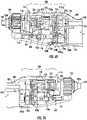
- FIG. 4is a diagram of a plan view of the surgical cutting instrument 100 and contents of the housing 101.
- the blade 102extends through the outer position knob 103 via the opening 103a, through the anterior chamber portion 106, and to the back end of the suction portion 108.
- the blade 102coaxially extends and passes through the housing 101.
- Inner member 113 of the blade 102extends into the suction portion 108, and may extend to a posterior end of the suction portion 108.
- Surgical cutting instrumentsare currently designed with a shorter disposable blade and a non-disposable housing.
- biological material cut and suctioned from the bodymust pass through both the disposable blade and the non-disposable housing.
- Suction tubingis typically narrower in diameter to allow the cut material to pass between the disposable and non-disposable portions of the cutting instrument.
- cut biological materialmay clog the tubing and may also become lodged between the disposable blade and non-disposable housing.
- the bladetypically extends into the housing only up to, and not past, a proximal chamber of the housing. By having the blade portion stop at a proximal chamber of the housing, contamination of the handpiece is increased and sterilization becomes difficult.
- the blade 102extends into the housing 101, completely through the anterior chamber portion 106, to the suction portion 108.
- the blade 102may extend to the back end of the suction portion 108. This configuration allows for an increased suction tube diameter which, in turn, increases the flow of biological material through the suction tube. Thus, clogging of biological material in the tubing may be avoided such that the biological material would not have to pass through both the disposable blade and non-disposable housing.
- the debrismay be suctioned through the entirety of the blade 102, which extends completely through the anterior chamber portion 106 and to the end of the suction portion 108. The debris may then pass through a suction tube into a suction source.
- the debrisdoes not come in contact with the components of the housing 101 as it does in typical surgical cutting instruments. As a result, easier and more thorough sterilization and avoidance of contamination of the surgical cutting instrument 100 can be achieved.
- the blade 102may also be retrofitted to pass through the non-disposable housing of current surgical cutting instruments, provided that the housing components are coaxially coupled to accommodate an extended blade.
- the configuration of the components inside the anterior chamber portion 106is coaxially coupled to accommodate the blade 102 extending and passing through the entirety of the anterior chamber portion 106. This enables the blade 102 to pass completely through the components of the anterior chamber portion 106 into the suction portion 108, allowing for more thorough sterilization of the housing by having the cut biological material pass completely through the blade 102 into the suction passage 108.
- FIG. 5is a diagram of a side view of the contents of the anterior chamber portion 106, base portion 107, and suction portion 108 of a housing 101 of the surgical cutting instrument 100.
- the blade 102coaxially passes and extends through the anterior chamber portion 106, and to a suction portion 108.
- the blade 102may extend all the way to a posterior end of the suction portion 108.
- Housing packaging of current surgical cutting instrumentsmay be cramped to include a short blade, a suction passage system, an irrigation system, and a motor mechanism to drive the blade.
- the suction portion and suction tubingare therefore narrower to accommodate the shortened blade.
- cut biological materialcan clog in the non-disposable housing when being suctioned.
- Current bladesdo not alleviate cramped packaging of the components or narrow suction diameters because the blades typically extend into the housing only up to and not past the proximal chamber of the housing. By having the blade portion stop at the proximal chamber of the housing, sterilization becomes increasingly difficult because the material can clog in the non-disposable housing.
- the blade 102extends into the housing 101, completely through the anterior chamber portion 106 to the suction portion 108, and passes coaxially through the components located in the anterior chamber portion 106.
- This configurationallows for the blade 102 to pass through the components of the anterior chamber portion 106.
- easier sterilizationcan be achieved because the cut biological material is passing completely through the blade 102 to the suction portion 108.
- the anterior chamber portion 106is a hollow portion of the housing 101 that may include a blade locking mechanism 114, a gear train 115, an irrigation system 116, an irrigation valve 117 on its outer surface (not depicted), and a flexible printed circuit board 118.
- the base portion 107is a hollow portion of the housing 101 that may include a motor mechanism 119 and the flexible printed circuit board 118.
- the motor mechanism 119may include a rotary output shaft 121 extending forward from the mechanism that drives the gear train 115.
- the suction portion 108is a hollow portion of the housing 101 that contains the inner member 113 of the blade 102.
- the suction portionmay have a diameter dimensions large enough to allow the blade 102 to pass through, and may have a thickness of 0.1-1.0 mm.
- the suction portion 108may include a suction valve 122 at its posterior end.
- the suction valve 122may be attached to a suction tube and suction source (not depicted) for aspiration of cut biological material.
- the inner member 113 of the blade 102may extend all the way to the end of the suction valve 122.
- biological materialmay be suctioned through the entirety of the blade in the housing and directly into a suction tube and suction source.
- FIG. 6Ais a diagram of a side view of the anterior chamber portion 106 of a housing 101 of the surgical cutting instrument 100.
- the blade 102coaxially extends and passes through the anterior chamber portion 106.
- the inner member 113 of the blade 102extends into the suction portion 108.
- the blade 102may be retrofitted into current surgical cutting tools provided that the housing components are coaxially coupled to accommodate an extended blade.
- the configuration of the components inside the anterior chamber portion 106is coaxially coupled to accommodate the blade 102 extending and passing through the entirety of the anterior chamber portion 106. This enables the blade 102 to pass completely through the components of the anterior chamber portion 106 into the suction portion 108, allowing for more thorough sterilization of the housing by having the cut biological material pass completely through the blade 102 into the suction passage 108.
- the gear train 115is located at a posterior end of anterior chamber portion 106.
- the gear train 115may include an upper gear set 115a and a lower gear set 115b.
- the upper gear set 115amay include a helical gear 115a 1 and a helical gear 115a 2 coupled coaxially.
- the lower gear set 115bmay also include a helical gear 115b 1 and a helical gear 115b 2 coupled coaxially.
- Other types of gearsmay be used in the gear train 115, including spur or V gears.
- the teeth of the helical gears 115a 1 and 115a 2may engage with each other while the teeth of the helical gears 115b 1 and 115b 2 engage with each other when the gears are rotating.
- the gear train 115may be welded to the inner member 113 of the blade 102 to drive the blade 102. Thus, rotation of the gear train 115 drives the blade 102 to move and cut biological material.
- the helical gear 115a 1is coaxially coupled to an flexible printed circuit board housing 123.
- the flexible printed circuit board housing 123is coaxially coupled to the irrigation system 116.
- the helical gear 115a2is coaxially coupled to an outer hollow casing 124 that makes up the flexible printed circuit board 118.
- the irrigation system 116is coupled to locking mechanism 114.
- the irrigation system 116 and the locking mechanism 114coaxially surround an inner knob 125.
- the inner knob 125is coaxially coupled to the outer position knob 103.
- the irrigation system 116 and the flexible printed circuit board housing 123may be further coupled to each other and held in place via a spacer 126a.
- Spacer 126amay also couple the irrigation system 116 and the flexible printed circuit board housing 123 to the flexible printed circuit board 118 on parallel axes.
- the flexible printed circuit board housing 123 and helical gear 115a 1may be further coupled to each other and held in place via a spacer 126b.
- Spacer 126bmay further couple the flexible printed circuit board housing 123 and helical gear 115a 1 to helical gear 115b 1 on parallel axes.
- Helical gear 115a 2 and outer hollow casing 124may be further coupled to each other and held in place via a spacer 126c.
- Spacer 126cmay further couple helical gear 115a 2 to helical gear 115b 2 on parallel axes.
- the outer hollow casing 124 and the motor mechanism 131may be further coupled to each other on parallel axes via a spacer 126d. In other embodiments, the components may be coupled on parallel axes via any other coupling means.
- the blade 102when the blade 102 is inserted into the housing 101, it coaxially passes and extends through the outer position knob 103 via the opening 103a, and extends completely through the anterior chamber portion 106 by passing coaxially through the inner knob 125, the locking mechanism 114, the irrigation system 116, spacer 126a, the flexible printed circuit board housing 123, spacer 126b, the upper gear set 115a, spacer 126c, the outer hollow casing 124, and spacer 126d; and then extends into the suction portion 108.
- FIG. 6Bis a diagram of inner contents of an example chamber portion 106 and flexible printed circuit board 118 of the surgical cutting instrument.
- the blade 102coaxially extends and passes through the inner contents of the chamber portion 106 and flexible printed circuit board 118, through the anterior chamber portion 106, and into the suction portion 108.
- Flexible printed circuit board 118includes flexible printed circuit board housing 123.
- Helical gear 115a 1may be further coaxially coupled to a washer 127a, which in turn may be further coaxially coupled to the flexible printed circuit board housing 123.
- Helical gear 115a 2may also be further coaxially coupled to a washer 127b, which in turn may be further coaxially coupled to the outer hollow casing 124.
- the flexible printed circuit board housing 123may surround the flexible printed circuit board 118 and may be further coaxially coupled to the irrigation system 116.
- Washer 127a and helical gear 115a 1may be further coupled to each other and held in place via spacer 126b.
- Spacer 126bmay further couple washer 127a and helical gear 115a 1 to helical gear 115b 1 on parallel axes.
- Helical gear 115a 2 and washer 127bmay be further coupled to each other and held in place via spacer 126c, which may further couple washer 127b and helical gear 115a 2 to helical gear 115b 2 on parallel axes.
- the outer diameter of the washers and spacersmay be 6.0-7.0mm.
- the inner diameter of the washers and spacersmay be 3.0-4.0mm.
- the componentsmay be coaxially coupled and coupled on parallel axes via any other coupling means.
- the inner knob 125also includes a hole 128, which is surrounded by the irrigation system 116.
- the hole 128allows saline or other liquid to pass from the irrigation system 116 to the blade 102, in order to aid in aspiration of cut biological material as it passes through the extended blade 102 to a suction portion 108.
- the blade 102when the blade 102 is inserted into the housing 101, it coaxially extends and passes through the outer position knob 103 via the opening 103a, the inner knob 125, the locking mechanism 114, the irrigation hub 126, spacer 126a, flexible printed circuit board 118, and the flexible printed circuit board housing 123, spacer 126b, washer 127a, helical gears 115a 1 and 115a 2 , spacer 126c, washer 127b, the outer hollow casing 124, and spacer 126d, and then extends into the suction portion 108.
- the coaxial coupling of the components in the anterior chamber portion 106allow for the blade 102 to pass through the components of the anterior chamber portion 106 to the suction portion 108.
- the hole 128 on the inner knob 125is surrounded by the irrigation system 116. Once the blade 102 is inserted, the hole 128 on the inner knob 125 aligns with the irrigation system 116 such that fluid flows from the irrigation system 116 into the hole 128 and subsequently into the blade 102. Thus, cut biological material as well as liquid passes right through the anterior chamber portion 106 inside the blade 102 to the suction portion 108, providing an easier and more thorough sterilization as the blade extends through the components of the chamber.
- FIG. 7Ais a diagram of an example irrigation system 116 and irrigation valve 117 in an anterior chamber portion 106.
- the blade 102coaxially extends and passes through the irrigation system 116.
- the irrigation valve 117allows liquid to flow directly into the blade 102, and pass through the blade 102 as the blade 102 extends through the irrigation system 116, through the anterior chamber portion 106, and into the suction portion 108.
- irrigation tubing connected to an irrigation sourcemay be connected to the irrigation valve 117.
- Saline or any other liquid suitable for performing irrigationmay then pass through the irrigation valve 117 through the irrigation system 116, and subsequently through the hole 128 on inner knob 125.
- the hole 128 on the inner knob 125aligns with the irrigation system 116 such that the irrigation system 116 surrounds and contains the hole 128 on the inner knob 125. Fluid then flows from the irrigation valve 117, into the irrigation system 116, into the hole 128 and subsequently into the blade 102.
- the hole 128allows the liquid to pass through the outer member 112 of the blade 102 to the surgical site, and eventually through the inner member 113 of the blade 102 as it is aspirated with cut biological material.
- the liquidflows radially through the entirety of the inner member 113 of the blade 102 via suction as the blade 102 extends to a suction portion 108, and then outward into a suction tube.
- the surgical cutting instrument 100can be used for simultaneously cutting tissue at the surgical site and removing flowable material from the surgical site through the extended blade 102.
- FIG. 7Bis a diagram of inner contents of an example irrigation system 116 and flexible printed circuit board 118 in an anterior chamber portion 106.
- the blade 102coaxially extends and passes through the irrigation system 116 and printed circuit board 118, and further through the anterior chamber portion 106.
- the inner member 113 of the blade 102extends into the suction portion 108 (as shown in FIG. 7A ).
- liquidenters the irrigation system 116.
- the irrigation system 116surrounds and contains the hole 128 on the inner knob 125.
- the hole 128 on the inner knob 125aligns with the irrigation system 116 such that fluid flows from the irrigation system 116 into the hole 128 and subsequently into the blade 102.
- Liquidsubsequently enters the outer member 112 of the blade 102 through the hole 128 on inner knob 125.
- the liquidthen flows to the surgical site and eventually flows radially through the entirety of the inner member 113 of the blade 102 as it extends to the suction portion 108 via suction.
- the liquidis then suctioned through the inner member 113 as it passes through the suction portion 108 (as shown in FIG. 7A ).
- Current surgical cutting instrument bladesare not configured to allow fluid to flow from an irrigation valve, into an irrigation system, through a hole in an inner knob, into an outer member, and through an inner member of the blade as it extends to a suction portion during aspiration.
- the biological material and liquidcan be suctioned and passed completely through the blade 102 into the suction portion 108 to improve sterilization by avoiding contamination in the anterior chamber portion 106.
- FIG. 8depicts the blade 102 as the inner member 113 is locked in the anterior chamber portion 106 of the housing 101.
- the blade 102coaxially extends and passes through the blade locking mechanism 114.
- the blade 102may be locked in place in the housing 101 by the blade locking mechanism 114.
- the blade locking mechanism 114may be made of a polymeric material and may be located at an anterior end of the anterior chamber portion 106.
- the blade locking mechanism 114comprises a push button 129, a locking tooth 130, and a spring 131. Pressing and holding the push button 129 pushes the locking tooth 130 and the spring 131 in a downward direction away from the blade 102. Thus, when the push button 129 is pressed downward and held, the blade 102 can be inserted into the housing 101.
- Releasing the push button 129releases the spring 131 and pushes the locking tooth 130 in an upward direction and against the inner knob 125 and further against the blade 102, thus locking the blade 102 in place. Pressing and holding the push button 129 subsequently releases the blade 102 for disposal.
Landscapes
- Health & Medical Sciences (AREA)
- Life Sciences & Earth Sciences (AREA)
- Surgery (AREA)
- General Health & Medical Sciences (AREA)
- Veterinary Medicine (AREA)
- Biomedical Technology (AREA)
- Heart & Thoracic Surgery (AREA)
- Medical Informatics (AREA)
- Molecular Biology (AREA)
- Animal Behavior & Ethology (AREA)
- Nuclear Medicine, Radiotherapy & Molecular Imaging (AREA)
- Public Health (AREA)
- Engineering & Computer Science (AREA)
- Orthopedic Medicine & Surgery (AREA)
- Dentistry (AREA)
- Oral & Maxillofacial Surgery (AREA)
- Otolaryngology (AREA)
- Pulmonology (AREA)
- Surgical Instruments (AREA)
- External Artificial Organs (AREA)
Description
- The present invention relates generally to a surgical cutting instrument, and more specifically to a cutting instrument with an extended blade for ear, nose, and throat (ENT) surgery.
- ENT surgery is the surgical treatment of diseases, injuries, or deformations of the ears, nose, throat, head, and neck areas. ENT surgery is one of the most elaborate fields of surgical specialty services, using advanced technology and a broad range of procedures that also includes major reconstructive surgery to correct deformity or injury. As a result, numerous surgical instruments, including a range of surgical cutting instruments, must be relied upon to successfully perform such procedures.
- Current surgical cutting instruments are designed with a disposable blade portion, and non-disposable housing portion. The non-disposable housing portion typically includes a proximal chamber portion, a handpiece, and contains a suction passage, irrigation system, and motor mechanism to drive the disposable blade. The disposable blade portion comprises a short blade and is affixed to the distal end of the non-disposable housing portion of the instrument. Utilizing this configuration, biological material that is cut and suctioned from the body must pass through both the disposable blade and the non-disposable portion of the housing.
- The diameter of the suction tubing is smaller than the diameter of the blade. To allow cut material to pass between the disposable blade and the non-disposable housing, the suction passage must be narrower to increase the suction into the narrow tubing. Thus, as cut biological material is aspirated, clogging and backup can occur in the suction passage of the non-disposable housing. The sterilization process for the housing is therefore tedious, since one or more specialized brushes are required to scrub the inside of the non-disposable housing free of biological material to properly sterilize the housing portion. This complexity of the sterilization process can therefore lead to incomplete sterilization of the instrument.
- It would therefore be useful to offer a surgical cutting instrument that prevents biological material from being trapped in the non-disposable portion of the instrument and allows for a more thorough sterilization.
US2010/152762A1 describes a tissue removal system with a multidirectional foot actuator assembly for neurosurgical and spinal surgery applications.US2007/073326A1 describes a rotating surgical cutter.- The invention is as defined in claim 1.
- A blade for use in a surgical cutting instrument comprising a distal cutting end, a distal non-cutting end, and an intermediate portion. The surgical cutting instrument comprises a housing that includes a chamber portion and a suction portion. The intermediate portion extends coaxially from the distal cutting end, into the housing, passes through the chamber portion, and extends coaxially into the suction portion to the distal non-cutting end. Thus, the distal cutting end may be located at an end of a part of the blade that protrudes from the housing, the distal non-cutting end may be located at a posterior end of the suction portion, and the intermediate portion may extend coaxially from the distal cutting portion, completely through the chamber portion of the housing, and to the suction portion.
- The blade may be a rigid, circular tube with constant diameter, and may be disposable. The blade may further comprise an outer member, and an inner member. The outer member may extend from the distal cutting end to a portion of the blade outside of the housing. The inner member may extend from the distal cutting end, into the housing, pass through the chamber portion, and extend coaxially into the suction portion to the distal non-cutting end. This configuration may allow for biological material to be cut and aspirated completely through the blade and housing to a suction source, avoiding contamination and improving instrument sterilization for surgeries.
- The blade may coaxially pass through components of the chamber portion that are coupled coaxially. These components may include a gear train, an irrigation system, and a flexible printed circuit board, and a blade locking mechanism. The blade locking mechanism may fix the blade in the housing during operation. The suction portion may contain the distal non-cutting end of the blade. The distal non-cutting end of the blade may extend to any point inside the suction portion, including up to a posterior end of the suction portion. Thus, as biological material is cut during surgery, the material may be irrigated with fluid and suctioned through the entirety of the blade to the suction portion, and ultimately through suction tubing to a suction source, while avoiding being trapped in the non-disposable housing.
- The present invention is illustrated by way of example, and not by way of limitation, in the figures of the accompanying drawings in which:
FIG. 1 is a diagram of a perspective view of the surgical cutting instrument.FIG. 2 is a diagram of a perspective view of a blade of the surgical cutting instrument.FIG. 3 is a diagram of a cross-sectional perspective view of the surgical cutting instrument.FIG. 4 is a diagram of a plan view of the surgical cutting instrument and contents of the housing.FIG. 5 is a diagram of a side view of the contents of an anterior chamber portion, base portion, and suction portion of a housing of the surgical cutting instrument.FIG. 6A is a diagram of a side view of an anterior chamber portion of a housing of the surgical cutting instrument.FIG. 6B is a diagram of a side view of inner contents of an anterior chamber portion of a housing of the surgical cutting instrument.FIG. 7A is a diagram of a side view of an irrigation valve and irrigation system in an anterior chamber portion of a housing of the surgical cutting instrument.FIG. 7B is a diagram of a side view of inner contents of an irrigation valve and irrigation system in an anterior chamber portion of a housing of the surgical instrument.FIG. 8 is a diagram of a cross-sectional perspective view of a blade locking mechanism of the surgical cutting instrument.- A surgical cutting instrument may be configured such that the cutting disposable blades pass completely through the handle. This configuration may permit easier and more thorough sterilization of the tool handle, since all of the cut tissue may be discarded in the disposable portion. In addition, extending the blade may simplify the sterilization process and make adherence to proper sterilization procedures much more likely.
FIG. 1 is a diagram of a perspective view of thesurgical cutting instrument 100.Surgical cutting instrument 100 comprises ahousing 101, ablade 102, anouter position knob 103, and apower cord housing 104. Theouter position knob 103 comprises anopening 103a to allow theblade 102 to pass through theouter position knob 103.Blade 102 is fixed in thehousing 101 and extends coaxially through theouter position knob 103 viaopening 103a. Thehousing 101 comprises aposterior handpiece portion 105 and ananterior chamber portion 106. Theposterior handpiece portion 105 includes abase portion 107 and asuction portion 108. In this embodiment, thesuction portion 108 is located abovebase portion 107. Thesuction portion 108 may, however, be located below or anywhere around thebase portion 107 inside thehandpiece portion 105.Suction portion 108 may be connected on its posterior end to a suction source via a suction tube (not depicted). Theblade 102 extends through thehousing 101, through theanterior chamber portion 106, and to asuction portion 108. Theblade 102 may extend to a posterior end of thesuction portion 108.FIG. 2 is a diagram of a perspective view of ablade 102 of the surgical cutting instrument. Theblade 102 may be a rigid, hollow circular tube with a constant diameter of 2.0-6.0 millimeters (mm). Theblade 102 may also be 200-300 mm in length. Theblade 102 may be made of stainless steel, titanium, or other metal alloy and may be disposable. In this example embodiment,blade 102 comprises adistal cutting end 109, a distalnon-cutting end 110, and anintermediate portion 111 extending fromdistal cutting end 109, to distalnon-cutting end 110. Thus,intermediate portion 111 may extend through the entire length of the housing to the distalnon-cutting end 110. Both thedistal cutting end 109 and the distalnon-cutting end 110 may be open; and the distalnon-cutting end 110 may extend to the posterior end of the suction portion 108 (as depicted inFIG. 1 ) to further allow fluid and debris to pass through the blade and aspirated.Blade 102 includes anouter member 112 and aninner member 113.Outer member 112 coaxially extends from thedistal cutting end 109, through theopening 103a, to a section of theintermediate portion 111 located outside of thehousing 101.Inner member 113 coaxially extends from thedistal cutting end 109, through theopening 103a, through the housing, and to the distalnon-cutting end 110.- Tissue and other biological material are cut at the
distal cutting end 109 and pass through the entirety of the blade, through thehousing 101, and all the way through the distalnon-cutting end 110. Thedistal cutting end 109 also includes theouter member 112 and theinner member 113. Theinner member 113 may extend from thedistal cutting end 109, all the way back to the distalnon-cutting end 110. Theouter member 112 may extend from thedistal cutting end 109, to a section of theintermediate portion 111 outside of thehousing 101. Both theouter member 112 and theinner member 113 include openings at thedistal cutting end 109. The opening of theouter member 112 at thedistal cutting end 109 may be located on a top side of theouter member 112 and may be surrounded by a set of teeth (not depicted) to allow for tissue to be cut and passed through the opening. The opening of theouter member 112 at thedistal cutting end 109 may expose a portion of theinner member 113. The opening of theinner member 113 at thedistal cutting end 109 may be located on a bottom side of theinner member 113 and may also be surrounded by a set of teeth (not depicted) to allow for tissue to be cut and passed through the opening. Theouter member 112 may surround the opening of theinner member 113 completely. - The
blade 102 may have ahole 128 for irrigation and aspiration of cut biological material. Thehole 128 may be located on aninner knob 125 to allow for saline or other liquid to pass through theouter member 112, to a suction site (not depicted), and up through theinner member 113 to the distalnon-cutting end 110 during irrigation and aspiration. FIG. 3 is a diagram of a cross-sectional perspective view of thesurgical cutting instrument 100. Theblade 102 may extend through thehousing 101. The distalnon-cutting end 110 is located inhousing 101 and thedistal cutting end 109 is located at the end of a part of the blade that protrudes from thehousing 101. Theintermediate portion 111 of theblade 102 coaxially extends from the distal cutting end and passes through theouter position knob 103 viaopening 103a and further extends through thehousing 101 to the distalnon-cutting end 110 in thesuction portion 108.- The
outer member 112 may extend from thedistal cutting end 109 through anopening 103a to a section of theintermediate portion 111 just before theintermediate portion 111 enters thehousing 101. Theinner member 113 extends from thedistal cutting end 109, completely through theanterior chamber portion 106, to the distalnon-cutting end 110 located in thesuction portion 108. The distalnon-cutting end 110 may have a variable length and may extend to any location insidesuction portion 108, including up to a back end ofsuction portion 108. Thus, theblade 102 may extend through and to the back end of thehandpiece 105 and, consequently, to the back of thehousing 101, all the way to the end of thesuction portion 108. FIG. 4 is a diagram of a plan view of thesurgical cutting instrument 100 and contents of thehousing 101. Theblade 102 extends through theouter position knob 103 via theopening 103a, through theanterior chamber portion 106, and to the back end of thesuction portion 108. Theblade 102 coaxially extends and passes through thehousing 101.Inner member 113 of theblade 102 extends into thesuction portion 108, and may extend to a posterior end of thesuction portion 108.- Surgical cutting instruments are currently designed with a shorter disposable blade and a non-disposable housing. In surgical procedures using current surgical cutting instruments, biological material cut and suctioned from the body must pass through both the disposable blade and the non-disposable housing. Suction tubing is typically narrower in diameter to allow the cut material to pass between the disposable and non-disposable portions of the cutting instrument. As a result, cut biological material may clog the tubing and may also become lodged between the disposable blade and non-disposable housing. With current blades, the blade typically extends into the housing only up to, and not past, a proximal chamber of the housing. By having the blade portion stop at a proximal chamber of the housing, contamination of the handpiece is increased and sterilization becomes difficult.
- Returning to
FIG. 4 , theblade 102 extends into thehousing 101, completely through theanterior chamber portion 106, to thesuction portion 108. In one embodiment, theblade 102 may extend to the back end of thesuction portion 108. This configuration allows for an increased suction tube diameter which, in turn, increases the flow of biological material through the suction tube. Thus, clogging of biological material in the tubing may be avoided such that the biological material would not have to pass through both the disposable blade and non-disposable housing. - Instead, when tissue or biological material is cut or comminuted by the
blade 102, the debris may be suctioned through the entirety of theblade 102, which extends completely through theanterior chamber portion 106 and to the end of thesuction portion 108. The debris may then pass through a suction tube into a suction source. Thus, the debris does not come in contact with the components of thehousing 101 as it does in typical surgical cutting instruments. As a result, easier and more thorough sterilization and avoidance of contamination of thesurgical cutting instrument 100 can be achieved. - The
blade 102 may also be retrofitted to pass through the non-disposable housing of current surgical cutting instruments, provided that the housing components are coaxially coupled to accommodate an extended blade. In the present embodiment, the configuration of the components inside theanterior chamber portion 106 is coaxially coupled to accommodate theblade 102 extending and passing through the entirety of theanterior chamber portion 106. This enables theblade 102 to pass completely through the components of theanterior chamber portion 106 into thesuction portion 108, allowing for more thorough sterilization of the housing by having the cut biological material pass completely through theblade 102 into thesuction passage 108. FIG. 5 is a diagram of a side view of the contents of theanterior chamber portion 106,base portion 107, andsuction portion 108 of ahousing 101 of thesurgical cutting instrument 100. Theblade 102 coaxially passes and extends through theanterior chamber portion 106, and to asuction portion 108. Theblade 102 may extend all the way to a posterior end of thesuction portion 108.- Housing packaging of current surgical cutting instruments may be cramped to include a short blade, a suction passage system, an irrigation system, and a motor mechanism to drive the blade. The suction portion and suction tubing are therefore narrower to accommodate the shortened blade. As a result, cut biological material can clog in the non-disposable housing when being suctioned. Current blades, however, do not alleviate cramped packaging of the components or narrow suction diameters because the blades typically extend into the housing only up to and not past the proximal chamber of the housing. By having the blade portion stop at the proximal chamber of the housing, sterilization becomes increasingly difficult because the material can clog in the non-disposable housing.
- Referring to
FIG. 5 , theblade 102 extends into thehousing 101, completely through theanterior chamber portion 106 to thesuction portion 108, and passes coaxially through the components located in theanterior chamber portion 106. This configuration allows for theblade 102 to pass through the components of theanterior chamber portion 106. As a result, easier sterilization can be achieved because the cut biological material is passing completely through theblade 102 to thesuction portion 108. - The
anterior chamber portion 106 is a hollow portion of thehousing 101 that may include ablade locking mechanism 114, agear train 115, anirrigation system 116, anirrigation valve 117 on its outer surface (not depicted), and a flexible printedcircuit board 118. Thebase portion 107 is a hollow portion of thehousing 101 that may include amotor mechanism 119 and the flexible printedcircuit board 118. Themotor mechanism 119 may include arotary output shaft 121 extending forward from the mechanism that drives thegear train 115. Thesuction portion 108 is a hollow portion of thehousing 101 that contains theinner member 113 of theblade 102. The suction portion may have a diameter dimensions large enough to allow theblade 102 to pass through, and may have a thickness of 0.1-1.0 mm. Thesuction portion 108 may include asuction valve 122 at its posterior end. Thesuction valve 122 may be attached to a suction tube and suction source (not depicted) for aspiration of cut biological material. In one embodiment, theinner member 113 of theblade 102 may extend all the way to the end of thesuction valve 122. Thus, biological material may be suctioned through the entirety of the blade in the housing and directly into a suction tube and suction source. FIG. 6A is a diagram of a side view of theanterior chamber portion 106 of ahousing 101 of thesurgical cutting instrument 100. Theblade 102 coaxially extends and passes through theanterior chamber portion 106. Theinner member 113 of theblade 102 extends into thesuction portion 108. Theblade 102 may be retrofitted into current surgical cutting tools provided that the housing components are coaxially coupled to accommodate an extended blade. In the present embodiment, the configuration of the components inside theanterior chamber portion 106 is coaxially coupled to accommodate theblade 102 extending and passing through the entirety of theanterior chamber portion 106. This enables theblade 102 to pass completely through the components of theanterior chamber portion 106 into thesuction portion 108, allowing for more thorough sterilization of the housing by having the cut biological material pass completely through theblade 102 into thesuction passage 108.- The
gear train 115 is located at a posterior end ofanterior chamber portion 106. Thegear train 115 may include an upper gear set 115a and alower gear set 115b. The upper gear set 115a may include ahelical gear 115a1 and ahelical gear 115a2 coupled coaxially. Thelower gear set 115b may also include ahelical gear 115b1 and ahelical gear 115b2 coupled coaxially. Other types of gears may be used in thegear train 115, including spur or V gears. Thus, the teeth of thehelical gears helical gears gear train 115 may be welded to theinner member 113 of theblade 102 to drive theblade 102. Thus, rotation of thegear train 115 drives theblade 102 to move and cut biological material. - In the present embodiment, the
helical gear 115a1 is coaxially coupled to an flexible printedcircuit board housing 123. The flexible printedcircuit board housing 123 is coaxially coupled to theirrigation system 116. The helical gear 115a2 is coaxially coupled to an outerhollow casing 124 that makes up the flexible printedcircuit board 118. Theirrigation system 116 is coupled to lockingmechanism 114. Theirrigation system 116 and thelocking mechanism 114 coaxially surround aninner knob 125. Theinner knob 125 is coaxially coupled to theouter position knob 103. - The
irrigation system 116 and the flexible printedcircuit board housing 123 may be further coupled to each other and held in place via aspacer 126a.Spacer 126a may also couple theirrigation system 116 and the flexible printedcircuit board housing 123 to the flexible printedcircuit board 118 on parallel axes. The flexible printedcircuit board housing 123 andhelical gear 115a1 may be further coupled to each other and held in place via aspacer 126b.Spacer 126b may further couple the flexible printedcircuit board housing 123 andhelical gear 115a1 tohelical gear 115b1 on parallel axes.Helical gear 115a2 and outerhollow casing 124 may be further coupled to each other and held in place via aspacer 126c.Spacer 126c may further couplehelical gear 115a2 tohelical gear 115b2 on parallel axes. The outerhollow casing 124 and themotor mechanism 131 may be further coupled to each other on parallel axes via aspacer 126d. In other embodiments, the components may be coupled on parallel axes via any other coupling means. - Thus, in this configuration, when the
blade 102 is inserted into thehousing 101, it coaxially passes and extends through theouter position knob 103 via theopening 103a, and extends completely through theanterior chamber portion 106 by passing coaxially through theinner knob 125, thelocking mechanism 114, theirrigation system 116, spacer 126a, the flexible printedcircuit board housing 123,spacer 126b, the upper gear set 115a,spacer 126c, the outerhollow casing 124, andspacer 126d; and then extends into thesuction portion 108. Having theblade 102 extend completely through theanterior chamber portion 106 and coaxially through the components of theanterior chamber portion 106, instead of stopping the blade inside the chamber portion in current surgical cutting instruments, allows for cut biological material to be suctioned and pass completely through theblade 102 into thesuction portion 108 to improve sterilization by avoiding contamination in theanterior chamber portion 106. FIG. 6B is a diagram of inner contents of anexample chamber portion 106 and flexible printedcircuit board 118 of the surgical cutting instrument. Theblade 102 coaxially extends and passes through the inner contents of thechamber portion 106 and flexible printedcircuit board 118, through theanterior chamber portion 106, and into thesuction portion 108. Flexible printedcircuit board 118 includes flexible printedcircuit board housing 123.Helical gear 115a1 may be further coaxially coupled to a washer 127a, which in turn may be further coaxially coupled to the flexible printedcircuit board housing 123.Helical gear 115a2 may also be further coaxially coupled to awasher 127b, which in turn may be further coaxially coupled to the outerhollow casing 124. The flexible printedcircuit board housing 123 may surround the flexible printedcircuit board 118 and may be further coaxially coupled to theirrigation system 116.- Washer 127a and
helical gear 115a1 may be further coupled to each other and held in place viaspacer 126b.Spacer 126b may further couple washer 127a andhelical gear 115a1 tohelical gear 115b1 on parallel axes.Helical gear 115a2 andwasher 127b may be further coupled to each other and held in place viaspacer 126c, which may further couplewasher 127b andhelical gear 115a2 tohelical gear 115b2 on parallel axes. The outer diameter of the washers and spacers may be 6.0-7.0mm. The inner diameter of the washers and spacers may be 3.0-4.0mm. In other embodiments, the components may be coaxially coupled and coupled on parallel axes via any other coupling means. - The
inner knob 125 also includes ahole 128, which is surrounded by theirrigation system 116. Thehole 128 allows saline or other liquid to pass from theirrigation system 116 to theblade 102, in order to aid in aspiration of cut biological material as it passes through theextended blade 102 to asuction portion 108. In this configuration, when theblade 102 is inserted into thehousing 101, it coaxially extends and passes through theouter position knob 103 via theopening 103a, theinner knob 125, thelocking mechanism 114, the irrigation hub 126, spacer 126a, flexible printedcircuit board 118, and the flexible printedcircuit board housing 123,spacer 126b, washer 127a,helical gears spacer 126c,washer 127b, the outerhollow casing 124, andspacer 126d, and then extends into thesuction portion 108. The coaxial coupling of the components in theanterior chamber portion 106 allow for theblade 102 to pass through the components of theanterior chamber portion 106 to thesuction portion 108. - The
hole 128 on theinner knob 125 is surrounded by theirrigation system 116. Once theblade 102 is inserted, thehole 128 on theinner knob 125 aligns with theirrigation system 116 such that fluid flows from theirrigation system 116 into thehole 128 and subsequently into theblade 102. Thus, cut biological material as well as liquid passes right through theanterior chamber portion 106 inside theblade 102 to thesuction portion 108, providing an easier and more thorough sterilization as the blade extends through the components of the chamber. FIG. 7A is a diagram of anexample irrigation system 116 andirrigation valve 117 in ananterior chamber portion 106. Theblade 102 coaxially extends and passes through theirrigation system 116. Theirrigation valve 117 allows liquid to flow directly into theblade 102, and pass through theblade 102 as theblade 102 extends through theirrigation system 116, through theanterior chamber portion 106, and into thesuction portion 108.- In various surgical procedures, it is desirable to irrigate the surgical site with liquid and then draw by suction the irrigation liquid and biological material from the surgical site. To achieve this, irrigation tubing connected to an irrigation source (not depicted) may be connected to the
irrigation valve 117. Saline or any other liquid suitable for performing irrigation may then pass through theirrigation valve 117 through theirrigation system 116, and subsequently through thehole 128 oninner knob 125. - When the
blade 102 is inserted into the housing, thehole 128 on theinner knob 125 aligns with theirrigation system 116 such that theirrigation system 116 surrounds and contains thehole 128 on theinner knob 125. Fluid then flows from theirrigation valve 117, into theirrigation system 116, into thehole 128 and subsequently into theblade 102. Thehole 128 allows the liquid to pass through theouter member 112 of theblade 102 to the surgical site, and eventually through theinner member 113 of theblade 102 as it is aspirated with cut biological material. The liquid flows radially through the entirety of theinner member 113 of theblade 102 via suction as theblade 102 extends to asuction portion 108, and then outward into a suction tube. Thus, thesurgical cutting instrument 100 can be used for simultaneously cutting tissue at the surgical site and removing flowable material from the surgical site through theextended blade 102. FIG. 7B is a diagram of inner contents of anexample irrigation system 116 and flexible printedcircuit board 118 in ananterior chamber portion 106. Theblade 102 coaxially extends and passes through theirrigation system 116 and printedcircuit board 118, and further through theanterior chamber portion 106. Theinner member 113 of theblade 102 extends into the suction portion 108 (as shown inFIG. 7A ). During irrigation, liquid enters theirrigation system 116. Theirrigation system 116 surrounds and contains thehole 128 on theinner knob 125. Thus, once theblade 102 is inserted, thehole 128 on theinner knob 125 aligns with theirrigation system 116 such that fluid flows from theirrigation system 116 into thehole 128 and subsequently into theblade 102. Liquid subsequently enters theouter member 112 of theblade 102 through thehole 128 oninner knob 125. The liquid then flows to the surgical site and eventually flows radially through the entirety of theinner member 113 of theblade 102 as it extends to thesuction portion 108 via suction. The liquid is then suctioned through theinner member 113 as it passes through the suction portion 108 (as shown inFIG. 7A ). Current surgical cutting instrument blades are not configured to allow fluid to flow from an irrigation valve, into an irrigation system, through a hole in an inner knob, into an outer member, and through an inner member of the blade as it extends to a suction portion during aspiration.- Thus, having the
inner member 113 of theblade 102 extend completely through theanterior chamber portion 106 and coaxially through the components of theanterior chamber portion 106, instead of stopping the blade inside the chamber portion in current surgical cutting instruments, and having thehole 128 on theinner knob 125 allows for liquid to flow radially throughout the blade to the surgical site and then be aspirated along with cut biological material. The biological material and liquid can be suctioned and passed completely through theblade 102 into thesuction portion 108 to improve sterilization by avoiding contamination in theanterior chamber portion 106. FIG. 8 depicts theblade 102 as theinner member 113 is locked in theanterior chamber portion 106 of thehousing 101. Theblade 102 coaxially extends and passes through theblade locking mechanism 114. Theblade 102 may be locked in place in thehousing 101 by theblade locking mechanism 114. Theblade locking mechanism 114 may be made of a polymeric material and may be located at an anterior end of theanterior chamber portion 106. Theblade locking mechanism 114 comprises apush button 129, a lockingtooth 130, and aspring 131. Pressing and holding thepush button 129 pushes the lockingtooth 130 and thespring 131 in a downward direction away from theblade 102. Thus, when thepush button 129 is pressed downward and held, theblade 102 can be inserted into thehousing 101. Releasing thepush button 129 releases thespring 131 and pushes the lockingtooth 130 in an upward direction and against theinner knob 125 and further against theblade 102, thus locking theblade 102 in place. Pressing and holding thepush button 129 subsequently releases theblade 102 for disposal.- It should be understood that many variations are possible based on the disclosure herein. Although features and elements are described above in particular combinations, each feature or element can be used alone without the other features and elements or in various combinations with or without other features and elements.
Claims (10)
- A disposable blade configured for use with a non-disposable housing of a surgical cutting instrument comprising:an outer member (112);an inner member (113);a distal cutting end (109);an intermediate portion (111) operatively coupled to the distal cutting end; anda proximal non-cutting end (110) operatively coupled to the intermediate portion,wherein the intermediate portion is configured to extend through the non-disposable housing (101) of the surgical cutting instrument, andwherein the proximal non-cutting end is configured to extend to a posterior end of a suction portion (108) of the housing,wherein the inner member is configured to extend from the distal cutting end, through the housing, and into the suction portion to the proximal non-cutting end and to the posterior end of the suction portion, andwherein the blade is configured to: cut biological material; pass the cut biological material from the distal cutting end, through the intermediate portion, to the proximal non-cutting end in the suction portion, and to a suction source via aspiration; and prevent the cut biological material from coming into contact with the housing.
- The disposable blade of claim 1, wherein the blade is a rigid, hollow circular tube with constant diameter.
- The disposable blade of claim 1, wherein the outer member is configured to extend from the distal cutting end to a portion of the blade outside of the housing.
- The disposable blade of claim 1, wherein the inner member is configured to extend and passes through components of the housing portion coupled coaxially, into the suction portion.
- The disposable blade of claim 4, wherein the components include a blade locking mechanism (114), a gear train (115), an irrigation system (116), and a flexible printed circuit board (118) that are coaxially coupled in the chamber portion.
- The disposable blade of claim 5, wherein the irrigation system is configured to surround a hole (128) on the blade to allow liquid to pass from the irrigation system to the blade and to a surgical site.
- The disposable blade of claim 6, wherein the blade is configured to allow liquid to pass from the irrigation system, into the hole, through the outer member, to the surgical site, and further through the inner member to the proximal non-cutting end in the suction portion.
- The disposable blade of claim 5, wherein the blade is fixed in the housing by the blade locking mechanism at the intermediate portion.
- The disposable blade of claim 1, wherein the blade is configured to be inserted through an opening (103a) into the housing.
- The disposable blade of claim 1, wherein the blade is made of a metal alloy.
Applications Claiming Priority (1)
| Application Number | Priority Date | Filing Date | Title |
|---|---|---|---|
| US15/423,214US10874416B2 (en) | 2017-02-02 | 2017-02-02 | Surgical cutting instrument with extended blades |
Publications (2)
| Publication Number | Publication Date |
|---|---|
| EP3357440A1 EP3357440A1 (en) | 2018-08-08 |
| EP3357440B1true EP3357440B1 (en) | 2022-04-06 |
Family
ID=61132303
Family Applications (1)
| Application Number | Title | Priority Date | Filing Date |
|---|---|---|---|
| EP18154694.6AActiveEP3357440B1 (en) | 2017-02-02 | 2018-02-01 | Surgical cutting instrument with extended blades |
Country Status (8)
| Country | Link |
|---|---|
| US (1) | US10874416B2 (en) |
| EP (1) | EP3357440B1 (en) |
| JP (1) | JP7102155B2 (en) |
| CN (1) | CN108378901A (en) |
| AU (1) | AU2018200392A1 (en) |
| CA (1) | CA2993673A1 (en) |
| IL (1) | IL256952B (en) |
| RU (1) | RU2018103217A (en) |
Families Citing this family (3)
| Publication number | Priority date | Publication date | Assignee | Title |
|---|---|---|---|---|
| US10524820B2 (en) | 2017-05-16 | 2020-01-07 | Biosense Webster (Israel) Ltd. | Deflectable shaver tool |
| WO2019188918A1 (en)* | 2018-03-28 | 2019-10-03 | テルモ株式会社 | Medical device and usage for treatment |
| US11179172B2 (en)* | 2019-12-05 | 2021-11-23 | Covidien Lp | Tissue resecting instrument |
Family Cites Families (24)
| Publication number | Priority date | Publication date | Assignee | Title |
|---|---|---|---|---|
| US3384085A (en) | 1964-07-03 | 1968-05-21 | Robert M. Hall | Surgical cutting tool |
| US4986825A (en) | 1988-10-11 | 1991-01-22 | Concept, Inc. | Surgical cutting instrument |
| US5797939A (en)* | 1989-12-05 | 1998-08-25 | Yoon; Inbae | Endoscopic scissors with longitudinal operating channel |
| US6346107B1 (en)* | 1990-12-14 | 2002-02-12 | Robert L. Cucin | Power-assisted liposuction instrument with cauterizing cannual assembly |
| US5437630A (en) | 1993-10-27 | 1995-08-01 | Stryker Corporation | Arthroscopic cutter having curved rotatable drive |
| US5814044A (en)* | 1995-02-10 | 1998-09-29 | Enable Medical Corporation | Apparatus and method for morselating and removing tissue from a patient |
| US5792167A (en) | 1996-09-13 | 1998-08-11 | Stryker Corporation | Surgical irrigation pump and tool system |
| US6152941A (en)* | 1998-04-10 | 2000-11-28 | Stryker Corporation | Endoscopic cannulated handpiece motor with integrated suction control |
| US6808505B2 (en) | 2000-02-01 | 2004-10-26 | Kadan Jeffrey S | Diagnostic needle arthroscopy and lavage system |
| WO2002094346A1 (en) | 2001-05-24 | 2002-11-28 | Pearl Technology Holdings, Llc | A liposuction cannula device |
| US7247161B2 (en)* | 2002-03-22 | 2007-07-24 | Gyrus Ent L.L.C. | Powered surgical apparatus, method of manufacturing powered surgical apparatus, and method of using powered surgical apparatus |
| US6939341B2 (en)* | 2002-06-28 | 2005-09-06 | Dutch Opthalmic Research Center (D.O.R.C.) | Surgical cutting tool |
| CA2493356A1 (en)* | 2002-07-13 | 2004-01-22 | Stryker Corporation | System and method for performing irrigated nose and throat surgery |
| US9408592B2 (en)* | 2003-12-23 | 2016-08-09 | Senorx, Inc. | Biopsy device with aperture orientation and improved tip |
| US8187294B2 (en) | 2005-09-26 | 2012-05-29 | Suros Surgical Systems, Inc. | Rotating surgical cutter |
| US20070173870A2 (en)* | 2005-10-18 | 2007-07-26 | Jaime Zacharias | Precision Surgical System |
| US7950562B2 (en)* | 2007-01-31 | 2011-05-31 | Tyco Healthcare Group Lp | Surgical instrument with replaceable loading unit |
| US20100152762A1 (en) | 2008-12-16 | 2010-06-17 | Mark Joseph L | Tissue removal system with multi-directional foot actuator assembly for neurosurgical and spinal surgery applications |
| US10368890B2 (en)* | 2008-12-16 | 2019-08-06 | Nico Corporation | Multi-functional surgical device for neurosurgical and spinal surgery applications |
| US8986334B2 (en)* | 2010-02-04 | 2015-03-24 | Nico Corporation | Tissue removal device with tissue grip |
| US8764680B2 (en)* | 2010-11-01 | 2014-07-01 | Devicor Medical Products, Inc. | Handheld biopsy device with needle firing |
| US8377086B2 (en) | 2011-01-25 | 2013-02-19 | Gyrus Ent L.L.C. | Surgical cutting instrument with distal suction passage forming member |
| US9186166B2 (en)* | 2011-09-01 | 2015-11-17 | Depuy Mitek, Llc | Tissue shavers |
| US20170172796A1 (en)* | 2015-12-16 | 2017-06-22 | Novartis Ag | Surgical system with substance delivery system |
- 2017
- 2017-02-02USUS15/423,214patent/US10874416B2/enactiveActive
- 2018
- 2018-01-16ILIL256952Apatent/IL256952B/enactiveIP Right Grant
- 2018-01-17AUAU2018200392Apatent/AU2018200392A1/ennot_activeAbandoned
- 2018-01-29RURU2018103217Apatent/RU2018103217A/ennot_activeApplication Discontinuation
- 2018-02-01EPEP18154694.6Apatent/EP3357440B1/enactiveActive
- 2018-02-01CACA2993673Apatent/CA2993673A1/ennot_activeAbandoned
- 2018-02-01JPJP2018016209Apatent/JP7102155B2/enactiveActive
- 2018-02-02CNCN201810106202.2Apatent/CN108378901A/enactivePending
Non-Patent Citations (1)
| Title |
|---|
| None* |
Also Published As
| Publication number | Publication date |
|---|---|
| IL256952B (en) | 2021-04-29 |
| RU2018103217A (en) | 2019-07-30 |
| US10874416B2 (en) | 2020-12-29 |
| EP3357440A1 (en) | 2018-08-08 |
| CA2993673A1 (en) | 2018-08-02 |
| IL256952A (en) | 2018-02-28 |
| CN108378901A (en) | 2018-08-10 |
| US20180214170A1 (en) | 2018-08-02 |
| JP2018122096A (en) | 2018-08-09 |
| AU2018200392A1 (en) | 2018-08-16 |
| JP7102155B2 (en) | 2022-07-19 |
Similar Documents
| Publication | Publication Date | Title |
|---|---|---|
| JP5866421B2 (en) | Surgical cutting instrument with distal suction function | |
| US11766274B2 (en) | Cutting assembly for surgical instrument with clog-reducing hub | |
| EP2883508B1 (en) | Tissue shaving device having a fluid removal path | |
| EP2564795B1 (en) | Surgical tissue shavers | |
| JP5795337B2 (en) | Rotatable cutting configuration for ultrasonic surgical instruments | |
| CN103108596B (en) | Ultrasonic powered surgical instrument with rotating cutting tool | |
| KR101455091B1 (en) | Rotary Cutting Tool with Improved Cutting and Reduced Clogging on Soft Tissue and Thin Bone | |
| JP5813668B2 (en) | Sealing arrangement for ultrasonically driven surgical instruments | |
| EP4014899A1 (en) | Reusable ultrasonic scalpel | |
| EP3357440B1 (en) | Surgical cutting instrument with extended blades | |
| AU2015315576B2 (en) | Method for resection of tumors and tissues | |
| KR20150003710A (en) | Surgical tool device | |
| JP2009066388A (en) | Trocar cannula | |
| EP2849658B1 (en) | Disposable blade assembly and reusable blade hub assembly | |
| CN102858258A (en) | Ultrasonic powered surgical instrument with rotating cutting tool | |
| EP3466355B1 (en) | Tissue resection device | |
| US9636131B2 (en) | Surgical tool arrangement and surgical cutting accessory for use therewith | |
| EP3099252B1 (en) | Surgical drive apparatus | |
| US8821459B2 (en) | Removable suction assembly for medical handpieces | |
| US20130184692A1 (en) | Coupling device between the drive shaft of a surgical instrument and a tool | |
| EP4146096B1 (en) | A cutting assembly and a drive assembly for a surgical instrument | |
| US20140155897A1 (en) | Surgical instrument | |
| US20110066122A1 (en) | Removable suction assembly for medical handpieces |
Legal Events
| Date | Code | Title | Description |
|---|---|---|---|
| PUAI | Public reference made under article 153(3) epc to a published international application that has entered the european phase | Free format text:ORIGINAL CODE: 0009012 | |
| STAA | Information on the status of an ep patent application or granted ep patent | Free format text:STATUS: THE APPLICATION HAS BEEN PUBLISHED | |
| AK | Designated contracting states | Kind code of ref document:A1 Designated state(s):AL AT BE BG CH CY CZ DE DK EE ES FI FR GB GR HR HU IE IS IT LI LT LU LV MC MK MT NL NO PL PT RO RS SE SI SK SM TR | |
| AX | Request for extension of the european patent | Extension state:BA ME | |
| STAA | Information on the status of an ep patent application or granted ep patent | Free format text:STATUS: REQUEST FOR EXAMINATION WAS MADE | |
| 17P | Request for examination filed | Effective date:20190122 | |
| RBV | Designated contracting states (corrected) | Designated state(s):AL AT BE BG CH CY CZ DE DK EE ES FI FR GB GR HR HU IE IS IT LI LT LU LV MC MK MT NL NO PL PT RO RS SE SI SK SM TR | |
| STAA | Information on the status of an ep patent application or granted ep patent | Free format text:STATUS: EXAMINATION IS IN PROGRESS | |
| 17Q | First examination report despatched | Effective date:20190814 | |
| RIC1 | Information provided on ipc code assigned before grant | Ipc:A61B 17/00 20060101ALI20200330BHEP Ipc:A61B 17/24 20060101ALI20200330BHEP Ipc:A61B 17/32 20060101AFI20200330BHEP Ipc:A61B 90/00 20160101ALI20200330BHEP | |
| GRAP | Despatch of communication of intention to grant a patent | Free format text:ORIGINAL CODE: EPIDOSNIGR1 | |
| STAA | Information on the status of an ep patent application or granted ep patent | Free format text:STATUS: GRANT OF PATENT IS INTENDED | |
| INTG | Intention to grant announced | Effective date:20211026 | |
| GRAS | Grant fee paid | Free format text:ORIGINAL CODE: EPIDOSNIGR3 | |
| GRAA | (expected) grant | Free format text:ORIGINAL CODE: 0009210 | |
| STAA | Information on the status of an ep patent application or granted ep patent | Free format text:STATUS: THE PATENT HAS BEEN GRANTED | |
| AK | Designated contracting states | Kind code of ref document:B1 Designated state(s):AL AT BE BG CH CY CZ DE DK EE ES FI FR GB GR HR HU IE IS IT LI LT LU LV MC MK MT NL NO PL PT RO RS SE SI SK SM TR | |
| REG | Reference to a national code | Ref country code:GB Ref legal event code:FG4D | |
| REG | Reference to a national code | Ref country code:CH Ref legal event code:EP | |
| REG | Reference to a national code | Ref country code:AT Ref legal event code:REF Ref document number:1480568 Country of ref document:AT Kind code of ref document:T Effective date:20220415 | |
| REG | Reference to a national code | Ref country code:IE Ref legal event code:FG4D | |
| REG | Reference to a national code | Ref country code:DE Ref legal event code:R096 Ref document number:602018033198 Country of ref document:DE | |
| REG | Reference to a national code | Ref country code:NL Ref legal event code:FP | |
| REG | Reference to a national code | Ref country code:LT Ref legal event code:MG9D | |
| REG | Reference to a national code | Ref country code:AT Ref legal event code:MK05 Ref document number:1480568 Country of ref document:AT Kind code of ref document:T Effective date:20220406 | |
| PG25 | Lapsed in a contracting state [announced via postgrant information from national office to epo] | Ref country code:SE Free format text:LAPSE BECAUSE OF FAILURE TO SUBMIT A TRANSLATION OF THE DESCRIPTION OR TO PAY THE FEE WITHIN THE PRESCRIBED TIME-LIMIT Effective date:20220406 Ref country code:PT Free format text:LAPSE BECAUSE OF FAILURE TO SUBMIT A TRANSLATION OF THE DESCRIPTION OR TO PAY THE FEE WITHIN THE PRESCRIBED TIME-LIMIT Effective date:20220808 Ref country code:NO Free format text:LAPSE BECAUSE OF FAILURE TO SUBMIT A TRANSLATION OF THE DESCRIPTION OR TO PAY THE FEE WITHIN THE PRESCRIBED TIME-LIMIT Effective date:20220706 Ref country code:LT Free format text:LAPSE BECAUSE OF FAILURE TO SUBMIT A TRANSLATION OF THE DESCRIPTION OR TO PAY THE FEE WITHIN THE PRESCRIBED TIME-LIMIT Effective date:20220406 Ref country code:HR Free format text:LAPSE BECAUSE OF FAILURE TO SUBMIT A TRANSLATION OF THE DESCRIPTION OR TO PAY THE FEE WITHIN THE PRESCRIBED TIME-LIMIT Effective date:20220406 Ref country code:GR Free format text:LAPSE BECAUSE OF FAILURE TO SUBMIT A TRANSLATION OF THE DESCRIPTION OR TO PAY THE FEE WITHIN THE PRESCRIBED TIME-LIMIT Effective date:20220707 Ref country code:FI Free format text:LAPSE BECAUSE OF FAILURE TO SUBMIT A TRANSLATION OF THE DESCRIPTION OR TO PAY THE FEE WITHIN THE PRESCRIBED TIME-LIMIT Effective date:20220406 Ref country code:ES Free format text:LAPSE BECAUSE OF FAILURE TO SUBMIT A TRANSLATION OF THE DESCRIPTION OR TO PAY THE FEE WITHIN THE PRESCRIBED TIME-LIMIT Effective date:20220406 Ref country code:BG Free format text:LAPSE BECAUSE OF FAILURE TO SUBMIT A TRANSLATION OF THE DESCRIPTION OR TO PAY THE FEE WITHIN THE PRESCRIBED TIME-LIMIT Effective date:20220706 Ref country code:AT Free format text:LAPSE BECAUSE OF FAILURE TO SUBMIT A TRANSLATION OF THE DESCRIPTION OR TO PAY THE FEE WITHIN THE PRESCRIBED TIME-LIMIT Effective date:20220406 | |
| PG25 | Lapsed in a contracting state [announced via postgrant information from national office to epo] | Ref country code:RS Free format text:LAPSE BECAUSE OF FAILURE TO SUBMIT A TRANSLATION OF THE DESCRIPTION OR TO PAY THE FEE WITHIN THE PRESCRIBED TIME-LIMIT Effective date:20220406 Ref country code:PL Free format text:LAPSE BECAUSE OF FAILURE TO SUBMIT A TRANSLATION OF THE DESCRIPTION OR TO PAY THE FEE WITHIN THE PRESCRIBED TIME-LIMIT Effective date:20220406 Ref country code:LV Free format text:LAPSE BECAUSE OF FAILURE TO SUBMIT A TRANSLATION OF THE DESCRIPTION OR TO PAY THE FEE WITHIN THE PRESCRIBED TIME-LIMIT Effective date:20220406 Ref country code:IS Free format text:LAPSE BECAUSE OF FAILURE TO SUBMIT A TRANSLATION OF THE DESCRIPTION OR TO PAY THE FEE WITHIN THE PRESCRIBED TIME-LIMIT Effective date:20220806 | |
| REG | Reference to a national code | Ref country code:DE Ref legal event code:R097 Ref document number:602018033198 Country of ref document:DE | |
| PG25 | Lapsed in a contracting state [announced via postgrant information from national office to epo] | Ref country code:SM Free format text:LAPSE BECAUSE OF FAILURE TO SUBMIT A TRANSLATION OF THE DESCRIPTION OR TO PAY THE FEE WITHIN THE PRESCRIBED TIME-LIMIT Effective date:20220406 Ref country code:SK Free format text:LAPSE BECAUSE OF FAILURE TO SUBMIT A TRANSLATION OF THE DESCRIPTION OR TO PAY THE FEE WITHIN THE PRESCRIBED TIME-LIMIT Effective date:20220406 Ref country code:RO Free format text:LAPSE BECAUSE OF FAILURE TO SUBMIT A TRANSLATION OF THE DESCRIPTION OR TO PAY THE FEE WITHIN THE PRESCRIBED TIME-LIMIT Effective date:20220406 Ref country code:EE Free format text:LAPSE BECAUSE OF FAILURE TO SUBMIT A TRANSLATION OF THE DESCRIPTION OR TO PAY THE FEE WITHIN THE PRESCRIBED TIME-LIMIT Effective date:20220406 Ref country code:DK Free format text:LAPSE BECAUSE OF FAILURE TO SUBMIT A TRANSLATION OF THE DESCRIPTION OR TO PAY THE FEE WITHIN THE PRESCRIBED TIME-LIMIT Effective date:20220406 Ref country code:CZ Free format text:LAPSE BECAUSE OF FAILURE TO SUBMIT A TRANSLATION OF THE DESCRIPTION OR TO PAY THE FEE WITHIN THE PRESCRIBED TIME-LIMIT Effective date:20220406 | |
| PLBE | No opposition filed within time limit | Free format text:ORIGINAL CODE: 0009261 | |
| STAA | Information on the status of an ep patent application or granted ep patent | Free format text:STATUS: NO OPPOSITION FILED WITHIN TIME LIMIT | |
| 26N | No opposition filed | Effective date:20230110 | |
| PG25 | Lapsed in a contracting state [announced via postgrant information from national office to epo] | Ref country code:AL Free format text:LAPSE BECAUSE OF FAILURE TO SUBMIT A TRANSLATION OF THE DESCRIPTION OR TO PAY THE FEE WITHIN THE PRESCRIBED TIME-LIMIT Effective date:20220406 | |
| PG25 | Lapsed in a contracting state [announced via postgrant information from national office to epo] | Ref country code:SI Free format text:LAPSE BECAUSE OF FAILURE TO SUBMIT A TRANSLATION OF THE DESCRIPTION OR TO PAY THE FEE WITHIN THE PRESCRIBED TIME-LIMIT Effective date:20220406 | |
| PGFP | Annual fee paid to national office [announced via postgrant information from national office to epo] | Ref country code:NL Payment date:20230113 Year of fee payment:6 | |
| PG25 | Lapsed in a contracting state [announced via postgrant information from national office to epo] | Ref country code:MC Free format text:LAPSE BECAUSE OF FAILURE TO SUBMIT A TRANSLATION OF THE DESCRIPTION OR TO PAY THE FEE WITHIN THE PRESCRIBED TIME-LIMIT Effective date:20220406 | |
| REG | Reference to a national code | Ref country code:CH Ref legal event code:PL | |
| REG | Reference to a national code | Ref country code:BE Ref legal event code:MM Effective date:20230228 | |
| PG25 | Lapsed in a contracting state [announced via postgrant information from national office to epo] | Ref country code:LI Free format text:LAPSE BECAUSE OF NON-PAYMENT OF DUE FEES Effective date:20230228 Ref country code:CH Free format text:LAPSE BECAUSE OF NON-PAYMENT OF DUE FEES Effective date:20230228 Ref country code:LU Free format text:LAPSE BECAUSE OF NON-PAYMENT OF DUE FEES Effective date:20230201 | |
| REG | Reference to a national code | Ref country code:IE Ref legal event code:MM4A | |
| PG25 | Lapsed in a contracting state [announced via postgrant information from national office to epo] | Ref country code:IE Free format text:LAPSE BECAUSE OF NON-PAYMENT OF DUE FEES Effective date:20230201 | |
| PG25 | Lapsed in a contracting state [announced via postgrant information from national office to epo] | Ref country code:BE Free format text:LAPSE BECAUSE OF NON-PAYMENT OF DUE FEES Effective date:20230228 | |
| REG | Reference to a national code | Ref country code:NL Ref legal event code:MM Effective date:20240301 | |
| PG25 | Lapsed in a contracting state [announced via postgrant information from national office to epo] | Ref country code:BG Free format text:LAPSE BECAUSE OF FAILURE TO SUBMIT A TRANSLATION OF THE DESCRIPTION OR TO PAY THE FEE WITHIN THE PRESCRIBED TIME-LIMIT Effective date:20220406 | |
| PG25 | Lapsed in a contracting state [announced via postgrant information from national office to epo] | Ref country code:NL Free format text:LAPSE BECAUSE OF NON-PAYMENT OF DUE FEES Effective date:20240301 | |
| PG25 | Lapsed in a contracting state [announced via postgrant information from national office to epo] | Ref country code:NL Free format text:LAPSE BECAUSE OF NON-PAYMENT OF DUE FEES Effective date:20240301 Ref country code:BG Free format text:LAPSE BECAUSE OF FAILURE TO SUBMIT A TRANSLATION OF THE DESCRIPTION OR TO PAY THE FEE WITHIN THE PRESCRIBED TIME-LIMIT Effective date:20220406 | |
| PGFP | Annual fee paid to national office [announced via postgrant information from national office to epo] | Ref country code:FR Payment date:20241231 Year of fee payment:8 | |
| PGFP | Annual fee paid to national office [announced via postgrant information from national office to epo] | Ref country code:DE Payment date:20241231 Year of fee payment:8 | |
| PGFP | Annual fee paid to national office [announced via postgrant information from national office to epo] | Ref country code:GB Payment date:20250102 Year of fee payment:8 Ref country code:IT Payment date:20250110 Year of fee payment:8 | |
| PG25 | Lapsed in a contracting state [announced via postgrant information from national office to epo] | Ref country code:CY Free format text:LAPSE BECAUSE OF FAILURE TO SUBMIT A TRANSLATION OF THE DESCRIPTION OR TO PAY THE FEE WITHIN THE PRESCRIBED TIME-LIMIT; INVALID AB INITIO Effective date:20180201 | |
| PG25 | Lapsed in a contracting state [announced via postgrant information from national office to epo] | Ref country code:HU Free format text:LAPSE BECAUSE OF FAILURE TO SUBMIT A TRANSLATION OF THE DESCRIPTION OR TO PAY THE FEE WITHIN THE PRESCRIBED TIME-LIMIT; INVALID AB INITIO Effective date:20180201 |