EP3355834B1 - Tibial prosthesis for tibia with varus resection - Google Patents
Tibial prosthesis for tibia with varus resectionDownload PDFInfo
- Publication number
- EP3355834B1 EP3355834B1EP16781218.9AEP16781218AEP3355834B1EP 3355834 B1EP3355834 B1EP 3355834B1EP 16781218 AEP16781218 AEP 16781218AEP 3355834 B1EP3355834 B1EP 3355834B1
- Authority
- EP
- European Patent Office
- Prior art keywords
- keel
- baseplate
- stem
- tibia
- acute angle
- Prior art date
- Legal status (The legal status is an assumption and is not a legal conclusion. Google has not performed a legal analysis and makes no representation as to the accuracy of the status listed.)
- Active
Links
Images


Classifications
- A—HUMAN NECESSITIES
- A61—MEDICAL OR VETERINARY SCIENCE; HYGIENE
- A61F—FILTERS IMPLANTABLE INTO BLOOD VESSELS; PROSTHESES; DEVICES PROVIDING PATENCY TO, OR PREVENTING COLLAPSING OF, TUBULAR STRUCTURES OF THE BODY, e.g. STENTS; ORTHOPAEDIC, NURSING OR CONTRACEPTIVE DEVICES; FOMENTATION; TREATMENT OR PROTECTION OF EYES OR EARS; BANDAGES, DRESSINGS OR ABSORBENT PADS; FIRST-AID KITS
- A61F2/00—Filters implantable into blood vessels; Prostheses, i.e. artificial substitutes or replacements for parts of the body; Appliances for connecting them with the body; Devices providing patency to, or preventing collapsing of, tubular structures of the body, e.g. stents
- A61F2/02—Prostheses implantable into the body
- A61F2/30—Joints
- A61F2/38—Joints for elbows or knees
- A61F2/389—Tibial components
- A—HUMAN NECESSITIES
- A61—MEDICAL OR VETERINARY SCIENCE; HYGIENE
- A61F—FILTERS IMPLANTABLE INTO BLOOD VESSELS; PROSTHESES; DEVICES PROVIDING PATENCY TO, OR PREVENTING COLLAPSING OF, TUBULAR STRUCTURES OF THE BODY, e.g. STENTS; ORTHOPAEDIC, NURSING OR CONTRACEPTIVE DEVICES; FOMENTATION; TREATMENT OR PROTECTION OF EYES OR EARS; BANDAGES, DRESSINGS OR ABSORBENT PADS; FIRST-AID KITS
- A61F2/00—Filters implantable into blood vessels; Prostheses, i.e. artificial substitutes or replacements for parts of the body; Appliances for connecting them with the body; Devices providing patency to, or preventing collapsing of, tubular structures of the body, e.g. stents
- A61F2/02—Prostheses implantable into the body
- A61F2/30—Joints
- A61F2/30721—Accessories
- A61F2/30749—Fixation appliances for connecting prostheses to the body
- A—HUMAN NECESSITIES
- A61—MEDICAL OR VETERINARY SCIENCE; HYGIENE
- A61F—FILTERS IMPLANTABLE INTO BLOOD VESSELS; PROSTHESES; DEVICES PROVIDING PATENCY TO, OR PREVENTING COLLAPSING OF, TUBULAR STRUCTURES OF THE BODY, e.g. STENTS; ORTHOPAEDIC, NURSING OR CONTRACEPTIVE DEVICES; FOMENTATION; TREATMENT OR PROTECTION OF EYES OR EARS; BANDAGES, DRESSINGS OR ABSORBENT PADS; FIRST-AID KITS
- A61F2/00—Filters implantable into blood vessels; Prostheses, i.e. artificial substitutes or replacements for parts of the body; Appliances for connecting them with the body; Devices providing patency to, or preventing collapsing of, tubular structures of the body, e.g. stents
- A61F2/02—Prostheses implantable into the body
- A61F2/30—Joints
- A61F2002/30001—Additional features of subject-matter classified in A61F2/28, A61F2/30 and subgroups thereof
- A61F2002/30108—Shapes
- A61F2002/3011—Cross-sections or two-dimensional shapes
- A61F2002/30112—Rounded shapes, e.g. with rounded corners
- A61F2002/30133—Rounded shapes, e.g. with rounded corners kidney-shaped or bean-shaped
- A—HUMAN NECESSITIES
- A61—MEDICAL OR VETERINARY SCIENCE; HYGIENE
- A61F—FILTERS IMPLANTABLE INTO BLOOD VESSELS; PROSTHESES; DEVICES PROVIDING PATENCY TO, OR PREVENTING COLLAPSING OF, TUBULAR STRUCTURES OF THE BODY, e.g. STENTS; ORTHOPAEDIC, NURSING OR CONTRACEPTIVE DEVICES; FOMENTATION; TREATMENT OR PROTECTION OF EYES OR EARS; BANDAGES, DRESSINGS OR ABSORBENT PADS; FIRST-AID KITS
- A61F2/00—Filters implantable into blood vessels; Prostheses, i.e. artificial substitutes or replacements for parts of the body; Appliances for connecting them with the body; Devices providing patency to, or preventing collapsing of, tubular structures of the body, e.g. stents
- A61F2/02—Prostheses implantable into the body
- A61F2/30—Joints
- A61F2002/30001—Additional features of subject-matter classified in A61F2/28, A61F2/30 and subgroups thereof
- A61F2002/30316—The prosthesis having different structural features at different locations within the same prosthesis; Connections between prosthetic parts; Special structural features of bone or joint prostheses not otherwise provided for
- A61F2002/30535—Special structural features of bone or joint prostheses not otherwise provided for
- A61F2002/30604—Special structural features of bone or joint prostheses not otherwise provided for modular
- A61F2002/30607—Kits of prosthetic parts to be assembled in various combinations for forming different prostheses
- A—HUMAN NECESSITIES
- A61—MEDICAL OR VETERINARY SCIENCE; HYGIENE
- A61F—FILTERS IMPLANTABLE INTO BLOOD VESSELS; PROSTHESES; DEVICES PROVIDING PATENCY TO, OR PREVENTING COLLAPSING OF, TUBULAR STRUCTURES OF THE BODY, e.g. STENTS; ORTHOPAEDIC, NURSING OR CONTRACEPTIVE DEVICES; FOMENTATION; TREATMENT OR PROTECTION OF EYES OR EARS; BANDAGES, DRESSINGS OR ABSORBENT PADS; FIRST-AID KITS
- A61F2/00—Filters implantable into blood vessels; Prostheses, i.e. artificial substitutes or replacements for parts of the body; Appliances for connecting them with the body; Devices providing patency to, or preventing collapsing of, tubular structures of the body, e.g. stents
- A61F2/02—Prostheses implantable into the body
- A61F2/30—Joints
- A61F2002/30001—Additional features of subject-matter classified in A61F2/28, A61F2/30 and subgroups thereof
- A61F2002/30316—The prosthesis having different structural features at different locations within the same prosthesis; Connections between prosthetic parts; Special structural features of bone or joint prostheses not otherwise provided for
- A61F2002/30535—Special structural features of bone or joint prostheses not otherwise provided for
- A61F2002/30604—Special structural features of bone or joint prostheses not otherwise provided for modular
- A61F2002/30616—Sets comprising a plurality of prosthetic parts of different sizes or orientations
- A—HUMAN NECESSITIES
- A61—MEDICAL OR VETERINARY SCIENCE; HYGIENE
- A61F—FILTERS IMPLANTABLE INTO BLOOD VESSELS; PROSTHESES; DEVICES PROVIDING PATENCY TO, OR PREVENTING COLLAPSING OF, TUBULAR STRUCTURES OF THE BODY, e.g. STENTS; ORTHOPAEDIC, NURSING OR CONTRACEPTIVE DEVICES; FOMENTATION; TREATMENT OR PROTECTION OF EYES OR EARS; BANDAGES, DRESSINGS OR ABSORBENT PADS; FIRST-AID KITS
- A61F2/00—Filters implantable into blood vessels; Prostheses, i.e. artificial substitutes or replacements for parts of the body; Appliances for connecting them with the body; Devices providing patency to, or preventing collapsing of, tubular structures of the body, e.g. stents
- A61F2/02—Prostheses implantable into the body
- A61F2/30—Joints
- A61F2/30767—Special external or bone-contacting surface, e.g. coating for improving bone ingrowth
- A61F2/30771—Special external or bone-contacting surface, e.g. coating for improving bone ingrowth applied in original prostheses, e.g. holes or grooves
- A61F2002/30878—Special external or bone-contacting surface, e.g. coating for improving bone ingrowth applied in original prostheses, e.g. holes or grooves with non-sharp protrusions, for instance contacting the bone for anchoring, e.g. keels, pegs, pins, posts, shanks, stems, struts
- A61F2002/30884—Fins or wings, e.g. longitudinal wings for preventing rotation within the bone cavity
Definitions
- the present subject matterrelates to orthopedic procedures and, more particularly, to tibial implants used in some knee arthroplasties where a varus resection of a tibia is utilized.
- a knee arthroplastycan be used to restore natural knee function by repairing damaged or diseased articular surfaces of the femur and/or tibia.
- An incisionis made into the knee joint to expose the bones comprising the joint.
- Cut guidesare used to guide the removal of the articular surfaces that are to be replaced.
- Prosthesesare used to replicate the articular surfaces.
- Knee prosthesescan include a femoral component implanted on the distal end of the femur, which articulates with a tibial component implanted on the proximal end of a tibia to replicate the function of a healthy natural knee.
- Various types of arthroplastiesare known including a total knee arthroplasty (TKA), where all of the articulating compartments of the joint are repaired with prosthetic components.
- TKAtotal knee arthroplasty
- WO2007/053905relates to a modular prosthesis assembly comprising a tray element and an extension member depending therefrom.
- US 2013/218284relates to an apparatus for reconstructing a joint comprising an implant body and a plurality of fixation elements extending into the host bone.
- the present inventorrecognizes, among other things, an opportunity for reducing trauma to the lateral tibial metaphysis and/or lateral tibial diaphysis during a TKA. More particularly, the present inventor has recognized that traditional fixation members for the tibial component such as a stem, keel, and/or fins may not be appropriately referenced to a central axis of the intramedullary canal. A result of such misalignment is that the fixation member does not reference down the center of the intramedullary canal.
- the present inventorproposes a tibial implant, methods, and systems where the fixation member is appropriately referenced to substantially align with the central axis of the intramedullary canal. Achieving this orientation can include having the fixation member(s) extend both distally and medially from a baseplate of the tibial implant such that the fixation member is oriented at an acute angle (i.e. be oriented in valgus) relative to the resected proximal surface (corresponding to a distal surface of a medial portion of the baseplate).
- the inventionprovides a system for forming a tibial implant configured for attachment to a tibia in a knee arthroplasty as described in claim 1.
- a system for forming a tibial implantconfigured for attachment to a tibia in a knee arthroplasty as described in claim 1.
- the methodcan include resecting a proximal surface of a tibia to expose a tibial metaphysis, and attaching a tibial implant to the resected surface at a distal surface of a baseplate of the tibial implant, the tibial implant having a fixation member that is configured to generally align with a central axis of the tibial diaphysis when coupled to the distal surface of the baseplate.
- the methodcan further include determining a desired angle based on degree of varus between the distal surface of the baseplate and the central axis of the tibial diaphysis, selecting from a plurality of fixation members that are configured to achieve the desired angle when coupled to the baseplate, and coupling the selected fixation member to the tibial baseplate.
- a kinematically aligned TKAcan improve the results of the TKA, including overall patient satisfaction and mobility.
- Primary goals of kinematically aligned TKAare (1) positioning the femoral and tibial components of a knee prosthesis such that the angles and levels of the distal and posterior femoral and tibial joint lines are restored to the patient's natural joint line, (2) restoration of the patient's natural or constitutional alignment prior to the patient having developed osteoarthritis, and (3) restoration of the patient's natural soft tissue laxity and envelope.
- the kinematically aligned TKAcan include a determination of three kinematic axes.
- FIGS. 1A-1Cshow various views of a knee prosthesis 10 implanted on a knee joint and illustrate the three kinematic axes of the knee joint in a kinematically aligned TKA.
- FIG. 1Aprovides a view of the knee prosthesis 10 in a coronal plane as viewed from the anterior with a femoral component 12 in extension.
- FIG. 1Bis a view of the knee prosthesis 10 in the coronal plane with the femoral component 12 in flexion.
- FIG. 1Cis a view of the 10 in the sagittal plane with the femoral component in extension.
- the femoral component 12is implanted on a femur 14 while a tibial component 16 implanted on a tibia 18.
- a polyethylene surfaceis inserted between the femur and tibia.
- a first kinematic axis 20can be a transverse axis in the femur 14 about which the tibia 18 flexes and extends.
- the first kinematic axis 20can be determined by projecting the lateral and medial femoral condyles of the femur 14 onto one another and fitting circles of equal radii over each other.
- the first kinematic axis 20passes through a center of the circles.
- a second kinematic axis 22can be a second transverse axis, parallel to the first kinematic axis 20, about which a patella of the knee joint flexes and extends.
- the second kinematic axis 22can be located anterior and proximal to the first kinematic axis 20.
- a third kinematic axis 24is an axis perpendicular to the first 20 and second 22 axes about which the tibia 18 internally and externally rotates on the femur 14.
- FIGS. 2-7Cprovide examples of surgical instruments, systems, methods and techniques that can be used to aid and improve on the kinematically aligned TKA.
- FIG. 2shows an example of a TKA knee prosthesis 110 in a right knee of a patient as viewed in the coronal plane.
- the knee prosthesis 110can include a femoral component 112 mounted to the femur 14 and a tibial component 116 mounted to the tibia 18.
- FIG. 2shows the knee prosthesis 110 alignment relative to the anatomical axes of the femur 14 and the tibia 18.
- FIG. 2shows a femoral anatomical axis 120 and a tibial anatomical axis 122.
- Disposition of the femoral component 112 relative to the femoral anatomical axis 120is indicated by ⁇ as measured between a line 124 across the bottom of the femoral condyles 113A and 113B the femoral shaft axis (superimposed with the femoral anatomical axis 120).
- Disposition of the tibial component 116 relative to the tibial anatomical axis 122is indicated by ⁇ as measured between a line 126 across a base of a tibial plate 128 of the tibial component 116 and a tibial shaft axis (superimposed with the tibial anatomical axis 122).
- An angle ⁇(a tibiofemoral axis) is also indicated and comprises a measure between the femoral shaft axis and the tibial shaft axis.
- An ⁇ of 90°comprises a neutral placement of the femoral component 112, ⁇ ⁇ 90° corresponds to varus placement of the femoral component 112, and ⁇ > 90° corresponds to valgus placement of the femoral component 112.
- ⁇90° corresponds to a neutral placement of the tibial component 116
- ⁇ ⁇ 90°corresponds to varus placement of placement of the tibial component 116
- ⁇ > 90°corresponds to valgus placement of the tibial component 116.
- ⁇180° this corresponds to a neutral alignment
- ⁇ ⁇ 180°corresponds to varus alignment
- ⁇ > 180°corresponds to valgus alignment.
- an optimal distal femoral cutis typically 2-7° of valgus.
- a certain degree of varus tibial alignment with a varus cutis generally desirable.
- tibial component 116 placement of a few more degrees varuse.g., about 0.1 degrees to about 5 degrees
- the femoral component 112 placed in a few more degrees valguse.g., about 0.1 degrees to about 5 degrees
- the present inventorhas recognized that especially with the additional varus disposition of the tibial component 116 in the kinematically aligned TKA, traditional fixation members for the tibial component 116 such as a stem, keel, or fins (e.g,, a keel and stem 130 as shown in FIG. 2 ) may not be appropriately referenced to the intramedullary canal which generally aligns with the tibial anatomical axis 122. Indeed, an example of such misalignment is shown in FIG. 2 where the keel 130 is not substantially aligned with the tibial anatomical axis 122.
- misalignmentis that the keel 130 does not reference down the center of the tibial diaphysis/ intramedullary canal. This misalignment can result in the keel 130 perforating the lateral metaphysis or lateral diaphysis when the tibial component 116 is seated down into a position on top of the resected proximal end surface 132 of the tibia 18.
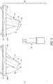
- FIGS. 3A and 3Bshow an example tibial implant 210 configured for a left knee (note difference from the configuration of FIG. 2 which is configured for the right knee). According to further examples the example of FIGS. 3A and 3B can be mirrored for use with the right knee.
- the tibial implant 210includes a baseplate 212 and a fixation member 214 ( FIG. 3B ).
- the baseplate 212includes a proximal surface 216 ( FIG. 3A ), a distal surface 218 ( FIG. 3B ), an anterior edge 220, a posterior edge 222, an anteroposterior axis 224, a lateral portion 226, and a medial portion 228.
- the fixation member 214 shown in FIG. 3Bcomprises a keel 230 and fins 232A and 232B.
- the keel 230includes a medial portion 234, a lateral portion 236, and a receptacle 238.
- the baseplate 212 and fixation member 214are coupled together.
- the baseplate 212can be configured at the proximal surface 216 to receive a tibial bearing component, for example.
- the distal surface 218is disposed on an opposing side of the baseplate 212 from the proximal surface 216 and is configured to interface with a resected proximal surface of a tibia.
- the distal surface 218can include a medial portion 218A (corresponding to that of the medial portion 226) and a lateral portion 218B (corresponding to that of the lateral portion 228). Both the proximal surface 216 and the distal surface 218 extend from the anterior edge 220 to the posterior edge 222 of the baseplate 212.
- the anteroposterior axis 224divides the baseplate 212 into the medial portion 226 and the lateral portion 228.
- the medial portion 226 and the lateral portion 228can be oriented relative to the anteroposterior axis 218.
- the medial portion 226 and the lateral portion 228can be substantially symmetric relative to one another.
- the fixation member 214is coupled to and extends both distally and medially from the distal surface 218 such that the fixation member 214 is oriented at an acute angle ⁇ ( FIG. 4 ) relative to the distal surface 218A of the medial portion 226 when viewed in the frontal or coronal plane.
- the fixation member 214can be provided with an angle ( ⁇ > 90° in reference to the tibial anatomical axis 122) to compensate for the varus orientation of the baseplate 212 on the resected proximal end surface 132 of the tibia 18.
- the fixation member 214can configured to substantially align with a central axis (indicated by tibial anatomical axis 122 of FIG. 2 ) of the tibial diaphysis when the fixation member 214 is coupled to the distal surface 218 of the baseplate 212.
- This orientation of the fixation memberreduces the risk that the fixation member 214 will perforate the lateral metaphysis or lateral diaphysis when the tibial component 210 is seated down into a position on top of the resected proximal end surface 132 of the tibia 18.
- the fixation member 214is configured as a keel 230, however in other examples the fixation member 214 can comprise some other type of projection (e.g., a stem, a peg, or the like) that is configured for insertion into the metaphysis or diaphysis of the tibia.
- the keel 230can have fins 232A and 232B extending to the medial portion 226 and lateral portion 228, respectively. Additionally, the keel 230 can have the medial portion 234 be differently configured than the lateral portion 236.
- the lateral portion 236can have a greater surface area than the medial portion 234 as shown in the illustrated example of FIG. 3B due to the angling of the fixation member 214 relative to the distal surface 318 of the baseplate 212. Such angling can provide the lateral portion 236 with a greater distal extent than a distal extent of the medial portion 234.
- the keel 230can form the receptacle 238 which extends through a substantial portion of the keel 230.
- the receptacle 238can receive a stem such as a stem 240 of FIGS. 4 and 5 , for example.
- a stemsuch as a stem 240 of FIGS. 4 and 5 , for example.
- Further disclosure of various examples of keels with stems including coupling mechanisms between these two components and/or the baseplateare provided in United States Patent Application Publication 2013/0024001, entitled “ASYMMETRIC TIBIAL COMPONENTS FOR A KNEE PROSTHESIS", filed January 23, 2013 and by United States Patent Number 7,691,150, entitled “MODULAR PLATE AND KEEL PROVISONALS", filed December 14, 2006 .
- FIG. 4shows an assembly 208 of the tibial implant 210 from FIGS. 2A and 2B with the stem 240 that can be configured to be received in the receptacle 238.
- the stem 240is configured to be insertable into the keel 230 to couple together the stem 240 and the keel 230.
- One or both of the keel 230 and the stem 240are configured to be removably attached to the baseplate 212.
- the keel 230has a female mating option (receptacle 238) where the stem 240 can be selected as a male counterpart.
- receptacle 238where the stem 240 can be selected as a male counterpart.
- the keel 230can be configured to couple to the baseplate 212 at the acute angle ⁇ and coupling of the stem 240 with the keel 230 orients the stem 240 at substantially a same acute angle relative to the distal surface 218A of the medial portion 226 as the acute angle ⁇ of the keel 230.
- the fixation member 214includes a symmetric feature (e.g. the receptacle 238 and the stem 240) each having an axis of symmetry A.
- the acute angle ⁇can extend between the axis of symmetry A and the distal surface 218A of the medial portion 226.
- FIGS. 3A to 4illustrate an example where the keel 230 can be integrally formed with the baseplate 212 such that the two components comprise a single component.
- the keel 230can be affixed by other mechanisms (weld, thread, interference fit, or the like) some of which allow the keel to be removable from the baseplate.
- FIG. 5shows components that can comprise assemblies 308 and 408.
- the componentswhen assembled together the components can comprise a tibial implant similar to those previously shown and discussed herein.
- the assemblies 308, 408include at least one baseplate (e.g., baseplate 312 and baseplate 412).
- each baseplate 312, 412has a medial portion 326, 426 and a lateral portion 328, 428.
- each of the medial portion 326, 426 and the lateral portion 328, 428has a distal surface 318, 418 configured to interface with a resected proximal surface of a tibia.
- the assemblies 308, 408also include at least one of a plurality of fixation members 314, 414.
- Each of the plurality of fixation members 314, 414is configured to attach to and extend both distally and medially from the distal surface 318, 418 such that each fixation member 314, 414 of the plurality of fixation members 314, 414 is oriented at an acute angle ⁇ 1 , ⁇ 2 relative to the distal surface 318A, 418A of the medial portion 326, 426 when viewed in the frontal or coronal plane.
- Each of the plurality of fixation members 314, 414is configured to differ from others of the plurality of fixation members 314, 414 such that the acute angle ⁇ 2 , ⁇ 1 formed by each of the plurality of fixation members 314, 414 when coupled to the baseplate 312, 412 would differ in degree.
- a keel 330, 430is coupled to and extends both distally and medially relative to the distal surface 318, 412 such that the keel 330, 430 creates the acute angle ⁇ 1 , ⁇ 2 between the keel 330, 430 and the distal surface 318A, 418A of the medial portion 326, 426 when viewed in the frontal or coronal plane.
- a stem 340can be configured to couple with one or both of the keel 330, 430 and the baseplate 312, 412 and can be configured to removably insert within a receptacle 338, 438 of the keel 330, 430.
- a componentsuch as one or more of the baseplates 312, 412, keels 330, 430, and/or stem 340 can be configured to universally couple with others of the components.
- the plurality of fixation members 314, 414can comprise a plurality of keels 330, 430 (each keel 330, 430 can have a different configuration) and a single stem 340.
- the single stem 340can have only a single configuration and can be configured to universally couple with any of the plurality of keels 330, 430. As shown in FIG.
- the keels 330, 430can comprise one of a plurality of keels (e.g., 330, 430, and so on) each keel 330, 430 can be configured to form a different acute angle (e.g., ⁇ 1 , ⁇ 2 , and so on) when coupled to the baseplate 312, 412.
- a plurality of baseplates 312, 412are shown in FIG. 5 , in some examples a single baseplate can be utilized with the assemblies and can be configured to couple to any of the plurality of keels (e.g., 330, 430).
- FIG. 6shows assemblies 508, 608 according to further examples.
- the assemblies 508, 608include at least one baseplate (e.g., baseplate 512 and baseplate 612).
- each baseplate 512, 612has a medial portion 526, 626 and a lateral portion 528, 628 oriented relative to an anteroposterior axis (not shown).
- each baseplate 512, 612has a distal surface 518, 618 configured to interface with a resected proximal end surface 132 ( FIG. 2 ) of a tibia.
- the assemblies 508, 608also include at least one of a plurality of fixation members 514, 614.
- Each of the plurality of fixation members 514, 614can be configured to attach to and extend both distally and medially from the distal surface 518, 618 such that each fixation member 514, 614 of the plurality of fixation members 514, 614 is oriented at an acute angle ⁇ 1 , ⁇ 2 relative to the distal surface 518A, 618A of the medial portion 526, 626 when viewed in the frontal or coronal plane.
- Each of the plurality of fixation members 514, 614is configured to differ from others of the plurality of fixation members 514, 614 such that the acute angle ⁇ 1 , ⁇ 2 formed by each of the plurality of fixation members 514, 614 when mounted to the baseplate 512, 612 would differ in degree.
- the examples of FIG. 6utilize a plurality of stems 540, 640 and a single keel 530. Each stem 540, 640 can be configured to couple to the baseplate 512 and/or 612 at the acute angle ⁇ 1 , ⁇ 2 .
- Coupling of the keel 530 with the stem 540can orient the keel 530 at substantially a same acute angle relative to the distal surface 518A, 618A of the medial portion 526, 626 as the acute angle ⁇ 1 , ⁇ 2 .
- the assemblies 508, 608can be have one or more components configured to universally couple with others of the components of the assemblies 508, 608.
- the plurality of fixation members 514, 614can comprise the plurality of stems 540, 640 (each keel 330, 430 can have a different configuration) and a single keel 530.
- the keel 530can have only a single configuration and can be configured to universally couple with any of the plurality of stems 540, 640. As shown in FIG.
- the stems 540, 640can comprise one of a plurality of stems (e.g., 540, 640, and so on) each keel 540, 640 can be configured to form a different acute angle (e.g., ⁇ 1 , ⁇ 2 , and so on) when coupled to the baseplate 512, 612.
- a different acute anglee.g., ⁇ 1 , ⁇ 2 , and so on
- An example method of performing a knee arthroplasty using a tibial implantcan include resecting a proximal surface of a tibia to expose a tibial metaphysis, and attaching a tibial implant to the resected surface at a distal surface of a baseplate of the tibial implant.
- the tibial implantcan have a fixation member which is configured to generally align with a central axis of the tibial diaphysis (e.g., indicated by tibial anatomical axis 122 of FIG. 2 ) when coupled to the distal surface of the baseplate.
- the methodcan include determining a desired angle based on degree of varus between the distal surface of the baseplate and the central axis of the tibial diaphysis, selecting from a plurality of fixation members that are configured to achieve the desired angle when coupled to the baseplate, and coupling the selected fixation member to the tibial baseplate.
- FIGS. 7A to 7Cshow another example of a tibial implant 710 where a baseplate 712 and fixation member 714 are configured such that the fixation member 714 is adjustable relative to the baseplate 712.
- the tibial implant 710includes the baseplate 712 and the fixation member 714 similar to those previously described.
- the baseplate 712includes a distal surface 718 and the fixation member 714 can comprise a stem 740 ( FIGS. 7B and 7C ) configured to mate with one or more keels (not shown).
- the baseplate 712can also include a coupling feature 720 ( FIG. 7A ) disposed at the distal surface 718.
- the coupling feature 720can be configured to couple with a base 722 ( FIG. 7B ) of the stem 740 with the base 722 and the stem 740 assembly in multiple orientations.
- the stem 740can be configured to be adjustable 180° relative to the baseplate 712 by simply reversing the orientation of the base 722 (shown in FIG. 7B ) and then recoupling the base 722 and the stem 740 to the baseplate 712. Therefore, FIGS.
- FIGS. 7A to 7Cshow an example where the baseplate 712 and fixation member 714 that are configured such that the fixation member 714 can be coupled to the baseplate 712 in at least two orientations including to create a first configuration for a right knee and a second configuration for a left knee.
- the fixation membercan be clocked to be incrementally adjustable both in the medial-lateral direction but also in the anterior-posterior direction.
- the fixation membercan be re-orientable relative to the baseplate to form a plurality of different configurations.
- the coupling feature 720can comprise fixation mechanisms known in the art such as those that use a slot, groove, flange, male/female connection, interference, tab, fastener, pin, or other mechanisms to couple the base 722 to the baseplate 712.
- the coupling feature 720comprises grooves 724 adapted to receive corresponding features of the base 722 which is inserted from a posterior toward an anterior of the baseplate 712.
- a fastener(not shown) can be received in hole 726 in the baseplate 712 and can insert into or abut the base 722 once the base 722 is moved into the desired position. This can further lock the base 722 relative to the baseplate 712.
- FIG. 7Aprovides only one example of a coupling feature others including those that utilize a different insertion direction and/or coupling mechanism(s) are contemplated.
Landscapes
- Health & Medical Sciences (AREA)
- Orthopedic Medicine & Surgery (AREA)
- Cardiology (AREA)
- Oral & Maxillofacial Surgery (AREA)
- Transplantation (AREA)
- Engineering & Computer Science (AREA)
- Biomedical Technology (AREA)
- Heart & Thoracic Surgery (AREA)
- Vascular Medicine (AREA)
- Life Sciences & Earth Sciences (AREA)
- Animal Behavior & Ethology (AREA)
- General Health & Medical Sciences (AREA)
- Public Health (AREA)
- Veterinary Medicine (AREA)
- Physical Education & Sports Medicine (AREA)
- Prostheses (AREA)
Description
- The present subject matter relates to orthopedic procedures and, more particularly, to tibial implants used in some knee arthroplasties where a varus resection of a tibia is utilized.
- Orthopedic procedures and prostheses are commonly utilized to repair and/or replace damaged bone and tissue in the human body. For example, a knee arthroplasty can be used to restore natural knee function by repairing damaged or diseased articular surfaces of the femur and/or tibia. An incision is made into the knee joint to expose the bones comprising the joint. Cut guides are used to guide the removal of the articular surfaces that are to be replaced. Prostheses are used to replicate the articular surfaces. Knee prostheses can include a femoral component implanted on the distal end of the femur, which articulates with a tibial component implanted on the proximal end of a tibia to replicate the function of a healthy natural knee. Various types of arthroplasties are known including a total knee arthroplasty (TKA), where all of the articulating compartments of the joint are repaired with prosthetic components.
WO2007/053905 relates to a modular prosthesis assembly comprising a tray element and an extension member depending therefrom.US 2013/218284 relates to an apparatus for reconstructing a joint comprising an implant body and a plurality of fixation elements extending into the host bone. - The present inventor recognizes, among other things, an opportunity for reducing trauma to the lateral tibial metaphysis and/or lateral tibial diaphysis during a TKA. More particularly, the present inventor has recognized that traditional fixation members for the tibial component such as a stem, keel, and/or fins may not be appropriately referenced to a central axis of the intramedullary canal. A result of such misalignment is that the fixation member does not reference down the center of the intramedullary canal. This misalignment can result in the fixation member perforating the lateral metaphysis or lateral diaphysis when the tibial component is seated down into a position on top of the resected proximal end of the tibia. The present inventor proposes a tibial implant, methods, and systems where the fixation member is appropriately referenced to substantially align with the central axis of the intramedullary canal. Achieving this orientation can include having the fixation member(s) extend both distally and medially from a baseplate of the tibial implant such that the fixation member is oriented at an acute angle (i.e. be oriented in valgus) relative to the resected proximal surface (corresponding to a distal surface of a medial portion of the baseplate).
- Accordingly, the invention provides a system for forming a tibial implant configured for attachment to a tibia in a knee arthroplasty as described in claim 1. To further illustrate the systems disclosed herein, the following nonlimiting examples are provided:
- There is also described a method of performing a knee arthroplasty.. The method can include resecting a proximal surface of a tibia to expose a tibial metaphysis, and attaching a tibial implant to the resected surface at a distal surface of a baseplate of the tibial implant, the tibial implant having a fixation member that is configured to generally align with a central axis of the tibial diaphysis when coupled to the distal surface of the baseplate.
- The method can further include determining a desired angle based on degree of varus between the distal surface of the baseplate and the central axis of the tibial diaphysis, selecting from a plurality of fixation members that are configured to achieve the desired angle when coupled to the baseplate, and coupling the selected fixation member to the tibial baseplate.
- The Detailed Description below is included to provide further information about the present apparatuses and methods.
- In the drawings, which are not necessarily drawn to scale, like numerals can describe similar components in different views. Like numerals having different letter suffixes can represent different instances of similar components. The drawings illustrate generally, by way of example, but not by way of limitation, various examples discussed in the present document.
FIG. 1A is a frontal or coronal plane view of a knee joint with an implanted knee prosthesis according to an example of the present application.FIG. 1B is a coronal view of the knee joint and knee prosthesis ofFIG. 1A in 90 degrees flexion according to an example of the present application.FIG. 1C is a side or sagittal plane view of the knee joint and knee prosthesis ofFIGS. 1A and 1B in full extension according to an example of the present application.FIG. 2 is a coronal plane view of a tibia and a femur for a right knee having implants thereon and showing orientations of the implants relative to axes of the knee according to an example of the present application.FIG. 3A is a plan view of a proximal side of a tibial implant for a left knee according to an example of the present application.FIG. 3B is a perspective view of a distal portion of the tibial implant ofFIG. 3A illustrating a fixation member canted relative to a distal surface of a baseplate according to an example of the present application.FIG. 4 is a view of an assembly in a coronal plane including the tibial implant ofFIGS. 3A and 3B and a stem according to an example of the present application.FIG. 5 is a view of two assemblies including tibial implants and other components according to an example of the present application.FIG. 6 is a view of two assemblies including tibial implants and other components according to another example of the present application.FIG. 7A is a plan view of a distal side of a tibial implant according to yet another example of the present application.FIG. 7B is a plan view of a fixation member in two orientations according to example of the present application.FIG. 7C is a coronal plan view of the tibial implant ofFIG. 7A coupled to the fixation member ofFIG. 7B with the fixation member in a first orientation such as is shown inFIG. 7B and with the fixation member in a second orientation such as is shown inFIG. 7B according to an example of the present application.- It has been established that a kinematically aligned TKA can improve the results of the TKA, including overall patient satisfaction and mobility. Primary goals of kinematically aligned TKA are (1) positioning the femoral and tibial components of a knee prosthesis such that the angles and levels of the distal and posterior femoral and tibial joint lines are restored to the patient's natural joint line, (2) restoration of the patient's natural or constitutional alignment prior to the patient having developed osteoarthritis, and (3) restoration of the patient's natural soft tissue laxity and envelope. The kinematically aligned TKA can include a determination of three kinematic axes.
FIGS. 1A-1C show various views of aknee prosthesis 10 implanted on a knee joint and illustrate the three kinematic axes of the knee joint in a kinematically aligned TKA. In particular,FIG. 1A provides a view of theknee prosthesis 10 in a coronal plane as viewed from the anterior with afemoral component 12 in extension.FIG. 1B is a view of theknee prosthesis 10 in the coronal plane with thefemoral component 12 in flexion.FIG. 1C is a view of the 10 in the sagittal plane with the femoral component in extension. Thefemoral component 12 is implanted on afemur 14 while atibial component 16 implanted on atibia 18. A polyethylene surface is inserted between the femur and tibia. A firstkinematic axis 20 can be a transverse axis in thefemur 14 about which thetibia 18 flexes and extends. The firstkinematic axis 20 can be determined by projecting the lateral and medial femoral condyles of thefemur 14 onto one another and fitting circles of equal radii over each other. The firstkinematic axis 20 passes through a center of the circles. A secondkinematic axis 22 can be a second transverse axis, parallel to the firstkinematic axis 20, about which a patella of the knee joint flexes and extends. The secondkinematic axis 22 can be located anterior and proximal to the firstkinematic axis 20. A thirdkinematic axis 24 is an axis perpendicular to the first 20 and second 22 axes about which thetibia 18 internally and externally rotates on thefemur 14.- The present application does not include a description of the surgical procedure for performing a kinematically aligned TKA. Such procedures are discussed, for example, in relation to Application
Serial Numbers 14/809,810, entitled "INSTRUMENTS AND METHODS IN PERFORMING KINEMATICALLY-ALIGNED TOTAL KNEE ARTHROPLASTY" filed July 27, 2015 13/819,528, entitled "FEMORAL PROTHESIS WITH MEDIALIZED PATELLAR GROOVE", filed September 9, 2011 FIGS. 2-7C provide examples of surgical instruments, systems, methods and techniques that can be used to aid and improve on the kinematically aligned TKA. FIG. 2 shows an example of aTKA knee prosthesis 110 in a right knee of a patient as viewed in the coronal plane. As was generally discussed with respect toFIGS. 1A-1C , theknee prosthesis 110 can include afemoral component 112 mounted to thefemur 14 and atibial component 116 mounted to thetibia 18.FIG. 2 shows theknee prosthesis 110 alignment relative to the anatomical axes of thefemur 14 and thetibia 18. In particular,FIG. 2 shows a femoralanatomical axis 120 and a tibialanatomical axis 122.- Disposition of the
femoral component 112 relative to the femoralanatomical axis 120 is indicated by α as measured between aline 124 across the bottom of thefemoral condyles tibial component 116 relative to the tibialanatomical axis 122 is indicated by β as measured between aline 126 across a base of atibial plate 128 of thetibial component 116 and a tibial shaft axis (superimposed with the tibial anatomical axis 122). An angle Δ (a tibiofemoral axis) is also indicated and comprises a measure between the femoral shaft axis and the tibial shaft axis. - An α of 90° comprises a neutral placement of the
femoral component 112, α < 90° corresponds to varus placement of thefemoral component 112, and α > 90° corresponds to valgus placement of thefemoral component 112. Similarly, if β = 90° corresponds to a neutral placement of thetibial component 116, β < 90° corresponds to varus placement of placement of thetibial component 116, and β > 90° corresponds to valgus placement of thetibial component 116. If Δ = 180° this corresponds to a neutral alignment, Δ < 180° corresponds to varus alignment, and Δ > 180° corresponds to valgus alignment. - With regard to coronal alignment of the
femoral component 112, it has generally been shown that an optimal distal femoral cut is typically 2-7° of valgus. With regard to coronal alignment of thetibial component 116, a certain degree of varus tibial alignment with a varus cut is generally desirable. With the kinematically aligned TKA it has generally been found thattibial component 116 placement of a few more degrees varus (e.g., about 0.1 degrees to about 5 degrees) and thefemoral component 112 placed in a few more degrees valgus (e.g., about 0.1 degrees to about 5 degrees) than traditional mechanically aligned TKA results in improved patient outcomes. - The present inventor has recognized that especially with the additional varus disposition of the
tibial component 116 in the kinematically aligned TKA, traditional fixation members for thetibial component 116 such as a stem, keel, or fins (e.g,, a keel and stem 130 as shown inFIG. 2 ) may not be appropriately referenced to the intramedullary canal which generally aligns with the tibialanatomical axis 122. Indeed, an example of such misalignment is shown inFIG. 2 where thekeel 130 is not substantially aligned with the tibialanatomical axis 122. A result of such misalignment is that thekeel 130 does not reference down the center of the tibial diaphysis/ intramedullary canal. This misalignment can result in thekeel 130 perforating the lateral metaphysis or lateral diaphysis when thetibial component 116 is seated down into a position on top of the resectedproximal end surface 132 of thetibia 18. FIGS. 3A and 3B show an exampletibial implant 210 configured for a left knee (note difference from the configuration ofFIG. 2 which is configured for the right knee). According to further examples the example ofFIGS. 3A and 3B can be mirrored for use with the right knee. Thetibial implant 210 includes abaseplate 212 and a fixation member 214 (FIG. 3B ). Thebaseplate 212 includes a proximal surface 216 (FIG. 3A ), a distal surface 218 (FIG. 3B ), ananterior edge 220, aposterior edge 222, ananteroposterior axis 224, alateral portion 226, and amedial portion 228. Thefixation member 214 shown inFIG. 3B comprises akeel 230 andfins keel 230 includes amedial portion 234, alateral portion 236, and areceptacle 238.- In the example provided, the
baseplate 212 andfixation member 214 are coupled together. As shown inFIG. 3A , thebaseplate 212 can be configured at theproximal surface 216 to receive a tibial bearing component, for example. Thedistal surface 218 is disposed on an opposing side of thebaseplate 212 from theproximal surface 216 and is configured to interface with a resected proximal surface of a tibia. Thedistal surface 218 can include amedial portion 218A (corresponding to that of the medial portion 226) and alateral portion 218B (corresponding to that of the lateral portion 228). Both theproximal surface 216 and thedistal surface 218 extend from theanterior edge 220 to theposterior edge 222 of thebaseplate 212. - As shown in
FIG. 3A theanteroposterior axis 224 divides thebaseplate 212 into themedial portion 226 and thelateral portion 228. Thus, themedial portion 226 and thelateral portion 228 can be oriented relative to theanteroposterior axis 218. Although shown with an asymmetrically shapedmedial portion 226 relative to thelateral portion 228, in some examples themedial portion 226 and thelateral portion 228 can be substantially symmetric relative to one another. - As shown in the example of
FIG. 3B , thefixation member 214 is coupled to and extends both distally and medially from thedistal surface 218 such that thefixation member 214 is oriented at an acute angle θ (FIG. 4 ) relative to thedistal surface 218A of themedial portion 226 when viewed in the frontal or coronal plane. Put another way with reference toFIG. 2 for terminology and points of reference, thefixation member 214 can be provided with an angle (β > 90° in reference to the tibial anatomical axis 122) to compensate for the varus orientation of thebaseplate 212 on the resectedproximal end surface 132 of thetibia 18. Thus, thefixation member 214 can configured to substantially align with a central axis (indicated by tibialanatomical axis 122 ofFIG. 2 ) of the tibial diaphysis when thefixation member 214 is coupled to thedistal surface 218 of thebaseplate 212. This orientation of the fixation member reduces the risk that thefixation member 214 will perforate the lateral metaphysis or lateral diaphysis when thetibial component 210 is seated down into a position on top of the resectedproximal end surface 132 of thetibia 18. - As shown in the example of
FIG. 3B , thefixation member 214 is configured as akeel 230, however in other examples thefixation member 214 can comprise some other type of projection (e.g., a stem, a peg, or the like) that is configured for insertion into the metaphysis or diaphysis of the tibia. According to the example ofFIG. 3B , thekeel 230 can havefins medial portion 226 andlateral portion 228, respectively. Additionally, thekeel 230 can have themedial portion 234 be differently configured than thelateral portion 236. For example, thelateral portion 236 can have a greater surface area than themedial portion 234 as shown in the illustrated example ofFIG. 3B due to the angling of thefixation member 214 relative to thedistal surface 318 of thebaseplate 212. Such angling can provide thelateral portion 236 with a greater distal extent than a distal extent of themedial portion 234. - As shown in
FIG. 3B , thekeel 230 can form thereceptacle 238 which extends through a substantial portion of thekeel 230. Thereceptacle 238 can receive a stem such as astem 240 ofFIGS. 4 and5 , for example. Further disclosure of various examples of keels with stems including coupling mechanisms between these two components and/or the baseplate are provided inUnited States Patent Application Publication 2013/0024001, entitled "ASYMMETRIC TIBIAL COMPONENTS FOR A KNEE PROSTHESIS", filed January 23, 2013 and byUnited States Patent Number 7,691,150, entitled "MODULAR PLATE AND KEEL PROVISONALS", filed December 14, 2006 . FIG. 4 shows anassembly 208 of thetibial implant 210 from FIGS. 2A and 2B with thestem 240 that can be configured to be received in thereceptacle 238. Thus, thestem 240 is configured to be insertable into thekeel 230 to couple together thestem 240 and thekeel 230. One or both of thekeel 230 and thestem 240 are configured to be removably attached to thebaseplate 212. In the example ofFIG. 4 , thekeel 230 has a female mating option (receptacle 238) where thestem 240 can be selected as a male counterpart. However, other configurations will be discussed subsequently. Thus, thekeel 230 can be configured to couple to thebaseplate 212 at the acute angle θ and coupling of thestem 240 with thekeel 230 orients thestem 240 at substantially a same acute angle relative to thedistal surface 218A of themedial portion 226 as the acute angle θ of thekeel 230. InFIG. 4 , thefixation member 214 includes a symmetric feature (e.g. thereceptacle 238 and the stem 240) each having an axis of symmetry A. The acute angle θ can extend between the axis of symmetry A and thedistal surface 218A of themedial portion 226.- Furthermore,
FIGS. 3A to 4 illustrate an example where thekeel 230 can be integrally formed with thebaseplate 212 such that the two components comprise a single component. However, in other examples thekeel 230 can be affixed by other mechanisms (weld, thread, interference fit, or the like) some of which allow the keel to be removable from the baseplate. FIG. 5 shows components that can compriseassemblies FIG. 5 , theassemblies baseplate 312 and baseplate 412). As with prior discussed embodiments, eachbaseplate medial portion lateral portion medial portion lateral portion distal surface - The
assemblies fixation members fixation members distal surface fixation member fixation members distal surface medial portion fixation members fixation members fixation members baseplate - More particular, a
keel distal surface keel keel distal surface medial portion stem 340 can be configured to couple with one or both of thekeel baseplate receptacle keel - It should be noted that although illustrated as
assemblies baseplates FIG. 5 the plurality offixation members keels 330, 430 (eachkeel single stem 340. Thesingle stem 340 can have only a single configuration and can be configured to universally couple with any of the plurality ofkeels FIG. 5 , thekeels keel baseplate baseplates FIG. 5 , in some examples a single baseplate can be utilized with the assemblies and can be configured to couple to any of the plurality of keels (e.g., 330, 430). FIG. 6 showsassemblies FIG. 6 , theassemblies baseplate 512 and baseplate 612). As with prior discussed embodiments, eachbaseplate medial portion lateral portion baseplate distal surface FIG. 2 ) of a tibia.- The
assemblies fixation members fixation members distal surface fixation member fixation members distal surface medial portion fixation members fixation members fixation members baseplate FIG. 6 utilize a plurality of stems 540, 640 and asingle keel 530. Eachstem baseplate 512 and/or 612 at the acute angle δ1, δ2. Coupling of thekeel 530 with thestem 540 can orient thekeel 530 at substantially a same acute angle relative to thedistal surface medial portion - It should be noted similar to
assemblies assemblies assemblies FIG. 6 the plurality offixation members keel single keel 530. Thus, according to some examples thekeel 530 can have only a single configuration and can be configured to universally couple with any of the plurality of stems 540, 640. As shown inFIG. 6 , the stems 540, 640 can comprise one of a plurality of stems (e.g., 540, 640, and so on) eachkeel baseplate - An example method of performing a knee arthroplasty using a tibial implant such as those discussed herein and not forming part of the invention can include resecting a proximal surface of a tibia to expose a tibial metaphysis, and attaching a tibial implant to the resected surface at a distal surface of a baseplate of the tibial implant. The tibial implant can have a fixation member which is configured to generally align with a central axis of the tibial diaphysis (e.g., indicated by tibial
anatomical axis 122 ofFIG. 2 ) when coupled to the distal surface of the baseplate. According to further examples the method can include determining a desired angle based on degree of varus between the distal surface of the baseplate and the central axis of the tibial diaphysis, selecting from a plurality of fixation members that are configured to achieve the desired angle when coupled to the baseplate, and coupling the selected fixation member to the tibial baseplate. FIGS. 7A to 7C show another example of atibial implant 710 where abaseplate 712 andfixation member 714 are configured such that thefixation member 714 is adjustable relative to thebaseplate 712. Thetibial implant 710 includes thebaseplate 712 and thefixation member 714 similar to those previously described. Thus, thebaseplate 712 includes adistal surface 718 and thefixation member 714 can comprise a stem 740 (FIGS. 7B and7C ) configured to mate with one or more keels (not shown). However, thebaseplate 712 can also include a coupling feature 720 (FIG. 7A ) disposed at thedistal surface 718.- The
coupling feature 720 can be configured to couple with a base 722 (FIG. 7B ) of thestem 740 with thebase 722 and thestem 740 assembly in multiple orientations. As illustrated and described according to the example ofFIGS. 7A to 7C , thestem 740 can be configured to be adjustable 180° relative to thebaseplate 712 by simply reversing the orientation of the base 722 (shown inFIG. 7B ) and then recoupling thebase 722 and thestem 740 to thebaseplate 712. Therefore,FIGS. 7A to 7C show an example where thebaseplate 712 andfixation member 714 that are configured such that thefixation member 714 can be coupled to thebaseplate 712 in at least two orientations including to create a first configuration for a right knee and a second configuration for a left knee. According to other examples, rather than being configured to be adjustable 180° relative to the baseplate, the fixation member can be clocked to be incrementally adjustable both in the medial-lateral direction but also in the anterior-posterior direction. Thus, in some examples the fixation member can be re-orientable relative to the baseplate to form a plurality of different configurations. - More particularly, the
coupling feature 720 can comprise fixation mechanisms known in the art such as those that use a slot, groove, flange, male/female connection, interference, tab, fastener, pin, or other mechanisms to couple the base 722 to thebaseplate 712. According to the example ofFIG. 7A , thecoupling feature 720 comprisesgrooves 724 adapted to receive corresponding features of the base 722 which is inserted from a posterior toward an anterior of thebaseplate 712. A fastener (not shown) can be received inhole 726 in thebaseplate 712 and can insert into or abut the base 722 once the base 722 is moved into the desired position. This can further lock thebase 722 relative to thebaseplate 712.FIG. 7A provides only one example of a coupling feature others including those that utilize a different insertion direction and/or coupling mechanism(s) are contemplated.
Claims (12)
- A system for forming a tibial implant configured for attachment to a tibia in a knee arthroplasty, the system comprising:
one or more baseplates (212,312,412,512,612) having a lateral portion (328,428,528,628) and a medial portion (326,426,526,626) oriented relative to an anteroposterior axis, each of the lateral portion and the medial portion having a distal surface (218,218A,318,318A,418,418A,518,518A,618,618A) configured to interface with a lateral resected proximal surface of a tibia and a medial resected proximal surface of a tibia respectively;characterized in that the system further comprises:
a plurality of fixation members (214,314,414,514,614) each of the plurality of fixation members being configured to couple to the baseplate and extend both distally and medially from the baseplate such that each fixation member of the plurality of fixation members is oriented at an acute angle (θ,θ1,θ2,δ1,δ2) relative to the distal surface of the medial portion, and wherein each of the plurality of fixation members is configured to differ from others of the plurality of fixation members such that the acute angle formed by each of the plurality of fixation members, when mounted to the baseplate, differs in degree. - The system of claim 1, wherein each of the plurality of fixation members comprise one or both of a keel (230,330,430,530) and a stem (240,340,540,640) that are configured for insertion into a metaphysis and/or diaphysis of the tibia.
- The system of claim 2, wherein one or both of the keel and stem are configured to be removably attached to the one or more baseplates.
- The system of claim 3, wherein one or both of the keel and stem are configured to be adjustable 180° relative to the one or more baseplates such that the tibial implant is configured for use with both a left tibia and a right tibia.
- The system of claim 2, wherein the system comprises a plurality of baseplates and each of the plurality of baseplates comprise both a stem and a keel, the stem and keel are configured to couple together, and wherein the stem is configured to couple to the baseplate at the acute angle and coupling of the keel with the stem orients the keel at substantially a same acute angle relative to the distal surface of the medial portion as the acute angle.
- The system of claim 2, wherein the system comprises a plurality of baseplates and each of the plurality of baseplates comprise both a stem and a keel, the stem and keel are configured to couple together, and wherein the keel is configured to couple to the baseplate at the acute angle and coupling of the stem with the keel orients the stem at substantially a same acute angle relative to the distal surface of the medial portion as the acute angle.
- The system of any one or any combination of claims 1-6, wherein each of the plurality of fixation members include a symmetric feature having an axis of symmetry, and wherein the acute angle is measured between the axis of symmetry and the distal surface of the medial portion.
- The system of any one or any combination of claims 1-7, wherein the medial portion has a greater surface area than the lateral portion.
- The system of any one or any combination of claims 1-8, wherein the baseplate and fixation member are configured such that the fixation member is adjustable 180° relative to the baseplate such that the tibial implant is configured for use with both a left tibia and a right tibia.
- The system of claim 1, wherein the plurality of fixation members comprises a plurality of keels each having a different configuration and a single stem having a single configuration, wherein the single stem is configured to universally couple with any of the plurality of keels.
- The system of claim 1, wherein the plurality of fixation members comprises a plurality of stems each having a different configuration and a single keel having a single shape, wherein the single keel is configured to universally couple with any of the plurality of stems.
- The system of any one or any combination of claims 1, 10, and 11, wherein the baseplate and fixation member are configured such that the fixation member can be coupled to the baseplate in at least two orientations including to create a first configuration for a right knee and a second configuration for a left knee.
Applications Claiming Priority (2)
| Application Number | Priority Date | Filing Date | Title |
|---|---|---|---|
| US201562234141P | 2015-09-29 | 2015-09-29 | |
| PCT/US2016/052173WO2017058535A1 (en) | 2015-09-29 | 2016-09-16 | Tibial prosthesis for tibia with varus resection |
Publications (2)
| Publication Number | Publication Date |
|---|---|
| EP3355834A1 EP3355834A1 (en) | 2018-08-08 |
| EP3355834B1true EP3355834B1 (en) | 2023-01-04 |
Family
ID=57130429
Family Applications (1)
| Application Number | Title | Priority Date | Filing Date |
|---|---|---|---|
| EP16781218.9AActiveEP3355834B1 (en) | 2015-09-29 | 2016-09-16 | Tibial prosthesis for tibia with varus resection |
Country Status (3)
| Country | Link |
|---|---|
| US (4) | US10136997B2 (en) |
| EP (1) | EP3355834B1 (en) |
| WO (1) | WO2017058535A1 (en) |
Families Citing this family (7)
| Publication number | Priority date | Publication date | Assignee | Title |
|---|---|---|---|---|
| CA2641966C (en) | 2005-12-15 | 2016-11-22 | Zimmer, Inc. | Distal femoral knee prostheses |
| CA2993979A1 (en) | 2010-09-10 | 2012-03-15 | Zimmer Gmbh | Femoral prosthesis with medialized patellar groove |
| US8932365B2 (en) | 2011-06-16 | 2015-01-13 | Zimmer, Inc. | Femoral component for a knee prosthesis with improved articular characteristics |
| US9308095B2 (en) | 2011-06-16 | 2016-04-12 | Zimmer, Inc. | Femoral component for a knee prosthesis with improved articular characteristics |
| US10130375B2 (en) | 2014-07-31 | 2018-11-20 | Zimmer, Inc. | Instruments and methods in performing kinematically-aligned total knee arthroplasty |
| US10582982B2 (en) | 2015-03-23 | 2020-03-10 | Zimmer, Inc. | Disposable multi-purpose tool for total knee arthroplasty |
| EP3355834B1 (en) | 2015-09-29 | 2023-01-04 | Zimmer, Inc. | Tibial prosthesis for tibia with varus resection |
Family Cites Families (226)
| Publication number | Priority date | Publication date | Assignee | Title |
|---|---|---|---|---|
| US2246066A (en) | 1940-06-11 | 1941-06-17 | Rothe Frank | Micrometric attachment for combination squares |
| US4081866A (en) | 1977-02-02 | 1978-04-04 | Howmedica, Inc. | Total anatomical knee prosthesis |
| US4340978A (en) | 1979-07-02 | 1982-07-27 | Biomedical Engineering Corp. | New Jersey meniscal bearing knee replacement |
| CH657268A5 (en) | 1983-03-23 | 1986-08-29 | Sulzer Ag | Femme part for a knee joint prosthesis. |
| DE3315401A1 (en) | 1983-04-28 | 1984-10-31 | Feldmühle AG, 4000 Düsseldorf | Knee-joint prosthesis |
| US4659331A (en) | 1983-11-28 | 1987-04-21 | Regents Of University Of Michigan | Prosthesis interface surface and method of implanting |
| US4769040A (en)* | 1986-11-18 | 1988-09-06 | Queen's University At Kingston | Tibial prosthesis |
| JPS6468255A (en) | 1987-08-10 | 1989-03-14 | Dow Corning Wright Corp | Artificial device for composing thighbone in knee joint |
| US5035700A (en) | 1988-02-03 | 1991-07-30 | Pfizer Hospital Products Group, Inc. | Prosthetic knee joint with improved patellar component tracking |
| US4944756A (en) | 1988-02-03 | 1990-07-31 | Pfizer Hospital Products Group | Prosthetic knee joint with improved patellar component tracking |
| US4959071A (en) | 1988-02-03 | 1990-09-25 | Biomet, Inc. | Partially stabilized knee prosthesis |
| US4950298A (en) | 1988-04-08 | 1990-08-21 | Gustilo Ramon B | Modular knee joint prosthesis |
| CA2006152C (en) | 1988-12-27 | 1999-03-23 | John Edward Slamin | Modular knee prosthesis |
| US5007933A (en) | 1989-01-31 | 1991-04-16 | Osteonics Corp. | Modular knee prosthesis system |
| US5061271A (en) | 1989-02-27 | 1991-10-29 | Boehringer Mannheim Corporation | Tool for separating components of a modular joint prosthesis |
| GB8912682D0 (en) | 1989-06-02 | 1989-07-19 | Thackray Chas F | Improvements in and relating to knee prosthesis |
| US5133760A (en)* | 1990-02-12 | 1992-07-28 | Alvarado Orthopedic Research, Inc. | Universal modular prosthesis stem extension |
| JPH03267055A (en) | 1990-03-16 | 1991-11-27 | Koshino Nariko | Shank side component of artificial knee joint |
| US5084982A (en) | 1990-06-09 | 1992-02-04 | Feng Yee Chang | Combined vernier gauge and protractor |
| US5282869A (en) | 1990-10-24 | 1994-02-01 | Kyocera Corporation | Artificial knee joint |
| US5330532A (en) | 1990-11-09 | 1994-07-19 | Chitranjan Ranawat | Knee joint prosthesis |
| JPH0553501A (en) | 1991-08-26 | 1993-03-05 | Sumitomo Electric Ind Ltd | Optimal route determination method using route table |
| JPH0568987A (en) | 1991-09-11 | 1993-03-23 | Matsushita Electric Ind Co Ltd | Rainwater purification equipment |
| US5133758A (en) | 1991-09-16 | 1992-07-28 | Research And Education Institute, Inc. Harbor-Ucla Medical Center | Total knee endoprosthesis with fixed flexion-extension axis of rotation |
| GB9125311D0 (en) | 1991-11-28 | 1992-01-29 | Biomet Ltd | Prosthetic components |
| US5282861A (en) | 1992-03-11 | 1994-02-01 | Ultramet | Open cell tantalum structures for cancellous bone implants and cell and tissue receptors |
| US5226915A (en) | 1992-04-03 | 1993-07-13 | Bertin Kim C | Femoral prosthesis component system for knee replacement surgery |
| EP0567705B1 (en) | 1992-04-30 | 1997-07-09 | Merck Biomaterial France | Posteriorly stabilized total knee prosthesis |
| US5445642A (en) | 1992-09-01 | 1995-08-29 | Depuy Inc. | Method for installing a femoral component |
| US5728162A (en) | 1993-01-28 | 1998-03-17 | Board Of Regents Of University Of Colorado | Asymmetric condylar and trochlear femoral knee component |
| US5549686A (en) | 1994-06-06 | 1996-08-27 | Zimmer, Inc. | Knee prosthesis having a tapered cam |
| FR2721500B1 (en) | 1994-06-22 | 1996-12-06 | Euros Sa | Femoral implant, in particular for a three-compartment knee prosthesis. |
| JPH0826976A (en) | 1994-07-21 | 1996-01-30 | Freunt Ind Co Ltd | Food medicine |
| US5549688A (en) | 1994-08-04 | 1996-08-27 | Smith & Nephew Richards Inc. | Asymmetric femoral prosthesis |
| US5755803A (en) | 1994-09-02 | 1998-05-26 | Hudson Surgical Design | Prosthetic implant |
| DE69416682T2 (en) | 1994-12-29 | 1999-09-09 | Tesa Brown & Sharpe Sa | Length measuring device |
| AUPN089495A0 (en) | 1995-02-03 | 1995-03-02 | Denupo Pty. Ltd. | Knee prosthesis |
| US5702460A (en) | 1995-02-15 | 1997-12-30 | Smith & Nephew, Inc. | Revision femoral trial prosthesis |
| US5519942A (en) | 1995-03-02 | 1996-05-28 | Webb; James | Levelling and transit system |
| US5609643A (en) | 1995-03-13 | 1997-03-11 | Johnson & Johnson Professional, Inc. | Knee joint prosthesis |
| US6540786B2 (en) | 1995-08-23 | 2003-04-01 | Jean Chibrac | Joint prosthesis members and method for making same |
| FR2737970B1 (en) | 1995-08-23 | 1998-01-09 | Chibrac Jean | JOINT PROSTHESIS ELEMENTS AND MANUFACTURING METHOD THEREOF |
| US5871546A (en) | 1995-09-29 | 1999-02-16 | Johnson & Johnson Professional, Inc. | Femoral component condyle design for knee prosthesis |
| JP3469972B2 (en) | 1995-09-29 | 2003-11-25 | 京セラ株式会社 | Artificial knee joint |
| US5776201A (en) | 1995-10-02 | 1998-07-07 | Johnson & Johnson Professional, Inc. | Modular femoral trial system |
| JP3495161B2 (en) | 1995-11-30 | 2004-02-09 | 京セラ株式会社 | Femoral component of a knee prosthesis |
| US5681354A (en) | 1996-02-20 | 1997-10-28 | Board Of Regents, University Of Colorado | Asymmetrical femoral component for knee prosthesis |
| US5964808A (en) | 1996-07-11 | 1999-10-12 | Wright Medical Technology, Inc. | Knee prosthesis |
| DE19646891A1 (en) | 1996-11-13 | 1998-05-14 | Kubein Meesenburg Dietmar | Artificial joint, especially an endoprosthesis to replace natural joints |
| US8545569B2 (en) | 2001-05-25 | 2013-10-01 | Conformis, Inc. | Patient selectable knee arthroplasty devices |
| US20090222103A1 (en) | 2001-05-25 | 2009-09-03 | Conformis, Inc. | Articular Implants Providing Lower Adjacent Cartilage Wear |
| US8771365B2 (en) | 2009-02-25 | 2014-07-08 | Conformis, Inc. | Patient-adapted and improved orthopedic implants, designs, and related tools |
| US20070233269A1 (en) | 2001-05-25 | 2007-10-04 | Conformis, Inc. | Interpositional Joint Implant |
| US8480754B2 (en) | 2001-05-25 | 2013-07-09 | Conformis, Inc. | Patient-adapted and improved articular implants, designs and related guide tools |
| US8882847B2 (en) | 2001-05-25 | 2014-11-11 | Conformis, Inc. | Patient selectable knee joint arthroplasty devices |
| GB9707717D0 (en) | 1997-04-16 | 1997-06-04 | Walker Peter S | Knee prosthesis having guide surfaces for control of anterior-posterior translation |
| DE19716879C2 (en) | 1997-04-22 | 1999-07-15 | Plus Endoprothetik Ag | Femur sledge |
| US5879393A (en) | 1997-05-21 | 1999-03-09 | Smith & Nephew, Inc. | Trial femoral prosthesis for use in knee joint replacement surgery |
| US6039764A (en) | 1997-08-18 | 2000-03-21 | Arch Development Corporation | Prosthetic knee with adjusted center of internal/external rotation |
| DE59712553D1 (en) | 1997-11-28 | 2006-04-06 | Zimmer Gmbh Winterthur | Instrument construction kit for knee joint prostheses |
| US6325828B1 (en) | 1997-12-02 | 2001-12-04 | Rose Biomedical Research | Apparatus for knee prosthesis |
| DE19754079A1 (en) | 1997-12-05 | 1999-06-10 | Gmt Medizinische Technik Gmbh | Endoprosthesis for at least partial replacement of a tibia |
| US6074424A (en) | 1998-01-23 | 2000-06-13 | Sulzer Orthopedics Inc. | Implantable knee joint prosthesis convertible from primary to revision |
| US6616696B1 (en) | 1998-09-04 | 2003-09-09 | Alan C. Merchant | Modular knee replacement system |
| US6152960A (en) | 1998-10-13 | 2000-11-28 | Biomedical Engineering Trust I | Femoral component for knee endoprosthesis |
| FR2784577B1 (en) | 1998-10-16 | 2001-03-09 | Depuy France | FEMALE IMPLANT FOR KNEE PROSTHESIS |
| US6106529A (en) | 1998-12-18 | 2000-08-22 | Johnson & Johnson Professional, Inc. | Epicondylar axis referencing drill guide |
| DE29906909U1 (en) | 1999-03-02 | 1999-09-30 | Plus Endoprothetik Ag, Rotkreuz | Femur sledge |
| FR2791553B1 (en) | 1999-04-01 | 2001-07-06 | Merck Biomaterial France | ANTERO-POSTERO-STABILIZED KNEE PROSTHESIS |
| FR2796836B1 (en) | 1999-07-26 | 2002-03-22 | Michel Bercovy | NEW KNEE PROSTHESIS |
| DE59908476D1 (en) | 1999-11-09 | 2004-03-11 | Link Waldemar Gmbh Co | Knee Prosthesis System |
| US7635390B1 (en) | 2000-01-14 | 2009-12-22 | Marctec, Llc | Joint replacement component having a modular articulating surface |
| FR2805455B1 (en) | 2000-02-24 | 2002-04-19 | Aesculap Sa | FEMORAL COMPONENT OF A THREE-BEND KNEE PROSTHESIS |
| US6712856B1 (en) | 2000-03-17 | 2004-03-30 | Kinamed, Inc. | Custom replacement device for resurfacing a femur and method of making the same |
| FR2815244B1 (en) | 2000-10-18 | 2003-06-27 | Aesculap Sa | INCLINED FEMORAL COMPONENT |
| US6421927B1 (en) | 2000-12-26 | 2002-07-23 | Michael L. Bach | Measuring tool |
| US6719800B2 (en) | 2001-01-29 | 2004-04-13 | Zimmer Technology, Inc. | Constrained prosthetic knee with rotating bearing |
| US8062377B2 (en) | 2001-03-05 | 2011-11-22 | Hudson Surgical Design, Inc. | Methods and apparatus for knee arthroplasty |
| US20080140212A1 (en) | 2001-05-15 | 2008-06-12 | Robert Metzger | Elongated femoral component |
| US6589283B1 (en) | 2001-05-15 | 2003-07-08 | Biomet, Inc. | Elongated femoral component |
| US7892288B2 (en) | 2001-08-27 | 2011-02-22 | Zimmer Technology, Inc. | Femoral augments for use with knee joint prosthesis |
| US6916325B2 (en) | 2002-02-11 | 2005-07-12 | Zimmer Orthobiologies, Inc. | Femoral sizing guide |
| EP2359775B1 (en) | 2002-02-20 | 2012-12-26 | Zimmer, Inc. | Knee arthroplasty prosthesis |
| GB0204381D0 (en) | 2002-02-26 | 2002-04-10 | Mcminn Derek J W | Knee prosthesis |
| FR2838634B1 (en) | 2002-04-19 | 2004-06-18 | Cabinet Boettcher | TOTAL KNEE PROSTHESIS |
| US7182786B2 (en)* | 2002-04-25 | 2007-02-27 | Zimmer Technology, Inc. | Modular bone implant, tool, and method |
| DE10220591B4 (en) | 2002-05-08 | 2004-03-18 | Mathys Medizinaltechnik Ag | Joint prosthesis with an intermediate element with different radii of curvature |
| US20030225458A1 (en) | 2002-06-04 | 2003-12-04 | Ron Donkers | Universal femoral component for endoprosthetic knee |
| AU2002330660A1 (en) | 2002-08-15 | 2004-03-03 | La Fondation De Soutien De L'hopital Orthopedique De La Suisse Romande | Knee prosthesis |
| US6827739B2 (en) | 2002-08-26 | 2004-12-07 | Zimmer Technology, Inc. | Easily assembled provisional orthopaedic implant |
| JP2006501977A (en) | 2002-10-07 | 2006-01-19 | コンフォーミス・インコーポレイテッド | Minimally invasive joint implant with a three-dimensional profile that conforms to the joint surface |
| JP4148316B2 (en) | 2002-11-18 | 2008-09-10 | 株式会社神戸製鋼所 | Artificial knee joint |
| US6770099B2 (en) | 2002-11-19 | 2004-08-03 | Zimmer Technology, Inc. | Femoral prosthesis |
| US20040102852A1 (en) | 2002-11-22 | 2004-05-27 | Johnson Erin M. | Modular knee prosthesis |
| ES2465090T3 (en) | 2002-12-20 | 2014-06-05 | Smith & Nephew, Inc. | High performance knee prostheses |
| US8551100B2 (en) | 2003-01-15 | 2013-10-08 | Biomet Manufacturing, Llc | Instrumentation for knee resection |
| NO20031333D0 (en) | 2003-03-24 | 2003-03-24 | Bjoern Franc Iversen | Tools and methods for inserting an artificial hip joint |
| US7364590B2 (en)* | 2003-04-08 | 2008-04-29 | Thomas Siebel | Anatomical knee prosthesis |
| FR2854060B1 (en) | 2003-04-24 | 2006-02-24 | Aesculap Sa | POSTERO-STABILIZED PROSTHESIS WITH TIBIAL ANTI-TILING PLOT |
| FR2854792B1 (en) | 2003-05-12 | 2005-09-09 | Tornier Sa | GAME OF PROTHETIC ELEMENTS FOR A TIBIAL PROTHETIC SET |
| EP1477142A3 (en) | 2003-05-13 | 2005-01-05 | Privelop AG | Endoprosthesis of the knee |
| US7153326B1 (en)* | 2003-06-19 | 2006-12-26 | Biomet Manufacturing Corp. | Method and apparatus for use of an offset stem connection |
| US7081137B1 (en) | 2003-06-23 | 2006-07-25 | Howmedica Osteonics Corp. | Knee prosthesis with extended range of motion |
| CA2542619C (en) | 2003-10-17 | 2011-10-11 | Smith & Nephew, Inc. | High flexion articular insert |
| US7387644B2 (en) | 2003-11-07 | 2008-06-17 | University Of Vermont And State Agricultural College | Knee joint prosthesis with a femoral component which links the tibiofemoral axis of rotation with the patellofemoral axis of rotation |
| AU2005209244A1 (en) | 2004-01-23 | 2005-08-11 | Massachusetts General Hospital | Anterior cruciate ligament substituting knee replacement prosthesis |
| US7442196B2 (en) | 2004-02-06 | 2008-10-28 | Synvasive Technology, Inc. | Dynamic knee balancer |
| JP3915989B2 (en) | 2004-03-17 | 2007-05-16 | 徹 勝呂 | Artificial knee joint |
| US7465320B1 (en) | 2004-05-06 | 2008-12-16 | Biomet Manufacturing Corp. | Knee joint prosthesis |
| FR2871678B1 (en) | 2004-06-17 | 2006-09-01 | Transysteme Sa | TOTAL KNEE PROSTHESIS |
| US7662156B2 (en) | 2004-06-22 | 2010-02-16 | Smith & Nephew, Inc. | Systems and processes for determining proper superior-inferior joint line positioning |
| JP4176062B2 (en) | 2004-08-04 | 2008-11-05 | Tdk株式会社 | Magnetoresistive element, thin film magnetic head, head gimbal assembly, head arm assembly, and magnetic disk apparatus |
| US20060085078A1 (en) | 2004-10-20 | 2006-04-20 | Steffensmeier Scott J | Mobile bearing unicondylar knee prosthesis |
| CA2591977C (en) | 2004-12-21 | 2013-07-30 | Smith & Nephew, Inc. | Distal femoral trial with removable cutting guide |
| US7374563B2 (en) | 2005-02-18 | 2008-05-20 | Howmedica Osteonics Corp. | Apparatus and method for guiding a surgical instrument for shaping the end of a bone |
| US8734453B2 (en) | 2005-02-21 | 2014-05-27 | Wright Medical Technology, Inc. | Instruments for minimally invasive surgery total knee arthroplasty |
| US20060224244A1 (en) | 2005-03-31 | 2006-10-05 | Zimmer Technology, Inc. | Hydrogel implant |
| US20060235541A1 (en) | 2005-04-15 | 2006-10-19 | Zimmer Technology, Inc. | Bearing implant |
| US20060235542A1 (en) | 2005-04-15 | 2006-10-19 | Zimmer Technology, Inc. | Flexible segmented bearing implant |
| GB0510194D0 (en) | 2005-05-19 | 2005-06-22 | Mcminn Derek J W | Knee prosthesis |
| GB0510193D0 (en) | 2005-05-19 | 2005-06-22 | Mcminn Derek J W | Knee prosthesis |
| US9301845B2 (en) | 2005-06-15 | 2016-04-05 | P Tech, Llc | Implant for knee replacement |
| US7955394B2 (en) | 2005-07-14 | 2011-06-07 | Saga University | Artificial knee joint |
| DE502005004461D1 (en) | 2005-08-16 | 2008-07-31 | Zimmer Gmbh | operation system |
| US20080243258A1 (en) | 2005-08-24 | 2008-10-02 | Kantilal Hastimal Sancheti | Knee Joint Prosthesis |
| US20080288080A1 (en) | 2005-08-24 | 2008-11-20 | Kantilal Hastimal Sancheti | Knee joint prosthesis |
| US7413577B1 (en) | 2005-09-22 | 2008-08-19 | Howmedica Osteonics Corp. | Total stabilized knee prosthesis with constraint |
| US20070088444A1 (en) | 2005-10-13 | 2007-04-19 | Robert A Hodorek | Method for repairing a bone defect using a formable implant which hardens in vivo |
| US20070123984A1 (en) | 2005-10-26 | 2007-05-31 | Zimmer Technology, Inc. | Ligament attachment and repair device |
| EP1973498B1 (en) | 2005-11-09 | 2014-04-23 | Zimmer GmbH | Implant |
| US20090149963A1 (en)* | 2005-11-14 | 2009-06-11 | Ronald Sekel | Prosthesis assembly including angle and position adaptors |
| US8211181B2 (en) | 2005-12-14 | 2012-07-03 | New York University | Surface guided knee replacement |
| US8292964B2 (en) | 2005-12-14 | 2012-10-23 | New York University | Surface guided knee replacement |
| CA2641966C (en) | 2005-12-15 | 2016-11-22 | Zimmer, Inc. | Distal femoral knee prostheses |
| US20080058947A1 (en) | 2005-12-15 | 2008-03-06 | Zimmer, Inc. | Distal femoral knee prostheses |
| GB0526385D0 (en) | 2005-12-28 | 2006-02-08 | Mcminn Derek J W | Improvements in or relating to knee prosthesis |
| US20070179607A1 (en) | 2006-01-31 | 2007-08-02 | Zimmer Technology, Inc. | Cartilage resurfacing implant |
| US8167823B2 (en) | 2009-03-24 | 2012-05-01 | Biomet Manufacturing Corp. | Method and apparatus for aligning and securing an implant relative to a patient |
| AU2007226924A1 (en) | 2006-03-21 | 2007-09-27 | Conformis, Inc. | Interpositional joint implant |
| CA2648444C (en) | 2006-04-04 | 2014-03-18 | Smith & Nephew, Inc. | Trial coupler systems and methods |
| GR1005477B (en) | 2006-04-07 | 2007-03-26 | Total knee arthroplasty consisting in the use of an internal prosthesis composed of a third condylus and a pivoting polyethylene insert | |
| GB0607544D0 (en) | 2006-04-13 | 2006-05-24 | Pinskerova Vera | Knee prothesis |
| FR2901689B1 (en) | 2006-05-30 | 2008-08-08 | Dedienne Sante Sa | TOTAL KNEE JOINT PROSTHESIS |
| US7695520B2 (en) | 2006-05-31 | 2010-04-13 | Biomet Manufacturing Corp. | Prosthesis and implementation system |
| FR2901996B1 (en) | 2006-06-12 | 2008-08-22 | Jean Francois Biegun | FEMORAL COMPONENT FOR RIGHT OR LEFT KNEE |
| FR2901995B1 (en) | 2006-06-12 | 2008-08-29 | Jean Francois Biegun | PROTHESIS TRICOMPARTIMENT A REINFORCEMENT |
| JP5851080B2 (en) | 2006-09-06 | 2016-02-03 | スミス アンド ネフュー インコーポレーテッド | Implants with transition surfaces and related processes |
| US7875081B2 (en) | 2006-09-25 | 2011-01-25 | New York Society For The Ruptured And Crippled Maintaining The Hospital For Special Surgery | Posterior stabilized knee prosthesis |
| US20080114463A1 (en) | 2006-10-13 | 2008-05-15 | Auger Daniel D | Mobile/fixed prosthetic knee systems |
| US9119734B2 (en) | 2006-10-31 | 2015-09-01 | Smith & Nephew, Inc. | Trial femoral prosthesis and its use |
| US7691150B2 (en) | 2006-12-15 | 2010-04-06 | Zimmer Technology, Inc. | Modular plate and keel provisionals |
| US7765712B2 (en) | 2007-01-05 | 2010-08-03 | American Radionic Company, Inc. | Multiple display electronic caliper |
| US8128704B2 (en) | 2007-02-06 | 2012-03-06 | Zimmer, Inc. | Femoral trochlea prostheses |
| US7582118B2 (en) | 2007-02-06 | 2009-09-01 | Zimmer Technology, Inc. | Femoral trochlea prostheses |
| US7685735B2 (en) | 2007-02-07 | 2010-03-30 | Eidosmed Llc | Electronic calipers with adjustable digital display |
| US20080281428A1 (en) | 2007-05-07 | 2008-11-13 | Zimmer, Inc. | Methods and apparatuses for attaching soft tissue to orthopaedic implants |
| US8382846B2 (en) | 2007-08-27 | 2013-02-26 | Kent M. Samuelson | Systems and methods for providing deeper knee flexion capabilities for knee prosthesis patients |
| US9107769B2 (en) | 2007-08-27 | 2015-08-18 | Kent M. Samuelson | Systems and methods for providing a femoral component |
| DE202007014128U1 (en) | 2007-10-09 | 2008-01-10 | Kloss, Henning | Knee endoprosthesis |
| US20090132055A1 (en) | 2007-11-08 | 2009-05-21 | Ferro Thomas D | Arthroplasty device |
| US8617171B2 (en) | 2007-12-18 | 2013-12-31 | Otismed Corporation | Preoperatively planning an arthroplasty procedure and generating a corresponding patient specific arthroplasty resection guide |
| KR100901528B1 (en) | 2008-01-08 | 2009-06-08 | 주식회사 코렌텍 | Artificial knee joint to prevent ligament injury |
| KR100901524B1 (en) | 2008-01-08 | 2009-06-08 | 주식회사 코렌텍 | Artificial knee joint with a plurality of curvatures formed in the femur joint member |
| KR100930727B1 (en) | 2008-01-08 | 2009-12-09 | 주식회사 코렌텍 | Artificial knee joint with improved post and improved cam structure |
| CN102006839B (en) | 2008-02-18 | 2014-07-23 | 麦克斯外科整形公司 | Total knee replacement prosthesis |
| EP2254520B1 (en) | 2008-02-18 | 2016-07-13 | Maxx Orthopedics, Inc. | Total knee replacement prosthesis with high order nurbs surfaces |
| CN101959475B (en) | 2008-02-25 | 2013-11-20 | 史密夫和内修有限公司 | Method and system of mapping femoral head for acetabular prosthesis alignment |
| US8790411B2 (en) | 2008-04-17 | 2014-07-29 | Steven L. Mandell | Femoral component of an artificial knee joint |
| US8696755B2 (en) | 2008-04-17 | 2014-04-15 | Steven L. Mandell | Tibial component of an artificial knee joint |
| US8298288B2 (en) | 2008-06-24 | 2012-10-30 | New York University | Recess-ramp knee joint prosthesis |
| US8236061B2 (en) | 2008-06-30 | 2012-08-07 | Depuy Products, Inc. | Orthopaedic knee prosthesis having controlled condylar curvature |
| US8828086B2 (en) | 2008-06-30 | 2014-09-09 | Depuy (Ireland) | Orthopaedic femoral component having controlled condylar curvature |
| US8075626B2 (en) | 2008-06-30 | 2011-12-13 | Depuy Products, Inc. | Orthopaedic knee prosthesis having increased axial-rotation |
| US8192498B2 (en) | 2008-06-30 | 2012-06-05 | Depuy Products, Inc. | Posterior cructiate-retaining orthopaedic knee prosthesis having controlled condylar curvature |
| US8206451B2 (en) | 2008-06-30 | 2012-06-26 | Depuy Products, Inc. | Posterior stabilized orthopaedic prosthesis |
| US8187335B2 (en) | 2008-06-30 | 2012-05-29 | Depuy Products, Inc. | Posterior stabilized orthopaedic knee prosthesis having controlled condylar curvature |
| US7981159B2 (en) | 2008-07-16 | 2011-07-19 | Depuy Products, Inc. | Antero-posterior placement of axis of rotation for a rotating platform |
| US8202323B2 (en) | 2008-07-16 | 2012-06-19 | Depuy Products, Inc. | Knee prostheses with enhanced kinematics |
| AU2009291646B2 (en) | 2008-09-12 | 2014-11-27 | Exactech, Inc. | Systems and methods relating to a knee prosthesis capable of conversion from a cruciate retaining type prosthesis to a posterior stablizing type prosthesis |
| US20100161067A1 (en) | 2008-12-23 | 2010-06-24 | Aesculap Ag | Knee prosthesis |
| US8795282B2 (en) | 2009-01-29 | 2014-08-05 | Zimmer, Inc. | Apparatus and method for the extramedullary location of the mechanical axis of a femur |
| US8480753B2 (en) | 2009-02-27 | 2013-07-09 | Howmedica Osteonics Corp. | Spot facing trochlear groove |
| CA2756226C (en) | 2009-03-27 | 2017-01-24 | Smith & Nephew Orthopaedics Ag | Artificial knee joint |
| US8915965B2 (en) | 2009-05-07 | 2014-12-23 | Depuy (Ireland) | Anterior stabilized knee implant |
| CN102497837B (en) | 2009-07-27 | 2015-12-02 | 托马斯·P·安瑞尔基 | Knee joint replacement system |
| DE102009029360A1 (en) | 2009-09-10 | 2011-03-24 | Aesculap Ag | Knee endoprosthesis |
| GB0918985D0 (en) | 2009-10-30 | 2009-12-16 | Airbus Operations Ltd | A measured device for determining the shortest distance betweeen features in a structure |
| JP5775092B2 (en) | 2009-12-09 | 2015-09-09 | ザ・ジエネラル・ホスピタル・コーポレーシヨン・ドウーイング・ビジネス・アズ・マサチユセツツ・ジエネラル・ホスピタル | Implants that repair the normal range of knee flexion and movement |
| CA2782137A1 (en) | 2009-12-11 | 2011-06-16 | Conformis, Inc. | Patient-specific and patient-engineered orthopedic implants |
| US8357202B2 (en) | 2009-12-22 | 2013-01-22 | Zimmer, Gmbh | J-curve for a femoral prosthesis component |
| US8771280B2 (en) | 2010-03-08 | 2014-07-08 | Zimmer, Inc. | Femoral cut guide |
| US20120330319A1 (en) | 2010-05-04 | 2012-12-27 | Depuy International Limited | Alignment guide with spirit level |
| US8974459B1 (en) | 2010-05-21 | 2015-03-10 | Howmedica Osteonics Corp. | Natural alignment knee instruments |
| CA2993979A1 (en) | 2010-09-10 | 2012-03-15 | Zimmer Gmbh | Femoral prosthesis with medialized patellar groove |
| ES2443827T3 (en) | 2010-10-05 | 2014-02-20 | Aesculap Ag | Knee Joint Endoprosthesis |
| US8603101B2 (en) | 2010-12-17 | 2013-12-10 | Zimmer, Inc. | Provisional tibial prosthesis system |
| WO2012112694A2 (en) | 2011-02-15 | 2012-08-23 | Conformis, Inc. | Medeling, analyzing and using anatomical data for patient-adapted implants. designs, tools and surgical procedures |
| AU2012271243B2 (en) | 2011-06-16 | 2015-05-07 | Zimmer, Inc. | Femoral component for a knee prosthesis with improved articular characteristics |
| US8932365B2 (en) | 2011-06-16 | 2015-01-13 | Zimmer, Inc. | Femoral component for a knee prosthesis with improved articular characteristics |
| US9060868B2 (en) | 2011-06-16 | 2015-06-23 | Zimmer, Inc. | Femoral component for a knee prosthesis with bone compacting ridge |
| US8551179B2 (en) | 2011-06-16 | 2013-10-08 | Zimmer, Inc. | Femoral prosthesis system having provisional component with visual indicators |
| US9308095B2 (en) | 2011-06-16 | 2016-04-12 | Zimmer, Inc. | Femoral component for a knee prosthesis with improved articular characteristics |
| US8951301B2 (en) | 2011-06-30 | 2015-02-10 | Depuy (Ireland) | Method of using a trialing system for a knee prosthesis |
| US20130006378A1 (en) | 2011-06-30 | 2013-01-03 | Wogoman Thomas E | Polymer femoral trial component |
| US8986390B2 (en) | 2011-06-30 | 2015-03-24 | Depuy (Ireland) | Method of trialing a knee prosthesis |
| US8968412B2 (en) | 2011-06-30 | 2015-03-03 | Depuy (Ireland) | Trialing system for a knee prosthesis and method of use |
| US9289305B2 (en) | 2011-08-03 | 2016-03-22 | Joint Development, Llc | Total knee arthroplasty with symmetric femoral implant having double Q-angle trochlear groove |
| US8409293B1 (en) | 2011-10-26 | 2013-04-02 | Sevika Holding AG | Knee prosthesis |
| US8808387B2 (en) | 2012-01-26 | 2014-08-19 | Epic Ortho, LLC | Prosthetic joint |
| IN2014DN07145A (en) | 2012-01-30 | 2015-04-24 | Zimmer Inc | |
| US20130218284A1 (en)* | 2012-02-16 | 2013-08-22 | Mobius Medical LLC | Tibial baseplate assembly for knee joint prosthesis |
| TWM433554U (en) | 2012-03-01 | 2012-07-11 | sheng-xiang Zhang | Vernier caliper for both left-hand and right-hand use |
| US9050197B2 (en) | 2012-07-23 | 2015-06-09 | Biomet Manufacturing, Llc | Knee sizing and balancing instrument |
| US9003672B2 (en) | 2012-10-05 | 2015-04-14 | Rodolfo Lozano, IV | Retractable solar railing installer and guide |
| US20140142714A1 (en) | 2012-11-21 | 2014-05-22 | Abraham P. Wright | Knee prosthesis assembly having proportional coronal geometry |
| WO2014124233A1 (en) | 2013-02-08 | 2014-08-14 | Orthopaedic International, Inc. | Instruments and methods for locating a femoral mechanical axis |
| EP2967883B1 (en) | 2013-03-14 | 2017-11-29 | Zimmer, Inc. | Prosthetic knee implant |
| FR3008605B1 (en) | 2013-07-18 | 2015-08-21 | Medacta Int Sa | TIBIAL COMPONENT FOR KNEE JOINT RECONSTRUCTION PROSTHESIS |
| US9337868B2 (en) | 2013-07-22 | 2016-05-10 | Nec Corporation | Iterative decoding for cascaded LDPC and TCM coding |
| CN203657640U (en) | 2013-12-27 | 2014-06-18 | 中国矿业大学 | Vernier caliper with measuring claws moving vertically |
| KR101563958B1 (en) | 2014-01-14 | 2015-10-28 | 주식회사 코렌텍 | An Apparatus for Determining the Location of Knee Joint Line |
| US10130375B2 (en) | 2014-07-31 | 2018-11-20 | Zimmer, Inc. | Instruments and methods in performing kinematically-aligned total knee arthroplasty |
| US10582982B2 (en) | 2015-03-23 | 2020-03-10 | Zimmer, Inc. | Disposable multi-purpose tool for total knee arthroplasty |
| GB201506675D0 (en) | 2015-04-20 | 2015-06-03 | Isis Innovation | Arthroplasty apparatus and method |
| EP3355834B1 (en) | 2015-09-29 | 2023-01-04 | Zimmer, Inc. | Tibial prosthesis for tibia with varus resection |
| CN111329553B (en) | 2016-03-12 | 2021-05-04 | P·K·朗 | Devices and methods for surgery |
- 2016
- 2016-09-16EPEP16781218.9Apatent/EP3355834B1/enactiveActive
- 2016-09-16WOPCT/US2016/052173patent/WO2017058535A1/ennot_activeCeased
- 2016-09-16USUS15/267,826patent/US10136997B2/enactiveActive
- 2018
- 2018-10-17USUS16/162,530patent/US10631991B2/enactiveActive
- 2020
- 2020-03-25USUS16/829,831patent/US11491018B2/enactiveActive
- 2022
- 2022-10-07USUS17/961,993patent/US20230036807A1/enactivePending
Also Published As
| Publication number | Publication date |
|---|---|
| WO2017058535A1 (en) | 2017-04-06 |
| US11491018B2 (en) | 2022-11-08 |
| US20200222198A1 (en) | 2020-07-16 |
| US20190046323A1 (en) | 2019-02-14 |
| US10631991B2 (en) | 2020-04-28 |
| US20170086982A1 (en) | 2017-03-30 |
| US10136997B2 (en) | 2018-11-27 |
| EP3355834A1 (en) | 2018-08-08 |
| US20230036807A1 (en) | 2023-02-02 |
Similar Documents
| Publication | Publication Date | Title |
|---|---|---|
| US11471288B2 (en) | Motion facilitating tibial components for a knee prosthesis | |
| US10322004B2 (en) | Femoral prosthesis with lateralized patellar groove | |
| US20230036807A1 (en) | Tibial prosthesis for tibia with varus resection | |
| US11413165B2 (en) | Bearing trial system | |
| EP3586775A1 (en) | Customized patient-specific orthopaedic surgical instrument | |
| EP3760167A1 (en) | Femoral trial components and associated orthopaedic surgical method of use | |
| US11571224B2 (en) | Tibial cut guide | |
| JP7325988B2 (en) | Method for testing orthopedic surgical instrument systems and orthopedic prosthesis assemblies | |
| US20220354508A1 (en) | Cutting block | |
| US20240016628A1 (en) | Spacer blocks, systems and methods for trialing knee joint |
Legal Events
| Date | Code | Title | Description |
|---|---|---|---|
| STAA | Information on the status of an ep patent application or granted ep patent | Free format text:STATUS: UNKNOWN | |
| STAA | Information on the status of an ep patent application or granted ep patent | Free format text:STATUS: THE INTERNATIONAL PUBLICATION HAS BEEN MADE | |
| PUAI | Public reference made under article 153(3) epc to a published international application that has entered the european phase | Free format text:ORIGINAL CODE: 0009012 | |
| STAA | Information on the status of an ep patent application or granted ep patent | Free format text:STATUS: REQUEST FOR EXAMINATION WAS MADE | |
| 17P | Request for examination filed | Effective date:20180419 | |
| AK | Designated contracting states | Kind code of ref document:A1 Designated state(s):AL AT BE BG CH CY CZ DE DK EE ES FI FR GB GR HR HU IE IS IT LI LT LU LV MC MK MT NL NO PL PT RO RS SE SI SK SM TR | |
| AX | Request for extension of the european patent | Extension state:BA ME | |
| DAV | Request for validation of the european patent (deleted) | ||
| DAX | Request for extension of the european patent (deleted) | ||
| STAA | Information on the status of an ep patent application or granted ep patent | Free format text:STATUS: EXAMINATION IS IN PROGRESS | |
| 17Q | First examination report despatched | Effective date:20190509 | |
| GRAP | Despatch of communication of intention to grant a patent | Free format text:ORIGINAL CODE: EPIDOSNIGR1 | |
| STAA | Information on the status of an ep patent application or granted ep patent | Free format text:STATUS: GRANT OF PATENT IS INTENDED | |
| INTG | Intention to grant announced | Effective date:20220719 | |
| GRAS | Grant fee paid | Free format text:ORIGINAL CODE: EPIDOSNIGR3 | |
| GRAA | (expected) grant | Free format text:ORIGINAL CODE: 0009210 | |
| STAA | Information on the status of an ep patent application or granted ep patent | Free format text:STATUS: THE PATENT HAS BEEN GRANTED | |
| AK | Designated contracting states | Kind code of ref document:B1 Designated state(s):AL AT BE BG CH CY CZ DE DK EE ES FI FR GB GR HR HU IE IS IT LI LT LU LV MC MK MT NL NO PL PT RO RS SE SI SK SM TR | |
| REG | Reference to a national code | Ref country code:GB Ref legal event code:FG4D | |
| REG | Reference to a national code | Ref country code:CH Ref legal event code:EP | |
| REG | Reference to a national code | Ref country code:AT Ref legal event code:REF Ref document number:1541431 Country of ref document:AT Kind code of ref document:T Effective date:20230115 | |
| REG | Reference to a national code | Ref country code:DE Ref legal event code:R096 Ref document number:602016077265 Country of ref document:DE | |
| REG | Reference to a national code | Ref country code:IE Ref legal event code:FG4D | |
| REG | Reference to a national code | Ref country code:LT Ref legal event code:MG9D | |
| REG | Reference to a national code | Ref country code:NL Ref legal event code:MP Effective date:20230104 | |
| REG | Reference to a national code | Ref country code:AT Ref legal event code:MK05 Ref document number:1541431 Country of ref document:AT Kind code of ref document:T Effective date:20230104 | |
| PG25 | Lapsed in a contracting state [announced via postgrant information from national office to epo] | Ref country code:NL Free format text:LAPSE BECAUSE OF FAILURE TO SUBMIT A TRANSLATION OF THE DESCRIPTION OR TO PAY THE FEE WITHIN THE PRESCRIBED TIME-LIMIT Effective date:20230104 | |
| P01 | Opt-out of the competence of the unified patent court (upc) registered | Effective date:20230525 | |
| PG25 | Lapsed in a contracting state [announced via postgrant information from national office to epo] | Ref country code:RS Free format text:LAPSE BECAUSE OF FAILURE TO SUBMIT A TRANSLATION OF THE DESCRIPTION OR TO PAY THE FEE WITHIN THE PRESCRIBED TIME-LIMIT Effective date:20230104 Ref country code:PT Free format text:LAPSE BECAUSE OF FAILURE TO SUBMIT A TRANSLATION OF THE DESCRIPTION OR TO PAY THE FEE WITHIN THE PRESCRIBED TIME-LIMIT Effective date:20230504 Ref country code:NO Free format text:LAPSE BECAUSE OF FAILURE TO SUBMIT A TRANSLATION OF THE DESCRIPTION OR TO PAY THE FEE WITHIN THE PRESCRIBED TIME-LIMIT Effective date:20230404 Ref country code:LV Free format text:LAPSE BECAUSE OF FAILURE TO SUBMIT A TRANSLATION OF THE DESCRIPTION OR TO PAY THE FEE WITHIN THE PRESCRIBED TIME-LIMIT Effective date:20230104 Ref country code:LT Free format text:LAPSE BECAUSE OF FAILURE TO SUBMIT A TRANSLATION OF THE DESCRIPTION OR TO PAY THE FEE WITHIN THE PRESCRIBED TIME-LIMIT Effective date:20230104 Ref country code:HR Free format text:LAPSE BECAUSE OF FAILURE TO SUBMIT A TRANSLATION OF THE DESCRIPTION OR TO PAY THE FEE WITHIN THE PRESCRIBED TIME-LIMIT Effective date:20230104 Ref country code:ES Free format text:LAPSE BECAUSE OF FAILURE TO SUBMIT A TRANSLATION OF THE DESCRIPTION OR TO PAY THE FEE WITHIN THE PRESCRIBED TIME-LIMIT Effective date:20230104 Ref country code:AT Free format text:LAPSE BECAUSE OF FAILURE TO SUBMIT A TRANSLATION OF THE DESCRIPTION OR TO PAY THE FEE WITHIN THE PRESCRIBED TIME-LIMIT Effective date:20230104 | |
| PG25 | Lapsed in a contracting state [announced via postgrant information from national office to epo] | Ref country code:SE Free format text:LAPSE BECAUSE OF FAILURE TO SUBMIT A TRANSLATION OF THE DESCRIPTION OR TO PAY THE FEE WITHIN THE PRESCRIBED TIME-LIMIT Effective date:20230104 Ref country code:PL Free format text:LAPSE BECAUSE OF FAILURE TO SUBMIT A TRANSLATION OF THE DESCRIPTION OR TO PAY THE FEE WITHIN THE PRESCRIBED TIME-LIMIT Effective date:20230104 Ref country code:IS Free format text:LAPSE BECAUSE OF FAILURE TO SUBMIT A TRANSLATION OF THE DESCRIPTION OR TO PAY THE FEE WITHIN THE PRESCRIBED TIME-LIMIT Effective date:20230504 Ref country code:GR Free format text:LAPSE BECAUSE OF FAILURE TO SUBMIT A TRANSLATION OF THE DESCRIPTION OR TO PAY THE FEE WITHIN THE PRESCRIBED TIME-LIMIT Effective date:20230405 Ref country code:FI Free format text:LAPSE BECAUSE OF FAILURE TO SUBMIT A TRANSLATION OF THE DESCRIPTION OR TO PAY THE FEE WITHIN THE PRESCRIBED TIME-LIMIT Effective date:20230104 | |
| REG | Reference to a national code | Ref country code:DE Ref legal event code:R097 Ref document number:602016077265 Country of ref document:DE | |
| PG25 | Lapsed in a contracting state [announced via postgrant information from national office to epo] | Ref country code:SM Free format text:LAPSE BECAUSE OF FAILURE TO SUBMIT A TRANSLATION OF THE DESCRIPTION OR TO PAY THE FEE WITHIN THE PRESCRIBED TIME-LIMIT Effective date:20230104 Ref country code:RO Free format text:LAPSE BECAUSE OF FAILURE TO SUBMIT A TRANSLATION OF THE DESCRIPTION OR TO PAY THE FEE WITHIN THE PRESCRIBED TIME-LIMIT Effective date:20230104 Ref country code:EE Free format text:LAPSE BECAUSE OF FAILURE TO SUBMIT A TRANSLATION OF THE DESCRIPTION OR TO PAY THE FEE WITHIN THE PRESCRIBED TIME-LIMIT Effective date:20230104 Ref country code:DK Free format text:LAPSE BECAUSE OF FAILURE TO SUBMIT A TRANSLATION OF THE DESCRIPTION OR TO PAY THE FEE WITHIN THE PRESCRIBED TIME-LIMIT Effective date:20230104 Ref country code:CZ Free format text:LAPSE BECAUSE OF FAILURE TO SUBMIT A TRANSLATION OF THE DESCRIPTION OR TO PAY THE FEE WITHIN THE PRESCRIBED TIME-LIMIT Effective date:20230104 | |
| PLBE | No opposition filed within time limit | Free format text:ORIGINAL CODE: 0009261 | |
| STAA | Information on the status of an ep patent application or granted ep patent | Free format text:STATUS: NO OPPOSITION FILED WITHIN TIME LIMIT | |
| PG25 | Lapsed in a contracting state [announced via postgrant information from national office to epo] | Ref country code:SK Free format text:LAPSE BECAUSE OF FAILURE TO SUBMIT A TRANSLATION OF THE DESCRIPTION OR TO PAY THE FEE WITHIN THE PRESCRIBED TIME-LIMIT Effective date:20230104 | |
| 26N | No opposition filed | Effective date:20231005 | |
| PG25 | Lapsed in a contracting state [announced via postgrant information from national office to epo] | Ref country code:SI Free format text:LAPSE BECAUSE OF FAILURE TO SUBMIT A TRANSLATION OF THE DESCRIPTION OR TO PAY THE FEE WITHIN THE PRESCRIBED TIME-LIMIT Effective date:20230104 | |
| REG | Reference to a national code | Ref country code:CH Ref legal event code:PL | |
| PG25 | Lapsed in a contracting state [announced via postgrant information from national office to epo] | Ref country code:LU Free format text:LAPSE BECAUSE OF NON-PAYMENT OF DUE FEES Effective date:20230916 | |
| REG | Reference to a national code | Ref country code:BE Ref legal event code:MM Effective date:20230930 | |
| PG25 | Lapsed in a contracting state [announced via postgrant information from national office to epo] | Ref country code:LU Free format text:LAPSE BECAUSE OF NON-PAYMENT OF DUE FEES Effective date:20230916 Ref country code:IT Free format text:LAPSE BECAUSE OF FAILURE TO SUBMIT A TRANSLATION OF THE DESCRIPTION OR TO PAY THE FEE WITHIN THE PRESCRIBED TIME-LIMIT Effective date:20230104 Ref country code:MC Free format text:LAPSE BECAUSE OF FAILURE TO SUBMIT A TRANSLATION OF THE DESCRIPTION OR TO PAY THE FEE WITHIN THE PRESCRIBED TIME-LIMIT Effective date:20230104 | |
| REG | Reference to a national code | Ref country code:IE Ref legal event code:MM4A | |
| PG25 | Lapsed in a contracting state [announced via postgrant information from national office to epo] | Ref country code:IE Free format text:LAPSE BECAUSE OF NON-PAYMENT OF DUE FEES Effective date:20230916 | |
| PG25 | Lapsed in a contracting state [announced via postgrant information from national office to epo] | Ref country code:CH Free format text:LAPSE BECAUSE OF NON-PAYMENT OF DUE FEES Effective date:20230930 | |
| PG25 | Lapsed in a contracting state [announced via postgrant information from national office to epo] | Ref country code:IE Free format text:LAPSE BECAUSE OF NON-PAYMENT OF DUE FEES Effective date:20230916 Ref country code:CH Free format text:LAPSE BECAUSE OF NON-PAYMENT OF DUE FEES Effective date:20230930 | |
| PG25 | Lapsed in a contracting state [announced via postgrant information from national office to epo] | Ref country code:BE Free format text:LAPSE BECAUSE OF NON-PAYMENT OF DUE FEES Effective date:20230930 | |
| PGFP | Annual fee paid to national office [announced via postgrant information from national office to epo] | Ref country code:DE Payment date:20240812 Year of fee payment:9 | |
| PGFP | Annual fee paid to national office [announced via postgrant information from national office to epo] | Ref country code:GB Payment date:20240806 Year of fee payment:9 | |
| PGFP | Annual fee paid to national office [announced via postgrant information from national office to epo] | Ref country code:FR Payment date:20240806 Year of fee payment:9 | |
| PG25 | Lapsed in a contracting state [announced via postgrant information from national office to epo] | Ref country code:BG Free format text:LAPSE BECAUSE OF FAILURE TO SUBMIT A TRANSLATION OF THE DESCRIPTION OR TO PAY THE FEE WITHIN THE PRESCRIBED TIME-LIMIT Effective date:20230104 | |
| PG25 | Lapsed in a contracting state [announced via postgrant information from national office to epo] | Ref country code:BG Free format text:LAPSE BECAUSE OF FAILURE TO SUBMIT A TRANSLATION OF THE DESCRIPTION OR TO PAY THE FEE WITHIN THE PRESCRIBED TIME-LIMIT Effective date:20230104 | |
| PG25 | Lapsed in a contracting state [announced via postgrant information from national office to epo] | Ref country code:CY Free format text:LAPSE BECAUSE OF FAILURE TO SUBMIT A TRANSLATION OF THE DESCRIPTION OR TO PAY THE FEE WITHIN THE PRESCRIBED TIME-LIMIT; INVALID AB INITIO Effective date:20160916 | |
| PG25 | Lapsed in a contracting state [announced via postgrant information from national office to epo] | Ref country code:HU Free format text:LAPSE BECAUSE OF FAILURE TO SUBMIT A TRANSLATION OF THE DESCRIPTION OR TO PAY THE FEE WITHIN THE PRESCRIBED TIME-LIMIT; INVALID AB INITIO Effective date:20160916 |